KR102448932B1 - Eartips for mating via wireform attachment mechanism - Google Patents
Eartips for mating via wireform attachment mechanismDownload PDFInfo
- Publication number
- KR102448932B1 KR102448932B1KR1020210146844AKR20210146844AKR102448932B1KR 102448932 B1KR102448932 B1KR 102448932B1KR 1020210146844 AKR1020210146844 AKR 1020210146844AKR 20210146844 AKR20210146844 AKR 20210146844AKR 102448932 B1KR102448932 B1KR 102448932B1
- Authority
- KR
- South Korea
- Prior art keywords
- eartip
- attachment
- opening
- attachment structure
- housing
- Prior art date
- Legal status (The legal status is an assumption and is not a legal conclusion. Google has not performed a legal analysis and makes no representation as to the accuracy of the status listed.)
- Active
Links
Images


Classifications
- H—ELECTRICITY
- H04—ELECTRIC COMMUNICATION TECHNIQUE
- H04R—LOUDSPEAKERS, MICROPHONES, GRAMOPHONE PICK-UPS OR LIKE ACOUSTIC ELECTROMECHANICAL TRANSDUCERS; DEAF-AID SETS; PUBLIC ADDRESS SYSTEMS
- H04R1/00—Details of transducers, loudspeakers or microphones
- H04R1/10—Earpieces; Attachments therefor ; Earphones; Monophonic headphones
- H04R1/1016—Earpieces of the intra-aural type
- H—ELECTRICITY
- H04—ELECTRIC COMMUNICATION TECHNIQUE
- H04R—LOUDSPEAKERS, MICROPHONES, GRAMOPHONE PICK-UPS OR LIKE ACOUSTIC ELECTROMECHANICAL TRANSDUCERS; DEAF-AID SETS; PUBLIC ADDRESS SYSTEMS
- H04R1/00—Details of transducers, loudspeakers or microphones
- H04R1/10—Earpieces; Attachments therefor ; Earphones; Monophonic headphones
- H04R1/1008—Earpieces of the supra-aural or circum-aural type
- A—HUMAN NECESSITIES
- A45—HAND OR TRAVELLING ARTICLES
- A45C—PURSES; LUGGAGE; HAND CARRIED BAGS
- A45C11/00—Receptacles for purposes not provided for in groups A45C1/00-A45C9/00
- A—HUMAN NECESSITIES
- A45—HAND OR TRAVELLING ARTICLES
- A45C—PURSES; LUGGAGE; HAND CARRIED BAGS
- A45C11/00—Receptacles for purposes not provided for in groups A45C1/00-A45C9/00
- A45C11/001—Receptacles for purposes not provided for in groups A45C1/00-A45C9/00 for storing portable audio devices, e.g. headphones or digital music players
- A—HUMAN NECESSITIES
- A45—HAND OR TRAVELLING ARTICLES
- A45C—PURSES; LUGGAGE; HAND CARRIED BAGS
- A45C13/00—Details; Accessories
- A45C13/002—Protective covers
- A—HUMAN NECESSITIES
- A45—HAND OR TRAVELLING ARTICLES
- A45C—PURSES; LUGGAGE; HAND CARRIED BAGS
- A45C13/00—Details; Accessories
- A45C13/005—Hinges
- E—FIXED CONSTRUCTIONS
- E05—LOCKS; KEYS; WINDOW OR DOOR FITTINGS; SAFES
- E05F—DEVICES FOR MOVING WINGS INTO OPEN OR CLOSED POSITION; CHECKS FOR WINGS; WING FITTINGS NOT OTHERWISE PROVIDED FOR, CONCERNED WITH THE FUNCTIONING OF THE WING
- E05F1/00—Closers or openers for wings, not otherwise provided for in this subclass
- E05F1/08—Closers or openers for wings, not otherwise provided for in this subclass spring-actuated, e.g. for horizontally sliding wings
- E05F1/10—Closers or openers for wings, not otherwise provided for in this subclass spring-actuated, e.g. for horizontally sliding wings for swinging wings, e.g. counterbalance
- E05F1/12—Mechanisms in the shape of hinges or pivots, operated by springs
- E05F1/1246—Mechanisms in the shape of hinges or pivots, operated by springs with a coil spring perpendicular to the pivot axis
- E05F1/1253—Mechanisms in the shape of hinges or pivots, operated by springs with a coil spring perpendicular to the pivot axis with a compression spring
- E05F1/1261—Mechanisms in the shape of hinges or pivots, operated by springs with a coil spring perpendicular to the pivot axis with a compression spring for counterbalancing
- E—FIXED CONSTRUCTIONS
- E05—LOCKS; KEYS; WINDOW OR DOOR FITTINGS; SAFES
- E05F—DEVICES FOR MOVING WINGS INTO OPEN OR CLOSED POSITION; CHECKS FOR WINGS; WING FITTINGS NOT OTHERWISE PROVIDED FOR, CONCERNED WITH THE FUNCTIONING OF THE WING
- E05F3/00—Closers or openers with braking devices, e.g. checks; Construction of pneumatic or liquid braking devices
- E05F3/20—Closers or openers with braking devices, e.g. checks; Construction of pneumatic or liquid braking devices in hinges
- G—PHYSICS
- G01—MEASURING; TESTING
- G01V—GEOPHYSICS; GRAVITATIONAL MEASUREMENTS; DETECTING MASSES OR OBJECTS; TAGS
- G01V3/00—Electric or magnetic prospecting or detecting; Measuring magnetic field characteristics of the earth, e.g. declination, deviation
- G01V3/08—Electric or magnetic prospecting or detecting; Measuring magnetic field characteristics of the earth, e.g. declination, deviation operating with magnetic or electric fields produced or modified by objects or geological structures or by detecting devices
- G01V3/081—Electric or magnetic prospecting or detecting; Measuring magnetic field characteristics of the earth, e.g. declination, deviation operating with magnetic or electric fields produced or modified by objects or geological structures or by detecting devices the magnetic field is produced by the objects or geological structures
- H—ELECTRICITY
- H01—ELECTRIC ELEMENTS
- H01F—MAGNETS; INDUCTANCES; TRANSFORMERS; SELECTION OF MATERIALS FOR THEIR MAGNETIC PROPERTIES
- H01F7/00—Magnets
- H01F7/02—Permanent magnets [PM]
- H—ELECTRICITY
- H04—ELECTRIC COMMUNICATION TECHNIQUE
- H04B—TRANSMISSION
- H04B1/00—Details of transmission systems, not covered by a single one of groups H04B3/00 - H04B13/00; Details of transmission systems not characterised by the medium used for transmission
- H04B1/38—Transceivers, i.e. devices in which transmitter and receiver form a structural unit and in which at least one part is used for functions of transmitting and receiving
- H04B1/3827—Portable transceivers
- H04B1/385—Transceivers carried on the body, e.g. in helmets
- H—ELECTRICITY
- H04—ELECTRIC COMMUNICATION TECHNIQUE
- H04R—LOUDSPEAKERS, MICROPHONES, GRAMOPHONE PICK-UPS OR LIKE ACOUSTIC ELECTROMECHANICAL TRANSDUCERS; DEAF-AID SETS; PUBLIC ADDRESS SYSTEMS
- H04R1/00—Details of transducers, loudspeakers or microphones
- H04R1/02—Casings; Cabinets ; Supports therefor; Mountings therein
- H04R1/023—Screens for loudspeakers
- H—ELECTRICITY
- H04—ELECTRIC COMMUNICATION TECHNIQUE
- H04R—LOUDSPEAKERS, MICROPHONES, GRAMOPHONE PICK-UPS OR LIKE ACOUSTIC ELECTROMECHANICAL TRANSDUCERS; DEAF-AID SETS; PUBLIC ADDRESS SYSTEMS
- H04R1/00—Details of transducers, loudspeakers or microphones
- H04R1/08—Mouthpieces; Microphones; Attachments therefor
- H04R1/083—Special constructions of mouthpieces
- H04R1/086—Protective screens, e.g. all weather or wind screens
- H—ELECTRICITY
- H04—ELECTRIC COMMUNICATION TECHNIQUE
- H04R—LOUDSPEAKERS, MICROPHONES, GRAMOPHONE PICK-UPS OR LIKE ACOUSTIC ELECTROMECHANICAL TRANSDUCERS; DEAF-AID SETS; PUBLIC ADDRESS SYSTEMS
- H04R1/00—Details of transducers, loudspeakers or microphones
- H04R1/10—Earpieces; Attachments therefor ; Earphones; Monophonic headphones
- H04R1/1041—Mechanical or electronic switches, or control elements
- H—ELECTRICITY
- H04—ELECTRIC COMMUNICATION TECHNIQUE
- H04R—LOUDSPEAKERS, MICROPHONES, GRAMOPHONE PICK-UPS OR LIKE ACOUSTIC ELECTROMECHANICAL TRANSDUCERS; DEAF-AID SETS; PUBLIC ADDRESS SYSTEMS
- H04R1/00—Details of transducers, loudspeakers or microphones
- H04R1/10—Earpieces; Attachments therefor ; Earphones; Monophonic headphones
- H04R1/1058—Manufacture or assembly
- H04R1/1066—Constructional aspects of the interconnection between earpiece and earpiece support
- H—ELECTRICITY
- H04—ELECTRIC COMMUNICATION TECHNIQUE
- H04R—LOUDSPEAKERS, MICROPHONES, GRAMOPHONE PICK-UPS OR LIKE ACOUSTIC ELECTROMECHANICAL TRANSDUCERS; DEAF-AID SETS; PUBLIC ADDRESS SYSTEMS
- H04R1/00—Details of transducers, loudspeakers or microphones
- H04R1/10—Earpieces; Attachments therefor ; Earphones; Monophonic headphones
- H04R1/1058—Manufacture or assembly
- H04R1/1075—Mountings of transducers in earphones or headphones
- H—ELECTRICITY
- H04—ELECTRIC COMMUNICATION TECHNIQUE
- H04R—LOUDSPEAKERS, MICROPHONES, GRAMOPHONE PICK-UPS OR LIKE ACOUSTIC ELECTROMECHANICAL TRANSDUCERS; DEAF-AID SETS; PUBLIC ADDRESS SYSTEMS
- H04R1/00—Details of transducers, loudspeakers or microphones
- H04R1/10—Earpieces; Attachments therefor ; Earphones; Monophonic headphones
- H04R1/1091—Details not provided for in groups H04R1/1008 - H04R1/1083
- H—ELECTRICITY
- H05—ELECTRIC TECHNIQUES NOT OTHERWISE PROVIDED FOR
- H05K—PRINTED CIRCUITS; CASINGS OR CONSTRUCTIONAL DETAILS OF ELECTRIC APPARATUS; MANUFACTURE OF ASSEMBLAGES OF ELECTRICAL COMPONENTS
- H05K5/00—Casings, cabinets or drawers for electric apparatus
- H05K5/0086—Casings, cabinets or drawers for electric apparatus portable, e.g. battery operated apparatus
- H—ELECTRICITY
- H05—ELECTRIC TECHNIQUES NOT OTHERWISE PROVIDED FOR
- H05K—PRINTED CIRCUITS; CASINGS OR CONSTRUCTIONAL DETAILS OF ELECTRIC APPARATUS; MANUFACTURE OF ASSEMBLAGES OF ELECTRICAL COMPONENTS
- H05K5/00—Casings, cabinets or drawers for electric apparatus
- H05K5/02—Details
- H05K5/0217—Mechanical details of casings
- H05K5/0226—Hinges
- H—ELECTRICITY
- H05—ELECTRIC TECHNIQUES NOT OTHERWISE PROVIDED FOR
- H05K—PRINTED CIRCUITS; CASINGS OR CONSTRUCTIONAL DETAILS OF ELECTRIC APPARATUS; MANUFACTURE OF ASSEMBLAGES OF ELECTRICAL COMPONENTS
- H05K5/00—Casings, cabinets or drawers for electric apparatus
- H05K5/02—Details
- H05K5/03—Covers
- A—HUMAN NECESSITIES
- A45—HAND OR TRAVELLING ARTICLES
- A45C—PURSES; LUGGAGE; HAND CARRIED BAGS
- A45C13/00—Details; Accessories
- A45C13/10—Arrangement of fasteners
- A45C13/1069—Arrangement of fasteners magnetic
- E—FIXED CONSTRUCTIONS
- E05—LOCKS; KEYS; WINDOW OR DOOR FITTINGS; SAFES
- E05Y—INDEXING SCHEME ASSOCIATED WITH SUBCLASSES E05D AND E05F, RELATING TO CONSTRUCTION ELEMENTS, ELECTRIC CONTROL, POWER SUPPLY, POWER SIGNAL OR TRANSMISSION, USER INTERFACES, MOUNTING OR COUPLING, DETAILS, ACCESSORIES, AUXILIARY OPERATIONS NOT OTHERWISE PROVIDED FOR, APPLICATION THEREOF
- E05Y2201/00—Constructional elements; Accessories therefor
- E05Y2201/20—Brakes; Disengaging means; Holders; Stops; Valves; Accessories therefor
- E05Y2201/224—Stops
- E—FIXED CONSTRUCTIONS
- E05—LOCKS; KEYS; WINDOW OR DOOR FITTINGS; SAFES
- E05Y—INDEXING SCHEME ASSOCIATED WITH SUBCLASSES E05D AND E05F, RELATING TO CONSTRUCTION ELEMENTS, ELECTRIC CONTROL, POWER SUPPLY, POWER SIGNAL OR TRANSMISSION, USER INTERFACES, MOUNTING OR COUPLING, DETAILS, ACCESSORIES, AUXILIARY OPERATIONS NOT OTHERWISE PROVIDED FOR, APPLICATION THEREOF
- E05Y2999/00—Subject-matter not otherwise provided for in this subclass
- H—ELECTRICITY
- H04—ELECTRIC COMMUNICATION TECHNIQUE
- H04B—TRANSMISSION
- H04B1/00—Details of transmission systems, not covered by a single one of groups H04B3/00 - H04B13/00; Details of transmission systems not characterised by the medium used for transmission
- H04B1/38—Transceivers, i.e. devices in which transmitter and receiver form a structural unit and in which at least one part is used for functions of transmitting and receiving
- H04B1/3827—Portable transceivers
- H04B1/385—Transceivers carried on the body, e.g. in helmets
- H04B2001/3866—Transceivers carried on the body, e.g. in helmets carried on the head
- H—ELECTRICITY
- H04—ELECTRIC COMMUNICATION TECHNIQUE
- H04R—LOUDSPEAKERS, MICROPHONES, GRAMOPHONE PICK-UPS OR LIKE ACOUSTIC ELECTROMECHANICAL TRANSDUCERS; DEAF-AID SETS; PUBLIC ADDRESS SYSTEMS
- H04R1/00—Details of transducers, loudspeakers or microphones
- H04R1/10—Earpieces; Attachments therefor ; Earphones; Monophonic headphones
- H04R1/1025—Accumulators or arrangements for charging
- H—ELECTRICITY
- H04—ELECTRIC COMMUNICATION TECHNIQUE
- H04R—LOUDSPEAKERS, MICROPHONES, GRAMOPHONE PICK-UPS OR LIKE ACOUSTIC ELECTROMECHANICAL TRANSDUCERS; DEAF-AID SETS; PUBLIC ADDRESS SYSTEMS
- H04R2201/00—Details of transducers, loudspeakers or microphones covered by H04R1/00 but not provided for in any of its subgroups
- H04R2201/10—Details of earpieces, attachments therefor, earphones or monophonic headphones covered by H04R1/10 but not provided for in any of its subgroups
- H—ELECTRICITY
- H04—ELECTRIC COMMUNICATION TECHNIQUE
- H04R—LOUDSPEAKERS, MICROPHONES, GRAMOPHONE PICK-UPS OR LIKE ACOUSTIC ELECTROMECHANICAL TRANSDUCERS; DEAF-AID SETS; PUBLIC ADDRESS SYSTEMS
- H04R2400/00—Loudspeakers
- H04R2400/11—Aspects regarding the frame of loudspeaker transducers
- H—ELECTRICITY
- H04—ELECTRIC COMMUNICATION TECHNIQUE
- H04R—LOUDSPEAKERS, MICROPHONES, GRAMOPHONE PICK-UPS OR LIKE ACOUSTIC ELECTROMECHANICAL TRANSDUCERS; DEAF-AID SETS; PUBLIC ADDRESS SYSTEMS
- H04R2420/00—Details of connection covered by H04R, not provided for in its groups
- H04R2420/07—Applications of wireless loudspeakers or wireless microphones
- H—ELECTRICITY
- H04—ELECTRIC COMMUNICATION TECHNIQUE
- H04R—LOUDSPEAKERS, MICROPHONES, GRAMOPHONE PICK-UPS OR LIKE ACOUSTIC ELECTROMECHANICAL TRANSDUCERS; DEAF-AID SETS; PUBLIC ADDRESS SYSTEMS
- H04R2460/00—Details of hearing devices, i.e. of ear- or headphones covered by H04R1/10 or H04R5/033 but not provided for in any of their subgroups, or of hearing aids covered by H04R25/00 but not provided for in any of its subgroups
- H04R2460/09—Non-occlusive ear tips, i.e. leaving the ear canal open, for both custom and non-custom tips
- H—ELECTRICITY
- H04—ELECTRIC COMMUNICATION TECHNIQUE
- H04R—LOUDSPEAKERS, MICROPHONES, GRAMOPHONE PICK-UPS OR LIKE ACOUSTIC ELECTROMECHANICAL TRANSDUCERS; DEAF-AID SETS; PUBLIC ADDRESS SYSTEMS
- H04R2460/00—Details of hearing devices, i.e. of ear- or headphones covered by H04R1/10 or H04R5/033 but not provided for in any of their subgroups, or of hearing aids covered by H04R25/00 but not provided for in any of its subgroups
- H04R2460/11—Aspects relating to vents, e.g. shape, orientation, acoustic properties in ear tips of hearing devices to prevent occlusion
- H—ELECTRICITY
- H04—ELECTRIC COMMUNICATION TECHNIQUE
- H04R—LOUDSPEAKERS, MICROPHONES, GRAMOPHONE PICK-UPS OR LIKE ACOUSTIC ELECTROMECHANICAL TRANSDUCERS; DEAF-AID SETS; PUBLIC ADDRESS SYSTEMS
- H04R2460/00—Details of hearing devices, i.e. of ear- or headphones covered by H04R1/10 or H04R5/033 but not provided for in any of their subgroups, or of hearing aids covered by H04R25/00 but not provided for in any of its subgroups
- H04R2460/17—Hearing device specific tools used for storing or handling hearing devices or parts thereof, e.g. placement in the ear, replacement of cerumen barriers, repair, cleaning hearing devices
Landscapes
- Engineering & Computer Science (AREA)
- Physics & Mathematics (AREA)
- Signal Processing (AREA)
- Acoustics & Sound (AREA)
- Microelectronics & Electronic Packaging (AREA)
- Remote Sensing (AREA)
- Manufacturing & Machinery (AREA)
- Electromagnetism (AREA)
- Life Sciences & Earth Sciences (AREA)
- Power Engineering (AREA)
- Geophysics (AREA)
- Environmental & Geological Engineering (AREA)
- Geology (AREA)
- General Life Sciences & Earth Sciences (AREA)
- General Physics & Mathematics (AREA)
- Computer Networks & Wireless Communication (AREA)
- Headphones And Earphones (AREA)
- Telephone Set Structure (AREA)
- Circuit For Audible Band Transducer (AREA)
- Helmets And Other Head Coverings (AREA)
- Toys (AREA)
- Surgical Instruments (AREA)
Abstract
Translated fromKoreanDescription
Translated fromKorean관련 출원에 대한 상호 참조CROSS-REFERENCE TO RELATED APPLICATIONS
본 출원은 2018년 9월 28일자로 출원된 미국 가특허 출원 제62/738,772호, 2018년 9월 28일자로 출원된 미국 가특허 출원 제62/738,788호, 2018년 9월 28일자로 출원된 미국 가특허 출원 제62/738,803호, 2018년 9월 28일자로 출원된 미국 가특허 출원 제62/738,813호, 2018년 9월 28일자로 출원된 미국 가특허 출원 제62/738,828호, 2018년 9월 28일자로 출원된 미국 가특허 출원 제62/738,843호, 2019년 6월 21일자로 출원된 미국 가특허 출원 제62/865,070호, 및 2019년 9월 13일자로 출원된 미국 가특허 출원 제62/900,307호에 대해 우선권을 주장하며, 이들 출원의 개시들은 전체적으로 그리고 모든 목적을 위해 본 명세서에 참고로 포함된다.This application is filed on September 28, 2018 in U.S. Provisional Patent Application No. 62/738,772, filed on September 28, 2018 in U.S. Provisional Patent Application No. 62/738,788, filed on September 28, 2018 U.S. Provisional Patent Application No. 62/738,803, U.S. Provisional Patent Application No. 62/738,813, filed September 28, 2018, U.S. Provisional Patent Application No. 62/738,828, filed September 28, 2018, 2018 U.S. Provisional Patent Application No. 62/738,843, filed September 28, U.S. Provisional Patent Application No. 62/865,070, filed June 21, 2019, and U.S. Provisional Patent Application, filed September 13, 2019 62/900,307, the disclosures of which are incorporated herein by reference in their entirety and for all purposes.
휴대용 청취 디바이스들은 휴대용 미디어 재생기, 스마트폰, 태블릿 컴퓨터, 랩톱 컴퓨터, 스테레오 시스템, 및 다른 유형의 디바이스와 같은 광범위한 전자 디바이스에 이용될 수 있다. 종래의 휴대용 청취 디바이스들은 사용자의 귀 상부, 내부, 또는 근처에 위치되도록 구성된 하나 이상의 소형 스피커, 스피커를 제위치에 유지시키는 구조적 컴포넌트들, 및 휴대용 청취 디바이스를 음원에 전기적으로 연결시키는 케이블을 포함하였다. 다른 휴대용 청취 디바이스들은 케이블을 포함하지 않는 대신 무선 음원으로부터 오디오 데이터의 스트림을 무선으로 수신하는 무선 디바이스들일 수 있다. 그러한 휴대용 청취 디바이스들은, 예를 들어, 사용자에게 사운드를 출력하고 사용자로부터 사운드를 수신하기 위해 쌍으로 (각각의 귀에 대해 하나씩) 또는 개별적으로 동작하는 무선 이어버드 디바이스들 또는 인-이어 청각 디바이스(in-ear hearing device)들을 포함할 수 있다.Portable listening devices can be used in a wide variety of electronic devices, such as portable media players, smartphones, tablet computers, laptop computers, stereo systems, and other types of devices. Conventional portable listening devices have included one or more small speakers configured to be positioned on, inside, or near a user's ear, structural components that hold the speakers in place, and cables that electrically connect the portable listening device to a sound source. . Other portable listening devices may be wireless devices that do not include a cable and instead wirelessly receive a stream of audio data from a wireless sound source. Such portable listening devices are, for example, wireless earbud devices or in-ear hearing devices that operate in pairs (one for each ear) or individually to output sound to and receive sound from the user, for example. -ear hearing devices).
무선 청취 디바이스들이 유선 휴대용 청취 디바이스들에 비해 많은 이점들을 가지고 있긴 하지만, 이들은 또한 일부 잠재적 결점들을 갖는다. 예를 들어, 각각의 청취 디바이스 내에서 이용가능한 제한된 양의 공간으로 인해 청취 디바이스들로부터 고급 음향 성능을 달성하는 것이 어려울 수 있다. 또한, 더 양호한 성능을 달성하기 위해 이도(ear canal) 내로 연장되는 일부 무선 청취 디바이스들은 종종 휴대용 청취 디바이스와 이도 사이에 부적절한 시일(seal)을 가져서, 사용자가 더 낮은 품질의 사운드를 경험하게 할 수 있다. 또한, 무선 청취 디바이스들의 작은 크기는 종종 사용자 인터페이스 특징부들, 센서들 및/또는 마이크로폰들의 차단, 및 더 낮은 전반적인 사용자 경험에 대한 절충을 야기한다.Although wireless listening devices have many advantages over wired portable listening devices, they also have some potential drawbacks. For example, it can be difficult to achieve advanced acoustic performance from listening devices due to the limited amount of space available within each listening device. Also, some wireless listening devices that extend into the ear canal to achieve better performance often have an inadequate seal between the portable listening device and the ear canal, which can lead to a lower quality sound experience for the user. have. In addition, the small size of wireless listening devices often results in compromises for user interface features, blocking of sensors and/or microphones, and a lower overall user experience.
본 개시의 일부 실시예들은 개선된 음향 성능 및 기능을 달성하는 무선 청취 디바이스를 제공하는데, 이는 풍부한 사용자 경험을 가져온다. 일부 경우들에서, 무선 청취 디바이스는 하우징 및 하우징에 부착될 수 있는 이어팁(eartip)을 포함할 수 있다. 이어팁은 사용자의 귀 내로 삽입되도록 그리고 하우징에 의해 생성된 사운드가 사용자에게 출력될 수 있는 통로(avenue)를 제공하도록 구성될 수 있다. 하우징은 무선 청취 디바이스가 사용자의 이도 내로 삽입된 때를 검출하는 것, 이어팁과 이도 사이에 적절한 시일이 이루어졌는지 여부를 결정하는 것, 무선 청취 디바이스의 하나 이상의 센서들의 부적절한 차단이 존재하는지 여부를 결정하는 것과 같은, 그러나 이에 제한되지 않는 다양한 기능들을 수행하기 위해 단독으로 또는 이어팁과 함께 작동할 수 있는 다양한 센서들을 포함할 수 있다. 하우징은 또한 무선 청취 디바이스에 근접한 사용자의 귀의 해부학적 부분들의 움직임을 통해서 뿐만 아니라, 사용자의 음성을 통해 단독으로 또는 추가적인 감지 측정치들과 함께 사용자 입력을 인식하도록 구성될 수 있다. 이러한 추가적인 특징부들은 사용자 경험을 개선할 뿐만 아니라 무선 청취 디바이스의 음향 성능을 향상시킬 수 있다.Some embodiments of the present disclosure provide a wireless listening device that achieves improved acoustic performance and functionality, resulting in a rich user experience. In some cases, a wireless listening device can include a housing and an eartip that can be attached to the housing. The eartip may be configured to be inserted into a user's ear and to provide an avenue through which the sound generated by the housing may be output to the user. The housing is configured to detect when the wireless listening device has been inserted into the user's ear canal, determine whether a proper seal has been established between the eartip and the ear canal, and determine whether there is improper blocking of one or more sensors of the wireless listening device. It may include a variety of sensors that may operate alone or in conjunction with an eartip to perform a variety of functions, such as, but not limited to, The housing may also be configured to recognize user input, either alone or in conjunction with additional sensory measurements, through the user's voice, as well as through movement of anatomical portions of the user's ear proximate the wireless listening device. These additional features may improve the user experience as well as improve the acoustic performance of the wireless listening device.
일부 실시예들에서, 이어팁은 부착 단부 및 부착 단부의 반대편에 있는 인터페이싱 단부(interfacing end)를 갖는 이어팁 본체를 포함한다. 이어팁 본체는 인터페이싱 단부와 부착 단부 사이에서 연장되는 측벽을 갖는 내측 이어팁 본체 - 측벽은 채널을 한정하고, 부착 단부 근처에서 제1 두께를 갖고 인터페이싱 단부에서 제1 두께와 상이한 제2 두께를 가짐 -, 및 이도 내로 삽입되도록 크기설정되고 형상화되며 인터페이싱 단부로부터 연장되는 외측 이어팁 본체를 포함할 수 있으며, 외측 이어팁 본체는 이어팁의 부착 단부를 향해 연장된다. 이어팁은 또한 부착 단부에서 내측 이어팁 본체에 결합된 부착 구조체를 포함할 수 있으며, 부착 구조체는 내측 표면 및 외측 표면을 갖는다. 부착 구조체는 측벽과 인터페이싱하고, 부착 구조체의 상기 내측 표면으로부터 외측 표면까지 연장되는 별개의 관통-구멍(through-hole)들을 한정하는 상부 영역, 상부 영역 아래의 하부 영역 - 하부 영역에서 내측 표면은 하부 영역 둘레에 위치된 복수의 리세스들을 한정함 -, 및 채널을 가로질러 그리고 상부 영역 내로 연장되는 메시(mesh)를 포함할 수 있다.In some embodiments, the eartip includes an eartip body having an attachment end and an interfacing end opposite the attachment end. the eartip body has an inner eartip body having a sidewall extending between the interfacing end and the attachment end, the sidewall defining a channel, the sidewall having a first thickness near the attachment end and a second thickness different from the first thickness at the interfacing end; and an outer eartip body sized and shaped for insertion into the ear canal and extending from the interfacing end, the outer eartip body extending toward the attachment end of the eartip. The eartip may also include an attachment structure coupled to the inner eartip body at the attachment end, the attachment structure having an inner surface and an outer surface. an attachment structure interfacing with the sidewall, an upper region defining discrete through-holes extending from the inner surface to an outer surface of the attachment structure, a lower region below the upper region - in the lower region the inner surface is a lower region defining a plurality of recesses positioned around the region, and a mesh extending across the channel and into the upper region.
일부 추가의 실시예들에서, 인-이어 청각 디바이스는 내부 공동을 한정하는 외측 구조체를 포함하는 하우징 - 외측 구조체는 사운드가 외측 구조체 밖으로 빠져나가도록 허용하는 음향 개구를 포함함 -, 및 하우징에 제거가능하게 결합되고 음향 개구를 통해 출력된 사운드를 지향시키는 이어팁을 포함한다. 이어팁은 부착 단부 및 부착 단부의 반대편에 있는 인터페이싱 단부를 갖는 이어팁 본체를 포함할 수 있고, 이어팁 본체는, 인터페이싱 단부와 부착 단부 사이에서 연장되는 측벽을 갖는 내측 이어팁 본체 - 측벽은 채널을 한정하고, 부착 단부 근처에서 제1 두께를 갖고 인터페이싱 단부에서 상기 제1 두께와 상이한 제2 두께를 가짐 -, 및 이도 내로 삽입되도록 크기설정되고 형상화되며 인터페이싱 단부로부터 연장되는 외측 이어팁 본체를 포함하며, 외측 이어팁 본체는 이어팁의 부착 단부를 향해 연장된다. 이어팁 본체는 또한 부착 단부에서 내측 이어팁 본체에 결합된 부착 구조체를 포함할 수 있으며, 부착 구조체는 내측 표면 및 외측 표면을 갖는다. 부착 구조체는 측벽과 인터페이싱하는 상부 영역, 및 상부 영역 아래의 하부 영역을 포함할 수 있으며, 하부 영역에서 내측 표면은 하부 영역 둘레에 위치된 복수의 리세스들을 한정한다.In some further embodiments, the in-ear hearing device includes a housing comprising an outer structure defining an inner cavity, the outer structure including an acoustic opening that allows sound to escape out of the outer structure, and removing the housing and an eartip that is operably coupled and directs sound output through the acoustic aperture. The eartip may include an eartip body having an attachment end and an interfacing end opposite the attachment end, the eartip body comprising: an inner eartip body having a sidewall extending between the interfacing end and the attachment end, the sidewall defining a channel; an outer eartip body having a first thickness near the attachment end and a second thickness different from the first thickness at the interfacing end; and an outer eartip body sized and shaped for insertion into an ear canal and extending from the interfacing end; extends towards the attachment end of the eartip. The eartip body may also include an attachment structure coupled to the inner eartip body at the attachment end, the attachment structure having an inner surface and an outer surface. The attachment structure can include an upper region interfacing with the sidewall, and a lower region below the upper region, wherein the inner surface defines a plurality of recesses positioned around the lower region.
일부 추가의 실시예들에서, 휴대용 전자 청취 디바이스 시스템은 케이스를 포함하고, 케이스는, 케이스 외부의 적어도 하나의 디바이스와 데이터를 전송 및 수신하도록 구성된 제1 통신 시스템, 제1 통신 시스템에 결합되고, 제1 통신 시스템과 데이터를 전송 및 수신하도록 구성된 하나 이상의 프로세서들을 포함하는 제1 컴퓨팅 시스템, 및 케이스 내에 수용가능한 무선 청취 디바이스를 포함한다. 무선 청취 디바이스는 내부 공동을 한정하는 외측 구조체를 포함하는 하우징 - 외측 구조체는 사운드가 외측 구조체 밖으로 빠져나가도록 허용하는 음향 개구를 포함함 -, 내부 공동 내에 배치되고 케이스의 제1 통신 시스템과 데이터를 전송 및 수신하도록 구성된 제2 통신 시스템, 및 하우징의 외측 구조체에 제거가능하게 부착되고 음향 개구를 통해 출력된 사운드를 지향시키는 이어팁을 포함할 수 있다. 이어팁은 부착 단부 및 부착 단부의 반대편에 있는 인터페이싱 단부를 갖는 이어팁 본체를 포함할 수 있고, 이어팁 본체는, 인터페이싱 단부와 부착 단부 사이에서 연장되는 측벽을 갖는 내측 이어팁 본체 - 측벽은 채널을 한정하고, 부착 단부 근처에서 제1 두께를 갖고 인터페이싱 단부에서 상기 제1 두께와 상이한 제2 두께를 가짐 -, 및 이도 내로 삽입되도록 크기설정되고 형상화되며 인터페이싱 단부로부터 연장되는 외측 이어팁 본체를 포함하며, 외측 이어팁 본체는 이어팁의 부착 단부를 향해 연장된다. 이어팁은 부착 단부에서 내측 이어팁 본체에 결합된 부착 구조체를 추가로 포함할 수 있으며, 부착 구조체는 내측 표면 및 외측 표면을 갖고, 부착 구조체는, 측벽과 인터페이싱하는 상부 영역, 상부 영역 아래의 하부 영역 - 하부 영역에서 내측 표면은 하부 영역 둘레에 위치된 복수의 리세스들을 한정함 -, 및 채널을 가로질러 그리고 상부 영역 내로 연장되는 메시를 포함한다.In some further embodiments, the portable electronic listening device system includes a case, the case coupled to the first communication system, a first communication system configured to transmit and receive data with at least one device external to the case, a first computing system comprising one or more processors configured to transmit and receive data with a first communication system; and a wireless listening device receivable within a case. The wireless listening device includes a housing including an outer structure defining an inner cavity, the outer structure including an acoustic opening that allows sound to escape out of the outer structure, the wireless listening device being disposed within the inner cavity and communicating data with a first communication system of the case a second communication system configured to transmit and receive, and an eartip removably attached to a structure outside the housing and directing sound output through the acoustic aperture. The eartip may include an eartip body having an attachment end and an interfacing end opposite the attachment end, the eartip body comprising: an inner eartip body having a sidewall extending between the interfacing end and the attachment end, the sidewall defining a channel; an outer eartip body having a first thickness near the attachment end and a second thickness different from the first thickness at the interfacing end; and an outer eartip body sized and shaped for insertion into an ear canal and extending from the interfacing end; extends towards the attachment end of the eartip. The eartip may further include an attachment structure coupled to the inner eartip body at the attachment end, the attachment structure having an inner surface and an outer surface, the attachment structure comprising: an upper region interfacing with the sidewall, a lower region below the upper region; The inner surface in the lower region defines a plurality of recesses positioned around the lower region, and a mesh extending across the channel and into the upper region.
본 발명의 실시예들의 본질 및 이점들의 더 나은 이해가 하기의 상세한 설명 및 첨부 도면을 참조하여 얻어질 수 있다.A better understanding of the nature and advantages of embodiments of the present invention may be obtained by reference to the following detailed description and accompanying drawings.
도 1a는 본 개시의 일부 실시예들에 따른, 예시적인 무선 청취 디바이스를 포함하는 휴대용 전자 청취 디바이스 시스템을 도시하는 블록도이다.
도 1b는 본 개시의 일부 실시예들에 따른, 스마트폰으로서 구성된 호스트 디바이스, 케이스, 및 이어버드로서 구성된 한 쌍의 무선 청취 디바이스들을 갖는 예시적인 휴대용 전자 청취 디바이스 시스템의 단순화된 예시이다.
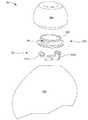
도 2a는 본 개시의 일부 실시예들에 따른, 이어팁이 하우징에 부착되는 예시적인 무선 청취 디바이스의 측면도 예시이다.
도 2b는 본 개시의 일부 실시예들에 따른, 이어팁이 하우징으로부터 분리되는 무선 청취 디바이스의 측면도 예시이다.
도 3a는 본 개시의 일부 실시예들에 따른, 부착 메커니즘을 통해 하우징의 외측 구조체에 부착된 이어팁의 단면도 예시이다.
도 3b는 본 개시의 일부 실시예들에 따른, 이어팁의 평면도 예시이다.
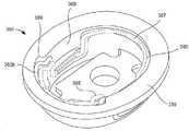
도 3c는 본 개시의 일부 실시예들에 따른, 부착 특징부들을 통해 외측 구조체들에 부착된 부착 메커니즘의 확대 단면도 예시이다.
도 3d는 본 개시의 일부 실시예들에 따른, 이어팁을 하우징에 부착하기 위한 와이어폼 부착 메커니즘을 포함하는 예시적인 무선 청취 디바이스의 분해도 예시이다.
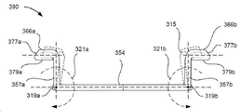
도 3e는 본 개시의 일부 실시예들에 따른, 와이어폼 부착 메커니즘에 의해 하우징에 부착되도록 구성된 이어팁의 단면도 예시이다.
도 3f 내지 도 3h는 본 개시의 일부 실시예들에 따른, 이어팁과 맞물릴 때 그의 중심을 향해 압축되도록 구성된 s-자형 프로파일을 갖는 와이어폼 부착 메커니즘의 예시들이다.
도 3i는 본 개시의 일부 실시예들에 따른, 와이어폼 부착 메커니즘을 통해 하우징에 부착된 이어팁의 단면도 예시이다.
도 3j 내지 도 3l은 본 개시의 일부 실시예들에 따른, 이어팁을 노즐에 부착하는 프로세스에 따라 상이한 지점들을 도시하는 일련의 예시들이다.
도 3m 내지 도 3o는 본 개시의 일부 실시예들에 따른, 이어팁과 맞물릴 때 그의 중심을 향해 압축되도록 구성된 u-자형 프로파일을 갖는 예시적인 와이어폼 부착 메커니즘의 예시들이다.
도 3p 및 도 3q는 본 개시의 일부 실시예들에 따른, 이어팁과 맞물릴 때 축을 중심으로 그의 단부 캡(end cap)들을 회전시키도록 구성된 u-자형 프로파일을 갖는 예시적인 와이어폼 부착 메커니즘의 예시들이다.
도 4a는 본 개시의 일부 실시예들에 따른, 용량성 센서로서 구성된 예시적인 이어팁의 단면도 예시이다.
도 4b 및 도 4c는 본 개시의 일부 실시예들에 따른, 이도 내로 삽입될 때의 이어팁의 단면도 예시들이다.
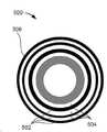
도 5a는 본 개시의 일부 실시예들에 따른, 그의 외측 이어팁 본체의 내측 표면 상의 공간들에 의해 분리된 패턴화된 라인들을 갖도록 구성된 예시적인 이어팁의 저면도 예시이다.
도 5b는 본 개시의 일부 실시예들에 따른, 이어팁 및 외측 이어팁 본체의 내측 표면을 관찰하기 위한 광학 센서를 갖는 하우징을 갖는 예시적인 무선 청취 디바이스의 측면도 예시이다.
도 5c는 본 개시의 일부 실시예들에 따른, 이도 내로 삽입되는 것으로부터의 편향 후의 이어팁의 저면도이다.
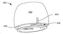
도 6a는 본 개시의 일부 실시예들에 따른, 그의 이어팁 내의 제어 누설부를 갖는 예시적인 무선 청취 디바이스의 사시도 예시이다.
도 6b 및 도 6c는 본 개시의 일부 실시예들에 따른, 상이한 제어 누설부 구성들을 갖는 상이한 이어팁들의 단면도 예시들이다.
도 6d는 본 개시의 일부 실시예들에 따른, 수직 절단 평면을 가로지르는 이어팁의 단면도 예시이다.
도 6e는 본 개시의 일부 실시예들에 따른, 수평 절단 평면을 가로지르는 이어팁의 단면도 예시이다.
도 6f 내지 도 6h는 본 개시의 일부 실시예들에 따른, 외측 이어팁 본체가 이도 내로 삽입되어 구부러지고 변형될 때 제어 누설부의 폐색을 완화시키기 위한 상이한 변경들을 갖는 예시적인 이어팁들의 사시도 예시들이다.
도 7은 본 개시의 일부 실시예들에 따른, 하우징의 추가 상세사항들을 보여주는 예시적인 무선 청취 디바이스의 단면도이다.
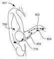
도 8은 본 개시의 일부 실시예들에 따른, 이도 및 귓바퀴에 대한 무선 청취 디바이스의 위치설정을 보여주기 위해 사용자에 의해 착용될 때의 무선 청취 디바이스의 단면도 예시이다.
도 9a는 본 개시의 일부 실시예들에 따른, 누설이 존재하지 않을 때의 무선 청취 디바이스의 단면도 예시이다.
도 9b는 본 개시의 일부 실시예들에 따른, 누설이 존재할 때의 무선 청취 디바이스의 단면 예시이다.
도 10은 본 개시의 일부 실시예들에 따른, 하나 이상의 포트들, 제어 누설부들, 및/또는 마이크로폰들이 폐색되는, 사용자에 의해 착용된 무선 청취 디바이스의 예시적인 측면도 예시이다.
도 11a 및 도 11b는 본 개시의 일부 실시예들에 따른, 하우징 내의 마이크로폰들을 위한 상이한 음향 차폐 컴포넌트들을 갖는 예시적인 구성들의 단면도 예시들이다.
도 12는 본 개시의 일부 실시예들에 따른, 다층 메시(multi-layer mesh)로서 구성된 예시적인 음향 차폐 컴포넌트의 분해도이다.
도 13은 본 개시의 일부 실시예들에 따른, 하우징의 크기를 감소시키기 위해 배터리 및 드라이버가 고유하게 위치되는 무선 청취 디바이스의 측면도 예시이다.
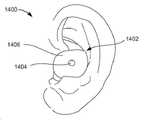
도 14는 본 개시의 일부 실시예들에 따른, 사용자의 청취 상태를 디스플레이하도록 구성된 무선 청취 디바이스의 측면도 예시이다.
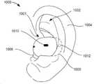
도 15는 본 개시의 일부 실시예들에 따른, 사용자의 귀의 해부학적 구조와의 상호작용을 통해 사용자 입력을 수신하도록 구성된 무선 청취 디바이스의 측면도 예시이다.
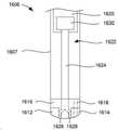
도 16a는 본 개시의 일부 실시예들에 따른, 스템을 포함하는 하우징에 결합된 이어팁을 포함하는 예시적인 무선 청취 디바이스의 사시도 예시이다.
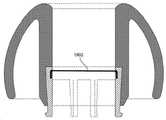
도 16b는 본 개시의 일부 실시예들에 따른, 스템 내의 전기 컴포넌트들의 단순화된 단면도 예시이다.
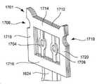
도 17a는 본 개시의 일부 실시예들에 따른, 정렬 바(alignment bar)로 구성된 예시적인 접촉 헤드의 사시도 예시이다.
도 17b는 본 개시의 일부 실시예들에 따른, 정렬 프레임으로 구성된 예시적인 접촉 헤드의 사시도 예시이다.
도 18a는 본 개시의 일부 실시예들에 따른, 단일 층 내에 2개의 전도성 트레이스들을 갖는 예시적인 버스 바의 단면도 예시이다.
도 18b는 본 개시의 일부 실시예들에 따른, 상이한 층들 내에 2개의 전도성 트레이스들을 갖는 예시적인 버스 바의 단면도 예시이다.
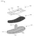
도 19a 내지 도 19g는 본 개시의 일부 실시예들에 따른, 이어팁을 형성하는 예시적인 방법의 단순화된 예시들이다.
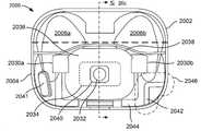
도 20a는 본 개시의 일부 실시예들에 따른, 정면으로부터의 케이스 내부의 컴포넌트들의 구성을 예시하기 위해 투명한 예시적인 케이스의 정면도 예시이다.
도 20b는 본 개시의 일부 실시예들에 따른, 후면으로부터의 케이스 내부의 컴포넌트들의 구성을 예시하기 위해 투명한 예시적인 케이스의 배면도 예시이다.
도 20c는 본 개시의 일부 실시예들에 따른 예시적인 케이스의 단면도 예시이다.
도 21a는 본 개시의 일부 실시예들에 따른 케이스에 대한 내부 프레임의 단순화된 사시도 예시이다.
도 21b는 본 개시의 일부 실시예들에 따른 케이스에 대한 내부 프레임의 단순화된 평면도 예시이다.
도 22a는 본 개시의 일부 실시예들에 따른, 도 21a의 내부 프레임의 단순화된 단면도 예시이다.
도 22b는 본 개시의 일부 실시예들에 따른, 도 22a의 단면도의 일부분의 단순화된 확대도 예시이다.
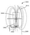
도 23은 본 개시의 일부 실시예들에 따른, 유지 자석들의 세트 및 무선 청취 디바이스의 단순화된 단면도 예시이다.
도 24a는 본 개시의 일부 실시예들에 따른 유지 자석들의 세트의 정면도 예시이다.
도 24b는 본 개시의 일부 실시예들에 따른 유지 자석들의 세트의 평면도 예시이다.
도 25는 본 개시의 일부 실시예들에 따른, 광 방출기 및 광 방출기에 의해 방출된 광을 케이스의 본체 내부로부터 케이스의 본체 외부의 영역으로 지향시키기 위한 광 튜브를 포함하는 예시적인 시각적 표시기의 단순화된 사시도 예시이다.
도 26a 및 도 26b는 본 개시의 일부 실시예들에 따른, 하이브리드 유지 및 센서 션트(shunt)를 포함하는 예시적인 자기 부착 및 센서 시스템의 단순화된 단면도들이다.
도 27은 본 개시의 일부 실시예들에 따른 예시적인 쌍안정 힌지(bistable hinge)의 사시도 예시이다.
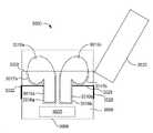
도 28a 내지 도 28c는 본 개시의 일부 실시예들에 따른, 쌍안정 힌지의 상이한 상태들의 단면도 예시들이다.
도 28d 내지 도 28f는 본 개시의 일부 실시예들에 따른, 로커(rocker)에 결합된 만곡 플레이트로 형성된 피스톤을 갖는 예시적인 쌍안정 힌지의 단순화된 예시들이다.
도 29a 내지 도 29c는 본 개시의 일부 실시예들에 따른, 예시적인 스트래들 배터리 팩(straddle battery pack)의 단순화된 예시들이다.
도 30은 본 개시의 일부 실시예들에 따른, 한 쌍의 무선 청취 디바이스들을 위한 케이스의 단순화된 평면도 예시이다.1A is a block diagram illustrating a portable electronic listening device system including an exemplary wireless listening device, in accordance with some embodiments of the present disclosure.
1B is a simplified illustration of an example portable electronic listening device system having a host device configured as a smartphone, a case, and a pair of wireless listening devices configured as earbuds, in accordance with some embodiments of the present disclosure.
2A is a side view illustration of an exemplary wireless listening device with an eartip attached to a housing, in accordance with some embodiments of the present disclosure.
2B is a side view illustration of a wireless listening device with an eartip separated from the housing, in accordance with some embodiments of the present disclosure.
3A is a cross-sectional illustration of an eartip attached to an outer structure of a housing via an attachment mechanism, in accordance with some embodiments of the present disclosure.
3B is a top view illustration of an ear tip, in accordance with some embodiments of the present disclosure.
3C is an enlarged cross-sectional illustration of an attachment mechanism attached to outer structures via attachment features, in accordance with some embodiments of the present disclosure.
3D is an exploded view illustration of an exemplary wireless listening device including a wireform attachment mechanism for attaching an eartip to a housing, in accordance with some embodiments of the present disclosure.
3E is a cross-sectional illustration of an eartip configured to be attached to a housing by a wireform attachment mechanism, in accordance with some embodiments of the present disclosure.
3F-3H are illustrations of a wireform attachment mechanism having an s-shaped profile configured to compress toward the center of an eartip when engaged with it, in accordance with some embodiments of the present disclosure.
3I is a cross-sectional illustration of an eartip attached to a housing via a wireform attachment mechanism, in accordance with some embodiments of the present disclosure.
3J-3L are a series of illustrations showing different points along the process of attaching an eartip to a nozzle, in accordance with some embodiments of the present disclosure.
3M-3O are illustrations of an exemplary wireform attachment mechanism having a u-shaped profile configured to compress toward a center thereof when engaged with an eartip, in accordance with some embodiments of the present disclosure.
3P and 3Q are illustrations of an exemplary wireform attachment mechanism having a u-shaped profile configured to rotate its end caps about an axis when engaged with an eartip, in accordance with some embodiments of the present disclosure; admit.
4A is a cross-sectional illustration of an exemplary eartip configured as a capacitive sensor, in accordance with some embodiments of the present disclosure.
4B and 4C are cross-sectional illustrations of an eartip when inserted into an ear canal, in accordance with some embodiments of the present disclosure.
5A is a bottom view illustration of an exemplary eartip configured to have patterned lines separated by spaces on the inner surface of its outer eartip body, in accordance with some embodiments of the present disclosure;
5B is a side view illustration of an exemplary wireless listening device having a housing with an optical sensor for viewing an inner surface of an eartip and an outer eartip body, in accordance with some embodiments of the present disclosure.
5C is a bottom view of an eartip after deflection from being inserted into the ear canal, in accordance with some embodiments of the present disclosure.
6A is a perspective illustration of an exemplary wireless listening device having a control leak in its eartip, in accordance with some embodiments of the present disclosure.
6B and 6C are cross-sectional illustrations of different ear tips with different control leak configurations, in accordance with some embodiments of the present disclosure.
6D is a cross-sectional illustration of an eartip across a vertical cutting plane, in accordance with some embodiments of the present disclosure.
6E is a cross-sectional illustration of an eartip across a horizontal cutting plane, in accordance with some embodiments of the present disclosure.
6F-6H are perspective illustrations of exemplary eartips with different modifications to alleviate occlusion of the control leak when the outer eartip body is flexed and deformed upon being inserted into the ear canal, in accordance with some embodiments of the present disclosure.
7 is a cross-sectional view of an exemplary wireless listening device showing additional details of a housing, in accordance with some embodiments of the present disclosure.
8 is a cross-sectional illustration of a wireless listening device when worn by a user to show positioning of the wireless listening device relative to the ear canal and pinna, in accordance with some embodiments of the present disclosure.
9A is a cross-sectional illustration of a wireless listening device when no leakage is present, in accordance with some embodiments of the present disclosure.
9B is a cross-sectional illustration of a wireless listening device when a leak is present, in accordance with some embodiments of the present disclosure.
10 is an exemplary side-view illustration of a wireless listening device worn by a user with one or more ports, control leaks, and/or microphones occluded, in accordance with some embodiments of the present disclosure.
11A and 11B are cross-sectional illustrations of example configurations with different acoustic shielding components for microphones in a housing, in accordance with some embodiments of the present disclosure.
12 is an exploded view of an exemplary acoustic shielding component configured as a multi-layer mesh, in accordance with some embodiments of the present disclosure.
13 is a side view illustration of a wireless listening device with a battery and driver uniquely positioned to reduce the size of the housing, in accordance with some embodiments of the present disclosure.
14 is a side view illustration of a wireless listening device configured to display a user's listening status, in accordance with some embodiments of the present disclosure.
15 is a side-view illustration of a wireless listening device configured to receive user input through interaction with the user's ear anatomy, in accordance with some embodiments of the present disclosure.
16A is a perspective illustration of an exemplary wireless listening device including an eartip coupled to a housing including a stem, in accordance with some embodiments of the present disclosure.
16B is a simplified cross-sectional illustration of electrical components within a stem, in accordance with some embodiments of the present disclosure.
17A is a perspective illustration of an exemplary contact head configured with an alignment bar, in accordance with some embodiments of the present disclosure.
17B is a perspective illustration of an exemplary contact head configured with an alignment frame, in accordance with some embodiments of the present disclosure.
18A is a cross-sectional illustration of an exemplary bus bar with two conductive traces in a single layer, in accordance with some embodiments of the present disclosure.
18B is a cross-sectional illustration of an exemplary bus bar with two conductive traces in different layers, in accordance with some embodiments of the present disclosure.
19A-19G are simplified illustrations of an example method of forming an eartip, in accordance with some embodiments of the present disclosure.
20A is a front view illustration of a transparent exemplary case to illustrate configuration of components inside the case from the front, in accordance with some embodiments of the present disclosure.
20B is a back view illustration of an example case that is transparent to illustrate configuration of components inside the case from the back, in accordance with some embodiments of the present disclosure.
20C is a cross-sectional illustration of an exemplary case in accordance with some embodiments of the present disclosure.
21A is a simplified perspective illustration of an inner frame for a case in accordance with some embodiments of the present disclosure;
21B is a simplified top view illustration of an inner frame for a case in accordance with some embodiments of the present disclosure.
22A is a simplified cross-sectional illustration of the inner frame of FIG. 21A , in accordance with some embodiments of the present disclosure.
22B is a simplified enlarged view illustration of a portion of the cross-sectional view of FIG. 22A , in accordance with some embodiments of the present disclosure.
23 is a simplified cross-sectional illustration of a set of retaining magnets and a wireless listening device, in accordance with some embodiments of the present disclosure.
24A is a front view illustration of a set of retaining magnets in accordance with some embodiments of the present disclosure.
24B is a top view illustration of a set of retaining magnets in accordance with some embodiments of the present disclosure.
25 is a simplification of an exemplary visual indicator including a light emitter and a light tube for directing light emitted by the light emitter from inside the body of the case to an area outside the body of the case, in accordance with some embodiments of the present disclosure. This is an example of a perspective view.
26A and 26B are simplified cross-sectional views of an exemplary magnetic attachment and sensor system including a hybrid retention and sensor shunt, in accordance with some embodiments of the present disclosure.
27 is a perspective illustration of an exemplary bistable hinge in accordance with some embodiments of the present disclosure.
28A-28C are cross-sectional illustrations of different states of a bistable hinge, in accordance with some embodiments of the present disclosure.
28D-28F are simplified illustrations of an exemplary bistable hinge having a piston formed of a curved plate coupled to a rocker, in accordance with some embodiments of the present disclosure.
29A-29C are simplified illustrations of an exemplary straddle battery pack, in accordance with some embodiments of the present disclosure.
30 is a simplified top view illustration of a case for a pair of wireless listening devices, in accordance with some embodiments of the present disclosure.
본 개시의 실시예들은 고급 음향 성능 및 개선된 사용자 경험을 달성하는 무선 청취 디바이스를 기술한다. 무선 청취 디바이스는 사용자에게 사운드를 출력하고 사용자 및/또는 주변 환경으로부터의 사운드를 입력하기 위해 사용자의 좌측 및 우측 귀에 끼워지도록 구성된 한 쌍의 무선 청취 디바이스들 중 하나일 수 있다. 일부 경우들에서, 무선 청취 디바이스는 하우징 및 하우징에 부착될 수 있는 이어팁을 포함할 수 있다. 하우징은 무선 청취 디바이스(예컨대, 배터리, 프로세서, 사운드를 생성하기 위한 드라이버 등)를 동작시키는 다양한 전기 컴포넌트들을 둘러싸는 강성 외측 구조체를 포함할 수 있다. 외측 구조체는 생성된 사운드가 이어팁에 출력될 수 있는 개구를 포함할 수 있으며, 이는 이어서 사운드를 사용자의 이도 내로 지향시킬 수 있다. 이어팁은 구성에서 실질적으로 유연할 수 있지만, 외측 구조체의 개구 내로 삽입함으로써 이어팁이 하우징에 용이하게 부착될 수 있게 하는 경성(stiff) 부착 구조체를 포함한다. 예시적인 이어팁들의 상세사항들은 도 3a 내지 도 3e와 관련하여 본 명세서에서 논의된다.Embodiments of the present disclosure describe a wireless listening device that achieves advanced acoustic performance and an improved user experience. The wireless listening device may be one of a pair of wireless listening devices configured to fit into the user's left and right ears to output sound to the user and input sound from the user and/or the surrounding environment. In some cases, a wireless listening device can include a housing and an eartip that can be attached to the housing. The housing may include a rigid outer structure that encloses various electrical components that operate a wireless listening device (eg, a battery, processor, driver for generating sound, etc.). The outer structure may include an opening through which the generated sound may be output to the eartip, which may in turn direct the sound into the user's ear canal. The eartip may be substantially flexible in construction, but includes a stiff attachment structure that allows the eartip to be easily attached to the housing by inserting it into an opening in the outer structure. Details of exemplary eartips are discussed herein with respect to FIGS. 3A-3E .
일부 경우들에서, 이어팁은, 이어팁을 제거하기 위해 높은 추출력을 요구하면서 낮은 삽입력의 인가 하에서 이어팁이 하우징에 부착될 수 있게 하는 와이어폼 부착 메커니즘에 의해 부착될 수 있다. 와이어폼 부착 메커니즘은 이어팁의 부착 구조체의 리세스들 내로 삽입하기 위한 단부 캡들을 포함하는 s-형상 프로파일을 가질 수 있다. 단부 캡들은 수직 삽입력이 수평력으로 변환되어 와이어폼 부착 메커니즘을 압축하도록 허용하기 위해 경사진 상부 코너(beveled upper corner)들을 가질 수 있다. 예시적인 와이어폼 부착 메커니즘들의 상세사항들은 도 3f 내지 도 3q와 관련하여 본 명세서에서 논의된다.In some cases, the eartip may be attached by a wireform attachment mechanism that allows the eartip to be attached to the housing under application of a low insertion force while requiring a high extraction force to remove the eartip. The wireform attachment mechanism may have an s-shaped profile that includes end caps for insertion into recesses of an attachment structure of an eartip. The end caps may have beveled upper corners to allow the vertical insertion force to be converted into a horizontal force to compress the wireform attachment mechanism. Details of exemplary wireform attachment mechanisms are discussed herein with respect to FIGS. 3F-3Q .
일부 추가적인 또는 대안적인 실시예들에서, 무선 청취 디바이스는 개선된 편안함을 위한 제어 누설부를 포함할 수 있다. 예를 들어, 이어팁은 이도가 대기에 노출될 수 있게 하는 특별히 설계된 개구 형태의 제어 누설부를 포함할 수 있다. 제어 누설부는 이어팁의 부착 구조체에 의해 한정될 수 있다. 제어 누설부가 없으면, 압력이 이도 내에 포획될 수 있고 사용자에게 불편할 수 있으며, 출력된 사운드가 머플링될 수 있다. 예시적인 제어 누설부들의 상세사항들은 도 6a 내지 도 6e와 관련하여 본 명세서에서 논의된다.In some additional or alternative embodiments, the wireless listening device may include a control leak for improved comfort. For example, the eartip may include a controlled leak in the form of a specially designed opening that allows the ear canal to be exposed to the atmosphere. The control leak may be defined by an attachment structure of the eartip. Without a control leak, pressure may be trapped in the ear canal and may be uncomfortable to the user, and the output sound may be muffled. Details of exemplary control leaks are discussed herein with respect to FIGS. 6A-6E .
일부 실시예들에서, 무선 청취 디바이스는 또한 윈드 노이즈를 완화시키고 사운드 캡처 품질을 개선하기 위한 음향 차폐 컴포넌트를 포함할 수 있다. 음향 차폐부는 장식용 메시(cosmetic mesh)와 보강재 사이에 개재된 음향 메시를 포함하는 다층 메시 구조체일 수 있다. 화장용 메쉬의 외측 표면은 하우징의 외측 윤곽들과 동일 높이일(flush with) 수 있어서, 윈드 노이즈가 완화될 수 있다. 예시적인 음향 차폐 컴포넌트들의 상세사항들은 도 11a, 도 11b, 및 도 12와 관련하여 본 명세서에서 논의된다.In some embodiments, the wireless listening device may also include an acoustic shielding component to mitigate wind noise and improve sound capture quality. The acoustic shield may be a multilayer mesh structure comprising an acoustic mesh sandwiched between a cosmetic mesh and a reinforcement. The outer surface of the cosmetic mesh can be flush with the outer contours of the housing, so that wind noise can be mitigated. Details of example acoustic shielding components are discussed herein with respect to FIGS. 11A , 11B , and 12 .
일부 추가적인 또는 대안적인 실시예들에서, 무선 청취 디바이스는 다양한 기능들을 수행하기 위한 다양한 센서들을 포함할 수 있다. 예를 들어, 이어팁은, 도 4a 내지 도 4c와 관련하여 본 명세서에서 논의된 바와 같이, 이어팁이 이도 내로 삽입되었을 때를 결정하기 위한 용량성 센서를 포함할 수 있다. 또는, 다른 경우에서, 하우징은, 도 5a 내지 도 5c와 관련하여 본 명세서에서 논의된 바와 같이, 이어팁이 이도 내로 삽입되었을 때를 결정하기 위해 이어팁의 특징부들과 함께 작동할 수 있는 광학 센서를 포함할 수 있다.무선 청취 디바이스는 또한, 도 9a 및 도 9b와 관련하여 본 명세서에서 논의된 바와 같이, 이어팁과 이도 사이에 적절한 시일이 이루어졌는지 여부 및 하우징의 하나 이상의 센서들이 부적절하게 차단되는지 여부를 결정하도록 구성될 수 있다.In some additional or alternative embodiments, the wireless listening device may include various sensors for performing various functions. For example, the eartip may include a capacitive sensor for determining when the eartip has been inserted into the ear canal, as discussed herein with respect to FIGS. 4A-4C . Or, in other cases, the housing includes an optical sensor operable with features of the eartip to determine when the eartip has been inserted into the ear canal, as discussed herein with respect to FIGS. 5A-5C . can do.The wireless listening device may also be configured to determine whether a proper seal has been made between the eartip and the ear canal and whether one or more sensors of the housing are improperly blocked, as discussed herein with respect to FIGS. 9A and 9B . can
무선 청취 디바이스는 또한, 도 7, 도 8, 도 10, 도 14, 및 도 15와 관련하여 본 명세서에서 논의된 바와 같이, 상태 광 표시기, 전략적으로 위치된 광학 센서들, 외향으로 향하는 마이크로폰, 및/또는 저전력 가속도계들과 같은 다양한 개선된 사용자 인터페이스 특징부들을 포함할 수 있다. 상태 광 표시기는 능동 노이즈 소거(active noise cancelling, ANC)가 활성화되는지를 나타내기 위해 상이한 색상들의 광을 출력하도록 구성될 수 있다. 예를 들어, 상태 광 표시기는 ANC가 켜져 있을 때 적색 광을, ANC가 꺼져 있을 때 녹색 광을 출력하여 사용자 주위의 사람들이 사용자의 의사소통 능력을 인식할 수 있도록 할 수 있다. 광학 센서들은 귀의 부분들을 관찰하도록 전략적으로 위치될 수 있어서, 귀가 움직일 때, 예컨대 사용자가 자신의 귀의 소정 부분들을 당길 때 귀가 무선 청취 디바이스로부터 멀리 당겨질 때, 무선 청취 디바이스가 그 움직임을 특정 사용자 입력과 연관시킬 수 있도록 할 수 있다. 저전력 가속도계는 사용자로부터의 음성 명령들을 검출하기 위해 외향으로 향하는 마이크로폰과 함께 사용될 수 있다. 예를 들어, 무선 청취 디바이스는 저전력 가속도계를 이용해 진동의 정도를 또한 측정함으로써, 사용자의 옆에서 또는 사용자에게 직접 말을 하고 있게 되는 다른 사람과는 대조적으로 사용자가 명령을 말하고 있다고 결정할 수 있다. 저전력 가속도계는 사용자가 말할 때 임계치를 초과하여 진동할 수 있다. 따라서, 무선 청취 디바이스는 명령이 임계량의 진동과 함께 말해질 때 사용자가 명령을 말하고 있다고 결정할 수 있다. 이러한 사용자 인터페이스 특징부들은 무선 청취 디바이스의 사용자 경험을 개선할 수 있으며, 이는 본 명세서에서 추가로 논의된다.The wireless listening device may also include a status light indicator, strategically positioned optical sensors, an outward-facing microphone, and, as discussed herein with respect to FIGS. 7 , 8 , 10 , 14 , and 15 , and and/or various advanced user interface features such as low power accelerometers. The status light indicator may be configured to output different colors of light to indicate whether active noise canceling (ANC) is active. For example, the status light indicator may output a red light when the ANC is on and a green light when the ANC is off so that people around the user can recognize the user's communication ability. The optical sensors can be strategically positioned to view portions of the ear so that when the ear is moved, such as when the user pulls certain portions of his or her ear, the ear is pulled away from the wireless listening device, the wireless listening device synchronizes that movement with a particular user input. can be made to be related. A low-power accelerometer can be used with an outward-facing microphone to detect voice commands from the user. For example, the wireless listening device may also measure the degree of vibration using a low-power accelerometer to determine that the user is speaking a command as opposed to someone else who may be speaking next to or directly to the user. A low-power accelerometer can vibrate beyond a threshold when the user speaks. Accordingly, the wireless listening device may determine that the user is speaking the command when the command is spoken with a threshold amount of vibration. Such user interface features may improve the user experience of the wireless listening device, as discussed further herein.
본 명세서에서 사용되는 바와 같이, 용어 "휴대용 청취 디바이스"는 사용자에게 들릴 수 있는 사운드를 재생하도록 설계된 임의의 휴대용 디바이스를 포함한다. 헤드폰은 하나의 유형의 휴대용 청취 디바이스이고, 휴대용 스피커는 다른 유형의 휴대용 청취 디바이스이다. 용어 "헤드폰"은 사용자의 머리 위 또는 둘레에 착용되도록 설계된 한 쌍의 소형 휴대용 청취 디바이스를 표현한다. 이들은 전기 신호를 사용자에게 들릴 수 있는 대응하는 사운드로 변환한다. 헤드폰은 사용자의 머리 위에 착용되는 기존의 헤드폰을 포함하며, 헤드밴드에 의해 서로 연결되는 좌측 및 우측 청취 디바이스, 헤드셋(헤드폰과 마이크로폰의 조합); 및 이어버드(사용자의 귀 내에 직접적으로 들어맞도록 설계된 매우 작은 헤드폰)를 포함한다. 종래의 헤드폰은 사용자의 귀를 전체적으로 감싸는 이어패드를 갖는 오버-이어 헤드폰(over-ear headphone)(때때로 서큠오랄(circumaural) 또는 풀-사이즈(full-size) 헤드폰으로 지칭됨), 및 귀를 감싸는 대신 사용자의 귀에 대해 누르는 이어패드를 갖는 온-이어 헤드폰(on-ear headphone)(때때로 수프라-오랄(supra-aural) 헤드폰으로 지칭됨)을 포함한다.As used herein, the term “portable listening device” includes any portable device designed to reproduce sound audible to a user. Headphones are one type of portable listening device, and portable speakers are another type of portable listening device. The term “headphones” refers to a pair of small portable listening devices designed to be worn over or around a user's head. They convert electrical signals into corresponding sounds audible to the user. Headphones include conventional headphones worn over a user's head, left and right listening devices connected to each other by a headband, a headset (a combination of a headphone and a microphone); and earbuds (very small headphones designed to fit directly within a user's ear). Conventional headphones include over-ear headphones (sometimes referred to as circumaural or full-size headphones) that have earpads that completely surround the user's ears, and those that wrap around the ears. Instead include on-ear headphones (sometimes referred to as supra-aural headphones) with earpads pressed against the user's ear.
용어 "이어버드"는 이어폰이나 이어-피팅 헤드폰(ear-fitting headphone)으로도 또한 지칭될 수 있으며, 이도 내로 삽입되지 않으면서 이도를 마주보는 사용자의 외이(outer ear) 내에 들어맞는 소형 헤드폰, 및 이도 자체 내로 삽입되는, 때때로 외이폰(canalphone)이라고도 칭해지는 인-이어 헤드폰을 포함한다. 따라서, 인-이어 청각 디바이스들은 실질적으로 사용자의 귀 내에 위치되도록 구성된 다른 유형의 휴대용 청취 디바이스일 수 있다. 다른 유형의 휴대용 청취 디바이스들은 또한 주변 환경으로부터의 사운드들을 사용자에게 증강시키는 보청기를 포함할 수 있다. 본 명세서에서 사용되는 바와 같이, 용어 "이어팁"은 이어몰드로도 또한 지칭될 수 있으며, 이도 내에 적어도 부분적으로 들어맞는 사전-형성된, 사후-형성된, 또는 맞춤-성형된 사운드-지향 구조체들을 포함한다. 이어팁은 장시간 동안 착용될 수 있는 편안한 착용감을 갖도록 형성될 수 있다. 이들은 사용자의 이도 및/또는 이강(ear cavity)과의 더 양호한 시일을 달성하기 위해 상이한 크기들 및 형상들을 가질 수 있다.The term "earbuds" may also refer to earphones or ear-fitting headphones, which are small headphones that fit within the user's outer ear facing the ear canal without being inserted into the ear canal, and Includes in-ear headphones, sometimes referred to as canalphones, that are inserted into the ear canal itself. Accordingly, in-ear hearing devices may be other types of portable listening devices configured to be positioned substantially within a user's ear. Other types of portable listening devices may also include hearing aids that augment sounds from the surrounding environment to the user. As used herein, the term “eartip” may also refer to an earmold and includes pre-formed, post-formed, or custom-shaped sound-directing structures that fit at least partially within the ear canal. . The ear tip may be formed to have a comfortable fit that can be worn for a long time. They may have different sizes and shapes to achieve a better seal with the user's ear canal and/or ear cavity.
본 명세서에서 전술된 무선 청취 디바이스에 더하여, 실시예들은 또한 하나 이상의 무선 청취 디바이스들을 수용하기 위한 케이스를 포함한다. 케이스는 서로에 대해 측방향으로 위치된 자석들의 세트로 형성된 자석 어레이를 포함할 수 있다. 각각의 자석은 작은 풋프린트에서 높은 인력을 생성하기 위해 무선 청취 디바이스 내의 유지 슬래브에서 자기력을 집중시키기 위해 별개의 방향으로 위치되는 특정 자기 극성을 가질 수 있다. 예시적인 자석 어레이들의 상세사항들은 도 23, 도 24a 및 도 24b와 관련하여 본 명세서에서 논의된다.In addition to the wireless listening device described above herein, embodiments also include a case for receiving one or more wireless listening devices. The case may include a magnet array formed of a set of magnets positioned laterally with respect to each other. Each magnet may have a specific magnetic polarity positioned in a distinct direction to focus the magnetic force on the holding slab within the wireless listening device to create a high attractive force in a small footprint. Details of exemplary magnet arrays are discussed herein with respect to FIGS. 23 , 24A and 24B .
일부 추가적인 또는 대안적인 실시예들에서, 케이스는 또한 2개의 안정된 상태들을 가질 수 있는 쌍안정 힌지를 포함할 수 있으며, 그 중 하나는 케이스의 덮개를 당겨서 폐쇄하고, 그 중 다른 하나는 케이스의 덮개를 밀어서 개방한다. 쌍안정 힌지는 3개의 피벗점(pivot point)들뿐만 아니라, 피스톤 가이드(piston guide)가 그를 따라 이동할 수 있는 피스톤 로드(piston rod) 및 스프링을 포함할 수 있다. 스프링에 의해 인가된 힘과, 2개의 피벗점들에 의해 한정된 변환 축(conversion axis)의 상대적 방향은 쌍안정 힌지가 밀거나 당기는 상태를 한정할 수 있다. 쌍안정 힌지는 케이스에 대한 덮개가 개방 또는 폐쇄될 때 좋은 촉감을 제공할 수 있고, 또한 덮개가 폐쇄된 상태로 유지하는 데 필요한 자석들의 수를 최소화할 수 있다. 예시적인 쌍안정 힌지들의 상세사항들은 도 27 및 도 28a 내지 도 28c와 관련하여 본 명세서에서 논의된다.In some additional or alternative embodiments, the case may also include a bistable hinge that may have two stable states, one of which pulls the lid of the case to close, the other of which may have a lid on the case. push to open The bistable hinge may include three pivot points, as well as a piston rod and a spring along which a piston guide can move. The force applied by the spring and the relative direction of the conversion axis defined by the two pivot points may define the pushing or pulling state of the bistable hinge. A bistable hinge can provide a good tactile feel when the lid to the case is open or closed, and can also minimize the number of magnets needed to keep the lid closed. Details of exemplary bistable hinges are discussed herein with respect to FIGS. 27 and 28A-28C.
소정 경우들에서, 케이스는 또한 케이스의 덮개가 폐쇄 위치에 있을 때를 검출하기 위한 하이브리드 유지 및 센서 션트를 포함할 수 있다. 하이브리드 션트는 덮개 내의 자석이 본체를 향해 당겨져 덮개를 폐쇄된 상태로 유지하도록 허용하면서, 또한 자석으로부터의 자기장이, 센서를 통해 검출될 션트 아래의 영역으로 가로지를 수 있는 본체를 제공할 수 있다. 그러한 방식으로, 센서는, 케이스 주위의 어딘가 다른 곳에 배치되어 귀중한 실면적을 차지하는 대신에, 하이브리드 션트에 제공된 공간을 활용할 수 있다. 예시적인 하이브리드 유지 및 센서 션트들의 상세사항들은 도 26a 및 도 26b와 관련하여 본 명세서에서 논의된다.In certain cases, the case may also include a hybrid retention and sensor shunt for detecting when the lid of the case is in the closed position. A hybrid shunt can provide a body that allows the magnets in the lid to be pulled towards the body to keep the lid closed, while also providing a body in which a magnetic field from the magnet can traverse to an area below the shunt to be detected via the sensor. In that way, the sensor can utilize the space provided in the hybrid shunt instead of being placed somewhere else around the case and occupying valuable real estate. Details of exemplary hybrid holding and sensor shunts are discussed herein with respect to FIGS. 26A and 26B .
I.I.무선 청취 디바이스wireless listening device
도 1a는 본 개시의 일부 실시예들에 따른, 예시적인 무선 청취 디바이스(101)를 포함하는 휴대용 전자 청취 디바이스 시스템(100)을 도시하는 블록도이다. 전술된 바와 같이, 무선 청취 디바이스(101)는 하우징(105)을 포함할 수 있다. 하우징(105)은 호스트 디바이스(130)에 대한 향상된 사용자 인터페이스를 제공하기 위해 사운드를 생성 및 수신하는 전자 디바이스 컴포넌트일 수 있다. 하우징(105)은 메모리 뱅크(104)에 결합된 컴퓨팅 시스템(102)을 포함할 수 있다. 컴퓨팅 시스템(102)은 하우징(105)을 동작시키기 위한 복수의 기능들을 수행하기 위해 메모리 뱅크(104)에 저장된 명령어들을 실행시킬 수 있다. 컴퓨팅 시스템(102)은 하나 이상의 적합한 컴퓨팅 디바이스들, 예컨대 마이크로프로세서, CPU(computer processing unit), GPU(graphics processing unit), FPGA(field programmable gate array) 등일 수 있다.1A is a block diagram illustrating a portable electronic
컴퓨팅 시스템(102)은 또한 하우징(105)이 하나 이상의 기능들을 수행할 수 있게 하기 위해 사용자 인터페이스 시스템(106), 통신 시스템(108) 및 센서 시스템(110)에 결합될 수 있다. 예를 들어, 사용자 인터페이스 시스템(106)은 사용자에게 사운드를 출력하기 위한 드라이버(예컨대, 스피커), 환경 또는 사용자로부터의 사운드를 입력하기 위한 마이크로폰, 및 임의의 다른 적합한 입력 및 출력 디바이스를 포함할 수 있다. 통신 시스템(108)은 하우징(105)이 호스트 디바이스(130)로부터 데이터/커맨드들을 전송 및 수신할 수 있게 하기 위한 블루투스 컴포넌트들을 포함할 수 있다. 센서 시스템(110)은 광학 센서들, 가속도계들, 마이크로폰들, 및 외부 엔티티 및/또는 환경의 파라미터를 측정할 수 있는 임의의 다른 유형의 센서를 포함할 수 있다.Computing system 102 may also be coupled to user interface system 106 , communication system 108 , and sensor system 110 to enable housing 105 to perform one or more functions. For example, user interface system 106 may include a driver (eg, a speaker) for outputting sound to a user, a microphone for inputting sound from an environment or user, and any other suitable input and output devices. have. Communication system 108 may include Bluetooth components to enable housing 105 to transmit and receive data/commands from host device 130 . Sensor system 110 may include optical sensors, accelerometers, microphones, and any other type of sensor capable of measuring a parameter of an external entity and/or environment.
하우징(105)은 또한, 에너지를 저장하고 하우징(105)을 동작시키기 위해 저장된 에너지를 방전할 수 있는 리튬 이온 배터리와 같은 임의의 적합한 에너지 저장 디바이스일 수 있는 배터리(112)를 포함할 수 있다. 방전된 에너지는 하우징(105)의 전기 컴포넌트들에 전력을 공급하기 위해 사용될 수 있다. 일부 실시예들에서, 배터리(112)는 또한 그의 저장된 에너지를 보충하기 위해 충전될 수 있다. 예를 들어, 배터리(112)는 수신 요소(116)로부터 전류를 수신할 수 있는 전력 수신 회로부(114)에 결합될 수 있다. 수신 요소(116)는, 수신 요소(116) 및 송신 요소(118)가 노출된 전기적 접촉부들로서 구성되는 실시예들에서, 케이스(103)의 송신 요소(118)와 전기적으로 결합될 수 있다. 케이스(103)는 전력 송신 회로부(120)에 에너지를 저장 및 방전할 수 있는 배터리(122)를 포함할 수 있으며, 전력 송신 회로부(120)는 이어서 송신 요소(118)에 전력을 제공할 수 있다. 제공된 전력은 전기 연결(128)을 통해 전달될 수 있고, 배터리(112)를 충전하기 위한 전력 수신 회로부(114)에 의해 수신될 수 있다. 케이스(103)는 수신 요소(116)를 통해 배터리(112)를 충전하기 위한 전력을 제공하는 디바이스일 수 있지만, 일부 실시예들에서, 케이스(103)는 또한 무선 청취 디바이스(101)가 케이스(103) 내에 보관되는 동안 무선 청취 디바이스(101)를 보관하고 그에 대한 보호를 제공하기 위해 무선 청취 디바이스(101)를 수용하는 디바이스일 수 있다.The housing 105 may also include a battery 112 , which may be any suitable energy storage device, such as a lithium ion battery, capable of storing energy and discharging the stored energy to operate the housing 105 . The discharged energy may be used to power electrical components of the housing 105 . In some embodiments, battery 112 may also be charged to replenish its stored energy. For example, battery 112 may be coupled to power receiving circuitry 114 that may receive current from receiving
케이스(103)는 또한 케이스 컴퓨팅 시스템(119) 및 케이스 통신 시스템(121)을 포함할 수 있다. 케이스 컴퓨팅 시스템(119)은 케이스(103)를 동작시키기 위한 하나 이상의 프로세서들, ASIC들, FPGA들, 마이크로프로세서들 등일 수 있다. 케이스 컴퓨팅 시스템(119)은 케이스(103)의 충전 기능들을 동작시키기 위해 전력 송신 회로부(120)에 결합될 수 있고, 케이스 컴퓨팅 시스템(119)은 또한 다른 디바이스들, 예컨대 하우징(105)과의 케이스(103)의 상호작용 기능들을 동작시키기 위해 케이스 통신 시스템(121)에 결합될 수 있다. 일부 실시예들에서, 케이스 통신 시스템(121)은 전도성 본체로 형성된 안테나와 같은, 하우징(105)의 통신 시스템(108)과 데이터를 전송 및 수신하는 블루투스 컴포넌트 또는 임의의 다른 적합한 통신 컴포넌트이다. 그러한 방식으로, 케이스(103)는 무선 청취 디바이스(101)의 상태(예컨대, 충전 상태 등)를 알게 될 수 있다. 케이스(103)는 또한 케이스 컴퓨팅 시스템(119)에 결합된 스피커(123)를 포함할 수 있어서, 스피커(123)가 통지 목적을 위해 사용자에 의해 들릴 수 있는 가청 잡음을 방출할 수 있다.Case 103 may also include case computing system 119 and case communication system 121 . Case computing system 119 may be one or more processors, ASICs, FPGAs, microprocessors, etc. for operating case 103 . The case computing system 119 may be coupled to the power transmission circuitry 120 to operate the charging functions of the case 103 , and the case computing system 119 may also be coupled to the case with other devices, such as the housing 105 . It may be coupled to the case communication system 121 to operate the interactive functions of 103 . In some embodiments, case communication system 121 is a Bluetooth component or any other suitable communication component that transmits and receives data with communication system 108 of housing 105 , such as an antenna formed of a conductive body. In that way, the case 103 may be aware of the state of the wireless listening device 101 (eg, charging state, etc.). Case 103 may also include a speaker 123 coupled to case computing system 119 such that speaker 123 may emit audible noise that may be heard by a user for notification purposes.
하우징(105)이 액세서리인, 호스트 디바이스(130)는 스마트 폰, 태블릿, 또는 랩톱 컴퓨터와 같은 휴대용 전자 디바이스일 수 있다. 호스트 디바이스(130)는 배터리(135) 및 호스트 디바이스(130)를 동작시키기 위해 호스트 컴퓨팅 시스템(132)에 의해 실행가능한 코드의 라인들을 포함하는 호스트 메모리 뱅크(134)에 결합된 호스트 컴퓨팅 시스템(132)을 포함할 수 있다. 호스트 디바이스(130)는 또한 호스트 디바이스(130)가 환경을 감지하도록 허용하기 위한 호스트 센서 시스템(136), 예컨대 가속도계, 자이로스코프, 광 센서 등, 및 사용자에게 정보를 출력하고 사용자로부터 입력을 수신하기 위한 호스트 사용자 인터페이스 시스템(138), 예컨대 디스플레이, 스피커, 버튼들, 터치 스크린 등을 포함할 수 있다. 추가적으로, 호스트 디바이스(130)는 또한 호스트 디바이스(130)가 무선 통신을 통해, 예컨대, WIFI(wireless fidelity), LTE(long term evolution), CDMA(code division multiple access), GSM(global system for mobiles), 블루투스 등을 통해, 인터넷 또는 셀 타워들로부터 데이터를 전송 및/또는 수신하도록 허용하기 위한 호스트 통신 시스템(140)을 포함할 수 있다. 일부 실시예들에서, 호스트 통신 시스템(140)은 또한 무선 통신 라인(142)을 통해 하우징(105) 내의 통신 시스템(108)과 통신할 수 있어서, 호스트 디바이스(130)가 사운드를 출력하기 위해 사운드 데이터를 하우징(105)에 전송하고, 사용자 입력들을 수신하기 위해 하우징(105)으로부터 데이터를 수신할 수 있다. 통신 라인(142)은 블루투스 연결과 같은 임의의 적합한 무선 통신 라인일 수 있다. 호스트 디바이스(130)와 하우징(105) 사이의 통신을 가능하게 함으로써, 무선 청취 디바이스(101)는 호스트 디바이스(130)의 사용자 인터페이스를 향상시킬 수 있다.The host device 130 , of which the housing 105 is an accessory, may be a portable electronic device such as a smart phone, tablet, or laptop computer. The host device 130 includes a battery 135 and a host computing system 132 coupled to a
그러한 휴대용 전자 청취 디바이스 시스템의 예가 도 1b에 도시되어 있으며, 이는 본 개시의 일부 실시예들에 따른, 스마트폰으로서 구성된 호스트 디바이스(152), 케이스(154), 및 한 쌍의 인-이어 청각 디바이스들로서 구성된 한 쌍의 무선 청취 디바이스들(156)을 갖는 예시적인 휴대용 전자 청취 디바이스 시스템(150)의 단순화된 도면이다. 호스트 디바이스(152)는 케이스(154)와 무선으로 통신가능하게 결합되어, 호스트 디바이스(152)가 케이스(154)에 대한 충전 레벨 데이터 및/또는 무선 청취 디바이스들(156)에 대한 충전 레벨 데이터를 수신할 수 있다. 호스트 디바이스(152)는 또한 무선 청취 디바이스들(156)과 무선으로 통신가능하게 결합되어, 오디오 데이터가 사용자에게 재생되기 위해 무선 청취 디바이스들(156)에 송신될 수 있고, 오디오 데이터는 무선 청취 디바이스들(156) 내의 마이크로폰들로부터 녹음/입력된 대로 호스트 디바이스(152)에 의해 수신될 수 있다. 무선 청취 디바이스들(156)은 케이스(154)와 무선으로 통신가능하게 결합되어, 케이스(154)로부터의 오디오 데이터가 무선 청취 디바이스들(156)로 송신될 수 있다. 일례로서, 케이스(154)는 물리적 연결, 예컨대, 보조 케이블 연결을 통해 호스트 디바이스(152)와는 상이한 음원에 결합될 수 있다. 오디오 소스로부터의 오디오 데이터는 케이스(154)에 출력될 수 있으며, 이는 이어서 데이터를 무선 청취 디바이스들(156)로 무선으로 송신할 수 있다. 그러한 방식으로, 오디오 디바이스가 무선 오디오 출력 능력들을 갖지 않더라도, 사용자는 무선 청취 디바이스들(156)에 의해 오디오를 들을 수 있다.An example of such a portable electronic listening device system is shown in FIG. 1B , which includes a
본 개시의 일부 실시예들에 따르면, 각각의 무선 청취 디바이스(156)는 본체(160) 및 본체(160)로부터 연장되는 스템(162)으로 형성된 하우징(158)을 포함할 수 있으며, 여기서 하우징(158)은 모놀리식 외측 구조체로 형성된다. 본체(160)는 도 7 내지 도 10과 관련하여 본 명세서에서 논의된 목적들을 위해 내부를 향하는 마이크로폰(164) 및 외부를 향하는 마이크로폰(166)을 포함할 수 있다. 외부를 향하는 마이크로폰(166)은 도 1b에 도시된 바와 같이 본체(160) 및 스템(162)의 부분들에 의해 한정된 개구 내에 위치될 수 있다. 본체(160) 및 스템(162) 둘 모두로 연장됨으로써, 마이크로폰(166)은 사용자 주위의 더 넓은 영역으로부터 사운드들을 수신하기에 충분히 클 수 있다. 일부 실시예들에서, 하우징(158)은 사운드를 내부 오디오 드라이버로부터 하우징(158) 밖으로 그리고 사용자의 이도 내로 지향시킬 수 있는 이어팁(174)에 부착될 수 있다. 따라서, 무선 청취 디바이스들(156)은 인-이어 청각 디바이스들로서 구성될 수 있다. 스템(162)은 구성이 실질적으로 원통형일 수 있지만, 그것은 원통형 구성의 곡률을 따르지 않는 평면 영역(168)을 포함할 수 있다. 평면 영역(168)은 무선 청취 디바이스가 사용자 입력을 수신할 수 있는 영역을 나타낼 수 있다. 예를 들어, 사용자 입력은 평면 영역(168)에서 스템(162)을 압착함으로써 입력될 수 있다. 스템(162)은 또한 도 20a에 관하여 본 명세서에서 추가로 논의되는 바와 같이, 케이스(154) 내의 대응하는 전기적 접촉부들과 접촉을 이루기 위한 전기적 접촉부들(170, 172)을 포함할 수 있다.According to some embodiments of the present disclosure, each
본 명세서에서 이해되는 바와 같이, 무선 청취 디바이스들(156)은 이들이 하루 종일 사용자에 의해 착용될 수 있게 하는 여러 특징부들을 포함할 수 있다. 그것의 이어팁은 부드럽고 유연할 수 있으며, 그것이 착용하기에 편안하도록 이도 내의 포획된 압력을 방출하기 위한 제어 누설부들을 포함할 수 있다. 그것의 기능은 또한 무선 청취 디바이스들(156)이 호스트 디바이스(152)에 대한 오디오 인터페이스를 제공할 수 있게 하여, 사용자가 호스트 디바이스(152)의 그래픽 인터페이스를 이용할 필요가 없을 수 있게 할 수 있다. 다시 말하면, 무선 청취 디바이스들(156)은, 사용자가 무선 청취 디바이스들(156)과의 상호작용들을 통해서만 호스트 디바이스(152)로부터의 일상 동작들을 수행하게 할 수 있도록, 매우 정교할 수 있다. 이는, 특히 무선 청취 디바이스들(156)의 기능이 호스트 디바이스(152)의 음성 제어 능력들과 조합될 때, 사용자가 호스트 디바이스(152)와 물리적으로 상호작용하고/하거나 호스트 디바이스(152)의 디스플레이 스크린을 볼 것을 요구하지 않음으로써 호스트 디바이스(152)로부터의 추가 독립성을 생성할 수 있다. 또한, 무선 청취 디바이스들(156)은, 주변 환경으로부터의 가청음들이 외부를 향하는 마이크로폰(166)에 의해 녹음될 수 있으며 이어팁(174)을 통해 사운드를 출력하여 사용자에 의해 들리도록 함으로써 사용자에게 즉시 복제될 수 있는, 투명 모드로 기능할 수 있다. 추가적으로, 듣기가 어려운 그러한 사용자들의 경우, 무선 청취 디바이스들(156)은 사용자가 듣도록 주변 환경에서의 사운드들의 볼륨을 증가시킬 수 있다. 더욱이, 음악 콘서트에 있는 사용자와 같은 극도로 시끄러운 환경에 있는 그러한 사용자들의 경우, 무선 청취 디바이스들(156)은 주변 환경에서의 사운드들의 볼륨을 더 허용가능한 레벨로 감소시킬 수 있다. 일부 실시예들에서, 볼륨을 증가시키는 것과 감소시키는 것 사이의 이러한 조정은 소정 데시벨 범위를 유지하기 위해 자동으로 발생할 수 있다. 따라서, 무선 청취 디바이스들(156)은 사용자에게 진정한 핸즈프리 경험을 가능하게 할 수 있다.As understood herein,
본 개시의 일부 실시예들에 따르면, 이어팁(124)은 도 2a 및 도 2b에 도시된 바와 같이 하우징(105)에 부착되고 그로부터 분리될 수 있다. 도 2a는 본 개시의 일부 실시예들에 따른, 이어팁(204)이 하우징(202)에 부착되어 있는, 이어팁(204) 및 하우징(202)을 포함하는 예시적인 무선 청취 디바이스(200)의 측면도 예시이고; 도 2b는 본 개시의 일부 실시예들에 따른, 이어팁(204)이 하우징(202)으로부터 분리되어 있는 무선 청취 디바이스(200)의 측면도 예시이다. 도 2a에 도시된 바와 같이, 이어팁(204)은 모놀리식 구조체를 함께 형성하는 팁 영역(206) 및 베이스 영역(208), 및 팁 영역(206) 및 베이스 영역(208) 둘 모두를 통해 연장되는 사운드 채널(210)을 포함할 수 있다. 팁 영역(206)은 하우징(202)으로부터 사용자에게 사운드를 지향시키기 위해 이도 내로 삽입되는 만곡된 환형 표면(207)을 포함할 수 있고, 음향 시일을 형성하기 위해 이도의 내측 표면들에 순응하도록 용이하게 구부러질 수 있는 유연한 재료로 형성될 수 있다.According to some embodiments of the present disclosure, the eartip 124 may be attached to and detached from the housing 105 as shown in FIGS. 2A and 2B . 2A illustrates a side view of an exemplary
이어팁(124)은 다양한 방식들로 하우징(105)에 부착될 수 있다. 예를 들어, 이어팁(124)은 자석들을 사용하여 하우징에 자기적으로 부착되어 이어팁(124)을 하우징(105)에 자기적으로 끌어당길 수 있다. 이어팁(124)은 또한 스크류 및 나사형 구멍 부착과 같은 기계적 수단을 사용하여 하우징(105)에 부착될 수 있다. 그러한 경우들에서, 하우징(105)의 개구가 나사형성될 수 있고, 베이스 영역(208)은 이어팁(124)이 하우징(105) 내로 나사결합될 수 있도록 대응하여 나사형성될 수 있다. 또한, 이어팁(124)은 접착제 또는 임의의 다른 화학적 접합을 사용하여 하우징(105)에 간단히 접착될 수 있다. 소정 실시예들에서, 이어팁(124)은 하우징(105)에 후크결합되는 특징부들을 가질 수 있거나, 또는 이어팁(124)에 래칭하기 위해 별개의 와이어폼 부착 메커니즘이 하우징(105) 내에 구현될 수 있다. 이어팁(204)의 구성의 추가의 상세사항들은 도 3a 내지 도 3c 및 도 3e와 관련하여 본 명세서에서 추가로 논의될 것이다. 이어팁(204)은 도 2b에 도시된 바와 같이 하우징(202)으로부터 분리될 수 있어서, 손상된 이어팁들이 쉽게 교체될 수 있거나, 또는 상이한 유형들 및/또는 크기들의 이어팁들이 상이한 해부학적 형상들 및 크기들의 이도들에 더 편안하게 맞도록 사용될 수 있다.Eartip 124 may be attached to housing 105 in a variety of ways. For example, the eartip 124 may be magnetically attached to the housing using magnets to magnetically attract the eartip 124 to the housing 105 . Eartip 124 may also be attached to housing 105 using mechanical means such as screws and threaded hole attachments. In such cases, the opening of the housing 105 may be threaded, and the
이어팁(204) 및 하우징(202)은 개선된 사운드 품질 및 사용자 경험을 야기하는 상이한 구성 및 기능을 가질 수 있다는 것이 이해될 것이다. 그러한 구성들 및 기능들의 상세사항들은 본 명세서에서 추가로 논의된다.It will be appreciated that
II.II.이어팁ear tips
전술된 바와 같이, 이어팁은 무선 청취 디바이스의 하우징에 부착되고 그로부터 분리될 수 있다. 인-이어 청각 디바이스 또는 보청기로서 구성될 때, 이어팁은 사용자의 이도 내부에 위치되고 하우징에 의해 출력된 사운드를 이도 내로 지향시킬 수 있다. 일부 실시예들에서, 부착 메커니즘은, 도 3a 내지 도 3c와 관련하여 본 명세서에서 논의된 바와 같이, 이어팁이 하우징에 부착되고 그로부터 분리될 수 있도록 이어팁의 베이스 내에 구현될 수 있다.As described above, the eartip may be attached to and detached from the housing of the wireless listening device. When configured as an in-ear hearing device or hearing aid, the eartip may be positioned within the user's ear canal and direct sound output by the housing into the ear canal. In some embodiments, the attachment mechanism may be implemented within the base of the eartip such that the eartip may be attached to and detached from the housing, as discussed herein with respect to FIGS. 3A-3C .
A.A.이어팁 및 부착 메커니즘의 구성Composition of the eartips and attachment mechanism
도 3a는 본 개시의 일부 실시예들에 따른, 부착 구조체(308)를 통해 하우징의 외측 구조체(304)에 부착된 이어팁(302)의 단면도(300)이다. 도 3a의 논의는 이어팁(302)의 구조에 대한 더 양호한 이해를 위해 도 3b를 참조할 수 있다는 것이 이해될 것이다. 도 3b는 본 개시의 일부 실시예들에 따른, 이어팁(302)의 평면도(301)이다.3A is a
도 3a를 참조하면, 이어팁(302)은 모놀리식 구조체를 함께 형성하는 내측 이어팁 본체(316) 및 외측 이어팁 본체(322)로 형성된 이어팁 본체를 포함할 수 있다. 외측 이어팁 본체(322)는 내측 이어팁 본체(316)의 주연부/원주 둘레로 연장될 수 있고, 제조 동안, 변형가능한 튜브로서 초기에 함께 형성될 수 있으며, 이는 나중에 도시된 바와 같이 외측 이어팁 본체(322)가 내측 이어팁 본체(316)의 외부에 위치되도록 접힌다. 내측 이어팁 본체(316)는 중심 축(313)을 따라 중심설정될 수 있고, 이어팁 본체의 인터페이싱 단부(312)와 부착 단부(314) 사이에서 이어팁(302)을 통해 연장되는 사운드 채널(310)을 한정할 수 있다. 사운드 채널(310)은, 사운드가 부착 단부(314)로부터 인터페이싱 단부(312)로 이동할 수 있는 빈 공간일 수 있다. 일부 실시예들에서, 부착 단부(314)는, 하우징에 의해 생성된 사운드가 외측 구조체(304)의 음향 개구(311)를 통해 사운드 채널(310) 내로 통과할 수 있도록, 하우징의 외측 구조체(304)에 부착되도록 구성된 이어팁(302)의 단부일 수 있고; 인터페이싱 단부(312)는, 외측 이어팁 본체(324)가 내측 이어팁 본체(316)로부터(예컨대, 이어팁(302)의 상부 단부에서) 연장되기 시작하고 사용자의 이도와 인터페이싱하도록(예컨대, 그 내로 삽입되도록) 구성되는, 부착 단부(314)의 반대편에 있는 이어팁(302)의 단부일 수 있다. 이어팁(302)이 외측 구조체(304)에 부착될 때, 사운드 채널(310)은 외측 구조체(304)의 음향 개구(311)와 실질적으로 정렬될 수 있어서, 하우징으로부터의 사운드가 사운드 채널(310) 내로 용이하게 전파될 수 있다.Referring to FIG. 3A , an
내측 이어팁 본체(316)는, 소정 실시예들에서, 실질적으로 원통형일 수 있고, 원통형 사운드 채널(310)을 한정할 수 있다. 따라서, 도 3b의 평면도(301)에 도시된 바와 같이, 사운드 채널(310)은 실질적으로 원형일 수 있다. 원형 프로파일이 단지 예시적인 것이며, 사운드 채널(310)의 하향식 프로파일은, 본 개시의 사상 및 범주로부터 벗어남이 없이, 난형(ovular), 삼각형, 직사각형, 타원형(oblong) 등과 같은 다른 프로파일들을 가질 수 있다는 것이 이해될 것이다.The
도 3a를 다시 참조하면, 일부 실시예들에서, 이어팁(302)은 팁 영역(318) 및 베이스 영역(320)(예컨대, 도 2의 팁 영역(206) 및 베이스 영역(208))을 포함할 수 있다. 팁 영역(318)은 사용자의 이도 내로 삽입되는 이어팁(302)의 일부일 수 있는 반면, 베이스 영역(320)은 하우징의 외측 구조체(304)를 향해 연장되고 그에 부착되는 이어팁(302)의 일부일 수 있다. 베이스 영역(320)은 이어팁(302)이 외측 구조체(304)로부터 최소로 돌출되도록 구성될 수 있다. 예를 들어, 베이스 영역(320)은 팁 영역(318)이 외측 구조체(304)의 비-돌출 표면으로부터 거리(D)(일부 실시예들에서 3 mm 미만, 특히 2 mm 미만임)만큼 떨어져 위치되도록 구성될 수 있다. 이어팁(302)이 하우징의 외측 구조체(304)로부터 최소 거리만큼 돌출되게 함으로써, 이어팁(302)은 우발적인 분리를 최소화하기 위해 의도하지 않은 분리력에 더 잘 저항할 수 있을 뿐만 아니라, 만족스러운 외관을 위해 착용될 때 사용자의 귀로부터 최소로 돌출될 수 있다.Referring back to FIG. 3A , in some embodiments,
일부 실시예들에서, 외측 이어팁 본체(322)는 부착 단부(314)를 향해 이어팁(302)의 인터페이스 단부(312)에서 내측 이어팁 본체(316)로부터 연장되고 그에 결합되는 팁 영역(318)의 일부일 수 있다. 외측 이어팁 본체(322)는 구부러지고 이도의 윤곽들에 순응하여서, 음향 시일을 형성하여 사운드가 이도 밖으로 누설되는 것을 방지할 수 있다. 따라서, 본 개시의 일부 실시예들에 따르면, 외측 이어팁 본체(322)는 이도의 다양한 윤곽들에 순응하도록 내향 및 외향으로 용이하게 구부러지고 편향될 수 있는, 얇은 순응성 재료(compliant material), 예컨대 실리콘, 열가소성 우레탄, 열가소성 탄성중합체 등으로 형성될 수 있다. 외측 이어팁 본체(322)가 내향 및 외향으로 편향되도록 허용하기 위해, 외측 이어팁 본체(322)는, 외측 이어팁 본체(322)가 자유롭게 편향될 수 있는 빈 공간으로 형성된 편향 구역(323)을 한정하도록, 부착 단부(314)에 가장 가까운 그의 단부가 내측 이어팁 본체(316)로부터 소정 거리만큼 떨어져 위치되는 캔틸레버와 유사할 수 있다. 일부 추가적인 그리고 대안적인 실시예들에서, 내측 이어팁 본체(316)는 또한 외측 이어팁 본체(322)와 동일한 재료로 형성될 수 있지만, 전체적으로 이어팁(300)의 상당한 부분이 유연성 재료로 형성될 수 있도록 상이한, 예컨대 더 큰, 두께로 형성될 수 있다. 내측 이어팁 본체(316)는 외측 이어팁 본체(322)보다 더 큰 두께를 가질 수 있는데, 그 이유는 그것은 이도와 접촉하지 않고 이어팁(300)에 약간의 구조적 완전성을 제공하기 때문이며; 따라서, 그것은 이도에 순응하기 위해 외측 이어팁 본체(322)만큼 순응성일 필요가 없다.In some embodiments, the
외측 이어팁 본체(322)는, 무선 청취 디바이스가 사용자에 의해 착용될 때 음향 시일을 형성하기 위해 이도의 내측 표면들과 접촉하도록 크기설정되고 형상화되는 만곡 인터페이스 표면(324)을 포함할 수 있다. 외측 이어팁 본체(322)는 인터페이싱 단부(312)를 향해 테이퍼져서, 사용자가 이어팁(302)을 자신의 이도 내로 삽입하는 것을 더 용이하게 할 수 있다. 일부 실시예들에서, 부착 단부(314)에 가장 가까운 외측 이어팁 본체(322)의 일부가 내측 이어팁 본체(316)를 향해 다시 구부러져, 외측 이어팁 본체(322)가 뒤집힐 가능성을 감소시킬 수 있다.The
본 개시의 일부 실시예들에 따르면, 이어팁(302)은 외측 구조체(304)에 견고하게 부착하기 위한 부착 구조체(308)를 포함할 수 있다. 본 명세서에 언급된 바와 같이, 이어팁(302)은 실리콘과 같은 순응성 재료로 형성될 수 있다. 순응성 재료들은 경성 구조체들에만 쉽게 부착되지 않을 수 있다. 따라서, 부착 구조체(308)는 이어팁(302)이 외측 구조체(304)에 견고하게 부착될 수 있게 하기 위해 이어팁(302)의 소정 부분들에 대해 약간의 강성을 제공하도록 구현될 수 있다. 일부 실시예들에서, 부착 구조체(308)는 베이스 부분(320) 내에 위치되고 부착 단부(314)에 가장 가까운 팁 부분(318)의 일부분 내로 연장될 수 있어서, 부착 구조체(308)는 이어팁(302)을 하우징의 외측 구조체(304)에 부착하는 것을 도울 수 있다. 부착 구조체(308)는 이어팁(302)을 외측 구조체(304)와 부착하기에 적합한 원하는 부착 특성들을 달성하기에 충분히 강한 플라스틱 또는 열 플라스틱 우레탄(TPU)과 같은 경성의, 강성 재료로 형성될 수 있다. 일부 실시예들에서, 부착 구조체(308)는 내측 이어팁 본체(316) 및 외측 이어팁 본체(322)보다 더 강성이도록 형성된다.According to some embodiments of the present disclosure, the
부착 구조체(308)는 오염물 및 다른 원치 않는 입자가 음향 개구(311)를 통해 하우징 내로 떨어지는 것을 방지하기 위한 메시(309)를 포함할 수 있다. 메시(309)는 사운드가 전파되는 것을 허용하지만 오염물이 통과하는 것을 방지하는 와이어의 네트워크로 형성된 인터레이싱된 구조체(interlaced structure)일 수 있다. 일부 실시예들에서, 메시(309)는 부착 구조체(308)의 일부분 내로 연장되어, 메시(309)가 부착 구조체(308)의 강성 구조체에 의해 이어팁(302) 내에 견고하게 고정될 수 있다. 부착 구조체(308)는 또한, 부착 단부(304) 밖으로 돌출되고 외측 구조체(304)와 물리적으로 결합하도록 구성되는 복수의 부착 특징부들(326)을 포함할 수 있다. 일부 경우들에서, 부착 특징부들(326)은 부착 특징부들(326)이 외측 구조체(304)의 별개의 위치들에 부착될 수 있도록 부착 구조체(308)의 주연부 둘레에 개별적으로 위치될 수 있다. 각각의 부착 특징부(326)는, 도 3c에서 더 잘 도시된 바와 같이, 외측 구조체(304)에 고정되는 아암 및 후크를 포함할 수 있다.The
도 3c는 본 개시의 일부 실시예들에 따른, 부착 특징부들(326)을 통해 외측 구조체(304)에 부착된 부착 구조체(308)의 확대 단면도 예시이다. 부착 구조체(308)는 모놀리식 구조체를 함께 형성하는 프레임 부분(328) 및 부착 특징부들(326)을 포함할 수 있다. 프레임 부분(328)은 중심 축(313) 둘레에 위치된 링일 수 있고, 프레임 부분(328)의 외측 원주 둘레로 연장되는 홈(330)을 포함할 수 있다. 홈(330)은 내측 이어팁 본체(316)와 부착 구조체(308) 사이의 구조적 결합을 향상시키기 위해 내측 이어팁 본체(316)와 접촉하는 표면적을 증가시킬 수 있다. 일부 실시예들에서, 부착 특징부들(326)은 중심 축(313)에 평행한 방향으로 프레임 부분(328)으로부터 연장될 수 있어서, 부착 특징부들(326)은 외측 구조체(304)에 부착될 수 있고, (도 3a에서 수평인 것으로 도시되는) 외측 구조체(304)가 부착 위치에서 배향되는 평면에 실질적으로 수직인 각도로 중심 축(313)을 위치시킬 수 있다. 각각의 부착 특징부들(326)은 외측 구조체(304)에 부착하기 위한 아암(332) 및 후크(334)를 포함할 수 있다. 후크(334)는 부착 구조체(308)의 중심 축(313)으로부터 멀어지게 구부러지는 부착 특징부(326)의 일부분일 수 있어서, 후크(334)가 외측 구조체(304)의 음향 개구(311) 내로 돌출되는 외측 구조체(304)의 립(lip)(336)을 붙잡을 수 있다. 일부 실시예들에서, 립(336)은 음향 개구(311) 내로 연장되고, 후크(334)가 부착될 수 있는 부착 표면(335)을 포함한다. 아암(332)은 하우징의 외측 구조체(304)에 이어팁(302)을 고정시키기 위해 후크(334)가 립(336)과 맞물릴 때 외향력을 인가하는 캔틸레버식 구조체일 수 있다. 일부 실시예들에서, 립(336)은 외측 구조체(304)로부터 짧은 거리만큼 떨어져 연장될 수 있고, 강건한 부착을 추가로 확보하기 위해 도 3c에 도시된 바와 같이 이어팁(302)의 베이스 부분(320)이 놓일 수 있는 경사진 표면을 제공할 수 있다.3C is an enlarged cross-sectional illustration of an
일부 실시예들에서, 복수의 부착 특징부들(326)은 의도하지 않은 분리를 견디기에 충분히 강한 힘으로(예컨대, 청취 디바이스가 이도 내에 재위치되거나 사용자의 손에 쥐어져 있을 때), 하지만 사용자에 의한 의도적인 분리를 허용하기에 충분히 약한 힘으로(예컨대, 사용자가 이어팁 유형들을 변경하기를 원할 때 또는 사용자가 이어팁(302)을 청소하기를 원할 때) 이어팁(302)을 외측 구조체(304)에 고정시킬 수 있다. 복수의 부착 특징부들(326)은 또한 맞물릴 때 촉각적 피드백을, 예컨대 후크들(334)이 립(336)과 맞물릴 때 스냅 감각을 제공할 수 있다. 또한, 본 명세서에서 이해될 수 있는 바와 같이, 부착 구조체(308)는 통상적으로 행해지는 바와 같이 외측 구조체(304)의 강성 돌출부 둘레를 감싸는 대신에, 외측 구조체(304)의 개구 내로 삽입함으로써 이어팁(302)이 외측 구조체(304)에 부착되는 것을 허용한다. 따라서, 부착될 때, 이어팁(302)의 일부분이 하우징의 외측 구조체(304) 내에 위치될 수 있다. 그러한 실시예들에서, 부착 구조체(308)는 이어팁(302)을 외측 구조체(304)와 견고하게 부착하기 위해 더 적은 총 공간을 필요로 하고, 낙하/굽힘/핀치 이벤트의 경우 고장 지점을, 하우징의 외측 구조체(304)와는 대조적으로 이어팁(302)의 베이스 영역(320)으로 이동시킨다. 이는 무선 청취 디바이스/인-이어 청각 디바이스의 교체/수리의 비용을 실질적으로 감소시킨다.In some embodiments, the plurality of attachment features 326 are applied with a force strong enough to withstand unintentional separation (eg, when the listening device is repositioned in the ear canal or held in the user's hand), but not against the user. Attach the
도 3b의 평면도에 도시된 바와 같은 원형 프로파일을 갖는 이어팁(302)을 구성하는 것은 외측 구조체(304)의 음향 개구(311)와의 정렬을 단순화한다. 그러나, 이어팁(302)이 외측 구조체(304)에 부착될 때 소정 방식으로 배향되도록 의도될 때 정렬은 달성하기에 더 어려울 수 있으며, 이어팁(302)이 비-원형일 때 훨씬 더 그러할 수 있다. 따라서, 일부 실시예들에서, 정렬 자석들은, 이들이 서로 근접하게 배치될 때 이들을 적절한 정렬 상태로 안내하기 위해, 이어팁(302) 및 외측 구조체(304)에서 구현될 수 있다. 예를 들어, 제1 자석(338)은 외측 구조체(304)와 접촉하는 표면에 인접하게 이어팁(302)의 저부 영역(320) 내에 위치될 수 있고, 제2 자석(340)은 이어팁(302)과 접촉하는 표면에 인접하게 외측 구조체(304)의 립(336) 내에 위치될 수 있어, 자석(338)은 부착 동안 이어팁(302)을 외측 구조체(304)와 적절히 배향시키도록 자석(340)을 끌어당길 수 있다. 자석들(338, 340)을 이어팁(302) 및 하우징의 외측 구조체(304) 둘 모두 내에 각각 구현하는 것은 2개의 컴포넌트들이 함께 부착될 때 정렬을 달성하는 방식을 용이하게 할 수 있다.Constructing the
비록 도 3a 내지 도 3c는 복수의 별개의 부착 특징부들(326)을 갖는 것으로서 부착 구조체(308)를 예시하지만, 실시예들은 그러한 구성들로 제한되지 않는다. 예를 들어, 각각 개별 아암 및 후크를 갖는 복수의 부착 특징부들을 갖는 대신에, 일부 실시예들은 외측 구조체(304)의 음향 개구(311)의 전체 주연부에 부착되는 단일의 환형 부착 특징부를 가질 수 있다. 외측 구조체(304)에 부착하기 위해 음향 개구(311) 내로 연장되는 다양한 다른 유형들의 후크들을 갖는 부착 특징부들이 본 명세서에서 구상될 수 있다는 것이 이해될 것이다.예를 들어, 본 개시의 일부 실시예들에 따른, 이어팁을 하우징과 부착하기 위한 와이어폼 부착 메커니즘들을 포함하는 다양한 부착 특징부 설계들이 도 3d 내지 도 3q와 관련하여 본 명세서에서 추가로 논의되고 예시된다.Although FIGS. 3A-3C illustrate the
도 3d는 본 개시의 일부 실시예들에 따른, 이어팁(352)을 하우징(353)에 부착하기 위한 와이어폼 부착 메커니즘(351)을 포함하는 예시적인 무선 청취 디바이스(350)의 분해도 예시이다. 일부 경우들에서, 이어팁(352)은 노즐(359)에 부착될 수 있고, 노즐(359)은 하우징(353)에 견고하게 부착되거나 하우징(353)의 일부분일 수 있다. 하우징(353)에 견고하게 부착되도록 구성될 때, 노즐(359)은, 노즐(359)이 하우징(353)으로부터 분리될 수 없도록 용접 또는 접착제를 통해 부착되는, 하우징(353)과는 별개의 구조체일 수 있다. 대안적으로, 하우징(353)의 일부분이도록 구성될 때, 노즐(359)은 하우징(353)으로부터 멀어지게 외향으로 돌출되는 하우징(353)의 모놀리식 부분일 수 있다. 노즐(359)은 개구(361)를 포함할 수 있으며, 이를 통해 와이어폼 부착 메커니즘(351)의 부분들이 이어팁(352)을 하우징(353)으로 래칭하기 위해 연장될 수 있고, 노즐(359)은, 노즐(359)의 개구를 덮고 먼지 및 오염물이 하우징(353)에 들어가는 것을 방지하는 메시(303)를 포함할 수 있으며, 이는 도 3i와 관련하여 본 명세서에서 추가로 논의될 것이다. 와이어폼 부착 메커니즘(351)은, 두 컴포넌트들 모두와 접촉하는, 노즐(359) 및 하우징(353)으로부터 독립적이고 분리된 구조체일 수 있다. 이어팁(352)은 와이어폼 부착 메커니즘(351)에 의해 하우징(353)에 부착되기 때문에, 이어팁(352)은 와이어폼 부착 메커니즘(351)의 설계를 보완하도록 구성될 수 있으며, 이는 본 명세서에서 추가로 논의될 것이다.3D is an exploded view illustration of an exemplary
도 3e는 본 개시의 일부 실시예들에 따른, 와이어폼 부착 메커니즘에 의해 하우징에 부착되도록 구성된 이어팁(352)의 단면도 예시이다. 도 3a의 이어팁(302)과 마찬가지로, 이어팁(352)은 모놀리식 구조체를 함께 형성하는 내측 이어팁 본체(325) 및 외측 이어팁 본체(327)로 형성된 이어팁 본체를 포함할 수 있다. 외측 이어팁 본체(327)는 내측 이어팁 본체(325)의 주연부/원주 둘레로 연장될 수 있고, 제조 동안, 변형가능한 튜브로서 초기에 함께 형성될 수 있으며, 이는 나중에 도 3e에 도시된 바와 같이 외측 이어팁 본체(327)가 내측 이어팁 본체(325)의 외부에 위치되도록 접힌다. 내측 이어팁 본체(325)는 중심 축(329)을 따라 중심설정될 수 있고, 이어팁 본체의 인터페이싱 단부(333)와 부착 단부(337) 사이에서 내부 이어팁 본체(325)를 통해 연장되는 사운드 채널(331)을 한정할 수 있다. 일부 실시예들에서, 부착 단부(337)는, 하우징에 의해 생성된 사운드가 하우징의 음향 개구를 통해 사운드 채널(331) 내로 통과할 수 있도록, 노즐 및 와이어폼 부착 특징부를 통해 하우징에 부착되도록 구성된 이어팁 본체의 단부일 수 있고; 인터페이싱 단부(333)는, 외측 이어팁 본체(327)가 내측 이어팁 본체(325)로부터, 예컨대 이어팁 본체의 상부 단부에서 연장되기 시작하는, 부착 단부(337)의 반대편에 있는 이어팁(352)의 단부일 수 있다.3E is a cross-sectional illustration of an
내측 이어팁 본체(325)는, 소정 실시예들에서, 실질적으로 난형일 수 있고, 사운드 채널(331)을 한정할 수 있으며; 따라서, 이어팁(352)의 하향식 외측 프로파일은 또한 일부 경우들에서 실질적으로 난형 또는 타원형일 수 있다. 그러나, 실시예들은 그러한 구성들로 제한되지 않으며, 본 개시의 사상 및 범주로부터 벗어남이 없이 원형, 삼각형, 직사각형 등과 같은 다른 프로파일들을 가질 수 있다.The
도 3a의 이어팁(302)과 마찬가지로, 이어팁(352)은 또한 팁 영역(339) 및 베이스 영역(341)을 포함할 수 있다. 팁 영역(339)은 사용자의 이도 내로 삽입되는 이어팁(352)의 일부일 수 있는 반면, 베이스 영역(341)은 하우징을 향해 연장되고 그에 부착되는 이어팁(352)의 일부일 수 있다. 베이스 영역(341)은, 이어팁(352)이 하우징의 외측 구조체로부터 예컨대 도 3a의 거리(D)만큼 최소로 돌출됨으로써, 이어팁(352)이 우발적인 분리를 최소화하기 위해 의도하지 않은 분리력에 더 잘 저항할 수 있게 할 뿐만 아니라, 만족스러운 외관을 위해 착용될 때 사용자의 귀로부터 최소로 돌출될 수 있게 하도록, 구성될 수 있다.Like the
일부 실시예들에서, 이어팁(352)은 이어팁 본체를 구성하는 데 사용되는 것과는 상이하고 더 경성인 재료로 형성되는 부착 구조체(343)를 포함할 수 있다. 부착 구조체(343)는,그의 강성이 하우징에 부착하기에 더 적합할 수 있도록, 보다 경성인 재료로 형성될 수 있다. 부착 구조체(343)는 상부 영역(378) 및 상부 영역(373)으로부터 연장되는 하부 영역(399)을 포함할 수 있다. 상부 영역(378)은 하부 영역(399)보다 더 수평 배치를 가질 수 있고, 하부 영역(399)은 상부 영역(378)보다 더 수직일 수 있으며, 이에 의해 도시된 바와 같이 뒤집힌 u-자형 프로파일이 된다. 하우징에 능동적으로 죄어지는(grip) 특징부들을 갖는 도 3a의 부착 구조체(308)와는 달리, 부착 구조체(343)는, 대신에, 부착을 위한 와이어폼 부착 메커니즘(351)을 위한 래칭 지점들을 제공하기 위해 하부 영역(399) 둘레에 리세스들(345a, 345b)을 포함한다. 리세스들(345a, 345b)은 부착 구조체(343)의 하부 영역(399)의 내측 표면(344)에 의해 한정된 공동들일 수 있으며, 이는 와이어폼 부착 메커니즘이 이어팁(352)을 하우징에 고정시키도록 수동적으로 허용한다. 예를 들어, 리세스들(345a, 345b) 아래의 하부 영역의 부분들은 와이어폼 부착 구조체의 단부 캡과 같은 외부 구조체에 후크결합되는(hook onto) 뒤집힌 오버행 구조체(inverted overhang structure)를 형성할 수 있으며, 이는 도 3j 내지 도 3l과 관련하여 본 명세서에서 추가로 논의될 것이다. 내측 이어팁 본체(325)는 경계(376)에서 부착 구조체(343)와 인터페이싱할 수 있는데, 경계(376)에서 내측 이어팁 본체(325)는 초기에 파선 및 점선으로 도시된 바와 같이 부착 구조체(343)와 접촉한다. 경계(376)는, 도 3e에 도시된 바와 같이, 인터페이싱 단부(333)와 부착 단부(337) 사이에 위치된 가상 수평선에 의해 한정될 수 있다.In some embodiments, the
본 개시의 일부 실시예들에 따르면, 내측 이어팁 본체(325)의 측벽의 두께는 일 단부로부터 다른 단부로 점진적으로 변화할 수 있다. 내측 이어팁 본체(325)의 측벽은 경계(376)와 인터페이싱 단부(333) 사이에 배치된 내측 이어팁 본체(325)의 일부분에 의해 한정될 수 있다. 일례로서, 내측 이어팁 본체(325)는 경계(376)에 가장 가까운 제1 측벽 두께(T1) 및 제1 측벽 두께(T1)보다 작은, 인터페이싱 단부(333)에 가장 가까운 제2 측벽 두께(T2)를 가질 수 있다. 일부 경우들에서, 측벽의 두께는 도 3e에 도시된 바와 같이 제1 측벽 두께(T1)로부터 제2 측벽 두께(T2)로 점진적으로 감소한다. 또한, 일부 실시예들에서, 내측 이어팁 본체(325)의 내측 표면은 실질적으로 수직일 수 있는 반면, 내측 이어팁 본체(325)의 외측 표면은 경사져서, 내측 이어팁 본체(325)의 외측 표면의 경사진 표면에 의해 두께의 점진적인 변화가 생성되게 할 수 있다. 인터페이싱 단부(333)에서 더 얇은 측벽 두께를 갖는 것은 이어팁 본체가 인터페이싱 단부(333)에서 더 유연할 수 있게 하여, 이어팁(352)이 착용될 때 사용자에게 더 편안할 수 있다. 소정 실시예들에서, 외측 이어팁 본체(327)의 두께는 내측 이어팁 본체(325)의 제2 측벽 두께(T2)와 동일할 수 있다.According to some embodiments of the present disclosure, the thickness of the sidewall of the
도 3e는 편향 구역에 의해 외측 이어팁 본체(327)로부터 분리된 내측 이어팁 본체(325)를 포함하는 이어팁 본체를 예시하지만, 실시예들은 그렇게 제한되지 않는다. 일부 실시예들에서, 내측 이어팁 본체(325) 및 외측 이어팁 본체(327)는 실리콘으로 형성된 하나의 견고한, 순응성 구조체일 수 있다. 따라서, 편향 구역은 내측 이어팁 본체(325)와 외측 이어팁 본체(327) 사이에서 한정되지 않을 수 있다. 본 개시의 사상 및 범주로부터 벗어남이 없이 임의의 다른 유형의 구성이 본 명세서에서 발명에서 구상된다.3E illustrates an eartip body including an
이어팁(352)은 또한 오염물 및 다른 원치 않는 입자가 사운드 채널(331)로 완전히 빠지는 것을 방지하기 위한 메시(303)를 포함할 수 있다. 메시(303)는 사운드가 전파되는 것을 허용하지만 오염물이 통과하는 것을 방지하는 부드러운 다공성 패브릭일 수 있다. 예를 들어, 메시(303)는 폴리에스테르 패브릭으로 형성될 수 있다. 일부 실시예들에서, 메시(303)는 부착 구조체(343)의 상부 영역(378) 내로 연장되어, 메시(303)가 부착 구조체(343)의 강성 구조체에 의해 이어팁(352) 내에 견고하게 고정될 수 있다.The
도 3e의 예시로부터 이해될 수 있는 바와 같이, 이어팁 본체(즉, 내측 이어팁 본체(325) 및 외측 이어팁 본체(327))의 구조체는 부착 구조체(343)를 형성하는 데 사용되는 것과는 상이한, 더 유연한 재료로 형성될 수 있다. 예를 들어, 내측 이어팁 본체(325) 및 외측 이어팁 본체(327)는 실리콘으로 형성될 수 있는 반면, 부착 구조체(343)는 폴리카르보네이트와 같은 경성 중합체로 형성된다. 따라서, 이어팁(352)을 형성하기 위해, 내측 이어팁 본체(325)의 부드럽고 유연한 구조체는 부착 구조체(343)에 견고하게 부착될 수 있다. 일부 실시예들에서, 내측 이어팁 본체(325) 및 외측 이어팁 본체(327)는 부착 구조체(343) 위에 성형되어, 제조 프로세스 동안 2개의 구조체들 사이의 인터페이스에서 어느 정도의 화학적 접합이 달성된다. 그러나, 일부 추가의 실시예들에서, 여러 관통-구멍들(349)이 부착 구조체(343)의 상부 영역 둘레에 위치되어, 내측 이어팁 본체(325)가 형성되는 연성 재료가 부착 구조체(343)의 외측 표면(342)으로부터 부착 구조체(343)의 내측 표면(344)까지 통과하도록 허용할 수 있다. 일부 경우들에서, 관통-구멍들(349)을 통과하는 재료의 양은, 관통-구멍들(349) 근처에서 부착 특징부(343)의 내측 표면(344)의 일부를 가로질러 연장되는 얇은 환형 구조체(346)의 형성을 야기할 수 있다. 내측 이어팁 본체(325)와 부착 구조체(343) 사이의 구조적 통로(pass-through)들과 환형 구조체(346)의 조합은 내측 이어팁 본체(325)와 부착 구조체(343) 사이의 접합을 추가로 강화시키는 기계적 인터로킹 특징부(mechanical interlocking feature)를 생성한다. 일부 경우들에서, 환형 구조체(346)는 부착 구조체(343)의 내측 표면(344)의 적어도 일부를 덮는 내측 이어팁 본체(325)의 연장부일 수 있다. 따라서, 환형 구조체(346), 통로들(349) 내의 재료, 내측 이어팁 본체(325), 및 외측 이어팁 본체(327)는 모두 동일한 모놀리식 구조체의 일부일 수 있다.As can be appreciated from the example of FIG. 3E , the structure of the eartip body (ie,
일부 실시예들에서, 부착 구조체(343)는 또한 공동 영역(307) 내에 박힌 제어 누설부(348)를 포함하는데, 이는 도 6d와 관련하여 본 명세서에서 추가로 논의될 것이다. 제어 누설부(348)는 외부 환경과 사운드 채널(331) 사이의 대기 통로를 제공하여, 이어팁(352)이 이도를 완전히 밀봉하지 않고 이도 내에 압력을 포획하지 않도록 할 수 있다. 이는 더 편안한 사용자 경험을 허용할 수 있고, 또한 청취 디바이스의 음향 성능을 개선할 수 있다. 공동 영역(307)은 제어 누설부(348)가 내측 이어팁 본체(325)의 내부로부터 폐색될 가능성을 완화시키기 위해 부착 구조체(343)의 내측 표면(344)에 의해 한정되는 얕은 공동일 수 있으며, 이는 도 6e와 관련하여 본 명세서에서 추가로 논의될 것이다. 일부 실시예들에서, 외측 이어팁 본체(327)는 제어 누설부(348)가 내측 이어팁 본체(325)의 외부로부터 폐색될 가능성을 완화시키기 위해 변경될 수 있으며, 이는 도 6f 내지 도 6h와 관련하여 여기서 추가로 논의될 것이다.In some embodiments, the
일부 경우들에서, 내측 이어팁 본체(325)는 부착 단부(337)에서 부착 구조체(343)의 주연부 둘레로 연장되는 환형 부착 플랜지(360)를 추가로 포함할 수 있다. 부착 플랜지(360)는 하우징, 예컨대 도 3d의 하우징(353)의 내측 측부 표면에 대항하여 가압함으로써 음향 시일을 형성할 수 있다. 부착 플랜지(360)는 도 3e에 도시된 바와 같이 내측 이어팁 본체(325)의 중심선(329)으로부터 멀어지게 그리고 상향 및 측방향으로 연장될 수 있다. 부착 플랜지(360)를 상향 및 측방향으로 연장하도록 구성함으로써, 그것이 하우징과 접촉할 때 부착 플랜지(360)의 접철의 방향성이 제어될 수 있다. 부착 플랜지(360)가 내측 이어팁 본체(325)의 일부이기 때문에, 부착 플랜지(360)는 실리콘과 같은, 내측 이어팁 본체(325)와 동일한 재료로 형성될 수 있다. 일부 경우들에서, 부착 플랜지(360)는 부착 구조체(343)의 외측 표면(342)의 적어도 일부를 덮는 내측 이어팁 본체(325)의 연장부일 수 있다. 따라서, 부착 플랜지(360), 내측 이어팁 본체(325), 및 외측 이어팁 본체(327)는 모두 동일한 모놀리식 구조체의 일부일 수 있다.In some cases, the
도 3d를 다시 참조하면, 본 개시의 일부 실시예들에 따르면, 와이어폼 부착 메커니즘(351)은 이어팁(352)을 노즐(359)에, 따라서 하우징(353)에 부착할 수 있다. 와이어폼 부착 메커니즘(351)은 이어팁(352)이 하우징(353)에 기계적으로 부착되고 그로부터 분리될 수 있게 하도록 구성될 수 있다. 일부 실시예들에서, 와이어폼 부착 메커니즘(351)은 낮은 삽입력의 인가로 이어팁(352)이 노즐(359)에 래칭될 수 있게 하고, 이어팁(352)이 노즐(359)에 래칭되면 하우징(353)으로부터의 분리에 저항할 수 있다. 이어팁(352)이 노즐(359)에 부착되면, 와이어폼 부착 메커니즘(351)은 부착을 유지하기 위해 능동적인 힘을 인가할 필요가 없다. 오히려, 와이어폼 부착 메커니즘(351)의 물리적 구조는 이어팁(352)이 노즐(359)에 부착된 상태로 유지되도록 허용할 수 있다. 그러한 방식으로, 와이어폼 부착 메커니즘(351)은, 이어팁(352)을 노즐(359)에 부착된 상태로 유지하기 위해 많은 양의 능동적인 힘을 인가할 필요가 없고 낮은 삽입력의 인가에 의한 부착을 허용하며, 이는 도 3i와 관련하여 본 명세서에서 추가로 논의될 것이다.Referring back to FIG. 3D , in accordance with some embodiments of the present disclosure, a
와이어폼 부착 메커니즘(351)은, 측방향으로 압력을 가하여 이어팁(352)을 노즐(359)에 부착시킬 수 있는 압축가능한 스프링을 생성하기 위해 다양한 방향들로 구부러지는 단일의 연속적인 와이어 스트립으로 형성된 본체를 포함할 수 있다. 도 3f 내지 도 3h는 본 개시의 일부 실시예들에 따른, 이어팁과 맞물릴 때 그의 중심을 향해 압축되도록 구성된 s-자형 프로파일을 갖는 와이어폼 부착 메커니즘(351)의 예시들이다. 구체적으로, 본 개시의 일부 실시예들에 따르면, 도 3f는 비압축된 상태에 있는 와이어폼 부착 메커니즘(351)의 평면도 예시이고, 도 3g는 압축된 상태 위에 중첩된 비압축된 와이어폼 부착 메커니즘(351)의 평면도 예시이며, 도 3h는 해제 상태 위에 중첩된 와이어폼 부착 메커니즘(351)의 측면도 예시이다.The
도 3f에 도시된 바와 같이, 와이어폼 부착 메커니즘(351)을 형성하는 와이어 스트립은 2개의 와이어폼 특징부들이 연장되는 대향 단부들을 갖는 중심 세그먼트(354)를 포함하는 s-형상 프로파일을 가질 수 있다. 2개의 와이어폼 특징부들은 각각의 중간 세그먼트들(356a, 356b), u-자형 세그먼트들(357a, 357b), 및 단부 세그먼트들(358a, 358b)을 각각 포함하는 제1 와이어폼 특징부(355a) 및 제2 와이어폼 특징부(355b)를 포함할 수 있다. u-자형 세그먼트들(357a, 357b)은 도 3f에 도시된 바와 같이 중간 세그먼트들(356a, 356b)과 단부 세그먼트들(358a, 358b) 사이에 위치될 수 있다. u-자형 세그먼트들(357a, 357b)은 도 3f의 평면도로부터 u-자형 프로파일을 갖는 것으로 보이지 않을 수 있는데, 그 이유는 구부러진 와이어의 u-자형 프로파일이 페이지 안팎으로 연장되기 때문이며, 하지만 그의 u-자형 프로파일은 와이어폼 부착 메커니즘(351)의 사시도를 도시하는 도 3d에서 더 명백해질 수 있다. 도 3f를 다시 참조하면, 일부 실시예들에서, 중심 세그먼트(354)는 실질적으로 직선인 프로파일/구성을 가질 수 있고, 중심 세그먼트(354)로부터 연장되는 중간 세그먼트들(356a, 356b)은 아치형 프로파일/구성을 가질 수 있다. 중간 세그먼트들(356a, 356b)의 곡률은 노즐(359)의 대응하는 외측 프로파일의 세그먼트에 순응할 수 있어서, 중간 세그먼트들(356a, 356b)은 노즐(359)과의 보다 양호한 끼워맞춤을 달성할 수 있다. 와이어폼 부착 메커니즘(351)은 또한 u-자형 세그먼트들(357a, 357b)의 각자의 측방향 굽힘 부분(lateral bend portion)들(375a, 375b)을 덮는 단부 캡들(366a, 366b)을 포함할 수 있다. 도 3h의 측면도 예시에 도시된 바와 같이, 단부 캡들(366a, 366b)은 경사진 상부 코너들(377a, 377b) 및 편평한 저부 표면(379b)을 가질 수 있다. 경사진 상부 코너(377a, 377b)는 부착 동안에 수직 삽입력을 측방향 힘으로 전이시켜 와이어폼 부착 메커니즘(380)을 구부릴 수 있고, 편평한 저부 표면(379b)은 일단 부착되면 이어팁의 분리에 저항할 수 있고 부착 구조체의 각각의 부분들(예컨대, 도 3e와 관련하여 본 명세서에서 논의된 리세스들(345a, 345b) 아래의 부착 구조체의 하부 영역의 부분들)에 로킹될 수 있다.As shown in FIG. 3F , the wire strip forming the
일부 실시예들에서, 중심 세그먼트(354), 중간 세그먼트들(356a, 356b) 및 단부 세그먼트들(358a, 358b)은 실질적으로 동일한 제1 평면에 위치될 수 있는 반면, u-자형 세그먼트들(357a, 357b)은 상이한, 그러나 평행한 제2 및 제3 평면들에 실질적으로 위치될 수 있다. 제1 평면은 제2 및 제3 평면들로부터 소정 각도로 위치될 수 있다. 예를 들어, 제1 평면은 제2 및 제3 평면들에 실질적으로 수직일 수 있거나, 본 개시의 사상 및 범주로부터 벗어남이 없이 임의의 다른 적합한 각도로 있을 수 있다. 일부 실시예들에서, 와이어폼 특징부들(355a, 355b)은 각각 u-자형 세그먼트들(357a, 357b)의 중심 부분을 덮는 각각의 단부 캡들(366a, 366b)을 포함하여, 이어팁(352)이 와이어폼 부착 메커니즘(351)을 통해 하우징(353)에 부착될 때 노즐(359) 및 이어팁(352)과의 더 양호한 끼워맞춤을 제공할 수 있다.In some embodiments,
부착 동안, 이어팁은 단부 캡들(366a, 366b)이 노즐 내의 리세스들 내로 스냅체결될 때까지 단부 캡들(366a, 366b)에 대항하여 가압될 수 있으며, 이는 도 3j 내지 도 3l과 관련하여 본 명세서에서 추가로 논의될 것이다. 단부 캡들(366a, 366b)에 대항하여 가압될 때, 와이어폼 부착 메커니즘(351)은, 와이어폼 부착 메커니즘(351)의 부분들의 점선 실루엣에 의해 나타내어진 도 3g에 도시된 바와 같이, 압축된 상태(315)로 구부러져, 이어팁의 부착 구조체가 노즐 위로 슬라이딩하도록 허용할 수 있다. 일부 실시예들에서, 와이어폼 부착 메커니즘(351)의 대향하는 반부들은 중심 세그먼트(354)의 중간점(317)으로부터 구부러지는 캔틸레버 빔들일 수 있다. 와이어폼 부착 메커니즘(351)의 각각의 반부는 긴 빔 길이를 가져서, 이들이 더 짧은 빔 길이들을 갖는 다른 구성들보다 낮은 삽입력으로 구부러지도록 할 수 있다. 빔 길이는 중간점(317)으로부터 그의 단부들 중 하나까지의 와이어폼 부착 메커니즘(351)의 길이에 의해 한정될 수 있다.During attachment, the eartip may be pressed against the
추출 동안, 이어팁은 이어팁의 리세스들로부터 단부 캡들(366a, 366b)을 해제시키기 위해 하우징으로부터 멀리 당겨질 수 있다. 리세스들로부터 단부 캡들(366a, 366b)을 해제시키기 위해 도 3g에 도시된 바와 같은 굽힘 모션을 야기하는 대신에, 추출은 도 3h에 도시된 바와 같이 비틀림 모션을 야기할 수 있다. 비틀림 모션 동안, 와이어폼 부착 메커니즘(351)은, 도 3h의 축들(319a, 319b)에 의해 도시된 바와 같이, 단부 세그먼트들(358a, 358b) 및 중간 세그먼트들(356a, 356b)이 u-자형 세그먼트들(357a, 357b)과 만나는 2개의 지점들과 교차하는 페이지에 수직인 라인에 의해 정의된 축들을 중심으로 u-자형 세그먼트들(357a, 357b)을 회전시킬 수 있다. 그러한 방식으로, u-자형 세그먼트들(357a, 357b)이 축들(319a, 319b) 둘레에서 곡선들(321a, 321b)을 따라 회전할 때, 단부 캡들(366a, 366b)은 내향으로 이동하여 이어팁이 하우징으로부터 해제되고 분리되도록 허용할 수 있다. u-자형 세그먼트들(357a, 357b)이 그를 따라 회전하는 곡선들(321a, 321b)의 방향은 서로 반대일 수 있다. 예를 들어, 도 3h에 도시된 바와 같이, 곡선(321a)은 시계방향일 수 있는 반면, 곡선(321b)은 반시계방향일 수 있다.During extraction, the eartip may be pulled away from the housing to release the
본 개시의 일부 실시예들에 따르면, 와이어폼 부착 메커니즘(351)은 비틀림 회전으로 이동하는 것보다 구부리기가 더 쉬울 수 있고, 따라서 높은 비틀림 힘(torsional force) 대 굽힘력 비를 가질 수 있다. 이러한 특성은 s-형상 프로파일로부터 야기된 긴 빔 길이뿐만 아니라, 와이어 자체의 속성들에 부분적으로 기인할 수 있으며, 이는 길고 얇은 와이어의 특성으로 인해 굽힘 강성보다 더 높은 비틀림 강성을 가질 수 있다. 이러한 높은 비는 와이어폼 부착 메커니즘(351)이, 이어팁을 하우징으로부터 해제시키기 위해 더 높은 추출력을 요구하면서 이어팁이 낮은 삽입력으로 하우징에 부착되도록 허용하게 할 수 있다. 이러한 힘 프로파일은, 이어팁이 하우징에 쉽지만 강하게 연결될 수 있게 하기 때문에, 사용자 경험을 향상시킨다. 일부 실시예들에서, 단부 캡들(366a, 366b)이 이어팁의 리세스들 내로 박히는 힘은, 이어팁이 부착되었음을 확인하기 위해 사용자에게 다른 정도의 피드백을 제공할 수 있는 가청 잡음을 생성할 수 있다.According to some embodiments of the present disclosure, the
이어팁(352) 및 노즐(359)을 하우징(353)에 부착하기 위해, 와이어폼 부착 메커니즘(351)은 중심 세그먼트(354)로부터 멀어지는 수평 방향으로 단부 캡들(366a, 366b)에 측방향 힘을 인가할 수 있다. 단부 캡들(366a, 366b)은 이어팁(352)을 하우징(353)에 부착하기 위해 노즐(359)의 개구들(361)을 통해 그리고 이어팁(352) 내의 각각의 리세스들 내에 끼워질 수 있으며, 이는 도 3i에 더 잘 예시되어 있다.To attach the
도 3i는 본 개시의 일부 실시예들에 따른, 와이어폼 부착 메커니즘(351)을 통해 하우징(353)에 부착된 이어팁(352)의 단면도 예시이다. 이어팁(352)은 노즐(359)에 직접 부착될 수 있으며, 이는 (1) 도 3i에 도시된 바와 같이 하우징(353)에 견고하게 부착되는 별개의 구조체, 또는 (2) 하우징(353)의 돌출된 모놀리식 부분(도시되지 않음)일 수 있다. 노즐(359)은 먼지 및 오염물이 하우징(353)에 들어가는 것을 방지하기 위해 노즐(359)의 개구를 덮는 메시(303)를 포함할 수 있다. 메시(303)는 장식용 메시(305a) 및 장식용 메시에 접착된 음향 메시(305b)를 포함하는 다층 구조체로서 형성될 수 있으며, 여기서 장식용 메시(305a)는 노즐(359)의 외측 표면을 형성하고 경성 와이어의 인터레이싱된 네트워크로 형성되는 반면, 음향 메시(305b)는 장식용 메시(305a)의 내측 표면에 접착되고 다공성 패브릭으로 형성된다. 예를 들어, 장식용 메시(305a)는 인터레이싱된 스테인레스강으로 형성될 수 있고, 음향 메시(305b)는 폴리에스테르로 형성될 수 있다. 노즐(359)을 하우징(353)에 견고하게 부착하기 위해, 용접 링(363)이 하우징(353)을 노즐(359)에 견고하게 부착하는 데 사용될 수 있다. 용접 링(363)은 상부 표면(364) 및 상부 표면(364)의 반대편인 저부 표면(365)을 갖는 편평한 링의 형상의 경성 구조체일 수 있다. 일부 실시예들에서, 하우징(353) 및 노즐(359)은 용접 링(363)의 상부 표면(364)에 용접되어, 하우징(353)과 노즐(359)이 서로 견고하게 부착되도록 할 수 있다. 용접 링(363)은 임의의 적합한 재료, 예컨대 금속으로 형성될 수 있다. 도 3i는 와이어폼 부착 메커니즘(351)이 이어팁(352) 하우징(353) 및 노즐(359)에 어떻게 부착되는지의 확대도이므로, 이어팁(352) 및 하우징(353)의 부분들만이 도시되어 있다는 것을 이해하여야 한다.3I is a cross-sectional illustration of an
도 3i에 도시된 바와 같이, 와이어폼 부착 메커니즘(351)은 중심 부분들이 단부 캡들(366a, 366b)에 의해 덮이는 u-자형 세그먼트들(357a, 357b)을 포함할 수 있다. 단부 캡들(366a, 366b)은 노즐(359) 내의 개구들(361)을 통해 그리고 이어팁(352) 내로 연장될 수 있다. 일부 실시예들에서, 단부 캡들(366a, 366b)은 이어팁(352) 내의 각자의 리세스들(368a, 368b) 내로 연장될 수 있다. 리세스들(368a, 368b)은 이어팁(352)의 프레임 부분(362) 내에 형성될 수 있다. 본 명세서에 언급된 바와 같이, 이어팁(352)은 실리콘과 같은 순응성 재료로 형성될 수 있으며, 이는 경성 구조체들, 예컨대 단부 캡들(366a, 366b)에만 쉽게 부착되지 않을 수 있다. 따라서, 프레임 부분(362)은 이어팁(352)에서 구현되어, 와이어폼 부착 메커니즘(351)을 통해 이어팁(352)을 노즐(359)에 견고하게 부착하기 위한 약간의 강성을 제공할 수 있다. 프레임 부분(362)은 이어팁(352)을 노즐(359)과 부착하기에 적합한 원하는 부착 특성들을 달성하기에 충분히 강한 플라스틱 또는 열 플라스틱 우레탄(TPU)과 같은 경성의, 강성 재료로 형성될 수 있다. 일부 실시예들에서, 프레임 부분(362)은 이어팁(352)의 내측 이어팁 본체 및 외측 이어팁 본체, 예컨대 도 3a의 내측 이어팁 본체(316) 및 외측 이어팁 본체(322)보다 더 강성이도록 형성된다.As shown in FIG. 3I , the
도 3j 내지 도 3l은 본 개시의 일부 실시예들에 따른, 이어팁(352)을 노즐(359)에 부착하는 프로세스에 따라 상이한 지점들을 도시하는 일련의 예시들이다. 이어팁(352)을 노즐(359)에(그리고 그에 따라 하우징(353)에) 부착하기 위해, 이어팁(352)은 도 3j에 도시된 바와 같이 하향 방향(369)으로 하우징(353) 내로 가압될 수 있다. 이어팁(352)을 하향으로 가압하는 것은, 도 3k에 도시된 바와 같이, 이어팁(352)의 프레임 부분(362)이 와이어폼 부착 메커니즘(351)의 단부 캡들(366a, 366b)에 대항하여 가압되게 한다. 일부 경우들에서, 이어팁(352)의 프레임 부분(362)은 중심 세그먼트(354)를 향해 측방향 내향 방향(370)으로의 힘으로 단부 캡들(366a, 366b)에 대항하여 가압되어, 그것이 프레임 부분(362)을 따라 슬라이딩함에 따라 단부 캡들(366a, 366b)이 내향으로 편향되도록 한다. 와이어폼 부착 메커니즘(351)의 중심 세그먼트(354)는 각각의 와이어폼 특징부가 중심 세그먼트(354)를 향해 측방향으로 이동하게 할 수 있다. 일부 실시예들에서, u-자형 세그먼트들(357a, 357b)은, 도 3k에 도시된 바와 같이, 전체적으로 중심 세그먼트(354)를 향해 수평으로 이동할 수 있다. 단부 캡들(366a, 366b)은 각각의 경사진 코너들(373a, 373b)을 포함하여, 단부 캡들(366a, 366b)이 수직 하향 힘을 측방향 내향 힘으로 전이시킬 수 있도록 하며, 이는 이어팁(352)을 노즐(359)에 부착하기 위해 하향 방향(369)의 힘이 인가될 때 단부 캡들(366a, 366b)을 중심 세그먼트(354)를 향해 내향으로 가압한다. 일단 단부 캡들(366a, 366b)이 도 3l에 도시된 바와 같이 리세스들(368a, 368b)에 도달하면, 와이어폼 부착 메커니즘(351)의 s-형상 프로파일에 의해 생성된 스프링력이 중심 세그먼트(354)로부터 측방향 외향 방향(371)으로 가압함에 따라, 단부 캡들(366a, 366b)은 제자리에 딸깍하고 걸릴(click into place) 수 있다. 단부 캡들(366a, 366b)이 제자리에 딸깍하고 걸릴 때, 이어팁(352)은 노즐(359) 및 하우징(353)에 성공적으로 부착될 수 있고, 음향 시일은 인터페이스(374)에서 부착 플랜지(360)에 의해 형성될 수 있다. 부착 플랜지(360)는 하우징(353)의 내측 표면에 대항하여 측방향으로 가압될 수 있고; 따라서, 부착 플랜지(360)는 하우징(353)과 반경방향 시일을 형성할 수 있다. 일부 실시예들에서, 단부 캡들(366a, 366b)을 리세스들(368a) 내로 딸깍하고 거는 것은 성공적인 부착이 일어났을 때를 나타내는 사용자 피드백을 제공하는 촉감을 제공하며, 이는 향상된 사용자 경험을 야기할 수 있다.3J-3L are a series of illustrations showing different points along the process of attaching the
도 3i를 다시 참조하면, 이어팁(352)이 노즐(359) 및 하우징(353)에 부착될 때, 와이어폼 부착 메커니즘(351)은 단부 캡들(366a, 366b)로 이어팁(352)의 상향 이동을 차단함으로써 상향 방향(372)으로의 분리력에 저항할 수 있다. 일부 실시예들에서, 단부 캡들(366a, 366b)은 프레임 부분(362)의 수직 이동을 방해하도록 위치되어, 그들의 구조가 하우징(353)으로부터의 이어팁(352)의 분리에 수동적으로 저항하도록 한다. 따라서, 와이어폼 부착 메커니즘은 이어팁(352)을 제자리에 유지하기 위해 능동 클램핑력을 인가할 필요가 없다. 이러한 설계는 강건하고 신뢰성있으며, 시간이 지남에 따라 저항 강도를 잃지 않는다. 소정 실시예들에서, 경사진 코너들(373a, 373b)의 경사는, 이어팁(352)을 노즐(359)에 부착하기 위해 하향 방향(369)으로의 힘이 인가될 때 단부 캡들(366a, 366b)이 중심 세그먼트(354)를 향해 내향으로 쉽게 가압되도록 허용한다. 반대로, 단부 캡들(366a, 366b)의 저부 코너는 단부 캡들(366a, 366b)이 상향 방향(372)으로의 실질적으로 더 큰 분리력에 저항할 수 있도록 경사진 코너들을 포함하지 않을 수 있다. 따라서, 이어팁(352)은 하향 방향(367)으로의 낮은 삽입력의 인가 하에서 부착될 수 있고, 상향 방향(372)으로의 높은 힘의 인가 하에서 분리될 수 있다. 와이어폼 부착 메커니즘(351)에 의해 가능하게 되는 이러한 힘 프로파일은 개선된 사용자 경험 및 부착 신뢰성을 제공할 수 있다. 일부 실시예들에서, 이어팁(352)을 노즐(359)에 부착시키기에 충분한 부착력은 자석들의 세트(도시되지 않음)에 의해 인가될 수 있다. 자석들은 인터페이스(374) 또는 이어팁(532)과 노즐(359)이 만나는 임의의 다른 인터페이스 근처에서 이어팁(532) 및 노즐(359) 내의 영역들에 배치될 수 있어서, 자기 인력은 부착을 달성하기에 충분한 힘으로 이어팁(532)을 노즐(359)로 끌어당길 수 있다.Referring back to FIG. 3I , when the
일부 실시예들에서, u-자형 세그먼트들(357a, 357b)은 도 3i에 도시된 바와 같이 단부 캡들(366a, 366b)이 부착되는 각자의 측방향 굽힘 부분들(367a, 367b)을 포함할 수 있다. 측방향 굽힘 부분들(367a, 367b)은 중심 세그먼트(351) 및 중간 세그먼트들(356a, 356b)이 비-중첩 방식으로 위치되는 평면에 평행한 수평 평면에서 연장될 수 있다. 따라서, 측방향 굽힘 부분들(367a, 367b)은 u-자형 세그먼트(357a, 357b)의 나머지에 대해 소정 각도로, 예컨대 90도 각도로 위치될 수 있다. 측방향 굽힘 부분들은 단부 캡들(366a, 366b)의 구조적 강도를 개선하고, 그것이 부착될 수 있는 경성 프레임을 제공할 수 있다.In some embodiments, the
도 3d 내지 도 3l이 s-형상 프로파일들로 구성된 와이어폼 부착 메커니즘들을 논의하지만, 실시예들은 그러한 구성들로 제한되지 않는다. 임의의 와이어폼 형상이 본 개시의 사상 및 범주로부터 벗어남이 없이 이어팁들을 하우징들에 부착하는 데 사용될 수 있다는 것이 이해될 것이다. 와이어폼 부착 메커니즘들의 일부 적합한 변형들의 예들이 도 3m 내지 도 3o 및 도 3p 내지 도 3q와 관련하여 본 명세서에서 논의된다.3D-3L discuss wireform attachment mechanisms comprised of s-shaped profiles, embodiments are not limited to such configurations. It will be appreciated that any wireform shape may be used to attach the eartips to the housings without departing from the spirit and scope of the present disclosure. Examples of some suitable variations of wireform attachment mechanisms are discussed herein with respect to FIGS. 3M-3O and 3P-3Q.
도 3m 내지 도 3o는 본 개시의 일부 실시예들에 따른, 이어팁과 맞물릴 때 그의 중심을 향해 압축되도록 구성된 u-자형 프로파일을 갖는 예시적인 와이어폼 부착 메커니즘(380)을 예시한다. 구체적으로, 본 개시의 일부 실시예들에 따르면, 도 3m은 비압축된 상태에 있는 와이어폼 부착 메커니즘(380)의 평면도 예시이고, 도 3n은 압축된 상태 위에 중첩된 비압축된 와이어폼 부착 메커니즘(380)의 평면도 예시이며, 도 3o는 노즐 내에 위치된 와이어폼 부착 메커니즘(380)의 저면 사시도 예시이다.3M-3O illustrate an exemplary
도 3m에 도시된 바와 같이, 와이어폼 부착 메커니즘(380)은 각각의 단부 세그먼트들(382a, 382b)에 결합된 각각의 측방향 굽힘 부분들(381a, 381b)을 갖는 u-자형 세그먼트들(이 도면으로부터 보이지 않음)을 포함하는 u-자형 프로파일을 갖도록 구부러진 단일의 연속적인 와이어 스트립으로 구성될 수 있다. 각각의 단부 세그먼트(382a, 382b)는 각각의 u-자형 세그먼트에 결합된 제1 단부 및 매달려있는, 예컨대, 와이어폼 부착 메커니즘(380)의 어떠한 다른 부분에도 연결되지 않은, 반대편 제2 단부를 가질 수 있다. 도 3d의 와이어폼 부착 메커니즘(351)과 달리, 와이어폼 부착 메커니즘(380)은 중심 세그먼트를 포함하지 않을 수 있지만, 대신에 단지 아치형 프로파일을 갖는 와이어의 단일 곡선으로 형성된 연결 세그먼트(383)를 가질 수 있다. 따라서, 본 개시의 일부 실시예들에 따르면, 와이어폼 부착 메커니즘(380)은 중심선(386)에 의해 기술되고 서로의 미러 이미지(mirror image)들로서 구성되는 2개의 와이어폼 특징부들을 포함할 수 있으며, 여기서 각각의 와이어폼 특징부는 연결 세그먼트(383)의 각자의 반부에 의해 형성된 중간 세그먼트를 포함한다. 연결 세그먼트(383)는 측방향 굽힘 부분(381a, 381b)이 부착되는 단부들 반대편에 있는 측방향 굽힘 부분들(381a, 381b)의 단부들에 결합될 수 있다. 일부 실시예들에서, 노즐에 이어팁을 부착하도록 노즐 내의 각각의 개구들 내로 삽입하기 위해, 단부 캡들(384a, 384b)은 도 3i와 관련하여 본 명세서에서 논의된 단부 캡들(366a, 366b) 및 측방향 굽힘 부분들(375a, 375b)과 유사하게 측방향 굽힘 부분들(381a, 381b) 위에 부착될 수 있다.As shown in FIG. 3M , the
부착 동안, 도 3j 내지 도 3l과 관련하여 본 명세서에서 논의된 바와 같이, 이어팁은 단부 캡들(384a, 384b)이 노즐 내의 리세스들 내로 스냅체결되는 소정 지점까지 단부 캡들(384a, 384b)에 대항하여 가압될 수 있다. 단부 캡들(384a, 384b)에 대항하여 가압될 때, 와이어폼 부착 메커니즘(380)은, 와이어폼 부착 메커니즘(380)의 부분들의 점선 실루엣에 의해 나타내어진 도 3n에 도시된 바와 같이, 압축된 상태(385)로 구부러져, 이어팁의 프레임 부분이 노즐 위로 슬라이딩하도록 허용할 수 있다. 일부 실시예들에서, (중심선(386)에 의해 분할될 때) 와이어폼 부착 메커니즘(380)의 대향하는 반부들은 연결 세그먼트(383)의 조인트 영역(387)에 고정되는 캔틸레버 빔들일 수 있다. 압축 동안, 일부 경우들에서, 각각의 전체 반부는 조인트 영역(387)에서 구부러지는 동안 수평 방향으로 중심선(386)을 향해 이동할 수 있다. 압축된 상태에서, 중심선(381)에 의해 분할된 와이어폼 부착 메커니즘(380)의 대향하는 반부들은, 와이어폼 부착 메커니즘(380)이 비압축된 상태에 있을 때보다 중심선(381)에 더 가깝게 위치될 수 있다. 또한, 조인트 영역(387)으로부터 더 멀리 위치된 와이어폼 부착 메커니즘(380)의 부분들은 조인트 영역(387)에 더 가깝게 위치된 와이어폼 부착 메커니즘(380)의 부분들보다 압축 동안 더 많이 이동할 수 있다.During attachment, as discussed herein with respect to FIGS. 3J-3L, the eartip is held against the
도 3o에 도시된 바와 같이, 노즐(359)은 와이어폼 부착 메커니즘(380)의 곡률과 매칭되는 내측 표면(388)을 가질 수 있다. 내측 표면(388)은, 단부 세그먼트들(382a, 382b)이 위치될 공간을 제공할 뿐만 아니라, 도 3n과 관련하여 본 명세서에서 논의된 바와 같이, 와이어폼 부착 메커니즘(380)이 비압축된 상태로부터 압축된 상태로 전이될 때 단부 세그먼트들(382a, 382b)이 이동하도록 허용하기 위한 클리어런스 공간을 제공하는 홈(389)을 포함할 수 있다. 일부 실시예들에서, 와이어폼 부착 메커니즘(380)의 조인트 영역(387)은 내측 표면(388) 상에 자유롭게 놓일 수 있거나, 조인트 영역(387)은 접착제, 용접, 또는 임의의 다른 적합한 부착 방법을 통해 내측 표면(388)에 견고하게 부착될 수 있다. 조인트 영역(387)은, 도 3n에 도시된 바와 같이, 와이어폼 부착 메커니즘(380)의 실질적인 대부분이 압축 동안 이동할 수 있도록 비교적 작을 수 있다. 그러나, 일부 실시예들에서, 조인트 영역(387)은, 도 3p 및 도 3q와 관련하여 본 명세서에서 논의된 바와 같이, 압축 동안 와이어폼 부착 메커니즘(380)의 작은 부분만이 이동할 수 있도록 비교적 클 수 있다.As shown in FIG. 3O , the
도 3p 및 도 3q는 본 개시의 일부 실시예들에 따른, 이어팁과 맞물릴 때 축을 중심으로 그의 단부 캡들을 회전시키도록 구성된 u-자형 프로파일을 갖는 예시적인 와이어폼 부착 메커니즘(390)을 예시한다. 구체적으로, 본 개시의 일부 실시예들에 따르면, 도 3p는 그의 압축된 상태 위에 중첩된 비압축된 와이어폼 부착 메커니즘(390)의 측면도 예시이며, 도 3q는 노즐 내에 위치된 와이어폼 부착 메커니즘(390)의 저면 사시도 예시이다.3P and 3Q illustrate an exemplary
와이어폼 부착 메커니즘(380)과 유사하게, 도 3p에 도시된 와이어폼 부착 메커니즘(390)은 도 3m에 도시된 것과 실질적으로 유사한 u-자형 프로파일을 갖도록 구부러진 단일의 연속적인 와이어 스트립으로 구성될 수 있다. 따라서, 와이어폼 부착 메커니즘(390)은 와이어의 단일 곡선으로 형성된 연결 세그먼트(393)를 통해 함께 결합되는 각각의 u-자형 세그먼트들(392a, 392b)에 결합된 한 쌍의 측방향 굽힘 부분들(391a, 391b)을 포함할 수 있다. 본 개시의 일부 실시예들에 따르면, 와이어폼 부착 메커니즘(390)은 중심선(396)에 의해 기술되고 서로의 미러 이미지들로서 구성되는 2개의 와이어폼 특징부들을 포함할 수 있다. 각각의 와이어폼 특징부는 단부 세그먼트, 측방향 굽힘 부분을 포함하는 u-자형 세그먼트, 및 연결 세그먼트(393)의 각각의 반부에 의해 형성된 중간 세그먼트를 포함할 수 있다. 연결 세그먼트(393)는 측방향 굽힘 부분(391a, 391b)이 부착되는 단부들 반대편에 있는 측방향 굽힘 부분들(391a, 391b)의 단부들에 결합될 수 있다. 단부 캡들(394a, 394b)은 노즐에 이어팁을 부착하도록 노즐 내의 각각의 개구들 내로 삽입하기 위해 측방향 굽힘 부분들(391a, 391b) 위에 부착될 수 있다.Similar to the
부착 동안 이어팁이 단부 캡들(394a, 394b)에 대항하여 가압될 때, 와이어폼 부착 메커니즘(390)은, 도 3p에 도시되고 와이어폼 부착 메커니즘(390)의 부분들의 점선 실루엣에 의해 나타내어진 바와 같이, 압축된 상태(395)로 구부러져, 이어팁의 프레임 부분이 노즐 위로 슬라이딩하도록 허용할 수 있다. 부착 동안에 전체 반부들이 측방향으로 압축되는 와이어폼 부착 메커니즘(380)과는 달리, 와이어폼 부착 메커니즘(390)은 대신에 축을 중심으로 u-자형 세그먼트들(392a, 392b)만을 회전시킬 수 있다. 축은, 도 3m에서 축들(396a, 396b)에 의해 도시된 바와 같이, 단부 세그먼트들 및 중간 세그먼트가 u-자형 세그먼트들(392a, 392b)과 만나는 2개의 지점들과 교차하는 선에 의해 정의될 수 있다. 그러한 방식으로, u-자형 세그먼트들(392a, 392b)이 축들(396a, 396b)을 중심으로 곡선들(397a, 397b)을 따라 회전할 때, 단부 캡들(394a, 394b)은 내향으로 이동하여, 단부 캡들(394a, 394b)이 이어팁의 리세스들 내로 스냅체결될 때까지 이어팁이 노즐을 향해 이동하게 할 수 있으며, 이는 도 3l과 관련하여 본 명세서에서 논의된 바와 같다. u-자형 세그먼트들(392a, 392b)이 그를 따라 회전하는 곡선들(397a, 397b)의 방향은 서로 반대일 수 있다. 예를 들어, 도 3p에 도시된 바와 같이, 곡선(397a)은 시계방향일 수 있는 반면, 곡선(397b)은 반시계방향일 수 있다.When the eartip is pressed against the
도 3q에 도시된 바와 같이, 와이어폼 부착 메커니즘(390)은 노즐(359)의 내측 표면(388) 상에 놓일 수 있다. 일부 실시예들에서, 연결 세그먼트(393)는 내측 표면(388) 상에 자유롭게 놓일 수 있거나, 연결 세그먼트(393)는 접착제, 용접, 또는 임의의 다른 적합한 부착 방법을 통해 내측 표면(388)에 견고하게 부착될 수 있다. 소정 실시예들에서, 연결 세그먼트(393)의 전체 길이와 같은 대부분의 연결 세그먼트(393)가 내측 표면(388)에 견고하게 부착될 수 있다. 또한, 단부 세그먼트들(398a, 398b)은 또한 노즐(359)의 내측 표면(388)에 견고하게 부착될 수 있다. 그러한 방식으로, u-자형 세그먼트들(392a, 392b)만이 압축 동안 축들(396a, 396b)을 중심으로 회전할 수 있으며, 이는 도 3p 내지 도 3n과 관련하여 본 명세서에서 논의된 바와 같다.As shown in FIG. 3Q , a
B.B.용량성 이어팁capacitive eartips
본 개시의 일부 실시예들에 따르면, 이어팁은 무선 청취 디바이스가 사용자에 의해 착용될 때를 검출하기 위한 센서로서 구성될 수 있다. 예를 들어, 이어팁은 이어팁이 이도 내에 삽입될 때 커패시턴스가 변화하는 용량성 센서로서 구성될 수 있다.According to some embodiments of the present disclosure, the eartip may be configured as a sensor for detecting when the wireless listening device is worn by a user. For example, the eartip may be configured as a capacitive sensor whose capacitance changes when the eartip is inserted into the ear canal.
도 4a는 본 개시의 일부 실시예들에 따른, 용량성 센서로서 구성된 예시적인 이어팁(400)이다. 용량성 센서로서, 이어팁(400)은 이어팁(400)의 팁 영역(318) 내에 위치되고 편향 구역(323)에 의해 분리된 제1 전도성 구조체(402) 및 제2 전도성 구조체(404)를 포함할 수 있다. 제1 전도성 구조체(402)는 일부 실시예들에서 내측 이어팁 본체(316)의 외측 표면 상에 위치될 수 있는 내측 이어팁 본체-유사 형상으로 구부러진 금속 플레이트일 수 있거나, 또는 내측 이어팁 본체(316)를 전도성 재료로 도핑하여 내측 이어팁 본체(316)를 전도성 구조체로 변환함으로써 전도성 내측 이어팁 본체(316)일 수 있다. 유사하게, 제2 전도성 구조체(404)는 외측 이어팁 본체(322)의 내측 표면에 순응하도록 구부러지고 만곡되는 금속 플레이트일 수 있거나, 또는 외측 이어팁 본체(322)를 전도성 재료로 도핑하여 외측 이어팁 본체(322)를 전도성 재료로 변환함으로써 전도성 외측 이어팁 본체(322)일 수 있다. 이러한 구성에 의해, 2개의 전도성 구조체들(402, 404) 및 편향 구역(323)은 이어팁(300)이 이도 내로 삽입되지 않을 때 제1 커패시턴스를 정의할 수 있지만, 도 4b 및 도 4c에 도시된 바와 같이, 이어팁(300)이 이도 내로 삽입될 때 외측 이어팁 본체(322)가 내측 이어팁 본체(316)를 향해 편향되는 것으로 인해 이어팁(300)이 이도 내로 삽입될 때 커패시턴스가 변화할(예컨대, 커패시턴스가 증가할) 수 있다. 일부 실시예들에서, 각각의 전도성 구조체(402, 404)는 이어팁(400)의 전체 원주 둘레로 연장된다. 그러나, 일부 다른 실시예들에서, 각각의 전도성 구조체(402, 404)는 이어팁(400)의 전체 원주의 단지 일부분 둘레로 연장될 수 있다. 그러한 경우들에서, 각각의 전도성 구조체(402, 404)는 커패시터를 형성하기 위해 서로 직접 가로질러 위치되는 전도성 도금의 스트립으로서 구성될 수 있다.4A is an
도 4b 및 도 4c는 본 개시의 일부 실시예들에 따른, 이도 내로 삽입될 때의 이어팁(400)의 단면도들이다. 도 4b에 도시된 바와 같이, 이어팁(400)은 이어팁(400)이 이도(406) 내로 삽입될 때 구부러지고 이도(406)의 내측 표면에 순응할 수 있다. 하우징(202)은 무선 청취 디바이스, 예컨대 인-이어 청각 디바이스가 사용자에 의해 착용될 때 구부러지거나 순응하지 않을 수 있다. 도 4c에 도시된 바와 같이, 외측 이어팁 본체(322)는 무선 청취 디바이스가 착용될 때 편향 구역(323)으로 구부러져, 제1 및 제2 전도성 구조체들(402, 404)의 일부 부분들이 서로 더 가깝게 위치되게 할 수 있다. 이와 같이, 전도성 구조체들(402, 404)에 의해 생성된 커패시턴스 및 그들 사이의 더 작은 분리 거리는, 예를 들어, 도 4a에 도시되는, 이도 내로 이어팁(400)이 삽입되지 않을 때의 커패시턴스와 상이할 수 있는데, 예컨대 그보다 클 수 있다. 따라서, 이어팁(400)은 그것이 이도 내로 삽입되지 않은 때의 제1 커패시턴스, 및 이도 내로 삽입되는 때의 제2 커패시턴스를 갖도록 구성될 수 있다. 이어팁(400)을 용량성 센서로 변경함으로써, 추가의 더 벌키한 센서들이 하우징 내에 필요하지 않아서, 하우징이 더 소형의 폼 팩터를 달성하는 것을 돕는다.4B and 4C are cross-sectional views of an
무선 청취 디바이스는 커패시턴스의 차이를 측정하고 무선 청취 디바이스가 사용자에 의해 착용되었다고 결정하도록 구성될 수 있다. 이러한 결정은 이어팁(400)의 커패시턴스가 임계 값을 지나서 변화할 때 이루어질 수 있다. 디바이스가 착용된 때를 결정할 수 있음으로써, 무선 청취 디바이스는 자신이 착용된 것을 검출할 때, 무선 청취 디바이스는 음악 재생/일시 정지 옵션들, 전화 통화들 응답/종료 등을 자동으로 제공하는 것과 같이, 무선 청취 디바이스와 관련된 특정 타겟화된 UI 제어를 자동으로 개시함으로써 사용자 경험을 향상시킬 수 있다.The wireless listening device may be configured to measure a difference in capacitance and determine that the wireless listening device is worn by a user. This determination may be made when the capacitance of the
C.C.패턴화된 이어팁patterned eartips
이어팁을 용량성 센서로서 구성하는 대신에 또는 그에 더하여, 일부 실시예들은 이어팁을, 이어팁이 이도 내로 삽입될 때 변화하는 광학 표시기로서 구성할 수 있다. 예를 들어, 도 5a 내지 도 5c에 관하여 본 명세서에서 추가로 논의되는 바와 같이, 이어팁은 무선 청취 디바이스가 사용자에 의해 착용되었는지를 결정하기 위해 하우징 내의 광학 센서에 의해 관찰될 수 있는 외측 이어팁 본체의 내측 표면 상의 라인들과 공간들의 패턴을 포함할 수 있다. 구체적으로, 도 5a는 본 개시의 일부 실시예들에 따른, 그의 외측 이어팁 본체(506)의 내측 표면 상의, 공간들(504)에 의해 분리된 패턴화된 라인들(502)로 구성된 예시적인 이어팁(500)의 저면도이며, 도 5b는 본 개시의 일부 실시예들에 따른, 이어팁(500) 및 외측 이어팁 본체(506)의 내측 표면을 관찰하기 위한 광학 센서(508)를 갖는 하우징(510)을 갖는 예시적인 무선 청취 디바이스(501)의 측면도이며, 도 5c는 본 개시의 일부 실시예들에 따른, 이도 내로 삽입되는 것으로 인한 편향 후의 이어팁(500)의 저면도이다.Instead of or in addition to configuring the eartip as a capacitive sensor, some embodiments may configure the eartip as an optical indicator that changes when the eartip is inserted into the ear canal. For example, as further discussed herein with respect to FIGS. 5A-5C , the eartip is an outer eartip body that can be viewed by an optical sensor within the housing to determine whether the wireless listening device has been worn by the user. It may include a pattern of lines and spaces on the inner surface. Specifically, FIG. 5A shows an exemplary eartip composed of patterned
도 5a에 도시된 바와 같이, 외측 이어팁 본체(506)의 내측 표면은 갭들(504)에 의해 분리된 일련의 패턴화된 라인들(502)을 가질 수 있다. 라인들(502)은 외측 이어팁 본체(506)의 전체 원주를 따라 연장될 수 있고, 따라서 실질적으로 원형인 형상을 가질 수 있다. 각각의 라인의 두께는 다른 패턴화된 라인들과 동일하거나 상이할 수 있고, 각각의 갭의 크기는 유사하게 다른 갭들의 크기와 동일하거나 상이할 수 있다. 일련의 패턴화된 라인들(502)은 이어팁(500)을 향하는 광학 센서(508)에 의해 관찰될 수 있다. 일부 실시예들에서, 광학 센서(508)는 이어팁(500)이 이도 내로 삽입될 때 패턴화된 라인들(502)의 변화들을 검출할 수 있다. 예를 들어, 도 5c에 도시된 바와 같이, 패턴화된 라인들(502) 및 갭들(504)은 외측 이어팁 본체(506)가 편향되고 이도의 내측 표면에 순응하는 것에 기인해 형상이 변경될 수 있다. 소정 실시예들에서, 광학 센서(508)는 패턴 라인들(502) 및 갭들(504)을 전체적으로 관찰하거나, 패턴화된 라인들(502) 및 갭들(504)의 일부분(510)을 관찰할 수 있다. 일부 실시예들에서, 광학 센서(508)는 광학 센서(508)의 전방에서 일련의 패턴화된 라인들(502) 및 갭들(504)의 일부분만을 관찰할 수 있다. 그리고, 일부 실시예들에서, 하나 초과의 광학 센서가 이어팁(500)의 원주 둘레의 전체 패턴화된 라인들(502) 및 갭들(504)을 관찰하도록 구현될 수 있다. 하나 초과의 광학 센서가 사용될 때, 이들은 이어팁(500)이 부착되는 하우징 내의 개구 둘레에 축방향 대칭으로 위치될 수 있다.5A , the inner surface of the
예컨대 도 5a에 도시된 바와 같이, 무선 청취 디바이스(501)는 자신이 이도 내로 삽입되지 않은 때인 그의 초기 위치로부터, 패턴화된 라인들(502) 및 갭들(504)이 임계 거리만큼 멀어지게 편향될 때, 자신이 사용자에 의해 착용된 것으로 결정할 수 있다. 따라서, 이어팁(500)은 이도 내로 삽입되지 않은 때의 제1 라인 패턴, 및 이도 내로 삽입되는 때의, 제1 라인 패턴과 상이한 제2 라인 패턴을 갖도록 구성될 수 있다. 각각의 라인 패턴은 실질적으로 원형이고 이어팁(500)의 원주 둘레로 연장될 수 있다. 이어팁(500)을 패턴화된 라인들(502) 및 갭들(504)을 갖도록 변경하고 하우징(510)을 패턴화된 라인들(502) 및 갭들(504)을 관찰하기 위한 광학 센서를 갖도록 구성함으로써, 이어팁(500)은 전도성 구조체들을 갖지 않을 수 있으며, 이에 의해 제조가 더 간단해지고 고장의 생성 가능성이 감소한다.As shown for example in FIG. 5A , the
무선 청취 디바이스는 패턴화된 라인들 및 갭들의 편향을 측정함으로써 디바이스가 착용된 때를 결정할 수 있음으로써, 자신이 착용된 것을 검출할 때, 무선 청취 디바이스는 음악 재생/일시 정지 옵션들, 전화 통화들 응답/종료 등을 자동으로 제공하는 것과 같이, 무선 청취 디바이스와 관련된 특정 타겟화된 UI 제어를 자동으로 개시함으로써 사용자 경험을 향상시킬 수 있다. 추가적으로, 무선 청취 디바이스는 고유 편향 패턴들을 검출하고 그들 고유 편향 패턴들을 개별 사용자들과 연관시키도록 구성될 수 있다. 이렇게 함으로써, 무선 청취 디바이스는 그 사용자의 특정의 미리 정의된 선호도를 반영하기 위해 그의 동작 설정들을 자동으로 설정할 수 있다. 또한, 고유 패턴들을 검출할 수 있다는 것은 무선 청취 디바이스가 어느 이어팁 유형이 하우징에 부착되는지를 식별할 수 있게 할 수 있다. 예를 들어, 상이한 크기들의 이어팁들은 라인들 및 갭들의 상이, 고유 패턴들을 가질 수 있다. 하우징은 이어팁들이 이도 내로 삽입되지 않았을 때의 라인들 및 갭들의 고유 패턴들을 관찰하고, 관찰된 라인들 및 갭들의 패턴들을, 상이한 유형들의 이어팁들에 대한 라인들 및 갭들의 알려진 패턴들의 리스트와 매칭시킴으로써 어느 이어팁이 하우징에 부착되는지 자동으로 결정하도록 구성될 수 있다. 일부 실시예들에서, 개별 라인 및 갭 패턴들을 관찰하는 대신에, 광학 센서(508)는 이어팁(500)의 내측 표면의 관찰된 색상을 전체적으로 측정할 수 있다. 그러한 방식으로, 더 저렴한 광학 센서가 여전히 이어팁(500)의 아이덴티티를 검출하는 데 사용될 수 있다.The wireless listening device can determine when the device is worn by measuring the deflection of the patterned lines and gaps so that when detecting that it is being worn, the wireless listening device can play/pause music options, a phone call The user experience may be improved by automatically initiating specific targeted UI controls associated with the wireless listening device, such as automatically providing responses/exit, etc. Additionally, the wireless listening device may be configured to detect unique bias patterns and associate those unique bias patterns with individual users. By doing so, the wireless listening device can automatically set its operational settings to reflect the user's particular predefined preferences. Also, being able to detect unique patterns may enable the wireless listening device to identify which eartip type is attached to the housing. For example, eartips of different sizes may have different, unique patterns of lines and gaps. The housing observes unique patterns of lines and gaps when the eartips are not inserted into the ear canal, and matches the observed patterns of lines and gaps with a list of known patterns of lines and gaps for different types of eartips. can be configured to automatically determine which eartip is attached to the housing. In some embodiments, instead of observing individual line and gap patterns, the
D.D.이어팁용 제어 누설부(control leak)Control leak for ear tip
본 명세서에서 이해될 수 있는 바와 같이, 본 개시의 일부 실시예들에 따른 이어팁의 외측 이어팁 본체는 이도의 내측 표면에 대해 가압되어 음향 시일을 형성할 수 있다. 이러한 음향 시일은 사용자에 의한 음향 경험의 품질을 향상시킬 수 있지만, 이는 또한 때때로 이도 내에 압력을 포획하여, 잠재적으로 사용자에게 불쾌한 감각을 야기할 수 있다. 따라서, 일부 실시예들에서, 이어팁은 이도 내의 압력의 포획을 방지하는 한편, 여전히 외측 이어팁 본체가 음향 시일을 형성할 수 있게 하기 위한 제어 누설부를 포함할 수 있다.As can be appreciated herein, the outer eartip body of an eartip according to some embodiments of the present disclosure may be pressed against the inner surface of the ear canal to form an acoustic seal. While such an acoustic seal can improve the quality of the acoustic experience by the user, it can also sometimes trap pressure within the ear canal, potentially causing an unpleasant sensation to the user. Accordingly, in some embodiments, the eartip may include a control leak to prevent entrapment of pressure within the ear canal while still allowing the outer eartip body to form an acoustic seal.
도 6a는 본 개시의 일부 실시예들에 따른, 이어팁(604) 내의 제어 누설부(602)를 갖는 예시적인 무선 청취 디바이스(600)의 사시도이다. 제어 누설부(602)는 이어팁(604)의 내측 이어팁 본체 내에 위치될 수 있다. 일부 실시예들에서, 제어 누설부(602)는 통로를 제공하는 개구이며, 이를 통해 이도 내에 축적된 압력이 대기로 발산됨으로써, 이도에서 임의의 포획된 압력을 완화시키고 사용자가 포획된 압력으로부터 임의의 불쾌한 감각을 경험하는 것을 방지한다. 제어 누설부(602)는 원형 구멍일 수 있거나, 본 개시의 사상 및 범주로부터 벗어남이 없이 난형, 타원형, 직사각형, 정사각-유사형(square-like), 삼각형, 팔각형 등과 같은 임의의 다른 형상으로 구성될 수 있다.6A is a perspective view of an exemplary
도 6a에 도시된 바와 같이, 이어팁(604) 내에 위치된 제어 누설부들은 하우징(606) 내에 구현되는 제어 누설부들보다 고막에 더 가깝게 위치될 수 있다. 제어 누설부(602)를 고막에 가까이 위치시키는 것은 고막에 대한 그들의 높은 근접도 단독만으로도 제어 누설부(602)의 유효성을 개선할 수 있다. 또한, 이어팁 내의 제어 누설부들을 구현하는 것은 하우징(606)의 외측 구조체 내의 추가적인 개구의 형성을 회피함으로써, 하우징이 더 양호한 제품 신뢰성을 위해 더 적은 오염물 유입 지점들을 갖게 한다. 또한, 이어팁(604)의 내측 이어팁 본체 내의 제어 누설부들을 구현하는 것은 제어 누설부들이 사용자의 귀의 물리적 윤곽들 및 돌출부들에 의해 차단될 가능성을 완화시키는데, 왜냐하면 외측 이어팁 본체가 그것들을 그들 표면들로부터 차폐할 수 있기 때문이다. 추가적으로, 제어 누설부를 이어팁(604) 내로 이동시키는 것은, 단지 하우징(606)으로부터 이어팁(604)을 제거함으로써 제어 누설부가 사용자에 의해 용이하게 액세스될 수 있게 한다. 따라서, 제어 누설부는 정기적으로 청소되고 용이하게 교체될 수 있다.As shown in FIG. 6A , the control leaks located in the
상이한 형상들 및 크기들의 제어 누설부들은 정도의 차이는 있겠으나(more or less) 폐색에 대한 저항을 가질 수 있다. 예를 들어, 난형, 직사각형, 또는 타원형 개구들의 형상인 세장형 제어 누설부들은 원 또는 정사각형 형상인 제어 누설부보다 오염물로 인한 폐색에 대해 더 저항성일 수 있는데, 왜냐하면 세장형 제어 누설부들이 비-세장형 제어 누설부들보다 더 큰 개구 영역들을 갖기 때문이다. 일부 실시예들에서, 이어팁(604)은 단일의 제어 누설부(602)를 포함하는 한편, 다른 실시예들은 도 6b 및 도 6c에 도시된 바와 같이 하나 초과의 제어 누설부를 가질 수 있다.Control leaks of different shapes and sizes may have more or less resistance to occlusion. For example, elongate control leaks that are shaped like oval, rectangular, or oval openings may be more resistant to occlusion due to contaminants than control leaks that are circular or square shaped, because elongate controlled leaks are non- This is because they have larger opening areas than elongated control leaks. In some embodiments, the
도 6b 및 도 6c는 상이한 제어 누설부 구성들을 갖는 상이한 이어팁들의 단면도 예시들이다. 도 6b에 도시된 바와 같이, 이어팁(601)은 적어도 2개의 제어 누설부들, 즉 제1 제어 누설부(608a) 및 제2 제어 누설부(608b)를 포함하는 제어 누설부 구성을 가질 수 있다. 제1 및 제2 제어 누설부들(608a, 608b)은 동일한 평면 내에 위치되지만 내측 이어팁 본체의 대향하는 반구들에 위치될 수 있어서, 압력이 개구(612)를 통해 압력 방출 경로들(609a, 609b)을 통해 이도로부터 방출될 수 있다. 더 많은 수의 제어 누설부들을 갖는 것은 완전한 폐색의 가능성을 감소시키는데, 왜냐하면 더 많은 제어 누설부들을 갖는 것은, 하나의 제어 누설부가 폐색된다 해도, 다른 제어 누설부들은 폐색되지 않아 여전히 포획된 압력이 방출될 수 있게 할 수 있는 더 큰 중복성(redundancy)을 의미하기 때문이다. 소정 실시예들에서, 제어 누설부들(608a, 608b) 둘 모두는 동일한 크기 및 형상을 갖도록 구성될 수 있다. 그러나, 일부 실시예들에서, 도 6c에 도시된 바와 같이, 제어 누설부들(608a, 608b)은 상이한 크기들 및 형상들을 갖도록 구성될 수 있다. 즉, 도 6c의 이어팁(603)은 세장형인 제1 제어 누설부(610a) 및 비-세장형인 제2 제어 누설부(610b), 또는 제2 제어 누설부(610b)와 동일한 형상을 가지나 단지 크기가 더 큰 제1 제어 누설부(610b)를 가질 수 있다. 본 개시의 사상 및 범주로부터 벗어남이 없이, 이어팁의 내측 이어팁 본체 내에 구현된 제어 누설부(들)의 임의의 개수, 형상 및 크기가 본 개시에서 구상된다는 것이 이해될 것이다.6B and 6C are cross-sectional illustrations of different eartips with different control leak configurations. As shown in FIG. 6B , the
비록 도 6a 내지 도 6c는 이어팁의 내측 이어팁 본체에 의해 형성되는 제어 누설부들을 예시하지만, 실시예들은 그러한 실시예들에 제한되지 않는다. 오히려, 도 6d 및 도 6e와 관련하여 본 명세서에서 추가로 논의되는 바와 같이, 하나 이상의 제어 누설부들이 이어팁의 부착 구조체에 형성될 수 있다.Although FIGS. 6A-6C illustrate the control leaks formed by the inner eartip body of the eartip, the embodiments are not limited to such embodiments. Rather, as discussed further herein with respect to FIGS. 6D and 6E , one or more control leaks may be formed in the attachment structure of the eartip.
도 6d 및 도 6e는 본 개시의 일부 실시예들에 따른, 그의 부착 메커니즘에 형성된 제어 누설부들(614a, 614b)을 갖는 예시적인 이어팁(612)의 단면도들이다. 구체적으로, 도 6d는 이어팁(612)의 수직 절단 평면을 가로지르는 단면도이고, 도 6e는 이어팁(612)의 수평 절단 평면을 가로지르는 단면도이다. 이어팁(612)은 도 3e의 이어팁(352)으로서 구성되는 것으로 도시되어 있다. 따라서, 이어팁(352)에 관하여 본 명세서에서 논의된 유사한 특징부들이 이어팁(612)에 적용되며 본 명세서에서 간결함을 위해 논의되지 않는다.6D and 6E are cross-sectional views of an
도 6a 내지 도 6c의 제어 누설부들(602, 608a, 608b, 610a, 610b)과 유사하게, 각각의 제어 누설부(614a, 614b)는 사운드 채널(632)을 대기로 개방시키는 개구이다. 각각의 제어 누설부(614a, 614b)는 사운드 채널(632)을 주변 환경에 유체적으로 결합시키는 개구일 수 있다. 따라서, 제어 누설부들(614a, 614b)은 이도/사운드 채널(632) 내에 축적된 압력이 대기 중으로 수동적으로 방출될 수 있는 통로들을 제공함으로써, 이도에서 포획된 압력을 완화시키고 사용자가 포획된 압력으로부터 임의의 불쾌한 감각을 경험하는 것을 방지할 수 있다. 각각의 제어 누설부(614a, 614b)는 부착 구조체(618)의 측벽의 내측 표면(620)으로부터 외측 표면(622)까지 연장될 수 있다. 부착 구조체(618)의 측벽은 부착 구조체(618)의 주연부 둘레로 연장될 수 있다. 제어 누설부들(614a, 614b)에 근접한 외측 표면(622)의 영역들은 외향으로 돌출되어 각자의 립들(624a, 624b)을 형성할 수 있어서, 외측 표면(622)의 그러한 영역들은 이어팁(612)의 내측 이어팁 본체(628)의 외측 표면(626)과 동일 평면/동일 높이일 수 있다. 립들(624a, 624b)은 제어 누설부들(614a, 614b)에 구조적 강성 및 완전성을 제공할 수 있다. 일부 실시예들에서, 제어 누설부들(614a, 614b)은 타원형 구멍일 수 있거나, 본 개시의 사상 및 범주로부터 벗어남이 없이 원형, 난형, 직사각형, 정사각-유사형, 삼각형, 팔각형 등과 같은 임의의 다른 형상으로 구성될 수 있다. 특정 실시예들에서, 제어 누설부들(614a, 614b)은 수평으로 배열되는, 예를 들어 그들의 장축이 중심선(630)을 중심으로 부착 구조체(618)의 주연부를 따라 연장되도록 배열되는 타원형 개구들이다.Similar to the control leaks 602 , 608a , 608b , 610a , 610b of FIGS. 6A-6C , each
도 6e에 도시된 바와 같이, 이어팁(312)은 2개의 제어 누설부들(614a, 614b) 및 2개의 리세스들(632a, 632b)을 포함할 수 있다. 제어 누설부들(614a, 614b)은 제1 축(634)을 따라 부착 구조체(618)의 대향하는 측면들 상에 위치될 수 있는 한편, 리세스들(632a, 632b)은 제2 축(636)을 따라 부착 구조체(618)의 대향하는 측면들 상에 위치된다. 이어팁(312)이 난형 단면 형상을 갖는 일부 경우들에서, 도 6e에 도시된 바와 같이, 제1 축(634)은 난형 이어팁의 장축일 수 있는 한편, 제2 축(636)은 난형 이어팁의 단축일 수 있다. 이어팁의 장축 상에 리세스들(632a, 632b)을 위치설정하는 것은 와이어폼 부착 메커니즘을 위한 단부 캡들이 이어팁(312)과 더 큰 표면적 접촉을 할 수 있게 하여 단부 캡이 리세스들(632a, 632b) 내로 스냅체결될 때 더 견고한 부착이 달성될 수 있을 뿐만 아니라 더 큰 스냅 사운드가 방출될 수 있다. 도 6e는 서로 직교하는 축을 따라 위치된 2개의 제어 누설부들(614a, 614b) 및 2개의 리세스들(632a, 632b)을 도시하고 있지만, 임의의 개수의 제어 누설부들 및 리세스들이 본 개시의 사상 및 범주로부터 벗어남이 없이 부착 구조체(618) 주위의 임의의 위치를 따라 위치될 수 있음이 이해될 것이다.As shown in FIG. 6E , the
일부 실시예들에서, 공동 영역들(638a, 638b)은 각자의 제어 누설부들(614a, 614b) 주위에 형성될 수 있다. 공동 영역들(638a, 638b)은 이어팁(612) 내부로부터의 제어 누설부들(614a, 614b)의 폐색의 가능성을 완화시키기 위해 부착 구조체(618)의 내측 표면(620)에 의해 형성되는 얕은 공동들일 수 있다. 예를 들어, 물체가 이어팁(612)의 내측 표면(620)에 대항하여 가압되면, 공동 영역들(638a, 638b)은 여전히 사운드 채널(632)로부터 압력이 방출될 수 있는 개구를 제공할 수 있다.In some embodiments,
일부 실시예들에서, 도 6d 및 도 6e에 도시된 바와 같이, 메시들(616a, 616b)은 각자의 제어 누설부들(614a, 614b) 내에 위치되어 오염물의 유입을 방지할 수 있다. 메시들(616a, 616b)은 공기가 통과하는 것을 허용하지만 오염물이 통과하는 것에 저항하는 와이어의 네트워크로 형성된 인터레이싱된 구조체일 수 있다. 일부 실시예들에서, 메시들(616a, 616b)은 각각 부착 구조체(618)의 내측 표면(620)에 부착되거나 부착 구조체(618) 내로 연장되어, 메시들(616a, 616b)이 이어팁(612) 내에 견고하게 고정될 수 있다.In some embodiments, as shown in FIGS. 6D and 6E , meshes 616a , 616b may be positioned within
본 명세서에서 이해될 수 있는 바와 같이, 이어팁(612)이 이도 내로 삽입될 때, 외측 이어팁 본체(640)는 그것이 이도에 대항하여 가압될 때 구부러지고 변형될 수 있다. 외측 이어팁 본체(640)의 굽힘 및 변형은 잠재적으로 그것이 하나 이상의 제어 누설부들(614a, 614b)을 폐색하게 할 수 있다. 따라서, 도 6f 내지 도 6h와 관련하여 본 명세서에서 추가로 논의되는 바와 같이, 이러한 폐색을 완화시키기 위해, 외측 이어팁 본체(640)는 이어팁(612)이 이도 내로 삽입될 때 외측 이어팁 본체(640)가 구부러지고 변형될 때에도 제어 누설부들(614a, 614b)을 위한 공기 경로를 유지하도록 변경될 수 있다.As will be appreciated herein, when the
도 6f 내지 도 6h는 본 개시의 일부 실시예들에 따른, 외측 이어팁 본체가 이도 내로 삽입되어 구부러지고 변형될 때 제어 누설부의 폐색을 완화시키기 위한 상이한 변경들을 갖는 예시적인 이어팁들의 사시도 예시들이다. 도 6f에 도시된 바와 같이, 이어팁(650)은 이어팁(650)의 부착 단부에 가장 가까운 외측 이어팁 본체(652)의 단부에 슬릿(654)을 포함하도록 변경되는 외측 이어팁 본체(652)를 가질 수 있다. 도 6a 내지 도 6e와 관련하여 본 명세서에서 논의된 바와 같이, 슬릿(654)은 외측 이어팁 본체(652)의 단부까지 완전히 연장될 수 있고 제어 누설부(656) 위에 위치될 수 있어서, 외측 이어팁 본체(652)가 구부러지고 부착 구조체(658)에 대항하여 가압될 때, 슬릿(654)은 제어 누설부(656)의 기능을 가능하게 하기 위해 공기가 통과할 수 있는 개구를 제공할 수 있다. 본 명세서에서 이해될 수 있는 바와 같이, 공기가 제어 누설부를 통과할 수 있게 하는 개구를 가능하게 하기 위한 많은 다른 유형들의 변경이 본 명세서에서 구상된다.6F-6H are perspective illustrations of exemplary eartips with different modifications to alleviate occlusion of the control leak when the outer eartip body is flexed and deformed when inserted into the ear canal, in accordance with some embodiments of the present disclosure. 6F , the
도 6g에 도시된 예와 같이, 이어팁(660)은 이어팁(660)의 부착 단부 부근에 위치되고 제어 누설부(666) 위에 위치된 구멍(664)을 포함하도록 변경된 외측 이어팁 본체(662)를 가질 수 있다. 구멍(664)이 원형 구멍으로서 도시되어 있지만, 난형, 타원형, 직사각형, 정사각형, 삼각형 등과 같은 임의의 다른 형상이 구멍(664)을 형성하기 위해 사용될 수 있다.6G , the
도 6h에 도시된 다른 예로서, 이어팁(670)은 이어팁(670)의 부착 단부에 가장 가까운 외측 이어팁 본체(672)의 단부에 위치되고 제어 누설부(676) 위에 위치된 하나 이상의 범프들(674a, 674b)을 포함하도록 변경된 외측 이어팁 본체(672)를 가질 수 있다. 범프들(674a, 674b)은 외측 이어팁 본체(672)의 내측 표면으로부터 제어 누설부(676)를 향해 연장되는 돌출부들일 수 있다. 그러한 방식으로, 외측 이어팁 본체(672)가 구부러지고 부착 구조체(678)에 대항하여 가압될 때, 범프들(674a, 674b)은 시일링 플랜지(672)가 제어 누설부(676)를 완전히 시일링하는 것을 방지하여, 도 6a 내지 도 6e와 관련하여 본 명세서에 논의된 바와 같이 공기가 통과하여 제어 누설부(656)의 기능을 가능하게 하기 위해 공기가 통과할 수 있는 개구가 유지될 수 있다.As another example shown in FIG. 6H , the
III.III.하우징housing
본 개시에 의해 이해될 수 있는 바와 같이, 무선 청취 디바이스는 또한 이어팁이 결합되는 하우징을 포함한다. 하우징은 스마트폰, 태블릿, 랩톱 등과 같은, 호스트 디바이스와 통신하도록 구성될 수 있는 전자 디바이스일 수 있다. 일례로서, 하우징은 사용자에게 사운드를 출력하기 위한 디지털화된 사운드 데이터/커맨드들을 수신할 수 있다. 또한, 하우징은 또한 마이크로폰으로부터 수신된 디지털화된 사운드 데이터를 전송하고/하거나 사용자 입력으로부터 호스트 디바이스로 커맨드들을 전송할 수 있다. 따라서, 하우징은 도 1a와 관련하여 본 명세서에서 논의되는 바와 같이, 하나 이상의 프로세서들, 메모리, 통신 시스템들, 센서 시스템들, 사용자 인터페이스 시스템들, 전원들, 및 전력 수신 회로부를 포함할 수 있다. 본 명세서에서 이해되는 바와 같이, 하우징의 다양한 추가적인 특징부들 및 구성들이 무선 청취 디바이스의 사용자 경험을 향상시키기 위해 구현될 수 있다. 예를 들어, 하나 이상의 사운드 포트들, 제어 누설부들, 및 마이크로폰들이 본 명세서에서 추가로 논의되는 바와 같이, 무선 청취 디바이스의 출력 사운드 품질, 편안함, 및 사용자 인터페이스 방법들을 개선하도록 하우징 내에 구현될 수 있다.As can be appreciated by the present disclosure, the wireless listening device also includes a housing to which the eartip is coupled. The housing may be an electronic device that may be configured to communicate with a host device, such as a smartphone, tablet, laptop, or the like. As an example, the housing may receive digitized sound data/commands for outputting sound to a user. Further, the housing may also transmit digitized sound data received from the microphone and/or transmit commands from user input to the host device. Accordingly, the housing may include one or more processors, memory, communication systems, sensor systems, user interface systems, power sources, and power receiving circuitry, as discussed herein with respect to FIG. 1A . As understood herein, various additional features and configurations of the housing may be implemented to enhance the user experience of the wireless listening device. For example, one or more sound ports, control leaks, and microphones may be implemented within the housing to improve the output sound quality, comfort, and user interface methods of the wireless listening device, as further discussed herein. .
도 7은 본 개시의 일부 실시예들에 따른, 하우징(702)의 추가 상세사항들을 도시하는 예시적인 무선 청취 디바이스(700)의 단면도이다. 도시된 바와 같이, 하우징(702)은 복수의 내부 컴포넌트들 및 외측 구조체(704)를 포함할 수 있으며, 외측 구조체는 강성 재료, 예를 들어 플라스틱으로 형성되고, 내부 컴포넌트들이 내부에 수용되어 환경과 낙하 이벤트 중의 물리적 손상으로부터 보호될 수 있는 내부 공동을 한정한다. 외측 구조체(704)는 또한 사운드가 이어팁(703)의 사운드 채널(717) 내로 외측 구조체(704)를 빠져나갈 수 있는 음향 개구(719)를 포함할 수 있다. 내부 컴포넌트들은 배터리(706), 상호연결 구조체(708), 전자 디바이스들(710), 및 드라이버(715)를 포함할 수 있다. 배터리(706)는 리튬 이온 배터리 등과 같은, 저장된 에너지를 저장 및 방전할 수 있는 임의의 적합한 에너지 저장 디바이스일 수 있다. 배터리(706)는 상호연결 구조체(708)를 통해 전자 디바이스들(710) 및 드라이버(715)에 전기적으로 결합되어, 방전 시에, 방전된 에너지가 전자 디바이스들(710) 및 드라이버(715)에 전력을 공급하는 데 사용될 수 있다. 상호연결 구조체(708)는 인쇄 회로 기판(PCB) 또는 가요성 PCB와 같은, 전자 디바이스들 사이에서 신호들과 전력을 라우팅할 수 있는 임의의 적합한 컴포넌트일 수 있다. 전자 디바이스들(710)은 마이크로제어기들, 프로세서들, 필드 프로그래밍가능 게이트 어레이들(FPGA), 주문형 집적 회로들(ASIC), 동적 랜덤 액세스 메모리(DRAM)등과 같은, 무선 청취 디바이스(700)를 동작시키기 위한 임의의 적합한 반도체 디바이스들일 수 있다. 전자 디바이스들(710)은 본 명세서에서 추가로 상세히 논의되는 바와 같이, 사용자 경험뿐만 아니라 무선 청취 디바이스(700)의 사운드 품질을 개선하는 다양한 기능들을 수행하기 위해 서로 상호작용하도록 그리고 다양한 다른 내부 컴포넌트들과 상호작용하도록 구성될 수 있다. 드라이버(715)는 스피커 및/또는 서브우퍼와 같은, 음파들을 생성하는 전기 디바이스일 수 있다. 드라이버(715)는 하나 이상의 전자 디바이스들(710)에 결합되고 그에 의해 동작될 수 있다. 무선 청취 디바이스(700)가 사용자에 의해 착용될 때, 무선 청취 디바이스(700)는 도 8에 더 잘 도시된 이어팁(703)을 통해 이도에 사운드를 제공할 수 있다.7 is a cross-sectional view of an exemplary
도 8은 본 개시의 일부 실시예들에 따른, 이도(804) 및 귓바퀴(801)에 대한 무선 청취 디바이스(700)의 위치설정을 보여주기 위해 사용자에 의해 착용될 때의 무선 청취 디바이스(700)의 단면도(800)이다. 무선 청취 디바이스(700)는 인-이어 청각 디바이스로서 도시된다. 무선 청취 디바이스(700)가 착용될 때, 이어팁(703)의 외측 이어팁 본체(705)는 이도(804)의 내측 표면들 내로 가압되어 음향 시일을 형성하여, 무선 청취 디바이스(700)에 의해 출력되는 사운드들이 시일링된 환경에서 사용자에 의해 들릴 수 있으며, 이는 무선 청취 디바이스(700)의 사운드 품질을 개선시킨다.8 is a
본 개시의 일부 실시예들에 따르면, 무선 청취 디바이스(700)는 또한 무선 청취 디바이스(700)가 여전히 소형 폼 팩터를 달성할 수 있게 하면서 무선 청취 디바이스(700)의 기능 및 사용성을 개선하기 위한 하나 이상의 사운드 포트들, 제어 누설부들, 및 마이크로폰들을 포함할 수 있다.According to some embodiments of the present disclosure, the
A.A.제어 누설부 및 사운드 포트Control leak and sound port
예를 들어, 도 7에 추가로 도시된 바와 같이, 하우징(702)의 외측 구조체(704)는, 일부 실시예들에서, 튜닝된 베이스 포트(bass port)(711) 및 튜닝된 제어 누설부(713)를 포함할 수 있다. 튜닝된 베이스 포트(711) 및 튜닝된 제어 누설부(713)는 무선 청취 디바이스(700)가 소정 기능들을 달성하는 것을 가능하게 하도록 외측 구조체(704) 내에 특별히 설계 및 위치되는 개구들일 수 있다. 예를 들어, 튜닝된 베이스 포트(711)는 음향 개구(719) 옆에 위치되고 드라이버(715)로부터의 포트 경로(724)를 통해 음향 경로(723)에 결합되는 개구일 수 있으며, 공기가 저주파수 사운드들, 예를 들어 20 ㎐ 보다 더 낮은 베이스 음파들에 대해 음향 경로 내에서 더 용이하게 유동하게 한다. 저주파수 사운드들에 대해, 드라이버는 음파들을 생성하기 때문에 다량의 공기를 이동시킬 수 있다. 드라이버가 공기를 이동시키는 것이 더 용이할 때, 드라이버는 더 양호한 사운드 품질을 달성할 수 있다. 따라서, 튜닝된 베이스 포트(711)는 공기가 대기로 쉽게 빠져나가고 대기로부터 흡인되는 개구를 제공하여, 무선 청취 디바이스(700)가 보다 더 높은 품질의 베이스 노트들을 제공할 수 있게 할 수 있다. 튜닝된 베이스 포트(711)는 드라이버(715)가 동작하고 있을 때 공기흐름의 소정 속도를 달성하도록 구성될 수 있다. 이러한 공기흐름의 속도는 설계에 따라 다양한 방식들로 튜닝될 수 있는 튜닝된 베이스 포트(711)의 형상 및 크기에 의해 변경될 수 있다.For example, as further shown in FIG. 7 , the
튜닝된 베이스 포트(711)와 유사하게, 튜닝된 제어 누설부(713)는 공기가 하우징(702) 밖으로 유동하게 하기 위한 외측 구조체(704) 내의 개구일 수 있다. 그러나, 하우징(702) 밖으로 공기를 방출함으로써 달성되는 결과는 튜닝된 베이스 포트(711)에 의해 달성되는 결과와 상이할 수 있다. 예를 들어, 베이스 사운드 품질을 개선하는 대신에, 튜닝된 제어 누설부(713)는, 예컨대 무선 청취 디바이스(700)가 사용자에 의해 착용될 때 외측 이어팁 본체(705)와 이도(804) 사이에 시일이 형성될 때 이도에 포획된 압력을 완화시키도록 구성될 수 있다. 일부 실시예들에서, 이도로부터의 압력은 개구(717)로부터 외측 구조체(704) 내로 유동하고 이어서 튜닝된 제어 누설부(713)를 통해 대기 중으로 유출되는 압력 방출 경로(726)를 통해 유동할 수 있다. 따라서, 튜닝된 제어 누설부(713)는 도 6a와 관련하여 본 명세서에서 논의되는 이어팁(604) 내의 제어 누설부(602)와 기능이 유사할 수 있다. 이도(804) 내의 포획된 압력을 완화시킴으로써, 무선 청취 디바이스(700)는 착용하기에 편안할 수 있다. 일부 실시예들에서, 튜닝된 제어 누설부(713)는 내측 이어팁 본체(707)의 개구(717)로부터의 음향 경로로부터 연장되어, 이도 내에 포획된 압력이 대기로 통기될 수 있게 한다. 튜닝된 베이스 포트(711)와 유사하게, 튜닝된 제어 누설부(713)는 압력이 이도 내에 축적될 때 공기흐름의 소정 속도를 달성하도록 구성될 수 있다. 이러한 공기흐름의 속도는 설계에 따라 다양한 방식들로 튜닝될 수 있는 튜닝된 제어 누설부(713)의 형상 및 크기에 의해 변경될 수 있다. 예를 들어, 튜닝된 제어 누설부(713)는 본 개시의 사상 및 범주로부터 벗어남이 없이 실질적으로 원형인 프로파일, 또는 난형, 타원형, 직사각형, 육각형 등과 같은 임의의 다른 형상 및 크기의 개구일 수 있다.Similar to the tuned
튜닝된 베이스 포트(711) 및 튜닝된 제어 누설부(713)의 특정 위치들은, 아래의 섹션 III, 서브섹션 C에 관하여 본 명세서에서 추가로 논의되는 바와 같이, 폐색 및 다른 내부 컴포넌트들과의 음향 결합을 최소화하도록 구체적으로 선택될 수 있음이 이해될 것이다.The specific locations of the tuned
B.B.외부 및 내부를 향하는 마이크로폰들External and internal facing microphones
계속해서 도 7 및 도 8을 참조하면, 하우징(702) 내의 복수의 내부 컴포넌트들은 하나 이상의 외부를 향하는 마이크로폰들(712, 714) 및 하나 이상의 내부를 향하는 마이크로폰들(716)을 추가로 포함할 수 있다. 외부를 향하는 마이크로폰들(712, 714)은 사용자의 이도 외부의 영역들로부터 사용자를 향해 전파되는 사운드들을 하우징(702) 외부의 환경으로부터 수신하도록 구성될 수 있는 한편, 내부를 향하는 마이크로폰(716)은 사용자의 이도 내의, 또는 그 둘레의 영역들로부터 사용자로부터 멀리 전파되는 사운드들을 하우징(702) 외부의 환경으로부터 수신하도록 구성될 수 있다.With continued reference to FIGS. 7 and 8 , the plurality of internal components within
하우징(702)의 대향하는 측면들 상에 외부를 향하는 마이크로폰들(712, 714) 및 내부를 향하는 마이크로폰(716)을 위치설정하는 것은 각각의 마이크로폰이 상이한 기능들을 달성하기 위해 2개의 상이한 환경들로부터 사운드를 수신하게 한다. 예를 들어, 외부를 향하는 마이크로폰들(712, 714)을 이용하여 이도의 외부로부터 사운드들을 수신함으로써, 무선 청취 디바이스(700)는, 사용자가 외부 환경으로부터 사운드들을 들을 수 있도록 무선 청취 디바이스(700)에 의한 증강에 의해 또는 증강 없이 이도의 외부로부터 수신된 사운드들이 재생될 수 있는 투명 모드로 동작할 수 있다. 이는 사용자의 이도가 이어팁(703)의 외측 이어팁 본체(705)에 의해 시일링될 수 있을지라도, 사용자가 자신의 환경으로부터의 사운드들, 예컨대 사용자가 대화하고 있는 사람으로부터의 음성 단어들을 여전히 들을 수 있게 한다. 또한, 이도의 외부 사운드들을 수신하는 것은 또한 무선 청취 디바이스(700)가 능동 노이즈 감소를 수행하여 환경으로부터의 방해가 되는 노이즈를 선택적으로 최소화할 수 있게 한다. 즉, 무선 청취 디바이스(700)는 외부 환경의 외부를 향하는 마이크로폰들(712 및/또는 714)로부터 수신된 사운드를 특히 무효화하는 사운드를 출력할 수 있다.Positioning outward-facing
내부를 향하는 마이크로폰(716)을 이용해 이도의 내부로부터 사운드들(904)을 수신함으로써, 무선 청취 디바이스(700)는 이도(804) 내의 사운드들을 측정하여 사운드들이 외측 이어팁 본체(705)를 가로질러 누설되는지를 결정할 수 있다. 외측 이어팁 본체(705)와 이도(804) 사이의 완전한 인-이어 시일은 그 시일이 있다는 가정에 기초하여 설계된 제품에 대해 훨씬 더 양호한 음향 성능을 생성한다. 그러한 제품들에서, 완전한 시일의 손실은 사용자가 경험하는 저주파수 사운드들의 볼륨을 감소시킬 수 있고, 주변 노이즈의 양을 증가시킬 수 있다. 완전한 시일의 손실은 때때로 사용자의 귀 해부학적 구조와 사용되는 이어팁의 크기의 불일치에 기인할 수 있다. 따라서, 외측 이어팁 본체(705)와 이도(804) 사이에 부적절한 시일이 이루어지는지를 결정할 수 있음으로써, 무선 청취 디바이스(700)는 사용자에게 그러한 것을 나타내는 경고를 전송하고 가능하게는 사용자에게 무선 청취 디바이스(700)의 끼워맞춤에 대한 소정 조정들을 행할 것을 지시하도록 구성될 수 있다.By receiving
일부 실시예들에서, 외부를 향하는 스피커(723)가 또한 하우징(702)의 외측 구조체(704) 내에 구현될 수 있다. 외부를 향하는 스피커(723)는 사운드를 생성하는 전자 디바이스일 수 있다. 외부를 향하는 스피커(723)는 외부를 향하는 스피커(723)가 외측 구조체(704) 내의 개구(725)를 통해 무선 청취 디바이스 외부 환경 내로 사운드를 출력할 수 있도록 외부를 향하는 마이크로폰들(712, 714) 옆에 위치될 수 있다. 사운드는 사용자 옆의 사람들이 외부를 향하는 스피커(723)에 의해 생성되는 사운드들을 들을 수 있도록 사용자의 이도로부터 멀리 출력될 수 있다. 사운드들은 사용자가 그 또는 그녀의 옆에 있는 사람과 공유하려고 의도하는 음악 또는 대화일 수 있다.In some embodiments, an outward-facing
도 9a 및 도 9b는 본 개시의 일부 실시예들에 따른, 사용자에 의해 착용될 때 이도와의 부적절한 시일을 검출하도록 구성된 무선 청취 디바이스(700)의 단면 예시들이다. 구체적으로, 도 9a는 누설이 존재하지 않을 때의 무선 청취 디바이스(700)의 단면도 예시(900)이고, 도 9b는 누설이 존재할 때의 무선 청취 디바이스(700)의 단면도 예시(901)이다.9A and 9B are cross-sectional illustrations of a
도 9a에 도시된 바와 같이, 무선 청취 디바이스(700)는 내부를 향하는 마이크로폰(716)을 사용하여 완전한 시일의 손실을 검출하도록 구성된 인-이어 청각 디바이스일 수 있다. 예를 들어, 무선 청취 디바이스(700)는 이도(804) 내로 테스트 사운드(902)를 생성할 수 있고, 내부를 향하는 마이크로폰(716)은 이도(804)와의 시일의 외부로부터 사운드를 수신하도록 활성화될 수 있다. 누설이 존재하지 않고, 이도(804)에 의해 완전한 시일이 이루어질 때, 내부를 향하는 마이크로폰(716)은 테스트 사운드(902)를 검출하지 않을 수 있다. 그러나, 도 9b에 도시된 바와 같이, 누설이 존재하고 이도(804)와의 부적절한 누출 시일이 이루어질 때, 내부를 향하는 마이크로폰(716)은 소정 정도까지의 테스트 사운드(902)를 검출하고, 검출된 사운드가 시일의 누출에 의해 야기되는지 여부를 결정할 수 있다. 예를 들어, 무선 청취 디바이스(700)는 제어 사운드 톤 또는 펄스에 의해 유도된 이도(804) 내의 공명하는 사운드의 데시벨 레벨을 측정하고 그 측정된 데시벨 레벨을 예상되는 데시벨 레벨과 비교하도록 구성될 수 있다. 측정된 데시벨 레벨이 예상되는 데시벨 레벨보다 큰 경우, 무선 청취 디바이스(700)는 부적절한 시일이 존재한다고 결정할 수 있고, 청취 디바이스(700)의 위치설정을 보정하기 위해 사용자에게 경고가 전송될 수 있다. 적절한 시일을 갖는 것은 외부 노이즈의 감쇠를 개선할 수 있어, 능동 노이즈 소거의 동작을 가능하게 하여 더 적은 전력을 사용할 수 있다. 또한, 적절한 시일을 갖는 것은 이어팁이 이도와의 견고한 접촉을 갖는다는 것을 암시할 수 있으며, 이는 개선된 인-이어 안정성을 가져올 수 있다.As shown in FIG. 9A , the
본 명세서에서 이해될 수 있는 바와 같이, 사용자의 귀에 매우 근접해 있는 것은 종종 하나 이상의 포트들, 제어 누설부들, 및/또는 마이크로폰들의 폐색들에 대한 기회를 유도하는 것이다. 폐색된 베이스 포트들은 종종 베이스/저주파수 응답의 전체적인 감소를 나타내고, 폐색된 제어 누설부들은 종종 베이스/저주파 응답의 비정상적인 증가 및 이도 내부의 측정가능한 주변 노이즈의 감소를 나타낸다. 따라서, 본 개시의 일부 실시예들에 따르면, 내부를 향하는 마이크로폰(716)은 또한 무선 청취 디바이스(700)가 폐색된 포트들, 제어 누설부들, 및/또는 외부 마이크로폰들의 존재여부를 결정하기 위해 음향 자체 테스트를 수행하고, 폐색이 검출될 때, 가장 양호한 음향 성능을 보장하기 위해, 부적절한 끼워맞춤 또는 무선 청취 디바이스(700)의 위치설정/사용을 변경하는 방법을 사용자에게 통지할 수 있게 한다.As can be understood herein, being in close proximity to a user's ear often introduces an opportunity for occlusions of one or more ports, control leaks, and/or microphones. Occluded bass ports often exhibit an overall decrease in bass/low frequency response, and occluded control leaks often exhibit an abnormal increase in bass/low frequency response and a decrease in measurable ambient noise inside the ear canal. Accordingly, in accordance with some embodiments of the present disclosure, the inwardly-facing
도 10은 하나 이상의 포트들, 제어 누설부들, 및/또는 마이크로폰들이 폐색되는, 사용자에 의해 착용된 무선 청취 디바이스(1001)의 예시적인 측면도 예시(1000)이다. 착용될 때, 이어팁(1006)은 이도의 내부에 위치될 수 있고, 하우징(1008)은 사용자의 귀의 귓바퀴(1004)에 의해 한정되는 이강(1002) 내에 위치될 수 있다. 일부 경우들에서, 무선 청취 디바이스(1001)는 귀(1004) 내에 부적절하게 위치될 수 있고, 이때 도 10에 도시된 바와 같이, 귀(1004)의 윤곽은 하나 이상의 포트들, 제어 누설부들, 및/또는 마이크로폰들, 예컨대 외부를 향하는 마이크로폰(1012)을 폐색한다. 외부를 향하는 마이크로폰(1012)은 그것이 귀(1004)에 의해 폐색될 때 적절하게 기능하지 못할 수 있다. 따라서, 무선 청취 디바이스(1001)는 외부를 향하는 마이크로폰(1012)이 폐색되었다고 결정하고, 사용자에게 경고하고/하거나 사용자에게 마이크로폰(1012)이 폐색되지 않는 정확한 위치로 무선 청취 디바이스(1001)를 이동시키도록 지시하도록 구성될 수 있다.10 is an example
일부 실시예들에서, 무선 청취 디바이스(1001)는 포트들, 제어 누설부들, 및/또는 마이크로폰들의 현재 동작을 그들의 예상되는 동작과 비교함으로써 하나 이상의 포트들, 제어 누설부들, 및/또는 마이크로폰들이 폐색된다고 결정할 수 있다. 일례로서, 무선 청취 디바이스(1001)는 외부를 향하는 마이크로폰(1012)이 케이스 내에 저장될 때 그것의 동작을 측정함으로써 외부를 향하는 마이크로폰(1012)의 예상되는 동작을 정의하도록 구성될 수 있다. 무선 청취 디바이스(1001)는 케이스 내에 사운드를 방출할 수 있고, 외부를 향하는 마이크로폰(1012)에 의해 수신된 사운드를 측정할 수 있다. 일부 실시예들에서, 케이스는 외부를 향하는 마이크로폰(1012)이 폐색되지 않도록 보장하며, 무선 청취 디바이스(1001)가 그의 외부를 향하는 마이크로폰(1012)의 동작의 측정을 수행할 수 있는, 제어되고 시일링된 환경을 제공하는 하나 이상의 공동들로 구성될 수 있다. 외부를 향하는 마이크로폰(1012)의 측정된 동작은 무선 청취 디바이스(1001) 또는 호스트 디바이스, 예를 들어 무선 청취 디바이스(1001)가 무선으로 결합되는 스마트폰의 메모리에 저장될 수 있다.In some embodiments, the
따라서, 무선 청취 디바이스(1001)가 사용자에 의해 착용될 때, 무선 청취 디바이스(1001)는 외부를 향하는 마이크로폰(1012)의 동작을 측정하고 외부를 향하는 마이크로폰(1012)의 측정된 동작을 외부를 향하는 마이크로폰(1012)의 예상되는 동작과 비교할 수 있다. 측정된 동작이 예상되는 동작과 임계량 초과만큼 상이한 경우, 무선 청취 디바이스(1001) 및/또는 호스트 디바이스는 외부를 향하는 마이크로폰(1012)이 폐색되었다고 결정하고, 필요한 경고들/무선 청취 디바이스(1001)의 위치를 보정하기 위한 명령어들을 사용자에게 전송할 수 있다. 그러나, 측정된 동작이 예상되는 동작과 임계량 미만만큼 상이하다면, 무선 청취 디바이스(1001) 및/또는 호스트 디바이스는 그러한 정보를 도 4a 내지 도 4c 및 도 5a 내지 도 5c와 관련하여 본 명세서에서 논의되는 바와 같이, 무선 청취 디바이스(1001)가 사용자에 의해 착용되었다는 것을 결정하는 다른 팩터로서, 이어팁에서의 용량 감지 또는 패턴화된 라인들과 같은 다른 팩터들과 함께 사용할 수 있다. 무선 청취 디바이스(1001)가 폐색들을 결정할 수 있게 하기 위해 각각의 포트, 제어 누설부, 및 마이크로폰에 대해 동일한 프로세스가 수행될 수 있다. 하나 이상의 포트들, 제어 누설부들, 및/또는 마이크로폰들의 폐색들을 결정할 수 있음으로써, 무선 청취 디바이스(1001)는 무선 청취 디바이스(1001)의 사운드 품질 및 사용성의 최대 잠재력이 사용자에 의해 경험되는 것을 더 잘 보장할 수 있다.Thus, when the
C.C.마이크로폰들, 포트들 및 제어 누설부들의 위치설정Positioning of microphones, ports and control leaks
다시 도 7 및 도 8을 참조하면, 마이크로폰들, 포트들, 및 제어 누설부들의 위치설정은 이들이 각각 귀와 이도 둘레의 특정 영역들로부터 사운드를 수신하고/하거나 그 특정 영역들로 사운드를 출력하도록 설계되었기 때문에 중요하다. 본 개시의 일부 실시예들에 따르면, 외부를 향하는 마이크로폰들(712, 714)은 하우징(702) 내에 위치되어, 인-이어 청각 디바이스로서 구성된 무선 청취 디바이스(700)가 착용될 때, 외부를 향하는 마이크로폰들(712, 714)은 이도로부터 멀리 향하고, 내부를 향하는 마이크로폰(716)은 이도 쪽을 향하며, 그 예가 도 8에 도시되어 있다.Referring again to Figures 7 and 8, the positioning of the microphones, ports, and control leaks is such that they receive sound from and/or output sound to specific areas around the ear and ear canal, respectively. It is important because it has been In accordance with some embodiments of the present disclosure, outward-facing
도 8은 본 개시의 일부 실시예들에 따른, 무선 청취 디바이스(700)의 외부 및 내부를 향하는 마이크로폰들(712, 714, 716), 튜닝된 베이스 포트(711), 및 튜닝된 제어 누설부(713)의 위치설정을 도시한다. 도시된 바와 같이, 외부를 향하는 마이크로폰들(712, 714)은 이강(802)의 내측에 위치되고 이도(804)로부터 멀리 향하는 한편, 내부를 향하는 마이크로폰(716)은 이강(802)의 내측에 위치되고 이도(804) 쪽을 향한다. 이강(802)은 귓바퀴(801)에 의해 한정되는 공동일 수 있고, 이도(804)에 맞닿을 수 있다.8 illustrates external and
일부 실시예들에서, 외부를 향하는 마이크로폰들(712, 714) 및 내부를 향하는 마이크로폰(716)은 분할선(806)에 의해 절반으로 분할될 때의 하우징(702)의 대향하는 반부들 상에 위치된다. 분할선(806)은 하우징(702)을 2개의 반부들로 분할하는 선일 수 있으며, 여기서 하나의 반부는 다른 반부보다 이도(804)에 더 가깝게 위치된다. 일부 실시예들에서, 다시 도 7을 참조하면, 분할선(806)은 음향 개구(719)의 축(709) 및 내측 이어팁 본체(707)에 수직일 수 있다. 그리고, 분할선(806)은 하우징(702)이 2개의 반부들로 분할되도록 위치될 수 있다. 따라서, 도 7에 도시된 바와 같이, 분할선(806)은 하우징(702)이 그의 측면 상에 놓일 때 대각선으로 배향될 수 있으며, 여기서 외부를 향하는 마이크로폰들(712, 714)은 하우징(702)의 하나의 반부 상에 위치되고 내부를 향하는 마이크로폰(716)은 하우징(702)의 다른 반부 상에 위치된다. 일부 실시예들에서, 내부를 향하는 마이크로폰(716) 및 이어팁(703)은 분할선(806)에 의해 절반으로 분할될 때의 하우징(702)의 동일한 반부 내에 위치된다.In some embodiments, outward-facing
본 명세서의 개시로부터 이해될 수 있는 바와 같이, 튜닝된 베이스 포트(711) 및 튜닝된 제어 누설부(713)는 그들을 통해 하우징(702) 내의 채널들이 대기에 결합되는 개구들이다. 따라서, 튜닝된 베이스 포트(711) 및 튜닝된 제어 누설부(713)가 적절하게 동작하려면, 포트(711) 및 제어 누설부(713)에 폐색이 없어야 한다. 따라서, 튜닝된 베이스 포트(711) 및 튜닝된 제어 누설부(713)는 사용자의 귀의 표면 특징부들에 의해 폐색될 가능성이 가장 적은 위치들에 위치될 수 있다. 일례로서, 도 7에 도시된 바와 같이, 튜닝된 베이스 포트(711) 및 튜닝된 제어 누설부(713)는 외측 이어팁 본체(705)의 우산 커버링 바로 아래의 영역들에서 외측 구조체(704) 내에 위치될 수 있다. 그러한 방식으로, 외측 이어팁 본체(705)는 튜닝된 베이스 포트(711) 및 튜닝된 제어 누설부(713) 주위의 공간에 대한 클리어런스를 제공할 수 있다.As can be appreciated from the disclosure herein, the tuned
외부를 향하는 마이크로폰들(712, 714)에 가까이 배치될 때, 튜닝된 베이스 포트(711) 및 튜닝된 제어 누설부(713)는 에코 및 피드백 왜곡을 야기할 수 있다. 따라서, 일부 실시예들에서, 튜닝된 베이스 포트(711) 및 튜닝된 제어 누설부(713)는 외부를 향하는 마이크로폰들(712, 714)로부터 멀리 위치될 수 있다. 예를 들어, 분할선(806)이 하우징(702)을 절반으로 분할하고 외부를 향하는 마이크로폰들(712, 714)이 하우징(702)의 하나의 반부 상에 위치하는 경우, 튜닝된 베이스 포트(711) 및 튜닝된 제어 누설부(713)는 이어팁(703) 옆의 하우징(702)의 다른 반부 상에 위치될 수 있다.When placed close to outward-facing
D.D.마이크로폰들의 음향 차폐 컴포넌트Acoustic shielding components of microphones
마이크로폰들(712, 714, 716)이 사운드를 정확하게 측정할 수 있게 하기 위해, 마이크로폰들(712, 714, 716)은 외측 구조체(704)에 인접하게 위치될 수 있고, 외측 구조체(704)는 사운드가 외측 구조체(704)의 외부로부터 마이크로폰들(712, 714, 716)로 각각 이동할 수 있는 통로를 제공하기 위한 개구들(718, 720, 722)을 포함할 수 있다. 개구들(718, 720, 722)에 의해 한정된 개방 공동들은 하우징(704)의 외측 표면과 각자의 마이크로폰들(712, 714, 716)의 최외측 표면 사이의 단차(step differential)들을 형성한다. (무선 청취 디바이스가 외부에서 사용되고 있을 때와 같이) 공기가 이들 단차들의 각각을 가로질러 불 때, 윈드 노이즈가 생성되고 가청 간섭을 야기할 수 있다. 따라서, 각각의 개구는, 도 11a 및 도 11b와 관련하여 본 명세서에서 논의된 바와 같이, 전술된 단차를 제거하고 윈드 노이즈를 완화시키기 위해 하우징(704)의 외측 표면과 동일 높이가 되도록 구성되는 음향 차폐 컴포넌트를 포함할 수 있다.To enable the
도 11a 및 도 11b는 본 개시의 일부 실시예들에 따른, 하우징 내의 마이크로폰들을 위한 상이한 음향 차폐 컴포넌트들을 갖는 예시적인 청취 디바이스 구성들의 측면 이미지(1103)에 도시된 절단선을 가로지른 단면도 예시들이다. 구체적으로, 도 11a는 하우징(1106)의 마이크로폰(1104)을 보호하기 위한 음향 차폐 컴포넌트(1102)를 포함하는 제1 구성(1100)의 단면도 예시이고, 도 11b는 하우징(1126)의 마이크로폰(1124)을 보호하기 위한 다층 메시(1122)를 포함하는 제2 구성(1101)의 단면도 예시이다.11A and 11B are cross-sectional illustrations across the cut line shown in
도 11a에 도시된 바와 같이, 음향 차폐 컴포넌트(1102)는, 마이크로폰이 대기에 노출되게 하지만 액체 및 오염물이 하우징(1106)에 들어가는 것에 저항하는 복수의 기공들을 한정하는 고체 매트릭스로 구성된 다공성 플라스틱 재료로 형성될 수 있다. 본 개시의 일부 실시예들에 따르면, 음향 차폐 컴포넌트(1102)는 외부를 향하는 마이크로폰(1104)과 하우징(1106)의 외측 표면(1108) 사이에서 적어도 부분적으로 연장되는 3차원 다공성 구조체일 수 있다. 일부 경우들에서, 음향 차폐 컴포넌트(1102)는 음향 차폐 컴포넌트(1102)가 하우징(1106)의 내측 표면(1112)으로부터 하우징(1106)의 외측 표면(1108)까지 연장되도록 개구(1110)를 완전히 메울 수 있다. 음향 차폐 컴포넌트(1102)의 외부 표면(1114)은 하우징(1106)의 외부를 향할 수 있고, 하우징(1106)의 외부 표면(1108)의 바로 인접한 영역들과 실질적으로 평면일 수 있다. 일부 실시예들에서, 음향 차폐 컴포넌트(1102)의 외부 표면(1114)은 하우징(1106)의 외측 표면(1108)의 곡률/프로파일과 끊김없이 통합되도록 만곡된다. 외부 표면(1114)과 외측 표면(1108) 사이의 실질적인 평면성 및 끊김없는 통합은 그들 인터페이스에서의 임의의 구조적 단차 형성부들 및 리세스들을 회피할 수 있으며, 이에 의해, 공기(1116)가 개구(1110)를 지나 신속하게 이동할 때 음향 난류의 형성을 실질적으로 완화시키는 한편, 여전히 외부 노이즈가 마이크로폰(1104)을 통해 필터링될 수 있게 한다. 음향 난류를 완화시키는 것은 실외 환경에서 마이크로폰 성능을 증가시킨다.As shown in FIG. 11A , the
음향 차폐 컴포넌트를 사용하여 하우징 내의 마이크로폰들을 보호하는 것이 추가적인 이점들을 달성할 수 있음이 이해될 것이다. 예를 들어, 음향 차폐 컴포넌트는, 특히 음향 차폐 컴포넌트가 외측 하우징(1106)을 형성하는 데 사용되는 유사한 재료로 형성될 때, 하우징(1106)의 외관과 조화를 이룸으로써 하우징 미관의 합동성(congruency)을 개선할 수 있다. 또한, 다공성 플라스틱을 사용하는 것은 3차원 구조체 내의 그의 작은 개구들의 어레이 때문에 액체 및 오염물 유입으로부터 더 양호한 보호를 달성할 수 있다.It will be appreciated that using an acoustic shielding component to protect the microphones within the housing may achieve additional advantages. For example, the acoustic shielding component may harmonize with the appearance of the
도 11a에 도시된 다공성 플라스틱 실시예에 대한 대안으로서, 음향 차폐 컴포넌트는, 도 11b에 도시된 바와 같이, 윈드 노이즈를 완화시키고 사운드 캡처를 개선하기 위한 일부 실시예들의 다층 메시 구조체로서 구성될 수 있다. 음향 차폐 컴포넌트(1122)는 외부를 향하는 마이크로폰(1104)과 하우징(1126)의 외측 표면(1128) 사이에서 적어도 부분적으로 연장되는 다층 메시 구조체로서 구성될 수 있다. 예를 들어, 도 11a의 음향 차폐 컴포넌트(1102)와 마찬가지로, 음향 차폐 컴포넌트(1122)의 외부 표면(1130)은 하우징(1126)의 외측을 향할 수 있고, 하우징(1126)의 외부 표면(1128)의 바로 인접한 영역들과 실질적으로 평면일 수 있다. 음향 차폐 컴포넌트(1112)의 외부 표면(1130)은 하우징(1126)의 외측 표면(1128)의 곡률/프로파일과 끊김없이 통합되도록(즉, 동일 높이가 되도록) 만곡될 수 있어서, 그의 인터페이스에서의 구조적 단차 형성부들 및 리세스들이 회피될 수 있으며, 이에 의해, 공기(1132)가 개구(1134)를 지나 신속하게 이동할 때 음향 난류의 형성을 실질적으로 완화시키는 한편, 여전히 외부 노이즈가 마이크로폰(1124)을 통해 필터링될 수 있게 한다.As an alternative to the porous plastic embodiment shown in FIG. 11A , the acoustic shielding component may be configured as a multilayer mesh structure of some embodiments to mitigate wind noise and improve sound capture, as shown in FIG. 11B . . The
그러나, 도 11a의 음향 차폐 컴포넌트(1102)와는 달리, 음향 차폐 컴포넌트(1122)는 하나 초과의 별개의 층들로 형성될 수 있다. 예를 들어, 음향 차폐 컴포넌트(1122)는, 도 12와 관련하여 본 명세서에서 더 상세히 논의되는 바와 같이, 장식용 메시 및 음향 메시를 포함할 수 있다. 일부 경우들에서, 음향 차폐 컴포넌트(1122)의 다층 메시 구조체는 개구(1134)의 깊이에 비해 상대적으로 얇다. 따라서, 음향 차폐 컴포넌트(1122)의 외부 표면(1130)이 하우징(1126)의 외부 표면(1128)과 평면으로 위치되기 때문에, 개구(1134) 내의 그리고 음향 차폐 컴포넌트(1122)의 외부 표면(1130) 아래의 공동(1136)은 음향 차폐 컴포넌트(1122)의 구조체에 의해 한정될 수 있다. 음향 차폐 컴포넌트(1122)의 외부 표면(1130)의 비교적 큰 표면적은 그것의 얇은 구조와 이강(1136)에 대한 위치에 더해지며, 음향 차폐 컴포넌트(1122)는 낙하 이벤트 동안 변형에 특히 취약할 수 있다. 따라서, 그러한 변형에 저항하기 위해, 지지 포스트(1138)가 외부 표면(1130)의 반대편에 있는 음향 차폐 컴포넌트(1122)의 내측 표면(1140)에 맞닿을 수 있다. 지지 포스트(1138)는 음향 차폐 컴포넌트(1122)를 향해 연장되고, 일부 경우들에서 그와 접촉하는 하우징(1126)의 확장부일 수 있다. 지지 포스트(1138)는 그것이 음향 차폐 컴포넌트(1122)의 중앙 영역과 접촉하도록 위치될 수 있다. 지지 포스트(1138)에 더하여, 보강재가 음향 차폐 컴포넌트(1122)에 구조적 강성을 제공하도록 구현될 수 있고, 접지 탭(1142)이 도 12와 관련하여 본 명세서에서 추가로 논의되는 바와 같이 음향 차폐 컴포넌트(1122)를 접지에 결합시킬 수 있다.However, unlike the
도 12는 본 개시의 일부 실시예들에 따른, 다층 메시로서 구성된 예시적인 음향 차폐 컴포넌트(1200)의 분해도이다. 음향 차폐 컴포넌트(1200)는 장식용 메시(1204)와 보강재(1206) 사이에 위치된 음향 메시(1202)를 포함할 수 있다. 음향 메시(1202)는 하우징의 외부 표면의 토포그래피에 순응하는 윤곽을 갖는 단일 층으로서 구성될 수 있다. 일부 경우들에서, 음향 메시(1202)는 하부 마이크로폰의 적절한 동작을 가능하게 하기 위해 특정 음향 임피던스에 튜닝된 다공성 층일 수 있다. 일부 실시예들에서, 음향 메시(1202)는 다공성 폴리에스테르와 같은 유연한 다공성 재료로 형성된다. 음향 메시(1202)는 음향 메시(1202)가 무선 청취 디바이스의 하우징 내로의 물의 유입에 저항할 수 있게 하는 소수성 코팅으로 덮일 수 있다.12 is an exploded view of an example
장식용 메시(1204)는 무선 청취 디바이스를 외측에서 볼 때 음향 차폐 컴포넌트(1200)에 가시적 메시 텍스처를 제공하기 위한 경성 와이어의 네트워크로 형성된 인터레이싱된 구조체일 수 있다. 장식용 메시(1204)의 메시 커버(1208)가 무선 청취 디바이스의 하우징 외부에 위치될 수 있다. 따라서, 메시 커버(1208)의 외측 표면은 도 11b의 음향 차폐 컴포넌트(1101)의 외측 표면(1130)과 같은, 음향 차폐 컴포넌트(1200)의 외부 표면을 형성할 수 있다. 따라서, 메시 커버(1208)는 하우징의 외부 표면의 토포그래피에 순응하는 윤곽들을 갖는 단일 층으로서 구성될 수 있다. 장식용 메시(1204)의 다공도는 그 자체로 다공성 차폐부(1200)를 통과하는 사운드들에 무시해도 될 정도의 음향 영향을 갖도록 돕는 한편, 그의 설계가 무선 청취 디바이스의 외관을 보완하도록 하는 정도의 심미적 매력을 갖게 할 수 있다. 일부 실시예들에서, 장식용 메시(1204)는 스테인레스강 메시로 형성된다. 음향 메시(1202)는 감압 접착제(PSA)와 같은 임의의 적합한 접착제를 통해 장식용 메시(1204)에 접착될 수 있다.The
일부 실시예들에서, 메시 커버(1208)의 내측 표면의 외측 주연부는 상향으로 연장되어 메시 벽(1210)을 형성할 수 있으며, 이는 하우징 내에 설치될 때 안정성을 개선하기 위해 하우징과 접촉할 수 있다. 메시 벽(1210)은 메시 커버(1208)에 실질적으로 수직일 수 있다. 소정 실시예들에서, 메시 벽(1210)은 메시 벽(1210)의 일부분으로부터 연장되는 탭(1212)을 한정할 수 있다. 탭(1212)은, 설치될 때, 탭(1212)이 안테나를 위한 접지 평면과 같은 내부 접지 특징부에 결합될 수 있도록 메시 커버(1208)로부터 멀리 연장될 수 있다. 이는 도 11b를 간략히 참조하여 더 잘 도시될 수 있는데, 여기서 음향 차폐 컴포넌트(1122)의 탭(1142)은 외부 표면(1130)으로부터 멀리 그리고 마이크로폰(1124)을 지나 연장되어 내부 접지 컴포넌트에 결합된다. 장식용 메시(1204)를 접지시킴으로써, 전기 정전기 방전으로부터의 디바이스에 대한 손상이 회피될 수 있다. 일부 실시예들에서, 메시 커버(1208), 메시 벽(1210), 및 탭(1212)은 함께 장식용 메시(1204)를 형성하는 모놀리식 구조체일 수 있다.In some embodiments, the outer perimeter of the inner surface of the
보강재(1206)는, 다공성인 대신에, 낙하 이벤트들 동안 변형에 저항하기 위해 구조적 완전성을 음향 차폐 컴포넌트(1200)에 제공하기 위한 높은 강성을 갖는 견고한 구조체일 수 있다. 보강재(1206)는 보강재 벽들(1216a, 1216b) 사이에 위치된 복수의 리브들(1214)을 포함할 수 있다. 리브들(1214)은 장식용 메시(1204)의 윤곽을 따를 수 있고; 따라서, 리브들(1214)은 또한 하우징의 외부 표면의 토포그래피에 순응하는 윤곽들을 포함할 수 있다. 리브들(1214)은 음향 차폐 컴포넌트(1200)의 길이를 가로질러 구조적 강성을 제공하기 위해, 음향 차폐 컴포넌트(1200)의 길이를 가로질러 균일하게 서로 이격되고 분포될 수 있다. 일부 실시예들에서, 보강재(1206)의 중심 근처의 리브들(1214) 사이의 거리는 다른 쌍들의 리브들 사이의 거리들보다 클 수 있어서, 지지 포스트, 예를 들어, 음향 차폐 컴포넌트(1200)에 대한 추가적인 지지를 제공하기 위해 위치될 도 11b의 지지 포스트(1138)를 위한 공간을 허용하도록 갭(1220)이 형성될 수 있다. 갭(1220)이 보강재(1206)에 의해 형성되는 것으로 도시되어 있지만, 다른 보강재들은 갭을 갖지 않을 수 있고, 대신에 갭(1220)의 위치에 동일하게 이격된 구성의 리브들을 가질 수 있다. 보강재(1206)는 스테인레스강과 같은 임의의 적합한 경성 재료로 형성될 수 있고, 보강재 벽들(1216a, 1216b) 상의 복수의 레이저 용접 지점들(1218)을 통해 장식용 메시(1204)에 부착될 수 있다. 보강재 벽들(1216a, 1216b)은 장식용 메시(1204)와의 기계적 결합을 개선하기 위해 장식용 메시(1204) 하우징과 접촉하는 표면적을 증가시키기 위한 상향으로 구부러지는 보강재(1206)의 부분들일 수 있다. 부착될 때, 보강재(1206)는 메시 벽(1210)에 의해 둘러싸일 수 있다.The
E.E.음향 경로를 한정하기 위한 배터리와 드라이버의 위치설정Battery and driver positioning to define the acoustic path
본 개시의 일부 실시예들에 따르면, 무선 청취 디바이스를 위한 배터리 및 드라이버는 그의 하우징의 크기를 감소시키도록 특별히 위치될 수 있다. 도 13은 본 개시의 일부 실시예들에 따른, 배터리(1302) 및 드라이버(1304)가 하우징(1306)의 크기를 감소시키도록 고유하게 위치된 무선 청취 디바이스(1300)의 측면도 예시이다. 무선 청취 디바이스(1300)가 사용자에 의해 착용될 때, 이어팁(1310)이 이도 내로 삽입될 수 있다. 이는 하우징(1306)이 귀의 개구 내로 더 멀리 연장될 수 있게 하고, 따라서 하우징(1306)이 외이에서 더 많은 공간을 점유하는 것을 가능하게 한다. 이러한 확대된 공간을 이용하기 위해, 더 큰 컴포넌트들이 이어팁(1310) 옆에 위치될 수 있다. 일례로서, 배터리(1302)는 그의 최장 차원, 예컨대 그의 폭이 이어팁(1310)의 축(1311)을 따라 배향되도록 이어팁(1310)에 인접하게 위치될 수 있다.According to some embodiments of the present disclosure, the battery and driver for the wireless listening device may be specifically positioned to reduce the size of its housing. 13 is a side view illustration of a
또한, 다른 더 큰 내부 디바이스들이 배터리(1302)에 가깝게 위치될 수 있어서, 더 큰 컴포넌트들이 하우징(1306)의 하나의 영역에서 집중되어 이도의 바로 외부의 더 큰 공간을 최대화할 수 있다. 예를 들어, 드라이버(1304)는 배터리(1302) 바로 옆에 위치될 수 있고, 그의 최장 차원, 예를 들어 그의 폭이 도 13에 도시된 바와 같이 외이에 의해 제공되는 여분의 공간을 최대로 이용할 수 있도록 배향될 수 있다. 이러한 방식으로 배향될 때, 드라이버(1304)의 음향 경로(1316)는 초기에 배터리(1302)의 평평한 측부 표면을 향해 지향될 수 있지만, 이어서 측부 표면에 의해 하우징(1306)의 개구(1312)를 향해 방향전환되고, 궁극적으로 개구(1312)를 나가 이어팁(1310)을 통해 이도 내로 이를 수 있다. 따라서, 배터리(1302)가 개구(1312)에 인접하게 위치될지라도, 배터리(1302)는 음향 경로가 배터리(1302) 옆의 개구(1312) 내에 여전히 제공될 수 있도록 위치될 수 있다.Also, other larger internal devices may be located close to the
배터리(1302)를 귀의 최대 개방 영역(예를 들어, 외이) 내에 배열함으로써, 배터리(1302)의 크기, 그리고 이에 따라 무선 청취 디바이스(1300)의 제품 배터리 수명이 최대화될 수 있다. 또한, 이러한 구성으로 배터리(1302)와 드라이버(1304)를 배열함으로써, 무선 청취 디바이스(1300)의 안테나(1314)가 가능한한 사용자의 신체로부터 멀리 떨어져 위치될 수 있으며, 이는 안테나 성능을 최적화할 수 있다. 또한, 더 작은 컴포넌트들이 하우징(1306)의 다른 영역들에 더 콤팩트하게 배열되어 하우징(1306)의 그들 영역들이 더 작아지게 할 수 있으며, 이는 따라서 하우징(1306)의 전체 크기를 감소시킨다. 더 작은 크기를 갖는 것은 무선 청취 디바이스(1300)가 착용될 때 그것의 편안함 및 외관을 개선할 수 있다.By arranging the
IV.IV.무선 청취 디바이스를 위한 사용자 인터페이스User Interface for Wireless Listening Devices
본 개시의 일부 실시예들에 따르면, 본 명세서에서 더 논의되는 바와 같이, 무선 청취 디바이스의 하나 이상의 프로세서들이 사용자의 청취 상태를 디스플레이하고, 무선 청취 디바이스의 하나 이상의 센서들과 상호작용하고 사용자가 무선 청취 디바이스를 동작시킬 수 있게 하는 다양한 고유 사용자 인터페이스 방법들을 제공하기 위해 그의 메모리에 저장된 커맨드들을 실행하도록 구성될 수 있다.According to some embodiments of the present disclosure, as further discussed herein, one or more processors of the wireless listening device display the user's listening status, interact with one or more sensors of the wireless listening device, and allow the user to wireless It can be configured to execute commands stored in its memory to provide various unique user interface methods that enable operating the listening device.
A.A.노이즈 소거 상태 표시기Noise canceling status indicator
도 14는 본 개시의 일부 실시예들에 따른, 사용자의 청취 상태를 표시하도록 구성된 무선 청취 디바이스(1402)의 측면도 예시(1400)이다. 본 명세서에서 이해될 수 있는 바와 같이, 무선 청취 디바이스(1402)는 외부 사운드들을 소거할 수 있는 능동 노이즈 소거 기능들을 수행할 수 있고, 외부 노이즈를 사용자에게 증폭시킬 수 있는 투명 기능들을 수행할 수 있다. 따라서, 무선 청취 디바이스(1402)는 무선 청취 디바이스(1402)가 사용자가 외부 사운드들을 들을 수 없는 능동 노이즈 소거 모드에 있는지 또는 사용자가 외부 사운드들을 들을 수 있는 투명 모드에 있는지 여부를 나타낼 수 있는 것이 유용할 수 있다.14 is a
본 개시의 일부 실시예들에 따르면, 동적 시각적 표시기(1404)가 사용자의 청취 상태를 디스플레이하기 위해 무선 청취 디바이스(1402)에 의해 구현될 수 있다. 예를 들어, 시각적 표시기(1404)는 상이한 색상들의 광을 디스플레이할 수 있고 하우징(1406) 내에 위치되는 발광 다이오드일 수 있고, 이는 무선 청취 디바이스(1402)가 사용자에 의해 착용될 때 볼 수 있다. 일부 실시예들에서, 시각적 표시기(1404)는 무선 청취 디바이스(1402)의 특정 동작 모드에 따라 상이한 색상들의 광을 디스플레이할 수 있다. 일례로서, 무선 청취 디바이스(1402)는 무선 청취 디바이스(1402)가 능동 노이즈 소거 모드에 있을 때 시각적 표시기(1404)를 이용해 적색 광을 출력하고, 무선 청취 디바이스(1402)가 투명 모드에 있을 때 녹색 광을 출력하고/하거나, 무선 청취 디바이스(1402)가 사운드를 출력하고 있을 때, 예를 들어 사용자가 전화 통화 중이거나 음악을 청취하고 있을 때 주황색 광을 출력하도록 구성될 수 있다. 그러한 방식으로, 사용자와 대화하기를 원할 수 있는 사람들은 사용자에게 사용자의 청취 상태를 그들 자신에게 알려줄 것을 필요로 하지 않고 알게 될 수 있다.According to some embodiments of the present disclosure, a dynamic
시각적 표시기(1404)의 색상을 변경하는 것 이외에, 무선 청취 디바이스(1402)는 어떤 모드가 활성인지를 보여주기 위해 시각적 표시기(1404)를 이용해 다양한 점멸 패턴들을 출력하도록 구성될 수 있다. 예를 들어, 시각적 표시기(1404)는 무선 청취 디바이스(1402)가 능동 노이즈 소거 모드에 있을 때 고주파수로 깜박일 수 있고, 무선 청취 디바이스(1402)가 투명 모드에 있을 때 안정된 광을 출력할 수 있고, 사용자가 전화 통화 중에 있거나 음악을 청취하고 있을 때 무선 청취 디바이스(1402)가 사운드를 출력하고 있을 때 저주파수로 깜박일 수 있다. 대안적으로, 무선 청취 디바이스(1402)는 어떤 모드가 활성인지를 보여주기 위해 시각적 표시기(1404)를 이용해 다양한 세기의 광을 출력하도록 구성될 수 있다. 예를 들어, 시각적 표시기(1404)는 무선 청취 디바이스(1402)가 능동 노이즈 소거 모드에 있을 때는 밝은 광을 방출하고, 무선 청취 디바이스(1402)가 투명 모드에 있을 때는 광을 방출하지 않고, 사용자가 전화 통화 중에 있거나 음악을 청취하고 있을 때는 광을 디밍(dim)할 수 있다. 도 14는 무선 청취 디바이스(1402)가 하나의 시각적 표시기만을 갖는 실시예들을 도시하지만, 실시예들은 그와 같이 제한되지 않는다. 다른 실시예들은 본 개시의 사상 및 범주로부터 벗어남이 없이, 시각적 표시기들의 상이한 조합들이 어느 모드가 활성인지 여부에 기초하여 광을 출력할 수 있는 하나 초과의 시각적 표시기를 가질 수 있다.In addition to changing the color of the
또한, 다른 유형들의 표시기들이 시각적 표시기(1404) 대신에 사용될 수 있음이 이해될 것이다. 예를 들어, 오디오 표시기가 사용자의 청취 상태를 나타내기 위해 사용될 수 있다. 일례로서, 무선 청취 디바이스의 외부를 향하는 스피커는 사용자의 청취 상태를 나타내는 사운드를 출력하기 위한 오디오 표시기로서 사용될 수 있다. 즉, 오디오 표시기는 사용자의 청취 상태를 나타내기 위해 특정 주파수들 및/또는 간격들로 출력되는 짹짹(chirping) 사운드들 및/또는 삐(beeping) 사운드들을 출력할 수 있다.It will also be appreciated that other types of indicators may be used in place of the
B.B.사용자 해부학적 구조와의 상호작용에 의한 사용자 입력User input by interaction with user anatomy
본 개시의 일부 실시예들에 따르면, 무선 청취 디바이스는 또한 다양한 사용자 입력들을 수신하기 위해 사용자의 귀의 해부학적 구조와 상호작용하도록 구성될 수 있다. 예를 들어, 귀의 상이한 부위들이 사용자 입력을 실행하도록 당겨질 수 있다. 도 15는 본 개시의 일부 실시예들에 따른, 사용자의 귀(1501)의 해부학적 구조와의 상호작용을 통해 사용자 입력을 수신하도록 구성된 무선 청취 디바이스(1502)의 측면도 예시(1500)이다. 소정 경우들에서, 무선 청취 디바이스(1500)는 사용자가 귀(1501)의 소정 부위들을 당길 때 사용자 입력을 수신하도록 구성될 수 있다.According to some embodiments of the present disclosure, the wireless listening device may also be configured to interact with the anatomy of the user's ear to receive various user inputs. For example, different regions of the ear can be pulled to effect user input. 15 is a
예를 들어, 무선 청취 디바이스(1502)는 특정 사용자 입력으로서 귓불(1506)의 하향 당김(1504)을 연관시킬 수 있다. 귓불(1506)이 하향으로 당겨질 때, 귀(1501)의 대이주(1508)도 또한 그보다 적은 정도만큼 하향으로 이동할 수 있다. 대이주(1508)의 이러한 하향 모션은 무선 청취 디바이스(1502)의 하나 이상의 광학 센서들 또는 마이크로폰들에 의해 검출되어, 귓불(1506)이 당겨졌음을 확인하고 그에 따라 하향 당김(1504)과 연관된 특정 사용자 입력을 수신할 수 있다.For example, the
다른 예에서, 무선 청취 디바이스(1502)는 귀둘레(helix)(1512)의 측부의 외향 당김(1510)을 특정 사용자 입력으로서 연관시킬 수 있다. 귀둘레(1512)의 측부가 외향으로 당겨질 때, 귀(1501)의 대이륜(1514)도 또한 그보다 적은 정도만큼 외향으로 이동할 수 있다. 대이륜(1514)의 이러한 외향 모션은 무선 청취 디바이스(1502)의 하나 이상의 광학 센서들 또는 마이크로폰들에 의해 검출되어, 귀둘레(1512)의 측부가 외향으로 당겨졌음을 확인하고 그에 따라 외향 당김(1510)과 연관된 특정 사용자 입력을 수신할 수 있다.In another example, the
또 다른 예에서, 무선 청취 디바이스(1502)는 귀둘레(1512)의 상부의 상향 당김(1504)을 특정 사용자 입력으로서 연관시킬 수 있다. 귀둘레(1512)의 상부가 상향으로 당겨질 때, 귀(1501)의 대이륜(1514)도 또한 그보다 적은 정도만큼 상향으로 이동할 수 있다. 대이륜(1514)의 이러한 상향 모션은 무선 청취 디바이스(1502)의 하나 이상의 광학 센서들 또는 마이크로폰들에 의해 검출되어, 귀둘레(1512)의 상부가 위로 당겨졌음을 확인하고 그에 따라 상향 당김(1516)과 연관된 특정 사용자 입력을 수신할 수 있다.In another example, the
도 15는 다양한 사용자 입력들에 대해 귀를 당기는 것을 논의하지만, 실시예들은 그렇게 제한되지 않는다. 일례로서, 무선 청취 디바이스(1502)는 귓불(1506)의 튕김(flicking)과 같은 귀와의 임의의 유형의 상호작용을 특정 사용자 입력으로서 연관시키도록 구성될 수 있다. 귓불(1506)이 튕겨질 때, 진동력이 무선 청취 디바이스(1502)에 의해 검출될 수 있고 특정 입력이 수신될 수 있다. 귀에 더하여, 사용자의 해부학적 구조의 다른 부위들이 또한 사용자 입력에 사용될 수 있다. 예를 들어, 사용자의 치아는 치아가 "딸깍(clicked)"할 때, 예를 들어 함께 물려 딸깍하거나 톡톡하는(tapping) 사운드를 생성할 때, 사용자 입력을 나타내는 데 사용될 수 있다. 치아가 딸깍하는 사운드는 하나 이상의 마이크로폰들에 의해 픽업될 수 있고/있거나, 치아의 딸깍거림에 의해 야기된 두개골을 통한 특정 잔향들은 무선 청취 디바이스(1502) 내의 하나 이상의 센서들, 예를 들어 가속도계들에 의해 픽업될 수 있다. 그러한 튕김 진동들 및/또는 치아가 딸깍하는 사운드들은 사용자가 처음으로 호스트 디바이스와 무선 청취 디바이스(1502)를 페어링하는 때 이전에 학습 또는 설정될 수 있다. 또한, 무선 청취 디바이스(1502)는 무선 청취 디바이스(1502)의 표면을 따라 터치하고 이동하는 손가락에 의해 생성되는 진동들 및/또는 다른 신호들을 측정하도록 구성될 수 있다. 손가락이 무선 청취 디바이스(1502)를 터치할 때의 손가락의 모션 및 위치의 방향은 무선 청취 디바이스(1502)에 의해 입력으로서 수신될 수 있다. 예를 들어, 사용자는, 손가락이 스템 위로 올라갈 때 볼륨을 증가시키고 손가락이 스템 아래로 내려갈 때 볼륨을 감소시키는 것과 같이, 입력을 실행하기 위해 그의 손가락을 무선 청취 디바이스(1502)의 스템(도 15에 도시되지 않지만 도 16에 스템(1606)으로 도시됨) 위 또는 아래로 움직일 수 있다.15 discusses ear pulling for various user inputs, embodiments are not so limited. As an example, the
C.C.음성 제어에 의한 사용자 입력User input by voice control
사용자의 해부학적 구조와 물리적 상호작용을 사용하는 것 이외에, 특정 사용자 입력들이 음성 제어를 사용하여 실행될 수 있다. 예를 들어, 하나 이상의 단어들을 포함하는 음성 구절이 사용자 입력, 예를 들어 음성 커맨드로서 수신될 수 있다. 종종, 음성 제어를 가능하게 하는 전자 디바이스들은 그것이 사용자 입력을 수신하기 위해 트리거 구절의 사용을 필요로 한다. 트리거 구절은 사용자에 의해 말해지고 호스트 디바이스에 의해 인식되는 디폴트 구절일 수 있다. 트리거 구절이 인식되면, 호스트 디바이스는 그 다음의 음성 구절을 사용자 입력으로서 처리할 수 있다. 사용자 입력들을 인식하기 위해 트리거 구절을 사용하는 것은 사용자가 하나 대신에 2개의 구절들을 말해야 하기 때문에 사용하기에 번거로울 수 있는 2-단계 프로세스이다. 또한, 전자 디바이스들은 특정 사용자가 커맨드를 말하고 있을 때를 인식할 수 없을 수 있다. 종종, 전자 디바이스는, 트리거 구절 또는 음성 커맨드로서 대화의 정상 코스 동안 인근 비-사용자(예를 들어, 디바이스를 제어하도록 인가되지 않은 사람)에 의해 말해진 구절을 실수로 해석할 수 있다. 결과적으로, 전자 디바이스는 대화의 부분들을 의도하지 않은 음성 커맨드들로서 부정확하게 해석할 수 있다. 또는, 인가되지 않은 사용자들이 단순히 트리거 구절과 이어서 음성 커맨드를 말함으로써 전자 디바이스를 부적절하게 동작시킬 수 있다.In addition to using the user's anatomy and physical interaction, certain user inputs may be executed using voice control. For example, a spoken phrase comprising one or more words may be received as user input, eg, a voice command. Often, electronic devices that enable voice control require the use of a trigger phrase for it to receive user input. The trigger phrase may be a default phrase spoken by the user and recognized by the host device. Once the trigger phrase is recognized, the host device may process the next spoken phrase as user input. Using a trigger phrase to recognize user inputs is a two-step process that can be cumbersome to use because the user has to say two phrases instead of one. Also, electronic devices may not be able to recognize when a particular user is speaking a command. Often, an electronic device may inadvertently interpret a phrase spoken by a nearby non-user (eg, a person not authorized to control the device) during the normal course of a conversation as a trigger phrase or voice command. As a result, the electronic device may incorrectly interpret portions of the conversation as unintended voice commands. Alternatively, unauthorized users may improperly operate the electronic device by simply speaking a trigger phrase followed by a voice command.
본 개시의 일부 실시예들에 따르면, 무선 청취 디바이스는 호스트 디바이스, 예를 들어 스마트폰, 태블릿, 랩톱 등이 트리거 구절에 대한 필요성 없이 사용자 입력으로서 음성 구절을 식별할 수 있게 할 수 있고, 음성 구절이 실제로 사용자(예를 들어, 호스트 디바이스를 제어하도록 인가된 사용자)에 의한 음성인 것을 검증함으로써 음성 구절을 사용자 입력으로서 수신하기 전에 음성 구절의 인증을 수행할 수 있다. 일례로서, 호스트 디바이스는 음성 구절을 수신하고, 이어서 그 음성 구절을 미리 결정된 음성 구절들의 목록에 대해 상호 참조할 수 있다. 음성 구절이 미리 결정된 음성 구절들의 목록 내의 음성 구절들 중 임의의 하나의 구절과 매칭되는 경우, 호스트 디바이스는 음성 구절이 사용자에 의해 말해진 것인지 여부를 검증함으로써 음성 구절을 인증할 수 있다.According to some embodiments of the present disclosure, a wireless listening device may enable a host device, eg, a smartphone, tablet, laptop, etc., to identify a spoken phrase as user input without the need for a trigger phrase, and Authentication of the spoken phrase may be performed prior to receiving the spoken phrase as user input by verifying that it is actually the voice by the user (eg, a user authorized to control the host device). As an example, the host device may receive a spoken phrase and then cross-reference the spoken phrase against a list of predetermined spoken phrases. If the spoken phrase matches any one of the spoken phrases in the list of predetermined spoken phrases, the host device may authenticate the spoken phrase by verifying whether the spoken phrase was spoken by the user.
일부 실시예들에서, 호스트 디바이스는 음성 구절의 사운드들(즉, 주파수들)을 사용자의 음성의 알려진 사운드들과 비교함으로써 음성 구절을 인증할 수 있다. 사운드들이 매칭되는 경우, 호스트 디바이스는 음성 구절이 입력임을 결정할 수 있고; 달리, 사운드들이 매칭되지 않는 경우, 호스트 디바이스는 음성 구절을 사용자 입력이 아닌 것으로서 무시할 수 있다. 음성 구절을 추가로 인증하기 위해, 일부 실시예들에서, 호스트 디바이스는 무선 청취 디바이스의 가속도계를 이용할 수 있다. 예를 들어, 호스트 디바이스는 구절이 말해졌을 때 무선 청취 디바이스 내의 가속도계에 의해 경험되는 진동력의 측정을 수신할 수 있다. 진동력이 임계값보다 큰 경우, 음성 구절의 인증이 확인되거나 독립적으로 결정될 수 있다. 무선 청취 디바이스의 하나 이상의 마이크로폰들을 이용함으로써 호스트 디바이스에 의해 더 추가적인 인증이 수행될 수 있다. 일례로서, 호스트 디바이스는 2개의 마이크로폰들에 걸친 사운드의 시간적 이동을 분석함으로써 사운드의 방향성을 결정할 수 있다. 사운드의 방향이 무선 청취 디바이스로부터 멀리 이동하고 있는 경우, 음성 구절의 인증이 확인되거나 독립적으로 결정될 수 있다.In some embodiments, the host device can authenticate the spoken phrase by comparing sounds (ie, frequencies) of the spoken phrase to known sounds of the user's voice. If the sounds match, the host device may determine that the spoken phrase is input; Alternatively, if the sounds do not match, the host device may ignore the spoken phrase as non-user input. To further authenticate the spoken phrase, in some embodiments, the host device may use the accelerometer of the wireless listening device. For example, the host device may receive a measure of the vibration force experienced by an accelerometer in the wireless listening device when a phrase is spoken. If the vibration force is greater than the threshold, the authenticity of the spoken phrase may be confirmed or determined independently. Further authentication may be performed by the host device by using one or more microphones of the wireless listening device. As an example, the host device can determine the directionality of the sound by analyzing the temporal movement of the sound across two microphones. If the direction of the sound is moving away from the wireless listening device, the authenticity of the spoken phrase may be verified or independently determined.
때때로, 대화 동안 사용자에 의해 말해지는 구절(즉, 사용자 입력으로 의도되지 않는 음성 구절)이 미리 결정된 음성 구절들의 목록 내의 음성 구절과 매칭될 수 있다. 호스트 디바이스가 사용자 입력으로 의도되지 않은 음성 구절이 사용자 입력으로 해석된다고 결정할 가능성을 최소화하기 위해, 호스트 디바이스는 말해진 구절 전후의 시간적 간격을 측정하고 측정된 시간 공간을 지연 임계치와 비교하도록 구성될 수 있다. 측정된 시간 간격이 지연 임계치보다 큰 경우, 호스트 디바이스는 음성 구절이 사용자 입력이라고 결정할 수 있고; 달리, 측정된 시간 간격이 지연 임계치보다 작은 경우, 호스트 디바이스는 음성 구절이 사용자 입력이 아니라고 결정할 수 있다.Occasionally, a phrase spoken by the user during a conversation (ie, a spoken phrase not intended for user input) may be matched with a spoken phrase in a list of predetermined spoken phrases. To minimize the likelihood that the host device determines that a spoken phrase not intended for user input is interpreted as user input, the host device may be configured to measure the temporal interval before and after the spoken phrase and compare the measured temporal space with a delay threshold. . If the measured time interval is greater than the delay threshold, the host device may determine that the spoken phrase is a user input; Alternatively, if the measured time interval is less than the delay threshold, the host device may determine that the spoken phrase is not user input.
일부 실시예들에서, 미리 결정된 음성 구절들의 목록 및 사용자의 음성의 사운드는 1회용 초기화 프로토콜 동안 설정될 수 있다. 초기화 프로토콜 동안, 호스트 디바이스는 스크립트를 따라 능동 노이즈 소거 모드를 켜는 것, 투명 모드를 켜는 것, 볼륨을 조정하는 것, 음악을 재생/일시정지하는 것, 및 다양한 다른 기능들과 같은 음성 커맨드에 의해 개시될 수 있는 다양한 기능들을 사용자에게 안내할 수 있다. 호스트 디바이스는 또한 사용자가 음성 구절들이 무엇이 되어야 할지를 정의할 수 있게 하여, 호스트 디바이스에 대한 개인적 유대를 향상시키도록 구성될 수 있다.In some embodiments, a list of predetermined spoken phrases and the sound of the user's voice may be established during the one-time initialization protocol. During the initialization protocol, the host device follows a script by voice commands such as to turn on active noise cancellation mode, turn on transparent mode, adjust volume, play/pause music, and various other functions. Various functions that may be initiated may be guided to the user. The host device may also be configured to enhance personal bonding to the host device by allowing the user to define what the spoken phrases should be.
V.V.버스 바를 갖는 스템 및 이어팁을 형성하는 방법How to form a stem with a bus bar and an eartip
본 명세서에서 논의된 실시예들은 실질적으로 난형/타원형인 하우징들(도 2a 및 도 2b, 도 5b, 도 6a, 도 7, 도 11a 및 도 11b 참조), 및/또는 비정질(도 13 참조)을 도시하였지만, 실시예들은 그러한 구성들로 제한되지 않는다. 오히려, 일부 실시예들은 하우징의 본체로부터 돌출하는 외측 구조체, 예를 들어 도 7의 외측 구조체(704)의 연장부일 수 있는 스템을 포함할 수 있다. 외측 구조체의 연장부로서, 스템은 또한 하나 이상의 전기 컴포넌트들을 둘러쌀 수 있다. 일부 실시예들에서, 스템은 무선 청취 디바이스를 충전하기 위해 전원과 상호작용하기 위한 전기적 접촉부들을 그의 원단에 갖는 관형 구조체일 수 있다.Embodiments discussed herein include housings that are substantially oval/oval (see FIGS. 2A and 2B, 5B, 6A, 7, 11A and 11B), and/or amorphous (see FIG. 13). Although shown, embodiments are not limited to such configurations. Rather, some embodiments may include an outer structure that protrudes from the body of the housing, for example a stem that may be an extension of the
도 16a는 본 개시의 일부 실시예들에 따른, 본체(1605) 및 스템(1606)를 포함하는 하우징(1604)에 결합된 이어팁(1602)을 포함하는 예시적인 무선 청취 디바이스(1600)의 사시도 예시이다. 하우징(1604)은 본체(1605) 및 스템(1606) 둘 모두를 형성하는 모놀리식 외측 구조체로 형성될 수 있다. 따라서, 외측 구조체는 본체 부분(1608), 및 본체 부분(1608)으로부터 연장되는 스템 부분(1610)을 포함할 수 있다. 스템(1606)의 세장형 구조체는, 도 20과 관련하여 본 명세서에서 추가로 논의되는 바와 같이, 무선 청취 디바이스(1606)를 케이스와 같은 충전 디바이스에 정렬시키기 위한 정렬 특징부로서 사용될 수 있다. 스템(1606)은 또한 전기 컴포넌트들을 수용할 수 있고, 그것들이 충전 디바이스와의 결합을 위해 하우징(1604)으로부터 멀리 위치되게 할 수 있다. 스템(1606) 내의 상이한 컴포넌트들이 도 16b와 관련하여 본 명세서에서 더 상세히 논의된다.16A is a perspective illustration of an exemplary
도 16b는 본 개시의 일부 실시예들에 따른, 스템(1606) 내의 전기 컴포넌트들의 단순화된 예시이다. 도시된 바와 같이, 스템(1606)은 스템(1606)의 외측 구조체(1607)의 바로 저부에 위치된 2개의 외부 접촉부들(1612, 1614)을 포함할 수 있다. 외부 접촉부들(1612, 1614)은 사용자에 의해 사용되지 않을 때 무선 청취 디바이스(1600)가 저장되는 케이스와 같은 외부 충전 디바이스의 리드들과 접촉하도록 구성된 전도성 구조체들일 수 있다. 접촉부들(1612)은 접촉부들(1612, 1614)을 스템(1606)의 저부에서 제 위치에 유지시키는(예를 들어, 하우징(1604)으로부터 가장 멀리 떨어진 지점에서 접촉부들(1612, 1614)을 스템(1606)에 부착하는) 인서트 주형(1616)에 견고하게 결합될 수 있다. 인서트 주형(1616)은 인서트 주형(1616)과 외측 구조체(1607) 사이에 심미적으로 만족스러운 끊김없는 전이를 제공하기 위해 스템(1606)의 외측 구조체(1607)와 유사한 미관을 갖는 장식용 피스일 수 있다. 일부 실시예들에서, 인서트 주형(1616) 및 접촉부(1614)는 인서트 주형(1616)과 접촉부(1614)를 통해 접촉부(1614)의 외측 표면으로부터 인서트 주형(1616)의 내측 표면까지 연장되는 개구(1618)를 한정할 수 있다. 개구(1618)는 스템(1606) 외부의 음파들이 스템(1606) 내로 들어가는 것을 가능하게 하여 마이크로폰(도시되지 않음)과 같은 내부 컴포넌트가 음파들을 수신할 수 있도록 하는 음향 포트일 수 있다. 도 16b에 도시되지 않았지만, 개스킷이 인서트 주형(1616)과 스템(1607)의 외측 구조체(1607) 사이에 구현될 수 있다. 그러한 방식으로, 품질 시일이 그들 사이에 형성되어 수분 및/또는 오염물의 유입을 방지할 수 있다.16B is a simplified illustration of electrical components within a
스템(1606)은 또한, 인쇄 회로 기판(PCB)과 같은, 전자 디바이스들을 서로 결합하기 위한 임의의 적합한 상호연결 구조체일 수 있는 상호연결 구조체(1620), 예를 들어, 도 7의 상호연결 구조체(708)를 포함할 수 있다. 일부 실시예들에서, 상호연결 구조체(1620)는 스템 외측 구조체(1607) 내로 연장되는 도 7의 상호연결 구조체(708)의 부분, 또는 스템 외측 구조체(1607) 내에 위치된 완전히 분리된 상호연결 구조체이다. 상호연결 구조체(1620) 상에는 도 7과 관련하여 본 명세서에서 논의된 전자 디바이스들(710)과 같은 다양한 전기 컴포넌트들(도시되지 않음)이 장착될 수 있다. 일부 실시예들에서, 외부 접촉부들(1612, 1614)은 상호연결 구조체(1620)에 전기적으로 결합된다. 외부 접촉부들(1612, 1614)이 상호연결 구조체(1620)에 결합될 수 있는 일부 방식들은, 상호연결 구조체(1620)가 솔더링, 핫바 프로세싱, 또는 임의의 다른 수단에 의해 외부 접촉부들(1612, 1614)에 직접 부착될 수 있도록 상호연결 구조체(1620)를 스템 외측 구조체(1607)를 통해 하향으로 연장하는 것을 포함할 수 있다. 그러나, 그러한 경우들에서, 최종 조립, 테스트 및 포장(final assembly, test and pack, FATP) 동안 솔더링으로부터의 고열 온도들이 인서트 주형(1616)을 왜곡 및/또는 변색시킬 수 있으며, 이는 인서트 주형(1616)의 미관 및 외측 구조체(1607)와의 그의 끊김없는 심미적 통합에 부정적인 영향을 줄 수 있다.
따라서, 본 개시의 일부 실시예들에 따르면, 버스 바 조립체(1622)는 FATP 동안 솔더링 또는 핫바 프로세스들과 같은 고열 프로세스들을 인서트 주형(1616)으로부터 멀리 이동시키도록 스템(1606)에 구현될 수 있다. 버스 바 조립체(1622)는 버스 바(1624), 버스 바(1624)의 저부에서의 2개의 리드들(1626, 1628), 및 버스 바(1624)의 상부에서의 접촉 헤드(1630)를 포함할 수 있다. 버스 바(1624)는 보호 절연막으로 코팅된 구리 트레이스들의 하나 이상의 층들로 형성될 수 있고, 리드들(1626, 1628)은 외부 구조체들과 접촉하기 위한 구리 트레이스들의 하나 이상의 층들의 노출된 단부들일 수 있고, 접촉 헤드(1630)는 정렬 프레임에 결합된 구리 트레이스들의 하나 이상의 층들의 노출된 단부들을 포함할 수 있다. 버스 바(1624) 및 접촉 헤드(1630)의 추가 상세사항들이 도 17a 및 도 17b, 그리고 도 18a 및 도 18b와 관련하여 본 명세서에서 추가로 논의된다.Thus, according to some embodiments of the present disclosure,
일부 실시예들에서, 버스 바(1624)는 리드들(1626, 1628)과 접촉하는 구조체들이 접촉 헤드(1630)와 접촉하는 구조체들에 전기적으로 결합될 수 있도록 리드들(1626, 1628)을 접촉 헤드(1630)에 전기적으로 결합하는 가요성 케이블일 수 있다. 일례로서, 외부 접촉부들(1612, 1614)은 리드들(1626, 1628)에 결합될 수 있고, 상호연결 구조체(1620)는 외부 접촉부들(1612, 1614)이 버스 바(1624)를 통해 상호연결 구조체(1620)(또는 상호연결 구조체(1620) 상에 장착된 임의의 다른 전자 컴포넌트들)에 전기적으로 결합될 수 있도록 접촉 헤드(1630)에 결합될 수 있다. 버스 바(1624)를 사용함으로써, 스템(1606)은 인서트 주형(1616)을 고온 프로세스들을 거치게 하지 않고 구성될 수 있다. 예를 들어, 제조 동안, 리드들(1626, 1628)은 인서트 주형(1616)이 존재하지 않을 때 먼저 외부 접촉부들(1612, 1614)에 레이저 용접될 수 있다. 이어서, 접촉부들(1612, 1614)이 오버몰딩되어 인서트 주형(1616)을 형성할 수 있다. 그 후에, FATP에서, 버스 바 조립체(1622)의 접촉 헤드(1630)는 상호연결 구조체(1620)에 핫바 처리 또는 솔더링될 수 있다. 따라서, 핫바 처리/솔더링의 고온 프로세스 단계는 인서트 주형(1616)으로부터 멀리 이동되고, 인서트 주형이 존재하지 않을 때 레이저 용접 프로세스가 수행될 수 있다. 그러한 방식으로, 인서트 주형(1616)의 장식적 및 구조적 완전성이 유지될 수 있으며, 그에 의해 더 심미적으로 만족스러운 그리고 구조적으로 견고한 제품을 형성할 수 있을 뿐만 아니라 제조 수율을 개선시킬 수 있다. 버스 바 조립체(1622)를 사용하는 것은 또한 인서트 주형(1616)이 접촉부들(1612, 1614)과 함께 이리저리 이동하게 하여 접착제가 인서트 주형(1616)과 외측 구조체(1607) 사이의 전체 인터페이스 표면에 용이하게 도포될 수 있다. 이는 제조를 용이하게 하고 그들 사이에 더 양호한 시일을 제공한다.In some embodiments,
도 17a 및 도 17b는 본 개시의 일부 실시예들에 따른, 버스 바 조립체를 위한 상이한 접촉 헤드들의 사시도 예시들이다. 구체적으로, 도 17a는 정렬 바를 갖도록 구성된 예시적인 접촉 헤드(1700)의 사시도 예시이고, 도 17b는 정렬 프레임을 갖도록 구성된 예시적인 접촉 헤드(1700)의 사시도 예시이다.17A and 17B are perspective illustrations of different contact heads for a bus bar assembly, in accordance with some embodiments of the present disclosure. Specifically, FIG. 17A is a perspective illustration of an
도 17a에 도시된 바와 같이, 전도성 헤드(1700)는 접촉부들(1704, 1706)을 포함할 수 있다. 접촉부들(1704, 1706)은 접촉 특징부들(1704, 1706)을 포함하도록 형성되는 버스 바(1624) 내의 구리 트레이스들(1703, 1705)의 노출된 단부들일 수 있다. 접촉 특징부들(1704, 1706)은 상호연결 구조체, 예컨대 도 16b의 상호연결 구조체(1620)와 더 강건한 결합을 가능하게 하기 위해 구리 트레이스들(1703, 1705)의 표면적을 증가시키기 위한 도 17a에 도시된 바와 같은 원들의 형상일 수 있다. 전도성 헤드(1700)는 또한 접촉 특징부들(1704, 1706)을 상호연결 구조체 상의 특정 접촉 위치들로 정렬시키기 위한 정렬 바(1702)를 포함할 수 있다. 정렬 바(1702)는 버스 바(1624) 반대편에 있는 구리 트레이스들(1703, 1705)의 단부들에 위치될 수 있다. 일부 실시예들에서, 정렬 바(1702)는 정렬 바(1702)의 측방향으로 대향하는 단부들 상에 위치된 정렬 특징부들(1708, 1710)을 포함할 수 있다. 정렬 특징부들(1708, 1710)은 상호연결 구조체 상에 위치될 수 있는 상보적인 정렬 포스트들과 정렬되도록 구성된 초승달들의 형상일 수 있다. 정렬 바(1702)가 단일 수평 피스로서 도시되어 있지만, 정렬 바(1702)는 도 17b에서 논의된 바와 같이, FATP 동안 굽힘을 방지하도록 보강될 수 있다.As shown in FIG. 17A ,
도 17b를 참조하면, 전도성 헤드(1701)는 접촉 특징부들(1704, 1706) 주위에 위치된 정렬 프레임(1712)을 포함할 수 있다. 정렬 프레임(1712)은 함께 모놀리식 구조체를 형성하는 4개의 부분들, 즉 상부 부분(1714), 저부 부분(1716), 및 2개의 측면 부분들(1718, 1720)을 포함하는 액자의 형상일 수 있다. 측부 부분들(1718, 1720)은 접촉 특징부들(1704, 1706)을 상호연결 구조체 상의 특정 접촉 위치들에 정렬시키는 것을 돕기 위한 정렬 특징부들(1708, 1710)을 포함할 수 있다. 정렬 프레임(1712)의 4개의 부분들은 제조를 용이하게 하기 위해 FATP 동안 굽힘 및/또는 좌굴(buckling)에 더 잘 저항할 수 있다.Referring to FIG. 17B ,
도 18a 및 도 18b는 본 개시의 일부 실시예들에 따른, 버스 바 조립체를 위한 상이한 버스 바들의 단면도 예시들이다. 구체적으로, 도 18a는 단일 층 내에 2개의 전도성 트레이스들을 갖는 예시적인 버스 바(1800)의 단면도 예시이고, 도 18b는 상이한 층들 내에 2개의 전도성 트레이스들을 갖는 예시적인 버스 바(1801)의 단면도 예시이다.18A and 18B are cross-sectional illustrations of different bus bars for a bus bar assembly, in accordance with some embodiments of the present disclosure. Specifically, FIG. 18A is a cross-sectional illustration of an
도 18a에 도시된 바와 같이, 버스 바(1800)는 절연막(1806)에 의해 서로 절연된 제1 구리 트레이스(1802) 및 제2 구리 트레이스(1804)를 포함할 수 있다. 제1 구리 트레이스(1802)는 접지에 결합될 수 있고, 제2 구리 트레이스(1804)는 전원에 결합될 수 있거나, 또는 그 반대일 수 있다. 제1 및 제2 구리 트레이스들(1802, 1804)은 구리 트레이스들(1802, 1804)이 동일 평면이도록 단일 층 내에 형성될 수 있다. 절연막(1806)은 폴리이미드(PI) 또는 임의의 다른 중합체 재료와 같은 임의의 적합한 절연 재료로 형성될 수 있다. 제1 및 제2 구리 트레이스들(1802, 1804)이 도 18a에서 단일 층 내에 배열되는 것으로 도시되어 있지만, 실시예들은 그러한 구성들로 제한되지 않는다. 일부 실시예들에서, 구리 트레이스들은 도 18b에 도시된 바와 같이 상이한 층들 내에 배열될 수 있다.As shown in FIG. 18A , the
도 18b를 참조하면, 버스 바(1801)는 둘 모두 절연막(1812) 내에 배치되는 제1 구리 트레이스(1808) 및 제2 구리 트레이스(1810)를 포함할 수 있다. 제1 구리 트레이스(1808)는 전원에 결합될 수 있고, 제2 구리 트레이스(1810)는 접지에 결합될 수 있거나, 그 반대일 수 있다. 제1 및 제2 구리 트레이스들(1808, 1810)은 절연층(1814)에 의해 분리되는 상이한 층들 내에 형성될 수 있다. 절연막(1812) 및 절연층(1814)은 폴리이미드(PI) 또는 임의의 다른 비전도성 중합체 재료와 같은 임의의 적합한 절연 재료로 형성될 수 있다. 제1 및 제2 구리 트레이스들(1808, 1810)을 상이한 층들 내에 배열함으로써, 각각의 트레이스는 버스 바(1801)의 전체 폭을 이용할 수 있다. 따라서, 구리 트레이스들 중 임의의 구리 트레이스, 예를 들어 제2 구리 트레이스(1810)는 버스 바(1810)의 전체 폭을 가로질러 연장되는 폭을 가질 수 있다. 더 큰 폭을 갖는 것은 제2 구리 트레이스(1810)의 단면적을 증가시켜서, 제2 구리 트레이스(1810)가 더 적은 저항을 갖게 하며, 이는 버스 바(1801)의 전도성을 개선시킨다.Referring to FIG. 18B , the
VI.VI.이어팁을 형성하는 방법How to shape the eartips
도 19a 내지 도 19g는 본 개시의 일부 실시예들에 따른, 이어팁을 형성하는 예시적인 방법의 단순화된 예시들이다. 이어팁은 도 3과 관련하여 본 명세서에서 논의된 이어팁(300)일 수 있다. 도 19a에 도시된 바와 같이, 제1 주형(1900)이 와이어 메시(1902)의 제1 측면(1901) 위에 패턴화될 수 있다. 와이어 메시(1902)는 사운드가 통과하도록 허용하지만 먼지가 통과하는 것을 방지하기에 적합한 와이어의 네트워크로 형성된 와이어 천의 시트, 예를 들어 50 메시 와이어 천으로부터 절단된 원형 디스크일 수 있다. 일부 실시예들에서, 와이어 메시(1902)는, 절단선 뒤의 구조체들을 나타내는 점선들로 예시된 바와 같이, 와이어 메시(1902)의 전체 주연부 둘레에서 90도 각도로 구부러진 립(1904)을 가질 수 있다. 립(1904)은 이후의 프로세스들을 위한 정렬 특징부로서 사용될 수 있다. 소정 실시예들에서, 제1 주형(1900)은 평탄 층(1905), 및 평탄 층(1905)의 중심으로부터 연장되는 돌출부(1906)를 포함할 수 있다. 평탄 층(1905)은 립(1904)에 의해 경계지어진 와이어 메시(1902)의 표면을 덮을 수 있고, 돌출부(1906)는 그것이 와이어 메시(1902)로부터 멀어지게 연장됨에 따라 좁아지는 테이퍼진 구조체일 수 있다. 돌출부(1906)는 이후의 프로세싱에서 정렬 목적을 위해 단독으로 또는 립(1905)과 함께 작동할 수 있는 정렬 특징부로서 작용할 수 있다.19A-19G are simplified illustrations of an example method of forming an eartip, in accordance with some embodiments of the present disclosure. The eartip may be the
일부 실시예들에서, 제2 주형(1910)이 제1 측면(1901) 반대편의 와이어 메시(1902)의 제2 측면(1903) 상에 형성될 수 있다. 제2 주형(1910)은 제1 주형(1900)의 미러 이미지로 형성되고 제1 주형(1900)과 수직으로 정렬되도록 위치될 수 있다. 따라서, 제2 주형(1910)은 또한 평탄 층(1912) 및 평탄 층(1912)의 중심으로부터 연장되는 돌출부(1914)를 포함할 수 있다. 돌출부(1914)는 와이어 메시(1902) 및 제1 주형(1900)으로부터 멀어지게 연장됨에 따라 좁아지는 테이퍼진 구조체일 수 있다. 돌출부(1914)는 이후의 프로세싱, 예를 들어 사출 성형을 위한 정렬 특징부로서 작용할 수 있다. 일부 실시예들에서, 제1 및 제2 주형들(1900, 1910)은 소정 재료들과의 접합에 저항하는 재료로 형성될 수 있고, 본 명세서에서 추가로 논의되는 바와 같이, 그러한 소정 재료들이 제1 및 제2 주형들(1900, 1910)에 의해 덮인 와이어 메시(1902)의 영역들 상에 형성되는 것을 방지하는 마스크로서 기능할 수 있다. 비록 도 19a 및 도 19b는 제1 주형(1900)이 제2 주형(1910) 이전에 형성되는 순서이지만, 이는 단지 예시적인 것이며, 다른 실시예들은 본 개시의 사상 및 범주로부터 벗어남이 없이 제1 주형(1900) 전에 제2 주형(1910)을 형성할 수 있음이 이해될 것이다.In some embodiments, a
일단 제2 주형(1910)이 형성되면, 생성된 구조체는 도 19c에 도시된 바와 같이 툴 고정구(tool fixture)(1916) 상에 위치될 수 있다. 툴 고정구(1916)는 와이어 메시(1902) 및 제1 및 제2 주형들(1900, 1910)을 포함하는 구조체를 수용하고 프로세싱을 위한 정확한 위치에 위치설정하도록 설계된 리세스(1918)를 갖는 프로세싱 툴, 예를 들어 실리콘 성형 툴의 고정구일 수 있다. 일부 실시예들에서, 제1 주형(1900)의 돌출부(1906)는 구조체를 리세스(1918) 내에 놓음으로써 툴 고정구(1916)에 정확하게 정렬시킬 수 있다. 또한, 립(1904)은 또한 고정구(1916)의 외측 에지들 주위를 감싸는 것에 의해 구조체를 툴 고정구(1916)와 정렬시키는 것을 도울 수 있다.Once the
구조체가 적절히 정렬된 후에, 에너지가 제1 및 제2 주형들(1900, 1910)의 부분들을 용융시키기 위해 인가될 수 있다. 예를 들어, 초음파 에너지가 구조체에 인가될 수 있고, 제1 및 제2 주형들(1900, 1910)이 제1 및 제2 주형들(1900, 1910) 사이에 배치된 와이어 메시(1902)의 일부분 위로 용융되게 하여 조합된 주형(1920)을 형성할 수 있다. 도 19e 및 도 19f와 관련하여 본 명세서에서 논의되는 바와 같이, 와이어 메시(1902)의 일부분을 덮도록 제1 및 제2 주형들(1900, 1910)을 용융시킴으로써, 제1 및 제2 주형들(1900, 1910) 사이의 에어 갭들이 제거될 수 있고, 따라서 와이어 메시(1902)는 주형들(1900, 1910)에 의해 더 잘 코팅되고 보호될 수 있어서, 후속 프로세싱 단계들에서 사출 성형을 사용한 구조체들, 예컨대 부착 메커니즘 및 이어팁의 내측 이어팁 본체의 형성이 주형들(1900 및 1910)에 의해 덮혀진 와이어 메시(1902)의 부분들 내로 누출 및/또는 범람(flashing)/확산되는 것을 방지 할 수 있다.After the structure is properly aligned, energy may be applied to melt portions of the first and
도 19e에 도시된 바와 같이, 부착 메커니즘(1922)이 사출 성형에 의해 형성될 수 있다. 부착 메커니즘(1922)은 도 3a 및 도 3c와 관련하여 본 명세서에서 논의된 부착 구조체(308)와 실질적으로 유사한 구조일 수 있다. 일부 실시예들에서, 부착 구조체(308)는 와이어 메시(1902)의 립(1904) 위에 성형될 수 있다. 립(1904) 위로의 성형은 부착 메커니즘(1922)이 와이어 메시(1902)와 견고하게 결합되기에 충분한 표면적을 제공할 수 있다. 일부 실시예들에서, 부착 구조체(308)는 폴리카르보네이트와 같은 경성 중합체로 형성될 수 있다. 본 명세서에서 이해될 수 있는 바와 같이, 주형들(1900, 1910)(및 이에 따라 조합된 주형(1920))은 폴리카르보네이트(PC) 재료들과 화학적 결합을 형성하는 것에 저항하는 재료, 예를 들어, 폴리비닐 알코올(PVA)과 같은 합성 중합체로 형성될 수 있다. 주형들(1900, 1910)을 PVA로 형성함으로써, 조합된 주형(1920)은 와이어 메시(1902)의 내측 영역들 내로의 PC 재료들의 범람을 방지하는 마스크로서 작용할 수 있다. 도 19g와 관련하여 본 명세서에서 추가로 이해되는 바와 같이, 주형들(1900, 1910)은 와이어 메시(1902)를 온전히(intact) 남겨두도록 깨끗하게 제거될 수 있도록 가용성 재료로 형성될 수 있다.As shown in FIG. 19E , the
이어서, 도 19f에 도시된 바와 같이, 이어팁의 나머지가 형성될 수 있다. 예를 들어, 내측 이어팁 본체(1926) 및 외측 이어팁 본체(1928)를 포함하는 단일의 모놀리식 구조체(1924)가 형성될 수 있다. 내측 이어팁 본체(1926) 및 외측 이어팁 본체(1928)의 구조 및 목적은 도 3a 내지 도 4c와 관련하여 본 명세서에서 논의된 내측 이어팁 본체(316) 및 외측 이어팁 본체(322)와 유사할 수 있다. 모놀리식 구조체(1924)는 용이하게 구부러지고 변형되어 이도 내에 끼워질 수 있는 연성의 순응성 재료로 형성될 수 있다. 일례로서, 모놀리식 구조체(1924), 그리고 이에 따라 이와 연관된 내측 이어팁 본체(1926) 및 외측 이어팁 본체(1928)는 실리콘으로 형성될 수 있다. 구조체(1924)는 부착 메커니즘(1922)의 부분들 위에 형성될 수 있어서, 부착 메커니즘(1922)은 구조체(1924)가 이어팁에 부착될 수 있는 경성 스토퍼를 제공할 수 있다.The remainder of the eartip may then be formed, as shown in FIG. 19F . For example, a single
일단 내측 이어팁 본체(1926) 및 외측 이어팁 본체(1928)를 포함하는 구조체(1924)가 형성되면, 도 19g에 도시된 바와 같이 본 개시의 일부 실시예들에 따라, 결합된 주형(1920)이 제거되어 완성된 이어팁을 형성할 수 있다. 예를 들어, 주형(1920)은 온수와 같은 PVA를 제거하는 데 적합한 용매를 사용하여 용해 및 세척 제거될 수 있다. 주형(1920)을 제거하는 것은 와이어 메시(1902)의 한때 덮였던(once-covered) 부분들을 노출시키고 이를 온전히 남길 수 있다. 그러한 방식으로, 와이어 메시(1902)는 오염물에 대한 장벽이자, 하우징, 예를 들어 도 7의 하우징(702)에 의해 생성된 사운드와 같은 사운드가 통과할 수 있는 통로로서 남을 수 있다.Once a
VII.VII.무선 청취 디바이스들을 위한 케이스Case for wireless listening devices
본 명세서에 언급된 바와 같이, 무선 청취 디바이스는 사용자의 귀에 끼워맞춰지도록 설계되고 사용 중이 아닐 때 케이스 내에 끼워맞춰지도록 설계된 한 쌍의 무선 청취 디바이스들 중 하나일 수 있다. 케이스는 무선 청취 디바이스들을 물리적 손상으로부터 보호할 수 있을 뿐만 아니라 무선 청취 디바이스들을 충전하기 위한 전력의 소스를 제공할 수 있다.As referred to herein, the wireless listening device may be one of a pair of wireless listening devices designed to fit into a user's ear and to fit within a case when not in use. The case may protect the wireless listening devices from physical damage as well as provide a source of power for charging the wireless listening devices.
도 20a 내지 도 20c는 본 개시의 일부 실시예들에 따른, 한 쌍의 무선 청취 디바이스들을 위한 예시적인 케이스의 상이한 도면들이다. 구체적으로, 도 20a는 전방으로부터 케이스(2000) 내부의 컴포넌트들의 구성을 예시하기 위해 투명하게 한 케이스(2000)의 정면도 예시이고, 도 20b는 후방으로부터 케이스(2000) 내부의 컴포넌트들의 구성을 예시하기 위해 또한 투명하게 한 케이스(2000)의 배면도 예시이며, 도 20c는 케이스(2000)의 단면도 예시이다.20A-20C are different views of an example case for a pair of wireless listening devices, in accordance with some embodiments of the present disclosure. Specifically, FIG. 20A is a front view illustration of the
도 20a에 도시된 바와 같이, 케이스(2000)는 한 쌍의 무선 청취 디바이스들(2006a, 2006b)을 수용하기 위한 내부 공동을 형성하는 덮개(2002) 및 본체(2004)를 포함할 수 있다. 덮개(2002) 및 본체(2004)는 인터페이스(2005)에서 만날 수 있다. 일부 실시예들에서, 케이스(2000)는 케이스(2000)의 크기를 최소화하기 위해 무선 청취 디바이스들(2006a, 2006b)이 본 명세서에서 논의된 전략적 위치들에 놓일 수 있는 윤곽 및 표면 특징부들을 제공하도록 설계된 부분들(2008a 내지 2008d)을 포함하는 모놀리식 구조체로 형성된 내부 프레임(2008)을 포함할 수 있다. 부분(2008a)은 외부 환경으로부터 부분(2008a) 아래의 케이스(2000) 내부의 영역들을 시일링하기 위해 본체(2004)와 접촉하는 내부 프레임의 일부일 수 있다. 부분들(2008b, 2008c)은 스템들(2010a, 2010b)이 놓일 수 있는 부분들일 수 있고, 부분들(2008d, 2008e)은 이어팁들(2012a, 2012b) 및 하우징들(2014a, 2014b)이 놓일 수 있는 부분들일 수 있다. 내부 프레임(2008)의 상세사항들이 도 21a 및 도 21b, 그리고 도 22a 및 도 22b와 관련하여 본 명세서에서 추가로 도시되고 논의된다.As shown in FIG. 20A ,
케이스(2000)의 전체 크기를 최소화하기 위해, 무선 청취 디바이스들(2006a, 2006b)은 케이스(2000) 내에 배치될 때 전략적 각도들로 위치될 수 있다. 일부 실시예들에서, 각자의 무선 청취 디바이스들(2006a, 2006b)의 각각의 스템(2010a, 2010b)은 실질적으로 수직으로 위치되는 대신에 - 이때 스템은 x-축 및 y-축에서 임의의 각도로 위치되지 않음 -, 2개의 축, 즉 x-축 및 y-축에 대한 소정 각도로 위치된다. 설명을 위해, x-축은 무선 청취 디바이스들(2006a, 2006b) 사이에서 연장되고, y-축은 케이스의 전방과 후방 사이에서 연장되고, z-축은 본체(2004)의 저부와 덮개(2002)의 상부 사이에서 연장된다.To minimize the overall size of
케이스(2000)는 무선 청취 디바이스들(2006a, 2006b)이 케이스(2000) 내에 수용될 때 이들을 충전하도록 구성될 수 있다. 따라서, 케이스(2000)는 전하가 케이스(2000)의 내부 배터리로부터 무선 청취 디바이스들(2006a, 2006b)의 내부 배터리들로 흐를 수 있도록 스템들(2010a, 2010b) 상의 각자의 핀들과 전기 접촉을 이루기 위한 2쌍의 접촉부들(2016a, 2016b, 그리고 2018a 및 2018b)을 포함할 수 있다. 일부 실시예들에서, 접촉부들의 각각의 쌍의 접촉부들은 서로에 대해 90도 각도들로 배향되는 축들(2020a, 2020b) 상에 위치된다. 그러한 방식으로, 접촉부들(2016a, 2016b)을 구현하는 데 필요한 공간의 양은 2개의 접촉부들이 서로에 대해 180도 각도들로 위치되는 일부 접촉부 배열들과 같은 다른 접촉부 배열들과 비교할 때 더 작다. 공간을 더 적게 이용하는 것은 케이스(2000) 내의 다른 컴포넌트들에 대한 더 많은 공간을 생성하고/하거나 케이스(2000)의 전체 크기를 감소시키는 것을 돕는다.
일부 실시예들에서, 접촉부들(2016a 및 2016b, 그리고 2018a 및 2018b)은 외부 환경으로부터 시일링되어 그것들을 수분으로부터 보호할 수 있다. 예를 들어, 시일링 링들(2022a, 2022b, 2022c)은 접촉부들(2016a 및 2016b, 그리고 2018a 및 2018b)에 대한 진입 지점들인 인터페이스 영역들에 전략적으로 위치될 수 있다. 일례로서, 시일링 링(2022a, 2022b)은 각각의 접촉부(2016a 및 2016b, 그리고 2018a 및 2018b)의 대향 단부들 상에 위치될 수 있고, 시일링 링(2022c)은 부분(2008b) 주위의 내부 프레임의 일부분 상에 위치될 수 있다.In some embodiments,
케이스(2000)는 또한 상이한 색상들의 광을 방출하도록 구성된 시각적 표시기(2024)를 포함할 수 있다. 시각적 표시기(2024)는 케이스의 충전 상태에 따라 색상들을 변화시킬 수 있는데, 예를 들어 케이스가 충전될 때 녹색 광을 방출하고, 케이스 배터리가 충전 중일 때 및/또는 케이스 배터리가 완전히 충전되지 않았을 때 주황색 광을 방출하고, 배터리가 완전히 방전될 때 적색 광을 방출할 수 있다. 케이스(2000)의 외부로부터 볼 때, 시각적 표시기(2024)는 원형 형상, 또는 정사각-유사형, 직사각형, 타원형 등과 같은 임의의 다른 적합한 형상을 가질 수 있다. 도 20c를 간략히 참조하면, 시각적 표시기(2024)는 광 방출기(2025) 및 광 튜브(2027)를 포함할 수 있다. 방출기(2024)로부터 방출된 광은 광을 케이스(2000) 외부로 지향시킬 수 있는 광 튜브(2027) 내로 투사될 수 있다. 본 개시의 일부 실시예들에 따르면, 광 튜브(2027)의 입력 단부 및 광 튜브(2027)의 출력 단부는 도 25와 관련하여 본 명세서에서 추가로 논의되는 바와 같이 상이한 형상들을 가질 수 있다.
도 20b의 케이스(2000)의 배면도 예시에 도시된 바와 같이, 케이스(2000)는 각자의 무선 청취 디바이스들(2006a, 2006b)의 하우징 본체들의 부분들 아래에 위치된 2개의 세트들의 유지 자석들(2030a, 2030b)을 포함할 수 있다. 각각의 세트의 유지 자석들은, 디바이스들(2006a, 2006b)이 케이스(2000) 내에 배치될 때, 각자의 무선 청취 디바이스들(2006a, 2006b)을 제위치에 끌어당기고 유지하도록 특별히 구성될 수 있다. 예를 들어, 각각의 세트의 유지 자석들(2030a, 2030b)은, 도 23, 도 24a 및 도 24b와 관련하여 본 명세서에 논의된 바와 같이, 무선 청취 디바이스들(2006a, 2006b) 내의 철 유지 슬래브들 상에 고도로 집중된 자기 인력을 생성하도록 고유하게 설계되고 배열된 복수의 자석들 및 션트들을 포함할 수 있다.As shown in the rear view illustration of
케이스(2000)는 버튼(2032)이 사용자에 의해 눌릴 때 전기 신호들을 라우팅하기 위한 전도성 트레이스들을 포함하는, PCB와 같은 버튼 기판(2034) 상에 장착된 버튼(2032)을 추가로 포함할 수 있다. 버튼(2032)은, 눌러질 때, 스마트폰과 같은 외부 디바이스와의 리셋 커맨드 또는 페어링 커맨드와 같은 상이한 커맨드들을 개시하도록 구성될 수 있다. 일부 실시예들에서, 케이스(2000)는 또한 외경(2038)과 내경(2040) 사이의 복수의 턴(turn)들로 배열된 와이어로 형성된 무선 전력 수신 코일(2036)을 포함할 수 있다. 수신 코일(2036)은 버튼(2032)에 감아서 버튼(2032)이 내경(2040) 내에서 수신 코일(2036)의 중심에 위치되도록 할 수 있다. 수신 코일(2036)은 시변 자속과 상호작용하여, 케이스(2000)의 내부 배터리를 충전하는 데 사용될 수 있는 전류를 생성할 수 있다. 수신 코일(2036)의 높이 및 폭을 최소화하기 위해, 내경(2040)이 기판(2034) 위에 위치되도록 수신 코일(2036)의 일부분이 버튼 기판(2034)의 일부분과 중첩될 수 있다. 이러한 구성의 다른 도면이 도 20c의 단면도에서 볼 수 있다. 도시된 바와 같이, 코일(2036)의 부분들은 버튼 기판(2034)의 외측 영역들과 중첩될 수 있고, 버튼(2032)은 코일(2036)의 내경 내에 위치될 수 있다. 일부 실시예들에서, 버튼(2032)은 버튼(2032)의 이동과 함께 이동하는 동적 시일로서 작용할 수 있는 o-링(2035)을 포함할 수 있다. O-링(2035)은 버튼(2032) 주위의 외부 환경으로부터 케이스(2000)의 내부 컴포넌트들을 시일링할 수 있다. O-링(2035)을 사용함으로써, 버튼(2032)에 의해 이용되는 공간이 최소화되어, 코일(2036)이 버튼 기판(2034)의 부분들과 중첩되게 할 수 있으며, 이는 전체적으로 케이스(2000)의 크기를 감소시키는 데 도움이 된다.
다시 도 20b를 참조하면, 일부 실시예들에서, 케이스(2000)는 또한 가청 사운드를 방출하도록 구성된 스피커(2041)를 포함할 수 있다. 스피커(2041)는 디바이스의 상이한 상태들을 나타내기 위해 사운드를 방출하도록 구성될 수 있다. 예를 들어, 스피커(2041)는 케이스(2000)가 스마트폰과 같은 외부 디바이스와 성공적으로 페어링될 때 삐 소리를 방출하고/하거나, 케이스(2000)가 외부 디바이스와의 연결이 끊어질 때 사운드를 방출할 수 있다. 또한, 스피커(2041)는, 케이스가 분실되고 사용자가 케이스를 찾고 있을 때와 같은 찾아내기 모드(find-me mode)에 있을 때 반복적인 땡(ping)하는 노이즈를 방출하도록 구성될 수 있다.Referring again to FIG. 20B , in some embodiments,
케이스(2000)는 또한 무선 주파수(RF) 신호들을 전송 및 수신하기 위한 안테나(2042)를 포함할 수 있다. 안테나(2042)는 케이스 기판(2044) 상에 형성된 전도성 본체일 수 있고, 안테나 동작의 간섭을 완화시키기 위해 다른 전기 컴포넌트들로부터 멀리 떨어져 위치될 수 있다. 예를 들어, 다른 전기 컴포넌트들이 위치될 수 없는 클리어런스 구역(clearance zone)(2046)이 안테나(2042) 주위에 부과될 수 있다. 안테나를 구비함으로써, 케이스(2000)는 데이터 및 커맨드들을 전송 및 수신하기 위해 다른 디바이스들과 무선으로 통신할 수 있다. 예를 들어, 케이스가 분실된 경우, 사용자는 케이스(2000)가 페어링된 자신의 스마트 폰에 액세스하고 찾아내기 시퀀스를 개시할 수 있으며, 이때 스피커(2041)는 반복적인 땡하는 노이즈를 방출하도록 활성화된다. 안테나(2042)는 본체(2004) 내의 케이스(2000)의 2개의 저부 코너들 중 하나에 그리고 덮개(2002)로부터 멀리 위치될 수 있다. 일부 경우들에 있어서, 스피커(2041)는, 도 20b에 도시된 바와 같이, 본체(2004) 내의 케이스(2000)의 2개의 저부 코너들 중 다른 하나에 그리고 덮개(2002)로부터 멀리 위치될 수 있다.
도 20c에 도시된 바와 같이, 케이스(2000)는 덮개(2002)를 개방 및 폐쇄하기 위한 힌지(2048)를 포함할 수 있다. 힌지(2048)는 2개의 안정된 상태, 즉 개방 상태 및 폐쇄 상태를 갖는 쌍안정 힌지일 수 있다. 쌍안정 힌지를 갖는 것은 케이스(2000)가 덮개(2002)를 본체(2004)를 향해 끌어당겨 덮개(2002)를 폐쇄하기 위한 높은 자기 인력을 생성하기 위한 많은 자석들을 필요로 함이 없이 폐쇄될 수 있게 할 수 있다. 따라서, 단지 단일 자석(2050)만으로도 덮개(2002)를 폐쇄되게 유지하기에 충분할 수 있다. 따라서, 안정된 폐쇄 상태에서, 힌지(2048)는 덮개(2002)가 본체(2004)를 가압하게 할 수 있고, 자석(2050)은 덮개(2002)의 부주의한 개방에 저항하여 폐쇄 상태를 유지하는 것을 도울 정도의 충분한 힘만 가질 필요가 있다. 쌍안정 힌지(2048)의 상세사항들은 도 27 및 도 28a 내지 도 28c와 관련하여 본 명세서에서 더 논의된다.As shown in FIG. 20C ,
덮개(2002)가 폐쇄 상태를 유지하는 것을 돕기 위해, 자석(2050)은 본체(2004) 내의 자기 컴포넌트로 끌어당겨질 수 있다. 예를 들어, 덮개(2002)가 폐쇄 위치에 있을 때, 강철과 같은 재료의 철 블록으로 형성된 션트(2052)가 본체(2004) 내에서 본체(2004)의 상부 표면 바로 아래에 위치되고 자석(2050)과 정렬될 수 있다. 자석(2050)은 자석(2050)으로부터의 자기장이 션트(2052)의 철 특성들과 상호작용할 때 션트(2052)로 끌어당겨질 수 있다. 본 개시의 일부 실시예들에 따르면, 도 26a 및 도 26b와 관련하여 본 명세서에서 추가로 논의되는 바와 같이, 션트(2052)는 자석(2050)을 끌어당김으로써 덮개(2002)가 폐쇄 상태를 유지하는 것을 도울 수 있을 뿐만 아니라, 센서 컴포넌트로서 사용되어 션트(2052) 아래에 위치된 센서(2054)가 덮개(2002)가 션트(2052)에 의해 개방 또는 폐쇄될 때를 검출할 수 있는 하이브리드 유지 및 센서 션트로서 동작할 수 있다. 센서(2052)는 홀 효과 센서와 같은 자기장의 존재를 검출할 수 있는 임의의 적합한 센서일 수 있다.To help the
일부 실시예들에서, 케이스(2000)는 복수의 전기 디바이스들이 장착될 수 있는 하나 이상의 에너지 저장 디바이스들(2056a, 2056b)을 추가로 포함할 수 있다. 에너지 저장 디바이스들(2056)은 케이스(2000)를 동작시키도록 방전될 수 있는 전력을 저장할 수 있다. 일부 실시예들에서, 케이스(2000)는 도 29a 내지 도 29c와 관련하여 본 명세서에서 더 논의되는 바와 같이, 수직으로 배향된 케이스 기판(2044)의 대향하는 측면들 상에 위치되는 2개의 에너지 저장 디바이스들(2056a, 2056b)을 포함할 수 있다. 안테나, 예를 들어 도 20b와 관련하여 본 명세서에서 논의된 안테나(2042)를 포함하는 것에 더하여, 케이스 기판(2044)은 케이스(2000)를 동작시키기 위한 마더보드로서 동작할 수 있고, 따라서, 통신 시스템들, 컴퓨팅 시스템들, 및 회로들, 예를 들어, 도 1의 케이스 통신 시스템(121), 케이스 컴퓨팅 시스템(119), 및 전력 송신 회로부(120)를 포함할 수 있다.In some embodiments,
A.A.내부 프레임inner frame
도 20a와 관련하여 본 명세서에서 논의되는 바와 같이, 내부 프레임은 케이스 내의 전자 컴포넌트들이 놓이고/거나 부착될 수 있는 윤곽들 및 표면 특징부들을 제공하도록 설계된 모놀리식 구조체로 형성될 수 있다. 도 21a 및 도 21b는 본 개시의 일부 실시예들에 따른 예시적인 내부 프레임(2100)의 상이한 도면들을 예시한다. 구체적으로, 도 21a는 내부 프레임(2100)의 단순화된 사시도 예시이고, 도 21b는 내부 프레임(2100)의 단순화된 평면도 예시이다.As discussed herein with respect to FIG. 20A , the inner frame may be formed of a monolithic structure designed to provide contours and surface features upon which electronic components within the case may be placed and/or attached. 21A and 21B illustrate different views of an exemplary
내부 프레임(2100)은 도 20a의 내부 프레임(2008)과 실질적으로 유사하고, 케이스의 내부 컴포넌트들에 대한 구조적 골격을 제공할 수 있다. 도 20a와 관련하여 본 명세서에 논의된 바와 같이, 내부 프레임은, 무선 청취 디바이스들, 인쇄 회로 보드, 배터리들, 스피커들 등과 같은 전기 디바이스들이 장착되고 구획될 수 있는 구조체를 제공할 수 있다. 따라서, 내부 프레임(2100)은 각각의 무선 청취 디바이스를 수용하기 위한 2개의 보울 영역들(2102a, 2102b), 배터리 팩들 및 전기 디바이스들을 갖는 인쇄 회로 기판을 보유하기 위한, 플랩들(2017a, 2017b)에 의해 한정되는 중심 영역(2105), 및 본 명세서에서 논의되는 다른 전자 디바이스들에 대한 다양한 다른 윤곽들을 한정할 수 있다.The
일부 실시예들에서, 내부 프레임(2100)은 케이스 본체의 상부를 통해 외부 환경으로부터 케이스의 내부 컴포넌트들을 시일링하도록 구성될 수 있다. 따라서, 내부 프레임(2100)은 시일링 목적에 적합한 유연한 재료로 형성된 시일링 구조체(2104)를 포함할 수 있다. 시일링 구조체(2104)는 내부 프레임(2100)의 상부 리지(ridge)들의 윤곽들을 따를 수 있다. 예를 들어, 도 21a에 도시된 바와 같이, 시일링 구조체(2104)는 내부 프레임(2100)의 상부 리지의 주연부 둘레로 연장될 수 있다. 케이스에 대한 힌지(도시되지 않음) 주위의 영역들을 시일링하기 위해, 시일링 구조체(2104)는 제1 지점(2018)에서 분기될 수 있고, 힌지의 일부분이 위치될 수 있는 클리어런스 영역(2106) 주위로 연장될 수 있고, 이어서, 클리어런스 영역(2106)을 지나 제2 지점(2020)에서 함께 수렴하고, 이어서 시일링 구조체(2104)의 일부로서 계속된다. 따라서, 시일링 구조체(2104)는 제1 분기 부분(2023) 및 제2 분기 부분(2024)을 포함할 수 있다.In some embodiments, the
도 21a에 도시된 바와 같이, 제1 분기 부분(2023)은 제2 분기 부분(2024)으로부터 멀리 떨어져 위치될 수 있다. 일부 실시예들에서, 제1 분기 부분(2023)은 제2 분기 부분(2024)으로부터 수직으로 멀리 떨어져 위치될 수 있다. 그리고, 도 21b에 도시된 바와 같이, 제1 분기 부분(2023)은 또한 제2 분기 부분(2024)으로부터 측방향으로 멀리 떨어져 위치될 수 있다. 일부 경우들에서, 제1 분기 부분(2023)은 내부 프레임(2100)의 외측 주연부에 위치될 수 있는 한편, 제2 분기 부분(2024)은 내부 프레임(2100)의 외측 주연부 내에 위치될 수 있다. 도 22a 및 도 22b와 관련하여 본 명세서에서 추가로 이해되는 바와 같이, 제2 분기 부분(2024)은 제1 분기 부분(2023)을 포함하는 시일링 구조체(2104)의 나머지와 상이하게 구성될 수 있어서, 내부 프레임(2100)이 케이스의 본체 내에 위치되고 인서트가 내부 프레임(2100) 위에 위치될 때, 시일링 구조체들(2014)은 케이스 본체 내의 전기 컴포넌트들을 외부 환경으로부터 시일링할 수 있다.As shown in FIG. 21A , the first
도 22a 및 도 22b는 본 개시의 일부 실시예들에 따른, 인서트(2203)가 본체(2200)의 상부 상에 부착된 케이스의 본체(2200) 내에 구현되는 내부 프레임(2100)의 단면도들을 도시한다. 구체적으로, 도 22a는 내부 프레임(2100)의 단순화된 단면도 예시(2200)이고, 도 22b는 도 22a의 단면도의 일부분의 단순화된 확대도 예시(2201)이다. 단면도는 도 21b에 도시된 절단선을 가로지르는 사시도로부터의 것일 수 있다.22A and 22B show cross-sectional views of an
인서트(2203)는 내부 프레임(2100) 위로 가압되고 케이스의 본체(2200)의 외측 상부 구조체의 일부로서 기능하는 구조체일 수 있다. 내부 프레임(2100)의 단면도 예시(2200)에서 알 수 있는 바와 같이, 시일링 구조체(2104) 및 제1 분기 부분(2023)은 인서트(2203) 및 본체(2200) 둘 모두와 접촉할 수 있는 한편, 제2 분기 부분(2024)은 단지 인서트(2203)와만 접촉하고 본체(2200)와는 접촉하지 않을 수 있다. 따라서, 제2 분기 부분(2024)은 내부 프레임(2100)과의 면 시일을 이루도록 구성될 수 있는 한편, 제1 분기 부분(2023)을 포함하는 시일링 구조체(2104)의 나머지는 인서트(2203)와의 면 시일 및 본체(2200)와의 반경방향 시일 둘 모두를 이루도록 구성될 수 있다.The
도 22b의 시일링 구조체(2104)의 확대 단면도 예시(2201)에 도시된 바와 같이, 시일링 구조체(2104)는 수평 부분(2204) 및 수직 부분(2206)을 포함할 수 있어 수평 부분(2204)과 수직 부분(2206)의 조합이 "L" 형상 프로파일을 갖는 모놀리식 구조체를 형성한다. 수평 부분(2204)은 케이스(2200)의 내측 측부 표면과 인터페이싱할 수 있는 한편, 수직 부분(2206)은 인서트(2203)의 저부 표면과 인터페이싱할 수 있다. 따라서, 시일링 구조체(2104)의 옆과 아래의 영역들이 외부 환경으로부터 시일링될 수 있다. 이러한 방식으로 시일링 구조체(2104)를 구성하는 것은 시일링 구조체(2104)가 2개 대신에 단지 하나의 구조체만으로 상이한 축에서 2개의 시일링 지점들을 달성하게 한다. 제1 분기 부분(2023)은 도 22b에 도시된 시일링 구조체(2104)의 일부분과 동일한 구조 및 기능을 가질 수 있지만, 제1 분기 부분(2023)은 단지 시일링 구조체(2104)의 일부분의 미러 이미지로서 배열될 수 있으며, 이는 도 21b에서 이해될 수 있는 바와 같이, 본체(2200)의 대향하는 측면과 시일링하기 때문인 것이 이해될 것이다.As shown in the enlarged
B.B.자기 유지 시스템self-maintenance system
본 명세서에서 논의되는 바와 같이, 케이스는 2세트들의 유지 자석들을 포함할 수 있으며, 이들 각각은 디바이스들이 케이스 내에 배치될 때 각자의 무선 청취 디바이스들을 제위치에 끌어당기고 유지하도록 특별히 구성될 수 있다. 도 23은 유지 자석들(2302)의 세트와 디바이스(2304) 내의 임의의 다른 컴포넌트를 제외한 무선 청취 디바이스(2304), 및 자석들(2302)과 디바이스(2304) 둘 모두가 위치된 케이스의 단순화된 단면도 예시(2300)이다. 유지 자석들(2302)의 세트는 무선 청취 디바이스(2304)의 하우징 내에서 유지 슬래브(2306)를 끌어당길 수 있다. 유지 슬래브(2306)는 무선 청취 디바이스(2304)의 하우징의 만곡된 표면을 보완하는 만곡된 표면을 가질 수 있다. 유지 슬래브(2306)는 철 및 실리콘 합금과 같은 임의의 적합한 철 재료로 형성될 수 있다. 일부 실시예들에서, 유지 슬래브(2306)는 하우징의 저부 영역에 그리고 무선 청취 디바이스(2304)의 스템(2308) 위에 위치된다. 그러한 방식으로, 유지 슬래브(2306)와 유지 자석들(2302)의 세트 사이의 거리는 유지 자석들(2302)의 세트에 의해 달성되는 잠재적인 자기력을 증가시키기 위해 작다. 일부 실시예들에서, 방향을 따라, 예를 들어 스템(2308)의 축(2309)을 따라 달성되는 자기 인력의 양은 일부 실시예들에서 대략 1 내지 1.5 N, 특히 1.2 N이다. 타겟화된 자기 인력의 방향이 소정 각도에 있기 때문에, 유지 자석들(2302)의 세트가 수직 방향으로 달성하는 힘의 실제 양은 1.5 N과 같은 1.2 N 초과일 수 있다.As discussed herein, the case may include two sets of retaining magnets, each of which may be specifically configured to attract and hold the respective wireless listening devices in place when the devices are placed within the case. 23 is a simplified illustration of a
소정 크기 제약들 내에서 충분한 자기 인력을 달성하기 위해, 유지 자석들(2302)의 세트는 그의 자기장을 한 방향으로 증대시키도록 특별히 설계될 수 있다. 그리고, 일부 경우들에서, 유지 자석들(2302)의 세트는 그의 자기장을 일반적인 증강 방향 내의 작은 영역을 향해 집중시키도록 추가로 설계될 수 있다. 이것의 예가 본 개시의 일부 실시예들에 따른 예시적인 유지 자석들(2400)의 세트의 단순화된 예시들인 도 24a 및 도 24b에 더 상세히 도시되어 있다. 구체적으로, 도 24a는 유지 자석들(2400)의 세트의 정면도 예시이고, 도 24b는 유지 자석들(2400)의 세트의 평면도 예시이다.To achieve sufficient magnetic attraction within certain size constraints, the set of retaining
도 24a에 도시된 바와 같이, 유지 자석들(2400)의 세트는 할바스(Halbach) 배열과 같이 서로 나란히 배열된 여러 자석들을 포함할 수 있다. 예를 들어, 유지 자석들(2400)의 세트는 4개의 자석들(2402a 내지 2402d)을 포함할 수 있으며, 여기서 자석들의 쌍(2402b, 2402c)은 서로 바로 옆에 위치하며, 자석들(2402a, 2402d)은 자석들(2402b, 2402c)의 대향하는 측면들 상에 위치된다. 특정 영역, 예컨대 자석들(2402b, 2402c) 위의 영역(2404)에 자기장을 집중시키기 위해, 유지 자석들(2400)의 세트 내의 각각의 자석의 극성은 그것의 극성이 상이한 방식으로 배향되게 할 수 있다. 일례로서, 자석(2402a)의 극성은 하향으로 배향되며 수직 차원에 대해 자석(2402b)으로부터 멀어지게 경사진 각도(2408)에 있을 수 있고, 자석(2402b)의 극성은 경사각이 없이 수직 하향으로 배향될 수 있고, 자석(2402c)의 극성은 경사각이 없이 수직 상향으로 배향될 수 있고, 자석(2402d)의 극성은 상향으로 배향되며 수직 차원에 대해 자석(2402c)을 향해 경사진 각도(2410)에 있을 수 있다. 이러한 방식으로 유지 자석들(2400)의 세트의 자석들을 배열함으로써, 자기장이 유지 슬래브(2306)가 위치될 수 있는 영역(2404)을 향해 집중될 수 있어서, 유지 자석들(2400)의 세트가 혹독한 크기 제약들을 갖는 무선 청취 디바이스를 유지할 충분히 높은 자기 인력을 생성할 수 있다. 참고로, 자석들(2402a 내지 2402d)의 극성들의 배향은 화살표들로 나타내어지며, 북극이 화살촉으로 나타내어지고 남극이 꼬리에 의해 나타내어지거나, 또는 그 반대이다.As shown in FIG. 24A , the set of retaining
두 자석들(2402a, 2402d)은 그 배향들이 수직 축에 대해 소정 각도로 위치되는 극성들을 갖지만, 그들의 경사각의 정도는 영역(2404)의 위치에 의존할 수 있다. 영역(2404)이 유지 자석들(2400)의 세트의 중심을 따라 위치되는 경우, 각도들(2408, 2410)은 동일할 수 있다. 그러나, 영역(2404)이 중심의 약간 좌측으로 위치되는 경우, 각도들(2408, 2410)은 그에 따라 조정될 수 있는데, 예를 들어 각도(2408)가 감소될 수 있고 각도(2410)가 증가될 수 있다. 일부 실시예들에서, 각도들(2408, 2410)에 대한 경사도는 소정의 특정 경우들에서, 20도 내지 40도 사이의 범위일 수 있으며, 예컨대 각도(2408)의 경우 28도, 그리고 각도(2410)의 경우 34도일 수 있다. 또한, 자석들(2402b, 2402c)이 단지 하나의 차원(z-차원)으로만 배향된 극성들을 갖는 것으로 도시되고, 자석들(2402a, 2402d)이 션트(2306)를 수직 하향으로 끌어당기기 위해 2차원(z-차원 및 x-차원)으로 배향된 극성들을 갖는 것으로 도시되지만, 실시예들은 그렇게 제한되지 않는다. 다른 실시예들은 2차원(z-차원 및 y-차원)에서 극성들을 갖는 자석들(2402b, 2402c) 및 3차원에서 극성들을 갖는 자석들(2402a, 2402d)을 포함할 수 있다. 그러한 방식으로, 생성된 자기력은 수직 하향 컴포넌트를 가질 뿐만 아니라, 자기력의 방향을 스템(2308)의 축(2309)에 더 근접하게 정렬시킴으로써 스템(2308)의 축(2309)을 따라 인력을 보다 효율적으로 지향시키기 위해 측방향 y-차원 컴포넌트를 갖는다.The two
도 24a는 4개의 자석들을 갖는 유지 자석들의 세트를 도시하지만, 실시예들은 그렇게 제한되지 않으며, 본 개시의 사상 및 범주로부터 벗어남이 없이 임의의 다른 개수 및 구성의 자석들이 본 개시에서 구상된다는 것이 이해될 것이다. 예를 들어, 유지 자석들의 세트는 6개의 자석들을 가질 수 있으며, 여기서 2개의 중심 자석들은 수직 자기 극성들을 갖는 한편, 그 2개의 중심 자석들을 스트래들링하는 바로 인접한 2개의 자석들은 기울어진 자기 극성들을 갖고, 내측의 4개의 자석들을 스트래들링하는 마지막 2개의 외측 자석들은 바로 인접한 2개의 자석들보다 훨씬 더 기울어진 자기 극성들을 갖는다. 본 명세서에서 논의되는 바와 같이, 유지 자석들의 세트 위의 소정 영역에 자기력을 집중시키기 위해 임의의 수의 자석들이 상이한 극성들을 가지고 사용될 수 있다는 것이 이해될 수 있다.24A shows a set of retaining magnets having four magnets, it is understood that embodiments are not so limited, and that any other number and configuration of magnets are envisioned in the present disclosure without departing from the spirit and scope of the present disclosure. will be For example, a set of retaining magnets may have six magnets, where the two center magnets have perpendicular magnetic polarities, while the immediately adjacent two magnets straddle the two center magnets are inclined magnetic. Having polarities, the last two outer magnets that straddle the inner four magnets have much more inclined magnetic polarities than the two immediately adjacent magnets. As discussed herein, it can be understood that any number of magnets with different polarities can be used to focus the magnetic force on a given area over a set of retaining magnets.
일부 실시예들에서, 유지 자석들(2400)의 세트는, 무선 청취 디바이스(2304)의 하우징이 놓일 수 있는 인터페이스 표면의 곡선을 따르도록 만곡된 상부 표면(2406)을 가질 수 있다. 따라서, 유지 자석들(2400)의 세트의 상부 표면(2406)의 곡률은 유지 슬래브(2306)가 위치될 수 있는 무선 청취 디바이스(2304)의 하우징의 저부의 곡률을 따를 수 있다. 상부 표면(2406)이 만곡되는 한편, 유지 자석들(2400)의 세트 내의 각각의 자석(2402a 내지 2402d)은 실질적으로 수직 구조체들일 수 있다. 예를 들어, 유지 자석들(2400)의 세트 내의 각각의 자석(2402a 내지 2402d)은 수직 측벽들 및 수평 저부 표면들을 가질 수 있는 한편, 그의 상부 표면은 만곡된다. 도 24a에서 추가로 이해될 수 있는 바와 같이, 자석들(2402a, 2402d)의 구조가 실질적으로 수직일지라도, 그들의 극성의 배향은 화살표로 도시된 바와 같이 기울어질 수 있다.In some embodiments, the set of retaining
자석들의 사용은 특정 위치에 자기장의 집중을 생성할 수 있는 한편, 그러한 자석들의 자기 특성들은 바람직하지 않은 방향들로 전파되는 자기장의 누설을 또한 초래할 수 있다. 예를 들어, 자기장은 상향으로 집중되도록 의도되는 반면, 일부 자기장은 하향으로, 또는 페이지의 내외로 전파될 수 있다. 따라서, 일부 실시예들에서, 자기장의 누설을 제어하기 위해 유지 자석들(2400)의 세트에 더하여 하나 이상의 자기 션트들이 구현될 수 있다. 일례로서, 자기 션트들(2412, 2414)은 자기장이 하향 누설되는 것을 방지하기 위해 유지 자석들(2400)의 세트의 저부에 위치될 수 있다. 일부 경우들에서, 션트들(2412, 2414)은 갭(2416)을 형성하도록 서로로부터 멀리 떨어져 위치될 수 있으며, 이는 무선 청취 디바이스의 스템을 위치설정하기 위한 클리어런스 공간을 제공할 수 있다. 자기 션트들(2412, 2414)은 부유 자기장이 션트들(2412, 2414)을 지나 하향 전파되는 것을 방지하기 위해 그들을 방향전환시키도록 구성될 수 있다. 따라서, 자기 션트들(2412, 2414)은 강철과 같은 높은 투자율을 갖는 임의의 재료로 형성될 수 있다. 션트들(2412, 2414)은 도 24a에 도시된 바와 같이 구성된 간단한 강철 플레이트로 형성될 수 있다.While the use of magnets can create a concentration of a magnetic field in a particular location, the magnetic properties of such magnets can also result in leakage of the magnetic field propagating in undesirable directions. For example, magnetic fields are intended to be focused upwards, while some magnetic fields may propagate downwards, or into and out of a page. Accordingly, in some embodiments, one or more magnetic shunts may be implemented in addition to the set of retaining
션트들(2412, 2414)에 더하여, 도 24b의 평면 사시도에서 더 잘 도시된 바와 같이, 추가의 션트가 또한 유지 자석들(2400)의 세트의 후방 표면 상에 위치될 수 있다. 도 24b에 도시된 바와 같이, 제3 션트인 션트(2418)는 션트(2418)가 각각의 자석(2402a 내지 2402d)과 접촉하도록 유지 자석들(2400)의 세트의 후방 표면(2420)에 부착될 수 있다. 션트(2418)는 유지 자석들(2400)의 세트의 자석들(2402a 내지 2402d)에 부착되어 이들을 단일 구조체로서 함께 유지할 수 있다. 그러한 방식으로, 접착제들 또는 다른 부착 방법들이 인접한 자석들 사이에 구현될 필요가 없으므로, 유지 자석들(2400)의 세트의 풋프린트를 추가로 감소시킬 수 있다. 션트는 유지 자석들(2400)의 세트의 전방 표면(2422) 상에 배치될 필요가 없을 수 있는데, 왜냐하면 그것이 무선 청취 디바이스가 위치되는 영역일 수 있기 때문이다.In addition to the
도 24a는 유지 자석들(2400)의 세트가 단지 만곡된 상부 표면을 갖는 것으로 예시하지만, 실시예들은 그러한 구성들로 제한되지 않는다. 일례로서, 도 24b의 평면 사시도에서, 유지 자석들(2400)의 세트는 또한 만곡된 전방 표면(2422)을 가질 수 있다. 전방 표면(2422)의 곡률은 무선 청취 디바이스의 윤곽을 따를 수 있어서, 유지 자석들(2400)의 세트가 무선 청취 디바이스 둘레의 그의 존재를 최대화하여 그의 자기력들을 증가시키는 한편 무선 청취 디바이스가 위치될 클리어런스 공간을 제공할 수 있다.24A illustrates the set of retaining
C.C.시각적 표시기visual indicator
도 25는 본 개시의 일부 실시예들에 따른, 광 방출기(2504) 및 광 방출기(2504)에 의해 방출된 광(2502)을 케이스의 본체 내부로부터 케이스의 본체 외부 영역으로 지향시키기 위한 광 튜브(2501)를 포함하는 예시적인 시각적 표시기(2500)의 단순화된 사시도 예시이다. 광 튜브(2501)는 입력 단부(2506) 및 출력 단부(2508)를 가질 수 있으며, 여기서 입력 단부(2506)는 광 방출기(2504)로부터 광(2502)을 수광하고 수광된 광을 출력 단부(2508) 외부로 출력한다. 입력 단부(2506)는 광 방출기(2504)의 프로파일과 실질적으로 유사한 프로파일을 가질 수 있어서, 광 튜브(2501)는 광 방출기(2504)로부터 방출된 광의 많은 양을 효율적으로 포착할 수 있다. 시각적 표시기(2500)가 케이스의 외측으로부터 어떻게 보일지에 관한 설계에 따라, 출력 단부(2508)는 그 특정 프로파일, 예를 들어 도 20a에 도시된 바와 같은 원형을 가질 수 있다. 따라서, 입력 단부(2506)의 프로파일은 출력 단부(2508)의 프로파일과 상이할 수 있다.25 illustrates a
일부 실시예들에서, 광 방출기(2504)는 정사각-유사형 프로파일을 갖는 발광 소자(LED)일 수 있다. 따라서, 시각적 표시기(2024)가 케이스의 외부로부터 볼 때 원형 프로파일을 갖는 실시예들에서, 광 튜브(2501)는 정사각-유사형 프로파일을 갖는 입력 단부(2506), 및 원형 프로파일을 갖는 출력 단부(2508)를 가질 수 있다. 입력 단부(2506)와 출력 단부(2508) 사이의 중간 영역(2510)은 입력 단부(2506)에서의 정사각-유사형 프로파일로부터 출력 단부(2508)에서의 원형 프로파일로 점진적으로 전이되는 구조로 형성될 수 있다. 따라서, 중간 영역(2510)은 4개의 표면들(2512)을 가질 수 있으며, 각각은 입력 단부(2506)로부터 연장되고 테이퍼링되어, 예를 들어 출력 단부(2508)를 향해 점진적으로 폭이 좁아져, 광 튜브(2501)의 구조가 정사각-유사형 프로파일로부터 원형 프로파일로 점진적으로 변화되도록 할 수 있다. 도 25가 광 튜브(2501)로부터 멀리 떨어져 위치된 광 방출기(2504)를 도시하지만, 실시예들은 그렇게 제한되지 않는다. 일부 실시예들에서, 광 방출기(2504)는 광 방출기(2504)와 광 튜브(2501)의 입력 단부(2506) 사이가 최소 거리가 되도록 광 튜브(2501)에 인접하게, 또는 그와 접촉하여 배치될 수 있다.In some embodiments,
입력 단부(2506) 및 출력 단부(2508)는 임의의 다른 프로파일을 가질 수 있고, 반드시 각각 정사각-유사형 및 원형이어야 하는 것은 아님이 이해될 것이다. 오히려, 입력 단부(2506)의 프로파일은 광 방출기(2504)의 형상에 의존할 수 있고, 출력 단부(2508)의 프로파일은 설계에 의존할 수 있다. 따라서, 입력 단부(2506) 및 출력 단부(2508)는 직사각형, 삼각형, 타원형 등과 같은 임의의 다른 적합한 형상일 수 있다. 일부 실시예들에서, 광 튜브(2501)는 도 20c에 도시된 바와 같이, 광 튜브(2501)를 케이스의 본체에 고정하기 위한 플랜지(2514)를 포함할 수 있다. 플랜지(2514)는 내측 이어팁 본체(2501)의 중심 축(2503)으로부터 외향으로 그리고 광 튜브(2501)의 입력 단부(2506)와 동일한 평면을 따라 연장될 수 있다.It will be appreciated that the
D.D.하이브리드 유지 및 센서 션트Hybrid hold and sensor shunt
도 20c와 관련하여 본 명세서에 논의된 바와 같이, 션트는 덮개 내의 자석이 그에 끌려당겨지게 함으로써 덮개가 폐쇄상태로 유지되도록 도울 수 있을 뿐만 아니라, 센서 컴포넌트로서 사용될 수 있어서 션트 아래에 위치된 센서는, 덮개가 션트에 의해 개방 또는 폐쇄되는 때를 검출할 수 있는, 하이브리드 유지 및 센서 션트로서 동작할 수 있다. 도 26a 및 도 26b는 본 개시의 일부 실시예들에 따른, 하이브리드 유지 및 센서 션트(2602)를 포함하는 예시적인 자기 부착 및 센서 시스템(2600)의 단순화된 단면도들이다. 구체적으로, 도 26a는 덮개(2610)가 개방될 때의 자기 부착 및 센서 시스템(2600)의 단순화된 단면도이고, 도 26b는 덮개(2610)가 폐쇄될 때의 자기 부착 및 센서 시스템(2600)의 단순화된 단면도이다. 하이브리드 유지 및 센서 션트(2602) 및 센서(2604)는 케이스의 본체(2606) 내에 위치될 수 있고, 자석(2050)은 케이스의 덮개(2610) 내에 위치될 수 있다.As discussed herein with respect to FIG. 20C , the shunt can help the lid remain closed by causing the magnets in the lid to be attracted to it, as well as being used as a sensor component so that a sensor positioned under the shunt can be used as a sensor component. , can operate as a hybrid holding and sensor shunt, capable of detecting when the lid is opened or closed by the shunt. 26A and 26B are simplified cross-sectional views of an exemplary magnetic attachment and
도 26a에 도시된 바와 같이, 덮개(2610)가 개방될 때, 덮개(2610)는 케이스의 본체(2606)로부터 멀리 위치된다. 덮개(2610)가 본체(2606)로부터 멀리 위치되면, 자석(2608)에 의해 생성된 자기장(2612)은 자석(2608) 주위로 전파될 수 있지만, 센서(2604)로부터 거리가 지나치게 멀어 센서 (2604)가 자기장(2612)의 존재를 검출하지 못할 수 있다. 이 경우에, 센서(2604)는 덮개(2610)가 개방된 것을 나타내는 신호를 생성할 수 있다.As shown in FIG. 26A , when the
그러나, 도 26b에 도시된 바와 같이, 덮개(2610)가 폐쇄될 때, 덮개(2610)는 본체(2606)와 접촉될 수 있다. 덮개(2610)가 본체(2606)와 접촉할 때, 자기장(2612)은 하이브리드 유지 및 센서 션트(2602)를 통해 전파될 수 있어서, 쌍안정 힌지가 덮개(2610)를 당겨 폐쇄하도록 돕기 위한 자기 인력이 생성될 수 있다. 또한, 자기장(2612)은 하이브리드 유지 및 센서 션트(2602)의 상부 표면을 진입하고 하이브리드 유지 및 센서 션트(2602)의 저부 표면을 빠져나옴으로써 하이브리드 유지 및 센서 션트(2602)를 통해 전파될 수 있다. 하이브리드 유지 및 센서 션트(2602)가 강철과 같은 철 재료로 형성되기 때문에, 자기장(2612)은 하이브리드 유지 및 센서 션트(2602)를 용이하게 통과할 수 있으며, 이는 자기장(2612)의 전파가 하이브리드 유지 및 센서 션트(2602) 아래로 확장되게 한다. 이 경우에, 센서(2604)는 자기장(2612)의 존재를 검출하고, 덮개(2610)가 폐쇄된 것을 나타내는 신호를 생성할 수 있다. 일부 실시예들에서, 센서(2604)는 덮개(2610)가 본체(2606)와 거의 접촉해 있을 때 자기장(2612)의 존재를 검출할 수 있다. 예를 들어, 덮개(2610)가 그것이 본체(2606)와 접촉할 때 0°의 각도에 있는 경우, 센서(2604)는, 덮개(2610)가 10° 미만의 각도에 있을 때 자기장(2612)의 존재를 검출할 수 있다. 그러한 방식으로, 덮개(2610)가 폐쇄될 때를 검출하기 위한 더 큰 허용오차가 있다. 하이브리드 유지와 센서 션트(2602)를 사용함으로써, 센서(2604)는 션트(2602) 아래에 수직으로 배치되어, 그렇지 않으면 가능하지 않았을 먼 거리에 위치되는 자석의 존재를 검출할 수 있다. 이는 센서(2604)를 위해 본체(2606) 주위의 어딘가의 공간이 예비되어야 하는 필요를 요구하지 않으면서, 센서(2604)가 하이브리드 유지 및 센서 션트(2602)를 위해 이미 제공된 공간을 효율적으로 이용할 수 있게 한다. 이러한 구성은 복잡한 감지 및 유지 시스템에 보다 간단하고 탁월한 해결책을 제공한다.However, as shown in FIG. 26B , when the
E.E.덮개 힌지 설계cover hinge design
도 20c와 관련하여 본 명세서에서 논의된 바와 같이, 케이스는 덮개를 개방 및 폐쇄하기 위한 스프링 장착식 힌지를 포함할 수 있다. 일부 실시예들에서, 힌지는 2개의 안정된 상태들, 즉 개방 상태 및 폐쇄 상태를 갖는 쌍안정 힌지일 수 있다. 이는 쌍안정 힌지가 덮개를 개방 또는 폐쇄하도록 당겨지지 않은 중립 위치를 가질 수 있지만, 일단 덮개가 중립 위치를 지나 일 방향으로 이동하면, 쌍안정 힌지는 덮개를 당겨 개방하거나 덮개를 당겨 폐쇄할 수 있다. 따라서, 덮개는 덮개를 폐쇄하기 위한 높은 자기 인력을 생성하기 위한 많은 수의 자석들을 필요로 하지 않고 폐쇄될 수 있다. 도 27 및 도 28a 내지 도 28c는 본 개시의 일부 실시예들에 따른 예시적인 쌍안정 힌지(2700)를 예시한다. 구체적으로, 도 27은 쌍안정 힌지(2700)의 사시도이며, 도 28a 내지 도 28c는 쌍안정 힌지(2700)의 상이한 상태들의 단면도 예시들이다.As discussed herein with respect to FIG. 20C , the case may include a spring-loaded hinge for opening and closing the lid. In some embodiments, the hinge may be a bistable hinge with two stable states, an open state and a closed state. It can have a neutral position in which the bistable hinge is not pulled to open or close the lid, but once the lid is moved in one direction past the neutral position, the bistable hinge can either pull the lid open or pull the lid closed. . Thus, the lid can be closed without requiring a large number of magnets to create a high magnetic attraction to close the lid. 27 and 28A-28C illustrate an exemplary
도 27에 도시된 바와 같이, 쌍안정 힌지(2700)는 케이스의 덮개(2702)의 일부로서 형성될 수 있다. 쌍안정 힌지(2700)는 여러 피벗점들을 포함할 수 있으며, 이들을 중심으로 쌍안정 힌지(2700)가 이동하여 덮개(2702)의 쌍안정 개방 및 폐쇄를 실행할 수 있다. 일례로서, 쌍안정 힌지(2700)는 쌍안정 힌지(2700)가 그를 중심으로 회전하는 제1 힌지를 형성하는 제1 샤프트(2706)를 따른 제1 피벗점(2704), 및 쌍안정 힌지(2700)가 그를 중심으로 회전하는 제2 힌지를 형성하는 제2 샤프트(2710)를 따른 제2 피벗점(2708)을 포함할 수 있다. 제1 샤프트(2706)와 제2 샤프트(2710) 사이의 상대 위치는 제1 샤프트(2706) 및 제2 샤프트(2710)가 서로로부터 멀리 떨어져 위치되도록 고정될 수 있다. 제1 및 제2 피벗점들(2704, 2708)과 교차하는 축은, 도 28a 내지 도 28c와 관련하여 본 명세서에서 추가로 논의되는 바와 같이, 쌍안정 힌지(2700)가 덮개(2702)를 개방하거나 폐쇄하기 위해 어느 한 방향으로 당겨지지 않는 중립 위치를 한정할 수 있다.27 , the
제1 및 제2 피벗점들(2704, 2708)에 더하여, 쌍안정 힌지(2700)는 또한 피스톤 가이드(2716)가 그를 중심으로 회전할 수 있는 제3 힌지를 형성하는 제3 샤프트(2714)를 따른 제3 피벗점(2712)을 포함할 수 있다. 피스톤 가이드(2716)는 피스톤 가이드(2716)가 피스톤 로드(2718)의 상하로 이동하는 동안 피스톤 로드(2718)와의 동심 정렬을 유지하기 위해 제3 샤프트(2714)를 중심으로 회전할 수 있다. 피스톤 가이드(2716)는 피스톤 로드(2718)의 원통형 형상에 순응하도록 튜브로서 형상화되는 내경을 가질 수 있다. 피스톤 로드(2718)의 제1 단부는 제2 샤프트(2710)에 결합될 수 있어서, 쌍안정 힌지(2700)가 개방 위치와 폐쇄 위치 사이에서 전이함에 따라 피스톤 로드(2718)가 제2 피벗점(2704)을 중심으로 피벗될 수 있고, 그의 제1 단부와 반대편에 있는 피스톤 로드(2718)의 제2 단부는 스토퍼(2720)에 부착될 수 있다. 스토퍼(2720)는 환형의 구조이고 피스톤 로드(2718)의 일부분 주위에 위치되고 피스톤 로드(2718)의 외측 표면에 수직인 플랜지 영역(2722)을 포함할 수 있다. 스토퍼(2720)는 도 28c와 관련하여 본 명세서에서 논의되는 바와 같이, 덮개(2702)가 개방 위치를 지나 이동하는 것을 방지하기 위해 덮개(2702)의 일부와 접촉할 수 있다.In addition to the first and
쌍안정 힌지(2700)의 동작을 위한 스프링 장착식 힘들을 생성하기 위해, 스프링(2721)이 피스톤 가이드(2716)와 제2 피벗점(2708) 사이에 구현될 수 있다. 스프링(2721)은 피스톤 로드(2718)의 일부분 주위에 권취되어 피스톤 가이드(2716)에 대항하여 힘을 가할 수 있는 코일 스프링일 수 있다. 소정의 경우들에서, 스프링(2721)은, 스프링(2721)이 압축 상태와 연장 상태 사이의 전이 동안 선형 힘 프로파일을 제공할 수 있도록, 스프링(2721)이 일 단부에서 더 넓고 반대편 단부에서 더 좁은 원뿔형이다. 엄격하게 원통형인 스프링들은 소정의 정도로 압축될 때 휘어질(buckle) 수 있으며, 이는 비선형 힘 프로파일을 초래할 것이다. 일부 실시예들에서, 제3 샤프트(2714)는 피스톤 가이드(2716)가 덮개(2702)에 대해 이동할 수 없도록 제 위치에 고정된다. 따라서, 스프링(2721)은 피스톤 로드(2718)의 축을 따르지만 피스톤 가이드(2716)로부터 멀어지는 방향으로 힘을 생성시킬 수 있다. 이러한 힘의 방향은, 도 28a 내지 도 28c와 관련하여 본 명세서에서 추가로 논의되는 바와 같이, 제1 및 제2 피벗점들(2704, 2708)에 의해 형성된 축과 비교할 때, 힌지(2700)의 쌍안정 동작을 실행할 수 있다.A
도 28a 내지 도 28c는 본 개시의 일부 실시예들에 따른, 쌍안정 힌지(2700)의 상이한 위치들의 단순화된 예시들이다. 본 명세서에서 논의되는 바와 같이, 쌍안정 힌지(2700)는 2개의 안정된 상태, 즉, 개방 상태 및 폐쇄 상태에 있을 수 있다. 폐쇄 상태에서, 쌍안정 힌지(2700)는 덮개를 밀어 폐쇄하는 밀기 비틀림 힘을 인가하는 반면, 개방 상태에서, 쌍안정 힌지(2700)는 덮개를 당겨 개방하는 당김 비틀림 힘을 인가한다. 개방 상태와 폐쇄 상태 사이는 중립 위치로, 여기서 쌍안정 힌지(2700)는 개방 상태 또는 폐쇄 상태 중 어느 하나로 밀거나 당겨지지 않는다. 일단 덮개가 우측 또는 좌측으로 밀리면, 쌍안정 힌지(2700)는 두 상태들 중 하나의 상태로 덮개를 밀거나 당기기 시작할 것이다. 일부 실시예들에서, 힌지가 각각의 상태로 더 들어갈수록, 더 큰 비틀림 힘이 인가되어 그 상태를 유지하게 된다.28A-28C are simplified illustrations of different positions of the
도 28a는 중립 위치에 있는 쌍안정 힌지(2700)를 도시한다. 중립 위치는 쌍안정 힌지(2700)가 폐쇄 또는 개방 상태를 향해 밀거나 그 상태로 당겨지지 않은 위치일 수 있다. 중립 위치는 힘의 방향(2802)(화살표로 나타내어짐)이 제1 및 제2 피벗점들(2704, 2708)의 중심들과 교차하는 선에 의해 한정되는 변환 축(2804)(파선으로 표시됨)과 정렬될 때 달성될 수 있으며, 여기서 제1 및 제2 샤프트들(2706, 2710)은 각각 도 28a에 도시된 바와 같이 위치된다. 이러한 위치에서, 스프링(2721)은 힘(2802)을 제공하면서 압축될(2813) 수 있고, 덮개(2702)는 수평에 대해 20° 내지 40°, 예컨대 30°의 각도에 있을 수 있다. 힘의 방향(2802)은 스프링(2721)이 피스톤 로드(2718)에 동심이기 때문에 피스톤 로드(2718)의 축과 일직선을 이룬다(in-line). 변환 축(2804)은 쌍안정 힌지(2700)가 폐쇄 상태와 개방 상태 사이에서 이동하는 각도를 한정할 수 있다.28A shows the
예를 들어, 쌍안정 힌지(2700)가 변환 축(2804)과의 정렬로부터 기울어지면, 쌍안정 힌지(2700)는 힘의 방향(2802)과 변환 축(2804) 사이의 각도가 증가함에 따라, 자신이 경사지기 시작하는 방향을 향해 증가하는 힘의 양들로 비틀림 힘을 인가하기 시작할 수 있다. 일례로서, 덮개가 폐쇄하기 시작하면, 힘의 방향(2802)은 변환 축(2804)으로부터 멀리 변환 축(2804)의 좌측을 향해 기울어지기 시작하고, 쌍안정 힌지(2700)는 도 28b에 도시된 바와 같이, 쌍안정 힌지(2700)가 폐쇄 상태에 도달할 때까지 덮개를 폐쇄 상태를 향해 밀기 위해 증가하는 양들의 비틀림 힘(2806)을 인가하기 시작한다. 이때, 스프링(2721)은 또한 그것이 힘(2802)을 변환 축(2804)의 좌측으로 인가함에 따라 팽창되기 시작한다(2814). 쌍안정 힌지(2700)는 덮개(2702)가 케이스의 본체에 대항하여 가압되면, 예컨대 덮개가 수평 차원에 대해 평행할(예를 들어, 0°의 각도에 있을) 때, 미는 것을 정지할 수 있다. 이러한 경우에, 쌍안정 힌지(2700)는 완전히 폐쇄 상태에 있을 수 있다.For example, if the
대안적으로, 덮개가 중립 위치로부터 개방되기 시작하면, 힘의 방향(2802)은 변환 축(2804)으로부터 멀리 변환 축(2804)의 우측을 향해 기울어지기 시작하고, 쌍안정 힌지(2700)는 도 28c에 도시된 바와 같이, 쌍안정 힌지(2700)가 개방 상태에 도달할 때까지 덮개를 개방 상태를 향해 끌어당기기 위해 증가하는 양들의 비틀림 힘(2808)을 인가하기 시작한다. 이때, 스프링(2721)은 또한 그것이 힘(2802)을 변환 축(2804)의 우측으로 인가함에 따라 팽창되기 시작한다(2816). 쌍안정 힌지(2700)는, 예를 들어 덮개가 수평 차원에 대해 100° 내지 130°, 예컨대 115°의 각도에 있을 때, 스토퍼(2720)가 덮개(2702) 내에 형성된 시트(2810)에 대항하여 가압되면 당기는 것을 정지할 수 있다. 이러한 경우에, 쌍안정 힌지(2700)는 완전히 개방 상태에 있을 수 있다.Alternatively, once the lid begins to open from the neutral position, the direction of
본 명세서에서 이해될 수 있는 바와 같이, 쌍안정 힌지(2700)는 제1 샤프트(2706) 또는 제1 및 제2 샤프트들(2706, 2710) 둘 모두에 결합된 피벗 안내 구조체(2812)를 포함할 수 있다. 피벗 안내 구조체(2812)는 그것이 힌지(2700)의 쌍안정 이동을 안내할 수 있도록 덮개(2702)로부터 독립적으로 이동할 수 있다. 예를 들어, 도 28a 내지 도 28c에 도시된 바와 같이, 피벗 안내 구조체(2812)는 제1 샤프트(2706)를 중심으로 피벗할 수 있는 한편, 제2 샤프트(2710)는 쌍안정 힌지(2700)가 개방 상태와 폐쇄 상태 사이에서 전이함에 따라 피벗 안내 구조체(2812)의 외측 표면을 따라 슬라이딩될 수 있다.As can be understood herein, the
일부 실시예들에서, 쌍안정 힌지(2700)는 자신이 완전히 폐쇄 상태 또는 개방 상태에 있을 때 최대량의 힘을 인가하고, 중립 위치에 접근할 때 점진적으로 적은 양들의 힘을 인가할 수 있다. 이는, 상태들 중 어느 하나의 상태에서의 힘의 방향(2802)과 변환 축(2804) 사이의 큰 각도와, 중립 위치에 접근할 때 힘의 방향(2802)과 변환 축(2804) 사이의 더 작은 각도들에 기인한 것일 수 있다. 따라서, 덮개를 눌러서 폐쇄 상태 또는 개방 상태 중 어느 하나로부터 벗어나게 이동할 때 대부분의 저항의 양이 느껴질 수 있으며, 이는 고품질 사용자 경험을 달성한다.In some embodiments, the
도 28d 내지 도 28f는 본 개시의 일부 실시예들에 따른 예시적인 쌍안정 힌지(2820)의 단순화된 예시들로서, 쌍안정 힌지(2820)가 로커에 결합된 만곡 플레이트로 형성된 피스톤을 갖는 점에서 도 27의 힌지(2700)와 상이하다. 구체적으로, 도 28d는 예시적인 쌍안정 힌지(2820)의 사시도 예시이다. 도시된 바와 같이, 쌍안정 힌지(2820)는 제1 샤프트(2822)와 제2 샤프트(2824) 사이에 결합된 푸시플레이트(pushplate)(2826) 및 로커(2828)를 포함할 수 있다. 푸시플레이트(2826)의 제1 단부는 푸시플레이트(2826)와 제1 샤프트(2822) 사이의 결합 조인트를 보호할 수 있는 힌지 블록(2830) 내의 제1 샤프트(2822)에 결합될 수 있는 한편, 제1 단부의 반대편에 있는 푸시플레이트(2826)의 제2 단부는 제3 샤프트(2832)를 통해 로커(2828)의 제1 단부에 결합될 수 있다. 이어서, 그의 제1 단부의 반대편에 있는 로커(2828)의 제2 단부가 제2 샤프트(2824)에 결합될 수 있다. 푸시플레이트(2826)와 로커(2828)의 조합된 이동은 쌍안정 힌지(2820)의 이동을 실행할 수 있다. 일부 실시예들에서, 푸시플레이트(2826)는 케이스 내의 다른 컴포넌트들에 대한 클리어런스 공간을 제공하기 위한 만곡 플레이트로서 구성될 수 있고, 쌍안정 힌지를 개방 및 폐쇄하기 위한 스프링력들을 제공하는 스프링(2834)에 결합될 수 있다. 푸쉬플레이트(2826)는 스프링(2834)이 쌍안정 힌지(2820)의 이동을 안내하기 위해 푸시플레이트(2826)와 함께 이동하도록 스프링(2834)에 대항하여 가압되는 단일 구조체일 수 있다. 그러나, 실시예들은 그렇게 제한되지 않는다. 예를 들어, 푸시플레이트(2826)는 도 28e에 도시된 바와 같이 스프링(2834)이 푸시플레이트(2826)에 대해 자유롭게 피벗하도록 허용하기 위해 2개의 구조체들로 분리될 수 있다.28D-28F are simplified illustrations of an exemplary
도 28e는 1차 구조체(2838) 및 2차 구조체(2840)로 구성된 예시적인 푸시플레이트(2836)의 사시도 예시이다. 제3 샤프트(2832)는 도시된 바와 같이 1차 구조체(2838) 및 2차 구조체(2840) 둘 모두를 통해 통과(thread)될 수 있다. 일부 실시예들에서, 2차 구조체(2840)는 1차 구조체(2838)의 부분들이 2차 구조체(2840)의 대향하는 측부들 상에 위치되도록 1차 구조체(2838)의 절결 영역(2842) 내에 박힌다. 소정 실시예들에서, 2차 구조체(2840)는 스프링(2834)이 1차 구조체(2838)로부터 결합해제되도록 1차 구조체(2838)로부터 독립적으로 이동하여서, 이에 의해 스프링(2834)이 1차 구조체(2838)로부터 독립적으로 이동하게 할 수 있다. 이러한 이동은 덮개를 개방 및 폐쇄할 때 보다 더 우수한 사용자 느낌을 제공할 수 있는 변경된 토크 곡선을 허용한다.28E is a perspective illustration of an
도 28f는 본 발명의 일부 실시예들에 따른, 푸시플레이트(2826) 및 로커(2828)를 포함하는 쌍안정 힌지(2820)와 함께 구현되는 케이스(2844)의 단면도 예시이다. 푸쉬플레이트(2826)는 힌지 블록(2830)에 의해 케이스(2820)의 본체(2844)에 결합될 수 있다. 제3 샤프트(2832)를 통해 로커(2828)에 결합되기 전에, 푸시플레이트(2826)의 곡률은 도 28f에 도시된 바와 같이 케이스(2820)의 내부 컴포넌트들 주위로 구부러질 수 있다. 로커(2828)는 푸시플레이트(2826)에 대해 소정 각도로 위치될 수 있고, 케이스(2820)의 덮개(2848)에 부착되는 장착 구조체(2846)에 결합될 수 있다. 스프링(2834)은 스프링(2834)에 의해 인가되는 힘들이 푸시플레이트(2826)에 대항하여 가압하여 푸시플레이트(2826)와 로커(2828) 사이의 각도를 변경하여 덮개(2848)을 개방할 수 있도록 푸시플레이트(2826)와 장착 구조체(2846)와 접촉할 수 있고 그 사이에 위치될 수 있다. 장착 구조체(2846) 및 푸시플레이트(2826)로부터 각각 연장되는 돌출부들(2850, 2852)은 스프링(2834)을 제 위치에 유지할 수 있다.28F is a cross-sectional illustration of a
F.F.스트래들 배터리 팩straddle battery pack
본 명세서에 논의된 바와 같이, 케이스는 케이스를 동작시키기 위해 나중에 방전될 수 있는 에너지를 저장하기 위한 하나 초과의 배터리 팩을 포함할 수 있다. 예를 들어, 케이스는 단일 배터리 팩보다 2배 많은 에너지 저장소를 제공하도록 함께 결합되는 2개의 배터리 팩들을 가질 수 있다. 그러한 경우에, 2개의 배터리 팩들은, 케이스가 더 작은 크기를 갖도록, 그리고/또는 더 많은 공간이 다른 내부 컴포넌트들에 의해 이용될 수 있도록, 점유된 공간을 최소화하도록 배열될 수 있다. 예를 들어, 2개의 배터리 팩들은 공간을 최소화하기 위해 나란히 위치되고 PCB와 같은 케이스 기판에 의해 분리될 수 있다.As discussed herein, a case may include more than one battery pack for storing energy that may later be discharged to operate the case. For example, a case may have two battery packs joined together to provide twice as much energy storage as a single battery pack. In such a case, the two battery packs may be arranged to minimize the space occupied such that the case has a smaller size and/or more space may be used by other internal components. For example, two battery packs may be placed side by side to minimize space and separated by a case substrate such as a PCB.
도 29a 내지 도 29c는 본 개시의 일부 실시예들에 따른 예시적인 스트래들 배터리 팩 (2900)의 구성들을 예시한다. 스트래들 배터리 팩(2900)은 2개의 배터리 팩들 즉, 수직으로 배향되고 나란히 위치될 수 있는 제1 배터리 팩(2902a) 및 제2 배터리 팩(2902b)을 포함할 수 있다. 배터리 팩들(2902a, 2902b)은 함께 동작하기 위해, 케이스를 동작시키기 위한 전력을 제공하기 위한 케이스 기판과 결합될 수 있는 연결 케이블들(2904)을 통해 함께 전기적으로 결합될 수 있다. 일부 실시예들에서, 배터리 팩들(2902a, 2902b)은 갭(2906)에 의해 분리될 수 있으며, 갭 내에는 하나 이상의 컴포넌트들이 배터리 팩들(2902a, 2902b)의 풋프린트를 최소화하기 위해 전략적으로 위치될 수 있다.29A-29C illustrate configurations of an exemplary straddle battery pack 2900 in accordance with some embodiments of the present disclosure. Straddle battery pack 2900 may include two battery packs, a
일례로서, 도 29b에 도시된 바와 같이, 복수의 전자 디바이스들(2910)이 장착된 케이스 기판(2908)은 갭(2906) 내의 제1 및 제2 배터리 팩들(2902a, 2902b) 사이에 위치될 수 있다. 케이스를 동작시키기 위한 전력을 제공하기 위해, 연결 케이블들(2904)은 배터리 팩들(2902a, 2902b)을 케이스 기판(2908)에 결합시킬 수 있다. 케이스 기판(2908)을 2개의 배터리 팩들 사이에 개재시킴으로써, 모듈의 전체 풋프린트는 케이스의 작은 영역으로 밀어 넣기에 충분히 작을 수 있다. 도 29c에 도시된 예로서, 배터리 팩들(2902a, 2902b)은 케이스를 위한 내측 프레임(2914)의 보울들(2912a, 2912b) 사이의 공간에 밀어 넣어질 수 있다. 그러한 방식으로, 배터리 팩들(2902a, 2902b)은 케이스 내의 최소 공간을 차지하면서 충분한 전력 저장을 제공할 수 있다.As an example, as shown in FIG. 29B , a
G.G.원 핸드 애플리케이터(One-Handed Applicator)로서의 케이스Case as a One-Handed Applicator
도 30은 본 개시의 일부 실시예들에 따른, 한 쌍의 무선 청취 디바이스들을 위한 케이스(3000)의 단순화된 평면도를 도시한다. 도 30에 도시된 바와 같이, 케이스(3000)는 한 쌍의 무선 청취 디바이스들(3015a, 3015b)을 수용하도록 구성된 하나 이상의 공동들(3010a, 3010b)을 갖는 하우징(3005)을 포함한다. 일부 실시예들에서, 공동들(3010a, 3010b)은 케이스(3000)의 중심면의 대향하는 측면들 상에 서로 인접하게 위치될 수 있다. 각각의 공동(3010a, 3010b)은 그의 각자의 무선 청취 디바이스(3015a, 3015b)에 매칭되는 크기 및 형상으로 정해질 수 있다. 각각의 공동은 스템 섹션(3016a, 3016b) 및 버드 섹션(3017a, 3017b)을 포함할 수 있다. 각각의 스템 섹션(3016a, 3016b)은 그의 각자의 버드 섹션(3017a, 3017b)으로부터 케이스(3000)의 저부(3006)로 연장되는 일반적으로 원통형인 세장형 공동일 수 있다. 각각의 버드 섹션(3017a, 3017b)은 그의 각자의 스템 섹션(3016a, 3016b)으로부터 오프셋되고 하우징(3005)의 상부 표면(3008)에서 개방될 수 있다. 본 개시의 실시예들은 공동들(3010a, 3010b)의 임의의 특정 형상, 구성 또는 개수에 한정되지 않으며, 다른 실시예들에서 공동들(3010a, 3010b)은 상이한 유형들의 청취 디바이스들, 상이한 구성들을 수용하기 위해 상이한 형상들을 가지고/가지거나 단일 공동 또는 2개 초과의 공동들일 수 있다.30 shows a simplified top view of a
케이스(3000)는 하우징(3005)에 부착된 덮개(3020)를 추가로 포함한다. 덮개(3020)는 하우징 내의 한 쌍의 청취 디바이스들(3015a, 3015b)을 전체적으로 감싸고 있는 하나 이상의 공동들(3010a, 3010b) 위로 덮개(3020)가 배열되어 있는 폐쇄 위치, 그리고 사용자가 공동들로부터 청취 디바이스들을 꺼내거나 공동들 내부로 청취 디바이스들을 교체해 넣을 수 있도록 하우징 및 공동들(3010a, 3010b)로부터 덮개가 변위된 개방 위치 사이에서 작동가능하다. 덮개(3020)는 피벗가능하게 하우징(3005)에 부착될 수 있으며, 아래에서 보다 상세히 기술되는 바와 같이 덮개(3020)에 쌍안정성 동작을 제공하는 자기 시스템 또는 기계적 시스템(도 30에 도시되지 않음)을 포함할 수 있다. 케이스(3000)는 또한 한 쌍의 청취 디바이스들(3015a, 3015b)을 충전하도록 구성된 충전 시스템(3025)을 포함할 수 있다. 충전 시스템(3025)은 한 쌍의 청취 디바이스들(3015a, 3015b)의 외부 접촉부들과 전기적 접촉을 이루어 청취 디바이스들(3015a, 3015b)에 전력을 제공할 수 있다.
본 개시의 일부 실시예들에 따르면, 케이스(3000)는, 한 손으로 케이스를 잡고 다른 손으로 케이스(3000)로부터 청취 디바이스들(3015a, 3015b)을 당길 필요 없이, 한 손으로 청취 디바이스들(3015a, 3015b) 중 하나 또는 둘 모두를 배출(eject)할 수 있는 원 핸드 애플리케이터로서 구성될 수 있다. 일례로서, 케이스(3000)는 청취 디바이스들(3015a, 3015b) 중 하나 또는 둘 모두를 배출하기 위해 상향으로 슬라이딩하도록 구성될 수 있는 배출 특징부(3022)를 포함할 수 있다. 일부 실시예들에서, 배출 특징부(3022)는 청취 디바이스들(3015a, 3015b) 아래에 위치되는 결합 부분(3026)을 포함하는 프레임으로 형성될 수 있어서, 배출 특징부(3022)가 상향으로 슬라이딩될 때, 결합 부분(3026)은 청취 디바이스들(3015a, 3015b) 중 하나 또는 둘 모두에 대해 상향으로 가압하여 하나 또는 둘 모두를 동시에 배출할 수 있다. 배출 특징부(3022)는 또한 케이스(3000)의 측부 표면 상에 노출되는 활성화 부분(3028)을 포함할 수 있어서, 사용자가 배출 특징부(3022)를 활성화시키기 위해 자신의 손가락을 사용할 수 있다. 일부 실시예들에서, 활성화 부분(3028)은 2개의 부분들을 포함할 수 있으며, 하나는 배출 특징부(3022)를 활성화시키는 데 있어서 유연성을 허용하도록 케이스(3000)의 대향하는 측면들 상에 위치된다. 케이스(3000)는 또한 활성화 부분(3028)이 상하로 이동하게 하도록 케이스(3000)의 측부 표면 상의 트랙들(도시되지 않음)을 포함할 수 있다. 일부 추가의 및 대안적인 실시예들에서, 활성화 부분(3028)은 슬라이딩하는 특징부 대신에 배출 특징부(3022)를 활성화시키기 위해 눌려지는 버튼 또는 돌려지는(flip) 스위치일 수 있다. 임의의 적절한 유형의 활성화 특징이 본 개시의 사상 및 범주로부터 벗어남이 없이 본 명세서에서 구상될 수 있음이 이해될 것이다.According to some embodiments of the present disclosure, the
본 발명이 특정 실시예들에 대하여 기술되었지만, 본 발명은 하기의 청구범위의 범주 내의 모든 수정들 및 등가물들을 커버하도록 의도된다는 것이 이해될 것이다.While the invention has been described with respect to specific embodiments, it will be understood that the invention is intended to cover all modifications and equivalents falling within the scope of the following claims.
Claims (20)
Translated fromKorean부착 단부 및 상기 부착 단부의 반대편에 있는 인터페이싱 단부를 갖는 이어팁 본체 - 상기 이어팁 본체는,
상기 인터페이싱 단부와 상기 부착 단부 사이에서 연장되는 측벽을 갖는 내측 이어팁 본체 - 상기 측벽은 채널을 한정하고, 상기 부착 단부 근처에서 제1 두께를 갖고 상기 인터페이싱 단부에서 상기 제1 두께와 상이한 제2 두께를 가짐 -; 및
이도 내로 삽입되도록 크기설정되고 형상화되며 상기 인터페이싱 단부로부터 연장되는 외측 이어팁 본체를 포함하고, 상기 외측 이어팁 본체는 상기 이어팁의 상기 부착 단부를 향해 연장됨 -; 및
상기 부착 단부에서 상기 내측 이어팁 본체에 결합되는 부착 구조체를 포함하고, 상기 부착 구조체는, 상기 부착 구조체의 주연부 둘레로 연장되며 개구를 한정하는 측벽을 포함하며, 상기 개구는 상기 부착 구조체의 측벽을 통해 연장되고 상기 채널을 주변 환경에 유체적으로 결합시키는, 이어팁.As an eartip,
an eartip body having an attachment end and an interfacing end opposite the attachment end, the eartip body comprising:
an inner eartip body having a sidewall extending between the interfacing end and the attachment end, the sidewall defining a channel, the sidewall having a first thickness near the attachment end and a second thickness different from the first thickness at the interfacing end have -; and
an outer eartip body sized and shaped for insertion into the ear canal and extending from the interfacing end, the outer eartip body extending toward the attachment end of the eartip; and
an attachment structure coupled to the inner eartip body at the attachment end, the attachment structure comprising a sidewall extending around a perimeter of the attachment structure and defining an opening, the opening through the sidewall of the attachment structure; an eartip extending and fluidly coupling the channel to a surrounding environment.
내부 공동을 한정하는 외측 구조체, 및 사운드가 상기 외측 구조체 밖으로 빠져나가도록 허용하는 음향 개구를 포함하는 하우징; 및
상기 하우징의 상기 외측 구조체에 부착되고 상기 음향 개구를 통해 출력된 사운드를 지향시키는 이어팁을 포함하고, 상기 이어팁은,
부착 단부 및 상기 부착 단부의 반대편에 있는 인터페이싱 단부를 갖는 이어팁 본체 - 상기 이어팁 본체는,
상기 인터페이싱 단부와 상기 부착 단부 사이에서 연장되는 측벽을 갖는 내측 이어팁 본체 - 상기 측벽은 채널을 한정하고, 상기 부착 단부 근처에서 제1 두께를 갖고 상기 인터페이싱 단부에서 상기 제1 두께와 상이한 제2 두께를 가짐 -; 및
이도 내로 삽입되도록 크기설정되고 형상화되며 상기 인터페이싱 단부로부터 연장되는 외측 이어팁 본체를 포함하고, 상기 외측 이어팁 본체는 상기 이어팁의 상기 부착 단부를 향해 연장됨 -; 및
상기 부착 단부에서 상기 내측 이어팁 본체에 결합되는 부착 구조체를 포함하고, 상기 부착 구조체는, 상기 부착 구조체의 주연부 둘레로 연장되며 개구를 한정하는 측벽을 포함하며, 상기 개구는 상기 부착 구조체의 측벽을 통해 연장되고 상기 채널을 주변 환경에 유체적으로 결합시키는, 인-이어 청각 디바이스.An in-ear hearing device comprising:
a housing comprising an outer structure defining an inner cavity and an acoustic opening that allows sound to escape out of the outer structure; and
and an ear tip attached to the outer structure of the housing and directing sound output through the acoustic opening, the ear tip comprising:
an eartip body having an attachment end and an interfacing end opposite the attachment end, the eartip body comprising:
an inner eartip body having a sidewall extending between the interfacing end and the attachment end, the sidewall defining a channel, the sidewall having a first thickness near the attachment end and a second thickness different from the first thickness at the interfacing end have -; and
an outer eartip body sized and shaped for insertion into the ear canal and extending from the interfacing end, the outer eartip body extending toward the attachment end of the eartip; and
an attachment structure coupled to the inner eartip body at the attachment end, the attachment structure comprising a sidewall extending around a perimeter of the attachment structure and defining an opening, the opening through the sidewall of the attachment structure; An in-ear hearing device extending and fluidly coupling the channel to a surrounding environment.
내부 공동을 한정하는 외측 구조체, 및 사운드가 상기 외측 구조체 밖으로 빠져나가도록 허용하는 음향 개구를 포함하는 하우징;
상기 음향 개구 둘레에서 상기 하우징에 부착된 노즐;
상기 노즐에 결합되고 상기 노즐을 통해 연장되며, 측방향들로 압축가능한 스프링을 형성하는 다양한 방향들로 구부러진 와이어로 형성되는 부착 메커니즘; 및
상기 부착 메커니즘에 의해 상기 노즐에 제거가능하게 부착된 이어팁을 포함하고, 상기 이어팁은,
부착 단부 및 상기 부착 단부의 반대편에 있는 인터페이싱 단부를 갖는 이어팁 본체 - 상기 이어팁 본체는,
상기 인터페이싱 단부와 상기 부착 단부 사이에서 연장되는 측벽을 갖는 내측 이어팁 본체 - 상기 측벽은 채널을 한정하고, 상기 부착 단부 근처에서 제1 두께를 갖고 상기 인터페이싱 단부에서 상기 제1 두께와 상이한 제2 두께를 가짐 -; 및
이도 내로 삽입되도록 크기설정되고 형상화되며 상기 인터페이싱 단부로부터 연장되는 외측 이어팁 본체를 포함하고, 상기 외측 이어팁 본체는 상기 이어팁의 상기 부착 단부를 향해 연장됨 -; 및
상기 부착 단부에서 상기 내측 이어팁 본체에 결합되는 부착 구조체를 포함하고, 상기 부착 구조체는, 상기 부착 구조체의 주연부 둘레로 연장되며 개구를 한정하는 측벽을 포함하며, 상기 개구는 상기 부착 구조체의 측벽을 통해 연장되고 상기 채널을 주변 환경에 유체적으로 결합시키는, 무선 청취 디바이스.A wireless listening device comprising:
a housing comprising an outer structure defining an inner cavity and an acoustic opening that allows sound to escape out of the outer structure;
a nozzle attached to the housing around the acoustic opening;
an attachment mechanism coupled to and extending through the nozzle and formed of a wire bent in various directions forming a spring compressible in the later directions; and
an eartip removably attached to the nozzle by the attachment mechanism, the eartip comprising:
an eartip body having an attachment end and an interfacing end opposite the attachment end, the eartip body comprising:
an inner eartip body having a sidewall extending between the interfacing end and the attachment end, the sidewall defining a channel, the sidewall having a first thickness near the attachment end and a second thickness different from the first thickness at the interfacing end have -; and
an outer eartip body sized and shaped for insertion into the ear canal and extending from the interfacing end, the outer eartip body extending toward the attachment end of the eartip; and
an attachment structure coupled to the inner eartip body at the attachment end, the attachment structure comprising a sidewall extending around a perimeter of the attachment structure and defining an opening, the opening through the sidewall of the attachment structure; extending and fluidly coupling the channel to a surrounding environment.
Priority Applications (1)
| Application Number | Priority Date | Filing Date | Title |
|---|---|---|---|
| KR1020220120244AKR102549456B1 (en) | 2018-09-28 | 2022-09-22 | Eartips for coupling via wireform attachment mechanisms |
Applications Claiming Priority (31)
| Application Number | Priority Date | Filing Date | Title |
|---|---|---|---|
| US201862738813P | 2018-09-28 | 2018-09-28 | |
| US201862738788P | 2018-09-28 | 2018-09-28 | |
| US201862738828P | 2018-09-28 | 2018-09-28 | |
| US201862738803P | 2018-09-28 | 2018-09-28 | |
| US201862738772P | 2018-09-28 | 2018-09-28 | |
| US201862738843P | 2018-09-28 | 2018-09-28 | |
| US62/738,772 | 2018-09-28 | ||
| US62/738,843 | 2018-09-28 | ||
| US62/738,828 | 2018-09-28 | ||
| US62/738,803 | 2018-09-28 | ||
| US62/738,813 | 2018-09-28 | ||
| US62/738,788 | 2018-09-28 | ||
| US201962865070P | 2019-06-21 | 2019-06-21 | |
| US62/865,070 | 2019-06-21 | ||
| US201962900307P | 2019-09-13 | 2019-09-13 | |
| US62/900,307 | 2019-09-13 | ||
| US16/584,934US10785553B2 (en) | 2018-09-28 | 2019-09-26 | Hinge for cases that store wireless listening devices |
| US16/584,914US11159869B2 (en) | 2018-09-28 | 2019-09-26 | Eartip with control leak |
| US16/584,934 | 2019-09-26 | ||
| US16/584,894 | 2019-09-26 | ||
| US16/584,929US11206473B2 (en) | 2018-09-28 | 2019-09-26 | Magnet array for securing wireless listening devices |
| US16/584,905US11102563B2 (en) | 2018-09-28 | 2019-09-26 | Attachment mechanism for eartips |
| US16/584,920 | 2019-09-26 | ||
| US16/584,905 | 2019-09-26 | ||
| US16/584,939 | 2019-09-26 | ||
| US16/584,894US10986433B2 (en) | 2018-09-28 | 2019-09-26 | Eartips for coupling via wireform attachment mechanisms |
| US16/584,914 | 2019-09-26 | ||
| US16/584,929 | 2019-09-26 | ||
| US16/584,920US11206472B2 (en) | 2018-09-28 | 2019-09-26 | Multi-layer porous shielding |
| US16/584,939US20200107106A1 (en) | 2018-09-28 | 2019-09-26 | Hybrid retention and sensor shunt for wireless listening devices |
| KR1020210009535AKR102322837B1 (en) | 2018-09-28 | 2021-01-22 | Eartips for coupling via wireform attachment mechanisms |
Related Parent Applications (1)
| Application Number | Title | Priority Date | Filing Date |
|---|---|---|---|
| KR1020210009535ADivisionKR102322837B1 (en) | 2018-09-28 | 2021-01-22 | Eartips for coupling via wireform attachment mechanisms |
Related Child Applications (1)
| Application Number | Title | Priority Date | Filing Date |
|---|---|---|---|
| KR1020220120244ADivisionKR102549456B1 (en) | 2018-09-28 | 2022-09-22 | Eartips for coupling via wireform attachment mechanisms |
Publications (2)
| Publication Number | Publication Date |
|---|---|
| KR20210135176A KR20210135176A (en) | 2021-11-12 |
| KR102448932B1true KR102448932B1 (en) | 2022-09-30 |
Family
ID=69945307
Family Applications (7)
| Application Number | Title | Priority Date | Filing Date |
|---|---|---|---|
| KR1020190120933AActiveKR102188083B1 (en) | 2018-09-28 | 2019-09-30 | Attachment mechanism for eartips |
| KR1020190120908AActiveKR102212411B1 (en) | 2018-09-28 | 2019-09-30 | Eartips for coupling via wireform attachment mechanisms |
| KR1020210009535AActiveKR102322837B1 (en) | 2018-09-28 | 2021-01-22 | Eartips for coupling via wireform attachment mechanisms |
| KR1020210146844AActiveKR102448932B1 (en) | 2018-09-28 | 2021-10-29 | Eartips for mating via wireform attachment mechanism |
| KR1020220120244AActiveKR102549456B1 (en) | 2018-09-28 | 2022-09-22 | Eartips for coupling via wireform attachment mechanisms |
| KR1020230081090AActiveKR102714063B1 (en) | 2018-09-28 | 2023-06-23 | Eartips for coupling via wireform attachment mechanisms |
| KR1020240132800APendingKR20240152255A (en) | 2018-09-28 | 2024-09-30 | Eartips for coupling via wireform attachment mechanisms |
Family Applications Before (3)
| Application Number | Title | Priority Date | Filing Date |
|---|---|---|---|
| KR1020190120933AActiveKR102188083B1 (en) | 2018-09-28 | 2019-09-30 | Attachment mechanism for eartips |
| KR1020190120908AActiveKR102212411B1 (en) | 2018-09-28 | 2019-09-30 | Eartips for coupling via wireform attachment mechanisms |
| KR1020210009535AActiveKR102322837B1 (en) | 2018-09-28 | 2021-01-22 | Eartips for coupling via wireform attachment mechanisms |
Family Applications After (3)
| Application Number | Title | Priority Date | Filing Date |
|---|---|---|---|
| KR1020220120244AActiveKR102549456B1 (en) | 2018-09-28 | 2022-09-22 | Eartips for coupling via wireform attachment mechanisms |
| KR1020230081090AActiveKR102714063B1 (en) | 2018-09-28 | 2023-06-23 | Eartips for coupling via wireform attachment mechanisms |
| KR1020240132800APendingKR20240152255A (en) | 2018-09-28 | 2024-09-30 | Eartips for coupling via wireform attachment mechanisms |
Country Status (7)
| Country | Link |
|---|---|
| US (11) | US11102563B2 (en) |
| EP (5) | EP3629591B1 (en) |
| JP (3) | JP6878542B2 (en) |
| KR (7) | KR102188083B1 (en) |
| CN (5) | CN110972006B (en) |
| DK (1) | DK3629593T3 (en) |
| TW (2) | TW202147865A (en) |
Families Citing this family (90)
| Publication number | Priority date | Publication date | Assignee | Title |
|---|---|---|---|---|
| WO2024087440A1 (en)* | 2022-10-28 | 2024-05-02 | 深圳市韶音科技有限公司 | Open-back earphone |
| US10067004B1 (en)* | 2014-11-04 | 2018-09-04 | Weber-Stephen Products Llc | Wireless temperature monitoring systems and methods of food |
| US11477560B2 (en)* | 2015-09-11 | 2022-10-18 | Hear Llc | Earplugs, earphones, and eartips |
| US10129625B2 (en) | 2015-09-30 | 2018-11-13 | Apple Inc. | Headphone eartips with internal support components for outer eartip bodies |
| US11323794B2 (en) | 2017-03-20 | 2022-05-03 | Buderflys Technologies, Inc. | Personal hearing device |
| US11307661B2 (en) | 2017-09-25 | 2022-04-19 | Apple Inc. | Electronic device with actuators for producing haptic and audio output along a device housing |
| US10757491B1 (en)* | 2018-06-11 | 2020-08-25 | Apple Inc. | Wearable interactive audio device |
| US11334032B2 (en) | 2018-08-30 | 2022-05-17 | Apple Inc. | Electronic watch with barometric vent |
| US11070904B2 (en) | 2018-09-21 | 2021-07-20 | Apple Inc. | Force-activated earphone |
| US11463797B2 (en) | 2018-09-21 | 2022-10-04 | Apple Inc. | Force-activated earphone |
| US11561144B1 (en) | 2018-09-27 | 2023-01-24 | Apple Inc. | Wearable electronic device with fluid-based pressure sensing |
| US11102563B2 (en) | 2018-09-28 | 2021-08-24 | Apple Inc. | Attachment mechanism for eartips |
| US10687135B1 (en) | 2019-01-04 | 2020-06-16 | Bose Corporation | Audio streaming charging case |
| US11012770B2 (en) | 2019-03-25 | 2021-05-18 | Apple Inc. | Eartips for in-ear listening devices |
| CN114399012B (en) | 2019-04-17 | 2024-08-06 | 苹果公司 | Wireless locatable tag |
| WO2020238619A1 (en)* | 2019-05-28 | 2020-12-03 | Guangdong Oppo Mobile Telecommunications Corp., Ltd. | Earphone |
| TWI723474B (en)* | 2019-07-23 | 2021-04-01 | 美律實業股份有限公司 | Earphone collecting box |
| US11665455B2 (en) | 2019-09-26 | 2023-05-30 | Apple Inc. | Windscreen mesh |
| KR102227134B1 (en)* | 2019-11-13 | 2021-03-15 | 주식회사 이엠텍 | Wireless ear bud having contact point outside of ear |
| KR102660580B1 (en)* | 2020-02-03 | 2024-04-26 | 삼성전자주식회사 | An electronic device for storing an external electronic device |
| CN212115615U (en)* | 2020-02-07 | 2020-12-08 | 东莞富强电子有限公司 | Bluetooth wireless earphone |
| TWI726610B (en)* | 2020-02-11 | 2021-05-01 | 英屬開曼群島商康而富控股股份有限公司 | Shrapnel with better strength and manufacturing method of the shrapnel |
| CN113363792B (en)* | 2020-03-05 | 2023-09-01 | 昆山康龙电子科技有限公司 | Spring piece and manufacturing method thereof |
| US11523208B2 (en)* | 2020-03-18 | 2022-12-06 | Advanced Semiconductor Engineering, Inc. | Eartip and a wearable device including an eartip |
| US11601747B2 (en)* | 2020-04-24 | 2023-03-07 | Google Llc | Magnet system for wireless earbuds and case |
| TWM608568U (en)* | 2020-05-06 | 2021-03-01 | 美律實業股份有限公司 | Earbud |
| USD942381S1 (en)* | 2020-05-08 | 2022-02-01 | Hu Ruan | Box for storing and charging camera batteries |
| US11297408B2 (en)* | 2020-05-26 | 2022-04-05 | Bose Corporation | In-ear earpiece retaining structure |
| US11095973B1 (en)* | 2020-06-15 | 2021-08-17 | Bose Corporation | Nozzle of an in-ear audio device including a flexible portion and a rigid portion |
| KR102288814B1 (en)* | 2020-06-23 | 2021-08-11 | 유아이엘 주식회사 | Ear tip |
| CN111741420B (en)* | 2020-06-30 | 2021-12-24 | 陈虎 | A wearable hearing aid |
| KR102860000B1 (en)* | 2020-07-17 | 2025-09-15 | 삼성전자주식회사 | Wearable device |
| DE102020120009A1 (en)* | 2020-07-29 | 2022-02-03 | Sennheiser Electronic Gmbh & Co. Kg | earphones |
| US11340315B2 (en)* | 2020-08-07 | 2022-05-24 | Bose Corporation | Earbud case with hall effect sensor and related holder |
| US11924601B2 (en)* | 2020-08-31 | 2024-03-05 | Bose Corporation | In-ear wearable audio devices with functional grading and/or embedded electronics |
| US11482361B2 (en)* | 2020-09-01 | 2022-10-25 | Eaton Intelligent Power Limited | Flexible Thomson coil to shape force profile/multi-stage Thomson coil |
| EP3971932B1 (en)* | 2020-09-16 | 2024-10-09 | Apple Inc. | Headphones with rotatable user input mechanism |
| US11272279B1 (en) | 2020-09-16 | 2022-03-08 | Apple Inc. | Headphones with off-center pivoting earpiece |
| US11457300B2 (en) | 2020-09-16 | 2022-09-27 | Apple Inc. | Support structure for earpiece cushion |
| US11272280B1 (en) | 2020-09-16 | 2022-03-08 | Apple Inc. | Earpiece with cushion retention |
| US11838709B1 (en)* | 2020-09-24 | 2023-12-05 | Apple Inc. | Systems with hidden openings |
| US11503399B2 (en) | 2020-09-25 | 2022-11-15 | Apple Inc. | Replaceable mesh in portable electronic devices |
| CN112135237B (en)* | 2020-09-27 | 2021-11-09 | 惠州市克林声学有限公司 | Earphone acoustics detection device and equipment |
| US11949251B2 (en)* | 2020-10-08 | 2024-04-02 | Google Llc | Wireless charging coil in wearable devices |
| KR102336438B1 (en)* | 2020-10-12 | 2021-12-07 | 부전전자 주식회사 | Improved structure of nozzle and eartip |
| US20220132235A1 (en)* | 2020-10-27 | 2022-04-28 | Google Llc | Use the Case of Wireless Earbuds as Audio Transmitter |
| DK181069B1 (en)* | 2020-12-23 | 2022-11-08 | Gn Hearing 2 As | Magnet shielding by using a magnetisable plate |
| US11589150B2 (en) | 2021-01-07 | 2023-02-21 | Apple Inc. | Wireless listening device |
| EP4027652A3 (en)* | 2021-01-07 | 2022-09-28 | Apple Inc. | Earphone |
| US11785372B2 (en)* | 2021-01-07 | 2023-10-10 | Apple Inc. | Wireless listening device |
| KR20220102459A (en) | 2021-01-13 | 2022-07-20 | 삼성전자주식회사 | Eartip, electronic deivce including the eartip and manufacturing method the eartip |
| US11336975B1 (en) | 2021-02-01 | 2022-05-17 | Shure Acquisition Holdings, Inc. | Wearable device with detune-resilient antenna |
| TWI751906B (en)* | 2021-02-09 | 2022-01-01 | 香港商吉承貿易有限公司 | Earplugs |
| US11606637B2 (en) | 2021-02-26 | 2023-03-14 | Apple Inc. | Wireless listening device |
| US12256032B2 (en) | 2021-03-02 | 2025-03-18 | Apple Inc. | Handheld electronic device |
| US20220313099A1 (en)* | 2021-03-31 | 2022-10-06 | Advanced Semiconductor Engineering, Inc. | Wearable device, headset device, and a method for operating the wearable device |
| US12396681B2 (en)* | 2021-03-31 | 2025-08-26 | Advanced Semiconductor Engineering, Inc. | Wearable device |
| KR102417567B1 (en)* | 2021-04-12 | 2022-07-06 | 부전전자 주식회사 | Ear tip structure for micro speaker having oval type opening nozzle |
| CN214481198U (en)* | 2021-04-12 | 2021-10-22 | 立讯精密工业股份有限公司 | A storage box for simultaneously storing a Bluetooth headset and an electronic cigarette |
| EP4252577A4 (en) | 2021-04-27 | 2024-08-07 | Samsung Electronics Co., Ltd. | ELECTRONIC DEVICE WITH HINGED STRUCTURE |
| KR20220147220A (en)* | 2021-04-27 | 2022-11-03 | 삼성전자주식회사 | Electronic device comprising the hinge structure |
| WO2022248628A1 (en)* | 2021-05-26 | 2022-12-01 | Hearable Labs Ug (Haftungsbeschränkt) | A detachable sensing ear tip for an ear-worn device, the ear-worn device and a base unit |
| EP4187917A1 (en)* | 2021-11-26 | 2023-05-31 | Hearable Labs UG (haftungsbeschränkt) | A detachable sensing ear tip for an ear-worn device, the ear-worn device and a base unit |
| EP4099713A1 (en)* | 2021-06-02 | 2022-12-07 | Sonova AG | Charger for one or more hearing devices |
| US11729542B2 (en)* | 2021-06-11 | 2023-08-15 | Iyo Inc. | Ear-mountable listening device with magnetic connector |
| US11540043B1 (en)* | 2021-06-29 | 2022-12-27 | Bose Corporation | Active noise reduction earbud |
| CN115776627A (en) | 2021-09-07 | 2023-03-10 | 北京小米移动软件有限公司 | Earphone box and earphone |
| CN117837169A (en)* | 2021-09-18 | 2024-04-05 | 三星电子株式会社 | Wearable device including speaker |
| US12160698B2 (en) | 2021-09-22 | 2024-12-03 | Apple Inc. | Audio device with wingtip anchor |
| WO2023084201A1 (en)* | 2021-11-11 | 2023-05-19 | Prevayl Innovations Limited | Retainer arranged to receive and retain an electronics module, electronics module, method and system |
| GB2612796A (en)* | 2021-11-11 | 2023-05-17 | Prevayl Innovations Ltd | Retainer arranged to receive and retain an electronics module, electronics module, method and system |
| US20230164472A1 (en)* | 2021-11-23 | 2023-05-25 | Hear Llc | Extended eartips |
| CN116419113A (en)* | 2021-12-31 | 2023-07-11 | 华为技术有限公司 | Wearable device |
| US11877110B2 (en)* | 2022-01-13 | 2024-01-16 | Bose Corporation | Flow relief features embedded in cosmetic surface of wearables |
| US12035094B2 (en) | 2022-02-22 | 2024-07-09 | Apple Inc. | Ear tip for portable wireless listening device |
| CN114615584B (en)* | 2022-03-22 | 2025-08-19 | 听智慧科技(深圳)有限公司 | In-ear wearable device |
| CN119014006A (en)* | 2022-04-15 | 2024-11-22 | 三星电子株式会社 | Electronic device including opening/closing structure |
| CN115038014B (en)* | 2022-06-02 | 2024-10-29 | 深圳市长丰影像器材有限公司 | Audio signal processing method and device, electronic equipment and storage medium |
| CN115119113B (en)* | 2022-06-29 | 2024-11-15 | 歌尔科技有限公司 | Method and device for adjusting earphone contact, sound playing device and medium |
| WO2024063297A1 (en)* | 2022-09-23 | 2024-03-28 | 삼성전자주식회사 | Deformable eartip and wearable device comprising same |
| US12413893B2 (en) | 2022-09-23 | 2025-09-09 | Samsung Electronics Co., Ltd. | Deformable ear tips and wearable device including same |
| US12047732B2 (en)* | 2022-09-23 | 2024-07-23 | JMJ Holdings, LLC | Tuned-frequency-spectrum earpiece |
| USD1051881S1 (en)* | 2022-11-18 | 2024-11-19 | Hangzhou Smart Technology Co., Ltd. | Ear tip |
| CN115922313A (en)* | 2022-11-30 | 2023-04-07 | 立讯电子科技(昆山)有限公司 | A sealing ring automatic assembly device |
| TWI857448B (en)* | 2023-01-03 | 2024-10-01 | 奕傑電子股份有限公司 | Wireless earphone device |
| KR102580887B1 (en)* | 2023-01-13 | 2023-09-20 | 주식회사 슈피겐코리아 | Locking module and locking module attaching device including the same |
| EP4456552A1 (en)* | 2023-04-25 | 2024-10-30 | GN Audio A/S | Eartip |
| WO2025005496A1 (en)* | 2023-06-29 | 2025-01-02 | 삼성전자 주식회사 | Wearable electronic device comprising coupling member |
| GB2631475A (en)* | 2023-06-30 | 2025-01-08 | Nokia Technologies Oy | User attentiveness indicator |
| WO2025171867A1 (en)* | 2024-02-14 | 2025-08-21 | Huawei Technologies Co., Ltd. | Wearable electronic apparatus and system comprising said wearable electronic apparatus |
Citations (3)
| Publication number | Priority date | Publication date | Assignee | Title |
|---|---|---|---|---|
| JP2008277909A (en) | 2007-04-25 | 2008-11-13 | Audio Technica Corp | Insertion type earphone |
| JP2013229728A (en) | 2012-04-25 | 2013-11-07 | Jvc Kenwood Corp | Earpiece and headphone |
| US20140355809A1 (en) | 2013-05-28 | 2014-12-04 | Etymotic Research, Inc. | Flexible eartip with retention base |
Family Cites Families (110)
| Publication number | Priority date | Publication date | Assignee | Title |
|---|---|---|---|---|
| US1058228A (en) | 1912-04-03 | 1913-04-08 | William F Farmer | Acetylene-gas generator. |
| GB606272A (en) | 1945-08-23 | 1948-08-11 | Zenith Radio Corp | Improvements in earphone assemblies |
| US2521414A (en) | 1947-12-01 | 1950-09-05 | Mayer B A Schier | Adjustable auditory insert |
| JPS60173254U (en) | 1984-04-24 | 1985-11-16 | 象印マホービン株式会社 | Liquid container hook device |
| US5261118A (en) | 1991-10-04 | 1993-11-09 | Motorola, Inc. | Simulcast synchronization and equalization system and method therefor |
| US5596304A (en)* | 1994-03-29 | 1997-01-21 | The Board Of Trustees Of The Leland Stanford Junior University | Permanent magnet edge-field quadrupole |
| CA2169910C (en) | 1995-02-27 | 2000-07-18 | Bernard T. Moner, Jr. | Speaker cover grille |
| JP2980307B2 (en) | 1996-10-18 | 1999-11-22 | 埼玉日本電気株式会社 | Foldable portable radio |
| US5944197A (en) | 1997-04-24 | 1999-08-31 | Southwestern Wire Cloth, Inc. | Rectangular opening woven screen mesh for filtering solid particles |
| US6668064B1 (en)* | 1999-07-06 | 2003-12-23 | Chung Yu Lin | Earphone without impulse noise and surrounding blockade |
| KR100383045B1 (en) | 2000-10-13 | 2003-05-12 | 엠엠기어 주식회사 | Headphone Accessory |
| JP3941933B2 (en) | 2002-08-26 | 2007-07-11 | 松下電器産業株式会社 | Opening and closing communication terminal and hinge device |
| EP1594395A4 (en)* | 2003-02-10 | 2009-03-25 | Brainscope Co Inc | Apparatus for evoking and recording bio-potentials |
| US7065834B2 (en)* | 2003-06-09 | 2006-06-27 | Southco, Inc. | Bistable hinge with dampening mechanism |
| US7349550B2 (en) | 2004-01-07 | 2008-03-25 | Hearing Components, Inc. | Earbud adapter |
| US20060232369A1 (en)* | 2005-04-14 | 2006-10-19 | Makrochem, Ltd. | Permanent magnet structure with axial access for spectroscopy applications |
| US20070018764A1 (en) | 2005-07-19 | 2007-01-25 | Analisi Tecnologica Innovadora Per A Processos | Device and method for separating magnetic particles |
| CN1955530B (en) | 2005-10-28 | 2012-07-18 | 丹福斯有限公司 | Combination spring and vavle with the same |
| KR100630139B1 (en)* | 2005-11-28 | 2006-10-02 | 삼성전자주식회사 | Portable terminal having a biaxial hinge device |
| JP4659672B2 (en) | 2006-05-15 | 2011-03-30 | アルプス電気株式会社 | Rotating operation type electric parts |
| US8249287B2 (en)* | 2010-08-16 | 2012-08-21 | Bose Corporation | Earpiece positioning and retaining |
| US10291980B2 (en) | 2006-06-30 | 2019-05-14 | Bose Corporation | Earpiece positioning and retaining |
| US8189845B2 (en) | 2006-12-21 | 2012-05-29 | Sperian Hearing Protection, Llc | Earbud coupling |
| US8101103B2 (en)* | 2007-02-06 | 2012-01-24 | Honeywell International Inc. | Earbud and method of manufacture |
| JP4855334B2 (en) | 2007-05-11 | 2012-01-18 | 音羽電機工業株式会社 | SPD for power supply |
| PL383051A1 (en) | 2007-07-31 | 2009-02-02 | Erhard Rothgangl | Device for drive of ventilation hole cover, especially roof smoke flap |
| US8280093B2 (en) | 2008-09-05 | 2012-10-02 | Apple Inc. | Deformable ear tip for earphone and method therefor |
| US8348010B2 (en) | 2007-10-19 | 2013-01-08 | Apple Inc. | Invertible ear tips for an ear piece |
| CN101453855B (en) | 2007-12-05 | 2012-03-28 | 鸿富锦精密工业(深圳)有限公司 | hinge structure |
| US8055003B2 (en) | 2008-04-01 | 2011-11-08 | Apple Inc. | Acoustic systems for electronic devices |
| KR100869560B1 (en) | 2008-04-01 | 2008-11-21 | (주)케이에이브이 | Detachable speaker lamp with detachable speaker cover |
| US7965010B2 (en) | 2008-09-03 | 2011-06-21 | Bose Corporation | Linear motor with patterned magnet arrays |
| JP5435692B2 (en) | 2008-11-26 | 2014-03-05 | 公立大学法人高知工科大学 | Reagent for inhibiting glycogen metabolism involving protein kinase A or C |
| JP4798219B2 (en) | 2008-12-26 | 2011-10-19 | ソニー株式会社 | Headphone device and playback device |
| US20100166241A1 (en) | 2008-12-29 | 2010-07-01 | Sabio Guillermo L | Hearing aid ear dome |
| US20100217100A1 (en)* | 2009-02-25 | 2010-08-26 | Leboeuf Steven Francis | Methods and Apparatus for Measuring Physiological Conditions |
| US8121661B2 (en) | 2009-03-03 | 2012-02-21 | Sony Ericsson Mobile Communications Ab | Mechanism for radio communication terminal |
| WO2010151492A1 (en)* | 2009-06-22 | 2010-12-29 | Shure Acquisition Holdings, Inc. | Earphone sleeve assembly having integral barrier |
| WO2011000375A1 (en)* | 2009-07-02 | 2011-01-06 | Widex A/S | An ear plug with surface electrodes |
| JP2011082701A (en) | 2009-10-05 | 2011-04-21 | Foster Electric Co Ltd | Headphone |
| US9232292B2 (en)* | 2009-10-30 | 2016-01-05 | Etymotic Research, Inc. | Electronic earplug windscreen |
| CN201708900U (en) | 2009-12-18 | 2011-01-12 | 飞利浦(中国)投资有限公司 | Sound tube for in-ear earphone |
| TW201127093A (en)* | 2010-01-28 | 2011-08-01 | Merry Electronics Co Ltd | Insert earphone with capacitance-sensing function |
| DK2355552T3 (en) | 2010-01-29 | 2013-02-18 | Oticon As | Hearing aid and handling tools |
| KR20120013703A (en) | 2010-08-06 | 2012-02-15 | 삼성전자주식회사 | Handheld terminal |
| WO2012047624A1 (en) | 2010-09-27 | 2012-04-12 | Intricon Corporation | Hearing aid positioning system and structure |
| JP2012085114A (en) | 2010-10-12 | 2012-04-26 | Sony Corp | Earphone |
| JPWO2012169254A1 (en)* | 2011-06-07 | 2015-02-23 | Necカシオモバイルコミュニケーションズ株式会社 | COMMUNICATION DEVICE, INPUT CONTROL METHOD, AND PROGRAM |
| TWM422001U (en)* | 2011-07-13 | 2012-02-01 | Quanta Comp Inc | Dual-axis hinge structure and electric device having the same |
| US8885866B2 (en) | 2011-07-22 | 2014-11-11 | Panasonic Corporation | Earphone |
| US8348011B1 (en)* | 2011-08-05 | 2013-01-08 | Rextec International Limited | Earplug cushion for an earphone |
| JP5440886B2 (en) | 2011-12-19 | 2014-03-12 | カシオ計算機株式会社 | Switch device and watch |
| US9414141B2 (en) | 2012-01-04 | 2016-08-09 | Apple Inc. | Mesh structure providing enhanced acoustic coupling |
| US8971561B2 (en)* | 2012-06-20 | 2015-03-03 | Apple Inc. | Earphone having a controlled acoustic leak port |
| EP2679113B1 (en) | 2012-06-27 | 2014-12-17 | The Swatch Group Research and Development Ltd. | Magnetic clasp |
| US9084053B2 (en)* | 2013-01-11 | 2015-07-14 | Red Tail Hawk Corporation | Microphone environmental protection device |
| CN205665612U (en) | 2013-03-15 | 2016-10-26 | 苹果公司 | Wrist can be worn electronic equipment and be used for its leather magnetism cover |
| US9014411B2 (en)* | 2013-07-02 | 2015-04-21 | Harman International Industries, Inc. | Speaker grille and assembly |
| EP3038487B1 (en) | 2013-08-26 | 2018-06-13 | Fidlock GmbH | Magnetic band device, in particular wristband |
| KR101946655B1 (en) | 2013-10-08 | 2019-02-12 | 매그나칩 반도체 유한회사 | Method of disposing sensor in display terminal |
| KR101539662B1 (en) | 2014-05-12 | 2015-07-29 | 최수민 | Ring for fixing an earpin onto an earphone |
| US9854345B2 (en)* | 2014-06-03 | 2017-12-26 | Bose Corporation | In-ear headphone with cable exit positioned for improved stability |
| US9578412B2 (en)* | 2014-06-27 | 2017-02-21 | Apple Inc. | Mass loaded earbud with vent chamber |
| GB2527784A (en)* | 2014-07-01 | 2016-01-06 | Audiogravity Holdings Ltd | Wind noise reduction apparatus |
| JP2016029880A (en) | 2014-07-18 | 2016-03-03 | 日立金属株式会社 | Magnet unit and method of manufacturing magnet unit |
| US9826789B2 (en)* | 2014-08-09 | 2017-11-28 | Apple Inc. | Milanese band |
| US10123608B2 (en) | 2014-08-11 | 2018-11-13 | Apple Inc. | Wearable band including magnets |
| US10619414B2 (en) | 2014-08-22 | 2020-04-14 | Zmc Metal Coating Inc. | Pivot mount for roller shade |
| CN204145701U (en) | 2014-08-28 | 2015-02-04 | 加一联创电子科技有限公司 | Earplug, bluetooth earphone and PlayGear Stealth |
| KR101503327B1 (en)* | 2014-09-18 | 2015-03-18 | 주식회사 애니모드 | Variable earphones for ear canal adaptation |
| US9941778B2 (en) | 2014-09-25 | 2018-04-10 | Panasonic Intellectual Property Management Co., Ltd. | Periodic magnetic field generator and actuator equipped with same |
| US9894442B2 (en) | 2015-01-16 | 2018-02-13 | Apple Inc. | Halbach array audio transducer |
| US10440458B2 (en) | 2015-03-09 | 2019-10-08 | Conversion Sound Inc. | Comfort and high retention vibration and sound damping ear tips |
| DE102015105854A1 (en) | 2015-04-16 | 2016-10-20 | Max Baermann Gmbh | Hall sensor |
| SE538538C2 (en) | 2015-05-15 | 2016-09-13 | Zound Ind Int Ab | A headset with a pair of listening devices and a behind the head resilient cord |
| EP3135142B1 (en) | 2015-08-31 | 2019-06-05 | Max-Planck-Gesellschaft zur Förderung der Wissenschaften e.V. | Magnetic closure element and closure device |
| DK3151582T3 (en) | 2015-09-30 | 2020-10-12 | Apple Inc | HEADPHONE WITH CHARGING SYSTEM CASE |
| US10129625B2 (en) | 2015-09-30 | 2018-11-13 | Apple Inc. | Headphone eartips with internal support components for outer eartip bodies |
| DE102015226139A1 (en) | 2015-12-21 | 2017-06-22 | Krones Ag | Linear transport system with minimal transport division |
| KR101742008B1 (en) | 2015-12-28 | 2017-05-31 | 주식회사 에이피케이 | Ear tip and ear phone including the same |
| KR20170087188A (en)* | 2016-01-20 | 2017-07-28 | 삼성전자주식회사 | Earphone and electronic device connected therewith |
| RU2738640C2 (en) | 2016-06-10 | 2020-12-15 | Анселми И К. С.Р.Л. | Automatic door closing device |
| WO2017223213A1 (en) | 2016-06-22 | 2017-12-28 | Dolby Laboratories Licensing Corporation | Headphones and headphone systems |
| US9788620B1 (en) | 2016-07-12 | 2017-10-17 | Ideo Plastics Inc. | Electronic device cover |
| EP3280158B1 (en) | 2016-07-12 | 2022-05-11 | Oticon A/s | Hearing aid |
| JP6468267B2 (en) | 2016-08-30 | 2019-02-13 | オンキヨー株式会社 | Earphone, band member used therefor, and method of using earphone |
| US9910455B1 (en) | 2016-11-04 | 2018-03-06 | Dell Products L.P. | Magnetic alignment connector with L-shaped shunt |
| CN206506647U (en) | 2016-12-30 | 2017-09-19 | 深圳市冠旭电子股份有限公司 | earbuds |
| US20180235540A1 (en)* | 2017-02-21 | 2018-08-23 | Bose Corporation | Collecting biologically-relevant information using an earpiece |
| US10511901B2 (en)* | 2017-04-06 | 2019-12-17 | Bose Corporation | Adaptable ear tip for headphones |
| US10334347B2 (en)* | 2017-08-08 | 2019-06-25 | Bose Corporation | Earbud insertion sensing method with capacitive technology |
| KR102366797B1 (en) | 2017-08-22 | 2022-02-23 | 삼성전자주식회사 | Electronic device including cover having open/close structure using magnetic force |
| WO2019046757A1 (en)* | 2017-08-31 | 2019-03-07 | Arizona Board Of Regents On Behalf Of Arizona State University | In-ear electrode assembly for non-invasive vagus nerve stimulation |
| CN207200926U (en) | 2017-08-31 | 2018-04-06 | 深圳市艾弗立电子科技有限公司 | A kind of In-Ear Headphones |
| JP2019057961A (en) | 2017-09-19 | 2019-04-11 | パナソニックIpマネジメント株式会社 | Non-contact charger |
| CN207543298U (en)* | 2017-11-30 | 2018-06-26 | 东莞市万富橡塑科技有限公司 | A waterproof silicone earplug |
| CN207783095U (en) | 2018-02-07 | 2018-08-28 | 深圳市雅乐电子有限公司 | Bluetooth headset that is a kind of easy to disassemble and adjusting |
| TWM574776U (en) | 2018-09-07 | 2019-02-21 | 正崴精密工業股份有限公司 | Headphone charging storage box |
| US11239668B2 (en)* | 2018-09-21 | 2022-02-01 | Google Llc | Charger case for wearable electronics |
| US11102563B2 (en)* | 2018-09-28 | 2021-08-24 | Apple Inc. | Attachment mechanism for eartips |
| US10841675B2 (en)* | 2018-12-12 | 2020-11-17 | Bose Corporation | Loudspeakers and related components and methods |
| US10701472B1 (en)* | 2019-01-07 | 2020-06-30 | Bose Corporation | Earbud charging case |
| US11166093B2 (en)* | 2019-03-19 | 2021-11-02 | Logitech Europe S.A. | Earphone device support and case |
| US11012770B2 (en) | 2019-03-25 | 2021-05-18 | Apple Inc. | Eartips for in-ear listening devices |
| CN111478382B (en)* | 2019-06-25 | 2022-01-28 | 美律电子(深圳)有限公司 | Charging box |
| CN210783233U (en)* | 2019-08-19 | 2020-06-19 | Oppo广东移动通信有限公司 | Storage Box |
| CN212115615U (en)* | 2020-02-07 | 2020-12-08 | 东莞富强电子有限公司 | Bluetooth wireless earphone |
| WO2021254100A1 (en)* | 2020-06-16 | 2021-12-23 | Oppo广东移动通信有限公司 | Rotating mechanism and housing case |
| US11785372B2 (en)* | 2021-01-07 | 2023-10-10 | Apple Inc. | Wireless listening device |
| EP4252577A4 (en)* | 2021-04-27 | 2024-08-07 | Samsung Electronics Co., Ltd. | ELECTRONIC DEVICE WITH HINGED STRUCTURE |
- 2019
- 2019-09-26USUS16/584,905patent/US11102563B2/enactiveActive
- 2019-09-26USUS16/584,929patent/US11206473B2/enactiveActive
- 2019-09-26USUS16/584,920patent/US11206472B2/enactiveActive
- 2019-09-26USUS16/584,894patent/US10986433B2/enactiveActive
- 2019-09-26USUS16/584,914patent/US11159869B2/enactiveActive
- 2019-09-26USUS16/584,934patent/US10785553B2/enactiveActive
- 2019-09-26USUS16/584,939patent/US20200107106A1/ennot_activeAbandoned
- 2019-09-29CNCN201910931039.8Apatent/CN110972006B/enactiveActive
- 2019-09-29CNCN201910931008.2Apatent/CN110972005B/enactiveActive
- 2019-09-29CNCN202111152838.9Apatent/CN113766386B/enactiveActive
- 2019-09-29CNCN201910930734.2Apatent/CN110972003B/enactiveActive
- 2019-09-29CNCN201910930796.3Apatent/CN110972004B/enactiveActive
- 2019-09-30KRKR1020190120933Apatent/KR102188083B1/enactiveActive
- 2019-09-30DKDK19200553.6Tpatent/DK3629593T3/enactive
- 2019-09-30EPEP19200547.8Apatent/EP3629591B1/enactiveActive
- 2019-09-30EPEP19200553.6Apatent/EP3629593B1/enactiveActive
- 2019-09-30EPEP25165777.1Apatent/EP4550674A3/enactivePending
- 2019-09-30EPEP19200551.0Apatent/EP3629592B1/enactiveActive
- 2019-09-30JPJP2019179622Apatent/JP6878542B2/enactiveActive
- 2019-09-30KRKR1020190120908Apatent/KR102212411B1/enactiveActive
- 2019-09-30EPEP22194719.5Apatent/EP4124059B1/enactiveActive
- 2019-09-30JPJP2019179588Apatent/JP6941651B2/enactiveActive
- 2019-10-01TWTW110130100Apatent/TW202147865A/enunknown
- 2019-10-01TWTW108135603Apatent/TWI742439B/enactive
- 2021
- 2021-01-22KRKR1020210009535Apatent/KR102322837B1/enactiveActive
- 2021-03-19USUS17/207,497patent/US11540039B2/enactiveActive
- 2021-09-06JPJP2021144878Apatent/JP7198888B2/enactiveActive
- 2021-10-29KRKR1020210146844Apatent/KR102448932B1/enactiveActive
- 2022
- 2022-09-22KRKR1020220120244Apatent/KR102549456B1/enactiveActive
- 2022-11-22USUS17/992,332patent/US11979703B2/enactiveActive
- 2023
- 2023-06-23KRKR1020230081090Apatent/KR102714063B1/enactiveActive
- 2024
- 2024-04-03USUS18/626,024patent/US12323757B2/enactiveActive
- 2024-09-30KRKR1020240132800Apatent/KR20240152255A/enactivePending
- 2025
- 2025-05-09USUS19/204,209patent/US20250301250A1/enactivePending
Patent Citations (3)
| Publication number | Priority date | Publication date | Assignee | Title |
|---|---|---|---|---|
| JP2008277909A (en) | 2007-04-25 | 2008-11-13 | Audio Technica Corp | Insertion type earphone |
| JP2013229728A (en) | 2012-04-25 | 2013-11-07 | Jvc Kenwood Corp | Earpiece and headphone |
| US20140355809A1 (en) | 2013-05-28 | 2014-12-04 | Etymotic Research, Inc. | Flexible eartip with retention base |
Also Published As
Similar Documents
| Publication | Publication Date | Title |
|---|---|---|
| KR102448932B1 (en) | Eartips for mating via wireform attachment mechanism | |
| WO2020069374A1 (en) | Eartips for coupling via wireform attachment mechanisms |
Legal Events
| Date | Code | Title | Description |
|---|---|---|---|
| A107 | Divisional application of patent | ||
| PA0107 | Divisional application | Comment text:Divisional Application of Patent Patent event date:20211029 Patent event code:PA01071R01D Filing date:20210122 Application number text:1020210009535 | |
| PA0201 | Request for examination | ||
| PG1501 | Laying open of application | ||
| E902 | Notification of reason for refusal | ||
| PE0902 | Notice of grounds for rejection | Comment text:Notification of reason for refusal Patent event date:20220128 Patent event code:PE09021S01D | |
| E701 | Decision to grant or registration of patent right | ||
| PE0701 | Decision of registration | Patent event code:PE07011S01D Comment text:Decision to Grant Registration Patent event date:20220729 | |
| GRNT | Written decision to grant | ||
| PR0701 | Registration of establishment | Comment text:Registration of Establishment Patent event date:20220926 Patent event code:PR07011E01D | |
| PR1002 | Payment of registration fee | Payment date:20220927 End annual number:3 Start annual number:1 | |
| PG1601 | Publication of registration |