KR102447976B1 - Monitoring system and method for detecting thermo-mechanical strain fatigue in electrical fuses - Google Patents
Monitoring system and method for detecting thermo-mechanical strain fatigue in electrical fusesDownload PDFInfo
- Publication number
- KR102447976B1 KR102447976B1KR1020197000962AKR20197000962AKR102447976B1KR 102447976 B1KR102447976 B1KR 102447976B1KR 1020197000962 AKR1020197000962 AKR 1020197000962AKR 20197000962 AKR20197000962 AKR 20197000962AKR 102447976 B1KR102447976 B1KR 102447976B1
- Authority
- KR
- South Korea
- Prior art keywords
- fuse
- fatigue
- controller
- current
- resistance
- Prior art date
- Legal status (The legal status is an assumption and is not a legal conclusion. Google has not performed a legal analysis and makes no representation as to the accuracy of the status listed.)
- Active
Links
- 238000000034methodMethods0.000titleclaimsabstractdescription67
- 238000012544monitoring processMethods0.000titleclaimsdescription16
- 230000000930thermomechanical effectEffects0.000titleabstractdescription5
- 230000006378damageEffects0.000claimsdescription36
- 238000010586diagramMethods0.000claimsdescription23
- 238000004891communicationMethods0.000claimsdescription20
- 230000008859changeEffects0.000claimsdescription19
- 238000011156evaluationMethods0.000claimsdescription17
- 230000001186cumulative effectEffects0.000claimsdescription16
- 239000002184metalSubstances0.000claimsdescription16
- 229910052751metalInorganic materials0.000claimsdescription16
- VYPSYNLAJGMNEJ-UHFFFAOYSA-NSilicium dioxideChemical compoundO=[Si]=OVYPSYNLAJGMNEJ-UHFFFAOYSA-N0.000description27
- 230000008569processEffects0.000description20
- 239000000463materialSubstances0.000description19
- 230000000694effectsEffects0.000description12
- 239000004576sandSubstances0.000description12
- 239000004020conductorSubstances0.000description9
- 238000005259measurementMethods0.000description9
- 238000011049fillingMethods0.000description8
- 238000010438heat treatmentMethods0.000description8
- 230000035882stressEffects0.000description8
- 239000004115Sodium SilicateSubstances0.000description7
- 238000004364calculation methodMethods0.000description7
- 239000010949copperSubstances0.000description7
- 230000000875corresponding effectEffects0.000description7
- 239000000377silicon dioxideSubstances0.000description7
- NTHWMYGWWRZVTN-UHFFFAOYSA-Nsodium silicateChemical compound[Na+].[Na+].[O-][Si]([O-])=ONTHWMYGWWRZVTN-UHFFFAOYSA-N0.000description7
- 229910052911sodium silicateInorganic materials0.000description7
- 239000011248coating agentSubstances0.000description6
- 238000000576coating methodMethods0.000description6
- 229910052802copperInorganic materials0.000description6
- 125000004122cyclic groupChemical group0.000description6
- 230000007704transitionEffects0.000description6
- BPQQTUXANYXVAA-UHFFFAOYSA-NOrthosilicateChemical compound[O-][Si]([O-])([O-])[O-]BPQQTUXANYXVAA-UHFFFAOYSA-N0.000description5
- 238000013461designMethods0.000description5
- 238000001514detection methodMethods0.000description5
- 239000000945fillerSubstances0.000description5
- 230000036961partial effectEffects0.000description5
- RYGMFSIKBFXOCR-UHFFFAOYSA-NCopperChemical compound[Cu]RYGMFSIKBFXOCR-UHFFFAOYSA-N0.000description4
- 238000009825accumulationMethods0.000description4
- 238000002485combustion reactionMethods0.000description4
- 230000002950deficientEffects0.000description4
- 238000004519manufacturing processMethods0.000description4
- 238000000691measurement methodMethods0.000description4
- 150000002739metalsChemical class0.000description4
- 230000002028prematureEffects0.000description4
- 230000004044responseEffects0.000description4
- 230000004323axial lengthEffects0.000description3
- 230000000903blocking effectEffects0.000description3
- 230000000295complement effectEffects0.000description3
- 238000010276constructionMethods0.000description3
- 238000010891electric arcMethods0.000description3
- 230000006870functionEffects0.000description3
- 230000006872improvementEffects0.000description3
- 238000002844meltingMethods0.000description3
- 230000008018meltingEffects0.000description3
- 230000009467reductionEffects0.000description3
- 238000005549size reductionMethods0.000description3
- 229910052718tinInorganic materials0.000description3
- 230000001052transient effectEffects0.000description3
- 229910001369BrassInorganic materials0.000description2
- BQCADISMDOOEFD-UHFFFAOYSA-NSilverChemical compound[Ag]BQCADISMDOOEFD-UHFFFAOYSA-N0.000description2
- 229910000831SteelInorganic materials0.000description2
- 238000005299abrasionMethods0.000description2
- 230000009471actionEffects0.000description2
- 230000032683agingEffects0.000description2
- 230000004888barrier functionEffects0.000description2
- 230000006399behaviorEffects0.000description2
- 230000008901benefitEffects0.000description2
- 230000015572biosynthetic processEffects0.000description2
- 239000010951brassSubstances0.000description2
- 230000001351cycling effectEffects0.000description2
- 230000007547defectEffects0.000description2
- 238000009826distributionMethods0.000description2
- 238000005516engineering processMethods0.000description2
- 238000002347injectionMethods0.000description2
- 239000007924injectionSubstances0.000description2
- 239000000155meltSubstances0.000description2
- 238000005555metalworkingMethods0.000description2
- 239000002245particleSubstances0.000description2
- 235000012239silicon dioxideNutrition0.000description2
- 239000004332silverSubstances0.000description2
- 239000010959steelSubstances0.000description2
- 230000009466transformationEffects0.000description2
- 238000013024troubleshootingMethods0.000description2
- 229910001316Ag alloyInorganic materials0.000description1
- 229910000881Cu alloyInorganic materials0.000description1
- 206010063601Exposure to extreme temperatureDiseases0.000description1
- 229920000877Melamine resinPolymers0.000description1
- ATJFFYVFTNAWJD-UHFFFAOYSA-NTinChemical compound[Sn]ATJFFYVFTNAWJD-UHFFFAOYSA-N0.000description1
- HCHKCACWOHOZIP-UHFFFAOYSA-NZincChemical compound[Zn]HCHKCACWOHOZIP-UHFFFAOYSA-N0.000description1
- 230000002159abnormal effectEffects0.000description1
- 238000010521absorption reactionMethods0.000description1
- 230000001133accelerationEffects0.000description1
- 238000004458analytical methodMethods0.000description1
- 238000013459approachMethods0.000description1
- 230000000712assemblyEffects0.000description1
- 238000000429assemblyMethods0.000description1
- 239000011230binding agentSubstances0.000description1
- 230000002860competitive effectEffects0.000description1
- 230000008602contractionEffects0.000description1
- 238000001816coolingMethods0.000description1
- 230000002596correlated effectEffects0.000description1
- 230000008878couplingEffects0.000description1
- 238000010168coupling processMethods0.000description1
- 238000005859coupling reactionMethods0.000description1
- 238000005336crackingMethods0.000description1
- 239000013078crystalSubstances0.000description1
- 238000000354decomposition reactionMethods0.000description1
- 230000006735deficitEffects0.000description1
- 230000003111delayed effectEffects0.000description1
- 230000006866deteriorationEffects0.000description1
- 238000011038discontinuous diafiltration by volume reductionMethods0.000description1
- 230000005489elastic deformationEffects0.000description1
- 238000004146energy storageMethods0.000description1
- 230000005496eutecticsEffects0.000description1
- 239000011521glassSubstances0.000description1
- 238000009434installationMethods0.000description1
- 238000002955isolationMethods0.000description1
- 238000005304joiningMethods0.000description1
- 238000002372labellingMethods0.000description1
- 239000007788liquidSubstances0.000description1
- 238000007726management methodMethods0.000description1
- 238000010297mechanical methods and processMethods0.000description1
- 230000007246mechanismEffects0.000description1
- JDSHMPZPIAZGSV-UHFFFAOYSA-NmelamineChemical compoundNC1=NC(N)=NC(N)=N1JDSHMPZPIAZGSV-UHFFFAOYSA-N0.000description1
- 229910001092metal group alloyInorganic materials0.000description1
- 239000002923metal particleSubstances0.000description1
- 230000000116mitigating effectEffects0.000description1
- 238000012986modificationMethods0.000description1
- 230000004048modificationEffects0.000description1
- 239000012811non-conductive materialSubstances0.000description1
- 230000003287optical effectEffects0.000description1
- 230000002688persistenceEffects0.000description1
- 229920001296polysiloxanePolymers0.000description1
- 238000002360preparation methodMethods0.000description1
- 230000002250progressing effectEffects0.000description1
- 230000001012protectorEffects0.000description1
- 238000004080punchingMethods0.000description1
- 230000001172regenerating effectEffects0.000description1
- 230000003252repetitive effectEffects0.000description1
- 229920002631room-temperature vulcanizate siliconePolymers0.000description1
- 238000010008shearingMethods0.000description1
- RMAQACBXLXPBSY-UHFFFAOYSA-Nsilicic acidChemical compoundO[Si](O)(O)ORMAQACBXLXPBSY-UHFFFAOYSA-N0.000description1
- 229910052710siliconInorganic materials0.000description1
- 239000010703siliconSubstances0.000description1
- 229910052709silverInorganic materials0.000description1
- 238000005476solderingMethods0.000description1
- 239000000243solutionSubstances0.000description1
- 238000005382thermal cyclingMethods0.000description1
- 230000008646thermal stressEffects0.000description1
- 229910052720vanadiumInorganic materials0.000description1
- XLYOFNOQVPJJNP-UHFFFAOYSA-NwaterSubstancesOXLYOFNOQVPJJNP-UHFFFAOYSA-N0.000description1
- 229910052725zincInorganic materials0.000description1
- 239000011701zincSubstances0.000description1
Images


Classifications
- G—PHYSICS
- G01—MEASURING; TESTING
- G01R—MEASURING ELECTRIC VARIABLES; MEASURING MAGNETIC VARIABLES
- G01R31/00—Arrangements for testing electric properties; Arrangements for locating electric faults; Arrangements for electrical testing characterised by what is being tested not provided for elsewhere
- G01R31/50—Testing of electric apparatus, lines, cables or components for short-circuits, continuity, leakage current or incorrect line connections
- G01R31/74—Testing of fuses
- G—PHYSICS
- G01—MEASURING; TESTING
- G01R—MEASURING ELECTRIC VARIABLES; MEASURING MAGNETIC VARIABLES
- G01R19/00—Arrangements for measuring currents or voltages or for indicating presence or sign thereof
- G01R19/04—Measuring peak values or amplitude or envelope of AC or of pulses
- G—PHYSICS
- G01—MEASURING; TESTING
- G01R—MEASURING ELECTRIC VARIABLES; MEASURING MAGNETIC VARIABLES
- G01R19/00—Arrangements for measuring currents or voltages or for indicating presence or sign thereof
- G01R19/25—Arrangements for measuring currents or voltages or for indicating presence or sign thereof using digital measurement techniques
- G01R19/2506—Arrangements for conditioning or analysing measured signals, e.g. for indicating peak values ; Details concerning sampling, digitizing or waveform capturing
- G—PHYSICS
- G01—MEASURING; TESTING
- G01R—MEASURING ELECTRIC VARIABLES; MEASURING MAGNETIC VARIABLES
- G01R27/00—Arrangements for measuring resistance, reactance, impedance, or electric characteristics derived therefrom
- G01R27/02—Measuring real or complex resistance, reactance, impedance, or other two-pole characteristics derived therefrom, e.g. time constant
- H—ELECTRICITY
- H01—ELECTRIC ELEMENTS
- H01H—ELECTRIC SWITCHES; RELAYS; SELECTORS; EMERGENCY PROTECTIVE DEVICES
- H01H85/00—Protective devices in which the current flows through a part of fusible material and this current is interrupted by displacement of the fusible material when this current becomes excessive
- H01H85/02—Details
- H01H85/04—Fuses, i.e. expendable parts of the protective device, e.g. cartridges
- H01H85/05—Component parts thereof
- H01H85/055—Fusible members
- H01H85/08—Fusible members characterised by the shape or form of the fusible member
- H—ELECTRICITY
- H01—ELECTRIC ELEMENTS
- H01H—ELECTRIC SWITCHES; RELAYS; SELECTORS; EMERGENCY PROTECTIVE DEVICES
- H01H85/00—Protective devices in which the current flows through a part of fusible material and this current is interrupted by displacement of the fusible material when this current becomes excessive
- H01H85/02—Details
- H01H85/04—Fuses, i.e. expendable parts of the protective device, e.g. cartridges
- H01H85/05—Component parts thereof
- H01H85/165—Casings
- H01H85/17—Casings characterised by the casing material
Landscapes
- Physics & Mathematics (AREA)
- General Physics & Mathematics (AREA)
- Engineering & Computer Science (AREA)
- Power Engineering (AREA)
- Fuses (AREA)
- Testing Electric Properties And Detecting Electric Faults (AREA)
- Investigating Or Analyzing Materials By The Use Of Electric Means (AREA)
- Measurement Of Resistance Or Impedance (AREA)
- Investigating Strength Of Materials By Application Of Mechanical Stress (AREA)
Abstract
Translated fromKoreanDescription
Translated fromKorean본 발명의 분야는 일반적으로 전력 시스템에서 비선형 저항을 갖는 도체를 통한 전류 흐름을 감지 및 모니터링하는 시스템 및 방법에 관한 것으로서, 보다 상세하게는, 전기 회로를 보호하는 전기 퓨즈에서의 열-기계적 변형 피로를 검출하기 위한 감지 및 모니터링 시스템에 관한 것이다.FIELD OF THE INVENTION The field of the present invention relates generally to systems and methods for sensing and monitoring current flow through conductors having non-linear resistance in power systems, and more particularly, thermo-mechanical strain fatigue in electrical fuses protecting electrical circuits. It relates to a detection and monitoring system for detecting
퓨즈는 전기 회로에서 많은 비용이 드는 손상을 방지하기 위한 과전류 보호 장치로 널리 사용된다. 퓨즈 단자는 통상적으로 전원 또는 전원 장치 및 전기 부품 또는 전기 회로에 배치된 부품들의 조합 사이에 전기적 연결을 형성한다. 하나 이상의 가융성 연결부 또는 소자, 또는 퓨즈 소자 어셈블리는 퓨즈 단자들 사이에 연결되어, 퓨즈를 통과하는 전류가 소정의 한계를 초과할 때, 상기 가융성 소자가 퓨즈를 통해 하나 이상의 회로를 용융하고 개방하여 전기적 부품 손상을 방지한다.Fuses are widely used as overcurrent protection devices to prevent costly damage in electrical circuits. A fuse terminal typically forms an electrical connection between a power source or power supply device and an electrical component or combination of components disposed in an electrical circuit. One or more fusible connections or elements, or fuse element assemblies, are connected between the fuse terminals so that when the current through the fuse exceeds a predetermined limit, the fusible element melts and opens one or more circuits through the fuse. to prevent damage to electrical components.
소위 전범위 전력 퓨즈는 고전압 전원 분배기에서 작동 가능하므로 상대적으로 높은 오류 전류와 상대적으로 낮은 오류 전류를 동일한 효율로 안전하게 차단한다. 지속적으로 확대되는 전력 시스템의 변화를 고려하면, 이러한 유형의 공지된 퓨즈는 몇몇 측면에서 단점이 있다. 시장의 요구를 충족시키기 위해서는 전범위 전력 퓨즈의 개선이 필요하다.So-called full-range power fuses are operable in high voltage power dividers, so they safely block relatively high and relatively low fault currents with equal efficiency. Given the ever-expanding changes in the power system, known fuses of this type are disadvantageous in several respects. Improvements in full range power fuses are needed to meet market needs.
이하, 도면을 참조하여 비제한적이고 비전면적인 실시예를 설명하며, 다르게 특정되지 않는 한, 동일한 참조 번호는 다양한 도면 전반에 걸쳐 동일한 부분을 나타낸다.
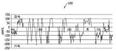
도 1은 전력 퓨즈에 따른 예시적인 전류 프로파일을 도시한다.
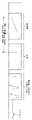
도 2는 도 1에 도시된 전류 프로파일이 적용되는 고전압 전력 퓨즈의 평면도이다.
도 3은 도 2에 도시된 전력 퓨즈의 부분 사시도이다.
도 4는 도 3에 도시된 퓨즈 소자 어셈블리의 확대도이다.
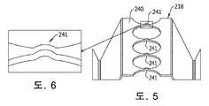
도 5는 도 4에 도시된 퓨즈 소자 어셈블리의 일부를 도시한다.
도 6은 피로 상태에 있는 도 4의 부분 확대도이다.
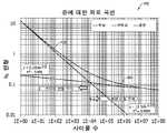
도 7은 퓨즈 소자 피로가 진행되는 전형적인 퓨즈를 예시하는 시간 대비 퓨즈 저항을 설멸하는 도표다.
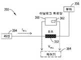
도 8은 퓨즈의 저항을 결정하는 제1 예시적 기술을 도시하는 전력 시스템의 일부에 대한 부분 회로 개략도이다.
도 9는 퓨즈의 저항을 결정하는 제2 예시적 기술을 도시하는 전력 시스템의 일부에 대한 부분 회로 개략도이다.
도 10은 퓨즈 소자에 대한 사이클 대비 변형을 예시하며 퓨즈 소자 피로를 설명하는 도표이다.
도 11은 예측 가능한 퓨즈 피로 평가 시스템에서 변형 사이클이 결정될 수 있음을 나타내는 시간 대비 전류 도표를 예시한다.
도 12는 본 발명의 예측 가능한 퓨즈 피로 평가 시스템에 대한 시간 대비 전류 도표에 대한 측정 윈도우를 예시한다.
도 13은 본 발명의 퓨즈 피로 평가 시스템에 대한 퓨즈 모니터링 모드들을 예시한다.
도 14는 본 발명의 일 실시예에 따른 제1 예시적 퓨즈 피로 평가 시스템을 나타내는 개략도이다.
도 15는 본 발명의 일 실시예에 따른 제2 예시적 퓨즈 피로 평가 시스템을 나타내는 개략도이다.
도 16은 본 발명의 일 실시예에 따른 제3 예시적 퓨즈 피로 평가 시스템을 나타내는 개략도이다.
도 17은 도 7 내지 도 15에 도시된 퓨즈 피로 평가 기술 및 시스템과 관련된 예시적인 프로세스를 도시하는 방법 흐름도이다.BRIEF DESCRIPTION OF THE DRAWINGS Non-limiting and non-exhaustive embodiments are described below with reference to the drawings, wherein like reference numerals refer to like parts throughout the various figures, unless otherwise specified.
1 shows an exemplary current profile according to a power fuse.
FIG. 2 is a plan view of a high voltage power fuse to which the current profile shown in FIG. 1 is applied.
FIG. 3 is a partial perspective view of the power fuse shown in FIG. 2 ;
FIG. 4 is an enlarged view of the fuse element assembly shown in FIG. 3 .
FIG. 5 shows a portion of the fuse element assembly shown in FIG. 4 .
Fig. 6 is a partial enlarged view of Fig. 4 in a fatigue state;
7 is a diagram illustrating fuse resistance versus time illustrating a typical fuse undergoing fuse element fatigue.
8 is a partial circuit schematic diagram of a portion of a power system illustrating a first exemplary technique for determining the resistance of a fuse.
9 is a partial circuit schematic diagram of a portion of a power system illustrating a second exemplary technique for determining the resistance of a fuse.
10 is a diagram illustrating strain versus cycle for a fuse element and explaining fuse element fatigue.
11 illustrates a plot of current versus time showing that strain cycles can be determined in a predictable fuse fatigue evaluation system.
12 illustrates a measurement window for a current versus time plot for a predictable fuse fatigue evaluation system of the present invention.
13 illustrates fuse monitoring modes for the fuse fatigue evaluation system of the present invention.
14 is a schematic diagram illustrating a first exemplary fuse fatigue evaluation system according to an embodiment of the present invention.
15 is a schematic diagram illustrating a second exemplary fuse fatigue evaluation system according to an embodiment of the present invention.
16 is a schematic diagram illustrating a third exemplary fuse fatigue evaluation system according to an embodiment of the present invention.
17 is a method flow diagram illustrating an exemplary process associated with the fuse fatigue assessment technique and system illustrated in FIGS. 7-15 .
최근 전기 차량 기술의 발전으로, 특히 퓨즈 제조사에 독특한 도전 과제가 제시되고 있다. 전기 자동차 제조업체들은 종래의 차량용 전력 분배 시스템보다 훨씬 높은 전압에서 작동하는 전력 분배 시스템을 위한 가융성 회로 보호를 추구하며, 동시에 전기 자동차 사양 및 요구 사항을 충족시키기 위해 더 작은 퓨즈를 추구하고 있다.Recent advances in electric vehicle technology present unique challenges, particularly for fuse manufacturers. Electric vehicle manufacturers are seeking fusible circuit protection for power distribution systems that operate at much higher voltages than conventional automotive power distribution systems, while at the same time pursuing smaller fuses to meet electric vehicle specifications and requirements.
종래의 내연 기관으로 구동되는 차량을 위한 전력 시스템은 비교적 낮은 전압, 통상적으로 약 48VDC 이하에서 작동한다. 그러나, 전동 차량(이하, 전기 자동차(EV)라 함)용 전력 시스템은 훨씬 더 높은 전압에서 작동한다. 전기 자동차(EV)의 상대적 고전압 시스템(예컨대, 200VDC 이상)은 일반적으로 배터리에 전원으로부터 더 많은 에너지가 저장될 수 있도록 하며, 내연 기관과 함께 사용되는 12 볼트 또는 24 볼트로, 특히 최근의 전력 시스템에서는 48 볼트로 에너지를 저장하는 종래의 배터리보다 낮은 손실(예컨대, 열 손실)로 차량의 전기 모터에 더 많은 에너지를 제공할 수 있도록 한다.Conventional power systems for vehicles powered by internal combustion engines operate at relatively low voltages, typically about 48 VDC or less. However, power systems for electric vehicles (hereinafter referred to as electric vehicles (EVs)) operate at much higher voltages. The relatively high voltage systems of electric vehicles (EVs) (eg, 200 VDC or higher) generally allow more energy to be stored from the power source in the battery, with 12 volts or 24 volts used with internal combustion engines, especially in more recent power systems. allows it to provide more energy to a vehicle's electric motor with lower losses (eg heat loss) than conventional batteries that store energy at 48 volts.
전기 자동차(EV)의 주문자 상표 제조업체(OEM)들은 모든 배터리 전기 자동차(BEV), 하이브리드 전기 자동차(HEV) 및 플러그인 하이브리드 전기 자동차(PHEV)의 전기 부하를 보호하기 위해 회로 보호 퓨즈를 사용한다. 각 전기 자동차(EV) 유형에 걸쳐, 전기 자동차 제조업체들은 소유 비용을 절감하면서도 배터리 충전 당 전기 자동차(EV)의 주행거리 범위를 극대화하는 방안을 모색한다. 이러한 목표를 달성 여부는 전기 자동차 시스템의 에너지 저장 및 전력 공급뿐만 아니라, 전력 시스템에 의해 작동되는 차량 구성품들의 크기, 부피 및 질량에 달려 있다. 소형화 및/또는 경량화된 차량은 대형 및 중량의 차량보다 이러한 수요를 보다 효과적으로 충족시킬 수 있으므로, 모든 전기 자동차 구성품에 대해 크기, 무게 및 비용 절감을 위한 가능성을 면밀히 조사 중이다.Original equipment manufacturers (OEMs) of electric vehicles (EVs) use circuit protection fuses to protect the electrical loads of all battery electric vehicles (BEVs), hybrid electric vehicles (HEVs) and plug-in hybrid electric vehicles (PHEVs). Across each electric vehicle (EV) type, electric vehicle manufacturers are looking to maximize the range of electric vehicles (EVs) per battery charge while reducing cost of ownership. Achieving these goals depends not only on the energy storage and power supply of the electric vehicle system, but also on the size, volume and mass of the vehicle components operated by the electric vehicle system. As miniaturized and/or lightweight vehicles can meet these demands more effectively than large and heavy vehicles, the potential for size, weight and cost savings for all electric vehicle components is being scrutinized.
일반적으로, 큰 구성품은 관련 재료비가 높은 경향이 있고, 전기 자동차(EV)의 전반적인 크기를 증가시키거나 차량 부피의 축소시 과도한 공간을 차지하는 경향이 있으며, 무게가 커져 배터리의 1회 충전 당 차량 주행 거리를 직접적으로 줄이는 경향이 있다. 한편, 공지된 고전압 회로 보호 퓨즈는 비교적 크고 무거운 구성품이다. 역사적으로 그리고 타당한 이유로, 회로 보호 퓨즈는 저전압 시스템과 달리 고전압 전력 시스템의 수요를 충족시키기 위해 크기가 증가하는 경향이 있다. 이와 같이 고전압 전기 자동차 전력 시스템을 보호하기 위해 필요한 기존의 퓨즈는 종래 내연 기관으로 구동되는 차량의 저전압 전력 시스템을 보호하는 데 필요한 기존 퓨즈보다 훨씬 크다. 회로 보호 성능을 희생시키지 않으면서도 보다 작고 가벼운 고전압 전력 퓨즈로 전기 자동차 제조업체들의 요구를 충족시키는 것이 바람직하다.In general, large components tend to have high associated material costs, tend to occupy excessive space when increasing the overall size of an electric vehicle (EV) or reducing vehicle volume, and increase in weight to drive the vehicle per charge of the battery It tends to reduce the distance directly. On the other hand, known high voltage circuit protection fuses are relatively large and heavy components. Historically and for good reason, circuit protection fuses tend to increase in size to meet the demands of high voltage power systems as opposed to low voltage systems. As such, a conventional fuse required to protect a high voltage electric vehicle power system is much larger than a conventional fuse required to protect a low voltage power system of a vehicle driven by a conventional internal combustion engine. It is desirable to meet the needs of electric vehicle manufacturers with smaller and lighter high voltage power fuses without sacrificing circuit protection performance.
최근의 전기 자동차(EV)를 위한 전력 시스템은 450VDC만큼 높은 전압에서 작동될 수 있다. 증가된 전력 시스템 전압은 바람직하게는 배터리 충전 당 더 많은 전력을 전기 자동차(EV)에 전달한다. 그러나, 고전압 전력 시스템에서 전기 퓨즈의 작동 조건은 저전압 시스템보다 훨씬 더 까다롭다. 특히, 퓨즈가 열릴 때의 전기 아크 상태와 관련된 사양은 고전압 전력 시스템에서 충족되는 것이 매우 어려울 수 있으며, 전기 퓨즈의 크기를 줄이는 것을 선호하는 업계와 결합하는 경우 특히 어려울 수 있다. 최근의 전기 자동차(EV)에 의한 전력 퓨즈에 부여된 현재의 사이클적 부하도 종래의 퓨즈 소자의 조기 결함을 야기할 수 있는 기계적 변형 및 마모를 유발하는 경향이 있다. 공지된 전력 퓨즈는 최근의 전기 자동차(EV) 애플리케이션의 고전압 회로에서 전기 자동차 주문자 상표 제조업체(EV OEM)들이 현재 사용 가능하지만, 전기 자동차(EV)용 고전압 전력 시스템의 요구 사항을 충족할 수 있는 종래의 전력 퓨즈의 비용뿐만 아니라 크기 및 무게가 커서 새로운 전기 자동차(EV)에서 구현하기에는 실용적이지 않다.Power systems for modern electric vehicles (EVs) can operate at voltages as high as 450 VDC. The increased power system voltage preferably delivers more power per battery charge to the electric vehicle (EV). However, the operating conditions of electrical fuses in high voltage power systems are much more demanding than in low voltage systems. In particular, specifications related to the condition of an electric arc when a fuse is opened can be very difficult to meet in high voltage power systems, especially when combined with an industry that favors reducing the size of electric fuses. The current cyclic load imposed on the power fuse by the recent electric vehicle (EV) also tends to induce mechanical deformation and wear which may cause premature failure of the conventional fuse element. Known power fuses are currently available to electric vehicle original equipment manufacturers (EV OEMs) in high voltage circuits in modern electric vehicle (EV) applications, but are conventionally capable of meeting the requirements of high voltage power systems for electric vehicles (EVs). The cost as well as the size and weight of the power fuse of
퓨즈 소자가 고전압에서 동작할 때 여전히 수용 가능한 중단 성능을 제공하면서도, 퓨즈 소자가 고전압에서 작동할 때 최첨단 전기 자동차 전력 시스템의 고전류 및 고전압을 처리할 수 있는 상대적으로 작은 전력 퓨즈를 제공하는 것은 적어도 쉽지는 않다. 퓨즈 제조사들과 전기 자동차 제조업체들은 각각 작고 가볍고 저렴한 퓨즈의 이점을 누리게 될 것이다. 전기 자동차(EV)의 혁신이 소형, 고전압 퓨즈를 필요로 하는 시장을 선도하고 있지만, 작으면서도 보다 강력한 전기 시스템을 향한 경향은 전기 자동차 시장을 넘어선다. 다양한 다른 전력 시스템 애플리케이션은 크고 종래 방식으로 제조된 퓨즈와 비교하여 경쟁력 있는 성능을 제공하는 소형 퓨즈로부터 이익을 얻을 수 있는 것은 의심의 여지가 없다. 그러나, 전기 자동차 전력 시스템 애플리케이션에 의해 전기 퓨즈에 부과된 요구는 전기 퓨즈의 서비스 수명을 단축시킬 수 있는 특정 과제를 제시한다. 해당 기술 분야에서 오랫동안 충족되지 못한 요구에 대한 개선이 필요하다.It is at least easy to provide a relatively small power fuse capable of handling the high currents and high voltages of state-of-the-art electric vehicle power systems when the fuse element is operating at high voltage while still providing acceptable interrupting performance when the fuse element operates at high voltage. is not Fuse manufacturers and electric vehicle manufacturers will each benefit from smaller, lighter, cheaper fuses. Although electric vehicle (EV) innovations are leading the market for smaller, higher voltage fuses, the trend towards smaller and more powerful electrical systems goes beyond the electric vehicle market. There is no doubt that a variety of other power system applications can benefit from small fuses that provide competitive performance compared to large, conventionally manufactured fuses. However, the demands placed on electric fuses by electric vehicle power system applications present certain challenges that can shorten the service life of electric fuses. There is a need for improvement in the long unmet need in the field of technology.
도 1은 퓨즈, 특히 그 내부의 부하 전류 순환 피로에 영향을 받기 쉬운 퓨즈 소자 또는 소자들을 제공하는 전기 자동차 전력 시스템 애플리케이션에서의 예시적인 전류 구동 프로파일(100)을 도시한다. 도 1에서, 전류가 수직 축으로 도시되고 시간이 수평 축으로 도시된다. 일반적인 전기 자동차 전력 시스템 애플리케이션에서 전력 퓨즈는 회로 보호 장치로 사용됨으로써 전기적 오류 조건으로 인한 전기 부하의 손상을 방지한다. 도 1의 예를 고려하면, 전기 자동차 전력 시스템은 상대적으로 짧은 시간 동안 전류 부하에 있어 큰 편차가 발생하기 쉽다. 전류의 변화는 전기 자동차(EV) 차량의 운전자의 행동, 교통 상황 및/또는 도로 상황에 기초하여 일견 무작위적인 운전 습관에 의해 생성된 순서대로 다양한 크기의 전류 펄스를 생성한다. 이로써 전기 자동차 구동 모터, 1차 구동 배터리 및 시스템 내에 포함된 모든 보호 전력 퓨즈 상에 실질적으로 무한하게 다양한 전류 부하 사이클을 생성한다.1 shows an exemplary
도 1의 상기 전류 부하 프로파일에 예시된 이러한 무작위 전류 부하 조건들은 전기 자동차(EV)의 가속(배터리 드레인에 해당) 및 전기 자동차(EV)의 감속(재생 배터리 충전에 해당)에 대해 사실상 사이클적이다. 이러한 사이클적 전류 부하는 퓨즈 소자, 보다 구체적으로는 주울 효과 가열 공정에 의해 전력 퓨즈 상의 퓨즈 소자 어셈블리의 소위 취약 구간에 열 응력 사이클을 가한다. 이러한 퓨즈 소자의 열 순환 부하는 특히 퓨즈 소자 약점에 기계적 팽창 및 수축 사이클을 부과한다. 이러한 퓨즈 소자의 취약 구간에 대한 반복적인 기계적 순환 부하는 취약 지점을 시간에 따른 파손 지점까지 손상시키는 누적 변형을 가한다. 본 개시의 목적을 위해, 본 명세서에는 이러한 열-기계적 공정 및 현상을 퓨즈 피로(Fuse fatigue)라고 한다. 후술되는 바와 같이, 퓨즈 피로는 퓨즈가 구동 프로파일을 견딜 경우의 크리프 변형에 주로 기인한다. 퓨즈 소자의 취약 구간에서 발생하는 열은 퓨즈 피로를 야기하는 주요 메커니즘이다.These random current load conditions exemplified in the current load profile of Figure 1 are cyclic in nature for the acceleration of the electric vehicle (EV) (corresponding to battery drain) and the deceleration of the electric vehicle (EV) (corresponding to regenerative battery charging). . This cyclic current load applies a cycle of thermal stress to the fuse element, more specifically the so-called fragile section of the fuse element assembly on the power fuse by a Joule effect heating process. The thermal cycling load of these fuse elements imposes cycles of mechanical expansion and contraction, particularly on fuse element weaknesses. The repetitive mechanical cyclic load on the fragile section of the fuse element applies a cumulative deformation that damages the fragile point to the point of failure over time. For the purposes of this disclosure, this thermo-mechanical process and phenomenon is referred to herein as Fuse fatigue. As discussed below, fuse fatigue is primarily due to creep deformation as the fuse withstands the drive profile. The heat generated in the fuse element's weak section is the main mechanism causing fuse fatigue.
이하, 전기 퓨즈의 피로를 평가하고 피로한 퓨즈가 피로 공정에서 실패하기 전에 이를 대체하기 위해 퓨즈의 잔여 수명을 예측 또는 추정할 수 있는 예시적인 퓨즈 모니터링 시스템 및 방법을 설명한다. 따라서, 상기 시스템은 모니터링한 피로 상태 및 수명 정보와 관련된 경고 및 알림을 제공하고, 그와 관련된 데이터 및 정보를 기록하고, 원격 장치에 상기 데이터 및 정보를 전달하며, 퓨즈의 기대 수명의 종료 전에 퓨즈가 개방되도록 하는 전기적 결함 상태들을 피로 모니터링을 기반으로 인식할 수도 있다.Hereinafter, an exemplary fuse monitoring system and method capable of evaluating the fatigue of an electrical fuse and predicting or estimating the remaining life of the fuse to replace the fatigued fuse before it fails in the fatigue process will be described. Accordingly, the system provides alerts and notifications related to monitored fatigue state and life information, records the data and information related thereto, communicates the data and information to a remote device, and provides a fuse prior to the end of the expected life of the fuse. Electrical fault conditions that cause the s to open can also be recognized based on fatigue monitoring.
상기 피로 모니터링은 적어도 부분적으로는 전기 저항 또는 기계적 변형과 같은 피로 매개변수를 모니터링하고, 모니터링된 매개변수를 유사한 퓨즈 소자에 대한 공지된 피로 매개변수들과 비교하여 퓨즈의 피로 상태 및 잔여 수명을 예측함으로써 달성된다. 피로 모니터링은 퓨즈를 통한 전류 흐름을 모니터링하고, 사이클적인 전류 부하에서 피크 전류와 관련된 변형을 계산하고, 각 피크 전류에 대한 피로 손상 성분을 계산하고, 시간 경과에 따라 피로 손상 성분을 누적하여 퓨즈의 피로 상태 및 관련 잔여 수명을 예측함으로써 달성될 수도 있다. 방법 측면은 부분적으로 명백하며 부분적으로는 하기 설명에서 명백하게 논의될 것이다.The fatigue monitoring is at least in part monitoring a fatigue parameter, such as electrical resistance or mechanical strain, and comparing the monitored parameter to known fatigue parameters for a similar fuse element to predict the fatigue state and remaining life of the fuse. is achieved by Fatigue monitoring monitors the current flow through the fuse, calculates the strain associated with the peak current in a cyclic current load, calculates the fatigue damage component for each peak current, and accumulates the fatigue damage component over time to determine the strength of the fuse. It may also be achieved by predicting fatigue conditions and associated remaining life. Method aspects are in part obvious and in part will be explicitly discussed in the description below.
본 발명은 도 1에 도시된 바와 같이 전류 프로파일을 생성하는 전기 자동차 애플리케이션의 맥락에서 설명되고, 본 발명은 예시적인 전기 자동차 애플리케이션의 요구 사항을 충족시키기 위해 퓨즈의 특정 유형 및 등급의 맥락에서도 설명된다. 본 발명의 효용은 설명된 전기 자동차 애플리케이션 또는 특정 유형이나 등급에 반드시 제한되는 것은 아니다. 오히려 본 발명의 효용은 다른 전류 프로파일을 생성하는 많은 상이한 전력 시스템 애플리케이션에 보다 넓게 적용될 수 있음을 유의하여야 한다. 또한, 본 발명은 본 명세서에서 논의된 것과 유사하거나 그와 상이한 등급을 갖는 상이한 유형의 퓨즈를 구성하기 위해 부분적으로 또는 전체적으로 실시될 수 있다. 따라서, 도 1에 도시된 전기 자동차 프로파일 및 후술하는 퓨즈는 본 발명을 제한하는 것이 아닌 예시로서 논의된다.The invention is described in the context of an electric vehicle application that generates a current profile as shown in FIG. 1 , and the invention is also described in the context of specific types and classes of fuses to meet the requirements of an exemplary electric vehicle application. . The utility of the present invention is not necessarily limited to the described electric vehicle application or specific type or class. Rather, it should be noted that the utility of the present invention is more broadly applicable to many different power system applications producing different current profiles. In addition, the present invention may be practiced in part or in whole to construct different types of fuses having ratings similar or different from those discussed herein. Accordingly, the electric vehicle profile shown in FIG. 1 and the fuse described below are discussed as examples and not limitation of the present invention.
도 2 내지 도 4는 전기 자동차 전력 시스템과 함께 사용하도록 설계된 예시적인 고전압 전력 퓨즈(200)의 다양한 도면이다. 종래 고전압 전력 퓨즈와 비교하여, 상기 퓨즈(200)는 상대적으로 작고 콤팩트한 물리적인 패키지의 크기를 제공하며, 이는 결국 전기 자동차(EV) 내에서 감소된 물리적 부피 또는 공간을 차지한다. 또한, 종래 퓨즈와 비교하여, 상기 퓨즈(200)는 비교적 높은 전력 처리 용량, 높은 전압 동작, 전범위 시간-전류 동작, 낮은 단락 통과(Let-through) 에너지 성능, 및 전술한 전기 자동차 전력 시스템과 같은 애플리케이션에서의 긴 수명 동작 및 신뢰도를 제공한다. 방법 측면은 부분적으로는 명료하게 논의될 것이며 부분적으로는 아래 논의에서 명료해질 것이다. 통상적으로 구성되는 공지된 UL 등급 J 퓨즈와 비교하여, 상기 퓨즈(200)는 훨씬 작은 패키지 크기에서 그에 필적하는 성능을 제공한다.2-4 are various views of an exemplary high
도 2에 도시된 바와 같이, 본 발명의 전력 퓨즈(200)는 하우징(202), 라인 및 로드 측 회로에 연결되도록 구성된 단자 블레이드(204, 206), 상기 단자 블레이드(204, 206)간의 전기적 연결을 완성하는 퓨즈 소자 어셈블리(208)을 포함한다. 소정의 전류 조건에서, 퓨즈 소자 어셈블리(208)의 적어도 일부가 용융되거나 분해되거나, 그렇지 않으면 구조적으로 결함이 생겨서 터미널 블레이드(204, 206) 사이의 회로 경로를 개방한다. 따라서, 부하측 회로는 라인측 회로와 전기적으로 절연되어 전기적 결함 상태가 발생할 때 부하측 회로 구성품 및 회로를 손상으로부터 보호한다.As shown in Fig. 2, the
일 실시예에서 퓨즈(200)는 500VDC의 전압 정격 및 150A의 전류 정격을 제공하도록 설계된다. 퓨즈(200)의 치수를 도시하는 예시에서 LH는 퓨즈의 대향하는 단부 사이 상기 하우징의 축 방향 길이, RH는 퓨즈의 하우징의 외경을 나타낸다. LT는 상기 하우징의 대향 측면에서 서로 대향하는 블레이드 단자들의 말단부 사이에서 측정된 퓨즈의 총 길이로서, 종래 구조에서 유사한 성능을 제공하는 공지된 UL 등급 J 퓨즈의 대응 치수의 약 50%이다. 또한, 퓨즈(200)의 부피는 동일한 정격에서 그에 필적하는 성능을 제공하는 종래의 UL 등급 J 퓨즈의 부피보다 약 87% 감소된다. 따라서, 퓨즈(200)는 종래 퓨즈에 비해 현저한 크기 및 부피 감소를 제공하고, 그렇지 않으면 그에 필적하는 퓨즈 보호 성능을 제공한다. 상기 퓨즈(200)의 크기 및 부피의 감소는 그 구조에 사용되는 재료의 감소를 통한 무게 및 비용을 절감에 있어 퓨즈(100)보다 더 도움이 된다. 따라서, 그리고 더 작은 치수로 인해, 퓨즈(200)는 전기 자동차 전력 시스템 애플리케이션에 더 바람직하다.In one embodiment, the
일예로, 하우징(202)은 일 실시예에서 유리 멜라민과 같은 당업계에 공지된 비도전성 재료로 제조된다. 또는, 다른 실시예에서는 하우징(202)에 적합한 다른 공지된 재료를 필요에 따라 사용할 수 있다. 또한, 도시된 하우징(202)은 일반적으로 원통형 또는 관형이며, 도시된 실시예에서의 축 방향 길이의 치수 LH 및 LR에 수직인 축을 따라 통상적으로 원형 단면을 갖는다. 또한, 필요한 경우 하우징(202)은 서로 직각으로 배치된 네 측벽을 가지므로 정사각형 또는 직사각형 단면을 갖는 직사각형을 포함하는 기타 형상으로 형성될 수 있지만, 이에 한정되지는 않는다. 도시된 바와 같이 하우징(202)은 제1 단부(210), 제2 단부(212), 및 퓨즈 소자 어셈블리(208)를 수용하는 대향 단부(210, 212) 사이의 내부 구멍 또는 통로를 포함한다.In one embodiment, the
일부 실시예에서, 하우징(202)은 단자 블레이드(204, 206)를 하우징(202)으로부터 전기적으로 절연시키기 위해 절연 가스켓 등이 요구될 수 있지만, 필요한 경우에는 전기 전도성 재료로 제조될 수 있다.In some embodiments, the
단자 블레이드(204, 206)는 하우징(202)의 대향 단부(210, 212)로부터 각각 반대 방향으로 연장되고 대체로 상호 동일한 평면 관계로 연장되도록 배치된다. 고려된 실시예에서 각각의 단자 블레이드(204, 206)는 구리 또는 황동과 같은 전기 전도성 재료로 제조될 수 있다. 다른 실시예에서는 필요에 따라 단자 블레이드(204, 206)를 형성하기 위해 다른 공지된 전도성 재료를 대안적으로 사용할 수 있다. 각각의 단자 블레이드(204, 206)에는 도 3에 도시된 바와 같이 개구(214, 216)가 형성되며, 개구(214, 216)는 볼트(미도시)와 같은 조임구를 수용함으로써, 전기 자동차(EV)에서의 정위치에 퓨즈(200)를 확보하고, 단자 블레이드(204, 206)를 통해 회로 도체에 대한 라인 및 로드 측 회로 연결을 확보할 수 있다.The
예시적인 단자 블레이드(204, 206)가 퓨즈(200)에 대해 도시되고 기술되었지만, 추가적 및/또는 대안적 실시예들에서 다른 단자 구조들 및 장치들도 마찬가지로 이용될 수 있다. 예컨대, 개구(214, 216)는 일부 실시예에서는 선택적으로 고려될 수 있고, 생략될 수 있다. 도시된 바와 같은 단자 블레이드 대신 칼날 접점이 제공될 수 있으며, 당업계의 기술자들에게 있어 다른 유형의 다양한 종단 접속 옵션을 제공하는 것으로 이해되는 바와 같이, 페룰 단자 또는 단부 캡이 제공될 수 있다. 또한, 단자 블레이드(204, 206)는 필요에 따라 이격되고 대체로 평행한 배향으로 배치될 수 있으며, 도시된 바와 다른 위치에서 하우징(202)으로부터 돌출할 수 있다.Although exemplary
하우징(202)이 제거된 도 3 및 도 4의 확대도에 도시된 바와 같이, 퓨즈 소자 어셈블리(208)는 단부 판(226, 228)에 구비된 단자 접촉 블록(222, 224)에 각각 연결되는 제1 퓨즈 소자(218) 및 제2 퓨즈 소자(220)를 포함한다. 다른 전도성 재료는 공지되어 있지만, 블록(222, 224)을 포함하는 단부 판(226, 228)은 구리, 황동 또는 아연과 같은 전기 전도성 재료로 제조되며, 다른 실시예에서도 마찬가지로 사용될 수 있다. 퓨즈 소자(218, 210) 및 단자 접촉 블록(222, 224)의 기계적 및 전기적 연결은 납땜 기술을 포함하지만 이에 한정되지 않는 공지된 기술을 사용하여 구현될 수 있다.3 and 4 with the
다양한 실시예에서, 단부 판(226, 228)은 단자 블레이드(204, 206)를 포함하도록 형성되거나, 단자 블레이드(204, 206)가 별개로 제공되고 부착될 수 있다. 단부 판(226, 228)은 일부 실시예에서는 선택적으로 고려될 수 있고, 퓨즈 소자 어셈블리(208)와 단자 블레이드(204, 206) 사이의 연결은 다른 방식으로 설정될 수 있다. In various embodiments,
단부 판(226, 228)을 하우징(202)에 대해 정위치에 고정시키는 다수의 고정 핀(230)도 도시된다. 일 실시예에서 고정 핀(230)은 강철로 제조될 수 있으며, 필요하다면 다른 공지된 재료가 사용될 수 있다. 일부 실시예에서, 핀(230)은 선택적으로 고려될 수 있고, 다른 기계적 연결 특징을 위해 생략될 수 있다.A number of retaining
소호 충전 매체 또는 재료(232)는 퓨즈 소자 어셈블리(208)를 감싼다. 충전재료(232)는 플러그(미도시)로 밀봉된 단부 판(226, 228) 중 하나에서 하나 이상의 충전 개구를 통해 하우징(202)으로 유입될 수 있다. 다양한 실시예에서 플러그는 강철, 플라스틱 또는 기타 재료로 제조될 수 있다. 다른 실시예에서, 충전 구멍 또는 충전 구멍들은 충전 재료(232)의 유입을 용이하게 하기 위해 하우징(202)을 포함하지만 이에 제한되지 않는 다른 위치에 마련될 수 있다.An arc-extinguishing filling medium or
하나의 고려된 실시예에서, 충전 매체(232)는 석영 규사 및 규산 나트륨 결합제로 구성된다. 규사는 느슨한 압축 상태에서 비교적 높은 열 전도 및 흡수 용량을 갖지만 개선된 성능을 제공하기 위해 규산염화될 수 있다. 예컨대, 액체 규산 나트륨 용액을 상기 모래에 첨가하여 자유수를 건조시킴으로써, 규산 충전 재료(232)는 하기의 효용을 얻을 수 있다.In one contemplated embodiment, the filling
규산 재료(232)는 퓨즈 소자(218, 220), 규사, 퓨즈 하우징(202), 단부 판(226, 228) 및 단자 접촉 블록(222, 224)에 대해 규산 나트륨의 열 전도 결합을 생성한다. 이러한 열 결합을 통해 퓨즈 소자(218, 220)로부터 그 주변부, 회로 인터페이스 및 도체로 더 높은 열 전도가 허용된다. 규사에 규산 나트륨을 도포하면 열 에너지를 퓨즈 소자(218, 220)로부터 외부로 멀리 전도시키는 것에 도움이 된다.The
규산 나트륨은 퓨즈 소자, 단자 및 이들 재료 사이의 열 전도를 증가시키는 하우징 튜브에 모래를 기계적으로 결합시킨다. 통상적으로, 모래만을 포함할 수 있는 충전 재료는 퓨즈 내의 퓨즈 소자들의 도전성 부위와 점 접촉을 하는 반면, 충전 재료(232)의 규산염화된 모래는 퓨즈 소자에 기계적으로 결합된다. 따라서, 퓨즈(100)를 포함하지만 이에 한정되지는 않는 유사한 성능을 제공하는 공지된 퓨즈에 비해 퓨즈(200)의 실질적인 크기 감소를 부분적으로 용이하게 하는 규산염화된 충전 재료(232)를 사용함으로써 훨씬 효율적이고 효과적인 열 전도가 가능해진다(도 1).Sodium silicate mechanically bonds the sand to the fuse element, the terminals, and the housing tube which increases heat conduction between these materials. Typically, the filler material, which may include only sand, makes point contact with the conductive portions of the fuse elements in the fuse, while the silicate sand of the
도 4는 퓨즈 소자 어셈블리(208)를 더 상세하게 도시한다. 전력 퓨즈(200)는 퓨즈(200)의 크기 감소를 더욱 용이하게 하는 어셈블리(208) 내의 퓨즈 소자 설계 특징으로 인해 더 높은 시스템 전압에서 동작할 수 있다.4 shows the
도 4에 도시된 바와 같이, 퓨즈 소자(218, 220) 각각은 일반적으로 전기 전도성 재료의 띠로 형성되어, 경사 구간(242, 244)에 의해 연결된 일련의 동일 평면 구간(240)으로 형성된다. 일반적으로 퓨즈 소자(218, 220)는 실질적으로 동일한 형상 및 기하학적 구조로 형성되지만, 어셈블리(208)에서 서로 반전된다. 즉, 도시된 실시예에서의 퓨즈 소자(218, 220)는 서로 거울상 관계로 배치된다. 달리 표현하면, 퓨즈 소자(218, 220) 중 하나는 우측이 상부로 배향되고 다른 하나는 상측이 하부로 배향되어 오히려 콤팩트하고 공간을 절약하는 구조를 이루게 된다. 특정 퓨즈 소자의 기하 구조 및 배치가 도시되어 있지만, 다른 실시예에서는 다른 유형의 퓨즈 소자, 퓨즈 소자의 기하 구조 및 퓨즈 소자 배치가 가능하다. 퓨즈 소자(218, 220)는 모든 실시예에서 서로 동일하게 형성될 필요는 없다. 또한, 일부 실시예에서는 단일 퓨즈 소자가 이용될 수 있다.As shown in FIG. 4 , each of the
도시된 예시적인 퓨즈 소자(218, 220)에서, 경사 구간(242, 244)이 형성되거나 평면 구간(240)으로부터 평면을 벗어나 굴곡되고, 경사 구간(242)은 다른 경사 구간(244)에 대해 동일하고 대향되는 경사도를 갖는다. 즉, 도시된 예에서 경사 구간(242) 중 하나는 양의 기울기를 가지며, 경사 구간(244) 중 다른 하나는 음의 기울기를 갖는다. 경사 구간(242, 244)은 도시된 바와 같이 평면 구간(240) 사이에 쌍으로 배열된다. 퓨즈 소자(218,220)의 대향되는 어느 단부에는 단자 탭(246)이 도시되며, 전술한 바와 같이 단부 판(226, 228)에 대한 전기 접속이 이루어질 수 있다.In the illustrated
도시된 예에서, 평면 구간(240)은 해당 기술 분야에서 s로 언급되는 다수의 감소된 단면 영역(241) 부위로 구획된다. 도시된 예에서 취약 부위(241)는 평면 구간(240)에서의 원형 개구로 구획된다. 취약 부위(241)는 인접한 개구들 사이의 구간(240)의 가장 얇은 부위에 대응한다. 취약 부위(241)에서의 감소된 단면 영역은 전류가 퓨즈 소자(218, 220)를 통해 흐를 때 열 집중이 가해지게 되며, 취약 부위(241)의 단면 영역은 전략적으로 선택되어, 특정 전류 조건이 가해지면 취약 부위(241)의 위치에서 퓨즈 소자(218, 220)가 개방되도록 한다.In the illustrated example, the
복수의 구간(240) 및 각 구간(240)에 마련된 복수의 취약 부위(241)는 퓨즈 소자(218, 220)가 동작함에 따른 아크 분할을 용이하게 한다. 도시된 예에서, 퓨즈 소자(218, 220)는 하나가 아니라 상기 구간들(240)에 대응하는 3개의 위치에서 동시에 개방하게 된다. 도시된 예에 따르면, 450VDC 시스템에서, 퓨즈 소자가 퓨즈(200)를 통해 회로를 개방하도록 동작할 때, 전기 아크가 상기 구간(240)의 3개의 위치에 걸쳐 분할되고 각 위치에서의 아크는 450VDC 대신 150VDC의 아크 전위를 갖게 된다. 각 구간(240)에 제공된 복수(예컨대, 4개)의 취약 부위(241)는 취약 부위(241)에서의 전기적 아크를 더 효과적으로 분할한다. 아크 분할은 충전 재료(232)의 양을 줄일 뿐만 아니라 하우징(202)의 반경을 감소시키므로 퓨즈(200)의 크기를 감소시킬 수 있다.The plurality of
평면 구간들(240) 사이의 굽은 경사 부위(242, 244)는 여전히 아크가 연소하기 위한 평탄한 길이를 제공하지만, 구간(242, 244)이 교차하는 모서리에서 아크가 결합할 가능성을 회피하도록 굽은 각도를 신중하게 선택하여야 한다. 굽은 경사 구간(242, 244)도 단자 탭(246)의 말단부 사이에서 평면 구간(240)에 평행한 방향으로 측정된 퓨즈 소자 어셈블리(208)의 짧은 유효 길이를 제공한다. 상기 짧은 유효 길이는 퓨즈 소자가 굽은 구간(242, 244)을 포함하지 않는 경우에 요구되는 퓨즈(200)의 하우징의 축 방향 길이의 감소를 용이하게 한다. 굽은 경사 구간(242, 244)도 제조 피로 및 사용시의 전류 사이클링 작동으로부터의 열팽창 피로로부터 응력을 완화시킨다.The
고전력 취급 및 고전압 작동 측면을 갖춘 소형 퓨즈 패키지를 유지하기 위해, 필러(232) 및 전술한 퓨즈 소자의 기하학적 구조에서 규산염화된 규사를 사용하는 것 이상으로 특별한 소자 처리가 적용될 수도 있다. 특히, RTV 실리콘 또는 UV 경화 실리콘과 같은 아크 차단 또는 아크 장벽 물질을 도포하는 것은 퓨즈 소자(218, 220)의 단자 탭(246)에 인접하여 적용될 수 있다. 가장 높은 비율의 이산화 규소(실리카)를 생성하는 실리콘은 단자 탭(246) 근처에서 아크 연소를 차단하거나 완화하는 것을 가장 잘 수행하는 것으로 밝혀졌다. 단자 탭(246)에서의 아크 현상은 바람직하지 않기 때문에, 아크 차단 또는 장벽 물질(250)은 아크 현상이 단자 탭(246)에 도달하는 것을 방지하도록 마련되는 위치에서 퓨즈 소자(218, 220)의 전체 단면을 완전히 감싼다.In order to maintain a compact fuse package with high power handling and high voltage operation aspects, special device treatment may be applied beyond the use of silicate silica sand in the geometry of the
전범위의 시간-전류 동작은 각각의 개별 퓨즈 소자(218, 220) 내에 2개의 퓨즈 소자 용융 장치를 사용함으로써 구현된다. 퓨즈 소자(218) 내의 하나의 용융 장치는 고전류 동작(또는 단락 결함)에 응답하고, 퓨즈 소자(220) 내의 하나의 용융 장치는 저전류 동작(또는 과부하 결함)에 반응한다. 이와 같이, 퓨즈 소자(218)는 단락 퓨즈 소자로 지칭되기도 하고, 퓨즈 소자(220)는 종종 과부하 퓨즈 소자로 지칭되기도 한다.Full range time-current operation is realized by using two fuse element melting devices within each
고려되는 실시예에서, 과부하 퓨즈 소자(220)는, 구간들(240) 중 하나에서의 취약 부위들 부근의 위치들에서 순수 주석(Sn)이 본 실시예에서 구리(Cu)로 제조된 퓨즈 소자에 도포하는 멧칼프 효과(M-효과) 코팅을 포함할 수 있다. 과부하 가열 중에 Sn 및 Cu는 공융 물질을 형성하기 위해 함께 확산된다. Cu 및 Sn 사이의 온도 또는 고려된 실시예에서 약 400°C에서의 낮은 용융 온도의 결과값을 갖는다. 따라서, 과부하 퓨즈 소자(220) 및 M-효과 코팅을 포함하는 섹션(240)은 단락 퓨즈 소자(218)에 영향을 미치지 않을 전류 조건에 응답할 것이다. 고려된 실시예에서, M-효과 코팅이 과부하 퓨즈 소자(220) 내의 3개의 구간들(240) 중 하나의 절반에만 적용되는 동시에, 필요한 경우 구간들(240) 중 나머지 부분에 M-효과 코팅이 추가적으로 적용될 수 있다. 또한, M-효과 코팅은 도 8에 도시된 바와 같이 더 큰 코팅과 대조적으로 다른 실시예에서의 취약 부위의 위치에서만 스폿으로서 적용될 수 있다.In the contemplated embodiment, the
낮은 단락 통과 에너지는 단락 퓨즈 소자(218)에서의 퓨즈 소자 용융 단면을 감소시킴으로써 구현된다. 이것은 일반적으로 추가된 저항 및 열로 인한 정격 전류 용량을 낮추게 되어 퓨즈 정격에 부정적인 영향을 미친다. 규산염화된 모래 충전 재료(232)가 퓨즈 소자(218)로부터 열을 더 효과적으로 제거하기 때문에, 그렇지 않은 경우에 발생했을 전류 용량의 손실이 보상된다.The low short pass energy is achieved by reducing the fuse element melting cross section in the
규산 나트륨을 규사에 도포하면 퓨즈 소자의 취약 부위에서 열 에너지를 방출하는 데에도 도움이 되고, 기계적 응력과 변형을 줄임으로써, 그렇지 않았을 때 발생할 부하 전류 순환 피로를 완화할 수 있다. 즉, 규산염화 충전재(232)는 취약 부위에서 퓨즈 소자의 작동 온도를 감소시킴으로써 퓨즈 피로를 완화시킨다. 규산 나트륨은 퓨즈 소자, 단자 및 이들 재료 간의 열 전도를 증가시키는 하우징에 모래를 기계적으로 결합시킨다. 취약 부위에서 열이 덜 발생하고 기계적 변형 및 퓨즈 피로도의 시작이 종래 퓨즈에 비해 지연되지만, 도 1에 도시된 전류 프로파일이 퓨즈를 가로질러 도포되는 전기 자동차 애플리케이션에서, 피로로 인한 퓨즈 소자의 결함은, 단락 또는 과부하 조건과는 대조적으로, 퓨즈의 수명에 실질적인 제한이 되어 왔다. 즉, 퓨즈(200)는 성능을 제한하는 매우 높은 전류뿐만 아니라 긴 수명 및 불필요하거나 미숙한 퓨즈 작동으로부터의 높은 신뢰성을 제공하도록 설계되었지만, 그럼에도 불구하고 퓨즈 피로는 전술한 전기 자동차 전력 시스템과 같은 애플리케이션에서 퓨즈의 불필요한 작동을 야기하고 전기 자동차 전력 시스템의 신뢰성에 영향을 미칠 수 있다.Applying sodium silicate to silica sand also helps to dissipate thermal energy from fragile areas of the fuse element, and reduces mechanical stress and strain, thereby alleviating load current circulation fatigue that would otherwise occur. That is, the
퓨즈(200)에 기술된 퓨즈 소자는, 통상적으로 설계된 퓨즈와 마찬가지로, 금속 스탬핑되거나 펀칭된 퓨즈 소자를 사용하며, 전술한 순환 전류 부하의 유형을 포함하는 전기 자동차 애플리케이션에 대한 관심을 나타낸다. 구리, 은 또는 구리 합금으로 제조된 상기와 같은 스탬핑된 퓨즈 소자 설계는 퓨즈 소자의 취약 부위(241)에 기계적 변형 및 응력을 바람직하지 않게 인가하기 때문에, 상이한 전류 부하를 갖는 다른 전력 시스템에 퓨즈(200)가 사용되는 경우보다 결과적으로 수명이 짧은 경향이 있다. 이러한 짧은 퓨즈 수명은 취약 부위(241)에서의 퓨즈 소자의 기계적 피로에 기인한 불량 퓨즈 작동의 형태로 나타난다.The fuse elements described in
도 4 내지 도 6에 도시된 바와 같이, 반복되는 고전류 펄스로 인해 퓨즈 소자(218, 220)에서 균열 전파 및 결함을 수반하는 입자 경계 붕괴로부터 퓨즈 소자(218, 220) 내의 금속 피로가 야기된다. 스탬핑된 퓨즈 소자 설계 및 제조에 의해 퓨즈 소자(218, 220)의 기계적 제약이 내재되며, 부하 전류 사이클이 반복되는 동안 취약 부위(241)의 좌굴이 악화되는 것으로 밝혀졌다. 이러한 좌굴은 인접한 금속 입자들 사이에서의 이탈 또는 미끄러짐이 발생하는 금속 입자 경계에 대한 손상으로 인한 결과이다. 취약 부위(241)의 상기 좌굴은 시간이 경과하면서 발생하며, 보다 높은 과도 전류 펄스에 의해 가속되고 더 확연해진다. 과도 전류 펄스 내의 가열-냉각 증감이 클수록 기계적 영향이 커지며, 따라서 취약 부위(241)의 좌굴 변형이 커진다.As shown in Figures 4-6, the repeated high current pulses cause metal fatigue in the
과도 전류 펄스의 가열 효과에 의해 야기된 금속의 반복된 물리적 기계적 조작은 결국 금속 퓨즈 소자(218, 220)의 결정 구조의 변화를 야기한다. 이러한 기계적 조작을 금속 작업이라고도 한다. 금속 작업으로 인해 인접한 입자들이 주변 입자들에 강하게 구속되는 입자 경계가 강화된다. 금속을 작업 중에 입자들이 서로를 미끄러지며 소위 슬립 밴드 또는 평면을 야기하는 입자 경계에 분해가 발생될 수 있다. 입자간의 이러한 미끄러짐 및 이탈로 인해 전류 펄스의 가열 효과를 증가시킴으로써 피로 과정을 가속시키는 전기 저항이 국부적으로 증가하게 된다. 피로 균열이 처음 개시되는 곳에서 슬립 밴드가 형성된다.The repeated physical and mechanical manipulation of the metal caused by the heating effect of the transient pulses eventually results in a change in the crystal structure of the
금속을 스탬핑 또는 펀칭하여 퓨즈 소자(218,220)를 형성하는 제조 방법은, 취약 부위(241)를 형성하기 위한 스탬핑 공정이 기계적인 전단 및 인열 공정이므로, 퓨즈 소자의 취약 부분(241)의 스탬핑된 모든 에지 상에 국부적인 슬립 밴드를 야기한다는 것을 본 발명자들은 발견했다. 상기 인열 공정에서, 많은 슬립 밴드 영역을 갖는 취약 지점(241)에 사전 응력을 가한다. 슬립 밴드 및 피로 균열은, 열 효과로 인한 상기 좌굴과 결합하여, 결국 전기적 결함 조건과 관련이 없는 취약 부위(241)의 구조적인 조기 결함을 초래한다. 전력 시스템에 문제가 있는 전기 상태와 관련이 없는 조기 결함 유형을 퓨즈의 불량 작동이라고도 한다. 퓨즈 소자(218, 220)에 결함이 발생하면 퓨즈가 교체될 때까지 퓨즈에 접속된 회로가 다시 작동하지 않기 때문에, 그러한 불량 작동을 회피하는 것은 전기 자동차 제조업체 및 소비자의 관점에서 전기 자동차 전력 시스템에 매우 바람직하다. 사실, 전기 자동차(EV) 차량 및 동력 시스템에 대한 관심이 높아지면서 퓨즈 피로 및 퓨즈의 관련 결함으로 인한 영향들은 차량 설계에서 중요한 핵심 품질(CTQ) 속성으로 간주된다.In the manufacturing method of forming the
스탬핑된 금속 퓨즈 소자(218, 220)를 갖는 전기 자동차 전력 시스템 및 이를 위한 퓨즈(200)의 맥락에서 기술되었지만, 정상 퓨즈 서비스의 주울 효과 가열 및 극한 온도 변동에 대한 노출로부터의 열-기계적 사이클에 의한 마모 감응성이 전기 자동차 전력 시스템 또는 설명된 특정 퓨즈나 퓨즈 소자에 대해 반드시 독특할 필요는 없다. 고전압 전력 퓨즈를 위한 종래 유형의 퓨즈 소자 대부분은 비교적 연약하게 설계된 하나 이상의 취약 부위로 형성된 퓨즈 소자, 및 전술한 피로 문제에 취약한 작은 전류 운반 단면을 포함한다. 퓨즈 소자의 피로 상태나 조건을 모니터링 및 측정할 수 있는 시스템을 제공하고, 피로한 퓨즈에 결함이 발생하기 전에 이를 대체함으로써 불량 퓨즈 작동을 회피하기 위해 퓨즈가 구비된 전력 시스템을 능동적으로 관리할 수 있도록 하는 시스템을 제공하는 것이 바람직하다.Although described in the context of an electric vehicle power system with stamped
상세히 후술하는 바와 같이, 퓨즈 피로 모니터링 시스템은 전력 동작 시스템에서 퓨즈 소자의 전기 저항을 결정하고 기계적 변형의 누적을 판단하여 전력 시스템에서 시간에 따른 퓨즈 소자의 피로 상태를 평가할 수 있다. 이와 같이, 퓨즈 소자 피로의 정도를 모니터링, 측정 및 계산하여 본 발명의 시스템에서 퓨즈에 대한 대략적인 잔여 수명을 예측할 수 있다. 이러한 시스템은 상태 정보 또는 경고 정보를 제공함으로써, 피로를 겪는 퓨즈가 불량 동작 중에 파열되기 전에 교체될 수 있다. 상기 정보를 고려하여 편리한 예정 시간에 교체가 발생할 수 있어, 전력 시스템 관리자는 전력 시스템의 전기 부하가 최소한으로 영향을 받는 때 식별된 퓨즈를 주도적으로 교체할 수 있다.As will be described later in detail, the fuse fatigue monitoring system may determine the electrical resistance of the fuse element in the power operation system and determine the accumulation of mechanical deformation to evaluate the fatigue state of the fuse element over time in the power system. In this way, by monitoring, measuring, and calculating the degree of fuse element fatigue, it is possible to predict the approximate remaining life of the fuse in the system of the present invention. These systems provide status information or warning information so that a fatigued fuse can be replaced before it ruptures during bad operation. In view of the above information, replacement may occur at a convenient scheduled time, allowing the power system manager to proactively replace the identified fuse when the electrical load of the power system is minimally affected.
도 7의 저항 대비 시간 도표(300)에 도시된 바와 같이, 전술한 퓨즈(200)를 포함하지만 이에 제한되지 않는 퓨즈는 피로 과정으로 인해 서비스 사용 중에 노화된 것으로 보여질 수 있다. 즉, 시간이 지남에 따라 퓨즈 소자는 전술한 바와 같은 가열 사이클로부터 기계적 변형이 누적된다. 퓨즈 소자(들)의 기계적 변형은 금속 입자가 작용 및 재배향되는 퓨즈 소자의 취약 부위에 대부분 집중된다. 전술한 바와 같이, 이러한 입자 구조의 작용은 입자 경계에서의 파괴 및 입자들 사이에서 슬립 밴드가 진행되는 결과를 야기한다. 슬립 밴드의 형성은 결과적으로 전술한 바와 같이 균열 형성 및 퓨즈 소자 내(s)의 손상을 야기한다.As shown in the resistance versus time diagram 300 of FIG. 7 , a fuse including, but not limited to, the above-described
이러한 피로 과정이 진행되면서, 도 7의 도표(300)에서 알 수 있듯이, 취약 부위의 기계적 손상으로 인해 퓨즈 소자의 전기 저항이 증가한다. 이러한 저항의 증가로 인해 각 전류 부하 사이클에 열이 추가되기 시작하여, 피로로 인한 퓨즈 노화 또는 마모가 가속화된다. 퓨즈가 전기적으로 노화되면서 제조시의 저항 측정 값이 증가하기 시작한다. 서비스 노출 수준에 따라, 상기 저항 증가는 도 7에 도시된 도표(300)의 제1 단계(302)에 분명히 나타난 바와 같이 통상적으로 매우 작고 매우 느리다. 초기 단계(302)에서의 퓨즈 서비스의 초기 수명에 있어서, 퓨즈 저항의 변화는 실질적으로 인식 불가능하며 시스템 잡음 및 측정 오차에 의해 가려진다. 그러나, 결과적으로, 저항은 제1 단계(302)에서도 신뢰성 있게 검출될 수 있는 수준으로 변화하며, 피로 과정이 계속됨에 따라 제1 단계(302)에서 퓨즈 소자의 저항이 매우 점진적으로 증가한다. 도시된 예에서, 퓨즈는 약 25년 동안 제1 단계(302)에 남아 있을 수 있다.As this fatigue process proceeds, as can be seen from the diagram 300 of FIG. 7 , the electrical resistance of the fuse element increases due to mechanical damage to the vulnerable portion. This increase in resistance starts adding heat to each current load cycle, accelerating fuse aging or wear due to fatigue. As fuses age electrically, their manufacturing resistance measurements begin to increase. Depending on the service exposure level, the resistance increase is typically very small and very slow, as evident in the
그러나, 결국 도시된 예에서 퓨즈 소자의 퓨즈 수명이 약 25년으로 접어들면, 퓨즈 소자 피로는 제1 단계(302)를 지나서 저항이 더 급격히 변화하기 시작하는 도표(300) 상의 전이 단계(304)로 진입하게 된다. 이는 퓨즈 소자의 피로 효과가 가속되는 지점으로 진행되고 있음을 나타낸다. 이 단계(304)에서 피로 과정이 계속 진행됨에 따라, 현재 발현되기 시작한 취약 부위의 기계적 손상으로 인해 퓨즈 소자의 전기 저항이 증가한다. 저항의 증가는 각 전류 부하 사이클의 취약 부위에 의해 가해지는 열을 증가시켜, 퓨즈 노화 또는 마모가 더 빠른 속도로 가속된다. 전이 단계(304)에서 저항의 변화가 비선형임을 알 수 있다. 상기 전이 단계(304)에서, 저항의 변화는 제1 단계(302) 보다 용이하게 검출된다. 그러나, 전이 단계(304)는 연장된 시간 동안 지속될 수 있으며, 일단 이 단계가 검출되면 퓨즈의 서비스 수명이 수년간 남아있게 된다. 도 7의 예에서, 전이 단계(304)는 약 5년 동안 지속될 수 있음을 알 수 있다.However, eventually, when the fuse life of the fuse element in the illustrated example approaches about 25 years, the fuse element fatigue passes through a
전이 단계(304)의 끝에서, 퓨즈 저항이 단기간에 걸쳐 가파른 저항 변화로 들어가는 피로의 제3 및 최종 단계(306)로 진입한다. 최종 단계는 퓨즈 소자의 균열이 존재하고 전류 흐름에 대한 취약 부위의 단면적이 급격히 감소하여 취약 부위에서 열 집중이 훨씬 높아지는 것을 나타낸다. 퓨즈 소자는 이러한 상태에서 오래 지속되지 않을 것이며, 먼저 교체되지 않으면 퓨즈 소자는 제3 단계(306)에 도달한 후에 금방 파손될 것이다.At the end of
퓨즈 소자가 피로해지고, 취약 부위에서 퓨즈 소자의 기계적 열화에 있어 퓨즈가 단계 302 및 304를 통해 단계 306으로 진행함에 따라 시간에 걸쳐 저항이 현저하게 증가함을 알 수 있고, 시간에 따른 퓨즈 저항을 측정함으로써 본 발명의 피로 모니터링 시스템은 작동중인 퓨즈의 피로 상태를 평가할 수 있다. 도 7에 도시된 것과 유사한 도표는, 전력 시스템에서 퓨즈에 대한 가열 사이클의 예상 횟수가 주어진 경우, 경험적으로 판단되거나 그렇지 않으면 계산될 수 있으며, 이는 전기 자동차(EV)에 대한 전력 시스템일 필요는 없다.It can be seen that the fuse element fatigues, and the resistance increases significantly over time as the fuse progresses from
본 발명의 의도된 시스템에서, 퓨즈 저항의 측정은 후술되는 바와 같이 퓨즈 소자를 가로질러 공지된 전류를 주입함으로써 정밀하게 수행될 수 있다. 즉, 시스템은 사용 중인 퓨즈 저항을 측정할 수 있으며, 저항의 변화를 평가하고 저항의 변화를 기반으로 퓨즈의 잔여 수명을 산정하거나 계산할 수 있는 알고리즘이 개발될 수 있다. 사용 중인 퓨즈 저항을 측정하는 것이 특정 유형의 전력 시스템에서는 어려울 수 있고/있거나 그다지 실용적이지 않은 경우, 아래에 설명된 피로를 고려하여 퓨즈 수명을 예측하는 대안적 방법이 활용될 수 있을 것이다.In the intended system of the present invention, the measurement of the fuse resistance can be performed precisely by injecting a known current across the fuse element as described below. That is, the system can measure the resistance of the fuse in use, and an algorithm that can evaluate the change in resistance and calculate or calculate the remaining life of the fuse based on the change in resistance can be developed. If measuring the fuse resistance in use can be difficult and/or not very practical in certain types of power systems, alternative methods of estimating fuse life, taking into account the fatigue described below, may be utilized.
도 8은 제1의 예시적인 시스템(350) 및 임의의 시점에서 퓨즈 저항을 감지하고 결과적으로 전술한 퓨즈(200)일 수 있는 퓨즈(352)를 통해 흐르는 전류를 감지할 수 있는 기술을 도시한다. 즉, 상기 퓨즈는 본 발명의 고려된 실시예에 따른 전력 시스템에서 라인측 회로(354) 및 부하측 회로(356) 사이에 연결된다. 전압(Vsense)은 퓨즈 소자의 저항을 판단되도록 하는 퓨즈(352)에 직접적으로 유도되고, 전류(Isense)도 마찬가지로 판단될 수 있다. 저항 판정 및 전류 감지 능력은 시스템(300)에서 향상된 퓨즈 상태 특징, 비정상 퓨즈 검출 및 알람 등을 용이하게 한다.8 illustrates a first
전류(Isense)를 판단하기 위해 퓨즈(352)에 대해 직접 전압(Vsense)을 감지하는 것은 보상 회로(360)에 의해 어드레싱되는 복잡성을 야기한다. 구체적으로, 모든 퓨즈 소자와 마찬가지로, 퓨즈(352) 내의 퓨즈 소자의 저항이 사용 중에 일정하지 않기 때문에 퓨즈(352) 내의 퓨즈 소자는 전류(Isense)를 계산하기 위해 옴의 법칙이 간단하고 직접적으로 적용되는 것을 배제하는 비선형 저항을 나타낸다.Sensing the voltage Vsense directly across the
따라서, 보상 회로(360)는 퓨즈 저항의 변화를 설명하기 위해 사이클적인 간격으로 퓨즈 소자의 저항을 측정하는 제어기(362)를 포함할 수 있다. 또는, 모든 실시예에서 제어기(362)는 보상 회로(360) 자체의 일부일 필요는 없지만 제어기(362)는 별도로 제공될 수 있다. 일부 실시예들에서 전압(Vsense)은 후술하는 바와 같이 전류(Isense)를 계산하는 또 다른 선택적인 제어기(364)에 입력될 수 있다. 그러나, 도시된 제어기(362, 364)의 기능성은 필요한 경우 단일 제어기로 결합될 수 있다는 것을 이해해야 한다.Accordingly, the
제어기(362 및/또는 364)는 프로세서 기반 제어 장치일 수 있다. 본 명세서에서 사용되는 "프로세서 기반"이라는 용어는 프로세서 또는 마이크로 프로세서를 포함하는 제어기 장치뿐만 아니라 마이크로 컴퓨터, 프로그램 가능한 논리 제어기, 축소 명령어 집합 회로(RISC), 주문형 집적 회로 및 기타 프로그램 가능 회로, 논리 회로, 이들의 등가물, 및 후술하는 기능을 실행할 수 있는 기타 회로 또는 프로세서 등의 등가 소자를 말한다. 상기 나열된 프로세서 기반 장치들은 단지 예시적인 것이며 "프로세서 기반"이라는 용어의 정의 및/또는 의미를 어떤 식으로든 제한하지 않는다.
도 8에 도시된 기술에 따르면, 모든 전기 퓨즈들과 마찬가지로 퓨즈(352)는 기본적으로 교정 저항이라는 것을 알 수 있다. 작동시 저항은 전압을 강하시키기 때문에, (제어기(362, 364) 중 하나에 의해 판단된 바와 같이) 퓨즈(352) 내의 퓨즈 소자의 저항을 알고 전압(Vsense)을 아는 상태에서, 비교적 작고 비용 효과적인 감지 시스템을 구현하면서도 옴의 법칙으로부터 도출된 관계를 이용하여 전류(Isense)를 계산할 수 있다. 도 8에 도시되고 도 9의 예시적인 구현 예에서 후술되는 전류 감지 기술은 실질적으로 효과를 갖는 어떠한 유형의 퓨즈에도 적용될 수 있다.According to the technique shown in FIG. 8, it can be seen that
고려되는 실시예에서, 알고리즘은 퓨즈 소자의 비선형 응답을 정확한 전류 독취 값으로 해석하도록 이용된다. 이후, 고유한 비선형 퓨즈 계수는 RFID 태그 또는 바코드 라벨 등을 사용하여 개별 퓨즈(352) 상에 또는 그 내부에 코딩될 수 있다. 또는, 후술되는 바와 같이, 퓨즈 판독기는 전류 모니터 전자 장치와 함께 퓨즈 홀더의 하우징 또는 베이스로 불리기도 하는 차단 스위치의 하우징에 통합될 수 있다. 퓨즈(352)는 비선형 저항 특성이 전류 모니터링 방정식에 도입되기 때문에, 비선형 퓨즈 저항을 보상하기 위한 알고리즘과 함께 전자 회로 보조의 감지 또는 획득이 제안된다.In the contemplated embodiment, an algorithm is used to interpret the non-linear response of the fuse element into an accurate current reading value. The unique non-linear fuse coefficients may then be coded on or within
시스템(350)에 의해 모니터링되는 각각의 퓨즈는 그 자체로 고유하고 개별적인 변수 및 특성을 가질 수 있기 때문에, 저항 및/또는 전류 측정으로 저항 전압을 적절하고 정확하게 해석하기 위해 이들 고유한 변수 및 특성을 코딩하는 방식이 필요할 수 있다. 코딩 방식은 RFID 태깅 및/또는 바코드 라벨링 등을 포함할 수 있다. 도 8에 도시된 제안된 개념은 아래의 예에서 설명된 바와 같이 직류(DC) 및 교류(AC) 전류 감지 및 측정에 모두 사용될 수 있다는 것을 이해해야 한다.Because each fuse monitored by
당업자라면 제안된 전자 회로가 전력 시스템의 시스템 전압을 전자 기기로부터 절연시키기 위한 적절한 절연 방식이 필요하다는 것을 이해할 것이다. 일단 결정되면, 전류 데이터는, 예컨대 광 또는 무선 통신 시스템을 통해 원격 위치로 전송될 수 있지만, 필요한 경우 다른 유형의 통신이 가능하다.Those skilled in the art will understand that the proposed electronic circuit requires a suitable isolation scheme to isolate the system voltage of the power system from the electronic equipment. Once determined, the current data may be transmitted to a remote location, such as via optical or wireless communication systems, although other types of communication are possible if desired.
도 9는 본 발명의 일 실시예에 따른 퓨즈 소자 저항을 판단하여 전류 검출을 용이하게 하는 보다 구체적인 시스템(380) 및 기술의 부분 회로도이다.9 is a partial circuit diagram of a more
도 9에 도시된 바와 같이, 라인측 회로(354)는 퓨즈 소자를 포함하는 퓨즈(352)에 전류 입력(Idc)을 전달한다. 도 8에 도시된 바와 같이 회로(360)는 퓨즈 소자와 전기적으로 병렬 접속되고, 회로(360)는 미리 설정된 주파수에서 AC 전류 주입(Iac)을 주입하는 전류 소스(382)를 포함한다. 옴의 법칙을 적용하여 다음 관계가 적용된다:As shown in FIG. 9 , the line-


퓨즈 소자(352)에 흐르는 전류는 Idc 및 Idc의 합이고, 상기 퓨즈 소자(352)에 걸쳐 감지된 전압은 Vac 및 Vdc의 합이다. 도 9에서 알 수 있는 바와 같이, 감지된 전압은 전압 Vac를 얻기 위해 하이 패스 필터가 적용될 수 있다. Vac 및 Iac가 모두 알려져 있으므로 이제 Rfuse가 판단될 수 있다. Rfuse가 일단 알려지면 Vdc를 알 수 있으므로 Idc를 계산할 수 있다. 시간에 따른 퓨즈 소자의 비선형 저항 작용을 설명하기 위해 원하는 시간 간격으로 관계 및 계산을 반복할 수 있다. 저항 및 전류를 판단할 수 있는 예시적인 기술이 도 9에 도시되어 있지만, 다른 회로 배열이 위에서 참조된 미국 특허 출원 제14/803,315호에 도시되고 기술되어 있으며, 마찬가지로 이용될 수 있다.The current flowing through the
시간 경과에 따른 특정 저항 및 상관 전류를 판단함으로써, 시스템(380)은 저항 및 전류 데이터를 이전에 판단된 저항 및 전류 데이터와 비교하거나, 저항 및 전류 데이터를 소정의 베이스 라인과 비교하여, 시간에 따른 저항의 변화를 검출하고 퓨즈 피로를 평가할 수 있다. 예컨대, 도 9와 관련하여 전술한 바와 같이 퓨즈 피로가 진행됨에 따라, 동일한 (또는 거의 동일한) 전류 레벨에서 나타나는 판단된 저항은 검출되고 평가될 수 있는 방식으로 시간에 따라 증가하게 된다. 퓨즈 저항에서 검출된 변화의 크기에 기초하여, 퓨즈의 서비스 수명은 전술한 바와 같이 추정되거나 예측될 수 있다. 예컨대, 시간 경과에 따라 검출된 저항 변화율에 기초하여, 제어기(362 또는 364)는 도 7에 도시된 도표에서 퓨즈 소자가 제1 단계(302), 제2 단계(304) 또는 최종 단계(306)에 있는지 여부를 추론할 수 있다. 제1 단계(302)에서, 시스템(380)은 평가된 피로도에 관한 정보가 만약 있다면 제공할 수 있다. 시스템(300)은 제2 단계(304)에서 경보 또는 알림을 제공하여 예상된 서비스 잔여 수명과 퓨즈(352)의 피로 상태를 전력 시스템 직원에게 알림으로써, 단계(306)에 진입하기 전에 주도적으로 퓨즈를 교체할 수 있는 충분한 기회를 제공한다.By determining a specific resistance and correlated current over time, the
설명된 시스템(350, 380) 및 방법은 구현하기가 가장 쉬우며 상대적으로 안정된 전류 부하를 갖는 전력 시스템에서 보다 정확하지만, 도 1에 도시된 바와 같은 무작위형 사이클 전류 펄스 프로파일을 갖는 전기 자동차 전력 시스템에서는 용이하지 않다. 그럼에도, 시스템(350, 380) 및 방법은 전기 자동차 전력 시스템에서 퓨즈의 피로 상태에 관한 몇몇 평가 및 표시를 제공하는데 유용할 수 있다. 시스템(350, 380)에 의해 수집된 데이터는 알고리즘을 정제하여 저항 및 피로 평가의 정확성 및 모니터링되는 퓨즈의 관련 예상 수명을 증가시키는데 바람직하게 사용될 수 있다.The described
퓨즈 소자 피로를 평가하기 위한 저항을 모니터링하는 도 7 내지 도 9에 도시된 기술들에 대한 대안으로서, 도 10 내지 도 13과 관련하여 다음에 설명되는 바와 같이, 퓨즈 소자 취약 부위에서의 변형 누적을 모니터링하여 서비스 수명 작용을 돕도록 하는 알고리즘이 개발될 수 있다.As an alternative to the techniques shown in Figs. 7-9 of monitoring resistance to evaluate fuse element fatigue, strain accumulation at fuse element weak points, as described below with respect to Figs. Algorithms can be developed to monitor and assist service life operations.
도 10은 퓨즈 피로의 영향을 나타내는 사이클 대비 변형의 도표를 예시적으로 도시한다. 퓨즈 소자의 취약 부위 내의 변형 누적은 퓨즈 소자에 가해진 전류 펄스 및 열 펄스의 크기와 주파수 또는 사이클과 직접적으로 관련된다. 공지된 관계를 사용하여, 이러한 기계적 변형은 전류 사이클 이벤트 동안 취약 부위의 주울 가열로부터 계산될 수 있다. 이러한 변형 측정을 위해, 금속에 대한 공지된 피로 곡선과 비교하여 결함에 대한 사이클 횟수를 예측할 수 있다. 이는 설명된 시스템(350, 380)과 유사한 시스템에서 구현될 수 있는데, 컨트롤러는 전류 사이클을 모니터링하고 상기 사이클과 관련하여 변형을 계산하여 비교 및 수명 산정 또는 예측을 한다.10 exemplarily shows a plot of strain versus cycle showing the effect of fuse fatigue. The accumulation of strain in the fuse element is directly related to the magnitude and frequency or cycle of the current and heat pulses applied to the fuse element. Using known relationships, this mechanical strain can be calculated from Joule heating of the weak site during a current cycle event. For these strain measurements, the number of cycles for the defect can be predicted by comparison with the known fatigue curves for the metal. This can be implemented in systems similar to the
도 10의 예시적인 도표에서, 은 퓨즈 소자에 대해 피로 곡선(400)이 도시되어 있다. 변형은 수직 축에 나타나고 사이클 횟수는 수평 축을 따라 나타난다. 도표의 제1 영역(402)에서, 퓨즈 소자는 탄성 변형을 나타내지만, 다수의 열 사이클 이후에는, 일반적으로 비탄성 변형을 나타내는 제 2 영역(404)이 나타난다. 비탄성 변형은 향상된 퓨즈 피로를 나타낸다. 제2 영역(404)에서 수직 변형이 거의 100%가 될 때까지 사이클 수가 증가함에 따라, 퓨즈 소자는 급격하게 결함 지점으로 열화된다. 따라서, 시스템(350, 380)과 같은 본 발명의 시스템은 다수의 사이클에 걸친 변형의 변화를 모니터링할 수 있으며, 도 10에 도시된 바와 같은 공지된 도표와 비교함으로써 또는 퓨즈 소자가 피로의 제1 단계(402) 또는 제2 단계(404)에 있는 여부를 추론하도록 시간에 따른 변형의 변화율을 평가함으로써 퓨즈 내의 피로 상태 및 잔여 수명을 추정할 수 있다.In the exemplary plot of FIG. 10 , a
도 10에 도시된 바와 같은 도표들은 다양한 금속 또는 금속 합금으로 제조된 퓨즈 소자 및 퓨즈 소자의 상이한 기하학적 구조에 대해 계산되거나 경험적으로 판단될 수 있다. 변형은 본 발명의 시스템에 의해 측정되거나 금속에 대한 공지된 피로 곡선과 비교되어, 결함이 발생하는 사이클의 수를 예측할 수 있다. 구체적으로, 시스템(350, 380)과 같은 시스템에서, 제어기(362 또는 364)는 퓨즈 소자가 퓨즈 피로의 제1 단계(402) 또는 제2 단계(404)에 있는 여부를 추론하기 위해 변형을 측정하고 이를 평가한다. 제1 단계(402)에서, 시스템(350, 380)은 예측된 피로도에 관한 정보가 만약 있다면 제공할 수 있다. 시스템(350, 380)은 제2 단계(404)에서 경보 또는 알림을 제공하여 시스템 직원에게 퓨즈(352)의 피로 상태 및 예상 잔여 수명을 경고함으로써, 진척된 피로로 인한 결함 전에 퓨즈(352)를 주도적으로 교체할 수 있는 충분한 기회를 제공하도록 한다. 이러한 변형 측정 기술은 경우에 따라 전술한 저항 측정 기법과 결합되어 시스템에 일정 정도의 여유를 제공할 수 있다.The diagrams as shown in FIG. 10 can be calculated or empirically determined for fuse elements made of various metals or metal alloys and for different geometries of fuse elements. Strain can be measured by the system of the present invention or compared to known fatigue curves for metals to predict the number of cycles at which a failure will occur. Specifically, in systems such as
도 11은 시스템(350, 380)과 유사한 시스템에서 이용될 수 있는 퓨즈 소자 피로를 평가하는 또 다른 기술을 설명하기 위한 전류 대비 시간 도표를 예시적으로 도시한다. 도 11에 도시된 바와 같이, 모니터링되는 퓨즈(전술한 퓨즈(200)에 해당할 수 있음)에 대해, 약 150A 미만의 전류에서는 전류 변형이 무시할 수 있는 것으로 간주되는 반면, 약 150A 이상에서는 변형을 무시할 수 없다. 또한, 전류의 대역 또는 범위는 약 150A 초과하여 도시되며, 전류의 각 피크 전류가 도시된 전류 프로파일에 걸쳐 계수되는 암페어의 상이한 영역 또는 구역을 식별한다. 도 1의 예에서, 상기 대역은 150A 내지 200A, 200A 내지 250A, 250A 내지 300A, 350A 내지 400A, 450A 내지 500A, 500A 내지 550A 및 550A 내지 600A에 대응한다. 전기 자동차 전력 시스템에 의해 생성될 수 있는 펄스형 전류 프로파일에 따라, 각 대역에서의 피크 전류 각각은 도 11에 도시된 기간 동안 11, 8, 4, 1, 5, 1, 2, 2 및 7 인 것으로 나타난다. 각 구역의 각 피크 전류는 공지된 관계에 따라 계산 가능한 변형량을 나타내므로, 각 피크에 해당하는 변형을 누적하여, 각 피크 전류 사이클 및/또는 추정 잔여 수명과 함께 각 퓨즈에 가해지는 피로의 양을 추정할 수 있다. 알고리즘은 전술한 시스템(350, 380)과 유사한 시스템에서 퓨즈 전류를 모니터링하도록 개발될 수 있으며, 이때 제어기(362, 364) 중 하나는 서비스 수명 동작을 돕기 위한 변형 누적을 계산할 수 있다. 경우에 따라 이러한 기술은 수행된 피로 평가에 대한 중복 정도를 위해 전술한 저항 측정 기법과 결합될 수 있다. 그럼에도, 각 피크 전류 이벤트에 대해 변형률 계산이 이루어지면, 퓨즈의 잔여 수명을 예측하기 위한 마이너(Miner) 규칙을 사용하여 총 누적 손상을 나타낼 수 있다.11 exemplarily shows a current versus time plot to illustrate another technique for evaluating fuse element fatigue that may be used in systems similar to
마이너 규칙은 피로로 인한 결함에 대해 가장 광범위하게 사용되는 누적 손상 모델 중 하나이다. 1945년 M. A. Miner에 의해 대중화되었기 때문에 "마이너 규칙"으로 불린다. 마이너 규칙은 아마 가장 단순한 누적 손상 모델일 수 있으며, 피로 상태 및/또는 예상 서비스 수명에 관해 원하는 출력을 계산하고 제공하는 제어기(362 또는 364)와 함께 설명된 시스템(350, 380)과 같은 시스템에서 용이하게 구현될 수 있다. 마이너 규칙에 따르면k 개의 응력 수준이 있고i 번째 응력 Si에서 파손되는 평균 사이클 횟수가 Ni이면 손상률 C는 다음 관계를 따른다:The minor rule is one of the most widely used cumulative damage models for fatigue-induced faults. It is called the "Minor Rule" because it was popularized by MA Miner in 1945. The minor rule is perhaps the simplest cumulative damage model, and in a system such as

이때, ni는 응력 Si에서 누적된 사이클의 수이고 C는 상이한 응력 수준에서 사이클에 노출되어 소진된 수명의 비율이다.where ni is the number of cycles accumulated at the stress Si and C is the proportion of the life exhausted by exposure to cycles at different stress levels.
일반적으로, 손상률 C가 1.0에 도달하면, 피로로 인해 퓨즈 소자에 결함이 발생한다. 일반적으로 피로의 영향 하에서 금속의 수명을 길게 유지하기 위해서는 가능한 한 C를 작게 유지하는 것이 바람직하다. 즉, C를 1에서 멀게 유지하려는 노력을 통해 높은 수명 신뢰성이 확보된다. 수학적으로 표현하면, 다음의 관계를 적용하여, 본 발명의 시스템으로부터 수집된 데이터를 기초로 디자인 요소를 최적화하는데 이용될 수 있다.In general, when the damage rate C reaches 1.0, the fuse element is defective due to fatigue. In general, it is desirable to keep C as small as possible in order to maintain a long service life of metals under the influence of fatigue. In other words, high lifetime reliability is ensured through the effort to keep C away from 1. Mathematically expressed, the following relationship can be applied, which can be used to optimize design elements based on data collected from the system of the present invention.

특정 구동 사이클에 응답하여 전술한 퓨즈(200)와 같은 퓨즈에 마이너 규칙을 적용함으로써 아래의 예와 같이 도표화할 수 있다. 공지된 관계를 사용하여 계산된 변형량을 개별적으로 생성하도록 전술한 피크 전류 및 구역이 산정된다. 각 피크 전류 수준에 대한 결함 사이클의 횟수도 계산되어 도시되어 있다. 이후, 시스템 내의 제어기(362 또는 364)는 각각의 구역에서의 전류 사이클 횟수를 계수하고, 결함 사이클의 횟수로 사이클 횟수를 나눔으로써 이들 주기로부터 누적 손상 성분을 판단한다. 다른 구역의 손상 성분이 누적되어 모든 구역에서의 전류 사이클로부터 총 손상을 평가할 수 있다.By applying a minor rule to a fuse such as the
예컨대, 전기 자동차(EV)의 주차 이벤트로부터의 변형은 아래 표의 제1 행에 표시된다. 이러한 전류 구역에서 결함 사이클의 횟수는 419,923이다. 제어기는 주차 이벤트의 36,000 사이클을 계산했으므로 손상 성분은 36,000/419,932 또는 0.0857이다. 후속되는 5개의 행에 대한 해당 손상 계산은 실질적으로 0이며, 마지막 3개의 행에 대한 계산은 0이 아니다. 총 누적 손상은 0.2139로 나타나며, 예상되는 서비스 수명의 약 21%가 소진됐고 예상 수명의 약 79 %가 남아 있음을 알 수 있다. 표에 제시된 데이터는, 예상되는 전류 부하를 고려하여 시간에 따른 누적 손상을 가능한 낮게, 그리고 피로로 인해 퓨즈 소자가 결함이 발생할 경우에는 1.0 미만으로 유지하기 위해 작동중인 시스템에 의해 수집된 데이터를 기반으로, 가능한 성능 향상 및 퓨즈 소자의 재설계를 위해 분석될 수 있다.For example, the transformation from a parking event of an electric vehicle (EV) is shown in the first row of the table below. The number of fault cycles in this current region is 419,923. The controller calculated 36,000 cycles of the parking event, so the damage component is 36,000/419,932, or 0.0857. The corresponding impairment calculation for the subsequent 5 rows is effectively zero, and the calculation for the last 3 rows is non-zero. The total cumulative damage is shown as 0.2139, indicating that approximately 21% of the expected service life has been exhausted and approximately 79% of the expected service life remains. The data presented in the table are based on data collected by the system in operation to keep the cumulative damage over time as low as possible, taking into account the expected current load, and below 1.0 in the event of a fuse element failure due to fatigue. Therefore, it can be analyzed for possible performance improvement and redesign of the fuse device.

상기 표에 예시된 기술은 시스템 제어기(362 또는 364)가 임의의 원하는 시간에 평가된 피로 수준에 관한 정보를 제공할 수 있도록 한다. 시스템(350, 380)은 소정의 누적 손상 임계값이 1.0 미만일 때(예컨대, 누적 손상이 약 0.80이거나 수명의 약 80%가 소진될 때) 전력 시스템 직원에게 경보 또는 알림을 제공할 수 있다. 진척된 피로로 인한 결함 전에 퓨즈를 주도적으로 교체할 수 있는 충분한 기회를 제공하도록, 상기 알림은 남은 예상 수명과 함께 퓨즈(352)의 피로 상태를 직원에게 경고할 수 있다. 이러한 누적 손상 평가 기술은 경우에 따라 전술한 저항 측정 및 변형 측정 기술과 결합되어 시스템에 일정 정도의 중복성을 제공할 수 있다. 기술된 매개변수(예컨대, 저항, 변형 또는 누적 피로 손상)를 사용하여 둘 이상의 피로 평가가 사용되는 실시예에서, 결과는 결과를 확인하기 위해 및/또는 피로 평가 중 하나가 다른 피로 평가와 상충되는 경우의 오류 상태를 검출하기 위해 서로 비교될 수 있다.The techniques illustrated in the table above allow the
도 12 및 도 13에 도시된 바와 같이, 퓨즈 수명의 최종 20초와 같은 소정의 시간 창은 시스템(300)과 같은 시스템에 연속적으로 기록될 수 있다. 상기 창에서 전류 데이터는 제어기(362, 364) 중 하나에 의해 저장된다. 이러한 데이터는 언제든지 검색될 수 있고 컨트롤러에 의해 다른 장치로 전달될 수 있다. 알고리즘은 피로 및/또는 변형에 대해 후술하는 설명과 유사한 기술들을 사용하여 상기 창에 기록된 데이터를 분석하도록 개발될 수 있다. 전술한 시스템과 마찬가지로, 피로 상태에 관한 알림을 전송함으로써 전력 시스템의 사전 관리를 용이하게 하며 피로로 인한 퓨즈의 개방을 회피할 수 있다. 전술한 실시예들과 같이, 상기 알림은 소진 및/또는 잔여 수명에 관한 정보를 포함할 수 있다.12 and 13 , a predetermined window of time, such as the last 20 seconds of fuse life, may be continuously recorded in a system such as
도 13에 도시된 바와 같이, 본 발명의 시스템은 피로 상태를 검출하고 이를 통신하는 것 외에도, 결함 유형을 검출할 수 있다. 도 13의 좌측 제1 창은 퓨즈 소자가 손상되지 않고 전류 피크를 견디는 정상 동작 상태를 도시하며, 도 12에 도시된 창과 마찬가지로, 시스템 제어기(362 또는 364)는 상기 창에서 수집된 데이터를 기초로 피로 상태를 평가할 수 있다. 도 13의 제2 또는 중간 창은 본 발명의 시스템에서의 제어기(362, 364) 중 하나에 의해 인식될 수 있는 단락 회로 상태를 도시한다. 도 13의 우측 제3 창은 본 발명의 시스템에서의 제어기(362, 364) 중 하나에 의해 인식될 수 있는 과부하 상태를 도시한다. 상기 제2 및 제3 창들의 상태 중 어느 하나로 인해 부하측 회로를 보호하기 위해 퓨즈가 개방되므로, 기록된 창 각각에 기초한 제어기들(362, 364) 중 하나는 기록된 퓨즈 수명의 마지막 20초를 기준으로 그 원인이 단락 회로 상태 또는 과부하 상태인지 여부를 추론할 수 있다. 따라서, 시스템은 퓨즈가 개방되었다는 사실뿐만 아니라 전력 시스템 관리자가 적절한 조치를 취하도록 하는 원인에 관해서도 경고 및 알림을 발신할 수 있다.As shown in Figure 13, the system of the present invention is capable of detecting fault types in addition to detecting and communicating fatigue conditions. The first window on the left of Fig. 13 shows the normal operating state in which the fuse element is not damaged and withstands the current peak, and like the window shown in Fig. 12, the
도 12 및 도 13에 도시된 기술을 사용하여, 퓨즈 동작 또는 퓨즈 개방 전에 퓨즈 전류의 마지막 몇 초 또는 몇 분을 모니터링하는 알고리즘이 개발될 수 있다. 루프 메모리 캐시는 결함 전류 이벤트를 기록할 수 있다. 전류 사용을 위한 회로 상태를 얻기 위해 시스템의 메모리는 언제든지 독취될 수 있다. 결함 이벤트가 발생하면 알고리즘은 퓨즈의 개방을 감지하고 메모리 루프를 중지하여 실제 결함 이미지 또는 데이터의 기록을 보존한다. 피로 상태, 회로 전류 또는 결함 전류는 여러 통신 방식으로 언제든지 검색될 수 있다. 무선 통신 방법은 여러 가지가 공지되어 있으며, 물리적 배선이 없기 때문에 가장 편리한 방법을 제공한다. 무선 통신은 적절한 프로토콜을 사용하는 데이터 검색 및 통신을 위해 RFID, WIFI 또는 블루투스 통신 방식 등을 사용하여 구축될 수 있다.Using the techniques shown in Figures 12 and 13, an algorithm can be developed that monitors the last seconds or minutes of fuse current prior to fuse operation or fuse opening. The loop memory cache may record a fault current event. The system's memory can be read at any time to obtain the circuit state for current use. When a fault event occurs, the algorithm detects an open fuse and stops the memory loop, preserving a record of the actual fault image or data. Fatigue conditions, circuit currents or fault currents can be retrieved at any time in several communication methods. Various wireless communication methods are known and provide the most convenient method because there is no physical wiring. Wireless communication may be established using RFID, WIFI, or Bluetooth communication method for data retrieval and communication using an appropriate protocol.
도 14는 본 발명의 일 실시예에 따른 바람직한 제1 퓨즈 피로 평가 시스템(500)을 개략적으로 도시한다. 시스템(500)은 퓨즈 소자를 포함하는 퓨즈(352) 및 퓨즈 하우징(502) 내부의 퓨즈 소자와 병렬로 연결된 회로(360)를 포함한다. 퓨즈 하우징(502)는 라인측 회로(354) 및 부하측 회로(356)와의 전기적 접속을 확보하기 위한 퓨즈 단자(T1, T2)가 구비된다.14 schematically illustrates a preferred first fuse
퓨즈 소자는 전술한 퓨즈 소자(218, 220)를 포함하지만 이에 제한되지 않는 임의의 구조적 형상 및 구성으로 마련될 수 있으며, 원하는 과전류 조건에 응답하여 개방되도록 설계될 수 있다. 마찬가지로, 하우징(502)은 원통형 및 직사각형 형상을 포함하며 반드시 이에 한정되는 것은 아니지만 필요한 어떠한 형상으로도 제공될 수 있으며, 전술하였거나 당업계에 공지된 바와 같은 소호 매개체로 충전될 수 있다. 퓨즈 단자(T1, T2)는 공지된 어떠한 퓨즈 단자의 형태 및 구성일 수 있는데, 단부 캡 또는 페룰, 칼날 접촉, 또는 단자 블레이드를 포함하지만 반드시 이에 한정되는 것은 아니다. 일부 실시예에서 고려되는 퓨즈(352)는 직사각형 하우징 및 상기 직사각형 하우징의 공통변으로부터 돌출된 단자 블레이드를 갖는 미주리주 세인트루이스 Eaton의 Bussmann의 모듈형 퓨즈 CUBEFuse®로 구성될 수 있다. 그럼에도, 도 14에 도시된 바와 같이, 보상 회로(360)는 퓨즈 구성에 내장된다. 즉, 회로(360) 및 전술한 전자 장치들은 퓨즈 하우징(502) 내부에 배치되며, 따라서 퓨즈에 내장된다.The fuse element may be provided in any structural shape and configuration, including, but not limited to, the
독취 장치(504)는 시스템(500)에 별도로 제공되는 장치로 도시된다. 독취 장치(504)는 일부 실시예에서 휴대용 장치일 수 있고, 또는 다른 실시예에서는 장착되는 고정 장치일 수 있다. 일부 실시예에서, 독취 장치(504)는 손으로 거치 가능한 장치일 수 있다. 독취 장치(504)는 프로세서 기반 장치일 수 있고, 전술한 방식으로 감지되는 전류를 분석하거나 계산하는데 필요한 감지된 전압 정보 또는 다른 데이터를 수신하기 위해 회로(360)와 무선으로 통신할 수 있다. 회로(360)와 독취 장치(504) 사이의 무선 통신은 대규모 전력 시스템에서 유용하지만 모든 경우에 반드시 필요하지는 않으며, 필요한 경우 독취 장치(504)는 퓨즈(352)의 연결 포트 및 단자를 통해 회로(360)에 유선 연결될 수 있다.Reading
고려되는 실시예에서 독취 장치(504)는 RFID 독취 장치 또는 심문응답 장치로 구성될 수 있다. 상기 실시예에서, 회로(360) 내의 해당 RFID 소자로부터 정보를 획득하면, 전술한 피로 평가를 위한 저항 및 전류는 독취 장치(504)에 의해 계산되거나, 퓨즈(352)에 내장된 전자기기 내에서 저항 또는 전류가 계산되는 실시예에서는, 계산된 저항 또는 전류가 독취 장치(504)에 간단히 전달될 수 있다.In the contemplated embodiment, the
전술한 바와 같이, 퓨즈(352)에는 퓨즈(352)의 하우징(502) 상에는 RFID 라벨 또는 바코드 라벨(506)이 제공될 수 있다. 라벨(506)은 독취 장치(504)에 통신되도록 인코딩된 정보를 포함할 수 있다. 따라서, 독취 장치(504)는 퓨즈 소자들과 통신하는 다수의 수단을 포함하는 다기능 장치일 수 있다. 상기 RFID 라벨 또는 바코드 라벨은 상기 퓨즈(352)에 대한 식별 정보, 상기 퓨즈(352)에 대한 정격 정보, 및 전술한 피로 평가를 수행할 수 있도록 하는 저항 또는 감지된 전류의 계산을 용이하게 하는 코딩 정보를 포함할 수 있다. 이와 같이, 퓨즈 하우징 상의 라벨 또는 바코드를 독취함으로써, 독취 장치(504)는 저항 및 전류를 계산하기 위해 소정의 알고리즘들 중 어느 것을 사용할지를 알 수 있으며, 독취 장치는 상기 알고리즘에서 사용하기 위한 독특한 퓨즈(352)일 수 있는 계수를 수득할 수도 있다. 이러한 설정에서, 독취 장치(504)는 상이한 유형의 퓨즈를 구별하고 감지된 전류를 계산하기 위한 다양한 소정의 알고리즘들 중 하나를 선택할 수 있는 지능형 장치이다.As described above, the
일단 수득한 경우, 전류 및 피로 평가를 포함하고 독취 장치(504)에 의해 수득된 정보는 원하는 통신 네트워크를 통해 원격 장치(508)와 더 연동될 수 있다. 원격 장치(508)는 전력 시스템 및 임의의 관련 공정을 용이하게 모니터링 및 감독하게 할 수 있다. 예컨대, 원격 장치(508)는 당업자가 알 수 있는 바와 같이 산업 설비 및 공정 측면을 모니터링하는 차량 제어 시스템 또는 감시 제어 데이터 수집 시스템(SCADA)의 일부일 수 있다.Once obtained, the information obtained by the
일부 실시예에서, 원하는 경우에 독취 장치(504)는 계산을 위해 필요한 정보만을 제공하면서, 감지된 전류 및 평가된 피로는 원격 장치(508)에 의해 원격에서 실제로 계산되거나 판단될 수 있다. 독취 장치(504)에 있어서 다양한 전문성 및 복잡성은 제안된 시스템(500)에 다양한 비용으로 제공될 수 있다.In some embodiments, the sensed current and assessed fatigue may actually be calculated or determined remotely by the
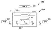
도 15는 본 발명의 다른 실시예에 따른 예시적 제2 퓨즈 피로 평가 시스템(550)을 개략적으로 도시한다. 시스템(550)은 각각 라인측 및 부하측 회로(354, 356)에 구조적으로 전기적 연결을 구성하는 단자(T1H, T2H)를 구비한 하우징(554)을 포함하는 퓨즈 홀더 또는 퓨즈 블록(552)을 포함한다. 퓨즈(352)의 단자(T1F, T2F)는 퓨즈 홀더 또는 퓨즈 블록(522)의 단자(T1H, T2H)와 구조적으로 정합하도록 구성됨으로써, 퓨즈 소자를 통해 라인측 및 부하측 회로 사이의 전기적 연결이 구축된다.15 schematically illustrates an exemplary second fuse
시스템(500)(도 14)과는 달리, 회로(360)는 퓨즈(352)의 하우징(502)에 제공되지 않으며, 대신에 퓨즈 홀더 또는 퓨즈 블록(552)의 하우징(554) 상에 또는 내부에 제공된다. 이와 같이, 본 실시예에서 회로(360)는 퓨즈(352) 대신에 퓨즈 블록(552)에 내장된다. 그러나, 회로(360)의 동작은 동일하게 유지되며, 라벨(506) 및 독취 장치(508)는 전술한 기술들을 사용하여 피로 평가를 제공하는 유사한 효과를 가지면서 전술한 바와 같이 제공될 수 있다.Unlike system 500 ( FIG. 14 ),
회로(360)가 전술한 바와 같이 시스템(500)에서의 퓨즈(352)에 내장된 다른 실시예에서, 독취 장치(508)는 퓨즈 블록 또는 하우징(552)에 내장될 수 있다.In other embodiments where
퓨즈 홀더 또는 퓨즈 블록 하우징(554)은 다수의 단자 세트(T1H, T2H)를 구비함으로써 다수의 퓨즈(352) 세트가 퓨즈 하우징 또는 퓨즈 블록(552) 내에 수용될 수 있다. 하우징(554)은 단일 부품 또는 다중 부품으로 제공될 수 있으며, 서로 부착될 수 있는 모듈형 부품으로 제공될 수 있다. 하우징(554)은 개방형 퓨즈 블록으로서 구성될 수 있거나 필요에 따라 퓨즈(들)(352)를 부분적으로 또는 완전히 감쌀 수 있다.The fuse holder or fuse
하우징(554)에 구비된 단자(T1H, T2H)는 구조적으로 퓨즈(352)의 단자(T1F, T2F)를 수용하고 유지하는 탄성 스프링 클립을 포함할 수 있다. 퓨즈 단자(T1F, T2F)는 단부 캡 또는 페룰, 칼날 접촉부 또는 단자 블레이드를 포함하지만 이에 한정되지는 않는 어떠한 형상 및 구조적 형태로 제공될 수 있다. 따라서, 퓨즈 홀더 또는 퓨즈 블록 하우징의 단자(T1H, T2H)는 퓨즈(352)의 단자(T1F, T2F)와 정합하도록 변경될 수 있다. 퓨즈 제거 특징부는 퓨즈(352)의 단자(T1F, T2F)에 내장될 수 있고/있거나 하우징(554) 내에 삽입되어 호환되지 않는 퓨즈가 설치되는 것을 방지할 수 있다.The terminals T1H and T2H provided in the
하우징(554)에 설치된 단자(T1H, T2H)도 라인측 및 부하측을 퓨즈 블록 또는 하우징(552)에 전기적인 접속을 위해 이용되는 배선의 단부를 수용 및 유지하도록 구성되는 상자 러그, 스프링 클램프 또는 기타 단자와 같은 단자 특징부를 포함한다. 또는, 라인측 및 로드측 회로(354, 356)에 기계적 및 전기적 연결을 하기 위한 기타 단자 구조뿐만 아니라 패널 장착 클립 등이 제공될 수도 있다.Terminals T1H , T2H installed on
도 16은 본 발명의 일 실시예에 따른 예시적인 제3 퓨즈 피로 평가 시스템(600)을 개략적으로 도시한다. 시스템(600)은 라인측 및 부하측 회로(354, 356)에 전기적으로 연결되도록 구조적으로 각각 구성된 단자(T1L, T2L)를 구비한 하우징 또는 베이스(604)를 포함하는 가융성 차단 스위치 장치(602)를 포함한다. 스위치(606)는 차단 스위치 장치(602)를 통해 전류 경로를 형성 또는 차단하도록 선택적으로 개방 또는 폐쇄될 수 있는 하우징 또는 베이스(604)에 마련되며, 퓨즈(352)가 설치되고 스위치(606)가 폐쇄되는 경우 퓨즈(352) 내의 퓨즈 소자는 라인측 및 로드측 회로(354, 356) 사이의 전기적 접속을 완료한다. 일부 실시예에서 베이스(604)는 미주리주 세인트루이스의 Eaton의 Bussmann의 콤팩트 회로 보호기(CCP)로 구성될 수 있다. 도 15의 개략도에 도시된 바와 같이, 차단 스위치 장치(602)는 인라인 회로 차단기를 포함하지 않으며, 따라서 종래의 인라인 회로 차단기 및 퓨즈의 조합보다 작다.16 schematically illustrates an exemplary third fuse
퓨즈(352)의 단자(T1F, T2F)는 구조적으로 베이스(604)의 상보 단자와 정합하도록 구성됨으로써, 퓨즈(352) 내의 퓨즈 소자를 통해 전기 접속될 수 있다. 베이스(604)의 상보 단자는 구조적으로 퓨즈(352)의 단자(T1F, T2F)를 수용 및 유지하도록 구성되는 탄성 스프링 클립을 포함할 수 있다. 퓨즈 단자(T1F, T2F)는 단부 캡 또는 페룰, 칼날 접촉부 또는 단자 블레이드를 포함하지만 이에 한정되지는 않는 임의의 형상 및 구조적 형태로 제공될 수 있다. 따라서, 퓨즈 홀더 또는 퓨즈 블록 하우징 상의 상보 단자는 퓨즈(352)의 단자(T1F, T2F)와 정합되도록 변경될 수 있다. 퓨즈 제거 특징부는 퓨즈(352)의 단자(T1F, T2F)에 내장될 수 있고/있거나 하우징(604)에 삽입됨으로써 호환되지 않는 퓨즈의 설치를 방지할 수 있다. 퓨즈(352)가 설치되는 경우, 스위치(606)는 퓨즈 소자를 통하여 그리고 라인측 및 부하측 회로(354, 356) 사이에서 전기적 연결을 접속하거나 차단하도록 동작될 수 있다. 이와 같이, 스위치(606)는 퓨즈(352)가 정위치에 유지되는 동안 장치(602)를 통해 회로 경로의 연결 및 차단을 제공한다.Terminals T1F , T2F of
도 16에 도시된 실시예에서, 회로(360)는 퓨즈(352)의 하우징(502)에 마련되지 않지만, 스위치 차단 장치(602)의 베이스(604) 상에 또는 내에 대신 제공된다. 이와 같이, 본 실시예의 회로(360)는 퓨즈(352) 대신에 베이스(602)에 내장된다. 그러나, 회로(360)의 동작은 동일하게 유지되고, 라벨(506) 및 독취기(508)는 전술한 바와 같이 유사한 효과로 제공될 수 있다.In the embodiment shown in FIG. 16 , the
시스템(500)에서 전술한 바와 같이 회로(360)가 퓨즈(352)에 내장된 다른 실시예에서, 독취 장치(504)는 베이스(604)에 내장될 수 있다.In other embodiments in which the
베이스(604)는 다수의 단자 세트를 구비함으로써 다수의 퓨즈(352) 세트가 수용될 수 있다. 베이스(604)는 단일 부품 또는 다중 부품으로 제공될 수 있으며, 서로 부착될 수 있는 모듈형 부품으로 제공될 수 있다. 베이스(604)는 필요에 따라 퓨즈(들)(352)를 부분적으로 또는 완전히 감쌀 수 있다.The
베이스(604)에 설치된 단자(T1L, T2L)도 라인측 및 부하측을 차단 스위치 장치(602)에 전기적인 접속을 위해 이용되는 배선의 단부를 수용 및 유지하도록 구성되는 상자 러그, 스프링 클램프 또는 기타 단자와 같은 단자 특징부를 포함한다. 또는, 라인측 및 로드측 회로(354, 356)에 기계적 및 전기적 연결을 하기 위한 기타 단자 구조뿐만 아니라 패널 장착 클립 등이 제공될 수도 있다.Terminals T1L , T2L installed on
도 17은 도 7 내지 도 15에 도시된 퓨즈 피로 평가 기술 및 시스템과 관련된 예시적인 프로세스(700)를 도시하는 방법 흐름도이다. 상기 프로세스(700)는 전술한 바와 같은 전기 퓨즈 피로 평가 시스템 또는 다른 전력 시스템의 특정 요구를 유연하게 충족시키기 위해 기술된 바와 같거나 적절하게 수행되는 추가적 변형을 구현하기 위해 전자적으로 구현될 수 있다. 상기 프로세스(700)는 전술한 전기 자동차 전력 시스템 애플리케이션에서 특히 바람직할 수 있지만 전기 자동차 전력 시스템 애플리케이션에 제한되지 않으며, 퓨즈 피로 및 상기 논의된 문제점들이 실질적인 관심사인 임의의 전력 시스템으로 확장될 수 있다.17 is a method flow diagram illustrating an
도 17의 준비 단계에 도시된 바와 같이, 퓨즈가 단계 702에서 제공되고 제어기가 단계 704에서 제공된다. 전술한 바와 같이, 단계 702에서 제공된 퓨즈는 하나 이상의 취약 부위를 포함하는 기하 구조를 한정하는 하나 이상의 스탬핑된 금속 퓨즈 소자를 포함할 수 있으며, 단계 704에서 제공된 제어기는 전술한 제어기를 포함할 수 있다. 고려되는 실시예에서, 제어기는 퓨즈에 내장될 수 있으며, 이 경우 단계 702 및 704는 별도의 단계가 아닌 단일 단계로 구현될 수 있다. 다른 고려되는 실시예에서, 제어기는 퓨즈 홀더 또는 차단 스위치에 내장될 수 있으며, 따라서 단계 704는 퓨즈 홀더 또는 제어기를 포함하는 차단 스위치를 제공하는 것을 포함할 수 있다. 그러나, 또 다른 실시예들에서, 단계 704에서 제공되는 제어기는 평가를 용이하게 하는 다른 방식으로 제공될 수 있다. 전술한 바와 같이 하나 이상의 제어기를 포함하는 실시예에서, 단계 704와 유사한 추가적인 단계가 적절히 수행될 수 있다. 상기와 같이 제공된 경우, 단계 702에서 제공된 퓨즈가 여기된 전력 시스템에 연결되는 동안 제어기 또는 제어기들은 하나 이상의 퓨즈 피로 매개변수를 일정 시간 동안 모니터링할 수 있다.As shown in the preparation phase of FIG. 17 , a fuse is provided in
단계 706에 나타난 바와 같이, 전류원이 제공될 수 있고 전류가 제어기에 의해 주입될 수 있다. 전술한 바와 같은 보상 회로는 퓨즈의 내부 또는 외부로 제공될 수 있고, 퓨즈를 통한 전류 흐름을 검출하도록 구성될 수 있다. 전술한 바와 같은 기술을 사용하여, 제어기는 전류원으로부터 퓨즈 소자에 걸쳐 주입된 전류에 기초하여 퓨즈 소자의 저항을 측정하도록 구성될 수 있다. 경우에 따라, 단계 708에 나타난 임의의 개별 전류 센서(또는 전류 센서들)도 저항 측정을 용이하게 하거나 그렇지 않으면 퓨즈 소자 피로 문제를 평가할 수 있는 능력을 제공하기 위해 이용될 수 있다. 이러한 전류 주입 기술 및 보상 회로는 모든 실시예에서 반드시 필요하지는 않다.As shown in
단계 720에 도시된 바와 같이, 제어기는 단계 702에서 제공된 퓨즈 내의 퓨즈 소자의 저항을 판단하도록 구성된다. 이러한 저항은 전술한 기술들을 사용하여 퓨즈 피로의 진행을 나타내는 저항의 변화를 판단하기 위해 시간에 따라 모니터링될 수 있다.As shown in
고려된 실시예에서, 측정된 저항은 퓨즈 소자의 피로 상태 또는 조건을 평가하기 위해 단계 722에 도시된 기간 동안 모니터링되는 퓨즈 피로 매개변수로서 이용된다. 특히, 전술한 바와 같이, 일부 실시예에서 측정된 저항 변화는 단계 724로 나타난 바와 같이 제어기에 의한 소정의 퓨즈 피로 저항 도표와 비교될 수 있다. 모니터링된 퓨즈 피로 매개변수(예컨대, 모니터링된 저항의 변화)에 기초하여, 제어기는 단계 726에 도시된 바와 같은 퓨즈 소자의 소진된 수명 또는 단계 728에 도시된 바와 같은 퓨즈 소자의 잔여 수명 중의 하나 이상을 판단하도록 더 구성된다.In the contemplated embodiment, the measured resistance is used as a monitored fuse fatigue parameter for the period shown in step 722 to evaluate a fatigue state or condition of the fuse element. In particular, as noted above, in some embodiments the measured resistance change may be compared to a predetermined fuse fatigue resistance plot by the controller as indicated by
소진된 서비스 수명 및/또는 잔여 서비스 수명이 판단되면, 제어기는 단계 730에 도시된 바와 같이 퓨즈 소자의 소모된 서비스 수명 또는 퓨즈 소자의 잔여 수명 중 하나 이상에 관한 정보를 전달할 수 있다. 상기 수명 정보는 전술되거나 공지된 것과 같은 방식으로 전달될 수 있다. 특정 시스템에서는 무선 통신이 선호될 수 있지만, 다른 경우에는 유선 통신이 선호될 수 있으며, 일부 시스템에서는 무선 통신과 유선 통신을 모두 사용하여 중복된 통신 방식을 제공할 수 있다. 전술한 바와 같이, 전달된 수명 정보는 적절한 목적지에서 수신되기 전에 하나의 제어기에서 다른 제어기로 (또는 하나의 장치로부터 다른 장치로) 전달될 수 있으며, 경고 또는 알림이 단계 732에 도시된 바와 같이 생성되어, 피로 문제로 인한 퓨즈의 불필요한 동작을 회피할 수 있다. 특히, 정보의 통신은 독취 장치, 또는 제어기와 통신하는 원격 장치를 포함할 수 있다. 다수의 제어기들을 갖는 실시예에서, 제어기들은 수명 정보가 퓨즈 소자가 그 수명을 거의 다 하는 경우의 단계 732에서 알림을 주는 최종 목적을 위한 단계 730에서 통신에 이용 가능할 때까지 수신된 정보를 추가로 처리할 수 있는 다른 제어기 또는 장치에 대해 정보의 일부만을 판단하거나 전달한다. 그러한 통지가 적절하게 발생되기 전에, 수명 정보는 기록되고 전달되며, 원하는 보고서뿐 아니라 데이터 기록 및 분석 기능을 용이하게 할 수도 있다.When the exhausted service life and/or the remaining service life is determined, the controller may transmit information about one or more of the consumed service life of the fuse element and the remaining service life of the fuse element as shown in
상기 알림(732)이 생성된 후, 전력 시스템의 사용 및 향유가 중단되지 않도록 진행된 퓨즈 피로로 인해 퓨즈 소자의 결함 전에 퓨즈를 사전에 교체할 수 있도록 약간의 리드 타임이 제공될 수 있다. 논의된 전기 자동차 전력 시스템 애플리케이션과 같은 애플리케이션에서, 퓨즈 피로로 인한 퓨즈의 예기치 않은 불필요한 동작을 회피함으로써 시스템 신뢰성 및 사용자 만족도가 향상될 수 있다.After the
다른 예시적인 프로세스에서, 제어기는 선택적으로 단계 734에 도시된 바와 같이 퓨즈를 통해 흐르는 전류와 관련된 변형을 계산하도록 구성될 수 있다. 계산된 변형은 단계 720, 722 및 724의 목적상 퓨즈 피로 매개변수로 이용될 수 있다. 단계 724에서, 제어기는 전술한 바와 같이 계산된 변형을 상기와 같이 논의된 소정의 퓨즈 피로 변형 도표와 비교하여, 단계 726 및 728에 도시된 바와 같이 퓨즈 소자의 소진된 서비스 수명 또는 잔여 수명 중 적어도 하나를 결정할 수 있다.In another exemplary process, the controller may optionally be configured to calculate a strain associated with the current flowing through the fuse as shown in
다른 예시적인 프로세스에서, 제어기는 단계 736에 도시된 바와 같이, 소정의 범위에서 검출된 전류 피크 수 및 계산된 변형에서 결함까지의 총 사이클 수에 기초하여 피로 손상 성분을 선택적으로 계산할 수 있다. 이러한 계산은 단계 734의 계산된 변형과 관련될 수도 있고 관련되지 않을 수도 있다. 그럼에도, 피로 손상 성분은 단계 720, 722 및 724의 목적상 퓨즈 피로 매개변수로 이용될 수 있다. 단계 724에서, 제어기는 누적 피로 손상 성분들을 비교하고 누적 피로를 1과 비교하여 단계 726 및 728에 도시된 바와 같이 퓨즈 소자의 소진된 서비스 수명 또는 잔여 수명 중 하나 이상을 판단할 수 있다.In another exemplary process, the controller may optionally calculate a fatigue damage component based on the number of current peaks detected in the predetermined range and the total number of cycles from deformation to failure, as shown in
이와 같이, 저항의 변화, 퓨즈 소자의 기계적 변형의 변화 및 누적 손상 성분과 같은 퓨즈 피로 매개변수는 동일하거나 상이한 실시예에서 개별적으로 또는 조합하여 모니터링되어 상이한 퓨즈 피로 평가 시스템을 다양하게 제공할 수 있다. 하나 이상의 퓨즈 피로 매개변수가 모니터링되는 실시예에서, 시스템 중복을 제공하도록 및/또는 시스템 오류 검출 능력 등과 같은 더 개선된 시스템 기능이 수행 가능하도록 결과값들이 비교될 수 있다. 상이한 퓨즈 피로 매개변수들에 기초한 적어도 하나 이상의 유형의 퓨즈 피로 평가가 마찬가지로 단계 730에서 전달된다.As such, fuse fatigue parameters such as changes in resistance, changes in mechanical deformation of fuse elements, and cumulative damage components can be monitored individually or in combination in the same or different embodiments to provide a variety of different fuse fatigue evaluation systems. . In embodiments in which one or more fuse fatigue parameters are monitored, the results may be compared to provide system redundancy and/or to enable more advanced system functions, such as system fault detection capabilities, and the like. At least one type of fuse fatigue assessment based on different fuse fatigue parameters is likewise passed in
단계 738에 도시된 바와 같이, 제어기는 결함 상태를 식별하도록 구성될 수 있다. 또한, 단계 740에서, 제어기는 전술한 바와 같은 기술(예컨대, 소정의 지속성의 평가 창에 기초한 결함 식별)을 사용하여 전력 시스템에서 특정 유형의 결함 전류를 식별하도록 구성될 수 있다. 단계 742에서, 제어기는 결함 전류의 유형을 전달하도록 구성될 수 있다. 특정 유형의 결함 전류에 대한 이러한 통신은 전력 시스템에서 전기 퓨즈의 성능에 관한 실시간 피드백을 제공할 뿐만 아니라, 시간 경과에 따라 전력 시스템의 문제를 해결하거나 최적화하는 데 유용할 수 있다.As shown in
도시되고 설명된 상기 프로세스들은 원하는 전력 시스템에서의 다수의 퓨즈에 대해 확대됨으로써, 퓨즈 피로 문제에 대해 다수의 퓨즈가 동시에 모니터링될 수 있다. 퓨즈 성능의 개별적인 변화는 하나의 퓨즈로부터의 피로 정보를 동일 또는 상이한 전류 프로파일에 적용될 수 있는 다른 퓨즈들과 비교하여 식별 및 검출할 수 있다. 여기된 전력 시스템에서 다수의 퓨즈에 대해 수집 및 전달되는 정보는 시간 경과에 따른 전력 시스템의 문제를 해결하거나 최적화 하기 위해서인 것뿐만 아니라, 전력 시스템에서 전기 퓨즈의 성능을 분석하고 최적화 하기 위한 유용한 실시간 피드백을 제공할 수 있다.The processes shown and described above are extended to multiple fuses in a desired power system, so that multiple fuses can be simultaneously monitored for fuse fatigue issues. Individual changes in fuse performance can be identified and detected by comparing fatigue information from one fuse to other fuses that can be applied to the same or different current profile. The information collected and communicated for multiple fuses in an excited power system is useful real-time for analyzing and optimizing the performance of electrical fuses in the power system, as well as for troubleshooting or optimizing the power system over time. You can provide feedback.
기능적인 측면에서 예시적인 시스템들(300, 500, 550 및 600)을 설명하였으므로, 당업자는 추가적인 설명 없이도 전술한 제어 방법 및 프로세스들을 구현하기 위한 제어 회로를 구성할 수 있다. 제어기의 프로그래밍은 당업자의 이해 범위 내에 있는 것으로 간주되는 바람직한 효과를 제공하기 위해 적절한 알고리즘 등을 사용하여 구현될 수 있다.Having described the
본 발명의 효용은 개시된 예시적인 실시예와 관련하여 충분히 예시되었다고 생각된다.It is believed that the utility of the present invention has been fully illustrated in connection with the disclosed exemplary embodiments.
개시된 전기 퓨즈 피로 평가 시스템의 일 실시예는, 퓨즈가 여기된 전력 시스템에 연결된 동안 적어도 하나의 퓨즈 피로 매개변수를 일정 기간 동안 모니터링하도록 구성된 제어기를 포함한다. 모니터링된 적어도 하나의 퓨즈 피로 매개변수에 기초하여, 제어기는 퓨즈 소자의 소진된 수명 또는 잔여 수명 중 적어도 하나를 결정하도록 더 구성된다.One embodiment of the disclosed electrical fuse fatigue evaluation system includes a controller configured to monitor at least one fuse fatigue parameter for a period of time while the fuse is coupled to an excited power system. Based on the monitored at least one fuse fatigue parameter, the controller is further configured to determine at least one of an exhausted life or a remaining life of the fuse element.
선택적으로, 적어도 하나의 퓨즈 피로 매개변수는 저항의 변화, 퓨즈 소자의 기계적 변형의 변화 또는 누적 손상 성분 중 하나를 포함할 수 있다.Optionally, the at least one fuse fatigue parameter may include one of a change in resistance, a change in mechanical deformation of the fuse element, or a cumulative damage component.
상기 시스템은 전류원을 포함할 수 있으며, 상기 컨트롤러는 상기 전류원으로부터 상기 퓨즈 소자에 걸쳐 주입된 전류에 기초하여 상기 퓨즈의 저항을 측정하도록 구성된다. 제어기는 측정된 저항을 소정의 퓨즈 피로 저항 도표와 비교하도록 구성될 수 있다. 상기 시스템은 상기 퓨즈를 통한 전류 흐름을 검출하도록 구성된 보상 회로를 포함할 수 있다.The system may include a current source, wherein the controller is configured to measure a resistance of the fuse based on a current injected from the current source across the fuse element. The controller may be configured to compare the measured resistance to a predetermined fuse fatigue resistance diagram. The system may include a compensation circuit configured to detect current flow through the fuse.
제어기는 선택적으로 퓨즈를 통해 흐르는 전류와 관련된 변형을 계산하도록 구성될 수 있다. 제어기는 계산된 변형을 소정의 퓨즈 피로 변형 도표와 비교하도록 구성될 수 있다.The controller may optionally be configured to calculate a strain associated with the current flowing through the fuse. The controller may be configured to compare the calculated strain to a predetermined fuse fatigue strain diagram.
제어기는 선택적으로 소정의 범위 내에서의 검출된 전류 피크 개수 및 상기 계산된 변형에서의 결함까지의 사이클의 총 횟수에 기초하여 피로 손상 성분을 계산하도록 구성될 수 있다. 제어기는 상기 계산된 피로 손상 성분을 누적하고 상기 누적된 피로를 1과 비교하여 상기 퓨즈 소자의 소진된 수명 또는 상기 퓨즈 소자의 잔여 수명 중 적어도 하나를 결정하도록 구성될 수 있다.The controller may optionally be configured to calculate the fatigue damage component based on the number of detected current peaks within a predetermined range and the total number of cycles to failure in the calculated strain. The controller may be configured to accumulate the calculated fatigue damage component and compare the accumulated fatigue to one to determine at least one of an exhausted life of the fuse element or a remaining life of the fuse element.
제어기는 선택적으로 상기 퓨즈 소자의 소진된 수명 또는 상기 퓨즈 소자의 잔여 수명 중 적어도 하나에 관한 정보를 전달하도록 구성될 수 있다. 제어기는 정보를 무선으로 통신하도록 구성될 수 있다.The controller may optionally be configured to communicate information regarding at least one of an exhausted life of the fuse element or a remaining life of the fuse element. The controller may be configured to wirelessly communicate information.
제어기는 선택적으로 전력 시스템에서의 결함 전류의 유형을 식별하도록 구성될 수 있다. 제어기는 결함 전류의 유형을 통신하도록 구성될 수 있다. 제어기는 결함 유형을 무선으로 통신하도록 구성될 수 있다. 제어기는 소정의 지속 시간의 평가 창에 기초하여 상기 결함 전류를 식별하도록 구성될 수 있다.The controller may optionally be configured to identify a type of fault current in the power system. The controller may be configured to communicate the type of fault current. The controller may be configured to wirelessly communicate the fault type. The controller may be configured to identify the fault current based on an evaluation window of a predetermined duration.
다른 옵션에 의하면, 컨트롤러는 퓨즈에 내장되거나, 퓨즈 홀더에 내장되거나, 차단 스위치에 내장될 수 있다. 마찬가지로, 시스템은 상기 제어기와 통신하는 독취 장치 또는 원격 장치 중 적어도 하나를 포함할 수 있다.According to another option, the controller may be embedded in a fuse, in a fuse holder, or in a disconnect switch. Likewise, the system may include at least one of a reading device or a remote device in communication with the controller.
퓨즈 소자는 적어도 하나의 취약 부위를 포함하는 기하학적 구조로 스탬핑된 금속 퓨즈 소자일 수 있다.The fuse element may be a metal fuse element stamped into a geometry including at least one weak point.
본 설명은 최상의 모드를 포함하여 본 발명을 개시하며, 당업자가 임의의 장치 또는 시스템을 제작 및 사용하고 임의의 통합된 방법을 수행하는 것을 포함하여 본 발명을 실시할 수 있도록 다양한 예시들을 사용하고 있다. 본 발명의 특허 가능한 범위는 청구 범위에 의해 한정되며, 당업자에게 발생할 수 있는 기타의 예들을 포함할 수 있다. 이러한 기타 예들은 청구항의 문언과 다르지 않은 구조적 요소를 갖거나 청구항의 문언과 실질적으로 다르지 않은 동등한 구조적 요소를 포함하는 경우에는 청구항의 범위 내에 있는 것으로 간주된다.This description discloses the invention, including the best mode, and uses various examples to enable any person skilled in the art to make and use any apparatus or system and to practice the invention in any integrated method. . The patentable scope of the invention is defined by the claims, and may include other examples that may occur to those skilled in the art. Such other examples are considered to be within the scope of the claims if they have structural elements that do not differ from the literal language of the claims, or contain equivalent structural elements that do not differ materially from the literal language of the claims.
Claims (15)
Translated fromKorean상기 전기 퓨즈와 전기적으로 병렬 접속되고, 상기 전기 퓨즈를 가로질러 전류를 주입하는 전류원을 포함하는 회로를 포함하며;
상기 제어기는 상기 전기 퓨즈를 가로지르는 주입된 전류에 기초하여 상기 전기 퓨즈의 저항을 측정하고,
상기 제어기는 상기 측정된 저항과 관련하여 상기 모니터된 퓨즈 피로 매개 변수를 평가하며,
상기 평가된 모니터된 퓨즈 피로 매개 변수를 기초로, 상기 제어기는 상기 전기 퓨즈의 소진된 수명 또는 상기 전기 퓨즈의 잔여 수명 중 적어도 하나를 결정하는, 전기 퓨즈 피로 평가 시스템.a controller for monitoring a fuse fatigue parameter of the electrical fuse for a predetermined time while the electrical fuse is connected to the energized power system; and
a circuit electrically connected in parallel with the electrical fuse and including a current source for injecting a current across the electrical fuse;
the controller measures a resistance of the electrical fuse based on an injected current across the electrical fuse;
the controller evaluates the monitored fuse fatigue parameter in relation to the measured resistance;
based on the assessed monitored fuse fatigue parameter, the controller determines at least one of an exhausted life of the electrical fuse or a remaining life of the electrical fuse.
상기 평가된 모니터링된 퓨즈 피로 매개 변수는 측정된 저항의 변화, 기계적 변형의 변화 또는 누적 손상 성분을 포함하는, 전기 퓨즈 피로 평가 시스템.The method of claim 1,
wherein the evaluated monitored fuse fatigue parameter comprises a measured change in resistance, a change in mechanical strain, or a cumulative damage component.
상기 전류원은 상기 전기 퓨즈를 가로질러 미리 설정된 주파수에서 AC 전류를 주입하는, 전기 퓨즈 피로 평가 시스템.According to claim 1,
and the current source injects an AC current at a preset frequency across the electrical fuse.
상기 제어기는 상기 측정된 저항을 상기 전기 퓨즈를 위한 미리 결정된 퓨즈 피로 저항 도표(plot)와 비교하는, 전기 퓨즈 피로 평가 시스템.4. The method of claim 3,
and the controller compares the measured resistance to a predetermined fuse fatigue resistance plot for the electrical fuse.
상기 제어기는, 상기 측정된 저항을 이용하여, 상기 전기 퓨즈를 통해 흐르는 전류를 계산하고;
상기 제어기는 상기 전기 퓨즈를 통해 흐르는 상기 전류와 관련된 변형을 더 계산하는, 전기 퓨즈 피로 평가 시스템.According to claim 1,
the controller calculates a current flowing through the electrical fuse by using the measured resistance;
and the controller further calculates a strain associated with the current flowing through the electrical fuse.
상기 제어기는 상기 계산된 변형을 상기 전기 퓨즈를 위한 미리 결정된 퓨즈 피로 변형 도표와 비교하는, 전기 퓨즈 피로 평가 시스템.6. The method of claim 5,
and the controller compares the calculated strain with a predetermined fuse fatigue strain diagram for the electrical fuse.
상기 제어기는, 상기 측정된 저항을 이용하여, 상기 전기 퓨즈를 통해 흐르는 전류를 계산하고; 상기 제어기는 미리 결정된 범위 내에서의 검출된 전류 피크 개수 및 상기 계산된 변형에서의 결함까지의 사이클의 총 수에 기초하여 피로 손상 성분을 더 계산하는, 전기 퓨즈 피로 평가 시스템.6. The method of claim 5,
the controller calculates a current flowing through the electrical fuse by using the measured resistance; and the controller further calculates a fatigue damage component based on a number of detected current peaks within a predetermined range and a total number of cycles to failure in the calculated strain.
상기 제어기는 시간에 따른 상기 계산된 피로 손상 성분을 더 누적하고; 상기 제어기는 상기 누적된 피로를 1과 비교하여 상기 전기 퓨즈의 소진된 수명 또는 상기 전기 퓨즈의 잔여 수명 중 적어도 하나를 더 결정하는, 전기 퓨즈 피로 평가 시스템.8. The method of claim 7,
the controller further accumulates the calculated fatigue damage component over time; and the controller compares the accumulated fatigue with one to further determine at least one of an exhausted life of the electric fuse or a remaining life of the electric fuse.
상기 제어기는 상기 전기 퓨즈의 소진된 수명 또는 상기 전기 퓨즈의 잔여 수명 중 적어도 하나에 관한 정보를 전달하는, 전기 퓨즈 피로 평가 시스템.According to claim 1,
and the controller transmits information about at least one of an exhausted life span of the electric fuse or a remaining life of the electric fuse.
상기 제어기는 상기 전력 시스템에서의 결함 전류의 유형을 식별하고 전달하는, 전기 퓨즈 피로 평가 시스템.According to claim 1,
and the controller identifies and communicates a type of fault current in the power system.
상기 제어기는 미리 결정된 지속 시간의 평가 창에 기초하여 상기 결함 전류를 식별하는, 전기 퓨즈 피로 평가 시스템.11. The method of claim 10,
and the controller identifies the fault current based on an evaluation window of a predetermined duration.
상기 제어기는 상기 퓨즈에 내장되는(built-in), 전기 퓨즈 피로 평가 시스템.According to claim 1,
and the controller is built-in to the fuse.
상기 제어기는 퓨즈 홀더 및 차단 스위치 중 하나에 내장되는, 전기 퓨즈 피로 평가 시스템.According to claim 1,
wherein the controller is built into one of the fuse holder and the disconnect switch.
상기 제어기와 통신하는 판독기 장치 또는 원격 장치 중 적어도 하나를 더 포함하는, 전기 퓨즈 피로 평가 시스템.According to claim 1,
and at least one of a reader device or a remote device in communication with the controller.
상기 전기 퓨즈는 적어도 하나의 취약점(weak spot)을 포함하는 기하학 구조로 각인된 금속 퓨즈 소자인, 전기 퓨즈 피로 평가 시스템.
According to claim 1,
wherein the electrical fuse is a metal fuse element engraved with a geometrical structure including at least one weak spot.
Applications Claiming Priority (3)
| Application Number | Priority Date | Filing Date | Title |
|---|---|---|---|
| US15/186,865US9989579B2 (en) | 2016-06-20 | 2016-06-20 | Monitoring systems and methods for detecting thermal-mechanical strain fatigue in an electrical fuse |
| US15/186,865 | 2016-06-20 | ||
| PCT/US2017/029763WO2017222639A1 (en) | 2016-06-20 | 2017-04-27 | Monitoring systems and methods for detecting thermal-mechanical strain fatigue in an electrical fuse |
Publications (2)
| Publication Number | Publication Date |
|---|---|
| KR20190019139A KR20190019139A (en) | 2019-02-26 |
| KR102447976B1true KR102447976B1 (en) | 2022-09-28 |
Family
ID=58699282
Family Applications (1)
| Application Number | Title | Priority Date | Filing Date |
|---|---|---|---|
| KR1020197000962AActiveKR102447976B1 (en) | 2016-06-20 | 2017-04-27 | Monitoring system and method for detecting thermo-mechanical strain fatigue in electrical fuses |
Country Status (8)
| Country | Link |
|---|---|
| US (2) | US9989579B2 (en) |
| EP (1) | EP3472632B1 (en) |
| JP (1) | JP7213094B2 (en) |
| KR (1) | KR102447976B1 (en) |
| CN (1) | CN109313229B (en) |
| CA (1) | CA3027690C (en) |
| ES (1) | ES2933700T3 (en) |
| WO (1) | WO2017222639A1 (en) |
Cited By (1)
| Publication number | Priority date | Publication date | Assignee | Title |
|---|---|---|---|---|
| WO2025013976A1 (en)* | 2023-07-13 | 2025-01-16 | 이종호 | Thermal fuse for high voltage direct current |
Families Citing this family (18)
| Publication number | Priority date | Publication date | Assignee | Title |
|---|---|---|---|---|
| US9989579B2 (en)* | 2016-06-20 | 2018-06-05 | Eaton Intelligent Power Limited | Monitoring systems and methods for detecting thermal-mechanical strain fatigue in an electrical fuse |
| US10288665B2 (en)* | 2016-12-12 | 2019-05-14 | Lg Chem, Ltd. | Vehicle having a diagnostic system for an electrical fuse |
| US11143718B2 (en)* | 2018-05-31 | 2021-10-12 | Eaton Intelligent Power Limited | Monitoring systems and methods for estimating thermal-mechanical fatigue in an electrical fuse |
| US11289298B2 (en) | 2018-05-31 | 2022-03-29 | Eaton Intelligent Power Limited | Monitoring systems and methods for estimating thermal-mechanical fatigue in an electrical fuse |
| CN110824267B (en)* | 2018-08-10 | 2025-05-13 | 深圳市虹鹏能源科技有限责任公司 | Information processing method, device and energy storage system |
| US11126764B2 (en)* | 2018-10-01 | 2021-09-21 | Palo Alto Research Center Incorporated | Physics-based model particle-filtering framework for predicting RUL using resistance measurements |
| CN110395114A (en)* | 2019-07-25 | 2019-11-01 | 广州小鹏汽车科技有限公司 | A kind of the fuse monitoring method and device of vehicle |
| JP7667140B2 (en) | 2019-09-09 | 2025-04-22 | イートン インテリジェント パワー リミテッド | Electrical busbar and method for manufacturing same |
| CN111243915B (en)* | 2020-01-10 | 2024-01-05 | 浙江吉利汽车研究院有限公司 | Fuse prompting replacement device and method and automobile |
| EP4086646B1 (en)* | 2021-05-03 | 2023-07-19 | Volvo Truck Corporation | A method for estimating the ageing state of fuse elements and an electrical fuse maintenance system |
| KR102540398B1 (en)* | 2021-05-27 | 2023-06-12 | 한국전력공사 | Apparatus for exchanging fuse in potential transformer and fuse exchanging method using the same |
| US12136500B2 (en) | 2021-08-18 | 2024-11-05 | Eaton Intelligent Power Limited | Electrical busbar and method of fabricating the same |
| CN113820633B (en)* | 2021-09-15 | 2024-02-27 | 上海舒盈科技股份有限公司 | Fuse specification determination method, system, terminal and medium for fusing overvoltage protection device |
| US11892522B2 (en) | 2021-11-22 | 2024-02-06 | Eaton Intelligent Power Limited | Systems and methods for monitoring and estimating service life of electrical fuses |
| US11874342B2 (en) | 2021-12-20 | 2024-01-16 | Caterpillar Inc. | Method to determine fuse health |
| US11867719B1 (en) | 2022-05-20 | 2024-01-09 | Eaton Intelligent Power Limited | Systems and methods for monitoring electrical fuses |
| US12196695B2 (en) | 2023-02-17 | 2025-01-14 | Dell Products L.P. | Systems and methods for detecting mechanical strain on a ball of a ball grid array |
| US12416686B2 (en)* | 2023-02-17 | 2025-09-16 | Dell Products L.P. | Systems and methods for detecting mechanical strain on a circuit board |
Citations (2)
| Publication number | Priority date | Publication date | Assignee | Title |
|---|---|---|---|---|
| JP2007043860A (en)* | 2005-08-05 | 2007-02-15 | Meidensha Corp | Estimating device for lifetime of protecting fuse |
| CN101793943A (en)* | 2010-02-26 | 2010-08-04 | 苏州热工研究院有限公司 | Intelligent type test system for service life of fuses |
Family Cites Families (68)
| Publication number | Priority date | Publication date | Assignee | Title |
|---|---|---|---|---|
| JPS6183825A (en)* | 1984-10-02 | 1986-04-28 | Babcock Hitachi Kk | Ignition device of burner |
| JPS63131416A (en)* | 1986-11-20 | 1988-06-03 | ブラザー工業株式会社 | Printed circuit board |
| JPS63131426A (en)* | 1986-11-21 | 1988-06-03 | 新日本製鐵株式会社 | Method for diagnosing fuse deterioration in operating low-pressure power equipment |
| JPS63250036A (en) | 1987-04-06 | 1988-10-17 | 矢崎総業株式会社 | Fuse material |
| JPS63292547A (en)* | 1987-05-26 | 1988-11-29 | Toshiba Corp | Monitoring device for protection element |
| US4998086A (en)* | 1988-08-09 | 1991-03-05 | Amp Incorporated | Fuse assembly and method of manufacture |
| US5237875A (en)* | 1991-03-29 | 1993-08-24 | Tensiodyne Corporation | Metal fatigue detector |
| US5419201A (en)* | 1993-02-25 | 1995-05-30 | Li; Yuanfeng | Methods and devices for electrochemically determining metal fatigue status |
| DE4338850A1 (en)* | 1993-11-13 | 1995-05-18 | Dornier Gmbh | Device for monitoring the durability of structures |
| US5453696A (en)* | 1994-02-01 | 1995-09-26 | Crosspoint Solutions, Inc. | Embedded fuse resistance measuring circuit |
| JP3194429B2 (en) | 1998-06-02 | 2001-07-30 | オムロン株式会社 | Overcurrent cutoff structure |
| JP3638102B2 (en)* | 1999-09-30 | 2005-04-13 | Necトーキン栃木株式会社 | Battery pack |
| AU3634201A (en) | 1999-10-29 | 2001-05-08 | University Of Pennsylvania | Methods and devices for evaluating fatigue damage |
| US6654219B1 (en)* | 2000-12-11 | 2003-11-25 | Pass & Seymour, Inc. | Arc fault detector with diagnostic indicator |
| US7153903B1 (en)* | 2002-06-19 | 2006-12-26 | The Board Of Regents Of The University Of Oklahoma | Carbon nanotube-filled composites prepared by in-situ polymerization |
| JP4539168B2 (en)* | 2004-05-18 | 2010-09-08 | トヨタ自動車株式会社 | Door lock control device |
| DE102004062475A1 (en)* | 2004-12-24 | 2006-07-06 | Bayer Healthcare Ag | Solid, orally administrable, modified release pharmaceutical dosage forms |
| JP2007004857A (en)* | 2005-06-22 | 2007-01-11 | Tdk Corp | Magnetic disk apparatus having tunnel magneto-resistive head element |
| FR2900745B1 (en)* | 2006-05-05 | 2008-10-10 | Eurocopter France | METHOD AND DEVICE FOR DIAGNOSING A MECHANISM |
| US7706116B2 (en)* | 2007-01-22 | 2010-04-27 | Honeywell International Inc. | SSPC technology incorporated with thermal memory effects to achieve the fuse curve coordination |
| JP4740167B2 (en) | 2007-02-01 | 2011-08-03 | 三洋電機株式会社 | Power supply for vehicle |
| US7679211B2 (en)* | 2007-05-30 | 2010-03-16 | Ford Global Technologies, Llc | Electrical disconnect system |
| CN101546902A (en)* | 2008-03-24 | 2009-09-30 | 茗熔集团有限公司 | Device for monitoring working state of fuse |
| JP5307437B2 (en)* | 2008-04-14 | 2013-10-02 | ルネサスエレクトロニクス株式会社 | Semiconductor device |
| US20100164677A1 (en) | 2008-12-29 | 2010-07-01 | Chin-Chi Yang | Fuse |
| US8068323B2 (en)* | 2009-01-26 | 2011-11-29 | Cooper Technologies Company | Circuit protector monitoring and management systems and methods |
| CN201725002U (en)* | 2010-01-04 | 2011-01-26 | 苏州热工研究院有限公司 | Multi-factor detection system for aging state of fuse |
| CN101776720B (en)* | 2010-01-04 | 2011-09-07 | 苏州热工研究院有限公司 | Multiple-factor detection system for aging condition of fuse and assessment method for aging condition |
| CN101915887B (en)* | 2010-07-05 | 2012-09-05 | 苏州热工研究院有限公司 | Fuse life characteristic data test and evaluation system and evaluation method thereof |
| CN102081125A (en)* | 2010-12-02 | 2011-06-01 | 深圳市万瑞和电子有限公司 | Integrated test system for PTC (Positive Temperature Coefficient) resettable fuse |
| CN202018827U (en)* | 2011-03-16 | 2011-10-26 | 中国电子科技集团公司第五十八研究所 | Antifuse memory unit suitable for memorizer |
| JP5185474B2 (en) | 2011-05-31 | 2013-04-17 | パナソニック株式会社 | Fuse plate and battery block including the same |
| CN102288908B (en)* | 2011-07-22 | 2013-04-03 | 重庆大学 | Fault monitoring device and fault judgment method for measurement potential transformer (PT) fuse |
| CN102288830A (en)* | 2011-09-09 | 2011-12-21 | 浙江东冠电气科技有限公司 | Storage battery impedance detection device excited by SPWA (Sine-wave Pulse Width Modulation) signal generated by single chip microcomputer |
| JP5672390B2 (en)* | 2011-10-05 | 2015-02-18 | 富士通株式会社 | RFID tag |
| CN103149444B (en)* | 2011-12-06 | 2017-04-19 | 联想(北京)有限公司 | Battery core internal resistance measuring method and battery core matching method |
| CN103163396B (en)* | 2011-12-14 | 2016-01-27 | 中国广核集团有限公司 | Nuclear power station midget fuse detection method |
| US9558904B2 (en)* | 2012-02-15 | 2017-01-31 | Mta S.P.A. | Fuse |
| DE102012209138A1 (en) | 2012-05-31 | 2013-12-05 | Robert Bosch Gmbh | Method for aging determination of fuse in battery system connected to propulsion system of e.g. motor car, involves measuring flowing stream of fuse of battery system by battery control device |
| CN102707238A (en)* | 2012-06-01 | 2012-10-03 | 江苏省电力公司检修分公司 | Storage battery performance on-line monitoring system and monitoring method |
| CN102798780A (en)* | 2012-08-08 | 2012-11-28 | 东莞市贝特电子科技股份有限公司 | Fuse Test System |
| US8979600B2 (en)* | 2012-09-25 | 2015-03-17 | Cooper Technologies Company | Fuse holder and fuse clip assembly with dual directional bias element support |
| DE102012022562A1 (en)* | 2012-11-17 | 2014-05-22 | Daimler Ag | Fuse with thermo-mechanical compensation element |
| DE102012224223A1 (en) | 2012-12-21 | 2014-07-10 | Robert Bosch Gmbh | Battery system for hybrid drive vehicle, has monitoring device adapted to output signal, and control system that is arranged to bring plant or system into customized operating state and/or to send warning to operator of plant |
| AU2014238202B2 (en)* | 2013-03-15 | 2016-02-25 | Allison Transmission, Inc. | Service disconnect interlock system and method for hybrid vehicles |
| EP2786891B1 (en)* | 2013-04-05 | 2019-06-26 | Samsung SDI Co., Ltd. | Circuit arrangement, vehicle with a circuit arrangement and method for operating a circuit arrangement in a vehicle |
| CN103308819B (en)* | 2013-05-17 | 2016-04-06 | 苏州热工研究院有限公司 | There is the test system for service life of fuses of remote information transmission and controlling functions |
| US9041151B2 (en)* | 2013-05-31 | 2015-05-26 | International Business Machines Corporation | Fin eFuse formed by trench silicide process |
| CN104237044A (en)* | 2013-06-18 | 2014-12-24 | 山东科技大学 | Testing machine for quantitatively measuring thermal fatigue performance of alloy and forecasting life span of alloy |
| CN103558461A (en)* | 2013-09-06 | 2014-02-05 | 电子科技大学 | Method for testing surge pulse current resistance of fuse |
| CN103675464A (en)* | 2013-11-13 | 2014-03-26 | 国家电网公司 | Power distribution system equivalent ground distributed capacitor measuring method |
| US9006794B1 (en)* | 2014-01-24 | 2015-04-14 | Altera Corporation | Low-voltage programmable electrical fuses |
| FR3017754B1 (en)* | 2014-02-14 | 2018-04-27 | Commissariat A L'energie Atomique Et Aux Energies Alternatives | CONTINUOUS VOLTAGE SUPPLY SYSTEM CONFIGURED TO PRECHARGE A FILTER CAPACITOR BEFORE FEEDING A LOAD |
| CN105900092B (en)* | 2014-03-26 | 2019-05-14 | 株式会社日立制作所 | Time series data management method and time series data management system |
| CN104155525B (en)* | 2014-05-14 | 2017-07-11 | 国家电网公司 | A kind of multi-frequency scanning formula pole tower ground resistance measurement apparatus and method |
| US11075048B2 (en)* | 2014-05-28 | 2021-07-27 | Eaton Intelligent Power Limited | Compact high voltage power fuse and methods of manufacture |
| US11075047B2 (en) | 2014-05-28 | 2021-07-27 | Eaton Intelligent Power Limited | Compact high voltage power fuse and methods of manufacture |
| JP6604740B2 (en) | 2014-05-30 | 2019-11-13 | キヤノン株式会社 | Method for manufacturing semiconductor substrate and substrate for liquid discharge head |
| US20150357144A1 (en)* | 2014-06-04 | 2015-12-10 | Hamilton Sundstrand Corporation | Fuse assembly |
| CN104749527A (en)* | 2015-03-27 | 2015-07-01 | 观致汽车有限公司 | Method and device used for determining health condition of battery fuse |
| US9851393B2 (en)* | 2015-04-08 | 2017-12-26 | GM Global Technology Operations LLC | Determination of fuse life in a fuse system |
| US10050981B2 (en)* | 2015-05-04 | 2018-08-14 | Intel Corporation | Attack detection through signal delay monitoring |
| WO2017010583A1 (en)* | 2015-07-13 | 2017-01-19 | 주식회사 엘지화학 | Battery residual life estimation device and method |
| US10598703B2 (en)* | 2015-07-20 | 2020-03-24 | Eaton Intelligent Power Limited | Electric fuse current sensing systems and monitoring methods |
| CN204903720U (en)* | 2015-08-25 | 2015-12-23 | 南京亚电电力自动化有限公司 | Drop out fuse on -line monitoring device based on electric current and displacement monitoring |
| US10164300B2 (en)* | 2015-12-16 | 2018-12-25 | GM Global Technology Operations LLC | Sensing feature on fuse element for detection prior to fuse open |
| CN205484567U (en)* | 2016-01-28 | 2016-08-17 | 武汉标迪电子科技有限公司 | Fuse on -line measuring device for electric automobile |
| US9989579B2 (en)* | 2016-06-20 | 2018-06-05 | Eaton Intelligent Power Limited | Monitoring systems and methods for detecting thermal-mechanical strain fatigue in an electrical fuse |
- 2016
- 2016-06-20USUS15/186,865patent/US9989579B2/enactiveActive
- 2017
- 2017-04-27KRKR1020197000962Apatent/KR102447976B1/enactiveActive
- 2017-04-27JPJP2018566385Apatent/JP7213094B2/enactiveActive
- 2017-04-27CNCN201780038041.1Apatent/CN109313229B/enactiveActive
- 2017-04-27WOPCT/US2017/029763patent/WO2017222639A1/ennot_activeCeased
- 2017-04-27CACA3027690Apatent/CA3027690C/enactiveActive
- 2017-04-27ESES17722950Tpatent/ES2933700T3/enactiveActive
- 2017-04-27EPEP17722950.7Apatent/EP3472632B1/enactiveActive
- 2018
- 2018-04-27USUS15/965,080patent/US10254329B2/enactiveActive
Patent Citations (2)
| Publication number | Priority date | Publication date | Assignee | Title |
|---|---|---|---|---|
| JP2007043860A (en)* | 2005-08-05 | 2007-02-15 | Meidensha Corp | Estimating device for lifetime of protecting fuse |
| CN101793943A (en)* | 2010-02-26 | 2010-08-04 | 苏州热工研究院有限公司 | Intelligent type test system for service life of fuses |
Cited By (1)
| Publication number | Priority date | Publication date | Assignee | Title |
|---|---|---|---|---|
| WO2025013976A1 (en)* | 2023-07-13 | 2025-01-16 | 이종호 | Thermal fuse for high voltage direct current |
Also Published As
| Publication number | Publication date |
|---|---|
| CN109313229B (en) | 2022-03-08 |
| CN109313229A (en) | 2019-02-05 |
| KR20190019139A (en) | 2019-02-26 |
| WO2017222639A1 (en) | 2017-12-28 |
| ES2933700T3 (en) | 2023-02-13 |
| US9989579B2 (en) | 2018-06-05 |
| US10254329B2 (en) | 2019-04-09 |
| JP2019526784A (en) | 2019-09-19 |
| CA3027690A1 (en) | 2017-12-28 |
| US20180306852A1 (en) | 2018-10-25 |
| JP7213094B2 (en) | 2023-01-26 |
| US20170363674A1 (en) | 2017-12-21 |
| EP3472632A1 (en) | 2019-04-24 |
| EP3472632B1 (en) | 2022-10-26 |
| CA3027690C (en) | 2023-12-12 |
Similar Documents
| Publication | Publication Date | Title |
|---|---|---|
| KR102447976B1 (en) | Monitoring system and method for detecting thermo-mechanical strain fatigue in electrical fuses | |
| US9257729B2 (en) | Response to over-current in a battery pack | |
| US12362122B2 (en) | Monitoring systems and methods for estimating thermal-mechanical fatigue in an electrical fuse | |
| CN104854466B (en) | A method of the availability for pre- telegraph relay or protector | |
| KR101982427B1 (en) | Batteries, batteries and batteries for automobiles | |
| KR101947664B1 (en) | Method and device for managing electrical energy storage assemblies for electrical power supply of an electric motor vehicle | |
| JP5025160B2 (en) | Secondary battery device | |
| KR101836516B1 (en) | Battery System having Current Interrupt Device and Operation Method thereof | |
| KR20130005229A (en) | Electric fuse with torque restricting terminals | |
| JP2008312396A (en) | Vehicle power supply system | |
| US11143718B2 (en) | Monitoring systems and methods for estimating thermal-mechanical fatigue in an electrical fuse | |
| EP3381092A1 (en) | Electrical module | |
| WO2018163736A1 (en) | Protection circuit for in-vehicle battery | |
| EP2175135A1 (en) | Sealed electric compressor | |
| US20170110768A1 (en) | Method for operating an energy storage unit, battery management system for performing such a method and energy storage unit with such a battery management system | |
| CN206442130U (en) | Power battery charging protection device | |
| CN203788009U (en) | Disconnection control system of battery assembly, and battery assembly and vehicle with system | |
| KR20230089713A (en) | Battery management apparatus and control method thereof | |
| KR20220141594A (en) | Sensing wire short preventing device using PCB pattern | |
| JP2008002345A (en) | Hermetic electric compressor |
Legal Events
| Date | Code | Title | Description |
|---|---|---|---|
| PA0105 | International application | Patent event date:20190110 Patent event code:PA01051R01D Comment text:International Patent Application | |
| PG1501 | Laying open of application | ||
| PA0201 | Request for examination | Patent event code:PA02012R01D Patent event date:20200427 Comment text:Request for Examination of Application | |
| E902 | Notification of reason for refusal | ||
| PE0902 | Notice of grounds for rejection | Comment text:Notification of reason for refusal Patent event date:20210510 Patent event code:PE09021S01D | |
| E902 | Notification of reason for refusal | ||
| PE0902 | Notice of grounds for rejection | Comment text:Notification of reason for refusal Patent event date:20211129 Patent event code:PE09021S01D | |
| E701 | Decision to grant or registration of patent right | ||
| PE0701 | Decision of registration | Patent event code:PE07011S01D Comment text:Decision to Grant Registration Patent event date:20220622 | |
| PR0701 | Registration of establishment | Comment text:Registration of Establishment Patent event date:20220922 Patent event code:PR07011E01D | |
| PR1002 | Payment of registration fee | Payment date:20220923 End annual number:3 Start annual number:1 | |
| PG1601 | Publication of registration |