KR102447506B1 - Display control method and device of display device - Google Patents
Display control method and device of display deviceDownload PDFInfo
- Publication number
- KR102447506B1 KR102447506B1KR1020160001125AKR20160001125AKR102447506B1KR 102447506 B1KR102447506 B1KR 102447506B1KR 1020160001125 AKR1020160001125 AKR 1020160001125AKR 20160001125 AKR20160001125 AKR 20160001125AKR 102447506 B1KR102447506 B1KR 102447506B1
- Authority
- KR
- South Korea
- Prior art keywords
- pixel
- sub
- blue
- mode
- filter
- Prior art date
- Legal status (The legal status is an assumption and is not a legal conclusion. Google has not performed a legal analysis and makes no representation as to the accuracy of the status listed.)
- Active
Links
Images


Classifications
- G—PHYSICS
- G09—EDUCATION; CRYPTOGRAPHY; DISPLAY; ADVERTISING; SEALS
- G09G—ARRANGEMENTS OR CIRCUITS FOR CONTROL OF INDICATING DEVICES USING STATIC MEANS TO PRESENT VARIABLE INFORMATION
- G09G3/00—Control arrangements or circuits, of interest only in connection with visual indicators other than cathode-ray tubes
- G09G3/20—Control arrangements or circuits, of interest only in connection with visual indicators other than cathode-ray tubes for presentation of an assembly of a number of characters, e.g. a page, by composing the assembly by combination of individual elements arranged in a matrix no fixed position being assigned to or needed to be assigned to the individual characters or partial characters
- G09G3/2003—Display of colours
- G—PHYSICS
- G09—EDUCATION; CRYPTOGRAPHY; DISPLAY; ADVERTISING; SEALS
- G09G—ARRANGEMENTS OR CIRCUITS FOR CONTROL OF INDICATING DEVICES USING STATIC MEANS TO PRESENT VARIABLE INFORMATION
- G09G3/00—Control arrangements or circuits, of interest only in connection with visual indicators other than cathode-ray tubes
- G09G3/20—Control arrangements or circuits, of interest only in connection with visual indicators other than cathode-ray tubes for presentation of an assembly of a number of characters, e.g. a page, by composing the assembly by combination of individual elements arranged in a matrix no fixed position being assigned to or needed to be assigned to the individual characters or partial characters
- G09G3/22—Control arrangements or circuits, of interest only in connection with visual indicators other than cathode-ray tubes for presentation of an assembly of a number of characters, e.g. a page, by composing the assembly by combination of individual elements arranged in a matrix no fixed position being assigned to or needed to be assigned to the individual characters or partial characters using controlled light sources
- G09G3/30—Control arrangements or circuits, of interest only in connection with visual indicators other than cathode-ray tubes for presentation of an assembly of a number of characters, e.g. a page, by composing the assembly by combination of individual elements arranged in a matrix no fixed position being assigned to or needed to be assigned to the individual characters or partial characters using controlled light sources using electroluminescent panels
- G09G3/32—Control arrangements or circuits, of interest only in connection with visual indicators other than cathode-ray tubes for presentation of an assembly of a number of characters, e.g. a page, by composing the assembly by combination of individual elements arranged in a matrix no fixed position being assigned to or needed to be assigned to the individual characters or partial characters using controlled light sources using electroluminescent panels semiconductive, e.g. using light-emitting diodes [LED]
- G09G3/3208—Control arrangements or circuits, of interest only in connection with visual indicators other than cathode-ray tubes for presentation of an assembly of a number of characters, e.g. a page, by composing the assembly by combination of individual elements arranged in a matrix no fixed position being assigned to or needed to be assigned to the individual characters or partial characters using controlled light sources using electroluminescent panels semiconductive, e.g. using light-emitting diodes [LED] organic, e.g. using organic light-emitting diodes [OLED]
- G09G3/3225—Control arrangements or circuits, of interest only in connection with visual indicators other than cathode-ray tubes for presentation of an assembly of a number of characters, e.g. a page, by composing the assembly by combination of individual elements arranged in a matrix no fixed position being assigned to or needed to be assigned to the individual characters or partial characters using controlled light sources using electroluminescent panels semiconductive, e.g. using light-emitting diodes [LED] organic, e.g. using organic light-emitting diodes [OLED] using an active matrix
- G—PHYSICS
- G09—EDUCATION; CRYPTOGRAPHY; DISPLAY; ADVERTISING; SEALS
- G09G—ARRANGEMENTS OR CIRCUITS FOR CONTROL OF INDICATING DEVICES USING STATIC MEANS TO PRESENT VARIABLE INFORMATION
- G09G5/00—Control arrangements or circuits for visual indicators common to cathode-ray tube indicators and other visual indicators
- G09G5/02—Control arrangements or circuits for visual indicators common to cathode-ray tube indicators and other visual indicators characterised by the way in which colour is displayed
- G—PHYSICS
- G09—EDUCATION; CRYPTOGRAPHY; DISPLAY; ADVERTISING; SEALS
- G09G—ARRANGEMENTS OR CIRCUITS FOR CONTROL OF INDICATING DEVICES USING STATIC MEANS TO PRESENT VARIABLE INFORMATION
- G09G2300/00—Aspects of the constitution of display devices
- G09G2300/04—Structural and physical details of display devices
- G09G2300/0439—Pixel structures
- G09G2300/0452—Details of colour pixel setup, e.g. pixel composed of a red, a blue and two green components
- G—PHYSICS
- G09—EDUCATION; CRYPTOGRAPHY; DISPLAY; ADVERTISING; SEALS
- G09G—ARRANGEMENTS OR CIRCUITS FOR CONTROL OF INDICATING DEVICES USING STATIC MEANS TO PRESENT VARIABLE INFORMATION
- G09G2320/00—Control of display operating conditions
- G09G2320/02—Improving the quality of display appearance
- G09G2320/0242—Compensation of deficiencies in the appearance of colours
- G—PHYSICS
- G09—EDUCATION; CRYPTOGRAPHY; DISPLAY; ADVERTISING; SEALS
- G09G—ARRANGEMENTS OR CIRCUITS FOR CONTROL OF INDICATING DEVICES USING STATIC MEANS TO PRESENT VARIABLE INFORMATION
- G09G2340/00—Aspects of display data processing
- G09G2340/04—Changes in size, position or resolution of an image
- G09G2340/0457—Improvement of perceived resolution by subpixel rendering
- G—PHYSICS
- G09—EDUCATION; CRYPTOGRAPHY; DISPLAY; ADVERTISING; SEALS
- G09G—ARRANGEMENTS OR CIRCUITS FOR CONTROL OF INDICATING DEVICES USING STATIC MEANS TO PRESENT VARIABLE INFORMATION
- G09G2340/00—Aspects of display data processing
- G09G2340/06—Colour space transformation
- G—PHYSICS
- G09—EDUCATION; CRYPTOGRAPHY; DISPLAY; ADVERTISING; SEALS
- G09G—ARRANGEMENTS OR CIRCUITS FOR CONTROL OF INDICATING DEVICES USING STATIC MEANS TO PRESENT VARIABLE INFORMATION
- G09G2360/00—Aspects of the architecture of display systems
- G09G2360/14—Detecting light within display terminals, e.g. using a single or a plurality of photosensors
- G09G2360/144—Detecting light within display terminals, e.g. using a single or a plurality of photosensors the light being ambient light
Landscapes
- Engineering & Computer Science (AREA)
- Physics & Mathematics (AREA)
- Computer Hardware Design (AREA)
- General Physics & Mathematics (AREA)
- Theoretical Computer Science (AREA)
- Control Of Indicators Other Than Cathode Ray Tubes (AREA)
- Liquid Crystal Display Device Control (AREA)
- Preparation Of Compounds By Using Micro-Organisms (AREA)
Abstract
Translated fromKoreanDescription
Translated fromKorean본 발명의 실시예들은 표시 장치의 표시 제어 방법 및 장치에 관한 것이다.Embodiments of the present invention relate to a display control method and apparatus for a display device.
인간의 몸에서 분비되는 호르몬 중 멜라토닌은 생체시계의 역할을 한다. 멜라토닌은 밤이 되면 온 몸으로 분비되어 몸의 각 부분에 밤이 되었음을 알린다. 멜라토닌이 분비되면 수면이 유도된다.Among the hormones secreted by the human body, melatonin plays a role in the biological clock. Melatonin is secreted throughout the body at night to notify each part of the body that it is night. Sleep is induced when melatonin is secreted.
아침이 되어 빛이 들어오면 멜라토닌 호르몬의 분비가 억제되며 인간은 잠에서 깨어나게 된다. 그 중에서도 특히, 464nm 대의 파장이 우리 몸에서 인지되면 멜라토닌의 분비가 억제된다고 알려져 있다. 즉, 464nm 파장의 인지에 따라 우리 몸은 밤과 낮을 구별한다. 일반적으로 사람들은 470nm 정도의 중심파장을 갖는 빛을 청색으로 인지하므로, 464nm 파장은 청색 광이라고 볼 수 있다.When the light comes in in the morning, the secretion of the hormone melatonin is suppressed and the human wakes up. In particular, it is known that the secretion of melatonin is suppressed when the wavelength of 464 nm is recognized by our body. In other words, according to the perception of the 464nm wavelength, our body distinguishes between day and night. In general, people perceive light having a central wavelength of about 470 nm as blue, and therefore, a wavelength of 464 nm can be regarded as blue light.
본 발명의 실시예들은 표시 장치의 표시 제어를 위한 장치 및 방법을 제공한다. 상세히, 본 발명의 실시예들은 각성 또는 숙면 유도 효과가 있는 표시 장치 및 이의 표시 제어 방법 및 장치를 제공한다.SUMMARY Embodiments of the present invention provide an apparatus and method for display control of a display device. In detail, embodiments of the present invention provide a display device having an effect of inducing arousal or deep sleep, and a display control method and apparatus thereof.
본 발명의 일 실시예에 따른 표시 장치는 적색 서브 픽셀, 녹색 서브 픽셀, 제1 청색 서브 픽셀 및 상기 제1 청색 서브 픽셀과 상이한 중심 파장을 갖는 광을 방출하는 제2 청색 서브 픽셀을 포함하고, 상기 표시 제어 방법은, 청색 광 방출을 위해 상기 제1 청색 서브 픽셀을 사용하는 제1 모드, 상기 제2 청색 서브 픽셀을 사용하는 제2 모드 및 상기 제1 청색 서브 픽셀과 상기 제2 청색 서브 픽셀을 모두 사용하는 제3 모드 중 어느 하나로 상기 표시 장치의 표시 모드를 설정하는 단계; 및 적색, 녹색 및 청색 각각의 입력 데이터를 상기 적색 서브 픽셀, 상기 녹색 서브 픽셀, 상기 제1 청색 서브 픽셀 및 상기 제2 청색 서브 픽셀의 배열에 따라 서브 픽셀 렌더링하여 출력 데이터로 변환하는 단계;를 포함하고, 상기 변환 단계는, 상기 표시 모드에 따라, 상기 적색, 녹색 및 청색 각각의 입력 데이터에 대한 렌더링 필터의 크기 및 계수를 변경하여 서브 픽셀 렌더링을 수행하는 단계;를 포함한다.A display device according to an embodiment of the present invention includes a red sub-pixel, a green sub-pixel, a first blue sub-pixel, and a second blue sub-pixel emitting light having a center wavelength different from that of the first blue sub-pixel, The display control method includes a first mode using the first blue sub-pixel for emitting blue light, a second mode using the second blue sub-pixel, and the first blue sub-pixel and the second blue sub-pixel setting a display mode of the display device to any one of a third mode using all of ; and converting each of red, green, and blue input data into output data by sub-pixel rendering according to the arrangement of the red sub-pixel, the green sub-pixel, the first blue sub-pixel, and the second blue sub-pixel. and performing sub-pixel rendering by changing sizes and coefficients of rendering filters for each of the red, green, and blue input data according to the display mode.
상기 표시 모드가 제1 모드인 경우, 상기 적색 입력 데이터를 상기 적색 서브 픽셀의 출력 데이터로 변환하기 위한 제1 렌더링 필터의 크기 및 계수와, 상기 청색 입력 데이터를 상기 제1 청색 서브 픽셀의 출력 데이터로 변환하기 위한 제2 렌더링 필터의 크기 및 계수가 상이할 수 있다.When the display mode is the first mode, the size and coefficient of a first rendering filter for converting the red input data into the output data of the red sub-pixel, and the blue input data to the output data of the first blue sub-pixel Sizes and coefficients of the second rendering filter for converting to ? may be different.
상기 제1 렌더링 필터는 2×1 필터이고, 상기 2×1 필터의 계수는 0.5이고, 상기 제2 렌더링 필터는 2×2 필터이고, 상기 2×2 필터의 계수는 0.25일 수 있다.The first rendering filter may be a 2×1 filter, the coefficient of the 2×1 filter may be 0.5, the second rendering filter may be a 2×2 filter, and the coefficient of the 2×2 filter may be 0.25.
상기 표시 모드가 제2 모드인 경우, 상기 적색 입력 데이터를 상기 적색 서브 픽셀의 출력 데이터로 변환하기 위한 제1 렌더링 필터의 크기 및 계수와, 상기 청색 입력 데이터를 상기 제2 청색 서브 픽셀의 출력 데이터로 변환하기 위한 제3 렌더링 필터의 크기 및 계수가 상이할 수 있다.When the display mode is the second mode, the size and coefficient of a first rendering filter for converting the red input data into the output data of the red sub-pixel, and the blue input data to the output data of the second blue sub-pixel Sizes and coefficients of the third rendering filter for converting to ? may be different.
상기 제1 렌더링 필터는 2×1 필터이고, 상기 2×1 필터의 계수는 0.5이고, 상기 제3 렌더링 필터는 2×2 필터이고, 상기 2×2 필터의 계수는 0.25일 수 있다.The first rendering filter may be a 2×1 filter, the coefficient of the 2×1 filter may be 0.5, the third rendering filter may be a 2×2 filter, and the coefficient of the 2×2 filter may be 0.25.
상기 표시 모드가 제3 모드인 경우, 상기 적색 입력 데이터를 상기 적색 서브 픽셀의 출력 데이터로 변환하기 위한 제1 렌더링 필터의 크기 및 계수와, 상기 청색 입력 데이터를 상기 제1 청색 서브 픽셀 및 상기 제2 청색 서브 픽셀의 출력 데이터로 변환하기 위한 제4 렌더링 필터의 크기 및 계수가 동일할 수 있다.When the display mode is the third mode, the size and coefficient of a first rendering filter for converting the red input data into the output data of the red sub-pixel, and the blue input data to the first blue sub-pixel and the second The size and coefficient of the fourth rendering filter for converting the output data of the 2 blue sub-pixels may be the same.
상기 제1 렌더링 필터 및 상기 제3 렌더링 필터는 2×1 필터이고, 상기 2×1 필터의 계수는 0.5일 수 있다.The first rendering filter and the third rendering filter may be a 2×1 filter, and a coefficient of the 2×1 filter may be 0.5.
상기 제1 청색 서브 픽셀에서 방출되는 광의 중심 파장은, 상기 제2 청색 서브 픽셀에서 방출되는 광의 중심 파장보다 낮을 수 있다.A central wavelength of light emitted from the first blue sub-pixel may be lower than a central wavelength of light emitted from the second blue sub-pixel.
상기 표시 모드 설정 단계는, 현재 상태를 낮 또는 밤으로 결정하고, 상기 현재 상태가 낮이면 상기 표시 모드를 제2 모드 또는 제3 모드로 설정하고, 상기 현재 상태가 밤이면 상기 표시 모드를 제1 모드로 설정할 수 있다.The setting of the display mode may include determining a current state as day or night, setting the display mode to a second mode or a third mode if the current state is day, and setting the display mode to a first mode if the current state is night mode can be set.
상기 표시 모드 설정 단계는, 현재 시간, 기설정된 표시 모드 전환 주기, 또는 외부 조도 중 적어도 하나에 기초하여 현재 상태를 낮 또는 밤으로 인식하고, 상기 인식된 현재 상태에 기초하여 상기 표시 모드를 설정할 수 있다.The display mode setting step may include recognizing the current state as day or night based on at least one of a current time, a preset display mode switching period, or external illuminance, and setting the display mode based on the recognized current state have.
본 발명의 일 실시예에 따른 표시 장치는 적색 서브 픽셀, 녹색 서브 픽셀, 제1 청색 서브 픽셀 및 상기 제1 청색 서브 픽셀과 상이한 중심 파장을 갖는 광을 방출하는 제2 청색 서브 픽셀을 포함하고, 상기 표시 장치의 표시를 제어하는 표시 제어 장치는, 청색 광 방출을 위해 상기 제1 청색 서브 픽셀을 사용하는 제1 모드, 상기 제2 청색 서브 픽셀을 사용하는 제2 모드 및 상기 제1 청색 서브 픽셀과 상기 제2 청색 서브 픽셀을 모두 사용하는 제3 모드 중 어느 하나로 상기 표시 장치의 표시 모드를 설정하는 표시모드 제어부; 및 적색, 녹색 및 청색 각각의 입력 데이터를 상기 적색 서브 픽셀, 상기 녹색 서브 픽셀, 상기 제1 청색 서브 픽셀 및 상기 제2 청색 서브 픽셀의 배열에 따라 서브 픽셀 렌더링하여 출력 데이터로 변환하는 데이터 변환부;를 포함하고, 상기 데이터 변환부는, 상기 표시 모드에 따라, 상기 적색, 녹색 및 청색 각각의 입력 데이터에 대한 렌더링 필터의 크기 및 계수를 변경하여 서브 픽셀 렌더링을 수행한다.A display device according to an embodiment of the present invention includes a red sub-pixel, a green sub-pixel, a first blue sub-pixel, and a second blue sub-pixel emitting light having a center wavelength different from that of the first blue sub-pixel, A display control device for controlling display of the display device includes a first mode using the first blue sub-pixel for emitting blue light, a second mode using the second blue sub-pixel, and the first blue sub-pixel and a display mode controller configured to set a display mode of the display device to any one of a third mode using both the second blue sub-pixel and the second blue sub-pixel; and a data converter configured to convert red, green, and blue input data into output data by sub-pixel rendering according to the arrangement of the red sub-pixel, the green sub-pixel, the first blue sub-pixel, and the second blue sub-pixel. ; and the data converter performs sub-pixel rendering by changing the size and coefficient of a rendering filter for each of the red, green, and blue input data according to the display mode.
본 발명의 실시예들에 따른 표시 제어 장치 및 방법은 표시 모드의 설정에 따라 숙면 유도 기능 및/또는 각성 기능을 제공할 수 있다.A display control apparatus and method according to embodiments of the present invention may provide a deep sleep inducing function and/or an awakening function according to a setting of a display mode.
본 발명의 실시예들에 따른 표시 제어 장치 및 방법은 표시 모드의 설정에 따라 서브 픽셀 렌더링 알고리즘을 변경하여 이용함으로써 표시 모드 변경에 따른 화질을 향상시킬 수 있다.The display control apparatus and method according to the embodiments of the present invention may improve the image quality according to the change of the display mode by changing and using the sub-pixel rendering algorithm according to the setting of the display mode.
도 1은 본 발명의 일 실시예에 따른 표시 장치(100)의 구성을 개략적으로 도시하는 블록도이다.
도 2a 및 도 2b는 본 발명의 일 실시예에 따른 픽셀 구조를 개략적으로 나타낸 도면이다.
도 3a 및 도 3b는 본 발명의 다른 실시예에 따른 픽셀 구조를 개략적으로 나타낸 도면이다.
도 4는 본 발명의 일 실시예에 따른 표시 제어부의 구성을 개략적으로 도시한 블록도이다.
도 5는 본 발명의 일 실시예에 따른 데이터 변환부의 구성을 개략적으로 도시한 블록도이다.
도 6은 본 발명의 일 실시예에 따른 서브 픽셀 렌더링 방법을 설명하는 예시도이다.
도 7은 본 발명의 일 실시예에 따른 표시 제어부의 표시 제어 방법을 개략적으로 설명하는 흐름도이다.
도 8 내지 도 11은 표시 제어부의 표시 제어 방법을 설명하는 예시도이다.1 is a block diagram schematically illustrating a configuration of a
2A and 2B are diagrams schematically illustrating a pixel structure according to an embodiment of the present invention.
3A and 3B are diagrams schematically illustrating a pixel structure according to another embodiment of the present invention.
4 is a block diagram schematically illustrating a configuration of a display control unit according to an embodiment of the present invention.
5 is a block diagram schematically illustrating a configuration of a data conversion unit according to an embodiment of the present invention.
6 is an exemplary diagram illustrating a sub-pixel rendering method according to an embodiment of the present invention.
7 is a flowchart schematically illustrating a display control method of a display controller according to an embodiment of the present invention.
8 to 11 are exemplary views illustrating a display control method of the display controller.
본 발명은 다양한 변환을 가할 수 있고 여러 가지 실시예를 가질 수 있는 바, 특정 실시예들을 도면에 예시하고 상세한 설명에 상세하게 설명하고자 한다. 본 발명의 효과 및 특징, 그리고 그것들을 달성하는 방법은 도면과 함께 상세하게 후술되어 있는 실시예들을 참조하면 명확해질 것이다. 그러나 본 발명은 이하에서 개시되는 실시예들에 한정되는 것이 아니라 다양한 형태로 구현될 수 있다.Since the present invention can apply various transformations and can have various embodiments, specific embodiments are illustrated in the drawings and described in detail in the detailed description. Effects and features of the present invention, and a method for achieving them, will become apparent with reference to the embodiments described below in detail in conjunction with the drawings. However, the present invention is not limited to the embodiments disclosed below and may be implemented in various forms.
이하, 첨부된 도면을 참조하여 본 발명의 실시예들을 상세히 설명하기로 하며, 도면을 참조하여 설명할 때 동일하거나 대응하는 구성 요소는 동일한 도면부호를 부여하고 이에 대한 중복되는 설명은 생략하기로 한다.Hereinafter, embodiments of the present invention will be described in detail with reference to the accompanying drawings, and when described with reference to the drawings, the same or corresponding components are given the same reference numerals, and the overlapping description thereof will be omitted. .
이하의 실시예에서, 제1, 제2 등의 용어는 한정적인 의미가 아니라 하나의 구성 요소를 다른 구성 요소와 구별하는 목적으로 사용되었다. 이하의 실시예에서, 단수의 표현은 문맥상 명백하게 다르게 뜻하지 않는 한, 복수의 표현을 포함한다. 이하의 실시예에서, 포함하다 또는 가지다 등의 용어는 명세서상에 기재된 특징, 또는 구성요소가 존재함을 의미하는 것이고, 하나 이상의 다른 특징들 또는 구성요소가 부가될 가능성을 미리 배제하는 것은 아니다.In the following embodiments, terms such as first, second, etc. are used for the purpose of distinguishing one component from another, not in a limiting sense. In the following examples, the singular expression includes the plural expression unless the context clearly dictates otherwise. In the following embodiments, terms such as include or have means that the features or components described in the specification are present, and the possibility that one or more other features or components may be added is not excluded in advance.
도면에서는 설명의 편의를 위하여 구성 요소들이 그 크기가 과장 또는 축소될 수 있다. 예컨대, 도면에서 나타난 각 구성의 크기 및 두께는 설명의 편의를 위해 임의로 나타내었으므로, 본 발명이 반드시 도시된 바에 한정되지 않는다.In the drawings, the size of the components may be exaggerated or reduced for convenience of description. For example, since the size and thickness of each component shown in the drawings are arbitrarily indicated for convenience of description, the present invention is not necessarily limited to the illustrated bar.
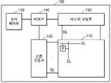
도 1은 본 발명의 일 실시예에 따른 표시 장치(100)의 구성을 개략적으로 도시하는 블록도이다.1 is a block diagram schematically illustrating a configuration of a
도 1을 참조하면, 표시 장치(100)는 표시 패널(110), 스캔 구동부(120), 데이터 구동부(130), 제어부(140), 및 표시 제어 장치(150)를 포함할 수 있다. 표시장치(100)는 유기발광표시장치일 수 있다.Referring to FIG. 1 , the
표시 패널(110)은 대략 행 방향으로 연장된 복수의 스캔 라인들(SL), 대략 열 방향으로 연장된 복수의 데이터 라인들(DL) 및 복수의 픽셀(P)들을 포함한다. 픽셀(P)들은 스캔 구동부(120)와 데이터 구동부(130)로부터 인가되는 신호에 따라 빛을 방출함으로써 화상을 표시한다. 도시되지 않았으나, 표시 패널(110)에는 복수의 발광 제어 라인들, 전원 라인들 및 다른 신호 라인들이 더 구비될 수 있다. 복수의 픽셀들 각각은 적색 서브 픽셀, 청색 서브 픽셀을 하나씩, 녹색 서브 픽셀을 두 개 포함하는 픽셀 구조로 이루어질 수 있다.The
데이터 구동부(130)는 복수의 데이터 라인들(DL)에 연결되고, 제어부(140)의 제어에 따라 출력 데이터로부터 아날로그 또는 디지털 데이터 신호를 생성하여 데이터 라인들(DL)에 공급한다.The
스캔 구동부(120)는 복수의 스캔 라인들(SL)에 연결되고, 제어부(140)의 제어에 따라 스캔 펄스를 발생시켜 스캔 라인들(SL)에 순차적으로 스캔 신호를 공급함으로써, 데이터 신호가 인가될 수평 라인을 선택한다.The
제어부(140)는 데이터 구동부(130) 및 스캔 구동부(120)의 구동을 제어한다.The
표시 제어부(150)는 표시 장치(100)의 표시를 전반적으로 제어한다. 본 발명의 일 실시예에 따르면 표시 제어부(150)는 표시 장치(100)의 표시 모드를 설정할 수 있다. 표시 제어부(150)는 표시 모드에 따라 서브 픽셀 렌더링 알고리즘을 선택하여 외부 장치로부터 입력되는 적색, 녹색, 청색의 입력 데이터(r, g, b)를 서브 픽셀 구조(배열)에 대응하는 출력 데이터(R, G, B1, B2)로 변환할 수 있다. 표시 제어부(150)는 출력 데이터를 제어부(140)에 제공할 수 있다. 출력 데이터는 서브 픽셀의 휘도(luminance) 정보를 포함할 수 있다. 휘도는 1024(210) 계조, 256(28) 계조, 또는 64(26) 계조 등을 가질 수 있다.The
스캔 구동부(120), 데이터 구동부(130), 제어부(140) 및 표시 제어부(150)는 각각 별개의 집적 회로 칩 또는 하나의 집적 회로 칩의 형태로 형성되어 표시 패널(110)을 구성하는 일 기판 위에 직접 장착되거나, 연성인쇄회로필름(flexible printed circuit film) 위에 장착되거나 TCP(tape carrier package)의 형태로 기판에 부착되거나, 기판에 직접 형성될 수도 있다.The
본 발명의 일 실시예에 따른 표시 장치(100)는 시청자에게 각성 효과를 주는 기능, 또는 시청자의 수면을 방해하지 않는 기능을 제공할 수 있다. 사람의 몸에 464nm 대의 파장이 인지되면, 멜라토닌의 분비가 억제된다고 알려져 있다. 멜라토닌은 수면을 유도하는 호르몬이다.The
본 발명의 일 실시예에 따른 표시 장치(100)는 서로 다른 중심파장을 갖는 2 종류의 청색 서브 픽셀을 구비한다. 예를 들어, 일 실시예에 따른 표시 장치(100)는 중심 파장이 464nm에서 멀리 떨어져 있는 제1 청색 광을 방출하는 제1 청색 서브 픽셀과, 중심 파장이 464nm에 가까운 제2 청색 광을 방출하는 제2 청색 서브 픽셀을 포함할 수 있다. 예컨대, 제1 청색 서브 픽셀은 어두운 청색(dark blue, deep blue) 광을 방출하고, 제2 청색 서브 픽셀은 밝은 청색(sky blue) 광을 방출할 수 있다. 제1 청색 광의 중심 파장은 제2 청색 광의 중심 파장보다 짧을 수 있다. 제1 청색 광의 중심 파장은 440nm 내지 450nm 사이의 값일 수 있고, 제2 청색 광의 중심 파장은 460nm 내지 470nm 사이의 값일 수 있다. 일 예로, 제1 청색 광의 중심 파장은 450nm, 제2 청색 광의 중심 파장은 464nm가 되도록 제1 청색 서브 픽셀과 제2 청색 서브 픽셀이 형성될 수 있다.The
제1 청색 서브 픽셀로부터 방출되는 광은 중심 파장이 464nm에서 떨어져 있으므로 멜라토닌 억제 효과가 미비하지만, 제2 청색 서브 픽셀로부터 방출되는 광은 중심 파장이 464nm에 가까우므로 멜라토닌의 분비를 억제시키는 효과가 발생한다. 따라서 제1 청색 서브 픽셀로부터 방출되는 광은 시청자의 수면을 방해하지 않는 효과, 즉 결과적으로 수면을 유도하는 효과를 발생시키며, 제2 청색 서브 픽셀로부터 방출되는 광은 시청자를 각성시키는 효과를 발생시킨다. 일 실시예에 따른 표시 장치(100)는 표시 모드에 따라 2개의 청색 서브 픽셀을 적절히 구동시킴으로써, 시청자에게 각성 효과를 주거나, 시청자의 수면을 유도하는 기능을 제공할 수 있다.The light emitted from the first blue sub-pixel has a melatonin inhibitory effect because the center wavelength is far from 464 nm, but the light emitted from the second blue sub-pixel has a center wavelength close to 464 nm, so the effect of inhibiting the secretion of melatonin occurs. do. Accordingly, the light emitted from the first blue sub-pixel generates an effect that does not disturb the viewer's sleep, that is, consequently induces sleep, and the light emitted from the second blue sub-pixel generates an effect that awakens the viewer. . The
도 2a 및 도 2b는 본 발명의 일 실시예에 따른 픽셀 구조를 개략적으로 나타낸 도면이다.2A and 2B are diagrams schematically illustrating a pixel structure according to an embodiment of the present invention.
도 2a 및 도 2b에 도시된 픽셀 구조는 본 발명의 일 실시예에 따라 표시 패널(110)에 배열된 픽셀의 구조의 예이다. 도 2a 및 도 2b에 도시된 사각형의 아웃 라인은 하나의 픽셀을 나타낸다.The pixel structure shown in FIGS. 2A and 2B is an example of a structure of a pixel arranged in the
도 2a를 참조하면, 표시 패널(110)은 제1 픽셀(P1)과 제2 픽셀(P2)을 포함한다. 제1 픽셀(P1)은 적색 서브 픽셀(이하, 서브 픽셀 R), 제1 청색 서브 픽셀(이하, 서브 픽셀 B1), 및 2 개의 녹색 서브 픽셀(이하, 서브 픽셀 G)을 포함한다. 제2 픽셀(P2)은 서브 픽셀 R, 제2 청색 서브 픽셀(이하, 서브 픽셀 B2), 및 2개의 서브 픽셀 G를 포함한다. 한편, 서브 픽셀을 2개씩 묶어 단위 픽셀로 볼 수도 있다. 제1 픽셀(P1)은 서브 픽셀 R과 G로 구성된 제1 서브 픽셀 군(SPG1)과 서브 픽셀 B1과 G로 구성된 제2 서브 픽셀 군(SPG2)을 포함하고, 제2 픽셀(P2)은 서브 픽셀 R와 G로 구성된 제3 서브 픽셀 군(SPG3)과 서브 픽셀 B2와 G로 구성된 제4 서브 픽셀 군(SPG4)을 포함한다.Referring to FIG. 2A , the
일 실시예에 따르면 제1 픽셀(P1)과 제2 픽셀(P2)은 인접하여 배치된다. 도 2a를 참조하면, 일 실시예에 따른 표시패널(110)에는 제1 픽셀(P1)의 열과 제2 픽셀(P2)의 열이 교대로 배치된다.According to an exemplary embodiment, the first pixel P1 and the second pixel P2 are disposed adjacent to each other. Referring to FIG. 2A , a column of first pixels P1 and a column of second pixels P2 are alternately disposed on the
도 2a를 참조하면, 일 실시예에 따른 표시패널(110)의 픽셀 구조는 제1 서브 픽셀 열(C1)과 제2 서브 픽셀 열(C2)이 교대로 배치되는 구조로 볼 수 있다. 제1 서브 픽셀 열(C1)에는 서브 픽셀 B1 또는 B2 중 어느 하나와 R이 제1 방향으로 교대로 나열되고, 제2 서브 픽셀 열(C2)에는 서브 픽셀 G가 제1 방향으로 나열될 수 있다. 예컨대 도 2a의 예에서 제1 서브 픽셀 열(C1)은 서브 픽셀 R과 B1이 교대로 나열되거나, 서브 픽셀 R과 B2가 교대로 나열되는 두 가지 구조 중 어느 하나의 구조를 갖는 것으로 도시되었다.Referring to FIG. 2A , the pixel structure of the
도 2b는 도 2a의 변형예를 나타낸 도면이다.FIG. 2B is a diagram illustrating a modified example of FIG. 2A .
도 2b를 참조하면, 픽셀들은 상하좌우에 동일한 픽셀이 인접하지 않도록 제1 픽셀(P1)과 제2 픽셀(P2)이 교대로 배열된다. 도 3b를 참조하면, 일 실시예에 따른 표시 패널(110)의 하나의 픽셀 열에는 제1 픽셀(P1)과 제2 픽셀(P2)이 교대로 나열된다.Referring to FIG. 2B , a first pixel P1 and a second pixel P2 are alternately arranged so that the same pixels are not adjacent to each other on the top, bottom, left, and right sides. Referring to FIG. 3B , a first pixel P1 and a second pixel P2 are alternately arranged in one pixel column of the
도 2b를 참조하면, 일 실시예에 따른 표시 패널(110)의 픽셀 구조는 제1 서브 픽셀 열(C1)과 제2 서브 픽셀 열(C2)이 교대로 배치되는 구조일 수 있다. 제1 서브 픽셀 열(C1)에는 서브 픽셀 B1 또는 B2 중 어느 하나와 R이 교대로 나열되는데, 상세히 서브 픽셀이 R, B1, R, B2의 순서로 나열될 수 있다. 제2 서브 픽셀 열(C2)에는 도 2a의 예와 같이 서브 픽셀 G가 제1 방향으로 나열될 수 있다.Referring to FIG. 2B , the pixel structure of the
도 3a 및 도 3b는 본 발명의 다른 실시예에 따른 픽셀 구조를 개략적으로 나타낸 도면이다.3A and 3B are diagrams schematically illustrating a pixel structure according to another embodiment of the present invention.
도 3a 및 도 3b에 도시된 픽셀 구조는 본 발명의 일 실시예에 따라 표시 패널(110)에 배열된 픽셀의 구조의 예이다. 도 3a 및 도 3b에 도시된 사각형의 큰 점선은 하나의 픽셀을 나타낸다.The pixel structure shown in FIGS. 3A and 3B is an example of a structure of a pixel arranged in the
도 3a를 참조하면, 표시 패널(110)은 제1 픽셀(P1)과 제2 픽셀(P2)을 포함한다. 제1 픽셀(P1)은 서브 픽셀 R, 서브 픽셀 B1 및 2개의 서브 픽셀 G를 포함한다. 제2 픽셀(P2)은 서브 픽셀 R, 서브 픽셀 B2, 및 2개의 서브 픽셀 G를 포함한다. 일 실시예에 따르면 제1 픽셀(P1)과 제2 픽셀(P2)은 인접하여 배치된다. 도 3a를 참조하면, 일 실시예에 따른 표시패널(110)에는 제1 픽셀(P1)의 열과 제2 픽셀(P2)의 열이 교대로 배치된다.Referring to FIG. 3A , the
도 3a를 참조하면, 일 실시예에 따른 표시패널(110)의 픽셀 구조는 제1 서브 픽셀 열(C1)과 제2 서브 픽셀 열(C2)이 교대로 배치되는 구조로 볼 수 있다. 제1 서브 픽셀 열(C1)에는 서브 픽셀 B1 또는 B2 중 어느 하나와 R이 제1 방향으로 교대로 나열되고, 제2 서브 픽셀 열(C2)에는 서브 픽셀 G가 제1 방향으로 나열될 수 있다. 예컨대 도 6a의 예에서 제1 서브 픽셀 열(C1)은 서브 픽셀 R과 B1이 교대로 나열되거나, 서브 픽셀 R과 B2가 교대로 나열되는 두 가지 구조 중 어느 하나의 구조를 갖는 것으로 도시되었다.Referring to FIG. 3A , the pixel structure of the
한편, 도 2a의 예와 달리 도 3a에 도시된 픽셀 구조에서는 제1 서브 픽셀 열(C1)과 제2 서브 픽셀 열(C2)에 포함된 서브 픽셀들의 위치가 서로 엇갈리도록 배치될 수 있다. 예를 들어, 제2 픽셀 열(C2)에 포함된 하나의 서브 픽셀 G(61)를 기준으로 볼 때, 상기 제2 픽셀 열(C2)의 양쪽에 위치하는 2개의 제1 픽셀 열(C1)들에 포함된 픽셀들(62)은 서브 픽셀 G(61)를 기준으로 하는 사각형의 모서리 중 어느 하나의 위치에 배치될 수 있다.Meanwhile, unlike the example of FIG. 2A , in the pixel structure illustrated in FIG. 3A , positions of sub-pixels included in the first sub-pixel column C1 and the second sub-pixel column C2 may be arranged to cross each other. For example, when one
도 3b는 도 3a의 변형예를 나타낸 도면이다.3B is a view showing a modified example of FIG. 3A.
도 3b를 참조하면, 픽셀들은 상하좌우에 동일한 픽셀이 인접하지 않도록 제1 픽셀(P1)과 제2 픽셀(P2)이 교대로 배열된다. 도 3b를 참조하면, 일 실시예에 따른 표시 패널(110)의 하나의 픽셀 열에는 제1 픽셀(P1)과 제2 픽셀(P2)이 교대로 나열된다.Referring to FIG. 3B , a first pixel P1 and a second pixel P2 are alternately arranged so that the same pixels are not adjacent to each other on the top, bottom, left, and right sides. Referring to FIG. 3B , a first pixel P1 and a second pixel P2 are alternately arranged in one pixel column of the
도 3b를 참조하면, 일 실시예에 따른 표시 패널(110)의 픽셀 구조는 제1 서브 픽셀 열(C1)과 제2 서브 픽셀 열(C2)이 교대로 배치되는 구조로 볼 수 있다. 제1 서브 픽셀 열(C1)에는 서브 픽셀 B1 또는 B2 중 어느 하나와 R이 교대로 나열되는데, 예컨대 서브 픽셀이 R, B1, R, B2의 순서로 나열될 수 있다. 제2 서브 픽셀 열(C2)에는 도 3a의 예와 같이 서브 픽셀 G가 제1 방향으로 나열될 수 있다.Referring to FIG. 3B , the pixel structure of the
도 4는 본 발명의 일 실시예에 따른 표시 제어부의 구성을 개략적으로 도시한 블록도이다.4 is a block diagram schematically illustrating a configuration of a display control unit according to an embodiment of the present invention.
도 4를 참조하면, 도 1에 도시된 표시 제어부(150)는 표시 모드 제어부(151) 및 데이터 변환부(152)를 포함할 수 있다.Referring to FIG. 4 , the
도 4에 도시된 표시 제어부(150)는 본 실시예의 특징이 흐려지는 것을 방지하기 위하여 본 실시예와 관련된 구성요소들만을 도시한 것이다. 따라서, 도 4에 도시된 구성요소들 외에 다른 범용적인 구성요소들이 더 포함될 수 있음을 본 실시예와 관련된 기술분야에서 통상의 지식을 가진 자라면 이해할 수 있다.The
본 실시예에 따른 표시 제어부(150)는 적어도 하나 이상의 프로세서(processor)에 해당하거나, 적어도 하나 이상의 프로세서를 포함할 수 있다. 이에 따라, 표시 제어부(150)는 마이크로 프로세서나 범용 컴퓨터 시스템과 같은 다른 하드웨어 장치에 포함된 형태로 구동될 수 있다.The
도 4를 참조하면, 본 발명의 일 실시예에 따른 표시 제어부(150)는 표시 모드 제어부(151) 및 데이터 변환부(152)를 포함한다. 표시 모드 제어부(151) 및 데이터 변환부(152)는 각각 별개의 반도체 칩에 형성될 수도 있고, 하나의 반도체 칩에 집적될 수도 있다.Referring to FIG. 4 , the
표시 모드 제어부(151)는 표시 패널(110)의 표시 모드를 설정한다. 표시 모드는 청색 서브 픽셀의 구동 방식에 따라 구분될 수 있다. 예를 들어, 표시 모드는 청색의 표시를 위해 제1 청색 서브 픽셀만을 사용하는 제1 모드, 청색의 표시를 위해 제2 청색 서브 픽셀만을 사용하는 제2 모드, 청색의 표시를 위해 제1 청색 서브 픽셀과 제2 청색 서브 픽셀을 모두 사용하는 제3 모드를 포함할 수 있다.The
표시 모드 제어부(151)는 예를 들어, 사용자의 수면을 유도하기 위해 제1 모드를 선택하거나, 사용자에게 각성 효과를 주기 위해 제2 모드를 선택하거나, 일반적인 표시 모드로써 제3 모드를 선택할 수 있다. 표시 모드의 선택 기준은 현재 시간, 조도 센서에 의해 센싱된 외부 조도, 또는 사용자에 의해 설정된 모드 변경 주기에 따를 수 있다. 예를 들어, 표시 모드 제어부(151)는 현재 시간을 기준으로 낮에는 제2 모드, 밤에는 제1 모드를 선택할 수 있다. 또는 표시 모드 제어부(151)는 시간에 관계없이 제3 모드를 선택할 수 있다. 또는 표시 모드 제어부(151)는 외부 조도가 높을 때에는 제1 모드, 외부 조도가 낮을 때에는 제2 모드를 선택할 수 있다. 또는 표시 모드 제어부(151)는 사용자에 의해 미리 설정된 표시 모드 변경 주기(cycle)에 따라 표시 모드를 선택할 수 있다. 또는 표시 모드 제어부(151)는 사용자의 선택에 의해 표시 모드를 변경할 수 있다.The display
표시 모드 제어부(151)는 선택된 표시 모드를 나타내는 모드 신호(S)를 생성하여 데이터 변환부(152)로 출력할 수 있다.The
데이터 변환부(152)는 모드 신호(S) 및 입력 데이터를 수신하고, 표시 모드에 따라 입력 데이터를 변환한 출력 데이터를 생성한다. 데이터 변환부(152)는 출력 데이터를 제어부(140)를 통해 데이터 구동부(130)로 출력하고, 데이터 구동부(130)는 출력 데이터를 데이터 신호로 변환하여 표시 패널(110)에 인가할 수 있다. 입력 데이터는 적색, 녹색 및 청색 각각의 계조(그레이 레벨) 데이터이다. 출력 데이터는 입력 데이터를 픽셀 구조(픽셀 배열)에 따라 서브 픽셀 렌더링하여 변환한 계조 데이터이다.The
데이터 변환부(152)는 계조 데이터인 입력 데이터에 감마 함수를 적용하고 휘도 데이터로 변환한 후 서브 픽셀 렌더링하고, 렌더링된 휘도 데이터에 역 감마 함수를 적용하고 계조 데이터로 변환하여 출력 데이터를 생성할 수 있다.The
한편, 전술한 표시 패널(110)의 표시 모드의 종류에 따라 픽셀의 구동 방법이 달라진다. 상세히, 표시 모드의 종류에 따라 화상의 표시에 사용되는, 특히 청색 광의 방출에 사용되는 픽셀의 종류가 달라진다. 데이터 변환부(152)는 표시 패널(110)의 표시 모드에 대응하여 입력 데이터를 서브 픽셀 렌더링한 출력 데이터를 생성한다. 예를 들어, 데이터 변환부(152)는 표시 패널(110)의 표시 모드가 제1 모드인 경우 제1 청색 서브 픽셀이 사용되도록 입력 데이터를 서브 픽셀 렌더링한 출력 데이터를 생성한다. 이 경우 제2 청색 서브 픽셀의 픽셀값은 0으로 출력될 수 있다. 데이터 변환부(152)는 표시 패널(110)의 표시 모드가 제2 모드인 경우 제2 청색 서브 픽셀이 사용되도록 입력 데이터를 서브 픽셀 렌더링한 출력 데이터를 생성한다. 이 경우 제1 청색 서브 픽셀의 픽셀값은 0으로 출력될 수 있다. 데이터 변환부(152)는 표시 패널(110)의 표시 모드가 제3 모드인 경우 제1 청색 서브 픽셀과 제2 청색 서브 픽셀이 모두 사용되도록 입력 데이터를 서브 픽셀 렌더링한 출력 데이터를 생성한다.Meanwhile, a method of driving a pixel varies according to the type of the display mode of the
즉, 데이터 변환부(152)는 서브 픽셀 렌더링을 위해 기준 입력 데이터(렌더링할 서브 픽셀의 위치에 대응하는 위치의 입력 데이터) 및 기준 입력 데이터에 이웃하는 주변 입력 데이터를 이용하여 휘도를 보상함으로써 화질을 향상시킬 수 있다. 데이터 변환부(152)는 제1 모드 또는 제2 모드에서, 기준 청색 입력 데이터와 좌측, 상측 및 대각의 청색 입력 데이터를 이용하여 제1 청색 서브 픽셀 또는 제2 청색 서브 픽셀을 렌더링하고, 기준 적색 입력 데이터와 좌측 또는 좌측 및 상측의 적색 입력 데이터를 이용하여 적색 서브 픽셀을 렌더링할 수 있다. 데이터 변환부(152)는 제3 모드에서, 기준 청색 입력 데이터와 좌측 또는 좌측 및 상측의 청색 입력 데이터를 이용하여 제1 청색 서브 픽셀 및 제2 청색 서브 픽셀을 렌더링하고, 기준 적색 입력 데이터와 좌측 또는 좌측 및 상측의 적색 입력 데이터를 이용하여 적색 서브 픽셀을 렌더링할 수 있다.That is, the
도 5는 본 발명의 일 실시예에 따른 데이터 변환부의 구성을 개략적으로 도시한 블록도이다. 도 6은 본 발명의 일 실시예에 따른 서브 픽셀 렌더링 방법을 설명하는 예시도이다.5 is a block diagram schematically illustrating a configuration of a data conversion unit according to an embodiment of the present invention. 6 is an exemplary diagram illustrating a sub-pixel rendering method according to an embodiment of the present invention.
도 5를 참조하면, 데이터 변환부(152)는 입력 감마부(160), 서브 픽셀 렌더링부(162) 및 출력 감마부(164)를 포함할 수 있다.Referring to FIG. 5 , the
입력 감마부(160)는 RGB 입력 데이터(r, g, b)에 감마 함수를 적용하여 RGB 입력 데이터를 선형화시킨다. 예를 들어, 입력 감마부(160)는 RGB 입력 데이터 각각에 기준 감마값(예를 들어, 2.2)을 적용하는 감마 함수(f = x2.2)를 이용하여 선형화된 RGB 입력 데이터(r', g', b')를 생성할 수 있다.The input gamma unit 160 applies a gamma function to the RGB input data r, g, and b to linearize the RGB input data. For example, the input gamma unit 160 uses a gamma function (f = x2.2 ) that applies a reference gamma value (eg, 2.2) to each of the RGB input data (r', g') , b') can be created.
서브 픽셀 렌더링부(162)는 선형화된 RGB 입력 데이터(r', g', b')를 표시 패널(110)의 서브 픽셀 구조에 대응하도록 서브 픽셀 렌더링하여 선형화된 출력 데이터(R', G', B1', B2')를 생성한다. 서브 픽셀 렌더링부(162)는 모드 신호(S)에 의해 표시 모드를 인식하고, 표시 모드에 따라 서브 픽셀 렌더링 알고리즘을 서브 픽셀별로 선택하여 서브 픽셀 렌더링을 수행할 수 있다. 서브 픽셀 렌더링부(162)는 표시 모드에 따라 서브 픽셀 렌더링 알고리즘에 사용될 렌더링 필터를 서브 픽셀별로 선택할 수 있다. 렌더링 필터의 크기 및 계수는 표시 모드 및 서브 픽셀에 따라 상이하게 결정될 수 있다.The sub-pixel rendering unit 162 sub-pixel-renders the linearized RGB input data r', g', and b' to correspond to the sub-pixel structure of the
출력 감마부(164)는 선형화된 출력 데이터(R', G', B1', B2')에 역감마 함수(f = x1/2.2)를 적용하여 선형화된 출력 데이터(R', G', B1', B2')를 비선형화시켜 출력 데이터(R, G, B1, B2)를 생성할 수 있다.The output gamma unit 164 applies an inverse gamma function (f = x1/2.2 ) to the linearized output data R', G', B1', and B2' to obtain the linearized output data R', G', The output data R, G, B1, and B2 may be generated by non-linearizing B1' and B2'.
데이터 변환부(152)는 표시 모드가 제3 모드인 경우 제1 청색 서브 픽셀 및 제2 청색 서브 픽셀 각각에 대한 출력 데이터(B1, B2)를 생성할 수 있다. 데이터 변환부(152)는 표시 모드가 제1 모드 또는 제2 모드인 경우 일부 픽셀의 청색 서브 픽셀(예를 들어, 제1 모드에서 제2 청색 서브 픽셀, 제2 모드에서 제1 청색 서브 픽셀)의 픽셀 값이 0이 되도록 출력 데이터(B1, B2)를 생성할 수 있다.When the display mode is the third mode, the
데이터 변환부(152)는 출력 데이터를 포함하는 화상 데이터의 외곽 에지 보상 및 디더링을 수행할 수 있다.The
도 6을 참조하면, 데이터 변환부(152)는 스트라이프(Stripe) 배열의 픽셀 구조에 맞추어진 입력 데이터를 도 2 및 도 3에 도시된 본 발명의 픽셀 구조(펜타일 배열의 픽셀 구조)에 맞는 출력 데이터로 변환할 수 있다. 설명의 편의상, 입력 데이터는 적색, 녹색, 청색 컬러 데이터(r, g, b)를 포함하는 것으로 가정한다. 또한, 입력 데이터가 스트라이프 배열의 픽셀(SP1, SP2, SP3, SP4)에서 구현되는 이미지와 출력 데이터가 펜타일 배열의 픽셀(PP1, PP2, PP3, PP4)에서 구현되는 이미지가 동일하다고 가정한다.Referring to FIG. 6 , the
(n-1)열 및 (m-1)행의 입력 픽셀(SP1)은 (n-1)열 및 (m-1)행의 출력 픽셀(PP1)에 대응한다. (n)열 및 (m-1)행의 입력 픽셀(SP2)은 (n)열 및 (m-1)행의 출력 픽셀(PP2)에 대응한다. (n-1)열 및 (m)행의 입력 픽셀(SP3)은 (n-1)열 및 (m)행의 출력 픽셀(PP3)에 대응한다. (n)열 및 (m)행의 입력 픽셀(SP4)은 (n)열 및 (m)행의 출력 픽셀(PP4)에 대응한다.The input pixel SP1 in column (n-1) and row (m-1) corresponds to the output pixel PP1 in column (n-1) and row (m-1). The input pixel SP2 in column (n) and row (m-1) corresponds to the output pixel PP2 in column (n) and row (m-1). The input pixel SP3 in columns (n-1) and (m) corresponds to the output pixel PP3 in columns (n-1) and (m). The input pixels SP4 in columns (n) and (m) correspond to the output pixels PP4 in columns (n) and (m).
출력 픽셀(PP1, PP2, PP3, PP4)의 적색 서브 픽셀 및 청색 서브 픽셀의 크기(면적)는 입력 픽셀(SP1, SP2, SP3, SP4)의 적색 서브 픽셀 및 청색 서브 픽셀의 크기의 2배일 수 있다. 출력 픽셀(PP1, PP2, PP3, PP4)의 녹색 서브 픽셀의 크기는 입력 픽셀(SP1, SP2, SP3, SP4)의 녹색 서브 픽셀의 크기와 동일할 수 있다.The size (area) of the red sub-pixels and the blue sub-pixels of the output pixels PP1, PP2, PP3, PP4 can be twice the size of the red sub-pixels and the blue sub-pixels of the input pixels SP1, SP2, SP3, SP4 have. The size of the green sub-pixel of the output pixels PP1 , PP2 , PP3 , and PP4 may be the same as the size of the green sub-pixel of the input pixels SP1 , SP2 , SP3 , and SP4 .
출력 픽셀(PP1, PP2, PP3, PP4)은 입력 픽셀(SP1, SP2, SP3, SP4)의 행 및 열에 대응하는 행 및 열에 배열된 서브 픽셀 군일 수 있다. 입력 픽셀(SP1, SP2, SP3, SP4)의 세 개의 서브 픽셀들에 대해 출력 픽셀(PP1, PP2, PP3, PP4)은 두 개의 서브 픽셀들이 대응한다.The output pixels PP1 , PP2 , PP3 , and PP4 may be a group of sub-pixels arranged in rows and columns corresponding to the rows and columns of the input pixels SP1 , SP2 , SP3 , and SP4 . For the three sub-pixels of the input pixels SP1, SP2, SP3, and SP4, the output pixels PP1, PP2, PP3, and PP4 correspond to two sub-pixels.
데이터 변환부(152)는 입력 픽셀(SP1, SP2, SP3, SP4)의 서브 픽셀들에 의해 표현되는 색을 출력 픽셀(PP1, PP2, PP3, PP4)의 서브 픽셀들에 의해 표현되는 색으로 변환한다.The
출력 픽셀(PP2, PP3)의 청색 서브 픽셀(B)은 제1 청색 서브 픽셀(B1) 또는 제2 청색 서브 픽셀(B2)일 수 있다.The blue sub-pixel B of the output pixels PP2 and PP3 may be the first blue sub-pixel B1 or the second blue sub-pixel B2.
도 7은 본 발명의 일 실시예에 따른 표시 제어부의 표시 제어 방법을 개략적으로 설명하는 흐름도이다. 도 8 내지 도 11은 표시 제어부의 표시 제어 방법을 설명하는 예시도이다.7 is a flowchart schematically illustrating a display control method of a display controller according to an embodiment of the present invention. 8 to 11 are exemplary views illustrating a display control method of the display controller.
도 7 도시된 흐름도는, 도 4에 도시된 표시 제어부(150)에서 시계열적으로 처리되는 단계들로 구성된다. 따라서, 이하에서 생략된 내용이라 하더라도, 도 4에서 도시된 구성들에 관하여 이상에서 기술된 내용은 도 7에 도시된 흐름도에도 적용됨을 알 수 있다.The flowchart illustrated in FIG. 7 includes steps that are time-series processed by the
도 7을 참조하면, 단계 41에서 표시 모드 제어부(151)는 표시 패널의 표시 모드를 설정한다. 표시 모드 제어부(151)는 현재 상태에 따라 표시 모드를 설정할 수 있다. 예컨대, 현재 상태를 낮 또는 밤으로 결정하고, 현재 상태가 낮이면 표시 모드를 제2 모드 또는 제3 모드로 설정하고, 현재 상태가 밤이면 표시 모드를 제1 모드로 설정할 수 있다. 표시 모드 제어부(151)는 현재 시간, 기설정된 표시 모드 전환 주기, 또는 외부 조도 중 적어도 하나에 기초하여 현재 상태를 낮 또는 밤으로 인식할 수 있다.Referring to FIG. 7 , in
단계 42에서 데이터 변환부(152)는 단계 41에서 설정된 표시 패널의 표시 모드에 따라 단계 431 내지 단계 433중 어느 하나의 단계로 진행한다. 표시 모드가 제1 모드인 경우 단계 431으로 진행하고, 표시 모드가 제2 모드인 경우 단계 432로 진행하고, 표시 모드가 제3 모드인 경우 단계 433으로 진행한다.In
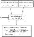
단계 431에서 데이터 변환부(152)는 제1 모드의 표시 모드에 따라 제1 청색 서브 픽셀을 사용하여 화상을 표시하도록 입력 데이터를 서브 픽셀 렌더링하여 출력 데이터를 생성할 수 있다. 데이터 변환부(152)는 제1 모드의 서브 픽셀 렌더링 알고리즘을 선택할 수 있다. 데이터 변환부(152)는 선택된 서브 픽셀 렌더링 알고리즘에 이용되는 서브 픽셀별 렌더링 필터를 선택할 수 있다. 데이터 변환부(152)는 출력 픽셀의 위치 또는 좌표(열, 행)에 대응하는 좌표(기준 좌표)의 적색 입력 데이터와 기준 좌표의 좌측 방향에 인접한 좌표의 적색 입력 데이터에 2×1 렌더링 필터의 계수를 적용하여 적색 서브 픽셀의 출력 데이터를 생성할 수 있다. 데이터 변환부(152)는 출력 픽셀의 위치 또는 좌표(열, 행)에 대응하는 기준 좌표의 청색 입력 데이터와 기준 좌표의 좌측, 상측 및 대각 방향에 인접한 좌표의 청색 입력 데이터에 2×2 렌더링 필터의 계수를 적용하여 청색 서브 픽셀의 출력 데이터를 생성할 수 있다. 데이터 변환부(152)는 출력 픽셀의 위치 또는 좌표(열, 행)에 대응하는 기준 좌표의 녹색 입력 데이터와 동일한 녹색 서브 픽셀의 출력 데이터를 생성할 수 있다.In
도 8a 및 도 8b를 함께 참조하면, 데이터 변환부(152)는 제1 모드의 모드 신호(S1)를 수신하고, 제1 모드에 설정된 적색 서브 픽셀, 녹색 서브 픽셀, 청색 서브 픽셀 각각의 렌더링 필터를 선택하고 서브 픽셀 렌더링을 수행할 수 있다.8A and 8B together, the
데이터 변환부(152)는 2행의 RGB 입력 데이터를 저장하는 2 라인 버퍼(미도시)로부터 서브 픽셀 렌더링에 필요한 RGB 입력 데이터를 추출할 수 있다.The
예를 들어, 하기 식(1)과 같이, 좌표(n, m-1)의 출력 픽셀에 포함된 적색 서브 픽셀의 출력 데이터{R(n, m-1)}는 대응하는 기준 좌표(n, m-1)의 적색 입력 데이터{r(n, m-1)}에 2×1 렌더링 필터의 계수 a=0.5를 적용하고, 좌측 방향에 인접한 좌표(n-1, m-1)의 적색 입력 데이터{r(n-1, m-1)}에 2×1 렌더링 필터의 계수 c=0.5를 적용하여 생성될 수 있다.For example, as shown in Equation (1) below, the output data {R(n, m-1)} of the red sub-pixel included in the output pixel of the coordinates (n, m-1) is the corresponding reference coordinate (n, The coefficient a = 0.5 of the 2×1 rendering filter is applied to the red input data {r(n, m-1)} of m-1), and the red input of the coordinates (n-1, m-1) adjacent to the left direction It may be generated by applying a coefficient c=0.5 of a 2×1 rendering filter to data {r(n-1, m-1)}.

하기 식(2)과 같이, 좌표(n, m)의 픽셀에 포함된 제1 청색 서브 픽셀의 출력 데이터{B1(n, m)}는 대응하는 기준 좌표(n, m)의 청색 입력 데이터{b(n, m)}에 2×2 렌더링 필터의 계수 a=0.25를 적용하고, 좌측 방향에 인접한 좌표(n-1, m)의 청색 입력 데이터{b(n-1, m)}, 상측 방향에 인접한 좌표(n, m-1)의 청색 입력 데이터{b(n, m-1)}, 대각 방향에 인접한 좌표(n-1, m-1)의 청색 입력 데이터{b(n-1, m-1)} 각각에 2×2 렌더링 필터의 계수 c=0.25를 적용하여 생성될 수 있다.As shown in Equation (2), the output data {B1(n, m)} of the first blue sub-pixel included in the pixel of the coordinate (n, m) is the blue input data { of the corresponding reference coordinate (n, m) { Applying the coefficient a = 0.25 of the 2×2 rendering filter to b(n, m)}, the blue input data {b(n-1, m)} of the coordinates (n-1, m) adjacent to the left direction, the upper side Blue input data {b(n, m-1)} of coordinates (n, m-1) adjacent to the direction, blue input data {b(n-1) of coordinates (n-1, m-1) adjacent to the diagonal direction , m-1)} may be generated by applying a coefficient c=0.25 of a 2×2 rendering filter to each.

하기 식(3)과 같이, 좌표(n, m)의 픽셀에 포함된 녹색 서브 픽셀의 출력 데이터{G(n, m)}는 대응하는 기준 좌표(n, m)의 녹색 입력 데이터{g(n, m)}와 동일하게 생성될 수 있다. 즉, 녹색 서브 픽셀의 출력 데이터는 필터 없이 그대로 입력 데이터를 사용할 수 있다.As shown in the following equation (3), the output data {G(n, m)} of the green sub-pixel included in the pixel at the coordinates (n, m) is the green input data {g( n, m)} can be generated in the same way. That is, the output data of the green sub-pixel may use the input data as it is without a filter.
G(n, m)=g(n,m) ...(3)G(n, m)=g(n,m) ...(3)
좌표(n-1, m-1)의 픽셀에 포함된 제2 청색 서브 픽셀의 출력 데이터는 0의 계조 데이터일 수 있다.Output data of the second blue sub-pixel included in the pixel at coordinates (n-1, m-1) may be grayscale data of 0.
단계 432에서 데이터 변환부(152)는 제2 모드의 표시 모드에 따라 제2 청색 서브 픽셀을 사용하여 화상을 표시하도록 입력 데이터를 서브 픽셀 렌더링하여 출력 데이터를 생성한다. 데이터 변환부(152)는 제2 모드의 서브 픽셀 렌더링 알고리즘을 선택함으로써 서브 픽셀 렌더링 알고리즘에 이용되는 서브 픽셀별 렌더링 필터를 선택할 수 있다. 데이터 변환부(152)는 출력 픽셀의 좌표(열, 행)에 대응하는 좌표(기준 좌표)의 적색 입력 데이터와 기준 좌표의 좌측 방향에 인접한 좌표의 적색 입력 데이터에 2×1 렌더링 필터의 계수를 적용하여 적색 서브 픽셀의 출력 데이터를 생성할 수 있다. 데이터 변환부(152)는 출력 픽셀의 좌표(열, 행)에 대응하는 기준 좌표의 청색 입력 데이터와 기준 좌표의 좌측, 상측 및 대각 방향에 인접한 좌표의 청색 입력 데이터에 2×2 렌더링 필터의 계수를 적용하여 청색 서브 픽셀의 출력 데이터를 생성할 수 있다. 데이터 변환부(152)는 출력 픽셀의 좌표(열, 행)에 대응하는 기준 좌표의 녹색 입력 데이터와 동일한 녹색 서브 픽셀의 출력 데이터를 생성할 수 있다.In
도 9a 및 도 9b를 함께 참조하면, 데이터 변환부(152)는 제2 모드의 모드 신호(S2)를 수신하고, 제2 모드에 설정된 적색 서브 픽셀, 녹색 서브 픽셀, 청색 서브 픽셀 각각의 렌더링 필터를 선택하고 서브 픽셀 렌더링을 수행할 수 있다.9A and 9B together, the
데이터 변환부(152)는 2행의 RGB 입력 데이터를 저장하는 2 라인 버퍼(미도시)로부터 서브 픽셀 렌더링에 필요한 RGB 입력 데이터를 추출할 수 있다.The
예를 들어, 하기 식(4)과 같이, 좌표(n, m-1)의 픽셀에 포함된 적색 서브 픽셀의 출력 데이터{R(n, m-1)}는 대응하는 기준 좌표(n, m-1)의 적색 입력 데이터{r(n, m-1)}에 2×1 렌더링 필터의 계수 a=0.5를 적용하고, 좌측 방향에 인접한 좌표(n-1, m-1)의 적색 입력 데이터{r(n-1, m-1)}에 2×1 렌더링 필터의 계수 c=0.5를 적용하여 생성될 수 있다. 마찬가지로, 좌표(n-1, m)의 픽셀에 포함된 적색 서브 픽셀의 출력 데이터{R(n-1, m)}는 기준 좌표(n-1, m)와 좌측 좌표(n-2, m)의 적색 입력 데이터{r(n-1, m), (n-2, m-1)}에 2×1 렌더링 필터의 계수 a=c=0.5를 적용하여 생성될 수 있다.For example, as shown in Equation (4), the output data {R(n, m-1)} of the red sub-pixel included in the pixel of the coordinate (n, m-1) corresponds to the reference coordinate (n, m) The coefficient a = 0.5 of the 2×1 rendering filter is applied to the red input data {r(n, m-1)} of -1), and the red input data of the coordinates (n-1, m-1) adjacent to the left direction It may be generated by applying a coefficient c=0.5 of a 2×1 rendering filter to {r(n-1, m-1)}. Similarly, the output data {R(n-1, m)} of the red sub-pixel included in the pixel at the coordinates (n-1, m) includes the reference coordinates (n-1, m) and the left coordinates (n-2, m). ) of the red input data {r(n-1, m), (n-2, m-1)} may be generated by applying the coefficient a=c=0.5 of the 2×1 rendering filter.

하기 식(5)과 같이, 좌표(n, m)의 픽셀에 포함된 제2 청색 서브 픽셀의 출력 데이터{B2(n, m)}는 대응하는 기준 좌표(n, m)의 청색 입력 데이터{b(n, m)}에 2×2 렌더링 필터의 계수 a=0.25를 적용하고, 좌측 방향에 인접한 좌표(n-1, m)의 청색 입력 데이터{b(n-1, m)}, 상측 방향에 인접한 좌표(n, m-1)의 청색 입력 데이터{b(n, m-1)}, 대각 방향에 인접한 좌표(n-1, m-1)의 청색 입력 데이터{b(n-1, m-1)} 각각에 2×2 렌더링 필터의 계수 c=0.25를 적용하여 생성될 수 있다.As shown in Equation (5), the output data {B2(n, m)} of the second blue sub-pixel included in the pixel of the coordinates (n, m) is the blue input data of the corresponding reference coordinates (n, m) { Applying the coefficient a = 0.25 of the 2×2 rendering filter to b(n, m)}, the blue input data {b(n-1, m)} of the coordinates (n-1, m) adjacent to the left direction, the upper side Blue input data {b(n, m-1)} of coordinates (n, m-1) adjacent to the direction, blue input data {b(n-1) of coordinates (n-1, m-1) adjacent to the diagonal direction , m-1)} may be generated by applying a coefficient c=0.25 of a 2×2 rendering filter to each.

하기 식(6)과 같이, 좌표(n, m)의 픽셀에 포함된 녹색 서브 픽셀의 출력 데이터{G(n, m)}는 대응하는 기준 좌표(n, m)의 녹색 입력 데이터{g(n, m)}와 동일하게 생성될 수 있다. 즉, 녹색 서브 픽셀의 출력 데이터는 필터 없이 그대로 입력 데이터를 사용할 수 있다.As shown in Equation (6), the output data {G(n, m)} of the green sub-pixel included in the pixel at the coordinates (n, m) is the green input data {g( n, m)} can be generated in the same way. That is, the output data of the green sub-pixel may use the input data as it is without a filter.
G(n, m)=g(n,m) ...(6)G(n, m)=g(n,m) ...(6)
좌표(n-1, m-1)의 픽셀에 포함된 제1 청색 서브 픽셀의 출력 데이터는 0의 계조 데이터일 수 있다.Output data of the first blue sub-pixel included in the pixel at coordinates (n-1, m-1) may be grayscale data of 0.
단계 433에서 데이터 변환부(152)는 제3 모드의 표시 모드에 따라 제1 청색 서브 픽셀 및 제2 청색 서브 픽셀을 사용하여 화상을 표시하도록 입력 데이터를 서브 픽셀 렌더링하여 출력 데이터를 생성한다.In
데이터 변환부(152)는 제3 모드의 서브 픽셀 렌더링 알고리즘을 선택함으로써 서브 픽셀 렌더링 알고리즘에 이용되는 서브 픽셀별 렌더링 필터를 선택할 수 있다.The
데이터 변환부(152)는 출력 픽셀의 좌표(열, 행)에 대응하는 좌표(기준 좌표)의 적색 입력 데이터와 기준 좌표의 좌측 방향에 인접한 좌표의 적색 입력 데이터에 2×1 렌더링 필터의 계수를 적용하여 적색 서브 픽셀의 출력 데이터를 생성할 수 있다. 마찬가지로, 데이터 변환부(152)는 출력 픽셀의 좌표(열, 행)에 대응하는 기준 좌표의 청색 입력 데이터와 기준 좌표의 좌측 방향에 인접한 좌표의 청색 입력 데이터에 2×1 렌더링 필터의 계수를 적용하여 청색 서브 픽셀의 출력 데이터를 생성할 수 있다. 데이터 변환부(152)는 출력 픽셀의 좌표(열, 행)에 대응하는 기준 좌표의 녹색 입력 데이터와 동일한 녹색 서브 픽셀의 출력 데이터를 생성할 수 있다.The
도 10a 및 도 10b를 함께 참조하면, 데이터 변환부(152)는 제3 모드의 모드 신호(S3)를 수신하고, 제3 모드에 설정된 적색 서브 픽셀, 녹색 서브 픽셀, 청색 서브 픽셀 각각의 렌더링 필터를 선택하고 서브 픽셀 렌더링을 수행할 수 있다.10A and 10B together, the
일 실시예에서, 데이터 변환부(152)는 1행의 RGB 입력 데이터를 저장하는 1 라인 버퍼(미도시)로부터 서브 픽셀 렌더링에 필요한 RGB 입력 데이터를 추출할 수 있다.In an embodiment, the
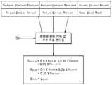
예를 들어, 하기 식(7)과 같이, 좌표(n-1, m)의 픽셀에 포함된 적색 서브 픽셀의 출력 데이터{R(n-1, m)}는 대응하는 기준 좌표(n-1, m)의 적색 입력 데이터{r(n-1, m)}에 2×1 렌더링 필터의 계수 a=0.5를 적용하고, 좌측 방향에 인접한 좌표(n-2, m)의 적색 입력 데이터{r(n-2, m)}에 2×1 렌더링 필터의 계수 c=0.5를 적용하여 생성될 수 있다.For example, as shown in Equation (7), the output data {R(n-1, m)} of the red sub-pixel included in the pixel of the coordinate (n-1, m) is the corresponding reference coordinate (n-1) , m) of the red input data {r(n-1, m)}, the coefficient a=0.5 of the 2×1 rendering filter is applied, and the red input data {r of the coordinates (n-2, m) adjacent to the left direction (n-2, m)} can be generated by applying the coefficient c=0.5 of the 2×1 rendering filter.

하기 식(8)과 같이, 좌표(n, m)의 픽셀에 포함된 청색 서브 픽셀(제1 청색 서브 픽셀 및 제2 청색 서브 픽셀)의 출력 데이터{B(n, m)}는 대응하는 기준 좌표(n, m)의 청색 입력 데이터{b(n, m)}에 2×1 렌더링 필터의 계수 a=0.5를 적용하고, 좌측 방향에 인접한 좌표(n-1, m)의 청색 입력 데이터{b(n-1, m)}에 2×1 렌더링 필터의 계수 c=0.5를 적용하여 생성될 수 있다.As shown in Equation (8), the output data {B(n, m)} of the blue sub-pixels (the first blue sub-pixel and the second blue sub-pixel) included in the pixel of the coordinate (n, m) is the corresponding reference The coefficient a = 0.5 of the 2×1 rendering filter is applied to the blue input data {b(n, m)} of the coordinates (n, m), and the blue input data of the coordinates (n-1, m) adjacent to the left direction { b(n-1, m)} may be generated by applying a coefficient c=0.5 of a 2×1 rendering filter.

하기 식(9)와 같이, 좌표(n, m)의 픽셀에 포함된 녹색 서브 픽셀의 출력 데이터{G(n, m)}는 대응하는 기준 좌표(n, m)의 녹색 입력 데이터{g(n, m)}와 동일하게 생성될 수 있다. 즉, 녹색 서브 픽셀의 출력 데이터는 필터 없이 그대로 입력 데이터를 사용할 수 있다.As shown in Equation (9), the output data {G(n, m)} of the green sub-pixel included in the pixel of the coordinate (n, m) is the green input data {g( n, m)} can be generated in the same way. That is, the output data of the green sub-pixel may use the input data as it is without a filter.
G(n, m)=g(n,m) ...(9)G(n, m)=g(n,m) ...(9)
다른 예로서, 데이터 변환부(152)는 출력 픽셀의 좌표(열, 행)에 대응하는 좌표(기준 좌표)의 적색 입력 데이터와 기준 좌표의 좌측 및 상측 방향에 인접한 좌표의 적색 입력 데이터에 2×2 렌더링 필터의 계수를 적용하여 적색 서브 픽셀의 출력 데이터를 생성할 수 있다. 마찬가지로, 데이터 변환부(152)는 출력 픽셀의 좌표(열, 행)에 대응하는 기준 좌표의 청색 입력 데이터와 기준 좌표의 좌측 및 상측 방향에 인접한 좌표의 청색 입력 데이터에 2×2 렌더링 필터의 계수를 적용하여 청색 서브 픽셀의 출력 데이터를 생성할 수 있다. 데이터 변환부(152)는 출력 픽셀의 좌표(열, 행)에 대응하는 기준 좌표의 녹색 입력 데이터와 동일한 녹색 서브 픽셀의 출력 데이터를 생성할 수 있다.As another example, the
2 라인 버퍼가 필요한 2×2 렌더링 필터를 사용하는 서브 픽셀 렌더링에 비해 2×1 렌더링 필터를 사용하는 경우 1 라인 버퍼만으로 서브 픽셀 렌더링이 가능하여 소비전력, 메모리 및 계산량을 최소화하고, 선예도(sharpness)는 최대화할 수 있다.Compared to sub-pixel rendering that uses a 2×2 rendering filter that requires a 2-line buffer, when a 2×1 rendering filter is used, sub-pixel rendering is possible with only one line buffer, minimizing power consumption, memory, and computation, and improving sharpness. ) can be maximized.
도 11a 및 도 11b를 함께 참조하면, 데이터 변환부(152)는 제3 모드의 모드 신호(S3)를 수신하고, 제3 모드에 설정된 적색 서브 픽셀, 녹색 서브 픽셀, 청색 서브 픽셀 각각의 렌더링 필터를 선택하고 서브 픽셀 렌더링을 수행할 수 있다.11A and 11B together, the
데이터 변환부(152)는 2행의 RGB 입력 데이터를 저장하는 2 라인 버퍼(미도시)로부터 서브 픽셀 렌더링에 필요한 RGB 입력 데이터를 추출할 수 있다.The
예를 들어, 하기 식(10)과 같이, 좌표(n-1, m)의 픽셀에 포함된 적색 서브 픽셀의 출력 데이터{R(n-1, m)}는 대응하는 기준 좌표(n-1, m)의 적색 입력 데이터{r(n-1, m)}에 2×2 렌더링 필터의 계수 a=0.5를 적용하고, 좌측 방향에 인접한 좌표(n-2, m)의 적색 입력 데이터{r(n-2, m)}, 상측 방향에 인접한 좌표(n-1, m-1)의 적색 입력 데이터{r(n-1, m-1)} 각각에 2×2 렌더링 필터의 계수 c=0.25를 적용하여 생성될 수 있다.For example, as shown in Equation (10), the output data {R(n-1, m)} of the red sub-pixel included in the pixel of the coordinate (n-1, m) corresponds to the reference coordinate (n-1) , m) of the red input data {r(n-1, m)}, the coefficient a=0.5 of the 2×2 rendering filter is applied, and the red input data {r of the coordinates (n-2, m) adjacent to the left direction {r (n-2, m)}, the coefficient c of the 2×2 rendering filter for each of the red input data {r(n-1, m-1)} of the coordinates (n-1, m-1) adjacent to the upper direction c= Can be created by applying 0.25.

하기 식(11)과 같이, 좌표(n, m)의 픽셀에 포함된 청색 서브 픽셀(제1 청색 서브 픽셀 또는 제2 청색 서브 픽셀)의 출력 데이터{B(n, m)}는 대응하는 기준 좌표(n, m)의 청색 입력 데이터{b(n, m)}에 2×2 렌더링 필터의 계수 a=0.5를 적용하고, 좌측 방향에 인접한 좌표(n-1, m)의 청색 입력 데이터{b(n-1, m)}, 상측 방향에 인접한 좌표(n, m-1)의 청색 입력 데이터{b(n, m-1)}에 2×2 렌더링 필터의 계수 c=0.25를 적용하여 생성될 수 있다.As shown in the following equation (11), the output data {B(n, m)} of the blue sub-pixel (the first blue sub-pixel or the second blue sub-pixel) included in the pixel of the coordinate (n, m) is the corresponding reference The coefficient a = 0.5 of the 2×2 rendering filter is applied to the blue input data {b(n, m)} of the coordinates (n, m), and the blue input data of the coordinates (n-1, m) adjacent to the left direction { b(n-1, m)}, applying the coefficient c=0.25 of the 2×2 rendering filter to the blue input data {b(n, m-1)} of the coordinates (n, m-1) adjacent to the upper direction can be created

하기 식(12)와 같이, 좌표(n, m)의 픽셀에 포함된 녹색 서브 픽셀의 출력 데이터{G(n, m)}는 대응하는 기준 좌표(n, m)의 녹색 입력 데이터{g(n, m)}와 동일하게 생성될 수 있다. 즉, 녹색 서브 픽셀의 출력 데이터는 필터 없이 그대로 입력 데이터를 사용할 수 있다.As shown in Equation (12), the output data {G(n, m)} of the green sub-pixel included in the pixel of the coordinate (n, m) is the green input data {g( n, m)} can be generated in the same way. That is, the output data of the green sub-pixel may use the input data as it is without a filter.
G(n, m)=g(n,m) ...(12)G(n, m)=g(n,m) ...(12)
도 8 내지 도 11에 기재된 식에서는 편의상 감마 함수 및 역감마 함수 적용 및 휘도 데이터 변환을 생략하고 최종 계조 데이터로 서브 픽셀 렌더링된 출력 데이터를 표시하였다. 도 8 내지 도 11에서는 256 계조를 예로서 설명하였으나, 본 발명의 실시예는 이에 한정되지 않고, 표시 장치에 따라 다른 계조로 표현될 수 있다. 또한 도 8 내지 도 11에서는 각각 특정 좌표의 출력 픽셀에 포함된 서브 픽셀의 출력 데이터 렌더링을 예시적으로 설명하고 있으나, 이는 다른 좌표의 출력 픽셀에 포함된 서브 픽셀의 출력 데이터 렌더링에 동일하게 적용될 수 있다.8 to 11, for convenience, application of a gamma function and an inverse gamma function and conversion of luminance data are omitted, and sub-pixel-rendered output data is displayed as final grayscale data. 8 to 11 , 256 grayscales have been described as an example, but embodiments of the present invention are not limited thereto, and different grayscales may be expressed according to display devices. In addition, although the output data rendering of the sub-pixel included in the output pixel of a specific coordinate is exemplarily described in FIGS. 8 to 11 , this may be equally applied to the rendering of the output data of the sub-pixel included in the output pixel of the other coordinates. have.
한편, 도 11a 및 도 11b에 도시된 2×2 렌더링 필터를 이용한 적색 서브 픽셀의 서브 픽셀 렌더링은 표시 모드가 제1 모드 및 제2 모드인 경우 적색 서브 픽셀의 서브 픽셀 렌더링에 적용될 수 있다.Meanwhile, the sub-pixel rendering of the red sub-pixel using the 2×2 rendering filter shown in FIGS. 11A and 11B may be applied to the sub-pixel rendering of the red sub-pixel when the display modes are the first mode and the second mode.
전술된 실시예들은 기준 입력 데이터의 좌측 입력 데이터를 이용하여 서브 픽셀 렌더링을 수행하고 있으나, 본 발명의 실시예들은 이에 한정되지 않고, 기준 입력 데이터의 우측 입력 데이터를 이용하여 서브 픽셀 렌더링을 수행할 수 있다. 즉, 데이터 변환부(152)는 제1 모드 또는 제2 모드에서, 기준 청색 입력 데이터와 우측, 상측 및 대각의 청색 입력 데이터를 이용하여 제1 청색 서브 픽셀 또는 제2 청색 서브 픽셀을 렌더링하고, 기준 적색 입력 데이터와 우측 또는 우측 및 상측의 적색 입력 데이터를 이용하여 적색 서브 픽셀을 렌더링할 수 있다. 데이터 변환부(152)는 제3 모드에서, 기준 청색 입력 데이터와 우측 또는 우측 및 상측의 청색 입력 데이터를 이용하여 제1 청색 서브 픽셀 및 제2 청색 서브 픽셀을 렌더링하고, 기준 적색 입력 데이터와 우측 또는 우측 및 상측의 적색 입력 데이터를 이용하여 적색 서브 픽셀을 렌더링할 수 있다.Although the above-described embodiments perform sub-pixel rendering using left input data of reference input data, embodiments of the present invention are not limited thereto, and sub-pixel rendering is performed using right input data of reference input data. can That is, the
본 발명의 실시예들은 인간의 청색 파장 대역에 대한 인지 특성을 고려한 픽셀 구조 및 표시 모드를 구현한다. 서로 다른 중심 파장을 갖는 두 개의 청색 서브 픽셀을 이용하여 표시 모드별로 이용하는 청색 서브 픽셀을 달리한다. 이에 따른 해상도 감소로 인한 화면의 yellowish 현상을 억제하기 위해 서브 픽셀 렌더링 알고리즘을 표시 모드별 및 서브 픽셀별로 달리한다.Embodiments of the present invention implement a pixel structure and display mode in consideration of human perception characteristics of a blue wavelength band. The blue sub-pixels used for each display mode are different using two blue sub-pixels having different center wavelengths. In order to suppress the yellowish phenomenon of the screen due to the reduction in resolution, the sub-pixel rendering algorithm is different for each display mode and for each sub-pixel.
본 발명의 실시예들은 2행의 입력 데이터 또는 1행의 입력 데이터를 이용하여 서브 픽셀 렌더링을 수행함으로써 2 라인 버퍼 또는 1 라인 버퍼에 의한 서브 픽셀 렌더링이 가능하다. 이에 따라 본 발명의 실시예에 따른 표시 장치는 3 라인 버퍼에 의한 서브 픽셀 렌더링에 비해 소비전력, 메모리, 계산량을 줄이면서 선예도가 향상된 화상을 제공할 수 있다.In the embodiments of the present invention, sub-pixel rendering is possible by using a 2-line buffer or a 1-line buffer by performing sub-pixel rendering using two rows of input data or one row of input data. Accordingly, the display device according to the embodiment of the present invention can provide an image with improved sharpness while reducing power consumption, memory, and calculation amount compared to sub-pixel rendering using a 3-line buffer.
이와 같이 본 발명은 도면에 도시된 일 실시예를 참고로 하여 설명하였으나 이는 예시적인 것에 불과하며 당해 분야에서 통상의 지식을 가진 자라면 이로부터 다양한 변형 및 실시예의 변형이 가능하다는 점을 이해할 것이다. 따라서, 본 발명의 진정한 기술적 보호 범위는 첨부된 특허청구범위의 기술적 사상에 의하여 정해져야 할 것이다.As such, the present invention has been described with reference to one embodiment shown in the drawings, but this is merely exemplary, and those skilled in the art will understand that various modifications and variations of the embodiments are possible therefrom. Accordingly, the true technical protection scope of the present invention should be defined by the technical spirit of the appended claims.
Claims (20)
Translated fromKorean상기 표시 장치는 적색 서브 픽셀, 녹색 서브 픽셀, 제1 청색 서브 픽셀 및 상기 제1 청색 서브 픽셀과 상이한 중심 파장을 갖는 광을 방출하는 제2 청색 서브 픽셀을 포함하고,
상기 표시 제어 방법은,
청색 광 방출을 위해 상기 제1 청색 서브 픽셀을 사용하는 제1 모드, 상기 제2 청색 서브 픽셀을 사용하는 제2 모드 및 상기 제1 청색 서브 픽셀과 상기 제2 청색 서브 픽셀을 모두 사용하는 제3 모드 중 어느 하나로 상기 표시 장치의 표시 모드를 설정하는 단계; 및
적색, 녹색 및 청색 각각의 입력 데이터를 상기 적색 서브 픽셀, 상기 녹색 서브 픽셀, 상기 제1 청색 서브 픽셀 및 상기 제2 청색 서브 픽셀의 배열에 따라 서브 픽셀 렌더링하여 출력 데이터로 변환하는 단계;를 포함하고,
상기 변환 단계는,
상기 표시 모드에 따라, 상기 적색, 녹색 및 청색 각각의 입력 데이터에 대한 렌더링 필터의 크기 및 계수를 변경하여 서브 픽셀 렌더링을 수행하는 단계;를 포함하고,
상기 제1 모드와 상기 제2 모드에서, 상기 적색 입력 데이터에 대한 렌더링 필터의 크기 및 계수와 상기 청색 입력 데이터에 대한 렌더링 필터의 크기 및 계수가 상이한, 표시 제어 방법.A display control method for controlling display of a display device, comprising:
the display device includes a red sub-pixel, a green sub-pixel, a first blue sub-pixel and a second blue sub-pixel emitting light having a different center wavelength than the first blue sub-pixel;
The display control method comprises:
A first mode using the first blue sub-pixel for emitting blue light, a second mode using the second blue sub-pixel, and a third mode using both the first blue sub-pixel and the second blue sub-pixel setting a display mode of the display device to any one of the modes; and
converting red, green, and blue input data into output data by sub-pixel rendering according to the arrangement of the red sub-pixel, the green sub-pixel, the first blue sub-pixel, and the second blue sub-pixel; do,
The conversion step is
performing sub-pixel rendering by changing the size and coefficient of a rendering filter for each of the red, green, and blue input data according to the display mode;
In the first mode and the second mode, a size and coefficient of a rendering filter for the red input data and a size and coefficient of a rendering filter for the blue input data are different from each other.
상기 표시 모드가 제1 모드인 경우,
상기 적색 입력 데이터를 상기 적색 서브 픽셀의 출력 데이터로 변환하기 위한 제1 렌더링 필터는 2×1 필터이고, 상기 2×1 필터의 계수는 0.5이고,
상기 청색 입력 데이터를 상기 제1 청색 서브 픽셀의 출력 데이터로 변환하기 위한 제2 렌더링 필터는 2×2 필터이고, 상기 2×2 필터의 계수는 0.25인, 표시 제어 방법.According to claim 1,
When the display mode is the first mode,
A first rendering filter for converting the red input data into the output data of the red sub-pixel is a 2×1 filter, and a coefficient of the 2×1 filter is 0.5;
A second rendering filter for converting the blue input data into the output data of the first blue sub-pixel is a 2×2 filter, and a coefficient of the 2×2 filter is 0.25.
상기 표시 모드가 제2 모드인 경우,
상기 적색 입력 데이터를 상기 적색 서브 픽셀의 출력 데이터로 변환하기 위한 제1 렌더링 필터는 2×1 필터이고, 상기 2×1 필터의 계수는 0.5이고,
상기 청색 입력 데이터를 상기 제2 청색 서브 픽셀의 출력 데이터로 변환하기 위한 제3 렌더링 필터는 2×2 필터이고, 상기 2×2 필터의 계수는 0.25인, 표시 제어 방법.According to claim 1,
When the display mode is the second mode,
A first rendering filter for converting the red input data into the output data of the red sub-pixel is a 2×1 filter, and a coefficient of the 2×1 filter is 0.5;
A third rendering filter for converting the blue input data into the output data of the second blue sub-pixel is a 2×2 filter, and a coefficient of the 2×2 filter is 0.25.
상기 표시 모드가 제3 모드인 경우, 상기 적색 입력 데이터를 상기 적색 서브 픽셀의 출력 데이터로 변환하기 위한 제1 렌더링 필터의 크기 및 계수와, 상기 청색 입력 데이터를 상기 제1 청색 서브 픽셀 및 상기 제2 청색 서브 픽셀의 출력 데이터로 변환하기 위한 제4 렌더링 필터의 크기 및 계수가 동일한, 표시 제어 방법.According to claim 1,
When the display mode is the third mode, the size and coefficient of a first rendering filter for converting the red input data into the output data of the red sub-pixel, and the blue input data to the first blue sub-pixel and the second 2 A display control method, wherein the size and coefficient of the fourth rendering filter for converting the blue sub-pixel output data are the same.
상기 제1 렌더링 필터 및 상기 제4 렌더링 필터는 2×1 필터이고, 상기 2×1 필터의 계수는 0.5인, 표시 제어 방법.7. The method of claim 6,
The first rendering filter and the fourth rendering filter are a 2×1 filter, and a coefficient of the 2×1 filter is 0.5.
상기 제1 청색 서브 픽셀에서 방출되는 광의 중심 파장은, 상기 제2 청색 서브 픽셀에서 방출되는 광의 중심 파장보다 낮은, 표시 제어 방법.According to claim 1,
A center wavelength of light emitted from the first blue sub-pixel is lower than a center wavelength of light emitted from the second blue sub-pixel.
상기 표시 모드 설정 단계는,
현재 상태를 낮 또는 밤으로 결정하고, 상기 현재 상태가 낮이면 상기 표시 모드를 제2 모드 또는 제3 모드로 설정하고, 상기 현재 상태가 밤이면 상기 표시 모드를 제1 모드로 설정하는, 표시 제어 방법.According to claim 1,
The display mode setting step includes:
display control, wherein the current state is determined as day or night, when the current state is daytime, the display mode is set to a second mode or a third mode, and when the current state is night, the display mode is set to the first mode. Way.
상기 표시 모드 설정 단계는,
현재 시간, 기설정된 표시 모드 전환 주기, 또는 외부 조도 중 적어도 하나에 기초하여 현재 상태를 낮 또는 밤으로 인식하고, 상기 인식된 현재 상태에 기초하여 상기 표시 모드를 설정하는, 표시 제어 방법.According to claim 1,
The display mode setting step includes:
A display control method, comprising: recognizing a current state as day or night based on at least one of a current time, a preset display mode switching period, or external illuminance, and setting the display mode based on the recognized current state.
상기 표시 장치는 적색 서브 픽셀, 녹색 서브 픽셀, 제1 청색 서브 픽셀 및 상기 제1 청색 서브 픽셀과 상이한 중심 파장을 갖는 광을 방출하는 제2 청색 서브 픽셀을 포함하고,
상기 표시 제어 장치는,
청색 광 방출을 위해 상기 제1 청색 서브 픽셀을 사용하는 제1 모드, 상기 제2 청색 서브 픽셀을 사용하는 제2 모드 및 상기 제1 청색 서브 픽셀과 상기 제2 청색 서브 픽셀을 모두 사용하는 제3 모드 중 어느 하나로 상기 표시 장치의 표시 모드를 설정하는 표시모드 제어부; 및
적색, 녹색 및 청색 각각의 입력 데이터를 상기 적색 서브 픽셀, 상기 녹색 서브 픽셀, 상기 제1 청색 서브 픽셀 및 상기 제2 청색 서브 픽셀의 배열에 따라 서브 픽셀 렌더링하여 출력 데이터로 변환하는 데이터 변환부;를 포함하고,
상기 데이터 변환부는,
상기 표시 모드에 따라, 상기 적색, 녹색 및 청색 각각의 입력 데이터에 대한 렌더링 필터의 크기 및 계수를 변경하여 서브 픽셀 렌더링을 수행하고,
상기 제1 모드와 상기 제2 모드에서, 상기 적색 입력 데이터에 대한 렌더링 필터의 크기 및 계수와 상기 청색 입력 데이터에 대한 렌더링 필터의 크기 및 계수가 상이한, 표시 제어 장치.A display control device for controlling display of a display device, the display control device comprising:
the display device includes a red sub-pixel, a green sub-pixel, a first blue sub-pixel and a second blue sub-pixel emitting light having a different center wavelength than the first blue sub-pixel;
The display control device,
A first mode using the first blue sub-pixel for emitting blue light, a second mode using the second blue sub-pixel, and a third mode using both the first blue sub-pixel and the second blue sub-pixel a display mode controller configured to set a display mode of the display device to any one of modes; and
a data conversion unit converting red, green, and blue input data into output data by sub-pixel rendering according to the arrangement of the red sub-pixel, the green sub-pixel, the first blue sub-pixel, and the second blue sub-pixel; including,
The data conversion unit,
performing sub-pixel rendering by changing the size and coefficient of a rendering filter for each of the red, green, and blue input data according to the display mode;
and a size and coefficient of a rendering filter for the red input data and a size and coefficient of a rendering filter for the blue input data are different in the first mode and the second mode.
상기 표시 모드가 제1 모드인 경우,
상기 적색 입력 데이터를 상기 적색 서브 픽셀의 출력 데이터로 변환하기 위한 제1 렌더링 필터는 2×1 필터이고, 상기 2×1 필터의 계수는 0.5이고,
상기 청색 입력 데이터를 상기 제1 청색 서브 픽셀의 출력 데이터로 변환하기 위한 제2 렌더링 필터는 2×2 필터이고, 상기 2×2 필터의 계수는 0.25인, 표시 제어 장치.12. The method of claim 11,
When the display mode is the first mode,
A first rendering filter for converting the red input data into the output data of the red sub-pixel is a 2×1 filter, and a coefficient of the 2×1 filter is 0.5;
A second rendering filter for converting the blue input data into the output data of the first blue sub-pixel is a 2×2 filter, and a coefficient of the 2×2 filter is 0.25.
상기 표시 모드가 제2 모드인 경우,
상기 적색 입력 데이터를 상기 적색 서브 픽셀의 출력 데이터로 변환하기 위한 제1 렌더링 필터는 2×1 필터이고, 상기 2×1 필터의 계수는 0.5이고,
상기 청색 입력 데이터를 상기 제2 청색 서브 픽셀의 출력 데이터로 변환하기 위한 제3 렌더링 필터는 2×2 필터이고, 상기 2×2 필터의 계수는 0.25인, 표시 제어 장치.12. The method of claim 11,
When the display mode is the second mode,
A first rendering filter for converting the red input data into the output data of the red sub-pixel is a 2×1 filter, and a coefficient of the 2×1 filter is 0.5;
and a third rendering filter for converting the blue input data into the output data of the second blue sub-pixel is a 2×2 filter, and a coefficient of the 2×2 filter is 0.25.
상기 표시 모드가 제3 모드인 경우, 상기 적색 입력 데이터를 상기 적색 서브 픽셀의 출력 데이터로 변환하기 위한 제1 렌더링 필터의 크기 및 계수와, 상기 청색 입력 데이터를 상기 제1 청색 서브 픽셀 및 상기 제2 청색 서브 픽셀의 출력 데이터로 변환하기 위한 제4 렌더링 필터의 크기 및 계수가 동일한, 표시 제어 장치.12. The method of claim 11,
When the display mode is the third mode, the size and coefficient of a first rendering filter for converting the red input data into the output data of the red sub-pixel, and the blue input data to the first blue sub-pixel and the second 2 The display control device, wherein the size and coefficient of the fourth rendering filter for converting to the output data of the blue sub-pixel are the same.
상기 제1 렌더링 필터 및 상기 제4 렌더링 필터는 2×1 필터이고, 상기 2×1 필터의 계수는 0.5인, 표시 제어 장치.17. The method of claim 16,
and the first rendering filter and the fourth rendering filter are a 2×1 filter, and a coefficient of the 2×1 filter is 0.5.
상기 제1 청색 서브 픽셀에서 방출되는 광의 중심 파장은, 상기 제2 청색 서브 픽셀에서 방출되는 광의 중심 파장보다 낮은, 표시 제어 장치.12. The method of claim 11,
and a center wavelength of light emitted from the first blue sub-pixel is lower than a center wavelength of light emitted from the second blue sub-pixel.
상기 표시 모드 제어부는,
현재 상태를 낮 또는 밤으로 결정하고, 상기 현재 상태가 낮이면 상기 표시 모드를 제2 모드 또는 제3 모드로 설정하고, 상기 현재 상태가 밤이면 상기 표시 모드를 제1 모드로 설정하는, 표시 제어 장치.12. The method of claim 11,
The display mode control unit,
Display control, wherein the current state is determined as day or night, and when the current state is daytime, the display mode is set to a second mode or a third mode, and when the current state is night, the display mode is set to the first mode. Device.
상기 표시 모드 제어부는,
현재 시간, 기설정된 표시 모드 전환 주기, 또는 외부 조도 중 적어도 하나에 기초하여 현재 상태를 낮 또는 밤으로 인식하고, 상기 인식된 현재 상태에 기초하여 상기 표시 모드를 설정하는, 표시 제어 장치.12. The method of claim 11,
The display mode control unit,
A display control apparatus configured to recognize a current state as day or night based on at least one of a current time, a preset display mode switching period, or external illuminance, and set the display mode based on the recognized current state.
Priority Applications (2)
| Application Number | Priority Date | Filing Date | Title |
|---|---|---|---|
| KR1020160001125AKR102447506B1 (en) | 2016-01-05 | 2016-01-05 | Display control method and device of display device |
| US15/353,765US10373541B2 (en) | 2016-01-05 | 2016-11-17 | Method and device for controlling display of display device |
Applications Claiming Priority (1)
| Application Number | Priority Date | Filing Date | Title |
|---|---|---|---|
| KR1020160001125AKR102447506B1 (en) | 2016-01-05 | 2016-01-05 | Display control method and device of display device |
Publications (2)
| Publication Number | Publication Date |
|---|---|
| KR20170082195A KR20170082195A (en) | 2017-07-14 |
| KR102447506B1true KR102447506B1 (en) | 2022-09-27 |
Family
ID=59227324
Family Applications (1)
| Application Number | Title | Priority Date | Filing Date |
|---|---|---|---|
| KR1020160001125AActiveKR102447506B1 (en) | 2016-01-05 | 2016-01-05 | Display control method and device of display device |
Country Status (2)
| Country | Link |
|---|---|
| US (1) | US10373541B2 (en) |
| KR (1) | KR102447506B1 (en) |
Families Citing this family (24)
| Publication number | Priority date | Publication date | Assignee | Title |
|---|---|---|---|---|
| JP6516236B2 (en)* | 2015-02-20 | 2019-05-22 | Tianma Japan株式会社 | Electro-optical device |
| KR102399571B1 (en)* | 2015-09-09 | 2022-05-19 | 삼성디스플레이 주식회사 | Display apparatus and method of driving the same |
| US11448807B2 (en) | 2016-02-18 | 2022-09-20 | Chengdu Boe Optoelectronics Technology Co., Ltd. | Display substrate, fine metal mask set and manufacturing method thereof |
| US11747531B2 (en) | 2016-02-18 | 2023-09-05 | Chengdu Boe Optoelectronics Technology Co., Ltd. | Display substrate, fine metal mask set and manufacturing method thereof |
| CN110133899A (en) | 2018-02-09 | 2019-08-16 | 京东方科技集团股份有限公司 | Pixel arrangement structure, display substrate and display device |
| CN110134353B (en) | 2018-02-09 | 2021-04-27 | 京东方科技集团股份有限公司 | Color compensation method, compensation device, and display device |
| US11233096B2 (en) | 2016-02-18 | 2022-01-25 | Boe Technology Group Co., Ltd. | Pixel arrangement structure and driving method thereof, display substrate and display device |
| CN110137215B (en) | 2018-02-09 | 2025-01-14 | 京东方科技集团股份有限公司 | Pixel arrangement structure, display substrate and display device |
| US10854684B2 (en) | 2016-02-18 | 2020-12-01 | Boe Technology Group Co., Ltd. | Pixel arrangement structure and driving method thereof, display substrate and display device |
| CN111326121B (en)* | 2018-12-13 | 2021-11-16 | 京东方科技集团股份有限公司 | Driving method, driving chip, display device and storage medium |
| WO2021016946A1 (en) | 2019-07-31 | 2021-02-04 | 京东方科技集团股份有限公司 | Display substrate and preparation method therefor, display panel, and display apparatus |
| CN110137213B (en) | 2018-02-09 | 2025-03-25 | 京东方科技集团股份有限公司 | Pixel arrangement structure and display method thereof, and display substrate |
| US11264430B2 (en) | 2016-02-18 | 2022-03-01 | Chengdu Boe Optoelectronics Technology Co., Ltd. | Pixel arrangement structure with misaligned repeating units, display substrate, display apparatus and method of fabrication thereof |
| WO2019140309A1 (en) | 2018-01-11 | 2019-07-18 | Ecosense Lighting Inc. | Switchable systems for white light with high color rendering and biological effects |
| WO2019140327A2 (en) | 2018-01-11 | 2019-07-18 | Ecosense Lighting Inc. | Display lighting systems with circadian effects |
| CN114355678B (en) | 2018-02-09 | 2023-11-03 | 京东方科技集团股份有限公司 | Display substrate and display device |
| US11574960B2 (en) | 2018-02-09 | 2023-02-07 | Boe Technology Group Co., Ltd. | Pixel arrangement structure, display substrate, display device and mask plate group |
| KR102578096B1 (en)* | 2018-09-21 | 2023-09-14 | 삼성전자주식회사 | Electronic device for improving visual recognition of partial area of display |
| US20220001200A1 (en) | 2018-11-08 | 2022-01-06 | Ecosense Lighting Inc. | Switchable bioactive lighting |
| KR102656408B1 (en)* | 2019-05-13 | 2024-04-15 | 삼성디스플레이 주식회사 | Display device and method of driving the same |
| CN112673476A (en) | 2019-07-31 | 2021-04-16 | 京东方科技集团股份有限公司 | Display substrate and display device |
| KR102651803B1 (en)* | 2019-10-14 | 2024-03-28 | 엘지디스플레이 주식회사 | Biorhythm-based tunable image display device |
| CN113450713B (en)* | 2020-03-25 | 2022-08-12 | 北京小米移动软件有限公司 | Screen display method and device, grayscale mapping information generation method and device |
| KR20230061647A (en) | 2021-10-28 | 2023-05-09 | 삼성디스플레이 주식회사 | Display device, and method of operating a display device |
Family Cites Families (16)
| Publication number | Priority date | Publication date | Assignee | Title |
|---|---|---|---|---|
| EP2280398A3 (en)* | 1998-02-23 | 2011-03-09 | Kabushiki Kaisha Toshiba | Information storage medium, information playback method and apparatus and information recording method |
| US7417648B2 (en) | 2002-01-07 | 2008-08-26 | Samsung Electronics Co. Ltd., | Color flat panel display sub-pixel arrangements and layouts for sub-pixel rendering with split blue sub-pixels |
| US7525526B2 (en)* | 2003-10-28 | 2009-04-28 | Samsung Electronics Co., Ltd. | System and method for performing image reconstruction and subpixel rendering to effect scaling for multi-mode display |
| US20090281604A1 (en)* | 2006-04-11 | 2009-11-12 | Koninklijke Philips Electronics N.V. | Controlling a photo-biological effect with light |
| WO2008144180A1 (en)* | 2007-05-18 | 2008-11-27 | Samsung Electronics Co., Ltd. | Image color balance adjustment for display panels with 2d subpixel layouts |
| US8314907B2 (en)* | 2009-07-28 | 2012-11-20 | Pixel Qi Corporation | Transflective display sub-pixel structures with transmissive area having different sizes and reflective area having equal sizes |
| KR101146992B1 (en) | 2010-05-07 | 2012-05-23 | 삼성모바일디스플레이주식회사 | Flat pane display device and driving method thereof |
| CN101984487B (en) | 2010-11-02 | 2013-05-22 | 友达光电股份有限公司 | Driving method of active matrix organic light emitting diode display panel |
| KR101440773B1 (en)* | 2010-12-13 | 2014-09-18 | 엘지디스플레이 주식회사 | Apparatus and method for driving of organic light emitting display device |
| KR102061283B1 (en) | 2012-09-13 | 2020-01-02 | 삼성디스플레이 주식회사 | Pixel arrangement structure for organic light emitting diode display |
| KR101971924B1 (en) | 2012-10-05 | 2019-04-25 | 삼성디스플레이 주식회사 | Display Device and Method of Driving thereof |
| KR102023184B1 (en) | 2013-02-20 | 2019-09-20 | 삼성디스플레이 주식회사 | Display device, data processing apparatus and method thereof |
| KR102085284B1 (en)* | 2013-07-05 | 2020-03-06 | 삼성디스플레이 주식회사 | Display Device and Display Device Driving Method |
| KR102253039B1 (en) | 2013-11-04 | 2021-05-20 | 삼성디스플레이 주식회사 | Apparatus and method for encoding a image data |
| KR102296918B1 (en) | 2014-11-03 | 2021-09-02 | 삼성디스플레이 주식회사 | Display apparatus, method and apparatus for controlling thereof |
| KR102239160B1 (en) | 2014-11-10 | 2021-04-13 | 삼성디스플레이 주식회사 | Display device and a driving method thereof |
- 2016
- 2016-01-05KRKR1020160001125Apatent/KR102447506B1/enactiveActive
- 2016-11-17USUS15/353,765patent/US10373541B2/enactiveActive
Also Published As
| Publication number | Publication date |
|---|---|
| US20170193880A1 (en) | 2017-07-06 |
| KR20170082195A (en) | 2017-07-14 |
| US10373541B2 (en) | 2019-08-06 |
Similar Documents
| Publication | Publication Date | Title |
|---|---|---|
| KR102447506B1 (en) | Display control method and device of display device | |
| KR102296918B1 (en) | Display apparatus, method and apparatus for controlling thereof | |
| KR102399571B1 (en) | Display apparatus and method of driving the same | |
| JP6881888B2 (en) | Display device and display panel drive method using this | |
| KR101971924B1 (en) | Display Device and Method of Driving thereof | |
| US8203572B2 (en) | Organic light emitting display device and processing method of image signals thereof | |
| US10366673B2 (en) | Display device and image processing method thereof | |
| US10937353B2 (en) | Display apparatus and method of driving display panel using the same | |
| CN104347025B (en) | Apparatus for converting data and display apparatus using the same | |
| EP2178072A2 (en) | Four color display device and method of converting image signal thereof | |
| KR102287803B1 (en) | Display apparatus | |
| KR20060109451A (en) | Smart Clipper for Mobile Display | |
| EP2339568B1 (en) | Data display method and device | |
| KR20160055490A (en) | Display device and a driving method thereof | |
| CN110473486A (en) | The method and electronic device of display device are controlled based on color-aware brightness | |
| JP6727047B2 (en) | Display device | |
| CN114420039A (en) | IR drop compensation for display panels including regions of different pixel layouts | |
| US10373584B2 (en) | Device and method for display color adjustment | |
| KR102575261B1 (en) | Display Driving Device and Driving Method for Adjusting Brightness of Image based on Ambient Illumination | |
| KR20220030509A (en) | Display device and the method for luminance compensation of display device | |
| KR102410029B1 (en) | Timing controller and display apparatus having them | |
| TWI625719B (en) | Signal generating device, computer-readable medium, signal generating method, and image display device | |
| CN111292688B (en) | Screen brightness adjustment method and device, and display device | |
| US20170098426A1 (en) | Method of driving a display apparatus | |
| US11645982B2 (en) | Display device and method for processing compensation data thereof |
Legal Events
| Date | Code | Title | Description |
|---|---|---|---|
| PA0109 | Patent application | Patent event code:PA01091R01D Comment text:Patent Application Patent event date:20160105 | |
| PG1501 | Laying open of application | ||
| A201 | Request for examination | ||
| PA0201 | Request for examination | Patent event code:PA02012R01D Patent event date:20201221 Comment text:Request for Examination of Application Patent event code:PA02011R01I Patent event date:20160105 Comment text:Patent Application | |
| E902 | Notification of reason for refusal | ||
| PE0902 | Notice of grounds for rejection | Comment text:Notification of reason for refusal Patent event date:20220211 Patent event code:PE09021S01D | |
| E701 | Decision to grant or registration of patent right | ||
| PE0701 | Decision of registration | Patent event code:PE07011S01D Comment text:Decision to Grant Registration Patent event date:20220621 | |
| GRNT | Written decision to grant | ||
| PR0701 | Registration of establishment | Comment text:Registration of Establishment Patent event date:20220921 Patent event code:PR07011E01D | |
| PR1002 | Payment of registration fee | Payment date:20220922 End annual number:3 Start annual number:1 | |
| PG1601 | Publication of registration |