KR102446995B1 - Implantable micro-biosensor - Google Patents
Implantable micro-biosensorDownload PDFInfo
- Publication number
- KR102446995B1 KR102446995B1KR1020200097055AKR20200097055AKR102446995B1KR 102446995 B1KR102446995 B1KR 102446995B1KR 1020200097055 AKR1020200097055 AKR 1020200097055AKR 20200097055 AKR20200097055 AKR 20200097055AKR 102446995 B1KR102446995 B1KR 102446995B1
- Authority
- KR
- South Korea
- Prior art keywords
- working electrode
- sensing section
- section
- sensing
- electrode
- Prior art date
- Legal status (The legal status is an assumption and is not a legal conclusion. Google has not performed a legal analysis and makes no representation as to the accuracy of the status listed.)
- Active
Links
- 229910052709silverInorganic materials0.000claimsabstractdescription110
- 239000004332silverSubstances0.000claimsabstractdescription110
- 238000005259measurementMethods0.000claimsabstractdescription65
- -1silver halideChemical class0.000claimsabstractdescription64
- 239000012491analyteSubstances0.000claimsabstractdescription45
- 239000003153chemical reaction reagentSubstances0.000claimsabstractdescription35
- 230000009471actionEffects0.000claimsabstractdescription20
- 230000001172regenerating effectEffects0.000claimsabstractdescription12
- 239000004020conductorSubstances0.000claimsdescription110
- 239000000463materialSubstances0.000claimsdescription66
- 239000000758substrateSubstances0.000claimsdescription53
- BQCADISMDOOEFD-UHFFFAOYSA-NSilverChemical compound[Ag]BQCADISMDOOEFD-UHFFFAOYSA-N0.000claimsdescription50
- 238000000034methodMethods0.000claimsdescription48
- 238000001514detection methodMethods0.000claimsdescription43
- OKTJSMMVPCPJKN-UHFFFAOYSA-NCarbonChemical compound[C]OKTJSMMVPCPJKN-UHFFFAOYSA-N0.000claimsdescription32
- 229910052799carbonInorganic materials0.000claimsdescription32
- BASFCYQUMIYNBI-UHFFFAOYSA-NplatinumChemical compound[Pt]BASFCYQUMIYNBI-UHFFFAOYSA-N0.000claimsdescription16
- 230000035945sensitivityEffects0.000claimsdescription16
- 238000012544monitoring processMethods0.000claimsdescription13
- 229910000510noble metalInorganic materials0.000claimsdescription9
- 230000004044responseEffects0.000claimsdescription9
- KDLHZDBZIXYQEI-UHFFFAOYSA-NPalladiumChemical compound[Pd]KDLHZDBZIXYQEI-UHFFFAOYSA-N0.000claimsdescription8
- 229910052697platinumInorganic materials0.000claimsdescription8
- PCHJSUWPFVWCPO-UHFFFAOYSA-NgoldChemical compound[Au]PCHJSUWPFVWCPO-UHFFFAOYSA-N0.000claimsdescription4
- 229910052737goldInorganic materials0.000claimsdescription4
- 239000010931goldSubstances0.000claimsdescription4
- 229910052741iridiumInorganic materials0.000claimsdescription4
- GKOZUEZYRPOHIO-UHFFFAOYSA-Niridium atomChemical compound[Ir]GKOZUEZYRPOHIO-UHFFFAOYSA-N0.000claimsdescription4
- 229910052763palladiumInorganic materials0.000claimsdescription4
- 239000010410layerSubstances0.000description129
- WQZGKKKJIJFFOK-GASJEMHNSA-NGlucoseNatural productsOC[C@H]1OC(O)[C@H](O)[C@@H](O)[C@@H]1OWQZGKKKJIJFFOK-GASJEMHNSA-N0.000description52
- 239000008103glucoseSubstances0.000description52
- RZVAJINKPMORJF-UHFFFAOYSA-NAcetaminophenChemical compoundCC(=O)NC1=CC=C(O)C=C1RZVAJINKPMORJF-UHFFFAOYSA-N0.000description37
- 229910021607Silver chlorideInorganic materials0.000description31
- HKZLPVFGJNLROG-UHFFFAOYSA-Msilver monochlorideChemical compound[Cl-].[Ag+]HKZLPVFGJNLROG-UHFFFAOYSA-M0.000description31
- 230000008569processEffects0.000description25
- 230000002452interceptive effectEffects0.000description23
- 239000000126substanceSubstances0.000description23
- 239000000243solutionSubstances0.000description20
- MHAJPDPJQMAIIY-UHFFFAOYSA-NHydrogen peroxideChemical compoundOOMHAJPDPJQMAIIY-UHFFFAOYSA-N0.000description19
- 238000004519manufacturing processMethods0.000description19
- 229960005489paracetamolDrugs0.000description18
- 239000002243precursorSubstances0.000description15
- 239000007772electrode materialSubstances0.000description13
- 230000008929regenerationEffects0.000description12
- 238000011069regeneration methodMethods0.000description12
- 239000000047productSubstances0.000description11
- 108010015776Glucose oxidaseProteins0.000description10
- 239000004366Glucose oxidaseSubstances0.000description10
- 238000010276constructionMethods0.000description10
- 229940116332glucose oxidaseDrugs0.000description10
- 235000019420glucose oxidaseNutrition0.000description10
- 230000006870functionEffects0.000description9
- 238000012360testing methodMethods0.000description9
- 238000007254oxidation reactionMethods0.000description8
- 230000006399behaviorEffects0.000description7
- 238000010586diagramMethods0.000description7
- 239000002356single layerSubstances0.000description7
- 210000003491skinAnatomy0.000description7
- 238000011017operating methodMethods0.000description6
- 238000006243chemical reactionMethods0.000description5
- 238000000059patterningMethods0.000description5
- CIWBSHSKHKDKBQ-JLAZNSOCSA-NAscorbic acidChemical compoundOC[C@H](O)[C@H]1OC(=O)C(O)=C1OCIWBSHSKHKDKBQ-JLAZNSOCSA-N0.000description4
- 108090000790EnzymesProteins0.000description4
- 102000004190EnzymesHuman genes0.000description4
- PXHVJJICTQNCMI-UHFFFAOYSA-NNickelChemical compound[Ni]PXHVJJICTQNCMI-UHFFFAOYSA-N0.000description4
- 238000004458analytical methodMethods0.000description4
- 238000003487electrochemical reactionMethods0.000description4
- 229940088598enzymeDrugs0.000description4
- 235000019162flavin adenine dinucleotideNutrition0.000description4
- 239000011714flavin adenine dinucleotideSubstances0.000description4
- 239000000203mixtureSubstances0.000description4
- 238000006722reduction reactionMethods0.000description4
- 239000013060biological fluidSubstances0.000description3
- 238000013461designMethods0.000description3
- 238000011161developmentMethods0.000description3
- 230000018109developmental processEffects0.000description3
- LOKCTEFSRHRXRJ-UHFFFAOYSA-Idipotassium trisodium dihydrogen phosphate hydrogen phosphate dichlorideChemical groupP(=O)(O)(O)[O-].[K+].P(=O)(O)([O-])[O-].[Na+].[Na+].[Cl-].[K+].[Cl-].[Na+]LOKCTEFSRHRXRJ-UHFFFAOYSA-I0.000description3
- 230000000694effectsEffects0.000description3
- 210000003722extracellular fluidAnatomy0.000description3
- 230000026030halogenationEffects0.000description3
- 238000005658halogenation reactionMethods0.000description3
- 238000000338in vitroMethods0.000description3
- 238000001727in vivoMethods0.000description3
- 239000002953phosphate buffered salineSubstances0.000description3
- 230000009467reductionEffects0.000description3
- VEXZGXHMUGYJMC-UHFFFAOYSA-MChloride anionChemical compound[Cl-]VEXZGXHMUGYJMC-UHFFFAOYSA-M0.000description2
- PHOQVHQSTUBQQK-SQOUGZDYSA-ND-glucono-1,5-lactoneChemical compoundOC[C@H]1OC(=O)[C@H](O)[C@@H](O)[C@@H]1OPHOQVHQSTUBQQK-SQOUGZDYSA-N0.000description2
- YPZRHBJKEMOYQH-UYBVJOGSSA-NFADH2Chemical compoundC1=NC2=C(N)N=CN=C2N1[C@@H]([C@H](O)[C@@H]1O)O[C@@H]1COP(O)(=O)OP(O)(=O)OC[C@@H](O)[C@@H](O)[C@@H](O)CN1C(NC(=O)NC2=O)=C2NC2=C1C=C(C)C(C)=C2YPZRHBJKEMOYQH-UYBVJOGSSA-N0.000description2
- XEEYBQQBJWHFJM-UHFFFAOYSA-NIronChemical compound[Fe]XEEYBQQBJWHFJM-UHFFFAOYSA-N0.000description2
- 239000004642PolyimideSubstances0.000description2
- LEHOTFFKMJEONL-UHFFFAOYSA-NUric AcidChemical compoundN1C(=O)NC(=O)C2=C1NC(=O)N2LEHOTFFKMJEONL-UHFFFAOYSA-N0.000description2
- TVWHNULVHGKJHS-UHFFFAOYSA-NUric acidNatural productsN1C(=O)NC(=O)C2NC(=O)NC21TVWHNULVHGKJHS-UHFFFAOYSA-N0.000description2
- 206010052428WoundDiseases0.000description2
- 208000027418Wounds and injuryDiseases0.000description2
- WQZGKKKJIJFFOK-VFUOTHLCSA-Nbeta-D-glucoseChemical compoundOC[C@H]1O[C@@H](O)[C@H](O)[C@@H](O)[C@@H]1OWQZGKKKJIJFFOK-VFUOTHLCSA-N0.000description2
- 230000015572biosynthetic processEffects0.000description2
- 210000004369bloodAnatomy0.000description2
- 239000008280bloodSubstances0.000description2
- 239000006227byproductSubstances0.000description2
- 238000000576coating methodMethods0.000description2
- 206010012601diabetes mellitusDiseases0.000description2
- 239000012530fluidSubstances0.000description2
- 235000012209glucono delta-lactoneNutrition0.000description2
- 229960003681gluconolactoneDrugs0.000description2
- 150000004820halidesChemical class0.000description2
- 239000007943implantSubstances0.000description2
- 238000002513implantationMethods0.000description2
- 230000003993interactionEffects0.000description2
- 230000007246mechanismEffects0.000description2
- 230000004048modificationEffects0.000description2
- 238000012986modificationMethods0.000description2
- 229910052759nickelInorganic materials0.000description2
- 230000003647oxidationEffects0.000description2
- 230000001590oxidative effectEffects0.000description2
- 229920001721polyimidePolymers0.000description2
- 229920000642polymerPolymers0.000description2
- 238000012545processingMethods0.000description2
- 239000003826tabletSubstances0.000description2
- 229940116269uric acidDrugs0.000description2
- JKFYKCYQEWQPTM-UHFFFAOYSA-N2-azaniumyl-2-(4-fluorophenyl)acetateChemical compoundOC(=O)C(N)C1=CC=C(F)C=C1JKFYKCYQEWQPTM-UHFFFAOYSA-N0.000description1
- GUBGYTABKSRVRQ-XLOQQCSPSA-NAlpha-LactoseChemical compoundO[C@@H]1[C@@H](O)[C@@H](O)[C@@H](CO)O[C@H]1O[C@@H]1[C@@H](CO)O[C@H](O)[C@H](O)[C@H]1OGUBGYTABKSRVRQ-XLOQQCSPSA-N0.000description1
- RYGMFSIKBFXOCR-UHFFFAOYSA-NCopperChemical compound[Cu]RYGMFSIKBFXOCR-UHFFFAOYSA-N0.000description1
- ZZZCUOFIHGPKAK-UHFFFAOYSA-ND-erythro-ascorbic acidNatural productsOCC1OC(=O)C(O)=C1OZZZCUOFIHGPKAK-UHFFFAOYSA-N0.000description1
- GYHNNYVSQQEPJS-UHFFFAOYSA-NGalliumChemical compound[Ga]GYHNNYVSQQEPJS-UHFFFAOYSA-N0.000description1
- 108010050375Glucose 1-DehydrogenaseProteins0.000description1
- GUBGYTABKSRVRQ-QKKXKWKRSA-NLactoseNatural productsOC[C@H]1O[C@@H](O[C@H]2[C@H](O)[C@@H](O)C(O)O[C@@H]2CO)[C@H](O)[C@@H](O)[C@H]1OGUBGYTABKSRVRQ-QKKXKWKRSA-N0.000description1
- 229920000106Liquid crystal polymerPolymers0.000description1
- 239000004977Liquid-crystal polymers (LCPs)Substances0.000description1
- FYYHWMGAXLPEAU-UHFFFAOYSA-NMagnesiumChemical compound[Mg]FYYHWMGAXLPEAU-UHFFFAOYSA-N0.000description1
- ZOKXTWBITQBERF-UHFFFAOYSA-NMolybdenumChemical compound[Mo]ZOKXTWBITQBERF-UHFFFAOYSA-N0.000description1
- 229920000557Nafion®Polymers0.000description1
- 229920001486SU-8 photoresistPolymers0.000description1
- 229910021612Silver iodideInorganic materials0.000description1
- ATJFFYVFTNAWJD-UHFFFAOYSA-NTinChemical compound[Sn]ATJFFYVFTNAWJD-UHFFFAOYSA-N0.000description1
- RTAQQCXQSZGOHL-UHFFFAOYSA-NTitaniumChemical compound[Ti]RTAQQCXQSZGOHL-UHFFFAOYSA-N0.000description1
- 229930003268Vitamin CNatural products0.000description1
- HCHKCACWOHOZIP-UHFFFAOYSA-NZincChemical compound[Zn]HCHKCACWOHOZIP-UHFFFAOYSA-N0.000description1
- QCWXUUIWCKQGHC-UHFFFAOYSA-NZirconiumChemical compound[Zr]QCWXUUIWCKQGHC-UHFFFAOYSA-N0.000description1
- RRKGBEPNZRCDAP-UHFFFAOYSA-N[C].[Ag]Chemical compound[C].[Ag]RRKGBEPNZRCDAP-UHFFFAOYSA-N0.000description1
- 230000003213activating effectEffects0.000description1
- 230000002411adverseEffects0.000description1
- 239000000956alloySubstances0.000description1
- 229910045601alloyInorganic materials0.000description1
- 229910052782aluminiumInorganic materials0.000description1
- XAGFODPZIPBFFR-UHFFFAOYSA-NaluminiumChemical compound[Al]XAGFODPZIPBFFR-UHFFFAOYSA-N0.000description1
- 230000000202analgesic effectEffects0.000description1
- 238000010420art techniqueMethods0.000description1
- 235000010323ascorbic acidNutrition0.000description1
- 239000011668ascorbic acidSubstances0.000description1
- 229960005070ascorbic acidDrugs0.000description1
- QVGXLLKOCUKJST-UHFFFAOYSA-Natomic oxygenChemical compound[O]QVGXLLKOCUKJST-UHFFFAOYSA-N0.000description1
- 230000008901benefitEffects0.000description1
- 230000005540biological transmissionEffects0.000description1
- 210000001124body fluidAnatomy0.000description1
- 239000010839body fluidSubstances0.000description1
- 239000003575carbonaceous materialSubstances0.000description1
- 230000015556catabolic processEffects0.000description1
- 230000008859changeEffects0.000description1
- 150000003841chloride saltsChemical class0.000description1
- 239000002131composite materialSubstances0.000description1
- 229910052802copperInorganic materials0.000description1
- 239000010949copperSubstances0.000description1
- 230000007423decreaseEffects0.000description1
- 238000006731degradation reactionMethods0.000description1
- 210000004207dermisAnatomy0.000description1
- 239000004205dimethyl polysiloxaneSubstances0.000description1
- 235000013870dimethyl polysiloxaneNutrition0.000description1
- 238000010494dissociation reactionMethods0.000description1
- 230000005593dissociationsEffects0.000description1
- 238000005516engineering processMethods0.000description1
- 230000002708enhancing effectEffects0.000description1
- 238000005530etchingMethods0.000description1
- VWWQXMAJTJZDQX-UYBVJOGSSA-Nflavin adenine dinucleotideChemical compoundC1=NC2=C(N)N=CN=C2N1[C@@H]([C@H](O)[C@@H]1O)O[C@@H]1CO[P@](O)(=O)O[P@@](O)(=O)OC[C@@H](O)[C@@H](O)[C@@H](O)CN1C2=NC(=O)NC(=O)C2=NC2=C1C=C(C)C(C)=C2VWWQXMAJTJZDQX-UYBVJOGSSA-N0.000description1
- 229940093632flavin-adenine dinucleotideDrugs0.000description1
- 229910052733galliumInorganic materials0.000description1
- 150000002303glucose derivativesChemical class0.000description1
- 125000002791glucosyl groupChemical groupC1([C@H](O)[C@@H](O)[C@H](O)[C@H](O1)CO)*0.000description1
- 229910021389grapheneInorganic materials0.000description1
- 229910052738indiumInorganic materials0.000description1
- APFVFJFRJDLVQX-UHFFFAOYSA-Nindium atomChemical compound[In]APFVFJFRJDLVQX-UHFFFAOYSA-N0.000description1
- 208000015181infectious diseaseDiseases0.000description1
- 239000011810insulating materialSubstances0.000description1
- 238000009413insulationMethods0.000description1
- 229910052742ironInorganic materials0.000description1
- 239000008101lactoseSubstances0.000description1
- 238000003475laminationMethods0.000description1
- 238000010147laser engravingMethods0.000description1
- 239000011133leadSubstances0.000description1
- 230000007774longtermEffects0.000description1
- 229910052749magnesiumInorganic materials0.000description1
- 239000011777magnesiumSubstances0.000description1
- 150000002736metal compoundsChemical class0.000description1
- 229910052750molybdenumInorganic materials0.000description1
- 239000011733molybdenumSubstances0.000description1
- 230000035772mutationEffects0.000description1
- CXQXSVUQTKDNFP-UHFFFAOYSA-NoctamethyltrisiloxaneChemical compoundC[Si](C)(C)O[Si](C)(C)O[Si](C)(C)CCXQXSVUQTKDNFP-UHFFFAOYSA-N0.000description1
- 229910052762osmiumInorganic materials0.000description1
- SYQBFIAQOQZEGI-UHFFFAOYSA-Nosmium atomChemical compound[Os]SYQBFIAQOQZEGI-UHFFFAOYSA-N0.000description1
- 239000001301oxygenSubstances0.000description1
- 229910052760oxygenInorganic materials0.000description1
- 230000008058pain sensationEffects0.000description1
- 229940072647panadolDrugs0.000description1
- 206010033675panniculitisDiseases0.000description1
- 238000004987plasma desorption mass spectroscopyMethods0.000description1
- 229920000435poly(dimethylsiloxane)Polymers0.000description1
- 229920000052poly(p-xylylene)Polymers0.000description1
- 229920000728polyesterPolymers0.000description1
- 229920005597polymer membranePolymers0.000description1
- 230000002265preventionEffects0.000description1
- 108090000623proteins and genesProteins0.000description1
- 102000004169proteins and genesHuman genes0.000description1
- 238000006479redox reactionMethods0.000description1
- 230000027756respiratory electron transport chainEffects0.000description1
- 229910052703rhodiumInorganic materials0.000description1
- 239000010948rhodiumSubstances0.000description1
- MHOVAHRLVXNVSD-UHFFFAOYSA-Nrhodium atomChemical compound[Rh]MHOVAHRLVXNVSD-UHFFFAOYSA-N0.000description1
- 238000007650screen-printingMethods0.000description1
- 230000035807sensationEffects0.000description1
- 229910052710siliconInorganic materials0.000description1
- 239000010703siliconSubstances0.000description1
- 229940045105silver iodideDrugs0.000description1
- 238000004544sputter depositionMethods0.000description1
- 210000004304subcutaneous tissueAnatomy0.000description1
- 229910052718tinInorganic materials0.000description1
- 239000011135tinSubstances0.000description1
- 210000001519tissueAnatomy0.000description1
- 229910052719titaniumInorganic materials0.000description1
- 239000010936titaniumSubstances0.000description1
- 235000019154vitamin CNutrition0.000description1
- 239000011718vitamin CSubstances0.000description1
- 229910052725zincInorganic materials0.000description1
- 239000011701zincSubstances0.000description1
- 229910052726zirconiumInorganic materials0.000description1
Images


Classifications
- G—PHYSICS
- G01—MEASURING; TESTING
- G01N—INVESTIGATING OR ANALYSING MATERIALS BY DETERMINING THEIR CHEMICAL OR PHYSICAL PROPERTIES
- G01N27/00—Investigating or analysing materials by the use of electric, electrochemical, or magnetic means
- G01N27/26—Investigating or analysing materials by the use of electric, electrochemical, or magnetic means by investigating electrochemical variables; by using electrolysis or electrophoresis
- G01N27/28—Electrolytic cell components
- G01N27/30—Electrodes, e.g. test electrodes; Half-cells
- G01N27/327—Biochemical electrodes, e.g. electrical or mechanical details for in vitro measurements
- G01N27/3271—Amperometric enzyme electrodes for analytes in body fluids, e.g. glucose in blood
- A—HUMAN NECESSITIES
- A61—MEDICAL OR VETERINARY SCIENCE; HYGIENE
- A61B—DIAGNOSIS; SURGERY; IDENTIFICATION
- A61B5/00—Measuring for diagnostic purposes; Identification of persons
- A61B5/145—Measuring characteristics of blood in vivo, e.g. gas concentration or pH-value ; Measuring characteristics of body fluids or tissues, e.g. interstitial fluid or cerebral tissue
- A61B5/1468—Measuring characteristics of blood in vivo, e.g. gas concentration or pH-value ; Measuring characteristics of body fluids or tissues, e.g. interstitial fluid or cerebral tissue using chemical or electrochemical methods, e.g. by polarographic means
- A61B5/1486—Measuring characteristics of blood in vivo, e.g. gas concentration or pH-value ; Measuring characteristics of body fluids or tissues, e.g. interstitial fluid or cerebral tissue using chemical or electrochemical methods, e.g. by polarographic means using enzyme electrodes, e.g. with immobilised oxidase
- A61B5/14865—Measuring characteristics of blood in vivo, e.g. gas concentration or pH-value ; Measuring characteristics of body fluids or tissues, e.g. interstitial fluid or cerebral tissue using chemical or electrochemical methods, e.g. by polarographic means using enzyme electrodes, e.g. with immobilised oxidase invasive, e.g. introduced into the body by a catheter or needle or using implanted sensors
- A—HUMAN NECESSITIES
- A61—MEDICAL OR VETERINARY SCIENCE; HYGIENE
- A61B—DIAGNOSIS; SURGERY; IDENTIFICATION
- A61B5/00—Measuring for diagnostic purposes; Identification of persons
- A61B5/145—Measuring characteristics of blood in vivo, e.g. gas concentration or pH-value ; Measuring characteristics of body fluids or tissues, e.g. interstitial fluid or cerebral tissue
- A61B5/14503—Measuring characteristics of blood in vivo, e.g. gas concentration or pH-value ; Measuring characteristics of body fluids or tissues, e.g. interstitial fluid or cerebral tissue invasive, e.g. introduced into the body by a catheter or needle or using implanted sensors
- A—HUMAN NECESSITIES
- A61—MEDICAL OR VETERINARY SCIENCE; HYGIENE
- A61B—DIAGNOSIS; SURGERY; IDENTIFICATION
- A61B5/00—Measuring for diagnostic purposes; Identification of persons
- A61B5/145—Measuring characteristics of blood in vivo, e.g. gas concentration or pH-value ; Measuring characteristics of body fluids or tissues, e.g. interstitial fluid or cerebral tissue
- A61B5/14507—Measuring characteristics of blood in vivo, e.g. gas concentration or pH-value ; Measuring characteristics of body fluids or tissues, e.g. interstitial fluid or cerebral tissue specially adapted for measuring characteristics of body fluids other than blood
- A61B5/1451—Measuring characteristics of blood in vivo, e.g. gas concentration or pH-value ; Measuring characteristics of body fluids or tissues, e.g. interstitial fluid or cerebral tissue specially adapted for measuring characteristics of body fluids other than blood for interstitial fluid
- A—HUMAN NECESSITIES
- A61—MEDICAL OR VETERINARY SCIENCE; HYGIENE
- A61B—DIAGNOSIS; SURGERY; IDENTIFICATION
- A61B5/00—Measuring for diagnostic purposes; Identification of persons
- A61B5/145—Measuring characteristics of blood in vivo, e.g. gas concentration or pH-value ; Measuring characteristics of body fluids or tissues, e.g. interstitial fluid or cerebral tissue
- A61B5/14532—Measuring characteristics of blood in vivo, e.g. gas concentration or pH-value ; Measuring characteristics of body fluids or tissues, e.g. interstitial fluid or cerebral tissue for measuring glucose, e.g. by tissue impedance measurement
- A—HUMAN NECESSITIES
- A61—MEDICAL OR VETERINARY SCIENCE; HYGIENE
- A61B—DIAGNOSIS; SURGERY; IDENTIFICATION
- A61B5/00—Measuring for diagnostic purposes; Identification of persons
- A61B5/145—Measuring characteristics of blood in vivo, e.g. gas concentration or pH-value ; Measuring characteristics of body fluids or tissues, e.g. interstitial fluid or cerebral tissue
- A61B5/14546—Measuring characteristics of blood in vivo, e.g. gas concentration or pH-value ; Measuring characteristics of body fluids or tissues, e.g. interstitial fluid or cerebral tissue for measuring analytes not otherwise provided for, e.g. ions, cytochromes
- A—HUMAN NECESSITIES
- A61—MEDICAL OR VETERINARY SCIENCE; HYGIENE
- A61B—DIAGNOSIS; SURGERY; IDENTIFICATION
- A61B5/00—Measuring for diagnostic purposes; Identification of persons
- A61B5/145—Measuring characteristics of blood in vivo, e.g. gas concentration or pH-value ; Measuring characteristics of body fluids or tissues, e.g. interstitial fluid or cerebral tissue
- A61B5/1468—Measuring characteristics of blood in vivo, e.g. gas concentration or pH-value ; Measuring characteristics of body fluids or tissues, e.g. interstitial fluid or cerebral tissue using chemical or electrochemical methods, e.g. by polarographic means
- A61B5/1473—Measuring characteristics of blood in vivo, e.g. gas concentration or pH-value ; Measuring characteristics of body fluids or tissues, e.g. interstitial fluid or cerebral tissue using chemical or electrochemical methods, e.g. by polarographic means invasive, e.g. introduced into the body by a catheter
- A61B5/14735—Measuring characteristics of blood in vivo, e.g. gas concentration or pH-value ; Measuring characteristics of body fluids or tissues, e.g. interstitial fluid or cerebral tissue using chemical or electrochemical methods, e.g. by polarographic means invasive, e.g. introduced into the body by a catheter comprising an immobilised reagent
- A—HUMAN NECESSITIES
- A61—MEDICAL OR VETERINARY SCIENCE; HYGIENE
- A61B—DIAGNOSIS; SURGERY; IDENTIFICATION
- A61B5/00—Measuring for diagnostic purposes; Identification of persons
- A61B5/15—Devices for taking samples of blood
- A61B5/155—Devices specially adapted for continuous or multiple sampling, e.g. at predetermined intervals
- A—HUMAN NECESSITIES
- A61—MEDICAL OR VETERINARY SCIENCE; HYGIENE
- A61B—DIAGNOSIS; SURGERY; IDENTIFICATION
- A61B5/00—Measuring for diagnostic purposes; Identification of persons
- A61B5/68—Arrangements of detecting, measuring or recording means, e.g. sensors, in relation to patient
- A61B5/6846—Arrangements of detecting, measuring or recording means, e.g. sensors, in relation to patient specially adapted to be brought in contact with an internal body part, i.e. invasive
- A61B5/6847—Arrangements of detecting, measuring or recording means, e.g. sensors, in relation to patient specially adapted to be brought in contact with an internal body part, i.e. invasive mounted on an invasive device
- A61B5/686—Permanently implanted devices, e.g. pacemakers, other stimulators, biochips
- G—PHYSICS
- G01—MEASURING; TESTING
- G01N—INVESTIGATING OR ANALYSING MATERIALS BY DETERMINING THEIR CHEMICAL OR PHYSICAL PROPERTIES
- G01N27/00—Investigating or analysing materials by the use of electric, electrochemical, or magnetic means
- G01N27/26—Investigating or analysing materials by the use of electric, electrochemical, or magnetic means by investigating electrochemical variables; by using electrolysis or electrophoresis
- G01N27/28—Electrolytic cell components
- G01N27/30—Electrodes, e.g. test electrodes; Half-cells
- G01N27/327—Biochemical electrodes, e.g. electrical or mechanical details for in vitro measurements
- G01N27/3275—Sensing specific biomolecules, e.g. nucleic acid strands, based on an electrode surface reaction
- G01N27/3278—Sensing specific biomolecules, e.g. nucleic acid strands, based on an electrode surface reaction involving nanosized elements, e.g. nanogaps or nanoparticles
- A—HUMAN NECESSITIES
- A61—MEDICAL OR VETERINARY SCIENCE; HYGIENE
- A61B—DIAGNOSIS; SURGERY; IDENTIFICATION
- A61B2560/00—Constructional details of operational features of apparatus; Accessories for medical measuring apparatus
- A61B2560/02—Operational features
- A61B2560/0223—Operational features of calibration, e.g. protocols for calibrating sensors
- A—HUMAN NECESSITIES
- A61—MEDICAL OR VETERINARY SCIENCE; HYGIENE
- A61B—DIAGNOSIS; SURGERY; IDENTIFICATION
- A61B2560/00—Constructional details of operational features of apparatus; Accessories for medical measuring apparatus
- A61B2560/04—Constructional details of apparatus
- A61B2560/0462—Apparatus with built-in sensors
- A61B2560/0468—Built-in electrodes
- A—HUMAN NECESSITIES
- A61—MEDICAL OR VETERINARY SCIENCE; HYGIENE
- A61B—DIAGNOSIS; SURGERY; IDENTIFICATION
- A61B2562/00—Details of sensors; Constructional details of sensor housings or probes; Accessories for sensors
- A61B2562/02—Details of sensors specially adapted for in-vivo measurements
- A—HUMAN NECESSITIES
- A61—MEDICAL OR VETERINARY SCIENCE; HYGIENE
- A61B—DIAGNOSIS; SURGERY; IDENTIFICATION
- A61B2562/00—Details of sensors; Constructional details of sensor housings or probes; Accessories for sensors
- A61B2562/02—Details of sensors specially adapted for in-vivo measurements
- A61B2562/0209—Special features of electrodes classified in A61B5/24, A61B5/25, A61B5/283, A61B5/291, A61B5/296, A61B5/053
- A61B2562/0215—Silver or silver chloride containing
- A—HUMAN NECESSITIES
- A61—MEDICAL OR VETERINARY SCIENCE; HYGIENE
- A61B—DIAGNOSIS; SURGERY; IDENTIFICATION
- A61B2562/00—Details of sensors; Constructional details of sensor housings or probes; Accessories for sensors
- A61B2562/02—Details of sensors specially adapted for in-vivo measurements
- A61B2562/0209—Special features of electrodes classified in A61B5/24, A61B5/25, A61B5/283, A61B5/291, A61B5/296, A61B5/053
- A61B2562/0217—Electrolyte containing
- A—HUMAN NECESSITIES
- A61—MEDICAL OR VETERINARY SCIENCE; HYGIENE
- A61B—DIAGNOSIS; SURGERY; IDENTIFICATION
- A61B2562/00—Details of sensors; Constructional details of sensor housings or probes; Accessories for sensors
- A61B2562/02—Details of sensors specially adapted for in-vivo measurements
- A61B2562/028—Microscale sensors, e.g. electromechanical sensors [MEMS]
- A—HUMAN NECESSITIES
- A61—MEDICAL OR VETERINARY SCIENCE; HYGIENE
- A61B—DIAGNOSIS; SURGERY; IDENTIFICATION
- A61B2562/00—Details of sensors; Constructional details of sensor housings or probes; Accessories for sensors
- A61B2562/12—Manufacturing methods specially adapted for producing sensors for in-vivo measurements
- A61B2562/125—Manufacturing methods specially adapted for producing sensors for in-vivo measurements characterised by the manufacture of electrodes
- A—HUMAN NECESSITIES
- A61—MEDICAL OR VETERINARY SCIENCE; HYGIENE
- A61B—DIAGNOSIS; SURGERY; IDENTIFICATION
- A61B2562/00—Details of sensors; Constructional details of sensor housings or probes; Accessories for sensors
- A61B2562/16—Details of sensor housings or probes; Details of structural supports for sensors
- A—HUMAN NECESSITIES
- A61—MEDICAL OR VETERINARY SCIENCE; HYGIENE
- A61B—DIAGNOSIS; SURGERY; IDENTIFICATION
- A61B2562/00—Details of sensors; Constructional details of sensor housings or probes; Accessories for sensors
- A61B2562/18—Shielding or protection of sensors from environmental influences, e.g. protection from mechanical damage
- G—PHYSICS
- G01—MEASURING; TESTING
- G01N—INVESTIGATING OR ANALYSING MATERIALS BY DETERMINING THEIR CHEMICAL OR PHYSICAL PROPERTIES
- G01N2800/00—Detection or diagnosis of diseases
- G01N2800/04—Endocrine or metabolic disorders
- G01N2800/042—Disorders of carbohydrate metabolism, e.g. diabetes, glucose metabolism
Landscapes
- Health & Medical Sciences (AREA)
- Life Sciences & Earth Sciences (AREA)
- Physics & Mathematics (AREA)
- Molecular Biology (AREA)
- General Health & Medical Sciences (AREA)
- Pathology (AREA)
- Engineering & Computer Science (AREA)
- Biophysics (AREA)
- Biomedical Technology (AREA)
- Heart & Thoracic Surgery (AREA)
- Medical Informatics (AREA)
- Surgery (AREA)
- Animal Behavior & Ethology (AREA)
- Public Health (AREA)
- Veterinary Medicine (AREA)
- Optics & Photonics (AREA)
- Chemical & Material Sciences (AREA)
- Chemical Kinetics & Catalysis (AREA)
- General Chemical & Material Sciences (AREA)
- Emergency Medicine (AREA)
- Immunology (AREA)
- Analytical Chemistry (AREA)
- Biochemistry (AREA)
- Electrochemistry (AREA)
- General Physics & Mathematics (AREA)
- Spectroscopy & Molecular Physics (AREA)
- Hematology (AREA)
- Nanotechnology (AREA)
- Measurement Of The Respiration, Hearing Ability, Form, And Blood Characteristics Of Living Organisms (AREA)
- Organic Chemistry (AREA)
- Proteomics, Peptides & Aminoacids (AREA)
- Wood Science & Technology (AREA)
- Zoology (AREA)
- Measuring Or Testing Involving Enzymes Or Micro-Organisms (AREA)
- Apparatus Associated With Microorganisms And Enzymes (AREA)
- Investigating Or Analysing Biological Materials (AREA)
- Microbiology (AREA)
- General Engineering & Computer Science (AREA)
- Genetics & Genomics (AREA)
- Bioinformatics & Cheminformatics (AREA)
Abstract
Translated fromKoreanDescription
Translated fromKorean본 발명 개시는 마이크로-바이오센서에 관한 것이며, 더 상세하게는 신체 내 피분석물의 생리학적 파라미터를 연속하여 모니터하기 위한 이식 가능 마이크로-바이오센서에 관한 것이다.The present disclosure relates to micro-biosensors, and more particularly, to implantable micro-biosensors for continuously monitoring physiological parameters of analytes in the body.
당뇨 환자의 집단의 급격한 증가는 환자의 신체 내 포도당 농도의 변이를 모니터하고 제어할 필요성을 강조한다. 그 결과, 많은 연구들은 이식 가능한 연속적인 포도당 모니터링 시스템 개발로 향하고 있으며, 이는 혈액 수집 및 테스트의 반복된 절차들과 연관된 불편함을 해결하기 위한 것이다. 연속 포도당 모니터링 시스템의 기본적인 구성은 바이오센서 및 전송기를 포함한다. 바이오센서는 신체 내 포도당 농도에 반응한 생리학적 신호를 측정하며, 그리고 그 신호 측정은 전기화학적인 프로세스에 대부분 기반한다. 특히, 포도당 산화효소 (GOx)와 촉매 반응을 하여 글루코노락톤 (gluconolactone) 및 감소된 포도당 산화효소를 생성하기 쉬우며, 신체 내 생물학적 유동체 내에서 상기 감소된 포도당 산화효소 및 산소 사이에서의 전자 전달 반응이 이어져서 과산화수소 (H2O2)를 부산물로서 생성한다. 그러면 포도당 농도는 그 부산물 H2O2의 산화 반응으로부터 유도된다. 상기 전기화학적 프로세스의 반응 메커니즘은 아래와 같다.The rapid increase in the population of diabetic patients underscores the need to monitor and control variations in glucose concentrations in the patient's body. As a result, many studies are directed towards the development of implantable continuous glucose monitoring systems, which address the inconveniences associated with repeated procedures of blood collection and testing. The basic configuration of a continuous glucose monitoring system includes a biosensor and a transmitter. Biosensors measure physiological signals in response to glucose concentrations in the body, and measurement of those signals is mostly based on electrochemical processes. In particular, it is easy to catalyze glucose oxidase (GOx) to produce gluconolactone and reduced glucose oxidase, and electron transfer between the reduced glucose oxidase and oxygen in the biological fluid in the body. The reaction continues to produce hydrogen peroxide (H2 O2 ) as a by-product. The glucose concentration is then derived from the oxidation reaction of its by-product H2 O2 . The reaction mechanism of the electrochemical process is as follows.
포도당 + GOx (FAD) -> GOx(FADH2) + 글루코노락톤Glucose + GOx (FAD) -> GOx (FADH2 ) + gluconolactone
GOx(FADH2) + O2 -> GOx(FAD) + H2O2GOx(FADH2 ) + O2 -> GOx(FAD) + H2 O2
위의 반응 메커니즘에서, FAD (즉, 플라빈 아데닌 디뉴클리오티드 (flavin adenine dinucleotide))는 GOx의 활성중심 (active center)이다.In the above reaction mechanism, FAD (ie, flavin adenine dinucleotide) is the active center of GOx.
그러나, 아스코빅 산 (비타민 C의 주요 성분), 아세트아미노펜 (acetaminophen; 일반적인 진통체 성분), 요산, 단백질, 포도당 유사체 등과 같은 간섭 물질들이 혈액이나 조직액 내에 존재하고 그것들의 산화 전위들이 H2O2의 산화 전위에 근사하면, 포도당 농도 측정은 불리하게 영향을 받을 것이다. 그러므로, 환자의 생리학적 파라미터들이 측정값들에 의해 진정하게 반영되는 것을 보장하는 것이 어려우며 연속 포도당 모니터링 시스템의 작동 시에 그 측정된 신호의 장기간 안정성을 유지하는 것이 어렵다. 이와 같은 기술에 대해서는 논문 "Electrochemical Sensing of Acetaminophen on Electrochemically Reduced Graphene Oxide-Nafion Composite Film Modified Electrode;"Int. J. Electrochem. Sci., 8 (2013) 5724 -5737, 그리고 특허문헌 US 9504413 B2 (컬럼 37, 라인 54-67; 컬럼 38, 라인 1-7; 컬럼 91, 라인 45-67; 및 컬럼 92, 라인 1-4) 등에서 더욱 상세하게 설명된다.However, interfering substances such as ascorbic acid (a major component of vitamin C), acetaminophen (a common analgesic component), uric acid, proteins, and glucose analogues are present in blood or tissue fluids and their oxidation potentials are reduced by H2 O2 Approximating the oxidation potential of , the glucose concentration measurements will be adversely affected. Therefore, it is difficult to ensure that the patient's physiological parameters are truly reflected by the measured values and it is difficult to maintain long-term stability of the measured signal in operation of a continuous glucose monitoring system. For such technology, the paper "Electrochemical Sensing of Acetaminophen on Electrochemically Reduced Graphene Oxide-Nafion Composite Film Modified Electrode;"Int. J. Electrochem. Sci ., 8 (2013) 5724-5737, and patent document US 9504413 B2 (column 37, lines 54-67;
현재는, 예를 들면, 그 간섭 물질들을 걸러내기 위해 폴리머 멤브레인을 제공하여, 상기 전술한 단점들은 해결되었다. 그러나, 그 간섭 물질들을 완전하게 걸러재는 것은 여전히 어렵다. 대안으로, 옵션으로 효소나 상이한 유형의 효소들로 코딩된 복수의 작업 전극들 (working electrodes) 각각에는 그 작업 전극들로부터 복수의 신호를 읽기 위해 전위가 인가된다. 그 신호들은 피분석물 (analyte)의 생리학적 파라미터를 정밀하게 획득하기 위해 그 후에 프로세싱된다. 그러나, 상기 작업 전극들 사용을 수반하는 그런 통상적인 프로세스들은 매우 복잡하다.At present, for example, by providing a polymer membrane to filter out the interfering substances, the above-mentioned disadvantages have been solved. However, it is still difficult to completely filter out the interfering substances. Alternatively, a potential is applied to each of a plurality of working electrodes optionally encoded with an enzyme or different types of enzymes to read a plurality of signals from the working electrodes. The signals are then processed to precisely obtain the physiological parameters of the analyte. However, such conventional processes involving the use of the working electrodes are very complex.
추가로, 안정적인 감지 전위들이 은/염화은을 레퍼런스 전극이나 카운터/레퍼런스 전극의 재질로서 사용하여 획득될 수 있다. 레퍼런스 전극이나 카운터 전극의 염화은은 완전하게 소모되지 않으면서 최소의 양에서 유지되어야 하며, 이는 상기 바이오센서가 생리학적 신호를 측정하기 위한 그리고 탐지될 피분석물의 생리학적 신호 및 생리학적 파라미터 사이의 안정적인 비율 관계를 달성하기 위한 테스트 환경에서 안정적으로 유지되도록 하기 위한 것이다. 이와 같은 기술에 대해서는 논문 "In Vitro and In Vivo Stability of Electrode Potentials in Needle-Type Glucose Sensors;"Diabetes. 1989 Feb;38(2):164-71 에서 더욱 상세하게 설명된다.Additionally, stable sensing potentials can be obtained using silver/silver chloride as the material of the reference electrode or counter/reference electrode. The silver chloride of the reference electrode or the counter electrode should be kept in a minimum amount without being completely consumed, which means that the biosensor is capable of measuring a physiological signal and is stable between the physiological signal and physiological parameters of the analyte to be detected. This is to ensure that it remains stable in the test environment to achieve the ratio relationship. The paper "In Vitro and In Vivo Stability of Electrode Potentials in Needle-Type Glucose Sensors;"Diabetes . 1989 Feb;38(2):164-71.
그러나, 염화은은 용해될 것이며, 염화물 이온들의 손실의 결과를 가져오며, 이는 레퍼런스 전위의 변화를 초래할 것이다. 은/염화은이 산화 환원 반응에 실제로 결부되기 위해서 카운터 전극을 위해 사용될 때에, 염화은으로부터 은으로의 환원에 의해 염화은은 더욱 더 많이 소모될 것이다. 따라서, 상기 바이오센서의 서비스 수명은 레퍼런스 전극이나 카운터 전극 상의 염화은의 양에 의해 종종 제한된다. 그 문제는 많은 종래 기술들에 의해 해결된다. 예를 들면, 두-전극 시스템에서, 카운터 전극은 20 nA (nanoampere)의 평균 감지 전류하에서 약 1.73 mC/day (microcoulomb/day)의 소모량을 가진다. 즉, 바이오센서가 16일 동안 연속해서 포도당을 모니터하기 위해 신체의 피부 아래에 덮어지도록 예정된다면, 27.68 mC의 최소 소모 용량이 필요하다. 그러므로, 현존 기술은 카운터 전극의 길이를 10 mm 보다 더 크게 증가시키도록 시도한다. 그러나, 피하 조직으로 깊게 이식되는 것을 피하기 위해서, 바이오센서는 비스듬한 각도로 이식될 것을 필요로 하며, 이는 더 큰 상처, 더 높은 감염 위험 등과 같은 문제들의 결과를 가져온다. 추가로, 그 이식에 의해 초래된 통증이 더 존재한다. 이와 같은 기술에 대해서는 논문 "Prevention of the Rapid Degradation of Subcutaneously Implanted Ag/AgCI Reference Electrodes Using Polymer Coatings;"Anal. Chem.1994, 66, 674-679 에서 더욱 상세하게 설명된다.However, the silver chloride will dissolve, resulting in loss of chloride ions, which will result in a change in the reference potential. When silver/silver chloride is used for the counter electrode to actually engage the redox reaction, the silver chloride to silver reduction will consume more and more silver chloride. Thus, the service life of the biosensor is often limited by the amount of silver chloride on the reference electrode or counter electrode. The problem is solved by many prior art techniques. For example, in a two-electrode system, the counter electrode has a consumption of about 1.73 mC/day (microcoulomb/day) under an average sensing current of 20 nA (nanoampere). That is, if the biosensor were to be covered under the body's skin to monitor glucose for 16 consecutive days, a minimum consumed dose of 27.68 mC would be required. Therefore, existing techniques attempt to increase the length of the counter electrode to greater than 10 mm. However, to avoid implantation deeply into the subcutaneous tissue, the biosensor needs to be implanted at an oblique angle, which results in problems such as larger wounds, higher risk of infection, and the like. In addition, there is more pain caused by the implant. For such a technique, the paper "Prevention of the Rapid Degradation of Subcutaneously Implanted Ag/AgCI Reference Electrodes Using Polymer Coatings;"Anal. Chem. 1994, 66, 674-679.
연속적인 포도당 모니터링 시스템의 소형화 버전의 개발과 함께, 측정 정밀도를 향상시키고, 서비스 수명을 확장하며, 제조 프로세스를 단순화시키며 제조 비용을 줄일 수 있는 바이오센서 개발은 달성되어야 할 긴급한 목표이다.Along with the development of miniaturized versions of continuous glucose monitoring systems, the development of biosensors that can improve measurement precision, extend service life, simplify manufacturing processes and reduce manufacturing costs is an urgent goal to be achieved.
그러므로, 본 발명 개시의 목적은 정밀한 측정 및 확대된 서비스 수명을 가지며 피분석물의 생리학적 파라미터를 연속해서 모니터할 수 있는 이식 가능한 마이크로-바이오센서를 제공하는 것이다.Therefore, it is an object of the present disclosure to provide an implantable micro-biosensor capable of continuously monitoring physiological parameters of analytes with precise measurement and extended service life.
본 발명 개시의 첫 번째 모습에 따라, 탐지 시간 구간 동안에 신체 내 피분석물의 생리학적 파라미터를 연속하여 모니터하기 위한 이식 가능 마이크로-바이오센서자 제공된다. 상기 이식 가능 마이크로-바이오센서는 적어도 하나의 카운터 전극, 제1 작업 전극, 화학 시약 레이어, 및 적어도 하나의 제2 작업 전극을 포함한다.According to a first aspect of the present disclosure, there is provided an implantable micro-biosensor for continuously monitoring a physiological parameter of an analyte in the body during a detection time interval. The implantable micro-biosensor includes at least one counter electrode, a first working electrode, a chemical reagent layer, and at least one second working electrode.
상기 적어도 하나의 카운터 전극은 은/할로겐화은을 포함한다.The at least one counter electrode comprises silver/silver halide.
상기 제1 작업 전극은 제1 감지 섹션을 포함한다.The first working electrode includes a first sensing section.
상기 화학 시약 레이어는 상기 제1 감지 섹션의 적어도 일부를 덮으며 그리고 상기 피분석물과 반응해서 생성물질을 산출하여, 측정 행동을 수행하기 위해서 상기 탐지 시간 구간의 적어도 하나의 제1 시간 섹션 동안에 제1 전위차에 의해 상기 제1 감지 섹션이 구동되도록 하여 상기 피분석물의 생리학적 파라미터에 반응하여 생리학적 신호를 획득한다.The chemical reagent layer covers at least a portion of the first detection section and reacts with the analyte to yield a product, wherein during at least one first time section of the detection time interval, to perform a measurement action. A physiological signal is acquired in response to a physiological parameter of the analyte by driving the first sensing section by one potential difference.
상기 적어도 하나의 제2 작업 전극은 상기 제1 감지 섹션에 근접하게 배치된 제2 감지 섹션을 포함한다.The at least one second working electrode includes a second sensing section disposed proximate the first sensing section.
상기 제2 작업 전극의 상기 제2 감지 섹션은, 간섭물을 소모하기 위해 간섭-제거 행동을 수행하기 위해서 상기 탐지 시간 구간의 적어도 하나의 제2 시간 섹션 동안에 제2 전위차에 의해 구동된다.The second sensing section of the second working electrode is driven by a second potential difference during at least one second time section of the detection time interval to perform an interference-cancelling action to consume the interferer.
상기 제2 작업 전극은 상기 탐지 시간 구간의 적어도 하나의 제3 시간 섹션 동안에 상기 카운터 전극과 협응하여, 할로겐화은을 재생 (regenerate)하기 위해 재생 행동을 수행하기 위해서 상기 카운터 전극이 구동되는 것을 가능하게 한다.the second working electrode cooperates with the counter electrode during at least one third time section of the detection time interval to enable the counter electrode to be driven to perform a regenerative action to regenerate silver halide .
본 발명 개시의 두 번째 모습에 따라, 탐지 시간 구간 동안에 신체 내 피분석물의 생리학적 파라미터를 연속하여 모니터하기 위한 이식 가능 마이크로-바이오센서가 제공된다. 상기 이식 가능 마이크로-바이오센서는 적어도 하나의 카운터 전극, 제1 작업 전극, 화학 시약 레이어, 및 적어도 하나의 제2 작업 전극을 포함한다.According to a second aspect of the present disclosure, there is provided an implantable micro-biosensor for continuously monitoring a physiological parameter of an analyte in the body during a detection time interval. The implantable micro-biosensor includes at least one counter electrode, a first working electrode, a chemical reagent layer, and at least one second working electrode.
상기 적어도 하나의 카운터 전극은 은/할로겐화은을 포함한다.The at least one counter electrode comprises silver/silver halide.
상기 제1 작업 전극은 제1 감지 섹션을 포함한다.The first working electrode includes a first sensing section.
상기 화학 시약 레이어는 상기 제1 감지 섹션의 적어도 일부를 덮으며 그리고 상기 피분석물과 반응해서 생성물질을 산출하여, 측정 행동을 수행하기 위해서 상기 탐지 시간 구간의 적어도 하나의 제1 시간 섹션 동안에 제1 전위차에 의해 상기 제1 감지 섹션이 구동되도록 하여 상기 피분석물의 생리학적 파라미터에 반응하여 생리학적 신호를 획득하며, 그리고 상기 탐지 시간 구간의 적어도 하나의 제3 시간 섹션 동안에 상기 제1 작업 전극이 상기 카운터 전극과 협응하도록 하여, 할로겐화은을 재생하기 위해 재생 행동을 수행하기 위해서 상기 카운터 전극이 구동되는 것을 가능하게 한다.The chemical reagent layer covers at least a portion of the first detection section and reacts with the analyte to yield a product, wherein during at least one first time section of the detection time interval, to perform a measurement action. causing the first sensing section to be driven by one potential difference to obtain a physiological signal in response to a physiological parameter of the analyte, and wherein during at least one third time section of the detection time interval, the first working electrode Coordinate with the counter electrode, thereby enabling the counter electrode to be driven to perform a regenerative action to regenerate the silver halide.
상기 적어도 하나의 제2 작업 전극은 상기 제1 작업 전극에 근접하게 배치된 제2 감지 섹션을 포함하며, 그리고 간섭물을 소모하기 위해 간섭-제거 행동을 수행하기 위해서 상기 탐지 시간 구간의 적어도 하나의 제2 시간 섹션 동안에 상기 제2 작업 전극의 상기 제2 감지 섹션이 제2 전위차에 의해 구동되도록 구성된다.the at least one second working electrode includes a second sensing section disposed proximate to the first working electrode, and at least one of the detection time intervals for performing an interference-removing action to consume the interferer. The second sensing section of the second working electrode is configured to be driven by a second potential difference during a second time section.
본 발명 개시에 따른 이식 가능 마이크로-바이오센서 내에, 상기 제1 작업 전극, 상기 적어도 하나의 제2 작업 전극, 및 상기 적어도 하나의 카운터 전극이 포함되며, 그리고 상기 제1 감지 섹션 및 제2 감지 섹션의 상대적인 위치가 할당되어, 본 발명 개시에 따른 이식 가능 마이크로-바이오센서가 피분석물에 대한 측정을 수행하고 간섭 물질들의 영향을 줄일 수 있는 것만이 아니라, 카운터 전극에 전위차를 인가함으로써 할로겐화은을 또한 재생할 수 있도록 한다. 피분석물 측정, 간섭 물질들의 영향 축소, 및 할로겐화은 재생은 실제적인 필요성들에 따라 조절 가능하게 수행될 수 있다. 그러므로, 본 발명 개시에 따른 이식 가능 마이크로-바이오센서는 정밀한 측정 및 확장된 서비스 수명을 가지며, 그리고 피분석물의 생리학적 파라미터를 연속해서 모니터할 수 있다.In an implantable micro-biosensor according to the present disclosure, the first working electrode, the at least one second working electrode, and the at least one counter electrode are included, and the first sensing section and the second sensing section are included. is assigned, so that the implantable micro-biosensor according to the present disclosure can not only perform measurements on an analyte and reduce the influence of interfering substances, but also convert silver halide by applying a potential difference to the counter electrode. make it playable. Analyte measurement, reduction of the influence of interfering substances, and silver halide regeneration can be tunably performed according to practical needs. Therefore, the implantable micro-biosensor according to the present disclosure has precise measurement and extended service life, and can continuously monitor physiological parameters of analytes.
본 발명 개시의 다른 특징들 및 이점들은 동반 도면들을 참조한 실시예들에 대한 다음의 상세한 설명에서 명백해질 것이다.
도 1은 본 발명 개시에 따른 이식 가능 마이크로-바이오센서의 실시예 1을 도시한 개략적인 모습이다.
도 2는 도 1의 라인 II-II을 따라 취해진 개략적인 단면 모습이다.
도 3은 도 1의 라인 III-III을 따라 취해진 개략적인 단면 모습이다.
도 4는 도 1의 라인 IV-IV를 따라 취해진 개략적인 단면 모습이다.
도 5는 실시예 1의 제1 감지 섹션 및 제2 감지 섹션 사이의 상호작용을 도시한 개략적인 단면 모습이다.
도 6은 실시예 1의 변이의 구성을 도시한 개락적인 모습이다.
도 7은 도 6의 라인 VII-VII을 따라 취해진 개략적인 단면 모습이다.
도 8은 실시예 1의 제2 표면의 구성의 변이를 도시한 개략적인 모습이다.
도 9는 도 8의 라인 IX-IX을 따라 취해진 개략적인 단면 모습이다.
도 10은 실시예 1의 제1 표면의 구성의 변형을 도시한 개략적인 단편 모습이다.
도 11은 도 10의 라인 XI-XI를 따라 취해진 개략적인 단면 모습이다.
도 12는 도 10의 라인 XII-XII를 따라 취해진 개략적인 단면 모습이다.
도 13은 실시예 1의 제1 표면의 구성의 다른 변형을 도시한 개략적인 단편 모습이다.
도 14는 도 13의 라인 XIV-XIV를 따라 취해진 개략적인 단면 모습이다.
도 15는 도 13의 라인 XV-XV를 따라 취해진 개략적인 단면 모습이다.
도 16은 본 발명 개시에 따른 이식 가능 마이크로-바이오센서의 실시예 2의 구성을 도시한 개략적인 모습이다.
도 17은 도 16의 라인 XVII-XVII를 따라 취해진 개략적인 단면 모습이다.
도 18은 도 16의 라인 XVIII-XVIII를 따라 취해진 개략적인 단면 모습이다.
도 19는 도 16의 라인 XIX-XIX를 따라 취해진 개략적인 단면 모습이다.
도 20은 실시예 2의 하나의 제1 감지 섹션 및 두 개의 제2 감지 섹션들 사이의 상호작용 (interaction)을 도시한 개략적인 단면 모습이다.
도 21은 실시예 2의 제1 작업 전극의 제1 감지 섹션 및 제2 작업 전극의 제2 감지 섹션의 구성의 변형들을 도시한 개략적인 단편 모습들을 보여준다.
도 22는 실시예 2의 제1 작업 전극의 제1 감지 섹션 및 제2 작업 전극의 제2 감지 섹션의 구성의 다른 변형들을 도시한 개략적인 단편 모습들을 보여준다.
도 23은 도 22의 라인 XXIII-XXIII을 따라 취해진 개략적인 단면 모습이다.
도 24는 본 발명 개시에 따른 이식 가능 마이크로-바이오센서의 실시예 3의 구성을 도시한 개략적인 단편 모습들을 보여준다.
도 25는 도 24의 라인 XXV-XXV을 따라 취해진 개략적인 단면 모습이다.
도 26은 도 24의 라인 XXVI-XXVI을 따라 취해진 개략적인 단면 모습이다.
도 27은 실시예 3의 구성의 변형을 도시한 개략적인 단편 모습들을 보여준다.
도 28는 도 27의 라인 XXVIII-XXVIII을 따라 취해진 개략적인 단면 모습이다.
도 29는 실시예 3을 제조하기 위한 프로세스의 단계들 (a1), (a2), (a3)을 도시한 개략적인 모습들을 보여준다.
도 30은 실시예의 제2 표면의 구성을 보여주기 위해 도 29의 라인 XXX-XXX를 따라 취해진 개략적인 단면 모습이다.
도 31은 실시예 3의 제2 표면의 구성을 보여주기 위해 도 29의 라인 XXXI-XXXI을 따라 취해진 개략적인 단면 모습이다.
도 32는 본 발명 개시에 따른 이식 가능 마이크로-바이오센서의 실시예 4의 구성을 도시한 개략적인 모습들을 보여준다.
도 33은 도 32의 라인 XXXIII-XXXIII을 따라 취해진 개략적인 단면 모습이다.
도 34는 도 32의 라인 XXXIV-XXXIV을 따라 취해진 개략적인 단면 모습이다.
도 35는 본 발명 개시에 따른 이식 가능 마이크로-바이오센서의 실시예 5의 구성을 도시한 개략적인 모습들을 보여준다.
도 36은 애플리케이션 실시예 1의 회로 설계를 도시한 회로도이다.
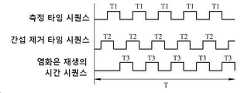
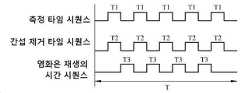
도 37은 애플리케이션 실시예 1의 동작 타임 시퀀스를 도시한 개략적인 타임-시퀀스 도면이다.
도 38은 애플리케이션 실시예 2의 동작 타임 시퀀스를 도시한 개략적인 타임-시퀀스 도면이다.
도 39는 애플리케이션 실시예 3의 동작 타임 시퀀스를 도시한 개략적인 타임-시퀀스 도면이다.
도 40은 애플리케이션 실시예 4의 회로 설계를 도시한 회로도이다.
도 41은 애플리케이션 실시예 4의 다른 회로 설계를 도시한 회로도이다.
도 42는 애플리케이션 실시예 4의 동작 타임 시퀀스를 도시한 개략적인 타임-시퀀스 도면이다.
도 43은 애플리케이션 예 1의 간섭물의 생체외 (in vitro) 제거의 결과를 도시하기 위한 전류 신호 대 시간의 그래프 곡선이며, 여기에서 커브 C1은 제2 작업 전극이 간섭물 제거를 위해 스위치 온 될 때에 제1 감지 섹션에서 측정된 전류 신호들을 보여주며, 커브 C2는 제2 작업 전극이 간섭물 제거를 위해 스위치 온 될 때에 제2 감지 섹션에서 측정된 전류 신호들을 보여주며, 그리고 커브 C3는 제2 작업 전극이 간섭물 제거를 위해 스위치 온 되지 않을 때에 제1 감지 섹션에서 측정된 전류 신호들을 보여준다.
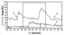
도 44는 간섭물 제거 실행을 하지 않으면서 측정 시간 구간에 걸쳐 신체 내 포도당의 측정 결과를 도시하기 위한 포도당 농도 대 시간 커브의 그래프 곡선이며, 여기에서 점선 프레임으로 표시된 부분은 의학적 간섭의 시간 구간을 나타내며, 커브 (a)는 제1 작업 전극의 측정 결과를 나타내며, 그리고 복수의 점들 (c)는 분석 도구를 사용하여 통상적인 테스트 스트립으로 측정된 포도당 농도 값들을 나타낸다.
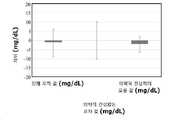
도 45는 의학적 간섭 하에서 그리고 그 의학적 간섭 없는 도 44의 측정 결과의 차이를 도시한 막대 차트이다.
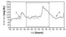
도 46은 간섭물 제거 실행을 하면서 측정 시간 구간에 걸쳐 신체 내 포도당의 측정 결과를 도시하기 위한 포도당 농도 대 시간 커브의 그래프 곡선이며, 여기에서 점선 프레임으로 표시된 부분은 의학적 간섭의 시간 구간을 나타내며, 커브 (a)는 제1 작업 전극의 측정 결과를 나타내며, 커브 (b)는 제2 작업 전극의 측정 결과를 나타내며, 그리고 복수의 점들 (c)는 분석 도구를 사용하여 통상적인 테스트 스트립으로 측정된 포도당 농도 값들을 나타낸다.
도 47은 의학적 간섭 하에서 그리고 그 의학적 간섭 없는 도 46의 측정 결과의 차이를 도시한 막대 차트이다.Other features and advantages of the present disclosure will become apparent from the following detailed description of embodiments with reference to the accompanying drawings.
1 is a schematic view showing Example 1 of an implantable micro-biosensor according to the present disclosure.
FIG. 2 is a schematic cross-sectional view taken along line II-II of FIG. 1 .
FIG. 3 is a schematic cross-sectional view taken along line III-III of FIG. 1 .
FIG. 4 is a schematic cross-sectional view taken along line IV-IV of FIG. 1 ;
Fig. 5 is a schematic cross-sectional view showing the interaction between the first sensing section and the second sensing section in
Fig. 6 is a schematic view showing the configuration of a mutation in Example 1.
FIG. 7 is a schematic cross-sectional view taken along line VII-VII of FIG. 6 .
Fig. 8 is a schematic view showing a variation in the configuration of the second surface of Example 1;
FIG. 9 is a schematic cross-sectional view taken along line IX-IX of FIG. 8 .
Fig. 10 is a schematic fragmentary view showing a variant of the configuration of the first surface of Example 1;
11 is a schematic cross-sectional view taken along line XI-XI of FIG. 10 ;
12 is a schematic cross-sectional view taken along line XII-XII of FIG. 10 ;
13 is a schematic fragmentary view showing another variant of the configuration of the first surface of Example 1. FIG.
FIG. 14 is a schematic cross-sectional view taken along line XIV-XIV of FIG. 13 ;
FIG. 15 is a schematic cross-sectional view taken along line XV-XV of FIG. 13 ;
16 is a schematic view showing the configuration of Example 2 of the implantable micro-biosensor according to the present disclosure.
17 is a schematic cross-sectional view taken along line XVII-XVII of FIG. 16 .
18 is a schematic cross-sectional view taken along line XVIII-XVIII of FIG. 16 ;
19 is a schematic cross-sectional view taken along line XIX-XIX of FIG. 16 ;
Fig. 20 is a schematic cross-sectional view showing the interaction between one first sensing section and two second sensing sections in
21 shows schematic fragmentary views showing variations in the configuration of the first sensing section of the first working electrode and the second sensing section of the second working electrode in Example 2;
22 shows schematic fragmentary views showing other variants of the configuration of the first sensing section of the first working electrode and the second sensing section of the second working electrode in Example 2;
23 is a schematic cross-sectional view taken along line XXIII-XXIII of FIG. 22 .
24 shows schematic fragmentary views showing the configuration of Example 3 of an implantable micro-biosensor according to the present disclosure.
Fig. 25 is a schematic cross-sectional view taken along line XXV-XXV of Fig. 24;
FIG. 26 is a schematic cross-sectional view taken along line XXVI-XXVI of FIG. 24 .
Fig. 27 shows schematic fragmentary views showing a modification of the configuration of the third embodiment.
FIG. 28 is a schematic cross-sectional view taken along line XXVIII-XXVIII of FIG. 27 ;
Fig. 29 shows schematic views showing steps (a1), (a2), (a3) of the process for manufacturing Example 3;
Fig. 30 is a schematic cross-sectional view taken along line XXX-XXX of Fig. 29 to show the construction of the second surface of the embodiment;
FIG. 31 is a schematic cross-sectional view taken along line XXXI-XXXI of FIG. 29 to show the configuration of the second surface of Example 3. FIG.
32 shows schematic views showing the configuration of Example 4 of an implantable micro-biosensor according to the present disclosure.
FIG. 33 is a schematic cross-sectional view taken along line XXXIII-XXXIII of FIG. 32 .
FIG. 34 is a schematic cross-sectional view taken along line XXXIV-XXXIV of FIG. 32 ;
35 shows schematic views showing the configuration of Example 5 of an implantable micro-biosensor according to the present disclosure.
Fig. 36 is a circuit diagram showing a circuit design of the first application embodiment.
Fig. 37 is a schematic time-sequence diagram showing an operation time sequence of
Fig. 38 is a schematic time-sequence diagram showing an operation time sequence of
Fig. 39 is a schematic time-sequence diagram showing an operation time sequence of
Fig. 40 is a circuit diagram showing a circuit design of the fourth application embodiment.
Fig. 41 is a circuit diagram showing another circuit design of the
Fig. 42 is a schematic time-sequence diagram showing an operation time sequence of
43 is a graph curve of current signal versus time to show the results ofin vitro removal of the interferer of Application Example 1, wherein curve C1 is when the second working electrode is switched on for interference removal. shows the current signals measured in the first sensing section, curve C2 shows the current signals measured in the second sensing section when the second working electrode is switched on for interference removal, and curve C3 shows the current signals measured in the second working electrode Shows the current signals measured in the first sensing section when the electrode is not switched on for interference cancellation.
44 is a graph curve of the glucose concentration versus time curve for showing the measurement results of glucose in the body over the measurement time interval without performing interference removal, wherein the portion indicated by the dashed frame represents the time interval of the medical intervention. A curve (a) represents a measurement result of the first working electrode, and a plurality of dots (c) represents glucose concentration values measured with a conventional test strip using an analysis tool.
45 is a bar chart showing the difference in the measurement results of FIG. 44 under and without medical intervention.
46 is a graph curve of the glucose concentration versus time curve for showing the measurement result of glucose in the body over the measurement time interval while performing the interference removal, wherein the portion indicated by the dotted frame represents the time interval of the medical intervention; Curve (a) shows the measurement result of the first working electrode, curve (b) shows the measurement result of the second working electrode, and a plurality of points (c) are measured with a conventional test strip using an analysis tool. Shows glucose concentration values.
47 is a bar chart showing the difference in the measurement results of FIG. 46 under and without medical intervention.
본 발명 개시를 더 상세하게 설명하기 이전에, 적절하게 고려되는 경우, 참조번호들 또는 참조번호들의 말단 부분들은 대응하거나 유사한 요소들을 표시하기 위해 도면들 사이에서 반복될 것이며, 이는 옵션으로는 유사한 특징들을 가질 수 있다.Prior to describing the present disclosure in greater detail, where considered appropriate, reference numerals or distal portions of reference numerals will be repeated among the drawings to indicate corresponding or analogous elements, which optionally have similar features. can have
본원에서 사용된 "피분석물 (analyte)"의 용어는 유기체 내에 존재하는 것으로 탐지되는 임의 물질을 언급하는 것이며, 예를 들면, 포도당, 락토오스, 및 요산이지만, 그것들로 한정되는 것은 아니다. 아래에서 예시된 실시예들에서, 상기 피분석물은 포도당이다. 특정 실시예들에서, 상기 이식 가능 마이크로-바이오센서는 이식 가능 포도당 마이크로-바이오센서이며, 이는 신체 내 간질액 (interstitial fluid) 내 포도당의 농도를 탐지하기 위해 사용된다. 본원에서 사용된 "생물학적 유동체 (biological fluid)"의 용어는, 예를 들면, 상기 간질액일 수 있지만, 그것으로 한정되지는 않는다. 본원에서 사용되는 "생리학적 파라미터 (physiological parameter)"의 용어는, 예를 들면, 농도일 수 있지만, 그것으로 한정되지는 않는다.As used herein, the term “analyte” refers to any substance that is detected to be present in an organism, including, but not limited to, glucose, lactose, and uric acid. In the embodiments illustrated below, the analyte is glucose. In certain embodiments, the implantable micro-biosensor is an implantable glucose micro-biosensor, which is used to detect the concentration of glucose in interstitial fluid in the body. As used herein, the term "biological fluid" may be, for example, but not limited to, the interstitial fluid. The term "physiological parameter" as used herein can be, for example, but not limited to, concentration.
본원에서 사용되는 "적어도 하나"라는 용어는 하나 그리고 하나보다 많은 임의 개수를 포함하는 것으로 이해한다.As used herein, the term “at least one” is understood to include one and any number greater than one.
탐지 시간 구간 동안에 신체 내 피분석물의 생리학적 파라미터를 연속하여 모니터하기 위해 본 발명 개시에 따른 이식 가능 마이크로-바이오센서가 사용된다. 상기 이식 가능 마이크로-바이오센서는 적어도 하나의 카운터 전극, 제1 작업 전극, 화학 시약 레이어, 및 적어도 하나의 제2 작업 전극을 포함한다.An implantable micro-biosensor according to the present disclosure is used to continuously monitor physiological parameters of an analyte in the body during a detection time interval. The implantable micro-biosensor includes at least one counter electrode, a first working electrode, a chemical reagent layer, and at least one second working electrode.
상기 적어도 하나의 카운터 전극은 은/할로겐화은을 포함한다.The at least one counter electrode comprises silver/silver halide.
상기 제1 작업 전극은 제1 감지 섹션을 포함한다.The first working electrode includes a first sensing section.
상기 화학 시약 레이어는 상기 제1 감지 섹션의 적어도 일부를 덮으며 그리고 상기 피분석물과 반응해서 생성물질을 산출하여, 측정 행동을 수행하기 위해서 상기 탐지 시간 구간의 적어도 하나의 제1 시간 섹션 동안에 제1 전위차에 의해 상기 제1 감지 섹션이 구동되도록 하여 상기 피분석물의 생리학적 파라미터에 반응하여 생리학적 신호를 획득한다.The chemical reagent layer covers at least a portion of the first detection section and reacts with the analyte to yield a product, wherein during at least one first time section of the detection time interval, to perform a measurement action. A physiological signal is acquired in response to a physiological parameter of the analyte by driving the first sensing section by one potential difference.
상기 적어도 하나의 제2 작업 전극은 상기 제1 감지 섹션에 근접하게 배치된 제2 감지 섹션을 포함한다.The at least one second working electrode includes a second sensing section disposed proximate the first sensing section.
상기 제2 작업 전극의 상기 제2 감지 섹션은, 간섭물을 소모하기 위해 간섭-제거 행동을 수행하기 위해서 상기 탐지 시간 구간의 적어도 하나의 제2 시간 섹션 동안에 제2 전위차에 의해 구동된다.The second sensing section of the second working electrode is driven by a second potential difference during at least one second time section of the detection time interval to perform an interference-cancelling action to consume the interferer.
상기 제2 작업 전극은 상기 탐지 시간 구간의 적어도 하나의 제3 시간 섹션 동안에 상기 카운터 전극과 협응하여, 할로겐화은을 재생 (regenerate)하기 위해 재생 행동을 수행하기 위해서 상기 카운터 전극이 구동되는 것을 가능하게 한다.the second working electrode cooperates with the counter electrode during at least one third time section of the detection time interval to enable the counter electrode to be driven to perform a regenerative action to regenerate silver halide .
특정 실시예들에서, 상기 제1 전위차는 상기 제1 작업 전극이 상기 카운터 전극의 전위보다 더 높은 전위를 가지는 것을 가능하게 한다.In certain embodiments, the first potential difference enables the first working electrode to have a higher potential than the potential of the counter electrode.
특정 실시예들에서, 상기 제2 전위차는 상기 제2 작업 전극이 상기 카운터 전극의 전위보다 더 높은 전위를 가지는 것을 가능하게 한다.In certain embodiments, the second potential difference enables the second working electrode to have a higher potential than the potential of the counter electrode.
특정 실시예들에서, 상기 카운터 전극은 제3 전위차에 의해 구동되어 상기 카운터 전극이 상기 제2 작업 전극의 전위보다 더 높은 전위를 가지는 것을 가능하게 한다.In certain embodiments, the counter electrode is driven by a third potential difference to enable the counter electrode to have a higher potential than the potential of the second working electrode.
특정 실시예들에서, 상기 제1 시간 섹션 및 제2 시간 섹션은 서로 겹치지 않는다.In certain embodiments, the first time section and the second time section do not overlap each other.
특정 실시예들에서, 상기 제1 시간 섹션 및 제2 시간 섹션은 서로 적어도 부분적으로 겹친다.In certain embodiments, the first time section and the second time section at least partially overlap each other.
특정 실시예들에서, 상기 제1 감지 섹션의 표면 재질은 제1 전도성 재질을 포함하고, 상기 제2 감지 섹션의 표면 재질은 상기 제1 전도성 재질과는 상이한 제2 전도성 재질을 포함한다. 상기 제1 작업 전극은 상기 제1 전도성 재질이 상기 생성물질에 반응하는 제1 민감도를 가지는 것을 가능하게 하기 위해서 상기 제1 전위차에 의해 구동되며, 그리고 상기 제2 작업 전극은 상기 제2 전도성 재질이, 상기 생성물질에 반응하며 상기 제1 민감도보다 더 작은 제2 민감도를 가지는 것을 가능하게 하기 위해서 상기 제2 전위차에 의해 구동된다.In certain embodiments, the surface material of the first sensing section includes a first conductive material, and the surface material of the second sensing section includes a second conductive material different from the first conductive material. the first working electrode is driven by the first potential difference to enable the first conductive material to have a first sensitivity to reacting to the product, and the second working electrode is configured to have the second conductive material , driven by the second potential difference to make it possible to react to the product and have a second sensitivity that is less than the first sensitivity.
특정 실시예들에서, 상기 제1 전도성 재질은, 귀금속, 귀금속 유도체 및 그것들의 조합으로 구성된 그룹으로부터 선택되며, 그리고 상기 귀금속은 금, 백금, 팔라듐, 이리듐 및 그것들의 조합으로 구성된 그룹으로부터 선택된다. 상기 제1 전위차는 0.2 V 부터 0.8 V 까지의 범위이다.In certain embodiments, the first conductive material is selected from the group consisting of noble metals, noble metal derivatives, and combinations thereof, and the noble metal is selected from the group consisting of gold, platinum, palladium, iridium, and combinations thereof. The first potential difference is in the range of 0.2 V to 0.8 V.
특정 실시예들에서, 상기 제2 전도성 재질은 탄소이며, 그리고 상기 제2 전위차는 0.2 V 부터 0.8 V 까지의 범위이다.In certain embodiments, the second conductive material is carbon, and the second potential difference ranges from 0.2 V to 0.8 V.
특정 실시예들에서, 상기 제1 작업 전극의 상기 제1 감지 섹션은 상기 제1 전위차에 의해 구동되어 측정 구역을 형성하며, 그리고 상기 제2 작업 전극의 상기 제2 감지 섹션은 상기 제1 전위차에 의해 구동되어, 상기 제1 감지 섹션의 주변과 접촉하며 상기 측정 구역과 적어도 부분적으로 겹치는 간섭-제거 구역을 형성한다.In certain embodiments, the first sensing section of the first working electrode is driven by the first potential difference to form a measurement zone, and the second sensing section of the second working electrode is driven by the first potential difference. driven to form an interference-cancelling zone contacting the periphery of the first sensing section and at least partially overlapping the measurement zone.
특정 실시예들에서, 상기 제2 감지 섹션은 상기 제1 감지 섹션의 적어도 하나의 측면을 따라서 배치되며 그리고 그 적어도 하나의 측면으로부터 0.2 mm까지의 거리만큼 이격하여 위치한다.In certain embodiments, the second sensing section is disposed along at least one side of the first sensing section and spaced apart from the at least one side by a distance of 0.2 mm.
특정 실시예들에서, 상기 제2 감지 섹션은 상기 제1 감지 섹션의 외면의 적어도 일부를 따라서 확장하며 그리고 그 적어도 일부로부터 이격하여 위치하며, 그리고 상기 제1 감지 섹션의 상기 외면의 상기 일부의 상기 제1 감지 섹션의 전체 외면에 대한 비율은 30% 부터 100% 까지의 범위이다.In certain embodiments, the second sensing section extends along and spaced apart from at least a portion of an outer surface of the first sensing section, and wherein the portion of the outer surface of the first sensing section is The proportion to the total outer surface of the first sensing section ranges from 30% to 100%.
특정 실시예들에서, 상기 적어도 하나의 제2 작업 전극의 개수는 2이며, 그리고 상기 제2 작업 전극들 중 둘의 상기 제2 감지 섹션들 중 둘은 상기 제1 작업 전극의 상기 제1 감지 섹션의 두 반대편 측면들을 따라 각각 배치된다.In certain embodiments, the number of the at least one second working electrode is two, and two of the second sensing sections of two of the second working electrodes are the first sensing section of the first working electrode. are respectively placed along the two opposite sides of the
특정 실시예들에서, 상기 이식 가능 마이크로-바이오센서는 제1 표면 및 상기 제1 표면 반대편의 제2 표면을 구비한 기판을 더 포함한다. 상기 제1 감지 섹션 및 제2 감지 섹션은 상기 기판의 상기 제1 표면 상에 배치된다. 상기 카운터 전극은 상기 기판의 상기 제2 표면 상에 배치된다.In certain embodiments, the implantable micro-biosensor further comprises a substrate having a first surface and a second surface opposite the first surface. The first sensing section and the second sensing section are disposed on the first surface of the substrate. The counter electrode is disposed on the second surface of the substrate.
특정 실시예들에서, 상기 이식 가능 마이크로-바이오센서는 상기 신체의 피부에 수직으로 작동하며, 그리고 상기 이식 가능 마이크로-바이오센서는 6 mm까지의 길이인 이식 말단을 가진다.In certain embodiments, the implantable micro-biosensor operates perpendicular to the skin of the body, and the implantable micro-biosensor has an implantable tip that is up to 6 mm in length.
본 발명 개시에 따른 이식 가능 마이크로-바이오센서는 탐지 시간 구간 동안에 신체 내 피분석물의 생리학적 파라미터를 연속하여 모니터하기 위해 사용된다. 상기 이식 가능 마이크로-바이오센서는 적어도 하나의 카운터 전극, 제1 작업 전극, 화학 시약 레이어, 및 적어도 하나의 제2 작업 전극을 포함한다.The implantable micro-biosensor according to the present disclosure is used to continuously monitor physiological parameters of an analyte in the body during a detection time interval. The implantable micro-biosensor includes at least one counter electrode, a first working electrode, a chemical reagent layer, and at least one second working electrode.
상기 적어도 하나의 카운터 전극은 은/할로겐화은을 포함한다.The at least one counter electrode comprises silver/silver halide.
상기 제1 작업 전극은 제1 감지 섹션을 포함한다.The first working electrode includes a first sensing section.
상기 화학 시약 레이어는 상기 제1 감지 섹션의 적어도 일부를 덮으며 그리고 상기 피분석물과 반응해서 생성물질을 산출하여, 측정 행동을 수행하기 위해서 상기 탐지 시간 구간의 적어도 하나의 제1 시간 섹션 동안에 제1 전위차에 의해 상기 제1 감지 섹션이 구동되도록 하여 상기 피분석물의 생리학적 파라미터에 반응하여 생리학적 신호를 획득하며, 그리고 상기 탐지 시간 구간의 적어도 하나의 제3 시간 섹션 동안에 상기 제1 작업 전극이 상기 카운터 전극과 협응하도록 하여, 할로겐화은을 재생하기 위해 재생 행동을 수행하기 위해서 상기 카운터 전극이 구동되는 것을 가능하게 한다.The chemical reagent layer covers at least a portion of the first detection section and reacts with the analyte to yield a product, wherein during at least one first time section of the detection time interval, to perform a measurement action. causing the first sensing section to be driven by one potential difference to obtain a physiological signal in response to a physiological parameter of the analyte, and wherein during at least one third time section of the detection time interval, the first working electrode Coordinate with the counter electrode, thereby enabling the counter electrode to be driven to perform a regenerative action to regenerate the silver halide.
상기 적어도 하나의 제2 작업 전극은 상기 제1 작업 전극에 근접하게 배치된 제2 감지 섹션을 포함하며, 그리고 간섭물을 소모하기 위해 간섭-제거 행동을 수행하기 위해서 상기 탐지 시간 구간의 적어도 하나의 제2 시간 섹션 동안에 상기 제2 작업 전극의 상기 제2 감지 섹션이 제2 전위차에 의해 구동되도록 구성된다.the at least one second working electrode includes a second sensing section disposed proximate to the first working electrode, and at least one of the detection time intervals for performing an interference-removing action to consume the interferer. The second sensing section of the second working electrode is configured to be driven by a second potential difference during a second time section.
특정 실시예들에서, 상기 제1 시간 섹션 및 제3 시간 섹션은 서로 겹치지 않는다.In certain embodiments, the first time section and the third time section do not overlap each other.
특정 실시예들에서, 상기 제1 시간 섹션 및 제2 시간 섹션은 서로 적어도 부분적으로 겹친다.In certain embodiments, the first time section and the second time section at least partially overlap each other.
특정 실시예들에서, 상기 제1 감지 섹션의 표면 재질은 제1 전도성 재질을 포함하고, 상기 제2 감지 섹션의 표면 재질은 상기 제1 전도성 재질과는 상이한 제2 전도성 재질을 포함한다. 상기 제1 작업 전극은 상기 제1 전도성 재질이 상기 생성물질에 반응하는 제1 민감도를 가지는 것을 가능하게 하기 위해서 상기 제1 전위차에 의해 구동되며, 그리고 상기 제2 작업 전극은 상기 제2 전도성 재질이, 상기 생성물질에 반응하며 상기 제1 민감도보다 더 작은 제2 민감도를 가지는 것을 가능하게 하기 위해서 상기 제2 전위차에 의해 구동된다.In certain embodiments, the surface material of the first sensing section includes a first conductive material, and the surface material of the second sensing section includes a second conductive material different from the first conductive material. the first working electrode is driven by the first potential difference to enable the first conductive material to have a first sensitivity to reacting to the product, and the second working electrode is configured to have the second conductive material , driven by the second potential difference to make it possible to react to the product and have a second sensitivity that is less than the first sensitivity.
특정 실시예들에서, 상기 제2 감지 섹션은 상기 제1 감지 섹션의 적어도 한 측면을 따라 배치되며 그 적어도 한 측면으로부터 0.2 mm까지의 거리만큼 이격하여 위치한다.In certain embodiments, the second sensing section is disposed along at least one side of the first sensing section and spaced apart from the at least one side by a distance of up to 0.2 mm.
이식 가능 마이크로-바이오센서의 전극 구성 및 제조 프로세스:Electrode construction and manufacturing process for implantable micro-biosensors:
실시예 1:Example 1:
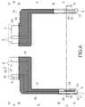
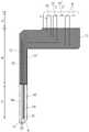
도 1을 참조하면, 본 발명 개시에 따른 이식 가능 마이크로-바이오센서의 실시예 1의 제1 표면은 전송기 (도시되지 않음)에 연결될 제1 신호 출력 구역 (A), 신체 내 피분석물 (예를 들면 포도당)의 생리학적 파라미터 (예를 들면, 농도)를 측정하기 위한 제1 감지 구역 (C), 및 상기 제1 신호 출력 구역 (A)과 상기 제1 감지 구역 (C)을 상호접속시키기 위한 제1 신호 연결 구역 (B)을 포함한다. 상기 이식 가능 마이크로-바이오센서는 신체의 피부에 수직으로 작동하여 그 신체로 부분적으로 이식되며, 그리고 이식되는 말단 부분을 가지며, 이는 상기 제1 감지 구역 (C)을 적어도 포함한다. 특히, 상기 이식되는 말단 부분은 간질액 내 포도당 농도를 측정하기 위해 피부의 진피에 적어도 도달하기에 충분한 길이를 가진다. 특정 실시예들에서, 상기 이식 가능 말단 부분의 길이는 최대 6 mm이다. 특정 실시예들에서, 외부 신체 감각을 피하고, 더 작은 이식 창상 (implantation wound)을 형성하며, 고통 감각을 줄이는 등의 이점들을 가지기 위해서, 상기 이식 말단 부분의 길이는 최대 5 mm이다. 특정 실시예들에서, 상기 이식 가능 말단 부분의 길이는 4.5 mm에 달한다. 특정 실시예들에서, 상기 이식 가능 말단 부분의 길이는 3.5 mm에 달한다. 더 상세하게는, 특정 실시예들에서, 상기 제1 감지 구역 (C)은 2 mm 부터 6 mm 까지의 범위인 길이를 가진다. 특정 실시예들에서, 상기 제1 감지 구역 (C)의 길이는 2 mm 부터 5 mm 까지의 범위이다. 특정 실시예들에서, 상기 제1 감지 구역 (C)의 길이는 2 mm 부터 4.5 mm 까지의 범위이다. 특정 실시예들에서, 상기 제1 감지 구역 (C)의 길이는 2 mm 부터 3.5 mm 까지의 범위이다. 특정 실시예들에서, 상기 제1 감지 구역 (C)은 0.01 mm 부터 0.5 mm까지의 범위인 폭을 가진다. 특정 실시예들에서, 상기 제1 감지 구역 (C)의 폭은 0.3 mm 미만이다.Referring to FIG. 1 , the first surface of Example 1 of the implantable micro-biosensor according to the present disclosure includes a first signal output region (A) to be connected to a transmitter (not shown), an analyte in the body (eg a first sensing zone (C) for measuring a physiological parameter (eg, concentration) of glucose), and interconnecting the first signal output zone (A) and the first sensing zone (C) a first signal connection zone (B) for The implantable micro-biosensor operates perpendicular to the skin of the body to be partially implanted into the body, and has an implanted distal portion, which includes at least the first sensing zone (C). In particular, the distal portion to be implanted has a length sufficient to at least reach the dermis of the skin for measuring the glucose concentration in the interstitial fluid. In certain embodiments, the length of the implantable distal portion is up to 6 mm. In certain embodiments, the length of the implant distal portion is up to 5 mm in order to avoid external bodily sensations, to form a smaller implantation wound, to reduce pain sensation, and the like. In certain embodiments, the length of the implantable distal portion amounts to 4.5 mm. In certain embodiments, the length of the implantable distal portion amounts to 3.5 mm. More specifically, in certain embodiments, the first sensing zone (C) has a length ranging from 2 mm to 6 mm. In certain embodiments, the length of the first sensing zone (C) ranges from 2 mm to 5 mm. In certain embodiments, the length of the first sensing zone (C) ranges from 2 mm to 4.5 mm. In certain embodiments, the length of the first sensing zone (C) ranges from 2 mm to 3.5 mm. In certain embodiments, the first sensing zone (C) has a width ranging from 0.01 mm to 0.5 mm. In certain embodiments, the width of the first sensing zone (C) is less than 0.3 mm.
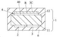
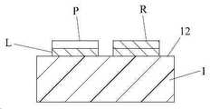
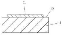
도 1 내지 도 4를 참조하면, 본 발명 개시에 따른 이식 가능 마이크로-바이오센서의 실시예 1은 기판 (1), 제1 작업 전극 (2), 제2 작업 전극 (3), 카운터 전극 (4), 과산화수소를 생성하기 위해 신체 내에서 포도당과 반응하기 위한 화학 시약 레이어 (6), 그리고 절연 유닛 (7)을 포함하며, 상기 절연 유닛은 제1 절연 레이어 (71) 및 제2 절연 레이어 (72)를 포함한다.1 to 4 , Example 1 of an implantable micro-biosensor according to the present disclosure includes a
상기 기판 (1)은 제1 표면 (11) 및 그 제1 표면 (11) 반대편의 제2 표면 (12)을 가진다. 상기 기판 (1)은 전극 기판을 만들기 위해 유용하며 유연성 및 절연 특성들을 가진 임의 물질로 만들어질 수 있다. 상기 기판 (1)을 만들기 위한 물질의 예는 폴리스터, 폴리이미드 등 및 그것들의 조합들일 수 있지만, 그것들로 제한되지는 않는다.The
상기 제1 작업 전극 (2)은 상기 기판 (1)은 제1 표면 (11) 상에 배치되며, 그리고 상기 제1 감지 구역 (C)에 위치하며 상기 화학 시약 레이어 (6)에 의해 덮여진 제1 감지 섹션 (20), 상기 제1 신호 연결 구역 (B)에 위치한 제1 연결 섹션 (21), 및 상기 제1 신호 출력 구역 (A)에 위치한 제1 출력 섹션 (22)을 포함한다. 상기 제1 감지 섹션 (20)의 표면 재질은 제1 전도성 재질 (1C)을 적어도 포함한다. 상기 제1 감지 섹션 (20)은 제1 전위차에 의해 구동되어, 전류 신호를 생성하기 위해 상기 제1 전도성 재질 (1C)이 과산화수소와 반응하는 것을 가능하게 하며, 이 과산화수소는 상기 화학 시약 레이어 (6)의 포도당과의 반응의 생성 물질이다. 포도당 농도에 반응한 생리학적 신호는 상기 전류 신호의 값 및 과산화수소의 농도 사이의 비율 관계가 달성될 때에 획득된다.The first working electrode (2) is the substrate (1) disposed on a first surface (11), and located in the first sensing region (C) and covered by the chemical reagent layer (6). a first sensing section (20), a first connection section (21) located in the first signal connection region (B), and a first output section (22) located in the first signal output region (A). The surface material of the
상기 제1 전도성 재질 (1C)의 예들은 탄소, 백금, 알루미늄, 갈륨, 금, 인듐, 이리듐, 철, 납, 마그네슘, 니켈, 몰리브데넘, 오스뮴, 팔라듐, 로듐, 은, 주석, 티타늄, 아연, 실리콘, 지르코늄, 그것들의 조합, 및 그것들의 유도체들 (예를 들면, 합금, 산화물, 금속 화합물 등)을 포함한다. 특정 실시예들에서, 상기 제1 전도성 재질 (1C)은 귀금속, 귀금속의 유도체. 또는 그것들의 조합이다.Examples of the first
상기 제2 작업 전극 (3)은 상기 기판 (1)의 제1 표면 (11) 상에 배치되며, 그리고 제2 감지 섹션 (30), 제2 연결 섹션 (31), 및 제2 출력 섹션 (32)을 포함한다. 상기 제2 감지 섹션 (30)은 상기 제1 감지 섹션 (20)에 가깝게 배치되며 그리고 상기 제1 감지 구역 (c)에 위치한다. 상기 제2 연결 섹션 (31)은 상기 제1 신호 연결 구역 (B)에 위치한다. 상기 제2 출력 섹션 (32)은 상기 제1 신호 출력 구역 (A)에 위치한다. 상기 제2 감지 섹션 (3)의 표면 재질은 제2 전도성 재질 (2C)을 최소한 포함한다. 상기 제2 감지 섹션은 제2 전위차에 의해 구동되어, 상기 제2 전도성 재질 (2C)이 상기 제2 감지 섹션 (3)에 접근하는 신체 내 간섭 물질의 적어도 일부를 소모하는 것을 가능하게 한다. 제2 전도성 재질 (2C)의 예들은 상기 제1 전도성 재질 (1C)에 대해 위에서 설명된 것들과 동일할 수 있다.The
도 5를 참조하면, 상기 제1 작업 전극 (2)이 전기화학적 반응을 수행하기 위해 제1 전위차에 의해 구동될 때에, 제1 감지 섹션 (20)은 자신의 표면 주위에 측정 구역 (1S)을 형성하여 그 측정 구역 (1S) 내에서 과산화수소를 측정할 수 있는 것만이 아니라 신체 내 생물학적 유동체 내 간섭 물질과 또한 반응할 수 있어서 간섭 회로 신호를 생성하며, 이 신호는 상기 회로 신호와 함께 출력되어 상기 생리학적 신호에 대한 간섭을 초래할 것이라는 것이 이해되어야 한다. 상기 제2 작업 전극 (3)이 제2 전위차에 의해 구동될 때에, 제2 감지 섹션 (30)의 표면에 접근하는 간섭 물질이 전기화학적 반응을 경유하여 소모되어, 상기 간섭 물질의 농도가 상기 제2 감지 섹션 (30)의 표면을 향한 방향을 따라 점진적으로 감소하는 농도 기울기를 가지는 것을 가능하게 하며, 그럼으로써 적어도 하나의 간섭-제거 구역 (2S)을 형성한다. 상기 제2 감지 섹션 (30)이 상기 제1 감지 섹션 (20)에 근접하기 때문에, 상기 간섭-제거 구역 (2S)은 상기 제1 감지 섹션 (20)의 주변과 접촉하며 그리고 상기 측정 구역 (1S)과 적어도 부분적으로 겹칠 수 있으며, 그래서 상기 제1 및 제2 감지 섹션들 (20, 30)에 접근하는 간섭 물질이 동시에 소모될 수 있도록 한다. 상기 간섭-제거 구역 (2S)이 상기 측정 구역 (1S)과 충분하게 겹치도록 허용하기 위해서, 제1 감지 구역 (C)에서, 상기 제2 작업 전극 (3)의 제2 감지 섹션 (30)은 상기 제1 작업 전극 (2)의 제1 감지 섹션 (20)의 적어도 한 측면을 따라 배치되며 그리고 그 측면으로부터 최대 0.2 mm까지의 거리만큼 이격하여 위치하며, 이는 간섭 물질에 의해 초래된 포도당 농도 측정에 대한 간섭을 줄이기 위한 것이다. 특정 실시예들에서, 상기 거리는 0.01 mm 부터 0.2 mm까지의 범위이다. 특정 실시예들에서, 상기 거리는 0.01 mm 부터 0.1 mm까지의 범위이다. 특정 실시예들에서, 상기 거리는 0.02 mm 부터 0.05 mm까지의 범위이다.Referring to FIG. 5 , when the first working
또한, 제2 작업 전극 (3)이 제2 전위차에 의해 구동될 때에, 상기 제2 전도성 재질 (2C)은 상기 과산화수소와 반응하여 다른 전류 신호를 생성할 수 있으며, 그래서 피분석물의 농도를 정밀하게 측정하기 위해서 제1 작업 전극 (2)에 의해 감지되어야만 하는 과산화수소의 일부가 제2 작업 전극 (3)에 의해 소모되도록 하며, 이는 상기 피분석물의 농도의 정밀한 측정에 부정적인 영향을 초래한다. 그러므로, 상기 제1 작업 전극 (2)의 제1 전도성 재질 (1C)이 제1 전위차에 의해 구동되어 과산화수소에 반응하여 제1 민감도를 가지며 그리고 상기 제2 작업 전극 (3)의 제2 전도성 재질 (2C)이 제2 전위차에 의해 구동되어 제2 민감도를 가질 때에, 상기 제1 전도성 재질 (1C)의 제1 민감도는 상기 제2 전도성 재질 (2C)의 제2 민감도보다 더 커야 한다. 그러므로, 상기 제1 전도성 재질 (1C)은 상기 제2 전도성 재질 (2C)과 상이하다. 특정 실시예들에서, 상기 제1 전도성 재질 (1C)은 금, 백금, 팔라듐, 이리듐, 또는 그것들의 조합과 같은 귀금속일 수 있다. 바람직하게는, 상기 제2 전도성 재질 (2C)은 과산화수소에 대해 민감하지 않으며 그리고 탄소, 니켈, 구리 등일 수 있지만, 그것들로 제한되지는 않는다.Further, when the second working
실시예 1에서, 상기 제1 전도성 재질 (1C)은 백금이며, 상기 제1 전위차는 0.2 V (볼트)부터 0.8 V 까지의 범위이며, 예를 들면, 0.4 V 내지 0.7 V 이다. 상기 제2 전도성 재질 (2C)은 탄소이다. 상기 제2 전위차는 0.2 V (볼트)부터 0.8 V 까지의 범위이며, 예를 들면, 0.4 V 내지 0.7 V 이다. 상기 제1 전위차는 상기 제2 전위차와 동일할 수 있다.In Example 1, the first
도 6을 참조하면, 제1 전도성 재질 (1C)이 제1 감지 구역 (C)에서 형성되었지만, 제1 감지 구역 (C)에서 상기 제1 전도성 재질 (1C)과 함께 형성된 제1 작업 전극 (2)의 일부만을 구비하는 것이 가능하다.Referring to FIG. 6 , although a first
도 1로 돌아가서, 본 발명 개시에 따른 이식 가능 마이크로-바이오센서의 실시예 1의 제2 표면은 제1 신호 출력 구역 (D), 제2 신호 연결 구역 (B), 및 제2 감지 구역 (F)을 포함한다. 카운터 전극 (4)이 기판 (1)의 제2 표면 (12) (즉, 상기 이식 가능 마이크로-바이오센서의 제2 표면) 상에 배치되며, 그리고 제2 감지 구역 (F)에 위치한 제3 감지 섹션 (40), 제2 신호 연결 구역 (E)에 위치한 제3 연결 섹션 (41), 및 제2 신호 출력 구역 (D)에 위치한 제3 출력 섹션 (42)을 포함하며, 이는 상기 생리학적 신호를 측정하기 위해 상기 제1 작업 전극 (2)과 협응하고, 상기 간섭 물질을 소모하기 위해 상기 제2 작업 전극 (3)과 협응하기 위한 것이다. 상기 카운터 전극 (4)은 상기 제2 표면 (12) 상에 배치되는 것으로 한정되지 않으며, 상기 제1 및 제2 작업 전극들 (2, 3) 각각과의 전술한 협응이 충족되는 한은 상기 제1 표면 (11) 상에 배치될 수 있다는 것이 이해되어야 한다. 상기 카운터 전극 (4)이 제2 표면 (12) 상에 배치될 때에, 상기 이식 가능 마이크로-바이오센서의 폭은 감소될 수 있다. 추가로, 상기 카운터 전극 (4)은 할로겐화은 (silver halide)을 재생 (regenerate)하기 위해 상기 제1 작업 전극 (2)이나 제2 작업 전극 (3)과 선택적으로 협응할 수 있다.1 , the second surface of Example 1 of the implantable micro-biosensor according to the present disclosure comprises a first signal output region (D), a second signal connection region (B), and a second sensing region (F). ) is included. A
실시예 1에서, 상기 카운터 전극 (4)의 재질은, 카운터 전극 (4)이 또한 레퍼런스 전극으로서 기능하는 것을 가능하게 하기 위해 은/할로겐화은 (R)을 포함한다. 즉, 상기 카운터 전극 (4)은 전기화학적 반응이 제1 작업 전극 (2)에서 발생하는 것을 허용하기 위해서 그리고 안정적인 상대적인 전위를 레퍼런스 전위로서 제공하기 위해서 루프를 형성하기 위해 상기 제1 작업 전극 (2)과 협응할 수 있다. 할로겐화은의 비-한정적인 예는 염화은이며, 요오드화은 또한 가능하다. 생성물질 가격을 줄이고 본 발명 개시의 이식 가능 마이크로-바이오센서의 생물학적 호환성을 향상시키는 것을 고려하여, 상기 은/할로겐화은 (R)은 카운터 전극 (4)의 표면 상에만 포함될 수 있다. 은/할로겐화은 (R)은 상기 카운터 전극 (4)이 상기 의도된 기능을 실행할 수 있는 한은 탄소 물질 (예를 들면, 탄소 페이스트 (carbon paste))과 혼합될 수 있다.In Example 1, the material of the
상기 카운터 전극 (4)의 제3 감지 섹션 (4)의 할로겐화은의 양은 안전한 범위 내에 있어야만 하며, 이는 할로겐화은을 완전하게 소모하는 것을 피하고 본 발명의 이식 가능 마이크로-바이오센서가 상기 생리학적 신호를 측정하기 위한 테스트 환경에서 안정하게 유지되도록 하는 것을 가능하게 하기 위한 것이다. 그러므로, 도 7을 참조하면, 신체의 환경에서 할로겐화은을 벗겨내는 것을 피하기 위해서, 상기 제3 감지 섹션 (40)은 상기 은/할로겐화은 (R)의 적어도 일부를 덮는 제3 전도성 재질 (3C)을 더 포함할 수 잇다. 상기 제3 전도성 재질 (3C)에 의해 덮이지 않은 상기 제3 감지 섹션 (40) 상의 은/할로겐화은 (R)은 상기 생리학적 신호를 측정하기 위해 사용될 수 있다. 위에서 설명된 "적어도 일부를 덮는다"는 용어는 부분적으로 덮거나 완전하게 덮는 것을 언급하는 것이다. 상기 제3 전도성 재질 (3C)은 탄소, 은 및 상기 카운터 전극 (4)의 상기의 의도된 기능에 영향을 주지 않을 어떤다른 전도성 재질들을 포함한다.The amount of silver halide in the
추가로, 본 발명 개시의 상기 이식 가능 마이크로-바이오센서를 최소화하기 위해 그리고 상기 할로겐화은의 양을 안정한 범위 내에 유지하기 위해서, 상가 카운터 전극 (4)과 상기 제1 작업 전극 (2) 사이에 또는 상기 카운터 전극 (4)과 상기 제2 작업 전극 (3) 사이에 제3 전위차가 인가되어 상기 카운터 전극 (4)이 상기 제1 작업 전극 (2)이나 제2 작업 전극 (3)의 전위보다 더 높은 전위를 가지는 것을 가능하게 하며, 이는 할로겐화은을 재생하기 위한 것이며 그리고 상기 카운터 전극 (4)의 제3 감지 섹션 (4)에서 할로겐화은이 안전한 범위 내에 있도록 유지하기 위한 것이다. 특히, 은 대 할로겐화은의 무게 비율은, 은 및 할로겐화은의 전체 무게의 100 wt%에 기초한 95 wt%:5 wt%, 70 wt%:30 wt%, 60 wt%:40 wt%, 50 wt%:50 wt%, 40 wt%:60 wt%, 30 wt%:70 wt%, 또는 5 wt%:95 wt% 일 수 있지만, 그것들로 한정되지는 않는다. 다른 말로 하면, 할로겐화은의 은/할로겐화은 (R)에 대한 무게 비율은 0보다 크며 1보다 작다. 특히, 상기 언급된 무게 비율은 0.01 및 0.99 사이, 더 특별하게는, 0.1 및 0.9 사이, 0.2 및 0.8 사이, 0.3 및 0.7 사이, 또는 0.4 및 0.6 사이의 범위이다.Further, in order to minimize the implantable micro-biosensor of the present disclosure and to keep the amount of silver halide within a stable range, between the
위에서 설명되었듯이, 상기 화학 시약 레이어 (6)는 상기 제1 감지 섹션 (20)의 제1 전도성 재질 (1C)의 적어도 일부를 덮는다. 특히 도 2를 참조하면, 실시예 1에서, 상기 화학 시약 레이어 (6)는 상기 제1 감지 섹션 (2)만이 아니라, 상기 제2 감지 섹션 (30), 상기 제1 감지 섹션 및 제2 감지 섹션 (30) 사이의 틈새의 일부나 전부, 그리고 상기 제3 감지 섹션 (40)도 덮는다. 다른 말로 하면, 상기 화학 시약 레이어 (6)는 상기 제1 감지 구역 (C) 및 상기 제2 감지 구역 (F)의 적어도 부분들을 덮는다. 화학 시약 레이어 (6)는, 상기 피분석물과 반응하거나 그 피분석물의 다른 물질과의 반응을 향상시킬 수 있는 적어도 한 가지 유형의 효소를 포함한다. 그 효소의 예들은 포도당 산화효소 (glucose oxidase) 및 포도당 탈수소효소 (glucose dehydrogenase)를 포함할 수 있지만, 그것들로 제한되지는 않는다. 본 발명 개시에서, 상기 제1 작업 전극 (2) 및 제2 작업 전극 (3)은 상기 화학 시역 레이어 (6)가 매개체 (mediator)를 포함하지 않을 수 있도록 설계된다.As described above, the
신호 감지를 위한 상기 감지 구역들 (상기 제1 및 제2 감지 구역들 (C, F)을 포함함) 및 신호 출력을 위한 상기 신호 출력 구역들 (상기 제1 및 제2 신호 출력 구역들 (A, D)을 포함함) 노출을 제외하면, 상기 신호 연결 구역들 (상기 제1 및 제2 신호 연결 구역들 (B, E)을 포함함)에서 상기 제1, 제2, 및 제3 신호 연결 섹션들 (21, 31, 41)을 절연시키는 것이 필수적이다. 그러므로, 제1 절연 레이어 (71)는 상기 제1 신호 연결 구역 (B)에 위치하며, 제1 작업 전극 (2)의 제1 연결 섹션 (21) 및 제2 작업 전극 (3)의 제2 연결 섹션 (31)을 덮는다. 제2 절연 레이어 (72)는 상기 제2 신호 연결 구역 (E)에 위치하며, 기판 (1)의 제2 표면 (12) 상의 카운터 전극 (4)의 제3 연결 섹션 (41)을 덮는다. 상기 제2 절연 레이어 (72)는 제1 절연 레이어 (71)의 길이와 동일하거나 상이할 수 있는 길이를 가진다. 절연 레이어 유닛 (7)은 임의 절연 재질, 예를 들면, 파릴렌, 폴리이미드, PDMS, LCP 또는 MicroChem의 SU-8 등으로 만들어질 수 있지만, 그것들로 한정되지는 않는다. 상기 제1 및 제2 절연 레이어들 (71, 72) 각각은 단일-레이어 또는 다중-레이어 구성을 가질 수 있다. 상기 화학 시약 레이어 (6)는 상기 제1, 제2 및 제3 감지 섹션들 (20, 30, 40)에 추가로 상기 제1 절연 레이어 (71) 및/또는 상기 제2 절연 레이어 (72)를 또한 덮을 수 있다.The detection zones (including the first and second detection zones (C, F)) for signal detection and the signal output zones (the first and second signal output zones (A) for signal output) , D)) exposure, the first, second, and third signal connections in the signal connection regions (including the first and second signal connection regions (B, E)) It is essential to insulate the
상기 화학 시약 레이어 (6), 제1 절연 레이어 (71), 및 제2 절연 레이어 (72)는 폴리머 구속 레이어 (confinement layer) (도시되지 않음)로 덮어질 수 있으며, 달갑지 않은 물질들이 상기 이식 가능 마이크로-바이오센서로 진입하면 피분석물 측정에 영향을 줄 수 있는데, 이를 제한하기 위한 것이다.The
도 1을 특히 참조하면, 상기 제1 및 제2 신호 출력 구역들 (A, D) 각각은 복수의 전기 접점부들 (8)을 더 포함한다. 특히, 상기 제1 및 제2 신호 출력 구역들 (A, D) 각각은 상기 전기 접점부들 (8) 중 두 개를 포함한다. 전송기가 이식 가능 마이크로-바이오센서에 전기적으로 연결될 때에 그 두 개의 전기 접점부들 (8)은 상기 전송기의 전력 소스를 작동시키기 위한 스위치 세트로서 사용된다. 상기 전기 접점부들 (8) 중 다른 두 개는 데이터 전송을 위해 매개체로서 사용된다. 상기 전기 접점부들 (8)의 개수 및 기능은 전술한 내용으로 제한되지 않는다는 것이 이해되어야 한다.With particular reference to FIG. 1 , each of the first and second signal output zones A, D further comprises a plurality of
도 8 및 도 9를 참조하면, 이식 가능 마이크로-바이오센서의 실시예 1은 기판 (1)의 제2 표면 (12) 상에 배치된 레퍼런스 전극 (9)과 함께 또한 구성될 수 있다. 상기 레퍼런스 전극 (9)은 제2 감지 구역 (F)에 위치한 제4 감지 섹션 (90), 제2 신호 연결 구역 (E)에 위치한 제4 연결 섹션 (91), 및 제2 신호 출력 구역 (D)에 위치한 제4 출력 섹션 (92)을 포함한다. 그래서, 카운터 전극 (4)의 은/할로겐화은 (R)은 생략될 수 있으며 상기 제4 감지 섹션 (90)의 표면 상에 적어도 제공될 수 있다.8 and 9 , Example 1 of an implantable micro-biosensor may also be configured with a
도 1 내지 도 4를 특히 참조하면, 본 발명 개시에 따른 이식 가능 마이크로-바이오센서의 실시예 1은 다음의 단계들을 포함한다:With particular reference to FIGS. 1 to 4 , Example 1 of an implantable micro-biosensor according to the present disclosure includes the following steps:
(A) 제1 표면 (11)을 가진 기판 (1) 제공;(A) providing a substrate (1) having a first surface (11);
(B) 기판 (1)의 제1 표면 (11) 상에 제1 작업 전극 (2) 형성, 상기 제1 작업 전극 (2)은 제1 전도성 재질 (1C)을 포함한 제1 감지 섹션 (20)을 적어도 포함한다;(B) forming a first working electrode (2) on a first surface (11) of a substrate (1), the first working electrode (2) comprising a first sensing section (20) comprising a first conductive material (1C) at least include;
(C) 기판 (1)의 제1 표면 (11) 상에 제2 작업 전극 (3) 형성, 상기 제2 작업 전극 (3)은 제2 감지 섹션 (30)을 적어도 포함하며, 이 제2 감지 섹션은 제1 감지 섹션 (20)의 적어도 한 측면에 가깝게 배치되며 상기 제1 전도성 재질 (1C)과는 상이한 제2 전도성 재질 (2C)을 포함한다;(C) formation of a second working electrode (3) on a first surface (11) of a substrate (1), said second working electrode (3) comprising at least a second sensing section (30), said second sensing the section is disposed close to at least one side of the
(D) 피분석물의 생리학적 파라미터를 측정하기 위해 제1 작업 전극 (2)과 협응하기 위해서 기판 (1) 상에 카운터 전극 (4) 형성; 그리고(D) forming a counter electrode (4) on the substrate (1) to coordinate with the first working electrode (2) for measuring a physiological parameter of the analyte; and
(E) 생성물질 (product)을 생성하기 위해 피분석물과 반응하기 위해서 상기 제1 감지 섹션 (20)의 제1 전도성 재질 (1C)을 적어도 덮는 화학 시약 레이어 (6) 형성.(E) Formation of a chemical reagent layer (6) covering at least the first conductive material (1C) of the first sensing section (20) to react with an analyte to produce a product.
특히, 기판 (1)의 제1 표면 (11)은 제1 신호 출력 구역 (A), 제1 신호 연결 구역 (B), 및 제1 감지 구역 (C)을 포함한다. 단계 B) 및 단계 C)는 다음의 서브단계들에 의해 구현된다:In particular, the
(a) 기판 (1)의 제1 표면 (11) 상에 제2 전도성 재질 (2C) 적용;(a) applying a second conductive material (2C) on the first surface (11) of the substrate (1);
(b) 제2 전도성 재질 (2C)을 상기 제1 및 제2 작업 전극들 (2, 3)의 미리 정해진 크기, 위치, 길이, 면적 등에 따라 패터닝 (patterning)하도록 하며, 이는 상기 제2 전도성 재질 (2C)을 서로 분리된 제1 영역 및 적어도 하나의 제2 영역으로 분할하기 위한 것이다; 그리고(b) patterning a second
(c) 제1 전도성 재질 (1C)을 제1 감지 구역 (C)에 적용하여 제1 영역에서 제2 전도성 재질 (2C)의 적어도 일부를 덮도록 하며, 이는 제1 작업 전극 (2)의 제1 감지 섹션 (20)을 형성하도록 하며 상기 제2 전도성 재질 (2C)이 상기 적어도 하나의 제2 영역에서 제2 작업 전극 (3)으로서 구성되는 것을 가능하게 하기 위한 것이며, 이 제2 작업 전극 (3)은 제1 신호 출력 구역 (A)에 위치한 제2 신호 출력 섹션 (32), 제1 신호 연결 구역 (B)에 위치한 제2 신호 연결 섹션 (31), 및 제1 감지 구역 (C)에 위치한 제2 감시 섹션 (3)을 포함한다. 그러므로, 위에서 언급된 프로세스에 의해 제조된 실시예 1에서의 제1 및 제2 감지 섹션들 (20, 30) 둘 모두는 상기 제1 감지 구역 (C)에 위치한다.(c) applying a first conductive material (1C) to the first sensing zone (C) to cover at least a portion of the second conductive material (2C) in the first area, which is the second conductive material (2C) of the first working electrode (2) 1 to form a sensing section (20) and to enable the second conductive material (2C) to be configured as a second working electrode (3) in the at least one second region, the second working electrode ( 3) is in the second
특히, 도 10 내지 도 12를 참조하면, 서브-단계 (b) 이후에, 제2 전도성 재질 (2C)은 제1 영역 및 제2 영역으로 분할되며, 이 영역들은 줄무늬 외형을 가지며 서로로부터 분리된다. 도 1에서 보이는 것처럼, 제2 영역에서의 제2 전도성 재질 (2C)은 상기 제1 감지 구역 (C)으로부터 상기 제1 신호 연결 구역 (B)을 통해 상기 제1 신호 출력 구역 (A)으로 확장한다. 서브-단계 (C) 이후에, 상기 제1 전도성 재질은 제1 감지 구역 (C)에서 상기 제2 전도성 재질 (2C)만을 덮는다. 그러므로, 도 11을 특히 참조하면, 제1 작업 전극 (2)의 상기 제1 감지 섹션 (20)은 기판 (1)의 제1 표면 (11) 상에 배치된 제2 전도성 재질 (2C)의 레이어 그리고 상기 제2 전도성 재질 (2C)의 레이어를 덮는 제1 전도성 재질 (1C)의 레이어를 포함한다. 상기 제1 작업 전극 (2)의 제1 연결 섹션 (21)은 도 12에서 보이는 것처럼 제2 전도성 재질 (2C)의 레이어만을 포함한다. 상기 제3 작업 전극 (3)은 제2 전도성 재질 (2C)의 레이어만을 포함한다.In particular, referring to FIGS. 10 to 12 , after the sub-step (b), the second
실시예 1의 변형에서, 상기 제1 전도성 재질 (1C)은, 서브-단계 (c)를 변경함으로써 도 6에서 보이는 것처럼 제1 감지 구역 (C)의 제2 전도성 재질 (2C)의 일부만을 덮는다.In a variant of
실시예 1의 다른 변형에서, 상기 제1 전도성 재질 (1C)은 상기 제1 감지 구역 (C)의 제2 전도성 재질 (2C)을 덮는 것만이 아니라, 서브-단계들 (b) 및 (c)를 변경함으로써 상기 제1 연결 구역 (B)에서 상기 제2 전도성 재질 (2C)의 일부를 덮기 위해 또한 확장된다.In another variant of
실시예 1의 추가의 다른 변형에서, 제1 구역에서의 상기 제2 전도성 재질 (2C)은 서브-단계 (b)를 변경함으로써 상기 제2 영역에서의 상기 제2 전도성 재질 (2C)의 길이보다 더 작은 길이를 가질 수 있다. 예를 들면, 상기 제1 구역에서 상기 제2 전도성 재질 (2C)은 상기 제1 신호 출력 구역 (A) 및 상기 제1 신호 연결 구역 (B)에만 위치할 수 있다. 그 이후에, 상기 제1 전도성 재질 (1C)은 상기 제1 감지 구역 (C)에 형성되는 것만이 아니라, 서브-단계 (c)에 의해 상기 제1 신호 연결 구역 (B)에서 상기 제2 전도성 재질 (2C)을 또한 덮으며, 이는 상기 제1 감지 섹션 (20)이 상기 제1 신호 출력 섹션 (22)에 연결되는 것을 가능하게 하기 위한 것이다.In a further further variant of
도 13 내지 도 15를 참조하면, 실시예 1의 또 다른 변형에서, 제1 전도성 재질 (1C)은 제2 전도성 재질 (2C) 전체를 덮을 수 있으며, 그래서 제1 감지 섹션 (20), 제1 연결 섹션 (21), 및 제1 신호 출력 섹션 (22) 각각이 제2 전도성 재질 (2C)의 레이어 및 그 제2 전도성 재질 (2C)의 레이어를 덮는 제1 전도성 재질 (1C)의 레이어를 포함하는 2-레이어 구성을 가지도록 한다. 상기 제2 작업 전극 (3)은 위에서 설명된 것처럼 제2 전도성 재질 (2C)의 레이어만을 포함한다. 대안으로, 상기 제1 작업 전극 (2)은 제2 전도성 재질 (2C)을 제외한 제1 전도성 재질 (1C)만을 포함할 수 있다는 것이 이해되어야 한다.13 to 15 , in another variation of
제1 신호 출력 구역 (A), 제1 신호 연결 구역 (B), 및 제1 감지 구역 (C)의 위치들 및 면적들은 절연 레이어에 의해 한정될 수 있다. 그러므로, 특정 실시예들에서, 서브-단계 (b)에는 기판 (1)의 제1 표면 (11) 상에 제1 절연 레이어 (71)를 형성하는 서브-단계 (b')가 이어질 수 있으며, 이는 제1 절연 레이어가 위치한 제1 신호 연결 구역 (B), 상기 제1 절연 레이어가 덮지 않으며 신체의 피부 아래에 이식될 제1 감지 구역 (C), 그리고 상기 제1 절연 레이어 (71)가 덮지 않는 그리고 전송기에 연결될 제1 신호 출력 구역 (A)을 한정하기 위한 것이다. 제1 신호 연결 구역 (B)에서, 제1 작업 전극 (2)의 제1 연결 섹션 (21) 및 상기 제2 작업 전극 (3)의 제2 연결 섹션 (31) 각각은 상기 제2 전도성 재질 (2C)의 레이어를 적어도 포함하는 레이어 구성을 가진다. 특정 실시예에서, 서브-단계 (b)가 수행되어, 제2 감지 섹션 (30)이 제1 감지 섹션 (20)의 적어도 한 측면으로부터 최대 0.2 mm까지의 거리만큼 이격되는 것을 가능하게 한다.The positions and areas of the first signal output region (A), the first signal connection region (B), and the first sensing region (C) may be defined by an insulating layer. Therefore, in certain embodiments, the sub-step (b) may be followed by a sub-step (b′) of forming a first insulating
특정 실시예들에서, 서브-단계 (a)는 스크린 인쇄 프로세스에 의해 구현된다. 서브-단계 (b)는 에칭 프로세스, 그리고 바람직하게는 레이저 각인 (laser engraving) 프로세스에 의해 구현된다. 서브-단계 (d)는 스퍼터링 (sputtering) 프로세스에 의해, 바람직하게는 표면 피복 프로세스에 의해 전도성 물질을 이용하여 구현된다In certain embodiments, sub-step (a) is implemented by a screen printing process. Sub-step (b) is implemented by an etching process, and preferably by a laser engraving process. Sub-step (d) is implemented using a conductive material by a sputtering process, preferably by a surface coating process
단계 (E)는 제1 작업 전극 (2), 제2 작업 전극들 (3) 및 카운터 전극 (4)과 함께 형성된 기판 (1)을 화학 시약을 함유한 용액에 담금으로써 구현되며, 이는 제1 감지 섹션 (20)의 제1 전도성 재질 (1C), 제2 감지 섹션 (30)의 제2 전도성 재질 (2C) 및 카운터 전극 (4)의 제3 감지 섹션 (40)이 상기 화학 시약으로 동시에 덮어지는 것이 가능하도록 하기 위한 것이다.Step (E) is implemented by immersing the
특정 실시예들에서, 단계 (E) 이전에, 단계 (D')는 기판 (1) 상에 제3 전극 (도시되지 않음)을 형성함으로써 구현된다. 상기 제3 전극은 상기 카운터 전극 (4) 및 상기 제1 작업 전극 (2)으로부터 이격하여 배치되며, 그리고 레퍼런스 전극이나 제3 작업 전극일 수 있다.In certain embodiments, prior to step (E), step (D′) is implemented by forming a third electrode (not shown) on the
특정 실시예들에서, 단계 (E)에는 상기 기판 (1)의 제2 표면 (12) 상에 제2 절연 레이어 (72)를 형성하는 단계 (D")가 이어질 수 있으며, 이는 상기 기판 (1)의 제2 표면 (12) 상에 제2 감지 구역 (F)을 한정하기 위한 것이다.In certain embodiments, step (E) may be followed by step (D″) of forming a second insulating
본 발명 개시에 따른 이식 가능 마이크로-바이오센서의 실시예 1을 제조하기 위한 프로세스는 전술한 단계들, 서브-단계들, 및 순서에 한정되지 않으며, 그리고 전술한 단계들 및 서브-단계들의 순서는 실제적인 요구사항들에 따라 조절될 수 있다는 것이 이해되어야 한다.The process for
본 발명 개시에 따른 이식 가능 마이크로-바이오센서의 실시예 1을 제조하기 위한 프로세스에서, 자신의 표면 상에 상이한 재질들을 구비한 두 개의 감지 섹션들은 동일한 감지 구역 상에 형성될 수 있으며, 그래서 통상적인 프로세스를 간략하게 하기 위해서 상기 감지 섹션들이 동일한 화학 시약 레이어와 동시에 덮어질 수 있도록 한다. 추가로, 상기 제1 및 제2 작업 전극들 (2, 3)의 기하학적 구조들 및 크기들 그리고 상기 제1 및 제2 작업 전극들 (2, 3) 등 사이의 간격은 패터닝 프로세스에 의해 정밀하게 제어될 수 있다. 또한, 기판 (1)의 제2 표면 (12) 상에 수행된 프로세싱은 실제적인 요구사항들에 따라 변경될 수 있다.In the process for
실시예 2:Example 2:
도 16 내지 도 19를 참조하면, 본 발명 개시에 따른 이식 가능 마이크로-바이오센서의 실시예 2는 다음의 차이점들을 제외하면 실시예 1과 실질적으로 유사하다.16 to 19 , Example 2 of the implantable micro-biosensor according to the present disclosure is substantially similar to Example 1 except for the following differences.
수용할 수 있는 오차 범위 내에 있도록 하기 위해 생리학적 신호를 측정하는 것에 관한 간섭 물질의 간섭을 효과적으로 줄이기 위해서, 실시예 2에서, 상기 제2 감지 섹션 (30)은 상기 제1 감지 섹션 (20)의 적어도 3 측면들을 따라 배치되며 상기 적어도 3 측면들로부터 거리를 두어 이격하여 위치한다. 다른 말로 하면, 상기 제1 감지 섹션 (20)의 적어도 3 측면들은 상기 제2 감지 섹션 (30)에 의해 둘러싸이며 거리를 두고 이격하여 배치된다. 특정 실시예들에서, 상기 거리는 0.2 mm에 달한다. 특정 실시예들에서, 상기 거리는 0.02 mm부터 0.05 mm의 범위이다. 특히, 상기 감지 섹션 (30)은 상기 제1 감지 섹션 (20)의 적어도 3개 측면들을 따라 U-형상의 기하학적 구조로 배치되며 그리고 상기 적어도 3개 측면들로부터 이격하여 위치한다. 그러므로, 도 20을 참조하면, 상기 제2 감지 섹션 (30)은 간섭-제거 구역들 (2S) 중 적어도 두 개를 형성하며, 이것들은 상기 제1 감지 섹션 (20)의 두 개의 반대편 측면들 상에 위치하며 상기 측정 구역 (1S)와 겹치는데, 이는 상기 제2 감지 섹션 (30)에 접근하는 간섭 물질을 소모하기 위한 것만이 아니라 제1 감지 섹션 (20) 내 간섭 물질을 또한 소모하기 위한 것이다. 특정 실시예들에서, 간섭의 허용할 수 있는 오차 범위는 20%에 달하며, 예를 들면, 10%에 달한다.In order to effectively reduce the interference of an interfering material with respect to measuring a physiological signal so as to be within an acceptable error range, in
실시예 2를 제조하기 위한 프로세스는 다음의 차이점들을 제외하면 실시예 1을 제조하기 위한 프로세스와 실질적으로 동일하다.The process for manufacturing Example 2 is substantially the same as the process for manufacturing Example 1 except for the following differences.
서브-단계 (b)에서, 제2 전도성 재질 (2C)은 패턴이 형성되어, 상기 제2 영역에서 제2 전도성 재질 (2C)이 U-형상의 기하학적 구조로 형성되고 상기 제1 영역에서 상기 제2 전도성 재질 (2C)을 둘러싸는 것을 가능하게 하도록 한다. 그러므로, 제1 감지 섹션 (20)을 둘러싸기 위한 제2 감지 섹션 (30)의 기하학적 구조 및 제2 감지 섹션 (30)의 확장은 제2 전도성 재질 (2C)의 패터닝 (patterning)에 의해 변경될 수 있다.In sub-step (b), the second
추가로, 실시예 2의 다른 변형들에서, 상기 제1 및 제2 감지 섹션들 (20, 30)은 도 21 (a) 및 도 21 (b)에서 보이는 것처럼 위치할 수 있다. 다른 말로 하면, 제2 감지 섹션 (30)이 제1 감지 섹션 (20)의 외면 (periphery)의 적어도 일부를 따라 확장하며 그리고 그 적어도 일부로부터 이격하여 위치할 때에, 제1 감지 섹션 (20)의 외면의 일부에 대한 제1 감지 섹션 (20)의 전체 외면에 대한 비율은 30% 내지 100%의 범위이며, 그래서 제2 감지 섹션 (30)이 (실시예 1에 도시된 것 같은) I-형상의, L-형상의, 또는 U-형상의 기하학적 구조로 구성될 수 있도록 한다.Additionally, in other variations of
도 22 및 도 23을 참조하면, 실시예 2의 또 다른 변형에서, 제2 감지 섹션 (30)은 제1 감지 섹션 (20)의 외면 전체를 따라서 확장할 수 있으며 상기 주변 전체로부터 이격하여 위치할 수 있다. 특히, 상기 제1 연결 섹션 (21) 및 제1 출력 섹션 (22)은 기판 (1)의 제2 표면 (12) 상에 배치된다. 제1 감지 섹션 (20)은 기판 (1)의 제1 표면 (11) 상에 배치된 제1 부분, 기판 (1)의 제2 표면 (12) 상에 배치되며 제1 연결 섹션 (21)을 향하여 확장하는 제2 부분, 그리고 상기 기판 (1)을 따라서 확장하여 상기 제1 부분 및 제2 부분을 서로 연결시키는 중간 부분을 포함한다.22 and 23 , in another variation of
실시예 3:Example 3:
도 24 내지 도 26을 참조하면, 본 발명 개시에 따른 이식 가능 마이크로-바이오센서의 실시예 3은 다음의 차이점들을 제외하면 실시예 2와 실질적으로 유사하다.24 to 26 , Example 3 of the implantable micro-biosensor according to the present disclosure is substantially similar to Example 2 except for the following differences.
실시예 3에서, 상기 이식 가능 마이크로-바이오센서는 기판 (1)의 제2 표면 (12) 상에 배치되며 카운터 전극 (4)으로부터 이격하여 위치한 레퍼런스 전극 (9)을 더 포함한다. 레퍼런스 전극 (9)의 표면 재질은 은/할로겐화은 (R)을 적어도 포함한다. 레퍼런스 전극 (9)은 카운터 전극 (4)의 면적보다 작은 면적을 가지며, 이는 충분한 용량을 제공하고 은/할로겐화은 (R)의 양을 조절하기 위한 것이다.In Example 3, the implantable micro-biosensor further comprises a reference electrode (9) disposed on the second surface (12) of the substrate (1) and spaced apart from the counter electrode (4). The surface material of the
특히, 상기 카운터 전극 (4)은 기판 (1)의 제2 표면 (12) 상에 배치되며, 그리고 카운터 전극 (4)의 제3 감지 섹션 (40)은 제2 감지 구역 (F)을 따라 길이방향으로 확장하는 전방부 (40a) 및 제2 감지 구역 (F)으로부터 멀어지는 방향을 향하여 길이방향으로 확장하는 후방부 (40b)를 포함한다. 실시예 3에서, 카운터 전극 (4)의 제3 감지 섹션 (40)은 상기 전방부 및 후방부 (40a, 40b)로 구성된다. 상기 레퍼런스 전극 (9)은 카운터 전극 (4)으로부터 이격되어 위치하며 제2 감지 구역 (F)에 위치한 제4 감지 섹션 (90)을 포함한다. 상기 제4 감지 섹션 (90)은 상기 제3 감지 섹션 (40)보다 더 작은 면적을 가진다. 특히, 상기 제3 감지 섹션 (40)의 전방부 및 후방부 (40a, 40b)는 레퍼런스 전극 (9)의 제4 감지 섹션 (90)의 두 인접한 측면들에 가깝게 배치되어, 카운터 전극 (4)이 L-형상의 기하학적 구조로서 구성되는 것을 가능하게 한다. 상기 제4 감지 섹션 (90) 및 상기 카운터 전극 (4)의 후방부 (40b)의 폭들 전체는 상기 카운터 전극 (4)의 전방부 (40a)의 폭보다 작다. 추가로, 상기 제1 및 제2 절연 레이어들 (71, 72)은 동일한 길이를 가질 수 있다. 도 26을 참조하면, 상기 화학 시약 레이어 (6)는 상기 제1, 제2, 제3 및 제4 감지 섹션들 (20, 30, 40, 90)을 덮을 수 있다.In particular, the
도 27 및 도 28을 참조하면, 실시예 3의 변형에서, 상기 제1 및 제2 절연 레이어들은 상이한 길이들을 가져서, 상기 제1 감지 구역 (C)이 상기 제2 감지 구역 (F)의 길이보다 더 짧은 길이를 가지도록 한다. 그러므로, 상기 화학 시약 레이어 (6)는 제1 감지 섹션 (20), 제2 감지 섹션 (30), 및 상기 카운터 전극 (4)의 전방부 (40a)만을 덮는다. 상기 레퍼런스 전극 (9)의 제4 감지 섹션 (90)은 상기 화학 시약 레이어 (6)로 덮어지지 않을 수 있다.27 and 28 , in a variant of
실시예 3의 다른 변형에서, 레퍼런스 전극 (9)의 제4 감지 섹션 (90) 상의 은/할로겐화은 (R)의 적어도 일부는 상기 제3 전도성 재질 (3C)에 의해 덮어질 수 있으며, 이는 상기 할로겐화은의 노출 영역을 줄여서 상기 할로겐화은이 해리 (dissociation)로 인해 손실될 가능성을 줄이기 위한 것이다. 그러므로, 제3 전도성 재질 (3C)에 의해 덮어지지 않은 상기 레퍼런스 전극 (9)의 표면 및/또는 측면 가장자리는 상기 측정을 수행하기 위해 상기 제1 작업 전극 (2) 및 상기 카운터 전극 (4)과 협응할 수 있다. 특정 실시예들에서, 상기 제3 전도상 재질 (3C)은 탄소이다.In another variant of
본 발명 개시에 따른 이식 가능 마이크로-바이오센서의 실시예 3을 제조하기 위한 프로세스는 다음의 차이들을 제외하면 실시예 2를 제조하기 위한 프로세스와 실질적으로 유사하다.The process for manufacturing Example 3 of the implantable micro-biosensor according to the present disclosure is substantially similar to the process for manufacturing Example 2 except for the following differences.
단계 (D)에서, 카운터 전극 (4)은 기판 (1)의 제2 표면 (12) 상에 형성되며, 그리고 제2 감지 구역 (F)에 위치한 제3 감지 섹션 (40)을 포함한다. 상기 제3 감지 섹션 (40)은 전방부 (40a) 및 후방부 (40b)를 포함한다. 단계 (D')에서, 레퍼런스 전극 (9)은 기판 (1)의 제2 표면 (12) 상에 형성되며, 그리고 카운터 전극 (4)으로부터 이격하여 위치한다. 레퍼런스 전극 (9)은 제2 감지 구역 (F)에 위치한 제4 감지 섹션 (90)을 포함한다.In step (D), the
마이크로-바이오센서가 판매를 위해 공장에서 반출할 준비가 되기 이전에, 실시예 1 또는 실시예 2의 카운터 전극 (4)이나 실시예 3의 레퍼런스 전극 (9)은 할로겐화은이 아니라 은을 가질 수 있다는 것에 유의한다 (즉, 할로겐화은의 초기 양이 0일 수 있다). 마이크로-바이오센서가 환자에게 피하 이식된 이후에 그리고 제1 측정이 진행되기 이전의 바로 첫 번째 보충 (replenishment) 동안에 카운터 전극 (4)이나 레퍼런스 전극 (9) 상에 코팅된 은을 산화시킴으로써 상기 카운터 전극 (4)이나 레퍼런스 전극 (9) 상에 할로겐화은의 초기 양이 생성될 수 있다. 그런 경우에, 은은 은 이온으로 산화되며 그래서 체액 내 염화물과 결합되어 할로겐화은을 형성한다. 은과 할로겐화은 사이의 미리 정해진 비율에 도달한 이후에 상기 측정이 수행될 수 있다.Before the micro-biosensor is ready to leave the factory for sale, it is noted that the
따라서, 도 29를 참조하면, 이식 가능 마이크로-바이오센서의 실시예 3를 제조하기 위한 제1 프로세스에서, 단계 (D) 및 단계 (D')는 다음의 서브-단계들에 의해 구현된다:Thus, referring to FIG. 29 , in the first process for manufacturing Example 3 of the implantable micro-biosensor, step (D) and step (D′) are implemented by the following sub-steps:
(a1) 기판 (1)의 제2 표면 (12) 상에 지지 (backing) 재질 레이어 (L) 형성; 그리고(a1) forming a backing material layer (L) on the second surface (12) of the substrate (1); and
(a2) 레퍼런스 전극 재질 (예를 들면, 은-할로겐화은)이나 레퍼런스 전극 재질의 전구체 (precursor) 재질 (P) (예를 들면, 은)을 상기 지지 재질 레이어 (L)의 일부에 적용; 그리고(a2) applying a reference electrode material (eg silver-silver halide) or a precursor material (P) (eg silver) of the reference electrode material to a portion of the support material layer (L); and
(a3) 지지 재질 레이어 (L) 및 레퍼런스 전극 재질이나 전구체 재질 (P)을 패터팅하며, 이는 서로에게 분리되며 서로에게 전기적으로 연결되지 않은 제3 영역 및 제4 영역을 한정하기 위한 것이며, 제3 영역에서의 상기 지지 재질 레이어 (L)는 카운터 전극 (4)으로서 구성된다.(a3) patterning a layer of support material (L) and a reference electrode material or precursor material (P) to define third and fourth regions that are separated from each other and are not electrically connected to each other, The support material layer (L) in
특히, 카운터 전극 (4)의 능동 영역 및 레퍼런스 전극 (9), 상기 둘 사이의 협응 구성, 상기 전극의 표면 상의 은-할로겐화은의 위치나 크기는 서브-단계 (a2)를 통해 쉽게 제어될 수 있으며, 이는 상기 카운터 전극 (4) 및 레퍼런스 전극 (9) 제조를 완료하기 위해서 그리고 은-할로겐화은의 양을 제어하기 위한 것이다.In particular, the active region of the
특히, 제3 영역에 위치한 상기 지지 재질 레이어 (L)는 그 제3 영역의 길이 방향을 따라 상이한 폭을 가진다. 더 큰 폭을 가진 상기 지지 재질 레이어 (L)의 전방부는 카운터 전극 (4)의 제3 감지 섹션 (40)의 전방부 (40a)를 형성하기 위해 사용되며, 더 작은 폭은 가진 상기 지지 재질 레이어 (L)의 후방부는 카운터 전극 (4)의 제3 감지 섹션 (40)의 후방부 (40b)를 형성하기 위해 사용된다. 상기 레퍼런스 전극 재질이나 상기 전구체 재질 (P)의 일부나 전체는 상기 제4 영역에 위치한다. 상기 레퍼런스 전극 재질이 서브-단계 (a2)에서 적용되면, 상기 레퍼런스 전극 (9)의 제4 감지 섹션 (90)은 그것에 의해 직접적으로 형성된다. 대안으로, 상기 전구체 재질 (P)이 서브-단계 (a2)에서 적용되면, 레퍼런스 전극 (9)의 제4 감지 섹션 (90)을 형성하기 위해 상기 제4 영역에서 상기 전구체 재질 (P)을 레퍼런스 전극 재질로 변환하기 위해서 추가의 서브-단계 (a4)가 구현된다. 도 30 및 도 31을 특히 참조하면, 상기 카운터 전극 (4)의 제3 감지 섹션 (40)의 후방부 (40b)는, 상기 지지 재질 레이어 (L) 및 상기 지지 재질 레이어 (L)를 덮는 상기 전구체 재질 (P)의 레이어를 포함하는 적층 구성으로서 형성된다. 상기 레퍼런스 전극 (9)의 제4 감지 섹션 (90)은, 상기 지지 재질 레이어 (L) 및 상기 지지 재질 레이어 (L)를 덮는 은/할로겐화은 (R)의 레이어를 포함하는 적층 구성으로서 형성된다. 상기 카운터 전극 (4)의 제3 감지 섹션 (40)의 전방부 (40a)는 상기 지지 재질 레이어 (L)로 만들어진 단일-레이어 구성으로서 형성된다.In particular, the support material layer L located in the third region has different widths along the longitudinal direction of the third region. The front portion of the support material layer L with a larger width is used to form the
실시예 3에서, 상기 전구체 재질 (P)의 일부는 상기 제4 영역에 위치하며, 그리고 그 전구체 재질 (P)의 나머지 부분은 상기 제3 영역에 위치한다. 실시예 3의 다른 변형에서, 서브-단계 (a3)에서, 상기 전구체 재질 (P) 전체가 상기 제4 영역에 위치할 수 있다.In Example 3, a portion of the precursor material (P) is located in the fourth region, and the remaining portion of the precursor material (P) is located in the third region. In another variation of Example 3, in the sub-step (a3), the entirety of the precursor material (P) may be located in the fourth region.
상기 이식 가능 마이크로-바이오센서의 실시예 3을 제조하기 위한 제2 프로세스에서, 단계 (D) 및 단계 (D')는 다음의 서브-단계들에 의해 구현된다:In the second process for manufacturing Example 3 of the implantable micro-biosensor, steps (D) and (D′) are implemented by the following sub-steps:
(b1) 상기 지지 재질 레이어 (L)를 기판 (1)의 제2 표면 (12) 상에 형성;(b1) forming the support material layer (L) on the second surface (12) of the substrate (1);
(b2) 서로 분리되며 서로 전기적으로 연결되지 않은 제3 영역 및 제4 영역을 한정하기 위해 상기 지지 재질 레이어 (L)를 패터닝하며, 상기 제3 영역에서 상기 지지 재질 레이어 (L)는 카운터 전극 (4)으로서 구성되며; 그리고(b2) patterning the layer of support material (L) to define third and fourth regions that are separated from each other and are not electrically connected to each other, wherein the layer of support material (L) in the third region comprises a counter electrode ( 4) is configured as; and
(b3) 레퍼런스 전극 재질 또는 상기 레퍼런스 전극 재질의 전구체 재질 (P)을 상기 제4 영역의 적어도 일부에 적용하며, 이는 상기 제4 영역이 상기 레퍼런스 전극 (9)으로서 구성되는 것을 가능하게 하기 위한 것이다.(b3) applying a reference electrode material or a precursor material (P) of the reference electrode material to at least a part of the fourth region, to enable the fourth region to be configured as the reference electrode (9) .
상기 레퍼런스 전극 재질이 서브-단계 (b3)에서 적용되면, 러퍼런스 전극 (9)의 제4 감지 섹션 (90)은 그에 의해 직접적으로 형성된다. 대안으로, 상기 전구체 재질 (P)이 서브-단계 (b3)에서 적용되면, 추가의 서브-단계 (a4)가 구현되어, 상기 제4 영역에서 상기 전구체 재질을 상기 레퍼런스 전극 재질로 변환시켜서 레퍼런스 전극 (9)의 제4 감지 섹션 (90)을 형성한다.If the reference electrode material is applied in sub-step (b3), the
특정 실시예들에서, 상기 지지 재질 레이어 (L)는 단일-레이어 구성이나 다중-레이어 구성으로서 형성될 수 있으며, 그것들 각각은 탄소, 은, 또는 그것들의 결합으로 만들어진다. 특히, 상기 지지 재질 레이어 (L)는 탄소로 만들어진 단일-레이어 구성으로 형성될 수 있으며, 그래서 상기 카운터 전극 (4)의 제3 감지 섹션 (40)이 탄소 레이어로서 구성되도록 한다. 대안으로, 상기 지지 재질 레이어 (L)는 2-레이어 구성으로 형성될 수 있으며, 이는 기판 (1)의 제2 표면 상에 배치된 은 레이어 및 그 은 레이어 상에 배치된 탄소 레이어를 포함한다.In certain embodiments, the support material layer (L) may be formed as a single-layer construction or as a multi-layer construction, each of which is made of carbon, silver, or a combination thereof. In particular, the support material layer L can be formed of a single-layer construction made of carbon, so that the
실시예 4:Example 4:
도 32 내지 도 34를 참조하면, 본 발명 개시에 따른 이식 가능 마이크로-바이오센서의 실시예 4는 다음의 차이점들을 제외하면 실시예 3과 실질적으로 유사하다.32 to 34 , Example 4 of the implantable micro-biosensor according to the present disclosure is substantially similar to Example 3 except for the following differences.
실시예 4에서, 상기 카운터 전극 (4)은 레퍼런스 전극으로서 또한 기능하며, 그리고 실시예 2에서 상기 레퍼런스 전극 (2)은 제3 작업 전극 (5)으로 교체된다. 상기 제3 작업 전극 (5)을 위한 재질 및 구성은 상기 제1 작업 전극 (2)이나 상기 제2 작업 전극 (3)을 위해 위에서 설명된 것들과 동일할 수 있다. 특히, 실시예 4에서 상기 제3 작업 전극 (5)의 구성은 실시예 1에서의 제1 작업 전극 (2)의 구성과 동일하며, 그리고 탄소 레이어 및 그 탄소 레이어 상에 배치된 백금 레이어를 포함한다. 특정 실시예들에서, 상기 제3 작업 전극 (5)은 기판 (1)의 제1 표면 (11) 상에 배치될 수 있다. 다른 말로 하면, 상기 제3 작업 전극 (5) 및 상기 카운터 전극 (4)은 기판 (1)의 동일한 표면이나 상이한 표면들 상에 배치될 수 있다. 추가로, 제3 작업 전극 (5)의 구성은 실시예 4로 제한되지 않으며 그리고 도 8에서 보이는 실시예 1처럼 배치될 수 있으며, 즉, 상기 제3 작업 전극 (5)의 길이, 면적 및 심지어는 형상은 카운터 전극 (4)의 길이, 면적 및 형상과 동일할 수 있다.In Example 4, the
특히 도 33 및 도 34를 참조하면, 본 발명 개시에 따른 이식 가능 마이크로-바이오센서의 실시예 4를 제조하기 위한 프로세스는 다음의 차이들을 제외하면 실시예 3을 제조하기 위한 프로세스와 실질적으로 동일하다.33 and 34 , the process for manufacturing Example 4 of the implantable micro-biosensor according to the present disclosure is substantially the same as the process for manufacturing Example 3 except for the following differences. .
실시예 4를 제조하기 위한 프로세스에서, 단계 (D')에서, 상기 제3 작업 전극 (5)은 기판 (1)의 제2 표면 (12) 상에 형성되며, 그리고 카운터 전극 (4)으로부터 이격하여 위치한다. 제3 작업 전극 (5)은 제2 감지 구역 (F)에 위치한 제4 감지 섹션 (50)을 포함한다. 상기 제4 감지 섹션 (50)은 상기 제3 감지 섹션 (40)의 후방부 (40b)에 평행하며, 그리고 상기 카운터 전극 (4)의 길이 방향을 따라 제3 감지 섹션 (40)의 전방부 (40a)로부터 이격하여 위치한다. 다른 말로 하면, 상기 카운터 전극은 L-형상 기하학적 구조로서 구성되며, 그래서 상기 카운터 전극의 제3 감지 섹션 (40)이 제3 작업 전극 (5)의 제4 감지 섹션 (50)으로부터 이격하여 위치하도록 한다.In the process for manufacturing Example 4, in step (D′), the third working
특정 실시예들에서, 단계 (D)는 다음의 서브-단계들에 의해 구현된다:In certain embodiments, step (D) is implemented by the following sub-steps:
(c1) 기판 (1)의 제2 표면 (12) 상에 지지 재질 레이어 (L) 형성;(c1) forming a support material layer (L) on the second surface (12) of the substrate (1);
(c2) 기판 (1)의 제2 표면 (12) 상에, 서로 분리된 제3 영역 및 제4 영역을 한정하며, 상기 제3 영역은 카운터 전극 (4)을 위해 사용되며, 그리고 상기 제3 영역은 카운터 전극 (4)을 위해 사용되며, 그리고 상기 제3 영역에 위치한 상기 지지 재질 레이어 (L)는 상기 제3 영역의 길이 방향을 따라 상이한 폭을 가진다. 더 큰 폭을 가진 상기 지지 재질 레이어 (L)의 전방부는 카운터 전극 (4)의 제3 감지 섹션 (40)의 전방부 (40a)를 형성하기 위해 사용되며, 그리고 더 작은 폭을 가진 상기 지지 재질 레이어 (L)의 후방부는 상기 카운터 전극 (4)의 제3 감지 섹션 (40)의 후방부 (40b)를 형성하기 위해 사용된다; 그리고(c2) defining, on the
(c3) 상기 레퍼런스 전극 재질 (예를 들면, 은-할로겐화은)이나 상기 레퍼런스 전극 재질의 전구체 재질 (P) (예를 들면, 은)을 상기 제3 영역에서의, 특히 상기 제3 감지 섹션 (40)의 전방부 (40a)에서의 상기 지지 재질 레이어 (L)의 적어도 일부에 적용한다.(c3) the reference electrode material (eg silver-silver halide) or a precursor material (P) of the reference electrode material (eg silver) in the third region, in particular the third sensing section 40 ) to at least a portion of the support material layer (L) in the front portion (40a).
상기 전구체 재질 (P)이 서브-단계 (c3)에서 적용되면, 추가의 서브-단계 (c4)가 구현되어 상기 전구체 재질 (P)을 상기 레퍼런스 전극 재질로 변환하며, 이는 상기 카운터 전극 (4)의 전방부 (40a)가 제3 감지 섹션 (40)으로서 사용되는 것을 가능하게 하기 위한 것이며 그리고 레퍼런스 전극으로서 기능하도록 하는 것을 가능하게 하기 위한 것이다.If the precursor material (P) is applied in sub-step (c3), a further sub-step (c4) is implemented to convert the precursor material (P) into the reference electrode material, which is the counter electrode (4) This is to enable the
특정 실시예들에서, 서브-단계 (c1)에서, 상기 지지 재질 레이어 (L)는 단일-레이어 구성이나 다중-레이어 구성으로서 형성될 수 있으며, 이것들 각각은 탄소, 은, 또는 그것들의 조합으로부터 만들어진다.In certain embodiments, in sub-step (c1), the support material layer (L) may be formed as a single-layer construction or as a multi-layer construction, each of which is made from carbon, silver, or a combination thereof. .
상기 카운터 전극 (4)이 단일-, 이중-, 또는 3중-레이어 구성으로서 형성될 수 있다는 것이 이해되어야 한다. 이중-레이어 구성으로서 형성된 카운터 전극 (4)은 기판 (1) 상에 배치된 전도성 재질 레이어 (예를 들면, 탄소 레이어이지만 그것으로 한정되지는 않는다) 및 그 전도성 재질 레이어를 덮는 은/할로겐화은 (R)의 레이어를 포함할 수 있다. 상기 전도성 재질 레이어는 서브-단계 (c4)나 상기 언급된 초기 할로겐화 단계에서 은의 과도한 할로겐화로 인한 임피던스 문제를 피하기 위해 제공된다.It should be understood that the
상기 전도성 재질 레이어는 탄소 레이어일 때에, 다른 전도성 재질 레이어 (예를 들면, 은 레이어)는 상기 기판 (1)의 제2 표면 (12) 및 상기 전도성 재질 레이어 사이에 배치되어 상기 카운터 전극 (4)이 3중-레이어 구성으로서 형성되는 것을 가능하게 하며, 이는 상기 탄소 레이어가 상기 기판 (1)의 제2 표면 (12) 상에 직접적으로 배치될 때에 제2 신호 출력 구역 (D)에서 발생할 수 있을 고 임피던스 문제를 줄이기 위한 것이다.When the conductive material layer is a carbon layer, another conductive material layer (eg, a silver layer) is disposed between the
특정 실시예들에서, 상기 카운터 전극 (4)은 단일-레이어 구성으로서 형성될 수 있다. 그러므로, 서브-단계 (c1)에서 상기 지지 재질 레이어 (L)는 은/할로겐화은, 은/할로겐화은 및 전도성 재질 (예를 들면, 탄소)의 혼합, 또는 은 및 상기 전도성 재질 (예를 들면, 탄소)의 혼합으로부터 만들어질 수 있으며, 단계 (c3)은 생략될 수 있다. 상기 카운터 전극 (4)은 그래서, 은/할로겐화은 또는 은/할로겐화은 및 전도성 재질 (예를 들면, 탄소)의 혼합을 포함하는 단일-레이어 구성으로서 형성된다. 카운터 전극 (4) 내 존재하는 은/할로겐화은의 양은 상기 카운터 전극 (4)이 상기 예정된 동작을 실행하는 한은 특별하게 제한되지 않는다. 은/할로겐화은 및 전도성 재질의 혼합을 사용하여 카운터 전극 (4)을 형성하는 것은 할로겐화 동안의 절연 문제, 적층 동안의 점착 문제, 및 제2 신호 출력 구역 (D)의 고 임피던스 문제를 경감시킬 수 있다.In certain embodiments, the
유사하게, 실시예 4에서, 상기 제1 작업 전극 (2)은 생리학적 신호를 측정하기 위해 사용되며, 그리고 상기 제2 작업 전극 (3)은 신체 내 간섭 물질의 간섭을 상기 측정으로 줄이기 위해 사용된다. 그러나, 할로겐화은의 재생은 상기 제3 작업 전극 (5)을 카운터 전극 (4)과 협응함으로써 수행된다. 특히, 상기 카운터 전극 (4) 및 상기 제3 작업 전극 (5) 사이에 제3 전위차가 인가되어 상기 카운터 전극 (4)이 상기 제3 작업 전극 (5)의 전위보다 더 높은 전위를 가지는 것을 가능하게 하며, 이는 할로겐화은을 재생하기 위해 상기 카운터 전극 (4)이 산화 반응을 수행하는 것을 가능하게 하여 상기 측정, 상기 간섭 소모, 및 할로겐화은 재생의 효율성을 향상시킨다.Similarly, in Example 4, the first working
실시예 5:Example 5:
도 35를 참조하면, 본 발명 개시에 따른 이식 가능 마이크로-바이오센셔의 실시예 5는 다음의 차이들을 제외하면 실시예 1과 실질적으로 유사하다.Referring to FIG. 35 , Example 5 of an implantable micro-biosensor according to the present disclosure is substantially similar to Example 1 except for the following differences.
실시예 5에서, 제2 작업 전극들 (3, 3') 중 두 개가 포함된다. 위에서 설명된 제2 작업 전극 (3)과 유사하게, 상기 제2 작업 전극 (3')은 제2 감지 섹션 (30'), 제2 연결 섹션 (31'), 및 제2 출력 섹션 (32')을 포함한다. 상기 제2 작업 전극들 (3, 3')의 제2 감지 섹션들 (30, 30')은 동일한 또는 상이한 길이들 및/또는 면적들을 가질 수 있다. 상기 제2 감지 섹션들 (30, 30') 중 하나와 상기 제1 감지 섹션 (20) 사이의 거리는 상기 두 제2 감지 섹션들 (30, 30') 중 다른 하나와 상기 제2 감지 섹션 (20) 사이의 거리와 상이할 수 있다.In Example 5, two of the
본 발명 개시에 따른 이식 가능 마이크로-바이오센셔의 실시예 5를 제조하기 위한 프로세스는 다음의 차이들을 제외하면 실시예 1을 제조하기 위한 프로세스와 실질적으로 유사하다.The process for manufacturing Example 5 of the implantable micro-biosensor according to the present disclosure is substantially similar to the process for manufacturing Example 1 except for the following differences.
본 발명 개시에 따른 이식 가능 마이크로-바이오센셔의 실시예 5를 제조하기 위한 프로세스에서, 서브-단계 (b)에서, 상기 제2 영역들 중 두 개는 상기 두 개의 제2 작업 전극들 (3, 3')을 한정하기 위해 형성되며, 그리고 상기 두 제2 작업 전극들 (3, 3')의 상기 두 제2 감지 섹션들 (30, 30')은 상기 제1 작업 전극 (2)의 제1 감지 섹션 (20)의 두 반대편 측면들을 따라 각각 배치된다.In the process for
이식 가능 마이크로-바이오센서의 작동 절차들Operating procedures for implantable micro-biosensors
애플리케이션 실시예 1:Application Example 1:
본 발명 개시에 따른 이식 가능 마이크로-바이오센서의 실시예 4는 애플리케이션 실시예 1에서 사용되며, 그리고 기판 (1), 제1 작업 전극 (2), 제2 작업 전극 (3), 카운터 전극 (4), 제3 작업 전극 (5), 및 화학 시약 레이어 (6)를 포함한다. 제1 작업 전극 (2)의 상기 제1 감지 섹션 (20)은 탄소 레이어 및 그 탄소 레이어를 덮는 백금 레이어를 포함한다. 상기 제2 작업 전극 (3)의 제2 감지 섹션 (30)은 U-형상의 기하학적 구조로서 형성되며 상기 제1 감지 섹션 (20)을 둘러싸며, 그리고 탄소 레이어를 포함한다. 상기 카운터 전극 (4)의 제3 감지 섹션 (40)은 탄소 레이어 및 그 탄소 레이어를 덮는 은/염화은 레이어를 포함한다. 제3 작업 전극 (5)의 제4 감시 섹션 (50)은 제1 작업 전극 (2)의 제1 감지 섹션 (20)의 구성과 동일한 구성을 가진다. 상기 화학 시약 레이어 (6)는 제1, 제2, 제3, 제4 감지 섹션들 (20, 30, 40, 50)을 덮는다.Example 4 of an implantable micro-biosensor according to the present disclosure is used in application example 1, and includes a substrate (1), a first working electrode (2), a second working electrode (3), a counter electrode (4) ), a
도 36 내지 도 39를 참조하면, 본 발명 개시에 따른 이식 가능 마이크로-바이오센서의 실시예 4는, 피분석물을 측정하기 위한 적어도 하나의 제1 시간 섹션 (T1), 상기 신체 내 간섭 물질을 소모하기 위한 적어도 하나의 제2 시간 섹션 (T2), 그리고 염화은을 재생하기 위한 적어도 하나의 제3 시간 섹션 (T3)을 포함하는 탐지 시간 구간 (T) 동안에 신체 내 상기 피분석물 (예를 들면, 포도당)의 생리학적 파라미터 (예를 들면, 농도)를 탐지하기 위해 사용된다.36 to 39 , in Example 4 of the implantable micro-biosensor according to the present disclosure, at least one first time section (T1) for measuring an analyte, the interfering substance in the body said analyte (e.g., in the body) during a detection time period (T) comprising at least one second time section (T2) for consumption and at least one third time section (T3) for regenerating silver chloride , glucose) is used to detect physiological parameters (eg, concentrations).
제1 시간 섹션 (T1) 동안에, 스위치 S1은 폐-회로 상태로 스위치되며 제1 전위차 (예를 들면, 0.5 V, 그러나 이 값으로 한정되는 것은 아니다)가 제1 작업 전극 (2) 및 카운터 전극 (4) 사이에 인가되어 상기 제2 작업 전극 (2)이 카운터 전극 (4)의 전위 V4보다 더 높은 전원 V1을 가지는 것을 가능하게 하며, 이는 상기 제1 작업 전극 (2)이 전술한 산화 반응을 수행하는 것을 가능하게 하며 생리학적 신호 (i1)를 획득하기 위해 상기 화학 시약 레이어 (6) 및 상기 피분석물과의 전기화학적 반응을 수행하는 것을 가능하게 하기 위한 것이다. 동시에, 상기 카운터 전극 (4)은 아래의 화학식에 따라 염화은을 은으로 환원하기 위해 환원 반응을 수행한다.During the first time section T1 , the switch S1 is switched to the closed-loop state and a first potential difference (eg, but not limited to, 0.5 V) is applied to the first working
2AgCl + 2e― -> 2Ag + 2Cl-2AgCl + 2e― -> 2Ag + 2Cl-
추가로, 상기 제1 시간 섹션 (T1)의 값은, 2.5 초, 5 초, 15 초, 30 초, 1 분, 2.5 분, 5 분, 10 분 또는 30 분처럼 일정할 수 있다. 바람직하게는, 상기 제1 시간 섹션 (T1)의 값은 30 초이다.Additionally, the value of the first time section T1 may be constant, such as 2.5 seconds, 5 seconds, 15 seconds, 30 seconds, 1 minute, 2.5 minutes, 5 minutes, 10 minutes or 30 minutes. Preferably, the value of the first time section T1 is 30 seconds.
제2 시간 섹션 (T2) 동안에, 스위치 S2는 폐-회로 상태로 스위치되며 제2 전위차 (예를 들면, 0.5 V, 그러나 이 값으로 한정되는 것은 아니다)가 제2 작업 전극 (3) 및 카운터 전극 (4) 사이에 인가되어 상기 제2 작업 전극 (3)이 카운터 전극 (4)의 전위 V4보다 더 큰 전위 V2를 가지는 것을 가능하게 하며, 이는 제2 작업 전극 (3)이 자신의 표면 상에서 반응하는 것을 가능하게 하여, 간섭 물질을 소모시킨다.During the second time section T2 , the switch S2 is switched to a closed-loop state and a second potential difference (eg, but not limited to, 0.5 V) is applied to the second working
제3 시간 섹션 (T3) 동안에, 스위치 S3은 폐-회로 상태로 스위치되며 제3 전위차가 카운터 전극 (4) 및 제3 작업 전극 (5) 사이에 인가되어 카운터 전극 (4)의 전위 V4가 상기 제3 작업 전극 (5)의 전위 V3보다 더 높도록 허용하며, 이는 카운터 전극 (4)이 산화 반응을 수행하는 것을 가능하게 하여 은을 은 이온으로 산화시킴으로써 염화은을 재생하며, 상기 은 이온은 생물학적 유동체 내에서 염화물 이온들과 결합하여 염화은을 형성한다.During the third time section T3, the switch S3 is switched to the closed-loop state and a third potential difference is applied between the
생리학적 신호를 획득하며, 간섭 물질을 소모하며, 그리고 염화은을 재생하는 상기 단계들은 상기 제1, 제2, 및 제3 작업 전극들 (2, 3, 5)과 카운터 전극 (4)의 전위들 V1, V2, V3, V4의 적절한 배치, 상기 제1, 제2 및 제3 전위치들의 적절한 배치, 그리고 스위치들 S1, S2, S3의 적절한 스위칭에 의해 동시에 또는 분리하여 구현될 수 있다. 다른 말로 하면, 상기 제1, 제2, 및 제3 시간 섹션들 (T1, T2, T3)은 서로 부분적으로 또는 전체가 겹칠 수 있으며, 또는 서로 겹치지 않을 수 있다. 추가로, 상기 제1, 제2, 및 제3 시간 섹션들 (T1, T2, T3) 각각은 일정한 또는 가변의 시간 구간일 수 있다.The above steps of acquiring a physiological signal, consuming an interfering substance, and regenerating silver chloride are the potentials of the first, second and third working
특히, 도 36 및 도 37을 참조하면, 상기 도면들의 수평축 및 수직축은 각각 시간 및 전류를 나타내며, 여기에서 측정 행동의 라인은 제1 전위차의 인가 및 제거를 보여주며, 간섭물 제거 행동의 다른 라인은 제2 전위차의 인가 및 제거를 보여주며, 그리고 염화은 재생 행동의 또 다른 라인은 제3 전위차의 인가 및 제거를 보여준다. 애플리케이션 실시예 1의 탐지 시간 구간 (T)은 제1 시간 섹션들 (T1) 중 다섯, 제2 타임 섹션 (T2) 중 하나, 그리고 제3 시간 섹션들 (T3) 중 넷을 포함한다. 탐지 시간 구간 (T) 전체 동안에, 스위치 S2는 폐-회로 상태로 스위치되며 그리고 제2 작업 전극 (3)의 전위 V2는 카운터 전극 (4)의 전위 V4보다 더 높아지도록 허용되며, 이는 제2 작업 전극 (3)이 간섭물을 소모하는 것을 수행하도록 허용하기 위한 것이다. 상기 탐지 시간 구간 (T) 동안에, 스위치 S1은 개-회로 상태 및 폐-회로 상태 사이에서 주기적으로 또는 교대로 스위치되며, 이는 상기 피분석물 측정을 수행하기 위해 상기 제1 작업 전극 (2)이 상기 카운터 전극 (4)과 간헐적으로 협응하는 것을 가능하게 하기 위한 것이다. 상기 제1 시간 섹션들 (T1) 중 인접한 둘은 개회로 작동을 구현함으로써 또는 제로 전위차를 인가함으로써 서로로부터 분리될 수 있다.In particular, referring to FIGS. 36 and 37 , the horizontal and vertical axes of the figures represent time and current, respectively, in which a line of measurement action shows the application and removal of a first potential difference, and another line of interference rejection action. shows the application and removal of a second potential difference, and another line of silver chloride regeneration behavior shows the application and removal of a third potential difference. The detection time interval T of the
추가로, 상기 제1 시간 섹션들 (T1) 중 두 개의 인접한 것들 사이의 시간 인터벌 (즉, 상기 제3 시간 섹션들 (T3) 중 대응하는 하나) 동안에, 상기 카운터 전극 (4)은 염화은을 재생하는 것을 실행하기 위해 제3 작업 전극 (5)과 협응한다. 다른 말로 하면, 상기 제1 시간 섹션들 (T1) 및 상기 제3 시간 섹션들 (T3)은 서로 겹치지 않는다.Additionally, during a time interval between two adjacent ones of the first time sections T1 (ie, a corresponding one of the third time sections T3 ), the
애플리케이션 실시예 2:Application Example 2:
도 38을 참조하면, 애플리케이션 실시예 2의 작동 절차들은 다음의 차이점들을 제외하면 애플리케이션 실시예 1의 작동 절차들과 실질적으로 유사하다.Referring to Fig. 38, the operating procedures of the
애플리케이션 실시예 2에서, 탐지 시간 구간 (T)은 제1 시간 섹션들 (T1) 중 다섯, 제2 타임 섹션들 (T2) 중 여섯, 그리고 제3 시간 섹션들 (T3) 중 둘을 포함한다. 상기 제1 시간 섹션들 (T1) 및 제2 시간 섹션들 (T2)은 서로 겹치지 않는다. 말하자면, 제1 작업 전극 (2)이 제1 시간 섹션들 (T1) 동안에 피분석물에 대한 측정을 수행할 때에, 제2 작업 전극 (3)은 개회로 구현에 의해 또는 접지에 의해 작동될 수 있다. 추가로, 염화은 재생 행동은 여러 측정 행동들이나 간섭물 제거 행동들 이후에 수행될 수 있다. 예를 들어, 애플리케이션 실시예 2에서 두 개의 제3 시간 섹션들 (T3)은 상기 제2 시간 섹션들 (T2) 중 단지 두 개와 겹친다. 즉, 염화은 재생 행동은 두 개의 측정 행동들 및 세 개의 간섭물 제어 행동들 이후에 수행된다. 추가로, 상기 제1 간섭물 제거 행동은 신체 내 간섭 물질의 상기 측정에 대한 간섭을 효과적으로 피하기 위해서 상기 제1 측정 행동 이전에 수행될 수 있다.In
애플리케이션 실시예 3:Application Example 3:
도 39를 참조하면, 실시예 3을 위한 작동 절차들은 다음의 차이점들을 제외하면 애플리케이션 실시예 1의 작동 절차들과 실질적으로 유사하다.Referring to Fig. 39, the operating procedures for
애플리케이션 실시예 3에서, 탐지 시간 구간 (T)은 제1 시간 섹션들 (T1) 중 다섯, 제2 타임 섹션들 (T2) 중 여섯, 그리고 제3 시간 섹션들 (T3) 중 다섯을 포함한다. 상기 제1 시간 섹션들 (T1) 및 상기 제2 시간 섹션들 (T2)은 서로 부분적으로 겹친다. 상기 제2 시간 섹션들 (T2) 및 상기 제3 시간 섹션들 (T3)은 서로 부분적으로 겹친다. 상기 제1 시간 섹션들 (T1) 및 상기 제3 시간 섹션들 (T3)은 서로 겹치지 않는다. 유사하게, 제1 간섭 제거 행동은 간섭 물질의 상기 측정에 대한 간섭을 효과적으로 피하기 위해서 상기 제1 측정 행동 이전에 수행될 수 있다. 염화은의 재생은 상기 제1 시간 섹션들 (T1) 중 두 개의 인접한 것들 사이에서의 시간 인터벌 동안에 수행될 수 있으며, 이는 카운터 전극 (4)의 제3 감지 섹션 (40) 내 존재하는 할로겐화은의 양이 안정한 범위 내에서 유지되는 것을 가능하게 하기 위한 것이다.In
애플리케이션 실시예 4:Application Example 4:
애플리케이션 실시예 4를 위한 절차들은 다음의 차이들을 제외하면 애플리케이션 실시예 1의 절차들과 실질적으로 유사하다.The procedures for
애플리케이션 실시예 4에서, 본 발명 개시에 따른 이식 가능 마이크로-바이오센서가 사용되며, 그리고 기판 (1), 제1 작업 전극 (2), 제2 작업 전극 (3), 카운터 전극 (4), 및 화학 시약 레이어 (6)를 포함한다. 제1 작업 전극 (2)의 상기 제1 감지 섹션 (20)은 탄소 레이어 및 그 탄소 레이어를 덮는 백금 레이어를 포함한다. 상기 제2 작업 전극 (3)의 제2 감지 섹션 (30)은 U-형상의 기하학적 구조로서 형성되며 상기 제1 감지 섹션 (20)을 둘러싸며, 그리고 탄소 레이어를 포함한다. 상기 카운터 전극 (4)의 제3 감지 섹션 (40)은 탄소 레이어 및 그 탄소 레이어를 덮는 은/염화은 레이어를 포함한다. 상기 화학 시약 레이어 (6)는 제1, 제2, 제3 섹션들 (20, 30, 40)을 덮는다. 특히, 상기 제3 작업 전극 (5)은 상기 이식 가능 마이크로-바이오센서의 실시예 2에서 포함되지 않는다.In application example 4, an implantable micro-biosensor according to the present disclosure is used, and a substrate (1), a first working electrode (2), a second working electrode (3), a counter electrode (4), and Contains a chemical reagent layer (6). The
도 40을 참조하면, 제2 작업 전극 (3) 및 카운터 전극 (4) 사이에 제2 전위차를 인가함으로써 간섭물을 소모하는 것이 실행되어, 제2 작업 전극 (3)의 전위 V2가 카운터 전극 (4)의 전위 V4보다 더 높도록 허용하며, 간섭 물질을 소모하기 위해 제2 작업 전극 (3)이 산화 반응을 수행하는 것을 가능하게 한다.Referring to FIG. 40 , consuming the interferer is performed by applying a second potential difference between the second working
카운터 전극 (4)의 전위 V4가 제2 작업 전극 (3)의 전위 V2보다 더 높도록 허용하기 위해 그리고 염화은을 재생하기 위해서 산화 반응을 수행하기 위해 카운터 전극 (4)이 작업 전극으로서 기능하는 것을 가능하게 하기 위해, 제3 전위차를 카운터 전극 (4) 및 제2 작업 전극 (3) 사이에 인가함으로써 염화은 재생이 실행된다. 특히, 스위치 S2는, 제2 작업 전극 (3)이 간섭물을 소모하는 것을 실행하는 것을 허용하기 위해 상대적으로 높은 전위 (즉, 카운터 전극 (4)의 전위 V4보다 더 높은 전위)에, 또는 제2 작업 전극 (3)이 염화은을 재생하는 것을 실행하는 것을 허용하기 위해 상대적으로 낮은 전위 (즉, 카운터 전극 (4)의 전위 V4보다 더 낮은 전위)에 선택적으로 연결될 수 있다.To allow the potential V4 of the
대안으로, 특히 도 41을 참조하면, 전위 V2를 가진 제2 작업 전극 (3)은, 염화은 재생들 각각에 의해 획득된 재생된 염화은의 양을 조절하기 위해서 제어 유닛 (U)에 연결될 수 있다. 예를 들면, 카운터 전극 (4) 내에 존재하는 염화은 소모의 양은 상기 생리학적 신호에 대응한다. 상기 제3 전위차가 일정할 때에, 단계 d) (즉, 염화은 재생 단계)의 실행 시간은 염화은을 소모하는 양에 따라 동적으로 바뀔 수 있다. 단계 d)의 실행 시간이 일정할 때에, 상기 제3 전위차는 염화은의 소모량에 따라서 동적으로 변할 수 있다.Alternatively, with reference in particular to FIG. 41 , a
도 42를 특히 참조하면, 탐지 시간 구간 (T)은 제1 시간 섹션들 (T1) 중 다섯, 제2 타임 섹션들 (T2) 중 다섯, 그리고 제3 시간 섹션들 (T3) 중 넷을 포함한다. 제1 작업 전극 (2)은 탐지 시간 구간 (T) 동안에 상기 피분석물의 측정을 간헐적으로 실행한다. 상기 제1 작업 전극 (2)에 의해 실행된 상기 측정 및 제2 작업 전극 (3)에 의해 실행된 간섭물 소모는 동시에 구현된다. 다른 말로 하면, 상기 제1 시간 섹션들 (T1)은 상기 제2 시간 섹션들 (T2)과 완전하게 겹치며, 이는 상기 간섭 물질의 상기 피분석물 측정에 대한 간섭을 줄이기 위한 것이다. 상기 제1 작업 전극 (2)에 의해 실행된 상기 측정 및 제2 작업 전극 (3)에 의해 실행된 간섭물 소모가 일시 중단될 때에, 상기 제2 작업 전극 (3)은 카운터 전극 (4)과 협응하여 염화은 재생을 실행한다. 다를 말로 하면, 제3 시간 섹션들 (T3)은 제1 시간 섹션들 (T1) 및 제2 시간 섹션들 (T2)과 겹치지 않는다. 애플리케이션 실시예 4에서 제2 작업 전극 (3)은 두 개의 기능을 가진다. 특히, 제2 작업 전극 (3)은 카운터 전극 (4)과 협응하여 제2 시간 섹션들 (T2) 동안에 간섭물을 소모하는 것을 실행할 뿐만 아니라 카운터 전극 (4)과 협응하여 제3 시간 섹션들 (T3) 동안에 할로겐화은을 재생하는 것을 실행하기도 한다.With particular reference to FIG. 42 , the detection time interval T includes five of the first time sections T1 , five of the second time sections T2 , and four of the third time sections T3 . . The
애플리케이션 실시예 5:Application Example 5:
애플리케이션 실시예 5를 위한 작동 절차들은 다음의 차이들을 제외하면 애플리케이션 실시예 4의 작동 절차들과 실질적으로 유사하다.The operation procedures for the
애플리케이션 실시예 5에서, 카운터 전극 (4)의 전위 V4가 제1 작업 전극 (5)의 전위 V1보다 더 높은 것을 가능하게 하기 위해 제3 전위차를 카운터 전극 (4) 및 제1 작업 전극 (2) 사이에 인가함으로써 염화은 재생이 실행된다. 특히, 애플리케이션 실시예 5에서 제1 작업 전극 (2)은 제2 시간 섹션들 (T2) 동안에 상기 간섭물을 소모하기 위해 카운터 전극 (4)과 협응하는 것만이 아니라, 제3 시간 섹션들 (T3) 동안에 할로겐화은을 재생하기 위해 카운터 전극 (4)과 협응하기도 한다. 즉, 상기 제1 작업 전극 (2)은 여기에서 두 가지 기능들을 가진다.In application example 5, a third potential difference is applied to the
특히 도 36을 참조하면, 애플리케이션 실시예 1의 변형에서, 탐지 시간 구간 (T) 동안에 스위치 S1은 폐-회로 상태로 유지되며, 이는 상기 피분석물 측정을 실행하기 위해 제1 작업 전극 (2)이 카운터 전극 (4)과 협응하는 것을 가능하게 하기 위한 것이며, 그리고 스위치 S2는 개-회로 상태 및 폐-회로 상태 사이에서 주기적으로 그리고 교대로 스위치되며, 이는 간섭물을 소모하는 것을 실행하기 위해 제2 작업 전극 (3)이 카운터 전극 (4)과 간헐적으로 협응하는 것을 가능하게 하기 위한 것이다. 추가로, 특정 실시예들에서, 상기 제1 시간 섹션 (T1)은 제2 시간 섹션들 (T2)과 겹치지 않을 수 있으며, 제2 시간 섹션들 (T2)은 제3 시간 섹션들 (T3)과 부분적으로 겹칠 수 있다.Referring in particular to FIG. 36 , in a variant of
애플리케이션 예 1: 간섭물의 생체외 (In vitro) 제거Application Example 1:In vitro removal of interferences
간섭물에 대한 생체외 제거는 애플리케이션 실시예 1의 작동 절차에 따른 이식 가능 마이크로-바이오센서의 실시예 4를 사용하여 수행되었다. 소모될 간섭물은 아세트아미노펜이었다.Ex vivo removal of interferences was performed using Example 4 of an implantable micro-biosensor according to the operating procedure of Application Example 1. The interferer to be consumed was acetaminophen.
도 43을 참조하면, 차이 시간 구간들 (P1 to P9) 동안에, 상기 이식 가능 마이크로-바이오센서는 인산 완충 식염수 (phosphate buffered saline solution) 용액, 40 mg/dL 포도당 용액, 100 mg/dL 포도당 용액, 300 mg/dL 포도당 용액, 500 mg/dL 포도당 용액, 100 mg/dL 포도당 용액, 2.5 mg/dL 아세트아미노펜과 혼합된 100 mg/dL 포도당 용액, 100 mg/dL 포도당 용액, 및 5 mg/dL 아세트아미노펜과 혼합된 100 mg/dL 포도당 용액에서 순차적으로 가라앉혀졌다. 그 결과들은 도 43에서 보이며, 여기에서 커브 1은 제2 작업 전극 (3)이 간섭물 소모를 실행하지 않을 때에 제1 감지 섹션 (20)에 의해 측정된 전류 신호를 나타내며, 커브 2는 제2 작업 전극 (3)이 간섭물 소모를 실행할 때에 제1 감지 섹션 (20)에 의해 측정된 전류 신호를 나타내며, 그리고 커브 3은 제2 작업 전극 (3)이 간섭물 소모를 실행할 때에 제2 감지 섹션 (30)에 의해 측정된 전류 신호를 나타낸다.Referring to FIG. 43 , during the differential time intervals (P1 to P9 ), the implantable micro-biosensor is a phosphate buffered saline solution, 40 mg/dL glucose solution, 100 mg/dL glucose solution, 300 mg/dL glucose solution, 500 mg/dL glucose solution, 100 mg/dL glucose solution, 100 mg/dL glucose solution mixed with 2.5 mg/dL acetaminophen, 100 mg/dL glucose solution, and 5 mg/dL glucose solution They were quenched sequentially in a 100 mg/dL glucose solution mixed with dL acetaminophen. The results are shown in FIG. 43 , where
도 43에서 커브 3에 의해 보이는 것처럼, 제1 감지 섹션 (20)은 인산 완충 식염수 용액에서 전류 신호를 측정하지 않는다. 포도당 용액의 농도가 증가될 때에, 제1 감지 섹션 (20)에 의해 측정된 전류 신호는 그에 따라서 증가된다. 그러나, 시간 구간 P3 동안에 제1 감지 섹션 (20)에 의해 측정된 전류 신호에 비교하면, 시간 구간 P7 동안에 2.5 mg/dL 아세트아미노펜과 혼합된 100 mg/dL 포도당 용액에서 제1 감지 섹션 (20)에 의해 측정된 전류 신호는 더 높으며, 이는 시간 구간 P7 동안에 측정된 전류 신호는 아세트아미노펜에 의해 간섭받는다는 것을 표시한다. 또한, 시간 구간 P9 동안에 5 mg/dL 아세트아미노펜과 혼합된 100 mg/dL 포도당 용액에서 제1 감지 섹션 (20)에 의해 측정된 전류 신호는 더욱 더 높으며, 이는 시간 구간 P9 동안에 측정된 전류 신호는 아세트아미노펜에 의해 상당하게 간섭받는다는 것을 표시한다As shown by
반대로, 도 43에서 커브 1 및 커브 2에 의해 도시되었듯이, 상기 이식 가능 마이크로-바이오센서는 시간 구간 P7 동안에 2.5 mg/dL 아세트아미노펜과 혼합된 100 mg/dL 포도당 용액에 가라앉혀졌을 때에, 상기 제1 감지 섹션 (20)에 의해 측정된 전류 신호는 시간 구간 P3 동안에 측정된 전류 신호와 실질적으로 동일하며, 이는 제2 작업 전극 (3)이 스위치되어 간섭물 소모를 실행할 때에 제1 감지 섹션 (20)에 의해 측정된 전류 신호가 간섭받지 않는다는 것을 표시한다. 추가로, 아세트아미노펜을 소모하기 위해서 제2 작업 전극 (3)의 제2 감지 섹션 (30)이 아세트아미노펜을 산화하기 위해 사용된다. 그러므로, 인산 완충 식염수 용액 및 아세트아미노펜이 없는 포도당 용액에서는 제2 감지 섹션 (30)에 의해 어떤 전류도 탐지되지 않으며, 제2 감지 섹션 (30)에 의해 측정된 전류 신호는 아세트아미노펜을 담고있는 포도당 용액들에서 존재한다. 측정 환경 (즉, 측정 구역)이 아세트아미노펜을 포함할 때에, 상기 아세트아미노펜은 상기 제2 감지 섹션 (30)에 의해 소모될 수 있으며, 그래서 제1 감지 섹션 (20)에 의해 실행된 포도당 측정이 아세트아미노펜에 의해 간섭받지 않도록 한다. 그러므로, 본 발명 개시의 이식 가능 마이크로-바이오센서는 피분석물의 생리학적 파라미터를 정밀하게 모니터하기 위해 사용될 수 있다.Conversely, as shown by
애플리케이션 예 2: 간섭물의 생체내 (In vivo) 제거Application Example 2:In vivo removal of interferences
간섭물을 생체내 제거하는 것은 애플리케이션 실시예 1의 작동 절차에 따른 이식 가능 마이크로-바이오센서의 실시예 4를 사용하여 수행되었다. 소모될 간섭물은 아세트아미노펜 (즉, 의학적 간섭물)이었다. 상기 이식 가능 마이크로-바이오센서는 연속적인 포도당 모니터링 시스템을 구축하기 위해 베이스 및 전송기와 협응한다. 상기 이식 가능 마이크로-바이오센서는 캐리어에 의해 환자의 피부 상에 유지되며 그리고 포도당 농도에 반응하여 생리학적 신호를 측정하기 위해 피부 아래에 부분적으로 이식된다. 상기 전송기는 상기 베이스와 결합되며 그리고 상기 이식 가능 마이크로-바이오센서에 의해 측정된 생리학적 신호를 수신하고 프로세싱하기 위해 상기 이식 가능 마이크로-바이오센서에 연결된다. 환자는 Panadol® (아세트아미노펜, 500 mg) 두 개 정제를 섭취했으며, 의학적 간섭의 시간 구간은 그 정제들을 섭취한 이후에 4시간부터 6시간까지의 범위이다. 그 결과들은 도 44 내지 도 47에 도시된다.Removal of interferences in vivo was performed using Example 4 of an implantable micro-biosensor according to the operating procedure of Application Example 1. The interferer to be consumed was acetaminophen (ie, a medical interferer). The implantable micro-biosensor cooperates with a base and transmitter to establish a continuous glucose monitoring system. The implantable micro-biosensor is held on the skin of a patient by a carrier and is partially implanted under the skin to measure physiological signals in response to glucose concentrations. The transmitter is coupled to the base and coupled to the implantable micro-biosensor for receiving and processing physiological signals measured by the implantable micro-biosensor. The patient took two tablets of Panadol® (acetaminophen, 500 mg), and the time interval for medical intervention ranges from 4 to 6 hours after ingesting the tablets. The results are shown in FIGS. 44-47.
도 44는 간섭물 소모를 하지 않으면서 측정 시간 구간에 걸쳐 신체 내 포도당의 측정 결과를 도시하기 위한 포도당 농도 대 시간 커브의 그래프 곡선이며, 여기에서 점선 프레임으로 표시된 부분은 의학적 간섭의 시간 구간을 나타내며, 커브 (a)는 제1 작업 전극 (2)의 측정 결과를 나타내며, 그리고 복수의 점들 (c)는 분석 도구를 사용하여 통상적인 테스트 스트립으로 측정된 포도당 농도 값들을 나타낸다. 도 45는 의학적 간섭 하에서 그리고 그 의학적 간섭 없는 도 44의 측정 결과의 차이를 도시한 막대 차트이다. 도 46은 간섭물 소모를 하면서 측정 시간 구간에 걸쳐 신체 내 포도당의 측정 결과를 도시하기 위한 포도당 농도 대 시간 커브의 그래프 곡선이며, 여기에서 점선 프레임으로 표시된 부분은 의학적 간섭의 시간 구간을 나타내며, 커브 (a)는 제1 작업 전극 (2)의 측정 결과를 나타내며, 커브 (b)는 제2 작업 전극 (3)의 측정 결과를 나타내며, 그리고 복수의 점들 (c)는 분석 도구를 사용하여 통상적인 테스트 스트립으로 측정된 포도당 농도 값들을 나타낸다. 도 47은 의학적 간섭 하에서 그리고 그 의학적 간섭 없는 도 46의 측정 결과의 차이를 도시한 막대 차트이다.44 is a graph curve of a glucose concentration versus time curve for showing the measurement results of glucose in the body over a measurement time interval without consuming the interferer, where the dotted frame indicates the time interval of medical intervention , curve (a) represents the measurement result of the first working
도 44 및 도 45에서 보이듯이, 상기 이식 가능 마이크로-바이오센서가 간섭물 소모를 하지 않을 때에, 의학적 간섭 하에서의 시간 구간 동안에 측정된 값들은 통상적인 테스트 스트립을 이용하여 측정된 값들보다 더 높다. 의학적 간섭이 없을 때의 시간 구간 동안의 평균 오차 값은 -0.2 mg/dL이다. 의학적 간섭의 시간 구간의 시간 구간 동안의 평균 오차 값은 12.6 mg/dL이다. 전체 오차 값은 6.7 mg/dL이다. 의학적 간섭의 시간 구간 동안의 정확도 (mean absolute relative difference)는 10.6이다.As shown in FIGS. 44 and 45 , when the implantable micro-biosensor does not consume an interferer, values measured during a time period under medical intervention are higher than values measured using a conventional test strip. The mean error value over the time interval in the absence of medical intervention is -0.2 mg/dL. The mean error value over the time interval of the time interval of medical intervention is 12.6 mg/dL. The overall error value is 6.7 mg/dL. The accuracy (mean absolute relative difference) over the time interval of medical intervention is 10.6.
도 46 및 도 47에서 보이는 것처럼, 상기 이식 가능 마이크로-바이오센서가 간섭물 소모를 할 때에, 의학적 간섭 하에서의 측정 결과들은 통상적인 테스트 스트립을 사용하여 획득된 것들과 실질적으로 동일하며, 그리고 의학적 간섭이 없는 시간 구간 동안의 평균 오차 값은 0.1 mg/dL이다. 의학적 간섭의 시간 구간 동안의 평균 오차 값은 -2.1 mg/dL이다. 전체 오차 값은 -1.1 mg/dL이다. 의학적 간섭의 시간 구간 동안의 정확도는 4.6이다.46 and 47 , when the implantable micro-biosensor consumes the interference, the measurement results under medical interference are substantially the same as those obtained using a conventional test strip, and the medical interference The mean error value for the absent time interval is 0.1 mg/dL. The mean error value over the time interval of medical intervention is -2.1 mg/dL. The overall error value is -1.1 mg/dL. The accuracy over the time interval of medical intervention is 4.6.
전술한 결과들은 본 발명 개시의 이식 가능 마이크로-바이오센서가 간섭물 소모를 할 때에 오차 값들은 크게 감소될 수 있으며, 그래서 측정 정밀도가 향상될 수 있다는 것을 증명한다.The above-mentioned results prove that the error values can be greatly reduced when the implantable micro-biosensor of the present disclosure consumes the interference, and thus the measurement precision can be improved.
요약하면, 본 발명 개시에 따른 이식 가능 마이크로-바이오센서 내에, 상기 제1 작업 전극, 상기 적어도 하나의 제2 작업 전극, 및 상기 적어도 하나의 카운터 전극이 포함되며, 그리고 상기 제1 감지 섹션 및 제2 감지 섹션의 상대적인 위치가 할당되어, 본 발명 개시에 따른 이식 가능 마이크로-바이오센서가 피분석물에 대한 측정을 수행하고 간섭 물질들의 영향을 줄일 수 있는 것만이 아니라, 카운터 전극에 전위차를 인가함으로써 할로겐화은을 또한 재생할 수 있도록 한다. 피분석물 측정, 간섭 물질들의 영향 축소, 및 할로겐화은 재생은 실제적인 필요성들에 따라 조절 가능하게 수행될 수 있다. 그래서, 본 발명 개시에 따른 이식 가능 마이크로-바이오센서는 피분석물에 대한 정밀한 측정을 수행할 수 있으며 확장된 서비스 수명을 가지며, 그리고 피분석물의 생리학적 파라미터를 연속해서 모니터할 수 있다.In summary, in an implantable micro-biosensor according to the present disclosure, the first working electrode, the at least one second working electrode, and the at least one counter electrode are included, and the first sensing section and the second 2 The relative positions of the sensing sections are assigned so that the implantable micro-biosensor according to the present disclosure can not only perform measurements on analytes and reduce the influence of interfering substances, but also by applying a potential difference to the counter electrode. It also allows the silver halide to be regenerated. Analyte measurement, reduction of the influence of interfering substances, and silver halide regeneration can be tunably performed according to practical needs. Thus, the implantable micro-biosensor according to the present disclosure can perform precise measurement on an analyte, have an extended service life, and continuously monitor physiological parameters of the analyte.
위에서의 설명에서 설명의 목적들을 위해, 상기 실시예들에 대한 완전한 이해를 제공하기 위해서 여러 특정 상세 내용들이 제시되었다. 그러나, 하나 이상의 다른 실시예들이 그런 특정 상세 내용들 중 몇몇이 없이도 실행될 수 있다는 것은 본 발명이 속한 기술 분야에서의 통상의 지식을 가진 자에게는 자명할 것이다. 본 명세서 전체적으로 "일 실시예", "한 실시예", 순서의 숫자의 표시를 구비한 실시예 등을 참조하는 것은 특별한 특성, 구조, 또는 특징이 본 발명 개시의 실행에 포함될 수 있을 것이라는 것을 의미한다는 것이 또한 인정되어야 한다. 상기 설명에서, 본 발명 개시를 간결화하고 다양한 특허성있는 모습들을 이해하는 것을 돕는 목적을 위해 다양한 특징들은 때로는 단일의 실시예, 도면, 또는 그 도면의 설명 내에 함께 그룹화되며, 그리고 본 발명 개시의 실행에 있어서 적절한 경우, 한 실시예로부터의 하나 이상의 특징들이나 특정 상세 내용들은 다른 실시예로부터의 하나 이상의 특징들이나 특정 상세 내용들과 함께 실행될 수 있다는 것이 더 인정되어야 한다.For purposes of explanation in the description above, several specific details have been set forth in order to provide a thorough understanding of the embodiments. It will be apparent, however, to one of ordinary skill in the art to which this invention pertains, that one or more other embodiments may be practiced without some of these specific details. Reference throughout this specification to “one embodiment,” “one embodiment,” an embodiment having an ordinal number, etc., means that a particular feature, structure, or characteristic may be included in the practice of the present disclosure. It should also be acknowledged that In the foregoing description, various features are sometimes grouped together within a single embodiment, drawing, or description of the drawing, for the purpose of conciseness of the present disclosure and of helping to understand the various patentable aspects, and practice of the present disclosure It should further be appreciated that one or more features or specific details from one embodiment may be practiced together with one or more features or specific details from another embodiment, where appropriate.
본 발명 개시가 예시적인 실시예들인 것으로 간주되는 것들에 관련하여 설명되었지만, 이 개시된 내용은 상기 개시된 실시예들로 한정되는 것이 아니며 가장 넓은 해석의 사상 및 범위 내에 포함된 다양한 배열들을 커버하는 것으로 의도된다는 것이 이해되어야 하며, 이는 모든 그런 변형들 및 동등한 배열들을 포함하기 위한 것이다.Although the present disclosure has been described in terms of what are considered to be exemplary embodiments, this disclosure is not intended to be limited to the disclosed embodiments but is intended to cover various arrangements included within the spirit and scope of the broadest interpretation. It is to be understood that this is intended to include all such modifications and equivalent arrangements.
Claims (20)
Translated fromKorean제1 표면 및 상기 제1 표면 반대편의 제2 표면을 구비한 기판;
은/할로겐화은을 포함하는 적어도 하나의 카운터 전극;
상기 기판의 상기 제1 표면상에 배치된 제1 감지 섹션을 포함하는 제1 작업 전극;
상기 제1 감지 섹션의 적어도 일부를 덮는 화학 시약 레이어로서, 상기 피분석물과 반응해서 생성물질을 산출하여, 측정 행동을 수행하기 위해서 상기 탐지 시간 구간의 적어도 하나의 제1 시간 섹션 동안에 제1 전위차에 의해 상기 제1 감지 섹션이 구동되도록 하여 상기 피분석물의 생리학적 파라미터에 반응하여 생리학적 신호를 획득하는, 화학 시약 레이어; 그리고
상기 기판의 상기 제1 표면상에 그리고 상기 제1 감지 섹션에 근접하게 배치된 제2 감지 섹션을 포함하는 적어도 하나의 제2 작업 전극을 포함하며,
상기 제2 작업 전극의 상기 제2 감지 섹션은, 간섭물을 소모하기 위해 간섭-제거 행동을 수행하기 위해서 상기 탐지 시간 구간의 적어도 하나의 제2 시간 섹션 동안에 제2 전위차에 의해 구동되며;
상기 제2 작업 전극은 상기 탐지 시간 구간의 적어도 하나의 제3 시간 섹션 동안에 상기 카운터 전극과 협응하여, 할로겐화은을 재생 (regenerate)하기 위해 재생 행동을 수행하기 위해서 상기 카운터 전극이 구동되는 것을 가능하게 하는, 이식 가능 마이크로-바이오센서.An implantable micro-biosensor for continuously monitoring a physiological parameter of an analyte in a body during a detection time interval, the implantable micro-biosensor comprising:
a substrate having a first surface and a second surface opposite the first surface;
at least one counter electrode comprising silver/silver halide;
a first working electrode including a first sensing section disposed on the first surface of the substrate;
a chemical reagent layer overlying at least a portion of the first sensing section, wherein the first potential difference during at least one first time section of the detection time interval is to react with the analyte to yield a product to perform a measurement action. a chemical reagent layer to cause the first sensing section to be driven by to obtain a physiological signal in response to a physiological parameter of the analyte; and
at least one second working electrode comprising a second sensing section disposed on the first surface of the substrate and proximate the first sensing section;
the second sensing section of the second working electrode is driven by a second potential difference during at least one second time section of the detection time interval to perform an interference-cancelling action to consume the interferer;
wherein the second working electrode cooperates with the counter electrode during at least one third time section of the detection time interval to enable the counter electrode to be driven to perform a regenerative action to regenerate silver halide. , an implantable micro-biosensor.
상기 제1 전위차는 상기 제1 작업 전극이 상기 카운터 전극의 전위보다 더 높은 전위를 가지는 것을 가능하게 하는, 이식 가능 마이크로-바이오센서.According to claim 1,
and the first potential difference enables the first working electrode to have a higher potential than the potential of the counter electrode.
상기 제2 전위차는 상기 제2 작업 전극이 상기 카운터 전극의 전위보다 더 높은 전위를 가지는 것을 가능하게 하는, 이식 가능 마이크로-바이오센서.3. The method of claim 1 or 2,
and the second potential difference enables the second working electrode to have a higher potential than the potential of the counter electrode.
상기 카운터 전극은 제3 전위차에 의해 구동되어 상기 카운터 전극이 상기 제2 작업 전극의 전위보다 더 높은 전위를 가지는 것을 가능하게 하는, 이식 가능 마이크로-바이오센서.3. The method of claim 1 or 2,
wherein the counter electrode is driven by a third potential difference to enable the counter electrode to have a higher potential than the potential of the second working electrode.
상기 제1 시간 섹션 및 제2 시간 섹션은 서로 겹치지 않는, 이식 가능 마이크로-바이오센서.3. The method of claim 1 or 2,
wherein the first time section and the second time section do not overlap each other.
상기 제1 시간 섹션 및 제2 시간 섹션은 서로 적어도 부분적으로 겹치는, 이식 가능 마이크로-바이오센서.3. The method of claim 1 or 2,
wherein the first time section and the second time section at least partially overlap each other.
상기 제1 감지 섹션의 표면 재질은 제1 전도성 재질을 포함하고, 상기 제2 감지 섹션의 표면 재질은 상기 제1 전도성 재질과는 상이한 제2 전도성 재질을 포함하며, 그리고
상기 제1 작업 전극은 상기 제1 전도성 재질이 상기 생성물질에 반응하는 제1 민감도를 가지는 것을 가능하게 하기 위해서 상기 제1 전위차에 의해 구동되며, 그리고 상기 제2 작업 전극은 상기 제2 전도성 재질이, 상기 생성물질에 반응하며 상기 제1 민감도보다 더 작은 제2 민감도를 가지는 것을 가능하게 하기 위해서 상기 제2 전위차에 의해 구동되는, 이식 가능 마이크로-바이오 센서.3. The method of claim 1 or 2,
The surface material of the first sensing section includes a first conductive material, the surface material of the second sensing section includes a second conductive material different from the first conductive material, and
the first working electrode is driven by the first potential difference to enable the first conductive material to have a first sensitivity to reacting to the product, and the second working electrode is configured to have the second conductive material , responsive to the product and driven by the second potential difference to enable it to have a second sensitivity that is less than the first sensitivity.
상기 제1 전도성 재질은, 귀금속, 귀금속 유도체 및 그것들의 조합으로 구성된 그룹으로부터 선택되며, 그리고 상기 귀금속은 금, 백금, 팔라듐, 이리듐 및 그것들의 조합으로 구성된 그룹으로부터 선택되며,
상기 제1 전위차는 0.2 V 부터 0.8 V 까지의 범위인, 이식 가능 마이크로-바이오 센서.8. The method of claim 7,
the first conductive material is selected from the group consisting of noble metals, noble metal derivatives, and combinations thereof, and the noble metal is selected from the group consisting of gold, platinum, palladium, iridium, and combinations thereof;
The first potential difference is in the range of 0.2 V to 0.8 V, implantable micro-biosensor.
상기 제2 전도성 재질은 탄소이며, 그리고 상기 제2 전위차는 0.2 V 부터 0.8 V 까지의 범위인, 이식 가능 마이크로-바이오센서.8. The method of claim 7,
wherein the second conductive material is carbon, and the second potential difference ranges from 0.2 V to 0.8 V.
상기 제1 작업 전극의 상기 제1 감지 섹션은 상기 제1 전위차에 의해 구동되어 측정 구역을 형성하며, 그리고 상기 제2 작업 전극의 상기 제2 감지 섹션은 상기 제1 전위차에 의해 구동되어, 상기 제1 감지 섹션의 주변과 접촉하며 상기 측정 구역과 적어도 부분적으로 겹치는 간섭-제거 구역을 형성하는, 이식 가능 마이크로-바이오센서.3. The method of claim 1 or 2,
the first sensing section of the first working electrode is driven by the first potential difference to form a measuring zone, and the second sensing section of the second working electrode is driven by the first potential difference, 1 An implantable micro-biosensor contacting the periphery of the sensing section and forming an interference-cancelling zone at least partially overlapping the measurement zone.
상기 제2 감지 섹션은 상기 제1 감지 섹션의 적어도 하나의 측면을 따라서 배치되며 그리고 그 적어도 하나의 측면으로부터 0.2 mm까지의 거리만큼 이격하여 위치한, 이식 가능 마이크로-바이오 센서.3. The method of claim 1 or 2,
and the second sensing section is disposed along at least one side of the first sensing section and spaced apart from the at least one side by a distance of up to 0.2 mm.
상기 제2 감지 섹션은 상기 제1 감지 섹션의 외면의 적어도 일부를 따라서 확장하며 그리고 그 적어도 일부로부터 이격하여 위치하며, 그리고
상기 제1 감지 섹션의 상기 외면의 상기 일부의 상기 제1 감지 섹션의 전체 외면에 대한 비율은 30% 부터 100% 까지의 범위인, 이식 가능 마이크로-바이오 센서.3. The method of claim 1 or 2,
the second sensing section extends along at least a portion of an outer surface of the first sensing section and is located spaced apart from at least a portion thereof; and
wherein the ratio of the portion of the outer surface of the first sensing section to the total outer surface of the first sensing section ranges from 30% to 100%.
상기 적어도 하나의 제2 작업 전극의 개수는 2이며,
상기 제2 작업 전극들 중 둘의 상기 제2 감지 섹션들 중 둘은 상기 제1 작업 전극의 상기 제1 감지 섹션의 두 반대편 측면들을 따라 각각 배치된, 이식 가능 마이크로-바이오 센서.3. The method of claim 1 or 2,
the number of the at least one second working electrode is two;
two of the second sensing sections of two of the second working electrodes are respectively disposed along two opposite sides of the first sensing section of the first working electrode.
상기 카운터 전극은 상기 기판의 상기 제2 표면상에 배치된, 이식 가능 마이크로-바이오센서.3. The method of claim 1 or 2,
and the counter electrode is disposed on the second surface of the substrate.
상기 이식 가능 마이크로-바이오센서는 상기 신체의 피부에 수직으로 작동하며, 여기에서 상기 이식 가능 마이크로-바이오센서는 6 mm까지의 길이인 이식 말단을 가지는, 이식 가능 마이크로-바이오 센서.3. The method of claim 1 or 2,
wherein the implantable micro-biosensor operates perpendicular to the skin of the body, wherein the implantable micro-biosensor has an implantable end that is up to 6 mm in length.
제1 표면 및 상기 제1 표면 반대편의 제2 표면을 구비한 기판;
은/할로겐화은을 포함하는 적어도 하나의 카운터 전극;
상기 기판의 상기 제1 표면상에 배치된 제1 감지 섹션을 포함하는 제1 작업 전극;
상기 제1 감지 섹션의 적어도 일부를 덮는 화학 시약 레이어로서, 상기 피분석물과 반응해서 생성물질을 산출하여, 측정 행동을 수행하기 위해서 상기 탐지 시간 구간의 적어도 하나의 제1 시간 섹션 동안에 제1 전위차에 의해 상기 제1 감지 섹션이 구동되도록 하여 상기 피분석물의 생리학적 파라미터에 반응하여 생리학적 신호를 획득하며, 그리고 상기 탐지 시간 구간의 적어도 하나의 제3 시간 섹션 동안에 상기 제1 작업 전극이 상기 카운터 전극과 협응하도록 하여, 할로겐화은을 재생하기 위해 재생 행동을 수행하기 위해서 상기 카운터 전극이 구동되는 것을 가능하게 하는, 화학 시약 레이어; 그리고
상기 기판의 상기 제1 표면상에 그리고 상기 제1 작업 전극에 근접하게 배치된 제2 감지 섹션을 포함하는 적어도 하나의 제2 작업 전극으로서, 간섭물을 소모하기 위해 간섭-제거 행동을 수행하기 위해서 상기 탐지 시간 구간의 적어도 하나의 제2 시간 섹션 동안에 상기 제2 작업 전극의 상기 제2 감지 섹션이 제2 전위차에 의해 구동되도록 구성된 적어도 하나의 제2 작업 전극을 포함하는, 이식 가능 마이크로-바이오센서.An implantable micro-biosensor for continuously monitoring a physiological parameter of an analyte in a body during a detection time interval, the implantable micro-biosensor comprising:
a substrate having a first surface and a second surface opposite the first surface;
at least one counter electrode comprising silver/silver halide;
a first working electrode including a first sensing section disposed on the first surface of the substrate;
a chemical reagent layer overlying at least a portion of the first sensing section, wherein the first potential difference during at least one first time section of the detection time interval is to react with the analyte to yield a product to perform a measurement action. cause the first sensing section to be driven to obtain a physiological signal in response to a physiological parameter of the analyte, and wherein during at least one third time section of the detection time interval, the first working electrode activates the counter. a chemical reagent layer, adapted to cooperate with an electrode, thereby enabling the counter electrode to be actuated to perform a regenerative action to regenerate the silver halide; and
at least one second working electrode comprising a second sensing section disposed on the first surface of the substrate and proximate to the first working electrode, for performing an interference-removing action to consume the interferer and at least one second working electrode configured such that the second sensing section of the second working electrode is driven by a second potential difference during at least one second time section of the detection time interval. .
상기 제1 시간 섹션 및 제3 시간 섹션은 서로 겹치지 않는, 이식 가능 마이크로-바이오센서.17. The method of claim 16,
wherein the first time section and the third time section do not overlap each other.
상기 제1 시간 섹션 및 제2 시간 섹션은 서로 적어도 부분적으로 겹치는, 이식 가능 마이크로-바이오센서.18. The method of claim 16 or 17,
wherein the first time section and the second time section at least partially overlap each other.
상기 제1 감지 섹션의 표면 재질은 제1 전도성 재질을 포함하고, 상기 제2 감지 섹션의 표면 재질은 상기 제1 전도성 재질과는 상이한 제2 전도성 재질을 포함하며, 그리고
상기 제1 작업 전극은 상기 제1 전도성 재질이 상기 생성물질에 반응하는 제1 민감도를 가지는 것을 가능하게 하기 위해서 상기 제1 전위차에 의해 구동되며, 그리고 상기 제2 작업 전극은 상기 제2 전도성 재질이, 상기 생성물질에 반응하며 상기 제1 민감도보다 더 작은 제2 민감도를 가지는 것을 가능하게 하기 위해서 상기 제2 전위차에 의해 구동되는, 이식 가능 마이크로-바이오 센서.18. The method of claim 16 or 17,
The surface material of the first sensing section includes a first conductive material, the surface material of the second sensing section includes a second conductive material different from the first conductive material, and
the first working electrode is driven by the first potential difference to enable the first conductive material to have a first sensitivity to reacting to the product, and the second working electrode is configured to have the second conductive material , responsive to the product and driven by the second potential difference to enable it to have a second sensitivity that is less than the first sensitivity.
상기 제2 감지 섹션은 상기 제1 감지 섹션의 적어도 한 측면을 따라 배치되며 그 적어도 한 측면으로부터 0.2 mm까지의 거리만큼 이격하여 위치한, 이식 가능 마이크로-바이오센서.18. The method of claim 16 or 17,
and the second sensing section is disposed along at least one side of the first sensing section and spaced apart from the at least one side by a distance of up to 0.2 mm.
Applications Claiming Priority (4)
| Application Number | Priority Date | Filing Date | Title |
|---|---|---|---|
| US201962882162P | 2019-08-02 | 2019-08-02 | |
| US62/882,162 | 2019-08-02 | ||
| US202062988549P | 2020-03-12 | 2020-03-12 | |
| US62/988,549 | 2020-03-12 |
Publications (2)
| Publication Number | Publication Date |
|---|---|
| KR20210016314A KR20210016314A (en) | 2021-02-15 |
| KR102446995B1true KR102446995B1 (en) | 2022-09-23 |
Family
ID=71943924
Family Applications (5)
| Application Number | Title | Priority Date | Filing Date |
|---|---|---|---|
| KR1020200096004AActiveKR102506277B1 (en) | 2019-08-02 | 2020-07-31 | Micro biosensor and measuring method thereof |
| KR1020200095890AActiveKR102532761B1 (en) | 2019-08-02 | 2020-07-31 | Method for Reducing Measurement Interference of Micro Biosensor |
| KR1020200095893AActiveKR102497046B1 (en) | 2019-08-02 | 2020-07-31 | Micro Biosensor and Method for Reducing Measurement Interference Using the Same |
| KR1020200097055AActiveKR102446995B1 (en) | 2019-08-02 | 2020-08-03 | Implantable micro-biosensor |
| KR1020200096992AActiveKR102417943B1 (en) | 2019-08-02 | 2020-08-03 | Implantable micro-biosensor and method for operating the same |
Family Applications Before (3)
| Application Number | Title | Priority Date | Filing Date |
|---|---|---|---|
| KR1020200096004AActiveKR102506277B1 (en) | 2019-08-02 | 2020-07-31 | Micro biosensor and measuring method thereof |
| KR1020200095890AActiveKR102532761B1 (en) | 2019-08-02 | 2020-07-31 | Method for Reducing Measurement Interference of Micro Biosensor |
| KR1020200095893AActiveKR102497046B1 (en) | 2019-08-02 | 2020-07-31 | Micro Biosensor and Method for Reducing Measurement Interference Using the Same |
Family Applications After (1)
| Application Number | Title | Priority Date | Filing Date |
|---|---|---|---|
| KR1020200096992AActiveKR102417943B1 (en) | 2019-08-02 | 2020-08-03 | Implantable micro-biosensor and method for operating the same |
Country Status (9)
| Country | Link |
|---|---|
| US (11) | US12023150B2 (en) |
| EP (10) | EP3771410A1 (en) |
| JP (6) | JP7143373B2 (en) |
| KR (5) | KR102506277B1 (en) |
| CN (11) | CN112294320B (en) |
| AU (5) | AU2020210303B2 (en) |
| CA (5) | CA3104900A1 (en) |
| TW (11) | TWI755802B (en) |
| WO (4) | WO2021024132A1 (en) |
Families Citing this family (15)
| Publication number | Priority date | Publication date | Assignee | Title |
|---|---|---|---|---|
| KR102506277B1 (en)* | 2019-08-02 | 2023-03-07 | 바이오나임 코포레이션 | Micro biosensor and measuring method thereof |
| TWI770871B (en)* | 2020-03-12 | 2022-07-11 | 華廣生技股份有限公司 | Method for recovering biological sensor and device using same |
| EP3928697A1 (en) | 2020-06-23 | 2021-12-29 | Roche Diabetes Care GmbH | Analyte sensor and a method for producing an analyte sensor |
| US20240182998A1 (en) | 2021-03-08 | 2024-06-06 | Kabushiki Kaisha Kobe Seiko Sho (Kobe Steel, Ltd.) | Method for manufacturing steel sheet |
| CO2021005504A1 (en)* | 2021-04-27 | 2022-10-31 | Pontificia Univ Javeriana | Device for electronic and electrochemical measurement of analyte concentrations in biological samples |
| JP2024526365A (en)* | 2021-07-22 | 2024-07-17 | 華廣生技股▲ふん▼有限公司 | Microbiosensors and their sensing structures |
| US20230112140A1 (en)* | 2021-10-07 | 2023-04-13 | Uxn Co., Ltd. | Electrochemical sensor, continuous analyte meter including electrochemical sensor, and method of fabricating electrochemical sensor |
| KR102813850B1 (en)* | 2021-10-07 | 2025-05-28 | 주식회사 유엑스엔 | Electrochemical biosensor |
| CN114748208B (en)* | 2022-04-15 | 2024-01-12 | 柔脉医疗(深圳)有限公司 | Tissue engineering scaffold capable of in-situ detecting multiple chemical and biological components |
| JP2025524533A (en)* | 2022-07-05 | 2025-07-30 | バイオリンク インコーポレイテッド | Sensor assembly for a microneedle array-based continuous analyte monitoring device |
| CN119604234A (en)* | 2022-07-26 | 2025-03-11 | 豪夫迈·罗氏有限公司 | Method and analyte sensor system for detecting at least one analyte |
| CN115541670B (en)* | 2022-10-09 | 2025-03-14 | 深圳市优维健康科技有限公司 | Preparation method of dynamic blood glucose meter sensor and implantable sensor |
| WO2024144266A2 (en)* | 2022-12-29 | 2024-07-04 | 주식회사 아이센스 | Complex sensor capable of measuring two or more analytes |
| CN116421191B (en)* | 2023-03-08 | 2024-08-06 | 宁波康麦隆医疗器械有限公司 | Flexible integrated bioelectric signal sensor, detection method and device |
| CN116626132A (en)* | 2023-05-15 | 2023-08-22 | 广州达安基因股份有限公司 | Implantable biosensor and preparation method thereof |
Citations (3)
| Publication number | Priority date | Publication date | Assignee | Title |
|---|---|---|---|---|
| US20090294301A1 (en)* | 2008-06-02 | 2009-12-03 | Feldman Benjamin J | Reference Electrodes Having An Extended Lifetime for Use in Long Term Amperometric Sensors |
| US20110259741A1 (en)* | 2010-04-22 | 2011-10-27 | Arkray, Inc. | Biosensor |
| US20130245412A1 (en)* | 2009-07-02 | 2013-09-19 | Dexcom, Inc. | Analyte sensor with increased reference capacity |
Family Cites Families (163)
| Publication number | Priority date | Publication date | Assignee | Title |
|---|---|---|---|---|
| US3719576A (en)* | 1971-01-29 | 1973-03-06 | Gen Electric | Electrode for measuring co2 tension in blood and other liquid and gaseous environments |
| US3957612A (en)* | 1974-07-24 | 1976-05-18 | General Electric Company | In vivo specific ion sensor |
| GB2012435B (en)* | 1978-01-11 | 1982-10-27 | Environmental Sciences Ass | Electrochemical testing system |
| JPS57118152A (en)* | 1981-01-14 | 1982-07-22 | Matsushita Electric Ind Co Ltd | Enzyme electrode |
| JPS6423155A (en)* | 1987-07-17 | 1989-01-25 | Daikin Ind Ltd | Electrode refreshing device for biosensor |
| US5200051A (en)* | 1988-11-14 | 1993-04-06 | I-Stat Corporation | Wholly microfabricated biosensors and process for the manufacture and use thereof |
| US5078854A (en)* | 1990-01-22 | 1992-01-07 | Mallinckrodt Sensor Systems, Inc. | Polarographic chemical sensor with external reference electrode |
| AU7226994A (en)* | 1993-07-28 | 1995-02-28 | Novo Nordisk A/S | Reference electrode |
| AUPN363995A0 (en)* | 1995-06-19 | 1995-07-13 | Memtec Limited | Electrochemical cell |
| US6002954A (en)* | 1995-11-22 | 1999-12-14 | The Regents Of The University Of California | Detection of biological molecules using boronate-based chemical amplification and optical sensors |
| JP3800252B2 (en)* | 1996-01-10 | 2006-07-26 | 王子製紙株式会社 | Concentration measuring method and apparatus |
| DE19605739C1 (en) | 1996-02-16 | 1997-09-04 | Wolfgang Dr Fleckenstein | Brain pO2 measuring device |
| US20050033132A1 (en)* | 1997-03-04 | 2005-02-10 | Shults Mark C. | Analyte measuring device |
| JP2002505008A (en)* | 1997-06-16 | 2002-02-12 | エラン コーポレーション ピーエルシー | Methods for calibrating and testing sensors for in vivo measurement of analytes and devices for use in such methods |
| US6134461A (en)* | 1998-03-04 | 2000-10-17 | E. Heller & Company | Electrochemical analyte |
| CA2265119C (en)* | 1998-03-13 | 2002-12-03 | Cygnus, Inc. | Biosensor, iontophoretic sampling system, and methods of use thereof |
| US8688188B2 (en) | 1998-04-30 | 2014-04-01 | Abbott Diabetes Care Inc. | Analyte monitoring device and methods of use |
| US6175752B1 (en)* | 1998-04-30 | 2001-01-16 | Therasense, Inc. | Analyte monitoring device and methods of use |
| US8974386B2 (en)* | 1998-04-30 | 2015-03-10 | Abbott Diabetes Care Inc. | Analyte monitoring device and methods of use |
| US6338790B1 (en)* | 1998-10-08 | 2002-01-15 | Therasense, Inc. | Small volume in vitro analyte sensor with diffusible or non-leachable redox mediator |
| EP1192269A2 (en)* | 1999-06-18 | 2002-04-03 | Therasense, Inc. | MASS TRANSPORT LIMITED i IN VIVO /i ANALYTE SENSOR |
| US6682649B1 (en)* | 1999-10-01 | 2004-01-27 | Sophion Bioscience A/S | Substrate and a method for determining and/or monitoring electrophysiological properties of ion channels |
| WO2001088534A2 (en)* | 2000-05-16 | 2001-11-22 | Cygnus, Inc. | Methods for improving performance and reliability of biosensors |
| US6872297B2 (en) | 2001-05-31 | 2005-03-29 | Instrumentation Laboratory Company | Analytical instruments, biosensors and methods thereof |
| TWI244550B (en)* | 2001-06-21 | 2005-12-01 | Hmd Biomedical Inc | Electrochemistry test unit, biological sensor, the manufacturing method, and the detector |
| US20030032874A1 (en)* | 2001-07-27 | 2003-02-13 | Dexcom, Inc. | Sensor head for use with implantable devices |
| US6964871B2 (en)* | 2002-04-25 | 2005-11-15 | Home Diagnostics, Inc. | Systems and methods for blood glucose sensing |
| US7736309B2 (en)* | 2002-09-27 | 2010-06-15 | Medtronic Minimed, Inc. | Implantable sensor method and system |
| EP1557662B1 (en)* | 2002-10-31 | 2016-07-13 | Panasonic Healthcare Holdings Co., Ltd. | Determination method for automatically identifying analyte liquid and standard solution for biosensor |
| JP4535741B2 (en)* | 2003-01-30 | 2010-09-01 | 株式会社タニタ | Measuring method using chemical sensor and chemical sensor type measuring device |
| US7132041B2 (en)* | 2003-02-11 | 2006-11-07 | Bayer Healthcare Llc | Methods of determining the concentration of an analyte in a fluid test sample |
| US9763609B2 (en)* | 2003-07-25 | 2017-09-19 | Dexcom, Inc. | Analyte sensors having a signal-to-noise ratio substantially unaffected by non-constant noise |
| US7074307B2 (en) | 2003-07-25 | 2006-07-11 | Dexcom, Inc. | Electrode systems for electrochemical sensors |
| ES2709991T3 (en)* | 2003-08-21 | 2019-04-22 | Agamatrix Inc | Method and apparatus for the analysis of electrochemical properties |
| US20050067277A1 (en)* | 2003-09-30 | 2005-03-31 | Pierce Robin D. | Low volume electrochemical biosensor |
| WO2005040404A1 (en)* | 2003-10-29 | 2005-05-06 | Agency For Science, Technology And Research | Biosensor |
| DE602004021835D1 (en) | 2003-10-31 | 2009-08-13 | Lifescan Scotland Ltd | METHOD FOR REDUCING INTERFERENCE IN AN ELECTROCHEMICAL SENSOR USING TWO DIFFERENT APPROPRIATE POTENTIALS |
| ATE480761T1 (en)* | 2003-12-05 | 2010-09-15 | Dexcom Inc | CALIBRATION METHODS FOR A CONTINUOUSLY WORKING ANALYTICAL SENSOR |
| US8423114B2 (en) | 2006-10-04 | 2013-04-16 | Dexcom, Inc. | Dual electrode system for a continuous analyte sensor |
| US11633133B2 (en)* | 2003-12-05 | 2023-04-25 | Dexcom, Inc. | Dual electrode system for a continuous analyte sensor |
| US7125382B2 (en)* | 2004-05-20 | 2006-10-24 | Digital Angel Corporation | Embedded bio-sensor system |
| JP2008510506A (en)* | 2004-08-20 | 2008-04-10 | ノボ・ノルデイスク・エー/エス | Manufacturing process for forming narrow sensors |
| KR100698961B1 (en)* | 2005-02-04 | 2007-03-26 | 주식회사 아이센스 | Electrochemical Biosensor |
| DE602005002344T2 (en)* | 2005-03-03 | 2008-06-12 | Apex Biotechnology Corporation | Method for reducing the measurement deviation of amperometric biosensors |
| US7695600B2 (en)* | 2005-06-03 | 2010-04-13 | Hypoguard Limited | Test system |
| JP5385607B2 (en) | 2005-07-20 | 2014-01-08 | バイエル・ヘルスケア・エルエルシー | Gated current measuring instrument |
| US7846311B2 (en) | 2005-09-27 | 2010-12-07 | Abbott Diabetes Care Inc. | In vitro analyte sensor and methods of use |
| DE502006004037D1 (en) | 2005-12-19 | 2009-07-30 | Roche Diagnostics Gmbh | SANDWICH SENSOR TO DETERMINE AN ANALYTIC CONCENTRATION |
| JP4394654B2 (en)* | 2006-02-24 | 2010-01-06 | 三菱重工環境・化学エンジニアリング株式会社 | Pyrolysis gas treatment method and apparatus for high water content organic carbonization system |
| US7887682B2 (en)* | 2006-03-29 | 2011-02-15 | Abbott Diabetes Care Inc. | Analyte sensors and methods of use |
| US8346335B2 (en)* | 2008-03-28 | 2013-01-01 | Abbott Diabetes Care Inc. | Analyte sensor calibration management |
| ATE514942T1 (en)* | 2006-04-10 | 2011-07-15 | Bayer Healthcare Llc | CORRECTION OF OXYGEN EFFECTS IN A TEST SENSOR USING REAGENTS |
| GB0607205D0 (en) | 2006-04-10 | 2006-05-17 | Diagnoswiss Sa | Miniaturised biosensor with optimized anperimetric detection |
| BRPI0711433A2 (en)* | 2006-05-08 | 2011-11-16 | Bayer Healthcare Llc | Abnormal output detection system for a biosensor |
| US20070299617A1 (en)* | 2006-06-27 | 2007-12-27 | Willis John P | Biofouling self-compensating biosensor |
| AU2006348994A1 (en)* | 2006-10-04 | 2008-04-10 | Dexcom, Inc. | Dual electrode system for a continuous analyte sensor |
| ES2825036T3 (en)* | 2006-10-24 | 2021-05-14 | Ascensia Diabetes Care Holdings Ag | Transient decay amperometry |
| US20080214912A1 (en)* | 2007-01-10 | 2008-09-04 | Glucose Sensing Technologies, Llc | Blood Glucose Monitoring System And Method |
| US8808515B2 (en)* | 2007-01-31 | 2014-08-19 | Abbott Diabetes Care Inc. | Heterocyclic nitrogen containing polymers coated analyte monitoring device and methods of use |
| US20200037874A1 (en)* | 2007-05-18 | 2020-02-06 | Dexcom, Inc. | Analyte sensors having a signal-to-noise ratio substantially unaffected by non-constant noise |
| EP2179027A4 (en)* | 2007-07-23 | 2013-12-04 | Agamatrix Inc | Electrochemical test strip |
| CN101520428B (en) | 2008-02-25 | 2013-05-01 | 华广生技股份有限公司 | Electrochemical sensing method and test piece |
| WO2009121026A1 (en)* | 2008-03-28 | 2009-10-01 | Dexcom, Inc. | Polymer membranes for continuous analyte sensors |
| US8583204B2 (en)* | 2008-03-28 | 2013-11-12 | Dexcom, Inc. | Polymer membranes for continuous analyte sensors |
| US8280474B2 (en)* | 2008-06-02 | 2012-10-02 | Abbott Diabetes Care Inc. | Reference electrodes having an extended lifetime for use in long term amperometric sensors |
| US8620398B2 (en) | 2008-06-02 | 2013-12-31 | Abbott Diabetes Care Inc. | Reference electrodes having an extended lifetime for use in long term amperometric sensors |
| US8700114B2 (en)* | 2008-07-31 | 2014-04-15 | Medtronic Minmed, Inc. | Analyte sensor apparatuses comprising multiple implantable sensor elements and methods for making and using them |
| US20100025238A1 (en)* | 2008-07-31 | 2010-02-04 | Medtronic Minimed, Inc. | Analyte sensor apparatuses having improved electrode configurations and methods for making and using them |
| JP5228891B2 (en) | 2008-11-21 | 2013-07-03 | 株式会社リコー | Sensor device |
| US20100169035A1 (en)* | 2008-12-29 | 2010-07-01 | Medtronic Minimed, Inc. | Methods and systems for observing sensor parameters |
| US20100204556A1 (en)* | 2009-02-12 | 2010-08-12 | Keimar, Inc. | Physiological parameter sensors |
| EP2416893B1 (en)* | 2009-02-24 | 2013-10-30 | Ultradian Diagnostics LLC | Microsecond response electrochemical sensors and methods thereof |
| CN104825171B (en)* | 2009-02-26 | 2017-08-04 | 雅培糖尿病护理公司 | Improved analyte sensor and production and preparation method thereof |
| LT3912551T (en)* | 2009-02-26 | 2023-12-11 | Abbott Diabetes Care, Inc. | Method of calibrating an analyte sensor |
| US20100219085A1 (en)* | 2009-02-27 | 2010-09-02 | Edwards Lifesciences Corporation | Analyte Sensor Offset Normalization |
| GR1007310B (en)* | 2009-03-09 | 2011-06-10 | Αχιλλεας Τσουκαλης | Implantable biosensor with automatic calibration |
| US8359081B2 (en) | 2009-04-28 | 2013-01-22 | Abbott Diabetes Care Inc. | Service-detectable analyte sensors and methods of using and making same |
| US9034172B2 (en)* | 2009-09-08 | 2015-05-19 | Bayer Healthcare Llc | Electrochemical test sensor |
| CN102712946A (en)* | 2009-10-30 | 2012-10-03 | 爱德华兹生命科学公司 | Sensor layers and methods related thereto |
| US8500979B2 (en)* | 2009-12-31 | 2013-08-06 | Intel Corporation | Nanogap chemical and biochemical sensors |
| US10448872B2 (en)* | 2010-03-16 | 2019-10-22 | Medtronic Minimed, Inc. | Analyte sensor apparatuses having improved electrode configurations and methods for making and using them |
| LT3622883T (en)* | 2010-03-24 | 2021-08-25 | Abbott Diabetes Care, Inc. | Medical device inserters and processes of inserting and using medical devices |
| JP5785937B2 (en)* | 2010-04-16 | 2015-09-30 | アークレイ株式会社 | Sensor and interfering substance removal method |
| US8476079B2 (en)* | 2010-04-30 | 2013-07-02 | Abbott Point Of Care Inc. | Reagents for reducing leukocyte interference in immunoassays |
| JP2012026910A (en)* | 2010-07-26 | 2012-02-09 | Arkray Inc | Biosensor unit and biosensor system |
| CN107961016B (en)* | 2010-12-09 | 2021-06-15 | 雅培糖尿病护理股份有限公司 | Analyte sensor having a sensing surface comprising a small sensing spot |
| JP4991967B1 (en)* | 2011-02-25 | 2012-08-08 | パナソニック株式会社 | Method for quantifying chemical substances by conversion stripping method and sensor chip used therefor |
| US8399262B2 (en)* | 2011-03-23 | 2013-03-19 | Darrel A. Mazzari | Biosensor |
| US9008744B2 (en)* | 2011-05-06 | 2015-04-14 | Medtronic Minimed, Inc. | Method and apparatus for continuous analyte monitoring |
| WO2013052092A1 (en)* | 2011-10-03 | 2013-04-11 | Cpfilms Inc. | Method of activation of noble metal for measurement of glucose and associated biosensor electrode |
| US9493807B2 (en)* | 2012-05-25 | 2016-11-15 | Medtronic Minimed, Inc. | Foldover sensors and methods for making and using them |
| KR101466222B1 (en) | 2012-06-01 | 2014-12-01 | 주식회사 아이센스 | Electrochemical biosensor with improved accuracy |
| US9632060B2 (en)* | 2012-06-08 | 2017-04-25 | Medtronic Minimed, Inc. | Application of electrochemical impedance spectroscopy in sensor systems, devices, and related methods |
| US10881339B2 (en)* | 2012-06-29 | 2021-01-05 | Dexcom, Inc. | Use of sensor redundancy to detect sensor failures |
| US10598627B2 (en)* | 2012-06-29 | 2020-03-24 | Dexcom, Inc. | Devices, systems, and methods to compensate for effects of temperature on implantable sensors |
| US9201038B2 (en)* | 2012-07-24 | 2015-12-01 | Lifescan Scotland Limited | System and methods to account for interferents in a glucose biosensor |
| JP6282226B2 (en)* | 2012-09-19 | 2018-02-21 | パナソニックヘルスケアホールディングス株式会社 | Biosensor and biosensor manufacturing method |
| US8965478B2 (en)* | 2012-10-12 | 2015-02-24 | Google Inc. | Microelectrodes in an ophthalmic electrochemical sensor |
| US9265455B2 (en)* | 2012-11-13 | 2016-02-23 | Medtronic Minimed, Inc. | Methods and systems for optimizing sensor function by the application of voltage |
| US20140275903A1 (en)* | 2013-03-14 | 2014-09-18 | Lifescan Scotland Limited | System and method for quick-access physiological measurement history |
| CN103462615B (en)* | 2013-09-13 | 2015-12-16 | 上海移宇科技有限公司 | Micrometer-scale glucose sensor microelectrode |
| JP6635789B2 (en)* | 2013-11-27 | 2020-01-29 | Phcホールディングス株式会社 | How to measure blood components |
| US9861747B2 (en)* | 2013-12-05 | 2018-01-09 | Lifescan, Inc. | Method and system for management of diabetes with a glucose monitor and infusion pump to provide feedback on bolus dosing |
| US9603561B2 (en)* | 2013-12-16 | 2017-03-28 | Medtronic Minimed, Inc. | Methods and systems for improving the reliability of orthogonally redundant sensors |
| US20150196224A1 (en)* | 2014-01-16 | 2015-07-16 | Dermal Therapy (Barbados) Inc. | Implantable Sensor and Method for Such Sensor |
| US11259724B2 (en)* | 2014-03-12 | 2022-03-01 | Glucovation, Inc. | Electrochemical sensing system |
| JP6925804B2 (en)* | 2014-04-10 | 2021-08-25 | デックスコム・インコーポレーテッド | A method for making a sensor device for measuring the concentration of an analyte in a host and a sensor device configured to be embedded in the host without using an inserter. |
| US20170042480A1 (en)* | 2014-04-15 | 2017-02-16 | Medella Health Inc. | Functional contact lens and related systems and methods |
| JP2017516548A (en)* | 2014-06-06 | 2017-06-22 | デックスコム・インコーポレーテッド | Fault identification and response processing based on data and context |
| CN105445339B (en) | 2014-07-31 | 2018-07-06 | 天津大学 | A kind of flexibility differential type array electrochemical glucose sensor and application method |
| WO2016033204A2 (en)* | 2014-08-26 | 2016-03-03 | Echo Therapeutics, Inc. | Differential biosensor system |
| DE102014014942A1 (en)* | 2014-10-07 | 2016-04-07 | Neuroloop GmbH | Implantable arrangement |
| KR101703948B1 (en)* | 2014-10-27 | 2017-02-07 | 광운대학교 산학협력단 | Implantable flexible biosensor and method of manufacturing the same |
| US10722160B2 (en)* | 2014-12-03 | 2020-07-28 | The Regents Of The University Of California | Non-invasive and wearable chemical sensors and biosensors |
| JP6410308B2 (en)* | 2014-12-12 | 2018-10-24 | 国立大学法人東北大学 | Sensor chip, detection system, and detection method |
| CN104535627B (en)* | 2014-12-17 | 2017-01-04 | 浙江大学 | glucose sensing system |
| US20160235347A1 (en)* | 2015-02-13 | 2016-08-18 | Maarij Baig | Artificial sensors and methods of manufacture thereof |
| US20160249840A1 (en)* | 2015-02-26 | 2016-09-01 | Medtronic Minimed, Inc. | Ph microsensor for glucose and other analyte sensor fault detection |
| US10575767B2 (en)* | 2015-05-29 | 2020-03-03 | Medtronic Minimed, Inc. | Method for monitoring an analyte, analyte sensor and analyte monitoring apparatus |
| GB2539224A (en)* | 2015-06-09 | 2016-12-14 | Giuseppe Occhipinti Luigi | Method of forming a chemical sensor device and device |
| KR102119301B1 (en) | 2015-06-15 | 2020-06-05 | 에프. 호프만-라 로슈 아게 | Method and test element for electrochemically detecting at least one analyte in a sample of a body fluid |
| GB201510765D0 (en)* | 2015-06-18 | 2015-08-05 | Inside Biometrics Ltd | Method, apparatus and electrochemical test device |
| US20170079568A1 (en)* | 2015-09-17 | 2017-03-23 | Greg GERHARDT | Dual-Sided Biomorphic Bioflex Polymer-based Microelectrode Array and Fabrication Thereof |
| CN105445345B (en)* | 2015-11-12 | 2018-06-05 | 三诺生物传感股份有限公司 | A kind of preparation method of flexibility implant electrode |
| US20170185733A1 (en) | 2015-12-28 | 2017-06-29 | Medtronic Minimed, Inc. | Retrospective sensor systems, devices, and methods |
| EP3397163B1 (en)* | 2015-12-30 | 2023-09-13 | DexCom, Inc. | Diffusion resistance layer for analyte sensors |
| DK3220137T3 (en) | 2016-03-14 | 2019-05-06 | Hoffmann La Roche | METHOD OF DETECTING AN INTERFERENCE CONTRIBUTION IN A BIOS SENSOR |
| JP2017173014A (en) | 2016-03-22 | 2017-09-28 | 大日本印刷株式会社 | Electrode structure manufacturing method, electrochemical sensor manufacturing method, electrode structure, and electrochemical sensor |
| TWM528727U (en)* | 2016-03-25 | 2016-09-21 | Hong Yue Technology Corp | Wearable physiological measuring instrument |
| CN105891297B (en)* | 2016-05-09 | 2018-07-06 | 三诺生物传感股份有限公司 | A kind of electrochemical measuring method |
| US11298059B2 (en)* | 2016-05-13 | 2022-04-12 | PercuSense, Inc. | Analyte sensor |
| HUE071465T2 (en)* | 2016-06-29 | 2025-08-28 | Hoffmann La Roche | Galvanically functionalized sensors |
| JP2018019826A (en)* | 2016-08-02 | 2018-02-08 | セイコーエプソン株式会社 | Detection element, measurement device, agent feeding device, and manufacturing method for detection element |
| TWI589869B (en)* | 2016-08-08 | 2017-07-01 | 友達光電股份有限公司 | Sensing Device and Electrode Strip thereof |
| CN106290530B (en)* | 2016-08-31 | 2018-10-30 | 微泰医疗器械(杭州)有限公司 | It is a kind of can self-correction interference signal electrochemical analyte sensor-based system and method |
| CN107817337B (en) | 2016-09-13 | 2020-09-22 | 华广生技股份有限公司 | Analyte measuring module |
| WO2018057695A1 (en)* | 2016-09-21 | 2018-03-29 | University Of Cincinnati | Accurate enzymatic sensing of sweat analytes |
| TWI631330B (en)* | 2016-10-03 | 2018-08-01 | 國立清華大學 | Non-enzymatic glucose biosensor and manufacturing method thereof and manufacturing method of nanometal catalyst |
| WO2018080637A1 (en)* | 2016-10-24 | 2018-05-03 | Roche Diabetes Care, Inc. | Methods of correcting for uncompensated resistances in the conductive elements of biosensors, as well as devices and systems |
| CN106725470B (en)* | 2016-11-22 | 2023-12-19 | 南通九诺医疗科技有限公司 | A continuous or discontinuous physiological parameter analysis system |
| CN207202871U (en)* | 2016-11-22 | 2018-04-10 | 南通九诺医疗科技有限公司 | A kind of physiologic parameter analysis system continuously or discontinuously |
| CN110418605A (en) | 2017-01-19 | 2019-11-05 | 德克斯康公司 | Flexible Analyte Sensors |
| US20180217079A1 (en)* | 2017-01-31 | 2018-08-02 | Cilag Gmbh International | Determining an analyte concentration of a physiological fluid having an interferent |
| CN107122703B (en)* | 2017-03-15 | 2019-12-17 | 深圳信炜科技有限公司 | Biological information sensing device, electronic apparatus, and common mode interference detection method |
| EP3606599A4 (en)* | 2017-04-03 | 2021-01-13 | Presidio Medical, Inc. | Systems and methods for direct current nerve conduction block |
| US20180306744A1 (en)* | 2017-04-20 | 2018-10-25 | Lifescan Scotland Limited | Analyte measurement system and method |
| CN107064261A (en)* | 2017-05-01 | 2017-08-18 | 台州亿联健医疗科技有限公司 | A kind of biology sensor and detection method based on glucose dehydrogenase |
| EP3399308B1 (en)* | 2017-05-05 | 2023-06-07 | NeoSense Technologies AB | Oxygen sensor |
| TW201903404A (en)* | 2017-06-03 | 2019-01-16 | 暐世生物科技股份有限公司 | Strip with metal electrode and manufacturing method of the same including an insulating substrate, metal electrodes, an insulating pad high sheet and an upper cover sheet |
| CN107064266A (en)* | 2017-06-07 | 2017-08-18 | 杭州暖芯迦电子科技有限公司 | A kind of many working electrode glucose sensors and its manufacture method |
| KR101979257B1 (en) | 2017-06-29 | 2019-05-16 | 주식회사 아이센스 | A method of replenishing level of AgCl on a reference electrode of a electrochemical sensor |
| US11344235B2 (en)* | 2017-09-13 | 2022-05-31 | Medtronic Minimed, Inc. | Methods, systems, and devices for calibration and optimization of glucose sensors and sensor output |
| CN109920922B (en)* | 2017-12-12 | 2020-07-17 | 京东方科技集团股份有限公司 | Organic light-emitting device, preparation method thereof, display substrate and display driving method |
| US20200392473A1 (en)* | 2017-12-22 | 2020-12-17 | The Broad Institute, Inc. | Novel crispr enzymes and systems |
| CN111655147A (en)* | 2018-01-29 | 2020-09-11 | 普和希控股公司 | Protective film materials for biosensor probes |
| ES3036843T3 (en)* | 2018-02-05 | 2025-09-24 | Abbott Diabetes Care Inc | Notes and event log information associated with analyte sensors |
| US11583213B2 (en) | 2018-02-08 | 2023-02-21 | Medtronic Minimed, Inc. | Glucose sensor electrode design |
| US11284816B2 (en)* | 2018-02-13 | 2022-03-29 | PercuSense, Inc. | Multi-analyte continuous glucose monitoring |
| CN109283234A (en)* | 2018-08-15 | 2019-01-29 | 浙江大学 | A kind of anti-interference paper-based electrochemical sensor and its testing method |
| CN109298032A (en)* | 2018-08-15 | 2019-02-01 | 浙江大学 | A kind of anti-interference electrochemical paper-based test piece based on interdigital structure and its test method |
| CN109916980A (en)* | 2019-03-06 | 2019-06-21 | 北京大学 | A wearable sensor for bodily fluid analytes and its sensing method |
| JP7605819B2 (en)* | 2019-07-16 | 2024-12-24 | デックスコム・インコーポレーテッド | Analyte Sensor Electrode Arrangement |
| KR102506277B1 (en)* | 2019-08-02 | 2023-03-07 | 바이오나임 코포레이션 | Micro biosensor and measuring method thereof |
- 2020
- 2020-07-31KRKR1020200096004Apatent/KR102506277B1/enactiveActive
- 2020-07-31CNCN202010758905.0Apatent/CN112294320B/enactiveActive
- 2020-07-31CACA3104900Apatent/CA3104900A1/enactivePending
- 2020-07-31AUAU2020210303Apatent/AU2020210303B2/enactiveActive
- 2020-07-31USUS16/945,620patent/US12023150B2/enactiveActive
- 2020-07-31USUS16/944,458patent/US20210032671A1/enactivePending
- 2020-07-31AUAU2020210301Apatent/AU2020210301B2/enactiveActive
- 2020-07-31CNCN202010758094.4Apatent/CN112305040B/enactiveActive
- 2020-07-31WOPCT/IB2020/057265patent/WO2021024132A1/ennot_activeCeased
- 2020-07-31WOPCT/CN2020/106386patent/WO2021023125A1/ennot_activeCeased
- 2020-07-31KRKR1020200095890Apatent/KR102532761B1/enactiveActive
- 2020-07-31TWTW109125962Apatent/TWI755802B/enactive
- 2020-07-31CACA3127420Apatent/CA3127420C/enactiveActive
- 2020-07-31EPEP20188965.6Apatent/EP3771410A1/enactivePending
- 2020-07-31AUAU2020294358Apatent/AU2020294358B2/enactiveActive
- 2020-07-31TWTW109125968Apatent/TWI799725B/enactive
- 2020-07-31USUS16/944,328patent/US11950902B2/enactiveActive
- 2020-07-31TWTW109125964Apatent/TWI755803B/enactive
- 2020-07-31CNCN202010757984.3Apatent/CN112294318B/enactiveActive
- 2020-07-31USUS16/945,292patent/US11319570B2/enactiveActive
- 2020-07-31AUAU2020327164Apatent/AU2020327164B2/enactiveActive
- 2020-07-31CACA3088582Apatent/CA3088582C/enactiveActive
- 2020-07-31USUS16/945,676patent/US11974842B2/enactiveActive
- 2020-07-31KRKR1020200095893Apatent/KR102497046B1/enactiveActive
- 2020-07-31EPEP20188969.8Apatent/EP3771411A1/enactivePending
- 2020-07-31USUS16/945,216patent/US11506627B2/enactiveActive
- 2020-07-31USUS16/945,239patent/US12097025B2/enactiveActive
- 2020-07-31WOPCT/IB2020/057275patent/WO2021024136A1/ennot_activeCeased
- 2020-07-31CACA3088599Apatent/CA3088599C/enactiveActive
- 2020-08-03JPJP2020131742Apatent/JP7143373B2/enactiveActive
- 2020-08-03EPEP20189170.2Apatent/EP3771430A1/enactivePending
- 2020-08-03CNCN202010767087.0Apatent/CN112294310B/enactiveActive
- 2020-08-03CACA3104769Apatent/CA3104769A1/enactivePending
- 2020-08-03KRKR1020200097055Apatent/KR102446995B1/enactiveActive
- 2020-08-03USUS16/983,055patent/US11766193B2/enactiveActive
- 2020-08-03CNCN202510414864.6Apatent/CN120241055A/enactivePending
- 2020-08-03TWTW109126240Apatent/TWI736383B/enactive
- 2020-08-03CNCN202010769134.5Apatent/CN112294325B/enactiveActive
- 2020-08-03CNCN202010767028.3Apatent/CN112294322B/enactiveActive
- 2020-08-03TWTW109126239Apatent/TWI783250B/enactive
- 2020-08-03TWTW111132568Apatent/TWI788274B/enactive
- 2020-08-03CNCN202010767531.9Apatent/CN112294323B/enactiveActive
- 2020-08-03EPEP20189169.4Apatent/EP3771420B1/enactiveActive
- 2020-08-03EPEP20189119.9Apatent/EP3771414B1/enactiveActive
- 2020-08-03WOPCT/CN2020/106571patent/WO2021023153A1/ennot_activeCeased
- 2020-08-03EPEP20189122.3Apatent/EP3771415B1/enactiveActive
- 2020-08-03CNCN202010767014.1Apatent/CN112294321A/enactivePending
- 2020-08-03AUAU2020324193Apatent/AU2020324193B2/enactiveActive
- 2020-08-03CNCN202411515407.8Apatent/CN119344724A/enactivePending
- 2020-08-03CNCN202010767629.4Apatent/CN112294324B/enactiveActive
- 2020-08-03EPEP20189167.8Apatent/EP3771419B1/enactiveActive
- 2020-08-03EPEP20189125.6Apatent/EP3771416A1/ennot_activeCeased
- 2020-08-03TWTW109126241Apatent/TWI805938B/enactive
- 2020-08-03EPEP20189172.8Apatent/EP3771421B1/enactiveActive
- 2020-08-03JPJP2020131753Apatent/JP7162642B2/enactiveActive
- 2020-08-03JPJP2020131741Apatent/JP7198243B2/enactiveActive
- 2020-08-03JPJP2020131642Apatent/JP7089559B2/enactiveActive
- 2020-08-03EPEP23151910.9Apatent/EP4186423A1/enactivePending
- 2020-08-03TWTW109126238Apatent/TWI783249B/enactive
- 2020-08-03KRKR1020200096992Apatent/KR102417943B1/enactiveActive
- 2020-08-03TWTW109126201Apatent/TWI757811B/enactive
- 2020-08-03TWTW109126213Apatent/TWI770571B/enactive
- 2020-08-03JPJP2020131579Apatent/JP7104109B2/enactiveActive
- 2020-08-03TWTW111132569Apatent/TWI784921B/enactive
- 2020-08-03USUS16/983,148patent/US20210030340A1/enactivePending
- 2022
- 2022-07-07JPJP2022109556Apatent/JP7595045B2/enactiveActive
- 2024
- 2024-01-16USUS18/414,093patent/US20240148280A1/enactivePending
- 2024-03-07USUS18/599,104patent/US20240206771A1/enactivePending
Patent Citations (3)
| Publication number | Priority date | Publication date | Assignee | Title |
|---|---|---|---|---|
| US20090294301A1 (en)* | 2008-06-02 | 2009-12-03 | Feldman Benjamin J | Reference Electrodes Having An Extended Lifetime for Use in Long Term Amperometric Sensors |
| US20130245412A1 (en)* | 2009-07-02 | 2013-09-19 | Dexcom, Inc. | Analyte sensor with increased reference capacity |
| US20110259741A1 (en)* | 2010-04-22 | 2011-10-27 | Arkray, Inc. | Biosensor |
Also Published As
Similar Documents
| Publication | Publication Date | Title |
|---|---|---|
| KR102446995B1 (en) | Implantable micro-biosensor | |
| EP3771413B1 (en) | Method for manufacturing implantable micro-biosensor |
Legal Events
| Date | Code | Title | Description |
|---|---|---|---|
| PA0109 | Patent application | Patent event code:PA01091R01D Comment text:Patent Application Patent event date:20200803 | |
| PA0201 | Request for examination | Patent event code:PA02012R01D Patent event date:20200929 Comment text:Request for Examination of Application Patent event code:PA02011R01I Patent event date:20200803 Comment text:Patent Application | |
| PG1501 | Laying open of application | ||
| E902 | Notification of reason for refusal | ||
| PE0902 | Notice of grounds for rejection | Comment text:Notification of reason for refusal Patent event date:20211029 Patent event code:PE09021S01D | |
| E701 | Decision to grant or registration of patent right | ||
| PE0701 | Decision of registration | Patent event code:PE07011S01D Comment text:Decision to Grant Registration Patent event date:20220628 | |
| PR0701 | Registration of establishment | Comment text:Registration of Establishment Patent event date:20220920 Patent event code:PR07011E01D | |
| PR1002 | Payment of registration fee | Payment date:20220921 End annual number:3 Start annual number:1 | |
| PG1601 | Publication of registration |