KR102446172B1 - Method for performing communication through input/output interface and apparatus therefor - Google Patents
Method for performing communication through input/output interface and apparatus thereforDownload PDFInfo
- Publication number
- KR102446172B1 KR102446172B1KR1020170141499AKR20170141499AKR102446172B1KR 102446172 B1KR102446172 B1KR 102446172B1KR 1020170141499 AKR1020170141499 AKR 1020170141499AKR 20170141499 AKR20170141499 AKR 20170141499AKR 102446172 B1KR102446172 B1KR 102446172B1
- Authority
- KR
- South Korea
- Prior art keywords
- input
- output interface
- external device
- electronic device
- pin
- Prior art date
- Legal status (The legal status is an assumption and is not a legal conclusion. Google has not performed a legal analysis and makes no representation as to the accuracy of the status listed.)
- Active
Links
Images


Classifications
- G—PHYSICS
- G06—COMPUTING OR CALCULATING; COUNTING
- G06F—ELECTRIC DIGITAL DATA PROCESSING
- G06F13/00—Interconnection of, or transfer of information or other signals between, memories, input/output devices or central processing units
- G06F13/38—Information transfer, e.g. on bus
- G06F13/42—Bus transfer protocol, e.g. handshake; Synchronisation
- G06F13/4282—Bus transfer protocol, e.g. handshake; Synchronisation on a serial bus, e.g. I2C bus, SPI bus
- G—PHYSICS
- G06—COMPUTING OR CALCULATING; COUNTING
- G06F—ELECTRIC DIGITAL DATA PROCESSING
- G06F13/00—Interconnection of, or transfer of information or other signals between, memories, input/output devices or central processing units
- G06F13/38—Information transfer, e.g. on bus
- G06F13/40—Bus structure
- G06F13/4063—Device-to-bus coupling
- G06F13/4068—Electrical coupling
- G—PHYSICS
- G06—COMPUTING OR CALCULATING; COUNTING
- G06F—ELECTRIC DIGITAL DATA PROCESSING
- G06F1/00—Details not covered by groups G06F3/00 - G06F13/00 and G06F21/00
- G06F1/26—Power supply means, e.g. regulation thereof
- G06F1/263—Arrangements for using multiple switchable power supplies, e.g. battery and AC
- G—PHYSICS
- G06—COMPUTING OR CALCULATING; COUNTING
- G06F—ELECTRIC DIGITAL DATA PROCESSING
- G06F1/00—Details not covered by groups G06F3/00 - G06F13/00 and G06F21/00
- G06F1/26—Power supply means, e.g. regulation thereof
- G06F1/266—Arrangements to supply power to external peripherals either directly from the computer or under computer control, e.g. supply of power through the communication port, computer controlled power-strips
- G—PHYSICS
- G06—COMPUTING OR CALCULATING; COUNTING
- G06F—ELECTRIC DIGITAL DATA PROCESSING
- G06F1/00—Details not covered by groups G06F3/00 - G06F13/00 and G06F21/00
- G06F1/26—Power supply means, e.g. regulation thereof
- G06F1/32—Means for saving power
- G06F1/3203—Power management, i.e. event-based initiation of a power-saving mode
- G06F1/3206—Monitoring of events, devices or parameters that trigger a change in power modality
- G—PHYSICS
- G06—COMPUTING OR CALCULATING; COUNTING
- G06F—ELECTRIC DIGITAL DATA PROCESSING
- G06F13/00—Interconnection of, or transfer of information or other signals between, memories, input/output devices or central processing units
- G06F13/38—Information transfer, e.g. on bus
- G06F13/40—Bus structure
- H—ELECTRICITY
- H02—GENERATION; CONVERSION OR DISTRIBUTION OF ELECTRIC POWER
- H02J—CIRCUIT ARRANGEMENTS OR SYSTEMS FOR SUPPLYING OR DISTRIBUTING ELECTRIC POWER; SYSTEMS FOR STORING ELECTRIC ENERGY
- H02J7/00—Circuit arrangements for charging or depolarising batteries or for supplying loads from batteries
- H02J7/00032—Circuit arrangements for charging or depolarising batteries or for supplying loads from batteries characterised by data exchange
- H02J7/00034—Charger exchanging data with an electronic device, i.e. telephone, whose internal battery is under charge
- H—ELECTRICITY
- H02—GENERATION; CONVERSION OR DISTRIBUTION OF ELECTRIC POWER
- H02J—CIRCUIT ARRANGEMENTS OR SYSTEMS FOR SUPPLYING OR DISTRIBUTING ELECTRIC POWER; SYSTEMS FOR STORING ELECTRIC ENERGY
- H02J7/00—Circuit arrangements for charging or depolarising batteries or for supplying loads from batteries
- H02J7/0029—Circuit arrangements for charging or depolarising batteries or for supplying loads from batteries with safety or protection devices or circuits
- H—ELECTRICITY
- H02—GENERATION; CONVERSION OR DISTRIBUTION OF ELECTRIC POWER
- H02J—CIRCUIT ARRANGEMENTS OR SYSTEMS FOR SUPPLYING OR DISTRIBUTING ELECTRIC POWER; SYSTEMS FOR STORING ELECTRIC ENERGY
- H02J7/00—Circuit arrangements for charging or depolarising batteries or for supplying loads from batteries
- H02J7/0042—Circuit arrangements for charging or depolarising batteries or for supplying loads from batteries characterised by the mechanical construction
- G—PHYSICS
- G06—COMPUTING OR CALCULATING; COUNTING
- G06F—ELECTRIC DIGITAL DATA PROCESSING
- G06F2213/00—Indexing scheme relating to interconnection of, or transfer of information or other signals between, memories, input/output devices or central processing units
- G06F2213/0042—Universal serial bus [USB]
Landscapes
- Engineering & Computer Science (AREA)
- Theoretical Computer Science (AREA)
- General Engineering & Computer Science (AREA)
- Physics & Mathematics (AREA)
- General Physics & Mathematics (AREA)
- Power Engineering (AREA)
- Computer Hardware Design (AREA)
- Power Sources (AREA)
- Communication Control (AREA)
Abstract
Translated fromKorean
Description
Translated fromKorean본 문서에서 개시되는 실시 예들은, 입출력 인터페이스를 이용한 통신 기술과 관련된다.Embodiments disclosed in this document relate to communication technology using an input/output interface.
스마트폰(smartphone), 태블릿 PC(personal computer)와 같은 전자 장치는 외부 장치와의 연결을 위한 유선 입출력 인터페이스를 포함한다. 일반적으로 유선 입출력 인터페이스는, 케이블 또는 기타 액세서리와의 결합을 위해 전자 장치의 외관 중 일부에 노출되어 있다. 유선 입출력 인터페이스가 플러그를 포함한 케이블 또는 기타 액세서리에 물리적으로 결합함으로써 상기 전자 장치는 배터리 충전 및/또는 유선 통신을 수행할 수 있다.BACKGROUND Electronic devices such as smartphones and personal computers (PCs) include wired input/output interfaces for connection with external devices. In general, a wired input/output interface is exposed on a part of the exterior of an electronic device for coupling with a cable or other accessory. When the wired input/output interface is physically coupled to a cable or other accessory including a plug, the electronic device may charge a battery and/or perform wired communication.
상기 유선 입출력 인터페이스는, 다양한 규격, 예를 들어, USB(universal serial bus), HDMI(high definition multimedia interface), RS-232(recommended standard-232), POTS(plain old telephone service), I2C(inter integrated circuit) 또는 UART(universal asynchronous receiver/transmitter)을 따를 수 있다.The wired input/output interface includes various standards, for example, universal serial bus (USB), high definition multimedia interface (HDMI), recommended standard-232 (RS-232), plain old telephone service (POTS), and inter integrated (I2C). circuit) or a universal asynchronous receiver/transmitter (UART).
USB와 같은 고속 통신의 입출력 인터페이스는 예를 들어, USB 커넥터를 포함할 수 있다. I2C 또는 UART와 같은 저속 통신을 위한 입출력 인터페이스는 예를 들어, 포고(POGO) 핀일 수 있다.The input/output interface of high-speed communication such as USB may include, for example, a USB connector. The input/output interface for low-speed communication such as I2C or UART may be, for example, a POGO pin.
포고 핀과 같이 외부 환경에 민감한 입출력 인터페이스는 부식이 빨리 발생하는 등 다양한 문제점이 있다. I2C와 같은 통신 방식의 경우 전류 사용의 제약 등으로 인해 부식 문제를 해결하기 어려울 수 있다. 또한, USB와 같은 통신 방식을 사용하는 경우에는 장치의 부식 문제를 해결하더라도 소모 전류가 증가하는 문제가 있다.Input/output interfaces that are sensitive to the external environment, such as pogo pins, have various problems such as rapid corrosion. In the case of a communication method such as I2C, it may be difficult to solve the corrosion problem due to restrictions on the use of current. In addition, when a communication method such as USB is used, there is a problem in that the current consumption increases even if the corrosion problem of the device is solved.
이하, 본 문서에 개시된 다양한 실시 예에서는 포고 핀을 포함하는 입출력 인터페이스를 통해 유선 통신을 수행하는 방법 및 이를 위한 장치를 제공한다.Hereinafter, various embodiments disclosed in this document provide a method and an apparatus for performing wired communication through an input/output interface including a pogo pin.
본 문서에 개시되는 일 실시 예에 따른 전자 장치는, 하우징, 상기 하우징의 일 부분을 통해 노출되는 복수의 포고 핀들을 포함하고, 외부 장치와 유선 연결 가능한 입출력 인터페이스, 상기 입출력 인터페이스에 전기적으로 연결되고 상기 외부 장치를 식별하도록 구성된 식별 회로, 상기 식별 회로에 전기적으로 연결된 프로세서, 및 상기 입출력 인터페이스에 전기적으로 연결되고, 상기 외부 장치로 전원을 공급하기 위한 부스터를 포함할 수 있다. 상기 복수의 포고(pogo) 핀들은, 상기 외부 장치와의 데이터 통신을 위한 적어도 하나의 제1 핀, 상기 식별 회로에 전기적으로 연결되고, 상기 외부 장치의 식별자를 전달하기 위한 제2 핀, 상기 부스터에 전기적으로 연결되는 제3 핀, 및 상기 전자 장치의 그라운드(ground)에 전기적으로 연결되는 제4 핀을 포함할 수 있다.An electronic device according to an embodiment disclosed in this document includes a housing, a plurality of pogo pins exposed through a portion of the housing, an input/output interface capable of being wired to an external device, and electrically connected to the input/output interface, an identification circuit configured to identify the external device, a processor electrically connected to the identification circuit, and a booster electrically connected to the input/output interface for supplying power to the external device. The plurality of pogo pins may include at least one first pin for data communication with the external device, a second pin electrically connected to the identification circuit and transmitting an identifier of the external device, and the booster. It may include a third pin electrically connected to the , and a fourth pin electrically connected to a ground of the electronic device.
또한, 본 문서에 개시되는 일 실시 예에 따른 전자 장치는, 하우징, 상기 하우징의 제1 부분을 통해 노출되는 제1 표준 타입의 USB(user serial bus) 입출력 인터페이스, 상기 하우징의 제2 부분을 통해 노출되는 복수의 포고 핀들을 포함하는 제2 비표준 타입의 USB 입출력 인터페이스, 상기 제1 입출력 인터페이스 또는 상기 제2 입출력 인터페이스를 선택하기 위한 선택 회로, 상기 선택 회로에 전기적으로 연결되고, 외부 장치를 식별하도록 구성된 식별 회로, 상기 식별 회로에 전기적으로 연결된 프로세서, 상기 제1 입출력 인터페이스 또는 상기 제2 입출력 인터페이스 중 적어도 하나에 전기적으로 연결된 적어도 하나의 충전기, 및 상기 충전기에 전기적으로 연결된 배터리를 포함할 수 있다. 상기 복수의 포고 핀들은, 상기 선택 회로에 전기적으로 연결되고, 외부 장치와 데이터를 통신하기 위한 적어도 제1 핀, 상기 선택 회로를 우회해서 상기 식별 회로에 전기적으로 연결되는 제2 핀, 상기 배터리에 전기적으로 연결되는 제3 핀, 및 상기 전자 장치의 그라운드(ground)에 전기적으로 연결되는 제4 핀을 포함할 수 있다.In addition, the electronic device according to an embodiment disclosed in this document includes a housing, a first standard-type user serial bus (USB) input/output interface exposed through a first part of the housing, and a second part of the housing. A second non-standard type USB input/output interface including a plurality of exposed pogo pins, a selection circuit for selecting the first input/output interface or the second input/output interface, electrically connected to the selection circuit, to identify an external device A configured identification circuit, a processor electrically connected to the identification circuit, at least one charger electrically connected to at least one of the first input/output interface or the second input/output interface, and a battery electrically connected to the charger. The plurality of pogo pins are electrically connected to the selection circuit, at least a first pin for communicating data with an external device, a second pin electrically connected to the identification circuit bypassing the selection circuit, and to the battery. It may include a third pin electrically connected to and a fourth pin electrically connected to a ground of the electronic device.
본 문서에 개시되는 실시 예들에 따르면, 입출력 인터페이스의 부식을 개선할 수 있다.According to the embodiments disclosed in this document, corrosion of the input/output interface may be improved.
본 문서에 개시되는 실시 예들에 따르면, 입출력 인터페이스를 이용한 통신으로 인해 소모되는 전류를 줄일 수 있다.According to the embodiments disclosed in this document, it is possible to reduce the current consumed due to communication using the input/output interface.
이 외에, 본 문서를 통해 직접적 또는 간접적으로 파악되는 다양한 효과들이 제공될 수 있다.In addition, various effects directly or indirectly identified through this document may be provided.
도 1은 일 실시 예에 따른 사용자 인터페이스를 포함하는 전자 장치의 구성 블록도를 나타낸다.
도 2는 일 실시 예에 따른 전자 장치의 구성 블록도이다.
도 3은 일 실시 예에 따른 전자 장치의 구성 블록도이다.
도 4는 일 실시 예에 따른 전자 장치 및 외부 전자 장치 간의 연결 방법 흐름도이다.
도 5는 일 실시 예에 따른 전자 장치가 외부 장치와 연결하는 방법의 흐름도이다.
도 6은 일 실시 예에 따른 전자 장치가 외부 장치와 연결 중에 전력 절약 모드에 진입하는 방법을 설명한다.
도 7은 일 실시 예에 따른 전자 장치의 전력 절약 방법의 개략적인 흐름도를 나타낸다.
도 8은 일 실시 예에 따른 전자 장치의 LPM(link power management) 상태 변경을 나타낸다.
도 9는 다양한 실시 예들에 따른 네트워크 환경 내의 전자 장치의 블록도이다.
도면의 설명과 관련하여, 동일 또는 유사한 구성요소에 대해서는 동일 또는 유사한 참조 부호가 사용될 수 있다.1 is a block diagram illustrating a configuration of an electronic device including a user interface according to an exemplary embodiment.
2 is a block diagram of an electronic device according to an exemplary embodiment.
3 is a block diagram of an electronic device according to an exemplary embodiment.
4 is a flowchart of a connection method between an electronic device and an external electronic device according to an exemplary embodiment.
5 is a flowchart of a method of connecting an electronic device with an external device according to an exemplary embodiment.
6 illustrates a method for an electronic device to enter a power saving mode while being connected to an external device, according to an exemplary embodiment.
7 is a schematic flowchart of a power saving method of an electronic device according to an exemplary embodiment.
8 illustrates a link power management (LPM) state change of an electronic device according to an embodiment.
9 is a block diagram of an electronic device in a network environment according to various embodiments of the present disclosure;
In connection with the description of the drawings, the same or similar reference numerals may be used for the same or similar components.
이하, 본 발명의 다양한 실시 예가 첨부된 도면을 참조하여 기재된다. 그러나, 이는 본 발명을 특정한 실시 형태에 대해 한정하려는 것이 아니며, 본 발명의 실시 예의 다양한 변경(modification), 균등물(equivalent), 및/또는 대체물(alternative)을 포함하는 것으로 이해되어야 한다.Hereinafter, various embodiments of the present invention will be described with reference to the accompanying drawings. However, this is not intended to limit the present invention to specific embodiments, and it should be understood that various modifications, equivalents, and/or alternatives of the embodiments of the present invention are included.
도 1은 일 실시 예에 따른 사용자 인터페이스를 포함하는 전자 장치의 구성 블록도를 나타낸다.1 is a block diagram illustrating a configuration of an electronic device including a user interface according to an exemplary embodiment.
일 실시 예에 따르면, 전자 장치(100)의 구성을 보호하고 외관을 형성하기 위한 하우징(101)을 포함할 수 있다. 일 실시 예에 따르면, 전자 장치(100)는 하우징(101) 내부에 프로세서(110), 메모리(120) 또는 입출력 인터페이스(140)를 포함할 수 있다. 다양한 실시 예에서 전자 장치(100)는 위 구성 요소들 중 일부 구성을 생략하거나, 혹은 다른 구성 요소를 추가적으로 구비할 수 있다. 예를 들어, 디스플레이, 카메라, 배터리와 같은 구성이 전자 장치(100)에 추가적으로 포함될 수 있다. 하우징(101)의 일 부분을 통해서는 디스플레이가 노출될 수 있다.According to an embodiment, the housing 101 for protecting the configuration of the electronic device 100 and forming an appearance may be included. According to an embodiment, the electronic device 100 may include a processor 110 , a
일 실시 예에 따르면, 프로세서(110)는 본 문서에 개시된 다양한 실시 예에 따른 동작을 수행할 수 있다. 예를 들어, 프로세서(110)는 입출력 인터페이스(140)를 통해 외부 장치를 인식하고, 외부 장치와의 통신 연결을 수행하거나, 입출력 인터페이스(140)를 통해 외부 장치와 어플리케이션 프로그램에 연관된 데이터 통신을 수행할 수 있다. 프로세서(110)는 메모리(120), 식별 회로(130) 또는 입출력 인터페이스(140) 또는 부스터(142)와 전기적으로 또는 작동적으로 연결될 수 있다. 프로세서(110)는 메모리(120)에 저장된 명령어들(instructions)을 실행할 수 있다.According to an embodiment, the processor 110 may perform operations according to various embodiments disclosed herein. For example, the processor 110 recognizes an external device through the input/
일 실시 예에 따르면, 프로세서(110)는 USB 규격에 명시된 동작을 수행할 수 있다. 예컨대, 프로세서(110)는 USB 컨트롤러(111)를 포함할 수 있다. USB 컨트롤러(111)는 USB 규격에 부합하는 동작을 지원할 수 있다. 예컨대, USB 컨트롤러(111)는 USB 규격을 따르는 신호를 생성할 수 있다. 일 실시 예에 따르면, USB 컨트롤러(111)는 USB 호스트 기능을 수행할 수 있다. USB 컨트롤러(111)는 전자 장치(100)의 USB 역할을 결정할 수 있다. 예를 들어, USB 컨트롤러(111)는 전자 장치(100)가 싱크(sink) 장치인지 소스(source) 장치인지 결정할 수 있다. 또는 전자 장치(100)가 호스트 장치인지 클라이언트 장치인지 결정할 수 있다. 일 실시 예에 따르면, USB 컨트롤러(111)는 비표준 타입의 USB 인터페이스와 전기적으로 연결될 수 있다.According to an embodiment, the processor 110 may perform an operation specified in the USB standard. For example, the processor 110 may include a
일 실시 예에 따르면, 프로세서(110)는 본 문서에 개시된 동작을 수행하거나 해당 동작의 수행을 위해 다른 구성들을 제어할 수 있다. 예컨대, 프로세서(110)는 전자 장치(100) 내부의 구성을 턴 온(turn-on)하거나 턴 오프(turn-off)할 수 있다. 상기 턴 온은 상기 구성을 활성화 하거나 상기 구성의 적어도 일부 기능을 활성화 하는 동작을 포함할 수 있다. 상기 턴-오프는 상기 구성을 비활성화 하거나 상기 구성의 적어도 일부 기능을 비활성화 하는 동작을 포함할 수 있다. 예컨대, 프로세서(110)가 부스터(142)를 턴 온 하는 동작은 부스터(142)의 VBUS 기능을 활성화 또는 턴 온 하는 것으로 이해될 수 있다. 예컨대, 프로세서(110)가 충전기(예: 도 2의 제2 충전기(180))를 턴 온 하는 것은 충전기의 부스터 기능을 턴 온 하는 것으로 이해될 수 있다. 에컨대, 프로세서(110)가 USB 호스트를 턴 온 하는 것은 USB 컨트롤러(111)의 호스트 기능 또는 호스트 기능 블록을 활성화 또는 턴 온 하는 것으로 이해될 수 있다. 일 실시 예에 따르면, 메모리(120)는 전자 장치(100) 운용과 관련한 적어도 하나의 어플리케이션 또는 데이터를 저장할 수 있다. 다양한 실시 예에 따르면, 메모리(120)는 본 문서에 개시된 다양한 동작들에 관한 명령어들을 포함할 수 있다. 상기 명령어들은 프로세서(110)에 의해 실행될 수 있다.According to an embodiment, the processor 110 may perform an operation disclosed in this document or control other components to perform the corresponding operation. For example, the processor 110 may turn on or turn off an internal configuration of the electronic device 100 . The turning on may include activating the configuration or activating at least some functions of the configuration. The turn-off may include deactivating the configuration or at least some functions of the configuration. For example, the operation of the processor 110 turning on the
일 실시 예에 따르면, 입출력 인터페이스(140)는 비(non) 표준 타입의 USB 인터페이스일 수 있다. 일 실시 예에 따르면, 입출력 인터페이스(140)는 복수의 포고(pogo) 핀(pin)을 포함할 수 있다. 비표준 타입의 USB 입출력 인터페이스(140)은 USB 규격에서 정의하지 않는 타입의 인터페이스를 의미할 수 있다. 다만, 비표준 타입의 USB 인터페이스를 통해 USB 규격에 따른 신호가 교환될 수 있다. 상기 핀은, 단자로 참조할 수도 있다. 일 실시 예에 따르면, 입출력 인터페이스(140)는 커넥터(connector)일 수 있다. 상기 커넥터는 외부 장치의 커넥터와 직접 연결되거나, 별도의 케이블을 통해 연결될 수 있다.According to an embodiment, the input/
일 실시 예에 따르면, 입출력 인터페이스(140)는 외부 장치와 전자 장치(100) 사이의 전원 신호 또는 데이터 신호를 전달할 수 있다. 입출력 인터페이스(140)는 외부 장치와 연결되면, 전원 또는 데이터를 송수신하기 위한 적어도 하나의 핀을 포함할 수 있다. 입출력 인터페이스(140)에 포함된 적어도 하나의 핀은 외부 장치의 입출력 인터페이스에 포함된 적어도 하나의 핀과 접촉하여 데이터를 송수신하기 위한 컨택(contact)을 형성할 수 있다.According to an embodiment, the input/
다양한 실시 예에 따르면, 입출력 인터페이스(140)는 복수의 포고 핀을 포함할 수 있다. 예를 들어, 입출력 인터페이스(140)는 데이터 핀, 식별 핀, 그라운드 핀 또는 전원 핀을 포함할 수 있다.According to various embodiments, the input/
외부 장치와의 데이터 통신을 위한 적어도 하나의 데이터 핀을 포함할 수 있다. 예컨대, 상기 데이터 핀은 D+ 핀, D- 핀을 포함할 수 있다. 상기 적어도 하나의 데이터 핀은 프로세서(110) 또는 식별 회로(120)와 전기적으로 또는 작동적으로 연결될 수 있다.It may include at least one data pin for data communication with an external device. For example, the data pin may include a D+ pin and a D- pin. The at least one data pin may be electrically or operatively connected to the processor 110 or the
입출력 인터페이스(140)는 식별 회로(130)에 전기적으로 연결되는 식별 핀(ID pin)을 포함할 수 있다. 상기 식별 핀은 외부 장치의 식별자(identification, ID)를 식별 회로(130)에 전달할 수 있다. 상기 외부 장치의 식별자는 포고 ID에 대응할 수 있다. The input/
일 실시 예에 따르면, 상기 식별 핀은 식별 회로(130)의 식별 핀에 연결될 수 있다. 일 실시 예에 따르면, 식별 회로(130)는 식별 핀을 통해 상기 외부 장치의 식별자를 획득할 수 있다.According to an embodiment, the identification pin may be connected to the identification pin of the
입출력 인터페이스(140)는 그라운드(ground) 핀을 포함할 수 있다. 입출력 인터페이스(140)는 전자 장치(100)의 그라운드에 그라운드 핀을 통해 연결될 수 있다.The input/
입출력 인터페이스(140)는 전원 핀을 포함할 수 있다. 전원 핀은 장치 인식, 또는 장치 연결 확인(connection detection) 등의 기능을 수행하는데 필요한 신호를 송수신하는 핀일 수 있다. 상기 전원 핀은 VBUS를 공급하거나 공급받기 위한 VBUS 핀일 수 있다. 상기 전원 핀은 VBUS를 공급받기 위한 핀(이하, VBUS in 핀) 또는 VBUS를 공급하기 위한 핀(이하, VBUS out 핀)을 포함할 수 있다. VBUS in 핀은 전원 수신 핀으로 참조할 수도 있다. VBUS out 핀은 전원 공급 핀으로 참조할 수도 있다. 일 실시 예에 따르면, 상기 전원 핀은 부스터(142)에 전기적으로 연결될 수 있다. 이하의 실시 예에서, 부스터(142)는 포고 부스터로 참조할 수 있다.The input/
일 실시 예에 따르면, 부스터(142)는 입출력 인터페이스(140)를 통해 외부 장치로 전원을 공급할 수 있다. 상기 외부 장치로 공급되는 전원은 VBUS out으로 참조할 수 있다. 식별 회로(130)에서 저항 값을 획득하면, 식별 회로(130) 또는 프로세서(110)는 부스터(142)가 상기 외부 장치로 전원을 공급하도록 할 수 있다. 부스터(142)는 포고 핀에 연결되고, 포고 부스터로 참조할 수 있다. USB 규격을 따르는 핀에 연결된 부스터의 경우, VBUS 부스터 또는 USB 부스터로 참조할 수 있다. 일 실시 예에 따르면, 부스터(142)는 배터리이고, 충전기에 연결될 수도 있다.According to an embodiment, the
일 실시 예에 따르면, 식별 회로(130)는 프로세서(110) 및 입출력 인터페이스(140) 사이에 배치될 수 있다. 식별 회로(130)는 입출력 인터페이스(140)의 데이터 핀 및 식별 핀에 전기적으로 연결될 수 있다.According to an embodiment, the
일 실시 예에 따르면, 식별 회로(130)는 상기 식별 핀으로부터 식별자를 획득할 수 있다. 예컨대, 상기 식별자는 포고 ID 또는 ADC(analog to digital converter) 값일 수 있다. 식별 회로(130)는 상기 ADC 값을 읽어 들여서 해당 ADC 값에 기초해서 특정 장치를 감지하면, 필요한 동작을 수행할 수 있다. 예컨대, 식별 회로(130)가 상기 ADC 값을 읽어 들여서 이 값을 프로세서(100)로 전달하고, 프로세서(100)는 식별회로 드라이버(미도시)를 통해 수신한 ADC 값에 기초해서 특정 장치를 감지할 수 있다. 이에 따라 프로세서(100)는 USB 컨트롤러(111)를 활성화하거나 USB 호스트 기능을 활성화할 수 있다.According to an embodiment, the
일 실시 예에 따르면, 식별 회로(130)에서 특정 장치를 감지하면, 전자 장치(100)는 부스터(142)를 활성화할 수 있다. 예를 들어, 식별 회로(130)를 통해 특정 장치가 감지될 경우, 프로세서(110) 또는 식별 회로(130)는 부스터(142)의 적어도 일부 기능을 턴 온할 수 있다. 상기 ADC 또는 포고 ID는 외부 장치의 저항 값에 대응할 수 있다. 상기 외부 장치의 저항 값은 0 이상의 값을 가질 수 있다.According to an embodiment, when the
일 실시 예에 따르면, 도 1에 도시한 바와 같이 식별 회로(130)는 프로세서(110)와 별도의 구성일 수 있으나, 프로세서(110)에 포함될 수 있다. 일 실시 예에 따르면, 식별 회로(130)는 마이크로 USB 인터페이스 컨트롤러를 포함할 수 있다.According to an embodiment, as shown in FIG. 1 , the
일 실시 예에 따르면, 식별 회로(130)는 본 문서에 개시된 다른 구성들을 제어할 수도 있다. 도 1의 설명에서, 식별 회로(130)는 프로세서(110)와 별도의 구성으로 설명하였으나, 식별 회로(130)는 프로세서(110)에 의해 구현될 수도 있다. 이하 설명들에서, 식별 회로(130)는 프로세서(110)에서 동작하는 프로그램(예: 식별회로 드라이버)일 수도 있다.According to an embodiment, the
일 실시 예에 따르면, 전자 장치는, 하우징, 상기 하우징의 일 부분을 통해 노출되는 복수의 포고 핀들을 포함하고, 외부 장치와 유선 연결 가능한 입출력 인터페이스, 상기 입출력 인터페이스에 전기적으로 연결되고 상기 외부 장치를 식별하도록 구성된 식별 회로, 상기 식별 회로에 전기적으로 연결된 프로세서, 및 상기 입출력 인터페이스에 전기적으로 연결되고, 상기 외부 장치로 전원을 공급하기 위한 부스터를 포함할 수 있다.According to an embodiment, the electronic device includes a housing and a plurality of pogo pins exposed through a portion of the housing, an input/output interface capable of being wired to an external device, and an input/output interface electrically connected to the input/output interface and configured to connect the external device an identification circuit configured to identify, a processor electrically coupled to the identification circuit, and a booster electrically coupled to the input/output interface for supplying power to the external device.
일 실시 예에 따르면, 상기 복수의 포고 핀들은, 상기 외부 장치와의 데이터 통신을 위한 적어도 하나의 제1 핀, 상기 식별 회로에 전기적으로 연결되고, 상기 외부 장치의 식별자를 전달하기 위한 제2 핀, 상기 부스터에 전기적으로 연결되는 제3 핀, 및 상기 전자 장치의 그라운드에 전기적으로 연결되는 제4 핀을 포함할 수 있다.According to an embodiment, the plurality of pogo pins are electrically connected to at least one first pin for data communication with the external device, the identification circuit, and a second pin for transmitting the identifier of the external device. , a third pin electrically connected to the booster, and a fourth pin electrically connected to a ground of the electronic device.
일 실시 예에 따르면, 상기 전자 장치는 USB(user serial bus) 컨트롤러(controller)를 더 포함할 수 있다. 상기 입출력 인터페이스는 상기 USB 컨트롤러에 전기적으로 연결될 수 있다.According to an embodiment, the electronic device may further include a user serial bus (USB) controller. The input/output interface may be electrically connected to the USB controller.
일 실시 예에 따르면, 상기 프로세서 또는 상기 식별 회로는, 적어도 제2 핀에 기반해서 상기 외부 전자 장치와의 통신 연결을 트리거하도록 할 수 있다.According to an embodiment, the processor or the identification circuit may trigger a communication connection with the external electronic device based on at least a second pin.
일 실시 예에 따르면, 상기 식별 회로는, 상기 제2 핀을 통해서 상기 외부 장치의 식별자를 획득하면, 상기 부스터는 상기 제3 핀을 통해서 전원을 공급하도록 할 수 있다.According to an embodiment, when the identification circuit obtains the identifier of the external device through the second pin, the booster may supply power through the third pin.
일 실시 예에 따르면, 상기 프로세서는, 일정 시간 구간 동안 상기 적어도 하나의 제1 핀을 통해 통신되는 데이터를 모니터하고, 상기 일정 시간 구간 내에 상기 데이터가 통신되지 않으면, 상기 전원을 공급하는 동작을 멈추도록 구성될 수 있다. 일 실시 예에 따르면, 상기 일정 시간 구간은 상기 외부 장치의 식별자를 획득한 이후의 구간을 포함할 수 있다. 일 실시 예에 따르면, 상기 일정 시간 구간은 상기 전원이 공급된 시점으로부터 일정 시간 구간일 수 있다.According to an embodiment, the processor monitors data communicated through the at least one first pin for a predetermined time period, and stops the operation of supplying the power when the data is not communicated within the predetermined time period It can be configured to According to an embodiment, the predetermined time period may include a period after obtaining the identifier of the external device. According to an embodiment, the predetermined time period may be a predetermined time period from the time when the power is supplied.
일 실시 예에 따르면, 상기 식별자는 저항값을 가질 수 있다.According to an embodiment, the identifier may have a resistance value.
일 실시 예에 따르면, 상기 식별 회로 또는 프로세서는, 상기 외부 장치와의 데이터를 통신하는 중에 상기 외부 장치의 식별자의 변경을 검출할 수 있다.According to an embodiment, the identification circuit or the processor may detect a change in the identifier of the external device while communicating data with the external device.
일 실시 예에 따르면, 상기 식별 회로 또는 프로세서는, 상기 식별자의 변경에 응답하여, 상기 데이터의 통신을 멈추도록 할 수 있다.According to an embodiment, the identification circuit or the processor may stop communication of the data in response to the change of the identifier.
일 실시 예에 따르면, 상기 식별 회로 또는 프로세서는, 상기 식별자의 변경에 응답하여, 상기 부스터가 전원을 공급하는 동작을 멈추도록 할 수 있다.According to an embodiment, the identification circuit or the processor may cause the booster to stop supplying power in response to the change of the identifier.
일 실시 예에 따르면, 상기 전자 장치는 상기 입출력 인터페이스에 전기적으로 연결된 적어도 하나의 충전기, 및 상기 충전기에 전기적으로 연결된 배터리를 더 포함할 수 있다.According to an embodiment, the electronic device may further include at least one charger electrically connected to the input/output interface, and a battery electrically connected to the charger.
일 실시 예에 따르면, 상기 입출력 인터페이스는 상기 충전기에 전기적으로 연결되는 제5 핀을 더 포함하고, 상기 제5 핀을 통해 상기 외부 장치로부터 전력을 획득하도록 구성될 수 있다.According to an embodiment, the input/output interface may further include a fifth pin electrically connected to the charger, and may be configured to obtain power from the external device through the fifth pin.
일 실시 예에 따르면, 상기 입출력 인터페이스는 TA(travel adapter)를 지원할 수 있다.According to an embodiment, the input/output interface may support a travel adapter (TA).
도 2는 일 실시 예에 따른 전자 장치의 구성 블록도이다.2 is a block diagram of an electronic device according to an exemplary embodiment.
일 실시 예에 따르면, 전자 장치(100)는 프로세서(110), 메모리(120), 식별 회로(130), 제1 입출력 인터페이스(140), 부스터(142), 멀티플렉서(multiplexer, MUX, 150), 제2 입출력 인터페이스(160), 연결 설정 회로(170), 제1 충전기(190), 또는 제2 충전기(180)를 포함할 수 있다. 여기서, 도 1에서 사용한 부호와 동일한 부호의 구성은 도 1의 해당 구성과 동일 또는 유사할 수 있다. 예컨대, 도 2의 제1 입출력 인터페이스(140)는 도 1의 입출력 인터페이스(140)와 동일 또는 유사할 수 있다.According to an embodiment, the electronic device 100 includes a processor 110 , a
일 실시 예에 따르면, 전자 장치(100)는 추가적인 입출력 인터페이스(160)를 포함할 수 있다. 추가적인 입출력 인터페이스(160)는 제2 입출력 인터페이스(160)로 참조할 수 있다.According to an embodiment, the electronic device 100 may include an additional input/
일 실시 예에 따르면, 프로세서(110)는 제2 입출력 인터페이스(160)에 연관된 동작을 더 수행할 수 있다. 컨트롤러(111)는 제2 입출력 인터페이스(160)에 연관된 동작을 수행할 수 있다. 예컨대, 컨트롤러(111)는 USB 규격에 명시된 동작을 수행하는 USB 컨트롤러일 수 있다. 프로세서(110)는 제2 입출력 인터페이스(160)를 통해 외부 장치와 신호 또는 데이터를 교환하고, 상기 신호 또는 데이터를 처리할 수 있다. 일 실시 예에 따르면, 프로세서(110)는 동일 시점에 제1 입출력 인터페이스(140) 또는 제2 입출력 인터페이스(160) 중 하나의 인터페이스를 통해 데이터를 통신할 수 있다. 상기 USB 컨트롤러(111)는 제1 입출력 인터페이스(140)에 연관된 신호를 생성하거나 및/또는 제2 입출력 인터페이스(160)에 연관된 신호를 생성할 수 있다.According to an embodiment, the processor 110 may further perform an operation related to the second input/
도 2에서는 식별 회로(130)가 프로세서(110)와 멀티플렉서(150) 사이에 위치하는 것을 도시하였으나, 프로세서(110)가 식별 회로(130)와 멀티플렉서(150) 사이에 배치될 수도 있다.Although FIG. 2 illustrates that the
일 실시 예에 따르면, 전자 장치(100)는 제1 입출력 인터페이스(140) 또는 제2 입출력 인터페이스(160)에 선택적으로 연결하기 위한 선택 회로를 포함할 수 있다. 상기 선택 회로는 예를 들어, 멀티플렉서(150)를 포함할 수 있다. 이하의 설명에서는, 상기 선택 회로가 멀티플렉서(150)인 것을 예시하여 설명한다.According to an embodiment, the electronic device 100 may include a selection circuit for selectively connecting to the first input/
일 실시 예에 따르면, 멀티플렉서(150) 및 제1 입출력 인터페이스(140) 간의 경로를 제1 데이터 경로로 참조하고, 멀티플렉서(150) 및 제2 입출력 인터페이스(160) 간의 경로를 제2 데이터 경로로 참조할 수 있다. 멀티플렉서(150)는 제1 데이터 경로 및 제2 데이터 경로 간의 경로 스위칭을 수행할 수 있다. 멀티플렉서(150)는 프로세서(110)의 제1 입출력 인터페이스(140) 또는 제2 입출력 인터페이스(150)로의 선택적 연결을 수행할 수 있다. 상기 제1 데이터 경로는 포고 경로로 참조하고, 상기 제2 데이터 경로는 USB 경로로 참조할 수 있다.According to an embodiment, a path between the
일 실시 예에 따르면, 멀티플렉서(150)는 프로세서(110)(또는 식별 회로(130)) 및 입출력 인터페이스들(140, 160) 사이에 배치되고 입출력 인터페이스들(140, 160) 중 하나와 프로세서(110)(또는 식별 회로(130))를 전기적으로 연결할 수 있다. 일 실시 예에 따르면, 멀티플렉서(150)는 제1 입출력 인터페이스(140)와 연결된 동안에는 제2 입출력 인터페이스(160)와는 프로세서(110) 간에 데이터 통신 연결을 제공하지 않을 수 있다.According to an embodiment, the
일 실시 예에 따르면, 식별 회로(130)는 멀티플렉서(150)와 입출력 인터페이스들(140, 160) 간의 데이터 경로를 제어할 수 있다. 식별 회로(130)는 프로세서(110)가 상기 제1 데이터 경로 또는 상기 제2 데이터 경로에 연결되도록 멀티플렉서(150)를 제어할 수 있다.According to an embodiment, the
일 실시 예에 따르면, 식별 회로(130)는 도 1에서 언급한 바와 같이 ADC 값을 읽어 들여서 해당 ADC 값에 기초해서 특정 외부 장치를 감지하면, 해당 장치에 필요한 동작을 수행할 수 있다. 예컨대, 식별 회로(130)는 USB 컨트롤러(111)를 턴 온 또는 USB 호스트 기능의 턴 온할 수 있다. 식별 회로(130)는 USB 컨트롤러(111)를 턴 온하도록 프로세서(110)로 ADC 값을 전달할 수 있다. 식별 회로(130)는 멀티플렉서(150)의 데이터 경로를 스위칭할 수 있다.According to an embodiment, as described in FIG. 1 , the
일 실시 예에 따르면, 상기 제1 데이터 경로는 상기 제2 데이터 경로에 우선할 수 있다. 이에 따르면, 제2 입출력 인터페이스(160)에 외부 장치가 연결되고, 상기 제1 데이터 경로를 통해 데이터를 송수신 중에도 제1 입출력 인터페이스(140)에 외부 장치가 연결되면, 상기 제1 데이터 경로로 데이터 경로가 바뀔 수 있다.According to an embodiment, the first data path may take precedence over the second data path. According to this, when an external device is connected to the second input/
일 실시 예에 따르면, 식별 회로(130)는 제1 입출력 인터페이스(140)를 통해 외부 장치의 식별자를 획득하면, 전자 장치(100)(예: 프로세서(110) 또는 식별 회로(130))는 데이터 경로를 상기 제1 데이터 경로로 설정할 수 있다. 예컨대, 식별 회로(130)는 제1 입출력 인터페이스(140)의 식별 핀을 통해 외부 장치의 식별자를 획득할 수 있다.According to an embodiment, when the
일 실시 예에 따르면, 제2 입출력 인터페이스(160)는 USB 규격을 따르는 USB 입출력 인터페이스일 수 있다. 다시 말해, 제2 입출력 인터페이스(160)는 표준 타입의 USB 입출력 인터페이스일 수 있다. 예컨대, 제2 입출력 인터페이스(160)는 USB 규격에서 정의하고 있는, 타입-C USB 커넥터일 수 있다. 제2 입출력 인터페이스(160)는 외부 장치의 커넥터와 직접 연결되거나, 별도의 케이블을 통해 외부 장치와 연결될 수 있다. 예컨대, 제2 입출력 인터페이스(160)는 OTG(on the go) 커넥터 또는 USB 케이블을 통해 외부 장치와 연결될 수 있다.According to an embodiment, the second input/
일 실시 예에 따르면, 제2 입출력 인터페이스(160)는 외부 장치의 인식을 위해 적어도 하나의 인식 핀을 포함할 수 있다. 상기 인식 핀은 예컨대, CC(configuration channel) 핀일 수 있다. 다시 말해, 제2 입출력 인터페이스(160)는 적어도 하나의 CC 핀을 포함할 수 있다. 예컨대, 상기 적어도 하나의 CC 핀은 CC1 핀 및 CC2 핀을 포함할 수 있다. 일 실시 예에 따르면, 상기 CC 핀은 연결 설정 회로(170)에 전기적으로 연결될 수 있다.According to an embodiment, the second input/
일 실시 예에 따르면, 제2 입출력 인터페이스(160)는 적어도 하나의 데이터 핀을 포함할 수 있다. 상기 적어도 하나의 데이터 핀은 프로세서(110) 또는 식별 회로(130)와 전기적으로 또는 작동적으로 연결될 수 있다. 전자 장치(100)는 상기 데이터 핀을 통해 외부 장치와 데이터 통신을 수행할 수 있다. 상기 데이터 핀은 D+, 또는 D- 핀일 수 있다.According to an embodiment, the second input/
일 실시 예에 따르면, 제2 입출력 인터페이스(160)는 전원 핀을 포함할 수 있다. 상기 전원 핀은 예컨대, VBUS 핀일 수 있다. 상기 전원 핀은 제2 충전기(180)에 전기적으로 연결될 수 있다. 전자 장치(100)는 전원 핀을 통해 제2 입출력 인터페이스(160) 및/또는 외부 장치에 전원을 공급하거나 외부 장치로부터 전원을 공급 받을 수 있다. 이 외에도, 제2 입출력 인터페이스(160)는 USB 통신 규격에 부합하는 다양한 핀들을 포함할 수 있다.According to an embodiment, the second input/
일 실시 예에 따르면, 연결 설정 회로(170)는 제2 입출력 인터페이스(160)에 연관된 동작을 제어할 수 있다. 일 실시 예에 따르면, 연결 설정 회로(170)는 프로세서(110)와 별도의 칩으로 제조되거나 또는 프로세서(110)에 포함될 수 있다. 연결 설정 회로(170)는 제2 입출력 인터페이스(160)에 포함된 CC 핀에 연결될 수 있다. 연결 설정 회로(170)는 CC 통신을 통해 제2 입출력 인터페이스(160)에 연관된 동작을 제어하거나 외부 장치와 CC 통신을 수행할 수 있다. 연결 설정 회로(170)는 외부 장치로의 전력 공급 또는 전력 수신에 연관된 동작을 수행할 수 있다. 연결 설정 회로(170)는 제2 입출력 인터페이스(160)에 연결된 전자 장치의 정보 (예: CC 통신을 통해 획득한 정보)를 인지하고, 제2 입출력 인터페이스(160)로 내보낼 전원을 결정하거나, 외부 장치와의 연결을 확인할 수 있다. 일 실시 예에 따르면, 연결 설정 회로(170)는 USB 규격에 명시된 동작을 수행할 수 있다. 구체적으로, 연결 설정 회로(170)는 연결된 전자 장치의 정보를 프로세서(110)으로 전달하고, 프로세서(110)에서 동작하는 프로그램(예: 연결 설정 회로 드라이버)이 제2 입출력 인터페이스(160)로 내보낼 전원을 결정하거나, 외부 장치와의 연결을 확인할 수 있다.According to an embodiment, the
연결 설정 회로(170)는 PDIC(power delivery integrated circuit) 및/또는 CCIC(configuration channel intergrated circuit)를 포함할 수 있다. 이하의 설명에서, 연결 설정 회로(170)는 CCIC(170)로 참조할 수 있다.The
일 실시 예에 따르면, 전자 장치(100)는 전원을 공급받거나 공급하기 위해 적어도 하나의 충전기(180, 190) 및/또는 배터리(미도시)를 포함할 수 있다. 예컨대, 전자 장치(100)는 제1 입출력 인터페이스(140)와 연관된 제1 충전기(190) 및 제2 입출력 인터페이스(160)와 연관된 제2 충전기(180)를 포함할 수 있다.According to an embodiment, the electronic device 100 may include at least one
일 실시 예에 따르면, 제2 입출력 인터페이스(160)는 제2 충전기(180)에 전기적으로 연결될 수 있다. 제2 입출력 인터페이스(160)의 전원 핀은 상기 제2 충전기(180)에 연결될 수 있다. 전자 장치(100)는 전원 핀을 통해 제2 입출력 인터페이스(160) 및/또는 상기 제2 입출력 인터페이스(160)에 연결된 외부 장치에 전원을 공급할 수 있다. 충전기(180)는 부스터의 기능을 수행할 수 있다. 예컨대, 충전기(180)는 VBUS 전원을 공급할 수 있다. 이 외에도, 충전기(180)는 본 문서에 기재된 다양한 동작을 수행할 수 있다. 예컨대, 제2 충전기(180)는 제2 입출력 인터페이스(160)에 TA(travel adapter)를 연결하거나 OTG(on the go) 커넥터를 연결 시 VBUS를 내주거나 받을 수 있다. 상기 전원 핀은 예컨대, VBUS 핀일 수 있다. 이하, 충전기(180)는 VBUS 부스터로 참조할 수도 있다.According to an embodiment, the second input/
일 실시 예에 따르면, 제1 입출력 인터페이스(140)는 제1 충전기(190)에 전기적으로 연결될 수 있다. 제1 입출력 인터페이스(140)의 전원 핀은 상기 제1 충전기(190)에 연결될 수 있다. 상기 전원 핀은 예컨대, VBUS out핀일 수 있다. VBUS out 핀은 전원 공급 핀으로 참조할 수도 있다. 전자 장치(100)는 전원 핀을 통해 상기 제1 입출력 인터페이스(140)에 연결된 외부 장치로부터 충전 전류를 획득할 수 있다. 상기 제1 충전기(190)는 WPC (wireless power consortium) 충전기 일 수 있다. 상기 WPC 충전기는 포고 핀을 지원하는 장치에 TA 연결 시 전자 장치를 충전하기 위해 사용될 수 있다. 제1 입출력 인터페이스(140)는 상기 VBUS in, VBUS out 핀 이외에 별도로 TA 연결을 위한 TA 핀을 구비할 수도 있다.According to an embodiment, the first input/
도 2에서는 제1 충전기(190), 제2 충전기(180)를 도시하였으나, 전자 장치(100)는 제1 입출력 인터페이스(140) 또는 제2 입출력 인터페이스(160)에 연결되는 하나의 충전기를 포함할 수도 있다.Although the
도 2에 도시하지 않았으나, 전자 장치(100)는 적어도 하나의 배터리를 더 포함할 수 있다. 상기 배터리는 제1 충전기(190) 또는 제2 충전기(180) 중 적어도 하나와 연결될 수 있다. 상기 배터리는 상기 외부 전자 장치로 전력을 공급할 수 있다. 상기 배터리는, 예컨대, 상기 부스터(142)에 전기적으로 연결될 수 있다.Although not shown in FIG. 2 , the electronic device 100 may further include at least one battery. The battery may be connected to at least one of the
일 실시 예에 따르면, 전자 장치는, 하우징, 상기 하우징의 제1 부분을 통해 노출되는 제1 표준 타입의 USB(user serial bus) 입출력 인터페이스, 상기 하우징의 제2 부분을 통해 노출되는 복수의 포고 핀들을 포함하는 제2 비표준 타입의 USB 입출력 인터페이스, 상기 제1 입출력 인터페이스 또는 상기 제2 입출력 인터페이스를 선택하기 위한 선택 회로, 상기 선택 회로에 전기적으로 연결되고, 외부 장치를 식별하도록 구성된 식별 회로, 상기 식별 회로에 전기적으로 연결된 프로세서, 상기 제1 입출력 인터페이스 또는 상기 제2 입출력 인터페이스 중 적어도 하나에 전기적으로 연결된 적어도 하나의 충전기, 및 상기 충전기에 전기적으로 연결된 배터리를 포함할 수 있다. 상기 복수의 포고 핀들은, 상기 선택 회로에 전기적으로 연결되고, 외부 장치와 데이터를 통신하기 위한 적어도 제1 핀, 상기 선택 회로를 우회해서 상기 식별 회로에 전기적으로 연결되는 제2 핀, 상기 배터리에 전기적으로 연결되는 제3 핀, 및 상기 전자 장치의 그라운드(ground)에 전기적으로 연결되는 제4 핀을 포함할 수 있다.According to an embodiment, the electronic device includes a housing, a first standard-type user serial bus (USB) input/output interface exposed through a first portion of the housing, and a plurality of pogo pins exposed through a second portion of the housing A second non-standard type USB input/output interface comprising: a selection circuit for selecting the first input/output interface or the second input/output interface; an identification circuit electrically connected to the selection circuit and configured to identify an external device; the identification A processor electrically connected to the circuit, at least one charger electrically connected to at least one of the first input/output interface or the second input/output interface, and a battery electrically connected to the charger. The plurality of pogo pins are electrically connected to the selection circuit, at least a first pin for communicating data with an external device, a second pin electrically connected to the identification circuit bypassing the selection circuit, and to the battery. It may include a third pin electrically connected to and a fourth pin electrically connected to a ground of the electronic device.
일 실시 예에 따르면, 상기 복수의 포고 핀들은 상기 충전기에 전기적으로 연결된 제5 핀을 더 포함할 수 있다.According to an embodiment, the plurality of pogo pins may further include a fifth pin electrically connected to the charger.
일 실시 예에 따르면, 상기 프로세서는, 상기 제2 입출력 인터페이스에 상기 외부 장치가 연결되면, 상기 제4 핀을 통해 상기 외부 장치로 전력을 제공하거나 상기 제5 핀을 통해 상기 외부 장치로부터 전력을 획득하도록 구성될 수 있다.According to an embodiment, when the external device is connected to the second input/output interface, the processor provides power to the external device through the fourth pin or obtains power from the external device through the fifth pin can be configured to
일 실시 예에 따르면, 상기 선택 회로는 멀티플렉서(multiplexer)를 포함할 수 있다.According to an embodiment, the selection circuit may include a multiplexer.
일 실시 예에 따르면, 상기 프로세서 또는 식별 회로는, 상기 외부 장치가 상기 제1 입출력 인터페이스에 연결되고, 다른 외부 장치가 상기 제2 입출력 인터페이스에 연결되면, 상기 멀티플렉서가 상기 멀티플렉서 및 상기 제2 입출력 인터페이스 사이에 데이터를 통신하도록 하되, 상기 멀티플렉서 및 상기 제1 입출력 인터페이스 사이에 데이터를 통신하지 않도록 할 수 있다.According to an embodiment, when the external device is connected to the first input/output interface and another external device is connected to the second input/output interface, the processor or the identification circuit may cause the multiplexer to operate between the multiplexer and the second input/output interface. Data may be communicated between the multiplexers, but data may not be communicated between the multiplexer and the first input/output interface.
일 실시 예에 따르면, 상기 전자 장치는, USB 컨트롤러(controller)를 더 포함할 수 있다. 일 실시 예에 따르면, 상기 USB 컨트롤러는 상기 제2 입출력 인터페이스에 연관된 신호를 생성하도록 구성될 수 있다. 상기 USB 컨트롤러는 상기 제1 입출력 인터페이스에 연관된 신호도 생성하도록 구성될 수 있다.According to an embodiment, the electronic device may further include a USB controller. According to an embodiment, the USB controller may be configured to generate a signal associated with the second input/output interface. The USB controller may be configured to also generate a signal associated with the first input/output interface.
도 3은 일 실시 예에 따른 전자 장치의 구성 블록도이다.3 is a block diagram of an electronic device according to an exemplary embodiment.
도 3의 전자 장치(200)는 상기 도 1 또는 도 2의 전자 장치(100)에 연결될 수 있는 전자 장치의 구성을 나타낸다. 전자 장치(100)의 입장에서, 전자 장치(200)는 외부 장치일 수 있다. 이하의 설명에서, 전자 장치(200)의 외부 장치는 전자 장치(100)일 수 있다. 전자 장치(200)는 전자 장치(100)와 포고 핀을 포함하는 입출력 인터페이스(예: 도 1의 입출력 인터페이스(140))을 통해 유선 연결될 수 있다. 이 경우, 전자 장치(200)는 포고 USB 디바이스로 참조할 수 있다.The
전자 장치(200)는 프로세서(210), 메모리(220), 식별 회로(230), 입출력 인터페이스(240), USB 컨트롤러(211)(예: USB 디바이스 컨트롤러), 부스터(250), 전력 수신 모듈(260) 또는 입력 장치(270)를 포함할 수 있다. 부스터(250)는 전력 공급 모듈(250)로 참조할 수 있다. 다양한 실시 예에서 전자 장치(200)는 위 구성 요소들 중 일부 구성을 생략하거나, 혹은 다른 구성 요소를 추가적으로 구비할 수 있다. 전자 장치(200)의 일부 구성은 도 1의 전자 장치(100)의 일부 구성과 동일 또는 유사할 수 있다. 예컨대, 프로세서(210), 메모리(220), 식별 회로(230), 입출력 인터페이스(240), 부스터(250)는 도 1의 프로세서(110), 메모리(120), 식별 회로(130), 입출력 인터페이스(140) 또는 부스터(142)의 설명을 참조할 수 있다.The
일 실시 예에 따르면, 전자 장치(200)는 USB 규격에 명시된 동작을 수행할 수 있다. 예컨대, 전자 장치(200)는 USB 컨트롤러(211)를 포함할 수 있다. 일 실시 예에 따르면, USB 컨트롤러(211)는 USB 디바이스 기능을 수행할 수 있다. USB 컨트롤러(211)는 입출력 인터페이스(240)와 전기적으로 연결될 수 있다. 도 3에서 USB 컨트롤러(211)는 프로세서(200)와 동일한 칩에 구현되는 것을 도시하였으나, USB 컨트롤러(211)는 별도의 칩으로 구현될 수도 있다. 일 실시 예에 따르면, 전자 장치(200)는 입력 장치(270)를 포함할 수 있다. 예를 들어, 전자 장치(200)는 키보드를 포함할 수 있다. 전자 장치(200)는 입출력 인터페이스(240)를 통해, 입력 장치(270)를 통해 획득한 입력 신호를 외부 장치(예: 도 1의 전자 장치(100))로 전달할 수 있다.According to an embodiment, the
일 실시 예에 따르면, 전자 장치(200)는 부스터(250)(또는 전력 공급 모듈(250))을 포함할 수 있다. 부스터(250)은 외부 장치(100)로 VBUS를 내어주거나, 외부 장치(100)로 충전 전력을 공급할 수 있다.According to an embodiment, the
일 실시 예에 따르면, 전자 장치(200)는 전력 수신 모듈(260)을 포함할 수 있다. 전력 수신 모듈(260)은 외부 장치로부터 입출력 인터페이스(240)를 통해 전력을 공급받을 수 있다. 전력 수신 모듈(260)은 예컨대, VBUS in 핀에 전기적으로 연결될 수 있다. 또는 전력 수신 모듈(260)은 TA 핀에 연결되고, TA 연결을 통해 전력을 공급 받을 수도 있다.According to an embodiment, the
일 실시 예에 따르면, 전력 수신 모듈(260)은 프로세서(210)와 같은 내부 구성에 전력을 분배하고, 공급할 수 있다. 일 실시 예에 따르면, 전력 수신 모듈(260)은 배터리(미도시)에 전달하여 배터리를 충전할 수 있다.According to an embodiment, the
일 실시 예에 따르면, 프로세서(210) 또는 식별 회로(230)는 전자 장치(200)의 입출력 인터페이스(240)에 연관된 식별자(예: 저항)를 변경할 수 있다. 상기 식별자는 포고 ID(또는 저항 ID)일 수 있다. 예컨대, 프로세서(210) 또는 식별 회로(230)는 ADC 값을 변경할 수 있다. 상기 전자 장치(200)는 상기 저항 ID를 설정하기 위해 적어도 제1 저항 및 제2 저항을 포함할 수 있다. 프로세서(210)는 상기 제1 저항 및 제2 저항 중 하나를 식별 핀에 연결하고, 상기 식별 핀에 걸리는 저항 ID를 변경할 수 있다.According to an embodiment, the processor 210 or the
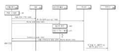
도 4는 일 실시 예에 따른 전자 장치 및 외부 전자 장치 간의 연결 방법 흐름도이다.4 is a flowchart of a connection method between an electronic device and an external electronic device according to an exemplary embodiment.
도 4에 도시된 동작들은 전자 장치(예: 도 1의 전자 장치(100))에 의해 수행될 수 있다. 상기 동작들 중 적어도 일부는 프로세서(예: 도 1 또는 도 2의 프로세서(110))에 의해 수행되고, 명령어의 형태로 메모리에 저장될 수 있다. 예를 들어, 식별 회로(130) 및 USB 컨트롤러(111)의 동작으로 기술된 사항은 프로세서 또는 메모리에 포함된 프로그램(예: 회로 드라이버)에서 동작될 수 있다.The operations illustrated in FIG. 4 may be performed by an electronic device (eg, the electronic device 100 of FIG. 1 ). At least some of the above operations may be performed by a processor (eg, the processor 110 of FIG. 1 or FIG. 2 ) and stored in a memory in the form of an instruction. For example, items described as operations of the
일 실시 예에 따르면, 전자 장치는 입출력 인터페이스의 부식을 방지하기 위해 2 단계에 걸쳐서 외부 장치(예: 도 3의 전자 장치(200))와의 연결을 인식할 수 있다. 전자 장치(예: 도 1의 전자 장치(100))가 ADC 값을 통해 외부 장치를 인지한 경우에도, 이물질 등에 의해 ADC 값이 오인식되는 경우가 발생할 수 있다. 전자 장치는 포고 핀의 방수, 부식 방지 또는 불필요한 전력 낭비를 줄이기 위해 외부 장치의 연결에 대해 추가적인 확인을 수행할 수 있다.According to an embodiment, the electronic device may recognize a connection with an external device (eg, the
동작 401에서, 전자 장치(예: 식별 회로(130)(예: 도 1 또는 도 2의 식별 회로(130)))는 외부 장치의 식별자를 인식할 수 있다. 예컨대, 상기 외부 장치의 식별자는 포고 ID일 수 있다. 포고 ID는 입출력 인터페이스(140)(예: 도 1 또는 도 2의 입출력 인터페이스(140))에서의 저항 값에 대응할 수 있다.In
동작 403에서, 상기 식별자의 인식에 응답하여, 전자 장치(예: 프로세서 또는 식별 회로(130))는 데이터 경로를 설정할 수 있다. 예컨대, 전자 장치가 식별 회로(130)를 통해, 멀티플렉서(150)(예: 도 2의 멀티플렉서(150))가 제2 데이터 경로(또는 USB 경로)에 연결된 상태에서 상기 식별자를 인식하면, 전자 장치는 멀티플렉서(150)를 제1 데이터 경로(또는 포고 경로)에 연결하도록 제어할 수 있다. 이 때, 제2 데이터 경로는 디폴트 경로일 수 있다. 멀티플렉서(150)는, 프로세서의 제어에 따라, 제2 입출력 인터페이스(160)(예: 도 2의 제2 입출력 인터페이스(160))의 데이터 핀으로부터 제1 입출력 인터페이스(140)(예: 도 1 또는 도 2의 제1 입출력 인터페이스(140))의 데이터 핀으로 데이터 경로를 변경할 수 있다.In operation 403 , in response to the recognition of the identifier, the electronic device (eg, the processor or the identification circuit 130 ) may establish a data path. For example, when the electronic device recognizes the identifier through the
동작 405에서, 전자 장치(예: 프로세서 및/또는 식별 회로(130))는 부스터(142)(예: 도 1 또는 도 2의 부스터(142))를 턴 온할 수 있다. 여기서, 부스터(142)의 턴 온은 VBUS 공급을 활성화 것으로 이해될 수 있다. 전자 장치는 부스터(142)를 제어하여, 제1 입출력 인터페이스(140)의 VBUS 핀을 통해 외부 전자 장치로 전원(power)을 내어줄 수 있다. 동작 405는 동작 403과 동시에 수행되거나 동작 403에 비해 먼저 수행될 수도 있다. 이러한, 동작은 포고 부스터를 턴 온 하는 것으로 참조할 수 있다.In operation 405 , the electronic device (eg, the processor and/or the identification circuit 130 ) may turn on the booster 142 (eg, the
동작 407에서, 전자 장치(예: 식별 회로(130) 또는 프로세서)는 USB 호스트 동작의 턴 온을 요청할 수 있다. 예컨대, 식별 회로(130) 또는 USB 컨트롤러(111)로 USB 호스트(host) 동작의 턴 온을 요청할 수 있다. 예컨대, 식별 회로(130)는 프로세서 또는 USB 컨트롤러(111)로 호스트 턴 온 요청 메시지를 전송할 수 있다.In operation 407 , the electronic device (eg, the
동작 409에서, 상기 호스트 턴 온 요청 메시지에 응답하여, 전자 장치(예: 프로세서 또는 USB 컨트롤러(111))는 호스트 기능을 턴 온할 수 있다. USB 컨트롤러(111)는 호스트 기능을 턴 온할 수 있다. 프로세서는 USB 컨트롤러(111)가 호스트 기능을 턴 온하도록 제어할 수 있다. USB 컨트롤러(111)는 호스트 기능을 수행하는 호스트 블록을 포함할 수 있다.In
동작 411에서, 전자 장치(예: 프로세서(110) 또는 USB 컨트롤러(111))는 외부 장치를 확인할 수 있다. 전자 장치는 포고 핀을 포함하는 입출력 인터페이스를 통해 외부 장치가 인식되는지 추가적으로 확인할 수 있다. 예를 들어, 프로세서(110) 또는 USB 컨트롤러(111) USB 이뉴머레이션 절차를 개시(trigger)할 수 있다. 전자 장치는 USB 이뉴머레이션 절차를 통해 외부 USB 디바이스를 인식하고 그에 따른 기능(예: USB class 기능)을 활성화하여 USB 통신을 시작할 수 있다. 전자 장치는 특정 시점으로부터 일정 시간 이후에 외부 장치가 인식이 되었는지 확인할 수 있다. 예컨대, VBUS가 켜진 후, 3초 이내에 외부 장치가 인식이 되었는지 확인할 수 있다. 전자 장치는 상기 일정 시간 이후에도 외부 장치가 인식 되지 않으면, 부스터(142)를 제어하여 외부 전자 장치에 내어주는 전원을 턴 오프할 수 있다. 예컨대, 부스터(142)의 VBUS를 끌 수 있다.In operation 411 , the electronic device (eg, the processor 110 or the USB controller 111 ) may identify an external device. The electronic device may additionally check whether an external device is recognized through an input/output interface including a pogo pin. For example, the processor 110 or the
일 실시 예에 따르면, 부스터(142)가 VBUS 전원을 내어주면, 외부 장치(예: 도 3의 전자 장치(200))는 수신한 전원으로 구동이 시작될 수 있다. 외부 장치의 USB 컨트롤러(예: 도 3의 USB 컨트롤러(211))는 데이터 핀(예: D+ 핀)의 신호 선을 풀업(pull up)하게 되면, 전자 장치(100)의 USB 컨트롤러(111)는 데이터 핀이 풀업 된 것을 감지하고, USB 이뉴머레이션 절차를 개시하여 USB 디바이스를 인식할 수 있다.According to an embodiment, when the
상기 외부 장치의 인식은 전자 장치 입장에서 USB 디바이스의 인식에 대응할 수 있다. 상기 외부 장치가 USB 디바이스로 인식되면, 전자 장치는 USB 호스트로 동작할 수 있다.The recognition of the external device may correspond to the recognition of the USB device from the standpoint of the electronic device. When the external device is recognized as a USB device, the electronic device may operate as a USB host.
동작 413에서, 전자 장치(예: USB 컨트롤러(111) 또는 프로세서(110))는 특정 시점으로부터 일정 시간 이내에 외부 장치가 인식 되지 않으면, 일정 시간이 경과 후 상기 외부 장치가 없다고 판단할 수 있다. 전자 장치는 상기 외부 장치가 없음을 나타내는 메시지를 식별 회로(130)에 전송할 수 있다. 예컨대, USB 컨트롤러(111)는 상기 일정 시간 동안 데이터 핀을 통해 통신되는 데이터를 모니터할 수 있다. 상기 일정 시간 구간 내에 상기 데이터가 통신되지 않으면, USB 컨트롤러(111)는 외부 장치가 없다고 판단할 수 있다. 또는 상기 동작은 프로세서(110) 또는 프로세서(110)에서 동작하는 USB 컨트롤러 드라이버에 의해 수행될 수 있다.In operation 413, if the external device is not recognized within a predetermined time from a specific time point, the electronic device (eg, the
동작 415에서, 전자 장치(예: 프로세서(110) 또는 USB 컨트롤러(111))는 상기 외부 장치가 없음을 확인하고, 전원 공급을 멈출 수 있다. 이러한 동작은 부스터(142)를 턴 오프하는 동작으로 참조할 수 있다. 상기 포고 핀의 부식 방지를 위해, 전자 장치는 상기 부스터(142)의 VBUS를 비활성화할 수 있다.In operation 415 , the electronic device (eg, the processor 110 or the USB controller 111 ) may confirm that the external device does not exist and stop supplying power. This operation may be referred to as an operation of turning off the
외부 장치가 있다고 인식한 경우, 전자 장치는 외부 장치와의 연결을 수행할 수 있다.When recognizing that there is an external device, the electronic device may connect to the external device.
동작 417에서, 외부 장치 TA가 연결되면, 전자 장치는 충전기(190)를 통해 충전 전류를 획득할 수 있다. 전자 장치는 충전기(190)를 통해 충전 전류를 받고, 배터리를 충전할 수 있다. 전자 장치는 상기 입출력 인터페이스의 전원 핀(VBUS in)을 통해 충전 전류를 획득할 수 있다. 전자 장치는, 배터리를 충전하면서 외부 장치와 데이터 통신을 수행할 수 있다.In operation 417 , when the external device TA is connected, the electronic device may acquire a charging current through the
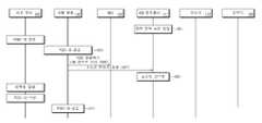
도 5는 일 실시 예에 따른 전자 장치가 외부 장치와 연결하는 방법의 흐름도이다.5 is a flowchart of a method of connecting an electronic device with an external device according to an exemplary embodiment.
도 5에 도시된 동작들은 전자 장치(예: 도 2의 전자 장치(100))에 의해 수행될 수 있다. 상기 동작들 중 적어도 일부는 프로세서(예: 도 1 또는 도 2의 프로세서(110))에 의해 수행되고, 명령어의 형태로 메모리에 저장될 수 있다. 예를 들어, 식별 회로(130) 및 USB 컨트롤러(111)의 동작으로 기술된 사항은 프로세서 또는 메모리에 포함된 프로그램(예: 회로 드라이버)에서 동작될 수 있다.The operations illustrated in FIG. 5 may be performed by an electronic device (eg, the electronic device 100 of FIG. 2 ). At least some of the above operations may be performed by a processor (eg, the processor 110 of FIG. 1 or FIG. 2 ) and stored in a memory in the form of an instruction. For example, items described as operations of the
이하의 실시 예에서, 제1 입출력 인터페이스(예: 도 2의 제1 입출력 인터페이스(140))에 연결된 외부 장치(예: 도 3의 외부 장치(200))는 제1 외부 장치로 참조하고, 제2 입출력 인터페이스(예: 도 2의 제2 입출력 인터페이스(160))에 연결된 외부 장치는 제2 외부 장치로 참조할 수 있다.In the following embodiments, an external device (eg, the
일 실시 예에 따르면, 전자 장치는 상기 제2 외부 장치와 데이터 통신 중에 상기 제1 외부 장치를 인식하면, 상기 제1 외부 장치에 연관된 동작을 상기 제2 외부 장치에 우선하여 수행할 수 있다. 다시 말해, 상기 제1 외부 장치는 상기 제2 외부 장치에 대해 우선 순위를 가질 수 있다.According to an embodiment, when recognizing the first external device during data communication with the second external device, the electronic device may perform an operation related to the first external device with priority over the second external device. In other words, the first external device may have priority over the second external device.
동작 501에서, 전자 장치는 제2 외부 장치와의 연결을 검출할 수 있다. 상기 전자 장치는 CCIC(170)(예: 도 2의 연결 설정 회로(170))를 통해서 제2 입출력 인터페이스에서의 CC 핀에서 제2 외부 장치가 연결된 것을 검출할 수 있다. 상기 제2 외부 장치에 연관된 동작은 USB 규격을 참조할 수 있다.In
동작 503에서, 전자 장치는 부스터 기능을 턴 온할 수 있다. 프로세서, USB 컨트롤러(111) 및/또는 CCIC(170)는 제2 충전기(180)를 제어하여 전원 부스터 기능을 턴 온할 수 있다. 상기 전원은 VBUS 전원일 수 있다. 이러한, 동작은 VBUS 부스터(booster) 기능을 턴 온 하는 것에 대응할 수 있다.In operation 503, the electronic device may turn on the booster function. The processor, the
동작 505에서, 전자 장치는 USB 호스트 동작들을 활성화할 수 있다. 예컨대, 전자 장치는 CCIC(170)를 통해 USB 컨트롤러(111) 또는 USB 호스트 동작들을 활성화할 수 있다. 예컨대, CCIC(170)는 USB 컨트롤러(111)를 턴 온(turn-on) 또는 USB 호스트 기능을 턴 온할 수 있다. USB 컨트롤러(111)는 USB 호스트 기능을 수행하는 구성을 포함할 수 있다. 전자 장치는 제2 외부 장치와의 USB 연결을 수행하고, 상기 제2 외부 장치와 USB 연결 상태에 있을 수 있고, 데이터 경로는 제2 데이터 경로에 연결된 상태일 수 있다.In operation 505 , the electronic device may activate USB host operations. For example, the electronic device may activate the
동작 507에서, 전자 장치는 식별 회로(130)를 통해서 제1 외부 장치의 식별자를 인식할 수 있다. 예컨대, 상기 제1 외부 장치의 식별자는 포고 ID일 수 있다.In
상기 제1 외부 장치의 식별자를 인식하면, 전자 장치(예: 프로세서 또는 USB 컨트롤러(111))는 상기 제2 외부 장치와의 연결을 끊어버리고, 상기 제1 외부 장치와의 연결을 수행할 수 있다. 이를 위해, 식별 회로(130)는 상기 제1 외부 장치의 식별자를 프로세서 또는 USB 컨트롤러(111)로 전달할 수 있다.Upon recognizing the identifier of the first external device, the electronic device (eg, the processor or the USB controller 111) may disconnect the second external device and establish a connection with the first external device. . To this end, the
동작 509에서, 상기 식별자의 인식에 응답하여, 전자 장치(예: 프로세서, USB 컨트롤러(111) 및/또는 식별 회로(130))는 데이터 경로를 변경할 수 있다. 예컨대, 멀티플렉서(150)(예: 도 2의 멀티플렉서(150))가 제2 데이터 경로에 연결된 상태에서 상기 식별자를 인식하면, 전자 장치는 멀티플렉서(150)를 제1 데이터 경로에 연결하도록 제어할 수 있다.In operation 509 , in response to the recognition of the identifier, the electronic device (eg, the processor, the
동작 511에서, 전자 장치(예: 프로세서, USB 컨트롤러(111) 및/또는 식별 회로(130))는 부스터 기능을 턴 오프할 수 있다. 상기 전원은 VBUS 전원일 수 있다. 이러한, 동작은 VBUS 부스터(booster)를 턴 오프 하는 것으로 참조할 수 있다.In operation 511 , the electronic device (eg, the processor, the
동작 513에서, 전자 장치(예: 프로세서, USB 컨트롤러(111) 및/또는 식별 회로(130))는 부스터(142)의 일부 기능을 턴 온시킬 수 있다. 전자 장치(예: 프로세서(110))는 부스터(142)에 메시지를 전달하고, 부스터 기능을 켤 수 있다. 이러한, 동작은 포고 부스터를 턴 온 하는 것으로 참조할 수 있다.In operation 513 , the electronic device (eg, the processor, the
동작 515에서, 전자 장치(예: 식별 회로(130))는 프로세서(110)로 호스트 턴 온 요청을 수행할 수 있다. 예컨대, 식별 회로(130)는 프로세서(110)로 호스트 턴 온 요청 메시지를 전송할 수 있다. 식별 회로(130)는 USB 컨트롤러(111)로 호스트 턴 온 요청 메시지를 전송할 수 있다.In operation 515 , the electronic device (eg, the identification circuit 130 ) may perform a host turn-on request to the processor 110 . For example, the
동작 517에서, 전자 장치(예: 프로세서 또는 USB 컨트롤러(111))는 호스트 기능을 턴 온할 수 있다. 다만, 동작 507에 의해 호스트는 이미 턴 온 상태일 수 있다.In
동작 519에서, 전자 장치(예: 프로세서 또는 USB 컨트롤러(111))는 제1 외부 장치를 확인할 수 있다. 전자 장치는 제1 입출력 인터페이스(데이터 핀)를 통해 제1 외부 장치가 인식되는지 추가적으로 확인할 수 있다. USB 컨트롤러(111)는 특정 시점으로부터 일정 시간(T) 이내에 제1 외부 장치가 인식이 되는지 확인할 수 있다.In operation 519, the electronic device (eg, the processor or the USB controller 111) may identify the first external device. The electronic device may additionally check whether the first external device is recognized through the first input/output interface (data pin). The
동작 521에서, 상기 일정 시간 이내에 제1 외부 장치를 인식하지 못한 경우(예: 입출력 인터페이스에 물 또는 먼지 등의 이물질이 있는 경우), 전자 장치(예: 프로세서 또는 USB 컨트롤러(111))는 제1 외부 장치가 없음을 식별 회로(130)에 알릴 수 있다. 전자 장치(예: 프로세서)는 식별 회로(130)에 제1 외부 장치가 없음을 알리는 메시지를 전송할 수 있다.In operation 521, when the first external device is not recognized within the predetermined time (eg, when there is a foreign object such as water or dust in the input/output interface), the electronic device (eg, the processor or the USB controller 111) performs the first It may inform the
동작 523에서, 전자 장치(예: 프로세서, USB 컨트롤러(111) 또는 식별 회로(130))는 상기 외부 장치가 없음을 확인하고, 부스터 기능을 턴 오프할 수 있다. 상기 포고 핀의 부식 방지를 위해, 전자 장치(예: 프로세서)는 상기 부스터(142)의 VBUS 기능을 끌 수 있다. 식별 회로(130) 또는 부스터(142)에서 제1 외부 장치가 있다고 인식한 경우, 제1 외부 장치와의 연결을 수행할 수 있다.In operation 523 , the electronic device (eg, the processor, the
동작 525 이하의 동작은 제1 외부 장치와 전자 장치의 연결 중에 제1 외부 장치와 전자 장치의 연결이 끊어진 경우 전자 장치의 동작을 나타낸다.Operations 525 and below indicate an operation of the electronic device when the first external device and the electronic device are disconnected while the first external device and the electronic device are connected.
동작 525에서 전자 장치(예: 프로세서, USB 컨트롤러(111) 또는 식별 회로(130))는 제1 외부 장치의 식별자의 분리(detach)를 검출할 수 있다. 예컨대, 식별 회로(130)가 식별자의 분리를 검출하면, 프로세서로 식별자의 분리를 알릴 수 있다. In operation 525 , the electronic device (eg, the processor, the
동작 527에서 전자 장치(예: 프로세서, USB 컨트롤러(111) 또는 식별 회로(130))는 상기 분리에 응답하여, 데이터 경로를 디폴트 경로로 변경할 수 있다. 상기 디폴트 경로는 예컨대, 제2 데이터 경로일 수 있다. 전자 장치는 멀티플렉서(150)에 연결된 데이터 경로를 제2 데이터 경로로 설정할 수 있다. 전자 장치는 제2 데이터 경로에 연결되도록 멀티 플렉서(150)를 제어할 수 있다.In operation 527, the electronic device (eg, the processor, the
동작 529에서, 전자 장치(예: 프로세서, USB 컨트롤러(111) 또는 식별 회로(130))는 상기 부스터(142)의 전원을 턴 오프할 수 있다. 상기 부스터(142)는 VBUS를 턴 오프할 수 있다.In operation 529 , the electronic device (eg, the processor, the
동작 531에서, 전자 장치(예: 프로세서, USB 컨트롤러(111) 또는 식별 회로(130))는 VBUS 부스터 기능을 턴 온할 수 있다. 전자 장치는 제2 충전기(180)를 통해 VBUS 부스터 기능을 턴 온할 수 있다.In operation 531 , the electronic device (eg, the processor, the
동작 533에서, 전자 장치는 CC 핀 검출을 수행할 수 있다. 예컨대, CCIC(170)는 CC 핀 검출을 수행할 수 있다. CC 핀의 검출 및 연결 동작은 USB 규격을 참조할 수 있다. 이후, 전자 장치는 제2 외부 장치와 연결을 다시 수행할 수 있다.In
도 6은 일 실시 예에 따른 전자 장치가 외부 장치와 연결 중에 전력 절약 모드에 진입하는 방법을 설명한다.6 illustrates a method for an electronic device to enter a power saving mode while being connected to an external device, according to an exemplary embodiment.
도 6에 도시된 동작들은 전자 장치(예: 도 1 또는 도 2의 전자 장치(100))에 의해 수행될 수 있다. 상기 동작들 중 적어도 일부는 프로세서(예: 도 1 또는 도 2의 프로세서(110))에 의해 수행되고, 명령어의 형태로 메모리에 저장될 수 있다. 이하의 실시 예에서, 제1 입출력 인터페이스(예: 도 2의 제1 입출력 인터페이스(140))에 연결된 외부 장치(200)(예: 도 3의 외부 장치(200))로 참조할 수 있다. 상기 외부 장치(200)는 포고 USB 디바이스로 참조할 수도 있다.The operations illustrated in FIG. 6 may be performed by an electronic device (eg, the electronic device 100 of FIG. 1 or 2 ). At least some of the above operations may be performed by a processor (eg, the processor 110 of FIG. 1 or FIG. 2 ) and stored in a memory in the form of an instruction. In the following embodiments, reference may be made to the external device 200 (eg, the
USB 규격에 따라 동작을 수행 시 전자 장치에는 많은 양의 전력 소모가 발생할 수 있다. 이하의 실시 예에서는, 전자 장치가 외부 장치와 연결 중에 많은 양의 전력을 사용하지 않아도 되는 경우에는 전력 절약 모드에 진입할 수 있다.When an operation is performed according to the USB standard, a large amount of power may be consumed in the electronic device. In the following embodiment, when the electronic device does not need to use a large amount of power while being connected to an external device, the electronic device may enter the power saving mode.
이하의 동작을 설명하기 위해, 전자 장치가 외부 장치(200)를 인식하고 상기 외부 장치(200)와 연결된 것을 가정한다. 예를 들어, 식별 회로(130) 및 USB 컨트롤러(111)의 동작으로 기술된 사항은 프로세서 또는 메모리에 포함된 프로그램(예: 회로 드라이버)에서 동작될 수 있다.To describe the following operations, it is assumed that the electronic device recognizes the
동작 601에서, 전자 장치(예: 프로세서 또는 USB 컨트롤러(111))는 전력 절약 모드에 진입할 수 있다. 전자 장치는 데이터 통신을 모니터링하고, 전력 절약 모드 진입 여부를 결정할 수 있다.In operation 601 , the electronic device (eg, the processor or the USB controller 111 ) may enter a power saving mode. The electronic device may monitor data communication and determine whether to enter the power saving mode.
일 실시 예에 따르면, 전자 장치는 일정 시간 동안 외부 장치(예: 도 3의 전자 장치(100))와의 패킷 교환이 있는지 확인할 수 있다. 일정 시간 동안, 외부 장치와의 패킷 교환이 없으면, 전자 장치는 전력 절약 모드로 진입할 수 있다. 상기 패킷은 예를 들어, SOF(start of frame) 패킷일 수 있다.According to an embodiment, the electronic device may check whether there is a packet exchange with an external device (eg, the electronic device 100 of FIG. 3 ) for a predetermined time. If there is no packet exchange with the external device for a certain period of time, the electronic device may enter the power saving mode. The packet may be, for example, a start of frame (SOF) packet.
일 실시 예에 따르면, 상기 전력 절약 모드의 진입은 L1 또는 L2 모드일 수 있다. 이하, 전력 절약 모드를 L2 모드로 예시한다. 전자 장치는 일정 시간 동안 SOF 패킷이 없으면, 외부 장치와의 통신 연결이 비활성화(inactive) 상태라고 인지하고, L2 모드로 진입할 수 있다.일 실시 예에 따르면, 전자 장치는 상기 전력 절약 모드의 진입을 확인하고 외부 장치(200)에 전력 절약 모드에 연관된 메시지를 전송할 수 있다. 전력 절약 모드에 관한 설명은 후술하도록 한다.According to an embodiment, the entry into the power saving mode may be an L1 or L2 mode. Hereinafter, the power saving mode is exemplified as the L2 mode. If there is no SOF packet for a predetermined period of time, the electronic device may recognize that the communication connection with the external device is in an inactive state and enter the L2 mode. According to an embodiment, the electronic device enters the power saving mode may be checked and a message related to the power saving mode may be transmitted to the
동작 603에서, 전자 장치(프로세서, USB 컨트롤러(111) 또는 식별 회로(130))는 외부 장치(200)와의 데이터 통신 중에 외부 장치(200)의 식별자 변경을 확인할 수 있다. 예컨대, 전자 장치는 동작 601에서 검출한 식별자(예: 제1 저항 값)와는 다른 값의 식별자(예: 제2 저항 값)를 식별 회로(130)를 통해 검출할 수 있다. 상기 식별자의 변경은 제1 입출력 인터페이스(예: 도 1의 제1 입출력 인터페이스(140))의 포고 ID 핀에 연결된 저항 값의 변경에 대응할 수 있다. 일 실시 예에 따르면, 외부 장치(200)는 상기 전자 장치의 전력 절약 모드에 연관된 메시지에 대한 응답으로 상기 식별자를 변경할 수 있다.In
동작 605에서, 전자 장치(예: 프로세서, USB 컨트롤러(111) 또는 식별 회로(130))는 외부 장치(200)의 식별자 변경을 확인하면(또는, 외부 장치로부터 포고 식별자가 없어진 것을 감지하면), 데이터 경로를 변경할 수 있다. 예컨대, 프로세서는 식별 회로(130)를 통해 식별자 변경을 확인하고, 데이터 통신을 위한 경로를 제2 데이터 경로로 변경할 수 있다. 멀티플렉서(130)는 제2 데이터 경로를 선택하도록 설정될 수 있다. 다양한 실시예에 따르면 동작 605는 생략될 수 있다.In operation 605, when the electronic device (eg, the processor, the
동작 607에서, 전자 장치(예: 프로세서, USB 컨트롤러(111) 또는 식별 회로(130))는 USB 호스트 기능을 턴 오프할 수 있다. 전자 장치는 USB 컨트롤러(111)의 호스트 기능을 턴 오프 하도록 USB 컨트롤러(111)를 제어할 수 있다. 예컨대, 식별 회로(130)는 USB 컨트롤러(111)로 호스트 턴 오프 요청 메시지를 전송할 수 있다.In operation 607 , the electronic device (eg, the processor, the
동작 609에서, 전자 장치(예: 프로세서 또는 USB 컨트롤러(111))는 상기 호스트 동작을 턴 오프할 수 있다. USB 컨트롤러(111)는 상기 호스트 턴 오프 메시지에 응답하여, 호스트 동작을 턴 오프할 수 있다. USB 컨트롤러(111)는 호스트 기능을 수행하는 호스트 블록을 포함하고, 상기 호스트 블록을 턴 오프할 수 있다.In
다양한 실시 예에 따르면, 상기 호스트 블록을 턴 오프 하는 경우에도, 전자 장치는 추후 외부 장치(200)와의 재연결을 고려하여 부스터(142)의 VBUS 기능을 턴 오프하지 않고, 턴 온 상태로 유지할 수 있다. 부스터(142)는 계속하여 외부 장치(200)로 VBUS 전원을 공급할 수 있다. 이 경우, 다양한 실시예에 따르면, 부스터(142)에서 공급되는 VBUS의 전력 량은 외부 장치(200)와 통신 연결된 상황에서의 전력 량 보다 적은 값일 수 있다. 다시 말해, 호스트 기능이 턴-오프 되면, 전자 장치는 VBUS로 내어주는 전력 량을 줄일 수 있다.According to various embodiments, even when the host block is turned off, the electronic device may maintain the turned-on state without turning off the VBUS function of the
일 실시 예에 따르면, 외부 장치(200)는 특정 이벤트(예: 입력장치(270)를 통한 사용자 입력 이벤트)가 발생하면, 상기 특정 이벤트에 응답하여 외부 장치(200) 식별자를 변경할 수 있다. 예컨대, 외부 장치(200)의 식별자를 변경 이전의 식별자로 복원할 수 있다.According to an embodiment, when a specific event (eg, a user input event through the input device 270 ) occurs, the
동작 611에서, 전자 장치(예: 프로세서, USB 컨트롤러(111) 및/또는 식별 회로(130))는 상기 복원된 식별자를 검출할 수 있다. 예를 들어, 전자 장치는 식별 회로(130)를 통해 입출력 인터페이스(140)의 식별 핀에 걸리는 저항이 제2 저항 값에서 제1 저항 값으로 변경된 것을 검출할 수 있다. 전자 장치는 상기 복원된 식별자의 검출에 응답하여, 외부 장치(200)와의 연결을 다시 수행할 수 있다. 예컨대, 전자 장치는 도 4에 도시된 외부 장치와의 연결 동작을 수행할 수 있다. 이 경우, 다양한 실시예에 따르면, 부스터(142)의 VBUS 기능은 턴 온 상태이므로 동작 405는 수행하지 않을 수 있다. 전자 장치는 VBUS 전력 량을 증가시킬 수 있다.In
경우에 따라서는, 전자 장치는 전력 절약 모드에서 부스터(142)의 VBUS 기능을 턴 오프할 수도 있다. 이 경우, 전자 장치는 외부 장치(200)에 다시 연결하는 경우에 동작 405를 수행할 수 있다.In some cases, the electronic device may turn off the VBUS function of the
도 7은 일 실시 예에 따른 전자 장치의 전력 절약 방법의 개략적인 흐름도를 나타낸다.7 is a schematic flowchart of a power saving method of an electronic device according to an exemplary embodiment.
도 7에 도시된 동작들은 전자 장치(예: 도 3의 전자 장치(200))에 의해 수행될 수 있다. 상기 동작들 중 적어도 일부는 프로세서(예: 도 3의 프로세서(210))에 의해 수행되고, 명령어의 형태로 메모리에 저장될 수 있다. 이하의 실시 예에서, 전자 장치의 입출력 인터페이스(예: 도 2의 제1 입출력 인터페이스(140))에 연결된 외부 장치는 도 1 또는 도 2의 전자 장치(100)일 수 있다. 상기 전자 장치는 예컨대, 포고 USB 디바이스일 수 있고, 도 4 내지 도 6의 외부 장치(예: 도 6의 외부 장치(200))에 대응할 수 있다.The operations illustrated in FIG. 7 may be performed by an electronic device (eg, the
동작 701에서, 전자 장치는 외부 장치가 전력 절약 모드에 진입한 것을 확인할 수 있다. 상기 전자 장치는, 외부 장치로부터 전력 절약 모드 연관된 메시지를 획득할 수 있다.In
동작 703에서, 전자 장치는 상기 전자 장치의 식별자를 변경할 수 있다. 상기 전자 장치는 제1 식별자에서 제2 식별자로 변경할 수 있다. 다시 말해, 상기 외부 장치의 포고 핀에서 전자 장치의 저항 값은 제1 값에서 제2 값으로 변경될 수 있다. 상기 식별자는 포고 ID일 수 있다. 전자 장치는 상기 전력 절약 모드에 연관된 메시지에 응답하여, 상기 식별자를 변경할 수 있다.In
동작 705에서, 전자 장치는 상기 외부 장치와의 재연결을 위한 특정 이벤트를 인식할 수 있다. 상기 특정 이벤트는 예를 들어, 상기 전자 장치에 대한 사용자 입력의 발생, 또는 상기 전자 장치의 상태 변경일 수 있다.In
일 실시 예에 따르면, 전자 장치는 상기 특정 이벤트의 감지를 위해 전력 절약 모드에서도 외부 장치로부터 전원을 공급받을 수 있다. 상기 전자 장치의 입출력 인터페이스(예: 도 3의 입출력 인터페이스(240))는 상기 전원을 공급받기 위한 전원 핀을 포함할 수 있다. 이를 위해, 외부 장치는 부스터(142)의 전원이 온(on) 상태일 수 있다.According to an embodiment, the electronic device may receive power from the external device even in the power saving mode to detect the specific event. The input/output interface (eg, the input/
또는 전자 장치는 상기 수퍼 캡(super cap) 또는 소형 배터리와 같이 전원을 공급할 수 있는 회로를 더 포함하거나, 외부 장치와 TA 연결된 상태일 수 있다. 이 경우, 전자 장치 및 외부 장치는 VBUS 전원 공급이 차단된 상태라도, 특정 이벤트를 감지하고, 그에 따른 동작을 수행할 수 있다.Alternatively, the electronic device may further include a circuit capable of supplying power, such as the super cap or a small battery, or may be in a TA-connected state with an external device. In this case, even when the VBUS power supply is cut off, the electronic device and the external device may detect a specific event and perform an operation accordingly.
동작 707에서, 전자 장치는 상기 특정 이벤트에 응답하여, 식별자를 변경할 수 있다. 예컨대, 전자 장치는 제2 식별자에서 제1 식별자로 식별자로 변경할 수 있다. 상기 특정 이벤트는 예를 들어, 사용자 입력 획득일 수 있다. 상기 전자 장치는 예를 들어, 포고 핀을 통해 전자 장치에 연결되고, USB 통신을 지원하는 키보드일 수 있다. 이 경우, 키보드를 통해 사용자 입력을 획득하면, 전자 장치는 상기 식별자를 변경할 수 있다.In
동작 709에서, 전자 장치는 다시 외부 장치와 연결을 수행하고, 외부 장치로 데이터를 송신하거나 데이터를 수신할 수 있다. 상기 식별자의 변경으로 인해, 외부 장치와의 연결이 트리거링될 수 있다.In
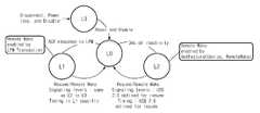
도 8은 일 실시 예에 따른 USB 컨트롤러의 LPM(link power management) 상태 변경을 나타낸다.8 illustrates a link power management (LPM) state change of a USB controller according to an embodiment.
일 실시 예에 따르면, 전자 장치(예: 도 1 또는 도 2의 전자 장치(100), 또는 도 3의 전자 장치(200))는 다양한 상태에서 동작할 수 있다. 예컨대, USB 컨트롤러(예: 도 1의 USB 컨트롤러(111))는 L0 내지 L3 상태에 있을 수 있다.According to an embodiment, the electronic device (eg, the electronic device 100 of FIG. 1 or 2 , or the
L0는 외부 장치와의 연결 상태일 수 있다. L0 상태의 전자 장치는 LPM에 대한 긍정 응답(ACK response)을 획득하면, L1 상태로 천이할 수 있다. L0 상태의 전자 장치는 소정 시간(예: 3ms) 동안 비활성화 상태이면, L2 상태로 천이할 수 있다.L0 may be in a connection state with an external device. When the electronic device in the L0 state obtains an ACK response to the LPM, it may transition to the L1 state. If the electronic device in the L0 state is in an inactive state for a predetermined time (eg, 3 ms), it may transition to the L2 state.
L3는 외부 장치와 연결이 끊어진 상태(disconnect)일 수 있다. L3 상태의 전자 장치는 리셋(reset) 및 인에이블(enable)에 의해 L1 상태로 천이할 수 있다. L0 내지 L3 동작과 관련하여, 구체적인 사항은 USB 관련 규격을 참조할 수 있다.L3 may be in a disconnected state from an external device. The electronic device in the L3 state may transition to the L1 state by reset and enable. Regarding the L0 to L3 operations, for specific details, reference may be made to the USB related standard.
다시 도 7을 참조하면, 전자 장치는 소정 시간 동안 패킷 교환이 없으면, L2 상태로 진입할 수 있고, 재개(resume) 신호를 셋팅하여 L2 모드에서 L0 모드로 진입할 수 있다.Referring back to FIG. 7 , if there is no packet exchange for a predetermined time, the electronic device may enter the L2 state, and may enter the L0 mode from the L2 mode by setting a resume signal.
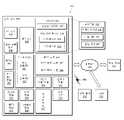
도 9는, 다양한 실시 예들에 따른, 네트워크 환경(900) 내의 전자 장치(901)의 블록도이다.9 is a block diagram of an electronic device 901 in a
도 9를 참조하면, 네트워크 환경(900)에서 전자 장치(901)(예: 도 1 또는 도 2의 전자 장치(100))는 제 1 네트워크(998)(예: 근거리 무선 통신)를 통하여 전자 장치(902)와 통신하거나, 또는 제 2 네트워크(999)(예: 원거리 무선 통신)를 통하여 전자 장치(904)(예: 도 3의 전자 장치(200)) 또는 서버(908)와 통신할 수 있다. 일 실시 예에 따르면, 전자 장치(901)는 서버(908)를 통하여 전자 장치(904)와 통신할 수 있다. 일 실시 예에 따르면, 전자 장치(901)는 프로세서(920), 메모리(930), 입력 장치(950), 음향 출력 장치(955), 표시 장치(960), 오디오 모듈(970), 센서 모듈(976), 인터페이스(977), 햅틱 모듈(979), 카메라 모듈(980), 전력 관리 모듈(988), 배터리(989), 통신 모듈(990), 가입자 식별 모듈(996), 및 안테나 모듈(997)을 포함할 수 있다. 어떤 실시 예에서는, 전자 장치(901)에는, 이 구성요소들 중 적어도 하나(예: 표시 장치(960) 또는 카메라 모듈(980))가 생략되거나 다른 구성 요소가 추가될 수 있다. 어떤 실시 예에서는, 예를 들면, 표시 장치(960)(예: 디스플레이)에 임베디드된 센서 모듈(976)(예: 지문 센서, 홍채 센서, 또는 조도 센서)의 경우와 같이, 일부의 구성요소들이 통합되어 구현될 수 있다.Referring to FIG. 9 , in the
프로세서(920)(예: 도 1의 프로세서(110))는, 예를 들면, 소프트웨어(예: 프로그램(940))를 구동하여 프로세서(920)에 연결된 전자 장치(901)의 적어도 하나의 다른 구성요소(예: 하드웨어 또는 소프트웨어 구성요소)을 제어할 수 있고, 다양한 데이터 처리 및 연산을 수행할 수 있다. 프로세서(920)는 다른 구성요소(예: 센서 모듈(976) 또는 통신 모듈(990))로부터 수신된 명령 또는 데이터를 휘발성 메모리(932)에 로드하여 처리하고, 결과 데이터를 비휘발성 메모리(934)에 저장할 수 있다. 일 실시 예에 따르면, 프로세서(920)는 메인 프로세서(921)(예: 중앙 처리 장치 또는 어플리케이션 프로세서), 및 이와는 독립적으로 운영되고, 추가적으로 또는 대체적으로, 메인 프로세서(921)보다 저전력을 사용하거나, 또는 지정된 기능에 특화된 보조 프로세서(923)(예: 그래픽 처리 장치, 이미지 시그널 프로세서, 센서 허브 프로세서, 또는 커뮤니케이션 프로세서)를 포함할 수 있다. 여기서, 보조 프로세서(923)는 메인 프로세서(921)와 별개로 또는 임베디드되어 운영될 수 있다.The processor 920 (eg, the processor 110 of FIG. 1 ) may, for example, run software (eg, a program 940 ) to be at least one other component of the electronic device 901 connected to the processor 920 . It can control elements (eg, hardware or software components) and can perform various data processing and operations. The processor 920 loads and processes commands or data received from other components (eg, the sensor module 976 or the communication module 990 ) into the volatile memory 932 , and stores the result data in the non-volatile memory 934 . can be stored in According to an embodiment, the processor 920 is operated independently of the main processor 921 (eg, central processing unit or application processor), and additionally or alternatively, uses less power than the
이런 경우, 보조 프로세서(923)는, 예를 들면, 메인 프로세서(921)가 인액티브(예: 슬립) 상태에 있는 동안 메인 프로세서(921)를 대신하여, 또는 메인 프로세서(921)가 액티브(예: 어플리케이션 수행) 상태에 있는 동안 메인 프로세서(921)와 함께, 전자 장치(901)의 구성요소들 중 적어도 하나의 구성요소(예: 표시 장치(960), 센서 모듈(976), 또는 통신 모듈(990))와 관련된 기능 또는 상태들의 적어도 일부를 제어할 수 있다. 일 실시 예에 따르면, 보조 프로세서(923)(예: 이미지 시그널 프로세서 또는 커뮤니케이션 프로세서)는 기능적으로 관련 있는 다른 구성 요소(예: 카메라 모듈(980) 또는 통신 모듈(990))의 일부 구성 요소로서 구현될 수 있다. 메모리(930)는, 전자 장치(901)의 적어도 하나의 구성요소(예: 프로세서(920) 또는 센서모듈(976))에 의해 사용되는 다양한 데이터, 예를 들어, 소프트웨어(예: 프로그램(940)) 및, 이와 관련된 명령에 대한 입력 데이터 또는 출력 데이터를 저장할 수 있다. 메모리(930)는, 휘발성 메모리(932) 또는 비휘발성 메모리(934)를 포함할 수 있다. In this case, the
프로그램(940)은 메모리(930)(예: 도 1의 메모리(120))에 저장되는 소프트웨어로서, 예를 들면, 운영 체제(942), 미들 웨어(944) 또는 어플리케이션(946)을 포함할 수 있다.The program 940 is software stored in the memory 930 (eg, the
입력 장치(950)는, 전자 장치(901)의 구성요소(예: 프로세서(920))에 사용될 명령 또는 데이터를 전자 장치(901)의 외부(예: 사용자)로부터 수신하기 위한 장치로서, 예를 들면, 마이크, 마우스, 또는 키보드를 포함할 수 있다.The
음향 출력 장치(955)는 음향 신호를 전자 장치(901)의 외부로 출력하기 위한 장치로서, 예를 들면, 멀티미디어 재생 또는 녹음 재생과 같이 일반적인 용도로 사용되는 스피커와 전화 수신 전용으로 사용되는 리시버를 포함할 수 있다. 일 실시 예에 따르면, 리시버는 스피커와 일체 또는 별도로 형성될 수 있다.The
표시 장치(960)는 전자 장치(901)의 사용자에게 정보를 시각적으로 제공하기 위한 장치로서, 예를 들면, 디스플레이, 홀로그램 장치, 또는 프로젝터 및 해당 장치를 제어하기 위한 제어 회로를 포함할 수 있다. 일 실시 예에 따르면, 표시 장치(960)는 터치 회로(touch circuitry) 또는 터치에 대한 압력의 세기를 측정할 수 있는 압력 센서를 포함할 수 있다.The display device 960 is a device for visually providing information to a user of the electronic device 901 , and may include, for example, a display, a hologram device, or a projector and a control circuit for controlling the corresponding device. According to an embodiment, the display device 960 may include a touch circuitry or a pressure sensor capable of measuring the intensity of the pressure applied to the touch.
오디오 모듈(970)은 소리와 전기 신호를 쌍방향으로 변환시킬 수 있다. 일 실시 예에 따르면, 오디오 모듈(970)은, 입력 장치(950) 를 통해 소리를 획득하거나, 음향 출력 장치(955), 또는 전자 장치(901)와 유선 또는 무선으로 연결된 외부 전자 장치(예: 전자 장치(902)(예: 스피커 또는 헤드폰))를 통해 소리를 출력할 수 있다.The audio module 970 may interactively convert a sound and an electrical signal. According to an embodiment, the audio module 970 acquires a sound through the
센서 모듈(976)은 전자 장치(901)의 내부의 작동 상태(예: 전력 또는 온도), 또는 외부의 환경 상태에 대응하는 전기 신호 또는 데이터 값을 생성할 수 있다. 센서 모듈(976)은, 예를 들면, 제스처 센서, 자이로 센서, 기압 센서, 마그네틱 센서, 가속도 센서, 그립 센서, 근접 센서, 컬러 센서, IR(infrared) 센서, 생체 센서, 온도 센서, 습도 센서, 또는 조도 센서를 포함할 수 있다.The sensor module 976 may generate an electrical signal or data value corresponding to an internal operating state (eg, power or temperature) of the electronic device 901 or an external environmental state. The sensor module 976 may include, for example, a gesture sensor, a gyro sensor, a barometric pressure sensor, a magnetic sensor, an acceleration sensor, a grip sensor, a proximity sensor, a color sensor, an IR (infrared) sensor, a biometric sensor, a temperature sensor, a humidity sensor, Alternatively, it may include an illuminance sensor.
인터페이스(977)(예: 도 1의 입출력 인터페이스)는 외부 전자 장치(예: 전자 장치(902))와 유선 또는 무선으로 연결할 수 있는 지정된 프로토콜을 지원할 수 있다. 일 실시 예에 따르면, 인터페이스(977)는 HDMI(high definition multimedia interface), USB(universal serial bus) 인터페이스, SD카드 인터페이스, 또는 오디오 인터페이스를 포함할 수 있다.The interface 977 (eg, the input/output interface of FIG. 1 ) may support a designated protocol capable of connecting to an external electronic device (eg, the electronic device 902 ) in a wired or wireless manner. According to an embodiment, the
연결 단자(978)는 전자 장치(901)와 외부 전자 장치(예: 전자 장치(902))를 물리적으로 연결시킬 수 있는 커넥터, 예를 들면, HDMI 커넥터, USB 커넥터, SD 카드 커넥터, 또는 오디오 커넥터(예: 헤드폰 커넥터)를 포함할 수 있다.The
햅틱 모듈(979)은 전기적 신호를 사용자가 촉각 또는 운동 감각을 통해서 인지할 수 있는 기계적인 자극(예: 진동 또는 움직임) 또는 전기적인 자극으로 변환할 수 있다. 햅틱 모듈(979)은, 예를 들면, 모터, 압전 소자, 또는 전기 자극 장치를 포함할 수 있다.The
카메라 모듈(980)은 정지 영상 및 동영상을 촬영할 수 있다. 일 실시 예에 따르면, 카메라 모듈(980)은 하나 이상의 렌즈, 이미지 센서, 이미지 시그널 프로세서, 또는 플래시를 포함할 수 있다.The camera module 980 may capture still images and moving images. According to an embodiment, the camera module 980 may include one or more lenses, an image sensor, an image signal processor, or a flash.
전력 관리 모듈(988)은 전자 장치(901)에 공급되는 전력을 관리하기 위한 모듈로서, 예를 들면, PMIC(power management integrated circuit)의 적어도 일부로서 구성될 수 있다.The power management module 988 is a module for managing power supplied to the electronic device 901 , and may be configured as, for example, at least a part of a power management integrated circuit (PMIC).
배터리(989)는 전자 장치(901)의 적어도 하나의 구성 요소에 전력을 공급하기 위한 장치로서, 예를 들면, 재충전 불가능한 1차 전지, 재충전 가능한 2차 전지 또는 연료 전지를 포함할 수 있다.The
통신 모듈(990)은 전자 장치(901)와 외부 전자 장치(예: 전자 장치(902), 전자 장치(904), 또는 서버(908))간의 유선 또는 무선 통신 채널의 수립, 및 수립된 통신 채널을 통한 통신 수행을 지원할 수 있다. 통신 모듈(990)은 프로세서(920)(예: 어플리케이션 프로세서)와 독립적으로 운영되는, 유선 통신 또는 무선 통신을 지원하는 하나 이상의 커뮤니케이션 프로세서를 포함할 수 있다. 일 실시 예에 따르면, 통신 모듈(990)은 무선 통신 모듈(992)(예: 셀룰러 통신 모듈, 근거리 무선 통신 모듈, 또는 GNSS(global navigation satellite system) 통신 모듈) 또는 유선 통신 모듈(994)(예: LAN(local area network) 통신 모듈, 또는 전력선 통신 모듈)을 포함하고, 그 중 해당하는 통신 모듈을 이용하여 제 1 네트워크(998)(예: 블루투스, WiFi direct 또는 IrDA(infrared data association) 같은 근거리 통신 네트워크) 또는 제 2 네트워크(999)(예: 셀룰러 네트워크, 인터넷, 또는 컴퓨터 네트워크(예: LAN 또는 WAN)와 같은 원거리 통신 네트워크)를 통하여 외부 전자 장치와 통신할 수 있다. 상술한 여러 종류의 통신 모듈(990)은 하나의 칩으로 구현되거나 또는 각각 별도의 칩으로 구현될 수 있다.The communication module 990 establishes a wired or wireless communication channel between the electronic device 901 and an external electronic device (eg, the
일 실시 예에 따르면, 무선 통신 모듈(992)은 가입자 식별 모듈(996)에 저장된 사용자 정보를 이용하여 통신 네트워크 내에서 전자 장치(901)를 구별 및 인증할 수 있다.According to an embodiment, the wireless communication module 992 may use the user information stored in the
안테나 모듈(997)은 신호 또는 전력을 외부로 송신하거나 외부로부터 수신하기 위한 하나 이상의 안테나들을 포함할 수 있다. 일시예에 따르면, 통신 모듈(990)(예: 무선 통신 모듈(992))은 통신 방식에 적합한 안테나를 통하여 신호를 외부 전자 장치로 송신하거나, 외부 전자 장치로부터 수신할 수 있다.The
상기 구성요소들 중 일부 구성요소들은 주변 기기들간 통신 방식(예: 버스, GPIO(general purpose input/output), SPI(serial peripheral interface), 또는 MIPI(mobile industry processor interface))를 통해 서로 연결되어 신호(예: 명령 또는 데이터)를 상호간에 교환할 수 있다.Some of the components are connected to each other through a communication method between peripheral devices (eg, a bus, general purpose input/output (GPIO), serial peripheral interface (SPI), or mobile industry processor interface (MIPI)) to signal (eg commands or data) can be exchanged with each other.
일 실시 예에 따르면, 명령 또는 데이터는 제 2 네트워크(999)에 연결된 서버(908)를 통해서 전자 장치(901)와 외부의 전자 장치(904)간에 송신 또는 수신될 수 있다. 전자 장치(902, 904) 각각은 전자 장치(901)와 동일한 또는 다른 종류의 장치일 수 있다. 일 실시 예에 따르면, 전자 장치(901)에서 실행되는 동작들의 전부 또는 일부는 다른 하나 또는 복수의 외부 전자 장치에서 실행될 수 있다. 일 실시 예에 따르면, 전자 장치(901)가 어떤 기능이나 서비스를 자동으로 또는 요청에 의하여 수행해야 할 경우에, 전자 장치(901)는 기능 또는 서비스를 자체적으로 실행시키는 대신에 또는 추가적으로, 그와 연관된 적어도 일부 기능을 외부 전자 장치에게 요청할 수 있다. 상기 요청을 수신한 외부 전자 장치는 요청된 기능 또는 추가 기능을 실행하고, 그 결과를 전자 장치(901)로 전달할 수 있다. 전자 장치(901)는 수신된 결과를 그대로 또는 추가적으로 처리하여 요청된 기능이나 서비스를 제공할 수 있다. 이를 위하여, 예를 들면, 클라우드 컴퓨팅, 분산 컴퓨팅, 또는 클라이언트-서버 컴퓨팅 기술이 이용될 수 있다. According to an embodiment, the command or data may be transmitted or received between the electronic device 901 and the external
본 문서에 개시된 다양한 실시 예들에 따른 전자 장치는 다양한 형태의 장치가 될 수 있다. 전자 장치는, 예를 들면, 휴대용 통신 장치 (예: 스마트폰), 컴퓨터 장치, 휴대용 멀티미디어 장치, 휴대용 의료 기기, 카메라, 웨어러블 장치, 또는 가전 장치 중 적어도 하나를 포함할 수 있다. 본 문서의 실시 예에 따른 전자 장치는 전술한 기기들에 한정되지 않는다.The electronic device according to various embodiments disclosed in this document may be a device of various types. The electronic device may include, for example, at least one of a portable communication device (eg, a smart phone), a computer device, a portable multimedia device, a portable medical device, a camera, a wearable device, and a home appliance device. The electronic device according to the embodiment of the present document is not limited to the above-described devices.
본 문서의 다양한 실시 예들 및 이에 사용된 용어들은 본 문서에 기재된 기술을 특정한 실시 형태에 대해 한정하려는 것이 아니며, 해당 실시 예의 다양한 변경, 균등물, 및/또는 대체물을 포함하는 것으로 이해되어야 한다. 도면의 설명과 관련하여, 유사한 구성요소에 대해서는 유사한 참조 부호가 사용될 수 있다. 단수의 표현은 문맥상 명백하게 다르게 뜻하지 않는 한, 복수의 표현을 포함할 수 있다. 본 문서에서, "A 또는 B", "A 및/또는 B 중 적어도 하나", "A, B 또는 C" 또는 "A, B 및/또는 C 중 적어도 하나" 등의 표현은 함께 나열된 항목들의 모든 가능한 조합을 포함할 수 있다. "제 1", "제 2", "첫째" 또는 "둘째" 등의 표현들은 해당 구성요소들을, 순서 또는 중요도에 상관없이 수식할 수 있고, 한 구성요소를 다른 구성요소와 구분하기 위해 사용될 뿐 해당 구성요소들을 한정하지 않는다. 어떤(예: 제 1) 구성요소가 다른(예: 제 2) 구성요소에 "(기능적으로 또는 통신적으로) 연결되어" 있다거나 "접속되어" 있다고 언급된 때에는, 상기 어떤 구성요소가 상기 다른 구성요소에 직접적으로 연결되거나, 다른 구성요소(예: 제 3 구성요소)를 통하여 연결될 수 있다.The various embodiments of this document and the terms used therein are not intended to limit the technology described in this document to a specific embodiment, but it should be understood to include various modifications, equivalents, and/or substitutions of the embodiments. In connection with the description of the drawings, like reference numerals may be used for like components. The singular expression may include the plural expression unless the context clearly dictates otherwise. In this document, expressions such as “A or B”, “at least one of A and/or B”, “A, B or C” or “at least one of A, B and/or C” refer to all of the items listed together. Possible combinations may be included. Expressions such as “first”, “second”, “first” or “second” can modify the corresponding components regardless of order or importance, and are only used to distinguish one component from another. The components are not limited. When an (eg, first) component is referred to as being “connected (functionally or communicatively)” or “connected” to another (eg, second) component, that component is It may be directly connected to the component or may be connected through another component (eg, a third component).
본 문서에서 사용된 용어 "모듈"은 하드웨어, 소프트웨어 또는 펌웨어로 구성된 유닛을 포함하며, 예를 들면, 로직, 논리 블록, 부품, 또는 회로 등의 용어와 상호 호환적으로 사용될 수 있다. 모듈은, 일체로 구성된 부품 또는 하나 또는 그 이상의 기능을 수행하는 최소 단위 또는 그 일부가 될 수 있다. 예를 들면, 모듈은 ASIC(application-specific integrated circuit)으로 구성될 수 있다.As used herein, the term “module” includes a unit composed of hardware, software, or firmware, and may be used interchangeably with terms such as, for example, logic, logic block, component, or circuit. A module may be an integrally formed part or a minimum unit or a part of one or more functions. For example, the module may be configured as an application-specific integrated circuit (ASIC).
본 문서의 다양한 실시 예들은 기기(machine)(예: 컴퓨터)로 읽을 수 있는 저장 매체(machine-readable storage media)(예: 내장 메모리(936) 또는 외장 메모리(938))에 저장된 명령어를 포함하는 소프트웨어(예: 프로그램(940))로 구현될 수 있다. 기기는, 저장 매체로부터 저장된 명령어를 호출하고, 호출된 명령어에 따라 동작이 가능한 장치로서, 개시된 실시 예들에 따른 전자 장치(예: 전자 장치(901))를 포함할 수 있다. 상기 명령이 프로세서(예: 프로세서(920))에 의해 실행될 경우, 프로세서가 직접, 또는 상기 프로세서의 제어하에 다른 구성요소들을 이용하여 상기 명령에 해당하는 기능을 수행할 수 있다. 명령은 컴파일러 또는 인터프리터에 의해 생성 또는 실행되는 코드를 포함할 수 있다. 기기로 읽을 수 있는 저장매체는, 비일시적(non-transitory) 저장매체의 형태로 제공될 수 있다. 여기서, ‘비일시적’은 저장매체가 신호(signal)를 포함하지 않으며 실재(tangible)한다는 것을 의미할 뿐 데이터가 저장매체에 반영구적 또는 임시적으로 저장됨을 구분하지 않는다.Various embodiments of the present document include instructions stored in a machine-readable storage media (eg, internal memory 936 or external memory 938) that can be read by a machine (eg, a computer). It may be implemented as software (eg, the program 940). The device is a device capable of calling a stored command from a storage medium and operating according to the called command, and may include an electronic device (eg, the electronic device 901 ) according to the disclosed embodiments. When the instruction is executed by a processor (eg, the processor 920), the processor may directly or use other components under the control of the processor to perform a function corresponding to the instruction. Instructions may include code generated or executed by a compiler or interpreter. The device-readable storage medium may be provided in the form of a non-transitory storage medium. Here, 'non-transitory' means that the storage medium does not include a signal and is tangible, and does not distinguish that data is semi-permanently or temporarily stored in the storage medium.
일시예에 따르면, 본 문서에 개시된 다양한 실시 예들에 따른 방법은 컴퓨터 프로그램 제품(computer program product)에 포함되어 제공될 수 있다. 컴퓨터 프로그램 제품은 상품으로서 판매자 및 구매자 간에 거래될 수 있다. 컴퓨터 프로그램 제품은 기기로 읽을 수 있는 저장 매체(예: compact disc read only memory (CD-ROM))의 형태로, 또는 어플리케이션 스토어(예: 플레이 스토어TM)를 통해 온라인으로 배포될 수 있다. 온라인 배포의 경우에, 컴퓨터 프로그램 제품의 적어도 일부는 제조사의 서버, 어플리케이션 스토어의 서버, 또는 중계 서버의 메모리와 같은 저장 매체에 적어도 일시 저장되거나, 임시적으로 생성될 수 있다.According to an example, the method according to various embodiments disclosed in this document may be included in a computer program product and provided. Computer program products may be traded between sellers and buyers as commodities. The computer program product may be distributed in the form of a machine-readable storage medium (eg compact disc read only memory (CD-ROM)) or online through an application store (eg Play StoreTM ). In the case of online distribution, at least a portion of the computer program product may be temporarily stored or temporarily generated in a storage medium such as a memory of a server of a manufacturer, a server of an application store, or a relay server.
다양한 실시 예들에 따른 구성 요소(예: 모듈 또는 프로그램) 각각은 단수 또는 복수의 개체로 구성될 수 있으며, 전술한 해당 서브 구성 요소들 중 일부 서브 구성 요소가 생략되거나, 또는 다른 서브 구성 요소가 다양한 실시 예에 더 포함될 수 있다. 대체적으로 또는 추가적으로, 일부 구성 요소들(예: 모듈 또는 프로그램)은 하나의 개체로 통합되어, 통합되기 이전의 각각의 해당 구성 요소에 의해 수행되는 기능을 동일 또는 유사하게 수행할 수 있다. 다양한 실시 예들에 따른, 모듈, 프로그램 또는 다른 구성 요소에 의해 수행되는 동작들은 순차적, 병렬적, 반복적 또는 휴리스틱하게 실행되거나, 적어도 일부 동작이 다른 순서로 실행되거나, 생략되거나, 또는 다른 동작이 추가될 수 있다.Each of the components (eg, a module or a program) according to various embodiments may be composed of a singular or a plurality of entities, and some sub-components of the aforementioned sub-components may be omitted, or other sub-components may be various. It may be further included in the embodiment. Alternatively or additionally, some components (eg, a module or a program) may be integrated into a single entity to perform the same or similar functions performed by each corresponding component prior to integration. According to various embodiments, operations performed by a module, program, or other component may be sequentially, parallel, repetitively or heuristically executed, or at least some operations may be executed in a different order, omitted, or other operations may be added. can
Claims (20)
Translated fromKorean하우징,
상기 하우징의 일 부분을 통해 노출되는 복수의 포고 핀들을 포함하고, 외부 장치와 유선 연결 가능한 입출력 인터페이스;
상기 입출력 인터페이스에 전기적으로 연결되고 상기 외부 장치를 식별하도록 구성된 식별 회로;
상기 식별 회로에 전기적으로 연결된 프로세서; 및
상기 입출력 인터페이스에 전기적으로 연결되고, 상기 외부 장치로 전원을 공급하기 위한 부스터를 포함하고,
상기 복수의 포고(pogo) 핀들은;
상기 외부 장치와의 데이터 통신을 위한 적어도 하나의 제1 핀;
상기 식별 회로에 전기적으로 연결되고, 상기 외부 장치의 식별자를 전달하기 위한 제2 핀;
상기 부스터에 전기적으로 연결되는 제3 핀; 및
상기 전자 장치의 그라운드(ground)에 전기적으로 연결되는 제4 핀을 포함하고,
상기 제3 핀은 VBUS를 공급하거나 수신하도록 설정되고, 및
상기 프로세서는,
상기 VBUS가 턴-온 된 이후, 제1 시간 구간 내에 상기 외부 장치가 상기 입출력 인터페이스를 통해 인식되었는지 여부를 결정하고, 및
상기 제1 시간 구간 내에 상기 외부 장치가 인식되지 않은 경우 상기 VBUS를 턴-오프하도록 상기 부스터를 제어하는, 전자 장치.In an electronic device,
housing,
an input/output interface including a plurality of pogo pins exposed through a portion of the housing and capable of wire connection with an external device;
an identification circuit electrically connected to the input/output interface and configured to identify the external device;
a processor electrically coupled to the identification circuit; and
and a booster electrically connected to the input/output interface and configured to supply power to the external device,
The plurality of pogo pins are;
at least one first pin for data communication with the external device;
a second pin electrically connected to the identification circuit and configured to transmit an identifier of the external device;
a third pin electrically connected to the booster; and
and a fourth pin electrically connected to the ground of the electronic device;
the third pin is configured to supply or receive VBUS, and
The processor is
After the VBUS is turned on, it is determined whether the external device is recognized through the input/output interface within a first time interval, and
and controlling the booster to turn off the VBUS when the external device is not recognized within the first time period.
USB(user serial bus) 컨트롤러(controller)를 더 포함하고,
상기 입출력 인터페이스는 상기 USB 컨트롤러에 전기적으로 연결되는, 전자 장치.The method according to claim 1,
Further including a USB (user serial bus) controller (controller),
and the input/output interface is electrically connected to the USB controller.
상기 프로세서 또는 상기 식별 회로는, 적어도 제2 핀에 기반해서 상기 외부 장치와의 통신 연결을 트리거하도록 하는, 전자 장치.The method according to claim 1,
and the processor or the identification circuit trigger a communication connection with the external device based on at least a second pin.
상기 식별 회로는, 상기 제2 핀을 통해서 상기 외부 장치의 식별자를 획득하면, 상기 부스터는 상기 제3 핀을 통해서 전원을 공급하도록 하는, 전자 장치.4. The method of claim 3,
the identification circuit, when obtaining the identifier of the external device through the second pin, causes the booster to supply power through the third pin.
상기 프로세서는:
제2 시간 구간 동안 상기 적어도 하나의 제1 핀을 통해 통신되는 데이터를 모니터하고, 및
상기 제2 시간 구간 내에 상기 데이터가 통신되지 않으면, 상기 전원을 공급하는 동작을 멈추도록 구성된, 전자 장치.5. The method according to claim 4,
The processor is:
monitor data communicated over the at least one first pin during a second time period; and
and stop supplying the power if the data is not communicated within the second time period.
상기 제2 시간 구간은 상기 외부 장치의 식별자를 획득한 이후의 구간을 포함하는, 전자 장치.6. The method of claim 5,
The second time interval includes an interval after obtaining the identifier of the external device.
상기 식별자는 저항값을 가지는, 전자 장치.5. The method according to claim 4,
and the identifier has a resistance value.
상기 식별 회로는, 상기 외부 장치와의 데이터를 통신하는 중에 상기 외부 장치의 식별자의 변경을 검출하는, 전자 장치.The method according to claim 1,
and the identification circuit detects a change in the identifier of the external device while communicating data with the external device.
상기 프로세서 또는 상기 식별 회로는, 상기 식별자의 변경에 응답하여, 상기 데이터의 통신을 멈추도록 하는, 전자 장치.9. The method of claim 8,
and the processor or the identification circuit causes, in response to the change of the identifier, to stop communication of the data.
상기 프로세서 또는 상기 식별 회로는:
상기 식별자의 변경에 응답하여, 상기 부스터가 전원을 공급하는 동작을 멈추도록 하는, 전자 장치.9. The method of claim 8,
The processor or the identification circuit comprises:
In response to the change of the identifier, the booster stops the operation of supplying power.
상기 입출력 인터페이스에 전기적으로 연결된 적어도 하나의 충전기; 및
상기 충전기에 전기적으로 연결된 배터리를 더 포함하는, 전자 장치.The method according to claim 1,
at least one charger electrically connected to the input/output interface; and
and a battery electrically connected to the charger.
상기 입출력 인터페이스는 상기 충전기에 전기적으로 연결되는 제5 핀을 더 포함하고,
상기 제5 핀을 통해 상기 외부 장치로부터 전력을 획득하도록 구성된, 전자 장치.12. The method of claim 11,
The input/output interface further includes a fifth pin electrically connected to the charger,
and obtain power from the external device through the fifth pin.
상기 입출력 인터페이스는 TA(travel adapter)를 지원하는, 전자 장치.The method according to claim 1,
The input/output interface supports a travel adapter (TA), an electronic device.
하우징,
상기 하우징의 제1 부분을 통해 노출되는 표준 USB(user serial bus) 타입의 제1 입출력 인터페이스;
상기 하우징의 제2 부분을 통해 노출되는 복수의 포고 핀들을 포함하는 비표준 USB 타입의 제2 입출력 인터페이스;
상기 제1 입출력 인터페이스 또는 상기 제2 입출력 인터페이스를 선택하기 위한 선택 회로;
상기 선택 회로에 전기적으로 연결되고, 외부 장치를 식별하도록 구성된 식별 회로;
상기 식별 회로에 전기적으로 연결된 프로세서;
상기 제1 입출력 인터페이스 또는 상기 제2 입출력 인터페이스 중 적어도 하나에 전기적으로 연결된 적어도 하나의 충전기; 및
상기 충전기에 전기적으로 연결된 배터리를 포함하고,
상기 복수의 포고 핀들은:
상기 선택 회로에 전기적으로 연결되고, 외부 장치와 데이터를 통신하기 위한 적어도 제1 핀;
상기 선택 회로를 우회해서 상기 식별 회로에 전기적으로 연결되는 제2 핀;
상기 배터리에 전기적으로 연결되는 제3 핀; 및
상기 전자 장치의 그라운드(ground)에 전기적으로 연결되는 제4 핀을 포함하고,
상기 제3 핀은 VBUS를 공급하거나 수신하도록 설정되고, 및
상기 프로세서는,
상기 VBUS가 턴-온 된 이후, 지정된 시간 내에 상기 외부 장치가 상기 입출력 인터페이스를 통해 인식되었는지 여부를 결정하고, 및
상기 지정된 시간 내에 상기 외부 장치가 인식되지 않은 경우 상기 VBUS를 턴-오프하도록 부스터를 제어하는, 전자 장치.In an electronic device,
housing,
a first input/output interface of a standard user serial bus (USB) type exposed through a first portion of the housing;
a second input/output interface of a non-standard USB type including a plurality of pogo pins exposed through the second portion of the housing;
a selection circuit for selecting the first input/output interface or the second input/output interface;
an identification circuit electrically connected to the selection circuit and configured to identify an external device;
a processor electrically coupled to the identification circuit;
at least one charger electrically connected to at least one of the first input/output interface and the second input/output interface; and
a battery electrically connected to the charger;
The plurality of pogo pins include:
at least a first pin electrically connected to the selection circuit and configured to communicate data with an external device;
a second pin electrically coupled to the identification circuit bypassing the selection circuit;
a third pin electrically connected to the battery; and
and a fourth pin electrically connected to the ground of the electronic device;
the third pin is configured to supply or receive VBUS, and
The processor is
After the VBUS is turned on, it is determined whether the external device is recognized through the input/output interface within a specified time, and
and controlling the booster to turn off the VBUS when the external device is not recognized within the specified time.
상기 복수의 포고 핀들은 상기 충전기에 전기적으로 연결된 제5 핀을 더 포함하는, 전자 장치.15. The method of claim 14,
and the plurality of pogo pins further include a fifth pin electrically connected to the charger.
상기 프로세서는, 상기 제2 입출력 인터페이스에 상기 외부 장치가 연결되면, 상기 제4 핀을 통해 상기 외부 장치로 전력을 제공하거나 상기 제5 핀을 통해 상기 외부 장치로부터 전력을 획득하도록 구성된, 전자 장치.16. The method of claim 15,
The processor is configured to provide power to the external device through the fourth pin or obtain power from the external device through the fifth pin when the external device is connected to the second input/output interface.
상기 선택 회로는 멀티플렉서(multiplexer)를 포함하는, 전자 장치.15. The method of claim 14,
wherein the selection circuit comprises a multiplexer.
상기 프로세서 또는 식별 회로는:
상기 외부 장치가 상기 제1 입출력 인터페이스에 연결되고, 다른 외부 장치가 상기 제2 입출력 인터페이스에 연결되면,
상기 멀티플렉서가 상기 멀티플렉서 및 상기 제2 입출력 인터페이스 사이에 데이터를 통신하도록 하되, 상기 멀티플렉서 및 상기 제1 입출력 인터페이스 사이에 데이터를 통신하지 않도록 하는, 전자 장치.18. The method of claim 17,
The processor or identification circuit comprises:
When the external device is connected to the first input/output interface and another external device is connected to the second input/output interface,
and cause the multiplexer to communicate data between the multiplexer and the second input/output interface, but not to communicate data between the multiplexer and the first input/output interface.
USB 컨트롤러(controller)를 더 포함하고,
상기 USB 컨트롤러는 적어도 상기 제2 입출력 인터페이스에 연관된 신호를 생성하도록 구성된, 전자 장치.15. The method of claim 14,
Further comprising a USB controller (controller),
and the USB controller is configured to generate a signal associated with at least the second input/output interface.
상기 USB 컨트롤러는 상기 제1 입출력 인터페이스에 연관된 신호를 생성하도록 구성된, 전자 장치.20. The method of claim 19,
and the USB controller is configured to generate a signal associated with the first input/output interface.
Priority Applications (3)
| Application Number | Priority Date | Filing Date | Title |
|---|---|---|---|
| KR1020170141499AKR102446172B1 (en) | 2017-10-27 | 2017-10-27 | Method for performing communication through input/output interface and apparatus therefor |
| PCT/KR2018/008499WO2019083135A1 (en) | 2017-10-27 | 2018-07-27 | Communication method using input/output interface, and apparatus therefor |
| US16/645,644US11176078B2 (en) | 2017-10-27 | 2018-07-27 | Communication method using input/output interface, and apparatus therefor |
Applications Claiming Priority (1)
| Application Number | Priority Date | Filing Date | Title |
|---|---|---|---|
| KR1020170141499AKR102446172B1 (en) | 2017-10-27 | 2017-10-27 | Method for performing communication through input/output interface and apparatus therefor |
Publications (2)
| Publication Number | Publication Date |
|---|---|
| KR20190047526A KR20190047526A (en) | 2019-05-08 |
| KR102446172B1true KR102446172B1 (en) | 2022-09-23 |
Family
ID=66246617
Family Applications (1)
| Application Number | Title | Priority Date | Filing Date |
|---|---|---|---|
| KR1020170141499AActiveKR102446172B1 (en) | 2017-10-27 | 2017-10-27 | Method for performing communication through input/output interface and apparatus therefor |
Country Status (3)
| Country | Link |
|---|---|
| US (1) | US11176078B2 (en) |
| KR (1) | KR102446172B1 (en) |
| WO (1) | WO2019083135A1 (en) |
Families Citing this family (7)
| Publication number | Priority date | Publication date | Assignee | Title |
|---|---|---|---|---|
| CN114116570B (en)* | 2020-08-28 | 2024-08-02 | 中强光电股份有限公司 | Electronic device control system and electronic device control method |
| CN114977538A (en)* | 2021-02-23 | 2022-08-30 | Oppo广东移动通信有限公司 | Data communication method, device, storage medium, electronic equipment and protective sleeve |
| US11979832B2 (en)* | 2021-11-02 | 2024-05-07 | Snap Inc. | Eyewear having current consumption optimization of wireless system interface |
| US11983132B2 (en)* | 2022-01-25 | 2024-05-14 | Dell Products L.P. | USB connector functionality modification system |
| US20230384843A1 (en)* | 2022-05-27 | 2023-11-30 | Hewlett-Packard Development Company, L.P. | Configuration changes for expansion cards |
| CN115223310A (en)* | 2022-06-30 | 2022-10-21 | 无锡睿勤科技有限公司 | OTG priority selection circuit and multichannel charging circuit |
| CN116382728B (en)* | 2023-02-24 | 2023-11-21 | 荣耀终端有限公司 | Propagation name display method and terminal equipment |
Citations (1)
| Publication number | Priority date | Publication date | Assignee | Title |
|---|---|---|---|---|
| US20160091930A1 (en) | 2014-09-25 | 2016-03-31 | Acer Incorporated | Touch display device and method for launching touch panel of touch display device |
Family Cites Families (27)
| Publication number | Priority date | Publication date | Assignee | Title |
|---|---|---|---|---|
| EP2640170B1 (en)* | 2007-01-06 | 2015-07-29 | Apple Inc. | Wireless headset comprising a housing and an earbud electrically coupled to the housing by a flexible circuit board |
| US8838408B2 (en)* | 2010-11-11 | 2014-09-16 | Optimal Plus Ltd | Misalignment indication decision system and method |
| US9083769B2 (en)* | 2011-09-14 | 2015-07-14 | Barco N.V. | Electronic tool and methods for meetings |
| WO2014066639A1 (en)* | 2012-10-24 | 2014-05-01 | Sells Denyveaus | Apparatus comprising power strip and battery |
| US20140133080A1 (en) | 2012-11-15 | 2014-05-15 | Samsung Electronics Co., Ltd. | Detachable electronic device and connection apparatus usable with the same |
| US9558482B2 (en)* | 2013-01-13 | 2017-01-31 | Retail Technologies Corporation | Point of sale (POS) docking station system and method for a mobile barcode scanner gun system with mobile tablet device or stand alone mobile tablet device |
| WO2015127429A1 (en)* | 2014-02-24 | 2015-08-27 | Arash Sabet | Electronic cigarette charging systems integration with cell phone case |
| DE102014215543A1 (en)* | 2014-08-06 | 2016-02-11 | Robert Bosch Gmbh | Frame device for receiving memory cells of an energy storage module |
| WO2016051268A1 (en)* | 2014-10-01 | 2016-04-07 | L.I.F.E. Corporation S.A. | Devices and methods for use with physiological monitoring garments |
| US9747245B2 (en)* | 2014-12-17 | 2017-08-29 | Intel Corporation | Method, apparatus and system for integrating devices in a root complex |
| US10298028B1 (en)* | 2015-06-04 | 2019-05-21 | Amazon Technologies, Inc. | Systems and methods for dynamic configuration and control of bus interface |
| KR20160149631A (en)* | 2015-06-18 | 2016-12-28 | 삼성전자주식회사 | Electronic device and operating method of electronic device |
| KR102359271B1 (en) | 2015-06-30 | 2022-02-07 | 삼성전자주식회사 | Method for controlling a plurality of batteries and electronic device for supporting the same |
| KR20170025069A (en)* | 2015-08-27 | 2017-03-08 | 삼성전자주식회사 | Method for obtaining bio signal and electronic device implementing the same |
| WO2017049323A1 (en)* | 2015-09-17 | 2017-03-23 | Innosys, Inc. | Solid state lighting systems |
| KR102476581B1 (en) | 2015-10-02 | 2022-12-12 | 삼성전자 주식회사 | Method and appratus for adaptively managing power |
| US10500739B2 (en)* | 2015-11-13 | 2019-12-10 | Ethicon Llc | Robotic surgical system |
| KR102582600B1 (en)* | 2015-12-07 | 2023-09-25 | 삼성전자주식회사 | Electronic device and operating method thereof |
| KR102401718B1 (en) | 2015-12-21 | 2022-05-26 | 삼성전자 주식회사 | Electronic device including structure for connecting |
| US10139881B2 (en)* | 2016-01-28 | 2018-11-27 | Dell Products L.P. | Information handling system port power management and cable detect |
| GB201614188D0 (en)* | 2016-08-19 | 2016-10-05 | Gowerlabs Ltd | Devices and apparatus for measuring changes in chromophore concetration and light guide for use therewith |
| US10424955B2 (en)* | 2016-10-28 | 2019-09-24 | Starkey Laboratories, Inc. | Charging system with compressible contacts |
| US10236972B2 (en)* | 2016-11-18 | 2019-03-19 | Motorola Solutions, Inc. | Method and apparatus for providing expanded interface operation between a portable communication device and an accessory |
| US10861347B2 (en)* | 2017-01-06 | 2020-12-08 | Alex B. Tavares | Device and method for teaching phonics using a touch detecting interface |
| CN117373636A (en)* | 2017-05-08 | 2024-01-09 | 梅西莫股份有限公司 | System for pairing a medical system with a network controller using an adapter |
| US11258280B2 (en)* | 2017-07-21 | 2022-02-22 | Huawei Technologies Co., Ltd. | Mobile terminal, peripheral device, and charging method thereof |
| US11465631B2 (en)* | 2017-12-08 | 2022-10-11 | Tesla, Inc. | Personalization system and method for a vehicle based on spatial locations of occupants' body portions |
- 2017
- 2017-10-27KRKR1020170141499Apatent/KR102446172B1/enactiveActive
- 2018
- 2018-07-27USUS16/645,644patent/US11176078B2/enactiveActive
- 2018-07-27WOPCT/KR2018/008499patent/WO2019083135A1/ennot_activeCeased
Patent Citations (1)
| Publication number | Priority date | Publication date | Assignee | Title |
|---|---|---|---|---|
| US20160091930A1 (en) | 2014-09-25 | 2016-03-31 | Acer Incorporated | Touch display device and method for launching touch panel of touch display device |
Also Published As
| Publication number | Publication date |
|---|---|
| WO2019083135A1 (en) | 2019-05-02 |
| US20200265001A1 (en) | 2020-08-20 |
| US11176078B2 (en) | 2021-11-16 |
| KR20190047526A (en) | 2019-05-08 |
Similar Documents
| Publication | Publication Date | Title |
|---|---|---|
| KR102446172B1 (en) | Method for performing communication through input/output interface and apparatus therefor | |
| KR102475260B1 (en) | Electronic device having electronic pen and method for controlling communication connection between electronic device and electronic pen | |
| KR20200117461A (en) | Electronic device and method of communicating with an external device via a power supply line | |
| US11482871B2 (en) | Electronic device and charging control method therefor | |
| KR102787543B1 (en) | An electronic device supporting connection with external device and power consumption reducing method when using in connection with the external device | |
| EP3771987B1 (en) | Electronic device for preventing damage of usb device and operating method thereof | |
| KR102635443B1 (en) | Electronic Device which operates by External Power | |
| US11775040B2 (en) | Electronic device and method for receiving power from external electronic device | |
| KR20200017251A (en) | Method and electronic device for controlling at least one pin included in the interface to open state according to moisture detection | |
| US20210160618A1 (en) | Electronic device, method, and system for converting digital audio signal received in wired or wireless manner into analog audio signal | |
| KR20200134058A (en) | Apparatus for detecting feedback on voltage supplied from an electronic device to external device | |
| KR20190011456A (en) | Method for utilizing input device and electronic device for the same | |
| KR20220123994A (en) | Electronic devices and methods of controlling the power supply of electronic devices | |
| KR102682883B1 (en) | Method for keyless reset and electronic devic therefor | |
| EP3629428B1 (en) | Method and apparatus for changing impedance of terminal included in connector | |
| KR102631533B1 (en) | Method for detecting water in conncting terminal of electronic device and electronic device for supporting the same | |
| KR20210054172A (en) | Method for controlling power path and electronic device supporting the same | |
| CN112740205A (en) | Electronic device and method of controlling connection of external device using the same | |
| KR20210037309A (en) | Electronic device and method for controlling reset of control integrated circuit | |
| US11282356B2 (en) | Electronic device and method for outputting alert, and system comprising locking device coupled to electronic device |
Legal Events
| Date | Code | Title | Description |
|---|---|---|---|
| PA0109 | Patent application | St.27 status event code:A-0-1-A10-A12-nap-PA0109 | |
| PG1501 | Laying open of application | St.27 status event code:A-1-1-Q10-Q12-nap-PG1501 | |
| A201 | Request for examination | ||
| PA0201 | Request for examination | St.27 status event code:A-1-2-D10-D11-exm-PA0201 | |
| E902 | Notification of reason for refusal | ||
| PE0902 | Notice of grounds for rejection | St.27 status event code:A-1-2-D10-D21-exm-PE0902 | |
| P11-X000 | Amendment of application requested | St.27 status event code:A-2-2-P10-P11-nap-X000 | |
| P13-X000 | Application amended | St.27 status event code:A-2-2-P10-P13-nap-X000 | |
| E701 | Decision to grant or registration of patent right | ||
| PE0701 | Decision of registration | St.27 status event code:A-1-2-D10-D22-exm-PE0701 | |
| PR0701 | Registration of establishment | St.27 status event code:A-2-4-F10-F11-exm-PR0701 | |
| PR1002 | Payment of registration fee | St.27 status event code:A-2-2-U10-U11-oth-PR1002 Fee payment year number:1 | |
| PG1601 | Publication of registration | St.27 status event code:A-4-4-Q10-Q13-nap-PG1601 | |
| PR1001 | Payment of annual fee | St.27 status event code:A-4-4-U10-U11-oth-PR1001 Fee payment year number:4 |