KR102445835B1 - Battery module with fire extinguishing device - Google Patents
Battery module with fire extinguishing deviceDownload PDFInfo
- Publication number
- KR102445835B1 KR102445835B1KR1020170133314AKR20170133314AKR102445835B1KR 102445835 B1KR102445835 B1KR 102445835B1KR 1020170133314 AKR1020170133314 AKR 1020170133314AKR 20170133314 AKR20170133314 AKR 20170133314AKR 102445835 B1KR102445835 B1KR 102445835B1
- Authority
- KR
- South Korea
- Prior art keywords
- battery
- battery module
- battery cells
- operating temperature
- cooling
- Prior art date
- Legal status (The legal status is an assumption and is not a legal conclusion. Google has not performed a legal analysis and makes no representation as to the accuracy of the status listed.)
- Active
Links
Images


Classifications
- H—ELECTRICITY
- H01—ELECTRIC ELEMENTS
- H01M—PROCESSES OR MEANS, e.g. BATTERIES, FOR THE DIRECT CONVERSION OF CHEMICAL ENERGY INTO ELECTRICAL ENERGY
- H01M50/00—Constructional details or processes of manufacture of the non-active parts of electrochemical cells other than fuel cells, e.g. hybrid cells
- H01M50/20—Mountings; Secondary casings or frames; Racks, modules or packs; Suspension devices; Shock absorbers; Transport or carrying devices; Holders
- H01M50/233—Mountings; Secondary casings or frames; Racks, modules or packs; Suspension devices; Shock absorbers; Transport or carrying devices; Holders characterised by physical properties of casings or racks, e.g. dimensions
- H01M50/24—Mountings; Secondary casings or frames; Racks, modules or packs; Suspension devices; Shock absorbers; Transport or carrying devices; Holders characterised by physical properties of casings or racks, e.g. dimensions adapted for protecting batteries from their environment, e.g. from corrosion
- H—ELECTRICITY
- H01—ELECTRIC ELEMENTS
- H01M—PROCESSES OR MEANS, e.g. BATTERIES, FOR THE DIRECT CONVERSION OF CHEMICAL ENERGY INTO ELECTRICAL ENERGY
- H01M10/00—Secondary cells; Manufacture thereof
- H01M10/60—Heating or cooling; Temperature control
- H01M10/61—Types of temperature control
- H01M10/613—Cooling or keeping cold
- H—ELECTRICITY
- H01—ELECTRIC ELEMENTS
- H01M—PROCESSES OR MEANS, e.g. BATTERIES, FOR THE DIRECT CONVERSION OF CHEMICAL ENERGY INTO ELECTRICAL ENERGY
- H01M10/00—Secondary cells; Manufacture thereof
- H01M10/60—Heating or cooling; Temperature control
- H01M10/65—Means for temperature control structurally associated with the cells
- H01M10/653—Means for temperature control structurally associated with the cells characterised by electrically insulating or thermally conductive materials
- H—ELECTRICITY
- H01—ELECTRIC ELEMENTS
- H01M—PROCESSES OR MEANS, e.g. BATTERIES, FOR THE DIRECT CONVERSION OF CHEMICAL ENERGY INTO ELECTRICAL ENERGY
- H01M10/00—Secondary cells; Manufacture thereof
- H01M10/60—Heating or cooling; Temperature control
- H01M10/65—Means for temperature control structurally associated with the cells
- H01M10/655—Solid structures for heat exchange or heat conduction
- H01M10/6554—Rods or plates
- H01M10/6555—Rods or plates arranged between the cells
- H—ELECTRICITY
- H01—ELECTRIC ELEMENTS
- H01M—PROCESSES OR MEANS, e.g. BATTERIES, FOR THE DIRECT CONVERSION OF CHEMICAL ENERGY INTO ELECTRICAL ENERGY
- H01M50/00—Constructional details or processes of manufacture of the non-active parts of electrochemical cells other than fuel cells, e.g. hybrid cells
- H01M50/20—Mountings; Secondary casings or frames; Racks, modules or packs; Suspension devices; Shock absorbers; Transport or carrying devices; Holders
- H—ELECTRICITY
- H01—ELECTRIC ELEMENTS
- H01M—PROCESSES OR MEANS, e.g. BATTERIES, FOR THE DIRECT CONVERSION OF CHEMICAL ENERGY INTO ELECTRICAL ENERGY
- H01M2220/00—Batteries for particular applications
- H01M2220/20—Batteries in motive systems, e.g. vehicle, ship, plane
- Y—GENERAL TAGGING OF NEW TECHNOLOGICAL DEVELOPMENTS; GENERAL TAGGING OF CROSS-SECTIONAL TECHNOLOGIES SPANNING OVER SEVERAL SECTIONS OF THE IPC; TECHNICAL SUBJECTS COVERED BY FORMER USPC CROSS-REFERENCE ART COLLECTIONS [XRACs] AND DIGESTS
- Y02—TECHNOLOGIES OR APPLICATIONS FOR MITIGATION OR ADAPTATION AGAINST CLIMATE CHANGE
- Y02E—REDUCTION OF GREENHOUSE GAS [GHG] EMISSIONS, RELATED TO ENERGY GENERATION, TRANSMISSION OR DISTRIBUTION
- Y02E60/00—Enabling technologies; Technologies with a potential or indirect contribution to GHG emissions mitigation
- Y02E60/10—Energy storage using batteries
Landscapes
- Chemical & Material Sciences (AREA)
- Chemical Kinetics & Catalysis (AREA)
- Electrochemistry (AREA)
- General Chemical & Material Sciences (AREA)
- Engineering & Computer Science (AREA)
- Manufacturing & Machinery (AREA)
- Health & Medical Sciences (AREA)
- Public Health (AREA)
- Business, Economics & Management (AREA)
- Emergency Management (AREA)
- Battery Mounting, Suspending (AREA)
- Hybrid Cells (AREA)
Abstract
Translated fromKoreanDescription
Translated fromKorean본 발명의 실시예들은 소화 장치를 구비한 전지 모듈과 관련된다.Embodiments of the present invention relate to a battery module having a fire extinguishing device.
최근 충방전이 가능한 이차전지는 와이어리스 모바일 기기의 에너지원으로 광범위하게 사용되고 있다. 또한, 이차전지는 화석 연료를 사용하는 기존의 가솔린 차량, 디젤 차량 등의 대기오염 등을 해결하기 위한 방안으로 제시되고 있는 전기자동차(EV), 하이브리드 전기자동차(HEV), 플러그-인 하이브리드 전기자동차(Plug-In HEV)등의 동력원으로서도 주목받고 있다.Recently, rechargeable batteries that can be charged and discharged have been widely used as energy sources for wireless mobile devices. In addition, the secondary battery is an electric vehicle (EV), a hybrid electric vehicle (HEV), a plug-in hybrid electric vehicle, which is being proposed as a method to solve air pollution such as conventional gasoline and diesel vehicles using fossil fuels. It is also attracting attention as a power source such as (Plug-In HEV).
소형 모바일 기기들에는 디바이스 1 대당 1개 내지 4개의 전지셀들이 사용됨에 비해, 자동차 등과 같은 중대형 디바이스에는 고출력 대용량의 필요성으로 인해, 다수의 전지셀을 전기적으로 연결한 전지 모듈이 사용된다.In small mobile devices, one to four battery cells per device are used, whereas in mid-to-large devices such as automobiles, a battery module electrically connecting a plurality of battery cells is used due to the need for high output and large capacity.
전지 모듈은 가능하면 작은 크기와 중량으로 제조되는 것이 바람직하므로, 높은 집적도로 충적될 수 있고 용량 대비 중량이 작은 각형 전지, 파우치형 전지 등이 중대형 전지 모듈의 전지셀로서 주로 사용되고 있다. 특히, 알루미늄 라미네이트 시트 등을 외장부재로 사용하는 파우치형 전지는 중량이 작고 제조비용이 낮다는 등의 이점으로 인해 최근 많은 관심을 모으고 있다.Since the battery module is preferably manufactured as small as possible in size and weight, a prismatic battery, a pouch-type battery, etc., which can be stacked with a high degree of integration and have a small weight to capacity, are mainly used as battery cells for medium and large-sized battery modules. In particular, a pouch-type battery using an aluminum laminate sheet or the like as an exterior member has recently attracted a lot of attention due to advantages such as a small weight and a low manufacturing cost.
또한, 리튬 이차전지에는 각종 가연성 물질들이 내장되어 있어서, 과충전, 과전류, 기타 물리적 외부 충격 등에 의해 발열, 폭발 등의 위험성이 있으므로, 안전성에 큰 단점을 가지고 있다. 따라서, 이러한 이차전지를 다수 포함하고 있는 전지 모듈 또는 전지팩의 경우 전지를 안전하고 효율적으로 관리하기 위하여, Battery Management System (BMS)를 이용하기도 한다.In addition, since various combustible materials are embedded in the lithium secondary battery, there is a risk of heat generation and explosion due to overcharging, overcurrent, and other physical external shocks, so it has a major disadvantage in safety. Therefore, in the case of a battery module or battery pack including a plurality of such secondary batteries, a Battery Management System (BMS) is sometimes used to safely and efficiently manage the batteries.
다만, 이러한 조치에도 불구하고, 외부로부터의 충격이나 내부 전지 셀의 이상 동작, BMS에 의한 제어 실패 등으로 전지팩 내부에 화재가 발생하는 경우가 있다.However, despite these measures, a fire may occur inside the battery pack due to external shock, abnormal operation of internal battery cells, or failure of control by BMS.
전지팩 내부에 화재가 발생하였을 경우, 고온의 화염에 의하여 내부에 존재하는 전선의 절연 피복이 소손될 수 있고, 이 경우, 절연 기능이 상실된 전선이 전지팩 내부의 다른 부품, 예를 들어, 금속 등의 전도성 부품 또는 전지셀과 직접 접촉하면 고전압 전류의 누설 혹은 단락이 발생하게 되어, 결국, 전지팩 내부의 화재를 더욱 가속화 시키는 결과를 초래한다.When a fire occurs inside the battery pack, the insulation coating of the electric wire existing inside may be damaged by the high-temperature flame. When it comes into direct contact with conductive parts or battery cells, high voltage current leakage or short circuit occurs, which in turn accelerates the fire inside the battery pack.
특히, 전지 모듈을 구성하는 일부 전지셀에서 유발된 발화 또는 폭발은 다른 전지셀로 연속적으로 전달되어 심각한 상태를 초래할 수 있으므로, 전지셀의 일부분에 열화가 발생된 상황에서 다른 전지셀들에 영향을 미치는 것을 차단하거나 지연시키는 연구에 대한 필요성이 높은 실정이다.In particular, since ignition or explosion induced in some battery cells constituting a battery module may be continuously transmitted to other battery cells and cause a serious condition, it may affect other battery cells in a situation where a part of the battery cell is deteriorated. There is a high need for research to block or delay the effect.
본 발명의 실시예들은 전지 모듈 내부에 위치하는 전지셀들 일부에서 열화가 발생할 시 인접하는 다른 전지셀들에 영향을 미치는 것을 차단하거나 최대한 지연시킬 수 있는 구조를 제공하기 위한 것이다.Embodiments of the present invention are to provide a structure capable of blocking or maximally delaying an effect on other adjacent battery cells when deterioration occurs in some of the battery cells located inside the battery module.
또한, 본 발명의 실시예들은 전지 모듈의 발화 및 폭발 등의 안전성 문제를 해결할 수 있는 전지 모듈을 제공하는 것이다.In addition, embodiments of the present invention provide a battery module capable of solving safety problems such as ignition and explosion of the battery module.
본 발명의 일 실시예에 따르면, 둘 또는 그 이상의 전지셀들이 적층되어 측면방향으로 상호 인접하도록 배열되어 있는 전지셀 적층체; 및 상기 전지셀들과 인접하게 위치하여 정상 작동 온도 범위보다 높은 비정상 작동 온도에서 구동되어 소화 가스를 분사하는 소화 분사기;를 포함하는, 전지 모듈을 제공할 수 있다.According to an embodiment of the present invention, two or more battery cells are stacked and arranged to be adjacent to each other in the lateral direction; and a fire extinguishing injector positioned adjacent to the battery cells and driven at an abnormal operating temperature higher than a normal operating temperature range to inject extinguishing gas.
또한, 상기 소화 분사기는, 내부에 상기 소화 가스를 담지하는 본체부; 상기 본체부의 일 측 단부에 장착되어 있고, 상기 본체부를 기계적으로 파손 시켜 상기 소화 가스를 외부로 배출시키는 파단부; 및 비정상 작동 온도에서 상기 본체부를 기계적으로 파손시키기 위해서 상기 파단부를 상기 본체부 방향으로 이동시키는 구동부;를 포함할 수 있다.In addition, the fire extinguishing injector may include: a main body for carrying the fire extinguishing gas therein; a breaking part mounted on one end of the body part, mechanically breaking the body part, and discharging the extinguishing gas to the outside; and a driving unit configured to move the fractured portion toward the main body in order to mechanically break the main body at an abnormal operating temperature.
또한, 상기 구동부는, 니켈-티타늄합금(Ni-Ti), 구리아연합금(Cu-Zn), 구리아연알루미늄합금(Cu-Zn-Al), 구리카드늄합금(Cu-Cd), 니켈알루미늄합금(Ni-Al), 구리아연알루미늄합금(Cu-Zn-Al) 및 구리알루미늄니켈합금(Cu-Al-Ni)으로 이루어진 군에서 선택된 1종 이상을 포함하는 형상기억합금을 포함할 수 있다.In addition, the driving unit, nickel-titanium alloy (Ni-Ti), copper zinc alloy (Cu-Zn), copper zinc aluminum alloy (Cu-Zn-Al), copper cadmium alloy (Cu-Cd), nickel aluminum alloy ( Ni-Al), copper zinc-aluminum alloy (Cu-Zn-Al), and copper aluminum nickel alloy (Cu-Al-Ni) may include a shape memory alloy including at least one selected from the group consisting of.
또한, 상기 구동부는, 상기 파단부를 감싸는 스프링부재로서, 정상 작동 온도에서 수축되어 있고, 비정상 작동 온도에서 팽창하는 구조일 수 있다.In addition, the driving unit, as a spring member surrounding the fractured portion, may have a structure that is contracted at a normal operating temperature and expands at an abnormal operating temperature.
또한, 상기 전지셀들의 적어도 일면에 접촉되도록 개재되어 있는 복수개의 냉각부재들을 추가로 포함할 수 있다.In addition, a plurality of cooling members interposed to be in contact with at least one surface of the battery cells may be further included.
또한, 상기 복수개의 냉각부재들은 하나의 상기 전지셀의 양측면에 각각 접촉하는 구조로 개재되어, 인접하는 두 개의 상기 전지셀들 사이에 한쌍의 냉각부재들이 개재되며, 상기 소화 분사기는, 상기 한쌍의 냉각부재들의 외측 단부에 위치할 수 있다.In addition, the plurality of cooling members are interposed in a structure in contact with both sides of the one battery cell, so that a pair of cooling members is interposed between the two adjacent battery cells, and the fire extinguishing injector is the pair of It may be located at the outer end of the cooling members.
또한, 상기 복수개의 냉각부재들은, 제 1 전지셀과 일면이 접촉하는 제 1 냉각부재, 제 2 냉각부재 및 상기 제 1 전지셀과 인접하게 위치하는 제 2 전지셀과 일면이 접촉하는 제 3 냉각부재, 제 4 냉각부재를 포함하고, 상기 제 2 냉각부재 및 제 3 냉각부재의 외측 단부에 상기 소화 분사기가 위치하는 구조일 수 있다.In addition, the plurality of cooling members, a first cooling member having one surface in contact with the first battery cell, a second cooling member, and a third cooling in which one surface is in contact with a second battery cell positioned adjacent to the first battery cell It may include a member and a fourth cooling member, and the fire extinguishing injector may be positioned at outer ends of the second cooling member and the third cooling member.
또한, 상기 소화 분사기는, 상기 제 1 냉각부재 및 상기 제 4 냉각부재의 외측 단부에 추가로 위치하는 구조일 수 있다.In addition, the fire extinguishing injector may have a structure that is additionally located at outer ends of the first cooling member and the fourth cooling member.
또한, 상기 복수개의 냉각부재들은, 열전도성 소재의 금속 판재일 수 있다.In addition, the plurality of cooling members may be a metal plate made of a thermally conductive material.
또한, 상기 비정상 작동 온도는, 90℃ 내지 150℃ 범위일 수 있다.In addition, the abnormal operating temperature may be in the range of 90 °C to 150 °C.
또한, 상기 소화 가스는, CO2 가스일 수 있다.In addition, the extinguishing gas may be a CO2 gas.
본 발명의 실시예들에 따르면, 전지 모듈서, 둘 또는 그 이상의 전지셀들이 적층되어 측면방향으로 상호 인접하도록 배열되어 있는 전지셀 적층체 및 상기 전지셀들과 인접하게 위치하여 정상 작동 온도 범위보다 높은 비정상 작동 온도에서 구동되어 소화 가스를 분사하는 소화 분사기를 포함함으로써, 일부 전지셀에서 발열 또는 화재가 발생하는 경우에도 소화 분사기가 작동되어 인접한 다른 전지셀에 영향을 미치는 현상을 차단하거나 최대한 지연시킬 수 있다.According to embodiments of the present invention, a battery module, a battery cell stack in which two or more battery cells are stacked and arranged to be adjacent to each other in the lateral direction, and the battery cells are located adjacent to the normal operating temperature range. By including a fire extinguisher that is driven at a high abnormal operating temperature and sprays fire extinguishing gas, the fire extinguisher operates even in the event of heat or fire in some battery cells to block or delay the phenomenon affecting other adjacent battery cells as much as possible. can
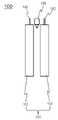
도 1은 본 발명의 일 실시예에 따른 전지 모듈의 구조를 나타내는 단면도이다
도 2는 도 1의 전지 모듈에서 소화 분사기가 작동된 상태를 나타내는 단면도이다
도 3은 도 1의 소화 분사기의 구조를 나타내는 확대도이다
도 4는 본 발명의 또 다른 실시예에 따른 전지 모듈의 구조를 나타내는 단면도이다
도 5은 도 4의 전지 모듈에서 소화 분사기가 작동된 상태를 나타내는 단면도이다1 is a cross-sectional view showing the structure of a battery module according to an embodiment of the present invention;
2 is a cross-sectional view showing a state in which the fire extinguishing injector is operated in the battery module of FIG. 1;
3 is an enlarged view showing the structure of the fire extinguisher of FIG. 1
4 is a cross-sectional view showing the structure of a battery module according to another embodiment of the present invention;
5 is a cross-sectional view showing a state in which the fire extinguishing injector is operated in the battery module of FIG.
이하, 도면을 참조하여 본 발명의 구체적인 실시형태를 설명하기로 한다. 이하의 상세한 설명은 본 명세서에서 기술된 방법, 장치 및/또는 시스템에 대한 포괄적인 이해를 돕기 위해 제공된다. 그러나 이는 예시에 불과하며 본 발명은 이에 제한되지 않는다.Hereinafter, specific embodiments of the present invention will be described with reference to the drawings. The following detailed description is provided to provide a comprehensive understanding of the methods, apparatus, and/or systems described herein. However, this is merely an example and the present invention is not limited thereto.
본 발명의 실시예들을 설명함에 있어서, 본 발명과 관련된 공지기술에 대한 구체적인 설명이 본 발명의 요지를 불필요하게 흐릴 수 있다고 판단되는 경우에는 그 상세한 설명을 생략하기로 한다. 그리고, 후술되는 용어들은 본 발명에서의 기능을 고려하여 정의된 용어들로서 이는 사용자, 운용자의 의도 또는 관례 등에 따라 달라질 수 있다. 그러므로 그 정의는 본 명세서 전반에 걸친 내용을 토대로 내려져야 할 것이다. 상세한 설명에서 사용되는 용어는 단지 본 발명의 실시예들을 기술하기 위한 것이며, 결코 제한적이어서는 안 된다. 명확하게 달리 사용되지 않는 한, 단수 형태의 표현은 복수 형태의 의미를 포함한다. 본 설명에서, "포함" 또는 "구비"와 같은 표현은 어떤 특성들, 숫자들, 단계들, 동작들, 요소들, 이들의 일부 또는 조합을 가리키기 위한 것이며, 기술된 것 이외에 하나 또는 그 이상의 다른 특성, 숫자, 단계, 동작, 요소, 이들의 일부 또는 조합의 존재 또는 가능성을 배제하도록 해석되어서는 안 된다.In describing the embodiments of the present invention, if it is determined that the detailed description of the known technology related to the present invention may unnecessarily obscure the gist of the present invention, the detailed description thereof will be omitted. And, the terms to be described later are terms defined in consideration of functions in the present invention, which may vary according to intentions or customs of users and operators. Therefore, the definition should be made based on the content throughout this specification. The terminology used in the detailed description is for the purpose of describing embodiments of the present invention only, and should in no way be limiting. Unless explicitly used otherwise, expressions in the singular include the meaning of the plural. In this description, expressions such as "comprising" or "comprising" are intended to indicate certain features, numbers, steps, acts, elements, some or a combination thereof, and one or more other than those described. It should not be construed to exclude the presence or possibility of other features, numbers, steps, acts, elements, or any part or combination thereof.
도 1에는 본 발명의 일 실시예에 따른 전지 모듈의 구조를 나타내는 단면도가 도시되어 있고, 도 2에는 도 1의 전지 모듈에서 소화 분사기가 작동된 상태를 나타내는 단면도가 도시되어 있으며, 도 3에는 도 1의 소화 분사기의 구조를 나타내는 확대도가 도시되어 있다.1 is a cross-sectional view showing the structure of a battery module according to an embodiment of the present invention, FIG. 2 is a cross-sectional view showing a state in which the fire extinguishing injector is operated in the battery module of FIG. 1, and FIG. An enlarged view showing the structure of the fire extinguisher of 1 is shown.
먼저, 도 1 및 2를 참조하면, 본 발명의 일 실시예에 따른 전지 모듈(100)은 둘 또는 그 이상의 전지셀들(111, 112)이 적층되어 측면방향으로 상호 인접하도록 배열되어 있는 전지셀 적층체(110), 전지셀들(111, 112)과 인접하게 위치하여 정상 작동 온도 범위보다 높은 비정상 작동 온도에서 구동되어 소화 가스를 분사하는 소화 분사기(130)를 포함할 수 있다.First, referring to FIGS. 1 and 2 , in the
전지셀들(111, 112)은, 예를 들어, 전극 리드(141, 142)가 일 방향으로 전지셀들(111, 112)의 상단부 또는 양단부로 돌출되어 있는 장방형 구조로 이루어질 수 있으며, 수지층, 금속층 및 수지층 순서로 이루어진 전지케이스 내부에 전극조립체(도시하지 않음)를 장착한 상태에서 상호 접촉하는 부위에 열과 압력을 가하여 수지층을 상호 융착시키는 구조의 파우치형 전지셀일 수 있으나 이것만으로 한정되는 것은 아니다.The
이러한 전지셀들(111, 112)은 상호 직렬 또는 병렬로 서로 전기적으로 연결되어 있는 전지 모듈(100) 구조를 이룰 수 있으며, 필요에 따라 전지 모듈(100) 구조를 커버하기 위한 셀 커버들이 부착될 수 있으나 이러한 구조만으로 한정되는 것은 아니다.These
또한, 전지셀 적층체(110)의 구조는 적용되는 전지셀들(111, 112)의 개수 또는 형상에 따라 다양한 형태로 적층되는 것이 가능함은 물론이다.In addition, the structure of the
한편, 도 3을 참조하면, 소화 분사기(130)는 내부에 상기 소화 가스를 담지하는 본체부(131), 본체부(131)의 일 측 단부에 장착되어 있고, 본체부(131)를 기계적으로 파손 시켜 소화 가스를 외부로 배출시키는 파단부(132) 및 비정상 작동 온도에서 본체부(131)를 기계적으로 파손시키기 위해서 파단부(132)를 본체부(131) 방향으로 이동시키는 구동부(133)를 포함할 수 있다.Meanwhile, referring to FIG. 3 , the
구체적으로, 구동부(133)는, 니켈-티타늄합금(Ni-Ti), 구리아연합금(Cu-Zn), 구리아연알루미늄합금(Cu-Zn-Al), 구리카드늄합금(Cu-Cd), 니켈알루미늄합금(Ni-Al), 구리아연알루미늄합금(Cu-Zn-Al) 및 구리알루미늄니켈합금(Cu-Al-Ni)으로 이루어진 군에서 선택된 1종 이상을 포함하는 형상기억합금일 수 있다.Specifically, the
이러한 형상기억합금은 원하는 형상으로 성형한 후에 작동 온도를 기억시키기 위하여 열처리를 선행할 수 있으며, 예를 들어, 앞서 설명한 비정상 작동 온도에서 구동부(133)가 팽창하거나 형상이 변화하여 작동하는 구조일 수 있다.Such a shape memory alloy may be preceded by heat treatment in order to memorize the operating temperature after being molded into a desired shape, for example, it may have a structure in which the
이때, 비정상 작동 온도는 전지셀들(111, 112)의 발화가 발생할 수 있는 온도 범위에서 조정되는 것이 가능하며, 예를 들어, 비정상 작동 온도는 90℃ 내지 150℃ 범위일 수 있으나 적용되는 전지셀들(111, 112)의 종류 또는 성능에 따라 조절되는 것이 가능하다.In this case, the abnormal operating temperature may be adjusted in a temperature range in which ignition of the
한편, 구동부(133)의 구조는 파단부(132)를 본체부(131) 방향으로 이동시키기 위한 구조이면 특별히 제한되는 것은 아니며, 예를 들어, 도 3에 예시되어 있는 바와 같이, 파단부(132)를 감싸는 스프링부재일 수 있으며, 도 3(a)에 예시되어 있는 바와 같이, 정상 작동 온도에서 수축되어 있고, 도 3(b)에 예시되어 있는 바와 같이, 비정상 작동 온도에서 팽창하는 구조일 수 있다.On the other hand, the structure of the
즉, 상기 구조에서 비정상 작동 온도에서 구동부(133)가 팽창하게 되고, 구동부(133)에 의해 파단부(132)가 본체부(131) 방향으로 이동하여 본체부(131)의 일 측을 기계적으로 파손시키게 되어 내부에 담지되어 있던 소화 가스가 전지셀들(111, 112) 방향으로 분사하는 구조일 수 있다.That is, in the above structure, the driving
이때, 소화 가스는 전지셀들(111, 112)에서 발생되는 발열 또는 발화 등에 대해서 급격한 온도 변화를 완화시키는 기체이면 특별히 제한되는 것은 아니며, 예를 들어 CO2 일 수 있으나 이러한 기체만으로 한정되는 것은 아니다.At this time, the extinguishing gas is not particularly limited as long as it is a gas that alleviates a sudden temperature change with respect to heat or ignition generated in the
따라서, 본 발명의 일 실시예에 따른 전지 모듈(100)은 둘 또는 그 이상의 전지셀들(111, 112)이 적층되어 측면방향으로 상호 인접하도록 배열되어 있는 전지셀 적층체(110)와 인접하게 위치하여 정상 작동 온도 범위보다 높은 비정상 작동 온도에서 구동되어 전지셀들(111, 112)에 대해 소화 가스를 분사하는 소화 분사기(130)를 포함함으로써, 일부 전지셀(111)에서 발열 또는 화재가 발생하는 경우에도 소화 분사기(130)에 의해 인접한 다른 전지셀(112)에 영향을 미치는 현상을 차단하거나 최대한 지연시킬 수 있는 바, 일부 전지셀(111)에서 발생한 발열 또는 화재로 인하여 전지 모듈(100) 전체에 발열 또는 화재가 일어나는 문제를 해결할 수 있으며, 이로 인하여 전지 모듈(100)이 적용되는 차량 등에서 화재가 발생하는 환경에서도 최대한 대피할 시간을 확보할 수 있고 인명 피해를 최소화할 수 있다.Accordingly, the
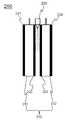
도 4에는 본 발명의 또 다른 실시예에 따른 전지 모듈의 구조를 나타내는 단면도가 도시되어 있고, 도 5에는 도 4의 전지 모듈에서 소화 분사기가 작동된 상태를 나타내는 단면도가 도시되어 있다.4 is a cross-sectional view showing the structure of a battery module according to another embodiment of the present invention, FIG. 5 is a cross-sectional view showing a state in which the fire extinguishing injector is operated in the battery module of FIG.
먼저, 도 4를 참조하면, 본 발명의 또 다른 실시예에 따른 전지 모듈(200)은 냉각부재들(221, 222)이 하나의 전지셀(211)의 양측면에 각각 접촉하는 구조로 개재되어 있고, 냉각부재들(223, 224)이 전지셀(211)과 인접하게 위치하는 전지셀(212)의 양측면에 각각 접촉하는 구조로 개재되어 인접하는 두 개의 전지셀들(211, 212) 사이에 한쌍의 냉각부재들(222, 223)이 개재되며, 소화 분사기(230)는, 한쌍의 냉각부재들(222, 223)의 외측 단부에 위치하는 구조일 수 있다.First, referring to FIG. 4 , the
이때, 냉각부재들(221, 222, 223, 224)은 높은 냉각 효율성의 발현을 위한 열전도성이 우수한 소재이면 특별한 제한은 없으며, 예를 들어, 높은 열전도성을 가진 금속 소재로 이루어진 금속 판재일 수 있고, 알루미늄 또는 구리 소재의 금속 판재일 수 있다.At this time, the cooling members (221, 222, 223, 224) is not particularly limited as long as it is a material having excellent thermal conductivity for the expression of high cooling efficiency. For example, it may be a metal plate made of a metal material having high thermal conductivity. and may be a metal plate made of aluminum or copper.
즉, 도 4에 예시되어 있는 바와 같이, 전지셀들(211, 212)의 표면과 직접 접촉하여 전지셀들(211, 212)에서 발생되는 열을 방출하는 구조로서, 냉각부재들(221, 222, 223, 224)의 내측 또는 외주변에 냉각 효율성을 높이기 위한 냉매가 유동되는 구조를 추가로 포함할 수 있으며, 냉각부재들(221, 222, 223, 224)의 일측에서 상호 연결하는 구조의 방열 구조를 추가로 포함할 수 있다.That is, as illustrated in FIG. 4 , as a structure for emitting heat generated from the
한편, 도 5에 예시되어 있는 바와 같이, 냉각부재들(221, 222, 223, 224)은, 제 1 전지셀(211)과 일면이 접촉하는 제 1 냉각부재(221), 제 2 냉각부재(222) 및 제 1 전지셀(211)과 인접하게 위치하는 제 2 전지셀(212)과 일면이 접촉하는 제 3 냉각부재(223), 제 4 냉각부재(224)를 포함할 수 있고, 제 2 냉각부재(222) 및 제 3 냉각부재(223)의 외측 단부에 소화 분사기(230)가 위치하는 구조일 수 있다.Meanwhile, as illustrated in FIG. 5 , the cooling
즉, 소화 분사기(230)는 제 1 전지셀(211) 및 제 2 전지셀(212)이 배열되어 있는 절지셀 적층체(210)에서 각각의 제 1 전지셀(211) 및 제 2 전지셀(212)과 인접하게 위치할 수 있으며, 마찬가지로, 소화 분사기(230)가 제 1 냉각부재(221) 및 제 4 냉각부재(224) 각각의 외측 단부에 추가로 위치하여 이어서 인접하게 배열되는 다른 전지셀들(도시하지 않음) 사이에서 개재되는 구조일 수 있다.That is, the
이상에서 본 발명의 대표적인 실시예들을 상세하게 설명하였으나, 본 발명이 속하는 기술분야에서 통상의 지식을 가진 자는 상술한 실시예에 대하여 본 발명의 범주에서 벗어나지 않는 한도 내에서 다양한 변형이 가능함을 이해할 것이다. 그러므로 본 발명의 권리범위는 설명된 실시예에 국한되어 정해져서는 안 되며, 후술하는 특허청구범위뿐만 아니라 이 특허청구범위와 균등한 것들에 의해 정해져야 한다.Although representative embodiments of the present invention have been described in detail above, those of ordinary skill in the art to which the present invention pertains will understand that various modifications are possible within the limits without departing from the scope of the present invention with respect to the above-described embodiments. . Therefore, the scope of the present invention should not be limited to the described embodiments, and should be defined by the claims described below as well as the claims and equivalents.
100, 200: 전지 모듈
110, 210: 전지셀 적층체
111, 112: 전지셀
130, 230: 소화 분사기
131: 본체부
132: 파단부
133: 구동부
141, 142, 241, 242: 전극 리드
211: 제 1 전지셀
212: 제 2 전지셀
221: 제 1 냉각부재
222: 제 2 냉각부재
223: 제 3 냉각부재
224: 제 4 냉각부재100, 200: battery module
110, 210: battery cell stack
111, 112: battery cell
130, 230: fire extinguisher
131: body part
132: break
133: driving unit
141, 142, 241, 242: electrode leads
211: first battery cell
212: second battery cell
221: first cooling member
222: second cooling member
223: third cooling member
224: fourth cooling member
Claims (11)
Translated fromKorean상기 복수개의 전지셀들 중 상호 인접한 두 전지셀의 사이에 위치하며, 상기 두 전지셀에서 이격되는, 소화 분사기;를 포함하고,
상기 소화 분사기는,
내부에 소화 가스를 담지하는, 본체부와,
상기 본체부의 일 측 단부에 장착되는, 파단부 및
주변의 온도가 정상 작동 온도 범위보다 높은 비정상 작동 온도가 되면, 상기 파단부를 상기 본체부를 향해 이동시키는, 구동부를 포함하고,
상기 파단부는,
상기 구동부에 의해 상기 본체부를 기계적으로 파손시켜 상기 소화 가스가 상기 두 전지셀을 향해 배출되게 하는,
전지 모듈.
a plurality of battery cells adjacent to each other but arranged to be spaced apart from each other; and
a fire extinguishing injector positioned between two adjacent battery cells among the plurality of battery cells and spaced apart from the two battery cells;
The fire extinguisher is
A body portion that holds the extinguishing gas inside, and
A fractured portion mounted on one end of the body portion, and
When the ambient temperature becomes an abnormal operating temperature higher than the normal operating temperature range, a driving unit for moving the fractured part toward the main body,
The breaking part,
Mechanically destroying the body part by the driving part so that the extinguishing gas is discharged toward the two battery cells,
battery module.
상기 구동부는, 니켈-티타늄합금(Ni-Ti), 구리아연합금(Cu-Zn), 구리아연알루미늄합금(Cu-Zn-Al), 구리카드늄합금(Cu-Cd), 니켈알루미늄합금(Ni-Al), 구리아연알루미늄합금(Cu-Zn-Al) 및 구리알루미늄니켈합금(Cu-Al-Ni)으로 이루어진 군에서 선택된 1종 이상을 포함하는 형상기억합금을 포함하는, 전지 모듈.
The method according to claim 1,
The driving unit includes a nickel-titanium alloy (Ni-Ti), a copper zinc alloy (Cu-Zn), a copper zinc aluminum alloy (Cu-Zn-Al), a copper cadmium alloy (Cu-Cd), a nickel aluminum alloy (Ni- Al), a copper zinc aluminum alloy (Cu-Zn-Al) and copper aluminum nickel alloy (Cu-Al-Ni) comprising a shape memory alloy comprising at least one selected from the group consisting of, the battery module.
상기 구동부는, 상기 파단부를 감싸는 스프링부재로서, 정상 작동 온도에서 수축되어 있고, 비정상 작동 온도에서 팽창하는, 전지 모듈.
The method according to claim 1,
The driving unit, as a spring member surrounding the breaking part, is contracted at a normal operating temperature, and expands at an abnormal operating temperature, the battery module.
상기 전지셀들의 적어도 일면에 접촉되도록 개재되어 있는 복수개의 냉각부재들을 추가로 포함하는, 전지 모듈.
The method according to claim 1,
A battery module further comprising a plurality of cooling members interposed to be in contact with at least one surface of the battery cells.
상기 복수개의 냉각부재들은 하나의 상기 전지셀의 양측면에 각각 접촉하는 구조로 개재되어, 인접하는 두 개의 상기 전지셀들 사이에 한쌍의 냉각부재들이 개재되며,
상기 소화 분사기는, 상기 한쌍의 냉각부재들의 외측 단부에 위치하는, 전지 모듈.
6. The method of claim 5,
The plurality of cooling members are interposed in a structure in contact with both sides of the one battery cell, and a pair of cooling members are interposed between the two adjacent battery cells,
The fire extinguisher is located at the outer end of the pair of cooling members, the battery module.
상기 복수개의 냉각부재들은, 제 1 전지셀과 일면이 접촉하는 제 1 냉각부재, 제 2 냉각부재 및 상기 제 1 전지셀과 인접하게 위치하는 제 2 전지셀과 일면이 접촉하는 제 3 냉각부재, 제 4 냉각부재를 포함하고, 상기 제 2 냉각부재 및 제 3 냉각부재의 외측 단부에 상기 소화 분사기가 위치하는, 전지 모듈.
7. The method of claim 6,
The plurality of cooling members may include a first cooling member having one surface in contact with the first battery cell, a second cooling member, and a third cooling member having one surface in contact with a second battery cell positioned adjacent to the first battery cell; A battery module comprising a fourth cooling member, wherein the fire extinguishing injector is located at the outer ends of the second cooling member and the third cooling member.
상기 소화 분사기는, 상기 제 1 냉각부재 및 상기 제 4 냉각부재의 외측 단부에 추가로 위치하는, 전지 모듈.
8. The method of claim 7,
The fire extinguishing injector, the first cooling member and the battery module, which is further located at the outer end of the fourth cooling member.
상기 복수개의 냉각부재들은, 열전도성 소재의 금속 판재인, 전지 모듈.
6. The method of claim 5,
The plurality of cooling members is a metal plate of a thermally conductive material, the battery module.
상기 비정상 작동 온도는, 90℃ 내지 150℃ 범위인, 전지 모듈.
The method according to claim 1,
The abnormal operating temperature is in the range of 90 ℃ to 150 ℃, the battery module.
상기 소화 가스는, CO2 가스인, 전지 모듈.
The method according to claim 1,
The extinguishing gas is CO2 gas, the battery module.
Priority Applications (2)
| Application Number | Priority Date | Filing Date | Title |
|---|---|---|---|
| KR1020170133314AKR102445835B1 (en) | 2017-10-13 | 2017-10-13 | Battery module with fire extinguishing device |
| KR1020220117094AKR102638685B1 (en) | 2017-10-13 | 2022-09-16 | Battery Module Having Extinguishing Apparatus |
Applications Claiming Priority (1)
| Application Number | Priority Date | Filing Date | Title |
|---|---|---|---|
| KR1020170133314AKR102445835B1 (en) | 2017-10-13 | 2017-10-13 | Battery module with fire extinguishing device |
Related Child Applications (1)
| Application Number | Title | Priority Date | Filing Date |
|---|---|---|---|
| KR1020220117094ADivisionKR102638685B1 (en) | 2017-10-13 | 2022-09-16 | Battery Module Having Extinguishing Apparatus |
Publications (2)
| Publication Number | Publication Date |
|---|---|
| KR20190041725A KR20190041725A (en) | 2019-04-23 |
| KR102445835B1true KR102445835B1 (en) | 2022-09-20 |
Family
ID=66285435
Family Applications (2)
| Application Number | Title | Priority Date | Filing Date |
|---|---|---|---|
| KR1020170133314AActiveKR102445835B1 (en) | 2017-10-13 | 2017-10-13 | Battery module with fire extinguishing device |
| KR1020220117094AActiveKR102638685B1 (en) | 2017-10-13 | 2022-09-16 | Battery Module Having Extinguishing Apparatus |
Family Applications After (1)
| Application Number | Title | Priority Date | Filing Date |
|---|---|---|---|
| KR1020220117094AActiveKR102638685B1 (en) | 2017-10-13 | 2022-09-16 | Battery Module Having Extinguishing Apparatus |
Country Status (1)
| Country | Link |
|---|---|
| KR (2) | KR102445835B1 (en) |
Families Citing this family (7)
| Publication number | Priority date | Publication date | Assignee | Title |
|---|---|---|---|---|
| KR102818246B1 (en) | 2020-05-04 | 2025-06-10 | 주식회사 엘지에너지솔루션 | Battery Module Equipped With A Fire Extinguishing Unit Containing A Fire Extinguishing Material |
| KR20220072887A (en)* | 2020-11-23 | 2022-06-03 | 주식회사 엘지에너지솔루션 | Battery Pack Including Heat Diffusion Suppression Structure |
| CN113178657B (en)* | 2021-04-19 | 2023-03-31 | 湖南顺隆新能源科技有限公司 | Monomer type lithium battery pack system based on new energy automobile and use method thereof |
| CN113764180B (en)* | 2021-09-10 | 2022-11-25 | 成都伍零三科技集团有限公司 | Fireproof power capacitor |
| KR20230105449A (en) | 2022-01-04 | 2023-07-11 | 주식회사 엘지에너지솔루션 | Battery module and method thereof |
| KR20230135998A (en) | 2022-03-17 | 2023-09-26 | 주식회사 엘지에너지솔루션 | Heat sink, manufacturing method thereof, and battery module |
| US20250161730A1 (en)* | 2022-03-25 | 2025-05-22 | Tyco Fire Products Lp | Battery pack with condition-sensitive membranes |
Citations (1)
| Publication number | Priority date | Publication date | Assignee | Title |
|---|---|---|---|---|
| JP2009219257A (en)* | 2008-03-11 | 2009-09-24 | Panasonic Corp | Power supply apparatus and electronic apparatus using the same |
Family Cites Families (5)
| Publication number | Priority date | Publication date | Assignee | Title |
|---|---|---|---|---|
| KR100968528B1 (en)* | 2008-02-12 | 2010-07-08 | 유승주 | Manufacturing Method of Spring for Thermal Sensor Using Shape Memory Alloy |
| KR101539584B1 (en)* | 2012-06-18 | 2015-07-27 | 주식회사 엘지화학 | Battery Module with Improved Safety |
| KR20140064418A (en) | 2012-11-20 | 2014-05-28 | 에스케이이노베이션 주식회사 | Secondary battery module |
| KR101757382B1 (en)* | 2014-10-07 | 2017-07-26 | 주식회사 엘지화학 | Cooling member of improved cooling performance and battery module comprising the same |
| KR101811492B1 (en)* | 2015-05-14 | 2018-01-26 | 김부열 | A device for fume removal contained hood having function of flame to be flowed |
- 2017
- 2017-10-13KRKR1020170133314Apatent/KR102445835B1/enactiveActive
- 2022
- 2022-09-16KRKR1020220117094Apatent/KR102638685B1/enactiveActive
Patent Citations (1)
| Publication number | Priority date | Publication date | Assignee | Title |
|---|---|---|---|---|
| JP2009219257A (en)* | 2008-03-11 | 2009-09-24 | Panasonic Corp | Power supply apparatus and electronic apparatus using the same |
Also Published As
| Publication number | Publication date |
|---|---|
| KR20190041725A (en) | 2019-04-23 |
| KR20220132494A (en) | 2022-09-30 |
| KR102638685B1 (en) | 2024-02-19 |
Similar Documents
| Publication | Publication Date | Title |
|---|---|---|
| KR102445835B1 (en) | Battery module with fire extinguishing device | |
| KR102446772B1 (en) | Battery Module Having Safety Apparatus | |
| KR102258179B1 (en) | Cylindrical secondary battery module | |
| US11046206B2 (en) | Battery module with short-circuit unit, and battery pack and vehicle including the same | |
| CN110637380B (en) | Power supply device, vehicle provided with same, power storage device, and power supply device separator | |
| US20250226502A1 (en) | Battery pack including fire suppression means | |
| JP5804540B2 (en) | Battery pack with improved safety | |
| KR102585988B1 (en) | Battery module, battery pack comprising the battery module and vehicle comprising the battery pack | |
| KR102424274B1 (en) | Battery Module Having Heat Shielding Function | |
| JP5866463B2 (en) | Battery cell assembly with improved safety and battery module including the same | |
| KR20160041311A (en) | Battery Pack Comprising Fire-resistance Safety Member | |
| WO2017169524A1 (en) | Battery pack | |
| WO2012014353A1 (en) | Battery module | |
| KR101037042B1 (en) | Pouch type secondary battery with improved safety | |
| KR20130043258A (en) | Battery pack of improved safety | |
| JP7027638B2 (en) | Battery module, battery pack including it and automobile | |
| KR102250180B1 (en) | Battery module, battery pack including the same, and vehicle including the same | |
| US20150140390A1 (en) | Apparatus for preventing overcharge of battery | |
| JP2020501318A (en) | Battery module, battery pack including the same, and automobile | |
| KR101822612B1 (en) | Battery module for power shut off when battery is over-charged | |
| KR102267056B1 (en) | Battery module, battery pack including the same, and vehicle including the same | |
| JP2017045508A (en) | Battery pack | |
| KR101554877B1 (en) | Battery Module Of High Cooling Efficiency | |
| KR101274937B1 (en) | Battery pack | |
| CN204375861U (en) | Battery pack |
Legal Events
| Date | Code | Title | Description |
|---|---|---|---|
| PA0109 | Patent application | Patent event code:PA01091R01D Comment text:Patent Application Patent event date:20171013 | |
| PG1501 | Laying open of application | ||
| A201 | Request for examination | ||
| PA0201 | Request for examination | Patent event code:PA02012R01D Patent event date:20200826 Comment text:Request for Examination of Application Patent event code:PA02011R01I Patent event date:20171013 Comment text:Patent Application | |
| E902 | Notification of reason for refusal | ||
| PE0902 | Notice of grounds for rejection | Comment text:Notification of reason for refusal Patent event date:20211201 Patent event code:PE09021S01D | |
| PN2301 | Change of applicant | Patent event date:20211224 Comment text:Notification of Change of Applicant Patent event code:PN23011R01D | |
| E701 | Decision to grant or registration of patent right | ||
| PE0701 | Decision of registration | Patent event code:PE07011S01D Comment text:Decision to Grant Registration Patent event date:20220620 | |
| GRNT | Written decision to grant | ||
| PA0107 | Divisional application | Comment text:Divisional Application of Patent Patent event date:20220916 Patent event code:PA01071R01D | |
| PR0701 | Registration of establishment | Comment text:Registration of Establishment Patent event date:20220916 Patent event code:PR07011E01D | |
| PR1002 | Payment of registration fee | Payment date:20220916 End annual number:3 Start annual number:1 | |
| PG1601 | Publication of registration |