KR102444147B1 - Refrigerator - Google Patents
RefrigeratorDownload PDFInfo
- Publication number
- KR102444147B1 KR102444147B1KR1020217037142AKR20217037142AKR102444147B1KR 102444147 B1KR102444147 B1KR 102444147B1KR 1020217037142 AKR1020217037142 AKR 1020217037142AKR 20217037142 AKR20217037142 AKR 20217037142AKR 102444147 B1KR102444147 B1KR 102444147B1
- Authority
- KR
- South Korea
- Prior art keywords
- door
- refrigerator
- sensing
- opening
- compartment door
- Prior art date
- Legal status (The legal status is an assumption and is not a legal conclusion. Google has not performed a legal analysis and makes no representation as to the accuracy of the status listed.)
- Active
Links
Images


Classifications
- F—MECHANICAL ENGINEERING; LIGHTING; HEATING; WEAPONS; BLASTING
- F25—REFRIGERATION OR COOLING; COMBINED HEATING AND REFRIGERATION SYSTEMS; HEAT PUMP SYSTEMS; MANUFACTURE OR STORAGE OF ICE; LIQUEFACTION SOLIDIFICATION OF GASES
- F25D—REFRIGERATORS; COLD ROOMS; ICE-BOXES; COOLING OR FREEZING APPARATUS NOT OTHERWISE PROVIDED FOR
- F25D23/00—General constructional features
- F25D23/02—Doors; Covers
- E—FIXED CONSTRUCTIONS
- E05—LOCKS; KEYS; WINDOW OR DOOR FITTINGS; SAFES
- E05F—DEVICES FOR MOVING WINGS INTO OPEN OR CLOSED POSITION; CHECKS FOR WINGS; WING FITTINGS NOT OTHERWISE PROVIDED FOR, CONCERNED WITH THE FUNCTIONING OF THE WING
- E05F15/00—Power-operated mechanisms for wings
- E05F15/60—Power-operated mechanisms for wings using electrical actuators
- E05F15/603—Power-operated mechanisms for wings using electrical actuators using rotary electromotors
- E05F15/611—Power-operated mechanisms for wings using electrical actuators using rotary electromotors for swinging wings
- E05F15/616—Power-operated mechanisms for wings using electrical actuators using rotary electromotors for swinging wings operated by push-pull mechanisms
- E05F15/619—Power-operated mechanisms for wings using electrical actuators using rotary electromotors for swinging wings operated by push-pull mechanisms using flexible or rigid rack-and-pinion arrangements
- E—FIXED CONSTRUCTIONS
- E05—LOCKS; KEYS; WINDOW OR DOOR FITTINGS; SAFES
- E05F—DEVICES FOR MOVING WINGS INTO OPEN OR CLOSED POSITION; CHECKS FOR WINGS; WING FITTINGS NOT OTHERWISE PROVIDED FOR, CONCERNED WITH THE FUNCTIONING OF THE WING
- E05F15/00—Power-operated mechanisms for wings
- E05F15/70—Power-operated mechanisms for wings with automatic actuation
- E05F15/73—Power-operated mechanisms for wings with automatic actuation responsive to movement or presence of persons or objects
- E05F15/75—Power-operated mechanisms for wings with automatic actuation responsive to movement or presence of persons or objects responsive to the weight or other physical contact of a person or object
- F—MECHANICAL ENGINEERING; LIGHTING; HEATING; WEAPONS; BLASTING
- F21—LIGHTING
- F21V—FUNCTIONAL FEATURES OR DETAILS OF LIGHTING DEVICES OR SYSTEMS THEREOF; STRUCTURAL COMBINATIONS OF LIGHTING DEVICES WITH OTHER ARTICLES, NOT OTHERWISE PROVIDED FOR
- F21V14/00—Controlling the distribution of the light emitted by adjustment of elements
- F21V14/06—Controlling the distribution of the light emitted by adjustment of elements by movement of refractors
- F—MECHANICAL ENGINEERING; LIGHTING; HEATING; WEAPONS; BLASTING
- F21—LIGHTING
- F21V—FUNCTIONAL FEATURES OR DETAILS OF LIGHTING DEVICES OR SYSTEMS THEREOF; STRUCTURAL COMBINATIONS OF LIGHTING DEVICES WITH OTHER ARTICLES, NOT OTHERWISE PROVIDED FOR
- F21V17/00—Fastening of component parts of lighting devices, e.g. shades, globes, refractors, reflectors, filters, screens, grids or protective cages
- F21V17/10—Fastening of component parts of lighting devices, e.g. shades, globes, refractors, reflectors, filters, screens, grids or protective cages characterised by specific fastening means or way of fastening
- F21V17/12—Fastening of component parts of lighting devices, e.g. shades, globes, refractors, reflectors, filters, screens, grids or protective cages characterised by specific fastening means or way of fastening by screwing
- F—MECHANICAL ENGINEERING; LIGHTING; HEATING; WEAPONS; BLASTING
- F21—LIGHTING
- F21V—FUNCTIONAL FEATURES OR DETAILS OF LIGHTING DEVICES OR SYSTEMS THEREOF; STRUCTURAL COMBINATIONS OF LIGHTING DEVICES WITH OTHER ARTICLES, NOT OTHERWISE PROVIDED FOR
- F21V19/00—Fastening of light sources or lamp holders
- F21V19/001—Fastening of light sources or lamp holders the light sources being semiconductors devices, e.g. LEDs
- F21V19/0015—Fastening arrangements intended to retain light sources
- F—MECHANICAL ENGINEERING; LIGHTING; HEATING; WEAPONS; BLASTING
- F21—LIGHTING
- F21V—FUNCTIONAL FEATURES OR DETAILS OF LIGHTING DEVICES OR SYSTEMS THEREOF; STRUCTURAL COMBINATIONS OF LIGHTING DEVICES WITH OTHER ARTICLES, NOT OTHERWISE PROVIDED FOR
- F21V23/00—Arrangement of electric circuit elements in or on lighting devices
- F21V23/04—Arrangement of electric circuit elements in or on lighting devices the elements being switches
- F21V23/0442—Arrangement of electric circuit elements in or on lighting devices the elements being switches activated by means of a sensor, e.g. motion or photodetectors
- F21V23/0471—Arrangement of electric circuit elements in or on lighting devices the elements being switches activated by means of a sensor, e.g. motion or photodetectors the sensor detecting the proximity, the presence or the movement of an object or a person
- F—MECHANICAL ENGINEERING; LIGHTING; HEATING; WEAPONS; BLASTING
- F21—LIGHTING
- F21V—FUNCTIONAL FEATURES OR DETAILS OF LIGHTING DEVICES OR SYSTEMS THEREOF; STRUCTURAL COMBINATIONS OF LIGHTING DEVICES WITH OTHER ARTICLES, NOT OTHERWISE PROVIDED FOR
- F21V33/00—Structural combinations of lighting devices with other articles, not otherwise provided for
- F21V33/0004—Personal or domestic articles
- F21V33/0044—Household appliances, e.g. washing machines or vacuum cleaners
- F—MECHANICAL ENGINEERING; LIGHTING; HEATING; WEAPONS; BLASTING
- F21—LIGHTING
- F21V—FUNCTIONAL FEATURES OR DETAILS OF LIGHTING DEVICES OR SYSTEMS THEREOF; STRUCTURAL COMBINATIONS OF LIGHTING DEVICES WITH OTHER ARTICLES, NOT OTHERWISE PROVIDED FOR
- F21V5/00—Refractors for light sources
- F21V5/008—Combination of two or more successive refractors along an optical axis
- F—MECHANICAL ENGINEERING; LIGHTING; HEATING; WEAPONS; BLASTING
- F21—LIGHTING
- F21V—FUNCTIONAL FEATURES OR DETAILS OF LIGHTING DEVICES OR SYSTEMS THEREOF; STRUCTURAL COMBINATIONS OF LIGHTING DEVICES WITH OTHER ARTICLES, NOT OTHERWISE PROVIDED FOR
- F21V5/00—Refractors for light sources
- F21V5/04—Refractors for light sources of lens shape
- F—MECHANICAL ENGINEERING; LIGHTING; HEATING; WEAPONS; BLASTING
- F25—REFRIGERATION OR COOLING; COMBINED HEATING AND REFRIGERATION SYSTEMS; HEAT PUMP SYSTEMS; MANUFACTURE OR STORAGE OF ICE; LIQUEFACTION SOLIDIFICATION OF GASES
- F25D—REFRIGERATORS; COLD ROOMS; ICE-BOXES; COOLING OR FREEZING APPARATUS NOT OTHERWISE PROVIDED FOR
- F25D11/00—Self-contained movable devices, e.g. domestic refrigerators
- F25D11/02—Self-contained movable devices, e.g. domestic refrigerators with cooling compartments at different temperatures
- F—MECHANICAL ENGINEERING; LIGHTING; HEATING; WEAPONS; BLASTING
- F25—REFRIGERATION OR COOLING; COMBINED HEATING AND REFRIGERATION SYSTEMS; HEAT PUMP SYSTEMS; MANUFACTURE OR STORAGE OF ICE; LIQUEFACTION SOLIDIFICATION OF GASES
- F25D—REFRIGERATORS; COLD ROOMS; ICE-BOXES; COOLING OR FREEZING APPARATUS NOT OTHERWISE PROVIDED FOR
- F25D23/00—General constructional features
- F25D23/02—Doors; Covers
- F25D23/028—Details
- F—MECHANICAL ENGINEERING; LIGHTING; HEATING; WEAPONS; BLASTING
- F25—REFRIGERATION OR COOLING; COMBINED HEATING AND REFRIGERATION SYSTEMS; HEAT PUMP SYSTEMS; MANUFACTURE OR STORAGE OF ICE; LIQUEFACTION SOLIDIFICATION OF GASES
- F25D—REFRIGERATORS; COLD ROOMS; ICE-BOXES; COOLING OR FREEZING APPARATUS NOT OTHERWISE PROVIDED FOR
- F25D23/00—General constructional features
- F25D23/02—Doors; Covers
- F25D23/04—Doors; Covers with special compartments, e.g. butter conditioners
- F—MECHANICAL ENGINEERING; LIGHTING; HEATING; WEAPONS; BLASTING
- F25—REFRIGERATION OR COOLING; COMBINED HEATING AND REFRIGERATION SYSTEMS; HEAT PUMP SYSTEMS; MANUFACTURE OR STORAGE OF ICE; LIQUEFACTION SOLIDIFICATION OF GASES
- F25D—REFRIGERATORS; COLD ROOMS; ICE-BOXES; COOLING OR FREEZING APPARATUS NOT OTHERWISE PROVIDED FOR
- F25D27/00—Lighting arrangements
- F25D27/005—Lighting arrangements combined with control means
- F—MECHANICAL ENGINEERING; LIGHTING; HEATING; WEAPONS; BLASTING
- F25—REFRIGERATION OR COOLING; COMBINED HEATING AND REFRIGERATION SYSTEMS; HEAT PUMP SYSTEMS; MANUFACTURE OR STORAGE OF ICE; LIQUEFACTION SOLIDIFICATION OF GASES
- F25D—REFRIGERATORS; COLD ROOMS; ICE-BOXES; COOLING OR FREEZING APPARATUS NOT OTHERWISE PROVIDED FOR
- F25D29/00—Arrangement or mounting of control or safety devices
- F25D29/003—Arrangement or mounting of control or safety devices for movable devices
- F—MECHANICAL ENGINEERING; LIGHTING; HEATING; WEAPONS; BLASTING
- F25—REFRIGERATION OR COOLING; COMBINED HEATING AND REFRIGERATION SYSTEMS; HEAT PUMP SYSTEMS; MANUFACTURE OR STORAGE OF ICE; LIQUEFACTION SOLIDIFICATION OF GASES
- F25D—REFRIGERATORS; COLD ROOMS; ICE-BOXES; COOLING OR FREEZING APPARATUS NOT OTHERWISE PROVIDED FOR
- F25D29/00—Arrangement or mounting of control or safety devices
- F25D29/005—Mounting of control devices
- H—ELECTRICITY
- H05—ELECTRIC TECHNIQUES NOT OTHERWISE PROVIDED FOR
- H05B—ELECTRIC HEATING; ELECTRIC LIGHT SOURCES NOT OTHERWISE PROVIDED FOR; CIRCUIT ARRANGEMENTS FOR ELECTRIC LIGHT SOURCES, IN GENERAL
- H05B47/00—Circuit arrangements for operating light sources in general, i.e. where the type of light source is not relevant
- H05B47/10—Controlling the light source
- H05B47/16—Controlling the light source by timing means
- E—FIXED CONSTRUCTIONS
- E05—LOCKS; KEYS; WINDOW OR DOOR FITTINGS; SAFES
- E05F—DEVICES FOR MOVING WINGS INTO OPEN OR CLOSED POSITION; CHECKS FOR WINGS; WING FITTINGS NOT OTHERWISE PROVIDED FOR, CONCERNED WITH THE FUNCTIONING OF THE WING
- E05F15/00—Power-operated mechanisms for wings
- E05F15/70—Power-operated mechanisms for wings with automatic actuation
- E05F15/73—Power-operated mechanisms for wings with automatic actuation responsive to movement or presence of persons or objects
- E05F2015/765—Power-operated mechanisms for wings with automatic actuation responsive to movement or presence of persons or objects using optical sensors
- E—FIXED CONSTRUCTIONS
- E05—LOCKS; KEYS; WINDOW OR DOOR FITTINGS; SAFES
- E05Y—INDEXING SCHEME ASSOCIATED WITH SUBCLASSES E05D AND E05F, RELATING TO CONSTRUCTION ELEMENTS, ELECTRIC CONTROL, POWER SUPPLY, POWER SIGNAL OR TRANSMISSION, USER INTERFACES, MOUNTING OR COUPLING, DETAILS, ACCESSORIES, AUXILIARY OPERATIONS NOT OTHERWISE PROVIDED FOR, APPLICATION THEREOF
- E05Y2400/00—Electronic control; Electrical power; Power supply; Power or signal transmission; User interfaces
- E05Y2400/10—Electronic control
- E05Y2400/44—Sensors not directly associated with the wing movement
- E—FIXED CONSTRUCTIONS
- E05—LOCKS; KEYS; WINDOW OR DOOR FITTINGS; SAFES
- E05Y—INDEXING SCHEME ASSOCIATED WITH SUBCLASSES E05D AND E05F, RELATING TO CONSTRUCTION ELEMENTS, ELECTRIC CONTROL, POWER SUPPLY, POWER SIGNAL OR TRANSMISSION, USER INTERFACES, MOUNTING OR COUPLING, DETAILS, ACCESSORIES, AUXILIARY OPERATIONS NOT OTHERWISE PROVIDED FOR, APPLICATION THEREOF
- E05Y2400/00—Electronic control; Electrical power; Power supply; Power or signal transmission; User interfaces
- E05Y2400/10—Electronic control
- E05Y2400/45—Control modes
- E—FIXED CONSTRUCTIONS
- E05—LOCKS; KEYS; WINDOW OR DOOR FITTINGS; SAFES
- E05Y—INDEXING SCHEME ASSOCIATED WITH SUBCLASSES E05D AND E05F, RELATING TO CONSTRUCTION ELEMENTS, ELECTRIC CONTROL, POWER SUPPLY, POWER SIGNAL OR TRANSMISSION, USER INTERFACES, MOUNTING OR COUPLING, DETAILS, ACCESSORIES, AUXILIARY OPERATIONS NOT OTHERWISE PROVIDED FOR, APPLICATION THEREOF
- E05Y2400/00—Electronic control; Electrical power; Power supply; Power or signal transmission; User interfaces
- E05Y2400/80—User interfaces
- E05Y2400/85—User input means
- E05Y2400/856—Actuation thereof
- E05Y2400/858—Actuation thereof by body parts, e.g. by feet
- E—FIXED CONSTRUCTIONS
- E05—LOCKS; KEYS; WINDOW OR DOOR FITTINGS; SAFES
- E05Y—INDEXING SCHEME ASSOCIATED WITH SUBCLASSES E05D AND E05F, RELATING TO CONSTRUCTION ELEMENTS, ELECTRIC CONTROL, POWER SUPPLY, POWER SIGNAL OR TRANSMISSION, USER INTERFACES, MOUNTING OR COUPLING, DETAILS, ACCESSORIES, AUXILIARY OPERATIONS NOT OTHERWISE PROVIDED FOR, APPLICATION THEREOF
- E05Y2900/00—Application of doors, windows, wings or fittings thereof
- E05Y2900/30—Application of doors, windows, wings or fittings thereof for domestic appliances
- E05Y2900/31—Application of doors, windows, wings or fittings thereof for domestic appliances for refrigerators
- F—MECHANICAL ENGINEERING; LIGHTING; HEATING; WEAPONS; BLASTING
- F21—LIGHTING
- F21W—INDEXING SCHEME ASSOCIATED WITH SUBCLASSES F21K, F21L, F21S and F21V, RELATING TO USES OR APPLICATIONS OF LIGHTING DEVICES OR SYSTEMS
- F21W2131/00—Use or application of lighting devices or systems not provided for in codes F21W2102/00-F21W2121/00
- F21W2131/30—Lighting for domestic or personal use
- F21W2131/305—Lighting for domestic or personal use for refrigerators
- F—MECHANICAL ENGINEERING; LIGHTING; HEATING; WEAPONS; BLASTING
- F21—LIGHTING
- F21Y—INDEXING SCHEME ASSOCIATED WITH SUBCLASSES F21K, F21L, F21S and F21V, RELATING TO THE FORM OR THE KIND OF THE LIGHT SOURCES OR OF THE COLOUR OF THE LIGHT EMITTED
- F21Y2115/00—Light-generating elements of semiconductor light sources
- F21Y2115/10—Light-emitting diodes [LED]
- F—MECHANICAL ENGINEERING; LIGHTING; HEATING; WEAPONS; BLASTING
- F25—REFRIGERATION OR COOLING; COMBINED HEATING AND REFRIGERATION SYSTEMS; HEAT PUMP SYSTEMS; MANUFACTURE OR STORAGE OF ICE; LIQUEFACTION SOLIDIFICATION OF GASES
- F25D—REFRIGERATORS; COLD ROOMS; ICE-BOXES; COOLING OR FREEZING APPARATUS NOT OTHERWISE PROVIDED FOR
- F25D2323/00—General constructional features not provided for in other groups of this subclass
- F25D2323/02—Details of doors or covers not otherwise covered
- F25D2323/021—French doors
- F—MECHANICAL ENGINEERING; LIGHTING; HEATING; WEAPONS; BLASTING
- F25—REFRIGERATION OR COOLING; COMBINED HEATING AND REFRIGERATION SYSTEMS; HEAT PUMP SYSTEMS; MANUFACTURE OR STORAGE OF ICE; LIQUEFACTION SOLIDIFICATION OF GASES
- F25D—REFRIGERATORS; COLD ROOMS; ICE-BOXES; COOLING OR FREEZING APPARATUS NOT OTHERWISE PROVIDED FOR
- F25D2323/00—General constructional features not provided for in other groups of this subclass
- F25D2323/02—Details of doors or covers not otherwise covered
- F25D2323/023—Door in door constructions
- F—MECHANICAL ENGINEERING; LIGHTING; HEATING; WEAPONS; BLASTING
- F25—REFRIGERATION OR COOLING; COMBINED HEATING AND REFRIGERATION SYSTEMS; HEAT PUMP SYSTEMS; MANUFACTURE OR STORAGE OF ICE; LIQUEFACTION SOLIDIFICATION OF GASES
- F25D—REFRIGERATORS; COLD ROOMS; ICE-BOXES; COOLING OR FREEZING APPARATUS NOT OTHERWISE PROVIDED FOR
- F25D2327/00—Lighting arrangements not provided for in other groups of this subclass
- F25D2327/001—Lighting arrangements on the external side of the refrigerator, freezer or cooling box
- F—MECHANICAL ENGINEERING; LIGHTING; HEATING; WEAPONS; BLASTING
- F25—REFRIGERATION OR COOLING; COMBINED HEATING AND REFRIGERATION SYSTEMS; HEAT PUMP SYSTEMS; MANUFACTURE OR STORAGE OF ICE; LIQUEFACTION SOLIDIFICATION OF GASES
- F25D—REFRIGERATORS; COLD ROOMS; ICE-BOXES; COOLING OR FREEZING APPARATUS NOT OTHERWISE PROVIDED FOR
- F25D2400/00—General features of, or devices for refrigerators, cold rooms, ice-boxes, or for cooling or freezing apparatus not covered by any other subclass
- F25D2400/36—Visual displays
- F—MECHANICAL ENGINEERING; LIGHTING; HEATING; WEAPONS; BLASTING
- F25—REFRIGERATION OR COOLING; COMBINED HEATING AND REFRIGERATION SYSTEMS; HEAT PUMP SYSTEMS; MANUFACTURE OR STORAGE OF ICE; LIQUEFACTION SOLIDIFICATION OF GASES
- F25D—REFRIGERATORS; COLD ROOMS; ICE-BOXES; COOLING OR FREEZING APPARATUS NOT OTHERWISE PROVIDED FOR
- F25D2600/00—Control issues
- F25D2600/02—Timing
- F—MECHANICAL ENGINEERING; LIGHTING; HEATING; WEAPONS; BLASTING
- F25—REFRIGERATION OR COOLING; COMBINED HEATING AND REFRIGERATION SYSTEMS; HEAT PUMP SYSTEMS; MANUFACTURE OR STORAGE OF ICE; LIQUEFACTION SOLIDIFICATION OF GASES
- F25D—REFRIGERATORS; COLD ROOMS; ICE-BOXES; COOLING OR FREEZING APPARATUS NOT OTHERWISE PROVIDED FOR
- F25D2700/00—Means for sensing or measuring; Sensors therefor
- F25D2700/02—Sensors detecting door opening
- F—MECHANICAL ENGINEERING; LIGHTING; HEATING; WEAPONS; BLASTING
- F25—REFRIGERATION OR COOLING; COMBINED HEATING AND REFRIGERATION SYSTEMS; HEAT PUMP SYSTEMS; MANUFACTURE OR STORAGE OF ICE; LIQUEFACTION SOLIDIFICATION OF GASES
- F25D—REFRIGERATORS; COLD ROOMS; ICE-BOXES; COOLING OR FREEZING APPARATUS NOT OTHERWISE PROVIDED FOR
- F25D2700/00—Means for sensing or measuring; Sensors therefor
- F25D2700/04—Sensors detecting the presence of a person
- Y—GENERAL TAGGING OF NEW TECHNOLOGICAL DEVELOPMENTS; GENERAL TAGGING OF CROSS-SECTIONAL TECHNOLOGIES SPANNING OVER SEVERAL SECTIONS OF THE IPC; TECHNICAL SUBJECTS COVERED BY FORMER USPC CROSS-REFERENCE ART COLLECTIONS [XRACs] AND DIGESTS
- Y02—TECHNOLOGIES OR APPLICATIONS FOR MITIGATION OR ADAPTATION AGAINST CLIMATE CHANGE
- Y02B—CLIMATE CHANGE MITIGATION TECHNOLOGIES RELATED TO BUILDINGS, e.g. HOUSING, HOUSE APPLIANCES OR RELATED END-USER APPLICATIONS
- Y02B20/00—Energy efficient lighting technologies, e.g. halogen lamps or gas discharge lamps
- Y02B20/40—Control techniques providing energy savings, e.g. smart controller or presence detection
- Y—GENERAL TAGGING OF NEW TECHNOLOGICAL DEVELOPMENTS; GENERAL TAGGING OF CROSS-SECTIONAL TECHNOLOGIES SPANNING OVER SEVERAL SECTIONS OF THE IPC; TECHNICAL SUBJECTS COVERED BY FORMER USPC CROSS-REFERENCE ART COLLECTIONS [XRACs] AND DIGESTS
- Y02—TECHNOLOGIES OR APPLICATIONS FOR MITIGATION OR ADAPTATION AGAINST CLIMATE CHANGE
- Y02B—CLIMATE CHANGE MITIGATION TECHNOLOGIES RELATED TO BUILDINGS, e.g. HOUSING, HOUSE APPLIANCES OR RELATED END-USER APPLICATIONS
- Y02B40/00—Technologies aiming at improving the efficiency of home appliances, e.g. induction cooking or efficient technologies for refrigerators, freezers or dish washers
Landscapes
- Engineering & Computer Science (AREA)
- General Engineering & Computer Science (AREA)
- Chemical & Material Sciences (AREA)
- Combustion & Propulsion (AREA)
- Physics & Mathematics (AREA)
- Mechanical Engineering (AREA)
- Thermal Sciences (AREA)
- Refrigerator Housings (AREA)
- Cold Air Circulating Systems And Constructional Details In Refrigerators (AREA)
- Devices That Are Associated With Refrigeration Equipment (AREA)
Abstract
Translated fromKoreanDescription
Translated fromKorean본 발명은 냉장고에 관한 것이다.The present invention relates to a refrigerator.
일반적으로 냉장고는 도어에 의해 차폐되는 내부의 저장공간에 음식물을 저온 저장할 수 있도록 하는 가전 기기이다. 이를 위해 냉장고는 냉동사이클을 순환하는 냉매와의 열교환을 통해 발생하는 냉기를 이용하여 저장공간의 내부를 냉각함으로써 저장된 음식물들을 최적상태로 보관할 수 있도록 구성된다.BACKGROUND ART In general, a refrigerator is a home appliance that can store food at a low temperature in an internal storage space that is shielded by a door. To this end, the refrigerator is configured to store the stored food in an optimal state by cooling the inside of the storage space using cold air generated through heat exchange with the refrigerant circulating in the refrigeration cycle.
최근의 냉장고는 식생활의 변화 및 제품의 고급화의 추세에 따라 점차 대형화 다기능화되고 있는 추세이며, 사용자의 편의를 향상시키기 위한 다양한 편의장치를 구비한 냉장고가 출시되고 있다.Recently, refrigerators are gradually becoming larger and multifunctional in accordance with changes in dietary habits and the trend of luxury products, and refrigerators equipped with various convenience devices for improving user convenience have been released.
냉장고의 저장 공간은 도어에 의해 개폐될 수 있다. 그리고, 통상 도어에는 닫힌 상태에서의 냉기 누설을 방지하기 위해서 가스켓이 구비되며, 가스켓과 캐비닛의 밀착력이 강할수록 냉기의 누설을 방지하는 효과가 커지게 된다.The storage space of the refrigerator may be opened and closed by a door. In addition, a gasket is provided in a door to prevent leakage of cold air in a closed state, and the stronger the adhesion between the gasket and the cabinet, the greater the effect of preventing leakage of cold air.
따라서, 가스켓의 밀착력 향상을 위해 가스켓의 내부에 자석이 구비되고, 상기 도어가 닫히게 되면 상기 가스켓이 스틸소재의 상기 캐비닛에 밀착될 수 있는 구조를 가지게 된다.Therefore, a magnet is provided inside the gasket to improve adhesion of the gasket, and when the door is closed, the gasket has a structure in which the gasket can be closely adhered to the cabinet made of steel.
한편, 자석을 사용하여 상기 가스켓을 밀착시키게 되는 경우, 자력으로 인해 상기 도어의 개방시 자력의 크기만큼 힘이 더 들게 되며, 사용자는 더 큰 힘으로 도어를 개방하여야 하므로 사용상의 불편함이 초래되는 문제가 발생된다.On the other hand, when the gasket is brought into close contact using a magnet, a force equal to the magnitude of the magnetic force is increased when the door is opened due to the magnetic force, and the user has to open the door with a greater force, which causes inconvenience in use. A problem arises.
이와 같은 문제의 해결을 위해서 상기 도어의 개방을 보조하기 위한 다양한 도어 개방장치가 있으며, 사용자의 조작에 의해 상기 도어 개방장치가 구동되어 상기 도어를 보다 적은 힘으로 개방할 수 있도록 하는 냉장고가 개발되고 있다.In order to solve such a problem, there are various door opening devices for assisting in opening the door, and a refrigerator has been developed in which the door opening device is driven by a user's operation to open the door with less force. have.
대한민국공개특허 제 10-2011-0040030호에는 냉장고 도어에 도어 핸들이 구비되고 도어 핸들에는 조작부가 구비되어, 사용자의 상기 조작부 조작시 상기 캐비닛에 구비된 도어 개방장치가 구동되어 상기 도어를 밀어서 개방하는 구조가 개시되어 있다.In Korean Patent Laid-Open Patent No. 10-2011-0040030, a door handle is provided on the refrigerator door and an operation unit is provided on the door handle, and when the user operates the operation unit, a door opening device provided in the cabinet is driven to open the door by pushing the door. The structure is disclosed.
하지만, 이와 같은 구조의 냉장고에서는, 도어의 개방을 위해서 밀어주는 위치가 힌지축과 먼 거리에 위치하게 되어 도어의 개방시 로드의 길이가 매우 길어지게 되는 문제가 있다.However, in the refrigerator having such a structure, the position for pushing the door to open is located far from the hinge shaft, and thus there is a problem that the length of the rod becomes very long when the door is opened.
그리고, 도어의 개방을 위해서 상기 도어 핸들의 조작부를 조작하여야 하므로 사용자가 물건을 들고 있어 양손의 사용이 불가능한 상태에서는 상기 조작부의 조작이 불가능한 문제가 있다.In addition, since the manipulation unit of the door handle must be manipulated to open the door, there is a problem in that the manipulation unit cannot be operated in a state where the user is holding an object and thus cannot use both hands.
본 발명은 사용자가 양손 중 어느 것도 사용하지 않은 상태에서 냉장고가 개방되는 것을 허용하는 냉장고 및 냉장고 도어의 개방 방법을 제공하는 것을 목적으로 한다. 본 목적은 특허청구범위의 특징에 의해 달성된다.An object of the present invention is to provide a refrigerator and a refrigerator door opening method that allows a user to open the refrigerator without using either of both hands. This object is achieved by the features of the claims.
본 발명에 따른 냉장고 및 방법의 바람직한 기술적 효과 또는 이점은 사용자가 물건을 들고 있는 상태에서 상기 사용자가 손이 아닌 다른 신체 부위를 사용하여 도어를 자동 및 추가 개방할 수 있다는 점이다.A preferred technical effect or advantage of the refrigerator and method according to the present invention is that the user can automatically and additionally open the door using a body part other than his or her hand while the user is holding an object.
본 발명에 따른 냉장고 및 방법의 더 바람직한 기술적 효과 및 이점은 도어가 양손을 사용하지 않은 상태에서 개방될 수 있고, 상기 도어가 신체의 일부를 도어 틈새에 넣음으로써 개방될 수 있다는 점이다.A more desirable technical effect and advantage of the refrigerator and method according to the present invention is that the door can be opened without using both hands, and the door can be opened by putting a part of the body into the door gap.
본 발명의 요지는 사람을 감지하여 상기 냉장고 도어를 자동 개방하는 냉장고 및 냉장고 도어의 개방 방법을 제공하는 것을 목적으로 한다.An object of the present invention is to provide a refrigerator and a refrigerator door opening method for automatically opening the refrigerator door by detecting a person.
본 발명의 실시 예는 사용자가 양손에 물건을 들고 있는 상태에서 손이 아닌 다른 신체 일부를 이용하여 상기 도어의 자동 개방 및 추가 개방이 가능한 냉장고의 제어 방법을 제공하는 것을 목적으로 한다.It is an object of the present invention to provide a method for controlling a refrigerator capable of automatically opening and additionally opening the door using a body part other than the hand while the user holds an object in both hands.
본 발명의 실시 예는 사용자가 양손을 사용하지 않는 상태에서도 도어의 개방 조작이 가능하며, 신체의 일부를 도어 틈새에 넣어서 개방할 수 있을 정도로 도어의 개방이 가능한 냉장고의 제어 방법을 제공하는 것을 목적으로 한다.It is an object of the present invention to provide a method for controlling a refrigerator in which a door opening operation is possible even when a user does not use both hands, and the door can be opened to such an extent that a part of the body can be inserted into a gap in the door to open the door. do it with
본 발명의 실시 예는 나란히 배치되는 한쌍의 냉장고 도어 중 어느 하나의 배면이 적어도 다른 도어의 전면보다 더 전방에 위치하도록 개방될 수 있는 냉장고의 제어 방법을 제공하는 것을 목적으로 한다.It is an object of the present invention to provide a method for controlling a refrigerator in which a rear surface of one of a pair of refrigerator doors arranged side by side can be opened so that at least a front surface of the other door can be opened.
본 발명의 실시 예는 상기 푸쉬로드의 정확한 동작을 제어할 수 있도록 하는 냉장고의 제어 방법을 제공하는 것을 목적으로 한다.It is an object of the present invention to provide a control method of a refrigerator capable of controlling an accurate operation of the push rod.
본 발명의 실시 예는 상기 도어의 자동 개방 동작의 신뢰성을 향상시킬 수 있는 냉장고의 제어 방법을 제공하는 것을 목적으로 한다.It is an object of the present invention to provide a method for controlling a refrigerator capable of improving the reliability of the automatic door opening operation.
본 발명의 실시 예는 상황에 따른 상기 도어의 개폐속도의 조절이 가능한 냉장고의 제어 방법을 제공하는 것을 목적으로 한다.It is an object of the present invention to provide a control method of a refrigerator capable of adjusting the opening/closing speed of the door according to a situation.
본 발명의 실시 예는 상기 푸쉬로드의 인출 및 인입 속도의 조절이 가능한 냉장고의 제어 방법을 제공하는 것을 목적으로 한다.It is an object of the present invention to provide a control method of a refrigerator capable of adjusting the pulling-out and pulling-in speed of the push rod.
본 발명의 실시 예는 상기 도어의 개폐시 도어 개방장치의 파손을 방지할 수 있는 냉장고의 제어 방법을 제공하는 것을 목적으로 한다.It is an object of the present invention to provide a control method of a refrigerator capable of preventing damage to a door opening device when the door is opened or closed.
본 발명의 실시 예는 상기 도어의 자동 개방 후 설정시간 동안에 도어의 개방 상태가 유지될 수 있도록 하는 냉장고의 제어 방법을 제공하는 것을 목적으로 한다.It is an object of the present invention to provide a method for controlling a refrigerator that allows the door to be maintained in an open state for a set time after the automatic door is opened.
본 발명의 실시 예는 상기 도어의 자동 개폐과정에서 이상 상황의 발생시 이를 디스플레이 유닛을 통해 표시할 수 있는 냉장고의 제어 방법을 제공하는 것을 목적으로 한다.It is an object of the present invention to provide a method for controlling a refrigerator capable of displaying an abnormal situation through a display unit when an abnormal situation occurs in the automatic opening and closing process of the door.
본 발명의 실시 예는 사람을 감지하여 냉장고의 도어를 자동으로 개방하는 냉장고 및 냉장고 도어의 개방 방법을 제공하는 것을 목적으로 한다.It is an object of the present invention to provide a refrigerator and a refrigerator door opening method for automatically opening the refrigerator door by detecting a person.
본 발명의 실시 예는 상기 도어의 자동 개폐과정에서 이상 상황의 발생시 이를 디스플레이 유닛을 통해 이상 상황별로 코드화하여 출력할 수 있는 냉장고의 제어 방법을 제공하는 것을 목적으로 한다.It is an object of the present invention to provide a control method of a refrigerator capable of encoding and outputting an abnormal situation for each abnormal situation through a display unit when an abnormal situation occurs in the automatic opening/closing process of the door.
본 발명의 실시 예는 사람을 감지하여 냉장고의 도어를 자동으로 개방시킬 수 있는 냉장고 및 냉장고 도어의 개방 방법을 제공하는 것을 목적으로 한다.It is an object of the present invention to provide a refrigerator and a refrigerator door opening method capable of automatically opening the refrigerator door by detecting a person.
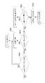
본 발명의 실시 예에 의한 냉장고의 제어 방법은, 냉장고 도어 일측에 도어 개방장치가 구비되며, 상기 개방장치는 구동모터에 의해 인출입되는 푸쉬로드를 포함하며, 상기 푸쉬로드가 상기 캐비닛을 밀어서 개방시키는 냉장고의 제어 방법에 있어서, 도어 개방신호의 입력을 대기하는 대기운전단계; 도어 개방신호의 입력시 상기 구동모터의 정방향 회전에 의해 상기 푸쉬로드가 인출되어 상기 도어가 개방되는 열림운전단계; 상기 푸쉬로드가 완전히 인출되어 상기 도어를 개방한 상태를 유지하는 열림 후 정지운전단계; 및 상기 구동모터의 역방향 회전에 의해 상기 푸쉬로드가 인입되어 상기 도어가 닫히는 복귀운전단계를 포함하는 것을 특징으로 한다.In the control method of a refrigerator according to an embodiment of the present invention, a door opening device is provided on one side of a refrigerator door, the opening device includes a push rod that is drawn in and out by a driving motor, and the push rod pushes the cabinet to open it. A control method of a refrigerator that makes a refrigerator, comprising: a standby operation step of waiting for an input of a door open signal; an opening operation step in which the push rod is drawn out by forward rotation of the driving motor when a door opening signal is input and the door is opened; a stop operation step after the push rod is completely drawn out to maintain the open state of the door; and a return operation step in which the push rod is drawn in and the door is closed by the reverse rotation of the driving motor.
상기 대기운전단계의 이전에는 초기운전단계를 실시하게 되며, 상기 초기운전단계는, 전원이 입력되는 과정과; 상기 제 1 홀센서가 온 상태인 경우 상기 구동모터를 정시시키는 과정과; 상기 제 1 홀센서가 온 상태가 아닌 경우 상기 제 1 홀센서가 온 상태가 될 때까지 구동모터를 역회전시키는 과정을 포함하는 것을 특징으로 한다.An initial operation step is performed before the standby operation step, and the initial operation step includes: a process in which power is input; stopping the driving motor when the first Hall sensor is in an on state; and, when the first Hall sensor is not in the on state, reversely rotating the driving motor until the first Hall sensor is in the on state.
상기 구동모터의 역회전이 시작된 후 상기 제 1 홀센서가 설정시간이 경과되어도 온 상태가 되지 않는 경우, 상기 구동모터를 정지시키고 에러신호를 출력하는 것을 특징으로 한다.When the first Hall sensor does not turn on even after a set time has elapsed after the reverse rotation of the driving motor is started, the driving motor is stopped and an error signal is output.
상기 대기운전단계에서는, 상방에 배치되는 제 2 감지장치와 상기 제 2 감지장치의 동일 연장선상의 하방에 위치되는 제 1 감지장치가 온 되는 경우 도어 개방신호를 출력하는 것을 특징으로 한다.In the standby operation step, a door opening signal is output when the second sensing device disposed above and the first sensing device positioned below the same extension line are turned on.
상기 대기운전단계에서는, 도어 하단에 구비되는 투사장치가 온 된 상태에서 상기 제 1 감지장치에 의해 상기 투사된 상의 영역을 사용자가 조작하는 것을 감지하는 경우 상기 도어 개방신호를 출력하는 것을 특징으로 한다.In the standby operation step, the door opening signal is output when detecting that the user manipulates the image projected by the first sensing device in a state in which the projection device provided at the lower end of the door is turned on. .
상기 도어의 개폐에 따라 온/오프 되는 리드 스위치에 의해, 상기 도어가 닫혀있는 상태에는 개방신호가 출력되고, 상기 도어가 열려있는 상태에서는 개방신호가 처리되지 않는 것을 특징으로 한다.An open signal is output when the door is closed by the reed switch turned on/off according to the opening and closing of the door, and the open signal is not processed when the door is open.
상기 열림운전단계는, 상기 구동모터가 정회전되는 과정; 상기 푸쉬로드를 인출되어 제 2 홀센서가 온 되면 상기 열림 후 정지운전단계를 실시하는 과정; 상기 제 2 홀센서가 설정시간이 경과될 때까지 온 되지 않는 경우 에러신호를 출력하고 복귀운전단계를 실시하는 것을 특징으로 한다.The opening operation step may include a process in which the driving motor is rotated forward; When the push rod is drawn out and the second hall sensor is turned on, performing a stop operation step after the opening; When the second Hall sensor is not turned on until a set time elapses, an error signal is output and a return operation step is performed.
상기 구동모터의 정회전 후 상기 제 2 홀센서가 온 되지 않은 상태에서, 상기 도어의 개방을 방해하는 외력이 가해지는 경우 상기 복귀 운전단계를 실시하는 것을 특징으로 한다.In a state in which the second hall sensor is not turned on after the driving motor is rotated forward, the return operation step may be performed when an external force that prevents the door from opening is applied.
상기 구동모터의 회전 속도가 설정 속도 이상으로 느려지게 되면, 상기 도어의 개방을 방해하는 외력이 가해진 것으로 판단하는 것을 특징으로 한다.When the rotation speed of the driving motor becomes slower than a set speed, it is determined that an external force that prevents opening of the door is applied.
상기 구동모터의 정회전시, 상기 구동모터의 회전 속도는 단계적으로 느려지는 것을 특징으로 한다.During the forward rotation of the driving motor, the rotation speed of the driving motor is characterized in that it is gradually slowed down.
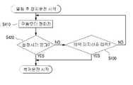
상기 열림 후 정지운전단계에서는, 상기 도어의 자중에 의해 상기 푸쉬로드가 밀려 인입되지 않도록 상기 구동모터가 정회전 상태를 유지하되, 상기 열림운전시의 회전 속도보다 낮은 속도로 회전되는 것을 특징으로 한다.In the stop operation step after opening, the drive motor maintains a normal rotation state so that the push rod is not pushed in by the weight of the door, but rotates at a speed lower than the rotation speed during the opening operation .
상기 모터의 정회전이 설정시간 이상 실시되거나 상기 도어에 외력이 가해지는 것으로 판단되면 상기 복귀운전단계를 실시하는 것을 특징으로 한다.When it is determined that the forward rotation of the motor is carried out for more than a set time or an external force is applied to the door, the return operation step is performed.
상기 복귀운전단계에서는, 상기 구동모터가 상기 제 1 홀센서가 온 될 때까지 역회전된 후 구동모터가 정지되며, 상기 구동모터의 정지 후 상기 대기운전단계를 실시하는 것을 특징으로 한다.In the return operation step, the drive motor is reversely rotated until the first Hall sensor is turned on, and then the drive motor is stopped, and the standby operation step is performed after the drive motor is stopped.
상기 구동모터의 회전 후 설정시간이 경과된 상태에서 상기 제 1 홀센서가 온 상태에 도달하지 못하게 되면 에러신호를 출력하고 대기운전단계를 실시하는 것을 특징으로 한다.When the first Hall sensor does not reach the on state after the rotation of the driving motor has elapsed after a set time has elapsed, an error signal is output and a standby operation step is performed.
상기 구동모터의 역회전시, 상기 구동모터의 회전속도가 단계적으로 낮아지도록 하는 것을 특징으로 한다.When the driving motor rotates in reverse, the rotation speed of the driving motor is lowered in stages.
상기 복귀운전의 시작시 상기 구동모터는 일시적으로 정지되는 과정을 거친 후 역회전 되는 것을 특징으로 한다.When the return operation is started, the driving motor is temporarily stopped and then reversely rotates.
상기 푸쉬로드가 완전히 인출된 상태 또는 상기 푸쉬로드가 인출되고 있는 상태 또는 상기 푸쉬로드가 인입되고 있는 상태에서 상기 리드 스위치가 오프되면 상기 구동모터가 상기 복귀운전 단계보다 더 빠른 속도로 역회전 되는 것을 특징으로 한다.When the reed switch is turned off in a state in which the push rod is fully drawn out or the push rod is drawn out or the push rod is drawn in, the drive motor is reversely rotated at a faster speed than the return operation step characterized.
상기 구동모터의 역회전시 상기 구동모터는 일정 속도를 유지하고, 상기 도어가 닫히기 직전에 상기 구동모터의 회전 속도를 급격하게 감소시키는 것을 특징으로 한다.When the driving motor rotates in reverse, the driving motor maintains a constant speed, and the rotation speed of the driving motor is rapidly reduced just before the door is closed.
상기 구동모터의 회전 후 설정시간이 경과된 상태에서 상기 제 1 홀센서가 온 상태에 도달하지 못하게 되면 에러신호를 출력하고 대기운전단계를 실시하는 것을 특징으로 한다.When the first Hall sensor does not reach the on state after the rotation of the driving motor has elapsed after a set time has elapsed, an error signal is output and a standby operation step is performed.
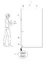
그리고, 본 발명의 실시 예에 의한 냉장고 도어의 개방 방법은, 제 2 감지장치가 사람을 검출하는 단계; 냉장고가 놓인 바닥면으로 센서어셈블리가 광 패턴을 투사하는 단계; 상기 제 2 감지장치에서 사람이 검출된 시점 또는 상기 광 패턴이 투사 시작된 시점으로부터 기준 시간이 경과하기 전에 제 1 감지장치가 도어 개방 신호를 검출하였는지 여부를 판단하는 단계; 및 상기 제 1 감지장치가 도어 개방 신호를 검출하였다고 판단되면, 도어 개방장치가 냉장고 도어를 개방시키는 단계를 포함한다.In addition, the method of opening a refrigerator door according to an embodiment of the present invention includes the steps of: detecting, by a second sensing device, a person; Projecting, by the sensor assembly, a light pattern to the bottom surface on which the refrigerator is placed; determining whether the first detection device detects a door open signal before a reference time elapses from a time when a person is detected by the second detection device or a time when the light pattern is projected; and opening the refrigerator door by the door opening device when it is determined that the first detection device detects the door open signal.
또한, 상기 광 패턴의 투사에 의해서 상기 바닥면에 가상 스위치가 생성되며, 상기 도어 개방 신호는, 사람의 발을 가상 스위치의 상방에 위치시키는 것 또는 사람의 발이 가상 스위치의 상방에서 미리 결정된 방식으로 움직이는 것일 수 있다.In addition, a virtual switch is generated on the floor surface by the projection of the light pattern, and the door open signal is determined by placing a person's foot above the virtual switch or placing the person's foot above the virtual switch in a predetermined manner. it could be moving
또한, 상기 제 2 감지장치에서 사람이 지속적으로 감지되는 중에 상기 제 1 감지장치가 도어 개방 신호를 검출하는 경우에 상기 도어 개방장치가 냉장고 도어를 개방시킬 수 있다.Also, when the first detection device detects a door opening signal while the second detection device continuously detects a person, the door opening device may open the refrigerator door.
또한, 본 발명은 상기 제 2 감지장치에서 사람이 검출된 시점 또는 상기 광 패턴이 투사 시작된 시점으로부터 기준 시간이 경과할 때까지 상기 제 1 감지장치가 도어 개방 신호를 검출하지 못하는 경우, 상기 센서어셈블리에 의한 광 패턴의 투사를 종료하는 단계를 더 포함할 수 있다.In addition, in the present invention, when the first detection device does not detect a door open signal until a reference time elapses from the time when a person is detected by the second detection device or the time when the light pattern is projected, the sensor assembly It may further include the step of terminating the projection of the light pattern by.
또한, 본 발명은 상기 제 2 감지장치가 사람을 검출하였고 따라서 상기 광 패턴이 상기 센서어셈블리를 통해 투사중인 동안에 상기 제 2 감지 장치가 기준 시간이 경과하기 전에 사람을 감지하지 못하면 상기 센서어셈블리를 통해 광 패턴의 투사를 종료하는 단계를 더 포함할 수 있다.Further, in the present invention, if the second sensing device detects a person and thus, while the light pattern is being projected through the sensor assembly, if the second sensing device fails to detect a person before a reference time elapses, the sensor assembly The method may further include terminating the projection of the light pattern.
그리고, 본 발명의 실시 예에 의한 냉장고 도어의 개방 방법은, 제 2 감지장치가 사람을 검출하는 단계; 냉장고가 놓인 바닥면으로 하나 이상의 센서어셈블리가 하나 이상의 광 패턴을 투사하는 단계; 제 1 감지장치가 다수의 도어 중 하나 이상의 도어의 개방을 위한 개방 신호를 검출하였는지 여부를 판단하는 단계; 및 상기 제 1 감지장치가 도어 개방 신호를 검출하였다고 판단되면, 도어 개방장치가 다수의 도어 중 하나 이상의 도어를 개방시키는 단계를 포함한다.In addition, the method of opening a refrigerator door according to an embodiment of the present invention includes the steps of: detecting, by a second sensing device, a person; Projecting, by one or more sensor assemblies, one or more light patterns to a bottom surface on which the refrigerator is placed; determining whether the first detection device detects an open signal for opening at least one door among the plurality of doors; and when it is determined that the first detection device detects the door open signal, the door opening device opens at least one door among the plurality of doors.
또한, 상기 하나 이상의 광 패턴을 투사하는 단계는 하나의 센서어셈블리가 다수의 광 패턴을 투사하는 단계를 포함하고, 다수의 광 패턴은 각각 바닥면 상에 다수의 가상 스위치를 형성하며, 상기 다수의 가상 스위치 중 하나 이상의 가려지는 가상 스위치에 대응하는 하나 이상의 도어가 개방될 수 있다.In addition, the step of projecting the one or more light patterns includes the step of one sensor assembly projecting a plurality of light patterns, the plurality of light patterns respectively forming a plurality of virtual switches on the bottom surface, the plurality of One or more doors corresponding to one or more of the virtual switches may be opened.
또한, 상기 하나 이상의 광 패턴을 투사하는 단계는, 다수의 센서어셈블리 각각이 다수의 광 패턴을 투사하는 단계를 포함하고, 다수의 광 패턴은 각각 바닥면 상에 다수의 가상 스위치를 형성하며, 다수의 가상 스위치 중 하나 이상의 가려지는 가상 스위치에 대응하는 하나 이상의 도어가 개방될 수 있다.In addition, the step of projecting the one or more light patterns includes each of a plurality of sensor assemblies projecting a plurality of light patterns, the plurality of light patterns respectively forming a plurality of virtual switches on the bottom surface, One or more doors corresponding to one or more hidden virtual switches among the virtual switches may be opened.
또한, 상기 하나 이상의 광 패턴을 투사하는 단계는, 센서어셈블리가 하나의 광 패턴을 투사하는 단계를 포함하며, 상기 하나의 광 패턴은 바닥면 상에 가상 스위치를 형성하며, 상기 가상 스위치의 가려짐 패턴에 따라 다수의 도어 중 개방될 도어가 결정될 수 있다.In addition, the projecting of the one or more light patterns includes projecting, by the sensor assembly, one light pattern, wherein the one light pattern forms a virtual switch on the bottom surface, and the virtual switch is obscured. A door to be opened among a plurality of doors may be determined according to the pattern.
또한, 상기 제 2 감지장치가 사람을 검출하는 단계는, 다수의 도어 중 둘 이상의 도어에 각각 설치된 제 2 감지장치들 중 하나 이상이 사람을 검출하는 단계를 포함할 수 있다.In addition, the step of detecting the person by the second detection device may include detecting the person at least one of the second detection devices respectively installed in at least two doors among the plurality of doors.
본 발명의 실시 예에 의한 냉장고는, 냉장실과 냉동실을 구비하는 캐비닛; 상기 캐비닛에 연결되며, 상기 냉장실을 개폐할 수 있고, 일부 또는 전부는 제 1 도어와 제 2 도어를 포함하는 다수의 냉장실 도어; 상기 캐비닛에 연결되고, 상기 다수의 냉장실 도어의 하방에서 상기 냉장실을 개폐하기 위한 다수의 냉동실 도어; 상기 다수의 냉장실 도어 중 하나 이상에 구비되며, 사람을 감지하기 위한 제 2 감지장치; 상기 다수의 도어 들 중 하나 이상의 도어 또는 상기 캐비닛에 구비되며, 구동모터를 구비하는 도어 개방장치; 상기 다수의 냉동실 도어 중 하나 이상에 구비되며, 하나 이상의 광 패턴을 투사하기 위한 하나 이상의 센서어셈블리; 상기 광 패턴에 의해서 바닥면에 생성되는 하나 이상의 가상 스위치의 가려짐을 감지하기 위한 제 1 감지장치; 및 상기 도어 개방장치를 제어하기 위한 메인 제어부를 포함하고, 상기 제 1 감지장치에 의해서 상기 하나 이상의 가상 스위치의 가려짐이 검출되면, 상기 메인 제어부는 상기 도어 개방장치를 작동시켜, 상기 다수의 도어 들 중 하나 이상의 도어를 개방시킨다.A refrigerator according to an embodiment of the present invention includes: a cabinet having a refrigerating compartment and a freezing compartment; a plurality of refrigerating compartment doors connected to the cabinet and capable of opening and closing the refrigerating compartment, some or all of which include a first door and a second door; a plurality of freezing compartment doors connected to the cabinet and configured to open and close the refrigerating compartment below the plurality of refrigerating compartment doors; a second sensing device provided on at least one of the plurality of refrigerating compartment doors and configured to detect a person; a door opening device provided in at least one of the plurality of doors or in the cabinet and having a driving motor; one or more sensor assemblies provided on one or more of the plurality of freezing chamber doors and configured to project one or more light patterns; a first sensing device for detecting the occlusion of one or more virtual switches generated on the floor by the light pattern; and a main control unit for controlling the door opening device, wherein when occlusion of the one or more virtual switches is detected by the first sensing device, the main control unit operates the door opening device to operate the door opening device Open one or more of the doors.
그리고, 본 발명의 실시 예에 의한 냉장고는, 냉장실과 냉동실을 구비하는 캐비닛; 상기 캐비닛에 연결되며, 상기 냉장실을 개폐하는 냉장실 도어; 상기 냉장실 도어의 측방에 위치되며, 상기 냉동실을 개폐하는 냉동실 도어; 상기 냉장실 도어와 냉동실 도어 중 하나 이상에 구비되며, 사람을 감지하기 위한 제 2 감지장치; 상기 도어 들 중 하나 이상의 도어 또는 상기 캐비닛에 구비되며, 구동모터를 구비하는 도어 개방장치; 상기 도어 들 중 하나 이상에 구비되며, 하나 이상의 광 패턴을 투사하기 위한 하나 이상의 센서어셈블리; 상기 하나 이상의 광 패턴에 의해서 바닥면에 생성되는 하나 이상의 가상 스위치의 가려짐을 감지하기 위한 제 1 감지장치; 및 상기 도어 개방장치를 제어하기 위한 메인 제어부를 포함하고, 상기 제 1 감지장치에 의해서 상기 하나 이상의 가상 스위치의 가려짐이 검출되면, 상기 메인 제어부는 상기 도어 개방장치를 작동시켜, 상기 도어 들 중 하나 이상의 도어를 개방시킨다.In addition, a refrigerator according to an embodiment of the present invention includes a cabinet having a refrigerating compartment and a freezing compartment; a refrigerating compartment door connected to the cabinet and configured to open and close the refrigerating compartment; a freezing compartment door positioned at a side of the refrigerating compartment door and configured to open and close the freezing compartment; a second sensing device provided on at least one of the refrigerating compartment door and the freezing compartment door to detect a person; a door opening device provided in at least one of the doors or the cabinet and having a driving motor; one or more sensor assemblies provided on one or more of the doors and for projecting one or more light patterns; a first sensing device for detecting occlusion of one or more virtual switches generated on a floor surface by the one or more light patterns; and a main control unit for controlling the door opening device, wherein when occlusion of the one or more virtual switches is detected by the first sensing device, the main control unit operates the door opening device to operate the door opening device among the doors. Open one or more doors.
그리고, 본 발명의 실시 예에 의한 냉장고는, 냉장실과 냉동실을 구비하는 캐비닛; 상기 캐비닛에 연결되며, 상기 냉장실을 개폐하는 냉장실 도어; 상기 냉장실 도어의 상방에 위치되며, 상기 냉동실을 개폐하는 냉동실 도어; 상기 냉동실 도어에 구비되며, 사람을 감지하기 위한 제 2 감지장치; 상기 도어 들 중 하나 이상의 도어 또는 상기 캐비닛에 구비되며, 구동모터를 구비하는 도어 개방장치; 상기 냉장실 도어에 구비되며, 하나 이상의 광 패턴을 투사하기 위한 하나 이상의 센서어셈블리; 상기 광 패턴에 의해서 바닥면에 생성되는 하나 이상의 가상 스위치의 가려짐을 감지하기 위한 제 1 감지장치; 및 상기 도어 개방장치를 제어하기 위한 제어부를 포함하고, 상기 제 1 감지장치에 의해서 상기 하나 이상의 가상 스위치의 가려짐이 검출되면, 상기 메인 제어부는 상기 도어 개방장치를 작동시켜, 상기 도어 들 중 하나 이상의 도어를 개방시킬 수 있다.In addition, a refrigerator according to an embodiment of the present invention includes a cabinet having a refrigerating compartment and a freezing compartment; a refrigerating compartment door connected to the cabinet and configured to open and close the refrigerating compartment; a freezing compartment door positioned above the refrigerating compartment door and configured to open and close the freezing compartment; a second sensing device provided on the freezing compartment door and configured to detect a person; a door opening device provided in at least one of the doors or the cabinet and having a driving motor; one or more sensor assemblies provided in the refrigerator compartment door and configured to project one or more light patterns; a first sensing device for detecting the occlusion of one or more virtual switches generated on the floor by the light pattern; and a control unit for controlling the door opening device, wherein when occlusion of the one or more virtual switches is detected by the first sensing device, the main control unit operates the door opening device to operate one of the doors More than one door can be opened.
바닥면 상의 상기 하나 이상의 가상 스위치의 적어도 일부는 상기 냉장실 도어 및 상기 냉동실 도어 중 하나 이상의 도어와 상하 방향으로 중첩될 수 있다.At least a portion of the one or more virtual switches on the bottom surface may vertically overlap with one or more of the refrigerating compartment door and the freezing compartment door.
또한, 상기 제 2 감지장치는 상기 캐비닛의 높이의 1/2 이상의 지점에 배치될 수 있다.In addition, the second sensing device may be disposed at a position equal to or greater than 1/2 of the height of the cabinet.
본 발명의 다른 측면에 따르면, 냉장고는 저장실을 정의하는 캐비닛, 상기 캐비닛에 연결되고 상기 저장실을 개폐하도록 구성되는 도어 - 상기 도어는 사용자에 의한 회동시에 설정된 수동 범위로 회동 개방되고 상기 도어 내에 배치되는 구동모터에 의한 회동시에 설정된 자동 범위로 회동 개방되도록 구성됨 -, 상기 냉장고의 전면에 구비되는 제 1 센싱어셈블리, 및 상기 냉장고의 상기 전면에 구비되고 일정 거리 내의 사용자의 존재를 감지하도록 구성되는 제 2 센싱어셈블리를 포함한다. 상기 제 1 센싱어셈블리는 일정 거리 내의 상기 사용자의 존재에 대한 상기 제 2 센싱어셈블리의 감지에 기초하여 상기 사용자의 이동을 감지하도록 구성되고, 상기 도어는 상기 사용자의 이동에 대한 상기 제 1 센싱 어셈블리의 감지에 기초하여, 상기 구동모터에 의해 상기 설정된 자동 범위로 개방되도록 구성된다.According to another aspect of the present invention, the refrigerator includes a cabinet defining a storage compartment, a door connected to the cabinet and configured to open and close the storage compartment, wherein the door is rotated and opened within a manual range set upon rotation by a user and is disposed within the door configured to rotate and open within an automatic range set when rotating by a driving motor; a first sensing assembly provided on a front side of the refrigerator; and a second sensing assembly provided on the front side of the refrigerator and configured to detect the presence of a user within a predetermined distance Includes sensing assembly. The first sensing assembly is configured to sense the movement of the user based on the detection of the second sensing assembly for the presence of the user within a predetermined distance, and the door is configured to detect the movement of the first sensing assembly with respect to the movement of the user. It is configured to be opened to the set automatic range by the driving motor based on the detection.
본 측면에 따른 실시 예들은 다음의 특징들 중 하나 이상을 포함할 수 있다. 예를 들어, 상기 제 1 센싱어셈블리는 상기 제 2 센싱어셈블리보다 상하로 더 낮은 위치에서 상기 냉장고의 상기 전면에 구비될 수 있다. 상기 도어는 수직축을 중으로 회동함으로써 개폐되도록 구성될 수 있다. 상기 저장실은 상단 저장실 및 하단 저장실을 포함할 수 있고, 상기 도어는 상단 저장실을 커버하도록 구성되는 상단 저장실 도어 및 하단 저장실을 커버하도록 구성되는 하단 저장실 도어를 포함할 수 있고, 상기 구동모터는 상단 저장실 도어를 설정된 자동 범위로 개방하도록 구성될 수 있다. 상기 제 1 센싱어셈블리는 상기 하단 저장실 도어에 구비되고 상기 제 2 센싱어셈블리는 상기 상단 저장실 도어에 구비될 수 있다. 일부 경우에, 상기 제 1 및 제 2 센싱어셈블리 중 하나 또는 둘 다는 사용자 또는 사용자의 일부가 위치 감지장치의 감지 범위 내에 존재하는지 여부를 판단하도록 구성되는 위치 감지장치를 포함할 수 있다. 상기 제 1 센싱어셈블리는 제 1 위치 감지장치를 포함할 수 있으며, 제 1 위치 감지장치의 감지 범위은 15 cm 미만이다. 상기 제 2 센싱어셈블리는 제 2 위치 감지장치를 포함할 수 있으며, 상기 제 2 위치 감지장치의 감지 범위은 대략 15 내지 100 cm 사이이다. 상기 제 1 센싱어셈블리는 사용자의 발이 상기 제 1 위치 감지장치의 상기 감지 범위 내에 존재하는 지 여부를 판단하도록 구성될 수 있다.Embodiments according to this aspect may include one or more of the following features. For example, the first sensing assembly may be provided on the front surface of the refrigerator at a position vertically lower than that of the second sensing assembly. The door may be configured to open and close by rotating the vertical axis to the middle. The storage compartment may include an upper storage compartment and a lower storage compartment, and the door may include an upper storage compartment door configured to cover the upper storage compartment and a lower storage compartment door configured to cover the lower storage compartment, and the drive motor may include an upper storage compartment. It may be configured to open the door to a set automatic range. The first sensing assembly may be provided in the lower storage chamber door and the second sensing assembly may be provided in the upper storage chamber door. In some cases, one or both of the first and second sensing assemblies may include a position sensing device configured to determine whether a user or portion of a user is within the sensing range of the position sensing device. The first sensing assembly may include a first position sensing device, and the sensing range of the first position sensing device is less than 15 cm. The second sensing assembly may include a second position sensing device, and the sensing range of the second position sensing device is approximately 15 to 100 cm. The first sensing assembly may be configured to determine whether the user's foot is within the sensing range of the first position sensing device.
일부 실시 예에서, 상기 설정된 자동 범위는 대략 25°일 수 있다. 상기 제 2 센싱어셈블리의 수직 위치는 상기 캐비닛의 높이의 절반 이상일 수 있다. 상기 제 2 센싱어셈블리는 지면의 수직 상방에 1 미터 이상으로 위치될 수 있다. 상기 제 1 센싱어셈블리는 상기 하단 저장실 도어의 하향 대향면에 구비될 수 있다. 상기 제 1 센싱어셈블리는 투사장치를 구비할 수 있으며, 상기 투사장치는 상기 냉장고의 전방의 지면에 광 패턴을 투사하도록 구성되고, 상기 광 패턴의 적어도 일부는 상기 제 1 위치 감지장치의 감지 범위 내에 있을 수 있다. 상기 투사장치는 상기 사용자의 존재에 대한 상기 제 2 센싱어셈블리의 감지에 기초하여, 상기 광 패턴을 투사하도록 구성될 수 있다. 일부 경우에서, 상기 투사장치는 도어의 전동 개방 이전 또는 설정 시간의 경과에 기초하여, 상기 광 패턴을 투사하는 것을 멈추도록 구성될 수 있다. 상기 광 패턴은 "도어 열림(Open Door)", "도어 열림(Door open)", "열림(Open)", 또는 "자동 도어(Auto Door)"로 판독되는 문자를 포함할 수 있다. 상기 설정된 수동 범위는 대략 180°이상일 수 있다.In some embodiments, the set auto range may be approximately 25°. The vertical position of the second sensing assembly may be at least half the height of the cabinet. The second sensing assembly may be positioned vertically above the ground by 1 meter or more. The first sensing assembly may be provided on a downwardly facing surface of the lower storage compartment door. The first sensing assembly may include a projection device, the projection device is configured to project a light pattern on the ground in front of the refrigerator, and at least a portion of the light pattern is within a sensing range of the first position detection device. there may be The projection device may be configured to project the light pattern based on the sensing of the second sensing assembly for the presence of the user. In some cases, the projection device may be configured to stop projecting the light pattern prior to electric opening of the door or based on the lapse of a set time. The light pattern may include characters read as “Open Door”, “Door open”, “Open”, or “Auto Door”. The set manual range may be approximately 180° or more.
본 발명의 더 다른 측면에 따르면, ―저장실을 정의하는 캐비닛, 상기 캐비닛에 연결되고 상기 저장실을 개폐하도록 구성되는 도어 - 상기 도어는 사용자에 의한 회동시에 설정된 수동 범위로 회동 개방되고 상기 도어 내에 위치되는 구동모터에 의한 회동시에 설정된 자동 범위로 회동 개방되도록 구성됨 -를 포함하는 냉장고 - 상기 냉장고는 제 1 감지 범위를 갖는 제 1 센싱어셈블리 및 상기 제 1 감지 범위보다 더 큰 제 2 감지 범위를 갖는 제 2 센싱어셈블리를 포함함―를 제어하는 방법은, 상기 제 2 센싱어셈블리를 사용하여 상기 제 2 감지 범위 내의 상기 사용자의 존재를 감지하는 단계, 상기 제 2 감지 범위 내의 상기 사용자의 존재에 대한 상기 제 2 센싱어셈블리의 감지에 기초하여 상기 제 1 감지 범위 내의 상기 사용자 또는 상기 사용자의 일부의 존재를 감지하는 단계, 및 상기 제 1 감지 범위 내의 상기 사용자 또는 상기 사용자의 일부의 존재를 감지하는 것에 기초하여, 상기 도어를 상기 설정된 자동 범위로 개방하기 위해 상기 구동모터를 동작시키는 단계를 포함한다.According to still another aspect of the present invention, a cabinet defining a storage room, a door connected to the cabinet and configured to open and close the storage room, wherein the door is pivotally opened to a manual range set when a user rotates and is positioned within the door Refrigerator comprising - configured to rotate and open within an automatic range set when rotating by a driving motor, wherein the refrigerator includes a first sensing assembly having a first sensing range and a second sensing assembly having a second sensing range greater than the first sensing range comprising a sensing assembly, the method comprising: detecting the presence of the user within the second sensing range using the second sensing assembly; detecting the presence of the user or a portion of the user within the first sensing range based on sensing of a sensing assembly, and based on detecting the presence of the user or a portion of the user within the first sensing range, and operating the driving motor to open the door to the set automatic range.
상기 측면에 따른 실시 예는 다음의 특징들 중 하나 이상을 포함할 수 있다. 예를 들어, 상기 방법은 상기 제 2 감지 범위 내의 상기 사용자의 존재에 대한 상기 제 2 센싱어셈블리의 감지에 기초하여, 상기 냉장고의 정면의 지면에 광 패턴을 투사하는 단계 - 상기 광 패턴의 적어도 일부는 상기 제 1 센싱어셈블리의 상기 감지 범위 내에 존재함 -를 포함할 수 있다. 일부 경우에서, 상기 방법은 도어의 전동 개방 이전 또는 설정 시간의 경과에 기초하여 상기 광 패턴의 투사를 정지시키는 단계를 더 포함할 수 있다.An embodiment according to the above aspect may include one or more of the following features. For example, the method may include projecting a light pattern onto the ground surface of the front of the refrigerator - at least a portion of the light pattern, based on the sensing of the second sensing assembly for the presence of the user within the second sensing range. exists within the sensing range of the first sensing assembly. In some cases, the method may further include stopping the projection of the light pattern before the electric opening of the door or based on the lapse of a set time.
또 다른 측면에 따른 냉장고는, 냉동실과 냉장실을 구비하는 캐비닛; 상기 냉동실을 개폐하기 위한 냉동실 도어; 상기 냉장실을 개폐하기 위한 냉장실 도어; 상기 냉동실 도어와 상기 냉장실 도어 중 어느 하나에 구비되며, 감지 거리 내로의 사용자의 접근을 감지하기 위한 제 2 감지 장치; 상기 냉동실 도어와 상기 냉장실 도어 중 어느 하나에 구비되며, 상기 제 2 감지 장치 보다 낮은 위치에 배치되는 센싱어셈블리; 상기 냉동실 도어와 상기 냉장실 도어 중 어느 하나를 개방시키기 위한 도어 개방장치; 및 상기 도어 개방장치를 제어하는 메인 제어부를 포함한다.A refrigerator according to another aspect includes: a cabinet having a freezing compartment and a refrigerating compartment; a freezing compartment door for opening and closing the freezing compartment; a refrigerating compartment door for opening and closing the refrigerating compartment; a second sensing device provided on one of the freezing compartment door and the refrigerating compartment door and configured to detect a user's approach within a sensing distance; a sensing assembly provided on one of the freezing compartment door and the refrigerating compartment door and disposed at a lower position than the second sensing device; a door opening device for opening one of the freezing compartment door and the refrigerating compartment door; and a main control unit for controlling the door opening device.
상기 센싱어셈블리는, 상기 제 2 감지 장치에서 상기 감지 거리 내로의 사용자의 접근을 감지되면, 상기 캐비닛이 설치되는 바닥면에 광 패턴을 투사하는 투사 장치; 및 상기 광 패턴 상에서 사용자의 발을 감지하기 위한 제 1 감지 장치를 포함하고, 상기 메인 제어부는, 상기 제 1 감지 장치에 의한 사용자의 발 감지 여부에 기초하여 상기 도어 개방장치를 제어한다.The sensing assembly may include: a projection device for projecting a light pattern on a floor surface on which the cabinet is installed when the second sensing device detects a user's approach within the sensing distance; and a first sensing device for detecting the user's foot on the light pattern, wherein the main control unit controls the door opening device based on whether the user's foot is detected by the first sensing device.
상기 센싱어셈블리는 상기 투사 장치와 상기 제 1 감지 장치가 단일의 케이스에 수용되는 모듈 타입으로 형성될 수 있다.The sensing assembly may be formed of a module type in which the projection device and the first sensing device are accommodated in a single case.
상기 투사장치는, 상기 제 1 감지 장치의 하측에 위치될 수 있다.The projection device may be located below the first sensing device.
상기 냉동실 도어와 상기 냉장실 도어 중 어느 하나는 바닥면에 대해서 경사지는 경사면을 포함할 수 있다. 상기 투사장치 및 상기 제 1 감지 장치는 상기 경사면에 설치될 수 있다.Any one of the freezing compartment door and the refrigerating compartment door may include an inclined surface inclined with respect to a floor surface. The projection device and the first sensing device may be installed on the inclined surface.
상기 센싱어셈블리는, 상기 제 1 감지 장치 및 상기 투사 장치를 수용하는 케이스와, 상기 케이스를 커버하며 광의 투과가 가능한 케이스 커버를 더 포함하고, 상기 경사면에는 상기 케이스가 통과하는 장착홀이 형성될 수 있다.The sensing assembly may further include a case accommodating the first sensing device and the projection device, and a case cover that covers the case and allows light to pass therethrough, and a mounting hole through which the case passes may be formed in the inclined surface. have.
상기 제 1 감지 장치는, 발광부와 수광부를 포함하고, 상기 케이스는, 상기 발광부와 수광부를 구획하는 배리어를 포함할 수 있다.The first sensing device may include a light emitting unit and a light receiving unit, and the case may include a barrier dividing the light emitting unit and the light receiving unit.
상기 투사 장치는, 발광부와, 상기 발광부에서 조사된 광이 투과하는 필름과, 하나 이상의 렌즈를 포함할 수 있다.The projection device may include a light emitting unit, a film through which the light irradiated from the light emitting unit transmits, and one or more lenses.
상기 도어 개방장치는, 케이스와, 상기 케이스에 장착되는 구동모터와, 상기 구동모터의 동력을 전달하는 다수의 기어와, 상기 다수의 기어 중 일 기어에 연결되는 푸쉬로드를 포함할 수 있다.The door opening device may include a case, a driving motor mounted to the case, a plurality of gears for transmitting power of the driving motor, and a push rod connected to one of the plurality of gears.
상기 메인 제어부는, 도어 개방을 위하여, 상기 구동모터를 작동시켜 상기 푸쉬로드가 상기 케이스에서 인출되어 도어가 개방되도록 하고, 도어가 설정 각도 개방된 것으로 판단되면 상기 구동모터를 정지시킬 수 있다.The main control unit may operate the driving motor to open the door so that the push rod is pulled out of the case to open the door, and when it is determined that the door is opened at a set angle, the driving motor may be stopped.
상기 제 2 감지 장치는 상기 냉동실 도어에 장착되고, 상기 센싱어셈블리는 상기 냉장실 도어에 장착될 수 있다.The second sensing device may be mounted on the freezing compartment door, and the sensing assembly may be mounted on the refrigerating compartment door.
상기 제 2 감지 장치는, 상기 냉장실 도어에 장착되고, 상기 센싱어셈블리는 상기 냉동실 도어에 장착될 수 있다.The second sensing device may be mounted on the refrigerator compartment door, and the sensing assembly may be mounted on the freezing compartment door.
상기 냉동실 도어와 상기 냉장실 도어는 좌우로 배치되고, 상기 제 2 감지 장치 및 상기 센싱 어셈블리는 상기 냉장실 도어에 장착될 수 있다.The freezing compartment door and the refrigerating compartment door may be disposed left and right, and the second sensing device and the sensing assembly may be mounted on the refrigerating compartment door.
하나 이상의 실시 예들의 상세들은 아래의 첨부 도면들 및 설명에 진술된다. 다른 특징들은 명세서 및 도면들, 그리고 청구범위들로부터 명백해질 것이다.The details of one or more embodiments are set forth in the accompanying drawings and description below. Other features will become apparent from the specification and drawings, and from the claims.
상기 제안된 실시 예에 따른 냉장고 및 냉장고의 제어 방법에서, 다음의 효과가 기대될 수 있다.In the refrigerator and the method for controlling the refrigerator according to the proposed embodiment, the following effects can be expected.
본 발명의 실시 예에 따른 냉장고에서, 상기 도어 개방장치가 상기 도어에 구비되는 상기 센싱어셈블리의 감지를 통해 구동되므로, 상기 도어는 상기 사용자가 양손에 물건을 들고 있는 경우에도 자동으로 개방되어, 상기 사용자 편의가 향상될 수 있다.In the refrigerator according to the embodiment of the present invention, since the door opening device is driven by sensing the sensing assembly provided in the door, the door is automatically opened even when the user holds an object in both hands, User convenience can be improved.
그리고, 상기 센싱어셈블리는 상기 냉장고가 위치되는 바닥면 상에 상을 투사하고, 상기 사용자의 조작을 유도하고, 상기 조작이 상기 감지 장치를 통해 상기 투사되는 상의 영역에서 수행되는지를 감지함으로써, 상기 도어 개방장치가 구동되게 할 수 있다.In addition, the sensing assembly projects an image on the bottom surface on which the refrigerator is located, induces the user's manipulation, and detects whether the manipulation is performed in the projected image area through the sensing device, thereby generating the door. The opening device may be actuated.
따라서, 상기 사용자는 정확한 위치 조작을 통해 용이하고 신뢰할 수 있는 도어 개방 조작을 수행할 수 있다.Accordingly, the user can perform an easy and reliable door opening operation through an accurate position operation.
특히, 상기 센싱어셈블리는 하방에 구비되는 상기 냉동실 도어에 구비되고, 상기 투사되는 상은 상기 냉장고에 가까이 위치됨으로써, 상기 투사되는 상의 품질 및 감지 성능이 향상될 수 있다.In particular, the sensing assembly is provided in the freezer compartment door provided below, and the projected image is located close to the refrigerator, so that the quality and sensing performance of the projected image can be improved.
또한, 상기 냉장고를 지나가는 동물, 아이 또는 다른 것들로 인한 오인식이 방지될 수 있고, 따라서 상기 도어가 우연히 개방되는 것이 방지될 수 있다.In addition, misrecognition due to animals, children or others passing by the refrigerator can be prevented, and thus the door can be prevented from being opened accidentally.
또한, 상기 상들은 상기 경사면의 하방을 향하여 투사되고, 상기 조작은 자유로운 사용자의 발에 의해 용이하게 수행될 수 있고, 도어를 개방하는 조작은 사용자가 냉장고에 근접하여 있는 동안에 간단하게 수행될 수 있다.In addition, the images are projected downward of the inclined surface, the operation can be easily performed by the free user's feet, and the operation of opening the door can be easily performed while the user is close to the refrigerator. .
그리고, 상기 사용자의 접근이 상기 냉장실 도어에 구비되는 상기 제 2 감지장치에 의해 주로 감지되고, 그 다음, 상기 투사장치가 턴 온 되므로, 상기 투사장치의 불필요한 조작이 방지될 수 있다.And, since the user's approach is mainly detected by the second sensing device provided in the refrigerator compartment door, and then the projection device is turned on, unnecessary manipulation of the projection device can be prevented.
또한, 상기 도어가 상기 제 2 감지장치의 감지 후에 상기 제 1 감지장치의 감지에 의해 개방되므로, 상기 도어 개방 조작이 신뢰할 수 있게 수행될 수 있고, 상기 오인식이 최소화될 수 있다.In addition, since the door is opened by the detection of the first detection device after the detection of the second detection device, the door opening operation can be reliably performed and the misrecognition can be minimized.
그리고, 상기 도어가 개방되는 동안에, 상기 리드 스위치가 오프되고, 상기 투사장치 및 상기 제 1 감지장치가 활성화되지 않고, 따라서, 상기 불필요한 도어 개방 조작이 상기 도어가 이미 개방되어 있는 동안에 수행되지 않는다.And, while the door is being opened, the reed switch is turned off, the projection device and the first detection device are not activated, and thus, the unnecessary door opening operation is not performed while the door is already open.
그리고, 상기 비구면 렌즈가 제거되고, 초점을 조절하는 렌즈의 수가 감소되지만, 상기 투사장치는 상기 필름의 배치 및 상기 투사 거리의 조절을 통해, 상기 사용자에 의해 인식될 수 있는 상의 품질을 투사할 수 있다.And, although the aspherical lens is removed and the number of lenses for adjusting focus is reduced, the projection device can project the image quality that can be recognized by the user through the arrangement of the film and adjustment of the projection distance. have.
따라서, 상기 투사장치의 전체 길이는 단축될 수 있고, 상기 투사장치는 단열재로 인해 제한된 폭을 갖는 상기 냉동실 도어에 장착될 수 있는 구조를 가질 수 있다.Accordingly, the overall length of the projection device can be shortened, and the projection device can have a structure that can be mounted on the freezer door having a limited width due to the heat insulating material.
특히, 상기 센싱어셈블리는 상기 경사면에 장착되고, 상기 도어의 내부에서 지면에 대해 경사지도록 배치될 수 있고, 따라서, 상기 제한된 폭을 갖는 상기 도어의 내측에 효과적으로 장착될 수 있다.In particular, the sensing assembly may be mounted on the inclined surface and disposed to be inclined with respect to the ground inside the door, and thus may be effectively mounted on the inside of the door having the limited width.
그리고, 상기 투사장치의 상기 필름에 형성되는 상기 문자는 프린딩에 의해 형성되고, 고 해상도를 가질 수 있고, 따라서, 상기 바닥면 상에 형성되는 상기 상의 문자는 선명하게 나타날 수 있고, 또한 사용자의 편의가 향상될 수 있다.And, the characters formed on the film of the projection device are formed by printing and can have high resolution, so that the characters of the image formed on the bottom surface can appear clearly, and also the user's Convenience can be improved.
또한, 상기 필름 상에 형성되는 상기 문자가 프린트되는 경우, 폭의 비율은 상기 바닥면 상에 경사되도록 형성되는 상기 이미지의 형상을 고려하여 조정되고, 따라서 상기 이미지는 경사된 방향으로 투사되는 경우에도 명확하고 선명하게 형성될 수 있고, 따라서, 사용자의 편의는 더 향상될 수 있다.In addition, when the character formed on the film is printed, the ratio of the width is adjusted in consideration of the shape of the image formed to be inclined on the bottom surface, and thus the image is projected even when projected in an inclined direction. It can be formed clearly and clearly, thus, the user's convenience can be further improved.
그리고, 상기 센싱어셈블리에서, 상기 센싱어셈블리 및 상기 투사장치 는 하나의 모듈로 형성될 수 있고, 따라서 생산성이 향상될 수 있고 조립 작업이 단순화될 수 있고, 이에 의해 조립성을 개선한다.And, in the sensing assembly, the sensing assembly and the projection device can be formed as one module, and thus productivity can be improved and the assembly operation can be simplified, thereby improving the assembly property.
또한, 최소 용적을 갖는 상기 센싱어셈블리는 제한된 공간을 갖는 상기 도어의 내측에 배치될 수 있고, 따라서, 공간 배치가 효과적으로 배치될 수 있고, 상기 단열재 성능이 열화되는 것이 방지될 수 있다.In addition, the sensing assembly having a minimum volume may be disposed inside the door having a limited space, thus, the spatial arrangement may be effectively disposed, and the performance of the insulation material may be prevented from being deteriorated.
상기 제한된 발명에 따르면, 사람의 조작 없이 개방될 도어를 개방할 수 있는 장점이 있을 수 있다.According to the limited invention, there may be an advantage in that the door to be opened can be opened without human manipulation.
특히, 사람이 양손을 자유롭게 사용할 수 없는 경우, 도어 개방 동작 없이 냉장고의 도어를 자동으로 개방할 수 있는 장점이 있을 수 있다.In particular, when a person cannot freely use both hands, there may be an advantage of automatically opening the door of the refrigerator without a door opening operation.
또한, 냉장고가 다수의 도어를 포함하는 경우, 다수의 도어 중에서 개방될 도어를 용이하게 선택할 수 있는 장점이 있을 수 있다.Also, when the refrigerator includes a plurality of doors, there may be an advantage in that a door to be opened can be easily selected from among the plurality of doors.
본 발명의 실시 예들은 유사한 참조 번호들이 유사한 요소들을 지칭하는 이하의 도면들을 참조하여 상세히 설명될 것이다.
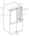
도 1은 본 발명의 제 1 실시 예에 의한 냉장고의 사시도이다.
도 2는 상기 냉장고의 전체 도어가 개방된 정면도이다.
도 3은 상기 냉장고의 서브 도어가 개방된 사시도이다.
도 4는 상기 메인 도어와 서브 도어가 분리된 분해 사시도이다.
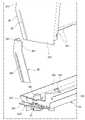
도 5는 본 발명의 제 1 실시 예에 의한 도어 개방장치의 장착구조를 보인 분해 사시도이다.
도 6은 상기 도어 개방장치를 하방에서 본 사시도이다.
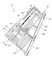
도 7은 상기 도어 개방장치의 분해 사시도이다.
도 8은 상기 도어가 닫혔을 때의 상기 도어 개방장치의 상태를 나타낸 도면이다.
도 9는 상기 도어가 열렸을 때의 상기 도어 개방장치의 상태를 나타낸 도면이다.
도 10은 상기 서브 도어의 사시도이다.
도 11은 상기 서브 도어의 하부의 분해 사시도이다.
도 12는 상기 서브 도어의 종단면도이다.
도 13은 본 발명의 제 1 실시 예에 의한 냉동실 도어의 사시도이다.
도 14는 상기 냉동실 도어의 분해 사시도이다.
도 15a 내지 15e는 상기 냉동실 도어의 아웃 플레이트의 성형과정을 순차적으로 나타낸 도면이다.
도 16은 상기 냉동실 도어의 부분 사시도이다.
도 17은 상기 도어 플레이트와 로어 데코 및 커버링 부재의 결합구조를 보인 분해 사시도이다.
도 18은 상기 도어 플레이트와 로어 데코 및 커버링 부재의 결합 상태를 보인 부분 절개 사시도이다.
도 19는 도 13의 19-19' 단면도이다.
도 20은 상기 냉동실 도어의 로어 데코를 전방에서 본 사시도이다.
도 21은 상기 로어 데코를 상방에서 본 사시도이다.
도 22는 상기 로어 데코의 센싱어셈블리 장착부를 보인 부분 사시도이다.
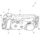
도 23은 본 발명의 제 1실시 예에 의한 센싱어셈블리를 전방에서 본 사시도이다.
도 24는 상기 센싱어셈블리를 후방에서 본 사시도이다.
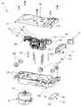
도 25는 상기 센싱어셈블리를 일 방향에서 본 분해 사시도이다.
도 26은 상기 센싱어셈블리를 다른 방향에서 본 분해 사시도이다.
도 27은 상기 센싱어셈블리의 종단면도이다.
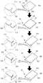
도 28a 내지 28c는 상기 센싱어셈블리의 장착 과정을 차례로 보인 도면이다.
도 29는 상기 센싱어셈블리의 투사장치를 통해 상의 조사 상태를 나태는 도면이다.
도 30은 도 29의 A영역의 확대도이다.
도 31은 상기 센싱어셈블리에 의한 상 조사 영역과 감지 범위을 나타낸 도면이다.
도 32는 상기 냉장고의 제어 신호의 흐름을 보인 블럭도이다.
도 33a 및 33b는 상기 메인 도어의 개방 조작 상태를 나타낸 도면이다.
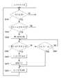
도 34는 상기 도어 개방장치의 동작을 순차적으로 나타낸 순서도이다.
도 35는 상기 도어 개방장치의 초기운전을 순차적으로 나타낸 순서도이다.
도 36은 상기 도어 개방장치의 대기운전을 순차적으로 나타낸 순서도이다.
도 37은 상기 도어 개방장치의 열림운전을 순차적으로 나타낸 순서도이다.
도 38은 상기 열림 운전시의 FG Pulse Count에 따른 Duty 변화를 보인 도면이다.
도 39는 상기 도어 개방장치의 열림 후 정지운전을 순차적으로 나타낸 순서도이다.
도 40은 상기 도어 개방장치의 복귀운전을 순차적으로 나타낸 순서도이다.
도 41은 상기 복귀운전시의 FG Pulse Count에 따른 Duty 변화를 보인 도면이다.
도 42는 상기 도어 개방장치의 긴급 복귀운전을 순차적으로 나타낸 순서도이다.
도 43은 상기 긴급 복귀운전시의 FG Pulse Count에 따른 Duty 변화를 보인 도면이다.
도 44는 제 2 실시 예에 따른 냉장고의 사시도이다.
도 45는 도 44의 냉장고의 측면도이다.
도 46은 제 2 실시 예에 따른 냉장고의 블럭도이다.
도 47은 제 2 실시 예에 따른 냉장실 도어를 보여주는 단면도이다.
도 48은 제 2 실시 예에 따른 냉장고 도어의 개방방법을 설명하기 위한 흐름도이다.
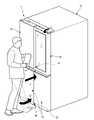
도 49는 음식물을 양손에 든 사람이 냉장고에 접근한 상태를 보여주는 도면이다.
도 50은 가상 스위치의 상방에 발이 위치된 모습을 보여주는 도면이다.
도 51은 제 2 실시 예에 따른 제 2 도어가 개방된 모습을 보여주는 도면이다.
도 52는 제 3 실시 예에 따른 냉장고를 보여주는 도면이다.
도 53은 제 4 실시 예에 따른 냉장고를 보여주는 도면이다.
도 54는 제 5 실시 예에 따른 냉장고를 보여주는 도면이다.
도 55는 제 6 실시 예에 따른 냉장고를 보여주는 도면이다.
도 56은 제 7 실시 예에 따른 냉장고를 보여주는 도면이다.
도 57은 제 8 실시 예에 따른 냉장고를 보여주는 도면이다.
도 58은 제 9 실시 예에 따른 냉장고를 보여주는 도면이다.
도 59는 제 10 실시 예에 따른 냉장고를 보여주는 도면이다.Embodiments of the present invention will be described in detail with reference to the following drawings in which like reference numerals refer to like elements.
1 is a perspective view of a refrigerator according to a first embodiment of the present invention.
2 is a front view of the refrigerator in which all doors are opened.
3 is a perspective view showing an open sub-door of the refrigerator.
4 is an exploded perspective view in which the main door and the sub-door are separated.
5 is an exploded perspective view showing the mounting structure of the door opening device according to the first embodiment of the present invention.
6 is a perspective view of the door opening device as viewed from below.
7 is an exploded perspective view of the door opening device.
8 is a view showing a state of the door opening device when the door is closed.
9 is a view showing a state of the door opening device when the door is opened.
10 is a perspective view of the sub-door.
11 is an exploded perspective view of a lower portion of the sub-door.
12 is a longitudinal cross-sectional view of the sub-door.
13 is a perspective view of a freezer compartment door according to a first embodiment of the present invention.
14 is an exploded perspective view of the freezing compartment door.
15A to 15E are views sequentially illustrating a molding process of the outer plate of the freezing compartment door.
16 is a partial perspective view of the freezer compartment door.
17 is an exploded perspective view showing the coupling structure of the door plate, the lower decoration and the covering member.
18 is a partially cut-away perspective view illustrating a coupling state between the door plate and the lower decoration and covering member.
19 is a cross-sectional view 19-19' of FIG. 13 .
20 is a perspective view of the lower decoration of the freezer compartment door viewed from the front.
21 is a perspective view of the lower decoration viewed from above.
22 is a partial perspective view showing a sensing assembly mounting portion of the lower decor.
23 is a perspective view of the sensing assembly according to the first embodiment of the present invention viewed from the front.
24 is a perspective view of the sensing assembly viewed from the rear.
25 is an exploded perspective view of the sensing assembly viewed from one direction.
26 is an exploded perspective view of the sensing assembly viewed from another direction.
27 is a longitudinal cross-sectional view of the sensing assembly.
28A to 28C are views sequentially showing the mounting process of the sensing assembly.
29 is a view showing a state of irradiation of an image through a projection device of the sensing assembly.
30 is an enlarged view of area A of FIG. 29 .
31 is a view showing an image irradiation area and a sensing range by the sensing assembly.
32 is a block diagram illustrating a flow of a control signal of the refrigerator.
33A and 33B are views illustrating an opening operation state of the main door.
34 is a flowchart sequentially illustrating the operation of the door opening device.
35 is a flowchart sequentially illustrating the initial operation of the door opening device.
36 is a flowchart sequentially illustrating the standby operation of the door opening device.
37 is a flowchart sequentially illustrating an opening operation of the door opening device.
38 is a view showing the duty change according to the FG pulse count during the open operation.
39 is a flowchart sequentially illustrating a stop operation after the door opening device is opened.
40 is a flowchart sequentially illustrating a return operation of the door opening device.
41 is a view showing the duty change according to the FG pulse count during the return operation.
42 is a flowchart sequentially illustrating an emergency return operation of the door opening device.
43 is a view showing the duty change according to the FG pulse count during the emergency return operation.
44 is a perspective view of a refrigerator according to a second embodiment.
45 is a side view of the refrigerator of FIG. 44 .
46 is a block diagram of a refrigerator according to the second embodiment.
47 is a cross-sectional view illustrating a refrigerator compartment door according to a second embodiment.
48 is a flowchart illustrating a method of opening a refrigerator door according to the second embodiment.
49 is a view showing a state in which a person holding food in both hands approaches the refrigerator.
50 is a view showing a state in which a foot is positioned above a virtual switch.
51 is a view showing an open state of the second door according to the second embodiment.
52 is a view showing a refrigerator according to a third embodiment.
53 is a view showing a refrigerator according to a fourth embodiment.
54 is a view showing a refrigerator according to a fifth embodiment.
55 is a view showing a refrigerator according to a sixth embodiment.
56 is a view showing a refrigerator according to a seventh embodiment.
57 is a view showing a refrigerator according to an eighth embodiment.
58 is a view showing a refrigerator according to a ninth embodiment.
59 is a view showing a refrigerator according to a tenth embodiment.
이하에서는 본 발명의 구체적인 실시 예를 첨부 도면과 함께 상세히 설명하도록 한다. 그러나 본 발명은 많은 상이한 형태로 구현될 수 있고 본 발명의 사상이 제시되는 실시 예에 제한된다고 할 수 없으며, 또 다른 구성요소의 추가, 변경, 삭제 등에 의해서 퇴보적인 다른 발명이나 본 발명의 사상범위 내에 포함되는 다른 실시 예를 용이하게 제안될 수 있고, 본 발명의 개념을 당업자에게 완전히 전달할 것이다.Hereinafter, specific embodiments of the present invention will be described in detail with accompanying drawings. However, the present invention can be implemented in many different forms and cannot be said to be limited to the embodiments in which the spirit of the present invention is presented, and other inventions that are degenerate by addition, change, deletion, etc. of other components or the scope of the present invention Other embodiments included therein may be readily proposed and will fully convey the inventive concept to those skilled in the art.
도 1은 본 발명의 제 1 실시 예에 의한 냉장고의 사시도이다. 그리고, 도 2는 상기 냉장고의 전체 도어가 개방된 정면도이다. 그리고, 도 3은 상기 냉장고의 서브 도어가 개방된 사시도이다.1 is a perspective view of a refrigerator according to a first embodiment of the present invention. And, FIG. 2 is a front view of the refrigerator in which all doors are opened. And, FIG. 3 is a perspective view in which the sub-door of the refrigerator is opened.
도면에 도시된 것과 같이, 본 발명의 실시 예에 의한 냉장고(1)는 저장공간을 형성하는 캐비닛(10)과, 상기 저장공간을 개폐하는 도어에 의해 외형이 형성될 수 있다.As shown in the drawings, the
상기 캐비닛(10)의 내부는 베리어(11)에 의해 상하로 구획될 수 있으며, 상기 캐비닛(10)의 상부에는 냉장실(12)이 형성될 수 있고 상기 캐비닛(10)의 하부에는 냉동실(13)이 형성될 수 있다.The interior of the
그리고, 상기 냉장실(12)의 내부에는 선반, 서랍 또는 바스켓과 같은 다양한 수납부재(121)가 구비될 수 있다. 상기 냉장실(12)에는 냉장실(12)을 밝히기 위한 메인 라이팅 유닛(85)이 구비될 수 있다. 상기 메인 라이팅 유닛(85)은 냉동실(13)에도 배치될 수 있으며, 냉장고(1) 내의 내측 벽면 어느 위치에도 배치될 수 있을 것이다.In addition, various accommodating
상기 냉동실(13)의 내부에는 상기 냉동실(13)로 인출입 가능한 서랍 형상의 냉동실 수납부재(131)가 주로 배치될 수 있으며, 이들 냉동실 수납부재(131)는 냉동실 도어(30)의 개방에 연동하여 인출입되도록 구성될 수도 있다. 그리고, 냉동실 도어(30) 전면에는 사용자의 인체를 감지할 수 있는 제 1 감지장치(92)가 구비될 수 있다. 상기 제 1 감지장치(92)에 대한 구체적인 설명은 아래에서 다시 살펴보기로 한다.A freezer
상기 도어는 냉장실 도어(20)와 냉동실 도어(30)로 구성될 수 있다. 상기 냉장실 도어(20)는 상기 냉장실(12)의 개구된 전면을 회동에 의해 개폐하며, 상기 냉동실 도어(30)는 상기 냉동실(13)의 개구된 전면을 회동에 의해 개폐하도록 구성될 수 있다. 그리고, 상기 냉장실 도어(20)와 냉동실 도어(30)는 좌우 한쌍이 구비되어 각각 냉장실(12)과 냉동실(13)을 차폐할 수 있도록 구성된다.The door may include a
상기 냉장실 도어(20)와 냉동실 도어(30)에는 다수의 도어 바스켓이 구비될 수 있다. 상기 도어 바스켓은 상기 냉장실 도어(20)와 냉동실 도어(30)가 닫힌 상태에서 냉장고 내에 구비되는 수납부재들(121,131)과 간섭되지 않도록 구성될 수 있다.A plurality of door baskets may be provided in the
한편, 본 발명의 실시 예에서는 냉동실이 하방에 구비되는 바텀 프리즈 타입의 냉장고에 하나의 공간을 나란히 배치된 한쌍의 도어가 회동되면서 개폐하는 프렌치 타입의 도어가 적용된 냉장고를 예를 들어 설명하고 있으나, 본 발명은 냉장고의 형태에 구애받지 않고 도어가 구비되는 모든 타입의 냉장고에 적용될 수 있을 것이다.On the other hand, in the embodiment of the present invention, a refrigerator to which a French-type door that opens and closes while a pair of doors arranged side by side with one space is rotated is applied to a bottom-freeze-type refrigerator having a freezer compartment below it as an example. The present invention may be applied to any type of refrigerator provided with a door regardless of the shape of the refrigerator.
상기 냉장실 도어(20)와 냉동실 도어(30)는 금속 소재로 외관이 형성되어 상기 냉장고(1)가 전체적으로 금속 질감을 가지도록 할 수 있다. 그리고, 필요에 따라서 상기 냉장실 도어(20)에는 물 또는 얼음의 취출을 위한 디스펜서가 구비될 수 있다.The refrigerating
한편, 한쌍의 냉장실 도어(20) 중 우측(도 1에서 볼 때)의 도어는 이중으로 개폐될 수 있도록 구성될 수 있다. 상세히, 우측에 위치되는 상기 냉장실 도어(20)는 금속 소재로 형성되어 상기 냉장실(12)을 개폐하는 메인 도어(40)와, 상기 메인 도어(40)의 내측에 회동 가능하게 배치되어 상기 메인 도어(40)의 개구를 개폐하는 서브 도어(50)로 구성될 수 있다.Meanwhile, the door on the right side (as seen in FIG. 1 ) of the pair of refrigerating
상기 메인 도어(40)는 한쌍의 냉장실 도어(20) 중 좌측(도 1에서 볼 때)의 상기 냉장실 도어(20)와 동일한 크기로 형성될 수 있으며, 메인 힌지(401) 및 미들 힌지(402)에 의해 상기 캐비닛(10)에 회동 가능하게 장착되어 상기 냉장실(12)의 일부를 개폐하게 된다.The
그리고, 상기 메인 도어(40)에는 소정의 크기로 개구된 개구부(403)가 형성된다. 상기 개구부(403)의 내측을 비롯한 상기 메인 도어(40)의 배면에는 도어 바스켓(404)이 장착된다. 따라서, 사용자는 상기 개구부(403)를 통해서 상기 메인 도어(40)를 개방하지 않고도 상기 도어 바스켓(404)에 접근 가능할 수 있다. 이때, 상기 개구부(403)의 크기는 상기 메인 도어(40)의 둘레 일부를 제외한 상기 메인 도어(40)의 전면 대부분을 차지하게 된다.In addition, an
상기 서브 도어(50)는 상기 개구부(403)의 내측에 회동 가능하게 장착되어 상기 개구부(403)를 개폐하게 된다. 그리고, 상기 서브 도어(50)는 적어도 일부가 유리와 같은 투명 소재로 형성된다. 따라서 상기 서브 도어(50)가 닫힌 상태에서도 상기 개구부(403)의 내측을 투시할 수 있게 된다. 상기 서브 도어(50)는 씨스루 도어라 불릴 수 있다.The sub-door 50 is rotatably mounted inside the
한편, 상기 서브 도어(50)의 전면은 빛의 투과율과 반사율이 조절되어 사용자의 조작에 따른 투명 또는 불투명 상태의 선택적인 조작이 가능하도록 구성될 수 있다. 그리고, 상기 메인 도어(40) 상부에는 상기 개구부(403)의 내측을 향하여 빛을 조사하는 도어 라이팅 유닛(49)이 구비되어 사용자의 조작에 따라 온/오프될 수 있다.Meanwhile, the front surface of the sub-door 50 may be configured to enable selective manipulation of a transparent or opaque state according to a user's manipulation by controlling light transmittance and reflectance. In addition, a
상기 메인 도어(40)와 상기 서브 도어(50)가 모두 닫힌 상태에서, 아무런 조작을 하지 않게 되면 상기 도어 라이팅 유닛(49) 및 메인 라이팅 유닛(85)은 오프상태를 유지하게 된다. 이와 같은 상태에서는 냉장고(1) 외측의 빛이 상기 서브 도어(40)의 전면에서 반사되어 상기 서브 도어(50)는 불투명한 블랙 색상 또는 거울면과 같은 상태가 된다. 따라서, 상기 메인 도어(40)의 수납 공간 및 상기 냉장실(12)의 내부 공간을 가시화할 수 없게 된다.When no operation is performed while the
따라서, 상기 서브 도어(50)는 상기 냉장고의 외관이 미려한 거울과 같은 질감을 가지도록 하여 심플하고 미려한 외관을 가질 수 있도록 한다. 또한, 이러한 외관은 상기 메인 도어(40) 및 상기 냉장실 도어(20)와 냉동실 도어(30)들의 금속 질감과 조화되어 한층 더 고급스러운 이미지를 줄 수 있게 된다.Accordingly, the sub-door 50 allows the exterior of the refrigerator to have a beautiful mirror-like texture to have a simple and beautiful exterior. In addition, such an appearance can be harmonized with the metal texture of the
반면에 상기 메인 도어(40)와 상기 서브 도어(50)가 모두 닫힌 상태에서 사용자가 특정 조작을 통해 상기 도어 라이팅 유닛(49) 또는 메인 라이팅 유닛(85)이 온(ON) 된다. 상기 도어 라이팅 유닛(49) 또는 메인 라이팅 유닛(85)이 온 된 상태에서는 냉장고(1)의 내측이 더 밝아지게 되며 냉장고(1) 내측의 빛이 상기 서브 도어(50)를 투과할 수 있게 되어 상기 서브 도어(50)가 투명하게 될 수 있다.On the other hand, in a state in which the
상기 서브 도어(50)가 투명한 상태가 되면 상기 메인 도어(40)의 수납 공간 및 냉장실(12)의 내부 공간이 가시화될 수 있다. 따라서, 사용자는 상기 메인 도어(40) 및 서브 도어(50)를 개방하지 않고도 상기 메인 도어(40)의 수납 공간 및 냉장실(12)의 내부 공간의 식품 수납 상태를 확인할 수 있게 된다.When the sub-door 50 is in a transparent state, the storage space of the
또한, 상기 서브 도어(50)가 투명한 상태가 될 경우 상기 서브 도어(50) 후방에 배치되는 디스플레이 유닛(60) 또한 가시화 상태가 되어 냉장고(1)의 동작 상태를 외부로 표시할 수 있게 된다.In addition, when the sub-door 50 is in a transparent state, the
도 4는 상기 메인 도어와 서브 도어가 서로 분리된 상태를 예시하는 분해 사시도이다.4 is an exploded perspective view illustrating a state in which the main door and the sub-door are separated from each other.
도면에 도시된 것과 같이, 상기 메인 도어(40)는 상기 아웃 플레이트(41)와 도어 라이너(42) 그리고, 도어 캡데코(45,46)에 의해 외형이 형성될 수 있다.As shown in the drawings, the
상기 아웃 플레이트(41)는 판상의 스테인레스 소재로 형성될 수 있으며, 상기 메인 도어(40)의 전면과 둘레면 일부를 형성하도록 절곡 형성될 수 있다.The
그리고, 상기 도어 라이너(42)는 플라스틱 소재로 사출 형성될 수 있으며, 상기 메인 도어(40)의 배면을 형성하게 된다. 그리고, 상기 도어 라이너(42)는 상기 개구부(403)와 연통되는 공간을 형성하고, 둘레에는 상기 도어 바스켓(404)이 장착될 수 있도록 다수의 도어 다이크 및 요철 구조가 형성될 수 있다.In addition, the
상기 도어 라이너(42)의 배면 둘레에는 리어 가스켓(44)이 구비될 수 있다. 상기 리어 가스켓(44)은 상기 캐비닛(10)의 둘레와 밀착되어 상기 메인 도어(40)와 캐비닛(10) 사이의 냉기 누설을 방지하게 된다.A
상기 어퍼 캡데코(45)와 로어 캡데코(46)는 상기 메인 도어(40)의 상면과 하면을 형성하게 된다. 그리고, 어퍼 캡데코(45)와 로어 캡데코(46)에는 상기 메인 도어(40)가 상기 캐비닛(10)에 회동 가능하게 장착될 수 있도록 하는 힌지 장착부(451)가 형성될 수 있다. 따라서, 상기 메인 도어(40)의 상단과 하단은 각각 상기 메인 힌지(401)와 미들 힌지(402)에 의해 회동 가능하게 지지 된다.The
그리고, 상기 메인 도어(40)의 하면 즉, 상기 로어 캡데코(46)에는 도어 핸들(462)이 함몰될 수 있으며, 사용자는 상기 도어 핸들(462)에 손을 넣어 상기 메인 도어(40)를 회동 조작하여 상기 냉장실(12)을 개폐할 수 있게 된다.In addition, the
한편, 상기 아웃 플레이트(41)와 상기 도어 라이너(42)의 사이에는 도어 프레임(43)이 더 구비될 수 있으며, 상기 개구부(403)의 둘레를 형성하게 된다.Meanwhile, a
상기 아웃 플레이트(41)와 도어 라이너(42), 도어 프레임(43) 및 상기 캡데코(45,46)가 결합된 상태에서 상기 메인 도어(40)의 내부 공간에는 발포액이 충전되어 단열재가 형성될 수 있게 된다. 즉, 상기 개구부(403)의 둘레 영역에는 단열재가 배치되어 냉장고(1) 내의 공간과 냉장고(1) 외의 공간을 단열시키게 된다.In a state in which the
그리고, 상기 도어 프레임(43)의 양측에는 상기 서브 도어(50)의 장착을 위한 서브 힌지(51,52)가 장착되는 힌지 홀(433)이 형성될 수 있다. 상기 힌지 홀(433)은 상기 서브 도어(50)의 측면과 마주보는 위치에 형성되며 상기 서브 힌지(51,52)가 삽입될 수 있도록 형성될 수 있다.Also, hinge
상기 서브 힌지(51,52)는 상기 서브 도어(50)의 상단과 하단에 각각 장착되는 어퍼 힌지(51)와 로어 힌지(52)로 구성될 수 있다. 상기 서브 도어(50)의 상단과 하단에는 상기 어퍼 힌지(51)와 로어 힌지(52)가 장착될 수 있도록 상기 서브 힌지(51,52)가 함몰 형성될 수 있다. 그리고, 상기 어퍼 힌지(51)와 로어 힌지(52)는 상기 힌지 홀(433)을 향하여 측방으로 연장되어 상기 메인 도어(40)의 내측에서 결합될 수 있다.The sub-hinges 51 and 52 may include an
따라서, 상기 메인 도어(40)와 서브 도어(50) 사이의 틈새에 상기 서브 힌지(51,52)의 간섭 구조가 존재하지 않게 된다. 그리고, 상기 메인 도어(40)와 서브 도어(50) 사이의 간격이 매우 좁은 상태를 유지할 수 있게 되어 외관이 더욱 미려하게 할 수 있다. 이와 같이 상기 메인 도어(40)와 서브 도어(50) 사이의 간격이 매우 좁은 상태를 유지하면서도 상기 서브 도어(50)의 회동시 메인 도어(40)와의 간섭이 일어나지 않도록 형성된다.Accordingly, the interference structure of the sub hinges 51 and 52 does not exist in the gap between the
그리고, 상기 어퍼 힌지(51)의 상방에는 상기 어퍼 힌지(51)를 차폐하고 상기 서브 도어(50)의 전선이 상기 메인 도어(40)를 향하도록 전선 출입을 가이드 하기 위한 힌지 커버(53)가 더 구비될 수 있다.And, above the
한편, 상기 개구부(403)에는 디스플레이 유닛(60)이 구비될 수 있다. 상기 디스플레이 유닛(60)은 상기 냉장고(1)의 동작 상태를 표시 및 조작을 위한 것으로 상기 서브 도어(50)가 투명한 상태가 되었을 때 외부에서 사용자가 상기 서브 도어(50)를 통해서 볼 수 있도록 구성될 수 있다. 즉, 상기 디스플레이 유닛(60)은 상기 서브 도어(50)가 불투명한 상태에서는 외부로 노출되지 않고, 투명한 상태에서는 각종 정보를 외부로 표시할 수 있게 된다.Meanwhile, the
물론, 상기 디스플레이 유닛(60)에는 상기 냉장고(1)의 상태 정보를 표시하기 위한 디스플레이(61)와 상기 냉장고(1)의 동작 설정을 위한 각종 조작 버튼(62)들을 구비할 수 있다. 상기 조작 버튼(62)의 조작에 의해 상기 냉장고(1)의 동작을 조작할 수 있게 된다.Of course, the
상기 디스플레이 유닛(60)은 상기 개구부(403)의 하단에 탈착 가능하게 제공될 수 있다. 따라서, 상기 디스플레이 유닛(60)의 점검 또는 수리가 필요한 경우, 디스플레이 유닛(60)은 탈착될 수 있다. 그리고, 상기 메인 도어(40)의 조립 후 별도 모듈로 조립된 디스플레이 유닛(60)을 간단하게 장착하여 조립할 수 있다. 또한, 상기 냉장고(1)의 사양에 따라 필요한 기능을 가진 디스플레이 유닛(60)을 선택적으로 장착할 수도 있다.The
상기 디스플레이 유닛(60)의 탈착을 위해서 상기 개구부(403)의 내부 양측면에는 상기 디스플레이 유닛(60) 측면의 디스플레이 가이드(634)와 결합되는 디스플레이 장착돌기(435)가 형성된다. 그리고, 상기 개구부(403)의 하단에는 상기 디스플레이 유닛(60)과 전기적으로 연결될 수 있도록 하는 디스플레이 연결부(436)가 구비될 수 있다.In order to detach the
상기 메인 도어(40)의 상단에는 상기 어퍼 캡데코(45)가 구비되며, 상기 어퍼 캡데코(45)에는 하방으로 함몰되어 개방장치 수용부(452)(도 5에서)가 형성되며, 상기 개방장치 수용부(452)는 캡데코 커버(453)에 의해 차폐될 수 있게 된다.The
도 5는 본 발명의 제 1 실시 예에 의한 도어 개방장치의 장착구조를 보인 분해 사시도이다. 그리고, 도 6은 상기 도어 개방장치를 하방에서 본 사시도이다. 그리고, 도 7은 상기 도어 개방장치의 분해 사시도이다.5 is an exploded perspective view showing the mounting structure of the door opening device according to the first embodiment of the present invention. And, Figure 6 is a perspective view of the door opening device viewed from below. And, Figure 7 is an exploded perspective view of the door opening device.
도면에 도시된 것과 같이, 상기 메인 도어(40) 상면의 어퍼 캡데코(45)에는 상기 개방장치 수용부(452)가 형성된다. 그리고, 상기 개방장치 수용부(452)의 내측에는 도어 개방장치(70)가 구비될 수 있다. 그리고, 상기 개방장치 수용부(452)의 개구된 상면은 캡데코 커버(453)에 의해 차폐된다. 그리고, 상기 개방장치 수용부(452)의 내측면에는 상기 캐비닛(10)을 향하여 개구되는 로드 홀(4511)이 형성될 수 있다.As shown in the drawing, the opening
상기 도어 개방장치(70)는 상기 메인 도어(40)의 자동 개방을 위한 것으로, 상기 개방장치 수용부(452)의 내측에 수용될 수 있으며, 상기 캡데코 커버(453)에 의해 차폐될 수 있도록 구성된다.The
상기 도어 개방장치(70)는, 외형을 형성하는 어퍼 케이스(71)와 로어 케이스(72)를 포함하며, 상기 어퍼 케이스(71)와 로어 케이스(72)에는 구동모터(73)와 다수의 기어들이 장착되며, 다수의 기어들에 의해 이동되는 푸쉬로드(77)가 상기 캐비닛(10)을 밀어 상기 메인 도어(40)를 개방시킬 수 있도록 구성된다.The
본 발명의 실시 예에서는 상기 도어 개방장치(70)가 상기 메인 도어(40)의 상단에 구비되는 것을 예를 들어 설명하고 있다. 그러나, 상기 도어 개방장치(70)는 서브 도어(50)와 냉동실 도어(30)에 구비될 수도 있으며, 상기 서브 도어(50)와 냉동실 도어(30)를 자동 개방하도록 구성될 수도 있다.In the exemplary embodiment of the present invention, the
상기 어퍼 케이스(71)와 로어 케이스(72)는 각각 상기 도어 개방장치(70)의 상부와 하부의 외형을 형성한다. 그리고, 상기 어퍼 케이스(71)와 로어 케이스(72)는 결합에 의해 내부에 다수의 기어들과 푸쉬로드(77)가 배치될 수 있는 공간을 제공하게 된다.The
그리고, 상기 로어 케이스(72)의 외측에는 다수의 마운팅 링(722)이 장착되는 링 장착부(721)가 형성된다. 상기 마운팅 링(722)은 상기 로어 케이스(72)가 상기 개방장치 수용부(452)의 내측에 안착되도록 지지하는 것으로 실리콘 소재로 형성될 수 있다. 따라서 상기 도어 개방장치(70)의 구동시 발생되는 진동을 감쇄시킬 수 있으며 이로 인한 소음을 방지할 수 있는 구조를 가지게 된다.In addition, a
상기 마운팅 링(722)은 상기 개방장치 수용부(452) 내측의 링 보스(454)에 의해 관통되도록 형성된다. 그리고, 상기 어퍼 케이스(71)를 관통하는 스크류가 상기 링 보스(454)에 체결되도록 하여 상기 어퍼 케이스(71)와 로어 케이스(72)가 서로 결합은 물론 상기 로어 케이스(72)가 상기 개방장치 수용부(452)의 내측에 고정 장착되도록 한다.The mounting
상기 구동모터(73)는 상기 로어 케이스(72)의 하면에 장착된다. 상기 구동모터(73)는 정역회전이 가능한 BLDC타입의 모터가 사용될 수 있다. 상기 구동모터(73)는 BLDC 타입의 모터를 사용함으로써 FG(frequency generating)신호를 카운팅하여 상기 구동모터(73)의 속도를 가변 제어 가능하게 된다.The driving
따라서, 상기 도어 개방장치(70)의 동작시 속도 조절을 통해 상기 메인 도어(40)의 개폐시 충격을 완화시킬 수 있다. 긴급 상황시, 상기 푸쉬로드(77)의 긴급 복귀 등이 가능하게 된다. 본 발명의 실시 예에서는 3개의 홀센서가 구비되어 1회전시 3 FG가 카운팅될 수 있도록 구성된 BLDC모터가 사용된 것을 예를 들어 설명하기로 한다.Therefore, it is possible to alleviate the shock when the
상기 구동모터(73)는 상기 로어 케이스(72)의 하면에서 장착되며, 상기 구동모터(73)의 회전축(731)은 상기 로어 케이스(72)의 내측으로 관통되며, 상기 구동모터(73)의 회전축(731)에는 모터 피니언(732)이 구비된다. 상기 모터 피니언(732)은 상기 로어 케이스(72)의 내측 공간에 구비될 수 있으며 제 1 감속기어(751)와 결합될 수 있다.The driving
상기 로어 케이스(72)의 하면에는 개방장치 피시비(74)가 구비될 수 있다. 상기 개방장치 피시비(74)는 상기 로어 케이스(72)의 하면에 장착되며, 상기 푸쉬로드(77)의 하방에 장착될 수 있다.An
상기 개방장치 피시비(74)는 상기 구동모터(73)의 제어를 위한 것으로, 상기 개방장치 피시비(74)에는 제 1 홀센서(741)와 제 2 홀센서(742)가 구비될 수 있다. 상기 제 1 홀센서(741)는 상기 푸쉬로드(77)가 완전히 인입되었을 때 상기 푸쉬로드(77)에 구비되는 자석(774)을 감지할 수 있는 위치에 구비된다. 그리고, 상기 제 2 홀센서(742)는 상기 푸쉬로드(77)가 완전히 인출되었을 때 상기 푸쉬로드(77)에 구비되는 자석(774)을 감지할 수 있는 위치에 구비된다. 따라서, 상기 구동모터(73)는 상기 제 1 홀센서(741)와 제 2 홀센서(742)의 감지 신호에 따라 상기 개방장치 피시비(74)에 의해 제어될 수 있다.The
상기 로어 케이스(72)의 내부에는 다수의 기어들이 서로 맞물리도록 배치될 수 있으며, 샤프트(723)에 의해 상기 로어 케이스(72)와 어퍼 케이스(71)의 사이에 회전 가능하게 장착될 수 있다. 상기 다수의 기어는 감속기어(75) 및 더미기어(76)를 포함한다. 상기 감속기어(75)는 회전속도를 감속시켜 상기 푸쉬로드(77)의 구동을 위한 힘을 전달할 수 있다. 그리고, 상기 더미기어(76)는 상기 푸쉬로드(77)의 인출거리를 확보하기 위한 것으로 상기 더미기어(76)의 조합에 의해 상기 푸쉬로드(77)와의 접점위치를 이동시킬 수 있게 된다.A plurality of gears may be disposed to mesh with each other inside the
상세히, 상기 모터 피니언(732)은 제 1 감속기어(751)와 결합된다. 상기 제 1 감속기어(751)는 가장 회전속도가 높은 모터 피니언(732)과 결합되는 기어로 소음 발생 가능성이 가장 높다. 따라서, 상기 모터 피니언(732)과 제 1 감속기어(751)는 우수한 기계적 강도와 탄성회복률 그리고 높은 내열성을 가지는 엘라스토머(Elastomer)소재로 형성될 수 있다. 따라서 상기 모터 피니언(732)과 제 1 감속기어(751)에 요구되는 기계적 강도를 만족하면서도 상기 모터 피니언(732)과 제 1 감속기어(751) 사이의 소음을 저감시킬 수 있게 된다. 그외 나머지 기어들은 엔지니어링 플라스틱(POM) 소재로 형성될 수 있다.In detail, the
상기 제 1 감속기어(751)는 제 2 감속기어(752)와 연결되며, 제 2 감속기어(752)는 제 3 감속기어(753)와, 제 3 감속기어(753)는 제 4 감속기어(754)와 차례로 연결될 수 있다. 상기 감속기어(75)들은 일반적인 감속기어와 같이 입력측과 출력측이 상하 2단 배치되는 구조를 가지며 이웃하는 기어와 입력측과 출력측이 접하여 감속될 수 있도록 구성된다.The
이러한 다수개의 감속기어(75)들의 조합을 통해서 회전수가 조절될 수 있으며, 회전수의 조절을 통해 상기 푸쉬로드(77)로 전달되는 힘을 조절할 수 있게 된다. 물론, 상기 감속기어(75)의 개수는 필요에 따라 조절될 수도 있을 것이다.Through the combination of the plurality of reduction gears 75, the number of rotations can be adjusted, and the force transmitted to the
상기 제 4 감속기어(754)에는 제 1 더미기어(761)가 배치되고, 상기 제 1 더미기어(761)와 상기 푸쉬로드(77)는 제 2 더미기어(762)에 의해 연결될 수 있다. 상기 더미기어(76)는 일반적인 평기어 형상으로 상기 제 4 감속기어(754)의 힘을 상기 푸쉬로드(77)로 단순 전달하되, 상기 푸쉬로드(77)와의 접점 거리를 조정하여 상기 푸쉬로드(77)의 최대 인출거리를 확보할 수 있도록 구성된다. 이를 위해 상기 더미기어(76)는 크기가 다른 복수의 기어로 구성될 수 있다.A
상세히, 상기 캡데코(45) 내부에 제공되는 상기 로어 케이스(72)의 구조의 특성상 상기 로어 케이스(72)의 폭은 제한적일 수 밖에 없으며, 따라서 상기 로어 케이스(72) 내부에 배치되는 감속기어(75)들의 크기 또한 제한적일 수 밖에 없다. 더불어 상기 푸쉬로드(77)의 길이 또한 상기 로어 케이스(72)의 내부에서 인출입되어야 하는 구조의 특성상 그 길이가 제한적이게 된다.In detail, due to the nature of the structure of the
이와 같은 상태에서 상기 감속기어(75)들은 감속을 위해 입력측과 출력측의 2단 구조를 가지게 된다. 따라서 그 크기가 일정 크기 이상으로 제한되며 상기 제 4 감속기어(754)가 상기 푸쉬로드(77)와 직접 연결될 경우 상기 제 4 감속기어(754)의 직경으로 인하여 상기 제 4 감속기어(754)와 푸쉬로드(77)와의 접점은 상기 메인 도어(40)와 먼 지점에 위치되고, 상기 푸쉬로드(77)의 충분한 인출거리를 확보할 수 없게 된다.In this state, the reduction gears 75 have a two-stage structure of an input side and an output side for deceleration. Therefore, the size is limited to a certain size or more, and when the
상기 푸쉬로드(77)로의 동력을 전달하기 위한 접점의 위치는 최대한 상기 푸쉬로드(77)의 인출 방향으로 배치되어야 하며, 상기 메인 도어(40)의 배면과 가까운 위치에 위치되어야 한다. 이를 위해 상기 제 4 감속기어(754)와 상기 푸쉬로드(77)의 사이에는 더미기어(76)가 배치될 수 있다.The position of the contact point for transmitting power to the
그리고, 제한된 공간에서 상기 더미기어(76)가 커지게 될 경우 상기 푸쉬로드(77)와의 접점의 위치가 상기 메인 도어(40)의 배면과 멀어지게 되므로 크기가 작은 복수의 더미기어(76)를 사용하여 상기 제 4 감속기어(754)의 동력을 상기 푸쉬로드(77)로 전달하게 된다. 즉, 상기 제 1 더미기어(761)와 제 2 더미기어(762)를 이용하여 상기 제 4 감속기어(754)의 동력을 상기 푸쉬로드(77)로 전달할 수 있다.In addition, when the
이때, 상기 푸쉬로드(77)와 접하는 제 2 더미기어(762)의 크기는 제 1 더미기어(761)의 크기보다 더 작게 형성하여 상기 메인 도어(40)의 배면과 최대한 가까운 위치에서 상기 푸쉬로드(77)와 접할 수 있도록 한다. 그리고, 상기 제 2 더미기어(762)가 위치되는 상기 로어 케이스(72)의 일부가 외측으로 함몰되도록 하여 상기 제 2 더미기어(762)의 위치를 최대한 상기 캐비닛(10) 측으로 확보할 수 있다.At this time, the size of the
상기 푸쉬로드(77)는 상기 캐비닛(10)을 밀어서 상기 메인 도어(40)를 개방시킬 수 있다. 그리고, 상기 푸쉬로드(77)는 상기 로어 케이스(72) 내측에 장착되며, 상기 제 2 더미기어(762)와 결합될 수 있도록 외측면에 랙(771)이 형성된다. 따라서, 상기 더미기어(76)의 회전에 의해 상기 랙(771)은 상기 로드 홀(4511)을 통과하여 돌출될 수 있다.The
상기 푸쉬로드(77)는 상기 어퍼 캡데코(54)의 폭보다 작게 형성될 수 있으며, 상기 메인 도어(40)의 인출거리를 확보할 수 있는 길이로 형성될 수 있다. 그리고, 상기 푸쉬로드(77)는 소정의 곡률을 가지도록 연장 형성될 수 있다. 따라서 상기 푸쉬로드(77)는 상기 메인 도어(40)가 회동되는 상황에서도 상기 캐비닛(10)의 전면의 일정 지점과 접촉된 상태를 유지할 수 있게 된다. 따라서, 메인 도어(40)의 회동시에도 상기 푸쉬로드(77)가 슬립되지 않고 상기 캐비닛(10)의 일지점을 밀어 상기 메인 도어(40)를 개방할 수 있다.The
상기 푸쉬로드(77)의 전단에는 로드 캡(78)이 형성될 수 있다. 상기 로드 캡(78)은 고무 또는 탄성소재로 형성될 수 있으며, 상기 캐비닛(10)과 접촉되어 상기 푸쉬로드(77)와 캐비닛(10)의 접촉시 소음을 방지하고 접지력을 향상시켜 상기 푸쉬로드(77)가 밀어주는 힘을 상기 캐비닛(10)에 효과적으로 전달할 수 있도록 한다.A
또한, 상기 푸쉬로드(77)의 외측면의 크기는 상기 로드 홀(4511)의 크기와 동일하게 형성되거나 다소 크게 형성될 수 있다. 따라서, 상기 푸쉬로드(77)가 완전히 인입된 상태에서는 상기 로드 캡(78)이 상기 로드 홀(4511)을 차폐하도록 구성될 수 있다.Also, the size of the outer surface of the
상기 푸쉬로드(77)의 상면과 하면에는 가이드 홈(772)이 형성될 수 있다. 상기 가이드 홈(772)은 상기 푸쉬로드(77)의 연장된 형상을 따라 형성될 수 있으며, 상기 푸쉬로드(77)의 곡률과 동일하게 형성될 수 있다.
상기 로어 케이스(72)와 어퍼 케이스(71)에는 상기 가이드 홈(772)에 삽입되는 가이드 돌기(714,724)가 돌출 형성될 수 있다. 상기 가이드 돌기(714,724) 또한 상기 푸쉬로드(77)의 곡률과 동일하게 형성되므로 상기 푸쉬로드(77)의 인출입시 상기 푸쉬로드(77)는 상기 가이드 돌기(714,724)를 따라서 이동된다. 따라서, 상기 푸쉬로드(77)의 인출입시 상기 가이드 돌기(714,724)가 상기 가이드 홈(772)에 삽입된 상태를 유지하게 되어 상기 푸쉬로드(77)가 유동되는 것을 방지하게 된다. 그리고, 상기 푸쉬로드(77)는 유동이 방지되어 인출입 동작 중에도 상기 제 2 더미기어(762)와 안정적인 기어 결합 상태를 유지할 수 있게 된다.
상기 푸쉬로드(77)의 후단에는 상기 자석(774)이 수용되는 자석 장착부(773)가 형성된다. 상기 자석 장착부(773)의 위치는 상기 푸쉬로드(77)가 완전히 인입된 상태에서 상기 제 1 홀센서(741)의 수직 상방이 된다. 그리고, 상기 푸쉬로드(77)가 완전히 인출된 상태에서는 상기 자석 장착부(773)는 상기 제 2 홀센서(742)의 수직 상방에 위치될 수 있다. 따라서, 상기 푸쉬로드(77)의 인출입시 상기 개방장치 피시비(74)의 제 1 홀센서(741)와 제 2 홀센서(742)를 통해서 상기 푸쉬로드(77)의 동작을 감지할 수 있게 된다.A
한편, 상기 개방장치 수용부(452)에는 스위치 자석(455)이 구비된다. 상기 스위치 자석(455)은 상기 힌지 장착부(451)와 접하는 상기 개방장치 수용부(452)의 내측에 고정 장착된다. 그리고, 상기 힌지 장착부(451)에 장착되는 메인 힌지(401)에는 리드 스위치(4011)가 구비될 수 있다. 상기 리드 스위치(4011)가 장착되는 메인 힌지(401)는 상기 메인 도어(40)를 실질적으로 고정하는 금속 소재의 힌지는 물론 상기 메인 힌지(401)를 차폐하는 힌지 커버를 포함한다.On the other hand, the opening
상기 리드 스위치(4011)는 상기 메인 힌지(401)에 구비되어 상기 메인 도어(40)의 회동에도 고정된 위치를 유지하게 된다. 그리고, 상기 스위치 자석(455)은 상기 메인 도어(40)의 회동시 함께 회전하게 된다.The
따라서, 상기 메인 도어(40)가 닫힌 상태에서는 상기 리드 스위치(4011)가 상기 스위치 자석(455)에 의해 온 되고, 상기 메인 도어(40)가 개방되는 순간 상기 스위치 자석(455)이 멀어지게 되어 상기 리드 스위치는 오프 된다. 이와 같이 상기 리드 스위치(4011)의 온/오프에 따라 상기 메인 도어(40)의 개폐 여부를 감지할 수 있으며, 상기 메인 도어(40)의 개폐에 따라 상기 도어 개방장치(70)의 구동을 제어할 수 있다.Accordingly, when the
즉, 상기 리드 스위치(4011)는 상기 메인 도어(40)가 개방된 상태에서는 오프되므로, 상기 메인 도어(40)가 오프된 상태에서는 상기 도어 개방장치(70)의 개방 신호가 입력되더라도 상기 구동모터(73)가 동작되지 않도록 한다.That is, since the
도 8은 상기 도어가 닫혔을 때의 상기 도어 개방장치의 상태를 나타낸 도면이다.8 is a view showing a state of the door opening device when the door is closed.
도면에 도시된 것과 같이, 상기 메인 도어(40)가 닫힌 상태에서는 상기 스위치 자석(455)은 상기 리드 스위치(4011)와 마주보는 위치에 위치되어 상기 리드 스위치(4011)는 온 상태를 유지하게 된다.As shown in the figure, when the
그리고, 상기 푸쉬로드(77)는 완전히 인입된 상태가 되며, 이와 같은 상태에서 상기 자석(774)은 상기 제 1 홀센서(741)의 상방에 위치하여 상기 제 1 홀센서(741)가 온 상태가 된다. 즉, 사용자의 조작이 없는 상태에서는 상기 리드 스위치(4011)와 제 1 홀센서(741)가 온 상태를 유지하게 되며, 상기 구동모터(73)는 회전되지 않게 된다.In addition, the
그리고, 상기 푸쉬로드(77)가 완전히 인입된 상태에서는 상기 로드 캡(78)이 상기 로드 홀(4511)을 차폐하는 상태가 되며, 상기 푸쉬로드(77)의 단부는 상기 캐비닛(10)의 전면과 이격된 상태가 된다.In a state in which the
이와 같은 상태에서 사용자가 상기 도어 개방장치(70)의 동작을 위한 조작을 실시하게 되면, 상기 메인 도어(40)의 개방 신호가 입력되고 상기 구동모터(73)는 정회전하면서 구동을 시작하게 된다. 상기 구동모터(73)의 구동에 의해 발생되는 힘은 상기 감속기어(75)와 더미기어(76)들에 의해 상기 푸쉬로드(77)로 전달되고, 상기 푸쉬로드(77)는 상기 캐비닛(10)을 향하여 이동하게 된다.In this state, when the user performs an operation for the operation of the
상기 푸쉬로드(77)의 이동에 의해 상기 푸쉬로드(77)의 단부는 상기 캐비닛(10)과 접촉하게 된다. 그리고, 상기 푸쉬로드(77)는 상기 캐비닛(10)과 접하는 상태로 지속적으로 이동하게 되며, 상기 푸쉬로드(77)가 상기 캐비닛(10)을 밀어 상기 메인 도어(40)가 점차 개방된다.The end of the
도 9는 상기 도어가 열렸을 때의 상기 도어 개방장치의 상태를 나타낸 도면이다.9 is a view showing a state of the door opening device when the door is opened.
도면에 도시된 것과 같이, 상기 푸쉬로드(77)가 완전히 인출된 상태에서는 상기 자석(774)이 제 2 홀센서(742)에 위치하게 된다. 상기 제 2 홀센서(742)가 온 되면 상기 개방장치 피시비(74)는 상기 메인 도어(40)가 설정 각도만큼 회동된 것으로 판단하여 상기 구동모터(73)의 구동을 정지시킬 수도 있다.As shown in the drawing, in a state in which the
이와 같은 상태에서는 상기 메인 도어(40)가 소정의 각도, 또는 결정된 자동 범위로 개방되며, 사용자의 팔꿈치를 넣어서 상기 메인 도어(40)를 회동시키는 것이 가능하게 된다. 즉, 사용자가 양손에 물건을 들고 있어 손으로 상기 메인 도어(40)의 개방 조작이 불가능한 상태에서, 사용자가 팔꿈치 또는 신체의 일부를 이용하여 상기 메인 도어(40)를 설정된 수동 범위로 추가 개방할 수 있게 된다.In such a state, the
예를 들어, 상기 도어 개방장치(70)의 동작에 의해, 상기 메인 도어(40)는 상기 메인 도어(40)의 후면과 이웃하는 상기 냉장실 도어(20)의 전면 사이의 간격(D)이 대략 70mm ~ 90mm가 되도록 개방될 수 있다. 이때, 상기 메인 도어의 회동 각도는 24°내지 26°, 예를 들어 25°일 수 있다. 일부 경우들에서, 상기 메인 도어(40)의 자동 회동 범위는 상기 사용자와 상기 메인 도어(40) 사이의 거리에 의존할 수 있다. 예를 들어 상기 사용자가 상기 냉장고로부터 더 멀리 서 있으면 상기 메인 도어(40)의 상기 자동 회동 각도는 26°이상으로 증가될 수 있다. 이때, 상기 사용자는 상기 도어를 더 개방하기 위해 상기 사용자의 신체의 일부, 예를 들어 팔꿈치를 사용할 수 있다. 이러한 수동 개방 조작 동안에, 상기 도어는 전체 수동 범위, 예를 들어 180°이상으로 개방될 수 있다.For example, by the operation of the
그리고, 개방된 상기 메인 도어(40)는 식품의 수납 완료 후에 닫힐 수 있다. 인출된 상태의 상기 푸쉬로드(77)는 설정시간이 경과하면 상기 구동모터(73)가 역회전하여 자동으로 복귀하게 되어 다시 도 8과 같은 상태가 될 수 있다. 그리고, 상기 메인 도어(40)의 개방시 장애물이 감지되거나, 상기 메인 도어(40)가 개방된 상태에서 외력이 가해지는 경우에도 상기 구동모터(73)는 역회전하여 상기 푸쉬로드(77)가 복귀되도록 할 수 있다.In addition, the opened
한편, 상기 메인 도어(40)가 개방된 후 사용자가 상기 메인 도어(40)를 추가 개방하여 상기 리드 스위치(4011)가 오프되는 경우에는, 사용자가 설정시간의 경과 이전에 다시 상기 메인 도어(40)를 닫을 수 있으므로 상기 푸쉬로드(77)를 빠르게 복귀시켜 상기 푸쉬로드(77)가 상기 캐비닛(10)에 부딪혀 파손되는 것을 방지할 수 있다.On the other hand, when the
도 10은 상기 서브 도어의 사시도이다. 그리고, 도 11은 상기 서브 도어의 하부의 분해 사시도이다. 그리고, 도 12는 상기 서브 도어의 종단면도이다.10 is a perspective view of the sub-door. And, FIG. 11 is an exploded perspective view of a lower portion of the sub-door. And, Fig. 12 is a longitudinal cross-sectional view of the sub-door.
도면에 도시된 것과 같이, 상기 서브 도어(50)는 상기 개구부(403)의 형상과 대응하는 형상으로 형성될 수 있다. 그리고, 상기 서브 힌지(51,52)에 의해 상기 메인 도어(40)에 회동 가능하게 장착되어 상기 개구부(403)를 개폐할 수 있다.As shown in the drawing, the sub-door 50 may have a shape corresponding to the shape of the
상기 서브 도어(50)에는 복수의 유리가 일정 간격으로 적층 구성되는 패널 어셈블리(54)가 구비되며, 상기 패널 어셈블리(54)를 통해 냉장고(1)의 내측을 선택적으로 투시할 수 있도록 구성된다. 상기 패널 어셈블리(54)는 복수 유리가 서로 이격 배치되어 단열층을 형성할 수 있도록 구성된다. 그리고, 상기 복수의 유리층 중 상기 서브 도어(50)의 전면을 형성하는 유리는 하프 글래스 소재로 형성되어 냉장고(1) 내의 선택적인 투시가 가능하도록 구성된다. 그리고, 상기 패널 어셈블리(54)의 둘레에는 단열재가 형성되어 상기 패널 어셈블리(54) 외측의 영역을 단열할 수 있다.The sub-door 50 is provided with a
상기 패널 어셈블리(54)의 양측방에는 상기 서브 도어(50)의 양측면을 형성하는 사이드 프레임(55, 56)이 구비된다. 어느 하나의 상기 사이드 프레임(56)에는 상기 서브 도어(50)의 손잡이(561)가 함몰 형성되며, 다른 하나의 사이드 프레임(55)에는 상기 서브 힌지(51,52)가 고정될 수 있다.Side frames 55 and 56 forming both sides of the sub-door 50 are provided on both sides of the
그리고, 상기 패널 어셈블리(54)의 상하방에는 서브 캡데코(57,58)가 구비된다. 상기 서브 캡데코(57,58)는 상기 서브 도어(50)의 상면과 하면을 형성하며, 상기 사이드 프레임(55,56)과 결합되어 상기 서브 도어(50)의 둘레를 형성하게 된다. 그리고, 상기 서브도어(50) 상단과 하단의 상기 서브 캡데코(57,58)에는 각각 서브 힌지(51,52)가 장착된다.In addition,
상기 서브 도어 하면을 형성하는 서브 캡데코(58)에는 제 2 감지장치(81)와 노크 감지장치(82)가 장착되는 감지장치 수용부(582)가 형성될 수 있다. 상기 감지장치 수용부(582)는 수용부 커버(583)에 의해 차폐될 수 있다.In the
상기 서브 캡데코(58)에 장착되는 제 2 감지장치(81)는 사용자의 근접을 확인하기 위한 장치이며, 상기 노크 감지장치(82)는 사용자에 의한 상기 서브 도어(50)의 노크 조작을 감지하기 위한 장치이다. 상기 제 2 감지장치(81)와 상기 노크 감지장치(82)는 상기 패널 어셈블리(54)의 전면을 형성하는 전면 패널(541)의 배면에 부착될 수 있다.The
상기 전면 패널(541)의 배면 둘레를 따라서 베젤(5411)이 형성될 수 있다. 그리고, 상기 전면 패널(541)의 하단에 형성된 베젤(5411)에는 상기 제 2 감지장치(81)와 노크 감지장치(82)가 배치될 수 있게 된다. 따라서 냉장고(1)의 외측에서 볼 때, 상기 제 2 감지장치(81)와 상기 노크 감지장치(82)가 가려질 수 있도록 형성된다. 이때, 상기 제 2 감지장치(81)가 배치되는 부분은 상기 베젤(5411)의 일부가 제거되어 적외선의 송수신을 보다 용이하게 할 수도 있다.A
상기 제 2 감지장치(81)는 상기 제 1 감지장치(92)와 동일 연장선상에서 상하로 위치될 수 있다. 그리고, 상기 제 2 감지장치(81)가 설치되는 높이는 상기 서브 도어(50)의 하단으로 일반적인 성인의 경우 감지가 가능하지만 키가 작은 유아 또는 동물 기타 상기 제 2 감지장치(81)의 높이보다 낮은 다른 물건의 경우 감지를 하지 않게 된다.The
상기 제 2 감지장치(81)는 피에스디(Position Sensing Device)가 사용될 수 있다. 즉 상기 제 2 감지장치(81)는 발광부(811)에서 적외선을 조사하여 반사되는 빛의 각도를 수광부에서 측정하여 사용자의 위치를 인식하도록 구성된다. 상기 피에스디에 의해 검출 가능한 근접 거리는 설정 가능하며, 상기 제 2 감지장치(81)는 감지 가능 거리를 1m 이내, 예를 들어 15 cm와 100 cm 사이로 설정하여 사용자가 상기 냉장고(1) 전면의 1m 거리 이내에 위치하게 되면 사용자가 조작을 위해 상기 냉장고(1)의 전방에 위치하는 것으로 인식할 수 있도록 한다.The
상기 제 2 감지장치(81)의 장착 위치는 상기 노크 감지장치(82)와 마찬가지로 상방에 위치되는 상기 서브 도어(50)의 하단에 해당하며, 이 위치는 지면으로부터 대략 1m 정도 상방의 높이에 해당하므로 키가 작은 유아 또는 높이가 낮은 다른 물건들이 감지되지 않도록 할 수 있다.The mounting position of the
상기 제 2 감지장치(81)의 후방에는 가압부재(813)가 더 구비될 수 있다. 상기 가압부재(813)는 상기 제 2 감지장치(81)가 상기 감지장치 수용부(582)에 고정 장착됨은 물론 상기 제 2 감지장치(81)가 상기 전면 패널(541)에 밀착될 수 있도록 가압할 수 있도록 구성된다.A pressing member 813 may be further provided at the rear of the
상기 노크 감지장치(82)는 사용자가 상기 서브 도어(50)의 전면 패널(541)을 노크 조작하였는지를 인식할 수 있도록 구성된다. 상기 노크 감지장치(82)에 의해 감지되는 노크 조작에 의해 상기 냉장고(1)의 특정 동작을 지시할 수 있게 된다. 예컨데, 사용자의 노크 조작에 의해 상기 도어 라이팅 유닛(49)이 점등될 수 있으며, 이를 통해서 상기 서브 도어(50)가 투명하게 될 수 있다.The
상기 노크 감지장치(82)는 상기 전면 패널(541)의 가장자리 부분에 위치하게 되지만, 사용자의 노크 조작의 유효 입력 부분이 이에 한정되는 것은 아니다. 상기 노크 감지장치(82)는 진동 자체가 아닌 진동에 의한 음파를 감지하는 마이크를 포함하여 구성된다. 따라서, 상기 노크 감지장치(82)가 노크 조작에 의해 진동이 발생되는 매질에 밀착되어 있는 상태에서는 어느 위치를 노크 조작하더라도 연속되는 동일 매질을 통해 음파가 전달되어 유효하게 감지될 수 있게 된다. 그리고, 상기 노크 감지장치(82)의 위치는 전선의 배치와 상기 서브 도어(50)의 가시화 면적을 최대로 할 수 있는 일단으로 배치할 수 있게 된다.Although the
즉, 사용자가 노크 입력을 가하는 영역은 전면 패널(541)의 전면이 정의하는 영역 모두일 수 있다. 그리고, 테두리 부분을 제외한 상기 전면 패널(541)의 대부분은 실질적으로 선택적으로 투명하게 되는 시스루 영역으로 상기 노크 감지장치(82)가 배치될 수 없다.That is, the area to which the user applies the knock input may be all areas defined by the front surface of the
따라서, 상기 노크 감지장치(82)는 상기 전면 패널(541) 중 상기 베젤(5411) 영역에 위치되는 것이 바람직하다. 특히, 전면 패널(541)의 좌우양측 보다는 하단에 위치하는 것이 상기 전면 패널(541) 좌우 양측과 상단의 베젤을 최소화시킬 수 있는 방법이 될 수 있다. 이와 같은 상기 베젤(5411)의 형상에 의해 상기 시스루 영역을 확장시킬 수 있으며, 노크 감지장치(82)가 사용자의 시선이 상대적으로 많이 가지 않는 전면 패널(541)의 하단부에 위치하게 되어 사용자에게 시스루 영역이 보다 넓게 보이도록 할 수 있다.Accordingly, the
상기 노크 감지장치(82)는 상기 베젤(5411)의 영역에 위치되어 외부로 노출되지 않게 되지만, 상기 전면 패널(541)에 밀착되는 구조를 가지게 되므로 사용자는 상기 전면 패널(541)의 어느 위치를 노크 하더라도 사용자의 노크를 감지하는 것이 가능하게 된다.The
한편, 노크 조작 외에도 전면 패널(541)의 전면에 진동을 가하는 환경 요소는 매우 많이 발생될 수 있다. 상기 메인 도어(40) 및 서브 도어(50)의 열고 닫음에 따른 충격, 외부의 강한 소음 등에 의해 상기 서브 도어(50) 전면이 진동할 수 있고, 이러한 외부 환경에 의한 입력을 노크 신호로 판단될 여지도 있다.On the other hand, in addition to the knock operation, environmental factors that apply vibration to the front surface of the
따라서, 상기 감지장치 피시비(83)에서는 사용자가 서브 도어(50) 전면을 복수 회 두드리는 것을 정상적인 노크 입력으로 판단하도록 할 수 있다. 더욱 구체적으로는 사용자가 소정 시간 간격을 두고 서브 도어(50)의 전면을 복수 회(예를 들어 2회) 두드리는 것을 정상적인 노크 입력으로 판단할 수 있다.Accordingly, the
상기 수용부 커버(583)의 일측에는 상기 수용부 커버(583)를 상기 서브 캡데코(58)에 고정하기 위한 스크류가 체결되는 케이스 고정부(5832)가 형성된다. 그리고, 상기 수용부 커버(583)의 다른 일측에는 주입구 커버부(5831)가 더 형성된다. 상기 주입구 커버부(5831)는 상기 서브 캡데코(58) 상에 형성되어 상기 단열재(501) 성형을 위해 충전되는 발포액이 주입되는 제 1 주입구(5824)를 차폐할 수 있도록 형성된다.A
상기 수용부 커버(583)를 상기 서브 캡데코(58)에 장착하게 되면, 상기 감지장치 수용부(582)를 차폐할 수 있게 되며, 동시에 상기 제 1 주입구(5824)까지 차폐할 수 있게 된다.When the
한편, 상기 로어 힌지(52)와 인접하는 상기 서브 캡데코(58)의 일측에는 발포액이 주입되는 제 2 주입구(584)가 더 형성되며, 상기 제 2 주입구(584)는 별도의 주입구 커버(5841)에 의해 차폐될 수 있게 된다.On the other hand, on one side of the
상기 감지장치 수용부(582)의 바닥면에는 상기 제 2 감지장치(81)의 고정을 위한 스크류가 체결되는 제 1 보스(5821)와, 상기 노크 감지장치(82)의 고정을 위한 제 2 보스(5822)가 각각 형성된다.A
그리고, 상기 감지장치 수용부(582)의 일면에는 전선 홀(5823)이 형성된다. 상기 감지장치 피시비(83) 및 상기 제 2 감지장치(81), 노크 감지장치(82)와 연결된 전선(L)은 상기 전선 홀(5823)을 통해서 상기 서브 도어(50)의 둘레를 경유하여 상기 힌지 커버(53)를 통해 상기 서브 도어(50)의 외측으로 안내될 수 있게 된다.In addition, a
도 13은 본 발명의 제 1 실시 예에 의한 냉동실 도어의 사시도이다. 그리고, 도 14는 상기 냉동실 도어의 분해 사시도이다.13 is a perspective view of a freezer compartment door according to a first embodiment of the present invention. And, FIG. 14 is an exploded perspective view of the freezing compartment door.
상기 냉동실 도어(30)는 좌우 양측에 한쌍이 구비되며, 상기 냉동실(13)을 회동에 의해 개폐될 수 있도록 구성된다. 상기 냉동실 도어(30) 중 우측(도 1에서 볼 때)의 냉동실 도어(30)에는 센싱어셈블리(90)가 구비될 수 있다. 상기 한쌍의 냉동실 도어(30)는 상기 센싱어셈블리(90)외 다른 구조는 모두 동일하므로 이하에서는 우측의 냉동실 도어(30)에 관하여서만 설명하기로 한다.A pair of the freezing
상기 냉동실 도어(30)는 도어 플레이트(31)와, 상기 냉동실 도어 라이너(32) 그리고 어퍼 데코(33)와 로어 데코(34)로 구성될 수 있다. 그리고, 상기 냉동실 도어(30)의 내부에는 단열재가 채워진다.The freezing
상기 도어 플레이트(31)는 상기 냉동실 도어(30)의 전면 및 좌우 양측면을 형성하는 것으로, 판상의 스테인레스 소재가 절곡되어 형성될 수 있다. 특히, 상기 냉동실 도어(30)의 전면 하단에 상기 센싱어셈블리(90)가 장착될 수 있는 경사면(35)을 형성할 수 있도록 구성된다.The
상기 냉동실 도어 라이너(32)는 상기 냉동실 도어(30)의 배면을 형성한다. 상기 냉동실 도어 라이너(32)는 수지재로 사출 형성되며, 상기 냉동실 도어(30)의 배면에 수납을 위한 부재가 장착되도록 형성될 수도 있다. 그리고, 상기 냉동실 도어 라이너(32)와 상기 도어 플레이트(31)와의 사이에는 단열재가 채워질 수 있다.The freezing
상기 어퍼 데코(33)는 상기 도어 플레이트(31) 및 상기 냉동실 도어 라이너(32)와 결합되어 상기 냉동실 도어의 상면을 형성한다. 그리고, 상기 어퍼 데코(33)에는 하방으로 함몰된 냉동실 도어 손잡이(331)가 형성될 수 있다. 상기 어퍼 데코(33)는 상기 도어 플레이트(31)와 동일 소재로 형성될 수 있다.The
상기 로어 데코(34)는 상기 도어 플레이트(31) 및 상기 냉동실 도어 라이너(32)와 결합되어 상기 냉동실 도어(30)의 하면을 형성한다.The
한편, 상기 냉동실 도어(30)의 전면과 양 측면을 형성하는 상기 도어 플레이트(31)는 판상의 소재가 절곡되어 형성된다. 특히 상기 냉동실 도어(30) 전면의 하단에 경사면(35)을 형성하게 된다.Meanwhile, the
상기 경사면(35)의 형성을 위해서는 상기 도어 플레이트(31)는 판상의 소재가 다수회 절곡 형성된다. 그리고, 상기 도어 플레이트(31)는 상기 경사면(35)을 형성하면서도 외관에 주름이 발생되거나 난반사가 발생되지 않도록 제작될 수 있다.In order to form the
도 15a 내지 15e는 상기 냉동실 도어의 아웃 플레이트의 성형과정을 순차적으로 나타낸 도면이다.15A to 15E are views sequentially illustrating a molding process of the outer plate of the freezing compartment door.
도 15a 내지 15e를 참조하여 상기 도어 플레이트의 제조 과정을 살펴보면 다음과 같다.A manufacturing process of the door plate will be described with reference to FIGS. 15A to 15E .
우선, 도어 플레이트(31)의 성형을 해서는 원소재가 되는 스테인레스 강판을 블랭킹 가공하게 된다. 상기 강판의 블랭킹 가공에 의해 상기 도어 플레이트(31)는 도 15a와 같은 형상으로 성형된다.First, by forming the
상세히, 상기 도어 플레이트(31)는 블랭킹 가공에 의해 상기 냉동실 도어(30) 전면을 형성하는 전면부(311), 그리고 상기 전면부(311) 하단에서 상기 경사면(35)을 형성하는 경사부(312), 그리고 상기 냉동실 도어(30)의 측면을 형성하는 측면부(313)를 형성하게 된다.In detail, the
그리고, 상기 도어 플레이트(31)의 상단 중 상기 전면부(311)와 상기 측면부(313)가 나누어지는 부분에는 함몰부(314)가 형성된다. 상기 전면부(311)와 측면부(313)를 절곡하게 되면, 상기 함몰부(314)에 의해 상기 어퍼 데코(33)와 결합될 수 있는 형상을 형성할 수 있다.In addition, a
상기 도어 플레이트(31)의 하단 중 상기 경사부(312)와 상기 측면부(313)가 나누어지는 부분에는 절개부(315)가 형성된다. 상기 절개부(315)에 의해 상기 전면부(311)와 측면부(313) 그리고 경사부(312)를 절곡하게 될 때 경사부(312)와 측면부(313)가 형성하는 모서리 부분에 도어 슬릿(36)이 형성될 수 있다. 그리고, 블랭킹 가공에 의해 상기 경사부(312)에 상기 센싱어셈블리(90)가 삽입되는 장착홀(351)이 형성될 수 있다.A
블랭킹 가동된 상기 도어 플레이트(31)는 도 15B와 같이 포밍 가공에 의해 도어 플레이트(31)의 가장자리를 따라서 포밍부(316)가 절곡 형성된다. 상기 포밍부(316)는 상기 도어 플레이트(31) 중 상기 어퍼 데코(33) 및 로어 데코(34)와 결합되는 부분 그리고 상기 냉동실 도어 라이너(32)와 결합되는 부분을 형성하는 것으로, 수직하게 절곡 형성될 수 있다. 이때, 상기 절개부(315)를 형성하는 상기 경사부(312)와 측면부(313)의 일부는 포밍 가공되지 않는다.The blanking operation of the
포밍 가공된 상기 도어 플레이트(31)는 도 15C와 같이 상기 전면부(311)와 측면부(313)의 경계부분이 1차 벤딩 가공된다. 1차 벤딩 가공되는 부분은 상기 냉동실 도어(30)의 전면과 측면이 접하는 모서리 부분으로 소정의 곡률을 가지도록 벤딩 가공될 수 있다. 상기 벤딩 가공시 상기 경사면(35)의 양측단, 즉 상기 절개부(315)와 접하는 부분까지 동일 곡률로 벤딩될 수 있다.As shown in FIG. 15C , in the formed
1차 벤딩 가공된 상기 도어 플레이트(31)는 도 15D와 같이 2차 벤딩 가공될 수 있다. 2차 벤딩 가동되는 부분은 상기 전면부(311)와 경사부(312)의 경계선으로 소정의 곡률을 가지도록 벤딩 가공될 수 있다. 2차 벤딩 가공에 의해서 상기 경사면(35)이 형성될 수 있으며, 상기 경사면(35)은 소정의 각도를 가지게 된다. 본 발명의 실시 예에서 상기 경사면(35)은 상기 냉동실 도어(30) 전면과 대략 20°~ 30°의 각도를 가지도록 형성될 수 있다. 상기 경사면(35)의 각도는 사용자의 조작 감지를 용이하게 하고 오인식을 방지할 수 있는 범위에서 설정될 수 있다. 상기 2차 벤딩 가공에 의해서 상기 경사면(35)의 측단과 상기 측면부(313)의 단부는 서로 인접하게 된다.The
2차 벤딩 가공된 상기 도어 플레이트(31)는 도 15E와 같이 3차 벤딩 가공될 수 있다. 3차 벤딩 가공되는 부분은 절개부(315)를 형성하는 상기 측면부(313)의 일단에 해당하며, 소정의 곡률을 가지도록 벤딩된다. 3차 벤딩 가공에 의해 상기 도어 슬릿(36)이 정확한 간격으로 성형될 수 있게 된다.The
이와 같은 과정에 의해 상기 도어 플레이트(31)는 전체적인 형상이 형성될 수 있으며, 특히 상기 도어 슬릿(36) 성형 구조에 의해 상기 경사면(35)을 성형하면서도 주름이 발생되지 않고 난반사가 발생되는 굴곡이 발생되지 않게 된다.The overall shape of the
성형 완료된 상기 도어 플레이트(31)는 상기 어퍼 데코(33) 및 로어 데코(34)와 결합되며, 상기 냉동실 도어 라이너(32)와 결합될 수 있다. 그리고, 상기 냉동실 도어(30)의 내부에는 발포액이 충진되어 단열재를 성형하게 된다.The molded
도 16은 상기 냉동실 도어의 부분 사시도이다.16 is a partial perspective view of the freezer compartment door.
도면에 도시된 것과 같이, 상기 냉동실 도어(30) 중 상기 냉동실 도어(30)의 하단을 지지하는 바텀 힌지(37)와 가까운 측면에는 상기 도어 슬릿(36)이 형성되며, 상기 도어 슬릿(36)을 차폐하기 위해서 상기 냉동실 도어(30)의 내측에는 커버링 부재(38)가 구비된다.As shown in the drawing, the door slit 36 is formed on a side of the freezing
상기 도어 슬릿(36)은 상기 냉장고(1)의 전방에서 바라볼 때 노출을 방지하기 위해서 상기 냉동실 도어(30)의 측면 즉, 상기 도어 플레이트(31)의 측면부(313)에 형성될 수 있다.The door slit 36 may be formed on a side surface of the
그리고, 상기 도어 슬릿(36)은 상기 경사면(35)의 성형이 용이하도록 상기 경사면(35)과 인접한 위치에서 상기 경사면(35)을 따라서 형성될 수 있다. 상기 도어 슬릿(36)에 의해 상기 경사면(35)을 성형하게 되더라도 상기 도어 플레이트(31)에 주름이 생기거나 난반사가 일어나는 것을 방지할 수 있게 된다. 상기 도어 슬릿(36)은 상기 경사면(35)의 길이와 대응하게 형성될 수 있으며, 상기 냉동실 도어(30) 측면의 하단까지 연장되어 형성될 수 있게 된다.In addition, the door slit 36 may be formed along the
물론, 상기 도어 슬릿(36)이 형성되는 위치는 전술한 실시 예에 한정되지 않고, 상기 경사면(35)과 측면의 모서리 부분, 또는 상기 경사면(35)의 일측 등 상기 경사면(35)의 벤딩을 가능하게 하는 다양한 위치에 형성될 수 있을 것이다.Of course, the position where the door slit 36 is formed is not limited to the above-described embodiment, and bending of the
상기 커버링 부재(38)는 상기 냉동실 도어(30)의 내측에 장착될 수 있다. 상기 커버링 부재(38)는 상기 도어 플레이트(31)의 내측면에 밀착될 수 있으며, 이때, 상기 커버링 부재(38)의 리브부(383)가 상기 도어 슬릿(36)의 내측에 삽입된다.The covering
상기 리브부(383)는 상기 도어 슬릿(36)과 동일한 길이와 폭을 가지도록 형성될 수 있으며, 상기 도어 슬릿(36)에 장착된 상태에서 상기 냉동실 도어(30)의 측면와 동일 평면을 형성하도록 돌출 형성될 수 있다. 따라서 상기 리브부(383)가 상기 도어 슬릿(36)에 삽입되면 상기 도어 슬릿(36)을 채워 상기 도어 슬릿(36)이 노출되지 않도록 할 수 있다.The
그리고, 상기 커버링 부재(38) 또는 적어도 상기 리브부(383)는 상기 아웃 플레이트(41)와 동일 색상으로 형성될 수 있다. 따라서 상기 도어 슬릿(36)에 삽입된 상태에서 외부로 노출되는 상기 리브부(383)는 상기 도어 플레이트(31)와 일체감을 가지게 된다.In addition, the covering
도 17은 상기 도어 플레이트와 로어 데코 및 커버링 부재의 결합구조를 보인 분해 사시도이다. 그리고, 도 18은 상기 도어 플레이트와 로어 데코 및 커버링 부재의 결합 상태를 보인 부분 절개 사시도이다. 그리고, 도 19는 도 13의 19-19' 단면도이다.17 is an exploded perspective view showing the coupling structure of the door plate, the lower decoration and the covering member. And, FIG. 18 is a partially cut-away perspective view showing the coupling state of the door plate, the lower decoration and the covering member. And, Figure 19 is a cross-sectional view 19-19' of Figure 13.
도면을 참조하여 상기 커버링 부재(38) 및 상기 커버링 부재(38)의 결합 구조를 보다 상세하게 살펴보기로 한다.Referring to the drawings, the coupling structure of the covering
상기 로어 데코(34)는 상기 냉동실 도어(30)의 하면을 형성할 수 있도록 상기 냉동실 도어(30)의 하면 형상과 대응하도록 형성된다.The
상기 로어 데코(34)의 전단과 좌우 양측단 가장자리를 따라서 플레이트 삽입부(341)가 함몰 형성된다. 상기 플레이트 삽입부(341)는 상기 도어 플레이트(31)의 테두리를 형성하는 포밍부(316)가 삽입되는 공간을 형성한다. 상기 플레이트 삽입부(341)의 내측에는 상기 포밍부(316)가 삽입된 상태에서 고정될 수 있도록 경사를 가지는 다수의 리브(3411)가 형성될 수 있다.
그리고, 상기 로어 데코(34)의 후단을 제외한 둘레에는 상방으로 연장되는 플레이트 지지부(342)가 형성될 수 있다. 상기 플레이트 지지부(342)는 상기 도어 플레이트(31)와 접하여 상기 도어 플레이트(31)를 지지하도록 구성될 수 있다.In addition, a
그리고, 상기 로어 데코(34)의 후단에는 상방으로 연장되는 라이너 지지부(343)가 형성될 수 있다. 상기 라이너 지지부(343)는 상기 냉동실 도어 라이너(32)와 접하여 상기 냉동실 도어 라이너(32)의 하단을 지지하게 된다.In addition, a
상기 플레이트 지지부(342) 및 라이너 지지부(343)에 의해 상기 냉동실 도어(30)의 내부 공간은 밀폐된 공간을 형성할 수 있으며, 상기 플레이트 지지부(342)의 내측에 발포액이 충전되어 단열재를 형성할 수 있다.The inner space of the freezing
그리고, 상기 로어 데코(34)의 측단에는 상기 커버링 부재(38)의 하단 형상과 대응하는 형상으로 형성된 커버링 부재 삽입부(344)가 형성될 수 있다. 상기 커버링 부재 삽입부(344)는 상기 로어 데코(34)의 측단에 단차지게 형성될 수 있으며, 상기 도어 플레이트(31)와 상기 로어 데코(34)의 결합시 상기 커버링 부재 삽입부(344)의 하단이 삽입될 수 있는 공간을 제공하게 된다.In addition, a covering
그리고, 상기 로어 데코(34)에는 아래에서 상세하게 설명할 힌지 삽입부(345)와 전선 고정부(346)가 더 형성될 수 있다.In addition, a
상기 커버링 부재(38)는 상기 로어 데코(34)에 고정 장착되며, 상기 바텀 힌지(37)가 장착되는 힌지 삽입부(345)와 인접하는 상기 냉동실 도어(30) 일측의 모서리에 밀착되도록 형성될 수 있다.The covering
상세히, 상기 커버링 부재(38)는 상기 도어 플레이트(31)의 측면부(313)와 접하는 제 1 면(381)과, 상기 경사부(312) 및 전면부(311)과 접하는 제 2 면(382)을 포함하여 구성될 수 있다. 그리고, 상기 제 1 면(381)과 제 2 면(382)이 서로 접하는 부분은 상기 도어 플레이트(31)의 절곡된 모서리 부분과 대응하는 곡률을 가지도록 형성된다.In detail, the covering
상기 제 1 면(381)의 하단은 상기 제 2 면(382)의 하단보다 더 하방으로 연장되며, 상기 커버링 부재 삽입부(344)에 삽입될 수 있다. 그리고, 상기 제 1 면(381)의 외측면에는 외측으로 돌출되는 상기 리브부(383)가 형성된다. 상기 리브부(383)는 상기 도어 슬릿(36)에 삽입될 수 있는 위치에 형성된다.A lower end of the
상기 제 2 면(382)은 상기 경사면(35)과 전면에 밀착되도록 형성되며, 상기 경사면(35)과 대응하는 각도로 절곡 형성될 수 있다. 그리고, 상기 제 2 면(382)의 하단은 상기 제 1 면(381)의 하단보다 더 상방에 위치되며, 상기 플레이트 지지부(342)와 간섭되지 않도록 형성된다.The
상기 커버링 부재(38)가 장착된 상태에서 상기 커버링 부재(38)의 외측면 전체는 상기 도어 플레이트(31)의 내측면에 밀착될 수 있으며, 접착제에 의해 상기 도어 플레이트(31)에 밀착된 상태를 유지할 수 있다. 그리고, 상기 커버링 부재(38)가 장착된 상태에서는 상기 리브부(383)가 상기 도어 슬릿(36)을 관통하여 외부로 노출될 수 있다.In a state in which the covering
도 20은 상기 냉동실 도어의 로어 데코를 전방에서 본 사시도이다. 그리고, 도 21은 상기 로어 데코를 상방에서 본 사시도이다.20 is a perspective view of the lower decoration of the freezer compartment door viewed from the front. And, Fig. 21 is a perspective view of the lower decoration viewed from above.
도면에 도시된 것과 같이, 상기 로어 데코(34)의 일측에는 상기 센싱어셈블리(90)가 장착되기 위한 센싱어셈블리 장착부(39)가 함몰 형성된다. 상기 센싱어셈블리 장착부(39)는 상기 플레이트 지지부(342)의 외측 공간에 형성될 수 있다. 따라서, 상기 센싱어셈블리 장착부(39)는 단열재가 형성되는 공간과 구획된 별도의 공간으로 단열제 성형을 위한 발포액의 주입 후 또는 주입 전에 상기 센싱어셈블리(90)를 장착할 수 있다.As shown in the figure, a sensing
상기 센싱어셈블리 장착부(39)는 상기 냉동실 도어(30)를 지지하는 바텀 힌지(37)가 장착되는 부분과 반대되는 일단에 배치된다. 즉, 좌우 한쌍의 냉동실 도어(30)가 서로 인접하는 일단에 상기 센싱어셈블리 장착부(39)가 형성될 수 있다. 따라서, 상기 센싱어셈블리 장착부(39)에 장착되는 상기 센싱어셈블리(90)는 상기 제 2 감지장치(81)와 상하방향으로 동일 연장선상에 위치될 수 있다. 또한, 상기 센싱어셈블리 장착부(39)의 전방에 상기 장착홀(351)이 배치될 수 있다.The sensing
상기 센싱어셈블리 장착부(39)는 전선 안내홀(348)에 의해 상기 로어 데코(34)의 상방에 형성되는 공간과 연통될 수 있다. 따라서, 상기 센싱어셈블리(90)와 연결되는 전선(L)들은 상기 전선 안내홀(348)을 통해서 상기 로어 데코(34)의 내측으로 유입되며, 상기 로어 데코(34)의 내측을 따라 상기 로어 데코(34)의 다른 일측에 형성된 데코 전선홀(347) 까지 안내될 수 있게 된다.The sensing
이때, 상기 로어 데코(34)의 내측면에는 전선의 배치 방향을 따라 전선 고정부(346)가 다수개 형성될 수 있으며, 상기 전선(L)은 상기 전선 고정부(346)에 밀착된 상태를 유지할 수 있게 된다. 따라서 상기 냉동실 도어(30)의 내측에 발포액이 주입되는 상황에서도 상기 전선(L)은 이탈되지 않고 위치가 고정될 수 있다.At this time, a plurality of
상기 센싱어셈블리 장착부(39)와 떨어진 상기 로어 데코(34)의 다른 일측에는 상기 힌지 삽입부(345)가 형성된다. 상기 힌지 삽입부(345)는 상기 바텀 힌지(37)의 힌지축이 수용될 수 있도록 보스 형상으로 상방으로 연장 형성될 수 있다.The
그리고, 상기 힌지 삽입부(345)와 인접하는 상기 로어 데코(34)의 바닥면에는 데코 전선홀(347)이 형성된다. 상기 데코 전선홀(347)을 통해서 상기 센싱어셈블리(90)와 연결된 전선(L)은 상기 로어 데코(34)의 외측으로 안내될 수 있다. 이때, 상기 전선(L)은 상기 바텀 힌지(37)측을 경유하여 상기 캐비닛(10)측으로 향하여 메인 제어부(2)와 연결될 수 있다.In addition, a
도 22는 상기 로어 데코의 센싱어셈블리 장착부를 보인 부분 사시도이다.22 is a partial perspective view showing a sensing assembly mounting portion of the lower decor.
도면에 도시된 것과 같이, 상기 센싱어셈블리 장착부(39)는 상기 로어 데코(34)의 일측단에 형성될 수 있다. 상기 센싱어셈블리 장착부(39)는 내측으로 함몰되어 상기 센싱어셈블리(90)를 수용하는 공간을 형성하는 최소의 깊이로 함몰 형성된다. 즉, 상기 센싱어셈블리 장착부(39)의 후방에는 단열재가 형성되어 상기 냉동실 도어(30)의 단열 성능이 유지될 수 있도록 한다.As shown in the drawing, the sensing
특히, 상기 센싱어셈블리(90)는 상기 센싱어셈블리 장착부(39)의 내측에서 기울어진 상태로 장착될 수 있다. 따라서 길이가 긴 상기 센싱어셈블리(90)가 제한된 상기 냉동실 도어(30)의 내부에서 단열 공간을 유지하면서 장착될 수 있도록 한다.In particular, the
상기 센싱어셈블리 장착부(39)의 가장자리를 따라서 상기 플레이트 지지부(342)가 형성되며, 상기 센싱어셈블리 장착부(39)는 좌측면과 전면이 개구되도록 형성된다. 따라서, 상기 로어 데코(34)의 사출 성형시 상기 센싱어셈블리 장착부(39)의 내부를 용이하게 성형할 수 있게 된다.The
상기 센싱어셈블리 장착부(39)는 어셈블리 수용부(391)와 커넥터 수용부(392)로 구성될 수 있다. 상기 어셈블리 수용부(391)는 상기 센싱어셈블리(90)가 수용되는 공간으로 상기 로어 데코(34)의 일측단에 형성된다.The sensing
상기 어셈블리 수용부(391)는 지면을 기준으로 기울어지게 배치되는 상기 센싱어셈블리의 후면을 지지할 수 있도록 경사지게 형성될 수 있다. 즉, 상기 센싱어셈블리(90)가 장착 완료된 상태에서, 상기 센싱어셈블리(90)의 후단은 상기 어셈블리 수용부(391)의 내측면과 접하게 된다.The
상기 어셈블리 수용부(391)의 바닥면에는 어셈블리 가이드(394)가 형성될 수 있다. 상기 어셈블리 가이드(394)는 다수의 리브 형상으로 형성될 수 있으며, 일정간격으로 연속 배치될 수 있다. 그리고, 다수의 상기 어셈블리 가이드(394)들은 모두 동일 형상으로 형성되며, 상기 어셈블리 수용부(391)의 내측면(393)과 상기 로어 데코(34)의 바닥면을 연결하도록 형성될 수 있다.An
상기 어셈블리 가이드(394)는 상하 방향으로 길게 형성되며, 상기 도어 플레이트(31)를 향하는 상기 어셈블리 가이드의 단부에는 가이드 경사부(395)가 형성될 수 있다. 상기 가이드 경사부(395)는 상기 어셈블리 가이드(394)의 전단에서 상기 어셈블리 수용부(391)의 내측면(393)을 향하도록 점차 높아지는 경사를 가지도록 형성된다.The
상기 가이드 경사부(395)는 상기 어셈블리 가이드(394)의 전단에서부터 연장되는 제 1 경사부(3951)와 상기 제 1 경사부(3951)의 후단에서 상기 어셈블리 가이드(394)의 후단까지 연장되는 제 2 경사부(3952)로 구성될 수 있다.The guide inclined
상기 제 1 경사부(3951)는 제 2 경사부(3952)의 기울기보다 더 크게 형성된다. 따라서 상기 센싱어셈블리(90)의 장착시 상기 케이스(93,94)의 후단이 상기 제 1 경사부(3951)와 접하여 후방으로 이동할 수 있도록 하며 상기 어셈블리 수용부(391)의 내측면(393)까지 보다 용이하게 삽입될 수 있도록 한다.The first
그리고, 상기 제 2 경사부(3952)의 기울기는 완전히 장착된 상태의 상기 센싱어셈블리(90)의 기울기와 동일하게 형성될 수 있다. 즉, 상기 센싱어셈블리(90)의 장착시 상기 센싱어셈블리(90)의 하단은 상기 제 2 경사부(3952)에 의해 지지될 수 있으며, 상기 센싱어셈블리(90)는 상기 제 2 경사부(3952)를 따라 완전히 삽입된다. 그리고, 상기 센싱어셈블리(90)가 완전히 삽입 장착된 상태에서 상기 센싱어셈블리(90)의 하단을 지지하여 상기 센싱어셈블리(90)의 장착 위치가 변경되지 않도록 한다.In addition, the inclination of the second
상기 커넥터 수용부(392)는 상기 어셈블리 수용부(391)의 측방에 형성된다. 상기 커넥터 수용부(392)는 상기 센싱어셈블리(90)와 메인 제어부(2)를 연결하기 위한 센싱어셈블리 커넥터(912,922)가 수용되는 공간을 형성하게 된다. 따라서, 상기 커넥터 수용부(392)는 상기 어셈블리 수용부(391)보다 상대적으로 작은 크기로 형성될 수 있다. 그리고, 상기 커넥터 수용부(392)의 상방에는 전선 안내홀(348)이 형성될 수 있다.The connector
따라서, 상기 센싱어셈블리(90)의 장착시 상기 센싱어셈블리(90)와 연결된 제 1 커넥터(912)와 상기 메인 제어부(2)와 연결된 제 2 커넥터(922)를 상기 냉동실 도어(30) 외측에서 먼저 연결한 후에 상기 센싱어셈블리(90)를 상기 어셈블리 수용부(391)에 삽입하게 되며, 이때 서로 연결된 상태의 제 1 커넥터(912)와 제 2 커넥터(922)를 상기 커넥터 수용부(392) 측으로 위치시키게 된다.Therefore, when the
도 23은 본 발명의 제 1 실시 예에 의한 센싱어셈블리를 전방에서 본 사시도이다. 그리고, 도 24는 상기 센싱어셈블리를 후방에서 본 사시도이다. 그리고, 도 25는 상기 센싱어셈블리를 일 방향에서 본 분해 사시도이다. 그리고, 도 26은 상기 센싱어셈블리를 다른 방향에서 본 분해 사시도이다. 그리고, 도 27은 상기 센싱어셈블리의 종단면도이다.23 is a perspective view of the sensing assembly according to the first embodiment of the present invention viewed from the front. And, FIG. 24 is a perspective view of the sensing assembly viewed from the rear. And, FIG. 25 is an exploded perspective view of the sensing assembly viewed from one direction. And, FIG. 26 is an exploded perspective view of the sensing assembly viewed from another direction. And, FIG. 27 is a longitudinal cross-sectional view of the sensing assembly.
도면에 도시된 것과 같이, 상기 센싱어셈블리(90)는 사용자의 조작을 유도하기 위한 상을 조사하는 투사장치(91)와, 상기 투사장치(91)에 의해 투사되는 상의 영역을 사용자가 조작하는 것을 감지하는 제 1 감지장치(92)를 포함한다. 그리고, 상기 투사장치(91)와 상기 제 1 감지장치(92)는 하나의 모듈 형태로 구성될 수 있다.As shown in the figure, the
이를 보다 상세하게 살펴보면, 상기 센싱어셈블리(90)는 한쌍의 케이스(93,94)와, 상기 케이스(93,94)의 개구된 전면을 차폐하는 케이스 커버(95)에 의해 외형이 형성될 수 있다. 그리고 상기 케이스(93,94)의 내부에 상기 투사장치(91)와 제 1 감지장치(92)가 모두 장착된다.Looking at this in more detail, the
이때, 상기 투사장치(91)와 제 1 감지장치(92)는 상하로 배치되며 상기 투사장치(91)가 상기 제 1 감지장치(92)의 하방에 위치된다. 상기 투사장치(91)가 하방에 위치하도록 함으로써 적정 위치에서 투사되는 상의 위치를 확보할 수 있으며, 상기 투사장치(91)가 상기 제 1 감지장치(92)의 상방에 배치될 경우 상대적으로 투사 거리가 길어지게 되어 오인식의 가능성이 높아질 뿐만 아니라 투사되는 상의 품질이 저하될 수 있다.At this time, the
상기 케이스(93,94)는 좌우 양측을 형성하는 제 1 케이스(93)와 제 2 케이스(94)로 구성될 수 있다. 상기 제 1 케이스(93)와 제 2 케이스(94)는 서로 결합되어 내부에 상기 투사장치(91)와 상기 제 1 감지장치(92)를 수용할 수 있게 된다.The
상기 제 1 케이스(93)와 제 2 케이스(94)는 결합 후크(941)와 후크 홈(931)에 의해 후면이 서로 결합될 수 있다. 상기 결합 후크(941)는 상기 후크 홈(931)에 삽입될 수 있으며, 상기 결합 후크(941) 및 상기 후크 홈(931)은 상기 제 1 케이스(93)와 제 2 케이스(94)에 각각 형성될 수 있다.The rear surfaces of the
그리고, 상기 제 1 케이스(93)와 제 2 케이스(94)의 전면은 상기 케이스 커버(95)의 결합에 의해 고정될 수 있다. 이를 위해 상기 제 1 케이스(93)와 제 2 케이스(94)의 양측면에는 각각 사이드 후크(932,942)가 형성될 수 있으며, 상기 케이스 커버(95)에 구비되는 후크 구속부(951)에 삽입되어 서로 구속될 수 있다.In addition, the front surfaces of the
그리고, 상기 제 2 케이스(94)에는 스크류 또는 볼트와 같은 결합부재(9431)가 삽입되는 결합 홀(943)이 형성되며, 상기 제 1 케이스(93)의 내측에는 상기 결합부재(9431)가 체결되는 체결 보스(933)가 형성된다.In addition, a
상기 케이스(93,94)의 배면에는 엘이디 피시비(911)와 감지장치 피시비(921)가 노출되는 제 1 피시비 홀(901)과 제 2 피시비 홀(902)이 형성된다. 상기 제 1 피시비 홀(901)은 상기 엘이디 피시비(911)와 대응하는 위치에 형성되며, 상기 엘이디 피시비(911) 크기보다는 작게 형성된다. 상기 제 1 피시비 홀(901)을 통해서 상기 엘이디 피시비(911)와 연결되는 전선(L)이 출입될 수 있다.A
그리고, 상기 제 2 피시비 홀(902)은 상기 제 1 감지장치(92)의 동작을 위한 감지장치 피시비(921)와 대응하는 위치에 형성될 수 있다. 따라서, 상기 제 2 피시비 홀(902)을 통해서 상기 감지장치 피시비(921)와 연결되는 전선(L)이 출입될 수 있다.In addition, the
상기 엘이디 피시비(911) 및 감지장치 피시비(921)의 전선(L)과 연결된 제 1 커넥터(912)는 상기 메인 제어부(2)와 연결된 제 2 커넥터(922)와 연결되어 상기 커넥터 수용부(392) 상에 배치될 수 있게 된다.The
상기 제 1 케이스(93)의 일측에는 상기 냉장고(1)가 설치된 실내의 바닥면에 투사될 상에 나타나는 문자 또는 그림이 형성되는 필름(913)이 삽입되는 필름 슬롯(934)이 형성된다. 상기 필름 슬롯(934)의 폭은 상기 필름(913)의 두께보다 크게 형성되어 상기 케이스(93,94)의 외부에서 상기 필름(913)을 삽입하여 상기 케이스(93,94) 내부에 장착되도록 할 수 있다.A
상기 필름(913)은 매우 얇은 판상으로 형성될 수 있으므로, 상기 케이스(93,94) 내부에 장착한 후 상기 제 1 케이스(93)와 제 2 케이스(94)를 조립하게 될 경우 상기 필름(913)이 눌려지게 되어 휘어지는 등 변형되거나 손상될 가능성이 있다. 따라서 필름(913)의 손상을 방지하기 위해서 상기 필름 슬롯(934)을 통해서 상기 케이스(93,94) 외측에서 삽입되는 구조를 가질 수 있다.Since the
한편, 상기 필름 슬롯(934)과 대응하는 상기 제 2 케이스(94)의 내측면에는 필름 홈(944)이 형성될 수 있다. 상기 필름 홈(944)은 상기 제 2 케이스(94)의 내측면에서 상기 필름(913)이 삽입될 수 있도록 함몰될 수 있다. 따라서, 상기 필름 홈(944)이 형성하는 틈과 같은 공간에 상기 필름(913)의 단부가 삽입되어 고정될 수 있게 된다.Meanwhile, a
상기 필름 홈(944)은 상기 필름(913)이 삽입되는 일단과 대응하도록 형성된다. 그리고, 상기 필름(913)은 일단의 모서리가 경사지게 형성되어 SD카드와 같이 방향성을 가지고 삽입될 수 있도록 형성된다. 그리고, 상기 필름 홈(944)은 이에 대응하도록 형성된다. 따라서, 상기 필름(913)은 일방향으로만 삽입될 수 있으며, 따라서 상기 필름(913)을 뒤집어서 장착하거나 정확하지 않은 위치에 장착되는 등 상기 필름(913)의 오장착을 방지할 수 있게 된다.The
그리고, 상기 필름(913)의 변형을 방지하기 위해서 상기 필름(913)의 전면 또는 배면에 대응하는 형상의 보강판이 더 구비될 수 있다. 상기 보강판은 빛의 투과가 가능한 투명 소재로 형성될 수 있으며, 상기 필름(913)과 동일 형상으로 형성될 수 있다.In addition, in order to prevent deformation of the
상기 케이스(93,94)의 내부 중 하부에는 투사장치(91)가 배치된다. 상기 투사장치(91)의 배치를 위해 상기 케이스(93,94) 내부는 원형 단면을 가지는 투사부(930)가 형성된다. 그리고, 상기 투사부(930)의 내측에 배치되는 상기 투사장치(91)는 엘이디 피시비(911)와 상기 필름(913) 그리고 다수의 렌즈(914)로 구성될 수 있다.A
상세히, 상기 엘이디 피시비(911)는 상기 케이스(93,94)의 가장 후방에 위치되며, 상기 엘이디 피시비(911)에 실장된 엘이디(9111)는 필름(913)을 향하여 빛을 조사하게 된다. 상기 엘이디 피시비(911)의 고정을 위해서 상기 투사부(930)에는 피시비 고정부(935)가 형성된다. 상기 피시비 고정부(935)는 상기 엘이디 피시비(911)의 모서리가 삽입되도록 함몰될 수 있다.In detail, the
그리고, 상기 피시비 고정부(935)의 전방에는 상기 필름(913)이 삽입되는 필름 홈(944)이 형성될 수 있다. 상기 필름 홈(944)은 상기 엘이디 피시비(911)와 상기 렌즈(914)의 사이에 형성될 수 있다. 상기 필름 홈(944)의 위치는 상기 투사장치(91)에 의해 투사되는 상이 선명하게 맺힐 수 있도록 그 위치가 결정될 수 있다.In addition, a
상기 필름 홈(944)이 형성되는 상기 투사부(930)의 둘레에는 전후방향으로 연장되는 다수의 살빼기 홈(936)이 형성될 수 있다. 상기 살빼기 홈(936)은 상기 투사부(930)의 둘레를 따라 다수개가 형성될 수 있으며, 상기 케이스(93,94)의 사출 성형시 수축에 의한 변형을 방지한다.A plurality of thinning
상기 필름 홈(944)의 전방에는 다수의 렌즈(914)가 구비된다. 상기 다수의 렌즈(914)는 다수개가 일정 간격으로 배치될 수 있으며, 상기 렌즈(914)의 간격을 조절하는 것에 의해 투사되는 상의 촛점 거리를 조절할 수 있게 된다. 따라서, 상기 다수의 렌즈(914)는 상기 냉장고(1)가 설치되는 바닥면에 뚜렷한 상이 맺힐 수 있도록 그 간격이 조절될 수 있다.A plurality of
그리고, 상기 투사부(930)에는 상기 렌즈(914)들이 장착되는 렌즈 홈(937)이 형성된다. 상기 렌즈 홈(937)의 간격에 따라서 상기 렌즈(914)의 간격이 결정될 수 있다. 상기 투사부(930)에 배치되는 렌즈(914)는 다수개가 구비될 수 있으나, 초점 거리와 제한적인 상기 어셈블리 수용부(391)의 공간을 고려할 때 3개의 렌즈(914)가 사용되는 것이 바람직할 것이다.In addition, a
더 많은 렌즈(914)를 사용하여 바닥면에 투사되는 상을 보다 선명하게 할 수도 있으나, 렌즈(914) 수가 증가될 경우 상기 투사장치 자체의 길이가 길어지게 되어 제한된 두께의 상기 냉동실 도어(30) 내부에 상기 센싱어셈블리(90)가 장착될 수 없는 문제가 발생할 수 있다.Although
상기 투사부(930)의 전면은 개구되도록 형성될 수 있으며, 상기 투사부(930)의 개구된 전면은 상기 케이스 커버(95)에 의해 차폐될 수 있다. 그리고 상기 엘이디(9111)에서 조사되어 상기 필름(913)과 상기 렌즈(914)를 통과한 빛은 상기 케이스 커버(95)의 프로젝팅 홀(952)을 통과하여 바닥에 조사될 수 있게 된다.The front surface of the
상기 투사부(930)의 상방 즉 상기 케이스(93,94)의 상부에는 감지부(940)가 형성될 수 있다. 상기 감지부(940)는 상기 제 1 감지장치(92)가 수용되는 부분으로 상기 제 1 감지장치(92)와 대응하는 형상으로 형성될 수 있다.A
상기 제 1 감지장치(92)는 사용자의 발이 상기 투사장치(91)에 의해 투사된 상의 영역에 위치하였는지를 감지하기 위한 것으로, 사용자의 근접을 감지할 수 있는 장치가 사용될 수 있다. 예를 들어 상기 제 1 감지장치(92)는 제 2 감지장치(81)와 마찬가지로 적외선을 발광 및 수광하는 피에스디(PSD)센서가 사용될 수 있다. 다만 제 1 감지장치(92)와 제 2 감지장치(81)는 그 설치 위치 및 감지 대상의 차이로 감지 거리가 다르게 설정될 수 있을 것이다. 상기 제 1 감지장치(92)는 상기 투사장치(91)에 의해 투사된 상이 형성되는 바닥면까지의 거리와 대응하도록 15 cm 미만의 감지거리, 예를 들어 10cm ~ 15cm의 감지거리를 가질 수 있다.The
한편, 상기 제 1 감지장치(92)는 발광부(923)와 수광부(924)가 상하 배치될 수 있다. 그리고, 상기 제 1 감지장치(92)와 상기 케이스 커버(95)의 사이에는 베리어(925)가 구비된다. 상기 베리어(925)는 양단이 각각 제 1 감지장치(92)의 전면과 상기 케이스 커버(95)의 배면에 접하도록 형성된다. 그리고, 상기 베리어(925)는 상기 발광부(923)와 수광부(924)의 사이를 구획하게 된다. 따라서, 상기 발광부(923)에서 조사되는 적외선("감지용 광"이라고 할 수 있음)이 상기 케이스 커버(95)에 반사되어 바로 수광부(924)로 향하는 것을 차단할 수 있게 된다.Meanwhile, in the
상기 냉동실 도어(30)의 경사면(35)에 상기 센싱어셈블리(90)가 장착되어 기울어진 상태에서 상기 제 1 감지장치(92)는 상기 케이스(93,94)의 내측에 경사면(35)과 교차되는 기울기로 장착된다. 그리고, 상기 제 1 감지장치(92)와 상기 케이스 커버(95)는 서로 이격되며 서로 교차되는 방향으로 배치될 수 밖에 없게 된다. 이와 같은 상태에서는 상기 발광부(923)에서 조사되는 빛의 일부가 상기 케이스 커버(95)와 부딪히게 될 경우 상기 빛이 반사되어 나오게 되며 상기 수광부(924)로 들어갈 수도 있다.In a state in which the
하지만, 상기 베리어(925)에 의해 상기 발광부(923)와 수광부(924)의 사이를 구획하게 될 경우 상기 발광부(923)에 의해 조사되는 적외선은 상기 케이스 커버(95)를 투과하게 되고, 바닥면 또는 사용자에 반사된 빛이 상기 케이스 커버(95)를 투과하여 상기 수광부(924)로 들어올 수 있게 된다.However, when the
상기 베리어(925)는 상기 케이스(93,94)의 내측에 형성되며, 상기 케이스(93,94)와 일체로 형성될 수 있다. 물론, 상기 베리어(925)는 상기 제 1 감지장치(92) 또는 상기 케이스 커버(95)와 일체로 형성되는 것도 가능할 것이다.The
상기 감지부(940)의 개구된 전면은 상기 케이스 커버(95)에 의해 차폐될 수 있다. 즉, 상기 투사부(930)와 상기 감지부(940)의 개구된 전면은 상기 케이스 커버(95)에 의해 모두 차폐될 수 있다.The opened front surface of the
상기 케이스 커버(95)는 빛의 투과가 가능한 투명소재로 형성될 수 있으며, 상기 투사부(930)와 대응하는 부분은 상기 프로젝팅 홀(952)이 형성될 수 있다. 그리고, 상기 프로젝팅 홀(952)의 둘레와 상기 감지부(940)와 대응하는 영역에는 돌출부(953)가 형성된다.The case cover 95 may be formed of a transparent material capable of transmitting light, and the
상기 케이스 커버(95) 배면에는 상기 케이스 커버(95)의 둘레를 따라서 테두리(954)가 후방으로 연장 형성된다. 그리고, 상기 케이스 커버(95)의 양측에는 후방으로 연장된 후크 구속부(951)가 형성된다. 상기 후크 구속부(951)에 의해 상기 케이스(93,94)에 형성된 사이드 후크(932)가 걸림 구속된다.A
그리고, 상기 케이스 커버(95)의 양측에는 상기 케이스 커버(95)가 상기 장착홀(351)에 걸림 고정될 수 있도록 하는 커버 고정 후크(956)가 형성될 수 있다. 상기 커버 고정 후크(956)에 의해서 상기 센싱어셈블리(90)는 상기 센싱어셈블리 장착부(39)에 고정 장착된 상태를 유지할 수 있게 된다.In addition,
한편, 상기 케이스 커버(95)의 전면에는 데코 플레이트(96)가 부착된다. 상기 데코 플레이트(96)는 상기 도어 플레이트(31)와 동일한 금속 소재로 형성될 수 있다. 그리고, 상기 데코 플레이트(96)는 상기 케이스 커버(95)의 전면과 동일 형상으로 형성되어 상기 케이스 커버(95)의 전면을 모두 덮을 수 있도록 형성된다.Meanwhile, a
그리고, 상기 데코 플레이트(96)에는 상기 케이스 커버(95)의 돌출부(953)가 삽입되는 플레이트 홀(961,962)이 형성될 수 있다. 따라서 상기 데코 플레이트(96)는 상기 케이스 커버(95)에 결합될 수 있게 된다.In addition, plate holes 961 and 962 into which the
상기 센싱어셈블리(90)의 장착시 상기 냉동실 도어(30)의 경사면에 형성된 장착홀(351)을 통해 상기 데코 플레이트(96)가 노출되며, 상기 도어 플레이트(31)와 일체감을 가질 수 있다.When the
한편, 개구된 상기 프로젝팅 홀(952)에는 별도의 클리어 커버(미도시)가 더 구비될 수 있다. 상기 클리어 커버는 상기 프로젝팅 홀(952)을 차폐하여 이물질이 들어가지 않도록 할 수 있으며, 상기 투사장치(91)에서 투사되는 빛이 투과될 수 있도록 형성된다. 물론, 상기 프로젝팅 홀(952) 및 클리어 커버가 구비되지 않고 상기 투사장치(91)에서 투사되는 빛이 투명하게 형성되는 상기 케이스 커버(95)를 투과하여 조사되도록 구성될 수도 있다.Meanwhile, a separate clear cover (not shown) may be further provided in the opened projecting
도 28a 내지 28c는 상기 센싱어셈블리의 장착 과정을 차례로 보인 도면이다.28A to 28C are views sequentially showing the mounting process of the sensing assembly.
도면에 도시된 것과 같이, 상기 센싱어셈블리(90)를 상기 냉동실 도어(30)에 장착하기 위해서는 먼저, 도 28a에서와 같이 상기 냉동실 도어(30)의 성형이 완료된 상태에서 상기 메인 제어부(2)측과 연결된 전선(L)에 구비된 제 2 커넥터(922)를 장착홀(351)을 통해 꺼내 상기 센싱어셈블리(90)와 연결된 제 1 커넥터(912)와 결합시키게 된다.As shown in the drawing, in order to mount the
상기 제 1 커넥터(912)와 제 2 커넥터(922)가 연결된 상태에서 상기 결합된 상태의 제 1 커넥터(912)와 제 2 커넥터(922)를 상기 커넥터 수용부(392)의 내측으로 밀어 넣은 다음 상기 센싱어셈블리(90)를 상기 장착홀(351)에 삽입하게 된다In a state in which the
상기 센싱어셈블리(90)의 후면이 상기 장착홀(351)에 삽입되면 상기 케이스(93,94)의 하면이 상기 어셈블리 가이드(394)와 접하게 된다. 즉, 도 28b에서와 같이 상기 케이스(93,94)의 하면은 상기 제 1 경사부(3951)와 접촉 상태로 이동될 수 있게 된다.When the rear surface of the
상기 센싱어셈블리(90)를 지속적으로 후방으로 밀어 넣게 되면 상기 케이스(93,94)의 하단은 상기 제 2 경사부(3952)를 따라 이동되고 상기 케이스(93,94)의 후단이 상기 어셈블리 수용부(391)의 내측면(393)과 접하여 도 28c와 같은 상태가 된다.When the
상기 센싱어셈블리(90)가 완전히 삽입 장착된 상태에서는 상기 제 2 경사부(3952)가 하방에서 상기 센싱어셈블리(90)를 지지하고 있는 상태가 된다. 그리고, 상기 케이스 커버(95)의 커버 고정 후크(956)에 의해 상기 케이스 커버(95)는 상기 장착홀(351)상에 고정될 수 있다.In a state in which the
그리고, 센싱어셈블리(90)의 고정 장착이 완료된 상태에서는 상기 케이스 커버(95) 또는 데코 플레이트(96)의 전면이 상기 경사면(35)의 전면과 동일 평면상에 위치하게 되며 상기 장착홀(351)을 차폐하게 된다.In addition, in a state in which the fixed mounting of the
이하에서는 상기 센싱어셈블리(90)에 의한 상의 투사 방식 및 제 1 감지장치(92)의 감지 방식에 관하여 보다 상세하게 살펴보기로 한다.Hereinafter, an image projection method by the
도 29는 상기 센싱어셈블리의 투사장치를 통해 상의 조사 상태를 나태는 도면이다. 그리고, 도 30은 도 29의 A영역의 확대도이다.29 is a view showing a state of irradiation of an image through a projection device of the sensing assembly. And, FIG. 30 is an enlarged view of area A of FIG. 29 .
도면에 도시된 것과 같이, 상기 센싱어셈블리(90)의 투사장치(91)에 의해 상기 냉장고(1)가 설치된 바닥면에 소정의 상을 투사하여 사용자의 조작을 유도할 수 있도록 표시하게 된다.As shown in the drawing, a predetermined image is projected on the floor on which the
상기 엘이디 피시비(911)의 엘이디(9111)에서 조사되는 빛은 상기 필름(913)을 통과하게 되며, 상기 필름(913)을 통과한 빛은 다수의 상기 렌즈(914)를 지나게 된다. 상기 렌즈(914)를 지나는 빛은 초점을 지나 바닥면에 상기 필름(913)에 표현된 문자(T)를 표현하게 된다.Light irradiated from the
이때, 상기 센싱어셈블리(90)는 단열되는 냉동실 도어(30) 구조의 특성상 길이와 크기에 대한 제약을 받을 수 밖에 없게 된다. 따라서 상기 투사장치(91)에는 상의 선명도를 높이기 위해 빛이 일직선으로 상기 필름을 투과하도록 하는 비구면 렌즈를 생략하여 크기를 줄이게 된다. 상기 비구면 렌즈의 생략으로 상기 필름(913)면에 입사되는 빛의 세기가 일정하지 않게 되어 상이 선명하게 보이지 않게 된다.At this time, the
따라서, 이러한 문제의 해결을 위해 상기 필름(913)의 거리를 상기 엘이디(9111) 측으로 이동시켜 상기 필름(913)에 입사되는 광도를 높이고, 상기 필름(913)상의 문자(t)를 고해상도의 인화방식으로 형성함으로서 바닥면에 표시되는 상의 문자가 보다 선명하게 보일 수 있도록 한다.Therefore, in order to solve this problem, the distance of the
그리고, 경사진 바닥면으로 상을 투사하게 될 경우, 전반부와 후반부의 투영거리 차이로 인한 광도차로 인해 바닥면에 표시되는 상의 균제도가 좋지 않게 된다.And, when the image is projected on the inclined floor surface, the uniformity of the image displayed on the floor surface is not good due to the difference in luminosity due to the difference in projection distance between the first half and the second half.
상세히, 상기 냉동실 도어(30)의 경사면(35)에서 바닥을 향하여 조사되는 빛의 특성상 상기 냉장실 도어(20)의 전면과 가까운 쪽은 투영거리가 짧아 광도가 높지만 상기 냉장실 도어(20)의 전면과 먼 쪽은 투영거리가 길어 광도가 낮게 된다. 따라서, 바닥면 표시되는 상에 의해 나타나는 문자(T)가 상기 냉동실 도어(30)와 가까운 쪽과 먼쪽의 상의 크기가 달라지게 되는 문제가 발생된다. 또한, 이러한 광도의 차이로 인하여 상기 냉동실 도어(30)에 가까운 바닥면에 형성되는 문자(T)가 번지게 되거나, 상기 냉동실 도어(30)로부터 먼 상기 바닥면에 형성되는 문자(T)가 어두워지게 되는 문제가 발생 된다.In detail, due to the nature of the light irradiated from the
이러한 문제의 해결을 위해서 상대적으로 경사진 바닥면에 투영되더라도 정상적인 비율로 전체 문자(T)가 선명하게 보일 수 있도록 상기 필름(913)에 형성된 문자(T)를 보정하여 인쇄할 수 있다.In order to solve this problem, the character T formed on the
상세히, 도 30에서와 같이 필름(913)에 인화되는 문자(T)는 전체 문자 중 "Door" 부분의 면적이 넓고 "Open"부분의 면적이 좁도록 하여 전체적으로 사다리꼴 형상으로 형성되도록 할 수 있다. 설명의 이해를 돕기 위해 특정 문자로 설명을 하였으나 다른 문자, 그림 또는 도형의 경우에도 마찬가지로 상기 필름에 인화된 상기 그림 또는 도형이 상방에서 하방으로 갈수록 가로 폭이 좁아지도록 형성될 수 있다.In detail, as shown in FIG. 30 , in the letter T printed on the
이와 같은 형상으로 문자(T)가 인화된 필름(913)에 상기 엘이디(9111)에서 빛이 조사되는 경우 상대적으로 경사진 바닥면에 나타나게 되는 상의 문자(T)는 투영거리의 차이에도 불구하고 상하 폭의 비율이 동일한 문자의 형태로 표시될 수 있다. 뿐만 아니라 냉동실 도어(30)와 가까운 쪽과 먼쪽의 밝기와 선명도 또한 상대적으로 개선되어 사용자가 보다 용이하게 문자(T)를 인식하도록 할 수 있다.When light is irradiated from the
도 31은 상기 센싱어셈블리에 의한 상 조사 영역과 감지 범위을 나타낸 도면이다.31 is a view showing an image irradiation area and a sensing range by the sensing assembly.
도면에 도시된 것과 같이, 상기 센싱어셈블리(90)는 상기 센싱어셈블리 장착부(39)에 장착된다. 상기 센싱어셈블리(90)는 상기 어셈블리 가이드(394)에 의해 경사지게 지지될 수 있다. 그리고, 상기 센싱어셈블리(90)의 전면은 상기 냉동실 도어(30)의 경사면(35)에 위치된다. 따라서, 상기 투사장치(91)에 의해 조사되는 빛에 의해 상기 냉장고(1) 전방의 바닥에 상이 형성될 수 있으며, 해당 위치를 상기 제 1 감지장치(92)에 의해 감지할 수 있게 된다. 이때, 바닥면에 형성되는 상의 위치 및 상기 제 1 감지장치(92)에 의한 감지 위치는 모두 상기 경사면(35)의 각도에 의해 결정될 수 있다As shown in the drawing, the
이를 보다 상세하게 살펴보면, 상기 냉동실 도어(30)의 경사면(35)은 상기 냉동실 도어(30)의 전면을 기준으로 할 때 대략 20°~ 30°의 각도를 가지도록 형성될 수 있다. 상기 경사면(35)의 각도가 20°보다 작게 되는 경우 상기 냉동실()로부터 너무 먼 거리로 상을 투사하게 되고, 따라서 바닥면에 형성되는 상의 형상 또한 그 형태가 매우 흐리거나 왜곡된 형상이 된다.Looking at this in more detail, the
특히, 제 1 감지장치(92)에 의한 사용자의 조작 감지 거리가 너무 멀게 되어 사용자가 도어 개방 조작을 원하지 않는 상황에서 오인식에 의해 상기 도어 개방장치(70)가 동작되는 문제점이 발생할 수 있다. 즉, 단순히 상기 냉장고(1) 앞을 사람이나 동물이 지나는 상황 또는 상기 냉장고(1) 앞에 다른 물체가 위치되거나 이동되는 상황에서 이를 상기 메인 도어(40)의 개방 조작 상황으로 오인식하여 상기 도어 개방장치(70)를 구동시키게 될 수 있다.In particular, since the distance detected by the user's manipulation by the
또한, 상기 경사면(35)의 각도가 30°보다 더 크게 되면 상기 투사장치(91)에 의해 투사되는 상이 상기 냉장고(1)의 전면과 너무 가까운 쪽에 형성되고, 상기 제 1 감지장치(92)에 의한 사용자의 조작 감지 위치 또한 상기 냉동실 도어(30)와 너무 가깝게 된다.In addition, when the angle of the
이와 같은 경우, 상기 메인 도어(40)의 조작을 위해 사용자가 냉장고(1)에 가까운 위치까지 접근해야 한다, 이와 같은 상태에서, 상기 도어 개방장치(70)가 구동하게 될 경우, 상기 사용자는 자동 개방되는 상기 메인 도어(40)와 충돌하는 문제가 발생할 수도 있다.In this case, in order to operate the
또한, 상기 경사면(35)의 각도가 너무 크게 될 경우 상기 냉동실 도어(30)의 하단에 구비되는 바텀 힌지(37) 또는 바텀 힌지(37)를 차폐하는 커버를 비롯한 다른 구성들이 노출될 수 있게 된다. 그리고, 상기 캐비닛(10) 하면에서 상기 캐비닛(10)을 지지하는 레그(14)가 노출될 수도 있게 되어 외관상 좋지 못한 문제가 있다.In addition, when the angle of the
이러한 상황을 고려하여 상기 경사면은 대략 20°~ 30°의 각도를 가지는 것이 좋으며, 이와 같은 상태에서는 사용자의 발이 상기 냉동실 도어(30)의 전면으로부터 5cm ~ 10cm 정도의 거리에서 감지될 수 있도록 한다.Considering this situation, it is preferable that the inclined surface has an angle of approximately 20° to 30°, and in this state, the user's foot can be detected at a distance of about 5 cm to 10 cm from the front of the
따라서, 상기 메인 도어(40)의 개방시 상기 메인 도어(40)와 사용자가 부딪히지 않는 정도의 위치에서 조작이 가능하게 된다. 특히, 경사면(35)에서 바닥으로 상이 투사되며, 사용자의 발을 경사면(35) 하방의 공간으로 가져가게 될 때 감지가 가능하게 되므로 오인식의 가능성을 대폭적으로 줄일 수 있게 된다.Accordingly, when the
이하에서는 상기와 같은 구조를 가지는 본 발명의 실시 예에 의한 냉장고의 작용에 관하여 살펴보기로 한다.Hereinafter, the operation of the refrigerator according to the embodiment of the present invention having the above structure will be described.
도 32는 상기 냉장고의 제어 신호의 흐름을 보인 블럭도이다.32 is a block diagram illustrating a flow of a control signal of the refrigerator.
도면에 도시된 것과 같이, 상기 냉장고(1)는 냉장고(1)의 동작을 제어하는 메인 제어부(2)를 포함하며, 상기 메인 제어부(2)는 리드 스위치(4011)와 연결될 수 있다. 상기 리드 스위치(4011)는 상기 메인 힌지(401)에 구비되어 상기 메인 도어(40)의 개방을 감지할 수 있다.As shown in the drawing, the
그리고, 상기 메인 제어부(2)는 상기 캐비닛(10) 내부에 구비된 상기 메인 라이팅 유닛(85)와 연결되어 상기 냉장실 도어(20) 또는 메인 도어(40)의 개방시 냉장고(1) 내를 밝힐 수 있다. 그리고, 상기 메인 제어부(2)는 상기 도어 라이팅 유닛(49)과 연결되어 상기 서브 도어(50)의 개방시 또는 노크 감지장치(82)의 신호의 입력시 점등되도록 할 수 있다.In addition, the
상기 메인 제어부(2)는 디스플레이 유닛(60)과 연결되어 상기 디스플레이 유닛(60)의 동작을 제어할 수 있으며, 상기 디스플레이 유닛(60)을 통해 상기 냉장고(1)의 동작 정보를 표시하거나 각종 기능을 조작할 수 있다.The
상기 메인 제어부(2)는 상기 제 1 감지장치(92)와 제 2 감지장치(81), 노크 감지장치(82) 및 투사장치(91)와 직, 간접적으로 연결될 수 있으며, 이들에 의한 동작 신호를 수신하거나 동작의 제어가 가능할 것이다.The
그리고, 상기 메인 제어부(2)는 도어 개방장치(70)와 연결되며, 사용자의 조작에 따라 상기 도어 개방장치(70)가 구동되어 상기 메인 도어(40)가 자동 개방되도록 할 수 있다.In addition, the
도 33a와 33b는 상기 메인 도어의 개방 조작 상태를 나타낸 도면이다. 그리고, 도 34는 상기 도어 개방장치의 동작을 순차적으로 나타낸 순서도이다.33A and 33B are views illustrating an opening operation state of the main door. And, FIG. 34 is a flowchart sequentially illustrating the operation of the door opening device.
도면에 도시된 것과 같이, 상기 냉장고(1)가 설치된 상태에서 상기 냉장고(1)에 전원이 인가되면 상기 냉장고(1)는 초기운전을 통해서 상기 메인 도어(40)의 개방을 위해 대기하는 상태로 진입할 수 있게 된다[S100].As shown in the drawing, when power is applied to the
전원공급에 의해 초기운전이 완료된 상태에서는 대기운전을 실시하게 된다. 그리고, 상기 대기운전에서는 상기 냉장고(1)는 사용자의 상기 메인 도어(40) 개방을 위한 조작을 감지할 수 있도록 대기하게 된다.When the initial operation is completed by power supply, the standby operation is performed. And, in the standby operation, the
도 33a에서와 같이 상기 냉장고(1)가 대기운전되고 있는 상태에서 사용자가 두 손에 물건을 들고 상기 냉장고(1) 앞에 서게 되면, 상기 제 2 감지장치(81)에 의해 사용자의 위치를 인식하게 된다. 그리고, 상기 제 2 감지장치(81)에서 사용자가 감지 범위 내에 위치된 것으로 인식하게 되면 상기 투사장치(91)가 동작하여 상기 냉장고(1)가 설치된 바닥면에 상을 투사하게 된다.As shown in FIG. 33A , when a user stands in front of the
이와 같은 상태에서 사용자가 발을 상기 냉동실 도어(30)에 형성된 경사면(35)의 하방으로 가져가게 되면 도 33b에서와 같이 바닥면에 투사된 상의 적어도 일부를 가릴 수 있게 된다. 그리고, 상기 제 1 감지장치(92)는 상기 투사장치(91)에 의해 투사된 상의 영역에 사용자의 발이 위치된 것을 감지할 수 있게 되며, 상기 메인 도어(40)의 개방을 위한 신호를 전송하게 된다[S200].In such a state, when the user takes his or her feet below the
대기운전 상태에서 상기 메인 도어(40)의 개방 신호가 입력되면, 상기 도어 개방장치(70)의 구동이 시작되어 상기 메인 도어(40)가 자동으로 개방되는 열림운전이 실시되며, 상기 메인 도어(40)는 설정된 각도만큼 회전된다.When the open signal of the
설정 각도만큼 회전된 상태의 메인 도어(40)는 이웃하는 상기 냉장실(12)의 전면과 소정의 간격을 가지도록 개방될 수 있으며, 사용자가 팔꿈치를 개방된 공간으로 넣어 상기 메인 도어(40)를 추가 개방하는 것이 가능하게 된다[S300].The
상기 메인 도어(40)가 개방된 상태에서 상기 메인 도어(40)는 설정된 시간 동안 개방상태를 유지하기 위해서 열림 후 정지운전을 실시하여 상기 메인 도어(40)가 개방된 상태를 유지할 수 있도록 한다[S400].In the state in which the
한편, 상기 메인 도어(40)가 열린 후 설정시간이 경과하게 되면 상기 도어 개방장치(70)는 복귀운전을 실시하게 된다. 상기 메인 도어(40)는 복귀운전시 자중에 의해 회동되어 상기 냉장실(12)을 차폐하게 된다. 상기 냉장고(1)는 설치시 전면이 후면보다 다소 높도록 경사지게 배치되며 이는 상기 냉장고(1)의 메인 도어(40)를 포함한 도어의 개방 후 외력이 제거될 때 자중에 의해 상기 도어들이 닫힐 수 있도록 하기 위함이다.On the other hand, when a set time elapses after the
상기 복귀운전을 완료하게 되면, 상기 냉장고(1)는 다시 대기운전 상태가 되며, 다시 사용자의 조작을 감지하기 위한 상태가 된다. 이와 같은 과정을 반복할 수 있도록 상기 냉장고(1)는 전원의 인가 후 대기운전 상태를 유지하게 된다 [S500].When the return operation is completed, the
한편, 상기 메인 도어(40)가 개방진행 중인 상태에서 사용자의 조작에 의해 상기 메인 도어(40)가 추가 개방되면 긴급 복귀신호가 발생되며, 상기 도어 개방장치(70)는 긴급 복귀운전을 실시하여 상기 푸쉬로드(77)를 빠르게 복귀시킬 수 있다. 따라서, 상기 메인 도어(40)와 푸쉬로드(77)의 충돌을 방지하여 상기 푸쉬로드(77) 또는 도어 개방장치(70)의 파손을 방지할 수 있다[S600].On the other hand, when the
이하에서는 각 운전 상태에 관하여 도면을 참조하여 보다 상세하게 살펴보기로 한다Hereinafter, each driving state will be described in more detail with reference to the drawings.
도 35는 상기 도어 개방장치의 초기운전을 순차적으로 나타낸 순서도이다.35 is a flowchart sequentially illustrating the initial operation of the door opening device.
도면에 도시된 것과 같이, 초기운전이 시작되면 상기 냉장고(1)에 전원이 인가된다[S110]. 전원이 인가되면 상기 제 1 홀센서(741)가 온 상태인지를 확인하게 된다[S120]. 상기 제 1 홀센서(741)가 온 상태가 되면 상기 푸쉬로드(77)가 완전히 인입된 초기 상태로 정상적인 동작이 가능하게 된다. 따라서, 상기 제 1 홀센서(741)가 온 상태인 경우에는 상기 구동모터(73)는 동작되지 않고 상기 냉장고(1)는 대기운전 상태로 진입하게 된다[S130].As shown in the drawing, when the initial operation starts, power is applied to the refrigerator 1 [S110]. When power is applied, it is checked whether the
상기 제 1 홀센서(741)가 온 상태가 아닌 경우 상기 푸쉬로드(77)가 초기 위치에 위치되지 않은 것이므로 상기 구동모터(73)를 역회전시켜, 상기 제 1 홀센서(741)가 온 상태가 되도록 한다[S140].When the
한편, 상기 구동모터(73)의 역회전이 시작된 상태에서 설정시간(예를 들어 5초)이 경과되어도 상기 제 1 홀센서(741)가 온 상태가 되지 않는 경우에는 상기 도어 개방장치(70)에 이상이 발생한 것으로 판단하고[S150], 상기 구동모터(73)를 정지시키고 에러 신호를 발생시키게 된다[S160]. 에러 신호의 발생에 따라 사용자가 확인할 수 있도록 상기 디스플레이 유닛(60)에서 현재의 상태를 코드화하여 에러 코드를 출력하게 된다[S170].On the other hand, when the
도 36은 상기 도어 개방장치의 대기운전을 순차적으로 나타낸 순서도이다.36 is a flowchart sequentially illustrating the standby operation of the door opening device.
도면에 도시된 것과 같이, 대기운전이 시작되면, 우선 상기 리드 스위치(4011)를 통해서 상기 메인 도어(40)가 닫혀있는 상태인지를 확인하게 된다. 상기 리드 스위치(4011)가 온된 상태에서는 상기 메인 도어(40)의 자동 개방이 가능하지만, 상기 리드 스위치(4011)가 오프된 상태에서는 상기 메인 도어(40)가 열려 있는 상태이므로 상기 도어 개방장치(70)가 동작되지 않도록 한다[S210].As shown in the figure, when the standby operation starts, it is first checked whether the
상기 리드 스위치(4011)가 온 된 상태에서 상기 제 2 감지장치(81)에서 먼저 사용자의 근접을 감지하게 된다. 이때, 상기 제 2 감지장치(81)는 지면으로부터 대략 1m정도의 높이에 위치되며, 감지 거리는 상기 냉장고(1) 전방 대략 1m 이내가 될 수 있다[S220].In a state in which the
상기 제 2 감지장치(81)가 온 되면, 상기 투사장치(91)가 온되어 상기 엘이디(9111)에서 빛을 조사하여 상기 경사면(35) 하방에 상을 투사하게 된다. 따라서, 사용자는 상기 냉동실 도어(30)의 전방의 바닥면에 표시되는 문자를 확인할 수 있게 되며, 두 손을 사용하지 못하는 상태에서 사용자의 발을 움직여 상기 문자의 위치에 가져가게 된다[S230].When the
이때, 상기 제 1 감지장치(92)는 바닥면에 투사되는 상의 영역을 감지 거리에 포함되므로 사용자의 발이 상기 문자의 위치에 위치하게 되면 이를 감지할 수 있다. 상기 제 1 감지장치(92)는 설정시간 동안 감지 상태를 지속하게 되며, 설정시간이 경과되는 경우[S240], 감지를 중단하고 투사장치 또한 오프시키게 된다[S280].In this case, since the
사용자가 상기 문자의 영역에 발을 위치시켜 상기 제 1 감지장치(92)에서 이를 감지하게 되면[S250], 상기 메인 제어부(2)에서는 상기 메인 도어(40)의 개방신호를 입력하게 된다[S260]. 상기 메인 도어(40)의 개방 신호의 입력에 의해 상기 메인 도어(40)는 열림 운전을 실시하게 된다[S270].When the user places his/her foot in the text area and the
도 37은 상기 도어 개방장치의 열림운전을 순차적으로 나타낸 순서도이다. 그리고, 도 38은 상기 열림 운전시의 FG Pulse Count에 따른 Duty 변화를 보인 도면이다.37 is a flowchart sequentially illustrating an opening operation of the door opening device. And, FIG. 38 is a view showing the duty change according to the FG pulse count during the open operation.
도면에 도시된 것과 같이, 상기 열림운전이 시작되면 상기 구동모터(73)가 정회전하게 된다[S310]. 상기 구동모터(73)의 정회전으로 초기위치에 위치되어 있던 상기 푸쉬로드(77)의 이동이 시작된다. 즉, 상기 제 1 홀센서(741)가 온 상태에서 상기 푸쉬로드(77)의 이동으로 제 2 홀센서(742)가 온 되는 상태가 될 때까지 상기 구동모터(73)가 정회전하게 된다[S310].As shown in the drawing, when the opening operation starts, the driving
상기 구동모터(73)의 정회전에 의해 상기 푸쉬로드(77)는 돌출될 수 있으며, 상기 캐비닛(10)을 밀어서 상기 메인 도어(40)의 개방이 이루어질 수 있도록 한다. 그리고 상기 구동모터(73)는 듀티를 줄여가면서 구동될 수 있도록 제어된다. 즉, 상기 구동모터(73)가 동일 속도로 구동되는 경우 상기 메인 도어(40)의 열림이 완료된 후 상기 메인 도어(40)가 정지되는 순간 상기 메인 도어(40)가 관성에 의해 흔들리게 된다. 하지만, 구동모터(73)의 속도를 상기 메인 도어(40)의 열림이 완료되기 전에 감속시키게 되면 상기 메인 도어(40)의 열림이 완료되는 순간 상기 메인 도어(40)의 흔들림을 감소시킬 수 있게 된다.The
도 38에 도시된 것과 같이, 상기 구동모터(73)는 FG가 270이 되는 열림 1구간(O1)에서는 듀티가 200으로 구동된다. 그리고, 상기 구동모터(73)는 FG가 300이 되는 열림 2구간(O2)에서는 듀티가 170으로 구동된다. 그리고, 상기 구동모터(73)는 FG가 325가 되는 열림 3구간(O3)에서는 듀티가 135, FG가 340이 되는 마지막 열림 4구간(O4)에서는 듀티가 100으로 구동될 수 있다.As shown in FIG. 38 , the driving
이와 같이 상기 구동모터(73)는 상기 메인 도어(40)가 개방되는 초기에는 가장 빠른 속도로 상기 구동모터(73)를 회전시켜 상기 메인 도어(40)의 열림이 빠르게 수행될 수 있도록 하며, 상기 메인 도어(40)의 열림이 진행될수록 상기 구동모터(73)의 회전 속도를 단계적으로 감속하여 상기 메인 도어(40)의 열림 완료시 상기 메인 도어(40)의 흔들림을 방지하게 된다.In this way, the driving
한편, 상기 구동모터(73)의 정회전이 시작되고 난 후 설정시간(예를 들어 5초)이 경과 되어도 상기 제 2 홀센서(742)가 온되지 않는 경우에는 상기 도어 개방장치(70)에 이상이 있으므로 에러 신호를 발생하게 되며, 해당되는 에러 코드를 상기 디스플레이 유닛(60)을 통해 출력할 수 있다. 그리고, 상기 메인 도어(40)의 열림운전의 지속적인 수행이 불가하게 된 상태이므로 복귀 운전을 시작하게 된다.On the other hand, when the
그리고, 상기 구동모터(73)의 정회전이 시작되고 난 후 설정시간이 경과되지 않는 상태에서는 상기 메인 도어(40)의 열림 운전이 지속된다[S330]. 이때, 상기 메인 도어(40)의 전방 가까운 위치에 사람이나 물건이 위치된 경우 상기 메인 도어(40)가 개방될 수 없는 상태가 될 수도 있다.And, after the forward rotation of the driving
즉, 상기 메인 도어(40)의 열림운전이 진행되는 도중 상기 메인 도어(40)의 개방이 외부 요인으로 인하여 방해될 수 있다[S340]. 이와 같은 상태에서는 상기 메인 도어(40)가 정상적인 또는 설정된 회전 속도로 회전될 수 없게 된다. 따라서, 상기 메인 제어부(2)에서는 상기 구동모터(73)의 FG카운터를 확인하여 각 열림 구간에서의 FG카운터 수가 설정횟수 미만일 경우 상기 디스플레이 유닛을 통해 에러 코드를 출력하게 된다[S350]. 그리고, 상기 메인 제어부(2)는 상기 메인 도어(40)의 개방이 방해되고 있는 것으로 판단하여 복귀운전을 실시하게 된다.That is, while the opening operation of the
따라서, 상기 메인 도어(40)의 회동에 의해 사용자에게 충격이 가해지는 것을 방지할 수 있으며, 무리한 상기 도어 개방장치(70)의 구동에 의해 상기 도어 개방장치(70)가 파손되는 것을 방지하게 된다.Therefore, it is possible to prevent the user from being impacted by the rotation of the
한편, 상기 제 2 홀센서(742)가 온 되는 위치까지 상기 푸쉬로드(77)가 이동하게 되면 열림 후 정지운전이 시작된다.On the other hand, when the
도 39는 상기 도어 개방장치의 열림 후 정지운전을 순차적으로 나타낸 순서도이다.39 is a flowchart sequentially illustrating a stop operation after the door opening device is opened.
도면에 도시된 것과 같이, 상기 열림 후 정지운전이 시작되면 상기 구동모터(73)는 지속적으로 정회전 상태를 유지하게 된다. 이때, 상기 구동모터(73)는 정방향으로 일정 듀티를 유지하면서 동작된다. 이때 상기 구동모터(73)의 듀티는 12로 자중에 의해 상기 메인 도어(40)가 밀려 닫히지 않도록 상기 푸쉬로드(77)가 지지하는 정도로만 상기 메인 도어(40)측으로 힘을 가하게 될 뿐 실질적으로 상기 메인 도어(40)를 더 개방하지는 않게 된다[S410].As shown in the drawing, when the stop operation is started after the opening, the driving
상기 구동모터(73)는 설정시간(예를 들어 3초) 동안 정회전 상태를 유지하게 되며, 설정시간이 경과되면 복귀운전을 실시하게 된다[S420].The driving
그리고, 상기 설정시간이 경과되기 전에 사용자가 개방된 상태의 상기 메인 도어(40)를 닫기 위해 상기 메인 도어(40)를 누를 수도 있다. 따라서, 상기 메인 도어(40)에 외력이 가해지게 될 때 상기 도어 개방장치(70)를 보호하기 위해서 상기 복귀운전을 실시하게 된다.Also, before the set time elapses, the user may press the
이때, 상기 메인 도어(40)에 외력이 가해지는 것을 판단하기 위해서는 상기 구동모터(73)의 FG가 3 이상이 되어 상기 구동모터(73)가 1회전가량 역회전한 것으로 판단되는 경우 외력감지 신호를 상기 메인 제어부(2)로 입력하게 된다. 상기 메인 제어부(2)는 외력감지 신호의 입력시 복귀운전을 시작하게 된다[S430].At this time, in order to determine that an external force is applied to the
도 40은 상기 도어 개방장치의 복귀운전을 순차적으로 나타낸 순서도이다. 그리고, 도 41은 상기 복귀운전시의 FG Pulse Count에 따른 Duty 변화를 보인 도면이다.40 is a flowchart sequentially illustrating a return operation of the door opening device. And, FIG. 41 is a view showing the duty change according to the FG pulse count during the return operation.
도어 복귀 운전이 시작되면, 우선 상기 구동모터(73)는 정회전 상태에서 순간적(예를 들어 10msec 동안)으로 정지된다[S510]. 상기 구동모터(73)의 정지 후 상기 푸쉬로드(77)의 복귀를 위해 상기 구동모터(73)는 역회전하게 된다[S520].When the door return operation starts, first, the driving
상기 메인 도어(40)를 포함하는 냉장실 도어(20)는 프렌치 도어 구조를 가질 수 있다. 상기 메인 도어(40)가 닫히게 될 때, 상기 냉장실 도어(20)의 사이를 기밀하는 필러의 영향에 의해 상기 냉장실 도어(20)가 닫히게 될 때 저항이 발생된다.The
따라서, 상기 메인 도어(40)가 닫히게 될 때 상기 필러에 의해 상기 메인 도어(40)가 완전히 닫히지 않는 것을 방지하기 위해 빠른 속도로 상기 메인 도어(40)가 닫히도록 한다. 그리고, 상기 메인 도어(40)가 닫히는 순간에 충격과 소음을 방지하기 위해 닫히는 순간에는 감속시키게 된다.Accordingly, when the
도 41에 도시된 것과 같이, 상기 메인 도어(40)의 열림이 완료된 상태에서 상기 구동모터(73)의 FG는 340이 된다. 상기 구동모터(73)는 FG가 70이 되는 닫힘 1구간(C1)에서는 듀티가 200으로 구동된다. 그리고, 상기 구동모터(73)는 FG가 45이 되는 닫힘 2구간(C2)에서는 듀티가 180으로 구동된다. 그리고, 상기 구동모터(73)는 FG가 25가 되는 닫힘 3구간(C3)에서는 듀티가 140, FG가 0이 되는 마지막 닫힘 4구간(C4)에서는 듀티가 100으로 구동된다.As shown in FIG. 41 , the FG of the driving
상기 구동모터(73)의 역회전으로 상기 푸쉬로드(77)가 이동하게 되며, 상기 제 2 홀센서(742)가 오프되고 상기 제 1 홀센서(741)가 온 될 때까지 상기 구동모터(73)가 역회전하게 된다. 그리고, 상기 제 1 홀센서(741)가 온되어 상기 푸쉬로드(77)가 초기 위치로 복귀된 것으로 확인되면[S530], 상기 구동모터(73)는 정지되고 대기운전 상태로 진입하게 된다[S540].The
한편, 상기 구동모터가 설정시간(예를 들어 5초) 이상 역회전 된 후에도 상기 제 1 홀센서(741)가 온 상태가 되지 않는 경우[S550], 상기 도어 개방장치(70)에 이상이 발생한 것이므로 에러신호를 출력하게 된다. 그리고, 상기 디스플레이 유닛(60)을 통해 에러 코드를 표시하게 되며 대기운전 상태로 돌아가게 된다[S560].On the other hand, when the
도 42는 상기 도어 개방장치의 긴급 복귀운전을 순차적으로 나타낸 순서도이다. 그리고, 도 43은 상기 긴급 복귀운전시의 FG Pulse Count에 따른 Duty 변화를 보인 도면이다.42 is a flowchart sequentially illustrating an emergency return operation of the door opening device. And, FIG. 43 is a view showing the duty change according to the FG pulse count during the emergency return operation.
상기 도어 개방장치(70)는 상기 도어 개방장치(70)의 보호를 위해서 긴급하게 상기 푸쉬로드(77)를 복귀시킬 수 있다.The
상기 열림운전 중 또는 열림 후 정지운전 중 또는 복귀운전 중에 사용자가 상기 메인 도어(40)를 추가 개방할 수 있다. 사용자가 필요에 의해 상기 메인 도어(40)를 개방한 후에는 사용자의 필요에 따라 상기 메인 도어(40)를 닫을 수 있으며, 이때 상기 메인 도어(40)를 빠른 속도로 회동시키게 되면 상기 푸쉬로드(77)가 초기 위치로 복귀되기 전에 상기 메인 도어(40)와 부딪히게 될 수 있다. 상기 푸쉬로드(77)와 메인 도어(40)가 빠른 속도로 부딪히게 될 경우 상기 푸쉬로드(77) 또는 도어 개방장치(70) 자체가 손상될 수도 있다.The user may additionally open the
따라서, 상기 열림운전 중 또는 열림 후 정지운전 중 또는 복귀운전 중에 상기 리드 스위치(4011)가 오프되면 상기 메인 도어(40)가 사용자에 의해 추가 개방된 것으로 판단하여 상기 푸쉬로드(77)를 빠르게 복귀시키는 긴급 복귀운전을 실시하게 된다.Therefore, if the
도면에 도시된 것과 같이, 상기 긴급 복귀 운전이 시작되면 우선 상기 구동모터(73)가 정회전 상태인지를 판단하게 된다[S610]. 상기 구동모터(73)가 정회전 상태인 경우 정회전 상태에서 순간적(예를 들어 10msec 동안)으로 정지된다[S620]. 상기 구동모터(73)의 정지 후 상기 푸쉬로드(77)의 복귀를 위해 상기 구동모터(73)는 역회전하게 된다[S630]. 한편, 상기 구동모터(73)가 상기 정회전 상태가 아닌 경우에는 역회전하게 된다.As shown in the figure, when the emergency return operation is started, it is first determined whether the driving
상기 구동모터(73)는 역회전이 시작됨과 동시에 일반적인 복귀 운전시 보다 더 큰 220의 듀티로 구동된다. 상기 구동모터(73)는 상기 메인 도어(40)가 닫히기 직전까지 속도를 유지하여 빠르게 닫히게 된다. 그리고 상기 메인 도어(40)가 닫히기 직전인 FG가 25인 구간에서는 상기 구동모터(73)의 듀티를 100으로 낮추어 상기 메인 도어(40)가 닫히는 순간의 충격을 줄일 수 있다.The driving
상기 구동모터(73)의 역회전으로 상기 푸쉬로드(77)가 이동하게 되며, 상기 제 2 홀센서(742)가 오프되고 상기 제 1 홀센서(741)가 온 될 때까지 상기 구동모터(73)가 역회전하게 된다[S640]. 그리고, 상기 제 1 홀센서(741)가 온되어 상기 푸쉬로드(77)가 초기 위치로 복귀된 것으로 확인되면 상기 구동모터(73)는 정지되고 대기운전 상태로 진입하게 된다[S650].The
한편, 상기 구동모터(73)가 설정시간(예를 들어 5초) 이상 역회전 된 후에도 상기 제 1 홀센서(741)가 온 상태가 되지 않는 경우[S660], 상기 도어 개방장치(70)에 이상이 발생한 것이므로 에러신호를 출력하게 된다. 그리고, 상기 디스플레이 유닛(60)을 통해 에러 코드를 표시하게 되며 대기운전 상태로 돌아가게 된다[S670].On the other hand, when the
제안되는 실시 예에 따른 냉장고(1)의 제어 방법에서는 다음과 같은 효과를 기대할 수 있다.The following effects can be expected in the control method of the
본 발명의 실시 예에 의한 냉장고에서는, 사용자가 양손에 물건을 들고 있는 상태에서도 상기 도어에 구비된 센싱어셈블리의 감지를 통해 도어 개방장치를 구동시켜 상기 도어가 자동 개방될 수 있도록 함으로써 사용 편의성을 향상시킬 수 있게 된다.In the refrigerator according to the embodiment of the present invention, even when the user is holding an object in both hands, the door opening device is driven through the sensing of a sensing assembly provided in the door so that the door can be automatically opened, thereby improving the convenience of use. be able to do
그리고, 상기 도어 개방장치는 상기 도어가 적어도 사용자의 신체, 예를 들어 팔꿈치를 넣어서 개방할 수 있을 정도로 개방되도록 하여, 양손이 아닌 다른 신체의 일부를 개방된 틈새에 넣어서 용이하게 추가 개방할 수 있도록 한다. 따라서, 양손을 사용하지 않고도 완전한 도어의 개방이 가능하게 되므로 사용 편의성이 한층더 향상되는 효과를 기대할 수 있다.In addition, the door opening device allows the door to be opened enough to open at least the user's body, for example, by putting an elbow, so that a part of the body other than both hands can be inserted into the open gap to easily additionally open the door. do. Therefore, since it is possible to completely open the door without using both hands, it is possible to expect the effect of further improving the usability.
특히, 한쌍의 도어가 나란히 배치된 경우 자동 개방된 도어의 배면과 닫혀있는 도어의 전면 사이의 간격이 충분히 제공될 수 있도록 하여 이러한 추가 개방이 보다 용이하게 이루어 질 수 있도록 한다.In particular, when a pair of doors are arranged side by side, the gap between the rear surface of the automatically opened door and the front surface of the closed door is sufficiently provided so that the additional opening can be made more easily.
그리고, 상기 도어 개방장치에는 상기 푸쉬로드의 이동을 위한 동력을 제공하는 구동모터가 구비되며, 상기 구동모터는 FG 카운팅을 이용한 속도조절이 가능하여 상기 푸쉬로드의 인출입 속도를 조절할 수 있게 된다. 따라서, 상기 도어의 개폐속도를 조절할 수 있게 되어 상기 도어의 개폐시 유동을 방지하여 상기 도어의 개폐 성능을 향상시킬 수 있게 된다.And, the door opening device is provided with a driving motor that provides power for the movement of the push rod, and the driving motor is capable of speed control using FG counting, so that it is possible to adjust the pull-out speed of the push rod. Accordingly, it is possible to adjust the opening/closing speed of the door, thereby preventing the flow during opening and closing of the door, thereby improving the opening/closing performance of the door.
또한, 이상상황에서 상기 푸쉬로드의 복귀 또는 긴급 복귀가 가능하도록 하여 상기 도어의 개폐시 사용자의 충격 또는 도어 개방장치의 파손을 방지하는 등 안정성을 향상시킬 수 있다.In addition, by enabling the return or emergency return of the push rod in an abnormal situation, it is possible to improve stability, such as preventing a user's impact or damage to the door opening device when the door is opened and closed.
그리고, 상기 도어의 자동 개방이 완료된 상태에서도 상기 구동모터는 일정 속도로 도어의 개방 방향으로의 회전을 유지하여 상기 도어가 자중에 의해 닫히는 것을 방지하여 사용자가 추가작업을 할 수 있는 시간을 충분히 제공하여 사용 편의성을 향상시킬 수 있다.In addition, even when the automatic opening of the door is completed, the driving motor maintains rotation in the opening direction of the door at a constant speed to prevent the door from being closed by its own weight, providing sufficient time for the user to perform additional work This can improve usability.
그리고, 상기 도어 개폐 과정에서 이상 상황이 발생될 경우 상기 디스플레이 유닛을 통해 에러표시를 출력하여 사용자가 용이하게 식별할 수 있도록 한다. 또한, 상기 디스플레이 유닛을 통해 에러 상황을 코드화하여 표시함으로써 사용자가 에러 상황을 용이하게 인지하고 적절한 후속 조치를 취할 수 있도록 하여 사용 편의성을 향상시킬 수 있다.And, when an abnormal situation occurs in the opening and closing process of the door, an error indication is output through the display unit so that the user can easily identify it. In addition, by coding and displaying the error situation through the display unit, the user can easily recognize the error situation and take appropriate follow-up measures, thereby improving usability.
한편, 본 발명에 의한 냉장고는 전술한 실시 예 외에도 다양한 다른 실시 예가 가능할 것이다. 이하에서는, 본 발명의 다른 실시 예에 관하여 살펴보기로 한다.Meanwhile, the refrigerator according to the present invention may have various other embodiments in addition to the above-described embodiments. Hereinafter, another embodiment of the present invention will be described.
본 발명의 다른 실시 예들은 전술한 실시 예의 도어 개방장치의 다른 구조와 다양한 다른 제 1 감지장치 및 제 2 감지장치의 배치를 가질 수 있다. 본 발명의 다른 실시 예들의 구성 중 전술한 실시 예와 동일한 구성들에 대해서는 동일한 도면 부호를 사용하고 그 상세한 설명은 생략하기로 한다.Other embodiments of the present invention may have different structures of the door opening device of the above-described embodiment and the arrangement of the first sensing device and the second sensing device variously different. Among the configurations of other embodiments of the present invention, the same reference numerals are used for the same components as those of the above-described embodiments, and detailed descriptions thereof will be omitted.
도 44는 제 2 실시 예에 따른 냉장고의 사시도이고, 도 45는 도 44의 냉장고의 측면도이며, 도 46은 제 2 실시 예에 따른 냉장고의 블럭도이다.Fig. 44 is a perspective view of the refrigerator according to the second embodiment, Fig. 45 is a side view of the refrigerator of Fig. 44, and Fig. 46 is a block diagram of the refrigerator according to the second embodiment.
도 44 내지 도 46을 참조하면, 제 2 실시 예에 따른 냉장고(1)는, 내부에 저장 공간이 구비되는 캐비닛(10)과, 상기 캐비닛(10)의 전면에 회전 또는 슬라이딩 가능하게 연결되어 상기 저장 공간을 선택적으로 개폐하는 도어를 포함할 수 있다.44 to 46 , the
상세히, 상기 저장 공간은 냉장실(12)과 냉동실(13) 중 하나 이상을 포함할 수 있다.In detail, the storage space may include at least one of the
상기 냉장실(12)은 냉장실 도어(20)에 의하여 개폐될 수 있고, 상기 냉동실(13)은 냉동실 도어(30)에 의하여 선택적으로 개폐될 수 있다.The refrigerating
또한, 상기 냉장실(12)을 개폐하는 냉장실 도어(20)가 회동식 도어일 경우에는, 상기 냉장실 도어(20)는 상기 캐비닛(10)의 전면 좌측 가장자리와 우측 가장 자리에 각각 회동 가능하게 연결되는 한 쌍의 프렌치 도어(french door)(203, 204)일 수 있다.In addition, when the refrigerating
또한, 상기 한 쌍의 프렌치 도어(203, 204) 중 적어도 어느 하나는, 상기 캐비닛(10)의 전면에 밀착되는 제 1 도어(201)와, 상기 제 1 도어(201)의 전면에서 상기 제 1 도어(201)에 회동 가능하게 연결되는 제 2 도어(202)를 포함할 수 있다.In addition, at least one of the pair of
상기 냉동실(13)을 개폐하는 냉동실 도어(30)가 회동식 도어일 경우에는, 상기 냉동실 도어(30)는 상기 캐비닛(10)의 전면 좌측 가장자리와 우측 가장자리에 각각 회동 가능하게 연결되는 한 쌍의 프렌치 도어(french door)(301, 302)일 수 있다.When the freezing
또는, 상기 냉동실 도어(30)가 슬라이딩 방식으로 상기 냉동실(13)을 개폐하는 서랍식 도어인 경우에는 다수의 냉동실 도어가 상하 방향 또는 좌우 방향으로 배열될 수 있다.Alternatively, when the freezing
상기 냉장고(1)는, 사람을 감지할 수 있는 제 2 감지장치(81)를 더 포함할 수 있다.The
상기 냉장고(1)는, 상기 제 2 감지장치(81)에서 사람이 감지되면, 냉장고(1)가 놓인 바닥면으로 광 패턴을 투사하는 센서어셈블리(90)를 더 포함할 수 있다. 상기 센서어셈블리(90)는 제 1 감지장치(92)를 포함할 수 있다. 또는 제 1 감지장치(92)가 센서어셈블리(90)와 별도의 구성으로 존재할 수 있다.The
상기 냉장고(1)는, 냉장고 도어를 개방시키기 위한 도어 개방장치(70')와, 상기 도어 개방장치(70') 및 상기 센서어셈블리(90)를 제어하기 위한 메인 제어부(2)를 더 포함할 수 있다.The
이하에서는 냉장고 도어 중 제 2 도어(202)를 도어 개방장치(70')가 자동으로 개방하는 것을 예를 들어 설명하기로 하며, 개방이 필요한 도어에 도어 개방장치(70')가 배치될 수 있다.Hereinafter, the automatic opening of the
다만, 본 명세서에서, 상기 도어 개방장치(70')의 위치가 냉장고 도어로 한정되는 것은 아니며, 캐비닛(10)에 배치되는 것도 가능하다.However, in this specification, the position of the
상기 제 2 감지장치(81)는 사람이 상기 냉장고(1)로 접근 또는 상기 냉장고(1)의 전방에 위치하고 있음을 감지하기 센서이다The
이때, 상기 제 2 감지장치(81)는, 사람이 냉장고(1)의 도어를 열기 위하여 상기 냉장고(1)로 접근하거나 상기 냉장고(1)의 전방에 위치하는 의도를 감지할 수 있음이 바람직하다.In this case, it is preferable that the
일반적으로, 냉장고 도어는 성인이 개방할 수 있으며, 아이에 의해서 냉장고 도어가 의도치 않게 개방되는 것이 방지됨이 바람직하다.In general, the refrigerator door can be opened by an adult, and it is desirable to prevent the refrigerator door from being unintentionally opened by a child.
따라서, 상기 제 2 감지장치(81)가 성인의 냉장고 도어 개방 의도를 정확하게 감지하기 위하여, 상기 제 2 감지장치(81)는, 상기 냉장고(1)가 놓인 바닥면에서 일정 높이(H1)에 위치될 필요가 있다.Therefore, in order for the
상기 제 2 감지장치(81)의 높이(H1)는, 제한적이지는 않으나, 냉장고(1)(또는 캐비닛(10))의 높이(H2)의 1/2 이상일 수 있다.The height H1 of the
일 예로 상기 제 2 감지장치(81)는 냉장실 도어(20)에 배치될 수 있다. 도 44에는 일 예로 제 2 도어(202)에 배치되는 것이 도시된다For example, the
상기 제 2 감지장치(81)가 제 2 도어(202)에 배치되는 경우, 키가 일정 크기 이상인 사람이 상기 냉장고(1)에 접근하는 경우에 상기 제 2 감지장치(81)가 사람을 감지할 수 있다. 따라서, 상기 제 2 감지장치(81)가 아이 또는 집안 내의 동물 등을 감지하는 것이 방지될 수 있다.When the
상기 제 2 감지장치(81)는, 사람의 존재를 검출하기 위한 용량성 센서 또는 비용량성 센서일 수 있다.The
용량성 센서는 검출 구역을 형성하는 전자기장을 형성하도록 자동차의 차체 상에 적합한 방식으로 배열되는 전극 또는 전극들의 세트일 수 있다.The capacitive sensor may be an electrode or set of electrodes arranged in a suitable manner on the body of the motor vehicle to form an electromagnetic field that forms the detection zone.
특히, 전극(들)은 넓은 각도를 갖는 검출 구역을 생성하도록 개방될 개방 패널에 가까이 장착될 수 있다. 따라서, 사람이 냉장고(1)에 접근할 때, 넓은 접근 각도에 걸쳐 검출이 수행될 수 있다. 다시 말해서, 사람이 검출되기 위해 자신을 용량성 센서(들)에 실질적으로 대면하도록 할 필요가 없다.In particular, the electrode(s) may be mounted close to an open panel to be opened to create a detection zone with a wide angle. Therefore, when a person approaches the
검출은 사람의 신체의 일부분, 예를 들어 손, 머리 또는 그 밖에 부분이 이러한 검출 구역으로 들어갈 때 전자기장을 변경시킴으로써 발생할 수 있다.Detection may occur by altering the electromagnetic field when a part of a person's body, such as a hand, head, or other part, enters such a detection zone.
비용량성 센서는 광트랜지스터와 관련된 램프와 같은 광학 센서일 수 있으며, 그 종류에 제한은 없다.The non-capacitive sensor may be an optical sensor such as a lamp associated with a phototransistor, and the type is not limited.
상기 센서어셈블리(90)는, 제한적이지는 않으나, 상기 제 2 감지장치(81)의 높이(H1) 보다 낮은 높이에 위치될 수 있다.The
일 예로 상기 센서어셈블리(90)는 상기 냉동실 도어(30)에 배치될 수 있다. 상기 냉동실 도어(30)의 하측에는 경사면(35)이 구비될 수 있다. 상기 경사면(35)에 의해서, 상기 경사면(35)과 바닥면 사이에 사람의 발이 위치될 수 있는 공간이 형성될 수 있다. 다른 예로서, 상기 냉동실 도어(30)의 하면이 평면으로서 수평한 경우에도 상기 냉동실 도어(30)의 하면과 바닥면의 거리 일반적인 사람의 발 두께 보다 큰 경우에도 상기 냉동실 도어(30)의 하방에 사람의 발이 위치될 수 있는 공간이 형성될 수 있다.For example, the
상기 센서어셈블리(90)은 상기 경사면(35)에 설치될 수 있다. 또는, 상기 냉동실 도어(30)에 상기 센서어셈블리(90)이 구비된 상태에서 상기 센서어셈블리(90)에서 조사된 광 패턴이 상기 경사면(35)을 투과할 수 있다.The
도 47은 제 2 실시 예에 따른 냉장실 도어를 보여주는 단면도이다.47 is a cross-sectional view illustrating a refrigerator compartment door according to a second embodiment.
도 47을 참조하면, 상기 냉장실 도어(20)는, 상술한 바와 같이 제 1 도어(201)와 제 2 도어(202)를 포함할 수 있다.Referring to FIG. 47 , the
상기 제 1 도어(201)는 음식물의 출입을 위한 개구(2011)를 포함할 수 있고, 상기 제 2 도어(202)가 상기 개구(2011)를 개폐할 수 있다.The
상기 제 1 도어(201)에는 음식물을 수납하기 위한 공간을 형성하는 하우징(2012)이 결합될 수 있다. 상기 하우징(2012)의 내부 공간은 상기 냉장실(12)과 연통될 수 있다.A
상기 하우징(2012)에는 음식물을 수납하기 위한 하나 이상의 바스켓(2013)이 구비될 수 있다.One or
상기 도어 개방장치(70')는, 상기 제 2 도어(202) 내에 위치될 수 있다. 상기 도어 개방장치(70')는, 케이스(72')을 포함할 수 있다.The
상기 도어 개방장치(70')는, 상기 프레임(72') 내에 수용되는 구동모터(73’)와, 상기 구동모터(73’)의 동력을 전달받아 작동하는 푸쉬로드(77’)와, 상기 푸쉬로드(77’)로 상기 구동모터(73’)의 동력을 전달하는 동력전달기구를 포함할 수 있으나, 본 발명에서 상기 도어 개방장치(70')의 구성에는 제한이 없음을 밝혀둔다.The door opening device 70' includes a drive motor 73' accommodated in the frame 72', a push rod 77' operated by receiving power from the drive motor 73', and the A power transmission mechanism for transmitting power of the driving motor 73' to the push rod 77' may be included, but the configuration of the door opening device 70' is not limited in the present invention.
상기 동력전달기구는, 상기 구동모터(73’)에 의해서 회전되는 웜 기어(732')와, 상기 웜 기어(732')와 연결되어 상기 구동모터(73’)의 동력을 상기 푸쉬로드(77’)로 전달하는 하나 이상의 피니언 기어(751', 752', 753')를 포함할 수 있다.The power transmission mechanism includes a
상기 푸쉬로드(77’)는 하나 이상의 피니어 기어(751', 752', 753')와 맞물릴 수 있는 랙 기어(771')를 포함할 수 있다. 따라서, 상기 구동모터(73’)가 작동하면, 상기 푸쉬로드(77’)는 직선 운동할 수 있다.The push rod 77' may include a rack gear 771' that may mesh with one or more pinne gears 751', 752', 753'. Accordingly, when the driving
상기 푸쉬로드(77’)가 상기 제 1 도어(201)를 향하여 직선 운동하면, 상기 푸쉬로드(77’)가 상기 제 1 도어(201)와 접촉하게 되어 상기 제 1 도어(201)를 밀고, 상기 푸쉬로드(77’)가 상기 제 1 도어(201)를 미는 힘에 의해서 상기 제 2 도어(202)가 상기 제 1 도어(201)와 이격되어 상기 제 2 도어(202)가 자동으로 개방될 수 있다.When the push rod 77' moves linearly toward the
개방이 완료된 후에는 상기 구동모터(73’)의 작동에 의해서 상기 푸쉬로드(77')가 원래의 위치로 복귀할 수 있다. 상기 구동모터(73’)가 일 예로 모터인 경우에는 상기 제 2 도어(202)의 개방을 위하여 모터가 일 방향으로 회전될 수 있고, 푸쉬로드(77')의 복귀를 위하여 모터가 타 방향으로 회전될 수 있다.After the opening is completed, the push rod 77' may return to its original position by the operation of the driving motor 73'. When the driving motor 73' is a motor, for example, the motor may be rotated in one direction to open the
이하에서는 냉장고 도어의 개방방법에 대해서 설명하기로 한다.Hereinafter, a method of opening the refrigerator door will be described.
도 48은 제 2 실시 예에 따른 냉장고 도어의 개방방법을 설명하기 위한 흐름도이고, 도 49는 음식물을 양손에 든 사람이 냉장고에 접근한 상태를 보여주는 도면이고, 도 50은 가상 스위치의 상방에 발이 위치된 모습을 보여주는 도면이며, 도 51은 제 2 실시 예에 따른 제 2 도어가 개방된 모습을 보여주는 도면이다.48 is a flowchart for explaining a method of opening a refrigerator door according to the second embodiment, FIG. 49 is a view showing a state in which a person holding food in both hands approaches the refrigerator, and FIG. It is a view showing a state where it is located, and FIG. 51 is a view showing a state in which the second door is opened according to the second embodiment.
도 46, 도 48 내지 도 51을 참조하면, 냉장고 도어의 개방방법은, 제 2 감지장치(81)가 사람을 검출하는 단계(S1); 상기 냉장고(1)가 놓인 바닥면으로 센서어셈블리(90)가 광 패턴을 투사하는 단계(S2); 상기 제 2 감지장치(81)에서 사람이 검출된 시점으로부터 기준 시간이 경과되기 전에 제 1 감지장치(92)가 도어 개방 신호를 검출하였는지 여부를 판단하는 단계(S3); 및 상기 제 1 감지장치(92)가 도어 개방 신호를 검출하였다고 판단되면, 도어 개방장치(70')가 냉장고 도어를 개방시키는 단계(S4)를 포함할 수 있다.46 and 48 to 51 , the method of opening the refrigerator door includes: detecting a person by the second sensing device 81 (S1); Projecting a light pattern by the
단계 S2는 단계 S1에서 제 2 감지장치(81)가 사람을 감지하는 즉시 또는 상기 제 2 감지장치(81)가 사람을 감지하고, 감지 시간이 일정 시간 누적되면 수행될 수 있다.Step S2 may be performed as soon as the
또는 단계 S3는 센서어셈블리(90)에서 광 패턴이 투사된 시점으로부터 기준 시간이 경과되기 전에 과 전에 제 1 감지장치(92)가 도어 개방 신호를 검출하는 단계로 대체될 수 있다.Alternatively, step S3 may be replaced with a step in which the
단계 S3에서는, 상기 메인 제어부(2)가 도어 개방 신호의 검출 여부를 판단할 수 있다.In step S3, the
상기 센서어셈블리(90)에서 투사되는 광 패턴(T)은 임의의 형상, 특히 광의 원, 발의 움직임 방향을 나타내는 화살표, 또는 십자가형일 수 있다.The light pattern T projected from the
상기 광 패턴(T)은 하나의 형상 또는 다수의 형상, 예를 들어 원 또는 화살표의 세트를 가질 수 있다. 또는, 상기 광 패턴(T)은, 문자를 포함할 수 있다. 문자를 제한적이지는 않으나, "도어 열림(Open Door)"을 포함할 수 있다. 예를 들어 문자는 "도어 열림(Door Open)", "자동 도어(Auto Door)" 등으로 읽혀질 수 있다.The light pattern T may have one shape or a plurality of shapes, for example, a circle or a set of arrows. Alternatively, the light pattern T may include characters. Characters may include, but are not limited to, "Open Door". For example, the text may be read as "Door Open", "Auto Door", and the like.
상기 광 패턴(T)은 임의의 색상, 특히 바닥면 상에서, 보일 수 있기 위한 녹색, 적색, 또는 백색 일 수 있으나, 이에 제한되는 것은 아니다.The light pattern T may be of any color, particularly green, red, or white for being visible on the bottom surface, but is not limited thereto.
상기 센서어셈블리(90)는 광 패턴(T)을 형성하는 빔을 생성하기 위해 레이저 및/또는 하나 이상의 다이오드를 가질 수 있다.The
바닥면으로 투사된 광 패턴(T)은 가상 스위치 역할을 할 수 있다. 냉장고 도어를 자동으로 개방시키고자 하는 사람은 발을 가상 스위치의 상방에 위치시키거나, 가상 스위치의 상방에서 미리 결정된 방식으로 움직일 수 있다.The light pattern T projected to the bottom surface may serve as a virtual switch. A person who wants to automatically open the refrigerator door may place a foot above the virtual switch or move above the virtual switch in a predetermined manner.
사람 외의 물체나 동물 등에 의한 가상 스위치의 가림 현상이 방지되도록 상기 가상 스위치의 적어도 일부는 하나 이상의 냉장고 도어와 상하 방향으로 중첩되도록 배치될 수 있다.At least a portion of the virtual switch may be disposed to overlap one or more refrigerator doors in the vertical direction to prevent the virtual switch from being blocked by an object other than a person or an animal.
즉, 상기 가상 스위치의 적어도 일부는 냉동실 도어(30)의 하방에 위치될 수 있다. 도 49에 도시된 바와 같이, 상기 가상 스위치의 적어도 일부는 상기 가상 스위치가 상기 경사면(35)과 상기 바닥면 사이에 사람의 발을 위치시킴으로써 가려질 수 있도록 상기 경사면(35)의 하방에 위치된다. 도시된 바와 같이, 투사된 상은 상기 냉장고의 전면의 후방에 배치될 수 있다. 일부 경우에서, 투사된 상의 일부는 상기 냉장고의 전면의 후방에 배치될 수 있다.That is, at least a portion of the virtual switch may be located below the freezing
이 경우, 사람의 발 외의 다른 물체나 동물 등이 가상 스위치를 가리는 것이 방지될 수 있다.In this case, an object other than a person's feet or an animal may be prevented from blocking the virtual switch.
상기 제 1 감지장치(92)가 감지하는 도어 개방 신호는, 일 예로 사람의 발을 가상 스위치 상에 위치시키는 것 또는 사람의 발이 가상 스위치의 상방에서 미리 결정된 방식으로 움직이는 것일 수 있다.The door opening signal detected by the
상기 제 1 감지장치(92)는 가상 스위치의 가려짐으로부터 유래하는 임의의 광 변화를 검출하도록 구성된 하나 이상의 광학 센서를 포함할 수 있다.The
상기 광학 센서는 광 패턴(T)을 가리는 물체가 미리 결정된 치수 및 미리 결정된 기하학적 형상에 기초해 발의 형상을 갖는지 여부를 결정하는 것을 가능할 수 있다.The optical sensor may be capable of determining whether an object obscuring the light pattern T has a shape of a foot based on a predetermined dimension and a predetermined geometric shape.
발에 의한 가상 스위치의 가려짐은 미리 결정된 기준 기간 동안 지속되는 것이 바람직하다The occlusion of the virtual switch by the foot preferably lasts for a predetermined reference period.
이는 냉장고 도어의 개방을 원하는 사람이 발을 가상 스위치의 상방에 위치시키기 전에, 사람 이외의 물체, 타인의 발 또는 동물 등에 의해서 가상 스위치가 가려져 냉장고 도어가 개방되는 것을 방지하기 위함이다.This is to prevent the refrigerator door from being opened because the virtual switch is covered by an object other than a person, another person's foot, or an animal before a person who wants to open the refrigerator door places his or her feet above the virtual switch.
한편, 상기 미리 결정된 방식은 발의 움직임 방향, 치수 및/또는 기하학적 형상의 세트, 및 발이 광 패턴(T)을 가리는 기간을 포함할 수 있다.Meanwhile, the predetermined manner may include a movement direction of the foot, a set of dimensions and/or geometric shapes, and a period during which the foot obscures the light pattern T.
상기 제 1 감지장치(92)가 발의 움직임 방향을 감지하는 경우에는, 발의 움직임 방향을 안내하기 위한 안내 수단이 가상 스위치 상에 표시될 수 있다.When the
상기 안내 수단은 발을 위한 움직인 방향을 분명하게 하도록 가상 스위치 상에 중심을 둔 임의의 형상이거나 문구일 수 있다. 일 예로 상기 안내 수단은 가상 스위치 상에 중심을 둔 원의 호(arc)일 수 있다.The guiding means may be of any shape or text centered on the virtual switch to clarify the direction of movement for the foot. For example, the guide means may be an arc of a circle centered on the virtual switch.
상기 냉장고 도어가 개방되기 위해서는 제 1 감지장치(92)가 도어 개방 신호를 감지할 때, 상기 제 2 감지장치(81)가 사람을 지속적으로 감지하고 있어야 한다. 즉, 제 2 감지장치(81)에서 사람이 지속적으로 감지되는 중에, 제 1 감지장치(92)에서 도어 개방 신호가 감지되면, 냉장고 도어가 개방될 수 있다.In order to open the refrigerator door, when the
이는, 사람이 냉장고 도어의 개방을 의도하지 않고 냉장고(1)로 잠시 접근한 후 냉장고(1)에서 멀어졌으나, 사람 이외의 물체, 타인의 발 또는 동물 등에 의해서 가상 스위치가 가려져 냉장고 도어가 개방되는 것을 방지하기 위함이다.This is when a person approaches the
따라서, 본 실시 예에 의하면, 사람이 냉장고 도어 개방 의도를 가지지 않고, 냉장고(1)에 접근하는 경우에 냉장고 도어가 개방되는 것을 방지할 수 있다.Accordingly, according to the present embodiment, when a person approaches the
단계 S3에서 판단 결과, 제 2 감지장치(81)에서 사람이 검출된 시점으로부터 기준 시간이 경과 할 때까지 제 1 감지장치(92)가 도어 개방 신호를 검출하지 못하는 경우, 센서어셈블리(90)에서의 광 패턴(T)의 투사는 종료될 수 있다(S5).As a result of the determination in step S3, if the
또는, 제 2 감지장치(81)에서 사람이 검출되고, 센서어셈블리(90)에서 광 패턴(T)이 투사되는 중에, 기준 시간의 경과 전에 제 2 감지장치(81)에서 사람이 미 검출되면 센서어셈블리(90)에서의 광 패턴(T)의 투사는 종료될 수 있다.Alternatively, when a person is detected by the
예시적으로, 센서어셈블리(90)의 투사 종료 전에 광 패턴(T)의 형태나 색상이 변화되거나 가상 스위치가 깜빡거릴 수 있다. 이는 사람으로 하여금 발을 가상 스위치 상으로 위치시키도록 환기시키는 역할을 한다.For example, before the end of projection of the
도 52는 제 3 실시 예에 따른 냉장고를 보여주는 도면이다.52 is a view showing a refrigerator according to a third embodiment.
본 실시 예는 다른 부분에 있어서는 제 2 실시 예와 동일하고 다만, 센서어셈블리의 개수 및 위치에 있어서 차이가 있다. 따라서, 이하에서는 본 실시 예의 특징적인 부분에 대해서만 설명하기로 한다.This embodiment is the same as the second embodiment in other parts, except that there is a difference in the number and position of the sensor assemblies. Therefore, only the characteristic parts of the present embodiment will be described below.
도 52를 참조하면, 본 실시 예에 따른 냉장고(1)는, 두 개의 냉장실 도어(203, 204) 중 어느 하나에 제 2 감지장치(81)가 배치되고, 두 개의 냉동실 도어(301, 302) 각각에 센서어셈블리(90a, 90b)가 배치될 수 있다.Referring to FIG. 52 , in the
즉, 좌측의 냉동실 도어(301)에 제 1 센서 어셈블리(90a)가 배치되고, 우측의 냉동실 도어(302)에 제 2 센서 어셈블리(90b)가 배치될 수 있다.That is, the
그리고, 도시되지는 않았으나, 두 개의 냉장실 도어(203, 204) 각각에 도어 개방장치(70')가 배치될 수 있다.Also, although not shown, a
사람이 냉장고(1)에 접근하여 상기 제 2 감지장치(81)가 사람을 감지하면, 두 개의 센서어셈블리(90a, 90b) 각각이 광 패턴(T)을 투사할 수 있다.When a person approaches the
따라서, 바닥면에는 두 개의 가상 스위치가 생성될 수 있고, 사람은 개방이 필요한 상기 냉장실 도어(13,14)에 대응하는 가상 스위치의 상방에 발을 위치시킬 수 있다.Accordingly, two virtual switches may be created on the bottom surface, and a person may place their feet above the virtual switches corresponding to the
그러면, 발이 위치된 가상 스위치와 대응되는 냉장실 도어(13,14)가 도어 개방장치(70')에 의해서 개방될 수 있다.Then, the
본 실시 예에서, 하나의 제 2 감지장치(81)를 사용하면서 개방될 냉장실 도어(13,14)를 선택할 수 있도록, 좌측의 냉동실 도어(301)에 배치되는 제 1 센서 어셈블리(90a)는 우측의 냉동실 도어(302)와 인접하게 위치될 수 있고, 우측의 냉동실 도어(302)에 배치되는 제 2 센서 어셈블리(90b)는 좌측의 냉동실 도어(301)와 인접하게 위치될 수 있다.In the present embodiment, the
일 예로, 상기 제 1 센서 어셈블리(90a)는 좌측의 냉동실 도어(301)를 좌우 방향으로 이등분하는 가상의 선(L1)을 기준으로 좌측의 냉동실 도어(301)에서 우측의 냉동실 도어(302)와 인접한 쪽에 위치될 수 있다.As an example, the
상기 제 2 센서 어셈블리(90b)는 우측의 냉동실 도어(302)를 좌우 방향으로 이등분하는 가상의 선(L2)을 기준으로 우측의 냉동실 도어(302)에서 좌측의 냉동실 도어(301)와 인접한 쪽에 위치될 수 있다.The
따라서, 상기 제 1 센서 어셈블리(90a)와 제 2 센서 어셈블리(90b) 간의 거리는 각 냉동실 도어(301, 302)의 좌우 길이 보다 짧을 수 있다.Accordingly, the distance between the
일반적으로는, 두 개의 가상 스위치 중 어느 하나의 가상 스위치의 상방에 발이 위치할 수 있으나, 사람의 왼쪽 발이 어느 한 가상 스위치 상방에 위치되고, 오른쪽 발이 다른 하나의 가상 스위치 상방에 위치되는 경우, 두 개의 냉장실 도어(203, 204)가 함께 열릴 수 있다.In general, a foot may be positioned above any one of the two virtual switches, but when a person's left foot is positioned above one virtual switch and the right foot is positioned above the other virtual switch, the two The two
또한, 도 48에서 설명한 기준 시간 경과 전이라면, 한쪽 발을 어느 한 가상 스위치의 상방에 위치시킨 후에, 다른 한 가상 스위치의 상방에 위치시켜, 두 개의 냉장실 도어(203, 204)가 순차적으로 열리도록 하는 것도 가능하다.In addition, if it is before the lapse of the reference time described in FIG. 48 , one foot is placed above one virtual switch and then placed above the other virtual switch, so that the two
도 52에서는 두 개의 냉장실 도어(13,14)가 도어 개방장치(70')에 의해서 개방되는 것으로 설명하였으나, 이와 달리 두 개의 냉동실 도어(13,14)가 도어 개방장치(70')에 의해서 개방되는 것도 가능하다.52, the two
도 52에서 설명한 것과 달리, 다수의 냉동실 도어가 상하 방향으로 배열되는 경우에는 다수의 냉동실 도어 중, 하측에 배치되는 냉동실 도어에 다수의 센서어셈블리가 배치될 수 있다.Unlike that described in FIG. 52 , when a plurality of freezing chamber doors are arranged in the vertical direction, a plurality of sensor assemblies may be disposed in a freezing chamber door disposed on a lower side among the plurality of freezing chamber doors.
이 경우에도 다수의 센서어셈블리 중 어느 한 센서어셈블리에 대응하는 가상 스위치의 상방에 발을 위치시키면, 해당 스위치와 대응되는 냉동실 도어 또는 냉장실 도어가 개방될 수 있다.Even in this case, if a foot is positioned above a virtual switch corresponding to any one of the plurality of sensor assemblies, the freezer compartment door or the refrigerator compartment door corresponding to the corresponding switch may be opened.
도 53은 제 4 실시 예에 따른 냉장고를 보여주는 도면이다.53 is a view showing a refrigerator according to a fourth embodiment.
본 실시 예는 다른 부분에 있어서는 제 2 실시 예와 동일하고 다만, 센서어셈블리의 개수 및 위치에 있어서 차이가 있다. 따라서, 이하에서는 본 실시 예의 특징적인 부분에 대해서만 설명하기로 한다.This embodiment is the same as the second embodiment in other parts, except that there is a difference in the number and position of the sensor assemblies. Therefore, only the characteristic parts of the present embodiment will be described below.
도 53을 참조하면, 본 실시 예에 따른 냉장고(1)는, 두 개의 냉장실 도어(203, 204) 중 어느 하나에 제 2 감지장치(81)가 배치되고, 두 개의 냉동실 도어(301, 302) 각각에 센서어셈블리(90c, 90d)가 배치될 수 있다.Referring to FIG. 53 , in the
좌측의 냉동실 도어(301)에 제 3 센서어셈블리(90c)가 배치되고, 우측의 냉동실 도어(302)에 제 4 센서 어셈블리(90d)가 배치될 수 있다.The
상기 제 3 센서어셈블리(90c) 및 제 4 센서 어셈블리(90d)중 하나 이상은 다수의 광 패턴을 투사할 수 있다. 즉, 하나의 센서어셈블리에 의해서 두 개 이상의 가상 스위치가 생성될 수 있다.At least one of the
다수의 가상 스위치는 개방될 도어를 선택하기 위하여 사용될 수 있다. 예를 들어, 제 4 센서 어셈블리(90d)에 의해서 생성된 두 개의 가상 스위치 중 제 1 가상 스위치의 상방에 발을 위치시키면, 우측의 냉장실 도어(203)가 개방되고, 두 개의 가상 스위치 중 제 2 가상 스위치의 상방에 발을 위치되면, 우측의 냉동실 도어(302)가 개방될 수 있다.A number of virtual switches may be used to select a door to be opened. For example, if the foot is positioned above the first virtual switch among the two virtual switches generated by the
또한, 제 3 센서어셈블리(90c)에 의해서 생성된 두 개의 가상 스위치 중 제 1 가상 스위치의 상방에 발을 위치시키면, 좌측의 냉장실 도어(204)가 개방되고, 두 개의 가상 스위치 중 제 2 가상 스위치의 상방에 발을 위치시키면, 좌측의 냉동실 도어(301)가 개방될 수 있다.In addition, when the foot is positioned above the first virtual switch among the two virtual switches generated by the
이때, 사람이 다수의 가상 스위치를 확인한 후 개방될 도어를 용이하게 선택하기 위하여, 가상 스위치는 안내 문구를 포함할 수 있다. 제한적이지는 않으나, 안내 문구는 "upper"와 "lower"일 수 있다.In this case, in order for a person to easily select a door to be opened after checking the plurality of virtual switches, the virtual switch may include a guide text. Although not limiting, the guide phrases may be "upper" and "lower".
본 실시 예에 의하면, 모든 도어의 개방이 가능하고, 사람이 쉽게 개방이 필요한 도어를 선택할 수 있는 장점이 있다.According to this embodiment, all doors can be opened, and there is an advantage that a person can easily select a door that needs to be opened.
도 53에서 설명한 것과 달리, 냉동실 도어(301, 302)에 자동으로 개방될 도어의 개수와 동일한 수의 센서어셈블리가 구비되는 것도 가능하다. 일 예로 도 53과 같이 냉장고(1)가 4개의 도어를 포함하는 경우, 4개의 센서어셈블리가 구비될 수 있다.53 , it is also possible that the same number of sensor assemblies as the number of doors to be automatically opened are provided in the
다른 예로서, 하나의 센서어셈블리가 하나의 광 패턴을 투사하되, 발의 움직임의 패턴(가상 스위치의 가려짐 패턴)에 따라 개방될 도어가 선택될 수 있다.As another example, one sensor assembly projects one light pattern, but a door to be opened may be selected according to a pattern of foot movement (occlusion pattern of a virtual switch).
예를 들어, 발을 오른쪽에서 왼쪽으로 움직이는 패턴으로 상측의 냉장실 도어를 선택할 수 있고, 발을 왼쪽에서 오른쪽으로 움직이는 패턴으로 하측의 냉동실 도어를 선택할 수 있다.For example, the upper refrigerator door may be selected as a pattern of moving the feet from right to left, and the lower freezer door may be selected as the pattern of moving the feet from left to right.
도 54는 제 5 실시 예에 따른 냉장고를 보여주는 도면이다.54 is a view showing a refrigerator according to a fifth embodiment.
본 실시 예는 다른 부분에 있어서는 제 2 실시 예와 동일하고 다만, 냉장고의 종류에 있어서 차이가 있다. 따라서, 이하에서는 본 실시 예의 특징적인 부분에 대해서만 설명하기로 한다.This embodiment is the same as the second embodiment in other parts, except that there is a difference in the type of refrigerator. Therefore, only the characteristic parts of the present embodiment will be described below.
도 54를 참조하면, 본 실시 예에 따른 냉장고(1a)는, 일 예로 사이드 바이 사이드 타입의 냉장고일 수 있다. 즉, 냉장고(1a)에서 냉동실 도어(30)와 냉장실 도어(20)가 좌우로 배치될 수 있다.Referring to FIG. 54 , the
상기 냉장실 도어(20)와 상기 냉동실 도어(30) 중 어느 하나에는 제 2 감지장치(81)가 배치될 수 있다.A
상기 제 2 감지장치(81)는 제 2 실시 예에서 설명한 바와 같이 냉장고(1a)의 높이의 1/2 이상의 지점에 배치될 수 있다.As described in the second embodiment, the
상기 냉동실 도어(30)에는 제 1 센서 어셈블리(90a)가 배치되고, 상기 냉장실 도어(20)에는 제 2 센서어셈블리(22b)가 배치될 수 있다.A
따라서, 상기 제 2 감지장치(81)가 사람을 감지하면, 두 개의 센서어셈블리(90a, 90b) 각각이 광 패턴을 투사할 수 있다.Accordingly, when the
본 실시 예에서는 상기 냉동실 도어(30) 및 냉장실 도어(20) 각각이 자동으로 개방될 수 있다.In this embodiment, each of the freezing
따라서, 바닥면에는 두 개의 가상 스위치가 생성될 수 있고, 사람은 개방이 필요한 도어에 대응하는 가상 스위치의 상방에 발을 위치시킬 수 있다.Accordingly, two virtual switches may be created on the floor surface, and a person may place a foot above the virtual switch corresponding to a door that needs to be opened.
그러면, 발이 위치된 가상 스위치와 대응되는 냉동실 도어(30) 또는 냉장실 도어(20)가 도어 개방장치(70')에 의해서 자동으로 개방될 수 있다.Then, the freezing
물론, 냉동실 도어(30)와 냉장실 도어(20) 중 어느 하나만이 개방되는 것도 가능하다. 이 경우에는, 자동 개방이 가능한 도어에 제 2 감지장치(81)와 센서어셈블리에 배치될 수 있다.Of course, only one of the freezing
도 55는 제 6 실시 예에 따른 냉장고를 보여주는 도면이다.55 is a view showing a refrigerator according to a sixth embodiment.
본 실시 예는 다른 부분에 있어서는 제 5 실시 예와 동일하고, 다만, 제 2 감지장치(81)의 개수에 있어서 차이가 있다. 따라서, 이하에서는 본 실시 예의 특징적인 부분에 대해서만 설명하기로 한다.This embodiment is the same as the fifth embodiment in other parts, except that there is a difference in the number of the
도 55를 참조하면, 본 실시 예의 냉장고(1a)의 경우, 냉동실 도어(30) 및 냉장실 도어(20) 각각에 제 2 감지장치(81)가 배치될 수 있다.Referring to FIG. 55 , in the case of the
그리고, 상기 냉동실 도어(30)에 제 1 센서 어셈블리(90a)가 구비되고, 냉장실 도어(20)에 제 2 센서 어셈블리(90b)가 구비될 수 있다.In addition, a
따라서, 상기 냉동실 도어(30)를 개방시키고자 하는 경우, 사람은 냉동실 도어(30) 앞쪽에 위치할 수 있다. 이 경우, 냉동실 도어(30)에 구비되는 제 2 감지장치(81)가 사람을 감지하고, 상기 제 1 센서 어셈블리(90a)가 광 패턴을 투사할 수 있다.Accordingly, when opening the freezing
반면, 상기 냉장실 도어(20)를 개방시키고자 하는 경우, 사람이 냉장실 도어(20) 앞쪽에 위치할 수 있다. 이 경우, 냉장실 도어(20)에 구비되는 제 2 감지장치(81)가 사람을 감지하고, 상기 제 2 센서어셈블리(90b)가 광 패턴을 투사할 수 있다.On the other hand, when the refrigerating
상기 냉장실 도어(20) 및 냉동실 도어(30) 각각에 배치되는 제 2 감지장치(81)가 동시에 사람을 감지하지 않도록, 두 개의 제 2 감지장치(81)의 이격 거리는 일정 거리 만큼 확보 되어야 한다. 일 예로 이격 거리는 일반적인 사람의 좌우 폭 보다 크게 설정될 수 있다.The separation distance between the two
또는, 두 개의 제 2 감지장치(81) 중 어느 한 센서가 사람을 감지하고, 그 이후에, 나머지 센서가 사람을 감지하여도 상기 나머지 센서에서 감지된 정보는 무시할 수 있다.Alternatively, even if any one of the two
도 56은 제 7 실시 예에 따른 냉장고를 보여주는 도면이다.56 is a view showing a refrigerator according to a seventh embodiment.
본 실시 예는 다른 부분에 있어서는 제 5 실시 예와 동일하고, 다만, 냉장실 도어의 형태에 있어서 차이가 있다. 따라서, 이하에서는 본 실시 예의 특징적인 부분에 대해서만 설명하기로 한다.This embodiment is the same as the fifth embodiment in other parts, except that there is a difference in the shape of the refrigerator compartment door. Therefore, only the characteristic parts of the present embodiment will be described below.
도 56을 참조하면, 본 실시 예의 냉장고(1b)의 경우, 냉장실 도어(20)가 홈바 도어(205)(또는 보조 도어)를 포함할 수 있다. 또는, 냉장실 도어(20)가 제 1 도어와 홈바 도어인 제 2 도어를 포함할 수 있다.Referring to FIG. 56 , in the case of the
제한적이지는 않으나, 상기 홈바 도어(205)에는 제 2 감지장치(81)가 배치될 수 있다.Although not limited, the
본 실시 예에서는 냉장실 도어(12), 냉동실 도어(15) 및 홈바 도어(205)가 자동으로 개방될 수 있다.In this embodiment, the
상기 냉동실 도어(30)에는 제 1 센서 어셈블리(90a)이 배치될 수 있고, 상기 냉장실 도어(20)에는 제 3 센서어셈블리(90c)가 배치될 수 있다.A
사람이 냉장실 도어(20) 및 홈바 도어(205) 중 개방될 도어를 선택할 수 있도록, 상기 제 3 센서어셈블리(90c)는 두 개의 광 패턴을 투사할 수 있다. 따라서, 바닥면에 두 개의 가상 스위치가 생성될 수 있다.The
사람이 두 개의 가상 스위치를 확인하고 개방될 도어를 용이하게 선택하기 위하여, 각 가상 스위치는 안내 문구를 포함할 수 있다. 제한적이지는 않으나, 안내 문구는 "홈바 도어"와 "냉장실 도어"일 수 있다.In order for a person to identify the two virtual switches and easily select a door to be opened, each virtual switch may include a guide text. Although not limited, the guide phrases may be "home bar door" and "refrigerator door".
상기 제 2 감지장치(81)가 사람을 감지하면, 상기 제 1 센서 어셈블리(90a)에서 광 패턴이 투사되고, 상기 제 3 센서어셈블리(90c)에서 두 개의 광 패턴이 투사될 수 있다.When the
즉, 바닥면에는 세 개의 가상 스위치가 생성될 수 있고, 사람은 세 개의 가상 스위치 중 어느 한 가상 스위치의 상방에 발을 위치시킬 수 있다.That is, three virtual switches may be created on the floor surface, and a person may place a foot above any one of the three virtual switches.
도 56에는 일 예로 홈바 도어(205)의 상하 길이가 냉장실 도어(20)의 상하 길이 보다 짧은 것이 도시되나, 홈바 도어(205)의 상하 길이가 냉장실 도어(20)의 상하 길이와 동일한 경우에도 도 55에서 설명한 내용이 그대로 적용될 수 있다.56 shows, for example, that the vertical length of the
다만, 이 경우에는 제 3 센서어셈블리가 상기 홈바 도어(205)에 배치될 수 있다.However, in this case, the third sensor assembly may be disposed on the
또한, 냉동실 도어(30)가 홈바 도어를 포함하는 경우에도 동일하게 냉동실 도어(30) 또는 홈바 도어를 자동으로 개방시킬 수 있다.Also, even when the
도 57은 제 8 실시 예에 따른 냉장고를 보여주는 도면이다.57 is a view showing a refrigerator according to an eighth embodiment.
본 실시 예는 다른 부분에 있어서는 제 7 실시 예와 동일하고, 다만, 제 2 감지장치의 개수에 있어서 차이가 있다. 따라서, 이하에서는 본 실시 예의 특징적인 부분에 대해서만 설명하기로 한다.This embodiment is the same as the seventh embodiment in other parts, except that there is a difference in the number of second sensing devices. Therefore, only the characteristic parts of the present embodiment will be described below.
도 57을 참조하면, 본 실시 예의 냉장고(1b)의 경우, 냉장실 도어(20)가 홈바 도어(205)(또는 보조 도어)를 포함할 수 있다. 제한적이지는 않으나, 상기 홈바 도어(205)에는 제 2 감지장치(81)가 배치될 수 있다. 또한, 상기 냉동실 도어(30)에도 제 2 감지장치(81)가 배치될 수 있다.Referring to FIG. 57 , in the case of the
상기 냉동실 도어(30)에는 제 1 센서 어셈블리(90a)가 배치될 수 있고, 상기 냉장실 도어(20)에는 제 2 센서 어셈블리(90b)가 배치될 수 있다A
사람이 냉장실 도어(20) 및 홈바 도어(205) 중 개방될 도어를 선택할 수 있도록, 상기 제 2 센서 어셈블리(90b)는 두 개의 광 패턴을 투사할 수 있다. 따라서, 바닥면에 두 개의 가상 스위치가 생성될 수 있다.The
따라서, 상기 냉동실 도어(30)를 개방시키고자 하는 경우, 사람이 냉동실 도어(30) 앞쪽에 위치할 수 있다. 이 경우, 냉동실 도어(30)에 구비되는 제 2 감지장치(81)가 사람을 감지하고, 상기 제 1 센서 어셈블리(90a)가 광 패턴을 투사할 수 있다.Accordingly, when the
반면, 상기 냉장실 도어(20) 또는 홈바 도어(205)를 개방시키고자 하는 경우, 사람이 냉장실 도어(20) 앞쪽에 위치할 수 있다. 이 경우, 냉장실 도어(20) 또는 홈바 도어(205)에 구비되는 제 2 감지장치(81)가 사람을 감지하고, 상기 제 2 센서 어셈블리(90b)가 두 개의 광 패턴을 투사할 수 있다.On the other hand, when the refrigerating
사람은 두 개의 가상 스위치 중 어느 한 가상 스위치의 상방에 발을 위치시킬 수 있고, 이에 따라 홈바 도어(205) 또는 냉장실 도어(20)가 자동으로 개방될 수 있다.A person may place a foot above one of the two virtual switches, and accordingly, the
도 58은 제 9 실시 예에 따른 냉장고를 보여주는 도면이다.58 is a view showing a refrigerator according to a ninth embodiment.
본 실시 예는 다른 부분에 있어서는 제 2 실시 예와 동일하고 다만, 냉장고의 종류에 있어서 차이가 있다. 따라서, 이하에서는 본 실시 예의 특징적인 부분에 대해서만 설명하기로 한다.This embodiment is the same as the second embodiment in other parts, except that there is a difference in the type of refrigerator. Therefore, only the characteristic parts of the present embodiment will be described below.
도 58을 참조하면, 본 실시 예에 따른 냉장고(1c)는, 일 예로 탑 마운트 타입의 냉장고일 수 있다. 즉, 냉장고(1c)에서 냉동실 도어(30)와 냉장실 도어(20)가 상하로 배치되되, 냉동실 도어(30)의 하방에 냉장실 도어(20)가 위치될 수 있다.Referring to FIG. 58 , the
제한적이지는 않으나, 본 실시 예에서는 냉동실 도어(30)와 냉장실 도어(20)가 각각 자동으로 개방될 수 있다.Although not limited, in the present embodiment, the
상기 냉동실 도어(30)에 제 2 감지장치(81)가 배치될 수 있고, 상기 냉장실 도어(20)에 센서 어셈블리(90e)가 구비될 수 있다.A
이때, 냉동실 도어(30)와 냉장실 도어(20) 중 개방될 도어를 선택하기 위하여 상기 센서 어셈블리(90e)는 두 개의 광 패턴을 투사할 수 있다.In this case, the
도 59는 제 10 실시 예에 따른 냉장고를 보여주는 도면이다.59 is a view showing a refrigerator according to a tenth embodiment.
본 실시 예는 다른 부분에 있어서는 제 9 실시 예와 동일하고 다만, 냉장고의 종류에 있어서 차이가 있다. 따라서, 이하에서는 본 실시 예의 특징적인 부분에 대해서만 설명하기로 한다.This embodiment is the same as the ninth embodiment in other parts, except that there is a difference in the type of refrigerator. Therefore, only the characteristic parts of the present embodiment will be described below.
도 59를 참조하면, 본 실시 예에 따른 냉장고(10c)의 경우, 냉동실 도어(30)에 제 2 감지장치(81)가 배치될 수 있고, 상기 냉장실 도어(20)에 제 1 센서 어셈블리(90a) 및 제 2 센서 어셈블리(90b)가 배치될 수 있다.Referring to FIG. 59 , in the case of the refrigerator 10c according to the present embodiment, the
따라서, 상기 제 2 감지장치(81)가 사람을 감지하면, 두 개의 센서어셈블리(90a, 90b) 각각이 광 패턴을 투사할 수 있다.Accordingly, when the
따라서, 바닥면에는 두 개의 가상 스위치가 생성될 수 있고, 사람은 개방이 필요한 도어에 대응하는 가상 스위치 상에 발을 위치시킬 수 있다.Accordingly, two virtual switches may be created on the floor surface, and a person may place a foot on the virtual switch corresponding to a door that needs to be opened.
그러면, 발이 위치된 가상 스위치와 대응되는 냉동실 도어(30) 또는 냉장실 도어(20)가 도어 개방장치(70')에 의해서 자동으로 개방될 수 있다.Then, the freezing
물론, 냉동실 도어(30)와 냉장실 도어(20) 중 어느 하나만이 개방되는 것도 가능하다. 이 경우에도, 제 2 감지장치(12)는 냉동실 도어(30)에 배치되고, 센서어셈블리(90a, 90b)는 냉장실 도어(20)에 배치되되, 개방될 도어 또는 캐비닛에 도어 개방장치가 배치될 수 있다.Of course, only one of the freezing
위의 실시 예들에서는 냉장고가 다수의 도어를 포함하는 것을 예를 들어 설명하였으나, 이와 달리 냉장고가 하나의 도어를 포함하는 경우에도 도어가 자동으로 개방될 수 있다.In the above embodiments, the refrigerator including a plurality of doors has been described as an example, but otherwise, even when the refrigerator includes one door, the door may be automatically opened.
이 경우, 도어에 제 2 감지장치, 도어 개방장치 및 센서어셈블리가 배치될 수 있다. 물론, 도어 개방장치는 캐비닛에 배치되는 것도 가능하다.In this case, the second sensing device, the door opening device, and the sensor assembly may be disposed on the door. Of course, the door opening device may be disposed in the cabinet.
본 명세서에서 냉장고는, 도시되지는 않았으나, 도어가 자동으로 개방될 때, 도어의 자동 개방을 알리기 위한 알림부를 더 포함할 수 있다.Although not shown in the present specification, the refrigerator may further include a notification unit for notifying the automatic opening of the door when the door is automatically opened.
반면에, 상기 실시 예들은 설명 및 이해의 편의를 위해 냉장고들에 제한되지만, 본 발명은 상기 냉장고들을 포함하는 개폐 가능한 도어들을 갖는 모든 전자 기기들에 적용될 수 있다.On the other hand, although the above embodiments are limited to refrigerators for convenience of explanation and understanding, the present invention can be applied to all electronic devices including the refrigerators and having openable and closed doors.
본 발명은 또한 냉장고들 이외의 다른 장치들 또는 기기들을 포함한다. 예를 들어, 본 발명은 세탁기, 건조기, 오더 세탁-건조기(oder wash-dryer)와 같은 세탁물 처리 장치를 포함한다.The present invention also includes devices or appliances other than refrigerators. For example, the present invention includes laundry treatment devices such as washing machines, dryers, and order wash-dryers.
상기 세탁물 처리 장치는 몸체 및 도어를 포함할 수 있다. 상기 몸체는 세탁물 처리 장치의 외형을 형성하고, 세탁물이 투입되는 세탁물 투입구를 구비한다. 상기 세탁물 투입구는 상기 몸체의 전면 상에 형성될 수 있다. 상기 세탁물 투입구를 통해 세탁물을 수용하도록 구성되는 세탁물 수용부는 상기 몸체 상에 구비된다. 예를 들어, 본 발명에 따른 상기 세탁물 처리 장치가 세탁물을 건조하는 역할을 하면, 상기 세탁물 수용부는 상기 몸체에 회동 가능하게 구비되는 드럼으로서 구성될 수 있다. 다른 예로서, 본 발명에 따른 상기 세탁물 처리 장치가 세탁물을 세탁하고 건조하는 역할을 하면, 상기 세탁물 수용부는 상기 몸체에 구비되고 그 안에 세탁수를 저장하는 통(tub), 및 상기 통에 회동 가능하게 구비되고 그 안에 세탁물을 수용하도록 구성되는 드럼으로써 구성될 수 있다. 상기 도어는 상기 몸체에 대해 회동 가능하도록 힌지부(또는 힌지 모듈)에 의해 장착된다. 상기 도어는 상기 세탁물 투입구를 개폐하도록 구성된다. 상기 몸체는 상기 몸체의 외측면으로부터 내측으로 함몰되고 그 안에 세탁물 투입구를 갖는 도어 수용부를 구비할 수 있다. 상기 도어는 닫혀있는 상태로 상기 도어 수용부에 수용될 수 있고, 열려있는 상태로 상기 도어 수용부로부터 분리될 수 있다. 이와 같은 구성에 따라, 상기 도어는 열려있는 상태로 상기 세탁물 투입구를 개방하도록 구성되고, 닫혀있는 상태에서 상기 세탁물 투입구를 차단하도록 구성된다.The laundry treatment apparatus may include a body and a door. The body forms an outer shape of the laundry treatment device and includes a laundry inlet into which laundry is put. The laundry inlet may be formed on the front surface of the body. A laundry receiving portion configured to receive laundry through the laundry inlet is provided on the body. For example, when the laundry treatment apparatus according to the present invention serves to dry laundry, the laundry receiving unit may be configured as a drum rotatably provided to the body. As another example, when the laundry processing apparatus according to the present invention serves to wash and dry laundry, the laundry receiving part is provided in the body and is rotatable to a tub for storing wash water therein, and the tub It may be configured as a drum provided with a drum and configured to receive laundry therein. The door is mounted by a hinge part (or a hinge module) so as to be rotatable with respect to the body. The door is configured to open and close the laundry inlet. The body may be provided with a door receiving portion recessed inwardly from the outer surface of the body and having a laundry inlet therein. The door may be accommodated in the door accommodating part in a closed state, and may be separated from the door accommodating part in an open state. According to this configuration, the door is configured to open the laundry inlet in an open state, and is configured to block the laundry inlet in a closed state.
본 실시 예에서, 상기 세탁물 처리 장치는 상기 도어에서 상기 개방장치 수용부 내측에 구비되고 구동모터를 갖는 도어 개방장치 - 상기 도어 개방장치는 다수의 기어들, 및 상기 도어를 개방하기 위해 상기 캐비닛에 대해 상기 다수의 기어들에 의해 이동 가능한 푸쉬로드를 포함함 -, 및 상기 도어 개방장치를 제어하도록 구성되는 메인 제어부 - 상기 메인 제어부는 도어 개방 신호에 응답하여 상기 저장실 도어(compartment door)을 개방하기 위해 상기 도어 개방장치를 작동시킴 -를 포함한다.In this embodiment, the laundry treatment device is a door opening device provided inside the opening device accommodating part in the door and having a driving motor - the door opening device is a plurality of gears, and is installed in the cabinet to open the door. and a push rod movable by the plurality of gears with respect to each other; and a main control configured to control the door opening device, wherein the main control is configured to open the compartment door in response to a door opening signal. actuating the door opening device for
본 발명에 따른 냉장고는: 저장실을 정의하는 캐비닛; 상기 캐비닛에 연결되고 상기 저장실을 개폐하도록 구성되는 도어 - 상기 도어는 사용자에 의한 회동시에 설정된 수동 범위로 회동 가능하게 개방되고 상기 도어 내에 배치되는 구동모터에 의한 회동시에 상기 설정된 수동 범위 미만인 설정된 자동 범위로 회동 가능하게 개방되도록 구성됨 -; 상기 냉장고의 전면에 구비되는 제 1 센싱어셈블리; 및 상기 냉장고의 상기 전면에 구비되고 일정 거리 내의 상기 사용자의 존재를 감지하도록 구성되는 제 2 센싱어셈블리를 포함한다.A refrigerator according to the present invention includes: a cabinet defining a storage room; A door connected to the cabinet and configured to open and close the storage compartment - The door is rotatably opened within a manual range set when rotating by a user, and a set automatic range that is less than the set manual range when rotated by a drive motor disposed in the door configured to be rotatably open with -; a first sensing assembly provided on the front side of the refrigerator; and a second sensing assembly provided on the front surface of the refrigerator and configured to detect the presence of the user within a predetermined distance.
상기 제 1 센싱어셈블리는 상기 일정 거리 내의 상기 사용자의 존재에 대한 상기 제 2 센싱어셈블리의 감지에 기초하여 상기 사용자의 이동을 감지하도록 구성된다.The first sensing assembly is configured to sense the movement of the user based on the sensing of the second sensing assembly for the presence of the user within the predetermined distance.
상기 도어는 상기 사용자의 이동에 대한 상기 제 1 센싱어셈블리의 감지에 기초하여, 상기 구동모터에 의해 상기 설정된 자동 범위로 개방되도록 구성된다.The door is configured to be opened in the automatic range set by the driving motor based on the sensing of the first sensing assembly for the movement of the user.
상기 제 1 센싱어셈블리는 상기 제 2 센싱어셈블리보다 상하로 더 낮은 위치로 상기 냉장고의 전면에 구비된다.The first sensing assembly is provided on the front surface of the refrigerator at a lower and vertical position than the second sensing assembly.
상기 도어는 수직축에 대해 회동함으로써 개폐되도록 구성된다.The door is configured to open and close by pivoting about a vertical axis.
상기 저장실은 상단 저장실 및 하단 저장실을 포함할 수 있고, 상기 도어는 상기 상단 저장실을 커버하도록 구성되는 상단 저장실 도어 및 상기 하단 저장실을 커버하도록 구성되는 하단 저장실 도어를 포함하고, 상기 구동모터는 상기 상단 저장실 도어를 상기 설정된 자동 범위로 개방하도록 구성된다.The storage compartment may include an upper storage compartment and a lower storage compartment, wherein the door includes an upper storage compartment door configured to cover the upper storage compartment and a lower storage compartment door configured to cover the lower storage compartment, and the drive motor is configured to and open the storage compartment door to the set automatic range.
상기 제 1 센싱어셈블리는 상기 하단 저장실 도어에 구비되고 상기 제 2 센싱어셈블리는 상기 상단 저장실 도어에 구비된다.The first sensing assembly is provided in the lower storage chamber door and the second sensing assembly is provided in the upper storage chamber door.
상기 제 1 및 제 2 센싱어셈블리들 중 하나 또는 둘 다는 사용자 또는 사용자의 일부가 상기 위치 감지장치의 감지 범위 내에 존재하는지를 판단하도록 구성되는 위치 감지장치를 포함할 수 있다.One or both of the first and second sensing assemblies may include a position sensing device configured to determine whether a user or portion of a user is within a sensing range of the position sensing device.
상기 제 1 센싱어셈블리는 제 1 위치 감지장치를 포함할 수 있으며, 상기 제 1 위치 감지장치의 상기 감지 범위은 15 cm 미만이다.The first sensing assembly may include a first position sensing device, and the sensing range of the first position sensing device is less than 15 cm.
상기 제 2 센싱어셈블리는 제 2 위치 감지장치를 포함할 수 있으며, 상기 제 2 위치 감지장치의 상기 감지 범위은 대략 15 내지 100 cm 사이이다.The second sensing assembly may include a second position sensing device, and the sensing range of the second position sensing device is between approximately 15 and 100 cm.
상기 제 1 센싱어셈블리는 상기 사용자의 발이 상기 제 1 위치 감지장치의 상기 감지 범위 내에 존재하는지 여부를 판단하도록 구성된다.The first sensing assembly is configured to determine whether the user's foot is within the sensing range of the first position sensing device.
상기 미리 설정된 자동 범위는 대략 25°이다.The preset auto range is approximately 25°.
상기 제 2 센싱어셈블리의 수직 위치는 상기 캐비닛의 높이의 절반 이상이다.The vertical position of the second sensing assembly is at least half the height of the cabinet.
상기 제 2 센싱어셈블리는 지면의 상방에 1 미터 이상 배치된다.The second sensing assembly is disposed above the ground by 1 meter or more.
상기 제 1 센싱어셈블리는 상기 하단 저장실 도어의 하향 대향면에 구비된다.The first sensing assembly is provided on a downwardly facing surface of the lower storage compartment door.
상기 제 1 센싱어셈블리는 투사장치를 포함하고, 상기 투사장치는 상기 냉장고의 정면의 지면에 광 패턴을 투사하도록 구성되고, 상기 광 패턴의 적어도 일부는 상기 제 1 위치 감지장치의 상기 감지 범위 내에 있다.The first sensing assembly includes a projection device, the projection device is configured to project a light pattern on the ground surface of the front of the refrigerator, and at least a portion of the light pattern is within the sensing range of the first position detection device .
상기 투사장치는 상기 사용자의 존재에 대한 상기 제 2 센싱어셈블리의 감지에 기초하여, 상기 광 패턴을 투사하도록 구성된다.The projection device is configured to project the light pattern based on the sensing of the second sensing assembly of the presence of the user.
상기 투사장치는 상기 도어의 전동 개방 이전 또는 설정 시간의 경과에 기초하여, 상기 광 패턴을 투사하는 것을 멈추도록 구성된다.The projection device is configured to stop projecting the light pattern before the electric opening of the door or based on the lapse of a set time.
상기 광 패턴은 "도어 열림(Open Door)", "도어 열림(Door open)", "열림(Open)", 또는 "자동 도어(Auto Door)"로 판독되는 문자를 포함할 수 있다.The light pattern may include characters read as “Open Door”, “Door open”, “Open”, or “Auto Door”.
상기 설정된 수동 범위는 대략 180°이상이다.The set manual range is approximately 180° or more.
본 발명에 따른 냉장고 제어 방법은, 저장실을 정의하는 캐비닛, 상기 캐비닛에 연결되고 상기 저장실을 개폐하도록 구성되는 도어 - 상기 도어는 사용자에 의한 회동시에 설정된 수동 범위로 회동 가능하게 개방되고 상기 도어 내에 배치되는 구동모터에 의한 회동시에 설정된 자동 범위로 회동 가능하게 개방되도록 구성됨 -를 포함하는 냉장고 - 상기 냉장고는 제 1 감지 범위를 갖는 제 1 센싱어셈블리 및 상기 제 1 감지 범위보다 더 큰 제 2 감지 범위를 갖는 제 2 센싱어셈블리를 포함함 -를 제어하는 방법이 제공된다.A refrigerator control method according to the present invention includes a cabinet defining a storage compartment, a door connected to the cabinet and configured to open and close the storage compartment, wherein the door is rotatably opened within a manual range set upon rotation by a user and disposed within the door A refrigerator comprising - configured to be rotatably opened in an automatic range set upon rotation by a driving motor that is A method is provided for controlling - including a second sensing assembly having
상기 방법은: 상기 제 2 센싱어셈블리를 사용하여 상기 제 2 감지 범위 내의 상기 사용자의 존재를 감지하는 단계; 상기 제 2 감지 범위 내의 상기 사용자의 존재에 대한 상기 제 2 센싱어셈블리의 감지에 기초하여 상기 제 1 감지 범위 내의 상기 사용자 또는 상기 사용자의 일부의 존재를 감지하는 단계; 및 상기 제 1 감지 범위 내의 상기 사용자 또는 상기 사용자의 일부의 존재를 감지하는 단계에 기초하여, 상기 도어를 상기 설정된 자동 범위로 개방하기 위해 상기 구동모터를 구동시키는 단계를 포함한다.The method includes: detecting the presence of the user within the second sensing range using the second sensing assembly; detecting the presence of the user or a portion of the user within the first sensing range based on sensing of the second sensing assembly for the presence of the user within the second sensing range; and driving the drive motor to open the door to the set automatic range based on the step of detecting the presence of the user or a part of the user within the first detection range.
상기 방법은 상기 제 2 감지 범위 내의 상기 사용자의 존재에 대한 상기 제 2 센싱어셈블리의 감지에 기초하여, 상기 냉장고의 전방의 지면에 광 패턴을 투사하는 단계 - 상기 광 패턴의 적어도 일부는 상기 제 1 센싱어셈블리의 상기 감지 범위 내에 존재함 -를 더 포함할 수 있다.The method includes projecting a light pattern onto the ground in front of the refrigerator, based on the sensing of the second sensing assembly of the presence of the user within the second sensing range, wherein at least a portion of the light pattern comprises the first Existing within the sensing range of the sensing assembly may further include.
상기 방법은 도어의 전동 개방 이전 또는 설정 시간의 경과에 기초하여 상기 광 패턴의 투사를 정지시키는 단계를 더 포함할 수 있다.The method may further include stopping the projection of the light pattern before the electric opening of the door or based on the lapse of a set time.
본 발명에 따른 냉장고의 제어 방법은, 도어 개방장치가 냉장고 도어의 일측에 구비되고, 상기 도어 개방장치가 구동모터에 의해 인출입되는 푸쉬로드를 포함하고, 상기 푸쉬로드가 캐비닛을 밀어서 개방하는 냉장고의 제어 방법을 제공한다.A refrigerator control method according to the present invention includes a refrigerator in which a door opening device is provided on one side of a refrigerator door, the door opening device includes a push rod that is drawn in and out by a driving motor, and the push rod pushes a cabinet to open it. control method is provided.
본 발명에 따른 냉장고의 제어 방법은, 도어 개방 신호의 입력을 대기하는 대기운전단계; 상기 도어 개방 신호가 입력시 상기 푸쉬로드가 상기 구동모터의 정방향 회전에 의해 인출되고, 상기 도어가 개방되는 열림운전단계; 상기 푸쉬로드가 완전히 인출되고 상기 도어의 개방 상태가 유지되는 열림 후 정지운전단계; 및 상기 푸쉬로드가 상기 구동모터의 역방향 회전에 의해 인입되고, 상기 도어가 닫히는 복귀운전단계를 포함한다.A method for controlling a refrigerator according to the present invention includes: a standby operation step of waiting for an input of a door open signal; an opening operation step in which the push rod is drawn out by forward rotation of the driving motor when the door open signal is input, and the door is opened; a stop operation step after opening in which the push rod is completely drawn out and the open state of the door is maintained; and a return operation step in which the push rod is retracted by reverse rotation of the driving motor and the door is closed.
초기운전단계가 대기운전단계 전에 실시되고, 상기 초기운전단계는 전원을 공급하는 과정과, 제 1 홀센서가 온 상태인 경우 상기 구동모터를 정지시키는 과정과, 상기 제 1 홀센서가 온 상태가 아닌 경우, 상기 제 1홀센서가 온 상태가 될 때까지 상기 모터를 역회전시키는 과정을 포함한다.The initial operation step is performed before the standby operation step, and the initial operation step includes a process of supplying power, a process of stopping the driving motor when the first Hall sensor is on, and a process of stopping the driving motor when the first Hall sensor is on If not, the step of rotating the motor in reverse until the first Hall sensor is turned on.
상기 제 1 홀 센서가 상기 구동모터의 역회전이 시작된 후 설정 시간이 경과된 경우에도 온 상태가 되지 않는 경우, 상기 구동모터는 정지되고, 에러 신호가 출력된다.When the first Hall sensor does not turn on even when a set time has elapsed after the reverse rotation of the driving motor starts, the driving motor is stopped and an error signal is output.
대기운전단계에서, 상방에 배치되는 제 2 감지장치와 상기 제 2 감지장치의 연장선 상에서 하방에 위치되는 제 1 감지장치가 온 되는 경우, 상기 도어 개방신호가 출력된다.In the standby operation step, when the second detection device disposed above and the first detection device disposed below the extension line of the second detection device are turned on, the door open signal is output.
상기 대기운전단계에서, 도어의 하단에 구비되는 투사장치가 온 되고, 상기 제 1 감지장치가 사용자가 투사되는 영상의 영역을 조작하는 것을 감지하는 경우, 상기 도어 개방 신호가 출력된다.In the standby operation step, when the projection device provided at the lower end of the door is turned on and the first detection device detects that the user manipulates the area of the projected image, the door open signal is output.
상기 도어의 개폐에 따라 온/오프 되는 리드 스위치에 의해, 상기 도어 개방 신호는 상기 도어가 닫혀있는 상태에는 출력되고, 상기 도어 개방 신호는 상기 도어가 열려있는 상태에서는 처리되지 않는다.By the reed switch turned on/off according to the opening and closing of the door, the door open signal is output when the door is closed, and the door open signal is not processed when the door is open.
상기 열림운전단계는 상기 구동모터를 정회전시키는 과정, 상기 푸쉬로드를 인출하고, 제 2 홀센서가 온 되면 상기 열림 후 정지운전단계를 실시하는 과정, 상기 제 2 홀센서가 설정시간이 경과될 때까지 온 되지 않는 경우 에러신호를 출력하고 복귀운전단계를 실시하는 과정을 포함할 수 있다.The opening operation step is a process of rotating the drive motor forward, withdrawing the push rod, and performing a stop operation step after opening when the second hall sensor is turned on, and the second hall sensor is set for a set time. It may include a process of outputting an error signal and performing a return operation step if it does not turn on until
상기 도어의 개방을 방해하는 외력이 상기 구동모터의 정회전 후 상기 제 2 홀센서가 온되지 않은 상태에서 가해지는 경우, 상기 복귀운전단계가 실시된다.When the external force that prevents opening of the door is applied in a state in which the second Hall sensor is not turned on after the driving motor rotates forward, the return operation step is performed.
상기 구동모터의 회전 속도가 설정 속도보다 더 느려지게 되면, 상기 도어의 개방을 방해하는 외력이 가해진 것으로 판단된다.When the rotation speed of the driving motor becomes slower than the set speed, it is determined that an external force that prevents the door from opening is applied.
상기 구동모터의 정회전시, 상기 구동모터의 회전 속도는 단계적으로 느려지게 된다.When the driving motor rotates forward, the rotation speed of the driving motor is gradually slowed down.
상기 열림 후 정지운전단계에서는, 상기 구동모터의 상기 정회전은 상기 푸쉬로드가 상기 도어의 자중에 의해 밀려 인입되지 않도록 유지되고, 상기 구동모터는 상기 열림운전단계의 회전 속도보다 더 낮은 속도로 회전된다.In the stop operation step after opening, the forward rotation of the drive motor is maintained so that the push rod is not pushed in by the weight of the door, and the drive motor rotates at a speed lower than the rotation speed of the opening operation step do.
상기 모터의 정회전이 설정시간 이상 실시되거나, 외력이 상기 도어에 가해지는 것으로 판단되면, 상기 복귀운전단계가 실시된다.When it is determined that the forward rotation of the motor is performed for more than a set time or that an external force is applied to the door, the return operation step is performed.
상기 복귀운전단계에서, 상기 구동모터는 상기 제 1 홀센서가 온 될 때까지 역회전되고, 그 다음에 정지되고, 상기 대기운전단계는 상기 구동모터의 정지 후 실시된다.In the return operation step, the drive motor is reversely rotated until the first Hall sensor is turned on, and then is stopped, and the standby operation step is performed after the drive motor is stopped.
상기 구동모터의 회전 후 설정시간이 경과된 상태에서 상기 제 1 홀센서가 온 상태에 도달하지 못하게 되면 에러신호를 출력하고 대기운전단계가 실시된다.If the first Hall sensor does not reach the on state after the rotation of the driving motor has elapsed after the set time has elapsed, an error signal is output and a standby operation step is performed.
상기 구동모터의 역회전시, 상기 구동모터의 회전속도가 단계적으로 낮아진다.When the driving motor rotates in reverse, the rotation speed of the driving motor is lowered in stages.
상기 복귀운전단계가 시작되는 경우, 상기 구동모터는 일시적으로 정지되고 그 다음 역회전된다.When the return operation step is started, the drive motor is temporarily stopped and then reversed.
상기 푸쉬로드가 완전히 인출된 상태 또는 상기 푸쉬로드가 인출되고 있는 상태 또는 상기 푸쉬로드가 인입되고 있는 상태에서 상기 리드 스위치가 오프되면, 상기 구동모터가 상기 복귀운전단계보다 더 빠른 속도로 역회전된다.When the reed switch is turned off in a state in which the push rod is fully drawn out or the push rod is drawn out or the push rod is retracted, the drive motor is reversely rotated at a faster speed than in the return operation step .
상기 구동모터가 역회전되는 경우, 상기 구동모터는 일정 속도를 유지하고, 상기 구동모터의 회전 속도는 상기 도어가 닫히기 직전에 급격하게 감소된다.When the driving motor rotates in reverse, the driving motor maintains a constant speed, and the rotational speed of the driving motor is rapidly reduced just before the door is closed.
상기 구동모터의 회전 후 설정시간이 경과된 상태에서 상기 제 1 홀센서가 온 상태에 도달하지 못하는 경우, 에러신호가 출력되고, 대기운전단계가 실시된다.When the first hall sensor does not reach the on state after a set time has elapsed after the rotation of the driving motor, an error signal is output and a standby operation step is performed.
본 발명에 따른 냉장고 도어를 개방하는 방법은, 제 2 감지장치를 통해 사람을 감지하는 단계; 냉장고가 배치되는 바닥면 상에 센서어셈블리를 통해 광 패턴을 투사하는 단계; 상기 제 2 감지장치가 사람을 검출하거나 상기 광 패턴이 투사되는 시점으로부터 기준 시간이 경과하기 전에 제 1 감지장치가 도어 개방 신호를 검출하였는지 여부를 판단하는 단계; 및 상기 제 1 감지장치가 상기 도어 개방 신호를 검출하였다고 판단되면 도어 개방장치를 통해 상기 냉장고의 도어를 개방시키는 단계들을 포함한다.A method of opening a refrigerator door according to the present invention includes: detecting a person through a second sensing device; Projecting a light pattern through a sensor assembly on the bottom surface on which the refrigerator is disposed; determining whether the first detection device detects a door open signal before the second detection device detects a person or a reference time elapses from a time point at which the light pattern is projected; and opening the door of the refrigerator through the door opening device when it is determined that the first detection device detects the door opening signal.
가상 스위치는 광 패턴을 투사함으로써 상기 바닥면 상에 생성되고, 상기 도어 개방 신호는 사람이 발을 가상 스위치의 상방에 위치시키는 것 및 사람이 발을 가상 스위치의 상방에서 미리 결정된 방식으로 움직이는 것 중 하나이다.A virtual switch is generated on the floor surface by projecting a light pattern, and the door open signal is one of a person placing a foot above the virtual switch and a person moving a foot above the virtual switch in a predetermined manner one
상기 도어 개방방지는 상기 제 2 감지장치가 사람을 지속적으로 감지되는 동안에 상기 제 1 감지장치가 상기 도어 개방 신호를 검출하는 경우 상기 냉장고의 도어를 개방한다.The door opening prevention opens the door of the refrigerator when the first detection device detects the door open signal while the second detection device continuously detects a person.
상기 방법은 상기 제 2 감지장치가 사람을 검출하거나 상기 광 패턴이 투사된 시점으로부터 기준 시간이 경과할 때까지 상기 제 1 감지장치가 상기 도어 개방 신호를 검출하지 못하면, 상기 센서어셈블리를 통한 광 패턴의 투사를 종료하는 단계를 더 포함할 수 있다.In the method, if the first detecting device does not detect the door open signal until the second detecting device detects a person or a reference time elapses from the time the light pattern is projected, the light pattern through the sensor assembly It may further include the step of terminating the projection of.
상기 방법은 상기 제 2 감지장치가 사람을 검출하였고 따라서 상기 광 패턴이 상기 센서어셈블리를 통해 투사중이지만 상기 제 2 감지장치가 상기 기준 시간 전에 사람을 검출하지 못하면, 상기 센서어셈블리를 통한 광 패턴의 투사를 종료하는 단계를 더 포함할 수 있다.The method is such that if the second sensing device has detected a person and thus the light pattern is being projected through the sensor assembly but the second sensing device does not detect a person before the reference time, projection of the light pattern through the sensor assembly It may further include the step of terminating.
본 발명에 따른 냉장고 도어를 개방하는 방법은, 제 2 감지장치를 통해 사람을 검출하는 단계; 냉장고가 배치되는 바닥면 상으로 하나 이상의 센서어셈블리를 통해 하나 이상의 광 패턴을 투사하는 단계; 제 1 감지장치가 다수의 도어 중 하나 이상의 도어를 개방하기 위한 개방 신호를 검출하였는지 여부를 판단하는 단계; 및 상기 제 1 감지장치가 상기 도어 개방 신호를 검출하였다고 판단되면 상기 도어 개방장치를 통해 상기 다수의 도어 중 하나 이상의 도어를 개방하는 단계를 포함한다.A method of opening a refrigerator door according to the present invention includes: detecting a person through a second sensing device; Projecting one or more light patterns through one or more sensor assemblies onto a bottom surface on which the refrigerator is disposed; determining whether the first detection device detects an open signal for opening at least one door among the plurality of doors; and opening at least one door among the plurality of doors through the door opening device when it is determined that the first detection device detects the door open signal.
상기 하나 이상의 광 패턴들을 투사하는 단계는 하나의 센서어셈블리를 통해 다수의 광 패턴을 투사하는 단계를 포함할 수 있다.Projecting the one or more light patterns may include projecting a plurality of light patterns through one sensor assembly.
상기 다수의 광 패턴은 바닥면 상에 다수의 가상 스위치를 형성하고, 다수의 가상 스위치 중 하나 이상의 가려지는 가상 스위치에 대응하는 하나 이상의 도어가 개방된다.The plurality of light patterns form a plurality of virtual switches on the bottom surface, and one or more doors corresponding to one or more virtual switches that are hidden among the plurality of virtual switches are opened.
상기 하나 이상의 광 패턴을 투사하는 단계는 다수의 센서어셈블리를 통해 다수의 광 패턴을 투사하는 단계를 포함할 수 있다.Projecting the one or more light patterns may include projecting a plurality of light patterns through a plurality of sensor assemblies.
상기 다수의 광 패턴은 바닥면 상에 다수의 가상 스위치를 형성하며, 상기 다수의 가상 스위치 중 하나 이상의 가려지는 가상 스위치에 대응하는 하나 이상의 도어가 개방된다.The plurality of light patterns form a plurality of virtual switches on the bottom surface, and one or more doors corresponding to one or more virtual switches that are hidden among the plurality of virtual switches are opened.
상기 하나의 광 패턴은 상기 바닥면 상에 가상 스위치를 형성하고, 상기 다수의 도어 중 개방될 도어는 상기 가상 스위치의 가려짐 패턴에 따라 결정된다.The one light pattern forms a virtual switch on the bottom surface, and a door to be opened among the plurality of doors is determined according to a shielding pattern of the virtual switch.
상기 제 2 감지장치를 통해 사람을 검출하는 단계는 상기 다수의 도어 중 둘 이상의 도어에 각각 설치된 하나 이상의 제 2 감지장치를 통해 상기 사람을 검출하는 단계를 포함할 수 있다.Detecting the person through the second sensing device may include detecting the person through one or more second sensing devices respectively installed in at least two doors among the plurality of doors.
본 발명의 실시 예에 의한 냉장고는, 냉장실과 냉동실을 구비하는 캐비닛; 상기 캐비닛에 연결되고, 상기 냉장실을 개폐하도록 구성되는 다수의 냉장실 도어 - 상기 다수의 냉장실 도어 중 전부 또는 일부는 제 1 도어 및 제 2 도어를 포함함 -; 상기 캐비닛에 연결되고 상기 다수의 냉장실 도어의 하방에서 상기 냉동실을 개폐하도록 구성되는 다수의 냉동실 도어; 상기 다수의 냉장질 도어 중 하나 이상의 냉장실 도어에 구비되고 사람을 감지하도록 구성되는 제 2 감지장치; 상기 다수의 냉장실 도어 중 하나 이상의 냉장실 도어 또는 상기 캐비닛에 구비되고 구동모터를 갖도록 구성되는 도어 개방장치; 상기 다수의 냉동실 도어 중 하나 이상의 냉동실 도어에 구비되고 하나 이상의 광 패턴을 투사하도록 구성되는 하나 이상의 센서어셈블리; 바닥면 상에 상기 하나 이상의 광 패턴에 의해 생성되는 하나 이상의 가상 스위치의 가려짐을 감지하도록 구성되는 제 1 감지장치; 및 상기 도어 개방장치를 제어하도록 구성되는 메인 제어부를 포함한다.A refrigerator according to an embodiment of the present invention includes: a cabinet having a refrigerating compartment and a freezing compartment; a plurality of refrigerating compartment doors connected to the cabinet and configured to open and close the refrigerating compartment, wherein all or some of the plurality of refrigerating compartment doors include a first door and a second door; a plurality of freezing compartment doors connected to the cabinet and configured to open and close the freezing compartment below the plurality of refrigerating compartment doors; a second sensing device provided in at least one refrigerating compartment door among the plurality of refrigerating quality doors and configured to detect a person; a door opening device provided in at least one of the plurality of refrigerating compartment doors or the cabinet and configured to have a driving motor; at least one sensor assembly provided in at least one freezer compartment door of the plurality of freezer compartment doors and configured to project at least one light pattern; a first sensing device configured to detect occlusion of one or more virtual switches generated by the one or more light patterns on a bottom surface; and a main control unit configured to control the door opening device.
상기 메인 제어부는 상기 제 1 감지장치가 상기 하나 이상의 가상 스위치의 가려짐을 검출하는 경우 상기 다수의 냉장실 도어 및 냉동실 도어 중 하나 이상의 도어를 개방하기 위해 상기 도어 개방장치를 작동시킨다.The main control unit operates the door opening device to open at least one door among the plurality of refrigerator compartment doors and freezer compartment doors when the first sensing device detects that the at least one virtual switch is obscured.
상기 바닥면 상의 상기 하나 이상의 가상 스위치의 적어도 일부는 상하 방향으로 상기 냉장실 도어 및 상기 냉동실 도어 중 상기 하나 이상의 도어들과 중첩된다.At least a portion of the one or more virtual switches on the bottom surface overlaps the one or more doors of the refrigerating compartment door and the freezing compartment door in a vertical direction.
본 발명의 실시 예에 의한 냉장고는, 냉장실과 냉동실을 구비하는 캐비닛; 상기 캐비닛에 연결되고, 상기 냉장실을 개폐하도록 구성되는 냉장실 도어; 상기 냉장실 도어의 측방에 구비되고 상기 냉동실을 개폐하도록 구성되는 냉동실 도어; 상기 냉장실 도어 및 상기 냉동실 도어 중 하나 이상의 도어들에 구비되고 사람을 감지하도록 구성되는 제 2 감지 장치; 상기 냉장실 도어 및 상기 냉동실 도어 중 상기 하나 이상의 도어들에 구비되고 구동모터를 갖도록 구성되는 도어 개방장치; 상기 냉장실 도어 및 상기 냉동실 도어 중 상기 하나 이상의 도어들에 구비되고 하나 이상의 광 패턴을 투사하도록 구성되는 하나 이상의 센서어셈블리; 바닥면 상의 상기 하나 이상의 광 패턴에 의해 생성되는 하나 이상의 가상 스위치의 가려짐을 감지하도록 구성되는 제 1 감지장치; 및 상기 도어 개방장치를 제어하도록 구성되는 메인 제어부를 포함한다.A refrigerator according to an embodiment of the present invention includes: a cabinet having a refrigerating compartment and a freezing compartment; a refrigerating compartment door connected to the cabinet and configured to open and close the refrigerating compartment; a freezing compartment door provided on a side of the refrigerating compartment door and configured to open and close the freezing compartment; a second sensing device provided on one or more of the refrigerator compartment door and the freezing compartment door and configured to detect a person; a door opening device provided in at least one of the refrigerator compartment door and the freezing compartment door and configured to have a driving motor; one or more sensor assemblies provided on the one or more of the refrigerator compartment door and the freezing compartment door and configured to project one or more light patterns; a first sensing device configured to detect occlusion of one or more virtual switches generated by the one or more light patterns on a bottom surface; and a main control unit configured to control the door opening device.
상기 메인 제어부는 상기 제 1 감지장치가 상기 하나 이상의 가상 스위치의 가려짐을 감지하는 경우 상기 냉장실 도어 및 상기 냉동실 도어 중 상기 하나 이상의 도어를 개방하기 위해 상기 도어 개방장치를 작동시킨다.The main control unit operates the door opening device to open the at least one of the refrigerator compartment door and the freezing compartment door when the first sensing device detects that the at least one virtual switch is obscured.
바닥면 상의 상기 하나 이상의 가상 스위치의 적어도 일부는 상하 방향으로 상기 냉장실 도어 및 상기 냉동실 도어 중 상기 상기 하나 이상의 도어들과 중첩된다.At least a portion of the one or more virtual switches on the bottom surface overlaps the one or more doors among the refrigerating compartment door and the freezing compartment door in a vertical direction.
제 2 감지장치는 상기 캐비닛의 높이의 1/2 이상의 위치에 배치된다.The second sensing device is disposed at a position of at least 1/2 of the height of the cabinet.
본 발명의 실시 예에 의한 냉장고는: 냉장실과 냉동실을 구비하는 캐비닛; 상기 캐비닛에 연결되고, 상기 냉장실을 개폐하도록 구성되는 냉장실 도어; 상기 냉장실 도어의 상방에 구비되고 상기 냉동실을 개폐하도록 구성되는 냉동실 도어; 상기 냉동실 도어에 구비되고 사람을 감지하도록 구성되는 제 2 감지 장치; 상기 냉장실 도어 및 상기 냉동실 도어 중 하나 이상의 도어 또는 상기 캐비닛에 구비되고, 구동모터를 갖도록 구성되는 도어 개방장치; 상기 냉장실 도어에 구비되고 하나 이상의 광 패턴을 투사하도록 구성되는 하나 이상의 센서어셈블리; 바닥면 상의 상기 하나 이상의 광 패턴에 의해 생성되는 하나 이상의 가상 스위치의 가려짐을 감지하도록 구성되는 제 1 감지장치; 및 상기 도어 개방장치를 제어하도록 구성되는 메인 제어부를 포함한다.A refrigerator according to an embodiment of the present invention includes: a cabinet having a refrigerating compartment and a freezing compartment; a refrigerating compartment door connected to the cabinet and configured to open and close the refrigerating compartment; a freezing compartment door provided above the refrigerating compartment door and configured to open and close the freezing compartment; a second sensing device provided in the freezing compartment door and configured to detect a person; a door opening device provided in at least one of the refrigerator compartment door and the freezing compartment door or the cabinet and configured to have a driving motor; one or more sensor assemblies provided on the refrigerator compartment door and configured to project one or more light patterns; a first sensing device configured to detect occlusion of one or more virtual switches generated by the one or more light patterns on a bottom surface; and a main control unit configured to control the door opening device.
상기 메인 제어부는 상기 제 1 감지장치가 상기 하나 이상의 가상 스위치의 가려짐을 감지하는 경우 상기 냉장실 도어 및 상기 냉동실 도어 중 상기 하나 이상의 도어를 개방하기 위해 상기 도어 개방장치를 작동시킨다.The main control unit operates the door opening device to open the at least one of the refrigerator compartment door and the freezing compartment door when the first sensing device detects that the at least one virtual switch is obscured.
상기 바닥면 상의 상기 하나 이상의 가상 스위치의 적어도 일부는 상하 방향으로 상기 냉장실 도어 및 상기 냉동실 도어 중 상기 하나 이상의 도어들과 중첩된다.At least a portion of the one or more virtual switches on the bottom surface overlaps the one or more doors of the refrigerating compartment door and the freezing compartment door in a vertical direction.
본 발명의 실시예들에 따르면, 사용 편의성이 향상되고, 그것에 의해 높은 산업상 이용가능성을 달성한다.According to embodiments of the present invention, ease of use is improved, thereby achieving high industrial applicability.
Claims (12)
Translated fromKorean상기 냉동실을 개폐하기 위한 냉동실 도어;
상기 냉장실을 개폐하기 위한 냉장실 도어;
상기 냉동실 도어와 상기 냉장실 도어 중 어느 하나에 구비되며, 감지 거리 내로의 사용자의 접근을 감지하기 위한 제 2 감지 장치;
상기 냉동실 도어와 상기 냉장실 도어 중 어느 하나에 구비되며, 상기 제 2 감지 장치 보다 낮은 위치에 배치되는 센싱어셈블리;
상기 냉동실 도어와 상기 냉장실 도어 중 어느 하나를 개방시키기 위한 도어 개방장치; 및
상기 도어 개방장치를 제어하는 메인 제어부를 포함하고,
상기 센싱어셈블리는,
상기 제 2 감지 장치에서 상기 감지 거리 내로의 사용자의 접근을 감지되면, 상기 캐비닛이 설치되는 바닥면에 광 패턴을 투사하는 투사 장치; 및
상기 광 패턴 상에서 사용자의 발을 감지하기 위한 제 1 감지 장치를 포함하고,
상기 메인 제어부는, 상기 제 1 감지 장치에 의한 사용자의 발 감지 여부에 기초하여 상기 도어 개방장치를 제어하는 냉장고.a cabinet having a freezer compartment and a refrigerating compartment;
a freezing compartment door for opening and closing the freezing compartment;
a refrigerating compartment door for opening and closing the refrigerating compartment;
a second sensing device provided on one of the freezing compartment door and the refrigerating compartment door and configured to detect a user's approach within a sensing distance;
a sensing assembly provided on one of the freezing compartment door and the refrigerating compartment door and disposed at a lower position than the second sensing device;
a door opening device for opening one of the freezing compartment door and the refrigerating compartment door; and
A main control unit for controlling the door opening device,
The sensing assembly is
a projection device for projecting a light pattern on a floor surface on which the cabinet is installed when the second sensing device detects a user's approach within the sensing distance; and
A first sensing device for detecting a user's foot on the light pattern,
The main controller is configured to control the door opening device based on whether the user's foot is detected by the first sensing device.
상기 센싱어셈블리는 상기 투사 장치와 상기 제 1 감지 장치가 단일의 케이스에 수용되는 모듈 타입으로 형성되는 냉장고.The method of claim 1,
The sensing assembly is a refrigerator formed of a module type in which the projection device and the first sensing device are accommodated in a single case.
상기 투사장치는, 상기 제 1 감지 장치의 하측에 위치되는 냉장고.The method of claim 1,
The projection device is a refrigerator located below the first sensing device.
상기 냉동실 도어와 상기 냉장실 도어 중 어느 하나는 바닥면에 대해서 경사지는 경사면을 포함하고,
상기 투사장치 및 상기 제 1 감지 장치는 상기 경사면에 설치되는 냉장고.The method of claim 1,
one of the freezing compartment door and the refrigerating compartment door includes an inclined surface inclined with respect to a floor surface;
The projector and the first sensing device are installed on the inclined surface.
상기 센싱어셈블리는,
상기 제 1 감지 장치 및 상기 투사 장치를 수용하는 케이스와,
상기 케이스를 커버하며 광의 투과가 가능한 케이스 커버를 더 포함하고,
상기 경사면에는 상기 케이스가 통과하는 장착홀이 형성되는 냉장고.5. The method of claim 4,
The sensing assembly is
a case accommodating the first sensing device and the projection device;
Covering the case and further comprising a case cover that allows light to pass through,
A refrigerator in which a mounting hole through which the case passes is formed in the inclined surface.
상기 제 1 감지 장치는, 발광부와 수광부를 포함하고,
상기 케이스는, 상기 발광부와 수광부를 구획하는 배리어를 포함하는 냉장고.6. The method of claim 5,
The first sensing device includes a light emitting unit and a light receiving unit,
The case may include a barrier dividing the light emitting unit and the light receiving unit.
상기 투사 장치는, 발광부와, 상기 발광부에서 조사된 광이 투과하는 필름과, 하나 이상의 렌즈를 포함하는 냉장고.The method of claim 1,
The projector includes a light emitting unit, a film through which the light irradiated from the light emitting unit passes, and one or more lenses.
상기 도어 개방장치는, 케이스와,
상기 케이스에 장착되는 구동모터와,
상기 구동모터의 동력을 전달하는 다수의 기어와,
상기 다수의 기어 중 일 기어에 연결되는 푸쉬로드를 포함하는 냉장고.The method of claim 1,
The door opening device includes a case,
a driving motor mounted on the case;
A plurality of gears for transmitting the power of the driving motor;
A refrigerator comprising a push rod connected to one of the plurality of gears.
상기 메인 제어부는, 도어 개방을 위하여, 상기 구동모터를 작동시켜 상기 푸쉬로드가 상기 케이스에서 인출되어 도어가 개방되도록 하고, 도어가 설정 각도 개방된 것으로 판단되면 상기 구동모터를 정지시키는 냉장고.9. The method of claim 8,
The main control unit operates the driving motor to open the door so that the push rod is pulled out of the case to open the door, and when it is determined that the door is opened at a set angle, the refrigerator stops the driving motor.
상기 제 2 감지 장치는 상기 냉동실 도어에 장착되고, 상기 센싱어셈블리는 상기 냉장실 도어에 장착되는 냉장고.The method of claim 1,
The second sensing device is mounted on the freezing compartment door, and the sensing assembly is mounted on the refrigerating compartment door.
상기 제 2 감지 장치는, 상기 냉장실 도어에 장착되고, 상기 센싱어셈블리는 상기 냉동실 도어에 장착되는 냉장고.The method of claim 1,
The second sensing device is mounted on the refrigerator compartment door, and the sensing assembly is mounted on the freezing compartment door.
상기 냉동실 도어와 상기 냉장실 도어는 좌우로 배치되고,
상기 제 2 감지 장치 및 상기 센싱 어셈블리는 상기 냉장실 도어에 장착되는 냉장고.The method of claim 1,
The freezing compartment door and the refrigerating compartment door are arranged to the left and right,
The second sensing device and the sensing assembly are mounted on the refrigerator compartment door.
Priority Applications (1)
| Application Number | Priority Date | Filing Date | Title |
|---|---|---|---|
| KR1020227031470AKR102573836B1 (en) | 2015-04-27 | 2016-04-27 | Refrigerator |
Applications Claiming Priority (6)
| Application Number | Priority Date | Filing Date | Title |
|---|---|---|---|
| KR1020150058952 | 2015-04-27 | ||
| KR20150058952 | 2015-04-27 | ||
| KR1020160001272 | 2016-01-05 | ||
| KR20160001272 | 2016-01-05 | ||
| PCT/KR2016/004425WO2016175562A1 (en) | 2015-04-27 | 2016-04-27 | Refrigerator and method for opening a refrigerator door |
| KR1020207003440AKR102328135B1 (en) | 2015-04-27 | 2016-04-27 | Refrigerator |
Related Parent Applications (1)
| Application Number | Title | Priority Date | Filing Date |
|---|---|---|---|
| KR1020207003440ADivisionKR102328135B1 (en) | 2015-04-27 | 2016-04-27 | Refrigerator |
Related Child Applications (1)
| Application Number | Title | Priority Date | Filing Date |
|---|---|---|---|
| KR1020227031470ADivisionKR102573836B1 (en) | 2015-04-27 | 2016-04-27 | Refrigerator |
Publications (2)
| Publication Number | Publication Date |
|---|---|
| KR20210138178A KR20210138178A (en) | 2021-11-18 |
| KR102444147B1true KR102444147B1 (en) | 2022-09-19 |
Family
ID=57199599
Family Applications (7)
| Application Number | Title | Priority Date | Filing Date |
|---|---|---|---|
| KR1020217037142AActiveKR102444147B1 (en) | 2015-04-27 | 2016-04-27 | Refrigerator |
| KR1020257006063APendingKR20250035595A (en) | 2015-04-27 | 2016-04-27 | Refrigerator and home appliance |
| KR1020207003440AActiveKR102328135B1 (en) | 2015-04-27 | 2016-04-27 | Refrigerator |
| KR1020227031470AActiveKR102573836B1 (en) | 2015-04-27 | 2016-04-27 | Refrigerator |
| KR1020247020317AActiveKR102858712B1 (en) | 2015-04-27 | 2016-04-27 | Home appliance and refrigerator |
| KR1020177021681AActiveKR102076190B1 (en) | 2015-04-27 | 2016-04-27 | How to open the refrigerator and freezer door |
| KR1020237029330AActiveKR102678738B1 (en) | 2015-04-27 | 2016-04-27 | Refrigerator |
Family Applications After (6)
| Application Number | Title | Priority Date | Filing Date |
|---|---|---|---|
| KR1020257006063APendingKR20250035595A (en) | 2015-04-27 | 2016-04-27 | Refrigerator and home appliance |
| KR1020207003440AActiveKR102328135B1 (en) | 2015-04-27 | 2016-04-27 | Refrigerator |
| KR1020227031470AActiveKR102573836B1 (en) | 2015-04-27 | 2016-04-27 | Refrigerator |
| KR1020247020317AActiveKR102858712B1 (en) | 2015-04-27 | 2016-04-27 | Home appliance and refrigerator |
| KR1020177021681AActiveKR102076190B1 (en) | 2015-04-27 | 2016-04-27 | How to open the refrigerator and freezer door |
| KR1020237029330AActiveKR102678738B1 (en) | 2015-04-27 | 2016-04-27 | Refrigerator |
Country Status (5)
| Country | Link |
|---|---|
| US (10) | US10767918B2 (en) |
| EP (3) | EP3146281B1 (en) |
| KR (7) | KR102444147B1 (en) |
| CN (2) | CN112212604B (en) |
| WO (1) | WO2016175562A1 (en) |
Families Citing this family (84)
| Publication number | Priority date | Publication date | Assignee | Title |
|---|---|---|---|---|
| US20180141779A1 (en)* | 2015-05-21 | 2018-05-24 | Otis Elevator Company | Lift call button without contact |
| KR101892794B1 (en) | 2015-08-25 | 2018-08-28 | 엘지전자 주식회사 | Refrigerator |
| KR102550258B1 (en) | 2016-01-05 | 2023-07-03 | 엘지전자 주식회사 | Refrigerator |
| KR101862564B1 (en)* | 2016-01-05 | 2018-05-30 | 엘지전자 주식회사 | Refrigerator |
| KR102001870B1 (en)* | 2016-11-03 | 2019-07-19 | 엘지전자 주식회사 | Refrigerator and a control method of the same |
| KR101871056B1 (en)* | 2016-11-03 | 2018-07-20 | 엘지전자 주식회사 | Refrigerator |
| KR101897356B1 (en)* | 2016-11-03 | 2018-09-11 | 엘지전자 주식회사 | Refrigerator and a control method of the same |
| US10995536B2 (en)* | 2017-01-03 | 2021-05-04 | Samsung Electronics Co., Ltd. | Refrigerator |
| TWI639762B (en)* | 2017-01-26 | 2018-11-01 | 一德金屬工業股份有限公司 | Door for access control system |
| KR102368377B1 (en) | 2017-03-29 | 2022-03-02 | 엘지전자 주식회사 | Refrigerator |
| KR101972785B1 (en) | 2017-03-29 | 2019-04-25 | 엘지전자 주식회사 | Refrigerator |
| KR102308080B1 (en) | 2017-04-05 | 2021-10-05 | 엘지전자 주식회사 | Refrigerator |
| KR102490433B1 (en)* | 2017-04-24 | 2023-01-19 | 엘지전자 주식회사 | Refrigerator |
| KR102320986B1 (en)* | 2017-04-24 | 2021-11-04 | 엘지전자 주식회사 | Refrigerator |
| KR102268366B1 (en)* | 2017-04-24 | 2021-06-23 | 엘지전자 주식회사 | Refrigerator and method for contorlling the same |
| KR102412060B1 (en)* | 2017-04-26 | 2022-06-23 | 엘지전자 주식회사 | Refrigerator |
| KR102530915B1 (en)* | 2017-11-27 | 2023-05-11 | 엘지전자 주식회사 | Refrigerator and method for contorlling the same |
| KR102530693B1 (en)* | 2017-11-27 | 2023-05-10 | 엘지전자 주식회사 | Refrigerator and method for contorlling the same |
| KR102494128B1 (en)* | 2017-12-01 | 2023-02-01 | 엘지전자 주식회사 | Refrigerator |
| US10401018B1 (en)* | 2018-03-16 | 2019-09-03 | Hafele America Co. | Illuminated cabinet |
| CN109652954B (en)* | 2018-03-22 | 2020-08-28 | 青岛海尔滚筒洗衣机有限公司 | Control method of clothes treatment device and clothes treatment device |
| DE102018213979A1 (en)* | 2018-08-20 | 2020-02-20 | BSH Hausgeräte GmbH | Household appliance with a projection device |
| DE102018213980A1 (en)* | 2018-08-20 | 2020-02-20 | BSH Hausgeräte GmbH | Household appliance with a manual input device |
| DE102018213978B4 (en)* | 2018-08-20 | 2021-05-06 | BSH Hausgeräte GmbH | Household appliance with a projection device and method for assembling a household appliance |
| CN109184444A (en)* | 2018-08-31 | 2019-01-11 | 佛山市顺德区美的洗涤电器制造有限公司 | Household electrical appliance and its accelerator control system and method |
| CN109168241B (en)* | 2018-10-30 | 2020-08-25 | 重庆辉烨通讯技术有限公司 | Intelligent control method, system and server |
| CN109556345B (en)* | 2018-11-30 | 2020-08-11 | 海信(山东)冰箱有限公司 | A kind of refrigerator |
| CN109681078A (en)* | 2018-12-27 | 2019-04-26 | 安徽大学 | Chemical reagent storage cabinet induction type intelligence shutdown method and chemical reagent storage cabinet |
| CN109855353A (en)* | 2018-12-29 | 2019-06-07 | 青岛海尔股份有限公司 | Refrigerator and its enabling control method |
| KR102630194B1 (en) | 2019-01-10 | 2024-01-29 | 엘지전자 주식회사 | Refrigerator |
| KR102679302B1 (en) | 2019-01-10 | 2024-07-01 | 엘지전자 주식회사 | Refrigerator |
| KR102665398B1 (en) | 2019-01-10 | 2024-05-13 | 엘지전자 주식회사 | Refrigerator |
| KR102663842B1 (en)* | 2019-01-10 | 2024-05-07 | 엘지전자 주식회사 | Refrigerator |
| US11480382B2 (en) | 2019-01-10 | 2022-10-25 | Lg Electronics Inc. | Refrigerator |
| KR102633905B1 (en)* | 2019-01-31 | 2024-02-05 | 엘지전자 주식회사 | Refrigerator Capable of Sound Input |
| JP7285087B2 (en)* | 2019-02-22 | 2023-06-01 | ホシザキ株式会社 | storage |
| CN111664641A (en)* | 2019-03-05 | 2020-09-15 | Bsh家用电器有限公司 | Domestic refrigeration device having an inner door wall provided integrally with a suspension rib |
| CN111664640B (en)* | 2019-03-05 | 2022-11-11 | Bsh家用电器有限公司 | Domestic refrigeration appliance with door device comprising a cover |
| JP2020143829A (en)* | 2019-03-06 | 2020-09-10 | 東芝ライフスタイル株式会社 | refrigerator |
| AU2020234892B2 (en)* | 2019-03-08 | 2023-05-11 | Inventio Ag | Access control system comprising a sliding door and visualization of status information |
| CN111719987B (en)* | 2019-03-21 | 2021-09-21 | 合肥华凌股份有限公司 | Control method and system of driving mechanism, refrigeration equipment and readable storage medium |
| CN111809357B (en)* | 2019-04-12 | 2024-03-08 | 青岛海尔洗衣机有限公司 | Clothes treatment equipment for knocking control machine door and control method thereof |
| KR102312667B1 (en) | 2019-04-15 | 2021-10-15 | 삼성전자주식회사 | Refrigerator |
| WO2020213861A1 (en) | 2019-04-15 | 2020-10-22 | Samsung Electronics Co., Ltd. | Refrigerator |
| CN112290319A (en)* | 2019-07-10 | 2021-01-29 | 泰科电子(上海)有限公司 | Electric connection assembly and electric equipment |
| CN110428945A (en)* | 2019-08-09 | 2019-11-08 | 广东奥马冰箱有限公司 | A kind of refrigerator temperature control potentiometer and wind cooling refrigerator is freezed entirely |
| MX2021001927A (en)* | 2019-08-20 | 2021-04-28 | Samsung Electronics Co Ltd | Refrigerator and home appliance. |
| KR20210027912A (en)* | 2019-09-03 | 2021-03-11 | 엘지전자 주식회사 | Refrigerator and control method thereof |
| CN112797711A (en)* | 2019-11-13 | 2021-05-14 | Lg电子株式会社 | refrigerator |
| USD951309S1 (en)* | 2019-11-22 | 2022-05-10 | Samsung Electronics Co., Ltd. | Refrigerator |
| USD951310S1 (en)* | 2019-11-29 | 2022-05-10 | Samsung Electronics Co., Ltd. | Refrigerator |
| CN113048702A (en)* | 2019-12-26 | 2021-06-29 | 佛山市云米电器科技有限公司 | Automatic door opening control method and automatic door opening device for household appliances |
| CN113124606B (en)* | 2019-12-31 | 2022-07-22 | 合肥华凌股份有限公司 | Door operating assembly and refrigerator |
| DE202020100748U1 (en)* | 2020-02-12 | 2020-02-26 | Cool Compact Kühlgeräte GmbH | Refrigeration cabinets |
| US11340853B2 (en)* | 2020-04-01 | 2022-05-24 | Anova Applied Electronics, Inc. | Appliance handle with automatic shutoff of input interface elements |
| KR20210125379A (en) | 2020-04-08 | 2021-10-18 | 삼성전자주식회사 | Refrigerator |
| USD1032668S1 (en)* | 2020-05-04 | 2024-06-25 | Samsung Electronics Co., Ltd. | Refrigerator |
| KR102593785B1 (en)* | 2020-05-08 | 2023-10-24 | 엘지전자 주식회사 | Home appliance equipped with see-through window |
| KR20210157217A (en)* | 2020-06-19 | 2021-12-28 | 삼성전자주식회사 | Electronic apparatus and controlling method thereof |
| KR20210157119A (en) | 2020-06-19 | 2021-12-28 | 삼성전자주식회사 | Refrigerator |
| KR20220005218A (en)* | 2020-07-06 | 2022-01-13 | 엘지전자 주식회사 | Refrigerator |
| KR20220007290A (en) | 2020-07-10 | 2022-01-18 | 엘지전자 주식회사 | Door assembly and refrigerator having this |
| US20220065021A1 (en)* | 2020-08-28 | 2022-03-03 | Haven Innovation, Inc. | Cooking and warming oven with no-touch movement of cabinet door |
| KR20220030124A (en)* | 2020-09-02 | 2022-03-10 | 엘지전자 주식회사 | Refrigerator |
| USD960210S1 (en)* | 2020-09-18 | 2022-08-09 | Lg Electronics Inc. | Door for refrigerator |
| USD968481S1 (en)* | 2020-09-18 | 2022-11-01 | Lg Electronics Inc. | Refrigerator |
| USD960209S1 (en)* | 2020-09-18 | 2022-08-09 | Lg Electronics Inc. | Door for refrigerator |
| USD959512S1 (en)* | 2020-09-18 | 2022-08-02 | Lg Electronics Inc. | Door for refrigerator |
| CN114508881B (en)* | 2020-11-17 | 2023-12-12 | 海信冰箱有限公司 | Refrigerator with a refrigerator body |
| CN114608260A (en)* | 2020-12-04 | 2022-06-10 | 久周实业有限公司 | Automatic Door Control System for Refrigerator Freezer |
| CN112923643B (en)* | 2021-02-24 | 2022-05-10 | 长虹美菱股份有限公司 | Control method for vacuum chamber in refrigerator |
| KR102660462B1 (en)* | 2021-04-27 | 2024-04-25 | 주식회사 에이유이 | Optical object detection sensor with improved performance and home appliance including the same |
| KR20230004004A (en)* | 2021-06-30 | 2023-01-06 | 삼성전자주식회사 | Electric apparatus and control method thereof |
| KR20230071577A (en)* | 2021-11-16 | 2023-05-23 | 엘지전자 주식회사 | Home appliance |
| US12429275B2 (en) | 2021-11-16 | 2025-09-30 | Lg Electronics Inc. | Home appliance |
| CN114739087B (en)* | 2022-05-06 | 2024-10-29 | 珠海格力电器股份有限公司 | Refrigerator with a refrigerator body |
| CN115218600A (en)* | 2022-08-09 | 2022-10-21 | 海信冰箱有限公司 | A kind of refrigerator and refrigerator door body control method |
| WO2024143960A1 (en)* | 2022-12-30 | 2024-07-04 | 삼성전자주식회사 | Display apparatus and home appliance having same |
| EP4553574A1 (en)* | 2022-12-30 | 2025-05-14 | Samsung Electronics Co., Ltd. | Display apparatus and home appliance having same |
| WO2024143965A1 (en)* | 2022-12-30 | 2024-07-04 | 삼성전자주식회사 | Display apparatus and home appliance having same |
| KR20250121561A (en)* | 2023-01-03 | 2025-08-12 | 엘지전자 주식회사 | refrigerator |
| WO2024147467A1 (en)* | 2023-01-04 | 2024-07-11 | 삼성전자주식회사 | Refrigerator and controlling method for same |
| EP4556826A1 (en) | 2023-02-02 | 2025-05-21 | Samsung Electronics Co., Ltd. | Refrigerator comprising touch interfaces |
| WO2024162643A1 (en)* | 2023-02-02 | 2024-08-08 | 삼성전자주식회사 | Refrigerator comprising touch interfaces |
Citations (1)
| Publication number | Priority date | Publication date | Assignee | Title |
|---|---|---|---|---|
| JP2010151330A (en) | 2008-12-24 | 2010-07-08 | Panasonic Corp | Refrigerator |
Family Cites Families (64)
| Publication number | Priority date | Publication date | Assignee | Title |
|---|---|---|---|---|
| US3742434A (en)* | 1971-09-30 | 1973-06-26 | Republic Industries | Automatic door-opening system using an acoustic object detection system |
| US4367632A (en) | 1981-05-08 | 1983-01-11 | Tyler Refrigeration Corporation | Flexible door operating mechanism for refrigerated merchandizer display cabinet |
| US4614057A (en)* | 1985-07-08 | 1986-09-30 | Keane Monroe Corporation | Automatic operating system and method for swinging doors |
| US5183307A (en)* | 1991-12-06 | 1993-02-02 | Chiu Jr Herbert | Partition system forming a vehicle storage compartment |
| KR0168811B1 (en) | 1996-08-20 | 1999-01-15 | 윤종용 | Lamp lighting control method for refrigerators and apparatus thereof |
| KR19990005002U (en) | 1997-07-08 | 1999-02-05 | 권중만 | Automatically closing door hinges |
| EP1108106B1 (en) | 1998-08-19 | 2006-02-22 | Fisher & Paykel Appliances Limited | Door opening and closing system |
| JP3929206B2 (en) | 1999-06-25 | 2007-06-13 | 株式会社アドバンスト・ディスプレイ | Liquid crystal display |
| TW536613B (en)* | 1999-10-25 | 2003-06-11 | Sharp Kk | Door opening/closing mechanism and manufacturing method thereof |
| KR20010074381A (en)* | 2000-01-25 | 2001-08-04 | 구자홍 | Automatic door openning control apparatus and method for refrigerator |
| DE10032733C2 (en) | 2000-07-05 | 2003-08-21 | Schott Glas | Viewing window for household appliances |
| JP2002243354A (en) | 2001-02-20 | 2002-08-28 | Sharp Corp | Information display device holding device |
| CA2349373C (en)* | 2001-05-31 | 2007-07-24 | Camco Inc. | Two part refrigerator shelf |
| ATE355572T1 (en)* | 2001-10-17 | 2006-03-15 | Gary Malcolm Keyser | SAFETY DEVICE |
| DE10303354B4 (en) | 2003-01-29 | 2010-05-20 | Halemeier Gmbh & Co. Kg | Luminaire with light emitting diodes arranged in a row |
| US6967587B2 (en)* | 2003-09-22 | 2005-11-22 | Sanidoor, Llc | Hands-free door opener and method |
| KR100733310B1 (en) | 2005-05-25 | 2007-06-28 | 엘지전자 주식회사 | Door opener of the refrigerator |
| JP4457973B2 (en)* | 2005-05-27 | 2010-04-28 | パナソニック株式会社 | refrigerator |
| KR100641432B1 (en)* | 2005-07-25 | 2006-11-01 | 엘지전자 주식회사 | Door opening and closing structure of electric oven |
| US20070035521A1 (en)* | 2005-08-10 | 2007-02-15 | Ping-Chang Jui | Open virtual input and display device and method thereof |
| US7832224B2 (en) | 2005-08-29 | 2010-11-16 | Lg Electronics Inc. | Apparatus and method for controlling lamp of refrigerator |
| JP4693903B2 (en) | 2005-09-07 | 2011-06-01 | エルジー エレクトロニクス インコーポレイティド | Refrigerator door handle |
| KR101199610B1 (en)* | 2005-09-16 | 2012-11-08 | 엘지전자 주식회사 | A door of Kim-chi refrigerator |
| TWM291130U (en) | 2005-11-16 | 2006-05-21 | Shr-Yung Chiou | Wireless remote-controlled door lamp |
| US7688179B2 (en)* | 2005-12-12 | 2010-03-30 | Denso International America, Inc. | Hands-free vehicle door opener |
| US20090161349A1 (en) | 2007-12-21 | 2009-06-25 | Smith Mark A | Sensor Actuated Door Lighting |
| KR100904322B1 (en) | 2008-01-23 | 2009-06-23 | 엘지전자 주식회사 | Refrigerator and Fridge Door |
| KR101598626B1 (en)* | 2009-01-09 | 2016-02-29 | 엘지전자 주식회사 | Air conditioner indoor unit |
| CN201419904Y (en) | 2009-04-28 | 2010-03-10 | 吴小红 | Foot induction-type garbage can |
| DE102009033737A1 (en)* | 2009-07-17 | 2011-01-27 | Huf Hülsbeck & Fürst Gmbh & Co. Kg | Device for arranging sensors for an electronic actuation of a flap of a motor vehicle |
| KR101687546B1 (en)* | 2009-07-28 | 2016-12-19 | 엘지전자 주식회사 | Refrigerator |
| US9745788B2 (en) | 2009-10-02 | 2017-08-29 | BSH Hausgeräte GmbH | Door device for a household appliance, household appliance comprising such a door device and method for actuating a door device for a household appliance |
| KR101658668B1 (en) | 2009-10-13 | 2016-09-21 | 엘지전자 주식회사 | Opening method of refrigerator door |
| DE102009058864B4 (en)* | 2009-12-18 | 2012-05-10 | Temtec Fahrzeugtechnik Entwicklungsgesellschaft Mbh | Method for activating a motor vehicle closure and closure device for motor vehicles |
| CN201575653U (en)* | 2010-01-08 | 2010-09-08 | 泰州乐金电子冷机有限公司 | Automatic door-openable refrigerator |
| CN102278033A (en)* | 2010-06-08 | 2011-12-14 | 苏州三星电子有限公司 | Automatic door opening device and side by side combination refrigerator using same |
| EP2587201B1 (en) | 2010-06-28 | 2017-03-08 | Hefei Midea Rongshida Refrigerator Co., Ltd. | Lighting device for drawer type refrigerator |
| DE102010049400A1 (en)* | 2010-10-26 | 2012-04-26 | Brose Fahrzeugteile Gmbh & Co. Kommanditgesellschaft, Hallstadt | Sensor unit for contactless actuation of a vehicle door |
| CN201964716U (en) | 2011-02-24 | 2011-09-07 | 深圳市创维电器科技有限公司 | Refrigerator and intelligent control circuit thereof |
| US8976006B2 (en)* | 2011-05-24 | 2015-03-10 | Overhead Door Corporation | Wall console diverse commands to barrier operators |
| KR101311168B1 (en) | 2011-09-11 | 2013-09-23 | 김준규 | Refrigerator Automatic door |
| FR2979873B1 (en)* | 2011-09-12 | 2013-10-04 | Valeo Securite Habitacle | METHOD FOR OPENING AN OPENING OF A MOTOR VEHICLE |
| US8801245B2 (en) | 2011-11-14 | 2014-08-12 | Magna Mirrors Of America, Inc. | Illumination module for vehicle |
| WO2013106764A1 (en) | 2012-01-12 | 2013-07-18 | EMS Mind Reader LLC | Refrigerator |
| DE102012202392B4 (en)* | 2012-02-16 | 2015-08-27 | Schott Ag | refrigeration cabinets |
| US9642214B2 (en)* | 2012-10-22 | 2017-05-02 | Whirlpool Corporation | Sensor system for refrigerator |
| DE102013101204A1 (en) | 2013-02-07 | 2014-08-07 | Miele & Cie. Kg | Domestic appliance and method for automated opening of at least one door of this household appliance |
| KR101519198B1 (en)* | 2013-04-18 | 2015-05-11 | 엘지전자 주식회사 | Refrigerator |
| US20140265805A1 (en) | 2013-03-15 | 2014-09-18 | Whirlpool Corporation | Appliance with automatic door opener |
| KR20140121187A (en) | 2013-04-05 | 2014-10-15 | 엘지전자 주식회사 | Door assembly and Refrigerator having the same |
| KR20140131759A (en)* | 2013-05-06 | 2014-11-14 | 엘지전자 주식회사 | Refrigerator |
| US20150023000A1 (en)* | 2013-07-17 | 2015-01-22 | Whirlpool Corporation | Lighted refrigerator shelf with overmold |
| US9475369B2 (en)* | 2013-07-17 | 2016-10-25 | Aisin Seiki Kabushiki Kaisha | Vehicle door opening and closing apparatus and method of controlling the same |
| US9702619B2 (en) | 2013-07-31 | 2017-07-11 | Whirlpool Corporation | Controlled, dynamic lighting of interior of appliance |
| DE102013014142A1 (en)* | 2013-08-23 | 2015-02-26 | Brose Fahrzeugteile Gmbh & Co. Kommanditgesellschaft, Hallstadt | Device for the contactless actuation of a vehicle door |
| CN103983081B (en)* | 2013-09-11 | 2016-10-05 | 史良俊 | Refrigerator |
| JP6213869B2 (en) | 2013-11-01 | 2017-10-18 | パナソニックIpマネジメント株式会社 | Lighting system |
| KR102206179B1 (en) | 2014-03-11 | 2021-01-22 | 삼성전자주식회사 | Refrigerator |
| CN104061741B (en)* | 2014-06-03 | 2016-08-17 | 合肥美的电冰箱有限公司 | For the automatic door operator of refrigerator and the refrigerator with it |
| CN105318077B (en) | 2014-07-25 | 2018-11-30 | 成霖企业股份有限公司 | Infrared sensing device and sensing type faucet thereof |
| CN203908177U (en) | 2014-08-19 | 2014-10-29 | 蒋懿 | Double-door refrigerator |
| DE102014117896A1 (en) | 2014-12-04 | 2016-06-23 | Brose Fahrzeugteile Gmbh & Co. Kg, Hallstadt | Method for controlling a sliding door arrangement of a motor vehicle |
| KR20160095374A (en) | 2015-02-03 | 2016-08-11 | 엘지전자 주식회사 | Cooler having transparent dispaly |
| US20180096634A1 (en) | 2016-10-03 | 2018-04-05 | Rebecca Gaye Walker | Lighting device and kit |
- 2016
- 2016-04-27KRKR1020217037142Apatent/KR102444147B1/enactiveActive
- 2016-04-27CNCN202010772442.3Apatent/CN112212604B/enactiveActive
- 2016-04-27KRKR1020257006063Apatent/KR20250035595A/enactivePending
- 2016-04-27WOPCT/KR2016/004425patent/WO2016175562A1/ennot_activeCeased
- 2016-04-27KRKR1020207003440Apatent/KR102328135B1/enactiveActive
- 2016-04-27CNCN201680003379.9Apatent/CN107076509B/enactiveActive
- 2016-04-27KRKR1020227031470Apatent/KR102573836B1/enactiveActive
- 2016-04-27KRKR1020247020317Apatent/KR102858712B1/enactiveActive
- 2016-04-27EPEP16786748.0Apatent/EP3146281B1/enactiveActive
- 2016-04-27EPEP22162314.3Apatent/EP4083549A1/enactivePending
- 2016-04-27KRKR1020177021681Apatent/KR102076190B1/enactiveActive
- 2016-04-27EPEP19159988.5Apatent/EP3521737B1/enactiveActive
- 2016-04-27USUS15/532,806patent/US10767918B2/enactiveActive
- 2016-04-27KRKR1020237029330Apatent/KR102678738B1/enactiveActive
- 2017
- 2017-09-08USUS15/699,033patent/US10684064B2/enactiveActive
- 2017-09-08USUS15/699,396patent/US10677511B2/enactiveActive
- 2017-09-08USUS15/699,268patent/US10677510B2/enactiveActive
- 2017-09-08USUS15/699,152patent/US10690393B2/enactiveActive
- 2017-09-08USUS15/699,331patent/US10746457B2/enactiveActive
- 2020
- 2020-07-24USUS16/938,568patent/US11274872B2/enactiveActive
- 2022
- 2022-02-03USUS17/592,177patent/US11740007B2/enactiveActive
- 2023
- 2023-07-14USUS18/222,198patent/US12169091B2/enactiveActive
- 2024
- 2024-07-26USUS18/785,264patent/US20240384923A1/enactivePending
Patent Citations (1)
| Publication number | Priority date | Publication date | Assignee | Title |
|---|---|---|---|---|
| JP2010151330A (en) | 2008-12-24 | 2010-07-08 | Panasonic Corp | Refrigerator |
Also Published As
Similar Documents
| Publication | Publication Date | Title |
|---|---|---|
| KR102444147B1 (en) | Refrigerator | |
| KR102431187B1 (en) | Refrigerator | |
| KR102012487B1 (en) | How to control your refrigerator and freezer |
Legal Events
| Date | Code | Title | Description |
|---|---|---|---|
| A107 | Divisional application of patent | ||
| PA0104 | Divisional application for international application | St.27 status event code:A-0-1-A10-A18-div-PA0104 St.27 status event code:A-0-1-A10-A16-div-PA0104 | |
| PG1501 | Laying open of application | St.27 status event code:A-1-1-Q10-Q12-nap-PG1501 | |
| A201 | Request for examination | ||
| PA0201 | Request for examination | St.27 status event code:A-1-2-D10-D11-exm-PA0201 | |
| E902 | Notification of reason for refusal | ||
| PE0902 | Notice of grounds for rejection | St.27 status event code:A-1-2-D10-D21-exm-PE0902 | |
| P11-X000 | Amendment of application requested | St.27 status event code:A-2-2-P10-P11-nap-X000 | |
| P13-X000 | Application amended | St.27 status event code:A-2-2-P10-P13-nap-X000 | |
| E701 | Decision to grant or registration of patent right | ||
| PE0701 | Decision of registration | St.27 status event code:A-1-2-D10-D22-exm-PE0701 | |
| PA0104 | Divisional application for international application | St.27 status event code:A-0-1-A10-A18-div-PA0104 St.27 status event code:A-0-1-A10-A16-div-PA0104 | |
| GRNT | Written decision to grant | ||
| PR0701 | Registration of establishment | St.27 status event code:A-2-4-F10-F11-exm-PR0701 | |
| PR1002 | Payment of registration fee | St.27 status event code:A-2-2-U10-U12-oth-PR1002 Fee payment year number:1 | |
| PG1601 | Publication of registration | St.27 status event code:A-4-4-Q10-Q13-nap-PG1601 | |
| PR1001 | Payment of annual fee | St.27 status event code:A-4-4-U10-U11-oth-PR1001 Fee payment year number:4 |