KR102444075B1 - Electronic devices, peripherals and their control methods - Google Patents
Electronic devices, peripherals and their control methodsDownload PDFInfo
- Publication number
- KR102444075B1 KR102444075B1KR1020160069650AKR20160069650AKR102444075B1KR 102444075 B1KR102444075 B1KR 102444075B1KR 1020160069650 AKR1020160069650 AKR 1020160069650AKR 20160069650 AKR20160069650 AKR 20160069650AKR 102444075 B1KR102444075 B1KR 102444075B1
- Authority
- KR
- South Korea
- Prior art keywords
- peripheral device
- information
- electronic device
- received
- external speaker
- Prior art date
- Legal status (The legal status is an assumption and is not a legal conclusion. Google has not performed a legal analysis and makes no representation as to the accuracy of the status listed.)
- Active
Links
Images


Classifications
- H—ELECTRICITY
- H04—ELECTRIC COMMUNICATION TECHNIQUE
- H04S—STEREOPHONIC SYSTEMS
- H04S3/00—Systems employing more than two channels, e.g. quadraphonic
- H04S3/008—Systems employing more than two channels, e.g. quadraphonic in which the audio signals are in digital form, i.e. employing more than two discrete digital channels
- H—ELECTRICITY
- H04—ELECTRIC COMMUNICATION TECHNIQUE
- H04R—LOUDSPEAKERS, MICROPHONES, GRAMOPHONE PICK-UPS OR LIKE ACOUSTIC ELECTROMECHANICAL TRANSDUCERS; DEAF-AID SETS; PUBLIC ADDRESS SYSTEMS
- H04R3/00—Circuits for transducers, loudspeakers or microphones
- H04R3/005—Circuits for transducers, loudspeakers or microphones for combining the signals of two or more microphones
- G—PHYSICS
- G01—MEASURING; TESTING
- G01S—RADIO DIRECTION-FINDING; RADIO NAVIGATION; DETERMINING DISTANCE OR VELOCITY BY USE OF RADIO WAVES; LOCATING OR PRESENCE-DETECTING BY USE OF THE REFLECTION OR RERADIATION OF RADIO WAVES; ANALOGOUS ARRANGEMENTS USING OTHER WAVES
- G01S5/00—Position-fixing by co-ordinating two or more direction or position line determinations; Position-fixing by co-ordinating two or more distance determinations
- G01S5/18—Position-fixing by co-ordinating two or more direction or position line determinations; Position-fixing by co-ordinating two or more distance determinations using ultrasonic, sonic, or infrasonic waves
- G01S5/30—Determining absolute distances from a plurality of spaced points of known location
- H—ELECTRICITY
- H04—ELECTRIC COMMUNICATION TECHNIQUE
- H04M—TELEPHONIC COMMUNICATION
- H04M1/00—Substation equipment, e.g. for use by subscribers
- H04M1/72—Mobile telephones; Cordless telephones, i.e. devices for establishing wireless links to base stations without route selection
- H04M1/724—User interfaces specially adapted for cordless or mobile telephones
- H04M1/72403—User interfaces specially adapted for cordless or mobile telephones with means for local support of applications that increase the functionality
- H04M1/72409—User interfaces specially adapted for cordless or mobile telephones with means for local support of applications that increase the functionality by interfacing with external accessories
- H04M1/72412—User interfaces specially adapted for cordless or mobile telephones with means for local support of applications that increase the functionality by interfacing with external accessories using two-way short-range wireless interfaces
- H—ELECTRICITY
- H04—ELECTRIC COMMUNICATION TECHNIQUE
- H04N—PICTORIAL COMMUNICATION, e.g. TELEVISION
- H04N21/00—Selective content distribution, e.g. interactive television or video on demand [VOD]
- H04N21/40—Client devices specifically adapted for the reception of or interaction with content, e.g. set-top-box [STB]; Operations thereof
- H04N21/41—Structure of client; Structure of client peripherals
- H04N21/422—Input-only peripherals, i.e. input devices connected to specially adapted client devices, e.g. global positioning system [GPS]
- H04N21/42204—User interfaces specially adapted for controlling a client device through a remote control device; Remote control devices therefor
- H04N21/42206—User interfaces specially adapted for controlling a client device through a remote control device; Remote control devices therefor characterized by hardware details
- H04N21/42222—Additional components integrated in the remote control device, e.g. timer, speaker, sensors for detecting position, direction or movement of the remote control, microphone or battery charging device
- H—ELECTRICITY
- H04—ELECTRIC COMMUNICATION TECHNIQUE
- H04N—PICTORIAL COMMUNICATION, e.g. TELEVISION
- H04N21/00—Selective content distribution, e.g. interactive television or video on demand [VOD]
- H04N21/40—Client devices specifically adapted for the reception of or interaction with content, e.g. set-top-box [STB]; Operations thereof
- H04N21/43—Processing of content or additional data, e.g. demultiplexing additional data from a digital video stream; Elementary client operations, e.g. monitoring of home network or synchronising decoder's clock; Client middleware
- H04N21/439—Processing of audio elementary streams
- H—ELECTRICITY
- H04—ELECTRIC COMMUNICATION TECHNIQUE
- H04N—PICTORIAL COMMUNICATION, e.g. TELEVISION
- H04N21/00—Selective content distribution, e.g. interactive television or video on demand [VOD]
- H04N21/40—Client devices specifically adapted for the reception of or interaction with content, e.g. set-top-box [STB]; Operations thereof
- H04N21/47—End-user applications
- H04N21/485—End-user interface for client configuration
- H04N21/4852—End-user interface for client configuration for modifying audio parameters, e.g. switching between mono and stereo
- H—ELECTRICITY
- H04—ELECTRIC COMMUNICATION TECHNIQUE
- H04N—PICTORIAL COMMUNICATION, e.g. TELEVISION
- H04N5/00—Details of television systems
- H04N5/44—Receiver circuitry for the reception of television signals according to analogue transmission standards
- H04N5/60—Receiver circuitry for the reception of television signals according to analogue transmission standards for the sound signals
- H04N5/607—Receiver circuitry for the reception of television signals according to analogue transmission standards for the sound signals for more than one sound signal, e.g. stereo, multilanguages
- H—ELECTRICITY
- H04—ELECTRIC COMMUNICATION TECHNIQUE
- H04R—LOUDSPEAKERS, MICROPHONES, GRAMOPHONE PICK-UPS OR LIKE ACOUSTIC ELECTROMECHANICAL TRANSDUCERS; DEAF-AID SETS; PUBLIC ADDRESS SYSTEMS
- H04R5/00—Stereophonic arrangements
- H04R5/02—Spatial or constructional arrangements of loudspeakers
- H—ELECTRICITY
- H04—ELECTRIC COMMUNICATION TECHNIQUE
- H04S—STEREOPHONIC SYSTEMS
- H04S3/00—Systems employing more than two channels, e.g. quadraphonic
- H—ELECTRICITY
- H04—ELECTRIC COMMUNICATION TECHNIQUE
- H04S—STEREOPHONIC SYSTEMS
- H04S7/00—Indicating arrangements; Control arrangements, e.g. balance control
- H04S7/30—Control circuits for electronic adaptation of the sound field
- H04S7/301—Automatic calibration of stereophonic sound system, e.g. with test microphone
- H—ELECTRICITY
- H04—ELECTRIC COMMUNICATION TECHNIQUE
- H04S—STEREOPHONIC SYSTEMS
- H04S7/00—Indicating arrangements; Control arrangements, e.g. balance control
- H04S7/30—Control circuits for electronic adaptation of the sound field
- H04S7/302—Electronic adaptation of stereophonic sound system to listener position or orientation
- H—ELECTRICITY
- H04—ELECTRIC COMMUNICATION TECHNIQUE
- H04S—STEREOPHONIC SYSTEMS
- H04S7/00—Indicating arrangements; Control arrangements, e.g. balance control
- H04S7/40—Visual indication of stereophonic sound image
- H—ELECTRICITY
- H04—ELECTRIC COMMUNICATION TECHNIQUE
- H04N—PICTORIAL COMMUNICATION, e.g. TELEVISION
- H04N5/00—Details of television systems
- H04N5/44—Receiver circuitry for the reception of television signals according to analogue transmission standards
- H04N5/60—Receiver circuitry for the reception of television signals according to analogue transmission standards for the sound signals
- H—ELECTRICITY
- H04—ELECTRIC COMMUNICATION TECHNIQUE
- H04R—LOUDSPEAKERS, MICROPHONES, GRAMOPHONE PICK-UPS OR LIKE ACOUSTIC ELECTROMECHANICAL TRANSDUCERS; DEAF-AID SETS; PUBLIC ADDRESS SYSTEMS
- H04R2205/00—Details of stereophonic arrangements covered by H04R5/00 but not provided for in any of its subgroups
- H04R2205/024—Positioning of loudspeaker enclosures for spatial sound reproduction
- H—ELECTRICITY
- H04—ELECTRIC COMMUNICATION TECHNIQUE
- H04R—LOUDSPEAKERS, MICROPHONES, GRAMOPHONE PICK-UPS OR LIKE ACOUSTIC ELECTROMECHANICAL TRANSDUCERS; DEAF-AID SETS; PUBLIC ADDRESS SYSTEMS
- H04R2499/00—Aspects covered by H04R or H04S not otherwise provided for in their subgroups
- H04R2499/10—General applications
- H04R2499/15—Transducers incorporated in visual displaying devices, e.g. televisions, computer displays, laptops
- H—ELECTRICITY
- H04—ELECTRIC COMMUNICATION TECHNIQUE
- H04S—STEREOPHONIC SYSTEMS
- H04S2400/00—Details of stereophonic systems covered by H04S but not provided for in its groups
- H04S2400/01—Multi-channel, i.e. more than two input channels, sound reproduction with two speakers wherein the multi-channel information is substantially preserved
Landscapes
- Engineering & Computer Science (AREA)
- Signal Processing (AREA)
- Physics & Mathematics (AREA)
- Acoustics & Sound (AREA)
- Multimedia (AREA)
- Human Computer Interaction (AREA)
- Computer Networks & Wireless Communication (AREA)
- Radar, Positioning & Navigation (AREA)
- Remote Sensing (AREA)
- Health & Medical Sciences (AREA)
- General Health & Medical Sciences (AREA)
- Otolaryngology (AREA)
- General Physics & Mathematics (AREA)
- Circuit For Audible Band Transducer (AREA)
- Selective Calling Equipment (AREA)
- Electrical Discharge Machining, Electrochemical Machining, And Combined Machining (AREA)
- Electrophonic Musical Instruments (AREA)
- Extrusion Moulding Of Plastics Or The Like (AREA)
Abstract
Translated fromKoreanDescription
Translated fromKorean본 발명은 전자 장치, 주변 기기 및 그 제어 방법에 관한 것으로, 더욱 상세하게는 음향 출력이 가능한 전자 장치, 주변 기기 및 그 제어 방법에 관한 것이다.The present invention relates to an electronic device, a peripheral device, and a control method thereof, and more particularly, to an electronic device capable of outputting sound, a peripheral device, and a control method thereof.
전자 기술의 발달에 힘입어 다양한 종류의 전자 장치가 개발되어 보급되고 있다. 특히, 최근에는 TV를 비롯한 다양한 유형의 전자 장치들이 일반 가정에서 사용되고 있다. 이들 전자 장치들은 사용자의 요구에 따라 점차 다양한 기능을 구비하게 되었다.With the development of electronic technology, various types of electronic devices have been developed and distributed. In particular, in recent years, various types of electronic devices including TVs have been used in general homes. These electronic devices are gradually equipped with various functions according to the user's needs.
특히, 리모콘과 같은 주변 기기의 경우 음성 인식 등의 기능이 추가됨에 따라 마이크를 구비하는 경우가 증가하고 있다.In particular, in the case of peripheral devices such as a remote control, as a function such as voice recognition is added, the case of having a microphone is increasing.
본 발명은 상술한 필요성에 따른 것으로, 본 발명의 목적은, 음향 출력이 가능한 전자 장치와 음향 수신이 가능한 주변 기기를 이용하여 각 기기 간 위치를 파악하여 다양하게 활용할 수 있는 전자 장치, 주변 기기 및 그 제어 방법을 제공함에 있다.The present invention has been made in accordance with the above-described needs, and an object of the present invention is to provide an electronic device, a peripheral device, and It is to provide a control method.
이상과 같은 목적을 달성하기 위한 본 발명의 일 실시 예에 따른 전자 장치는, 제1 음향 신호를 출력하는 제1 스피커, 제2 음향 신호를 출력하는 제2 스피커, 주변 기기와 통신을 수행하는 통신부 및, 상기 제1 및 제2 음향 신호를 수신한 상기 주변 기기로부터 상기 제1 및 제2 음향 신호가 각각 수신된 시간과 관련된 정보를 수신하고, 상기 수신된 정보에 기초하여 상기 전자 장치를 기준으로 상기 주변 기기의 이격 거리 및 방향을 판단하는 프로세서를 포함한다.According to an embodiment of the present invention for achieving the above object, an electronic device includes a first speaker for outputting a first sound signal, a second speaker for outputting a second sound signal, and a communication unit for communicating with a peripheral device. and receiving information related to a time at which the first and second sound signals were received, respectively, from the peripheral device that received the first and second sound signals, and based on the electronic device based on the received information and a processor for determining the separation distance and direction of the peripheral device.
또한, 상기 주변 기기에 대응되는 기 설정된 타겟 위치에 대한 정보를 저장하는 저장부를 더 포함하고, 상기 프로세서는, 상기 이격 거리 및 방향에 기초하여 상기 주변 기기가 상기 타겟 위치에 위치하는지 여부를 판단하고, 상기 주변 기기가 상기 타겟 위치에 위치하지 않는 경우 상기 주변 기기를 상기 타겟 위치에 배치시키기 위한 상기 주변 기기의 이동 정보를 제공할 수 있다.In addition, the apparatus further comprises a storage unit for storing information on a preset target location corresponding to the peripheral device, wherein the processor determines whether the peripheral device is located at the target location based on the separation distance and direction, , when the peripheral device is not located at the target position, it is possible to provide movement information of the peripheral device for disposing the peripheral device at the target position.
여기서, 상기 수신된 정보는, 상기 주변 기기에 구비된 마이크를 통해 상기 제1 음향 신호 및 상기 제1 음향 신호와 상이한 상기 제2 음향 신호가 순차적으로 수신되는 상태를 기록한 정보일 수 있다.Here, the received information may be information recording a state in which the first sound signal and the second sound signal different from the first sound signal are sequentially received through a microphone provided in the peripheral device.
또는, 상기 수신된 정보는, 상기 주변 기기에 구비된 마이크를 통해 상기 제1 음향 신호 및 상기 제1 음향 신호와 상이한 상기 제2 음향 신호가 순차적으로 수신된 시간 정보를 포함하는 정보일 수 있다.Alternatively, the received information may be information including time information at which the first sound signal and the second sound signal different from the first sound signal are sequentially received through a microphone provided in the peripheral device.
또한, 상기 프로세서는, 상기 주변 기기로부터 기준 신호가 수신되면, 상기 제1 및 제2 음향 신호를 동시에 출력할 수 있다.Also, when the reference signal is received from the peripheral device, the processor may simultaneously output the first and second sound signals.
또한, 상기 프로세서는, 상기 수신된 정보에서 추출된 상기 주변 기기에서 상기 제1 및 제2 음향 신호를 각각 수신한 제1 및 제2 시간 정보 및, 상기 기준 신호가 수신된 시간 및 상기 제1 및 제2 음향 신호가 출력된 시간 차에 대한 제3 시간 정보에 기초하여 상기 이격 거리 및 방향을 판단할 수 있다.In addition, the processor is configured to include first and second time information for receiving the first and second sound signals from the peripheral device extracted from the received information, respectively, a time at which the reference signal is received, and the first and second time information The separation distance and direction may be determined based on third time information on the time difference at which the second sound signal is output.
또한, 상기 제1 및 제2 스피커는 각각 상기 전자 장치의 우측 및 좌측에 구비되고, 상기 프로세서는, 상기 제1 및 제3 시간 정보의 시간 차에 음향 신호의 속도 값을 곱하여 우측 이격 거리를 산출하고, 상기 제2 및 제3 시간 정보의 시간 차에 음향 신호의 속도 값을 곱하여 좌측 이격 거리를 산출하며, 상기 산출된 우측 및 좌측 이격 거리 및 상기 제1 및 제2 스피커 간 거리에 기초하여 상기 이격 거리 및 방향을 판단할 수 있다.In addition, the first and second speakers are provided on the right and left sides of the electronic device, respectively, and the processor calculates the right separation distance by multiplying the time difference between the first and third time information by the speed value of the sound signal. and multiplying the time difference of the second and third time information by the speed value of the sound signal to calculate a left separation distance, and based on the calculated right and left separation distances and the distance between the first and second speakers, the The separation distance and direction can be determined.
또한, 상기 프로세서는, 기 설정된 이벤트에 따라 상기 제1 및 제2 음향 신호를 동시에 출력하고, 상기 수신된 정보에서 추출된 상기 주변 기기에 상기 제1 및 제2 음향 신호가 각각 수신된 제1 및 제2 시간 정보, 상기 이벤트가 발생된 제4 시간 정보에 기초하여 상기 이격 거리 및 방향을 판단할 수 있다.In addition, the processor simultaneously outputs the first and second sound signals according to a preset event, and receives first and second sound signals from the peripheral device extracted from the received information, respectively. The separation distance and direction may be determined based on the second time information and the fourth time information at which the event occurred.
여기서, 상기 이동 정보는, 상기 전자 장치를 기준으로 하는 상기 주변 기기의 상대적 위치에 대한 정보일 수 있다.Here, the movement information may be information on a relative position of the peripheral device with respect to the electronic device.
또한, 디스플레이부를 더 포함하고, 상기 프로세서는, 상기 상대적 위치를 나타내는 UI 화면을 상기 디스플레이부를 통해 디스플레이할 수 있다.The display unit may further include a display unit, and the processor may display a UI screen indicating the relative position through the display unit.
또한, 상기 프로세서는, 상기 주변 기기가 상기 타겟 위치에 위치하는지 여부를 판단하고, 상기 주변 기기가 상기 타겟 위치에 위치하지 않는 경우 상기 주변 기기를 상기 타겟 위치에 배치시키기 위한 상기 주변 기기의 이동 정보를 표시하는 UI 화면을 상기 디스플레이부를 통해 디스플레이할 수 있다.In addition, the processor is configured to determine whether the peripheral device is located at the target position, and when the peripheral device is not located at the target position, movement information of the peripheral device for placing the peripheral device at the target position A UI screen for displaying may be displayed through the display unit.
또한, 상기 주변 기기는 제1 및 제2 외부 스피커를 포함하고, 상기 프로세서는, 상기 제1 및 제2 외부 스피커로부터 수신된, 상기 제1 및 제2 음향 신호가 각각 수신된 시간과 관련된 정보에 기초하여 상기 제1 외부 스피커에 대응되는 타겟 위치로부터 상기 제1 외부 스피커보다 상기 제2 외부 스피커가 더 근접한 거리에 위치하는 것으로 판단되면, 상기 제2 외부 스피커를 상기 제1 외부 스피커에 대응되는 타겟 위치에 배치시키기 위한 상기 제2 외부 스피커의 이동 정보를 제공하며, 상기 제2 외부 스피커가 상기 제1 외부 스피커에 대응되는 타겟 위치에 배치되면, 상기 제2 외부 스피커를 상기 제1 외부 스피커로 동작하도록 하는 제어 신호를 상기 제2 외부 스피커로 전송할 수 있다.In addition, the peripheral device includes first and second external speakers, and the processor is configured to receive information related to the time at which the first and second sound signals received from the first and second external speakers, respectively, were received. When it is determined that the second external speaker is located at a closer distance than the first external speaker from the target position corresponding to the first external speaker, the second external speaker is set to the target corresponding to the first external speaker. Provides movement information of the second external speaker for positioning in a position, and operates the second external speaker as the first external speaker when the second external speaker is disposed at a target position corresponding to the first external speaker It is possible to transmit a control signal to the second external speaker.
또한, 상기 프로세서는, 상기 주변 기기가 상기 타겟 위치에 위치하는 경우 상기 주변 기기가 상기 타겟 위치에 배치되었음을 알리는 정보를 제공할 수 있다.Also, when the peripheral device is located at the target location, the processor may provide information indicating that the peripheral device is disposed at the target location.
또한, 상기 제1 및 제2 음향 신호 중 적어도 하나는 상기 주변 기기와 페어링(pairing)을 수행하기 위한 기기 식별 정보를 포함할 수 있다.Also, at least one of the first and second sound signals may include device identification information for pairing with the peripheral device.
한편, 본 발명의 일 실시 예에 따른, 제1 및 제2 스피커를 구비한 전자 장치의 제어 방법은, 상기 제1 및 제2 스피커를 통해 제1 및 제2 음향 신호를 출력하는 단계, 상기 제1 및 제2 음향 신호를 수신한 주변 기기로부터 상기 제1 및 제2 음향 신호가 각각 수신된 시간과 관련된 정보를 수신하는 단계, 상기 수신된 정보에 기초하여 상기 전자 장치를 기준으로 상기 주변 기기의 이격 거리 및 방향을 판단하는 단계를 포함한다.Meanwhile, according to an embodiment of the present invention, a method for controlling an electronic device having first and second speakers includes outputting first and second sound signals through the first and second speakers; Receiving information related to a time at which the first and second sound signals were received, respectively, from a peripheral device that has received the first and second acoustic signals, based on the received information, and determining the separation distance and direction.
또한, 상기 주변 기기에 대응되는 기 설정된 타겟 위치에 대한 정보를 저장하는 단계를 더 포함하고, 상기 판단하는 단계는, 상기 이격 거리 및 방향에 기초하여 상기 주변 기기가 상기 타겟 위치에 위치하는지 여부를 판단하고, 상기 주변 기기가 상기 타겟 위치에 위치하지 않는 경우 상기 주변 기기를 상기 타겟 위치에 배치시키기 위한 상기 주변 기기의 이동 정보를 제공할 수 있다.The method may further include storing information on a preset target location corresponding to the peripheral device, wherein the determining includes determining whether the peripheral device is located at the target location based on the separation distance and direction and, when the peripheral device is not located at the target position, movement information of the peripheral device for arranging the peripheral device at the target position may be provided.
또한, 상기 제1 및 제2 음향 신호를 출력하는 단계는, 상기 주변 기기로부터 기준 신호가 수신되면, 상기 제1 및 제2 음향 신호를 동시에 출력할 수 있다.In addition, the outputting of the first and second sound signals may include simultaneously outputting the first and second sound signals when a reference signal is received from the peripheral device.
또한, 상기 판단하는 단계는, 상기 수신된 정보에서 추출된 상기 주변 기기에서 상기 제1 및 제2 음향 신호를 각각 수신한 제1 및 제2 시간 정보 및, 상기 기준 신호가 수신된 시간 및 상기 제1 및 제2 음향 신호가 출력된 시간 차에 대한 제3 시간 정보에 기초하여 상기 이격 거리 및 방향을 판단할 수 있다.In addition, the determining may include first and second time information at which the first and second sound signals are respectively received from the peripheral device extracted from the received information, and the time at which the reference signal is received and the second time information. The separation distance and direction may be determined based on the third time information on the time difference at which the first and second sound signals are output.
또한, 상기 제1 및 제2 스피커는 각각 상기 전자 장치의 우측 및 좌측에 구비되고, 상기 판단하는 단계는, 상기 제1 및 제3 시간 정보의 시간 차에 음향 신호의 속도 값을 곱하여 우측 이격 거리를 산출하고, 상기 제2 및 제3 시간 정보의 시간 차에 음향 신호의 속도 값을 곱하여 좌측 이격 거리를 산출하며, 상기 산출된 우측 및 좌측 이격 거리 및 상기 제1 및 제2 스피커 간 거리에 기초하여 상기 이격 거리 및 방향을 판단할 수 있다.In addition, the first and second speakers are provided on the right and left sides of the electronic device, respectively, and the determining may include multiplying the time difference between the first and third time information by the speed value of the sound signal to the right separation distance calculates the left separation distance by multiplying the time difference of the second and third time information by the speed value of the sound signal, based on the calculated right and left separation distances and the distance between the first and second speakers Thus, the separation distance and direction can be determined.
한편, 본 발명의 다른 실시 예에 따른 복수의 스피커를 구비하는 전자 장치와 통신하는 주변 기기는, 음향 수신부, 상기 전자 장치와 통신을 수행하는 통신부 및, 상기 전자 장치에 구비된 복수의 스피커 각각으로부터 출력되는 상이한 제1 및 제2 음향 신호가 상기 음향 수신부를 통해 순차적으로 수신되면, 상기 수신된 음향 신호를 기록한 정보로부터 상기 제1 및 제2 음향 신호가 각각 수신된 제1 및 제2 시간 정보를 획득하고, 상기 제1 및 제2 시간 정보에 기초하여 상기 전자 장치를 기준으로 상기 주변 기기의 이격 거리 및 방향을 판단하는 프로세서를 포함한다.Meanwhile, a peripheral device communicating with an electronic device having a plurality of speakers according to another embodiment of the present invention includes a sound receiving unit, a communication unit communicating with the electronic device, and a plurality of speakers provided in the electronic device, respectively. When the output different first and second sound signals are sequentially received through the sound receiver, the first and second time information at which the first and second sound signals are received, respectively, from information recorded on the received sound signal and a processor configured to determine a separation distance and a direction of the peripheral device based on the electronic device based on the first and second time information.
본 발명의 다양한 실시 예에 따르면, 주변 기기 등에 추가되는 기능을 다양하게 활용할 수 있게 된다. 이에 따라 사용자의 편의성이 향상된다.According to various embodiments of the present disclosure, functions added to peripheral devices and the like can be used in various ways. Accordingly, user convenience is improved.
도 1은 본 발명의 일 실시 예에 따른 홈 시스템의 구성을 나타내는 모식도,
도 2는 본 발명의 일 실시 예에 따른 전자 장치의 구성을 나타내는 블록도,
도 3a 및 3b는 도 2에 도시된 전자 장치의 세부 구성을 나타내는 블록도,
도 4a 및 4b는 본 발명의 일 실시 예에 따른 주변 기기의 구성을 나타내는 블록도,
도 5 내지 7은 본 발명의 다양한 실시 예에 따라, 주변 기기의 이격 거리 및 방향을 판단하는 방법을 설명하기 위한 도면,
도 8a 내지 8b는 본 발명의 다양한 실시 예에 따라 제공되는 서비스를 설명하기 위한 도면,
도 9는 본 발명의 일 실시 예에 따른 전자 장치 및 주변 기기의 상호간 동작을 설명하기 위한 시퀀스도,
도 10은 본 발명의 다른 실시 예에 따른 전자 장치 및 주변 기기의 상호간 동작을 설명하기 위한 시퀀스도,
도 11 및 12는 본 발명의 일 실시 예에 따른 디스플레이 장치 및 외부 스피커를 포함하는 음향 출력 시스템의 구성을 간략히 설명하기 위한 블록도,
도 13 및 14는 본 발명의 다양한 실시 예에 따른 외부 스피커의 이격 거리 및 방향을 판단하기 위한 방법을 설명하기 위한 도면,
도 15는 본 발명의 일 실시 예에 따른 음향 출력 시스템의 구성을 간략히 설명하기 위한 블록도,
도 16은 본 발명의 일 실시 예에 따른 전자 장치 및 외부 스피커의 구성을 간략히 설명하기 위한 시퀀스도,
도 17은 본 발명의 일 실시 예에 따른, 전자 장치 및 외부 스피커 간에 페어링이 수행되는 과정을 설명하기 위한 도면,
도 18a 내지 도 19는 본 발명의 일 실시 예에 따른 외부 스피커의 이동 정보를 표시하는 UI 화면을 설명하기 위한 도면,
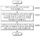
도 20 내지 23은 본 발명의 다양한 실시 예에 따른 전자 장치 및 주변 기기의 제어 방법을 설명하기 위한 흐름도이다.1 is a schematic diagram showing the configuration of a home system according to an embodiment of the present invention;
2 is a block diagram showing the configuration of an electronic device according to an embodiment of the present invention;
3A and 3B are block diagrams showing the detailed configuration of the electronic device shown in FIG. 2;
4A and 4B are block diagrams showing the configuration of a peripheral device according to an embodiment of the present invention;
5 to 7 are views for explaining a method of determining a separation distance and direction of a peripheral device, according to various embodiments of the present disclosure;
8A to 8B are diagrams for explaining a service provided according to various embodiments of the present disclosure;
9 is a sequence diagram illustrating mutual operations of an electronic device and a peripheral device according to an embodiment of the present invention;
10 is a sequence diagram for explaining the mutual operation of an electronic device and a peripheral device according to another embodiment of the present invention;
11 and 12 are block diagrams for briefly explaining the configuration of a sound output system including a display device and an external speaker according to an embodiment of the present invention;
13 and 14 are views for explaining a method for determining a separation distance and direction of an external speaker according to various embodiments of the present disclosure;
15 is a block diagram for briefly explaining the configuration of a sound output system according to an embodiment of the present invention;
16 is a sequence diagram for briefly explaining the configuration of an electronic device and an external speaker according to an embodiment of the present invention;
17 is a view for explaining a process in which pairing is performed between an electronic device and an external speaker according to an embodiment of the present invention;
18A to 19 are diagrams for explaining a UI screen displaying movement information of an external speaker according to an embodiment of the present invention;
20 to 23 are flowcharts for explaining a method of controlling an electronic device and a peripheral device according to various embodiments of the present disclosure.
본 발명에 대하여 구체적으로 설명하기에 앞서, 본 명세서 및 도면의 기재 방법에 대하여 설명한다.Before describing the present invention in detail, a description will be given of the description of the present specification and drawings.
먼저, 본 명세서 및 청구범위에서 사용되는 용어는 본 발명의 다양한 실시 예들에서의 기능을 고려하여 일반적인 용어들을 선택하였다. 하지만, 이러한 용어들은 당 분야에 종사하는 기술자의 의도나 법률적 또는 기술적 해석 및 새로운 기술의 출현 등에 따라 달라질 수 있다. 또한, 일부 용어는 출원인이 임의로 선정한 용어일 수 있다. 이러한 용어에 대해서는 본 명세서에서 정의된 의미로 해석될 수 있으며, 구체적인 용어 정의가 없으면 본 명세서의 전반적인 내용 및 당해 기술 분야의 통상적인 기술 상식을 토대로 해석될 수도 있다.First, the terms used in the present specification and claims were selected in consideration of functions in various embodiments of the present invention. However, these terms may vary depending on the intention, legal or technical interpretation of a person skilled in the art, and the emergence of new technology. Also, some terms may be arbitrarily selected by the applicant. These terms may be interpreted in the meaning defined in the present specification, and if there is no specific term definition, it may be interpreted based on the general content of the present specification and common technical knowledge in the art.
또한, 본 명세서에 첨부된 각 도면에 기재된 동일한 참조 번호 또는 부호는 실질적으로 동일한 기능을 수행하는 부품 또는 구성요소를 나타낸다. 설명 및 이해의 편의를 위해서 서로 다른 실시 예들에서도 동일한 참조번호 또는 부호를 사용하여 설명하도록 한다. 즉, 복수의 도면에서 동일한 참조 번호를 가지는 구성 요소를 모두 도시하고 있다고 하더라도, 복수의 도면들이 하나의 실시 예를 의미하는 것은 아니다.Also, the same reference numerals or reference numerals in each drawing appended hereto indicate parts or components that perform substantially the same functions. For the convenience of explanation and understanding, the same reference numbers or reference numerals are used in different embodiments to be described. That is, even though all the components having the same reference number are shown in the plurality of drawings, the plurality of drawings do not mean one embodiment.
또한, 본 명세서 및 청구범위에서는 구성요소들 간의 구별을 위하여 “제1”, “제2” 등과 같이 서수를 포함하는 용어가 사용될 수 있다. 이러한 서수는 동일 또는 유사한 구성 요소들을 서로 구별하기 위하여 사용하는 것이며, 이러한 서수 사용으로 인하여 용어의 의미가 한정 해석되어서는 안될 것이다. 일 예로, 이러한 서수와 결합된 구성 요소는 그 숫자에 의해 사용 순서나 배치 순서 등이 제한 해석되어서는 안된다. 필요에 따라서는, 각 서수들은 서로 교체되어 사용될 수도 있다.In addition, in this specification and claims, terms including ordinal numbers such as “first” and “second” may be used to distinguish between elements. This ordinal number is used to distinguish the same or similar components from each other, and the meaning of the term should not be limitedly interpreted due to the use of the ordinal number. As an example, the components combined with such an ordinal number should not be construed as limiting the order of use or arrangement by the number. If necessary, each ordinal number may be used interchangeably.
본 명세서에서 단수의 표현은 문맥상 명백하게 다름을 뜻하지 않는 한, 복수의 표현을 포함한다. 본 출원에서, “포함하다” 또는 “구성하다” 등의 용어는 명세서 상에 기재된 특징, 숫자, 단계, 동작, 구성 요소, 부품 또는 이들을 조합한 것이 존재함을 지정하려는 것이지, 하나 또는 그 이상의 다른 특징들이나 숫자, 단계, 동작, 구성 요소, 부품 또는 이들을 조합한 것들의 존재 또는 부가 가능성을 미리 배제하지 않는 것으로 이해되어야 한다.In this specification, the singular expression includes the plural expression unless the context clearly dictates otherwise. In the present application, terms such as “comprises” or “comprises” are intended to designate that the features, numbers, steps, operations, components, parts, or combinations thereof described in the specification exist, but one or more other It should be understood that this does not preclude the possibility of addition or presence of features or numbers, steps, operations, components, parts, or combinations thereof.
본 발명의 실시 예에서 “모듈”, “유닛”, “부(part)” 등과 같은 용어는 적어도 하나의 기능이나 동작을 수행하는 구성 요소를 지칭하기 위한 용어이며, 이러한 구성 요소는 하드웨어 또는 소프트웨어로 구현되거나 하드웨어 및 소프트웨어의 결합으로 구현될 수도 있다. 또한, 복수의 “모듈”, “유닛”, “부(part)” 등은 각각이 개별적인 특정한 하드웨어로 구현될 필요가 있는 경우를 제외하고는, 적어도 하나의 모듈이나 칩으로 일체화되어 적어도 하나의 프로세서(미도시)로 구현될 수 있다.In an embodiment of the present invention, terms such as “module”, “unit”, “part”, etc. are terms for designating a component that performs at least one function or operation, and these components are hardware or software. It may be implemented or implemented as a combination of hardware and software. In addition, a plurality of “modules”, “units”, “parts”, etc. are integrated into at least one module or chip, except when each needs to be implemented as individual specific hardware, so that at least one processor (not shown) may be implemented.
또한, 본 발명의 실시 예에서, 어떤 부분이 다른 부분과 연결되어 있다고 할 때, 이는 직접적인 연결뿐 아니라, 다른 매체를 통한 간접적인 연결의 경우도 포함한다. 또한 어떤 부분이 어떤 구성 요소를 포함한다는 의미는, 특별히 반대되는 기재가 없는 한 다른 구성 요소를 제외하는 것이 아니라 다른 구성 요소를 더 포함할 수 있다는 것을 의미한다.In addition, in an embodiment of the present invention, when a part is connected to another part, this includes not only direct connection but also indirect connection through another medium. In addition, the meaning that a certain part includes a certain component means that other components may be further included, rather than excluding other components, unless specifically stated to the contrary.
이하, 첨부된 도면을 이용하여 본 발명에 대하여 구체적으로 설명한다.Hereinafter, the present invention will be described in detail with reference to the accompanying drawings.
도 1은 본 발명의 일 실시 예에 따른 홈 시스템의 구성을 나타내는 모식도이다.1 is a schematic diagram showing the configuration of a home system according to an embodiment of the present invention.
도 1에 따르면, 본 발명의 일 실시 예에 따른 홈 시스템(1000)은 메인 전자 장치(100) 및, 복수의 주변 디바이스(200-1 내지 200-4)로 구현될 수 있다.Referring to FIG. 1 , a
전자 장치(100)는 적어도 두 개의 스피커를 구비하여 서로 다른 음향을 출력할 수 있는 장치로 구현될 수 있으며, 예를 들어 도시된 바와 같이 스마트 TV로 구현될 수 있다. 다만 이에 한정되는 것은 아니며, 적어도 두 개의 스피커를 구비한 장치라면 이에 한정되지 않고 적용가능하다.The
복수의 주변 디바이스(200-1 내지 200-4)는 전자 장치(100)로부터 출력되는 음향을 수신할 수 있는 마이크를 구비하는 장치로 구현될 수 있으며, 예를 들어, 가정 또는 사무실 등과 같은 일정한 공간에서 쓰이는 모든 전기, 전자 제품으로 구현될 수 있다. 특히 복수의 주변 디바이스(200-1 내지 200-4)는 전자 장치(100)와 양 방향 통신이 가능하도록 구현될 수 있다. 다만 실시 예에 따라 주변 디바이스(200-1 내지 200-4)는 전자 장치(100)와 일방향 통신을 수행할 수도 있으나, 이에 대한 설명은 후술하도록 한다.The plurality of peripheral devices 200 - 1 to 200 - 4 may be implemented as a device having a microphone capable of receiving a sound output from the
또한, 실시 예에 따라 홈 시스템(100)은 복수의 주변 디바이스(200-1 내지 200-4)를 유무선 하나의 시스템으로 연결, 쌍방향 통신이 가능한 홈 네트워크 시스템으로 구현될 수 있으나, 네트워크를 통해 복수의 기기를 연결하여 제어하는 시스템이면 이에 한정되지 않고 적용 가능하다.In addition, according to an embodiment, the
이 경우, 전자 장치(100)는 게이트웨이 장치, 네트워크 서버, 컨트롤러 장치 등과 통신을 수행하거나, 게이트웨이 장치, 네트워크 서버, 컨트롤러 장치 등의 기능을 구비하도록 구현되어, 네트워크 시스템 내의 복수의 디바이스의 동작을 전반적으로 제어할 수 있다.In this case, the
한편, 도 1과 같은 홈 시스템(1000)이 구축된 경우, 전자 장치(100)는 적어도 두 개의 스피커를 구비한 스마트 TV로 구현되고, 복수의 주변 디바이스(200-1 내지 200-4)는 각각 마이크를 구비한 스마트 폰(200-1), 룸 스피커(200-2), 리모콘(200-3), 에어컨(200-4)으로 구현될 수 있다. 하지만, 이는 일 예일 뿐, 주변 디바이스는 로봇 청소기, 히터, 냉장고, 세탁기, 공기 청정기, 모니터, DVD 플레이어, 디지털 카메라, 전자 액자, 전등, 블라인드 등 다양한 형태로 구현될 수 있음은 물론이다.Meanwhile, when the
한편, 본 발명의 일 실시 예에 따르면, 전자 장치(100)에 구비된 두 개의 스피커를 통해 상이한 음향이 출력되고, 주변 디바이스에서 이를 수신하는 과정을 통해 해당 주변 디바이스의 위치를 파악하고, 파악된 위치에 기초하여 다양한 서비스를 제공할 수 있는데, 이하에서는 도면을 참조하여 본 발명의 다양한 실시 예에 대해 자세히 설명하도록 한다.Meanwhile, according to an embodiment of the present invention, different sounds are output through two speakers provided in the
도 2는 본 발명의 일 실시 예에 따른 전자 장치의 구성을 나타내는 블록도이다.2 is a block diagram illustrating a configuration of an electronic device according to an embodiment of the present invention.
도 2에 따르면, 전자 장치(100)는 제1 스피커(111), 제2 스피커(112), 통신부(120) 및 프로세서(130)를 포함한다.Referring to FIG. 2 , the
제1 스피커(111)는 제1 음향 신호를 출력한다.The
제2 스피커(112)는 제1 음향 신호와 상이한 제2 음향 신호를 출력한다. 여기서, 제2 음향 신호는, 제1 음향 신호와 주파수, 음역, 음고(pitch), 음색(tinebre), 음가(duration) 중 적어도 하나가 상이한 신호가 될 수 있다. 예를 들어, 제1 스피커(111)에서 출력되는 제1 음향 신호는 10Hz의 주파수를, 제2 스피커(112)에서 출력되는 제2 음향 신호는 20Hz의 주파수를 가질 수 있다.The
제1 및 제2 스피커(111, 112)는 전기 펄스를 음파로 변환시키는 기능을 하며, 전기신호를 음파로 변환시키는 원리와 방법에 따라 구분되는 동전형(動電型) 즉, 다이내믹 형으로 구현될 수 있으나, 이에 한정되는 것은 아니며 정전형(靜電型), 유전체형(誘電體型), 자기왜형(磁氣歪型) 등으로 구현될 수 있다.The first and
또한, 제1 및 제2 스피커(111, 112)는 재생 대역을 저음·중음·고음 등으로 음역을 나누고, 각각에 알맞은 스피커에 분담시키는 멀티웨이 방식으로 구현될 수 있다. 예를 들어, 3 개의 스피커에 분담시킨 3 웨이 방식의 경우, 고주파 음향 신호를 재생하기 위한 고음역 스피커(tweeter), 중간 주파수 음향 신호를 재생하기 위한 중음역 스피커(midrange), 저주파 음향 신호를 재생하기 위한 저음역 스피커(또는 우퍼(woofer)) 등을 포함하는 형태로 구현될 수 있다. 이 경우, 제1 및 제2 스피커(111, 112)는 3 개의 스피커 중 두 개의 스피커로 구현될 수 있다.In addition, the first and
한편, 제1 및 제2 스피커(111, 112)는 가로 방향으로 기설정된 간격 이상 이격되어 구비될 수 있다. 예를 들어, 전자 장치(100)가 디지털 TV로 구현되는 경우 제1 및 제2 스피커(111, 112)는 우측 끝 단 및 좌측 끝 단에 각각 매립된 스피커로 구현될 수 있으나, 이에 한정되는 것은 아니다. 예를 들어, 전자 장치(100)에 부착된 별도의 스피커라도 전자 장치(100)가 그 부착 위치를 알 수 있는 경우라면 이에 포함될 수 있다.Meanwhile, the first and
통신부(120)는 마이크를 구비한 주변 기기(200)와 통신을 수행한다. 여기서, 통신부(120)는 BT(BlueTooth), WI-FI(Wireless Fidelity), Zigbee, IR(Infrared), Serial Interface, USB(Universal Serial Bus), NFC(Near Field Communication) 등과 같은 다양한 통신 방식을 통해 주변 기기(200)와 통신을 수행할 수 있다.The
구체적으로, 통신부(120)는 기 설정된 이벤트가 발생하면, 외부 스피커(200)와의 기 정의된 통신 방식에 따라 통신을 수행하여 연동 상태가 될 수 있다. 여기서, 연동은 전자 장치(100)와 주변 기기(200) 간에 통신이 초기화되는 동작, 네트워크가 형성되는 동작, 기기 페어링이 수행되는 동작 등 통신이 가능한 상태가 되는 모든 상태를 의미할 수도 있다. 예를 들어 주변 기기(200)의 핀 코드(pin code) 등의 기기 식별 정보가 전자 장치(100)로 제공되고, 그에 따라 양 기기 간의 페어링 절차가 수행될 수 있다. 예를 들어, 전자 장치(100) 및 주변 기기(200)에서 기 설정된 이벤트가 발생하면, DLNA(Digital Living Network Alliance) 기술을 통해 주변 기기(200)가 전자 장치(100)를 탐색하고, 전자 장치(100) 및 주변 기기(200)가 페어링을 수행하여 연동 상태가 될 수 있다.Specifically, when a preset event occurs, the
이때, 통신부(120)는 음파를 기반으로 하는 핀 코드(pin code) 등의 기기 식별 정보를 주변 기기(200)로 전송하여 페어링을 수행할 수 있다. 주변 기기(200)가 핀 코드를 수신하면 수신된 핀 코드를 자동으로 입력하여 페어링이 수행된다.In this case, the
BT 등을 이용하여 주변 기기(200)와 페어링을 수행하고, 페어링된 주변 기기(200)에 대하여 와이파이(Wi-Fi) 등의 무선 네트워크 연결 정보를 전송하여 주변 기기(200)와 무선 네트워크 상으로 연결될 수 있다. 무선 네트워크로 연결되면, 통신부(120)는 주변 기기(200)로부터 제품 종류 및 주변 기기(200)에서 분석된 위치와 관련된 정보를 수신할 수 있다.Pairing is performed with the
프로세서(130)는 전자 장치(100)의 전반적인 동작을 제어한다.The
프로세서(130)는 통신부(110)에 의해, 제1 및 제2 스피커부(111, 112)를 통해 출력된 제1 및 제2 음향 신호를 마이크에 의해 수신한 주변 기기(200)로부터 제1 및 제2 음향 신호를 수신한 시간에 대한 정보를 수신한다. 이어서, 프로세서(130)는 수신된 정보에 기초하여 전자 장치(100)를 기준으로 주변 기기(200)의 이격 거리 및 방향을 판단할 수 있다.The
여기서, 수신된 정보는, 주변 기기(200)에 구비된 마이크를 통해 제1 및 제2 음향 신호가 순차적으로 수신되는 상태를 기록(또는 녹음 또는 캡쳐)한 파일이거나, 주변 기기(200)에 구비된 마이크를 통해 제1 및 제2 음향 신호가 순차적으로 수신된 시간 정보를 포함하는 정보가 될 수 있다. 즉, 주변 기기(200)는 구비된 마이크를 통해 제1 및 제2 음향 신호가 순차적으로 수신되는 상태를 기록한 후, 기록된 정보를 그대로 전자 장치(100)로 전송하거나, 기록 정보를 분석하여 제1 및 제2 음향 신호가 순차적으로 수신된 시간 정보를 획득한 후, 획득된 시간 정보를 전자 장치(100)로 전송할 수도 있다.Here, the received information is a file in which a state in which the first and second sound signals are sequentially received through a microphone provided in the peripheral device 200 (or recorded or captured), or provided in the
또한, 프로세서(130)는 주변 기기(200)로부터 기준 신호(또는 트리거 신호)가 수신되면, 제1 및 제2 음향 신호를 동시에 출력할 수 있다. 이 경우, 주변 기기(200)는 전자 장치(100)에 기준 신호를 전송하고, 녹음 모드로 동작할 수 있다. 즉 음향 신호에 대한 기록을 시작할 수 있다. 여기서, 기준 신호를 BT(BlueTooth)와 같은 RF 통신을 통해 수신될 수 있으나, 이에 한정되는 것은 아니다.Also, when the reference signal (or trigger signal) is received from the
또한, 프로세서(130)는 주변 기기(200)로부터 기준 신호를 수신한 시점부터 제1 및 제2 음향 신호가 출력된 시점 간의 시간차를 산출할 수 있다.Also, the
프로세서(130)는 상기와 같은 동작에 따른 시간 정보에 기초하여 전자 장치(100)의 위치를 기준으로 주변 기기(200)의 이격 거리 및 방향을 판단할 수 있다.The
프로세서(130)는 수신된 정보로부터 추출된 주변 기기(200)에서 제1 및 제2 음향 신호를 각각 수신한 제1 및 제2 시간 정보, 기준 신호가 주변 기기(200)에서 출력된 시간(또는 전자 장치(100)가 기준 신호를 수신한 시간) 및 제1 및 제2 음향 신호가 출력된 시간 차에 대한 제3 시간 정보에 기초하여 주변 기기(200)의 이격 거리 및 방향을 판단할 수 있다.The
구체적으로, 프로세서(130)는 제1 시간 정보 및 제3 시간 정보의 시간 차에 음향 신호의 속도 값을 곱하여 우측 이격 거리를 산출할 수 있다. 동일한 방법으로, 프로세서(130)는 제2 시간 정보 및 제3 시간 정보의 시간 차에 음향 신호의 속도 값을 곱하여 좌측 이격 거리를 산출할 수 있다. 이 후, 프로세서(130)는 산출된 우측 및 좌측 이격 거리 및 제1 및 제2 스피커(111, 112) 간 거리에 기초하여 기초하여 주변 기기(200)의 이격 거리 및 방향을 판단할 수 있다.Specifically, the
다만, 상술한 실시 예에 한정되는 것은 아니며, 다른 실시 예에 따르면, 프로세서(130)는 기설정된 이벤트에 따라 제1 및 제2 음향 신호를 동시에 출력하고 수신된 정보에서 추출된 주변 기기(200)에서 제1 및 제2 음향 신호를 각각 수신한 제1 및 제2 시간 정보, 이벤트가 발생된 제3 시간 정보에 기초하여 이격 거리를 판단할 수 있다. 예를 들어, 전자 장치(100) 및 주변 기기(200) 간 시간이 동기화된 경우, 전자 장치(100)는 주변 기기(200)에 음향 신호 기록을 요청하는 신호를 전송한 후, 기설정된 시간 후에 음향 신호를 출력하고, 주변 기기(200)로부터 수신된 시간 정보에 기초하여 이격 거리를 판단할 수 있다. 구체적으로, 전자 장치(100)가 음향 신호를 출력한 시간이 a, 주변 기기(200)에서 제1 및 제2 음향 신호를 수신한 시간이 각각 b, c 인 경우 b-a, c-a 각각에 음향 신호의 속도 값을 곱하여, 우측 이격 거리 및 좌측 이격 거리를 산출할 수 있다.However, it is not limited to the above-described embodiment, and according to another embodiment, the
한편, 프로세서(130)는 상술한 다양한 실시 예에 따라 획득한 외부 기기(200)의 이격 거리 및 방향에 기초하여 다양한 서비스를 제공할 수 있다. 예를 들어 프로세서(130)는 주변 기기(200)가 리모콘으로 구현되는 경우 리모콘 찾기 서비스, 절대 좌표 방식에 따른 리모콘의 지향 방향 및 지향 위치를 판단하는 서비스, 주변 기기(200)가 홈씨어터 스피커로 구현되는 경우, HTS easy setup 서비스, 홈 네트워크 내 IoT 기기간 네트워크 구성 서비스, 가전 제품(예를 들어, 에어컨, 로봇 청소기)의 위치 감지를 통한 다양한 서비스를 제공할 수 있다.Meanwhile, the
예를 들어, 전자 장치(100)가 TV로 구현되고, 주변 기기(200)가 포인팅 디바이스로 구현되는 경우, 프로세서(130)는 주변 기기(200)의 이격 거리 및 방향에 신호 처리 알고리즘을 적용하여 전자 장치(100) 화면 상의 X, Y 좌표로 변환한다. 이 후, 프로세서(130)는 변환된 X, Y 좌표를 디스플레이 장치(100)의 UI 화면에서 포인팅 오브젝트의 X, Y 좌표에 매핑하여 포인팅 오브젝트의 좌표를 지정할 수 있다.For example, when the
이렇게 지정된 좌표를 이용하여 포인팅 오브젝트의 위치를 지정할 수 있게 된다. 이 경우, 주변 기기(200)가 해당 위치에서 화면 방향을 향한다는 가정하에 화면 상에서 주변 기기(200)가 지향하는 위치를 판단할 수 있다. 이에 따라 트리거 신호에 따라 절대 좌표 방식으로 포인팅 오브젝트를 디스플레이할 수 있게 된다.The position of the pointing object can be specified using the coordinates specified in this way. In this case, on the assumption that the
도 3a 및 3b는 도 2에 도시된 전자 장치의 세부 구성을 나타내는 블록도이다.3A and 3B are block diagrams illustrating a detailed configuration of the electronic device shown in FIG. 2 .
도 3a는 도 2에 도시된 전자 장치의 구체적 구성을 나타내는 블럭도이다. 도 3a에 따르면, 전자 장치(100')는 제1 스피커(111), 제2 스피커(112), 통신부(120), 프로세서(130), 디스플레이부(140), 저장부(150), 오디오 처리부(160), 비디오 처리부(170) 및 사용자 인터페이스부(180)를 포함한다. 도 3a에 도시된 구성 중 도 2에 도시된 구성과 중복되는 부분에 대해서는 자세한 설명을 생략하도록 한다.3A is a block diagram illustrating a specific configuration of the electronic device illustrated in FIG. 2 . Referring to FIG. 3A , the
프로세서(130)는 전자 장치(100')의 동작을 전반적으로 제어한다.The
구체적으로, 프로세서(130)는 RAM(131), ROM(132), 메인 CPU(133), 그래픽 처리부(134), 제1 내지 n 인터페이스(135-1 ~ 135-n), 버스(136)를 포함한다.Specifically, the
RAM(131), ROM(132), 메인 CPU(133), 그래픽 처리부(134), 제1 내지 n 인터페이스(135-1 ~ 135-n) 등은 버스(136)를 통해 서로 연결될 수 있다.The
제1 내지 n 인터페이스(135-1 내지 135-n)는 상술한 각종 구성요소들과 연결된다. 인터페이스들 중 하나는 네트워크를 통해 외부 장치와 연결되는 네트워크 인터페이스가 될 수도 있다.The first to n-th interfaces 135-1 to 135-n are connected to the various components described above. One of the interfaces may be a network interface connected to an external device through a network.
메인 CPU(133)는 저장부(150)에 액세스하여, 저장부(150)에 저장된 O/S를 이용하여 부팅을 수행한다. 그리고, 저장부(150)에 저장된 각종 프로그램, 컨텐츠, 데이터 등을 이용하여 다양한 동작을 수행한다.The
ROM(132)에는 시스템 부팅을 위한 명령어 세트 등이 저장된다. 턴온 명령이 입력되어 전원이 공급되면, 메인 CPU(133)는 ROM(132)에 저장된 명령어에 따라 저장부(150)에 저장된 O/S를 RAM(131)에 복사하고, O/S를 실행시켜 시스템을 부팅시킨다. 부팅이 완료되면, 메인 CPU(133)는 저장부(150)에 저장된 각종 어플리케이션 프로그램을 RAM(131)에 복사하고, RAM(131)에 복사된 어플리케이션 프로그램을 실행시켜 각종 동작을 수행한다.The
그래픽 처리부(134)는 연산부(미도시) 및 렌더링부(미도시)를 이용하여 아이콘, 이미지, 텍스트 등과 같은 다양한 오브젝트를 포함하는 화면, 예를 들어, 포인팅 오브젝트를 포함하는 화면을 생성한다. 연산부(미도시)는 수신된 제어 명령에 기초하여 화면의 레이아웃에 따라 각 오브젝트들이 표시될 좌표값, 형태, 크기, 컬러 등과 같은 속성값을 연산한다. 렌더링부(미도시)는 연산부(미도시)에서 연산한 속성값에 기초하여 오브젝트를 포함하는 다양한 레이아웃의 화면을 생성한다. 렌더링부(미도시)에서 생성된 화면은 디스플레이(140)의 사용자 인터페이스 영역 내에 표시된다.The
한편, 상술한 프로세서(130)의 동작은 도 3b에 도시된 바와 같이 저장부(150)에 저장된 프로그램에 의해 이루어질 수도 있다.Meanwhile, the above-described operation of the
저장부(150)는 전자 장치(100')를 구동시키기 위한 O/S(Operating System) 소프트웨어 모듈, 각종 멀티미디어 컨텐츠와 같은 다양한 데이터를 저장한다. 특히, 저장부(150)는 도 3b에 도시된 바와 같이 본 발명의 일 실시 예에 따른 기능을 제공하기 위한 통신 모듈(151), 신호 처리 모듈(152), 위치 산출 모듈(153) 및 서비스 제공 모듈(154) 등의 프로그램이 저장되어 있을 수 있다.The
프로세서(130)는 통신 모듈(151)을 이용하여 주변 기기(200)로부터 신호를 수신하고, 주변 기기(200)로 신호를 전송할 수 있다.The
예를 들어, 프로세서(130)는 통신 모듈(151)을 이용하여 주변 기기(200)로부터 기준 신호를 수신하고, 제1 및 제2 스피커(111, 112)를 통해 음향 신호를 출력한 시간 정보를 포함하는 신호를 주변 기기(200)로 전송할 수 있다.For example, the
프로세서(130)는 신호 처리 모듈(152)을 이용하여 주변 기기(200)로부터 수신된 신호를 신호 처리하거나, 주변 기기(200)로 전송할 신호를 신호처리 할 수 있다.The
예를 들어, 주변 기기(200)로부터 제1 및 제2 음향 신호의 수신 상태를 기록한 파일이 수신되면, 프로세서(130)는 신호 처리 모듈(152)을 이용하여 해당 파일을 위치 산출 모듈(153)에서 분석 가능한 상태로 신호 처리할 수 있다.For example, when a file in which the reception state of the first and second sound signals is received from the
또한, 저장부(150)는 주변 기기(200)에 대응되는 타겟 위치에 대한 정보를 저장할 수 있다. 여기서, 타겟 위치란, 전자 장치(100)를 기준으로 각 주변 기기(200)가 배치되어야할 가장 적절한 위치를 의미한다. 타겟 위치는 전자 장치(100)를 기준으로 하는 상대적 위치로서, 전자 장치(100)로부터 특정한 방향 및 거리로 설정되어 저장될 수 있다. 프로세서(130)는 저장부(150)에 저장된 타겟 위치에 대한 정보를 이용하여, 주변 기기(200)가 타겟 위치에 위치하는지 여부를 판단할 수 있으며, 일치하지 않는 경우, 주변 기기(200)를 타겟 위치에 배치시키기 위한 주변 기기(200)의 이동 정보를 제공할 수 있다.Also, the
프로세서(130)는 통신부(120)를 통해 주변 기기(200)로부터 주변 기기(200)의 위치 정보를 수신하고, 수신된 위치 정보에 따른 주변 기기(200)가 타겟 위치에 위치하는지 여부를 판단한다. 프로세서(130)는 주변 기기(200)가 타겟 위치에 위치하지 않는 것으로 판단되면, 주변 기기(200)를 타겟 위치에 배치시키기 위한 주변 기기(200)의 이동 정보를 제공할 수 있다.The
여기서, 이동 정보는, 주변 기기(200)로부터 수신된 주변 기기(200)의 현재 위치 및 주변 기기(200)를 배치시키기 위한 기 저장된 타겟 위치에 대한 정보를 포함할 수 있다. 또한, 이동 정보는, 주변 기기(200)의 위치로부터 타겟 위치에 대한 방향 및 거리에 대한 정보를 포함할 수 있다.Here, the movement information may include the current location of the
또한, 프로세서(130)는 위치 산출 모듈(153)을 이용하여 신호 처리 모듈(152)을 통해 처리된 값에 기초하여 외부 기기(200)의 위치, 즉, 이격 거리 및 방향을 산출할 수 있다.In addition, the
디스플레이부(140)는 다양한 컨텐츠 화면을 제공하는 구성이다. 여기서, 컨텐츠 화면은 이미지, 동영상, 텍스트, 음악 등과 같은 다양한 컨텐츠, 다양한 컨텐츠를 포함하는 어플리케이션 실행 화면, GUI(Graphic User Interface) 화면 등을 포함할 수 있다. 이러한 디스플레이부(140)를 포함하는 전자 장치(100')는 디스플레이 장치로 명명될 수도 있다.The
특히, 프로세서(130)는 산출된 주변 기기(200)의 이격 거리 및 방향을 기초로 전자 장치(100)를 기준으로 주변 기기(200)의 상대적 위치를 나타내는 UI 화면을 디스플레이부(140)를 통해 디스플레이한다. 여기서, UI 화면은 이미지, 동영상, 텍스트 등과 같은 다양한 형태로 구현될 수 있다. 한편, 디스플레이(140)는 LCD(Liquid Crystal Display Panel), OLED(Organic Light Emitting Diodes) 등으로 구현될 수 있으나, 이에 한정되는 것은 아니다. 또한, 디스플레이(140)는 경우에 따라 플렉서블 디스플레이, 투명 디스플레이 등으로 구현되는 것도 가능하다.In particular, the
구체적으로, 프로세서(130)는 홈 네트워크에 연결된 디바이스들을 포함하는 2D 또는 3D 공간 배치도를 디스플레이하고, 해당 공간 배치도 내에서 주변 기기(200)의 위치를 제공할 수 있다. 즉, 공간 배치도는 홈 네트워크에 연결된 적어도 하나의 홈 디바이스에 대한 정보를 포함할 수 있으며, 이러한 정보는 홈 디바이스의 식별 정보를 텍스트(예를 들어 홈 디바이스 명칭) 또는 이미지(예를 들어, 홈 디바이스의 실사, 외관 이미지 또는 아이콘) 형태로 포함할 수 있다. 한편, 공간 배치도는 홈 디바이스 각각의 위치 정보 및 디바이스 타입에 기초하여 생성될 수 있다. 구체적으로, 홈 네트워크에 연결된 홈 디바이스 각각의 위치 정보 및 디바이스 타입을 토대로 가상의 공간 배치도를 생성하고, 홈 네트워크에 기존 홈 디바이의 연결이 해제되거나, 새로운 홈 디바이스가 연결될 때마다 입력되는 위치 정보를 토대로 공간 배치도를 업데이트할 수 있다.Specifically, the
한편, 디스플레이부(140)는 LCD(Liquid Crystal Display Panel), OLED(Organic Light Emitting Diodes), LCoS(Liquid Crystal on Silicon), DLP(Digital Light Processing) 등과 같은 다양한 형태의 디스플레이로 구현될 수 있다. 또한, 디스플레이(110) 내에는 a-si TFT, LTPS(low temperature poly silicon) TFT, OTFT(organic TFT) 등과 같은 형태로 구현될 수 있는 구동 회로, 백라이트 유닛 등도 함께 포함될 수 있다.Meanwhile, the
그 밖에 전자 장치(100')는 음향 데이터에 대한 수행하는 오디오 처리부(160), 비디오 데이터에 대한 처리를 수행하는 비디오 처리부(170), 사용자의 제어에 따라 정지 영상 또는 동영상을 촬상하기 카메라, 사용자 음성이나 기타 음향을 입력받아 오디오 데이터로 변환하기 위한 마이크 등을 포함하는 사용자 인터페이스부(180)를 더 포함할 수 있다. 예를 들어, 프로세서(130)는 제1 및 제2 스피커(111, 112)를 통해 출력되는 제1 및 제2 음향 신호를 처리하도록 오디오 처리부(160)를 제어할 수 있다.In addition, the
도 4a 및 4b는 본 발명의 일 실시 예에 따른 주변 기기의 구성을 나타내는 블록도이다.4A and 4B are block diagrams illustrating a configuration of a peripheral device according to an embodiment of the present invention.
도 4a에 따르면, 주변 기기(200)는 음향 수신부(210), 통신부(220) 및 프로세서(230)를 포함한다.According to FIG. 4A , the
음향 수신부(210)는 전자 장치(100)에서 출력되는 제1 및 제2 음향 신호를 수신하는 적어도 하나의 마이크를 포함하도록 구현될 수 있다.The
통신부(220)는 전자 장치(100)와 통신을 수행하며 상세한 구성은 전자 장치(100)의 통신부(120)와 유사하므로 자세한 설명은 생략하도록 한다.The
일 실시 예에 따르면, 프로세서(230)는 전자 장치(100)에 구비된 복수의 스피커 각각으로부터 출력되는 상이한 제1 및 제2 음향 신호가 음향 수신부(210)를 통해 순차적으로 수신되면, 수신되는 음향 신호를 기록하고, 기록 정보를 전자 장치(100)로 전송할 수 있다. 이 경우, 프로세서(230)는 기설정된 이벤트(예를 들어, 기설정된 버튼 입력)에 따라 전자 장치(100)가 음향 신호를 출력하도록 하는 트리거 신호를 전자 장치(100)로 전송할 수 있다. 즉, 프로세서(230)는 도 2에서 설명한 전자 장치(100)의 동작에 대응되는 동작을 수행할 수 있다.According to an embodiment, when different first and second sound signals output from each of a plurality of speakers provided in the
다만, 다른 실시 예에 따르면, 주변 기기(200)가 전자 장치(100)의 위치를 기준으로 자신의 이격 거리 및 방향을 직접 판단할 수 있으며, 판단된 정보를 필요에 따라 전자 장치(100)에 제공할 수 있다.However, according to another embodiment, the
다른 실시 예에 따르면, 프로세서(230)는 전자 장치(100)에 구비된 복수의 스피커 각각으로부터 출력되는 상이한 제1 및 제2 음향 신호가 음향 수신부(210)를 통해 순차적으로 수신되면, 수신되는 음향 신호를 기록하고, 기록 정보로부터 제1 및 제2 음향 신호가 수신된 시간을 획득하고, 획득된 시간 기초하여 전자 장치(100)를 기준으로 주변 기기(200)의 이격 거리 및 방향을 판단할 수 있다. 이 경우, 프로세서(230)는 전자 장치(100)가 음향 신호를 출력하도록 하는 트리거 신호를 전자 장치(100)로 전송할 수 있다.According to another embodiment, when different first and second sound signals output from each of the plurality of speakers provided in the
구체적으로, 프로세서(230)는 기록된 파일로부터 획득된 주변 기기(200)가 제1 및 제2 음향 신호를 각각 수신한 제1 및 제2 시간 정보, 전자 장치(100)가 기준 신호를 수신한 시간 및 전자 장치(100)에서 제1 및 제2 음향 신호가 출력된 시간 차에 대한 제3 시간 정보에 기초하여 전자 장치(100)로부터의 이격 거리 및 방향을 판단할 수 있다. 이 경우, 제3 시간 정보는 전자 장치(100)로부터 획득될 수 있으며, 프로세서(230)가 주변 기기(200)가 제1 및 제2 음향 신호를 각각 수신한 시간차를 산출하여 획득할 수도 있다.Specifically, the
구체적으로, 프로세서(230)는 제1 시간 정보 및 제3 시간 정보의 시간 차에 음향 신호의 속도 값을 곱하여 우측 이격 거리를 산출할 수 있다. 동일한 방법으로, 프로세서(230)는 제2 시간 정보 및 제3 시간 정보의 차에 음향 신호의 속도 값을 곱하여 좌측 이격 거리를 산출할 수 있다. 이 후, 프로세서(230)는 산출된 우측 및 좌측 이격 거리에 기초하여 전자 장치(100)로부터의 이격 거리 및 방향를 판단할 수 있다.Specifically, the
다만, 상술한 실시 예에 한정되는 것은 아니며, 다른 실시 예에 따르면, 전자 장치(100)의 프로세서(130)는 외부 스피커(200)에 대하여 음향 신호 기록을 요청하는 신호를 전송한 후, 기 설정된 이벤트에 따라 제1 및 제2 음향 신호를 동시에 출력할 수 있다.However, the present invention is not limited to the above-described embodiment, and according to another embodiment, the
도 4b는 도 4a에 도시된 주변 기기의 구체적 구성을 나타내는 블럭도이다. 도 4b에 따르면, 주변 기기(200')는 음향 수신부(210), 통신부(220), 프로세서(230), 저장부(240), 오디오 처리부(250) 및 스피커(260)를 포함한다. 도 4b에 도시된 구성 중 도 4a에 도시된 구성과 중복되는 부분에 대해서는 자세한 설명을 생략하도록 한다.4B is a block diagram showing a specific configuration of the peripheral device shown in FIG. 4A. According to FIG. 4B , the
프로세서(230)의 동작은 저장부(240)에 저장된 프로그램에 의해 이루어질 수 있다.The operation of the
저장부(240)에는 주변 기기(200)에서 수신된 신호를 처리하기 위한 신호 처리 알고리즘이 저장될 수 있다. 또한, 구현 예에 따라 전자 장치(100)를 구동시키기 위한 O/S(Operating System) 소프트웨어, 다양한 감지 신호에 대한 연산을 수행하기 위한 신호 처리 알고리즘 등과 같이 다양한 데이터가 저장될 수 있다.A signal processing algorithm for processing a signal received from the
한편, 프로세서(230)의 세부 구성은 전자 장치(100')의 프로세서(130)(도 3a)와 유사하므로 자세한 설명은 생략하도록 한다.Meanwhile, since the detailed configuration of the
한편, 구현 예에 따라 주변 기기(200)가 포인팅 디바이스로 구현되는 경우, 주변 기기(200)의 움직임을 센싱하기 위한 다양한 센서(예를 들어, 가속도 센서, 지자기 센서, 자이로 센서 등)를 더 포함할 수 있다.On the other hand, when the
이 경우, 프로세서(230)는 각종 센싱 신호에 따라 다양한 연산 동작을 수행할 수 있다. 예를 들어, 프로세서(230)는 다양한 센서들로부터 수신된 센서값에 대한 전처리를 수행하여 전자 장치(100)로 전송할 수 있다. 예를 들어, 디지털 값으로 변환된 센서 값을 실제 물리량으로 변환하고, 가속도 센서, 지자기 센서, 자이로 센서의 개별 축을 하나의 정의된 축으로 맞추는 작업을 수행하고, 저역 통과 필터링을 통해 센서의 전기적 잡음과 의도하지 않은 고주파 움직임을 제거하는 등의 전처리 작업을 수행할 수 있다. 다만, 경우에 따라서는, 감지된 신호 처리 알고리즘에 따라 연산하고, 연산된 값을 전자 장치(100)로 전송할 수도 있다.In this case, the
또한, 주변 기기(200)가 포인팅 디바이스로 구현되는 경우, 전원 ON/OFF를 위한 사용자 명령을 입력받는 전원 버튼부, 전자 장치(100)의 화면 상에 포인팅 오브젝트를 표시하고 기준 위치를 설정하기 위한 센터링 버튼부 등을 더 포함할 수 있다. 예를 들어, 주변 기기(200)의 전원이 ON 되면 주변 기기(200)는 전자 장치(100)와 페어링 동작을 수행할 수 있다. 페어링이 완료된 후, 사용자가 센터링 버튼부(미도시)을 누름 조작하게 되면 전자 장치(100)의 디스플레이 화면의 센터에는 포인팅 오브젝트가 디스플레이될 수 있다.In addition, when the
도 5 내지 7은 본 발명의 다양한 실시 예에 따라, 주변 기기의 이격 거리 및 방향을 판단하는 방법을 설명하기 위한 도면이다.5 to 7 are diagrams for explaining a method of determining a separation distance and direction of a peripheral device, according to various embodiments of the present disclosure;
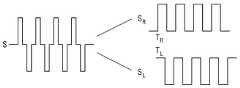
도 5에서는 주변 기기(200)에서 이격 거리 및 방향을 판단하는 실시 예의 경우에 대해 설명하도록 한다.In FIG. 5 , an embodiment in which the separation distance and direction are determined in the
도 5에 따르면, 주변 기기(200)가 기준 신호 즉, Time Reference 신호를 전자 장치(100)로 출력하고, 녹음 모드로 동작한다.Referring to FIG. 5 , the
이 경우, 해당 기준 신호를 수신한 전자 장치(100)는 우측 및 좌측 스피커를 통해 상이한 제1 및 제2 음향 신호를 출력하고, 기준 신호를 수신한 시점부터 음향 신호를 출력한 시간차 D2에 대한 시간 정보를 주변 기기(200)로 전송한다.In this case, the
이 경우, 도 6에 도시된 바와 같이 주변 기기(200)는 수신된 음향 신호 S에서 제1 음향 신호 SR 및 제2 음향 신호 SL를 각각 추출하고, 각 음향 신호가 수신된 시점 TR 및 TL에 대한 정보를 획득할 수 있다.In this case, as shown in FIG. 6 , the
이 경우, 주변 기기(200)는 기준 신호를 출력한 시점 및 마이크를 통해 제1 음향 신호를 수신한 시점 간의 시간 차(D1R)에서 D2를 뺀 값 즉, D1R - D2 및, 기준 신호를 출력한 시점 및 마이크를 통해 제2 음향 신호를 수신한 시점 간의 시간 차(D1L)에서 D2를 뺀 값 즉, D1L - D2에 기초하여 전자 장치(100)를 기준으로 주변 기기(200)의 이격 거리 및 방향을 산출할 수 있다.In this case, the
구체적으로, 도 7을 참고하면, 프로세서(230)는 D1R - D2에 음향 신호의 속도 Vs(예를 들어, 340m/s)를 곱하여 좌측 스피커(711)로부터의 이격 거리 L1을 산출하고, D1L - D2에 음향 신호의 속도 Vs를 곱하여 우측 스피커(712)로부터의 이격 거리 L2를 산출할 수 있다. 이 경우 전자 장치(100)에 구비된 좌측 스피커(711) 및 우측 스피커(712) 간 거리 A는 이미 알고 있으므로, 이에 기초하여 전자 장치(100)로부터의 수직 이격 거리 L 및 방향 θ를 산출할 수 있게 된다.Specifically, referring to FIG. 7 , the
도 8a 내지 8b는 본 발명의 다양한 실시 예에 따라 제공되는 서비스를 설명하기 위한 도면이다.8A to 8B are diagrams for explaining services provided according to various embodiments of the present disclosure.
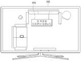
본 발명의 일 실시 예에 따라 사용자가 이동 가능한 주변 기기, 예를 들어 리모콘의 위치를 알고자 하는 경우, 리모콘 위치 찾기 메뉴를 선택하여, 해당 서비스를 제공받을 수 있다.According to an embodiment of the present invention, when a user wants to know the location of a movable peripheral device, for example, a remote control, a corresponding service can be provided by selecting a remote control location search menu.
즉, 전자 장치(100)는 상술한 방법으로 리모콘의 위치 즉, 이격 거리 및 방향이 판단되면, 도 8a 및 도 8b에 도시된 바와 같이 리모콘의 위치에 대한 정보를 다양한 방식의 UI 화면으로 제공할 수 있다. 예를 들어 도 8a에 도시된 바와 같이 가상의 공간 배치도 상에 리모콘 위치를 가이드 하는 UI(810)를 제공하거나, 또는 도 8b에 도시된 바와 같이 전자 장치(100)를 기준으로 리모콘의 대략적 위치를 수치적으로 제공하는 UI(820)를 제공할 수도 있다.That is, when the location of the remote control, that is, the separation distance and direction, is determined by the above-described method, the
도 9는 본 발명의 일 실시 예에 따른 전자 장치 및 주변 기기의 상호간 동작을 설명하기 위한 시퀀스도이다.9 is a sequence diagram illustrating mutual operations of an electronic device and a peripheral device according to an embodiment of the present invention.
도 9에 도시된 바에 따르면, 우선 주변 기기(200)가 전자 장치(100)로 음향 출력을 위한 기준 신호를 전송한다(S910). 이 경우, 주변 기기(200)는 녹음 모드로 진입한다(S920).As shown in FIG. 9 , first, the
이어서, 전자 장치(100)가 기준 신호를 수신하면, 복수의 스피커를 통해 상이한 음향 신호를 출력한다(S930).Subsequently, when the
이 경우, 주변 기기(200)는 녹음 모드에서 마이크를 통해 수신되는 음향 신호를 기록한다(S940).In this case, the
이어서, 주변 기기(200)는 순차적으로 수신된 상이한 음향 신호가 기록된 정보를 전자 장치(100)로 전송한다(S950).Subsequently, the
전자 장치(100)는 주변 기기(200)로부터 수신된 기록 정보를 분석하여 주변 기기(200)의 위치를 판단한다(S960).The
각 단계의 상세 동작에 대해서는 상술한 바 있으므로 자세한 설명은 생략하도록 한다.Since the detailed operation of each step has been described above, a detailed description thereof will be omitted.
도 10은 본 발명의 다른 실시 예에 따른 전자 장치 및 주변 기기의 상호간 동작을 설명하기 위한 시퀀스도이다.10 is a sequence diagram illustrating mutual operations of an electronic device and a peripheral device according to another embodiment of the present invention.
도 10에 도시된 바에 따르면, 우선 주변 기기(200)가 전자 장치(100)로 음향 출력을 위한 기준 신호를 전송한다(S1010). 이 경우, 주변 기기(200)는 녹음 모드로 진입한다(S1020).Referring to FIG. 10 , first, the
이어서, 전자 장치(100)가 기준 신호를 수신하면, 복수의 스피커를 통해 상이한 음향 신호를 출력한다(S1030).Subsequently, when the
이 경우, 주변 기기(200)는 녹음 모드에서 마이크를 통해 수신되는 음향 신호를 기록한다(S1040).In this case, the
이어서, 전자 장치(100)는 기준 신호를 수신한 시간 및 음향 신호를 출력한 시간 차에 대한 시간 정보를 전자 장치(100)로 전송한다(S1050).Next, the
이 후, 주변 기기(200)는 전자 장치(100)로부터 수신된 시간 정보 및 음향 신호가 기록된 기록 정보를 분석하여 주변 기기(200)의 위치를 판단한다(S1060).Thereafter, the
각 단계의 상세 동작에 대해서는 상술한 바 있으므로 자세한 설명은 생략하도록 한다.Since the detailed operation of each step has been described above, a detailed description thereof will be omitted.
도 11 및 12는 본 발명의 일 실시 예에 따른 디스플레이 장치 및 외부 스피커를 포함하는 음향 출력 시스템의 구성을 간략히 설명하기 위한 블록도이다.11 and 12 are block diagrams for briefly explaining the configuration of a sound output system including a display device and an external speaker according to an embodiment of the present invention.
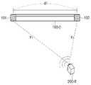
도 11은 본 발명의 일 실시 예에 따라 음향 출력 시스템(1000')을 구성하는 스피커를 설정하는 HTS easy setup 서비스를 제공하는 방법을 설명하기 위한 도면이다. 도 11에 도시된 바와 같이 전자 장치(100)를 기준으로 좌우에 4 개의 스피커(1110 내지 1140)를 배치하여 음향 출력 시스템(1000')을 구성하는 경우를 상정하여 설명하도록 한다. 이하의 실시 예에서, 전자 장치(100)는 디스플레이 장치로, 주변 기기(200)는 복수의 스피커로 구현됨을 상정하여 설명하기로 한다.11 is a diagram for explaining a method of providing an HTS easy setup service for setting speakers constituting the sound output system 1000' according to an embodiment of the present invention. As shown in FIG. 11 , it is assumed that the
예를 들어, 사용자가 음향 출력 시스템(1000')의 구성을 위해 4 개의 스피커(1110 내지 1140)를 연결하였다고 가정한다.For example, it is assumed that the user connects four
이 경우, 디스플레이 장치(100)는 각 스피커들의 이격 거리 및 방향을 측정하여, 연결이 제대로 되어 있는지 판단하고, 그에 따른 피드백 서비스를 제공할 수 있다. 예를 들어, 최좌측 스피커(1110) 및 최우측 스피커(1140)를 잘못 연결하였다고 가정하면, 전자 장치(100)는 이들의 이격 거리 및 방향을 측정하여, 설정이 제대로 되어 있지 않음에 대한 노티(noti)를 사용자에게 제공하거나, 경우에 따라서는 자동으로 연결 설정을 변경하는 것도 가능하다. 다만, 해당 실시 예의 경우, 각 스피커들에 마이크가 구비된 경우를 상정할 수도 있지만, 이에 한정되는 것은 아니다. 즉, 스피커 두 개와 마이크 하나만으로 본 발명의 기술적 사상을 적용할 수 있으므로, 전자 장치(100)에 마이크가 구비된 경우, 각 스피커들로부터 출력되는 음향 신호 및 각 스피커들의 위치에 기초하여 디스플레이 장치(100)와 4 개의 스피커(1110 내지 1140)들의 상대적 위치를 판단할 수 있음은 물론이다.In this case, the
도 12는 집안의 거실에 홈씨어터(Home theater) 시스템으로 구현된 음향 출력 시스템(1000')을 도시한 것이다. 홈 씨어터 시스템은, 고화질의 영상과 돌비 5.1 채널과 같은 풍부한 오디오 자원을 이용하여 가정에서도 입체감, 현장감을 느낄 수 있도록 하는 음향 출력 시스템이다.12 illustrates a
홈씨어터 시스템은, 청취위치를 기준으로 옆이나 뒤에 위치하는 복수 개의 외부 스피커를 포함하며, 복수 개의 외부 스피커는 음향의 입체효과를 높여주는 역할을 한다. 복수 개의 외부 스피커는 일반적으로 프론트 L, 프론트 R, 센터, 리어 L, 리어 R, 서브 우퍼로 구성되며, 복수 개의 외부 스피커는 극장의 스피커 배열과 유사하도록 가정환경에서 합리적인 위치에 배치되는 것이 기본 배치의 목적이 될 수 있다.A home theater system includes a plurality of external speakers positioned next to or behind a listening position, and the plurality of external speakers serves to enhance a three-dimensional effect of sound. A plurality of external speakers are generally composed of front L, front R, center, rear L, rear R, and subwoofer, and the basic arrangement of the plurality of external speakers is to be placed in a reasonable location in the home environment to be similar to the speaker arrangement of a theater. can be the purpose of
그러나, 기존에 홈씨어터 시스템을 설치하는 경우, 일반적인 사용자는 각 외부 스피커의 적절한 위치를 알기 어렵고, 이에 따라 설명서를 참조해가면서 각 외부 스피커를 배치시킬 수 밖에 없다. 또한, 설명서를 참조하더라도 TV를 기준으로 각 외부 스피커가 어느 방향으로 얼마만큼 떨어져 배치되어야 하는지 정확히 알기 어려운 문제가 있다. 따라서, 본 발명의 기술적 사상에 따른 일 실시 예에 의하면, 일반 사용자가 전문가의 도움 없이도, 쉽고 편리하게 외부 스피커를 배치시킬 수 있도록 가이드할 수 있다.However, when installing an existing home theater system, it is difficult for a general user to know the proper location of each external speaker, and accordingly, they have no choice but to arrange each external speaker while referring to the manual. In addition, even referring to the manual, there is a problem in that it is difficult to know exactly in which direction and how far apart each external speaker should be placed with respect to the TV. Therefore, according to an embodiment according to the technical idea of the present invention, it is possible to guide the general user to easily and conveniently arrange the external speaker without the help of an expert.
도 12에 도시된 바와 같이, 디스플레이 장치(100)는 적어도 두개의 스피커를 구비하여 서로 다른 음향 신호를 출력할 수 있는 전자 장치로서, 스마트 TV 등으로 구현될 수 있다. 다만, 이에 한정되는 것은 아니며, 적어도 두 개의 스피커를 구비한 전자 장치라면 이에 한정되지 않고 적용이 가능하다.As shown in FIG. 12 , the
외부 스피커(200)는 디스플레이 장치(100)로부터 출력되는 음향 신호를 수신할 수 있는 마이크를 구비하는 스피커로 구현될 수 있으며, 특히 외부 스피커(200)는 디스플레이 장치(100)와 양방향 통신이 가능하도록 구현될 수 있다. 다만, 실시 예에 따라서는 외부 스피커(200)는 디스플레이 장치(100)와 일방향 통신을 수행할 수도 있으나, 이에 대한 설명은 후술하도록 한다.The
구체적으로, 복수의 스피커(200)는 홈씨어터 시스템(1000')을 구성하는 서라운드(surround) 스피커로 구현될 수 있다. 일 예로서, 외부 스피커(200)는 도 1에 도시된 바와 같이, 프론트 L(200-1), 프론트 R(200-2), 센터(200-3), 리어 L(200-4), 리어 R(200-5), 서브우퍼(200-6), 백 L(200-7) 및 백 R(200-8) 스피커 등을 포함할 수 있으며, 각 외부 스피커(200-1 ~ 200-8)는 각 기능에 따라 적절한 위치에 배치되어야 한다. 일 예로, 프론트 L(200-1), 프론트 R(200-2) 스피커는 사용자의 전면에, 리어 L(200-4), 리어 R(200-5) 스피커는 사용자의 측면에 배치되는 것이 바람직하며, 사용자를 둘러 싸도록 배치되는 것이 바람직하다.Specifically, the plurality of
일 실시 예에 따른 홈씨어터 시스템(1000')은 디스플레이 장치(100) 및 복수의 외부 스피커(200-1 ~ 200-8)를 유무선 하나의 시스템으로 연결, 쌍방향 통신이 가능한 홈 네트워크 시스템으로 구현될 수 있으나, 네트워크를 통해 복수의 기기를 연결하여 제어하는 시스템이면 이에 한정되지 않고 적용 가능하다.The
이 경우, 디스플레이 장치(100)는 게이트웨이 장치, 네트워크 서버, 컨트롤러 장치 등과 통신을 수행하거나, 게이트웨이 장치, 네트워크 서버, 컨트롤러 장치 등의 기능을 구비하도록 구현되어, 네트워크 시스템 내의 복수의 디바이스의 동작을 전반적으로 제어할 수 있다.In this case, the
한편, 일반적인 사용자는 이러한 홈 씨어터 시스템을 설치하는 경우에 있어서, 디스플레이 장치(100)의 위치를 기준으로 각 외부 스피커(200-1 ~ 200-8)를 어느 방향에 얼마만큼 떨어진 거리에 놓아야 하는지 알기가 어렵고, 각 외부 스피커(200-1 ~ 200-8)의 종류 또한 알기가 쉽지 않다. 본 발명의 일 실시 예에 따르면, 각 외부 스피커(200-1 ~ 200-8)의 위치를 적절한 위치로 안내하기 위하여 각 외부 스피커(200-1 ~ 200-8)의 현재 위치가 정확히 산출되는 것이 선행되어야 하며 음향 신호를 통한 삼각 측량법을 기본원리로 하여 각 외부 스피커(200-1 ~ 200-8)의 위치가 산출될 수 있다.Meanwhile, when installing such a home theater system, a general user knows in which direction and how far apart each external speaker 200-1 to 200-8 should be placed based on the position of the
이에 따른, 본 발명의 일 실시 예에 따르면, 디스플레이 장치(100)에 구비된 두 개의 스피커를 통해 상이한 음향이 출력되며, 전자 장치(100)의 주변에 놓인 외부 스피커(200-1 ~ 200-8)에서 서로 상이한 음향을 각각 수신하는 과정에 따라 삼각측량법에 기초하여 해당 외부 스피커의 위치를 파악하고, 파악된 위치에 기초하여 이를 적절하게 배치시키기 위한 다양한 UI 서비스를 제공할 수 있다. 이하에서는 도면을 참조하여 본 발명의 다양한 실시 예에 대해 자세히 설명하도록 한다.Accordingly, according to an embodiment of the present invention, different sounds are output through two speakers provided in the
도 13 및 14는 본 발명의 다양한 실시 예에 따른 외부 스피커의 이격 거리 및 방향을 판단하기 위한 방법을 설명하기 위한 도면이다.13 and 14 are diagrams for explaining a method for determining a separation distance and direction of an external speaker according to various embodiments of the present disclosure.
구체적으로, 도 13을 참고하면, 외부 스피커(200-7)는 D1L에서 D2를 뺀 값에 음향 신호의 속도 Vs(예를 들어, 340m/s)를 곱하여 디스플레이 장치(100-1)의 좌측에 구비된 제1 스피커(111)로부터의 이격 거리 y1을 산출할 수 있다. 또한, 외부 스피커(200-7)는 D1L에서 D2를 뺀 값에 음향 신호의 속도 Vs를 곱하여 디스플레이 장치(100-1)의 우측에 구비된 제2 스피커(112)로부터의 이격 거리 y2를 산출할 수 있다. 이에 따라, y1 및 y2가 계산되면, 외부 스피커(200-7)의 수평 위치는 삼각 측량법에 의해 계산될 수 있다. 즉, 디스플레이 장치(100-1) 또는 외부 스피커(200-7)에서 제1 스피커(111) 및 제2 스피커(112) 사이의 거리 d1은 기 저장된 기지의 정보라고 했을 때, 제1 스피커(111)로부터 y1만큼 떨어진 거리와 제2 스피커(112)로부터 y2만큼 떨어진 거리가 계산되면 삼각형의 3요소(세 변의 길이)가 결정되며, 외부 스피커(200-7)는, 삼각 측량법에 의해 외부 스피커(200-7)의 수평 위치를 결정할 수 있다. 외부 스피커(200-7)는 결정된 수평 위치에 대한 정보를 디스플레이 장치(100-1)로 전송할 수 있다.Specifically, referring to FIG. 13 , the external speaker 200-7 multiplies the value obtained by subtracting D2 from D1L by the speed Vs of the sound signal (eg, 340 m/s) to the left side of the display apparatus 100-1. It is possible to calculate the separation distance y1 from the
또한, 도 14를 참고하면, 본 발명의 다른 실시 예에 다른 디스플레이 장치(100-2)는 제1 및 제2 마이크(191, 192)를 구비할 수 있다. 제1 마이크(191) 및 제2 마이크(192)는 외부 스피커(200)로부터 출력된 음향 신호를 수신하기 위한 구성이다. 제1 마이크(191) 및 제2 마이크(192)는 전자 장치(100-2)의 가로 방향으로 기 설정된 간격으로 이격되어 있으며, 제1 마이크(191)는 전자 장치(100-2)의 우측 끝 단에 제2 마이크(192)는 좌측 끝 단에 각각 매립된 형태로 구현됨이 바람직하다. 이 경우, 디스플레이 장치(100-2)는 기준 신호 즉, time reference 신호를 외부 스피커(200-8)로 출력하고, 녹음 모드로 동작한다.Also, referring to FIG. 14 , the display apparatus 100 - 2 according to another embodiment of the present invention may include first and
이 경우, 해당 기준 신호를 수신한 외부 스피커(200-8)는 음향 신호를 출력하고, 기준 신호를 수신한 시점부터 음향 신호를 출력한 시간차 D3에 대한 시간 정보를 디스플레이 장치(100-2)로 전송한다. 이 경우, 디스플레이 장치(100-2)의 프로세서(130)는 기준 신호를 출력한 시점 및 제1 마이크(191)를 통해 음향 신호를 수신한 시점 간의 시간 차(D2R)에서 D3를 뺀 값 즉, D2R - D3 및, 기준 신호를 출력한 시점 및 제2 마이크(192)를 통해 음향 신호를 수신한 시점 간의 시간 차(D2L)에서 D3를 뺀 값 즉, D2L - D3에 기초하여 디스플레이 장치(100-2)를 기준으로 외부 스피커(200-8)의 이격 거리 및 방향을 산출할 수 있다.In this case, the external speaker 200 - 8 that has received the reference signal outputs a sound signal, and transmits time information about the time difference D3 from the time the reference signal is received to the time difference D3 in which the sound signal is output to the display apparatus 100 - 2 . send. In this case, the
구체적으로 도 14를 참고하면, 프로세서(130)는 D2R에서 D3를 뺀 값에 음향 신호의 속도 Vs(예를 들어, 340m/s)를 곱하여 제1 마이크(191)로부터의 이격 거리 y1을 산출할 수 있다. 또한, 프로세서(130)는 D2L에서 D3를 뺀 값에 음향 신호의 속도 Vs를 곱하여 제2 마이크(192)로부터의 이격 거리 y2를 산출할 수 있다. 이에 따라, y1 및 y2가 계산되면, 프로세서(130)는 외부 스피커(200-8)의 수평 위치를 삼각 측량법에 의해 계산할 수 있다. 즉, 디스플레이 장치(100-2)에서 제1 마이크(191) 및 제2 마이크(192) 사이의 거리 d1은 기 저장된 기지의 정보라고 했을 때, 제1 마이크(191)로부터 y1 만큼 떨어진 거리와 제2 마이크(192)로부터 y2만큼 떨어진 거리가 계산되면 삼각형의 3요소(세 변의 길이)가 결정되며, 프로세서(130)는 삼각 측량법에 의해 외부 스피커(200-8)의 수평 위치를 결정할 수 있다.Specifically, referring to FIG. 14 , the
또한, 본 발명의 다른 실시 예에 따른 전자 장치(100)는 촬영부(미도시)를 더 포함할 수 있다. 프로세서(130)는 촬영부를 통해 외부 스피커(200)를 촬영하고, 촬영된 외부 스피커가 포함된 영상 프레임을 통해 외부 스피커(200)의 위치 정보를 획득할 수 있다. 프로세서(130)는 획득된 위치 정보를 통해 전자 장치(100)와 외부 스피커(200) 간의 방향 및 거리를 판단할 수 있을 것이다.In addition, the
한편, 도 13 내지 도 14에서는 외부 스피커(200)가 외부 스피커(200)의 이격 거리 및 방향을 판단하는 것으로 설명하였으나, 디스플레이 장치(100)의 프로세서(130)가 외부 스피커(200)로부터 제1 및 제2 음향 신호가 수신된 시간과 관련된 정보를 수신하여 도 13 내지 14에 도시된 방법으로 외부 스피커(200)의 이격 거리 및 방향을 판단할 수 있음은 물론이다.Meanwhile, in FIGS. 13 to 14 , it has been described that the
도 15는 본 발명의 일 실시 예에 따른 음향 출력 시스템의 구성을 간략히 설명하기 위한 블록도이다.15 is a block diagram for briefly explaining the configuration of a sound output system according to an embodiment of the present invention.
도 15에 도시된 바와 같이, 음향 출력 시스템(1000)은 디스플레이 장치(100) 및 외부 스피커(200)로 구성될 수 있다. 전자 장치(100)는 제1 스피커(111), 제2 스피커(112), 통신부(120), 프로세서(130), 디스플레이부(140), 저장부(150), 오디오 처리부(160) 및 비디오 처리부(170)를 포함할 수 있다.As shown in FIG. 15 , the
외부 스피커(200)는 마이크(210), 통신부(220), 프로세서(230), 오디오 처리부(250) 및 스피커(260)를 포함할 수 있다. 이하에서는 도 4a 및 4b에서의 설명과 중복되는 부분에 대한 자세한 설명은 생략하기로 한다.The
외부 스피커(200)는 통신부(220)를 통해 디스플레이 장치(100)로 하여금 음향 신호를 출력하도록 하기 위한 기준 신호를 디스플레이 장치(100)로 전송할 수 있다. 이때, 기준 신호는 IR 통신 방식 또는 BT 통신 방식에 의할 수 있다. 디스플레이 장치(100)의 통신부(120)에서 기준 신호를 수신하면, 디스플레이 장치(100)의 프로세서(130)가 현재 출력되는 음향 신호를 오디오 처리부(160)를 통해 주파수가 서로 상이한 제1 음향 신호 및 제2 음향 신호로 변환하고, 제1 스피커(111) 및 제2 스피커(112)를 이용하여 제1 음향 신호 및 제2 음향 신호를 출력할 수 있다. 이때, 외부 스피커(200)가 마이크(210)를 통해 음향 신호를 감지하면, 오디오 처리부(250)에서 음향 신호를 주파수 대역별로 제1 음향 신호 및 제2 음향 신호로 분리할 수 있다.The
외부 스피커(200)의 프로세서(230)는 각각의 음향 신호가 감지된 시간 정보를 이용하여, 디스플레이 장치(100)를 기준으로 하는 외부 스피커(200)의 방향 및 이격된 거리를 포함하는 위치를 판단할 수 있으며, 판단된 위치와 관련된 정보를 통신부(220)를 통해 디스플레이 장치(100)로 전송할 수 있다.The
디스플레이 장치(100)의 프로세서(130)는, 수신된 위치와 관련된 정보에 기초하여 외부 스피커(200)를 저장부(150)에 기 저장된 타겟 위치에 배치시키기 위한 외부 스피커(200)의 이동 정보를 표시하는 UI 화면을 디스플레이부(140)를 통해 디스플레이할 수 있다.The
도 16은 본 발명의 일 실시 예에 따른 전자 장치 및 외부 스피커의 구성을 간략히 설명하기 위한 시퀀스도이다.16 is a sequence diagram for briefly explaining the configuration of an electronic device and an external speaker according to an embodiment of the present invention.
먼저, 사용자가 전자 장치(100)에 디스플레이된 UI 상에서 음향 출력 시스템(1000)을 설치하기 위한 이지 셋업 서비스를 선택할 수 있다(S1605).First, a user may select an easy setup service for installing the
전자 장치(100)는 제1 및 제2 스피커(111, 112)를 통해 서로 다른 제1 및 제2 음향 신호를 출력할 수 있다(S1610). 이때, 전자 장치(100)는 제1 및 제2 음향 신호 중 적어도 하나에 외부 스피커(200)와의 페어링을 위한 음파 기반의 핀 코드를 포함시켜 전송할 수 있다.The
외부 스피커(200)가 수신한 음향 신호로부터 핀 코드를 수신하면, 페어링 모드로 전환되고(S1620), 핀 코드가 자동적으로 입력되어 전자 장치(100)와 페어링될 수 있다(S1625). 페어링이 완료되면, 전자 장치(100)는 외부 스피커(200)에 대하여 Wi-Fi의 AP 등의 정보를 포함하는 무선 네트워크 연결 정보를 전달하고(S1630), 외부 스피커(200)는 수신된 무선 네트워크 연결 정보에 기초하여 해당 무선 네트워크를 설정할 수 있다(S1635).When the
한편, 외부 스피커(200)는 제1 음향 신호 및 제2 음향 신호가 수신된 시간 차에 기초하여 삼각 측량법에 의한 외부 스피커(200)의 전자 장치(100)와의 상대적 위치를 산출할 수 있다(S1640). 외부 스피커(200)는 외부 스피커(200)의 종류 및 산출된 위치와 관련된 정보를 전자 장치(100)로 전송하고(S1645), 전자 장치(100)는 수신된 외부 스피커(200)의 종류 및 위치와 관련된 정보에 기초하여 외부 스피커(200)의 현재 위치가 타겟 위치와 일치하는지 여부를 판단할 수 있다(S1650).Meanwhile, the
일치하지 않는 경우, 전자 장치(100)는 외부 스피커(200)를 타겟 위치에 배치시키기 위한 외부 스피커(200)의 이동 정보를 표시하는 UI 화면을 디스플레이할 수 있으며, 일치하는 경우에는 외부 스피커(200)가 타겟 위치에 배치되었음을 표시하는 UI 화면을 디스플레이할 수 있다(S1655).If they do not match, the
도 17은 본 발명의 일 실시 예에 따른, 전자 장치 및 외부 스피커 간에 페어링이 수행되는 과정을 설명하기 위한 도면이다.17 is a diagram for explaining a process in which pairing is performed between an electronic device and an external speaker, according to an embodiment of the present invention.
도 17에 도시된 바와 같이, 전자 장치(100)는 제1 음향 신호 및 제1 음향 신호와 다른 제2 음향 신호를 출력하면서, 타 블루투스 기기를 탐색하기 위한 BT Discovery 신호를 스캐닝한다. 전자 장치(100)는 외부 스피커(200-1)가 탐지되면, 해당 외부 스피커(200-1)에 대하여 블루투스 하드웨어 장치 주소(BD ADDR)를 전송하고, 제1 및 제2 음향 신호를 출력하면서, 블루투스 연결을 위한 음파 기반의 핀 코드를 외부 스피커(200-1)로 전송할 수 있다.As shown in FIG. 17 , the
한편, 옥외의 권한이 없는 타 전자 장치(300) 또한 댁내의 외부 스피커(200-1)에 대하여 BT Discovery 신호의 스캐닝에 따른 BD ADDR의 전송이 가능할 수 있을 것이나, 외부 스피커(200-1)는 타 전자 장치(300)에서 출력되는 음향 신호 및 음파 기반의 핀 코드를 벽 등의 차단막에 의해 수신하지 못하므로, 타 전자 장치(300)와 페어링이 수행되는 것을 방지할 수 있다.On the other hand, the other
페어링이 수행되면 전자 장치(100)는 전자 장치(100)의 암호화된 설정 값을 외부 스피커(200-1)에 전송할 수 있다. 구체적으로 전자 장치는 현재 연결된 무선 AP 정보 등의 무선 네트워크 연결 정보 등을 외부 스피커(200-1)로 전송할 수 있다. 외부 스피커(200-1)는 전자 장치(100)와 무선 네트워크로 연결되면, 외부 스피커(200-1)의 종류 및 위치에 대한 정보를 전자 장치(100)로 전송할 수 있다.When pairing is performed, the
도 18a 및 18b는 본 발명의 서로 다른 실시 예에 따른 외부 스피커의 이동 정보를 표시하는 UI 화면을 설명하기 위한 도면이다.18A and 18B are diagrams for explaining a UI screen displaying movement information of an external speaker according to another embodiment of the present invention.
전자 장치(100)가 디스플레이부(140)를 구비한 경우, 프로세서(130)는 외부 스피커(200)의 위치가 해당 외부 스피커(200)에 대응되는 타겟 위치와 일치하지 않않으면, 외부 스피커(200)를 타겟 위치에 배치시키기 위한 외부 스피커(200)의 이동 정보를 표시하는 UI(User Interface) 화면을 디스플레이할 수 있다. 이때, UI 화면은 외부 스피커(200)의 판단된 위치 및 외부 스피커(200)가 배치되어야 할 적절한 위치를 표시하는 화면일 수 있다. 또한, UI 화면은 외부 스피커(200)가 이동되어야 할 방향과 거리를 안내하는 문구일 수도 있다. 또한, 이동 정보는 외부 스피커(200)의 현재 위치 및 외부 스피커(200)를 배치시키기 위한 타겟 위치에 대한 정보를 포함할 수 있다.When the
UI는 2D 또는 3D 공간 배치도를 디스플레이하고, 해당 공간 배치도 내에서 디스플레이 장치(100)의 위치를 기준으로 하는 외부 스피커(200)의 위치를 표시할 수 있다. 이때, 외부 스피커(200)가 복수 개인 경우, 각각의 외부 스피커(200)의 위치가 표시될 수 있다. 공간 배치도는 외부 스피커(200)에 대한 식별 정보로서, 텍스트(예를 들어, 스피커의 종류, 좌/우 정보) 또는 이미지(예를 들어, 스피커의 실사, 외관 이미지 또는 아이콘) 등이 표시될 수 있다.The UI may display a 2D or 3D spatial layout diagram and display the position of the
도 18a에 도시된 바와 같이, 프로세서(130)는 공간 배치도 상에서 전자 장치(100)의 위치(1801), 복수의 외부 스피커(200-1 ~ 200-5)에 대응되는 각 타겟 위치(1801 ~ 1805) 및 현재 판단된 복수의 외부 스피커(200-1 ~ 200-5) 각각의 위치(1807 ~ 1811)를 디스플레이할 수 있다. 이에 따라, 사용자는 전자 장치(100)에 디스플레이된 복수의 외부 스피커(200-1 ~ 200-5)의 위치를 확인하면서, 각 외부 스피커(200-1 ~ 200-5)의 위치를 각 외부 스피커(200-1 ~ 200-5)에 대응되는 타겟 위치(1801 ~ 1805)로 이동시킬 수 있다. 이때, 화면에 디스플레이되는 UI는 화살표 모양의 아이콘(1812 ~ 1815)을 도시하여 사용자가 좀더 직관적으로 이동 방향을 알 수 있도록 할 수 있다.As shown in FIG. 18A , the
프로세서(130)는 외부 스피커(200)의 위치가 해당 외부 스피커(200)에 설정된 타겟 위치와 일치하는 경우에는 적절한 위치에 배치된 것이므로 외부 스피커(200)가 타겟 위치에 적절히 배치되었음을 표시하는 UI 화면을 디스플레이할 수 있다.When the position of the
도 18a에 도시된 바와 같이, 프로세서(130)는 복수의 외부 스피커(200-1 ~ 200-5) 중 일 외부 스피커(200-5)의 현재 위치(1811)가 대응되는 타겟 위치(1806)에 기 설정된 범위 내로 근접한 것으로 판단되면, 해당 외부 스피커(200-5)가 타겟 위치(1806)에 배치되었음을 나타내는 "OK" 등의 문구 등을 디스플레이할 수 있다.As shown in FIG. 18A , the
또한, 이동 정보는, 복수의 외부 스피커(200-1 ~ 200-5)의 위치로부터 각 외부 스피커(200-1 ~ 200-5)에 대응되는 타겟 위치에 대한 방향 및 이격 거리에 대한 정보를 포함할 수도 있다.In addition, the movement information includes information on the direction and separation distance from the positions of the plurality of external speakers 200-1 to 200-5 with respect to the target positions corresponding to the external speakers 200-1 to 200-5. You may.
도 18b에 도시된 바와 같이, 프로세서(130)는 이동 정보로서 "좌측 리어스피커의 재배치가 필요합니다. TV에서 우측 30° 방향으로 50cm 이동"과 같은 메시지(1817)를 디스플레이할 수도 있다. 이러한 메시지는 도 18b에 도시된 형태 뿐만 아니라, 컨텐츠가 디스플레이되는 디스플레이부(140)의 하단에 작은 글씨로 표시될 수도 있다. 이에 따라, 전자 장치(100)는 사용자가 컨텐츠를 시청 중인 경우에도 컨텐츠 시청에 대한 방해를 최소화하여 이동 정보를 표시할 수도 있다.As shown in FIG. 18B , the
또한, 프로세서(130)는 제1 및 제2 스피커(111, 112) 중 적어도 하나를 통해 각 외부 스피커(200-1 ~ 200-5)를 대응되는 타겟 위치로 이동하도록 안내하는 음성을 출력할 수도 있다.In addition, the
한편, 프로세서(130)는 각 외부 스피커(200-1 ~200-5)의 위치 정보에 기초하여, 각 외부 스피커(200-1 ~ 200-5)의 동작을 제어할 수 있다. 구체적으로, 프로세서(130)는 제1 외부 스피커(200-1) 및 제2 외부 스피커(200-2)로부터 제1 외부 스피커(200-1) 및 제2 외부 스피커(200-2)의 위치 정보를 통신부(120)를 통해 각각 수신할 수 있다. 이때, 만약 제1 외부 스피커(200-1)에 대응되는 타겟 위치로부터 제1 외부 스피커(200-1)보다 제2 외부 스피커(200-2)가 더 근접한 거리에 위치하는 것으로 판단되면, 제2 외부 스피커(200-2)를 제1 외부 스피커(200-1)에 대응되는 타겟 위치에 배치시키기 위한 제2 외부 스피커(200-2)의 이동 정보를 제공할 수 있다. 이와 함께, 프로세서(130)는 제2 외부 스피커(200-2)가 제1 외부 스피커(200-1)에 대응되는 타겟 위치에 배치되면, 제2 외부 스피커(200-2)를 제1 외부 스피커(200-1)로 동작하도록 하는 제어 신호를 제2 외부 스피커(200-2)로 전송할 수 있다. 이에 따라, 제2 외부 스피커(200-2)는 제1 외부 스피커(200-1)와 같이 동작할 수 있게 된다.Meanwhile, the
이와 동일한 방식으로 프로세서(130)는, 제1 외부 스피커(200-1)를 제2 외부 스피커(200-2)에 대응되는 타겟 위치로 배치시키기 위한 제1 외부 스피커(200-1)의 이동 정보를 제공할 수 있으며, 이에 따라 제1 외부 스피커(200-1)는 제2 외부 스피커(200-2)와 같이 동작할 수 있다.In the same manner, the
좌측 리어스피커(200-4)가 우측 리어스피커(200-5)보다 우측 리어스피커(200-5)에 대응되는 타겟 위치(1205)에 더 근접한 거리에 위치하는 것으로 판단되는 경우, 좌측 리어스피커(200-4)를 우측 리어스피커(200-5)에 대응되는 타겟 위치(1205)에 배치시키기 위한 이동 정보를 표시하는 UI를 디스플레이할 수 있다. 이러한 UI는 도 18a 또는 18b에 도시된 형태로 디스플레이될 수 있다. 좌측 리어스피커(200-4)가 해당 타겟 위치(1205)에 배치되면, 프로세서(130)는 좌측 리어스피커(200-4)를 우측 리어스피커(200-5)와 같이 동작하도록 하는 제어 신호를 좌측 리어스피커(200-4)로 전송할 수 있다.When it is determined that the left rear speaker 200-4 is located closer to the target position 1205 corresponding to the right rear speaker 200-5 than the right rear speaker 200-5, the left rear speaker ( 200-4) may be displayed on a UI displaying movement information for arranging the target position 1205 corresponding to the right rear speaker 200-5. Such a UI may be displayed in the form shown in FIG. 18A or 18B . When the left rear speaker 200-4 is disposed at the corresponding target position 1205, the
이때, 도 19에 도시된 바와 같이, "좌측 리어스피커가 우측 리어스피커로 동작이 변경됩니다"와 같은 메시지(1900)를 디스플레이할 수 있다.At this time, as shown in FIG. 19 , a
한편, 프로세서(130)는 통신부(110)를 통해 유선 또는 무선으로 연결된 외부 디스플레이 장치에 외부 스피커(200)를 타겟 위치에 배치시키기 위한 이동 정보를 전송할 수도 있다. 이동 정보를 수신한 외부 디스플레이 장치는, 해당 이동 정보를 표시하는 상술한 바와 같은 UI 화면을 디스플레이할 수 있으며, 그 효과는 상술한 바와 같을 것이다.Meanwhile, the
한편, 이동 정보는 외부 스피커(200)가 제공할 수도 있다. 예를 들어, 외부 스피커(200)가 자신이 타겟 위치에 위치하는 지 여부를 판단하고, 타겟 위치에 위치하는 경우에만 알림음을 출력하여 사용자로 하여금 외부 스피커(200)가 적절한 위치에 놓였음을 알 수 있도록 할 수 있다. 또한, 외부 스피커(200)는 LED 등을 구비하여, 외부 스피커(200)가 타겟 위치에 위치한 경우, 특정한 색의 광을 LED로 출력하도록 할 수 있다. 이에 따라, 사용자는 LED의 색을 보고 외부 스피커(200)가 적절한 위치에 놓였는지 여부를 알 수 있다.Meanwhile, the movement information may be provided by the
도 20 내지 23은 본 발명의 다양한 실시 예에 따른 전자 장치 및 주변 기기의 제어 방법을 설명하기 위한 흐름도이다.20 to 23 are flowcharts for explaining a method of controlling an electronic device and a peripheral device according to various embodiments of the present disclosure.
도 20에 도시된 전자 장치의 제어 방법에 따르면, 전자 장치(100)는 제1 및 제2 스피커를 통해 상이한 제1 및 제2 음향 신호를 출력한다(S2010). 이 경우, 전자 장치(100)는 주변 기기(200)로부터 기준 신호가 수신되면, 제1 및 제2 스피커를 통해 제1 및 제2 음향 신호를 동시에 출력할 수 있다.According to the control method of the electronic device illustrated in FIG. 20 , the
이어서, 마이크를 통해 제1 및 제2 음향 신호를 수신한 주변 기기(200)로부터 제1 및 제2 음향 신호가 수신된 시간과 관련된 정보를 수신한다(S2020). 여기서, 수신되는 정보는, 주변 기기(200)에 구비된 마이크를 통해 제1 및 제2 음향 신호가 순차적으로 수신되는 상태를 기록한 정보이거나, 제1 및 제2 음향 신호가 순차적으로 수신된 시간 정보를 포함하는 정보가 될 수 있다.Subsequently, information related to the time at which the first and second sound signals were received is received from the
이 후, 수신된 정보에 기초하여 전자 장치(100)를 기준으로 주변 기기(200)의 이격 거리 및 방향을 판단한다(S2030).Thereafter, based on the received information, the separation distance and direction of the
구체적으로, S1230 단계에서는 수신된 정보에서 추출된 주변 기기(200)에서 제1 및 제2 음향 신호를 각각 수신한 제1 및 제2 시간 정보 및, 기준 신호가 수신된 시간 및 제1 및 제2 음향 신호가 출력된 시간 차에 대한 제3 시간 정보에 기초하여 이격 거리 및 방향을 판단할 수 있다.Specifically, in step S1230, the first and second time information for receiving the first and second sound signals from the
특히, 제1 및 제2 스피커는 전자 장치(100)의 우측 및 좌측에 배치된 스피커로 구현될 수 있으며, S1230 단계에서는 제1 및 제3 시간 정보의 시간 차에 음향 신호의 속도 값을 곱하여 우측 이격 거리를 산출하고, 제2 및 제3 시간 정보의 시간 차에 음향 신호의 속도 값을 곱하여 좌측 이격 거리를 산출할 수 있다. 또한, 산출된 우측 및 좌측 이격 거리 및, 제1 및 제2 스피커 간 거리에 기초하여 주변 기기의 이격 거리 및 방향를 판단할 수 있다.In particular, the first and second speakers may be implemented as speakers disposed on the right and left sides of the
한편, 전자 장치(100)는 상술한 방식으로 획득된 주변 기기(200)의 위치 정보에 기초하여 다양한 서비스를 제공할 수 있다.Meanwhile, the
도 21은 본 발명의 다른 실시 예에 따른 주변 기기의 제어 방법을 설명하기 위한 흐름도이다.21 is a flowchart illustrating a method of controlling a peripheral device according to another embodiment of the present invention.
도 21에 도시된 주변 기기의 제어 방법에 따르면, 우선 외부 전자 장치(100)에 구비된 복수의 스피커 각각으로부터 출력되는 상이한 제1 및 제2 음향 신호가 마이크를 통해 수신되면 수신 상태를 기록한다(S2110). 이에 앞서 주변 기기(200)는 전자 장치(100)로 기준 신호를 출력하고, 녹음 모드로 동작하여 제1 및 제2 음향 신호의 수신 상태를 기록할 수 있다.According to the control method of a peripheral device shown in FIG. 21 , first, when different first and second sound signals output from a plurality of speakers provided in the external
이어서, 수신된 음향 신호를 기록한 정보로부터 제1 및 제2 음향 신호가 각각 수신된 제1 시간 정보 및 제2 시간 정보를 획득한다(S2120).Subsequently, first time information and second time information at which the first and second sound signals are received, respectively, are obtained from the information recorded on the received sound signal ( S2120 ).
이 후, 획득된 제1 및 제2 시간 정보에 기초하여 전자 장치(100)를 기준으로 주변 기기(200)의 이격 거리 및 방향을 판단한다(S2130).Thereafter, based on the obtained first and second time information, the separation distance and direction of the
또한, 주변 기기(200)는 전자 장치(100)로부터 기준 신호가 수신된 시간 및 제1 및 제2 음향 신호가 출력된 시간 차에 대한 제3 시간 정보를 수신할 수 있다.Also, the
이 경우, S2130 단계에서는 제1 내지 제3 시간 정보에 기초하여 이격 거리 및 방향을 판단할 수 있다.In this case, in step S2130, the separation distance and direction may be determined based on the first to third time information.
도 22는 본 발명의 다른 실시 예에 따른 전자 장치의 제어 방법을 설명하기 위한 흐름도이다.22 is a flowchart illustrating a method of controlling an electronic device according to another embodiment of the present invention.
먼저, 외부 스피커로부터 외부 스피커의 위치 정보를 수신한다(S2210). 이때, 전자 장치는, 제1 및 제2 스피커를 통해 제1 및 제2 음향 신호를 각각 출력하고, 제1 및 제2 음향 신호를 수신한다.First, location information of the external speaker is received from the external speaker (S2210). In this case, the electronic device outputs the first and second sound signals through the first and second speakers, respectively, and receives the first and second sound signals.
이후, 외부 스피커에 대응되는 타겟 위치에 대한 기 저장된 정보 및 수신된 위치 정보에 기초하여, 외부 스피커가 타겟 위치에 위치하는지 여부를 판단한다(S2220).Thereafter, based on the received location information and pre-stored information on the target location corresponding to the external speaker, it is determined whether the external speaker is located at the target location ( S2220 ).
이후, 외부 스피커가 타겟 위치에 위치하지 않는 경우, 외부 스피커를 타겟 위치에 배치시키기 위한 외부 스피커의 이동 정보를 제공한다(S2230). 여기서, 이동 정보는 외부 스피커의 현재 위치 및 외부 스피커를 배치시키기 위한 타겟 위치에 대한 정보를 포함할 수 있다. 또한, 이동 정보는 외부 스피커의 위치로부터 타겟 위치에 대한 방향 및 거리에 대한 정보를 포함할 수 있다.Thereafter, when the external speaker is not located at the target position, movement information of the external speaker for disposing the external speaker at the target position is provided ( S2230 ). Here, the movement information may include information on a current position of the external speaker and a target position for arranging the external speaker. Also, the movement information may include information about a direction and a distance from the location of the external speaker to the target location.
한편, 이동 정보는, 외부 스피커의 이동 정보를 표시하는 UI 화면을 디스플레이하는 방식으로 제공될 수 있다. 또한, 제1 및 제2 스피커 중 적어도 하나를 통해 외부 스피커를 타겟 위치로 이동하도록 안내하는 음성을 출력하는 방식으로 이동 정보가 제공될 수도 있다.Meanwhile, the movement information may be provided by displaying a UI screen displaying movement information of the external speaker. Also, the movement information may be provided by outputting a voice guiding the external speaker to move to the target position through at least one of the first and second speakers.
도 23은 본 발명의 다른 실시 예에 따른 전자 장치의 제어 방법을 설명하기 위한 흐름도이다.23 is a flowchart illustrating a method of controlling an electronic device according to another embodiment of the present invention.
먼저, 제1 및 제2 마이크를 통해 외부 스피커로부터 출력된 음향 신호를 수신한다(S2310). 만약, 외부 스피커가 복수 개인 경우, 복수 개의 외부 스피커로부터 기 설정된 순서대로 음향 신호를 수신할 수 있다.First, an acoustic signal output from an external speaker is received through the first and second microphones (S2310). If there are a plurality of external speakers, sound signals may be received from the plurality of external speakers in a preset order.
이후, 음향 신호를 제1 및 제2 마이크가 각각 수신한 시간에 기초하여 외부 스피커의 위치를 판단한다(S2320).Thereafter, the position of the external speaker is determined based on the time at which the first and second microphones respectively receive the sound signal ( S2320 ).
이후, 외부 스피커에 대응되는 타겟 위치에 대한 기 저장된 정보에 기초하여, 외부 스피커가 타겟 위치에 위치하는지 여부를 판단한다(S2330).Thereafter, it is determined whether the external speaker is located at the target position based on pre-stored information on the target position corresponding to the external speaker ( S2330 ).
이후, 외부 스피커가 타겟 위치에 위치하지 않는 경우 외부 스피커를 타겟 위치에 배치시키기 위한 외부 스피커의 이동 정보를 제공한다(S2340). 외부 스피커가 복수 개인 경우에는, 순차적으로 출력되는 음향 신호 중에서 현재 음향 신호를 출력하는 외부 스피커를 대응되는 타겟 위치에 배치시키기 위한 외부 스피커의 이동 정보를 제공할 수 있다.Thereafter, when the external speaker is not located at the target position, movement information of the external speaker for disposing the external speaker at the target position is provided ( S2340 ). When there are a plurality of external speakers, movement information of the external speaker for arranging the external speaker currently outputting the current sound signal from among the sequentially output sound signals at a corresponding target position may be provided.
이상과 같은 본 발명의 다양한 실시 예에 따르면, 음향 출력이 가능한 전자 장치와 음향 수신이 가능한 주변 기기를 이용하여 각 기기 간 위치를 파악하여 다양한 서비스에 활용할 수 있게 된다. 또한, 일반 사용자가 홈씨어터와 같은 음향 출력 시스템을 설치할 때에 전문가의 도움을 받지 않고도 쉽고 편리하게 외부 스피커를 적절한 위치에 배치시킬 수 있게 된다.According to various embodiments of the present invention as described above, it is possible to use an electronic device capable of outputting a sound and a peripheral device capable of receiving a sound to identify a location between each device and use it for various services. In addition, when a general user installs a sound output system such as a home theater, it is possible to easily and conveniently place an external speaker at an appropriate location without the assistance of an expert.
상술한 다양한 실시 예에 따른 전자 장치 및 주변 기기의 제어 방법은 프로그램으로 구현되어 디스플레이 시스템에 제공될 수 있다.The method for controlling the electronic device and the peripheral device according to the above-described various embodiments may be implemented as a program and provided to the display system.
일 예로, 제1 및 제2 스피커를 통해 상이한 제1 및 제2 음향 신호를 출력하는 단계, 마이크를 통해 제1 및 제2 음향 신호를 수신한 주변 기기로부터 제1 및 제2 음향 신호가 수신된 시간과 관련된 정보를 수신하는 단계 및, 수신된 정보에 기초하여 전자 장치를 기준으로 주변 기기의 이격 거리 및 방향을 판단하는 단계를 수행하는 프로그램이 저장된 비일시적 판독 가능 매체(non-transitory computer readable medium)가 제공될 수 있다.For example, outputting different first and second sound signals through the first and second speakers; A non-transitory computer readable medium storing a program for receiving time-related information and determining a separation distance and direction of a peripheral device based on the electronic device based on the received information ) can be provided.
비일시적 판독 가능 매체란 레지스터, 캐쉬, 메모리 등과 같이 짧은 순간 동안 데이터를 저장하는 매체가 아니라 반영구적으로 데이터를 저장하며, 기기에 의해 판독(reading)이 가능한 매체를 의미한다. 구체적으로는, 상술한 다양한 어플리케이션 또는 프로그램들은 CD, DVD, 하드 디스크, 블루레이 디스크, USB, 메모리카드, ROM 등과 같은 비일시적 판독 가능 매체에 저장되어 제공될 수 있다.The non-transitory readable medium refers to a medium that stores data semi-permanently, rather than a medium that stores data for a short moment, such as a register, cache, memory, etc., and can be read by a device. Specifically, the above-described various applications or programs may be provided by being stored in a non-transitory readable medium such as a CD, DVD, hard disk, Blu-ray disk, USB, memory card, ROM, and the like.
또한, 이상에서는 본 발명의 바람직한 실시 예에 대하여 도시하고 설명하였지만, 본 발명은 상술한 특정의 실시 예에 한정되지 아니하며, 청구범위에서 청구하는 본 발명의 요지를 벗어남이 없이 당해 발명이 속하는 기술분야에서 통상의 지식을 가진 자에 의해 다양한 변형실시가 가능한 것은 물론이고, 이러한 변형실시들은 본 발명의 기술적 사상이나 전망으로부터 개별적으로 이해되어져서는 안될 것이다.In addition, although preferred embodiments of the present invention have been illustrated and described above, the present invention is not limited to the specific embodiments described above, and the technical field to which the present invention pertains without departing from the gist of the present invention as claimed in the claims Various modifications are possible by those of ordinary skill in the art, and these modifications should not be individually understood from the technical spirit or prospect of the present invention.
100: 전자 장치
111: 제1 스피커 112: 제2 스피커
120: 통신부 130: 프로세서100: electronic device
111: first speaker 112: second speaker
120: communication unit 130: processor
Claims (20)
Translated fromKorean제1 음향 신호를 출력하는 제1 스피커;
제2 음향 신호를 출력하는 제2 스피커;
주변 기기와 통신을 수행하는 통신부; 및
상기 주변 기기로부터 기준 신호가 수신되면, 상기 제1 및 제2 음향 신호를 동시에 출력하고, 상기 제1 및 제2 음향 신호를 수신한 상기 주변 기기로부터 상기 제1 및 제2 음향 신호가 각각 수신된 시간과 관련된 정보를 수신하고, 상기 수신된 정보에 기초하여 상기 전자 장치를 기준으로 상기 주변 기기의 이격 거리 및 방향을 판단하는 프로세서;를 포함하고,
상기 프로세서는,
상기 수신된 정보에서 추출된 상기 주변 기기에서 상기 제1 및 제2 음향 신호를 각각 수신한 제1 및 제2 시간 정보 및, 상기 기준 신호가 수신된 시간 및 상기 제1 및 제2 음향 신호가 출력된 시간 차에 대한 제3 시간 정보에 기초하여 상기 이격 거리 및 방향을 판단하는, 전자 장치.
In an electronic device,
a first speaker for outputting a first sound signal;
a second speaker for outputting a second sound signal;
a communication unit for communicating with peripheral devices; and
When the reference signal is received from the peripheral device, the first and second sound signals are simultaneously output, and the first and second sound signals are respectively received from the peripheral device that has received the first and second sound signals. A processor for receiving time-related information and determining a separation distance and direction of the peripheral device based on the electronic device based on the received information;
The processor is
The first and second time information at which the first and second sound signals are respectively received by the peripheral device extracted from the received information, the time at which the reference signal is received, and the first and second sound signals are output The electronic device is configured to determine the separation distance and direction based on third time information on the time difference.
상기 주변 기기에 대응되는 기 설정된 타겟 위치에 대한 정보를 저장하는 저장부;를 더 포함하고,
상기 프로세서는,
상기 이격 거리 및 방향에 기초하여 상기 주변 기기가 상기 타겟 위치에 위치하는지 여부를 판단하고, 상기 주변 기기가 상기 타겟 위치에 위치하지 않는 경우 상기 주변 기기를 상기 타겟 위치에 배치시키기 위한 상기 주변 기기의 이동 정보를 제공하는, 전자 장치.According to claim 1,
A storage unit for storing information on a preset target location corresponding to the peripheral device; further comprising,
The processor is
Determining whether the peripheral device is located at the target position based on the separation distance and direction, and placing the peripheral device at the target position when the peripheral device is not located at the target position An electronic device that provides movement information.
상기 수신된 정보는,
상기 주변 기기에 구비된 마이크를 통해 상기 제1 음향 신호 및 상기 제1 음향 신호와 상이한 상기 제2 음향 신호가 순차적으로 수신되는 상태를 기록한 정보인, 전자 장치.According to claim 1,
The received information is
The electronic device is information recording a state in which the first sound signal and the second sound signal different from the first sound signal are sequentially received through a microphone provided in the peripheral device.
상기 수신된 정보는,
상기 주변 기기에 구비된 마이크를 통해 상기 제1 음향 신호 및 상기 제1 음향 신호와 상이한 상기 제2 음향 신호가 순차적으로 수신된 시간 정보를 포함하는 정보인, 전자 장치.According to claim 1,
The received information is
The electronic device is information including time information at which the first sound signal and the second sound signal different from the first sound signal are sequentially received through a microphone provided in the peripheral device.
상기 제1 및 제2 스피커는 각각 상기 전자 장치의 우측 및 좌측에 구비되고,
상기 프로세서는,
상기 제1 및 제3 시간 정보의 시간 차에 음향 신호의 속도 값을 곱하여 우측 이격 거리를 산출하고, 상기 제2 및 제3 시간 정보의 시간 차에 음향 신호의 속도 값을 곱하여 좌측 이격 거리를 산출하며, 상기 산출된 우측 및 좌측 이격 거리 및 상기 제1 및 제2 스피커 간 거리에 기초하여 상기 이격 거리 및 방향을 판단하는, 전자 장치.
According to claim 1,
The first and second speakers are provided on right and left sides of the electronic device, respectively,
The processor is
The time difference between the first and third time information is multiplied by the speed value of the sound signal to calculate the right separation distance, and the time difference between the second and third time information is multiplied by the speed value of the sound signal to calculate the left separation distance and determining the separation distance and direction based on the calculated right and left separation distances and the distance between the first and second speakers.
상기 이동 정보는,
상기 전자 장치를 기준으로 하는 상기 주변 기기의 상대적 위치에 대한 정보인, 전자 장치.3. The method of claim 2,
The movement information is
The electronic device is information on the relative position of the peripheral device with respect to the electronic device.
디스플레이부;를 더 포함하고,
상기 프로세서는,
상기 상대적 위치를 나타내는 UI 화면을 상기 디스플레이부를 통해 디스플레이하는, 전자 장치.10. The method of claim 9,
Display unit; further comprising,
The processor is
An electronic device that displays a UI screen indicating the relative position through the display unit.
상기 프로세서는,
상기 주변 기기가 상기 타겟 위치에 위치하는지 여부를 판단하고, 상기 주변 기기가 상기 타겟 위치에 위치하지 않는 경우 상기 주변 기기를 상기 타겟 위치에 배치시키기 위한 상기 주변 기기의 이동 정보를 표시하는 UI 화면을 상기 디스플레이부를 통해 디스플레이하는, 전자 장치.11. The method of claim 10,
The processor is
A UI screen for determining whether the peripheral device is located at the target position and displaying movement information of the peripheral device for placing the peripheral device at the target position when the peripheral device is not located at the target position An electronic device for displaying through the display unit.
상기 주변 기기는 제1 및 제2 외부 스피커를 포함하고,
상기 프로세서는,
상기 제1 및 제2 외부 스피커로부터 수신된, 상기 제1 및 제2 음향 신호가 각각 수신된 시간과 관련된 정보에 기초하여 상기 제1 외부 스피커에 대응되는 타겟 위치로부터 상기 제1 외부 스피커보다 상기 제2 외부 스피커가 더 근접한 거리에 위치하는 것으로 판단되면, 상기 제2 외부 스피커를 상기 제1 외부 스피커에 대응되는 타겟 위치에 배치시키기 위한 상기 제2 외부 스피커의 이동 정보를 제공하며, 상기 제2 외부 스피커가 상기 제1 외부 스피커에 대응되는 타겟 위치에 배치되면, 상기 제2 외부 스피커를 상기 제1 외부 스피커로 동작하도록 하는 제어 신호를 상기 제2 외부 스피커로 전송하는, 전자 장치.3. The method of claim 2,
The peripheral device includes first and second external speakers,
The processor is
The first and second sound signals received from the first and second external speakers, based on information related to the time at which the first and second sound signals were received, respectively, from a target position corresponding to the first external speaker, the second sound signal from the first external speaker If it is determined that the second external speaker is located at a closer distance, movement information of the second external speaker for arranging the second external speaker at a target position corresponding to the first external speaker is provided, and the second external speaker When a speaker is disposed at a target position corresponding to the first external speaker, the electronic device transmits a control signal for operating the second external speaker as the first external speaker to the second external speaker.
상기 프로세서는,
상기 주변 기기가 상기 타겟 위치에 위치하는 경우 상기 주변 기기가 상기 타겟 위치에 배치되었음을 알리는 정보를 제공하는, 전자 장치.3. The method of claim 2,
The processor is
When the peripheral device is located at the target position, the electronic device provides information indicating that the peripheral device is located at the target position.
상기 제1 및 제2 음향 신호 중 적어도 하나는 상기 주변 기기와 페어링(pairing)을 수행하기 위한 기기 식별 정보를 포함하는, 전자 장치.According to claim 1,
At least one of the first and second acoustic signals includes device identification information for pairing with the peripheral device.
상기 제1 및 제2 스피커를 통해 제1 및 제2 음향 신호를 출력하는 단계;
상기 제1 및 제2 음향 신호를 수신한 주변 기기로부터 상기 제1 및 제2 음향 신호가 각각 수신된 시간과 관련된 정보를 수신하는 단계; 및
상기 수신된 정보에 기초하여 상기 전자 장치를 기준으로 상기 주변 기기의 이격 거리 및 방향을 판단하는 단계;를 포함하고,
상기 제1 및 제2 음향 신호를 출력하는 단계는,
상기 주변 기기로부터 기준 신호가 수신되면, 상기 제1 및 제2 음향 신호를 동시에 출력하고,
상기 판단하는 단계는,
상기 수신된 정보에서 추출된 상기 주변 기기에서 상기 제1 및 제2 음향 신호를 각각 수신한 제1 및 제2 시간 정보 및, 상기 기준 신호가 수신된 시간 및 상기 제1 및 제2 음향 신호가 출력된 시간 차에 대한 제3 시간 정보에 기초하여 상기 이격 거리 및 방향을 판단하는, 제어 방법.
A method of controlling an electronic device having first and second speakers, the method comprising:
outputting first and second sound signals through the first and second speakers;
receiving information related to a time at which the first and second sound signals were received, respectively, from a peripheral device that has received the first and second sound signals; and
determining a separation distance and direction of the peripheral device based on the electronic device based on the received information;
The step of outputting the first and second sound signals comprises:
When a reference signal is received from the peripheral device, the first and second sound signals are simultaneously output,
The determining step is
The first and second time information at which the first and second sound signals are respectively received by the peripheral device extracted from the received information, the time at which the reference signal is received, and the first and second sound signals are output A control method for determining the separation distance and direction based on the third time information about the time difference.
상기 주변 기기에 대응되는 기 설정된 타겟 위치에 대한 정보를 저장하는 단계;를 더 포함하고,
상기 판단하는 단계는,
상기 이격 거리 및 방향에 기초하여 상기 주변 기기가 상기 타겟 위치에 위치하는지 여부를 판단하고, 상기 주변 기기가 상기 타겟 위치에 위치하지 않는 경우 상기 주변 기기를 상기 타겟 위치에 배치시키기 위한 상기 주변 기기의 이동 정보를 제공하는, 제어 방법.16. The method of claim 15,
Storing information on a preset target location corresponding to the peripheral device; further comprising,
The determining step is
Determining whether the peripheral device is located at the target position based on the separation distance and direction, and placing the peripheral device at the target position when the peripheral device is not located at the target position A control method that provides movement information.
상기 제1 및 제2 스피커는 각각 상기 전자 장치의 우측 및 좌측에 구비되고,
상기 판단하는 단계는,
상기 제1 및 제3 시간 정보의 시간 차에 음향 신호의 속도 값을 곱하여 우측 이격 거리를 산출하고, 상기 제2 및 제3 시간 정보의 시간 차에 음향 신호의 속도 값을 곱하여 좌측 이격 거리를 산출하며, 상기 산출된 우측 및 좌측 이격 거리 및 상기 제1 및 제2 스피커 간 거리에 기초하여 상기 이격 거리 및 방향을 판단하는, 제어 방법.16. The method of claim 15,
The first and second speakers are provided on right and left sides of the electronic device, respectively,
The determining step is
The time difference between the first and third time information is multiplied by the speed value of the sound signal to calculate the right separation distance, and the time difference between the second and third time information is multiplied by the speed value of the sound signal to calculate the left separation distance and determining the separation distance and direction based on the calculated right and left separation distances and the distance between the first and second speakers.
Priority Applications (4)
| Application Number | Priority Date | Filing Date | Title |
|---|---|---|---|
| CN201680034058.5ACN107873136B (en) | 2015-06-09 | 2016-06-09 | Electronic equipment, peripheral equipment and control method thereof |
| US15/560,342US10349171B2 (en) | 2015-06-09 | 2016-06-09 | Electronic device, peripheral devices and control method therefor |
| EP16807811.1AEP3258709B1 (en) | 2015-06-09 | 2016-06-09 | Electronic device, peripheral devices and control method therefor |
| PCT/KR2016/006119WO2016200171A1 (en) | 2015-06-09 | 2016-06-09 | Electronic device, peripheral devices and control method therefor |
Applications Claiming Priority (4)
| Application Number | Priority Date | Filing Date | Title |
|---|---|---|---|
| KR20150081195 | 2015-06-09 | ||
| KR1020150081195 | 2015-06-09 | ||
| KR20150146650 | 2015-10-21 | ||
| KR1020150146650 | 2015-10-21 |
Publications (2)
| Publication Number | Publication Date |
|---|---|
| KR20160144919A KR20160144919A (en) | 2016-12-19 |
| KR102444075B1true KR102444075B1 (en) | 2022-09-16 |
Family
ID=57735166
Family Applications (1)
| Application Number | Title | Priority Date | Filing Date |
|---|---|---|---|
| KR1020160069650AActiveKR102444075B1 (en) | 2015-06-09 | 2016-06-03 | Electronic devices, peripherals and their control methods |
Country Status (4)
| Country | Link |
|---|---|
| US (1) | US10349171B2 (en) |
| EP (1) | EP3258709B1 (en) |
| KR (1) | KR102444075B1 (en) |
| CN (1) | CN107873136B (en) |
Families Citing this family (96)
| Publication number | Priority date | Publication date | Assignee | Title |
|---|---|---|---|---|
| US8930005B2 (en) | 2012-08-07 | 2015-01-06 | Sonos, Inc. | Acoustic signatures in a playback system |
| US10095470B2 (en) | 2016-02-22 | 2018-10-09 | Sonos, Inc. | Audio response playback |
| US9947316B2 (en) | 2016-02-22 | 2018-04-17 | Sonos, Inc. | Voice control of a media playback system |
| US10264030B2 (en) | 2016-02-22 | 2019-04-16 | Sonos, Inc. | Networked microphone device control |
| US9965247B2 (en) | 2016-02-22 | 2018-05-08 | Sonos, Inc. | Voice controlled media playback system based on user profile |
| US9811314B2 (en) | 2016-02-22 | 2017-11-07 | Sonos, Inc. | Metadata exchange involving a networked playback system and a networked microphone system |
| US9826306B2 (en) | 2016-02-22 | 2017-11-21 | Sonos, Inc. | Default playback device designation |
| US9978390B2 (en) | 2016-06-09 | 2018-05-22 | Sonos, Inc. | Dynamic player selection for audio signal processing |
| US10152969B2 (en) | 2016-07-15 | 2018-12-11 | Sonos, Inc. | Voice detection by multiple devices |
| US10134399B2 (en) | 2016-07-15 | 2018-11-20 | Sonos, Inc. | Contextualization of voice inputs |
| US10115400B2 (en) | 2016-08-05 | 2018-10-30 | Sonos, Inc. | Multiple voice services |
| US9942678B1 (en) | 2016-09-27 | 2018-04-10 | Sonos, Inc. | Audio playback settings for voice interaction |
| US9743204B1 (en) | 2016-09-30 | 2017-08-22 | Sonos, Inc. | Multi-orientation playback device microphones |
| US10181323B2 (en) | 2016-10-19 | 2019-01-15 | Sonos, Inc. | Arbitration-based voice recognition |
| US10299060B2 (en)* | 2016-12-30 | 2019-05-21 | Caavo Inc | Determining distances and angles between speakers and other home theater components |
| US11183181B2 (en) | 2017-03-27 | 2021-11-23 | Sonos, Inc. | Systems and methods of multiple voice services |
| JP6881004B2 (en)* | 2017-05-09 | 2021-06-02 | 船井電機株式会社 | Display device |
| CN110786023B (en) | 2017-06-21 | 2021-12-28 | 雅马哈株式会社 | Information processing apparatus, information processing system, recording medium, and information processing method |
| KR20190011531A (en) | 2017-07-25 | 2019-02-07 | 삼성전자주식회사 | Display device, remote control device, display system comprising the same and distance measurement method thereof |
| US10475449B2 (en) | 2017-08-07 | 2019-11-12 | Sonos, Inc. | Wake-word detection suppression |
| US10048930B1 (en) | 2017-09-08 | 2018-08-14 | Sonos, Inc. | Dynamic computation of system response volume |
| US10446165B2 (en) | 2017-09-27 | 2019-10-15 | Sonos, Inc. | Robust short-time fourier transform acoustic echo cancellation during audio playback |
| US10482868B2 (en) | 2017-09-28 | 2019-11-19 | Sonos, Inc. | Multi-channel acoustic echo cancellation |
| US10621981B2 (en) | 2017-09-28 | 2020-04-14 | Sonos, Inc. | Tone interference cancellation |
| US10051366B1 (en) | 2017-09-28 | 2018-08-14 | Sonos, Inc. | Three-dimensional beam forming with a microphone array |
| US10466962B2 (en) | 2017-09-29 | 2019-11-05 | Sonos, Inc. | Media playback system with voice assistance |
| KR102369121B1 (en)* | 2017-10-12 | 2022-03-03 | 삼성전자주식회사 | Image processing apparatus, display device and control method thereof |
| US10880650B2 (en) | 2017-12-10 | 2020-12-29 | Sonos, Inc. | Network microphone devices with automatic do not disturb actuation capabilities |
| US10818290B2 (en) | 2017-12-11 | 2020-10-27 | Sonos, Inc. | Home graph |
| US10306394B1 (en)* | 2017-12-29 | 2019-05-28 | Samsung Electronics Co., Ltd. | Method of managing a plurality of devices |
| CN107995562B (en)* | 2018-01-02 | 2020-11-20 | 联想(北京)有限公司 | Information processing method and device |
| US11343614B2 (en) | 2018-01-31 | 2022-05-24 | Sonos, Inc. | Device designation of playback and network microphone device arrangements |
| EP3546977B1 (en)* | 2018-03-29 | 2024-08-21 | CAE Inc. | Method and system for validating a position of a microphone |
| CA3000122C (en) | 2018-03-29 | 2019-02-26 | Cae Inc. | Method and system for determining a position of a microphone |
| CN108600906B (en)* | 2018-04-18 | 2020-05-22 | 广东小天才科技有限公司 | Playing control method and device for multiple sound boxes |
| US11175880B2 (en) | 2018-05-10 | 2021-11-16 | Sonos, Inc. | Systems and methods for voice-assisted media content selection |
| US10847178B2 (en) | 2018-05-18 | 2020-11-24 | Sonos, Inc. | Linear filtering for noise-suppressed speech detection |
| US10959029B2 (en) | 2018-05-25 | 2021-03-23 | Sonos, Inc. | Determining and adapting to changes in microphone performance of playback devices |
| US10681460B2 (en) | 2018-06-28 | 2020-06-09 | Sonos, Inc. | Systems and methods for associating playback devices with voice assistant services |
| US11076035B2 (en) | 2018-08-28 | 2021-07-27 | Sonos, Inc. | Do not disturb feature for audio notifications |
| US10461710B1 (en) | 2018-08-28 | 2019-10-29 | Sonos, Inc. | Media playback system with maximum volume setting |
| JP7119809B2 (en)* | 2018-09-13 | 2022-08-17 | 富士通株式会社 | Information display control program, information display control method and information display control device |
| US10587430B1 (en)* | 2018-09-14 | 2020-03-10 | Sonos, Inc. | Networked devices, systems, and methods for associating playback devices based on sound codes |
| US10878811B2 (en) | 2018-09-14 | 2020-12-29 | Sonos, Inc. | Networked devices, systems, and methods for intelligently deactivating wake-word engines |
| US11024331B2 (en) | 2018-09-21 | 2021-06-01 | Sonos, Inc. | Voice detection optimization using sound metadata |
| US10811015B2 (en) | 2018-09-25 | 2020-10-20 | Sonos, Inc. | Voice detection optimization based on selected voice assistant service |
| US11100923B2 (en) | 2018-09-28 | 2021-08-24 | Sonos, Inc. | Systems and methods for selective wake word detection using neural network models |
| US10692518B2 (en) | 2018-09-29 | 2020-06-23 | Sonos, Inc. | Linear filtering for noise-suppressed speech detection via multiple network microphone devices |
| US11899519B2 (en) | 2018-10-23 | 2024-02-13 | Sonos, Inc. | Multiple stage network microphone device with reduced power consumption and processing load |
| EP3654249A1 (en) | 2018-11-15 | 2020-05-20 | Snips | Dilated convolutions and gating for efficient keyword spotting |
| US10542582B1 (en)* | 2018-11-27 | 2020-01-21 | Honeywell International Inc. | Wireless communication with adaptive responsiveness |
| US11183183B2 (en) | 2018-12-07 | 2021-11-23 | Sonos, Inc. | Systems and methods of operating media playback systems having multiple voice assistant services |
| US11132989B2 (en) | 2018-12-13 | 2021-09-28 | Sonos, Inc. | Networked microphone devices, systems, and methods of localized arbitration |
| US10602268B1 (en) | 2018-12-20 | 2020-03-24 | Sonos, Inc. | Optimization of network microphone devices using noise classification |
| KR102602942B1 (en) | 2019-01-07 | 2023-11-16 | 삼성전자 주식회사 | Electronic device and method for determining audio process algorithm based on location of audio information processing apparatus |
| KR102232045B1 (en) | 2019-01-08 | 2021-03-25 | 삼성전자주식회사 | Electronic apparatus, controlling method of electronic apparatus and computer readable medium |
| US10867604B2 (en) | 2019-02-08 | 2020-12-15 | Sonos, Inc. | Devices, systems, and methods for distributed voice processing |
| US11315556B2 (en) | 2019-02-08 | 2022-04-26 | Sonos, Inc. | Devices, systems, and methods for distributed voice processing by transmitting sound data associated with a wake word to an appropriate device for identification |
| US11120794B2 (en) | 2019-05-03 | 2021-09-14 | Sonos, Inc. | Voice assistant persistence across multiple network microphone devices |
| US10586540B1 (en) | 2019-06-12 | 2020-03-10 | Sonos, Inc. | Network microphone device with command keyword conditioning |
| US11361756B2 (en) | 2019-06-12 | 2022-06-14 | Sonos, Inc. | Conditional wake word eventing based on environment |
| US11200894B2 (en) | 2019-06-12 | 2021-12-14 | Sonos, Inc. | Network microphone device with command keyword eventing |
| KR20210009189A (en)* | 2019-07-16 | 2021-01-26 | 삼성전자주식회사 | Display apparatus and controlling method thereof |
| US11138975B2 (en) | 2019-07-31 | 2021-10-05 | Sonos, Inc. | Locally distributed keyword detection |
| US11138969B2 (en) | 2019-07-31 | 2021-10-05 | Sonos, Inc. | Locally distributed keyword detection |
| US10871943B1 (en) | 2019-07-31 | 2020-12-22 | Sonos, Inc. | Noise classification for event detection |
| US11189286B2 (en) | 2019-10-22 | 2021-11-30 | Sonos, Inc. | VAS toggle based on device orientation |
| KR20210068953A (en) | 2019-12-02 | 2021-06-10 | 삼성전자주식회사 | Electronic apparatus and method for controlling thereof |
| US11200900B2 (en) | 2019-12-20 | 2021-12-14 | Sonos, Inc. | Offline voice control |
| US11562740B2 (en) | 2020-01-07 | 2023-01-24 | Sonos, Inc. | Voice verification for media playback |
| US11556307B2 (en) | 2020-01-31 | 2023-01-17 | Sonos, Inc. | Local voice data processing |
| US11308958B2 (en) | 2020-02-07 | 2022-04-19 | Sonos, Inc. | Localized wakeword verification |
| KR20210127388A (en)* | 2020-04-14 | 2021-10-22 | 삼성전자주식회사 | Apparatus and method for wireless connection between electronic devices |
| US11308962B2 (en) | 2020-05-20 | 2022-04-19 | Sonos, Inc. | Input detection windowing |
| US11482224B2 (en) | 2020-05-20 | 2022-10-25 | Sonos, Inc. | Command keywords with input detection windowing |
| US11727919B2 (en) | 2020-05-20 | 2023-08-15 | Sonos, Inc. | Memory allocation for keyword spotting engines |
| US12387716B2 (en) | 2020-06-08 | 2025-08-12 | Sonos, Inc. | Wakewordless voice quickstarts |
| KR102794335B1 (en)* | 2020-07-24 | 2025-04-11 | 삼성전자주식회사 | Electronic device and Method for controlling the electronic device |
| US11698771B2 (en) | 2020-08-25 | 2023-07-11 | Sonos, Inc. | Vocal guidance engines for playback devices |
| EP4218249B1 (en)* | 2020-09-25 | 2025-07-09 | Sonos, Inc. | Intelligent setup for playback devices |
| CN112162460B (en)* | 2020-09-27 | 2021-09-03 | 深圳市火乐科技发展有限公司 | Audio playing method and related device |
| CN119484696A (en)* | 2020-09-30 | 2025-02-18 | 华为技术有限公司 | Method, device and system for adjusting location information |
| US12283269B2 (en) | 2020-10-16 | 2025-04-22 | Sonos, Inc. | Intent inference in audiovisual communication sessions |
| US12236840B2 (en)* | 2020-10-20 | 2025-02-25 | Samsung Electronics Co., Ltd. | Display apparatus, electronic apparatus and methods thereof |
| US11984123B2 (en) | 2020-11-12 | 2024-05-14 | Sonos, Inc. | Network device interaction by range |
| EP4258006A4 (en)* | 2021-01-25 | 2024-05-29 | Huawei Technologies Co., Ltd. | Device interaction method, position determining method, electronic device, and chip system |
| US11551700B2 (en) | 2021-01-25 | 2023-01-10 | Sonos, Inc. | Systems and methods for power-efficient keyword detection |
| CN114895244A (en)* | 2021-01-25 | 2022-08-12 | 华为技术有限公司 | Device interaction method, position determination method, electronic device and chip system |
| CN117413493A (en)* | 2021-07-14 | 2024-01-16 | 海信视像科技股份有限公司 | Control device, household electrical appliance and control method |
| EP4409933A1 (en) | 2021-09-30 | 2024-08-07 | Sonos, Inc. | Enabling and disabling microphones and voice assistants |
| WO2023063730A1 (en)* | 2021-10-13 | 2023-04-20 | 삼성전자 주식회사 | Electronic device, method, and computer readable storage medium for identifying location of external electronic device within wireless environment |
| US12327549B2 (en) | 2022-02-09 | 2025-06-10 | Sonos, Inc. | Gatekeeping for voice intent processing |
| EP4329337A1 (en)* | 2022-08-22 | 2024-02-28 | Bang & Olufsen A/S | Method and system for surround sound setup using microphone and speaker localization |
| CN118566841A (en)* | 2023-02-28 | 2024-08-30 | 华为技术有限公司 | Method and electronic device for determining location information |
| KR20240168009A (en)* | 2023-05-22 | 2024-11-29 | 삼성전자주식회사 | Sound output device for obtaining sound configuration information using space information and control method thereof |
| KR102620198B1 (en)* | 2023-08-31 | 2024-01-02 | 주식회사 와이드테크 | Television board equipped with wireless input module and television device using the same |
Citations (4)
| Publication number | Priority date | Publication date | Assignee | Title |
|---|---|---|---|---|
| JP2007060253A (en)* | 2005-08-24 | 2007-03-08 | Sharp Corp | Speaker placement determination system |
| JP2007158582A (en)* | 2005-12-02 | 2007-06-21 | Yamaha Corp | Position detection system, audio device used therefor, and terminal equipment |
| KR100824038B1 (en)* | 2000-06-08 | 2008-04-21 | 코닌클리케 필립스 일렉트로닉스 엔.브이. | Remote control unit and receiver and audio system |
| US20130201097A1 (en)* | 2011-10-03 | 2013-08-08 | Research In Motion Limited | Methods and devices to provide common user interface mode based on sound |
Family Cites Families (21)
| Publication number | Priority date | Publication date | Assignee | Title |
|---|---|---|---|---|
| US5666424A (en) | 1990-06-08 | 1997-09-09 | Harman International Industries, Inc. | Six-axis surround sound processor with automatic balancing and calibration |
| JP3370433B2 (en) | 1994-05-13 | 2003-01-27 | 株式会社竹中工務店 | Sound localization system |
| KR100905966B1 (en) | 2002-12-31 | 2009-07-06 | 엘지전자 주식회사 | Audio output adjusting device and method of home theater |
| KR20050003220A (en) | 2003-06-30 | 2005-01-10 | 주식회사 대우일렉트로닉스 | Apparatus for displaying fitting position of speaker in audio system |
| KR100988664B1 (en) | 2003-08-13 | 2010-10-18 | 엘지전자 주식회사 | Method and device for optimal positioning of rear speakers in home theater system |
| KR101002844B1 (en) | 2003-09-08 | 2010-12-21 | 엘지전자 주식회사 | Automatic Control of Speaker Output Level in Digital TV System and Its System |
| JP4765289B2 (en) | 2003-12-10 | 2011-09-07 | ソニー株式会社 | Method for detecting positional relationship of speaker device in acoustic system, acoustic system, server device, and speaker device |
| KR100974044B1 (en) | 2004-06-09 | 2010-08-05 | 인터내셔널 비지네스 머신즈 코포레이션 | Distance measuring systems, distance measuring methods, information processing apparatus and programs and recording media |
| JP4816307B2 (en) | 2006-07-28 | 2011-11-16 | ヤマハ株式会社 | Audio system |
| JP4966705B2 (en) | 2007-03-27 | 2012-07-04 | Necカシオモバイルコミュニケーションズ株式会社 | Mobile communication terminal and program |
| JP5050755B2 (en) | 2007-09-27 | 2012-10-17 | 株式会社Jvcケンウッド | Audio reproduction device, program, and speaker arrangement control method |
| JP5334037B2 (en) | 2008-07-11 | 2013-11-06 | インターナショナル・ビジネス・マシーンズ・コーポレーション | Sound source position detection method and system |
| JP2010118838A (en) | 2008-11-12 | 2010-05-27 | Nec Electronics Corp | Acoustic system, and speaker arranging method thereof |
| JP2011188248A (en)* | 2010-03-09 | 2011-09-22 | Yamaha Corp | Audio amplifier |
| US8565791B1 (en)* | 2012-02-02 | 2013-10-22 | Google Inc. | Computing device interaction with visual media |
| KR101253451B1 (en)* | 2012-02-29 | 2013-04-11 | 주식회사 팬택 | Mobile device capable of position detecting of sound source and control method thereof |
| KR20140058996A (en) | 2012-11-07 | 2014-05-15 | 삼성전자주식회사 | User terminal, external apparatus, data transreceiving system and data transreceiving method |
| JP6111611B2 (en) | 2012-11-16 | 2017-04-12 | ヤマハ株式会社 | Audio amplifier |
| KR20140099122A (en)* | 2013-02-01 | 2014-08-11 | 삼성전자주식회사 | Electronic device, position detecting device, system and method for setting of speakers |
| KR20140104215A (en) | 2013-02-20 | 2014-08-28 | 삼성전자주식회사 | Wireless network audio system having auto pairing function and method of auto pairing using the same |
| KR102109739B1 (en) | 2013-07-09 | 2020-05-12 | 삼성전자 주식회사 | Method and apparatus for outputing sound based on location |
- 2016
- 2016-06-03KRKR1020160069650Apatent/KR102444075B1/enactiveActive
- 2016-06-09EPEP16807811.1Apatent/EP3258709B1/enactiveActive
- 2016-06-09CNCN201680034058.5Apatent/CN107873136B/ennot_activeExpired - Fee Related
- 2016-06-09USUS15/560,342patent/US10349171B2/enactiveActive
Patent Citations (4)
| Publication number | Priority date | Publication date | Assignee | Title |
|---|---|---|---|---|
| KR100824038B1 (en)* | 2000-06-08 | 2008-04-21 | 코닌클리케 필립스 일렉트로닉스 엔.브이. | Remote control unit and receiver and audio system |
| JP2007060253A (en)* | 2005-08-24 | 2007-03-08 | Sharp Corp | Speaker placement determination system |
| JP2007158582A (en)* | 2005-12-02 | 2007-06-21 | Yamaha Corp | Position detection system, audio device used therefor, and terminal equipment |
| US20130201097A1 (en)* | 2011-10-03 | 2013-08-08 | Research In Motion Limited | Methods and devices to provide common user interface mode based on sound |
Also Published As
| Publication number | Publication date |
|---|---|
| CN107873136B (en) | 2021-04-13 |
| US10349171B2 (en) | 2019-07-09 |
| KR20160144919A (en) | 2016-12-19 |
| EP3258709A4 (en) | 2018-02-28 |
| US20180091898A1 (en) | 2018-03-29 |
| CN107873136A (en) | 2018-04-03 |
| EP3258709B1 (en) | 2020-04-29 |
| EP3258709A1 (en) | 2017-12-20 |
Similar Documents
| Publication | Publication Date | Title |
|---|---|---|
| KR102444075B1 (en) | Electronic devices, peripherals and their control methods | |
| JP6399748B2 (en) | Content reproducing apparatus, UI providing method thereof, network server and control method thereof | |
| US12299339B2 (en) | Electronic system for producing a coordinated output using wireless localization of multiple portable electronic devices | |
| US11956712B2 (en) | Electronic apparatus and method of setting network of audio device | |
| US20140347565A1 (en) | Media devices configured to interface with information appliances | |
| US10477461B2 (en) | Electronic apparatus and method of setting network of audio device | |
| KR102381369B1 (en) | Portable apparatus and method for network setup of audio apparatus | |
| KR20150072087A (en) | Security device, broadcast receiving device, and image photographing method of broadcast receiving device | |
| WO2022250300A1 (en) | A method and an electronic apparatus for acquiring a floor map of a room layout | |
| EP2927804B1 (en) | Display apparatus, control method thereof, and display system | |
| KR20190125855A (en) | Image display device and operating method for the same | |
| KR20160024848A (en) | Remote control programming using images | |
| EP3631606B1 (en) | Display device, user terminal device, display system including the same and control method thereof | |
| CN111092795B (en) | Function control method, function control apparatus, and computer-readable storage medium | |
| EP3491840B1 (en) | Image display apparatus | |
| US20220303707A1 (en) | Terminal and method for outputting multi-channel audio by using plurality of audio devices | |
| TWI676130B (en) | Display device | |
| US20180203661A1 (en) | Information processing device, information processing method, and program | |
| EP4298610A1 (en) | A method and an electronic apparatus for acquiring a floor map of a room layout | |
| KR102428271B1 (en) | Electronic apparatus and method for controlling sound of electronic apparatus | |
| US10567694B2 (en) | Electronic apparatus and method for controlling sound of electronic apparatus | |
| WO2016200171A1 (en) | Electronic device, peripheral devices and control method therefor | |
| TWM512358U (en) | Media center of digital mirror | |
| CN118250370A (en) | Electronic device and corresponding method for identifying content presentation companion device ports | |
| KR20150101091A (en) | Display apparatus and the controlling method thereof |
Legal Events
| Date | Code | Title | Description |
|---|---|---|---|
| PA0109 | Patent application | St.27 status event code:A-0-1-A10-A12-nap-PA0109 | |
| PG1501 | Laying open of application | St.27 status event code:A-1-1-Q10-Q12-nap-PG1501 | |
| A201 | Request for examination | ||
| PA0201 | Request for examination | St.27 status event code:A-1-2-D10-D11-exm-PA0201 | |
| D13-X000 | Search requested | St.27 status event code:A-1-2-D10-D13-srh-X000 | |
| D14-X000 | Search report completed | St.27 status event code:A-1-2-D10-D14-srh-X000 | |
| E902 | Notification of reason for refusal | ||
| PE0902 | Notice of grounds for rejection | St.27 status event code:A-1-2-D10-D21-exm-PE0902 | |
| E13-X000 | Pre-grant limitation requested | St.27 status event code:A-2-3-E10-E13-lim-X000 | |
| P11-X000 | Amendment of application requested | St.27 status event code:A-2-2-P10-P11-nap-X000 | |
| P13-X000 | Application amended | St.27 status event code:A-2-2-P10-P13-nap-X000 | |
| E701 | Decision to grant or registration of patent right | ||
| PE0701 | Decision of registration | St.27 status event code:A-1-2-D10-D22-exm-PE0701 | |
| GRNT | Written decision to grant | ||
| PR0701 | Registration of establishment | St.27 status event code:A-2-4-F10-F11-exm-PR0701 | |
| PR1002 | Payment of registration fee | St.27 status event code:A-2-2-U10-U11-oth-PR1002 Fee payment year number:1 | |
| PG1601 | Publication of registration | St.27 status event code:A-4-4-Q10-Q13-nap-PG1601 | |
| PR1001 | Payment of annual fee | St.27 status event code:A-4-4-U10-U11-oth-PR1001 Fee payment year number:4 |