KR102439993B1 - Electronic device with heat dissipation device and control method thereof - Google Patents
Electronic device with heat dissipation device and control method thereofDownload PDFInfo
- Publication number
- KR102439993B1 KR102439993B1KR1020150028640AKR20150028640AKR102439993B1KR 102439993 B1KR102439993 B1KR 102439993B1KR 1020150028640 AKR1020150028640 AKR 1020150028640AKR 20150028640 AKR20150028640 AKR 20150028640AKR 102439993 B1KR102439993 B1KR 102439993B1
- Authority
- KR
- South Korea
- Prior art keywords
- electronic device
- fan
- heat dissipation
- portable electronic
- frame
- Prior art date
- Legal status (The legal status is an assumption and is not a legal conclusion. Google has not performed a legal analysis and makes no representation as to the accuracy of the status listed.)
- Active
Links
Images


Classifications
- H—ELECTRICITY
- H05—ELECTRIC TECHNIQUES NOT OTHERWISE PROVIDED FOR
- H05K—PRINTED CIRCUITS; CASINGS OR CONSTRUCTIONAL DETAILS OF ELECTRIC APPARATUS; MANUFACTURE OF ASSEMBLAGES OF ELECTRICAL COMPONENTS
- H05K7/00—Constructional details common to different types of electric apparatus
- H05K7/20—Modifications to facilitate cooling, ventilating, or heating
- H05K7/20009—Modifications to facilitate cooling, ventilating, or heating using a gaseous coolant in electronic enclosures
- H05K7/20209—Thermal management, e.g. fan control
- H—ELECTRICITY
- H05—ELECTRIC TECHNIQUES NOT OTHERWISE PROVIDED FOR
- H05K—PRINTED CIRCUITS; CASINGS OR CONSTRUCTIONAL DETAILS OF ELECTRIC APPARATUS; MANUFACTURE OF ASSEMBLAGES OF ELECTRICAL COMPONENTS
- H05K7/00—Constructional details common to different types of electric apparatus
- H05K7/20—Modifications to facilitate cooling, ventilating, or heating
- H05K7/20954—Modifications to facilitate cooling, ventilating, or heating for display panels
- H05K7/20972—Forced ventilation, e.g. on heat dissipaters coupled to components
- G—PHYSICS
- G02—OPTICS
- G02B—OPTICAL ELEMENTS, SYSTEMS OR APPARATUS
- G02B27/00—Optical systems or apparatus not provided for by any of the groups G02B1/00 - G02B26/00, G02B30/00
- G02B27/01—Head-up displays
- G02B27/017—Head mounted
- G—PHYSICS
- G02—OPTICS
- G02B—OPTICAL ELEMENTS, SYSTEMS OR APPARATUS
- G02B27/00—Optical systems or apparatus not provided for by any of the groups G02B1/00 - G02B26/00, G02B30/00
- G02B27/0006—Optical systems or apparatus not provided for by any of the groups G02B1/00 - G02B26/00, G02B30/00 with means to keep optical surfaces clean, e.g. by preventing or removing dirt, stains, contamination, condensation
- G—PHYSICS
- G02—OPTICS
- G02B—OPTICAL ELEMENTS, SYSTEMS OR APPARATUS
- G02B27/00—Optical systems or apparatus not provided for by any of the groups G02B1/00 - G02B26/00, G02B30/00
- G02B27/01—Head-up displays
- G02B27/017—Head mounted
- G02B27/0176—Head mounted characterised by mechanical features
- H—ELECTRICITY
- H05—ELECTRIC TECHNIQUES NOT OTHERWISE PROVIDED FOR
- H05K—PRINTED CIRCUITS; CASINGS OR CONSTRUCTIONAL DETAILS OF ELECTRIC APPARATUS; MANUFACTURE OF ASSEMBLAGES OF ELECTRICAL COMPONENTS
- H05K5/00—Casings, cabinets or drawers for electric apparatus
- H05K5/0017—Casings, cabinets or drawers for electric apparatus with operator interface units
- H—ELECTRICITY
- H05—ELECTRIC TECHNIQUES NOT OTHERWISE PROVIDED FOR
- H05K—PRINTED CIRCUITS; CASINGS OR CONSTRUCTIONAL DETAILS OF ELECTRIC APPARATUS; MANUFACTURE OF ASSEMBLAGES OF ELECTRICAL COMPONENTS
- H05K5/00—Casings, cabinets or drawers for electric apparatus
- H05K5/02—Details
- H05K5/03—Covers
- H—ELECTRICITY
- H05—ELECTRIC TECHNIQUES NOT OTHERWISE PROVIDED FOR
- H05K—PRINTED CIRCUITS; CASINGS OR CONSTRUCTIONAL DETAILS OF ELECTRIC APPARATUS; MANUFACTURE OF ASSEMBLAGES OF ELECTRICAL COMPONENTS
- H05K7/00—Constructional details common to different types of electric apparatus
- H05K7/20—Modifications to facilitate cooling, ventilating, or heating
- H05K7/20009—Modifications to facilitate cooling, ventilating, or heating using a gaseous coolant in electronic enclosures
- H05K7/20127—Natural convection
- H—ELECTRICITY
- H05—ELECTRIC TECHNIQUES NOT OTHERWISE PROVIDED FOR
- H05K—PRINTED CIRCUITS; CASINGS OR CONSTRUCTIONAL DETAILS OF ELECTRIC APPARATUS; MANUFACTURE OF ASSEMBLAGES OF ELECTRICAL COMPONENTS
- H05K7/00—Constructional details common to different types of electric apparatus
- H05K7/20—Modifications to facilitate cooling, ventilating, or heating
- H05K7/20009—Modifications to facilitate cooling, ventilating, or heating using a gaseous coolant in electronic enclosures
- H05K7/20136—Forced ventilation, e.g. by fans
- G—PHYSICS
- G02—OPTICS
- G02B—OPTICAL ELEMENTS, SYSTEMS OR APPARATUS
- G02B27/00—Optical systems or apparatus not provided for by any of the groups G02B1/00 - G02B26/00, G02B30/00
- G02B27/01—Head-up displays
- G02B27/0101—Head-up displays characterised by optical features
- G02B2027/014—Head-up displays characterised by optical features comprising information/image processing systems
- G—PHYSICS
- G02—OPTICS
- G02B—OPTICAL ELEMENTS, SYSTEMS OR APPARATUS
- G02B27/00—Optical systems or apparatus not provided for by any of the groups G02B1/00 - G02B26/00, G02B30/00
- G02B27/01—Head-up displays
- G02B27/0149—Head-up displays characterised by mechanical features
- G02B2027/0154—Head-up displays characterised by mechanical features with movable elements
- G02B2027/0156—Head-up displays characterised by mechanical features with movable elements with optionally usable elements
- G02B2027/017—
- G—PHYSICS
- G02—OPTICS
- G02B—OPTICAL ELEMENTS, SYSTEMS OR APPARATUS
- G02B27/00—Optical systems or apparatus not provided for by any of the groups G02B1/00 - G02B26/00, G02B30/00
- G02B27/01—Head-up displays
- G02B27/017—Head mounted
- G02B2027/0178—Eyeglass type
Landscapes
- Physics & Mathematics (AREA)
- Engineering & Computer Science (AREA)
- Microelectronics & Electronic Packaging (AREA)
- General Physics & Mathematics (AREA)
- Optics & Photonics (AREA)
- Thermal Sciences (AREA)
- Devices For Indicating Variable Information By Combining Individual Elements (AREA)
- Heating, Cooling, Or Curing Plastics Or The Like In General (AREA)
- Casings For Electric Apparatus (AREA)
Abstract
Translated fromKoreanDescription
Translated fromKorean본 발명은 방열 장치를 구비한 전자 장치 및 이의 제어 방법에 관한 것이다.
The present invention relates to an electronic device having a heat dissipation device and a method for controlling the same.
전자 장치들 중에는 신체에 착용할 수 있는 형태로 제공되는 전자 장치들이 있다. 이러한 전자 장치들은 통상적으로 웨어러블 디바이스(wearable device)라고 칭해진다. 웨어러블 전자 장치의 예는, 머리 장착 형 디스플레이 장치(E.g. Head-mounted display), 스마트 안경 (smart glass), 스마트 시계 또는 밴드(smart watch, wristband), 콘텍트 렌즈 형 장치, 반지 형 장치, 신발 형 장치, 의복 형 장치, 장갑형 장치 등을 포함하며, 인체의 일부 또는 의복에 탈 부착 가능한 다양한 형태를 가질 수 있다. 웨어러블 전자 장치는 신체에 직접 착용되어, 이동성(portability) 및 사용자의 접근성(Accessibility)이 향상될 수 있다.Among electronic devices, there are electronic devices provided in a form that can be worn on the body. These electronic devices are commonly referred to as wearable devices. Examples of the wearable electronic device include a head-mounted display device (E.g. Head-mounted display), smart glasses (smart glass), a smart watch or wristband, a contact lens-type device, a ring-type device, and a shoe-type device. , clothing-type devices, glove-type devices, and the like, and may have various forms that can be attached and detached to a part of the human body or clothes. The wearable electronic device may be directly worn on the body, and thus portability and user accessibility may be improved.
상기의 웨어러블 전자 장치의 일 례로서, 착용자의 두부 또는 머리에 장착할 수 있는 머리 장착형 장치(HMD(head mounted display or head mounted device))가 있다. HMD는 증강 현실(argumented reality, AR)을 제공하는 씨-스루(see-through) 형태와 가상 현실(virtual reality, VR)을 제공하는 씨-클로즈드(see-closed) 형태로 크게 구분할 수 있다.As an example of the wearable electronic device, there is a head mounted display or head mounted device (HMD) that can be mounted on a wearer's head or head. The HMD can be roughly divided into a see-through type providing augmented reality (AR) and a see-closed type providing virtual reality (VR).
씨-스루 형태의 대표적인 예로 구글 글래스를 들 수 있다. 구글 글래스는 반투과성 렌즈의 특성을 이용해 현실 세계의 기반 위에 가상의 대상 또는 사물을 합성 및 결합하여 현실 세계만으로 얻기 어려운 부가적인 정보들을 보강해 제공할 수 있다. 씨-클로즈드 형태의 대표적인 예는 소니 HMZ를 들 수 있다. 소니 HMZ는 두 개의 디스플레이가 눈 앞에 놓여진 형태의 전자 장치로서, 외부 입력을 통해 제공되는 콘텐츠(게임, 영화, 스트리밍, 방송 등)를 독립된 화면에서 홀로 감상할 수 있어 뛰어난 몰입감을 제공할 수 있다.
A typical example of the see-through type is Google Glass. Google Glass uses the characteristics of a semi-transparent lens to synthesize and combine virtual objects or objects on the basis of the real world to reinforce and provide additional information that is difficult to obtain only in the real world. A representative example of the sea-closed type is the Sony HMZ. The Sony HMZ is an electronic device in which two displays are placed in front of your eyes, and you can enjoy content (games, movies, streaming, broadcasting, etc.) provided through an external input alone on an independent screen, providing an excellent sense of immersion.
종래 머리 장착형 전자 장치들은 동영상 및 3D 컨텐츠 등과 같은 고사양의 어플리케이션을 실행할 경우, 내장된 디스플레이 모듈 및 GPU 등 또는 탈착 가능한 단말기와 같은 전자 장치에서 열이 발생하고, 이로 인해 머리 장착형 전자 장치 또는 탈착되는 전자 장치의 성능 저하를 야기시킬 수 있다.Conventional head-mounted electronic devices generate heat in electronic devices such as embedded display modules and GPUs or detachable terminals when high-spec applications such as moving pictures and 3D content are executed, thereby generating head-mounted electronic devices or detachable electronic devices. This may cause degradation of the device's performance.
또한, 머리 장착형 전자 장치 또는 머리 장착형 전자 장치에 탈착되는 전자 장치에서 발생되는 열로 인해 사용자는 고사양의 가상 현실 앱(Virtual reality, VR)을 안정적으로 감상하는 것이 어려울 수 있고, 또는 플레이가 어려울 수 있다.In addition, due to heat generated by the head mounted electronic device or the electronic device detached from the head mounted electronic device, it may be difficult for the user to stably enjoy or play a high-end virtual reality (VR) app. .
이에, 본 발명의 다양한 실시 예는 머리 장착형 전자 장치의 구동에 따라 발생되는 열, 또는 머리 장착형 전자 장치에서 탈착되는 별도의 전자 장치의 구동에 따라 발생되는 열을 효율적으로 방열시킬 수 있는 방열 장치를 구비한 전자 장치 및 이의 제어 방법을 제공할 수 있다.
Accordingly, various embodiments of the present invention provide a heat dissipation device capable of efficiently dissipating heat generated by driving a head mounted electronic device or heat generated by driving a separate electronic device detached from the head mounted electronic device. It is possible to provide an electronic device and a method for controlling the same.
본 발명의 다양한 실시 예에 따른 전자 장치는, 적어도 하나의 광학 조립체를 포함하는 프레임으로서, 디스플레이를 포함하는 휴대용 전자 장치가 장착될 수 있는 구조를 포함하고, 상기 휴대용 전자 장치가 상기 구조 내에 장착될 때 상기 디스플레이가 상기 적어도 하나의 광학 조립체를 통하여 이미지를 제공하도록 구성된 프레임; 상기 프레임에 연결되고, 상기 프레임과 함께 사용자의 머리에 장착되도록 구성된 장착구; 및 상기 휴대용 전자 장치가 상기 구조 내에 장착될 때 상기 디스플레이 및 상기 광학 조립체 사이의 공간으로부터 외부로 열을 방출하도록 구성된 방열 장치를 포함할 수 있다.An electronic device according to various embodiments of the present disclosure includes a frame including at least one optical assembly, in which a portable electronic device including a display can be mounted, and the portable electronic device is mounted in the structure. a frame configured such that when the display provides an image through the at least one optical assembly; a mount connected to the frame and configured to be mounted on a user's head together with the frame; and a heat dissipation device configured to dissipate heat from the space between the display and the optical assembly to the outside when the portable electronic device is mounted within the structure.
또한, 본 발명의 다양한 실시 예에 따른 전자 장치는, 적어도 하나의 광학 조립체를 포함하는 프레임으로서, 디스플레이를 포함하는 휴대용 전자 장치가 장착될 수 있는 구조를 포함하고, 상기 휴대용 전자 장치가 상기 구조 내에 장착될 때 상기 디스플레이가 상기 적어도 하나의 광학 조립체를 통하여 이미지를 제공하도록 구성된 프레임; 상기 프레임에 연결되고, 상기 프레임과 함께 사용자의 머리에 장착되도록 구성된 장착구; 및 상기 휴대용 전자 장치가 상기 구조 내에 장착될 때 상기 디스플레이 및 상기 광학 조립체 사이의 공간 내에서 공기의 흐름을 발생시키는 팬을 포함할 수 있다.In addition, the electronic device according to various embodiments of the present disclosure includes a frame including at least one optical assembly, in which a portable electronic device including a display can be mounted, and the portable electronic device is installed in the structure. a frame configured such that, when mounted, the display provides an image through the at least one optical assembly; a mount connected to the frame and configured to be mounted on a user's head together with the frame; and a fan for generating a flow of air within the space between the display and the optical assembly when the portable electronic device is mounted within the structure.
또한, 본 발명의 다양한 실시 예에 따른 전자 장치의 방열 제어 방법은, 적어도 가상 현실 동작 및 씨-스루 동작 중 하나의 동작에 따른 화면을 디스플레이하는 휴대용 전자 장치를 장착한 상기 장치가 사용자의 얼굴에 착용되었는지 판단하는 단계; 및 상기 휴대용 전자 장치의 열을 방열하기 위해 상기 장치에 장착된 방열장치를 구동하는 단계를 포함할 수 있다.In addition, in the method for controlling heat dissipation of an electronic device according to various embodiments of the present disclosure, the device equipped with a portable electronic device that displays a screen according to at least one of a virtual reality operation and a see-through operation is applied to a user's face. determining whether it is worn; and driving a heat dissipation device mounted on the portable electronic device to dissipate heat from the portable electronic device.
또한, 본 발명의 다양한 실시 예에 따른 전자 장치의 방열 제어 방법은, 적어도 가상 현실 동작 및 씨-스루 동작 중 하나의 동작에 따른 화면을 디스플레이하는 휴대용 전자 장치를 장착한 장치에서, 상기 휴대용 전자 장치의 구동에 따른 온도를 검출하는 단계; 및 상기 온도검출 값에 따라 상기 휴대용 전자 장치의 열을 방열하기 위해 상기 장치에 장착된 방열장치를 구동하는 단계를 포함할 수 있다.Also, in the method for controlling heat dissipation of an electronic device according to various embodiments of the present disclosure, the portable electronic device is equipped with a portable electronic device that displays a screen according to at least one of a virtual reality operation and a see-through operation. detecting a temperature according to the driving of and driving a heat dissipating device mounted on the portable electronic device to dissipate heat from the portable electronic device according to the temperature detection value.
또한, 본 발명의 다양한 실시 예에 따른 전자 장치의 방열 제어 방법은, 적어도 가상 현실 동작 및 씨-스루 동작 중 하나의 동작에 따른 화면을 디스플레이하는 휴대용 전자 장치를 장착한 장치가 사용자의 얼굴에 착용되었는지 판단하는 단계; 상기 휴대용 전자 장치의 구동에 따른 온도를 검출하는 단계; 및 상기 휴대용 전자 장치에서 발생되는 열을 방열하기 위해 상기 장치에 장착된 방열장치를 구동하는 단계를 포함할 수 있다.
In addition, in the method for controlling heat dissipation of an electronic device according to various embodiments of the present disclosure, a device equipped with a portable electronic device that displays a screen according to at least one of a virtual reality operation and a see-through operation is worn on a user's face. determining whether or not; detecting a temperature according to driving of the portable electronic device; and driving a heat dissipating device mounted on the portable electronic device to dissipate heat generated by the portable electronic device.
본 발명의 다양한 실시 예에 따라, 전자 장치는 머리 장착형 전자 장치의 구동 시 발생되는 열을 효율적으로 방열시켜, 착용자가 VR을 안정적으로 이용할 수 있다.According to various embodiments of the present disclosure, the electronic device efficiently radiates heat generated when the head mounted electronic device is driven, so that the wearer can stably use the VR.
또한, 본 발명의 다양한 실시 예에 따라, 전자 장치는 방열부를 통해 제1영역으로 유입된 외부 공기를 제1영역의 내측에 위치되는 제2영역으로 이동시켜 제1영역과 제2영역의 온도 차이를 줄일 수 있고, 머리 장착형 전자 장치에 구비되는 렌즈 표면에 습기가 발생되는 것을 제한할 수 있다.In addition, according to various embodiments of the present disclosure, the electronic device moves the external air introduced into the first region through the heat dissipation unit to the second region located inside the first region, thereby causing a temperature difference between the first region and the second region. can be reduced, and the occurrence of moisture on the lens surface provided in the head-mounted electronic device can be restricted.
또한, 본 발명의 다양한 실시 예에 따라, 전자 장치는 감지부를 통해 머리 장착형 전자 장치가 착용자에게 착용되거나 또는 전자 장치에서 발생되는 발열 온도에 따라 발열부의 구동을 제어할 수 있다.
Also, according to various embodiments of the present disclosure, the electronic device may control the driving of the heating unit according to the heating temperature generated by the wearer or the head mounted electronic device through the sensing unit.
도 1은 본 발명의 다양한 실시 예에 따른 휴대용 전자 장치가 장치에 장착되는 예를 도시한 도면이다.
도 2는 본 발명의 다양한 실시 예에 따라 휴대용 전자 장치가 장착된 장치를 사용자가 착용한 예를 도시한 도면이다.
도 3은 본 발명의 다양한 실시 예에 따른 장치의 다른 방향 사시도이다.
도 4는 본 발명의 다양한 실시 예에 따른 장치의 전면 방향 사시도이다.
도 5는 본 발명의 다양한 실시 예에 따른 장치의 구성 예를 도시한 블록도이다.
도 6은 본 발명의 다양한 실시 예에 따른 전자 장치에서, 방열 장치를 분리한 사시도이다.
도 7은 본 발명의 다양한 실시 예에 따른 전자 장치의 방열장치에 의한 공기의 흐름을 나타내는 도면이다.
도 8은 본 발명의 다양한 실시 예에 따른 전자 장치의 결합 사시도이다.
도 9는 본 발명의 다양한 실시 예에 따른 방열 장치 부분의 상부 확대도이다.
도 10은 도 9의 A-A'선 확대 단면도이다.
도 11a는 본 발명의 다양한 실시 예들에 따른 팬 커버부재의 다른 실시 예를 나타내는 도면이다.
도 11b는 본 발명의 다양한 실시 예들에 따른 프레임에 다른 실시 예에 따른 팬 커버부재가 장착된 상태를 나타내는 단면도이다.
도 12a는 본 발명의 다양한 실시 예에 따른 관통홀이 형성된 팬 커버부재에 홀 커버가 구비되는 것을 나타내는 도면이다.
도 12b는 본 발명의 다양한 실시 예에 따른 홀 커버가 구비된 팬 커버부재가 프레임에 장착된 상태를 나타내는 단면도이다.
도 13은 본 발명의 다양한 실시 예에 따른 전자 장치에 방지 메시부가 장착된 상태를 나타내는 단면도이다.
도 14는 본 발명의 다양한 실시 예에 따른 장치의 적어도 일부에 열확산 부재가 구비된 상태를 나타내는 사시도이다.
도 15는 본 발명의 다양한 실시 예에 따른 장치의 적어도 일부에 열전달부재가 구비된 전자 장치의 사시도이다.
도 16은 본 발명의 다양한 실시 예에 따른 장치의 적어도 일부에 열전달 부재가 구비된 전자 장치의 단면도이다.
도 17는 본 발명의 다양한 실시 예에 따른 휴대용 전자 장치의 디스플레이 중 열전달부재가 접촉되는 부분을 나타내는 도면이다.
도 18은 본 발명의 다양한 실시 예에 따른 장치를 렌즈 조립체를 기준으로 제1영역과 제2영역으로 구획한 도면이다.
도 19는 본 발명의 다양한 실시 예에 따른 연결 홀이 형성된 장치를 나타내는 도면이다.
도 20은 본 발명의 다양한 실시 예에 따른 전자 장치에서 연결 홀을 통해 제1영역에 제2영역으로 공기가 유입되는 것을 나타내는 도면이다.
도 21은 본 발명의 다양한 실시 예에 따른 전자 장치에서, 방열 장치의 구동을 제어하는 블록도이다.
도 22는 본 발명의 다양한 실시 예에 따른 전자 장치의 입려된 모드에 따른 방열장치의 구동모드를 나타내는 블록도이다.
도 23은 본 발명의 다양한 실시 예에 따른 전자 장치의 설정된 입력 모드에 따른 방열장치의 구동모드를 나타내는 블록도이다.
도 24는 본 발명의 다양한 실시 예에 따른 전자 장치의 방열 제어 방법의 일 실시 예를 나타내는 흐름도이다.
도 25는 본 발명의 다양한 실시 에에 따른 전자 장치의 방열 제어 방법의 다른 실시 예를 나타내는 흐름도이다.
도 26은 본 발명의 다양한 실시 에에 따른 전자 장치의 방열 제어 방법의 또 다른 실시 예를 나타내는 흐름도이다.1 is a diagram illustrating an example in which a portable electronic device is mounted on the device according to various embodiments of the present disclosure.
2 is a diagram illustrating an example in which a user wears a device equipped with a portable electronic device according to various embodiments of the present disclosure.
3 is a perspective view in another direction of an apparatus according to various embodiments of the present disclosure;
4 is a front perspective view of an apparatus according to various embodiments of the present disclosure;
5 is a block diagram illustrating a configuration example of an apparatus according to various embodiments of the present disclosure.
6 is an exploded perspective view of a heat dissipation device in an electronic device according to various embodiments of the present disclosure;
7 is a diagram illustrating an air flow by a heat dissipation device of an electronic device according to various embodiments of the present disclosure.
8 is a combined perspective view of an electronic device according to various embodiments of the present disclosure;
9 is an enlarged upper view of a portion of a heat dissipation device according to various embodiments of the present disclosure;
10 is an enlarged cross-sectional view taken along line A-A' of FIG. 9 .
11A is a view showing another embodiment of a fan cover member according to various embodiments of the present disclosure;
11B is a cross-sectional view illustrating a state in which a fan cover member according to another embodiment is mounted to a frame according to various embodiments of the present disclosure;
12A is a view illustrating that a hole cover is provided in a fan cover member having a through hole formed therein according to various embodiments of the present disclosure;
12B is a cross-sectional view illustrating a state in which a fan cover member having a hole cover is mounted on a frame according to various embodiments of the present disclosure.
13 is a cross-sectional view illustrating a state in which an anti-mesh part is mounted on an electronic device according to various embodiments of the present disclosure;
14 is a perspective view illustrating a state in which a thermal diffusion member is provided in at least a portion of an apparatus according to various embodiments of the present disclosure;
15 is a perspective view of an electronic device in which a heat transfer member is provided in at least a part of the device according to various embodiments of the present disclosure;
16 is a cross-sectional view of an electronic device in which a heat transfer member is provided in at least a portion of the device according to various embodiments of the present disclosure;
17 is a diagram illustrating a portion in contact with a heat transfer member in a display of a portable electronic device according to various embodiments of the present disclosure;
18 is a diagram illustrating a device according to various embodiments of the present disclosure divided into a first region and a second region based on a lens assembly.
19 is a view showing a device in which a connection hole is formed according to various embodiments of the present disclosure;
20 is a diagram illustrating that air is introduced into a first region into a second region through a connection hole in an electronic device according to various embodiments of the present disclosure;
21 is a block diagram for controlling driving of a heat dissipation device in an electronic device according to various embodiments of the present disclosure;
22 is a block diagram illustrating a driving mode of a heat dissipation device according to an applied mode of an electronic device according to various embodiments of the present disclosure.
23 is a block diagram illustrating a driving mode of a heat dissipation device according to a set input mode of an electronic device according to various embodiments of the present disclosure.
24 is a flowchart illustrating an embodiment of a method for controlling heat dissipation of an electronic device according to various embodiments of the present disclosure.
25 is a flowchart illustrating another embodiment of a method for controlling heat dissipation of an electronic device according to various embodiments of the present disclosure.
26 is a flowchart illustrating another embodiment of a method for controlling heat dissipation of an electronic device according to various embodiments of the present disclosure.
이하, 본 발명의 다양한 실시 예가 첨부된 도면과 연관되어 기재된다. 본 발명의 다양한 실시 예는 다양한 변경을 가할 수 있고 여러 가지 실시 예를 가질 수 있는 바, 특정 실시 예들이 도면에 예시되고 관련된 상세한 설명이 기재되어 있다. 그러나, 이는 본 발명의 다양한 실시 예를 특정한 실시 형태에 대해 한정하려는 것이 아니며, 본 발명의 다양한 실시 예의 사상 및 기술 범위에 포함되는 모든 변경 및/또는 균등물 내지 대체물을 포함하는 것으로 이해되어야 한다. 도면의 설명과 관련하여, 유사한 구성요소에 대해서는 유사한 참조 부호가 사용될 수 있다.Hereinafter, various embodiments of the present invention will be described in connection with the accompanying drawings. Various embodiments of the present invention can be made various changes and can have various embodiments, specific embodiments are illustrated in the drawings and the related detailed description is described. However, this is not intended to limit the various embodiments of the present invention to specific embodiments, and should be understood to include all changes and/or equivalents or substitutes included in the spirit and scope of various embodiments of the present invention. In connection with the description of the drawings, like reference numerals may be used for like components.
본 발명의 다양한 실시 예에서 사용될 수 있는 "포함한다" 또는 "포함할 수 있다" 등의 표현은 개시(disclosure)된 해당 기능, 동작 또는 구성요소 등의 존재를 가리키며, 추가적인 하나 이상의 기능, 동작 또는 구성요소 등을 제한하지 않는다. 또한, 본 발명의 다양한 실시 예에서, "포함하다" 또는 "가지다" 등의 용어는 명세서상에 기재된 특징, 숫자, 단계, 동작, 구성요소, 부품 또는 이들을 조합한 것이 존재함을 지정하려는 것이지, 하나 또는 그 이상의 다른 특징들이나 숫자, 단계, 동작, 구성요소, 부품 또는 이들을 조합한 것들의 존재 또는 부가 가능성을 미리 배제하지 않는 것으로 이해되어야 한다.Expressions such as “include” or “may include” that may be used in various embodiments of the present invention indicate the existence of a disclosed corresponding function, operation, or component, and may include one or more additional functions, operations, or components, etc. are not limited. In addition, in various embodiments of the present invention, terms such as "comprise" or "have" are intended to designate that the features, numbers, steps, operations, components, parts, or combinations thereof described in the specification exist, It should be understood that it does not preclude the possibility of addition or existence of one or more other features or numbers, steps, operations, components, parts, or combinations thereof.
본 발명의 다양한 실시 예에서 "또는" 등의 표현은 함께 나열된 단어들의 어떠한, 그리고 모든 조합을 포함한다. 예를 들어, "A 또는 B"는, A를 포함할 수도, B를 포함할 수도, 또는 A 와 B 모두를 포함할 수도 있다.In various embodiments of the present disclosure, expressions such as “or” include any and all combinations of words listed together. For example, "A or B" may include A, may include B, or may include both A and B.
본 발명의 다양한 실시 예에서 사용된 "제 1", "제2", "첫째" 또는 "둘째" 등의 표현들은 다양한 실시 예의 다양한 구성요소들을 수식할 수 있지만, 해당 구성요소들을 한정하지 않는다. 예를 들어, 상기 표현들은 해당 구성요소들의 순서 및/또는 중요도 등을 한정하지 않는다. 상기 표현들은 한 구성요소를 다른 구성요소와 구분하기 위해 사용될 수 있다. 예를 들어, 제1 사용자 기기와 제 2 사용자 기기는 모두 사용자 기기이며, 서로 다른 사용자 기기를 나타낸다. 예를 들어, 본 발명의 다양한 실시 예의 권리 범위를 벗어나지 않으면서 제1 구성요소는 제2 구성요소로 명명될 수 있고, 유사하게 제2 구성요소도 제1 구성요소로 명명될 수 있다.Expressions such as “first”, “second”, “first” or “second” used in various embodiments of the present disclosure may modify various components of various embodiments, but do not limit the corresponding components. For example, the above expressions do not limit the order and/or importance of corresponding components. The above expressions may be used to distinguish one component from another. For example, both the first user device and the second user device are user devices, and represent different user devices. For example, without departing from the scope of the present disclosure, a first component may be referred to as a second component, and similarly, a second component may also be referred to as a first component.
어떤 구성요소가 다른 구성요소에 "연결되어" 있다거나 "접속되어" 있다고 언급된 때에는, 상기 어떤 구성요소가 상기 다른 구성요소에 직접적으로 연결되어 있거나 또는 접속되어 있을 수도 있지만, 상기 어떤 구성요소와 상기 다른 구성요소 사이에 새로운 다른 구성요소가 존재할 수도 있다고 이해되어야 할 것이다. 반면에, 어떤 구성요소가 다른 구성요소에 "직접 연결되어" 있다거나 "직접 접속되어" 있다고 언급된 때에는, 상기 어떤 구성요소와 상기 다른 구성요소 사이에 새로운 다른 구성요소가 존재하지 않는 것으로 이해될 수 있어야 할 것이다.When a component is referred to as being “connected” or “connected” to another component, the component may be directly connected to or connected to the other component, but with the component It should be understood that other new components may exist between the other components. On the other hand, when an element is referred to as being "directly connected" or "directly connected" to another element, it will be understood that no new element exists between the element and the other element. should be able to
본 발명의 다양한 실시 예에서 사용한 용어는 단지 특정한 실시 예를 설명하기 위해 사용된 것으로, 본 발명의 다양한 실시 예를 한정하려는 의도가 아니다. 단수의 표현은 문맥상 명백하게 다르게 뜻하지 않는 한, 복수의 표현을 포함한다.Terms used in various embodiments of the present invention are only used to describe specific embodiments, and are not intended to limit various embodiments of the present invention. The singular expression includes the plural expression unless the context clearly dictates otherwise.
다르게 정의되지 않는 한, 기술적이거나 과학적인 용어를 포함해서 여기서 사용되는 모든 용어들은 본 발명의 다양한 실시 예가 속하는 기술 분야에서 통상의 지식을 가진 자에 의해 일반적으로 이해되는 것과 동일한 의미를 가지고 있다. 일반적으로 사용되는 사전에 정의되어 있는 것과 같은 용어들은 관련 기술의 문맥 상 가지는 의미와 일치하는 의미를 가지는 것으로 해석되어야 하며, 본 발명의 다양한 실시 예에서 명백하게 정의되지 않는 한, 이상적이거나 과도하게 형식적인 의미로 해석되지 않는다.Unless otherwise defined, all terms used herein, including technical or scientific terms, have the same meaning as commonly understood by those of ordinary skill in the art to which various embodiments of the present invention pertain. Terms such as those defined in commonly used dictionaries should be interpreted as having meanings consistent with the meanings in the context of the related art, and unless explicitly defined in various embodiments of the present invention, ideal or excessively formal terms not interpreted as meaning
본 발명의 다양한 실시 예에 따른 전자 장치는, 예를 들어 후술하는 본 발명이 다양한 실시 예에 관한 설명에서 언급되는 휴대용 전자 장치 또는 장치일 수 있다.The electronic device according to various embodiments of the present disclosure may be, for example, a portable electronic device or device described below in the description of various embodiments of the present invention.
본 발명의 다양한 실시 예에 따른 전자 장치는, 예를 들면, 스마트 폰(smartphone), 태블릿 PC(tablet personal computer), 이동 전화기(mobile phone), 화상전화기, 전자북 리더기(e-book reader), 데스크탑 PC(desktop personal computer), 랩탑 PC(laptop personal computer), 넷북 컴퓨터(netbook computer), PDA(personal digital assistant), PMP(portable multimedia player), MP3(MPEG-1 audio layer-3) 플레이어, 모바일 의료기기, 카메라(camera) 또는 웨어러블 장치(wearable device)(예: 전자 안경과 같은 HMD(head-mounted-device), 전자 의복, 전자 팔찌, 전자 목걸이, 전자 앱세서리(appcessory), 전자 문신, 또는 스마트 와치(smart watch)) 중 적어도 하나를 포함할 수 있다.An electronic device according to various embodiments of the present disclosure may include, for example, a smart phone, a tablet personal computer, a mobile phone, a video phone, an e-book reader, desktop personal computer (desktop personal computer), laptop personal computer (netbook computer), personal digital assistant (PDA), portable multimedia player (PMP), MP3 (MPEG-1 audio layer-3) player, mobile Medical devices, cameras or wearable devices (such as head-mounted-devices such as electronic glasses, electronic garments, electronic bracelets, electronic necklaces, electronic accessories, electronic tattoos, or It may include at least one of a smart watch (smart watch).
어떤 실시 예들에 따르면, 전자 장치는 스마트 가전 제품(smart home appliance)일 수 있다. 스마트 가전 제품은, 예를 들자면, 텔레비전, DVD(digital video disk) 플레이어, 오디오, 냉장고, 에어컨, 청소기, 오븐, 전자레인지, 세탁기, 공기 청정기, 셋톱 박스(set-top box), TV 박스(예를 들면, 삼성 HomeSyncTM, 애플TVTM, 또는 구글 TVTM), 게임 콘솔(game consoles), 전자 사전, 전자 키, 캠코더(camcorder), 또는 전자 액자 중 적어도 하나를 포함할 수 있다.According to some embodiments, the electronic device may be a smart home appliance. Smart home appliances are, for example, televisions, digital video disk (DVD) players, audio, refrigerators, air conditioners, vacuum cleaners, ovens, microwave ovens, washing machines, air purifiers, set-top boxes, TV boxes (e.g. For example, it may include at least one of Samsung HomeSync™, Apple TV™, or Google TV™), game consoles, an electronic dictionary, an electronic key, a camcorder, or an electronic picture frame.
어떤 실시 예들에 따르면, 전자 장치는 각종 의료기기(예: MRA(magnetic resonance angiography), MRI(magnetic resonance imaging), CT(computed tomography), 촬영기, 초음파기 등), 네비게이션(navigation) 장치, GPS 수신기(global positioning system receiver), EDR(event data recorder), FDR(flight data recorder), 자동차 인포테인먼트(infotainment) 장치, 선박용 전자 장비(예: 선박용 항법 장치 및 자이로 콤파스 등), 항공 전자기기(avionics), 보안 기기, 차량용 헤드 유닛, 산업용 또는 가정용 로봇, 금융 기관의 ATM(automatic teller's machine) 또는 상점의 POS(point of sales) 중 적어도 하나를 포함할 수 있다.According to some embodiments, the electronic device includes various medical devices (eg, magnetic resonance angiography (MRA), magnetic resonance imaging (MRI), computed tomography (CT), imagers, ultrasound machines, etc.), navigation devices, and GPS receivers ( global positioning system receiver), event data recorder (EDR), flight data recorder (FDR), automotive infotainment devices, marine electronic equipment (such as marine navigation devices and gyro compasses), avionics, security It may include at least one of a device, a head unit for a vehicle, an industrial or household robot, an automatic teller's machine (ATM) of a financial institution, or a point of sales (POS) of a store.
어떤 실시 예들에 따르면, 전자 장치는 통신 기능을 포함한 가구(furniture) 또는 건물/구조물의 일부, 전자 보드(electronic board), 전자 사인 입력장치(electronic signature receiving device), 프로젝터(projector), 또는 각종 계측기기(예: 수도, 전기, 가스, 또는 전파 계측 기기 등) 중 적어도 하나를 포함할 수 있다.According to some embodiments, the electronic device is a piece of furniture or a building/structure including a communication function, an electronic board, an electronic signature receiving device, a projector, or various measurement devices. It may include at least one of devices (eg, water, electricity, gas, or radio wave measuring devices, etc.).
본 발명의 다양한 실시 예에 따른 전자 장치는 전술한 다양한 장치들 중 하나 또는 그 이상의 조합일 수 있다. 또한, 본 발명의 다양한 실시 예에 따른 전자 장치는 플렉서블 장치일 수 있다. 또한, 본 발명의 다양한 실시 예에 따른 전자 장치는 전술한 기기들에 한정되지 않음은 당업자에게 자명하다.The electronic device according to various embodiments of the present disclosure may be a combination of one or more of the various devices described above. Also, the electronic device according to various embodiments of the present disclosure may be a flexible device. Also, it is apparent to those skilled in the art that the electronic device according to various embodiments of the present disclosure is not limited to the above-described devices.
본 발명의 다양한 실시 예에 관한 설명에서 사용되는 용어 '사용자'는 전자 장치를 사용하는 사람 또는 전자 장치를 사용하는 장치(예: 인공지능 전자 장치)를 지칭할 수 있다. 또한 본 발명의 다양한 관한 설명에서 사용되는 용어 '착용자'는 머리 장착형 전자 장치를 머리에 착용하고 머리 장착형 전자 장치 또는 머리 장착형 전자 장치에 착탈 가능하게 장착된 전자 장치가 제공하는 콘텐츠를 이용하는 사람을 지칭할 수 있다.
The term 'user' used in the description of various embodiments of the present disclosure may refer to a person who uses an electronic device or a device (eg, an artificial intelligence electronic device) using the electronic device. In addition, the term 'wearer' used in various descriptions of the present invention refers to a person who wears a head-mounted electronic device on the head and uses the content provided by the head-mounted electronic device or the electronic device detachably mounted on the head-mounted electronic device. can do.
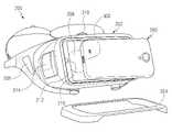
도 1은 본 발명의 다양한 실시 예에 따른 휴대용 전자 장치(300)가 장치(200)에 장착되는 예를 도시한 도면이고, 도 2는 본 발명의 다양한 실시 예에 따라 휴대용 전자 장치(300)가 장착된 장치(200)를 사용자가 착용한 예를 도시한 도면이다. 도 3은 본 발명의 다양한 실시 예에 따른 장치의 다른 방향 사시도이다. 도 4는 본 발명의 다양한 실시 예에 따른 장치의 전면 방향 사시도이다.1 is a diagram illustrating an example in which a portable
도 1 내지 도 4를 참조하면, 본 발명의 전자 장치(이하 '머리 장착형 전자 장치'라고 함.)는 디스플레이를 구비한 휴대용 전자 장치(300) 또는 투명/반투명 렌즈 중 적어도 하나를 구비한 장치(200)로 구비될 수 있고, 머리 장착형 전자 장치를 사용자의 머리에 고정시킬 수 있게 구비됨과 아울러 선택적으로 사용자 유저 인터페이스를 구현할 수 있도록 구비될 수 있다. 본 발명의 일 실시 예에 따른 디스플레이를 구비한 휴대용 전자 장치(300)는 장치(200)에 고정되거나, 또는 착탈 가능하게 구비될 수 있다.1 to 4, the electronic device of the present invention (hereinafter referred to as a 'head-mounted electronic device') is a portable
본 발명의 머리 장착형 전자 장치는 증강 현실(Augmented reality, AR)을 제공하는 씨-쓰루(See-through) 또는 가상 현실(Virtual reality, VR)을 제공하는 씨-클로즈드(See-closed) 기능 중 적어도 하나를 제공할 수 있다.The head-mounted electronic device of the present invention provides at least one of a see-through function that provides augmented reality (AR) and a see-closed function that provides virtual reality (VR). can provide one.
씨-쓰루 기능은, 예를 들면, 상기 디스플레이 또는 투명/반투명 렌즈를 통하여 실제 외부의 사물(들)을 사용자의 안구에 전달하면서, 상기 사물 또는 가상의 대상 또는 사물을, 사용자에게 시각적 또는 다양한 감각적인 수단을 사용하여, 제공하는 기능을 일반적으로 의미할 수 있다. 씨-쓰루 기능에 의하면, 실제로 보이는 사물 등에 대한 부가적인 정보 및 또 이미지들을 사용자에게 제공할 수 있다. 다른 실시 예에서는, 디스플레이나, 렌즈 없이, 홀로그램 등을 이용하여, 사용자에게 부가 정보를 제공할 수도 있다.The see-through function, for example, transmits the actual external object(s) to the user's eye through the display or the transparent/translucent lens, while providing the object or virtual object or object to the user visually or variously By using means of being, it can generally mean a function to provide. According to the see-through function, it is possible to provide the user with additional information and images about an object that is actually seen. In another embodiment, additional information may be provided to the user by using a hologram or the like without a display or a lens.
씨-클로즈드 기능은, 별도의 디스플레이에 의하여 제공될 수 있다. 한 실시예에서, 머리 장착형 전자 장치는, 두 개의 디스플레이가 사용자의 안구 앞에 배치되어, 상기 디스플레이를 통하여 제공되는 컨텐츠 (게임, 영화, 스트리밍, 방송 등)를 사용자가 볼 수 있도록 구성될 수 있다. 이는, 독립된 화면을 이용하여 사용자에게 몰입감을 제공할 수 있다.
The sea-closed function may be provided by a separate display. In one embodiment, the head-mounted electronic device may be configured such that two displays are disposed in front of the user's eyes so that the user can view content (games, movies, streaming, broadcast, etc.) provided through the displays. This may provide a sense of immersion to the user by using an independent screen.
본 발명의 머리 장착형 전자 장치는 휴대용 전자 장치(300), 장치(200) 및 방열 장치(400)를 포함할 수 있다.The head mounted electronic device of the present invention may include a portable
상기 휴대용 전자 장치(300)는 예를 들어 도 1의 전자 장치(102)일 수 있으며, 장치(200)에 착탈되게 구비되고, 적어도 가상 현실 동작 및 씨-쓰루 동작 중 하나의 동작에 따른 화면을 디스플레이할 수 있다.The portable
상기 장치(200)는 예를 들어 도 1의 전자 장치(104)일 수 있으며, 주변둘레의 적어도 일부 영역에 상기 휴대용 전자 장치(300)를 장착하는 장착면(212)이 구비되고, 일면이 사용자의 얼굴과 대면하게 구비될 수 있다.The
방열장치(400)는 상기 장치(200)의 적어도 일부 영역, 구체적으로 장치(200)의 프레임(202)의 일 측면에 구비되고, 상기 휴대용 전자 장치(300)에서 발생되는 열을 방열시키도록 적어도 하나 이상 구비될 수 있다.
The
장치(200)는 프레임(202)과, 커버(204)를 포함할 수 있다.The
프레임(202)에는 예를 들어 도 1의 전자 장치(102)를 수납할 수 있는 공간이나 구조를 포함할 수 있다. 또한, 프레임(202)에는 상기 휴대용 전자 장치(300)의 디스플레이와 사용자의 안구 사이에 위치되는 서로 이웃하게 구비되는 2개의 렌즈들(208, 210)을 포함하는 렌즈 조립체(또는 '광학 조립체'라고도 하며, 이하 '렌즈 조립체'로 통칭함.)가 구비될 수 있다. 프레임(202)의 일측면에는 휴대용 전자 장치(300)가 장착되는 경우, 장치(200)와 휴대용 전자 장치(300)가 전기적으로 연결되어 연동될 수 있는 커넥터(216)가 구비될 수 있다. 또한, 프레임(202)에는 상기 휴대용 전자 장치(300)의 디스플레이와 사용자의 안구 사이에 위치되는 서로 이웃하게 구비되는 2개의 렌즈들(208, 210)을 포함하는 렌즈 조립체가 구비될 수 있다.The
후술하나, 프레임의 적어도 일부, 구체적으로 프레임의 하부에는 방열장치(400)를 통해 프레임 내측으로 유입된 공기를 배출하는 배출구가 구비될 수 있다. 배출구는 프레임에 별도로 형성될 수도 있고, 프레임과 렌즈 조립체 사이에 형성되는 홀을 배출구로 사용할 수 도 있다.Although described later, at least a portion of the frame, specifically, a lower portion of the frame may be provided with an outlet for discharging air introduced into the frame through the
상기 프레임(202)은 사용자의 착용성을 위하여 비교적 가벼운 재료, 예를 들어, 플라스틱과 같은 재질을 포함하여 이루어질 수 있다. 그러나, 프레임(202)의 재질은 이에 한정되는 것은 아니다. 프레임(202) 재질의 다른 실시예로서, 상기 프레임(202)은, 강도 또는 미관을 위하여, 다양한 다른 재료, 예를 들어, 유리, 세라믹, 알루미늄과 같은 금속 또는 강철, 스테인레스강, 티타늄 또는 마그네슘 합금과 같은 금속 합금 중 적어도 하나를 포함할 수 있다.The
상기 프레임(202)은, 유저 인터페이스로서, 프레임(202)의 외측면 일부분에, 예를 들어, 터치 패널을 포함할 수 있다. 상기 터치 패널은, 하나 또는 그 이상의 디스플레이의 위치를 조정하거나, 렌즈들(208, 210)의 위치를 조정할 수 있도록 상기 프레임(202)의 외부 표면에 포함할 수 있다. 이와는 달리 후술하나 상기 프레임(202)에는 상기 휴대용 전자 장치(300)을 컨트롤 하기 위한 다른 종류의 컨트롤 장치(214)가 구비될 수 있다.The
커버(204)는 장치(200)에 착탈 가능하게 구비되며, 장치(200)에 휴대용 전자 장치(300)가 장착되는 경우 휴대용 전자 장치(300)가 장착된 상태를 유지하도록 휴대용 전자 장치(300)의 후면 가장자리를 덮어 장치(200)에 고정할 수 있다.The
본 발명의 일 실시 예에 따른 장치(200)의 일면에는 휴대용 전자 장치(300)의 장착 상태를 유지할 수 있도록 커버(204)가 구비되는 것을 예를 들어 설명하나, 이에 한정되는 구성은 아니다. 예를 들어, 장치(200)의 적어도 일부에는 휴대용 전자 장치(300)가 장착되는 장착면(212)이 구비될 수 있는데, 장착면(212)의 양측으로 휴대용 전자 장치(300)를 고정 지지할 수 있는 구조물이 구비되어 커버가 구비되지 않을 수 도 있을 것이다.
It is described as an example that a
본 발명의 일 실시 예에 따른 프레임(202)은 지지물(206)(또는 '장착구'라고도 하며, 이하에서는 '지지물'로 통칭 함.), 렌즈 조립체, 장착면(212), 커넥터(216), 안면 접촉부(202a), 컨트롤 장치(214), 위치 조정부(218) 및 장착 개구부(260) 등을 포함할 수 있다.
지지물(206)은 사용자가 전자 장치를 머리에 착용하는데 사용될 수 있는 기구물일 수 있다. 본 발명의 지지물(206)은 예를 들면, 탄성 소재로 형성된 밴드 또는, 안경 다리(eyeglass temples), 헬멧(helmets) 또는 스트랩(straps) 등을 포함할 수 있다. 상기 지지물(206)은 상기 프레임(202)이 사용자의 얼굴의 눈 주위로 밀착되게 구비될 수 있다.The
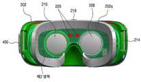
렌즈 조립체(200b)는 착용자의 양쪽 눈 각각에 대응하는 위치에 렌즈들(208, 210)을 구비하며, 프레임(202)의 내측면으로 설치될 수 있다. 착용자는 렌즈들(208, 210)을 통해 디스플레이(도시하지 않았음)의 화면을 볼 수 있다. 사용자가 머리 장착형 전자 장치를 착용하였을 때, 사용자의 눈으로 디스플레이의 화면을 볼 수 있도록 렌즈들(208, 210)의 일면은 후술하는 안면 접촉부(202a) 측으로 노출되게 구비되며, 렌즈들(208, 210)이 다른 일면은 장치(200)의 전면에 장착되는 휴대용 전자 장치(300)의 디스플레이 화면이 보일 수 있도록 후술하는 장착면(212) 측으로 노출될 수 있다.The lens assembly 200b includes
장착면(212)은 프레임(202)의 적어도 일부분, 구체적으로 프레임(202)의 전면에서 내측으로 인입되어 휴대용 전자 장치(300)가 장착되는 공간을 구비할 수 있다. 장착면(212)은 장치(200)에 휴대용 전자 장치(300)를 착탈 가능하게 장착할 수 있는 기구적 구조일 수 있다. 장착면(212)은 장착면(212)으로 다양한 크기를 가지는 휴대용 전자 장치(300)가 장착될 수 있도록 공간의 크기를 변형시킬 수 있는 탄성 소재와 같은 플렉서블한 재질이나 변형 가능한 재질을 포함하여 이루어질 수 있다. 장착면(212)이 플렉서블하거나 변형 가능한 재질로 이루어짐에 따라, 휴대용 전자 장치(300)가 장착면(212)에 안착된 상태에서 커버(204)나 휴대용 전자 장치(300)를 고정 지지하는 구조물에 의해 고정될 때, 휴대용 전자 장치(300)의 디스플레이가 스크래치나 파손 발생 없이 장착면(212) 측으로 밀착될 수 있다. 장착면(212)에는 후술하는 커넥터(216)와, 지지부(217)가 구비되어 휴대용 전자 장치(300)를 장착면에 지지하면서 전기적으로 접속되도록 구비될 수 있다.The mounting
커넥터(216)는 장치(200)에 휴대용 전자 장치(300)가 장착되는 경우, 휴대용 전자 장치(300)의 연결부(302)와 접속되어 휴대용 전자 장치(300)와 장치(200) 간에 서로 통신할 수 있도록 구비될 수 있다. 커넥터(216)는, 도 5처럼, 프레임(202), 구체적으로 장착면(212)의 일측에 위치되어 휴대용 전자 장치(300)의 연결 단자(302)와 전기적으로 접속되며 상기 휴대용 전자 장치(300)의 일측을 지지 고정할 수 있도록 구비될 수 있다.The
지지부(217)는, 도 5처럼, 프레임, 구체적으로 장착면(212)의 타측으로 커넥터(216)와 대향하게 위치되며, 휴대용 전자 장치(300)의 타측을 지지하도록 구비될 수 있다. 따라서, 휴대용 전자 장치(300)가 장착면(212)에 안착되면, 휴대용 전자 장치(300)의 일측은 커넥터(216)에 전기적으로 접속되면서 지지되고, 휴대용 전자 장치(300)의 타측은 지지부(217)에 고정 지지될 수 있다.As shown in FIG. 5 , the
안면 접촉부(202a)는, 도 4처럼, 프레임(202)의 적어도 일부, 구체적으로 프레임(202)의 후면에 위치되며, 머리 장착형 전자 장치가 사용자의 얼굴에 착용될 때, 사용자의 안면에 접촉되는 부분이다. 상기 안면 접촉부(202a)는 사용자의 안면의 굴곡에 대응하는 구조를 가질 수 있으며, 사용자의 안면과 안정적으로 밀착되며, 사용자의 신체에서 발생되는 열등에 따른 습기를 배출 할 수 있도록 탄성체를 적어도 일부 포함할 수 있다. 상기 안면 접촉부(202a)의 일부분은, 사용자의 코가 삽입될 수 있는 형상을 가진 코 홈(nose recess)을 포함할 수 있다.The
컨트롤 장치(214)는 장치(200)에 장착되는 휴대용 전자 장치(300)를 컨트롤 하기 위해 구비되는 구성물일 수 있으며, 프레임(202)의 적어도 일부면, 예를 들어 프레임(202)의 외측 측면에 설치될 수 있다. 컨트롤 장치(214)는 착용자가 머리 장착형 전자 장치를 제어하기 위한 입력, 예를 들어 휴대용 전자 장치(300)의 디스플레이 위치를 조정 하기 위한 조정 장치 일 수도 있고, 렌즈들(208, 210)의 위치를 조정하기 위한 조정부일 수도 있으며, 이와는 달리 휴대용 전자 장치(300)를 컨트롤 하는데 사용될 수 있다. 예를 들어 컨트롤 장치(214)는 물리적 키, 물리적 버튼, 터치 패널, 조이스틱, 버튼, 휠(wheel)) 키, 및 터치 패드 등 중에 적어도 하나를 포함할 수 있다. 터치 패널로 구비되는 컨트롤 장치(214)는 사용자의 터치 입력을 수신할 수 있다. 터치 입력은 사용자가 터치 패널을 직접 터치하는 입력 또는 터치 패널에 근접한 호버링(hovering) 입력일 수 있다. 터치패드로 구비되는 컨트롤 장치(214)는 휴대용 전자 장치(300)의 기능을 제어할 수 있는 그래픽 사용자 인터페이스 (Graphical User Interface, GUI)를 표시할 수 있다. 예를 들어, 음향 또는 영상을 제어하는 그래픽 사용자 인터페이스 GUI를 표시할 수 있을 것이다.The
앞서 언급한 바와 같이, 휴대용 전자 장치(300)가 장치(200)에 장착될 때, 휴대용 전자 장치(300)의 연결단자(302)가 장치(200)의 커넥터(216)와 연결되어, 상기 터치패널이 수신한 터치 입력이 상기 휴대용 전자 장치(300)에 전송될 수 있다. 상기 휴대용 전자 장치(300)는 상기 터치 패널에서 수신한 터치 입력에 응답하여 터치 입력에 대응하는 기능을 제어할 수 있다. 예를 들어, 휴대용 전자 장치(300)는 수신된 터치 입력에 응답하여 음량을 조절하거나 영상 재생을 제어할 수 있다.As mentioned above, when the portable
위치 조정부(218)는 프레임(202)의 적어도 일부면, 예를 들어 프레임(202)의 외측 상부면에 설치될 수 있다. 위치 조정부(218)는 컨트롤 장치(214)와 별개로 휴대용 전자 장치(300)의 디스플레이 위치를 조정하거나, 렌즈들(208, 210)의 위치를 조정할 수 있다.
The
휴대용 전자 장치(300)는 예를 들어 후면에 설치된 후면 카메라를 포함하는 스마트 폰일 수 있다. 사용자는 도 1처럼 휴대용 전자 장치(300)를 휴대용 전자 장치(300)의 디스플레이(도시하지 않았음)가 설치된 전면이 렌즈들(208, 210))을 향하도록 장치(200)의 장착면(212)에 장착할 수 있다. 사용자는 커버(204)를 덮어 휴대용 전자 장치(300)를 장치(200)에 고정시킬 수 있다. 사용자는 휴대용 전자 장치(300)가 장착된 장치(200)를 도 3처럼 머리에 착용할 수 있다. 도 2는 휴대용 전자 장치(300)가 장착된 장치(200를 착용자가 머리에 착용한 모습을 보인다. 착용자는 장치(200)의 렌즈들(208, 210))을 통해 휴대용 전자 장치(300)의 디스플레이의 화면을 볼 수 있다.The portable
장착 개구부(260)는 장치(200)의 일부 영역, 구체적으로 프레임(202)의 측면에 구비될 수 있다. 장착 개구부(260)는 그 내측으로 방열 장치(400)를 장착하며, 방열장치(400)의 구동에 따라 외부 공기를 상기 장치의 내부, 구체적으로 프레임(202)의 내측으로 유입되도록 구비될 수 있다.
The mounting
도 5는 본 발명의 다양한 실시 예에 따른 장치(400)의 구성 예를 도시한 블록도이다.5 is a block diagram illustrating a configuration example of an
도 5를 참조하면, 장치(400)는 도 2의 머리 장착형 전자 장치(200)일 수 있으며 도 1 및 도 2의 장치(200)일 수 있다. 장치(400)는 MCU(micro controller unit)(410), 통신 모듈(420), 센서 모듈(430), 입력 모듈(440), 시선 추적(eye tracking) 모듈(450), 바이브레이터(452), 초점 조절(adjustable optics) 모듈(454), 전력 관리 모듈(460), 배터리(462)를 포함할 수 있다.Referring to FIG. 5 , the
MCU(410)는 운영체제 또는 임베디드 소프트웨어 프로그램을 구동하여 다른 구성 요소들(예를 들어, 통신 모듈(420), 센서 모듈(430), 입력 모듈(440), 시선 추적(eye tracking) 모듈(450), 바이브레이터(452), 초점 조절(adjustable optics) 모듈(454), 전력 관리 모듈(460))을 제어할 수 있는 장치(400)의 제어부일 수 있다. MCU(410)는 프로세서 및 메모리를 포함할 수 있다.The
통신 모듈(420)은 휴대용 전자 장치(300)와 장치(400)를 유선 통신 또는 무선 통신을 이용하여 전기적으로 연결하여 데이터 송수신을 수행할 수 있다. 한 실시 예에 따르면, 통신 모듈(420)은 USB 모듈(421), WiFi 모듈(422), BT 모듈(423), NFC 모듈(424), GPS 모듈(425)을 포함할 수 있다. 한 실시 예에 따르면, USB 모듈(421), WiFi 모듈(422), BT 모듈(423), NFC 모듈(424), GPS 모듈(425) 중 적어도 2개는 하나의 IC(integrated chip) 또는 IC 패키지 내에 포함될 수 있다.The
센서 모듈(430)은 물리량을 계측하거나 장치(400)의 작동 상태를 감지하여, 계측 또는 감지된 정보를 전기 신호로 변환할 수 있다. 센서 모듈(430)은, 예를 들면, 가속도 센서(431), 자이로 센서(432), 지자계 센서(433), 마그네틱 센서(434), 근접 센서(435), 제스처 센서(436), 그립 센서(437), 생체 센서(438), 접근 센서(439) 중의 적어도 하나를 포함할 수 있다. 장치(400)는 장치(400)를 착용한 착용자의 머리 움직임을 가속도 센서(431), 자이로 센서(432), 지자계 센서(433) 중 적어도 하나를 이용하여 감지할 수 있다. 장치(400)는 근접 센서(435) 혹은 그립 센서(437)를 이용하여 장치(400)의 착용 여부를 감지할 수 있다. 한 실시 예에 따르면 장치(400)는 사용자가 장치(400)를 착용함에 따른 IR(infrared) 인식, 가압 인식, 캐패시턴스(혹은 유전율)의 변화량 중 적어도 하나를 감지하여 사용자의 착용 여부를 감지할 수 있다. 제스처 센서(436)는 사용자의 손 또는 손가락의 움직임을 감지하여 장치(400)의 입력 동작으로 받을 수 있다. 장치(400)는 장치(400)의 착용자에게 물체가 접근하는 것을 접근 센서(439)를 이용하여 감지할 수 있다. 추가적으로 또는 대체적으로, 센서 모듈(430)은, 예를 들면, 후각 센서(E-nose sensor), EMG 센서(electromyography sensor), EEG 센서(electroencephalogram sensor), ECG 센서(electrocardiogram sensor), 홍채 센서, 지문 센서 등의 생체 인식 센서를 포함하고 생체 인식 센서를 이용하여 사용자의 생체 정보를 인식할 수 있다. 센서 모듈(430)은 그 안에 속한 적어도 하나 이상의 센서들을 제어하기 위한 제어 회로를 더 포함할 수 있다.The
입력 모듈(440)은 도 2의 컨트롤 장치(214)일 수 있다. 입력 모듈(440)은 사용자로부터 입력을 받아들일 수 있다. 입력 모듈(440)은 터치 패드(441), 버튼(442)을 포함할 수 있다. 터치 패드(441)는, 예를 들면, 정전식, 감압식, 적외선 방식 또는 초음파 방식 중 적어도 하나의 방식으로 터치 입력을 인식할 수 있다. 터치 패드(441)는 제어 회로를 더 포함할 수도 있다. 정전식의 경우, 물리적 접촉 또는 근접 인식이 가능하다. 터치 패드(441)는 택타일 레이어(tactile layer)를 더 포함할 수도 있다. 이 경우, 터치 패드(440)는 사용자에게 촉각 반응을 제공할 수 있다. 버튼(442)은, 예를 들면, 물리적인 버튼, 광학식 키 또는 키패드를 포함할 수 있다.The
전력관리 모듈(460)은 장치(400)의 전력을 관리할 수 있다. 도시하지는 않았으나, 전력관리 모듈(460)은, 예를 들면, PMIC(power management integrated circuit), 충전 IC(charger integrated circuit) 또는 배터리 게이지(battery fuel gauge)를 포함할 수 있다.The
상기 PMIC는, 예를 들면, 집적회로 또는 SoC 반도체 내에 탑재될 수 있다. 충전 방식은 유선과 무선으로 구분될 수 있다. 충전 IC는 배터리를 충전시킬 수 있으며, 충전기로부터의 과전압 또는 과전류 유입을 방지할 수 있다. 한 실시 예에 따르면, 충전 IC는 유선 충전 방식 또는 무선 충전 방식 중 적어도 하나를 위한 충전 IC를 포함할 수 있다. 무선 충전 방식으로는, 예를 들면, 자기공명 방식, 자기유도 방식 또는 전자기파 방식 등이 있으며, 무선 충전을 위한 부가적인 회로, 예를 들면, 코일 루프, 공진 회로, 정류기 등의 회로가 추가될 수 있다.The PMIC may be mounted in, for example, an integrated circuit or an SoC semiconductor. The charging method can be divided into wired and wireless. The charger IC can charge the battery and prevent overvoltage or overcurrent from being drawn from the charger. According to an embodiment, the charging IC may include a charging IC for at least one of a wired charging method and a wireless charging method. As a wireless charging method, for example, there is a magnetic resonance method, a magnetic induction method, or an electromagnetic wave method, and an additional circuit for wireless charging, for example, a circuit such as a coil loop, a resonance circuit, and a rectifier may be added. have.
배터리 게이지는, 예를 들면, 배터리(462)의 잔량, 충전 중 전압, 전류 또는 온도를 측정할 수 있다. 배터리(462)는 전기를 저장하여 전원을 공급할 수 있다. 배터리(462)는, 예를 들면, 충전식 전지(rechargeable battery) 또는 태양 전지(solar battery)를 포함할 수 있다.The battery gauge may measure, for example, the remaining amount of the
시선 추적 모듈(450)은 예를 들면, EOG(Electircal oculography) 센서, 코일 시스템(coil systems), 듀얼 푸르키네 시스템(dual purkinje systems), 브라이트 눈동자 시스템(bright pupil systems), 다크 눈동자 시스템(dark pupil systems) 중 적어도 하나의 방식을 이용하여 사용자의 시선을 추적할 수 있다. 또한, 시선 추적 모듈(450)은 시선추적을 위한 마이크로 카메라를 더 포함할 수도 있다.The
초점 조절 모듈(454)은 사용자가 자신의 시력에 적합한 영상을 감상할 수 있도록 사용자의 양안 사이 거리(inter-pupil distance, IPD)를 측정할 수 있다. 장치(400)는 초점 조절 모듈(454)을 통해 측정된 사용자의 양안 사이 거리에 따라 렌즈의 거리를 조정할 수 있다. 장치(400)는 초점 조절 모듈(454)을 통해 측정된 사용자의 양안 사이 거리를 휴대용 전자 장치(300)로 전송하여 휴대용 전자 장치(300)의 디스플레이를 통한 화면의 디스플레이 위치를 조정할 수 있다.The
MCU(410)는 센서 모듈(430)의 움직임 센서를 통해 감지된 움직임 신호를 휴대용 전자 장치(300)로 전송할 수 있다. 움직임 센서는 가속도 센서(431), 자이로 센서(432), 지자계 센서(433) 중 적어도 하나일 수 있다.The
MCU(410)는 장치(400)의 착용자에게 물체가 접근하는 것을 접근 센서(439)를 통해 감지하고 접근 감지 신호를 휴대용 전자 장치(300)로 전송할 수 있다. MCU(410)는 장치(400)의 착용자에게 물체가 접근하는 방향을 접근 센서(439)를 통해 측정하여 휴대용 전자 장치(300)로 전송할 수 있다.The
접근 센서(439)로서, IR(infrared) 센서, 초음파 센서, RF(radio fre'uency) 센서, 레이더 등과 같은 공간 인식 센서가 사용될 수 있다. RF 센서로서는 와이씨(Wisee) 센서, 올씨(Allsee) 센서 등이 사용될 수 있다. 한 실시 예에 있어서, 접근 센서(439)로서 무선 통신 모듈이 이용될 수 있다. 무선 통신 모듈은 WiFi 모듈(422), BT 모듈(423), NFC 모듈(424), GPS 모듈(425) 중 적어도 하나일 수 있다. 장치(400)에 물체가 접근하면 무선 통신 모듈에 수신되는 무선 통신 신호의 수신 전계 강도가 접근하는 물체로 인해 약해질 수 있다. 장치(400)의 착용자가 이동하지 않는 중에 수신 전계 강도가 지정된 임계값보다 큰 차이로 급격히 저하되는 경우 MCU(410)는 물체가 접근하는 것으로 감지할 수 있다. 또한 MCU(410)는 수신 전계 강도가 지정된 임계값보다 큰 차이로 급격히 저하되는 방향을 물체가 접근하는 방향인 것으로 감지할 수 있다.
As the
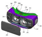
도 6은 본 발명의 다양한 실시 예에 따른 전자 장치에서, 방열 장치를 분리한 사시도이다. 도 7은 본 발명의 다양한 실시 예에 따른 전자 장치의 방열장치(400)에 의한 공기의 흐름을 나타내는 도면이다.6 is an exploded perspective view of a heat dissipation device in an electronic device according to various embodiments of the present disclosure; 7 is a diagram illustrating an air flow by the
도 6 및 도 7을 참조하면, 머리 장착형 전자 장치에는 방열장치(400)가 구비될 수 있다. 구체적으로 방열장치(400)는 장치(200)의 적어도 일부 영역, 구체적으로 프레임(202)의 측면으로 구비되고, 구동됨에 따라 외부 공기를 프레임(202)의 내측으로 인입시켜 휴대용 전자 장치(300)에서 발생되는 열을 방열시킬 수 있도록 구비될 수 있다. 상기 방열장치(400)는 블레이드를 포함한 팬타입으로 구비될 수도 있고, 피에조 쿨러(Piezo Cooler)와 같은 형태 일 수 도 있다. 방열장치(400)가 구동되면, 외부로부터 공기를 빨아드린 후 빨아드린 공기를 프레임(202) 내부에 공급함으로써 휴대용 전자 장치(300)의 발열을 제어 할 수 있다.6 and 7 , the head mounted electronic device may include a
방열장치(400)를 통해 프레임(202)의 내측으로 유입된 공기는 휴대용 전자 장치(300)의 열을 전달 받아 프레임(202)의 적어도 일부, 구체적으로 프레임(202)의 하면에 구비된 배출구를 통해 배출될 수 있다. 상기 방열장치(400)는 앞서 언급한 바와 같이, 외부 공기를 프레임(200) 내부에 공급하여 휴대용 전자 장치(300)의 발열을 제어 할 수도 있다. 또한, 이와 반대로 프레임(202) 내부의 공기를 외부로 내보냄으로써, 휴대용 전자 장치(300)의 발열을 제어 할 수도 있다. 즉, 휴대용 전자 장치(300)에서 발생된 열이 프레임(202)의 내부에 채워지게 되는데, 프레임(202)의 내부의 데워진 공기가 방열 장치(400)의 구동에 따라 프레임(202)의 내부에서 외부로 방출되어 방열될 수 있는 것이다. 상기와 같이 프레임(202) 내부 공기를 외부로 내보내는 경우, 프레임(202) 내부에 열을 전달하기 위한 열전달 부재(600, 도 14 참조), 구체적으로 그라파이트시트, 그래핀 등과 같은 탄소가 함유된 열전달 부재, 동시트 등과 같은 금속 부재, 히트파이프(Heat pipe) 등과 같은 촉매제를 이용한 열전달 부재(600, 도 14 참조)들이 장착 될 수 있다. 추가로 상기 열전달 부재(600, 도 14 참조) 또는 공기 방출구(미도시) 주변에 히트싱크(Heat sink)와 같이 방열 효과를 높일 수 있는 열전달 부재(700, 도 15 참조)들이 장착될 수 있다.The air introduced into the
상기 방열장치(400)는, 팬 부재(410, 420)와, 팬 커버부재(430)를 포함할 수 있다.The
팬 부재(410, 420)는 프레임(202)의 내측, 구체적으로 장착 개구부(260) 내부에 장착되며, 팬(410)과 팬 덕트(420)를 포함할 수 있다.The
팬(410)은 블래이드로 구비되거나 페이조 쿨러와 같은 형태로 구비될 수도 있다, 팬(410)이 작동되면서 외부로부터 공기를 빨아드린 후, 프레임(202)의 내측으로 공급함으로써, 휴대용 전자 장치(300)의 발열을 제어할 수 있도록 구비되는 것이다.The
팬(410) 덕트는 팬(410) 주위를 둘러싸도록 구비되며, 장착 개구부(260)의 둘레면에 장착될 수 있다.The
팬 커버부재(430)는 프레임(202)의 외측에 결합되어 외부에서 들어오는 공기의 흐름을 가이드 할 수 있다.
The
도 8은 본 발명의 다양한 실시 예에 따른 전자 장치의 결합 사시도이다. 도 9는 본 발명의 다양한 실시 예에 따른 방열 장치 부분의 상부 확대도이다. 도 10은 도 8의 A-A'선 확대 단면도이다.8 is a combined perspective view of an electronic device according to various embodiments of the present disclosure; 9 is an enlarged upper view of a portion of a heat dissipation device according to various embodiments of the present disclosure; 10 is an enlarged cross-sectional view taken along line A-A' of FIG. 8 .
도 8 내지 도 9를 참조하면, 프레임(202)의 일측면에 형성되는 장착 개구부(260)에는 방열장치(400), 구체적으로 팬 부재(410, 420)가 내장되어 있고, 장착 개구부(260)에는 팬(410)의 내부로 공기가 통할 수 있도록 적어도 하나 이상의 개구가 구비될 수 있다.8 to 9 , the
팬 커버부재(430)는 장착 개구부(260)에 장착된 팬 부재(410, 420)를 커버하도록 구비될 수 있다. 팬 커버부재(430)는 프레임(202)의 외측면으로 노출되어 장착 개구부(260)의 전면에 착탈 가능하게 구비될 수 있다. 상기 팬 커버부재(430)의 크기는 상기 장착 개구부(260)의 크기와 동일하거나 크게 구비될 수 있다. 팬 커버부재(430)는 상기 장치(200)의 표면에서 돌출되게 고정되어 상기 팬 커버부재(430)의 주변 둘레와 상기 장치(200) 사이에서 공기 유입구(400a)를 형성할 수 있다. 공기 유입구(400a)는 팬 커버부재(430)의 가장 자리를 따라 위치되어, 팬(410)의 구동 시 외부 공기가 팬(410)으로 직접 유입되는 것을 방지하고, 팬 커버부재(430)의 가장 자리의 공기 유입구(400a)를 통해 유입될 수 있도록 한다. 또한 팬 커버부재(430)는 외부로부터 팬(410)을 은폐할 수 있어서 디자인적인 미려함을 높일 수 있다.
The
도 11a는 본 발명의 다양한 실시 예들에 따른 팬 커버부재(430)의 다른 실시 예를 나타내는 도면이다. 도 11b는 본 발명의 다양한 실시 예들에 따른 프레임(202)에 따른 실시 예에 따른 팬 커버부재(430)가 장착된 상태를 나타내는 단면도이다.11A is a view showing another embodiment of the
도 11a 내지 도 11b를 참조하면, 상기 팬 커버부재(430)의 표면에는 적어도 하나 이상의 관통 홀(431)이 형성될 수 있다. 상기 관통 홀(431)은 프레임(202) 내부로 더 많은 외부 공기가 유입될 수 있도록 구비될 수 있다. 본 발명에서 상기 관통 홀(431)은 원형뿐만 아니라 적용 가능한 다른 형상으로 형성될 수도 있고, 또한 반복적인 형상의 패턴으로 적용될 수 있다.
11A to 11B , at least one through
도 12a는 본 발명의 다양한 실시 예에 따른 관통 홀(431)이 형성된 팬 커버부재(430)에 홀 커버(432)가 구비되는 것을 나타내는 도면이다. 도 12b는 본 발명의 다양한 실시 예에 따른 홀 커버(432)가 구비된 팬 커버부재(430)가 프레임(202)에 장착된 상태를 나타내는 단면도이다.12A is a view illustrating that the
도 12a 및 도 12b를 참조하면, 상기 팬 커버부재(430)에는 홀 커버(432)가 구비될 수 있다. 홀 커버(432)는 상기 관통 홀(431)에 착탈 가능하게 구비되며, 상기 관통 홀(431)을 덮도록 구비될 수 있다. 홀 커버(432)는 머리 장착형 전자 장치의 일반적인 상황, 예를 들어 휴대용 전자 장치(300)의 온도가 높지 않은 경우 또는 후술하는 제2감지부(270)의 온도 검출 값이 설정 온도 이하인 경우, 관통 홀(431)을 덮고 있도록 구비될 수 있다. 그러나, 휴대용 전자 장치(300)의 온도가 급격히 올라가거나, 일반적인 팬(410)의 동작상태에서 더 이상 방열이 어려워 후술하는 제2감지부(270)에서 검출되는 온도 검출 값이 임계 값을 넘어서는 경우가 검출되면 홀 커버(432)를 팬 커버부재(430)에서 분리시켜 관통 홀(431)을 개방시킬 수 있다. 홀 커버(432)가 팬 커버부재(430)에서 분리되어 관통 홀(431)이 개방됨으로써 더 많은 외부 공기를 프레임(202) 내부로 유입시킬 수 있다.
12A and 12B , the
도 13은 본 발명의 다양한 실시 예에 따른 전자 장치에 방진 메시부(500)가 장착된 상태를 나타내는 단면도이다.13 is a cross-sectional view illustrating a state in which the dust-
도 13을 참조하면, 상기 팬 부재(410, 420)의 일면에는 이물질 유입을 제한하는 방진 메시부(500)가 더 포함될 수 있다.Referring to FIG. 13 , one surface of the
팬(410)이 동작하여 외부 공기가 프레임(202) 내부로 유입 시에, 외부 먼지와 같은 이물질이 프레임(202) 내부로 유입될 수도 있다. 상기 이물질은 프레임(202) 내부에 유입되어 렌즈들(208, 210)이나 디스플레이 같이 투명도가 필요한 부품 표면에 부착되어 렌즈들(208, 210)의 표면이 오염시킬 수 있다, 이에, 방진 메시부(500)는 팬 부재(410, 420)의 적어도 일면, 구체적으로 전면 또는 후면에 배치되어, 장착 개구부(260)로 유입되는 이물질을 필터링 할 수 있도록 구비될 수 있다. 방진 메시부(500)는 메시 형태뿐만 아니라, 적용 가능한 다양한 재질 및 형태로 사용할 수 있다. 예를 들어 공기를 유입시킬 수 있는 부직포나, 다공성 재질의 탄성부재 등으로 이루어질 수도 있다.
When the
도 14는 본 발명의 다양한 실시 예에 따른 장치(200)의 적어도 일면에 열확산부재(600)가 구비된 상태를 나타내는 사시도이다.14 is a perspective view illustrating a state in which the
도 14를 참조하면, 열확산 부재(600)는 상기 휴대용 전자 장치(300)의 열을 전달받아 확산하도록 상기 장치(200)에 구비될 수 있다. 열확산 부재(600)는 휴대용 전자 장치(300)가 안착되는 장치(200)의 일면, 예를 들어 장착면(212)에 구비될 수 있다. 즉, 휴대용 전자 장치(300)가 장치(200)에 안착되면, 렌즈들(208, 210)의 주변둘레로 휴대용 전자 장치(300)의 디스플레이의 일면과 장치(200)의 장착면(212)이 대면되는 면이 발생될 수 있다. 열확산 부재(600)는 장착면(212)의 전면으로 휴대용 전자 장치(300)와 장치(200)가 서로 대면되는 면에 구비되어 휴대용 전자 장치(300)의 열을 전달 받을 수 있도록 구비될 수 있는 것이다. 열확산 부재(600)는 휴대용 전자 장치(300)에서 발생되는 열을 복사열로서 전달 받아 휴대용 전자 장치(300)의 열을 방열시킬 수 있도록 구비될 수 있다. 열확산 부재(600)는 렌즈들(208, 210)의 일면 주변둘레로 장착면(212)에 마치 'エ' 형태로 형성될 수 있다. 상기 열확산 부재(600)는, 알루미늄, 구리, STS과 같은 열전도율이 높은 금속 재질을 포함하는 재질로 이루어지거나, 그라파이트, 탄소나노튜브, 그래핀과 같은 탄소를 포함하는 재질로 이루어질 수 있다.Referring to FIG. 14 , a
또한, 상기 열확산 부재(600)는, 다이아몬드 코팅(DLC_Diamond like cabon), 도금, 증착과 같은 코팅으로 형성되거나, 히트 파이프(Heat-Pipe)와 같은 촉매제 중 적어도 하나로 구비될 수 있다.In addition, the
상기 열확산 부재(600)는 상기 장치(200)의 프레임(202)의 전면에 조립되는 프론트 케이스의 일부분에 인서트되어 구비될 수 있다. 또한, 이와는 달리 상기 장치(200)의 프레임(202)의 전면에 조립되는 프론트 케이스 전체를 열확산 부재(600)로 구비시킬 수도 있다. 예를 들어 프론트 케이스 전체를 열전도 플라스틱으로 제작하여 휴대용 전자 장치(300)를 장착하는 장착면(212)을 형성함과 아울러 휴대용 전자 장치(300)에서 발생되는 열을 전달 받아 프레임(202)의 내측에서 흐르는 공기를 통해 방열 시킬 수 있도록 구비될 수 있는 것이다.
The
도 15는 본 발명의 다양한 실시 예에 따른 장치(200)의 적어도 일부에 열전달부재(700)가 구비된 전자 장치의 사시도이다. 도 16은 본 발명의 다양한 실시 예에 따른 장치(200)의 적어도 일부에 열전달부재(700)가 구비된 전자 장치의 전면측 단면도이다. 도 17은 본 발명의 다양한 실시 예에 따른 휴대용 전자 장치(300)의 디스플레이 중 열전달부재(700)가 접촉되는 부분을 나타내는 도면이다.15 is a perspective view of an electronic device in which a
도 15 내지 도 17을 참조하면, 열전달부재(700)는 상기 열확산 부재(600)와 상기 휴대용 전자 장치(300) 사이에 구비되어, 상기 휴대용 전자 장치(300)의 열을 상기 열확산 부재(600)로 전도를 통해 전달하도록 구비될 수 있다. 상기 열전달부재(700)는 휴대용 전자 장치(300)에서 발생한 열을 복사열로 열확산 부재(600)로 전달되는 것보다 빨리 열을 퍼뜨릴 수 있다.15 to 17 , a
상기 열전달부재(700)는 상기 휴대용 전자 장치(300)와 상기 열확산 부재(600) 사이의 공간에 대응하는 두께를 가지도록 구비되거나 또는 상기 공간보다 두꺼운 두께를 가지도록 구비될 수 있다. 상기 열전달부재(700)가 상기 공간보다 큰 두께로 구비될 경우, 휴대용 전자 장치(300)와 열확산 부재(600) 사이의 밀착력이 높아지고, 이에 따라 휴대용 전자 장치(300)에서 열확산 부재(600)로 열 전달이 더 용이하게 발생될 수 있다. The
상기 열전달부재(700)는 TIM(Thermal interface material) 재질로 구비될 수 있다. 이와는 달리 열전달부재(700)의 재질은 열전달이 가능한 도전스폰지와 같은 쿠션류의 재질로 이루어질 수도 있다. 본 발명의 일 실시 예에 따른 열전달부재(700)의 재질은 TIM이나 도전스폰지와 같은 재질을 예를 들어 설명하였으나, 이에 한정되는 것은 아니며, 휴대용 전자 장치(300)의 발생 열을 열확산 부재(600)로 용이하게 전달할 수 있는 재질이라면 얼마든지 변경이나 변형이 가능할 것이다.The
본 발명의 일 실시 예에서, 상기 열전달부재(700)는 상기 열확산 부재(600)의 중앙에 배치되는 것을 예를 들어 설명한다. 이에, 열전달부재(700)는 휴대용 전자 장치(300)의 디스플레이 면 중 렌즈들(208, 210)과 맞물려 화면이 디스플레이되는 활성 영역 사이의 비 활성 영역에 위치될 수 있고, 열전달부재(700)는 활성화되는 화면 영역과 간섭없이 위치될수 있는 것이다. 열전달부재(700)가 렌즈들(208, 210) 사이에 위치되어 휴대용 전자 장치(300)에서 발생된 열을 열확산 부재(600)로 일정하게 퍼뜨릴 수 있다. 그러나, 열전달부재(700)의 장착 위치는 이에 한정되는 것은 아니다. 예를 들어, 열전달부재(700)는 휴대용 전자 장치(300)의 디스플레이의 면에서 렌즈들(208, 210)과 맞물려 화면이 디스플레이되는 활성 영역 이외의 어느 비활성 영역에도 위치될 수 있다. 즉, 휴대용 전자 장치(300)의 디스플레이의 면에서 화면이 디스플레이되는 활성 영역 이외의 비활성 영역의 어느 위치에도 배치될 수 있어, 열전달부재(700)가 구비됨에 따라 열전달부재(700)는 활성화되는 화면 영역과 간섭 발생을 방지할 수 있는 것이다.
In one embodiment of the present invention, the
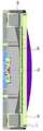
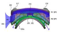
도 19는 본 발명의 다양한 실시 예에 따른 장치(200)를 렌즈 조립체(202b)를 기준으로 제1영역과 제2영역으로 구획한 도면이다. 도 20은 본 발명의 다양한 실시 예에 따른 연결 홀(220)이 형성된 장치(200)를 나타내는 도면이다. 도 21은 본 발명의 다양한 실시 예에 따른 전자 장치에서 연결 홀(220)을 통해 제1영역에서 제2영역으로 공기가 유입되는 것을 나타내는 도면이다.19 is a view in which the
도 19 내지 도 21을 참조하면, 장치(200)는 프레임(202)의 렌즈 조립체(202b)를 기준으로 제1영역과 제2영역으로 구획 할 수 있다. 제1영역은 프레임(202)의 내측에서 방열장치(400)를 통해 공기가 유입되는 영역일 수 있다. 또한, 제2영역은 제1영역에 인접하며, 상기 사용자의 얼굴에 인접한 영역일 수 있다.19 to 21 , the
방열장치(400)의 팬(410)을 통해 유입되는 외부 공기는 상기 제 1영역 내부로 유입되어 휴대용 전자 장치(300)로부터 발행하는 열을 식힐 수 있다. 그러나, 상기 제 2영역의 경우 사용자가 머리 장착형 전자 장치를 장착할 경우 사용자 얼굴에서 발생하는 열이 얼굴과 렌즈 사이 공간인 제 2영역 내부에 있는 공기를 데움으로 인해 렌즈들(208, 210)의 표면에 습기가 발생할 수 있다. 이에, 팬(410)이 동작됨에 따라 제 1영역을 향하는 렌즈들(208, 210)의 일면과 제 2영역을 향하는 렌즈들(208, 210) 타면 간의 온도 차가 더욱 커짐에 따라 제 2영역을 향하는 렌즈들(208, 210)의 타면은 습기 발생이 더 용이 할 수 있다. 따라서, 제2영역 측을 향하는 렌즈 조립체(202b)의 일면에는 제1영역에서 제2영역으로 관통될 수 있는 연결 홀(220)이 형성될 수 있다. 연결 홀(220)은 프레임(202) 내부의 제1영역과 제2영역을 연결하여 제1영역에서 이동되는 공기가 상기 제2영역으로 유입되도록 구비될 수 있다.
External air introduced through the
상기 연결 홀(220)을 통해 제1영역에서 제2영역으로 유입된 공기는 사용자 얼굴에 닿는 안면 접촉부(202a) 상에 위치하는 개구들을 통해 외부로 빠져 나갈 수 있다. 연결 홀(220)을 통해 제2영역으로 공기가 흐름에 따라 제 1영역과 제 2영역간의 온도차를 줄여들게 되고, 장시간 머리 장착형 전자 장치를 착용하고 있어도 렌즈들(208, 210)의 표면에 습기가 발생되는 것을 제한할 수 있게 된다.
The air introduced from the first area to the second area through the
도 22는 본 발명의 다양한 실시 예에 따른 전자 장치에서, 방열장치(400)의 구동을 제어하는 블록도이다.22 is a block diagram for controlling the operation of the
도 22를 참조하면, 상기 장치(200)에는, 제1감지부(260)와 제2감지부(270) 및 제어부(250)를 포함할 수 있다.Referring to FIG. 22 , the
제1감지부(260)는 장치(200)의 적어도 일부, 예를 들어 안면 접촉부(202a)의 적어도 일부면에 구비될 수 있다. 제1감지부(260)는 휴대용 전자 장치(300)를 장착한 상기 장치(200)가 사용자의 얼굴에 장착되는 것을 감지하도록 구비될 수 있다.The
상기 제1감지부(260)는 스위치 또는 버튼과 같은 기계적 부재로 구비될 수 있다. 또한, 이와 달리 제1감지부(260)는 근접센서, 조도센서, 그립센서와 같은 센서 중 적어도 하나를 포함하여 이루어질 수 있다. 본 발명의 일 실시 예에서 제1감지부(260)는 근접센서인 것을 예를 들어 설명한다. 장치(200)가 사용자의 머리에 착용되면, 근접센서는 장치(200)가 사용자의 신체에 착용된 것을 센싱하게 된다. 상기 근접센서에 발생되는 신호 검출 여부에 따라 방열장치(400), 예를 들어 팬(410)의 구동 여부가 제어될 수 있다. 즉, 근접센서에 장치(200)가 사용자의 머리에 착용된 신호가 검출되면, 상기 검출 값에 따라 팬(410)은 구동되고, 장치(200)에서 발생되는 열은 팬(410)의 구동에 따라 유입되는 공기를 통해 방열될 수 있다.The
본 발명은 근접센서의 검출에 따라 바로 방열장치(400)가 구동되는 것을 예를 들어 설명하나, 이에 한정되는 것은 아니다. 예를 들어 근접센서가 구동된 후, 추후 후술하는 제2감지부(270)의 검출 값에 따라 방열장치(400)의 구동 여부가 제어될 수도 있는 것과 같이 다양한 변형이나 변경이 가능할 것이다.Although the present invention is described as an example that the
제2감지부(270)는 휴대용 전자 장치(300) 또는 장치(200)에 구비되 될 수 있다. 제2감지부(270)는 상기 휴대용 전자 장치(300)에서 발생되는 열을 감지하도록 구비될 수 있다. 제2감지부(270)는 온도센서를 포함하여 이루어질 수 있다. 본 발명의 일 실시 예에서 제2감지부(270)는 장치(200)에 구비되는 것을 예를 들어 설명하나, 앞서 언급한 바와 같이 휴대용 전자 장치(300)에 위치되어 휴대용 전자 장치(300)에서 발생되는 온도를 좀더 정확하게 감지하도록 구비될 수 있다.The
제어부(250)는 상기 제1감지부(260) 또는 상기 제2감지부(270) 중 적어도 하나에서 감지된 검출 값에 따라 상기 방열장치(400)의 구동을 제어하도록 구비될 수 있으며, 또한, 설정된 입력 모드에 따라서 방열장치(400)의 구동모드를 제어하도록 구비될 수도 있다.
The
도 22는 본 발명의 다양한 실시 예에 따른 전자 장치의 제2감지부(270)의 검출 값에 따른 방열장치(400)의 구동모드를 나타내는 블록도이다. 도 23은 본 발명의 다양한 실시 예에 따른 전자 장치의 설정 모드에 따른 방열장치(400)의 구동모드를 나타내는 블록도이다.22 is a block diagram illustrating a driving mode of the
먼저 도 22를 참조하면, 본 발명의 일 실시 예에 따른 방열장치(400), 구체적으로 팬(410)은 제2감지부(270)에서 검출되는 검출 값에 따라 구동 속도를 달리 할 수 있다(도 23 참조). 예를 들어 설정된 임계 온도 값을 기준으로 제2감지부(270)에서 검출되는 온도 값이 설정된 임계 온도 값(T(ref))보다 낮으면, 제어부(250)는 미리 지정된 제1팬 구동모드(DM1)로 팬(410)이 구동될 수 있도록 제어할 수 있다. 즉, 제2감지부(270)에서 검출된 온도 값이 임계 값보다 작으면, 팬(410)은 미리 지정된 제1팬 구동모드(DM1)의 RPM으로 동작을 할 수 있다. 또한, 이와는 달리 설정된 임계 온도 값을 기준으로 제2감지부(270)에서 검출되는 온도 값이 설정된 임계 온도 값보다 높으면, 제어부(250)는 미리 지정된 제2팬 구동모드(DM2)로 팬(410)이 구동되도록 제어할 수 있다. 즉, 제2감지부(270)에서 검출된 온도 값이 임계 값보다 높으면, 팬(410)은 미리 지정된 제1팬 구동모드(DM1)의 RPM의 속도보다 빠른 RPM으로 구동되게 동작을 할 수 있다.First, referring to FIG. 22 , the
도 23을 참조하면, 앞선 실시 예와 달리 방열장치(400)는 설정된 입력 모드에 따라 구동속도를 달리 할 수 있다. 예를 들어 팬(410)이 3가지의 서로 다른 속도로 구동될 수 있도록 입력모드는 3가지, 구체적으로 제1모드(M1)와, 제2모드(M2)와, 제3모드(M3)를 구비할 수 있다. 제1모드(M1)가 선택되는 경우, 제어부(250)는 팬 부재(410, 420)를 제1속도를 가지는 일반 모드(NM)로 구동되도록 제어할 수 있다. 또한, 제2모드(M2)가 선택되는 경우, 제어부(250)는 상기 팬 부재(410, 420)를 상기 제1속도보다 빠른 제2속도를 가지는 하이 퀄리티 모드(HQM)(high quality mode)로 구동되도록 제어할 수 있다. 또한, 제3모드(M3)가 선택되는 경우, 제어부(250)는 상기 상기 팬 부재(410, 420)를 상기 제1속도보다 느린 제3속도를 가지는 파워 세이빙 모드(PSM)(power saving mode)로 제어할 수 있다.Referring to FIG. 23 , unlike the previous embodiment, the
사용자의 선택에 따라 방열장치(400)는 평상적으로 일반 모드(NM)에서 사용 될 수 있다. 방열장치(400)가 일반 모드(NM)로 사용되는 경우 팬(410)은 미리 정해진 제1속도의 RPM으로 동작할 수 있다. 또한, 사용자의 선택에 따라 방열장치(400)는 파워 세이빙 모드(PSM)로 사용될 수 있다. 방열장치(400)가 파워 세이빙 모드(PSM)로 사용되는 경우, 휴대용 전자 장치(300)의 방열은 일반 모드(NM)로 사용 할 때 보다 떨어지지만, 소모 전류를 줄일 수 있다. 또한, 사용자의 선택에 따라 방열장치(400)는 하이 퀄리티 모드(HQM)로 사용될 수 있다. 방열장치(400)가 하이 퀄리티 모드(HQM)로 사용되는 경우, 휴대용 전자 장치(300)의 방열은 일반 모드(NM)로 사용할 때 보다 높아질 수 있다. 다만, 팬(410)의 빠른 RPM으로 인해 팬(410)의 소음이 발생할 수는 있으나, 고사양 VR앱을 안정적으로 실행할 수 있게 된다.According to the user's selection, the
본 발명의 방열장치(400)의 구동은 제1감지부(260) 또는 제2감지부(270) 중 적어도 어느 하나의 검출 값에 따라 제어될 수 있다. 예를 들어 후술하는 제1감지부(260)의 검출 값에 따라서 방열장치(400)의 구동이 온/오프 될 수 있고(도 4참조), 이와는 달리 제2감지부(270)의 검출 값에 따라서 방열장치(400)의 구동이 온/오프 될 수 있으며(도 25 참조), 이와는 또 달리 제1감지부(260) 및 제2감지부(270)의 검출 값에 따라 방열장치(400)의 구동이 온/오프 될 수 있다(도 26 참조).
The driving of the
도 24는 본 발명의 다양한 실시 예에 따른 전자 장치의 방열 제어 방법의 일 실시 예를 나타내는 흐름도이다.24 is a flowchart illustrating an embodiment of a method for controlling heat dissipation of an electronic device according to various embodiments of the present disclosure.
도 24를 참조하면, 방열 제어 방법은, 적어도 가상 현실 동작 및 씨-스루 동작 중 하나의 동작에 따른 화면을 디스플레이하는 휴대용 전자 장치(300)를 장착한 장치(200)가 사용자의 얼굴에 착용되었는지 판단하는 단계(S110))와, 상기 장치(200)가 신체에 장착된 판단 여부에 따라 상기 휴대용 전자 장치(300)의 열을 방열하기 위해 상기 장치(200)에 장착된 방열장치(400)를 구동하는 단계(S210, S220)를 포함할 수 있다.Referring to FIG. 24 , the heat dissipation control method determines whether the
즉 상술한 제1감지부(260)를 통해 장치(200)가 사용자의 얼굴에 장착되었는지 유무를 판단하고(S110), 제1감지부(260)에 검출 값에 따라 방열장치(400)를 온시켜 구동시키거나(S210), 방열장치(400)를 오프시킬 수 있는 것이다(S220).That is, it is determined whether the
또한, 도시되진 않았으나, 상기 장치(200)의 착용을 판단하는 단계 후, 제2감지부(270)를 통해 상기 장치(200)의 온도를 검출하는 단계를 포함할 수 있다. 앞서 도 23처럼, 상기 제2감지부(270)에서 감지된 검출 값이 설정된 임계 값보다 작으면 제1팬 구동모드(DM1)로 회전될 수있고, 상기 검출 값이 임계 값보다 크면 상기 제1팬 구동모드(DM1)보다 빠른 회전으로 구동되는 제2팬 구동모드(DM2)로 회전될 수 있을 것이다.Also, although not shown, after determining whether the
또한, 도 23처럼, 방열장치(400)가 온되는 경우, 설정된 입력 모드에 따라 방열장치(400)의 구동속도를 달리 할 수 있다. 예를 들어 제1모드(M1)가 선택되는 경우, 팬 부재(410, 420)는 제1속도를 가지는 일반 모드(NM)로 구동될 수 있으며, 제2모드(M2)가 선택되는 경우, 팬 부재(410, 420)는 상기 제1속도보다 빠른 제2속도를 가지는 하이 퀄리티 모드(HQM)(high quality mode)로 구동될 수 있으며, 제3모드(M3)가 선택되는 경우, 상기 팬 부재(410, 420)는 상기 제1속도보다 느린 제3속도를 가지는 파워 세이빙 모드(PSM)(power saving mode)로 구동될 수 있다.
Also, as shown in FIG. 23 , when the
도 25는 본 발명의 다양한 실시 에에 따른 전자 장치의 방열 제어 방법의 다른 실시 예를 나타내는 흐름도이다.25 is a flowchart illustrating another embodiment of a method for controlling heat dissipation of an electronic device according to various embodiments of the present disclosure.
도 25를 참조하면, 적어도 가상 현실 동작 및 씨-스루 동작 중 하나의 동작에 따른 화면을 디스플레이하는 휴대용 전자 장치(300)를 장착장착한 제1전자장치 또는 장치(200)에서, 상기 휴대용 전자 장치(300)의 구동에 따라 상기 휴대용 전자 장치(300)에서 발생되는 온도를 검출하는 단계(S120, S130)와, 상기 온도 검출 값에 따라 상기 휴대용 전자 장치(300)의 열을 방열하기 위해 상기 장치(200)에 장착된 방열장치(400)를 구동하는 단계(S230, S240)를 포함할 수 있다.Referring to FIG. 25 , in the first electronic device or
구체적으로, 상술한 제2감지부(270)가 구동되면(S120), 장치(200)의 동작에 따라 발생되는 온도를 검출하게 된다. 제2감지부(270)를 통해 휴대용 전자 장치(300)에서 발생되는 열의 온도를 검출하고, 제2감지부(270)에서 검출된 온도 값과 설정된 임계 값을 비교한다(S130). 이에, 제2감지부(270)에서 검출된 온도 값이 설정된 임계 값보다 낮으면, 방열장치(400)를 온시키되, 제1팬 구동모드(DM1)로 구동되도록 온시킬 수 있다(S230). 또한, 제2감지부(270)에서 검출 된 온도 값이 설정된 임계 값보다 높으면, 방열장치(400)를 온시키되, 제2팬 구동모드(DM2)로 구동되도록 온시킬 수 있다(S240).
Specifically, when the above-described
도 26은 본 발명의 다양한 실시 에에 따른 전자 장치의 방열 제어 방법의 또 다른 실시 예를 나타내는 흐름도이다.26 is a flowchart illustrating another embodiment of a method for controlling heat dissipation of an electronic device according to various embodiments of the present disclosure.
도 26을 참조하면, 본 발명의 방열 제어 방법은, 적어도 가상 현실 동작 및 씨-스루 동작 중 하나의 동작에 따른 화면을 디스플레이하는 휴대용 전자 장치(300)를 장착한 장치(200)가 사용자의 얼굴에 착용되었는지 판단하는 단계(S110)와, 상기 휴대용 전자 장치(300)의 구동에 따른 온도를 검출하는 단계(S120, S130)와, 상기 휴대용 전자 장치(300)에서 발생되는 열을 방열하기 위해 상기 장치(200)에 장착된 방열장치(400)를 구동하는 단계(S210, S230, S240)를 포함할 수 있다.Referring to FIG. 26 , in the heat dissipation control method of the present invention, the
즉 상술한 제1감지부(260)를 통해 장치(200)가 사용자의 얼굴에 장착되었는지 유무를 판단하고(S110), 제1감지부(260)에 검출 값에 따라 방열장치(400)를 온시켜 구동시키거나(S210), 방열장치(400)를 오프시킬 수 있는 것이다(S220).That is, it is determined whether the
또한, 방열장치(400)가 구동되는 상태에서(S210), 제2감지부(270)는 동작되고 있는 상기 장치(200)의 온도를 검출할 수 있다(S120). 앞서 도 22처럼, 상기 제2감지부(270)에서 감지된 검출 값(S130)이 설정된 임계 값보다 작으면 제1팬 구동모드(DM1)로 회전될 수 있고(S230), 상기 검출 값이 임계 값보다 크면 상기 제1팬 구동모드(DM1)보다 빠른 회전으로 구동되는 제2팬 구동모드(DM2)로 회전될 수 있을 것이다(S240).Also, in a state in which the
또한, 도 23처럼, 방열장치(400)가 온 되는 경우, 설정된 입력 모드에 따라 방열장치(400)의 구동속도를 달리 할 수 있다. 예를 들어 제1모드(M1)가 선택되는 경우, 팬 부재(410, 420)는 제1속도를 가지는 일반 모드(NM)로 구동될 수 있으며, 제2모드(M2)가 선택되는 경우, 팬 부재(410, 420)는 상기 제1속도보다 빠른 제2속도를 가지는 하이 퀄리티 모드(HQM)(high quality mode)로 구동될 수 있으며, 제3모드(M3)가 선택되는 경우, 상기 팬 부재(410, 420)는 상기 제1속도보다 느린 제3속도를 가지는 파워 세이빙 모드(PSM)(power saving mode)로 구동될 수 있다.
Also, as shown in FIG. 23 , when the
본 명세서와 도면에 개시된 본 발명의 실시 예들은 본 발명의 기술 내용을 쉽게 설명하고 이해를 돕기 위해 특정 예를 제시한 것일 뿐이며, 본 발명의 실시 예의 범위를 한정하고자 하는 것은 아니다. 따라서 본 발명의 다양한 실시 예의 범위는 여기에 기재(describe)된 실시 예들 이외에도 본 발명의 다양한 실시 예의 기술적 사상을 바탕으로 도출되는 모든 변경 또는 변형된 형태가 본 발명의 범위에 포함되는 것으로 해석되어야 한다.
The embodiments of the present invention disclosed in the present specification and drawings are merely presented as specific examples to easily explain and understand the technical contents of the present invention, and are not intended to limit the scope of the embodiments of the present invention. Therefore, in the scope of various embodiments of the present invention, in addition to the embodiments described herein, all changes or modifications derived from the technical ideas of various embodiments of the present invention should be construed as being included in the scope of the present invention. .
200: 제2전자 장치 202: 프레임
202a: 안면 장착부 202b: 렌즈 조립체
204: 커버 206; 지지물 208, 210: 렌즈들
212: 장착면 214: 컨트롤 장치
216: 커넥터 217: 지지부
218: 위치 조정부 250: 제어부
260; 제1감지부 270: 제2감지부
300: 휴대용 전자 장치 302: 연결 단자
400: 방열 부재 410: 팬
420: 팬 덕트 430: 팬 커버부재
500: 방진 메시부 600: 방열 시트부
700: 열전달부재200: second electronic device 202: frame
202a:
204:
212: mounting surface 214: control device
216: connector 217: support
218: position adjustment unit 250: control unit
260; first detection unit 270: second detection unit
300: portable electronic device 302: connection terminal
400: heat dissipation member 410: fan
420: fan duct 430: fan cover member
500: dustproof mesh portion 600: heat dissipation sheet portion
700: heat transfer member
Claims (40)
Translated fromKorean적어도 하나의 광학 조립체를 포함하는 프레임으로서, 디스플레이를 포함하는 휴대용 전자 장치가 장착될 수 있는 구조를 포함하고, 상기 휴대용 전자 장치가 상기 구조 내에 장착될 때 상기 디스플레이가 상기 적어도 하나의 광학 조립체를 통하여 이미지를 제공하도록 구성된 프레임;
상기 프레임에 연결되고, 상기 프레임과 함께 사용자의 머리에 장착되도록 구성된 장착구; 및
상기 휴대용 전자 장치가 상기 구조 내에 장착될 때 상기 디스플레이 및 상기 광학 조립체 사이의 공간으로부터 외부로 열을 방출하도록 구성된 방열 장치를 포함하고,
상기 방열 장치는 팬을 포함하고,
상기 프레임은 상기 팬이 장착되는 상기 프레임의 측면에 형성된 장착 개구부를 포함하고,
상기 방열 장치는 상기 팬의 적어도 일부를 둘러싸는 팬 덕트, 상기 장착 개구부의 전면에 착탈 가능하게 구비되며, 상기 장착 개구부를 커버하는 팬 커버부재를 포함하고,
상기 팬은 상기 전자 장치의 외부로부터 공기를 상기 프레임의 내부로 유입시키거나 상기 프레임 내부의 공기를 상기 전자 장치의 외부로 배출시키도록 구성된 장치.
In an electronic device,
A frame including at least one optical assembly, comprising a structure to which a portable electronic device including a display can be mounted, wherein the display passes through the at least one optical assembly when the portable electronic device is mounted within the structure. a frame configured to present an image;
a mount connected to the frame and configured to be mounted on a user's head together with the frame; and
a heat dissipation device configured to dissipate heat from a space between the display and the optical assembly to the outside when the portable electronic device is mounted within the structure;
The heat dissipation device includes a fan,
The frame includes a mounting opening formed in the side of the frame to which the fan is mounted,
The heat dissipation device includes a fan duct surrounding at least a portion of the fan, a fan cover member detachably provided on a front surface of the mounting opening and covering the mounting opening,
The fan is configured to introduce air from the outside of the electronic device to the inside of the frame or to exhaust air inside the frame to the outside of the electronic device.
상기 팬 커버부재는 상기 장착 개구부의 크기와 동일하거나 또는 상기 장착 개구부의 크기보다 크게 구비되며,
상기 팬 커버부재는 상기 전자 장치의 표면에서 돌출되게 실장되어, 상기 팬 커버부재의 주변 둘레와 상기 전자 장치 사이에서 공기 유입구를 형성하는 것을 특징으로 하는 장치.
According to claim 1,
The fan cover member is provided with the same size as the size of the mounting opening or larger than the size of the mounting opening,
wherein the fan cover member is mounted to protrude from the surface of the electronic device, and forms an air inlet between the periphery of the fan cover member and the electronic device.
상기 팬 커버부재의 표면에는 적어도 하나 이상의 관통 홀이 형성되는 것을 특징으로 하는 장치.
According to claim 1,
At least one through hole is formed in a surface of the fan cover member.
상기 커버부재에는 상기 관통 홀에 착탈 가능하게 구비되며, 상기 관통 홀을 덮는 홀 커버가 더 포함되는 것을 특징으로 하는 장치.
7. The method of claim 6,
The device according to claim 1, wherein the cover member further includes a hole cover that is detachably provided in the through hole and covers the through hole.
상기 팬의 일면에는 이물질 유입을 제한하는 방진 메시부가 더 포함되는 것을 특징으로 하는 장치.
According to claim 1,
The device characterized in that it further comprises a dust-proof mesh portion for restricting the inflow of foreign substances on one surface of the fan.
상기 방열 장치는 열확산 부재를 포함하는 것을 특징으로 하는 장치.
The method of claim 1,
The device according to claim 1, wherein the heat dissipation device includes a heat diffusion member.
알루미늄, 구리, STS과 같은 금속 재질을 포함하는 재질로 이루어지거나,
그라파이트, 탄소나노튜브, 그래핀과 같은 탄소를 포함하는 재질로 이루어지 것을 특징으로 하는 장치.
The method of claim 9, wherein the thermal diffusion member,
made of a material containing a metal material such as aluminum, copper, STS, or
Device, characterized in that made of a material containing carbon, such as graphite, carbon nanotubes, graphene.
다이아몬드 코팅(DLC_Diamond like cabon), 도금, 증착과 같은 코팅으로 형성되거나, 히트 파이프(Heat-Pipe)를 포함하는 것을 특징으로 하는 장치.
The method of claim 9, wherein the thermal diffusion member,
A device characterized in that it is formed of a coating such as diamond coating (DLC_Diamond like cabon), plating, vapor deposition, or includes a heat pipe.
상기 열확산 부재는 상기 전자 장치의 프레임의 전면에 구비되는 프론트 케이스의 일부분에 인서트되어 구비되거나, 상기 전자 장치의 프레임의 전면에 구비되는 프론트 케이스 전체로 구비되는 것을 특징으로 하는 장치.
10. The method of claim 9,
The device according to claim 1, wherein the thermal diffusion member is provided by being inserted into a portion of a front case provided on the front surface of the frame of the electronic device, or provided in the entire front case provided on the front surface of the frame of the electronic device.
상기 열확산 부재와 상기 휴대용 전자 장치 사이에는 상기 휴대용 전자 장치의 열을 상기 열확산 부재로 전달하는 열전달부재가 더 포함되는 것을 특징으로 하는 장치.
10. The method of claim 9,
and a heat transfer member for transferring heat from the portable electronic device to the heat diffusion member between the heat diffusion member and the portable electronic device.
상기 열전달부재는 상기 휴대용 전자 장치와 상기 열확산 부재 사이의 공간에 대응하는 두께 또는 상기 공간보다 두꺼운 두께로 구비되는 것을 특징을 하는 장치.
14. The method of claim 13,
The heat transfer member is provided with a thickness corresponding to a space between the portable electronic device and the heat diffusion member or a thickness thicker than the space.
상기 열전달부재는 TIM(Thermal interface material) 재질 또는 열전달이 가능한 도전스폰지와 같은 재질 중 적어도 하나로 이루어지는 것을 특징으로 하는 장치.
14. The method of claim 13,
The heat transfer member is a device, characterized in that made of at least one of a material such as a thermal interface material (TIM) material or a conductive sponge capable of heat transfer.
상기 열전달부재는 상기 열확산 부재의 중앙에 배치되거나, 또는 휴대용 전자 장치의 화면이 디스플레이되는 영역 이외의 비활성 영역에 위치되는 것을 특징으로 하는 장치.
14. The method of claim 13,
The heat transfer member is disposed at the center of the heat diffusion member or is located in an inactive area other than the area where the screen of the portable electronic device is displayed.
상기 전자 장치가 사용자의 머리에 착용될 때, 상기 광학 조립체 및 사용자의 눈들 사이의 공간의 적어도 일부로부터 공기의 흐름을 발생시키도록 구성된 것을 특징으로 하는 장치.
According to claim 1, wherein the heat dissipation device,
and wherein the electronic device is configured to generate a flow of air from at least a portion of the space between the optical assembly and the user's eyes when the electronic device is worn on a user's head.
상기 광학 조립체 및 상기 사용자의 눈들 사이의 공간으로 공기의 흐름을 발생시키는 연결 홀이 더 구비되는 것을 특징으로 하는 장치.
18. The method of claim 17,
The device further comprising a connection hole for generating a flow of air into a space between the optical assembly and the user's eyes.
상기 방열 장치는, 상기 휴대용 전자 장치가 상기 구조 내에 장착된 상태에서, 상기 근접 센서로부터의 신호에 응답하여 구동되는 것을 특징으로 하는 장치.According to claim 1, wherein the electronic device further comprises a proximity sensor,
wherein the heat dissipation device is driven in response to a signal from the proximity sensor while the portable electronic device is mounted in the structure.
상기 전자 장치에는 상기 근접 센서로부터의 신호에 응답하여 상기 방열 장치의 구동을 제어하는 제어부가 더 포함되는 것을 특징으로 하는 장치.
20. The method of claim 19,
The electronic device may further include a controller configured to control driving of the heat dissipation device in response to a signal from the proximity sensor.
상기 제어부는, 설정된 입력 모드에 따라 상기 방열 장치의 구동 모드를 제어하는 장치.
21. The method of claim 20,
The control unit controls a driving mode of the heat dissipation device according to a set input mode.
상기 제어부는,
상기 팬을 제1속도로 구동하는 일반모드(normal mode)와,
상기 팬을 상기 제1속도보다 빠른 제2속도로 구동하는 하이 퀄리티 모드(high quality mode)와,
상기 팬을 상기 제1속도보다 느린 제3속도로 구동하는 파워 세이빙 모드(power saving mode),
중 적어도 어느 하나의 모드로 제어하는 것을 특징으로 하는 장치.
22. The method of claim 21,
The control unit is
a normal mode for driving the fan at a first speed;
a high quality mode for driving the fan at a second speed faster than the first speed;
a power saving mode for driving the fan at a third speed slower than the first speed;
Device, characterized in that the control in at least one mode.
상기 전자 장치 또는 상기 휴대용 전자 장치 중 적어도 하나는 상기 휴대용 전자 장치에서 발생되는 열을 감지하기 위한 온도 센서를 더 포함하는 것을 특징으로 하는 장치.
23. The method of claim 22,
At least one of the electronic device and the portable electronic device further comprises a temperature sensor for detecting heat generated by the portable electronic device.
상기 제어부는 상기 온도 센서로부터 신호에 따른 검출 값이 설정된 임계 값보다 작으면 상기 팬을 제1팬 구동모드로 회전되게 제어하고,
상기 제어부는 상기 온도 센서로부터 신호에 따른 검출 값이 임계 값보다 크면 상기 팬을 상기 제1팬 구동모드보다 빠른 회전으로 구동되는 제2팬 구동모드로 회전되게 제어하는 것을 특징으로 하는 장치.
24. The method of claim 23,
The control unit controls the fan to rotate in the first fan driving mode when the detection value according to the signal from the temperature sensor is less than a set threshold value,
The controller is configured to control the fan to be rotated in a second fan driving mode driven at a higher speed than the first fan driving mode when the detected value according to the signal from the temperature sensor is greater than a threshold value.
적어도 하나의 광학 조립체를 포함하는 프레임으로서, 디스플레이를 포함하는 휴대용 전자 장치가 장착될 수 있는 구조를 포함하고, 상기 휴대용 전자 장치가 상기 구조 내에 장착될 때 상기 디스플레이가 상기 적어도 하나의 광학 조립체를 통하여 이미지를 제공하도록 구성된 프레임;
상기 프레임에 연결되고, 상기 프레임과 함께 사용자의 머리에 장착되도록 구성된 장착구; 및
상기 휴대용 전자 장치가 상기 구조 내에 장착될 때 상기 디스플레이 및 상기 광학 조립체 사이의 공간 내에서 공기의 흐름을 발생시키는 팬을 포함하는 방열 장치를 포함하고,
상기 프레임은 상기 팬이 장착되는 상기 프레임의 측면에 형성된 장착 개구부를 포함하고,
상기 방열 장치는 상기 팬의 적어도 일부를 둘러싸는 팬 덕트, 상기 장착 개구부의 전면에 착탈 가능하게 구비되며, 상기 장착 개구부를 커버하는 팬 커버부재를 포함하고, 상기 팬은 상기 전자 장치의 외부로부터 공기를 상기 프레임의 내부로 유입시키거나 상기 프레임 내부의 공기를 상기 전자 장치의 외부로 배출시키도록 구성된 장치.
In an electronic device,
A frame including at least one optical assembly, comprising a structure to which a portable electronic device including a display can be mounted, wherein the display passes through the at least one optical assembly when the portable electronic device is mounted within the structure. a frame configured to present an image;
a mount connected to the frame and configured to be mounted on a user's head together with the frame; and
a heat dissipation device comprising a fan for generating a flow of air within a space between the display and the optical assembly when the portable electronic device is mounted within the structure;
The frame includes a mounting opening formed in the side of the frame to which the fan is mounted,
The heat dissipation device includes a fan duct surrounding at least a portion of the fan, a fan cover member detachably provided on a front surface of the mounting opening, and covering the mounting opening, wherein the fan receives air from outside the electronic device. A device configured to introduce a device to the inside of the frame or to exhaust air inside the frame to the outside of the electronic device.
상기 팬은, 상기 휴대용 전자 장치가 상기 구조 내에 장착된 상태에서, 상기 근접 센서로부터의 신호에 응답하여 구동되는 것을 특징으로 하는 장치.
26. The electronic device of claim 25, further comprising a proximity sensor;
wherein the fan is driven in response to a signal from the proximity sensor while the portable electronic device is mounted within the structure.
상기 전자 장치는 설정된 입력 모드에 따라,
상기 팬을 제1속도로 구동하는 일반모드(normal mode)와,
상기 팬을 상기 제1속도보다 빠른 제2속도로 구동하는 하이 퀄리티 모드(high quality mode)와,
상기 팬을 상기 제1속도보다 느린 제3속도로 구동하는 파워 세이빙 모드(power saving mode),
중 적어도 하나의 구동 모드로 동작시키는 것을 특징으로 하는 장치.
27. The method of claim 26,
The electronic device according to the set input mode,
a normal mode for driving the fan at a first speed;
a high quality mode for driving the fan at a second speed faster than the first speed;
a power saving mode for driving the fan at a third speed slower than the first speed;
An apparatus, characterized in that it operates in at least one driving mode.
상기 전자 장치 또는 상기 휴대용 전자 장치 중 적어도 하나는 상기 휴대용 전자 장치에서 발생되는 열을 감지하기 위한 온도 센서를 더 포함하는 것을 특징으로 하는 장치.
27. The method of claim 26,
At least one of the electronic device and the portable electronic device further comprises a temperature sensor for detecting heat generated by the portable electronic device.
상기 전자 장치는 상기 온도 센서의 신호에 따라,
상기 온도 센서로부터 신호에 따른 검출 값이 설정된 임계 값보다 작으면 상기 팬을 제1팬 구동모드로 회전시키고,
상기 온도 센서로부터 신호에 따른 검출 값이 임계 값보다 크면 상기 팬을 상기 제1팬 구동모드보다 빠른 회전으로 구동되는 제2팬 구동모드로 회전시키는 것을 특징으로 하는 장치.
29. The method of claim 28,
The electronic device according to the signal of the temperature sensor,
If the detection value according to the signal from the temperature sensor is less than a set threshold value, the fan is rotated in the first fan driving mode,
When the detection value according to the signal from the temperature sensor is greater than a threshold value, the device is characterized in that the fan is rotated in a second fan driving mode driven at a higher speed than the first fan driving mode.
적어도 가상 현실 동작 및 씨-스루 동작 중 하나의 동작에 따른 화면을 디스플레이하는 휴대용 전자 장치를 장착한 상기 전자 장치가 사용자의 얼굴에 착용되었는지 판단하는 단계; 및
상기 휴대용 전자 장치의 열을 방열하기 위해 상기 전자 장치에 장착된 방열 장치를 구동하는 단계를 포함하고,
상기 방열 장치는 팬을 포함하고,
상기 전자 장치는 프레임 및 상기 팬이 장착되는 상기 프레임의 측면에 형성된 장착 개구부를 포함하고,
상기 방열 장치는 상기 팬의 적어도 일부를 둘러싸는 팬 덕트, 상기 장착 개구부의 전면에 착탈 가능하게 구비되며, 상기 장착 개구부를 커버하는 팬 커버부재를 포함하고, 상기 팬은 상기 전자 장치의 외부로부터 공기를 상기 프레임의 내부로 유입시키거나 상기 프레임 내부의 공기를 상기 전자 장치의 외부로 배출시키도록 구성된 방열 제어 방법.
A method for controlling heat dissipation of an electronic device, the method comprising:
determining whether the electronic device equipped with a portable electronic device that displays a screen according to at least one of a virtual reality operation and a see-through operation is worn on a user's face; and
driving a heat dissipation device mounted on the electronic device to dissipate heat from the portable electronic device;
The heat dissipation device includes a fan,
The electronic device includes a frame and a mounting opening formed in a side surface of the frame to which the fan is mounted,
The heat dissipation device includes a fan duct surrounding at least a portion of the fan, a fan cover member detachably provided on a front surface of the mounting opening, and covering the mounting opening, wherein the fan receives air from outside the electronic device. A heat dissipation control method configured to introduce a device into the frame or exhaust air inside the frame to the outside of the electronic device.
상기 전자 장치에는 상기 전자 장치가 사용자의 얼굴에 장착되는 것을 감지하기 위한 근접 센서가 포함되고,
상기 근접 센서의 검출 값에 따라 상기 전자 장치의 장치착용 상태를 판단하는 것을 특징으로 하는 방열 제어 방법.
31. The method of claim 30,
The electronic device includes a proximity sensor for detecting that the electronic device is mounted on a user's face,
The heat dissipation control method, characterized in that determining a device wearing state of the electronic device according to the detection value of the proximity sensor.
상기 휴대용 전자 장치의 착용을 판단하는 단계 후, 상기 휴대용 전자 장치의 온도를 검출하는 단계를 더 포함하고,
상기 전자 장치 또는 상기 휴대용 전자 장치에는 상기 휴대용 전자 장치의 온도를 검출하는 온도 센서가 더 구비되고,
상기 방열 장치를 구동하는 단계에서, 상기 방열 장치는,
상기 온도 센서로부터의 신호에 따른 검출 값이 설정된 임계 값보다 작으면 제1팬 구동모드로 회전되고,
상기 온도 센서로부터의 신호에 따른 검출 값이 임계 값보다 크면 상기 제1팬 구동모드보다 빠른 회전으로 구동되는 제2팬 구동모드로 회전되는 것을 특징으로 하는 방열 제어 방법.
31. The method of claim 30,
After determining the wearing of the portable electronic device, the method further comprising: detecting a temperature of the portable electronic device;
The electronic device or the portable electronic device further includes a temperature sensor for detecting a temperature of the portable electronic device,
In the step of driving the heat dissipation device, the heat dissipation device,
If the detection value according to the signal from the temperature sensor is less than the set threshold value, the motor rotates in the first fan driving mode,
When the detection value according to the signal from the temperature sensor is greater than a threshold value, the heat dissipation control method, characterized in that the rotation is rotated in a second fan driving mode driven at a higher speed than the first fan driving mode.
상기 방열장치를 구동하는 단계에서, 상기 방열장치는,
제1속도로 구동되는 일반모드(normal mode)와,
상기 제1속도보다 빠른 제2속도로 구동되는 하이 퀄리티 모드(high quality mode)와,
상기 제1속도보다 느린 제3속도로 구동되는 파워 세이빙 모드(power saving mode),
중 적어도 어느 하나의 모드로 구동되는 것을 특징으로 하는 방열 제어 방법.
31. The method of claim 30,
In the step of driving the heat dissipation device, the heat dissipation device,
A normal mode driven at a first speed, and
a high quality mode driven at a second speed faster than the first speed;
a power saving mode driven at a third speed slower than the first speed;
Heat dissipation control method, characterized in that driven in at least one mode.
적어도 가상 현실 동작 및 씨-스루 동작 중 하나의 동작에 따른 화면을 디스플레이하는 휴대용 전자 장치를 장착한 장치가 사용자의 얼굴에 착용되었는지 판단하는 단계;
상기 휴대용 전자 장치의 구동에 따른 온도를 검출하는 단계; 및
상기 휴대용 전자 장치에서 발생되는 열을 방열하기 위해 상기 전자 장치에 장착된 방열 장치를 구동하는 단계를 포함하고,
상기 방열 장치는 팬을 포함하고,
상기 전자 장치는 프레임 및 상기 팬이 장착되는 상기 프레임의 측면에 형성된 장착 개구부를 포함하고,
상기 방열 장치는 상기 팬의 적어도 일부를 둘러싸는 팬 덕트, 상기 장착 개구부의 전면에 착탈 가능하게 구비되며, 상기 장착 개구부를 커버하는 팬 커버부재를 포함하고, 상기 팬은 상기 전자 장치의 외부로부터 공기를 상기 프레임의 내부로 유입시키거나 상기 프레임 내부의 공기를 상기 전자 장치의 외부로 배출시키도록 구성된 방열 제어 방법.
A method for controlling heat dissipation of an electronic device, the method comprising:
determining whether a device equipped with a portable electronic device that displays a screen according to at least one of a virtual reality operation and a see-through operation is worn on the user's face;
detecting a temperature according to driving of the portable electronic device; and
driving a heat dissipation device mounted on the electronic device to dissipate heat generated from the portable electronic device;
The heat dissipation device includes a fan,
The electronic device includes a frame and a mounting opening formed in a side surface of the frame to which the fan is mounted,
The heat dissipation device includes a fan duct surrounding at least a portion of the fan, a fan cover member detachably provided on a front surface of the mounting opening, and covering the mounting opening, wherein the fan receives air from outside the electronic device. A heat dissipation control method configured to introduce a device into the frame or exhaust air inside the frame to the outside of the electronic device.
상기 전자 장치에는 상기 전자 장치가 사용자의 얼굴에 장착되는 것을 감지하는 근접 센서가 포함되고,
상기 근접 센서로부터의 신호에 따라 상기 전자 장치의 착용 상태를 판단하는 것을 특징으로 하는 방열 제어 방법.
38. The method of claim 37,
The electronic device includes a proximity sensor that detects that the electronic device is mounted on the user's face,
Heat dissipation control method, characterized in that determining the wearing state of the electronic device according to the signal from the proximity sensor.
상기 전자 장치가 사용자의 얼굴에 착용되었는지 판단하는 단계에서, 상기 근접 센서에는 상기 전자 장치의 착용 신호가 유입되어 착용 여부를 판단하고,
상기 근접 센서로부터의 신호에 응답하여 상기 방열 장치의 구동을 온/오프하는 방열 제어 방법.
39. The method of claim 38,
In the step of determining whether the electronic device is worn on the user's face, a wear signal of the electronic device is introduced into the proximity sensor to determine whether the electronic device is worn,
A heat dissipation control method for turning on/off driving of the heat dissipation device in response to a signal from the proximity sensor.
상기 휴대용 전자 장치의 온도를 검출하는 단계에서,
상기 휴대용 전자 장치에 장착된 온도 센서가 상기 휴대용 전자 장치의 온도를 검출하고,
상기 방열 장치를 구동하는 단계에서, 상기 방열장치는,
상기 온도 센서로부터 응답된 검출 값이 설정된 임계 값보다 작으면 제1 팬 구동 모드로 회전되고,
상기 검출 값이 임계 값보다 크면 상기 제1 팬 구동 모드보다 빠른 회전으로 구동되는 제2 팬 구동 모드로 회전되는 것을 특징으로 하는 방열 제어 방법.
38. The method of claim 37,
In the step of detecting the temperature of the portable electronic device,
a temperature sensor mounted on the portable electronic device detects the temperature of the portable electronic device;
In the step of driving the heat dissipation device, the heat dissipation device,
If the detected value responded from the temperature sensor is less than a set threshold value, it is rotated in the first fan drive mode,
If the detection value is greater than the threshold value, the heat dissipation control method, characterized in that the rotation is rotated in a second fan driving mode driven at a higher speed than the first fan driving mode.
Priority Applications (4)
| Application Number | Priority Date | Filing Date | Title |
|---|---|---|---|
| KR1020150028640AKR102439993B1 (en) | 2015-02-27 | 2015-02-27 | Electronic device with heat dissipation device and control method thereof |
| EP16157122.9AEP3070511B1 (en) | 2015-02-27 | 2016-02-24 | Electronic device having heat radiator and method for controlling the electronic device |
| US15/053,439US9839166B2 (en) | 2015-02-27 | 2016-02-25 | Electronic device having heat radiator and method for controlling the electronic device |
| CN201610112111.0ACN105934134B (en) | 2015-02-27 | 2016-02-29 | Electronic devices with heat sinks |
Applications Claiming Priority (1)
| Application Number | Priority Date | Filing Date | Title |
|---|---|---|---|
| KR1020150028640AKR102439993B1 (en) | 2015-02-27 | 2015-02-27 | Electronic device with heat dissipation device and control method thereof |
Publications (2)
| Publication Number | Publication Date |
|---|---|
| KR20160105228A KR20160105228A (en) | 2016-09-06 |
| KR102439993B1true KR102439993B1 (en) | 2022-09-06 |
Family
ID=55699315
Family Applications (1)
| Application Number | Title | Priority Date | Filing Date |
|---|---|---|---|
| KR1020150028640AActiveKR102439993B1 (en) | 2015-02-27 | 2015-02-27 | Electronic device with heat dissipation device and control method thereof |
Country Status (4)
| Country | Link |
|---|---|
| US (1) | US9839166B2 (en) |
| EP (1) | EP3070511B1 (en) |
| KR (1) | KR102439993B1 (en) |
| CN (1) | CN105934134B (en) |
Cited By (1)
| Publication number | Priority date | Publication date | Assignee | Title |
|---|---|---|---|---|
| WO2024058459A1 (en)* | 2022-09-13 | 2024-03-21 | 삼성전자주식회사 | Electronic device and method for dissipating heat from plurality of heat sources |
Families Citing this family (120)
| Publication number | Priority date | Publication date | Assignee | Title |
|---|---|---|---|---|
| US9420075B2 (en) | 2014-07-16 | 2016-08-16 | DODOcase, Inc. | Virtual reality viewer and input mechanism |
| US20160127716A1 (en)* | 2014-10-29 | 2016-05-05 | Juan Carlos Ramiro | Virtual reality underwater mask |
| KR102524322B1 (en)* | 2015-09-25 | 2023-04-24 | 삼성전자주식회사 | Band connecting device and head-mounted display apparatus having the same |
| US20170184863A1 (en)* | 2015-12-24 | 2017-06-29 | Sulon Technologies Inc. | Cooling system for head mounted device |
| JP2017195514A (en)* | 2016-04-20 | 2017-10-26 | キヤノン株式会社 | Head mount device and gripping device |
| CN106019597A (en)* | 2016-07-27 | 2016-10-12 | 北京小米移动软件有限公司 | Virtual reality glasses |
| KR102696898B1 (en)* | 2016-07-28 | 2024-08-20 | 삼성전자주식회사 | Interface connector device including compatible gender |
| CN106132169A (en)* | 2016-08-16 | 2016-11-16 | 青岛歌尔声学科技有限公司 | A kind of wear-type virtual reality device |
| WO2018049622A1 (en)* | 2016-09-14 | 2018-03-22 | 深圳市柔宇科技有限公司 | Head-mounted display apparatus and eye patch thereof |
| TWI605329B (en)* | 2016-09-22 | 2017-11-11 | 建準電機工業股份有限公司 | Head wearable display device |
| US10095461B2 (en)* | 2016-09-23 | 2018-10-09 | Intel IP Corporation | Outside-facing display for head-mounted displays |
| US10168798B2 (en)* | 2016-09-29 | 2019-01-01 | Tower Spring Global Limited | Head mounted display |
| CN106646871B (en)* | 2016-10-20 | 2024-03-12 | 深圳纳德光学有限公司 | Head-mounted display with heat radiation system |
| CN108108011B (en)* | 2016-11-24 | 2025-01-10 | 京东方科技集团股份有限公司 | A virtual reality all-in-one machine |
| CN107995957B (en)* | 2016-12-29 | 2021-01-12 | 深圳市柔宇科技有限公司 | Head-mounted display device |
| US10437343B2 (en)* | 2017-01-06 | 2019-10-08 | Samsung Electronics Co., Ltd. | Augmented reality control of internet of things devices |
| RU172721U1 (en)* | 2017-01-16 | 2017-07-21 | Александр Владимирович Золин | Augmented Reality Glasses |
| WO2018132031A1 (en)* | 2017-01-16 | 2018-07-19 | Александр Владимирович ЗОЛИН | Augmented reality glasses |
| CN106873183A (en)* | 2017-01-17 | 2017-06-20 | 上海电力学院 | Multifunctional 3 D glasses |
| CN106852076B (en)* | 2017-01-23 | 2019-06-04 | 昆山国显光电有限公司 | A kind of radiator structure and the VR glasses using it |
| CN106932905A (en)* | 2017-02-27 | 2017-07-07 | 阿里巴巴集团控股有限公司 | Virtual reality helmet |
| CN106950695A (en)* | 2017-03-31 | 2017-07-14 | 谢亦瞻 | A kind of VR glasses |
| US10379583B2 (en)* | 2017-04-19 | 2019-08-13 | Facebook Technologies, Llc | System for discharging heat out of head-mounted display based on hybrid fan and heat pipe |
| US11494986B2 (en)* | 2017-04-20 | 2022-11-08 | Samsung Electronics Co., Ltd. | System and method for two dimensional application usage in three dimensional virtual reality environment |
| US10261555B1 (en)* | 2017-04-28 | 2019-04-16 | Google Llc | Airflow in augmented and/or virtual reality head mounted display device |
| US11366491B2 (en)* | 2017-05-04 | 2022-06-21 | Htc Corporation | Head-mounted display device |
| TWI624707B (en)* | 2017-05-18 | 2018-05-21 | Syndiant Inc | Double-eye head-mounted device with a distance adjustment mechanism |
| WO2018222618A1 (en)* | 2017-05-30 | 2018-12-06 | Magic Leap, Inc. | Power supply assembly with fan assembly for electronic device |
| CN107238930A (en)* | 2017-07-19 | 2017-10-10 | 北京小米移动软件有限公司 | Virtual reality glasses |
| TWI626473B (en)* | 2017-07-25 | 2018-06-11 | 廣達電腦股份有限公司 | Head-mounted display |
| CN110998099B (en) | 2017-07-28 | 2025-06-10 | 奇跃公司 | Fan assembly for displaying images |
| US10579114B1 (en)* | 2017-08-15 | 2020-03-03 | Facebook Technologies, Llc | Heat dissipating assembly for head-mounted displays |
| WO2019050782A1 (en)* | 2017-09-07 | 2019-03-14 | Apple Inc. | Thermal regulation for head-mounted display |
| US10405467B2 (en)* | 2017-09-29 | 2019-09-03 | Google Llc | Integrated thermal door component for head mounted display |
| US10416735B2 (en)* | 2017-10-10 | 2019-09-17 | Google Llc | Heat pipe thermal component for cooling system |
| CN107949236B (en)* | 2017-10-27 | 2019-09-27 | 中国船舶重工集团公司第七二三研究所 | A kind of synthesis heat-exchanger rig based on conduction |
| CN107656373A (en)* | 2017-11-08 | 2018-02-02 | 深圳创维新世界科技有限公司 | visual device |
| CN107703635A (en)* | 2017-11-17 | 2018-02-16 | 重庆创通联达智能技术有限公司 | A kind of VR glasses and its radiator structure |
| CN108125679A (en)* | 2017-12-22 | 2018-06-08 | 玉林市玉州区万通华信科技服务部 | A kind of portable cardiac electric data sampler |
| FR3077650A1 (en)* | 2018-02-05 | 2019-08-09 | Valeo Comfort And Driving Assistance | HIGH HEAD DISPLAY FOR MOTOR VEHICLE |
| KR102580702B1 (en)* | 2018-02-22 | 2023-09-20 | 삼성전자주식회사 | Electronic device including moisture inducing structure |
| TWI658683B (en)* | 2018-02-22 | 2019-05-01 | 宏碁股份有限公司 | Head mount display |
| CN108650367B (en)* | 2018-04-20 | 2020-08-04 | 歌尔科技有限公司 | Cell-phone fixture and wear product |
| US20190354148A1 (en)* | 2018-05-17 | 2019-11-21 | Microsoft Technology Licensing, Llc | Conducting heat through a hinge |
| KR102090094B1 (en)* | 2018-05-23 | 2020-03-17 | 주식회사 브이알이지이노베이션 | VR Headset Device Providing Wide Viewing Angle |
| US12099386B2 (en) | 2018-07-24 | 2024-09-24 | Magic Leap, Inc. | Thermal management system for electronic device |
| US11076510B2 (en)* | 2018-08-13 | 2021-07-27 | Facebook Technologies, Llc | Heat management device and method of manufacture |
| KR102619540B1 (en)* | 2018-08-20 | 2023-12-29 | 주식회사 테그웨이 | Feedback device and method for providing thermal using the same |
| JP7042194B2 (en)* | 2018-08-31 | 2022-03-25 | 株式会社日立エルジーデータストレージ | Image projection optical module and head-mounted display |
| CN112740136A (en)* | 2018-09-26 | 2021-04-30 | 索尼公司 | Temperature control equipment, clothing and attachment aids |
| TWI735906B (en)* | 2018-10-08 | 2021-08-11 | 宏達國際電子股份有限公司 | Head-mounted display device |
| CN109358424B (en)* | 2018-10-23 | 2020-12-04 | 重庆工程学院 | Be suitable for VR equipment of wearing in motion |
| WO2020087268A1 (en)* | 2018-10-30 | 2020-05-07 | 深圳市大疆创新科技有限公司 | Head-mounted electronic device |
| US10823969B1 (en) | 2018-12-14 | 2020-11-03 | Google Llc | Heat transfer through frame component of head-mounted device |
| KR102424311B1 (en)* | 2019-03-27 | 2022-07-22 | 다보(주) | Telescope type viewing system having mobile device for augmented reality |
| US11758702B2 (en)* | 2019-04-30 | 2023-09-12 | Apple Inc. | Noise mitigation for head-mounted device |
| US10579111B1 (en)* | 2019-05-03 | 2020-03-03 | Facebook Technologies, Llc | Heat management device for eyecup assemblies of head mounted displays |
| EP3757643B1 (en)* | 2019-06-28 | 2023-03-29 | Valeo Comfort and Driving Assistance | Head-up display |
| CN110376745A (en)* | 2019-07-30 | 2019-10-25 | 华育昌(肇庆)智能科技研究有限公司 | Convenient for the VR glasses of heat dissipation |
| CN110376746B (en)* | 2019-08-01 | 2021-09-07 | 华育昌(肇庆)智能科技研究有限公司 | VR glasses |
| CN110471183A (en)* | 2019-08-06 | 2019-11-19 | 衡振兴 | A kind of Virtual Reality glasses with massage functions |
| CN110716308B (en)* | 2019-09-06 | 2024-07-16 | 华为技术有限公司 | Mask and head-mounted display device |
| TWI723613B (en)* | 2019-11-04 | 2021-04-01 | 宏星技術股份有限公司 | Head-mounted display |
| CN111356339B (en)* | 2020-02-28 | 2022-02-08 | 上海天马微电子有限公司 | Vehicle-mounted heat dissipation system and heat dissipation method |
| US11860444B2 (en)* | 2020-04-15 | 2024-01-02 | Apple Inc. | Electronic devices with covering structures |
| US11910568B2 (en)* | 2020-04-20 | 2024-02-20 | Cisco Technology, Inc. | Heat dissipation system with microelectromechanical system (MEMS) for cooling electronic or photonic components |
| US11815693B2 (en)* | 2020-04-20 | 2023-11-14 | Apple Inc. | Head-mounted electronic device |
| WO2021225082A1 (en)* | 2020-05-07 | 2021-11-11 | ソニーグループ株式会社 | Information processing device, information processing method, housing for head-mounted display, and head-mounted display system |
| CN113835226B (en)* | 2020-06-09 | 2025-09-02 | 宏达国际电子股份有限公司 | Head-mounted display device |
| US11737218B2 (en)* | 2020-06-09 | 2023-08-22 | Htc Corporation | Head-mounted display device |
| CN213218179U (en)* | 2020-06-15 | 2021-05-18 | 深圳北极之光科技有限公司 | Electronic goggles structure |
| CN111770666B (en)* | 2020-06-30 | 2021-11-30 | 歌尔科技有限公司 | Head-mounted device, heat dissipation method thereof, and computer-readable storage medium |
| US11762422B1 (en)* | 2020-07-06 | 2023-09-19 | Apple Inc. | Electronic devices with drop protection |
| TWM604890U (en)* | 2020-08-10 | 2020-12-01 | 和碩聯合科技股份有限公司 | Electronic device |
| CN112099238B (en)* | 2020-10-30 | 2022-07-08 | 歌尔光学科技有限公司 | Head-mounted display equipment and front end air cooling heat dissipation structure thereof |
| US11513573B2 (en)* | 2020-11-09 | 2022-11-29 | Meta Platforms Technologies, Llc | Active thermal management of a display panel |
| CN112291977B (en)* | 2020-11-13 | 2022-12-27 | Oppo广东移动通信有限公司 | Main body device of head-mounted equipment and head-mounted equipment |
| CN112505923B (en)* | 2020-11-13 | 2023-03-21 | Oppo广东移动通信有限公司 | Mainboard and head-mounted equipment |
| US11874471B2 (en) | 2020-11-23 | 2024-01-16 | Samsung Electronics Co., Ltd. | Electronic device including heat radiating member |
| CN112433378A (en)* | 2020-12-02 | 2021-03-02 | 陈姣娇 | Immersive display device based on 3D animation design |
| EP4274396A4 (en) | 2021-02-03 | 2024-06-12 | Samsung Electronics Co., Ltd. | PORTABLE ELECTRONIC DEVICE WITH HEAT DISSIPATION STRUCTURE |
| JP7713189B2 (en) | 2021-02-08 | 2025-07-25 | サイトフル コンピューターズ リミテッド | Content Sharing in Extended Reality |
| EP4288950A4 (en) | 2021-02-08 | 2024-12-25 | Sightful Computers Ltd | User interactions in extended reality |
| KR20250103813A (en) | 2021-02-08 | 2025-07-07 | 사이트풀 컴퓨터스 리미티드 | Extended reality for productivity |
| WO2023009580A2 (en) | 2021-07-28 | 2023-02-02 | Multinarity Ltd | Using an extended reality appliance for productivity |
| US11698536B2 (en)* | 2021-07-30 | 2023-07-11 | Meta Platforms Technologies, Llc | Thermal management system for electronic device |
| US11782281B2 (en)* | 2021-07-30 | 2023-10-10 | Meta Platforms Technologies, Llc | Thermal management system for electronic device |
| JP2023049402A (en)* | 2021-09-29 | 2023-04-10 | キヤノン株式会社 | Image display device |
| CN114200677B (en)* | 2021-12-16 | 2023-04-11 | 南京奇元科技有限公司 | A circulation heat abstractor for wear-type VR equipment |
| US11586283B1 (en)* | 2021-12-22 | 2023-02-21 | Meta Platforms Technologies, Llc | Artificial reality device headset DONN and DOFF detection |
| EP4439239A4 (en)* | 2021-12-30 | 2025-04-09 | Samsung Electronics Co., Ltd. | ELECTRONIC DEVICE COMPRISING A CONNECTION ELEMENT |
| JPWO2023140222A1 (en)* | 2022-01-24 | 2023-07-27 | ||
| US12380238B2 (en) | 2022-01-25 | 2025-08-05 | Sightful Computers Ltd | Dual mode presentation of user interface elements |
| US12175614B2 (en) | 2022-01-25 | 2024-12-24 | Sightful Computers Ltd | Recording the complete physical and extended reality environments of a user |
| US11948263B1 (en) | 2023-03-14 | 2024-04-02 | Sightful Computers Ltd | Recording the complete physical and extended reality environments of a user |
| US11762208B1 (en)* | 2022-03-31 | 2023-09-19 | Lenovo Global Technology (United States) Inc. | Cooling a virtual reality headset |
| TWI844025B (en)* | 2022-05-27 | 2024-06-01 | 大立光電股份有限公司 | Optical system and head-mounted device |
| US12001253B2 (en)* | 2022-06-08 | 2024-06-04 | Motorola Mobility Llc | Wearable electronic device with thermal energy transfer system and corresponding methods |
| US20240015938A1 (en)* | 2022-07-11 | 2024-01-11 | Meta Platforms Technologies, Llc | Artificial reality device accessories to increase thermal budget |
| WO2024034833A1 (en)* | 2022-08-12 | 2024-02-15 | 삼성전자주식회사 | Electronic device comprising structure for dissipating heat to outside |
| CN119790720A (en)* | 2022-08-29 | 2025-04-08 | 三星电子株式会社 | Electronic device including a heat pipe surrounding a plurality of integrated circuits |
| WO2024048902A1 (en)* | 2022-08-29 | 2024-03-07 | 삼성전자주식회사 | Electronic device comprising heat pipe surrounding multiple integrated circuits |
| EP4595015A1 (en) | 2022-09-30 | 2025-08-06 | Sightful Computers Ltd | Adaptive extended reality content presentation in multiple physical environments |
| KR102842681B1 (en)* | 2022-12-29 | 2025-08-05 | 주식회사 피앤씨솔루션 | Augmented reality glass device with air vent and graphite sheet for heat prevention |
| WO2024228462A1 (en)* | 2023-05-04 | 2024-11-07 | 삼성전자주식회사 | Electronic device comprising structure for dissipating heat to outside |
| US12147598B1 (en) | 2023-05-15 | 2024-11-19 | Apple Inc. | Head mountable display |
| US12379595B2 (en) | 2023-05-15 | 2025-08-05 | Apple Inc. | Head mountable display |
| US12347051B2 (en) | 2023-05-15 | 2025-07-01 | Apple Inc. | Head mountable display |
| US12238909B2 (en) | 2023-05-15 | 2025-02-25 | Apple Inc. | Head mountable display |
| US12289874B2 (en) | 2023-05-15 | 2025-04-29 | Apple Inc. | Head mountable display |
| US12196974B2 (en) | 2023-05-15 | 2025-01-14 | Apple Inc. | Head mountable display |
| US20240389287A1 (en)* | 2023-05-15 | 2024-11-21 | Apple Inc. | Head mountable display ventilation |
| US20240385648A1 (en)* | 2023-05-15 | 2024-11-21 | Apple Inc. | Head mountable display |
| US12061339B1 (en) | 2023-05-15 | 2024-08-13 | Apple Inc. | Head mountable display |
| US12210169B2 (en) | 2023-05-15 | 2025-01-28 | Apple Inc. | Head mountable display |
| US12148332B1 (en) | 2023-05-15 | 2024-11-19 | Apple Inc. | Head mountable display |
| US12169283B2 (en) | 2023-05-15 | 2024-12-17 | Apple Inc. | Head mountable display |
| WO2024248568A1 (en)* | 2023-06-02 | 2024-12-05 | 삼성전자주식회사 | Heat dissipation structure and electronic device comprising same |
| US12204113B1 (en)* | 2023-09-12 | 2025-01-21 | Qualcomm Incorporated | Head-mounted display device incorporating piezo-electric device for heat dissipation, and related methods |
| CN118466034B (en)* | 2024-07-12 | 2024-09-06 | 吉林大学 | VR glasses that heat dissipation is ventilative |
Citations (2)
| Publication number | Priority date | Publication date | Assignee | Title |
|---|---|---|---|---|
| JP2000193910A (en) | 1998-10-20 | 2000-07-14 | Matsushita Electric Works Ltd | Display device |
| US20140333773A1 (en) | 2013-05-11 | 2014-11-13 | Randy James Davis | Portable audio/ video mask |
Family Cites Families (16)
| Publication number | Priority date | Publication date | Assignee | Title |
|---|---|---|---|---|
| DE3046046A1 (en)* | 1980-12-06 | 1982-07-15 | Uvex Winter Optik GmbH, 8510 Fürth | Ventilation system for ski goggles - has battery-driven fan blowing air through goggles when skier stops |
| JPH06175066A (en)* | 1992-12-07 | 1994-06-24 | Yaskawa Electric Corp | Method and device for cooling head part of helmet for video display device |
| JPH0915527A (en)* | 1995-06-27 | 1997-01-17 | Olympus Optical Co Ltd | Head-mounted video display device |
| JPH1184310A (en)* | 1997-09-16 | 1999-03-26 | Sony Corp | Optical visual sensation device |
| KR100873143B1 (en)* | 2007-04-20 | 2008-12-09 | 엘지전자 주식회사 | Cooling device and virtual image optical system comprising the same |
| US8605008B1 (en) | 2007-05-04 | 2013-12-10 | Apple Inc. | Head-mounted display |
| US8957835B2 (en)* | 2008-09-30 | 2015-02-17 | Apple Inc. | Head-mounted display apparatus for retaining a portable electronic device with display |
| WO2010062479A1 (en)* | 2008-11-02 | 2010-06-03 | David Chaum | System and apparatus for eyeglass appliance platform |
| CN101799585A (en)* | 2010-03-25 | 2010-08-11 | 杨鲁新 | Portable stereoscopic image player |
| US9606612B2 (en)* | 2010-07-20 | 2017-03-28 | Empire Technology Development Llc | Augmented reality proximity sensing |
| KR101958778B1 (en)* | 2012-08-31 | 2019-03-15 | 엘지전자 주식회사 | A Head Mounted Display and a Method for Controlling a Digital Device Using the Same |
| KR20140078237A (en)* | 2012-12-17 | 2014-06-25 | (주)이재경스튜디오 | Head mounted display |
| JP2014153578A (en)* | 2013-02-11 | 2014-08-25 | Nippon Seiki Co Ltd | Head-up display |
| DE202013102458U1 (en) | 2013-06-07 | 2013-07-03 | Stefan Welker | Carrying device for an electronic display device |
| KR102086511B1 (en)* | 2013-07-25 | 2020-03-09 | 엘지전자 주식회사 | Head Mounted Display and controlling method thereof |
| DE202014006891U1 (en) | 2014-07-02 | 2014-10-22 | Christian Stroetmann | data glasses |
- 2015
- 2015-02-27KRKR1020150028640Apatent/KR102439993B1/enactiveActive
- 2016
- 2016-02-24EPEP16157122.9Apatent/EP3070511B1/enactiveActive
- 2016-02-25USUS15/053,439patent/US9839166B2/enactiveActive
- 2016-02-29CNCN201610112111.0Apatent/CN105934134B/enactiveActive
Patent Citations (2)
| Publication number | Priority date | Publication date | Assignee | Title |
|---|---|---|---|---|
| JP2000193910A (en) | 1998-10-20 | 2000-07-14 | Matsushita Electric Works Ltd | Display device |
| US20140333773A1 (en) | 2013-05-11 | 2014-11-13 | Randy James Davis | Portable audio/ video mask |
Cited By (1)
| Publication number | Priority date | Publication date | Assignee | Title |
|---|---|---|---|---|
| WO2024058459A1 (en)* | 2022-09-13 | 2024-03-21 | 삼성전자주식회사 | Electronic device and method for dissipating heat from plurality of heat sources |
Also Published As
| Publication number | Publication date |
|---|---|
| US20160255748A1 (en) | 2016-09-01 |
| US9839166B2 (en) | 2017-12-05 |
| EP3070511A2 (en) | 2016-09-21 |
| CN105934134A (en) | 2016-09-07 |
| CN105934134B (en) | 2019-12-31 |
| EP3070511B1 (en) | 2018-03-14 |
| KR20160105228A (en) | 2016-09-06 |
| EP3070511A3 (en) | 2017-01-11 |
Similar Documents
| Publication | Publication Date | Title |
|---|---|---|
| KR102439993B1 (en) | Electronic device with heat dissipation device and control method thereof | |
| CN106802482B (en) | Coupler and head-mounted display device | |
| US10607323B2 (en) | Head-mounted electronic device | |
| KR102441686B1 (en) | Head mounted device | |
| US10684654B2 (en) | Head-mounted display device with detachable device | |
| US10095275B2 (en) | Band connecting device and head mounted display including the same | |
| US10168772B2 (en) | Head mounted electronic device | |
| US10028227B2 (en) | Mobile terminal and motion-based low power implementing method thereof | |
| KR102229890B1 (en) | Method for processing data and an electronic device thereof | |
| CN108289217A (en) | The electronic equipment of method and support this method for exporting image | |
| US20150382321A1 (en) | Method and apparatus for providing notification | |
| KR102400383B1 (en) | Method for obtaining sensor data and Electronic device using the same | |
| US10285299B2 (en) | Interface connector device including compatible gendered connector | |
| KR20160120495A (en) | Noise shielding device with heat sink structure and electronic device having it | |
| CN105380596A (en) | electronic device and sleep monitoring method in electronic device | |
| KR20160024168A (en) | Method for controlling display in electronic device and the electronic device | |
| EP3550415B1 (en) | Method for displaying object and electronic device thereof | |
| US20160357250A1 (en) | Wearable device having control panel | |
| US20250155732A1 (en) | Thermal architecture designs for a head-worn device, and systems and methods of use thereof |
Legal Events
| Date | Code | Title | Description |
|---|---|---|---|
| PA0109 | Patent application | St.27 status event code:A-0-1-A10-A12-nap-PA0109 | |
| P11-X000 | Amendment of application requested | St.27 status event code:A-2-2-P10-P11-nap-X000 | |
| P13-X000 | Application amended | St.27 status event code:A-2-2-P10-P13-nap-X000 | |
| R15-X000 | Change to inventor requested | St.27 status event code:A-3-3-R10-R15-oth-X000 | |
| R16-X000 | Change to inventor recorded | St.27 status event code:A-3-3-R10-R16-oth-X000 | |
| PG1501 | Laying open of application | St.27 status event code:A-1-1-Q10-Q12-nap-PG1501 | |
| P22-X000 | Classification modified | St.27 status event code:A-2-2-P10-P22-nap-X000 | |
| A201 | Request for examination | ||
| PA0201 | Request for examination | St.27 status event code:A-1-2-D10-D11-exm-PA0201 | |
| E902 | Notification of reason for refusal | ||
| PE0902 | Notice of grounds for rejection | St.27 status event code:A-1-2-D10-D21-exm-PE0902 | |
| E13-X000 | Pre-grant limitation requested | St.27 status event code:A-2-3-E10-E13-lim-X000 | |
| P11-X000 | Amendment of application requested | St.27 status event code:A-2-2-P10-P11-nap-X000 | |
| P13-X000 | Application amended | St.27 status event code:A-2-2-P10-P13-nap-X000 | |
| E701 | Decision to grant or registration of patent right | ||
| PE0701 | Decision of registration | St.27 status event code:A-1-2-D10-D22-exm-PE0701 | |
| GRNT | Written decision to grant | ||
| PR0701 | Registration of establishment | St.27 status event code:A-2-4-F10-F11-exm-PR0701 | |
| PR1002 | Payment of registration fee | St.27 status event code:A-2-2-U10-U11-oth-PR1002 Fee payment year number:1 | |
| PG1601 | Publication of registration | St.27 status event code:A-4-4-Q10-Q13-nap-PG1601 | |
| PR1001 | Payment of annual fee | St.27 status event code:A-4-4-U10-U11-oth-PR1001 Fee payment year number:4 |