KR102436838B1 - Mask apparatus and controlling method thereof - Google Patents
Mask apparatus and controlling method thereofDownload PDFInfo
- Publication number
- KR102436838B1 KR102436838B1KR1020200080417AKR20200080417AKR102436838B1KR 102436838 B1KR102436838 B1KR 102436838B1KR 1020200080417 AKR1020200080417 AKR 1020200080417AKR 20200080417 AKR20200080417 AKR 20200080417AKR 102436838 B1KR102436838 B1KR 102436838B1
- Authority
- KR
- South Korea
- Prior art keywords
- mask
- pressure value
- time
- fan module
- time point
- Prior art date
- Legal status (The legal status is an assumption and is not a legal conclusion. Google has not performed a legal analysis and makes no representation as to the accuracy of the status listed.)
- Active
Links
Images


Classifications
- A—HUMAN NECESSITIES
- A62—LIFE-SAVING; FIRE-FIGHTING
- A62B—DEVICES, APPARATUS OR METHODS FOR LIFE-SAVING
- A62B18/00—Breathing masks or helmets, e.g. affording protection against chemical agents or for use at high altitudes or incorporating a pump or compressor for reducing the inhalation effort
- A62B18/006—Breathing masks or helmets, e.g. affording protection against chemical agents or for use at high altitudes or incorporating a pump or compressor for reducing the inhalation effort with pumps for forced ventilation
- A—HUMAN NECESSITIES
- A61—MEDICAL OR VETERINARY SCIENCE; HYGIENE
- A61B—DIAGNOSIS; SURGERY; IDENTIFICATION
- A61B5/00—Measuring for diagnostic purposes; Identification of persons
- A61B5/08—Measuring devices for evaluating the respiratory organs
- A—HUMAN NECESSITIES
- A61—MEDICAL OR VETERINARY SCIENCE; HYGIENE
- A61B—DIAGNOSIS; SURGERY; IDENTIFICATION
- A61B5/00—Measuring for diagnostic purposes; Identification of persons
- A61B5/68—Arrangements of detecting, measuring or recording means, e.g. sensors, in relation to patient
- A61B5/6801—Arrangements of detecting, measuring or recording means, e.g. sensors, in relation to patient specially adapted to be attached to or worn on the body surface
- A61B5/6802—Sensor mounted on worn items
- A61B5/6803—Head-worn items, e.g. helmets, masks, headphones or goggles
- A—HUMAN NECESSITIES
- A62—LIFE-SAVING; FIRE-FIGHTING
- A62B—DEVICES, APPARATUS OR METHODS FOR LIFE-SAVING
- A62B18/00—Breathing masks or helmets, e.g. affording protection against chemical agents or for use at high altitudes or incorporating a pump or compressor for reducing the inhalation effort
- A62B18/02—Masks
- A62B18/025—Halfmasks
- A—HUMAN NECESSITIES
- A62—LIFE-SAVING; FIRE-FIGHTING
- A62B—DEVICES, APPARATUS OR METHODS FOR LIFE-SAVING
- A62B18/00—Breathing masks or helmets, e.g. affording protection against chemical agents or for use at high altitudes or incorporating a pump or compressor for reducing the inhalation effort
- A62B18/08—Component parts for gas-masks or gas-helmets, e.g. windows, straps, speech transmitters, signal-devices
- A—HUMAN NECESSITIES
- A62—LIFE-SAVING; FIRE-FIGHTING
- A62B—DEVICES, APPARATUS OR METHODS FOR LIFE-SAVING
- A62B23/00—Filters for breathing-protection purposes
- A62B23/02—Filters for breathing-protection purposes for respirators
- A—HUMAN NECESSITIES
- A62—LIFE-SAVING; FIRE-FIGHTING
- A62B—DEVICES, APPARATUS OR METHODS FOR LIFE-SAVING
- A62B7/00—Respiratory apparatus
- A62B7/10—Respiratory apparatus with filter elements
- A—HUMAN NECESSITIES
- A62—LIFE-SAVING; FIRE-FIGHTING
- A62B—DEVICES, APPARATUS OR METHODS FOR LIFE-SAVING
- A62B9/00—Component parts for respiratory or breathing apparatus
- F—MECHANICAL ENGINEERING; LIGHTING; HEATING; WEAPONS; BLASTING
- F04—POSITIVE - DISPLACEMENT MACHINES FOR LIQUIDS; PUMPS FOR LIQUIDS OR ELASTIC FLUIDS
- F04D—NON-POSITIVE-DISPLACEMENT PUMPS
- F04D25/00—Pumping installations or systems
- F04D25/02—Units comprising pumps and their driving means
- F04D25/08—Units comprising pumps and their driving means the working fluid being air, e.g. for ventilation
- F—MECHANICAL ENGINEERING; LIGHTING; HEATING; WEAPONS; BLASTING
- F04—POSITIVE - DISPLACEMENT MACHINES FOR LIQUIDS; PUMPS FOR LIQUIDS OR ELASTIC FLUIDS
- F04D—NON-POSITIVE-DISPLACEMENT PUMPS
- F04D27/00—Control, e.g. regulation, of pumps, pumping installations or pumping systems specially adapted for elastic fluids
- F04D27/004—Control, e.g. regulation, of pumps, pumping installations or pumping systems specially adapted for elastic fluids by varying driving speed
- A—HUMAN NECESSITIES
- A61—MEDICAL OR VETERINARY SCIENCE; HYGIENE
- A61B—DIAGNOSIS; SURGERY; IDENTIFICATION
- A61B2562/00—Details of sensors; Constructional details of sensor housings or probes; Accessories for sensors
- A61B2562/02—Details of sensors specially adapted for in-vivo measurements
- A61B2562/0247—Pressure sensors
- A—HUMAN NECESSITIES
- A61—MEDICAL OR VETERINARY SCIENCE; HYGIENE
- A61B—DIAGNOSIS; SURGERY; IDENTIFICATION
- A61B2562/00—Details of sensors; Constructional details of sensor housings or probes; Accessories for sensors
- A61B2562/18—Shielding or protection of sensors from environmental influences, e.g. protection from mechanical damage
Landscapes
- Health & Medical Sciences (AREA)
- General Health & Medical Sciences (AREA)
- Pulmonology (AREA)
- Emergency Management (AREA)
- Business, Economics & Management (AREA)
- Life Sciences & Earth Sciences (AREA)
- Engineering & Computer Science (AREA)
- Heart & Thoracic Surgery (AREA)
- Biomedical Technology (AREA)
- General Engineering & Computer Science (AREA)
- Veterinary Medicine (AREA)
- Physics & Mathematics (AREA)
- Biophysics (AREA)
- Pathology (AREA)
- Zoology (AREA)
- Mechanical Engineering (AREA)
- Medical Informatics (AREA)
- Molecular Biology (AREA)
- Surgery (AREA)
- Animal Behavior & Ethology (AREA)
- Public Health (AREA)
- Physiology (AREA)
- Respiratory Apparatuses And Protective Means (AREA)
Abstract
Translated fromKoreanDescription
Translated fromKorean본 발명은 마스크 장치 및 그 제어방법에 관한 것이다.The present invention relates to a mask apparatus and a method for controlling the same.
일반적으로 마스크(Mask)는 병균, 먼지 등의 흡입 및 비산을 막기 위해 사용자의 코와 입을 가리는 장치이다. 마스크는 사용자의 코와 입을 가리기 위해 사용자의 얼굴에 밀착된다. 마스크는 사용자의 코와 입으로 유입되는 공기에 포함된 병균, 먼지 등을 필터링하고, 필터링된 공기가 사용자의 입과 코로 유입되도록 한다.In general, a mask is a device that covers a user's nose and mouth to prevent inhalation and scattering of germs and dust. The mask is closely adhered to the user's face to cover the user's nose and mouth. The mask filters germs and dust contained in the air flowing into the user's nose and mouth, and allows the filtered air to flow into the user's mouth and nose.
공기와 공기에 포함된 병균, 먼지 등은 필터로 형성된 마스크의 몸체를 통과하면서 병균, 먼지 등은 마스크의 몸체에 의해 필터링된다. 그러나, 공기가 마스크의 몸체를 통과 후 사용자의 코와 입으로 유입되거나, 마스크의 몸체를 통과한 후 외부로 유출되는 과정에서 사용자의 호흡이 원활하지 않은 문제가 있다.Air and germs, dust, etc. contained in the air pass through the body of the mask formed of the filter, while the germs, dust, etc. are filtered by the body of the mask. However, there is a problem in that the user's breathing is not smooth in the process in which air is introduced into the user's nose and mouth after passing through the body of the mask, or flows out after passing through the body of the mask.
최근에는 이러한 문제를 해소하기 위하여 팬, 모터 및 필터가 구비된 마스크가 개발되고 있다.Recently, in order to solve this problem, a mask having a fan, a motor, and a filter has been developed.
선행문헌 대한민국 공개특허공보 제10-2019-0100605호(공개일: 2019년08월29일)에는 “차압센서가 구비된 전동식 방진 마스크”가 개시된다.Prior Literature Korean Patent Application Laid-Open No. 10-2019-0100605 (published on August 29, 2019) discloses a “electric dust mask equipped with a differential pressure sensor”.
상기 선행문헌에 개시된 방진 마스크는 마스크 본체와, 상기 마스크 본체에 형성된 필터와, 상기 필터를 통해 유입된 공기의 유량을 제어하는 모터, 및 상기 마스크 본체 내부의 압력 변화를 측정하는 차압 센서를 포함한다.The dust mask disclosed in the prior literature includes a mask body, a filter formed on the mask body, a motor for controlling the flow rate of air introduced through the filter, and a differential pressure sensor for measuring a change in pressure inside the mask body .
상기 방진 마스크는 상기 차압 센서로부터 측정된 압력 차에 대한 크기값을 기초로 동작 모드를 설정하고, 설정된 동작 모드에 따라 상기 모터의 최대 출력 또는 최소 출력을 가변시킬 수 있다. 따라서, 사용자의 호흡 상태에 따라 동작 모드가 실시간으로 결정되고, 결정된 동작 모드에 따라 모터의 출력이 적절하게 제어되므로 마스크이 착용 환경이 개선될 수 있다.The dust mask may set an operation mode based on a magnitude value of a pressure difference measured from the differential pressure sensor, and may vary the maximum output or minimum output of the motor according to the set operation mode. Accordingly, since the operation mode is determined in real time according to the user's breathing state, and the output of the motor is appropriately controlled according to the determined operation mode, the mask wearing environment can be improved.
그러나, 상기 선행문헌에 개시된 방진 마스크는 단순히 마스크 내부 공간의 압력 차를 이용하여 사용자가 호흡하는지 또는 대화하는지 여부를 판단하고 이에 따라 모터의 출력을 일정하게 제어할 뿐, 사용자의 호흡 상태를 구체적으로 고려하지 않는 문제가 있다.However, the dust mask disclosed in the prior document simply determines whether the user is breathing or talking by using the pressure difference in the inner space of the mask and constantly controls the output of the motor accordingly, and specifically controls the user's breathing state. There are issues that are not taken into account.
예를 들어, 사용자의 들숨이 시작할 때와, 날숨이 시작할 때의 팬의 회전속도가 동일하게 제어되므로, 실제로 사용자가 숨을 들이마시거나 내쉴 때 호흡이 불편한 문제가 있다. 즉, 팬의 회전속도가 빠를 경우, 들숨은 편해지지만 날숨이 힘들어지고, 팬의 회전속도가 느릴 경우, 날숨은 편해지지만 들숨이 힘들어지는 문제가 있다.For example, since the rotation speed of the fan when the user's inhalation starts and when the user's exhalation starts are controlled to be the same, there is a problem in that breathing is inconvenient when the user actually inhales or exhales. That is, when the rotation speed of the fan is fast, inhalation becomes easy but exhalation becomes difficult, and when the rotation speed of the fan is slow, there is a problem in that exhalation is easy but breathing in is difficult.
결국, 팬의 회전속도는 사용자의 호흡 상태를 정확히 고려하지 않으므로, 호흡 상태에 따라 풍량이 적절하게 제공될 수 없다는 문제가 있다.After all, since the rotational speed of the fan does not accurately consider the user's breathing state, there is a problem that the air volume cannot be provided appropriately according to the breathing state.
본 발명은 상기와 같은 문제점을 해결하기 위해 안출된 것으로서, 본 발명의 목적은 마스크의 내부 압력을 감지하여 사용자의 호흡 상태를 정확히 판단할 수 있는 마스크 장치 및 그 제어방법을 제공함에 있다.The present invention has been devised to solve the above problems, and an object of the present invention is to provide a mask device capable of accurately determining the user's breathing state by sensing the internal pressure of the mask, and a method for controlling the same.
본 발명의 다른 목적은, 사용자의 호흡 상태에 따라 흡입유량(외부공기)이 적절하게 제공될 수 있는 마스크 장치 및 그 제어방법을 제공함에 있다.Another object of the present invention is to provide a mask device and a method for controlling the same, in which the suction flow rate (external air) can be appropriately provided according to the user's breathing state.
본 발명의 또 다른 목적은 마스크 내부의 압력 상태에 기초하여 팬의 회전속도가 적절히 가변될 수 있는 마스크 장치 및 그 제어방법을 제공함에 있다.Another object of the present invention is to provide a mask device and a method for controlling the same in which the rotation speed of a fan can be appropriately varied based on the pressure state inside the mask.
본 발명의 또 다른 목적은 사용자의 호흡 주기 또는 패턴(들숨 또는 날숨 등)을 분석하고, 분석결과에 따라서 사용자의 호흡을 도와줄 수 있는 마스크 장치 및 그 제어방법을 제공함에 있다.Another object of the present invention is to analyze a user's breathing cycle or pattern (inhalation or exhalation, etc.), and to provide a mask device capable of assisting the user's breathing according to the analysis result and a control method thereof.
본 발명의 실시 예에 따른 마스크 장치는, 마스크 몸체, 팬 모듈, 압력 센서 및 상기 압력 센서에서 감지된 정보에 기초하여, 상기 팬 모듈의 회전속도를 제어하는 제어부를 포함한다.A mask device according to an embodiment of the present invention includes a mask body, a fan module, a pressure sensor, and a controller configured to control a rotation speed of the fan module based on information sensed by the pressure sensor.
상기 제어부는, 상기 압력 센서를 통해 감지된 압력값들 중에서, 최대 압력값과 최소 압력값을 추출하여 호흡 주기를 분석하고, 상기 최대 압력값에 해당하는 시점과, 상기 최소 압력값에 해당하는 시점 사이의 시간차를 계산하고, 상기 호흡 주기와 상기 시간차에 기초하여, 들숨 예상시점을 판단하고, 상기 들숨 예상시점이 도래하는 경우, 상기 팬 모듈의 회전속도를 증가시키도록 제어할 수 있다.The control unit analyzes a breathing cycle by extracting a maximum pressure value and a minimum pressure value from among the pressure values sensed by the pressure sensor, and a time point corresponding to the maximum pressure value and a time point corresponding to the minimum pressure value Calculate the time difference between the, based on the respiration cycle and the time difference, determine the expected inhalation time, and when the expected inhalation time arrives, it is possible to control to increase the rotation speed of the fan module.
이러한 구성에 의하여, 마스크 내부 압력에 따라 사용자의 호흡 상태(들숨, 날숨)를 판단하고, 판단된 정보에 기초하여 팬 모듈의 회전속도가 가변되므로, 호흡 시 흡입유량(외부공기)이 적절하게 제공될 수 있다. 따라서, 마스크 장치를 착용한 상태에서 호흡이 편해지는 장점이 있다.According to this configuration, the user's breathing state (inhalation, exhalation) is determined according to the pressure inside the mask, and the rotation speed of the fan module is changed based on the determined information, so that the inhalation flow rate (external air) is provided appropriately during breathing can be Therefore, there is an advantage in that breathing becomes easier while wearing the mask device.
상기 제어부는, 상기 팬 모듈이 저속 운전되는 상태에서, 상기 압력 센서를 이용하여 마스크의 내부 압력을 일정시간 동안 감지할 수 있다.The controller may sense the internal pressure of the mask for a predetermined time using the pressure sensor while the fan module operates at a low speed.
상기 호흡 주기는, 날숨 구간과 들숨 구간을 포함하고, 상기 최소 압력값에 해당하는 시점은, 날숨이 종료되는 시점이고, 상기 들숨 예상시점은, 상기 날숨이 종료되는 시점 이후의 시점일 수 있다.The respiration cycle may include an exhalation section and an inspiration section, the time point corresponding to the minimum pressure value may be a time point at which the exhalation ends, and the expected inspiration time point may be a time point after the time point at which the exhalation ends.
상기 제어부는, 상기 호흡 주기와 상기 시간차에 기초하여, 들숨 예상시점을 판단하는 경우, 다음 호흡 주기에 해당하는 최대 압력값을 감지할 수 있다.The controller may detect a maximum pressure value corresponding to the next respiration cycle when determining an expected inhalation time based on the time difference between the respiration cycle and the respiration cycle.
예를 들어, 상기 제어부는, 다음 호흡 주기에 해당하는 최대 압력값이 감지된 시점으로부터, 상기 시간차의 20% 내지 50%에 해당하는 시간이 경과한 시점을, 들숨 예상시점으로 판단할 수 있다.For example, the controller may determine a time point at which a time corresponding to 20% to 50% of the time difference has elapsed from a time point at which the maximum pressure value corresponding to the next respiration cycle is sensed, as an expected inhalation time point.
상기 제어부는, 다음 호흡 주기에 해당하는 최소 압력값이 감지되는지 여부를 더 판단할 수 있다. 그리고 상기 제어부는, 다음 호흡 주기에 해당하는 최소 압력값이 감지된 것으로 판단되면, 상기 팬 모듈의 회전속도를 감소시킬 수 있다.The controller may further determine whether a minimum pressure value corresponding to the next respiration cycle is sensed. In addition, when it is determined that the minimum pressure value corresponding to the next respiration cycle is sensed, the controller may decrease the rotation speed of the fan module.
상기 제어부는, 마스크 전원 오프 명령이 입력되는지 여부를 판단하고, 마스크 전원 오프 명령이 입력되지 않은 것으로 판단되면, 다음 호흡 주기에 해당하는 최대 압력값에 해당하는 시점과, 다음 호흡 주기에 해당하는 최소 압력값에 해당하는 시점 사이의 시간차를 다시 계산할 수 있다.The control unit determines whether a mask power-off command is input, and when it is determined that the mask power-off command is not input, the time point corresponding to the maximum pressure value corresponding to the next respiration cycle and the minimum corresponding to the next respiration cycle The time difference between the time points corresponding to the pressure values can be recalculated.
상기 제어부는, 상기 팬 모듈의 회전속도를 모니터링하고, 상기 팬 모듈의 회전속도에 따른 압력 변화량을, 상기 감지된 마스크의 내부 압력에 반영할 수 있다. 따라서, 마스크의 내부 압력 변화를 좀더 정확히 감지할 수 있다.The control unit may monitor the rotation speed of the fan module, and reflect an amount of pressure change according to the rotation speed of the fan module to the sensed internal pressure of the mask. Accordingly, it is possible to more accurately detect a change in the internal pressure of the mask.
상기 제어부는, 상기 팬 모듈의 목표 회전속도 보다 빠른 회전속도를 과입력하여, 상기 팬 모듈의 회전속도를 증가시킬 수 있다. 따라서, 팬 모듈이 목표 회전속도에 보다 신속하게 도달할 수 있어서, 호흡이 편해지는 장점이 있다.The controller may increase the rotation speed of the fan module by over-inputting a rotation speed faster than the target rotation speed of the fan module. Accordingly, the fan module can reach the target rotational speed more quickly, so that breathing becomes easier.
본 발명의 실시 예에 따른 마스크 장치의 제어방법은, 압력 센서를 이용하여 마스크의 내부 압력을 감지하는 단계와, 감지된 압력값들 중에서, 최대 압력값과 최소 압력값을 추출하여 호흡 주기를 분석하는 단계와, 상기 최대 압력값에 해당하는 시점과, 상기 최소 압력값에 해당하는 시점 사이의 시간차를 계산하는 단계와, 상기 호흡 주기와 상기 시간차에 기초하여, 들숨 예상시점을 판단하는 단계 및 상기 들숨 예상시점이 도래하는 경우, 팬 모듈의 회전속도를 증가시키는 단계를 포함할 수 있다.The control method of the mask apparatus according to an embodiment of the present invention includes the steps of detecting the internal pressure of the mask by using a pressure sensor, and extracting a maximum pressure value and a minimum pressure value from the detected pressure values to analyze the breathing cycle and calculating a time difference between a time point corresponding to the maximum pressure value and a time point corresponding to the minimum pressure value, and based on the respiration cycle and the time difference, determining an expected inhalation time point, and the When the expected inhalation time arrives, the method may include increasing the rotational speed of the fan module.
상술한 바와 같은 본 발명의 구성에 의하면 다음과 같은 효과가 있다.According to the configuration of the present invention as described above, the following effects are obtained.
첫째, 마스크 내부 압력에 따라 사용자의 호흡 상태(들숨, 날숨)를 판단하고, 판단된 정보에 기초하여 팬 모듈의 회전속도가 가변되므로, 호흡 시 흡입유량(외부공기)이 적절하게 제공될 수 있다. 따라서, 마스크 장치를 착용한 상태에서 호흡이 편해지는 장점이 있다.First, the user's respiration state (inhalation, exhalation) is determined according to the pressure inside the mask, and the rotation speed of the fan module is changed based on the determined information, so that the suction flow rate (external air) during respiration can be provided appropriately. . Therefore, there is an advantage in that breathing becomes easier while wearing the mask device.
둘째, 팬 구동에 의한 압력 변화값을 추정하고 이를 압력 센서의 감지값에 반영함으로써, 마스크 압력을 정확히 감지할 수 있는 장점이 있다.Second, there is an advantage in that the mask pressure can be accurately sensed by estimating the pressure change value due to the fan driving and reflecting it in the detection value of the pressure sensor.
셋째, 팬 모터의 펄스(Pulse)에 입력되는 듀티비(Duty Ratio)를 적절하게 조절함으로써, 사용자의 호흡이 더욱 원활해지는 장점이 있다.Third, by appropriately adjusting the duty ratio input to the pulse of the fan motor, there is an advantage in that the user's breathing becomes more smooth.
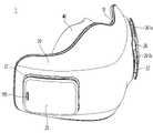
도 1은 본 발명의 실시 예에 따른 마스크 장치의 좌측 사시도이다.
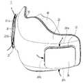
도 2는 본 발명의 실시 예에 따른 마스크 장치의 우측 사시도이다.
도 3은 본 발명의 실시 예에 따른 마스크 장치의 배면도이다.
도 4는 본 발명의 실시 예에 따른 마스크 장치의 저면도이다.
도 5는 본 발명의 실시 예에 따른 마스크 장치의 분해 사시도이다.
도 6 및 도 7은 본 발명의 실시 예에 따른 마스크 장치를 작동 시 공기의 흐름을 나타내는 도면이다.
도 8은 본 발명의 실시 예에 따른 마스크 장치의 제어방법을 보여주는 순서도이다.
도 9는 본 발명의 실시 예에 따른 압력 센서에서 감지된 호흡 공간의 압력 변화 그래프이다.
도 10은 본 발명의 실시 예에 따른 1회 호흡 주기에 해당하는 압력 변화 싸이클을 보여주는 도면이다.
도 11은 본 발명의 실시 예에 따른 마스크 장치의 제어방법을 상세히 보여주는 순서도이다.
도 12는 종래의 팬 모듈에서 듀티비(Duty Ratio) 입력에 따른 팬 회전속도(RPM)를 보여주는 그래프이다.
도 13은 본 발명에 따른 팬 모듈에서 듀티비 입력에 따른 팬 회전속도를 보여주는 그래프이다.1 is a left perspective view of a mask device according to an embodiment of the present invention.
2 is a right perspective view of a mask device according to an embodiment of the present invention.
3 is a rear view of a mask device according to an embodiment of the present invention.
4 is a bottom view of a mask device according to an embodiment of the present invention.
5 is an exploded perspective view of a mask device according to an embodiment of the present invention.
6 and 7 are diagrams illustrating the flow of air when the mask device according to an embodiment of the present invention is operated.
8 is a flowchart illustrating a method for controlling a mask apparatus according to an embodiment of the present invention.
9 is a graph showing a change in pressure in a breathing space sensed by a pressure sensor according to an embodiment of the present invention.
10 is a view showing a pressure change cycle corresponding to a single breathing cycle according to an embodiment of the present invention.
11 is a flowchart illustrating in detail a method for controlling a mask apparatus according to an embodiment of the present invention.
12 is a graph showing a fan rotation speed (RPM) according to a duty ratio input in a conventional fan module.
13 is a graph showing a fan rotation speed according to a duty ratio input in the fan module according to the present invention.
이하, 본 발명의 일부 실시 예들을 예시적인 도면을 통해 상세하게 설명한다. 각 도면의 구성요소들에 참조부호를 부가함에 있어서, 동일한 구성요소들에 대해서는 비록 다른 도면상에 표시되더라도 가능한 한 동일한 부호를 가지도록 하고 있음에 유의해야 한다. 또한, 본 발명의 실시 예를 설명함에 있어, 관련된 공지 구성 또는 기능에 대한 구체적인 설명이 본 발명의 실시 예에 대한 이해를 방해한다고 판단되는 경우에는 그 상세한 설명은 생략한다.Hereinafter, some embodiments of the present invention will be described in detail with reference to exemplary drawings. In adding reference numerals to the components of each drawing, it should be noted that the same components are given the same reference numerals as much as possible even though they are indicated on different drawings. In addition, in describing the embodiment of the present invention, if it is determined that a detailed description of a related known configuration or function interferes with the understanding of the embodiment of the present invention, the detailed description thereof will be omitted.
또한, 본 발명의 실시 예의 구성 요소를 설명하는 데 있어서, 제 1, 제 2, A, B, (a), (b) 등의 용어를 사용할 수 있다. 이러한 용어는 그 구성 요소를 다른 구성 요소와 구별하기 위한 것일 뿐, 그 용어에 의해 해당 구성 요소의 본질이나 차례 또는 순서 등이 한정되지 않는다. 어떤 구성 요소가 다른 구성요소에 "연결", "결합" 또는 "접속"된다고 기재된 경우, 그 구성 요소는 그 다른 구성요소에 직접적으로 연결되거나 접속될 수 있지만, 각 구성 요소 사이에 또 다른 구성 요소가 "연결", "결합" 또는 "접속"될 수도 있다고 이해되어야 할 것이다.In addition, in describing the components of the embodiment of the present invention, terms such as first, second, A, B, (a), (b), etc. may be used. These terms are only for distinguishing the elements from other elements, and the essence, order, or order of the elements are not limited by the terms. When it is described that a component is “connected”, “coupled” or “connected” to another component, the component may be directly connected or connected to the other component, but between each component another component It will be understood that may also be "connected", "coupled" or "connected".
도 1은 본 발명의 실시 예에 따른 마스크 장치의 좌측 사시도이고, 도 2는 본 발명의 실시 예에 따른 마스크 장치의 우측 사시도이고, 도 3은 본 발명의 실시 예에 따른 마스크 장치의 배면도이고, 도 4는 본 발명의 실시 예에 따른 마스크 장치의 저면도이다.1 is a left perspective view of a mask apparatus according to an embodiment of the present invention, FIG. 2 is a right perspective view of a mask apparatus according to an embodiment of the present invention, and FIG. 3 is a rear view of the mask apparatus according to an embodiment of the present invention , Figure 4 is a bottom view of a mask device according to an embodiment of the present invention.
도 1 내지 도 4를 참조하면, 본 발명의 실시 예에 따른 마스크 장치(1)는 마스크 몸체(10)와, 상기 마스크 몸체(10)에 결합되는 마스크 몸체 커버(20)를 포함할 수 있다.1 to 4 , the
상기 마스크 몸체(10)와 상기 마스크 몸체 커버(20)는 분리 가능하게 결합될 수 있다. 상기 마스크 몸체(10)와 상기 마스크 몸체 커버(20)를 결합하면, 상기 마스크 몸체(10)와 상기 마스크 몸체 커버(20)의 사이에는 내부 공간이 형성될 수 있다. 상기 내부 공간에는 상기 마스크 장치(1)를 구동하기 위한 구성들이 배치될 수 있다. 상기 내부 공간은 상기 마스크 몸체(10)의 전면과 상기 마스크 몸체 커버(20)의 배면 사이에 위치할 수 있다. 상기 마스크 몸체(10)는 상기 마스크 장치(1)의 배면을 형성하고, 상기 마스크 몸체 커버(20)는 상기 마스크 장치(1)의 전면을 형성할 수 있다.The
상기 마스크 장치(1)의 후방은 사용자의 얼굴과 마주하는 마스크 장치(1)의 배면이 위치하는 방향을 정의하며, 상기 마스크 장치(1)의 전방은 외부로 노출되는 마스크 장치(1)의 전면이 위치하는 방향으로 상기 후방의 반대 방향으로 정의한다.The rear of the
상기 마스크 장치(1)는 실링 브라켓(30)과 실링부(40)를 더 포함할 수 있다.The
상기 실링 브라켓(30)은 상기 마스크 몸체(10)의 배면에 분리 가능하게 결합될 수 있다. 상기 실링 브라켓(30)은 상기 실링부(40)를 상기 마스크 몸체(10)의 배면에 고정시킬 수 있다. 상기 실링 브라켓(30)을 상기 마스크 몸체(10)의 배면으로부터 분리 시, 상기 실링부(40)는 상기 마스크 몸체(10)로부터 이탈될 수 있다.The sealing
상기 실링부(40)는 상기 실링 브라켓(30)에 의해 상기 마스크 몸체(10)의 배면에 지지되며, 상기 실링부(40)와 상기 마스크 몸체(10)의 사이에 호흡을 위한 호흡 공간이 정의될 수 있다. 상기 실링부(40)는 사용자의 얼굴에 밀착되며, 사용자의 코와 입을 감싸서 외부 공기가 상기 호흡 공간으로 유입되는 것을 제한할 수 있다.The sealing
상기 마스크 몸체 커버(20)에는 제1필터 장착부(21)와 제2필터 장착부(22)가 포함될 수 있다. 상기 제1필터 장착부(21)는 상기 마스크 몸체 커버(20)의 우측에 위치하고, 상기 제2필터 장착부(22)는 상기 마스크 몸체 커버(20)의 좌측에 위치할 수 있다. 사용자의 얼굴에 장착된 마스크 장치(1)를 기준으로, 좌측 방향(좌측)과 우측 방향(우측)을 정의한다. 또한, 사용자의 얼굴에 장착된 마스크 장치(1)를 기준으로, 상측 방향(상방)과 하측 방향(하방)을 정의한다.The
상기 제1필터 장착부(21)에는 제1필터 커버(25)가 장착되고, 상기 제2필터 장착부(22)에는 제2필터 커버(26)가 장착될 수 있다. 상기 제1필터 장착부(21)와 상기 제2필터 장착부(22)의 내측에는 필터가 배치되며, 상기 제1필터 커버(25)와 상기 제2필터 커버(26)는 상기 필터를 커버할 수 있다.A
상기 제1필터 커버(25)와 상기 제2필터 커버(26)는 상기 제1필터 장착부(21)와 상기 제2필터 장착부(22)에 각각 분리 가능하게 결합될 수 있다. 예를 들어, 상기 제1필터 커버(25)와 상기 제2필터 커버(26)는 상기 제1필터 장착부(21)와 상기 제2필터 장착부(22)에 끼움 결합될 수 있다.The
상기 제1필터 커버(25)에는 제1공기 유입구(251)가 형성될 수 있다. 상기 제2필터 커버(26)에는 제2공기 유입구(261)가 형성될 수 있다. 상기 제1공기 유입구(251) 및 상기 제2공기 유입구(261)는 다수 개로 제공될 수 있다.A
상기 제1필터 장착부(21)에 상기 제1필터 커버(25)가 장착된 상태에서, 상기 제1공기 유입구(251)는 외부 공간으로 노출되도록 형성될 수 있다. 상기 제2필터 장착부(22)에 상기 제2필터 커버(26)가 장착된 상태에서, 상기 제2공기 유입구(261)는 외부 공간으로 노출되도록 형성될 수 있다. 상기 제1공기 유입구(251) 및 상기 제2공기 유입구(261)는 상기 제1필터 커버(25) 및 상기 제2필터 커버(26)의 상면 및 측면 중 하나 이상에 형성될 수 있다.In a state in which the
상기 필터 커버(25,26)를 기준으로, 상기 필터 장착부(21,22)를 마주하는 면을 저면으로 정의하고, 외부 공간으로 노출되는 면을 상면으로 정의하고, 상기 저면과 상기 상면을 연결하는 면을 측면으로 정의한다.Based on the filter covers 25 and 26, a surface facing the
상기 제1공기 유입구(251) 및 상기 제2공기 유입구(261)가 상기 필터 커버(25,26)의 측면에 제공될 경우에, 상기 필터 커버(25,26)의 측면 하부는 상기 필터 장착부(21,22)에 지지되며, 상기 필터 커버(25,26)의 측면 상부에 상기 제1공기 유입구(251) 및 상기 제2공기 유입구(261)가 형성될 수 있다.When the
본 실시 예에서 상기 제1공기 유입구(251)는 상기 마스크 장치(1)의 상방을 향하는 제1필터 커버(25)의 측면에 제공되는 제1공기 유입구(251a), 상기 마스크 장치(1)의 전방을 향하는 제1필터 커버(25)의 측면에 제공되는 제1공기 유입구(251b), 및 상기 마스크 장치(1)의 하방을 향하는 제1필터 커버(25)의 측면에 제공되는 제1공기 유입구(251c)를 포함할 수 있다.In this embodiment, the
상기 제2공기 유입구(261)는 상기 마스크 장치(1)의 상방을 향하는 제2필터 커버(26)의 측면에 제공되는 제2공기 유입구(261a), 상기 마스크 장치(1)의 전방을 향하는 제2필터 커버(26)의 측면에 제공되는 제2공기 유입구(261b), 상기 마스크 장치(1)의 하방을 향하는 제2필터 커버(26)의 측면에 제공되는 제2공기 유입구(261c)를 포함할 수 있다.The
한편, 상기 제1필터 커버(25) 및 상기 제2필터 커버(26) 중 어느 하나에는 상기 마스크 장치(1)의 작동을 제어하기 위한 조작부(195)를 설치하기 위한 개구가 형성될 수 있다. 상기 조작부(195)는 상기 마스크 장치(1)의 전원을 온/오프 하는 조작 스위치로 제공될 수 있다. 상기 조작부(195)는 상기 필터 커버(25,26)의 개구를 통해 상기 마스크 장치(1)의 전방으로 노출될 수 있다.Meanwhile, an opening for installing a
상기 마스크 몸체(10)는 걸이 장착부(108)를 포함할 수 있다. 상기 걸이 장착부(108)는 상기 마스크 몸체(10)의 좌측과 우측에 각각 제공될 수 있다. 상기 마스크 몸체(10)의 우측에 제공되는 걸이 장착부를 제1걸이 장착부(108a)라 정의하고, 상기 마스크 몸체(10)의 좌측에 제공되는 걸이 장착부를 제2걸이 장착부(108b)라 정의한다.The
상기 제1걸이 장착부(108a)와 상기 제2걸이 장착부(108b)는 상기 마스크 몸체(10)의 상하 방향으로 이격되게 다수 개로 제공될 수 있다. 상기 제1걸이 장착부(108a)는 상기 마스크 몸체(10)의 우측 상방 및 우측 하방에 제공되고, 상기 제2걸이 장착부(108b)는 상기 마스크 몸체(10)의 좌측 상방 및 좌측 하방에 제공될 수 있다.A plurality of the first
상기 걸이 장착부(108)에는 사용자의 얼굴에 상기 마스크 장치(1)를 착용하기 위한 끈 또는 줄 등이 장착될 수 있다. 끈 또는 줄 등은 상기 제1걸이 장착부(108a)와 상기 제2걸이 장착부(108b)를 연결하거나, 상하 방향으로 이격된 복수의 제1걸이 장착부(108a)와 상하 방향으로 이격된 복수의 제2걸이 장착부(108b) 각각을 연결할 수 있다.A string or string for wearing the
상기 걸이 장착부(108)는 상기 마스크 몸체(10)의 일부가 절개되어 형성될 수 있다. 그렇기에, 상기 걸이 장착부(108)를 통해서 상기 마스크 몸체(10)와 상기 마스크 몸체 커버(20)의 내부 공간으로 공기가 유입될 수도 있다. 상기 걸이 장착부(108)를 통해 상기 내부 공간으로 유입된 외부 공기는 상기 마스크 장치(1)의 내부 공간에 배치되는 전자 부품들을 공기 냉각할 수 있다.The
상기 걸이 장착부(108)를 통해 상기 마스크 몸체(10)의 내부 공간으로 유입된 외부 공기는 상기 걸이 장착부(108)를 통해 다시 외부 공간으로 배출되며, 상기 외부 공기가 상기 호흡 공간으로 유입되는 것을 제한하기 위해 상기 마스크 장치(1)의 내부는 밀봉 구조를 가질 수 있다.External air introduced into the inner space of the
상기 마스크 몸체(10)는 호흡 공간으로 여과된 공기를 토출하기 위한 공기 토출구(129)를 포함할 수 있다. 상기 공기 토출구(129)로부터 상기 호흡 공간으로 공급되는 여과된 공기를 사용자가 들이마시며 호흡할 수 있다. 상기 공기 토출구(129)는 상기 제1공기 유입구(251)로 유입되어 여과된 공기를 상기 호흡 공간으로 토출하는 제1공기 토출구(129a)와, 상기 제2공기 유입구(261)로 유입되어 여과된 공기를 상기 호흡 공간으로 토출하는 제2공기 토출구(129b)를 포함할 수 있다.The
상기 제1공기 토출구(129a)는 상기 마스크 몸체(10)의 중심을 기준으로 우측에 배치되고, 상기 제2공기 토출구(129b)는 좌측에 배치될 수 있다. 상기 제1공기 유입구(251)로 유입된 공기는 필터를 통과한 후 상기 제1공기 토출구(129a)로 유동할 수 있다. 상기 제2공기 유입구(261)로 유입된 공기는 필터를 통과한 후 상기 제2공기 유입구(261)로 유동할 수 있다.The
상기 마스크 몸체(10)는 사용자가 내쉬는 공기를 외부 공간으로 배출하기 위한 공기 유출구(154,155)를 포함할 수 있다. 상기 공기 유출구(154,155)는 상기 마스크 몸체(10)의 하부 에 위치할 수 있다.The
상기 공기 유출구(154,155)는 상기 마스크 몸체(10)가 개구되어 형성되는 제1공기 유출구(154)와, 상기 마스크 몸체(10)의 저면에 형성되는 제2공기 유출구(155)를 포함할 수 있다. 상기 마스크 몸체(10)와 상기 마스크 몸체 커버(20)의 사이에는 상기 제1공기 유출구(154)를 통과하여 상기 제2공기 유출구(155)를 향해 유동하는 공기가 통과하기 위한 유동 공간이 형성될 수 있다.The
상기 제1공기 유출구(154) 및 상기 제2공기 유출구(155) 중 하나 이상에는 체크 밸브가 형성될 수 있다. 상기 체크 밸브에 의해 외부 공기가 상기 호흡 공간으로 역류되는 것이 방지될 수 있다. 상기 체크 밸브는 상기 제1공기 유출구(154)와 상기 제2공기 유출구(155)를 연결하는 유동 공간에 위치할 수 있다.A check valve may be formed at at least one of the
상기 마스크 몸체(10)는 센서 장착부(109)를 포함할 수 있다. 상기 센서 장착부(109)에는 상기 호흡 공간으로부터 정보를 획득하기 위한 센서가 장착될 수 있다. 상기 센서 장착부(109)는 상기 마스크 몸체(10)의 상부에 위치할 수 있다. 사용자가 호흡 시 상기 호흡 공간의 압력 변화가 일정하게 감지될 수 있는 위치를 고려하여 상기 센서 장착부(109)가 상기 마스크 몸체(10)의 상부에 위치할 수 있다.The
상기 마스크 몸체(10)는 커넥터 홀(135)을 포함할 수 있다. 상기 커넥터 홀(135)은 상기 마스크 장치(1)로 전원을 공급하기 위한 커넥터(미도시)가 설치되는 개구로 이해할 수 있다. 상기 커넥터 홀(135)은 상기 마스크 몸체(10)의 좌측 및 우측 중 어느 하나에 위치할 수 있다. 본 실시 예에서 상기 조작부(195)와 상기 커넥터는 후술할 전원 모듈(19)에 연결되어 있기에, 상기 커넥터 홀(135)은 상기 전원 모듈(19)이 설치되는 위치에 해당되는 마스크 몸체(10)의 좌측 및 우측 중 어느 하나에 제공될 수 있다.The
이하에서는, 상기 마스크 장치(1)의 구성들을 분해 사시도에 기초하여 상세히 설명한다.Hereinafter, the components of the
도 5는 본 발명의 실시 예에 따른 마스크 장치의 분해 사시도이다.5 is an exploded perspective view of a mask device according to an embodiment of the present invention.
도 5를 참조하면, 본 발명에 따른 마스크 장치(1)는 마스크 몸체(10)와, 마스크 몸체 커버(20)와, 실링 브라켓(30)과, 실링부(40)를 포함할 수 있다. 상기 마스크 몸체(10)와 상기 마스크 몸체 커버(20)가 서로 결합되어 상기 마스크 장치(1)의 몸체를 형성할 수 있다.Referring to FIG. 5 , the
상기 마스크 몸체(10)와 상기 마스크 몸체 커버(20)의 사이에는 상기 마스크 장치(1)를 작동하기 위한 구성들이 수용되기 위한 내부 공간이 형성될 수 있다. 상기 실링 브라켓(30)과 상기 실링부(40)는 상기 마스크 몸체(10)의 배면에 결합되어 사용자의 얼굴과 상기 마스크 몸체(10)의 사이에 호흡 공간을 형성하며, 상기 호흡 공간으로 외부 공기가 유입되는 것을 방지할 수 있다.An inner space for accommodating components for operating the
상기 마스크 몸체(10)는 커버 결합홈(101)을 포함할 수 있다. 상기 커버 결합홈(101)은 상기 마스크 몸체(10)의 전면 가장자리에 형성될 수 있다. 상기 커버 결합홈(101)은 단차에 의해 형성될 수 있다. 상기 커버 결합홈(101)은 상기 마스크 몸체 커버(20)의 가장자리에 대응되게 형성될 수 있다. 상기 커버 결합홈(101)은 상기 마스크 몸체(10)의 전면 일부가 후방으로 함몰되어 형성될 수 있다. 상기 마스크 몸체(10)의 커버 결합홈(101)을 향해 상기 마스크 몸체 커버(20)를 이동시켜서 상기 커버 결합홈(101)에 상기 마스크 몸체 커버(20)를 삽입할 수 있다.The
상기 마스크 몸체(10)는 제1커버 결합부(102)를 포함할 수 있다. 상기 제1커버 결합부(102)에는 상기 마스크 몸체 커버(20)의 상부가 지지될 수 있다. 상기 제1커버 결합부(102)는 상기 마스크 몸체(10)의 전면에 형성될 수 있다. 상기 제1커버 결합부(102)는 상기 마스크 몸체(10)의 상부에 위치할 수 있다.The
예를 들어, 상기 제1커버 결합부(102)는 상기 마스크 몸체(10)의 전면에 후크가 결합되는 후크 걸림부로 형성될 수 있다. 상기 마스크 몸체 커버(20)에는 상기 제1커버 결합부(102)에 결합되는 후크가 형성될 수 있다. 상기 제1커버 결합부(102)는 다수로 제공되며, 상기 후크도 상기 제1커버 결합부(102)에 대응되게 다수로 제공될 수 있다. 본 실시 예에서 상기 제1커버 결합부(102)는 상기 마스크 몸체(10)의 중심을 기준으로 좌측과 우측에 각각 제공될 수 있다. 상기 제1커버 결합부(102)는 상측 커버 결합부라 칭할 수 있다.For example, the first
상기 마스크 몸체(10)는 제1브라켓 결합부(103)를 포함할 수 있다. 상기 제1브라켓 결합부(103)는 상기 실링 브라켓(30)의 상부가 지지될 수 있다. 상기 제1브라켓 결합부(103)는 상기 마스크 몸체(10)의 배면에 형성될 수 있다. 상기 제1브라켓 결합부(103)는 상기 마스크 몸체(10)의 상부에 위치할 수 있다.The
예를 들어, 상기 제1브라켓 결합부(103)는 상기 마스크 몸체(10)의 배면에서 후방으로 돌출되는 후크 형상으로 형성될 수 있다. 상기 실링 브라켓(30)에는 상기 제1브라켓 결합부(103)에 결합되는 제1몸체 결합부(304)가 형성될 수 있다. 상기 제1브라켓 결합부(103)는 다수로 제공되며, 상기 제1몸체 결합부(304)도 상기 제1브라켓 결합부(103)에 대응되게 다수로 제공될 수 있다. 본 실시 예에서 상기 제1브라켓 결합부(103)는 상기 마스크 몸체(10)의 중심을 기준으로 좌측과 우측에 각각 제공될 수 있다. 상기 제1브라켓 결합부(103)는 상측 브라켓 결합부라 칭할 수 있다.For example, the first
상기 마스크 몸체(10)는 지지 리브(104)를 포함할 수 있다. 상기 지지 리브(104)는 상기 마스크 몸체(10)의 전면에서 전방으로 돌출되어 형성될 수 있다. 상기 지지 리브(104)는 상기 마스크 몸체(10)와 상기 마스크 몸체 커버(20)를 결합 시 상기 마스크 몸체 커버(20)에 접촉될 수 있다. 상기 마스크 몸체(10)와 상기 마스크 몸체 커버(20)는 상기 지지 리브(104)에 의해 전후 방향으로 외력에 저항할 수 있다. 상기 지지 리브(104)는 상기 마스크 몸체(10)의 전면에 다수로 제공될 수 있다.The
상기 마스크 몸체(10)는 제2커버 결합부(106)를 포함할 수 있다. 상기 제2커버 결합부(106)에는 상기 마스크 몸체 커버(20)의 하부가 지지될 수 있다. 상기 제2커버 결합부(106)는 상기 마스크 몸체(10)의 전면에 형성될 수 있다. 상기 제2커버 결합부(106)는 상기 마스크 몸체(10)의 하부에 위치할 수 있다.The
예를 들어, 상기 제2커버 결합부(106)는 상기 마스크 몸체(10)의 전면에 후크로 형성될 수 있다. 상기 마스크 몸체 커버(20)에는 상기 제2커버 결합부(106)에 결합되는 후크 걸림부가 형성될 수 있다. 상기 제2커버 결합부(106)는 다수로 제공되며, 상기 후크 걸림부도 상기 제2커버 결합부(106)에 대응되게 다수로 제공될 수 있다. 본 실시 예에서 상기 제2커버 결합부(106)는 상기 마스크 몸체(10)의 중심을 기준으로 좌측과 우측에 각각 제공될 수 있다. 상기 제2커버 결합부(106)는 하측 커버 결합부라 칭할 수 있다.For example, the second
상기 마스크 몸체(10)는 제2브라켓 결합부(107)를 포함할 수 있다. 상기 제2브라켓 결합부(107)에는 상기 실링 브라켓(30)의 하부가 지지될 수 있다. 상기 제2브라켓 결합부(107)는 상기 마스크 몸체(10)가 개구되어 형성될 수 있다. 상기 제2브라켓 결합부(107)는 상기 마스크 몸체(10)의 하부에 위치할 수 있다.The
예를 들어, 상기 제2브라켓 결합부(107)는 상기 마스크 몸체(10)가 개구되는 관통홀로 형성될 수 있다. 상기 실링 브라켓(30)에는 상기 제2브라켓 결합부(107)에 결합되는 제2몸체 결합부(305)가 형성될 수 있다. 상기 제2브라켓 결합부(107)는 다수로 제공되며, 상기 제2몸체 결합부(305)도 상기 제2브라켓 결합부(107)에 대응되게 다수로 제공될 수 있다. 본 실시 예에서 상기 제2브라켓 결합부(107)는 상기 마스크 몸체(10)의 중심을 기준으로 좌측과 우측에 각각 제공될 수 있다. 상기 제2브라켓 결합부(107)는 하측 브라켓 결합부라 칭할 수 있다.For example, the second bracket coupling part 107 may be formed as a through hole through which the
상기 마스크 몸체(10)는 센서 장착부(109)를 포함할 수 있다. 상기 센서 장착부(109)는 상기 마스크 몸체(10)의 전면에 형성될 수 있다. 상기 센서 장착부(109)는 상기 마스크 몸체(10)의 전면이 전방으로 돌출되어 형성되고, 내부에 센서가 설치되는 설치 공간을 가지도록 형성될 수 있다. 상기 마스크 몸체(10)에는 상기 설치 공간과 상기 호흡 공간을 연통하는 홀이 형성되며, 상기 설치 공간에 배치된 센서는 상기 홀을 통해 상기 설치 공간으로 유입된 공기로부터 상기 호흡 공간의 정보를 획득할 수 있다. 본 실시 예에서 상기 센서는 압력 센서로 제공되며, 상기 호흡 공간의 압력 정보를 감지할 수 있다.The
상기 마스크 몸체(10)는 팬 모듈 장착부(110)를 포함할 수 있다. 상기 팬 모듈 장착부(110)는 제1팬 모듈(16)이 장착되는 제1팬 모듈 장착부(110a)와 제2팬 모듈(17)이 장착되는 제2팬 모듈 장착부(110b)를 포함할 수 있다. 상기 제1팬 모듈 장착부(110a) 및 상기 제2팬 모듈 장착부(110b)는 상기 마스크 몸체(10)의 전면에 형성될 수 있다.The
상기 제1팬 모듈 장착부(110a)는 상기 마스크 몸체(10)의 우측에 배치되고, 상기 제2팬 모듈 장착부(110b)는 상기 마스크 몸체(10)의 좌측에 배치될 수 있다. 상기 제1팬 모듈(16) 및 상기 제2팬 모듈(17)은 상기 제1팬 모듈 장착부(110a) 및 상기 제2팬 모듈 장착부(110b)에 각각 분리 가능하게 결합될 수 있다.The first fan module mounting part 110a may be disposed on the right side of the
상기 마스크 몸체(10)는 에어 덕트부(120)를 포함할 수 있다. 상기 에어 덕트부(120)는 상기 마스크 몸체(10)의 전면에 형성될 수 있다. 상기 에어 덕트부(120)의 내부에는 공기가 통과할 수 있는 유로가 형성될 수 있다. 상기 에어 덕트부(120)는 상기 제1팬 모듈 장착부(110a)에 연결되는 제1에어 덕트부(120a)와, 상기 제2팬 모듈 장착부(110b)에 연결되는 제2에어 덕트부(120b)를 포함할 수 있다.The
상기 제1에어 덕트부(120a)와 상기 제2에어 덕트부(120b)는 상기 마스크 몸체(10)의 중심을 향하는 제1팬 모듈 장착부(110a)의 일측 및 제2팬 모듈 장착부(110b)의 타측에 배치될 수 있다. 상기 제1에어 덕트부(120a)와 상기 제2에어 덕트부(120b)는 상기 제1팬 모듈 장착부(110a)와 상기 제2팬 모듈 장착부(110b)의 사이에 위치할 수 있다. 상기 에어 덕트부(120)의 일단부는 상기 팬 모듈(16,17)과 연통되어 공기가 유입되고, 상기 에어 덕트부(120)의 타단부는 상기 공기 토출구(129)와 연통되어 유입된 공기가 토출될 수 있다.The first air duct part 120a and the second air duct part 120b are one side of the first fan module mounting part 110a facing the center of the
상기 에어 덕트부(120)에는 제어 모듈(18)을 장착하기 위한 제어 모듈 장착부(128)가 포함될 수 있다. 상기 에어 덕트부(120)의 일부가 상기 제어 모듈(18)이 안착될 수 있는 평면으로 형성되며, 상기 평면을 상기 제어 모듈 장착부(128)로 정의한다. 상기 제어 모듈 장착부(128)는 상기 제1에어 덕트부(120a)에 제공되는 제1제어 모듈 장착부(128a)와 상기 제2에어 덕트부(120b)에 제공되는 제2제어 모듈 장착부(128b)를 포함할 수 있다. 상기 제1제어 모듈 장착부(128a)와 상기 제2제어 모듈 장착부(128b)에는 하나의 제어 모듈(18)이 고정되거나, 복수의 제어 모듈이 각각 고정될 수 있다.The
상기 마스크 몸체(10)는 전원 모듈(19)을 장착하기 위한 전원 모듈 장착부(130)를 포함할 수 있다. 상기 전원 모듈 장착부(130)는 상기 마스크 몸체(10)의 전면에 형성될 수 있다. 상기 전원 모듈 장착부(130)는 상기 마스크 몸체(10)의 좌측과 우측 중 어느 하나에 제공될 수 있다.The
상기 전원 모듈 장착부(130)는 상기 제어 모듈 장착부(128)의 측방에 위치할 수 있다. 상기 전원 모듈 장착부(130)는 상기 제어 모듈 장착부(128)와 상기 마스크 몸체(10)의 좌측 및 우측 중 어느 하나의 단부의 사이에 제공될 수 있다. 상기 전원 모듈 장착부(130)가 제공되는 마스크 몸체(10)의 좌측 및 우측 중 어느 하나에 인접하게 상기 커넥터 홀(135)이 위치할 수 있다.The power
상기 마스크 몸체(10)는 배터리를 장착하기 위한 배터리 장착부(140)를 포함할 수 있다. 상기 배터리 장착부(140)는 상기 마스크 몸체(10)의 전면에 형성될 수 있다. 상기 배터리 장착부(140)는 상기 마스크 몸체(10)의 전면에서 전방으로 돌출되어 상기 배터리를 감싸도록 형성될 수 있다.The
예를 들어, 상기 배터리 장착부(140)는 상기 마스크 몸체(10)의 전면에서 전방으로 복수의 가이드 리브가 돌출되어 형성될 수 있다. 전방으로 돌출되는 복수의 가이드 리브의 일부는 서로를 마주하는 방향으로 절곡되면, 상기 복수의 가이드 리브와 상기 마스크 몸체(10)의 전면 사이에 상기 배터리가 수용되는 배터리 수용 공간이 형성될 수 있다. 상기 배터리는 상하 방향으로 이동하여 상기 배터리 장착부(140)의 배터리 수용 공간에 삽입 또는 분리될 수 있다. 상기 배터리 장착부(140)에 삽입된 배터리의 하부는 후술할 공기 배출부(150)에 지지될 수 있다.For example, the
상기 마스크 몸체(10)는 공기 배출부(150)를 포함할 수 있다. 상기 공기 배출부(150)는 상기 마스크 몸체(10)의 하부에 형성될 수 있다. 상기 공기 배출부(150)는 상기 제1공기 유출구(154)로부터 상기 제2공기 유출구(155)를 향해 유동하는 공기가 통과하는 유동 공간을 형성할 수 있다. 상기 공기 배출부(150)는 상기 마스크 몸체(10)의 전면이 전방으로 돌출되어 형성될 수 있다.The
상기 마스크 몸체(10)와 상기 마스크 몸체 커버(20)를 결합 시, 상기 공기 배출부(150)는 상기 마스크 몸체 커버(20)에 접촉되며, 상기 마스크 몸체(10)의 내부 공간과 상기 유동 공간이 구분되도록 할 수 있다. 예를 들어, 상기 공기 배출부(150)는 유동 공간을 정의하는 상면, 저면, 양측면을 포함할 수 있다. 상기 공기 배출부(150)의 전면은 상기 마스크 몸체 커버(20)에 의해 정의되고, 상기 공기 배출부(150)의 배면은 상기 마스크 몸체(10)에 의해 정의된다. 상기 공기 배출부(150)의 상면에는 상기 배터리가 지지될 수 있다.When the
상기 공기 배출부(150)의 저면은 개구되며, 상기 제2공기 유출구(155)가 형성될 수 있다. 상기 공기 배출부(150)의 저면은 상기 마스크 몸체(10)의 저면과 연결되며, 상기 마스크 몸체(10)의 저면은 상기 마스크 몸체(10)의 전면이 상기 공기 배출부(150)를 향해 돌출되어 형성되는 보강 리브의 일면으로 정의될 수 있다. 상기 마스크 몸체(10)의 저면에는 상기 커버 결합홈(101)이 형성되며, 상기 마스크 몸체(10)와 상기 마스크 몸체 커버(20)의 하측 단부가 결합되도록 할 수 있다. 상기 공기 배출부(150)의 배면은 개구되며, 상기 제1공기 유출구(154)가 형성될 수 있다. 상기 공기 배출부(150)의 양측면은 절곡되게 형성될 수 있다.A bottom surface of the
상기 마스크 몸체 커버(20)는 필터 장착부(21,22)를 포함할 수 있다. 상기 필터 장착부(21,22)는 상기 마스크 몸체 커버(20)의 전면이 배면을 향하는 방향으로 함몰되어 형성될 수 있다. 함몰되어 형성된 필터 장착부(21,22)의 내측에는 필터(23,24)가 수용되며, 상기 필터(23,24)가 수용된 상태에서 상기 필터 장착부(21,22)에 필터 커버(25,26)가 장착될 수 있다.The
상기 필터 장착부(21,22)의 저면에는 공기 흡입구(211,221)가 형성될 수 있다. 상기 공기 흡입구(211,221)는 후술할 팬 모듈(16,17)의 흡입구와 연통될 수 있다. 상기 공기 흡입구(211,221)는 하방으로 경사지는 경사면을 가질 수 있다. 상기 필터 장착부(21,22)의 측면에는 상기 필터 커버(25,26)를 고정하기 위한 필터 커버 장착홈(212)이 형성될 수 있다.Air intakes 211 and 221 may be formed on the bottom surfaces of the
상기 필터 커버(25,26)에는 상기 필터 커버 장착홈(212)에 삽입되는 결합 돌기가 형성될 수 있다. 상기 필터 장착부(21,22)의 상면은 개구되어, 상기 필터(23,24) 및 상기 필터 커버(25,26)가 삽입될 수 있다. 상기 필터 장착부(21,22)는 상기 마스크 몸체 커버(20)의 전면을 상면으로, 상기 마스크 몸체 커버(20)의 배면을 저면으로, 상기 상면과 상기 저면을 연결하는 면을 측면으로 정의한다.A coupling protrusion inserted into the filter
상기 필터 장착부(21,22)의 저면은 후술할 팬 모듈(16,17)의 흡입구와 밀착하게 접촉될 수 있다. 상기 필터 장착부(21,22)와 상기 팬 모듈(16,17)의 사이에는 밀봉을 위한 밀봉재가 제공될 수 있다. 상기 밀봉재는 상기 공기 흡입구(211,221)와 상기 팬 모듈(16,17)의 흡입구를 감싸서 외부 공기가 유입되는 것을 방지할 수 있다.The bottom surfaces of the
상기 필터 장착부(25,26)는 상기 마스크 몸체 커버(20)의 우측에 제공되는 제1필터 장착부(21)와 상기 마스크 몸체 커버(20)의 좌측에 제공되는 제2필터 장착부(22)를 포함할 수 있다. 상기 제1필터 장착부(21)에 형성되는 공기 흡입구를 제1공기 흡입구(211)라 정의하고, 상기 제2필터 장착부(22)에 형성되는 공기 흡입구를 제2공기 흡입구(221)라 정의할 수 있다.The
상기 필터(23,24)는 상기 제1필터 장착부(21)의 내측에 수용되는 제1필터(23)와 상기 제2필터 장착부(22)의 내측에 수용되는 제2필터(24)를 포함할 수 있다.The
상기 필터 커버(25,26)는 상기 제1필터 장착부(21)에 장착되는 제1필터 커버(25)와 상기 제2필터 장착부(22)에 장착되는 제2필터 커버(26)를 포함할 수 있다. 상기 제1필터 커버(25)에는 다수의 제1공기 유입구(251)가 형성되어 외부 공기가 유입되고, 상기 제2필터 커버(26)에는 다수의 제2공기 유입구(261)가 형성되어 외부 공기가 유입될 수 있다.The filter covers 25 and 26 may include a
상기 마스크 장치(1)의 몸체 내부에는 팬 모듈(16,17)과, 제어 모듈(18)과, 전원 모듈(19)이 포함될 수 있다. 상기 팬 모듈(16,17)과, 상기 제어 모듈(18)과, 상기 전원 모듈(19)은 상기 마스크 몸체(10)의 전면과 상기 마스크 몸체 커버(20)의 배면 사이에 형성되는 내부 공간에 수용될 수 있다. 상기 제어 모듈(18)은 제1전자 회로 부품이라 칭하고, 상기 전원 모듈(19)은 제2전자 회로 부품이라 칭할 수 있다.The inside of the body of the
상기 팬 모듈(16,17)은 팬과 팬 모터, 및 상기 팬과 상기 팬 모터를 수용하는 팬 하우징을 포함할 수 있다. 상기 팬 하우징에는 상기 팬으로 공기가 유입되는 흡입구와 상기 팬에 의해 강제 유동하는 공기가 토출되는 토출구를 포함할 수 있다. 상기 팬은 원심 팬으로 제공될 수 있다.The
본 실시 예에서 상기 팬 모듈(16,17)은 상기 마스크 몸체 커버(20)의 전방으로 공기를 흡입하여 상기 마스크 몸체(10)의 측방으로 토출할 수 있다. 상기 팬 모듈(16,17)은 상기 제1팬 모듈 장착부(110a)에 장착되는 제1팬 모듈(16)과, 상기 제2팬 모듈 장착부(110b)에 장착되는 제2팬 모듈(17)을 포함할 수 있다.In this embodiment, the
상기 제1팬 모듈(16)은 상기 제1공기 흡입구(211)와 연통되며, 상기 제1공기 흡입구(211)를 향해 상기 제1공기 유입구(251)로 유입되어 상기 제1필터(23)를 통과한 공기가 흡입되도록 할 수 있다. 상기 제2팬 모듈(17)은 상기 제2공기 흡입구(221)와 연통되며, 상기 제2공기 흡입구(221)를 향해 상기 제2공기 유입구(261)로 유입되어 상기 제2필터(24)를 통과한 공기가 흡입되도록 할 수 있다. 상기 제1팬 모듈(16)은 상기 제1에어 덕트부(120a)와 연통되어 상기 호흡 공간으로 공기를 토출하고, 상기 제2팬 모듈(17)은 상기 제2에어 덕트부(120b)와 연통되어 상기 호흡 공간으로 공기를 토출할 수 있다.The
상기 제어 모듈(18)은 상기 마스크 장치(1)의 작동을 제어할 수 있다. 상기 제어 모듈(18)은 상기 제어 모듈 장착부(128)에 고정될 수 있다. 상기 제어 모듈(18)은 상기 배터리 또는 상기 전원 모듈(19)로부터 전원을 공급받아 작동할 수 있다. 상기 제어 모듈(18)은 통신 모듈을 포함하여, 다양한 정보를 송수신할 수 있다.The
상기 제어 모듈(18)은 데이터 저장 모듈을 포함하여, 다양한 정보를 저장할 수 있다. 상기 제어 모듈(18)은 상기 팬 모듈(16,17)의 작동을 제어할 수 있다. 상기 제어 모듈(18)은 센서로부터 감지되는 정보에 기초하여 상기 팬 모듈(16,17)의 작동을 제어할 수도 있다. 상기 제어 모듈(18)은 상기 전원 모듈(19), 상기 팬 모듈(16,17), 배터리와 전기적으로 연결되어 연동할 수 있다.The
상기 전원 모듈(19)은 외부로부터 전원을 공급받을 수 있다. 상기 전원 모듈(19)은 상기 배터리를 충전할 수 있다. 상기 전원 모듈(19)은 커넥터와 조작부(195)를 포함할 수 있다. 상기 전원 모듈(19)은 상기 조작부(195)에 의해 상기 마스크 장치(1)의 전원을 제어할 수 있다. 상기 전원 모듈(19)은 상기 제어 모듈(18), 상기 팬 모듈(16,17), 상기 배터리와 전기적으로 연결되어 전원을 공급할 수 있다.The
상기 실링부(40)는 상기 실링 브라켓(30)에 의해 상기 마스크 몸체(10)의 배면에 결합되어 사용자의 얼굴에 밀착될 수 있다. 상기 실링부(40)에 의해 상기 마스크 몸체(10)의 배면은 사용자의 얼굴로부터 이격되게 배치될 수 있다.The sealing
상기 실링 브라켓(30)은 폐루프를 형성하는 링 형상으로 형성될 수 있다. 상기 실링 브라켓(30)은 상기 실링부(40)가 분리 가능하게 결합되도록 구성될 수 있다. 상기 실링 브라켓(30)을 상기 마스크 몸체(10)로부터 분리하여, 상기 실링부(40)를 세척할 수 있다. 상기 실링부(40)를 상기 실링 브라켓(30)에 결합한 후, 상기 실링 브라켓(30)을 상기 마스크 몸체(10)에 결합하면, 상기 실링부(40)가 상기 마스크 몸체(10)에 단단히 고정될 수 있다.The sealing
상기 실링 브라켓(30)은 상기 실링부(40)가 결합되는 실링 삽입부(301)를 포함할 수 있다. 상기 실링 삽입부(301)는 상기 실링부(40)가 끼움 결합되는 삽입 돌기로 형성될 수 있다. 상기 실링 삽입부(301)는 내측에서 외측을 향해 연장되어 형성될 수 있다. 상기 실링 삽입부(301)는 내측에서 외측을 향해 두께가 작아지게 형성될 수 있다. 상기 실링 삽입부(301)와 후술할 고정 가이드(302)에 의해 상기 실링 브라켓(30)의 몸체가 형성될 수 있다.The sealing
상기 실링 브라켓(30)은 고정 가이드(302)를 포함할 수 있다. 상기 고정 가이드(302)는 상기 실링 삽입부(301)의 내측 단부에 형성될 수 있다. 상기 고정 가이드(302)는 상기 실링 삽입부(301)에 삽입되는 실링부(40)의 고정 위치를 가이드 할 수 있다. 상기 실링부(40)가 상기 고정 가이드(302)에 접촉되면, 상기 실링부(40)가 상기 실링 브라켓(30)에 밀착하게 결합될 수 있다. 상기 고정 가이드(302)는 상기 실링 삽입부(301)보다 두께가 커지게 형성될 수 있다. 상기 실링 삽입부(301)의 외측으로부터 내측을 향해 두께가 커지고, 상기 실링 삽입부(301)보다 두께가 커진 고정 가이드(302)에 의해 상기 실링부(40)의 이동이 제한될 수 있다.The sealing
상기 실링 브라켓(30)은 상기 제1브라켓 결합부(103)에 결합되는 제1몸체 결합부(304)를 포함할 수 있다. 상기 제1몸체 결합부(304)는 상기 실링 브라켓(30)의 상부에 제공될 수 있다. 상기 제1몸체 결합부(304)는 상기 제1브라켓 결합부(103)에 대응되는 위치 및 개수로 제공될 수 있다. 상기 제1몸체 결합부(304)는 상측 몸체 결합부라 칭할 수 있다. 예를 들어, 상기 제1몸체 결합부(304)는 후크 형상으로 형성되는 제1브라켓 결합부(103)가 걸림 고정되는 걸림 고정 형상으로 형성될 수 있다.The sealing
상기 실링 브라켓(30)은 제2브라켓 결합부(107)에 결합되는 제2몸체 결합부(305)를 포함할 수 있다. 상기 제2몸체 결합부(305)는 상기 실링 브라켓(30)의 하부에 제공될 수 있다. 상기 제2몸체 결합부(305)는 상기 제2브라켓 결합부(107)에 대응되는 위치 및 개수로 제공될 수 있다. 상기 제2몸체 결합부(305)는 하측 몸체 결합부라 칭할 수 있다. 예를 들어, 상기 제2몸체 결합부(305)는 상기 실링 삽입부(301)로부터 전방으로 돌출되는 후크 형상으로 형성될 수 있다.The sealing
상기 실링 브라켓(30)은 상기 마스크 몸체(10)에 결합되는 브라켓 삽입부(306)를 포함할 수 있다. 상기 브라켓 삽입부(306)는 상기 마스크 몸체(10)에 형성되는 절개부(127)에 삽입될 수 있다. 상기 절개부(127)는 상기 에어 덕트부(120)와 연통되어 공기가 통과하는 개구로 이해할 수 있다. 상기 절개부(127)의 일측에 상기 브라켓 삽입부(306)가 삽입될 수 있다. 상기 절개부(127)의 일측에 상기 브라켓 삽입부(306)가 삽입되면, 상기 절개부(127)의 타측은 상기 에어 덕트부(120)를 통과한 공기가 토출되는 상기 공기 토출구(129)로 정의될 수 있다.The sealing
상기 브라켓 삽입부(306)가 상기 절개부(127)의 일측에 삽입되어 상기 절개부(127)의 일측을 차폐하면, 상기 팬 모듈(16,17)에서 토출된 공기는 상기 에어 덕트부(120)와 상기 브라켓 삽입부(306)의 사이를 통과하여 상기 절개부(127)의 타측인 상기 공기 토출구(129)로 유동할 수 있다. 상기 브라켓 삽입부(306)는 상기 에어 덕트부(120)의 일측면을 형성하면서, 상기 실링 브라켓(30)을 상기 마스크 몸체(10)에 고정하는 기능을 제공할 수 있다.When the
상기 실링 브라켓(30)의 상부는 상기 제1몸체 결합부(304)에 의해 상기 마스크 몸체(10)의 상부에 고정되고, 상기 실링 브라켓(30)의 하부는 상기 제2몸체 결합부(305)에 의해 상기 마스크 몸체(10)의 하부에 고정되고, 상기 실링 브라켓(30)의 중간부는 상기 브라켓 삽입부(306)에 의해 상기 마스크 몸체(10)의 중간부에 고정될 수 있다.The upper part of the sealing
상기 실링부(40)는 탄성을 가지는 재질로 형성될 수 있다. 상기 실링부(40)는 사용자의 얼굴에 밀착되어 사용자의 얼굴에 대응되게 변형될 수 있다. 상기 실링부(40)는 폐루프를 형성하는 링 형상으로 형성될 수 있다. 상기 실링부(40)는 사용자의 코와 입을 커버할 수 있도록 형성될 수 있다.The sealing
상기 실링부(40)는 사용자의 얼굴에 접촉되는 배면과, 상기 마스크 몸체(10)에 접촉되는 전면과, 상기 배면과 상기 전면을 연결하며 내측이 중공으로 형성되는 측면을 포함할 수 있다. 상기 실링부(40)의 전면 내측에는 제1개구가 포함되고, 상기 실링부(40)의 배면 내측에는 제2개구가 포함될 수 있다. 상기 실링부(40)를 상기 마스크 몸체(10)에 결합 시, 상기 제1개구의 내측에는 상기 공기 토출구(129)와 상기 공기 유출구(154,155)가 위치할 수 있다. 사용자의 얼굴과 상기 실링부(40)가 접촉 시 상기 제2개구의 내측에는 사용자의 코와 입이 위치할 수 있다.The sealing
사용자의 얼굴과 상기 마스크 몸체(10)의 사이에 상기 실링부(40)가 위치하며, 상기 실링부(40)의 전면, 배면, 상기 전면과 상기 배면을 연결하는 측면의 내측에 호흡을 위한 호흡 공간이 정의된다.The sealing
상기 실링부(40)는 브라켓 삽입홈(401)을 포함할 수 있다. 상기 브라켓 삽입홈(401)은 상기 실링 브라켓(30)의 실링 삽입부(301)에 삽입되도록 구성될 수 있다. 상기 브라켓 삽입홈(401)은 상기 실링부(40)의 전면에 형성될 수 있다. 상기 브라켓 삽입홈(401)은 상기 전면의 내측 단부에 형성될 수 있다. 상기 실링부(40)의 전면에 형성된 브라켓 삽입홈(401)은 상기 실링 브라켓(30)의 실링 삽입부(301)에 삽입되어 상기 실링부(40)와 상기 실링 브라켓(30)이 서로 결합될 수 있다.The sealing
상기 실링부(40)는 상기 제1몸체 결합부(304) 및 상기 브라켓 삽입부(306)가 안착되는 안착홈(404,406)과, 상기 제2몸체 결합부(305)가 관통하는 관통홀(405)을 포함할 수 있다. 상기 안착홈(404,406)과 상기 관통홀(405)은 상기 실링부(40)의 전면에 형성될 수 있다.The sealing
상기 안착홈(404,406)은 상기 제1몸체 결합부(304)에 대응되는 개수 및 위치에 형성되는 제1안착홈(404)과, 상기 브라켓 삽입부(306)에 대응되는 개수 및 위치에 형성되는 제2안착홈(406)을 포함할 수 있다. 상기 관통홀(405)은 상기 제2몸체 결합부(305)에 대응되는 개수 및 위치에 형성될 수 있다.The
상기 안착홈(404,406)과 상기 관통홀(405)에 상기 제1몸체 결합부(304), 상기 제2몸체 결합부(305), 및 상기 브라켓 삽입부(306)가 삽입되면, 상기 실링부(40)와 상기 실링 브라켓(30)이 밀착하게 결합될 수 있다.When the first
도 6 및 도 7은 본 발명의 실시 예에 따른 마스크 장치를 작동 시 공기의 흐름을 나타내는 도면이다.6 and 7 are diagrams illustrating the flow of air when the mask device according to an embodiment of the present invention is operated.
도 6 및 도 7을 참조하면, 본 발명에 따른 마스크 장치(1)는 필터 커버(25,26)에 형성되는 공기 유입구(251,261)를 통해 외부 공기를 흡입할 수 있다. 상기 마스크 장치(1)로 흡입되는 외부 공기의 유동 방향은 화살표 "A"로 나타낸다. 상기 공기 유입구(251,261)가 다양한 방향에서 공기를 흡입할 수 있도록 다수로 구성되기에, 외부 공기의 유입량이 증가될 수 있다.6 and 7 , the
예를 들어, 상기 공기 유입구(251,261)는 상기 마스크 장치(1)의 상방에서 공기를 흡입하는 공기 유입구(251a,261a), 상기 마스크 장치(1)의 전방에서 공기를 흡입하는 공기 유입구(251b,261b), 상기 마스크 장치(1)의 하방에서 공기를 흡입하는 공기 유입구(251c,261c)를 포함할 수 있다. 상기 공기 유입구(251,261)가 형성되는 필터 커버(25,26)는 상기 마스크 장치(1)의 양측에 각각 배치되기에, 외부 공기를 상기 마스크 장치(1)의 양측으로부터 원활하게 흡입할 수 있다.For example, the air inlets 251,261 include the
상기 공기 유입구(251,261)를 통해 유입된 외부 공기는 상기 필터 커버(25,26)와 필터 장착부(21,22)의 내측에 위치하는 필터(23,24)에 의해 이물질이 여과될 수 있다. 상기 필터(23,24)는 상기 필터 커버(25,26)를 상기 마스크 장치(1)로부터 분리 시 교체 가능하다.External air introduced through the air inlets 251,261 may have foreign substances filtered by the
상기 필터(23,24)를 통과한 공기는 공기 흡입구(211,221)를 통해 팬 모듈(16,17)의 흡입구로 유입될 수 있다. 상기 공기 흡입구(211,221)가 형성되는 필터 장착부(21,22)와 상기 팬 모듈(16,17)은 서로 밀착하게 접촉되어 있기에 여과된 공기가 누설되거나, 외부 공기가 유입되는 것이 방지될 수 있다.The air that has passed through the
상기 팬 모듈(16,17)의 토출구를 통해 배출되는 공기는 에어 덕트부(120)를 통과한 후 공기 토출구(129)를 통해 호흡 공간으로 유입될 수 있다. 상기 공기 토출구(129)를 통해 호흡 공간으로 유입되는 공기의 유동 방향을 화살표 "B"로 나타낸다. 상기 호흡 공간은 상기 마스크 몸체(10)와 상기 실링부(40)에 의해 정의될 수 있다. 상기 마스크 몸체(10)를 사용자의 얼굴에 장착하면, 상기 실링부(40)가 상기 마스크 몸체(10)와 사용자의 얼굴에 밀착되어 외부 공간과 구분되는 독립된 호흡 공간을 형성할 수 있다.The air discharged through the outlets of the
상기 공기 토출구(129)를 통해 공급되는 여과된 공기를 사용자가 들이쉬고, 사용자가 내쉬는 공기는 공기 유출구(154,155)를 통해 외부 공간으로 배출될 수 있다. 상기 공기 유출구(154,155)는 호흡 공간과 연통되는 제1공기 유출구(154)와 외부 공간과 연통되는 제2공기 유출구(155)를 포함하며, 상기 제1공기 유출구(154)과 상기 제2공기 유출구(155)는 유동 공간에 의해 서로 연통될 수 있다. 사용자가 내쉬는 공기는 제1공기 유출구(154)를 통해 상기 유동 공간으로 유동할 수 있다. 상기 제1공기 유출구(154)를 통해 상기 유동 공간으로 유동하는 공기의 유동 방향을 화살표 "C"로 나타낸다.The filtered air supplied through the air outlet 129 may be inhaled by the user, and the air exhaled by the user may be discharged to the external space through the
상기 제1공기 유출구(154)를 통해 상기 유동 공간으로 유동한 공기는 상기 제2공기 유출구(155)를 통해 외부 공간으로 배출될 수 있다. 상기 제2공기 유출구(155)를 통해 외부 공간으로 유동하는 공기의 유동 방향을 화살표 "D"로 나타낸다. 상기 제1공기 유출구(154) 및 상기 제2공기 유출구(155) 중 하나 이상에는 체크 밸브가 제공되며, 외부 공기가 상기 호흡 공간으로 역류하는 것을 방지할 수 있다.The air flowing into the flow space through the
이하에서는 도면을 참조하여 압력 센서를 이용한 팬 모듈의 제어방법에 대하여 상세히 설명하도록 한다.Hereinafter, a method of controlling a fan module using a pressure sensor will be described in detail with reference to the drawings.
도 8은 본 발명의 실시 예에 따른 마스크 장치의 제어방법을 보여주는 순서도이고, 도 9는 본 발명의 실시 예에 따른 압력 센서에서 감지된 호흡 공간의 압력 변화 그래프이고, 도 10은 본 발명의 실시 예에 따른 1회 호흡 주기에 해당하는 압력 변화 싸이클을 보여주는 도면이다.8 is a flowchart showing a control method of a mask apparatus according to an embodiment of the present invention, FIG. 9 is a graph of a change in pressure in a breathing space sensed by a pressure sensor according to an embodiment of the present invention, and FIG. 10 is an embodiment of the present invention It is a diagram showing a pressure change cycle corresponding to a tidal breathing cycle according to an example.
먼저, 도 8을 참조하면, 단계 S1에서 상기 마스크 장치(1)(또는 제어부)는 상기 압력 센서(14)를 이용하여 마스크의 내부 압력을 감지한다.First, referring to FIG. 8 , in step S1 , the mask device 1 (or control unit) senses the internal pressure of the mask using the pressure sensor 14 .
여기서, 상기 마스크의 내부 압력은, 마스크 착용자의 안면과 상기 실링부(30)에 의해 정의되는 호흡 공간을 의미할 수 있다.Here, the internal pressure of the mask may mean a breathing space defined by the mask wearer's face and the sealing
이때, 상기 팬 모듈(16,17)이 작동되며, 상기 팬 모듈(16,17)은 정해진 RPM으로 팬이 회전되어, 상기 마스크 장치(1)의 호흡 공간 내에서 호흡이 원활하게 되도록 할 수 있다.At this time, the
상기 마스크 장치(1)는 상기 압력 센서(14)를 통해 일정시간 동안 마스크의 내부 압력을 감지할 수 있다. 상기 압력 센서(14)에서 압력값이 감지되면, 도 9와 같이 압력 변화 그래프가 표시될 수 있다.The
상기 팬 모듈(16,17)이 작동되면, 외부의 공기는 상기 필터 커버(25,26) 및 상기 필터(23,24)를 통과한 후 상기 팬 모듈(16,17)로 흡입될 수 있다. 그리고 상기 팬 모듈(16,17)로 흡입된 공기는, 상기 에어 덕트부(120) 및 상기 공기 토출구(129a,129b)를 통과하여 상기 호흡 공간으로 유입될 수 있다. 그러면, 상기 호흡 공간으로 유입된 공기를 사용자가 들이마시고 내쉴 수 있게 된다.When the
이때, 사용자는 상기 호흡 공간 내에서 코를 통해 공기를 들이마시면(들숨), 상기 호흡 공간의 공기가 사용자의 코로 유입되어 상기 호흡 공간의 압력이 낮아질 수 있다. 반대로, 사용자는 상기 호흡 공간 내에서 코를 통해 공기를 내쉬면(날숨), 상기 호흡 공간으로 공기가 토출되어 상기 호흡 공간의 압력이 높아질 수 있다.In this case, when the user inhales air through the nose in the breathing space (inhalation), the air in the breathing space may be introduced into the user's nose to lower the pressure in the breathing space. Conversely, when the user exhales air through the nose in the breathing space (exhalation), the air may be discharged into the breathing space, thereby increasing the pressure in the breathing space.
상술한 바와 같이 상기 호흡 공간 내의 압력은 사용자의 호흡 상태(들숨, 날숨)에 따라 낮아지거나 높아질 수 있다. 그리고 이러한 호흡 공간 내의 압력은 상기 압력 센서(14)에 의해서 감지될 수 있다. 상기 압력 센서(14)에서 감지된 압력 정보는 상기 제어 모듈(18)로 실시간으로 제공될 수 있다.As described above, the pressure in the breathing space may be lowered or higher according to the user's breathing state (inhalation, exhalation). And the pressure in the breathing space may be sensed by the pressure sensor 14 . The pressure information sensed by the pressure sensor 14 may be provided to the
단계 S2에서 상기 마스크 장치(1)는 감지된 압력값들 중에서, 최대 압력값과 최소 압력값을 추출하여 호흡 주기를 분석한다.In step S2, the
구체적으로, 상기 마스크 장치(1)는 상기 압력 센서(14)를 통해 감지된 압력 데이터를 통해 사용자의 들숨 및 날숨에 대한 정보를 추출한다.Specifically, the
예를 들어, 도 9에 도시된 바와 같이 상기 마스크 장치(1)는 일정시간 동안 상기 압력 센서(14)에서 감지된 압력 데이터를 수집한다. 상기 압력 데이터는 실시간으로 측정된 압력값을 포함하고, 이에 따라 1회 호흡(1회 들숨 및 1회 날숨)에 걸리는 시간, 1회 호흡 주기 및 1회 호흡 시 최대 압력값과 최소 압력값 등을 확인할 수 있다.For example, as shown in FIG. 9 , the
앞서 설명된 바와 같이, 사용자가 공기를 들이마시면(들숨), 상기 호흡 공간의 공기가 사용자의 코로 유입되어 상기 호흡 공간의 압력이 점점 낮아지고, 사용자가 공기를 내쉬면(날숨), 상기 호흡 공간으로 공기가 유입되어 상기 호흡 공간의 압력이 점점 높아질 수 있다.As described above, when the user inhales (inhales) air, the air in the breathing space flows into the user's nose so that the pressure in the breathing space gradually decreases, and when the user exhales the air (exhales), the air in the breathing space flows into the breathing space. As air is introduced, the pressure of the breathing space may gradually increase.
결국, 상기 호흡 공간의 압력이 가장 높은 지점(A1,A2,A3)이 날숨이 끝나는 지점이고, 상기 호흡 공간의 압력이 가장 낮은 지점(B1,B2,B3)이 들숨이 끝나는 지점인 것으로 예측할 수 있다. 따라서, 날숨이 끝나는 지점(A1,A2,A3)부터 일정시간 동안 들숨이 시작되고, 들숨이 끝나는 지점(B1,B2,B3)부터 일정시간 동안 날숨이 시작될 수 있다. 이러한 원리에 의하여, 상기 마스크 장치(1)는 사용자의 호흡 주기, 즉 들숨 예상시점(A1,A2,A3) 및 날숨 예상시점(B1,B2,B3)을 예상할 수 있다.As a result, it can be predicted that the point (A1, A2, A3) with the highest pressure in the breathing space is the point where exhalation ends, and the point (B1, B2, B3) with the lowest pressure in the breathing space is the point where the inhalation ends. have. Accordingly, in-breath may be started for a predetermined time from the end of the exhalation point (A1, A2, A3), and the exhalation may be started for a predetermined time from the point where the in-breath ends (B1, B2, B3). According to this principle, the
다만, 실제로 날숨이 끝나는 시점부터 들숨이 바로 일어나지는 않는다. 다시 말하면, 날숨이 끝나더라도 즉시 들숨이 시작되지 않고, 일정시간 경과 후에 들숨이 일어나게 된다.However, the in-breath does not occur immediately from the point where the exhalation actually ends. In other words, even if the exhalation ends, the inhalation does not start immediately, but the inhalation occurs after a certain period of time has elapsed.
따라서, 본 발명에서는 들숨이 실제로 일어나는 시점을 정확히 판단하는 제어 알고리즘을 제시한다.Accordingly, the present invention proposes a control algorithm for accurately determining the point in time when inhalation actually occurs.
단계 S3에서 상기 마스크 장치(1)는 최대 압력값에 해당하는 시점과, 최소 압력값에 해당하는 시점 사이의 시간차를 계산한다.In step S3, the
구체적으로, 도 10과 같이 상기 마스크 장치(1)는 1회 호흡 주기에서 최대 압력값(A1)에 해당하는 시점(Ta)과, 최소 압력값(B1)에 해당하는 시점(Tb) 사이의 시간차를 계산할 수 있다.Specifically, as shown in FIG. 10 , the
본 발명에서 최대 압력값(A1)에 해당하는 시점(Ta)과, 최소 압력값(B1)에 해당하는 시점(Tb) 사이의 시간차는 일례로, 2초가 될 수 있다.In the present invention, the time difference between the time point Ta corresponding to the maximum pressure value A1 and the time point Tb corresponding to the minimum pressure value B1 may be, for example, 2 seconds.
단계 S4에서 상기 마스크 장치(1)는 분석된 호흡 주기와 계산된 시간차에 기초하여, 들숨 예상시점을 판단한다.In step S4, the
구체적으로, 상기 마스크 장치(1)는 다음 호흡 주기에 해당하는 최대 압력값을 감지하고, 다음 호흡 주기에 해당하는 최대 압력값이 감지된 시점으로부터, 상기 계산된 시간차의 20% 내지 50%에 해당하는 시간이 경과한 시점을, 들숨 예상 시점으로 판단할 수 있다.Specifically, the
예를 들어, 상기 계산된 시간차가 2초일 경우, 들숨 예상시점은 다음 호흡 주기에 해당하는 최대 압력값이 감지된 시점으로부터, 0.4초 내지 1초 사이의 시간이 경과한 시점으로 추정할 수 있다.For example, when the calculated time difference is 2 seconds, the expected time of inhalation may be estimated as a time when a time between 0.4 seconds and 1 second has elapsed from the time when the maximum pressure value corresponding to the next respiration cycle is sensed.
단계 S5에서 상기 마스크 장치(1)는 들숨 예상시점이 도래하는 경우, 팬 모듈의 회전속도를 증가시킨다.In step S5, the
앞서 설명된 바와 같이, 상기 마스크 장치(1)는 분석된 호흡 주기를 통해 사용자의 다음 호흡 주기를 예상할 수 있다. 그리고, 다음 호흡 주기에 해당하는 최대 압력값이 감지되고, 계산된 시간차의 20% 내지 50%에 해당하는 시간이 경과되면, 상기 마스크 장치(1)는 팬 모듈의 회전속도를 증가시켜, 사용자의 호흡을 원활히 하도록 할 수 있다.As described above, the
도 11은 본 발명의 실시 예에 따른 마스크 장치의 제어방법을 상세히 보여주는 순서도이다.11 is a flowchart illustrating in detail a method for controlling a mask apparatus according to an embodiment of the present invention.
도 11을 참조하면, 단계 S11에서 상기 마스크 장치(1)의 전원이 온 되고, 단계 S12에서 팬 모듈의 저속 운전이 시작된다.Referring to FIG. 11 , the power of the
상기 마스크 장치(1)의 전원이 온 되면, 상기 팬 모듈(16,17)이 작동될 수 있다. 이때, 상기 팬 모듈(16,17)은 비교적 느린 회전속도의 저속 운전을 수행한다.When the power of the
상기 팬 모듈(16,17)을 저속 운전시키는 이유는, 사용자의 호흡을 원활히 도와줄 뿐 아니라, 마스크 장치(1)의 내부에 습기 또는 수증기 등을 제거하기 위함이다.The reason for the low speed operation of the
만일, 상기 팬 모듈(16,17)을 고속 운전시키면, 상기 팬 모듈(16,17)의 고속 회전에 의한 공기저항으로 인해 상기 압력 센서(14)에서 감지되는 압력값이 불안정해질 수 있다.If the
단계 S13에서 상기 마스크 장치(1)는 압력 센서를 이용하여 마스크의 내부 압력을 감지한다.In step S13, the
상기 마스크 장치(1)는 상기 압력 센서(14)를 통해 일정시간 동안 마스크의 내부 압력을 감지할 수 있다. 상기 압력 센서(14)에서 압력값이 감지되면, 도 9와 같이 압력 변화 그래프가 표시될 수 있다.The
단계 S14에서 상기 마스크 장치(1)는 감지된 압력값들 중에서, 최대 압력값과 최소 압력값을 추출하여 호흡 주기를 분석한다.In step S14, the
구체적으로, 상기 마스크 장치(1)는 상기 압력 센서(14)를 통해 감지된 압력 데이터를 통해 사용자의 들숨 및 날숨에 대한 정보를 추출한다.Specifically, the
예를 들어, 도 9에 도시된 바와 같이 상기 마스크 장치(1)는 일정시간 동안 상기 압력 센서(14)에서 감지된 압력 데이터를 수집한다. 상기 압력 데이터는 실시간으로 측정된 압력값을 포함하고, 이에 따라 1회 호흡(1회 들숨 및 1회 날숨)에 걸리는 시간, 1회 호흡 주기 및 1회 호흡 시 최대 압력값과 최소 압력값 등을 확인할 수 있다.For example, as shown in FIG. 9 , the
단계 S15에서 상기 마스크 장치(1)는 최대 압력값에 해당하는 시점과, 최소 압력값에 해당하는 시점 사이의 시간차를 계산한다.In step S15, the
구체적으로, 도 10과 같이 상기 마스크 장치(1)는 1회 호흡 주기에서 최대 압력값(A1)에 해당하는 시점(Ta)과, 최소 압력값(B1)에 해당하는 시점(Tb) 사이의 시간차를 계산할 수 있다.Specifically, as shown in FIG. 10 , the
본 발명에서 최대 압력값(A1)에 해당하는 시점(Ta)과, 최소 압력값(B1)에 해당하는 시점(Tb) 사이의 시간차는 일례로, 2초가 될 수 있다.In the present invention, the time difference between the time point Ta corresponding to the maximum pressure value A1 and the time point Tb corresponding to the minimum pressure value B1 may be, for example, 2 seconds.
단계 S16에서 상기 마스크 장치(1)는 분석된 호흡 주기와 계산된 시간차에 기초하여, 들숨 예상시점을 판단한다.In step S16, the
구체적으로, 상기 마스크 장치(1)는 다음 호흡 주기에 해당하는 최대 압력값을 감지하고, 다음 호흡 주기에 해당하는 최대 압력값이 감지된 시점으로부터, 상기 계산된 시간차의 20% 내지 50%에 해당하는 시간이 경과한 시점을, 들숨 예상 시점으로 판단할 수 있다.Specifically, the
예를 들어, 상기 계산된 시간차가 2초일 경우, 들숨 예상시점은 다음 호흡 주기에 해당하는 최대 압력값이 감지된 시점으로부터, 0.4초 내지 1초 사이의 시간이 경과한 시점으로 추정할 수 있다.For example, when the calculated time difference is 2 seconds, the expected time of inhalation may be estimated as a time when a time between 0.4 seconds and 1 second has elapsed from the time when the maximum pressure value corresponding to the next respiration cycle is sensed.
단계 S17에서 상기 마스크 장치(1)는 다음 호흡 주기에 해당하는 최대 압력값을 감지하는지 여부를 판단한다.In step S17, the
도 9에 도시된 바와 같이 상기 마스크 장치(1)는 다음 호흡 주기에 해당하는 최대 압력값(A2)을 감지할 수 있다.As shown in FIG. 9 , the
예를 들어, 상기 마스크 장치(1)는 이전 호흡 주기에 해당하는 최대 압력값(A1)을 감지한 후, 이전 호흡 주기에 해당하는 최소 압력값(B1)을 감지할 수 있고, 이어서 다음 호흡 주기에 해당하는 최대 압력값(A2)을 감지할 수 있다.For example, the
다음 호흡 주기에 해당하는 최대 압력값(A2)을 감지한 경우, 단계 S18에서 상기 마스크 장치(1)는 들숨 예상시점이 도래하는지 여부를 판단한다.When the maximum pressure value A2 corresponding to the next respiration cycle is sensed, in step S18, the
앞서 설명된 바와 같이, 상기 마스크 장치(1)는 이전 호흡 주기에 해당하는 최대 압력값(A1)에 해당하는 시점과, 최소 압력값(B1)에 해당하는 시점 사이의 시간차를 통해, 들숨 예상시점을 판단할 수 있다.As described above, the
그리고 다음 호흡 주기에 해당하는 최대 압력값(A2)이 감지된 시점으로부터, 상기 계산된 시간차의 20% 내지 50%에 해당하는 시간(예: 0.4초 내지 1초)이 경과하였는지 여부를 판단한다.And it is determined whether a time (eg, 0.4 seconds to 1 second) corresponding to 20% to 50% of the calculated time difference has elapsed from the point in time when the maximum pressure value A2 corresponding to the next respiration cycle is sensed.
들숨 예상시점이 도래한 것으로 판단되면, 단계 S19에서 상기 마스크 장치(1)는 팬 모듈의 고속 운전을 수행한다.If it is determined that the expected time of inhalation has arrived, the
상기 마스크 장치(1)는 들숨 예상시점이 도래하면, 상기 팬 모듈(16,17)이 동작 중인 저속 운전을 고속 운전으로 전환할 수 있다.The
상기 팬 모듈(16,17)을 고속 운전으로 전환하는 이유는, 착용자가 들숨 시 외부의 공기를 마스크 장치(1)의 내부로 신속하게 불어넣어줌으로써, 착용자의 호흡을 원활하게 하기 위함이다.The reason for switching the
상기 마스크 장치(1)는 들숨 예상시점으로부터 일정시간 동안 상기 팬 모듈(16,17)의 회전속도를 높게 유지할 수 있다.The
단계 S20에서 상기 마스크 장치(1)는 다음 호흡 주기에 해당하는 최소 압력값을 감지하는지 여부를 판단한다.In step S20, the
도 9에 도시된 바와 같이 상기 마스크 장치(1)는 다음 호흡 주기에 해당하는 최소 압력값(B2)을 감지할 수 있다.As shown in FIG. 9 , the
예를 들어, 상기 마스크 장치(1)는 이전 호흡 주기에 해당하는 최소 압력값(B1)을 감지한 후, 다음 호흡 주기에 해당하는 최대 압력값(A2)을 감지할 수 있고, 이어서 다음 호흡 주기에 해당하는 최소 압력값(B2)을 감지할 수 있다.For example, the
다음 호흡 주기에 해당하는 최소 압력값(B2)을 감지한 것으로 판단되면, 단계 S21에서 상기 마스크 장치(1)는 팬 모듈의 저속 운전을 수행한다.If it is determined that the minimum pressure value B2 corresponding to the next respiration cycle is sensed, the
상기 마스크 장치(1)는 다음 주기에 해당하는 최소 압력값(B2)을 감지하면, 상기 팬 모듈(16,17)이 동작 중인 고속 운전을 저속 운전으로 전환할 수 있다.When the
상기 팬 모듈(16,17)을 저속 운전으로 전환하는 이유는, 착용자가 날숨 시 마스크 내부의 공기를 외부로 신속하게 토출시키기 위함이다. 만일, 착용자의 날숨 시, 팬 모듈(16,17)이 고속 운전을 수행하면, 외부로부터 유입되는 공기 흐름에 의해 날숨이 힘들어질 수 있다.The reason for switching the
상기 마스크 장치(1)는 날숨 예상시점으로부터 일정시간 동안 상기 팬 모듈(16,17)의 회전속도를 낮게 유지할 수 있다.The
이후 단계 S22에서 상기 마스크 장치(1)는 마스크 전원 오프 명령이 입력되는지 여부를 판단한다.Thereafter, in step S22, the
예를 들어, 착용자는 마스크 장치(1)를 탈거하거나 또는 마스크의 사용을 중지하고 싶을 경우, 마스크 전원 오프 명령을 입력할 수 있다.For example, when the wearer wants to remove the
마스크 전원 오프 명령은, 상기 마스크 장치(1)의 외면에 설치된 조작부(195)를 통해 입력할 수 있다.The mask power-off command may be input through the
마스크 전원 오프 명령이 입력되면, 단계 S23에서 상기 마스크 장치(1)는 마스크 및 팬 모듈의 전원을 오프한다.When the mask power-off command is input, the
만일, 마스크 전원 오프 명령이 입력되지 않은 경우, 상기 마스크 장치(1)는 단계 S13으로 복귀하여 단계 S13 이후의 동작들을 반복한다.If the mask power-off command is not input, the
구체적으로, 상기 마스크 장치(1)는 마스크의 내부 압력을 감지한 후, 감지된 값들 중에서, 최대 압력값(A2)과, 최소 압력값(B2)을 추출하여 호흡 주기를 분석하고, 최대 압력값(A2)에 해당하는 시점과, 최소 압력값(B2)에 해당하는 시점 사이의 시간차를 계산한다.Specifically, after detecting the internal pressure of the mask, the
그리고 분석된 호흡 주기와 계산된 시간차에 기초하여, 들숨 예상시점을 판단하고, 들숨 예상시점이 도래한 경우, 팬 모듈(16,17)의 고속 운전을 수행한다.And based on the analyzed respiration cycle and the calculated time difference, an expected inhalation time is determined, and when the expected inhalation time has arrived, high-speed operation of the
정리하면, 1회 호흡 주기에 따른 팬 모듈(16,17)의 제어가 완료되면, 다음 호흡 주기에 따른 팬 모듈(16,17)을 제어하기 위해, 들숨 예상시점을 다시 판단할 수 있다. 1회 호흡 주기마다 들숨 예상시점을 다시 판단하는 이유는, 착용자의 호흡 상태가 실시간으로 변화할 수 있기 때문이다.In summary, when the control of the
예를 들어, 착용자가 걷고 있는 상태, 뛰고 있는 상태 또는 운동을 하고 있는 상태 등에 따라서 착용자의 호흡 상태가 달라질 수 있다. 따라서, 1회 호흡 주기의 분석이 완료되면, 다음 호흡 주기에서 들숨 예상시점에 팬 모듈의 회전속도를 증가시키고, 이어서 다음 호흡 주기를 분석하여 그 다음 호흡 주기에서의 들숨 예상시점을 다시 판단할 수 있다.For example, the breathing state of the wearer may be changed according to a state in which the wearer is walking, running, or exercising. Therefore, when the analysis of one respiration cycle is completed, the rotation speed of the fan module is increased at the expected time of inhalation in the next respiration cycle, and then the expected time of inhalation in the next respiration cycle can be determined again by analyzing the next respiration cycle. have.
한편, 본 실시 예에서 팬 모듈(16,17)의 회전속도를 모니터링 하는 단계를 더 포함할 수 있다. 특히, 압력 센서를 이용하여 마스크의 내부 압력을 감지하는 단계 S13에서, 팬 모듈(16,17)의 회전속도에 따른 압력 변화량을, 감지된 마스크의 내부 압력에 반영하는 단계를 더 포함할 수 있다.Meanwhile, in the present embodiment, the method may further include monitoring the rotational speeds of the
이러한 본 발명의 구성에 의하면, 팬 구동에 의한 압력 변화값을 추정하고 이를 압력 센서의 감지값에 반영함으로써, 마스크 압력을 정확히 감지할 수 있는 장점이 있다.According to the configuration of the present invention, there is an advantage in that the mask pressure can be accurately sensed by estimating the pressure change value due to the fan driving and reflecting it in the detection value of the pressure sensor.
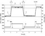
도 12는 종래의 팬 모듈에서 듀티비(Duty Ratio) 입력에 따른 팬 회전속도(RPM)를 보여주는 그래프이다.12 is a graph showing a fan rotation speed (RPM) according to a duty ratio input in a conventional fan module.
도 12에서 상부 그래프는, 종래의 팬 모듈의 회전속도(RPM)를 보여주고, 하부 그래프는, 팬 모듈에 대한 펄스(Pulse)의 듀티비(Duty Ratio)를 보여준다.In FIG. 12 , the upper graph shows the rotational speed (RPM) of the conventional fan module, and the lower graph shows the duty ratio of pulses for the fan module.
구체적으로, 팬 모듈이 저속 운전(F1)에서 고속 운전(F2)으로 전환될 때에는, 고속 운전이 시작되는 시점(D1)에서 듀티비를 기존 30%에서 50%로 변경하여 회전속도를 조절한다.Specifically, when the fan module is switched from the low-speed operation F1 to the high-speed operation F2, the rotation speed is adjusted by changing the duty ratio from 30% to 50% at the time point D1 when the high-speed operation starts.
이 경우, 실질적으로 저속 회전속도(F1)에서 목표 회전속도인 고속 회전속도(F2)에 도달하기까지 걸리는 시간은 제1시간(t1)이 요구될 수 있다.In this case, the first time t1 may be required for the time it takes from the low rotation speed F1 to the high rotation speed F2 that is the target rotation speed.
여기서, 제1시간(t1)은 0.7초가 될 수 있다.Here, the first time t1 may be 0.7 seconds.
반대로, 팬 모듈이 고속 운전(F2)에서 저속 운전(F1)으로 전환될 때에는, 저속 운전이 시작되는 시점(D2)에서 듀티비를 기존 50%에서 30%로 변경하여 회전속도를 조절한다.Conversely, when the fan module is switched from the high-speed operation F2 to the low-speed operation F1, the rotation speed is adjusted by changing the duty ratio from 50% to 30% at the time point D2 when the low-speed operation starts.
이 경우에도, 실질적으로 고속 회전속도(F2)에서 목표 회전속도인 저속 회전속도(F1)에 도달하기까지 걸리는 시간은 제2시간(t2)이 요구될 수 있다.Even in this case, the second time t2 may be required for the time it takes from the high rotation speed F2 to the target rotation speed F1, which is the low rotation speed.
여기서, 제2시간(t1)은 0.7초가 될 수 있다.Here, the second time t1 may be 0.7 seconds.
즉, 종래의 경우, 저속 운전에서 고속 운전으로 전환되거나 또는 고속 운전에서 저속 운전으로 전환될 때에는 비교적 많은 시간이 걸리는 것을 알 수 있다.That is, it can be seen that, in the case of the related art, it takes a relatively long time to change from low-speed operation to high-speed operation or from high-speed operation to low-speed operation.
한편, 본 발명에서는 마스크 장치의 특성상, 착용자의 들숨이 시작될 때 최대한 신속하게 팬 모듈의 회전속도를 올려줄 필요가 있다. 즉, 사람의 들숨은 대략 1초 내외의 시간에 이루어지기 때문에, 팬 모듈의 회전속도가 신속하게 목표 회전속도로 전환될 필요가 있다.On the other hand, in the present invention, due to the characteristics of the mask device, it is necessary to increase the rotation speed of the fan module as quickly as possible when the wearer starts breathing. That is, since a person's inhalation takes about 1 second or so, the rotational speed of the fan module needs to be quickly converted to the target rotational speed.
도 13은 본 발명에 따른 팬 모듈에서 듀티비 입력에 따른 팬 회전속도를 보여주는 그래프이다.13 is a graph showing a fan rotation speed according to a duty ratio input in the fan module according to the present invention.
도 13에서 상부 그래프는, 본 발명에 따른 팬 모듈의 회전속도(RPM)를 보여주고, 하부 그래프는, 본 발명에 따른 팬 모듈에 대한 펄스(Pulse)의 듀티비(Duty Ratio)를 보여준다.In FIG. 13 , the upper graph shows the rotational speed (RPM) of the fan module according to the present invention, and the lower graph shows the duty ratio of pulses for the fan module according to the present invention.
구체적으로, 팬 모듈이 저속 운전(F1)에서 고속 운전(F2)으로 전환될 때에는, 고속 운전이 시작되는 시점(D1)에서 듀티비를 기존 30%에서 70%로 변경하여 회전속도를 조절한다.Specifically, when the fan module is switched from the low-speed operation F1 to the high-speed operation F2, the rotation speed is adjusted by changing the duty ratio from 30% to 70% at the time point D1 when the high-speed operation starts.
이때, 상기 마스크 장치(1)는 팬 모듈의 목표 회전속도에 해당하는 듀티비(50%) 보다 높은 듀티비(70%)를 과입력함으로써, 팬의 회전속도를 신속하게 증가시킬 수 있다.In this case, the
이 경우, 실질적으로 저속 회전속도(F1)에서 목표 회전속도인 고속 회전속도(F2)에 도달하기까지 걸리는 제1시간(t1)이 요구될 수 있다.In this case, the first time t1 taken from the low rotation speed F1 to the high rotation speed F2 that is the target rotation speed may be substantially required.
여기서, 제1시간(t1)은 0.2초가 될 수 있다.Here, the first time t1 may be 0.2 seconds.
그리고 팬 모듈이 목표 회전속도(F2)에 도달하는 시점(D2)에서는, 듀티비를 정상적인 50%로 변경하여 회전속도를 유지한다.And at the time point D2 when the fan module reaches the target rotation speed F2, the rotation speed is maintained by changing the duty ratio to a normal 50%.
반대로, 팬 모듈이 고속 운전(F2)에서 저속 운전(F1)으로 전환될 때에는, 저속 운전이 시작되는 시점(D3)에서 듀티비를 기존 50%에서 20%로 변경하여 회전속도를 조절한다.Conversely, when the fan module is switched from the high-speed operation F2 to the low-speed operation F1, the rotation speed is adjusted by changing the duty ratio from 50% to 20% at the time point D3 when the low-speed operation starts.
이때, 상기 마스크 장치(1)는 팬 모듈의 목표 회전속도에 해당하는 듀티비(30%) 보다 낮은 듀티비(20%)를 입력함으로써, 팬의 회전속도를 신속하게 감소시킬 수 있다.In this case, the
이 경우, 실질적으로 고속 회전속도(F2)에서 목표 회전속도인 저속 회전속도(F1)에 도달하기까지 걸리는 시간은 제2시간(t2)이 요구될 수 있다.In this case, the second time t2 may be required for the time it takes from the high rotation speed F2 to the target rotation speed F1 to be reached.
여기서, 제2시간(t2)은 0.2초가 될 수 있다.Here, the second time t2 may be 0.2 seconds.
그리고 팬 모듈이 목표 회전속도(F1)에 도달하는 시점(D4)에서는, 듀티비를 정상적인 30%로 변경하여 회전속도를 유지한다.And at the time point D4 when the fan module reaches the target rotation speed F1, the rotation speed is maintained by changing the duty ratio to a normal 30%.
정리하면, 본 발명에서는 회전속도를 증가시키는 시점이 도래하면, 목표 회전속도에 따른 튜티비 보다 높게 설정하여, 목표 회전속도에 도달하는 시간을 단축시킬 수 있다.In summary, in the present invention, when the time of increasing the rotation speed arrives, the time to reach the target rotation speed can be shortened by setting a higher than the duty ratio according to the target rotation speed.
또한, 회전속도를 감소시키는 시점이 도래하면, 목표 회전속도에 따른 튜티비 보다 낮게 설정하여, 목표 회전속도에 도달하는 시간을 단축시킬 수 있다.In addition, when the time point for reducing the rotation speed arrives, the time for reaching the target rotation speed can be shortened by setting the tu ratio lower than the target rotation speed according to the target rotation speed.
이러한 본 발명의 구성에 의하면, 팬 모터의 펄스(Pulse)에 입력되는 듀티비를 적절하게 조절함으로써, 목표 회전속도에 도달하는 시간을 현저히 단축할 수 있으므로, 팬 회전에 따른 착용자의 호흡이 더욱 원활해지는 장점이 있다.According to this configuration of the present invention, by appropriately adjusting the duty ratio input to the pulse of the fan motor, the time to reach the target rotation speed can be significantly shortened, so that the wearer's breathing according to the fan rotation is more smooth There are advantages to canceling.
이상에서 대표적인 실시 예를 통하여 본 발명을 상세하게 설명하였으나, 본 발명이 속하는 기술 분야에서 통상의 지식을 가진 자는 상술한 실시 예에 대하여 본 발명의 범주에서 벗어나지 않는 한도 내에서 다양한 변형이 가능함을 이해할 것이다. 그러므로 본 발명의 권리 범위는 설명한 실시 예에 국한되어 정해져서는 안 되며, 후술하는 특허청구범위 뿐만 아니라 특허청구범위와 균등 개념으로부터 도출되는 모든 변경 또는 변형된 형태에 의하여 정해져야 한다.Although the present invention has been described in detail through representative embodiments above, those of ordinary skill in the art to which the present invention pertains will understand that various modifications are possible within the limits without departing from the scope of the present invention with respect to the above-described embodiments. will be. Therefore, the scope of the present invention should not be limited to the described embodiments and should be defined by all changes or modifications derived from the claims and equivalent concepts as well as the claims to be described later.
Claims (20)
Translated fromKorean상기 마스크 몸체에 결합되는 팬 모듈;
상기 마스크 몸체에 결합되며, 상기 마스크 몸체의 내부 압력을 측정하는 압력 센서; 및
상기 압력 센서에서 감지된 정보에 기초하여, 상기 팬 모듈의 회전속도를 제어하는 제어부를 포함하고,
상기 제어부는,
상기 팬 모듈이 저속 운전되는 상태에서, 상기 압력 센서를 이용하여 마스크의 내부 압력을 일정시간 동안 감지하고,
상기 압력 센서를 통해 감지된 압력값들 중에서, 1회 호흡 주기에 포함되는 최대 압력값과 최소 압력값을 추출하여 호흡 주기를 분석하고,
상기 최대 압력값에 해당하는 시점과, 상기 최소 압력값에 해당하는 시점 사이의 시간차를 계산하고,
상기 호흡 주기와 상기 시간차에 기초하여, 들숨 예상시점을 판단하고,
상기 들숨 예상시점이 도래하는 경우, 상기 팬 모듈의 회전속도를 증가시키도록 제어하고,
상기 제어부는, 상기 호흡 주기와 상기 시간차에 기초하여 들숨 예상시점을 판단할 때, 다음 호흡 주기에 해당하는 최대 압력값을 감지하고, 다음 호흡 주기에 해당하는 최대 압력값이 감지된 시점으로부터, 상기 시간차의 20% 내지 50%에 해당하는 시간이 경과한 시점을, 들숨 예상시점으로 판단하는 것을 특징으로 하는 마스크 장치.mask body;
a fan module coupled to the mask body;
a pressure sensor coupled to the mask body and configured to measure an internal pressure of the mask body; and
a control unit for controlling the rotation speed of the fan module based on the information sensed by the pressure sensor;
The control unit is
In a state in which the fan module is operated at a low speed, the internal pressure of the mask is sensed for a certain period of time using the pressure sensor,
Analyze the breathing cycle by extracting the maximum pressure value and the minimum pressure value included in one breathing cycle from among the pressure values sensed through the pressure sensor,
calculating a time difference between a time point corresponding to the maximum pressure value and a time point corresponding to the minimum pressure value;
Based on the respiration cycle and the time difference, determining an expected inhalation time,
When the expected inhalation time arrives, control to increase the rotation speed of the fan module,
The control unit, when determining the expected time of inhalation based on the respiration cycle and the time difference, detects a maximum pressure value corresponding to the next respiration cycle, from the point at which the maximum pressure value corresponding to the next respiration cycle is sensed, the A mask device, characterized in that the time point corresponding to 20% to 50% of the time difference is determined as an expected inhalation time point.
상기 호흡 주기는, 날숨 구간과 들숨 구간을 포함하고,
상기 최소 압력값에 해당하는 시점은, 날숨이 종료되는 시점이고,
상기 들숨 예상시점은, 상기 날숨이 종료되는 시점 이후의 시점인 마스크 장치.The method of claim 1,
The respiratory cycle includes an exhalation section and an inhalation section,
The time point corresponding to the minimum pressure value is the time point at which exhalation ends,
The expected inhalation time is a mask device that is a time point after the end of the exhalation.
상기 제어부는,
다음 호흡 주기에 해당하는 최소 압력값이 감지되는지 여부를 더 판단하는 마스크 장치.The method of claim 1,
The control unit is
A mask device that further determines whether a minimum pressure value corresponding to the next breathing cycle is detected.
상기 제어부는,
다음 호흡 주기에 해당하는 최소 압력값이 감지된 것으로 판단되면, 상기 팬 모듈의 회전속도를 감소시키는 마스크 장치.7. The method of claim 6,
The control unit is
A mask device for reducing the rotation speed of the fan module when it is determined that the minimum pressure value corresponding to the next respiration cycle is detected.
상기 제어부는,
마스크 전원 오프 명령이 입력되는지 여부를 판단하고,
마스크 전원 오프 명령이 입력되지 않은 것으로 판단되면, 다음 호흡 주기에 해당하는 최대 압력값에 해당하는 시점과, 다음 호흡 주기에 해당하는 최소 압력값에 해당하는 시점 사이의 시간차를 다시 계산하는 마스크 장치.The method of claim 1,
The control unit is
determine whether a mask power-off command is input;
When it is determined that the mask power-off command is not input, the mask device recalculates the time difference between the time point corresponding to the maximum pressure value corresponding to the next respiration cycle and the time point corresponding to the minimum pressure value corresponding to the next respiration cycle.
상기 제어부는,
상기 팬 모듈의 회전속도를 모니터링하고, 상기 팬 모듈의 회전속도에 따른 압력 변화량을, 상기 감지된 마스크의 내부 압력에 반영하는 마스크 장치.The method of claim 1,
The control unit is
A mask device for monitoring the rotation speed of the fan module, and reflecting an amount of pressure change according to the rotation speed of the fan module to the sensed internal pressure of the mask.
상기 제어부는,
상기 팬 모듈의 회전속도를 증가시키기 위하여, 상기 팬 모듈의 목표 회전속도에 따른 듀티비(Duty Ratio) 보다 높은 듀티비를 과입력하는 마스크 장치.The method of claim 1,
The control unit is
In order to increase the rotation speed of the fan module, a mask device that over-inputs a duty ratio higher than a duty ratio according to a target rotation speed of the fan module.
감지된 압력값들 중에서, 1회 호흡 주기에 포함되는 최대 압력값과 최소 압력값을 추출하여 호흡 주기를 분석하는 단계;
상기 최대 압력값에 해당하는 시점과, 상기 최소 압력값에 해당하는 시점 사이의 시간차를 계산하는 단계;
상기 호흡 주기와 상기 시간차에 기초하여, 들숨 예상시점을 판단하는 단계; 및
상기 들숨 예상시점이 도래하는 경우, 상기 팬 모듈의 회전속도를 증가시키는 단계를 포함하고,
상기 호흡 주기와 상기 시간차에 기초하여 들숨 예상시점을 판단하는 단계는, 다음 호흡 주기에 해당하는 최대 압력값을 감지하고, 다음 호흡 주기에 해당하는 최대 압력값이 감지된 시점으로부터, 상기 시간차의 20% 내지 50%에 해당하는 시간이 경과한 시점을, 들숨 예상시점으로 판단하는 것을 특징으로 하는 마스크 장치의 제어방법.Sensing the internal pressure of the mask for a predetermined time using a pressure sensor while the fan module operates at a low speed;
extracting a maximum pressure value and a minimum pressure value included in one respiration cycle from among the sensed pressure values to analyze the respiration cycle;
calculating a time difference between a time point corresponding to the maximum pressure value and a time point corresponding to the minimum pressure value;
based on the respiration cycle and the time difference, determining an expected time of inhalation; and
Comprising the step of increasing the rotation speed of the fan module when the expected inhalation time arrives,
The step of determining the expected time of inhalation based on the respiration cycle and the time difference may include detecting a maximum pressure value corresponding to a next respiration cycle, and from a time point at which the maximum pressure value corresponding to the next respiration cycle is sensed, 20 of the time difference A control method of a mask device, characterized in that the time point corresponding to % to 50% elapses is determined as an expected inhalation time point.
상기 호흡 주기는, 날숨 구간과 들숨 구간을 포함하고,
상기 최소 압력값에 해당하는 시점은, 날숨이 종료되는 시점이고,
상기 들숨 예상시점은, 상기 날숨이 종료되는 시점 이후의 시점인 마스크 장치의 제어방법.12. The method of claim 11,
The respiratory cycle includes an exhalation section and an inhalation section,
The time point corresponding to the minimum pressure value is the time point at which exhalation ends,
The expected time of inhalation is a control method of a mask device that is a time point after the time when the exhalation is terminated.
다음 호흡 주기에 해당하는 최소 압력값이 감지되는지 여부를 판단하는 단계를 더 포함하는 마스크 장치의 제어방법.12. The method of claim 11,
The control method of the mask device further comprising the step of determining whether a minimum pressure value corresponding to the next breathing cycle is detected.
다음 호흡 주기에 해당하는 최소 압력값이 감지된 것으로 판단되면, 상기 팬 모듈의 회전속도를 감소시키는 마스크 장치의 제어방법.17. The method of claim 16,
When it is determined that the minimum pressure value corresponding to the next respiration cycle is detected, the control method of the mask device for reducing the rotation speed of the fan module.
마스크 전원 오프 명령이 입력되는지 여부를 판단하는 단계; 및
마스크 전원 오프 명령이 입력되지 않은 것으로 판단되면, 다음 호흡 주기에 해당하는 최대 압력값에 해당하는 시점과, 다음 호흡 주기에 해당하는 최소 압력값에 해당하는 시점 사이의 시간차를 다시 계산하는 단계를 더 포함하는 마스크 장치의 제어방법.12. The method of claim 11,
determining whether a mask power-off command is input; and
If it is determined that the mask power-off command has not been input, the step of recalculating the time difference between the time point corresponding to the maximum pressure value corresponding to the next breathing cycle and the time point corresponding to the minimum pressure value corresponding to the next breathing cycle is further performed A control method of a mask device comprising a.
상기 팬 모듈의 회전속도를 모니터링 하는 단계를 더 포함하고,
상기 압력 센서를 이용하여 상기 마스크의 내부 압력을 감지하는 단계는, 상기 팬 모듈의 회전속도에 따른 압력 변화량을, 상기 감지된 마스크의 내부 압력에 반영하는 단계를 포함하는 마스크 장치의 제어방법.12. The method of claim 11,
Further comprising the step of monitoring the rotation speed of the fan module,
Sensing the internal pressure of the mask by using the pressure sensor includes reflecting an amount of change in pressure according to the rotation speed of the fan module to the detected internal pressure of the mask.
상기 팬 모듈의 회전속도를 증가시키는 단계는, 상기 팬 모듈의 목표 회전속도에 따른 듀티비(Duty Ratio) 보다 높은 듀티비를 과입력하는 단계를 포함하는 마스크 장치의 제어방법.12. The method of claim 11,
The increasing the rotation speed of the fan module includes the step of over-inputting a duty ratio higher than a duty ratio according to the target rotation speed of the fan module.
Priority Applications (4)
| Application Number | Priority Date | Filing Date | Title |
|---|---|---|---|
| KR1020200080417AKR102436838B1 (en) | 2020-06-30 | 2020-06-30 | Mask apparatus and controlling method thereof |
| CN202110382635.2ACN113856076B (en) | 2020-06-30 | 2021-04-09 | Mask device and control method thereof |
| US17/231,466US12263362B2 (en) | 2020-06-30 | 2021-04-15 | Mask apparatus and method for controlling the same |
| EP21169773.5AEP3932494B1 (en) | 2020-06-30 | 2021-04-22 | Mask apparatus and method for controlling the same |
Applications Claiming Priority (1)
| Application Number | Priority Date | Filing Date | Title |
|---|---|---|---|
| KR1020200080417AKR102436838B1 (en) | 2020-06-30 | 2020-06-30 | Mask apparatus and controlling method thereof |
Publications (2)
| Publication Number | Publication Date |
|---|---|
| KR20220001913A KR20220001913A (en) | 2022-01-06 |
| KR102436838B1true KR102436838B1 (en) | 2022-08-26 |
Family
ID=75639733
Family Applications (1)
| Application Number | Title | Priority Date | Filing Date |
|---|---|---|---|
| KR1020200080417AActiveKR102436838B1 (en) | 2020-06-30 | 2020-06-30 | Mask apparatus and controlling method thereof |
Country Status (4)
| Country | Link |
|---|---|
| US (1) | US12263362B2 (en) |
| EP (1) | EP3932494B1 (en) |
| KR (1) | KR102436838B1 (en) |
| CN (1) | CN113856076B (en) |
Families Citing this family (13)
| Publication number | Priority date | Publication date | Assignee | Title |
|---|---|---|---|---|
| JP1721428S (en)* | 2020-03-26 | 2022-08-02 | Silicone support frame for air mask encapsulation | |
| KR102256713B1 (en)* | 2020-06-05 | 2021-05-27 | 엘지전자 주식회사 | Mask apparatus and controlling method thereof |
| KR102309925B1 (en) | 2020-06-05 | 2021-10-08 | 엘지전자 주식회사 | Mask apparatus |
| KR102408364B1 (en) | 2020-06-05 | 2022-06-13 | 엘지전자 주식회사 | Mask apparatus |
| KR102452392B1 (en) | 2020-06-05 | 2022-10-11 | 엘지전자 주식회사 | Mask apparatus |
| KR102307772B1 (en) | 2020-06-05 | 2021-10-05 | 엘지전자 주식회사 | Mask apparatus |
| KR102494579B1 (en) | 2020-06-05 | 2023-02-02 | 엘지전자 주식회사 | Mask apparatus |
| KR102367071B1 (en) | 2020-06-05 | 2022-02-25 | 엘지전자 주식회사 | Mask apparatus |
| KR102460798B1 (en) | 2020-06-30 | 2022-10-31 | 엘지전자 주식회사 | Mask apparatus |
| USD966497S1 (en)* | 2020-07-10 | 2022-10-11 | Lg Electronics Inc. | Facial contact pad for mask type air purifier |
| KR102458618B1 (en) | 2020-07-17 | 2022-10-25 | 엘지전자 주식회사 | Mask apparatus and controlling method thereof |
| KR102294479B1 (en) | 2020-08-28 | 2021-08-27 | 엘지전자 주식회사 | Sterilizing case |
| US20230285784A1 (en)* | 2022-01-31 | 2023-09-14 | Georgia Tech Research Corporation | Respiratory protective device with continuous fit monitoring |
Citations (2)
| Publication number | Priority date | Publication date | Assignee | Title |
|---|---|---|---|---|
| KR101827016B1 (en)* | 2009-08-11 | 2018-02-07 | 쓰리엠 이노베이티브 프로퍼티즈 컴파니 | Method of controlling a powered air purifying respirator |
| US20190175962A1 (en)* | 2016-08-24 | 2019-06-13 | Koninklijke Philips N.V. | Breathing mask with increased user comfort |
Family Cites Families (181)
| Publication number | Priority date | Publication date | Assignee | Title |
|---|---|---|---|---|
| GB1155046A (en) | 1966-09-16 | 1969-06-11 | Louis Sachs | Surgical Mask |
| US4050458A (en)* | 1976-01-26 | 1977-09-27 | Puritan-Bennett Corporation | Respiration system with patient assist capability |
| US4546793A (en) | 1982-12-27 | 1985-10-15 | Sensormedics Corporation | Breath switch |
| US4646732A (en) | 1985-08-26 | 1987-03-03 | Chien Chao Huei | Circulative respiratory mask |
| US5062421A (en) | 1987-11-16 | 1991-11-05 | Minnesota Mining And Manufacturing Company | Respiratory mask having a soft, compliant facepiece and a thin, rigid insert and method of making |
| JPH05137808A (en) | 1991-07-26 | 1993-06-01 | Yoshio Nakagawa | Protector used for coating operation or the like |
| US5372130A (en) | 1992-02-26 | 1994-12-13 | Djs&T Limited Partnership | Face mask assembly and method having a fan and replaceable filter |
| GB9307733D0 (en) | 1993-04-14 | 1993-06-02 | Msa Britain Ltd | Respiratory protective device |
| JPH0786173A (en) | 1993-09-16 | 1995-03-31 | Tokyo Electron Ltd | Film deposition |
| US5562607A (en) | 1995-01-18 | 1996-10-08 | Alza Corporation | Electrotransport device having reusable controller power saver |
| US5782234A (en) | 1995-04-05 | 1998-07-21 | Bates; Charles W. | Respiratory breathing filter apparatus and method |
| AUPN616795A0 (en) | 1995-10-23 | 1995-11-16 | Rescare Limited | Ipap duration in bilevel cpap or assisted respiration treatment |
| JPH09225012A (en) | 1996-02-26 | 1997-09-02 | Kyoji Aono | Portable ultraviolet sterilizer |
| JP3090059B2 (en) | 1996-06-21 | 2000-09-18 | ダイキン工業株式会社 | Air purifier with dust detection sensor |
| JP3039303U (en) | 1996-11-11 | 1997-07-15 | 陳 慶華 | Electric blown safety mask |
| JPH10165527A (en) | 1996-12-12 | 1998-06-23 | Shiseido Co Ltd | Disposable sheet for mask |
| US6543450B1 (en) | 1998-09-29 | 2003-04-08 | John T. Flynn | Survival mask |
| JP3077655U (en) | 2000-11-13 | 2001-05-29 | 有限会社五福屋商事 | Mobile box with sterilization function |
| JP4928691B2 (en) | 2001-09-13 | 2012-05-09 | スパンション エルエルシー | UV irradiation equipment |
| US20030066257A1 (en) | 2001-10-04 | 2003-04-10 | Barry Shovlin | Method for manufacturing a door and door manufactured therefrom |
| US20030066527A1 (en) | 2001-10-09 | 2003-04-10 | Chen Yen Ling | Face mask having device for drawing air into the mask |
| JP2003322712A (en) | 2002-04-30 | 2003-11-14 | Omron Corp | Reflection plate and method of manufacturing the same and reflective liquid crystal display device |
| JP2004364177A (en) | 2003-06-06 | 2004-12-24 | Ricoh Co Ltd | Dustproof and waterproof equipment |
| ATE533092T1 (en) | 2003-12-17 | 2011-11-15 | Eta Sa Mft Horlogere Suisse | PORTABLE ELECTRONIC DEVICE EQUIPPED WITH A PRESSURE SENSOR |
| US20050145249A1 (en) | 2003-12-31 | 2005-07-07 | Solyntjes Alan J. | Personal respiratory protection device that has a permanent or semi-permanent bayonet connection |
| JP2006102324A (en) | 2004-10-07 | 2006-04-20 | Shigematsu Works Co Ltd | Protective tool for breathing with electric fan |
| US20100329924A1 (en) | 2005-05-16 | 2010-12-30 | Harris Debra J Fogel | Sponge Sterilizer |
| JP3117209U (en) | 2005-08-31 | 2006-01-05 | 北條 すみれ | Adjustable string face mask |
| US7448386B2 (en) | 2005-12-07 | 2008-11-11 | Ric Investments, Llc | Full face respiratory mask with integrated nasal interface |
| JP4167271B2 (en) | 2006-03-08 | 2008-10-15 | エセンシア カンパニー,リミテッド | Portable toothbrush sterilizer |
| JP2010512198A (en) | 2006-12-13 | 2010-04-22 | ラドウィク フェドルコ, | Method and apparatus for ventilation assistance |
| JP5739664B2 (en) | 2007-09-20 | 2015-06-24 | スリーエム イノベイティブ プロパティズ カンパニー | Filtered face-mounted respiratory mask with buckle integrated with mask body support structure |
| JP2011504398A (en) | 2007-11-20 | 2011-02-10 | エイヴォン プロテクション システムズ,インク. | Electric air purification respiratory module |
| JP5041596B2 (en) | 2007-12-07 | 2012-10-03 | 株式会社重松製作所 | Breathing apparatus |
| AU2009251721B2 (en) | 2008-04-04 | 2012-05-03 | 3M Innovative Properties Company | Air filtration device |
| US8196581B2 (en) | 2008-04-14 | 2012-06-12 | Jeffrey Evan Bozanic | Mouthpiece supply valve |
| US20110232646A1 (en) | 2008-12-17 | 2011-09-29 | Koninklijke Philips Electronics, N.V. | Respiratory interface device with filtration medium |
| KR200455964Y1 (en) | 2009-03-27 | 2011-10-05 | 세진물산 주식회사 | dustproof mask |
| JP5305401B2 (en) | 2009-10-07 | 2013-10-02 | 株式会社重松製作所 | Breathing apparatus |
| JP2011078678A (en) | 2009-10-09 | 2011-04-21 | Aroma Science Kk | Mask sterilizer |
| JP2011115449A (en) | 2009-12-04 | 2011-06-16 | Keinan Chemical:Kk | Mask stopper |
| KR101094143B1 (en) | 2009-12-15 | 2011-12-14 | (주)라눅스 | LED Flat Lamps |
| US9024276B2 (en) | 2010-06-23 | 2015-05-05 | Johnson & Johnson Vision Care, Inc. | Contact lens storage case surface disinfection |
| JP2012016516A (en) | 2010-07-09 | 2012-01-26 | Midori Anzen Co Ltd | Mask tightening string length adjuster, and mask |
| JP5615119B2 (en) | 2010-10-05 | 2014-10-29 | サンエムパッケージ 株式会社 | mask |
| KR200461294Y1 (en) | 2011-04-06 | 2012-07-03 | 강홍구 | Cold mask |
| US9165756B2 (en) | 2011-06-08 | 2015-10-20 | Xenex Disinfection Services, Llc | Ultraviolet discharge lamp apparatuses with one or more reflectors |
| JP5883287B2 (en) | 2011-12-16 | 2016-03-09 | 地方独立行政法人東京都立産業技術研究センター | Protective cap, method of using protective cap, protective clothing and protective device |
| JP5592908B2 (en) | 2012-02-23 | 2014-09-17 | 興研株式会社 | Respiratory protection |
| KR101228403B1 (en) | 2012-04-02 | 2013-01-31 | 한국기계연구원 | Duct silencer with periodic wrinkled surfaces for reducing noise having variable frequency |
| WO2013165988A1 (en) | 2012-04-30 | 2013-11-07 | Scott Technologies, Inc. | Half facepiece |
| JP2015527130A (en) | 2012-08-03 | 2015-09-17 | コーニンクレッカ フィリップス エヌ ヴェ | Patient interface assembly with force limiter |
| GB201214088D0 (en) | 2012-08-06 | 2012-09-19 | Scott Health & Safety Ltd | Switchable exhale filter system |
| GB2553475B8 (en) | 2012-08-08 | 2019-01-02 | Fisher & Paykel Healthcare Ltd | Headgear for patient interface |
| GB2505484A (en) | 2012-08-31 | 2014-03-05 | 3M Innovative Properties Co | Powered exhaust apparatus for a personal protection respiratory device |
| US9510626B2 (en) | 2013-02-01 | 2016-12-06 | 3M Innovative Properties Company | Sleeve-fit respirator cartridge |
| CN105188819B (en) | 2013-03-13 | 2017-07-18 | 皇家飞利浦有限公司 | Liner and the patient interface device using the pad under nose |
| CN105142734B (en) | 2013-03-15 | 2022-04-05 | 斯科特科技公司 | Reconfigurable full facemask with cartridge module for respiratory protection |
| EP2996750B1 (en) | 2013-05-13 | 2018-09-19 | Karl Küfner GmbH & Co. KG | Device for artificial respiration in emergencies |
| FR3006593B1 (en) | 2013-06-06 | 2015-05-29 | Air Liquide Medical Systems | GAS PRESSURE MEASUREMENT SYSTEM FOR PATIENT VENTILATION APPARATUS |
| CN103505788B (en) | 2013-10-11 | 2015-09-23 | 中山大学 | A kind of mechanical ventilation control method of positive pressure respirator and respirator |
| JP2015093036A (en) | 2013-11-12 | 2015-05-18 | 也人 竹内 | Mask stopper |
| US9814913B2 (en) | 2013-11-15 | 2017-11-14 | 3M Innovative Properties Company | Respirator with floating elastomeric sleeve |
| CN103751919B (en) | 2014-01-27 | 2016-05-11 | 胡昀 | Can form with face the mouth mask of airtight respiratory cavity |
| DE102014001938B4 (en) | 2014-02-06 | 2015-10-22 | Moldex-Metric Ag & Co. Kg | Respirator with bayonet closure for a filter module |
| DE102014001937C5 (en) | 2014-02-06 | 2019-10-10 | Moldex-Metric Ag & Co. Kg | Respirator |
| DE102014001940B4 (en) | 2014-02-06 | 2015-10-22 | Moldex-Metric Ag & Co. Kg | Respirator with sliding seat device |
| DE202014001315U1 (en) | 2014-02-06 | 2014-02-24 | Moldex-Metric Ag & Co. Kg | Respirator with sliding seat device |
| TWM490327U (en) | 2014-04-15 | 2014-11-21 | Besmed Health Business Corp | Buckle and mask device |
| US20150306324A1 (en) | 2014-04-29 | 2015-10-29 | Arturo Alejo Ayon | Self-contained continuous positive airway pressure mask and method of use |
| US9696294B2 (en) | 2014-06-11 | 2017-07-04 | Integrated Monitoring Systems, Llc | Removable tamper-resistant breath alcohol sampling system |
| CN203943119U (en) | 2014-06-26 | 2014-11-19 | 石家庄融和天成电子科技有限公司 | A kind of high leakproofness mouth mask |
| EP3164161B1 (en) | 2014-07-04 | 2019-03-13 | Egohealth S.r.l. | Device for the sterilisation of stethoscopes |
| SG11201700351VA (en) | 2014-07-18 | 2017-02-27 | Fisher & Paykel Healthcare Ltd | Headgear clip arrangement |
| WO2016018797A1 (en) | 2014-07-31 | 2016-02-04 | Munster Jason | Personal air filtration device |
| TWM491477U (en) | 2014-08-01 | 2014-12-11 | Euclid Technology Co Ltd | Mask |
| CN104162236B (en) | 2014-09-01 | 2016-09-28 | 上海朗沁投资管理有限公司 | Active Multi-purpose protection mouth-piece |
| KR101554664B1 (en) | 2014-10-21 | 2015-09-21 | 박형순 | Nail Clippers Sterilization Case |
| JP2016087376A (en) | 2014-11-03 | 2016-05-23 | 修 枦山 | Rigid sports mask with convection fan |
| EP3782685B1 (en) | 2014-11-07 | 2023-12-27 | Fisher & Paykel Healthcare Limited | Breathing apparatus |
| KR101643682B1 (en) | 2014-11-25 | 2016-07-29 | (주)씨앤투스성진 | Portable mask |
| US20160236016A1 (en) | 2015-02-12 | 2016-08-18 | Shigematsu Works Co., Ltd. | Breathing apparatus |
| US9694217B2 (en) | 2015-03-24 | 2017-07-04 | Famask, Inc. | Positive air pressure facemask and multi-staged filter system therefor |
| CN104826247A (en) | 2015-03-25 | 2015-08-12 | 肖仕钦 | Mouth mask type air purifier |
| JP2018512518A (en)* | 2015-04-03 | 2018-05-17 | マイクロスフェア ピーティーイー. リミテッド | Respirator, system and method |
| KR101536265B1 (en) | 2015-04-14 | 2015-07-13 | 주식회사 산청 | Hood type gas mask |
| KR20160129562A (en) | 2015-04-30 | 2016-11-09 | 정륵성 | Air inhale mask |
| KR101733470B1 (en) | 2015-05-06 | 2017-05-25 | 주식회사 아이카이스트 | Pressure sensor-based electric respiratory system with real-time breath control function |
| CN204637356U (en) | 2015-05-11 | 2015-09-16 | 肖永初 | A kind of anti-haze mouth mask |
| CN107847824B (en) | 2015-06-30 | 2020-10-27 | 3M创新有限公司 | Filter cartridge including filter media with adhesively sealed edge ends and methods of manufacture and use |
| GB201511904D0 (en) | 2015-07-07 | 2015-08-19 | 3M Innovative Properties Co | Powered exhaust apparatus for a personal protection respiratory device |
| CN105167366A (en) | 2015-08-20 | 2015-12-23 | 张植强 | Intelligent bra storage box |
| CN105126219A (en) | 2015-08-31 | 2015-12-09 | 肖永初 | Micro breathing machine |
| US10994090B2 (en) | 2015-09-04 | 2021-05-04 | Fisher & Paykel Healthcare Limited | Patient interfaces |
| US10342999B2 (en) | 2015-10-16 | 2019-07-09 | Yang Song | Particulate filter face mask having fan breathing assist |
| KR101930144B1 (en) | 2015-12-29 | 2018-12-18 | 한가현 | Mask for health care of cutting off harmful materials by using air curtain |
| WO2017116174A1 (en) | 2015-12-29 | 2017-07-06 | 한가현 | Harmful-substance-blocking health mask using air curtain |
| CN205285072U (en) | 2015-12-31 | 2016-06-08 | 山东科技大学 | Automatic antifog haze gauze mask of formula of taking a breath |
| CN105495776A (en) | 2016-01-11 | 2016-04-20 | 王红兵 | Intelligent electric haze prevention respirator |
| CN105476118A (en) | 2016-01-26 | 2016-04-13 | 深圳市波米科技有限公司 | Multifunctional mask |
| KR101619487B1 (en) | 2016-02-17 | 2016-05-10 | (주)대성엠텍 | Functional mask |
| US9950289B2 (en) | 2016-02-26 | 2018-04-24 | Lg Electronics Inc. | Air cleaner |
| CN107149182B (en) | 2016-03-02 | 2021-01-15 | 苏州柯琳艾尔智能科技有限公司 | Intelligent double-cavity mask |
| CN105641821A (en) | 2016-03-03 | 2016-06-08 | 北京尚宏恒远科技有限公司 | Active intake mask |
| KR20170111132A (en) | 2016-03-25 | 2017-10-12 | 신택선 | Forced inhale and exhale mask |
| KR101865203B1 (en) | 2016-05-09 | 2018-06-07 | 경남엔지니어링(주) | Dust mask |
| US9848666B1 (en) | 2016-06-23 | 2017-12-26 | 3M Innovative Properties Company | Retrofit sensor module for a protective head top |
| WO2018009080A1 (en) | 2016-07-08 | 2018-01-11 | Fisher & Paykel Healthcare Limited | A vent for a component of a respiratory therapy system |
| KR101942785B1 (en) | 2016-07-18 | 2019-01-28 | 신홍제 | Functional mask |
| JP6624735B2 (en) | 2016-07-26 | 2019-12-25 | 株式会社重松製作所 | Breathing device with electric fan linked to breathing |
| KR101849610B1 (en) | 2016-07-27 | 2018-04-17 | (주)에이치앤비이십일 | Puff sterilizer |
| CN106039607B (en) | 2016-07-30 | 2022-03-25 | 四川海特亚美航空技术有限公司 | Digital respiration following oxygen supply system and oxygen supply method thereof |
| CN106253937A (en) | 2016-07-31 | 2016-12-21 | 长沙科创投资管理有限公司 | A kind of earthquake rescue device |
| CN106235464A (en) | 2016-08-31 | 2016-12-21 | 苏州佐纳电子科技有限公司 | A kind of monitoring formula PM2.5 protection breath device |
| JP7085719B2 (en) | 2016-09-01 | 2022-06-17 | 天眼技研株式会社 | Respiratory protective equipment with electric fan suitable for consumer use |
| EP3509709A4 (en) | 2016-09-12 | 2020-10-07 | Canada Prosper Apparel Ltd. | FACE MASK FOR AIR FILTERING AND MONITORING SYSTEM |
| KR20180045934A (en) | 2016-10-25 | 2018-05-08 | 코스맥스 주식회사 | Double-sterilizer for a cosmetic puff |
| JP6746138B2 (en) | 2016-12-05 | 2020-08-26 | 山本光学株式会社 | Respiratory protection |
| CN106730464B (en) | 2016-12-05 | 2022-09-30 | 北京丽源博瑞环境科技有限公司 | Air purifying device |
| KR20180070966A (en) | 2016-12-19 | 2018-06-27 | 쓰리엠 이노베이티브 프로퍼티즈 컴파니 | Filter catridge |
| GB201700576D0 (en) | 2017-01-12 | 2017-03-01 | 3M Innovative Properties Co | Powered apparatus for a personal protection respiratory device |
| KR102023974B1 (en) | 2017-02-07 | 2019-09-23 | 주식회사 미코 | Dryer for make up tool |
| US20200008539A1 (en) | 2017-02-08 | 2020-01-09 | Illinois Tool Works Inc. | Attachment clip assembly |
| JP6423027B2 (en) | 2017-03-06 | 2018-11-14 | 京セラ株式会社 | Electronics |
| CN206577264U (en) | 2017-03-07 | 2017-10-24 | 广州市德定电子科技有限公司 | A kind of Intelligent purifying mouth mask |
| US20180318457A1 (en) | 2017-05-03 | 2018-11-08 | 3B Medical, Inc. | Device for disinfecting cpap components and method of using the same |
| KR20180130658A (en) | 2017-05-30 | 2018-12-10 | 박현수 | Coding device using image processing |
| CN109078277A (en) | 2017-06-13 | 2018-12-25 | 深圳市美好创亿医疗科技有限公司 | Seal support part and anti-haze mask for anti-haze mask |
| CN206995630U (en) | 2017-06-28 | 2018-02-13 | 中国矿业大学 | A kind of adaptive anti-dust respirator of respiratory rate |
| JP6863135B2 (en) | 2017-06-29 | 2021-04-21 | 東芝ライテック株式会社 | Fluid sterilizer |
| CN207040968U (en) | 2017-07-03 | 2018-02-27 | 坚实科技(北京)有限公司 | A kind of haze mouth mask |
| KR101925388B1 (en) | 2017-07-05 | 2018-12-05 | 박은호 | Air supply mask |
| CN207152901U (en) | 2017-07-06 | 2018-03-30 | 惠州尘大侠环境科技有限公司 | A kind of electric mask |
| CN107308564A (en) | 2017-07-06 | 2017-11-03 | 惠州尘大侠环境科技有限公司 | A kind of electric mask |
| CN207011751U (en) | 2017-07-17 | 2018-02-16 | 广州海科电子科技有限公司 | Air-purifying mask |
| CN207041756U (en) | 2017-07-28 | 2018-02-27 | 长沙蓝室科技开发有限公司 | A kind of face mask type wears air purifier |
| CN107224687A (en) | 2017-07-28 | 2017-10-03 | 长沙蓝室科技开发有限公司 | A kind of face mask type wears air purifier |
| EP3446756A1 (en)* | 2017-08-24 | 2019-02-27 | Koninklijke Philips N.V. | A mask and control method |
| EP3446755A1 (en) | 2017-08-24 | 2019-02-27 | Koninklijke Philips N.V. | A mask and control method |
| JP2018000982A (en) | 2017-08-24 | 2018-01-11 | 株式会社重松製作所 | Respiratory protective device |
| TWM555232U (en) | 2017-09-11 | 2018-02-11 | Golden Right Company Ltd | Electric air supplied mask |
| KR102002878B1 (en) | 2017-09-21 | 2019-07-23 | 주식회사 칼슨 | An electronic powered air purification respirator mask |
| US11209417B2 (en) | 2017-10-12 | 2021-12-28 | Carrot, Inc. | Breath sensor apparatus and methods of use |
| KR102027058B1 (en) | 2017-11-10 | 2019-09-30 | 조현문 | Comfortable wearable dust mask |
| CN207604526U (en) | 2017-12-05 | 2018-07-13 | 王冬艳 | Electric mask backwashes all-in-one machine |
| CN207836817U (en) | 2017-12-18 | 2018-09-11 | 苏州微应网络科技有限公司 | Lower resistance air-purifying mask |
| KR101858442B1 (en) | 2017-12-19 | 2018-05-16 | 김은하 | Dust protecting mask |
| CN208694061U (en) | 2017-12-29 | 2019-04-05 | 深圳市奥朗激光科技有限公司 | A kind of laser head-shield |
| CN207721249U (en) | 2018-01-14 | 2018-08-14 | 广东伊斐净化科技有限公司 | An electric anti-fog mask |
| KR20190096496A (en) | 2018-02-09 | 2019-08-20 | 주식회사 경동나비엔 | Air blower |
| KR102022181B1 (en) | 2018-02-21 | 2019-09-17 | 서울과학기술대학교 산학협력단 | Electric dustproof mask with differential pressure sensor |
| KR101997813B1 (en) | 2018-02-22 | 2019-10-01 | 서울과학기술대학교 산학협력단 | An electronic powered air purificationrespirator |
| US20190275357A1 (en) | 2018-03-10 | 2019-09-12 | P&B Innovations LLC | Portable positive air filtration device |
| CN208145256U (en) | 2018-03-15 | 2018-11-27 | 厦门伊亚创新科技有限公司 | It is a kind of can be according to the filter face mask of human body respiration rate adaptation intake |
| KR102089657B1 (en) | 2018-04-13 | 2020-03-16 | 장대수 | A Dustproof Mask and Manufacturing method of thereof |
| KR102020809B1 (en) | 2018-04-20 | 2019-09-11 | 주식회사 지에스리테일 | System and method for managing goods on the internet using portable device |
| CN208403333U (en) | 2018-05-31 | 2019-01-22 | 深圳市华盛昌科技实业股份有限公司 | intelligent mask |
| CN108635689A (en) | 2018-06-22 | 2018-10-12 | 中国安全生产科学研究院 | Synchronized with breath electric blowing-in breathing mask |
| KR20200029971A (en) | 2018-09-11 | 2020-03-19 | 비클시스템주식회사 | Facial mask |
| TWI737934B (en) | 2018-09-14 | 2021-09-01 | 雃博股份有限公司 | Respiratory mask |
| EP4082381A1 (en) | 2018-09-19 | 2022-11-02 | LG Electronics Inc. | Storage device |
| KR102117442B1 (en) | 2018-09-20 | 2020-06-02 | 주식회사 휴먼퍼스트 | Mask having fan |
| KR102065360B1 (en) | 2018-09-27 | 2020-02-11 | 김성관 | Device for management of mask |
| KR102627983B1 (en) | 2018-10-30 | 2024-01-23 | 엘지전자 주식회사 | Mask apparatus |
| US11617806B2 (en) | 2018-10-30 | 2023-04-04 | Lg Electronics Inc. | Mask storage apparatus |
| KR102313609B1 (en) | 2018-10-30 | 2021-10-19 | 엘지전자 주식회사 | Mask storage apparatus |
| CN111135492A (en) | 2018-11-06 | 2020-05-12 | 雪玛株式会社 | Filter part for filtering air and mask with filter part, with filter being easy to replace |
| KR102110687B1 (en) | 2018-11-07 | 2020-05-13 | 진푸유 인더스트리얼 컴퍼니 리미티드 | Respirator mask |
| KR101968876B1 (en) | 2018-11-08 | 2019-04-12 | 이수찬 | UV Sterilizing device of cosmetic case |
| CN212214401U (en) | 2018-11-09 | 2020-12-25 | 皇家飞利浦有限公司 | Anti-pollution face mask |
| US11285344B2 (en) | 2018-11-16 | 2022-03-29 | Paul Key | Personal air filtration apparatus and method |
| KR102054265B1 (en) | 2018-12-13 | 2019-12-10 | 전용선 | Puff sanitizer of cosmetics kit using UV LED |
| KR102153201B1 (en) | 2018-12-19 | 2020-09-07 | 서울과학기술대학교 산학협력단 | Aparatus for generating a highlight video using chat data and audio data |
| KR102534223B1 (en) | 2018-12-26 | 2023-05-19 | 엘지전자 주식회사 | Mask apparatus, mask storage apparatus and controlling method thereof |
| US11938352B2 (en) | 2020-01-23 | 2024-03-26 | Suzaleja B.V. | Filtering mask assembly |
| US20210337891A1 (en) | 2020-05-03 | 2021-11-04 | Shalin Raj Shah | Mask and method of manufacturing the same |
| KR102256713B1 (en) | 2020-06-05 | 2021-05-27 | 엘지전자 주식회사 | Mask apparatus and controlling method thereof |
| KR102309925B1 (en) | 2020-06-05 | 2021-10-08 | 엘지전자 주식회사 | Mask apparatus |
| KR102408364B1 (en) | 2020-06-05 | 2022-06-13 | 엘지전자 주식회사 | Mask apparatus |
| KR102367071B1 (en) | 2020-06-05 | 2022-02-25 | 엘지전자 주식회사 | Mask apparatus |
| KR102458618B1 (en) | 2020-07-17 | 2022-10-25 | 엘지전자 주식회사 | Mask apparatus and controlling method thereof |
- 2020
- 2020-06-30KRKR1020200080417Apatent/KR102436838B1/enactiveActive
- 2021
- 2021-04-09CNCN202110382635.2Apatent/CN113856076B/enactiveActive
- 2021-04-15USUS17/231,466patent/US12263362B2/enactiveActive
- 2021-04-22EPEP21169773.5Apatent/EP3932494B1/enactiveActive
Patent Citations (2)
| Publication number | Priority date | Publication date | Assignee | Title |
|---|---|---|---|---|
| KR101827016B1 (en)* | 2009-08-11 | 2018-02-07 | 쓰리엠 이노베이티브 프로퍼티즈 컴파니 | Method of controlling a powered air purifying respirator |
| US20190175962A1 (en)* | 2016-08-24 | 2019-06-13 | Koninklijke Philips N.V. | Breathing mask with increased user comfort |
Also Published As
| Publication number | Publication date |
|---|---|
| CN113856076B (en) | 2023-01-06 |
| US20210402222A1 (en) | 2021-12-30 |
| EP3932494A1 (en) | 2022-01-05 |
| EP3932494B1 (en) | 2023-11-08 |
| KR20220001913A (en) | 2022-01-06 |
| US12263362B2 (en) | 2025-04-01 |
| CN113856076A (en) | 2021-12-31 |
Similar Documents
| Publication | Publication Date | Title |
|---|---|---|
| KR102436838B1 (en) | Mask apparatus and controlling method thereof | |
| KR102458618B1 (en) | Mask apparatus and controlling method thereof | |
| KR102256713B1 (en) | Mask apparatus and controlling method thereof | |
| KR102458616B1 (en) | Mask apparatus and controlling method thereof | |
| KR102671344B1 (en) | Mask apparatus and method for controlling the same | |
| KR102526087B1 (en) | Mask apparatus and controlling method thereof | |
| KR102458611B1 (en) | Mask apparatus and controlling method thereof | |
| CN115634392B (en) | Mask device and control method thereof | |
| KR102293918B1 (en) | Mask apparatus and controlling method thereof | |
| HK40057542A (en) | Mask apparatus and method for controlling the same | |
| HK40058093A (en) | Mask apparatus and method for controlling the same | |
| HK40057433A (en) | Mask apparatus and method for controlling the same | |
| HK40057433B (en) | Mask apparatus and method for controlling the same | |
| KR20210004750A (en) | Mask apparatus and controlling method thereof |
Legal Events
| Date | Code | Title | Description |
|---|---|---|---|
| PA0109 | Patent application | St.27 status event code:A-0-1-A10-A12-nap-PA0109 | |
| PA0201 | Request for examination | St.27 status event code:A-1-2-D10-D11-exm-PA0201 | |
| D13-X000 | Search requested | St.27 status event code:A-1-2-D10-D13-srh-X000 | |
| D14-X000 | Search report completed | St.27 status event code:A-1-2-D10-D14-srh-X000 | |
| E902 | Notification of reason for refusal | ||
| PE0902 | Notice of grounds for rejection | St.27 status event code:A-1-2-D10-D21-exm-PE0902 | |
| PG1501 | Laying open of application | St.27 status event code:A-1-1-Q10-Q12-nap-PG1501 | |
| E13-X000 | Pre-grant limitation requested | St.27 status event code:A-2-3-E10-E13-lim-X000 | |
| P11-X000 | Amendment of application requested | St.27 status event code:A-2-2-P10-P11-nap-X000 | |
| P13-X000 | Application amended | St.27 status event code:A-2-2-P10-P13-nap-X000 | |
| E701 | Decision to grant or registration of patent right | ||
| PE0701 | Decision of registration | St.27 status event code:A-1-2-D10-D22-exm-PE0701 | |
| GRNT | Written decision to grant | ||
| PR0701 | Registration of establishment | St.27 status event code:A-2-4-F10-F11-exm-PR0701 | |
| PR1002 | Payment of registration fee | St.27 status event code:A-2-2-U10-U11-oth-PR1002 Fee payment year number:1 | |
| PG1601 | Publication of registration | St.27 status event code:A-4-4-Q10-Q13-nap-PG1601 | |
| PR1001 | Payment of annual fee | St.27 status event code:A-4-4-U10-U11-oth-PR1001 Fee payment year number:4 |