KR102436728B1 - Apparatus and method for measuring bio-signal - Google Patents
Apparatus and method for measuring bio-signalDownload PDFInfo
- Publication number
- KR102436728B1 KR102436728B1KR1020150096547AKR20150096547AKR102436728B1KR 102436728 B1KR102436728 B1KR 102436728B1KR 1020150096547 AKR1020150096547 AKR 1020150096547AKR 20150096547 AKR20150096547 AKR 20150096547AKR 102436728 B1KR102436728 B1KR 102436728B1
- Authority
- KR
- South Korea
- Prior art keywords
- light
- biosignal
- biosignal measuring
- reflected
- insertion layer
- Prior art date
- Legal status (The legal status is an assumption and is not a legal conclusion. Google has not performed a legal analysis and makes no representation as to the accuracy of the status listed.)
- Active
Links
Images


Classifications
- A—HUMAN NECESSITIES
- A61—MEDICAL OR VETERINARY SCIENCE; HYGIENE
- A61B—DIAGNOSIS; SURGERY; IDENTIFICATION
- A61B5/00—Measuring for diagnostic purposes; Identification of persons
- A61B5/02—Detecting, measuring or recording for evaluating the cardiovascular system, e.g. pulse, heart rate, blood pressure or blood flow
- A61B5/024—Measuring pulse rate or heart rate
- A61B5/02416—Measuring pulse rate or heart rate using photoplethysmograph signals, e.g. generated by infrared radiation
- A61B5/02427—Details of sensor
- A—HUMAN NECESSITIES
- A61—MEDICAL OR VETERINARY SCIENCE; HYGIENE
- A61B—DIAGNOSIS; SURGERY; IDENTIFICATION
- A61B5/00—Measuring for diagnostic purposes; Identification of persons
- A61B5/0059—Measuring for diagnostic purposes; Identification of persons using light, e.g. diagnosis by transillumination, diascopy, fluorescence
- A61B5/0062—Arrangements for scanning
- A—HUMAN NECESSITIES
- A61—MEDICAL OR VETERINARY SCIENCE; HYGIENE
- A61B—DIAGNOSIS; SURGERY; IDENTIFICATION
- A61B5/00—Measuring for diagnostic purposes; Identification of persons
- A61B5/02—Detecting, measuring or recording for evaluating the cardiovascular system, e.g. pulse, heart rate, blood pressure or blood flow
- A61B5/02007—Evaluating blood vessel condition, e.g. elasticity, compliance
- A—HUMAN NECESSITIES
- A61—MEDICAL OR VETERINARY SCIENCE; HYGIENE
- A61B—DIAGNOSIS; SURGERY; IDENTIFICATION
- A61B5/00—Measuring for diagnostic purposes; Identification of persons
- A61B5/02—Detecting, measuring or recording for evaluating the cardiovascular system, e.g. pulse, heart rate, blood pressure or blood flow
- A61B5/021—Measuring pressure in heart or blood vessels
- A—HUMAN NECESSITIES
- A61—MEDICAL OR VETERINARY SCIENCE; HYGIENE
- A61B—DIAGNOSIS; SURGERY; IDENTIFICATION
- A61B5/00—Measuring for diagnostic purposes; Identification of persons
- A61B5/02—Detecting, measuring or recording for evaluating the cardiovascular system, e.g. pulse, heart rate, blood pressure or blood flow
- A61B5/024—Measuring pulse rate or heart rate
- A61B5/02416—Measuring pulse rate or heart rate using photoplethysmograph signals, e.g. generated by infrared radiation
- A—HUMAN NECESSITIES
- A61—MEDICAL OR VETERINARY SCIENCE; HYGIENE
- A61B—DIAGNOSIS; SURGERY; IDENTIFICATION
- A61B5/00—Measuring for diagnostic purposes; Identification of persons
- A61B5/02—Detecting, measuring or recording for evaluating the cardiovascular system, e.g. pulse, heart rate, blood pressure or blood flow
- A61B5/024—Measuring pulse rate or heart rate
- A61B5/02438—Measuring pulse rate or heart rate with portable devices, e.g. worn by the patient
- A—HUMAN NECESSITIES
- A61—MEDICAL OR VETERINARY SCIENCE; HYGIENE
- A61B—DIAGNOSIS; SURGERY; IDENTIFICATION
- A61B5/00—Measuring for diagnostic purposes; Identification of persons
- A61B5/145—Measuring characteristics of blood in vivo, e.g. gas concentration or pH-value ; Measuring characteristics of body fluids or tissues, e.g. interstitial fluid or cerebral tissue
- A61B5/1455—Measuring characteristics of blood in vivo, e.g. gas concentration or pH-value ; Measuring characteristics of body fluids or tissues, e.g. interstitial fluid or cerebral tissue using optical sensors, e.g. spectral photometrical oximeters
- A61B5/14551—Measuring characteristics of blood in vivo, e.g. gas concentration or pH-value ; Measuring characteristics of body fluids or tissues, e.g. interstitial fluid or cerebral tissue using optical sensors, e.g. spectral photometrical oximeters for measuring blood gases
- A61B5/14552—Details of sensors specially adapted therefor
- A—HUMAN NECESSITIES
- A61—MEDICAL OR VETERINARY SCIENCE; HYGIENE
- A61B—DIAGNOSIS; SURGERY; IDENTIFICATION
- A61B5/00—Measuring for diagnostic purposes; Identification of persons
- A61B5/68—Arrangements of detecting, measuring or recording means, e.g. sensors, in relation to patient
- A61B5/6801—Arrangements of detecting, measuring or recording means, e.g. sensors, in relation to patient specially adapted to be attached to or worn on the body surface
- A61B5/6802—Sensor mounted on worn items
- A—HUMAN NECESSITIES
- A61—MEDICAL OR VETERINARY SCIENCE; HYGIENE
- A61B—DIAGNOSIS; SURGERY; IDENTIFICATION
- A61B5/00—Measuring for diagnostic purposes; Identification of persons
- A61B5/68—Arrangements of detecting, measuring or recording means, e.g. sensors, in relation to patient
- A61B5/6801—Arrangements of detecting, measuring or recording means, e.g. sensors, in relation to patient specially adapted to be attached to or worn on the body surface
- A61B5/6813—Specially adapted to be attached to a specific body part
- A61B5/6814—Head
- A61B5/6815—Ear
- A—HUMAN NECESSITIES
- A61—MEDICAL OR VETERINARY SCIENCE; HYGIENE
- A61B—DIAGNOSIS; SURGERY; IDENTIFICATION
- A61B5/00—Measuring for diagnostic purposes; Identification of persons
- A61B5/68—Arrangements of detecting, measuring or recording means, e.g. sensors, in relation to patient
- A61B5/6801—Arrangements of detecting, measuring or recording means, e.g. sensors, in relation to patient specially adapted to be attached to or worn on the body surface
- A61B5/6813—Specially adapted to be attached to a specific body part
- A61B5/6824—Arm or wrist
- A—HUMAN NECESSITIES
- A61—MEDICAL OR VETERINARY SCIENCE; HYGIENE
- A61B—DIAGNOSIS; SURGERY; IDENTIFICATION
- A61B5/00—Measuring for diagnostic purposes; Identification of persons
- A61B5/68—Arrangements of detecting, measuring or recording means, e.g. sensors, in relation to patient
- A61B5/6801—Arrangements of detecting, measuring or recording means, e.g. sensors, in relation to patient specially adapted to be attached to or worn on the body surface
- A61B5/6813—Specially adapted to be attached to a specific body part
- A61B5/6825—Hand
- A61B5/6826—Finger
- A—HUMAN NECESSITIES
- A61—MEDICAL OR VETERINARY SCIENCE; HYGIENE
- A61B—DIAGNOSIS; SURGERY; IDENTIFICATION
- A61B5/00—Measuring for diagnostic purposes; Identification of persons
- A61B5/68—Arrangements of detecting, measuring or recording means, e.g. sensors, in relation to patient
- A61B5/6801—Arrangements of detecting, measuring or recording means, e.g. sensors, in relation to patient specially adapted to be attached to or worn on the body surface
- A61B5/6813—Specially adapted to be attached to a specific body part
- A61B5/6829—Foot or ankle
- A—HUMAN NECESSITIES
- A61—MEDICAL OR VETERINARY SCIENCE; HYGIENE
- A61B—DIAGNOSIS; SURGERY; IDENTIFICATION
- A61B5/00—Measuring for diagnostic purposes; Identification of persons
- A61B5/68—Arrangements of detecting, measuring or recording means, e.g. sensors, in relation to patient
- A61B5/6887—Arrangements of detecting, measuring or recording means, e.g. sensors, in relation to patient mounted on external non-worn devices, e.g. non-medical devices
- A61B5/6898—Portable consumer electronic devices, e.g. music players, telephones, tablet computers
- A—HUMAN NECESSITIES
- A61—MEDICAL OR VETERINARY SCIENCE; HYGIENE
- A61B—DIAGNOSIS; SURGERY; IDENTIFICATION
- A61B5/00—Measuring for diagnostic purposes; Identification of persons
- A61B5/72—Signal processing specially adapted for physiological signals or for diagnostic purposes
- A61B5/7203—Signal processing specially adapted for physiological signals or for diagnostic purposes for noise prevention, reduction or removal
- A61B5/7207—Signal processing specially adapted for physiological signals or for diagnostic purposes for noise prevention, reduction or removal of noise induced by motion artifacts
- A—HUMAN NECESSITIES
- A61—MEDICAL OR VETERINARY SCIENCE; HYGIENE
- A61B—DIAGNOSIS; SURGERY; IDENTIFICATION
- A61B5/00—Measuring for diagnostic purposes; Identification of persons
- A61B5/02—Detecting, measuring or recording for evaluating the cardiovascular system, e.g. pulse, heart rate, blood pressure or blood flow
- A61B5/026—Measuring blood flow
- A61B5/0261—Measuring blood flow using optical means, e.g. infrared light
- A—HUMAN NECESSITIES
- A61—MEDICAL OR VETERINARY SCIENCE; HYGIENE
- A61B—DIAGNOSIS; SURGERY; IDENTIFICATION
- A61B5/00—Measuring for diagnostic purposes; Identification of persons
- A61B5/145—Measuring characteristics of blood in vivo, e.g. gas concentration or pH-value ; Measuring characteristics of body fluids or tissues, e.g. interstitial fluid or cerebral tissue
- A61B5/1455—Measuring characteristics of blood in vivo, e.g. gas concentration or pH-value ; Measuring characteristics of body fluids or tissues, e.g. interstitial fluid or cerebral tissue using optical sensors, e.g. spectral photometrical oximeters
Landscapes
- Health & Medical Sciences (AREA)
- Life Sciences & Earth Sciences (AREA)
- Engineering & Computer Science (AREA)
- Physics & Mathematics (AREA)
- General Health & Medical Sciences (AREA)
- Molecular Biology (AREA)
- Pathology (AREA)
- Biophysics (AREA)
- Biomedical Technology (AREA)
- Heart & Thoracic Surgery (AREA)
- Medical Informatics (AREA)
- Veterinary Medicine (AREA)
- Surgery (AREA)
- Animal Behavior & Ethology (AREA)
- Public Health (AREA)
- Cardiology (AREA)
- Physiology (AREA)
- Signal Processing (AREA)
- Vascular Medicine (AREA)
- Computer Vision & Pattern Recognition (AREA)
- Artificial Intelligence (AREA)
- Psychiatry (AREA)
- Spectroscopy & Molecular Physics (AREA)
- Optics & Photonics (AREA)
- Hematology (AREA)
- Otolaryngology (AREA)
- Measuring Pulse, Heart Rate, Blood Pressure Or Blood Flow (AREA)
- Nuclear Medicine, Radiotherapy & Molecular Imaging (AREA)
- Radiology & Medical Imaging (AREA)
- Multimedia (AREA)
Abstract
Translated fromKoreanDescription
Translated fromKorean아래의 설명은 생체 신호를 측정하는 장치 및 방법에 관한 것이다.The following description relates to an apparatus and method for measuring a biosignal.
스마트폰을 비롯한 개인화된 전자 장치가 보편화됨에 따라, 개인의 생체 신호를 측정한 정보를 건강 관리, 웰니스(wellness), 엔터테인먼트(entertainment), 및 인간-기계 인터페이스(human-machine interface) 등의 다양한 영역에서 활용하고자 하는 연구가 널리 시도되고 있다. 심박(heart beat)은 사용자의 스트레스 상태와 운동 상태를 비롯한 다양한 정보를 제공할 수 있으며, 비교적 간편하게 측정될 수 있으므로 다양한 영역의 응용에서 선호되는 생체 신호들 중 하나이다. 심박을 측정하기 위해 광용적 맥파(Photo-Plethysmo-Graphy, PPG) 또는 심전도를 측정하는 방법이 널리 이용된다. PPG는 심전도와 달리 손목 또는 손가락 끝 등의 신체 말단에서 쉽게 측정될 수 있다. PPG를 이용하여 심박을 측정하는 방법은, 피하(beneath skin)에 광을 방사하고, 신체 조직에서 반사된 반사광 또는 신체 조직을 투과하고 나온 투과광을 측정함으로써 해당 신체 조직을 관통하여 지나가는 혈액의 맥파(pulse wave)를 복원하는 방법이다.As personalized electronic devices, including smartphones, become common, information obtained by measuring an individual's bio-signals can be used in various fields such as health care, wellness, entertainment, and human-machine interface. Research to be used in the field is being widely attempted. A heart beat can provide various information including a user's stress state and exercise state, and can be measured relatively easily, so it is one of the preferred biosignals in various fields of application. A method of measuring a photo-plethysmo-Graphy (PPG) or an electrocardiogram is widely used to measure the heart rate. Unlike an electrocardiogram, PPG can be easily measured at the end of the body, such as the wrist or fingertip. The method of measuring the heart rate using PPG is to radiate light to the subcutaneous (beneath skin) and measure the reflected light reflected from the body tissue or the transmitted light that has passed through the body tissue, so that the pulse wave of blood passing through the body tissue ( It is a method to restore pulse wave).
일 실시예에 따른 생체 신호 측정 장치는, 측정 대상을 향하여 제1 광 및 제2 광을 선택적으로 방사하는 광원부; 상기 제1 광을 투과시키고, 상기 제2 광을 반사시키는 삽입층; 및 상기 측정 대상에 의해 반사된 제1 광 또는 상기 측정 대상을 투과한 제1 광을 검출하고, 상기 삽입층에 의해 반사된 제2 광을 검출하는 광 검출기를 포함할 수 있다.A biosignal measuring apparatus according to an embodiment includes: a light source for selectively emitting a first light and a second light toward a measurement target; an insertion layer that transmits the first light and reflects the second light; and a photodetector configured to detect the first light reflected by the measurement object or the first light transmitted through the measurement object, and detect the second light reflected by the insertion layer.
일 실시예에 따른 생체 신호 측정 장치에서, 상기 제1 광은, 제1 각도로 편광된 광이고, 상기 제2 광은, 상기 제1 각도와 다른 제2 각도로 편광된 광이며, 상기 삽입층은, 상기 제1 각도로 편광된 광을 투과시키고, 상기 제2 각도로 편광된 광을 반사시킬 수 있다.In the biosignal measuring apparatus according to an embodiment, the first light is light polarized at a first angle, the second light is light polarized at a second angle different from the first angle, and the insertion layer Silver may transmit the light polarized at the first angle and reflect the light polarized at the second angle.
일 실시예에 따른 생체 신호 측정 장치는, 상기 광 검출기로부터 입력되는 신호들 중 적어도 하나에 기초하여 생체 신호 정보를 추출하는 신호 처리기를 더 포함할 수 있다.The biosignal measuring apparatus according to an embodiment may further include a signal processor configured to extract biosignal information based on at least one of the signals input from the photodetector.
일 실시예에 따른 생체 신호 측정 장치는, 상기 광 검출기에 외부 광이 유입되는 것을 방지하기 위한 쉴드를 더 포함할 수 있다.The biosignal measuring apparatus according to an embodiment may further include a shield for preventing external light from being introduced into the photodetector.
일 실시예에 따른 생체 신호 측정 장치에서, 상기 광원부는, 상기 측정 대상을 향하여 상기 제1 광을 방사하고, 상기 쉴드의 일측에 위치하는 제1 광원; 및 상기 측정 대상을 향하여 상기 제2 광을 방사하고, 상기 쉴드의 타측에 위치하는 제2 광원을 포함할 수 있다.In the biosignal measuring apparatus according to an embodiment, the light source unit may include: a first light source emitting the first light toward the measurement target and positioned at one side of the shield; and a second light source emitting the second light toward the measurement target and positioned on the other side of the shield.
일 실시예에 따른 생체 신호 측정 장치에서, 상기 광 검출기는, 상기 측정 대상을 투과한 제1 광을 검출하고, 상기 쉴드의 일측에 위치하는 제1 광 검출기; 및 상기 삽입층에 의해 반사된 제2 광을 검출하고, 상기 쉴드의 타측에 위치하는 제2 광 검출기를 포함할 수 있다.In the biosignal measuring apparatus according to an embodiment, the photodetector may include: a first photodetector configured to detect a first light that has passed through the measurement target and located at one side of the shield; and a second photodetector configured to detect the second light reflected by the insertion layer and located at the other side of the shield.
다른 실시예에 따른 생체 신호 측정 장치는, 측정 대상을 향하여 광을 방사하는 광원; 상기 광을 투과시키는 삽입층; 상기 측정 대상에 의해 반사된 반사광 또는 상기 측정 대상을 투과한 투과광을 검출하는 광 검출기; 및 상기 측정 대상의 표면에서 변위의 변화 또는 접촉력의 변화를 검출하는 변위/힘 검출기를 포함할 수 있다.A biosignal measuring apparatus according to another embodiment includes: a light source emitting light toward a measurement target; an insertion layer that transmits the light; a photodetector for detecting reflected light reflected by the measurement object or transmitted light transmitted through the measurement object; and a displacement/force detector for detecting a change in displacement or a change in contact force on the surface of the measurement target.
다른 실시예에 따른 생체 신호 측정 장치에서, 상기 변위/힘 검출기는, 압전 소자 또는 압저항 소자를 이용하여 상기 변위의 변화 또는 상기 접촉력의 변화를 검출할 수 있다.In the biosignal measuring apparatus according to another embodiment, the displacement/force detector may detect a change in the displacement or a change in the contact force using a piezoelectric element or a piezoresistive element.
다른 실시예에 따른 생체 신호 측정 장치에서, 상기 변위/힘 검출기는, 상기 제1 전극과 상기 제2 전극 간의 거리 변화에 따른 커패시턴스의 변화에 기초하여 상기 변위의 변화 또는 상기 접촉력의 변화를 검출할 수 있다.In the biosignal measuring apparatus according to another embodiment, the displacement/force detector may detect a change in the displacement or a change in the contact force based on a change in capacitance according to a change in distance between the first electrode and the second electrode. can
다른 실시예에 따른 생체 신호 측정 장치는, 상기 광 검출기로부터 입력되는 신호 및 상기 변위/힘 검출기로부터 입력되는 신호 중 적어도 하나에 기초하여 상기 측정 대상의 생체 신호 정보를 획득하는 신호 처리기를 더 포함할 수 있다.The biosignal measuring apparatus according to another embodiment may further include a signal processor configured to obtain biosignal information of the measurement target based on at least one of a signal inputted from the photodetector and a signal inputted from the displacement/force detector can
일 실시예에 따른 생체 신호 측정 방법은, 측정 대상을 향하여 제1 광을 방사하는 단계; 상기 측정 대상에 의해 반사된 제1 광 또는 상기 측정 대상을 투과한 제1 광을 검출하는 단계; 상기 측정 대상을 향하여 제2 광을 방사하는 단계; 삽입층에 반사된 상기 제2 광을 검출하는 단계; 및 상기 검출된 제1 광 및 상기 검출된 제2 광 중 적어도 하나에 기초하여 상기 측정 대상의 생체 신호 정보를 획득하는 단계를 포함할 수 있다.A method for measuring a biosignal according to an embodiment includes emitting a first light toward a measurement target; detecting the first light reflected by the measurement object or the first light transmitted through the measurement object; emitting a second light toward the measurement target; detecting the second light reflected by the insertion layer; and obtaining biosignal information of the measurement target based on at least one of the detected first light and the detected second light.
도 1은 일 실시예에 따른 생체 신호 측정 장치의 동작을 설명하기 위한 도면이다.
도 2는 일 실시예에 따른 신호 측정부의 동작을 설명하기 위한 도면이다.
도 3은 다른 실시예에 따른 생체 신호 측정 장치의 동작을 설명하기 위한 도면이다.
도 4는 일 실시예에 따른 제2 신호 측정부의 동작을 설명하기 위한 도면이다.
도 5a 및 도 5b는 일 실시예에 따른 반사형 구조의 생체 신호 측정 센서를 도시하는 도면들이다.
도 6은 다른 실시예에 따른 반사형 구조의 생체 신호 측정 센서를 도시하는 도면이다.
도 7은 또 다른 실시예에 따른 반사형 구조의 생체 신호 측정 센서를 도시하는 도면이다.
도 8a 및 도 8b는 일 실시예에 따른 투과형 구조의 생체 신호 측정 센서를 도시하는 도면들이다.
도 9 및 도 10은 다른 실시예에 따른 투과형 구조의 생체 신호 측정 센서를 도시하는 도면들이다.
도 11 및 도 12는 일 실시예에 따른 측정 대상의 표면 변위 또는 접촉력을 검출하기 위한 삽입층의 구조를 설명하기 위한 도면들이다.
도 13은 일 실시예에 따른 생체 신호 처리 방법의 동작을 설명하기 위한 흐름도이다.1 is a diagram for explaining an operation of a biosignal measuring apparatus according to an exemplary embodiment.
2 is a diagram for describing an operation of a signal measuring unit according to an exemplary embodiment.
3 is a diagram for explaining an operation of a biosignal measuring apparatus according to another exemplary embodiment.
4 is a diagram for describing an operation of a second signal measuring unit according to an exemplary embodiment.
5A and 5B are diagrams illustrating a biosignal measuring sensor having a reflective structure according to an exemplary embodiment.
6 is a diagram illustrating a biosignal measuring sensor having a reflective structure according to another exemplary embodiment.
7 is a diagram illustrating a biosignal measuring sensor having a reflective structure according to another exemplary embodiment.
8A and 8B are diagrams illustrating a biosignal measuring sensor having a transmissive structure according to an exemplary embodiment.
9 and 10 are diagrams illustrating a biosignal measuring sensor having a transmissive structure according to another exemplary embodiment.
11 and 12 are diagrams for explaining a structure of an insertion layer for detecting a surface displacement or a contact force of a measurement target according to an exemplary embodiment.
13 is a flowchart illustrating an operation of a biosignal processing method according to an exemplary embodiment.
이하, 실시예들을 첨부된 도면을 참조하여 상세하게 설명한다. 아래의 특정한 구조적 내지 기능적 설명들은 단지 실시예들을 설명하기 위한 목적으로 예시된 것으로, 권리 범위가 본문에 설명된 내용에 한정되는 것으로 해석되어서는 안된다. 설명한 분야에 속하는 통상의 지식을 가진 자라면 이러한 기재로부터 다양한 수정 및 변형이 가능하다. 본 명세서에서 "일 실시예" 또는 "실시예"에 대한 언급은 그 실시예와 관련하여 설명되는 특정한 특징, 구조 또는 특성이 적어도 하나의 실시예에 포함된다는 것을 의미하며, "일 실시예" 또는 "실시예"에 대한 언급이 반드시 모두 동일한 실시예를 지칭하는 것이라고 이해되어서는 안된다. 각 도면에 제시된 동일한 참조 부호는 동일한 부재를 나타내며, 공지된 기능 및 구조는 생략하도록 한다.Hereinafter, embodiments will be described in detail with reference to the accompanying drawings. The specific structural or functional descriptions below are only exemplified for the purpose of describing the embodiments, and the scope of rights should not be construed as being limited to the content described in the text. Various modifications and variations are possible from these descriptions to those of ordinary skill in the art described. Reference herein to “one embodiment” or “an embodiment” means that a particular feature, structure, or characteristic described in connection with the embodiment is included in at least one embodiment, and that “one embodiment” or References to “an embodiment” should not be construed as necessarily all referring to the same embodiment. The same reference numerals shown in the respective drawings denote the same members, and well-known functions and structures are omitted.
도 1은 일 실시예에 따른 생체 신호 측정 장치의 동작을 설명하기 위한 도면이다. 생체 신호 측정 장치(100)는 측정 대상으로부터 생체 신호를 측정한다. 예를 들어, 생체 신호 측정 장치(100)는 사용자의 손목, 귀, 손가락 또는 발가락 등의 측정 부위에서 PPG 신호를 측정하고, 측정된 PPG 신호로부터 심박, 혈중산소포화도, 혈압 또는 혈관의 탄력성 등에 관한 정보를 추출할 수 있다. 또한, 생체 신호 측정 장치(100)는 측정 부위의 표면에서 변위의 변화 또는 접촉력의 변화를 측정하고, 측정된 표면 변위 또는 접촉력에 기초하여 생체 신호 정보를 추출할 수 있다. 생체 신호 측정 장치(100)는 진단 기기뿐만 아니라 모바일 장치 또는 사용자가 착용할 수 있는 웨어러블 디바이스(wearable device)에 포함되어 동작할 수 있다.1 is a diagram for explaining an operation of a biosignal measuring apparatus according to an exemplary embodiment. The
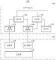
도 1을 참조하면, 생체 신호 측정 장치(100)는 생체 신호 측정 센서(110) 및 신호 처리기(150)를 포함한다. 생체 신호 측정 센서(110)는 광원부(120), 광 검출기(130) 및 삽입층(140)을 포함하고, 신호 처리기(150)는 광원 구동부(155), 신호 측정부(160), 제어부(165), 처리부(170) 및 통신부(175)를 포함할 수 있다.Referring to FIG. 1 , the
생체 신호 측정 센서(110)는 측정 대상에 부착되어 생체 신호를 측정할 수 있다. 예를 들어, 생체 신호 측정 센서(110)는 광이 측정 대상 내 혈관에 반사되거나 또는 혈관을 투과한 신호를 측정하여 측정 대상 내 혈관의 확장 및 수축에 따른 혈관 용적의 변화를 측정할 수 있다.The
광원 구동부(155)는 광원부(120)를 구동하기 위한 구동 신호를 출력한다. 광원부(120)는 광원 구동부(155)로부터 수신한 구동 신호에 기초하여 측정 대상을 향하여 서로 다른 파장의 광들을 선택적으로 방사할 수 있다. 광원부(120)는 예를 들어, 장파장의 광을 방사하기 위한 광원과 단파장의 광을 방사하기 위한 광원을 포함할 수 있다. 광원으로서 LED(Light Emitting Diode) 또는 레이저 다이오드(Laser Diode) 등이 이용될 수 있다. 제어부(165)는 광원 구동부(155)를 제어하여, 광원부(120)로부터 방사되는 광의 타입 및 광이 방사되는 시간 구간을 제어할 수 있다.The
삽입층(140)은 광원부(120)로부터 방사되는 광들을 선택적으로 투과 또는 반사시킬 수 있다. 예를 들어, 삽입층(140)은 광원부(120)로부터 방사된 장파장의 광은 투과시키고, 단파장의 광은 반사시킬 수 있다. 이러한 파장 선택성을 가지는 삽입층(140)을 통해, 생체 신호 측정 센서(110)는 심부 반사파와 표면 반사파를 구분하여 측정할 수 있다. 삽입층(140)은 외부의 힘에 의해 변형될 수 있고, 얇고 플렉서블(flexible)한 박막의 형태를 가질 수 있다. 삽입층(140)은 예를 들어, 실리콘 계열의 물질을 포함할 수 있고, 하나 이상의 레이어로 구성될 수 있다.The
일 실시예에 따르면, 생체 신호 측정 센서(110)는 생체 신호의 측정 방식에 따라 반사형 구조와 투과형 구조로 구분될 수 있다. 반사형 구조의 생체 신호 측정 센서에서는 측정 대상에 광을 방사한 후 측정 대상에 의해 반사되는 반사광의 양을 측정하고, 투과형 구조의 생체 신호 측정 센서에서는 측정 대상에 광을 방사한 후 측정 대상에 의해 흡수되지 않고 투과되는 투과광의 양을 측정한다.According to an embodiment, the
생체 신호 측정 센서(110)가 반사형 구조인 경우, 광원부(120)로부터 방사된 후 삽입층(140)을 투과한 광은 측정 대상의 심부(deep)에서 반사되고, 심부에서 반사된 반사광은 광 검출기(130)에 의해 검출될 수 있다. 이렇게 검출된 심부 반사파는 측정 대상 내 혈관의 확장 및 수축에 따른 혈관 용적의 변화에 대한 정보를 포함할 수 있다. 삽입층(140)에 의해 반사된 반사광은 광 검출기(130)에 의해 검출되고, 이렇게 검출된 표면 반사파는 혈관의 확장 및 수축에 따른 표면 변위의 변화 또는 접촉력의 변화에 대한 정보를 포함할 수 있다. 광 검출기(130)로서, 포토다이오드(photodiode), CCD(charge coupled device), 또는 포토트랜지스터 (phototransistor)가 이용될 수 있다.When the
생체 신호 측정 센서(110)가 투과형 구조인 경우, 광원부(120)로부터 방사된 후 삽입층(140)을 투과한 광 중 일부는 측정 대상을 투과하고, 측정 대상을 투과한 투과광은 광 검출기(130)에 의해 검출될 수 있다. 이렇게 검출된 심부 투과파는 측정 대상 내 혈액량의 변화에 따른 광 투과량에 대한 정보를 포함할 수 있다. 예를 들어, 혈관이 확장하여 혈액량이 증가하는 경우에는 측정 대상을 투과하는 광량이 줄어들고, 혈관이 축소하여 혈액량이 감소하는 경우에는 측정 대상을 투과하는 광량이 증가할 수 있다.When the
광 검출기(130)에 의해 검출된 신호는 신호 측정부(160)에 전달된다. 신호 측정부(160)는 검출된 신호를 증폭, 필터링 처리 및 디지털 신호로 변환 등의 신호 처리를 수행할 수 있다. 일 실시예에 따르면, 신호 측정부(160)는 도 2에 도시된 바와 같이, 광 검출기(130)로부터 전달된 신호를 증폭하기 위한 증폭부(210), 증폭된 신호를 샘플 및 홀드(sample and hold)하기 위한 샘플 및 홀드부(220), 샘플 및 홀드된 신호를 제공받는 버퍼(230), 버퍼(230)로부터 제공받는 신호를 필터링 처리하는 필터(240) 및 필터링 처리된 신호를 디지털 신호로 변환하기 위한 A/D(analog-to-digital) 컨버터(250)를 포함할 수 있다. 필터링 처리를 통해 획득하고자 하는 주파수 성분 이외의 주파수 성분이 제거되거나 또는 신호에 포함된 노이즈가 제거될 수 있다.The signal detected by the
신호 측정부(160)는 제어부(165)의 제어 하에 광원이 활성화되는 시간 구간에서 검출된 광 신호와 광원이 비활성화되는 시간 구간에서 검출된 광 신호를 구분하여 측정할 수 있다. 예를 들어, 제어부(165)는 샘플 및 홀드부(22)의 샘플링 타이밍과 홀드 타이밍을 조절하여 광원이 활성화되는 시간 구간에서 검출된 광 신호를 추출할 수 있다. 다시 도 1로 돌아오면, 처리부(170)는 신호 측정부(160)로부터 출력된 신호로부터 생체 신호 정보를 추출할 수 있다. 처리부(170)는 제어부(165)에 의해 제어될 수 있다.The
심부 반사파 또는 심부 투과파와 같은 심부 정보 및 표면 반사파와 같은 표면 정보의 신호 품질은 측정 대상 및 측정 환경 등에 따라 달라질 수 있다. 처리부(170)는 심부 정보 및 표면 정보 중 신호 품질이 더 양호한 것에 기초하여 생체 신호 정보를 추출하거나, 또는 심부 정보 및 표면 정보를 조합하여 생체 신호 정보를 추출할 수 있다. 처리부(170)는 어플리케이션에 따라 심부 정보 및 표면 정보로부터 심박, 혈중 산소 포화도, 혈압 또는 혈관의 탄력성 등에 관한 정보를 획득할 수 있다.Signal quality of deep information such as a deep reflected wave or a deep transmitted wave and surface information such as a surface reflected wave may vary depending on a measurement target, a measurement environment, and the like. The
다른 실시예에 따르면, 삽입층(140)에 의해 반사된 반사광에 의한 표면 정보는 동잡음을 추정하는데 이용될 수 있다. 예를 들어, 처리부(170)는 측정 표면 정보에 기초하여 심부 정보에 포함된 동잡음을 추정하고, 추정된 동잡음과 심부 정보를 적응 필터링(adaptive filtering)하여 심부 정보로부터 동잡음을 제거할 수 있다. 처리부(170)는 동잡음이 제거된 심부 정보로부터 생체 신호 정보를 추출할 수 있다.According to another embodiment, the surface information by the reflected light reflected by the
통신부(175)는 제어부(165)의 제어 하에 처리부(170)에 의해 추출된 생체 신호 정보를 신호 처리기(150)의 외부로 전송할 수 있다.The
도 3은 다른 실시예에 따른 생체 신호 측정 장치의 동작을 설명하기 위한 도면이다. 도 3을 참조하면, 생체 신호 측정 장치(300)는 생체 신호 측정 센서(310) 및 신호 처리기(355)를 포함할 수 있다. 생체 신호 측정 센서(310)는 광원부(320), 광 검출기(330), 삽입층(340) 및 변위/힘 검출기(350)를 포함하고, 신호 처리기(355)는 광원 구동부(360), 신호 측정부(365), 제어부(370), 처리부(375) 및 통신부(380)를 포함할 수 있다.3 is a diagram for explaining an operation of a biosignal measuring apparatus according to another exemplary embodiment. Referring to FIG. 3 , the
생체 신호 측정 센서(310)는 광을 이용하여 혈관 용적의 변화에 따른 측정 대상의 심부 정보뿐만 아니라 측정 대상의 표면에서의 변위 또는 접촉력의 변화에 따른 표면 정보를 측정할 수 있다. 측정 대상 내 혈관의 확장 및 수축은 측정 대상의 표면에 힘을 가하여 표면의 변위 또는 접촉력을 발생시키고, 생체 신호 측정 센서(310)는 이와 같은 표면의 변위 또는 접촉력을 측정할 수 있다. 예를 들어, 생체 신호 측정 센서(310)는 동일한 측정 부위에서 광을 이용한 맥파 정보와 피부의 변위 또는 접촉력을 이용한 맥파 정보를 동시에 측정할 수 있다.The
광원 구동부(360)는 제어부(370)의 제어 하에 광원부(320)를 구동하기 위한 구동 신호를 출력하고, 광원부(320)는 구동 신호에 기초하여 적어도 하나의 광을 측정 대상을 향해 방사할 수 있다. 삽입층(340)은 광원부(320)로부터 방사된 광을 투과시킬 수 있다. 광 검출기(330)는 광원부(320)로부터 방사된 광이 측정 대상의 심부에서 반사된 반사광을 검출하거나 또는 광원부(320)로부터 방사된 광이 측정 대상을 투과한 투과광을 검출할 수 있다.The
변위/힘 검출기(350)는 측정 대상 내 혈류량의 변화에 따른 표면 변위의 변화 또는 접촉력의 변화를 검출할 수 있다. 또는, 변위/힘 검출기(350)는 표면 변위 또는 접촉력의 변화에 따른 압력의 변화를 측정할 수 있다. 일 실시예에 따르면, 변위/힘 검출기(350)는 삽입층(340)에 단일 레이어 또는 멀티 레이어 구조로 형성되어 측정 대상의 맥파의 진동에 따른 피부의 변위 또는 접촉력을 검출할 수 있다. 변위/힘 검출기(350)는 혈류량의 변화에 따른 표면 변위 또는 접촉력의 변화를 전기 신호의 변화로 출력하는 압전 소자(piezoelectric element) 또는 압저항(piezoresistive) 소자를 포함할 수 있다. 신호 처리기(355)는 광 검출기(330)에 의해 획득된 신호 및 변위/힘 검출기(350)에 의해 획득된 신호를 선택적으로 이용하거나 또는 두 신호를 조합하여 생체 신호 정보를 획득할 수 있다.The displacement/
광 검출기(330)에 의해 검출된 신호 및 변위/힘 검출기(350)에 의해 검출된 신호는 신호 측정부(365)에 전달된다. 일 실시예에 따르면, 신호 측정부(365)는 광 검출기(330)에 의해 검출된 신호를 처리하기 위한 제1 신호 측정부(미도시)와 변위/힘 검출기(350)에 의해 검출된 신호를 처리하기 위한 제2 신호 측정부(410)를 포함할 수 있다. 제1 신호 측정부는 도 2의 신호 측정부(160)에 포함된 증폭부(210), 샘플 및 홀드부(220), 버퍼(230), 필터(240), A/D 컨버터(250)를 포함할 수 있다.The signal detected by the
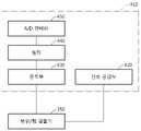
일 실시예에 따르면, 제2 신호 측정부(410)는 도 4에 도시된 바와 같이, 변위/힘 검출기(350)가 표면 변위 또는 접촉력을 측정하는데 이용되는 전기 신호를 공급하는 신호 공급부(420), 변위/힘 검출기(350)로부터 전달된 신호를 증폭하기 위한 증폭부(430), 증폭된 신호를 필터링 처리하기 위한 필터(440), 필터링 처리된 신호를 디지털 신호로 변환하기 위한 A/D 컨버터(450)를 포함할 수 있다. 다시, 도 3으로 돌아오면, 처리부(375)는 신호 측정부(160)로부터 출력된 신호로부터 생체 신호 정보를 추출할 수 있다. 추출된 생체 신호 정보는 통신부(380)를 통해 외부로 전송될 수 있다. 제어부(370)는 광원 구동부(360), 신호 측정부(365), 처리부(375) 및 통신부(380)의 동작을 제어할 수 있다.According to one embodiment, the second
도 5a 및 도 5b는 일 실시예에 따른 반사형 구조의 생체 신호 측정 센서를 도시하는 도면들이다. 도 5a 및 도 5b를 참조하면, 생체 신호 측정 센서(500)는 광원부(510), 삽입층(520), 광 검출기(530) 및 쉴드(shield)(540)를 포함할 수 있다. 광원부(510)는 측정 대상(550)을 향하여 제1 광 및 제2 광을 선택적으로 방사할 수 있다. 예를 들어, 제1 광은 적외선 또는 적색 광과 같은 장파장의 광이고, 제2 광은 청색 광과 같은 단파장의 광일 수 있다.5A and 5B are diagrams illustrating a biosignal measuring sensor having a reflective structure according to an exemplary embodiment. 5A and 5B , the
삽입층(520)은 제1 광을 투과시키고, 제2 광을 반사시킬 수 있다. 삽입층(520)은 도 5a에서와 같이 생체 신호 측정 센서(500)에 결합되거나 또는 도 5b에서와 같이 생체 신호 측정 센서(500)와 분리되어 측정 대상(550)의 표면(예를 들어, 피부)에 부착되는 스티커 또는 임시 타투(tattoo)의 형태를 가질 수 있다.The
광 검출기(530)는 측정 대상(550)의 심부에서 반사된 제1 광 및 삽입층(520)에 의해 반사된 제2 광을 검출할 수 있다. 측정 대상(550)의 심부에서 반사된 제1 광은 측정 대상(550) 내 혈관(560)의 용적 변화에 따른 심부 반사파 정보를 포함하고, 삽입층(520)에 의해 반사된 제2 광은 혈관(560)의 용적 변화에 따른 표면 반사파 정보를 포함할 수 있다. 측정 대상(550)의 심부에서 반사된 제1 광은, 측정 대상(550) 내 혈류량의 변화에 따라 반사되는 광 특성이 달라질 수 있다. 예를 들어, 혈류량의 변화에 따라 반사되는 광량이 달라지거나 반사되는 광의 파장이 달라질 수 있다. 삽입층(520)에 의해 반사된 제2 광은, 측정 대상(550) 내 혈류량의 변화에 따른 측정 대상(550)의 표면 변위 또는 접촉력에 기초하여 반사되는 광량이 변할 수 있다. 쉴드(540)는 광원부(510)와 광 검출기(530)의 외측에 구비되고, 광 검출기(530)에 외부 광이 유입되는 것을 차단할 수 있다. 쉴드(540)는 생체 신호 측정 센서(500)의 엘리먼트들을 보호하는 하우징(housing) 또는 케이스(case)의 역할을 수행할 수 있다.The
다른 실시예에 따르면, 광원부(510)는 제1 각도로 편광된 제1 광과 제2 각도로 편광된 제2 광을 선택적으로 방사하고, 삽입층(520)은 제1 각도로 편광된 광을 투과시키고, 제2 각도로 편광된 광을 반사시키는 편광 필터의 역할을 할 수 있다. 예를 들어, 제1 광은 0도로 편광 또는 선편광될 수 있고, 제2 광은 90도 편광 또는 회전 편광될 수 있다.According to another embodiment, the
도 6 및 도 7은 다른 실시예에 따른 반사형 구조의 생체 신호 측정 센서를 도시하는 도면들이다. 도 6을 참조하면, 생체 신호 측정 센서(600)는 광원부(610), 삽입층(620), 광 검출기(630), 변위/힘 검출기(640) 및 쉴드(650)를 포함할 수 있다. 광원부(610)는, 예를 들어 적외선 또는 적색 광과 같은 장파장의 광을 측정 대상(660)을 향하여 방사할 수 있다. 삽입층(620)은 광원부(610)로부터 방사된 광을 투과시킬 수 있다. 광 검출기(630)는 측정 대상(660)의 심부에서 반사된 반사광을 검출할 수 있다. 심부에서 반사된 반사광은 측정 대상(660) 내 혈관(670)의 용적 변화에 따른 심부 반사파 정보를 포함할 수 있다. 쉴드(650)는 광원부(610)와 광 검출기(630)의 외측에 구비되고, 광 검출기(630)에 외부 광이 유입되는 것을 차단할 수 있다.6 and 7 are diagrams illustrating a biosignal measuring sensor having a reflective structure according to another exemplary embodiment. Referring to FIG. 6 , the
변위/힘 검출기(640)는 맥파의 진동에 따른 측정 대상(660)의 표면 변위 또는 접촉력(contact force)을 측정할 수 있다. 변위/힘 검출기(640)는 삽입층(620)에 단일 레이어 또는 멀티 레이어 구조로 형성될 수 있다. 측정된 측정 대상(660)의 표면 변위 또는 접촉력으로부터 측정 대상(660)의 맥파가 추출될 수 있다. 일 실시예에 따르면, 도 6에 도시된 것과 같이 변위/힘 검출기(640)는 측정 대상(660)의 표면 변위/힘을 전기 신호의 변화로 출력하는 압전 소자 또는 압저항 소자를 이용하여 표면 변위 또는 접촉력의 변화를 검출할 수 있다. 압저항 소자는 스트레인 게이지(strain gauge)일 수 있다. 일 실시예에 따르면, 압전 소자 또는 압저항 소자는 삽입층(620) 상에 형성될 수 있다.The displacement/
다른 실시예에 따르면, 변위/힘 검출기는 커패시턴스(capacitance)의 변화를 측정하여 측정 대상(660)의 표면 변위 또는 접촉력의 변화를 검출할 수 있다. 도 7를 참조하면, 생체 신호 측정 센서(700)는 커패시터 소자를 형성하는 제1 전극(710) 및 제2 전극(720)을 포함할 수 있다. 제1 전극(710)은 삽입층(620) 상에 형성되고, 제2 전극(720)은 제1 전극(710)과 이격되어 위치할 수 있다. 일 실시예에 따르면, 실리콘 계열의 물질로 구성된 삽입층(620)에 전도성을 지닌 물질을 도핑(doping)하여 제1 전극(710)이 형성될 수 있다.According to another embodiment, the displacement/force detector may measure a change in capacitance to detect a change in surface displacement or contact force of the
맥파 진동은 측정 대상(660)의 표면을 진동하게 하고, 측정 대상(660)의 표면 진동에 따라 제1 전극(710)과 제2 전극(720) 간의 거리가 달라질 수 있다. 제1 전극(710)과 제2 전극(720) 간의 거리에 따라 제1 전극(710)과 제2 전극(720)에 의해 형성되는 커패시터 소자의 커패시턴스가 결정될 수 있다. 변위/힘 검출기는 제1 전극(710)과 제2 전극(720) 간의 거리 변화에 따른 커패시턴스의 변화에 기초하여 맥파 신호가 반영된 표면 변위 또는 접촉력의 변화를 검출할 수 있다.The pulse wave vibration causes the surface of the
도 8a 및 도 8b는 일 실시예에 따른 투과형 구조의 생체 신호 측정 센서를 도시하는 도면들이다. 도 8a를 참조하면, 생체 신호 측정 센서(800)는 광원부, 삽입층(820), 광 검출기(830) 및 쉴드(840)를 포함할 수 있다. 광원부는 측정 대상(850)을 향하여 제1 광을 방사하는 제1 광원(815)과 제2 광을 방사하는 제2 광원(810)을 포함할 수 있다. 제1 광원(815)으로부터 방사된 제1 광의 일부는 측정 대상(850)을 투과하고, 측정 대상(850)을 투과한 투과광은 광 검출기(830)에 의해 검출될 수 있다. 제2 광원(810)으로부터 방사된 제2 광은 삽입층(820)에 의해 반사되고, 삽입층(820)에 의해 반사된 제2 광은 광 검출기(830)에 의해 검출될 수 있다. 광 검출기(830)에 의해 검출되는 투과광의 광량은 측정 대상(850) 내 혈관(860)의 확장 및 수축에 따른 혈액량의 변화에 따라 달라질 수 있다. 제1 광원(815)은 쉴드(840)의 일측에 위치하고, 제2 광원(810) 및 광 검출기(830)는 쉴드(840)의 타측에 위치할 수 있다.8A and 8B are diagrams illustrating a biosignal measuring sensor having a transmissive structure according to an exemplary embodiment. Referring to FIG. 8A , the
다른 실시예에 따르면, 제1 광원(815)은 제1 각도로 편광된 제1 광을 방사하고, 제2 광원(810)은 제2 각도로 편광된 제2 광을 제어 신호에 기초하여 방사할 수 있다. 삽입층(820)은 제1 각도로 편광된 광을 투과시키고, 제2 각도로 편광된 광을 반사시킬 수 있다.According to another embodiment, the first
도 8b에 도시된 생체 신호 측정 센서(800)은, 광원부(870)가 제1 광 및 제2 광을 선택적으로 방사할 수 있고, 측정 대상(850)을 투과한 제1 광을 검출하는 제1 광 검출기(835)와 삽입층(820)에 의해 반사된 제2 광을 검출하는 제2 광 검출기(830)를 포함할 수 있다. 제1 광 검출기(835)는 쉴드(840)의 일측에 위치하고, 광원부(810)와 제2 광 검출기(830)는 쉴드(840)의 타측에 위치할 수 있다.In the
도 9 및 도 10은 다른 실시예에 따른 투과형 구조의 생체 신호 측정 센서를 도시하는 도면들이다. 도 9를 참조하면, 생체 신호 측정 센서(900)는 광원부(910), 삽입층(920), 광 검출기(930), 변위/힘 검출기(940) 및 쉴드(950)를 포함할 수 있다. 광원부(910)는 측정 대상(960)을 향하여 광을 방사하고, 삽입층(920)은 광원부(910)로부터 방사된 광을 투과시킬 수 있다. 광 검출기(930)는 측정 대상(960)을 투과한 투과광을 검출할 수 있다. 변위/힘 검출기는 삽입층(920) 상에 구비되어 혈관(970)의 확장 및 수축에 따른 측정 대상(960)의 표면 변위 또는 접촉력의 변화를 검출할 수 있다. 예를 들어, 변위/힘 검출기(940)로서 압전 소자 또는 스트레인 게이지가 이용될 수 있고, 압전 소자 또는 스트레인 게이지는 삽입층(920) 상에 형성될 수 있다. 도 10은 변위/힘 검출기가 제1 전극(1010) 및 제2 전극(1020) 간의 거리 변화에 따른 커패시턴스의 변화를 측정하여 측정 대상(960)의 표면 변위 또는 접촉력의 변화를 검출하는 투과형 구조의 생체 신호 측정 센서(1000)를 도시하고 있다.9 and 10 are diagrams illustrating a biosignal measuring sensor having a transmissive structure according to another exemplary embodiment. Referring to FIG. 9 , the
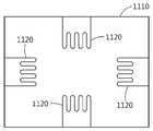
도 11 및 도 12는 일 실시예에 따른 측정 대상의 표면 변위 또는 힘을 검출하기 위한 삽입층의 구조를 설명하기 위한 도면들이다. 도 11을 참조하면, 삽입층(1110)의 변형에 따른 압력(strain)을 측정하기 위한 스트레인 게이지(1120)가 삽입층(1110)에 형성되어 있다. 측정 대상 내 맥파의 진동은 측정 대상 표면의 진동으로 나타나고, 측정 대상 표면의 진동은 측정 대상 표면에 부착된 삽입층(1110)에 압력을 가하게 된다. 압력에 의해 삽입층(1110)은 변형되고, 스트레인 게이지(1120)는 삽입층(1110)에 가해지는 압력을 전기적 신호로서 검출할 수 있다.11 and 12 are diagrams for explaining a structure of an insertion layer for detecting a surface displacement or force of a measurement target according to an exemplary embodiment. Referring to FIG. 11 , a
도 12를 참조하면, 삽입층(1210) 상에 형성된 제1 전극(1220)이 도시되어 있다. 제1 전극(1220)은 제1 전극(1220)과 이격된 제2 전극과 함께 커패시터를 형성하고, 생체 신호 측정 센서는 제1 전극(1220)과 제2 전극 간의 거리 변화에 따른 커패시턴스의 변화를 측정할 수 있다. 제1 전극(1220)은 예를 들어, 삽입층(1210) 상에 전도성 물질을 패터닝(patterning)하거나 또는 삽입층(1210)의 특정 영역을 불순물로 도핑(doping)하는 것에 의해 형성될 수 있다.Referring to FIG. 12 , the
도 13은 일 실시예에 따른 생체 신호 처리 방법의 동작을 설명하기 위한 흐름도이다. 생체 신호 처리 방법은 위에 설명된 생체 신호 처리 장치에 의해 수행될 수 있으며, 도 1 내지 도 12의 관련 설명이 도 13에 적용될 수 있다.13 is a flowchart illustrating an operation of a biosignal processing method according to an exemplary embodiment. The biosignal processing method may be performed by the biosignal processing apparatus described above, and the related descriptions of FIGS. 1 to 12 may be applied to FIG. 13 .
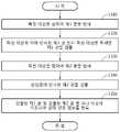
단계(1310)에서, 생체 신호 처리 장치는 측정 대상을 향하여 제1 광을 방사할 수 있다. 예를 들어, 생체 신호 처리 장치는 적외선 또는 적색 광의 제1 광을 방사할 수 있다. 방사된 제1 광은 삽입층을 투과한 후에 측정 대상에 도달할 수 있다. 일 실시예에 따르면, 측정 대상에 도달한 제1 광은 측정 대상의 심부에서 반사되고, 단계(1320)에서 생체 신호 처리 장치는 삽입층을 투과하고, 측정 대상에 의해 반사된 제1 광을 검출할 수 있다. 다른 실시예에 따르면, 단계(1320)에서 생체 신호 처리 장치는 측정 대상을 투과한 제1 광을 검출할 수 있다.In
단계(1330)에서, 생체 신호 처리 장치는 측정 대상을 향하여 제2 광을 방사할 수 있다. 예를 들어, 생체 신호 처리 장치는 청색 광과 같이 제1 광에 비해 상대적으로 파장이 짧은 제2 광을 방사할 수 있다. 방사된 제2 광은 삽입층에 의해 반사되고, 단계(1340)에서 생체 신호 처리 장치는 삽입층에 의해 반사된 제2 광을 검출할 수 있다.In
단계(1350)에서, 생체 신호 처리 장치는 검출된 제1 광 및 검출된 제2 광 중 하나 이상에 기초하여 생체 신호 정보를 획득할 수 있다. 생체 신호 처리 장치는 검출된 제1 광에 대한 신호 및 검출된 제2 광에 대한 신호 중 신호 품질이 좋은 신호에 기초하여 생체 신호 정보를 추출하거나 또는 두 신호를 조합하여 생체 신호 정보를 추출할 수 있다.In
이상에서 설명된 실시예들은 하드웨어 구성요소, 소프트웨어 구성요소, 및/또는 하드웨어 구성요소 및 소프트웨어 구성요소의 조합으로 구현될 수 있다. 예를 들어, 실시예들에서 설명된 장치, 방법 및 구성요소는, 예를 들어, 프로세서, 콘트롤러, ALU(arithmetic logic unit), 디지털 신호 프로세서(digital signal processor), 마이크로컴퓨터, FPGA(field programmable gate array), PLU(programmable logic unit), 마이크로프로세서, 또는 명령(instruction)을 실행하고 응답할 수 있는 다른 어떠한 장치와 같이, 하나 이상의 범용 컴퓨터 또는 특수 목적 컴퓨터를 이용하여 구현될 수 있다. 처리 장치는 운영 체제(OS) 및 상기 운영 체제 상에서 수행되는 하나 이상의 소프트웨어 애플리케이션을 수행할 수 있다. 또한, 처리 장치는 소프트웨어의 실행에 응답하여, 데이터를 접근, 저장, 조작, 처리 및 생성할 수도 있다. 이해의 편의를 위하여, 처리 장치는 하나가 사용되는 것으로 설명된 경우도 있지만, 해당 기술분야에서 통상의 지식을 가진 자는, 처리 장치가 복수 개의 처리 요소(processing element) 및/또는 복수 유형의 처리 요소를 포함할 수 있음을 알 수 있다. 예를 들어, 처리 장치는 복수 개의 프로세서 또는 하나의 프로세서 및 하나의 콘트롤러를 포함할 수 있다. 또한, 병렬 프로세서(parallel processor)와 같은, 다른 처리 구성(processing configuration)도 가능하다.The embodiments described above may be implemented by a hardware component, a software component, and/or a combination of a hardware component and a software component. For example, the apparatus, methods and components described in the embodiments may include, for example, a processor, a controller, an arithmetic logic unit (ALU), a digital signal processor, a microcomputer, a field programmable gate (FPGA). array), a programmable logic unit (PLU), a microprocessor, or any other device capable of executing and responding to instructions, may be implemented using one or more general purpose or special purpose computers. The processing device may execute an operating system (OS) and one or more software applications running on the operating system. The processing device may also access, store, manipulate, process, and generate data in response to execution of the software. For convenience of understanding, although one processing device is sometimes described as being used, one of ordinary skill in the art will recognize that the processing device includes a plurality of processing elements and/or a plurality of types of processing elements. It can be seen that may include For example, the processing device may include a plurality of processors or one processor and one controller. Other processing configurations are also possible, such as parallel processors.
소프트웨어는 컴퓨터 프로그램(computer program), 코드(code), 명령(instruction), 또는 이들 중 하나 이상의 조합을 포함할 수 있으며, 원하는 대로 동작하도록 처리 장치를 구성하거나 독립적으로 또는 결합적으로(collectively) 처리 장치를 명령할 수 있다. 소프트웨어 및/또는 데이터는, 처리 장치에 의하여 해석되거나 처리 장치에 명령 또는 데이터를 제공하기 위하여, 어떤 유형의 기계, 구성요소(component), 물리적 장치, 가상 장치(virtual equipment), 컴퓨터 저장 매체 또는 장치, 또는 전송되는 신호 파(signal wave)에 영구적으로, 또는 일시적으로 구체화(embody)될 수 있다. 소프트웨어는 네트워크로 연결된 컴퓨터 시스템 상에 분산되어서, 분산된 방법으로 저장되거나 실행될 수도 있다. 소프트웨어 및 데이터는 하나 이상의 컴퓨터 판독 가능 기록 매체에 저장될 수 있다.The software may comprise a computer program, code, instructions, or a combination of one or more thereof, which configures a processing device to operate as desired or is independently or collectively processed You can command the device. The software and/or data may be any kind of machine, component, physical device, virtual equipment, computer storage medium or device, to be interpreted by or to provide instructions or data to the processing device. , or may be permanently or temporarily embody in a transmitted signal wave. The software may be distributed over networked computer systems and stored or executed in a distributed manner. Software and data may be stored in one or more computer-readable recording media.
실시예에 따른 방법은 다양한 컴퓨터 수단을 통하여 수행될 수 있는 프로그램 명령 형태로 구현되어 컴퓨터 판독 가능 매체에 기록될 수 있다. 컴퓨터 판독 가능 매체는 프로그램 명령, 데이터 파일, 데이터 구조 등을 단독으로 또는 조합하여 포함할 수 있다. 컴퓨터 판독 가능 매체에 기록되는 프로그램 명령은 실시예를 위하여 특별히 설계되고 구성된 것들이거나 컴퓨터 소프트웨어 당업자에게 공지되어 사용 가능한 것일 수도 있다. 컴퓨터 판독 가능 기록 매체의 예에는 하드 디스크, 플로피 디스크 및 자기 테이프와 같은 자기 매체(magnetic media), CD-ROM, DVD와 같은 광기록 매체(optical media), 플롭티컬 디스크(floptical disk)와 같은 자기-광 매체(magneto-optical media), 및 롬(ROM), 램(RAM), 플래시 메모리 등과 같은 프로그램 명령을 저장하고 수행하도록 특별히 구성된 하드웨어 장치가 포함된다. 프로그램 명령의 예에는 컴파일러에 의해 만들어지는 것과 같은 기계어 코드뿐만 아니라 인터프리터 등을 사용해서 컴퓨터에 의해서 실행될 수 있는 고급 언어 코드를 포함한다. 상기된 하드웨어 장치는 실시예의 동작을 수행하기 위해 하나 이상의 소프트웨어 모듈로서 작동하도록 구성될 수 있으며, 그 역도 마찬가지이다.The method according to the embodiment may be implemented in the form of program instructions that can be executed through various computer means and recorded in a computer-readable medium. The computer-readable medium may include program instructions, data files, data structures, and the like, alone or in combination. The program instructions recorded on the computer-readable medium may be specially designed and configured for the embodiment, or may be known and available to those skilled in the art of computer software. Examples of the computer-readable recording medium include magnetic media such as hard disks, floppy disks and magnetic tapes, optical media such as CD-ROMs and DVDs, and magnetic such as floppy disks. - includes magneto-optical media, and hardware devices specially configured to store and execute program instructions, such as ROM, RAM, flash memory, and the like. Examples of program instructions include not only machine language codes such as those generated by a compiler, but also high-level language codes that can be executed by a computer using an interpreter or the like. The hardware devices described above may be configured to operate as one or more software modules to perform the operations of the embodiments, and vice versa.
이상과 같이 비록 한정된 도면에 의해 실시예들이 설명되었으나, 해당 기술분야에서 통상의 지식을 가진 자라면 상기의 기재로부터 다양한 수정 및 변형이 가능하다. 예를 들어, 설명된 기술들이 설명된 방법과 다른 순서로 수행되거나, 및/또는 설명된 시스템, 구조, 장치, 회로 등의 구성요소들이 설명된 방법과 다른 형태로 결합 또는 조합되거나, 다른 구성요소 또는 균등물에 의하여 대치되거나 치환되더라도 적절한 결과가 달성될 수 있다. 그러므로, 다른 구현들, 다른 실시예들 및 특허청구범위와 균등한 것들도 후술하는 특허청구범위의 범위에 속한다.As described above, although the embodiments have been described with reference to the limited drawings, various modifications and variations are possible from the above description by those of ordinary skill in the art. For example, the described techniques are performed in a different order than the described method, and/or the described components of the system, structure, apparatus, circuit, etc. are combined or combined in a different form than the described method, or other components Or substituted or substituted by equivalents may achieve an appropriate result. Therefore, other implementations, other embodiments, and equivalents to the claims are also within the scope of the following claims.
Claims (19)
Translated fromKorean상기 제1 광을 투과시키고, 상기 제2 광을 반사시키는 삽입층; 및
상기 측정 대상에 의해 반사된 제1 광 또는 상기 측정 대상을 투과한 제1 광을 검출하고, 상기 삽입층에 의해 반사된 제2 광을 검출하는 광 검출기
를 포함하고,
상기 삽입층에 의해 반사된 제2 광은,
상기 측정 대상의 표면 변위의 변화 또는 상기 측정 대상의 표면에서의 접촉력의 변화에 기초하여 반사되는 광 특성이 변하는 것을 특징으로 하는 생체 신호 측정 장치.a light source for selectively emitting the first light and the second light toward the measurement target;
an insertion layer that transmits the first light and reflects the second light; and
A photodetector that detects the first light reflected by the measurement object or the first light transmitted through the measurement object, and detects the second light reflected by the insertion layer
including,
The second light reflected by the insertion layer,
A biosignal measuring apparatus, characterized in that the reflected optical property changes based on a change in the displacement of the surface of the measurement object or a change in a contact force on the surface of the measurement object.
상기 제1 광의 파장은, 상기 제2 광의 파장보다 긴 것을 특징으로 하는 생체 신호 측정 장치.According to claim 1,
A wavelength of the first light is longer than a wavelength of the second light.
상기 제1 광은, 제1 각도로 편광된 광이고,
상기 제2 광은, 상기 제1 각도와 다른 제2 각도로 편광된 광이며,
상기 삽입층은, 상기 제1 각도로 편광된 광을 투과시키고, 상기 제2 각도로 편광된 광을 반사시키는, 생체 신호 측정 장치.According to claim 1,
The first light is light polarized at a first angle,
The second light is light polarized at a second angle different from the first angle,
The insertion layer transmits the light polarized at the first angle and reflects the light polarized at the second angle.
상기 측정 대상에 의해 반사된 제1 광은,
상기 측정 대상 내 혈류량의 변화에 따라 반사되는 광 특성이 달라지는 것을 특징으로 하는 생체 신호 측정 장치.According to claim 1,
The first light reflected by the measurement object is
A biosignal measuring apparatus, characterized in that the reflected light characteristics vary according to a change in blood flow in the measurement target.
상기 삽입층은,
외부 힘에 의해 물리적으로 외형이 변형될 수 있는, 생체 신호 측정 장치.According to claim 1,
The insert layer,
A biosignal measuring device capable of being physically deformed by an external force.
상기 삽입층은,
상기 측정 대상의 표면에 부착되는 스티커 및 타투 중 어느 하나인 것을 특징으로 하는 생체 신호 측정 장치.According to claim 1,
The insert layer,
A biosignal measuring device, characterized in that it is any one of a sticker and a tattoo attached to the surface of the measurement target.
상기 광 검출기로부터 입력되는 신호들 중 적어도 하나에 기초하여 생체 신호 정보를 추출하는 신호 처리기
를 더 포함하는 생체 신호 측정 장치.According to claim 1,
A signal processor extracting biosignal information based on at least one of the signals input from the photodetector
A biosignal measuring device further comprising a.
상기 생체 신호 측정 장치는,
모바일 장치 또는 웨어러블 장치에 포함되어 동작하는, 생체 신호 측정 장치.According to claim 1,
The biosignal measuring device,
A biosignal measuring device that operates while being included in a mobile device or a wearable device.
상기 광 검출기에 외부 광이 유입되는 것을 방지하기 위한 쉴드
를 더 포함하는 생체 신호 측정 장치.According to claim 1,
A shield for preventing external light from entering the photodetector
A biosignal measuring device further comprising a.
상기 광원부는,
상기 측정 대상을 향하여 상기 제1 광을 방사하고, 상기 쉴드의 일측에 위치하는 제1 광원; 및
상기 측정 대상을 향하여 상기 제2 광을 방사하고, 상기 쉴드의 타측에 위치하는 제2 광원
을 포함하는 생체 신호 측정 장치.11. The method of claim 10,
The light source unit,
a first light source emitting the first light toward the measurement target and positioned at one side of the shield; and
A second light source emitting the second light toward the measurement target and positioned on the other side of the shield
A biosignal measuring device comprising a.
상기 광 검출기는,
상기 측정 대상을 투과한 제1 광을 검출하고, 상기 쉴드의 일측에 위치하는 제1 광 검출기; 및
상기 삽입층에 의해 반사된 제2 광을 검출하고, 상기 쉴드의 타측에 위치하는 제2 광 검출기
를 포함하는 생체 신호 측정 장치.11. The method of claim 10,
The photodetector is
a first photodetector configured to detect the first light passing through the measurement target and positioned at one side of the shield; and
A second photodetector that detects the second light reflected by the insertion layer and is located on the other side of the shield
A biosignal measuring device comprising a.
상기 생체 신호 측정 센서의 광원부가, 측정 대상을 향하여 제1 광을 방사하는 단계;
상기 생체 신호 측정 센서의 광 검출기가, 상기 측정 대상에 의해 반사된 제1 광 또는 상기 측정 대상을 투과한 제1 광을 검출하는 단계;
상기 광원부가, 상기 측정 대상을 향하여 제2 광을 방사하는 단계;
상기 광 검출기가, 상기 삽입층에 반사된 상기 제2 광을 검출하는 단계; 및
상기 생체 신호 측정 센서의 신호 처리기가, 상기 검출된 제1 광 및 상기 검출된 제2 광 중 적어도 하나에 기초하여 상기 측정 대상의 생체 신호 정보를 획득하는 단계
를 포함하고,
상기 삽입층에 의해 반사된 제2 광은,
상기 측정 대상의 표면 변위의 변화 또는 상기 측정 대상의 표면에서의 접촉력의 변화에 기초하여 반사되는 광 특성이 변하는 것을 특징으로 하는, 생체 신호 측정 방법.A biosignal measuring method for measuring a biosignal using a biosignal measuring sensor including an insertion layer, the biosignal measuring method comprising:
emitting, by the light source unit of the biosignal measuring sensor, a first light toward a measurement target;
detecting, by the photodetector of the biosignal measuring sensor, the first light reflected by the measurement object or the first light transmitted through the measurement object;
emitting, by the light source unit, a second light toward the measurement target;
detecting, by the photodetector, the second light reflected by the insertion layer; and
acquiring, by the signal processor of the biosignal measuring sensor, biosignal information of the measurement target based on at least one of the detected first light and the detected second light
including,
The second light reflected by the insertion layer,
A method for measuring a biosignal, characterized in that the reflected light property is changed based on a change in surface displacement of the measurement object or a change in a contact force on the surface of the measurement object.
Priority Applications (5)
| Application Number | Priority Date | Filing Date | Title |
|---|---|---|---|
| KR1020150096547AKR102436728B1 (en) | 2015-07-07 | 2015-07-07 | Apparatus and method for measuring bio-signal |
| US14/968,975US9737220B2 (en) | 2015-07-07 | 2015-12-15 | Apparatus and method for measuring biosignal |
| EP16152026.7AEP3114986B1 (en) | 2015-07-07 | 2016-01-20 | Apparatus and method for measuring biosignal |
| JP2016012066AJP6814540B2 (en) | 2015-07-07 | 2016-01-26 | Biological signal measuring device and method |
| CN201610090001.9ACN106333662B (en) | 2015-07-07 | 2016-02-17 | Apparatus and method for measuring biological signals |
Applications Claiming Priority (1)
| Application Number | Priority Date | Filing Date | Title |
|---|---|---|---|
| KR1020150096547AKR102436728B1 (en) | 2015-07-07 | 2015-07-07 | Apparatus and method for measuring bio-signal |
Publications (2)
| Publication Number | Publication Date |
|---|---|
| KR20170006106A KR20170006106A (en) | 2017-01-17 |
| KR102436728B1true KR102436728B1 (en) | 2022-08-26 |
Family
ID=55699301
Family Applications (1)
| Application Number | Title | Priority Date | Filing Date |
|---|---|---|---|
| KR1020150096547AActiveKR102436728B1 (en) | 2015-07-07 | 2015-07-07 | Apparatus and method for measuring bio-signal |
Country Status (5)
| Country | Link |
|---|---|
| US (1) | US9737220B2 (en) |
| EP (1) | EP3114986B1 (en) |
| JP (1) | JP6814540B2 (en) |
| KR (1) | KR102436728B1 (en) |
| CN (1) | CN106333662B (en) |
Families Citing this family (20)
| Publication number | Priority date | Publication date | Assignee | Title |
|---|---|---|---|---|
| KR102455430B1 (en)* | 2015-01-12 | 2022-10-17 | 삼성전자주식회사 | Method and apparatus for simultaneously detecting body surface pressure and blood volume |
| GB2547736B (en)* | 2016-07-01 | 2018-06-20 | Polar Electro Oy | Photoplethysmographic sensor configuration |
| US11395628B2 (en)* | 2017-02-16 | 2022-07-26 | Samsung Electronics Co., Ltd. | Method of providing service based on biometric information and wearable electronic device |
| US11612330B2 (en) | 2017-07-21 | 2023-03-28 | Ecole polytechnique fédérale de Lausanne (EPFL) | Health monitoring device including pinned photodiode |
| CN109427244B (en)* | 2017-08-30 | 2019-11-08 | 上海耕岩智能科技有限公司 | Operation method and device for physical health detection |
| US11529058B2 (en)* | 2017-11-29 | 2022-12-20 | Edwards Lifesciences Corporation | Atrial stretch measurement for atrial fibrillation prevention |
| KR102580267B1 (en)* | 2018-01-18 | 2023-09-19 | 삼성전자주식회사 | Apparatus for measuring biological signal |
| KR102534002B1 (en)* | 2018-02-14 | 2023-05-19 | 삼성전자주식회사 | Electronic device including a sensor for sensing biometric information using a plurality of receiving units and control method thereof |
| EP3545821A1 (en) | 2018-03-27 | 2019-10-02 | Koninklijke Philips N.V. | Device, system and method for extracting physiological information indicative of at least one vital sign of a subject |
| CN108563333B (en)* | 2018-04-12 | 2022-02-01 | 京东方科技集团股份有限公司 | Wearable device and control method thereof |
| WO2019208165A1 (en) | 2018-04-24 | 2019-10-31 | ソニー株式会社 | Scattered light signal measuring device, and information processing device |
| KR102655674B1 (en)* | 2018-09-11 | 2024-04-05 | 삼성전자주식회사 | Apparatus and method for estimating bio-information |
| KR102371700B1 (en)* | 2018-12-19 | 2022-03-08 | 한국전자기술연구원 | Apparatus and method for noninvasively examining blood |
| WO2020130571A1 (en)* | 2018-12-19 | 2020-06-25 | 전자부품연구원 | Non-invasive blood testing device and method |
| US11172836B1 (en)* | 2019-12-05 | 2021-11-16 | Sergio Lara Pereira Monteiro | Method and means to measure heart rate with fitbit devices |
| US20230000378A1 (en)* | 2019-12-05 | 2023-01-05 | Sergio Lara Pereira Monteiro | Method and means to measure oxygen saturation/concentration in animals |
| KR20210137648A (en)* | 2020-05-11 | 2021-11-18 | 삼성전자주식회사 | Apparatus and method for estimating bio-information, bio-signal measuring sensor |
| US12201396B2 (en)* | 2021-09-10 | 2025-01-21 | Rockley Photonics Limited | Optical speckle receiver |
| KR102687782B1 (en)* | 2021-12-23 | 2024-07-23 | 삼성전자주식회사 | Apparatus and method for estimating blood pressure and sensor for estimating thereof |
| US12396648B1 (en) | 2024-11-27 | 2025-08-26 | Rockley Photonics Limited | Wearable device with light source and optical sensor |
Citations (3)
| Publication number | Priority date | Publication date | Assignee | Title |
|---|---|---|---|---|
| JP2006102189A (en)* | 2004-10-06 | 2006-04-20 | Nippon Telegr & Teleph Corp <Ntt> | Blood pressure measurement device |
| US20100217098A1 (en)* | 2009-02-25 | 2010-08-26 | Leboeuf Steven Francis | Form-Fitted Monitoring Apparatus for Health and Environmental Monitoring |
| US20130131519A1 (en)* | 2009-02-25 | 2013-05-23 | Valencell, Inc. | Light-guiding devices and monitoring devices incorporating same |
Family Cites Families (25)
| Publication number | Priority date | Publication date | Assignee | Title |
|---|---|---|---|---|
| US4258719A (en) | 1978-12-04 | 1981-03-31 | Hughes Aircraft Company | Heart rate measurement system |
| KR100498794B1 (en) | 1995-05-12 | 2006-07-19 | 세이코 엡슨 가부시키가이샤 | Apparatus for diagnosing condition of living organism and control unit |
| US5766131A (en) | 1995-08-04 | 1998-06-16 | Seiko Epson Corporation | Pulse-wave measuring apparatus |
| JP3873359B2 (en)* | 1996-10-03 | 2007-01-24 | セイコーエプソン株式会社 | Tactile detection device, tactile reproduction device, tactile transmission system, pulse diagnosis device, pulse diagnosis education device, and pulse diagnosis information transmission system |
| JP2002172095A (en) | 2000-12-06 | 2002-06-18 | K & S:Kk | Pulse measurement device |
| JP2003061957A (en) | 2001-08-28 | 2003-03-04 | Seiko Instruments Inc | Piezoelectric transducer and pulse wave detector using piezoelectric transducer |
| JP3727592B2 (en)* | 2002-01-07 | 2005-12-14 | 株式会社ケーアンドエス | Blood pressure measurement device |
| JP2004305567A (en)* | 2003-04-09 | 2004-11-04 | Nippon Telegr & Teleph Corp <Ntt> | Pulse wave meter |
| JP4345459B2 (en)* | 2003-12-01 | 2009-10-14 | 株式会社デンソー | Biological condition detection device |
| KR20040015311A (en) | 2004-01-26 | 2004-02-18 | 한상현 | Method and device for evaluating fatigue index from stress and vascular function declination |
| KR20050101840A (en) | 2004-04-20 | 2005-10-25 | 매그나칩 반도체 유한회사 | Serial communication circuit |
| JP2006043146A (en) | 2004-08-04 | 2006-02-16 | Sony Corp | Pulse wave analysis method and apparatus |
| KR100681387B1 (en) | 2005-05-11 | 2007-02-09 | 정동근 | Pulse wave detection device and detection method |
| JP4554476B2 (en) | 2005-08-30 | 2010-09-29 | 財団法人電力中央研究所 | Life activity monitoring method and optical fiber plate sensor used therefor |
| WO2007097702A1 (en)* | 2006-02-21 | 2007-08-30 | Lindberg Lars-Goeran | Non-invasive monitoring of blood flow in deep tissue |
| KR100956180B1 (en) | 2007-12-24 | 2010-05-04 | 진재텍(주) | Body Diagnosis System Using Photoelectric Pulse Wave Measurement |
| JP2013106837A (en) | 2011-11-22 | 2013-06-06 | Ricoh Co Ltd | Heart rate detection method, heart rate detector, and mental stress measuring apparatus |
| US9155473B2 (en)* | 2012-03-21 | 2015-10-13 | Korea Electrotechnology Research Institute | Reflection detection type measurement apparatus for skin autofluorescence |
| JP2015025769A (en)* | 2013-07-29 | 2015-02-05 | ビフレステック株式会社 | Sample information detection unit, sample information processing apparatus, and method for manufacturing sample information detection unit |
| US10881310B2 (en) | 2012-08-25 | 2021-01-05 | The Board Of Trustees Of The Leland Stanford Junior University | Motion artifact mitigation methods and devices for pulse photoplethysmography |
| JP2014068733A (en) | 2012-09-28 | 2014-04-21 | Rohm Co Ltd | Pulse wave sensor |
| JP2014079352A (en) | 2012-10-16 | 2014-05-08 | Seiko Epson Corp | Biological information measuring apparatus and biological information measuring method |
| JP6229338B2 (en)* | 2013-07-12 | 2017-11-15 | セイコーエプソン株式会社 | Photodetection unit and biological information detection apparatus |
| JP2015039542A (en) | 2013-08-22 | 2015-03-02 | セイコーエプソン株式会社 | Pulse wave measuring device |
| CN104224144B (en)* | 2014-09-28 | 2016-08-24 | 成都维客亲源健康科技有限公司 | Photoplethysmographic photoelectric testing sensor |
- 2015
- 2015-07-07KRKR1020150096547Apatent/KR102436728B1/enactiveActive
- 2015-12-15USUS14/968,975patent/US9737220B2/enactiveActive
- 2016
- 2016-01-20EPEP16152026.7Apatent/EP3114986B1/enactiveActive
- 2016-01-26JPJP2016012066Apatent/JP6814540B2/enactiveActive
- 2016-02-17CNCN201610090001.9Apatent/CN106333662B/enactiveActive
Patent Citations (3)
| Publication number | Priority date | Publication date | Assignee | Title |
|---|---|---|---|---|
| JP2006102189A (en)* | 2004-10-06 | 2006-04-20 | Nippon Telegr & Teleph Corp <Ntt> | Blood pressure measurement device |
| US20100217098A1 (en)* | 2009-02-25 | 2010-08-26 | Leboeuf Steven Francis | Form-Fitted Monitoring Apparatus for Health and Environmental Monitoring |
| US20130131519A1 (en)* | 2009-02-25 | 2013-05-23 | Valencell, Inc. | Light-guiding devices and monitoring devices incorporating same |
Also Published As
| Publication number | Publication date |
|---|---|
| CN106333662B (en) | 2021-04-27 |
| JP2017018569A (en) | 2017-01-26 |
| KR20170006106A (en) | 2017-01-17 |
| US20170007138A1 (en) | 2017-01-12 |
| CN106333662A (en) | 2017-01-18 |
| JP6814540B2 (en) | 2021-01-20 |
| EP3114986A1 (en) | 2017-01-11 |
| US9737220B2 (en) | 2017-08-22 |
| EP3114986B1 (en) | 2019-07-17 |
Similar Documents
| Publication | Publication Date | Title |
|---|---|---|
| KR102436728B1 (en) | Apparatus and method for measuring bio-signal | |
| KR102631707B1 (en) | Apparatus and method for measuring bio-information | |
| EP3456251B1 (en) | Bio-information measuring apparatus and bio-information measuring method | |
| CN106560155B (en) | Apparatus and method for measuring biological information | |
| EP3454724B1 (en) | Systems and methods for non-pulsatile blood volume measurements | |
| CN105796070B (en) | Device for detecting biometric information of living body | |
| CN113260308B (en) | Electronic device and method for obtaining information about user's blood sugar | |
| KR102630393B1 (en) | Apparatus and method for measuring bio-information | |
| US11246516B2 (en) | Measuring apparatus and measuring method | |
| CN111166311A (en) | Electronic device | |
| US11354933B2 (en) | Wearable device and method for estimating bio-information | |
| KR20200112095A (en) | the Electronic Device measuring the Blood Pressure and the Method for measuring the Blood Pressure | |
| KR20220030089A (en) | Apparatus and method for estimating bio-information | |
| KR102856341B1 (en) | Apparatus for processing signal and, apparatus and method for estimating bio-information | |
| KR20200012599A (en) | Optical sensor, Optical sensor array, Biological signal measurement apparatus and method | |
| US20200085323A1 (en) | Blood pressure measuring apparatus and blood pressure measuring method | |
| US11490822B2 (en) | Apparatus and method for estimating bio-information | |
| KR102564544B1 (en) | Biological signal measurement apparatus, Blood pressure measurement apparatus and method | |
| KR102569988B1 (en) | Apparatus and method for estimating blood pressure | |
| CN114376515A (en) | Device for estimating biological information and sensor for measuring multiple signals | |
| EP4201316B1 (en) | Apparatus and method for estimating blood pressure, and sensor for estimating the same | |
| KR20170054030A (en) | Method and apparatus of extracting feature of biomedical signal | |
| KR102504784B1 (en) | Oxygen saturation measuring method based on independent componet analysis technique and apparatus therefore | |
| US20210106232A1 (en) | Non-contact physiological signal measuring device |
Legal Events
| Date | Code | Title | Description |
|---|---|---|---|
| PA0109 | Patent application | St.27 status event code:A-0-1-A10-A12-nap-PA0109 | |
| PG1501 | Laying open of application | St.27 status event code:A-1-1-Q10-Q12-nap-PG1501 | |
| P22-X000 | Classification modified | St.27 status event code:A-2-2-P10-P22-nap-X000 | |
| A201 | Request for examination | ||
| PA0201 | Request for examination | St.27 status event code:A-1-2-D10-D11-exm-PA0201 | |
| D13-X000 | Search requested | St.27 status event code:A-1-2-D10-D13-srh-X000 | |
| D14-X000 | Search report completed | St.27 status event code:A-1-2-D10-D14-srh-X000 | |
| E902 | Notification of reason for refusal | ||
| PE0902 | Notice of grounds for rejection | St.27 status event code:A-1-2-D10-D21-exm-PE0902 | |
| AMND | Amendment | ||
| E13-X000 | Pre-grant limitation requested | St.27 status event code:A-2-3-E10-E13-lim-X000 | |
| P11-X000 | Amendment of application requested | St.27 status event code:A-2-2-P10-P11-nap-X000 | |
| P13-X000 | Application amended | St.27 status event code:A-2-2-P10-P13-nap-X000 | |
| E601 | Decision to refuse application | ||
| PE0601 | Decision on rejection of patent | St.27 status event code:N-2-6-B10-B15-exm-PE0601 | |
| AMND | Amendment | ||
| E13-X000 | Pre-grant limitation requested | St.27 status event code:A-2-3-E10-E13-lim-X000 | |
| P11-X000 | Amendment of application requested | St.27 status event code:A-2-2-P10-P11-nap-X000 | |
| P13-X000 | Application amended | St.27 status event code:A-2-2-P10-P13-nap-X000 | |
| PX0901 | Re-examination | St.27 status event code:A-2-3-E10-E12-rex-PX0901 | |
| PX0701 | Decision of registration after re-examination | St.27 status event code:A-3-4-F10-F13-rex-PX0701 | |
| X701 | Decision to grant (after re-examination) | ||
| GRNT | Written decision to grant | ||
| PR0701 | Registration of establishment | St.27 status event code:A-2-4-F10-F11-exm-PR0701 | |
| PR1002 | Payment of registration fee | St.27 status event code:A-2-2-U10-U11-oth-PR1002 Fee payment year number:1 | |
| PG1601 | Publication of registration | St.27 status event code:A-4-4-Q10-Q13-nap-PG1601 | |
| PR1001 | Payment of annual fee | St.27 status event code:A-4-4-U10-U11-oth-PR1001 Fee payment year number:4 |