KR102433470B1 - Intravascular micro coil - Google Patents
Intravascular micro coilDownload PDFInfo
- Publication number
- KR102433470B1 KR102433470B1KR1020200171226AKR20200171226AKR102433470B1KR 102433470 B1KR102433470 B1KR 102433470B1KR 1020200171226 AKR1020200171226 AKR 1020200171226AKR 20200171226 AKR20200171226 AKR 20200171226AKR 102433470 B1KR102433470 B1KR 102433470B1
- Authority
- KR
- South Korea
- Prior art keywords
- arm
- coil
- micro
- blood vessel
- plane
- Prior art date
- Legal status (The legal status is an assumption and is not a legal conclusion. Google has not performed a legal analysis and makes no representation as to the accuracy of the status listed.)
- Active
Links
- 210000004204blood vesselAnatomy0.000claimsabstractdescription39
- 239000003989dielectric materialSubstances0.000claimsabstractdescription11
- 238000000034methodMethods0.000claimsdescription12
- 239000000463materialSubstances0.000claimsdescription4
- 238000009826distributionMethods0.000description21
- 238000003384imaging methodMethods0.000description13
- 230000002792vascularEffects0.000description11
- 238000002595magnetic resonance imagingMethods0.000description10
- 239000000758substrateSubstances0.000description7
- 210000004556brainAnatomy0.000description4
- 206010002329AneurysmDiseases0.000description3
- 239000003990capacitorSubstances0.000description3
- 230000000740bleeding effectEffects0.000description2
- 238000010586diagramMethods0.000description2
- 238000001727in vivoMethods0.000description2
- 238000004088simulationMethods0.000description2
- 230000003068static effectEffects0.000description2
- 210000001519tissueAnatomy0.000description2
- 201000001320AtherosclerosisDiseases0.000description1
- 208000014644Brain diseaseDiseases0.000description1
- RYGMFSIKBFXOCR-UHFFFAOYSA-NCopperChemical compound[Cu]RYGMFSIKBFXOCR-UHFFFAOYSA-N0.000description1
- 201000008450Intracranial aneurysmDiseases0.000description1
- 230000017531blood circulationEffects0.000description1
- 230000002490cerebral effectEffects0.000description1
- 238000005253claddingMethods0.000description1
- 229910052802copperInorganic materials0.000description1
- 239000010949copperSubstances0.000description1
- 230000007423decreaseEffects0.000description1
- 230000005672electromagnetic fieldEffects0.000description1
- 230000005865ionizing radiationEffects0.000description1
- 230000003902lesionEffects0.000description1
- 230000007102metabolic functionEffects0.000description1
- 230000003278mimic effectEffects0.000description1
- 239000000203mixtureSubstances0.000description1
- 238000012986modificationMethods0.000description1
- 230000004048modificationEffects0.000description1
- 210000003205muscleAnatomy0.000description1
- 238000005457optimizationMethods0.000description1
Images


Classifications
- A—HUMAN NECESSITIES
- A61—MEDICAL OR VETERINARY SCIENCE; HYGIENE
- A61B—DIAGNOSIS; SURGERY; IDENTIFICATION
- A61B5/00—Measuring for diagnostic purposes; Identification of persons
- A61B5/05—Detecting, measuring or recording for diagnosis by means of electric currents or magnetic fields; Measuring using microwaves or radio waves
- A61B5/055—Detecting, measuring or recording for diagnosis by means of electric currents or magnetic fields; Measuring using microwaves or radio waves involving electronic [EMR] or nuclear [NMR] magnetic resonance, e.g. magnetic resonance imaging
- A—HUMAN NECESSITIES
- A61—MEDICAL OR VETERINARY SCIENCE; HYGIENE
- A61B—DIAGNOSIS; SURGERY; IDENTIFICATION
- A61B5/00—Measuring for diagnostic purposes; Identification of persons
- A61B5/02—Detecting, measuring or recording for evaluating the cardiovascular system, e.g. pulse, heart rate, blood pressure or blood flow
- A61B5/02007—Evaluating blood vessel condition, e.g. elasticity, compliance
- A61B5/02014—Determining aneurysm
- A—HUMAN NECESSITIES
- A61—MEDICAL OR VETERINARY SCIENCE; HYGIENE
- A61B—DIAGNOSIS; SURGERY; IDENTIFICATION
- A61B5/00—Measuring for diagnostic purposes; Identification of persons
- A61B5/68—Arrangements of detecting, measuring or recording means, e.g. sensors, in relation to patient
- A61B5/6846—Arrangements of detecting, measuring or recording means, e.g. sensors, in relation to patient specially adapted to be brought in contact with an internal body part, i.e. invasive
- A61B5/6847—Arrangements of detecting, measuring or recording means, e.g. sensors, in relation to patient specially adapted to be brought in contact with an internal body part, i.e. invasive mounted on an invasive device
- A61B5/6852—Catheters
- A—HUMAN NECESSITIES
- A61—MEDICAL OR VETERINARY SCIENCE; HYGIENE
- A61B—DIAGNOSIS; SURGERY; IDENTIFICATION
- A61B5/00—Measuring for diagnostic purposes; Identification of persons
- A61B5/68—Arrangements of detecting, measuring or recording means, e.g. sensors, in relation to patient
- A61B5/6846—Arrangements of detecting, measuring or recording means, e.g. sensors, in relation to patient specially adapted to be brought in contact with an internal body part, i.e. invasive
- A61B5/6847—Arrangements of detecting, measuring or recording means, e.g. sensors, in relation to patient specially adapted to be brought in contact with an internal body part, i.e. invasive mounted on an invasive device
- A61B5/6862—Stents
- A—HUMAN NECESSITIES
- A61—MEDICAL OR VETERINARY SCIENCE; HYGIENE
- A61B—DIAGNOSIS; SURGERY; IDENTIFICATION
- A61B5/00—Measuring for diagnostic purposes; Identification of persons
- A61B5/68—Arrangements of detecting, measuring or recording means, e.g. sensors, in relation to patient
- A61B5/6846—Arrangements of detecting, measuring or recording means, e.g. sensors, in relation to patient specially adapted to be brought in contact with an internal body part, i.e. invasive
- A61B5/6867—Arrangements of detecting, measuring or recording means, e.g. sensors, in relation to patient specially adapted to be brought in contact with an internal body part, i.e. invasive specially adapted to be attached or implanted in a specific body part
- A61B5/6876—Blood vessel
- A—HUMAN NECESSITIES
- A61—MEDICAL OR VETERINARY SCIENCE; HYGIENE
- A61F—FILTERS IMPLANTABLE INTO BLOOD VESSELS; PROSTHESES; DEVICES PROVIDING PATENCY TO, OR PREVENTING COLLAPSING OF, TUBULAR STRUCTURES OF THE BODY, e.g. STENTS; ORTHOPAEDIC, NURSING OR CONTRACEPTIVE DEVICES; FOMENTATION; TREATMENT OR PROTECTION OF EYES OR EARS; BANDAGES, DRESSINGS OR ABSORBENT PADS; FIRST-AID KITS
- A61F2/00—Filters implantable into blood vessels; Prostheses, i.e. artificial substitutes or replacements for parts of the body; Appliances for connecting them with the body; Devices providing patency to, or preventing collapsing of, tubular structures of the body, e.g. stents
- A61F2/82—Devices providing patency to, or preventing collapsing of, tubular structures of the body, e.g. stents
- A61F2/86—Stents in a form characterised by the wire-like elements; Stents in the form characterised by a net-like or mesh-like structure
- G—PHYSICS
- G01—MEASURING; TESTING
- G01R—MEASURING ELECTRIC VARIABLES; MEASURING MAGNETIC VARIABLES
- G01R33/00—Arrangements or instruments for measuring magnetic variables
- G01R33/20—Arrangements or instruments for measuring magnetic variables involving magnetic resonance
- G01R33/28—Details of apparatus provided for in groups G01R33/44 - G01R33/64
- G01R33/285—Invasive instruments, e.g. catheters or biopsy needles, specially adapted for tracking, guiding or visualization by NMR
Landscapes
- Health & Medical Sciences (AREA)
- Life Sciences & Earth Sciences (AREA)
- Physics & Mathematics (AREA)
- Engineering & Computer Science (AREA)
- General Health & Medical Sciences (AREA)
- Biomedical Technology (AREA)
- Animal Behavior & Ethology (AREA)
- Heart & Thoracic Surgery (AREA)
- Public Health (AREA)
- Veterinary Medicine (AREA)
- Pathology (AREA)
- Medical Informatics (AREA)
- Molecular Biology (AREA)
- Surgery (AREA)
- Biophysics (AREA)
- Vascular Medicine (AREA)
- Nuclear Medicine, Radiotherapy & Molecular Imaging (AREA)
- Cardiology (AREA)
- Oral & Maxillofacial Surgery (AREA)
- Neurosurgery (AREA)
- Physiology (AREA)
- Condensed Matter Physics & Semiconductors (AREA)
- General Physics & Mathematics (AREA)
- High Energy & Nuclear Physics (AREA)
- Transplantation (AREA)
- Radiology & Medical Imaging (AREA)
- Magnetic Resonance Imaging Apparatus (AREA)
Abstract
Translated fromKoreanDescription
Translated fromKorean본 기술은 혈관용 마이크로 코일과 관련된다.The present technology relates to microcoils for blood vessels.
자기 공명 영상 (MRI)은 죽상 경화증 및 혈관 내 영역에 대한 잠재적 진단 정보를 얻는 데 사용할 수 있다. 혈관 내 플라크 등의 인체 내 병변의 생체 내 구조, 구성 및 대사 기능은 상당한 관심을 받고 있다. 최근에는 혈관 내 및 뇌 질환을 진단하기 위해 하이 필드 MRI(high-field MRI)가 주목받고 있다. MRI로 얻은 이미지의 해상도는 신호 대 잡음비 (SNR)와 직접적인 관련이 있다. 외부 자기장이 증가하면 SNR이 증가한다. 그러나 파장이 짧기 때문에 RF (무선 주파수) 자기장(B1)의 균질성이 감소한다. 높은 SNR을 달성하기 위하여 균질성 문제를 해결하기 위하여 더 관심 영역(ROI) 주변의 RF 코일 분포 및 배열이 요청된다. 따라서 RF 코일은 신체의 특정 부분을 이미징하기 위해 송신 전용 코일, Rx 코일 및 송수신 코일과 같은 다양한 배열로 사용된다.Magnetic resonance imaging (MRI) can be used to obtain potentially diagnostic information about atherosclerosis and intravascular areas. The in vivo structure, composition, and metabolic function of lesions in the human body, such as intravascular plaque, are receiving considerable attention. Recently, high-field MRI has been attracting attention for diagnosing intravascular and brain diseases. The resolution of images obtained by MRI is directly related to the signal-to-noise ratio (SNR). As the external magnetic field increases, the SNR increases. However, because of the short wavelength, the homogeneity of the RF (radio frequency) magnetic field B1 decreases. A further RF coil distribution and arrangement around the region of interest (ROI) is required to solve the homogeneity problem to achieve high SNR. Therefore, RF coils are used in various arrangements such as transmit-only coils, Rx coils, and transmit/receive coils to image specific parts of the body.
지금까지 제시된 코일 설계는 제한적인 성공을 거두었으며 생체 내 애플리케이션에서 몇 가지 일반적인 문제에 직면했다. 일반적으로 코일의 가장 민감한 영역은 동맥벽이 아닌 동맥 내강이며, 코일의 움직임으로 인해 강렬한 혈류 중에 심한 이미지 아티팩트가 종종 발견된다는 단점이 있다.The coil designs presented so far have had limited success and face some common challenges in in vivo applications. In general, the most sensitive area of the coil is the arterial lumen, not the arterial wall, and the disadvantage is that severe image artifacts are often found during intense blood flow due to the movement of the coil.
본 실시예는 이러한 종래 기술의 난점을 해소하는 것이 해결하고자 하는 과제 중 하나이다. 즉, 본 실시예는 보다 높은 이미징 성능을 제공하며, 균일한 필드, 향상된 대역폭을 및 작은 부피를 가지는 마이크로 코일을 제공하는 것이 해결하고자 하는 과제 중 하나이다.The present embodiment is one of the problems to be solved to solve the difficulties of the prior art. That is, the present embodiment provides a higher imaging performance, and is one of the problems to be solved to provide a microcoil having a uniform field, an improved bandwidth, and a small volume.
본 실시예에 의한 혈관 내 삽입되는 마이크로 코일은: 유전체 물질(dielectric material); 유전체 물질을 사이에 두고 배치된 그라운드 플레인(ground plane)와 패치 플레인(patch plane)을 포함하고, 패치 플레인은, 제1 암(first arm)과 제2 암(second arm) 및 제1 암과 제2 암이 연결된 연결부를 포함하며, 그라운드 플레인은 그라운드 슬롯(ground slot)을 포함하고, 제1 암과 제2 암은 중심부를 기준으로 대칭 구조를 가진다.The micro-coil to be inserted into the blood vessel according to this embodiment includes: a dielectric material; a ground plane and a patch plane disposed with a dielectric material interposed therebetween, wherein the patch plane includes a first arm and a second arm and a first arm and a second arm It includes a connection part to which the two arms are connected, the ground plane includes a ground slot, and the first arm and the second arm have a symmetrical structure with respect to the center.
본 실시예의 일 태양에 의하면, 유전체 물질은 상대 유전율(relative permitivity, εr)이 10 보다 큰 물질이다.According to one aspect of this embodiment, the dielectric material is a material having a relative permitivity (εr) greater than 10.
본 실시예의 일 태양에 의하면, 그라운드 플레인과 패치 플레인은, 연결부에 위치한 연결 핀(short pin)에 의하여 전기적으로 연결된다.According to one aspect of this embodiment, the ground plane and the patch plane are electrically connected by a connection pin (short pin) located in the connection part.
본 실시예의 일 태양에 의하면, 제1 암과 제2 암은 각각 사각 나선(rectangular spiral) 형태를 가지고, 연결부를 기준으로 대칭이다.According to one aspect of the present embodiment, the first arm and the second arm each have a rectangular spiral shape, and are symmetrical with respect to the connection part.
본 실시예의 일 태양에 의하면, 그라운드 슬롯은 제1 영역, 제2 영역 및 제1 영역과 제2 영역이 연결된 연결 영역을 포함하고, 제1 영역 및 제2 영역은 연결 영역을 기준으로 대칭이다.According to one aspect of the present embodiment, the ground slot includes a first region, a second region, and a connection region in which the first region and the second region are connected, and the first region and the second region are symmetrical with respect to the connection region.
본 실시예의 일 태양에 의하면, 제1 영역 및 제2 영역은 각각 개구가 형성된 제1 부분, 제1 부분과 연결되어 90도 각도를 이루는 제2 부분, 제2 부분과 연결되어 제1 부분과 평행한 제3 부분 및 제3 부분과 연결되어 제2 부분과 평행한 제4 부분을 포함하고, 제4 부분의 폭은 제1 내지 제3 부분의 폭에 비하여 크다.According to one aspect of the present embodiment, the first region and the second region are respectively a first portion having an opening, a second portion connected to the first portion to form a 90 degree angle, and a second portion connected to the second portion and parallel to the first portion a third portion and a fourth portion connected to the third portion and parallel to the second portion, wherein the width of the fourth portion is greater than the width of the first to third portions.
본 실시예의 일 태양에 의하면, 그라운드 플레인의 제1 영역은 패치 플레인의 제1 암의 위치에 상응하고, 제2 영역은 패치 플레인의 제2 암의 위치에 상응한다.According to one aspect of this embodiment, the first area of the ground plane corresponds to the position of the first arm of the patch plane, and the second area corresponds to the position of the second arm of the patch plane.
본 실시예의 일 태양에 의하면, 제1 암과 제2 암은 각각 외곽선이 타원형인 나선 형태를 가지며, 연결부를 기준으로 대칭이다.According to one aspect of the present embodiment, the first arm and the second arm each have a spiral shape with an elliptical outline, and are symmetrical with respect to the connection part.
본 실시예의 일 태양에 의하면, 그라운드 슬롯은 개구가 형성된 제5 부분과 제5 부분과 연결되어 90도 각도를 이루는 제6 부분, 제6 부분과 연결되어 제1 부분과 평행한 제7 부분을 포함한다.According to one aspect of the present embodiment, the ground slot includes a fifth part having an opening, a sixth part connected to the fifth part to form a 90 degree angle, and a seventh part connected to the sixth part and parallel to the first part do.
본 실시예의 일 태양에 의하면, 제5 부분과 제7 부분의 사이는 연결 핀을 통하여 연결부와 전기적으로 연결된다.According to one aspect of the present embodiment, between the fifth part and the seventh part is electrically connected to the connection part through the connection pin.
본 실시예의 일 태양에 의하면, 마이크로 코일은 혈관에 삽입되어 혈관의 혈관류(blood vessel sack)를 검출한다.According to one aspect of the present embodiment, the micro-coil is inserted into a blood vessel to detect a blood vessel sack.
본 실시예의 일 태양에 의하면, 마이크로 코일은 혈관의 스텐트(stent)로 기능한다.According to one aspect of this embodiment, the micro-coil functions as a stent of a blood vessel.
본 실시예에 의한 마이크로 코일은 혈관에 삽입되어 MRI 장치와 함께 혈관 이미징을 수행할 수 있으며, 혈관류(blood vessel sack)을 정밀하게 검출하고, 혈관류에 대한 스텐트로 기능할 수 있다는 장점이 제공된다.The micro-coil according to this embodiment is inserted into a blood vessel to perform blood vessel imaging together with an MRI device, accurately detects a blood vessel sack, and provides the advantage of functioning as a stent for blood vessel flow do.
도 1(a)는 본 실시예에 의한 등각 이식형 마이크로 코일(conformal implantable micro coil) 패치 플레인(patch plane, 100a)의 평면도이고, 도 1(b)는 제1 실시예에 의한 마이크로 코일 그라운드 플레인(ground plane, 100b)의 평면도이며, 도 1(c)는 본 실시예에 의한 마이크로 코일의 단면도이다.
도 2(a)는 제2 실시예에 의한 코일의 패치 플레인(200)의 평면도이고, 도 2(b)는 제2 실시예에 의한 마이크로 코일 그라운드 플레인(200)의 평면도이다.
도 3(a) 및 도 3(b)는 각각 제1 실시예와 제2 실시예에 의한 마이크로 코일들이 혈관에 삽입될 수 있도록 변형된 상태를 각각 도시한 도면이다.
도 4는 본 실시예에 의한 마이크로 코일이 혈관 내에 삽입된 상태를 예시한 도면이다.
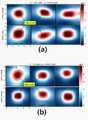
도 5(a)는 제1 실시예에 의한 마이크로 코일의 시상 및 관상 슬라이스에서 시뮬레이션된 자기장 분포를 도시하고, 도 5(b)는 제2 실시예에 의한 마이크로 코일의 시상 및 관상 슬라이스에서 시뮬레이션된 자기장 분포를 도시한다. 도 5(b)에서 마지막 줄은 혈관류 내의 자기장 분포를 도시한다.
도 6(a)는 3T에서 제1 실시예에 의한 마이크로 코일의 가로, 시상 및 관상 슬라이스에서 시뮬레이션된 B1- 필드의 분포이고, 도 6(b)는 3T에서 제2 실시예에 의한 마이크로 코일의 가로, 시상 및 관상 슬라이스에서 시뮬레이션된 B1- 필드의 분포이다.1 (a) is a plan view of a conformal implantable micro coil patch plane 100a according to the present embodiment, and FIG. 1 (b) is a micro coil ground plane according to the first embodiment. (ground plane, 100b) is a plan view, Figure 1 (c) is a cross-sectional view of the microcoil according to the present embodiment.
FIG. 2(a) is a plan view of a
3( a ) and 3( b ) are diagrams respectively illustrating deformed states in which microcoils according to the first and second embodiments are inserted into blood vessels.
4 is a view illustrating a state in which the microcoil according to the present embodiment is inserted into a blood vessel.
Fig. 5(a) shows the simulated magnetic field distribution in the sagittal and coronal slices of the microcoil according to the first embodiment, and Fig. 5(b) shows the simulated magnetic field distribution in the sagittal and coronal slices of the microcoil according to the second embodiment. The magnetic field distribution is shown. The last line in Fig. 5(b) shows the magnetic field distribution within the vascular flow.
Fig. 6(a) is a simulated B1-field distribution in transverse, sagittal and coronal slices of a microcoil according to the first embodiment in 3T, and Fig. 6(b) is a microcoil according to the second embodiment in 3T. is the distribution of simulated B1-fields in transverse, sagittal and coronal slices.
MRI는 환자에게 전리 방사선 위험이 없는 비 침습적 기술로, MRI에 사용되는 전자기장의 각 주파수 ωr은 아래의 수학식 1(Larmor 방정식)로 표시될 수 있다.MRI is a non-invasive technology that does not pose a risk of ionizing radiation to the patient, and the angular frequency ωr of the electromagnetic field used in MRI may be expressed by Equation 1 (Larmor equation) below.
[수학식 1][Equation 1]

(Bo:는 정자기장(static magnetic field)의 강도, γ: 자이로마그네틱 비율(gyromagnetic ratio)(Bo : is the strength of a static magnetic field, γ: gyromagnetic ratio)
정자기장(Bo)와 함께 RF 코일은 B1 필드(시변 RF 근접 자기장, time-varying RF magnetic near field)를 생성하며, 코일은 복귀(returning) MR 신호를 수신한다. RF 코일은 RF 신호의 송수신을 위한 MRI 스캐너의 주요한 요소이다. 자기장의 서로 반대 방향으로 편파된 두 개의 시뮬레이션된 원형 편파(circular polarization)된 성분들(B1+ 및 B1-)은 수학식 2의 ①식과 ②식과 같이 표시된다.Together with the static magnetic field Bo, the RF coil generates a B1 field (a time-varying RF magnetic near field), and the coil receives a returning MR signal. The RF coil is a major element of an MRI scanner for transmitting and receiving RF signals. Two simulated circularly polarized components (B1+ and B1- ) polarized in opposite directions of the magnetic field are expressed as
[수학식 2][Equation 2]

(B1+: 송신 및 수신 필드 패턴, B1-: 수신 필드 패턴)(B1+ : transmit and receive field pattern, B1- : receive field pattern)
낮은 SNR 및 저해상도의 혈관 이미지 경우에는 환자에게 혈관 내 Rx 마이크로 코일이 권장된다. 환자는 신체에 삽입될 수 있는 MRI 유도 중재(MRI-guided interventions), 카테터 트래킹(catheter tracking) 혈관 이미징을 위한 소형 카테터 기반 마이크로 코일이 필요하다. 카테터 와이어를 통해 마이크로 코일을 심장 또는 뇌 혈관에 삽입하기 위하여 혈관 접근 절차 검사를 수행한 이후, 카테터를 통하여 마이크로 코일이 삽입된다. 카테터 단부에 위치한 마이크로 코일은 혈관의 MR 이미징을 수행한다. 결과적으로, 혈관 접근 카테터를 신체에서 제거함으로써 마이크로 코일을 신체에서 제거할 수 있다.For low SNR and low resolution vascular imaging, an intravascular Rx microcoil is recommended for the patient. Patients need MRI-guided interventions that can be inserted into the body, catheter tracking, and miniature catheter-based microcoils for vascular imaging. After performing a vascular access procedure test to insert the microcoil into the heart or brain blood vessel through the catheter wire, the microcoil is inserted through the catheter. A microcoil located at the end of the catheter performs MR imaging of the blood vessel. Consequently, the microcoil can be removed from the body by removing the vascular access catheter from the body.
도 1(a)는 본 실시예에 의한 등각 이식형 마이크로 코일(conformal implantable micro coil) 패치 플레인(patch plane, 100a)의 평면도이고, 도 1(b)는 제1 실시예에 의한 마이크로 코일 그라운드 플레인(ground plane, 100b)의 평면도이며, 도 1(c)는 본 실시예에 의한 마이크로 코일의 단면도이다.1 (a) is a plan view of a conformal implantable micro coil patch plane 100a according to the present embodiment, and FIG. 1 (b) is a micro coil ground plane according to the first embodiment. (ground plane, 100b) is a plan view, Figure 1 (c) is a cross-sectional view of the microcoil according to the present embodiment.
본 실시예에 의한 마이크로 코일(10)은 유전체 물질(dielectric material)인 기판(substrate)과, 유전체 물질 기판(substrate)을 사이에 두고 배치된 그라운드 플레인(ground plane, 140)와 패치 플레인(patch plane, 100)을 포함하고, 패치 플레인(100)은, 제1 암(first arm, 110a)과 제2 암(second arm, 110b) 및 제1 암(110a)과 제2 암(110b)이 연결된 연결부(120)를 포함하며, 그라운드 플레인은 그라운드 슬롯(ground slot)을 포함하고, 제1 암(110a)과 제2 암(110b)은 중심부(120)를 기준으로 대칭 구조를 가진다.The
도 1(a)를 참조하면, 제1 실시예에 의한 패치 플레인(100)은 제1 암(110a), 제2 암(110b) 및 제1 암(110a)와 제2 암(110b)이 연결된 연결부(120)를 포함한다. 도 1(a)로 예시된 실시예에서, 제1 암(110a) 및 제2 암(110b)은 사각형 외주(rectagnular periphery) 내에서 나선형으로 배치된 코일의 형태를 가질 수 있다. 또한, 제1 암(110a)과 제2 암(110b)은 연결부(120)를 기준으로 대칭일 수 있다.Referring to FIG. 1A , the
도 1(b)를 참조하면, 제1 실시예에 의한 그라운드 플레인(140)은 제1 영역(150a)와 제2 영역(150b) 및 제1 영역(150a)과 제2 영역(150b)이 연결된 연결 영역(160)을 포함한다. 도 1(b)로 예시된 실시예에서, 제1 영역(150a)과 제2 영역(150b)은 각각 개구가 형성된 제1 부분(P1), 제1 부분(P1)과 연결되어 90도 각도를 이루는 제2 부분(P2), 제2 부분(P2)과 연결되어 제1 부분(P1)과 평행한 제3 부분(P3) 및 제3 부분(P3)과 연결되어 제2 부분(P2)과 평행한 제4 부분(P4)을 포함하고, 제4 부분(P4)의 폭은 제1 내지 제3 부분(P1, P2, P3)의 폭에 비하여 크다. 또한, 그라운드 플레인(140)의 제1 영역(150a)과 제2 영역(150b)은 연결 영역(160)을 기준으로 대칭일 수 있다.Referring to FIG. 1B , in the
도 1(a) 및 도 1(b)로 예시된 실시예에서, 패치 플레인(100)에 위치하는 제1 암(110a)은 그라운드 플레인(140)에 위치하는 제1 영역(150a)에 서로 상응하도록 위치할 수 있고, 패치 플레인(100)에 위치하는 제2 암(110b)은 그라운드 플레인(140)에 위치하는 제2 영역(150b)에 서로 상응하도록 위치할 수 있으며, 패치 플레인(100)에 위치하는 연결부(120)는 그라운드 플레인(140)에 위치하는 연결 영역(160)에 서로 상응하도록 위치할 수 있다.1(a) and 1(b) , the
또한, 패치 플레인(100)에 위치하는 연결부(120)는 연결 구조(130)에 의하여 그라운드 플레인(140)에 위치하는 연결 영역(160)과 전기적으로 연결될 수 있다. 일 실시예로, 연결 구조(130)는 연결부(120)와 연결 영역(160)을 전기적으로 쇼트(short)하는 핀(pin)일 수 있다.In addition, the
도 1(c)를 참조하면, 그라운드 플레인(140)과 패치 플레인(100)는 기판(substrate)을 사이에 두고 배치될 수 있다. 도시된 실시예에서, 기판(substate)은 유전물질일 수 있으며, 일 예로, 상대 유전율(relative permitivity, εr)이 10 보다 큰 물질일 수 있다. 또한 패치 플레인(100)의 상부에는 상판(superstate)이 형성될 수 있으며, 상판(superstate)은 기판(substrate)과 동일한 물질일 수 있다.Referring to FIG. 1C , the
이하에서는 도 2(a) 및 도 2(b)를 참조하여 제2 실시예에 의한 마이크로 코일의 예를 설명한다. 다만, 간결하고 명확한 설명을 위하여 위에서 설명된 실시예와 동일하거나, 유사한 요소에 대한 설명은 생략될 수 있다. 도 2(a)는 제2 실시예에 의한 코일의 패치 플레인(200)의 평면도이고, 도 2(b)는 제2 실시예에 의한 마이크로 코일 그라운드 플레인(200)의 평면도이다. 도 2(a)를 참조하면, 제2 실시예에 의한 패치 플레인(200)은 제1 암(210a), 제2 암(220b) 및 제1 암(210a)과 제2 암(210b)이 연결된 연결부(220)를 포함한다. 도 2(a)로 예시된 실시예에서, 제1 암(210a) 및 제2 암(210b)은 타원형 외주(oval periphery) 내에서 미앤더 패턴(meander pattern)으로 배치된 코일의 형태를 가질 수 있다. 또한, 제1 암(210a)과 제2 암(220b)은 연결부(220)를 기준으로 대칭일 수 있다.Hereinafter, an example of a microcoil according to the second embodiment will be described with reference to FIGS. 2A and 2B . However, for the sake of concise and clear description, the description of elements that are the same as or similar to those of the above-described embodiment may be omitted. Fig. 2 (a) is a plan view of a
도 2(b)를 참조하면, 제2 실시예에 의한 그라운드 플레인(240)은 개구가 형성된 제5 부분(P5), 제5 부분(P5)과 연결되어 90도 각도를 이루는 제6 부분(P6), 제6 부분(P6)과 연결되어 제5 부분(P5)과 평행한 제7 부분(P7)을 포함한다. 일 실시예로, 그라운드 플레인(240)은 제5 부분과 제7 부분 사이에 위치하는 연결 영역(260)을 더 포함할 수 있다.Referring to FIG. 2B , the
도 2(a) 및 도 2(b)로 예시된 실시예에서, 패치 플레인(200)에 위치하는 연결부(220)는 그라운드 플레인(240)에 위치하는 연결 영역(260)에 서로 상응하도록 위치할 수 있다. 또한, 패치 플레인(200)에 위치하는 연결부(220)는 연결 구조(230)에 의하여 그라운드 플레인(240)에 위치하는 연결 영역(260)과 전기적으로 연결될 수 있다. 일 실시예로, 연결 구조(230)는 연결부(220)와 연결 영역(260)을 전기적으로 쇼트(short)하는 핀(pin)일 수 있다.In the embodiment illustrated in FIGS. 2( a ) and 2 ( b ), the
도 3(a) 및 도 3(b)는 각각 제1 실시예와 제2 실시예에 의한 마이크로 코일들이 혈관에 삽입될 수 있도록 변형된 상태를 각각 도시한 도면이다. 도 3(a)와 도 3(b)를 참조하면, 본 실시예에 의한 마이크로 코일들은 예시된 것과 같이 변형되어 혈관 내에 삽입되고, MRI 장치와 함께 혈관의 이미징을 수행할 수 있다. 또한 패치 플레인(100, 200)과 그라운드 플레인(140, 240)이 커패시터(cap)으로 연결되어 목적하는 주파수의 신호에 동조될 수 있다.3( a ) and 3( b ) are diagrams respectively illustrating deformed states of microcoils according to the first and second embodiments to be inserted into blood vessels. Referring to FIGS. 3A and 3B , the microcoils according to the present embodiment may be deformed and inserted into a blood vessel as illustrated, and may perform imaging of a blood vessel together with an MRI apparatus. In addition, the patch planes 100 and 200 and the ground planes 140 and 240 are connected by capacitors (caps) to be tuned to a signal of a desired frequency.
도 4는 본 실시예에 의한 마이크로 코일이 혈관 내에 삽입된 상태를 예시한 도면이다. 도 4를 참조하면, 본 실시예에 의한 마이크로 코일은 혈관 내에 삽입되어 MRI 장치와 함께 혈관 내 이미징(intravascular imaging)을 수행할 수 있다. 나아가 도 4로 예시된 것과 같이 혈관이 주머니 혹은 풍선처럼 늘어나 혈관류(blood vessel sack)가 발생할 수 있다. 혈관류는 혈관이 늘어나 발생하는 것으로 혈관이 쉽게 파열되어 출혈이 발생할 수 있다. 특히 뇌동맥류가 발생하면 뇌에서 출혈이 발생하여 크게 위험할 수 있다.4 is a view illustrating a state in which the microcoil according to the present embodiment is inserted into a blood vessel. Referring to FIG. 4 , the microcoil according to the present embodiment may be inserted into a blood vessel to perform intravascular imaging together with an MRI apparatus. Furthermore, as exemplified in FIG. 4 , blood vessel sack may occur as the blood vessel is stretched like a bag or balloon. A vascular aneurysm is an enlarged blood vessel that can easily rupture and cause bleeding. In particular, when a cerebral aneurysm occurs, bleeding in the brain can occur, which can be very dangerous.
본 실시예에 의한 마이크로 코일은 혈관 내로 삽입되어 MRI 장치와 함께 혈관을 이미징할 수 있다. 특히, 본 실시예에 의한 마이크로 코일은 혈과 내에서 이미징을 수행하므로 높은 정확도로 혈관에 형성되는 혈관류를 검출할 수 있다는 장점이 제공되며, 임시적으로 혈관내에 배치되어 혈관류가 발생한 혈관에서 출혈을 방지하도록 스텐트(stent)의 기능을 수행할 수 있다.The microcoil according to the present embodiment may be inserted into a blood vessel to image the blood vessel together with the MRI apparatus. In particular, since the microcoil according to this embodiment performs imaging within the blood vessel, it is possible to detect a blood vessel formed in the blood vessel with high accuracy. It can perform the function of a stent (stent) to prevent.
구현예implementation
제1 실시예에 의한 마이크로 코일은 각각 4.8mm와 4mm의 직경과 길이를 가지도록 구현되었고 제2 실시예에 의한 마이크로 코일의 직경과 길이는 각각 4.3mm와 9.8mm로 구현되었다. 등각 형태로 좌우 대칭을 이루는 두 개의 팔(arm)을 가진 나선형 구조를 가지고 있다.The micro-coils according to the first embodiment were implemented to have diameters and lengths of 4.8 mm and 4 mm, respectively, and the diameters and lengths of the micro-coils according to the second embodiment were implemented to be 4.3 mm and 9.8 mm, respectively. It has a spiral structure with two arms that are symmetrical left and right in an isometric shape.
마이크로 코일이 목적하는 주파수에 동조되고, 소형화를 위하여 그라운드 플레인에는 루프 모양의 개방형 슬롯을 형성하였다. 마이크로 코일은 17μm의 구리 클래딩(copper cladding)을 가지는 0.127mm 두께의 Rogers RT/duroid 6010 (εr = 10.2, tanδ = 0.0035) 기판에 형성되었다. 고유전성 기판을 선택하여 코일을 소형화할 수 있다. 노출된 패치 플레인을 덮도록 상판(superstrate)이 위치하며, 상판에 의하여 공진 주파수를 줄이고 작은 크기의 코일을 형성할 수 있다. 연결 핀으로 패치 레이어를 접지 레이어와 상호 연결하여 마이크로 토일이 목적하는 주파수에 동조될 수 있다. 일 예로, 본 실시예서, 코일은 주파수 300MHz(7T)에 동조되었다. 연결 핀은 구조의 전기적 길이를 증가시켜 목적하는 이미징 주파수에서 코일을 소형화할 수 있도록 한다.The micro-coil is tuned to the desired frequency, and a loop-shaped open slot is formed in the ground plane for miniaturization. Microcoils were formed on a 0.127 mm thick Rogers RT/duroid 6010 (εr = 10.2, tanδ = 0.0035) substrate with a 17 μm copper cladding. The coil can be miniaturized by selecting a high-k substrate. A superstrate is positioned to cover the exposed patch plane, and a small-sized coil can be formed by reducing the resonance frequency. Connecting pins interconnect the patch layer with the ground layer so that the microtoile can be tuned to the desired frequency. For example, in this embodiment, the coil is tuned to a frequency of 300 MHz (7T). The connecting pins increase the electrical length of the structure, allowing the coil to be miniaturized at the desired imaging frequency.
본 실시예에 의한 마이크로 코일은 커패시터와 연결되어 복수의 주파수(3T, 7T)에서 동작하도록 형성될 수 있다. 본 실시예에 의한 마이크로 코일은 255 MHz ~ 348 MHz 범위의 넓은 93MHz 대역폭을 가진다. 따라서, 코일 특성을 변경하지 않고 다양한 혈관 환경에 장착될 수 있다.The micro coil according to the present embodiment may be formed to operate at a plurality of
본 실시예에 의한 마이크로 코일은 커패시터, 피드 구조, 연결 핀 및 접지 슬롯을 도입하고, 미세 튜닝(fine tuning)하여 향상된 대역폭 특성을 가지며, 다중 대역 작동특성을 가진다.The micro-coil according to this embodiment has improved bandwidth characteristics by introducing a capacitor, a feed structure, a connection pin and a ground slot, and fine tuning, and has a multi-band operation characteristic.
모의imitation실험예Experimental example
수신 필드 패턴(B1-)의 성능 비교 및 성능 개선을 위해 사람 머리에서 5cm * 5cm의 대상 영역(ROI, region of interest)을 선정하였다.To compare and improve the performance of the reception field pattern (B1- ), a region of interest (ROI) of 5 cm * 5 cm in the human head was selected.
본 실시예에서는 동일한 ROI에서 두 가지 최적화 파라미터를 평가했다. 첫 째는 ROI 내의 수신 필드 패턴(B1-)의 강도를 나타내는 ROI의 ∑B1- 이다. 두 번째는 RXeff 로, 아래의 수학식 3과 같이 평가된다.In this example, two optimization parameters were evaluated in the same ROI. The first is ∑B1- of the ROI indicating the intensity of the received field pattern (B1- ) in the ROI. The second is RXeff , which is evaluated as in
[수학식 3][Equation 3]

(μ: μT 단위로 측정된 수신 필드 패턴(B1-)의 평균값, Pin: kW 단위로 측정된 입력 전력)(μ: average value of received field pattern (B1- ) measured in μT, Pin: input power measured in kW)
본 실시예에서는 시뮬레이션을 위해 두 가지 시나리오를 분석했다. 첫 번째는 εr = 78, σ= 0.52 S / m, 면적 = 10 x 10 cm2 인 균일한 근육 모방 팬텀이고, 고주파 구조 시뮬레이터 (HFSS)를 사용하여 시뮬레이션 했다. 두 번째는 Sim4Life에서 얻을 수 있는 인간 복셀 기반 해부학적 듀크 모델이다.In this embodiment, two scenarios were analyzed for simulation. The first is a uniform muscle-mimicking phantom with εr = 78, σ = 0.52 S/m, and area = 10 x 10 cm2, which was simulated using a high-frequency structural simulator (HFSS). The second is a human voxel-based anatomical Duke model available in Sim4Life.
도 5(a)는 제1 실시예에 의한 마이크로 코일의 시상 및 관상 슬라이스에서 시뮬레이션된 자기장 분포를 도시하고, 도 5(b)는 제2 실시예에 의한 마이크로 코일의 시상 및 관상 슬라이스에서 시뮬레이션된 자기장 분포를 도시한다. 도 6(b)에서 마지막 줄은 혈관류 내의 자기장 분포를 도시한다.Fig. 5(a) shows the simulated magnetic field distribution in the sagittal and coronal slices of the microcoil according to the first embodiment, and Fig. 5(b) shows the simulated magnetic field distribution in the sagittal and coronal slices of the microcoil according to the second embodiment. The magnetic field distribution is shown. The last line in Fig. 6(b) shows the magnetic field distribution within the vascular flow.
도 5(a) 및 도 5(b)는 제1 실시예에 의한 코일 및 제2 실시예에 의한 코일에 의해 생성된 균일한 근육 모방 팬텀 내의 자기장 분포의 시뮬레이션된 중앙 횡단, 시상 및 관상 슬라이스를 도시한다. 세 필드 슬라이스 간의 비교를 위해 두 마이크로 코일의 모든 필드 분포를 1A /m로 정규화 하였다. 두 코일 모두의 모의 실험결과에서, 팬텀의 중심에서 더 높은 중심 자기장이 나타나는 것을 알 수 있다. 그러나 마이크로 코일에서 멀어지는 방사형 방향으로 약해진다.5(a) and 5(b) show simulated central transverse, sagittal and coronal slices of magnetic field distribution in a uniform muscle mimic phantom produced by a coil according to a first embodiment and a coil according to a second embodiment; show For comparison between the three field slices, all field distributions of the two microcoils were normalized to 1 A/m. From the simulation results of both coils, it can be seen that a higher central magnetic field appears at the center of the phantom. However, it weakens in the radial direction away from the microcoil.
두 마이크로 코일 모두 혈관과 주변 조직에서 더 높은 자기장 분포를 생성하였다. 따라서 제안된 코일은 혈관벽 이미징을 위한 이식형 혈관 코일로 사용될 수 있으며, 혈관 근처의 필드 분포는 균일하였다. 제2 실시예에 의한 마이크로 코일은 원형 모양으로부터 혈관류 부근에서 더 높은 필드 분포를 나타내고, 혈관류 이미징에 적합하며, 뇌 스텐트 역할을 할 수 있다.Both microcoils produced higher magnetic field distributions in blood vessels and surrounding tissues. Therefore, the proposed coil can be used as an implantable vascular coil for imaging the vessel wall, and the field distribution near the vessel was uniform. The microcoil according to the second embodiment exhibits a higher field distribution in the vicinity of blood vessels from a circular shape, is suitable for imaging of blood vessels, and can serve as a brain stent.
도 6(a)는 3T에서 제1 실시예에 의한 마이크로 코일의 가로, 시상 및 관상 슬라이스에서 시뮬레이션된 B1- 필드의 분포이고, 도 6(b)는 3T에서 제2 실시예에 의한 마이크로 코일의 가로, 시상 및 관상 슬라이스에서 시뮬레이션된 B1- 필드의 분포이다. 도 6(b)에서 뇌혈관 동맥류(brain vessel aneurysm)에 대한 혈관류 내의 제2 실시예에 의한 마이크로 코일의 B1- 필드가 도시되었다. 각 도면의 상단에는 ∑B1- 값과 Rx,eff 값들이 도시되었다.Fig. 6(a) is a simulated B1-field distribution in transverse, sagittal and coronal slices of a microcoil according to the first embodiment in 3T, and Fig. 6(b) is a microcoil according to the second embodiment in 3T. is the distribution of the simulated B1-fields in transverse, sagittal and coronal slices. In Fig. 6(b) the B1-field of the microcoil according to the second embodiment in a vascular aneurysm for a brain vessel aneurysm is shown. At the top of each figure, ∑B1- values and Rx,eff values are shown.
도 6(a)와 도 6(b)는 각각 제1 실시예에 의한 코일과 제2 실시예에 의한 코일에 의해 생성된 인간 듀크 모델 내 B1- 필드 분포의 시뮬레이션된 중앙 가로, 시상 및 관상 슬라이스를 도시한다. 3 개의 B1- 필드를 5T로 정규화 하였다. B1- 필드는 심장, 목, 뇌 혈관과 같은 다양한 혈관 환경에서도 나타난다. 두 코일의 B1- 분포에서 볼 수 있듯이 중앙 자기장이 모든 슬라이스의 중심에서 중심 자기장의 크기가 강한 반면 마이크로 코일과의 거리가 멀수록 약해진다. B1-은 목적하는 혈관의 개선된 B1- 과 함께 주변의 조직은 물론, 혈관내에서 더 균질하였다. 제2 실시예에 의한 B1-은 혈관류를 더욱 명확하게 하며, 이로부터 혈관류 이미징 사용 가능성이 높음을 보여준다.6( a ) and 6( b ) show simulated central transverse, sagittal and coronal distributions of B1-field distributions in a human Duke model generated by a coil according to the first embodiment and a coil according to the second embodiment, respectively; Slices are shown. Three B1-fields were normalized to 5T. B1- Fields also appear in various vascular environments, such as heart, neck, and cerebral vessels. As can be seen from the B1− distribution of the two coils, the central magnetic field is strong at the center of all slices, whereas the magnitude of the central magnetic field is weaker as the distance from the microcoil increases. B1− was more homogeneous within the vessels as well as the surrounding tissues with the improved B1− of the desired vessels. B1− according to the second embodiment makes the vascular flow more clear, and thus shows a high possibility of using vascular flow imaging.
제1 실시예에 의한 ∑B1- 값은 1.39mT, Rx,eff 값은 0.0475μT로 연산되었으며, 제2 실시예에 의한 ∑B1- 값은 2.38mT, Rx,eff 값은 0.0523μT로 연산되었다.According to the first embodiment, the ∑B1- value was calculated as 1.39mT, the Rx,eff value was calculated as 0.0475 μT, the ∑B1- value according to the second embodiment was calculated as 2.38 mT, and the Rx,eff value was calculated as 0.0523 μT.
위에서 설명된 바와 같이 본 실시예에 의한 마이크로 코일은 혈관 내에 삽압되어 혈관의 이미징을 수행하여 혈관류(blood vessel sack)을 높은 정확도로 검출할 수 있다는 장점이 제공되며, 혈관류에 대한 스텐트로도 기능할 수 있다는 장점이 제공된다.As described above, the micro-coil according to this embodiment is inserted into a blood vessel to perform imaging of the blood vessel, thereby providing the advantage of detecting blood vessel sack with high accuracy, and is also used as a stent for blood vessel flow. It has the advantage of being able to function.
본 발명에 대한 이해를 돕기 위하여 도면에 도시된 실시 예를 참고로 설명되었으나, 이는 실시를 위한 실시예로, 예시적인 것에 불과하며, 당해 분야에서 통상적 지식을 가진 자라면 이로부터 다양한 변형 및 균등한 타 실시 예가 가능하다는 점을 이해할 것이다. 따라서, 본 발명의 진정한 기술적 보호범위는 첨부된 특허청구범위에 의해 정해져야 할 것이다.Although it has been described with reference to the embodiment shown in the drawings in order to help the understanding of the present invention, this is an embodiment for implementation, it is merely exemplary, and those of ordinary skill in the art will find various modifications and equivalents therefrom. It will be appreciated that other embodiments are possible. Accordingly, the true technical protection scope of the present invention should be defined by the appended claims.
100: 패치 플레인110a, 110b: 제1 및 제2 암
120: 연결부130: 연결 부재
140: 그라운드 플레인150a, 150b: 제1 영역 및 제2 영역
160: 연결 영역200: 패치 플레인
210a, 210b: 제1 및 제2 암220: 연결부
240: 그라운드 플레인260: 연결 영역100:
120: connecting portion 130: connecting member
140:
160: connection area 200: patch plane
210a, 210b: first and second arms 220: connection part
240: ground plane 260: connection area
Claims (12)
Translated fromKorean유전체 물질(dielectric material);
상기 유전체 물질을 사이에 두고 배치된 그라운드 플레인(ground plane)와 패치 플레인(patch plane)을 포함하고,
상기 패치 플레인은, 제1 암(first arm)과 제2 암(second arm) 및 상기 제1 암과 상기 제2 암이 연결된 연결부를 포함하며,
상기 그라운드 플레인은 그라운드 슬롯(ground slot)을 포함하고,
상기 제1 암과 상기 제2 암은 중심부를 기준으로 대칭 구조를 가지는 마이크로 코일.A micro-coil to be inserted into a blood vessel, the micro-coil comprising:
dielectric material;
and a ground plane and a patch plane disposed with the dielectric material therebetween,
The patch plane includes a first arm and a second arm, and a connection part connected to the first arm and the second arm,
The ground plane includes a ground slot,
The first arm and the second arm have a symmetrical structure with respect to a central microcoil.
상기 유전체 물질은 상대 유전율(relative permitivity, εr)이 10 보다 큰 물질인 마이크로 코일.The method of claim 1,
The dielectric material is a material having a relative permittivity (εr ) greater than 10 micro-coils.
상기 그라운드 플레인과 상기 패치 플레인은,
상기 연결부에 위치한 연결 핀(short pin)에 의하여 전기적으로 연결되는 마이크로 코일.The method of claim 1,
The ground plane and the patch plane,
A micro coil electrically connected by a short pin located in the connection part.
상기 제1 암과 제2 암은 각각 사각 나선(rectangular spiral) 형태를 가지고, 상기 연결부를 기준으로 대칭인 마이크로 코일.The method of claim 1,
The first arm and the second arm each have a rectangular spiral shape, and are symmetrical with respect to the connection part.
상기 그라운드 슬롯은 제1 영역, 제2 영역 및 상기 제1 영역과 제2 영역이 연결된 연결 영역을 포함하고,
상기 제1 영역 및 상기 제2 영역은 상기 연결 영역을 기준으로 대칭인 마이크로 코일.The method of claim 1,
The ground slot includes a first area, a second area, and a connection area in which the first area and the second area are connected,
The first region and the second region are symmetrical with respect to the connection region.
상기 제1 영역 및 상기 제2 영역은 각각
개구가 형성된 제1 부분, 상기 제1 부분과 연결되어 90도 각도를 이루는 제2 부분, 상기 제2 부분과 연결되어 상기 제1 부분과 평행한 제3 부분 및 제3 부분과 연결되어 상기 제2 부분과 평행한 제4 부분을 포함하고, 상기 제4 부분의 폭은 상기 제1 내지 제3 부분의 폭에 비하여 큰 마이크로 코일.6. The method of claim 5,
The first area and the second area are each
A first portion having an opening, a second portion connected to the first portion to form a 90 degree angle, a third portion connected to the second portion and parallel to the first portion, and a third portion connected to the second portion and a fourth portion parallel to the portion, wherein a width of the fourth portion is greater than a width of the first to third portions.
상기 그라운드 플레인의 상기 제1 영역은 상기 패치 플레인의 상기 제1 암의 위치에 상응하고,
상기 제2 영역은 상기 패치 플레인의 상기 제2 암의 위치에 상응하는 마이크로 코일.6. The method of claim 5,
the first region of the ground plane corresponds to a position of the first arm of the patch plane;
and the second region corresponds to a position of the second arm of the patch plane.
상기 제1 암과 제2 암은 각각 외곽선이 타원형인 나선 형태를 가지며, 상기 연결부를 기준으로 대칭인 마이크로 코일.The method of claim 1,
The first arm and the second arm each have a spiral shape having an elliptical outline, and are symmetrical with respect to the connection part.
상기 그라운드 슬롯은 개구가 형성된 제5 부분과 상기 제5 부분과 연결되어 90도 각도를 이루는 제6 부분, 상기 제6 부분과 연결되어 상기 제1 부분과 평행한 제7 부분을 포함하는 마이크로 코일.7. The method of claim 6,
The ground slot includes a fifth portion having an opening, a sixth portion connected to the fifth portion to form a 90 degree angle, and a seventh portion connected to the sixth portion and parallel to the first portion.
상기 제5 부분과 상기 제7 부분의 사이는 연결 핀을 통하여 상기 연결부와 전기적으로 연결되는 마이크로 코일.10. The method of claim 9,
A micro coil electrically connected to the connection part through a connection pin between the fifth part and the seventh part.
상기 마이크로 코일은
상기 혈관에 삽입되어 상기 혈관의 혈관류(blood vessel sack)를 검출하는 마이크로 코일.The method of claim 1,
The microcoil
A microcoil inserted into the blood vessel to detect a blood vessel sack in the blood vessel.
상기 마이크로 코일은 상기 혈관의 스텐트(stent)로 기능하는 마이크로 코일.
The method of claim 1,
The micro-coil is a micro-coil that functions as a stent of the blood vessel.
Priority Applications (1)
| Application Number | Priority Date | Filing Date | Title |
|---|---|---|---|
| KR1020200171226AKR102433470B1 (en) | 2020-12-09 | 2020-12-09 | Intravascular micro coil |
Applications Claiming Priority (1)
| Application Number | Priority Date | Filing Date | Title |
|---|---|---|---|
| KR1020200171226AKR102433470B1 (en) | 2020-12-09 | 2020-12-09 | Intravascular micro coil |
Publications (2)
| Publication Number | Publication Date |
|---|---|
| KR20220081581A KR20220081581A (en) | 2022-06-16 |
| KR102433470B1true KR102433470B1 (en) | 2022-08-18 |
Family
ID=82217232
Family Applications (1)
| Application Number | Title | Priority Date | Filing Date |
|---|---|---|---|
| KR1020200171226AActiveKR102433470B1 (en) | 2020-12-09 | 2020-12-09 | Intravascular micro coil |
Country Status (1)
| Country | Link |
|---|---|
| KR (1) | KR102433470B1 (en) |
Citations (3)
| Publication number | Priority date | Publication date | Assignee | Title |
|---|---|---|---|---|
| JP2001520057A (en) | 1997-10-13 | 2001-10-30 | メルツァー,アンドレアス | MR imaging method for displaying and determining stent and stent location |
| US20070023424A1 (en) | 2005-07-26 | 2007-02-01 | Boston Scientific Scimed, Inc. | Resonator for medical device |
| US20170146622A1 (en) | 2015-11-20 | 2017-05-25 | Quality Electrodynamics, Llc | Current magnitude control at different sections in one coil |
- 2020
- 2020-12-09KRKR1020200171226Apatent/KR102433470B1/enactiveActive
Patent Citations (3)
| Publication number | Priority date | Publication date | Assignee | Title |
|---|---|---|---|---|
| JP2001520057A (en) | 1997-10-13 | 2001-10-30 | メルツァー,アンドレアス | MR imaging method for displaying and determining stent and stent location |
| US20070023424A1 (en) | 2005-07-26 | 2007-02-01 | Boston Scientific Scimed, Inc. | Resonator for medical device |
| US20170146622A1 (en) | 2015-11-20 | 2017-05-25 | Quality Electrodynamics, Llc | Current magnitude control at different sections in one coil |
Non-Patent Citations (1)
| Title |
|---|
| Ullah S, Yoo H, High Resolution Implantable Microcoil Antennas for Blood-Vessel Imaging in High-Field MRIs, IEEE TRANSACTIONS ON ANTENNAS AND PROPAGATION |
Also Published As
| Publication number | Publication date |
|---|---|
| KR20220081581A (en) | 2022-06-16 |
Similar Documents
| Publication | Publication Date | Title |
|---|---|---|
| US10197645B2 (en) | Multi-channel endorectal coils and interface devices therefor | |
| EP1169749B1 (en) | Magnetic resonance imaging guidewire probe | |
| Puchnin et al. | Metamaterial inspired wireless coil for clinical breast imaging | |
| US9259556B2 (en) | MRI guidewire | |
| Ginefri et al. | Implanted, inductively-coupled, radiofrequency coils fabricated on flexible polymeric material: Application to in vivo rat brain MRI at 7 T | |
| EP1811898B1 (en) | Intracavity probes and interfaces therefor for use in obtaining images and spectra of intracavity structures using high field magnetic resonance systems | |
| Ullah et al. | Wireless, battery-free, and fully implantable micro-coil system for 7 T brain MRI | |
| Hong et al. | Design of a quadrature 1H/31P coil using bent dipole antenna and four-channel loop at 3T MRI | |
| US20160095552A1 (en) | Non-invasive radiofrequency coil for magnetic resonance imaging | |
| Ullah et al. | High-resolution implantable microcoil antennas for blood-vessel imaging in high-field MRIs | |
| Hayat et al. | Modeling and in vitro measurement of a compact antenna for intravascular catheter tracking and imaging system | |
| Kowal et al. | Impact of unit cell density on grid and stripe metasurfaces for MRI receive enhancement | |
| KR102433470B1 (en) | Intravascular micro coil | |
| US8554303B2 (en) | Magnetic resonance RF coil assembly for imaging of the cervical region | |
| EP3761872B1 (en) | Mri tracking device design, fabrication, and methods of use for mri-guided robotic system | |
| Hayat et al. | High-resolution imaging with a miniaturized dual-channel iMRI antenna for interventional applications | |
| KR20150142489A (en) | Radio frequency surface coil and Magnetic resonance imaging system comprising the same | |
| KR102801111B1 (en) | RadioFrequency Braided coil and Magnetic Resonance Imaging system | |
| KR20250000665A (en) | MAGNETIC RESONANCE ANTENNA AND iNTERVENTIONAL MAGNETIC RESONANCE IMAGING APPARATUS | |
| Maunder et al. | An 8-Channel MRI Head Coil Array for Enhanced MRI-Guided Transcranial Focused Ultrasound Imaging Performance | |
| Zhang | Novel electro-textile antenna designs supporting magnetic resonance imaging and communication systems | |
| Hong et al. | Novel 1H/19F double‐tuned coil using an asymmetrical butterfly coil | |
| Vazquez et al. | External waveguide magnetic resonance imaging for lower limbs at 3 T | |
| WO2011135312A2 (en) | Mri rf coil with improved pin diode switch and reduced b1 distortions | |
| Hidalgo et al. | Petal resonator band coil |
Legal Events
| Date | Code | Title | Description |
|---|---|---|---|
| PA0109 | Patent application | Patent event code:PA01091R01D Comment text:Patent Application Patent event date:20201209 | |
| PA0201 | Request for examination | ||
| PE0902 | Notice of grounds for rejection | Comment text:Notification of reason for refusal Patent event date:20211213 Patent event code:PE09021S01D | |
| E701 | Decision to grant or registration of patent right | ||
| PE0701 | Decision of registration | Patent event code:PE07011S01D Comment text:Decision to Grant Registration Patent event date:20220524 | |
| PG1501 | Laying open of application | ||
| GRNT | Written decision to grant | ||
| PR0701 | Registration of establishment | Comment text:Registration of Establishment Patent event date:20220812 Patent event code:PR07011E01D | |
| PR1002 | Payment of registration fee | Payment date:20220812 End annual number:3 Start annual number:1 | |
| PG1601 | Publication of registration |