KR102430788B1 - Lidar sensor with parameter optimization function and tof calculation method thereof - Google Patents
Lidar sensor with parameter optimization function and tof calculation method thereofDownload PDFInfo
- Publication number
- KR102430788B1 KR102430788B1KR1020190151396AKR20190151396AKR102430788B1KR 102430788 B1KR102430788 B1KR 102430788B1KR 1020190151396 AKR1020190151396 AKR 1020190151396AKR 20190151396 AKR20190151396 AKR 20190151396AKR 102430788 B1KR102430788 B1KR 102430788B1
- Authority
- KR
- South Korea
- Prior art keywords
- laser light
- parameter
- signal
- light reflection
- intensity
- Prior art date
- Legal status (The legal status is an assumption and is not a legal conclusion. Google has not performed a legal analysis and makes no representation as to the accuracy of the status listed.)
- Active
Links
- 238000005457optimizationMethods0.000titleclaimsabstractdescription26
- 238000004364calculation methodMethods0.000titledescription12
- 238000000034methodMethods0.000claimsdescription5
- 230000005855radiationEffects0.000claims1
- 230000006870functionEffects0.000description10
- 238000001514detection methodMethods0.000description6
- 238000010586diagramMethods0.000description6
- 238000012545processingMethods0.000description6
- 230000002829reductive effectEffects0.000description3
- 230000005540biological transmissionEffects0.000description2
- 230000000694effectsEffects0.000description2
- 238000005259measurementMethods0.000description2
- 238000012544monitoring processMethods0.000description2
- 230000036961partial effectEffects0.000description2
- 238000006243chemical reactionMethods0.000description1
- 230000002452interceptive effectEffects0.000description1
- 230000000670limiting effectEffects0.000description1
- 238000012986modificationMethods0.000description1
- 230000004048modificationEffects0.000description1
- 230000003068static effectEffects0.000description1
- 238000006467substitution reactionMethods0.000description1
- 238000009966trimmingMethods0.000description1
Images


Classifications
- G—PHYSICS
- G01—MEASURING; TESTING
- G01S—RADIO DIRECTION-FINDING; RADIO NAVIGATION; DETERMINING DISTANCE OR VELOCITY BY USE OF RADIO WAVES; LOCATING OR PRESENCE-DETECTING BY USE OF THE REFLECTION OR RERADIATION OF RADIO WAVES; ANALOGOUS ARRANGEMENTS USING OTHER WAVES
- G01S7/00—Details of systems according to groups G01S13/00, G01S15/00, G01S17/00
- G01S7/48—Details of systems according to groups G01S13/00, G01S15/00, G01S17/00 of systems according to group G01S17/00
- G01S7/491—Details of non-pulse systems
- G01S7/4912—Receivers
- G01S7/4918—Controlling received signal intensity, gain or exposure of sensor
- G—PHYSICS
- G04—HOROLOGY
- G04F—TIME-INTERVAL MEASURING
- G04F10/00—Apparatus for measuring unknown time intervals by electric means
- G04F10/005—Time-to-digital converters [TDC]
- G—PHYSICS
- G01—MEASURING; TESTING
- G01S—RADIO DIRECTION-FINDING; RADIO NAVIGATION; DETERMINING DISTANCE OR VELOCITY BY USE OF RADIO WAVES; LOCATING OR PRESENCE-DETECTING BY USE OF THE REFLECTION OR RERADIATION OF RADIO WAVES; ANALOGOUS ARRANGEMENTS USING OTHER WAVES
- G01S17/00—Systems using the reflection or reradiation of electromagnetic waves other than radio waves, e.g. lidar systems
- G01S17/02—Systems using the reflection of electromagnetic waves other than radio waves
- G01S17/06—Systems determining position data of a target
- G01S17/08—Systems determining position data of a target for measuring distance only
- G01S17/10—Systems determining position data of a target for measuring distance only using transmission of interrupted, pulse-modulated waves
- G01S17/14—Systems determining position data of a target for measuring distance only using transmission of interrupted, pulse-modulated waves wherein a voltage or current pulse is initiated and terminated in accordance with the pulse transmission and echo reception respectively, e.g. using counters
- G—PHYSICS
- G01—MEASURING; TESTING
- G01S—RADIO DIRECTION-FINDING; RADIO NAVIGATION; DETERMINING DISTANCE OR VELOCITY BY USE OF RADIO WAVES; LOCATING OR PRESENCE-DETECTING BY USE OF THE REFLECTION OR RERADIATION OF RADIO WAVES; ANALOGOUS ARRANGEMENTS USING OTHER WAVES
- G01S7/00—Details of systems according to groups G01S13/00, G01S15/00, G01S17/00
- G01S7/48—Details of systems according to groups G01S13/00, G01S15/00, G01S17/00 of systems according to group G01S17/00
- G01S7/483—Details of pulse systems
- G01S7/486—Receivers
- G01S7/4868—Controlling received signal intensity or exposure of sensor
- G—PHYSICS
- G01—MEASURING; TESTING
- G01S—RADIO DIRECTION-FINDING; RADIO NAVIGATION; DETERMINING DISTANCE OR VELOCITY BY USE OF RADIO WAVES; LOCATING OR PRESENCE-DETECTING BY USE OF THE REFLECTION OR RERADIATION OF RADIO WAVES; ANALOGOUS ARRANGEMENTS USING OTHER WAVES
- G01S7/00—Details of systems according to groups G01S13/00, G01S15/00, G01S17/00
- G01S7/48—Details of systems according to groups G01S13/00, G01S15/00, G01S17/00 of systems according to group G01S17/00
- G01S7/491—Details of non-pulse systems
- G01S7/4911—Transmitters
- G—PHYSICS
- G01—MEASURING; TESTING
- G01S—RADIO DIRECTION-FINDING; RADIO NAVIGATION; DETERMINING DISTANCE OR VELOCITY BY USE OF RADIO WAVES; LOCATING OR PRESENCE-DETECTING BY USE OF THE REFLECTION OR RERADIATION OF RADIO WAVES; ANALOGOUS ARRANGEMENTS USING OTHER WAVES
- G01S7/00—Details of systems according to groups G01S13/00, G01S15/00, G01S17/00
- G01S7/48—Details of systems according to groups G01S13/00, G01S15/00, G01S17/00 of systems according to group G01S17/00
- G01S7/491—Details of non-pulse systems
- G01S7/4912—Receivers
- G01S7/4913—Circuits for detection, sampling, integration or read-out
- G—PHYSICS
- G01—MEASURING; TESTING
- G01S—RADIO DIRECTION-FINDING; RADIO NAVIGATION; DETERMINING DISTANCE OR VELOCITY BY USE OF RADIO WAVES; LOCATING OR PRESENCE-DETECTING BY USE OF THE REFLECTION OR RERADIATION OF RADIO WAVES; ANALOGOUS ARRANGEMENTS USING OTHER WAVES
- G01S7/00—Details of systems according to groups G01S13/00, G01S15/00, G01S17/00
- G01S7/48—Details of systems according to groups G01S13/00, G01S15/00, G01S17/00 of systems according to group G01S17/00
- G01S7/483—Details of pulse systems
- G01S7/484—Transmitters
Landscapes
- Engineering & Computer Science (AREA)
- Physics & Mathematics (AREA)
- General Physics & Mathematics (AREA)
- Computer Networks & Wireless Communication (AREA)
- Radar, Positioning & Navigation (AREA)
- Remote Sensing (AREA)
- Electromagnetism (AREA)
- Optical Radar Systems And Details Thereof (AREA)
Abstract
Translated fromKorean
Description
Translated fromKorean본 발명은 라이다 센서에 관한 것으로, 일례로 파라미터 최적화 기능을 구비하는 라이다 센서 및 그것의 TOF 산출 방법에 관한 것이다.The present invention relates to a lidar sensor, for example, a lidar sensor having a parameter optimization function, and a TOF calculation method thereof.
라이다 센서는, 대상물체와의 거리를 감지하기 위해 레이저 다이오드(LD: Laser Diode)와 포토다이오드 어레이(PD: Photodiode Array)를 이용하고 있다. 레이저 다이오드는 대상물체를 향해 레이저 광을 방사한다. 포토다이오드는 대상물체를 맞고 반사되는 레이저 광을 수신하여 전류화 및 신호화한다.The lidar sensor uses a laser diode (LD) and a photodiode array (PD) to detect a distance to an object. The laser diode emits laser light toward the target object. The photodiode receives the laser light that hits the target and is reflected, and converts it into current and signal.
라이다 센서는 레이저 광의 방사 시점과 반사된 레이저 광의 수신 시점 사이의 신호간격을 체크하여 대상물체와의 거리를 계산한다. 이러한 과정에서 라이다 센서는 대상물체에 맞고 반사된 레이더 광의 신호 세기가 약하면, 대상물체를 정확히 감지하지 못하는 상황이 발생한다.The lidar sensor calculates the distance to the target object by checking the signal interval between the laser light emission time and the reflected laser light reception time. In this process, when the radar sensor hits the target and the signal strength of the reflected radar light is weak, a situation arises in which the target cannot be accurately detected.
이러한 상황 발생에 대응하기 위해 라이다 센서는, 최대감지거리의 물체를 감지할 수 있도록 방사되는 레이저 광의 출력 레벨 조절을 위한 별도의 파라미터가 설정되는데, 설정되는 파라미터에 따라 방사되는 레이저 다이오드의 출력 레벨이 필요 이상으로 설정될 경우, 에너지 효율이 감소하고 신호 대 잡음비가 하락하는 문제가 있다.In order to respond to such a situation, a separate parameter for adjusting the output level of the emitted laser light is set for the lidar sensor to detect an object of the maximum sensing distance, and the output level of the emitted laser diode according to the set parameter If it is set more than necessary, there is a problem in that energy efficiency is reduced and the signal-to-noise ratio is lowered.
이에 본 발명은 상기한 사정을 감안하여 안출된 것으로, 최대감지거리의 물체를 감지한 최대 레이저 광 반사신호의 세기를 기초로, 최대감지거리의 물체를 효율적으로 감지할 수 있도록 관련 파라미터에 대해 최적화를 수행하는 파라미터 최적화 기능을 구비하는 라이다 센서 및 그것의 TOF 산출 방법을 제공하는 것을 목적으로 한다.Accordingly, the present invention was devised in consideration of the above circumstances, and based on the intensity of the maximum laser light reflection signal that detected the object with the maximum detection distance, the related parameters are optimized to efficiently detect the object with the maximum detection distance. An object of the present invention is to provide a lidar sensor having a parameter optimization function for performing the above and a TOF calculation method thereof.
상기 목적을 달성하기 위한 본 발명의 바람직한 실시예에 따른 파라미터 최적화 기능을 구비하는 라이다 센서는, 레이저 광 신호를 방사하는 레이저 다이오드; 상기 레이저 광 신호 중에서 스캔 가능한 최대거리의 대상물체로부터 반사되는 최대 레이저 광 반사신호를 수신하는 포토 다이오드; 및 상기 최대 레이저 광 반사신호를 기초로, 레이저 광 신호의 출력 세기 또는 레이저 광 신호의 수신 세기와 관련한 파라미터를 설정하는 파라미터 설정부;를 포함할 수 있다.A lidar sensor having a parameter optimization function according to a preferred embodiment of the present invention for achieving the above object includes: a laser diode emitting a laser light signal; a photodiode for receiving a maximum laser light reflection signal reflected from a scannable maximum distance among the laser light signals; and a parameter setting unit configured to set a parameter related to an output intensity of a laser light signal or a reception intensity of a laser light signal based on the maximum laser light reflection signal.
상기 설정된 파라미터를 기초로 상기 레이저 다이오드의 출력 범위를 변경하여, 변경된 출력 범위를 기초로 상기 레이저 광 신호가 방사되도록 제어하는 LD 콘트롤러를 더 포함할 수 있다.By changing the output range of the laser diode based on the set parameter, the LD controller may further include an LD controller for controlling the laser light signal to be emitted based on the changed output range.
상기 포토 다이오드는, 상기 설정된 파라미터에 따라 변경되는 바이어스 전압이 인가되고, 변경되는 바이어스 전압을 이용하여 상기 최대 레이저 광 반사신호의 세기를 조절하여 출력할 수 있다.The photodiode may apply a bias voltage that is changed according to the set parameter, and adjust the intensity of the maximum laser light reflection signal by using the changed bias voltage to output it.
상기 설정된 파라미터에 따라 변경되는 게인을 이용하여 상기 최대 레이저 광 반사신호의 세기를 조절하여 출력하는 제1 증폭기를 더 포함할 수 있다.The apparatus may further include a first amplifier that adjusts and outputs the intensity of the maximum laser light reflection signal by using a gain that is changed according to the set parameter.
상기 설정된 파라미터에 따라 세기가 조절된 상기 최대 레이저 광 반사신호를 디지털 변환하여 상기 파라미터 설정부에 전달하는 ADC를 더 포함할 수 있다.The digital converter may further include an ADC that digitally converts the maximum laser light reflection signal whose intensity is adjusted according to the set parameter and transmits it to the parameter setting unit.
상기 설정된 파라미터에 따라 세기가 조절된 상기 최대 레이저 광 반사신호와 기준 전압을 비교하여 비교결과를 출력하는 비교부와, 상기 비교결과를 이용하여 상기 최대 레이저 광 반사신호의 세기를 판단하고 판단결과를 상기 파라미터 설정부에 전달하는 신호세기 판단부를 더 포함할 수 있다.a comparator that compares the maximum laser light reflection signal whose intensity is adjusted according to the set parameter and a reference voltage and outputs a comparison result, and determines the intensity of the maximum laser light reflection signal using the comparison result It may further include a signal strength determination unit to be transmitted to the parameter setting unit.
상기 파라미터 설정부는, 상기 최대 레이저 광 반사신호의 세기가 기설정된 포화세기를 초과하는 경우, 상기 파라미터를 변경할 수 있다.The parameter setting unit may change the parameter when the intensity of the maximum laser light reflection signal exceeds a preset saturation intensity.
상기 파라미터 설정부는, 상기 최대 레이저 광 반사신호의 세기가 상기 포화세기 이하이고 기설정된 임계값을 초과하는 경우, 상기 파라미터의 최적화 상태인 것으로 판단할 수 있다.The parameter setting unit may determine that the parameter is in an optimized state when the intensity of the maximum laser light reflection signal is equal to or less than the saturation intensity and exceeds a preset threshold.
최적화 상태의 파라미터에 따라 방사되는 레이저 광 방사신호의 방사 시점과 최적화 상태의 파라미터에 따라 신호 세기가 변경되는 레이저 광 반사신호의 수신 시점 사이의 시간 간격을 이용하여 TOF 값을 산출하는 TDC를 더 포함할 수 있다.TDC for calculating the TOF value by using a time interval between the emission time of the laser light emission signal emitted according to the parameter of the optimization state and the reception time of the laser light reflection signal whose signal strength is changed according to the parameter of the optimization state can do.
상기 목적을 달성하기 위한 본 발명의 바람직한 실시예에 따른 라이다 센서의 TOF 산출 방법은, 레이저 광 반사신호를 수신하는 대상물체 감지 단계; 및 수신되는 상기 레이저 광 반사신호 중에서 최대거리의 대상물체로부터 반사되는 최대 레이저 광 반사신호를 기초로, 레이저 광 방사신호의 출력 세기 또는 레이저 광 반사신호의 수신 세기와 관련한 파라미터를 설정하는 파라미터 설정 단계; 및 설정된 파라미터에 따른 레이저 광 반사신호를 이용하여 TOF 값을 산출하는 TOF 산출 단계;를 포함한다.TOF calculation method of the lidar sensor according to a preferred embodiment of the present invention for achieving the above object, the target object sensing step of receiving a laser light reflection signal; and a parameter setting step of setting a parameter related to the output intensity of the laser light emission signal or the reception intensity of the laser light reflection signal based on the maximum laser light reflection signal reflected from the target object at the maximum distance among the received laser light reflection signals ; and a TOF calculation step of calculating a TOF value using the laser light reflection signal according to the set parameter.
상기 파라미터는 레이저 광 신호의 출력 범위, 상기 레이저 광 반사신호를 수신하는 포토 다이오드의 바이어스 전압, 및 상기 레이저 광 반사신호의 증폭을 위한 증폭기의 게인을 포함할 수 있다.The parameter may include an output range of the laser light signal, a bias voltage of a photodiode that receives the laser light reflected signal, and a gain of an amplifier for amplifying the laser light reflected signal.
상기 파라미터 설정 단계는, 상기 최대 레이저 광 반사신호의 세기가 기설정된 포화신호를 초과하는 경우, 상기 파라미터 중에서 적어도 하나 이상을 변경할 수 있다.In the parameter setting step, when the intensity of the maximum laser light reflection signal exceeds a preset saturation signal, at least one or more of the parameters may be changed.
상기 파라미터 설정 단계는, 상기 최대 레이저 광 반사신호의 세기가 상기 포화신호 이하이고 기설정된 임계값을 초과하는 경우, 상기 파라미터의 최적화가 완료된 것으로 판단할 수 있다.In the parameter setting step, when the intensity of the maximum laser light reflection signal is equal to or less than the saturation signal and exceeds a preset threshold, it may be determined that the parameter optimization is complete.
본 발명의 바람직한 실시예에 따른 파라미터 최적화 기능을 구비하는 라이다 센서에 의하면, 최대감지거리의 물체를 감지한 레이저 광 반사 신호의 세기를 기초로, 대상물체 감지 관련한 파라미터의 최적화를 수행함으로써 최대감지거리의 물체를 효율적으로 감지할 수 있는 효과가 있다.According to the lidar sensor having a parameter optimization function according to a preferred embodiment of the present invention, the maximum detection is performed by optimizing the parameters related to the detection of the object based on the intensity of the laser light reflected signal that has detected the object of the maximum detection distance. It has the effect of efficiently detecting objects in the distance.
또한, 파라미터의 최적화를 통해 대상물체로부터 반사되고 포토다이오드에서 감지되는 레이저 광 반사신호의 노이즈 레벨이 최소화되어 신호 대 잡음비(SNR)가 향상되는 효과가 있다.In addition, the noise level of the laser light reflected signal reflected from the target object and sensed by the photodiode is minimized through the parameter optimization, thereby improving the signal-to-noise ratio (SNR).
또한, 포토다이오드 바이어스, 및 증폭기 소모전류의 최적화를 통해 수명 연장 및 내구성이 향상되는 효과가 있다.In addition, through optimization of the photodiode bias and the current consumption of the amplifier, there is an effect of extending the lifespan and improving the durability.
도 1은 본 발명의 바람직한 실시예에 따른 파라미터 최적화 기능을 구비하는 라이다 센서의 일부 구성을 보여주는 도면이다.
도 2는 레이저 광 반사신호의 세기에 따른 파라미터 최적화를 설명하기 위한 도면이다.
도 3은 파라미터 최적화 기능을 구비하는 라이다 센서의 TOF 산출 구성을 보여주는 도면이다.
도 4는 본 발명의 바람직한 실시예에 따른 라이다 센서의 TOF 산출 방법의 순서도이다.1 is a diagram showing a partial configuration of a lidar sensor having a parameter optimization function according to a preferred embodiment of the present invention.
2 is a diagram for explaining parameter optimization according to the intensity of a laser light reflected signal.
3 is a diagram showing a TOF calculation configuration of a lidar sensor having a parameter optimization function.
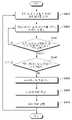
4 is a flowchart of a TOF calculation method of a lidar sensor according to a preferred embodiment of the present invention.
이하, 본 발명의 바람직한 실시예를 첨부된 도면들을 참조하여 상세히 설명한다. 우선 각 도면의 구성 요소들에 참조 부호를 부가함에 있어서, 동일한 구성 요소들에 대해서는 비록 다른 도면상에 표시되더라도 가능한 한 동일한 부호를 가지도록 하고 있음에 유의해야 한다. 또한, 이하에서 본 발명의 바람직한 실시예를 설명할 것이나, 본 발명의 기술적 사상은 이에 한정하거나 제한되지 않고 당업자에 의해 변형되어 다양하게 실시될 수 있음은 물론이다.Hereinafter, preferred embodiments of the present invention will be described in detail with reference to the accompanying drawings. First of all, it should be noted that in adding reference numerals to the components of each drawing, the same components are given the same reference numerals as much as possible even though they are indicated on different drawings. In addition, preferred embodiments of the present invention will be described below, but the technical spirit of the present invention is not limited thereto or may be variously implemented by those skilled in the art without being limited thereto.
도 1은 본 발명의 바람직한 실시예에 따른 파라미터 최적화 기능을 구비하는 라이다 센서의 일부 구성을 보여주는 도면이다.1 is a diagram showing a partial configuration of a lidar sensor having a parameter optimization function according to a preferred embodiment of the present invention.
도 1을 참고하면, 본 발명의 바람직한 실시예에 따른 파라미터 최적화 기능을 구비하는 라이다 센서(100)는, 모터에 의해 회전 동작할 수 있다. 라이다 센서(100)는 회전하면서 레이저 광 신호를 방사하여 스캔 가능한 최대거리의 물체를 감지할 수 있다. 라이다 센서(100)는 스캔 가능한 최대거리의 물체로부터 반사되는 최대 레이저 광 반사신호를 수신할 수 있다.Referring to FIG. 1 , a
라이다 센서(100)는, 신호 경로(Path)를 통해 수신되는 레이저 광 반사신호를 모니터링하는 회로구조가 구성되고, 모니터링을 통해 최대거리의 물체로부터 반사된 최대 레이저 광 반사신호의 세기를 실시간으로 반영하여 레이저 광 방사신호의 출력레벨을 트리밍하는 알고리즘을 구비하는 것을 특징으로 한다.The
이를 위해 라이다 센서(100)는, 레이저 다이오드(110), LD 콘트롤러(120), 포토다이오드(130), 제1 증폭기(140), 제2 증폭기(150), ADC(160), 비교부(170), 신호세기 판단부(180), 및 파라미터 설정부(190)를 포함할 수 있다. 라이다 센서(100)는, 상기한 구성으로 한정되는 것이 아니고 도 4의 구성을 추가 구비할 수 있다.To this end, the
레이저 다이오드(110)는 LD 콘트롤러(120)의 제어에 따라 대상물체를 향해 레이저 광 신호를 방사할 수 있다.The
LD 콘트롤러(120)는 레이저 광 신호를 방사하도록 레이저 다이오드(110)를 제어할 수 있다.The
포토다이오드(130)는, 대상물체를 맞고 반사되는 레이저 광 반사신호를 수신할 수 있다. 포토다이오드(130)는 수신한 레이저 광 반사신호를 전기신호로 변환하여 전달할 수 있다.The
제1 증폭기(140)는, 포토다이오드(130)로부터 레이저 광 반사신호를 전달받을 수 있다. 제1 증폭기(140)는 트랜스 임피던스 증폭기(TIA: TransImpedance Amplifier)일 수 있다. 제1 증폭기(140)는 가변되는 이득을 적용하여 레이저 광 반사신호의 세기를 증폭시킬 수 있다.The
제2 증폭기(150)는, 제1 증폭기(140)로부터 증폭된 레이저 광 반사신호를 전달받을 수 있다. 제2 증폭기(150)는 프로그래머블 게인 증폭기(Programmable Gain Amplifier)일 수 있다. 제2 증폭기(150)는 기설정된 이득을 적용하여 레이저 광 반사신호의 세기를 증폭시킬 수 있다.The
ADC(160)는, 아날로그 디지털 컨버터(Analog to Digital Converter) 로서, 레이저 광 반사신호의 디지털 변환을 수행할 수 있다.The ADC 160, as an analog to digital converter, may perform digital conversion of a laser light reflected signal.
비교부(170)는 기준전압이 다른 복수의 비교기를 포함할 수 있다. 복수의 비교기는 n개(n은 1 이상의 정수)가 구비될 수 있다. 복수의 비교기 각각은 기준전압과 레이저 광 반사신호의 전압레벨을 비교하여 비교결과를 출력할 수 있다.The
신호세기 판단부(180)는, 비교부(170)의 비교결과를 이용하여 레이저 광 반사신호의 세기를 판단할 수 있다.The signal
파라미터 설정부(190)는 신호세기 판단부(180)에서 판단한 신호세기와 ADC(160)에서 출력된 신호세기를 이용하여 최대거리의 물체로부터 반사되는 최대 레이저 광 반사신호의 세기를 판단할 수 있다.The
파라미터 설정부(190)는 최대 레이저 광 반사신호와 미리 설정된 포화신호를 비교하고 비교결과를 이용하여 레이저 광 신호의 출력 세기 또는 레이저 광 신호의 수신 세기와 관련한 파라미터를 설정할 수 있다. 여기서, 파라미터는 제1 증폭기(140)의 이득, 포토다이오드(130)의 바이어스 전압, 또는 LD 콘트롤러(120)의 출력 범위를 포함할 수 있다.The
레이저 광 방사신호와 레이저 광 반사신호는 설정된 파라미터에 따라 세기가 조절되며, 이를 통해 비효율적인 에너지 사용이 감소하고, 신호 대 잡음비가 개선되는 효과가 있다. 또한, 최대거리의 물체보다 가까운 물체들로부터 반사되는 레이저 광 반사신호는 포화신호보다 그 세기가 크므로 대부분 감지될 수 있다.The intensity of the laser light emission signal and the laser light reflection signal is adjusted according to a set parameter, thereby reducing inefficient energy use and improving the signal-to-noise ratio. In addition, the laser light reflection signal reflected from objects closer than the maximum distance object has a greater intensity than the saturation signal, so that most can be detected.
도 2는 레이저 광 반사신호의 세기에 따른 파라미터 최적화를 설명하기 위한 도면이다.2 is a diagram for explaining parameter optimization according to the intensity of a laser light reflected signal.
도 2의 (a)에서, 최대거리의 물체로부터 반사되는 최대 레이저 광 반사신호(MDS)와 최대거리보다 가까운 물체로부터 반사되는 근접 레이저 광 반사신호(NDS)를 확인할 수 있다. 라이다 센서(100)는 임계값(threshold)을 기초로 최대 레이저 광 반사신호(MDS)로부터 물체를 감지할 수 있는데, 최대 레이저 광 반사신호(MDS)와 근접 레이저 광 반사신호(NDS)가 임계값(threshold)보다 큰 신호세기를 가지므로, 오버스펙(Overspec) 부분이 발생한다. 이러한 오버스펙(Overspec)은 라이다 센서(100)의 에너지 효율이 감소하게 되는 원인이다. 파라미터 설정부(190)는 최대 레이저 광 반사신호(MDS)와 포화신호(Saturation)를 비교하여 파라미터 설정 여부를 판단할 수 있다. 파라미터 설정부(190)는 최대 레이저 광 반사신호(MDS)와 임계값(threshold)을 비교하여 파라미터 최적화를 수행할 수 있다.In FIG. 2A , the maximum laser light reflection signal MDS reflected from the object at the maximum distance and the proximity laser light reflection signal NDS reflected from the object closer than the maximum distance can be identified. The
파라미터 설정부(190)는, 최대 레이저 광 반사신호(MDS)가 포화신호(Saturation)를 초과하는 경우, 현재 제1 증폭기(140)의 이득이 감소되도록 설정할 수 있다. 또한, 파라미터 설정부(190)는, 포화신호(Saturation)에 따라 현재 포토다이오드(130)의 바이어스 전압이 감소되도록 설정할 수 있다. 또한, 파라미터 설정부(190)는, 현재 LD 콘트롤러(120)의 출력 범위가 감소되도록 설정할 수 있다.The
한편, 파라미터 설정부(190)는 신호 세기 별로 이득, 바이어스 전압, 및 출력 범위 등의 파라미터값이 설정되는 룩업 테이블을 생성할 수 있다. 파라미터 설정부(190)는 포화신호(Saturation)에 대응하는 룩업 테이블의 파라미터값을 이용하여 이득, 바이어스 전압, 및 출력 범위 등을 조절할 수 있다.Meanwhile, the
파라미터 설정부(190)는 다수의 파라미터 중에서 어느 하나를 변경하거나, 필요에 따라 둘 이상의 파라미터를 함께 변경할 수 있다.The
도 2의(b)에서, 라이다 센서(100)는 변경된 파라미터를 이용하여 최대 레이저 광 반사신호(MDS)와 근접 레이저 광 반사신호(NDS)를 감지할 수 있다. 도 2의(a)와 대비하면, 최대 레이저 광 반사신호(MDS)와 근접 레이저 광 반사신호(NDS)는 보다 작은 신호 세기를 가지는 것을 확인할 수 있다. 또한, 도 2의(a)와 대비하면, 최대 레이저 광 반사신호(MDS)와 근접 레이저 광 반사신호(NDS)는 노이즈(noise) 레벨이 감소하여 신호 대 잡음비(SNR)가 향상되는 것을 확인할 수 있다.In FIG. 2B , the
도 3은 파라미터 최적화 기능을 구비하는 라이다 센서의 TOF 산출 구성을 보여주는 도면이다.3 is a diagram showing a TOF calculation configuration of a lidar sensor having a parameter optimization function.
도 1 및 도 3을 참고하면, 파라미터 최적화 기능을 구비하는 라이다 센서(200)는 도 1의 라이다 센서(100)에 TOF 산출 구성이 포함된 것일 수 있다.1 and 3 , the
라이다 센서(200)는 MCU(210), 메모리부(220), 신호처리부(230), 인코더(240), 및 TDC(250)를 포함할 수 있다.The
MCU(210)는, 라이다 센서(200)의 물체 감지 동작시, 파라미터값 산출 모드로 동작할 수 있다. MCU(210)는 LD 콘트롤러(120)로부터 레이저 광 방사신호를 전달받아 메모리부(220)에 저장할 수 있다. MCU(210)는 ADC(160) 또는 신호세기 판단부(180)로부터 레이저 광 반사신호를 전달받아 메모리부(220)에 저장할 수 있다.The
메모리부(220)는 SRAM(Static Random Access Memory)일 수 있다. 메모리부(220)는 레이저 광 방사신호와 레이저 광 반사신호의 세기 정보, 방사 시점, 및 수신 시점 등을 저장할 수 있다.The
신호처리부(230)는 제1 증폭기(140)를 포함할 수 있다. 신호처리부(230)는 포화신호(Saturation)의 전압레벨(Vth)에 따라 제1 증폭기(140)의 게인을 조절할 수 있다. 신호처리부(230)는 제1 증폭기(140)의 게인 조절을 통해 레이저 광 반사신호의 세기를 변경할 수 있다.The
인코더(240)는 변경된 레이저 광 반사신호의 세기를 부호화하여 MCU(210)에 전송할 수 있다.The encoder 240 may encode the changed intensity of the laser light reflection signal and transmit it to the
MCU(210)는 레이저 광 반사신호의 세기를 기초로 파라미터를 설정하는 파라미터 설정부(190)를 구비할 수 있다.The
신호처리부(230)는 파라미터에 따라 신호 세기가 변경된 레이저 광 신호를 TDC(250)에 전달할 수 있다.The
TDC(250)는 레이저 광 방사신호와 레이저 광 반사신호의 송수신 시점에 따라 TOF 값을 복수 산출할 수 있다. TDC(250)는 복수의 TOF 값을 메모리부(220)에 저장할 수 있다.The
MCU(210)는 메모리부(220)에 저장되는 복수의 TOF 값의 평균 TOF 값을 산출할 수 있다. MCU(210)는 평균 TOF 값을 상위제어기(300)에 전송할 수 있다.The
도 4는 본 발명의 바람직한 실시예에 따른 라이다 센서의 TOF 산출 방법의 순서도이다.4 is a flowchart of a TOF calculation method of a lidar sensor according to a preferred embodiment of the present invention.
도 1, 도 3, 및 도 4를 참고하면, 본 발명의 바람직한 실시예에 따른 라이다 센서의 TOF 산출 방법은, S410 단계 내지 S480 단계를 포함할 수 있다.1, 3, and 4, the TOF calculation method of the lidar sensor according to a preferred embodiment of the present invention may include steps S410 to S480.
S410 단계에서, 레이저 다이오드(110)는 대상물체를 향해 레이저 광 신호를 방사한다. 포토 다이오드(130)는 대상물체로부터 반사되는 레이저 광 반사신호를 수신한다. TDC(250)는 레이저 광 방사신호와 레이저 광 반사신호의 송수신 시점을 이용하여 최대거리의 대상물체에 대한 TOF 값을 산출한다. MCU(210)는 TOF 값의 평균값을 산출하여 최대거리의 대상물체와의 거리정보를 획득한다. 이때, LD 콘트롤러(120)의 LD 출력 범위는 최대 상태로 설정되고, 포토 다이오드(130)의 바이어스 전압은 최대 상태로 설정되고, 제1 증폭기(140)의 게인은 최대 상태로 설정된 상태일 수 있다.In step S410, the
S420 단계에서, 파라미터 설정부(190)는 최대거리의 대상물체로부터 반사된 최대 레이저 광 반사신호의 세기에 따라 각종 파라미터를 설정할 수 있다. 파라미터 설정부(190)는 신호 세기 별 파라미터값이 저장되는 룩업 테이블을 이용하여 각종 파라미터를 설정할 수 있다. 파라미터 설정부(190)는 최대 레이저 광 반사신호의 세기가 미리 설정된 포화신호를 초과하는 경우, LD 콘트롤러(120)의 출력 범위를 낮추거나, 포토 다이오드(130)의 바이어스 전압을 낮추거나, 또는 제1 증폭기(140)의 게인을 낮추도록 파라미터를 설정할 수 있다. S430 단계에서, 파라미터 설정부(190)는 S420 단계에서 설정된 파라미터에 따라 신호 세기가 가변된 레이저 광 반사신호를 전달받을 수 있다. 신호 세기가 가변된 레이저 광 반사신호에는 최대 레이저 광 반사신호(MDS)와 근접 레이저 광 반사신호(NDS)가 포함될 수 있다. 파라미터 설정부(190)는 신호 세기가 가변된 최대 레이저 광 반사신호와 포화신호(Vth)를 비교할 수 있다. 파라미터 설정부(190)는 신호 세기가 가변된 최대 레이저 광 반사신호가 포화신호(Vth)를 초과한 것으로 판단되면, S420 단계로 돌아가서 각종 파라미터를 재설정할 수 있다.In step S420 , the
S440 단계에서, 파라미터 설정부(190)는 S430 단계에서 최대 레이저 광 반사신호가 포화신호(Vth) 이하이면, 임계값(Vth2)을 초과하는지를 판단할 수 있다. 파라미터 설정부(190)는 최대 레이저 광 반사신호가 임계값(Vth2) 이하이면, 최대거리의 물체 정보를 획득하기 위해 S410 단계로 돌아가서 레이저 다이오드(110)에서 레이저 광 신호를 방사한다.In step S440 , the
S450 단계에서, 파라미터 설정부(190)는 최대 레이저 광 반사신호가 임계값(Vth2)을 초과하면, 파라미터 최적화 상태인 것으로 판단한다. 여기서, 파라미터는 감지된 대상물체의 이동 속도를 더욱 고려하여 재설정될 수 있다.In step S450 , the
S460 단계에서, TDC(250)는 다수회 동안 버스트(burst) 동작하여 TOF 측정을 수행한다. TOF 측정 횟수는 초 당 수십회 이내로 이루어질 수 있으며, 필요에 따라 적절히 설정될 수 있다.In step S460 , the
S470 단계에서, MCU(210)는 복수의 TOF 값의 평균값을 산출할 수 있다. MCU(210)는 TOF 평균값을 통해 유효 TOF 값을 산출할 수 있다. 여기서, 유효 TOF값은 S410 단계에서 S470 단계까지의 한 사이클이 완료됨에 따라 산출될 수 있다.In step S470 , the
이상의 설명은 본 발명의 기술 사상을 예시적으로 설명한 것에 불과한 것으로서, 본 발명이 속하는 기술 분야에서 통상의 지식을 가진 자라면 본 발명의 본질적인 특성에서 벗어나지 않는 범위 내에서 다양한 수정, 변경 및 치환이 가능할 것이다. 따라서, 본 발명에 개시된 실시예 및 첨부된 도면들은 본 발명의 기술 사상을 한정하기 위한 것이 아니라 설명하기 위한 것이고, 이러한 실시예 및 첨부된 도면에 의하여 본 발명의 기술 사상의 범위가 한정되는 것은 아니다.The above description is merely illustrative of the technical idea of the present invention, and those of ordinary skill in the art to which the present invention pertains may make various modifications, changes, and substitutions within the scope without departing from the essential characteristics of the present invention. will be. Accordingly, the embodiments disclosed in the present invention and the accompanying drawings are for explaining, not limiting, the technical spirit of the present invention, and the scope of the technical spirit of the present invention is not limited by these embodiments and the accompanying drawings. .
본 발명에 따른 단계들 및/또는 동작들은 기술분야의 통상의 기술자에 의해 이해될 수 있는 것과 같이, 다른 순서로, 또는 병렬적으로, 또는 다른 에포크(epoch) 등을 위해 다른 실시 예들에서 동시에 일어날 수 있다.Steps and/or operations according to the present invention may occur concurrently in different embodiments, either in a different order, or in parallel, or for different epochs, etc., as would be understood by one of ordinary skill in the art. can
실시 예에 따라서는, 단계들 및/또는 동작들의 일부 또는 전부는 하나 이상의 비-일시적 컴퓨터-판독가능 매체에 저장된 명령, 프로그램, 상호작용 데이터 구조(interactive data structure), 클라이언트 및/또는 서버를 구동하는 하나 이상의 프로세서들을 사용하여 적어도 일부가 구현되거나 또는 수행될 수 있다. 하나 이상의 비-일시적 컴퓨터-판독가능 매체는 예시적으로 소프트웨어, 펌웨어, 하드웨어, 및/또는 그것들의 어떠한 조합일 수 있다. 또한, 본 명세서에서 논의된 "모듈"의 기능은 소프트웨어, 펌웨어, 하드웨어, 및/또는 그것들의 어떠한 조합으로 구현될 수 있다.Depending on the embodiment, some or all of the steps and/or operations run instructions, programs, interactive data structures, clients and/or servers stored in one or more non-transitory computer-readable media. At least some may be implemented or performed using one or more processors. The one or more non-transitory computer-readable media may be illustratively software, firmware, hardware, and/or any combination thereof. Further, the functionality of a “module” discussed herein may be implemented in software, firmware, hardware, and/or any combination thereof.
100, 200: 라이다 센서
110: 레이저 다이오드
120: LD 콘트롤러
130: 포토 다이오드
140: 제1 증폭기
150: 제2 증폭기
160: ADC
170: 비교부
180: 신호세기 판단부
190: 파라미터 설정부
210: MCU
220: 메모리부
230: 신호처리부
240: 인코더
250: TDC
300: 상위제어기100, 200: lidar sensor
110: laser diode
120: LD controller
130: photodiode
140: first amplifier
150: second amplifier
160: ADC
170: comparison unit
180: signal strength determination unit
190: parameter setting unit
210: MCU
220: memory unit
230: signal processing unit
240: encoder
250: TDC
300: upper controller
Claims (13)
Translated fromKorean상기 레이저 광 신호 중에서 스캔 가능한 최대거리의 대상물체로부터 반사되는 최대 레이저 광 반사신호를 수신하는 포토 다이오드; 및
상기 최대 레이저 광 반사신호를 기초로, 레이저 광 신호의 출력 세기 및 레이저 광 신호의 수신 세기와 관련한 파라미터를 설정하는 파라미터 설정부;를 포함하고,
상기 파라미터 설정부는, 상기 최대 레이저 광 반사신호의 세기가 기설정된 포화세기를 초과하는 경우 상기 파라미터를 변경하고, 상기 최대 레이저 광 반사신호의 세기가 상기 포화세기 이하이고 기설정된 임계값을 초과하는 경우 상기 파라미터의 최적화 상태인 것으로 판단하고, 상기 최적화 상태로 판단된 파라미터에 따라 레이저 다이오드의 레이저 광 신호의 방사 세기, 포토 다이오드의 최대 레이저 광 반사신호의 세기 및 최대거리보다 가까운 물체로부터 반사되는 근접 레이저 광 반사신호의 세기가 함께 조절되도록 하며,
상기 설정된 파라미터에 따라 세기가 조절된 상기 최대 레이저 광 반사신호를 디지털 변환하여 상기 파라미터 설정부에 전달하는 ADC;를 더 포함하고,
상기 설정된 파라미터에 따라 세기가 조절된 상기 최대 레이저 광 반사신호와 기준 전압을 비교하여 비교결과를 출력하는 비교부; 및 상기 비교결과를 이용하여 상기 최대 레이저 광 반사신호의 세기를 판단하고 판단결과를 상기 파라미터 설정부에 전달하는 신호세기 판단부;를 더 포함하는 것을 특징으로 하는 파라미터 최적화 기능을 구비하는 라이다 센서.a laser diode emitting a laser light signal;
a photodiode for receiving a maximum laser light reflection signal reflected from a scannable maximum distance among the laser light signals; and
a parameter setting unit for setting parameters related to the output intensity of the laser light signal and the reception intensity of the laser light signal based on the maximum laser light reflection signal;
The parameter setting unit changes the parameter when the intensity of the maximum laser light reflection signal exceeds a preset saturation intensity, and when the intensity of the maximum laser light reflection signal is equal to or less than the saturation intensity and exceeds a preset threshold value It is determined that the parameter is in the optimized state, and according to the parameter determined as the optimized state, the radiation intensity of the laser light signal of the laser diode, the intensity of the maximum laser light reflection signal of the photodiode, and the proximity laser reflected from an object closer than the maximum distance so that the intensity of the light reflection signal is adjusted together,
The ADC digitally converts the maximum laser light reflection signal whose intensity is adjusted according to the set parameter and transmits it to the parameter setting unit; further comprising:
a comparator comparing the maximum laser light reflection signal whose intensity is adjusted according to the set parameter with a reference voltage and outputting a comparison result; and a signal strength determination unit that determines the intensity of the maximum laser light reflection signal by using the comparison result and transmits the determination result to the parameter setting unit. .
상기 설정된 파라미터를 기초로 상기 레이저 다이오드의 출력 범위를 변경하여, 변경된 출력 범위를 기초로 상기 레이저 광 신호가 방사되도록 제어하는 LD 콘트롤러를 더 포함하는 것을 특징으로 하는 파라미터 최적화 기능을 구비하는 라이다 센서.The method of claim 1,
By changing the output range of the laser diode based on the set parameter, the lidar sensor having a parameter optimization function, characterized in that it further comprises an LD controller for controlling the laser light signal to be emitted based on the changed output range .
상기 포토 다이오드는,
상기 설정된 파라미터에 따라 변경되는 바이어스 전압이 인가되고, 변경되는 바이어스 전압을 이용하여 상기 최대 레이저 광 반사신호의 세기를 조절하여 출력하는 것을 특징으로 하는 파라미터 최적화 기능을 구비하는 라이다 센서.The method of claim 1,
The photodiode is
A lidar sensor having a parameter optimization function, characterized in that a bias voltage that is changed according to the set parameter is applied, and the intensity of the maximum laser light reflection signal is adjusted and output using the changed bias voltage.
상기 설정된 파라미터에 따라 변경되는 게인을 이용하여 상기 최대 레이저 광 반사신호의 세기를 조절하여 출력하는 제1 증폭기를 더 포함하는 것을 특징으로 하는 파라미터 최적화 기능을 구비하는 라이다 센서.The method of claim 1,
The lidar sensor having a parameter optimization function, characterized in that it further comprises a first amplifier that adjusts and outputs the intensity of the maximum laser light reflection signal using a gain that is changed according to the set parameter.
최적화 상태의 파라미터에 따라 방사되는 레이저 광 방사신호의 방사 시점과 최적화 상태의 파라미터에 따라 신호 세기가 변경되는 레이저 광 반사신호의 수신 시점 사이의 시간 간격을 이용하여 TOF 값을 산출하는 TDC를 더 포함하는 것을 특징으로 하는 파라미터 최적화 기능을 구비하는 라이다 센서.The method of claim 1,
TDC for calculating the TOF value by using the time interval between the emission time of the laser light emission signal emitted according to the parameter of the optimization state and the reception time of the laser light reflection signal whose signal strength is changed according to the parameter of the optimization state Lidar sensor having a parameter optimization function, characterized in that.
Priority Applications (2)
| Application Number | Priority Date | Filing Date | Title |
|---|---|---|---|
| KR1020190151396AKR102430788B1 (en) | 2019-11-22 | 2019-11-22 | Lidar sensor with parameter optimization function and tof calculation method thereof |
| US17/089,403US12123948B2 (en) | 2019-11-22 | 2020-11-04 | LiDAR sensor having parameter optimization function and TOF calculation method thereof |
Applications Claiming Priority (1)
| Application Number | Priority Date | Filing Date | Title |
|---|---|---|---|
| KR1020190151396AKR102430788B1 (en) | 2019-11-22 | 2019-11-22 | Lidar sensor with parameter optimization function and tof calculation method thereof |
Publications (2)
| Publication Number | Publication Date |
|---|---|
| KR20210063012A KR20210063012A (en) | 2021-06-01 |
| KR102430788B1true KR102430788B1 (en) | 2022-08-10 |
Family
ID=75975320
Family Applications (1)
| Application Number | Title | Priority Date | Filing Date |
|---|---|---|---|
| KR1020190151396AActiveKR102430788B1 (en) | 2019-11-22 | 2019-11-22 | Lidar sensor with parameter optimization function and tof calculation method thereof |
Country Status (2)
| Country | Link |
|---|---|
| US (1) | US12123948B2 (en) |
| KR (1) | KR102430788B1 (en) |
Families Citing this family (5)
| Publication number | Priority date | Publication date | Assignee | Title |
|---|---|---|---|---|
| CN113777584A (en)* | 2021-09-06 | 2021-12-10 | 上海惚恍微电子科技有限公司 | Apparatus and method for automatically controlling signal strength of direct time-of-flight sensing system |
| KR20230102817A (en)* | 2021-12-30 | 2023-07-07 | 삼성전자주식회사 | LiDAR device and operating method thereof |
| CN114637016B (en)* | 2022-05-11 | 2022-08-09 | 西安晟昕科技发展有限公司 | Laser radar signal transmitting and processing method |
| CN115113219A (en)* | 2022-06-14 | 2022-09-27 | 探维科技(北京)有限公司 | Method for measuring distance and laser radar |
| CN115980708B (en)* | 2023-03-21 | 2023-06-02 | 北醒(北京)光子科技有限公司 | Strong light protection system and method for laser radar |
Citations (1)
| Publication number | Priority date | Publication date | Assignee | Title |
|---|---|---|---|---|
| JP2008232800A (en)* | 2007-03-20 | 2008-10-02 | Ihi Corp | Laser monitor |
Family Cites Families (6)
| Publication number | Priority date | Publication date | Assignee | Title |
|---|---|---|---|---|
| JP2008020203A (en)* | 2006-07-10 | 2008-01-31 | Omron Corp | Radar system |
| IL235359A0 (en)* | 2014-10-27 | 2015-11-30 | Ofer David | High dynamic range imaging of environment with a high-intensity reflecting/transmitting source |
| KR101998859B1 (en) | 2017-06-16 | 2019-07-11 | 광주과학기술원 | Device and method for controlling detection signal of lidar |
| KR102506438B1 (en)* | 2017-07-06 | 2023-03-06 | 삼성전자주식회사 | Distance measuring device and method for measuring distance by using thereof |
| KR102030457B1 (en) | 2017-10-30 | 2019-10-10 | 현대오트론 주식회사 | An Apparatus And Method For Compensating Time Variation For Distance Detection Sensor |
| KR102132519B1 (en) | 2017-12-22 | 2020-07-10 | 주식회사 에스오에스랩 | Device and method for controlling detection signal of lidar |
- 2019
- 2019-11-22KRKR1020190151396Apatent/KR102430788B1/enactiveActive
- 2020
- 2020-11-04USUS17/089,403patent/US12123948B2/enactiveActive
Patent Citations (1)
| Publication number | Priority date | Publication date | Assignee | Title |
|---|---|---|---|---|
| JP2008232800A (en)* | 2007-03-20 | 2008-10-02 | Ihi Corp | Laser monitor |
Also Published As
| Publication number | Publication date |
|---|---|
| KR20210063012A (en) | 2021-06-01 |
| US12123948B2 (en) | 2024-10-22 |
| US20210156998A1 (en) | 2021-05-27 |
Similar Documents
| Publication | Publication Date | Title |
|---|---|---|
| KR102430788B1 (en) | Lidar sensor with parameter optimization function and tof calculation method thereof | |
| CN110784220B (en) | Dynamic threshold timing circuit, laser radar and method for acquiring time information | |
| US12411243B2 (en) | Systems and methods for light detection and ranging | |
| CN108401444B (en) | Laser radar and time measuring method based on laser radar | |
| US10775507B2 (en) | Adaptive transmission power control for a LIDAR | |
| US20230061653A1 (en) | Detection circuit for adjusting width of output pulses, receiving unit, laser radar | |
| WO2018236447A4 (en) | Time varying gain in an optical detector operating in a lidar system | |
| JP5798202B2 (en) | Photoelectric sensor and method for detecting an object in a monitoring area | |
| US20150204978A1 (en) | Distance Measuring Sensor and Method for the Detection and Distance Determination of Objects | |
| KR102506438B1 (en) | Distance measuring device and method for measuring distance by using thereof | |
| US9689985B2 (en) | Laser radar device and object detection method | |
| CN211698204U (en) | Pulse width detection circuit and laser radar ranging circuit | |
| US10281578B2 (en) | Compensated distance measurement methods and apparatus | |
| CN111366942B (en) | LiDAR system, device and method for increasing LiDAR sensing range | |
| EP4022357A1 (en) | Systems and methods for light detection and ranging | |
| KR102610763B1 (en) | Apparatus for reducing noise of lidar and method thereof | |
| KR102526759B1 (en) | Distance measuring device and method for measuring distance by using thereof | |
| WO2017221909A1 (en) | Distance measuring device | |
| US20160245901A1 (en) | Optoelectronic sensor and method for the detection of objects | |
| JP2016014535A (en) | Distance measuring system | |
| JP7221029B2 (en) | Error correction device, distance measuring device | |
| KR102645092B1 (en) | Distance measuring device and method | |
| US20180275256A1 (en) | Method to detect a signal and optoelectronic sensor | |
| CN110850427A (en) | Amplifying circuit for laser radar, laser radar and control method | |
| US20190212445A1 (en) | Laser distance sensing using prior measurement information |
Legal Events
| Date | Code | Title | Description |
|---|---|---|---|
| PA0109 | Patent application | Patent event code:PA01091R01D Comment text:Patent Application Patent event date:20191122 | |
| PA0201 | Request for examination | ||
| PE0902 | Notice of grounds for rejection | Comment text:Notification of reason for refusal Patent event date:20210127 Patent event code:PE09021S01D | |
| PG1501 | Laying open of application | ||
| PN2301 | Change of applicant | Patent event date:20210609 Comment text:Notification of Change of Applicant Patent event code:PN23011R01D | |
| PN2301 | Change of applicant | Patent event date:20210610 Comment text:Notification of Change of Applicant Patent event code:PN23011R01D | |
| E902 | Notification of reason for refusal | ||
| PE0902 | Notice of grounds for rejection | Comment text:Notification of reason for refusal Patent event date:20211207 Patent event code:PE09021S01D | |
| E701 | Decision to grant or registration of patent right | ||
| PE0701 | Decision of registration | Patent event code:PE07011S01D Comment text:Decision to Grant Registration Patent event date:20220713 | |
| PR0701 | Registration of establishment | Comment text:Registration of Establishment Patent event date:20220804 Patent event code:PR07011E01D | |
| PR1002 | Payment of registration fee | Payment date:20220805 End annual number:3 Start annual number:1 | |
| PG1601 | Publication of registration |