KR102428105B1 - Clad Mode Stripper for a High-power Fiber Laser and Production Method thereof - Google Patents
Clad Mode Stripper for a High-power Fiber Laser and Production Method thereofDownload PDFInfo
- Publication number
- KR102428105B1 KR102428105B1KR1020200038823AKR20200038823AKR102428105B1KR 102428105 B1KR102428105 B1KR 102428105B1KR 1020200038823 AKR1020200038823 AKR 1020200038823AKR 20200038823 AKR20200038823 AKR 20200038823AKR 102428105 B1KR102428105 B1KR 102428105B1
- Authority
- KR
- South Korea
- Prior art keywords
- optical fiber
- glass tube
- clad
- refractive index
- glass
- Prior art date
- Legal status (The legal status is an assumption and is not a legal conclusion. Google has not performed a legal analysis and makes no representation as to the accuracy of the status listed.)
- Active
Links
Images


Classifications
- G—PHYSICS
- G02—OPTICS
- G02B—OPTICAL ELEMENTS, SYSTEMS OR APPARATUS
- G02B6/00—Light guides; Structural details of arrangements comprising light guides and other optical elements, e.g. couplings
- G02B6/02—Optical fibres with cladding with or without a coating
- G02B6/02052—Optical fibres with cladding with or without a coating comprising optical elements other than gratings, e.g. filters
- G—PHYSICS
- G02—OPTICS
- G02B—OPTICAL ELEMENTS, SYSTEMS OR APPARATUS
- G02B6/00—Light guides; Structural details of arrangements comprising light guides and other optical elements, e.g. couplings
- G02B6/10—Light guides; Structural details of arrangements comprising light guides and other optical elements, e.g. couplings of the optical waveguide type
- G02B6/14—Mode converters
- H—ELECTRICITY
- H01—ELECTRIC ELEMENTS
- H01S—DEVICES USING THE PROCESS OF LIGHT AMPLIFICATION BY STIMULATED EMISSION OF RADIATION [LASER] TO AMPLIFY OR GENERATE LIGHT; DEVICES USING STIMULATED EMISSION OF ELECTROMAGNETIC RADIATION IN WAVE RANGES OTHER THAN OPTICAL
- H01S3/00—Lasers, i.e. devices using stimulated emission of electromagnetic radiation in the infrared, visible or ultraviolet wave range
- H01S3/05—Construction or shape of optical resonators; Accommodation of active medium therein; Shape of active medium
- H01S3/06—Construction or shape of active medium
- H01S3/063—Waveguide lasers, i.e. whereby the dimensions of the waveguide are of the order of the light wavelength
- H01S3/067—Fibre lasers
- H01S3/0675—Resonators including a grating structure, e.g. distributed Bragg reflectors [DBR] or distributed feedback [DFB] fibre lasers
Landscapes
- Physics & Mathematics (AREA)
- Optics & Photonics (AREA)
- Electromagnetism (AREA)
- General Physics & Mathematics (AREA)
- Engineering & Computer Science (AREA)
- Plasma & Fusion (AREA)
- Lasers (AREA)
Abstract
Translated fromKoreanDescription
Translated fromKorean본 발명은 고출력 광섬유 레이저용 클래드 모드 스트리퍼 및 그 제작 방법에 관한 것이다.The present invention relates to a clad mode stripper for a high-power fiber laser and a method for manufacturing the same.
이 부분에 기술된 내용은 단순히 본 발명의 일 실시예에 대한 배경 정보를 제공할 뿐 종래기술을 구성하는 것은 아니다.The content described in this section merely provides background information on an embodiment of the present invention and does not constitute the prior art.
대구경의 광섬유를 이용한 고출력 광섬유 레이저는 차세대 광통신, 의료용, 산업용 가공기 및 군사용 레이저 광원으로서 사용될 수 있으며, 신호의 손실이 적고, 높은 출력을 얻을 수 있는 것이 특징이다. 고출력 광섬유 레이저는 출력 파장의 안정성, 조절성, 파장 선택성 및 다파장 동작 등을 구현할 수 있으며, 특히, 반도체 레이저로는 구현하기 힘든 파장을 구현함으로써 새로운 레이저 광원으로 각광받고 있다. 이러한 고출력 광섬유 레이저는 통상 수백 와트(W) 내지 수 킬로와트(kW)급의 전력을 발생시키기 때문에, 고출력을 감당할 수 있는 광섬유 레이저 부품에 대한 수요가 증가하고 있다.A high-power fiber laser using a large-diameter optical fiber can be used as a next-generation optical communication, medical, industrial processing machine, and military laser light source, and is characterized by low signal loss and high output. A high-power fiber laser can implement stability, controllability, wavelength selectivity, and multi-wavelength operation of an output wavelength, and in particular, it is in the spotlight as a new laser light source by implementing a wavelength that is difficult to implement with a semiconductor laser. Since these high-power fiber lasers typically generate power of several hundred watts (W) to several kilowatts (kW), the demand for fiber laser components capable of handling high power is increasing.
고출력 광섬유 레이저에서 코어로 흡수되지 못한 펌프 광, 이중 클래드 광섬유의 코어로부터 이탈된 광 또는 가공물체의 표면으로부터 되반사 되는 광은 이중-클래드 광섬유의 코어와 내부 클래드 내에서 종종 전파된다. 이러한 미 흡수 펌프광, 이탈된 광, 되반사 된 광 등의 원치 않는 광은 이중 클래드 광섬유에서 제거되지 않으면, 고출력 레이저의 출력 빔 품질을 저하시키거나 열적 손상으로 인해 레이저 시스템에 심각한 고장을 일으킬 수 있다. 클래드 모드 스트리퍼(Clad Mode Stripper)는 내부 클래드에 남아있는 광을 제거함으로써 펌프 광에 의해 광섬유 레이저가 손상되는 것을 방지할 수 있다.In high-power fiber lasers, pump light that is not absorbed into the core, light that escapes from the core of a double-clad optical fiber, or light that is reflected back from the surface of a workpiece often propagates within the core and inner clad of a double-clad optical fiber. If unwanted light such as unabsorbed pump light, escaped light, reflected light, etc. is not removed from the double clad optical fiber, it may deteriorate the output beam quality of the high power laser or cause serious failure of the laser system due to thermal damage. . The clad mode stripper can prevent the optical fiber laser from being damaged by the pump light by removing the light remaining in the inner clad.
종래의 클래드 모드 스트리퍼는 일반적인 폴리머 기반으로 형성되고, 저 굴절률 폴리머 외부 클래드를 실리카의 굴절률보다 높은 굴절률을 갖는 물질로 교체하고, 이로써 바람직하지 않은 광이 소정의 길이를 지나서 내부 클래드로부터 완벽히 추출되도록 한다. 그러나, 외부 클래드의 굴절률보다 높은 임의의 굴절률 값은 내부 클래드 내를 도파하는 광의 전반사 조건을 해소시킴으로써 상기 내부 클래드로부터 광을 추출한다.Conventional clad mode strippers are formed on a common polymer basis and replace the low refractive index polymer outer clad with a material having a refractive index higher than that of silica, thereby allowing undesirable light to be completely extracted from the inner clad over a predetermined length. . However, any refractive index value higher than the refractive index of the outer clad extracts light from the inner clad by resolving the total reflection condition of light guiding in the inner clad.
이러한 클래드 모드 스트리퍼는 내부 클래드로부터 빠져나온 광은 굴절률 차이로 인해 고 굴절률 소재 외부로 빠져나가지 못하고 열로 변환되며, 이러한 열이 특정 부위에 집속되어 열화 현상이 발생될 수 있는 문제점이 있다. 따라서 열적 손상(thermal damage)으로 유발되는 고장을 방지하도록 클래드로 전파되는 광의 적절한 제거 및 온도 관리를 필요로 한다.In such a clad mode stripper, the light emitted from the inner clad cannot escape to the outside of the high refractive index material due to the difference in refractive index, but is converted into heat, and there is a problem that the heat may be focused on a specific area to cause deterioration. Accordingly, proper removal of light propagating to the cladding and temperature management are required to prevent failure caused by thermal damage.
또한, 고출력 광섬유 레이저의 코어와 클래드는 실리카나 폴리머 재질로 형성되어 있어 열이나 물에 약하기 때문에 방열이나 워터 쿨링 할 경우 내구성이 약하다는 문제점이 있다.In addition, since the core and clad of the high-power fiber laser are made of silica or a polymer material, they are weak to heat or water, so there is a problem in that durability is weak when heat dissipation or water cooling is performed.
본 발명은 전술한 문제점을 해결하기 위하여, 본 발명의 일 실시예에 따라 광섬유보다 높은 서로 다른 굴절률을 가지는 하나 이상의 글라스 튜브(glass tube)를 이용하여 광섬유와의 접속에서 열이 집중되는 부분을 사전에 방지할 수 있도록 하는 것에 목적이 있다.In order to solve the above problems, the present invention uses one or more glass tubes having different refractive indices than the optical fiber according to an embodiment of the present invention to prevent a portion where heat is concentrated in connection with the optical fiber in advance. The purpose is to prevent
다만, 본 실시예가 이루고자 하는 기술적 과제는 상기된 바와 같은 기술적 과제로 한정되지 않으며, 또 다른 기술적 과제들이 존재할 수 있다.However, the technical task to be achieved by the present embodiment is not limited to the above-described technical task, and other technical tasks may exist.
상기한 기술적 과제를 달성하기 위한 기술적 수단으로서 본 발명의 일 실시예에 따른 고출력 광섬유 레이저용 클래드 모드 스트리퍼는, 코어, 제1 클래드 및 제2 클래드를 포함하는 광섬유; 및 일 방향을 따라 연장된 관통 홀을 구비하고, 상기 관통 홀에 상기 광섬유가 안착되어 융착 방식으로 상기 광섬유와 결합되는 하나 이상의 글라스 튜브를 포함하되, 상기 하나 이상의 글라스 튜브는 상기 광섬유보다 높은 서로 다른 굴절률을 가지는 것이다.As a technical means for achieving the above technical problem, a clad mode stripper for a high-power fiber laser according to an embodiment of the present invention includes: an optical fiber including a core, a first clad and a second clad; and at least one glass tube having a through hole extending in one direction, wherein the optical fiber is seated in the through hole and coupled to the optical fiber in a fusion method, wherein the at least one glass tube is higher than the optical fiber. It has a refractive index.
상기 하나 이상의 글라스 튜브는 상기 광섬유와 융착 방식으로 결합된 이후에, 상기 광섬유와 글라스 튜브의 직경 차이로 인해 굴곡 부분이 형성되고, 상기 굴곡 부분을 이용하여 펌프 광이 추출되도록 하는 것이다.After the one or more glass tubes are fused to the optical fiber, a bent portion is formed due to a difference in diameter between the optical fiber and the glass tube, and the pump light is extracted using the bent portion.
상기 하나 이상의 글라스 튜브의 외주면을 감싸는 형태로 형성되고, 상기 하나 이상의 글라스 튜브보다 높은 굴절률을 가지는 글라스 관을 더 포함하는 것이다.It is formed to surround the outer circumferential surface of the one or more glass tubes, and further includes a glass tube having a higher refractive index than that of the one or more glass tubes.
상기 광섬유는 복수 개의 전방향(Forward)의 스트립부를 포함하는 경우, 상기 하나 이상의 글라스 튜브는 각각의 굴절률이 단계적으로 높아지도록 배치되는 것이다.When the optical fiber includes a plurality of forward strip portions, the one or more glass tubes are arranged such that the respective refractive indexes are increased step by step.
상기 광섬유는 복수 개의 역방향(Backward)의 스트립부를 포함하는 경우, 상기 하나 이상의 글라스 튜브는 각각의 굴절률이 단계적으로 작아지도록 배치되는 것이다.When the optical fiber includes a plurality of backward strip portions, the one or more glass tubes are arranged such that the respective refractive indexes are gradually decreased.
상기 광섬유는 복수 개의 양방향(Forward 및 Backward)의 스트립부를 포함하는 경우, 전방향의 스트립부에 대해 각각의 굴절률이 단계적으로 높아지도록 하나 이상의 글라스 튜브를 배치한 전방향 배치 구조와, 역방향의 스트립부에 대해 각각의 굴절률이 단계적으로 작아지도록 하나 이상의 글라스 튜브를 배치한 역방향 배치 구조가 서로 결합된 형태로 형성되는 것이다.When the optical fiber includes a plurality of bidirectional (forward and backward) strip portions, a forward arrangement structure in which one or more glass tubes are disposed so that each refractive index is increased step by step with respect to the strip portion in the forward direction, and a strip portion in the reverse direction The reverse arrangement structure in which one or more glass tubes are arranged so that each refractive index becomes smaller with respect to each other is formed in a form coupled to each other.
상기 광섬유는 복수 개의 양방향의 스트립부를 포함하는 경우, 최상위 굴절율을 가지는 글라스 튜브를 중심으로 선단에 전방향의 스트립부에 대응하여 각각의 굴절율이 단계적으로 높아지도록 하나 이상의 글라스 튜브를 배치하고, 역방향 스트립부에 대응하여 각각의 굴절률이 단계적으로 작아지도록 하나 이상의 글라스 튜브를 배치한 일체형 배치 구조로 형성되는 것이다.When the optical fiber includes a plurality of bidirectional strip portions, one or more glass tubes are disposed at the tip of the glass tube having the highest refractive index so that the respective refractive indexes are increased step by step in response to the omnidirectional strip portion, and the reverse strip It is formed in an integrated arrangement structure in which one or more glass tubes are disposed so that each refractive index is gradually decreased in correspondence to the negative portions.
한편, 본 발명의 일 실시예에 따른 고출력 광섬유 레이저용 클래드 모드 스트리퍼의 제작 방법은, 코어, 제1 클래드 및 제2 클래드를 포함하는 광섬유를 일방향을 따라 연장된 관통 홀을 갖는 하나 이상의 글라스 튜브에 삽입하고, 상기 광섬유와 하나 이상의 글라스 튜브에 기 설정된 온도의 열을 가해 융착시키는 단계; 및 상기 하나 이상의 글라스 튜브와 광섬유가 결합되면, 적정 길이의 글라스 관을 하나 이상의 글라스 튜브의 외주면을 감싸는 형태로 밀봉 시키는 단계를 포함하되, 상기 하나 이상의 글라스 튜브는 상기 광섬유보다 높은 서로 다른 굴절률을 가지는 방법일 수 있다.On the other hand, in the method of manufacturing a clad mode stripper for a high-power fiber laser according to an embodiment of the present invention, an optical fiber including a core, a first clad and a second clad is applied to one or more glass tubes having a through hole extending in one direction. inserting, and applying heat at a preset temperature to the optical fiber and one or more glass tubes to fuse them; And when the one or more glass tubes and the optical fiber are combined, sealing a glass tube of an appropriate length in a form surrounding the outer circumferential surface of the one or more glass tubes, wherein the one or more glass tubes have different refractive indices than the optical fiber. it could be a way
상기 하나 이상의 글라스 튜브는 상기 광섬유의 코어, 제1 클래드 및 제2 클래드의 직경보다 점진적으로 커지는 직경을 갖도록 하는 것이다.The at least one glass tube is to have a diameter that is gradually larger than the diameters of the core, the first clad, and the second clad of the optical fiber.
상기 광섬유는 복수 개의 전방향(Forward)의 스트립부를 포함하는 경우, 상기 하나 이상의 글라스 튜브는 각각의 굴절률이 단계적으로 높아지도록 배치하고, 상기 광섬유는 복수 개의 역방향(Backward)의 스트립부를 포함하는 경우, 상기 하나 이상의 글라스 튜브는 각각의 굴절률이 단계적으로 작아지도록 배치하는 것이다.When the optical fiber includes a plurality of forward strip portions, the one or more glass tubes are arranged such that each refractive index increases step by step, and when the optical fiber includes a plurality of backward strip portions, The one or more glass tubes are arranged such that the respective refractive indexes are gradually decreased.
본 발명의 또 다른 일 실시예에 따른 고출력 광섬유 레이저용 클래드 모드 스트리퍼의 제작 방법은, 고출력 광섬유 레이저용 클래드 모드 스트리퍼의 제작 방법에 있어서, 동일한 크기를 가지면서 굴절률 크기가 서로 다른 하나 이상의 글라스 튜브를 일방향을 따라 배치하고, 하나 이상의 글라스 튜브를 서로 융착 접속하여 하나의 관통 홀을 공유하는 기 설정된 길이의 글라스 튜브를 제작하는 단계; 및 상기 관통 홀에 광섬유를 삽입하고, 상기 글라스 튜브에 열을 가해 수축 융착시키는 단계; 및 상기 글라스 튜브와 광섬유가 서로 결합되면, 기설정된 길이의 글라스 관을 글라스 튜브의 외주면을 감싸는 형태로 밀봉시키는 단계를 포함하되, 상기 하나 이상의 글라스 튜브의 굴절률은 상기 광섬유의 제1 클래드 보다 높은, 서로 다른 굴절률을 가지는 것이다.In the manufacturing method of the clad mode stripper for high power fiber laser according to another embodiment of the present invention, in the manufacturing method of the clad mode stripper for high power fiber laser, one or more glass tubes having the same size and different refractive index sizes are used. manufacturing a glass tube having a predetermined length that is disposed along one direction and shares one through hole by fusion splicing one or more glass tubes to each other; and inserting an optical fiber into the through hole and applying heat to the glass tube to shrink and fuse; And when the glass tube and the optical fiber are coupled to each other, sealing the glass tube of a predetermined length in a form surrounding the outer circumferential surface of the glass tube, wherein the refractive index of the one or more glass tubes is higher than the first clad of the optical fiber, They have different refractive indices.
전술한 본 발명의 과제 해결 수단에 의하면, 광섬유보다 높은 서로 다른 굴절률을 가지는 하나 이상의 글라스 튜브를 이용하여 굴절률이 단계적으로 높아지거나 작아지도록 함으로써 기존의 급격한 굴절률 차이로 인해 펌핑 광이 추출되지 못하는 현상을 사전에 차단할 수 있고, 글라스 재질로 형성되기 때문에 실리카나 폴리머 재질의 클래드 모드 스트리퍼에 비해 방열이나 방수 면에서 내구성이 우수해질 수 있다. 또한, 본 발명은 광섬유의 순방향, 역방향 또는 양방향의 스트립부에 대응하여 글라스 튜브를 전방향 또는 역방향으로 배치할 수 있고, 고출력 핸들링이 용이해질 수 있다.According to the above-described problem solving means of the present invention, by using one or more glass tubes having different refractive indices than optical fibers to increase or decrease the refractive index step by step, the phenomenon that the pumping light cannot be extracted due to the existing abrupt refractive index difference It can be blocked in advance, and since it is formed of a glass material, it can be superior in durability in terms of heat dissipation and waterproofing compared to a clad mode stripper made of silica or polymer material. In addition, according to the present invention, the glass tube can be disposed in the forward direction or the reverse direction corresponding to the strip portion of the optical fiber in the forward direction, the reverse direction, or both directions, and high-power handling can be facilitated.
도 1은 본 발명의 일 실시예에 따른 광섬유 레이저의 구성을 도시한 도면이다.
도 2는 본 발명의 일 실시예에 따른 고출력 광섬유 레이저용 클래드 모드 스트리퍼의 구성을 설명하는 도면이다.
도 3은 본 발명의 일 실시예에 따른 글라스 튜브의 결합 상태를 설명하는 도면이다.
도 4는 본 발명의 일 실시예에 따른 글라스 튜브 및 글라스 관의 구성을 설명하는 도면이다.
도 5는 본 발명의 일 실시예에 따른 하나 이상의 글라스 튜브의 분리형 결합 상태를 설명하는 도면이다.
도 6은 본 발명의 일 실시예에 따른 하나 이상의 글라스 튜브의 일체형 결합 상태를 설명하는 도면이다.
도 7은 본 발명의 일 실시예에 따른 고출력 광섬유 레이저용 클래드 모드 스트리퍼의 제작 방법을 설명하는 도면이다.
도 8은 본 발명의 다른 일 실시예에 따른 글라스 튜브의 결합 상태를 설명하는 도면이다.1 is a diagram showing the configuration of a fiber laser according to an embodiment of the present invention.
2 is a view for explaining the configuration of a clad mode stripper for a high-power fiber laser according to an embodiment of the present invention.
3 is a view for explaining the coupling state of the glass tube according to an embodiment of the present invention.
4 is a view for explaining the configuration of the glass tube and the glass tube according to an embodiment of the present invention.
5 is a view for explaining a detachable coupling state of one or more glass tubes according to an embodiment of the present invention.
6 is a view for explaining an integrally coupled state of one or more glass tubes according to an embodiment of the present invention.
7 is a view for explaining a method of manufacturing a clad mode stripper for a high-power fiber laser according to an embodiment of the present invention.
8 is a view for explaining the coupling state of the glass tube according to another embodiment of the present invention.
본 발명은 다양한 변경을 가할 수 있고 여러 가지 실시 예를 가질 수 있는 바, 특정 실시 예들을 도면에 예시하고 상세하게 설명하고자 한다.Since the present invention can have various changes and can have various embodiments, specific embodiments are illustrated in the drawings and described in detail.
그러나, 이는 본 발명을 특정한 실시 형태에 대해 한정하려는 것이 아니며, 본 발명의 사상 및 기술 범위에 포함되는 모든 변경, 균등물 내지 대체물을 포함하는 것으로 이해되어야 한다. 각 도면을 설명하면서 유사한 참조부호를 유사한 구성요소에 대해 사용하였다.However, this is not intended to limit the present invention to specific embodiments, and should be understood to include all modifications, equivalents and substitutes included in the spirit and scope of the present invention. In describing each figure, like reference numerals have been used for like elements.
제1, 제2, A, B 등의 용어는 다양한 구성요소들을 설명하는데 사용될 수 있지만, 상기 구성요소들은 상기 용어들에 의해 한정되어서는 안 된다. 상기 용어들은 하나의 구성요소를 다른 구성요소로부터 구별하는 목적으로만 사용된다.Terms such as first, second, A, and B may be used to describe various elements, but the elements should not be limited by the terms. The above terms are used only for the purpose of distinguishing one component from another.
예를 들어, 본 발명의 권리 범위를 벗어나지 않으면서 제1 구성요소는 제2 구성요소로 명명될 수 있고, 유사하게 제2 구성요소도 제1 구성요소로 명명될 수 있다. 및/또는이라는 용어는 복수의 관련된 기재된 항목들의 조합 또는 복수의 관련된 기재된 항목들 중의 어느 항목을 포함한다.For example, without departing from the scope of the present invention, a first component may be referred to as a second component, and similarly, a second component may also be referred to as a first component. and/or includes a combination of a plurality of related listed items or any of a plurality of related listed items.
어떤 구성요소가 다른 구성요소에 "연결되어" 있다거나 "접속되어" 있다고 언급된 때에는, 그 다른 구성요소에 직접적으로 연결되어 있거나 또는 접속되어 있을 수도 있지만, 중간에 다른 구성요소가 존재할 수도 있다고 이해되어야 할 것이다. 반면에, 어떤 구성요소가 다른 구성요소에 "직접 연결되어" 있다거나 "직접 접속되어" 있다고 언급된 때에서, 중간에 다른 구성요소가 존재하지 않는 것으로 이해되어야 할 것이다.When a component is referred to as being “connected” or “connected” to another component, it is understood that the other component may be directly connected or connected to the other component, but other components may exist in between. it should be On the other hand, when it is said that a certain element is "directly connected" or "directly connected" to another element, it should be understood that no other element is present in the middle.
본 출원에서 사용한 용어는 단지 특정한 실시 예를 설명하기 위해 사용된 것으로, 본 발명을 한정하려는 의도가 아니다. 단수의 표현은 문맥상 명백하게 다르게 뜻하지 않는 한, 복수의 표현을 포함한다. 본 출원에서 "포함하다" 또는 "가지다." 등의 용어는 명세서상에 기재된 특징, 숫자, 단계, 동작, 구성요소, 부품 또는 이들을 조합한 것들의 존재 또는 부가 가능성을 미리 배제하지 않는 것으로 이해되어야 한다.The terms used in the present application are only used to describe specific embodiments, and are not intended to limit the present invention. The singular expression includes the plural expression unless the context clearly dictates otherwise. In this application, "include" or "have." It should be understood that the terms such as do not preclude in advance the possibility of the presence or addition of features, numbers, steps, operations, components, parts, or combinations thereof described in the specification.
다르게 정의되지 않는 한, 기술적이거나 과학적인 용어를 포함해서 여기서 사용되는 모든 용어들은 본 발명이 속하는 기술 분야에서 통상의 지식을 가진 자에 의해서 일반적으로 이해되는 것과 동일한 의미를 가지고 있다.Unless defined otherwise, all terms used herein, including technical or scientific terms, have the same meaning as commonly understood by one of ordinary skill in the art to which this invention belongs.
일반적으로 사용되는 사전에 정의되어 있는 것과 같은 용어들은 관련 기술의 문맥상 가지는 의미와 일치하는 의미를 가지는 것으로 해석되어야 하며, 본 출원에서 명백하게 정의하지 않는 한, 이상적이거나 과도하게 형식적인 의미로 해석되지 않는다.Terms such as those defined in commonly used dictionaries should be interpreted as having a meaning consistent with the meaning in the context of the related art, and should not be interpreted in an ideal or excessively formal meaning unless explicitly defined in the present application. does not
또한, 본 발명의 각 실시예에 포함된 각 구성, 과정, 공정 또는 방법 등은 기술적으로 상호간 모순되지 않는 범위 내에서 공유될 수 있다.In addition, each configuration, process, process or method included in each embodiment of the present invention may be shared within a range that does not technically contradict each other.
도 1은 본 발명의 일 실시예에 따른 광섬유 레이저의 구성을 도시한 도면이다.1 is a diagram showing the configuration of a fiber laser according to an embodiment of the present invention.
도 1을 참조하면, 광섬유 레이저(100)는 펌프 광원(110), 컴바이너(120), 연결 광섬유(130), 제1 광섬유 격자 필터(140), 액티브 광섬유(150), 제2광섬유 격자 필터(160), 클래드 모드 스트리퍼(170) 및 광섬유 케이블(180)을 포함한다.Referring to FIG. 1 , a
펌프 광원(110)은 광섬유 레이저(100)의 여기 광원으로서 펌프 광을 발진시킨다. 펌프 광원(110)으로부터 발생된 펌프 광은 펌프 광원(110)에 연결된 광섬유에 의해 컴바이너(120)로 전송된다. 펌프 광원(110)은 레이저 다이오드(Laser Diode)로 구성될 수 있으나, 반드시 이에 한정되는 것은 아니다. 펌프 광원(110)은 고출력의 레이저를 발진시키기 위해 복수 개로 구성될 수 있다.The pump light source 110 oscillates the pump light as an excitation light source of the
컴바이너(120)는 복수 개의 펌프 광원(110)으로부터 발진된 펌프 광을 수신하고, 이를 하나로 합쳐 출력한다. 컴바이너(120)의 입력단(미도시)과 출력단(미도시)은 대구경 코어를 갖는 광섬유로 구성될 수 있으나, 이에 한정되지는 않는다.The
연결 광섬유(130)는 컴바이너(120)의 출력단(미도시)과 결합되며, 펌프 광원(110)으로부터 발생한 펌프 광을 이득 매질인 액티브 광섬유(150)로 전송한다.The connection
제1 광섬유 격자(또는, Fiber Bragg Grating, FBG)(140)는 기 설정된 대역의 파장을 선택적으로 반사시킨다. 제1 광섬유 격자(140)는 액티브 광섬유(150)를 사이에 둔 채로 제2 광섬유 격자(160)와 서로 마주보도록 배치됨으로써, 광섬유 레이저(100) 구성 내 공진기로서의 역할을 수행한다. 제1 광섬유 격자(140)는 제2 광섬유 격자(160)와 함께 액티브 광섬유(150)로부터 출사된 광을 상호 반사시켜 증폭시킨다. 제1 광섬유 격자(140)는 연결 광섬유(130) 및 액티브 광섬유(150)와 융착(또는, 스플라이싱(Splicing)) 접속될 수 있다.The first optical fiber grating (or Fiber Bragg Grating, FBG) 140 selectively reflects a wavelength of a preset band. The first optical fiber grating 140 is disposed to face the second optical fiber grating 160 with the active
액티브 광섬유(150)는 제1 광섬유 격자(140) 및 제2 광섬유 격자(160)와 각각 융착 접속된 형태로 구성됨으로써, 액티브 광섬유(150)를 통과하는 펌프 광을 제1 광섬유 격자(140) 및 제2 광섬유 격자(160)로 구성되는 공진기로 출사 시킨다. 액티브 광섬유(150)는 어븀(Er) 또는 이터븀(Yb)과 같은 희토류가 도핑 된 코어, 내부 클래드 및 외부 클래드를 포함하는 이중 클래드 광섬유로 구성될 수 있으나, 이에 한정되지 않으며, 외부 클래드를 둘러싸는 피막을 더 포함하는 트리플 클래드 구조의 광섬유로 구현될 수도 있다. 액티브 광섬유(150)는 광섬유 권취 장치(미도시)에 의해 와인딩(Winding)된 형태로 구성될 수 있다.The active
제2 광섬유 격자(160)는 액티브 광섬유(150)를 사이에 둔 채로 제1 광섬유 격자(140)와 서로 마주하도록 배치됨으로써, 제1 광섬유 격자(140)와 함께 액티브 광섬유(150)로부터 출사된 광을 증폭시킨다. 제2 광섬유 격자(160)는 기 설정된 파장 대역을 선택적으로 반사 또는 회절시킴으로써, 기 설정된 출력 이상으로 펌핑 된 레이저 광을 반사시키지 않는다. 제2 광섬유 격자(160)는 액티브 광섬유(150) 및 클래드 모드 스트리퍼(170)와 융착 접속될 수 있다.The second optical fiber grating 160 is disposed to face the first optical fiber grating 140 with the active
클래드 모드 스트리퍼(Clad Mode Stripper, 또는, Clad Power Stripper, CPS)(170)는 내부에 광섬유가 안착되는 안착 홈(미도시)을 구비하고 있으며, 안착 홈(미도시)에는 출력 광섬유(미도시)가 고정된다. 출력 광섬유는 코어, 내부 클래드 및 외부 클래드를 갖는 이중 클래드 광섬유로 구성될 수 있는데, 외부 클래드는 기 설정된 간격마다 서로 다른 길이로 탈피(Stripped)된 복수 개의 스트립부(미도시)를 포함하는 형태로 구성될 수 있다. 액티브 광섬유(150)의 내부 클래드로 입사된 펌핑 광은 코어로 모두 흡수되는 것은 아니기 때문에, 액티브 광섬유(150)를 지나 공진기(140, 160)로부터 출사된 펌핑 광은 출력 광섬유 내 코어 및 내부 클래드로 입사된다.The clad mode stripper (or, Clad Power Stripper, CPS) 170 has a seating groove (not shown) in which the optical fiber is mounted, and an output optical fiber (not shown) in the seating groove (not shown). is fixed The output optical fiber may be composed of a double clad optical fiber having a core, an inner clad and an outer clad, wherein the outer clad includes a plurality of strip portions (not shown) stripped to different lengths at preset intervals. can be configured. Since the pumping light incident to the inner clad of the active
출력 광섬유의 내부 클래드로 입사된 펌핑 광(즉, 클래드 모드(Clad Mode))은 열로 변환되며, 이러한 열은 광섬유 레이저(100)의 성능을 저하시킨다. 즉, 클래드 모드 스트리퍼(170)는 출력 광섬유 내 내부 클래드로 입사된 펌핑 광을 제거함으로써, 광섬유 레이저(100)의 각 구성이 열화 되는 것을 방지한다. 클래드 모드 스트리퍼(170)의 각 구성에 대해서는 도 2 내지 도 7을 참조하여 상세하게 설명하도록 한다.The pumping light (ie, clad mode) incident on the inner clad of the output optical fiber is converted into heat, and the heat degrades the performance of the
클래드 모드 스트리퍼(170)는 제2 광섬유 격자(160) 및 광섬유 케이블(180)과 융착 접속되며, 광섬유 레이저(100) 내 적절한 위치에 복수 개로 배치될 수 있다.The
광섬유 케이블(180)은 클래드 모드 스트리퍼(170)의 후단에 배치될 수 있으며, 광섬유 레이저(100)를 보호한다. 광섬유 케이블(180)은 내구성이 강한 소재로 구성될 수 있으며, 이러한 소재가 여러 겹 겹쳐져 있는 형태로 구성될 수 있으나, 광섬유 레이저(100)의 구성에 따라 구조는 달라질 수 있다.The
냉각 모듈(190)은 광섬유 레이저(100)로부터 발생한 열을 냉각시킨다. 광섬유 레이저(100)가 레이저를 발진하고 증폭시키는 과정에서 많은 열을 방출하기 때문에, 냉각 모듈(190)은 냉각수를 이용하여 광섬유 레이저(100)를 냉각시킴으로써, 열에 의해 발생되는 손상을 방지할 수 있다.The
도 2는 본 발명의 일 실시예에 따른 고출력 광섬유 레이저용 클래드 모드 스트리퍼의 구성을 설명하는 도면이고, 도 3은 본 발명의 일 실시예에 따른 글라스 튜브의 결합 상태를 설명하는 도면이며, 도 4는 본 발명의 일 실시예에 따른 글라스 튜브 및 글라스 관의 구성을 설명하는 도면이다.2 is a view for explaining the configuration of a clad mode stripper for a high-power fiber laser according to an embodiment of the present invention, FIG. 3 is a view for explaining a bonding state of a glass tube according to an embodiment of the present invention, FIG. 4 is a view for explaining the configuration of the glass tube and the glass tube according to an embodiment of the present invention.
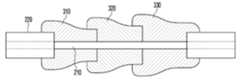
도 2 내지 도 4를 참조하면, 고출력 광섬유 레이저용 클래드 모드 스트리퍼는, 일 방향을 따라 연장된 관통 홀(311)을 구비하는 중공 형상의 글라스 튜브(310)가 하나 이상 구비되고, 관통 홀(311)에 삽입되어 하나 이상의 글라스 튜브(310, 320, 330)와 융착 방식으로 결합되는 광섬유(200)를 포함한다.2 to 4, the clad mode stripper for high power fiber laser is provided with one or more
이때, 클래드 모드 스트리퍼는 기존의 클래드 모드 스트리퍼와 달리 광섬유(200)보다 높은 서로 다른 굴절률을 가지는 2개 이상의 글라스 튜브가 배치된 형태이다. 즉, 양 끝단이 절단되고, 관통 홀(311)이 형성된 하나 이상의 글라스 튜브(glass tube)(310, 320, 330)는 광섬유(200)의 직경보다 점진적으로 커지는 직경을 가지고, 광섬유(200)가 제1 글라스 튜브(310)에 삽입되고, 제1 글라스 튜브(310)의 끝단에 제2 글라스 튜브(320)가 삽입되고, 제2 글라스 튜브(320)의 끝단에 제3 글라스 튜브(330)가 삽입된다. 이때, 제1 글라스 튜브(310), 제2 글라스 튜브(320) 및 제3 글라스 튜브(330)의 각 관통 홀에 광섬유(200)가 안착된 상태에서 융착 공정이 진행될 수 있다.At this time, the clad mode stripper is a form in which two or more glass tubes having different refractive indices than the
일례로, 도 3에 도시된 바와 같이, 제1 글라스 튜브(310)는 광섬유(200)의 직경보다 큰 직경을 가지며, 광섬유(200)를 모두 감싸는 원통 형태로 형성된다. 따라서, 제1 글라스 튜브(310)는 광섬유(200)와 융착 방식으로 결합되면, 각 글라스 튜브(310, 320, 330)와 광섬유(200)의 융착 부분이 이음새가 없도록 밀착 결합된다. 이때, 글라스 튜브(310, 320, 330)는 광섬유(200)의 제 2 클래드(220) 및 제 1 클래드(210)의 직경보다 크게 형성되어 있으므로, 융착 후에 글라스 튜브(310)는 광섬유(200)의 제 2 클래드(220)에서 제 1 클래드(210) 쪽으로 갈수록 직경이 점차 작아져 자연스럽게 굴곡 부분이 형성된다. 글라스 튜브(310)는 융착 공정 이후에 기 설정된 곡률로 굴곡된 형상으로 구현됨에 따라, 굴곡 부분을 이용하여 광섬유(200)의 클래드 내의 펌핑 광이 더욱 효과적으로 제거될 수 있다.For example, as shown in FIG. 3 , the
고출력 광섬유 레이저용 클래드 모드 스트리퍼는 도 3의 (a), (b), (c)에 도시된 바와 같이, 광섬유에 제1 글라스 튜브(310)만 결합된 형태, 제1 글라스 튜브(310)와 제2 글라스 튜브(320)가 순차적으로 결합된 형태, 제1 글라스 튜브(310), 제2 글라스 튜브(320) 및 제3 글라스 튜브(330)가 순차적으로 결합된 형태 등 다양한 형태를 가질 수 있다.As shown in (a), (b), (c) of FIG. 3, the clad mode stripper for high-power fiber laser is a form in which only the
또한, 도 3의 (d)에 도시된 바와 같이, 제1 글라스 튜브(310)가 광섬유에 아령 모양으로 제1 클래드(210)를 모두 감싸는 형태로 결합될 수도 있다.In addition, as shown in (d) of FIG. 3, the
도 4에 도시된 바와 같이, 제1 글라스 튜브(310), 제2 글라스 튜브(320) 및 제3 글라스 튜브(330)가 순차적으로 광섬유(200)에 배치되어 융착 방식으로 결합되는데, 제1 글라스 튜브(310), 제2 글라스 튜브(320) 및 제3 글라스 튜브(330)는 각각의 직경과 굴절률이 광섬유(200)에 비해 단계적으로 높아지도록 형성된다.As shown in FIG. 4 , the
또한, 글라스 관(340)은 제1 내지 제3 글라스 튜브(310, 320, 330)를 모두 감싸는 형태로 형성되고, 제1 내지 제3 글라스 튜브(131, 132, 133)보다 높은 굴절률을 가진다. 또한 글라스 관 외부 또는 내부로 물을 순환(미도시)시켜 클래드 광의 제거과정에서 발생하는 열을 냉각할 수 있다.In addition, the
이와 같이, 제1 내지 제3 글라 튜브(310, 320, 330)와 글라스 관(340)은 광섬유(200)에 비해 굴절률이 단계적으로 높아지기 때문에 광 추출 효율이 증대되어 열이 집중되는 현상을 사전에 방지할 수 있다.As described above, since the refractive index of the first to
도 5는 본 발명의 일 실시예에 따른 하나 이상의 글라스 튜브의 분리형 결합 상태를 설명하는 도면이고, 도 6은 본 발명의 일 실시예에 따른 하나 이상의 글라스 튜브의 일체형 결합 상태를 설명하는 도면이다.5 is a view for explaining a detachable coupling state of one or more glass tubes according to an embodiment of the present invention, and FIG. 6 is a view for explaining an integrally coupled state of one or more glass tubes according to an embodiment of the present invention.
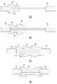
광섬유(200)가 복수 개의 전방향(Forward)의 스트립부를 포함하는 경우, 하나 이상의 글라스 튜브(310, 320, 330)는 각각의 굴절률이 단계적으로 높아지도록 배치된다. 즉, 광섬유의 굴절률 < 제1 글라스 튜브의 굴절률 < 제2 글라스 튜브의 굴절률 < 제3 글라스 튜브의 굴절률이 되도록 한다.When the
광섬유(200)가 복수 개의 역방향(Backward)의 스트립부를 포함하는 경우, 하나 이상의 글라스 튜브는 각각의 굴절률이 단계적으로 작아지도록 배치되는데, 제3 글라스 튜브의 굴절률 > 제2 글라스 튜브의 굴절률 > 제1 글라스 튜브의 굴절률 > 광섬유의 굴절율이 된다.When the
광섬유(200)가 복수 개의 양방향(Forward 및 Backward)의 스트립부를 포함하는 경우, 전방향의 스트립부에 대해 각각의 굴절률이 단계적으로 높아지도록 하나 이상의 글라스 튜브를 배치한 전방향 배치 구조(351)와 역방향의 스트립부에 대해 각각의 굴절률이 단계적으로 작아지도록 하나 이상의 글라스 튜브를 배치한 역방향 배치 구조(352)가 결합된 형태로 형성된다. 이때, 전방향 배치 구조(351)와 역방향 배치 구조(352)는 광섬유에 적정 길이만큼 이격되어 형성될 수 있다.When the
한편, 광섬유는 복수 개의 양방향(Forward 및 Backward)의 스트립부를 포함하는 경우, 전방향의 스트립부에 대해 각각의 굴절률이 단계적으로 높아지다가 다시 각각의 굴절률이 단계적으로 작아지도록 하나 이상의 글라스 튜브를 배치한 일체형 배치 구조(350)로 형성된다. 즉, 도 6에 도시된 바와 같이 제1 글라스 튜브(310), 제2 글라스 튜브(320), 제3 글라스 튜브(330), 제2 글라스 튜브(320) 및 제1 글라스 튜브(310)를 순차적으로 배치하여 일체형 튜브 배치 구조(350)로 형성할 수 있다. 최상위 굴절률을 가지는 제3 글라스 튜브(330)를 중심으로 굴절률이 점진적으로 커지다가 작아지는 형태가 될 수 있다.On the other hand, when the optical fiber includes a plurality of bidirectional (forward and backward) strip portions, one or more glass tubes are disposed so that each refractive index increases step by step with respect to the strip portion in the forward direction and then decreases each refractive index step by step. It is formed as an integral arrangement structure (350). That is, as shown in FIG. 6 , the
고출력 광섬유 레이저용 클래드 모드 스트리퍼는 전방향의 배치 구조(351)와 역방향 배치 구조(352)를 분리하여 결합한 형태이거나, 일체형 튜브 배치 구조(350)로 형성된 경우에도 글라스 관(340)을 각각 포함할 수 있다.The clad mode stripper for high-power fiber laser is a form in which the
도 7은 본 발명의 일 실시예에 따른 고출력 광섬유 레이저용 클래드 모드 스트리퍼의 제작 방법을 설명하는 도면이다.7 is a view for explaining a method of manufacturing a clad mode stripper for a high-power fiber laser according to an embodiment of the present invention.
도 7에 도시된 바와 같이, 고출력 광섬유 레이저용 클래드 모드 스트리퍼의 제작 방법은, 광섬유(200)를 제1 글라스 튜브(310), 제2 글라스 튜브(320) 및 제3 글라스 튜브(330)의 관통 홀(311)에 끼우고 기 설정된 온도의 열을 가해 융착시킨다(S1, S2).As shown in FIG. 7 , the method for manufacturing a clad mode stripper for a high-power fiber laser is through an
이때, 광섬유(200)의 직경보다 제1 글라스 튜브(310), 제2 글라스 튜브(320) 및 제3 글라스 튜브(330)의 직경이 점진적으로 커지도록 한다. 또한, 제1 글라스 튜브(301), 제2 글라스 튜브(320) 및 제3 글라스 튜브(330)의 굴절률이 광섬유(200) 제 1 클래드의 굴절률보다 높고, 각기 서로 다른 굴절률을 갖도록 형성된다. 따라서, 광섬유(200)와 하나 이상의 글라스 튜브(310, 320, 330)가 융착 방식으로 결합되면, 하나 이상의 글라스 튜브(310, 320, 330)는 서로 다른 직경 차이로 인해 자연스러운 굴곡 부분이 형성되고, 이 굴곡 부분으로 인해 펌핑 광의 추출 효율이 증대될 수 있다.At this time, the diameters of the
제1 글라스 튜브(310), 제2 글라스 튜브(320) 및 제3 글라스 튜브(330)는 광섬유의 외부 클래드에 형성된 스트립부의 방향에 따라 순방향 배치 구조 또는 역방향 배치구조가 결합된 형태로 형성되거나, 순방향 배치구조와 역방향 배치구조를 일체형으로 형성할 수 있다.The
클래드 모드 스트리퍼는 적정 길이의 패키징 용 글라스 관(340)으로 제1 내지 제3 글라스 튜브(310, 320, 330)를 포함하는 형태로 감싸서 완전히 밀봉 상태가 되도록 한다(S3).The clad mode stripper is wrapped in a shape including the first to
도 8은 본 발명의 다른 일 실시예에 따른 글라스 튜브의 결합 상태를 설명하는 도면이다.8 is a view for explaining the coupling state of the glass tube according to another embodiment of the present invention.
도 8에 도시된 바와 같이, 고출력 광섬유 레이저용 클래드 모드 스트리퍼는 동일한 직경을 갖지만 서로 다른 굴절률을 갖는 제1 글라스 튜브(310), 제2 글라스 튜브(320) 및 제3 글라스 튜브(330)를 서로 융착 접속하여 하나의 관통 홀(311)을 공유하는 중공 형상의 길이가 긴 글라스 튜브로 제작한다.As shown in FIG. 8, the clad mode stripper for high-power fiber lasers has the same diameter but different refractive indices; It is made of a long glass tube having a hollow shape that shares one through
따라서, 고출력 광섬유 레이저용 클래드 모드 스트리퍼는 관통 홀(311)에 광섬유를 끼운 후 글라스 튜브에 열을 가하여 수축 융착하여 제작될 수 있다. 따라서, 글라스 튜브는 제1 클래드(210)와 제2 클래드(220)의 직경 차이로 인해 양 끝단 부에 비해 중심부의 직경이 작아지는 굴곡 형상을 갖게 된다.Therefore, the clad mode stripper for the high-power fiber laser can be manufactured by inserting the optical fiber in the through
또한, 글라스 관(미도시)이 제1 내지 제3 글라스 튜브(310, 320, 330)를 감싸는 형태로 제작될 수 있고, 제1 내지 제3 글라스 튜브(131, 132, 133)보다 높은 굴절률을 가진다.In addition, a glass tube (not shown) may be manufactured to surround the first to
이상의 설명은 본 실시예의 기술 사상을 예시적으로 설명한 것에 불과한 것으로서, 본 실시예가 속하는 기술 분야에서 통상의 지식을 가진 자라면 본 실시예의 본질적인 특성에서 벗어나지 않는 범위에서 다양한 수정 및 변형이 가능할 것이다. 따라서, 본 실시예들은 본 실시예의 기술 사상을 한정하기 위한 것이 아니라 설명하기 위한 것이고, 이러한 실시예에 의하여 본 실시예의 기술 사상의 범위가 한정되는 것은 아니다. 본 실시예의 보호 범위는 아래의 청구범위에 의하여 해석되어야 하며, 그와 동등한 범위 내에 있는 모든 기술 사상은 본 실시예의 권리 범위에 포함되는 것으로 해석되어야 할 것이다.The above description is merely illustrative of the technical idea of this embodiment, and a person skilled in the art to which this embodiment belongs may make various modifications and variations without departing from the essential characteristics of the present embodiment. Accordingly, the present embodiments are intended to explain rather than limit the technical spirit of the present embodiment, and the scope of the technical spirit of the present embodiment is not limited by these embodiments. The protection scope of this embodiment should be interpreted by the following claims, and all technical ideas within the scope equivalent thereto should be construed as being included in the scope of the present embodiment.
200 : 광섬유
210 : 제1 클래드
220 : 제2 클래드
310 : 제1 글라스 튜브
320 : 제2 글라스 튜브
330 : 제3 글라스 튜브
340 : 글라스 관200: optical fiber
210: first clad
220: second clad
310: first glass tube
320: second glass tube
330: third glass tube
340: glass tube
Claims (11)
Translated fromKorean일 방향을 따라 연장된 관통 홀을 구비하고, 상기 관통 홀에 상기 광섬유가 안착되어 융착 방식으로 상기 광섬유와 결합되는 하나 이상의 글라스 튜브(glass tube)를 포함하되,
상기 하나 이상의 글라스 튜브는 상기 광섬유보다 높은 굴절률을 가지고, 상기 광섬유와 융착 방식으로 결합된 이후에 상기 광섬유와 글라스 튜브의 직경 차이로 인해 굴곡 부분이 형성되며, 상기 굴곡 부분을 이용하여 펌프 광이 추출되도록 하는 것인, 고출력 광섬유 레이저용 클래드 모드 스트리퍼.an optical fiber including a core, a first clad and a second clad; and
At least one glass tube having a through-hole extending in one direction, wherein the optical fiber is seated in the through-hole and coupled to the optical fiber by a fusion bonding method,
The one or more glass tubes have a higher refractive index than the optical fiber, and after being bonded to the optical fiber in a fusion method, a bent portion is formed due to a difference in diameter between the optical fiber and the glass tube, and pump light is extracted using the bent portion A clad mode stripper for high-power fiber lasers.
상기 하나 이상의 글라스 튜브의 외주면을 감싸는 형태로 형성되고, 상기 하나 이상의 글라스 튜브보다 높은 굴절률을 가지는 글라스 관을 더 포함하는 것인, 고출력 광섬유 레이저용 클래드 모드 스트리퍼.According to claim 1,
The clad mode stripper for a high-power fiber laser, which is formed in a shape surrounding the outer circumferential surface of the one or more glass tubes, and further comprises a glass tube having a higher refractive index than the one or more glass tubes.
상기 광섬유는 복수 개의 전방향(Forward)의 스트립부를 포함하며, 상기 글라스 튜브가 복수 개일 경우,
상기 글라스 튜브는 각각의 굴절률이 단계적으로 높아지도록 배치되는 것인, 고출력 광섬유 레이저용 클래드 모드 스트리퍼.According to claim 1,
The optical fiber includes a plurality of forward strip portions, and when there are a plurality of glass tubes,
The glass tube is a clad mode stripper for a high-power fiber laser, which is arranged so that each refractive index increases step by step.
상기 광섬유는 복수 개의 역방향(Backward)의 스트립부를 포함하며, 상기 글라스 튜브가 복수 개일 경우,
상기 글라스 튜브는 각각의 굴절률이 단계적으로 작아지도록 배치되는 것인, 고출력 광섬유 레이저용 클래드 모드 스트리퍼.According to claim 1,
The optical fiber includes a plurality of backward strip portions, and when there are a plurality of glass tubes,
The glass tube is arranged so that each refractive index becomes smaller step by step, a high-power fiber laser clad mode stripper.
상기 광섬유는 복수 개의 양방향(Forward 및 Backward)의 스트립부를 포함하며, 상기 글라스 튜브가 복수 개일 경우,
전방향의 스트립부에 대해 각각의 굴절률이 단계적으로 높아지도록 글라스 튜브를 배치한 전방향 배치 구조와, 후방향의 스트립부에 대해 각각의 굴절률이 단계적으로 작아지도록 글라스 튜브를 배치한 역방향 배치 구조가 서로 결합된 형태로 형성되는 것인, 고출력 광섬유 레이저용 클래드 모드 스트리퍼.According to claim 1,
The optical fiber includes a plurality of bidirectional (forward and backward) strip portions, and when the glass tube is a plurality,
A forward arrangement structure in which glass tubes are arranged so that each refractive index increases step by step with respect to the strip portion in the forward direction, and a reverse arrangement structure in which glass tubes are arranged so that each refractive index decreases stepwise with respect to the strip portion in the rear direction. A clad mode stripper for a high-power fiber laser that is formed in a form combined with each other.
상기 광섬유는 복수 개의 양방향의 스트립부를 포함하며, 상기 글라스 튜브가 복수 개일 경우,
최상위 굴절률을 가지는 글라스 튜브를 중심으로 선단에 전방향의 스트립부에 대응하여 각각의 굴절율이 단계적으로 높아지도록 글라스 튜브를 배치하고, 역방향 스트립부에 대응하여 각각의 굴절률이 단계적으로 작아지도록 글라스 튜브를 배치한 일체형 배치 구조로 형성되는 것인, 고출력 광섬유 레이저용 클래드 모드 스트리퍼.According to claim 1,
The optical fiber includes a plurality of bidirectional strip portions, and when there are a plurality of glass tubes,
Centering on the glass tube having the highest refractive index, the glass tube is arranged so that each refractive index increases step by step corresponding to the strip portion in the forward direction at the tip, and the glass tube so that each refractive index decreases step by step corresponding to the reverse strip portion A clad mode stripper for a high-power fiber laser that is formed in an integrated arrangement structure arranged.
코어, 제1 클래드 및 제2 클래드를 포함하는 광섬유를 일방향을 따라 연장된 관통 홀을 갖는 하나 이상의 글라스 튜브에 삽입하고, 상기 광섬유와 하나 이상의 글라스 튜브에 기 설정된 온도의 열을 가해 융착시키는 단계; 및
상기 하나 이상의 글라스 튜브와 광섬유가 결합되면, 적정 길이의 글라스 관을 하나 이상의 글라스 튜브의 외주면을 감싸는 형태로 밀봉시키는 단계를 포함하되,
상기 하나 이상의 글라스 튜브는 상기 광섬유보다 높은 굴절률을 가지고, 상기 광섬유와 융착 방식으로 결합된 이후에 상기 광섬유와 글라스 튜브의 직경 차이로 인해 굴곡 부분이 형성되며, 상기 굴곡 부분을 이용하여 펌프 광이 추출되도록 하는 것인, 고출력 광섬유 레이저용 클래드 모드 스트리퍼의 제작 방법.In the manufacturing method of the clad mode stripper for high power fiber laser,
inserting an optical fiber including a core, a first clad, and a second clad into one or more glass tubes having through-holes extending in one direction, and applying heat at a preset temperature to the optical fiber and the one or more glass tubes to fuse them; and
When the one or more glass tubes and the optical fiber are combined, sealing a glass tube of an appropriate length in a form surrounding the outer circumferential surface of the one or more glass tubes,
The one or more glass tubes have a higher refractive index than the optical fiber, and after being bonded to the optical fiber in a fusion method, a bent portion is formed due to a difference in diameter between the optical fiber and the glass tube, and pump light is extracted using the bent portion A method of manufacturing a clad mode stripper for high-power fiber lasers.
상기 글라스 튜브가 복수 개일 경우,
상기 글라스 튜브는 상기 광섬유의 코어, 제1 클래드 및 제2 클래드의 직경보다 점진적으로 커지는 직경을 갖도록 하는 것인, 고출력 광섬유 레이저용 클래드 모드 스트리퍼의 제작 방법.9. The method of claim 8,
If there are a plurality of glass tubes,
The glass tube is to have a diameter that is gradually larger than the diameter of the core, the first clad and the second clad of the optical fiber, a method of manufacturing a clad mode stripper for a high-power fiber laser.
상기 광섬유는 복수 개의 전방향의 스트립부를 포함하며, 상기 글라스 튜브가 복수 개일 경우, 상기 글라스 튜브는 각각의 굴절률이 단계적으로 높아지도록 배치하고,
상기 광섬유는 복수 개의 역방향의 스트립부를 포함하며, 상기 글라스 튜브가 복수 개일 경우, 상기 글라스 튜브는 각각의 굴절률이 단계적으로 작아지도록 배치하는 것인, 고출력 광섬유 레이저용 클래드 모드 스트리퍼의 제작 방법.9. The method of claim 8,
The optical fiber includes a plurality of omnidirectional strip portions, and when there are a plurality of glass tubes, the glass tubes are arranged such that each refractive index increases step by step,
The optical fiber includes a plurality of reverse-direction strip portions, and when there are a plurality of glass tubes, the glass tubes are arranged such that each refractive index becomes smaller step by step.
동일한 크기를 가지면서 굴절률 크기가 서로 다른 하나 이상의 글라스 튜브를 일방향을 따라 배치하고, 하나 이상의 글라스 튜브를 서로 융착 접속하여 하나의 관통 홀을 공유하는 기 설정된 길이의 글라스 튜브를 제작하는 단계; 및
상기 관통 홀에 광섬유를 삽입하고, 상기 글라스 튜브에 열을 가해 수축 융착시키는 단계; 및
상기 글라스 튜브와 광섬유가 서로 결합되면, 기설정된 길이의 글라스 관을 글라스 튜브의 외주면을 감싸는 형태로 밀봉시키는 단계를 포함하되,
상기 하나 이상의 글라스 튜브의 굴절률은 상기 광섬유의 제1 클래드 보다 높은 굴절률을 가지는 것인, 고출력 광섬유 레이저용 클래드 모드 스트리퍼의 제작 방법.
In the manufacturing method of the clad mode stripper for high power fiber laser,
disposing one or more glass tubes having the same size and different refractive index sizes along one direction, and fusion splicing the one or more glass tubes to each other to manufacture a glass tube having a predetermined length and sharing one through hole; and
inserting an optical fiber into the through hole and applying heat to the glass tube to shrink and fuse; and
When the glass tube and the optical fiber are coupled to each other, the step of sealing the glass tube of a predetermined length in a form surrounding the outer circumferential surface of the glass tube,
The refractive index of the at least one glass tube is to have a higher refractive index than the first clad of the optical fiber, a method of manufacturing a clad mode stripper for a high power fiber laser.
Priority Applications (1)
| Application Number | Priority Date | Filing Date | Title |
|---|---|---|---|
| KR1020200038823AKR102428105B1 (en) | 2020-03-31 | 2020-03-31 | Clad Mode Stripper for a High-power Fiber Laser and Production Method thereof |
Applications Claiming Priority (1)
| Application Number | Priority Date | Filing Date | Title |
|---|---|---|---|
| KR1020200038823AKR102428105B1 (en) | 2020-03-31 | 2020-03-31 | Clad Mode Stripper for a High-power Fiber Laser and Production Method thereof |
Publications (2)
| Publication Number | Publication Date |
|---|---|
| KR20210121685A KR20210121685A (en) | 2021-10-08 |
| KR102428105B1true KR102428105B1 (en) | 2022-08-03 |
Family
ID=78115828
Family Applications (1)
| Application Number | Title | Priority Date | Filing Date |
|---|---|---|---|
| KR1020200038823AActiveKR102428105B1 (en) | 2020-03-31 | 2020-03-31 | Clad Mode Stripper for a High-power Fiber Laser and Production Method thereof |
Country Status (1)
| Country | Link |
|---|---|
| KR (1) | KR102428105B1 (en) |
Citations (4)
| Publication number | Priority date | Publication date | Assignee | Title |
|---|---|---|---|---|
| JP2008158094A (en) | 2006-12-21 | 2008-07-10 | Hamamatsu Photonics Kk | Optical component and optical apparatus |
| JP2014183317A (en)* | 2013-03-15 | 2014-09-29 | Ofs Fitel Llc | Removing unwanted light from high-power optical systems |
| US20140363125A1 (en) | 2013-06-06 | 2014-12-11 | Prima Electro North America, LLC | Cladding mode stripper |
| JP6653407B1 (en) | 2019-03-28 | 2020-02-26 | 株式会社フジクラ | Surplus light removing fiber, method of manufacturing surplus light removing fiber, and fiber laser device |
Family Cites Families (1)
| Publication number | Priority date | Publication date | Assignee | Title |
|---|---|---|---|---|
| EP3030926A4 (en)* | 2013-08-07 | 2017-04-12 | Coractive High-Tech Inc. | A spatially modulated cladding mode stripper and optical fiber therewith |
- 2020
- 2020-03-31KRKR1020200038823Apatent/KR102428105B1/enactiveActive
Patent Citations (4)
| Publication number | Priority date | Publication date | Assignee | Title |
|---|---|---|---|---|
| JP2008158094A (en) | 2006-12-21 | 2008-07-10 | Hamamatsu Photonics Kk | Optical component and optical apparatus |
| JP2014183317A (en)* | 2013-03-15 | 2014-09-29 | Ofs Fitel Llc | Removing unwanted light from high-power optical systems |
| US20140363125A1 (en) | 2013-06-06 | 2014-12-11 | Prima Electro North America, LLC | Cladding mode stripper |
| JP6653407B1 (en) | 2019-03-28 | 2020-02-26 | 株式会社フジクラ | Surplus light removing fiber, method of manufacturing surplus light removing fiber, and fiber laser device |
Also Published As
| Publication number | Publication date |
|---|---|
| KR20210121685A (en) | 2021-10-08 |
Similar Documents
| Publication | Publication Date | Title |
|---|---|---|
| KR101405414B1 (en) | optic fiber coupler, manufacturing method of the same and active optic module | |
| JP3247292B2 (en) | Optical communication system | |
| US7839901B2 (en) | High power fiber laser system with cladding light stripper | |
| JP5260885B2 (en) | Optical fiber leakage light processing structure | |
| JP5621930B2 (en) | Fiber laser | |
| JP5236081B2 (en) | Optical combiner and fiber laser device using the same | |
| US7440176B2 (en) | Bi-directionally pumped optical fiber lasers and amplifiers | |
| CN113966569B (en) | Fiber Laser Pump Reflectors | |
| CN110418992B (en) | Cladding mode light removal structure and laser device | |
| KR102135943B1 (en) | Optical Fiber Laser Device | |
| KR20100048689A (en) | Optical coupler and fiber laser system including the same | |
| JP7306870B2 (en) | Optical coupler and optical output device | |
| KR101339445B1 (en) | optic fiber coupler, manufacturing method of the same and active optic module | |
| JP6301959B2 (en) | Laser apparatus and optical fiber laser | |
| KR101937404B1 (en) | Hybrid optical fibers amplifier for high power narrow band optical fibers laser | |
| CN210577001U (en) | Optical fiber laser | |
| JP2005129863A (en) | Exciting light incident method to double cladding fiber | |
| KR102428105B1 (en) | Clad Mode Stripper for a High-power Fiber Laser and Production Method thereof | |
| KR101871996B1 (en) | Clading mode stripper and fiber laser using the same | |
| KR102143426B1 (en) | Clad Mode Stripper and Fiber Laser Using the Same | |
| JP2020034664A (en) | Cladding mode light removing structure, laser device, and method of manufacturing cladding mode light removing structure | |
| JP2010232634A (en) | Optical combiner and fiber laser using the same | |
| WO2020264126A1 (en) | Reverse pumped fiber amplifier with cladding light stripper between segments of active fiber | |
| WO2019172398A1 (en) | Excess light removing device and fiber laser | |
| KR101232659B1 (en) | Optical combiner, forming method of the same, and optical amplifier |
Legal Events
| Date | Code | Title | Description |
|---|---|---|---|
| PA0109 | Patent application | St.27 status event code:A-0-1-A10-A12-nap-PA0109 | |
| PA0201 | Request for examination | St.27 status event code:A-1-2-D10-D11-exm-PA0201 | |
| D13-X000 | Search requested | St.27 status event code:A-1-2-D10-D13-srh-X000 | |
| D14-X000 | Search report completed | St.27 status event code:A-1-2-D10-D14-srh-X000 | |
| PG1501 | Laying open of application | St.27 status event code:A-1-1-Q10-Q12-nap-PG1501 | |
| E902 | Notification of reason for refusal | ||
| PE0902 | Notice of grounds for rejection | St.27 status event code:A-1-2-D10-D21-exm-PE0902 | |
| E13-X000 | Pre-grant limitation requested | St.27 status event code:A-2-3-E10-E13-lim-X000 | |
| P11-X000 | Amendment of application requested | St.27 status event code:A-2-2-P10-P11-nap-X000 | |
| P13-X000 | Application amended | St.27 status event code:A-2-2-P10-P13-nap-X000 | |
| E701 | Decision to grant or registration of patent right | ||
| PE0701 | Decision of registration | St.27 status event code:A-1-2-D10-D22-exm-PE0701 | |
| PR0701 | Registration of establishment | St.27 status event code:A-2-4-F10-F11-exm-PR0701 | |
| PR1002 | Payment of registration fee | St.27 status event code:A-2-2-U10-U11-oth-PR1002 Fee payment year number:1 | |
| PG1601 | Publication of registration | St.27 status event code:A-4-4-Q10-Q13-nap-PG1601 | |
| PR1001 | Payment of annual fee | St.27 status event code:A-4-4-U10-U11-oth-PR1001 Fee payment year number:4 |