KR102426760B1 - Head mount display apparatus - Google Patents
Head mount display apparatusDownload PDFInfo
- Publication number
- KR102426760B1 KR102426760B1KR1020150057875AKR20150057875AKR102426760B1KR 102426760 B1KR102426760 B1KR 102426760B1KR 1020150057875 AKR1020150057875 AKR 1020150057875AKR 20150057875 AKR20150057875 AKR 20150057875AKR 102426760 B1KR102426760 B1KR 102426760B1
- Authority
- KR
- South Korea
- Prior art keywords
- optical surface
- display device
- head mounted
- mounted display
- beam splitter
- Prior art date
- Legal status (The legal status is an assumption and is not a legal conclusion. Google has not performed a legal analysis and makes no representation as to the accuracy of the status listed.)
- Active
Links
Images

Classifications
- G—PHYSICS
- G02—OPTICS
- G02B—OPTICAL ELEMENTS, SYSTEMS OR APPARATUS
- G02B27/00—Optical systems or apparatus not provided for by any of the groups G02B1/00 - G02B26/00, G02B30/00
- G02B27/01—Head-up displays
- G02B27/0101—Head-up displays characterised by optical features
- G—PHYSICS
- G02—OPTICS
- G02B—OPTICAL ELEMENTS, SYSTEMS OR APPARATUS
- G02B27/00—Optical systems or apparatus not provided for by any of the groups G02B1/00 - G02B26/00, G02B30/00
- G02B27/01—Head-up displays
- G02B27/017—Head mounted
- G02B27/0172—Head mounted characterised by optical features
- G—PHYSICS
- G02—OPTICS
- G02B—OPTICAL ELEMENTS, SYSTEMS OR APPARATUS
- G02B19/00—Condensers, e.g. light collectors or similar non-imaging optics
- G02B19/0033—Condensers, e.g. light collectors or similar non-imaging optics characterised by the use
- G02B19/0047—Condensers, e.g. light collectors or similar non-imaging optics characterised by the use for use with a light source
- G—PHYSICS
- G02—OPTICS
- G02B—OPTICAL ELEMENTS, SYSTEMS OR APPARATUS
- G02B26/00—Optical devices or arrangements for the control of light using movable or deformable optical elements
- G02B26/08—Optical devices or arrangements for the control of light using movable or deformable optical elements for controlling the direction of light
- G02B26/0816—Optical devices or arrangements for the control of light using movable or deformable optical elements for controlling the direction of light by means of one or more reflecting elements
- G—PHYSICS
- G02—OPTICS
- G02B—OPTICAL ELEMENTS, SYSTEMS OR APPARATUS
- G02B26/00—Optical devices or arrangements for the control of light using movable or deformable optical elements
- G02B26/08—Optical devices or arrangements for the control of light using movable or deformable optical elements for controlling the direction of light
- G02B26/0875—Optical devices or arrangements for the control of light using movable or deformable optical elements for controlling the direction of light by means of one or more refracting elements
- G02B26/0883—Optical devices or arrangements for the control of light using movable or deformable optical elements for controlling the direction of light by means of one or more refracting elements the refracting element being a prism
- G—PHYSICS
- G02—OPTICS
- G02B—OPTICAL ELEMENTS, SYSTEMS OR APPARATUS
- G02B27/00—Optical systems or apparatus not provided for by any of the groups G02B1/00 - G02B26/00, G02B30/00
- G02B27/28—Optical systems or apparatus not provided for by any of the groups G02B1/00 - G02B26/00, G02B30/00 for polarising
- G02B27/283—Optical systems or apparatus not provided for by any of the groups G02B1/00 - G02B26/00, G02B30/00 for polarising used for beam splitting or combining
- G—PHYSICS
- G02—OPTICS
- G02B—OPTICAL ELEMENTS, SYSTEMS OR APPARATUS
- G02B5/00—Optical elements other than lenses
- G02B5/04—Prisms
- G—PHYSICS
- G02—OPTICS
- G02B—OPTICAL ELEMENTS, SYSTEMS OR APPARATUS
- G02B27/00—Optical systems or apparatus not provided for by any of the groups G02B1/00 - G02B26/00, G02B30/00
- G02B27/01—Head-up displays
- G02B27/0101—Head-up displays characterised by optical features
- G02B2027/0138—Head-up displays characterised by optical features comprising image capture systems, e.g. camera
- G—PHYSICS
- G02—OPTICS
- G02B—OPTICAL ELEMENTS, SYSTEMS OR APPARATUS
- G02B27/00—Optical systems or apparatus not provided for by any of the groups G02B1/00 - G02B26/00, G02B30/00
- G02B27/01—Head-up displays
- G02B27/017—Head mounted
- G02B2027/0178—Eyeglass type
Landscapes
- Physics & Mathematics (AREA)
- General Physics & Mathematics (AREA)
- Optics & Photonics (AREA)
Abstract
Translated fromKoreanDescription
Translated fromKorean본 발명은 헤드 마운트 디스플레이 장치에 관한 것이다.
The present invention relates to a head mounted display device.
헤드 마운트 디스플레이(Head Mount Display, HMD) 장치는 허상 광학 장치의 일종으로 광학시스템은 눈과 매우 근접한 위치에서 발생하는 영상광을 정밀한 광학 장치를 이용하여 먼 거리에 가상의 대형화면이 구성될 수 있도록 초점을 형성함으로써 사용자로 하여금 확대된 허상을 볼 수 있도록 하는 영상 표시 장치이다. HMD용 광학시스템은 원래 군사용으로 사용되었으나, 컴퓨터 시스템의 고성능화 및 소형화가 비약적으로 진행되고 디스플레이 소자의 비약적인 발전으로 인해 몸에 착용하는 컴퓨터(Wearable Computer) 개념이 제시되었고, 현재는 항공우주, 비디오 게임, 실습 및 레저 분야 등 다양한 분야에서 사용된다.A Head Mount Display (HMD) device is a kind of virtual image optical device. It is an image display device that allows a user to view an enlarged virtual image by forming a focal point. The optical system for HMD was originally used for military purposes, but the high performance and miniaturization of the computer system progressed rapidly, and the concept of a wearable computer was proposed due to the rapid development of display devices, and now aerospace, video games It is used in various fields such as , practice and leisure fields.
특히, 헤드 마운트 디스플레이 장치에 디스플레이 소자의 영상을 볼뿐만 아니라 카메라를 장착하여 사용자가 바라보는 시야를 촬영하여 사용자에게 제공하는 방법이 사용되고 있다. In particular, a method of not only viewing an image of a display device in a head mounted display device but also attaching a camera to photograph the field of view viewed by the user and providing the image to the user is being used.
하지만 이때 카메라는 사용자의 눈 앞에는 설치할 수 없으므로 눈의 측면에 설치될 수 밖에 없다. 따라서 카메라가 전방을 향하도록 장착되면 헤드 마운트 디스플레이 기기의 사용자가 바라보는 시야 범위와 카메라가 촬영하는 촬영 범위가 일치하지 않는 문제점이 있다.
However, in this case, the camera cannot be installed in front of the user's eyes, so it has to be installed on the side of the eyes. Therefore, when the camera is mounted to face forward, there is a problem in that the viewing range viewed by the user of the head mounted display device and the photographing range captured by the camera do not match.
본 발명이 해결하고자 하는 과제는, 기기에 장착된 카메라의 시야 범위와 이를 착용한 사용자의 시야 범위가 동일한 헤드 마운트 디스플레이 장치를 제공하는 것이다.
SUMMARY OF THE INVENTION An object of the present invention is to provide a head mounted display device in which a viewing range of a camera mounted on a device and a viewing range of a user wearing the same are the same.
상기와 같은 기술적 과제를 해결하기 위해, 본 발명의 일실시예에 따른 헤드 마운트 디스플레이 장치는 입사광의 경로를 변경해 출사하되, 내부에는 입사광을 반사 또는 투과하는 반사투과면을 포함하는 프리즘; 및 렌즈가 상기 프리즘 방향으로 향하도록 배치되는 카메라 모듈을 포함할 수 있다.In order to solve the above technical problems, the head mounted display device according to an embodiment of the present invention is a prism including a reflective and transmissive surface for reflecting or transmitting the incident light, but changing the path of the output, the inside of the incident light; and a camera module arranged such that the lens faces in the prism direction.
상기 프리즘은 제1 광학면, 상기 제1 광학면과 연장 형성된 제2 광학면, 상기 제2 광학면과 연장 형성되고 상기 제1 광학면에 평형하게 형성된 제3 광학면, 상기 제3 광학면과 연장 형성되어 상기 제2 광학면과 대향하는 제4 광학면을 포함하고, 상기 제1 광학면과 제3 광학면에 경사지게 형성된 제1 반사투과면을 포함할 수 있다.The prism includes a first optical surface, a second optical surface extending from the first optical surface, a third optical surface extending from the second optical surface and formed parallel to the first optical surface, the third optical surface and It may extend and include a fourth optical surface facing the second optical surface, and may include a first reflective and transmissive surface inclined to the first optical surface and the third optical surface.
상기 제1 반사투과면은 편광 성분에 따라 반사 또는 투과하는 제1 편광빔 스플리터일 수 있다.The first reflective transmission surface may be a first polarization beam splitter that reflects or transmits according to a polarization component.
상기 제1 편광빔 스플리터는 상기 제1광학면 및 제3 광학면과 45도 경사지게 형성될 수 있다. The first polarization beam splitter may be formed to be inclined at 45 degrees to the first and third optical surfaces.
상기 제2 광학면에는 집광렌즈가 형성될 수 있다.A condensing lens may be formed on the second optical surface.
상기 제1 편광빔 스플리터는 입사광을 반사시켜 상기 카메라 모듈로 출사시킬 수 있다.The first polarization beam splitter may reflect incident light to be emitted to the camera module.
상기 프리즘의 일측에 카메라 모듈에 의해 촬영된 영상을 표시하는 디스플레이 소자를 더 포함할 수 있다.A display device for displaying an image captured by the camera module on one side of the prism may be further included.
상기 프리즘은 상기 제1 반사투과면과 평형하게 형성된 제2 반사투과면을 더 포함할 수 있다.The prism may further include a second reflective and transmissive surface formed in parallel with the first reflective and transmissive surface.
상기 제1 반사투과면은 제2 편광빔 스플리터일 수 있다.The first reflective and transmissive surface may be a second polarization beam splitter.
상기 디스플레이 소자는 상기 제3 광학면의 일측에 형성되고, 상기 제3 광학면에는 집광렌즈가 형성될 수 있다.The display device may be formed on one side of the third optical surface, and a condensing lens may be formed on the third optical surface.
상기 제2 편광빔 스플리터는 상기 디스플레이 소자에서 출사되는 편광을 반사시킬 수 있다.The second polarization beam splitter may reflect the polarized light emitted from the display device.
상기 제4 광학면은 상기 제2 편광빔 스플리터에서 반사된 빛을 반사시킬 수 있다.The fourth optical surface may reflect light reflected from the second polarization beam splitter.
상기 제4 광학면은 오목하게 형성될 수 있다.The fourth optical surface may be concave.
상기 제4 광학면에는 반사 코팅이 되어 있을 수 있다.
A reflective coating may be applied to the fourth optical surface.
본 발명에 의하면, 헤드 마운트 디스플레이 장치에 장착된 카메라의 시야 범위와 장치를 착용한 사용자의 시야 범위가 동일해지도록 할 수 있다.
According to the present invention, the viewing range of the camera mounted on the head mounted display device and the viewing range of the user wearing the device can be made to be the same.
도 1은 본 발명의 일실시예에 따른 헤드 마운트 디스플레이 장치의 외형을 나타내는 사시도이다.
도 2는 도 1의 헤드 마운트 디스플레이 장치의 구성 블록도이다.
도 3은 본 발명의 일실시예에 따른 헤드 마운트 디스플레이 장치(1)의 광경로 형성을 도시한 것이다.
도 4는 본 발명의 다른 일실시예에 따른 헤드 마운트 디스플레이 장치(1)의 광경로 형성을 도시한 것이다.1 is a perspective view showing an external appearance of a head mounted display device according to an embodiment of the present invention.
FIG. 2 is a block diagram of the head mounted display device of FIG. 1 .
3 illustrates the formation of an optical path of the head mounted
4 illustrates the formation of an optical path of the head mounted
본 발명은 다양한 변경을 가할 수 있고 여러가지 실시예를 가질 수 있는바, 특정 실시예들을 도면에 예시하고 상세한 설명에 상세하게 설명하고자 한다. 그러나, 이는 본 발명을 특정한 실시 형태에 대해 한정하려는 것이 아니며, 본 발명의 사상 및 기술범위에 포함되는 모든 변경, 균등물 내지 대체물을 포함하는 것으로 이해되어야 한다.Since the present invention can have various changes and can have various embodiments, specific embodiments are illustrated in the drawings and will be described in detail in the detailed description. However, this is not intended to limit the present invention to a specific embodiment, it should be understood to include all modifications, equivalents and substitutes included in the spirit and scope of the present invention.
이하, 첨부된 도면을 참조하여 본 발명의 실시예에 따른 헤드 마운트 디스플레이 장치를 상세히 설명한다.Hereinafter, a head mounted display apparatus according to an embodiment of the present invention will be described in detail with reference to the accompanying drawings.
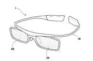
도 1은 본 발명의 일실시예에 따른 헤드 마운트 디스플레이 장치(1)의 외형을 도시한 사시도이다.1 is a perspective view illustrating an external appearance of a head mounted
도 1에서와 같이, 본 발명에 따른 헤드 마운트 디스플레이 장치(1)는 사람의 머리에 장착되는 타입으로, 일반적인 안경과 유사현 형태를 가지는바, 사람의 머리 또는 귀에 걸치도록 마련된 프레임(10)과, 프레임(10)에의히 지지되며 사용자의 좌안 및 우안 각각의 시야를 커버하는 글래스부(20), 및 프레임의 일측에 장착되어 주변 환경을 촬영하는 카메라(30)를 포함하고 있다.As shown in FIG. 1 , the head mounted
상기 프레임(10) 및 글래스부(20)는 형상 또는 재질이 한정되지 않고 다양하게 적용될 수 있다. 다만, 프레임(10) 및 글래스부(20)는 디스플레이장치(1)의 후술할 다양한 구성들을 수용할 수 있도록, 내부에 공간을 형성한다. 또한, 글래스부(20)는 광의 투과가 가능하도록 투명한 재질로 구현된다.The
이하, 헤드 마운트 디스플레이 장치(1)의 구체적인 구성에 관해 도 2를 참조하여 설명한다.Hereinafter, a specific configuration of the head mounted
도 2는 헤드 마운트 디스플레이 장치(1)의 구성 블록도이다. 본 도면에 도시된 디스플레이 장치(1)의 각 구성들은 도 1의 프레임(10) 또는 글래스부(20)에 수용되며, 이 구성들이 수용되는 형태 또는 방식은 프레임(10) 및 글래스부(20)의 형상에 따라서 가변적이므로 본 발명의 사상을 한정하는 사항이 아니다.2 is a block diagram of the head mounted
또한, 본 도면에 도시된 구성들은 디스플레이장치(1)의 하나의 예시일 뿐으로서, 본 발명의 사상이 구현된 디스플레이 장치(1)에서 본 도면에 도시되거나 또는 설명되지 않은 구성이 불필요하거나, 또는 디스플레이 장치(1)가 본 도면에 도시된 구성들만을 포함하여야 함을 의미하는 것은 아니다.In addition, the configurations shown in this figure are only one example of the
도 2에 도시된 바와 같이, 헤드 마운트 디스플레이 장치(1)는 외부로부터 영상신호를 수신하는 신호수신부(110), 신호수신부(110)에 수신되는 영상신호를 기 설정된 영상처리 프로세스에 따라서 처리하는 신호처리부(120), 신호처리부(120)에 의해 처리되는 영상신호를 영상으로 표시하는 디스플레이부(130), 다양한 외부장치(미도시)와 통신하는 통신부(140), 사용자의 조작에 의하여 기 설정된 제어 커맨드가 생성되는 사용자입력부(150), 데이터를 저장하는 저장부(160), 헤드 마운트 디스플레이 장치(1)의 각 구성에 동작 전원을 공급하는 전원공급부(170), 헤드 마운트 디스플레이 장치(1)의 제반 동작을 제어하는 제어부(180), 및 외부 환경에 대한 동영상 또는 정지영상을 촬영하는 카메라(190)를 포함한다. 이외에도 추가적으로 소리를 감지하는 마이크나 소리를 출력하는 이어폰을 더 포함할 수 있다.As shown in FIG. 2 , the head mounted
신호수신부(110)는 외부로부터 유선/무선으로 전달되는 영상신호를 수신하여 신호처리부(120) 또는 제어부(180)에 전달한다. 예를 들면, 신호수신부(110)는 방송국(미도시)으로부터 송출되는 RF(radio frequency)신호를 무선으로 수신하거나, 컴포지트(composite) 비디오, 컴포넌트(component) 비디오, 슈퍼 비디오(supervideo), SCART, HDMI(high definition multimedia interface), 디스플레이포트(DisplayPort), UDI(unified display interface), 또는 와이어리스(wireless) HD 규격 등에 의한 영상신호를 유선으로 수신할 수 있다.The
본 실시예에서 신호수신부(110)는 통신부(140)와 별도의 구성인 것으로 표현하였으나, 설계방식에 따라서 신호수신부(110) 및 통신부(140)는 통신 인터페이스(interface)로 통합될 수도 있다.In the present embodiment, the
신호처리부(120)는 신호수신부(110)에 수신되는 영상신호에 대해 다양한 영상처리 프로세스를 수행한다. 신호처리부(120)는 이러한 프로세스를 수행한 영상신호를 디스플레이부(130)에 출력함으로써, 디스플레이부(130)에 해당 영상신호에 기초하는 영상이 표시되게 한다. 신호처리부(120)가 수행하는 영상처리 프로세스의 종류는 한정되지 않는 바, 예를 들면 영상데이터의 영상 포맷에 대응하는 디코딩(decoding), 인터레이스(interlace) 방식의 영상데이터를 프로그레시브(progressive) 방식으로 변환하는 디인터레이싱(de-interlacing), 영상데이터를 기 설정된 해상도로 조정하는 스케일링(scaling), 영상 화질 개선을 위한 노이즈 감소(noise reduction), 디테일 강화(detail enhancement), 프레임 리프레시 레이트(frame refresh rate) 변환 등을 포함할 수 있다. 신호처리부(120)는 이러한 여러 기능을 통합시킨 SOC(system-on-chip), 또는 이러한 각 프로세스를 독자적으로 수행할 수 있는 개별적인 구성들이 인쇄회로기판 상에 장착됨으로써 영상처리보드(미도시)로 구현되어 헤드 마운트 디스플레이 장치(1)에 내장된다.The
디스플레이부(130)는 신호처리부(120)에서 처리된 영상신호를 사용자의 양안에 근접하게 영상으로 맺히도록 표시한다. 디스플레이부(130)가 영상을 표시하기 위한 보다 자세한 구조는 후술한다.The
통신부(140)는 유선/무선을 통해 다양한 종류의 외부장치(미도시)와 양방향 통신을 수행한다. 통신부(140)는 설계방식에 따라서 신호수신부(110)와 함께 통신 인터페이스를 구성할 수도 있다. 본 실시예에 따른 통신부(140)는 RF(radio frequency), 블루투스(Bluetooth)와 같은 양방향 RF 무선통신규격에 따라서 무선 통신을 수행한다.The
사용자입력부(150)는 사용자에 의해 조작됨으로써 기 설정된 제어 커맨드를 생성하여 제어부(180)에 전달한다. 예를 들면, 사용자입력부(150)는 프레임(10, 도 1 참조)에 설치된 입력 키 패드(미도시)나, 글래스(20, 도 1 참조) 상의 터치스크린(미도시) 또는 터치센서(미도시)로 구현될 수 있다. 또는, 사용자입력부(150)는 디스플레이 장치(1)와 별도로 분리된 리모트 컨트롤러(remote controller) 또는 모바일 폰과 같은 외부장치(미도시)로 구현될 수도 있다. 이 경우, 사용자입력부(150)는 통신부(140)와 통신함으로써 제어 커맨드를 제어부(180)에 전달한다.The
저장부(160)는 제어부(180)의 제어에 따라서 한정되지 않은 데이터가 저장된다. 저장부(160)는 플래시메모리(flash-memory), 하드디스크 드라이브(hard-disc drive)와 같은 비휘발성 메모리로 구현된다. 저장부(160)는 제어부(180)에 의해 액세스되며, 제어부(180)에 의한 데이터의 독취/기록/수정/삭제/갱신 등이 수행된다.The
전원공급부(170)는 헤드 마운트 디스플레이 장치(1)의 제반 구성이 동작하기 위한 직류전원을 제공한다. 전원공급부(170)는 1차전지 또는 2차전지로 구현될 수 있지만, 활용성을 위해 외부전원으로 충전 가능한 2차전지로 구현됨이 바람직하다. 전원공급부(170)는 제어부(180)에 의해 전원 공급이 제어되는 바, 예를 들면 특정 구성요소에 대한 전원의 출력 여부, 출력 전압의 레벨, 출력 듀티(duty)의 조정 등이 제어된다. The
카메라(190)는 프레임(10, 도 1 참조)의 외측에 설치되며, 디스플레이장치(1)의 외부 환경을 감지 및 촬영한다. The
카메라(190)는 소정 시점의 외부 환경을 촬상하여 정지화상을 생성하거나, 또는 기 설정된 시간 동안에 외부 환경을 촬영하여 동영상을 생성할 수 있다. 카메라(190)는 소정 시간 동안에 외부 환경을 모니터링할 수 있다.
The
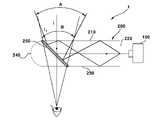
도 3은 본 발명의 실시예에 따른 헤드 마운트 디스플레이 장치(1)에서 카메라 모듈(190)의 광경로 형성을 도시한 것이다.3 illustrates the formation of an optical path of the
도 1에 도시된 바와 같이, 헤드 마운트 디스플레이 장치(1)는 카메라 모듈(190) 및 프리즘(200)을 포함하여 구성된다.As shown in FIG. 1 , the head mounted
상기 카메라 모듈(190)은 헤드 마운트 디스플레이 장치 주변의 영상을 촬영하기 위한 것으로, 렌즈 방향이 프리즘(200)을 향하도록 설치된다.The
한편 상기 카메라 모듈(190)의 전방에는 집광 렌즈(미도시)와 같은 광학계가 배치될 수 있다. 집광렌즈는 카메라 모듈이나 디스플레이소자의 빛 진행 방향 전방에 위치하여 입사광을 모으는 역할을 한다. 집광렌즈는 구면렌즈 또는 비구면 렌즈 중 선택된 렌즈의 조합으로 구성될 수 있다. 도 3에는 카메라 모듈(190)과 프리즘(200)이 이격되어 도시되어 있으나, 경우에 따라 카메라 모듈(190)은 프리즘(200)과 접촉하도록 형성될 수도 있다.Meanwhile, an optical system such as a condensing lens (not shown) may be disposed in front of the
상기 프리즘(200)은 카메라 모듈(190)에 상이 맺힐 수 있도록 광경로를 형성하는 소자이다. 본 실시예에 따른 프리즘(200)은 4 개의 광학면(210, 220, 230, 240)으로 구성되어 있고, 내부에는 편광빔 스플리터(250)가 형성되어 있다. 제1광학면(210)을 통해 프리즘(200)으로 입사된 입사광(I, incident light)은 편광빔 스플리터(250)에서 반사되어 제3 광학면(220)으로 출사되어 카메라 모듈(190)로 입사된다. 이때 편광빔 스플리터(250)는 입사된 광의 편광 성분의 차이에 따라 반사 또는 투과하는 반사 투과면이다. 예를 들어 입사광(I) 중 P파는 편광빔 스플리터(250)를 투과하고 S파는 편광빔 스플리터(250)에서 반사되어 카메라 모듈(190)로 입사된다. 이때 입사광은 수직으로만 입사하는 것이 아니라 도시된 바와 같이 경사지게 입사되기도 하는데, 경사지게 입사된 광(I1, I2)는 편광빔 스플리터(250)에서 반사된 후, 프리즘(200) 내부의 제1 광학면(210)과 제3 광학면(230)에서 전반사되어 카메라 모듈(190)로 입사된다.The
상기 제1 광학면(210)과 제3 광학면(230)은 서로 평행하게 배치되고, 편광빔 스플리터(250)는 제1 광학면과 제3 광학면 사이에 45도 각도로 경사지게 배치된다. 상기 제1 광학면(210)과 제3 광학면(230)에서는 임계각 이상으로 입사될 경우 스넬의 법칙에 의해 전반사가 일어난다. 스넬의 법칙 및 전반사의 원리는 이 출원의 기술분야에 종사하는 통상의 기술자가 용이하게 알 수 있는 사항이므로 자세한 설명은 생략하기로 한다.The first
그리고 상기 제2 광학면(220)에는 집광 렌즈(미도시)가 형성될 수 있다. 즉, 앞서 살펴본 바와 같이 카메라 모듈(190)과 제2 광학면 사이에 집광 렌즈가 형성될 수도 있지만, 제2 광학면(220)을 렌즈 형태로 설계할 수도 있다.In addition, a condensing lens (not shown) may be formed on the second
상기와 같은 구조에 의해 범위(A) 내에서 입사된 광(I)은 편광빔 스플리터(250)에서 반사되어 제1 광학면(210)과 제3 광학면(230)에서 반사되어 카메라 모듈(190)로 입사된다. 이때 입사광(I1)은 제1 광학면(210)에서 1회 전반사된 후 다시 제3 광학면(230)에서 전반사되어 전반사가 2회 일어나고, 입사광(I2)는 제1 광학면(210)에서만 전반사되어 전반사가 1회 일어난다. 하지만 이러한 전반사 횟수는 한정되는 것이 아니며, 프리즘(200)의 길이에 따라 다양하게 변경 가능하다.The light I incident within the range A by the above structure is reflected from the
상기와 같은 광경로에 의해 카메라 모듈(190)은 범위(A)안에 존재하는 주변 환경을 촬영할 수 있다. 이렇게 형성되는 카메라 모듈(190)의 촬영 범위(A)는 헤드 마운트 디스플레이 장치(1)를 착용한 사용자의 시야 범위(B)가 거의 일치하는 것을 확인할 수 있다.By the optical path as described above, the
이상에서 살펴본 바와 같이 카메라 모듈(190)의 방향을 회전시켜 프리즘(200) 방향으로 향하게 하면 헤드 마운트 디스플레이 장치(1)를 통해 보는 관찰자의 시야(B)와 카메라 모듈(190)의 촬영 범위(A)가 거의 동일해지게 된다.
As described above, when the direction of the
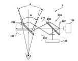
도 4는 도 3의 실시예에 디스플레이 소자를 추가한 것이다.FIG. 4 is a display element added to the embodiment of FIG. 3 .
즉, 본 실시예에 따른 헤드 마운트 디스플레이 장치(1)는 카메라 모듈(190) 과 프리즘(200)외에 디스플레이 소자(132)를 더 포함한 것으로, 본 실시예에 의하면, 카메라 모듈(190)에서 촬영한 영상을 디스플레이 소자(132)를 이용해서 볼 수 있다.That is, the head mounted
상기 디스플레이 소자(132)는 영상(Image)을 표시하는 소자로 LCD 패널 등 다양한 디스플레이 기기가 사용될 수 있으며, 신호처리부(120)에 의해 영상이 표시된다. 예를 들면, 디스플레이 소자(132)는 반사형인 실리콘 액정 표시소자(Liquid Crystal on Silicon : LCoS), 디지털 광원 표시소자(Digital Light Processing :DLP), 광원이 결합된 마이크로 LCD 소자 또는 자체발광하는 마이크로 OLED 소자 등이 사용될 수 있고 크기는 1인치 이하인 것이 바람직하다. 한편, 마이크로 반사형인 실리콘 액정 표시소자, 디지털 광원 표시소자, 마이크로 LCD 소자는 자체 발광이 아니므로 외부에서 광원이 결합되어야 한다. 즉, 백라이트를 사용한 투과형 마이크로 LCD 패널 또는 프론트 라이트(Frontlight)를 사용한 반사형 마이크로 LCD 패널이 가능하다. 마이크로 OLED 패널은 자체 발광이 가능하기 때문에 별도의 광원이 필요 없으므로 헤드 마운트 디스플레이 장치를 보다 소형으로 구성할 수 있다. 이때 광원에서 출사되는 빛을 디스플레이 소자(132)로 입사되도록 광경로를 조절하는 광학계가 사용될 수 있다.The
그리고 디스플레이 소자(132)의 전방에는 앞서 살펴본 바와 같이 집광렌즈(미도시)가 형성될 수 있다.In addition, a condensing lens (not shown) may be formed in front of the
디스플레이 소자(132)가 추가됨에 따라 프리즘(200) 내부에는 디스플레이 소자(132)로부터 출사되는 빛을 처리하기 위한 편광빔 스플리터(260)가 하나 더 형성된다. 이하에서는 편광빔 스플리터들(210, 260)은 제1 편광빔 스플리터(250) 및 제2 편광빔 스플리터(260)로 부르기로 한다.As the
상기 제1 편광빔 스플리터(250)와 제2 편광빔 스플리터(260)는 서로 평형하게 설치되며 제1, 2 광학면(210, 230)과 45도 경사각으로 비스듬히 설치된다.The first
이러한 구성에 의해, 디스플레이 소자(132)에서 출사된 빛은 프리즘(200)으로 입사되고 제2 편광빔 스플리터(260)과 제1 편광빔 스플리터(250)를 사용자의 눈으로 입사된다. 보다 상세하게 살며보면, 디스플레이 소자(132)에서는 S편광이 출사되기 때문에서, S편광은 제2 편광빔 스플리터(260)에서 반사되면서 P편광으로 변하게 된다. P편광은 제1 편광빔 스플리터(250)를 투과하다 제4 광학면(250)에서 반사되어 다시 S편광으로 변하고, 제1 편광빔 스플리터(250)에서 반사되어 헤드 마운트 디스플레이 장치를 착용한 사용자의 눈으로 입사된다.With this configuration, the light emitted from the
이때 제4 광학면(250)은 평면일 수도 있으나 오목하게 형성되는 것이 바람직하다. 제4 광학면(250)을 오목하게 형성하면 프리즘의 전체 길이를 짧게 할 수 있으므로 소형화에 보다 유리하다. 그리고 제4 광학면(240)에는 반사 코팅이 되어 있다.In this case, the fourth
카메라 모듈(190)로 입사되는 광 경로는 도 3에서 살펴본 것과 동일하므로 생략하도록 한다.Since the light path incident to the
상기와 같이 디스플레이 소자(132)를 추가함으로써 헤드 마운트 디스플레이 장치(1)의 사용자는 카메라 모듈(190)을 통해 촬영되는 영상을 볼 수 있을 뿐만 아니라 디스플레이 소자(132)에서 표시되는 영상도 볼 수 있다.By adding the
카메라 모듈(190)에서 촬영된 영상은 저장부(160, 도 2참조)에 저장되며, 사용자 입력부(150)의 재생 명령이 입력되면, 디스플레이 소자(132)를 통해 디스사용자가 영상을 시청할 수 있다.
The image captured by the
이상에서 본 발명에 따른 실시예들이 설명되었으나, 이는 예시적인 것에 불과하며, 당해 분야에서 통상적 지식을 가진 자라면 이로부터 다양한 변형 및 균등한 범위의 실시예가 가능하다는 점을 이해할 것이다. 따라서, 본 발명의 진정한 기술적 보호 범위는 다음의 특허청구범위에 의해서 정해져야 할 것이다.
Although the embodiments according to the present invention have been described above, these are merely exemplary, and those of ordinary skill in the art will understand that various modifications and equivalent ranges of embodiments are possible therefrom. Accordingly, the true technical protection scope of the present invention should be defined by the following claims.
1 : 헤드 마운트 디스플레이 장치10: 프레임
20 : 글래스부110 : 신호수신부
120 : 신호처리부 130 : 디스플레이부
140 : 통신부150 : 사용자 입력부
160 : 저장부170 : 전원공급부
180 : 제어부190 : 카메라 모듈
200 : 프리즘 210 : 제1 광학면
220 : 제2 광학면230 : 제3 광학면
240 : 제4 광학면250 : 제1 편광빔 스플리터
260 : 제2 편광빔 스플리터132: 디스플레이 소자1: head mounted display device 10: frame
20: glass unit 110: signal receiving unit
120: signal processing unit 130: display unit
140: communication unit 150: user input unit
160: storage unit 170: power supply unit
180: control unit 190: camera module
200: prism 210: first optical surface
220: second optical surface 230: third optical surface
240: fourth optical surface 250: first polarization beam splitter
260: second polarization beam splitter 132: display element
Claims (14)
Translated fromKorean렌즈가 상기 프리즘 방향으로 향하도록 배치되는 카메라 모듈을 포함하고,
상기 프리즘은 제1광학면, 상기 제1광학면과 연장 형성된 제2광학면, 상기 제2광학면과 연장 형성되고 상기 제1광학면에 평형하게 형성된 제3광학면, 상기 제3광학면과 연장 형성되어 상기 제2광학면과 대향하는 제4광학면을 포함하고,
상기 제1광학면과 상기 제3광학면에 경사지게 형성된 제1반사투과면을 포함하고,
상기 프리즘은 상기 제1 반사투과면과 평형하게 형성된 제2반사투과면을 포함하고,
상기 프리즘의 일측에 카메라 모듈에 의해 촬영된 영상을 표시하는 디스플레이 소자를 포함하고,
상기 디스플레이 소자는 상기 제3 광학면의 일측에 형성되고,
상기 제3광학면에는 집광렌즈가 형성되고,
상기 제4광학면은 오목하게 형성되고 반사 코팅이 되는 헤드 마운트 디스플레이장치.a prism including a reflective and transmissive surface for reflecting or transmitting the incident light therein, but changing the path of the incident light; and
It includes a camera module disposed so that the lens is directed toward the prism,
The prism includes a first optical surface, a second optical surface extending from the first optical surface, a third optical surface extending from the second optical surface and formed parallel to the first optical surface, and the third optical surface and It is formed to extend and includes a fourth optical surface facing the second optical surface,
and a first reflective and transmissive surface inclined to the first optical surface and the third optical surface,
The prism includes a second reflective transmissive surface formed in parallel with the first reflective transmissive surface,
A display device for displaying an image captured by a camera module on one side of the prism,
The display element is formed on one side of the third optical surface,
A condensing lens is formed on the third optical surface,
The fourth optical surface is concavely formed and a reflective coating is applied to the head mounted display device.
상기 제1반사투과면은 편광 성분에 따라 반사 또는 투과하는 제1편광빔 스플리터인 것을 특징으로 하는 헤드 마운트 디스플레이 장치.According to claim 1,
The first reflective transmission surface is a head mounted display device, characterized in that the first polarization beam splitter that reflects or transmits according to the polarization component.
상기 제1편광빔 스플리터는 상기 제1광학면 및 제3광학면과 45도 경사지게 형성되어 있는 것을 특징으로 하는 헤드 마운트 디스플레이 장치.4. The method of claim 3
The head mounted display device, characterized in that the first polarization beam splitter is formed to be inclined at 45 degrees to the first and third optical surfaces.
상기 제2광학면에는 집광렌즈가 형성되어 있는 것을 특징으로 하는 헤드 마운트 디스플레이 장치.4. The method of claim 3,
A head mounted display device, characterized in that a condensing lens is formed on the second optical surface.
상기 제1편광빔 스플리터는 입사광을 반사시켜 상기 카메라 모듈로 출사시키는 것을 특징으로 하는 헤드 마운트 디스플레이 장치.4. The method of claim 3,
The first polarized beam splitter is a head mounted display device, characterized in that for reflecting the incident light to be emitted to the camera module.
상기 제1반사투과면은 제2편광빔 스플리터인 것을 특징으로 하는 헤드 마운트 디스플레이 장치.According to claim 1,
The first reflective transmission surface is a head mounted display device, characterized in that the second polarization beam splitter.
상기 제2편광빔 스플리터는 상기 디스플레이 소자에서 출사되는 편광 성분을 반사시키는 것을 특징으로 하는 헤드 마운트 디스플레이 장치.10. The method of claim 9,
The second polarization beam splitter is a head mounted display device, characterized in that for reflecting the polarization component emitted from the display device.
상기 제4광학면은 상기 제2편광빔 스플리터에서 반사된 빛을 반사시키는 것을 특징으로 하는 헤드 마운트 디스플레이 장치.
12. The method of claim 11,
The fourth optical surface is a head mounted display device, characterized in that for reflecting the light reflected from the second polarization beam splitter.
Priority Applications (3)
| Application Number | Priority Date | Filing Date | Title |
|---|---|---|---|
| KR1020150057875AKR102426760B1 (en) | 2015-04-24 | 2015-04-24 | Head mount display apparatus |
| US15/569,025US10514538B2 (en) | 2015-04-24 | 2016-04-21 | Head-mounted display device |
| PCT/KR2016/004136WO2016171479A1 (en) | 2015-04-24 | 2016-04-21 | Head-mounted display device |
Applications Claiming Priority (1)
| Application Number | Priority Date | Filing Date | Title |
|---|---|---|---|
| KR1020150057875AKR102426760B1 (en) | 2015-04-24 | 2015-04-24 | Head mount display apparatus |
Publications (2)
| Publication Number | Publication Date |
|---|---|
| KR20160126603A KR20160126603A (en) | 2016-11-02 |
| KR102426760B1true KR102426760B1 (en) | 2022-07-29 |
Family
ID=57143226
Family Applications (1)
| Application Number | Title | Priority Date | Filing Date |
|---|---|---|---|
| KR1020150057875AActiveKR102426760B1 (en) | 2015-04-24 | 2015-04-24 | Head mount display apparatus |
Country Status (3)
| Country | Link |
|---|---|
| US (1) | US10514538B2 (en) |
| KR (1) | KR102426760B1 (en) |
| WO (1) | WO2016171479A1 (en) |
Families Citing this family (1)
| Publication number | Priority date | Publication date | Assignee | Title |
|---|---|---|---|---|
| US11740742B2 (en)* | 2019-09-23 | 2023-08-29 | Apple Inc. | Electronic devices with finger sensors |
Citations (2)
| Publication number | Priority date | Publication date | Assignee | Title |
|---|---|---|---|---|
| US20050243433A1 (en)* | 2002-12-03 | 2005-11-03 | Essilor International, A France Corporation | Polarization splitter, method of manufacturing same and ophthalmic lens incorporating projection inserts containing it |
| US20130021658A1 (en) | 2011-07-20 | 2013-01-24 | Google Inc. | Compact See-Through Display System |
Family Cites Families (9)
| Publication number | Priority date | Publication date | Assignee | Title |
|---|---|---|---|---|
| US4302079A (en)* | 1980-04-10 | 1981-11-24 | Bell Telephone Laboratories, Incorporated | Photolithographic projection apparatus using light in the far ultraviolet |
| US5886822A (en)* | 1996-10-08 | 1999-03-23 | The Microoptical Corporation | Image combining system for eyeglasses and face masks |
| JP4341108B2 (en)* | 1999-07-14 | 2009-10-07 | ソニー株式会社 | Virtual image observation optical device |
| TW201806001A (en)* | 2003-05-23 | 2018-02-16 | 尼康股份有限公司 | Exposure device and device manufacturing method |
| JP4218553B2 (en)* | 2004-03-08 | 2009-02-04 | ソニー株式会社 | Image display device |
| JP2011238698A (en)* | 2010-05-07 | 2011-11-24 | Furukawa Electric Co Ltd:The | Laser module |
| US8749886B2 (en)* | 2012-03-21 | 2014-06-10 | Google Inc. | Wide-angle wide band polarizing beam splitter |
| KR101478424B1 (en) | 2013-01-30 | 2014-12-31 | 박수원 | Apparatus for head mount display |
| KR101546962B1 (en)* | 2013-08-27 | 2015-08-24 | 주식회사 에픽옵틱스 | Optical System of Head Mounted Display |
- 2015
- 2015-04-24KRKR1020150057875Apatent/KR102426760B1/enactiveActive
- 2016
- 2016-04-21USUS15/569,025patent/US10514538B2/enactiveActive
- 2016-04-21WOPCT/KR2016/004136patent/WO2016171479A1/ennot_activeCeased
Patent Citations (2)
| Publication number | Priority date | Publication date | Assignee | Title |
|---|---|---|---|---|
| US20050243433A1 (en)* | 2002-12-03 | 2005-11-03 | Essilor International, A France Corporation | Polarization splitter, method of manufacturing same and ophthalmic lens incorporating projection inserts containing it |
| US20130021658A1 (en) | 2011-07-20 | 2013-01-24 | Google Inc. | Compact See-Through Display System |
Also Published As
| Publication number | Publication date |
|---|---|
| US10514538B2 (en) | 2019-12-24 |
| KR20160126603A (en) | 2016-11-02 |
| US20180129045A1 (en) | 2018-05-10 |
| WO2016171479A1 (en) | 2016-10-27 |
Similar Documents
| Publication | Publication Date | Title |
|---|---|---|
| US12140741B2 (en) | Optical system for head-mounted display | |
| CN113009690B (en) | Image display method, near-eye display device and device | |
| CN109960481B (en) | Display system and control method thereof | |
| CN106461943A (en) | Method and apparatus for see-through near-eye display | |
| US9568732B2 (en) | Mobile terminal | |
| KR101598480B1 (en) | See-through type head mounted display | |
| CN105404005A (en) | Head-mounted display for augmented reality | |
| CN114450621A (en) | head mounted display | |
| US9519092B1 (en) | Display method | |
| KR101606854B1 (en) | Head Mountain display device for a mobile phone that provides visual content is being charged | |
| KR20200050689A (en) | An electronic device including optical members that change the optical path | |
| KR102426760B1 (en) | Head mount display apparatus | |
| CN116472477A (en) | Head-mounted display | |
| KR20190085345A (en) | Head mount device | |
| WO2024123918A1 (en) | Reflector orientation of geometrical and mixed waveguide for reducing grating conspicuity | |
| CN207557586U (en) | A kind of head-mounted display apparatus | |
| CN204856378U (en) | Electronic device | |
| KR20150084603A (en) | Near to eye display and wearable device having the same | |
| CN107908006A (en) | A kind of head-mounted display apparatus | |
| WO2018145463A1 (en) | Device and method for implementing augmented reality | |
| CN118859548A (en) | Image generating device, display equipment and transportation tool | |
| CN118483816A (en) | Folded beam 2D beam scanner | |
| KR20170002262U (en) | See-through head mount display device | |
| CN118859549A (en) | Projection lens, image generating device, display equipment and transportation vehicle | |
| JP2023048164A (en) | Illumination optical unit and image projection device using the same |
Legal Events
| Date | Code | Title | Description |
|---|---|---|---|
| PA0109 | Patent application | Patent event code:PA01091R01D Comment text:Patent Application Patent event date:20150424 | |
| PG1501 | Laying open of application | ||
| A201 | Request for examination | ||
| PA0201 | Request for examination | Patent event code:PA02012R01D Patent event date:20200421 Comment text:Request for Examination of Application Patent event code:PA02011R01I Patent event date:20150424 Comment text:Patent Application | |
| E902 | Notification of reason for refusal | ||
| PE0902 | Notice of grounds for rejection | Comment text:Notification of reason for refusal Patent event date:20211014 Patent event code:PE09021S01D | |
| E701 | Decision to grant or registration of patent right | ||
| PE0701 | Decision of registration | Patent event code:PE07011S01D Comment text:Decision to Grant Registration Patent event date:20220425 | |
| GRNT | Written decision to grant | ||
| PR0701 | Registration of establishment | Comment text:Registration of Establishment Patent event date:20220725 Patent event code:PR07011E01D | |
| PR1002 | Payment of registration fee | Payment date:20220726 End annual number:3 Start annual number:1 | |
| PG1601 | Publication of registration | ||
| PR1001 | Payment of annual fee | Payment date:20250616 Start annual number:4 End annual number:4 |