KR102426694B1 - electronic device including flexible display - Google Patents
electronic device including flexible displayDownload PDFInfo
- Publication number
- KR102426694B1 KR102426694B1KR1020170056440AKR20170056440AKR102426694B1KR 102426694 B1KR102426694 B1KR 102426694B1KR 1020170056440 AKR1020170056440 AKR 1020170056440AKR 20170056440 AKR20170056440 AKR 20170056440AKR 102426694 B1KR102426694 B1KR 102426694B1
- Authority
- KR
- South Korea
- Prior art keywords
- housing
- slide
- disposed
- electronic device
- slide module
- Prior art date
- Legal status (The legal status is an assumption and is not a legal conclusion. Google has not performed a legal analysis and makes no representation as to the accuracy of the status listed.)
- Active
Links
Images


Classifications
- G—PHYSICS
- G09—EDUCATION; CRYPTOGRAPHY; DISPLAY; ADVERTISING; SEALS
- G09F—DISPLAYING; ADVERTISING; SIGNS; LABELS OR NAME-PLATES; SEALS
- G09F9/00—Indicating arrangements for variable information in which the information is built-up on a support by selection or combination of individual elements
- G09F9/30—Indicating arrangements for variable information in which the information is built-up on a support by selection or combination of individual elements in which the desired character or characters are formed by combining individual elements
- G09F9/301—Indicating arrangements for variable information in which the information is built-up on a support by selection or combination of individual elements in which the desired character or characters are formed by combining individual elements flexible foldable or roll-able electronic displays, e.g. thin LCD, OLED
- H—ELECTRICITY
- H05—ELECTRIC TECHNIQUES NOT OTHERWISE PROVIDED FOR
- H05K—PRINTED CIRCUITS; CASINGS OR CONSTRUCTIONAL DETAILS OF ELECTRIC APPARATUS; MANUFACTURE OF ASSEMBLAGES OF ELECTRICAL COMPONENTS
- H05K5/00—Casings, cabinets or drawers for electric apparatus
- H05K5/02—Details
- H05K5/0217—Mechanical details of casings
- H05K5/0226—Hinges
- E—FIXED CONSTRUCTIONS
- E05—LOCKS; KEYS; WINDOW OR DOOR FITTINGS; SAFES
- E05D—HINGES OR SUSPENSION DEVICES FOR DOORS, WINDOWS OR WINGS
- E05D11/00—Additional features or accessories of hinges
- E05D11/06—Devices for limiting the opening movement of hinges
- E—FIXED CONSTRUCTIONS
- E05—LOCKS; KEYS; WINDOW OR DOOR FITTINGS; SAFES
- E05D—HINGES OR SUSPENSION DEVICES FOR DOORS, WINDOWS OR WINGS
- E05D3/00—Hinges with pins
- E05D3/06—Hinges with pins with two or more pins
- E05D3/12—Hinges with pins with two or more pins with two parallel pins and one arm
- E05D3/122—Gear hinges
- E—FIXED CONSTRUCTIONS
- E05—LOCKS; KEYS; WINDOW OR DOOR FITTINGS; SAFES
- E05D—HINGES OR SUSPENSION DEVICES FOR DOORS, WINDOWS OR WINGS
- E05D3/00—Hinges with pins
- E05D3/06—Hinges with pins with two or more pins
- E05D3/18—Hinges with pins with two or more pins with sliding pins or guides
- F—MECHANICAL ENGINEERING; LIGHTING; HEATING; WEAPONS; BLASTING
- F16—ENGINEERING ELEMENTS AND UNITS; GENERAL MEASURES FOR PRODUCING AND MAINTAINING EFFECTIVE FUNCTIONING OF MACHINES OR INSTALLATIONS; THERMAL INSULATION IN GENERAL
- F16C—SHAFTS; FLEXIBLE SHAFTS; ELEMENTS OR CRANKSHAFT MECHANISMS; ROTARY BODIES OTHER THAN GEARING ELEMENTS; BEARINGS
- F16C29/00—Bearings for parts moving only linearly
- F16C29/02—Sliding-contact bearings
- G—PHYSICS
- G06—COMPUTING OR CALCULATING; COUNTING
- G06F—ELECTRIC DIGITAL DATA PROCESSING
- G06F1/00—Details not covered by groups G06F3/00 - G06F13/00 and G06F21/00
- G06F1/16—Constructional details or arrangements
- G06F1/1613—Constructional details or arrangements for portable computers
- G06F1/1615—Constructional details or arrangements for portable computers with several enclosures having relative motions, each enclosure supporting at least one I/O or computing function
- G06F1/1616—Constructional details or arrangements for portable computers with several enclosures having relative motions, each enclosure supporting at least one I/O or computing function with folding flat displays, e.g. laptop computers or notebooks having a clamshell configuration, with body parts pivoting to an open position around an axis parallel to the plane they define in closed position
- G—PHYSICS
- G06—COMPUTING OR CALCULATING; COUNTING
- G06F—ELECTRIC DIGITAL DATA PROCESSING
- G06F1/00—Details not covered by groups G06F3/00 - G06F13/00 and G06F21/00
- G06F1/16—Constructional details or arrangements
- G06F1/1613—Constructional details or arrangements for portable computers
- G06F1/1633—Constructional details or arrangements of portable computers not specific to the type of enclosures covered by groups G06F1/1615 - G06F1/1626
- G06F1/1635—Details related to the integration of battery packs and other power supplies such as fuel cells or integrated AC adapter
- G—PHYSICS
- G06—COMPUTING OR CALCULATING; COUNTING
- G06F—ELECTRIC DIGITAL DATA PROCESSING
- G06F1/00—Details not covered by groups G06F3/00 - G06F13/00 and G06F21/00
- G06F1/16—Constructional details or arrangements
- G06F1/1613—Constructional details or arrangements for portable computers
- G06F1/1633—Constructional details or arrangements of portable computers not specific to the type of enclosures covered by groups G06F1/1615 - G06F1/1626
- G06F1/1637—Details related to the display arrangement, including those related to the mounting of the display in the housing
- G06F1/1641—Details related to the display arrangement, including those related to the mounting of the display in the housing the display being formed by a plurality of foldable display components
- G—PHYSICS
- G06—COMPUTING OR CALCULATING; COUNTING
- G06F—ELECTRIC DIGITAL DATA PROCESSING
- G06F1/00—Details not covered by groups G06F3/00 - G06F13/00 and G06F21/00
- G06F1/16—Constructional details or arrangements
- G06F1/1613—Constructional details or arrangements for portable computers
- G06F1/1633—Constructional details or arrangements of portable computers not specific to the type of enclosures covered by groups G06F1/1615 - G06F1/1626
- G06F1/1637—Details related to the display arrangement, including those related to the mounting of the display in the housing
- G06F1/1652—Details related to the display arrangement, including those related to the mounting of the display in the housing the display being flexible, e.g. mimicking a sheet of paper, or rollable
- G—PHYSICS
- G06—COMPUTING OR CALCULATING; COUNTING
- G06F—ELECTRIC DIGITAL DATA PROCESSING
- G06F1/00—Details not covered by groups G06F3/00 - G06F13/00 and G06F21/00
- G06F1/16—Constructional details or arrangements
- G06F1/1613—Constructional details or arrangements for portable computers
- G06F1/1633—Constructional details or arrangements of portable computers not specific to the type of enclosures covered by groups G06F1/1615 - G06F1/1626
- G06F1/1656—Details related to functional adaptations of the enclosure, e.g. to provide protection against EMI, shock, water, or to host detachable peripherals like a mouse or removable expansions units like PCMCIA cards, or to provide access to internal components for maintenance or to removable storage supports like CDs or DVDs, or to mechanically mount accessories
- G—PHYSICS
- G06—COMPUTING OR CALCULATING; COUNTING
- G06F—ELECTRIC DIGITAL DATA PROCESSING
- G06F1/00—Details not covered by groups G06F3/00 - G06F13/00 and G06F21/00
- G06F1/16—Constructional details or arrangements
- G06F1/1613—Constructional details or arrangements for portable computers
- G06F1/1633—Constructional details or arrangements of portable computers not specific to the type of enclosures covered by groups G06F1/1615 - G06F1/1626
- G06F1/1675—Miscellaneous details related to the relative movement between the different enclosures or enclosure parts
- G06F1/1681—Details related solely to hinges
- G—PHYSICS
- G06—COMPUTING OR CALCULATING; COUNTING
- G06F—ELECTRIC DIGITAL DATA PROCESSING
- G06F1/00—Details not covered by groups G06F3/00 - G06F13/00 and G06F21/00
- G06F1/16—Constructional details or arrangements
- G06F1/1613—Constructional details or arrangements for portable computers
- G06F1/1633—Constructional details or arrangements of portable computers not specific to the type of enclosures covered by groups G06F1/1615 - G06F1/1626
- G06F1/1675—Miscellaneous details related to the relative movement between the different enclosures or enclosure parts
- G06F1/1683—Miscellaneous details related to the relative movement between the different enclosures or enclosure parts for the transmission of signal or power between the different housings, e.g. details of wired or wireless communication, passage of cabling
- G—PHYSICS
- G06—COMPUTING OR CALCULATING; COUNTING
- G06F—ELECTRIC DIGITAL DATA PROCESSING
- G06F1/00—Details not covered by groups G06F3/00 - G06F13/00 and G06F21/00
- G06F1/16—Constructional details or arrangements
- G06F1/1613—Constructional details or arrangements for portable computers
- G06F1/1633—Constructional details or arrangements of portable computers not specific to the type of enclosures covered by groups G06F1/1615 - G06F1/1626
- G06F1/1684—Constructional details or arrangements related to integrated I/O peripherals not covered by groups G06F1/1635 - G06F1/1675
- G06F1/1698—Constructional details or arrangements related to integrated I/O peripherals not covered by groups G06F1/1635 - G06F1/1675 the I/O peripheral being a sending/receiving arrangement to establish a cordless communication link, e.g. radio or infrared link, integrated cellular phone
- H—ELECTRICITY
- H01—ELECTRIC ELEMENTS
- H01Q—ANTENNAS, i.e. RADIO AERIALS
- H01Q1/00—Details of, or arrangements associated with, antennas
- H01Q1/12—Supports; Mounting means
- H01Q1/22—Supports; Mounting means by structural association with other equipment or articles
- H01Q1/2258—Supports; Mounting means by structural association with other equipment or articles used with computer equipment
- H01Q1/2266—Supports; Mounting means by structural association with other equipment or articles used with computer equipment disposed inside the computer
- H—ELECTRICITY
- H05—ELECTRIC TECHNIQUES NOT OTHERWISE PROVIDED FOR
- H05K—PRINTED CIRCUITS; CASINGS OR CONSTRUCTIONAL DETAILS OF ELECTRIC APPARATUS; MANUFACTURE OF ASSEMBLAGES OF ELECTRICAL COMPONENTS
- H05K1/00—Printed circuits
- H05K1/18—Printed circuits structurally associated with non-printed electric components
- H05K1/189—Printed circuits structurally associated with non-printed electric components characterised by the use of a flexible or folded printed circuit
- H—ELECTRICITY
- H05—ELECTRIC TECHNIQUES NOT OTHERWISE PROVIDED FOR
- H05K—PRINTED CIRCUITS; CASINGS OR CONSTRUCTIONAL DETAILS OF ELECTRIC APPARATUS; MANUFACTURE OF ASSEMBLAGES OF ELECTRICAL COMPONENTS
- H05K5/00—Casings, cabinets or drawers for electric apparatus
- H05K5/0017—Casings, cabinets or drawers for electric apparatus with operator interface units
- H—ELECTRICITY
- H05—ELECTRIC TECHNIQUES NOT OTHERWISE PROVIDED FOR
- H05K—PRINTED CIRCUITS; CASINGS OR CONSTRUCTIONAL DETAILS OF ELECTRIC APPARATUS; MANUFACTURE OF ASSEMBLAGES OF ELECTRICAL COMPONENTS
- H05K5/00—Casings, cabinets or drawers for electric apparatus
- H05K5/02—Details
- H05K5/03—Covers
- H—ELECTRICITY
- H05—ELECTRIC TECHNIQUES NOT OTHERWISE PROVIDED FOR
- H05K—PRINTED CIRCUITS; CASINGS OR CONSTRUCTIONAL DETAILS OF ELECTRIC APPARATUS; MANUFACTURE OF ASSEMBLAGES OF ELECTRICAL COMPONENTS
- H05K7/00—Constructional details common to different types of electric apparatus
- H05K7/14—Mounting supporting structure in casing or on frame or rack
- H05K7/1422—Printed circuit boards receptacles, e.g. stacked structures, electronic circuit modules or box like frames
- H05K7/1427—Housings
- H—ELECTRICITY
- H10—SEMICONDUCTOR DEVICES; ELECTRIC SOLID-STATE DEVICES NOT OTHERWISE PROVIDED FOR
- H10K—ORGANIC ELECTRIC SOLID-STATE DEVICES
- H10K50/00—Organic light-emitting devices
- H10K50/80—Constructional details
- H10K50/84—Passivation; Containers; Encapsulations
- E—FIXED CONSTRUCTIONS
- E05—LOCKS; KEYS; WINDOW OR DOOR FITTINGS; SAFES
- E05Y—INDEXING SCHEME ASSOCIATED WITH SUBCLASSES E05D AND E05F, RELATING TO CONSTRUCTION ELEMENTS, ELECTRIC CONTROL, POWER SUPPLY, POWER SIGNAL OR TRANSMISSION, USER INTERFACES, MOUNTING OR COUPLING, DETAILS, ACCESSORIES, AUXILIARY OPERATIONS NOT OTHERWISE PROVIDED FOR, APPLICATION THEREOF
- E05Y2201/00—Constructional elements; Accessories therefor
- E05Y2201/20—Brakes; Disengaging means; Holders; Stops; Valves; Accessories therefor
- E05Y2201/224—Stops
- E—FIXED CONSTRUCTIONS
- E05—LOCKS; KEYS; WINDOW OR DOOR FITTINGS; SAFES
- E05Y—INDEXING SCHEME ASSOCIATED WITH SUBCLASSES E05D AND E05F, RELATING TO CONSTRUCTION ELEMENTS, ELECTRIC CONTROL, POWER SUPPLY, POWER SIGNAL OR TRANSMISSION, USER INTERFACES, MOUNTING OR COUPLING, DETAILS, ACCESSORIES, AUXILIARY OPERATIONS NOT OTHERWISE PROVIDED FOR, APPLICATION THEREOF
- E05Y2999/00—Subject-matter not otherwise provided for in this subclass
- F—MECHANICAL ENGINEERING; LIGHTING; HEATING; WEAPONS; BLASTING
- F16—ENGINEERING ELEMENTS AND UNITS; GENERAL MEASURES FOR PRODUCING AND MAINTAINING EFFECTIVE FUNCTIONING OF MACHINES OR INSTALLATIONS; THERMAL INSULATION IN GENERAL
- F16C—SHAFTS; FLEXIBLE SHAFTS; ELEMENTS OR CRANKSHAFT MECHANISMS; ROTARY BODIES OTHER THAN GEARING ELEMENTS; BEARINGS
- F16C2380/00—Electrical apparatus
- G—PHYSICS
- G06—COMPUTING OR CALCULATING; COUNTING
- G06F—ELECTRIC DIGITAL DATA PROCESSING
- G06F2203/00—Indexing scheme relating to G06F3/00 - G06F3/048
- G06F2203/041—Indexing scheme relating to G06F3/041 - G06F3/045
- G06F2203/04102—Flexible digitiser, i.e. constructional details for allowing the whole digitising part of a device to be flexed or rolled like a sheet of paper
- H—ELECTRICITY
- H10—SEMICONDUCTOR DEVICES; ELECTRIC SOLID-STATE DEVICES NOT OTHERWISE PROVIDED FOR
- H10K—ORGANIC ELECTRIC SOLID-STATE DEVICES
- H10K2102/00—Constructional details relating to the organic devices covered by this subclass
- H10K2102/301—Details of OLEDs
- H10K2102/311—Flexible OLED
Landscapes
- Engineering & Computer Science (AREA)
- Computer Hardware Design (AREA)
- Theoretical Computer Science (AREA)
- General Engineering & Computer Science (AREA)
- Physics & Mathematics (AREA)
- General Physics & Mathematics (AREA)
- Human Computer Interaction (AREA)
- Microelectronics & Electronic Packaging (AREA)
- Mechanical Engineering (AREA)
- Mathematical Physics (AREA)
- Computer Networks & Wireless Communication (AREA)
- Optics & Photonics (AREA)
- Power Engineering (AREA)
- Telephone Set Structure (AREA)
- Casings For Electric Apparatus (AREA)
- Devices For Indicating Variable Information By Combining Individual Elements (AREA)
- Electroluminescent Light Sources (AREA)
Abstract
Translated fromKoreanDescription
Translated fromKorean본 발명은 다양한 실시예에 따른 전자 장치에 관한 것으로, 전자 장치 외면에 폴딩이 가능한 플렉서블 디스플레이를 포함한 전자 장치에 관한 것이다.The present invention relates to an electronic device according to various embodiments, and to an electronic device including a flexible display that can be folded on an outer surface of the electronic device.
정보통신 기술과 반도체 기술 등의 눈부신 발전에 힘입어 각종 전자 장치들의 보급과 이용이 급속도로 증가하고 있다. 특히 최근의 전자 장치들은 휴대하고 다니며 통신할 수 있도록 개발되고 있다.BACKGROUND ART With the remarkable development of information and communication technology and semiconductor technology, the dissemination and use of various electronic devices are rapidly increasing. In particular, recent electronic devices are being developed to be portable and to be able to communicate.
전자 장치라 함은, 가전제품으로부터, 전자 수첩, 휴대용 멀티미디어 재생기, 이동통신 단말기, 태블릿 PC, 영상/음향 장치, 데스크톱/랩톱 컴퓨터, 차량용 내비게이션 등, 탑재된 프로그램에 따라 특정 기능을 수행하는 장치를 의미할 수 있다. 예를 들면, 이러한 전자 장치들은 저장된 정보를 음향이나 영상으로 출력할 수 있다. 전자 장치의 집적도가 높아지고, 초고속, 대용량 무선통신이 보편화되면서, 최근에는, 이동통신 단말기와 같은 하나의 전자 장치에 다양한 기능이 탑재될 수 있다. 예를 들면, 통신 기능뿐만 아니라, 게임과 같은 엔터테인먼트 기능, 음악/동영상 재생과 같은 멀티미디어 기능, 모바일 뱅킹 등을 위한 통신 및 보안 기능, 일정 관리나 전자 지갑 등의 기능이 하나의 전자 장치에 집약되고 있는 것이다. 이러한 전자 장치는 사용자가 편리하게 휴대할 수 있도록 소형화되고 있다.The term "electronic device" refers to a device that performs a specific function according to a loaded program, such as an electronic notebook, a portable multimedia player, a mobile communication terminal, a tablet PC, an image/audio device, a desktop/laptop computer, a vehicle navigation device, from home appliances. can mean For example, these electronic devices may output stored information as sound or image. As the degree of integration of electronic devices increases and high-speed and large-capacity wireless communication becomes common, various functions may be mounted in one electronic device such as a mobile communication terminal in recent years. For example, not only communication functions, but also entertainment functions such as games, multimedia functions such as music/video playback, communication and security functions for mobile banking, etc., functions such as schedule management and electronic wallets are integrated into one electronic device. there will be Such electronic devices are being miniaturized so that users can conveniently carry them.
이동통신 서비스가 멀티미디어 서비스 영역까지 확장되면서, 음성 통화나 단문 메시지뿐만 아니라 멀티미디어 서비스를 사용자가 충분히 이용하기 위해서, 전자 장치의 디스플레이의 크기가 커져야 할 필요성이 있다. 그러나, 전자 장치의 디스플레이의 크기는 전자 장치의 소형화와 트레이드 오프(trade-off) 관계에 있다.As the mobile communication service extends to the multimedia service area, there is a need to increase the size of the display of the electronic device in order for the user to fully use the multimedia service as well as the voice call or short message. However, the size of the display of the electronic device has a trade-off relationship with the miniaturization of the electronic device.
전자 장치(예를 들어, 휴대 단말기)는 평면 또는 평면과 곡면을 가진 형태의 디스플레이를 포함하고 있다. 기존 형태의 디스플레이를 포함한 전자 장치는 고정된 디스플레이의 구조로 인해 전자 장치의 사이즈보다 큰 화면을 구현할 때는 또 다른 단말기가 필요할 수 있다.An electronic device (eg, a portable terminal) includes a flat display or a display having a flat surface and a curved surface. An electronic device including a conventional display may require another terminal to implement a screen larger than the size of the electronic device due to the fixed display structure.
또한, 전자 장치가 폴딩되는 구조에 있어서, 디스플레이가 폴딩되는 영역은 분절되어 분리되어 있으며, 상기 분절 부분은 서로 움직이는 구조로 구현되어 디스플레이가 전자 장치 내에 고정된 위치에 배치되지 못할 수 있다. 또한, 상기 전자 장치가 플랫 상태에서 폴딩되는 동작이 반복되는 경우, 디스플레이의 폴딩 영역은 변형이 발생하고, 평편한 면을 유지하지 못할 수 있다.In addition, in the structure in which the electronic device is folded, the area in which the display is folded is segmented and separated, and the segmented parts are implemented in a structure that moves with each other, so that the display may not be disposed at a fixed position in the electronic device. Also, when the folding operation of the electronic device in a flat state is repeated, the folding area of the display may be deformed and may not maintain a flat surface.
본 발명의 다양한 실시예에 따른 플렉서블 디스플레이를 포함하는 전자 장치는, 플렉서블 디스플레이가 사용자가 조작에 의해 펼치거나 폴딩할 수 있는 전자 장치를 제공할 수 있다.An electronic device including a flexible display according to various embodiments of the present disclosure may provide an electronic device in which the flexible display can be unfolded or folded by a user manipulation.
본 발명의 다양한 실시예에 따른 플렉서블 디스플레이를 포함하는 전자 장치는, 플렉서블 디스플레이의 사용성을 소형 화면모드와 대형 화면모드로 자유롭게 가변할 수 있는 전자 장치를 제공할 수 있다..An electronic device including a flexible display according to various embodiments of the present disclosure may provide an electronic device capable of freely changing the usability of the flexible display into a small screen mode and a large screen mode.
본 발명의 다양한 실시예에 따른 플렉서블 디스플레이를 포함하는 전자 장치는, 플렉서블 디스플레이가 폴딩되는 영역에 힌지 구조를 배치하여, 상기 플렉서블 디스플레이의 가변하는 길이 변화를 흡수할 수 있는 전자 장치를 제공할 수 있다.An electronic device including a flexible display according to various embodiments of the present disclosure may provide an electronic device capable of absorbing a variable length change of the flexible display by arranging a hinge structure in an area where the flexible display is folded. .
다양한 실시예에 따른 전자 장치는, 제 1 하우징 및 제 2 하우징, 상기 제 1 하우징 및 상기 제 2 하우징에 의해 수용된 플렉서블 디스플레이, 상기 제 1 하우징 및 상기 제 2 하우징과 연결된 힌지 구조로서, 상기 플렉서블 디스플레이가 상기 힌지 구조에 대하여 접히거나 펼쳐지도록, 상기 제 1 하우징 및 상기 제 2 하우징이 서로를 향하거나 멀어지도록 회전 운동을 용이하게 하도록 구성된 힌지 구조, 상기 힌지 구조로부터 연장된 가이드, 상기 제 1 하우징 또는 상기 제 2 하우징과 부착되고, 상기 힌지 구조로부터 멀어지도록 상기 가이드를 따라 슬라이딩되도록 배치된 슬라이더로서, 상기 플렉서블 디스플레이가 펼쳐질 때, 상기 힌지 구조로부터 멀어지도록 상기 플렉서블 디스플레이의 일부를 당기기위해, 상기 제 1 하우징 또는 상기 제 2 하우징은 상기 슬라이더와 함께 상기 힌지 구조로부터 멀어지게 이동하도록 구성된, 슬라이더, 및 상기 슬라이더가 상기 힌지 구조로부터 멀어지도록 상기 가이드를 따라 슬라이딩되는 탄성력을 제공하기 위해 상기 슬라이더와 접촉 배치된 탄성 요소를 포함할 수 있다.
다양한 실시예에 따른 전자 장치는, 서로 대향하는 제 1 표면 및 제 2 표면을 포함하는 제 1 하우징, 및 서로 대향하는 제 3 표면 및 제 4 표면을 포함하는 제 2 하우징을 포함하는 하우징 구조, 상기 제 1 하우징 및 상기 제 2 하우징 사이에 배치되고, 상기 제 1 하우징 및상기 제 2 하우징 사이의 회전 운동을 제공하도록 구성된 힌지 구조, 및 상기 제 1 하우징의 상기 제 1 표면으로부터 상기 힌지 구조를 가로질러 상기 제 2 하우징의 상기 제 3 표면으로 배치된 플렉서블 디스플레이를 포함할 수 있다. 상기 힌지 구조는, 복수 개의 회전 샤프트들, 상기 제 1 하우징 또는 상기 제 2 하우징의 적어도 하나와 결합되고, 상기 회전 샤프트들에 대해 실질적으로 수직인 제 1 방향의 슬라이딩 운동을 제공하도록 구성된 제 1 슬라이드 플레이트, 상기 제 1 슬라이드 플레이트의 상기 슬라이딩 운동을 가이드하도록 구성된 제 1 레일 브라켓, 및 상기 힌지 구조 및 상기 하우징 구조 사이에 탄성력을 제공하도록 구성된 적어도 하나의 탄성 요소를 포함하고, 상기 제 1 슬라이드 플레이트는, 상기 플렉서블 디스플레이의 폴딩 영역에 상기 슬라이딩 운동에 대응하는 상기 제 1 방향의 힘을 제공하기 위해, 상기 플렉서블 디스플레이의 상기 폴딩 영역과 인접 배치될 수 있다.
다양한 실시예에 따른 휴대용 통신 장치는, 제 1 표시 영역 및 제 2 표시 영역을 포함하는 플렉서블 디스플레이, 상기 플렉서블 디스플레이를 수용하고, 상기 제 1 표시 영역에 대응하는 제 1 하우징 부분 및 상기 제 2 표시 영역에 대응하는 제 2 하우징 부분을 포함하는 하우징, 상기 제 1 하우징 부분 및 상기 제 2 하우징 부분과 결합된 힌지로서, 상기 힌지에 대한 상기 플렉서블 디스플레이의 폴딩을 용이하게 하기 위해, 상기 플렉서블 디스플레이가 상기 힌지에 대하여 접힐 때, 상기 제 1 표시 영역은 제 1 방향을 향하고 상기 제 2 표시 영역은 상기 제 1 방향과 실질적으로 반대인 제 2 방향을 향하도록 구성된 힌지, 상기 제 1 하우징 부분 또는 상기 제 2 하우징 부분과 결합되고, 상기 힌지로부터 연장된 가이드를 따라 슬라이딩하도록 배치된 슬라이드 부재, 및 상기 슬라이드 부재가 상기 힌지로부터 멀어지도록 상기 가이드를 따라 슬라이딩되는 탄성력을 제공하기 위해 상기 슬라이더 부재와 접촉 배치된 탄성 부재로서, 상기 슬라이드 부재와 결합된 상기 제 1 하우징 부분 또는 상기 제 2 하우징 부분은 상기 힌지로부터 멀어지게 이동하도록 구성된 탄성 부재를 포함할 수 있다.An electronic device according to various embodiments includes a first housing and a second housing, a flexible display accommodated by the first housing and the second housing, and a hinge structure connected to the first housing and the second housing, wherein the flexible display a hinge structure configured to facilitate rotational movement of the first housing and the second housing toward or away from each other, a guide extending from the hinge structure, the first housing or A slider attached to the second housing and arranged to slide along the guide so as to move away from the hinge structure, and to pull a part of the flexible display away from the hinge structure when the flexible display is unfolded, the first the housing or the second housing disposed in contact with the slider to provide a slider configured to move away from the hinge structure with the slider, and an elastic force for sliding the slider along the guide away from the hinge structure It may include an elastic element.
An electronic device according to various embodiments of the present disclosure includes a housing structure including a first housing including a first surface and a second surface facing each other, and a second housing including a third surface and a fourth surface facing each other; a hinge structure disposed between the first housing and the second housing and configured to provide rotational motion between the first housing and the second housing, and from the first surface of the first housing across the hinge structure. and a flexible display disposed on the third surface of the second housing. The hinge structure includes a first slide coupled to at least one of a plurality of rotation shafts, the first housing or the second housing, and configured to provide sliding motion in a first direction substantially perpendicular to the rotation shafts. a plate, a first rail bracket configured to guide the sliding movement of the first slide plate, and at least one elastic element configured to provide an elastic force between the hinge structure and the housing structure, the first slide plate comprising: , to provide a force in the first direction corresponding to the sliding motion to the folding area of the flexible display and may be disposed adjacent to the folding area of the flexible display.
A portable communication device according to various embodiments of the present disclosure includes a flexible display including a first display area and a second display area, a first housing portion accommodating the flexible display, and a first housing portion corresponding to the first display area and the second display area. a housing including a second housing portion corresponding to, a hinge coupled to the first housing portion and the second housing portion, wherein to facilitate folding of the flexible display with respect to the hinge, the flexible display is configured to include the hinge a hinge, the first housing portion or the second housing configured to face a second direction substantially opposite the first direction and the first display area to face in a first direction when folded with respect to a slide member coupled to the portion and arranged to slide along a guide extending from the hinge, and an elastic member disposed in contact with the slider member to provide an elastic force for sliding the slide member along the guide away from the hinge As an example, the first housing portion or the second housing portion coupled with the slide member may include an elastic member configured to move away from the hinge.
본 발명의 다양한 실시예에 따른, 플렉서블 디스플레이를 포함하는 전자 장치는 플렉서블 디스플레이가 사용자가 조작에 의해 펼치거나 폴딩하는 구조에 따라, 소형 화면모드와 대형 화면모드로 자유롭게 가변할 수 있다.According to various embodiments of the present disclosure, an electronic device including a flexible display may freely change to a small screen mode and a large screen mode according to a structure in which the flexible display is unfolded or folded by a user's manipulation.
본 발명의 다양한 실시예에 따른, 플렉서블 디스플레이를 포함하는 전자 장치는 플렉서블 디스플레이가 폴딩되는 영역에 힌지 구조를 배치하여, 상기 플렉서블 디스플레이의 가변하는 길이 변화를 흡수하여, 상시적으로 사용자에게 균일 품질의 화면을 제공할 수 있다.According to various embodiments of the present disclosure, in an electronic device including a flexible display, a hinge structure is disposed in an area in which the flexible display is folded to absorb a variable length change of the flexible display, thereby providing users with uniform quality at all times. screen can be provided.
본 발명의 다양한 실시예에 따른, 플렉서블 디스플레이를 포함하는 전자 장치 내부에는, 플렉서블 인쇄 회로기판이 폴딩되는 영역에 내부 공간을 마련하여 상기 인쇄회로기판이 지속적으로 가해지는 스트레스(stress)나 큰 외부 장력에 견딜 수 있다.According to various embodiments of the present disclosure, in an electronic device including a flexible display, an internal space is provided in an area where the flexible printed circuit board is folded to continuously apply stress or large external tension to the printed circuit board. can withstand
본 발명의 다양한 실시예에 따른 플렉서블 디스플레이를 포함하는 전자 장치의 상기 디스플레이는, 플렉서블하고 탄성 재질을 가진 필름을 적층 배치하여 상시적으로 사용자에게 균일 품질의 화면을 제공할 수 있다.The display of the electronic device including the flexible display according to various embodiments of the present disclosure may provide a screen of uniform quality to the user at all times by stacking films having a flexible and elastic material.
도 1은 본 발명의 다양한 실시예 중 하나에 따른 네트워크 환경(100) 내의 전자 장치(101)가 기재된다.
도 2a는 본 발명의 다양한 실시예 중 하나에 따른 전개된 전자 장치(200)를 나타내는 정면도이다.
도 2b는 본 발명의 다양한 실시예 중 하나에 따른 전개된 전자 장치(200)를 다른 방향에서 바라본 모습을 나타내는 배면도이다.
도 2c는 본 발명의 다양한 실시예 중 하나에 따른 전개된 전자 장치(200)를 측면 방향에서 바라본 모습을 나타내는 측면도이다.
도 3a는 본 발명의 다양한 실시예 중 하나에 따른 폴딩된 전자 장치(200)를 전면 방향에서 바라본 일면을 나타낸 정면도이다.
도 3b는 본 발명의 다양한 실시예 중 하나에 따른 폴딩된 전자 장치(200)를 다른 방향에서 바라본 타면을 나타낸 배면도이다.
도 3c는 본 발명의 다양한 실시예 중 하나에 따른 폴딩된 전자 장치(200)를 측면 방향에서 바라본 모습을 나타내는 측면도이다.
도 4는 본 발명의 다양한 실시예에 따른, 폴딩된 전자 장치(200)의 측면을 나타낸 도면이다. 도 4a는 디스플레이 조립체(220)의 곡면 영역이 배치된 측면에서 바라본 측면도이며, 도 4b는 상기 도 4a의 반대 방향에서 바라본 측면도이다.
도 5는 본 발명의 다양한 실시예에 따른, 전자 장치(300)의 우측 영역의 구성을 나타낸 분해 사시도이다.
도 6은 본 발명의 다양한 실시예에 따른, 전자 장치(300)의 좌측 영역의 구성을 나타낸 분해 사시도이다.
도 7은 본 발명의 다양한 실시예에 따른, 플랫 상태의 전자 장치(300) 내부 부품들의 배치관계를 나타낸 투영도이다.
도 8은 본 발명의 다양한 실시예에 따른, 상기 전개된 전자 장치(300)에 배치된 힌지 구조(400)를 나타낸 투영도이다.
도 9는 본 발명의 다양한 실시예에 따른, 힌지 구조(400)를 별도로 도시한 정면도이다.
도 10은 본 발명의 다양한 실시예에 따른, 상기 2축 힌지 모듈(500)을 부품별로 도시한 정면도이다.
도 11은 본 발명의 다양한 실시예에 따른, 전자 장치(300) 내에 배치된 상기 2축 힌지 모듈(500)의 기어부(530)를 절단한 영역을 나타낸 단면도이다. 도 11a는 전자 장치(300)가 일부 폴딩된 상태이며, 도 11b는 전자 장치(300)가 완전히 폴딩된 상태를 도시한 단면도이다.
도 12는 본 발명의 다양한 실시예에 따른, 도 9의 일부 영역을 확대한 상기 힌지 구조(400)의 일면을 절단한 사시도이다.
도 13은 본 발명의 다양한 실시예에 따른, 상기 도 9의 레일 브라켓 및 슬라이드 모듈을 확대하여 나타낸 상면도이다.
도 14는 본 발명의 다양한 실시예에 따른, 상기 도 13의 슬라이드 모듈(700)을 A-A'방향으로 절단한 단면 사시도이다.
도 15는 본 발명의 다양한 실시예에 따른, 상기 슬라이드 모듈(700)이 제 1 하우징(310a)에 결합된 상태를 나타낸 사시도이다.
도 16은 본 발명의 다양한 실시예에 따른, 도 15에 배치된 상기 슬라이드 모듈(700)을 B-B'방향으로 절단한 단면 사시도이다.
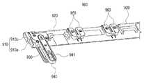
도 17은 본 발명의 다양한 실시예에 따른, 전개된 상태의 힌지 구조(800) 일면에 중심 바(center bar)(880)가 배치된 구조를 나타낸 사시도이다.
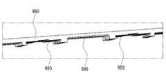
도 18은 본 발명의 다양한 실시예에 따른, 플랫한 상태의 힌지 구조(800) 일면에 멀티 바(multi bar)(890)가 배치된 구조를 나타낸 사시도이다.
도 19는 본 발명의 다앙한 실시예에 따른, 상기 플랫한 상태의 멀티 바(890)의 측면을 도시한 사시도이다.
도 20은 본 발명의 다양한 실시예에 따른, 상기 도 18의 힌지 구조(800)의 측면도이다.
도 21은 본 발명의 다양한 실시예에 따른, 폴딩된 상태의 힌지 구조(900)를 나타낸 사시도이다.
도 22는 본 발명의 다양한 실시예에 따른, 폴딩된 상태의 힌지 구조(900) 일면에 중심 바(980) 및 멀티 바(990)가 배치된 구조를 나타낸 사시도이다.
도 23은 본 발명의 다양한 실시예에 따른, 폴딩된 상태의 힌지 구조(900) 중 멀티 바(990)의 저면을 도시한 사시도이다.
도 24a는 본 발명의 다양한 실시예에 따른, 상기 제 1 하우징(1001) 및 제 2 하우징(1002)에 배치된 힌지 구조(1000)에서 슬라이드 커버(1010a,1010b)가 제외된 상태의 상면을 나타낸 도면이다. 도 24b는 본 발명의 다양한 실시예에 따른, 상기 도 26의 구조에서 슬라이드 커버(1010a,1010b)가 배치된 상태의 상면을 나타낸 도면이다.
도 25a 내지 도 25c는 본 발명의 다양한 실시예에 따른, 힌지 구조(1040)를 포함한 전자 장치(1000)가 전개된 상태에서 폴딩된 상태로 전환하는 동작을 순차적으로 나타낸 순서도이다.
도 26a 내지 도 26c는 본 발명의 다양한 실시예에 따른, 도 25a 내지 도 25c 일측을 절단하여 전자 장치(1000)가 전개된 상태에서 폴딩된 상태로 전환하는 동작을 순차적으로 나타낸 단면도이다.
도 27은 본 발명의 다양한 실시예에 따른, 하우징(1110) 내측에 배치된 메인 플렉서블 인쇄회로기판(1030)을 도시한 상태도이다.
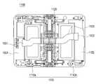
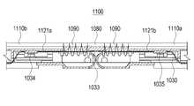
도 28은 본 발명의 다양한 실시예에 따른, 플랫한 상태의 전자 장치(1100) 내에 배치된 메인 플렉서블 인쇄회로기판(1030)의 단면을 나타낸 단면도이다.
도 29는 본 발명의 다양한 실시예에 따른, 폴딩된 전자 장치(1100) 내에 배치된 메인 플렉서블 인쇄회로기판(1030)의 단면을 나타낸 단면도이다.
도 30은 본 발명의 다양한 실시예에 따른, 디스플레이 조립체(1200)의 적층 구조를 도시한 단면도이다.
도 31은 본 발명의 다양한 실시예에 따른, 폴딩된 전자 장치에 배치된 디스플레이 조립체(1200)의 적층 구조의 가변 구조를 나타낸 단면도이다.1 illustrates an
2A is a front view illustrating a deployed
2B is a rear view illustrating the deployed
FIG. 2C is a side view illustrating the deployed
3A is a front view illustrating one side of the folded
3B is a rear view illustrating the other surface of the folded
3C is a side view illustrating the folded
4 is a view illustrating a side surface of a folded
5 is an exploded perspective view illustrating a configuration of a right region of an
6 is an exploded perspective view illustrating a configuration of a left area of an
7 is a projection diagram illustrating an arrangement relationship of internal components of the
8 is a projection diagram illustrating a
9 is a front view separately illustrating the
10 is a front view showing the two-
11 is a cross-sectional view illustrating a region in which the
FIG. 12 is a perspective view of one surface of the
13 is an enlarged top view of the rail bracket and the slide module of FIG. 9 according to various embodiments of the present invention.
14 is a cross-sectional perspective view of the
15 is a perspective view illustrating a state in which the
16 is a cross-sectional perspective view of the
17 is a perspective view illustrating a structure in which a
18 is a perspective view illustrating a structure in which a
19 is a perspective view showing the side of the multi-bar 890 in the flat state according to various embodiments of the present invention.
20 is a side view of the
21 is a perspective view illustrating a
22 is a perspective view illustrating a structure in which a
23 is a perspective view illustrating a bottom surface of the multi-bar 990 among the
24A is a view showing an upper surface of a state in which slide covers 1010a and 1010b are excluded from the
25A to 25C are flowcharts sequentially illustrating an operation of switching the
26A to 26C are cross-sectional views sequentially illustrating an operation of converting the
27 is a state diagram illustrating the main flexible printed
28 is a cross-sectional view of a main flexible printed
29 is a cross-sectional view illustrating a cross-section of a main flexible printed
30 is a cross-sectional view illustrating a stacked structure of the
31 is a cross-sectional view illustrating a variable structure of a stacked structure of a
이하, 본 문서의 다양한 실시예가 첨부된 도면을 참조하여 기재된다. 그러나, 이는 본 문서에 기재된 기술을 특정한 실시 형태에 대해 한정하려는 것이 아니며, 본 문서의 실시예의 다양한 변경(modifications), 균등물(equivalents), 및/또는 대체물(alternatives)을 포함하는 것으로 이해되어야 한다. 도면의 설명과 관련하여, 유사한 구성요소에 대해서는 유사한 참조 부호가 사용될 수 있다.Hereinafter, various embodiments of the present document will be described with reference to the accompanying drawings. However, it is not intended to limit the technology described in this document to specific embodiments, and it should be understood to include various modifications, equivalents, and/or alternatives of the embodiments of this document. . In connection with the description of the drawings, like reference numerals may be used for like components.
본 문서에서, "가진다," "가질 수 있다," "포함한다," 또는 "포함할 수 있다" 등의 표현은 해당 특징(예: 수치, 기능, 동작, 또는 부품 등의 구성요소)의 존재를 가리키며, 추가적인 특징의 존재를 배제하지 않는다.In this document, expressions such as "has," "may have," "includes," or "may include" refer to the presence of a corresponding characteristic (eg, a numerical value, function, operation, or component such as a part). and does not exclude the presence of additional features.
본 문서에서, "A 또는 B," "A 또는/및 B 중 적어도 하나," 또는 "A 또는/및 B 중 하나 또는 그 이상"등의 표현은 함께 나열된 항목들의 모든 가능한 조합을 포함할 수 있다. 예를 들면, "A 또는 B," "A 및 B 중 적어도 하나," 또는 "A 또는 B 중 적어도 하나"는, (1) 적어도 하나의 A를 포함, (2) 적어도 하나의 B를 포함, 또는 (3) 적어도 하나의 A 및 적어도 하나의 B 모두를 포함하는 경우를 모두 지칭할 수 있다.In this document, expressions such as "A or B," "at least one of A and/and B," or "one or more of A or/and B" may include all possible combinations of the items listed together. . For example, "A or B," "at least one of A and B," or "at least one of A or B" means (1) includes at least one A, (2) includes at least one B; Or (3) it may refer to all cases including both at least one A and at least one B.
본 문서에서 사용된 "제 1," "제 2," "첫째," 또는 "둘째,"등의 표현들은 다양한 구성요소들을, 순서 및/또는 중요도에 상관없이 수식할 수 있고, 한 구성요소를 다른 구성요소와 구분하기 위해 사용될 뿐 해당 구성요소들을 한정하지 않는다. 예를 들면, 제 1 사용자 기기와 제 2 사용자 기기는, 순서 또는 중요도와 무관하게, 서로 다른 사용자 기기를 나타낼 수 있다. 예를 들면, 본 문서에 기재된 권리 범위를 벗어나지 않으면서 제 1 구성요소는 제 2 구성요소로 명명될 수 있고, 유사하게 제 2 구성요소도 제 1 구성요소로 바꾸어 명명될 수 있다.As used herein, expressions such as "first," "second," "first," or "second," may modify various elements, regardless of order and/or importance, and refer to one element. It is used only to distinguish it from other components, and does not limit the components. For example, the first user equipment and the second user equipment may represent different user equipment regardless of order or importance. For example, without departing from the scope of the rights described in this document, a first component may be referred to as a second component, and similarly, the second component may also be renamed as a first component.
어떤 구성요소(예: 제 1 구성요소)가 다른 구성요소(예: 제 2 구성요소)에 "(기능적으로 또는 통신적으로) 연결되어((operatively or communicatively) coupled with/to)" 있다거나 "접속되어(connected to)" 있다고 언급된 때에는, 상기 어떤 구성요소가 상기 다른 구성요소에 직접적으로 연결되거나, 다른 구성요소(예: 제 3 구성요소)를 통하여 연결될 수 있다고 이해되어야 할 것이다. 반면에, 어떤 구성요소(예: 제 1 구성요소)가 다른 구성요소(예: 제 2 구성요소)에 "직접 연결되어" 있다거나 "직접 접속되어" 있다고 언급된 때에는, 상기 어떤 구성요소와 상기 다른 구성요소 사이에 다른 구성요소(예: 제 3 구성요소)가 존재하지 않는 것으로 이해될 수 있다.A component (eg, a first component) is "coupled with/to (operatively or communicatively)" to another component (eg, a second component) When referring to "connected to", it will be understood that the certain element may be directly connected to the other element or may be connected through another element (eg, a third element). On the other hand, when it is said that a component (eg, a first component) is "directly connected" or "directly connected" to another component (eg, a second component), the component and the It may be understood that other components (eg, a third component) do not exist between other components.
본 문서에서 사용된 표현 "~하도록 구성된(또는 설정된)(configured to)"은 상황에 따라, 예를 들면, "~에 적합한(suitable for)," "~하는 능력을 가지는(having the capacity to)," "~하도록 설계된(designed to)," "~하도록 변경된(adapted to)," "~하도록 만들어진(made to)," 또는 "~를 할 수 있는(capable of)"과 바꾸어 사용될 수 있다. 용어 "~하도록 구성된(또는 설정된)"은 하드웨어적으로 "특별히 설계된(specifically designed to)" 것만을 반드시 의미하지 않을 수 있다. 대신, 어떤 상황에서는, "~하도록 구성된 장치"라는 표현은, 그 장치가 다른 장치 또는 부품들과 함께 "~할 수 있는" 것을 의미할 수 있다. 예를 들면, 문구 "A, B, 및 C를 수행하도록 구성된(또는 설정된) 프로세서"는 해당 동작을 수행하기 위한 전용 프로세서(예: 임베디드 프로세서), 또는 메모리 장치에 저장된 하나 이상의 소프트웨어 프로그램들을 실행함으로써, 해당 동작들을 수행할 수 있는 범용 프로세서(generic-purpose processor)(예: CPU 또는 application processor)를 의미할 수 있다.As used herein, the expression "configured to (or configured to)" depends on the context, for example, "suitable for," "having the capacity to ," "designed to," "adapted to," "made to," or "capable of." The term “configured (or configured to)” may not necessarily mean only “specifically designed to” in hardware. Instead, in some circumstances, the expression “a device configured to” may mean that the device is “capable of” with other devices or parts. For example, the phrase “a processor configured (or configured to perform) A, B, and C” refers to a dedicated processor (eg, an embedded processor) for performing the operations, or by executing one or more software programs stored in a memory device. , may mean a generic-purpose processor (eg, a CPU or an application processor) capable of performing corresponding operations.
본 문서에서 사용된 용어들은 단지 특정한 실시예를 설명하기 위해 사용된 것으로, 다른 실시예의 범위를 한정하려는 의도가 아닐 수 있다. 단수의 표현은 문맥상 명백하게 다르게 뜻하지 않는 한, 복수의 표현을 포함할 수 있다. 기술적이거나 과학적인 용어를 포함해서 여기서 사용되는 용어들은 본 문서에 기재된 기술 분야에서 통상의 지식을 가진 자에 의해 일반적으로 이해되는 것과 동일한 의미를 가질 수 있다. 본 문서에 사용된 용어들 중 일반적인 사전에 정의된 용어들은, 관련 기술의 문맥상 가지는 의미와 동일 또는 유사한 의미로 해석될 수 있으며, 본 문서에서 명백하게 정의되지 않는 한, 이상적이거나 과도하게 형식적인 의미로 해석되지 않는다. 경우에 따라서, 본 문서에서 정의된 용어일지라도 본 문서의 실시예들을 배제하도록 해석될 수 없다.Terms used in this document are only used to describe specific embodiments, and may not be intended to limit the scope of other embodiments. The singular expression may include the plural expression unless the context clearly dictates otherwise. Terms used herein, including technical or scientific terms, may have the same meanings as commonly understood by one of ordinary skill in the art described in this document. Among the terms used in this document, terms defined in a general dictionary may be interpreted with the same or similar meaning to the meaning in the context of the related art, and unless explicitly defined in this document, ideal or excessively formal meanings is not interpreted as In some cases, even terms defined in this document cannot be construed to exclude embodiments of the present document.
본 문서의 다양한 실시예들에 따른 전자 장치는, 예를 들면, 스마트폰(smartphone), 태블릿 PC(tablet personal computer), 이동 전화기(mobile phone), 영상 전화기, 전자책 리더기(e-book reader), 데스크탑 PC(desktop personal computer), 랩탑 PC(laptop personal computer), 넷북 컴퓨터(netbook computer), 워크스테이션(workstation), 서버, PDA(personal digital assistant), PMP(portable multimedia player), MP3 플레이어, 모바일 의료기기, 카메라(camera), 또는 웨어러블 장치(wearable device) 중 적어도 하나를 포함할 수 있다. 다양한 실시예에 따르면, 웨어러블 장치는 액세서리형(예: 시계, 반지, 팔찌, 발찌, 목걸이, 안경, 콘택트 렌즈, 또는 머리 착용형 장치(head-mounted-device(HMD)), 직물 또는 의류 일체형(예: 전자 의복), 신체 부착형(예: 스킨 패드(skin pad) 또는 문신), 또는 생체 이식형(예: implantable circuit) 중 적어도 하나를 포함할 수 있다.The electronic device according to various embodiments of the present document may include, for example, a smartphone, a tablet personal computer, a mobile phone, a video phone, and an e-book reader. , desktop personal computer, laptop personal computer, netbook computer, workstation, server, personal digital assistant (PDA), portable multimedia player (PMP), MP3 player, mobile It may include at least one of a medical device, a camera, and a wearable device. According to various embodiments, the wearable device may be an accessory type (eg, a watch, ring, bracelet, anklet, necklace, eyeglass, contact lens, or head-mounted-device (HMD)), a fabric or an integral piece of clothing ( It may include at least one of, for example, electronic clothing), a body attachable type (eg, a skin pad or tattoo), or a bioimplantable type (eg, an implantable circuit).
어떤 실시예들에서, 전자 장치는 가전 제품(home appliance)일 수 있다. 가전 제품은, 예를 들면, 텔레비전, DVD(digital video disk) 플레이어, 오디오, 냉장고, 에어컨, 청소기, 오븐, 전자레인지, 세탁기, 공기 청정기, 셋톱 박스(set-top box), 홈 오토매이션 컨트롤 패널(home automation control panel), 보안 컨트롤 패널(security control panel), TV 박스(예: 삼성 HomeSyncTM, 애플TVTM, 또는 구글 TVTM), 게임 콘솔(예: XboxTM, PlayStationTM), 전자 사전, 전자 키, 캠코더(camcorder), 또는 전자 액자 중 적어도 하나를 포함할 수 있다.In some embodiments, the electronic device may be a home appliance. Home appliances are, for example, televisions, digital video disk (DVD) players, audio systems, refrigerators, air conditioners, vacuum cleaners, ovens, microwave ovens, washing machines, air purifiers, set-top boxes, home automation controls. panel (home automation control panel), security control panel (security control panel), TV box (eg Samsung HomeSyncTM , Apple TVTM , or Google TVTM ), game console (eg XboxTM , PlayStationTM ), electronic dictionary , an electronic key, a camcorder, or an electronic picture frame.
다른 실시예에서, 전자 장치는, 각종 의료기기(예: 각종 휴대용 의료측정기기(혈당 측정기, 심박 측정기, 혈압 측정기, 또는 체온 측정기 등), MRA(magnetic resonance angiography), MRI(magnetic resonance imaging), CT(computed tomography), 촬영기, 또는 초음파기 등), 네비게이션(navigation) 장치, 위성 항법 시스템(GNSS(global navigation satellite system)), EDR(event data recorder), FDR(flight data recorder), 자동차 인포테인먼트(infotainment) 장치, 선박용 전자 장비(예: 선박용 항법 장치, 자이로 콤파스 등), 항공 전자기기(avionics), 보안 기기, 차량용 헤드 유닛(head unit), 산업용 또는 가정용 로봇, 금융 기관의 ATM(automatic teller's machine), 상점의 POS(point of sales), 또는 사물 인터넷 장치(internet of things)(예: 전구, 각종 센서, 전기 또는 가스 미터기, 스프링클러 장치, 화재경보기, 온도조절기(thermostat), 가로등, 토스터(toaster), 운동기구, 온수탱크, 히터, 보일러 등) 중 적어도 하나를 포함할 수 있다.In another embodiment, the electronic device may include various medical devices (eg, various portable medical measuring devices (eg, a blood glucose meter, a heart rate monitor, a blood pressure monitor, or a body temperature monitor), magnetic resonance angiography (MRA), magnetic resonance imaging (MRI), Computed tomography (CT), imagers, or ultrasound machines, etc.), navigation devices, satellite navigation systems (global navigation satellite system (GNSS)), event data recorder (EDR), flight data recorder (FDR), automotive infotainment ) devices, ship electronic equipment (e.g. ship navigation devices, gyro compasses, etc.), avionics, security devices, vehicle head units, industrial or domestic robots, automatic teller's machines (ATMs) in financial institutions. , point of sales (POS) in stores, or internet of things (e.g. light bulbs, sensors, electricity or gas meters, sprinkler devices, smoke alarms, thermostats, street lights, toasters) , exercise equipment, hot water tank, heater, boiler, etc.) may include at least one.
어떤 실시예에 따르면, 전자 장치는 가구(furniture) 또는 건물/구조물의 일부, 전자 보드(electronic board), 전자 사인 수신 장치(electronic signature receiving device), 프로젝터(projector), 또는 각종 계측 기기(예: 수도, 전기, 가스, 또는 전파 계측 기기 등) 중 적어도 하나를 포함할 수 있다. 다양한 실시예에서, 전자 장치는 전술한 다양한 장치들 중 하나 또는 그 이상의 조합일 수 있다. 어떤 실시예에 따른 전자 장치는 플렉서블 전자 장치일 수 있다. 또한, 본 문서의 실시예에 따른 전자 장치는 전술한 기기들에 한정되지 않으며, 기술 발전에 따른 새로운 전자 장치를 포함할 수 있다.According to some embodiments, the electronic device is a piece of furniture or part of a building/structure, an electronic board, an electronic signature receiving device, a projector, or various measuring instruments (eg, water, electricity, gas, or a radio wave measuring device). In various embodiments, the electronic device may be a combination of one or more of the various devices described above. The electronic device according to an embodiment may be a flexible electronic device. In addition, the electronic device according to the embodiment of the present document is not limited to the above-described devices, and may include a new electronic device according to technological development.
이하, 첨부 도면을 참조하여, 다양한 실시예에 따른 전자 장치가 설명된다. 본 문서에서, 사용자라는 용어는 전자 장치 또는 후술될 액세서리 장치를 사용하는 사람 또는 전자 장치 또는 액세서리 장치를 사용하는 장치(예: 인공지능 전자 장치)를 지칭할 수 있다.Hereinafter, an electronic device according to various embodiments will be described with reference to the accompanying drawings. In this document, the term user may refer to a person using an electronic device or an accessory device to be described later, or a device (eg, an artificial intelligence electronic device) using the electronic device or accessory device.
도 1을 참조하여, 다양한 실시예에서의, 네트워크 환경(100) 내의 전자 장치(101)가 기재된다. 전자 장치(101)는 버스(110), 프로세서(120), 메모리(130), 입출력 인터페이스(150), 디스플레이(160), 및 통신 인터페이스(170)를 포함할 수 있다. 어떤 실시예에서는, 전자 장치(101)는, 구성요소들 중 적어도 하나를 생략하거나 다른 구성요소를 추가적으로 구비할 수 있다. 버스(110)는 구성요소들(110-170)을 서로 연결하고, 구성요소들 간의 통신(예: 제어 메시지 또는 데이터)을 전달하는 회로를 포함할 수 있다. 프로세서(120)는, 중앙처리장치, 어플리케이션 프로세서, 또는 커뮤니케이션 프로세서(communication processor(CP)) 중 하나 또는 그 이상을 포함할 수 있다. 프로세서(120)는, 예를 들면, 전자 장치(101)의 적어도 하나의 다른 구성요소들의 제어 또는 통신에 관한 연산이나 데이터 처리를 실행할 수 있다.1 , an
메모리(130)는, 휘발성 또는 비휘발성 메모리를 포함할 수 있다. 메모리(130)는, 예를 들면, 전자 장치(101)의 적어도 하나의 다른 구성요소에 관계된 명령 또는 데이터를 저장할 수 있다. 한 실시예에 따르면, 메모리(130)는 소프트웨어 또는 프로그램(140)을 저장할 수 있다. 프로그램(140)은, 예를 들면, 커널(141), 미들웨어(143), 어플리케이션 프로그래밍 인터페이스(API)(145), 또는 어플리케이션 프로그램(또는 "어플리케이션")(147) 등을 포함할 수 있다. 커널(141), 미들웨어(143), 또는 API(145)의 적어도 일부는, 운영 시스템으로 지칭될 수 있다. 커널(141)은, 예를 들면, 다른 프로그램들(예: 미들웨어(143), API(145), 또는 어플리케이션 프로그램(147))에 구현된 동작 또는 기능을 실행하는 데 사용되는 시스템 리소스들(예: 버스(110), 프로세서(120), 또는 메모리(130) 등)을 제어 또는 관리할 수 있다. 또한, 커널(141)은 미들웨어(143), API(145), 또는 어플리케이션 프로그램(147)에서 전자 장치(101)의 개별 구성요소에 접근함으로써, 시스템 리소스들을 제어 또는 관리할 수 있는 인터페이스를 제공할 수 있다.The
미들웨어(143)는, 예를 들면, API(145) 또는 어플리케이션 프로그램(147)이 커널(141)과 통신하여 데이터를 주고받을 수 있도록 중개 역할을 수행할 수 있다. 또한, 미들웨어(143)는 어플리케이션 프로그램(147)으로부터 수신된 하나 이상의 작업 요청들을 우선 순위에 따라 처리할 수 있다. 예를 들면, 미들웨어(143)는 어플리케이션 프로그램(147) 중 적어도 하나에 전자 장치(101)의 시스템 리소스(예: 버스(110), 프로세서(120), 또는 메모리(130) 등)를 사용할 수 있는 우선 순위를 부여하고, 상기 하나 이상의 작업 요청들을 처리할 수 있다. 1입출력 인터페이스(150)는, 예를 들면, 사용자 또는 다른 외부 기기로부터 입력된 명령 또는 데이터를 전자 장치(101)의 다른 구성요소(들)에 전달하거나, 또는 전자 장치(101)의 다른 구성요소(들)로부터 수신된 명령 또는 데이터를 사용자 또는 다른 외부 기기로 출력할 수 있다.The
디스플레이(160)는, 예를 들면, 액정 디스플레이(LCD), 발광 다이오드(LED) 디스플레이, 유기 발광 다이오드(OLED) 디스플레이, 또는 마이크로 전자기계 시스템 (MEMS) 디스플레이, 또는 전자종이(electronic paper) 디스플레이를 포함할 수 있다. 디스플레이(160)는, 예를 들면, 사용자에게 각종 콘텐츠(예: 텍스트, 이미지, 비디오, 아이콘, 또는 심볼 등)을 표시할 수 있다. 디스플레이(160)는, 터치 스크린을 포함할 수 있으며, 예를 들면, 전자 펜 또는 사용자의 신체의 일부를 이용한 터치, 제스쳐, 근접, 또는 호버링 입력을 수신할 수 있다. 통신 인터페이스(170)는, 예를 들면, 전자 장치(101)와 외부 장치(예: 제 1 외부 전자 장치(102), 제 2 외부 전자 장치(104), 또는 서버(106)) 간의 통신을 설정할 수 있다. 예를 들면, 통신 인터페이스(170)는 무선 통신 또는 유선 통신을 통해서 네트워크(162)에 연결되어 외부 장치(예: 제 2 외부 전자 장치(104) 또는 서버(106))와 통신할 수 있다.
무선 통신은, 예를 들면, LTE, LTE-A(LTE advance), CDMA(code division multiple access), WCDMA(wideband CDMA), UMTS(universal mobile telecommunications system), WiBro(wireless broadband), 또는 GSM(global system for mobile communications) 등 중 적어도 하나를 사용하는 셀룰러 통신을 포함할 수 있다. 한 실시예에 따르면, 무선 통신은, 도 1의 element 164로 예시된 바와 같이, 예를 들면, WiFi(wireless fidelity), LiFi(light fidelity), 블루투스, 블루투스 저전력(BLE), 지그비(ZigBee), NFC(near field communication), 자력 시큐어 트랜스미션(magnetic secure transmission), 라디오 프리퀀시(RF), 또는 보디 에어리어 네트워크(BAN) 중 적어도 하나를 포함할 수 있다. 한 실시예에 따르면, 무선 통신은 GNSS를 포함할 수 있다. GNSS는, 예를 들면, GPS(global positioning system), Glonass(global navigation satellite system), beidou navigation satellite system(이하 "Beidou") 또는 Galileo, the european global satellite-based navigation system일 수 있다. 이하, 본 문서에서는, "GPS"는 "GNSS"와 상호 호환적으로 사용될 수 있다. 유선 통신은, 예를 들면, USB(universal serial bus), HDMI(high definition multimedia interface), RS-232(recommended standard232), 전력선 통신, 또는 POTS(plain old telephone service) 등 중 적어도 하나를 포함할 수 있다. 네트워크(162)는 텔레커뮤니케이션 네트워크, 예를 들면, 컴퓨터 네트워크(예: LAN 또는 WAN), 인터넷, 또는 텔레폰 네트워크 중 적어도 하나를 포함할 수 있다.Wireless communication is, for example, LTE, LTE advance (LTE-A), code division multiple access (CDMA), wideband CDMA (WCDMA), universal mobile telecommunications system (UMTS), wireless broadband (WiBro), or global (GSM). system for mobile communications) and the like. According to one embodiment, wireless communication, as exemplified by
제 1 및 제 2 외부 전자 장치(102, 104) 각각은 전자 장치(101)와 동일한 또는 다른 종류의 장치일 수 있다. 다양한 실시예에 따르면, 전자 장치(101)에서 실행되는 동작들의 전부 또는 일부는 다른 하나 또는 복수의 전자 장치(예: 전자 장치(102, 104), 또는 서버(106)에서 실행될 수 있다. 한 실시예에 따르면, 전자 장치(101)가 어떤 기능이나 서비스를 자동으로 또는 요청에 의하여 수행해야 할 경우에, 전자 장치(101)는 기능 또는 서비스를 자체적으로 실행시키는 대신에 또는 추가적으로, 그와 연관된 적어도 일부 기능을 다른 장치(예: 전자 장치(102, 104), 또는 서버(106))에게 요청할 수 있다. 다른 전자 장치(예: 전자 장치(102, 104), 또는 서버(106))는 요청된 기능 또는 추가 기능을 실행하고, 그 결과를 전자 장치(101)로 전달할 수 있다. 전자 장치(101)는 수신된 결과를 그대로 또는 추가적으로 처리하여 요청된 기능이나 서비스를 제공할 수 있다. 이를 위하여, 예를 들면, 클라우드 컴퓨팅, 분산 컴퓨팅, 또는 클라이언트-서버 컴퓨팅 기술이 이용될 수 있다.Each of the first and second external
본 발명의 다양한 실시예 중 하나에 따른 전자 장치(101)는 내부에 배치된 힌지 구조에 의하여 펼쳐진 상태에서 접힌(folding) 상태로 동작할 수 있다. 펼쳐진 상태의 전자 장치는 '전개된 전자 장치' 또는 '복수의 하우징이 수평으로 배치된 전자 장치'로 명명하고, 접힌 상태의 전자 장치는 '폴딩된 전자 장치'로 명명하도록 한다.The
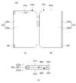
도 2a는 본 발명의 다양한 실시예 중 하나에 따른 전개된 전자 장치(200)를 나타내는 정면도이다. 도 2b는 본 발명의 다양한 실시예 중 하나에 따른 전개된 전자 장치(200)를 다른 방향에서 바라본 모습을 나타내는 배면도이다. 도 2c는 본 발명의 다양한 실시예 중 하나에 따른 전개된 전자 장치(200)를 측면 방향에서 바라본 모습을 나타내는 측면도이다.2A is a front view illustrating a deployed
도 2a 내지 도 2c의 상기 전자 장치(200)은 도 1의 전자 장치(101)의 구조와 일부 또는 전부가 동일할 수 있다.The structure of the
도 2a 내지 도 2c에서, 3축 직교 좌표계의 'X축'은 상기 전자 장치(200)의 폭 방향, 'Y축'은 상기 전자 장치(200)의 길이 방향, 'Z축'은 상기 전자 장치(200)의 두께 방향을 의미할 수 있다. 또한, 본 발명의 일 실시예에서, 'Z축'은 제 1 방향(+Z) 및 제 2 방향(-Z)을 의미할 수 있다.2A to 2C , in the three-axis Cartesian coordinate system, the 'X axis' is the width direction of the
도 2a 내지 도 2c에 도시된 바와 같이, 상기 전자 장치(200)는 복수 개의 하우징(210)과, 디스플레이 조립체(220) 및 연결 구조(예를 들면,힌지 구조(230))를 포함할 수 있다. 상기 하우징(200)은 제 1 하우징(210a), 제 2 하우징(210b)을 포함하고, 상기 제 1 하우징(210a)은 전면에 해당하는 제 1 면(201a), 후면에 해당하는 제 2 면(202a) 및 상기 제 1 면(201a) 및 제 2 면(202a) 사이의 공간의 일부를 둘러싸는 측면(203)을 포함할 수 있다. 상기 제 2 하우징(210b)은 전면에 해당하는 제 3 면(201b), 후면에 해당하는 제 4 면(202b) 및 상기 제 3 면(201b) 및 제 4 면(202b) 사이의 공간의 일부를 둘러싸는 측면(203)을 포함할 수 있다.2A to 2C , the
다양한 실시예에 따른, 상기 제 1 하우징(210a)은 제 1 면(201a)의 적어도 일부가 개방될 수 있으며, 투명 커버가 상기 제 1 하우징(210a) 제 1 면(201a)의 적어도 일부를 형성하도록 장착되어, 상기 제 1 하우징(210a)의 개방된 제 1 면(201a)을 폐쇄할 수 있다. 또 다른 예로, 상기 제 2 하우징(210b)은 제 3 면(201b)의 적어도 일부가 개방될 수 있으며, 투명 커버가 상기 제 2 하우징(210b) 제 3 면(201b)의 적어도 일부를 형성하도록 장착되어, 상기 제 2 하우징(210b)의 개방된 제 3 면(201b)을 폐쇄할 수 있다.According to various embodiments, at least a portion of the
다양한 실시예에 따른, 상기 전자 장치(200)는, 예컨대, 상기 하우징(210)의 전면(201a,201b)에서, 상기 투명 커버의 일 영역(예를 들어, 베젤 영역 또는 디스플레이와 중첩 영역)에는 신호를 전달하는 버튼이나 터치 키(미도시)를 포함하는 키패드가 제공될 수 있다. 상기 터치 키는 사용자의 신체 접촉에 의해 입력 신호를 발생할 수 있다. 다양한 실시예에 따르면, 상기 키패드는 기계적인 버튼들만으로, 또는, 상기 터치 키들만으로 구현될 수도 있다. 또 다른 예로, 상기 키패드는, 기계적 버튼 방식과 터치 방식의 혼합 형태로 구현될 수도 있다. 또한, 상기 키패드은 버튼들은 길게 또는 짧게 누르거나 터치하는 시간에 대응하여 디스플레이 조립체에 표현되는 화면을 다양하게 제공할 수 있다.According to various embodiments of the present disclosure, the
다양한 실시예에 따른, 상기 하우징(210)의 내부에는 각종 회로 장치들, 예컨대, 도 1에 전술한 바 있는 프로세서(120), 메모리(130), 입출력 인터페이스(150), 통신 인터페이스(170) 등이 수용될 수 있으며, 또한, 내부로 배터리(예를 들어, 도 5의 배터리(370) 또는 도 6의 배터리(380))를 수용함으로써 전원을 확보할 수 있다.Various circuit devices, for example, the
다양한 실시 예에 따른, 상기 전자 장치(200)는 제 1 하우징(210a), 제 2 하우징(210b) 및 힌지 구조(230)를 포함하고, 상기 힌지 구조(230)는 상기 제 2 하우징(210b)과 상기 제 1 하우징(210a)을 서로에 대하여 회전 가능하게 결합시킬 수 있다. 예를 들어, 상기 제 2 하우징(210b)에 대하여 상기 제 1 하우징(210a)이 전개되거나 폴딩될 수 있다.According to various embodiments, the
다양한 실시 예에 따른, 상기 제 1 하우징(210a)은 디스플레이 조립체(220)가 전면(예를 들어, 제 1 방향(+Z))을 향할 때, 우측면에 배치될 수 있으며, 전면(제 1 면(201a)) 상단 영역에는 제 1 카메라(12a)와, 광원부(12b) 또는 홍채 카메라(12c)가 포함될 수 있다. 예를 들어, 광원부(12b)는 IR LED일 수 있으며, 상기 홍채 카메라(12c)는 상기 IR LED에서 나오는 적색 근적외선을 광원으로 활용하여 사용자의 눈을 촬영하여 홍채 정보를 인식할 수 있다. 또 다른 예에서, 상기 전자 장치(200)의 전면 상단 영역에는, 광원부 표시등(12d) 또는 조도 센서 또는 근접 센서(12e)가 포함될 수 있다.According to various embodiments, the
다양한 실시 예에 따른, 상기 제 2 하우징(210b)은 디스플레이 조립체(220)가 전면(예를 들어, 제 1 방향(+Z))을 향할 때, 좌측면에 배치될 수 있으며, 전면(제 3 면(201b)) 상단 영역에는 제 2 카메라, 심박수 센서(HRM, heart rate monitor) 또는 플래시(flash)(미도시) 등이 포함될 수 있다. 본 발명의 일 실시예에 따르면, 상기 하우징의 일 영역 내에 특정 영역에 배치된 각각의 모듈들을 설명하였으나, 이에 한정된 것은 아니며, 각각의 모듈들의 배치 및 개수 등의 구성은 상기 전자 장치의 형상 및 구조에 따라 다양하게 변경 설계 가능하다.According to various embodiments, the
다양한 실시 예에 따른, 상기 제 1 하우징(210a), 제 2 하우징(210b) 및 상기 힌지 구조(230) 전면에는 디스플레이 조립체(220)가 배치될 수 있다. 상기 디스플레이 조립체(220)는 상기 제 1 하우징(210a)으로부터 상기 힌지 구조(230)를 가로질러 상기 제 2 하우징(210b)까지 연장되도록 형성되고, 상기 힌지 구조(230)의 길이 방향으로 형성된 가상의 힌지축(A1,A2)을 중심으로 폴딩될 수 있도록 플렉서블한 구조로 마련될 수 있다. 상기 힌지 구조(230)는 전면(제 1 방향(+Z))을 향하는 제 5 면(231) 및 상기 전면의 반대 방향(제 2 방향(-Z))을 향하는 제 6 면(232)을 포함할 수 있다.A
다양한 실시예에 따른, 상기 제 1 하우징(210a)의 제 2 면(202a) 및 제 2 하우징(210b)의 제 4 면(202b)은 상기 제 1 방향(+Z)과 반대인 제 2 방향(-Z)을 향하도록 배치되며, 무선 전파 또는 자기장을 투과시킬 수 있는 재질, 예를 들면, 강화 유리나 합성 수지로 제작될 수 있다. 또 다른 예로, 상기 제 1 하우징(210a)의 제 2 면(202a) 및 제 2 하우징(210b)의 제 4 면(202b)은 금속(예를 들어, 알루미늄, STS, 마그네슘)으로 제작되거나 적어도 일부분은 합성 수지를 포함하여로 제작될 수 있다.According to various embodiments, the
다양한 실시예에 따른, 상기 상기 제 1 하우징(210a)의 제 2 면(202a) 및 제 2 하우징(210b)의 제 4 면(202b)은 측면(203)과 동일한 재질로 제작될 수 있다. 또 다른 예로, 상기 하우징(210)의 제 2 면(202a) 및 제 4 면(202b)은 측면(203)과 일체로 제작될 수 있다. 상기 제 2 면(202a) 및 제 4 면(202b)은 상기 디스플레이 조립체(220)와 함께 상기 전자 장치(200)의 외관을 이룰 수 있다.According to various embodiments, the
다양한 실시예에 따른, 상기 측면(203)은 상기 하우징(210)의 측면을 형성할 수 있으며, 상기 제 1, 3 면(201a,201b) 및/또는 상기 제 2, 4 면(202a,202b)과 수직된 방향을 향하도록 배치되며, 무선 전파 또는 자기장을 투과시킬 수 있는 재질, 예를 들면, 강화 유리나 합성 수지로 제작될 수 있다. 또 다른 예로, 상기 측면(203)은 금속(예를 들어, 알루미늄, STS, 마그네슘)으로 제작되거나 적어도 일부분은 합성 수지를 포함하여 제작 될 수 있다. 상기 측면(203)에는 전자 장치(200) 내부에 장착된 스피커 엔클로져(spk encloser), 이어잭(ear jack), 충전 단자 등이 외부와 연결되도록 스피커 홀(14a), 이어잭 홀(14b) 또는 충전 단자 홀(14c)이 형성될 수 있다.According to various embodiments, the
도 3a는 본 발명의 다양한 실시예 중 하나에 따른 폴딩된 전자 장치(200)를 전면 방향에서 바라본 일면을 나타낸 정면도이다. 도 3b는 본 발명의 다양한 실시예 중 하나에 따른 폴딩된 전자 장치(200)를 다른 방향에서 바라본 타면을 나타낸 배면도이다. 도 3c는 본 발명의 다양한 실시예 중 하나에 따른 폴딩된 전자 장치(200)를 측면 방향에서 바라본 모습을 나타내는 측면도이다.3A is a front view illustrating one side of the folded
도 3a 내지 도 3c의 상기 전자 장치(200)의 구조는 도 2의 전자 장치(200)의 구조와 일부 또는 전부가 동일할 수 있다.The structure of the
도 3a 및 도 3c를 참조하면, 상기 전자 장치(200)는 제 1 하우징(210a), 제 2 하우징(210b) 및 힌지 구조(230)를 포함하고, 상기 힌지 구조(230)는 상기 제 2 하우징(210b)과 상기 제 1 하우징(210a)을 서로에 대하여 회전 가능하게 결합시킬 수 있다.3A and 3C , the
다양한 실시예에 따른, 상기 전자 장치(200)의 제 1 하우징(210a)은 상기 제 2 하우징(210b)에 대해 0~180도 회전할 수 있다. 상기 제 1 하우징(210a)이 상기 제 2 하우징(210b)에 대하여 180도 회전하여 상기 전자 장치(200)가 폴딩됨에 따라, 상기 제 1 하우징(210a)의 제 2 면(202a 상기 제 2 하우징(210b)의 제 4 면(202b)은 서로 대면 배치될 수 있다. 또 다른 예에 따른, 상기 제 1 하우징(210a) 및 상기 제 2 하우징(210b) 사이에 배치된 힌지 구조(230)는 적어도 하나의 가상의 회전축(도 2a의 가상의 회전축(A1,A2))을 기준으로 평면에서 곡면으로 가변하는 외면을 형성할 수 있다. 상기 힌지 구조(230)의 외면은 길이 방향으로 형성된 가상의 회전축(도 2a의 가상의 회전축(A1,A2))을 기준으로 우측면의 적어도 일부는 상기 제 1 하우징(210a)으로부터 연장되고, 좌측면의 적어도 일부는 상기 제 2 하우징(210b)으로부터 연장될 수 있다.According to various embodiments, the
다양한 실시예에 따른, 상기 디스플레이 조립체(220)는 상기 제 1 하우징(210a)으로부터 상기 힌지 구조(230)의 외면을 가로질러 상기 제 2 하우징(210b)까지 연장되어 배치될 수 있다. 상기 전자 장치(200)가 폴딩된 상태에서, 상기 제 1 하우징(210a)에 배치된 상기 디스플레이 조립체(220)의 제 1 영역(220a)은 전면 방향을 향하도록 배치되고, 상기 제 2 하우징(210b)에 배치된 상기 디스플레이 조립체(220)의 제 2 영역(220b)은 전면 방향과 반대인 후면 방향을 향하도록 배치될 수 있다.According to various embodiments, the
또 다른 예로, 상기 힌지 구조(230)의 외면에 배치된 제 3 영역(220c)은 측면 방향(예를 들어, 상기 전면 또는 후면과 적어도 일부가 수직을 형성하는 방향)을 향하도록 배치될 수 있다. 상기 제 3 영역(220c)은 측면 방향으로 돌출된 면을 형성할 수 있으며, 상기 돌출된 면의 일부는 플랫면(2201c) 및/또는 굴곡면(2202c)을 포함할 수 있다. 예를 들어, 상기 제 3 영역(220c)의 중심은 플랫면(2201c)으로 배치되고, 양측으로 연장된 굴곡면(2202c)은 상기 제 1 영역(220a) 및/또는 제 2 영역(220b)으로부터 자연스럽게 이어지는 곡면으로 구현될 수 있다.As another example, the
도 4는 본 발명의 다양한 실시예에 따른, 폴딩된 전자 장치(200)의 측면을 나타낸 도면이다. 도 4a는 디스플레이 조립체(220)의 곡면 영역이 배치된 측면에서 바라본 측면도이며, 도 4b는 상기 도 4a의 반대 방향에서 바라본 측면도이다.4 is a view illustrating a side surface of a folded
도 4a 및 도 4b의 상기 전자 장치(200)의 구조는 도 3a 내지 도 3c의 전자 장치(200)의 구조와 일부 또는 전부가 동일할 수 있다. 일 실시예에 따른, 상기 전자 장치(200)는 제 1 하우징(210a), 제 2 하우징(210b) 및 힌지 구조(230)를 포함하고, 상기 힌지 구조(230)는 상기 제 2 하우징(210b)과 상기 제 1 하우징(210a)을 서로에 대하여 회전 가능하게 결합시킬 수 있다.The structure of the
도 4a를 참조하면, 상기 디스플레이 조립체(220)가 배치된 폴딩된 전자 장치(200)의 측면은, 힌지 구조(230) 외면을 형성하는 중심 바(center bar)(231)를 기준으로 양측에 멀티 바(multi Bar)(232)들이 배치될 수 있다. 상기 중심 바(231)는 힌지 구조(230)의 외면 중심을 형성하고, 디스플레이 조립체(220)가 측면에서 평탄한 면을 형성할 수 있도록 지지할 수 있다. 상기 멀티 바(232)는 상기 중심 바(231) 양측에 형성되며, 적어도 일부 영역이 상기 하우징(210a,210b)과 대면 배치될 수 있다. 예를 들어, 제 1 멀티 바(232a)는 제 1 하우징(210a) 단부로부터 상기 중심 바(231)까지 형성되며, 소정의 곡률값을 가지도록 배치될 수 있다. 또 다른 예로, 제 2 멀티 바(232b)는 제 2 하우징(210b) 단부로부터 상기 중심 바(231)까지 형성되며, 소정의 곡률값을 가지도록 배치될 수 있다. 상기 멀티 바(232a,232b)는 디스플레이 조립체(220)의 곡률값에 대응되는 곡률값을 형성하도록 가변할 수 있다. 상기 중심 바(231) 및 멀티 바(232)의 구체적인 내용은 후술한다.Referring to FIG. 4A , the side of the folded
다양한 실시예에 따른, 상기 중심 바(231) 및 멀티 바(232)의 외면 중 적어도 일부 영역에는 디스플레이 조립체(220)가 배치될 수 있다. 예를 들어, 상기 디스플레이 조립체(220)는 상기 힌지 구조(230)의 폴딩으로 인하여, 상기 중심 바(231) 및 멀티 바(232)의 가변 형상에 대응되도록 폴딩될 수 있다. 상기 전자 장치(200)의 전면 및/또는 후면의 대부분 영역에는 디스플레이 조립체(220)가 배치되어 외부로 노출될 수 있으 상기 전자 장치(200)의 전면 및/또는 후면의 상단 및/또는 하단 영역에 해당하는 베젤에는 디스플레이 조립체(220)가 배치되지 않아, 외부 충격을 방지할 수 있다.According to various embodiments, the
도 4b를 참조하면, 상기 디스플레이 조립체(220)가 배치된 반대 방향을 향하는 전자 장치(200)의 측면은, 상기 제 1 하우징(210a)의 측면 및 상기 제 2 하우징(210b)의 측면이 서로 나란하게 배치될 수 있다. 상기 제 1 하우징(210a)의 측면의 가장자리 부분과 상기 제 2 하우징(210b)은 측면의 가장자리 부분은 서로 접촉하여 하나의 면을 형성할 수 있으며, 상기 하나의 면의 일부에는 전자 장치(200) 내측 방향으로 형성된 리세스(recess)(205)를 포함할 수 있다. 예를 들어, 상기 리세스(205)는 사용자가 손가락을 이용하여 손쉽게 상기 전자 장치(200)를 폴딩 또는 언폴딩이 가능하도록 홈 형태로 구현될 수 있다.Referring to FIG. 4B , the side of the
다양한 실시예에 따른, 상기 리세스(205) 내측에는 전원 키(power key)(16a) 및/또는 볼륨 조정키(volume key)(16b)가 배치될 수 있다. 예를 들어, 상기 전원 키(power key)(16a) 및/또는 볼륨 조정키(volume key)(16b)는 상기 제 1 하우징(210a)의 측면 또는 상기 제 2 하우징(210b)의 측면에 선택적으로 배치될 수 있다.According to various embodiments, a
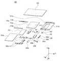
도 5 및 도 6는 본 발명의 다양한 실시예에 따른, 전자 장치(300)의 제품별 구성을 나타낸 분해 사시도이다. 도 5는 전자 장치(300)의 우측 영역의 구성을 나타낸 분해 사시도이며, 도 6은 전자 장치(300)의 좌측 영역의 구성을 나타낸 분해 사시도이다.5 and 6 are exploded perspective views illustrating the configuration of each product of the
도 7은 본 발명의 다양한 실시예에 따른, 플랫 상태의 전자 장치(300) 내부 부품들의 배치관계를 나타낸 투영도이다.7 is a projection diagram illustrating an arrangement relationship of internal components of the
도 5, 도 6 및 도 7의 상기 전자 장치(300)은 도 2 내지 도 4의 전자 장치(200)의 구조와 일부 또는 전부가 동일할 수 있다.The structure of the
도 5 내지 도 7을 참조하면, 본 발명의 다양한 실시예 중 하나에 따른 전자 장치(300)는 제 1 하우징(310a), 제 2 하우징(310b), 디스플레이 조립체(320) 및 힌지 구조(330)를 포함하고, 상기 힌지 구조(330)는 상기 제 2 하우징(310b)과 상기 제 1 하우징(310a)을 서로에 대하여 회전 가능하게 결합시킬 수 있다. 예를 들어, 상기 제 2 하우징(310b)에 대하여 상기 제 1 하우징(310a)이 전개되거나 폴딩될 수 있다.5 to 7 , an
도 5 및 도 7을 참조하면, 상기 전자 장치(300)의 우측 영역은, 제 1 하우징(310a) 및 디스플레이 조립체(320)의 일부 영역, 메인 인쇄 회로기판(350a) 및 제 1 배터리(370) 등을 포함할 수 있다.5 and 7 , the right region of the
다양한 실시예에 따른, 상기 제 1 하우징(310a)은 각종 전자 부품 등을 수용하기 위한 것으로서, 적어도 일부분이 도전성 재질로 이루어질 수 있다. 예컨대, 상기 제 1 하우징(310a)은 상기 전자 장치(300)의 외측면을 형성하는 측벽들을 포함할 수 있으며, 상기 전자 장치(300)의 외관으로 드러나는 부분은 도전성을 가진 금속 재질로 제작될 수 있다. 또 다른 예로, 상기 제 1 하우징(310a) 금속(예를 들어, 알루미늄, STS, 마그네슘)으로 제작되거나 적어도 일부분은 합성 수지를 포함하여로 제작 될 수 있다. 상기 제 1 하우징(310a)의 내부로는 메인 인쇄회로기판(350a) 및/또는 제 1 배터리(370)가 수용될 수 있다. 예를 들어, 상기 메인 인쇄회로기판(350a)에는 프로세서, 통신 모듈, 각종 인터페이스(예: 도 1의 인터페이스(150,170)), 전력 관리 모듈 등이 집적회로 칩 형태로 장착될 수 있으며, 제어 회로 또한 집적회로 칩으로 구성되어 상기 메인 인쇄회로기판(350a)에 장착될 수 있다. 예를 들어, 상기 제어 회로는 상술한 프로세서 또는 통신 모듈의 일부일 수 있다. 또 다른 예로, 상기 메인 인쇄회로기판(350a)의 직접회로 칩을 외부 자기장 등으로부터 차폐하도록 쉴드 캔(shield can)(351)이 배치될 수 있다.According to various embodiments, the
다양한 실시예에 따른, 상기 제 1 하우징(310a) 내부 상단 영역에는 전면 카메라(352), 리시버(353) 등이 배치될 수 있으며, 측면 영역에는 전술한 전원 키(power key)(306a) 및/또는 볼륨 조정키(volume key)(306b)들의 조합인 키 모듈(306)이 배치될 수 있다. 상기 측면 영역에는 상기 제 2 하우징(310b)과 자기적 결합을 유도하는 적어도 하나의 마그넷(308)이 배치될 수 있다. 상기 제 1 하우징(310a) 내부 하단 영역에는 심 카드(sim card)가 수용되는 심 소켓(309f)이 배치될 수 있으며, 충전부(309a), 충전 단자(예를 들어, USB type-C)(309b) 및/또는 마이크 모듈(mic module)(309c) 등이 배치될 수 있다. 다만 상기 부품 구조들의 배치는 이에 한정된 것은 아니며, 전자 장치(300) 내부에서 효율적인 실장을 위한 배치 관계가 구성하도록 상기 제 1 하우징(310a) 내부 다양한 영역에 배치될 수 있다.According to various embodiments, a
다양한 실시예에 따른, 상기 디스플레이 조립체(320) 일부 영역(예를 들어, 디스플레이 조립체(320)의 우측 영역)은 제 1 하우징(310a)의 전면을 통해 노출될 수 있다. 상기 디스플레이 조립체(320)는 적어도 부분적으로 무선 전파 또는 자기장을 투과하는 물질로 제작될 수 있으며, 상기 제 1 하우징(310a)의 전면(제 1 방향(+Z)을 향하도록)에 장착될 수 있다. 상기 디스플레이 조립체(320)는 플렉서블 윈도우 부재(예를 들어, PI(polyimide film) 필름)와, 상기 윈도우 부재의 내측면에 장착되는 디스플레이 패널(예를 들어, OLED(Organic Light Emitting Diodes))을 포함할 수 있다. 상기 윈도우 부재와 디스플레이 패널 사이에는 터치 패널이 탑재될 수 있다. 예컨대, 상기 디스플레이 조립체(320)는 화면을 출력하는 출력 장치이면서, 터치 스크린 기능이 탑재된 입력 장치로 활용될 수 있다. 일 실시예에 따르면, 상기 디스플레이 조립체(320)는 디스플레이 패널 후면에 입력 패널로서 별도의 디지타이저 패널(미도시)을 포함할 수 있다. 예를 들어, 상기 디지타이저 패널은 유선 또는 무선 방식으로 상기 전자 장치(300)와 통신을 수행하면서 입력 모듈(예를 들어, 펜)을 이용한 필기 내용을 검출하여 상기 전자 장치(300)로 전달할 수 있다. 상기 디지타이저 패널은 접거나 말아서 휴대할 수 있는 유연성을 가진 패널(flexible panel)로 제작될 수 있다. 예를 들어, 입력 패널로서의 상기 디지타이저 패널은 교류 전류가 인가되면 전자기장을 형성할 수 있다.According to various embodiments, a partial area of the display assembly 320 (eg, a right area of the display assembly 320 ) may be exposed through the front surface of the
다양한 실시예에 따르면, 상기 제 1 하우징(310a)은 상기 전자 장치(300) 중심에 배치된 힌지 구조(330)를 기준으로 좌, 우 이동할 수 있는 제 1 중간 플레이트(311a), 상기 제 1 중간 플레이트(311a)의 전면에 배치되며, 상기 디스플레이 조립체(320)의 일 영역을 지지하는 제 1 브라켓(312a) 및 상기 제 1 중간 플레이트(311a)의 양단 영역에 배치되어 상기 전자 장치(300)의 외면인 베젤 영역 형성하도록 노출된 상, 하단 플레이트(313a)를 포함할 수 있다.According to various embodiments, the
다양한 실시예에 따른, 상기 제 1 중간 플레이트(311a) 및/또는 상기 상,하단 플레이트(313a)의 외면에는 다양한 전자 부품들의 일부 영역이 상기 전자 장치(300) 외부로 노출되도록 다양한 형태의 홀을 포함할 수 있다. 도면에 상세히 도시하지는 않았으나, 다양한 실시예에 따르면, 상기 전자 장치(300)의 내부로 배치되는 전자 부품들의 배치나, 상기 제 1 하우징(310a) 사이의 결속 구조 등에 따라 상기 제 1 중간 플레이트(311a)의 표면에는 다양한 구조물들이 형성될 수 있다. 예를 들어, 상기 메인 인쇄 회로기판(350a)에 장착된 집적회로 칩들을 수용하는 공간이 상기 제 1 중간 플레이트(311a)에 각각 형성될 수 있다. 집적회로 칩들을 수용하는 공간은 홈 형태(recessed shape) 또는 집적회로 칩을 둘러싸는 리브(rib) 등으로 형성될 수 있다.According to various embodiments, various types of holes are formed on the outer surface of the first
다양한 실시예에 따른, 상기 제 1 중간 플레이트(311a)의 가장자리 영역에는 힌지 구조가 배치될 수 있다. 예를 들어, 상기 힌지 구조의 일부 영역이 상기 제 1 중간 플레이트(311a)와 연결될 수 있으며, 나머지 영역은 제 1 중간 플레이트(311a) 및 제 2 중간 플레이트(311b) 사이에 배치될 수 있다.According to various embodiments, a hinge structure may be disposed on an edge region of the first
다양한 실시예에 따른, 상기 제 1 브라켓(312a)은 플레이트 형상으로 마련되며, 상기 디스플레이 조립체(320)의 우측 영역이 안착된 상태로 상기 제 1 중간 플레이트(311a)와 결합할 수 있다. 예를 들어, 상기 제 1 브라켓(312a)은 제 1 결합홀(3111)을 구비하고, 상기 제 1 중간 플레이트(311a)에는 상기 제 1 결합홀(3111)에 대응되는 제 2 결합홀(3112)이 형성될 수 있으며, 스크류(미도시) 등의 결합 부재가 상기 제 1 결합홀(3111)과 상기 제 2 결합홀(3112)에 삽입되면서 상기 제 1 브라켓(312a)과 상기 제 1 중간 플레이트(311a)를 결합될 수 있다.According to various embodiments of the present disclosure, the
다양한 실시예에 따르면, 상기 전자 장치(300)는 상기 제 1 하우징(310a)의 후면을 보호하는 제 1 후면 커버(340a)를 포함할 수 있다. 상기 제 1 후면 커버(340a)는 상기 디스플레이 조립체(320)와 대향하는(opposite) 방향을 바라보게 장착되며, 무선 전파 또는 자기장을 투과시킬 수 있는 재질, 예를 들면, 강화 유리나 합성 수지로 제작될 수 있다. 또 다른 예로, 상기 제 1 하우징(310a)의 제 1 후면 커버(340a)는 금속(예를 들어, 알루미늄, STS, 마그네슘)으로 제작되거나 적어도 일부분은 합성 수지를 포함하여로 제작 될 수 있다. 상기 제 1 후면 커버(340a)는 상기 디스플레이 조립체(320)와 함께 상기 전자 장치(300)의 외관을 이룰 수 있다. 예를 들어, 상기 제 1 후면 커버(340a)의 제 2 방향(-Z)을 향하는 제 2 면(예를 들어, 도 2b의 제 2 면(202a)은 전자 장치의 외면을 형성할 수 있다.According to various embodiments, the
다양한 실시예에 따르면, 상기 전자 장치(300)는 도전성 패턴을 포함하는 제 1 안테나부(360a) 및 방사 도체부(미도시)를 포함할 수 있다. 상기 제 1 안테나부(360a)는 메인 인쇄회로기판(350a) 및 제 1 후면 커버(340a) 사이에 배치되며, 상기 제 1 안테나부(360a)의 도전성 패턴을 통해 송수신되는 무선 전파 또는 상기 제 1 안테나부(360a)의 도전성 패턴이 발생시킨 자기장은 상기 제 1 후면 커버(340a)를 투과할 수 있다.According to various embodiments, the
다양한 실시예에 따르면, 상기 제 1 안테나부(360a)의 일면은 절연체 또는 유전체 소재로 제작된 필름을 포함할 수 있으며, 상기 도전성 패턴(들)을 형성하기 위한 영역을 제공할 수 있다. 예를 들어, 상기 도전성 패턴이 포함된 제 1 안테나부(360a)는 플렉서블 인쇄 회로 기판의 외형을 가질 수 있다. 또는, 상기 제 1 안테나부(360a)는 플렉서블 인쇄 회로 기판이면서, 다층 회로 기판의 구조를 가질 수 있다 예를 들어, 상기 도전성 패턴(들)은 상기 제 1 안테나부(360a) 일면 또는 타면에 각각 배치될 수 있으며, 상기 제 1 안테나부(360a)가 다층 회로 기판(multi-layer circuit board) 구조를 가지고 있다면, 복수의 상기 도전성 패턴들이 상기 제 1 안테나부(360a)를 이루는 층들 중 적절한 층에 각각 형성될 수 있다. 예를 들어, 상기 도전성 패턴들은 도전성 잉크를 이용한 인쇄 방식, 증착, 도장 및/또는 도금 방식으로 상기 안테나부(360)에 형성된 도전층의 일부분을 식각(예: 습식 식각, 건식 식각) 방식으로 형성될 수 있다. 또는, 상기 제 1 안테나부(360a)는 레이저 직접 성형법(LDS; laser direct structuning)으로 형성된 내부 구조물의 일부 영역일 수 있다.According to various embodiments, one surface of the
도 6 및 도 7을 참조하면, 상기 전자 장치(300)의 좌측 영역은, 제 2 하우징(310b) 및 디스플레이 조립체(320)의 일부 영역, 서브 인쇄 회로기판(350a) 및 제 2 배터리(380) 등을 포함할 수 있다.6 and 7 , the left area of the
다양한 실시예에 따른, 상기 제 2 하우징(310b)은 각종 전자 부품 등을 수용하기 위한 것으로서, 적어도 일부분이 도전성 재질로 이루어질 수 있다. 예컨대, 상기 제 2 하우징(310b)은 상기 전자 장치(300)의 외측면을 형성하는 측벽들을 포함할 수 있으며, 상기 전자 장치(300)의 외관으로 드러나는 부분은 도전성을 가진 금속 재질로 제작될 수 있다. 또 다른 예로, 상기 제 2 하우징(310b) 금속(예를 들어, 알루미늄, STS, 마그네슘)으로 제작되거나 적어도 일부분은 합성 수지를 포함하여로 제작 될 수 있다. 상기 제 2 하우징(310b)의 내부로는 서브 인쇄 회로기판(350b) 및/또는 제 2 배터리(380)가 수용될 수 있다. 예를 들어, 상기 서브 인쇄 회로기판(350b)에는 프로세서, 통신 모듈, 각종 인터페이스(예: 도 1의 인터페이스(150,170)), 전력 관리 모듈(미도시) 등이 집적회로 칩 형태로 장착될 수 있으며, 제어 회로 또한 집적회로 칩으로 구성되어 상기 서브 인쇄 회로기판(350b)에 장착될 수 있다. 예를 들어, 상기 제어 회로는 상술한 프로세서 또는 통신 모듈의 일부일 수 있다.According to various embodiments, the
다양한 실시예에 따른, 상기 제 2 하우징(310b) 내부 상단 영역에는 메인 카메라(358), 홀 센서(미도시) 및/또는 진동 모듈(354) 등이 배치될 수 있으며, 측면 영역에는 상기 제 1 하우징(310a)에 배치된 마그넷(308)과 자기적 결합을 유도하는 적어도 하나의 마그넷(309) 및/또는 스피커 엔클로져(spk encloser)(309d)가 배치될 수 있다. 상기 제 2 하우징(310b) 내부 하단 영역에는 이어잭(ear jack)(309e) 등이 배치될 수 있다. 다만 상기 부품 구조들의 배치는 이에 한정된 것은 아니며, 전자 장치(300) 내부에서 효율적인 배치관계를 구성하도록 상기 제 2 하우징(310b) 내부 다양한 영역에 배치될 수 있다.According to various embodiments, a
다양한 실시예에 따른, 상기 디스플레이 조립체(320)의 일부 영역(예를 들어, 디스플레이(320)의 좌측 영역)은 제 2 하우징(310b)의 전면을 통해 노출될 수 있다. 상기 디스플레이 조립체(320)는 적어도 부분적으로 무선 전파 또는 자기장을 투과하는 물질로 제작될 수 있으며, 상기 제 2 하우징(310b)의 전면(제 1 방향(+Z)을 향하도록)에 장착될 수 있다. 상기 디스플레이 조립체(320)는 플렉서블 윈도우 부재(예를 들어, PI 필름)와, 상기 윈도우 부재의 내측면에 장착되는 디스플레이 패널(예를 들어, OLED(Organic Light Emitting Diodes))을 포함할 수 있다. 상기 윈도우 부재와 디스플레이 패널 사이에는 터치 패널이 탑재될 수 있다. 예컨대, 상기 디스플레이 조립체(320)는 화면을 출력하는 출력 장치이면서, 터치 스크린 기능이 탑재된 입력 장치로 활용될 수 있다. 일 실시예에 따르면, 상기 디스플레이 조립체(320)는 디스플레이 패널 후면에 입력 패널로서 별도의 디지타이저 패널(미도시)을 포함할 수 있다.According to various embodiments, a partial area of the display assembly 320 (eg, a left area of the display 320 ) may be exposed through the front surface of the
다양한 실시예에 따르면, 상기 제 2 하우징(310b)은 상기 전자 장치(300) 중심에 배치된 힌지 구조(330)를 기준으로 좌, 우 이동할 수 있는 제 2 중간 플레이트(311b), 상기 제 2 중간 플레이트(311b)의 전면에 배치되며, 상기 디스플레이 조립체(320)의 일 영역을 지지하는 제 2 브라켓(312b) 및 상기 제 2 중간 플레이트(311b)의 양단 영역에 배치되어 상기 전자 장치(300)의 외면인 베젤 영역 형성하도록 노출된 상, 하단 플레이트(313b)를 포함할 수 있다.According to various embodiments, the
다양한 실시예에 따른, 상기 제 2 중간 플레이트(311b) 및/또는 상기 상,하단 플레이트(313b)의 외면에는 다양한 전자 부품들의 일부 영역이 상기 전자 장치(300) 외부로 노출되도록 다양한 형태의 홀을 포함할 수 있다. 도면에 상세히 도시하지는 않았으나, 다양한 실시예에 따르면, 상기 전자 장치(300)의 내부로 배치되는 전자 부품들의 배치나, 상기 제 2 하우징(310b) 사이의 결속 구조 등에 따라 상기 제 2 중간 플레이트(311b)의 표면에는 다양한 구조물들이 형성될 수 있다. 예를 들어, 상기 서브 인쇄 회로기판(350b)에 장착된 집적회로 칩들을 수용하는 공간이 상기 제 2 중간 플레이트(311b)에 각각 형성될 수 있다. 집적회로 칩들을 수용하는 공간은 홈 형태(recessed shape) 또는 집적회로 칩을 둘러싸는 리브(rib) 등으로 형성될 수 있다.According to various embodiments, holes of various shapes are formed on the outer surface of the second
다양한 실시예에 따른, 상기 제 2 중간 플레이트(311b)의 가장자리 영역에는 힌지 구조가 배치될 수 있다. 예를 들어, 상기 힌지 구조의 일부 영역이 상기 제 2 중간 플레이트(311b)와 연결될 수 있으며, 나머지 영역은 제 2 중간 플레이트(311b) 및 제 1 중간 플레이트(311a) 사이에 배치될 수 있다.According to various embodiments, a hinge structure may be disposed on an edge region of the second
다양한 실시예에 따른, 상기 제 2 브라켓(312b)은 플레이트 형상으로 마련되며, 상기 디스플레이 조립체(320)의 우측 영역이 안착된 상태로 상기 제 2 중간 플레이트(311b)와 결합할 수 있다. 예를 들어, 상기 제 2 브라켓(312b)은 제 1 결합홀(3113)을 구비하고, 상기 제 2 중간 플레이트(311b)에는 상기 제 1 결합홀(3113)에 대응되는 제 2 결합홀(3114)이 형성될 수 있으며, 스크류(미도시) 등의 결합 부재가 상기 제 1 결합홀(3113)과 상기 제 2 결합홀(3114)에 삽입되면서 상기 제 2 브라켓(312b)과 상기 제 2 중간 플레이트(311b)를 결합될 수 있다.According to various embodiments, the
다양한 실시예에 따르면, 상기 전자 장치(300)는 상기 제 2 하우징(310b)의 후면을 보호하는 제 2 후면 커버(340b)를 포함할 수 있다. 상기 제 2 후면 커버(340b)는 상기 디스플레이 조립체(320)와 대향하는(opposite) 방향을 바라보게 장착되며, 무선 전파 또는 자기장을 투과시킬 수 있는 재질, 예를 들면, 강화 유리나 합성 수지로 제작될 수 있다. 또 다른 예로, 상기 제 2 하우징(310b)의 제 1 후면 커버(340b)는 금속(예를 들어, 알루미늄, STS, 마그네슘)으로 제작되거나 적어도 일부분은 합성 수지를 포함하여로 제작 될 수 있다. 상기 제 2 후면 커버(340b)는 상기 디스플레이 조립체(320)와 함께 상기 전자 장치(300)의 외관을 이룰 수 있다. 예를 들어, 상기 제 2 후면 커버(340b)의 제 2 방향(-Z)을 향하는 제 4 면(예를 들어, 도 2b의 제 4 면(202b)은 전자 장치의 외면을 형성할 수 있다.According to various embodiments, the
다양한 실시예에 따르면, 상기 전자 장치(300)는 도전성 패턴을 포함하는 제 2 안테나부(360b) 및 방사 도체부(미도시)를 포함할 수 있다. 상기 제 2 안테나부(360b)는 서브 인쇄회로기판(350b) 및 제 2 후면 커버(340b) 사이에 배치되며, 상기 제 2 안테나부(360b)의 도전성 패턴을 통해 송수신되는 무선 전파 또는 상기 제 2 안테나부(360b)의 도전성 패턴이 발생시킨 자기장은 상기 제 2 후면 커버(340b)를 투과할 수 있다. 상기 제 2 안테나부(360b)는 레이저 직접 성형법(LDS; laser direct structuning)으로 형성된 내부 구조물의 일부 영역일 수 있다.According to various embodiments, the
도 7을 참조하면, 상기 전자 장치(300)가 펼쳐진 상태에서, 상기 제 1 하우징(310a) 및 제 2 하우징(310b)은 각각의 측면을 서로 대면하도록 배치될 수 있다. 예를 들어, 상기 제 1 하우징(310a)의 측면 및 상기 제 2 하우징(310b)의 측면은 이격된 간격을 가지며 배치될 수 있다.Referring to FIG. 7 , in an unfolded state of the
다양한 실시예에 따른, 상기 제 1 하우징(310a) 및 상기 제 2 하우징(310b) 사이에는 힌지 구조(330)가 배치될 수 있다. 상기 힌지 구조(330)는 외면을 형성하는 일부분은 상기 이격된 간격에 끼움 결합될 수 있으며, 나머지 부분은 상기 제 1 하우징(310a) 및/또는 제 2 하우징(310b) 내측면에 안착될 수 있다. 상기 제 1 중간 플레이트(311a) 및 제 2 중간 플레이트(311b)의 내측면에는 상기 힌지 구조(330)의 적어도 일부가 안착될 수 있는 리세스를 각각 형성할 수 있다.According to various embodiments, a
다양한 실시예에 따른, 상기 플렉서블 인쇄회로기판(390)은 제 1 하우징(310a) 및 제 2 하우징(310b)을 가로 질러 배치될 수 있다. 예를 들면, 상기 플렉서블 인쇄회로기판(390)은 제 1 하우징(310a)으로부터 연장되어 상기 힌지 구조(330)을 거쳐 상기 제 2 하우징(310b)까지 연장 배치될 수 있다. 상기 플렉서블 인쇄회로기판(390)은 양단에 커넥터가 마련되어 제 1 하우징(310a)에 배치된 메인 인쇄 회로기판(350a)과 전기적으로 연결될 수 있으며, 상기 제 2 하우징(310b)에 배치된 서브 인쇄 회로기판(350b)과 전기적으로 연결될 수 있다.According to various embodiments, the flexible printed
이하, 전자 장치의 힌지 구조의 구성, 플렉서블 인쇄회로기판의 구성 및 디스플레이 조립체의 적층 구조에 관하여 구체적으로 설명한다.Hereinafter, the configuration of the hinge structure of the electronic device, the configuration of the flexible printed circuit board, and the stacked structure of the display assembly will be described in detail.
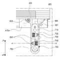
도 8은 본 발명의 다양한 실시예에 따른, 상기 전개된 전자 장치(300)에 배치된 힌지 구조(400)를 나타낸 투영도이다. 도 9는 본 발명의 다양한 실시예에 따른, 힌지 구조(400)를 별도로 도시한 정면도이다. 도 8 및 도 9의 상기 전자 장치(300)의 힌지 구조(400)는 도 5 내지 도 7의 전자 장치(300)의 힌지 구조(330)와 일부 또는 전부가 동일할 수 있다.8 is a projection diagram illustrating a
도 8 및 도 9를 참조하면, 본 발명의 다양한 실시예 중 하나에 따른 전자 장치(300)는 제 1 하우징(310a), 제 2 하우징(310b) 및 힌지 구조(400)를 포함하고, 상기 힌지 구조(400)는 상기 제 2 하우징(310b)과 상기 제 1 하우징(310a)을 서로에 대하여 회전 가능하게 결합시킬 수 있다. 예를 들어, 상기 제 2 하우징(310b)에 대하여 상기 제 1 하우징(310a)이 전개되거나 폴딩될 수 있다.8 and 9 , an
도 8은 상기 전면을 향하도록 전개된 전자 장치(300)를 나타내며, 우측 영역에 제 1 하우징(310a)이 배치되고 좌측 영역에 제 2 하우징(310b)이 배치될 수 있다. 상기 제 1 하우징(310a) 및 상기 제 2 하우징(310b) 사이 및 일부 중첩 영역에는 힌지 구조(400)가 배치될 수 있다. 다양한 실시예에 따르면, 상기 힌지 구조(400)는 슬라이드 커버(410), 2축 힌지 모듈(420), 슬라이드 모듈(430), 레일 브라켓(440), 슬라이드 스토퍼(450) 및 레일 스토퍼(460)를 포함할 수 있다.8 shows the
다양한 실시예에 따른, 상기 슬라이드 커버(410)는 전술된 후면 커버(예를 들어, 도 6, 7의 후면 커버(340a,340b)와 함께 전자 장치(300)의 후면을 커버하며, 전면 방향을 향하는 내측면에는 상기 2축 힌지 모듈(420), 레일 브라켓(440) 및 슬라이드 스토퍼(450), 레일 스토퍼(460)가 안착 가능하도록 안착면을 형성할 수 있다. 상기 슬라이드 커버(410)은 복수 개로 구성될 수 있다. 예를 들어, 상기 슬라이드 커버(410)는 제 1 슬라이드 커버(410a) 및 제 2 슬라이드 커버(410b)를 포함할 수 있다. 상기 제 1 슬라이드 커버(410a)는 적어도 일부 영역이 상기 제 1 하우징(310a)의 측면에 안착되는 제 1 부분(411a) 및 상기 제 1 부분(411a)으로부터 연장되며 상기 제 1 하우징(310a) 및 상기 제 2 하우징(310b)의 사이에 배치되는 제 2 부분(412a)을 포함할 수 있다. 상기 제 1 부분(411a)은 플레이트 형상으로 상기 제 1 하우징(310a)과 결합되도록 다수의 결속 홀 등이 배치될 수 있다. 상기 제 2 부분(412a)는 단부가 길이 방향을 따라 곡면을 형성하여 상기 2축 힌지 모듈(420)이 형성하는 적어도 하나의 가상의 회전축(A1)을 기준으로 부드러운 회전을 유도할 수 있다.According to various embodiments, the
상기 제 2 슬라이드 커버(410b)는 적어도 일부 영역이 상기 제 2 하우징(310b)의 측면에 안착되는 제 1 부분(411b) 및 상기 제 1 부분(411b)으로부터 연장되며 상기 제 2 하우징(310b) 및 상기 제 1 하우징(310a)의 사이에 배치되는 제 2 부분(412b)을 포함할 수 있다. 상기 제 1 부분(411b)은 플레이트 형상으로 상기 제 2 하우징(310b)과 결합되도록 다수의 결속 홀 등이 배치될 수 있다. 상기 제 2 부분(412b)는 단부가 길이 방향을 따라 곡면을 형성하여 상기 2축 힌지 모듈(420)이 형성하는 적어도 하나의 가상의 회전축(A2)을 기준으로 부드러운 회전을 유도할 수 있다.The
상기 펼쳐진 상태에서, 제 1 슬라이드 커버(410a)의 제 2 부분(412a) 및 상기 제 2 슬라이드 커버(410b)의 제 2 부분(412b)의 일부 영역은 서로 접촉 배치될 수 있다. 상기 제 1 슬라이드 커버(410a)를 기준으로 상기 제 2 슬라이드 커버(410b)가 회전함에 따라(또는 상기 제 2 슬라이드 커버(410b)를 기준으로 상기 제 1 슬라이드 커버(410a)가 회전함에 따라), 상기 제 1 슬라이드 커버(410a)의 제 1 부분(411a) 및 제 2 부분(412a)과 상기 제 2 슬라이드 커버(410b)의 제 1 부분(411b) 및 제 2 부분(412b)의 대면하는 면적이 확장될 수 있다.In the unfolded state, the
다양한 실시예에 따른, 상기 슬라이드 커버(410) 내측면(401)에는 슬라이드 모듈(430)이 안착된 레일 브라켓(440)이 배치될 수 있다. 상기 레일 브라켓(440)은 상기 슬라이드 커버(410)의 양단부에 배치될 수 있으며, 상기 슬라이드 커버(410)와 고정 결합될 수 있다. 예를 들어, 상기 제 1 슬라이드 커버(410a)의 길이 방향의 양단부에 각각 슬라이드 모듈(430)이 안착된 레일 브라켓(440) 배치될 수 있고, 상기 제 2 슬라이드 커버(410b)의 길이 방향의 양단부에 각각 슬라이드 모듈(430)이 안착된 레일 브라켓(440) 배치될 수 있다. According to various embodiments, a
다양한 실시예에 따른, 상기 제 1 슬라이드 커버(410a)의 일단부에 배치된 레일 브라켓(440)의 중심은 상기 제 2 슬라이드 커버(410b)의 일단부에 배치된 레일 브라켓(440)의 중심은 서로 동일 선상에 배치될 수 있다. 이에 따라, 전자 장치(300)가 폴딩 상태에서, 상기 제 1 슬라이드 커버(410a)에 배치된 레일 브라켓(440)과 상기 제 2 슬라이드 커버(410b)에 배치된 레일 브라켓(440)은 서로 대면하도록 배치될 수 있다. 다만 상기 레일 브라켓(440)의 배치 구조는 이에 한정된 것은 아니고, 제 1 하우징(310a) 및/또는 제 2 하우징(310b)에 배치된 배터리(미도시)가 효율적으로 안착되는 위치에 대응하여 다양한 배치관계를 형성할 수 있다.According to various embodiments, the center of the
또 다른 예에 따른, 상기 슬라이드 모듈(430)은 상기 레일 브라켓(440) 내측에 형성된 홀(441)에 배치되며, 상기 홀(441)의 길이 방향에 따라 전후 왕복 운동을 할 수 있다.According to another example, the
다양한 실시예에 따른, 상기 슬라이드 커버(410) 내측면(401)에는 2축 힌지 모듈(420)이 배치될 수 있다. 예를 들어, 상기 슬라이드 커버(410) 내면에 배치된 리세스(recess)(403) 내측으로 상기 2축 힌지 모듈(420)이 삽입 배치될 수 있으며, 상기 2축 힌지 모듈(420)의 적어도 일부 영역은 상기 레일 브라켓(440)에 의해 둘러싸이도록 배치될 수 있다. 상기 2축 힌지 모듈(420)은 두 개의 가상의 회전축(A1,A2)을 가지도록 형성되며, 하나의 가상의 회전축(A1)은 상기 제 1 하우징(310a)의 제 2 부분(412a)이 형성하는 가상의 회전축과 동일 선상에 배치될 수 있으며, 다른 하나의 회전축(A2)은 상기 제 2 하우징(310b)의 제 2 부분(412b)이 형성하는 가상의 회전축과 동일 선상에 배치될 수 있다.According to various embodiments, a two-
다양한 실시예에 따른, 상기 2축 힌지 모듈(420)은 복수 개로 배치될 수 있다. 예를 들어, 상기 슬라이드 커버(410) 양단에 배치된 각각의 레일 브라켓(440)과 인접하도록 개별적으로 형성될 수 있다. 또 다른 예로, 상기 2축 힌지 모듈(420)은 제 1 슬라이드 커버(410a) 및 제 2 슬라이드 커버(410b)가 각각 형성하는 리세스(recess)가 결합함에 따라 생기는 확장된 리세스(403) 내에 배치될 수 있으며, 하나의 가상의 회전축(A1)은 상기 제 1 슬라이드 커버(410a) 내부에 배치되고, 다른 하나의 가상의 회전축(A2)은 상기 제 2 슬라이드 커버(410b) 내부에 배치될 수 있다.According to various embodiments, the two-
다양한 실시예에 따른, 상기 슬라이드 커버(410) 내측면(401)에는 레일 스토퍼(460) 및 슬라이드 스토퍼(450)가 배치될 수 있다. 상기 레일 스토퍼(460) 및 슬라이드 스토퍼(450)는 상기 슬라이드 커버(410)의 중심 영역에 적어도 하나 이상 배치될 수 있으며, 각각의 슬라이드 커버(410a,410b)에 개별적으로 배치될 수 있다.According to various embodiments, a
다양한 실시예에 따른, 상기 슬라이드 스토퍼(450)는 한 쌍으로 배치된 레일 스토퍼(460) 사이에서 이동 가능하도록 배치될 수 있다. 예를 들어, 상기 슬라이드 커버(410a,410b) 내에 형성된 슬라이드 라인(미도시)을 따라 전후 왕복 움직임이 가능하며, 상기 슬라이드 모듈(430)의 움직임을 제한할 수 있다. 또 다른 예로, 상기 슬라이드 스토퍼(450)는 슬라이드 모듈(430)를 보조하면서 슬라이드 움직임을 수행하여, 상기 힌지 구조(400)와 더불어 전자 장치의 평형을 유지할 수 있으며, 상기 슬라이드 모듈(430) 사이에 배치되어 전자 장치의 강성을 보완할 수 있다.According to various embodiments, the
다양한 실시예에 따른, 상기 레일 스토퍼(460)는 상기 2축 힌지 모듈(420)과 인접하게 배치되며 적어도 한 쌍으로 구성될 수 있다. 상기 레일 스토퍼(460)는 상기 제 1 슬라이드 커버(410a) 및 제 2 슬라이드 커버(410b)가 서로 맞닿는 영역에서 각각 서로 밀접하게 배치되어, 상기 힌지 구조(400)가 소정의 각도 이상으로 확장되어 회전하는 것을 제한할 수 있다. 이하, 구체적인 내용은 후술한다.According to various embodiments, the
이하, 상기 2축 힌지 모듈(420), 스토퍼(450,460), 슬라이드 모듈(430) 및 레일 브라켓(440)의 구체적인 구성에 관하여 순차적으로 설명한다.Hereinafter, specific configurations of the two-
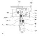
도 10은 본 발명의 다양한 실시예에 따른, 상기 2축 힌지 모듈(500)을 부품 별로 도시한 정면도이다. 도 11은 본 발명의 다양한 실시예에 따른, 전자 장치(300) 내에 배치된 상기 2축 힌지 모듈(500)의 기어부(530)를 절단한 영역을 나타낸 단면도이다. 도 11a는 전자 장치(300)가 일부 폴딩된 상태이며, 도 11b는 전자 장치(300)가 완전히 폴딩된 상태를 도시한 단면도이다. 도 10 및 도 11의 2축 힌지 모듈(500) 구조는 도 8 및 도 9의 2축 힌지 모듈(420)의 구조와 일부 또는 전부가 동일할 수 있다.10 is a front view illustrating the two-
도 10 및 도 11을 참조하면, 본 발명의 다양한 실시예 중 하나에 따른 전자 장치(300)는 제 1 하우징(310a), 제 2 하우징(310b) 및 2축 힌지 모듈(500)을 포함한 힌지 구조를 포함하고, 상기 2축 힌지 모듈(500)을 포함한 힌지 구조는 상기 제 2 하우징(310b)과 상기 제 1 하우징(310a)을 서로에 대하여 회전 가능하게 결합시킬 수 있다. 예를 들어, 상기 제 2 하우징(310b)에 대하여 상기 제 1 하우징(310a)이 전개되거나 폴딩될 수 있다.10 and 11 , an
도 10을 참조하면, 상기 2축 힌지 모듈(hinge module)(500)은 힌지 하우징(hinge housing)(510), 힌지 샤프트(hinge shaft)(520), 적어도 두 개의 기어(gear)를 포함한 기어부(530), 힌지 스토퍼(hinge stopper)(540), 피동 캠(stopper cam)(550),, 구동 캠(moving cam)(560), 탄성체(elastic body)(570), 및 샤프트 스토퍼(shaft stopper)(580)를 포함할 수 있다.Referring to FIG. 10 , the two-
다양한 실시예에 따른, 상기 힌지 하우징(510) 내에는 상기 힌지 샤프트(520)의 적어도 일부, 캠 부의 일부(예를 들어, 구동 캠(560)과 피동 캠(550)), 복수 개의 기어(531,532,533) 및 상기 탄성체(570)가 가상의 힌지축(A1,A2) 방향으로 수용될 수 있다. 예를 들어, 상기 2축 힌지 모듈(500)은 두 개의 가상의 회전축(A1, A2)에 대응되는 두 개의 힌지 샤프트(520)를 포함하고, 상기 각각의 힌지 샤프트(520) 상에는 샤프트 스토퍼(580), 탄성체(570), 피동 캠(550) 및 기어들(531,532)이 개별적으로 배치될 수 있다. 또 다른 예로, 상기 힌지 스토퍼(540) 및 구동 캠(560)은 상기 각각의 힌지 샤프트(520)가 관통하는 두 개의 홀을 구비할 수 있다. 이하, 하나의 힌지 샤프트(520) 상에 배치된 상기 구성 요소들을 기준으로 설명한다. 나머지 힌지 샤프트 상에 배치된 구성 요소들은 상기 내용에 준용한다.In the
다양한 실시예에 따른, 상기 힌지 하우징(510)은 제 1 영역(S1) 및 제 2 영역(S2)으로 구분되며, 상기 제 1 영역(S1)은 캠부가 동작하는 영역이며, 상기 제 2 영역(S2)은 기어부(530)가 동작하는 영역일 수 있다.According to various embodiments, the
다양한 실시예에 따른, 제 1 영역(S1)을 살펴보면, 상기 힌지 하우징(510) 내측에는 상기 구성 요소(예를 들어, 힌지 샤프트(520)의 일부, 힌지 스토퍼(540), 탄성체(570), 구동 캠(560) 및 피동 캠(550))들이 수용될 수 있다. 상기 힌지 하우징(510) 내에서 상기 탄성체(570)는 압축 또는 인장 운동을 하고, 상기 피동 캠(550)은 상기 힌지 샤프트(520)에 관통 설치되며 회전 운동을 할 수 있다. 상기 구동 캠(560)은 상기 피동 캠(550)의 회전 운동에 대응하여, 상기 힌지 샤프트(520)를 따라서 전후 직선 왕복 이동을 수행할 수 있다.Looking at the first region S1 according to various embodiments, inside the
다양한 실시예에 따른, 상기 힌지 샤프트(520)에는 상기 구동 캠(560), 피동 캠(550), 및 탄성체(570)가 순차적으로 관통 배치될 수 있다. 상기 구동 캠(560) 및 탄성체(570)의 외측에는 2축 힌지 모듈(500)의 회전 움직임을 제한하는 힌지 스토퍼(540)가 각각 배치될 수 있다. 상기 힌지 스토퍼(540)의 일단은 상기 힌지 하우징(510)과 결합하기 위한 체결구가 배치되며, 고정 핀이 삽입될 수 있다. 상기 힌지 스토퍼(540) 일단에는 상기 힌지 샤프트(520)의 움직임을 제한하는 샤프트 스토퍼(580)가 배치될 수 있다. 또 다른 예에 따른, 상기 힌지 스토퍼(540) 및 샤프트 스토퍼(580)는 두 개의 힌지 샤프트(520)가 관통하는 홀을 구비하며, 서로 연결되도록 마련될 수 있다.According to various embodiments, the driving
다양한 실시예에 따른, 상기 탄성체(570)는 상기 힌지 샤프트(520)가 관통되도록 배치되며, 상기 구동 캠(560)과 피동 캠(550)을 밀착시키는 힘을 제공함에 따라, 캠 운동을 제공할 수 있다. 상기 탄성체(570)의 일단은 상기 힌지 스토퍼(540)와 밀착 고정되고, 타단은 상기 구동 캠(560)과 밀착된 상태를 상시적으로 유지할 수 있다. 상기 탄성체(570)는 상기 힌지 하우징(510) 내에서 상기 구동 캠(560)의 전후 운동에 종속되어 인장되거나 압축되는 운동을 수행할 수 있다. 예를 들어, 상기 탄성체(570)는 압축 코일 스프링일 수 있다.According to various embodiments, the
다양한 실시예에 따른, 상기 2축 힌지 모듈(500)은 수평 유지를 위해 적어도 하나의 힌지 스토퍼(541)와 피동 캠(550)는 서로 면 대 면으로 접촉 배치될 수 있다. 또 한 예로, 적어도 하나의 힌지 스토퍼(542)와 샤프트 스토퍼(580)도 서로 면 대 면으로 접촉 배치되어 수평 유지를 위한 스토퍼 기능을 제공할 수 있다.According to various embodiments, in the two-
다양한 실시예에 따른, 상기 구동 캠(560) 및 피동 캠(550)에 의한 캠 동작 및 구성은 상기 구성에 한정된 것은 아니며, 일반적으로 공지된 구성에 따라 다양한 캠 운동을 제공할 수 있으며, 다양한 형상 변경이 가능하다.The cam operation and configuration by the driving
도 11 및 도 12를 참조하여 상기 제 2 영역(S2)을 살펴보면, 상기 2축 힌지 모듈(500)은 상기 힌지 하우징(510) 내에서 상기 피동 캠(550)과 인접하도록 배치되고, 다수의 기어들(531,532,533)이 배치된 기어부(530)를 포함할 수 있다.Referring to the second region S2 with reference to FIGS. 11 and 12 , the two-
다양한 실시예에 따른, 상기 기어부(530)는 제 1 기어(531), 제 2 기어(532), 및 적어도 하나의 아이들 기어(idle gear)(533)을 포함할 수 있다. 상기 제 1 기어(531) 및 제 2 기어(532)는 상기 각각의 힌지 샤프트(520)가 관통하도록 배치되며, 상기 각각의 기어(531,532)의 중심으로부터 힌지 샤프트(520) 방향으로 가상의 회전축(A1,A2)을 형성할 수 있다. 상기 아이들 기어(533)는 상기 제 1 기어(531) 및 제 2 기어(532) 사이에 배치되며, 상기 제 1 기어(531) 및 제 2 기어(532)와 연동되어 움직임을 보조할 수 있다. 상기 제 1 기어(531) 및 제 2 기어(532)의 이격된 간격에 존재하는 상기 아이들 기어(533)가 배치된 부분은 상기 전자 장치(300)의 폴딩(folding) 또는 전개되는 기준이 되는 부분일 수 있다.According to various embodiments, the
다양한 실시예에 따른, 상기 좌측면에 배치된 제 1 기어(531)(도 11a, 11b 참조)는 제 1 힌지 샤프트(520a)에 결합되어 상기 제 1 하우징(310a)에 배치된 리세스(recess)에 안착된 상태로 회전할 수 있다. 상기 우측면에 배치된 제 2 기어(도 11a, 11b 참조)는 제 2 힌지 샤프트(520b)에 결합되어 상기 제 2 하우징(310b)에 배치된 리세스(recess)에 안착된 상태로 회전할 수 있다. 또 다른 예로, 상기 복수 개의 아이들 기어(533)들은 상기 제 1 기어(531) 또는 상기 제 2 기어(532)와 맞물려 회전할 수 있다.According to various embodiments, the first gear 531 (refer to FIGS. 11A and 11B ) disposed on the left side is coupled to the
다양한 실시예에 따른, 상기 제 1 기어(531)의 중심은 상기 제 1 힌지 샤프트(520a)와 제 1 가상축(A1)의 일부를 형성할 수 있다. 상기 제 2 기어(532)의 중심은 상기 제 2 힌지 샤프트(520b)와 제 2가상축(A2)의 일부를 형성하며, 상기 제 2 기어(532)는 제 1 기어(531)와 서로 다른 방향으로 회전할 수 있다. 상기 전자 장치(300)가 전개된 플랫(flat)한 상태에서 폴딩된(folding) 상태로 동작 시에, 상기 제 1 가상축(A1) 및 제 2 가상축(A2)은 상시적으로 평행하게 배치된 상태를 유지할 수 있다.According to various embodiments, the center of the
다양한 실시예에 따른, 상기 제 1 기어(531) 및 제 2 기어(532)는 서로 동일한 직경을 가지는 크기로 구성될 수 있으며, 이에 따라 기어의 이도 동일한 수로 구성될 수 있다. 상기 제 1 기어(531) 및 상기 제 2 기어(532)의 직경은 상기 제 1 하우징(310a) 또는 제 2 하우징(310b)의 두께보다 크기 않도록 마련되어, 상기 전자 장치(300) 외부로 돌출되지 않을 수 있다.According to various embodiments, the
다양한 실시예에 따른, 복수 개의 아이들 기어(533)들은 짝수로 구성될 수 있다. 예를 들어, 아이들 기어(533)들은 서로 맞물려 회전 가능한 제 1 아이들 기어(533a), 제 2 아이들 기어(533b)를 포함할 수 있다. 상기 제 1 아이들 기어(533a)는 상기 제 1 기어(531)와 맞물려 회전 가능하며, 상기 제 1 기어(531)와 서로 다른 방향으로 회전할 수 있다. 상기 제 2 아이들 기어(533b)는 상기 제 2 기어(532)와 맞물려 회전 가능하며, 상기 제 2 기어(532)와 서로 다른 방향으로 회전할 수 있다. 상기 제 1 아이들 기어(533a)와 상기 제 2 아이들 기어(533b)는 서로 동일한 직경을 가질 수 있으며, 맞물려 회전할 수 있다. 따라서 제 1 기어(531)를 기준으로, 제 1 아이들 기어(533a), 제 2 아이들 기어(533b) 및 제 2 기어(532)가 서로 순차적으로 맞물려 회전하도록 배치될 수 있다.According to various embodiments, the plurality of
이하, 슬라이드 스토퍼 및 레일 스토퍼에 관하여 설명한다.Hereinafter, the slide stopper and the rail stopper will be described.
도 12는 본 발명의 다양한 실시예에 따른, 도 9의 일부 영역을 확대한 상기 힌지 구조(400)의 일면을 절단한 사시도이다. 도 12의 레일 스토퍼(460) 및 슬라이드 스토퍼(450) 구조는 도 8 및 도 9의 레일 스토퍼(460) 및 슬라이드 스토퍼(450)의 구조와 일부 또는 전부가 동일할 수 있다.FIG. 12 is a perspective view of one surface of the
도 10 및 도 12를 참조하면, 상기 제 1 방향(+Z)을 향해 내측(예를 들어, 폴딩시 서로 마주보도록 배치되고 상기 디스플레이 조립체와 서로 다른 방향을 향하는 영역)이 펼쳐진 플랫한 상태의 힌지 구조(400)는 레일 브라켓(440)을 기준으로 가상의 힌지 축(A1,A2) 방향에 따라, 2축 힌지 모듈(420), 레일 스토퍼(460) 및 슬라이드 스토퍼(450) 순으로 배치될 수 있다.10 and 12 , a hinge in a flat state with an inner side (eg, an area disposed to face each other when folded and facing a different direction from the display assembly) in the first direction (+Z) is unfolded. The
다양한 실시예에 따른, 상기 레일 스토퍼(460)는 상기 2축 힌지 모듈(420)과 인접하게 배치되며 적어도 한 쌍으로 구성될 수 있다. 한 쌍으로 배치된 레일 스토퍼(460)는 상기 슬라이드 스토퍼(450)의 움직임을 가이드하기 위하여 서로 이격되도록 배치될 수 있으며, 각각의 슬라이드 커버(410a,410b)에 개별적으로 배치될 수 있다. 예를 들면, 상기 제 1 슬라이드 커버(410a)의 길이 방향의 양단부에는 레일 브라켓(440)이 배치될 수 있으며, 상기 레일 브라켓(440) 사이에는 두 쌍의 레일 스토퍼(460)가 배치될 수 있다. 상기 제 2 슬라이드 커버(410b)의 길이 방향의 양단부에는 레일 브라켓(440)이 배치될 수 있으며, 상기 레일 브라켓(440) 사이에는 두 쌍의 레일 스토퍼(460)가 배치될 수 있다. 상기 제 1 슬라이드 커버(410a) 상에 배치된 레일 스토퍼(460)와 상기 제 2 슬라이드 커버(410b) 상에 배치된 레일 스토퍼(460)는 서로 대면하도록 배치될 수 있다.According to various embodiments, the
이하, 제 1 슬라이드 커버(410a)에 배치된 하나의 레일 스토퍼(460)의 구성에 대해 설명하며, 다른 레일 스토퍼는 이를 준용한다. 다양한 실시예에 따른, 레일 스토퍼(460)의 일 영역에는 상기 제 1 슬라이드 커버(410a)에 스크류(409) 등의 결합 부재를 통해 결합되도록 결합홀(461)이 형성되어 있으며, 일단에는 상기 슬라이드 커버(410a)에 배치된 리세스(recess)(404) 상에 안착 가능한 돌출부(462)가 형성될 수 있다. 상기 돌출부(462)의 반대 방향을 향하는 면은 굴곡면(463)을 형성하여 힌지 구조(400)의 부드러운 회전을 유도할 수 있다.Hereinafter, the configuration of one
다양한 실시예에 따른, 상기 제 1 슬라이드 커버(410a) 상에 배치된 상기 한 쌍의 레일 스토퍼(460)와 상기 제 2 슬라이드 커버(410b) 상에 배치된 상기 한 쌍의 레일 스토퍼(460)는 서로 밀접하게 대면하도록 배치되어, 상기 힌지 구조(400)가 소정의 각도 이상으로 확장되면 서로 접촉하도록 구성되어 회전하는 것을 제한할 수 있다.According to various embodiments, the pair of
다양한 실시예에 따른, 상기 슬라이드 스토퍼(450)는 상기 슬라이드 커버(410a,410b) 상에 복수 개로 배치된 상기 레일 스토퍼(460) 사이에 배치될 수 있다. 상기 슬라이드 스토퍼(450)는 한 쌍으로 배치된 레일 스토퍼(460) 사이에서 이동 가능하도록 배치될 수 있다. 예를 들면, 이격 배치된 한 쌍의 레일 스토퍼(460)가 상기 슬라이드 스토퍼(450)의 움직임을 가이드하기 때문에, 상기 슬라이드 스토퍼(450)는 상기 레일 스토퍼(460)의 길이 방향으로 움직임이 제한될 수 있다.According to various embodiments, the
다양한 실시예에 따른, 상기 슬라이드 스토퍼(450)는 각각의 한 쌍의 레일 스토퍼(460) 사이마다 배치될 수 있다. 예를 들면, 상기 제 1 슬라이드 커버(410a)의 길이 방향의 중심부에 두 쌍의 레일 스토퍼(460)가 배치될 수 있으며, 상기 두 쌍의 레일 스토퍼(460) 사이마다 슬라이드 스토퍼(450)가 배치될 수 있다. 상기 제 2 슬라이드 커버(410b)의 길이 방향의 중심부에 두 쌍의 레일 스토퍼(460)가 배치될 수 있으며, 상기 두 쌍의 레일 스토퍼(460) 사이마다 슬라이드 스토퍼(450)가 배치될 수 있다. 상기 제 1 슬라이드 커버(410a) 상에 배치된 슬라이드 스토퍼(450)와 상기 제 2 슬라이드 커버(410b) 상에 배치된 슬라이드 스토퍼(450)는 서로 대면하도록 배치될 수 있다.According to various embodiments, the
다양한 실시예에 따른, 상기 슬라이드 스토퍼(450)가 안착되는 슬라이드 커버(410a,410b)의 위치에는 홈 형상의 슬라이드 라인(408)이 형성될 수 있다. 상기 슬라이드 라인(408)은 상기 레일 스토퍼(460)의 길이 방향에 따라 형성되며, 슬라이드 스토퍼(450)에서 돌출된 돌기(미도시)가 안착되어 상기 슬라이드 라인(408)을 따라 이동하도록 가이드할 수 있다. 예를 들면, 상기 슬라이드 라인(408)은 서로 평행하도록 배치된 두 개의 라인으로 구성될 수 있다. 다만, 상기 구성에 한정된 것은 아니며, 안정적으로 상기 슬라이드 스토퍼(450)의 움직임을 가이드하기 위한 다양한 설계 변경이 가능하다.According to various embodiments, a groove-shaped
이하, 레일 브라켓 및 슬라이드 모듈에 관하여 설명한다.Hereinafter, the rail bracket and the slide module will be described.
도 13a 및 13b는 본 발명의 다양한 실시예에 따른, 상기 도 9의 레일 브라켓 및 슬라이드 모듈을 확대하여 나타낸 상면도이다. 도 14는 본 발명의 다양한 실시예에 따른, 상기 도 13a의 슬라이드 모듈(700)을 A-A'방향으로 절단한 단면 사시도이다. 도 15는 본 발명의 다양한 실시예에 따른, 상기 슬라이드 모듈(700)이 제 1 하우징(310a)에 결합된 상태를 나타낸 사시도이며, 도 16은 본 발명의 다양한 실시예에 따른, 도 15에 배치된 상기 슬라이드 모듈(700)을 B-B'방향으로 절단한 단면 사시도이다.13A and 13B are enlarged top views of the rail bracket and the slide module of FIG. 9 according to various embodiments of the present invention. 14 is a cross-sectional perspective view of the
도 13 내지 도 16의 레일 브라켓(600) 및 슬라이드 모듈(700)의 구조는 도 9의 레일 브라켓(440) 및 슬라이드 모듈(430)의 구조와 일부 또는 전부가 동일할 수 있다.The structures of the
도 9 및 도 13을 참조하면, 상기 힌지 구조(400)는 슬라이드 커버(410), 2축 힌지 모듈(420), 슬라이드 모듈(430,700), 레일 브라켓(440,600), 슬라이드 스토퍼(450) 및 레일 스토퍼(460)를 포함할 수 있다. 전면 방향을 향해 내측이 펼쳐진 플랫한 상태의 힌지 구조(400)는 레일 브라켓(440)을 기준으로 가상의 힌지 축(A1,A2) 방향에 따라, 2축 힌지 모듈(420), 레일 스토퍼(460) 및 슬라이드 스토퍼(450) 순으로 배치될 수 있다.9 and 13 , the
다양한 실시예에 따른, 상기 레일 브라켓(600) 및 슬라이드 모듈(700)은 제 1 슬라이드 커버(410a) 및 제 2 슬라이드 커버(410b)의 양단부에 각각 독립적으로 배치될 수 있다. 상기 레일 브라켓(600)은 상기 힌지 구조(400)의 길이 방향과 수직한 방향으로 형성되며, 상기 슬라이드 모듈(700)은 상기 레일 브라켓(600) 내에 안착되며, 상기 플레이트의 길이 방향에 따라 이동하도록 배치될 수 있다. 상기 제 1 슬라이드 커버(410a) 및 제 2 슬라이드 커버(410b) 상에 복수 개 배치된 상기 슬라이드 모듈(700)은 동일성을 가지므로, 제 1 슬라이드 커버(410a) 일단에 배치된 슬라이드 모듈(700)을 중심으로 설명하며, 다른 슬라이드 모듈들은 이를 준용한다.According to various embodiments, the
다양한 실시예에 따른, 상기 레일 브라켓(600)은 플레이트 형상으로 마련되며, 상기 슬라이드 모듈(700)의 이동을 가이드할 수 있는 가이드 홀(601)을 구비할 수 있다. 상기 슬라이드 모듈(700)은 슬라이드 플레이트(710), 롤러(720), 핀(730), 탄성체(740) 및 롤러 브라켓(750)을 포함할 수 있다. 상기 슬라이드 모듈(700)은 제 1 슬라이드 커버(410a)에 고정된 레일 브라켓(600) 내에서 상대적인 운동을 할 수 있으며, 상기 운동은 전자 장치가 전개한 상태에서 폴딩 상태로 동작시 발생하는 디스플레이 조립체의 틀어짐 및/또는 구겨짐 등을 보상할 수 있다.According to various embodiments, the
도 13 내지 도 15를 참조하면, 상기 레일 브라켓(600)은 제 1 슬라이드 커버(410a)와 고정 결합할 수 있다. 예를 들어, 상기 레일 브라켓(600)은 제 1 결합홀(603)을 구비하고, 상기 제 1 슬라이드 커버(410a)에는 상기 제 1 결합홀(603)에 대응되는 제 2 결합홀(미도시)이 형성될 수 있으며, 스크류(605) 등의 결합 부재가 상기 제 1 결합홀(603)과 상기 제 2 결합홀에 삽입되면서 상기 레일 브라켓(600)과 상기 제 1 슬라이드 커버(410a)이 결합할 수 있다.13 to 15 , the
다양한 실시예에 따른, 상기 레일 브라켓(600)은 상기 슬라이드 모듈(700)이 제 3 방향(+P) 또는 상기 제 3 방향(+P)과 반대인 제 4 방향(-P)으로 전후 운동할 수 있도록 가이드 홀(601)을 포함할 수 있다. 예를 들어, 상기 가이드 홀(601)의 길이 방향은 상기 슬라이드 모듈(700)의 길이 방향보다 길도록 형성되고, 폭 방향은 상기 슬라이드 플레이트(700)와 대응되는 형태로 구성되어 슬라이드 가능한 상태에서 끼움 결합될 수 있다.According to various embodiments, the
다양한 실시예에 따른, 상기 슬라이드 모듈(700)의 슬라이드 플레이트(710)는 상기 레일 브라켓(600)의 가이드 홀(601)에서 이동할 수 있도록 배치되며, 상기 제 1 하우징(310a)의 일면과 스크류 등의 결속 부재를 통해 결합할 수 있다. 예를 들어, 상기 슬라이드 플레이트(710)는 제 1 결합홀(718)을 구비하고, 상기 제 1 하우징(310a)에는 상기 제 1 결합홀(718)에 대응되는 제 2 결합홀(미도시)이 형성될 수 있으며, 스크류(719) 등의 결합 부재가 상기 제 1 결합홀(718)과 상기 제 2 결합홀에 삽입되면서 상기 슬라이드 플레이트(710)와 상기 제 1 하우징(310a)이 결합될 수 있다(도 15 참조). 상기 슬라이드 플레이트(710) 외측에는 상기 가이드 홀(601) 내측에 배치된 돌출부 형상에 대응한 라인 형상의 홈(711)이 형성될 수 있으며, 내측에는 부드러운 슬라이드 운동을 위한 부품들이 배치되도록 적어도 하나의 홈(712)이 형성될 수 있다.According to various embodiments, the
다양한 실시예에 따른, 상기 슬라이드 플레이트(710)의 홈(712)에는 롤러(720), 핀(730), 탄성체(740) 및 롤러 브라켓(750)이 배치될 수 있다. 상기 롤러(720)은 원통형의 구조로 회전 운동하면서 상기 슬라이드 플레이트(710)의 전후 직선 왕복 운동을 보조하고, 상기 핀(730)을 통해 상기 롤러(720)가 실장된 롤러 브라켓(750)과 슬라이드 플레이트(710)의 결속된 상태를 유지할 수 있다. 상기 슬라이드 모듈(700)의 롤러(720)는 핀(730)들 중심으로 회전하는 구조일 수 있다. 상기 탄성체(740)는 상기 홈(712) 내에서 압축 또는 인장 운동을 할 수 있다.According to various embodiments, a
다양한 실시예에 따른, 상기 탄성체(740)는 복수 개 배치되며, 상기 롤러(720)와 상기 레일 브라켓(600)의 가이드 홀(601) 내측면을 밀착시키는 힘을 제공함에 따라, 슬라이드 운동을 제공할 수 있다. 상기 탄성체(740)의 일단은 상기 슬라이드 플레이트(710) 홈(712) 내측에 밀착 고정되고, 타단은 상기 롤러 브라켓(750)과 밀착된 상태를 상시적으로 유지할 수 있다. 상기 탄성체(740)는 상기 슬라이드 플레이트(710)의 전후 운동에 종속되어 인장되거나 압축되는 운동을 수행할 수 있다. 예를 들어, 상기 탄성체(740)는 압축 코일 스프링일 수 있다.According to various embodiments, the
다양한 실시예에 따른, 상기 상기 레일 브라켓(600)은 상기 가이드 홀(601) 내측에 사선 형상의 홈(602)이 형성될 수 있다. 상기 사선 형상의 홈(602)은 내측 또는 외측 방향으로 기울기를 가진 경사면을 포함할 수 있다. 상기 레일 브라켓(600)의 사선 형상의 홈(602)의 경사면에 상기 롤러(720)가 접하도록 위치하면, 탄성체(740)의 인장력에 따라, 특정한 방향으로 힘을 받을 수 있다. 상기 힘을 받는 방향은 기울어진 경사면의 방향에 따라 제 3 방향(+P) 또는 제 4 방향(-P)일 수 있다. 예를 들어, 상기 탄성체(740)의 인장력에 따라 특정 방향의 힘을 받음으로로서 사용자는 슬라이드 플레이트(710)의 전후 운동에 따른 조절감(예: 걸리는 느낌 또는 운동 중 멈추는 느낌)을 제공하거나 전개 또는 폴딩 동작 정도를 가이드할 수 있다.According to various embodiments, in the
도 13a는 전개되는 전자 장치에서, 레일 브라켓(600)의 가이드 홀(601) 상에 배치된 슬라이드 모듈(700)이 배치된 구성을 나타내며, 도 13b는 폴딩되는 전자 장치에서, 레일 브라겟(600)의 가이드 홀(601) 상에 배치된 슬라이드 모듈(700)이 배치된 구성을 나타낸다.13A shows a configuration in which the
다양한 실시예에 따른 도 13a을 참조하면, 전개되는 동작에서, 상기 슬라이드 플레이트(710)는 제 3 방향(+P)으로 향하는 힘을 받아, 상기 가이드 홀(601)을 따라 제 3 방향(+P)으로 동작할 수 있다. 전자 장치가 전개된 후, 상기 가이드 홀(601) 내에서 이동하는 상기 슬라이드 모듈(700)의 롤러(720)는 상기 사선 형상의 홈(602)의 경사면에 접한 상태를 유지할 수 있다. 상기 탄성체(740)는 상기 롤러(720)가 상기 경사면에 접하는 방향으로 상기 롤러(720)를 가압할 수 있으며, 사용자는 슬라이드 플레이트(710)의 전후 운동에 따른 조절감을 가질 수 있다. 상기 디스플레이 조립체(예를 들어, 도 25a의 디스플레이의 조립체(1030))는 중간 플레이트(예를 들어, 도 5 및 도 6의 중간 플레이트(311a,311b))와 결합되고 상기 중간 플레이트는 상기 슬라이드 모듈(700)과 결합되어, 상기 디스플레이 조립체는 상기 슬라이드 모듈(700)의 움직임에 대응하여 길이 변화를 수용할 수 있다. 예를 들어, 상기 디스플레이 조립체의 일면은 틀어짐 및/또는 구겨짐 없이 상시적으로 편평한 상태를 유지할 수 있다.Referring to FIG. 13A according to various embodiments, in the unfolding operation, the
또 다른 예에 따른 도 13b를 참조하면, 폴딩되는 동작에서, 상기 슬라이드 플레이트(710)는 제 4 방향(-P)으로 향하는 힘을 받아, 상기 가이드 홀(601)을 따라 제 4 방향(-P)으로 동작할 수 있다. 전자 장치가 폴딩된 후, 상기 가이드 홀(601) 내에서 이동하는 상기 슬라이드 모듈(700)의 롤러(720)는 상기 사선 형상의 홈(602)의 경사면에 접한 상태를 유지할 수 있다. 상기 롤러(720)가 접한 경사면은 상기 전개된 상태에서 롤러(720)가 접한 경사면과 서로 반대되는 기울기를 가질 수 있다. 상기 탄성체(740)는 상기 롤러(720)가 상기 경사면에 접하는 방향으로 상기 롤러(720)를 가압할 수 있으며, 사용자는 슬라이드 플레이트(710)의 전후 운동에 따른 조절감을 가질 수 있다. 상기 디스플레이 조립체(예를 들어, 도 25c의 디스플레이의 조립체(1030))는 중간 플레이트(예를 들어, 도 5 및 도 6의 중간 플레이트(311a,311b))와 결합되고 상기 중간 플레이트는 상기 슬라이드 모듈(700)과 결합되어, 상기 디스플레이 조립체는 상기 슬라이드 모듈(700)의 움직임에 대응하여 길이 변화를 수용할 수 있다. 예를 들어, 상기 디스플레이 조립체의 일면은 틀어짐 및/또는 구겨짐 없이 매끈한 굴곡면을 포함할 수 있다.Referring to FIG. 13B according to another example, in the folding operation, the
도 15 및 16을 참조하면, 상기 레일 브라켓(600)과 슬라이드 플레이트(710) 사이의 결속 구조를 확인할 수 있다. 상기 레일 브라켓(600)의 가이드 홀(601) 내측에는 상기 제 3 방향(+P)(또는 제 4 방향(-P))을 따라 돌출된 라인(604)이 형성되어 있으며, 상기 슬라이드 플레이트(710)는 상기 돌출된 라인(604)과 대응되는 홈 형상의 라인(711)이 형성되어 서로 끼움 결합할 수 있다.15 and 16 , the binding structure between the
예를 들어, 상기 레일 브라켓(600)과 슬라이드 플레이트(710)은 상기 라인을 따라 이탈되지 않도록 결속될 수 있으며, 상기 슬라이드 플레이트(710)의 홈 형상의 라인(711)은'ㄷ'형상일 수 있다. 상기 라인을 따라 레일 브라켓(600) 내에서 상기 슬라이드 플레이트(710)은 슬라이드 왕복 직선 운동을 할 수 있다.For example, the
다양한 실시예에 따른, 상기 슬라이드 모듈(700)의 레일 브라켓(600)은 제 1 슬라이드 커버(410a)에 고정되고, 슬라이드 플레이트(710)는 상기 제 1 하우징(310a)에 고정될 수 있다. 예를 들어, 상기 레일 브라켓(600)은 상기 제 1 하우징(310a)과 더불어 레일 브라켓(600) 내에서 슬라이드 운동을 할 수 있다. 상기 슬라이드 모듈(700)은 전술한 대로, 상기 사선 형상의 홈(예를 들어, 도 13의 홈(602))의 구조로 인한, 롤러(720) 및 탄성체(740)의 연관 구성에 의해 특정한 방향으로 힘을 받을 수 있도록 마련되어 있으며, 이를 통해, 상기 전자 장치(300)가 전개된 플랫한 상태가 되었을 때, 상기 제 1 하우징 및 제 2 하우징은 바깥 방향(예를 들어, 도 13의 제 3 방향(+P))으로 힘을 받을 수 있다.According to various embodiments, the
이하, 힌지 구조의 중심 바 및 멀티 바의 구조 및 결합관계를 구체적으로 설명한다.Hereinafter, the structure and coupling relationship of the center bar and the multi-bar of the hinge structure will be described in detail.
도 17은 본 발명의 다양한 실시예에 따른, 전개된 상태의 힌지 구조(800) 일면에 중심 바(center bar)(880)가 배치된 구조를 나타낸 사시도이다. 도 18은 본 발명의 다양한 실시예에 따른, 플랫한 상태의 힌지 구조(800) 일면에 멀티 바(multi bar)(890)가 배치된 구조를 나타낸 사시도이다. 도 19는 본 발명의 다앙한 실시예에 따른, 상기 플랫한 상태의 멀티 바(890)의 측면을 도시한 사시도이며, 도 20은 본 발명의 다양한 실시예에 따른, 상기 도 18의 힌지 구조(800)의 단면을 나타낸 단면도이다.17 is a perspective view illustrating a structure in which a
도 17 내지 도 20의 상기 힌지 구조(800)는 도 9의 힌지 구조(400)와 일부 또는 전부가 동일할 수 있다.The
도 17을 참조하면, 상기 힌지 구조(800)는 슬라이드 커버(810), 2축 힌지 모듈(820), 슬라이드 모듈(830), 레일 브라켓(840), 슬라이드 스토퍼(850) 및 레일 스토퍼(860)를 포함할 수 있다. 상기 힌지 구조(800)는 제 1 슬라이드 커버(810a)와 제 2 슬라이드 커버(810b)를 포함하고, 상기 2축 힌지 모듈(820)은 상기 제 1 슬라이드 커버(810a)와 상기 제 2 슬라이드 커버(810b)를 서로에 대하여 회전 가능하게 결합시킬 수 있다. 예를 들어, 상기 제 2슬라이드 커버(810b)에 대하여 상기 제 1 슬라이드 커버(810a)가 전개되거나 폴딩될 수 있다.Referring to FIG. 17 , the
다양한 실시예에 따른, 상기 힌지 구조(800)의 제 1 방향(+Z)을 향하는 일면에는 길이 방향을 따라 중심 바(880)가 배치될 수 있다. 상기 제 1 슬라이드 커버(810a)와 제 2 슬라이드 커버(810b)는 서로 나란하게 대면 배치되며, 상기 중심 바(880)는 상기 제 1 슬라이드 커버(810a)의 일 영역과 상기 제 2 슬라이드 커버(810b)의 일 영역과 서로 중첩되도록 배치될 수 있다. 상기 중심 바(880)는 상기 슬라이드 커버(810a,810b)의 길이 방향 상에 배치된 2축 힌지 모듈(820), 슬라이드 스토퍼(850), 레일 스토퍼(860)의 일부 영역 상에 배치되도록 상기 슬라이드 커버(810a,810b)의 길이 방향으로 배치될 수 있다.According to various embodiments, a
다양한 실시예에 따른, 상기 중심 바(880)는 막대 형상일 수 있으며, 양단에는 제 1 방향(+Z)으로 돌출된 단턱(881,882)이 배치될 수 있다. 상기 단턱(881,882)은 후술될 멀티 바(890)의 구조와 대응되도록 형성될 수 있다. 또 다른 예에 따른, 상기 중심 바(880)는 상기 힌지 구조(800)와 스크류 등을 통한 결속을 유도하기 위해 상기 힌지 구조(800)의 결합홀(미도시)에 대응되는 위치에 적어도 하나의 결합홀(883)를 포함할 수 있다. 예를 들어, 상기 중심 바(880)의 결합은 상기 슬라이드 커버(810) 중심을 기준으로 대면 배치된 2축 힌지 모듈(820)과 이루어질 수 있다.According to various embodiments, the
다양한 실시예에 따른, 상기 중심 바(880)는 상기 힌지 구조(800) 일면에 고정 배치됨에 따라, 디스플레이 조립체를 지지할 수 있다. 이에 따라, 상기 디스플레이 조립체가 전자 장치 내측으로 휘어지는 것을 방지할 수 있다. 상기 중심 바(880)의 구조는 실질적으로 전자 장치가 폴딩된 상태에서 측면 방향을 향하는 디스플레이 조립체의 일 영역을 지지할 수 있으므로, 상기 중심 바(880)의 두께는 디스플레이 조립체의 측면 영역에 대응한 다양한 크기로 설계할 수 있다.According to various embodiments, the
도 18 및 19를 참조하면, 상기 힌지 구조(800)의 제 1 방향(+Z)을 향하는 일면에는 길이 방향을 따라 중심 바(880)가 배치될 수 있으며, 상기 중심 바(880)를 사이에 두고 복수 개의 멀티 바(890)가 배치될 수 있다. 예를 들어, 상기 제 1 슬라이드 커버(810a)와 제 2 슬라이드 커버(810b)는 서로 나란하게 대면 배치되며, 상기 중심 바(880)는 상기 제 1 슬라이드 커버(810a)의 일 영역과 상기 제 2 슬라이드 커버(810b)의 일 영역과 서로 중첩되도록 배치될 수 있다. 상기 멀티 바(890)는 제 1 멀티 바(890a) 및 제 2 멀티 바(890b)를 포함하며, 상기 제 1 멀티 바(890a)는 상기 제 1 슬라이드 커버(810a) 상에 배치되고, 상기 제 2 멀티 바(890b)는 상기 제 2 슬라이드 커버(810b) 상에 배치될 수 있다.18 and 19 , a
다양한 실시예에 따른, 상기 제 1 멀티 바(890a)는 복수 개로 구성된 막대 형상의 배열일 수 있으며, 양단에는 제 1 방향(+Z)으로 돌출된 단턱(891a,892a)이 배치될 수 있다. 상기 제 1 멀티 바(890a) 내측의 일 영역에는 상기 힌지 구조(800)와 결합할 수 있는 홈(893)이 배치될 수 있다. 또 다른 예에 따른, 상기 제 2 멀티 바(890b)는 복수 개로 구성된 막대 형상일 수 있으며, 양단에는 제 1 방향으로 돌출된 단턱(891b,892b)이 배치될 수 있다. 상기 제 2 멀티 바(890b) 내측의 일 영역에는 상기 힌지 구조(800)와 결합할 수 있는 홈(893)이 배치될 수 있다.According to various embodiments, the first multi-bar 890a may have a bar-shaped arrangement consisting of a plurality of bars, and stepped
다양한 실시예에 따른, 상기 제 1 멀티 바(890a) 및/또는 제 2 멀티 바(890b)는 복수 개로 구성된 상기 홈(893) 사이에 또 다른 홈(895)을 형성할 수 있다. 상기 홈(895)은 후술할(예를 들어, 도 19의 플렉서블 인쇄회로기판(1030))가 지나가는 통로를 제공할 수 있다. 다양한 실시예에 따른, 상기 멀티 바(890)가 상기 힌지 구조(800) 일면에 고정 배치됨에 따라, 상기 중심 바(880)와 더불어, 디스플레이 조립체가 전자 장치 내측으로 휘어지지 않도록 지지할 수 있다. 상기 멀티 바(890)의 구조는 실질적으로 전자 장치가 폴딩된 경우, 디스플레이 조립체가 형성하는 폴딩 영역에 대응되는 부분에 위치하고, 상기 복수 개로 구성된 바들이 일측이 서로 분리되면서 굴곡면을 형성할 수 있다. 이에 따라 굴곡을 형성하는 디스플레이 조립체의 구조에 대응하면서 지지할 수 있다. 상기 제 1 멀티 바(890a) 및 제 2 멀티 바(890b)는 각각 네 개의 바(bar)들로 구성되어 있으나, 이에 한정된 것을 아니며, 디스플레이를 지지하면서 더 완전한 굴곡을 형성할 수 있도록 다양한 형상 및 개수로 변경 설계할 수 있다.According to various embodiments, the first multi-bar 890a and/or the second multi-bar 890b may form another
도 20을 참조하면, 상기 멀티 바(890)와 상기 힌지 구조(800)의 다른 구성들과의 결속 구조를 확인할 수 있다. 상기 멀티 바(890)의 홈(893)은 상기 레일 스토퍼(860)의 형상과 대응된 구성으로 설계될 수 있으며, 예를 들어, 멀티 바(890) 하면은 '┗' '┛'으로 돌출된 단턱이 포함된 홈(893)으로 구성될 수 있다. 상기 레일 스토퍼(860)는 상기 단턱이 포함된 홈(893)과 서로 끼움 결합할 수 있다. 예를 들어, 상기 레일 스토퍼(860)의 상면에도 상기 단턱이 포함된 홈(893)에 대응하는 돌출된 라인(861)이 배치되고, 상기 홈(893)과 상기 라인(861)은 서로 이탈되지 않도록 결속될 수 있다.Referring to FIG. 20 , a binding structure between the multi-bar 890 and other components of the
다양한 실시예에 따른, 상기 멀티 바(890)를 구성하는 복수의 바들은 각각 독립적으로 동일한 단턱이 포함된 홈(893)을 구성할 수 있으며, 상기 복수의 바(bar)들 은 상기 레일 스토퍼(860)의 돌출된 라인(861)을 따라 일측이 벌어지거나 오므려질 수 있다.According to various embodiments, the plurality of bars constituting the multi-bar 890 may each independently constitute a
도 21은 본 발명의 다양한 실시예에 따른, 폴딩된 상태의 힌지 구조(900)를 나타낸 사시도이다. 도 22는 본 발명의 다양한 실시예에 따른, 폴딩된 상태의 힌지 구조(900) 일면에 중심 바(980) 및 멀티 바(990)가 배치된 구조를 나타낸 사시도이다. 도 23은 본 발명의 다양한 실시예에 따른, 폴딩된 상태의 힌지 구조(900) 중 멀티 바(990)의 저면을 도시한 사시도이다.21 is a perspective view illustrating a
도 21 내지 도 23에 도시된 상기 힌지 구조(900)는 도 17 내지 도 20의 힌지 구조(800)와 일부 또는 전부가 동일할 수 있다.The
도 21을 참조하면, 상기 힌지 구조(900)는 슬라이드 커버(910), 2축 힌지 모듈(920), 슬라이드 모듈(930), 레일 브라켓(940), 슬라이드 스토퍼(950) 및 레일 스토퍼(960)를 포함할 수 있다. 상기 힌지 구조(900)는 제 1 슬라이드 커버(910a)와 제 2 슬라이드 커버(910b)를 포함하고, 상기 2축 힌지 모듈(920)은 상기 제 1 슬라이드 커버(910a)와 상기 제 2 슬라이드 커버(910b)를 서로에 대하여 회전 가능하게 결합시킬 수 있다. 예를 들어, 상기 제 2슬라이드 커버(910b)에 대하여 상기 제 1 슬라이드 커버(910a)가 전개되거나 폴딩될 수 있다.Referring to FIG. 21 , the
다양한 실시예에 따른 폴딩된 동작에서, 상기 힌지 구조(900)의 제 1 슬라이드 커버(910a)의 일면은 상기 제 2 슬라이드 커버(910b)의 일면과 대면되도록 배치될 수 있다. 상기 제 1 슬라이드 커버(910a) 및 제 2 슬라이드 커버(910b)의 리세스(recess) 내측에 배치된 2축 힌지 모듈(920)은 두 개의 가상의 회전축(A1,A2)을 형성하고, 상기 가상의 회전축(A1,A2)에 따라 상기 제 1 슬라이드 커버(910a) 및 제 2 슬라이드 커버(910b)는 서로 회전할 수 있다. 예를 들어, 제 1 가상의 회전축(A1)을 기준으로 제 2 슬라이드 커버 커버(910b)를 기준으로 제 1 슬라이드 커버(910a)가 회전 운동할 수 있으며, 제 2 가상의 회전축(A2)을 기준으로 제 1 슬라이드 커버(910a)를 기준으로 제 2 슬라이드 커버(910b)가 회전할 수 있다.In the folded operation according to various embodiments, one surface of the
다양한 실시예에 따른 폴딩된 동작 상태에서, 상기 제 1 슬라이드 커버(910a) 및 제 2 슬라이드 커버(910b) 상에 배치된 슬라이드 모듈(930)들 및 레일 스토퍼(960)들은 서로 대면 배치될 수 있다.In the folded operation state according to various embodiments, the
도 21 및 22를 참조하면, 상기 폴딩된 힌지 구조(900) 상에 배치된 중심 바(980) 및 멀티 바(990)의 가변된 상태 및 슬라이드 모듈(930)의 동작을 확인할 수 있다.21 and 22 , the changed state of the
다양한 실시예에 따른, 상기 힌지 구조(900)의 상기 제 1 방향(+Z)을 향하는 일면에는 길이 방향을 따라 중심 바(980) 및 복수의 멀티 바(990)가 배치될 수 있다. 상기 중심 바(980)는 전체 면적이 제 1 방향(+Z)을 향하도록 배치될 수 있으며, 상기 멀티 바(990)는 제 1 방향(+Z)으로부터 제 1 방향(+Z)과 수직 방향인 제 3,4 방향(+X,-X)을 향하도록 굴곡진 면을 형성하도록 배치될 수 있다.According to various embodiments, a
다양한 실시예에 따른, 상기 멀티 바(990)는 상기 중심 바(980)를 사이에 두고 제 1 멀티 바(990a) 및 제 2 멀티 바(990b)를 포함하며, 상기 제 1 멀티 바(990a)는 상기 제 1 슬라이드 커버(910a) 상에 배치되고, 상기 제 2 멀티 바(990b)는 상기 제 2 슬라이드 커버(910b) 상에 배치될 수 있다.According to various embodiments, the multi-bar 990 includes a first multi-bar 990a and a second multi-bar 990b with the
다양한 실시예에 따른, 상기 힌지 구조(900)가 폴딩된 동작 상태에서, 상기 제 1 멀티 바(990a)를 구성하는 복수의 바(bar)들은 제 1 방향(+Z)에서 제 3 방향(+X)을 향하도록 배치되며, 단면은 부채꼴 형상을 가질 수 있다. 상기 제 1 멀티 바(990a)를 구성하는 복수의 바(bar)들의 각각은 외면의 폭의 길이가 내면의 폭의 길이보다 길도록 설계될 수 있으며, 단면은 사다리꼴 형상일 수 있다. 상기 제 1 멀티 바(990)를 구성하는 복수의 바(bar)들은 폴딩시 각각의 내면이 서로 접촉하도록 배치되고 외면은 상대적으로 이격됨에 따라 굴곡면을 형성할 수 있다.According to various embodiments, in the operation state in which the
다양한 실시예에 따른, 상기 힌지 구조(900)가 폴딩된 동작 상태에서, 상기 제 2 멀티 바(990b)를 구성하는 복수의 바(bar)들은 제 1 방향(+Z)에서 제 4 방향(-X)을 향하도록 배치되며, 단면은 부채꼴 형상을 가질 수 있다. 상기 제 2 멀티 바(990b)를 구성하는 복수의 바(bar)들의 각각은 외면의 폭의 길이가 내면의 폭의 길이보다 길도록 설계될 수 있으며, 단면은 사다리꼴 형상일 수 있다. 상기 제 2 멀티 바(990b)를 구성하는 복수의 바(bar)들은 폴딩시, 각각의 내면이 서로 접촉하도록 배치되고 외면은 상대적으로 이격됨에 따라 굴곡면을 형성할 수 있다.According to various embodiments, in the operation state in which the
도 23을 참조하면, 상기 멀티 바(990)와 상기 힌지 구조의 레일 스토퍼(960)와의 결속 구조를 확인할 수 있다. 상기 멀티 바(990)의 홈(993)은 상기 레일 스토퍼(960)의 돌기 형상과 대응된 구성으로 설계될 수 있으며, 예를 들어, 멀티 바(990) 하면은 돌출된 단턱이 포함된 홈(993)으로 구성될 수 있다. 상기 레일 스토퍼(960)는 상기 단턱이 포함된 홈(993)과 서로 끼움 결합할 수 있다. 상기 멀티 바(990)의 복수의 바(bar)들이 전자 장치가 폴딩됨에 따라, 부채꼴 형상으로 가변하여도, 상기 레일 스토퍼(860)의 상면의 돌출된 라인(961)은 상기 홈(993)과 서로 이탈되지 않도록 결속을 유지할 수 있다.Referring to FIG. 23 , a binding structure between the multi-bar 990 and the
도 24a는 본 발명의 다양한 실시예에 따른, 상기 제 1 하우징(1001) 및 제 2 하우징(1002) 사이에 배치된 힌지 구조(1000)에서 슬라이드 커버(1010a, 1010b)가 제외된 상태의 상면을 나타낸 도면이다. 도 24b는 본 발명의 다양한 실시예에 따른, 상기 도 26의 구조에서 슬라이드 커버(1010a,1010b)가 배치된 상태의 상면을 나타낸 도면이다.24A is an upper surface in a state in which slide covers 1010a and 1010b are excluded from the
도 24a 및 도 24b의 힌지 구조(1000)는 도 17 내지 도 23 의 힌지 구조(1000)와 일부 또는 전부가 동일할 수 있다.The
도 24a를 참조하면, 상기 제 1 하우징(1001) 및 제 2 하우징(1002)이 서로 수평일 때, 상기 슬라이드 커버(도 24b의 슬라이드 커버(1010a,1010b))가 제외된 구조는 상기 제 1 하우징(1001) 및 제 2 하우징(1002)의 외면에 배치된 중심 바(1080) 및 멀티 바(1090)의 측면이 외부로 노출될 수 있다. 상기 노출된 중심 바(1080)는 2축 힌지 모듈(1020)과의 결합 관계가 노출되어 이물질이 쉽게 침투할 수 있으며, 외관 상 미려함이 저하될 수 있다. 또 다른 예로, 상기 노출된 멀티 바(1090)는 양단이 사라리꼴 형상의 복수의 바(bar)들이 배열됨에 따라, 중간 중간 갭(1003)이 형성할 수 있다. 상기 갭(gap)(1003)이 외부로 노출된 경우, 이물질이 쉽게 침투할 수 있으며, 외관 상 미려함이 저하될 수 있다.Referring to FIG. 24A , when the
도 24b를 참조하면, 상기 외부로 노출된 중심 바(1080), 멀티 바(1090) 및 2축 힌지 모듈이 외부로 노출되지 않도록 슬라이드 커버(1010a,1010b)가 포함된 힌지 구조(1000)를 구현할 수 있다. 상기 슬라이드 커버(1010a,1010b)는 상기 중심 바(1080) 및 2축 힌지 모듈(1020)과의 결합 구조 및 멀티 바(1090)들이 형성한 갭을 외부로부터 밀폐하여 이물질이 침투하는 것을 방지할 수 있으며, 외관 상 미려함을 제공할 수 있다.Referring to FIG. 24B , a
다양한 실시예에 따른, 상기 슬라이드 커버(1010a,1010b)는 제 1 하우징(1001)에 배치된 제 1 슬라이드 커버(1010a) 및 제 2 하우징(1002)에 배치된 제 2 슬라이드 커버(1010b)를 포함할 수 있다. 상기 슬라이드 커버(1010a,1010b)는 힌지 샤프트(1021a,1021b)에 구속되어 상기 힌지 샤프트(1021a,1021b)의 길이 방향으로 형성된 가상의 회전축을 따라 회전할 수 있다. 상기 전자 장치가 전개되어 수평을 유지하는 경우, 상기 제 1 슬라이드 커버(1010a) 및 제 2 슬라이드 커버(1010b)도 서로 평행한 상태를 유지하며, 상기 전자 장치가 폴딩된 경우, 상기 제 1 슬라이드 커버(1010a) 및 제 2 슬라이드 커버(1010b)는 슬라이드 운동하면서 이동할 수 있다.According to various embodiments, the slide covers 1010a and 1010b include a
다양한 실시예에 따른, 상기 제 1 슬라이드 커버(1010a)는 적어도 일부 영역이 상기 제 1 하우징(1001)의 측면에 안착되는 제 1 부분(1011a) 및 상기 제 1 부분(1011a)으로부터 연장되며 상기 제 1 하우징(1001) 및 상기 제 2 하우징(1002)의 사이에 배치되는 제 2 부분(1012a)을 포함할 수 있다. 상기 제 2 부분(1012a)은 상기 제 1 부분(1011a)보다 힌지 샤프트(1021a) 방향으로 돌출 배치되어 있으며, 상기 전자 장치의 전개 및 폴딩 동작에 따라, 상기 힌지 샤프트(1021a)의 수직 방향으로 이동할 수 있다. 또 다른 예로, 상기 제 2 부분(1012a)는 단부가 길이 방향을 따라 곡면을 형성하여 힌지 샤프트(1021a)가 형성하는 회전축을 기준으로 부드러운 회전을 유도할 수 있다.According to various embodiments, the
또 다른 예로, 상기 제 2 슬라이드 커버(1010b)는 적어도 일부 영역이 상기 제 2 하우징(1002)의 측면에 안착되는 제 1 부분(1011b) 및 상기 제 1 부분(1011b)으로부터 연장되며 상기 제 2 하우징(1002) 및 상기 제 1 하우징(1001)의 사이에 배치되는 제 2 부분(1012b)을 포함할 수 있다. 상기 제 2 부분(1012b)은 상기 제 1 부분(1011b)보다 힌지 샤프트(1021b) 방향으로 돌출 배치되어 있으며, 상기 전자 장치의 전개 및 폴딩 동작에 따라, 상기 힌지 샤프트(1021b)의 수직 방향으로 이동할 수 있다. 또 다른 예로, 상기 제 2 부분(1012b)는 단부가 길이 방향을 따라 곡면을 형성하여 힌지 샤프트(1021b)가 형성하는 회전축을 기준으로 부드러운 회전을 유도할 수 있다.As another example, the
이하, 힌지 구조를 포함한 전자 장치의 회전 상태를 살펴본다.Hereinafter, the rotational state of the electronic device including the hinge structure will be described.
도 25a 내지 도 25c는 본 발명의 다양한 실시예에 따른, 힌지 구조(1040)를 포함한 전자 장치(1000)가 전개된 상태에서 폴딩된 상태로 전환하는 동작을 순차적으로 나타낸 순서도이다. 도 26a 내지 도 26c는 본 발명의 다양한 실시예에 따른, 도 25a 내지 도 25c 일측을 절단하여 전자 장치(1000)가 전개된 상태에서 폴딩된 상태로 전환하는 동작을 순차적으로 나타낸 단면도이다. 도 25a 내지 도 26c의 힌지 구조(1040)를 포함한 전자 장치(1000)는 도 17 내지 도 23의 힌지 구조(1040)를 포함한 전자 장치(1000)와 일부 또는 전부가 동일할 수 있다.25A to 25C are flowcharts sequentially illustrating an operation of switching the
다양한 실시예에 따른, 전자 장치(1000)는 상기 힌지 구조(1040) 내부에 배치된 2축 힌지 모듈(예를 들어, 도 17의 2축 힌지 모듈(820))의 구조를 통하여, 제 1 가상의 회전축(A1) 및 제 2 가상의 회전축(A2)이 형성될 수 있다. 상기 제 1 하우징(1001)은 상기 제 1 가상의 회전축(A1)을 가지면서 상기 제 1 가상의 회전축(A1)을 중심으로 회전할 수 있다. 또 다른 예로, 상기 제 2 하우징(1002)은 상기 제 2 가상의 회전축(A2)을 가지면서 상기 제 2 가상의 회전축(A2)을 중심으로 회전할 수 있다.According to various embodiments, the
다양한 실시예에 따른, 상기 제 1 하우징(1001)과 상기 제 2 하우징(1002)이 서로 다른 힌지축(예: 상기 제 1 가상의 회전축(A1)과 상기 제 2 가상의 회전축(A2))을 중심으로 회전함에 따라, 상기 제 1 하우징(1001)은 상기 제 2 하우징(1002)에 대해 0~180도 사이에서 회전할 수 있다. 설명의 편의를 위하여, 상기 0~180도를 나타내는 각도는 상기 제 2 하우징(1002)에 대한 상기 제 1 하우징(1001)의 각도로 정의할 수 있다. 본 명세서에서는 상기 제 1 하우징(1001)과 상기 제 2 하우징(1002)의 사이의 각도가 180도인 제 1 상태, 상기 제 1 하우징(1001)과 상기 제 2 하우징(1002)의 사이의 각도가 0도 초과에서 180도 미만인 동작 중 일 상태인 제 2 상태, 상기 제 1 하우징(1001)과 상기 제 2 하우징(1002) 사이의 각도가 0도인 제 3 상태인 것으로 정의하여 설명토록 한다. 다만, 상기 제 1 상태 및 제 3 상태에서 상기 제 1 하우징(1001) 및 제 2 하우징(1002)이 형성하는 각도는 180도 및 0도로 편의상 설명하였으나, 이에 한정된 것은 아니며, 상기 전자 장치가 실질적으로 전개되어 상기 제 1 하우징(1001)과 상기 제 2 하우징(1002)가 수평에 가까운 상태(두 하우징의 각도가 대략 180도)가 제 1 상태일 수 있으며, 상기 전자 장치가 폴딩되어 실질적으로 상기 제 1 하우징(1001)과 상기 제 2 하우징(1002)이 서로 대면된 상태(두 하우징의 각도가 대략 0도)가 제 3 상태일 수 있다. 상기 제 1 상태 및 제 3 상태의 사이의 동작 중 일 상태가 제 2 동작 상태일 수 있다.According to various embodiments, the
도 25a 및 도 26a를 참조한 전개되는 전자 장치는, 상기 제 1 하우징(1001) 및 제 2 하우징(1002)이 서로 플랫한 제 1 상태으로 정의할 수 있다. 상기 제 1 하우징(1001)과 상기 제 2 하우징(1002) 사이의 각도가 180도를 나타내며, 그에 따른 힌지 구조(1040)의 제 1 슬라이드 커버(제 1 슬라이드 커버 상에 배치된 구성 부품들) 및 제 2 슬라이드 커버(제 2 슬라이드 커버 상에 배치된 구성 부품들)의 사이의 각도도 180도를 나타낼 수 있다..The electronic device to be deployed with reference to FIGS. 25A and 26A may be defined as a first state in which the
다양한 실시예에 따른, 상기 제 1 상태에서, 상기 제 1 하우징(1001)은 제 1 표면(1011)과 제 2 하우징(1002)의 제 3 표면(1021)은 서로 같은 방향을 향하면서 나란하게 배치될 수 있으며, 상기 제 1 하우징(1001)의 제 2 표면(1012) 및 제 2 하우징(1002)의 제 4 표면(1022)도 서로 같은 방향을 향하면서 나란하게 배치(상기 제 1 표면(1011) 및 제 3 표면(1021)과 대향되도록 배치)될 수 있다. 예를 들어, 상기 제 1 하우징(1001)의 제 1 표면(1011)은 제 1 방향(+Z)를 향하도록 배치되고, 상기 제 2 하우징(1002)의 제 3 표면(1021)은 제 1 방향(+Z)을 향하도록 배치될 수 있다. 또한, 제 1 하우징(1001)의 제 2 표면(1012)은 제 2 방향(-Z)를 향하도록 배치되고, 상기 제 2 하우징(1002)의 제 4 표면(1022)은 제 3 방향(-Z)을 향하도록 배치될 수 있다.According to various embodiments, in the first state, the
다양한 실시예에 따른, 상기 디스플레이 조립체(1030)는 상기 제 1 하우징(1001)으로부터 상기 힌지 구조(1040)를 가로질러 상기 제 2 하우징(1002)까지 배치되어 있으며, 상기 제 1 상태에서 상기 제 1 방향(+Z)를 향하도록 배치될 수 있다.According to various embodiments, the
상기 전개되는의 전자 장치에서, 상기 제 1 하우징(1001) 및 제 2 하우징(1002)은 외측으로 향하는 힘(예를 들어, 제 P3 방향 및 제 P4 방향을 향하는 힘 또는 제 3 방향(+X) 및 제 4 방향(-X)을 향하는 힘)을 받을 수 있다. 예를 들어, 상기 제 P3 방향은 힌지 구조(1040)에서 제 1 하우징(1001)에 배치된 디스플레이 조립체(1030)를 향하는 방향일 수 있으며, 상기 제 P4 방향은 힌지 구조(1040)에서 제 2 하우징(1002)에 배치된 디스플레이 조립체를 향하는 방향일 수 있다.In the electronic device of the deployed method, the
다양한 실시예에 따른, 상기 전자 장치(1000) 내에 배치된 힌지 구조(1040)의 슬라이드 모듈(예를 들어, 도 13의 슬라이드 모듈(700))은 내부에 배치된 탄성체(도 13의 탄성체(740))의 힘에 의하여, 상기 제 1 하우징(1001) 및 제 2 하우징(1002)은 디스플레이 조립체(1030) 중립면을 기준으로 외측으로 향하는 힘(예를 들어, 제 P3 방향 및 제 P4 방향을 향하는 힘)을 받을 수 있다. 이에 따라, 슬라이드 플레이트(예를 들어, 도 13의 슬라이드 플레이트(710))는 상기 레일 브라켓(예를 들어, 도 13의 레일 브라켓(600))의 가이드 홀의 외측에 배치될 수 있다.According to various embodiments, the slide module (eg, the
다양한 실시예에 따른, 상기 하우징을 통해 상기 슬라이드 모듈과 결합된 디스플레이 조립체(1030)는, 상기 슬라이드 모듈의 슬라이드 동작에 따라 가변하는 길이가 제어될 수 있다. 예를 들어, 상기 전개된 전자 장치의 +X,-X축 상의 길이는 상기 폴딩된 전자 장치의 +X,-X축 상의 길이에 비하여 상대적으로 짧을 수 있다. 이에 따라, 전개된 전자 장치에 배치된 디스플레이 조립체는 들뜸 현상과 같은 변형이 발생할 수 있다. 상기와 같은 변형을 방지하기 상기 디스플레이 조립체는 상기 슬라이드 모듈과 함께 중립면을 기준으로 외측 (예를 들어, 제 P3 방향 및 제 P4 방향)으로 이동할 수 있다. 상기 가변되는 길이가 제어된 상기 디스플레이 조립체(1030)는 상시적으로 편평한 면을 유지할 수 있으며, 사용자에게 균일 품질의 화면을 제공할 수 있다.According to various embodiments of the present disclosure, the length of the
도 25b 및 도 26b를 참조하면, 상기 제 1 하우징(1001) 및 제 2 하우징(1002)은 서로 플랫한 상태에서 폴딩되는 동작 중 일 상태를 제 2 상태로 정의할 수 있다. 상기 제 1 하우징(1001)과 상기 제 2 하우징(1002) 사이의 각도가 0도 초과에서 180도 미만을 나타내며, 그에 따른 힌지 구조(1040)의 제 1 슬라이드 커버(제 1 슬라이드 커버 상에 배치된 구성 부품들) 및 제 2 슬라이드 커버(제 2 슬라이드 커버 상에 배치된 구성 부품들)의 사이의 각도도 0도 초과에서 180도 미만을 나타낼 수 있다.25B and 26B , one state during an operation in which the
다양한 실시예에 따른, 상기 제 2 상태에서, 상기 제 1 하우징(1001)은 제 1 표면(1011)과 제 2 하우징(1002)의 제 3 표면(1021)은 서로 소정의 각도(0도 초과에서 180도 미만)를 가지도록 배치될 수 있으며, 상기 제 1 하우징(1001)의 제 2 표면(1012) 및 제 2 하우징(1002)의 제 4 표면(1022)도 서로 소정의 각도(0도 초과에서 180도 미만)를 가지도록 배치될 수 있다. 예를 들어, 제 1 하우징(1001)의 제 1 표면(1011)과 제 2 하우징(1002)의 제 3 표면(1021)은 입설면을 기준으로 '∧'형상으로 배치될 수 있다. 또 다른 예로, 상기 제 1 하우징(1001)은 제 1 표면(1011)과 제 2 하우징(1002)의 제 3 표면(1021)이 대략 90도를 가지도록 배치될 수 있으며, 상기 제 2 하우징(1002)의 제 3 표면(1021)이 제 1 방향(+Z)을 향하도록 배치되고, 상기 제 1 하우징(1001)의 제 1 표면(1011)은 상기 제 3 표면(1021)을 기준으로 대략 90도 각도를 가지도록 배치될 수 있다. 또 다른 예로, 상기 제 1 하우징(1001)의 제 1 표면(1011)이 제 1 방향(+Z)을 향하도록 배치되고, 상기 제 2 하우징(1002)의 제 3 표면(1021)은 상기 제 1 표면(1011)을 기준으로 대략 90도 각도를 가지도록 배치될 수 있다.In the second state, according to various embodiments, the
다양한 실시예에 따른, 상기 디스플레이 조립체(1030)는 상기 제 1 하우징(1001)으로부터 상기 힌지 구조(1040)를 가로질러 상기 제 2 하우징(1002)까지 배치되어 있으며, 상기 제 2 상태에서 상기 디스플레이 조립체는, 상기 제 1 하우징(1001)의 제 1 표면이 향하는 방향, 상기 제 2 하우징(1002)의 제 3 표면(1021)이 향하는 방향 및 상기 다수의 폴딩 라인을 가진 힌지 구조(1040)가 향하는 방향으로 배치될 수 있다. 예를 들어, 상기 힌지 구조(1040) 상에 배치된 디스플레이 조립체(1030)는 굴곡면을 형성할 수 있다.According to various embodiments, the
다양한 실시예에 따른, 상기 전개 상태에서 폴딩 상태로 동작하는 전자 장치에서, 상기 제 1 하우징(1001) 및 제 2 하우징(1002)은 내측으로 향하는 힘(예를 들어, 제 P1 방향 및 제 P2 방향을 향하는 힘)을 받을 수 있다. 예를 들어, 상기 제 P1 방향은 제 1 하우징(1001)에 배치된 디스플레이 조립체(1030)에서 힌지 구조(1040)를 향하는 방향일 수 있으며, 상기 제 P2 방향은 제 2 하우징(1002)에 배치된 디스플레이 조립체(1030)에서 힌지 구조(1040)를 향하는 방향일 수 있다. 또 다른 예로, 상기 P1 방향은 상기 P3 방향과 반대 방향이며, 상기 P2 방향은 상기 P4 방향과 반대 방향일 수 있다.In the electronic device operating from the unfolded state to the folded state according to various embodiments of the present disclosure, the
다양한 실시예에 따른, 상기 전자 장치(1000) 내에 배치된 힌지 구조(1040)의 슬라이드 모듈(예를 들어, 도 13의 슬라이드 모듈(700))은 내부에 배치된 탄성체(도 13의 탄성체(740))의 힘에 의하여, 상기 제 1 하우징(1001) 및 제 2 하우징(1002)은 디스플레이 조립체(1030) 중립면을 기준으로 내측으로 향하는 힘(예를 들어, 제 P1 방향 및 제 P2 방향을 향하는 힘)을 받게 된다. 이에 따라, 슬라이드 플레이트(예를 들어, 도 13의 슬라이드 플레이트(710))는 상기 레일 브라켓(예를 들어, 도 13의 레일 브라켓(600))의 가이드 홀을 따라 내측에 배치될 수 있다.According to various embodiments, the slide module (eg, the
다양한 실시예에 따른, 상기 하우징을 통해 상기 슬라이드 모듈과 결합된 디스플레이 조립체(1030)는, 상기 슬라이드 모듈의 슬라이드 동작에 따라 가변하는 길이가 제어될 수 있다. 예를 들어, 상기 전개된 전자 장치의 상,하단의 길이는 상기 폴딩된 전자 장치의 상,하단의 길이에 비하여 상대적으로 짧을 수 있다. 전자 장치가 폴딩됨에 따라, 전자 장치에 배치된 디스플레이 조립체는 양측에서 당기는 힘을 받아 일부 영역에서 팽창에 따른 변형이 발생할 수 있다. 상기와 같은 변형을 방지하기 상기 디스플레이 조립체는 상기 슬라이드 모듈과 함께 중립면 방향으로(예를 들어, 제 P1 방향 및 제 P2 방향)으로 이동할 수 있다. 상기 가변되는 길이가 제어된 상기 디스플레이 조립체(1030)는 상시적으로 편평한 면을 유지할 수 있으며, 사용자에게 균일 품질의 화면을 제공할 수 있다.According to various embodiments of the present disclosure, the length of the
도 25c 및 도 26c를 참조한 상기 전자 장치는, 상기 제 1 하우징(1001) 및 제 2 하우징(1002)이 서로 폴딩된 제 3 상태로 정의할 수 있다. 상기 제 1 하우징(1001)과 상기 제 2 하우징(1002) 사이의 각도가 0도를 나타내며, 그에 따른 힌지 구조(1040)의 제 1 슬라이드 커버(제 1 슬라이드 커버 상에 배치된 구성 부품들) 및 제 2 슬라이드 커버(제 2 슬라이드 커버 상에 배치된 구성 부품들)의 사이의 각도도 0도를 나타낼 수 있다.The electronic device with reference to FIGS. 25C and 26C may be defined as a third state in which the
다양한 실시예에 따른, 상기 제 3 상태에서, 상기 제 1 하우징(1001)은 제 1 표면(1011)과 제 2 하우징(1002)의 제 3 표면(1021)은 서로 대면 배치될 수 있으며, 상기 제 1 하우징(1001)의 제 2 표면(1012) 및 제 2 하우징(1002)의 제 4 표면(1022)은 서로 대향 배치될 수 있다. 예를 들어, 상기 제 1 하우징(1001)의 제 1 표면(1011)은 제 3 방향(+X)를 향하도록 배치되고, 상기 제 2 하우징(1002)의 제 3 표면(1021)은 제 4 방향(-X)을 향하도록 배치될 수 있다. 또한, 제 1 하우징(1001)의 제 2 표면(1012)은 제 4 방향(-X)를 향하도록 배치되고, 상기 제 2 하우징(1002)의 제 4 표면(1022)은 제 3 방향(+X)을 향하도록 배치될 수 있다. 따라서, 디스플레이 조립체(1030)가 노출된 제 1 표면(1011) 및 제 3 표면(1021)만이 사용자에게 노출될 수 있다.According to various embodiments, in the third state, the
다양한 실시예에 따른, 상기 디스플레이 조립체(1030)는 상기 제 1 하우징(1001)으로부터 상기 힌지 구조(1040)를 가로질러 상기 제 2 하우징(1002)까지 배치되어 있으며, 상기 제 3 동작에서 상기 제 1 하우징(1001)에 배치된 영역은 제 3 방향(+X)을 상기 제 2 하우징(1002)에 배치된 영역은 제 4 방향(-X)을 향하도록 배치될 수 있다. 또 한 예로, 상기 힌지 구조(1040) 상에 배치된 영역은 제 1 방향(+Z)을 기준으로 제 3 방향(+X) 및/또는 제 4 방향(-X)을 따라 굴곡면을 형성하도록 배치될 수 있다.According to various embodiments, the
상기 폴딩하는 전자 장치에서, 상기 제 1 하우징(1001) 및 제 2 하우징(1002)은 내측으로 향하는 힘(예를 들어, 제 P1 방향 및 제 P2 방향을 향하는 힘 또는 제 1 방향(+Z)을 향하는 힘)을 받을 수 있다. 예를 들어, 상기 제 P1 방향은 제 1 하우징(1001)에 배치된 디스플레이 조립체(1030)에서 힌지 구조(1040)를 향하는 방향일 수 있으며, 상기 제 P2 방향은 제 2 하우징(1002)에 배치된 디스플레이 조립체(1030)에서 힌지 구조(1040)를 향하는 방향일 수 있다. 또 다른 예로, 상기 P1 방향은 상기 P3 방향과 반대 방향이며, 상기 P2 방향은 상기 P4 방향과 반대 방향일 수 있다.In the folding electronic device, the
다양한 실시예에 따른, 상기 전자 장치(1000) 내에 배치된 힌지 구조(1040)의 슬라이드 모듈(예를 들어, 도 13의 슬라이드 모듈(700))은 내부에 배치된 탄성체(도 13의 탄성체(740))의 힘에 의하여, 상기 제 1 하우징(1001) 및 제 2 하우징(1002)은 디스플레이 조립체(1030) 중립면을 기준으로 내측으로 향하는 힘(예를 들어, 제 P1 방향 및 제 P2 방향을 향하는 힘)을 받게 된다. 이에 따라, 슬라이드 플레이트(예를 들어, 도 13의 슬라이드 플레이트(710))는 상기 레일 브라켓(예를 들어, 도 13의 레일 브라켓(600))의 가이드 홀의따라 내측에 배치될 수 있다.According to various embodiments, the slide module (eg, the
다양한 실시예에 따른, 상기 하우징을 통해 상기 슬라이드 모듈과 결합된 디스플레이 조립체(1030)는, 상기 슬라이드 모듈의 슬라이드 동작에 따라 가변하는 길이가 제어될 수 있다. 상기 가변되는 길이가 제어된 상기 디스플레이 조립체(1030)는 상시적으로 편평한 면을 유지할 수 있으며, 사용자에게 균일 품질의 화면을 제공할 수 있다. 예를 들어, 상기 디스플레이 조립체(1030)를 지지하는 멀티 바(예를 도 18의 멀티 바(890))의 가변 구조 및 상기 하우징의 슬라이드 운동을 제공하는 슬라이드 모듈의 동작 구조에 따라, 제 1 하우징(1001) 및 제 2 하우징(1002)에 걸쳐 배치된 디스플레이 조립체는 전개 및 폴딩된 상태에서도 변형이 제한되고 상시적으로 주름 등이 발생하지 않고 편평한 면을 유지할 수 있다.According to various embodiments of the present disclosure, the length of the
도 27은 본 발명의 다양한 실시예에 따른, 하우징(1110) 내측에 배치된 메인 플렉서블 인쇄회로기판(1030)을 도시한 상태도이다. 도 28은 본 발명의 다양한 실시예에 따른, 플랫한 상태의 전자 장치(1100) 내에 배치된 메인 플렉서블 인쇄회로기판(1030)의 단면을 나타낸 단면도이며, 도 29는 본 발명의 다양한 실시예에 따른, 폴딩된 전자 장치(1100) 내에 배치된 메인 플렉서블 인쇄회로기판(1030)의 단면을 나타낸 단면도이다.27 is a state diagram illustrating the main flexible printed
도 27 내지 도 29에 나타난 제 1 하우징(1110a) 및 제 2 하우징(1110b)의 구조는 도 5 내지 7의 제 1 하우징(310a) 및 제 2 하우징(310b)의 구조와 일부 또는 전부가 동일할 수 있다.The structures of the
도 27을 참조하면, 상기 전자 장치(1100)는 제 1 하우징(1110a), 제 2 하우징(1110b), 힌지 구조(1020) 및 플렉서블 인쇄회로기판(1030)을 포함할 수 있다. 상기 힌지 구조(1020)는 상기 제 2 하우징(1110b)과 상기 제 1 하우징(1110a)을 서로에 대하여 회전 가능하게 결합시킬 수 있다. 예를 들어, 상기 제 2 하우징(1110b)에 대하여 상기 제 1 하우징(1110a)이 전개되거나 폴딩(folding)될 수 있다. 상기 플렉서블 인쇄회로기판(1030)은 제 1 하우징(1110a) 및 제 2 하우징(1110b)에 배치된 회로 부품들을 전기적으로 연결할 수 있다.Referring to FIG. 27 , the
다양한 실시예에 따른, 상기 플렉서블 인쇄회로기판(1030)은 제 1 하우징(1110a) 및 제 2 하우징(1110b)을 가로 질러 배치될 수 있다. 예를 들면, 상기 플렉서블 인쇄회로기판(1030)은 제 1 하우징(1110a)으로부터 연장되어 상기 힌지 구조(1020)을 통해 상기 제 2 하우징(1110b)까지 연장 배치될 수 있다. 상기 플렉서블 인쇄회로기판(1030)은 양단에 커넥터(1031,1032)가 마련되어 제 1 하우징(1110a)에 배치된 메인 인쇄 회로기판(1051)과 전기적으로 연결될 수 있으며, 상기 제 2 하우징(1110b)에 배치된 서브 인쇄 회로기판(1052)과 전기적으로 연결될 수 있다.According to various embodiments, the flexible printed
다양한 실시예에 따른, 상기 플렉서블 인쇄회로기판(1030)은 직선 부분과 굴곡 부분을 포함할 수 있다. 상기 플렉서블 인쇄회로기판(1030)은 적어도 하나의 신호라인을 포함하며, 상기 신호라인은 전원, 그라운드 및 디지털, 아날로그 신호 등으로 구성될 수 있다.According to various embodiments, the flexible printed
도 28을 참조하면, 상기 전개된 전자 장치(1100) 내부에 배치된 상기 플렉서블 인쇄회로기판(1030)을 확인할 수 있다. 상기 힌지 구조(1020)가 배치된 영역을 관통하는 상기 플렉서블 인쇄회로기판(1030)은 상기 힌지 구조(1020)의 중심 바(1080) 또는 멀티 바(1090)가 배치된 일면과 힌지 구조(1020) 내측면 사이에 배치될 수 있다. 상기 멀티 바(1090)의 길이 방향 중심에는 상기 플렉서블 인쇄회로기판(1030)이 가로질러 통과할 수 있는 내측으로 형성된 홈(예를 들어, 도 19의 홈(895))이 배치될 수 있다.Referring to FIG. 28 , the flexible printed
다양한 실시예에 따른, 상기 전자 장치(1100)가 플랫하도록 전개되거나 폴딩 되는 동작을 수행함에 따라, 상기 플렉서블 인쇄회로기판(1030)이 배치된 공간 영역이 증가하거나 감소하게되어 상기 플렉서블 인쇄회로기판(1030)은 영향을 받을 수 있다. 예를 들어, 전개된 전자 장치(1100) 내에 배치된 상기 플렉서블 인쇄회로기판(1030)은 가장 편평하게 늘어난 상태를 유지할 수 있다. 이에 반하여, 폴딩된 전자 장치(1100) 내에 배치된 플렉서블 인쇄회로기판(1030)은 길이 방향을 따라 상대적으로 협소한 공간에 배치될 수 있다.According to various embodiments, as the
다양한 실시예에 따른, 상기 플렉서블 인쇄회로기판(1030)은 상기 전자 장치(1100)의 가변 동작에 따라 전체적으로 실장된 위치가 가변되지 않도록 상기 전자 장치(1100)의 일부 영역과 결합할 수 있다. 상기 플렉서블 인쇄회로기판(1030)은 중심 바(1080) 일면과 결합하는 제 1 부분(1033), 상기 제 1 하우징(1110a) 상에 배치된 제 1 슬라이드 커버(1021a)와 결합하는 제 2 부분(1034) 및 상기 제 2 하우징(1110b) 상에 배치된 제 2 슬라이드 커버(1021b)와 결합하는 제 3 부분(1035)을 포함할 수 있다. 또 다른 예로, 상기 제 1 부분(1033) 및 제 2 부분(1034) 사이 및/또는 상기 제 1 부분(1033) 및 상기 제 3 부분(1035) 사이는 상기 전자 장치(1100)와 결합하지 않고 자유로운 움직임이 가능하도록 배치될 수 있다.According to various embodiments, the flexible printed
도 29를 참조하면, 상기 폴딩된 전자 장치(1100) 내부에 배치된 상기 플렉서블 인쇄회로기판(1030)을 확인할 수 있다. 상기 힌지 구조(1020)가 배치된 영역을 관통하는 상기 플렉서블 인쇄회로기판(1030)은 중심 바(1080) 또는 멀티 바(1090)가 배치된 일면과 힌지 구조(1020) 사이에 배치될 수 있다.Referring to FIG. 29 , the flexible printed
다양한 실시예에 따른, 상기 폴딩된 전자 장치(1100)에 배치된 상기 플렉서블 인쇄회로기판(1030)은 플랫한 전자 장치(1100)보다 상대적으로 상기 플렉서블 인쇄회로기판(1030)이 배치되기 위한 공간이 감소함에 따라, 일부분이 상기 내부 공간(1101,1102) 쪽으로 휘어지는 형상을 가질 수 있다. 상기 제 1 하우징(1110a) 또는 제 2 하우징(1110b)에 배치된 내부 공간(1101,1102)은 길이가 가변되는 상기 플렉서블 인쇄회로기판(1030) 내에 배치된 신호라인들의 단선을 방지할 수 있다.According to various embodiments, the flexible printed
다양한 실시예에 따른, 상기 폴딩된 전자 장치(1100)에 배치된 상기 플렉서블 인쇄회로기판(1030)의 제 1 부분(1033)은 상기 중심 바(1080) 일면과 결합하고, 상기 제 2 부분(1034)은 상기 제 1 하우징(1110a) 상에 배치된 제 1 슬라이드 커버(1021a)와 결합하고, 제 3 부분(1035)은 상기 제 2 하우징(1110b) 상에 배치된 제 2 슬라이드 커버(1021b)와 결합한 상태를 유지할 수 있다. 또 다른 예로, 상기 플렉서블 인쇄회로기판(1030)의 상기 제 1 부분(1033) 및 제 2 부분(1034) 사이 영역은 상기 제 1 하우징(1110a)에 배치된 내부 공간(1101)에서 제 2 방향(-Z)을 향하도록 굴곡을 형성할 수 있다. 상기 플렉서블 인쇄회로기판(1030)의 상기 제 1 부분(1033) 및 제 3 부분(1035) 사이 영역은 상기 제 2 하우징(1110b)에 배치된 내부 공간(1102)으로 제 1 방향(+Z)을 향하도록 굴곡을 형성할 수 있다.According to various embodiments, a
도 30은 본 발명의 다양한 실시예에 따른, 디스플레이 조립체(1200)의 적층 구조를 도시한 단면도이다. 도 31은 본 발명의 다양한 실시예에 따른, 폴딩된 전자 장치에 배치된 디스플레이 조립체(1200)의 적층 구조의 가변 구조를 나타낸 단면도이다.30 is a cross-sectional view illustrating a stacked structure of the
도 30 및 도 31의 전자 장치 및 디스플레이 조립체(1200)의 구조는 도 2의 전자 장치(200) 또는 디스플레이 조립체(220)의 구조의 일부 또는 전부가 동일할 수 있다. 본 발명의 다양한 실시예에 따른, 상기 전자 장치(200)는 하우징(210)과, 디스플레이 조립체(220,1200)를 포함할 수 있다.A part or all of the structure of the
도 2, 도 30 및 도 31를 참조하면, 상기 하우징(210)에 배치되는 디스플레이 조립체(1200)는 상기 디스플레이 조립체(1200) 저면에 상기 하우징(210)과의 결합하기 위한 다양한 필름들이 적층 배치될 수 있다.2, 30 and 31 , in the
다양한 실시예에 따른, 상기 디스플레이 조립체(1200)는 상기 디스플레이 모듈(1210)을 기준으로 제 2 방향(-Z)을 따라 순차적으로 제 1 접착 부재(1220), 지지 부재(1230), 탄성 부재(1240) 및 제 2 접착 부재(1250)가 배치될 수 있다. 일 예에 따라, 상기 디스플레이 모듈(1210)은 윈도우 부재(1211)를 기준으로 제 2 방향(-Z)을 따라 순차적으로 터치 패널(1212) 및 디스플레이 패널(1213)이 배치될 수 있다. 상기 윈도우 부재(1211)는 전자 장치의 외면을 형성하며 예를 들어, PI(polyimide film) 필름을 포함할 수 있다. 상기 윈도우 부재(1211)의 내측면에 디스플레이 패널(1213)(예를 들어, OLED(Organic Light Emitting Diodes))이 장착될 수 있다. 상기 윈도우 부재(1211)와 디스플레이 패널(1213) 사이에는 터치 패널(1212)이 탑재될 수 있다. 예컨대, 상기 디스플레이 모듈(1210)은 화면을 출력하는 출력 장치이면서, 터치 스크린 기능이 탑재된 입력 장치로 활용될 수 있다. 일 실시예에 따르면, 상기 디스플레이 모듈(1210)는 디스플레이 패널(1213) 후면에 입력 패널로서 별도의 디지타이저 패널(미도시)을 포함할 수 있다. 예를 들어, 상기 디지타이저 패널은 유선 또는 무선 방식으로 상기 전자 장치(300)와 통신을 수행하면서 입력 모듈(예를 들어, 펜)을 이용한 필기 내용을 검출하여 상기 전자 장치로 전달할 수 있다.According to various embodiments, the
다양한 실시예에 따른, 상기 디스플레이 모듈(1210) 저면에 적층된 다양한 필름들은, 상기 제 1 하우징(210)의 제 1 브라켓(예를 들어, 도 5의 제 1 브라켓(312a)) 및 상기 제 2 하우징(210)의 제 2 브라켓(예를 들어, 도 5의 제 2 브라켓(312b)에 배치되는 것 이외에, 폴딩되는 힌지 구조(230) 상에 면 품질의 저하없이 접착력을 유지할 수 있다. According to various embodiments, the various films stacked on the lower surface of the
다양한 실시예에 따른, 상기 탄성 부재(1240)는 멀티 바(1280)와 디스플레이 모듈(1210) 사이에 배치되고, 전자 장치가 폴딩됨에 따라 굴곡면을 형성하는 멀티 바(1280)와 디스플레이 모듈(1210) 간의 균일한 면을 구성하기 위해 사용될 수 있다. 예를 들어, 상기 멀티 바(1280)는 플랫 상태의 전자 장치에서 편평한 면을 형성하고, 폴딩 상태의 전자 장치에서 굴곡면을 형성할 수 있다. 상기 멀티 바(1280)는 직선 형상의 막대 구조로 성형되기 때문에, 폴딩시 형성된 곡면은 실질적으로 적층된 이면과 이격된 갭(gap)(1201)이 형성될 수 있다. 상기 멀티 바(1280)의 일면에 탄성 재질로 구성된 탄성 부재(1240)가 배치될 경우, 상기 갭(1201)이 제거되도록 보완되어 상기 멀티 바(1280) 상에 배치된 디스플레이 모듈(1210)의 구겨짐 등을 방지할 수 있으며, 이에 따라 디스플레이 조립체(1200)의 면 품질이 향상될 수 있다.According to various embodiments, the
다양한 실시예에 따른, 상기 탄성 부재(1240)는 멀티 바(1280)가 배치된 전체면에 배치될 수 있으며, 고무 또는 스폰지 등의 다양한 탄성 재질을 가진 물질을 포함할 수 있다.According to various embodiments, the
다양한 실시예에 따른, 상기 지지 부재(1230)는 상기 디스플레이 모듈(1210)과 탄성 부재(1240) 사이에 배치되고, 상기 탄성 부재(1240)가 형성하는 기공 등의 불량 품질 요소를 개선할 수 있다. 예를 들어, 상기 탄성 부재(1240)만을 사용하게 된 경우, 상기 탄성 부재(1240)에 있는 기공이 디스플레이 모듈(1210) 내면에 침투하게 됨에 따라 디스플레이 면 품질이 저하될 수 있다. 상기 탄성 부재(1240)의 일면에 지지 부재(1230)를 적층 배치할 경우, 상기 지지 부재(1230)가 탄성 부재(1240)의 기공을 커버하여 기공 침투를 억제할 수 있다.According to various embodiments, the
다양한 실시예에 따른, 상기 지지 부재(1230)는 멀티 바(1280)가 배치된 전체면에 배치될 수 있으며, 폴딩시에도 고른 표면을 제공하기 위하여 플렉서블하면서 거칠기가 낮은 물질을 이용할 수 있다. 예를 들어, 상기 지지 부재(1230)는 PI 필름(polyimide film) 또는 PU 필름(polyurethane film) 등을 포함할 수 있다.According to various embodiments, the
다양한 실시예에 따른, 상기 제 1 접착 부재(1220)는 상기 디스플레이 모듈(1210)과 상기 지지 부재(1230) 사이에 배치되어, 상기 디스플레이 모듈(1210) 및 지지 부재(1230)를 접착할 수 있다. 상기 제 1 접착 부재(1220)는 상온에서 적은 압력으로 접착되는 면들을 손상시키지 않은 다양한 물질을 사용할 수 있으며, 예를 들면, 감압성 접착제(PSA)일 수 있다,According to various embodiments, the
다양한 실시예에 따른, 상기 제 2 접착 부재(1250)는 상기 탄성 부재(1240)와 상기 멀티 바(1280) 사이에 배치되어, 상기 탄성 부재(1240) 및 멀티 바(1280)를 접착할 수 있다. 상기 제 2 접착 부재(1250)는 상온에서 적은 압력으로 접착되는 면들을 손상시키지 않은 다양한 물질을 사용할 수 있으며, 예를 들면, 감압성 접착제(PSA)일 수 있다.According to various embodiments, the
본 발명의 다양한 실시예에 따른, 상기 디스플레이 모듈(1210) 저면에 적층 배치된 복합 필름들로 구성된 디스플레이 조립체(1200)는, 폴딩되는 힌지 구조(230) 상에서 굴곡되는 면의 품질 저하없이 접착력을 유지할 수 있다.According to various embodiments of the present disclosure, the
본 발명의 다양한 실시예에 따른 전자 장치에 있어서, 제 1 면 및 제 2 면을 포함하는 제 1 하우징 구조, 제 3 면 및 제 4 면을 포함하는 제 2 하우징 구조, 및 상기 제 1 하우징 구조 및 상기 제 2 하우징 구조 사이에 연결되고 제 5 면 및 제 6 면을 포함하는 연결 구조로서, 상기 연결 구조가 완전하게 벤딩될 때, 상기 제 2 면과 상기 제 4 면이 대면하도록 벤딩 가능한 연결 구조를 포함하는 폴더블 하우징 구조(foldable housing structure); 상기 제 1 면, 상기 제 5 면 및 상기 제 3 면을 따라 연장되는 플렉서블 터치스크린 디스플레이 조립체; 상기 연결 구조와 연결되고, 상기 제 1 구조로부터 상기 연결 구조까지 제 1 방향으로 연장되는 제 1 레일 브라켓 및 상기 제 1 레일 브라켓 내측에 위치하고, 상기 제 1 하우징 구조에 연결되고, 상기 연결 구조가 벤딩될 때, 상기 제 1 방향으로 이동 가능한 제 1 슬라이드 모듈을 포함하는 제 1 슬라이딩 구조; 및 상기 연결 구조와 연결되고 상기 제 2 구조로부터 상기 연결 구조까지 제 2 방향으로 연장되는 제 2 레일 브라켓 및 상기 제 2 레일 브라켓 내측에 위치하고, 상기 제 2 하우징 구조에 연결되고, 상기 연결 구조가 벤딩될 때, 상기 제 2 방향으로 이동 가능한 제 2 슬라이드 모듈을 포함하는 제 2 슬라이딩 구조를 포함할 수 있다.In an electronic device according to various embodiments of the present disclosure, a first housing structure including a first surface and a second surface, a second housing structure including a third surface and a fourth surface, and the first housing structure; a connection structure connected between the second housing structures and including a fifth surface and a sixth surface, wherein when the connection structure is completely bent, the connection structure is bendable such that the second surface and the fourth surface face each other; a foldable housing structure comprising; a flexible touch screen display assembly extending along the first surface, the fifth surface, and the third surface; a first rail bracket connected to the connection structure and extending in a first direction from the first structure to the connection structure, located inside the first rail bracket, connected to the first housing structure, and bending the connection structure a first sliding structure including a first slide module movable in the first direction; and a second rail bracket connected to the connection structure and extending from the second structure to the connection structure in a second direction, and located inside the second rail bracket, connected to the second housing structure, wherein the connection structure is bent It may include a second sliding structure including a second slide module movable in the second direction.
다양한 실시예에 따른 전자 장치는, 상기 연결 구조와 연결되고 상기 제 1 레일 브라켓에 평행하게 연장되는 제 3 레일 브라켓 및 상기 제 3 레일 브라켓 내측에 위치하고, 상기 제 1 하우징 구조에 연결되고, 상기 연결 구조가 벤딩될 때, 상기 제 1 방향으로 이동 가능한 제 3 슬라이드 모듈을 포함하는 제 3 슬라이딩 구조; 및 상기 연결 구조와 연결되고, 상기 제 2 레일 브라켓에 평행하게 연장되는 제 4 레일 브라켓 및 상기 제 4 레일 브라켓 내측에 위치하고, 상기 제 2 하우징 구조에 연결되고, 상기 연결 구조가 벤딩될 때, 상기 제 2 방향으로 이동 가능한 제 4 슬라이드 모듈을 포함하는 제 4 슬라이딩 구조;를 더 포함할 수 있다.The electronic device according to various embodiments may include a third rail bracket connected to the connection structure and extending parallel to the first rail bracket, and located inside the third rail bracket, connected to the first housing structure, and connected to the connection structure. a third sliding structure including a third slide module movable in the first direction when the structure is bent; and a fourth rail bracket connected to the connection structure and extending parallel to the second rail bracket, located inside the fourth rail bracket, connected to the second housing structure, and when the connection structure is bent, the It may further include; a fourth sliding structure including a fourth slide module movable in the second direction.
다양한 실시예에 따른, 상기 제 1 레일 브라켓은 상기 제 1 방향에 수직하고 상기 제 1 면과 수직인 제 3 방향을 향하는 내면 및 상기 내면 상의 적어도 하나의 리세스를 포함하며, 상기 제 1 슬라이드 모듈은 상기 제 1 슬라이드 모듈이 상기 제 1 방향으로 이동하는 동안, 상기 적어도 하나의 리세스 내측으로 이동하는 적어도 하나의 탄성 부재를 포함할 수 있다.According to various embodiments, the first rail bracket includes an inner surface that is perpendicular to the first direction and faces a third direction perpendicular to the first surface, and at least one recess on the inner surface, the first slide module may include at least one elastic member that moves inside the at least one recess while the first slide module moves in the first direction.
다양한 실시예에 따른, 상기 디스플레이는 제 1 영역을 포함하고, 상기 제 1 영역은 유기 발광 표시(OLED)층; 상기 유기 발광 표시층 및 상기 제 1 하우징 구조 사이에 배치된 폼(form)층; 및 상기 폼층 및 상기 유기 발광 표시층 사이에 배치된 폴리이미드(polyimde)층을 포함할 수 있다.According to various embodiments of the present disclosure, the display includes a first area, wherein the first area includes an organic light emitting display (OLED) layer; a form layer disposed between the organic light emitting display layer and the first housing structure; and a polyimide layer disposed between the foam layer and the organic light emitting display layer.
다양한 실시예에 따른, 상기 디스플레이는 제 2 영역을 더 포함하고, 상기 제 2 영역은 유기 발광 표시(OLED)층; 상기 유기 발광 표시층 및 상기 제 2 하우징 구조 사이에 배치된 폼층; 및 상기 폼층 및 상기 유기 발광 표시층 사이에 배치된 폴리이미드층을 포함할 수 있다.According to various embodiments, the display further includes a second area, wherein the second area includes an organic light emitting display (OLED) layer; a foam layer disposed between the organic light emitting display layer and the second housing structure; and a polyimide layer disposed between the foam layer and the organic light emitting display layer.
다양한 실시예에 따른, 상기 디스플레이는 상기 제 1 영역과 상기 제 2 영역 사이에 연결된 제 3 영역을 더 포함하고, 상기 제 3 영역은, 유기 발광 표시층; 상기 유기 발광 표시층 및 상기 제 6 면 사이에 배치된 폼층; 및 상기 폼층 및 유기 발광 표시층 사이에 배치된 폴리이미드층을 포함할 수 있다.
다양한 실시예에 따른 전자 장치는, 제 1 하우징 및 제 2 하우징, 상기 제 1 하우징 및 상기 제 2 하우징에 의해 수용된 플렉서블 디스플레이, 상기 제 1 하우징 및 상기 제 2 하우징과 연결된 힌지 구조로서, 상기 플렉서블 디스플레이가 상기 힌지 구조에 대하여 접히거나 펼쳐지도록, 상기 제 1 하우징 및 상기 제 2 하우징이 서로를 향하거나 멀어지도록 회전 운동을 용이하게 하도록 구성된 힌지 구조, 상기 힌지 구조로부터 연장된 가이드, 상기 제 1 하우징 또는 상기 제 2 하우징과 부착되고, 상기 힌지 구조로부터 멀어지도록 상기 가이드를 따라 슬라이딩되도록 배치된 슬라이더로서, 상기 플렉서블 디스플레이가 펼쳐질 때, 상기 힌지 구조로부터 멀어지도록 상기 플렉서블 디스플레이의 일부를 당기기위해, 상기 제 1 하우징 또는 상기 제 2 하우징은 상기 슬라이더와 함께 상기 힌지 구조로부터 멀어지게 이동하도록 구성된, 슬라이더, 및 상기 슬라이더가 상기 힌지 구조로부터 멀어지도록 상기 가이드를 따라 슬라이딩되는 탄성력을 제공하기 위해 상기 슬라이더와 접촉 배치된 탄성 요소를 포함할 수 있다.
다양한 실시예에 따르면, 상기 힌지 구조는 상기 제 1 하우징 및 상기 제 2 하우징 사이의 회전 운동을 위해 복수 개의 회전 축을 제공하기 위한 힌지들을 포함하고, 상기 플렉서블 디스플레이가 펼쳐질 때, 상기 슬라이더는 상기 회전 축들에 대해 실질적으로 수직 방향의 슬라이딩 운동을 제공하도록 구성되고, 상기 가이드는 상기 힌지들과 연결되고, 상기 슬라이더의 상기 슬라이딩 운동을 가이드하도록 구성된 레일 브라켓을 포함할 수 있다.
다양한 실시예에 따르면, 상기 슬라이더는 제 1 슬라이더 및 제 2 슬라이더를 포함하고, 상기 제 1 슬라이더는 상기 회전 축들에 실질적으로 수직인 제 1 방향의 상기 슬라이딩 운동을 제공하도록 구성되고, 상기 제 2 슬라이더는 상기 제 1 방향과 반대인 제 2 방향의 상기 슬라이딩 운동을 제공하도록 구성될 수 있다.
다양한 실시예에 따른, 상기 슬라이더는 상기 플렉서블 디스플레이의 폴딩 영역과 인접 배치되고, 상기 슬라이더는 상기 제 1 하우징과 결합된 제 1 슬라이더 및 상기 제 2 하우징과 결합된 제 2 슬라이더를 포함하고, 상기 제 1 슬라이더는 상기 폴딩 영역의 일부분에 제 1 방향의 힘을 제공하고, 상기 제 2 슬라이더는 상기 폴딩 영역의 다른 부분에 상기 제 1 방향과 반대인 제 2 방향의 힘을 제공할 수 있다.
다양한 실시예에 따르면, 상기 탄성 요소는 상기 제 1 방향 또는 상기 제 2 방향과 실질적으로 수직인 방향으로 힘을 제공할 수 있다.
다양한 실시예에 따르면, 상기 슬라이더는 상기 제 1 하우징 또는 상기 제 2 하우징과 결합된 적어도 하나의 슬라이드 플레이트를 포함하고, 상기 탄성 요소는 상기 적어도 하나의 슬라이드 플레이트와 접촉 배치될 수 있다.
다양한 실시예에 따르면, 상기 탄성 요소는, 상기 제 1 하우징의 길이 방향과 실질적으로 수직인 방향을 따라 상기 플렉서블 디스플레이의 양측단(opposite sides)에 힘을 제공하기 위한, 상기 힌지 구조와 상기 제 1 하우징 사이에 상기 탄성력을 제공할 수 있다.
다양한 실시예에 따르면, 상기 탄성 요소는, 상기 플렉서블 디스플레이의 길이 방향으로 힘을 제공하도록 상기 힌지 구조와 상기 제 1 하우징 사이에 상기 탄성력을 제공하도록 구성될 수 있다.
다양한 실시예에 따르면, 상기 플렉서블 디스플레이는, 상기 제 1 하우징의 제 1 표면 측에 위치한 제 1 영역, 상기 제 2 하우징의 제 3 표면 측에 위치한 제 2 영역, 및 상기 제 1 영역 및 상기 제 2 영역 사이에 배치되고 상기 힌지 구조의 외부 표면의 적어도 일부 위에 위치한 폴딩 영역을 포함할 수 있다.
다양한 실시예에 따르면, 상기 제 1 하우징 및 상기 제 2 하우징이 펼쳐질 때, 상기 제 1 슬라이더 및 상기 제 2 슬라이더는 각각 상기 플렉서블 디스플레이의 상기 폴딩 영역으로부터 멀어지도록 슬라이딩할 수 있다.
다양한 실시예에 따르면, 상기 슬라이더는 상기 플렉서블 디스플레이의 길이 방향으로 정렬된 제 1 슬라이더 및 제 2 슬라이더를 포함하고, 상기 플렉서블 디스플레이의 길이 방향으로 정렬된 제 3 슬라이더 및 제 4 슬라이더를 포함할 수 있다.
다양한 실시예에 따르면, 상기 제 1 슬라이더 및 상기 제 3 슬라이더는 상기 제 1 하우징과 연결되고, 상기 제 2 슬라이더 및 상기 제 4 슬라이더는 상기 제 2 하우징과 연결되고, 상기 제 1 하우징이 상기 제 2 하우징 주변을 따라 접힐 때, 상기 제 1 슬라이더, 상기 제 2 슬라이더, 상기 제 3 슬라이더 및 상기 제 4 슬라이더는 각각 상기 플렉서블 디스플레이의 상기 폴딩 영역을 향해 상기 플렉서블 디스플레이의 상기 길이 방향으로 슬라이딩하도록 구성될 수 있다.
다양한 실시예에 따르면, 상기 제 1 하우징 및 상기 제 2 하우징이 펼쳐질 때, 기 제 1 슬라이더, 상기 제 2 슬라이더, 상기 제 3 슬라이더 및 상기 제 4 슬라이더는 각각 상기 플렉서블 디스플레이의 상기 폴딩 영역으로부터 멀어지도록 상기 플렉서블 디스플레이의 상기 길이 방향으로 슬라이딩하도록 구성될 수 있다.
다양한 실시예에 따르면, 상기 전자 장치는 상기 슬라이더의 이동을 제한하도록 구성된 적어도 하나의 슬라이더 스토퍼를 더 포함할 수 있다.
다양한 실시예에 따르면, 상기 전자 장치는, 적어도 한 쌍의 레일 스터퍼들 더 포함하고, 상기 적어도 하나의 슬라이드 스토퍼 각각이 상기 적어도 한 쌍의 레일 스토퍼 중 대응하는 하나 사이에서 이동 가능할 수 있다.
다양한 실시예에 따른 전자 장치는, 서로 대향하는 제 1 표면 및 제 2 표면을 포함하는 제 1 하우징, 및 서로 대향하는 제 3 표면 및 제 4 표면을 포함하는 제 2 하우징을 포함하는 하우징 구조, 상기 제 1 하우징 및 상기 제 2 하우징 사이에 배치되고, 상기 제 1 하우징 및상기 제 2 하우징 사이의 회전 운동을 제공하도록 구성된 힌지 구조, 및 상기 제 1 하우징의 상기 제 1 표면으로부터 상기 힌지 구조를 가로질러 상기 제 2 하우징의 상기 제 3 표면으로 배치된 플렉서블 디스플레이를 포함할 수 있다. 상기 힌지 구조는, 복수 개의 회전 샤프트들, 상기 제 1 하우징 또는 상기 제 2 하우징의 적어도 하나와 결합되고, 상기 회전 샤프트들에 대해 실질적으로 수직인 제 1 방향의 슬라이딩 운동을 제공하도록 구성된 제 1 슬라이드 플레이트, 상기 제 1 슬라이드 플레이트의 상기 슬라이딩 운동을 가이드하도록 구성된 제 1 레일 브라켓, 및 상기 힌지 구조 및 상기 하우징 구조 사이에 탄성력을 제공하도록 구성된 적어도 하나의 탄성 요소를 포함하고, 상기 제 1 슬라이드 플레이트는, 상기 플렉서블 디스플레이의 폴딩 영역에 상기 슬라이딩 운동에 대응하는 상기 제 1 방향의 힘을 제공하기 위해, 상기 플렉서블 디스플레이의 상기 폴딩 영역과 인접 배치될 수 있다.
다양한 실시예에 따르면, 상기 힌지 구조는, 상기 제 1 하우징 또는 상기 제 2 하우징 중 적어도 하나와 결합되고, 상기 제 1 방향과 반대인 제 2 방향의 슬라이딩 운동을 제공하도록 구성된 제 2 슬라이드 플레이트, 및 상기 제 2 슬라이드 플레이트의 상기 슬라이딩 운동을 가이드하도록 구성된 제 2 레일 브라켓을 더 포함하고, 상기 제 2 슬라이드 플레이트는, 상기 플렉서블 디스플레이의 상기 폴딩 영역에 상기 슬라이딩 운동에 대응하는 상기 제 2 방향의 힘을 제공하기 위해, 상기 플렉서블 디스플레이의 상기 폴딩 영역과 인접 배치될 수 있다.
다양한 실시예에 따르면, 상기 전자 장치는, 모바일 폰을 포함할 수 있다.
다양한 실시예에 따르면, 상기 전자 장치는 상기 적어도 하나의 탄성 요소는 스프링을 포함할 수 있다.
다양한 실시예에 따르면, 상기 힌지 구조가 접혔을 때, 상기 플렉서블 디스플레이의 상기 폴딩 영역은 곡면을 형성하도록 구성될 수 있다.
다양한 실시예에 따른 휴대용 통신 장치는, 제 1 표시 영역 및 제 2 표시 영역을 포함하는 플렉서블 디스플레이, 상기 플렉서블 디스플레이를 수용하고, 상기 제 1 표시 영역에 대응하는 제 1 하우징 부분 및 상기 제 2 표시 영역에 대응하는 제 2 하우징 부분을 포함하는 하우징, 상기 제 1 하우징 부분 및 상기 제 2 하우징 부분과 결합된 힌지로서, 상기 힌지에 대한 상기 플렉서블 디스플레이의 폴딩을 용이하게 하기 위해, 상기 플렉서블 디스플레이가 상기 힌지에 대하여 접힐 때, 상기 제 1 표시 영역은 제 1 방향을 향하고 상기 제 2 표시 영역은 상기 제 1 방향과 실질적으로 반대인 제 2 방향을 향하도록 구성된 힌지, 상기 제 1 하우징 부분 또는 상기 제 2 하우징 부분과 결합되고, 상기 힌지로부터 연장된 가이드를 따라 슬라이딩하도록 배치된 슬라이드 부재, 및 상기 슬라이드 부재가 상기 힌지로부터 멀어지도록 상기 가이드를 따라 슬라이딩되는 탄성력을 제공하기 위해 상기 슬라이더 부재와 접촉 배치된 탄성 부재로서, 상기 슬라이드 부재와 결합된 상기 제 1 하우징 부분 또는 상기 제 2 하우징 부분은 상기 힌지로부터 멀어지게 이동하도록 구성된 탄성 부재를 포함할 수 있다.
다양한 실시예에 따르면, 상기 슬라이드 부재는 상기 제 1 하우징 부분과 결합된 제 1 슬라이드 부재 및 상기 제 2 하우징 부분과 결합된 제 2 슬라이드 부재를 포함하고, 상기 탄성 부재는 상기 제 1 슬라이드 부재와 결합된 제 1 탄성 부재 및 상기 제 2 슬라이드 부재와 결합된 제 2 탄성 부재를 포함할 수 있다.
다양한 실시예에 따르면, 상기 제 1 탄성 부재는 상기 제 1 슬라이드 부재를 통해, 상기 제 1 하우징 부분 및 상기 힌지의 제 1 부분 사이에 제 1 탄성력을 제공하도록 구성되고, 상기 제 2 탄성 부재는 상기 제 2 슬라이드 부재를 통해, 상기 제 2 하우징 부분 및 상기 힌지의 제 2 부분 사이에 제 2 탄성력을 제공하도록 구성될 수 있다.
다양한 실시예에 따르면, 상기 전자 장치는, 상기 제 1 하우징 부분 내에 수용된 제 1 회로, 상기 제 2 하우징 부분 내에 수용된 제 2 회로, 및 상기 제 1 회로 및 상기 제 2 회로 사이에 연결되고, 상기 힌지를 통과하도록 배치된 플렉서블 인쇄 회로 기판을 더 포함할 수 있다.
다양한 실시예에 따르면, 상기 전자 장치는, 상기 플렉서블 디스플레이 및 상기 힌지 사이에 배치된 폴리머 층을 더 포함할 수 있다.
다양한 실시예에 따르면, 상기 폴리머 층은 폴리이미드(polyimide), 폴리우레탄(polyurethane) 또는 폴리에틸렌 테레프탈레이트(polyethylene terephthalate) 중 적어도 하나를 포함할 수 있다.
According to various embodiments of the present disclosure, the display further includes a third region connected between the first region and the second region, the third region comprising: an organic light emitting display layer; a foam layer disposed between the organic light emitting display layer and the sixth surface; and a polyimide layer disposed between the foam layer and the organic light emitting display layer.
An electronic device according to various embodiments includes a first housing and a second housing, a flexible display accommodated by the first housing and the second housing, and a hinge structure connected to the first housing and the second housing, wherein the flexible display a hinge structure configured to facilitate rotational movement of the first housing and the second housing toward or away from each other, a guide extending from the hinge structure, the first housing or A slider attached to the second housing and arranged to slide along the guide so as to move away from the hinge structure, and to pull a part of the flexible display away from the hinge structure when the flexible display is unfolded, the first the housing or the second housing disposed in contact with the slider to provide a slider configured to move away from the hinge structure with the slider, and an elastic force for sliding the slider along the guide away from the hinge structure It may include an elastic element.
According to various embodiments, the hinge structure includes hinges for providing a plurality of rotation axes for rotational movement between the first housing and the second housing, and when the flexible display is unfolded, the slider is configured to rotate the rotation axes between the first housing and the second housing. The guide may include a rail bracket connected to the hinges and configured to guide the sliding movement of the slider.
According to various embodiments, the slider includes a first slider and a second slider, wherein the first slider is configured to provide the sliding motion in a first direction substantially perpendicular to the axes of rotation, the second slider may be configured to provide the sliding motion in a second direction opposite to the first direction.
According to various embodiments, the slider is disposed adjacent to a folding area of the flexible display, and the slider includes a first slider coupled to the first housing and a second slider coupled to the second housing, A first slider may provide a force in a first direction to a portion of the folding area, and the second slider may provide a force in a second direction opposite to the first direction to another portion of the folding area.
According to various embodiments, the elastic element may provide a force in a direction substantially perpendicular to the first direction or the second direction.
According to various embodiments, the slider may include at least one slide plate coupled to the first housing or the second housing, and the elastic element may be disposed in contact with the at least one slide plate.
According to various embodiments, the elastic element is configured to provide a force to opposite sides of the flexible display along a direction substantially perpendicular to a longitudinal direction of the first housing, the hinge structure and the first The elastic force may be provided between the housings.
According to various embodiments, the elastic element may be configured to provide the elastic force between the hinge structure and the first housing to provide a force in the longitudinal direction of the flexible display.
According to various embodiments of the present disclosure, the flexible display may include a first area located on a first surface side of the first housing, a second area located on a third surface side of the second housing, and the first area and the second area and a folding region disposed between the regions and positioned over at least a portion of an outer surface of the hinge structure.
According to various embodiments, when the first housing and the second housing are unfolded, the first slider and the second slider may slide away from the folding area of the flexible display, respectively.
According to various embodiments, the slider may include first and second sliders aligned in a longitudinal direction of the flexible display, and may include third and fourth sliders aligned in a longitudinal direction of the flexible display. .
According to various embodiments, the first slider and the third slider are connected to the first housing, the second slider and the fourth slider are connected to the second housing, and the first housing is connected to the second housing. When folded along a periphery of a housing, the first slider, the second slider, the third slider, and the fourth slider may each be configured to slide in the longitudinal direction of the flexible display toward the folding area of the flexible display. have.
According to various embodiments, when the first housing and the second housing are unfolded, the first slider, the second slider, the third slider, and the fourth slider are respectively moved away from the folding area of the flexible display. It may be configured to slide in the longitudinal direction of the flexible display.
According to various embodiments, the electronic device may further include at least one slider stopper configured to limit movement of the slider.
According to various embodiments, the electronic device may further include at least one pair of rail stuffers, and each of the at least one slide stopper may be movable between a corresponding one of the at least one pair of rail stoppers.
An electronic device according to various embodiments of the present disclosure includes a housing structure including a first housing including a first surface and a second surface facing each other, and a second housing including a third surface and a fourth surface facing each other; a hinge structure disposed between the first housing and the second housing and configured to provide rotational motion between the first housing and the second housing, and from the first surface of the first housing across the hinge structure. and a flexible display disposed on the third surface of the second housing. The hinge structure includes a first slide coupled to at least one of a plurality of rotation shafts, the first housing or the second housing, and configured to provide sliding motion in a first direction substantially perpendicular to the rotation shafts. a plate, a first rail bracket configured to guide the sliding movement of the first slide plate, and at least one elastic element configured to provide an elastic force between the hinge structure and the housing structure, the first slide plate comprising: , to provide a force in the first direction corresponding to the sliding motion to the folding area of the flexible display and may be disposed adjacent to the folding area of the flexible display.
According to various embodiments, the hinge structure includes a second slide plate coupled to at least one of the first housing or the second housing and configured to provide a sliding motion in a second direction opposite to the first direction; and and a second rail bracket configured to guide the sliding motion of the second slide plate, wherein the second slide plate applies a force in the second direction corresponding to the sliding motion to the folding area of the flexible display. In order to provide this, it may be disposed adjacent to the folding area of the flexible display.
According to various embodiments, the electronic device may include a mobile phone.
According to various embodiments, in the electronic device, the at least one elastic element may include a spring.
According to various embodiments, when the hinge structure is folded, the folding area of the flexible display may be configured to form a curved surface.
A portable communication device according to various embodiments of the present disclosure includes a flexible display including a first display area and a second display area, a first housing portion accommodating the flexible display, and a first housing portion corresponding to the first display area and the second display area. a housing including a second housing portion corresponding to, a hinge coupled to the first housing portion and the second housing portion, wherein to facilitate folding of the flexible display with respect to the hinge, the flexible display is configured to include the hinge a hinge, the first housing portion or the second housing configured to face a second direction substantially opposite the first direction and the first display area to face in a first direction when folded with respect to a slide member coupled to the portion and arranged to slide along a guide extending from the hinge, and an elastic member disposed in contact with the slider member to provide an elastic force for sliding the slide member along the guide away from the hinge As an example, the first housing portion or the second housing portion coupled with the slide member may include an elastic member configured to move away from the hinge.
According to various embodiments, the slide member includes a first slide member coupled to the first housing portion and a second slide member coupled to the second housing portion, wherein the elastic member is coupled to the first slide member It may include a first elastic member and a second elastic member coupled to the second slide member.
According to various embodiments, the first elastic member is configured to provide, through the first slide member, a first elastic force between the first housing portion and the first portion of the hinge, and the second elastic member is the through a second slide member, it may be configured to provide a second elastic force between the second housing portion and the second portion of the hinge.
According to various embodiments, the electronic device includes a first circuit housed in the first housing part, a second circuit housed in the second housing part, and connected between the first circuit and the second circuit, the hinge It may further include a flexible printed circuit board disposed to pass through.
According to various embodiments, the electronic device may further include a polymer layer disposed between the flexible display and the hinge.
According to various embodiments, the polymer layer may include at least one of polyimide, polyurethane, and polyethylene terephthalate.
삭제delete
삭제delete
삭제delete
삭제delete
삭제delete
삭제delete
삭제delete
삭제delete
삭제delete
삭제delete
삭제delete
삭제delete
삭제delete
삭제delete
삭제delete
삭제delete
삭제delete
삭제delete
삭제delete
삭제delete
삭제delete
삭제delete
삭제delete
삭제delete
삭제delete
삭제delete
전자 장치: 200
제 1 하우징: 200a
제 2 하우징: 200b
힌지 구조: 230,330,400
플렉서블 디스플레이 조립체: 320
플렉서블 인쇄회로기판: 390
슬라이드 커버: 410
2축 힌지 모듈: 420
레일 브라켓: 440
슬라이드 모듈: 430
슬라이드 스토퍼: 450
레일 스토퍼: 460
중심 바: 880
멀티 바: 890Electronic Devices: 200
first housing: 200a
Second housing: 200b
Hinge construction: 230,330,400
Flexible Display Assembly: 320
Flexible Printed Circuit Board: 390
Slide Cover: 410
2-axis hinge module: 420
Rail bracket: 440
Slide module: 430
Slide stopper: 450
Rail stopper: 460
Center bar: 880
Multi bar: 890
Claims (26)
Translated fromKorean제 1 하우징 및 제 2 하우징;
상기 제 1 하우징 및 상기 제 2 하우징에 의해 수용된 플렉서블 디스플레이;
상기 제 1 하우징 및 상기 제 2 하우징과 연결된 힌지 구조로서, 상기 플렉서블 디스플레이가 상기 힌지 구조에 대하여 접히거나 펼쳐지도록, 상기 제 1 하우징 및 상기 제 2 하우징이 서로를 향하거나 멀어지도록 회전 운동을 용이하게 하도록 구성된 힌지 구조;
상기 힌지 구조로부터 연장된 레일 브라켓; 및
상기 제 1 하우징 또는 상기 제 2 하우징과 부착되고, 상기 힌지 구조로부터 멀어지도록 상기 레일 브라켓을 따라 슬라이딩되도록 배치된 슬라이드 모듈로서, 상기 플렉서블 디스플레이가 펼쳐질 때, 상기 힌지 구조로부터 멀어지도록 상기 플렉서블 디스플레이의 일부를 당기기위해, 상기 제 1 하우징 또는 상기 제 2 하우징은 상기 슬라이드 모듈과 함께 상기 힌지 구조로부터 멀어지게 이동하도록 구성된, 슬라이드 모듈을 포함하고,
상기 슬라이드 모듈은 탄성체를 포함하고, 상기 전자 장치가 펼쳐졌을 때, 상기 탄성체는 상기 제 1 하우징 또는 상기 제2 하우징이 상기 플렉서블 디스플레이의 중심 영역을 기준으로 상기 제1 하우징 또는 상기 제2 하우징의 외측 방향을 향하도록 탄성력을 인가하고, 상기 플렉서블 디스플레이가 상기 탄성력에 의해 당겨진 상태를 유지하도록 구성된 전자 장치.
In an electronic device,
a first housing and a second housing;
a flexible display accommodated by the first housing and the second housing;
A hinge structure connected to the first housing and the second housing, so that the flexible display can be folded or unfolded with respect to the hinge structure, and the first housing and the second housing are easily rotated toward or away from each other a hinge structure configured to;
a rail bracket extending from the hinge structure; and
A slide module attached to the first housing or the second housing and arranged to slide along the rail bracket away from the hinge structure, and a part of the flexible display so as to move away from the hinge structure when the flexible display is unfolded. wherein the first housing or the second housing comprises a slide module configured to move away from the hinge structure together with the slide module;
The slide module may include an elastic body, and when the electronic device is unfolded, the elastic body is disposed outside the first housing or the second housing with respect to the central region of the flexible display. An electronic device configured to apply an elastic force to face a direction, and to maintain a state in which the flexible display is pulled by the elastic force.
상기 힌지 구조는 상기 제 1 하우징 및 상기 제 2 하우징 사이의 회전 운동을 위해 복수 개의 회전 축을 제공하기 위한 힌지들을 포함하고,
상기 플렉서블 디스플레이가 펼쳐질 때, 상기 슬라이드 모듈은 상기 회전 축들에 대해 수직 방향의 슬라이딩 운동을 제공하도록 구성되고,
상기 레일 브라켓은 상기 힌지들과 연결되고, 상기 슬라이드 모듈의 상기 슬라이딩 운동을 가이드하도록 구성된 전자 장치.
The method of claim 1,
the hinge structure comprises hinges for providing a plurality of rotation axes for rotational motion between the first housing and the second housing;
When the flexible display is unfolded, the slide module is configured to provide a sliding motion in a vertical direction with respect to the rotation axes,
The rail bracket is connected to the hinges and is configured to guide the sliding movement of the slide module.
상기 슬라이드 모듈은 제 1 슬라이드 모듈 및 제 2 슬라이드 모듈을 포함하고,
상기 제 1 슬라이드 모듈은 상기 회전 축들에 수직인 제 1 방향의 상기 슬라이딩 운동을 제공하도록 구성되고,
상기 제 2 슬라이드 모듈은 상기 제 1 방향과 반대인 제 2 방향의 상기 슬라이딩 운동을 제공하도록 구성된 전자 장치.
3. The method of claim 2,
The slide module includes a first slide module and a second slide module,
the first slide module is configured to provide the sliding motion in a first direction perpendicular to the rotation axes;
and the second slide module is configured to provide the sliding motion in a second direction opposite to the first direction.
상기 슬라이드 모듈은 상기 플렉서블 디스플레이의 폴딩 영역과 인접 배치되고, 상기 슬라이드 모듈은 상기 제 1 하우징과 결합된 제 1 슬라이드 모듈 및 상기 제 2 하우징과 결합된 제 2 슬라이드 모듈을 포함하고,
상기 제 1 슬라이드 모듈은 상기 폴딩 영역의 일부분에 제 1 방향의 힘을 제공하고, 상기 제 2 슬라이드 모듈은 상기 폴딩 영역의 다른 부분에 상기 제 1 방향과 반대인 제 2 방향의 힘을 제공하는 전자 장치.
3. The method of claim 2,
the slide module is disposed adjacent to a folding area of the flexible display, and the slide module includes a first slide module coupled to the first housing and a second slide module coupled to the second housing,
The first slide module provides a force in a first direction to a portion of the folding area, and the second slide module provides a force in a second direction opposite to the first direction to another portion of the folding area Device.
상기 탄성체는 상기 제 1 방향 또는 상기 제 2 방향과 수직인 방향으로 힘을 제공하는 전자 장치.
4. The method of claim 3,
The elastic body provides a force in a direction perpendicular to the first direction or the second direction.
상기 슬라이드 모듈은 상기 제 1 하우징 또는 상기 제 2 하우징과 결합된 적어도 하나의 슬라이드 플레이트를 포함하고,
상기 탄성체는 적어도 하나의 슬라이드 플레이트와 접촉 배치된 전자 장치.
The method of claim 1,
The slide module includes at least one slide plate coupled to the first housing or the second housing,
The elastic body is disposed in contact with at least one slide plate.
상기 탄성체는, 상기 제 1 하우징의 길이 방향과 수직인 방향을 따라 상기 플렉서블 디스플레이의 양측단(opposite sides)에 힘을 제공하기 위한, 상기 힌지 구조와 상기 제 1 하우징 사이에 상기 탄성력을 제공하도록 구성된 전자 장치.
The method of claim 1,
The elastic body is configured to provide the elastic force between the hinge structure and the first housing for providing a force to opposite sides of the flexible display in a direction perpendicular to the longitudinal direction of the first housing electronic device.
상기 탄성체는, 상기 플렉서블 디스플레이의 길이 방향으로 힘을 제공하도록 상기 힌지 구조와 상기 제 1 하우징 사이에 상기 탄성력을 제공하도록 구성된 전자 장치.
The method of claim 1,
The elastic body is configured to provide the elastic force between the hinge structure and the first housing to provide a force in the longitudinal direction of the flexible display.
상기 플렉서블 디스플레이는,
상기 제 1 하우징의 제 1 표면 측에 위치한 제 1 영역, 상기 제 2 하우징의 제 2 표면 측에 위치한 제 2 영역, 및 상기 제 1 영역 및 상기 제 2 영역 사이에 배치되고 상기 힌지 구조의 외부 표면의 적어도 일부 위에 위치한 폴딩 영역을 포함하는 전자 장치.
4. The method of claim 3,
The flexible display,
a first region located on the first surface side of the first housing, a second region located on the second surface side of the second housing, and an outer surface of the hinge structure disposed between the first region and the second region An electronic device comprising a folding area positioned over at least a portion of the
상기 제 1 하우징 및 상기 제 2 하우징이 펼쳐질 때, 상기 제 1 슬라이드 모듈 및 상기 제 2 슬라이드 모듈은 각각 상기 플렉서블 디스플레이의 상기 폴딩 영역으로부터 멀어지도록 슬라이딩하는 전자 장치.
10. The method of claim 9,
When the first housing and the second housing are unfolded, the first slide module and the second slide module slide away from the folding area of the flexible display, respectively.
상기 슬라이드 모듈은 상기 플렉서블 디스플레이의 길이 방향으로 정렬된 제 1 슬라이드 모듈 및 제 2 슬라이드 모듈을 포함하고, 상기 플렉서블 디스플레이의 길이 방향으로 정렬된 제 3 슬라이드 모듈 및 제 4 슬라이드 모듈을 포함하는 전자 장치.
The method of claim 1,
The slide module includes a first slide module and a second slide module aligned in a longitudinal direction of the flexible display, and a third slide module and a fourth slide module aligned in the longitudinal direction of the flexible display.
상기 제 1 슬라이드 모듈 및 상기 제 3 슬라이드 모듈은 상기 제 1 하우징과 연결되고, 상기 제 2 슬라이드 모듈 및 상기 제 4 슬라이드 모듈은 상기 제 2 하우징과 연결되고,
상기 제 1 하우징이 상기 제 2 하우징 주변을 따라 접힐 때, 상기 제 1 슬라이드 모듈, 상기 제 2 슬라이드 모듈, 상기 제 3 슬라이드 모듈 및 상기 제 4 슬라이드 모듈은 각각 상기 플렉서블 디스플레이의 폴딩 영역을 향해 상기 플렉서블 디스플레이의 상기 길이 방향으로 슬라이딩하도록 구성된 전자 장치.
12. The method of claim 11,
the first slide module and the third slide module are connected to the first housing, and the second slide module and the fourth slide module are connected to the second housing;
When the first housing is folded along the periphery of the second housing, the first slide module, the second slide module, the third slide module, and the fourth slide module each move toward the folding area of the flexible display. An electronic device configured to slide in the longitudinal direction of a display.
상기 제 1 하우징 및 상기 제 2 하우징이 펼쳐질 때, 상기 제 1 슬라이드 모듈, 상기 제 2 슬라이드 모듈, 상기 제 3 슬라이드 모듈 및 상기 제 4 슬라이드 모듈은 각각 상기 플렉서블 디스플레이의 상기 폴딩 영역으로부터 멀어지도록 상기 플렉서블 디스플레이의 상기 길이 방향으로 슬라이딩하도록 구성된 전자 장치.
13. The method of claim 12,
When the first housing and the second housing are unfolded, the first slide module, the second slide module, the third slide module, and the fourth slide module are each configured to move away from the folding area of the flexible display. An electronic device configured to slide in the longitudinal direction of a display.
상기 슬라이드 모듈의 이동을 제한하도록 구성된 적어도 하나의 슬라이드 스토퍼를 더 포함하는 전자 장치.
The method of claim 1,
The electronic device further comprising at least one slide stopper configured to limit movement of the slide module.
적어도 한 쌍의 레일 스토퍼들 더 포함하고,
상기 적어도 하나의 슬라이드 스토퍼 각각이 상기 적어도 한 쌍의 레일 스토퍼 중 대응하는 한 쌍의 사이에서 이동 가능한 전자 장치.
15. The method of claim 14,
At least one pair of rail stoppers further comprising,
Each of the at least one slide stopper is movable between a corresponding pair of the at least one pair of rail stoppers.
서로 대향하는 제 1 표면 및 제 2 표면을 포함하는 제 1 하우징, 및 서로 대향하는 제 3 표면 및 제 4 표면을 포함하는 제 2 하우징을 포함하는 하우징 구조;
상기 제 1 하우징 및 상기 제 2 하우징 사이에 배치되고, 상기 제 1 하우징 및 상기 제 2 하우징 사이의 회전 운동을 제공하도록 구성된 힌지 구조; 및
상기 제 1 하우징의 상기 제 1 표면으로부터 상기 힌지 구조를 가로질러 상기 제 2 하우징의 상기 제 3 표면으로 배치된 플렉서블 디스플레이,를 포함하고,
상기 힌지 구조는,
복수 개의 회전 샤프트들;
상기 제 1 하우징 또는 상기 제 2 하우징의 적어도 하나와 결합되고, 상기 회전 샤프트들에 대해 수직인 제 1 방향의 슬라이딩 운동을 제공하도록 구성되고, 내측에 홈이 형성된 제 1 슬라이드 플레이트;
상기 제 1 슬라이드 플레이트의 상기 슬라이딩 운동을 가이드하도록 구성된 제 1 레일 브라켓;
상기 제 1 슬라이드 플레이트의 상기 홈 내에 배치되고, 상기 제 1 레일 브라켓의 일표면과 접촉하여 회전하도록 구성된 롤러; 및
상기 힌지 구조 및 상기 하우징 구조 사이에 탄성력을 제공하도록 구성된 적어도 하나의 탄성체를 포함하고,
상기 제 1 슬라이드 플레이트는, 상기 플렉서블 디스플레이의 폴딩 영역에 상기 슬라이딩 운동에 대응하는 상기 제 1 방향의 힘을 제공하기 위해, 상기 플렉서블 디스플레이의 상기 폴딩 영역과 인접 배치되고,
상기 제 1 레일 브라켓은 적어도 하나의 사선 형상의 홈을 포함하고, 상기 롤러는 상기 탄성체로부터 가압된 힘을 받아 상기 사선 형상의 홈의 경사면 방향을 따라 감속 또는 가속하도록 구성된 전자 장치.
In an electronic device,
a housing structure comprising a first housing comprising first and second surfaces opposing each other, and a second housing comprising third and fourth surfaces opposing each other;
a hinge structure disposed between the first housing and the second housing and configured to provide rotational motion between the first housing and the second housing; and
a flexible display disposed from the first surface of the first housing across the hinge structure to the third surface of the second housing;
The hinge structure is
a plurality of rotating shafts;
a first slide plate coupled to at least one of the first housing or the second housing and configured to provide a sliding motion in a first direction perpendicular to the rotation shafts, the first slide plate having a groove formed therein;
a first rail bracket configured to guide the sliding movement of the first slide plate;
a roller disposed in the groove of the first slide plate and configured to rotate in contact with one surface of the first rail bracket; and
at least one elastic body configured to provide an elastic force between the hinge structure and the housing structure;
The first slide plate is disposed adjacent to the folding area of the flexible display in order to provide a force in the first direction corresponding to the sliding motion to the folding area of the flexible display;
The first rail bracket includes at least one diagonal groove, and the roller is configured to decelerate or accelerate along an inclined surface direction of the diagonal groove by receiving a force pressed from the elastic body.
상기 제 1 하우징 또는 상기 제 2 하우징 중 적어도 하나와 결합되고, 상기 제 1 방향과 반대인 제 2 방향의 슬라이딩 운동을 제공하도록 구성된 제 2 슬라이드 플레이트; 및
상기 제 2 슬라이드 플레이트의 상기 슬라이딩 운동을 가이드하도록 구성된 제 2 레일 브라켓,을 더 포함하고,
상기 제 2 슬라이드 플레이트는, 상기 플렉서블 디스플레이의 상기 폴딩 영역에 상기 슬라이딩 운동에 대응하는 상기 제 2 방향의 힘을 제공하기 위해, 상기 플렉서블 디스플레이의 상기 폴딩 영역과 인접 배치된 전자 장치.
The method of claim 16, wherein the hinge structure,
a second slide plate coupled to at least one of the first housing or the second housing and configured to provide a sliding motion in a second direction opposite to the first direction; and
a second rail bracket configured to guide the sliding movement of the second slide plate;
The second slide plate is disposed adjacent to the folding area of the flexible display to provide a force in the second direction corresponding to the sliding motion to the folding area of the flexible display.
모바일 폰을 포함하는 전자 장치.
17. The method of claim 16,
Electronic devices including mobile phones.
상기 적어도 하나의 탄성체는 스프링을 포함하는 전자 장치.
17. The method of claim 16,
The at least one elastic body includes a spring.
상기 힌지 구조가 접혔을 때, 상기 플렉서블 디스플레이의 상기 폴딩 영역은 곡면을 형성하도록 구성된 전자 장치.
17. The method of claim 16,
The electronic device is configured to form a curved surface in the folding area of the flexible display when the hinge structure is folded.
제 1 표시 영역 및 제 2 표시 영역을 포함하는 플렉서블 디스플레이;
상기 플렉서블 디스플레이를 수용하고, 상기 제 1 표시 영역에 대응하는 제 1 하우징 부분 및 상기 제 2 표시 영역에 대응하는 제 2 하우징 부분을 포함하는 하우징;
상기 제 1 하우징 부분 및 상기 제 2 하우징 부분과 결합된 힌지로서, 상기 힌지에 대한 상기 플렉서블 디스플레이의 폴딩을 용이하게 하기 위해, 상기 플렉서블 디스플레이가 상기 힌지에 대하여 접힐 때, 상기 제 1 표시 영역은 제 1 방향을 향하고 상기 제 2 표시 영역은 상기 제 1 방향과 반대인 제 2 방향을 향하도록 구성된 힌지; 및
상기 제 1 하우징 부분 또는 상기 제 2 하우징 부분과 결합되고, 상기 힌지로부터 연장된 레일 브라켓을 따라 슬라이딩하도록 배치된 슬라이드 모듈을 포함하고,
상기 슬라이드 모듈은 탄성체를 포함하고, 상기 휴대용 통신 장치가 펼쳐졌을 때, 상기 탄성체는 상기 제 1 하우징 부분 또는 상기 제2 하우징 부분이 상기 플렉서블 디스플레이의 중심 영역을 기준으로 외측 방향을 향하도록 탄성력을 인가하고, 상기 플렉서블 디스플레이가 상기 탄성력에 의해 당겨진 상태를 유지하도록 구성된 휴대용 통신 장치.
A portable communication device comprising:
a flexible display including a first display area and a second display area;
a housing accommodating the flexible display and including a first housing portion corresponding to the first display area and a second housing portion corresponding to the second display area;
a hinge coupled with the first housing part and the second housing part, wherein when the flexible display is folded with respect to the hinge, the first display area is formed to a hinge that faces a first direction and the second display area faces a second direction opposite to the first direction; and
a slide module coupled to the first housing part or the second housing part and arranged to slide along a rail bracket extending from the hinge;
The slide module includes an elastic body, and when the portable communication device is unfolded, the elastic body applies an elastic force so that the first housing part or the second housing part faces outward with respect to the central region of the flexible display. and a portable communication device configured to maintain a state in which the flexible display is pulled by the elastic force.
상기 슬라이드 모듈은 상기 제 1 하우징 부분과 결합된 제 1 슬라이드 모듈 및 상기 제 2 하우징 부분과 결합된 제 2 슬라이드 모듈을 포함하고,
상기 탄성 부재는 상기 제 1 슬라이드 모듈과 결합된 제 1 탄성체 및 상기 제 2 슬라이드 모듈과 결합된 제 2 탄성체를 포함하는 휴대용 통신 장치.
22. The method of claim 21,
the slide module includes a first slide module coupled to the first housing part and a second slide module coupled to the second housing part;
The elastic member includes a first elastic body coupled to the first slide module and a second elastic body coupled to the second slide module.
상기 제 1 탄성체는 상기 제 1 슬라이드 모듈을 통해, 상기 제 1 하우징 부분 및 상기 힌지의 제 1 부분 사이에 제 1 탄성력을 제공하도록 구성되고,
상기 제 2 탄성체는 상기 제 2 슬라이드 모듈을 통해, 상기 제 2 하우징 부분 및 상기 힌지의 제 2 부분 사이에 제 2 탄성력을 제공하도록 구성된 휴대용 통신 장치.
23. The method of claim 22,
the first elastic body is configured to provide, via the first slide module, a first elastic force between the first housing portion and the first portion of the hinge;
and the second elastic body is configured to provide a second elastic force between the second housing portion and the second portion of the hinge via the second slide module.
상기 제 1 하우징 부분 내에 수용된 제 1 회로;
상기 제 2 하우징 부분 내에 수용된 제 2 회로; 및
상기 제 1 회로 및 상기 제 2 회로 사이에 연결되고, 상기 힌지를 통과하도록 배치된 플렉서블 인쇄 회로 기판,을 더 포함하는 휴대용 통신 장치.
22. The method of claim 21,
a first circuit received within the first housing portion;
a second circuit received within the second housing portion; and
and a flexible printed circuit board connected between the first circuit and the second circuit and disposed to pass through the hinge.
상기 플렉서블 디스플레이 및 상기 힌지 사이에 배치된 폴리머 층을 더 포함하는 휴대용 통신 장치.
22. The method of claim 21,
and a polymer layer disposed between the flexible display and the hinge.
상기 폴리머 층은 폴리이미드(polyimide), 폴리우레탄(polyurethane) 또는 폴리에틸렌 테레프탈레이트(polyethylene terephthalate) 중 적어도 하나를 포함하는 휴대용 통신 장치.
26. The method of claim 25,
wherein the polymer layer comprises at least one of polyimide, polyurethane, or polyethylene terephthalate.
Priority Applications (18)
| Application Number | Priority Date | Filing Date | Title |
|---|---|---|---|
| KR1020170056440AKR102426694B1 (en) | 2017-05-02 | 2017-05-02 | electronic device including flexible display |
| EP23156763.7AEP4206861A1 (en) | 2017-05-02 | 2018-04-26 | Electronic device including flexible display |
| EP22167698.4AEP4050455B1 (en) | 2017-05-02 | 2018-04-26 | Electronic device including flexible display |
| EP18794153.9AEP3602530B1 (en) | 2017-05-02 | 2018-04-26 | Electronic device including flexible display |
| CN202111048377.0ACN113766770B (en) | 2017-05-02 | 2018-04-26 | Electronic device including flexible display |
| PH1/2023/550103APH12023550103A1 (en) | 2017-05-02 | 2018-04-26 | Electronic device including flexible display |
| EP20159870.3AEP3683654B1 (en) | 2017-05-02 | 2018-04-26 | Electronic device including flexible display |
| CN201880028850.9ACN110582804B (en) | 2017-05-02 | 2018-04-26 | Electronic device including flexible display |
| PCT/KR2018/004830WO2018203614A1 (en) | 2017-05-02 | 2018-04-26 | Electronic device including flexible display |
| MYPI2019006364AMY203767A (en) | 2017-05-02 | 2018-04-26 | Electronic device including flexible display |
| CN202111048384.0ACN113766771B (en) | 2017-05-02 | 2018-04-26 | Electronic device including flexible display |
| US15/966,364US10827633B2 (en) | 2017-05-02 | 2018-04-30 | Electronic device including flexible display |
| PH12019502466APH12019502466A1 (en) | 2017-05-02 | 2019-10-31 | Electronic device including flexible display |
| US16/727,606US10856430B2 (en) | 2017-05-02 | 2019-12-26 | Electronic device including flexible display |
| US17/008,474US11032929B2 (en) | 2017-05-02 | 2020-08-31 | Electronic device including flexible display |
| US17/341,191US11576272B2 (en) | 2017-05-02 | 2021-06-07 | Electronic device including flexible display |
| KR1020220091836AKR102688120B1 (en) | 2017-05-02 | 2022-07-25 | Electronic device including flexible display |
| KR1020230004858AKR102772418B1 (en) | 2017-05-02 | 2023-01-12 | Electronic device including flexible display |
Applications Claiming Priority (1)
| Application Number | Priority Date | Filing Date | Title |
|---|---|---|---|
| KR1020170056440AKR102426694B1 (en) | 2017-05-02 | 2017-05-02 | electronic device including flexible display |
Related Child Applications (1)
| Application Number | Title | Priority Date | Filing Date |
|---|---|---|---|
| KR1020220091836ADivisionKR102688120B1 (en) | 2017-05-02 | 2022-07-25 | Electronic device including flexible display |
Publications (2)
| Publication Number | Publication Date |
|---|---|
| KR20180122210A KR20180122210A (en) | 2018-11-12 |
| KR102426694B1true KR102426694B1 (en) | 2022-07-29 |
Family
ID=64015148
Family Applications (3)
| Application Number | Title | Priority Date | Filing Date |
|---|---|---|---|
| KR1020170056440AActiveKR102426694B1 (en) | 2017-05-02 | 2017-05-02 | electronic device including flexible display |
| KR1020220091836AActiveKR102688120B1 (en) | 2017-05-02 | 2022-07-25 | Electronic device including flexible display |
| KR1020230004858AActiveKR102772418B1 (en) | 2017-05-02 | 2023-01-12 | Electronic device including flexible display |
Family Applications After (2)
| Application Number | Title | Priority Date | Filing Date |
|---|---|---|---|
| KR1020220091836AActiveKR102688120B1 (en) | 2017-05-02 | 2022-07-25 | Electronic device including flexible display |
| KR1020230004858AActiveKR102772418B1 (en) | 2017-05-02 | 2023-01-12 | Electronic device including flexible display |
Country Status (7)
| Country | Link |
|---|---|
| US (4) | US10827633B2 (en) |
| EP (4) | EP3602530B1 (en) |
| KR (3) | KR102426694B1 (en) |
| CN (3) | CN113766771B (en) |
| MY (1) | MY203767A (en) |
| PH (2) | PH12023550103A1 (en) |
| WO (1) | WO2018203614A1 (en) |
Families Citing this family (218)
| Publication number | Priority date | Publication date | Assignee | Title |
|---|---|---|---|---|
| KR20180121568A (en) | 2016-03-09 | 2018-11-07 | 코닝 인코포레이티드 | Cold Forming of Composite Curved Glass Products |
| JP7051720B2 (en) | 2016-06-28 | 2022-04-11 | コーニング インコーポレイテッド | Laminating thin tempered glass on curved molded plastic surfaces for decorative and display cover applications |
| KR102597034B1 (en) | 2016-07-05 | 2023-11-01 | 코닝 인코포레이티드 | Cold-formed glass article and assembly process thereof |
| WO2018081068A1 (en) | 2016-10-25 | 2018-05-03 | Corning Incorporated | Cold-form glass lamination to a display |
| US11016590B2 (en) | 2017-01-03 | 2021-05-25 | Corning Incorporated | Vehicle interior systems having a curved cover glass and display or touch panel and methods for forming the same |
| CN113157125A (en) | 2017-01-03 | 2021-07-23 | 康宁公司 | Vehicle interior system with curved cover glass and display or touch panel and method of forming same |
| US10712850B2 (en) | 2017-01-03 | 2020-07-14 | Corning Incorporated | Vehicle interior systems having a curved cover glass and a display or touch panel and methods for forming the same |
| KR102701604B1 (en)* | 2017-02-23 | 2024-09-03 | 삼성전자주식회사 | Out-foldable electronic apparatus and control method thereof |
| CN107093606B (en)* | 2017-03-31 | 2019-08-16 | 京东方科技集团股份有限公司 | A kind of production method of display panel, display device and display panel |
| KR102426694B1 (en) | 2017-05-02 | 2022-07-29 | 삼성전자주식회사 | electronic device including flexible display |
| JP7357546B2 (en) | 2017-05-15 | 2023-10-06 | コーニング インコーポレイテッド | Contoured glass article and method for making the same |
| USD901495S1 (en) | 2017-05-31 | 2020-11-10 | Samsung Display Co., Ltd. | Display device |
| CN207782858U (en)* | 2017-06-06 | 2018-08-28 | 杭州安费诺飞凤通信部品有限公司 | Flexible screen mobile terminal hinge and flexible screen mobile terminal |
| CN117962601A (en) | 2017-07-18 | 2024-05-03 | 康宁公司 | Cold forming of complex curved glass articles |
| KR102574235B1 (en) | 2017-09-12 | 2023-09-11 | 코닝 인코포레이티드 | Tactile elements for deadfront glass and methods for manufacturing the same |
| TWI873668B (en) | 2017-09-13 | 2025-02-21 | 美商康寧公司 | Light guide-based deadfront for display, related methods and vehicle interior systems |
| US11065960B2 (en) | 2017-09-13 | 2021-07-20 | Corning Incorporated | Curved vehicle displays |
| US10795416B2 (en)* | 2017-09-22 | 2020-10-06 | Microsoft Technology Licensing, Llc | Hinged device |
| US11121447B2 (en)* | 2017-09-27 | 2021-09-14 | Apple Inc. | Dielectric covers for antennas |
| TWI888167B (en) | 2017-10-10 | 2025-06-21 | 美商康寧公司 | Vehicle interior systems having a curved cover glass with improved reliability and methods for forming the same |
| US11768369B2 (en) | 2017-11-21 | 2023-09-26 | Corning Incorporated | Aspheric mirror for head-up display system and methods for forming the same |
| TWI789463B (en) | 2017-11-30 | 2023-01-11 | 美商康寧公司 | Vacuum mold apparatus, systems, and methods for forming curved mirrors |
| WO2019108016A1 (en) | 2017-11-30 | 2019-06-06 | Corning Precision Materials Co., Ltd. | Systems and methods for vacuum-forming aspheric mirrors |
| CN110022386B (en)* | 2018-01-09 | 2021-01-29 | 华为技术有限公司 | Foldable terminal equipment |
| CN111936891B (en) | 2018-03-02 | 2023-03-24 | 康宁公司 | Anti-reflective coating and article and method of forming the same |
| TWI699155B (en)* | 2018-03-02 | 2020-07-11 | 仁寶電腦工業股份有限公司 | Hinge structure and electronic device having same |
| US11718071B2 (en) | 2018-03-13 | 2023-08-08 | Corning Incorporated | Vehicle interior systems having a crack resistant curved cover glass and methods for forming the same |
| CN111937060A (en)* | 2018-03-28 | 2020-11-13 | 奥福雷株式会社 | Inward folding hinge structure provided with flexible display panel |
| CN108738258B (en)* | 2018-05-28 | 2019-11-15 | 武汉华星光电半导体显示技术有限公司 | Bent mobile terminal |
| CN112672984B (en) | 2018-07-12 | 2023-03-10 | 康宁公司 | Non-electric plate configured for color comparison |
| JP2021531187A (en) | 2018-07-16 | 2021-11-18 | コーニング インコーポレイテッド | Vehicle interior system with cold bent glass substrate and its formation method |
| US10802549B2 (en)* | 2018-07-31 | 2020-10-13 | Dell Products, L.P. | Multi-form factor information handling system (IHS) with multi-layered hinge |
| KR102699648B1 (en)* | 2018-08-29 | 2024-08-29 | (주)에이유플렉스 | Infolding Hinge Structure for Flexible Display Panel |
| CN108922408B (en)* | 2018-09-19 | 2024-02-27 | 云谷(固安)科技有限公司 | Foldable supporting device and foldable flexible display device |
| KR102524236B1 (en) | 2018-11-16 | 2023-04-24 | 삼성전자주식회사 | Electric device including waterproof structure |
| KR102587879B1 (en)* | 2018-11-23 | 2023-10-11 | 엘지디스플레이 주식회사 | Foldable Display Device |
| KR102689504B1 (en)* | 2018-11-29 | 2024-07-29 | 삼성전자주식회사 | Electronic device inlcuding a flexible display, and method of operating the same |
| CN109561178B (en)* | 2018-11-30 | 2020-07-03 | 京东方科技集团股份有限公司 | Articulated elements, terminal equipment's folding mechanism and terminal equipment |
| US11314288B2 (en)* | 2018-11-30 | 2022-04-26 | Dell Products L.P. | Portable information handling system stylus dock |
| KR102524398B1 (en)* | 2018-12-07 | 2023-04-24 | 삼성전자주식회사 | Electronic device including adhesive structure |
| US12091357B2 (en) | 2021-08-05 | 2024-09-17 | Corning Incorporated | Dynamically bendable automotive interior display systems |
| CN214083864U (en) | 2018-12-10 | 2021-08-31 | 康宁公司 | Automobile interior display system capable of being bent dynamically |
| TWI713433B (en)* | 2018-12-18 | 2020-12-11 | 仁寶電腦工業股份有限公司 | Expansion hinge and electronic deivce having the same |
| KR102536265B1 (en)* | 2018-12-21 | 2023-05-25 | 삼성전자주식회사 | Foldable electronic device |
| JP6698144B1 (en)* | 2018-12-25 | 2020-05-27 | レノボ・シンガポール・プライベート・リミテッド | Electronics |
| KR102709191B1 (en)* | 2018-12-31 | 2024-09-24 | 삼성디스플레이 주식회사 | Foldable display device |
| KR102660605B1 (en) | 2019-01-08 | 2024-04-25 | 삼성전자 주식회사 | Accessary for folderble electronic device and folderble electronic device comprising the same |
| CN114710576B (en)* | 2019-01-11 | 2025-07-04 | 华为技术有限公司 | Display method and related device |
| US10928863B2 (en) | 2019-01-14 | 2021-02-23 | Dell Products L.P. | Portable information handling system midframe to sliding frame assembly |
| US10817030B2 (en)* | 2019-01-14 | 2020-10-27 | Dell Products L.P. | Portable information handling system flexible display with alternating slide support frame |
| CN210178745U (en)* | 2019-01-15 | 2020-03-24 | 杭州安费诺飞凤通信部品有限公司 | Synchronous mechanism of hinge of inward-folding flexible screen mobile terminal |
| CN109638063B (en)* | 2019-01-15 | 2021-01-26 | 京东方科技集团股份有限公司 | Display device, display method, and method for manufacturing display device |
| US10754395B2 (en)* | 2019-01-17 | 2020-08-25 | Dell Products L.P. | Multi-axis hinge translation to adjust housing position relative to flexible display position |
| KR102577249B1 (en)* | 2019-01-21 | 2023-09-12 | 삼성전자주식회사 | Electronic device including magnet and magnetic shielding member |
| JP6758439B2 (en)* | 2019-01-24 | 2020-09-23 | レノボ・シンガポール・プライベート・リミテッド | Portable information equipment |
| CN109862154B (en)* | 2019-01-25 | 2020-10-16 | 武汉华星光电半导体显示技术有限公司 | Electronic device |
| TWI710308B (en)* | 2019-02-16 | 2020-11-11 | 兆利科技工業股份有限公司 | A hinge module for the foldable type device |
| KR102588997B1 (en)* | 2019-02-18 | 2023-10-13 | 삼성전자 주식회사 | Electronic device including fixing structure of electric wiring member |
| KR102638661B1 (en)* | 2019-02-19 | 2024-02-21 | 삼성전자주식회사 | Electronic device having battery |
| KR102690272B1 (en)* | 2019-02-19 | 2024-08-01 | 삼성전자 주식회사 | Electronic device including dual display |
| KR102601837B1 (en) | 2019-02-19 | 2023-11-15 | 삼성전자주식회사 | A hinge module and a foldable electronic device including the same |
| KR102640610B1 (en) | 2019-02-19 | 2024-02-26 | 삼성전자 주식회사 | Foldable electronic device including integrated ground structure |
| KR102729176B1 (en)* | 2019-02-19 | 2024-11-13 | 삼성전자주식회사 | Foldable electronic device including flexbile printed circuit board |
| KR102731955B1 (en)* | 2019-02-19 | 2024-11-20 | 삼성전자주식회사 | Foldable electronic device including protection member |
| EP3936976B1 (en)* | 2019-02-19 | 2023-06-07 | Samsung Electronics Co., Ltd. | Hinge module including detent structure and foldable electronic device including the hinge module |
| KR102730100B1 (en) | 2019-02-20 | 2024-11-14 | 삼성전자주식회사 | Pordable device |
| CN109688252B (en)* | 2019-02-28 | 2021-03-19 | 上海摩软通讯技术有限公司 | Electronic equipment |
| WO2020184988A1 (en) | 2019-03-11 | 2020-09-17 | 삼성전자 주식회사 | Electronic apparatus including foldable conductive plate |
| KR102186343B1 (en)* | 2019-04-05 | 2020-12-03 | 주식회사 에스코넥 | Hinge Apparatus And Foldable Display Apparatus Having The Same |
| US11737223B2 (en)* | 2019-04-12 | 2023-08-22 | Samsung Electronics Co., Ltd | Foldable electronic device including a sliding-type hinge structure beneath a flexible display |
| WO2020214176A1 (en)* | 2019-04-18 | 2020-10-22 | Hewlett-Packard Development Company, L.P. | Electronic devices with hinge assemblies |
| WO2021007750A1 (en)* | 2019-07-15 | 2021-01-21 | 深圳市柔宇科技有限公司 | Folding device and electronic apparatus |
| CN111862798B (en)* | 2019-04-25 | 2021-06-15 | Oppo广东移动通信有限公司 | Flexible display device and electronic device |
| KR102765539B1 (en)* | 2019-05-03 | 2025-02-12 | 삼성전자주식회사 | Electronic device inclduing elastic member |
| CN111930177B (en)* | 2019-05-13 | 2023-04-04 | 华为技术有限公司 | Foldable electronic equipment |
| KR102760756B1 (en)* | 2019-05-15 | 2025-02-03 | 삼성전자주식회사 | Foldable electronic device |
| TWM582287U (en)* | 2019-05-16 | 2019-08-11 | 和碩聯合科技股份有限公司 | Protection case |
| KR102588489B1 (en)* | 2019-05-23 | 2023-10-12 | 삼성전자주식회사 | A foldable electronic device including a plurality of acoustical input units |
| US10606318B1 (en)* | 2019-05-23 | 2020-03-31 | Google Llc | Hinge mechanism and mode detector for foldable display device |
| US12213267B2 (en)* | 2019-05-28 | 2025-01-28 | Apple Inc. | Electronic devices having folding expandable displays |
| PH12021552722A1 (en)* | 2019-05-31 | 2022-07-11 | Samsung Electronics Co Ltd | Foldable electronic device including display protection structure |
| KR102706486B1 (en) | 2019-06-03 | 2024-09-13 | 삼성디스플레이 주식회사 | Foldable display device |
| KR102747652B1 (en)* | 2019-06-05 | 2024-12-31 | 삼성전자주식회사 | Foldable electronic device |
| CN112151960A (en)* | 2019-06-28 | 2020-12-29 | 华为技术有限公司 | Foldable mobile terminal and antenna control method |
| US20200410540A1 (en) | 2019-06-28 | 2020-12-31 | Promo Drone | Hovering promotional advertisement apparatuses, systems, and methods of use thereof |
| KR20210150583A (en)* | 2019-07-04 | 2021-12-10 | 엘지전자 주식회사 | mobile terminal |
| US12058277B2 (en)* | 2019-07-08 | 2024-08-06 | Lg Electronics Inc. | Mobile terminal |
| US11083096B2 (en)* | 2019-07-16 | 2021-08-03 | Au Optronics Corporation | Display device |
| CN112243051B (en)* | 2019-07-17 | 2021-10-22 | 北京小米移动软件有限公司 | Mobile terminal, antenna control method and storage medium |
| KR102724538B1 (en)* | 2019-07-26 | 2024-11-04 | 삼성디스플레이 주식회사 | Display device |
| US11425833B2 (en)* | 2019-07-26 | 2022-08-23 | Samsung Electronics Co., Ltd. | Electronic device including foldable conductive plate |
| EP3771695A1 (en) | 2019-07-31 | 2021-02-03 | Corning Incorporated | Method and system for cold-forming glass |
| US11294431B2 (en) | 2019-08-02 | 2022-04-05 | Dell Products L.P. | Synchronized dual axis pivot hinge |
| US11586243B2 (en) | 2019-08-02 | 2023-02-21 | Dell Products L.P. | Information handling system flexible display rotational orientation monitoring and management |
| US11243578B2 (en) | 2019-08-02 | 2022-02-08 | Dell Products L.P. | Gear synchronized dual axis pivot hinge |
| KR20210016498A (en)* | 2019-08-04 | 2021-02-16 | (주)에이유플렉스 | Folding Hinge Module for Foldable Display Device |
| KR102848195B1 (en)* | 2019-09-10 | 2025-08-20 | 삼성디스플레이 주식회사 | Foldable display device |
| TWI748647B (en)* | 2019-09-17 | 2021-12-01 | 仁寶電腦工業股份有限公司 | Electronic device and hinge sructure |
| US10831244B1 (en)* | 2019-09-18 | 2020-11-10 | Robert Charles DeMaio | Hinge mechanism for electronic devices |
| KR102813618B1 (en)* | 2019-09-19 | 2025-05-29 | 삼성전자주식회사 | Method for power supply and an electronic device thereof |
| KR102821789B1 (en)* | 2019-09-30 | 2025-06-17 | 삼성전자주식회사 | Electronic device including haptic actuator |
| US11127321B2 (en) | 2019-10-01 | 2021-09-21 | Microsoft Technology Licensing, Llc | User interface transitions and optimizations for foldable computing devices |
| KR20210047389A (en)* | 2019-10-21 | 2021-04-30 | 삼성디스플레이 주식회사 | Display device |
| KR102689031B1 (en)* | 2019-10-21 | 2024-07-29 | 삼성전자주식회사 | Electronic device including dustproof structure |
| KR20210048022A (en) | 2019-10-22 | 2021-05-03 | 삼성디스플레이 주식회사 | Foldable display device and hinge device for the same |
| KR102751451B1 (en) | 2019-10-22 | 2025-01-10 | 삼성전자주식회사 | Foldable electronic device including display protection structure |
| KR20210049238A (en)* | 2019-10-24 | 2021-05-06 | 삼성디스플레이 주식회사 | Display device |
| KR102834211B1 (en) | 2019-10-25 | 2025-07-15 | 삼성디스플레이 주식회사 | Display device |
| KR20210050238A (en)* | 2019-10-28 | 2021-05-07 | (주)에이유플렉스 | Foldable Hinge for Display Device |
| TWI698591B (en)* | 2019-10-29 | 2020-07-11 | 富世達股份有限公司 | Display device and its hinge mechanism |
| KR20210059445A (en) | 2019-11-15 | 2021-05-25 | 삼성전자주식회사 | Foldable Electronic device |
| CN111106448B (en)* | 2019-11-22 | 2021-10-19 | Oppo广东移动通信有限公司 | customer terminal equipment |
| CN112866447B (en)* | 2019-11-28 | 2022-05-24 | 华为技术有限公司 | Foldable terminal equipment |
| KR102776325B1 (en)* | 2019-12-05 | 2025-03-07 | 삼성전자주식회사 | Electronic device including display |
| HUE061111T2 (en) | 2019-12-05 | 2023-05-28 | Samsung Electronics Co Ltd | Portable communication equipment that includes a display |
| CN113027899A (en)* | 2019-12-09 | 2021-06-25 | 深圳市富世达通讯有限公司 | Synchronous hinge |
| CN113883156A (en) | 2020-07-01 | 2022-01-04 | 华为技术有限公司 | Folding module and folding electronic equipment |
| EP4007946A1 (en)* | 2019-12-17 | 2022-06-08 | Google LLC | Hinge mechanism and foldable device having same |
| CN111147630B (en)* | 2019-12-20 | 2021-04-09 | 华为技术有限公司 | Folding screen device |
| KR102727844B1 (en) | 2019-12-23 | 2024-11-08 | 삼성전자주식회사 | Foldable electronic device including a protective layer |
| CN113037893B (en)* | 2019-12-24 | 2023-05-16 | Oppo广东移动通信有限公司 | Electronic equipment |
| KR20210081968A (en) | 2019-12-24 | 2021-07-02 | 삼성전자주식회사 | Circuit board, and electronic device including it |
| WO2021129882A1 (en)* | 2019-12-27 | 2021-07-01 | 华为技术有限公司 | Electronic device |
| KR20210091381A (en)* | 2020-01-13 | 2021-07-22 | 삼성디스플레이 주식회사 | Display device |
| KR20210092862A (en)* | 2020-01-16 | 2021-07-27 | 삼성디스플레이 주식회사 | Foldable display device |
| WO2021162290A1 (en) | 2020-02-10 | 2021-08-19 | 삼성전자 주식회사 | Electronic device comprising antenna |
| KR102641514B1 (en) | 2020-02-10 | 2024-02-27 | 삼성전자주식회사 | Foldable electronic device including hinge assembly |
| KR102738447B1 (en)* | 2020-02-10 | 2024-12-05 | 삼성전자주식회사 | Foldable electronic device |
| KR20210103610A (en)* | 2020-02-13 | 2021-08-24 | 삼성디스플레이 주식회사 | Display device |
| CN113280033B (en)* | 2020-02-20 | 2022-07-29 | 北京小米移动软件有限公司 | Hinge, hinge assembly and folding electronic device |
| CN111188972B (en)* | 2020-02-28 | 2022-01-18 | 联想(北京)有限公司 | Screen support and electronic equipment |
| CN111343310B (en)* | 2020-03-06 | 2021-04-20 | 昆山工研院新型平板显示技术中心有限公司 | Display device and mobile terminal |
| US11772361B2 (en) | 2020-04-02 | 2023-10-03 | Corning Incorporated | Curved glass constructions and methods for forming same |
| KR102809525B1 (en) | 2020-04-14 | 2025-05-19 | 삼성전자주식회사 | An electronic device comprising an antenna module |
| CN111614806B (en)* | 2020-04-15 | 2021-04-09 | 华为技术有限公司 | Folding device and electronic equipment |
| US11435785B2 (en) | 2020-04-22 | 2022-09-06 | Eum, Inc. | Foldable display device |
| KR102250196B1 (en)* | 2020-04-22 | 2021-05-10 | 주식회사 이음 | Foldable Display Device |
| KR20210137286A (en)* | 2020-05-07 | 2021-11-17 | 삼성디스플레이 주식회사 | Display device |
| KR20210142053A (en)* | 2020-05-15 | 2021-11-24 | 삼성디스플레이 주식회사 | Display device |
| WO2021241771A1 (en)* | 2020-05-26 | 2021-12-02 | 주식회사 파츠텍 | Foldable hinge module for mobile terminal |
| CN116336072A (en) | 2020-05-27 | 2023-06-27 | 三星电子株式会社 | Arm structure, hinge structure including arm structure, and electronic device including hinge structure |
| KR102719812B1 (en) | 2020-06-02 | 2024-10-21 | 삼성전자 주식회사 | Electronic device including multiple printed circuit boards |
| KR102392290B1 (en)* | 2020-06-03 | 2022-05-06 | (주)경신전선 | Flexible printed circuit device and manufacturing method of the flexible printed circuit device |
| KR102262991B1 (en)* | 2020-06-03 | 2021-06-09 | 삼성전자 주식회사 | Electronic device inlcuding slide-out display |
| CN113805646B (en)* | 2020-06-15 | 2024-01-30 | 华为技术有限公司 | Folding devices and electronic equipment |
| CN111681548B (en)* | 2020-06-15 | 2021-12-28 | 武汉华星光电半导体显示技术有限公司 | Foldable display device |
| CN113824819B (en)* | 2020-06-18 | 2022-11-22 | 华为技术有限公司 | Flexible screen assembly and terminal |
| KR102825916B1 (en)* | 2020-07-08 | 2025-06-30 | 삼성디스플레이 주식회사 | Electronic device |
| KR102816913B1 (en)* | 2020-07-10 | 2025-06-10 | 삼성전자주식회사 | Electronic device including flexible display |
| KR102850421B1 (en) | 2020-07-31 | 2025-08-26 | 삼성전자 주식회사 | Electronic device inlcuding slide-out display |
| KR102813366B1 (en)* | 2020-08-03 | 2025-05-28 | 삼성전자주식회사 | Electronic device including hinge module |
| MY199274A (en) | 2020-08-03 | 2023-10-24 | Samsung Electronics Co Ltd | Electronic device including flexible printed circuit board |
| KR102660006B1 (en)* | 2020-08-03 | 2024-04-24 | 삼성전자주식회사 | Electronic device including flexible printed circuit board |
| KR102850322B1 (en)* | 2020-08-10 | 2025-08-26 | 삼성전자주식회사 | Electronic device including hinge module |
| US11190629B1 (en)* | 2020-08-17 | 2021-11-30 | Wei Hu Koh | Sectioned wearable smartphone devices |
| US11570911B2 (en)* | 2020-08-20 | 2023-01-31 | Samsung Display Co., Ltd. | Display device |
| US11862047B2 (en)* | 2020-08-26 | 2024-01-02 | Samsung Display Co., Ltd. | Display device |
| CN111968519B (en)* | 2020-08-31 | 2022-06-17 | 合肥维信诺科技有限公司 | Display device |
| CN111862827B (en)* | 2020-09-02 | 2024-11-08 | 京东方科技集团股份有限公司 | A flexible display module middle frame and display device |
| KR102865770B1 (en)* | 2020-09-03 | 2025-09-30 | 삼성전자주식회사 | Electronic device including support member |
| CN112073563A (en)* | 2020-09-21 | 2020-12-11 | 珠海格力电器股份有限公司 | A folding hinge mechanism and foldable terminal device |
| CN114338862B (en)* | 2020-09-29 | 2023-05-05 | Oppo广东移动通信有限公司 | Electronic equipment |
| CN112333308B (en)* | 2020-11-03 | 2022-09-09 | Oppo广东移动通信有限公司 | Folding device, folding machine shell and mobile terminal |
| KR20220063488A (en)* | 2020-11-10 | 2022-05-17 | 삼성전자주식회사 | Display apparatus |
| KR20230112106A (en)* | 2020-12-07 | 2023-07-26 | 엘지전자 주식회사 | mobile terminal |
| KR102863276B1 (en) | 2021-01-12 | 2025-09-24 | 삼성전자주식회사 | Hinge Structure using a actuator and Foldable Electronic Device having the same |
| WO2022158952A1 (en)* | 2021-01-25 | 2022-07-28 | (주)에이유플렉스 | Hinge for shake-proof foldable display device |
| US11971756B2 (en) | 2021-01-27 | 2024-04-30 | Samsung Electronics Co., Ltd. | Electronic device including flexible display |
| US11385687B1 (en)* | 2021-01-29 | 2022-07-12 | Samsung Electronics Co., Ltd. | Hinge structure and electronic device including the same |
| KR102784923B1 (en)* | 2021-01-29 | 2025-03-21 | 삼성전자 주식회사 | Hinge structure and electronic device including the same |
| US11889007B2 (en) | 2021-01-29 | 2024-01-30 | Samsung Electronics Co., Ltd. | Hinge structure and electronic device including the same |
| AU2022212670A1 (en)* | 2021-01-29 | 2023-07-20 | Samsung Electronics Co., Ltd. | Hinge structure and electronic device comprising same |
| EP4304159A4 (en)* | 2021-04-16 | 2024-09-25 | Samsung Electronics Co., Ltd. | ELECTRONIC DEVICE WITH HINGED STRUCTURE |
| JP7189995B2 (en)* | 2021-04-20 | 2022-12-14 | レノボ・シンガポール・プライベート・リミテッド | Electronics |
| JP7170086B2 (en) | 2021-04-22 | 2022-11-11 | レノボ・シンガポール・プライベート・リミテッド | Electronics |
| JP2022170037A (en)* | 2021-04-28 | 2022-11-10 | キヤノン株式会社 | Electronic apparatus |
| KR20220159111A (en)* | 2021-05-25 | 2022-12-02 | 삼성전자주식회사 | Foldable electronic device |
| CN115460842B (en)* | 2021-06-08 | 2025-05-02 | 华为技术有限公司 | Foldable electronic device |
| KR20230015786A (en)* | 2021-07-23 | 2023-01-31 | 엘지디스플레이 주식회사 | Foldable display device |
| US12328811B2 (en)* | 2021-07-27 | 2025-06-10 | Samsung Electronics Co., Ltd | Insulating member arrangement structure and electronic device including the same |
| EP4343489A4 (en)* | 2021-08-03 | 2024-10-30 | Samsung Electronics Co., Ltd. | ELECTRONIC DEVICE FOR ALLOWING THE MOVEMENT OF A FLEXIBLE CIRCUIT BOARD WITH RESPECT TO A CARRIER BOARD DURING THE UNFOLDING MOVEMENT |
| JP2024531167A (en) | 2021-08-09 | 2024-08-29 | サムスン エレクトロニクス カンパニー リミテッド | Foldable Electronic Devices |
| EP4365708B1 (en)* | 2021-08-10 | 2025-09-24 | Samsung Electronics Co., Ltd. | Electronic apparatus including structure for preventing damage to flexible printed circuit board |
| KR20230040132A (en) | 2021-09-15 | 2023-03-22 | 삼성전자주식회사 | Foldable electronic device including connecting member for connecting electrical object |
| US20230081984A1 (en)* | 2021-09-15 | 2023-03-16 | Samsung Electronics Co., Ltd. | Foldable electronic device including flexible printed circuit board |
| WO2023059018A1 (en)* | 2021-10-06 | 2023-04-13 | 삼성전자 주식회사 | Electronic device including flexible circuit board |
| CN115996254B (en)* | 2021-10-20 | 2024-04-05 | 荣耀终端有限公司 | Electronic equipment |
| KR20230060624A (en)* | 2021-10-27 | 2023-05-08 | 삼성디스플레이 주식회사 | display device |
| US11785719B2 (en)* | 2021-11-03 | 2023-10-10 | Apple Inc. | Electronic device |
| CN113990202B (en)* | 2021-11-19 | 2025-04-25 | 武汉华星光电半导体显示技术有限公司 | Flexible display panel and electronic device |
| CN114038322B (en)* | 2021-11-22 | 2023-08-04 | 湖北长江新型显示产业创新中心有限公司 | Rollable display module and display device |
| US11937390B2 (en) | 2021-11-22 | 2024-03-19 | Wuhan China Star Optoelectronics Semiconductor Display Technology Co., Ltd. | Foldable display device |
| CN114023197B (en)* | 2021-11-22 | 2022-12-06 | 武汉华星光电半导体显示技术有限公司 | Folding display device |
| WO2023096466A1 (en)* | 2021-11-29 | 2023-06-01 | 삼성전자 주식회사 | Electronic device comprising magnetic shielding structure |
| US12164343B2 (en) | 2021-12-30 | 2024-12-10 | Microsoft Technology Licensing, Llc | Hinged device conductor pathway |
| US11656832B1 (en) | 2022-01-06 | 2023-05-23 | International Business Machines Corporation | Display of directions for configuring mechanically adjustable display screen |
| EP4269825B1 (en)* | 2022-01-10 | 2025-03-19 | Honor Device Co., Ltd. | Folding assembly and electronic device |
| EP4239989B1 (en)* | 2022-01-12 | 2025-03-19 | Samsung Electronics Co., Ltd. | Hinge and foldable electronic device including same |
| CN116697232A (en)* | 2022-02-28 | 2023-09-05 | 北京小米移动软件有限公司 | Support structure and device including support structure |
| JP7366179B2 (en)* | 2022-03-23 | 2023-10-20 | レノボ・シンガポール・プライベート・リミテッド | Electronics |
| US12061499B2 (en) | 2022-03-28 | 2024-08-13 | Microsoft Technology Licensing, Llc | Computing device hinge with sliding cover |
| WO2023210918A1 (en)* | 2022-04-29 | 2023-11-02 | 삼성전자 주식회사 | Foldable electronic device |
| WO2024013844A1 (en)* | 2022-07-12 | 2024-01-18 | シャープディスプレイテクノロジー株式会社 | Foldable display |
| CN116095205B (en)* | 2022-07-22 | 2023-11-14 | 荣耀终端有限公司 | Foldable electronic device and shaft cover assembly |
| WO2024039162A1 (en)* | 2022-08-17 | 2024-02-22 | 삼성전자 주식회사 | Electronic device comprising digitizer |
| US20240063525A1 (en)* | 2022-08-19 | 2024-02-22 | Htc Corporation | Antenna structure and head mounted display device |
| CN118160024A (en)* | 2022-08-31 | 2024-06-07 | 京东方科技集团股份有限公司 | Folding mechanism and display device |
| WO2024049077A1 (en)* | 2022-09-02 | 2024-03-07 | 삼성전자주식회사 | Electronic device comprising hinge-fastening structure |
| WO2024058464A1 (en)* | 2022-09-16 | 2024-03-21 | 삼성전자주식회사 | Electronic device comprising flexible layer |
| JP7495465B2 (en)* | 2022-10-20 | 2024-06-04 | レノボ・シンガポール・プライベート・リミテッド | Electronics |
| CN115985198B (en)* | 2023-01-31 | 2025-04-08 | 武汉天马微电子有限公司 | Folding mechanism and display device |
| KR102736194B1 (en) | 2023-03-08 | 2024-11-28 | 엘지전자 주식회사 | Display device |
| KR102745065B1 (en) | 2023-03-21 | 2024-12-19 | 엘지전자 주식회사 | Display device |
| KR20240154937A (en)* | 2023-04-19 | 2024-10-28 | 주식회사 솔루엠 | An electronic shelf label and method for operating the electronic shelf label |
| CN118998192A (en)* | 2023-05-22 | 2024-11-22 | 京东方科技集团股份有限公司 | Hinge and folding display device |
| CN119267415A (en)* | 2023-07-04 | 2025-01-07 | 北京小米移动软件有限公司 | Folding mechanism and foldable electronic device |
| CN119497309A (en)* | 2023-08-14 | 2025-02-21 | 北京小米移动软件有限公司 | Electronic devices |
| CN116795182B (en)* | 2023-08-28 | 2023-11-21 | 荣耀终端有限公司 | Rotary shafts and electronic equipment |
Citations (2)
| Publication number | Priority date | Publication date | Assignee | Title |
|---|---|---|---|---|
| US20140126121A1 (en) | 2012-11-02 | 2014-05-08 | Research In Motion Limited | Support for a flexible display |
| CN205858944U (en)* | 2016-02-05 | 2017-01-04 | 富世达股份有限公司 | Rotatable connecting device applied to flexible display screen |
Family Cites Families (70)
| Publication number | Priority date | Publication date | Assignee | Title |
|---|---|---|---|---|
| US6510325B1 (en)* | 1996-04-19 | 2003-01-21 | Mack, Ii Gawins A. | Convertible portable telephone |
| US5983073A (en)* | 1997-04-04 | 1999-11-09 | Ditzik; Richard J. | Modular notebook and PDA computer systems for personal computing and wireless communications |
| US6011699A (en)* | 1997-10-15 | 2000-01-04 | Motorola, Inc. | Electronic device including apparatus and method for routing flexible circuit conductors |
| US20080045093A1 (en)* | 2003-10-31 | 2008-02-21 | Richard Terrence Tamba | De-Coupling Clutch, Particularly for Marine Use |
| KR100631670B1 (en)* | 2003-12-09 | 2006-10-09 | 엘지전자 주식회사 | Portable terminal |
| JP3946719B2 (en)* | 2004-08-30 | 2007-07-18 | 日本航空電子工業株式会社 | Hinge connector and electronic device having hinge connector |
| TWI275291B (en)* | 2005-09-27 | 2007-03-01 | Asustek Comp Inc | Clam type mobile phone |
| JP4703386B2 (en) | 2005-11-30 | 2011-06-15 | 富士通株式会社 | Foldable information processing device |
| JP4327180B2 (en)* | 2006-07-24 | 2009-09-09 | 株式会社東芝 | Display device |
| TWI322281B (en)* | 2007-04-04 | 2010-03-21 | Eternal Chemical Co Ltd | Thin and flexible light guide element |
| US8005521B2 (en)* | 2007-06-01 | 2011-08-23 | Lg Electronics Inc. | Portable terminal |
| KR20090121711A (en)* | 2008-05-22 | 2009-11-26 | 삼성전자주식회사 | Display device and manufacturing method thereof |
| KR101117597B1 (en)* | 2009-09-15 | 2012-02-24 | 주식회사 한빛티앤아이 | Slide up module for handheld terminal |
| KR101589276B1 (en)* | 2009-10-12 | 2016-01-29 | 삼성전자 주식회사 | Hinge unit and portable computer including the same |
| KR101624916B1 (en)* | 2009-11-19 | 2016-05-27 | 삼성전자주식회사 | Apparatus for reducing noise of mobile terminal |
| JP5611743B2 (en)* | 2010-09-22 | 2014-10-22 | 三菱製鋼株式会社 | Cover mechanism for switchgear |
| US8773849B2 (en) | 2011-04-11 | 2014-07-08 | Microsoft Corporation | Extendable connecting link |
| KR101839615B1 (en)* | 2011-04-14 | 2018-03-19 | 삼성전자주식회사 | Portable communication device having flexible display |
| US8804324B2 (en)* | 2011-06-03 | 2014-08-12 | Microsoft Corporation | Flexible display overcenter assembly |
| US8787016B2 (en)* | 2011-07-06 | 2014-07-22 | Apple Inc. | Flexible display devices |
| US8929085B2 (en) | 2011-09-30 | 2015-01-06 | Apple Inc. | Flexible electronic devices |
| US20130104342A1 (en)* | 2011-10-27 | 2013-05-02 | Sony Mobile Communications Japan, Inc. | Mobile terminal |
| KR101346146B1 (en)* | 2011-12-23 | 2013-12-31 | 주식회사 세네카 | Hinge Module for Flexible Display Device |
| KR101911047B1 (en)* | 2012-07-25 | 2018-10-24 | 삼성디스플레이 주식회사 | Case and display device |
| TWI513914B (en)* | 2012-08-14 | 2015-12-21 | Au Optronics Corp | Electronic device and display module used therein with hinge signal passage design |
| US8804349B2 (en) | 2012-10-19 | 2014-08-12 | Samsung Display Co., Ltd. | Foldable display device |
| KR101986762B1 (en)* | 2012-10-19 | 2019-06-10 | 삼성디스플레이 주식회사 | Foldable display device |
| US9348362B2 (en)* | 2013-02-08 | 2016-05-24 | Samsung Electronics Co., Ltd. | Flexible portable terminal |
| KR102040288B1 (en)* | 2013-02-27 | 2019-11-04 | 삼성전자주식회사 | Display apparatus |
| KR102150711B1 (en)* | 2013-05-28 | 2020-09-02 | 삼성디스플레이 주식회사 | Flexible display apparatus |
| KR102020659B1 (en) | 2013-06-03 | 2019-09-11 | 삼성디스플레이 주식회사 | Foldable display device |
| KR102034585B1 (en) | 2013-07-09 | 2019-10-21 | 엘지전자 주식회사 | Display Device |
| KR101663728B1 (en)* | 2013-08-26 | 2016-10-07 | 삼성전자주식회사 | foldable electronic device having flexible display |
| US9383778B2 (en) | 2013-12-31 | 2016-07-05 | Google Inc. | Disc style 360 degree hinge for a laptop computer |
| KR101875855B1 (en)* | 2014-02-17 | 2018-07-06 | 삼성전자주식회사 | Hinge apparatus and foldable display apparatus having the same |
| KR101727971B1 (en)* | 2014-02-21 | 2017-04-18 | 삼성전자주식회사 | Foldable device |
| KR102210047B1 (en) | 2014-03-05 | 2021-02-01 | 엘지디스플레이 주식회사 | Foldable display apparatus |
| CN103914273B (en)* | 2014-03-25 | 2017-06-06 | 京东方科技集团股份有限公司 | Display device |
| US9910458B2 (en) | 2014-04-24 | 2018-03-06 | Sharp Kabushiki Kaisha | Flexible display device with stoppable hinge |
| KR102202228B1 (en)* | 2014-06-11 | 2021-01-13 | 삼성전자 주식회사 | Electronic device comprising a flexible display |
| DE202014103159U1 (en)* | 2014-07-09 | 2014-09-29 | Christian Stroetmann | Device housing, which has a mounting option for a flexible or bendable display and at least two housing parts, which are connected by a hinge / hinge |
| US9480155B2 (en)* | 2014-07-10 | 2016-10-25 | Apple Inc. | Flexible cables in electronic devices with moving components |
| CN203982278U (en)* | 2014-07-14 | 2014-12-03 | 联想(北京)有限公司 | Foldable electronic |
| KR102319835B1 (en)* | 2014-09-22 | 2021-11-01 | 엘지디스플레이 주식회사 | Foldable display apparatus |
| JP2016081051A (en)* | 2014-10-10 | 2016-05-16 | 株式会社半導体エネルギー研究所 | Function panel, device, information processing device |
| KR101634175B1 (en)* | 2014-10-17 | 2016-07-11 | 주식회사 세네카 | hinge device |
| US9379355B1 (en)* | 2014-12-15 | 2016-06-28 | Lg Display Co., Ltd. | Flexible display device having support layer with rounded edge |
| KR102333557B1 (en)* | 2014-12-30 | 2021-12-01 | 엘지디스플레이 주식회사 | Foldable display apparatus |
| CN104464524A (en) | 2015-01-06 | 2015-03-25 | 京东方科技集团股份有限公司 | Display substrate, display panel and display device |
| CN106255935B (en)* | 2015-04-09 | 2019-09-24 | 三星电子株式会社 | Folding device |
| US10365691B2 (en) | 2015-04-09 | 2019-07-30 | Samsung Electronics Co., Ltd. | Foldable device |
| CN104851365B (en)* | 2015-05-28 | 2017-07-04 | 京东方科技集团股份有限公司 | Folding display device |
| KR102384576B1 (en)* | 2015-06-15 | 2022-04-08 | 엘지디스플레이 주식회사 | Flexible display apparatus |
| CN104898784B (en)* | 2015-06-16 | 2019-04-02 | 京东方科技集团股份有限公司 | Display device |
| US9857832B2 (en)* | 2015-06-23 | 2018-01-02 | Samsung Electronics Co., Ltd. | Foldable electronic apparatus having display panel with variable curvature |
| KR102366516B1 (en)* | 2015-08-31 | 2022-02-22 | 엘지디스플레이 주식회사 | Foldable display apparatus |
| US10440840B2 (en)* | 2015-09-24 | 2019-10-08 | Sharp Kabushiki Kaisha | Flexible device |
| KR102421579B1 (en)* | 2015-11-16 | 2022-07-18 | 삼성디스플레이 주식회사 | Foldable display apparatus |
| US10227808B2 (en) | 2015-11-20 | 2019-03-12 | Microsoft Technology Licensing, Llc | Hinged device |
| CN205510128U (en)* | 2016-01-22 | 2016-08-24 | 周利英 | Foldable mobile phone |
| CN205847346U (en) | 2016-06-07 | 2016-12-28 | 杭州安费诺飞凤通信部品有限公司 | The hinge of a kind of flexible screen mobile terminal, hinge means and flexible screen mobile terminal |
| CN106444988B (en)* | 2016-09-26 | 2019-08-20 | 李威汉 | A foldable display |
| KR102595230B1 (en)* | 2016-10-13 | 2023-10-30 | 삼성전자주식회사 | Foldable electronic device including flexible display |
| CN106527585A (en)* | 2016-11-02 | 2017-03-22 | 上海天马微电子有限公司 | Foldable flexible display |
| US9874906B1 (en)* | 2016-12-09 | 2018-01-23 | First Dome Corporation | Bendable display apparatus and supporting device |
| JP6429909B2 (en) | 2017-01-10 | 2018-11-28 | レノボ・シンガポール・プライベート・リミテッド | Portable information equipment |
| US9848502B1 (en) | 2017-03-24 | 2017-12-19 | Shin Zu Shing Co., Ltd. | Hinge assembly and foldable display device using the same |
| WO2018198307A1 (en) | 2017-04-28 | 2018-11-01 | シャープ株式会社 | Mobile terminal with flexible display |
| KR102426694B1 (en) | 2017-05-02 | 2022-07-29 | 삼성전자주식회사 | electronic device including flexible display |
| KR102512482B1 (en)* | 2018-07-31 | 2023-03-21 | 엘지디스플레이 주식회사 | Foldable Display |
- 2017
- 2017-05-02KRKR1020170056440Apatent/KR102426694B1/enactiveActive
- 2018
- 2018-04-26WOPCT/KR2018/004830patent/WO2018203614A1/ennot_activeCeased
- 2018-04-26CNCN202111048384.0Apatent/CN113766771B/enactiveActive
- 2018-04-26MYMYPI2019006364Apatent/MY203767A/enunknown
- 2018-04-26PHPH1/2023/550103Apatent/PH12023550103A1/enunknown
- 2018-04-26EPEP18794153.9Apatent/EP3602530B1/enactiveActive
- 2018-04-26EPEP20159870.3Apatent/EP3683654B1/enactiveActive
- 2018-04-26EPEP22167698.4Apatent/EP4050455B1/enactiveActive
- 2018-04-26EPEP23156763.7Apatent/EP4206861A1/enactivePending
- 2018-04-26CNCN201880028850.9Apatent/CN110582804B/enactiveActive
- 2018-04-26CNCN202111048377.0Apatent/CN113766770B/enactiveActive
- 2018-04-30USUS15/966,364patent/US10827633B2/enactiveActive
- 2019
- 2019-10-31PHPH12019502466Apatent/PH12019502466A1/enunknown
- 2019-12-26USUS16/727,606patent/US10856430B2/enactiveActive
- 2020
- 2020-08-31USUS17/008,474patent/US11032929B2/enactiveActive
- 2021
- 2021-06-07USUS17/341,191patent/US11576272B2/enactiveActive
- 2022
- 2022-07-25KRKR1020220091836Apatent/KR102688120B1/enactiveActive
- 2023
- 2023-01-12KRKR1020230004858Apatent/KR102772418B1/enactiveActive
Patent Citations (2)
| Publication number | Priority date | Publication date | Assignee | Title |
|---|---|---|---|---|
| US20140126121A1 (en) | 2012-11-02 | 2014-05-08 | Research In Motion Limited | Support for a flexible display |
| CN205858944U (en)* | 2016-02-05 | 2017-01-04 | 富世达股份有限公司 | Rotatable connecting device applied to flexible display screen |
Also Published As
| Publication number | Publication date |
|---|---|
| CN110582804A (en) | 2019-12-17 |
| US11032929B2 (en) | 2021-06-08 |
| US20200396852A1 (en) | 2020-12-17 |
| KR102688120B1 (en) | 2024-07-25 |
| US20210298186A1 (en) | 2021-09-23 |
| KR20180122210A (en) | 2018-11-12 |
| PH12023550103A1 (en) | 2024-01-22 |
| EP4206861A1 (en) | 2023-07-05 |
| KR20230014807A (en) | 2023-01-30 |
| CN113766771B (en) | 2023-06-13 |
| KR20220108019A (en) | 2022-08-02 |
| EP3602530B1 (en) | 2021-08-04 |
| EP3602530A1 (en) | 2020-02-05 |
| US20200137908A1 (en) | 2020-04-30 |
| EP4050455B1 (en) | 2024-02-07 |
| CN113766771A (en) | 2021-12-07 |
| MY203767A (en) | 2024-07-17 |
| EP3602530A4 (en) | 2020-03-18 |
| KR102772418B1 (en) | 2025-02-26 |
| PH12019502466A1 (en) | 2020-07-13 |
| EP4050455A1 (en) | 2022-08-31 |
| EP3683654A1 (en) | 2020-07-22 |
| CN113766770B (en) | 2023-04-28 |
| WO2018203614A1 (en) | 2018-11-08 |
| EP3683654B1 (en) | 2022-04-13 |
| CN110582804B (en) | 2021-10-01 |
| CN113766770A (en) | 2021-12-07 |
| US10856430B2 (en) | 2020-12-01 |
| EP4050455C0 (en) | 2024-02-07 |
| US10827633B2 (en) | 2020-11-03 |
| US11576272B2 (en) | 2023-02-07 |
| US20180324964A1 (en) | 2018-11-08 |
Similar Documents
| Publication | Publication Date | Title |
|---|---|---|
| KR102688120B1 (en) | Electronic device including flexible display | |
| CN216146333U (en) | Electronic device comprising a flexible display | |
| US10912214B2 (en) | Flexible display device | |
| EP3753007B1 (en) | Electronic device including flexible display | |
| KR101917683B1 (en) | Mobile device | |
| CN105549682B (en) | Portable electronic device | |
| CN113760134A (en) | Electronic device including flexible display | |
| CN102256463B (en) | mobile device | |
| KR101801192B1 (en) | Mobile terminal | |
| CN115733909A (en) | Electronic device with a slider housing and a translating flexible display and corresponding method | |
| US12242309B2 (en) | Foldable electronic device | |
| CN119585785A (en) | Foldable electronic devices | |
| EP4525415A1 (en) | Foldable electronic device | |
| KR20150009343A (en) | Mobile terminal |
Legal Events
| Date | Code | Title | Description |
|---|---|---|---|
| PA0109 | Patent application | Patent event code:PA01091R01D Comment text:Patent Application Patent event date:20170502 | |
| PG1501 | Laying open of application | ||
| PA0201 | Request for examination | Patent event code:PA02012R01D Patent event date:20200207 Comment text:Request for Examination of Application Patent event code:PA02011R01I Patent event date:20170502 Comment text:Patent Application | |
| E902 | Notification of reason for refusal | ||
| PE0902 | Notice of grounds for rejection | Comment text:Notification of reason for refusal Patent event date:20210608 Patent event code:PE09021S01D | |
| E90F | Notification of reason for final refusal | ||
| PE0902 | Notice of grounds for rejection | Comment text:Final Notice of Reason for Refusal Patent event date:20211221 Patent event code:PE09021S02D | |
| E701 | Decision to grant or registration of patent right | ||
| PE0701 | Decision of registration | Patent event code:PE07011S01D Comment text:Decision to Grant Registration Patent event date:20220530 | |
| A107 | Divisional application of patent | ||
| GRNT | Written decision to grant | ||
| PA0107 | Divisional application | Comment text:Divisional Application of Patent Patent event date:20220725 Patent event code:PA01071R01D | |
| PR0701 | Registration of establishment | Comment text:Registration of Establishment Patent event date:20220725 Patent event code:PR07011E01D | |
| PR1002 | Payment of registration fee | Payment date:20220726 End annual number:3 Start annual number:1 | |
| PG1601 | Publication of registration |