KR102426086B1 - Suction nozzle apparatus and cleaner having the same - Google Patents
Suction nozzle apparatus and cleaner having the sameDownload PDFInfo
- Publication number
- KR102426086B1 KR102426086B1KR1020160037629AKR20160037629AKR102426086B1KR 102426086 B1KR102426086 B1KR 102426086B1KR 1020160037629 AKR1020160037629 AKR 1020160037629AKR 20160037629 AKR20160037629 AKR 20160037629AKR 102426086 B1KR102426086 B1KR 102426086B1
- Authority
- KR
- South Korea
- Prior art keywords
- foreign material
- material collecting
- collecting groove
- suction nozzle
- nozzle device
- Prior art date
- Legal status (The legal status is an assumption and is not a legal conclusion. Google has not performed a legal analysis and makes no representation as to the accuracy of the status listed.)
- Active
Links
- 239000000126substanceSubstances0.000claimsabstractdescription40
- 238000005520cutting processMethods0.000claimsabstractdescription33
- 239000000463materialSubstances0.000claimsdescription97
- 238000000034methodMethods0.000claimsdescription16
- 238000010438heat treatmentMethods0.000claimsdescription7
- 239000000428dustSubstances0.000claimsdescription6
- 229910003460diamondInorganic materials0.000claimsdescription2
- 239000010432diamondSubstances0.000claimsdescription2
- 238000012545processingMethods0.000claimsdescription2
- 238000005096rolling processMethods0.000claimsdescription2
- 239000004575stoneSubstances0.000claimsdescription2
- 230000020169heat generationEffects0.000claims1
- 210000004209hairAnatomy0.000description25
- 238000003780insertionMethods0.000description4
- 230000037431insertionEffects0.000description4
- 238000004140cleaningMethods0.000description2
- 238000013461designMethods0.000description2
- 238000004519manufacturing processMethods0.000description2
- 238000012986modificationMethods0.000description2
- 230000004048modificationEffects0.000description2
- 238000013021overheatingMethods0.000description2
- 230000001680brushing effectEffects0.000description1
- 239000011248coating agentSubstances0.000description1
- 238000000576coating methodMethods0.000description1
- 230000006835compressionEffects0.000description1
- 238000007906compressionMethods0.000description1
- 230000008878couplingEffects0.000description1
- 238000010168coupling processMethods0.000description1
- 238000005859coupling reactionMethods0.000description1
- 238000010586diagramMethods0.000description1
- 238000001746injection mouldingMethods0.000description1
- 230000002093peripheral effectEffects0.000description1
- 238000009987spinningMethods0.000description1
Images


Classifications
- A—HUMAN NECESSITIES
- A47—FURNITURE; DOMESTIC ARTICLES OR APPLIANCES; COFFEE MILLS; SPICE MILLS; SUCTION CLEANERS IN GENERAL
- A47L—DOMESTIC WASHING OR CLEANING; SUCTION CLEANERS IN GENERAL
- A47L9/00—Details or accessories of suction cleaners, e.g. mechanical means for controlling the suction or for effecting pulsating action; Storing devices specially adapted to suction cleaners or parts thereof; Carrying-vehicles specially adapted for suction cleaners
- A47L9/02—Nozzles
- A47L9/04—Nozzles with driven brushes or agitators
- A47L9/0461—Dust-loosening tools, e.g. agitators, brushes
- A47L9/0488—Combinations or arrangements of several tools, e.g. edge cleaning tools
- A—HUMAN NECESSITIES
- A47—FURNITURE; DOMESTIC ARTICLES OR APPLIANCES; COFFEE MILLS; SPICE MILLS; SUCTION CLEANERS IN GENERAL
- A47L—DOMESTIC WASHING OR CLEANING; SUCTION CLEANERS IN GENERAL
- A47L11/00—Machines for cleaning floors, carpets, furniture, walls, or wall coverings
- A47L11/40—Parts or details of machines not provided for in groups A47L11/02 - A47L11/38, or not restricted to one of these groups, e.g. handles, arrangements of switches, skirts, buffers, levers
- A47L11/4013—Contaminants collecting devices, i.e. hoppers, tanks or the like
- A—HUMAN NECESSITIES
- A47—FURNITURE; DOMESTIC ARTICLES OR APPLIANCES; COFFEE MILLS; SPICE MILLS; SUCTION CLEANERS IN GENERAL
- A47L—DOMESTIC WASHING OR CLEANING; SUCTION CLEANERS IN GENERAL
- A47L11/00—Machines for cleaning floors, carpets, furniture, walls, or wall coverings
- A47L11/02—Floor surfacing or polishing machines
- A47L11/04—Floor surfacing or polishing machines hand-driven
- A47L11/08—Floor surfacing or polishing machines hand-driven with rotating tools
- A—HUMAN NECESSITIES
- A47—FURNITURE; DOMESTIC ARTICLES OR APPLIANCES; COFFEE MILLS; SPICE MILLS; SUCTION CLEANERS IN GENERAL
- A47L—DOMESTIC WASHING OR CLEANING; SUCTION CLEANERS IN GENERAL
- A47L11/00—Machines for cleaning floors, carpets, furniture, walls, or wall coverings
- A47L11/02—Floor surfacing or polishing machines
- A47L11/20—Floor surfacing or polishing machines combined with vacuum cleaning devices
- A47L11/204—Floor surfacing or polishing machines combined with vacuum cleaning devices having combined drive for brushes and for vacuum cleaning
- A47L11/205—Floor surfacing or polishing machines combined with vacuum cleaning devices having combined drive for brushes and for vacuum cleaning for reciprocating brushes
- A—HUMAN NECESSITIES
- A47—FURNITURE; DOMESTIC ARTICLES OR APPLIANCES; COFFEE MILLS; SPICE MILLS; SUCTION CLEANERS IN GENERAL
- A47L—DOMESTIC WASHING OR CLEANING; SUCTION CLEANERS IN GENERAL
- A47L11/00—Machines for cleaning floors, carpets, furniture, walls, or wall coverings
- A47L11/40—Parts or details of machines not provided for in groups A47L11/02 - A47L11/38, or not restricted to one of these groups, e.g. handles, arrangements of switches, skirts, buffers, levers
- A47L11/4027—Filtering or separating contaminants or debris
- A47L11/4033—Means for cleaning filters
- A—HUMAN NECESSITIES
- A47—FURNITURE; DOMESTIC ARTICLES OR APPLIANCES; COFFEE MILLS; SPICE MILLS; SUCTION CLEANERS IN GENERAL
- A47L—DOMESTIC WASHING OR CLEANING; SUCTION CLEANERS IN GENERAL
- A47L5/00—Structural features of suction cleaners
- A47L5/12—Structural features of suction cleaners with power-driven air-pumps or air-compressors, e.g. driven by motor vehicle engine vacuum
- A47L5/22—Structural features of suction cleaners with power-driven air-pumps or air-compressors, e.g. driven by motor vehicle engine vacuum with rotary fans
- A47L5/28—Suction cleaners with handles and nozzles fixed on the casings, e.g. wheeled suction cleaners with steering handle
- A47L5/30—Suction cleaners with handles and nozzles fixed on the casings, e.g. wheeled suction cleaners with steering handle with driven dust-loosening tools, e.g. rotating brushes
- A—HUMAN NECESSITIES
- A47—FURNITURE; DOMESTIC ARTICLES OR APPLIANCES; COFFEE MILLS; SPICE MILLS; SUCTION CLEANERS IN GENERAL
- A47L—DOMESTIC WASHING OR CLEANING; SUCTION CLEANERS IN GENERAL
- A47L5/00—Structural features of suction cleaners
- A47L5/12—Structural features of suction cleaners with power-driven air-pumps or air-compressors, e.g. driven by motor vehicle engine vacuum
- A47L5/22—Structural features of suction cleaners with power-driven air-pumps or air-compressors, e.g. driven by motor vehicle engine vacuum with rotary fans
- A47L5/36—Suction cleaners with hose between nozzle and casing; Suction cleaners for fixing on staircases; Suction cleaners for carrying on the back
- A47L5/362—Suction cleaners with hose between nozzle and casing; Suction cleaners for fixing on staircases; Suction cleaners for carrying on the back of the horizontal type, e.g. canister or sledge type
- A—HUMAN NECESSITIES
- A47—FURNITURE; DOMESTIC ARTICLES OR APPLIANCES; COFFEE MILLS; SPICE MILLS; SUCTION CLEANERS IN GENERAL
- A47L—DOMESTIC WASHING OR CLEANING; SUCTION CLEANERS IN GENERAL
- A47L7/00—Suction cleaners adapted for additional purposes; Tables with suction openings for cleaning purposes; Containers for cleaning articles by suction; Suction cleaners adapted to cleaning of brushes; Suction cleaners adapted to taking-up liquids
- A47L7/0066—Suction cleaners adapted for additional purposes; Tables with suction openings for cleaning purposes; Containers for cleaning articles by suction; Suction cleaners adapted to cleaning of brushes; Suction cleaners adapted to taking-up liquids adapted for removing nail dust, hair or the like
- A—HUMAN NECESSITIES
- A47—FURNITURE; DOMESTIC ARTICLES OR APPLIANCES; COFFEE MILLS; SPICE MILLS; SUCTION CLEANERS IN GENERAL
- A47L—DOMESTIC WASHING OR CLEANING; SUCTION CLEANERS IN GENERAL
- A47L9/00—Details or accessories of suction cleaners, e.g. mechanical means for controlling the suction or for effecting pulsating action; Storing devices specially adapted to suction cleaners or parts thereof; Carrying-vehicles specially adapted for suction cleaners
- A47L9/009—Carrying-vehicles; Arrangements of trollies or wheels; Means for avoiding mechanical obstacles
- A—HUMAN NECESSITIES
- A47—FURNITURE; DOMESTIC ARTICLES OR APPLIANCES; COFFEE MILLS; SPICE MILLS; SUCTION CLEANERS IN GENERAL
- A47L—DOMESTIC WASHING OR CLEANING; SUCTION CLEANERS IN GENERAL
- A47L9/00—Details or accessories of suction cleaners, e.g. mechanical means for controlling the suction or for effecting pulsating action; Storing devices specially adapted to suction cleaners or parts thereof; Carrying-vehicles specially adapted for suction cleaners
- A47L9/02—Nozzles
- A47L9/04—Nozzles with driven brushes or agitators
- A47L9/0405—Driving means for the brushes or agitators
- A47L9/0411—Driving means for the brushes or agitators driven by electric motor
- A—HUMAN NECESSITIES
- A47—FURNITURE; DOMESTIC ARTICLES OR APPLIANCES; COFFEE MILLS; SPICE MILLS; SUCTION CLEANERS IN GENERAL
- A47L—DOMESTIC WASHING OR CLEANING; SUCTION CLEANERS IN GENERAL
- A47L9/00—Details or accessories of suction cleaners, e.g. mechanical means for controlling the suction or for effecting pulsating action; Storing devices specially adapted to suction cleaners or parts thereof; Carrying-vehicles specially adapted for suction cleaners
- A47L9/02—Nozzles
- A47L9/04—Nozzles with driven brushes or agitators
- A47L9/0461—Dust-loosening tools, e.g. agitators, brushes
- A47L9/0466—Rotating tools
- A47L9/0477—Rolls
- A—HUMAN NECESSITIES
- A47—FURNITURE; DOMESTIC ARTICLES OR APPLIANCES; COFFEE MILLS; SPICE MILLS; SUCTION CLEANERS IN GENERAL
- A47L—DOMESTIC WASHING OR CLEANING; SUCTION CLEANERS IN GENERAL
- A47L9/00—Details or accessories of suction cleaners, e.g. mechanical means for controlling the suction or for effecting pulsating action; Storing devices specially adapted to suction cleaners or parts thereof; Carrying-vehicles specially adapted for suction cleaners
- A47L9/10—Filters; Dust separators; Dust removal; Automatic exchange of filters
- A47L9/16—Arrangement or disposition of cyclones or other devices with centrifugal action
- A47L9/1683—Dust collecting chambers; Dust collecting receptacles
- A—HUMAN NECESSITIES
- A47—FURNITURE; DOMESTIC ARTICLES OR APPLIANCES; COFFEE MILLS; SPICE MILLS; SUCTION CLEANERS IN GENERAL
- A47L—DOMESTIC WASHING OR CLEANING; SUCTION CLEANERS IN GENERAL
- A47L2201/00—Robotic cleaning machines, i.e. with automatic control of the travelling movement or the cleaning operation
Landscapes
- Engineering & Computer Science (AREA)
- Mechanical Engineering (AREA)
- Nozzles For Electric Vacuum Cleaners (AREA)
- Supply And Installment Of Electrical Components (AREA)
Abstract
Translated fromKoreanDescription
Translated fromKorean본 발명은 흡입노즐장치 및 이를 구비하는 청소기에 관한 것으로서, 더욱 상세하게는 드럼 브러시에 걸리는 이물질을 제거할 수 있는 흡입노즐장치 및 이를 구비하는 청소기에 관한 것이다.The present invention relates to a suction nozzle device and a cleaner having the same, and more particularly, to a suction nozzle device capable of removing foreign substances caught in a drum brush, and a cleaner having the same.
생활의 편의를 위해 사용되는 진공청소기는 이제 없어서는 안될 생활 필수품이 되었다. 이러한 진공청소기를 사용하여 카펫과 같이 이물질이 깊숙한 곳에 부착되는 구역을 청소할 경우가 있다. 이런 경우에는 단순히 진공 청소기의 흡입구를 카펫 표면에 접근시키는 것만으로는 카펫의 모(毛)들 사이의 깊숙한 곳에 부착된 이물질을 흡입하기가 곤란하다.Vacuum cleaners used for the convenience of life have now become indispensable living necessities. These vacuum cleaners are sometimes used to clean areas where foreign matter adheres deeply, such as carpets. In this case, it is difficult to suck in foreign substances deeply attached between the hairs of the carpet by simply bringing the suction port of the vacuum cleaner close to the carpet surface.
이를 위해 드럼 브러시가 진공청소기에 채용되어 사용되고 있다. 드럼 브러시는 회전하면서 카펫과 같은 이물질이 깊숙이 부착된 대상물을 타격하여 이물질을 카펫으로부터 분리시킨다. 이렇게 분리된 이물질을 진공청소기의 흡입력으로 흡입하여 이물질을 제거하게 된다.For this purpose, a drum brush is employed and used in a vacuum cleaner. As the drum brush rotates, it strikes a deeply attached object, such as a carpet, to separate the foreign material from the carpet. The foreign substances thus separated are removed by suctioning them with the suction power of the vacuum cleaner.
그러나 이러한 드럼 브러시는 드럼 브러시의 외주에 복수의 모 형태로 이루어진 블레이드나 소정의 홈이 형성된 블레이드를 가지는 경우, 블레이드의 모 사이 또는 홈에 이물질이 끼임에 따라 드럼 브러시의 원활한 작동을 방해하는 문제가 있었다. 또한 이러한 드럼 브러시의 블레이드에 머리카락과 같은 길이가 긴 이물질이 감기는 경우, 이물질이 드럼 브러시에 감겨 누적됨에 따라 드럼 브러시의 회전에 부하를 가중시켜, 결국 드럼 브러시의 동작이 불가능하게 되므로 카펫과 같은 피청소면을 청소하기가 어렵게 된다.However, when such a drum brush has a blade having a plurality of bristles or a blade having a predetermined groove formed on the outer periphery of the drum brush, there is a problem that prevents the smooth operation of the drum brush as foreign substances are caught between the bristles or grooves of the blade. there was. In addition, if a long foreign material such as hair is wound on the blade of such a drum brush, the foreign material is wound around the drum brush and accumulates, adding a load to the rotation of the drum brush, and eventually the operation of the drum brush becomes impossible. It becomes difficult to clean the surface to be cleaned.
따라서 드럼 브러시에 이물질이 잘 끼이지 않으면서도, 끼인 이물질을 적절히 드럼 브러시로부터 제거하여, 드럼 브러시의 원활한 작동을 보장하는 새로운 드럼 브러시의 개발이 절실히 요구되는 실정이다.Therefore, there is an urgent need to develop a new drum brush that ensures smooth operation of the drum brush by properly removing the caught foreign material from the drum brush while preventing foreign substances from being easily caught in the drum brush.
상기 문제점을 해결하기 위해, 본 발명은 이물질이 잘 끼이지 않는 구조를 가진 드럼 브러시를 포함하는 흡입노즐장치 및 이를 구비하는 청소기를 제공하는 데 그 목적이 있다.In order to solve the above problems, an object of the present invention is to provide a suction nozzle device including a drum brush having a structure in which foreign substances are not easily caught, and a cleaner having the same.
또한 본 발명의 다른 목적은, 드럼 브러시에 낀 이물질을 적절히 드럼 브러시로부터 이탈시켜 드럼 브러시의 원활한 작동을 보장하는 흡입노즐장치 및 이를 구비하는 청소기를 제공하는 데 있다.Another object of the present invention is to provide a suction nozzle device for ensuring smooth operation of the drum brush by properly removing foreign substances caught in the drum brush from the drum brush, and a cleaner having the same.
상기 목적을 달성하기 위해, 본 발명은 저면에 저면에 장착홈이 형성되는 케이싱; 상기 케이싱의 장착홈에 회전 가능하게 결합된 드럼 브러시; 및 상기 드럼 브러시에 감긴 이물질을 제거하기 위한 커팅부재;를 포함하여 구성되고, 상기 드럼 브러시는, 외주에 이물질이 감기는 적어도 하나의 이물질 수거홈이 형성되는 드럼 코어; 및 상기 드럼 코어의 외주에 나선형으로 형성되는 블레이드;를 포함하는 흡입노즐장치를 제공한다.In order to achieve the above object, the present invention is a casing in which a mounting groove is formed on the bottom surface on the bottom surface; a drum brush rotatably coupled to the mounting groove of the casing; and a cutting member for removing the foreign material wound around the drum brush, wherein the drum brush includes: a drum core having at least one foreign material collecting groove wound around the drum brush; and a blade helically formed on the outer periphery of the drum core.
또한, 본 발명은 흡입력을 제공하는 흡입원과, 이물질을 집진하는 집진부를 포함하는 본체; 및 내측에 상기 본체와 연결된 흡입 유로를 가지는 흡입노즐장치;를 포함하며, 상기 흡입노즐장치는, 이물질을 수거하기 위한 적어도 하나의 이물질 수거홈과, 이물질을 상기 이물질 수거홈으로 이동시키기 위해 나선형으로 결합된 복수의 러버 블레이드를 포함하는 드럼 브러시; 및 상기 이물질 수거홈에 감긴 이물질을 마찰력 또는 열로써 제거하기 위한 커팅 부재;를 포함하는 청소기를 제공함으로써 상기 목적을 달성할 수 있다.In addition, the present invention provides a suction source for providing a suction force, and a main body including a dust collector for collecting foreign substances; and a suction nozzle device having a suction passage connected to the main body therein, wherein the suction nozzle device includes at least one foreign material collecting groove for collecting foreign substances, and spirally to move the foreign substances into the foreign material collecting groove. a drum brush comprising a plurality of combined rubber blades; and a cutting member for removing the foreign material wound around the foreign material collecting groove by frictional force or heat.
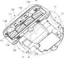
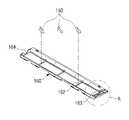
도 1은 본 발명의 일 실시 예에 따른 흡입노즐장치의 평면 사시도이다.
도 2는 본 발명의 일 실시 예에 따른 흡입노즐장치의 배면 사시도이다.
도 3은 본 발명의 일 실시 예에 따른 흡입노즐장치의 분해도이다.
도 4는 본 발명의 일 실시 예에 따른 흡입노즐장치의 측면도이다.
도 5는 도 4에 표시된 Ⅴ-Ⅴ선을 따라 나타낸 드럼 브러시의 단면도이다.
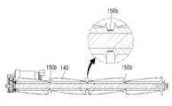
도 6은 도 5에 도시된 그라인더의 Ⅵ 부분을 나타내는 부분확대도이다.
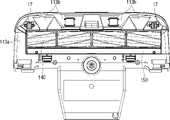
도 7은 본 발명의 일 실시 예에 따른 흡입노즐장치의 배면도이다.
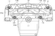
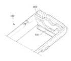
도 8은 도 7에서 드럼 브러시를 제거한 상태를 보여주는 케이싱의 배면도이다.
도 9는 본 발명의 다른 실시 예에 따른 히터가 장착된 드럼 브러시의 단면도이다.
도 10은 본 발명의 또 다른 실시 예에 따른 터빈이 장착된 드럼 브러시의 단면도이다.
도 11은 본 발명의 또 다른 실시 예에 따른 링 형상의 열선 코일이 장착된 드럼 브러시의 단면도이다.
도 12는 본 발명의 또 다른 실시 예에 따른 리브 상에 그라인더가 설치된 베이스 브러시를 도시한 도면이다.
도 13 및 도 14는 도 3에 도시된 베이스 브러시의 또 다른 실시 예로서, 저부 및 상부를 각각 나타내는 부분 확대 사시도들이다.1 is a plan perspective view of a suction nozzle device according to an embodiment of the present invention.
2 is a rear perspective view of a suction nozzle device according to an embodiment of the present invention.
3 is an exploded view of a suction nozzle device according to an embodiment of the present invention.
4 is a side view of a suction nozzle device according to an embodiment of the present invention.
5 is a cross-sectional view of the drum brush taken along the line V-V shown in FIG. 4 .
FIG. 6 is a partially enlarged view showing a portion VI of the grinder shown in FIG. 5 .
7 is a rear view of the suction nozzle device according to an embodiment of the present invention.
8 is a rear view of the casing showing a state in which the drum brush is removed in FIG. 7 .
9 is a cross-sectional view of a drum brush equipped with a heater according to another embodiment of the present invention.
10 is a cross-sectional view of a drum brush mounted with a turbine according to another embodiment of the present invention.
11 is a cross-sectional view of a drum brush equipped with a ring-shaped hot wire coil according to another embodiment of the present invention.
12 is a view illustrating a base brush in which a grinder is installed on a rib according to another embodiment of the present invention.
13 and 14 are partially enlarged perspective views respectively illustrating a bottom and an upper part of the base brush shown in FIG. 3 according to another embodiment.
이하, 첨부된 도면을 참조하여 본 문서에서는 이물질의 걸림이 해소되는 청소기용 흡입노즐장치의 실시예에 대하여 상세하게 설명한다. 이하에서 설명되는 실시 예들은 개시의 이해를 돕기 위하여 흡입노즐장치가 로봇 청소기에 적용되는 것으로 설명하지만 이는 예시적인 것으로, 여기서 설명되는 실시 예와 다르게 캐니스터 타입 진공 청소기, 업라이트 타입 진공 청소기, 스틱 타입 진공 청소기 등 다양하게 변형되어 실시될 수 있음이 이해되어야 할 것이다. 다만, 이하에서 본 발명을을 설명함에 있어, 관련된 공지 기능 혹은 구성요소에 대한 구체적인 설명이 본 발명의 요지를 불필요하게 흐릴 수 있다고 판단되는 경우 그 상세한 설명 및 구체적인 도시를 생략한다.Hereinafter, with reference to the accompanying drawings, this document will be described in detail with respect to an embodiment of the suction nozzle device for a cleaner in which the jamming of foreign substances is eliminated. Although the embodiments described below describe that the suction nozzle device is applied to a robot cleaner to help the understanding of the disclosure, this is exemplary, and unlike the embodiments described herein, a canister-type vacuum cleaner, an upright-type vacuum cleaner, and a stick-type vacuum It should be understood that various modifications, such as a cleaner, may be implemented. However, in the following description of the present invention, if it is determined that a detailed description of a related well-known function or component may unnecessarily obscure the gist of the present invention, the detailed description and specific illustration thereof will be omitted.
도 1 내지 도 3은 본 발명의 일 실시 예에 따른 흡입노즐장치를 나타내는 평면 사시도, 배면 사시도 및 분해 사시도이고, 도 4는 본 발명의 일 실시 예에 따른 흡입노즐장치의 측면도이다.1 to 3 are a plan perspective view, a rear perspective view, and an exploded perspective view showing a suction nozzle device according to an embodiment of the present invention, and FIG. 4 is a side view of the suction nozzle device according to an embodiment of the present invention.
도 1 내지 도 3을 참조하여 설명하면, 본 발명의 일 실시 예에 따른 흡입노즐장치(100)는 로봇 청소기(10)의 본체(11)에 설치될 수 있다. 이 경우 로봇 청소기(10)는 본체(11) 내에 도시하지 않은 흡입원의 역할을 하는 흡입모터와 집진부를 구비할 수 있다. 흡입모터는 피청소면의 오물을 흡입하기 위한 소정의 흡입력을 발생하며, 집진부는 흡입력에 의해 흡입노즐장치(100)을 통해 본체(11) 내로 흡입되는 오물을 수거할 수 있다. 집진부는 원심력을 이용하여 흡입된 공기로부터 오물을 분리하는 사이클론 구조를 포함할 수 있다.1 to 3 , the
본체(11)는 한 쌍의 주행휠(12)과 한 쌍의 주행휠(12)을 구동하기 위한 구동모터(미도시)를 포함할 수 있다. 로봇 청소기(10)는 주행휠(12) 외에 후술하는 하부 케이싱(113)의 저부에 구비되는 제1 아이들 휠(15)과, 한 쌍의 제2 아이들 휠(17)을 포함할 수 있다. 제1 아이들 휠(15)은 하부 케이싱(113)의 후방 중앙에 배치되며, 한 쌍의 제2 아이들 휠(17)은 하부 케이싱(113)의 전방 양측에 각각 배치될 수 있다.The
도 3을 참조하면, 흡입노즐장치(100)는 케이싱(110)과, 케이싱(110) 내에 각각 배치되는 구동부(120)와, 드럼 브러시(140), 커팅부재 및 베이스 브러시(160)를 포함할 수 있다.Referring to FIG. 3 , the
케이싱(110)은 제조 편의상 상부 케이싱(111)과 하부 케이싱(113)으로 각각 제작되어 조립될 수 있다. 하지만 이에 한정되지 않고 상부 및 하부 케이싱(111, 113)이 단일 부재로 제작되는 것도 물론 가능하다.The
하부 케이싱(113)은 바닥을 향하는 부분에 드럼 브러시(140)가 회전 가능하게 장착될 수 있는 장착홈(112)이 형성될 수 있다. 장착홈(112)은 드럼 브러시(140)를 감쌀 수 있도록 장착홈(112)의 상부가 대략 드럼 브러시(140)의 형상에 대응하도록 소정 높이로 융기된 구조(도 3 참조)를 이룰 수 있다.The
도 4를 참조하면, 장착홈(112)은 내측 후방으로 흡입유로(114)와 연통되는 흡입구(112a)가 형성될 수 있다. 흡입구(112a)는 장착홈(112)을 흡입유로(114)와 연결해주며, 흡입유로(114) 상에 부압 형성 시 장착홈(112) 내에도 부압이 형성되어 피청소면의 이물질을 흡입할 수 있다.Referring to FIG. 4 , the
다시 도 2를 참조하면, 하부 케이싱(113)은 저면(113a)의 전방을 따라 이물질을 장착홈(112) 내로 흡입할 수 있도록 복수의 흡입홈(113b)이 형성될 수 있다. 이 경우, 하부 케이싱(113)이 마루 바닥과 같은 피청소면에 안착될 때, 한 쌍의 제2 아이들 휠(17)에 의해 하부 케이싱(113)의 저면(113a)과 피청소면 사이에 소정의 간극이 형성될 수 있다. 이에 따라 피청소면의 이물질은 복수의 흡입홈(113b)을 통해서 뿐만 아니라, 하부 케이싱(113)의 저면(113a)과 피청소면 사이의 간극을 통해서 장착홈(112)으로 흡입될 수 있다.Referring back to FIG. 2 , the
구동부(120)는 드럼 브러시(140)를 회전 구동하기 위한 동력원으로서, 케이싱(110) 내에 배치될 수 있다. 구동부(120)는 모터로 이루어질 수 있으며 후술하는 커플러(145)를 통해 드럼 브러시(140)로 회전력을 전달하여 드럼 브러시(140)를 회전시키는 동력을 제공한다.The
한편, 로봇 청소기(10)는 흡입모터에 의해 흡입유로에 부압이 형성되면 장착홈(112)과 장착홈(112)의 외측 주변과의 압력 차에 의한 공기의 흐름을 유도하여 피청소면의 이물질(먼지, 오물 등)을 흡입한다. 통상적으로 카펫(미도시)과 같은 소재에 이물질이 부착되는 경우에, 공기의 흡입만으로는 카펫의 내부에 깊이 부착된 이물질을 흡입하기가 어렵다. 따라서 드럼 브러시(140)는 카펫의 다수의 모(毛) 사이에 깊숙이 부착된 이물질을 털어줌으로써 이물질을 카펫 상부로 비산시키고, 이렇게 비산된 이물질은 장착홈(112) 내의 흡입구(112a)로 흡입된다.On the other hand, the
도 5는 도 4에 표시된 Ⅴ-Ⅴ선을 따라 나타낸 단면도이고, 도 6은 도 5에 도시된 그라인더의 Ⅵ 부분을 나타내는 부분확대도이다.FIG. 5 is a cross-sectional view taken along line V-V shown in FIG. 4 , and FIG. 6 is a partially enlarged view showing part VI of the grinder shown in FIG. 5 .
도 5를 참조하면, 드럼 브러시(140)는 드럼 코어(141)와, 드럼 코어(141) 외주에 나선 방향으로 결합되는 복수의 러버 블레이드(143)와, 커플러(145) 그리고 베어링(147)을 포함할 수 있다. 5, the
드럼 코어(141)는 드럼 브러시(140)의 회전 중심축을 이루며, 러버 블레이드(143)를 지지한다. 드럼 코어(141)는 외주에 소정 간격을 두고 복수의 이물질 수거홈(142)이 형성되며, 이 경우 복수의 이물질 수거홈(142)은 드럼 브러시(140)의 원주 방향을 따라 형성될 수 있다.The
각 복수의 이물질 수거홈(142)에는 커팅 부재가 대응 배치되며, 각 복수의 이물질 수거홈(142)과 커팅 부재 사이에는 이물질(특히, 머리카락이나 동물의 털)이 쌓이는 틈새(133)가 형성된다.A cutting member is disposed correspondingly to each of the plurality of foreign
복수의 틈새(133)에는 드럼 브러시(140)와 함께 회전하는 머리카락 등의 이물질이 복수의 러버 블레이드(143)에 감기면서 점차 드럼 브러시(140)에 형성된 틈새(133) 측으로 이동하게 되고, 복수의 이물질 수거홈(142)에 감김으로써 틈새(133)에 쌓이게 된다.In the plurality of
도 6을 참조하면, 복수의 이물질 수거홈(142)은 외측으로부터 내측으로 갈수록 점차 좁아지도록 형성되는 경사면(142')을 구비할 수 있다. 이러한 경사면(142')은 머리카락(144)이 복수의 이물질 수거홈(142)의 중앙부터 감길 수 있도록 가이드 할 수 있다. 상기 이물질 수거홈(142)에 머리카락(144)이 감겨질 경우, 드럼 코어의 이물질 수거홈과 머리카락(144) 사이에 마찰력이 발생한다. 이러한 마찰력에 의해 머리카락(144)이 헛돌지 않고 드럼 코어에 감겨진다. 따라서 머리카락을 드럼 코어의 이물질 수거홈에 헛돌지 않고 원활히 감겨지도록 하기 위해, 바람직하게는 드럼 코어 이물질 수거홈의 재질을 머리카락을 지지하기에 충분한 마찰력을 발생시키는 재료로 선정할 필요가 있다.Referring to FIG. 6 , the plurality of foreign
이와 같은 복수의 이물질 수거홈(142)의 개수나 깊이, 틈새(133)의 개수나 각 틈새(133) 사이의 간격은 설계상 다양한 변경이 가능하다.The number and depth of the plurality of foreign
러버 블레이드(143)는 카펫과 같이 이물질이 깊숙히 부착된 청소 대상을 타격하여 이물질을 비산시키는 역할을 한다. 러버 블레이드(143)의 개수는 상세 설계의 범주에서 다양한 변형 실시가 가능하다.The
러버 블레이드(143)는 홈이 형성되지 않은 시트(sheet) 형상으로 형성될 수 있다. 만약 러버 블레이드(143)에 홈이 있으면 러버 블레이드(143)에 머리카락과 같은 이물질이 감기는 경우 상기 홈에 머리카락이 끼이게 된다. 결과적으로 홈에 누적하여 감겨진 머리카락은 드럼 브러시(140)의 회전을 저해하게 되고, 결국 드럼 브러시(140)의 작동을 불가능하게 한다. 이러한 드럼 브러시(140)의 단점을 개선하기 위해, 본 실시 예에서는 러버 블레이드(143)를 홈이 형성되지 않은 시트 형상으로 형성하여 이물질이 끼일 수 없는 구조를 취하였다. 또한 러버 블레이드(143)는 얇고 상대적으로 넓은 면적의 시트 형상으로 형성하여 카펫과 같은 구조물에 효과적으로 타격을 가할 수 있도록 하였다.The
러버 블레이드(143)의 일단은 드럼 코어(141)의 표면 상에 나선형으로 형성된다. 이에 따라 머리카락 같은 이물질은 회전하는 러버 블레이드(143)에 감기는 동시에 나선형으로 형성된 러버 블레이드(143)에 의해 드럼 코어(141)의 길이 방향으로 이동한다. 러버 블레이드(143)에 감겨 이동하는 이물질은 드럼 코어(141)와 커팅 부재의 선단 사이에 형성된 틈새(133)로 도달하여 복수의 이물질 수거홈(142)에 감기게 되며, 각 이물질 수거홈(142)에 대응하도록 배치된 커팅 부재에 의해 연마됨에 따라 잘게 커팅된다.One end of the
상기 복수의 러버 블레이드는 상기 이물질 수거홈의 양측으로 배치되는 적어도 2개의 그룹으로 이루어지며, 각 러버 블레이드 그룹은 이물질을 상기 이물질 수거홈으로 이동시키기 위해 나선 방향이 서로 반대 방향으로 형성될 수 있다.The plurality of rubber blades may consist of at least two groups disposed on both sides of the foreign material collecting groove, and each rubber blade group may be formed in a spiral direction opposite to each other in order to move the foreign material to the foreign material collecting groove.
상기 러버 블레이드(143)를 드럼 코어에 결합하는 방법에 있어서 다양한 실시 예가 가능하다. 우선 드럼 코어의 외주면 상에 나선형 이물질 수거홈을 형성하고, 상기 나선형 이물질 수거홈에 시트 형상의 러버 블레이드(143)를 끼움 결합할 수 있다. 한편, 시트 형상으로 제조된 러버 블레이드(143)를 드럼 코어의 외주면 상에 가열 압착하여 고정할 수도 있다.Various embodiments are possible in a method of coupling the
러버 블레이드(143)를 드럼 코어에 복수개 형성할 경우에는 제조 효율을 위해 러버 블레이드 어셈블리(149)를 제작할 수 있다. 러버 블레이드 어셈블리를 사출성형을 통해 제작하고, 이를 드럼 코어의 외주면 상에 드럼 코어의 길이 방향을 따라 씌워서 조립할 수 있다. 커플러(145)는 드럼 코어(141) 일측에 결합된다. 커플러(145)는 구동부(120) 의 회전력을 드럼 코어(141)에 전달한다.When a plurality of
베어링(147)은 드럼 코어(141)의 타측에 결합되며, 드럼 코어(141)가 장착홈(112) 내에 돌출된 지지돌기(미도시)에 의해 회전 가능하게 지지될 수 있다.The
드럼 브러시(140)는 구동부(120)에 의해 회전력을 전달받는다. 구동부(120)로 모터(121)를 이용하는 경우, 정확한 속도제어가 가능하며 친환경적이다.The
한편, 산업 현장에서 진공청소기를 사용하는 경우에 공기압축기(미도시) 로부터 고압의 압축공기를 제공받아 드럼 브러시(140)에 회전력을 전달할 수 있다. 도 10은 본 발명에 따른 터빈(123)이 장착된 드럼 브러시(140)의 단면도이다. 드럼 브러시(140)의 양단에는 소형 터빈(123)이 장착된다. 공기 압축기로부터 제공된 고압의 압축 공기가 터빈(123)의 날개에 충돌하여, 드럼 브러시(140)에 회전력을 전달한다.Meanwhile, in the case of using a vacuum cleaner in an industrial field, it is possible to receive high-pressure compressed air from an air compressor (not shown) and transmit rotational force to the
소형 터빈(123)은 도 9에 도시된 모터(121)를 대체하여 모터가 설치된 위치에 장착될 수도 있다. 이 때 소형 터빈(123)의 회전력은 커플러 내부에 장착된 벨트(미도시)를 통해 드럼 브러시(140)에 전달된다.The
본 발명에 따른 진공청소기용 흡입노즐장치(100)는 드럼 브러시(140)의 틈새(133)에 쌓여진 이물질을 절단하는 커팅 부재를 제공한다. 상기 커팅 부재를 통해 절단된 이물질은 케이싱(110)의 일측에 형성된 흡입구(112a)를 통해 흡입된다. 따라서 털실이나 머리카락과 같이 길이가 길어 드럼 브러시(140)의 회전을 저해하는 이물질이 쌓이더라도 커팅 부재에 의해 절단되어 흡입구(112a)로 흡입되므로, 드럼 브러시(140)의 원활한 작동이 가능하다. 결과적으로 카펫같은 재질의 내부에 깊숙이 부착된 이물질도 청소가 가능하다.The
본 발명에 따른 러버 블레이드(143)의 일단은 드럼 코어의 표면 상에 나선형으로 형성된다. 드럼 코어의 표면 상에 나선형으로 형성된 러버 블레이드(143)가 회전하면서 머리카락 같은 이물질이 감기는 동시에 드럼 코어의 길이 방향으로 이동된다. 결국 드럼 코어에 감긴 이물질은 드럼 코어에 형성된 틈새(133)로 도달하게 되며, 틈새(133) 근방에 형성된 커팅 부재에 의해 절단된다.One end of the
러버 블레이드(143)에 감겨진 이물질을 드럼 코어에 형성된 틈새(133)로 보다 효과적으로 이동시키기 위해, 드럼 브러시(140)를 감싸는 하부 케이싱(113)의 표면에 나선 방향으로 돌기(115)를 형성할 수 있다. 이렇게 형성된 돌기(115)는 러버 블레이드(143)를 지지하며 드럼 코어에 형성된 틈새(133)로 가이드하는 역할을 한다. 도 8은 본 발명에 따른 하부 케이싱의 배면도이다. 도 8에는 나선 방향으로 형성된 돌기(115)가 개시되어 있다.In order to more effectively move the foreign material wound around the
틈새(133)로 모아진 이물질을 절단하는 커팅 부재로 다양한 수단이 강구될 수 있으나, 본 발명에서는 연마와 가열에 의한 절단방법을 채택하였다.Various means may be used as a cutting member for cutting foreign substances collected in the
이물질을 연마에 의해 절단하기 위해 그라인더(150)가 형성된다. 상기 그라인더(150)는 드럼 브러시(140)를 감싸는 하부 케이싱(113)의 표면에서 상기 틈새(133)와 마주보는 위치에 형성된다.A
그라인더(150)는 연마석으로 형성하거나, 표면만을 다이아몬드 코팅 처리하여 형성할 수도 있으며, 전조(轉造) 가공을 통해 표면에 연마용 줄눈을 형성할 수도 있다.The
도 3 및 도 5를 참조하면, 그라인더(150)가 드럼 코어(141)의 중앙에 3개, 양단에 2개가 배치된다. 특히 드럼 코어(141)의 양단에 배치된 2개의 그라인더(150)는 드럼 브러시(140)의 양측으로 유입되는 이물질을 절단한다.Referring to FIGS. 3 and 5 , three
도 6을 참조하면, 이물질이 쌓이는 틈새(133)는 양측의 러버 블레이드(143)와 드럼 코어 상에 형성된 이물질 수거홈(142)에 의해 형성된다. 하부 케이싱(113)의 표면에서 상기 틈새(133)와 마주보는 위치에 형성된 그라인더(150)와 드럼 코어 (141)상의 이물질 수거홈 사이에는 간극이 형성된다. 이 간극에 머리카락 같은 이물질이 누적적으로 쌓이다가 이물질의 양이 일정량 이상이 되면 그라인더(150)의 면과의 마찰에 의해 이물질이 절단된다.Referring to FIG. 6 , the
상기 간극이 너무 좁게 형성되면 그라인더(150)와 드럼 코어(141)의 진동에 의하여 간섭이 발생될 수 있다. 따라서 상기 간극은 1.5mm 이상으로 형성하는 것이 바람직하다.If the gap is formed too narrow, interference may occur due to vibration of the
도 6은 본 발명에 따른 그라인더의 부분확대도이다. 도 6을 참조하면, 그라인더(150)의 단면의 형상은 "V”형상으로 형성된다. 그라인더(150)와 드럼 코어 상에 형성된 이물질 수거홈(142) 사이의 간극은 상기 이물질 수거홈의 중앙으로 갈수록 좁아진다. 드럼 코어의 이물질 수거홈(142)은 중앙부가 오목한 형상을 이루고 있으므로, 머리카락이 드럼 코어의 이물질 수거홈(142)에 감겨질 경우, 머리카락은 이물질 수거홈(142)의 중앙으로 모아지면서 감겨지게 된다. 그리고 간극이 이물질 수거홈(142)의 중앙에서 가장 좁은 구조를 이루고 있으므로, 머리카락이 이물질 수거홈의 중앙부에 형성된 간극 이상이 되면, 이물질 수거홈(142)에 감긴 머리카락은 상기 이물질 수거홈의 중앙부에 끼여 고정되면서 그라인더(150)와의 마찰에 의해 절단된다. 6 is a partially enlarged view of a grinder according to the present invention. 6, the cross-section of the
도 9는 본 발명에 따른 히터(150a)가 장착된 드럼 브러시(140)의 단면도이다. 커팅 부재로 히터(150a)를 채택하여 이물질을 가열에 의해 절단할 수 있다. 도 9를 참조하면, 히터(150a)는 상기 틈새(133)를 감싸는 케이싱(110)의 표면에 형성된다. 히터(150a)와 드럼 코어 상에 형성된 이물질 수거홈(142)사이에 쌓여진 이물질이 누적적으로 쌓이다가 일정량 이상으로 이물질이 쌓이게 되면 이물질은 가열된 히터(150a)와 접촉하면서 절단된다.9 is a cross-sectional view of the
히터(150a)를 커팅 부재로 사용하기 위해 적절한 제어가 요구된다. 이물질의 절단을 위해 히터(150a)에 전류가 흐르는 시간을 제어할 수 있다. 또한 과열로 인한 화재 방지를 위해 과열감지센서를 장착하고, 과열 감지시 전원이 차단되도록 제어할 수 있다.Appropriate control is required to use the
도 11은 링 형상의 열선 코일(150b)이 장착된 드럼 코어를 도시한 도면이다. 도 11을 참조하면, 커팅 부재로서 드럼 코어 상에 형성된 이물질 수거홈에 링 형상의 열선 코일(150b)을 장착할 수 있다. 드럼 코어 상에 형성된 이물질 수거홈에 링 형상의 홈을 형성하고, 링 형상의 열선 코일(150b)을 각 홈마다 장착한 후, 전류를 흐르게 하여 이물질을 절단할 수 있다.11 is a diagram illustrating a drum core to which a ring-shaped
도 3은 베이스 브러시의 일 실시 예를 나타낸다. 도 3을 참조하면, 본 발명의 흡입노즐장치(100)는 드럼 브러시(140)의 하부를 덮는 베이스 브러시(160)를 더 포함할 수 있다. 베이스 브러시는 청소 중 바닥에 산재해 있는 전선의 인입을 방지하는 리브(162), 드럼 코어와 결합되는 홀(164), 그라인더 삽입부(163)를 포함할 수 있다.3 shows an embodiment of a base brush. Referring to FIG. 3 , the
앞서 지적한 바와 같이, 그라인더(150)는 하부 케이싱(113)의 표면에 형성되나, 베이스 브러시의 단부에도 형성하여, 베이스 브러시(150) 단부 근방의 이물질을 효과적으로 절단할 수 있다. 이를 위해 베이스 브러시의 단부에는 그라인더(150)가 삽입되는 그라인더 삽입부(163)를 형성하고, 상기 그라인더 삽입부(163)에 그라인더(150)를 설치할 수 있다.As pointed out above, the
도 12는 베이스 브러시의 리브(162) 상에 그라인더가 설치된 다른 실시예를 도시한 도면이다. 그라인더는 전선의 인입 방지를 위한 리브 상에 설치하여 드럼 코어의 이물질 수거홈 상에 끼여진 이물질을 효율적으로 절단할 수 있다.12 is a view showing another embodiment in which the grinder is installed on the
도 13은 도 3의 A 부분에 대한 부분 확대도로서, 사이드 덮개(161')를 구비한 베이스 브러시의 다른 실시예를 도시한 도면이고, 도 14는 도 3의 A 부분에 대한 부분 확대도로서, 그라인더 삽입부(163')를 도시한 도면이다.13 is a partial enlarged view of part A of FIG. 3, showing another embodiment of a base brush having a
도 13 및 도 14를 참조하여 설명하면, 상기 베이스 브러시의 단부에는 상기 베이스 브러시의 길이 방향을 따라 연장된 사이드 덮개(161')가 형성된다. 베이스 브러시의 단부에 사이드 덮개가 없을 경우, 머리카락 같은 이물질이 베이스 브러시 양단의 벽을 타고 넘어와서 베이스 브러시의 체결부에 끼이게 된다. 이를 방지하기 위해 베이스 브러시에 사이드 덮개(161')를 베이스 브러시의 길이방향을 따라 연장하여 형성하므로써, 베이스 브러시(150) 단부 근방에 이물질의 끼임을 방지할 수 있다. 베이스 브러시가 드럼 브러시와 결합할 경우, 드럼 브러시에 결합된 러버 블레이드의 팁부분(143', 도 3 참조)은 접촉하는 베이스 브러시의 사이드 덮개(161')에 눌려지면서 드럼 브러시의 양단부를 통해 유입되는 이물질을 효과적으로 차단한다.Referring to FIGS. 13 and 14 , a
이상에서는 본 발명의 바람직한 실시예에 대하여 도시하고 설명하였지만, 본 발명은 상술한 특정의 실시예에 한정되지 아니하며, 청구범위에서 청구하는 본 발명의 요지를 벗어남이 없이 당해 발명이 속하는 기술분야에서 통상의 지식을 가진 자에 의해 다양한 변형실시가 가능한 것은 물론이고, 이러한 변형 실시 예들은 본 발명의 기술적 사상이나 전망으로부터 개별적으로 이해되어서는 안 될 것이다.In the above, preferred embodiments of the present invention have been illustrated and described, but the present invention is not limited to the specific embodiments described above, and it is common in the technical field to which the present invention pertains without departing from the gist of the present invention as claimed in the claims. Various modifications may be made by those having the knowledge of, of course, and these modified embodiments should not be individually understood from the technical spirit or perspective of the present invention.
100: 흡입노즐장치110: 케이싱
120: 구동부140: 드럼 브러시
141: 드럼코어142: 이물질 수거홈
143: 러버 블레이드144: 머리카락
145: 커플러147: 베어링
148: 러버 블레이드 어셈블리 베이스150: 그라인더
153: 틈새160, 160': 베이스 브러시
162: 리브164: 홀100: suction nozzle device 110: casing
120: driving unit 140: drum brush
141: drum core 142: foreign matter collecting groove
143: rubber blade 144: hair
145: coupler 147: bearing
148: rubber blade assembly base 150: grinder
153:
162: rib 164: hole
Claims (19)
Translated fromKorean상기 케이싱의 장착홈에 회전 가능하게 결합된 드럼 브러시; 및
상기 드럼 브러시에 감긴 이물질을 제거하기 위한 커팅부재;를 포함하여 구성되고,
상기 드럼 브러시는,
외주에 이물질이 감기는 적어도 하나의 이물질 수거홈이 형성되는 드럼 코어; 및
상기 드럼 코어의 외주에 나선형으로 형성되는 블레이드;를 포함하고,
상기 커팅 부재는, 상기 이물질 수거홈에 대응되는 위치에 고정되는 흡입노즐장치.a casing having a mounting groove formed on its bottom surface;
a drum brush rotatably coupled to the mounting groove of the casing; and
and a cutting member for removing foreign substances wound around the drum brush;
The drum brush,
a drum core having at least one foreign material collecting groove formed around the outer periphery of which foreign materials are wound; and
Including; blades spirally formed on the outer periphery of the drum core;
The cutting member is a suction nozzle device fixed to a position corresponding to the foreign material collecting groove.
상기 커팅부재는 상기 이물질 수거홈과 함께 미리 설정된 간격으로 틈새를 이루도록 상기 이물질 수거홈에 대응하는 위치에 배치되는 흡입노즐장치.According to claim 1,
The cutting member is a suction nozzle device disposed at a position corresponding to the foreign material collecting groove to form a gap with the foreign material collecting groove at a preset interval.
상기 블레이드는 복수 개로 형성되며, 상기 이물질 수거홈의 양측으로 배치되는 적어도 2개의 그룹으로 이루어지며,
각 블레이드 그룹은 이물질을 상기 이물질 수거홈으로 이동시키기 위해 나선 방향이 서로 반대 방향인 흡입노즐장치.3. The method of claim 2,
The blade is formed in plurality, and consists of at least two groups disposed on both sides of the foreign material collecting groove,
Each blade group has a suction nozzle device whose spiral direction is opposite to each other in order to move the foreign material to the foreign material collecting groove.
상기 커팅부재는 상기 장착홈 내에 설치되는 것을 특징으로 하는 흡입노즐장치.3. The method of claim 2,
The cutting member is a suction nozzle device, characterized in that installed in the mounting groove.
상기 커팅부재는 상기 이물질 수거홈에 끼이거나 감긴 이물질을 마찰력에 의해 절단하는 그라인더인 흡입노즐장치.3. The method of claim 2,
The cutting member is a suction nozzle device that is a grinder that cuts the foreign material caught or wound in the foreign material collecting groove by frictional force.
상기 드럼 코어의 이물질 수거홈은 드럼 브러시의 원주 방향으로 형성되고 외측에서 내측으로 갈수록 점차 좁아지는 흡입노즐장치.6. The method of claim 5,
A suction nozzle device in which the foreign material collecting groove of the drum core is formed in the circumferential direction of the drum brush and gradually narrows from the outside to the inside.
상기 그라인더와 상기 이물질 수거홈 사이의 간극은 상기 이물질 수거홈의 중앙으로 갈수록 좁아지는 흡입노즐장치.7. The method of claim 6,
A gap between the grinder and the foreign material collecting groove is narrower toward the center of the foreign material collecting groove.
상기 그라인더는 연마석으로 형성되거나, 표면이 다이아몬드 코팅 처리되거나, 또는 전조(轉造) 가공을 통해 표면에 연마용 줄눈이 형성되는 흡입노즐장치.6. The method of claim 5,
The grinder is a suction nozzle device that is formed of abrasive stone, the surface is diamond-coated, or a grinding joint is formed on the surface through rolling processing.
상기 케이싱의 저부에 분리 가능하게 설치되어 상기 장착홈으로 전선 유입을 방지하기 위한 적어도 하나의 리브를 구비한 베이스 브러시를 더 포함하며,
상기 커팅 부재는 상기 베이스 브러시에 설치되는 흡입노즐장치.3. The method of claim 2,
Further comprising a base brush that is detachably installed at the bottom of the casing and has at least one rib for preventing the inflow of electric wires into the mounting groove,
The cutting member is a suction nozzle device installed on the base brush.
상기 리브는 상기 이물질 수거홈에 대응하는 위치에 형성되는 것을 흡입노즐장치.10. The method of claim 9,
The rib is a suction nozzle device that is formed at a position corresponding to the foreign material collecting groove.
상기 케이싱의 저부에 분리 가능하게 설치되는 베이스 브러시를 더 포함하며,
상기 베이스 브러시는 상기 드럼 브러시의 양단부 중 적어도 어느 한 곳을 커버하는 적어도 하나의 사이드 덮개를 더 포함하는 것을 흡입노즐장치.3. The method of claim 2,
Further comprising a base brush that is detachably installed at the bottom of the casing,
The base brush may further include at least one side cover covering at least one of both ends of the drum brush.
상기 커팅 부재는 발열체인 흡입노즐장치.According to claim 1,
The cutting member is a heating element suction nozzle device.
상기 발열체는 상기 이물질 수거홈과 함께 틈새를 형성하도록 상기 이물질 수거홈과 이격 배치되는 흡입노즐장치.13. The method of claim 12,
The heating element is a suction nozzle device spaced apart from the foreign material collecting groove to form a gap together with the foreign material collecting groove.
상기 발열체는 상기 이물질 수거홈에 권취되는 것을 흡입노즐장치.13. The method of claim 12,
The heating element is a suction nozzle device that is wound in the foreign material collecting groove.
상기 발열체는 열선인 흡입노즐장치.15. The method of claim 14,
The heating element is a hot wire suction nozzle device.
상기 장착홈에 회전 가능하게 설치된 복수의 러버 블레이드를 구비하고, 이물질을 수거하기 위한 적어도 하나의 이물질 수거홈이 형성된 드럼 브러시; 및
상기 이물질 수거홈에 대응하는 위치에 고정되어 상기 이물질 수거홈에 감긴 이물질을 제거하는 커팅 부재;를 포함하는, 흡입노즐장치.a casing having a suction flow path inside it and having a mounting groove formed on a bottom surface thereof to communicate with the suction flow path;
a drum brush having a plurality of rubber blades rotatably installed in the mounting groove and having at least one foreign material collecting groove formed therein; and
and a cutting member fixed at a position corresponding to the foreign material collecting groove to remove the foreign material wound around the foreign material collecting groove.
상기 커팅 부재는 상기 이물질 수거홈과 간극을 유지하고, 마찰력에 의해 상기 이물질 수거홈에 수거된 이물질을 커팅하는 흡입노즐장치.17. The method of claim 16,
The cutting member maintains a gap with the foreign material collecting groove, and a suction nozzle device for cutting the foreign material collected in the foreign material collecting groove by frictional force.
상기 커팅 부재는 발열에 의해 상기 이물질 수거홈에 수거된 이물질을 태우는 흡입노즐장치.17. The method of claim 16,
The cutting member is a suction nozzle device for burning the foreign material collected in the foreign material collecting groove by heat generation.
내측에 상기 본체와 연결된 흡입 유로를 가지는 흡입노즐장치;를 포함하며,
상기 흡입노즐장치는,
이물질을 수거하기 위한 적어도 하나의 이물질 수거홈과, 이물질을 상기 이물질 수거홈으로 이동시키기 위해 나선형으로 결합된 복수의 러버 블레이드를 포함하는 드럼 브러시; 및
상기 이물질 수거홈에 감긴 이물질을 마찰력 또는 열로써 제거하기 위한 커팅 부재;를 포함하고,
상기 커팅 부재는, 상기 이물질 수거홈에 대응되는 위치에 고정되는 청소기.a body including a suction source providing suction force and a dust collecting unit for collecting foreign substances; and
It includes; a suction nozzle device having a suction passage connected to the body on the inside;
The suction nozzle device,
a drum brush comprising at least one foreign material collecting groove for collecting foreign substances, and a plurality of rubber blades spirally coupled to move the foreign substances into the foreign material collecting groove; and
and a cutting member for removing the foreign material wound around the foreign material collecting groove by friction or heat.
The cutting member is fixed to a position corresponding to the foreign material collecting groove.
Priority Applications (2)
| Application Number | Priority Date | Filing Date | Title |
|---|---|---|---|
| KR1020160037629AKR102426086B1 (en) | 2016-03-29 | 2016-03-29 | Suction nozzle apparatus and cleaner having the same |
| US15/467,144US10251520B2 (en) | 2016-03-29 | 2017-03-23 | Suction nozzle apparatus and cleaner having the same |
Applications Claiming Priority (1)
| Application Number | Priority Date | Filing Date | Title |
|---|---|---|---|
| KR1020160037629AKR102426086B1 (en) | 2016-03-29 | 2016-03-29 | Suction nozzle apparatus and cleaner having the same |
Publications (2)
| Publication Number | Publication Date |
|---|---|
| KR20170111688A KR20170111688A (en) | 2017-10-12 |
| KR102426086B1true KR102426086B1 (en) | 2022-07-28 |
Family
ID=59959046
Family Applications (1)
| Application Number | Title | Priority Date | Filing Date |
|---|---|---|---|
| KR1020160037629AActiveKR102426086B1 (en) | 2016-03-29 | 2016-03-29 | Suction nozzle apparatus and cleaner having the same |
Country Status (2)
| Country | Link |
|---|---|
| US (1) | US10251520B2 (en) |
| KR (1) | KR102426086B1 (en) |
Families Citing this family (28)
| Publication number | Priority date | Publication date | Assignee | Title |
|---|---|---|---|---|
| US11992172B2 (en) | 2018-10-19 | 2024-05-28 | Sharkninja Operating Llc | Agitator for a surface treatment apparatus and a surface treatment apparatus having the same |
| US11647881B2 (en) | 2015-10-21 | 2023-05-16 | Sharkninja Operating Llc | Cleaning apparatus with combing unit for removing debris from cleaning roller |
| WO2017070492A1 (en) | 2015-10-21 | 2017-04-27 | Sharkninja Operating Llc | Surface cleaning head with dual rotating agitators |
| WO2018049169A1 (en) | 2016-09-09 | 2018-03-15 | Sharkninja Operating Llc | Agitator with hair removal |
| KR102665907B1 (en)* | 2017-01-03 | 2024-05-20 | 삼성전자주식회사 | Vacummer cleaner |
| CN114403741B (en) | 2017-03-10 | 2024-02-27 | 尚科宁家运营有限公司 | Agitator with a hair remover and hair removal |
| US11202542B2 (en) | 2017-05-25 | 2021-12-21 | Sharkninja Operating Llc | Robotic cleaner with dual cleaning rollers |
| EP3629866B1 (en) | 2017-05-26 | 2022-01-19 | SharkNinja Operating LLC | Hair cutting brushroll |
| CN111787836B (en) | 2017-12-27 | 2022-10-14 | 尚科宁家运营有限公司 | End cap assembly |
| US11672393B2 (en) | 2017-12-27 | 2023-06-13 | Sharkninja Operating Llc | Cleaning apparatus with selectable combing unit for removing debris from cleaning roller |
| KR102546702B1 (en)* | 2018-08-09 | 2023-06-22 | 삼성전자주식회사 | A vaccum cleaner |
| CN116158688A (en)* | 2018-10-19 | 2023-05-26 | 尚科宁家运营有限公司 | Vacuum cleaner and agitator for a vacuum cleaner |
| KR102665897B1 (en)* | 2019-04-04 | 2024-05-20 | 삼성전자주식회사 | Vacuum cleaner |
| CN110419986A (en)* | 2019-08-29 | 2019-11-08 | 苏进库 | A kind of automatic sweeping machine device people |
| CN114786553A (en)* | 2019-09-05 | 2022-07-22 | 伊莱克斯公司 | Robot vacuum cleaner and method in robot vacuum cleaner |
| GB2588158B (en)* | 2019-10-10 | 2022-02-23 | Dyson Technology Ltd | Cleaner head for a vacuum cleaning appliance |
| CN216754344U (en)* | 2019-12-17 | 2022-06-17 | 尚科宁家运营有限公司 | Suction nozzle for use with a vacuum cleaner |
| DE21707892T1 (en)* | 2020-03-09 | 2023-08-10 | Pavel Lébl | CLEANING DEVICE, ESPECIALLY FOR ROBOTIC VACUUM CLEANERS |
| KR20210148832A (en) | 2020-06-01 | 2021-12-08 | 엘지전자 주식회사 | Cleaner |
| KR20210148830A (en) | 2020-06-01 | 2021-12-08 | 엘지전자 주식회사 | Cleaner |
| KR20210148831A (en) | 2020-06-01 | 2021-12-08 | 엘지전자 주식회사 | Cleaner |
| JP7553695B2 (en)* | 2020-07-29 | 2024-09-18 | シャークニンジャ オペレーティング エルエルシー | Nozzle for surface treatment device and surface treatment device having the same |
| CN112515584A (en)* | 2020-08-27 | 2021-03-19 | 深圳市银星智能科技股份有限公司 | Cleaning roller brush and cleaning robot |
| CN112353326B (en)* | 2020-11-09 | 2022-04-19 | 卓益科技(广东)有限公司 | Production method of sweeping roller of sweeper |
| EP4059397A1 (en)* | 2021-03-17 | 2022-09-21 | Koninklijke Philips N.V. | Transport of dirt in a suction head for use in a vacuum cleaner |
| US20230355055A1 (en)* | 2022-05-03 | 2023-11-09 | Bissell Inc. | Brushroll for vacuum cleaner |
| GB2618794A (en)* | 2022-05-16 | 2023-11-22 | Techtronic Cordless Gp | A cleaner head for a surface cleaning appliance |
| KR20240082943A (en)* | 2022-12-02 | 2024-06-11 | 삼성전자주식회사 | Cleaner |
Family Cites Families (9)
| Publication number | Priority date | Publication date | Assignee | Title |
|---|---|---|---|---|
| US4802254A (en)* | 1988-05-02 | 1989-02-07 | Whirlpool Corporation | Anti-cord swallowing system and method for a floor cleaner |
| JPH0595868A (en)* | 1991-10-11 | 1993-04-20 | Akai Electric Co Ltd | Suction port unit of vacuum cleaner |
| US20090044370A1 (en) | 2006-05-19 | 2009-02-19 | Irobot Corporation | Removing debris from cleaning robots |
| EP2273906B1 (en)* | 2008-03-17 | 2018-11-14 | Electrolux Home Care Products, Inc. | Agitator with cleaning features |
| US9820626B2 (en)* | 2008-03-17 | 2017-11-21 | Aktiebolaget Electrolux | Actuator mechanism for a brushroll cleaner |
| EP2770892B1 (en)* | 2011-10-26 | 2015-09-23 | Aktiebolaget Electrolux | Cleaning nozzle for a vacuum cleaner |
| GB2525107B (en) | 2012-11-26 | 2015-11-25 | Bissell Homecare Inc | Agitator Assembly For Vacuum Cleaner |
| CN105392406B (en)* | 2013-05-02 | 2018-04-27 | 伊莱克斯公司 | Cleaning nozzles for vacuum cleaners |
| WO2018049169A1 (en)* | 2016-09-09 | 2018-03-15 | Sharkninja Operating Llc | Agitator with hair removal |
- 2016
- 2016-03-29KRKR1020160037629Apatent/KR102426086B1/enactiveActive
- 2017
- 2017-03-23USUS15/467,144patent/US10251520B2/enactiveActive
Also Published As
| Publication number | Publication date |
|---|---|
| US10251520B2 (en) | 2019-04-09 |
| KR20170111688A (en) | 2017-10-12 |
| US20170280957A1 (en) | 2017-10-05 |
Similar Documents
| Publication | Publication Date | Title |
|---|---|---|
| KR102426086B1 (en) | Suction nozzle apparatus and cleaner having the same | |
| KR102546702B1 (en) | A vaccum cleaner | |
| EP3975812B1 (en) | A cleaner head for a vacuum cleaner | |
| CN111787836B (en) | End cap assembly | |
| KR102665897B1 (en) | Vacuum cleaner | |
| GB2534983B (en) | Brushroll for vacuum cleaner | |
| JP5767685B2 (en) | Autonomous floor cleaning robot | |
| CN203263284U (en) | Electric dust collector | |
| KR102620155B1 (en) | Cleaner | |
| US9717382B2 (en) | Upright vacuum with floating head | |
| KR20210022876A (en) | A vaccum cleaner | |
| US7478457B2 (en) | Rotating dust wand | |
| CN107072454A (en) | Side brushes and robot vacuums | |
| US12096906B2 (en) | Vacuum cleaner | |
| US20160183746A1 (en) | Agitator with disks | |
| US20110265285A1 (en) | Upright vacuum with reduced noise | |
| US20110265284A1 (en) | Method and system of detecting a blockage in a vacuum cleaner | |
| KR101671643B1 (en) | Rotary cleaning body, suction port body and electric cleaner | |
| JP2017144037A (en) | Autonomous vacuum cleaner | |
| JP6247521B2 (en) | Electric vacuum cleaner | |
| JP2018068823A (en) | Self-propelled vacuum cleaner | |
| JP2017060574A (en) | Vacuum cleaner and its suction port body | |
| KR101428811B1 (en) | Cleaning apparatus and vacuum cleaner eqipped it | |
| JP2018000754A (en) | Rotary cleaning body and suction port body | |
| JP6288149B2 (en) | Vacuum cleaner and vacuum cleaner |
Legal Events
| Date | Code | Title | Description |
|---|---|---|---|
| PA0109 | Patent application | Patent event code:PA01091R01D Comment text:Patent Application Patent event date:20160329 | |
| PG1501 | Laying open of application | ||
| A201 | Request for examination | ||
| PA0201 | Request for examination | Patent event code:PA02012R01D Patent event date:20201217 Comment text:Request for Examination of Application Patent event code:PA02011R01I Patent event date:20160329 Comment text:Patent Application | |
| E902 | Notification of reason for refusal | ||
| PE0902 | Notice of grounds for rejection | Comment text:Notification of reason for refusal Patent event date:20220214 Patent event code:PE09021S01D | |
| E701 | Decision to grant or registration of patent right | ||
| PE0701 | Decision of registration | Patent event code:PE07011S01D Comment text:Decision to Grant Registration Patent event date:20220513 | |
| PR0701 | Registration of establishment | Comment text:Registration of Establishment Patent event date:20220722 Patent event code:PR07011E01D | |
| PR1002 | Payment of registration fee | Payment date:20220725 End annual number:3 Start annual number:1 | |
| PG1601 | Publication of registration |