KR102425457B1 - A Fan Motor - Google Patents
A Fan MotorDownload PDFInfo
- Publication number
- KR102425457B1 KR102425457B1KR1020200014997AKR20200014997AKR102425457B1KR 102425457 B1KR102425457 B1KR 102425457B1KR 1020200014997 AKR1020200014997 AKR 1020200014997AKR 20200014997 AKR20200014997 AKR 20200014997AKR 102425457 B1KR102425457 B1KR 102425457B1
- Authority
- KR
- South Korea
- Prior art keywords
- motor
- air
- impeller
- cooling passage
- unit
- Prior art date
- Legal status (The legal status is an assumption and is not a legal conclusion. Google has not performed a legal analysis and makes no representation as to the accuracy of the status listed.)
- Active
Links
- 238000009434installationMethods0.000claimsabstractdescription171
- 238000001816coolingMethods0.000claimsabstractdescription155
- 238000000034methodMethods0.000claimsdescription19
- 230000008859changeEffects0.000claimsdescription4
- 230000008878couplingEffects0.000description45
- 238000010168coupling processMethods0.000description45
- 238000005859coupling reactionMethods0.000description45
- 230000007423decreaseEffects0.000description10
- 239000007769metal materialSubstances0.000description9
- 239000002184metalSubstances0.000description8
- 229920003002synthetic resinPolymers0.000description8
- 239000000057synthetic resinSubstances0.000description8
- 239000013585weight reducing agentSubstances0.000description8
- 239000000463materialSubstances0.000description7
- 230000001965increasing effectEffects0.000description5
- 238000004519manufacturing processMethods0.000description5
- 230000000694effectsEffects0.000description4
- 230000004308accommodationEffects0.000description2
- 230000006866deteriorationEffects0.000description2
- 230000001939inductive effectEffects0.000description2
- 230000013011matingEffects0.000description2
- 230000008569processEffects0.000description2
- 238000010992refluxMethods0.000description2
- 230000001105regulatory effectEffects0.000description2
- 230000015556catabolic processEffects0.000description1
- 238000006731degradation reactionMethods0.000description1
- 210000003298dental enamelAnatomy0.000description1
- 238000007599dischargingMethods0.000description1
- 239000002320enamel (paints)Substances0.000description1
- 230000017525heat dissipationEffects0.000description1
- 230000020169heat generationEffects0.000description1
- 239000000155meltSubstances0.000description1
- 230000004048modificationEffects0.000description1
- 238000012986modificationMethods0.000description1
- 238000000465mouldingMethods0.000description1
- 230000002093peripheral effectEffects0.000description1
- 238000003672processing methodMethods0.000description1
- 230000009467reductionEffects0.000description1
- 238000000926separation methodMethods0.000description1
Images


Classifications
- H—ELECTRICITY
- H02—GENERATION; CONVERSION OR DISTRIBUTION OF ELECTRIC POWER
- H02K—DYNAMO-ELECTRIC MACHINES
- H02K9/00—Arrangements for cooling or ventilating
- H02K9/02—Arrangements for cooling or ventilating by ambient air flowing through the machine
- H02K9/04—Arrangements for cooling or ventilating by ambient air flowing through the machine having means for generating a flow of cooling medium
- H02K9/06—Arrangements for cooling or ventilating by ambient air flowing through the machine having means for generating a flow of cooling medium with fans or impellers driven by the machine shaft
- A—HUMAN NECESSITIES
- A47—FURNITURE; DOMESTIC ARTICLES OR APPLIANCES; COFFEE MILLS; SPICE MILLS; SUCTION CLEANERS IN GENERAL
- A47L—DOMESTIC WASHING OR CLEANING; SUCTION CLEANERS IN GENERAL
- A47L9/00—Details or accessories of suction cleaners, e.g. mechanical means for controlling the suction or for effecting pulsating action; Storing devices specially adapted to suction cleaners or parts thereof; Carrying-vehicles specially adapted for suction cleaners
- A47L9/22—Mountings for motor fan assemblies
- H—ELECTRICITY
- H02—GENERATION; CONVERSION OR DISTRIBUTION OF ELECTRIC POWER
- H02K—DYNAMO-ELECTRIC MACHINES
- H02K5/00—Casings; Enclosures; Supports
- H02K5/04—Casings or enclosures characterised by the shape, form or construction thereof
- H02K5/16—Means for supporting bearings, e.g. insulating supports or means for fitting bearings in the bearing-shields
- H02K5/161—Means for supporting bearings, e.g. insulating supports or means for fitting bearings in the bearing-shields radially supporting the rotary shaft at both ends of the rotor
- H—ELECTRICITY
- H02—GENERATION; CONVERSION OR DISTRIBUTION OF ELECTRIC POWER
- H02K—DYNAMO-ELECTRIC MACHINES
- H02K5/00—Casings; Enclosures; Supports
- H02K5/04—Casings or enclosures characterised by the shape, form or construction thereof
- H02K5/20—Casings or enclosures characterised by the shape, form or construction thereof with channels or ducts for flow of cooling medium
- H02K5/207—Casings or enclosures characterised by the shape, form or construction thereof with channels or ducts for flow of cooling medium with openings in the casing specially adapted for ambient air
- H—ELECTRICITY
- H02—GENERATION; CONVERSION OR DISTRIBUTION OF ELECTRIC POWER
- H02K—DYNAMO-ELECTRIC MACHINES
- H02K7/00—Arrangements for handling mechanical energy structurally associated with dynamo-electric machines, e.g. structural association with mechanical driving motors or auxiliary dynamo-electric machines
- H02K7/14—Structural association with mechanical loads, e.g. with hand-held machine tools or fans
- H—ELECTRICITY
- H02—GENERATION; CONVERSION OR DISTRIBUTION OF ELECTRIC POWER
- H02K—DYNAMO-ELECTRIC MACHINES
- H02K9/00—Arrangements for cooling or ventilating
- H02K9/10—Arrangements for cooling or ventilating by gaseous cooling medium flowing in closed circuit, a part of which is external to the machine casing
- H—ELECTRICITY
- H02—GENERATION; CONVERSION OR DISTRIBUTION OF ELECTRIC POWER
- H02K—DYNAMO-ELECTRIC MACHINES
- H02K2205/00—Specific aspects not provided for in the other groups of this subclass relating to casings, enclosures, supports
- H02K2205/09—Machines characterised by drain passages or by venting, breathing or pressure compensating means
Landscapes
- Engineering & Computer Science (AREA)
- Power Engineering (AREA)
- Mechanical Engineering (AREA)
- Structures Of Non-Positive Displacement Pumps (AREA)
- Motor Or Generator Cooling System (AREA)
Abstract
Translated fromKoreanDescription
Translated fromKorean본 발명은 모터와 팬이 일체로 설치된 팬 모터에 관한 것으로, 보다 상세하게는 팬 모터의 출력을 더욱 높이고 모터의 냉각을 원활히 하면서도 소형 경랑화 할 수 있는 팬 모터 구조에 관한 것이다.The present invention relates to a fan motor in which a motor and a fan are integrally installed, and more particularly, to a fan motor structure that can further increase the output of the fan motor, facilitate cooling of the motor, and reduce the size of the fan.
팬 모터는 회전력을 제공하는 모터와, 상기 모터에 의해 회전하여 기류를 발생시키는 팬을 일체로 구성한 제품이다. 팬 모터는 기류가 필요한 가전제품에 널리 사용된다. 이러한 가전제품의 대표적인 예는 청소기이다.A fan motor is a product in which a motor providing rotational force and a fan rotating by the motor to generate an airflow are integrally formed. Fan motors are widely used in home appliances that require airflow. A typical example of such a home appliance is a vacuum cleaner.
팬 모터가 설치된 본체와 흡입구가 설치된 흡입 덕트가 별도로 구비되어 있던 종래의 청소기와 달리, 핸디 타입의 청소기는 팬 모터가 흡입 덕트 쪽에 일체로 설치되어 있기 때문에, 팬 모터의 무게가 무거울 경우 사용자의 편의성이 반감된다.Unlike conventional vacuum cleaners in which the main body in which the fan motor is installed and the suction duct in which the suction port is installed are separately provided, the handy type vacuum cleaner has the fan motor installed in the suction duct as an integral part. this is antagonized
이러한 점으로 인해 핸디 타입의 청소기에는 경량의 팬 모터가 설치되는 것이 일반적이었으나, 경량의 팬 모터는 그만큼 출력이 낮아 청소기의 흡입 능력이 떨어지는 문제가 있었다.Due to this, a light-weight fan motor is generally installed in a handy-type vacuum cleaner, but the light-weight fan motor has a low output so that the vacuum cleaner's suction ability is lowered.
따라서 팬 모터의 출력을 높이면서도 팬 모터를 소형 경량화 하려는 시도가 계속되고 있다. 이처럼 팬 모터를 소형으로 제작하면서도 출력을 높이기 위해서는 팬 모터의 고속 회전이 필수적인데, 고속 회전은 소음과 진동, 그리고 발열 문제를 야기한다.Therefore, attempts are being made to reduce the size and weight of the fan motor while increasing the output of the fan motor. High-speed rotation of the fan motor is essential to increase the output while making the fan motor small, and high-speed rotation causes noise, vibration, and heat generation problems.
팬 모터의 진동은 모터부의 회전축 정렬 문제에서 주로 야기되며, 고속 회전하는 회전축을 지지하기 위해서는 강성이 높은 금속 재질의 프레임 구조가 요구된다. 그러나 이러한 프레임 구조는 팬 모터의 무게를 증가시키는 요인이 된다. 또한 금속 재질의 프레임에는, 제조나 가공의 어려움 등을 이유로, 공기의 유동을 안내하는 유선형의 형상을 가지는 구조를 적용하기 어렵다.The vibration of the fan motor is mainly caused by the problem of alignment of the rotation shaft of the motor unit, and a frame structure made of a metal material with high rigidity is required to support the high-speed rotation shaft. However, this frame structure increases the weight of the fan motor. In addition, it is difficult to apply a structure having a streamlined shape for guiding the flow of air to a metal frame due to difficulties in manufacturing or processing.
따라서 회전하는 부품을 지지하는 구조에 대해서는 강성이 큰 금속 재질의 부품을 적용하면서도, 금속 재질의 부품이 배치되는 곳에는 공기 유동의 유로가 형성되지 않도록 팬 모터의 공기 유로를 설정하는 방안이 요구된다.Therefore, it is required to set the air flow path of the fan motor so that the metal component with high rigidity is applied to the structure supporting the rotating component and the air flow path is not formed where the metal component is disposed. .
한편 소형화된 모터하우징 내에서 고속으로 모터부가 회전하게 되면, 좁은 공간에서 그만큼 많은 열이 발생하므로, 이에 대한 효율적인 냉각이 필요하다. 그렇다고 팬 모터 출력의 일부를 모터의 방열에 사용하게 되면, 이는 다시 청소기의 흡입력에 사용되는 모터의 출력을 감소시킨다는 문제가 있다. 또한 팬 모터의 회전에 의해 발생하는 기류가 직접 모터를 냉각하도록 유로를 구성하게 되면 팬 모터의 배기 측 유동 저항이 높아져 팬 모터의 흡입력이 필연적으로 떨어지게 된다는 문제가 있다. 이와 같이 팬 모터의 흡입력이 떨어지면 그만큼 다시 모터부의 크기가 커져야 하고, 이는 제품의 소형 경량화에 역행하는 설계가 된다.On the other hand, when the motor unit rotates at a high speed in the miniaturized motor housing, a lot of heat is generated in a narrow space, so efficient cooling is required. However, if a part of the fan motor output is used for heat dissipation of the motor, there is a problem in that the output of the motor used for the suction power of the cleaner is again reduced. In addition, if the flow path is configured so that the airflow generated by the rotation of the fan motor directly cools the motor, the flow resistance of the exhaust side of the fan motor increases and the suction power of the fan motor inevitably decreases. As such, when the suction power of the fan motor decreases, the size of the motor unit must be increased again, which is a design that goes against the miniaturization and weight reduction of the product.
따라서 모터부의 출력의 일부를 모터의 냉각에 직접 사용하지 않고, 팬 모터의 공기 유동 저항을 최소화하여 모터부의 출력이 최대한 팬 모터의 공기 흡입을 위해 사용되도록 하고, 고속으로 회전하여 모터부에 발생하는 열을 충분히 냉각할 수 있으면서도, 소형화와 경량화가 가능한 팬 모터 구조가 요구된다.Therefore, a part of the output of the motor is not directly used for cooling the motor, and the air flow resistance of the fan motor is minimized so that the output of the motor is used for air intake of the fan motor as much as possible. A fan motor structure capable of sufficiently cooling heat and capable of miniaturization and weight reduction is required.
본 발명은 상술한 문제점을 해결하기 위해 안출된 것으로, 팬 모터의 소형화 및 경량화와 팬 모터의 흡입력을 모두 확보할 수 있는 팬 모터 구조를 제공하는 것을 목적으로 한다.The present invention has been devised to solve the above-described problems, and an object of the present invention is to provide a fan motor structure capable of securing both the miniaturization and weight reduction of the fan motor and the suction power of the fan motor.
또한 본 발명은, 회전하는 부품을 지지하는 구조에 대해서는 강성이 큰 금속 재질의 부품을 적용하면서도, 금속 재질의 부품이 배치되는 곳에는 공기 유동의 유로가 형성되지 않도록 팬 모터의 공기 유로를 설정하여 경량화가 가능하고 제조가 용이한 팬 모터 구조를 제공하는 것을 목적으로 한다.In addition, the present invention sets the air flow path of the fan motor so as not to form an air flow path where the metal component is disposed while applying a metal component with high rigidity to the structure supporting the rotating component. An object of the present invention is to provide a fan motor structure that can be reduced in weight and can be easily manufactured.
또한 본 발명은, 팬 모터를 고속 회전시켜 팬 모터의 흡입력을 확보하되 임펠러의 후단에서 발생할 수 있는 공기 유동 손실을 최소화할 수 있도록 공기 유동 경로의 길이를 최소화하고, 이에 따라 팬 모터의 소형화 및 경량화가 가능한 팬 모터 구조를 제공하는 것을 목적으로 한다.In addition, the present invention secures the suction power of the fan motor by rotating the fan motor at high speed, but minimizes the length of the air flow path so as to minimize air flow loss that may occur at the rear end of the impeller, thereby reducing the size and weight of the fan motor An object of the present invention is to provide a possible fan motor structure.
또한 본 발명은 팬 모터의 모터부에서 발생하는 열을 냉각하기 위한 공기 유동을 발생시킴에 있어서 모터의 출력 내지 팬의 흡입력 저하를 최소화하면서도, 모터부를 냉각할 수 있는 공기를 원활히 공급할 수 있는 모터부 냉각 유로 구조를 가져, 팬 모터의 소형화 및 경량화가 가능한 팬 모터 구조를 제공하는 것을 목적으로 한다.In addition, the present invention is a motor unit capable of smoothly supplying air capable of cooling the motor unit while minimizing a decrease in the output of the motor or the suction power of the fan in generating an air flow for cooling the heat generated in the motor unit of the fan motor. An object of the present invention is to provide a fan motor structure having a cooling flow path structure and capable of reducing the size and weight of the fan motor.
또한 본 발명은 팬 모터의 소형화 및 경량화와 함께 제조를 간단하게 할 수 있는 팬 모터 구조를 제공하는 것을 목적으로 한다.Another object of the present invention is to provide a fan motor structure capable of simplifying manufacturing while reducing the size and weight of the fan motor.
상술한 과제를 해결하기 위해 본 발명은, 내부에 모터부(20)가 수용되고, 측부 또는 하부 중 적어도 어느 한 곳에는 상기 모터부(20)에서 발생하는 열을 냉각시키기 위한 공기가 유입되는 통로가 되는 냉각 유로 입구(113)가 마련된 모터 설치부(111); 상기 모터부(20)의 상부에 위치하며, 모터부(20)로부터 회전력을 받아 회전하는 임펠러(31); 상기 임펠러(31)를 덮으며 상기 모터 설치부(111)의 상부에 배치되고, 상부 중앙부에 공기흡입구(341)가 마련된 임펠러 커버(34); 상기 모터 설치부(111)의 내측 공간과 외측 공간 중 외측 공간 쪽으로 개방되어, 상기 공기흡입부(341)를 통해 흡입되고 상기 임펠러(31)에 의해 가압된 공기가 모터 설치부(111)의 외측 공간으로 토출되도록 하는 공기 토출구(116); 및 상기 모터 설치부(111)의 상부에 마련되되 상기 모터 설치부(111)의 내측 공간이 상기 임펠러(31)와 공기 토출구(116) 사이의 공간과 연통되도록 하는 냉각 유로 출구(43)를 포함하고, 상기 모터부(20)를 냉각시키기 위한 공기는 상기 냉각 유로 입구(113)를 통해 상기 모터 설치부(111)의 외측 공간에서 상기 모터 설치부(111)의 내측 공간으로 유입되고, 상기 모터 설치부(111)의 내측으로 유입된 공기는 상기 모터부(20)를 냉각한 후 상기 냉각 유로 출구(43)를 통해 상기 모터 설치부(111)의 내측 공간에 비해 상대적으로 압력이 낮은 상기 임펠러(31)와 공기 토출구(116) 사이의 공간으로 배출되는 팬 모터를 제공한다.The present invention in order to solve the above problems, the
상기 임펠러(31)와 모터 바디부(10) 사이에는 디퓨져(40)가 더 배치되고, 상기 임펠러 커버(34)는 상기 임펠러(31)와 함께 상기 디퓨져(40)를 덮는다.A
상기 임펠러(31)는 사류형 팬을 구비하고, 상기 디퓨져(40)는 임펠러의 중심에서 멀어질수록 하향 경사진 사면을 구비하는 사류형 디퓨져를 포함한다.The
상기 디퓨져(40)의 하단부는 상기 모터 설치부(111)의 상단부와 직접 또는 간접적으로 밀착된다.The lower end of the
상기 디퓨져(40)는 디퓨져 바디(41) 및 상기 디퓨져 바디(41)의 외면에 구비된 베인(42)을 포함하고, 상기 디퓨져 바디(41)의 외면은 상기 임펠러 커버(34)의 내면과 협동하여 상기 임펠러(31)에서 가압된 공기를 유동시키는 유동 통로를 이룬다.The
상기 냉각 유로 출구(43)는 상기 베인(42)보다 상기 임펠러(31)와 더 가까운 위치에서 상기 디퓨져 바디(41)에 마련된다.The
상기 디퓨져 바디(41)는 상기 임펠러(31)와 인접한 위치에 배치되며 임펠러에서 멀어질수록 하향 경사진 형태의 사면부(411)와, 상기 사면부(411)의 외측 가장자리에서 하향 연장되는 형태의 원통부(412)를 구비하고, 상기 냉각 유로 출구(43)는 상기 사면부(411)에 마련되며, 상기 베인(42)은 상기 원통부(412)에 마련된다.The
상기 공기 토출구(116)는 상기 임펠러 커버(34)의 하부 가장자리 부근과 상기 모터 설치부(111)의 상부 가장자리 부근 사이에 배치된다.The
상기 모터 설치부(111)의 상부에는 상기 모터 설치부(111)로부터 외향 연장되는 연결 아암(114)이 마련되고, 상기 임펠러 커버(34)는 상기 연결 아암(114)을 통해 상기 모터 설치부(111)로부터 이격 고정된다.A
상기 연결 아암(114)의 선단부에는 상기 임펠러 커버(34)와 고정되는 바디 결합부(115)가 마련된다.A
상기 임펠러 커버(34)의 하부 가장자리에는 링 형상의 커버 결합부(342)가 구비되고, 상기 바디 결합부(115)는 상기 커버 결합부(342)와 대응하는 링 형상을 포함한다.A ring-shaped
또한 본 발명은, 내부에 모터부(20)가 수용되는 모터 설치부(111)를 포함하는 모터 바디부(10); 상기 모터 바디부(10)의 상부에 배치되는 디퓨져(40); 상기 디퓨져(40)의 상부에 배치되고 상기 모터부(20)에 의해 회전하는 임펠러(31); 및 상기 임펠러(31)와 디퓨져(40)를 덮으며 상기 모터 바디부(10)의 상부에 설치되는 임펠러 커버(34);를 포함하고, 상기 디퓨져(40)의 외면과 상기 임펠러 커버(34)의 내면은, 서로 협동하여 상기 임펠러(31)에서 가압된 공기를 유동시키는 유동 통로를 이루며, 상기 디퓨져(40)에는, 상기 임펠러에 의해 상기 유동 통로에 발생하는 공기 유동에 의해 상기 유동 통로의 압력이 상기 모터 설치부(111) 내부보다 낮아짐에 따라, 상기 모터 설치부(111) 내부의 공기를 상기 유동 통로 쪽으로 배출시키는 통로가 되는 냉각 유로 출구(43)가 마련된 팬 모터를 제공한다.In addition, the present invention, the
상기 모터 설치부의 측부 또는 하부 중 적어도 어느 한 곳에는 상기 모터부(20)에서 발생하는 열을 냉각시키기 위한 공기가 유입되는 통로가 되는 냉각 유로 입구(113)가 마련된다.At least one of a side or a lower portion of the motor installation unit is provided with a
상기 유동 통로를 유동하는 공기는 모터 설치부(111)의 외측 공간으로 개방된 공기 토출구(116)를 통해 토출된다.The air flowing through the flow passage is discharged through the
상기 임펠러 커버(34)의 하단부는 상기 모터 설치부(111)의 상부와 반경 방향으로 더 외측으로 이격된 위치에 배치되고, 이들 사이의 이격된 공간이 공기 토출구(116)를 이룬다.The lower end of the
상기 디퓨져(40)는 디퓨져 바디(41) 및 상기 디퓨져 바디(41)의 외면에 구비된 베인(42)을 포함하고, 상기 냉각 유로 출구(43)는 상기 베인(42)보다 상기 임펠러(31)와 더 가까운 위치에서 상기 디퓨져 바디(41)에 마련된다.The
또한 본 발명은, 하부 또는 측부에 냉각유로입구(113)가 마련된 모터설치부(111)를 구비하는 모터바디부(10); 상기 모터설치부(111)에 수용되는 모터부(20); 상기 모터부(20)의 상부에 위치하며, 모터부(20)로부터 회전력을 받아 회전하는 임펠러(31); 상기 임펠러(31)와 모터바디부(10) 사이에 배치되며 상기 모터바디부(10)와 밀착 설치되어, 상기 임펠러(31)에 의해 가압된 공기를 모터설치부 외부 공간으로 안내하는 디퓨져(40); 및 상기 임펠러(31)와 디퓨져(40)를 덮으며 상기 모터바디부(10)의 상부에 고정되되, 상부 중앙부에 공기흡입구(341)가 마련된 임펠러커버(34);를 포함하고, 상기 디퓨져(40)에는 상기 냉각유로입구(113)를 통해 모터설치부(111) 내로 유입된 공기가 상기 디퓨져(40) 상부의 공간으로 배출되는 통로인 냉각유로출구(43)가 마련된 팬 모터를 제공한다.In addition, the present invention, the
상기 모터바디부(10)는 상기 모터설치부(111)의 상부에서 상기 모터설치부(111)에 고정되며 상기 모터부(20)의 샤프트(23)를 지지하는 베어링(24)을 수용하는 베어링 하우징(17)을 더 구비하고, 상기 디퓨져(40)는 상기 베어링 하우징(17) 상부에서 상기 베어링 하우징(17)에 안착된다.The
상기 임펠러 커버(34)의 하부 가장자리 부근과 상기 모터 설치부(111)의 상부 가장자리 부근에, 상기 임펠러(31)에 의해 가압된 공기가 토출되는 공기 토출구(116)가 마련된다.An
상기 모터 설치부(111)의 상단부 부근에서 상기 모터 설치부(111)보다 반경 방향으로 이격된 위치에 바디 결합부(115)가 마련되고, 상기 임펠러 커버(34)의 하부 가장자리는 상기 바디 결합부(115)와 결합하며, 상기 공기 토출구(116)는 상기 모터 설치부(111)의 외주면과 바디 결합부(115) 사이의 공간을 포함한다.A
또한 상술한 과제를 해결하기 위해 본 발명은, 내부에 모터부(20)가 수용되는 모터설치부(111)와, 상기 모터설치부(111)의 상단 부근에서 상기 모터설치부(111)보다 외측에 이격된 위치에 마련된 바디결합부(115)와, 상기 모터설치부(111)의 상부와 상기 바디결합부(115)를 연결하는 연결아암(114)을 포함하는 모터하우징(11); 상기 모터하우징(11)의 상부에 배치되어 상기 모터부(20)에 의해 회전하는 임펠러(31); 및 상부에 공기흡입구(341)가 마련되고, 하부 가장자리에 커버결합부(342)가 마련되며, 상기 임펠러(31)를 덮으며 상기 커버결합부(342)가 상기 모터하우징(11)의 바디결합부(115)와 고정되는 임펠러커버(34);를 포함하는 팬 모터를 제공한다.In addition, in order to solve the above problems, the present invention provides a
상기 모터하우징(11)의 모터설치부(111)와 바디결합부(115)가 서로 이격되어 규정되는 개방 부위가 상기 팬 모터의 공기토출구(116)를 이룬다.An open portion where the
상기 임펠러커버(34)의 하단부는 상기 모터설치부(111)의 상부와 반경 방향으로 외측으로 이격된 위치에 배치되고, 이들 사이의 이격된 공간이 공기토출구(116)를 이룬다.The lower end of the
상기 공기토출구(116)는 상기 모터설치부(111)의 내측 공간과 외측 공간 중 외측 공간 쪽으로 개방된 형태이다.The
상기 커버결합부(342)는 상기 임펠러커버(34)의 하부 가장자리에 마련된 원통 형상을 포함하고, 상기 바디결합부(115)는 상기 커버결합부(342)와 대응하는 원통 형상을 포함하며, 상기 커버결합부(342)가 상기 바디결합부(115)의 외면에 형합된다.The
상기 모터설치부(111)의 측부 또는 하부 중 적어도 어느 한 곳에는 상기 모터부(20)에서 발생하는 열을 냉각시키기 위한 공기가 유입되는 통로가 되는 냉각유로입구(113)가 마련된다.At least one of a side or a lower portion of the
상기 모터설치부(111)의 상부에는, 상기 모터부를 냉각한 공기가 상기 모터설치부(111)로부터 배출되는 통로가 되는 냉각유로출구(43)가 마련된다.A
상기 모터바디부(10)는, 상기 임펠러(31)의 하부에 배치되고 상기 모터설치부(111)의 상부에 고정되는 베어링하우징(17)을 더 구비하고, 상기 베어링하우징(17)의 중앙부에는 상기 모터부(20)의 샤프트(23)를 지지하는 베어링지지부(174)가 마련되고, 상기 베어링지지부(174)와 모터설치부(111)는 상호 이격되어 고정되며, 상기 베어링지지부(174)와 모터설치부(111) 사이에 이격된 공간이 상기 모터부를 냉각한 공기가 상기 모터설치부(111)로부터 배출되는 통로의 일부를 구성한다.The
상기 베어링하우징(17)의 가장자리에는 상기 모터설치부(111)의 상부와 마운팅되는 고정부(171)가 마련되며, 상기 고정부(171)와 베어링지지부(174)는 내향아암(173)에 의해 서로 연결된다.A fixing
상기 베어링하우징(17)은 상기 모터설치부(111)의 연결아암(114)이 마련된 위치와 대응하는 위치에서 외향 연장되는 외향아암(172)을 구비하고, 상기 연결아암(114)과 외향아암(172)이 상호 체결된다.The bearing
또한 상술한 과제를 해결하기 위해 본 발명은, 내부에 모터부(20)가 수용되는 모터설치부(111)를 포함하는 모터하우징(11); 상기 모터하우징(11)의 상부에 고정되는 베어링하우징(17); 상기 베어링하우징(17)의 상부에 고정되고, 하단부가 상기 베어링하우징(17) 또는 상기 모터설치부(111)에 밀착되는 디퓨져(40); 상기 디퓨져(40)의 상부에 배치되고 상기 모터부(20)에 의해 회전하는 임펠러(31); 및 상기 임펠러(31)와 디퓨져(40)를 덮으며 상기 모터하우징(11)의 상부에 설치되는 임펠러커버(34);를 포함하는 팬 모터를 제공한다.In addition, in order to solve the above problems, the present invention includes a
상기 베어링하우징(17)의 중앙부에는 상기 모터부(20)의 샤프트(23)를 지지하는 베어링지지부(174)가 마련되고, 상기 디퓨져(40)의 중앙부는 상기 베어링하우징(17)의 베어링지지부(174) 부근에 결합된다.A
상기 베어링하우징(17)의 가장자리에는 상기 모터설치부(111)의 상부와 결합되는 고정부(171)가 마련되며, 상기 고정부(171)와 베어링지지부(174)는 내향아암(173)에 의해 서로 연결됨으로써 상기 베어링지지부(174)와 고정부(171)가 상호 이격된다.A fixing
상기 베어링하우징(17)은 금속 재질을 포함하고, 상기 디퓨져(40)는 합성수지 재질을 포함한다.The bearing
상기 디퓨져(40)는 디퓨져바디(41) 및 상기 디퓨져바디(41)의 외면에 구비된 베인(42)을 포함하고, 상기 디퓨져바디(41)에서 상기 베인(42)보다 상기 임펠러(31)와 더 가까운 위치에는 디퓨져바디(41) 하부 공간의 공기를 디퓨져바디(41) 상부 공간으로 유동시키는 냉각유로출구(43)가 마련된다.The
상기 베어링하우징(17)에는 상기 모터설치부(111)보다 더 외측으로 연장되는 외향아암(172)이 마련되고, 상기 모터하우징(11)은 상기 모터설치부(111)의 상단 부근에서 외향 연장된 연결아암(114)을 포함하며, 상기 연결아암(114)과 외향아암(172)이 상호 체결된다.The bearing
상기 연결아암(114)의 단부에는 상기 임펠러커버(34)를 고정하는 바디결합부(115)가 마련된다.A
상기 임펠러커버(34)의 하부 가장자리가 상기 바디결합부(115)에 결합된다.A lower edge of the
또한 본 발명은, 내부에 모터부(20)가 수용되고, 측부에는 상기 모터부(20)에서 발생하는 열을 냉각시키기 위한 공기가 유입되는 통로가 되는 제1 냉각 유로 입구(1131)가 마련된 모터 설치부(111); 상기 모터부(20)의 상부에 위치하며, 모터부(20)로부터 회전력을 받아 회전하는 임펠러(31); 상기 임펠러(31)를 덮으며 상기 모터 설치부(111)의 상부에 배치되고, 상부 중앙부에 공기흡입구(341)가 마련된 임펠러 커버(34); 상기 모터 설치부(111)의 내측 공간과 외측 공간 중 외측 공간 쪽으로 개방되어, 상기 공기흡입부(341)를 통해 흡입되고 상기 임펠러(31)에 의해 가압된 공기가 모터 설치부(111)의 외측 공간으로 토출되도록 하는 공기 토출구(116); 및 상기 모터 설치부(111)의 상부에 마련되되 상기 모터 설치부(111)의 내측 공간이 상기 임펠러(31)와 공기 토출구(116) 사이의 공간과 연통되도록 하는 냉각 유로 출구(43)를 포함하는 팬 모터를 제공한다.In the present invention, the
상기 공기 토출구(116)에서 토출된 공기의 적어도 일부는 상기 제1 냉각 유로 입구(1131)를 통해 상기 모터 설치부(111)의 내부로 유입되고, 상기 모터 설치부(111)는 상기 제1 냉각 유로 입구(1131)를 통해 내부로 유입된 공기의 유동 방향을 모터부(20) 쪽으로 전환하는 가이드형상(135)을 구비할 수 있다.At least a portion of the air discharged from the
상기 냉각 유로 출구(43)는 상기 모터 설치부(111)를 규정하는 측벽부재(131)보다 반경방향 외측에 마련되고, 상기 임펠러(31)에 의해 가압된 공기는 상기 냉각 유로 출구(43)를 통해 하향 토출되며, 상기 제1 냉각 유로 입구(1131)는 상기 냉각 유로 출구(43)의 하부에 배치될 수 있다.The
상기 모터 설치부(111)의 하부에는 상기 측벽부재(131)보다 큰 반경을 가지는 베이스부재(133)가 구비되고, 상기 가이드형상(135)은, 상기 베이스부재(133)가 상기 냉각 유로 출구(43)와 마주하는 부위에서 반경방향 외측으로 갈수록 상향하는 제1가이드형상(1351)을 포함할 수 있다.A
상기 가이드형상(135)은, 상기 제1가이드형상(1351) 보다 반경 방향 내측에 마련되고, 반경방향 내측으로 갈수록 상향하는 제2가이드형상(1352)을 더 포함할 수 있다.The
상기 제2가이드형상(1352)보다 반경방향 내측에는, 상기 제2가이드형상(1352)의 반경방향 내측 단부와 인접하도록 제2 냉각 유로 입구(1132)가 마련될 수 있다.A second
상기 제2냉각 유로 입구(1132) 하부의 공기는, 상기 제2 냉각 유로 입구(1132)를 통해 모터 설치부(111) 내부로 유입되어 상기 제2가이드형상(1352)에 의해 상부로 유동하는 공기와 함께 상부로 유동할 수 있다.The air under the second
상기 모터 설치부(111)는: 반경 방향 내측에 모터부(20)를 수용 고정하는 측벽부재(131); 상기 측벽부재(131)에서 하향 연장되는 복수 개의 연장아암부재(132); 상기 복수 개의 연장 아암 부재(132) 사이에 마련된 제1 냉각 유로 입구(1131); 및 상기 연장아암부재(132)의 하부에 연결되는 베이스부재(133);를 포함할 수 있다.The
상기 연장 아암 부재(132)는 측벽부재(131)로부터 베이스부재(133)까지 반경방향 외측으로 하향 연장되는 부분을 포함할 수 있다.The
상기 가이드형상(135)은 상기 베이스부재(133)에 마련될 수 있다.The
상기 냉각 유로 출구(43)는 상기 측벽부재(131)의 반경방향 외측에 마련되고, 상기 냉각 유로 출구(43)에서 토출된 공기의 적어도 일부는 상기 제1 냉각 유로 입구(1131)를 향해 유동할 수 있다.The
상기 모터 설치부(111)의 중앙 하부에는 베어링 지지부(112)가 구비되고, 상기 베어링 지지부(112)와 베이스부재(133)는 연결부재(134)에 의해 연결될 수 있다.A
이웃하는 상기 연결부재(134) 사이에 제2 냉각 유로 입구(1132)가 마련될 수 있다.A second
또한 본 발명은, 상기 팬 모터; 및 상기 팬 모터를 수용하는 하우징(60);을 포함하는 진공 청소기를 더 제공한다.In addition, the present invention, the fan motor; and a
상기 하우징(60)은 상기 가이드형상(135)이 연장되는 확장 가이드형상(69)을 구비하고, 상기 팬 모터가 상기 하우징(60)에 수용된 상태에서 상기 가이드형상(135)과 상기 확장 가이드형상(69)이 연결될 수 있다.The
상기 확장 가이드형상(69)은 팬 모터의 회전축으로부터 반경방향 외측으로 갈수록 상향하는 프로파일을 구비할 수 있다.The
상기 하우징(60)은, 상기 팬 모터의 임펠러 커버(34)를 위치 규제하며 고정하는 상부하우징(61)과, 상기 팬 모터의 모터 설치부(111)의 하단부를 위치 규제하며 고정하는 하부하우징(67)을 포함하고, 상기 확장 가이드형상(69)은 상기 하부하우징(67)에 마련될 수 있다.The
상기 하우징(60)에서, 팬 모터의 축방향으로 상기 공기 토출구(116)와 가이드형상(135) 사이이면서, 팬 모터의 반경방향으로 상기 가이드형상(135)보다 더 외측에는, 상기 공기 토출구(116)에서 토출된 공기의 적어도 일부가 배출되는 공기 배출구(65)가 마련될 수 있다.In the
상기 공기 배출구(65)는 반경방향으로 외향하는 방향으로 개방된 형태일 수 있다.The
본 발명의 팬 모터 구조에 따르면, 임펠러에서 발생시킨 공기 유동의 하류 및 출구 쪽 저항을 최소화함으로써 팬 모터의 출력, 흡입력 및 흡입 효율이 저하되는 것을 최소화할 수 있다.According to the fan motor structure of the present invention, it is possible to minimize the decrease in the output, suction power and suction efficiency of the fan motor by minimizing the resistance at the downstream and the outlet side of the air flow generated by the impeller.
또한 흡입 공기의 토출구를 임펠러와 가깝게 배치하여 공기 유동을 위한 유로를 형성하기 위해 필요한 부품의 개수나 크기를 최소화할 수 있어 제품의 소형화와 경량화가 가능하다.In addition, by arranging the outlet of the intake air close to the impeller, it is possible to minimize the number or size of parts required to form a flow path for air flow, thereby reducing the size and weight of the product.
본 발명은, 또한, 모터의 냉각을 위한 공기 유동을 발생시키기 위해 모터의 출력을 직접 사용하지 않고, 팬 모터에 의해 발생하는 공기 유동을, 유동 저항이 큰 모터 설치부 쪽이 아닌 대기 쪽으로 방출하도록 함으로써 출력 저하를 최소화할 수 있다.In addition, the present invention does not directly use the output of the motor to generate an air flow for cooling the motor, and discharges the air flow generated by the fan motor to the atmosphere rather than the motor installation part having a large flow resistance. By doing so, output degradation can be minimized.
이와 더불어, 상대적으로 압력이 높은 대기압 상태의 공기가 상대적으로 압력이 낮은 팬 모터의 공기 유로 쪽으로 유입되는 과정에서 모터를 거치도록 하여 모터의 냉각을 실시함으로써, 별도의 부품을 추가하거나 모터의 출력을 사용하지 않고도 모터의 냉각이 가능하다.In addition, by cooling the motor by allowing the air in the atmospheric pressure state with relatively high pressure to pass through the motor in the process of flowing into the air flow path of the fan motor with relatively low pressure, additional parts are added or the output of the motor is reduced. It is possible to cool the motor without using it.
아울러, 팬 모터에 의해 방출되는 공기 유동의 운동에너지 중 일부를 팬 모터 내부의 모터부 냉각을 위한 공기 유입 유도에 사용함으로써, 모터의 원활한 냉각이 가능하다. 그리고, 냉각 공기의 유입을 유도하는 과정에서 외부의 공기가 함께 유입되는 것이 유도될 수 있어, 냉각이 더욱 원활하게 이루어지게 할 수 있다.In addition, by using some of the kinetic energy of the air flow emitted by the fan motor to induce air inflow for cooling the motor unit inside the fan motor, smooth cooling of the motor is possible. In addition, in the process of inducing the inflow of cooling air, the inflow of external air may be induced, so that cooling may be performed more smoothly.
또한 본 발명에 따르면, 팬 모터에 있어서 고속 회전하는 모터부를 지지하고 전체적인 형태를 지지하는 부품은 강성이 높은 금속 재질로 제작하고, 공기의 유로를 안내하는 부품은 합성수지로 제작함으로써, 고속 회전하는 팬 모터에 대한 강성을 충분히 확보하면서도, 경량화가 가능하고, 공기 유로를 구성하는 부품의 성형이 용이하여 제작이 간단하다.In addition, according to the present invention, in the fan motor, the parts supporting the high-speed rotating motor unit and supporting the overall shape are made of a metal material with high rigidity, and the parts for guiding the air passage are made of synthetic resin, so that the high-speed rotating fan While sufficiently securing rigidity to the motor, it is possible to reduce the weight, and it is easy to manufacture the parts constituting the air flow path.
상술한 효과와 더불어 본 발명의 구체적인 효과는 이하 발명을 실시하기 위한 구체적인 사항을 설명하면서 함께 기술한다.In addition to the above-described effects, the specific effects of the present invention will be described together while describing specific details for carrying out the invention below.
도 1은 제1실시예에 따른 팬 모터의 분해 사시도이다.
도 2는 제1실시예에 따른 팬 모터에서 임펠러 커버를 제거한 상태를 나타낸 사시도이다.
도 3은 제1실시예에 따른 팬 모터의 측면 단면도이다.
도 4는 제2실시예에 따른 팬 모터와 하우징의 분해사시도이다.
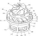
도 5는 도 4의 팬 모터의 사시도이다.
도 6은 제2실시예의 팬 모터가 진공 청소기의 하우징에 설치된 상태를 나타낸 측면 단면도이다.
도 7은 도 6의 팬 모터와 하우징의 일부를 확대하여 나타낸 사시도이다.
도 8은 제2실시예의 팬 모터의 유동을 나타낸 도면이다.1 is an exploded perspective view of a fan motor according to a first embodiment.
2 is a perspective view illustrating a state in which an impeller cover is removed from the fan motor according to the first embodiment.
3 is a side cross-sectional view of the fan motor according to the first embodiment.
4 is an exploded perspective view of a fan motor and a housing according to a second embodiment.
5 is a perspective view of the fan motor of FIG. 4 ;
6 is a side cross-sectional view showing a state in which the fan motor of the second embodiment is installed in the housing of the vacuum cleaner.
7 is an enlarged perspective view of the fan motor and a part of the housing of FIG. 6 .
8 is a view showing the flow of the fan motor according to the second embodiment.
이하, 본 발명의 바람직한 실시 예를 첨부한 도면을 참조로 하여 상세히 설명한다.Hereinafter, preferred embodiments of the present invention will be described in detail with reference to the accompanying drawings.
본 발명은 이하에서 개시되는 실시 예에 한정되는 것이 아니라 서로 다른 다양한 형태로 구현될 수 있으며, 단지 본 실시 예는 본 발명의 개시가 완전하도록 하며 통상의 지식을 가진 자에게 발명의 범주를 완전하게 알려주기 위하여 제공되는 것이다.The present invention is not limited to the embodiments disclosed below, but may be implemented in a variety of different forms, and only these embodiments allow the disclosure of the present invention to be complete and to completely convey the scope of the invention to those of ordinary skill in the art. It is provided to inform you.
[팬 모터의 구조][Structure of the fan motor]
도 1 내지 도 3에 도시된 제1실시예로서 팬 모터는, 모터부(20), 상기 모터부가 수용 설치되며 팬 모터의 전체적인 골격을 이루는 모터 바디부(10), 상기 팬 모터의 모터 바디부(10) 상부에 설치되어 공기의 유동을 발생시키는 유동 발생부(30), 상기 유동 발생부(30)에서 발생한 공기 유동을 분산시키는 디퓨져(40)를 포함한다.As the first embodiment shown in FIGS. 1 to 3, the fan motor includes a
<모터부><Motor part>
모터부(20)는 환 형의 스테이터(21), 상기 스테이터(21)의 중심을 관통하는 샤프트(23), 및 상기 샤프트(23)에 축설되며 상기 스테이터(21)에 의해 회전력을 발생시키는 로터(22)를 포함한다. 본 발명에 있어서, 상기 모터부(20)는 BLDC 모터(brushless direct current motor)인 것이 예시된다. 본 발명에서는 BLDC 모터로서 스테이터(21)가 로터(22)의 외측에 배치된 구조를 예시하고 있으나, 본 발명이 로터(22)의 안쪽에 스테이터(21)가 배치된 구조의 모터를 배제하는 것은 아니다.The
상기 샤프트(23)는 베어링(241)에 의해 회전 지지된다. 본 발명의 실시 예에서는 로터(22)를 사이에 두고 샤프트(23)의 양단에 베어링(241)이 설치된 양단 지지 구조를 예시하고 있으나, 샤프트(23)의 일측, 가령 로터(22)의 상부에 이점 지지하는 지지 구조 역시 적용 가능하다. 샤프트(23)의 하부에 설치된 베어링(241)은 후술할 모터 하우징(11)에 고정되어 지지될 수 있으며, 샤프트(23)의 상부에 설치된 베어링(241)은 후술할 베어링 하우징(17)에 의해 지지될 수 있다.The
<모터 바디부><Motor body part>
모터 바디부(10)는, 상기 모터부(20)를 수용하고 후술할 임펠러 커버(34)를 고정하는 바디 결합부(115)를 포함하는 모터 하우징(11)과, 상기 모터 하우징(11)의 상부에 고정되어 상기 모터부(20)의 상부에 설치된 베어링(241)을 지지하는 베어링 하우징(17)을 포함한다.The
후술하겠지만, 상기 모터 하우징(11)과 베어링 하우징(17)을 포함하는 모터 바디부(10)는, 강성이 높은 금속 재질로 제작하여서, 모터부(20)의 샤프트를 견고하게 지지하고, 고속으로 유동하는 공기를 안내하는 임펠러 커버를 견고하게 지지할 수 있도록 한다.,As will be described later, the
<모터 하우징><Motor housing>
상기 모터 하우징(11)은, 상기 모터부(20)가 내장되고 상부가 개방된 원통 형태의 모터 설치부(111)와, 상기 모터 설치부(111)의 상단부에서 반경 방향으로 방사상으로 외향 연장되는 연결 아암(114)과, 상기 연결 아암(114)의 단부에 마련되며, 상기 모터 설치부(111)의 직경보다 더 큰 직경을 가지는 환형의 바디 결합부(115)를 포함한다.The
모터 설치부(111)는 원통의 측면을 규정하는 측벽부재(131)와, 상기 측벽부재(131)의 하단부에 설치되어 모터 설치부(111)의 바닥을 규정하는 베이스부재(133)를 포함한다. 모터 설치부(111)의 바닥, 즉 베이스부재(133)의 중앙부에는 상기 모터부(20) 하부의 베어링(241)을 고정 지지하는 제1 베어링 지지부(112)가 구비된다. 제1 베어링 지지부(112)는 상부가 개방된 원통 형태이며, 샤프트(23) 하부의 베어링(241)은 상기 제1 베어링 지지부(112)의 개방된 상부를 통해 상기 제1 베어링 지지부(112)에 삽입되어 지지된다.The
상기 모터 설치부(111)의 바닥, 즉 배이스부재(133)에서 상기 제1 베어링 지지부(112)의 주변에는 모터부(20)의 냉각을 위한 공기가 유입되는 냉각 유로 입구(113)가 마련된다. 상기 냉각 유로 입구(113)는 모터 설치부(111)의 바닥뿐만 아니라, 모터 설치부(111)의 측벽부재(131)의 하부에도 마련될 수 있다. 상기 측벽부재(131)에 구비된 제1 냉각 유로 입구(1131)와 상기 베이스부재(133)에 구비된 제2 냉각 유로 입구(1132)는 팬 모터 외부의 공기가 상기 모터 설치부(111) 내부로 유입되는 통로가 된다.A
상기 제2 냉각 유로 입구(1132)는 냉각 공기의 유동 여건에 따라, 팬 모터 외부의 공기가 모터 설치부(111) 내부로 유입되기도 하며, 이와 달리 모터 설치부(111) 내부의 공기가 팬 모터 외부로 유출되기도 한다. 즉 제2 냉각 유로 입구(1132)는 그 명칭이 '입구'로 명명되지만, 팬 모터의 임펠러(31)에 의해 발생하는 공기 유동이 냉각 유로 출구(43)를 통해 배출된 후 어떻게 제어되느냐에 따라 공기의 유동 방향이 달라질 수 있다,In the second
제2 냉각 유로 입구(1132)는 도시된 바와 같이 베이스부재(133)에 방사상으로 배치되고, 제1 냉각 유로 입구(1131) 역시 측벽부재(131)의 둘레 방향을 따라 등 간격 복수 개 배치된다. 이에 따라, 이웃하는 제2 냉각 유로 입구(1132) 사이에는 방사상으로 연장되는 연결부재(134)가 구비되며, 이웃하는 제1 냉각 유로 입구(1131) 사이에는 상하 방향으로 연장되는 연장아암부재(132)가 마련된다. 이들은 제1 베어링 지지부(112)의 강성과 전체적인 모터설치부(111)의 강성을 유지할 수 있는 형태라면 다양한 배치와 형태가 적용 가능하다.The second
모터 설치부(111)의 측벽부재(131)가, 상기 모터 설치부(111)에 내장되는 스테이터(21)를 지지하는 점을 감안하여, 상기 측벽부재에 마련된 제1 냉각 유로 입구(1131)는 스테이터(21)의 지지 부위보다 하부에 마련되는 것이 바람직하다.Considering that the
또한 본 발명의 팬 모터에 적용되는 공기 유동 및 모터부 냉각 유동 경로와 관련하여 후술하겠지만, 본 발명의 팬 모터의 공기 토출구(116)가 모터 설치부(111)의 상부에 위치하는 점에서, 모터 설치부(111)의 측벽부재(131)에 마련되는 제1 냉각 유로 입구(1131)는 상기 공기 토출구(116)와 다소 거리가 확보된 위치에 마련되어 최대한 대기압과 가까운 공간과 연통하도록 하는 것이 바람직하다.In addition, as will be described later in relation to the air flow and motor unit cooling flow path applied to the fan motor of the present invention, in that the
본 발명에 있어서, 상기 냉각 유로 입구(113)는 모터 설치부(111) 내부로 모터부(20)의 냉각을 위한 공기가 유입되는 통로의 기능을 하면서, 팬 모터의 경량화를 도모한다는 점에 주목해야 할 것이다.In the present invention, it is noted that the
상기 모터 설치부(111)의 측벽부재(131)는 대략적으로 원통형의 형상을 구비하며, 상기 측벽의 내면에는 스테이터(21)가 고정된다.The
그리고 상기 모터 설치부(111)의 측벽부재(131)의 상단부에는 상기 측벽부재(131)로부터 반경 방향으로 외향 연장되는 형태의 연결 아암(114)과, 상기 연결 아암(114)의 반경 방향의 외측 단부에 구비되는 바디 결합부(115)를 포함한다. 상기 모터 설치부(111)의 측벽부재(131)의 상단부와, 상기 바디 결합부(115)의 내면에 의해 규정되는 공간은 후술할 임펠러(31)에 의해 발생하는 공기 유동이 배출되는 공기 토출구(116)가 된다.In addition, the upper end of the
본 발명에 따르면, 공기 토출구(116)는 모터 하우징(11)의 상부 가장자리에 마련되고, 상기 공기 토출구(116)를 통해 배출된 공기는 모터 설치부(111) 내부가 아닌, 외부 공간으로 즉시 방출되므로, 더 이상의 유동 저항으로 작용하지 않게 된다.According to the present invention, the
상기 모터 설치부(111)의 상단부는 후술할 베어링 하우징(17)이 안착되는 면을 제공하고, 상기 연결 아암(114)은 후술할 베어링 하우징의 외향 아암(172)이 고정되는 결합부위를 제공한다. 또한 상기 연결 아암(114)에는 외향 아암(172)과 나사 체결이 가능하도록 나사 체결공이 마련된다.The upper end of the
상기 공기 토출구(116)의 유동 단면적을 확보함과 함께, 상기 베어링 하우징과의 결합력을 확보하기 위해, 상기 연결 아암(114)의 개수와 두께는 적절히 선정될 수 있다. 본 발명에 따르면, 이러한 점을 감안하여, 120도 간격으로 3개의 연결 아암(114)이 마련된 구조가 예시된다.In order to secure a flow cross-sectional area of the
상기 바디 결합부(115)는 상기 모터 설치부(111)보다 큰 직경을 가지는 링 형상으로 이루어진다. 이러한 바디 결합부(115)의 형상의 일 실시 예로서, 바디 결합부(115)는 도시된 바와 같이 높이가 낮은 원통 형상일 수 있다. 또한 도시하지는 아니하였으나, 다른 일 실시 예로서, 바디 결합부(115)는 평평한 플랜지와 유사한 구조로 이루어질 수도 있다. 다만 도시된 바와 같이 높이가 낮은 원통 형상으로 바디 결합부(115)를 형성하면, 전체적인 팬 모터의 직경을 더 줄일 수 있다는 점에서 소형화에 더 유리하다.The
바디 결합부(115)는 후술할 임펠러 커버(34)의 하단부 둘레와 형합 되며 고정된다.The
<베어링 하우징><Bearing housing>
상기 모터 하우징(11)에 모터부(20)가 수용 설치된 상태에서, 상기 모터 하우징(11)의 상부에는 베어링 하우징(17)이 설치된다. 베어링 하우징(17)은 상기 모터부(20)의 상부에 마련된 베어링(241)을 지지하는 구조를 제공한다. 즉 로터(22)를 사이에 두고, 샤프트(23)의 하단부는 모터 하우징(11)에 의해 지지되고, 샤프트(23)의 상단부는 베어링 하우징(17)에 의해 지지된다.In a state in which the
상기 모터 하우징(11)과 베어링 하우징(17)은 고속으로 회전하는 로터(22)와 샤프트(23)를 지지해야 하므로, 강성이 높은 금속 재질로 제작되는 것이 바람직하다.Since the
상기 모터 하우징(11)과 베어링 하우징(17)은 고속으로 회전하는 모터부의 회전축을 정확히 정렬하고 확실히 지지하기 위한 구조를 구비한다. 따라서 모터 하우징(11)과 베어링 하우징(17)은 상호 위치가 정교하게 규제되며 체결되는 구조를 구비한다.The
베어링 하우징(17)의 중앙부에는 상기 샤프트(23)의 상단부에 설치된 베어링(241)을 지지하는 제2 베어링 지지부(174)를 구비한다. 제2 베어링 지지부(174)는 중공의 원통 형상으로서, 하부가 개방되고, 상부 중앙부에는 샤프트가 관통하는 홀이 마련된다. 베어링(241)은 상기 제2 베어링 지지부(174)의 하부로부터 그 내부에 삽입된다.A
제2 베어링 지지부(174)의 외측 둘레에는 방사상으로 복수 개의 내향 아암(173)이 구비된다. 본 발명에 따르면 3개의 내향 아암이 120도 간격으로 등간격 배치된 형태가 예시된다. 내향 아암(173)은 제2 베어링 지지부(174)로부터 외향 연장된다.A plurality of radially inwardly facing
반경 방향으로 내향 아암(173)의 안쪽과 제2 베어링 지지부(174)의 연결 부위에는 내향 아암보다 두툼한 직육면체 형태의 체결부(175)가 마련된다. 상기 체결부(175)는 후술할 디퓨져(40)의 중앙부가 안착 고정되는 부위이며, 여기에는 디퓨져와의 고정을 위한 나사 체결공이 마련된다.In the radial direction, a connection portion between the inner side of the
후술하겠지만, 상기 베어링 하우징(17)의 상부에는 임펠러에 의해 흡입된 공기가 유동하는 유동 경로가 위치한다. 따라서 베어링 하우징(17)의 상부에는 이러한 공기의 유동을 안내하는 형상부가 필요하다. 본 발명에 따르면, 팬 모터의 경량화와 공기 유동에 필요한 유선형의 형상을 성형하기에 간편한 합성수지 재질의 디퓨져(40)를 베어링 하우징(17)과 별개의 부품으로 구성한다.As will be described later, a flow path through which the air sucked by the impeller flows is located on the upper portion of the bearing
상기 내향 아암(173)은 제2 베어링 지지부(174)의 위치를 정확히, 그리고 견고하게 규제하며 고속으로 회전하는 모터부의 샤프트를 지지하면서도, 경량화를 위해 아암의 형태로 적용된다. 또한 후술하겠지만, 내향 아암(173)에 의해 확보되는 공간은 모터부의 냉각을 위한 공기가 지나갈 수 있는 통로가 된다.The inward-facing
반경 방향으로 내향 아암(173)의 바깥쪽에는 모터 설치부(111)의 측벽 상단에 고정되는 환형의 고정부(171)가 마련된다. 고정부(171)의 하부는 상기 모터 설치부(111)의 상부와 형합된다. 구체적으로, 고정부(171)의 하부에는 단턱 형상이 마련되고, 이러한 단턱 부위가 모터 설치부(111)의 상면 및 상부 내경면과 형합된다. 이러한 형합구조는 모터 하우징(11)에 대한 베어링 하우징(17) 축방향 위치와 반경방향 위치를 정확히 규제한다. 또한 상기 고정부(171)의 단턱 형상은 모터 설치부(111)의 내경면 쪽으로 형성되도록 함으로써, 모터 설치부의 외경면 쪽에 위치하는 공기 토출구(116)의 단면적을 더욱 확보할 수 있도록 하였다.An
또한 상기 고정부(171)의 외주면(outer circumferential surface)에는 반경 방향으로 외향 연장되는 형태의 외향 아암(172)이 마련된다. 그리고 상기 외향 아암(172)에도 나사 체결공이 마련된다. 상기 외향 아암(172)과 거기에 마련된 나사 체결공의 배치는, 앞서 설명한 모터 하우징(11)의 연결 아암(114) 및 거기에 마련된 나사 체결공의 배치와 매치된다.Also, an outward-facing
따라서 외향 아암(172)과 연결 아암(114)을 정렬시키며 상기 고정부(171)를 상기 모터 설치부(111)의 상단에 형합한 상태에서, 상기 외향 아암(172)과 연결 아암(114)을 나사 체결하면, 모터 하우징(11)과 베어링 하우징(17)은 상호 정밀하게 정렬된 상태에서 견고하게 고정된다.Therefore, in a state in which the
상기 베어링 하우징(17)은 충분한 강성을 확보하기 위해 금속 재질로 제작될 수 있다. 아울러, 상기 베어링 하우징(17)의 제2 베어링 지지부(174)와 고정부(171)는 내향 아암(173)을 통해 상호 이격된 상태로 배치된다. 이러한 형태는 베어링 하우징(17)의 경량화에 기여한다. 아울러, 후술하겠지만, 제2 베어링 지지부(174)와 고정부(171)가 이격 됨으로 인해 형성되는 공간은, 상기 냉각 유로 입구(113)를 통해 모터 설치부(111) 내부로 유입되어 모터부(20)를 냉각한 공기가 모터 설치부(111) 상부로 빠져나갈 수 있는 경로를 제공한다.The bearing
<디퓨져><Diffuser>
상기 베어링 하우징(17)의 상부에는, 디퓨져(40)가 설치된다. 디퓨져(40)는 전체적인 디퓨져의 외관을 규정하는 디퓨져 바디(41)와, 상기 디퓨져 바디(41)의 외면에 마련된 베인(42)을 포함한다.A
디퓨져 바디(41)는 중앙부에 홀(45)이 마련되고 평평한 형상을 가지는 평탄부(413)와, 상기 평탄부(413)의 외측 가장자리에서 반경방향으로 바깥쪽으로 갈수록 하향하는 경사면 형태의 사면부(411)과, 상기 사면부(411)의 외측 가장자리에서 원통 형태로 하향 연장되는 원통부(412)를 포함한다.The
상기 평탄부(413)의 상부에는 후술할 임펠러(31)가 배치되고, 상기 평탄부(413)의 하부면은 앞서 설명한 체결부(175)에 얹어진다. 평탄부(413)의 홀은 제2 베어링 지지부(174)의 외주면에 형합되는 형상으로 이루어지고, 상기 홀(45) 주변의 평탄부(413)에는 상기 체결부(175)의 나사 체결공과 대응하는 위치에 나사 체결공이 마련된다. 일 실시 예에서, 상기 홀(45)의 형상은 상기 원통형의 제2 베어링 지지부(174)의 직경과 대응하는 직경을 가지는 원형일 수 있다. 이에 따라 상기 홀의 내주면은 제2 베어링 지지부(174)의 외주면과 형합된다. 이 상태에서, 평탄부와 체결부는 나사 체결공을 통해 나사로 상호 고정된다.An
상기 평탄부(413)의 외측 가장자리에는 사면부(411)가 마련된다. 사면부의 경사각은 후술할 임펠러(31)의 경사각과 대응할 수 있다. 즉 본 발명에 있어서, 임펠러(31)는 사류형 임펠러이며, 디퓨져 역시 사류형일 수 있다.A
원통부(412)의 외경은 모터 설치부(111)의 측벽의 외경과 대응한다. 그리고 원통부(412)의 하단부는 상기 모터 설치부(111)의 상단부와 직접 또는 간접적으로 밀착된다. 본 발명의 실시 예에서는 베어링 하우징(17)의 고정부(171)가 모터 설치부(111)와 원통부(412) 사이에 개재된 상태로 원통부(412)의 하단부와 모터 설치부(111)의 상단부가 서로 밀착된 구조가 예시된다.The outer diameter of the
상기 베어링 하우징(17)의 고정부(171) 상부에는 단턱 구조가 마련된다. 그리고 상기 디퓨져(40)의 원통부(412)의 하단부에는 상기 단턱 구조와 대응하는 형태의 단턱 구조가 마련된다.A stepped structure is provided on the upper portion of the fixing
후술할 임펠러(31)에서 가압 토출되는 공기는 디퓨져 바디(41)의 외면을 따라 이동하여 공기 토출구(116)를 통해 외부로 배출된다. 즉 디퓨져 바디(41)는 후술할 임펠러 커버(34)와 함께 임펠러(31)에서 가압된 공기를 상기 공기 토출구(116) 쪽으로 안내한다.Air pressurized and discharged from the
상기 임펠러에 의해 발생하는 공기 유동이 모터 설치부(111) 내부로 유입되는 것을 방지하기 위해, 상기 디퓨져(40)와 모터 바디부(10)는 밀착되는 것이 바람직하다. 이러한 밀착 구조로서, 홀(45)과 제2 베어링 지지부(174)가 형합 구조를 가지고, 원통부(412)의 하단부와 고정부(171)의 상부가 단턱의 형합 구조를 가지며, 고정부(171)의 하부와 모터 설치부(111)의 상부가 단턱의 형합 구조를 가짐은 앞서 설명한 바와 같다.In order to prevent the air flow generated by the impeller from flowing into the
상기 디퓨져(40)의 하단부에는 베인(42)이 마련된다. 베인(42)은 임펠러(31)에 의해 가압 유동되는 공기의 유동 방향을 공기 토출구(116) 방향으로 가이드한다. 본 발명에 따르면 공기 토출구(116)가 모터 하우징(11)의 상부에 마련되며, 베인(42)은 상기 공기 토출구(116)보다 상부에서 디퓨져(40)에 마련된다.A
본 발명에 따르면, 상술한 베어링 하우징(17)은 금속 재질로 제작할 수 있고, 디퓨져(40)는 합성수지 재질로 제작할 수 있다. 고속으로 회전하는 모터부를 지지할 수 있는 강성을 확보하기 위해, 상기 베어링 하우징(17)은 금속 재질로 제작할 수 있다. 이에 반해, 임펠러에 의해 가압된 공기의 유동을 안내하는 기능을 하므로 높은 강성이 요구되지 않고, 형상이 복잡한 베인(42)의 가공도 용이하게 하기 위해, 상기 디퓨져(40)는 합성수지 재질로 제작할 수 있다.According to the present invention, the aforementioned bearing
만약 베어링 하우징(17)과 디퓨져(40)는 하나의 부품으로 제작한다면, 모터부에 대한 지지 강성을 확보하기 위해 그 재질은 금속을 선택할 가능성이 높다. 그런데 금속 재질로 베어링 하우징과 디퓨져를 일체로 제작한다면, 베인(42)의 가공 방식이 다소 제한적일 수 있다. 또한 이는 팬 모터의 경량화 관점에서도 아쉬움이 남을 수 있다.If the bearing
이에 반해 본 발명에서와 같이 베어링 하우징(17)과 디퓨져(40)를 별도의 부품으로 각각 제작하되, 각 부품에 요구되는 조건에 맞게 재질을 서로 다르게 하면, 부품의 가공도 용이하고, 제품을 보다 경량화하는 것이 가능하다.On the other hand, as in the present invention, the bearing
본 발명에 따르면 공기 토출구(116)가 모터 하우징(11)의 상부에 배치되므로, 베인을 모터 하우징(11)보다 상부에 배치할 수 있다. 따라서 베인(42)을 금속 재질의 모터 하우징(11)이 아닌, 합성수지 재질의 디퓨져(40)에 형성하는 것이 가능하다. 이러한 구조는 제조의 간편함은 물론, 전체적인 제품의 소형화와 경량화에 일조하게 된다.According to the present invention, since the
상기 디퓨져는 상하방향으로 보았을 때 후술할 임펠러(31)의 하부, 그리고 상기 베어링 하우징(17)의 상부에 배치되며, 반경방향으로 보았을 때 임펠러(31)보다 더 외측, 그리고 상기 바디 결합부(115)보다 내측 배치된다고 할 수 있다.The diffuser is disposed on the lower part of the
한편 상기 디퓨져(40)의 사면부(411)에는 그 둘레를 따라 복수 개의 냉각 유로 출구(43)가 마련된다. 냉각 유로 출구(43)는 상기 디퓨져 바디(41)의 상부 공간과 디퓨져 바디(41)의 하부 공간을 연통하는 통로의 형태를 이룬다.Meanwhile, a plurality of cooling
디퓨져 바디(41)의 하부 공간은 디퓨져 바디(41)의 저면과 모터 설치부(111)에 의해 규정되는 모터 수용 공간이다. 상기 모터 설치부(111)의 바닥과 측벽 하부에는 냉각 유로 입구(113)가 마련되어 있으며, 냉각 유로 입구(113)는 대기압 분위기의 공간 쪽으로 개방되어 있다.The lower space of the
반면 디퓨져 바디(41)의 상부 공간은 임펠러(31)에서 가압된 공기가 빠르게 유동하는 공간이므로, 상기 모터 설치부(111)의 내부 공간보다 상대적으로 압력이 낮다. 이러한 압력의 차이로 인해, 상기 모터 설치부(111) 내부의 공기는 상기 냉각 유로 출구(43)를 통해 디퓨져 바디(41)의 상부 공간으로 유동하고, 다시 상기 모터 설치부(111)의 내부 공간은 상기 냉각 유로 입구(113)에서 유입되는 공기로 채워진다.On the other hand, since the upper space of the
상기 냉각 유로 출구(43)는 베인(42)보다 임펠러(31)에 더 가까운 위치에 마련된다. 또한 상기 냉각 유로 출구(43)는 임펠러(31)의 공기 토출 측에 가깝게 배치되어 있어서, 냉각 유로 출구(43)의 상부와 하부의 압력 차이가 더욱 높아지도록 함으로써 냉각유로를 통해 모터부(20)를 냉각하기 위한 공기가 원활한 유동이 이루어지도록 한다.The
<임펠러><Impeller>
임펠러(31)는 디퓨져(40)의 상부에 설치된다. 임펠러(31)의 중심에는 상하방향으로 샤프트(23)가 삽입되는 축설공(312)이 마련된다. 상기 축설공(312)은 임펠러(31)의 전체적인 강성을 지지하는 허브 또는 임펠러 바디(311)에 형성되어 있어서, 샤프트(23)의 회전력은 상기 임펠러(31)에 잘 전달된다.The
상기 임펠러 바디(311)는 회전의 중심에서 반경방향으로 점점 멀어질수록 하향 경사지는 사면을 가진다. 즉 본 발명에 따른 임펠러(31)는 사류형 임펠러일 수 있다. 상기 임펠러 바디(311)의 상부에는 공기를 가압하는 블레이드(311)가 방사상으로 복수 개 마련된다.The
임펠러(31)의 흡입 효율을 높이기 위해서는, 블레이드(311)의 상단부가 후술할 임펠러 커버(34)의 내면과 거의 밀착되도록 하는 것이 바람직하다.In order to increase the suction efficiency of the
<임펠러 커버><Impeller cover>
임펠러 커버(34)는 상기 모터 바디부(10)의 상부를 덮는 형태이다. 임펠러 커버(34)의 상부 중앙부에는 팬 모터 내부로 흡입되는 통로인 공기흡입구(341)가 마련된다.The
상기 임펠러 커버(34)는 팬 모터의 중심축에서 멀어질수록 상기 공기흡입구(341)로부터 하향 경사진 형태를 포함하고, 임펠러 커버(34)의 하단부에는 커버 결합부(342)가 마련된다.The
커버 결합부(342)는 모터 바디부(10)의 바디 결합부(115)와 형합하는 구조이다. 커버 결합부(342)의 단턱 형상 내부에 상기 바디 결합부(115)가 끼워진다.The
임펠러 커버(34)는 팬 모터의 부품들 중 모터부(20)를 직접적으로 지지하지 않는 부품이므로, 경량의 합성 수지 재잘로 제작 가능하다. 다만 그 하단부는 금속 재질의 모터 하우징(11)에 의해 고정 지지되므로, 그 설치 위치는 견고하게 유지된다.Since the
[흡입공기의 유로][Intake air flow path]
상술한 구조를 가지는 팬 모터는 임펠러 커버(34)의 상부 중앙부에 마련된 공기흡입구(341)를 통해 공기를 흡입하여, 임펠러 커버(34)의 하단부와 모터 설치부(111) 사이에 마련된 공간, 즉 모터 하우징(11)의 상부 둘레에 마련된 공기 토출구(116)를 통해 공기를 토출한다.The fan motor having the above structure sucks air through the
상기 흡입공기는 임펠러(34)에 의해 가압되어 유동한다. 임펠러(34)의 출력 측에서 공기는, 임펠러 커버(34)의 내면과 디퓨져(40)의 외면에 의해 규정되는 공기 유동 경로를 지나 공기 토출구(116)에 이른다.The suction air is pressurized by the
상기 임펠러(34), 디퓨져(40), 임펠러 커버(34)는 흡입 공기의 유동 저항 손실을 최소화하기 위해 사류형으로 구성된다. 또한 디퓨져 바디(41), 고정부(171), 및 모터 설치부(111)의 측벽 외면은 서로 매끈하게 연결되어 공기 유동 손실이 발생하는 것을 최소화할 수 있다. 마찬가지로 임펠러 커버(34)의 하단부 내측면과 바디 결합부(115)의 내측면 역시 매끈하게 연결되어 공기 유동 손실의 발생을 최소화한다.The
디퓨져(40)의 사면부(411)를 거치며 팽창되어 감속되는 공기의 유동은 베인(42)에 의해 방향 전환이 이루어지고, 공기 토출구(116)의 단면에 대해 더욱 하향하며 토출된다.The flow of air that is expanded and decelerated through the
본 발명에 따르면 공기 토출구(116)가 모터 하우징(11) 상부에 마련되어 있기 때문에, 흡입공기 유로의 경로를 줄일 수 있고, 이는 유동 손실의 저감으로 이어진다. 그리고 흡입공기의 유로의 경로를 줄임으로써, 흡입공기의 유동을 안내하기 위한 형상을 가지는 부품의 개수나 부품의 크기를 줄일 수 있으므로, 제품의 경량화에 일조한다. 또한 모터 하우징(11)의 직경을 줄일 수 있으므로, 다시 말해 모터 하우징(11)의 상단부를 제외한 나머지 부분은 모터 설치부(111)의 직경이 팬 모터의 직경이 되므로, 팬 모터를 더 소형화하는 것이 가능하다.According to the present invention, since the
아울러, 베인(42)이 경량의 합성수지 재질로 제작되는 디퓨져(40)에 마련되므로, 제조가 간편하고 팬 모터의 경량화가 가능하다.In addition, since the
[냉각공기의 유로][Cooling air flow path]
상기 팬 모터는 초고속 회전을 할 수 있다. 팬 모터의 출력을 높이기 위해 가령 팬 모터를 11만 rpm 정도까지 회전시킬 경우, 모터부(20)의 발열량은 더욱 많아진다.The fan motor is capable of high-speed rotation. When, for example, the fan motor is rotated to about 110,000 rpm in order to increase the output of the fan motor, the amount of heat generated by the
모터부에 감겨져 있는 코일은 에나멜 피복이 코팅되어 있는 것이 보통이며, 모터부의 냉각이 잘 이루어지지 않아 에나멜 피복이 녹아 벗겨지면, 모터가 고장 난다. 또한 모터부가 고온으로 올라가면, 자계에도 영향을 미쳐 출력 저하를 일으킨다. 따라서 모터부를 적절히 냉각하는 것은 모터 설계에서 필수적인 요소라 할 수 있다.The coil wound around the motor is usually coated with enamel, and if the enamel coating melts and peels off because the motor is not cooled well, the motor will fail. In addition, when the motor part rises to a high temperature, it also affects the magnetic field and causes a decrease in output. Therefore, proper cooling of the motor unit is an essential element in motor design.
모터부(20)의 냉각을 위해, 가령 샤프트(23)의 하단부에 냉각공기의 유동을 만들기 위한 별도의 냉각팬을 설치한다면, 이는 팬 모터의 다시 출력 손실로 이어지게 된다. 즉 출력을 높이기 위해 팬 모터의 회전속도를 높임으로써 모터부에 발생하는 열을 냉각하기 위해, 다시 팬 모터의 출력 일부를 냉각 공기 유동을 일으키는데 사용하는 방식은, 팬 모터의 출력을 높이기 위한 취지에 부합하지 않는다. 아울러 냉각을 위한 별도의 팬을 설치하는 것은 팬 모터의 소형화 관점에서 다소 불리할 수 있다.For cooling the
한편 종래와 같이 흡입공기가 모터부(20)가 설치된 공간인 모터 설치부(111) 내부 공간을 통과하도록 하여 모터부(20)를 냉각시키는 냉각 구조는, 임펠러(31)보다 공기 유동의 하류 측 유동 손실 및 저항이 매우 크게 되므로, 팬 모터의 출력 저하를 일으킨다.On the other hand, as in the prior art, the cooling structure for cooling the
이에 본 발명은, 압력 차에 의하여 자연스럽게 공기의 유동이 발생하도록 하고, 이러한 공기의 유동이 모터부(20)가 설치된 공간을 유동하도록 함으로써, 모터부의 냉각을 위해 발생하는 출력의 저하를 최소화한다.Accordingly, in the present invention, the flow of air naturally occurs due to the pressure difference, and the flow of air flows through the space in which the
흡입 공기의 유로에 있어서, 디퓨져(40)의 사면부(411)에 형성된 냉각 유로 출구(43)는 흡입 공기의 유동 경로가 되는 공간과 모터부(20)가 설치된 공간을 연통시킨다. 상기 임펠러(31)에 의해 가압된 공기는 디퓨져(40)의 상부 공간에서 매우 빠른 유속을 가지게 되고, 이에 따라 모터부(20)가 설치된 공간보다 디퓨져(40)의 상부 공간의 압력이 낮아지게 된다. 따라서 대략 대기압 상태의 모터 하우징(11) 외부로부터 냉각 유로 입구(113), 모터부(20) 설치 공간, 베어링 하우징(17)의 베어링 지지부(174)와 고정부(171) 사이의 공간, 그리고 냉각 유로 출구(43)에 이르는 공기의 흐름이 생성된다. In the intake air passage, the
이와 같은 방식으로 생성되는 공기의 흐름은 팬 모터의 회전속도가 높아질수록 함께 증가된다.The flow of air generated in this way increases as the rotational speed of the fan motor increases.
물론 위와 같이 모터부의 냉각을 위한 공기의 흐름을 유도하는 경우에도 팬 모터의 출력은 저하된다. 그러나 강제 유동 방식, 또는 흡입공기가 모터부(20) 설치공간을 통과하도록 하는 방식에 비해, 팬 모터의 효율이 저하되는 정도를 최소화할 수 있다. 또한 팬 모터의 효율의 저하는 최소화하면서도, 모터부의 냉각을 원활하게 할 수 있다.Of course, even when the flow of air for cooling the motor is induced as described above, the output of the fan motor is reduced. However, compared to a forced flow method or a method in which suction air passes through the
모터부(20)를 냉각하기 위한 공기가 유입되도록 하는 냉각 유로 입구(113)를 형성하는 것은, 모터 하우징(11)의 경량화도 함께 이루게 된다. 아울러 냉각 공기 유동을 발생시키기 위한 별도의 팬이 설치될 필요가 없다는 점에서, 본 발명의 구조는 팬 모터의 경량화 및 소형화에 더욱 유리하다. 또한 임펠러에서 발생시키는 공기 유동에 대한 손실을 최소화하므로, 모터부를 소형으로 유지할 수 있어 팬 모터의 경량화와 소형화에도 유리하다.Forming the
이하 도 4 내지 도 6을 참조하여, 제1실시예의 변형예인 제2실시예에 대해 설명한다. 제2실시예를 설명함에 있어서 제1실시예와 중복되는 부분에 대한 설명은 생략한다. 제1실시예와 제2실시예의 각 구성은 서로 치환하거나, 변경, 부가, 삭제가 가능함이 자명하다.Hereinafter, a second embodiment, which is a modification of the first embodiment, will be described with reference to FIGS. 4 to 6 . In the description of the second embodiment, a description of parts overlapping with the first embodiment will be omitted. It is apparent that each configuration of the first embodiment and the second embodiment can be substituted for, changed, added, or deleted from each other.
<모터 하우징><Motor housing>
제2 실시예의 모터 하우징(11)은, 모터부(20)가 내장되고 상부가 개방된 중공의 통 형태의 모터 설치부(111)와, 상기 모터 설치부(111)의 상단부에서 반경 방향으로 방사상으로 외향 연장되는 연결 아암(114)과, 상기 연결 아암(114)의 단부에 마련되며, 상기 모터 설치부(111)의 직경보다 더 큰 직경을 가지는 환형의 바디 결합부(115)를 포함한다. 모터 설치부(111)와 바디 결합부(115) 사이의 링 형상으로 개방된 부위는 팬 모터의 공기 토출구(116)를 규정한다.The
모터 설치부(111)는 원통의 측면을 규정하는 측벽부재(131)와, 상기 측벽부재(131)의 하단부에 설치되어 모터 설치부(111)의 바닥을 규정하는 베이스부재(133)를 포함한다. 제2실시예의 모터 설치부(111)는 측벽부재(131)의 직경보다 베이스부재(133)의 직경이 더 큰 구조가 예시된다. 즉 측벽부재(131)의 상부는 원통 형태이며, 측벽부재(131)의 하부의 연장아암부재(132)는 하방으로 갈수록 직경이 확장되는 형태일 수 있다. 상기 측벽부재(131)와 연장아암부재(132)와 베이스부재(133)는 전체적으로 삼각플라스크와 유사한 형태일 수 있다.The
다만 모터 설치부(111)의 원통형 상부와 직경이 확장되는 하부의 제1경계가, 측벽부재(131)와 연장아암부재(132)의 제2경계와 일치하는 것은 아니다. 즉 제2경계가 제1경계보다 더 높게 위치할 수도 있고, 제2경계가 제1경계보다 더 낮게 위치할 수도 있다. 즉 제2실시예로 개시한 바와 같이 상기 연장아암부재(132)은 원통형 구간과 직경 확장 구간을 모두 구비할 수 있다. 또한 제2실시예와 달리, 상기 측벽부재(131)가 원통형 구간과 직경 확장 구간을 모두 구비할 수도 있다. 이는 후술할 제1 냉각 유로 입구(1131)의 면적 및 배치와 관련될 수 있다.However, the first boundary between the cylindrical upper part of the
베이스부재(133)의 중앙부에는 제1 베어링 지지부(112)가 구비된다. 상기 배이스부재(133)에서 상기 제1 베어링 지지부(112)의 주변에는 모터부(20)의 냉각을 위한 공기가 유입되는 제2냉각 유로 입구(1132)가 마련된다. 모터 설치부(111)의 측벽부재(131)의 하부에는 제1 냉각 유로 입구(1131)가 마련된다. 제1 냉각 유로 입구(1131)는 모터 설치부(111)의 직경이 확장되는 구간에 마련될 수 있다. 그리고 상기 제1 냉각 유로 입구(1131)는, 제2실시예에 개시한 바와 같이 상기 직경 확장 구간은 물론, 이와 인접하는 원통형 구간까지 연장될 수 있다.A
원통형의 측벽부재(131)와 바디 결합부(115) 사이의 공간으로 규정되는 상기 공기 토출구(116)의 하부에서, 상기 제1 냉각 유로 입구(1131)의 적어도 일부는 상기 공기 토출구(116)를 비스듬히 마주본다. 공기 토출구(116)에서 토출되는 공기는 하방으로 강하게 유동하는바, 토출 공기 중 적어도 일부는 상기 제1 냉각 유로 입구(1131)를 통해 모터 설치부(111) 내부 공간으로 직접적으로 유입될 수 있다.In the lower portion of the
상기 연장 아암부재(132)는 상방으로는 측벽부재(131)와 연결되고, 하방으로는 베이스부재(133)와 연결된다. 회전축(23 참조)을 기준으로, 베이스부재(133)의 직경은 측벽부재(131)보다 크다. 따라서 베이스부재(133)의 반경방향 외측 가장자리는, 공기 토출구(116)를 통해 하방으로 내려오는 공기와 직접 대면할 수 있다.The
상기 연장아암부재(132)의 하단부는 상기 베이스부재(133)의 반경방향 외측 가장자리에 연결될 수 있다. 따라서 공기 토출구(116)에서 토출된 공기는, 연장아암부재(132) 및 그 사이의 개방부위로 규정되는 제1 냉각 유로 입구(1131)를 지난 뒤 베이스부재(133)에 도달할 수 있다.A lower end of the
상기 베이스부재(133)의 직경은 바디 결합부(115)의 직경보다 크거나, 작을 수 있다. 제2실시예에서는 베이스부재(133)의 직경이 바디 결합부(115)의 직경보다 작은 구조가 예시된다.The diameter of the
상기 베이스부재(133)에는, 상기 공기 토출구(116)를 통해 하방으로 유동하는 공기를, 모터 설치부(111) 내에 설치된 모터부(20) 쪽으로 방향 전환시키는 가이드형상(135)이 구비될 수 있다. 상기 가이드형상(135)은, 하방으로 내려오는 공기의 유동 방향을 반경 방향의 내측 방향으로 전환하는 제1가이드형상(1351)과, 다시 반경 방향의 내측 방향으로 유동하는 공기의 유동 방향을 상방으로 전환하는 제2가이드형상(1352)을 포함할 수 있다.The
상기 제1가이드형상(1351)은, 측벽부재(131)의 원통형 구간의 직경보다 더 큰 베이스부재(133)의 영역(a; 도 5 참조)에 마련될 수 있다. 상기 제1가이드형상(1351)은 반경방향 외측으로 갈수록 점점 상향하는 경사면을 포함할 수 있다. 상기 경사면은 단면을 보았을 때 아래로 볼록한 유선형 프로파일일 수 있다.The
상기 제2가이드형상(1352)은, 측벽부재(131)의 원통형 구간의 직경보다 더 작은 베이스부재(133)의 영역(b; 도 5 참조)에 마련될 수 있다. 상기 제2가이드형상(1352)은 반경방향 외측으로 갈수록 점점 상향하는 경사면을 포함할 수 있다. 상기 경사면은 단면을 보았을 때 아래로 볼록한 유선형 프로파일일 수 있다.The
반경 방향으로 상기 제1가이드형상(1351)과 제2가이드형상(1352) 사이에는, 제1가이드형상(1351)에 의해 방향이 전환된 공기의 유동이 층류가 되도록 유도하는 구간이 마련될 수 있다. 이러한 구간은 평평한 면을 포함할 수 있다.Between the
공기 토출구(116)에서 하향 토출된 공기의 적어도 일부는 상기 제1 냉각 유로 입구(1131)를 통해 모터 설치부(111) 내부로 유입되어 상기 제1가이드형상(1351)에 의해 반경 방향 내측으로 유동 방향이 전환되고, 다시 제2가이드형상(1352)에 의해 상방으로 유동 방향이 전환된다. 이에 따라 모터부(20)는 냉각될 수 있다.At least a portion of the air discharged downward from the
상기 연장아암부재(132)의 하단부는 상기 베이스부재(133)의 반경방향 외측 가장자리에 연결되므로, 공기 토출구(116)에서 토출된 공기는 먼저 연장아암부재(132)를 지난 후 제1가이드형상(1351)에 도달할 수 있다. 연장아암부재(132)를 거치며 일부 난류(turbulence)가 된 공기 유동은 가이드형상(135)을 거치며 유동이 안정화 될 수 있다.Since the lower end of the
상기 제2가이드형상(1352)의 반경방향 내측에는, 제2냉각 유로 입구(1132)가 상기 제2가이드형상(1352)의 반경방향 내측 가장자리와 인접하여 마련된다. 제2냉각 유로 입구(1132)들 사이에는 베이스부재(133)의 제1 베어링지지부(112)와 가이드형상(135) 부위를 연결하는 연결부재(134)가 마련된다. 상기 연결부재(134)가 배치된 부분에는 제2가이드형상(1352)이 구비되지 않을 수 있다.A second
일 예로서, 제2가이드형상(1352)은, 베이스부재(133)를 "ㄷ" 형태로 커팅하고, 커팅된 "ㄷ"자 부위가 상방으로 들어올려진 형상으로 프레스 성형됨으로써 제공될 수 있다. 상기 커팅된 부위가 들어올려짐으로써 형성되는 개방 부위는 상기 제2 냉각 유로 입구(1132)를 구성할 수 있다.As an example, the
회전축을 기준으로 한 상기 연결부재(134)의 방위각은, 상기 연장아암부재(132)의 방위각과 일치할 수 있다. 즉 연결부재(134)와 연장아암부재(132)는 회전축을 기준으로 동일한 각도 위치에서 정렬된 형태일 수 있다. 따라서 회전축을 기준으로 제2가이드형상(1352)이 형성된 방위각도 범위에서는, 공기 유동을 방해하는 구조가 없게 된다.The azimuth angle of the
상기 모터 설치부(111)의 상단부에는 베어링 하우징(17)이 안착 고정될 수 있다.A bearing
<디퓨져><Diffuser>
상기 베어링 하우징(17)의 상부에는, 디퓨져(40)가 설치된다. 디퓨져(40)는 전체적인 디퓨져의 외관을 규정하는 디퓨져 바디(41)와, 상기 디퓨져 바디(41)의 외면에 마련된 베인(42)을 포함한다.A
디퓨져 바디(41)는 중앙부에 홀(45)이 마련되고 평평한 형상을 가지는 평탄부(413)와, 상기 평탄부(413)의 외측 가장자리에서 반경방향으로 바깥쪽으로 갈수록 하향하는 경사면 형태의 사면부(411)를 포함한다. 상기 평탄부(413)의 상부에는 임펠러(31)가 배치된다. 상기 홀(45)은 베어링 하우징(17)에 외삽된다.The
상기 평탄부(413)의 외측 가장자리에는 사면부(411)가 마련된다. 사면부의 경사각은 후술할 임펠러(31)의 경사각과 대응할 수 있다. 즉 제2실시예에 있어서, 임펠러(31)는 사류형 임펠러이며, 디퓨져 역시 사류형일 수 있다.A
베인(42)은 사면부(411)의 상면에 마련될 수 있다. 베인(42)은 임펠러(31)에 의해 원주의 접선방향으로 가압 유동되는 공기의 방향을 전환시킬 수 있다. 상기 베인(42)은 임펠러에서 가압된 공기가 상기 베인(42)을 거치며 원주 방향으로의 운동 성분을 줄이고 반경 방향으로의 운동 성분을 늘리도록 방향 전환할 수 있다. 그리고 베인(42)을 거친 유동 공기는 임펠러 커버(34)의 경사면(343)과 원통면(344)의 경계에서 하방으로 방향이 전환된다.The
사면부(411)의 반경방향 외측 가장자리는 모터 설치부(111)의 상단부와 이격 배치될 수 있다. 그리고 이와 같이 이격된 공간은 냉각 유로 출구(43)를 구성할 수 있다. 제2실시예에 따르면, 냉각 유로 출구(43)가 디퓨져(40)와 베인(42)보다 공기 유동의 하류에 위치한다. 아울러 상기 냉각 유로 출구(43)는 팬 모터의 둘레 방향을 따라 하나의 큰 링 형상을 이룰 수 있다.The radially outer edge of the
상기 디퓨져는 상하방향으로 보았을 때 임펠러(31)의 하부, 그리고 상기 베어링 하우징(17)의 상부에 배치되며, 반경방향으로 보았을 때 임펠러(31)보다 더 외측, 그리고 상기 바디 결합부(115)보다 내측 배치될 수 있다.The diffuser is disposed on the lower part of the
디퓨져 바디(41)의 하부 공간은 디퓨져 바디(41)의 저면과 모터 설치부(111)에 의해 규정되는 모터 수용 공간이다. 상기 모터 설치부(111)의 베이스부재(133)와 측벽부재(131)의 하부에는 냉각 유로 입구(113)가 마련되어 있으며, 냉각 유로 입구(113)는 대기압 분위기의 공간 쪽으로 개방될 수 있다.The lower space of the
반면 디퓨져 바디(41)와 임펠러 커버(34) 사이의 공간은 임펠러(31)에서 가압된 공기가 빠르게 유동하는 공간이므로, 상기 모터 설치부(111)의 내부 공간보다 상대적으로 압력이 낮다. 이러한 압력의 차이로 인해, 상기 모터 설치부(111) 내부의 공기는 상기 냉각 유로 출구(43)를 통해 모터 설치부(111) 외부로 유동하고, 다시 상기 모터 설치부(111)의 내부 공간은 상기 냉각 유로 입구(113)에서 유입되는 공기로 채워진다.On the other hand, since the space between the
[흡입공기의 유로][Intake air flow path]
제2실시예의 팬 모터는, 제1실시예와 마찬가지로, 임펠러 커버(34)의 상부 중앙부에 마련된 공기흡입구(341)를 통해 공기를 흡입하여, 임펠러 커버(34)의 하단부와 모터 설치부(111) 사이에 마련된 공간, 즉 모터 하우징(11)의 상부 둘레에 마련된 공기 토출구(116)를 통해 공기를 토출한다.The fan motor of the second embodiment, like the first embodiment, sucks air through the
디퓨져(40)의 사면부(411)를 거치며 팽창되어 감속되는 공기의 유동은 베인(42)에 의해 반경 방향 성분을 더 가지도록 방향 전환이 이루어지고, 다시 임펠러 커버(34)에 의해 하향 성분을 더 가지도록 방향 전환이 한번 더 이루어진 후, 공기 토출구(116)의 단면에 대해 더욱 하향하며 토출된다.The flow of air, which is expanded and decelerated through the
[냉각공기의 유로][Cooling air flow path]
제2실시예의 팬 모터는, 압력 차에 의하여 자연스럽게 공기의 유동이 발생하도록 하고, 이러한 공기의 유동이 모터부(20)가 설치된 공간을 유동하도록 함으로써, 모터부의 냉각을 위해 발생하는 출력의 저하를 최소화하되, 위와 같은 공기의 유동을 더욱 유도하기 위하여, 상기 가이드형상(135)을 더 구비할 수 있다.In the fan motor of the second embodiment, the flow of air naturally occurs due to the pressure difference, and this flow of air flows through the space in which the
가이드형상(135)은 공기 토출구(116)를 통해 토출된 공기의 운동 에너지의 일부를 이용하여 냉각 공기의 환류(냉각 유로 입구 → 모터 설치부 내부의 하부공간 → 모터부 냉각 → 모터 설치부 내부의 상부공간 → 냉각 유로 출구 → 공기 토출구 → 냉각 유로 입구)를 더욱 활성화시킬 수 있다.The
흡입 공기의 유로에 있어서, 디퓨져(40)와 모터 설치부(111) 사이에 형성된 냉각 유로 출구(43)는 흡입 공기의 유동 경로가 되는 공간과 모터부(20)가 설치된 공간을 연통시킨다. 상기 임펠러(31)에 의해 가압된 공기에 의해, 모터부(20)가 설치된 공간보다 디퓨져(40)와 임펠러 커버(37) 사이의 공간의 압력이 낮아지게 된다. 따라서 냉각 유로 출구(43) 부근에는, 모터설치부(111) 내부에서 모터설치부(111) 외부로 공기가 이동하게 된다. In the flow path of the intake air, the
한편 공기 토출구에서 하향 토출된 공기의 일부는, 베이스부재(133)의 가이드형상(135)에 의해 모터 설치부(111) 내부공간의 하부 외측 가장자리에서 중심축 쪽으로 방향 전환된 후 유동하고, 모터 설치부(111) 내부공간의 하부 중심 부근에서 다시 상부로 유동하는 공기의 흐름을 일으킨다.On the other hand, a part of the air discharged downward from the air outlet is changed from the lower outer edge of the inner space of the
상기 모터 설치부(111)의 내부공간의 하부 중심부근에서 상부로 유동하는 공기의 흐름은, 베이스부재(133) 하부 공간의 공기가 제2냉각 유로 입구(1132)를 통해 베이스부재(133) 상부로 유동하는 공기 흐름을 유도할 수 있다. 따라서 상기 환류의 흐름에는 임펠러에 의해 가압된 공기뿐만 아니라, 제2냉각 유로 입구(1132) 외부의 공기도 함께 유입될 수 있다.The flow of air flowing from the vicinity of the lower central portion of the inner space of the
이와 같은 방식으로 생성되는 공기의 흐름은 팬 모터의 회전속도가 높아질수록 함께 증가된다.The flow of air generated in this way increases as the rotational speed of the fan motor increases.
물론 위와 같이 모터부의 냉각을 위한 공기의 흐름을 유도하는 경우에도 팬 모터의 출력은 약간 저하될 수도 있다. 그러나 강제 유동 방식, 또는 흡입공기가 모터부(20) 설치공간을 통과하도록 하는 방식에 비해, 팬 모터의 효율이 저하되는 정도를 최소화할 수 있다. 또한 팬 모터의 효율의 저하는 최소화하면서도, 모터부의 냉각을 원활하게 할 수 있다.Of course, even when the flow of air for cooling the motor is induced as described above, the output of the fan motor may be slightly lowered. However, compared to a forced flow method or a method in which suction air passes through the
[진공청소기의 하우징][Housing of vacuum cleaner]
일 예로서, 상기 팬 모터는 진공청소기에 설치될 수 있다. 특히 경량 소형화 되었으면서도 초고속 회전하여 흡입력을 높인 팬 모터의 특성 상, 핸드 헬드(hand held) 청소기에 사용되기에 적합할 수 있다.As an example, the fan motor may be installed in a vacuum cleaner. In particular, it may be suitable for use in hand held vacuum cleaners due to the characteristics of the fan motor, which is light and miniaturized and rotates at a high speed to increase suction power.
상기 팬 모터는 청소기의 하우징(60)에 설치될 수 있다. 상기 하우징(60)은 팬 모터의 공기 흡입구(341) 쪽에서 임펠러 커버(34)를 감싸며 덮는 상부하우징(61)과, 팬 모터의 냉각유로입구(113) 쪽에서 베이스부재(133)를 감싸며 덮는 하부하우징(67)을 포함한다. 상부하우징(61)과 하부하우징(67)은 팬 모터의 외측 둘레에서 상호 체결된다.The fan motor may be installed in the
상부하우징(61)의 상부에는 필터 등을 거친 공기가 흡입되는 공기 흡입구(63)가 구비된다. 상기 공기 흡입구(63)는 팬 모터의 공기 흡입구(341)와 서로 마주하며 매칭되어 배치된다.An
상부하우징(61)의 하부 둘레에는 공기 배출구(65)가 구비된다. 상기 공기 배출구(65)는 반경 방향으로 상기 팬 모터의 공기 토출구(116)와 마주하여 배치된다.An
하부하우징(67)은 상기 팬 모터의 베이스부재(133)의 둘레를 감싸며 베이스부재(133)의 반경방향 외측 가장자리와 접하여 팬 모터를 고정한다. 상기 하우하우징(67)이 베이스부재(133)의 외주면과 접하는 부위에는, 상기 베이스부재(133)의 제1가이드형상(1351)이 반경방향 외측으로 더 연장된 형태를 가지는 확장 가이드형상(69)이 마련된다. 상기 확장 가이드형상(69)은 가이드형상(135)이 연결된 형태로서, 팬 모터의 회전축으로부터 반경방향 외측으로 갈수록 상향하는 프로파일을 구비한다. 그리고 상기 확장 가이드형상(69)은 상방으로, 상기 팬 모터의 공기 토출구(116)를 마주보게 된다.The
팬 모터가 회전하면, 진공청소기의 노즐을 통해 유입된 공기는 필터를 거쳐 집진하고, 필터를 통과한 공기는 상기 상부하우징(61)의 공기 흡입구(63)와 임펠러 커버(34)의 공기 흡입구(341)를 거쳐 팬 모터에 흡입된다.When the fan motor rotates, the air introduced through the nozzle of the vacuum cleaner is collected through the filter, and the air passing through the filter is collected through the
팬 모터에 흡입된 공기는 임펠러(31)에 의해 가압되어 사류형 디퓨져(40)와 임펠러 커버(34)에 의해 유동이 안내되며, 공기 토출구(116)를 통해 모터 설치부(111)의 외측 공간으로 토출된다.The air sucked into the fan motor is pressurized by the
모터 설치부(111)의 반경 방향 외측 공간으로 토출된 공기의 일부는, 상기 하우징(60)의 공기 배출구(65)를 통해 하우징의 측방으로 대기 중에 배출된다. 그리고 일부 공기는 하방으로 유동하여 상기 확장 가이드형상(69)과 제1가이드형상(1351)에 의해 모터 설치부(111)의 내부공간 하부로 유입이 안내된다.A part of the air discharged to the radially outer space of the
실시예에 따르면, 팬 모터의 베이스부재(133)와 하우징(60)에 걸쳐 가이드형상(135, 69)이 구비된 구조가 예시된다. 그러나 경우에 따라서는 베이스부재(133) 쪽에만 가이드형상(135)이 구비될 수도 있고, 하우징(60) 쪽에만 가이드형상(69)이 구비될 수도 있음은 물론이다.According to the embodiment, a structure in which the guide shapes 135 and 69 are provided over the
이상과 같이 본 발명에 대해서 예시한 도면을 참조로 하여 설명하였으나, 본 명세서에 개시된 실시 예와 도면에 의해 본 발명이 한정되는 것은 아니며, 본 발명의 기술사상의 범위 내에서 통상의 기술자에 의해 다양한 변형이 이루어질 수 있음은 자명하다. 아울러 앞서 본 발명의 실시 예를 설명하면서 본 발명의 구성에 따른 작용 효과를 명시적으로 기재하여 설명하지 않았을 지라도, 해당 구성에 의해 예측 가능한 효과 또한 인정되어야 함은 당연하다.As described above, the present invention has been described with reference to the illustrated drawings, but the present invention is not limited by the embodiments and drawings disclosed in the present specification. It is obvious that variations can be made. In addition, although the effects according to the configuration of the present invention are not explicitly described and described while describing the embodiments of the present invention, it is natural that the effects predictable by the configuration should also be recognized.
10: 모터 바디부
11: 모터 하우징
111: 모터 설치부
112: 베어링 지지부
113: 냉각 유로 입구
1131: 제1냉각 유로 입구
1132: 제2냉각 유로 입구
114: 연결 아암
115: 바디 결합부
116: 공기 토출구
131: 측벽부재
132: 연장아암부재
133: 베이스부재
134: 연결부재
135: 가이드형상
1351: 제1가이드형상
1332: 제2가이드형상
17: 베어링 하우징
171: 고정부
172: 외향 아암
173: 내향 아암
174: 베어링 지지부
175: 체결부
20: 모터부
21: 스테이터
22: 로터
23: 샤프트
24: 베어링
241: 베어링
30: 유동 발생부
31: 임펠러
311: 임펠러 바디(허브)
312: 축설공
313: 블레이드
34: 임펠러 커버
341: 공기 흡입구
342: 커버 결합부
40: 디퓨져
41: 디퓨져 바디
411: 사면부
412: 원통부
413: 평탄부
42: 베인
43: 냉각 유로 출구
45: 홀
60: 하우징
61: 상부하우징
63: 공기 흡입구
65: 공기 배출구
67: 하부하우징
69: 확장 가이드형상10: motor body part
11: Motor housing
111: motor installation part
112: bearing support
113: cooling passage inlet
1131: first cooling passage inlet
1132: inlet of the second cooling passage
114: connecting arm
115: body coupling part
116: air outlet
131: side wall member
132: extended arm member
133: base member
134: connecting member
135: guide shape
1351: first guide shape
1332: second guide shape
17: bearing housing
171: fixed part
172: outward arm
173: inward arm
174: bearing support
175: fastening part
20: motor unit
21: stator
22: rotor
23: shaft
24: bearing
241: bearing
30: flow generating unit
31: impeller
311: impeller body (hub)
312: shaft snow
313: blade
34: impeller cover
341: air intake
342: cover coupling portion
40: diffuser
41: diffuser body
411: slope
412: cylindrical part
413: flat part
42: vane
43: cooling passage outlet
45: Hall
60: housing
61: upper housing
63: air intake
65: air outlet
67: lower housing
69: extended guide shape
Claims (15)
Translated fromKorean상기 모터부(20)의 상부에 위치하며, 모터부(20)로부터 회전력을 받아 회전하는 임펠러(31);
상기 임펠러(31)를 덮으며 상기 모터 설치부(111)의 상부에 배치된 임펠러 커버(34);
상기 임펠러 커버(34)의 상부 중앙부에 마련된 공기흡입구(341);
상기 임펠러 커버(34)의 하단부에 마련되고, 상기 모터 설치부(111)의 외측 공간 쪽으로 개방된 공기 토출구(116);
상기 모터 설치부(111)에서 상기 모터부(20)보다 하부에 마련되고, 상기 모터부(20)에서 발생하는 열을 냉각시키기 위한 공기가 유입되는 통로가 되는 제1 냉각 유로 입구(1131);
상기 모터 설치부(111)에 구비되어 공기의 유동 방향을 전환하는 가이드형상(135);
적어도 일부분이 상기 모터 설치부(111)의 상부에서 상기 모터부(20)보다 상부에 마련되되, 상기 모터 설치부(111)의 내측 공간이 상기 임펠러(31)와 공기 토출구(116) 사이의 공간과 연통되도록 하는 냉각 유로 출구(43);를 포함하고,
상기 공기흡입구(341)를 통해 흡입되고 상기 임펠러(31)에 의해 가압된 공기는 상기 공기 토출구(116)를 통해 모터 설치부(111)의 외측 공간으로 토출되고,
상기 공기 토출구(116)에서 토출된 공기의 적어도 일부는 상기 제1 냉각 유로 입구(1131)를 통해 상기 모터 설치부(111)의 내부로 유입되고,
상기 가이드형상(135)은 상기 제1 냉각 유로 입구(1131)를 통해 내부로 유입된 공기의 유동 방향을 모터부(20) 쪽으로 전환하는, 팬 모터.
a motor installation unit 111 in which the motor unit 20 is accommodated;
an impeller 31 positioned above the motor unit 20 and rotating by receiving a rotational force from the motor unit 20;
an impeller cover 34 covering the impeller 31 and disposed on the motor installation part 111;
an air inlet 341 provided in the upper central portion of the impeller cover 34;
an air outlet 116 provided at a lower end of the impeller cover 34 and opened toward an outer space of the motor installation unit 111;
a first cooling passage inlet 1131 that is provided below the motor unit 20 in the motor installation unit 111 and serves as a passage through which air for cooling the heat generated in the motor unit 20 is introduced;
a guide shape 135 provided in the motor installation part 111 to change the flow direction of air;
At least a portion is provided above the motor unit 20 in the upper portion of the motor installation unit 111 , and the inner space of the motor installation unit 111 is a space between the impeller 31 and the air outlet 116 . and a cooling passage outlet (43) to communicate with;
The air sucked through the air inlet 341 and pressurized by the impeller 31 is discharged to the outer space of the motor installation part 111 through the air outlet 116,
At least a portion of the air discharged from the air outlet 116 is introduced into the motor installation unit 111 through the first cooling passage inlet 1131,
The guide shape 135 converts the flow direction of the air introduced into the inside through the first cooling passage inlet 1131 toward the motor unit 20 .
상기 냉각 유로 출구(43)는 상기 모터 설치부(111)를 규정하는 측벽부재(131)보다 반경방향 외측에 마련되고,
상기 임펠러(31)에 의해 가압된 공기는 상기 냉각 유로 출구(43)를 통해 하향 토출되며,
상기 제1 냉각 유로 입구(1131)는 상기 냉각 유로 출구(43)의 하부에 배치되는 팬 모터.
The method according to claim 1,
The cooling passage outlet 43 is provided radially outside the side wall member 131 defining the motor installation part 111,
The air pressurized by the impeller 31 is discharged downward through the cooling passage outlet 43,
The first cooling passage inlet 1131 is a fan motor disposed below the cooling passage outlet 43 .
상기 모터 설치부(111)의 하부에는 상기 측벽부재(131)보다 큰 반경을 가지는 베이스부재(133)가 구비되고,
상기 가이드형상(135)은, 상기 베이스부재(133)가 상기 냉각 유로 출구(43)와 마주하는 부위에서 반경방향 외측으로 갈수록 상향하는 제1가이드형상(1351)을 포함하는 팬 모터.
3. The method according to claim 2,
A base member 133 having a larger radius than the side wall member 131 is provided at a lower portion of the motor installation unit 111 ,
The guide shape (135) includes a first guide shape (1351) that is upward toward the outside in a radial direction at a portion where the base member (133) faces the cooling passage outlet (43).
상기 가이드형상(135)은, 상기 제1가이드형상(1351) 보다 반경 방향 내측에 마련되고, 반경방향 내측으로 갈수록 상향하는 제2가이드형상(1352)을 더 포함하는 팬 모터.
4. The method of claim 3,
The guide shape 135 further includes a second guide shape 1352 that is provided radially inside the first guide shape 1351 and is upward toward the radial inside.
상기 제2가이드형상(1352)보다 반경방향 내측에는, 상기 제2가이드형상(1352)의 반경방향 내측 단부와 인접하도록 제2 냉각 유로 입구(1132)가 마련되는 팬 모터.
5. The method according to claim 4,
A fan motor in which a second cooling passage inlet 1132 is provided on a radially inner side of the second guide shape 1352 so as to be adjacent to a radially inner end of the second guide shape 1352 .
상기 모터 설치부(111)는:
반경 방향 내측에 모터부(20)를 수용 고정하는 측벽부재(131);
상기 측벽부재(131)에서 하향 연장되는 복수 개의 연장아암부재(132);
상기 복수 개의 연장 아암 부재(132) 사이에 마련된 제1 냉각 유로 입구(1131); 및
상기 연장아암부재(132)의 하부에 연결되는 베이스부재(133);를 포함하고,
상기 가이드형상(135)은 상기 베이스부재(133)에 마련되는 팬 모터.
The method according to claim 1,
The motor installation unit 111 includes:
a side wall member 131 for receiving and fixing the motor unit 20 inside the radial direction;
a plurality of extension arm members 132 extending downwardly from the side wall member 131;
a first cooling passage inlet 1131 provided between the plurality of extension arm members 132; and
a base member 133 connected to a lower portion of the extension arm member 132;
The guide shape (135) is a fan motor provided on the base member (133).
상기 냉각 유로 출구(43)는 상기 측벽부재(131)의 반경방향 외측에 마련되고,
상기 냉각 유로 출구(43)에서 토출된 공기의 적어도 일부는 상기 제1 냉각 유로 입구(1131)를 향해 유동하는 팬 모터.
7. The method of claim 6,
The cooling passage outlet 43 is provided on the radially outer side of the side wall member 131,
At least a portion of the air discharged from the cooling passage outlet (43) flows toward the first cooling passage inlet (1131).
상기 모터 설치부(111)의 중앙 하부에는 베어링 지지부(112)가 구비되고,
상기 베어링 지지부(112)와 베이스부재(133)는 연결부재(134)에 의해 연결되는 팬 모터.
8. The method of claim 7,
A bearing support 112 is provided at the lower center of the motor installation unit 111,
A fan motor in which the bearing support 112 and the base member 133 are connected by a connecting member 134 .
이웃하는 상기 연결부재(134) 사이에 제2 냉각 유로 입구(1132)가 마련되는 팬 모터.
9. The method of claim 8,
A fan motor in which a second cooling passage inlet (1132) is provided between the adjacent connecting members (134).
상기 팬 모터를 수용하는 하우징(60);을 포함하는 진공 청소기.
The fan motor of any one of claims 1 to 9; and
A vacuum cleaner comprising a; housing (60) for accommodating the fan motor.
상기 하우징(60)은 상기 가이드형상(135)이 연장되는 확장 가이드형상(69)을 구비하고, 상기 팬 모터가 상기 하우징(60)에 수용된 상태에서 상기 가이드형상(135)과 상기 확장 가이드형상(69)이 연결되는 진공 청소기.
11. The method of claim 10,
The housing 60 includes an extended guide shape 69 from which the guide shape 135 extends, and the guide shape 135 and the extended guide shape ( 69) to which the vacuum cleaner is connected.
상기 확장 가이드형상(69)은 팬 모터의 회전축으로부터 반경방향 외측으로 갈수록 상향하는 프로파일을 구비하는 진공 청소기.
12. The method of claim 11,
The extension guide shape (69) is a vacuum cleaner having a profile that rises toward the outside in the radial direction from the rotation shaft of the fan motor.
상기 하우징(60)은, 상기 팬 모터의 임펠러 커버(34)를 위치 규제하며 고정하는 상부하우징(61)과, 상기 팬 모터의 모터 설치부(111)의 하단부를 위치 규제하며 고정하는 하부하우징(67)을 포함하고,
상기 확장 가이드형상(69)은 상기 하부하우징(67)에 마련되는 진공 청소기.
12. The method of claim 11,
The housing 60 includes an upper housing 61 for positioning and fixing the impeller cover 34 of the fan motor, and a lower housing for positioning and fixing the lower end of the motor installation part 111 of the fan motor ( 67),
The extension guide shape (69) is a vacuum cleaner provided in the lower housing (67).
상기 하우징(60)에서, 팬 모터의 축방향으로 상기 공기 토출구(116)와 가이드형상(135) 사이이면서, 팬 모터의 반경방향으로 상기 가이드형상(135)보다 더 외측에는, 상기 공기 토출구(116)에서 토출된 공기의 적어도 일부가 배출되는 공기 배출구(65)가 마련되는 진공 청소기.
11. The method of claim 10,
In the housing 60, between the air outlet 116 and the guide shape 135 in the axial direction of the fan motor, and further outside the guide shape 135 in the radial direction of the fan motor, the air outlet 116 ) A vacuum cleaner provided with an air outlet 65 through which at least a portion of the air discharged from the exhaust is discharged.
상기 공기 배출구(65)는 반경방향으로 외향하는 방향으로 개방된 진공 청소기.
15. The method of claim 14,
The air outlet (65) is open in a radially outward direction of the vacuum cleaner.
Priority Applications (1)
| Application Number | Priority Date | Filing Date | Title |
|---|---|---|---|
| KR1020200014997AKR102425457B1 (en) | 2018-10-19 | 2020-02-07 | A Fan Motor |
Applications Claiming Priority (2)
| Application Number | Priority Date | Filing Date | Title |
|---|---|---|---|
| KR1020180125502AKR102078716B1 (en) | 2018-10-19 | 2018-10-19 | A Fan Motor |
| KR1020200014997AKR102425457B1 (en) | 2018-10-19 | 2020-02-07 | A Fan Motor |
Related Parent Applications (1)
| Application Number | Title | Priority Date | Filing Date |
|---|---|---|---|
| KR1020180125502ADivisionKR102078716B1 (en) | 2018-10-19 | 2018-10-19 | A Fan Motor |
Publications (2)
| Publication Number | Publication Date |
|---|---|
| KR20200044737A KR20200044737A (en) | 2020-04-29 |
| KR102425457B1true KR102425457B1 (en) | 2022-07-25 |
Family
ID=82608916
Family Applications (1)
| Application Number | Title | Priority Date | Filing Date |
|---|---|---|---|
| KR1020200014997AActiveKR102425457B1 (en) | 2018-10-19 | 2020-02-07 | A Fan Motor |
Country Status (1)
| Country | Link |
|---|---|
| KR (1) | KR102425457B1 (en) |
Families Citing this family (6)
| Publication number | Priority date | Publication date | Assignee | Title |
|---|---|---|---|---|
| KR102786156B1 (en) | 2020-06-11 | 2025-03-26 | 삼성전자주식회사 | Motor assembly and a cleaner comprising the same |
| KR20220006918A (en)* | 2020-07-09 | 2022-01-18 | 엘지전자 주식회사 | Fan motor |
| KR102794456B1 (en)* | 2020-12-11 | 2025-04-11 | 엘지전자 주식회사 | Fan motor |
| CN216742070U (en)* | 2021-09-27 | 2022-06-14 | 深圳市几素科技有限公司 | Pressurized mixed flow generator and portable bladeless fan with same |
| KR20250037987A (en)* | 2023-09-11 | 2025-03-19 | 삼성전자주식회사 | Motor assembly, dust collector and cleaning device |
| KR20250070990A (en)* | 2023-11-14 | 2025-05-21 | 엘지전자 주식회사 | Fan motor |
Citations (2)
| Publication number | Priority date | Publication date | Assignee | Title |
|---|---|---|---|---|
| JP2006104976A (en)* | 2004-10-01 | 2006-04-20 | Toshiba Tec Corp | Electric blower |
| JP2018123738A (en)* | 2017-01-31 | 2018-08-09 | 日本電産株式会社 | Blower and vacuum cleaner |
Family Cites Families (2)
| Publication number | Priority date | Publication date | Assignee | Title |
|---|---|---|---|---|
| KR101873117B1 (en)* | 2016-11-07 | 2018-06-29 | 엘지전자 주식회사 | Motor |
| KR101924591B1 (en)* | 2017-03-16 | 2018-12-03 | 엘지전자 주식회사 | Fan motor |
- 2020
- 2020-02-07KRKR1020200014997Apatent/KR102425457B1/enactiveActive
Patent Citations (2)
| Publication number | Priority date | Publication date | Assignee | Title |
|---|---|---|---|---|
| JP2006104976A (en)* | 2004-10-01 | 2006-04-20 | Toshiba Tec Corp | Electric blower |
| JP2018123738A (en)* | 2017-01-31 | 2018-08-09 | 日本電産株式会社 | Blower and vacuum cleaner |
Also Published As
| Publication number | Publication date |
|---|---|
| KR20200044737A (en) | 2020-04-29 |
Similar Documents
| Publication | Publication Date | Title |
|---|---|---|
| KR102078716B1 (en) | A Fan Motor | |
| EP3795840B1 (en) | Motor fan | |
| KR102425457B1 (en) | A Fan Motor | |
| KR101943963B1 (en) | A Fan Motor | |
| KR101937420B1 (en) | A Fan Motor | |
| EP3489523B1 (en) | Blower | |
| US8317497B2 (en) | Motor-fan assembly having a tapered stationary fan with a concave underside | |
| WO2022107390A1 (en) | Electric blower, and electric vacuum cleaner provided with same | |
| CN112343840B (en) | Fans and electrical equipment | |
| CN210565190U (en) | Radial fan | |
| KR102334621B1 (en) | Fan Motor | |
| WO2021084875A1 (en) | Electric blower and vacuum cleaner provided with same | |
| US8317496B2 (en) | Motor-fan assembly having a tapered fan with a concave underside | |
| WO2022038816A1 (en) | Electric blower, and electric vacuum cleaner provided with same | |
| JP7477432B2 (en) | Electric blower and vacuum cleaner equipped with same | |
| JP2017082802A (en) | Centrifugal fan | |
| JP2024029646A (en) | axial fan | |
| JP2021080909A (en) | Electric blower |
Legal Events
| Date | Code | Title | Description |
|---|---|---|---|
| PA0107 | Divisional application | Comment text:Divisional Application of Patent Patent event date:20200207 Patent event code:PA01071R01D Filing date:20181019 Application number text:1020180125502 | |
| PG1501 | Laying open of application | ||
| A201 | Request for examination | ||
| PA0201 | Request for examination | Patent event code:PA02012R01D Patent event date:20211019 Comment text:Request for Examination of Application Patent event code:PA02011R04I Patent event date:20200207 Comment text:Divisional Application of Patent | |
| E902 | Notification of reason for refusal | ||
| PE0902 | Notice of grounds for rejection | Comment text:Notification of reason for refusal Patent event date:20220104 Patent event code:PE09021S01D | |
| E701 | Decision to grant or registration of patent right | ||
| PE0701 | Decision of registration | Patent event code:PE07011S01D Comment text:Decision to Grant Registration Patent event date:20220527 | |
| GRNT | Written decision to grant | ||
| PR0701 | Registration of establishment | Comment text:Registration of Establishment Patent event date:20220721 Patent event code:PR07011E01D | |
| PR1002 | Payment of registration fee | Payment date:20220721 End annual number:3 Start annual number:1 | |
| PG1601 | Publication of registration |