KR102424631B1 - Current collector for positive electrodes - Google Patents
Current collector for positive electrodesDownload PDFInfo
- Publication number
- KR102424631B1 KR102424631B1KR1020190173632AKR20190173632AKR102424631B1KR 102424631 B1KR102424631 B1KR 102424631B1KR 1020190173632 AKR1020190173632 AKR 1020190173632AKR 20190173632 AKR20190173632 AKR 20190173632AKR 102424631 B1KR102424631 B1KR 102424631B1
- Authority
- KR
- South Korea
- Prior art keywords
- conductive material
- current collector
- positive electrode
- polymer film
- thickness
- Prior art date
- Legal status (The legal status is an assumption and is not a legal conclusion. Google has not performed a legal analysis and makes no representation as to the accuracy of the status listed.)
- Active
Links
- 239000004020conductorSubstances0.000claimsabstractdescription171
- 229920006254polymer filmPolymers0.000claimsabstractdescription143
- 229910052751metalInorganic materials0.000claimsabstractdescription130
- 239000002184metalSubstances0.000claimsabstractdescription130
- XAGFODPZIPBFFR-UHFFFAOYSA-NaluminiumChemical compound[Al]XAGFODPZIPBFFR-UHFFFAOYSA-N0.000claimsabstractdescription38
- 239000011888foilSubstances0.000claimsabstractdescription37
- 229910052782aluminiumInorganic materials0.000claimsabstractdescription35
- 230000000903blocking effectEffects0.000claimsabstractdescription8
- 229910052744lithiumInorganic materials0.000claimsdescription48
- WHXSMMKQMYFTQS-UHFFFAOYSA-NLithiumChemical compound[Li]WHXSMMKQMYFTQS-UHFFFAOYSA-N0.000claimsdescription43
- 229920000642polymerPolymers0.000claimsdescription40
- 238000003466weldingMethods0.000claimsdescription27
- 239000003792electrolyteSubstances0.000claimsdescription13
- 238000009782nail-penetration testMethods0.000claimsdescription11
- 239000011148porous materialSubstances0.000claimsdescription10
- 238000000034methodMethods0.000claimsdescription8
- 239000011248coating agentSubstances0.000claimsdescription7
- 238000000576coating methodMethods0.000claimsdescription7
- 230000003247decreasing effectEffects0.000claimsdescription4
- 239000002105nanoparticleSubstances0.000claimsdescription3
- 229920001940conductive polymerPolymers0.000claims3
- 239000012811non-conductive materialSubstances0.000abstractdescription4
- -1polyethylenePolymers0.000description14
- 229920000139polyethylene terephthalatePolymers0.000description8
- 239000005020polyethylene terephthalateSubstances0.000description8
- OKTJSMMVPCPJKN-UHFFFAOYSA-NCarbonChemical compound[C]OKTJSMMVPCPJKN-UHFFFAOYSA-N0.000description7
- 238000005259measurementMethods0.000description7
- 239000004698PolyethyleneSubstances0.000description6
- 239000004743PolypropyleneSubstances0.000description6
- 230000007423decreaseEffects0.000description6
- 230000008018meltingEffects0.000description6
- 238000002844meltingMethods0.000description6
- 238000007747platingMethods0.000description6
- 229920000573polyethylenePolymers0.000description6
- 229910052799carbonInorganic materials0.000description5
- 239000000463materialSubstances0.000description5
- 239000004642PolyimideSubstances0.000description4
- 229920001721polyimidePolymers0.000description4
- 229920001155polypropylenePolymers0.000description4
- 230000020169heat generationEffects0.000description3
- 238000004519manufacturing processMethods0.000description3
- 229920001707polybutylene terephthalatePolymers0.000description3
- 229920002981polyvinylidene fluoridePolymers0.000description3
- 238000004544sputter depositionMethods0.000description3
- 238000012360testing methodMethods0.000description3
- 239000010405anode materialSubstances0.000description2
- 230000008901benefitEffects0.000description2
- 210000004027cellAnatomy0.000description2
- 230000008859changeEffects0.000description2
- 238000006243chemical reactionMethods0.000description2
- 210000001787dendriteAnatomy0.000description2
- 238000011161developmentMethods0.000description2
- 238000003487electrochemical reactionMethods0.000description2
- 230000008020evaporationEffects0.000description2
- 238000001704evaporationMethods0.000description2
- 239000010408filmSubstances0.000description2
- 229910002804graphiteInorganic materials0.000description2
- 239000010439graphiteSubstances0.000description2
- 239000000155meltSubstances0.000description2
- 239000000203mixtureSubstances0.000description2
- 238000012986modificationMethods0.000description2
- 230000004048modificationEffects0.000description2
- 239000007773negative electrode materialSubstances0.000description2
- 239000000615nonconductorSubstances0.000description2
- 239000002861polymer materialSubstances0.000description2
- 230000008569processEffects0.000description2
- 238000004381surface treatmentMethods0.000description2
- 239000010409thin filmSubstances0.000description2
- NIXOWILDQLNWCW-UHFFFAOYSA-MAcrylateChemical compound[O-]C(=O)C=CNIXOWILDQLNWCW-UHFFFAOYSA-M0.000description1
- 229910014195BM-400BInorganic materials0.000description1
- 239000006245Carbon black Super-PSubstances0.000description1
- RYGMFSIKBFXOCR-UHFFFAOYSA-NCopperChemical compound[Cu]RYGMFSIKBFXOCR-UHFFFAOYSA-N0.000description1
- 229910010942LiFP6Inorganic materials0.000description1
- XUIMIQQOPSSXEZ-UHFFFAOYSA-NSiliconChemical compound[Si]XUIMIQQOPSSXEZ-UHFFFAOYSA-N0.000description1
- 229920006373SolefPolymers0.000description1
- ATJFFYVFTNAWJD-UHFFFAOYSA-NTinChemical compound[Sn]ATJFFYVFTNAWJD-UHFFFAOYSA-N0.000description1
- GWEVSGVZZGPLCZ-UHFFFAOYSA-NTitan oxideChemical compoundO=[Ti]=OGWEVSGVZZGPLCZ-UHFFFAOYSA-N0.000description1
- 239000003522acrylic cementSubstances0.000description1
- 239000000654additiveSubstances0.000description1
- 230000000996additive effectEffects0.000description1
- 239000000853adhesiveSubstances0.000description1
- 230000001070adhesive effectEffects0.000description1
- 238000004891communicationMethods0.000description1
- 150000001875compoundsChemical class0.000description1
- 230000007797corrosionEffects0.000description1
- 238000005260corrosionMethods0.000description1
- 239000008151electrolyte solutionSubstances0.000description1
- 238000005516engineering processMethods0.000description1
- 239000005038ethylene vinyl acetateSubstances0.000description1
- 238000002474experimental methodMethods0.000description1
- 238000004880explosionMethods0.000description1
- 239000010419fine particleSubstances0.000description1
- 229910021385hard carbonInorganic materials0.000description1
- 238000009413insulationMethods0.000description1
- 239000012212insulatorSubstances0.000description1
- 150000002500ionsChemical class0.000description1
- 230000001788irregularEffects0.000description1
- 239000007769metal materialSubstances0.000description1
- 238000013021overheatingMethods0.000description1
- 239000002245particleSubstances0.000description1
- 230000000149penetrating effectEffects0.000description1
- 230000035515penetrationEffects0.000description1
- 239000007774positive electrode materialSubstances0.000description1
- 230000002265preventionEffects0.000description1
- 230000001681protective effectEffects0.000description1
- 238000011160researchMethods0.000description1
- 230000000630rising effectEffects0.000description1
- 238000011076safety testMethods0.000description1
- 229910052710siliconInorganic materials0.000description1
- 239000010703siliconSubstances0.000description1
- 229910021384soft carbonInorganic materials0.000description1
- 229910052718tinInorganic materials0.000description1
- 239000011135tinSubstances0.000description1
- OGIDPMRJRNCKJF-UHFFFAOYSA-Ntitanium oxideInorganic materials[Ti]=OOGIDPMRJRNCKJF-UHFFFAOYSA-N0.000description1
- 238000004804windingMethods0.000description1
Images


Classifications
- H—ELECTRICITY
- H01—ELECTRIC ELEMENTS
- H01M—PROCESSES OR MEANS, e.g. BATTERIES, FOR THE DIRECT CONVERSION OF CHEMICAL ENERGY INTO ELECTRICAL ENERGY
- H01M4/00—Electrodes
- H01M4/02—Electrodes composed of, or comprising, active material
- H01M4/64—Carriers or collectors
- H01M4/66—Selection of materials
- H01M4/661—Metal or alloys, e.g. alloy coatings
- H—ELECTRICITY
- H01—ELECTRIC ELEMENTS
- H01M—PROCESSES OR MEANS, e.g. BATTERIES, FOR THE DIRECT CONVERSION OF CHEMICAL ENERGY INTO ELECTRICAL ENERGY
- H01M50/00—Constructional details or processes of manufacture of the non-active parts of electrochemical cells other than fuel cells, e.g. hybrid cells
- H01M50/50—Current conducting connections for cells or batteries
- H01M50/572—Means for preventing undesired use or discharge
- H—ELECTRICITY
- H01—ELECTRIC ELEMENTS
- H01G—CAPACITORS; CAPACITORS, RECTIFIERS, DETECTORS, SWITCHING DEVICES, LIGHT-SENSITIVE OR TEMPERATURE-SENSITIVE DEVICES OF THE ELECTROLYTIC TYPE
- H01G11/00—Hybrid capacitors, i.e. capacitors having different positive and negative electrodes; Electric double-layer [EDL] capacitors; Processes for the manufacture thereof or of parts thereof
- H01G11/66—Current collectors
- H01G11/68—Current collectors characterised by their material
- H—ELECTRICITY
- H01—ELECTRIC ELEMENTS
- H01G—CAPACITORS; CAPACITORS, RECTIFIERS, DETECTORS, SWITCHING DEVICES, LIGHT-SENSITIVE OR TEMPERATURE-SENSITIVE DEVICES OF THE ELECTROLYTIC TYPE
- H01G11/00—Hybrid capacitors, i.e. capacitors having different positive and negative electrodes; Electric double-layer [EDL] capacitors; Processes for the manufacture thereof or of parts thereof
- H01G11/66—Current collectors
- H01G11/70—Current collectors characterised by their structure
- H—ELECTRICITY
- H01—ELECTRIC ELEMENTS
- H01M—PROCESSES OR MEANS, e.g. BATTERIES, FOR THE DIRECT CONVERSION OF CHEMICAL ENERGY INTO ELECTRICAL ENERGY
- H01M10/00—Secondary cells; Manufacture thereof
- H01M10/05—Accumulators with non-aqueous electrolyte
- H01M10/052—Li-accumulators
- H—ELECTRICITY
- H01—ELECTRIC ELEMENTS
- H01M—PROCESSES OR MEANS, e.g. BATTERIES, FOR THE DIRECT CONVERSION OF CHEMICAL ENERGY INTO ELECTRICAL ENERGY
- H01M10/00—Secondary cells; Manufacture thereof
- H01M10/42—Methods or arrangements for servicing or maintenance of secondary cells or secondary half-cells
- H01M10/4235—Safety or regulating additives or arrangements in electrodes, separators or electrolyte
- H—ELECTRICITY
- H01—ELECTRIC ELEMENTS
- H01M—PROCESSES OR MEANS, e.g. BATTERIES, FOR THE DIRECT CONVERSION OF CHEMICAL ENERGY INTO ELECTRICAL ENERGY
- H01M4/00—Electrodes
- H01M4/02—Electrodes composed of, or comprising, active material
- H—ELECTRICITY
- H01—ELECTRIC ELEMENTS
- H01M—PROCESSES OR MEANS, e.g. BATTERIES, FOR THE DIRECT CONVERSION OF CHEMICAL ENERGY INTO ELECTRICAL ENERGY
- H01M4/00—Electrodes
- H01M4/02—Electrodes composed of, or comprising, active material
- H01M4/64—Carriers or collectors
- H01M4/66—Selection of materials
- H01M4/665—Composites
- H01M4/667—Composites in the form of layers, e.g. coatings
- H—ELECTRICITY
- H01—ELECTRIC ELEMENTS
- H01M—PROCESSES OR MEANS, e.g. BATTERIES, FOR THE DIRECT CONVERSION OF CHEMICAL ENERGY INTO ELECTRICAL ENERGY
- H01M4/00—Electrodes
- H01M4/02—Electrodes composed of, or comprising, active material
- H01M4/64—Carriers or collectors
- H01M4/66—Selection of materials
- H01M4/669—Steels
- H—ELECTRICITY
- H01—ELECTRIC ELEMENTS
- H01M—PROCESSES OR MEANS, e.g. BATTERIES, FOR THE DIRECT CONVERSION OF CHEMICAL ENERGY INTO ELECTRICAL ENERGY
- H01M50/00—Constructional details or processes of manufacture of the non-active parts of electrochemical cells other than fuel cells, e.g. hybrid cells
- H01M50/50—Current conducting connections for cells or batteries
- H01M50/572—Means for preventing undesired use or discharge
- H01M50/574—Devices or arrangements for the interruption of current
- H01M50/581—Devices or arrangements for the interruption of current in response to temperature
- H—ELECTRICITY
- H01—ELECTRIC ELEMENTS
- H01M—PROCESSES OR MEANS, e.g. BATTERIES, FOR THE DIRECT CONVERSION OF CHEMICAL ENERGY INTO ELECTRICAL ENERGY
- H01M50/00—Constructional details or processes of manufacture of the non-active parts of electrochemical cells other than fuel cells, e.g. hybrid cells
- H01M50/50—Current conducting connections for cells or batteries
- H01M50/572—Means for preventing undesired use or discharge
- H01M50/574—Devices or arrangements for the interruption of current
- H01M50/583—Devices or arrangements for the interruption of current in response to current, e.g. fuses
- H—ELECTRICITY
- H01—ELECTRIC ELEMENTS
- H01M—PROCESSES OR MEANS, e.g. BATTERIES, FOR THE DIRECT CONVERSION OF CHEMICAL ENERGY INTO ELECTRICAL ENERGY
- H01M4/00—Electrodes
- H01M4/02—Electrodes composed of, or comprising, active material
- H01M2004/026—Electrodes composed of, or comprising, active material characterised by the polarity
- H01M2004/028—Positive electrodes
- H—ELECTRICITY
- H01—ELECTRIC ELEMENTS
- H01M—PROCESSES OR MEANS, e.g. BATTERIES, FOR THE DIRECT CONVERSION OF CHEMICAL ENERGY INTO ELECTRICAL ENERGY
- H01M2200/00—Safety devices for primary or secondary batteries
- H01M2200/10—Temperature sensitive devices
- H01M2200/103—Fuse
- Y—GENERAL TAGGING OF NEW TECHNOLOGICAL DEVELOPMENTS; GENERAL TAGGING OF CROSS-SECTIONAL TECHNOLOGIES SPANNING OVER SEVERAL SECTIONS OF THE IPC; TECHNICAL SUBJECTS COVERED BY FORMER USPC CROSS-REFERENCE ART COLLECTIONS [XRACs] AND DIGESTS
- Y02—TECHNOLOGIES OR APPLICATIONS FOR MITIGATION OR ADAPTATION AGAINST CLIMATE CHANGE
- Y02E—REDUCTION OF GREENHOUSE GAS [GHG] EMISSIONS, RELATED TO ENERGY GENERATION, TRANSMISSION OR DISTRIBUTION
- Y02E60/00—Enabling technologies; Technologies with a potential or indirect contribution to GHG emissions mitigation
- Y02E60/10—Energy storage using batteries
Landscapes
- Chemical & Material Sciences (AREA)
- Chemical Kinetics & Catalysis (AREA)
- Electrochemistry (AREA)
- General Chemical & Material Sciences (AREA)
- Engineering & Computer Science (AREA)
- Materials Engineering (AREA)
- Manufacturing & Machinery (AREA)
- Power Engineering (AREA)
- Composite Materials (AREA)
- Microelectronics & Electronic Packaging (AREA)
- Cell Electrode Carriers And Collectors (AREA)
- Connection Of Batteries Or Terminals (AREA)
- Secondary Cells (AREA)
- Primary Cells (AREA)
- Electric Double-Layer Capacitors Or The Like (AREA)
- Electrodes For Compound Or Non-Metal Manufacture (AREA)
Abstract
Translated fromKoreanDescription
Translated fromKorean본 발명은 양극 전극용 집전체에 관한 것으로, 더욱 상세하게는 고분자 필름에 알루미늄 금속이 도금됨으로써 단락시 전지의 과열 현상을 방지하거나 단락 전류 패스를 차단하거나 단락 전류를 낮추는 전기화학적 퓨즈 기능을 하는 양극 전극용 집전체에 관한 것이다.The present invention relates to a current collector for a positive electrode, and more particularly, to a positive electrode having an electrochemical fuse function that prevents overheating of a battery during a short circuit, blocks a short-circuit current path, or lowers a short-circuit current by plating aluminum metal on a polymer film It relates to a current collector for an electrode.
모바일 기기에 대한 기술 개발과 수요가 증가함에 따라 에너지원으로서의 이차전지의 수요가 급격히 증가하고 있고, 그러한 이차전지 중 높은 에너지 밀도와 작동전위를 나타내고, 자가방전율이 낮은 리튬 이차전지가 상용화되어 있다.As technology development and demand for mobile devices increase, the demand for secondary batteries as an energy source is rapidly increasing, and among such secondary batteries, lithium secondary batteries with high energy density and operating potential and low self-discharge rate have been commercialized.
리튬금속 이차전지는 최초로 상용화된 이차전지로서, 리튬 금속을 음극으로 사용한다. 그러나, 리튬 금속 이차전지는 리튬금속 음극의 표면에 형성되는 리튬 수지상에 의해 셀의 부피팽창, 용량 및 에너지 밀도의 점진적인 감소, 수지상 지속 성장에 따른 단락발생, 사이클 수명 감소와 셀 안정성 문제(폭발 및 발화)가 있어 상용화된지 불과 몇 년만에 생산이 중단되었다. 이에, 리튬 금속 대신에 보다 안정하고 격자나 빈 공간 내에 리튬을 이온상태로 안정하게 저장할 수 있는 탄소계 음극이 사용되었으며, 상기 탄소계 음극 사용으로 인해 본격적인 리튬 이차전지의 상용화 및 보급이 진행되었다.The lithium metal secondary battery is the first commercialized secondary battery, and uses lithium metal as an anode. However, lithium metal secondary batteries have cell volume expansion, gradual decrease in capacity and energy density due to lithium dendrites formed on the surface of lithium metal anodes, short circuit due to continuous dendrite growth, decrease in cycle life, and cell stability problems (explosion and ), and production ceased after only a few years of commercialization. Accordingly, a carbon-based negative electrode that is more stable and can stably store lithium in an ion state in a lattice or empty space has been used instead of lithium metal.
현재까지 리튬 이차전지는 탄소계 또는 비탄소계 음극 소재들이 주류를 이루고 있으며, 대부분의 음극재 개발은 탄소계(흑연, 하드카본, 소프트 카본 등)와 비탄소계(실리콘, 주석, 티타늄 산화물 등) 소재에 집중되어 있다.Until now, lithium secondary batteries have mainly been made of carbon-based or non-carbon-based anode materials, and most anode materials have been developed with carbon-based (graphite, hard carbon, soft carbon, etc.) and non-carbon-based (silicon, tin, titanium oxide, etc.) materials. is focused on
한편, 최근에는 휴대용 전자기기 및 정보 통신 기기가 소형화됨에 따라 이들을 구동하기 위한 초소형 전원 시스템으로서 리튬 이차전지의 이용이 크게 기대되고 있다.Meanwhile, as portable electronic devices and information communication devices are miniaturized in recent years, the use of a lithium secondary battery as an ultra-small power supply system for driving them is greatly expected.
더욱이, 최근에는 유연성(Flexibility), 저가격, 제작 용이성 등의 장점을 이용한 고분자계 전자기기 및 소자의 개발 및 연구가 활발하게 진행되고 있다. 따라서 소형화된 기기에 사용하기 위해서는 리튬 이차전지의 에너지 밀도 또는 성능은 유지하면서도 전지의 두께 또는 무게를 줄일 필요가 있다.Moreover, in recent years, the development and research of polymer-based electronic devices and devices using advantages such as flexibility, low price, and ease of manufacture are being actively conducted. Therefore, in order to be used in miniaturized devices, it is necessary to reduce the thickness or weight of the lithium secondary battery while maintaining the energy density or performance of the lithium secondary battery.
또한, 리튬 이차전지의 두께 또는 무게를 줄이더라도 단락 발생시 전류 패스를 차단하거나 단락 전류를 낮춤으로써 리튬 이차전지의 안전성을 높일 수 있어야 한다.In addition, even if the thickness or weight of the lithium secondary battery is reduced, the safety of the lithium secondary battery should be improved by blocking the current path or lowering the short-circuit current when a short circuit occurs.
본 출원인은, 상기와 같은 문제점을 해결하기 위하여, 본 발명을 제안하게 되었다.The present applicant has proposed the present invention in order to solve the above problems.
본 발명은 상기와 같은 문제점을 해결하기 위하여 제안된 것으로, 금속 포일로 된 집전체와 비교하여 두께 또는 무게를 줄일 수 있으면서 동시에 내부 단락 또는 외부 단락 발생시 퓨즈와 같은 기능함으로써 온도 상승을 방지하고 전지의 안정성을 높일 수 있는 양극 전극용 집전체를 제공한다.The present invention has been proposed to solve the above problems. Compared with the current collector made of metal foil, the thickness or weight can be reduced, and at the same time, it functions as a fuse when an internal short circuit or an external short circuit occurs, thereby preventing the temperature rise and reducing the temperature of the battery. Provided is a current collector for a positive electrode capable of increasing stability.
상기한 바와 같은 과제를 달성하기 위한 본 발명에 따른 양극 전극용 집전체는, 금속 포일을 대체하는 양극 전극용 집전체로서, 비금속 부도체 재질의 고분자 필름; 및 상기 고분자 필름의 상면 또는 하면 중 적어도 하나의 일면에 0.25 ~ 0.6 μm의 두께로 코팅 또는 도포되어 상기 양극 전극용 집전체의 최외면을 형성하는 알루미늄 도전재;를 포함하고, 상기 도전재는 내부 단락 또는 외부 단락 발생시 전기화학적 퓨즈의 기능을 가지거나 단락 전류를 차단하거나 단락 전류를 낮추는 기능을 가질 수 있다.A current collector for a positive electrode according to the present invention for achieving the above object is a current collector for a positive electrode replacing a metal foil, comprising: a polymer film made of a non-metallic non-conductive material; and an aluminum conductive material coated or applied to a thickness of 0.25 to 0.6 μm on at least one surface of the upper or lower surface of the polymer film to form the outermost surface of the current collector for the positive electrode; Alternatively, it may have a function of an electrochemical fuse when an external short circuit occurs, or a function of blocking a short-circuit current or lowering a short-circuit current.
또한, 본 발명에 따른 양극 전극용 집전체는, 금속 포일을 대체하는 양극 전극용 집전체로서, 비금속 부도체 재질의 고분자 필름; 및 상기 고분자 필름의 상면 또는 하면 중 적어도 하나의 일면에 0.25 ~ 0.6 μm의 두께로 코팅 또는 도포되어 상기 양극 전극용 집전체의 최외면을 형성하는 알루미늄 도전재;를 포함하고, 내부 단락 또는 외부 단락이 발생하면 상기 도전재는 전해액과 반응하여 상기 도전재의 전체 두께에 걸쳐서 두께 방향을 따라 부식되거나 깨지면서 단락 전류 패스를 차단하거나 단락 전류를 낮출 수 있다.In addition, the current collector for a positive electrode according to the present invention, as a current collector for a positive electrode replacing the metal foil, a polymer film made of a non-metallic non-conductor; and an aluminum conductive material coated or applied to a thickness of 0.25 to 0.6 μm on at least one surface of the upper surface or the lower surface of the polymer film to form the outermost surface of the current collector for the positive electrode; When this occurs, the conductive material reacts with the electrolyte to corrode or break along the thickness direction over the entire thickness of the conductive material, thereby blocking the short-circuit current path or lowering the short-circuit current.
또한, 본 발명에 따른 양극 전극용 집전체는, 금속 포일을 대체하는 양극 전극용 집전체로서, 비금속 부도체 재질의 고분자 필름; 및 상기 고분자 필름의 상면 또는 하면 중 적어도 하나의 일면에 0.25 ~ 0.6 μm의 두께로 코팅 또는 도포되어 상기 양극 전극용 집전체의 최외면을 형성하는 알루미늄 도전재;를 포함하고, 내부 단락 또는 외부 단락이 발생하면 상기 양극 전극용 집전체의 전위가 음극 전위까지 떨어지면서 상기 도전재는 전체 두께에 걸쳐서 두께 방향을 따라 부식되거나 깨지면서 단락 전류 패스를 차단하거나 단락 전류를 낮출 수 있다.In addition, the current collector for a positive electrode according to the present invention, as a current collector for a positive electrode replacing the metal foil, a polymer film made of a non-metallic non-conductor; and an aluminum conductive material coated or applied to a thickness of 0.25 to 0.6 μm on at least one surface of the upper surface or the lower surface of the polymer film to form the outermost surface of the current collector for the positive electrode; When this occurs, as the potential of the current collector for the positive electrode drops to the negative potential, the conductive material is corroded or broken along the thickness direction over the entire thickness, thereby blocking the short-circuit current path or lowering the short-circuit current.
상기 도전재와 전기적으로 연결되도록 상기 고분자 필름의 상면 또는 하면 쪽에 마련되는 금속편을 포함하고, 상기 금속편과 상기 고분자 필름 사이에 상기 도전재가 마련될 수 있다.A metal piece provided on an upper or lower surface of the polymer film to be electrically connected to the conductive material may be included, and the conductive material may be provided between the metal piece and the polymer film.
상기 금속편은 알루미늄 포일 또는 SUS 316L 포일로 마련될 수 있다.The metal piece may be made of aluminum foil or SUS 316L foil.
상기 금속편에 접합 또는 연결되는 리드탭을 포함할 수 있다.It may include a lead tab bonded to or connected to the metal piece.
상기 도전재와 상기 금속편 사이에는 절연성 고분자층이 마련될 수 있다.An insulating polymer layer may be provided between the conductive material and the metal piece.
상기 고분자 필름의 표면에 코팅 또는 도포되는 상기 도전재에는 나노 사이즈의 기공이 다수개 형성될 수 있다.A plurality of nano-sized pores may be formed in the conductive material coated or applied to the surface of the polymer film.
본 발명에 따른 양극 전극용 집전체는 금속 포일 대신 부도체로 된 고분자 필름을 이용하고, 고분자 필름의 상하 양면 중 적어도 일면에 도전재를 코팅 또는 도금층을 형성하기 때문에 금속 포일로 된 집전체 보다 두께 또는 무게를 줄일 수 있다.The current collector for a positive electrode according to the present invention uses a polymer film made of a non-conductive material instead of a metal foil, and a conductive material is coated or plated on at least one surface of the upper and lower surfaces of the polymer film, so it is thicker or thicker than the current collector made of metal foil. weight can be reduced.
본 발명에 따른 양극 전극용 집전체는 내부 단락 또는 외부 단락 발생시 금속 포일로 된 집전체의 저항 보다 큰 저항값을 가지며 또한 고분자 필름의 일면에 형성된 도전재의 부식 또는 전기화학적 반응의 결과물로 인해 전류 흐름이 방해를 받을 수 있기 때문에 단락 발생시 단락 전류를 저하시킬 수 있으며 전지의 온도가 높아지는 것을 방지하여 전지의 안전성을 향상시킬 수 있다.The current collector for a positive electrode according to the present invention has a resistance value greater than the resistance of the current collector made of metal foil when an internal short circuit or an external short circuit occurs, and current flows due to corrosion or electrochemical reaction of the conductive material formed on one surface of the polymer film Since it can be disturbed, the short-circuit current can be reduced when a short circuit occurs, and the battery temperature can be prevented from increasing, thereby improving the safety of the battery.
본 발명에 따른 양극 전극용 집전체는 이차전지의 에너지 밀도는 높이면서도 안전성을 높일 수 있고 단락 발생시 전지의 안전성을 확보할 수 있다.The current collector for a positive electrode according to the present invention can improve safety while increasing the energy density of a secondary battery, and can secure the safety of the battery when a short circuit occurs.
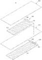
도 1은 본 발명에 따른 양극 전극용 집전체를 포함하는 전극 조립체를 도시한 사시도이다.
도 2는 본 발명에 따른 전극 조립체를 도시한 분해 사시도이다.
도 3은 본 발명에 따른 양극 전극용 집전체를 도시한 사시도이다.
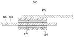
도 4는 본 발명의 제1 실시예에 따른 양극 전극용 집전체를 도시한 단면도이다.
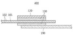
도 5는 본 발명의 제2 실시예에 따른 양극 전극용 집전체를 도시한 단면도이다.
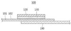
도 6은 본 발명의 제3 실시예에 따른 양극 전극용 집전체를 도시한 단면도이다.
도 7은 본 발명의 제4 실시예에 따른 양극 전극용 집전체를 도시한 단면도이다.
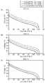
도 8은 본 발명의 제1 실시예에 따른 양극 전극용 집전체를 포함하는 리튬이차전지에 있어서 도전재의 두께에 따른 용량 측정 결과를 보여주는 그래프이다.
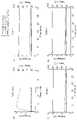
도 9는 본 발명의 제1 실시예에 따른 양극 전극용 집전체를 포함하는 리튬이차전지에 있어서 도전재의 두께에 따른 못 관통 시험 결과를 보여주는 그래프이다.1 is a perspective view illustrating an electrode assembly including a current collector for a positive electrode according to the present invention.
2 is an exploded perspective view illustrating an electrode assembly according to the present invention.
3 is a perspective view illustrating a current collector for a positive electrode according to the present invention.
4 is a cross-sectional view illustrating a current collector for a positive electrode according to a first embodiment of the present invention.
5 is a cross-sectional view illustrating a current collector for a positive electrode according to a second embodiment of the present invention.
6 is a cross-sectional view illustrating a current collector for a positive electrode according to a third embodiment of the present invention.
7 is a cross-sectional view illustrating a current collector for a positive electrode according to a fourth embodiment of the present invention.
8 is a graph showing the capacity measurement results according to the thickness of the conductive material in the lithium secondary battery including the current collector for the positive electrode according to the first embodiment of the present invention.
9 is a graph showing a nail penetration test result according to a thickness of a conductive material in a lithium secondary battery including a current collector for a positive electrode according to a first embodiment of the present invention.
이하에서, 첨부된 도면을 참조하여 본 발명에 따른 실시예들을 상세하게 설명한다. 그러나, 본 발명이 실시예들에 의해 제한되거나 한정되는 것은 아니다. 각 도면에 제시된 동일한 참조 부호는 동일한 부재를 나타낸다.Hereinafter, embodiments according to the present invention will be described in detail with reference to the accompanying drawings. However, the present invention is not limited or limited by the examples. Like reference numerals in each figure indicate like elements.
도 1은 본 발명에 따른 양극 전극용 집전체를 포함하는 전극 조립체를 도시한 사시도, 도 2는 본 발명에 따른 전극 조립체를 도시한 분해 사시도, 도 3은 본 발명에 따른 양극 전극용 집전체를 도시한 사시도, 도 4는 본 발명의 제1 실시예에 따른 양극 전극용 집전체를 도시한 단면도, 도 5는 본 발명의 제2 실시예에 따른 양극 전극용 집전체를 도시한 단면도, 도 6은 본 발명의 제3 실시예에 따른 양극 전극용 집전체를 도시한 단면도, 도 7은 본 발명의 제4 실시예에 따른 양극 전극용 집전체를 도시한 단면도, 도 8은 본 발명의 제1 실시예에 따른 양극 전극용 집전체를 포함하는 리튬이차전지에 있어서 도전재의 두께에 따른 용량 측정 결과를 보여주는 그래프, 도 9는 본 발명의 제1 실시예에 따른 양극 전극용 집전체를 포함하는 리튬이차전지에 있어서 도전재의 두께에 따른 못 관통 시험 결과를 보여주는 그래프이다.1 is a perspective view showing an electrode assembly including a current collector for a positive electrode according to the present invention, FIG. 2 is an exploded perspective view showing an electrode assembly according to the present invention, and FIG. 3 is a current collector for a positive electrode according to the
도 1 및 도 2에는 본 발명에 따른 양극 전극용 집전체(100)를 포함하는 전극조립체(10)가 도시되어 있다. 도 1 및 도 2의 경우, 본 발명에 따른 양극 전극용 집전체(100)는 전극조립체(10)에 사용되기 위해서 양극 전극용 집전체(100)의 표면에 양극 활물질(103)이 도포되어야 한다.1 and 2, the
한편, 음극 전극용 집전체(200)는 음극 금속포일(201)에 음극 활물질(203)이 도포되며, 길이방향의 일단측에 음극 리드탭(290)이 연결될 수 있다.On the other hand, in the
음극 전극용 집전체(200)와 본 발명에 따른 양극 전극용 집전체(100) 사이에 분리막(300)이 배치될 수 있다. 도 2에 도시된 바와 같은 상태로 분리막(300)을 사이에 두고 상하에 각각 음극 전극용 집전체(200)와 양극 전극용 집전체(100)를 순서대로 쌓으면 도 1과 같은 전극조립체(10)가 된다.The
도 3에는 본 발명에 따른 양극 전극용 집전체(100)가 도시되어 있다. 양극 전극용 집전체(100)는 앞서 언급한 음극 전극용 집전체(200)와는 달리 금속 포일을 사용하지 않는다.3 shows a
도 3에 도시된 바와 같은 본 발명에 따른 양극 전극용 집전체(100)는, 금속 포일로 된 집전체의 저항 보다 큰 저항값을 가지기 때문에, 집전체를 흐르는 전류의 한계 전류값을 조정할 수 있고 고분자 필름의 손상에 의해 전류 흐름이 방해를 받을 수 있기 때문에 이차전지의 내부 단락 발생시 단락 전류를 저하시키거나 발열을 방지할 수 있다.Since the
본 발명에 따른 양극 전극용 집전체(100)를 구비한 리튬이차전지(Lithium Secondary Battery)는 Max Current Limited Battery (MCLB)의 성격 또는 개념을 가질 수 있다. 이하에서는, MCLB의 구현을 가능하게 하는 본 발명에 따른 양극 전극용 집전체에 대해서 설명한다.A lithium secondary battery having the
본 발명에 따른 양극 전극용 집전체(100)는, 기존 전지의 금속 포일(metal foil)로 형성된 양극 전극용 집전체의 저항 보다 높은 저항값을 가지기 때문에 한계 전류를 조정할 수 있을 뿐만 아니라 내부 단락시 전류 패스를 붕괴시킴으로써 단락 전류를 저하시키거나 단락시 발생하는 발열 현상을 줄여서 전지의 안전성을 높일 수 있다.Since the
본 발명에 따른 양극 전극용 집전체(100)는 금속 포일을 사용하지 않고 고분자 필름(101)을 기본 소재로 하고, 고분자 필름(101) 위에 얇은 두께의 금속이 도포하거나 코팅될 수 있다.The
이하에서는 도면을 참조하여 본 발명에 따른 양극 전극용 집전체(100)의 다양한 형태에 대해서 설명한다.Hereinafter, various forms of the
우선, 도 4 내지 도 7을 참조하면, 본 발명에 따른 양극 전극용 집전체(100,400,500,600)는, 고분자 필름(101); 고분자 필름(101)의 상면 또는 하면 중 적어도 하나의 일면에 마련되는 도전재(102, Conductive material); 도전재(102)와 전기적으로 연결되도록 고분자 필름(101)의 상면 또는 하면 쪽에 마련되는 금속편(120, Metal element); 및 상기 금속편(120), 상기 도전재(102) 또는 상기 고분자 필름(101) 중 어느 하나와 접합되도록 마련되어 상기 도전재(102)와 전기적으로 연결되는 리드탭(190, Lead tab);을 포함하며, 상기 도전재(102)는 상기 금속편(120)과 상기 고분자 필름(101) 사이에 위치하거나 상기 리드탭(190)과 상기 고분자 필름(101) 사이에 위치하고, 상기 리드탭(190)은 상기 고분자 필름(101)의 상면 및 하면 쪽에 마련된 상기 금속편(120)과 용접되거나 상기 리드탭(190)과 마주 보는 상기 고분자 필름(101)의 일면 쪽에 마련된 상기 금속편(120)과 용접될 수 있다.First, referring to Figures 4 to 7, the current collector for a positive electrode according to the present invention (100, 400, 500, 600), a polymer film (101); a conductive material (102, Conductive material) provided on at least one surface of the upper surface or the lower surface of the
이때, 상기 도전재(102)는 상기 금속편(120)과 상기 고분자 필름(101) 사이에 위치하거나 상기 고분자 필름(101)과 상기 리드탭(190) 사이에 위치할 수 있다.In this case, the
여기서, 상기 도전재(102)는 단락시 전해액과의 반응을 통해 전기화학적 퓨즈(electrochemical fuse)의 기능을 할 수 있기 때문에 단락 방지 기능을 가질 수 있다. 이러한 도전재(102)의 전기 화학적 특성에 대해서는 후술하도록 한다.Here, the
고분자 필름(101)은 일정한 길이는 가지도록 띠 모양으로 마련될 수 있다. 여기서, 고분자 필름(101)은 그 길이방향(즉, 상대적으로 긴 길이를 가지는 방향)을 따라 롤투롤(Roll to roll) 방식으로 공급 또는 이송됨으로써 후술하는 전극조립체(10)를 형성할 수 있다.The
고분자 필름(101)은 폴리에틸렌(PE: polyethylene), 폴리프로필렌(PP: polypropylene), 폴리부틸렌 테레프탈레이트(PBT: Polybutylene terephthalate), 폴리이미드(PI: Polyimide) 또는 폴리에틸렌 테레프탈레이트(PET: polyethylene terephthalate) 등의 고분자 부도체 재질로 마련되는 것이 바람직하다.
고분자 필름(101)은 50 μm 이하의 두께를 가지되, 1.4 μm 이상, 50 μm 이하의 두께를 가지는 것이 바람직하다. 본 발명의 제1 실시예에 따른 양극 전극용 집전체(100)는 기존의 금속 포일 집전체를 사용하는 경우 보다 전지의 두께 또는 무게를 줄일 수 있는데, 두께가 1.4 μm 이상, 50 μm 이하인 부도체 재질의 고분자 필름을 고분자 필름(101)으로 사용함으로써 본 발명에 따른 양극 전극용 집전체(100,400,500,600)를 구비한 리튬이차전지의 전체적인 두께 또는 무게를 줄일 수 있다.The
한편, 고분자 필름(101)은 300℃ 보다 낮은 온도에서 녹는 재질로 형성되는 것이 바람직하다. 리드탭(190)을 용접하여 고분자 필름(101)에 고정하게 되는데, 고분자 필름(101)이 리드탭(190)의 용접 온도 보다 낮은 온도에서 녹지 않으면 리드탭(190)이 고분자 필름(101)에 결합될 수 없다. 따라서, 고분자 필름(101)은 리드탭(190)을 용접하는 과정에서 녹을 수 있는 정도의 녹는점을 가져야 하며 300℃ 보다 낮은 녹는점을 가지는 것이 바람직하다.On the other hand, the
한편, 본 발명에 따른 양극 전극용 집전체(100,400,500,600)는, 고분자 필름(101)의 상면 또는 하면 중 적어도 하나의 표면에 마련되는 도전재(102, conductive material)를 포함할 수 있다.Meanwhile, the
도전재(102)는 알루미늄(Al)으로 마련되는 것이 바람직하며, 고분자 필름(101)의 표면에 도금 또는 코팅된 상태로 형성될 수 있다. 따라서 도전재(102)는 양극 전극용 집전체(100)의 가장 외면을 형성하는 도전층(conductive layer)이라고 할 수도 있다.The
도전재(102)는 양극 전극용 집전체(100,400,500,600)의 한계 전류 또는 최대 전류를 조절하거나 낮추도록 형성될 수 있다. 다시 말하면, 도전재(102)는 양극 전극용 집전체(100,400,500,600)의 전도성(conductivity)을 제어하기 위해 고분자 필름(101)의 상면 또는 하면 중 적어도 하나의 표면에 도금되거나 코팅되는 알루미늄이며, 고분자 필름(101)의 표면에 도금 또는 코팅된 상태에 중점을 둘 경우에는 도전재(102)는 도전층이라고 할 수도 있다. 이하에서 도전재(102)는 도전층을 포함하는 개념임을 밝혀둔다.The
고분자 필름(101)의 상면 또는 하면 중 적어도 하나의 표면에 도금되거나 코팅되는 도전재(102)의 코팅량 또는 코팅 두께를 조절함으로써 양극 전극용 집전체(100,400,500,600)를 흐르는 전류의 최대량을 제어 또는 낮출 수 있고, 이로 인해 리튬이차전지의 안전성을 높일 수 있으며 단락 발생시 전지의 안전성을 확보할 수 있다.Control or lower the maximum amount of current flowing through the current collector 100,400,500,600 for the positive electrode by controlling the coating amount or the coating thickness of the
다시 말하면, 고분자 필름(101)의 표면에 형성된 도전재(102)의 두께 또는 양에 의해서 양극 전극용 집전체(100)를 흐르는 한계 전류 또는 최대 전류가 조절될 수 있다. 이와 같이, 본 발명에 따른 전극용 집전체(100,400,500,600)의 도전재(102)에 의해서 리튬이차전지(Lithium Secondary Battery)의 Max Current Limited Battery (MCLB)의 성격 또는 개념이 구현될 수 있다.In other words, the limit current or the maximum current flowing through the
또한, 물리적인 내부 단락 또는 외부 단락 발생시 고분자 필름(101)이 녹을 수 있어서 급격한 전류의 발생을 방해할 수 있기 때문에 전지의 안전성을 향상시킬 수 있다. 더불어, 도전재(102)의 두께가 얇은 경우에는 내부 단락 또는 외부 단락 발생시 도전재(102)를 형성하는 알루미늄 층의 전위가 낮아져서 알루미늄 층과 전해액의 전기화학적 반응을 유도하기 때문에 전도성을 낮추거나 전류를 차단함으로써 전지의 안전성을 향상시킬 수 있다.In addition, when a physical internal short circuit or an external short circuit occurs, the
상기 도전재(102)는 다양한 방식에 의해 고분자 필름(101)의 표면에 형성될 수 있다. 예를 들어, 도전재(102)가 금속인 경우에는 스퍼터링(sputtering) 또는 증발코팅(evaporation coating)에 의해서 고분자 필름(101)의 표면에 형성될 수 있다.The
도전재(102)가 도금 또는 코팅되는 양(무게) 또는 두께에 의해서 양극 전극용 집전체(100)의 전도성을 제어하거나 전지의 안전성을 확보할 수 있기 때문에, 도금 또는 코팅할 때 도전재(102)의 두께 또는 무게를 제어 내지 조절할 수 있는 방식을 사용할 필요가 있다.Since the conductivity of the
고분자 필름(101)의 표면에 도금되거나 코팅되는 도전재(102)의 두께는 리드탭(190)과 전극(집전체)의 길이에 의해서 결정될 수 있다. 예를 들어, 전극(집전체)의 길이가 길어지면 도전재(102)의 도금 두께도 증가하는 것이 바람직하다.The thickness of the
도전재(102)는 고분자 필름(101)의 어느 일면에만 형성되거나 양면에 모두 형성될 수도 있다. 이때, 도전재(102)는 고분자 필름(101)의 어느 일면 최소 0.25 μm, 최대 0.6 μm의 두께로 형성되는 것이 바람직하다.The
본 발명에 따른 양극 전극용 집전체(100,400,500,600)는 도전재(102)에 의해서 전류 흐름이 가능하기 때문에 고분자 필름(101)의 표면에 도전재(102)가 도금 또는 코팅된 상태가 잘 유지되어야 한다. 이를 위해서, 고분자 필름(101)의 표면 처리를 하여 도전재(102)와 고분자 필름(101)의 결착력을 높이는 것이 바람직하다.In the
도전재(102)와 고분자 필름(101) 간의 결착력이 좋지 않으면, 전해액이 주입된 상태에서 도전재(102)가 고분자 필름(101)의 표면에서 분리 또는 이탈될 수 있기 때문에 도전재(102)와 고분자 필름(101) 간의 결착력을 높이는 것이 중요하다.If the bonding strength between the
고분자 필름(101)의 표면에는 도전재(102)와의 접착력 또는 결착력을 높이기 위한 표면 처리가 형성될 수 있다.A surface treatment may be formed on the surface of the
도전재(102)와 고분자 필름(101)의 결착력을 높이기 위해서 고분자 필름(101)의 표면에 코로나 처리를 하는 것이 바람직하다.It is preferable to corona-treat the surface of the
한편, 본 발명에 따른 양극 전극용 집전체(100,400,500,600)는 외부 기기와의 연결을 위한 리드탭(190)을 구비할 수 있다.Meanwhile, the
금속 포일로 된 기존의 전극 집전체는 금속 포일에 직접 리드탭을 용접할 수 있지만, 본 발명에 따른 양극 전극용 집전체(100,400,500,600)는 기존의 금속 포일에 대응하는 구성이 얇은 고분자 필름(101)이기 때문에 고분자 필름(101)에 직접 리드탭을 용접하는 것이 불가능하다. 즉, 고분자 필름(101)의 상면 또는 하면에 형성된 도전재(102)에 리드탭(190)을 용접해야 하는데, 고분자 필름(101)이 얇기 때문에 용접 부위에 충분한 인장 강도를 확보할 수 없어서 리드탭(190)이 고분자 필름(101)에 부착하는 것이 어렵다. 본 발명에 따른 양극 전극용 집전체(100,400,500,600)는 고분자 필름(101)의 상면 및 하면에 금속 재질의 금속편(120)을 부착한 상태에서 금속편(120)에 리드탭(190)을 용접하거나, 어느 일면에 금속편(120)을 부착하고 타면에 리드탭(190)을 부착한 상태에서 리드탭(190)을 금속편(120)에 용접함으로써 이러한 문제를 해결할 수 있다.The conventional electrode current collector made of metal foil can directly weld lead tabs to the metal foil, but the current collector for a positive electrode according to the present invention (100, 400, 500, 600) has a thin polymer film (101) corresponding to the conventional metal foil. Therefore, it is impossible to directly weld the lead tab to the
본 발명에 따른 양극 전극용 집전체(100,400,500,600)에 있어서, 리드탭(190)은 초음파 용접(ultrasonic welding), 레이저 용접(laser welding) 또는 스폿 용접(spot welding)에 의해서 금속편(120), 도전재(102) 또는 고분자 필름(101)에 용접될 수 있다.In the
도 4 내지 도 7에 도시된 본 발명에 따른 양극 전극용 집전체(100,400,500,600)는, 고분자 필름(101)의 상면 및 하면에 모두 금속으로 된 금속편(120), 리드탭(190)이 위치할 수 있다.4 to 7, the
이하에서는 도 4 내지 도 7을 참조하여 양극 전극용 집전체(100,400,500,600)에 대해서 보다 상세하게 설명한다.Hereinafter, the
우선, 도 4에 도시된 본 발명의 제1 실시예에 따른 양극 전극용 집전체(100)는, 고분자 필름(101)의 상면과 하면에 도전재(102)가 마련될 수 있다. 상하의 도전재(102)와 접합 또는 연결되도록 고분자 필름(101)의 상면 및 하면에는 각각 금속편(120)이 마련되어 있다. 즉, 금속편(120)은 고분자 필름(101)의 상면쪽과 하면쪽에서 도전재(102)와 접합 또는 연결되도록 마련될 수 있다. 리드탭(190)은 고분자 필름(101)의 상하에 마련된 금속편(120) 중 어느 하나에 용접됨으로써 리드탭(190)은 금속편(120) 및 도전재(102)와 전기적으로 연결될 수 있다.First, in the
여기서, 금속편(120)은 고분자 필름(101) 상에서 리드탭(190)을 용접하는 위치를 확보하는 역할을 할 수 있다. 즉, 금속편(120)은 리드탭(190)의 연결부와 같은 역할을 할 수 있다.Here, the
금속편(120)은 5 μm 이상의 두께를 가지도록 형성되는 것이 바람직하다. 여기서, 금속편(120)은 고분자 필름(101)의 일부분에만 마련되는 것으로 충분하다. 고분자 필름(101) 상에 마련되는 금속편(120)의 개수 또는 위치 등에는 제한이 없다. 다만, 금속편(120)에 리드탭(190)이 용접되는 경우라면, 전극조립체의 형태를 고려하여 리드탭(190)이 용접되는 금속편(120)의 위치를 결정하는 것이 바람직하다.The
상기한 바와 같이, 금속편(120)은 5 μm 이상의 두께를 가지는 금속 박막 또는 금속 포일의 형태를 가지는 것이 바람직하지만, 반드시 이러한 형태에 국한되는 것은 아니다. 즉, 금속편(120)은 박막, 포일 또는 메쉬(mesh)의 형태로 마련될 수 있다.As described above, the
금속편(120)은 알루미늄 포일(foil) 또는 SUS 316L 포일로 마련될 수 있다.The
이와 같이, 본 발명의 제1 실시예에 따른 양극 전극용 집전체(100)의 금속편(120)은 리드탭(190)의 용접 위치를 확보할 수 있다.As described above, the
도 4에 도시된 바와 같이, 고분자 필름(101)의 상하 양면에 도전재(102)가 형성될 수 있고, 상하의 도전재(102)와 접촉하도록 금속편(120)이 고분자 필름(101)의 상하 양면 쪽에 마련될 수 있다. 리드탭(190)은 상하의 금속편(120) 중 어느 하나에 용접될 수 있다. 용접을 하게 되면 고분자 필름(101)이 녹으면서 도전재(102), 금속편(120) 및 리드탭(190)이 전기적으로 연결될 수 있다.As shown in FIG. 4 , the
또한, 도 4에 도시된 본 발명의 제1 실시예에 따른 양극 전극용 집전체(100)를 참조하면, 도전재(102)와 마주보는 금속편(120)의 일면과 도전재(102) 사이에는 절연성 고분자층(130)이 형성될 수 있다. 절연성 고분자층(130)은 고분자 필름(101)의 표면 또는 도전재(102)의 표면에 금속편(120)을 부착하거나 도전재(102)와 금속편(120)을 절연하기 위한 것이다. 도 4의 경우에는 도전재(102)와 금속편(120) 사이에 절연성 고분자층(130)이 마련될 수 있다.In addition, referring to the
절연성 고분자층(130)은 접착성 또는 점착성을 가지는 물질로 마련되는 것이 바람직하다. 또한, 절연성 고분자층(130)은 고분자(Polymer) 재질로 마련되거나 고분자 필름 형태로 마련될 수 있다. 절연성 고분자층(130)이 고분자 필름의 형태로 마련될 경우에는 두께가 50 μm 미만인 것이 바람직하다.The insulating
절연성 고분자층(130)은 고분자 필름(101)과 같은 온도에서 녹거나 고분자 필름(101)의 낮은 온도에서 녹을 수 있다. 즉, 절연성 고분자층(130)은 고분자 필름(101)과 같은 녹는점을 가지거나, 고분자 필름(101)의 녹는점 보다 낮은 온도의 녹는점을 가지는 것이 바람직하다.The insulating
절연성 고분자층(130)은 폴리에틸렌(PE: Polyethylene), 폴리프로필렌(PP: Polypropylene), 폴리비닐리덴디플루오라이드(PVDF: Polyvinylidene Difluoride), 폴리에틸렌 테레프탈레이트(PET: Polyethylene terephthalate), 폴리이미드(PI: Polyimide) 등의 고분자 재질로 형성될 뿐만 아니라 에틸렌아세트산비닐(EVA: Ethylene Vinyl Acetate) 또는 아크릴레이트(Acrylate)계 화합물 등과 같이 접착 성분을 가지는 고분자 재질로 형성될 수 있다.The insulating
절연성 고분자층(130)은 고분자 필름(101) 또는 도전재(102)의 표면에 금속편(120)을 부착하는 기능 뿐만 아니라 절연층의 기능도 할 수 있다. 리드탭(190)이 용접될 때 절연성 고분자층(130)은 녹으면서 도전재(102)와 전기적으로 연결되는데 용접된 부분을 제외한 부분은 절연성 고분자층(130)에 의하여 절연된 상태가 된다. 외부 단락시 전기적으로 연결된 부분이 용접된 부분으로 제한된 경우 용접된 부분의 도전재(102)가 반응하여 전류를 줄이거나 차단할 수 있다. 전기적으로 연결된 부분이 넓은 경우에는 반응이 많이 필요하기 때문에 전류 차단이 어려울 수 있다. 따라서, 도전재(102)에 금속편(120)이 부착되는 경우에 도전재(102)와 금속편(120) 사이에 절연성을 가지는 절연성 고분자층(130)이 마련되는 것이 바람직하다.The insulating
여기서, 고분자 필름(101)의 양면에 각각 마련된 도전재(102)에 부착되는 절연성 고분자층(130) 및 금속편(120)은 고분자 필름(101)을 기준으로 서로 동일한 위치에 마련될 수 있다.Here, the insulating
도 5에는 본 발명의 제2 실시예에 따른 양극 전극용 집전체(400)가 도시되어 있다. 도 5를 참조하면, 양극 전극용 집전체(400)는, 고분자 필름(101)의 상하 양면에 도포된 도전재(102), 어느 한 쪽의 도전재(102)의 표면에 마련되는 금속편(120), 다른 한 쪽의 도전재(102)의 표면에 마련되는 리드탭(190), 도전재(102)와 금속편(120) 사이에 마련되는 절연성 고분자층(130), 도전재(102)와 리드탭(190) 사이에 마련되는 절연성 고분자층(130)을 포함할 수 있다.5 shows a
도 4의 양극 전극용 집전체(100)와 비교하면, 금속편(120)이 고분자 필름(101)의 한 쪽에 마련되고 반대편에는 리드탭(190)만 마련되는 점, 금속편(120)과 도전재(102) 사이에는 절연성 고분자층(130)이 있지만 절연성 고분자층(130)과 리드탭(190) 사이에는 금속편(120)이 없는 점에서 차이가 있다. 하지만, 도 5에 도시된 양극 전극용 집전체(400)도 고분자 필름(101)의 상면과 하면에 모두 금속으로 된 부재 즉, 금속편(120)과 리드탭(190)이 위치하는 점에서는 도 4에 도시된 양극 전극용 집전체(100)와 유사하다.Compared with the
고분자 필름(101)의 상하 양면에 각각 마련되는 금속편(120)과 리드탭(190)은 동일한 위치에 마련될 수 있다.The
도 6에는 본 발명의 제3 실시예에 따른 양극 전극용 집전체(500)가 도시되어 있다. 도 6을 참조하면, 양극 전극용 집전체(500)는, 고분자 필름(101)의 상하 양면 중 어느 일면에만 도포된 도전재(102), 도전재(102)의 표면에 마련되는 금속편(120), 도전재(102)가 없는 고분자 필름(101)의 표면에 마련되는 리드탭(190), 도전재(102)와 금속편(120) 사이에 마련되는 절연성 고분자층(130)을 포함할 수 있다.6 illustrates a
도 5의 양극 전극용 집전체(400)와 비교하면, 도전재(102)와 금속편(120)이 고분자 필름(101)의 일면에만 마련되고 고분자 필름(101)의 반대면에는 리드탭(190)만 마련되는 점, 금속편(120)과 도전재(102) 사이에는 절연성 고분자층(130)이 있지만 고분자 필름(101)과 리드탭(190) 사이에는 절연성 고분자층(130)이 없는 점에서 차이가 있다. 하지만, 도 6에 도시된 양극 전극용 집전체(500)도 고분자 필름(101)의 상면과 하면에 모두 금속으로 된 부재 즉, 금속편(120)과 리드탭(190)이 위치하는 점에서는 도 4에 도시된 집전체(100), 도 5에 도시된 양극 전극용 집전체(400)와 유사하다.Compared with the
고분자 필름(101)의 상하 양면에 각각 마련되는 금속편(120)과 리드탭(190)은 동일한 위치에 마련될 수 있다.The
도 6에 도시된 본 발명의 제3 실시예에 따른 양극 전극용 집전체(500)는, 알루미늄 도전재(102)가 도포되어 있지 않은 고분자 필름(101)의 일면에 리드탭(190)이 부착되기 때문에 도전재(102)가 없는 면을 안쪽으로 하여 접어서 전극조립체를 형성할 때 리드탭(190)이 분리막 및 음극과 만나지 않게 된다. 따라서, 리드탭(190)의 단락을 방지하기 위한 별도의 보호 필름이 필요하지 않다는 장점이 있다.In the
도 7에는 본 발명의 제4 실시예에 따른 양극 전극용 집전체(600)가 도시되어 있다. 도 7을 참조하면, 양극 전극용 집전체(600)는, 고분자 필름(101)의 상하 양면 중 어느 일면에만 도포된 도전재(102), 도전재(102)의 표면에 마련되는 리드탭(190), 도전재(102)가 없는 고분자 필름(101)의 표면에 마련되는 금속편(120), 도전재(102)와 리드탭(190) 사이에 마련되는 절연성 고분자층(130)을 포함할 수 있다.7 shows a
고분자 필름(101)의 상하 양면에 각각 마련되는 금속편(120)과 리드탭(190)은 동일한 위치에 마련될 수 있다.The
도 7에 도시된 양극 전극용 집전체(600)는 금속편(120)와 리드탭(190)의 위치가 반대인 점에서 도 6에 도시된 양극 전극용 집전체(400)와 차이가 있다. 하지만, 도 7에 도시된 양극 전극용 집전체(600)도 고분자 필름(101)의 상면과 하면에 모두 금속으로 된 부재 즉, 금속편(120)과 리드탭(190)이 위치하는 점에서는 도 4에 도시된 양극 전극용 집전체(100), 도 5에 도시된 양극 전극용 집전체(400) 및 도 6에 도시된 양극 전극용 집전체(500)와 유사하다. 따라서, 도 7에 도시된 본 발명의 제4 실시예에 따른 양극 전극용 집전체(600)도 리드탭(190)의 용접 부위에 충분한 인장강도를 확보할 수 있고 양호한 전기전도도를 가진다고 볼 수 있다.The
상기한 바와 같이 본 발명에 따른 양극 전극용 집전체(100,400,500,600)는, 고분자 필름(101)의 상면 또는 하면 중 적어도 일면에 고분자로 된 절연성 고분자층(130)을 마련하는 경우에도 고분자 필름(101)의 양면에 금속으로 된 부재 즉, 금속편(120) 또는 리드탭(190)이 모두 있기 때문에 고분자 필름(101) 또는 리드탭(190)이 용접된 부위의 인장강도가 양호하다.As described above, the current collector for a positive electrode according to the present invention (100, 400, 500, 600) according to the present invention is a polymer film (101) even when the insulating polymer layer (130) made of a polymer is provided on at least one surface of the upper surface or the lower surface of the polymer film (101). Since there are both metal members, that is, the
리드탭(190)을 용접하게 되면 용접 부위에서 절연성 고분자층(130) 및 고분자 필름(101)이 녹으면서 리드탭(190)이 접합되어 도전재(102)와 전기적으로 연결될 수 있다.When the
한편, 도 3을 참조하면, 도전재(102) 위에 금속편(120)이 위치하고, 금속편(120) 위에 리드탭(190)이 위치하고 있다. 이때, 금속편(120)과 도전재(102) 사이에는 절연성 고분자층(130)이 존재한다. 리드탭(190)이 용접되는 과정에서 절연성 고분자층(130)과 고분자 필름(101)이 녹으면서 용접 포인트를 형성하게 된다. 도 3의 경우, 금속편(120)과 도전재(102) 사이에 위치하는 절연성 고분자층(130)이 녹으면서 리드탭(190)이 용접되는데, 전기적 연결은 절연성 고분자층(130)이 녹으면서 연결된 용접 포인트만으로 이루어지게 된다. 이와 같이, 절연성 고분자층(130)이 있는 경우에는 리드탭(190)의 용접시에 전기적 연결이 용접 포인트에서만 매우 작은 부위에 전류 패스(pass)가 형성되기 때문에 리드탭(190) 또는 금속편(120)과 도전재(102) 사이를 절연시킬 수 있다. 또한, 용접 포인트를 제외한 나머지 부분은 전해액에 노출되거나 전해액이 침투하기 쉬운 상태가 된다.Meanwhile, referring to FIG. 3 , the
만약, 리드탭 또는 금속편과 도전재 사이에 절연성 고분자층이 없으면, 리드탭 또는 금속편과 도전재가 직접 접촉하게 되는데 이때 양자는 리드탭 또는 금속편의 크기에 해당하는 면적으로 도전재와 물리적 접촉을 하게 된다. 이와 같이, 리드탭의 용접 부위에서 리드탭 또는 금속편과 도전재가 물리적 접촉하는 양극 전극용 집전체의 경우, 금속편과 도전재 사이에 절연성 고분자층이 없기 때문에 금속편의 넓이 만큼 면접촉을 가지게 되고 이에 따라 반응해야 하는 면적도 넓을 수밖에 없다. 이렇기 때문에, 고분자 필름의 표면에 도포된 도전재를 모두 반응시키기 어렵다. 이러한 양극 전극용 집전체를 사용하는 전지에 외부 단락이 발생하면 전류 패스(pass)가 유지되기 때문에 전류를 차단시키지 못하고 전지의 온도가 상승할 수 있다.If there is no insulating polymer layer between the lead tab or the metal piece and the conductive material, the lead tab or the metal piece and the conductive material come into direct contact with each other. . As such, in the case of a current collector for a positive electrode in which the lead tab or the metal piece and the conductive material are in physical contact with the lead tab at the welding site of the lead tab, since there is no insulating polymer layer between the metal piece and the conductive material, the surface contact is as much as the width of the metal piece, and accordingly The area that needs to be reacted is bound to be large. For this reason, it is difficult to react all the conductive materials applied to the surface of the polymer film. When an external short circuit occurs in a battery using the current collector for the positive electrode, the current pass is maintained, so that the current cannot be cut off and the temperature of the battery may rise.
고분자 필름(101)의 양면에 마련된 금속편(120) 중 어느 하나의 금속편(120)에 리드탭(190)을 용접할 때, 고분자 필름(101)이 녹음으로써 고분자 필름(101)의 양면에 마련된 금속편(120)이 서로 연결되고, 그 결과 리드탭(190)이 고분자 필름(101)의 양면에 마련된 도전재(102)와 동시에 전기적으로 연결될 수 있다.When the
고분자 필름(101)의 상하 양면에 금속편(120)와 도전재(102)가 마련된 상태에서 고분자 필름(101)의 어느 일면에 마련된 금속편(120)에 리드탭(190)을 초음파 용접, 레이저 용접 또는 스폿 용접하게 되면, 고분자 필름(101)의 일부가 녹을 수 있다. 리드탭(190)을 용접할 때 발생하는 용접열이 고분자 필름(101)의 녹는점 보다 높다면 용접 과정에서 고분자 필름(101)은 녹을 수 있다.The
이처럼 고분자 필름(101)이 녹은 부분에서는 고분자 필름(101)이 존재하지 않기 때문에 상하의 금속편(120)끼리 직접 접촉할 수 있다. 이때, 금속편(120)도 용접열에 의해서 용융된 상태이기 때문에 상하의 금속편(120)끼리 접합하게 된다. 따라서, 고분자 필름(101)이 녹아서 없는 부분에서 상하의 금속편(120)끼리 직접 용융 결합되기 때문에 어느 하나의 금속편(120)에 용접되는 리드탭(190)이 상하의 금속편(120) 뿐만 아니라 고분자 필름(101)의 상하면에 형성된 도전재(102)와 전기적으로 연결될 수 있다.As such, since the
본 발명에 따른 양극 전극용 집전체(100,400,500,600)는 용접열에 의해서 고분자 필름(101)의 일부가 녹더라도 금속편(120)이 고분자 필름(101)과 연결된 상태를 유지하기 때문에 리드탭(190)을 연결하는 것이 가능하다.The
다만, 경우에 따라서는 고분자 필름(101)이 녹지 않은 상태에서도 리드탭(190)을 금속편(120)에 용접할 수 있다.However, in some cases, the
한편, 본 발명에 따른 양극 전극용 집전체(100,400,500,600)는 리튬이차전지의 양극으로 사용되는 집전체로서, 기존의 금속 포일로 된 집전체와 달리 리튬이차전지의 안전성을 높일 수 있다. 왜냐하면, 고분자 필름(101)에 도포 또는 코팅된 도전재(102)가 마치 퓨즈와 같이 단락 전류를 차단하거나 단락 전류를 낮추는 기능을 하기 때문이다.On the other hand, the
일반적으로 이차전지에 내부 단락 또는 외부 단락이 발생하면 단락 전류에 의해서 이차전지의 온도가 올라가는 발열 현상이 생기고, 또한 발열 때문에 전지가 폭발하는 등의 위험성이 있다. 반면에, 양극으로 본 발명에 따른 양극 전극용 집전체(100,400,500,600)를 사용하는 리튬이차전지에 내부 단락 또는 외부 단락이 발생하더라도 리튬이차전지의 온도가 올라가는 것을 방지하고 단락 전류를 차단하거나 단락 전류를 낮춤으로써 리튬이차전지의 안전성을 확보할 수 있다.In general, when an internal or external short circuit occurs in a secondary battery, a heat generation phenomenon occurs in which the temperature of the secondary battery increases due to the short-circuit current, and there is a risk of the battery exploding due to the heat generation. On the other hand, even if an internal short circuit or an external short circuit occurs in a lithium secondary battery using the
양극으로 본 발명에 따른 양극 전극용 집전체(100,400,500,600)를 사용하는 리튬이차전지에 단락이 발생하면, 알루미늄 금속이 도전재(102)로 고분자 필름(101)에 도포 또는 코팅된 양극 전극용 집전체(100,400,500,600)의 전위가 음극 전위 근처(즉, < 0.3 volt, 음극 Li 금속)로 낮아지게 되면 알루미늄 도전재(102)가 전해질과 반응하게 되면 도전재(102)가 마치 부식된 것처럼 깨지면서 단락 전류를 차단하거나 단락 전류를 낮출 수 있다.When a short circuit occurs in a lithium secondary battery using the current collector for a positive electrode according to the present invention (100, 400, 500, 600) as the positive electrode, aluminum metal is applied or coated on the
고분자 필름(101)에 도포되거나 코팅된 도전재(102)가 전류 패스(pass)의 기능을 하게 되는데, 단락 발생시 도전재(102)가 전해액과 반응하면서 부식된 것처럼 잘게 깨지면 전류 패스가 차단되기 때문에 단락 전류가 더 이상 흐르지 않게 되거나 단락 전류가 줄어들게 된다.The
본 발명에 따른 양극 전극용 집전체(100,400,500,600)의 경우 단락 발생시 전류 패스를 차단하거나 단락 전류를 낮출 수 있는 이유는 고분자 필름(101)의 표면에 형성된 알루미늄 도전재(102)의 두께가 매우 얇기 때문에 도전재(102)의 깊이 방향 또는 두께 방향 전체에 대해서 도전재(102)가 전해질과 반응하여 부식되거나 깨져서 단락 전류 패스를 차단하거나 단락 전류를 낮출 수 있다.In the case of the
본 발명의 발명자들은 본 발명에 따른 양극 전극용 집전체(100,400,500,600)를 포함하는 리튬이차전지를 대상으로 도전재(102)의 두께별 리드탭의 저항측정, 전지용량측정, 못 관통 시험을 하였고, 그 결과 리튬이차전지의 안전성을 확보할 수 있는 도전재(102)의 최적 두께 범위를 찾을 수 있었다. 이하에서는 시험 결과 및 도전재(102)의 최적 두께 범위에 대해서 설명한다.The inventors of the present invention conducted a resistance measurement, battery capacity measurement, and nail penetration test of a lead tab by thickness of the
우선, 상기 실험을 하기 위해서 도 4에 도시된 본 발명의 제1 실시예에 따른 양극 전극용 집전체(100)를 제작한다. 도 4를 참조하면, 양극 전극용 집전체(100)는, 고분자 필름(101)의 상하 양면 중 적어도 일면에 도금 또는 코팅되어 마련된 도전재(102), 금속편(120)과 도전재(102) 사이에 마련되어 금속편(120)을 도전재(102)에 접착시키는 절연성 고분자층(130) 및 어느 하나의 금속편(120)에 용접되는 리드탭(190)을 포함할 수 있다.First, in order to conduct the above experiment, the
여기서, 고분자 필름(101)은 두께 7μm의 폴리에틸렌 테레프탈레이트(PET: polyethylene terephthalate)로 마련되고, 도전재(102)는 고분자 필름(101)의 일면에 0.12μm, 0.25μm, 0.4μm, 0.6μm의 두께로 스퍼터링(sputtering)으로 마련될 수 있다. 또한, 절연성 고분자층(130)은 두께 10μm의 아크릴계 접착제로 마련되고, 금속편(120)은 두께 12μm의 알루미늄 포일로 마련되되 고분자 필름(101)의 양면에 서로 90도 각도가 되도록 마련된다. 또한, 리드탭(190)은 두께 100μm, 폭 3mm의 알루미늄 금속으로 마련되고, 도전재(102)가 형성된 금속편(120)에 초음파 용접에 의해 용접된다.Here, the
**도전재의conductive material도금면과plated side리드탭lead tab 사이의 저항 측정 measure the resistance between
[표 1]은 도전재(102)의 두께별로 도전재(102)의 도금면과 리드탭(190) 사이의 저항을 측정한 결과이다. HIOKI 3554 계측기를 사용하여 저항을 측정하였다.[Table 1] shows the results of measuring the resistance between the plated surface of the
[표 1]을 참조하면, 도전재(102)의 두께가 작을수록 즉, 도전재(102)의 도금량이 적을수록 도전재(102)의 도금면과 리드탭(190) 사이의 저항이 커진다는 것을 확인할 수 있다.Referring to [Table 1], the smaller the thickness of the
* 도전재의 두께별 리튬이차전지의 용량 측정* Capacity measurement of lithium secondary battery by thickness of conductive material
도전재(102)의 두께에 따른 리튬이차전지의 용량을 측정하기 위해서, 다음과 같은 특성을 가지는 리튬이차전지를 제조하였다.In order to measure the capacity of the lithium secondary battery according to the thickness of the
(1) 양극 조성 : NCM(L&F NE-X6S) / super-P / PVDF(solef 5130) = 92 / 4 / 4(1) Anode composition: NCM(L&F NE-X6S) / super-P / PVDF(solef 5130) = 92 / 4 / 4
(2) 음극 조성 : 흑연(BTR 518) / SBR(Zeon BM-400B) / CMC (Nippon paper) = 97 / 1.5 / 1.5(2) Anode composition: Graphite (BTR 518) / SBR (Zeon BM-400B) / CMC (Nippon paper) = 97 / 1.5 / 1.5
(3) 양극 로딩 : 3mAh/cm2(3) Anode loading: 3mAh/cm2
(4) 음극 집전체 : Cu foil (8μm)(4) Anode current collector: Cu foil (8μm)
(5) 음극 로딩 : 3.1mAh/cm2(5) Cathode loading: 3.1mAh/cm2
(6) 분리막 : 7um PE (Tonen)(6) Separator: 7um PE (Tonen)
(7) 전해액 : EC/EMC 1M LiFP6, additive 추가(7) Electrolyte: EC/EMC 1M LiFP6, additive added
양극/분리막/음극을 와인딩(Winding)하여 파우치 타입(pouch type)의 리튬이차전지 제조(DNP 113um)Manufacture of pouch type lithium secondary battery by winding positive/separator/negative electrode (DNP 113um)
(8) 양극 size : 3cm x 15cm(8) Anode size: 3cm x 15cm
(9) 전지 용량 : ~120mAh(9) Battery capacity: ~120mAh
[표 2]는 상기와 같은 특성을 가지는 리튬이차전지의 전지 용량을 도전재(102)의 두께별로 측정한 결과이다.[Table 2] shows the results of measuring the battery capacity of the lithium secondary battery having the above characteristics for each thickness of the
(100%)122.7
(100%)
(97.0%)119.0
(97.0%)
(90.0%)110.4
(90.0%)
(100%)125.6
(100%)
(96.7%)121.4
(96.7%)
(92.8%)116.5
(92.8%)
(100%)124.6
(100%)
(96.8%)120.6
(96.8%)
(93.2%)116.1
(93.2%)
[표 2]에서 괄호 내의 %는 도전재(102)의 두께별로 0.2C 용량에 대한 비율을 의미한다. [표 2]를 참조하면, 도전재(101)의 도금양이 적을수록 즉, 도전재(102)의 두께가 작을수록 1.0C 용량이 작아지는 것을 볼 수 있다. 하지만, 전지는 정상적으로 작동하였다.In [Table 2], % in parentheses means a ratio to the 0.2C capacity for each thickness of the
다만, 도전재(102)의 두께가 0.12 μm인 경우에는 전지가 작동되지 않았다. 따라서, 전지로 작동하기 위해서 도전재(102)의 두께가 0.25 μm 이상이 되어야 한다는 것을 알 수 있다.However, when the thickness of the
도 8은 본 발명의 제1 실시예에 따른 양극 전극용 집전체를 포함하는 리튬이차전지에 있어서 도전재의 두께에 따른 용량 측정 결과를 보여주는 그래프이다. 즉, 도 8은 [표 2]의 내용 중 도전재 두께가 0.25μm(도 8(a) 참조), 0.4μm(도 8(b) 참조), 0.6μm(도 8(c) 참조) 일 때의 용량 측정 결과를 보여주는 그래프이다. 도 8을 참조하면, 양극 전극용 집전체(100)의 도전재(102) 두께가 0.25μm, 0.4μm, 0.6μm인 모든 경우에 리튬이차전지가 정상적인 전지의 기능을 발휘한다는 것을 알 수 있다.8 is a graph showing the capacity measurement results according to the thickness of the conductive material in the lithium secondary battery including the current collector for the positive electrode according to the first embodiment of the present invention. That is, FIG. 8 shows when the thickness of the conductive material among the contents of [Table 2] is 0.25 μm (refer to FIG. 8 (a)), 0.4 μm (refer to FIG. 8 (b)), and 0.6 μm (refer to FIG. 8 (c)). It is a graph showing the capacity measurement results of Referring to FIG. 8 , it can be seen that the lithium secondary battery exhibits a normal battery function in all cases where the thickness of the
* 도전재의 두께별 리튬이차전지의 안전성 시험 : 못 관통 시험* Safety test of lithium secondary battery by thickness of conductive material: nail penetration test
도전재의 두께별로 리튬이차전지의 안전성을 시험하기 위해서, 리튬이차전지를 4.2V 만충전 한 후, 직경 3mm의 SUS 못(Nail)을 사용하여 150mm/sec의 속도로 전지의 중앙부를 관통시키는 못(Nail) 관통 단락 시험을 하였다. [표 3]은 못 관통 시험의 결과이다.In order to test the safety of the lithium secondary battery by the thickness of the conductive material, after the lithium secondary battery is fully charged to 4.2V, a nail penetrating the center of the battery at a speed of 150mm/sec using a 3mm diameter SUS nail ( Nail) A penetration short-circuit test was performed. [Table 3] is the result of the nail penetration test.
(12 μm Al foil)Reference
(12 μm Al foil)
~ 90
~ 90
1~2 분 이내 0 V 근방으로 떨어짐
Falls to near 0 V within 1-2 minutes
[표 3]을 참조하면, 도전재(102)가 0.25 μm ~ 0.6 μm의 두께로 도금된 경우에, 외부 단락 발생시에도 전지의 안전성을 확보할 수 있고 전지가 정상적으로 작동한다는 것을 확인할 수 있었다.Referring to [Table 3], when the
도 9는 본 발명의 제1 실시예에 따른 양극 전극용 집전체를 포함하는 리튬이차전지에 있어서 도전재의 두께에 따른 못 관통 시험 결과를 보여주는 그래프이다. 즉, 도 9는 [표 3]의 내용 중 도전재 두께가 0.25μm(도 9(b) 참조), 0.4μm(도 9(c) 참조), 0.6μm(도 9(d) 참조)인 양극 전극용 집전체를 포함하는 리튬이차전지에 대해 못 관통 시험을 한 경우 전지의 온도 및 전압 변화와, 종래의 금속포일 양극 전극용 집전체를 포함하는 리튬이차전지(도 9의 (a) 참조)에 대해 못 관통 시험을 한 경우 전지의 온도 및 전압 변화를 보여주는 그래프이다. 도 9(a)를 참조하면, 금속포일 집전체를 사용하는 전지의 경우에는 못이 관통하게 되면 전지의 온도 급격하게 올라가고 전압은 급격하게 떨어지는 것을 알 수 있는데, 이 경우 전지의 안전성은 극도로 나빠지게 된다. 반면에, 도 9(a) 내지 (c)에 도시된 바와 같이, 0.25μm, 0.4μm, 0.6μm의 두께로 도포된 도전재(102)를 사용하는 전지의 경우에는 못이 관통하더라도 온도와 전압이 서서히 감소하는 것을 알 수 있다. 따라서, 본 발명에 따른 양극 전극용 집전체를 사용하는 리튬이차전지는 못 관통시에도 전지의 온도와 전압이 서서히 감소하기 때문에 전지의 안전성을 개선하고 향상시킬 수 있다.9 is a graph showing a nail penetration test result according to a thickness of a conductive material in a lithium secondary battery including a current collector for a positive electrode according to a first embodiment of the present invention. That is, FIG. 9 shows an anode having a conductive material thickness of 0.25 μm (refer to FIG. 9(b)), 0.4 μm (refer to FIG. 9(c)), and 0.6 μm (refer to FIG. 9(d)) among the contents of [Table 3]. When a nail penetration test is performed on a lithium secondary battery including a current collector for an electrode, the temperature and voltage change of the battery and a lithium secondary battery including a conventional current collector for a metal foil positive electrode (refer to FIG. 9 (a)) It is a graph showing the temperature and voltage change of the battery when the nail penetration test is performed. Referring to FIG. 9( a ), in the case of a battery using a metal foil current collector, it can be seen that when a nail penetrates, the temperature of the battery rapidly rises and the voltage drops sharply. In this case, the safety of the battery is extremely poor. will fall out On the other hand, as shown in Figs. 9(a) to (c), in the case of a battery using the
한편, 본 발명에 따른 양극 전극용 집전체(100,400,500,600)는 고분자 필름(101)의 표면에 알루미늄 도전재(102)가 스퍼터링(sputtering) 또는 증착(evaporation) 방식으로 도포되거나 코팅되는데, 이러한 방식으로 형성되는 알루미늄 도전재(102)에는 나노 사이즈의 기공(pore)이 다수개 형성되거나 크랙과 같은 불규칙적인 형태(이하 "기공"이라 함)가 표면에 존재할 수 있다. 왜냐하면, 고분자 필름(101)에 스퍼터링 또는 증착되는 알루미늄의 미세 입자가 틈새 없이 100% 밀착한 상태로 스퍼터링 또는 증착되는 것이 아니라 알루미늄 입자 사이에 미세한 틈새가 존재하게 되는데 이러한 틈새가 기공이 되는 것이다. 반면에 기존의 금속 포일로 된 양극 전극용 집전체의 경우에는 금속 포일은 압연박이기 때문에 기공이 전혀 존재하지 않는다.On the other hand, in the current collector for a positive electrode according to the present invention (100, 400, 500, 600), the
여기서, 본 발명에 따른 양극 전극용 집전체(100,400,500,600)의 경우에는, 전해액이 알루미늄 도전재(102)에 존재하는 다수개의 기공에 스며들게 되는데 전해액은 도전재(102)의 전체 또는 일부 두께에 걸쳐서 기공 내에 존재할 수 있게 된다. 이러한 상태에서 단락이 발생하게 되면, 도전재(120)의 기공 내에 존재하는 전해액과 도전재(102)가 반응하는 면적을 넓혀주기 때문에 도전재(102)가 그 두께방향으로 쉽게 부식되거나 깨질 수 있게 되고 그 결과 단락 전류가 흐를 수 없게 된다. 이와 같이, 도전재(102)에 존재하는 다수개의 기공이 퓨즈와 같은 역할을 하게 되어 단락시 단락 전류의 흐름이 차단되거나 단락 전류가 줄어들 수 있다.Here, in the case of the
상기한 바와 같이, 본 발명에 따른 양극 전극용 집전체(100,400,500,600)는 도전재(102)를 최소 단면 기준 0.25 μm, 최대 단면 기준 0.6 μm의 두께로 고분자 필름(101)의 표면에 형성함으로써, 이러한 전극용 집전체(100,400,500,600)를 양극으로 사용하는 리튬이차전지의 에너지 밀도는 높이면서도 안전성을 높일 수 있고 단락 발생시 전지의 안전성을 확보할 수 있다.As described above, the
이상과 같이 본 발명에서는 구체적인 구성 요소 등과 같은 특정 사항들과 한정된 실시예 및 도면에 의해 설명되었으나 이는 본 발명의 보다 전반적인 이해를 돕기 위해서 제공된 것일 뿐, 본 발명은 상기의 실시예에 한정되는 것은 아니며, 본 발명이 속하는 분야에서 통상적인 지식을 가진 자라면 이러한 기재로부터 다양한 수정 및 변형이 가능하다. 따라서, 본 발명의 사상은 설명된 실시예에 국한되어 정해져서는 아니 되며, 후술하는 청구범위뿐 아니라 이 청구범위와 균등하거나 등가적 변형이 있는 모든 것들은 본 발명 사상의 범주에 속한다고 할 것이다.As described above, the present invention has been described with specific matters such as specific components and limited embodiments and drawings, but these are only provided to help a more general understanding of the present invention, and the present invention is not limited to the above embodiments. , various modifications and variations are possible from these descriptions by those of ordinary skill in the art to which the present invention pertains. Accordingly, the spirit of the present invention should not be limited to the described embodiments, and not only the claims to be described below, but also all those with equivalent or equivalent modifications to the claims will fall within the scope of the spirit of the present invention.
10: 전극조립체100,400,500,600: 양극 전극용 집전체
101: 고분자 필름102: 도전재
103: 음극 활물질120: 금속편
130: 절연성 고분자층190: 리드탭
200: 음극 전극용 집전체201: 음극 금속포일
290: 음극 리드탭300: 분리막10: electrode assembly 100,400,500,600: current collector for positive electrode
101: polymer film 102: conductive material
103: negative active material 120: metal piece
130: insulating polymer layer 190: lead tab
200: current collector for negative electrode 201: negative electrode metal foil
290: negative lead tab 300: separator
Claims (8)
Translated fromKorean비금속 부도체 재질의 고분자 필름; 및
상기 고분자 필름의 상면 또는 하면 중 적어도 하나의 일면에 0.25 ~ 0.6 μm의 두께로 코팅 또는 도포되어 상기 양극 전극용 집전체의 최외면을 형성하는 알루미늄 도전재;를 포함하고,
상기 알루미늄 도전재는 내부 단락 또는 외부 단락 발생시 전기화학적 퓨즈의 기능을 가지거나 단락 전류를 차단하거나 낮추는 기능을 가지며,
상기 알루미늄 도전재가 0.25 ~ 0.6 μm의 두께로 코팅 또는 도포됨으로써 못 관통 시험시 상기 양극 전극용 집전체를 포함하는 리튬이차전지의 온도와 전압이 서서히 감소하는 것을 특징으로 하는 양극 전극용 집전체.
As a current collector for a positive electrode replacing a metal foil,
Non-metallic non-conductive polymer film; and
An aluminum conductive material coated or applied to a thickness of 0.25 to 0.6 μm on at least one surface of the upper surface or the lower surface of the polymer film to form the outermost surface of the current collector for the positive electrode;
The aluminum conductive material has a function of an electrochemical fuse or a function of blocking or lowering a short circuit current when an internal short circuit or an external short circuit occurs,
A current collector for a positive electrode, characterized in that the temperature and voltage of the lithium secondary battery including the current collector for the positive electrode are gradually decreased during the nail penetration test by coating or applying the aluminum conductive material to a thickness of 0.25 to 0.6 μm.
비금속 부도체 재질의 고분자 필름; 및
상기 고분자 필름의 상면 또는 하면 중 적어도 하나의 일면에 0.25 ~ 0.6 μm의 두께로 코팅 또는 도포되어 상기 양극 전극용 집전체의 최외면을 형성하는 알루미늄 도전재;를 포함하고,
내부 단락 또는 외부 단락이 발생하면 상기 알루미늄 도전재는 전해액과 반응하여 상기 알루미늄 도전재의 전체 두께에 걸쳐서 두께 방향을 따라 부식되거나 깨지면서 단락 전류 패스를 차단하거나 단락 전류를 낮추며,
상기 알루미늄 도전재가 0.25 ~ 0.6 μm의 두께로 코팅 또는 도포됨으로써 못 관통 시험시 상기 양극 전극용 집전체를 포함하는 리튬이차전지의 온도와 전압이 서서히 감소하는 것을 특징으로 하는 양극 전극용 집전체.
As a current collector for a positive electrode replacing a metal foil,
Non-metallic non-conductive polymer film; and
An aluminum conductive material coated or applied to a thickness of 0.25 to 0.6 μm on at least one surface of the upper surface or the lower surface of the polymer film to form the outermost surface of the current collector for the positive electrode;
When an internal or external short circuit occurs, the aluminum conductive material reacts with the electrolyte to corrode or break along the thickness direction over the entire thickness of the aluminum conductive material to block the short circuit current path or lower the short circuit current,
A current collector for a positive electrode, characterized in that the temperature and voltage of the lithium secondary battery including the current collector for the positive electrode are gradually decreased during the nail penetration test by coating or applying the aluminum conductive material to a thickness of 0.25 to 0.6 μm.
비금속 부도체 재질의 고분자 필름; 및
상기 고분자 필름의 상면 또는 하면 중 적어도 하나의 일면에 0.25 ~ 0.6 μm의 두께로 코팅 또는 도포되어 상기 양극 전극용 집전체의 최외면을 형성하는 알루미늄 도전재;를 포함하고,
내부 단락 또는 외부 단락이 발생하면 상기 양극 전극용 집전체의 전위가 음극 전위까지 떨어지면서 상기 알루미늄 도전재는 전체 두께에 걸쳐서 두께 방향을 따라 부식되거나 깨지면서 단락 전류 패스를 차단하거나 단락 전류를 낮추며,
상기 알루미늄 도전재가 0.25 ~ 0.6 μm의 두께로 코팅 또는 도포됨으로써 못 관통 시험시 상기 양극 전극용 집전체를 포함하는 리튬이차전지의 온도와 전압이 서서히 감소하는 것을 특징으로 하는 양극 전극용 집전체.
As a current collector for a positive electrode replacing a metal foil,
Non-metallic non-conductive polymer film; and
An aluminum conductive material coated or applied to a thickness of 0.25 to 0.6 μm on at least one surface of the upper surface or the lower surface of the polymer film to form the outermost surface of the current collector for the positive electrode;
When an internal or external short circuit occurs, the potential of the current collector for the positive electrode drops to the negative potential and the aluminum conductive material corrodes or breaks along the thickness direction over the entire thickness to block the short circuit current path or lower the short circuit current,
A current collector for a positive electrode, characterized in that the temperature and voltage of the lithium secondary battery including the current collector for the positive electrode are gradually decreased during the nail penetration test by coating or applying the aluminum conductive material to a thickness of 0.25 to 0.6 μm.
상기 알루미늄 도전재와 전기적으로 연결되도록 상기 고분자 필름의 상면 또는 하면 중 적어도 한 쪽에는 금속편이 마련되고,
상기 금속편의 일면 또는 상기 고분자 필름의 상면 또는 하면 중 상기 금속편과 대향하는 한 쪽에는 리드탭이 마련되며,
상기 금속편과 상기 고분자 필름 사이 또는 상기 리드탭과 상기 고분자 필름 사이에 상기 알루미늄 도전재가 마련되는 것을 특징으로 하는 양극 전극용 집전체.
4. The method according to any one of claims 1 to 3,
A metal piece is provided on at least one of the upper surface or the lower surface of the polymer film so as to be electrically connected to the aluminum conductive material,
A lead tab is provided on one side of the metal piece or one side of the upper surface or lower surface of the polymer film facing the metal piece,
The current collector for a positive electrode, wherein the aluminum conductive material is provided between the metal piece and the polymer film or between the lead tab and the polymer film.
상기 금속편은 알루미늄 포일 또는 SUS 316L 포일로 마련되는 것을 특징으로 하는 양극 전극용 집전체.
5. The method of claim 4,
The current collector for a positive electrode, characterized in that the metal piece is provided with aluminum foil or SUS 316L foil.
상기 알루미늄 도전재와 상기 금속편 사이 또는 상기 알루미늄 도전재와 상기 리드탭 사이에는 절연성 고분자층이 마련되며,
상기 리드탭과 상기 금속편의 용접시 상기 절연성 고분자층과 상기 고분자 필름이 녹으면서 용접 포인트를 형성하고 상기 용접 포인트에서만 전류 패스가 형성되는 것을 특징으로 하는 양극 전극용 집전체.
5. The method of claim 4,
An insulating polymer layer is provided between the aluminum conductive material and the metal piece or between the aluminum conductive material and the lead tab,
When the lead tab and the metal piece are welded, the insulating polymer layer and the polymer film are melted to form a welding point, and a current path is formed only at the welding point.
상기 고분자 필름의 표면에 코팅 또는 도포되는 상기 알루미늄 도전재에는 나노 사이즈의 기공이 다수개 형성되는 것을 특징으로 하는 양극 전극용 집전체.8. The method of claim 7,
A current collector for a positive electrode, characterized in that a plurality of nano-sized pores are formed in the aluminum conductive material coated or applied to the surface of the polymer film.
Priority Applications (7)
| Application Number | Priority Date | Filing Date | Title |
|---|---|---|---|
| KR1020190173632AKR102424631B1 (en) | 2019-12-24 | 2019-12-24 | Current collector for positive electrodes |
| EP20908053.0AEP4084211A4 (en) | 2019-12-24 | 2020-11-17 | POSITIVE ELECTRODE CURRENT COLLECTOR |
| US17/783,343US20230027109A1 (en) | 2019-12-24 | 2020-11-17 | Positive electrode current collector |
| JP2022539130AJP7477209B2 (en) | 2019-12-24 | 2020-11-17 | Positive electrode current collector |
| CN202411429594.8ACN119275507A (en) | 2019-12-24 | 2020-11-17 | Current collector for positive electrode |
| CN202080086218.7ACN114830431A (en) | 2019-12-24 | 2020-11-17 | Collector for positive electrode |
| PCT/KR2020/016146WO2021132886A1 (en) | 2019-12-24 | 2020-11-17 | Positive electrode current collector |
Applications Claiming Priority (1)
| Application Number | Priority Date | Filing Date | Title |
|---|---|---|---|
| KR1020190173632AKR102424631B1 (en) | 2019-12-24 | 2019-12-24 | Current collector for positive electrodes |
Publications (2)
| Publication Number | Publication Date |
|---|---|
| KR20210081548A KR20210081548A (en) | 2021-07-02 |
| KR102424631B1true KR102424631B1 (en) | 2022-07-25 |
Family
ID=76574856
Family Applications (1)
| Application Number | Title | Priority Date | Filing Date |
|---|---|---|---|
| KR1020190173632AActiveKR102424631B1 (en) | 2019-12-24 | 2019-12-24 | Current collector for positive electrodes |
Country Status (6)
| Country | Link |
|---|---|
| US (1) | US20230027109A1 (en) |
| EP (1) | EP4084211A4 (en) |
| JP (1) | JP7477209B2 (en) |
| KR (1) | KR102424631B1 (en) |
| CN (2) | CN119275507A (en) |
| WO (1) | WO2021132886A1 (en) |
Cited By (1)
| Publication number | Priority date | Publication date | Assignee | Title |
|---|---|---|---|---|
| WO2024205168A1 (en)* | 2023-03-26 | 2024-10-03 | 삼성에스디아이주식회사 | Lithium battery and manufacturing method therefor |
Families Citing this family (3)
| Publication number | Priority date | Publication date | Assignee | Title |
|---|---|---|---|---|
| CN217158236U (en)* | 2022-04-08 | 2022-08-09 | 宁德时代新能源科技股份有限公司 | Electrode Pieces, Electrode Assemblies and Batteries |
| KR20240178853A (en)* | 2023-06-23 | 2024-12-31 | 삼성에스디아이 주식회사 | All Solid secondary battery |
| KR20250019364A (en)* | 2023-08-01 | 2025-02-10 | 주식회사 엘지에너지솔루션 | Device for manufacturing electrode and method for manufacturing electrode |
Family Cites Families (30)
| Publication number | Priority date | Publication date | Assignee | Title |
|---|---|---|---|---|
| US4447509A (en)* | 1981-11-16 | 1984-05-08 | The United States Of America As Represented By The United States Department Of Energy | Pre-plated reactive diffusion-bonded battery electrode plaques |
| JPH09120818A (en)* | 1995-10-26 | 1997-05-06 | Sony Corp | Nonaqueous electrolyte secondary battery |
| JPH1167188A (en)* | 1997-08-22 | 1999-03-09 | Japan Storage Battery Co Ltd | Lead terminal for secondary battery and lithium secondary battery |
| JPH11102711A (en)* | 1997-09-25 | 1999-04-13 | Denso Corp | Lithium ion secondary battery |
| JP2004311073A (en)* | 2003-04-02 | 2004-11-04 | Matsushita Electric Ind Co Ltd | Energy device with overcurrent protection function and method of manufacturing the same |
| JP4920880B2 (en) | 2003-09-26 | 2012-04-18 | 三星エスディアイ株式会社 | Lithium ion secondary battery |
| KR100635737B1 (en)* | 2005-03-24 | 2006-10-17 | 삼성에스디아이 주식회사 | Lithium secondary battery |
| JP2009059571A (en)* | 2007-08-31 | 2009-03-19 | Sanyo Electric Co Ltd | Current collector for battery, and battery using this |
| CN102349181B (en)* | 2009-03-12 | 2016-02-10 | 日产自动车株式会社 | Bipolar battery current collector and bipolar cell |
| JP2010238410A (en) | 2009-03-30 | 2010-10-21 | Panasonic Corp | Nonaqueous electrolyte secondary battery electrode, nonaqueous electrolyte secondary battery, and methods for producing the same |
| KR101036070B1 (en)* | 2010-01-26 | 2011-05-19 | 에스비리모티브 주식회사 | Secondary battery |
| KR101130294B1 (en)* | 2010-03-30 | 2012-08-23 | 에스비리모티브 주식회사 | Rechargeable Battery |
| JP5784928B2 (en)* | 2011-03-03 | 2015-09-24 | シャープ株式会社 | Non-aqueous secondary battery |
| JP2013008564A (en)* | 2011-06-24 | 2013-01-10 | Sharp Corp | Nonaqueous secondary battery, and method of manufacturing the same |
| KR101342696B1 (en)* | 2012-12-07 | 2013-12-17 | 한화케미칼 주식회사 | Lithium ion battery and fabrication method thereof |
| KR20150035205A (en)* | 2013-09-27 | 2015-04-06 | 삼성에스디아이 주식회사 | Secondary battery |
| US10090510B2 (en)* | 2014-02-26 | 2018-10-02 | Sanyo Electric Co., Ltd. | Non-aqueous electrolyte secondary battery |
| JP6288057B2 (en)* | 2015-12-02 | 2018-03-07 | トヨタ自動車株式会社 | Stacked all-solid battery |
| KR102142552B1 (en) | 2016-10-05 | 2020-08-10 | 주식회사 엘지화학 | Negative electrode for lithium metal secondary battery and lithium metal secondary battery comprising the same |
| CN106601973B (en)* | 2016-11-27 | 2019-06-21 | 浙江吉利控股集团有限公司 | A high-efficiency and high-rate lithium battery structure |
| CN107123812B (en)* | 2017-04-14 | 2020-05-19 | 宁德时代新能源科技股份有限公司 | A positive electrode current collector, its preparation method and its application |
| US20190032220A1 (en)* | 2017-07-25 | 2019-01-31 | Rohm And Haas Electronic Materials Llc | Chrome-free etch solutions for chemically resistant polymer materials |
| US11139510B2 (en)* | 2017-09-09 | 2021-10-05 | Soteria Battery Innovation Group, Inc. | Battery connections and metallized film components in energy storage devices having internal fuses |
| CN109873161B (en)* | 2017-12-05 | 2021-07-30 | 宁德时代新能源科技股份有限公司 | a battery |
| CN109873166B (en)* | 2017-12-05 | 2021-06-29 | 宁德时代新能源科技股份有限公司 | A current collector, its pole piece and electrochemical device |
| CN109873163B (en)* | 2017-12-05 | 2021-07-06 | 宁德时代新能源科技股份有限公司 | A current collector, its pole piece and battery and application |
| CN110247057A (en)* | 2018-03-30 | 2019-09-17 | 宁德时代新能源科技股份有限公司 | Current collector, pole piece thereof and electrochemical device |
| CN110247055B (en)* | 2018-03-30 | 2020-12-04 | 宁德时代新能源科技股份有限公司 | A current collector, its pole piece and electrochemical device |
| CN108777308B (en)* | 2018-05-30 | 2021-04-30 | 中航锂电(洛阳)有限公司 | Current collector, preparation method thereof and electrochemical energy storage device |
| CN208507818U (en)* | 2018-06-29 | 2019-02-15 | 宁德时代新能源科技股份有限公司 | Secondary cell and its pole piece |
- 2019
- 2019-12-24KRKR1020190173632Apatent/KR102424631B1/enactiveActive
- 2020
- 2020-11-17EPEP20908053.0Apatent/EP4084211A4/enactivePending
- 2020-11-17CNCN202411429594.8Apatent/CN119275507A/enactivePending
- 2020-11-17CNCN202080086218.7Apatent/CN114830431A/enactivePending
- 2020-11-17USUS17/783,343patent/US20230027109A1/enactivePending
- 2020-11-17JPJP2022539130Apatent/JP7477209B2/enactiveActive
- 2020-11-17WOPCT/KR2020/016146patent/WO2021132886A1/ennot_activeCeased
Cited By (1)
| Publication number | Priority date | Publication date | Assignee | Title |
|---|---|---|---|---|
| WO2024205168A1 (en)* | 2023-03-26 | 2024-10-03 | 삼성에스디아이주식회사 | Lithium battery and manufacturing method therefor |
Also Published As
| Publication number | Publication date |
|---|---|
| KR20210081548A (en) | 2021-07-02 |
| WO2021132886A1 (en) | 2021-07-01 |
| EP4084211A1 (en) | 2022-11-02 |
| JP7477209B2 (en) | 2024-05-01 |
| US20230027109A1 (en) | 2023-01-26 |
| JP2023508672A (en) | 2023-03-03 |
| CN114830431A (en) | 2022-07-29 |
| EP4084211A4 (en) | 2024-08-28 |
| CN119275507A (en) | 2025-01-07 |
Similar Documents
| Publication | Publication Date | Title |
|---|---|---|
| US12166214B2 (en) | Current collector for electrode | |
| US11777102B2 (en) | Current collector for electrode | |
| KR102424631B1 (en) | Current collector for positive electrodes | |
| KR102267393B1 (en) | Current collector for cathode electrodes | |
| JP6831815B2 (en) | Lithium ion battery | |
| US12095097B2 (en) | Current collector for electrode | |
| EP4250405A1 (en) | Current collector for electrode | |
| KR102602260B1 (en) | Current collector for electrodes |
Legal Events
| Date | Code | Title | Description |
|---|---|---|---|
| PA0109 | Patent application | Patent event code:PA01091R01D Comment text:Patent Application Patent event date:20191224 | |
| PA0201 | Request for examination | ||
| PG1501 | Laying open of application | ||
| E902 | Notification of reason for refusal | ||
| PE0902 | Notice of grounds for rejection | Comment text:Notification of reason for refusal Patent event date:20210826 Patent event code:PE09021S01D | |
| E701 | Decision to grant or registration of patent right | ||
| PE0701 | Decision of registration | Patent event code:PE07011S01D Comment text:Decision to Grant Registration Patent event date:20220719 | |
| GRNT | Written decision to grant | ||
| PR0701 | Registration of establishment | Comment text:Registration of Establishment Patent event date:20220720 Patent event code:PR07011E01D | |
| PR1002 | Payment of registration fee | Payment date:20220720 End annual number:3 Start annual number:1 | |
| PG1601 | Publication of registration | ||
| PR1001 | Payment of annual fee | Payment date:20250407 Start annual number:4 End annual number:4 |