KR102423893B1 - Flexible display device - Google Patents
Flexible display deviceDownload PDFInfo
- Publication number
- KR102423893B1 KR102423893B1KR1020150045315AKR20150045315AKR102423893B1KR 102423893 B1KR102423893 B1KR 102423893B1KR 1020150045315 AKR1020150045315 AKR 1020150045315AKR 20150045315 AKR20150045315 AKR 20150045315AKR 102423893 B1KR102423893 B1KR 102423893B1
- Authority
- KR
- South Korea
- Prior art keywords
- flexible display
- window layer
- display device
- area
- bending
- Prior art date
- Legal status (The legal status is an assumption and is not a legal conclusion. Google has not performed a legal analysis and makes no representation as to the accuracy of the status listed.)
- Active
Links
Images


Classifications
- G—PHYSICS
- G06—COMPUTING OR CALCULATING; COUNTING
- G06F—ELECTRIC DIGITAL DATA PROCESSING
- G06F1/00—Details not covered by groups G06F3/00 - G06F13/00 and G06F21/00
- G06F1/16—Constructional details or arrangements
- G06F1/1613—Constructional details or arrangements for portable computers
- G06F1/1633—Constructional details or arrangements of portable computers not specific to the type of enclosures covered by groups G06F1/1615 - G06F1/1626
- G06F1/1637—Details related to the display arrangement, including those related to the mounting of the display in the housing
- G06F1/1641—Details related to the display arrangement, including those related to the mounting of the display in the housing the display being formed by a plurality of foldable display components
- G—PHYSICS
- G09—EDUCATION; CRYPTOGRAPHY; DISPLAY; ADVERTISING; SEALS
- G09F—DISPLAYING; ADVERTISING; SIGNS; LABELS OR NAME-PLATES; SEALS
- G09F9/00—Indicating arrangements for variable information in which the information is built-up on a support by selection or combination of individual elements
- G09F9/30—Indicating arrangements for variable information in which the information is built-up on a support by selection or combination of individual elements in which the desired character or characters are formed by combining individual elements
- G09F9/301—Indicating arrangements for variable information in which the information is built-up on a support by selection or combination of individual elements in which the desired character or characters are formed by combining individual elements flexible foldable or roll-able electronic displays, e.g. thin LCD, OLED
- G—PHYSICS
- G06—COMPUTING OR CALCULATING; COUNTING
- G06F—ELECTRIC DIGITAL DATA PROCESSING
- G06F1/00—Details not covered by groups G06F3/00 - G06F13/00 and G06F21/00
- G06F1/16—Constructional details or arrangements
- G06F1/1613—Constructional details or arrangements for portable computers
- G06F1/1633—Constructional details or arrangements of portable computers not specific to the type of enclosures covered by groups G06F1/1615 - G06F1/1626
- G06F1/1637—Details related to the display arrangement, including those related to the mounting of the display in the housing
- G06F1/1652—Details related to the display arrangement, including those related to the mounting of the display in the housing the display being flexible, e.g. mimicking a sheet of paper, or rollable
- B—PERFORMING OPERATIONS; TRANSPORTING
- B32—LAYERED PRODUCTS
- B32B—LAYERED PRODUCTS, i.e. PRODUCTS BUILT-UP OF STRATA OF FLAT OR NON-FLAT, e.g. CELLULAR OR HONEYCOMB, FORM
- B32B2457/00—Electrical equipment
- B32B2457/20—Displays, e.g. liquid crystal displays, plasma displays
- B—PERFORMING OPERATIONS; TRANSPORTING
- B32—LAYERED PRODUCTS
- B32B—LAYERED PRODUCTS, i.e. PRODUCTS BUILT-UP OF STRATA OF FLAT OR NON-FLAT, e.g. CELLULAR OR HONEYCOMB, FORM
- B32B2457/00—Electrical equipment
- B32B2457/20—Displays, e.g. liquid crystal displays, plasma displays
- B32B2457/202—LCD, i.e. liquid crystal displays
- B—PERFORMING OPERATIONS; TRANSPORTING
- B32—LAYERED PRODUCTS
- B32B—LAYERED PRODUCTS, i.e. PRODUCTS BUILT-UP OF STRATA OF FLAT OR NON-FLAT, e.g. CELLULAR OR HONEYCOMB, FORM
- B32B2457/00—Electrical equipment
- B32B2457/20—Displays, e.g. liquid crystal displays, plasma displays
- B32B2457/206—Organic displays, e.g. OLED
- B—PERFORMING OPERATIONS; TRANSPORTING
- B32—LAYERED PRODUCTS
- B32B—LAYERED PRODUCTS, i.e. PRODUCTS BUILT-UP OF STRATA OF FLAT OR NON-FLAT, e.g. CELLULAR OR HONEYCOMB, FORM
- B32B3/00—Layered products comprising a layer with external or internal discontinuities or unevennesses, or a layer of non-planar shape; Layered products comprising a layer having particular features of form
- B32B3/26—Layered products comprising a layer with external or internal discontinuities or unevennesses, or a layer of non-planar shape; Layered products comprising a layer having particular features of form characterised by a particular shape of the outline of the cross-section of a continuous layer; characterised by a layer with cavities or internal voids ; characterised by an apertured layer
- B32B3/30—Layered products comprising a layer with external or internal discontinuities or unevennesses, or a layer of non-planar shape; Layered products comprising a layer having particular features of form characterised by a particular shape of the outline of the cross-section of a continuous layer; characterised by a layer with cavities or internal voids ; characterised by an apertured layer characterised by a layer formed with recesses or projections, e.g. hollows, grooves, protuberances, ribs
- C—CHEMISTRY; METALLURGY
- C09—DYES; PAINTS; POLISHES; NATURAL RESINS; ADHESIVES; COMPOSITIONS NOT OTHERWISE PROVIDED FOR; APPLICATIONS OF MATERIALS NOT OTHERWISE PROVIDED FOR
- C09K—MATERIALS FOR MISCELLANEOUS APPLICATIONS, NOT PROVIDED FOR ELSEWHERE
- C09K2323/00—Functional layers of liquid crystal optical display excluding electroactive liquid crystal layer characterised by chemical composition
- C09K2323/05—Bonding or intermediate layer characterised by chemical composition, e.g. sealant or spacer
- C09K2323/051—Inorganic, e.g. glass or silicon oxide
- G—PHYSICS
- G02—OPTICS
- G02F—OPTICAL DEVICES OR ARRANGEMENTS FOR THE CONTROL OF LIGHT BY MODIFICATION OF THE OPTICAL PROPERTIES OF THE MEDIA OF THE ELEMENTS INVOLVED THEREIN; NON-LINEAR OPTICS; FREQUENCY-CHANGING OF LIGHT; OPTICAL LOGIC ELEMENTS; OPTICAL ANALOGUE/DIGITAL CONVERTERS
- G02F1/00—Devices or arrangements for the control of the intensity, colour, phase, polarisation or direction of light arriving from an independent light source, e.g. switching, gating or modulating; Non-linear optics
- G02F1/01—Devices or arrangements for the control of the intensity, colour, phase, polarisation or direction of light arriving from an independent light source, e.g. switching, gating or modulating; Non-linear optics for the control of the intensity, phase, polarisation or colour
- G02F1/13—Devices or arrangements for the control of the intensity, colour, phase, polarisation or direction of light arriving from an independent light source, e.g. switching, gating or modulating; Non-linear optics for the control of the intensity, phase, polarisation or colour based on liquid crystals, e.g. single liquid crystal display cells
- G02F1/133—Constructional arrangements; Operation of liquid crystal cells; Circuit arrangements
- G02F1/1333—Constructional arrangements; Manufacturing methods
- G02F1/133305—Flexible substrates, e.g. plastics, organic film
Landscapes
- Engineering & Computer Science (AREA)
- Theoretical Computer Science (AREA)
- Computer Hardware Design (AREA)
- Physics & Mathematics (AREA)
- General Physics & Mathematics (AREA)
- Human Computer Interaction (AREA)
- General Engineering & Computer Science (AREA)
- Devices For Indicating Variable Information By Combining Individual Elements (AREA)
- Electroluminescent Light Sources (AREA)
- Microelectronics & Electronic Packaging (AREA)
- Push-Button Switches (AREA)
Abstract
Translated fromKoreanDescription
Translated fromKorean본 발명은 플렉서블 표시 장치에 관한 것으로, 보다 구체적으로는, 벤딩에 의한 파손이 방지되며, 벤딩되더라도 광학적 특성이 유지될 수 있는 플렉서블 표시 장치에 관한 것이다.BACKGROUND OF THE INVENTION 1. Field of the Invention The present invention relates to a flexible display device, and more particularly, to a flexible display device capable of preventing breakage due to bending and maintaining optical characteristics even when bent.
현재 널리 알려진 표시 장치로는 액정 표시 장치(liquid crystal display: LCD), 플라즈마 표시 장치(plasma display panel: PDP), 유기 발광 표시 장치(organic light emitting diode device: OLED device), 전계 효과 표시 장치(field effect display: FED), 전기 영동 표시 장치(electrophoretic display device) 등과 같은 다양한 표시 장치들이 있다. 근래에 들어서는 이와 같은 다양한 표시 장치들을 플렉서블한 재질로 형성하는 기술에 대한 연구가 활발히 진행되고 있다. 플렉서블한 재질의 표시 장치가 도입되면, 전자 책, 전자 종이와 같은 새로운 분야에 적용될 수 있어, 표시 장치의 사용 범위를 더욱 증대시킬 수 있을 것이다.Currently widely known display devices include a liquid crystal display (LCD), a plasma display panel (PDP), an organic light emitting diode device (OLED device), and a field effect display device (field There are various display devices such as an effect display (FED) and an electrophoretic display device. In recent years, research on a technology for forming such various display devices using a flexible material has been actively conducted. When a display device made of a flexible material is introduced, it may be applied to new fields such as e-books and electronic paper, and thus the range of use of the display device may be further increased.
다만, 이와 같은 플렉서블 표시 장치들은 여러 개의 층이 적층되는 구조를 가지게 되므로, 벤딩 시 각각의 층을 이루는 재질들의 탄성 계수 차이 또는 각 층에 형성되는 서브 구성들의 물성 차이로 인해 응력이 분산되지 못하는 문제점이 발생될 수 있다. 분산되지 못한 응력은 어느 한 곳에 집중되어 제품의 불량이나 파손까지 일으킬 수 있는 위험 요소가 된다. 따라서 벤딩 시 응력을 분산시킬 수 있는 구조를 가지는 플렉서블 표시 장치에 대한 필요성이 대두되고 있다.However, since such flexible display devices have a structure in which multiple layers are stacked, stress is not dispersed due to a difference in elastic modulus of materials constituting each layer or a difference in physical properties of sub-components formed in each layer during bending. This can happen. Undistributed stress is concentrated in one place and becomes a risk factor that can cause product failure or even damage. Accordingly, there is a need for a flexible display device having a structure capable of dispersing stress during bending.
본 발명은 벤딩에 의한 파손이 방지되며, 벤딩되더라도 광학적 특성이 유지될 수 있는 플렉서블 표시 장치를 제공하고자 한다.An object of the present invention is to provide a flexible display device capable of preventing damage due to bending and maintaining optical characteristics even when bent.
또한, 본 발명이 해결하고자 하는 기술적 과제는 이상에서 언급한 기술적 과제로 제한되지 않으며, 언급되지 않은 또 다른 기술적 과제들은 아래의 기재로부터 본 발명이 속하는 기술분야에서 통상의 지식을 가진 자에게 명확하게 이해될 수 있을 것이다.In addition, the technical problems to be solved by the present invention are not limited to the technical problems mentioned above, and other technical problems not mentioned are clearly to those of ordinary skill in the art to which the present invention belongs from the description below. can be understood
본 발명의 일 실시예에 따른 플렉서블 표시 장치는, 벤딩 영역과 평판 영역을 포함하는 윈도우층 및 윈도우층의 일면에 배치되며, 화상을 표시하는 플렉서블 표시 패널을 포함하고, 벤딩 영역은 윈도우층이 커팅되어 형성되는 복수의 커팅 유닛을 포함한다.A flexible display device according to an embodiment of the present invention includes a window layer including a bending area and a flat area, and a flexible display panel disposed on one surface of the window layer and displaying an image, wherein the bending area is cut by the window layer. It includes a plurality of cutting units that are formed.
이때, 본 실시예의 플렉서블 표시 장치는, 윈도우층의 타면에 배치되는 하드 코팅층 및 윈도우층과 하드 코팅층 사이에 배치되어, 커팅 유닛의 일 단부가 표면을 따라 슬립되는 점착층을 더 포함할 수 있으며, 복수의 커팅 유닛 중 어느 하나의 일 단부가 점착층의 표면을 따라 슬립되어 이웃한 복수의 커팅 유닛 중 다른 하나와 이격될 수 있다.In this case, the flexible display device of the present embodiment may further include a hard coating layer disposed on the other surface of the window layer, and an adhesive layer disposed between the window layer and the hard coating layer so that one end of the cutting unit slips along the surface, One end of any one of the plurality of cutting units may slip along the surface of the adhesive layer to be spaced apart from the other of the plurality of neighboring cutting units.
본 실시예의 플렉서블 표시 패널은, 빛이 방출되는 화소를 포함하여 화상을 표시하는 표시 영역 및 빛이 차단되어 화상을 표시하지 못하는 비표시 영역을 포함하고, 평판 영역은 표시 영역에 대응되는 위치에 배치되며, 벤딩 영역은 비표시 영역에 대응되는 위치에 배치될 수 있다.The flexible display panel of the present embodiment includes a display area for displaying an image including pixels from which light is emitted, and a non-display area for displaying an image because light is blocked, and the flat panel area is disposed at a position corresponding to the display area and the bending area may be disposed at a position corresponding to the non-display area.
본 발명의 다른 실시예에 따른 플렉서블 표시 장치는, 벤딩 영역과 평판 영역을 포함하는 윈도우층 및 윈도우층의 일면에 배치되며, 단위 화소로부터 방출되는 빛이 통과되는 발광 영역을 포함하여 화상을 표시하는 플렉서블 표시 패널을 포함하고, 벤딩 영역은 윈도우층의 일부가 제거되어 형성된다.A flexible display device according to another exemplary embodiment of the present invention includes a window layer including a bending area and a flat area, and a light emitting area disposed on one surface of the window layer and including a light emitting area through which light emitted from a unit pixel passes. It includes a flexible display panel, and the bending region is formed by removing a portion of the window layer.
이때, 벤딩 영역은, 윈도우층의 일부가 제거되어, 발광 영역이 형성된 위치에 대응되는 위치에서 상기 발광 영역의 단면적보다 더 넓은 단면적을 가지도록 형성되는 복수의 돌기 및 벤딩 영역의 높이가 윈도우층의 표면과 동일해지도록 벤딩 영역을 충전하는 벤딩 영역 충전부를 포함할 수 있다.At this time, in the bending region, a portion of the window layer is removed, and the height of the plurality of protrusions and the bending region formed to have a larger cross-sectional area than the cross-sectional area of the light-emitting region at a position corresponding to the position where the light-emitting region is formed is the height of the window layer. It may include a bending area filling part that fills the bending area to be the same as the surface.
벤딩 영역 충전부는 투명 재질의 합성 수지 또는 글래스를 포함하여 이루어질 수 있다.The bending region filling part may include a transparent synthetic resin or glass.
본 실시예에 따른 플렉서블 표시 장치는 벤딩 영역 충전부와 동일한 재질로 이루어지며, 윈도우층의 타면에 배치되는 하드 코팅층을 더 포함할 수 있다.The flexible display device according to the present exemplary embodiment may be made of the same material as the bending region filling part and further include a hard coating layer disposed on the other surface of the window layer.
한편, 본 발명의 또 다른 실시예에 따른 플렉서블 표시 장치의 벤딩 영역은, 발광 영역의 형상에 대응되면서 발광 영역의 단면적보다 더 넓은 단면적을 가지도록, 발광 영역에 대응되는 윈도우층의 일부가 제거되어 형성되는 복수의 홈을 포함할 수 있다.Meanwhile, a portion of the window layer corresponding to the light emitting area is removed so that the bending area of the flexible display device according to another embodiment of the present invention has a larger cross-sectional area than that of the light emitting area while corresponding to the shape of the light emitting area. It may include a plurality of grooves formed.
이때 본 실시예에 따른 플렉서블 표시 장치는 윈도우층의 타면에 배치되며, 투명 재질의 합성 수지 또는 글래스를 포함하여 이루어지는 하드 코팅층을 더 포함할 수 있다.In this case, the flexible display device according to the present embodiment may further include a hard coating layer disposed on the other surface of the window layer and including a transparent synthetic resin or glass.
한편, 본 실시예에 따른 홈은 하드 코팅층과 동일한 재질로 충전될 수 있다.Meanwhile, the groove according to the present embodiment may be filled with the same material as the hard coating layer.
본 발명에 의하면, 플렉서블 표시 장치가 벤딩된다 하더라도, 벤딩으로 인해 가해지는 응력을 분산시킴으로써 제품의 파손이 방지되며, 벤딩 시에도 광학적 특성이 유지되는 플렉서블 표시 장치를 제공할 수 있다.According to the present invention, even when the flexible display device is bent, damage to the product is prevented by dispersing the stress applied due to the bending, and the flexible display device maintains optical properties even during bending.
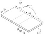
도 1은 본 발명에 따른 플렉서블 표시 장치를 개략적으로 도시한 사시도이다.
도 2는 도 1의 플렉서블 표시 장치가 벤딩된 모습을 도시한 도면이다.
도 3은 본 발명의 제1 실시예에 따른 플렉서블 표시 장치를 도 1의 Ⅱ-Ⅱ 절개선을 따라 절개한 단면의 일부를 도시한 단면도이다.
도 4는 도 3의 플렉서블 표시 장치가 벤딩된 모습을 도시한 도면이다.
도 5는 본 발명의 제2 실시예에 따른 플렉서블 표시 장치를 도 1의 Ⅱ-Ⅱ 절개선을 따라 절개한 단면의 일부를 도시한 단면도이다.
도 6은 도 5의 플렉서블 표시 장치가 벤딩된 모습을 도시한 도면이다.
도 7은 본 발명의 제3 실시예에 따른 플렉서블 표시 장치를 도 1의 Ⅱ-Ⅱ 절개선을 따라 절개한 단면의 일부를 도시한 단면도이다.
도 8은 도 7의 플렉서블 표시 장치가 벤딩된 모습을 도시한 도면이다.1 is a perspective view schematically illustrating a flexible display device according to the present invention.
FIG. 2 is a diagram illustrating a bent state of the flexible display device of FIG. 1 .
FIG. 3 is a cross-sectional view illustrating a portion of the flexible display device according to the first embodiment of the present invention taken along the line II-II of FIG. 1 .
FIG. 4 is a diagram illustrating a state in which the flexible display device of FIG. 3 is bent.
5 is a cross-sectional view illustrating a portion of the flexible display device according to the second exemplary embodiment of the present invention taken along the line II-II of FIG. 1 .
FIG. 6 is a diagram illustrating a state in which the flexible display device of FIG. 5 is bent.
FIG. 7 is a cross-sectional view illustrating a portion of the flexible display device according to the third exemplary embodiment of the present invention taken along the line II-II of FIG. 1 .
8 is a diagram illustrating a bent state of the flexible display device of FIG. 7 .
이하, 첨부된 도면을 참조하여 본 발명의 실시예들을 상세하게 설명하면 다음과 같다. 다만, 본 발명을 설명함에 있어서, 이미 공지된 기능 혹은 구성에 대한 설명은, 본 발명의 요지를 명료하게 하기 위하여 생략하기로 한다.Hereinafter, embodiments of the present invention will be described in detail with reference to the accompanying drawings. However, in describing the present invention, descriptions of already known functions or configurations will be omitted in order to clarify the gist of the present invention.
본 발명을 명확하게 설명하기 위해서 설명과 관계없는 부분을 생략하였으며, 명세서 전체를 통하여 동일 또는 유사한 구성요소에 대해서는 동일한 참조 부호를 붙이도록 한다. 또한, 도면에서 나타난 각 구성의 크기 및 두께는 설명의 편의를 위해 임의로 나타내었으므로 본 발명이 반드시 도시된 바에 한정되지 않는다.In order to clearly describe the present invention, parts irrelevant to the description are omitted, and the same reference numerals are given to the same or similar elements throughout the specification. In addition, since the size and thickness of each component shown in the drawings are arbitrarily indicated for convenience of description, the present invention is not necessarily limited to the illustrated bar.
도면에서 여러 층 및 영역을 명확하게 표현하기 위하여 두께를 확대하여 나타내었다. 그리고 도면에서 설명의 편의를 위해 일부 층 및 영역의 두께를 과장되게 나타내었다. 층, 막, 영역, 판 등의 부분이 다른 부분 "위에" 또는 "상에" 있다고 할 때, 이는 다른 부분 "바로 위에" 있는 경우뿐 아니라 그 중간에 또 다른 부분이 있는 경우도 포함한다.In order to clearly express various layers and regions in the drawings, the thicknesses are enlarged. In addition, in the drawings, the thickness of some layers and regions is exaggerated for convenience of description. When a part, such as a layer, film, region, plate, etc., is "on" or "on" another part, it includes not only cases where it is "directly on" another part, but also cases where there is another part in between.
도 1은 본 발명에 따른 플렉서블 표시 장치(100)를 개략적으로 도시한 사시도이며, 도 2는 도 1의 플렉서블 표시 장치(100)가 벤딩된 모습을 도시한 도면이다.FIG. 1 is a perspective view schematically illustrating a
도 1 및 도 2에 도시된 것과 같이, 본 발명의 일 실시예에 따른 플렉서블 표시 장치(100)는 윈도우층(110), 플렉서블 표시 패널(120) 및 하드 코팅층(130)을 포함한다.1 and 2 , the
윈도우층(110)은 본 실시예에 따른 플렉서블 표시 장치(100)에서 가장 외부에 배치되어 플렉서블 표시 장치(100)의 내부를 차단하고 보호한다. 본 실시예에 따른 윈도우층(110)은 플렉서블 표시 장치(100)가 벤딩됨에 따라 함께 벤딩될 수 있도록 플렉서블한 재질로 이루어질 수 있다. 또한, 플렉서블 표시 장치(100)의 내부를 전기적으로 절연시키기 위하여 절연성 재질로 이루어질 수 있으며, 플렉서블 표시 패널(120)로부터 발생되는 빛을 외부로 통과시키기 위하여 투명한 재질로 이루어질 수 있다.The
구체적으로 본 실시예에 따른 윈도우층(110)은 유리, 플라스틱과 같은 재질일 수 있으나, 이에 한정되는 것은 아니며, 전술한 성질을 모두 가지는 재질이라면 종류에 상관없이 본 실시예의 윈도우층(110)으로 사용 가능하다.Specifically, the
본 실시예에 따른 윈도우층(110)은 도 1에 도시된 것과 같이 벤딩 영역(BD)과 평판 영역(FL)으로 구획될 수 있다. 다만, 이들 영역의 구분은 도 2에 도시된 것과 같은 플렉서블 표시 장치(100)의 벤딩 시의 모습의 이해를 돕기 위한 가상의 구획에 불과하며, 따라서 플렉서블 표시 장치(100)가 펼쳐진 상태에서는 육안으로 구별되지 않는다. 또한, 이들 영역의 구분은 고정되지 않으며, 플렉서블 표시 장치(100)가 벤딩되는 부분에 따라 가변적일 수 있다.The
도 2에 도시된 것과 같이, 벤딩 영역(BD)은 플렉서블 표시 장치(100)가 벤딩되었을 때 실제 변형이 일어나는 영역이며, 평판 영역(FL)은 플렉서블 표시 장치(100)가 벤딩됨에도 불구하고 변형이 일어나지 않고 편평하게 유지되는 영역이다.As shown in FIG. 2 , the bending area BD is an area in which actual deformation occurs when the
플렉서블 표시 패널(120)은 본 실시예에 따른 플렉서블 표시 장치(100)에 의해 표시되는 화상을 제공하는 빛을 발생시키는 것으로, 본 실시예에 따른 윈도우층(110)의 일면에 배치된다.The
본 실시예의 플렉서블 표시 패널(120)은 빛을 발생시키기 위한 구조 및 원리에 따라 액정 표시 패널, 플라즈마 표시 패널, 유기 발광 표시 패널과 같은 다양한 종류가 존재할 수 있으나, 이에 한정되지 않고 이 외에도 다양한 종류의 표시 패널이 본 실시예에 적용될 수 있을 것이다.According to the structure and principle for generating light, various types of the
한편, 본 실시예의 플렉서블 표시 패널(120) 역시 벤딩이 용이하도록 플라스틱과 같은 플렉서블한 재질을 포함할 수 있다.Meanwhile, the
하드 코팅층(130)은 본 실시예에 따른 윈도우층(110)을 보호하기 위하여 윈도우층(110) 상에 형성된다. 그러므로, 도 1에 도시된 것과 같이 윈도우층(110)의 일면에는 플렉서블 표시 패널(120)이 배치되며, 윈도우층(110)의 타면에는 하드 코팅층(130)이 배치된다.The
도 1 및 도 2에는 하드 코팅층(130)이 도시되어 있으나, 경우에 따라 하드 코팅층(130)이 생략될 수도 있다. 본 실시예의 플렉서블 표시 장치(100)가 원활하게 벤딩되고 펼쳐지기 위해서는 하드 코팅층(130) 역시 플렉서블한 재질로 이루어질 수 있다.Although the
이때, 본 실시예의 윈도우층(110)에 형성되는 벤딩 영역(BD)과 평판 영역(FL)은 서로 불연속적인 구조를 가질 수 있다. "불연속적인 구조"라 함은 배치 또는 구성이 동일하지 않고 서로 상이한 것을 뜻한다. 그러므로, 본 실시예에 따른 벤딩 영역(BD)과 평판 영역(FL)은 배치 또는 구성이 서로 상이하며, 플렉서블 표시 장치(100)에서 실제로 변형이 일어나는 위치에 따라 가변적일 수 있음은 전술한 것과 같다.In this case, the bending region BD and the flat plate region FL formed in the
구체적인 벤딩 영역(BD)과 평판 영역(FL)의 구조 차이에 관한 본 발명의 제1 실시예 내지 제3 실시예에 대해서는, 도 3 내지 도 8을 참고하여 상세히 설명하기로 한다.The first to third embodiments of the present invention related to the specific structural difference between the bending region BD and the flat plate region FL will be described in detail with reference to FIGS. 3 to 8 .
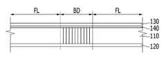
도 3은 본 발명의 제1 실시예에 따른 플렉서블 표시 장치(100)를 도 1의 Ⅱ-Ⅱ 절개선을 따라 절개한 단면의 일부를 도시한 단면도이며, 도 4는 도 3의 플렉서블 표시 장치(100)가 벤딩된 모습을 도시한 도면이다. 도 5는 본 발명의 제2 실시예에 따른 플렉서블 표시 장치(100)를 도 1의 Ⅱ-Ⅱ 절개선을 따라 절개한 단면의 일부를 도시한 단면도이며, 도 6은 도 5의 플렉서블 표시 장치(100)가 벤딩된 모습을 도시한 도면이다. 도 7은 본 발명의 제3 실시예에 따른 플렉서블 표시 장치(100)를 도 1의 Ⅱ-Ⅱ 절개선을 따라 절개한 단면의 일부를 도시한 단면도이며, 도 8은 도 7의 플렉서블 표시 장치(100)가 벤딩된 모습을 도시한 도면이다.FIG. 3 is a cross-sectional view illustrating a portion of the
이하에서는 첨부된 도면 중 도 3 및 도 4를 참고하여, 본 발명의 제1 실시예에 대하여 상세히 설명하기로 한다.Hereinafter, a first embodiment of the present invention will be described in detail with reference to FIGS. 3 and 4 among the accompanying drawings.
도 3 및 도 4에 도시된 것과 같이, 본 발명의 제1 실시예에 따른 플렉서블 표시 장치(100)는 벤딩 영역(BD)에 대응되는 윈도우층(110)의 일부 또는 전부가 커팅되어 형성되는 커팅 유닛(112)을 포함한다.3 and 4 , in the
커팅 유닛(112)은 플렉서블 표시 장치(100)가 벤딩되면 이격 배치되어 벤딩 시 가해지는 응력이 분산되도록 하고, 플렉서블 표시 장치(100)가 펼쳐지면 서로 인접 배치되도록 윈도우층(110)의 일부 또는 전부가 커팅되어 형성된다. 한 번의 커팅으로도 윈도우층(110)은 두 개의 영역으로 구획될 수 있기 때문에, 커팅 유닛(112)은 항상 복수로 형성된다.When the
윈도우층(110)을 커팅하여 커팅 유닛(112)을 형성하기 위해서는 레이저 커팅기가 이용될 수 있으나 이에 한정되는 것은 아니며, 윈도우층(110) 상에 절개선 또는 슬릿을 형성하기 위해 윈도우층(110)의 일부 또는 전부를 정밀하게 커팅할 수 있는 커팅 장치라면 어느 것에 의하여도 무방하다.A laser cutter may be used to cut the
본 실시예에 따라 윈도우층(110)이 커팅되어 형성되는 커팅 유닛(112)은 윈도우층(110)의 두께 방향을 따라 일정한 폭을 가지도록 윈도우층(110)의 표면에 대하여 수직한 방향으로 나란하게 커팅될 수 있다. 다만, 이에 한정되는 것은 아니며, 플렉서블 표시 장치(100)의 벤딩을 용이하게 하는 커팅 구조에 대해서 본 발명의 실시 범위가 제한되는 것은 아니다.According to the present embodiment, the cutting unit 112 formed by cutting the
본 실시예에 따른 플렉서블 표시 장치(100)는 전술한 것과 같이 하드 코팅층(130)을 포함할 수 있으며, 점착층(140)을 더 포함할 수 있다.The
본 실시예의 하드 코팅층(130)은 윈도우층(110)의 타면에 배치되고, 점착층(140)은 윈도우층(110)과 하드 코팅층(130) 사이에 배치되며, 커팅 유닛(112)의 일 단부가 점착층(140)의 표면을 따라 슬립될 수 있다.The
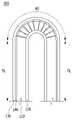
플렉서블 표시 장치(100)가 도 4와 같이 벤딩되면, 커팅 유닛(112)의 일 단부가 점착층(140)의 표면을 따라 슬립되면서, 인접하게 배치되는 이웃의 커팅 유닛(112)으로부터 분리되어 이격 배치된다. 따라서 플렉서블 표시 장치(100)가 벤딩된 경우에는 도 4에 도시된 것과 같이, 복수의 커팅 유닛(112)은 부채꼴 형상으로 배치될 수 있다.When the
이때 본 실시예에 따른 커팅 유닛(112)의 타 단부는 플렉서블 표시 패널(120)에 고정될 수 있다. 플렉서블 표시 패널(120)에 고정된 커팅 유닛(112)의 일측은 플렉서블 표시 장치(100)가 벤딩되어도 이격 배치되지 않고 인접 배치를 유지한다. 따라서 플렉서블 표시 패널(120)로부터 방출되는 빛의 굴절 또는 산란을 방지할 수 있다.In this case, the other end of the cutting unit 112 according to the present embodiment may be fixed to the
한편, 본 실시예에 따른 플렉서블 표시 패널(120)은 빛이 방출되는 단위 화소들을 포함하며, 각각의 화소로부터 발생되는 빛이 외부로 방출되어 화상을 표시하는 표시 영역(미도시) 및 빛이 차단되어 화상을 표시하지 못하는 비표시 영역(미도시)을 포함한다.On the other hand, the
이에 따라, 본 실시예의 평판 영역(FL)은 표시 영역에 대응되는 위치에 배치되며, 벤딩 영역(BD)은 비표시 영역에 대응되는 위치에 배치될 수 있다.Accordingly, the flat panel area FL of the present embodiment may be disposed at a position corresponding to the display area, and the bending area BD may be disposed at a position corresponding to the non-display area.
벤딩 영역(BD)이 표시 영역에 대응되는 위치에 배치되면, 커팅 유닛(112)의 슬립으로 인해 표시 영역으로부터 방출되는 빛이 굴절되거나 산란될 수 있다. 또한 빛샘 현상과 같은 문제가 발생될 수도 있다. 따라서 본 실시예에 따른 벤딩 영역(BD)은 앞서 서술한 것과 같은 문제점들의 발생을 방지하기 위하여,When the bending area BD is disposed at a position corresponding to the display area, light emitted from the display area may be refracted or scattered due to slippage of the cutting unit 112 . In addition, problems such as light leakage may occur. Therefore, the bending area BD according to the present embodiment is formed in order to prevent the above-described problems from occurring,
따라서, 본 실시예에 따른 커팅 유닛(112) 역시 발광 영역(LE)이 존재하지 않는 위치에 대응되는 위치에 배치될 수 있으며, 이에 따라 평판 영역(FL)은 표시 영역에 대응되는 위치에 배치될 수 있다. 그러므로, 보다 안정적인 화상의 표시가 가능한 플렉서블 표시 장치(100)가 제공된다.Accordingly, the cutting unit 112 according to the present embodiment may also be disposed at a position corresponding to a position where the light emitting area LE does not exist, and accordingly, the flat panel area FL may be disposed at a position corresponding to the display area. can Therefore, the
한편, 이하에서는 첨부된 도면 중 도 5 내지 도 8을 참고하여, 본 발명의 제2 실시예 및 제3 실시예에 대하여 상세히 설명하기로 한다.Meanwhile, a second embodiment and a third embodiment of the present invention will be described in detail below with reference to FIGS. 5 to 8 of the accompanying drawings.
도 5 및 도 6에는 본 발명의 제2 실시예에 따라 벤딩 영역(BD)에 복수의 돌기(114)가 형성되는 플렉서블 표시 장치(100)가 도시되어 있으며, 도 7 및 도 8에는 본 발명의 제3 실시예에 따라 벤딩 영역(BD)에 복수의 홈(116)이 형성되는 플렉서블 표시 장치(100)가 도시되어 있다.5 and 6 show the
도 5 및 도 6에 도시된 것과 같이, 본 발명의 제2 실시예에 따라 복수의 돌기(114)가 형성된 플렉서블 표시 장치(100)는 벤딩 영역(BD)과 평판 영역(FL)을 포함하는 윈도우층(110) 및 플렉서블 표시 패널(120)을 포함한다.5 and 6 , in the
본 실시예의 윈도우층(110)과 플렉서블 표시 패널(120)에 대한 구체적인 설명은 앞서 설명한 것과 동일하므로 생략하기로 한다.Detailed descriptions of the
이때, 본 실시예의 플렉서블 표시 패널(120)은 단위 화소로부터 방출되는 빛이 통과되는 발광 영역(LE)을 포함할 수 있다. 다시 말하면, 본 실시예의 플렉서블 표시 패널(120)은 플렉서블 표시 패널(120) 중 단위 화소에 대응되는 영역이 관통되어 형성되는 발광 영역(LE)을 포함한다.In this case, the
한편, 본 실시예의 벤딩 영역(BD)은 윈도우층(110)의 일부가 제거되어 형성된다. 구체적으로 설명하자면, 도 5 및 도 6에 도시된 것과 같이, 본 실시예의 벤딩 영역(BD)은 플렉서블 표시 패널(120)의 발광 영역(LE)의 단면적보다 더 넓은 단면적을 가지는 복수의 돌기(114)가 형성되도록, 돌기(114)에 대응되는 영역의 윈도우층(110)만을 남기고, 불필요한 윈도우층(110)을 제거함으로써 형성된다. 다시 말해, 본 실시예의 벤딩 영역(BD)은 복수의 돌기(114)가 남겨지도록 윈도우층(110)을 제거하여 형성된다.Meanwhile, the bending region BD of the present embodiment is formed by removing a portion of the
본 실시예와 같이 돌기(114)의 단면적이 발광 영역(LE)의 단면적보다 더 넓은 단면적을 가지게 되면, 발광 영역(LE)으로부터 방출되는 빛이 굴절되거나 산란되지 않고 그대로 통과하여 외부로 방출될 수 있다. 따라서 본 실시예에 따른 플렉서블 표시 장치(100)를 벤딩시킨다 하더라도 광학적 특성이 저해되지 않을 수 있다.When the cross-sectional area of the
본 실시예의 돌기(114)는 윈도우층(110)의 두께와 동일한 높이를 가지도록 형성될 수 있으나 이에 한정되는 것은 아니며, 윈도우층(110)의 두께보다 작은 높이를 가지도록 형성될 수도 있다. 또한, 복수의 돌기(114)의 하부가 윈도우층(110)으로 연결될 수 있도록 윈도우층(110)의 두께 방향의 일부를 남겨 도 5 내지 도 6과 같은 형상의 벤딩 영역(BD)을 형성할 수 있다.The
제거된 윈도우층(110)의 표면에는 벤딩 영역 충전부(132)가 형성된다. 벤딩 영역 충전부(132)는 윈도우층(110)의 제거된 영역이 윈도우층(110)의 표면과 동일한 높이 및 폭을 가지도록 벤딩 영역(BD)을 충전하여 형성된다.A bending
벤딩 영역 충전부(132)에 의해 복수의 돌기(114)가 완전히 덮일 수 있으나 이에 한정되는 것은 아니며, 복수의 돌기(114)의 높이가 윈도우층(110)의 표면의 높이와 동일하게 형성된 경우에는 벤딩 영역 충전부(132)에 의해 벤딩 영역(BD)이 충전된 이후에도, 복수의 돌기(114)의 표면이 벤딩 영역 충전부(132)의 표면 외부로 노출될 수도 있다.The plurality of
또한, 본 실시예에 따른 플렉서블 표시 패널(120)은 윈도우층(110) 및 벤딩 영역 충전부(132) 상에 형성되는 하드 코팅층(130)을 더 포함할 수 있다. 이때 본 실시예에 따른 하드 코팅층(130)은 벤딩 영역 충전부(132)와 동일한 재질로 이루어질 수 있다. 하드 코팅층(130)을 형성하는 물질이 플렉서블한 재질로 이루어질 수 있음은 전술한 것과 같다. 따라서 본 실시예의 벤딩 영역 충전부(132) 역시 하드 코팅층(130)과 동일한 플렉서블한 재질로 이루어질 수 있다.In addition, the
본 실시예에 따른 벤딩 영역 충전부(132)는 발광 영역(LE)에 해당되는 플렉서블 표시 패널(120)의 상부에 형성되므로 투명 재질로 형성될 수 있으며, 따라서 투명 재질의 합성 수지 또는 글래스를 포함하여 이루어질 수 있다. 그러므로, 본 실시예의 하드 코팅층(130) 역시 동일한 재질로 이루어질 수 있다.Since the bending
도 7 및 도 8에는 본 발명의 제3 실시예에 따라 윈도우층(110)의 일부가 제거되어 복수의 홈(116)이 형성된 플렉서블 표시 장치(100) 역시, 벤딩 영역(BD)과 평판 영역(FL)을 포함하는 윈도우층(110) 및 플렉서블 표시 패널(120)을 포함한다.7 and 8 show the
본 실시예의 윈도우층(110)과 플렉서블 표시 패널(120)에 대한 구체적인 설명은 앞서 설명한 것과 동일하므로 생략하기로 한다.Detailed descriptions of the
이때, 본 실시예의 벤딩 영역(BD)은, 도 7 및 도 8에 도시된 것과 같이, 윈도우층(110)의 일부가 제거되어 형성되는 복수의 홈(116)을 포함한다. 복수의 홈(116)은 플렉서블 표시 패널(120)의 발광 영역(LE)의 단면적보다 넓은 단면적을 가지도록 윈도우층(110) 일부가 제거되어 형성된다.In this case, as shown in FIGS. 7 and 8 , the bending area BD of the present embodiment includes a plurality of
본 실시예와 같이 홈(116)의 단면적이 발광 영역(LE)의 단면적보다 더 넓은 단면적을 가지게 되면, 제2 실시예와 마찬가지로, 발광 영역(LE)으로부터 방출되는 빛이 굴절되거나 산란되지 않고 그대로 통과하여 외부로 방출될 수 있다. 따라서 본 실시예에 따른 플렉서블 표시 장치(100)를 벤딩시킨다 하더라도 광학적 특성이 저해되지 않을 수 있다.When the cross-sectional area of the
본 실시예의 홈(116)은 발광 영역(LE)에 대응되는 위치의 윈도우층(110)이 관통되어 형성될 수 있으나, 이에 한정되는 것은 아니며, 윈도우층(110)의 두께 방향으로 일부만 제거되어 형성될 수도 있다.The
한편, 본 실시예의 플렉서블 표시 장치(100)는 윈도우층(110)의 타면에 배치되는 하드 코팅층(130)을 더 포함할 수 있다. 본 실시예의 하드 코팅층(130) 역시 제2 실시예의 하드 코팅층(130)과 마찬가지로 플렉서블 표시 패널(120)의 발광 영역(LE) 상부에 형성되므로, 투명 재질로 형성될 수 있으며, 따라서 투명 재질의 합성 수지 또는 글래스를 포함하여 이루어질 수 있다.Meanwhile, the
이때, 본 실시예에 따른 복수의 홈(116)은 하드 코팅층(130)과 동일한 재질에 의해 충전될 수 있다. 하드 코팅층(130)과 동일한 재질에 의해 복수의 홈(116)이 충전되면, 발광 영역(LE)으로부터 방출되는 빛이 홈(116)과 하드 코팅층(130) 사이의 계면에 의해 굴절되거나 산란되는 것을 방지할 수 있어, 본 실시예의 플렉서블 표시 장치(100)의 광학적 특성이 유지될 수 있다.At this time, the plurality of
이상에서는 본 발명의 다양한 실시예에 따른 플렉서블 표시 장치(100)에 대하여 설명하였다. 본 발명에 따르면, 플렉서블 표시 장치(100)가 벤딩된다 하더라도, 벤딩으로 인해 가해지는 응력을 분산시킴으로써 제품의 파손이 방지되며, 벤딩 시에도 광학적 특성이 유지되는 플렉서블 표시 장치(100)를 제공할 수 있다.In the above, the
앞에서, 본 발명의 특정한 실시예가 설명되고 도시되었지만 본 발명은 기재된 실시예에 한정되는 것이 아니고, 본 발명의 사상 및 범위를 벗어나지 않고 다양하게 수정 및 변형할 수 있음은 이 기술의 분야에서 통상의 지식을 가진 자에게 자명한 일이다. 따라서, 그러한 수정예 또는 변형예들은 본 발명의 기술적 사상이나 관점으로부터 개별적으로 이해되어서는 안되며, 변형된 실시예들은 본 발명의 특허청구범위에 속한다 하여야 할 것이다.In the foregoing, specific embodiments of the present invention have been described and illustrated, but it is common knowledge in the art that the present invention is not limited to the described embodiments, and that various modifications and variations can be made without departing from the spirit and scope of the present invention. It is self-evident to those who have Accordingly, such modifications or variations should not be individually understood from the technical spirit or point of view of the present invention, and modified embodiments should be said to belong to the claims of the present invention.
100: 플렉서블 표시 장치
110: 윈도우층
112: 커팅 유닛
114: 돌기
116: 홈
120: 플렉서블 표시 패널
130: 하드 코팅층
132: 벤딩 영역 충전부
134: 충전된 홈
140: 점착층
BD: 벤딩 영역
FL: 평판 영역
LE: 발광 영역100: flexible display device
110: window layer
112: cutting unit
114: turn
116: home
120: flexible display panel
130: hard coating layer
132: bending area charging part
134: filled groove
140: adhesive layer
BD: bending area
FL: flat area
LE: light emitting area
Claims (11)
Translated fromKorean상기 윈도우층의 일면에 배치되며, 단위 화소로부터 방출되는 빛이 통과되는 발광 영역을 포함하여 화상을 표시하는 플렉서블 표시 패널을 포함하고,
상기 벤딩 영역은 상기 윈도우층의 일부가 제거되어 형성되고,
상기 벤딩 영역은, 상기 발광 영역이 형성된 위치에 대응되는 위치에서 상기 발광 영역의 형상에 대응되면서 상기 발광 영역의 단면적보다 더 넓은 단면적을 갖는 복수의 돌기 또는 홈을 포함하는, 플렉서블 표시 장치.a window layer including a bending area and a flat area; and
and a flexible display panel disposed on one surface of the window layer and displaying an image including a light emitting area through which light emitted from a unit pixel passes;
The bending region is formed by removing a portion of the window layer,
The bending area includes a plurality of protrusions or grooves corresponding to the shape of the light emitting area and having a cross-sectional area larger than that of the light emitting area at a position corresponding to the position where the light emitting area is formed.
상기 벤딩 영역은,
상기 윈도우층의 일부가 제거된 부분에 형성되는 복수의 돌기; 및
상기 벤딩 영역의 높이가 상기 윈도우층의 표면과 동일해지도록 상기 벤딩 영역을 충전하는 벤딩 영역 충전부를 포함하는, 플렉서블 표시 장치.6. The method of claim 5,
The bending area is
a plurality of protrusions formed on a portion from which a portion of the window layer is removed; and
and a bending area filling part filling the bending area so that a height of the bending area is equal to a surface of the window layer.
상기 벤딩 영역 충전부는 투명 재질의 합성 수지 또는 글래스를 포함하여 이루어지는, 플렉서블 표시 장치.7. The method of claim 6,
The flexible display device of claim 1, wherein the bending region filling part includes a transparent synthetic resin or glass.
상기 벤딩 영역 충전부와 동일한 재질로 이루어지며, 상기 윈도우층의 타면에 배치되는 하드 코팅층을 더 포함하는, 플렉서블 표시 장치.8. The method of claim 7,
The flexible display device of claim 1 , further comprising a hard coating layer made of the same material as the bending region filling part and disposed on the other surface of the window layer.
상기 벤딩 영역은,
상기 발광 영역에 대응되는 상기 윈도우층의 일부가 제거되어 형성되는 복수의 홈을 포함하는, 플렉서블 표시 장치.6. The method of claim 5,
The bending area is
and a plurality of grooves formed by removing a portion of the window layer corresponding to the light emitting area.
상기 윈도우층의 타면에 배치되며, 투명 재질의 합성 수지 또는 글래스를 포함하여 이루어지는 하드 코팅층을 더 포함하는,
플렉서블 표시 장치.10. The method of claim 9,
It is disposed on the other surface of the window layer, further comprising a hard coating layer comprising a transparent synthetic resin or glass,
flexible display device.
상기 홈은 상기 하드 코팅층과 동일한 재질로 충전되는, 플렉서블 표시 장치.11. The method of claim 10,
and the groove is filled with the same material as the hard coating layer.
Priority Applications (6)
| Application Number | Priority Date | Filing Date | Title |
|---|---|---|---|
| KR1020150045315AKR102423893B1 (en) | 2015-03-31 | 2015-03-31 | Flexible display device |
| US14/961,571US20160295685A1 (en) | 2015-03-31 | 2015-12-07 | Flexible display |
| CN201610160315.1ACN106023810B (en) | 2015-03-31 | 2016-03-21 | flexible display |
| TW105109776ATWI747818B (en) | 2015-03-31 | 2016-03-29 | Flexible display |
| TW110140758ATWI804036B (en) | 2015-03-31 | 2016-03-29 | Flexible display |
| US16/138,844US11586247B2 (en) | 2015-03-31 | 2018-09-21 | Flexible display |
Applications Claiming Priority (1)
| Application Number | Priority Date | Filing Date | Title |
|---|---|---|---|
| KR1020150045315AKR102423893B1 (en) | 2015-03-31 | 2015-03-31 | Flexible display device |
Publications (2)
| Publication Number | Publication Date |
|---|---|
| KR20160117799A KR20160117799A (en) | 2016-10-11 |
| KR102423893B1true KR102423893B1 (en) | 2022-07-21 |
Family
ID=57017800
Family Applications (1)
| Application Number | Title | Priority Date | Filing Date |
|---|---|---|---|
| KR1020150045315AActiveKR102423893B1 (en) | 2015-03-31 | 2015-03-31 | Flexible display device |
Country Status (4)
| Country | Link |
|---|---|
| US (2) | US20160295685A1 (en) |
| KR (1) | KR102423893B1 (en) |
| CN (1) | CN106023810B (en) |
| TW (2) | TWI747818B (en) |
Families Citing this family (55)
| Publication number | Priority date | Publication date | Assignee | Title |
|---|---|---|---|---|
| JP6181646B2 (en) | 2011-07-06 | 2017-08-16 | ネステク ソシエテ アノニム | Assay for detection of neutralizing autoantibodies against biological therapy with TNF alpha |
| AU2015356613A1 (en) | 2014-12-05 | 2017-06-15 | Société des Produits Nestlé S.A. | Indirect homogeneous mobility shift assays for the detection of biologics in patient samples |
| KR102716709B1 (en)* | 2016-10-17 | 2024-10-14 | 삼성디스플레이 주식회사 | Display device and method of manufacturing the same |
| KR102653753B1 (en)* | 2016-11-16 | 2024-04-02 | 삼성디스플레이 주식회사 | Window for felxible display device and felxible display device having thereof |
| KR102676858B1 (en)* | 2016-12-16 | 2024-06-19 | 엘지디스플레이 주식회사 | Electroluminescent display device |
| KR102612041B1 (en)* | 2016-12-30 | 2023-12-07 | 엘지디스플레이 주식회사 | Foldable display device |
| US10312228B2 (en)* | 2017-01-25 | 2019-06-04 | Innolux Corporation | Display device |
| CN106652802B (en)* | 2017-02-27 | 2020-03-17 | 上海天马微电子有限公司 | Foldable display device |
| CN106910429B (en)* | 2017-03-08 | 2019-05-14 | 京东方科技集团股份有限公司 | A kind of flexible die group and preparation method thereof |
| CN107301821B (en)* | 2017-07-31 | 2020-04-17 | 上海中航光电子有限公司 | Foldable display screen and display device |
| KR102423192B1 (en) | 2017-09-06 | 2022-07-21 | 삼성디스플레이 주식회사 | Foldable display apparatus and the manufacturing method thereof |
| KR20250027587A (en) | 2017-10-27 | 2025-02-26 | 어플라이드 머티어리얼스, 인코포레이티드 | Flexible cover lens films |
| CN109727530A (en)* | 2017-10-31 | 2019-05-07 | 昆山工研院新型平板显示技术中心有限公司 | Flexible display module and preparation method of flexible display module |
| CN107946317B (en)* | 2017-11-20 | 2020-04-24 | 京东方科技集团股份有限公司 | Flexible array substrate, preparation method, display substrate and display device |
| CN107968109A (en)* | 2017-11-21 | 2018-04-27 | 武汉华星光电半导体显示技术有限公司 | Flexible OLED display panel and preparation method thereof, display device |
| CN207517288U (en) | 2017-11-30 | 2018-06-19 | 昆山国显光电有限公司 | Separable Flexible Displays structure, flexible display screen and display device |
| KR102448066B1 (en) | 2017-12-22 | 2022-09-28 | 엘지디스플레이 주식회사 | flexible display device |
| CN108091679B (en)* | 2017-12-27 | 2020-09-18 | 武汉华星光电半导体显示技术有限公司 | The wiring structure of the bending area of the flexible OLED display panel, the flexible OLED display panel |
| KR102450111B1 (en) | 2017-12-28 | 2022-10-05 | 삼성디스플레이 주식회사 | Display device |
| KR102610245B1 (en) | 2018-01-10 | 2023-12-05 | 삼성디스플레이 주식회사 | Display device and method for manufacturing the display device |
| KR102535784B1 (en) | 2018-02-02 | 2023-05-24 | 삼성디스플레이 주식회사 | Display apparatus and fabrication method thereof |
| CN108231800B (en) | 2018-02-02 | 2019-10-29 | 京东方科技集团股份有限公司 | A kind of flexible display panels and preparation method thereof, display device |
| WO2019174052A1 (en)* | 2018-03-16 | 2019-09-19 | 深圳市柔宇科技有限公司 | Back film layer, flexible display panel and flexible display device |
| TWI656629B (en)* | 2018-03-31 | 2019-04-11 | 律勝科技股份有限公司 | Flexible display device covering substrate and flexible display device using same |
| US11081660B2 (en)* | 2018-05-03 | 2021-08-03 | Samsung Display Co., Ltd. | Display device and support film structure for display device |
| JP7716853B2 (en) | 2018-05-10 | 2025-08-01 | アプライド マテリアルズ インコーポレイテッド | Interchangeable cover lenses for flexible displays |
| US10534400B2 (en)* | 2018-05-24 | 2020-01-14 | Innolux Corporation | Foldable electronic device |
| CN108630736B (en)* | 2018-07-06 | 2021-08-03 | 武汉华星光电半导体显示技术有限公司 | Flexible OLED Display |
| KR20240107376A (en) | 2018-08-14 | 2024-07-09 | 어플라이드 머티어리얼스, 인코포레이티드 | Multi-layer wet-dry hardcoats for flexible cover lens |
| CN109148534B (en)* | 2018-08-21 | 2021-01-15 | 武汉华星光电半导体显示技术有限公司 | Display panel and electronic device |
| KR20200034428A (en)* | 2018-09-21 | 2020-03-31 | 삼성전자주식회사 | Flexible display device including anti-reflection layer and anti-glare layer and electronic device including the same |
| KR102617925B1 (en)* | 2018-09-27 | 2023-12-26 | 삼성디스플레이 주식회사 | Display device |
| TWI691110B (en)* | 2018-11-09 | 2020-04-11 | 友達光電股份有限公司 | Flexible display panel |
| US10651120B1 (en)* | 2018-12-03 | 2020-05-12 | Wuhan China Star Optoelectronics Semiconductor Display Technology Co., Ltd. | Display panel, display module, and electronic device |
| KR102660032B1 (en) | 2019-01-10 | 2024-04-25 | 삼성디스플레이 주식회사 | Display device |
| KR102069040B1 (en)* | 2019-04-15 | 2020-01-22 | (주)유티아이 | Manufacturing Method of Flexible Cover Window and Flexible Cover Window Thereby |
| CN111833725A (en)* | 2019-04-18 | 2020-10-27 | 深圳市柔宇科技有限公司 | Folding device and electronic equipment |
| KR102780681B1 (en) | 2019-06-26 | 2025-03-11 | 어플라이드 머티어리얼스, 인코포레이티드 | Flexible multi-layered cover lens stacks for foldable displays |
| US12232408B2 (en)* | 2019-08-13 | 2025-02-18 | Lg Innotek Co., Ltd. | Substrate for display including plurality of holes and grooves |
| KR102814906B1 (en) | 2019-12-19 | 2025-06-02 | 삼성디스플레이 주식회사 | Display device |
| KR102146730B1 (en)* | 2019-12-23 | 2020-08-24 | (주)유티아이 | Flexible Cover Window |
| KR20210085145A (en) | 2019-12-30 | 2021-07-08 | 엘지이노텍 주식회사 | Foldable display |
| US11048295B1 (en)* | 2020-01-10 | 2021-06-29 | Sharp Kabushiki Kaisha | Flexible window for foldable display |
| CN111105718B (en)* | 2020-02-20 | 2022-04-19 | 京东方科技集团股份有限公司 | Flexible display module and preparation method thereof, and folding display device |
| KR102822185B1 (en)* | 2020-05-21 | 2025-06-19 | 삼성디스플레이 주식회사 | Flexible Cover Window and Foldable Display Device |
| KR20220019158A (en)* | 2020-08-06 | 2022-02-16 | 삼성디스플레이 주식회사 | Window and display device comprising theferof |
| KR20220030470A (en)* | 2020-09-01 | 2022-03-11 | 삼성디스플레이 주식회사 | Foldable display device |
| KR20220031839A (en)* | 2020-09-04 | 2022-03-14 | 삼성디스플레이 주식회사 | Display device |
| KR20220049066A (en)* | 2020-10-13 | 2022-04-21 | 삼성디스플레이 주식회사 | Display device |
| TWI773024B (en)* | 2020-12-16 | 2022-08-01 | 晨豐光電股份有限公司 | Bendable glass and manufacturing method thereof |
| KR20220098581A (en)* | 2021-01-04 | 2022-07-12 | 엘지이노텍 주식회사 | Elasticity member and display device having the same |
| CN112863337A (en)* | 2021-01-11 | 2021-05-28 | 京东方科技集团股份有限公司 | Membrane material and manufacturing method thereof, curved surface display panel and curved surface display device |
| KR20230067758A (en)* | 2021-11-08 | 2023-05-17 | 삼성디스플레이 주식회사 | Display device |
| US20240292709A1 (en)* | 2022-05-20 | 2024-08-29 | Boe Technology Group Co., Ltd. | Display Panel and Display Apparatus |
| CN115331551B (en)* | 2022-08-09 | 2024-06-04 | 维沃移动通信有限公司 | Folding screen and electronic devices |
Citations (1)
| Publication number | Priority date | Publication date | Assignee | Title |
|---|---|---|---|---|
| JP2006507543A (en)* | 2002-11-21 | 2006-03-02 | コーニンクレッカ フィリップス エレクトロニクス エヌ ヴィ | Flexible display |
Family Cites Families (14)
| Publication number | Priority date | Publication date | Assignee | Title |
|---|---|---|---|---|
| US9176535B2 (en) | 2011-06-03 | 2015-11-03 | Microsoft Technology Licensing, Llc | Flexible display flexure assembly |
| KR20130015230A (en)* | 2011-08-02 | 2013-02-13 | 삼성디스플레이 주식회사 | Display device and method for manufacturing the same |
| KR101958802B1 (en)* | 2012-07-26 | 2019-03-18 | 삼성디스플레이 주식회사 | Foldable display device |
| KR101910111B1 (en)* | 2012-08-28 | 2018-10-22 | 삼성디스플레이 주식회사 | Foldable display device |
| KR101973778B1 (en)* | 2012-11-16 | 2019-04-30 | 삼성디스플레이 주식회사 | Flexible display device and method of manufacturing cover window of the same |
| KR102117890B1 (en) | 2012-12-28 | 2020-06-02 | 엘지디스플레이 주식회사 | Flexible display device and method for manufacturing the same |
| KR102037694B1 (en)* | 2013-02-28 | 2019-10-30 | 엘지디스플레이 주식회사 | Flexible display device and method for manufacturing thereof |
| KR102084110B1 (en)* | 2013-03-20 | 2020-03-04 | 삼성디스플레이 주식회사 | Cover window for display device, display device comprising the same, and mathod for manufacturing the same |
| US9990004B2 (en)* | 2013-04-02 | 2018-06-05 | Samsung Dispaly Co., Ltd. | Optical detection of bending motions of a flexible display |
| CN103426904B (en)* | 2013-08-02 | 2015-11-11 | 京东方科技集团股份有限公司 | A kind of flexible organic light emitting diode display and preparation method thereof |
| KR20150017819A (en)* | 2013-08-07 | 2015-02-23 | 삼성디스플레이 주식회사 | Window member and display apparatus having the same |
| CN103390613B (en)* | 2013-08-14 | 2016-08-10 | 中国科学院长春光学精密机械与物理研究所 | The solid matter row LED area array device of high uniformity of luminance and preparation method |
| KR101663728B1 (en) | 2013-08-26 | 2016-10-07 | 삼성전자주식회사 | foldable electronic device having flexible display |
| KR102256084B1 (en)* | 2014-08-04 | 2021-05-25 | 엘지디스플레이 주식회사 | Flexible display device and method of fabricating thereof |
- 2015
- 2015-03-31KRKR1020150045315Apatent/KR102423893B1/enactiveActive
- 2015-12-07USUS14/961,571patent/US20160295685A1/ennot_activeAbandoned
- 2016
- 2016-03-21CNCN201610160315.1Apatent/CN106023810B/enactiveActive
- 2016-03-29TWTW105109776Apatent/TWI747818B/enactive
- 2016-03-29TWTW110140758Apatent/TWI804036B/enactive
- 2018
- 2018-09-21USUS16/138,844patent/US11586247B2/enactiveActive
Patent Citations (1)
| Publication number | Priority date | Publication date | Assignee | Title |
|---|---|---|---|---|
| JP2006507543A (en)* | 2002-11-21 | 2006-03-02 | コーニンクレッカ フィリップス エレクトロニクス エヌ ヴィ | Flexible display |
Also Published As
| Publication number | Publication date |
|---|---|
| TWI747818B (en) | 2021-12-01 |
| TW201640466A (en) | 2016-11-16 |
| US11586247B2 (en) | 2023-02-21 |
| KR20160117799A (en) | 2016-10-11 |
| TW202213299A (en) | 2022-04-01 |
| US20160295685A1 (en) | 2016-10-06 |
| CN106023810B (en) | 2020-09-11 |
| CN106023810A (en) | 2016-10-12 |
| TWI804036B (en) | 2023-06-01 |
| US20190025886A1 (en) | 2019-01-24 |
Similar Documents
| Publication | Publication Date | Title |
|---|---|---|
| KR102423893B1 (en) | Flexible display device | |
| KR102133220B1 (en) | Display device | |
| KR102363464B1 (en) | Flexible display device with wire having reinforced portion and manufacturing method for the same | |
| KR102334807B1 (en) | Flexible window and flexible display device | |
| KR102263602B1 (en) | Flexible display substrate, manufacturing method thereof and flexible display device having the same | |
| KR101933818B1 (en) | Flexible display devices and electronic devices | |
| KR101996437B1 (en) | Transparent protection window, flexible display apparatus with the same and the method for manufacturing the transparent protection window | |
| KR102348956B1 (en) | Multi vision display apparatus using a flexible display device | |
| US9507191B2 (en) | Window panel and display device including the same | |
| US20150173171A1 (en) | Display device | |
| KR101426997B1 (en) | Method for manufacturing display panel with curved shape and display panel with curved shape using the method | |
| CN102967965B (en) | Liquid crystal slit grating and three-dimensional display device | |
| CN109407196A (en) | Polaroid, flexible display panels and flexible display apparatus | |
| CN107516472B (en) | Flexible display device | |
| KR20120089077A (en) | Folderble display apparatus | |
| KR20140090482A (en) | Display device | |
| CN105739112A (en) | Polarization Control Unit And 2D And 3D Image Display Device Having The Same | |
| US20160178907A1 (en) | Head-mounted electronic device and display thereof | |
| KR102266008B1 (en) | Display device | |
| US20160377914A1 (en) | Display device | |
| US20150241711A1 (en) | 3d display apparatus | |
| KR102282937B1 (en) | Curved display device | |
| EP3037874A1 (en) | Display apparatus | |
| KR102071398B1 (en) | Flexible Display Device | |
| WO2017059730A1 (en) | Side-type light guide plate, backlight module, manufacturing method therefor and display device |
Legal Events
| Date | Code | Title | Description |
|---|---|---|---|
| PA0109 | Patent application | Patent event code:PA01091R01D Comment text:Patent Application Patent event date:20150331 | |
| PG1501 | Laying open of application | ||
| A201 | Request for examination | ||
| PA0201 | Request for examination | Patent event code:PA02012R01D Patent event date:20200306 Comment text:Request for Examination of Application Patent event code:PA02011R01I Patent event date:20150331 Comment text:Patent Application | |
| E902 | Notification of reason for refusal | ||
| PE0902 | Notice of grounds for rejection | Comment text:Notification of reason for refusal Patent event date:20210428 Patent event code:PE09021S01D | |
| E90F | Notification of reason for final refusal | ||
| PE0902 | Notice of grounds for rejection | Comment text:Final Notice of Reason for Refusal Patent event date:20211024 Patent event code:PE09021S02D | |
| E701 | Decision to grant or registration of patent right | ||
| PE0701 | Decision of registration | Patent event code:PE07011S01D Comment text:Decision to Grant Registration Patent event date:20220420 | |
| GRNT | Written decision to grant | ||
| PR0701 | Registration of establishment | Comment text:Registration of Establishment Patent event date:20220718 Patent event code:PR07011E01D | |
| PR1002 | Payment of registration fee | Payment date:20220718 End annual number:3 Start annual number:1 | |
| PG1601 | Publication of registration | ||
| PR1001 | Payment of annual fee | Payment date:20250625 Start annual number:4 End annual number:4 |