KR102423785B1 - Wound retractor - Google Patents
Wound retractorDownload PDFInfo
- Publication number
- KR102423785B1 KR102423785B1KR1020217023165AKR20217023165AKR102423785B1KR 102423785 B1KR102423785 B1KR 102423785B1KR 1020217023165 AKR1020217023165 AKR 1020217023165AKR 20217023165 AKR20217023165 AKR 20217023165AKR 102423785 B1KR102423785 B1KR 102423785B1
- Authority
- KR
- South Korea
- Prior art keywords
- ring
- curved
- inner ring
- segments
- segment
- Prior art date
- Legal status (The legal status is an assumption and is not a legal conclusion. Google has not performed a legal analysis and makes no representation as to the accuracy of the status listed.)
- Active
Links
Images


Classifications
- A—HUMAN NECESSITIES
- A61—MEDICAL OR VETERINARY SCIENCE; HYGIENE
- A61B—DIAGNOSIS; SURGERY; IDENTIFICATION
- A61B17/00—Surgical instruments, devices or methods
- A61B17/02—Surgical instruments, devices or methods for holding wounds open, e.g. retractors; Tractors
- A61B17/0293—Surgical instruments, devices or methods for holding wounds open, e.g. retractors; Tractors with ring member to support retractor elements
- A—HUMAN NECESSITIES
- A61—MEDICAL OR VETERINARY SCIENCE; HYGIENE
- A61B—DIAGNOSIS; SURGERY; IDENTIFICATION
- A61B17/00—Surgical instruments, devices or methods
- A61B17/02—Surgical instruments, devices or methods for holding wounds open, e.g. retractors; Tractors
- A61B17/0218—Surgical instruments, devices or methods for holding wounds open, e.g. retractors; Tractors for minimally invasive surgery
- A—HUMAN NECESSITIES
- A61—MEDICAL OR VETERINARY SCIENCE; HYGIENE
- A61B—DIAGNOSIS; SURGERY; IDENTIFICATION
- A61B17/00—Surgical instruments, devices or methods
- A61B17/34—Trocars; Puncturing needles
- A61B17/3417—Details of tips or shafts, e.g. grooves, expandable, bendable; Multiple coaxial sliding cannulas, e.g. for dilating
- A61B17/3421—Cannulas
- A61B17/3423—Access ports, e.g. toroid shape introducers for instruments or hands
- A—HUMAN NECESSITIES
- A61—MEDICAL OR VETERINARY SCIENCE; HYGIENE
- A61B—DIAGNOSIS; SURGERY; IDENTIFICATION
- A61B17/00—Surgical instruments, devices or methods
- A61B2017/00831—Material properties
- A61B2017/00946—Material properties malleable
- A—HUMAN NECESSITIES
- A61—MEDICAL OR VETERINARY SCIENCE; HYGIENE
- A61B—DIAGNOSIS; SURGERY; IDENTIFICATION
- A61B17/00—Surgical instruments, devices or methods
- A61B17/02—Surgical instruments, devices or methods for holding wounds open, e.g. retractors; Tractors
- A61B17/0218—Surgical instruments, devices or methods for holding wounds open, e.g. retractors; Tractors for minimally invasive surgery
- A61B2017/0225—Surgical instruments, devices or methods for holding wounds open, e.g. retractors; Tractors for minimally invasive surgery flexible, e.g. fabrics, meshes, or membranes
- A—HUMAN NECESSITIES
- A61—MEDICAL OR VETERINARY SCIENCE; HYGIENE
- A61B—DIAGNOSIS; SURGERY; IDENTIFICATION
- A61B17/00—Surgical instruments, devices or methods
- A61B17/02—Surgical instruments, devices or methods for holding wounds open, e.g. retractors; Tractors
- A61B2017/0287—Surgical instruments, devices or methods for holding wounds open, e.g. retractors; Tractors with elastic retracting members connectable to a frame, e.g. hooked elastic wires
Landscapes
- Health & Medical Sciences (AREA)
- Life Sciences & Earth Sciences (AREA)
- Surgery (AREA)
- Molecular Biology (AREA)
- General Health & Medical Sciences (AREA)
- Biomedical Technology (AREA)
- Heart & Thoracic Surgery (AREA)
- Medical Informatics (AREA)
- Nuclear Medicine, Radiotherapy & Molecular Imaging (AREA)
- Animal Behavior & Ethology (AREA)
- Engineering & Computer Science (AREA)
- Public Health (AREA)
- Veterinary Medicine (AREA)
- Pathology (AREA)
- Surgical Instruments (AREA)
- Continuous Casting (AREA)
- Winding Filamentary Materials (AREA)
- Secondary Cells (AREA)
Abstract
Translated fromKoreanDescription
Translated fromKorean수술 동안의 조직 견인(tissue retraction)은 절개부 내에 대향하는 도구들을 배치시키고 도구들로 절개부를 펼쳐서 개방함으로써 통상적으로 달성된다. 또 다른 방법은 절개부를 확대하기 위해 확장하는 원주 상으로 확장가능한 판(plate)들 또는 세그먼트(segment)들의 이용을 포함한다. 확대된 절개부는 확장된 장치에 의해 개방 상태로 유지된다. 추가적으로, 견인 장치는 절개된 벽들이 수술이 진행됨에 따라 오염되지 않도록 절개된 벽들을 격리시키도록 구성될 수 있다.Tissue retraction during surgery is typically accomplished by placing opposing instruments within an incision and spreading and opening the incision with the instruments. Another method involves the use of expanding circumferentially expandable plates or segments to enlarge the incision. The enlarged incision is held open by the enlarged device. Additionally, the traction device may be configured to isolate the dissected walls so that the dissected walls are not contaminated as the surgery progresses.
종래 기술에 따른 다른 견인 장치들은 제 1 링(ring)이 체벽(body wall)의 일측 상에 배치되고 제 2 링이 체벽의 반대측 상에 배치되는 한 쌍의 대향하는 유연성 링(flexible ring)들을 포함하고, 방수 재료의 얇은 막이 2개의 링들 사이에 펴져 있다. 이 장치들의 일부 구성들은 배치하기가 어려울 수 있고, 적당한 텐셔닝(tensioning)을 얻기 위하여 보조기의 이용을 필요로 할 수 있다.Other traction devices according to the prior art comprise a pair of opposing flexible rings in which a first ring is disposed on one side of a body wall and a second ring is disposed on an opposite side of the body wall. and a thin film of waterproofing material is spread between the two rings. Some configurations of these devices may be difficult to deploy and may require the use of a brace to obtain proper tensioning.
수술 절차 동안에 절개부의 견인을 유지하기 위한 용이하게 배치되고 용이하게 조절가능한 견인 장치에 대한 필요성이 남아 있다.There remains a need for an easily deployed and easily adjustable traction device for maintaining traction of an incision during surgical procedures.
[선행기술 문헌][Prior art literature]
선행기술 1: 미국 특허출원공개공보 US2007/0270654호(2007.11.22.)Prior Art 1: US Patent Application Publication No. US2007/0270654 (2007.11.22.)
선행기술 2: 국제공개공보 WO2006/057982호(2006.06.01.)Prior Art 2: International Publication No. WO2006/057982 (2006.06.01.)
본 발명은 제 1 상태에서 수술 절개부로 삽입될 수 있고 그 후에, 절개부를 견인하기 위하여 확장 또는 재형상화될 수 있는 장치를 제공한다. 또한, 발명은 생체 성분들의 전달을 방지하도록 크기가 정해지고 이와 같이 구성되는 유체 기밀성 및 가스 기밀성 장벽을 제공하기 위하여 조직-접촉(tissue-contacting) 부분들과 연관된 불투과성(impermeable) 막 또는 시트의 이용을 고려한다.SUMMARY OF THE INVENTION The present invention provides a device that can be inserted into a surgical incision in a first state and thereafter can be expanded or reshaped to retract the incision. The invention also provides an impermeable membrane or sheet associated with tissue-contacting portions to provide a fluid-tight and gas-tight barrier sized and constructed to prevent the transfer of biocomponents. Consider using
본 발명의 견인 장치는 체벽 내의 절개부를 견인하도록 구비된다. 견인 장치는 제 1 외부 링, 제 2 내부 링, 상기 제 1 링을 상기 제 2 링에 결합하는 제 1 힌지(hinge), 및 상기 제 1 링을 상기 제 2 링에 결합하는 제 2 힌지를 포함한다. 상기 제 1 및 제 2 힌지들은 공통 축을 따라 그리고 상기 제 1 및 제 2 링들의 원주 상에서 서로 실질적으로 대향하도록 위치된다. 또한, 상기 견인 장치는 상기 제 1 링의 원주 둘레에 그리고 상기 제 2 링의 원주 둘레에 결합되는 튜브형 쉬스(tubular sheath)를 포함한다. 제 1 동심 상태에서는, 상기 제 1 및 제 2 링들이 서로 실질적으로 동심인 반면, 제 2 각도 상태에서는, 상기 제 1 및 제 2 링들이 상기 축 둘레로 회전되고 상기 제 1 및 제 2 링들의 평면들 사이에서 각도를 형성한다. 또한, 견인 장치는 상기 견인 장치를 상기 제 2 각도 상태에서 유지하기 위한 수단을 포함한다. 상기 제 1 및 제 2 링들이 상기 제 2 각도 상태에 있을 때, 상기 쉬스는 실질적으로 원통형이다.The traction device of the present invention is provided to pull an incision in the body wall. The traction device includes a first outer ring, a second inner ring, a first hinge coupling the first ring to the second ring, and a second hinge coupling the first ring to the second ring do. The first and second hinges are positioned to substantially oppose each other along a common axis and on a circumference of the first and second rings. The traction device also includes a tubular sheath coupled around the circumference of the first ring and around the circumference of the second ring. In a first concentric state, the first and second rings are substantially concentric with each other, whereas in a second angular state, the first and second rings rotate about the axis and the plane of the first and second rings form an angle between them. The pulling device also includes means for maintaining the pulling device in the second angular state. When the first and second rings are in the second angular state, the sheath is substantially cylindrical.
하나의 측면에서는, 상기 견인 장치가 상기 제 1 동심 상태에 있을 때, 상기 쉬스가 실질적으로 텐셔닝(tensioning)되지 않는다. 상기 제 1 동심 상태에서는, 상기 체벽 내의 상기 절개부로의 상기 견인 장치의 삽입을 가능하게 하기 위하여 상기 제 1 및 제 2 힌지들 사이의 상기 축을 따라 상기 제 1 및 제 2 링들을 압축함으로써 상기 견인 장치가 더욱 유선형으로 될 수 있다. 상기 유지하기 위한 수단은 상기 제 1 및 제 2 힌지들 중의 적어도 하나에 근접하게 위치된 래칫 기구(ratchet mechanism)를 포함할 수 있다. 상기 래칫 기구는 상기 제 1 및 제 2 힌지들 각각에 근접하게 위치될 수 있다. 또 다른 측면에서, 상기 유지하기 위한 수단은 상기 체벽 외부의 상기 견인 장치 상에 장착되는 밸브 구조를 포함할 수 있다. 상기 쉬스는 탄성중합체 재료(elastomeric material)로 형성될 수 있다. 또 다른 측면에서, 상기 쉬스는 비-팽창성 재료(non-distensible material)로 형성될 수 있다.In one aspect, the sheath is substantially not tensioned when the traction device is in the first concentric state. In the first concentric state, the pulling device is compressed by compressing the first and second rings along the axis between the first and second hinges to enable insertion of the pulling device into the cutout in the body wall. may be more streamlined. The means for retaining may comprise a ratchet mechanism positioned proximate to at least one of the first and second hinges. The ratchet mechanism may be positioned proximate to each of the first and second hinges. In another aspect, the means for retaining may comprise a valve structure mounted on the traction device external to the body wall. The sheath may be formed of an elastomeric material. In another aspect, the sheath may be formed of a non-distensible material.
발명의 또 다른 실시예에서, 견인 장치는 제 1 링, 제 2 링, 상기 제 1 링을 상기 제 2 링에 결합하는 제 1 힌지, 상기 제 1 링을 상기 제 2 링에 결합하는 제 2 힌지, 및 상기 제 1 및 제 2 링들 각각에 결합되는 신축성(stretchable) 튜브형 쉬스를 포함한다. 상기 제 1 및 제 2 힌지들은 공통 축을 따라 그리고 상기 제 1 및 제 2 링들의 원주 상에서 서로 실질적으로 대향하도록 위치된다. 상기 제 1 및 제 2 링들의 평면들 사이에 각도가 형성되는 제 1 이완된 상태에서는, 상기 쉬스가 실질적으로 이완되고 상기 견인 장치의 근위 단부(proximal end) 및 원위 단부(distal end) 사이에서 실질적으로 관통 내강(through lumen)을 형성한다. 상기 제 1 및 제 2 링들이 근위 및 원위 개방 평면들을 가로질러 서로를 향해 회전되는 제 2 텐셔닝된 상태에서는, 상기 제 1 및 제 2 링들은 실질적으로 동심이고, 상기 쉬스는 상기 제 1 및 제 2 링들 사이에서 텐셔닝된다. 상기 견인 장치가 상기 제 2 텐셔닝된 상태에 있을 때, 상기 탄성중합체 쉬스 상의 텐션의 해제는 상기 견인 장치가 상기 제 1 이완된 상태를 취하도록 한다.In another embodiment of the invention, the traction device comprises a first ring, a second ring, a first hinge coupling the first ring to the second ring, a second hinge coupling the first ring to the second ring and a stretchable tubular sheath coupled to each of the first and second rings. The first and second hinges are positioned to substantially oppose each other along a common axis and on a circumference of the first and second rings. In a first relaxed state where an angle is formed between the planes of the first and second rings, the sheath is substantially relaxed and is substantially relaxed between a proximal end and a distal end of the traction device. to form a through lumen. In a second tensioned state in which the first and second rings are rotated toward each other across proximal and distal open planes, the first and second rings are substantially concentric, and wherein the sheath comprises the first and second rings. Tensioned between the 2 rings. When the traction device is in the second tensioned state, releasing the tension on the elastomeric sheath causes the traction device to assume the first relaxed state.
하나의 측면에서는, 상기 견인 장치가 상기 제 2 텐셔닝된 상태에 있을 때, 상기 쉬스의 상기 내강은 감소되고 실질적으로 막히고, 상기 견인 장치는 실질적으로 평평하다. 상기 제 2 텐셔닝된 상태에서는, 상기 체벽 내의 상기 절개부로의 상기 견인 장치의 삽입을 가능하게 하기 위하여 상기 제 1 및 제 2 힌지들 사이의 상기 축을 따라 상기 제 1 및 제 2 링들을 압축함으로써 상기 견인 장치가 더욱 유선형으로 될 수 있다.In one aspect, when the pulling device is in the second tensioned state, the lumen of the sheath is reduced and substantially blocked, and the pulling device is substantially flat. In the second tensioned state, by compressing the first and second rings along the axis between the first and second hinges to enable insertion of the traction device into the incision in the body wall. The traction device may be made more streamlined.
발명의 또 다른 실시예에서, 견인 장치는 원위(distal) 연속 링; 제 1 하프 링; 제 2 하프 링; 상기 원위 링, 상기 제 1 하프 링 및 상기 제 2 하프 링을 함께 결합하는 제 1 힌지; 상기 원위 링, 상기 제 1 하프 링 및 상기 제 2 하프 링을 함께 결합하는 제 2 힌지; 및 상기 원위 링 및 상기 제 1 및 제 2 하프 링들 사이에 결합되는 원주 탄성중합체 쉬스(circumferential elastomeric sheath)를 포함한다. 상기 제 1 및 제 2 힌지들은 공통 축을 따라 그리고 상기 원위 링의 원주 상에서 서로 실질적으로 대향하도록 위치된다. 제 1 중립 상태에서는, 상기 제 1 하프 링이 상기 원위 링에 근접한 상기 축의 제 1 측 상에 위치되고, 상기 제 2 하프 링이 상기 원위 링에 근접한 상기 축의 제 2 대향 측 상에 위치된다. 제 2 텐셔닝된 상태에서는, 상기 제 1 하프 링이 상기 축의 제 2 측 상의 상기 원위 링에 근접한 위치까지 상기 제 1 및 제 2 힌지들 둘레로 제 1 방향으로 회전되고, 이에 따라, 상기 원위 링 및 상기 제 1 하프 링 사이에 결합되는 쉬스의 부분을 텐션 하에서 배치한다. 상기 제 2 하프 링은 상기 축의 제 1 측 상의 상기 원위 링에 근접한 위치까지 상기 제 1 및 제 2 힌지들 둘레로 제 2 대향 방향으로 회전되고, 이에 따라, 상기 원위 링 및 상기 제 2 하프 링 사이에 결합되는 쉬스의 부분을 텐션 하에서 배치한다.In another embodiment of the invention, the traction device comprises a distal continuous ring; first half ring; second half ring; a first hinge coupling the distal ring, the first half ring and the second half ring together; a second hinge coupling the distal ring, the first half ring and the second half ring together; and a circumferential elastomeric sheath coupled between the distal ring and the first and second half rings. The first and second hinges are positioned substantially opposite each other along a common axis and on a circumference of the distal ring. In the first neutral state, the first half ring is located on a first side of the shaft proximate the distal ring and the second half ring is located on a second opposite side of the shaft proximate the distal ring. In the second tensioned state, the first half ring is rotated in a first direction about the first and second hinges to a position proximate the distal ring on the second side of the axis, thus, the distal ring and a portion of the sheath coupled between the first half rings is placed under tension. The second half ring is rotated in a second opposing direction about the first and second hinges to a position proximate the distal ring on the first side of the axis, thus, between the distal ring and the second half ring. Place the part of the sheath that is joined to it under tension.
상기 제 1 및 제 2 하프 링들은 상기 원위 링과 실질적으로 동심일 때까지 상기 축 둘레로 더욱 회전될 수 있다. 상기 제 2 텐셔닝된 상태에서는, 상기 체벽 내의 상기 절개부로의 상기 견인 장치의 삽입을 가능하게 하기 위하여 상기 제 1 및 제 2 힌지들 사이의 상기 축을 따라 상기 원위 링 및 상기 제 1 및 제 2 하프 링들을 압축함으로써 상기 견인 장치가 더욱 유선형으로 될 수 있다. 상기 쉬스는 상기 제 1 및 제 2 하프 링들 사이에 더욱 결합될 수 있다. 상기 제 1 및 제 2 하프 링들 중의 적어도 하나는 상기 원위 링의 외부 표면을 따라 위치될 수 있다. 대안적으로, 상기 제 1 및 제 2 하프 링들 중의 적어도 하나는 상기 원위 링의 내부 표면을 따라 위치될 수 있다. 상기 제 1 하프 링 및 상기 제 2 하프 링 각각의 제 1 단부 부분들은 중첩될 수 있고, 상기 제 1 하프 링 및 상기 제 2 하프 링 각각의 제 2 단부 부분들은 중첩될 수 있다. 하나의 측면에서, 상기 제 1 하프 링의 상기 제 1 단부 부분은 상기 원위 링 및 상기 제 2 하프 링의 상기 제 1 단부 부분 사이에 위치되고, 상기 제 1 하프 링의 상기 제 2 단부 부분은 상기 원위 링 및 상기 제 2 하프 링의 상기 제 2 단부 부분 사이에 위치되고, 상기 제 1 및 제 2 하프 링들이 상기 제 1 및 제 2 힌지들 둘레로 회전될 때, 상기 제 1 및 제 2 하프 링들은 서로를 지나 회전하도록 구비된다. 상기 원위 링은 상기 체벽의 내부 표면에 대하여 인접하도록 구비될 수 있다.The first and second half rings may be further rotated about the axis until substantially concentric with the distal ring. In the second tensioned state, the distal ring and the first and second halves along the axis between the first and second hinges to enable insertion of the traction device into the incision in the body wall. By compressing the rings, the traction device can be made more streamlined. The sheath may be further coupled between the first and second half rings. At least one of the first and second half rings may be positioned along an outer surface of the distal ring. Alternatively, at least one of the first and second half rings may be positioned along an inner surface of the distal ring. First end portions of each of the first half ring and the second half ring may overlap, and second end portions of each of the first half ring and the second half ring may overlap. In one aspect, the first end portion of the first half ring is positioned between the first end portion of the distal ring and the second half ring, and the second end portion of the first half ring comprises the the first and second half rings positioned between the distal ring and the second end portion of the second half ring, wherein the first and second half rings are rotated about the first and second hinges They are arranged to rotate past each other. The distal ring may be provided adjacent to the inner surface of the body wall.
발명의 또 다른 실시예에서, 견인 장치는 제 1 원위 유지 링, 제 2 근위 유지 링, 상기 제 1 및 제 2 유지 링들에 결합되는 원주 튜브형 쉬스(circumferential tubular sheath), 복수의 텐셔닝 스트랩(tensioning strap)들, 및 근위 로크 링(proximal lock ring)을 포함한다. 상기 쉬스는 내강(lumen)을 포함한다. 상기 복수의 스트랩들 각각은 상기 원위 유지 링에 결합되고, 상기 쉬스의 내강 및 상기 근위 유지 링을 통해 근위 측으로 연장된다. 상기 로크 링은 상기 근위 유지 링의 내부 표면 및 상기 로크 링의 외부 표면 사이에서 상기 스트랩들을 포획(capture)하도록 하는 크기로 정해지고 이와 같이 구성된다. 상기 로크 링은 상기 근위 유지 링의 내강 내에 위치되도록 구비되고, 상기 스트랩들은 상기 근위 유지 링 및 상기 로크 링 사이를 빠져나온다. 상기 스트랩들은 상기 절개부의 적절한 텐션 및 추후의 견인을 달성하기 위하여 근위 측으로 당겨지도록 구비된다. 상기 근위 유지 링의 내부 표면에 대해 쇄기로 고정하고, 상기 스트랩들이 상기 로크 링 및 상기 근위 유지 링 사이에서 원위 측으로 미끄러지는 것을 실질적으로 방지함으로써 상기 로크 링이 상기 스트랩들의 텐션에 반응한다.In another embodiment of the invention, the traction device comprises a first distal retention ring, a second proximal retention ring, a circumferential tubular sheath coupled to the first and second retention rings, a plurality of tensioning straps. straps, and a proximal lock ring. The sheath includes a lumen. Each of the plurality of straps is coupled to the distal retention ring and extends proximally through the lumen of the sheath and the proximal retention ring. The lock ring is sized and configured to capture the straps between the inner surface of the proximal retention ring and the outer surface of the lock ring. The lock ring is adapted to be positioned within a lumen of the proximal retention ring and the straps exit between the proximal retention ring and the lock ring. The straps are provided to be pulled proximally to achieve proper tension and subsequent traction of the incision. The lock ring responds to tension in the straps by clawing against the inner surface of the proximal retention ring and substantially preventing the straps from sliding distally between the lock ring and the proximal retention ring.
상기 근위 유지 링의 내부 표면 및 상기 로크 링의 외부 표면 중의 적어도 하나는 경사져 있을 수 있다. 상기 복수의 스트랩들 각각은 강하고 얇은 비-탄성(non-elastic) 재료로 형성될 수 있다. 상기 복수의 스트랩들의 텐션의 해제는 상기 근위 링으로부터 상기 로크 링을 해제하기 위하여 상기 텐셔닝된 스트랩들 중의 적어도 하나를 근위 측으로 약간 당기고 상기 로크 링을 제거함으로써 달성될 수 있다.At least one of the inner surface of the proximal retaining ring and the outer surface of the lock ring may be inclined. Each of the plurality of straps may be formed of a strong and thin non-elastic material. Release of tension of the plurality of straps may be accomplished by slightly pulling at least one of the tensioned straps proximally and removing the lock ring to release the lock ring from the proximal ring.
발명의 또 다른 실시예에서, 견인 장치는 근위 유지 링, 및 상기 근위 유지 링에 결합되고 상기 근위 유지 링으로부터 원위 측으로 연장되는 복수의 형상화가능한 연장 소자들을 포함한다. 상기 연장 소자들은 제 1 낮은-프로파일(low-profile)의 삽입 상태로부터, 연장 소자들의 원위 단부들이 방사상으로 외부를 향해 연장되는 제 2 확장된 높은-프로파일(high-profile)의 유지 상태로 전이하도록 구성된다.In another embodiment of the invention, a traction device includes a proximal retention ring and a plurality of shapeable extension elements coupled to and extending distally from the proximal retention ring. The extension elements are configured to transition from a first low-profile inserted state to a second extended high-profile retained state in which the distal ends of the extension elements extend radially outwardly. is composed
견인 장치는 상기 견인 장치의 내강 내에 위치된 원주 쉬스(circumferential sheath)를 또한 포함할 수 있다. 상기 근위 유지 링은 상기 체벽의 외부 표면에 대하여 인접하도록 구비될 수 있다. 상기 연장 소자들은 축방향 반원 단면을 갖는 판금(sheet metal)의 스트립(strip)들로 만들어질 수 있고, 상기 연장 소자들 각각은 반원 단면의 외부 곡선이 방사상으로 외부를 향해 위치되도록 지향되고, 상기 연장 소자들은 외부의 반원 표면 상에서 내부를 향해 굴곡될 때, 제 2 굴곡된 높은-프로파일 상태로 변환하도록 구비될 수 있다. 상기 연장 소자들은 스프링 강철(spring steel)로 만들어질 수 있다. 하나의 측면에서, 상기 연장 소자들은 형상-기억(shape-memory) 재료로 만들어질 수 있어서, 제 1 온도에서, 상기 연장 소자들은 제 1 실질적으로 직선 상태에 있고, 제 2 더 높은 온도에서, 상기 연장 소자들은 상기 연장 소자들의 원위 단부들이 방사상으로 외부를 향해 연장되는 제 2 굴곡된 상태로 변환한다. 상기 형상-기억 재료는 니켈-티타늄 합금(nickel-titanium alloy)을 포함할 수 있다.The traction device may also include a circumferential sheath positioned within a lumen of the traction device. The proximal retaining ring may be provided adjacent to the outer surface of the body wall. The extension elements may be made of strips of sheet metal having an axial semicircular cross-section, each of the extension elements being oriented such that an outer curve of the semicircular cross-section is positioned radially outward, The extension elements may be provided to transition to a second curved high-profile state when bent inwardly on the outer semicircular surface. The extension elements may be made of spring steel. In one aspect, the elongated elements may be made of a shape-memory material such that at a first temperature, the elongate elements are in a first substantially straight state and at a second higher temperature, the The extension elements transition to a second bent state in which the distal ends of the extension elements extend radially outward. The shape-memory material may include a nickel-titanium alloy.
하나의 측면에서, 상기 견인 장치는 복수의 풀 와이어(pull wire)들을 또한 포함할 수 있고, 상기 풀 와이어들 각각은 각각의 연장 소자의 원위 부분에 결합되고, 상기 풀 와이어가 근위 측으로 당겨질 때, 각각의 연장 소자를 방사상으로 외부를 향해 편향시키도록 구성될 수 있다. 상기 견인 장치는 상기 견인 장치의 내강 내에 위치된 원주 쉬스를 또한 포함할 수 있다. 상기 근위 유지 링은 상기 체벽의 외부 표면에 대하여 인접하도록 구비될 수 있다. 상기 연장 소자들은 스프링 강철로 만들어질 수 있다. 상기 풀 와이어들은 집합적으로 또는 개별적으로 전개될 수 있다. 하나의 측면에서, 상기 견인 장치는 상기 연장 소자들 중의 각각의 연장 소자의 외부 표면의 길이를 따라 풀 와이어 리테이너(pull wire retainer)가 위치될 수 있고, 상기 풀 와이어들 각각은 각각의 풀 와이어 리테이너를 통해 횡단할 수 있다. 각각의 풀 와이어 리테이너는 튜브를 포함할 수 있고, 상기 각각의 풀 와이어는 상기 튜브를 통해 횡단할 수 있다. 또 다른 측면에서, 각각의 풀 와이어 리테이너는 적어도 하나의 아일렛(eyelet)을 포함할 수 있고, 상기 풀 와이어들은 각각의 아일렛들을 통해 횡단할 수 있다. 상기 적어도 하나의 아일렛은 각각의 연장 소자의 길이를 따라 세로로 정렬된 복수의 아일렛들을 포함할 수 있고, 상기 풀 와이어들은 복수의 아일렛들 각각을 통해 횡단할 수 있다.In one aspect, the pulling device may also include a plurality of pull wires, each of the pull wires coupled to a distal portion of a respective extension element, wherein when the pull wire is pulled proximally, It may be configured to bias each extension element radially outward. The traction device may also include a circumferential sheath positioned within a lumen of the traction device. The proximal retaining ring may be provided adjacent to the outer surface of the body wall. The extension elements may be made of spring steel. The pull wires may be deployed collectively or individually. In one aspect, the pulling device may have a pull wire retainer positioned along the length of the outer surface of each one of the extension elements, each of the pull wires having a respective pull wire retainer can be traversed through Each pull wire retainer may include a tube, and each pull wire may traverse through the tube. In another aspect, each pull wire retainer may include at least one eyelet, and the pull wires may traverse through respective eyelets. The at least one eyelet may include a plurality of eyelets vertically aligned along the length of each extension element, and the pull wires may traverse through each of the plurality of eyelets.
발명의 또 다른 실시예에서, 견인 장치는 조절가능한 원주를 갖는 실질적으로 고리모양 형상을 가지는 외부 링, 상기 외부 링으로부터 원위 측으로 연장되는 실질적으로 튜브형 구조체, 및 상기 외부 링의 원주를 조절하기 위한 수단을 포함할 수 있다. 상기 외부 링은 복수의 굴곡된 링 세그먼트들로 분할된다. 상기 굴곡된 링 세그먼트들 각각은 제 1 근위 측, 제 2 원위 측, 상기 외부 링의 원주 둘레의 제 1 단부, 및 상기 외부 링의 원주 둘레의 제 2 단부를 포함한다. 상기 실질적으로 튜브형 구조체는 복수의 긴 튜브 세그먼트들로 분할된다. 상기 튜브 세그먼트들 각각은 각각의 굴곡된 링 세그먼트에 결합되고 상기 각각의 굴곡된 링 세그먼트로부터 원위 측으로 연장된다. 상기 외부 링의 직경은 상기 굴곡된 링 세그먼트들을 더 멀리 떨어지도록 이동시킴으로써 증가되고, 상기 직경은 상기 굴곡된 링 세그먼트들을 모두 함께 근접하도록 이동시킴으로써 감소된다.In another embodiment of the invention, the traction device comprises an outer ring having a substantially annular shape having an adjustable circumference, a substantially tubular structure extending distally from the outer ring, and means for adjusting the circumference of the outer ring. may include The outer ring is divided into a plurality of curved ring segments. Each of the curved ring segments includes a first proximal side, a second distal side, a first end around the circumference of the outer ring, and a second end around the circumference of the outer ring. The substantially tubular structure is divided into a plurality of elongated tube segments. Each of the tube segments is coupled to a respective bent ring segment and extends distally from the respective bent ring segment. The diameter of the outer ring is increased by moving the curved ring segments further apart, and the diameter is decreased by moving the curved ring segments all closer together.
상기 튜브형 구조체의 상기 튜브 세그먼트들 각각은 인접한 튜브 세그먼트들 사이에 실질적으로 중첩이 없도록 결합되는 각각의 굴곡된 링 세그먼트의 제 1 단부 및 제 2 단부 사이에서 원주 상으로 연장될 수 있다. 또 다른 측면에서, 상기 튜브 세그먼트들 각각은 인접한 튜브 세그먼트들이 중첩하도록 결합되는 각각의 굴곡된 링 세그먼트의 제 1 및 제 2 단부들 중의 적어도 하나를 지나서 원주 상으로 연장될 수 있다. 상기 튜브 세그먼트들 중의 각각의 튜브 세그먼트의 프로파일은 결합되는 각각의 굴곡된 링 세그먼트의 곡선을 실질적으로 따를 수 있다. 상기 외부 링의 직경이 조절될 때, 상기 굴곡된 링 세그먼트들은 상기 외부 링의 실질적으로 원주 형상을 유지하기 위하여 유연성이 있을 수 있다. 상기 튜브 세그먼트들 각각은 결합되는 각각의 굴곡된 링 세그먼트의 곡선의 변화들을 따르도록 실질적으로 유연성이 있을 수 있다. 상기 외부 링의 원주를 조절하기 위한 수단은 상기 외부 링의 고리모양 형상을 형성하기 위하여 상기 외부 링의 인접한 굴곡된 링 세그먼트들을 함께 결합하도록 구비되는 래칫팅 기구(ratcheting mechanism)를 포함할 수 있다. 하나의 측면에서, 견인 장치는 튜브형 구조체의 원위 단부에 결합되는 내부 링을 포함한다. 상기 내부 링은 상기 외부 링과 실질적으로 대향한다.Each of the tube segments of the tubular structure may extend circumferentially between a first end and a second end of each bent ring segment joined with substantially no overlap between adjacent tube segments. In another aspect, each of the tube segments may extend circumferentially past at least one of the first and second ends of each bent ring segment to which adjacent tube segments are joined to overlap. The profile of each one of the tube segments may substantially follow the curve of each curved ring segment to which it is joined. When the diameter of the outer ring is adjusted, the curved ring segments may be flexible to maintain the substantially circumferential shape of the outer ring. Each of the tube segments may be substantially flexible to follow changes in the curve of each curved ring segment to which it is joined. The means for adjusting the circumference of the outer ring may comprise a ratcheting mechanism provided to engage adjacent curved ring segments of the outer ring together to form an annular shape of the outer ring. In one aspect, the traction device includes an inner ring coupled to the distal end of the tubular structure. The inner ring is substantially opposite the outer ring.
하나의 측면에서, 상기 래칫팅 기구는 상기 굴곡된 링 세그먼트들 중의 각각의 굴곡된 링 세그먼트의 근위 표면 내의 홈(groove), 상기 홈들 각각에 위치된 복수의 래칫 치형부(ratchet tooth)들, 상기 굴곡된 링 세그먼트들 중의 각각의 굴곡된 링 세그먼트의 제 2 단부로부터 연장되는 긴 돌기, 및 상기 돌기들 중의 각각의 돌기 상에 위치된 적어도 하나의 래칫 치형부를 포함할 수 있다. 상기 홈들은 각각의 굴곡된 링 세그먼트의 곡선을 실질적으로 따를 수 있고, 상기 각각의 굴곡된 링 세그먼트의 제 1 단부로 개방될 수 있다. 상기 홈은 제 1 외부 굴곡된 표면 및 제 2 내부 굴곡된 표면을 형성한다. 상기 돌기들은 인접한 굴곡된 링 세그먼트 내의 상기 홈과 짝을 이루도록 구비될 수 있다. 상기 돌기 상의 상기 적어도 하나의 래칫 치형부는 각각의 인접한 굴곡된 링 세그먼트의 홈 내의 래칫 치형부들과 상호작용하도록 구비된다. 상기 굴곡된 링 세그먼트들 중의 각각의 굴곡된 링 세그먼트의 제 1 단부는 인접한 굴곡된 링 세그먼트의 제 2 단부에 인접하게 위치될 수 있고, 상기 긴 돌기 상의 적어도 하나의 래칫 치형부가 상기 홈 내의 상기 래칫 치형부들과 상호작용하도록, 각각의 굴곡된 링 세그먼트의 긴 돌기가 다른 인접한 굴곡된 링 세그먼트의 홈으로 삽입될 수 있다. 상기 래칫 치형부들은 각각의 굴곡된 링 세그먼트의 상기 홈의 제 1 외부 굴곡된 표면 상에, 또는 각각의 굴곡된 링 세그먼트의 상기 홈의 제 2 내부 굴곡된 표면 상에 위치될 수 있다. 대안적으로, 상기 래칫 치형부들은 각각의 굴곡된 링 세그먼트의 상기 홈의 원위 표면 상에 위치될 수 있다. 하나의 측면에서, 상기 견인 장치는 각각의 홈의 제 1 외부 굴곡된 표면 및 제 2 내부 굴곡된 표면 중의 적어도 하나 내의 상기 홈들 각각에 위치된 유지 채널(retention channel)을 또한 포함한다. 립(lip)은 상기 긴 돌기들 중의 각각의 긴 돌기 상에 위치된다. 상기 립은 각각의 돌기의 길이를 따라 세로로 연장되고, 각각의 인접한 굴곡된 링 세그먼트의 홈 내의 상기 유지 채널과 상호작용하도록 구비된다.In one aspect, the ratcheting mechanism comprises a groove in a proximal surface of each one of the curved ring segments, a plurality of ratchet teeth positioned in each of the grooves, the an elongated protrusion extending from a second end of each of the curved ring segments; and at least one ratchet tooth positioned on each of the protrusions. The grooves may substantially follow the curve of each curved ring segment and may open into a first end of each curved ring segment. The grooves define a first outer curved surface and a second inner curved surface. The protrusions may be provided to mate with the grooves in adjacent curved ring segments. The at least one ratchet tooth on the protrusion is adapted to interact with ratchet teeth in the groove of each adjacent curved ring segment. A first end of each one of the curved ring segments may be positioned adjacent a second end of an adjacent curved ring segment, wherein at least one ratchet tooth on the elongate protrusion is in the groove of the ratchet. To interact with the teeth, an elongated protrusion of each curved ring segment may be inserted into a groove of another adjacent curved ring segment. The ratchet teeth may be located on a first outer curved surface of the groove of each curved ring segment, or on a second inner curved surface of the groove of each curved ring segment. Alternatively, the ratchet teeth may be located on the distal surface of the groove of each curved ring segment. In one aspect, the retraction device also includes a retention channel located in each of the grooves in at least one of a first outer curved surface and a second inner curved surface of the respective groove. A lip is positioned on each of the elongated protrusions. The lip extends longitudinally along the length of each protrusion and is adapted to interact with the retaining channel in the groove of each adjacent curved ring segment.
발명의 또 다른 실시예에서, 상기 견인 장치는 제 1 근위 단부 및 제 2 원위 단부를 갖는 튜브형 쉬스, 상기 쉬스가 제 1 원주를 가지는 제 1 절첩된 상태, 및 상기 쉬스가 상기 제 1 원주보다 큰 제 2 원주를 가지는 제 2 절첩되지 않은 상태를 포함한다. 상기 쉬스는 체벽을 완전히 관통하여 끼워질 정도로 충분히 길다. 상기 제 1 절첩된 상태에서, 상기 쉬스는 그 원주 둘레에 파동부(undulation)들을 가진다. 상기 쉬스는 상기 제 2 절첩되지 않은 상태를 향해 바이어스(bias)가 가해진다. 상기 제 1 절첩된 상태에서 상기 쉬스를 유지하는 힘이 제거될 때, 상기 쉬스가 상기 제 2 절첩되지 않은 상태로 개방되도록, 상기 쉬스는 제 1 절첩된 상태로 압축될 수 있다.In another embodiment of the invention, the traction device comprises a tubular sheath having a first proximal end and a second distal end, the sheath in a first folded state having a first circumference, and wherein the sheath is greater than the first circumference. and a second unfolded state having a second circumference. The sheath is long enough to fit completely through the body wall. In the first folded state, the sheath has undulations around its circumference. The sheath is biased towards the second unfolded state. When the force holding the sheath in the first folded state is removed, the sheath may be compressed to the first folded state such that the sheath is opened to the second unfolded state.
상기 쉬스는 가단성(malleable) 있는 실질적으로 원형인 부재로 형성될 수 있다. 하나의 측면에서, 상기 견인 장치는 상기 쉬스를 상기 제 1 절첩된 상태로 압축하기 위한 수단을 또한 포함한다. 상기 압축하기 위한 수단은 상기 쉬스의 상기 파동부들을 통해 꿰어진 드로우스트링(drawstring)을 포함할 수 있다. 상기 드로우스트링이 상기 쉬스로부터 방사상으로 멀어지도록 당겨질 때, 상기 쉬스는 상기 제 1 절첩된 상태로 압축되도록 구비될 수 있고, 상기 드로우스트링이 이후에 해제될 때, 상기 쉬스는 상기 제 2 절첩되지 않은 상태로 확장하도록 구비될 수 있다.The sheath may be formed of a malleable substantially circular member. In one aspect, the pulling device also includes means for compressing the sheath to the first collapsed state. The means for compressing may comprise a drawstring threaded through the undulations of the sheath. When the drawstring is pulled radially away from the sheath, the sheath may be configured to be compressed into the first collapsed state, and when the drawstring is subsequently released, the sheath may be moved to the second unfolded state. It may be provided to expand to a state.
발명의 또 다른 실시예에서, 견인 장치는 제 1 외부 링, 제 2 내부 링, 상기 제 1 및 제 2 링들에 결합되는 실질적으로 원통형 슬리브(cylindrical sleeve), 상기 제 1 외부 링과 연관된 제 1 바이어싱 부재, 및 상기 제 2 내부 링과 연관된 제 2 바이어싱 부재를 포함한다. 상기 제 1 바이어싱 부재는 상기 제 1 링에 방사상으로 외부를 향해 바이어스를 가하고, 상기 제 2 바이어싱 부재는 상기 제 2 링에 방사상으로 외부를 향해 바이어스를 가한다. 상기 제 1 및 제 2 바이어싱 부재들은 상기 절개부를 견인하기 위하여 상기 원통형 슬리브를 텐션 하에서 배치한다.In another embodiment of the invention, the traction device comprises a first outer ring, a second inner ring, a substantially cylindrical sleeve coupled to the first and second rings, a first via associated with the first outer ring. a shingle member; and a second biasing member associated with the second inner ring. The first biasing member biases the first ring radially outward and the second biasing member biases the second ring radially outward. The first and second biasing members position the cylindrical sleeve under tension to retract the incision.
상기 제 1 및 제 2 바이어싱 부재들은 상기 제 1 및 제 2 외부 링 내에 위치된 스프링과 유사한 코어(spring-like core)를 각각 포함할 수 있다. 상기 원통형 슬리브는 상기 원통형 슬리브가 제 1 축방향 압축된 상태 및 제 2 축방향 연장된 상태 사이에서 전이하도록 하는 방사상 절첩부들을 포함할 수 있다. 상기 제 1 축방향 압축된 상태에서는, 상기 견인 장치를 낮은 프로파일의, 긴 실질적으로 타원 형상으로 변환하여 상기 절개부로의 삽입을 가능하게 하기 위하여, 상기 내부 및 외부 링들을 따라 대향하는 지점들에서 상기 견인 장치가 방사상으로 더욱 압축될 수 있다.The first and second biasing members may each include a spring-like core positioned within the first and second outer rings. The cylindrical sleeve may include radial folds that allow the cylindrical sleeve to transition between a first axially compressed state and a second axially extended state. In the first axially compressed state, the retraction device is transformed into an elongated, substantially elliptical shape of a low profile to enable insertion into the incision by converting the retraction device into an elongated, substantially elliptical shape at opposing points along the inner and outer rings. The traction device may be further compressed radially.
발명의 또 다른 실시예에서, 견인 장치는 제 1 외부 링, 제 2 내부 링, 및 상기 제 1 및 제 2 링들에 결합된 실질적으로 원통형 슬리브를 포함한다. 상기 외부 링은 체강 외부에 유지되도록 하는 크기이고 이와 같이 구성된다. 상기 내부 링은 유연성이 있고, 상기 내부 링을 긴 타원 형상으로 변환하여 상기 절개부로의 그리고 상기 체강으로의 삽입을 가능하게 하기 위하여, 그 원주를 따라 대향하는 지점들에서 방사상으로 압축되도록 구비된다. 상기 원통형 슬리브는 상기 제 1 링 및 상기 제 2 링 사이에서 텐셔닝되도록 구성된다. 상기 제 1 링은 실질적으로 중공(hollow)인 팽창가능한 구조체를 포함한다. 상기 견인 장치는, 상기 제 1 링이 신체 외부에 위치되고 상기 제 2 링이 체강 내에 위치될 때, 상기 제 1 링을 팽창시킴으로써 상기 절개부를 견인하기 위하여 상기 슬리브 상의 텐션을 증가시키도록 구비된다. 하나의 측면에서, 상기 원통형 슬리브는 상기 원통형 슬리브가 제 1 축방향 압축된 상태 및 제 2 축방향 연장된 상태 사이에서 전이하도록 하는 방사상 절첩부(radial fold)들을 포함한다.In another embodiment of the invention, a traction device includes a first outer ring, a second inner ring, and a substantially cylindrical sleeve coupled to the first and second rings. The outer ring is sized and configured to remain outside the body cavity. The inner ring is flexible and is adapted to compress radially at opposing points along its circumference to transform the inner ring into an elongated oval shape to enable insertion into the incision and into the body cavity. The cylindrical sleeve is configured to be tensioned between the first ring and the second ring. The first ring includes a substantially hollow inflatable structure. The traction device is configured to increase tension on the sleeve to pull the incision by inflating the first ring when the first ring is positioned outside the body and the second ring is positioned in a body cavity. In one aspect, the cylindrical sleeve includes radial folds that allow the cylindrical sleeve to transition between a first axially compressed state and a second axially extended state.
발명의 이러한 그리고 다른 특징들은 연관된 도면들을 참조한 다양한 실시예들의 논의와 함께 더욱 명백해질 것이다.These and other features of the invention will become more apparent upon discussion of various embodiments with reference to the associated drawings.
도 1은 견인 장치가 적소(in place)에 있는 수부 보조 복강경 절차(hand assisted laparoscopic procedure)의 측면도이다.
도 2는 견인 장치의 배치를 도시하는 수부 보조 복강경 절차의 측면도이다.
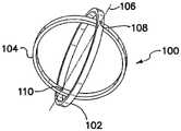
도 3은 절첩된(folded), 낮은 프로파일(profile)의 삽입 상태에서의 힌지결합된(hinged) 견인 장치를 위한 프레임의 사시도이다.
도 4는 낮은 프로파일의 중간-전개 상태에서의 도 3의 힌지결합된 견인 장치를 위한 프레임의 사시도이다.
도 5는 개방 상태에서의 도 3의 힌지결합된 견인 장치를 위한 프레임의 사시도이다.
도 6은 절개부로의 삽입에 적당한, 절첩된 낮은 프로파일 상태에서의 힌지결합된 견인 장치의 측면도이다.
도 7은 절개부로 그리고 체강(body cavity)으로 완전히 삽입된, 절첩된 낮은 프로파일 상태에서의 도 6의 힌지결합된 견인 장치의 측면도이다.
도 8은 절개부를 견인하기 위하여 절개부로 완전히 삽입되고 체강 내에서 완전히 전개된 도 6의 힌지결합된 견인 장치의 측면도이다.
도 9는 체벽 내의 절개부로의 삽입 이전의 비-텐셔닝된(non-tensioned) 상태에서의 크로스-링(cross-ring) 견인 장치의 측면도이다.
도 10은 체벽 내의 절개부를 통한 삽입에 적당한, 완전히 텐셔닝되고 절첩된 낮은 프로파일 상태에서의 도 9의 크로스-링 견인 장치의 측면도이다.
도 11은 체벽 내의 절개부를 통한 도 9의 크로스-링 견인 장치의 삽입 단계의 측면도이다.
도 12는 체벽에서 절개부를 견인하기 위하여 크로스-링 견인 장치가 미리 설정된 텐션(tension)을 취하도록 허용되는 도 9의 크로스-링 견인 장치의 전개 단계의 측면도이다.
도 13은 보관된 상태에서의 도 9의 크로스-링 견인 장치의 사시도이다.
도 14는 체벽 내의 절개부를 통한 삽입 이전에 텐셔닝하기 위해 준비될 때의 도 9의 크로스-링 견인 장치의 사시도이다.
도 15는 체벽 내의 절개부를 통한 삽입 이전에 부분적으로 텐셔닝되는 도 9의 크로스-링 견인 장치의 사시도이다.
도 16은 체벽 내의 절개부를 통한 삽입 이전에 부분적으로 텐셔닝되는 도 9의 크로스-링 견인 장치의 사시도이다.
도 17은 절첩 축(folding axis)을 따라 크로스-링을 타원형 형상으로 압축함으로써 삽입 프로파일을 감소시키는 단계 이전에, 체벽 내의 절개부를 통한 삽입 전에 부분적으로 텐셔닝되는 도 9의 크로스-링 견인 장치의 사시도이다.
도 18은 체벽 내의 절개부를 통한 삽입 이전에 완전히 텐셔닝되며, 절첩 축을 따라 크로스-링을 타원 형상으로 압축함으로써 더욱 준비된 도 9의 크로스-링 견인 장치의 사시도이다.
도 19는 제 1 강성 링 및 복수의 절첩 부분들을 포함하는 크로스-링 견인 장치의 사시도이다.
도 20은 텐셔닝 이전에, 보관된 상태에서의 도 19의 크로스-링 견인 장치의 측면도이다.
도 21은 절첩 부재들을 회전시킴으로써 이용을 위해 준비된 도 19의 크로스-링 견인 장치의 측면도이다.
도 22는 체벽 내의 절개부로 삽입될 때의 도 19의 크로스-링 견인 장치의 측면도이다.
도 23은 절개부를 통해 전적으로 체강 안으로 완전히 삽입되고 있는 도중에 체벽 내의 절개부 안으로 더욱 삽입될 때의 도 19의 크로스-링 견인 장치의 측면도이다.
도 24는 보관된 상태를 향해 부분적으로 다시 회전되고 체벽 내의 절개부를 통해 연장되는 절첩 부재들 및 체벽의 내부 표면에 대하여 강성 링으로 전개된 위치로 회전되는 도 19의 크로스-링 견인 장치의 측면도이다.
도 25는 보관된 상태를 취하는 것을 시도함에 따라, 체벽을 통해 완전히 삽입되고 전개된 상태를 취하도록 허용될 때의 도 19의 크로스-링 견인 장치의 측면도이다.
도 26은 제 1 유지 링 및 제 2 유지 링 사이에 텐션을 제공하기 위한 복수의 스트랩(strap)들을 갖는 창상 견인 장치의 사시도이다.
도 27은 제 1 상태에서의 복수의 형상화가능한 연장부들을 갖는 링-형상 견인 장치의 사시도이다.
도 28은 제 2 전개된 상태에서의 복수의 형상화가능한 연장부들을 갖는 도 27의 링-형상 견인 장치의 사시도이다.
도 29는 연장부들의 형상을 변경하기 위한 풀 와이어(pull wire)들을 포함하는, 도 27의 링-형상 견인 장치와 유사한 링-형상 견인 장치의 사시도이다.
도 30은 링 직경의 조절을 허용하는 복수의 조절가능한 견인 부분들을 갖는 링-형상 견인 장치의 사시도이다.
도 31은 링 직경의 조절을 허용하는 복수의 조절가능한 견인 부분들을 가지고 중첩하는 연장부들을 가지는 링-형상의 견인 장치의 사시도이다.
도 32는 도 31의 라인 32-32으로부터 취해지고 더 큰 축척으로 도시된 단면도이다.
도 33은 낮은 프로파일의 삽입 상태에서 벨로우즈(bellows)를 포함하는 쉬스(sheath) 및 2개의 링들을 갖는 조절가능한 창상 견인 장치의 측면도이다.
도 34는 전개된 견인 상태에서의 도 33의 조절가능한 창상 견인 장치의 측면도이다.
도 35는 절개부로의 삽입을 위해 폐쇄된 상태에서의 가단성 견인 링(malleable retraction ring)의 사시도이다.
도 36은 완전히 개방 전개된 상태에서의 도 35의 가단성 견인 링의 사시도이다.
도 37은 견인 링이 드로스트링(drawstring)에 의해 폐쇄된 상태로 유지되고 절개부로의 삽입을 위한 폐쇄된 상태에서의 도 35의 가단성 견인 링의 평면도이다.
도 38은 완전히 개방 전개된 상태에서의 도 37의 가단성 견인 링의 사시도이다.
도 39는 낮은 프로파일의, 팽창되지 않은 삽입 상태에서 팽창가능한 부분들을 갖는 확장가능한 그리고 견인가능한 앵커링(anchoring) 링을 예시한다.
도 40은 팽창된, 전개된 상태에서의 도 39의 확장가능한 그리고 견인가능한 앵커링 링을 예시한다.1 is a side view of a hand assisted laparoscopic procedure with a traction device in place;
2 is a side view of a hand-assisted laparoscopic procedure showing the deployment of a traction device.
3 is a perspective view of a frame for a hinged traction device in a folded, low profile, inserted state;
Fig. 4 is a perspective view of a frame for the hinged traction device of Fig. 3 in a low profile, mid-deployed state;
FIG. 5 is a perspective view of a frame for the hinged traction device of FIG. 3 in an open state;
6 is a side view of a hinged traction device in a collapsed low profile state suitable for insertion into an incision;
FIG. 7 is a side view of the hinged traction device of FIG. 6 in a collapsed low profile state, fully inserted into an incision and into a body cavity;
FIG. 8 is a side view of the hinged traction device of FIG. 6 fully inserted into the incision and fully deployed within a body cavity to retract the incision;
9 is a side view of a cross-ring traction device in a non-tensioned state prior to insertion into an incision in the body wall.
FIG. 10 is a side view of the cross-ring traction device of FIG. 9 in a fully tensioned and collapsed low profile state suitable for insertion through an incision in the body wall;
FIG. 11 is a side view of the insertion phase of the cross-ring traction device of FIG. 9 through an incision in the body wall;
FIG. 12 is a side view of the deployment phase of the cross-ring traction device of FIG. 9 in which the cross-ring traction device is allowed to assume a preset tension in order to pull an incision in the body wall;
Fig. 13 is a perspective view of the cross-ring towing device of Fig. 9 in a stored state;
14 is a perspective view of the cross-ring traction device of FIG. 9 as it is prepared for tensioning prior to insertion through an incision in the body wall;
15 is a perspective view of the cross-ring traction device of FIG. 9 partially tensioned prior to insertion through an incision in the body wall;
FIG. 16 is a perspective view of the cross-ring traction device of FIG. 9 partially tensioned prior to insertion through an incision in the body wall;
FIG. 17 shows the cross-ring traction device of FIG. 9 partially tensioned prior to insertion through an incision in the body wall, prior to reducing the insertion profile by compressing the cross-ring into an elliptical shape along the folding axis; FIG. is a perspective view.
FIG. 18 is a perspective view of the cross-ring traction device of FIG. 9 fully tensioned prior to insertion through an incision in the body wall and further prepared by compressing the cross-ring into an elliptical shape along the fold axis; FIG.
19 is a perspective view of a cross-ring traction device comprising a first rigid ring and a plurality of folded portions;
FIG. 20 is a side view of the cross-ring traction device of FIG. 19 in a stored state, prior to tensioning;
FIG. 21 is a side view of the cross-ring traction device of FIG. 19 ready for use by rotating the folding members;
FIG. 22 is a side view of the cross-ring retraction device of FIG. 19 when inserted into an incision in the body wall;
FIG. 23 is a side view of the cross-ring traction device of FIG. 19 as it is being further inserted into an incision in the body wall while being fully inserted entirely through the incision into a body cavity;
FIG. 24 is a side view of the cross-ring traction device of FIG. 19 rotated partially back towards a stowed state and rotated into a deployed position with a rigid ring relative to the inner surface of the body wall and folding members extending through cutouts in the body wall; .
FIG. 25 is a side view of the cross-ring retraction device of FIG. 19 when attempting to assume a stowed condition, fully inserted through the body wall and allowed to assume a deployed condition;
26 is a perspective view of a wound retraction device having a plurality of straps for providing tension between a first retention ring and a second retention ring;
27 is a perspective view of a ring-shaped pulling device having a plurality of shapeable extensions in a first state;
FIG. 28 is a perspective view of the ring-shaped traction device of FIG. 27 with a plurality of shapeable extensions in a second deployed state;
Fig. 29 is a perspective view of a ring-shaped pulling device similar to the ring-shaped pulling device of Fig. 27, including pull wires for changing the shape of the extensions;
30 is a perspective view of a ring-shaped traction device having a plurality of adjustable traction portions allowing adjustment of the ring diameter;
31 is a perspective view of a ring-shaped traction device having overlapping extensions with a plurality of adjustable traction portions allowing adjustment of the ring diameter;
FIG. 32 is a cross-sectional view taken from line 32-32 of FIG. 31 and shown at a larger scale;
33 is a side view of an adjustable wound retraction device having two rings and a sheath comprising bellows in the low profile insertion state.
Fig. 34 is a side view of the adjustable wound retraction device of Fig. 33 in a deployed traction state;
35 is a perspective view of a malleable retraction ring in a closed state for insertion into an incision;
FIG. 36 is a perspective view of the malleable pull ring of FIG. 35 in a fully open deployed state;
FIG. 37 is a top view of the malleable pull ring of FIG. 35 with the pull ring held closed by a drawstring and closed for insertion into an incision;
FIG. 38 is a perspective view of the malleable pull ring of FIG. 37 in a fully open deployed state;
39 illustrates a low profile, expandable and retractable anchoring ring with inflatable portions in an unexpanded inserted state.
FIG. 40 illustrates the expandable and retractable anchoring ring of FIG. 39 in an expanded, deployed state.
도면들을 참조하면, 도 1 및 도 2는 가압된 가스의 도입에 의해 복강(abdominal cavity)(52)이 신체의 복부 영역(54) 내에 생성되는 수부 보조 복강경 수술(hand assisted laparoscopic surgery)(50)을 도시한다. 견인 장치(56)는 이를 관통한 사람의 손(58)을 가지는 것으로 도시되어 있다. 견인 장치(56)를 환자의 복벽(abdominal wall)(60) 내에 전개하기 위하여, 수술 절개부(62)는 복벽을 관통하여 만들어지고, 견인 장치는 삽입되고, 그 후에, 절개부를 견인 및 확대하기 위해 전개된다. 견인 장치(56)는 제 1 외부 유지 부재, 제 2 내부 유지 부재, 및 제 1 유지 부재 및 제 2 유지 부재 사이에 결합된 멤브레인(membrane) 또는 슬리브(sleeve)를 포함할 수 있다. 견인 장치(56)는 작은 절개부(62)를 통한 배치를 가능하게 하기 위하여 형상화가능하게(64) 될 수 있다. 견인 장치(56)는 절개부(62)를 통해 삽입될 때 손(hand)에 의해 낮은 프로파일 형상 및 상태(64)에서 유지되고, 그 다음으로 해제될 수 있어서, 제 1 외부 유지 부재 및 제 2 내부 유지 부재가 체벽(60)의 외부 표면 및 체벽의 내부 표면(66) 사이에 멤브레인을 펴도록 한다.Referring to the drawings, FIGS. 1 and 2 illustrate hand assisted
도 3 내지 도 8을 참조하면, 견인 장치(100)는 서로에 대해 실질적으로 동심인 제 1 외부 링(102) 및 제 2 내부 링(104)을 갖는 것으로 도시되어 있다. 제 1 및 제 2 링들(102, 104)은 반강성(semi-rigid)일 수 있고, 제 1 및 제 2 링들의 원주(circumference) 상에서 서로 실질적으로 대향하도록 위치되는 힌지(hinge)들과 함께 제 1 링(102) 및 제 2 링(104)을 결합하는 제 1 힌지(108) 및 제 2 힌지(110)를 형성하는 공통 축(106)을 따라 힌지결합될 수 있다. 견인 장치(100)는 제 1 동심 상태(도 3)로부터, 제 1 및 제 2 링들(102, 104)이 축(106) 둘레로 회전되고 제 1 및 제 2 링들의 평면들 사이에서 각도를 형성하는 제 2 각도 상태(도 4, 도 5 및 도 8)(112)로 전이할 수 있다. 견인 장치(100)의 형태는 일반적으로 접을 수 있는 자이로스코프(collapsible gyroscope)와 유사하다. 가스 기밀성(gastight) 튜브형 멤브레인 또는 쉬스(sheath)(114)(도 6 내지 도 8)는 제 1 링(102)의 원주 주위 및 제 2 링(104)의 원주 주위에 결합되어, 제 1 및 제 2 링들이 제 2 각도 상태에 있을 때, 쉬스는 실질적으로 원통형이다.3-8 , the
제 1 및 제 2 링들(102, 104)은 먼저 함께 압축되어, 멤브레인 또는 쉬스(114)의 벽이 텐셔닝되지 않거나 약간만 텐셔닝되어 있는 실질적으로 동심 구조(도 6 및 도 7)를 형성한다. 압축된 동심 구조는 체벽(60) 내의 절개부(62)로의 견인 장치(100)의 삽입을 가능하게 하기 위해 제 1 및 제 2 힌지들(108, 110) 사이의 축을 따라 제 1 및 제 2 링들(102, 104)을 압축함으로써 더욱 유선형으로 될 수 있다. 축을 따라 더욱 유선형으로 하는 것은 견인 장치(100)를 상당히 길게 늘여서, 견인 장치(100)가 작은 절개부(62)를 통해 슬라이드(slide)할 수 있다. 일단 견인 장치(100)가 절개부(62) 안으로 대략 장치의 중간점(midpoint)까지 삽입되었으면, 제 1 및 제 2 힌지들(108, 110) 사이의 축은 복벽(60)에 대해 실질적으로 평행하고 절개부에 대해 평행하게 위치되고, 견인 장치는 절첩되지 않고(unfold) 멤브레인 또는 슬리브(114)가 절개부(62) 내에서 펴지도록 전개된다. 장치(100)의 2개의 링들(102, 104)이 제 1 및 제 2 힌지들(108, 110) 사이의 축(106) 둘레로 회전되므로, 멤브레인 또는 슬리브(114)는 멤브레인 또는 슬리브를 둘러싸는 조직에 견인 텐션(retracting tension)을 가한다. 제 1 링(102) 및 제 2 링(104)은 이제 절개부(62)를 횡단하고, 링들의 연장 부분들은 체벽(60)의 외부 표면 및 체벽의 내부 표면(66)과 인접한다. 이 배치는 견인 장치(100)를 절개부(62) 내의 적소에 유지하고, 또한, 절개부를 견인 및 확대한다.The first and
견인 장치(100)는 견인 장치를 제 2 각도 상태(105)에서 유지하기 위한 수단을 포함한다. 이러한 유지 수단은 제 1 및 제 2 힌지들(108, 110) 중의 적어도 하나에 근접하게 위치되는 래칫 기구(ratchet mechanism)를 포함할 수 있다. 래칫 기구는 제 1 및 제 2 힌지들(108, 110)의 각각에 근접하게 위치될 수 있다. 대안적으로, 유지 수단은 체벽(60) 외부의 견인 장치 상에 장착되는 밸브 구조를 포함할 수 있다. 견인 장치(100)를 개방 전개된 상태에서 유지하기 위한 다른 수단은 당 업계에서 잘 알려져 있는 임의의 적당한 기계적 수단을 포함할 수 있다.The pulling
제 1 및 제 2 링들(102, 104)은 외부의 힘들이 가해지지 않을 때, 원(circle)을 정상적으로 형성하기 위한 충분한 강도를 갖는 반강성 플라스틱 재료로 만들어질 수 있다. 대안적으로, 제 1 및 제 2 링들(102, 104)은 제 1 및 제 2 링들을 형성하는 탄성중합체의 중공 또는 튜브형 구조(elastomeric hollow or tubular structure) 내에 배치된 금속 또는 플라스틱 보강 부재를 포함할 수 있다. 또한, 링들(102, 104)은 링들이 평평한 금속 스프링 또는 원형의 금속 스프링으로 형성되는 스프링과 유사한(spring-like) 금속 구조로 만들어질 수 있다. 추가적으로, 링들(102, 104)은 형상화가능한 또는 가단성 있는 금속성 재료 또는 합성물로 형성될 수 있다. 대안적으로, 제 1 및 제 2 링들(102, 104) 중의 하나는 제 1 특성을 갖는 재료로 만들어질 수 있고, 제 1 및 제 2 링들 중의 다른 하나는 제 2 특성을 갖는 제 2 재료로 만들어질 수 있다. 더욱 구체적으로, 제 1 링(102)은 제 2 링(104)보다 더욱 강성이 있는 재료로 만들어질 수 있다. 예를 들어, 제 1 링(102)은 반강성의 금속 또는 플라스틱으로 만들어질 수 있고, 제 2 링(104)은 제 1 링이 만들어지는 재료보다 강성이 적은 플라스틱 또는 다른 재료로 만들어질 수 있다. 제 1 및 제 2 링들(102, 104)이 함께 압축되면(도 3), 제 2 링의 원주는 제 1 링의 원주 내에 끼워지도록 접혀진다.The first and
멤브레인 또는 쉬스(114)는 탄성중합체 재료 또는 얇은 비-팽창성(non-distensible) 재료로 형성될 수 있다. 탄성중합체 재료들은 실리콘(silicone), 폴리이소프렌(polyisoprene), 라텍스(latex), 비닐(vinyl) 및 폴리우레탄(polyurethane)을 포함할 수 있다. 비-탄성(non-elastic) 재료들은 폴리에스테르(polyester), 마일러(Mylar), 폴리에틸렌(polyethylene) 등을 포함할 수 있다. 이 재료들은 강도(strength) 및 내구성(durability)을 증가시키기 위하여 패브릭(fabric) 또는 직조(woven) 재료로 보강될 수 있다.The membrane or
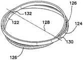
도 9 내지 도 18을 참조하면, 크로스-링 창상 견인 장치(120)는 제 1 및 제 2 견인 부분들 또는 링들(122, 124)과, 견인 부분들 사이에서 텐셔닝될 수 있는 가스 기밀성의 신축성 있는 튜브형 멤브레인 또는 쉬스(126)를 포함한다. 제 1 및 제 2 견인 부분들(122, 124)은 실질적으로 동심이다. 제 1 및 제 2 견인 부분들(122, 124)은 공통 축(128)을 따라 힌지결합될 수 있고, 이에 따라, 제 1 및 제 2 견인 부분들을 함께 결합하는 제 1 및 제 2 힌지들(130, 132)을 형성할 수 있다. 힌지들(130, 132)은 제 1 및 제 2 견인 부분들(122, 124)의 원주 상에서 서로 실질적으로 대향하도록 위치된다. 쉬스(126)는 제 1 및 제 2 견인 부분들(122, 124)의 각각에 결합된다.9-18 , the cross-ring
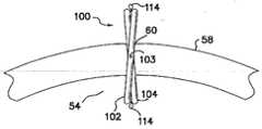
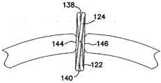
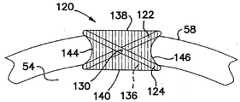
크로스-링 견인 장치(120)는 원주의 탄성중합체 쉬스(126)가 실질적으로 비-텐셔닝되거나 이완되는 제 1 이완 상태(134)(도 9)에서 공급될 수 있다. 제 1 이완 상태(134)에서는, 제 1 및 제 2 링들(122, 124)의 평면들 사이에서 각도가 형성되고, 견인 장치(120)의 근위 단부(138) 및 원위 단부(140) 사이에는 상당한 관통 내강(through lumen)(136)이 있다. 견인 장치(120)를 제 2 텐셔닝된 상태(142)에서 배치하기 위하여, 제 1 및 제 2 링들이 실질적으로 동심이 되도록 근위(138) 및 원위(140) 개방 평면들을 가로질러 견인 부분들(122, 124)을 서로를 향해 회전시킴으로써 작은 수술 절개부(62)를 통한 배치를 가능하게 하기 위해 견인 장치의 프로파일이 감소 및 변형될 수 있다. 그 후에, 탄성중합체 쉬스(126)는 근위 단부(138) 및 원위 단부(140) 사이에서 세로로 펴지고, 이에 따라, 쉬스를 텐션 하에서 배치하고, 내강(136)의 개방부는 감소되고 실질적으로 막히고, 견인 장치는 실질적으로 평평해진다(도 13 내지 도 18 참조). 추가적으로, 일단 견인 장치(120)가 이와 같이 평평해졌으면, 제 1 및 제 2 힌지들(130, 132)의 축(128)을 따라 링들(122, 124)을 압축함으로써 견인 장치(120)는 타원 형상(도 18)으로 더욱 유선형으로 될 수 있다. 평평해진 유선형 상태(도 18)의 견인 장치(120)는 장치가 정지 상태(134)인 경우보다 훨씬 작은 절개부(62)를 통해 끼워질 것이다. 견인 장치(120)는 절개부(62)(도 1 및 도 2)와 같은, 체벽(60) 내의 수술 결함을 통해 압박될 수 있고, 그 다음으로, 탄성중합체 쉬스(126)에 대한 텐션의 해제에 응답하여 제 1 이완 상태(134)를 취하도록 허용될 수 있다. 그 근위 및 원위 개방부들(138, 140)을 포함하는 내강(136)은 견인 장치(120)가 개방 전개된 상태(도 12)를 취할 때에 개방될 것이다. 탄성중합체 쉬스(126)는 견인 장치(120)의 내강(136)과 견인된 절개부 또는 결함(62)의 조직 사이에 연속적인 가스 기밀성 장벽(144, 146)을 형성한다.The
쉬스(126)가 만들어지는 탄성중합체 재료는 다양한 견인력들을 제공하도록 선택될 수 있다. 예를 들어, 경량의 얇은 벽으로 된 더욱 탄성인 재료는 두꺼운 벽으로 된 덜 탄성인 재료에 비해 약한 견인력을 산출한다. 폭넓은 범위의 체벽 상태들 또는 유형들을 수용하는 견인 장치들을 산출하기 위하여, 견인 링들(122, 124)의 다양한 직경들은 탄성중합체 재료의 다양한 품질들과 조합될 수 있다. 또한, 본 발명은 제 1 및 제 2 견인 부분들 또는 링들(122, 124)의 구성을 위한 강성 또는 반강성의 플라스틱 또는 스프링 금속의 이용을 고려한다.The elastomeric material from which the
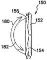
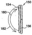
도 19 내지 도 25를 참조하면, 견인 장치(150)는 원위 연속 링(distal continuous ring)(152), 원위 연속 링에 힌지결합된 제 1 하프 링(half ring)(154), 원위 연속 링에 힌지결합된 제 2 하프 링(156), 및 원위 링 및 제 1 및 제 2 하프링들 사이에 결합된 가스 기밀성의 원주 탄성중합체 쉬스(circumferential elastomeric sheath)(158)를 포함할 수 있다. 또한, 쉬스(158)는 제 1 및 제 2 하프 링들(154, 156) 사이에 직접 결합될 수 있다.19-25, the
제 1 및 제 2 하프 링들(154, 156) 중의 하나 또는 둘 모두는 원위 연속 링(152)의 외부 표면(160)을 따라 위치될 수 있고 공통 축(162)을 따라 힌지결합될 수 있으며, 이에 따라, 제 1 및 제 2 하프 링들을 서로 그리고 원위 연속 링에 결합하는 제 1 힌지(164) 및 제 2 힌지(166)를 형성할 수 있고, 힌지들은 원위 연속 링의 원주 상에서 서로 실질적으로 대향하도록 위치될 수 있다(도 19). 대안적으로, 제 1 및 제 2 하프 링들(154, 156) 중의 하나 또는 둘 모두는 원위 연속 링(152)의 내부 표면을 따라 위치될 수 있다(도 20 내지 도 25). 제 1 중립 상태에서는(도 19), 제 1 하프 링(154)이 원위 연속 링(152)에 근접하게 축(162)의 제 1 측(168) 상에 위치되고, 제 2 하프 링(156)은 원위 연속 링에 근접하게 축의 제 2 대향 측(170) 상에 위치된다.One or both of the first and second half rings 154 , 156 can be positioned along the
제 1 하프 링(154)의 제 1 단부 부분(172) 및 제 2 하프 링(156)의 제 1 단부 부분(174)은 서로 중첩하고, 제 1 하프 링의 제 2 단부 부분(176) 및 제 2 하프 링의 제 2 단부 부분(178)은 서로 중첩한다. 제 1 하프 링(154)의 제 1 및 제 2 단부 부분들(172, 176)은 원위 연속 링(152)과, 제 2 하프 링(156)의 제 1 및 제 2 단부 부분들(174, 178) 사이에 각각 위치될 수 있어서, 제 1 및 제 2 하프 링들은 서로를 지나 회전할 수 있다. 견인 장치는 제 1 하프 링(154) 및 제 2 하프 링(156)을 평평하게 그리고 원위 연속 링(152)과 정렬되게 절첩함으로써 제 2 텐셔닝된 상태(도 21)로 전이될 수 있다. 제 2 텐셔닝된 상태에서는, 제 1 하프 링, 제 2 하프 링 및 원위 연속 링이 실질적으로 동심일 수 있다.The
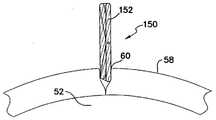
체벽(60) 내의 절개부(62) 안으로의 삽입을 위하여 견인 장치(150)를 준비하는 것은 견인 장치를 제 1 중립 상태로부터 제 2 텐셔닝된 상태로 전이하는 것을 포함한다. 제 1 중립 상태(도 19)로부터 제 2 텐셔닝된 상태(도 21)로의 전이는 제 1 하프 링(154)이 힌지들(164, 166) 둘레로 제 1 방향(180)으로 축(162)의 제 2 측(170) 상의 원위 연속 링(152)에 근접한 위치까지 회전되는 것을 포함하고, 이에 따라, 원위 링 및 제 1 하프 링 사이에 결합되는 쉬스(158)의 부분을 텐션 하에서 배치한다(도 20 및 도 21). 제 2 하프 링(156)은 힌지들(164, 166) 둘레로 제 2 대향 방향(182)으로 축(162)의 제 1 측(168) 상의 원위 연속 링(152)에 근접한 위치까지 회전되고, 이에 따라, 원위 링 및 제 2 하프 링 사이에 결합되는 쉬스(158)의 부분을 텐션 하에서 배치한다(도 20 및 도 21). 제 1 및 제 2 하프 링들(154, 156)은 원위 연속 링(152)과 실질적으로 동심이 될 때까지 힌지들(164, 166) 둘레로 더욱 회전될 수 있다. 견인 장치(150)는 제 1 및 제 2 힌지들(164, 166) 사이의 축(162)을 따라 원위 연속 링(152) 및 제 1 및 제 2 하프 링들(154, 156)을 압축함으로써 더욱 유선형으로 될 수 있고, 이에 따라, 절개부(62)로의 견인 장치의 삽입을 더욱 용이하게 가능하게 하기 위하여 견인 장치(150)를 길게 늘일 수 있다(도 22 및 도 23).Preparing the
견인 장치(150)는 절개부(62)를 통해 완전히 그리고 체강(52) 안으로 완전히 삽입된다. 견인 장치(150)가 완전히 체강(52) 내에 위치된 상태에서, 제 1 및 제 2 하프 링들이 원위 연속 링(152)에 실질적으로 수직으로, 서로에 대해 실질적으로 평행하게, 그리고 원위 연속 링에 근접할 때까지, 제 2 하프 링(156)은 제 1 방향(180)으로 다시 회전되고 제 1 하프 링(154)은 제 2 방향(182)으로 다시 회전된다(도 24 참조). 원위 연속 링(152)이 체벽(60)의 내부 표면(66)에 대해 인접하고 제 1 및 제 2 하프 링이 절개부로부터 부분적으로 돌출할 때까지, 제 1 및 제 2 하프 링(154, 156)은 절개부(62)를 통해 근위 측으로 당겨진다. 제 1 및 제 2 하프 링(154, 156)은 해제되고 거의 중립 상태(도 25)를 취하도록 허용되며, 이에 따라, 절개부(62)를 원주 상에서 견인한다.The
도 26을 참조하면, 견인 장치(200)는 제 1 원위 유지 링(202), 제 2 근위 유지 링(204), 제 1 및 제 2 유지 링들에 결합된 원주의 튜브형 쉬스(206), 복수의 텐셔닝 스트랩(tensioning strap)들(208) 및 근위 로크 링(proximal lock ring)(210)을 갖는 것으로 도시되어 있다. 원위 유지 링(202)은 작은 체벽 절개부를 통한 용이한 삽입을 위해 변형될 수 있고 그 후에, 일반적으로 원형 상태를 취하도록 허용될 수 있는 형상화가능한 또는 가단성 있는 재료로 만들어질 수 있다. 근위 유지 링(204)은 원위 유지 링(202)보다 더욱 강성인 재료로 만들어질 수 있다. 복수의 스트랩들(208)의 각각은 원위 유지 링(202)에 결합되고, 쉬스(206)의 내강 및 근위 유지 링(204)을 통해 근위 측으로 연장된다. 근위 로크 링(210)은 근위 유지 링(204)의 내부 표면(212) 및 로크 링(210)의 외부 표면(214) 사이에서 스트랩들(208)을 포획하도록 하는 크기로 정해지고 이와 같이 구성된다. 근위 유지 링(204)의 내부 표면(212) 및 로크 링(210)의 외부 표면(214) 중의 적어도 하나는 경사질 수 있다. 발명은 스트랩들(208)의 구성을 위하여 패브릭과 같이, 강하고 얇은 비-탄성(non-elastic) 재료의 이용을 고려한다.26 , the
이용 시에, 원위 유지 링(202)은 변형되어 체벽(60) 내의 절개부(62)를 통해 체강(52) 안으로 삽입된다. 근위 유지 링(204)은 체벽(60)의 외부 표면 상에 남아 있도록 허용된다. 로크 링(210)은 근위 유지 링(204)의 내강 내에 배치되고, 스트랩들(208)은 근위 유지 링 및 로크 링 사이를 빠져나온다. 스트랩들(208)은 적절한 텐션 및 절개부의 추후의 견인을 달성하기 위하여 근위 측으로 당겨질 수 있다. 근위 유지 링(204)의 내부 표면(212)에 대해 쐐기로 고정하고, 스트랩들이 로크 링 및 근위 유지 링 사이에서 원위 측으로 미끄러지는 것을 실질적으로 방지함으로써, 로크 링(210)은 스트랩들(208)의 텐션에 반응한다. 견인 장치(200)의 제거는 스트랩들(208) 중의 적어도 하나를 근위 측으로 약간 당겨 근위 링(204)으로부터 로크 링(210)을 해제하고 로크 링을 제거하여 스트랩들 상에 텐션을 해제함으로써 달성된다. 스트랩들(208)의 텐션이 제거됨으로써, 원위 링(202)은 절개부를 통해 체강(52)으로부터 제거될 수 있다.In use, the
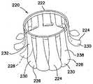
도 27 내지 도 29를 참조하면, 창상 견인 장치(220)는 근위 유지 링(222)과, 근위 유지 링에 결합되고 그것으로부터 원위 측으로 연장되는 복수의 형상화가능한, 원위 측으로 연장되는 견인 소자들(224)을 포함한다. 연장되는 견인 소자들(224)은 제 1 낮은 프로파일의 삽입 상태(226)(도 27)로부터, 연장 소자들의 원위 단부들이 방사상으로 외부를 향해 연장되는, 제 2 확장된 높은-프로파일의 유지 상태(도 28)로 전이하도록 구성된다. 유지 링(222)은 연장 소자들(224)을 유지 링의 평면에 대해 일반적으로 수직인 위치에서 유지하도록 하는 크기이고 이와 같이 구성될 수 있다. 대안적으로, 연장 소자들(224)은 절개부(62)로의 견인 장치(220)의 삽입을 용이하게 하기 위하여 방사상으로 내부를 향해 연장될 수 있다. 연장 소자들(224)은 절개부 내에서 견인된 상태로 형상화되도록 가단성이 있을 수 있거나, 제 1 내부를 향해 배치된 상태 내지 제 2 외부를 향해 배치된 상태(228) 사이에서 긴장완화 관계로 스냅하도록 하는 크기이고 이와 같이 구성될 수 있다. 원주의 쉬스는 견인 장치(220)와 연관될 수 있고, 연장 소자들(224) 및 인접한 조직 사이, 또는 견인 장치의 내강 내에 별도의 부품으로서 위치될 수 있다.27-29 , the
이용 시에, 연장 소자들(224)은 체벽(60) 내의 수술 절개부(62)(도 1 및 도 2) 안으로 삽입되고, 근위 유지 링(222)이 체벽의 외부 표면에 대해 실질적으로 인접될 때까지 원위 측으로 전진된다. 다음으로, 외과의사는 유지 링(222)을 통해 자신의 손을 원위 측으로 삽입할 수 있고, 연장 소자들(224) 각각의 원위 부분(230)을 방사상으로 외부를 향해 구부려서, 연장 소자들의 원위 부분들이 체벽(60)의 내부 표면(66)에 기대어 배치된다.In use, the
연장 소자들(224)은 강철 줄자 또는 베니션 블라인드(venetian blind)의 조각(slat)과 유사한 컵 모양의 또는 축방향으로 반원인 단면을 갖는 스프링 강철(spring steel)과 같은 판금(sheet metal)의 얇은 스트립(strip)들로 만들어질 수 있다. 연장 소자들(224)의 각각은 반원 단면의 외부 곡선(232)이 방사상으로 외부를 향해 위치되도록 지향된다. 연장 소자들(224)은 제 1 직선 삽입 상태(226)에서 용이하게 존재한다. 그러나, 일단 외부의 반원 표면(232) 상에서 내부를 향해 구부러지면, 연장부들은 절개부에서의 유지를 위한 제 2 굴곡된 높은-프로파일의 상태(228)로 변환한다.The
연장부들(224)은 니켈-티타늄 합금과 같은 형상-기억(shape-memory) 재료로 만들어질 수 있다. 제 1 온도에서는, 니켈-티타늄 합금으로 만들어진 연장 소자들(224)이 제 1 실질적으로 직선 상태(226)에 있을 수 있고, 제 2 더 높은 온도를 갖는 환경에 배치될 때, 연장부들은 제 2 굴곡된 상태(228)로 변환하고, 연장 소자들의 원위 단부들은 방사상으로 외부를 향해 연장된다. 예를 들어, 장치(220)는 빙수(ice water) 내부와 같이 상대적으로 차가운 환경에서 유지될 수 있고, 그 다음으로, 생체 내부와 같이 온도가 더 높은 더운 환경으로 삽입될 수 있다. 니켈-티타늄 합금의 연장 소자들(224)의 형상은 미리 설정된 조건에 따라 변한다.The
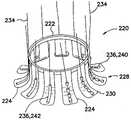
도 29를 참조하면, 창상 견인 장치(220)는 복수의 풀 와이어(pull wire)들(234)을 포함할 수 있고, 각각의 풀 와이어는 각각의 연장 소자(224)와 대응할 수 있다. 풀 와이어들(234) 각각은 각각의 연장 소자(224)의 원위 부분(230)에 결합되고, 풀 와이어가 근위 측으로 당겨질 때, 각각의 연장 소자의 원위 부분이 방사상으로 외부를 향해 편향하도록 구성된다. 각각의 풀 와이어(234)는 각각의 연장 소자(224)의 원위 부분(230)이 풀 와이어의 텐션에 의해 결정되는 형상을 나타내도록 한다. 풀 와이어들(234)은 연장 소자들(224)을 구부리기 위하여 집합적으로 또는 개별적으로 전개될 수 있다. 풀 와이어들(234)의 각각은 각각의 연장 소자(224)의 외부 표면(238)의 길이를 따라 위치되는 풀 와이어 리테이너(pull wire retainer)(236)를 통해 횡단할 수 있다. 각각의 풀 와이어 리테이너(236)는 적어도 하나의 아일렛(eyelet)(240), 튜브(242), 또는 다른 유사하게 기능하는 장치를 포함할 수 있다. 풀 와이어들이 연장 소자들의 원위 부분들(230)을 편향시키기 위하여 근위 측으로 당겨질 때, 풀 와이어 리테이너들(236)은 풀 와이어들(234)이 연장 소자들(224)의 외부 표면(238)으로부터 벗어나는 거리를 제한하도록 기능한다. 풀 와이어 리테이너들(236)은 연장 소자(224)의 외부 표면(238)의 길이를 따라 세로로 정렬될 수 있다.Referring to FIG. 29 , the
도 30 내지 도 32를 참조하면, 창상 견인 장치(250)는 조절가능한 원주를 갖는 실질적으로 고리모양 형상을 갖는 외부 링(252)과, 외부 링으로부터 원위 측으로 연장되는 실질적으로 튜브형 구조체(254)를 포함한다. 외부 링(252)은, 고리모양 형상을 형성하기 위하여 래칫팅 기구(ratcheting mechanism)(258)와 같이, 원주를 조절하기 위한 수단에 의해 함께 결합되는 인접한 굴곡된 링 세그먼트들을 갖는 복수의 굴곡된 링 세그먼트들(256)로 분할된다. 굴곡된 링 세그먼트들(256) 각각은 제 1 근위 측(260), 제 2 원위 측(262), 외부 링(252)의 원주 둘레의 제 1 단부(264), 및 외부 링의 원주 둘레의 제 2 단부(266)를 포함한다. 굴곡된 링 세그먼트들(256)은 외부 링의 직경이 조절됨에 따라 외부 링(252)의 실질적으로 원주 형상을 유지하기 위하여 유연성이 있을 수 있다.30-32 , wound
래칫팅 기구(258)는 굴곡된 링 세그먼트들(256) 각각의 근위 표면(proximal surface)(260) 내에 홈(groove)(268)을 포함할 수 있다. 홈(268)은 굴곡된 링 세그먼트(256)의 곡선을 실질적으로 따르고, 굴곡된 링 세그먼트의 제 1 단부(264)로 개방된다. 홈(268)은 예를 들어, 홈의 제 1 외부 굴곡된 표면(272) 상에 위치된 복수의 래칫 치형부(ratchet tooth)들(270)을 포함한다. 대안적으로, 래칫 치형부들(270)은 홈(268)의 제 2 내부 굴곡된 표면(274) 상에 또는 홈의 원위 표면(276) 상에 위치될 수 있다. 또한, 홈(268)은 홈의 외부 및 내부 굴곡된 표면들(272, 274) 중의 적어도 하나 내에 유지 채널(retention channel)(278)을 포함할 수 있다.The
또한, 굴곡된 링 세그먼트들(256) 각각은 인접한 굴곡된 링 세그먼트 내의 홈(268)과 짝을 이루도록 구비된 굴곡된 링 세그먼트의 제 2 단부(266)로부터 연장되는 유연성 있는 긴 돌기(flexible elongate protuberance)를 포함한다. 긴 돌기(280)는 긴 돌기에 인접한 굴곡된 링 세그먼트(256)의 홈(268)에서 래칫 치형부들(270)과 상호작용하는 적어도 하나의 래칫 치형부(282)를 포함한다. 외부 링(252)을 형성하는 것은 각각의 굴곡된 링 세그먼트의 제 1 단부(264)를 인접한 굴곡된 링 세그먼트의 제 2 단부(266)에 인접하게 위치시킴으로써 굴곡된 링 세그먼트들(256)을 원주 상에서 함께 정렬하는 것과, 긴 돌기 상의 적어도 하나의 래킷 치형부(282)가 홈 내의 래칫 치형부들(270)과 상호작용하도록, 굴곡된 링 세그먼트들 중의 각각의 굴곡된 링 세그먼트의 긴 돌기(280)를 다른 인접한 굴곡된 링 세그먼트의 홈(268) 안으로 삽입하는 것을 포함한다.Additionally, each of the
하나의 굴곡된 링 세그먼트(256)의 긴 돌기(280)가 인접한 굴곡된 링 세그먼트의 홈(268)으로부터 부주의하게 미끄러지는 것을 실질적으로 방지하기 위하여, 긴 돌기는 립(lip)(284)(도 32)을 포함할 수 있고, 이 립은 긴 돌기의 길이를 따라 세로로 연장되며, 인접한 굴곡된 링 세그먼트의 홈 내의 유지 채널(278)과 상호작용하도록 구비된다. 외부 링(252)의 직경은 인접한 굴곡된 링 세그먼트들(256)의 홈들(268) 내에서 긴 돌기들(280)을 삽입 및 견인함으로써 조절된다. 외부 링(252)의 직경은 굴곡된 링 세그먼트들(256)이 더 떨어지도록 이동됨에 따라 증가되고, 상기 직경은 굴곡된 링 세그먼트들이 서로 더 근접하게 이동됨에 따라 감소된다.To substantially prevent the
외부 링(252)과 마찬가지로, 실질적으로 튜브형 구조체(254)도 복수의 긴 튜브 세그먼트들(286)로 분할되고, 튜브 세그먼트들의 각각은 각각의 굴곡된 링 세그먼트(256)에 결합되고 각각의 굴곡된 링 세그먼트로부터 원위 측으로 연장된다. 튜브 세그먼트들(286)은 각각의 튜브 세그먼트가 결합되는 굴곡된 링 세그먼트(256)의 제 1 단부(264) 및 제 2 단부(266) 사이에서 원주 상으로 각각 연장될 수 있어서(도 30), 인접하는 튜브 세그먼트들 사이에 중첩이 없다. 대안적으로, 튜브 세그먼트들(286) 각각은 각각의 튜브 세그먼트가 결합되는 굴곡된 링 세그먼트의 제 1 및 제 2 단부들(264, 266) 중의 적어도 하나를 지나서 원주 상으로 연장될 수 있어서(도 31), 인접하는 튜브 세그먼트들이 서로 중첩할 수 있다. 튜브 세그먼트들(286)의 프로파일은 각각의 튜브 세그먼트가 결합되는 굴곡된 링 세그먼트(256)의 곡선을 실질적으로 따를 수 있다. 튜브 세그먼트들(286)은 각각의 튜브 세그먼트들이 결합되는 굴곡된 링 세그먼트들(256)의 곡선의 임의의 변경을 따르도록 유연성이 있을 수 있다. 튜브 세그먼트들(286)은 금속성 또는 중합체 재료와 같은 생체적합성 재료(biocompatible material)로 만들어질 수 있다.Like the
도 31을 참조하면, 견인 링(250)은 튜브형 구조체의 원위 단부(290)에서의 튜브형 구조체(254)의 직경을 튜브형 구조체의 근위 단부(292)에서의 직경과 실질적으로 동일하게 유지하기 위하여, 외부 링(252)과 실질적으로 대향하는 내부 링(288)을 포함할 수 있다. 내부 링(288)은 래칫팅 기구(258)를 포함하지만, 홈(268)은 굴곡된 링 세그먼트들(256)의 원위 표면 상에 위치된다. 이용 시에, 외부 링(252) 및 내부 링(288)이 그 각각의 최소 직경들로 견인됨에 따라, 내부 링을 포함하는 창상 견인 장치(250)의 원위 단부(262)는 체벽(60) 내의 작은 절개부(62)(도 1 및 도 2)를 통해 체강(52) 안으로 삽입될 수 있다. 내부 링(288)은 원위 유지 부재의 형태로 내부 링을 전개하기 위하여 더 큰 직경으로 확장될 수 있다. 내부 링(288)이 전개됨으로써, 외부 링(252)은 튜브 세그먼트들(286) 상에 텐션을 제공하기 위하여 더 큰 직경으로 조절될 수 있고, 이에 따라, 절개부의 원주 견인(circumferential retraction)을 제공할 수 있다.31 , the
내부 링(288)을 포함하지 않는 견인 링들(250)에 대하여, 튜브 세그먼트들(286)의 원위 단부들(290)은 절개부(62) 안으로 그리고 체강(52) 안으로 삽입될 수 있다. 외부 링(252)은 튜브 세그먼트들(286) 상에 텐션을 제공하기 위하여 더 큰 직경으로 조절될 수 있고, 이에 따라, 절개부(62)의 원주 견인을 제공할 수 있다. 튜브 세그먼트들(286)은 튜브 섹션들을 실질적으로 편향시키지 않으면서 절개부(62)의 견인을 유지할 정도로 충분히 강하다.For traction rings 250 that do not include an
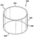
도 33 및 도 34를 참조하면, 원주 수술 견인 장치(300)는 제 1 실질적으로 고리모양 외부 링(302) 및 제 2 실질적으로 고리모양 내부 링(304)을 포함한다. 제 1 및 제 2 링들(302, 304)은 실질적으로 가스 기밀성인 원통형 슬리브(306)에 의해 분리된다. 제 1 및 제 2 링들(302, 304)은 중합체 재료와 같이, 실질적으로 유연성 있는 재료로 만들어질 수 있고, 제 1 및 제 2 링들을 방사상으로 외부를 향해 바이어스를 가하는, 제 1 및 제 2 링들 각각에 위치된 스프링과 유사한 코어(spring-like core)와 같은 제 1 및 제 2 바이어싱 부재(308, 310)로 각각 보강될 수 있다. 그 후에, 제 1 및 제 2 링들(302, 304)을 방사상으로 외부를 향해 바이어스를 가하는 것은 더 짧은 축 길이를 향해 견인 장치(300)에 바이어스를 가하는 것이다. 원통형 슬리브(306)는 제 1 및 제 2 링들(302, 304)에 결합된다. 원통형 슬리브(306)는 원통형 슬리브가 제 1 축방향 압축된 상태(도 33) 및 제 2 축방향 연장된 상태(도 34) 사이에서 전이하도록 하는 벨로우즈(bellows)(312) 또는 방사상 절첩부(radial fold)들을 포함할 수 있다.33 and 34 , circumferential
견인 장치(300)가 제 1 축방향 압축된 상태(도 33)에 있음으로써, 견인 장치는 견인 장치를 낮은 프로파일의 긴 타원형 형상으로 변환하여 절개부(62)로의 삽입을 가능하게 하기 위하여(도 1 및 도 2), 내부 및 외부 링들(302, 304)을 따라 대향하는 지점들에서 방사상으로 더욱 압축될 수 있다. 내부 링(304)이 완전히 체강(52) 내부에 있을 때까지, 견인 장치(300)는 절개부(62)를 통해 전진된다. 방사상 압축은 내부 링(304)으로부터 해제되고, 내부 링은 그 실질적으로 원형 구성을 취하도록 허용된다. 외부 링(302)은 절개부를 통해 근위 측으로 당겨지고, 이에 따라, 내부 링(304)을 당겨서 체벽(60)의 내부 표면(66)과 밀봉 접촉하고 원통형 슬리브(306)의 벨로우즈(312)를 편다. 외부 링이 절개부(62) 외부에 있고 견인 장치가 제 2 축방향 연장된 상태에 있을 때까지 외부 링(302)이 당겨진다(도 34). 외부 링(302)에서의 제 1 바이어싱 부재(308)는 외부 링에 방사상으로 외부를 향해 그리고 체벽(60)의 외부 표면과 밀봉 접촉하도록 바이어스를 가한다. 외부 및 내부 링들(302, 304) 내의 바이어싱 부재(308, 310)가 링들을 방사상으로 외부를 향해 바이어스를 가함으로써, 원통형 슬리브(306)는 텐션 하에서 배치되고 절개부(62)를 견인한다. 수술 절차 후에는, 체강(52) 안으로 뻗어서 절개부(62)를 통해 근위 측으로 내부 링(304)을 당김으로써 견인 장치(300)의 제거가 달성되고, 이에 따라, 절개부로부터 원통형 슬리브(306)를 제거한다.With the
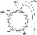
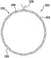
도 35 및 도 36을 참조하면, 창상 견인 장치(320)는 제 1 근위 단부(324) 및 제 2 원위 단부(326)를 갖는 가스 기밀성 튜브형 멤브레인 또는 쉬스(322)를 포함한다. 쉬스(322)는 복벽(60)(도 1 및 도 2)과 같은 체벽을 통해 완전히 끼워질 정도로 충분히 길다. 쉬스(322)는 제 1 절첩된 상태(330)로 압축될 때에 제 1 원주(도 35)를 취하고 제 2 절첩되지 않은 상태(332)로 절첩되지 않을 때에 제 2 더 큰 원주(도 36)를 취하는 가단성 있는 일반적으로 원형인 부재(328)를 포함한다. 쉬스(322)는 제 2 절첩되지 않은 상태(332)를 향해 바이어스가 가해진다. 쉬스(322)는 원형 견인 도구에 의해 또는 심지어 외과의사의 손들에 의해 제 1 절첩된 상태(330)로 압축될 수 있다. 제 1 절첩된 상태(330)에서는, 쉬스(322)가 그 원주 둘레로 파동부(undulation)들(334)을 포함할 수 있다. 절첩된 상태(330)에서 쉬스(322)를 유지하는 힘이 제거될 때, 쉬스는 제 2 절첩되지 않은 상태(332)로 개방된다.35 and 36 , the
이용 시에, 쉬스(322)는 제 1 절첩된 상태(330)로 압축되고 체벽(60) 내의 절개부(62)로 삽입된다. 쉬스(322)가 체벽(60)을 완전히 가로질러 위치될 때, 절첩된 상태에서 쉬스를 유지하는 힘은 제거되고, 쉬스는 제 2 절첩되지 않은 상태(332)로 확장하고 그것이 통과하여 배치된 절개부를 견인한다.In use, the
쉬스(322)의 절첩된 그리고 절첩되지 않은 상태들은, 제 1 절첩된 상태(도 35)가 이완된 비-텐셔닝된 상태 또는 압축된 상태이고 제 2 절첩되지 않은 상태(도 36)가 압축 또는 다시 절첩하는 것에 저항하기에 충분한 후프 강도를 갖는 고정된, 중심을 지난 상태인 긴장완화 관계를 나타낼 수 있다. 제 2 절첩되지 않은 상태(332)에서의 쉬스(322)는 쉬스의 외부 표면 상의 파동부들 또는 돌출부(protrusion)들과 같이, 견인된 창상 내의 위치를 쉬스가 시프트(shift)시키는 것을 방지하기 위한 수단을 포함할 수 있다. 대안적인 실시예들은 제 1 절첩된 상태 및 제 2 절첩되지 않은 상태 사이의 중간점 상태들을 포함할 수 있다.The folded and unfolded states of the
도 37을 참조하면, 도 35 및 도 36의 창상 견인 장치(320)는 쉬스(322)를 제 1 절첩된 상태(330)로 압축하기 위한 수단을 포함할 수 있다. 이러한 수단은 드로우스트링(drawstring)(336)을 포함할 수 있다. 드로우스트링(336)은 쉬스(322)의 파동부들(334)을 통해 꿰어지는 유연성 있는 스트링(338)을 포함할 수 있다. 스트링(338)은 줄(cord), 삼실(twine), 케이블(cable), 실(thread), 또는 당 업계에서 잘 알려져 있는 유사한 재료들을 포함할 수 있다. 쉬스(322)를 제 1 절첩된 상태(330)로 압축하기 위하여, 드로우스트링(336)은 쉬스로부터 방사상으로 멀어지도록 당겨진다. 드로우스트링(336)이 해제될 때(도 38), 쉬스(322)는 제 2 접철되지 않은 상태(332)를 취한다.Referring to FIG. 37 , the
도 39 및 도 40을 참조하면, 원주 견인 장치(circumferential retraction device)(350)는 제 1 외부 유지 링(352), 제 2 내부 유연성 있는 또는 형상화가능한 유지 링(354), 및 제 1 및 제 2 링들에 결합된 가스 기밀성의 실질적으로 원통형 슬리브(356)를 포함한다. 외부 유지 링(352)은 체강(52)의 외부에 남아 있도록 하는 크기이고 이와 같이 구성된다. 내부 유지 링(354)은 체벽(60) 내의 수술 절개부(62) 안으로 그리고 이 절개부를 통해 체강(52) 안으로 삽입하도록 하는 크기이고 이와 같이 구성된다. 원통형 슬리브(356)는 체벽(60) 내의 절개부(62)를 견인하기 위하여 제 1 링(352) 및 제 2 링(354) 사이에서 텐셔닝되도록 구성된다. 원통형 슬리브(356)는 제 1 축방향 압축된 상태(도 39) 및 제 2 축방향 연장된 상태(도 40) 사이에서 원통형 슬리브가 전이하도록 하는 벨로우즈(358) 또는 방사상 절첩부들을 포함할 수 있다.39 and 40 , a
견인 장치(350)가 제 1 축방향 압축된 상태(도 39)에 있음으로써, 제 2 내부 유지 링(354)은 원형의 제 2 유지 링을 긴 타원 형상으로 변환하여 절개부(62)로의 삽입을 가능하게 하기 위하여(도 1 및 도 2), 그 원주를 따라 대향하는 지점들에서 방사상으로 압축될 수 있다. 제 2 링(354)은 완전히 체강(52) 내부에 있을 때까지 절개부(62)를 통해 전진된다. 방사상 압축은 제 2 링(354)으로부터 해제되고, 제 2 링은 그 실질적으로 원형인 구성을 취하도록 허용된다. 제 1 링(352)은 가스 또는 유체의 가압에 의해 확대될 수 있는 실질적으로 중공(hollow)인 팽창가능한 구조체(360)를 포함한다. 견인 장치(350)가 절개부(62) 내에 위치됨으로써, 제 1 외부 링(352)은 팽창될 수 있고(도 40), 이에 따라, 가스 기밀성 슬리브(356) 상에 증가하는 텐션을 가할 수 있다. 제 2 내부 링(354)이 절개부 안으로 끌어당겨질 수 없으므로, 슬리브(356) 상의 증가하는 텐션은 절개부를 견인하고 확대하며, 이 절개부를 통해 연장된다.With the
발명의 취지 및 범위로부터 이탈하지 않으면서 개시된 실시예들에 대해 다수의 수정들이 행해질 수 있다는 것이 이해될 것이다. 예를 들어, 구성들 및 재료들의 다양한 유형들뿐만 아니라 수술 장치의 다양한 크기들이 고려된다. 또한, 그 상호작용뿐만 아니라 부품들의 구성에 대해 다수의 수정들이 행해질 수 있다는 것도 명백할 것이다. 이러한 이유들 때문에, 상기한 설명은 발명을 제한하는 것으로 해석되는 것이 아니라, 실시예들의 단지 예시로서 해독되어야 한다.It will be understood that many modifications may be made to the disclosed embodiments without departing from the spirit and scope of the invention. For example, various types of constructions and materials, as well as various sizes of surgical devices are contemplated. It will also be apparent that a number of modifications may be made to the construction of the parts as well as their interaction. For these reasons, the foregoing description should not be construed as limiting the invention, but rather as merely illustrative of the embodiments.
Claims (30)
Translated fromKorean조절가능한 원주를 갖는 고리모양 형상을 갖는 외부 링;
상기 외부 링으로부터 원위로 연장하는 튜브형 구조체;
상기 외부 링의 상기 원주를 조절하기 위한 수단; 및
조절가능한 원주를 갖는 고리모양 형상을 가고 상기 튜브형 구조체의 원위 단부에 결합되는 내부 링으로서, 상기 내부 링은 상기 외부 링에 대향되는, 상기 내부 링을 포함하며,
상기 외부 링은 복수의 굴곡된 링 세그먼트들로 분할되며, 상기 굴곡된 링 세그먼트들의 각각은 제 1 근위 측; 제 2 원위 측; 상기 외부 링의 상기 원주 둘레의 제 1 단부, 및 상기 외부 링의 상기 원주 둘레의 제 2 단부를 포함하고,
상기 튜브형 구조체는 복수의 긴(elongate) 튜브 세그먼트들로 분할되며, 상기 튜브 세그먼트들의 각각은 개별적인 굴곡된 링 세그먼트들에 결합되고 상기 개별적인 굴곡된 링 세그먼트로부터 원위로 연장하며, 상기 외부 링의 직경은 상기 굴곡된 링 세그먼트들을 더 떨어지도록 이동시킴으로써 증가되고 상기 직경은 상기 굴곡된 링 세그먼트들을 더 가깝게 이동시킴으로써 감소되는, 견인 장치.
A traction device for traction of a body wall, comprising:
an outer ring having an annular shape with an adjustable circumference;
a tubular structure extending distally from the outer ring;
means for adjusting the circumference of the outer ring; and
an inner ring having an annular shape with an adjustable circumference and coupled to the distal end of the tubular structure, the inner ring opposite the outer ring;
The outer ring is divided into a plurality of curved ring segments, each of the curved ring segments having a first proximal side; a second distal side; a first end around the circumference of the outer ring and a second end around the circumference of the outer ring;
The tubular structure is divided into a plurality of elongate tube segments, each of the tube segments coupled to and extending distally from the respective curved ring segments, the diameter of the outer ring being and the diameter is decreased by moving the curved ring segments closer together and increased by moving the curved ring segments further apart.
상기 튜브형 구조체의 상기 튜브 세그먼트들의 각각은, 인접하는 튜브 세그먼트들 사이에 실질적으로 중첩이 없도록 각각의 튜브 세그먼트가 결합되는 상기 개별적인 굴곡된 링 세그먼트의 상기 제 1 단부와 상기 제 2 단부 사이에서 원주 상으로 연장하는, 견인 장치.
The method according to claim 1,
Each of the tube segments of the tubular structure is circumferentially between the first end and the second end of the respective curved ring segment to which each tube segment is coupled such that there is substantially no overlap between adjacent tube segments. Extending to, traction device.
상기 튜브 세그먼트들의 각각은, 인접한 튜브 세그먼트들이 중첩하도록 각각의 튜브 세그먼트가 결합되는 개별적인 굴곡된 링 세그먼트의 상기 제 1 및 제 2 단부들 중 하나를 지나서 원주 상으로 연장하는, 견인 장치.
The method according to claim 1,
each of the tube segments extending circumferentially past one of the first and second ends of a respective curved ring segment to which each tube segment is coupled such that adjacent tube segments overlap.
상기 튜브 세그먼트들의 각각은, 각각의 튜브 세그먼트가 결합되는 상기 개별적인 굴곡된 링 세그먼트의 곡선을 따르는 프로파일을 갖는, 견인 장치.
The method according to claim 1,
wherein each of the tube segments has a profile that follows the curve of the respective curved ring segment to which the respective tube segment is coupled.
상기 굴곡된 링 세그먼트들은, 상기 외부 링의 직경이 조절됨에 따라 상기 외부 링의 원주 형상을 유지하기 위하여 유연성이 있는, 견인 장치.
The method according to claim 1,
wherein the curved ring segments are flexible to maintain the circumferential shape of the outer ring as the diameter of the outer ring is adjusted.
상기 튜브 세그먼트들의 각각은, 각각의 튜브 세그먼트가 결합되는 상기 개별적인 굴곡된 링 세그먼트의 곡선의 변경들을 따르기 위해 유연성이 있는, 견인 장치.
6. The method of claim 5,
wherein each of the tube segments is flexible to follow the changes in the curve of the respective curved ring segment to which the respective tube segment is coupled.
상기 외부 링의 상기 원주를 조절하기 위한 수단은 래칫팅 기구(ratcheting mechanism)를 포함하며, 상기 래칫팅 기구는 상기 외부 링의 상기 고리모양 형상을 형성하기 위해 상기 외부 링의 인접한 굴곡된 링 세그먼트들을 함께 결합하도록 적응되는, 견인 장치.
The method according to claim 1,
The means for adjusting the circumference of the outer ring comprises a ratcheting mechanism, wherein the ratcheting mechanism engages adjacent curved ring segments of the outer ring to form the annular shape of the outer ring. A traction device adapted to engage together.
상기 래칫팅 기구는,
상기 굴곡된 링 세그먼트들의 각각의 근위 표면 내의 홈으로서, 상기 홈은 상기 개별적인 굴곡된 링 세그먼트의 곡선을 따르고 상기 개별적인 굴곡된 링 세그먼트의 상기 제 1 단부로 개방되며, 상기 홈은 제 1 외부 굴곡된 표면 및 제 2 내부 굴곡된 표면을 형성하는, 상기 홈;
상기 홈들의 각각 내에 위치되는 복수의 래칫 치형부(ratchet tooth)들;
상기 굴곡된 링 세그먼트들의 상기 제 2 단부로부터 연장하는 긴 돌기로서, 상기 돌기들은 인접한 굴곡된 링 세그먼트 내의 상기 홈과 짝을 이루도록 적응되는, 상기 긴 돌기; 및
상기 돌기들의 각각 상에 위치되는 적어도 하나의 래칫 치형부로서, 상기 적어도 하나의 래칫 치형부는 상기 개별적인 인접한 굴곡된 링 세그먼트의 상기 홈 내의 상기 래칫 치형부들과 상호작용하도록 적응되는, 상기 적어도 하나의 래칫 치형부를 포함하는, 견인 장치.
8. The method of claim 7,
The ratcheting mechanism is
a groove in the proximal surface of each of the curved ring segments, the groove following a curve of the individual curved ring segment and opening into the first end of the individual curved ring segment, the groove being a first external curved ring segment the groove defining a surface and a second inner curved surface;
a plurality of ratchet teeth positioned within each of the grooves;
an elongate projection extending from the second end of the curved ring segments, the projections adapted to mate with the grooves in an adjacent curved ring segment; and
at least one ratchet tooth positioned on each of the protrusions, the at least one ratchet tooth adapted to interact with the ratchet teeth in the groove of the respective adjacent curved ring segment A traction device comprising teeth.
상기 굴곡된 링 세그먼트의 각각의 상기 제 1 단부는 인접한 굴곡된 링 세그먼트의 상기 제 2 단부에 인접하게 위치되며;
상기 긴 돌기 상의 상기 적어도 하나의 래칫 치형부가 상기 홈 내의 상기 래칫 치형부들과 상호작용하도록, 각각의 굴곡된 링 세그먼트의 상기 긴 돌기는 다른 인접한 굴곡된 링 세그먼트의 상기 홈 내로 삽입되는, 견인 장치.
9. The method of claim 8,
each said first end of said curved ring segment is positioned adjacent said second end of an adjacent curved ring segment;
wherein the elongate protrusion of each curved ring segment is inserted into the groove of another adjacent curved ring segment such that the at least one ratchet tooth on the elongate protrusion interacts with the ratchet teeth in the groove.
상기 래칫 치형부들은 상기 개별적인 굴곡된 링 세그먼트의 상기 홈의 상기 제 1 외부 굴곡된 표면 상에 위치되는, 견인 장치.
9. The method of claim 8,
and the ratchet teeth are located on the first outer curved surface of the groove of the respective curved ring segment.
상기 래칫 치형부들은 상기 개별적인 굴곡된 링 세그먼트의 상기 홈의 상기 제 2 내부 굴곡된 표면 상에 위치되는, 견인 장치.
9. The method of claim 8,
and the ratchet teeth are located on the second inner curved surface of the groove of the respective curved ring segment.
상기 래칫 치형부들은 상기 개별적인 굴곡된 링 세그먼트의 상기 홈의 원위 표면 상에 위치되는, 견인 장치.
9. The method of claim 8,
and the ratchet teeth are located on the distal surface of the groove of the respective curved ring segment.
상기 견인 장치는,
상기 개별적인 홈의 상기 제 1 외부 굴곡된 표면 및 상기 제 2 내부 굴곡된 표면 중의 적어도 하나 내의 상기 홈들의 각각에 위치되는 유지 채널(retention channel); 및
상기 긴 돌기들의 각각 상에 위치되는 립(lip)으로서, 상기 립은 상기 개별적인 돌기의 길이를 따라 세로로 연장하고, 상기 개별적인 인접한 굴곡된 링 세그먼트의 상기 홈 내의 상기 유지 채널과 상호작용하도록 적응되는, 상기 립을 더 포함하는, 견인 장치.
9. The method of claim 8,
The traction device is
a retention channel positioned in each of the grooves in at least one of the first outer curved surface and the second inner curved surface of the respective groove; and
a lip positioned on each of the elongated protrusions, the lip extending longitudinally along the length of the respective protrusion and adapted to interact with the retaining channel in the groove of the respective adjacent curved ring segment. , Traction device further comprising the lip.
상기 견인 장치는 상기 내부 링과 연관된 바이어싱 부재를 더 포함하며, 상기 바이어싱 부재는 상기 내부 링에 방사상으로 외부를 향해 바이어싱하는, 견인 장치.
The method according to claim 1,
The pulling device further comprises a biasing member associated with the inner ring, the biasing member biasing the inner ring radially outward.
상기 내부 링은 복수의 굴곡된 내부 링 세그먼트들로 분할되며, 상기 굴곡된 내부 링 세그먼트들의 각각은 1 근위 측, 제 2 원위 측, 상기 내부 링의 상기 원주 둘레의 제 1 단부, 및 상기 내부 링의 상기 원주 둘레의 제 2 단부를 포함하고; 상기 튜브형 구조체의 상기 튜브 세그먼트들의 각각은 개별적인 굴곡된 내부 링 세그먼트에 결합되는, 견인 장치.
The method according to claim 1,
The inner ring is divided into a plurality of curved inner ring segments, each of the curved inner ring segments having a first proximal side, a second distal side, a first end around the circumference of the inner ring, and the inner ring a second end around the circumference of and each of the tube segments of the tubular structure is coupled to a respective curved inner ring segment.
상기 내부 링의 직경은 상기 내부 링의 상기 굴곡된 내부 링 세그먼트들을 더 떨어지도록 이동시킴으로써 증가되고 상기 직경은 상기 내부 링의 상기 굴곡된 내부 링 세그먼트들을 더 가깝게 이동시킴으로써 감소되는, 견인 장치.
16. The method of claim 15,
and the diameter of the inner ring is increased by moving the curved inner ring segments of the inner ring further apart and the diameter is decreased by moving the curved inner ring segments of the inner ring closer together.
상기 견인 장치는 상기 내부 링의 상기 원주를 조정하기 위한 수단을 더 포함하는, 견인 장치.
17. The method of claim 1 or 16,
The pulling device further comprises means for adjusting the circumference of the inner ring.
상기 내부 링은 래칫팅 기구를 포함하며, 상기 래칫팅 기구는 상기 내부 링의 상기 고리모양 형상을 형성하기 위해 상기 내부 링의 인접한 굴곡된 내부 링 세그먼트들을 함께 결합하도록 적응되는, 견인 장치.
17. The method of claim 16,
wherein the inner ring comprises a ratcheting mechanism, the ratcheting mechanism adapted to join together adjacent curved inner ring segments of the inner ring to form the annular shape of the inner ring.
상기 래칫팅 기구는,
상기 내부 링의 상기 굴곡된 내부 링 세그먼트들의 근위 표면 내의 홈으로서, 상기 홈은 상기 내부 링의 상기 개별적인 굴곡된 내부 링 세그먼트의 곡선을 따르고 상기 내부 링의 상기 개별적인 굴곡된 내부 링 세그먼트의 상기 제 1 단부로 개방되며, 상기 홈은 제 1 외부 굴곡된 표면 및 제 2 내부 굴곡된 표면을 형성하는, 상기 홈;
상기 홈들의 각각 내에 위치되는 복수의 래칫 치형부들;
상기 내부 링의 상기 굴곡된 내부 링 세그먼트들의 각각의 상기 제 2 단부로부터 연장하는 긴 돌기로서, 상기 돌기들은 상기 내부 링의 인접한 굴곡된 내부 링 세그먼트 내의 상기 홈과 짝을 이루도록 적응되는, 상기 긴 돌기; 및
상기 돌기들의 각각 상에 위치되는 적어도 하나의 래칫 치형부로서, 상기 적어도 하나의 래칫 치형부는 상기 내부 링의 상기 개별적인 인접한 굴곡된 내부 링 세그먼트의 상기 홈 내의 상기 래칫 치형부들과 상호작용하도록 적응되는, 상기 적어도 하나의 래칫 치형부를 포함하는, 견인 장치.19. The method of claim 18,
The ratcheting mechanism is
a groove in the proximal surface of the curved inner ring segments of the inner ring, the groove following a curve of the respective curved inner ring segment of the inner ring and the first of the respective curved inner ring segments of the inner ring a groove opening to an end, the groove defining a first outer curved surface and a second inner curved surface;
a plurality of ratchet teeth positioned within each of the grooves;
an elongate projection extending from the second end of each of the curved inner ring segments of the inner ring, the projections adapted to mate with the groove in an adjacent curved inner ring segment of the inner ring ; and
at least one ratchet tooth positioned on each of the protrusions, the at least one ratchet tooth adapted to interact with the ratchet teeth in the groove of the respective adjacent curved inner ring segment of the inner ring; and said at least one ratchet tooth.
Priority Applications (1)
| Application Number | Priority Date | Filing Date | Title |
|---|---|---|---|
| KR1020227024214AKR102480917B1 (en) | 2011-05-10 | 2012-05-09 | Wound retractor |
Applications Claiming Priority (4)
| Application Number | Priority Date | Filing Date | Title |
|---|---|---|---|
| US201161484362P | 2011-05-10 | 2011-05-10 | |
| US61/484,362 | 2011-05-10 | ||
| KR1020207000223AKR20200006622A (en) | 2011-05-10 | 2012-05-09 | Wound retractor |
| PCT/US2012/037111WO2012154845A1 (en) | 2011-05-10 | 2012-05-09 | Wound retractor |
Related Parent Applications (1)
| Application Number | Title | Priority Date | Filing Date |
|---|---|---|---|
| KR1020207000223ADivisionKR20200006622A (en) | 2011-05-10 | 2012-05-09 | Wound retractor |
Related Child Applications (1)
| Application Number | Title | Priority Date | Filing Date |
|---|---|---|---|
| KR1020227024214ADivisionKR102480917B1 (en) | 2011-05-10 | 2012-05-09 | Wound retractor |
Publications (2)
| Publication Number | Publication Date |
|---|---|
| KR20210094156A KR20210094156A (en) | 2021-07-28 |
| KR102423785B1true KR102423785B1 (en) | 2022-07-21 |
Family
ID=46147742
Family Applications (5)
| Application Number | Title | Priority Date | Filing Date |
|---|---|---|---|
| KR1020217023165AActiveKR102423785B1 (en) | 2011-05-10 | 2012-05-09 | Wound retractor |
| KR1020227024214AActiveKR102480917B1 (en) | 2011-05-10 | 2012-05-09 | Wound retractor |
| KR1020207000223ACeasedKR20200006622A (en) | 2011-05-10 | 2012-05-09 | Wound retractor |
| KR1020227043188AActiveKR102641182B1 (en) | 2011-05-10 | 2012-05-09 | Wound retractor |
| KR1020137032331AActiveKR102064782B1 (en) | 2011-05-10 | 2012-05-09 | Wound retractor |
Family Applications After (4)
| Application Number | Title | Priority Date | Filing Date |
|---|---|---|---|
| KR1020227024214AActiveKR102480917B1 (en) | 2011-05-10 | 2012-05-09 | Wound retractor |
| KR1020207000223ACeasedKR20200006622A (en) | 2011-05-10 | 2012-05-09 | Wound retractor |
| KR1020227043188AActiveKR102641182B1 (en) | 2011-05-10 | 2012-05-09 | Wound retractor |
| KR1020137032331AActiveKR102064782B1 (en) | 2011-05-10 | 2012-05-09 | Wound retractor |
Country Status (7)
| Country | Link |
|---|---|
| US (5) | US8758236B2 (en) |
| EP (6) | EP2706923B1 (en) |
| JP (6) | JP6005143B2 (en) |
| KR (5) | KR102423785B1 (en) |
| AU (1) | AU2012253555B2 (en) |
| ES (3) | ES2822115T3 (en) |
| WO (1) | WO2012154845A1 (en) |
Families Citing this family (44)
| Publication number | Priority date | Publication date | Assignee | Title |
|---|---|---|---|---|
| EP2343032B1 (en) | 2002-06-05 | 2012-05-09 | Applied Medical Resources Corporation | Wound retractor |
| US20170049474A1 (en)* | 2004-07-21 | 2017-02-23 | Covidien Lp | Surgical port assembly |
| US8992558B2 (en) | 2008-12-18 | 2015-03-31 | Osteomed, Llc | Lateral access system for the lumbar spine |
| US9149265B2 (en) | 2011-02-26 | 2015-10-06 | Abbott Cardiovascular Systems, Inc. | Hinged tissue support device |
| US9549758B2 (en)* | 2011-03-23 | 2017-01-24 | Covidien Lp | Surgical access assembly with adapter |
| WO2013106347A1 (en) | 2012-01-10 | 2013-07-18 | The Board Of Trustees Of The Leland Stanford Junior University | Methods and devices for the prevention of surgical site infections |
| US9486200B2 (en)* | 2013-01-09 | 2016-11-08 | Cook Medical Technologies Llc | Abdominal retractor |
| US9486132B2 (en)* | 2013-01-17 | 2016-11-08 | Abbott Cardiovascular Systems, Inc. | Access device for accessing tissue |
| US9402612B2 (en)* | 2013-03-14 | 2016-08-02 | Precient Surgical, Inc. | Methods and devices for the prevention of incisional surgical site infections |
| JP6388914B2 (en)* | 2013-04-17 | 2018-09-12 | デピュイ・シンセス・プロダクツ・インコーポレイテッド | Extendable dilator |
| GB2518859B (en)* | 2013-10-02 | 2018-12-12 | Salts Healthcare Ltd | Wound management device |
| US9492153B2 (en)* | 2013-10-25 | 2016-11-15 | Vlv Associates, Inc. | Wound protector |
| WO2015138317A1 (en) | 2014-03-10 | 2015-09-17 | Stryker Corporation | Limb positioning system |
| EP4218629B1 (en)* | 2014-04-23 | 2024-11-20 | Applied Medical Resources Corporation | System for tissue removal |
| KR20240172766A (en) | 2014-08-15 | 2024-12-10 | 어플라이드 메디컬 리소시스 코포레이션 | Natural orifice surgery system |
| CA2967766C (en)* | 2014-11-13 | 2023-10-17 | Applied Medical Resources Corporation | Systems and methods for tissue removal |
| WO2016085930A2 (en) | 2014-11-25 | 2016-06-02 | Applied Medical Resources Corporation | Circumferential wound retraction with support and guidance structures |
| JP6292141B2 (en) | 2015-01-29 | 2018-03-14 | 独立行政法人国立病院機構 | Retractor |
| WO2016142749A1 (en)* | 2015-03-12 | 2016-09-15 | Synaptive Medical (Barbados) Inc. | System and method for guided port insertion to minimize trauma |
| US9951904B2 (en) | 2015-03-24 | 2018-04-24 | Stryker Corporation | Rotatable seat clamps for rail clamp |
| KR101592975B1 (en)* | 2015-08-19 | 2016-02-12 | 위캔메디케어 주식회사 | Surgical retractor |
| JP2018525083A (en)* | 2015-08-27 | 2018-09-06 | アプライド メディカル リソーシーズ コーポレイション | Wound retractor with inner ring that is non-circular, non-coplanar or non-parallel |
| WO2017062850A2 (en) | 2015-10-07 | 2017-04-13 | Applied Medical Resources Corporation | Wound retractor with multi-segment outer ring |
| AU2017209092B2 (en)* | 2016-01-21 | 2019-12-05 | The Cleveland Clinic Foundation | System and apparatus for assisting with submucosal dissections |
| EP3405126A1 (en)* | 2016-01-21 | 2018-11-28 | Boston Scientific Scimed, Inc. | Medical devices and related methods of use |
| WO2018039228A1 (en) | 2016-08-23 | 2018-03-01 | Stryker European Holdings I, Llc | Instrumentation for the implantation of spinal implants |
| US10213194B2 (en) | 2016-09-27 | 2019-02-26 | Ethicon, Inc. | Surgical retraction systems including sternal retractors and hemostatic inserts |
| USD832436S1 (en)* | 2017-02-16 | 2018-10-30 | Ergosurg Gmbh | Electromagnetic localizer |
| JP6889431B2 (en)* | 2017-07-11 | 2021-06-18 | 国立研究開発法人国立がん研究センター | Minimally invasive surgical instruments |
| EP3664874B1 (en)* | 2017-08-11 | 2023-10-04 | West Pharmaceutical Services, Inc. | Expandable and automatically retractable collar and method of use thereof |
| WO2019094502A1 (en) | 2017-11-07 | 2019-05-16 | Prescient Surgical, Inc. | Methods and apparatus for prevention of surgical site infection |
| EP3545857B1 (en) | 2018-03-30 | 2024-01-03 | Stryker European Operations Holdings LLC | Lateral access retractor and core insertion |
| CN112020333B (en)* | 2018-04-26 | 2024-06-25 | 奥林巴斯株式会社 | Treatment system and distention device |
| US11413029B2 (en) | 2018-10-24 | 2022-08-16 | Stryker European Operations Holdings Llc | Anterior to psoas instrumentation |
| US11690679B2 (en) | 2019-01-08 | 2023-07-04 | Covidien Lp | Localization systems and methods of use |
| KR102179518B1 (en) | 2019-03-29 | 2020-11-17 | 주식회사 혜안 | Manufacturing method of inorganic binder |
| US11426203B2 (en) | 2019-05-23 | 2022-08-30 | Covidien Lp | Tissue guards and systems incorporating the same for tissue specimen removal procedures and other surgical procedures |
| US11564674B2 (en) | 2019-11-27 | 2023-01-31 | K2M, Inc. | Lateral access system and method of use |
| US11058459B2 (en)* | 2019-12-12 | 2021-07-13 | Covidien Lp | Two-piece cutting guard with evacuation ports |
| US11931067B2 (en) | 2020-08-15 | 2024-03-19 | Covidien Lp | Insertable cutting guards |
| KR102601515B1 (en)* | 2021-04-14 | 2023-11-14 | 가톨릭대학교산학협력단 | Assistive device for vaginal natural orifice tranlumminal endoscopis surgery |
| US11712237B1 (en) | 2022-07-20 | 2023-08-01 | Samothrace Medical Innovations, Inc. | Anatomical tissue anchor and related methods |
| WO2024019794A1 (en)* | 2022-07-20 | 2024-01-25 | Samothrace Medical Innovations, Inc. | Anatomical tissue anchor and related methods |
| AU2024240140A1 (en)* | 2023-03-21 | 2025-10-09 | Lsi Solutions, Inc. | Surgical retractor assembly |
Citations (2)
| Publication number | Priority date | Publication date | Assignee | Title |
|---|---|---|---|---|
| WO2003034908A2 (en) | 2001-10-20 | 2003-05-01 | Applied Medical Resources Corporation | Sealed surgical access device |
| US20070156024A1 (en)* | 2006-01-04 | 2007-07-05 | William Frasier | Surgical Retractors and Methods of Minimally Invasive Surgery |
Family Cites Families (808)
| Publication number | Priority date | Publication date | Assignee | Title |
|---|---|---|---|---|
| US52104A (en) | 1866-01-16 | Improvement in sulky-plows | ||
| US447761A (en) | 1891-03-10 | Speculum | ||
| US52014A (en) | 1866-01-16 | Improvement in specula for uterine diseases | ||
| US202813A (en) | 1878-04-23 | Improvement in speculums | ||
| US558364A (en) | 1896-04-14 | Pipe-coupling | ||
| US758535A (en) | 1903-09-12 | 1904-04-26 | George F Cutter | Embroidery hoop or ring. |
| US929583A (en) | 1909-03-16 | 1909-07-27 | Sylvester W Gibbs | Embroidery-frame. |
| US1056966A (en) | 1911-11-15 | 1913-03-25 | Charles E Belding | Embroidery-hoop. |
| US1157202A (en) | 1913-10-14 | 1915-10-19 | Uri C Bates | Surgical apparatus. |
| US1180466A (en) | 1914-04-02 | 1916-04-25 | England J Barker | Type-writer. |
| US1242972A (en) | 1915-04-20 | 1917-10-16 | John H Pettit | Embroidery-holder. |
| US1221123A (en) | 1916-06-15 | 1917-04-03 | Evelyn M Westhaver | Embroidery-hoop. |
| US1598284A (en) | 1925-11-03 | 1926-08-31 | Justus R Kinney | Draining device |
| US1690995A (en) | 1927-12-28 | 1928-11-06 | Monte Lloyd Corp | Anorectal dilator |
| US1810466A (en) | 1928-05-25 | 1931-06-16 | Deutsch Josef | Device for giving access to cavities of the animal and human body |
| US2219564A (en) | 1937-06-14 | 1940-10-29 | James A Reyniers | Surgical operating device |
| US2305289A (en) | 1939-06-17 | 1942-12-15 | Coburg Hermann | Surgical appliance |
| US2313164A (en)* | 1939-11-13 | 1943-03-09 | Walfred A Nelson | Self-retaining surgical retractor |
| US2478586A (en) | 1946-12-12 | 1949-08-09 | John T Krapp | Coupling |
| US2695608A (en) | 1950-11-06 | 1954-11-30 | Philadelphia Children Hospital | Adjustable closure device for special purpose chambers |
| US2669991A (en) | 1951-12-27 | 1954-02-23 | Curutchet Pedro Domingo | Tetradigital grip for long lever pivoted surgical instruments |
| US2812758A (en) | 1955-07-26 | 1957-11-12 | John C Blumenschein | Surgical retractor |
| US2853075A (en) | 1956-07-10 | 1958-09-23 | Roy D Hoffman | Rumen trocar extricator |
| US2835253A (en) | 1956-08-14 | 1958-05-20 | Florence W Borgeson | Surgical appliance |
| US2841148A (en)* | 1957-06-21 | 1958-07-01 | Godfrey J Kadavy | Viscera retainer for use in abdominal operations |
| US3057350A (en) | 1958-06-27 | 1962-10-09 | Baxter Don Inc | Administration set |
| US3039468A (en) | 1959-01-07 | 1962-06-19 | Joseph L Price | Trocar and method of treating bloat |
| US3111943A (en) | 1961-08-02 | 1963-11-26 | John R Orndorff | Aseptic surgical wound protector |
| US3195934A (en) | 1962-05-31 | 1965-07-20 | Reuel C Parrish | Coupling for fluid conduits |
| US3129706A (en) | 1962-11-13 | 1964-04-21 | Jr Walker Reynolds | Surgical retractor |
| US3253594A (en) | 1963-07-30 | 1966-05-31 | Frank E Matthews | Peritoneal cannula |
| US3313299A (en) | 1964-02-05 | 1967-04-11 | Richard G Spademan | Intravascular catheter with coaxial puncturing means |
| US3244169A (en) | 1964-02-17 | 1966-04-05 | Surgical Devices | Viscera pouch |
| FR1456623A (en) | 1964-07-24 | 1966-07-08 | Device moving without friction by continuous turning | |
| US3447533A (en) | 1964-09-14 | 1969-06-03 | Richard J Spicer | Closure means for artificial body openings |
| US3347226A (en) | 1964-12-11 | 1967-10-17 | Harold W Harrower | Adjustable wound edge protector |
| US3347227A (en) | 1964-12-11 | 1967-10-17 | Harold W Harrower | Wound edge protector |
| US3329390A (en) | 1965-02-18 | 1967-07-04 | Eldon E Hulsey | Variable orifice valve |
| US3332417A (en) | 1965-04-22 | 1967-07-25 | Parke Davis & Co | Adjustable wound protector |
| US3397692A (en) | 1966-02-24 | 1968-08-20 | Parke Davis & Co | Protector for incised wounds |
| US3402710A (en) | 1966-06-27 | 1968-09-24 | Hydra Power Corp | Self-closing valve device for implantation in the human body |
| US3522800A (en) | 1966-07-19 | 1970-08-04 | Arthur J Lesser | Disposable wound retractor and drape and method of using same |
| GB1151993A (en) | 1966-08-12 | 1969-05-14 | Johnson & Johnson | Wound Edge Protector |
| US3416520A (en) | 1966-11-22 | 1968-12-17 | Parke Davis & Co | Surgical drape |
| US3523534A (en) | 1967-04-05 | 1970-08-11 | Hollister Inc | Closure for drainage pouch |
| US3570475A (en) | 1968-11-14 | 1971-03-16 | Mandel Weinstein | Surgical retractor |
| US3553862A (en) | 1969-01-17 | 1971-01-12 | Kaino J Hamu | Adjustable stretch frame for biaxially stressing sheet material |
| US3656485A (en) | 1970-04-27 | 1972-04-18 | Jack R Robertson | Method of and apparatus for viewing the interior of the bladder through a suprapubic incision |
| US3685786A (en) | 1970-08-31 | 1972-08-22 | Riley D Woodson | Elastic valve element having variable orifice |
| US3717883A (en) | 1970-11-23 | 1973-02-27 | Techno Corp | Cardiac valve replacement |
| US3703896A (en) | 1970-12-29 | 1972-11-28 | Abcor Inc | Intrauterine contraceptive device |
| US3729045A (en) | 1971-01-13 | 1973-04-24 | Adrian Inc | Molded screen frame |
| US3831583A (en) | 1971-03-05 | 1974-08-27 | Univ California | Implantable bulb for inflation of surgical implements |
| US3717151A (en) | 1971-03-11 | 1973-02-20 | R Collett | Flesh penetrating apparatus |
| US3729006A (en) | 1971-05-27 | 1973-04-24 | M Kanbar | Disposable surgical retractors |
| US3774596A (en) | 1971-06-29 | 1973-11-27 | G Cook | Compliable cavity speculum |
| US3729027A (en) | 1972-01-26 | 1973-04-24 | H Bare | Flexible tubing with integral end clamps |
| CS159428B1 (en) | 1972-02-01 | 1975-01-31 | ||
| GB1355611A (en) | 1972-02-25 | 1974-06-05 | Mucon Eng Co Ltd | Waste disposal containers |
| US3807393A (en) | 1972-03-01 | 1974-04-30 | Donald B Mc | Surgical retractor |
| GB1407023A (en) | 1972-03-16 | 1975-09-24 | Mucon Eng Co Ltd | Flow control valves |
| GB1379772A (en) | 1972-04-21 | 1975-01-08 | Mucon Eng Co Ltd | Flow control vavles |
| US3799166A (en) | 1972-05-22 | 1974-03-26 | A Marsan | Starch type gel seals for ostomy patients |
| FR2188437A5 (en) | 1972-06-05 | 1974-01-18 | Calhene | |
| US3789852A (en)* | 1972-06-12 | 1974-02-05 | S Kim | Expandable trochar, especially for medical purposes |
| US3788318A (en)* | 1972-06-12 | 1974-01-29 | S Kim | Expandable cannular, especially for medical purposes |
| US3797478A (en) | 1972-07-11 | 1974-03-19 | M Walsh | Multi-functional valve for use in the urethra |
| US3782370A (en)* | 1972-07-12 | 1974-01-01 | B Mcdonald | Surgical retractor |
| US3762080A (en) | 1972-08-24 | 1973-10-02 | C Poole | Frame |
| GB1400808A (en) | 1972-12-21 | 1975-07-23 | Mucon Eng Co Ltd | Vacuum conveying systems |
| US3828764A (en) | 1973-01-22 | 1974-08-13 | Well Saver Inc | Non-migrating reversible make sterilization coupler |
| US3853127A (en) | 1973-04-03 | 1974-12-10 | R Spademan | Elastic sealing member |
| GB1372491A (en) | 1973-05-08 | 1974-10-30 | Mucon Eng Co Ltd | Waste disposal containers |
| US3860274A (en) | 1973-07-02 | 1975-01-14 | Richard L Ledstrom | Pipe coupling |
| US3856021A (en) | 1973-10-01 | 1974-12-24 | A Mcintosh | Device for treatment of bloat of ruminants |
| US3853126A (en) | 1973-11-15 | 1974-12-10 | Heyer Schulte Corp | Artery-to-vein shunt |
| US3841332A (en) | 1973-11-19 | 1974-10-15 | D Treacle | Enterostomy drainage appliance |
| US3907389A (en) | 1973-12-12 | 1975-09-23 | Marion E Cox | Glove box chamber |
| US3863639A (en) | 1974-04-04 | 1975-02-04 | Richard N Kleaveland | Disposable visceral retainer |
| US3915171A (en) | 1974-06-06 | 1975-10-28 | Dennis William Shermeta | Gastrostomy tube |
| US3996623A (en) | 1974-07-30 | 1976-12-14 | Kaster Robert L | Method of implanting a prosthetic device and suturing member therefor |
| US3970089A (en) | 1974-08-05 | 1976-07-20 | Saice Dwayne D | Cardiovascular catheter seal device |
| GB1482857A (en) | 1974-09-10 | 1977-08-17 | Wolf Gmbh Richard | Trocar guides |
| US3965890A (en) | 1974-10-18 | 1976-06-29 | William Kohlmann Gauthier | Surgical retractor |
| US4030500A (en) | 1974-12-16 | 1977-06-21 | Hadar Yngve Ronnquist | Fecal matter collector |
| GB1496696A (en) | 1975-02-07 | 1977-12-30 | Mucon Eng Co Ltd | Valves for fluids and/or particulate material |
| DE2527706A1 (en) | 1975-06-21 | 1976-12-30 | Hanfried Dr Med Weigand | DEVICE FOR THE INTRODUCTION OF CONTRAST AGENTS INTO AN ARTIFICIAL INTESTINAL OUTLET |
| US4016884A (en) | 1975-07-02 | 1977-04-12 | Kwan Gett Clifford S | Atriotomy access device |
| US4000739A (en) | 1975-07-09 | 1977-01-04 | Cordis Corporation | Hemostasis cannula |
| US4069913A (en) | 1975-08-11 | 1978-01-24 | Harrigan Roy Major | Surgical glove package and fixture |
| US4082005A (en) | 1975-08-28 | 1978-04-04 | Teledyne Industries, Inc. | Spin coupled, angular rate sensitive inertial sensors with mounting structure and method of fabricating and mounting same |
| US4117847A (en) | 1976-02-05 | 1978-10-03 | Clayton Ralph S | Colon catheter |
| DE2605148B2 (en) | 1976-02-10 | 1977-11-24 | Rechenberg, Cornelius, 8204 Brannenburg | CHEST PROSTHESIS |
| US4024872A (en) | 1976-06-01 | 1977-05-24 | Muldoon James P | Colostomy device and method |
| US4043328A (en) | 1976-06-01 | 1977-08-23 | American Hospital Supply Corporation | Urological drape |
| US4183357A (en) | 1976-08-02 | 1980-01-15 | Bentley Laboratories, Inc. | Chronic transcutaneous implant assembly for enterostomies |
| US4083370A (en) | 1976-11-03 | 1978-04-11 | Taylor John D | Bloat relief tube and holder |
| US4130113A (en) | 1976-12-15 | 1978-12-19 | Richards Manufacturing Co., Inc. | Retractor |
| US4112932A (en) | 1977-02-24 | 1978-09-12 | Chiulli Robert D | Laparoscopic cannula |
| US5334646B1 (en) | 1977-03-17 | 1998-09-08 | Applied Elastomerics Inc | Thermoplastic elastomer gelatinous articles |
| US5508334A (en) | 1977-03-17 | 1996-04-16 | Applied Elastomerics, Inc. | Thermoplastic elastomer gelatinous compositions and articles |
| US5336708A (en) | 1977-03-17 | 1994-08-09 | Applied Elastomerics, Inc. | Gelatinous elastomer articles |
| US5262468A (en) | 1977-03-17 | 1993-11-16 | Applied Elastomerics, Inc. | Thermoplastic elastomer gelatinous compositions |
| US4369284A (en) | 1977-03-17 | 1983-01-18 | Applied Elastomerics, Incorporated | Thermoplastic elastomer gelatinous compositions |
| US4141364A (en) | 1977-03-18 | 1979-02-27 | Jorge Schultze | Expandable endotracheal or urethral tube |
| JPS6034241Y2 (en) | 1977-04-25 | 1985-10-12 | オリンパス光学工業株式会社 | Endoscope passage sealing device |
| SE402050B (en) | 1977-08-26 | 1978-06-19 | Triplus Sjukvardsprod Ab | OPERATING CLOTH INTENDED TO PROTECT THE SARCANTS AROUND AN INCISION |
| IE47372B1 (en) | 1977-09-23 | 1984-03-07 | Rhys Davies N C | Exsanguinating device |
| US4177814A (en) | 1978-01-18 | 1979-12-11 | KLI, Incorporated | Self-sealing cannula |
| US4189880A (en) | 1978-06-16 | 1980-02-26 | Gene Ballin | Combination mounting frame and film for a window |
| US4187849A (en) | 1978-07-28 | 1980-02-12 | Stim Edward M | Suction curettage device with valve control and support means for differing diameter tubes |
| US4306562A (en) | 1978-12-01 | 1981-12-22 | Cook, Inc. | Tear apart cannula |
| US4222126A (en) | 1978-12-14 | 1980-09-16 | The United States Of America As Represented By The Secretary Of The Department Of Health, Education & Welfare | Unitized three leaflet heart valve |
| US4217664A (en) | 1979-02-02 | 1980-08-19 | Faso Joseph M | Prosthesis and method for creating a stoma |
| US4331138A (en) | 1979-03-21 | 1982-05-25 | Jessen John W | Method of performing an emergency cricothyrotomy |
| US4428364A (en) | 1979-04-11 | 1984-01-31 | Dow Corning Corporation | Self-sealing injection button and method of making same |
| US4254973A (en) | 1979-04-30 | 1981-03-10 | Celanese Corporation | Fluid coupling seal |
| US4253201A (en) | 1979-05-24 | 1981-03-03 | Ross David A | Prosthesis with self-sealing valve |
| US4239036A (en) | 1979-05-29 | 1980-12-16 | Krieger Abbott J | Surgical retractor |
| US4321915A (en) | 1979-06-26 | 1982-03-30 | The United States Of America As Represented By The Department Of Health And Human Services | Everting tube device with relative advance control |
| DE2936256A1 (en) | 1979-09-07 | 1981-03-19 | H. Guido Dr. 8000 München Mutke | INSULATION DEVICE |
| US4338934A (en) | 1980-02-19 | 1982-07-13 | Spademan Richard George | Intravascular catheter apparatus |
| GB2071502A (en) | 1980-03-14 | 1981-09-23 | Nat Res Dev | Surgical retractors |
| US4399816A (en) | 1980-03-17 | 1983-08-23 | Spangler George M | Wound protector with transparent cover |
| US4776843A (en) | 1980-11-21 | 1988-10-11 | Minntech Corporation | Blood access systems |
| US4421296A (en) | 1980-07-17 | 1983-12-20 | Medical Valve Corporation | Disposable plastic reciprocating valve |
| US4338937A (en) | 1980-12-05 | 1982-07-13 | Lerman Sheldon H | Mechanical continent ileostomy or colostomy |
| US4430081A (en) | 1981-01-06 | 1984-02-07 | Cook, Inc. | Hemostasis sheath |
| US4436519A (en) | 1981-05-28 | 1984-03-13 | Argon Medical Corp. | Removable hemostasis valve |
| US4424833A (en) | 1981-10-02 | 1984-01-10 | C. R. Bard, Inc. | Self sealing gasket assembly |
| US4402683A (en) | 1981-12-28 | 1983-09-06 | Kopman Ercument A | Cannula introducer |
| US4454873A (en) | 1982-02-26 | 1984-06-19 | Hexcel Corporation | Separator medium for orthopedic cast material |
| US4434791A (en) | 1982-03-15 | 1984-03-06 | Humboldt Products Corp. | Surgical retractor array system |
| US4411659A (en) | 1982-03-16 | 1983-10-25 | Hollister Incorporated | Drainable collection pouch and filter assembly therefor |
| US4473067A (en) | 1982-04-28 | 1984-09-25 | Peter Schiff | Introducer assembly for intra-aortic balloons and the like incorporating a sliding, blood-tight seal |
| US4475548A (en) | 1982-06-01 | 1984-10-09 | Rudolph Muto | Fitting for endotracheal tube apparatus and method of making the fitting |
| US4488877A (en) | 1982-08-23 | 1984-12-18 | Renal Systems, Inc. | Percutaneous implant for peritoneal dialysis |
| US5308336A (en) | 1982-09-28 | 1994-05-03 | Applied Medical Resources | Seal protection mechanism |
| EP0113520A2 (en) | 1982-12-06 | 1984-07-18 | Vance Products Incorporated | Nephroscopy cannula |
| US4610665A (en) | 1983-01-18 | 1986-09-09 | Terumo Kabushiki Kaisha | Medical instrument |
| US4550713A (en) | 1983-03-10 | 1985-11-05 | Hyman Frederic E Dr | Method and apparatus for opposing deformity, displacement, and expulsion of the ocular tissues during open eye surgery |
| US4485490A (en) | 1983-06-06 | 1984-12-04 | Calspan Corporation | Apparatus for treating casualties in a contaminated area |
| US4553537A (en) | 1983-06-09 | 1985-11-19 | Max Rosenberg | Surgical barrier |
| US4714749A (en) | 1983-07-07 | 1987-12-22 | Exxon Research & Engineering Co. | Fully saturated petroleum resin and hot melt pressure sensitive adhesive formulations utilizing same as tackifier |
| US4556996A (en) | 1983-08-04 | 1985-12-10 | Robert S. Wallace | Heart valve |
| US4601710B1 (en) | 1983-08-24 | 1998-05-05 | United States Surgical Corp | Trocar assembly |
| DE3336279C2 (en) | 1983-10-05 | 1986-01-09 | Kunststofftechnik Degler GmbH, 8217 Grassau | Breast prosthesis and process for their manufacture |
| US4553967A (en) | 1983-10-14 | 1985-11-19 | E. R. Squibb & Sons, Inc. | Wound care and drainage system having hand access port |
| US4655752A (en) | 1983-10-24 | 1987-04-07 | Acufex Microsurgical, Inc. | Surgical cannula |
| US4543088A (en) | 1983-11-07 | 1985-09-24 | American Hospital Supply Corporation | Self-sealing subcutaneous injection site |
| US4555242A (en) | 1984-01-19 | 1985-11-26 | Saudagar Abdul S | Urinary drainage appliance |
| US4627436A (en) | 1984-03-01 | 1986-12-09 | Innoventions Biomedical Inc. | Angioplasty catheter and method for use thereof |
| US4634424A (en) | 1984-04-23 | 1987-01-06 | Windsor Medical, Inc. | Multiple re-entry implantable septum and method of using same |
| US4897081A (en) | 1984-05-25 | 1990-01-30 | Thermedics Inc. | Percutaneous access device |
| GB2161389B (en) | 1984-07-05 | 1988-06-08 | Wolf Gmbh Richard | Instrument insert for a uretero-renoscope |
| US4777943A (en) | 1984-11-10 | 1988-10-18 | Malliner Laboratories Inc. | Use of transparent membranes made of hydrogel polymers as a cover for various organs during surgery |
| JPS61154679A (en) | 1984-12-28 | 1986-07-14 | テルモ株式会社 | Medical instrument |
| EP0224505B1 (en) | 1985-04-23 | 1994-06-01 | Lone Star Medical Products, Inc. | Isolator for use in surgery |
| US4950222A (en) | 1985-04-23 | 1990-08-21 | Lone Star Medical Products, Inc. | Isolator for use in surgery or as a clean room and method of using the same |
| EP0225370A4 (en) | 1985-05-02 | 1987-07-23 | Raychem Corp | Sealing element and method of making same. |
| US4634432A (en) | 1985-05-13 | 1987-01-06 | Nuri Kocak | Introducer sheath assembly |
| US4738666A (en) | 1985-06-11 | 1988-04-19 | Genus Catheter Technologies, Inc. | Variable diameter catheter |
| US4929235A (en) | 1985-07-31 | 1990-05-29 | Universal Medical Instrument Corp. | Self-sealing percutaneous tube introducer |
| US4808168A (en) | 1986-05-05 | 1989-02-28 | Endotherapeutics | Pneumoneedle |
| US4626245A (en) | 1985-08-30 | 1986-12-02 | Cordis Corporation | Hemostatis valve comprising an elastomeric partition having opposed intersecting slits |
| GB8522037D0 (en) | 1985-09-05 | 1985-10-09 | Trimark R & D Ltd | Closure device |
| US4644951A (en) | 1985-09-16 | 1987-02-24 | Concept, Inc. | Vacuum sleeve for a surgical appliance |
| US4760933A (en) | 1985-10-07 | 1988-08-02 | Christner Susan A | Fuel tank tube vapor/fuel seal |
| US4863438A (en) | 1985-11-29 | 1989-09-05 | Applied Medical Technology, Inc. | Low profile gastrostomy device |
| DE3641107A1 (en) | 1985-12-03 | 1987-06-11 | Vladimir Feingold | SUBCUTANEOUS INPUT DEVICE |
| SU1342485A1 (en) | 1985-12-03 | 1987-10-07 | Львовский государственный медицинский институт | Wound retractor |
| US4649904A (en) | 1986-01-02 | 1987-03-17 | Welch Allyn, Inc. | Biopsy seal |
| US4673394A (en) | 1986-01-17 | 1987-06-16 | Strato Medical Corporation | Implantable treatment reservoir |
| US4654030A (en) | 1986-02-24 | 1987-03-31 | Endotherapeutics | Trocar |
| US4691942A (en) | 1986-08-13 | 1987-09-08 | Ford Michael B | Hose quick coupling apparatus |
| US5009224A (en) | 1986-09-30 | 1991-04-23 | Minnesota Mining And Manufacturing Company | Method for attaching a pressure-sensitive film article having high moisture vapor transmission rate |
| US4809679A (en) | 1986-11-19 | 1989-03-07 | Olympus Optical Co., Ltd. | Forceps plug for endoscopes |
| US4755170A (en) | 1986-12-03 | 1988-07-05 | Golden Theodore A | Venipuncture and cutaneous sealing device and method |
| GB2199498B (en) | 1987-01-06 | 1990-07-04 | John Garth Jessamine | Surgical isolation drapes |
| US4856502A (en) | 1987-05-05 | 1989-08-15 | Minnesota Mining And Manufacturing Company | Curable resin coated sheets having reduced tack |
| US4796629A (en) | 1987-06-03 | 1989-01-10 | Joseph Grayzel | Stiffened dilation balloon catheter device |
| JPH0768389B2 (en) | 1987-07-07 | 1995-07-26 | 東レ・ダウコーニング・シリコーン株式会社 | Non-adhesive silicone gel molding |
| US4863430A (en) | 1987-08-26 | 1989-09-05 | Surgical Dynamics, Inc. | Introduction set with flexible trocar with curved cannula |
| US4895565A (en) | 1987-09-21 | 1990-01-23 | Cordis Corporation | Medical instrument valve |
| US4798594A (en) | 1987-09-21 | 1989-01-17 | Cordis Corporation | Medical instrument valve |
| US4802694A (en) | 1987-10-26 | 1989-02-07 | Central Machine And Tool Co. | Quick-disconnect coupling |
| DE3737121A1 (en) | 1987-11-02 | 1989-05-11 | Alexander Staeblein | Controllable sealing system for catheter and instrument insertion kits |
| DE3739532C1 (en) | 1987-11-19 | 1988-12-08 | Ekkehard Prof Dr Med Zerbst | Turn-out tube |
| US4828554A (en) | 1987-11-25 | 1989-05-09 | Griffin Raymond E | One-way valve for leg urinals or the like |
| US5129885A (en) | 1990-02-13 | 1992-07-14 | United States Surgical Corporation | Safety device for trocars and surgical instruments therefor |
| US4889107A (en) | 1988-02-10 | 1989-12-26 | Kaufman Jack W | Surgical retractor |
| US4848575A (en) | 1988-03-02 | 1989-07-18 | Eluci Company Inc. | Resealable dispenser-container for wet tissues |
| US5632979A (en) | 1988-05-31 | 1997-05-27 | University Of Florida Research Foundation, Inc. | Method and composition for preventing surgical adhesions |
| US4842931A (en) | 1988-07-19 | 1989-06-27 | Zook Gerald P | Affixable padding material using gelatinous viscoelastic polymer |
| US4944732A (en) | 1988-08-15 | 1990-07-31 | Sandoz Nutrition Corporation | Gastrostomy feeding port |
| US4926882A (en) | 1988-09-06 | 1990-05-22 | Lawrence Sharon K | Transparent shielding device for use with autopsy saw |
| US5000745A (en) | 1988-11-18 | 1991-03-19 | Edward Weck Incorporated | Hemostatis valve |
| US5045070A (en) | 1988-12-22 | 1991-09-03 | Pentotech, Ltd. | Body cavity probe with everting tube |
| FR2641692A1 (en) | 1989-01-17 | 1990-07-20 | Nippon Zeon Co | Plug for closing an opening for a medical application, and device for the closure plug making use thereof |
| US4915132A (en) | 1989-01-23 | 1990-04-10 | The Boc Group, Inc. | Gas regulator selector valve |
| US5176697A (en) | 1989-04-06 | 1993-01-05 | Hasson Harrith M | Laparoscopic cannula |
| US5074878A (en) | 1989-04-24 | 1991-12-24 | Medical Engineering Corporation | Tissue expander and method |
| US5019101A (en) | 1989-05-31 | 1991-05-28 | Purkait Bobby K | Self-sealing valve for implantable device |
| US5015228A (en) | 1989-06-05 | 1991-05-14 | Eastman Kodak Company | Sterilizing dressing device and method for skin puncture |
| USD320658S (en) | 1989-06-07 | 1991-10-08 | Adept-Med International, Inc. | Surgical retractor |
| US4991593A (en) | 1989-06-13 | 1991-02-12 | Minnesota Scientific, Inc. | Flexible bag for storing body organs |
| US5620420A (en) | 1989-06-16 | 1997-04-15 | Kriesel; Marshall S. | Fluid delivery apparatus |
| US4998538A (en) | 1989-08-25 | 1991-03-12 | Charowsky Deborah A | Medical drape for laser surgery |
| US5149327A (en) | 1989-09-05 | 1992-09-22 | Terumo Kabushiki Kaisha | Medical valve, catheter with valve, and catheter assembly |
| US4984564A (en) | 1989-09-27 | 1991-01-15 | Frank Yuen | Surgical retractor device |
| US5127626A (en) | 1989-10-31 | 1992-07-07 | Applied Vascular Devices, Inc. | Apparatus for sealing around members extending therethrough |
| US5092846A (en) | 1989-11-07 | 1992-03-03 | Sumitomo Bakelite Company Limited | Introducer for medical tube |
| US5330497A (en) | 1989-11-22 | 1994-07-19 | Dexide, Inc. | Locking trocar sleeve |
| US5041095A (en) | 1989-12-22 | 1991-08-20 | Cordis Corporation | Hemostasis valve |
| US5180365A (en) | 1990-03-01 | 1993-01-19 | Ensminger William D | Implantable infusion device |
| US5514153A (en) | 1990-03-02 | 1996-05-07 | General Surgical Innovations, Inc. | Method of dissecting tissue layers |
| US5331975A (en) | 1990-03-02 | 1994-07-26 | Bonutti Peter M | Fluid operated retractors |
| US5454365A (en) | 1990-11-05 | 1995-10-03 | Bonutti; Peter M. | Mechanically expandable arthroscopic retractors |
| US5071411A (en) | 1990-03-26 | 1991-12-10 | Cordis Corporation | Pressure-actuated valve for sealing flow conduit |
| US5273449A (en) | 1990-03-26 | 1993-12-28 | Raychem Corporation | Modular telecommunications terminal block |
| US5207656A (en) | 1990-04-19 | 1993-05-04 | Cordis Corporation | Medical instrument valve having foam partition member |
| US5125897A (en) | 1990-04-27 | 1992-06-30 | Corpak, Inc. | Gastrostomy device with one-way valve and cuff pin |
| US5241968A (en) | 1990-05-10 | 1993-09-07 | Symbiosis Corporation | Single acting endoscopic instruments |
| US5884639A (en) | 1996-03-08 | 1999-03-23 | Applied Elastomerics, Inc. | Crystal gels with improved properties |
| US5962572A (en) | 1994-04-19 | 1999-10-05 | Applied Elastomerics, Inc. | Oriented gel and oriented gel articles |
| US6552109B1 (en) | 1994-04-19 | 2003-04-22 | Applied Elastomerics, Inc. | Gelatinous elastomer compositions and articles |
| US6050871A (en) | 1994-04-19 | 2000-04-18 | Applied Elastomerics, Inc. | Crystal gel airfoils with improved tear resistance and gel airfoils with profiles capable of exhibiting time delay recovery from deformation |
| US5760117A (en) | 1990-05-21 | 1998-06-02 | Applied Elastomerics, Inc. | Gelatinous composition and articles |
| US5037379A (en) | 1990-06-22 | 1991-08-06 | Vance Products Incorporated | Surgical tissue bag and method for percutaneously debulking tissue |
| US5429609A (en) | 1990-07-26 | 1995-07-04 | Yoon; Inbae | Endoscopic portal for use in endoscopic procedures and methods therefor |
| US5389080A (en) | 1990-07-26 | 1995-02-14 | Yoon; Inbae | Endoscopic portal for use in endoscopic procedures and methods therefor |
| US5161773A (en) | 1990-08-01 | 1992-11-10 | Numed, Inc. | Method and apparatus for controlling fluid flow |
| US5086763A (en) | 1990-08-06 | 1992-02-11 | Hathman Johnnie L | Protective reclosable wound dressing |
| US5176662A (en) | 1990-08-23 | 1993-01-05 | Minimed Technologies, Ltd. | Subcutaneous injection set with improved cannula mounting arrangement |
| US5990382A (en) | 1990-08-29 | 1999-11-23 | Biomedical Enterprises, Inc. | Method and implant for surgical manipulation of bone |
| US5073169A (en) | 1990-10-02 | 1991-12-17 | Steve Raiken | Trocar support |
| US5125396A (en) | 1990-10-05 | 1992-06-30 | Ray R Charles | Surgical retractor |
| US5213114A (en) | 1990-10-25 | 1993-05-25 | Bailey Jr Paul F | Ophthalmologic drape and method |
| US5261883A (en) | 1990-10-26 | 1993-11-16 | Alcon Surgical, Inc. | Portable apparatus for controlling fluid flow to a surgical site |
| DE4034705A1 (en) | 1990-10-31 | 1992-05-07 | Martin Neumann | WOUND CLOSURE |
| JPH04170966A (en) | 1990-11-01 | 1992-06-18 | Nippon Sherwood Kk | Valvular body for catheter introducer blood stop valve |
| US5159921A (en) | 1990-11-27 | 1992-11-03 | Hoover Rocklin L | Surgical retractor |
| US5082005A (en) | 1990-12-18 | 1992-01-21 | New England Deaconess Hospital | Surgical access device |
| US5158553A (en) | 1990-12-26 | 1992-10-27 | Cardiopulmonics | Rotatably actuated constricting catheter valve |
| US5108420A (en) | 1991-02-01 | 1992-04-28 | Temple University | Aperture occlusion device |
| US5342385A (en) | 1991-02-05 | 1994-08-30 | Norelli Robert A | Fluid-expandable surgical retractor |
| US5156617A (en) | 1991-02-21 | 1992-10-20 | Reid Toi L | Pacifier cover |
| GB2255019A (en) | 1991-04-04 | 1992-10-28 | Neil William Rasburn | Pressure sleeve for reduction of digital swelling |
| US5520632A (en) | 1991-04-11 | 1996-05-28 | Robert Leveen | Ascites valve |
| US5242409A (en) | 1991-05-16 | 1993-09-07 | Applied Medical Resources Corporation | Flexible access device |
| JP3307392B2 (en) | 1991-05-29 | 2002-07-24 | オリジン・メドシステムズ・インク | Endoscope retraction device for surgery |
| US5836871A (en) | 1991-05-29 | 1998-11-17 | Origin Medsystems, Inc. | Method for lifting a body wall using an inflatable lifting apparatus |
| US5865728A (en) | 1991-05-29 | 1999-02-02 | Origin Medsystems, Inc. | Method of using an endoscopic inflatable lifting apparatus to create an anatomic working space |
| US5370134A (en) | 1991-05-29 | 1994-12-06 | Orgin Medsystems, Inc. | Method and apparatus for body structure manipulation and dissection |
| US5468248A (en) | 1991-05-29 | 1995-11-21 | Origin Medsystems, Inc. | Endoscopic inflatable retraction devices for separating layers of tissue |
| US5820555A (en) | 1991-05-29 | 1998-10-13 | Watkins, Iii; Frank T. | Method for selectively creating and altering the shape of a body cavity |
| US5231974A (en)* | 1991-05-31 | 1993-08-03 | Giglio Steven R | Self retaining retractor |
| US5520610A (en)* | 1991-05-31 | 1996-05-28 | Giglio; Steven R. | Self retaining retractor |
| US5180373A (en) | 1991-06-07 | 1993-01-19 | United States Surgical Corporation | Valve system for introducing objects into anatomical body portions |
| US5104389A (en) | 1991-06-27 | 1992-04-14 | Cordis Corporation | Medical instrument valve with foam partition member having vapor permeable skin |
| US5188595A (en) | 1991-06-28 | 1993-02-23 | Laserscope | Method for enhanced retention of balloon catheter in body cavity |
| US5269763A (en) | 1991-07-18 | 1993-12-14 | Vernay Laboratories, Inc. | Self-sealing cannula cap |
| US5385553A (en) | 1991-07-18 | 1995-01-31 | Applied Medical Resources Corporation | Trocar with floating septum seal |
| US5263922A (en) | 1991-08-26 | 1993-11-23 | Plasco, Inc. | Valved bandage |
| EP0600895B1 (en) | 1991-08-30 | 1999-08-04 | Origin Medsystems, Inc. | Trocar with multiple converters and detachable obturator |
| US5141498A (en) | 1991-09-10 | 1992-08-25 | Unisurge, Incorporated | Flexible valve and device incorporating the same |
| US5299582A (en) | 1991-09-16 | 1994-04-05 | Little Rapids Corporation | Surgical isolation apparatus |
| US5273545A (en) | 1991-10-15 | 1993-12-28 | Apple Medical Corporation | Endoscopic cannula with tricuspid leaf valve |
| US5197955A (en) | 1991-10-18 | 1993-03-30 | Ethicon, Inc. | Universal seal for trocar assembly |
| CA2079278A1 (en) | 1991-10-18 | 1993-04-19 | H. Jonathan Tovey | External laparoscopic sealing means |
| US5364345A (en) | 1991-10-18 | 1994-11-15 | Imagyn Medical, Inc. | Method of tubal recanalization and catheter system therefor |
| US6569120B1 (en) | 1991-10-18 | 2003-05-27 | United States Surgical Corporation | Seal assembly |
| US5167636A (en) | 1991-10-24 | 1992-12-01 | Mectra Labs, Inc. | Cannula sealing mechanism |
| US5290310A (en) | 1991-10-30 | 1994-03-01 | Howmedica, Inc. | Hemostatic implant introducer |
| US5188607A (en) | 1991-11-12 | 1993-02-23 | Thomas Wu | Valve catheter connector assembly |
| US5226890A (en) | 1991-11-13 | 1993-07-13 | United States Surgical Corporation | Tissue gripping device |
| US5336192A (en) | 1991-11-27 | 1994-08-09 | Palestrant Aubrey M | Self-sealing valve device for angiographic catheters |
| DE4140156C2 (en) | 1991-12-05 | 1995-07-06 | Guenter Dr Med Schaller | Aid for laparoscopic operations |
| US5242400A (en) | 1991-12-06 | 1993-09-07 | The Medtech Group, Inc. | Disposable pre-filled syringe with retractable needle |
| US5395349A (en) | 1991-12-13 | 1995-03-07 | Endovascular Technologies, Inc. | Dual valve reinforced sheath and method |
| US5256150A (en) | 1991-12-13 | 1993-10-26 | Endovascular Technologies, Inc. | Large-diameter expandable sheath and method |
| US5176648A (en) | 1991-12-13 | 1993-01-05 | Unisurge, Inc. | Introducer assembly and instrument for use therewith |
| US5211370A (en) | 1992-01-06 | 1993-05-18 | Powers Ronald J | Variable orifice sealing valve |
| USD343236S (en) | 1992-01-10 | 1994-01-11 | Adept-Med International, Inc. | Surgical retractor blade |
| US5242412A (en) | 1992-01-21 | 1993-09-07 | Blake Joseph W Iii | Trocar tube subassembly having sealing ring and duckbill sealing tube having planar, truncate, diverging sealing bills |
| US5353786A (en) | 1992-01-24 | 1994-10-11 | Wilk Peter J | Surgical lighting method |
| US5269772A (en) | 1992-01-24 | 1993-12-14 | Wilk Peter J | Laparoscopic cannula assembly and associated method |
| US5183471A (en) | 1992-01-24 | 1993-02-02 | Wilk Peter J | Laparoscopic cannula |
| US5257973A (en) | 1992-02-05 | 1993-11-02 | Raul Villasuso | Sealing sleeve and method for laparoscopy |
| US5571115A (en) | 1992-02-12 | 1996-11-05 | United States Surgical Corporation | Manipulator apparatus |
| US5514157A (en) | 1992-02-12 | 1996-05-07 | United States Surgical Corporation | Articulating endoscopic surgical apparatus |
| US5234455A (en) | 1992-02-20 | 1993-08-10 | Arkansas Knee Clinic, P.A. | Lipped cannula and methods of introducing surgical instruments in arthroscopic surgical procedures |
| US5178162A (en) | 1992-04-14 | 1993-01-12 | Bose William J | Splash and spill resistant extremity irrigation and debridement surgical drape |
| DE4312147C2 (en) | 1992-04-14 | 1996-01-25 | Olympus Optical Co | Trocar |
| US5334143A (en) | 1992-04-17 | 1994-08-02 | Carroll Brendon J | Method to remove common bile duct stones |
| CA2093748C (en) | 1992-04-24 | 1996-11-12 | Roy D. Gravener | Valve assembly for introducing instruments into body cavities |
| US5303486A (en) | 1992-05-04 | 1994-04-19 | Dell Gay D | Quilting hoop |
| US5248304A (en) | 1992-05-29 | 1993-09-28 | Michael Vigdorchik | Single use intrauterine injector |
| US5540711A (en) | 1992-06-02 | 1996-07-30 | General Surgical Innovations, Inc. | Apparatus and method for developing an anatomic space for laparoscopic procedures with laparoscopic visualization |
| US5607443A (en) | 1992-06-02 | 1997-03-04 | General Surgical Innovations, Inc. | Expansible tunneling apparatus for creating an anatomic working space with laparoscopic observation |
| US5407427A (en) | 1992-06-16 | 1995-04-18 | Loma Linda University Medical Center | Trocar facilitator for endoscopic surgery |
| US5211633A (en) | 1992-06-24 | 1993-05-18 | Stouder Jr Albert E | Selectable seal cannula |
| GR930100244A (en) | 1992-06-30 | 1994-02-28 | Ethicon Inc | Flexible endoscopic surgical port |
| US5443452A (en) | 1992-07-02 | 1995-08-22 | Applied Medical Resources | Seal assembly for access device |
| US5368606A (en) | 1992-07-02 | 1994-11-29 | Marlow Surgical Technologies, Inc. | Endoscopic instrument system |
| US5496280A (en) | 1992-07-02 | 1996-03-05 | Applied Medical Resources Corporation | Trocar valve assembly |
| US5413571A (en) | 1992-07-16 | 1995-05-09 | Sherwood Medical Company | Device for sealing hemostatic incisions |
| US5511564A (en) | 1992-07-29 | 1996-04-30 | Valleylab Inc. | Laparoscopic stretching instrument and associated method |
| US5312391A (en) | 1992-07-29 | 1994-05-17 | Wilk Peter J | Laparoscopic instrument assembly |
| US5395367A (en) | 1992-07-29 | 1995-03-07 | Wilk; Peter J. | Laparoscopic instrument with bendable shaft and removable actuator |
| US5300034A (en) | 1992-07-29 | 1994-04-05 | Minnesota Mining And Manufacturing Company | Iv injection site for the reception of a blunt cannula |
| US5330486A (en) | 1992-07-29 | 1994-07-19 | Wilk Peter J | Laparoscopic or endoscopic anastomosis technique and associated instruments |
| US5279575A (en) | 1992-08-13 | 1994-01-18 | Brigham & Women's Hospital | Locking pivotal surgical orifice |
| US5242415A (en) | 1992-08-14 | 1993-09-07 | L-Vad Technology, Inc. | Percutaneous access device |
| US5257975A (en) | 1992-08-14 | 1993-11-02 | Edward Weck Incorporated | Cannula retention device |
| US5540648A (en) | 1992-08-17 | 1996-07-30 | Yoon; Inbae | Medical instrument stabilizer with anchoring system and methods |
| US5375588A (en) | 1992-08-17 | 1994-12-27 | Yoon; Inbae | Method and apparatus for use in endoscopic procedures |
| US5366473A (en) | 1992-08-18 | 1994-11-22 | Ultrasonic Sensing And Monitoring Systems, Inc. | Method and apparatus for applying vascular grafts |
| US20030004253A1 (en) | 2001-06-30 | 2003-01-02 | Chen John Y. | Extraction of hydrocarbons and articles made therefrom |
| US6420475B1 (en) | 1994-04-19 | 2002-07-16 | Applied Elastomerics, Inc. | Tear resistant elastic crystal gels gel composites and their uses |
| US6909220B2 (en) | 1994-04-19 | 2005-06-21 | Applied Elastomerics, Inc. | High strain tear resistant gels and gel composites for use as artificial muscle actuators |
| US6794440B2 (en) | 1994-04-19 | 2004-09-21 | Applied Elastomerics, Inc. | Tear resistant gelatinous elastomer compositions and articles for use as fishing bait |
| US6867253B1 (en) | 1994-04-19 | 2005-03-15 | Applied Elastomerics, Inc. | Tear resistant, crystalline midblock copolymer gels and articles |
| US7193002B2 (en) | 1992-08-24 | 2007-03-20 | Applied Elastomerics, Inc. | Adherent gels, composites, and articles |
| US6627275B1 (en) | 1994-04-19 | 2003-09-30 | Applied Elastomerics, Incorporated | Tear resistant elastic crystal gels suitable for inflatable restraint cushions and other uses |
| DE4229873C1 (en) | 1992-09-04 | 1994-03-24 | Ethicon Gmbh | Endoscopic test-seal for guide - has guide formed of sleeve with holed flange at proximal end distal end is capable of being cut to desired length |
| USD346022S (en) | 1992-09-08 | 1994-04-12 | Adept-Med International, Inc. | Abdominal retractor |
| US5658272A (en) | 1992-09-15 | 1997-08-19 | Hasson; Harrith M. | Surgical instrument support and method of using the same |
| DE4234452C2 (en) | 1992-10-13 | 1994-08-18 | Ethicon Gmbh | Reducer for trocar sleeves |
| DE4234990C2 (en) | 1992-10-16 | 1995-02-16 | Ethicon Gmbh | Trocar sleeve |
| US5580344A (en) | 1992-10-22 | 1996-12-03 | Hasson; Harrith M. | Incision converter & method of using the same |
| DE4236210C1 (en) | 1992-10-27 | 1994-04-14 | Olympus Optical Europ | Tubular implant for use in percutaneous feeding |
| US5259366A (en) | 1992-11-03 | 1993-11-09 | Boris Reydel | Method of using a catheter-sleeve assembly for an endoscope |
| US5476475A (en) | 1992-11-23 | 1995-12-19 | Applied Medical Resources | Trocar with universal seal protector |
| US5743884A (en) | 1992-12-17 | 1998-04-28 | Hasson; Harrith M. | Sealing structure for medical instrument |
| US5338313A (en) | 1992-12-17 | 1994-08-16 | Thomas J. Fogarty, M.D. | Adjustable valve having a radially compressible sealing body |
| US5314417A (en) | 1992-12-22 | 1994-05-24 | Ethicon, Inc. | Safety trocar |
| US5316541A (en) | 1993-01-19 | 1994-05-31 | Fischer William B | Enclosure for surgical procedures |
| CA2114330A1 (en) | 1993-01-29 | 1994-07-30 | Smith & Nephew Endoscopy, Inc. | Rotatable curved instrument |
| US5320611A (en) | 1993-02-04 | 1994-06-14 | Peter M. Bonutti | Expandable cannula having longitudinal wire and method of use |
| US5411483A (en) | 1993-02-10 | 1995-05-02 | Origin Medsystems, Inc. | Gas-tight seal accommodating surgical instruments with a wide range of diameters |
| US5407433A (en) | 1993-02-10 | 1995-04-18 | Origin Medsystems, Inc. | Gas-tight seal accommodating surgical instruments with a wide range of diameters |
| US5354280A (en) | 1993-02-19 | 1994-10-11 | Habley Medical Technology Corporation | Trocar and seal arrangement |
| US6346074B1 (en) | 1993-02-22 | 2002-02-12 | Heartport, Inc. | Devices for less invasive intracardiac interventions |
| GB2275420B (en) | 1993-02-22 | 1996-10-09 | David Ramon Gaunt | Organ access systems and trocar assemblies |
| US5797960A (en) | 1993-02-22 | 1998-08-25 | Stevens; John H. | Method and apparatus for thoracoscopic intracardiac procedures |
| US5431676A (en) | 1993-03-05 | 1995-07-11 | Innerdyne Medical, Inc. | Trocar system having expandable port |
| US5554124A (en) | 1993-03-08 | 1996-09-10 | Alvarado; Alfredo | Universal gasket for laparoscopic cannula |
| US5385552A (en) | 1993-03-11 | 1995-01-31 | Habley Medical Technology Corporation | Trocar with overlapping seal elements |
| US5364372A (en) | 1993-03-29 | 1994-11-15 | Endoscopic Concepts, Inc. | Trocar and cannula |
| US5380288A (en) | 1993-03-30 | 1995-01-10 | Innovasive Devices, Inc. | Surgical cannula and trocar system and method of using the same |
| US5391153A (en) | 1993-04-09 | 1995-02-21 | Habley Medical Technology Corporation | Trocar with linear movement seal |
| US5342315A (en) | 1993-04-12 | 1994-08-30 | Ethicon, Inc. | Trocar seal/protector assemblies |
| US5456284A (en) | 1993-05-10 | 1995-10-10 | Applied Medical Resources Corporation | Elastomeric valve assembly |
| EP0699053B1 (en) | 1993-05-14 | 1999-03-17 | Sri International | Surgical apparatus |
| US5389081A (en) | 1993-05-18 | 1995-02-14 | United States Surgical Corporation | Stabilizer for a valve assembly for introducing instruments into body cavities |
| US5657963A (en) | 1993-06-16 | 1997-08-19 | United States Surgical Corporation | Seal assembly for accommodating introduction of surgical instruments |
| US5492304A (en) | 1993-06-16 | 1996-02-20 | United States Surgical Corporation | Seal assembly for accommodating introduction of surgical instruments |
| CH687604A5 (en) | 1993-06-29 | 1997-01-15 | H U Grunig Ag | Stretcher for holding tensioned an arcuate material and method for mounting of this material. |
| US5795290A (en) | 1993-07-09 | 1998-08-18 | Bioplexus Corporation | Apparatus for holding intestines out of an operative field |
| US5366478A (en) | 1993-07-27 | 1994-11-22 | Ethicon, Inc. | Endoscopic surgical sealing device |
| US5507758A (en) | 1993-08-25 | 1996-04-16 | Inlet Medical, Inc. | Insertable suture grasping probe guide, and methodology for using same |
| US5526536A (en) | 1993-09-03 | 1996-06-18 | Ethicon, Inc. | Endo-surgery glove and seal |
| WO1995007056A2 (en) | 1993-09-06 | 1995-03-16 | Encoret Limited | Apparatus for use in surgery and a valve |
| US5578048A (en) | 1993-09-15 | 1996-11-26 | United States Surgical Corporation | Manipulator apparatus |
| US5403336A (en) | 1993-09-20 | 1995-04-04 | General Surgical Innovations, Inc. | Skin seal device and assembly thereof |
| US5486426A (en) | 1993-10-04 | 1996-01-23 | Mobil Oil Corporation | Cold sealable cohesive polymer coated polyolefin substrate |
| US5330437A (en) | 1993-11-12 | 1994-07-19 | Ethicon Endo-Surgery | Self sealing flexible elastomeric valve and trocar assembly for incorporating same |
| US5366446A (en) | 1993-11-17 | 1994-11-22 | Unisurge, Inc. | Introducer assembly |
| US5522824A (en) | 1994-01-24 | 1996-06-04 | Applied Medical Resources Corporation | Valvulotome and method for making and using same |
| US5538509A (en) | 1994-01-31 | 1996-07-23 | Richard-Allan Medical Industries, Inc. | Trocar assembly |
| IES950055A2 (en) | 1995-01-25 | 1996-08-07 | Gaya Ltd | Improvements in and relating to surgical instruments |
| IES940150A2 (en) | 1994-02-18 | 1995-10-04 | Gaya Ltd | Access port |
| AU695770B2 (en) | 1994-02-18 | 1998-08-20 | Gaya Limited | Surgical apparatus |
| IES940613A2 (en) | 1994-08-05 | 1995-10-04 | Gaya Ltd | Access device |
| US5707703A (en) | 1994-03-10 | 1998-01-13 | Minnesota Mining And Manufacturing Company | Refastenable tube and cable restraint for medical use |
| US5480410A (en) | 1994-03-14 | 1996-01-02 | Advanced Surgical, Inc. | Extracorporeal pneumoperitoneum access bubble |
| US5531758A (en) | 1994-03-25 | 1996-07-02 | Ethicon Endo-Surgery, Inc. | Sliding reducer seal for surgical trocar |
| US5562688A (en) | 1994-03-25 | 1996-10-08 | Riza; Erol D. | Apparatus facilitating suturing in laparoscopic surgery |
| WO1995026163A1 (en) | 1994-03-26 | 1995-10-05 | 3I Group Plc | Gas-tight seal for surgical trocars |
| AU2240395A (en) | 1994-04-08 | 1995-10-30 | Medical Creative Technologies, Inc. | Apparatus and method for use in surgery |
| US5813409A (en) | 1994-09-02 | 1998-09-29 | Medical Creative Technologies, Inc. | Surgical apparatus |
| US5640977A (en) | 1994-04-08 | 1997-06-24 | Medical Creative Technologies, Inc. | Apparatus and method for use in surgery |
| US7067583B2 (en) | 1994-04-19 | 2006-06-27 | Applied Elastomerics, Inc. | Tear resistant adherent gels, composites, and articles |
| US7222380B2 (en) | 1994-04-19 | 2007-05-29 | Applied Elastomerics, Inc. | Tear resistant gels, composites, and cushion articles |
| US7093599B2 (en) | 1994-04-19 | 2006-08-22 | Applied Elastomerics, Inc. | Gels, composites, and health care articles |
| US7134929B2 (en) | 1994-04-19 | 2006-11-14 | Applied Elastomerics, Inc. | Tear resistant gels, composites, and diving apparel articles |
| US7661164B2 (en) | 1997-05-27 | 2010-02-16 | Applied Elastomerics, Inc. | Collapsible gel articles |
| US7226484B2 (en) | 1994-04-19 | 2007-06-05 | Applied Elastomerics, Inc. | Tear resistant gels and articles for every uses |
| US7930782B2 (en) | 1994-04-19 | 2011-04-26 | Applied Elastomerics, Inc. | Gels, gel composites, and gel articles |
| US7105607B2 (en) | 1994-04-19 | 2006-09-12 | Applied Elastomerics, Inc. | Tear resistant gels, composites, and articles |
| US7234560B2 (en) | 1994-04-19 | 2007-06-26 | Applied Elastomerics, Inc. | Inflatable restraint cushions and other uses |
| US7290367B2 (en) | 1994-04-19 | 2007-11-06 | Applied Elastomerics, Inc. | Tear resistant gel articles for various uses |
| US7093316B2 (en) | 1994-04-19 | 2006-08-22 | Applied Elastomerics, Inc. | Gels for force gauging |
| US7344568B2 (en) | 1994-04-19 | 2008-03-18 | Applied Elastomerics, Inc. | Tear resistant gels, composites, and liner articles |
| US5460616A (en) | 1994-04-19 | 1995-10-24 | Cordis Corporation | Catheter introducer with fluid chamber valve |
| US5545150A (en) | 1994-05-06 | 1996-08-13 | Endoscopic Concepts, Inc. | Trocar |
| US5993839A (en) | 1994-05-09 | 1999-11-30 | Phoenix Medical Technology, Inc. | Antimicrobial gloves and a method of manufacture thereof |
| US5453095A (en) | 1994-06-07 | 1995-09-26 | Cordis Corporation | One piece self-aligning, self-lubricating catheter valve |
| IL113691A0 (en) | 1994-06-10 | 1995-08-31 | Johnson & Johnson Vision Prod | Low oxygen molding of soft contact lenses |
| US5503112A (en) | 1994-06-22 | 1996-04-02 | Land O'lakes, Inc. | Method for selecting ruminant feed composition using abomasal infusion |
| US5658306A (en) | 1994-07-01 | 1997-08-19 | Archimedes Surgical, Inc. | Method for making additional incisions in laparoscopic surgery |
| US5569205A (en) | 1994-07-14 | 1996-10-29 | Hart; Charles C. | Multiport trocar |
| US6162196A (en) | 1994-07-14 | 2000-12-19 | Applied Medical Resources Corporation | Multiport access device |
| US5603702A (en) | 1994-08-08 | 1997-02-18 | United States Surgical Corporation | Valve system for cannula assembly |
| US5439455A (en) | 1994-08-11 | 1995-08-08 | General Surgical Innovations, Inc. | Combination introducer cannula and reducer for use therein |
| US5460170A (en)* | 1994-08-23 | 1995-10-24 | Hammerslag; Julius G. | Adjustable surgical retractor |
| US5514133A (en)* | 1994-08-26 | 1996-05-07 | Golub; Robert | Access device for endoscopic surgery |
| US5522791A (en) | 1994-08-31 | 1996-06-04 | Leyva; Horacio A. | Apparatus for retracting an incision and inflating an abdominal cavity |
| US5803923A (en) | 1994-09-15 | 1998-09-08 | Jugvir I. Singh-Derewa | Presbyopia correction using a protected space pattern, methods and apparatus |
| US5672168A (en) | 1994-10-07 | 1997-09-30 | De La Torre; Roger A. | Laparoscopic access port for surgical instruments or the hand |
| US5653705A (en) | 1994-10-07 | 1997-08-05 | General Surgical Innovations, Inc. | Laparoscopic access port for surgical instruments or the hand |
| US5549563A (en) | 1994-10-11 | 1996-08-27 | Kronner; Richard F. | Reinforcing insert for uterine manipulator |
| US5651771A (en) | 1994-11-07 | 1997-07-29 | Applied Medical Resources Corporation | Adjustable surgical clamp |
| US5549637A (en) | 1994-11-10 | 1996-08-27 | Crainich; Lawrence | Articulated medical instrument |
| US5601579A (en) | 1994-12-29 | 1997-02-11 | Medex, Inc. | Method for the treatment of bowel adhesions |
| US5555653A (en) | 1995-01-27 | 1996-09-17 | Morgan; Robert E. | Craft hoop assembly |
| US5634936A (en) | 1995-02-06 | 1997-06-03 | Scimed Life Systems, Inc. | Device for closing a septal defect |
| US5518278A (en) | 1995-02-13 | 1996-05-21 | Sampson; Gerald A. | Coupling |
| US6110187A (en) | 1995-02-24 | 2000-08-29 | Heartport, Inc. | Device and method for minimizing heart displacements during a beating heart surgical procedure |
| US5636645A (en) | 1995-02-28 | 1997-06-10 | Ou; Honzen | Method and surgical glove for performing laparoscopic-assisted mini laparotomy |
| US6025067A (en) | 1995-03-08 | 2000-02-15 | Fay; John Nicholas | Soft elastomeric composite composition |
| US5713869A (en) | 1995-03-08 | 1998-02-03 | Morejon; Orlando | Trocar assembly |
| US5681341A (en) | 1995-03-14 | 1997-10-28 | Origin Medsystems, Inc. | Flexible lifting apparatus |
| GB2298906A (en) | 1995-03-15 | 1996-09-18 | Microsurgical Equipment Ltd | Modular seal system for trocars |
| US5697914A (en) | 1995-03-16 | 1997-12-16 | Becton Dickinson And Company | Control forward/flashback forward one hand introducer needle and catheter assembly |
| US5738628A (en) | 1995-03-24 | 1998-04-14 | Ethicon Endo-Surgery, Inc. | Surgical dissector and method for its use |
| US5575799A (en) | 1995-03-30 | 1996-11-19 | United States Surgical Corporation | Articulating surgical apparatus |
| US5713858A (en) | 1995-04-28 | 1998-02-03 | Medtronic, Inc. | Permanently implantable guiding catheter |
| US5741298A (en) | 1995-04-28 | 1998-04-21 | Macleod; Cathel | Method and devices for video-assisted surgical techniques |
| US6589211B1 (en) | 1995-04-28 | 2003-07-08 | Macleod Cathel | Modified trocar and methods of use |
| IES960196A2 (en) | 1996-03-01 | 1997-08-27 | Gaya Ltd | Improved hand access port |
| US5899208A (en) | 1995-05-08 | 1999-05-04 | Gaya Limited | Hand access port |
| US5601581A (en) | 1995-05-19 | 1997-02-11 | General Surgical Innovations, Inc. | Methods and devices for blood vessel harvesting |
| US5964781A (en) | 1995-05-19 | 1999-10-12 | General Surgical Innovations, Inc. | Skin seal with inflatable membrane |
| US5997515A (en) | 1995-05-19 | 1999-12-07 | General Surgical Innovations, Inc. | Screw-type skin seal with inflatable membrane |
| US5634911A (en) | 1995-05-19 | 1997-06-03 | General Surgical Innovations, Inc. | Screw-type skin seal with inflatable membrane |
| US5634937A (en) | 1995-05-19 | 1997-06-03 | General Surgical Innovations, Inc. | Skin seal with inflatable membrane |
| US5584850A (en) | 1995-05-25 | 1996-12-17 | Applied Medical Resources Corporation | Trocar having an anti-inversion seal |
| US5643301A (en) | 1995-06-07 | 1997-07-01 | General Surgical Innovations, Inc. | Cannula assembly with squeeze operated valve |
| US5524644A (en) | 1995-06-09 | 1996-06-11 | Medical Creative Technologies, Inc. | Incrementally adjustable incision liner and retractor |
| US5683378A (en) | 1995-06-27 | 1997-11-04 | Christy; William J. | Endoscopic wound access and anchoring device method |
| US6605063B2 (en) | 1998-09-21 | 2003-08-12 | Gerald G. Bousquet | Transcutaneous access device |
| US5545179A (en) | 1995-07-21 | 1996-08-13 | Ethicon Endo-Surgery, Inc. | Endoscopic access assembly |
| US5662615A (en) | 1995-09-01 | 1997-09-02 | Blake, Iii; Joseph W. | Valve and valve cartridge for trocar |
| US5720730A (en) | 1995-09-01 | 1998-02-24 | Blake, Iii; Joseph W. | Lubricated trocar valve |
| US6397847B1 (en) | 1995-09-08 | 2002-06-04 | Respironics, Inc. | Customizable seal, mask with customizable seal and method of using such a seal |
| US5860995A (en) | 1995-09-22 | 1999-01-19 | Misener Medical Co. Inc. | Laparoscopic endoscopic surgical instrument |
| US5957888A (en) | 1995-10-10 | 1999-09-28 | United States Surgical Corporation | Surgical cannula having a variable length |
| US6035559A (en) | 1995-10-11 | 2000-03-14 | Rotasole Pty. Ltd. | Shoe with circular pad in the sole to relieve twisting stresses on the ankle |
| US5749882A (en) | 1995-10-18 | 1998-05-12 | Applied Medical Resources Corporation | Apparatus for disrupting vein valves |
| US5882344A (en) | 1995-10-18 | 1999-03-16 | Stouder, Jr.; Albert E. | Adjustable length cannula and trocar |
| US5755660A (en) | 1995-10-31 | 1998-05-26 | Tyagi; Narendra S. | Combination surgical retractor, light source, spreader, and suction apparatus |
| US5807350A (en) | 1995-11-03 | 1998-09-15 | Cordis Corporation | Kink resistant catheter sheath introducer |
| US5782817A (en) | 1995-11-06 | 1998-07-21 | Cordis Corporation | Catheter introducer having toroidal valve |
| EP0950385A3 (en)* | 1995-12-14 | 1999-10-27 | Prograft Medical, Inc. | Stent-graft deployment apparatus and method |
| US5628732A (en) | 1996-01-19 | 1997-05-13 | Ethicon Endo-Surgery, Inc. | Trocar with improved universal seal |
| DE29600939U1 (en) | 1996-01-20 | 1996-05-09 | Dunsch-Herzberg, Renate, 22880 Wedel | Device for abdominal mirroring or for the extraction of organs or organ parts |
| DE19604817C2 (en) | 1996-02-09 | 2003-06-12 | Pfm Prod Fuer Die Med Ag | Device for closing defect openings in the human or animal body |
| US6797765B2 (en) | 1996-02-14 | 2004-09-28 | Edizone, Lc | Gelatinous elastomer |
| US5994450A (en) | 1996-07-01 | 1999-11-30 | Teksource, Lc | Gelatinous elastomer and methods of making and using the same and articles made therefrom |
| US5749111A (en) | 1996-02-14 | 1998-05-12 | Teksource, Lc | Gelatinous cushions with buckling columns |
| US5894843A (en) | 1996-02-20 | 1999-04-20 | Cardiothoracic Systems, Inc. | Surgical method for stabilizing the beating heart during coronary artery bypass graft surgery |
| US5725536A (en) | 1996-02-20 | 1998-03-10 | Richard-Allen Medical Industries, Inc. | Articulated surgical instrument with improved articulation control mechanism |
| US5649550A (en) | 1996-02-26 | 1997-07-22 | Medical Creative Technologies, Inc. | Surgical retractor liner and integral drape assembly |
| DE19607123C2 (en) | 1996-02-26 | 1998-07-16 | Aesculap Ag & Co Kg | Drilling machine for surgical purposes |
| US5951588A (en) | 1996-02-29 | 1999-09-14 | Moenning; Stephen P. | Apparatus and method for protecting a port site opening in the wall of a body cavity |
| US6048309A (en) | 1996-03-04 | 2000-04-11 | Heartport, Inc. | Soft tissue retractor and delivery device therefor |
| IL117344A0 (en) | 1996-03-04 | 1996-07-23 | Lerner Alexander | Endoscopic device |
| AU2064797A (en) | 1996-03-04 | 1997-09-22 | Heartport, Inc. | Retractor for providing surgical access and suture organizer |
| US6814700B1 (en) | 1996-03-04 | 2004-11-09 | Heartport, Inc. | Soft tissue retractor and method for providing surgical access |
| US5810721A (en) | 1996-03-04 | 1998-09-22 | Heartport, Inc. | Soft tissue retractor and method for providing surgical access |
| US5817062A (en) | 1996-03-12 | 1998-10-06 | Heartport, Inc. | Trocar |
| US5814026A (en) | 1996-03-19 | 1998-09-29 | Yoon; Inbae | Endoscopic portal having a universal seal and methods for introducing instruments therethrough |
| US5685857A (en) | 1996-03-22 | 1997-11-11 | Plc Medical Systems, Inc. | Thoracoscopic cannula system |
| US5788676A (en) | 1996-03-25 | 1998-08-04 | Yoon; Inbae | Endoscopic portal having multiple universal seals and method of introducing instruments therethrough |
| US5841298A (en) | 1996-04-25 | 1998-11-24 | Industrial Technology Research Institute | Locally asynchronous, pipeline-able logic circuits for true-single-phase synchronous logic circuit |
| US5967973A (en)* | 1996-04-26 | 1999-10-19 | United States Surgical | Surgical retractor and method of surgery |
| PE69897A1 (en) | 1996-05-02 | 1997-11-05 | Raychem Sa Nv | CLOSE TO SEAL AN OPENING |
| EP0900051A1 (en) | 1996-05-08 | 1999-03-10 | Salviac Limited | An occluder device |
| DE69735146T2 (en) | 1996-05-09 | 2006-09-28 | Olympus Corporation | Surgical tool for holding a cavity |
| DE69634385D1 (en) | 1996-05-10 | 2005-03-31 | Emmanuil Giannadakis | SYSTEM FOR LAPAROSCOPIC AND ENDOSCOPIC SURGERY |
| US5820600A (en) | 1996-05-14 | 1998-10-13 | Innerdyne, Inc. | Adjustable introducer valve |
| US5842971A (en) | 1996-05-22 | 1998-12-01 | Yoon; Inbae | Optical endoscopic portals and methods of using the same to establish passages through cavity walls |
| US5632284A (en) | 1996-05-22 | 1997-05-27 | Graether; John M. | Barrier eye drape and method of using same |
| US6163949A (en) | 1996-06-05 | 2000-12-26 | L.H. Carbide Corporation | Method for manufacturing long, slender lamina stack from nonuniform laminae |
| US6066117A (en) | 1996-06-11 | 2000-05-23 | Endolap, Inc. | Cannula flapper valve assembly |
| US5820606A (en) | 1996-06-11 | 1998-10-13 | Origin Medsystems, Inc. | Reusable cannula with disposable seal |
| IL119813A (en) | 1996-06-13 | 2000-07-26 | One Way Ocular Technology Ltd | Surgical sealing sleeve |
| US5769783A (en) | 1996-06-27 | 1998-06-23 | Lone Star Medical Products, Inc. | Surgical retractor stay apparatus |
| US5741234A (en) | 1996-07-16 | 1998-04-21 | Aboul-Hosn; Walid Nagib | Anatomical cavity access sealing condit |
| US5728103A (en) | 1996-08-23 | 1998-03-17 | Applied Medical Technology, Inc. | Implantable subcutaneous access device and method of using same |
| IL119131A (en) | 1996-08-26 | 2002-04-21 | Oridion Medical Ltd | Multiple channel sample port for airway adaptor |
| US6488692B1 (en) | 1996-09-16 | 2002-12-03 | Origin Medsystems, Inc. | Access and cannulation device and method for rapidly placing same and for rapidly closing same in minimally invasive surgery |
| US5810712A (en) | 1996-09-27 | 1998-09-22 | Ohio Medical Instrument Company, Inc. | Surgical endoscope support and pivot |
| JP2957134B2 (en) | 1996-10-08 | 1999-10-04 | 株式会社八光電機製作所 | Valve and valved trocar mantle |
| US5993471A (en) | 1996-10-22 | 1999-11-30 | Erol D. Riza | Trocar assembly |
| AUPO339196A0 (en) | 1996-11-01 | 1996-11-28 | Chem Form Pty Limited | Apparatus & process for the production of solid surface material articles |
| US6276661B1 (en) | 1996-11-06 | 2001-08-21 | Medtronic, Inc. | Pressure actuated introducer valve |
| EP0849517B1 (en) | 1996-12-18 | 2001-10-10 | Volkswagen Aktiengesellschaft | Clamping band |
| US5961539A (en) | 1997-01-17 | 1999-10-05 | Segmed, Inc. | Method and apparatus for sizing, stabilizing and/or reducing the circumference of an anatomical structure |
| US5735791A (en) | 1997-01-31 | 1998-04-07 | Research Medical, Inc. | Inflatable heart elevation apparatus and method |
| US5853395A (en) | 1997-02-18 | 1998-12-29 | Dexterity, Inc. | Extracorporeal pneumoperitoneum enclosure and method of use |
| ATE258767T1 (en) | 1997-02-24 | 2004-02-15 | Cook Urological Inc | MEDICAL COLLAPSIBLE FILTER BASKET |
| US5848992A (en) | 1997-03-07 | 1998-12-15 | Hart; Charles C. | Superfascial surgical access device |
| EP1009291B8 (en) | 1997-03-20 | 2006-01-11 | Genzyme Corporation | Biodegradable tissue retractor |
| CH692240A5 (en) | 1997-03-26 | 2002-04-15 | Disetronic Licensing Ag | Catheter system for transdermal passage devices. |
| CH691726A5 (en) | 1997-03-26 | 2001-09-28 | Disetronic Licensing Ag | A connecting system for medical applications. |
| US5865817A (en) | 1997-04-29 | 1999-02-02 | Moenning; Stephen P. | Apparatus and method for securing a medical instrument to a cannula of a trocar assembly |
| US5906577A (en) | 1997-04-30 | 1999-05-25 | University Of Massachusetts | Device, surgical access port, and method of retracting an incision into an opening and providing a channel through the incision |
| US6440063B1 (en) | 1997-04-30 | 2002-08-27 | University Of Massachusetts | Surgical access port and laparoscopic surgical method |
| ES2333616T3 (en) | 1997-05-02 | 2010-02-24 | Tyco Healthcare Group Lp | CANULA ASSEMBLY |
| EP2111884A1 (en) | 1997-05-28 | 2009-10-28 | United States Surgical Corporation | Trocar seal system |
| US6053934A (en) | 1997-06-02 | 2000-04-25 | Cook Urological, Incorporated | Replaceable, medical device handle |
| US5832925A (en) | 1997-06-09 | 1998-11-10 | Minnesota Mining And Manufacturing Company | Surgical drape having improved sealing apparatus |
| ATE260126T1 (en) | 1997-06-25 | 2004-03-15 | Biotap As | TRANSCUTANE IMPLANT DEVICE |
| US6382211B1 (en) | 1997-07-21 | 2002-05-07 | Medical Creative Technologies, Inc. | Surgical retractor liner appliance |
| JPH1199156A (en) | 1997-07-29 | 1999-04-13 | Olympus Optical Co Ltd | Access device for surgical treatment |
| US5916198A (en) | 1997-08-05 | 1999-06-29 | Femrx, Inc. | Non-binding surgical valve |
| US6241768B1 (en) | 1997-08-27 | 2001-06-05 | Ethicon, Inc. | Prosthetic device for the repair of a hernia |
| US6325384B1 (en) | 1997-09-10 | 2001-12-04 | Transportation Leasing Corporation | Tank piston with improved seal and wiper |
| US6099506A (en) | 1997-09-26 | 2000-08-08 | Macoviak; John A. | Introducer and perfusion cannula |
| US5919476A (en) | 1997-09-29 | 1999-07-06 | Pmt Corporation | Reinforced gel sheeting for scar treatment |
| US6589167B1 (en) | 1997-10-08 | 2003-07-08 | Hakko Electric Machine Works Co., Ltd. | Valve and valved trocar jacket tube |
| US6485467B1 (en) | 1997-10-08 | 2002-11-26 | Medical Creative Technologies, Inc. | Extracorporeal pneumoperitoneum enclosure and method of use |
| US5916232A (en) | 1997-10-10 | 1999-06-29 | Applied Medical Resources Corporation | Asymmetrical obturator |
| US5865729A (en) | 1997-10-10 | 1999-02-02 | Olympus America, Inc. | Apparatus for facilitating gynecological examinations and procedures |
| US5951518A (en) | 1997-10-31 | 1999-09-14 | Teleflex, Incorporated | Introducing device with flared sheath end |
| CA2309934C (en) | 1997-11-14 | 2007-04-03 | Gaya Limited | Surgical hand access device |
| US5944017A (en) | 1997-11-17 | 1999-08-31 | Tweedle; Jack A. | Wound protecting device |
| IT1296196B1 (en) | 1997-11-21 | 1999-06-11 | Campagnolo Srl | DEVICE TO SUPPORT A BICYCLE WHEEL HUB IN ROTATION. |
| NL1007751C2 (en) | 1997-12-09 | 1999-06-22 | Surgical Innovations Vof | Surgical device. |
| US6004303A (en) | 1997-12-10 | 1999-12-21 | Phillips Plastics Corporation | Choker catheter |
| US6197002B1 (en) | 1997-12-10 | 2001-03-06 | Phillips Plastics Corporation | Laparoscopic tool and method |
| US6042573A (en) | 1997-12-11 | 2000-03-28 | Smith & Nephew, Inc. | Surgical valve |
| US5976174A (en) | 1997-12-15 | 1999-11-02 | Ruiz; Carlos E. | Medical hole closure device and methods of use |
| US6162206A (en) | 1997-12-23 | 2000-12-19 | Baxter International Inc. | Resealable access site |
| US6149642A (en) | 1998-01-16 | 2000-11-21 | Medical Creative Technologies Inc. | Surgical instrument and method for use in hand-assisted laparoscopy |
| US6464686B1 (en) | 1998-01-21 | 2002-10-15 | Abbott Laboratories | Polyurethane feeding tube and associated adaptors |
| US6162172A (en) | 1998-01-30 | 2000-12-19 | Edwards Lifesciences Corporation | Methods and apparatus for retracting tissue |
| US5993485A (en) | 1998-02-12 | 1999-11-30 | Beckers; Michael B. | Bladder portal |
| US6290731B1 (en) | 1998-03-30 | 2001-09-18 | Cordis Corporation | Aortic graft having a precursor gasket for repairing an abdominal aortic aneurysm |
| DE19815598B4 (en) | 1998-04-07 | 2007-01-18 | Stm Medizintechnik Starnberg Gmbh | Flexible access tube with everting tube system |
| JP3019150B2 (en) | 1998-04-07 | 2000-03-13 | 株式会社八光メディカル | Trocar mantle with valve |
| US5951466A (en) | 1998-04-13 | 1999-09-14 | Viamedics, Llc | Self-seating surgical access device and method of gaining surgical access to a body cavity |
| JP2002503140A (en) | 1998-04-23 | 2002-01-29 | サイムド ライフ システムズ,インコーポレイテッド | Non-traumatic medical recovery device |
| US6076560A (en) | 1998-04-30 | 2000-06-20 | Corrupipe Cc | Pool cleaner hose weight |
| DE19828099A1 (en) | 1998-06-24 | 1999-12-30 | Rudolf Gmbh Medizintechnik | Surgical instrument, especially rectuscope or trocar |
| US6554798B1 (en) | 1998-08-18 | 2003-04-29 | Medtronic Minimed, Inc. | External infusion device with remote programming, bolus estimator and/or vibration alarm capabilities |
| US6187000B1 (en) | 1998-08-20 | 2001-02-13 | Endius Incorporated | Cannula for receiving surgical instruments |
| JP2002523136A (en) | 1998-08-21 | 2002-07-30 | プロビデンス ヘルス システム−オレゴン | Insertable stent and method of making and using the stent |
| US6454783B1 (en) | 1998-09-15 | 2002-09-24 | Gregory Piskun | Laparoscopic instruments and trocar systems for trans-umbilical laproscopic surgery |
| US7344547B2 (en) | 1998-09-15 | 2008-03-18 | Phavel Systems, Inc. | Laparoscopic instruments and trocar systems and related surgical method |
| US6007523A (en) | 1998-09-28 | 1999-12-28 | Embol-X, Inc. | Suction support and method of use |
| US7559893B2 (en) | 1998-12-01 | 2009-07-14 | Atropos Limited | Wound retractor device |
| US20050192483A1 (en) | 1998-12-01 | 2005-09-01 | Frank Bonadio | Device |
| US7998068B2 (en) | 1998-12-01 | 2011-08-16 | Atropos Limited | Instrument access device |
| AU1405400A (en) | 1998-12-01 | 2000-06-19 | Atropos Limited | A medical device comprising an evertable sleeve |
| IE991012A1 (en) | 1998-12-01 | 2000-06-28 | Atropos Ltd | An Exsanguinator |
| US20070004968A1 (en) | 1998-12-01 | 2007-01-04 | Frank Bonadio | Seal for a cannula |
| US20020002324A1 (en) | 1998-12-01 | 2002-01-03 | Mcmanus Ronan Bernard | Device for use in surgery |
| US7537564B2 (en) | 1998-12-01 | 2009-05-26 | Atropos Limited | Wound retractor device |
| DE69937466T2 (en) | 1998-12-01 | 2008-11-13 | Atropos Ltd., Bray | Laparoscopic sealed access device |
| US7195590B2 (en) | 1998-12-01 | 2007-03-27 | Atropos Limited | Surgical device |
| US6254534B1 (en) | 1999-10-14 | 2001-07-03 | Atropos Limited | Retractor |
| CN100512766C (en) | 1998-12-01 | 2009-07-15 | 阿特波斯有限公司 | A surgical device for retracting and/or sealing an incision |
| EP1125552A1 (en) | 2000-02-18 | 2001-08-22 | Atropos Limited | Surgical retractor |
| US6024755A (en) | 1998-12-11 | 2000-02-15 | Embol-X, Inc. | Suture-free clamp and sealing port and methods of use |
| US6086603A (en) | 1998-12-14 | 2000-07-11 | Syntheon, Llc | Luminal port device having internal and external sealing mechanisms |
| DE19902036C1 (en) | 1999-01-20 | 2000-03-16 | Storz Karl Gmbh & Co Kg | Device to hold trocar tube aligned in various spaces; is designed to fasten trocar tube in different adjustable in situ positions on patient |
| US6217590B1 (en) | 1999-01-22 | 2001-04-17 | Scion International, Inc. | Surgical instrument for applying multiple staples and cutting blood vessels and organic structures and method therefor |
| US6033428A (en) | 1999-01-26 | 2000-03-07 | Sardella; William V. | Laparoscopic surgery device |
| US6866861B1 (en) | 1999-01-29 | 2005-03-15 | Land O'lakes, Inc. | Method and composition for enhancing milk component concentrations |
| NL1011903C2 (en) | 1999-02-05 | 2000-08-08 | Surgical Innovations Vof | Removable stent. |
| SE9900454D0 (en) | 1999-02-10 | 1999-02-10 | Safe Conduct Ab | trocar |
| IES990220A2 (en) | 1999-03-18 | 2000-11-15 | Gaya Ltd | A surgical device |
| IES990218A2 (en) | 1999-03-18 | 2000-11-15 | Gaya Ltd | A surgical device |
| IES990219A2 (en) | 1999-03-18 | 2000-11-15 | Gaya Ltd | A surgical device |
| US5951467A (en) | 1999-03-23 | 1999-09-14 | Applied Medical Technology, Inc. | Reconfigurable and self-retaining surgical retractor |
| US6258065B1 (en) | 1999-03-26 | 2001-07-10 | Core Dynamics, Inc. | Surgical instrument seal assembly |
| DE19920869A1 (en) | 1999-05-06 | 2000-12-07 | Storz Karl Gmbh & Co Kg | Retractor for use in endoscopic surgery, medical instrument for inserting a retractor, and method for using a retractor in endoscopic surgery |
| US6090043A (en) | 1999-05-17 | 2000-07-18 | Applied Medical Technology, Inc. | Tissue retractor retention band |
| US6423036B1 (en) | 1999-06-07 | 2002-07-23 | Gibbons Surgical Corporation | Cannula anchoring port |
| JP2006272018A (en) | 1999-06-08 | 2006-10-12 | Sumitomo Bakelite Co Ltd | Medical treatment instrument |
| US6533734B1 (en) | 1999-06-11 | 2003-03-18 | The Board Of Trustees Of The University Of Illinois | Time-integrated sampler of bodily fluid |
| MXPA01013402A (en) | 1999-06-22 | 2004-03-10 | E Blanco Ernesto | Safety trocar with progressive cutting tip guards and gas jet tissue deflector. |
| US7637905B2 (en) | 2003-01-15 | 2009-12-29 | Usgi Medical, Inc. | Endoluminal tool deployment system |
| US6171282B1 (en) | 1999-07-23 | 2001-01-09 | Edgar K. Ragsdale | Soft cannula and methods for use |
| IE990795A1 (en) | 1999-07-30 | 2001-03-07 | Gaya Ltd | Hand Access Port Device |
| IES990659A2 (en) | 1999-07-30 | 2001-02-21 | Gaya Ltd | A surgical device |
| US6154991A (en) | 1999-08-18 | 2000-12-05 | Duncan; Janet F. | Fabric workpiece holder |
| JP4302246B2 (en) | 1999-08-25 | 2009-07-22 | 住友ベークライト株式会社 | Medical treatment instrument insertion tool |
| EP1210014A1 (en) | 1999-09-07 | 2002-06-05 | Microvena Corporation | Retrievable septal defect closure device |
| US6287280B1 (en) | 1999-09-07 | 2001-09-11 | Merit Medical Systems, Inc. | Hemostasis valve apparatus with integral introducer |
| US6322541B2 (en) | 1999-09-10 | 2001-11-27 | Scimed Life Systems, Inc. | Vascular introducer sheath and hemostasis valve for use therewith |
| US20050203346A1 (en) | 1999-10-14 | 2005-09-15 | Frank Bonadio | Wound retractor device |
| WO2001026560A1 (en) | 1999-10-14 | 2001-04-19 | Atropos Limited | A viscera retainer |
| US7540839B2 (en) | 1999-10-14 | 2009-06-02 | Atropos Limited | Wound retractor |
| US6383162B1 (en) | 1999-11-12 | 2002-05-07 | Paul H. Sugarbaker | Apparatus and method for abdomino-pelvic chemotherapy perfusion and lavage |
| WO2001040747A1 (en) | 1999-12-01 | 2001-06-07 | Ryer Damond V | Spectral instrument using multiple non-interfering optical beam paths and elements for use therewith |
| WO2001045568A1 (en) | 1999-12-20 | 2001-06-28 | Dexterity Surgical, Inc. | Adjustable surgical wound protector and retractor |
| WO2001049363A1 (en) | 1999-12-30 | 2001-07-12 | Cook Vascular Incorporated | Splittable medical valve |
| US7101353B2 (en) | 1999-12-30 | 2006-09-05 | Cook Vascular Incorporated | Splittable medical valve |
| FR2803853B1 (en) | 2000-01-17 | 2004-10-22 | Farzin Sarem | CELL AND TISSUE CULTURE DEVICE WITH IMPROVED CIRCULATION OF CULTURE FLUID |
| US6447489B1 (en) | 2000-01-18 | 2002-09-10 | Ethicon Endo-Surgey, Inc. | Laparoscopic access tool with gas seal |
| US6328720B1 (en) | 2000-02-18 | 2001-12-11 | Zevex, Inc. | Low-profile enterostomy device |
| US6725080B2 (en) | 2000-03-01 | 2004-04-20 | Surgical Navigation Technologies, Inc. | Multiple cannula image guided tool for image guided procedures |
| EP1265522A1 (en) | 2000-03-23 | 2002-12-18 | Atropos Limited | An insertion device for an endoscope |
| US6440061B1 (en) | 2000-03-24 | 2002-08-27 | Donald E. Wenner | Laparoscopic instrument system for real-time biliary exploration and stone removal |
| DE20005818U1 (en) | 2000-03-29 | 2001-08-02 | König + Neurath AG, 61184 Karben | Seat and / or backrest covering of a chair |
| US7344546B2 (en) | 2000-04-05 | 2008-03-18 | Pathway Medical Technologies | Intralumenal material removal using a cutting device for differential cutting |
| US7660621B2 (en) | 2000-04-07 | 2010-02-09 | Medtronic, Inc. | Medical device introducer |
| US6551344B2 (en) | 2000-04-26 | 2003-04-22 | Ev3 Inc. | Septal defect occluder |
| US6884253B1 (en) | 2000-05-16 | 2005-04-26 | Taut, Inc. | Penetrating tip for trocar assembly |
| US6663598B1 (en) | 2000-05-17 | 2003-12-16 | Scimed Life Systems, Inc. | Fluid seal for endoscope |
| AU2001264184A1 (en) | 2000-06-01 | 2001-12-11 | Atropos Limited | An invaginator apparatus |
| US6254533B1 (en) | 2000-07-07 | 2001-07-03 | Dexterity Surgical, Inc. | Retractor assembly and method for surgical procedures |
| JP2002028163A (en) | 2000-07-17 | 2002-01-29 | Hakko Medical:Kk | Incision holding device |
| JP2002325769A (en)* | 2000-07-18 | 2002-11-12 | Sumitomo Bakelite Co Ltd | Tool for medical treatment |
| EP1303222A1 (en) | 2000-07-21 | 2003-04-23 | Atropos Limited | A cannula |
| AU2002224519A1 (en) | 2000-07-21 | 2002-02-05 | Atropos Limited | A surgical instrument |
| US7056321B2 (en) | 2000-08-01 | 2006-06-06 | Endius, Incorporated | Method of securing vertebrae |
| AU2001285071A1 (en) | 2000-08-17 | 2002-02-25 | John David | Trajectory guide with instrument immobilizer |
| US6811546B1 (en) | 2000-08-25 | 2004-11-02 | Origin Medsystems, Inc. | Endoscopic surgical access port and method |
| US6551270B1 (en) | 2000-08-30 | 2003-04-22 | Snowden Pencer, Inc. | Dual lumen access port |
| CA2441883A1 (en) | 2000-09-01 | 2002-03-07 | Onux Medical, Inc. | Multi-fastener surgical apparatus and method |
| US6579281B2 (en) | 2000-10-11 | 2003-06-17 | Popcab, Llc | Instrument stabilizer for through-a-port surgery |
| US6485435B1 (en) | 2000-10-18 | 2002-11-26 | The United States Of America As Represented By The Secretary Of The Interior | Fistula device and method for in-vivo evaluation of fish egg development |
| JP5190169B2 (en) | 2000-10-19 | 2013-04-24 | アプライド メディカル リソーシーズ コーポレイション | Surgical access instruments and methods |
| US20020188287A1 (en) | 2001-05-21 | 2002-12-12 | Roni Zvuloni | Apparatus and method for cryosurgery within a body cavity |
| US6890295B2 (en) | 2002-10-31 | 2005-05-10 | Medtronic, Inc. | Anatomical space access tools and methods |
| US6958069B2 (en) | 2001-01-17 | 2005-10-25 | Mark LoGuidice | Instruments and methods for use in laparoscopic surgery |
| US6793621B2 (en) | 2001-03-08 | 2004-09-21 | Atropos Limited | Colonic overtube |
| WO2002085187A2 (en) | 2001-04-20 | 2002-10-31 | Ohio Medical Instrument Company, Inc. | Radiolucent retractor and related components |
| US6560782B2 (en) | 2001-06-11 | 2003-05-13 | Playtex Products, Inc. | Antimicrobial glove and method of making same |
| US6817974B2 (en) | 2001-06-29 | 2004-11-16 | Intuitive Surgical, Inc. | Surgical tool having positively positionable tendon-actuated multi-disk wrist joint |
| US6607504B2 (en) | 2001-06-29 | 2003-08-19 | Scimed Life Systems, Inc. | Percutaneous access |
| EP1407715B1 (en) | 2001-07-18 | 2010-09-29 | Sumitomo Bakelite Company Limited | Medical treating instrument |
| US6929600B2 (en) | 2001-07-24 | 2005-08-16 | Stephen D. Hill | Apparatus for intubation |
| DE10135979B4 (en) | 2001-07-24 | 2004-02-19 | Karl Storz Gmbh & Co. Kg | Medical instrument |
| US7879267B2 (en) | 2001-08-02 | 2011-02-01 | J&J Vision Care, Inc. | Method for coating articles by mold transfer |
| EP2422829B1 (en) | 2001-08-14 | 2013-03-06 | Applied Medical Resources Corporation | Surgical access sealing apparatus |
| US20040260244A1 (en) | 2001-08-31 | 2004-12-23 | Piechowicz Michael E. | Seals for trocars |
| US6821529B2 (en) | 2001-09-05 | 2004-11-23 | Deanna Jean Nelson | Oligo(ethylene glycoll)-terminated 1,2-dithiolanes and their conjugates useful for preparing self-assembled monolayers |
| JP4287273B2 (en) | 2001-09-24 | 2009-07-01 | アプライド メディカル リソーシーズ コーポレイション | Bladeless obturator |
| US6913609B2 (en) | 2001-09-28 | 2005-07-05 | Cardica, Inc. | Access port system for anastomosis |
| US6450983B1 (en) | 2001-10-03 | 2002-09-17 | Robert D. Rambo | O-ring for incrementally adjustable incision liner and retractor |
| US20030192553A1 (en) | 2001-10-03 | 2003-10-16 | Robert Rambo | O-ring for incrementally adjustable incision liner and retractor |
| US7041056B2 (en) | 2001-10-09 | 2006-05-09 | Deslauriers Richard J | Inflatable speculums |
| US6939296B2 (en) | 2001-10-17 | 2005-09-06 | Applied Medical Resources Corp. | Laparoscopic illumination apparatus and method |
| JP2005505371A (en) | 2001-10-17 | 2005-02-24 | アプライド メディカル リソーシーズ コーポレイション | Laparoscopic illumination apparatus and method |
| US6958037B2 (en) | 2001-10-20 | 2005-10-25 | Applied Medical Resources Corporation | Wound retraction apparatus and method |
| US7052454B2 (en) | 2001-10-20 | 2006-05-30 | Applied Medical Resources Corporation | Sealed surgical access device |
| WO2003061480A1 (en) | 2001-10-20 | 2003-07-31 | Applied Medical Resources Corporation | Wound retraction apparatus and method |
| JP4082952B2 (en)* | 2001-11-02 | 2008-04-30 | 住友ベークライト株式会社 | Medical treatment tool |
| US7192436B2 (en) | 2001-11-08 | 2007-03-20 | Sub-Q, Inc. | Pledget-handling system and method for delivering hemostasis promoting material to a blood vessel puncture site by fluid pressure |
| US6830578B2 (en) | 2001-11-26 | 2004-12-14 | Neosurg Technologies, Inc. | Trocar |
| DE60211942T2 (en) | 2001-12-04 | 2007-01-25 | Cook Inc., Bloomington | ACCESS VALVE |
| AU2002348697A1 (en) | 2001-12-04 | 2003-06-17 | Atropos Limited | Eversible tube |
| US6723088B2 (en) | 2001-12-20 | 2004-04-20 | Board Of Regents, The University Of Texas | Laparoscopic porting |
| JP2003199755A (en) | 2001-12-28 | 2003-07-15 | Olympus Optical Co Ltd | Trocar for operation under endoscope |
| JP2003204920A (en) | 2002-01-11 | 2003-07-22 | Olympus Optical Co Ltd | Insertion assisting tool |
| US6878110B2 (en) | 2002-01-14 | 2005-04-12 | Seung Choul Yang | Surgical instruments and method for creating anatomic working space in minilaparotomy procedure |
| US7235062B2 (en) | 2002-01-24 | 2007-06-26 | Applied Medical Resources Corporation | Surgical access device with floating gel seal |
| JP2005516686A (en) | 2002-02-08 | 2005-06-09 | タウト インコーポレイテッド | Introduction assembly for medical instruments |
| JP2003235879A (en) | 2002-02-19 | 2003-08-26 | Meiji Univ | Veterinary fistula |
| US6929637B2 (en) | 2002-02-21 | 2005-08-16 | Spiration, Inc. | Device and method for intra-bronchial provision of a therapeutic agent |
| AU2003220124A1 (en) | 2002-03-08 | 2003-09-22 | Emphasys Medical, Inc. | Methods and devices for inducing collapse in lung regions fed by collateral pathways |
| US6723044B2 (en)* | 2002-03-14 | 2004-04-20 | Apple Medical Corporation | Abdominal retractor |
| US7261688B2 (en) | 2002-04-05 | 2007-08-28 | Warsaw Orthopedic, Inc. | Devices and methods for percutaneous tissue retraction and surgery |
| EP1503714A4 (en) | 2002-04-22 | 2007-01-24 | Philadelphia Children Hospital | COMBINED DEVICE WITH LOW PROFILE USED IN GASTROSTOMY OR JEJUNOSTOMY APPLICATIONS AND HAVING ANTI-GRANULOME CHARACTERISTICS |
| US20030225392A1 (en) | 2002-05-31 | 2003-12-04 | Kimberly-Clark Worldwide, Inc. | Low profile transpyloric jejunostomy system and method to enable |
| EP2343032B1 (en) | 2002-06-05 | 2012-05-09 | Applied Medical Resources Corporation | Wound retractor |
| WO2004012590A1 (en) | 2002-08-06 | 2004-02-12 | Atropos Limited | Evertable insertion tube for colonoscope |
| US9271753B2 (en) | 2002-08-08 | 2016-03-01 | Atropos Limited | Surgical device |
| US6979324B2 (en) | 2002-09-13 | 2005-12-27 | Neogen Technologies, Inc. | Closed wound drainage system |
| DE60314464T2 (en) | 2002-09-19 | 2008-02-14 | Atropos Ltd., Bray | SURGICAL WOUND RETRACTOR |
| US7217277B2 (en) | 2002-09-30 | 2007-05-15 | Ethicon, Inc. | Device for providing intracardiac access in an open chest |
| CA2499835A1 (en) | 2002-10-04 | 2004-04-15 | John Butler | A wound retractor device |
| US7083626B2 (en) | 2002-10-04 | 2006-08-01 | Applied Medical Resources Corporation | Surgical access device with pendent valve |
| US7105009B2 (en) | 2002-10-16 | 2006-09-12 | Applied Medical Resources Corporation | Access device maintenance apparatus and method |
| US20040111061A1 (en) | 2002-11-12 | 2004-06-10 | Diana Curran | Trocar having an inflatable cuff for maintaining an insufflated abdominal cavity during an open laparaoscopy procedure |
| US7390317B2 (en) | 2002-12-02 | 2008-06-24 | Applied Medical Resources Corporation | Universal access seal |
| ATE372824T1 (en) | 2002-12-06 | 2007-09-15 | Mixpac Systems Ag | STATIC MIXER AND METHOD |
| DE60315188T2 (en) | 2002-12-16 | 2008-04-03 | Atropos Ltd., Bray | SURGICAL DEVICE |
| SE0203762L (en) | 2002-12-18 | 2004-04-20 | Vsm Group Ab | Device at an embroidery bow and method of clamping and stretching a textile material |
| JP2004195037A (en) | 2002-12-20 | 2004-07-15 | Hakko Co Ltd | Insertion port of medical treatment instrument |
| US6951553B2 (en) | 2002-12-31 | 2005-10-04 | Kci Licensing, Inc | Tissue closure treatment system and method with externally-applied patient interface |
| US6887194B2 (en) | 2003-01-17 | 2005-05-03 | Applied Medical Resources Corporation | Surgical access apparatus and method |
| EP1585437B1 (en) | 2003-01-24 | 2014-01-01 | Applied Medical Resources Corporation | Internal tissue retractor |
| US7896889B2 (en) | 2003-02-20 | 2011-03-01 | Medtronic, Inc. | Trajectory guide with angled or patterned lumens or height adjustment |
| WO2004075730A2 (en) | 2003-02-25 | 2004-09-10 | Applied Medical Resources Corporation | Sealed surgical access device |
| WO2004075741A2 (en) | 2003-02-25 | 2004-09-10 | Applied Medical Resources Corporation | Wound retractor for use in hand assisted laparoscopic surgery |
| US20050020884A1 (en) | 2003-02-25 | 2005-01-27 | Hart Charles C. | Surgical access system |
| WO2004075930A2 (en) | 2003-02-25 | 2004-09-10 | Applied Medical Resources Corporation | Apparatus and method for illuminating a peritoneal cavity during laparoscopic surgery |
| US9486241B2 (en) | 2003-03-21 | 2016-11-08 | Ethicon Endo-Surgery, Llc | Trocar seal assembly |
| US7338473B2 (en) | 2003-04-08 | 2008-03-04 | Surgiquest, Incorporated | Pneumoseal trocar arrangement |
| JP4460576B2 (en) | 2003-04-25 | 2010-05-12 | タイコ ヘルスケア グループ リミテッド パートナーシップ | Surgical hand access device |
| US7645232B2 (en) | 2003-05-16 | 2010-01-12 | Zimmer Spine, Inc. | Access device for minimally invasive surgery |
| US6916310B2 (en) | 2003-05-30 | 2005-07-12 | Codman & Shurtleff, Inc. | Percutaneous access device |
| CA2533204A1 (en) | 2003-08-06 | 2005-02-17 | Applied Medical Resources Corporation | Surgical device with tack-free gel and method of manufacture |
| US7163510B2 (en) | 2003-09-17 | 2007-01-16 | Applied Medical Resources Corporation | Surgical instrument access device |
| US7182729B2 (en)* | 2003-09-18 | 2007-02-27 | Stryker Spine | Surgical retractor with removable scissor arms |
| US7753901B2 (en) | 2004-07-21 | 2010-07-13 | Tyco Healthcare Group Lp | Laparoscopic instrument and cannula assembly and related surgical method |
| JP2007506527A (en) | 2003-09-24 | 2007-03-22 | アプライド メディカル リソーシーズ コーポレイション | Anti-inversion trocar seal |
| EP2545862B1 (en) | 2003-10-03 | 2015-09-30 | Applied Medical Resources Corporation | Bladeless optical obturator with a lock for an optical instrument |
| US20060161050A1 (en) | 2003-10-15 | 2006-07-20 | John Butler | A surgical sealing device |
| WO2005034766A2 (en) | 2003-10-15 | 2005-04-21 | Atropos Limited | A surgical sealing device |
| US8262622B2 (en) | 2003-10-28 | 2012-09-11 | Applied Medical Resources Corporation | Surgical gel seal |
| US20050096695A1 (en) | 2003-11-03 | 2005-05-05 | Olich Jack M. | Flexible foam seal assembly |
| US20050155611A1 (en) | 2003-11-05 | 2005-07-21 | Trevor Vaugh | Surgical sealing device |
| US7294103B2 (en) | 2003-11-12 | 2007-11-13 | Endoscopic Technologies, Inc. | Retractor with inflatable blades |
| WO2005060844A1 (en) | 2003-12-12 | 2005-07-07 | Applied Medical Resources Corporation | Shielded septum trocar seal |
| US8038611B2 (en) | 2003-12-18 | 2011-10-18 | Depuy Spine, Inc. | Surgical methods and surgical kits |
| US20060047293A1 (en) | 2004-01-23 | 2006-03-02 | Haberland Gary W | Trocar having planar fixed septum seal and related methods |
| US7344495B2 (en) | 2004-01-27 | 2008-03-18 | Arvik Enterprises, Llc | Surgical retractor apparatus for use with a surgical port |
| US7195592B2 (en) | 2004-01-27 | 2007-03-27 | Sundaram Ravikumar | Surgical retractor apparatus for use with a surgical port |
| EP2022417B1 (en) | 2004-02-27 | 2010-04-07 | Applied Medical Resources Corporation | System for actuating a laparoscopic surgical instrument |
| US7118528B1 (en) | 2004-03-16 | 2006-10-10 | Gregory Piskun | Hemorrhoids treatment method and associated instrument assembly including anoscope and cofunctioning tissue occlusion device |
| US8100822B2 (en) | 2004-03-16 | 2012-01-24 | Macroplata Systems, Llc | Anoscope for treating hemorrhoids without the trauma of cutting or the use of an endoscope |
| EP1727476A1 (en) | 2004-03-23 | 2006-12-06 | Atropos Limited | A wound retractor device |
| WO2005089661A1 (en) | 2004-03-23 | 2005-09-29 | Atropos Limited | A wound retractor device |
| WO2005097234A2 (en) | 2004-04-05 | 2005-10-20 | Tyco Healthcare Group Lp | Surgical hand access apparatus |
| EP2407091B1 (en) | 2004-04-05 | 2013-08-28 | Covidien LP | Surgical hand access apparatus |
| US20060041270A1 (en) | 2004-05-07 | 2006-02-23 | Jay Lenker | Medical access sheath |
| US7951117B2 (en)* | 2008-06-25 | 2011-05-31 | Tyco Healthcare Group Lp | Multi-lumen access port |
| US20050277946A1 (en) | 2004-06-15 | 2005-12-15 | Secant Medical, Llc | Access port for laparoscopic surgery |
| US8857440B2 (en)* | 2004-06-22 | 2014-10-14 | DePuy Synthes Products, LLC | Devices and methods for protecting tissue at a surgical site |
| US20050288634A1 (en) | 2004-06-28 | 2005-12-29 | O'heeron Peter T | Universal seal |
| US7727225B2 (en) | 2004-07-28 | 2010-06-01 | University Of Virginia Patent Foundation | Coaxial catheter systems for transference of medium |
| US8241251B2 (en) | 2004-08-25 | 2012-08-14 | Tyco Healthcare Group Lp | Gel seal for a surgical trocar apparatus |
| US7223257B2 (en) | 2004-08-31 | 2007-05-29 | Igor Shubayev | Percutaneous vascular access device |
| US20060106402A1 (en) | 2004-11-18 | 2006-05-18 | Mclucas Bruce | Endovascular surgical method |
| WO2006057982A2 (en) | 2004-11-24 | 2006-06-01 | Edrich Health Technologies, Inc. | Gel based laparoscopic trocar |
| US20060149137A1 (en) | 2005-01-05 | 2006-07-06 | Applied Medical Resources Corporation | Easily placeable and removable wound retractor |
| EP1848350B1 (en) | 2005-02-04 | 2017-03-01 | Atropos Limited | An apparatus for inserting a surgical device at least partially through a wound opening |
| WO2006100658A2 (en) | 2005-03-22 | 2006-09-28 | Atropos Limited | A surgical instrument |
| US7766824B2 (en) | 2005-03-31 | 2010-08-03 | Tyco Healthcare Group Lp | Surgical hand access apparatus |
| US20060247678A1 (en) | 2005-04-08 | 2006-11-02 | Weisenburgh William B Ii | Surgical instrument system |
| US20060241651A1 (en) | 2005-04-22 | 2006-10-26 | Wilk Patent, Llc | Surgical port device and associated method |
| JP2009501045A (en)* | 2005-07-15 | 2009-01-15 | アトロポス・リミテッド | Wound retractor |
| JP2007044395A (en) | 2005-08-12 | 2007-02-22 | Hakko Co Ltd | Wound retractor |
| US20070051375A1 (en) | 2005-09-06 | 2007-03-08 | Milliman Keith L | Instrument introducer |
| DE102005052226B4 (en)* | 2005-09-30 | 2014-09-11 | Michael Friebe | Stent for insertion into human body cavities, especially in blood vessels |
| US7811251B2 (en) | 2005-10-13 | 2010-10-12 | Tyco Healthcare Group Lp | Trocar anchor |
| AU2006304141B2 (en) | 2005-10-14 | 2012-07-05 | Applied Medical Resources Corporation | Gel cap for wound retractor |
| US8157833B2 (en)* | 2005-11-09 | 2012-04-17 | Applied Medical Resources Corporation | Trocars with advanced fixation |
| JP4896504B2 (en)* | 2005-11-25 | 2012-03-14 | 株式会社八光 | System device consisting of a retractor and a retractor assisting device |
| US7955257B2 (en) | 2006-01-05 | 2011-06-07 | Depuy Spine, Inc. | Non-rigid surgical retractor |
| WO2007083305A2 (en) | 2006-01-17 | 2007-07-26 | Ez Surgical Ltd. | Access enabling device for surgical procedures |
| US9820771B2 (en) | 2006-03-03 | 2017-11-21 | Axcess Instruments Inc. | Apparatus and method for minimally invasive surgery |
| US9011319B2 (en) | 2006-03-03 | 2015-04-21 | Axcess Instruments, Inc. | Conical laparoscopic apparatus for minimally invasive surgery |
| US8357085B2 (en) | 2009-03-31 | 2013-01-22 | Ethicon Endo-Surgery, Inc. | Devices and methods for providing access into a body cavity |
| US8425410B2 (en) | 2008-09-30 | 2013-04-23 | Ethicon Endo-Surgery, Inc. | Surgical access device with protective element |
| US8485970B2 (en) | 2008-09-30 | 2013-07-16 | Ethicon Endo-Surgery, Inc. | Surgical access device |
| US8926506B2 (en) | 2009-03-06 | 2015-01-06 | Ethicon Endo-Surgery, Inc. | Methods and devices for providing access into a body cavity |
| US8251900B2 (en) | 2009-03-06 | 2012-08-28 | Ethicon Endo-Surgery, Inc. | Surgical access devices and methods providing seal movement in predefined paths |
| US8961406B2 (en) | 2009-03-06 | 2015-02-24 | Ethicon Endo-Surgery, Inc. | Surgical access devices and methods providing seal movement in predefined movement regions |
| US20070255219A1 (en) | 2006-04-19 | 2007-11-01 | Trevor Vaugh | Instrument access device |
| US8518024B2 (en) | 2006-04-24 | 2013-08-27 | Transenterix, Inc. | System and method for multi-instrument surgical access using a single access port |
| BRPI0711615A2 (en) | 2006-05-18 | 2011-12-06 | Aponos Medical Corp | introducer to access a site on a mammal's body, and method of making a high-torsion folding tubular introducer |
| US20070270654A1 (en)* | 2006-05-19 | 2007-11-22 | Acorn Cardiovascular, Inc. | Pericardium management tool for intra-pericardial surgical procedures |
| US20080021360A1 (en)* | 2006-07-18 | 2008-01-24 | Fihe Carrie I | Roll-up wound protector |
| WO2008012787A2 (en) | 2006-07-27 | 2008-01-31 | Atropos Limited | An apparatus for inserting a surgical device at least partially through a wound opening |
| EP2056922B1 (en) | 2006-08-04 | 2018-03-28 | Northgate Technologies, Inc. | In-dwelling port for access into a body |
| JP4148973B2 (en)* | 2006-08-07 | 2008-09-10 | アプライド メディカル リソーシーズ コーポレイション | Hermetic surgical access device |
| US20080048011A1 (en) | 2006-08-24 | 2008-02-28 | Weller Kip D | Shrink tubing jacket construction, and method |
| US7909761B2 (en) | 2006-10-26 | 2011-03-22 | Endoscopic Technologies, Inc. | Atraumatic tissue retraction device |
| WO2008093313A1 (en) | 2007-02-01 | 2008-08-07 | Atropos Limited | An instrument insertion device |
| AU2008233166B2 (en) | 2007-03-30 | 2013-05-16 | Covidien Lp | Laparoscopic port assembly |
| EP2146644A4 (en) | 2007-05-11 | 2012-07-18 | Applied Med Resources | Surgical retractor |
| WO2008141291A1 (en) | 2007-05-11 | 2008-11-20 | Applied Medical Resources Corporation | Surgical retractor with gel pad |
| US20100217087A1 (en) | 2007-06-05 | 2010-08-26 | Frank Bonadio | Instrument access system |
| WO2008149332A1 (en) | 2007-06-05 | 2008-12-11 | Atropos Limited | An instrument access device |
| US20090069837A1 (en) | 2007-08-20 | 2009-03-12 | Atropos Limited | Hand and instrument access device |
| WO2009035663A2 (en) | 2007-09-12 | 2009-03-19 | Synecor, Llc | Multi-instrument access devices and systems |
| US20100100043A1 (en) | 2007-10-05 | 2010-04-22 | Racenet Danyel J | Flexible Access Device For Use In Surgical Procedure |
| US20090093683A1 (en) | 2007-10-05 | 2009-04-09 | Tyco Healthcare Group Lp | Surgical portal kit for use in single incision surgery |
| US20090093752A1 (en) | 2007-10-05 | 2009-04-09 | Tyco Healthcare Group Lp | Seal anchor for use in surgical procedures |
| US20090149714A1 (en) | 2007-12-05 | 2009-06-11 | Frank Bonadio | Surgical devices and methods |
| US8162893B2 (en) | 2008-01-15 | 2012-04-24 | Applied Medical Resources Corporation | Trocar stability assembly |
| CA2711116C (en) | 2008-01-22 | 2017-08-29 | Applied Medical Resources Corporation | Surgical instrument access device |
| US7850667B2 (en) | 2008-06-27 | 2010-12-14 | Tyco Healthcare Group Lp | Low profile instrument access device |
| US8328761B2 (en) | 2008-09-30 | 2012-12-11 | Ethicon Endo-Surgery, Inc. | Variable surgical access device |
| CA2739910C (en) | 2008-10-13 | 2017-06-06 | Applied Medical Resources Corporation | Single port access system |
| US8147405B2 (en) | 2008-10-30 | 2012-04-03 | Ethicon Endo-Surgery, Inc. | Surgical access port with multilayered tortuous path seal |
| KR100909672B1 (en) | 2009-01-16 | 2009-07-29 | (주)다림써지넷 | Multichannel trocar with detachable sealing member |
| US9737334B2 (en) | 2009-03-06 | 2017-08-22 | Ethicon Llc | Methods and devices for accessing a body cavity |
| KR100913743B1 (en) | 2009-03-13 | 2009-08-24 | (주)다림써지넷 | Multichannel Trocar |
| US8574153B2 (en) | 2009-03-20 | 2013-11-05 | Covidien Lp | Flexible port seal |
| US8323184B2 (en) | 2009-03-31 | 2012-12-04 | Covidien Lp | Surgical access port and associated introducer mechanism |
| US8317690B2 (en) | 2009-03-31 | 2012-11-27 | Covidien Lp | Foam port and introducer assembly |
| KR100936926B1 (en) | 2009-03-31 | 2010-01-18 | 주식회사 래보 | Trocar for single port surgery |
| US20100261972A1 (en) | 2009-04-08 | 2010-10-14 | Ethicon Endo-Surgery, Inc. | Surgical Access Device with One Time Seal |
| US8257251B2 (en)* | 2009-04-08 | 2012-09-04 | Ethicon Endo-Surgery, Inc. | Methods and devices for providing access into a body cavity |
| US8968189B2 (en) | 2009-05-07 | 2015-03-03 | Covidien Lp | Flexible access assembly with multiple ports |
| US8129601B2 (en) | 2009-05-13 | 2012-03-06 | Monsanto Technology Llc | Plants and seeds of hybrid corn variety CH538919 |
| US20100298646A1 (en) | 2009-05-19 | 2010-11-25 | Tyco Healthcare Group Lp | Flexible access assembly with reinforced lumen |
| US20100305407A1 (en)* | 2009-06-02 | 2010-12-02 | Farley Daniel K | Malleable Port Retractor |
| US9173677B2 (en) | 2009-07-08 | 2015-11-03 | Covidien Lp | Apparatus and method for transvaginal surgery |
| EP4154824B1 (en)* | 2009-07-21 | 2024-09-04 | Applied Medical Resources Corporation | Surgical access device comprising internal retractor |
| US20110021877A1 (en) | 2009-07-24 | 2011-01-27 | Tyco Healthcare Group Lp | Surgical port and frangible introducer assembly |
| US8585632B2 (en) | 2009-07-31 | 2013-11-19 | Covidien LLP | Single port device having integral filter/vent |
| US8845528B2 (en) | 2009-08-06 | 2014-09-30 | Covidien Lp | Surgical device having non-circular cross-section |
| US8454502B2 (en) | 2009-08-06 | 2013-06-04 | Covidien Lp | Surgical device having a port with an undercut |
| US8398667B2 (en) | 2009-08-06 | 2013-03-19 | Covidien Lp | Surgical device having indicia for cutting to size |
| US9247955B2 (en)* | 2010-08-12 | 2016-02-02 | Covidien Lp | Thoracic access port |
| JP6396657B2 (en) | 2010-10-01 | 2018-09-26 | アプライド メディカル リソーシーズ コーポレイション | Natural orifice surgery system |
- 2012
- 2012-05-09USUS13/467,825patent/US8758236B2/enactiveActive
- 2012-05-09EPEP12723014.2Apatent/EP2706923B1/ennot_activeNot-in-force
- 2012-05-09ESES18207981Tpatent/ES2822115T3/enactiveActive
- 2012-05-09ESES12723014.2Tpatent/ES2550784T3/enactiveActive
- 2012-05-09WOPCT/US2012/037111patent/WO2012154845A1/enactiveApplication Filing
- 2012-05-09ESES16167739Tpatent/ES2720785T3/enactiveActive
- 2012-05-09KRKR1020217023165Apatent/KR102423785B1/enactiveActive
- 2012-05-09KRKR1020227024214Apatent/KR102480917B1/enactiveActive
- 2012-05-09EPEP18207981.4Apatent/EP3461423B1/enactiveActive
- 2012-05-09EPEP22189941.2Apatent/EP4104774B1/enactiveActive
- 2012-05-09KRKR1020207000223Apatent/KR20200006622A/ennot_activeCeased
- 2012-05-09KRKR1020227043188Apatent/KR102641182B1/enactiveActive
- 2012-05-09KRKR1020137032331Apatent/KR102064782B1/enactiveActive
- 2012-05-09EPEP16167739.8Apatent/EP3075324B1/enactiveActive
- 2012-05-09AUAU2012253555Apatent/AU2012253555B2/ennot_activeCeased
- 2012-05-09EPEP15173370.6Apatent/EP2939603B1/enactiveActive
- 2012-05-09EPEP20169466.8Apatent/EP3711682B1/enactiveActive
- 2012-05-09JPJP2014510439Apatent/JP6005143B2/enactiveActive
- 2014
- 2014-05-23USUS14/286,588patent/US9192366B2/enactiveActive
- 2014-06-19USUS14/309,043patent/US9241697B2/enactiveActive
- 2014-06-19USUS14/309,594patent/US9307975B2/enactiveActive
- 2016
- 2016-02-29USUS15/056,056patent/US20160174960A1/ennot_activeAbandoned
- 2016-09-06JPJP2016173887Apatent/JP6199460B2/enactiveActive
- 2017
- 2017-08-23JPJP2017160141Apatent/JP6411598B2/enactiveActive
- 2018
- 2018-09-26JPJP2018180036Apatent/JP6734336B2/enactiveActive
- 2020
- 2020-07-09JPJP2020118379Apatent/JP7053726B2/enactiveActive
- 2022
- 2022-03-31JPJP2022058912Apatent/JP7490010B2/enactiveActive
Patent Citations (2)
| Publication number | Priority date | Publication date | Assignee | Title |
|---|---|---|---|---|
| WO2003034908A2 (en) | 2001-10-20 | 2003-05-01 | Applied Medical Resources Corporation | Sealed surgical access device |
| US20070156024A1 (en)* | 2006-01-04 | 2007-07-05 | William Frasier | Surgical Retractors and Methods of Minimally Invasive Surgery |
Also Published As
Similar Documents
| Publication | Publication Date | Title |
|---|---|---|
| KR102423785B1 (en) | Wound retractor | |
| JP7374256B2 (en) | Multifunctional surgical access system |
Legal Events
| Date | Code | Title | Description |
|---|---|---|---|
| A107 | Divisional application of patent | ||
| PA0104 | Divisional application for international application | Comment text:Divisional Application for International Patent Patent event code:PA01041R01D Patent event date:20210721 Application number text:1020207000223 Filing date:20200103 | |
| PG1501 | Laying open of application | ||
| A201 | Request for examination | ||
| PA0201 | Request for examination | Patent event code:PA02012R01D Patent event date:20210729 Comment text:Request for Examination of Application | |
| E902 | Notification of reason for refusal | ||
| PE0902 | Notice of grounds for rejection | Comment text:Notification of reason for refusal Patent event date:20211027 Patent event code:PE09021S01D | |
| E701 | Decision to grant or registration of patent right | ||
| PE0701 | Decision of registration | Patent event code:PE07011S01D Comment text:Decision to Grant Registration Patent event date:20220427 | |
| GRNT | Written decision to grant | ||
| PR0701 | Registration of establishment | Comment text:Registration of Establishment Patent event date:20220718 Patent event code:PR07011E01D | |
| PR1002 | Payment of registration fee | Payment date:20220719 End annual number:3 Start annual number:1 | |
| PG1601 | Publication of registration | ||
| PR1001 | Payment of annual fee | Payment date:20250702 Start annual number:4 End annual number:4 |