KR102423775B1 - Laser processing of transparent materials - Google Patents
Laser processing of transparent materialsDownload PDFInfo
- Publication number
- KR102423775B1 KR102423775B1KR1020197009085AKR20197009085AKR102423775B1KR 102423775 B1KR102423775 B1KR 102423775B1KR 1020197009085 AKR1020197009085 AKR 1020197009085AKR 20197009085 AKR20197009085 AKR 20197009085AKR 102423775 B1KR102423775 B1KR 102423775B1
- Authority
- KR
- South Korea
- Prior art keywords
- focal line
- laser beam
- laser
- workpiece
- delete delete
- Prior art date
- Legal status (The legal status is an assumption and is not a legal conclusion. Google has not performed a legal analysis and makes no representation as to the accuracy of the status listed.)
- Active
Links
Images


Classifications
- H—ELECTRICITY
- H01—ELECTRIC ELEMENTS
- H01S—DEVICES USING THE PROCESS OF LIGHT AMPLIFICATION BY STIMULATED EMISSION OF RADIATION [LASER] TO AMPLIFY OR GENERATE LIGHT; DEVICES USING STIMULATED EMISSION OF ELECTROMAGNETIC RADIATION IN WAVE RANGES OTHER THAN OPTICAL
- H01S3/00—Lasers, i.e. devices using stimulated emission of electromagnetic radiation in the infrared, visible or ultraviolet wave range
- H01S3/005—Optical devices external to the laser cavity, specially adapted for lasers, e.g. for homogenisation of the beam or for manipulating laser pulses, e.g. pulse shaping
- H01S3/0085—Modulating the output, i.e. the laser beam is modulated outside the laser cavity
- B—PERFORMING OPERATIONS; TRANSPORTING
- B23—MACHINE TOOLS; METAL-WORKING NOT OTHERWISE PROVIDED FOR
- B23K—SOLDERING OR UNSOLDERING; WELDING; CLADDING OR PLATING BY SOLDERING OR WELDING; CUTTING BY APPLYING HEAT LOCALLY, e.g. FLAME CUTTING; WORKING BY LASER BEAM
- B23K26/00—Working by laser beam, e.g. welding, cutting or boring
- B23K26/02—Positioning or observing the workpiece, e.g. with respect to the point of impact; Aligning, aiming or focusing the laser beam
- B23K26/04—Automatically aligning, aiming or focusing the laser beam, e.g. using the back-scattered light
- B—PERFORMING OPERATIONS; TRANSPORTING
- B23—MACHINE TOOLS; METAL-WORKING NOT OTHERWISE PROVIDED FOR
- B23K—SOLDERING OR UNSOLDERING; WELDING; CLADDING OR PLATING BY SOLDERING OR WELDING; CUTTING BY APPLYING HEAT LOCALLY, e.g. FLAME CUTTING; WORKING BY LASER BEAM
- B23K26/00—Working by laser beam, e.g. welding, cutting or boring
- B23K26/02—Positioning or observing the workpiece, e.g. with respect to the point of impact; Aligning, aiming or focusing the laser beam
- B23K26/06—Shaping the laser beam, e.g. by masks or multi-focusing
- B23K26/073—Shaping the laser spot
- B—PERFORMING OPERATIONS; TRANSPORTING
- B23—MACHINE TOOLS; METAL-WORKING NOT OTHERWISE PROVIDED FOR
- B23K—SOLDERING OR UNSOLDERING; WELDING; CLADDING OR PLATING BY SOLDERING OR WELDING; CUTTING BY APPLYING HEAT LOCALLY, e.g. FLAME CUTTING; WORKING BY LASER BEAM
- B23K26/00—Working by laser beam, e.g. welding, cutting or boring
- B23K26/02—Positioning or observing the workpiece, e.g. with respect to the point of impact; Aligning, aiming or focusing the laser beam
- B23K26/06—Shaping the laser beam, e.g. by masks or multi-focusing
- B23K26/062—Shaping the laser beam, e.g. by masks or multi-focusing by direct control of the laser beam
- B23K26/0622—Shaping the laser beam, e.g. by masks or multi-focusing by direct control of the laser beam by shaping pulses
- B23K26/0624—Shaping the laser beam, e.g. by masks or multi-focusing by direct control of the laser beam by shaping pulses using ultrashort pulses, i.e. pulses of 1ns or less
- B—PERFORMING OPERATIONS; TRANSPORTING
- B23—MACHINE TOOLS; METAL-WORKING NOT OTHERWISE PROVIDED FOR
- B23K—SOLDERING OR UNSOLDERING; WELDING; CLADDING OR PLATING BY SOLDERING OR WELDING; CUTTING BY APPLYING HEAT LOCALLY, e.g. FLAME CUTTING; WORKING BY LASER BEAM
- B23K26/00—Working by laser beam, e.g. welding, cutting or boring
- B23K26/02—Positioning or observing the workpiece, e.g. with respect to the point of impact; Aligning, aiming or focusing the laser beam
- B23K26/06—Shaping the laser beam, e.g. by masks or multi-focusing
- B23K26/064—Shaping the laser beam, e.g. by masks or multi-focusing by means of optical elements, e.g. lenses, mirrors or prisms
- B23K26/0648—Shaping the laser beam, e.g. by masks or multi-focusing by means of optical elements, e.g. lenses, mirrors or prisms comprising lenses
- B—PERFORMING OPERATIONS; TRANSPORTING
- B23—MACHINE TOOLS; METAL-WORKING NOT OTHERWISE PROVIDED FOR
- B23K—SOLDERING OR UNSOLDERING; WELDING; CLADDING OR PLATING BY SOLDERING OR WELDING; CUTTING BY APPLYING HEAT LOCALLY, e.g. FLAME CUTTING; WORKING BY LASER BEAM
- B23K26/00—Working by laser beam, e.g. welding, cutting or boring
- B23K26/02—Positioning or observing the workpiece, e.g. with respect to the point of impact; Aligning, aiming or focusing the laser beam
- B23K26/06—Shaping the laser beam, e.g. by masks or multi-focusing
- B23K26/0665—Shaping the laser beam, e.g. by masks or multi-focusing by beam condensation on the workpiece, e.g. for focusing
- B—PERFORMING OPERATIONS; TRANSPORTING
- B23—MACHINE TOOLS; METAL-WORKING NOT OTHERWISE PROVIDED FOR
- B23K—SOLDERING OR UNSOLDERING; WELDING; CLADDING OR PLATING BY SOLDERING OR WELDING; CUTTING BY APPLYING HEAT LOCALLY, e.g. FLAME CUTTING; WORKING BY LASER BEAM
- B23K26/00—Working by laser beam, e.g. welding, cutting or boring
- B23K26/02—Positioning or observing the workpiece, e.g. with respect to the point of impact; Aligning, aiming or focusing the laser beam
- B23K26/06—Shaping the laser beam, e.g. by masks or multi-focusing
- B23K26/067—Dividing the beam into multiple beams, e.g. multifocusing
- B23K26/0673—Dividing the beam into multiple beams, e.g. multifocusing into independently operating sub-beams, e.g. beam multiplexing to provide laser beams for several stations
- B—PERFORMING OPERATIONS; TRANSPORTING
- B23—MACHINE TOOLS; METAL-WORKING NOT OTHERWISE PROVIDED FOR
- B23K—SOLDERING OR UNSOLDERING; WELDING; CLADDING OR PLATING BY SOLDERING OR WELDING; CUTTING BY APPLYING HEAT LOCALLY, e.g. FLAME CUTTING; WORKING BY LASER BEAM
- B23K26/00—Working by laser beam, e.g. welding, cutting or boring
- B23K26/50—Working by transmitting the laser beam through or within the workpiece
- B23K26/53—Working by transmitting the laser beam through or within the workpiece for modifying or reforming the material inside the workpiece, e.g. for producing break initiation cracks
- C—CHEMISTRY; METALLURGY
- C03—GLASS; MINERAL OR SLAG WOOL
- C03B—MANUFACTURE, SHAPING, OR SUPPLEMENTARY PROCESSES
- C03B33/00—Severing cooled glass
- C03B33/02—Cutting or splitting sheet glass or ribbons; Apparatus or machines therefor
- C03B33/0222—Scoring using a focussed radiation beam, e.g. laser
- H—ELECTRICITY
- H01—ELECTRIC ELEMENTS
- H01S—DEVICES USING THE PROCESS OF LIGHT AMPLIFICATION BY STIMULATED EMISSION OF RADIATION [LASER] TO AMPLIFY OR GENERATE LIGHT; DEVICES USING STIMULATED EMISSION OF ELECTROMAGNETIC RADIATION IN WAVE RANGES OTHER THAN OPTICAL
- H01S3/00—Lasers, i.e. devices using stimulated emission of electromagnetic radiation in the infrared, visible or ultraviolet wave range
- H01S3/05—Construction or shape of optical resonators; Accommodation of active medium therein; Shape of active medium
- H01S3/06—Construction or shape of active medium
- H01S3/0602—Crystal lasers or glass lasers
- H01S3/061—Crystal lasers or glass lasers with elliptical or circular cross-section and elongated shape, e.g. rod
- B—PERFORMING OPERATIONS; TRANSPORTING
- B23—MACHINE TOOLS; METAL-WORKING NOT OTHERWISE PROVIDED FOR
- B23K—SOLDERING OR UNSOLDERING; WELDING; CLADDING OR PLATING BY SOLDERING OR WELDING; CUTTING BY APPLYING HEAT LOCALLY, e.g. FLAME CUTTING; WORKING BY LASER BEAM
- B23K2103/00—Materials to be soldered, welded or cut
- B23K2103/50—Inorganic material, e.g. metals, not provided for in B23K2103/02 – B23K2103/26
- B23K2103/54—Glass
Landscapes
- Physics & Mathematics (AREA)
- Optics & Photonics (AREA)
- Engineering & Computer Science (AREA)
- Plasma & Fusion (AREA)
- Mechanical Engineering (AREA)
- Chemical & Material Sciences (AREA)
- Electromagnetism (AREA)
- Chemical Kinetics & Catalysis (AREA)
- General Chemical & Material Sciences (AREA)
- Oil, Petroleum & Natural Gas (AREA)
- Materials Engineering (AREA)
- Organic Chemistry (AREA)
- Crystallography & Structural Chemistry (AREA)
- Laser Beam Processing (AREA)
- Re-Forming, After-Treatment, Cutting And Transporting Of Glass Products (AREA)
- Lasers (AREA)
Abstract
Translated fromKorean
Description
Translated fromKorean본 출원은 35 U.S.C.§119 하에, 2016년 8월 30일 자로 출원된 미국 가출원 제62/381,345호의 우선권 주장 출원이고, 상기 미국 가출원의 내용은 전체적으로 참조로 여기에 통합된다. 본 출원은 또한 35 U.S.C.§119 하에, 2016년 9월 30일 자로 출원된 미국 가출원 제62/402,337호의 우선권 주장 출원이고, 상기 미국 가출원의 내용은 전체적으로 참조로 여기에 통합된다.This application is a priority application to U.S. Provisional Application No. 62/381,345, filed on August 30, 2016, under 35 U.S.C. §119, the contents of which are incorporated herein by reference in their entirety. This application also claims priority to U.S. Provisional Application No. 62/402,337, filed September 30, 2016, under 35 U.S.C. §119, the contents of which are incorporated herein by reference in their entirety.
본 개시는 일반적으로 투명 재료의 레이저 가공에 관한 것으로, 보다 구체적으로는 그러한 재료를 절단하거나 비-회절 레이저 빔에 의해 형성된 초점 라인을 갖는 그러한 재료에 홀을 형성하는 것에 관한 것이다.BACKGROUND This disclosure relates generally to laser processing of transparent materials, and more particularly to cutting such materials or forming holes in such materials having a focal line formed by a non-diffracting laser beam.
여기에 인용된 임의의 참조 문헌이 선행 기술을 구성한다는 인정은 하지 않는다. 출원인은 임의의 인용 문헌의 정확성 및 적합성에 이의를 제기할 수 있는 권리를 명시적으로 보유한다.There is no admission that any reference cited herein constitutes prior art. Applicants expressly reserve the right to challenge the accuracy and suitability of any cited documents.
본 발명의 목적은 재료를 절단하거나 비-회절 레이저 빔에 의해 형성된 초점 라인을 갖는 그러한 재료에 홀을 형성하는 것이다.It is an object of the present invention to cut a material or form a hole in such a material having a focal line formed by a non-diffracting laser beam.
본 개시의 일 실시예는 가공물을 레이저 가공하는 방법에 관한 것으로 상기 방법은:One embodiment of the present disclosure relates to a method of laser processing a workpiece, the method comprising:
상기 가공물에 지향된 레이저 빔 초점 라인으로 펄스 레이저 빔을 포커싱하는 단계 - 상기 레이저 빔 초점 라인은 상기 재료 내에서 유도 흡수를 발생시키고, 상기 유도 흡수는 상기 가공물 내에서 상기 레이저 빔 초점 라인을 따라 결함 라인을 만들어 냄;을 포함하며, 상기 초점 라인은 길이 L과, 그리고 상기 초점 라인의 길이 L의 적어도 85%에 걸친 피크 세기 분포가 평균 피크 세기로부터 40%를 초과하여 변화하지 않도록, 바람직하게 30%를 초과하여 변화하지 않도록, 바람직하게 20%를 초과하여 변화하지 않도록, 바람직하게 20%를 초과하여 변화하지 않도록, 및 심지어 보다 바람직하게 10%를 초과하여 변화하지 않도록, 실질적으로 균일한 세기 프로파일을 가진다. 몇몇 실시예에 따르면, 상기 레이저 빔 초점 라인은 축대칭이다. 다른 실시예에 따르면, 상기 레이저 빔 초점 라인은 축대칭이 아니다 (예를 들어, 이는 타원형 단면을 가질 수 있다). 몇몇 실시예에 따르면, 상기 레이저 빔 초점 라인은 축대칭 단면을 가진 중앙 로브 (lobe) 또는 중심 스폿을 갖는 베셀 빔 또는 가우스-베셀 빔 (Gauss-Bessel beam)에 의해 형성된다. 몇몇 실시예에 따르면, 상기 레이저 빔 초점 라인은 비-축대칭 단면을 가진 중앙 로브 또는 중심 스폿을 갖는 가우스-베셀 빔 또는 베셀 빔에 의해 형성된다.focusing a pulsed laser beam into a laser beam focal line directed to the workpiece, wherein the laser beam focal line generates induced absorption in the material, the induced absorption is a defect along the laser beam focal line in the workpiece creating a line, wherein the focal line preferably has a length L and a peak intensity distribution over at least 85% of the length L of the focal line does not vary by more than 40% from the average peak intensity. Substantially uniform intensity profile not to change by more than %, preferably not to change by more than 20%, preferably not to change by more than 20%, and even more preferably not to change by more than 10% have According to some embodiments, the laser beam focal line is axisymmetric. According to another embodiment, the laser beam focal line is not axisymmetric (eg it may have an elliptical cross-section). According to some embodiments, the laser beam focal line is formed by a Bessel beam or a Gauss-Bessel beam having a central lobe or a central spot with an axisymmetric cross-section. According to some embodiments, the laser beam focal line is formed by a Gaussian-Bessel beam or a Bessel beam with a central lobe or central spot with a non-axially symmetrical cross-section.
몇몇 실시예에 따르면, 상기 방법은 상기 가공물에 지향된 레이저 빔 초점 라인으로 상기 펄스 레이저 빔을 포커싱하기 위해 적어도 하나의 비구면 표면을 포함하는 광학 시스템을 활용하는 단계를 더욱 포함한다. 몇몇 실시예에 따르면, 상기 비구면 표면은 굴절 또는 반사 요소의 곡선 표면이다. 몇몇 실시예에 따르면, 상기광학 시스템은 적어도 2 개의 비구면 광학 구성요소를 포함한다.According to some embodiments, the method further comprises utilizing an optical system comprising at least one aspherical surface to focus the pulsed laser beam to a laser beam focal line directed to the workpiece. According to some embodiments, the aspherical surface is a curved surface of a refractive or reflective element. According to some embodiments, the optical system comprises at least two aspherical optical components.
몇몇 실시예에 따르면: (i) 상기 초점 라인은, 상기 초점 라인의 길이 L의 적어도 90%에 걸친 피크 세기 분포가 평균 피크 세기로부터 40%를 초과하여 변화하지 않도록, 예를 들어 35% 또는 심지어 30%를 초과하여 변화하지 않도록, 바람직하게 20%를 초과하여 변화하지 않도록, 바람직하게 20%를 초과하여 변화하지 않도록, 바람직하게 15%를 초과하여 변화하지 않도록, 그리고 심지어 보다 바람직하게 10%를 초과하여 변화하지 않도록, 실질적으로 균일한 세기 프로파일을 가지거나; 또는 (ii) 상기 초점 라인은, 상기 초점 라인의 길이 L에 걸친 세기 분포가 40%를 초과하여 변화하지 않도록, 바람직하게 35% 또는 30%를 초과하여 변화하지 않도록, 바람직하게 20%를 초과하여 변화하지 않도록, 바람직하게 20%를 초과하여 변화하지 않도록, 심지어 보다 바람직하게 15%를 초과하여 또는 심지어 10%를 초과하여 변화하지 않도록, 실질적으로 균일한 세기 프로파일을 가진다.According to some embodiments: (i) the focal line is such that the peak intensity distribution over at least 90% of the length L of the focal line does not vary by more than 40% from the average peak intensity, for example by 35% or even not to change by more than 30%, preferably not to change by more than 20%, preferably not to change by more than 20%, preferably not to change by more than 15%, and even more preferably not to change by more than 10%. have a substantially uniform intensity profile, so as not to vary excessively; or (ii) the focal line is such that the intensity distribution over the length L of the focal line does not change by more than 40%, preferably by more than 35% or 30%, preferably by more than 20% It has a substantially uniform intensity profile such that it does not change, preferably does not change by more than 20%, even more preferably does not change by more than 15% or even by more than 10%.
몇몇 실시예에 따르면, 상기 광학 시스템은: (i) 상기 빔 초점 라인의 임의의 주어진 단면에 대해, 상기 레이저 빔 초점 라인의 직경 D가 상기 결함 라인의 길이 L의 적어도 90%에 대한 최대 직경으로부터 15%를 초과하여 변화하지 않도록; 또는 (ii) 상기 빔 초점 라인의 임의의 주어진 단면에 대해, 상기 직경 D가 상기 결함 라인의 길이 L에 대한 최대 직경으로부터 10%를 초과하여 변화하지 않도록, 상기 레이저 빔 초점 라인을 형성하도록 구성된다.According to some embodiments, the optical system comprises: (i) for any given cross-section of the beam focal line, a diameter D of the laser beam focal line from a maximum diameter for at least 90% of the length L of the defect line. not to change by more than 15%; or (ii) form the laser beam focal line such that, for any given cross-section of the beam focal line, the diameter D does not vary by more than 10% from a maximum diameter for a length L of the defect line. .
몇몇 실시예에 따르면, 상기 초점 라인은 단위 길이 당 에너지 밀도에 의해 특징지어지며, 상기 전파 축을 따른 단위 길이 당 초점 라인의 에너지 밀도는 상기 초점 라인의 길이 L의 적어도 90%에 걸쳐 15%를 초과하여 변화하지 않고, 바람직하게 상기 초점 라인의 길이 L의 적어도 90%에 걸쳐 10%를 초과하여 변화하지 않는다.According to some embodiments, the focal line is characterized by an energy density per unit length, wherein the energy density of the focal line per unit length along the propagation axis is greater than 15% over at least 90% of the length L of the focal line. does not change by more than 10%, preferably over at least 90% of the length L of the focal line.
몇몇 실시예에 따르면, 광학 시스템은, 상기 광학 시스템을 빠져나가는 광학 빔이 상기 초점 라인에 대한 상이한 높이에 있는 임의의 단면에 대해, 서로 10% 내의 실질적으로 동일한 각도 β'로 상기 초점 라인을 향해 수렴하도록 구성된다.According to some embodiments, the optical system is directed toward the focal line at a substantially equal angle β' within 10% of each other, for any cross-section in which the optical beam exiting the optical system is at a different height relative to the focal line. configured to converge.
몇몇 실시예에 따르면, 투명 재료를 레이저 가공하는 디바이스는:According to some embodiments, a device for laser processing a transparent material comprises:
가우시안 세기 프로파일 빔을 발생시키는 레이저 소스,a laser source for generating a Gaussian intensity profile beam;
변형 가우스-베셀 빔을 형성하는 광학 시스템 - 상기 광학 시스템은 적어도 2 개의 비구면 구성요소를 포함하고 상기 빔 전파 축을 따라 배향된 레이저 빔 초점 라인을 제공하도록 구성됨;을 포함하며,an optical system for forming a modified Gaussian-Bessel beam, the optical system comprising at least two aspherical components and configured to provide a laser beam focal line oriented along the beam propagation axis;
상기 레이저 빔 초점 라인은 축상 (on-axis) 피크 세기 프로파일을 가지고 상기 레이저 빔 초점 라인의 광학 에너지는: (i) 총 세기의 75% 초과, 또는 심지어 80% 초과가 상기 전파 축을 따른 피크 세기 분포의 절반-최대 파워 지점들 사이에 포함되도록; 및/또는 (ii) 상기 빔 초점 라인의 임의의 주어진 단면에 대한 직경 D가 상기 길이 L의 적어도 90%에 대한 최대 직경으로부터 20%를 초과하여, 바람직하게 10% 이하로 변화하지 않도록, 상기 전파 축을 따른 영역에 한정된다.wherein the laser beam focal line has an on-axis peak intensity profile and the optical energy of the laser beam focal line is: (i) greater than 75%, or even greater than 80% of the total intensity, is a peak intensity distribution along the propagation axis to be included between the half-maximum power points of ; and/or (ii) the diameter D for any given cross-section of the beam focal line does not vary by more than 20%, preferably no more than 10%, from the maximum diameter for at least 90% of the length L. confined to the area along the axis.
이 디바이스의 몇몇 실시예에 따르면, 디바이스 광학 시스템은 상기 가공물에 지향된 레이저 빔 초점 라인으로 상기 펄스 레이저 빔을 포커싱하기 위해 적어도 하나의 비구면 표면을 포함한다. 몇몇 실시예에 따르면, 상기 비구면 표면은 굴절 또는 반사 요소의 곡선 표면이다. 몇몇 실시예에 따르면, 상기 광학 시스템은 적어도 2 개의 비구면 광학 구성요소를 포함한다.According to some embodiments of the device, the device optical system comprises at least one aspherical surface for focusing the pulsed laser beam into a laser beam focal line directed to the workpiece. According to some embodiments, the aspherical surface is a curved surface of a refractive or reflective element. According to some embodiments, the optical system comprises at least two aspherical optical components.
몇몇 실시예에 따르면, 디바이스는, 상기 빔 초점 라인이 단면 x-방향으로의 최소 레일리 범위 (Rayleigh range)


몇몇 실시예에 따르면, 상기 빔 초점 라인은 단면 x-방향으로의 최소 레일리 범위


몇몇 실시예에 따르면, 상기 방법은 빔 소스와 투명 가공물 사이에 위치된 디코셔링 (decohering) 광학 요소를 사용하여 펄스 레이저 빔의 제2 빔 부분으로부터 상기 펄스 레이저 빔의 제1 빔 부분을 디코셔링하는 단계를 포함한다. 예를 들어, 몇몇 실시예에 따르면, 제1 빔 부분을 제1 편광으로 편광시키고, 제2 빔 부분을 제2 빔 부분과 직교하는 제2 편광으로 편광시키는 것은 제2 빔 부분으로부터 제1 빔 부분을 디코셔링한다. 몇몇 실시예에 따르면, 디코셔링 광학 요소는 적어도 하나의 파장판 (예를 들어, SQW (split quarter waveplate))을 포함한다.According to some embodiments, the method comprises decoding a first beam portion of the pulsed laser beam from a second beam portion of the pulsed laser beam using a decohering optical element positioned between the beam source and the transparent workpiece. includes steps. For example, according to some embodiments, polarizing the first beam portion with a first polarization and polarizing the second beam portion with a second polarization orthogonal to the second beam portion may result from the first beam portion from the second beam portion. to decode According to some embodiments, the decorating optical element comprises at least one waveplate (eg, split quarter waveplate (SQW)).
몇몇 실시예에 따르면, 상기 방법은 광학 차단 요소를 넘어서 펄스 레이저 빔을 지향시키는 단계를 더욱 포함하고, 상기 광학 차단 요소는 원뿔형 파면 생성 광학 요소 (conical wavefront producing optical element)와 투명 가공물 사이에 위치된다. 바람직하게, 빔 단면은 단면 x-방향으로의 최소 레일리 범위


몇몇 실시예에 따르면, 상기 방법은 또 다른 부분 (펄스 레이저 빔의 제2 부분)에 대해, 펄스 레이저 빔의 제1 부분으로 특정 광학 지연 (지체)을 유도하도록 구성된 광학 지연 판의 사용을 더욱 포함한다. 예를 들어, 상기 광학 지연 판은 펄스 레이저 빔의 절반에 걸쳐 π의 광학 지체 (이 경우, 레이저 파장의 일 광학 주기는 광학 위상의 2π 라디안을 커버하는 것으로 간주되므로, π의 광학 지체는 광학 주기의 이분의 일의 지연이다), 펄스 레이저 빔의 절반에 걸쳐 0.875π의 광학 지체, 및 몇몇 실시예에서 레이저 빔의 절반에 걸쳐 0.5π의 광학 지체를 유도할 수 있다. 바람직하게, 빔 단면은 단면 x-방향으로의 최소 레일리 범위


몇몇 실시예에 따르면, 상기 가공물은: (a) 코팅을 포함하는 적어도 하나의 부분, 및 (b) 코팅을 포함하지 않는 적어도 하나의 부분을 포함한다.According to some embodiments, the workpiece includes: (a) at least one portion comprising a coating, and (b) at least one portion not comprising a coating.
본 개시의 일 실시예는 가공물을 레이저 가공하는 방법에 관한 것이며, 상기 방법은:One embodiment of the present disclosure relates to a method of laser processing a workpiece, the method comprising:
상기 가공물에 지향된 레이저 빔 초점 라인으로 펄스 레이저 빔을 포커싱하는 단계 - 상기 레이저 빔 초점 라인은 상기 재료 내에서 유도 흡수를 발생시키고, 상기 유도 흡수는 상기 가공물 내에서 상기 레이저 빔 초점 라인을 따라 결함 라인을 만들어 냄;을 포함하며,focusing a pulsed laser beam into a laser beam focal line directed at the workpiece, wherein the laser beam focal line generates induced absorption in the material, the induced absorption being a defect along the laser beam focal line in the workpiece creating a line; including;
상기 초점 라인은 길이 L과, 그리고 상기 초점 라인의 길이 L의 적어도 85%에 걸친 피크 세기 분포가 평균 피크 세기로부터 40%를 초과하여 변화하지 않도록 (예를 들면, 35%를 초과하여 또는 30%를 초과하여, 또는 25%를 초과하여, 또는 20%를 초과하여 변화하지 않도록) 실질적으로 균일한 세기 프로파일을 가진다.The focal line is such that the length L and the peak intensity distribution over at least 85% of the length L of the focal line do not vary by more than 40% from the average peak intensity (e.g., by more than 35% or by 30% (or more than 25%, or more than 20%) has a substantially uniform intensity profile.
또 다른 실시예는 가공물을 레이저 가공하는 방법에 관한 것으로, 상기 방법은:Another embodiment relates to a method of laser machining a workpiece, the method comprising:
상기 가공물에 지향된 레이저 빔 초점 라인으로 펄스 레이저 빔을 포커싱하는 단계 - 상기 레이저 빔 초점 라인은 상기 재료 내에서 유도 흡수를 발생시키고, 상기 유도 흡수는 상기 가공물 내에서 상기 레이저 빔 초점 라인을 따라 결함 라인을 만들어 냄;을 포함하며,focusing a pulsed laser beam into a laser beam focal line directed at the workpiece, wherein the laser beam focal line generates induced absorption in the material, the induced absorption being a defect along the laser beam focal line in the workpiece creating a line; including;
상기 초점 라인은 길이 L을 가지며, 빔 전파의 방향으로 상기 초점 라인의 길이 L의 적어도 85%에 걸친 피크 세기 분포가 최대 피크 세기로부터 20%를 초과하여 변화하지 않도록, 실질적으로 균일한 세기 프로파일을 가진다.The focal line has a length L and has a substantially uniform intensity profile such that the peak intensity distribution over at least 85% of the length L of the focal line in the direction of beam propagation does not vary by more than 20% from the maximum peak intensity. have
또 다른 실시예는 가공물을 레이저 가공하는 방법에 관한 것으로, 상기 방법은:Another embodiment relates to a method of laser machining a workpiece, the method comprising:
(i) 빔 전파 축을 따라 배향된 레이저 빔 초점 라인으로 펄스 레이저 빔을 포커싱하는 단계;(i) focusing the pulsed laser beam into a laser beam focal line oriented along the beam propagation axis;
(ii) 상기 레이저 빔 초점 라인을 상기 가공물에 지향시키는 단계 - 상기 레이저 빔 초점 라인은 상기 가공물 재료 내에서 유도 흡수를 발생시키고, 상기 유도 흡수는 상기 가공물 내에서 상기 레이저 빔 초점 라인을 따라 결함 라인을 만들어 내고, 상기 초점 라인은 길이 L 및 피크 축상 광학 파워 프로파일을 가지고, 상기 레이저 빔 초점 라인의 광학 파워는 상기 파워의 80%가 상기 전파 축을 따른 파워 분포의 절반-최대 파워 지점들 사이에 포함되도록 상기 전파 축을 따른 영역에 한정됨;를 포함한다.(ii) directing the laser beam focal line to the workpiece, wherein the laser beam focal line generates induced absorption in the workpiece material, the induced absorption being a defect line along the laser beam focal line in the workpiece wherein the focal line has a length L and a peak on-axis optical power profile, wherein the optical power of the laser beam focal line includes 80% of the power between the half-maximum power points of the power distribution along the propagation axis. limited to an area along the propagation axis as possible.
본 개시의 부가 실시예는 유리 가공물을 레이저 가공하는 방법에 관한 것으로, 상기 방법은:Additional embodiments of the present disclosure relate to a method of laser processing a glass workpiece, the method comprising:
(i) 빔 전파 축을 따라 배향된 레이저 빔 초점 라인으로 펄스 레이저 빔을 포커싱하는 단계;(i) focusing the pulsed laser beam into a laser beam focal line oriented along the beam propagation axis;
(ii) 상기 레이저 빔 초점 라인을 상기 유리 가공물에 지향시키는 단계 - 상기 레이저 빔 초점 라인은 상기 재료 내에서 유도 흡수를 발생시키고, 상기 유도 흡수는 상기 가공물 내에서 상기 레이저 빔 초점 라인을 따라 결함 라인을 만들어 내고, 상기 초점 라인은 축상 피크 세기 프로파일을 가지고, 상기 레이저 빔 초점 라인의 광학 에너지는 총 세기의 70% 초과 (>70%), 바람직하게 75% 초과 또는 80% 초과 (>80%)가 상기 전파 축을 따른 피크 세기 분포의 절반-최대 피크 세기 지점들 사이에 포함되도록 상기 전파 축을 따른 영역에 한정됨;를 포함한다.(ii) directing the laser beam focal line to the glass workpiece, wherein the laser beam focal line generates induced absorption in the material, the induced absorption being a defect line along the laser beam focal line in the workpiece wherein the focal line has an on-axis peak intensity profile, and the optical energy of the laser beam focal line is greater than 70% (>70%), preferably greater than 75% or greater than 80% (>80%) of the total intensity. is confined to a region along the propagation axis such that it is contained between half-maximum peak intensity points of a peak intensity distribution along the propagation axis.
본 개시의 부가 실시예는 유리 가공물을 레이저 가공하는 방법에 관한 것으로, 상기 방법은:Additional embodiments of the present disclosure relate to a method of laser processing a glass workpiece, the method comprising:
(i) 빔 전파 축을 따라 배향된 레이저 빔 초점 라인으로 펄스 레이저 빔을 포커싱하는 단계;(i) focusing the pulsed laser beam into a laser beam focal line oriented along the beam propagation axis;
(ii) 상기 레이저 빔 초점 라인을 상기 유리 가공물에 지향시키는 단계 - 상기 레이저 빔 초점 라인은 상기 재료 내에서 유도 흡수를 발생시키고, 상기 유도 흡수는 상기 가공물 내에서 상기 레이저 빔 초점 라인을 따라 결함 라인을 만들어 내고, 상기 초점 라인은 축상 피크 세기 프로파일을 가지고, 상기 레이저 빔 초점 라인의 광학 에너지는 총 세기의 75% 또는 심지어 80% 초과 (>80%) (예를 들어 85% 초과 (>85%) 또는 90% 초과)가 상기 전파 축을 따른 피크 세기 분포의 절반-최대 피크 세기 지점들 사이에 포함되도록 상기 전파 축을 따른 영역에 한정됨;를 포함한다.(ii) directing the laser beam focal line to the glass workpiece, wherein the laser beam focal line generates induced absorption in the material, the induced absorption being a defect line along the laser beam focal line in the workpiece wherein the focal line has an on-axis peak intensity profile, wherein the optical energy of the laser beam focal line is greater than 75% or even 80% (>80%) of the total intensity (eg greater than 85% (>85%) .
부가 실시예는 투명 재료를 레이저 가공하는 디바이스에 관한 것이며, 상기 디바이스는:A further embodiment relates to a device for laser processing a transparent material, the device comprising:
(i) 가우시안 세기 프로파일 빔을 발생시키는 레이저 소스,(i) a laser source for generating a Gaussian intensity profile beam;
(ii) 변형 가우스-베셀 빔을 형성하는 광학 시스템 - 상기 광학 시스템은 적어도 2 개의 비구면 구성요소를 포함하고 상기 빔 전파 축을 따라 배향된 레이저 빔 초점 라인을 제공하도록 구성됨;을 포함하며,(ii) an optical system for forming a modified Gaussian-Bessel beam, the optical system comprising at least two aspherical components and configured to provide a laser beam focal line oriented along the beam propagation axis;
상기 레이저 빔 초점 라인은 축상 피크 세기 프로파일을 가지고 상기 레이저 빔 초점 라인의 광학 에너지는 총 세기의 80% 초과가 상기 전파 축을 따른 피크 세기 분포의 절반-최대 파워 지점들 사이에 포함되도록 상기 전파 축을 따른 영역에 한정된다.the laser beam focal line has an on-axis peak intensity profile and the optical energy of the laser beam focal line is along the propagation axis such that more than 80% of the total intensity is comprised between the half-maximum power points of the peak intensity distribution along the propagation axis. limited to the area
부가 실시예는 투명 재료를 레이저 가공하는 디바이스에 관한 것으로, 상기 디바이스는:A further embodiment relates to a device for laser processing a transparent material, the device comprising:
(i) 가우시안 세기 프로파일 빔을 발생시키는 레이저 소스,(i) a laser source for generating a Gaussian intensity profile beam;
(ii) 변형 가우스-베셀 빔을 형성하는 광학 시스템 - 상기 광학 시스템은 적어도 하나의 비구면 구성요소를 포함하고 상기 빔 전파 축을 따라 배향된 레이저 빔 초점 라인을 제공하도록 구성되되, 상기 레이저 빔 초점 라인은 길이 L 및 직경 D를 가지고, 상기 빔 초점 라인의 임의의 주어진 단면에 대한 직경 D가 상기 길이 L의 적어도 90%에 대한 상기 초점 라인의 최대 직경으로부터 20%를 초과하여 변화하지 않음;을 포함한다.(ii) an optical system for forming a modified Gaussian-Bessel beam, the optical system comprising at least one aspherical component and configured to provide a laser beam focal line oriented along the beam propagation axis, the laser beam focal line comprising: having a length L and a diameter D, wherein the diameter D for any given cross-section of the beam focal line does not vary by more than 20% from the maximum diameter of the focal line for at least 90% of the length L; .
부가적인 특징 및 장점은 다음의 상세한 설명에서 설명될 것이고, 부분적으로는 상세한 설명으로부터 통상의 기술자에게 명백할 것이고, 본 명세서의 설명 및 청구 범위, 이뿐 아니라 첨부된 도면에 기술된 바와 같은 실시예를 실시함으로써 인식될 것이다.Additional features and advantages will be set forth in the detailed description that follows, and in part will be apparent to those skilled in the art from the detailed description, which, in addition to the description and claims of this specification, as well as the embodiments as set forth in the accompanying drawings. It will be recognized by doing it.
전술한 일반적인 설명 및 다음의 상세한 설명 둘 다는 단지 대표적이며, 청구 범위의 본질 및 특성을 이해하기 위한 개요 또는 틀을 제공하기 위한 것임을 이해해야 한다.It is to be understood that both the foregoing general description and the following detailed description are representative only and are intended to provide an overview or framework for understanding the nature and nature of the claims.
첨부 도면은 추가의 이해를 제공하기 위해 포함되며, 본 명세서에 통합되어 본 명세서의 일부를 구성한다. 도면은 하나 이상의 실시예(들)를 나타내며, 상세한 설명과 함께 다양한 실시예의 원리 및 동작을 설명하는 역할을 한다.The accompanying drawings are included to provide a further understanding, and are incorporated in and constitute a part of this specification. The drawings represent one or more embodiment(s) and, together with the description, serve to explain the principles and operation of the various embodiments.
도 1은 전형적인 액시콘 구성요소 상에 입사된 시준 가우시안 빔 및 액시콘 구성요소에 의해 형성된 초점 라인의 개략적인 단면도이고;
도 2는 가공물에 결함 라인을 형성하는 초점 라인을 형성하는 대표적인 광학 시스템의 광학 구성요소의 개략적인 도면이고;
도 3은 예를 들어, 도 2의 광학 시스템에 의해 형성된 가우스-베셀 빔의 횡단면을 도시하고;
도 4a 및 4b 각각은 광학 축 사이의 거리 mm의 함수로서, 초점 라인의 길이를 따른 가우스-베셀 빔의 모델링된 및 측정된 피크 세기 분포를 도시하고;
도 4c는 가우스-베셀 빔 세기 프로파일 내의 광 에너지의 상당 부분이 활용될 수 없는 법을 도시하고;
도 5a는 일 실시예에 따른 변형 가우스-베셀 빔 (MGB)에 의해 제공된 "탑 햇" 세기 분포 및 전형적인 가우스-베셀 빔 세기 프로파일을 도시하고;
도 5b는 MGB 빔 내에 및 가우스-베셀 빔 내에 포함된 총 에너지 (y-축) 대 도 5a에 도시된 세기 임계치 (피크의 % 세기로 표현, x-축)의 플롯을 도시하고;
도 6은 가우스-베셀 빔 및 MDB 둘 다의 경우에, (동일 영역 내에서 평균 피크 세기의 %로서) 광학 축을 따른 레이저 빔 초점 라인의 % 피크 세기 변화 대 동일 영역에 포함된 총 에너지의 레이저 초점 라인의 백분율의 플롯이고;
도 7은 본 발명의 실시예에 따라서, 변형 가우스-베셀 (MGB) 빔의 발생에 대해 적절한 광학 표면을 계산할 때 간주되기 위한 광학 시스템 특징의 개략적인 도면이고;
도 8a는 본 발명의 실시예에 따라서, 광학 구성요소 (변형 액시콘) 및 그로부터의 광학 광선 트레이스를 도시하고;
도 8b는 본 발명의 몇몇 실시예에 따른 다른 광학 구성요소를 도시하고;
도 9a는 유리 및 다른 재료를 레이저 가공 또는 절단하는 굴절 광학 시스템의 일 실시예를 도시한다. 광학 시스템은, 상기 광학 시스템에 의해 형성된 초점 라인이 실질적으로 균일한 피크 세기 분포 및 실질적으로 일정한 직경을 가지도록 변형 가우스-베셀 빔을 형성하기 위해 구성되고;
도 9b는 도 9a의 광학 구성요소를 보다 상세히 도시하고;
도 10a 및 10b는 실질적으로 균일한 피크 세기 분포 및 실질적으로 일정한 직경을 갖는 변형 가우스-베셀 빔 형성 초점 라인을 제공하도록 구성된, 유리 및 다른 재료를 레이저 가공 또는 절단하는 광학 시스템의 다른 실시예를 도시하고;
도 11a는 유리 및 다른 재료를 레이저 가공 또는 절단하는 광학 시스템의 일 실시예에 의해 형성된 초점 라인 내에서 측정된 피크 세기 분포를 도시하고;
도 11b는 도 11a에 도시된 피크 세기 분포를 가진 초점 라인의 중심 및 초점 라인의 일 말단부 근처의 빔 단면을 도시하고;
도 11c는 11a 및 11b에 대응하는 실시예의 경우, 광선이 초점 라인을 형성할 때 광학 축을 교차하는 위치 대 입력 광선 높이 (input ray height, hi)를 도시하고;
도 12a는 또 다른 실시예의 경우, 광선이 초점 라인을 형성할 때 광학 축을 교차하는 위치 대 입력 광선 높이 hi를 도시하고;
도 12b는 여전히 또 다른 실시예의 경우, 광선이 초점 라인을 형성할 때 광학 축을 교차하는 위치 대 입력 광선 높이 hi를 도시하고;
도 12c는 일 실시예에 따라서, MGB 빔에 의해 형성된 모델링된 및 측정된 피크 세기 분포를 도시하고;
도 13은 일 실시예에 따라서, MGB 빔에 의해 형성된 측정 피크 세기 분포이고;
도 14는 동일 실시예 광학 시스템으로 사용된 입력 가우시안 빔의 3 개의 상이한 크기에 대한 광학 축에 따른 거리 대 정규화된 피크 세기 분포 (Imax =1을 가짐)를 도시하고;
도 15a-15b는 변형 유리의 등간격 결합 라인 또는 손상 트랙을 갖는 단층 라인 (또는 천공 라인)을 도시하고;
도 16은 여기에 기술된 몇몇 실시예에 따라서, 광학 시스템에 의해 형성된 초점 라인을 따른 유도 흡수를 통해 재료의 가공의 개략적인 도면이며; 그리고
도 17a 및 17b는 펄스 버스트 및 펄스 버스트 내의 다수의 펄스를 도시한다.1 is a schematic cross-sectional view of a collimated Gaussian beam incident on a typical axicon component and a focal line formed by an axicon component;
2 is a schematic diagram of the optical components of an exemplary optical system forming a focal line that forms a defect line in a workpiece;
3 shows, for example, a cross-section of a Gaussian-Bessel beam formed by the optical system of FIG. 2 ;
4a and 4b respectively show the modeled and measured peak intensity distribution of a Gaussian-Bessel beam along the length of the focal line as a function of distance mm between optical axes;
Figure 4c shows how a significant portion of the light energy in the Gaussian-Bessel beam intensity profile cannot be utilized;
5A shows a “top hat” intensity distribution and a typical Gaussian-Bessel beam intensity profile provided by a modified Gaussian-Bessel beam (MGB) according to one embodiment;
FIG. 5B shows a plot of the total energy contained within an MGB beam and within a Gaussian-Bessel beam (y-axis) versus the intensity threshold (expressed as % intensity of peak, x-axis) shown in FIG. 5A ;
6 shows the % peak intensity change of the laser beam focal line along the optical axis (as % of average peak intensity within the same region) versus the laser focus of the total energy contained in the same region, for both a Gaussian-Bessel beam and MDB. is a plot of percentages of lines;
7 is a schematic diagram of optical system features to be considered when calculating an optical surface suitable for generation of a modified Gaussian-Bessel (MGB) beam, in accordance with an embodiment of the present invention;
8A depicts an optical component (modified axicon) and optical ray traces therefrom, in accordance with an embodiment of the present invention;
8B illustrates another optical component in accordance with some embodiments of the present invention;
9A illustrates one embodiment of a refractive optical system for laser processing or cutting glass and other materials. The optical system is configured to form a modified Gaussian-Bessel beam such that a focal line formed by the optical system has a substantially uniform peak intensity distribution and a substantially constant diameter;
Fig. 9B shows the optical component of Fig. 9A in more detail;
10A and 10B illustrate another embodiment of an optical system for laser processing or cutting glass and other materials, configured to provide a modified Gaussian-Bessel beamforming focal line having a substantially uniform peak intensity distribution and a substantially constant diameter; do;
11A shows a peak intensity distribution measured within a focal line formed by an embodiment of an optical system for laser processing or cutting glass and other materials;
Fig. 11B shows a beam cross-section near the center of the focal line and one end of the focal line with the peak intensity distribution shown in Fig. 11A;
11C plots the input ray height (hi ) versus the position at which the ray intersects the optical axis when forming a focal line, for the embodiment corresponding to 11a and 11b;
12A depicts the input ray height hi versus the position at which the ray intersects the optical axis when forming a focal line, for another embodiment;
12B depicts the input ray height hi versus the position at which the ray intersects the optical axis when forming a focal line, for still another embodiment;
12C shows a modeled and measured peak intensity distribution formed by an MGB beam, according to one embodiment;
13 is a measured peak intensity distribution formed by an MGB beam, according to an embodiment;
Figure 14 shows the normalized peak intensity distribution (with Imax =1) versus distance along the optical axis for three different magnitudes of an input Gaussian beam used with the same embodiment optical system;
15A-15B show a fault line (or perforation line) with equally spaced bond lines or damage tracks of strained glass;
16 is a schematic diagram of the processing of a material through induced absorption along a focal line formed by an optical system, in accordance with some embodiments described herein; and
17A and 17B show a pulse burst and multiple pulses within a pulse burst.
여기에 기술된 재료의 레이저 가공 영역은 절단, 드릴링, 밀링, 용접, 용융 등 및 상이한 유형의 재료를 포함하는 광범위한 적용을 포괄한다. 이러한 재료는 예를 들어 화학적으로 강화된 유리 기판 (예를 들어, Corning Incorporated로부터 입수 가능한 Gorilla® 유리) 또는 알칼리 토금속 붕소-알루미노실리케이트 유리 조성물 유리 (alkaline earth boro-aluminosilicate glass composition glasses), 예를 들어 TFT (thin film transistor) 유리 조성물, 그 예로 Eagle XG®, Corning LotusTM, 소다-석회 유리, 열적으로 강화된 (템퍼링된) 유리, 용융 실리카 (fused silica) 또는 다른 유리 기판일 수 있다. 상기 방법은, 예를 들어, 보다 큰 유리 기판으로부터 유리 조각을 절단하고, 필요에 따라 천공, 결함 라인을 생성하거나, 유리에 홀을 통해 또는 유리를 모따기하기 위해 사용될 수 있다. 여기에 기술된 방법은 또한 미크론 스케일 홀을 형성하기 위해 활용될 수 있고, 그러한 홀은 유리 "인터포저 (interposers)"를 고속 전기 신호를 라우팅하는데 사용할 수 있다.The area of laser processing of materials described herein encompasses a wide range of applications including cutting, drilling, milling, welding, melting, etc. and different types of materials. Such materials may be, for example, chemically strengthened glass substrates (eg, Gorilla® glass available from Corning Incorporated) or alkaline earth boro-aluminosilicate glass composition glasses, such as For example a TFT (thin film transistor) glass composition, such as Eagle XG® , Corning Lotus™ , soda-lime glass, thermally strengthened (tempered) glass, fused silica or other glass substrate. The method can be used, for example, to cut a piece of glass from a larger glass substrate, create perforations, defect lines as needed, or chamfer the glass or through holes in the glass. The methods described herein can also be utilized to form micron scale holes, which can use glass “interposers” to route high-speed electrical signals.
예를 들어, 보다 큰 유리 기판으로부터 유리 조각을 절단하기 위해, 공정은 원하는 형상을 묘사하고 크랙 전파에 대한 최소한의 저항 경로를 확보하는 단층 라인 (fault line), 윤곽 또는 경로 (110) (예를 들어, 도 15a 참조), 및 따라서 그 기판 매트릭스로부터 원하는 형상의 유리의 분리 및 이탈을 생성한다. 레이저 분리 방법은 수동 또는 기계적 분리, 부분 분리 또는 원래의 기판에서 유리 형상의 전체 분리가 가능하도록 튜닝 및 구성될 수 있다.For example, to cut a piece of glass from a larger glass substrate, the process delineates the desired shape and provides a fault line, contour, or path 110 (e.g. 15A), and thus produce separation and detachment of the glass of the desired shape from its substrate matrix. Laser separation methods can be tuned and configured to allow manual or mechanical separation, partial separation, or total separation of the glass features from the original substrate.
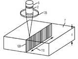
후술되는 유리 가공물 (7)과 같은 가공될 물체는 레이저 (5)에 의해 제공된 펄스 레이저 빔으로 조사된다. 펄스 레이저 빔은 예를 들어, 후술되는 바와 같이, 실질적으로 균일한 세기 분포 및 고 에너지 밀도를 가진 고 종횡비 라인 (초점 라인 (4'))으로 집광되는 (condensed) 초-단 펄스 (100 psec 미만의 펄스 폭) 레이저 빔일 수 있다. 레이저 빔 파장은 예를 들어 1064 nm 이하일 수 있다. 초점 라인 (4')은 가공되고 있는 가공물 (7)의 두께를 관통한다. 몇몇 실시 예에서, 가공물 (7)은 유리 기판이다. 이러한 고 에너지 밀도의 체적 내에서, 가공물 (7)의 재료는 비선형 효과를 통해 변형된다. 이러한 고 광학 세기 없이, 비선형 흡수가 유발되지 않음을 유의하는 것이 중요하다. 이러한 세기 임계치 이하에서, 재료는 레이저 복사에 대해 투명하고 그의 원래 상태로 유지된다. 원하는 라인 또는 경로를 걸쳐 레이저 빔에 의해 형성된 초점 라인을 스캐닝함으로써, 분리될 주변 또는 형상을 정의하는데 사용될 수 있는 윤곽 또는 경로를 따라 복수의 좁은 결함 라인 (120) (수 미크론의 폭)을 생성한다.An object to be processed, such as a
초점 라인은 가우시안 빔에 의해 형성된 동일한 크기의 단일 포커스 스폿의 전형적인 회절 속성에 의해 예상되는 것보다 긴 길이에 걸쳐 광학 빔의 포커싱된 스폿이 유지되는 영역이다. 빔이 점 (또는 적어도 매우 짧은 영역)에 포커싱되는 대신에, 초점 라인에 대응하는 빔은 빔 전파 방향을 따라 연장된 영역에 포커싱된다. 여기에서 언급되는 바와 같이, 초점 라인의 "길이 L"은 피크 단면 빔 세기가 그의 최대 피크 값의 ½로 떨어지는 지점들 사이의 (빔 전파 방향을 따른 초점 라인 내에서의) 거리이다. 가우시안 빔의 경우, 스폿 크기가 제곱근의 계수 내에 유지되는 전형적인 길이는 레일리 범위이며, 전형적으로 pi*w02/lambda로 주어지고, 여기서 lambda는 광의 파장이고 w0는 가우시안 빔 스폿의 1/e2 반경이다. 초점 라인을 형성하기 위한 하나의 전략은 준 (quasi)-비-회절 빔을 형성하는 것이며, 이는 레이저 시스템에서 흔한 가우시안 빔 프로파일을 사용하는 대신, 가우시안 빔보다 훨씬 더 느리게 효과적으로 회절되는, 베셀 또는 가우스-베셀 프로파일(들)과 같은 보다 정교한 빔 형상을 사용할 수 있다. 준 비-회절 빔, 레일리 범위, 및 이러한 보다 복잡한 빔 프로파일의 스폿 직경 측정법에 대한 자세한 논의는 본 명세서의 후반부에서 제시된다.The focal line is the region in which the focused spot of the optical beam is maintained over a length longer than would be expected by the diffractive properties typical of a single focal spot of the same size formed by a Gaussian beam. Instead of the beam being focused on a point (or at least a very short area), the beam corresponding to the focal line is focused on an area extending along the beam propagation direction. As referred to herein, the "length L" of a focal line is the distance (within the focal line along the beam propagation direction) between the points at which the peak cross-sectional beam intensity falls to ½ of its maximum peak value. For a Gaussian beam, the typical length at which the spot size remains within the coefficient of the square root is the Rayleigh range, typically given as pi*w02 /lambda, where lambda is the wavelength of light and w0 is the 1/e2 radius of the Gaussian beam spot. to be. One strategy for forming the focal line is to form a quasi-non-diffracted beam, which, instead of using the Gaussian beam profile common in laser systems, effectively diffracts much more slowly than a Gaussian beam, a Bessel or Gaussian beam. - More sophisticated beam shapes such as vessel profile(s) can be used. A detailed discussion of quasi-diffraction beams, Rayleigh ranges, and spot diameter measurements of these more complex beam profiles is presented later in this specification.
초점 라인 (4')에 포함된 광학 에너지는 예를 들어 유리 합성 가공물과 같은 실질적으로 투명한 재료에서 다중 광자 흡수 (multi-photon absorption, MPA)를 생성할 수 있다. MPA는 하나의 상태 (보통 기저 상태)로부터 보다 높은 에너지 전자 상태 (이온화)로 분자를 여기시키기 위해, 동일하거나 상이한 주파수의 두 개 이상의 광자를 동시에 흡수하는 것이다.The optical energy contained in the
MPA의 경우, 수반된 분자의 하부 상태와 상부 상태 사이의 에너지 차이는 두 개 이상의 광자의 에너지의 합과 같다. 유도 흡수라고도 불리는 MPA는 2-차 (order) 또는 3-차 과정 (또는 보다 높은 차원)일 수 있으며, 예를 들어 그는 선형 흡수보다 10의 몇 승 정도 (several orders of magnitude) 더 약하다. 이는, 예를 들어, 2-차 유도 흡수의 강도가 광 세기의 제곱에 비례될 수 있다는 점에서 선형 흡수와는 상이하며, 따라서 비선형 광학 과정이다.In the case of MPA, the energy difference between the lower and upper states of the involved molecule is equal to the sum of the energies of two or more photons. MPA, also called induced absorption, can be of second order or third order (or higher order), for example it is several orders of magnitude weaker than linear absorption. This differs from linear absorption, for example, in that the intensity of the second-order induced absorption can be proportional to the square of the light intensity, and thus is a non-linear optical process.
유리 기판 또는 가공물 (7)은 레이저 빔에 의해 형성된 초점 라인 (4')에 대해 이동되어 (또는 레이저 빔 초점 라인이 유리에 대해 병진 이동되어) 임의의 원하는 부분의 형상의 윤곽을 그리는 (trace out) 천공 영역을 생성한다. 예를 들어, 적어도 몇몇 실시예에서, 레이저 빔 초점 라인 (4')은, 예를 들어, 대략 0.3-1 미크론 직경의 내부 개구를 갖는 유리의 전체 깊이를 관통하는 홀형 결함 존 (또는 손상 트랙, 또는 결함 라인 (120))을 생성한다. 이러한 천공, 결함 영역, 손상 트랙 또는 결함 라인은 일반적으로 1 내지 50 미크론으로 이격된다 (예를 들어, 1-50 미크론, 1-25 미크론, 5-25 미크론, 5-30 미크론, 8-30 미크론, 8-40 미크론, 1-20 미크론, 3-15 미크론, 또는 5-10 미크론).The glass substrate or
결함 또는 천공을 갖는 라인 또는 윤곽이 생성되면, 분리는 다음을 통해 일어난다: 1) (화학적 강화로부터의 것과 같은) 고유의 재료 응력, 수동으로 가해지는 응력, 또는 다른 기계적 수단이 천공된 단층 라인 (110) 상에 또는 그 주위에서 응력을 생성하고; 응력 또는 압력은 천공된 단층 라인 (110)의 양 측면을 떼어내는 장력을 생성하고 여전히 함께 결합된 영역을 파괴하여야 한다; 2) 가열 소스를 사용하여, 단층 라인 (110) 주위에 응력 존을 생성하여 결함 (여기에서는 결함 라인 (120)으로도 지칭됨) 또는 천공된 단층 라인을 장력을 받게 하여 부분적 또는 전체적 분리를 유발시킨다. 양쪽 경우, 분리는 레이저 스캔 속도, 레이저 파워, 렌즈 파라미터, 펄스 폭, 반복률 등과 같은 여러 개의 공정 파라미터에 의존한다.When a line or contour with defects or perforations is created, separation occurs via: 1) intrinsic material stress (such as from chemical strengthening), manually applied stress, or other mechanical means perforated fault line ( 110) create a stress on or around it; The stress or pressure must create a tension that separates both sides of the
여기에 기술된 적어도 몇몇 실시예에 따르면, 레이저 절단 또는 홀 형성 공정은 유리 조성물의 범위의 몸체를 완전히 천공하도록 초점 라인 (4')을 발생시키는 광학 시스템과 결합된 초-단 펄스 레이저 (5)를 사용한다. 여기에서 기술된 바와 같이, 초점 라인 (4')은 초점 라인의 길이 (L) 내에서 필요한 거리를 따라 (예를 들어, 도 5a의 MGB 곡선으로 도시된 바와 같이) 실질적으로 균일한 광학 세기 분포를 제공한다.In accordance with at least some embodiments described herein, the laser cutting or hole forming process is an ultra-short
몇몇 실시예에서, 개별적인 펄스의 펄스 지속 기간은 약 1 피코초보다 크고 약 100 피코초보다 작고, 그 예로 약 5 피코초보다 크고 약 20 피코초보다 작은 범위이며, 개별적인 펄스의 반복률은 약 1 kHz 내지 4 MHz의 범위, 그 예로 약 10 kHz 내지 650 kHz의 범위에 있을 수 있다.In some embodiments, the pulse duration of the individual pulses ranges from greater than about 1 picosecond to less than about 100 picoseconds, such as greater than about 5 picoseconds and less than about 20 picoseconds, and the repetition rate of the individual pulses is about 1 kHz. to 4 MHz, such as about 10 kHz to 650 kHz.
상술된 개별적인 펄스 반복률에서의 단일 펄스 동작과 더불어, 펄스는 약 1 nsec 내지 약 50 nsec, 예를 들어, 10 내지 30 nsec의 범위에 있는, 그 예로 약 20 nsec인 버스트 내의 개별적인 펄스들 사이의 지속 기간에 의해 분리된 2 펄스 이상 (예를 들어, 3 펄스, 4 펄스, 5 펄스, 10 펄스, 15 펄스, 20 펄스 이상 등)의 버스트에서 만들어질 수 있고, 버스트 반복 주파수는 약 1 kHz 내지 약 200 kHz의 범위에 있을 수 있다. (펄스 버스트의 버스팅 또는 만들어짐은, 펄스의 방출이 균일하고 안정된 스트림 (stream)이 아니라 오히려 펄스의 촘촘한 클러스터인 레이저 동작 유형이다.) 펄스 버스트 레이저 빔은, 재료가 이 파장에서 실질적으로 투명하도록 선택된 동작 파장 λ를 가진다. 재료에서 측정된 버스트 당 평균 레이저 파워는, 재료의 mm 두께 당 40 microJoules를 초과, 예를 들어, 40 microJoules/mm 내지 2500 microJoules/mm, 또는 500 내지 2250 microJoules/mm일 수 있다. 예를 들어, 0.1 mm-0.2 mm 두께의 Corning Eagle XG®유리의 경우, 유리를 절단 및 분리하기 위해 200 μJ 펄스 버스트를 사용할 수 있고, 이는 1000-2000 μJ/mm의 대표적인 범위를 준다. 예를 들어, 0.5-0.7mm 두께의 Corning Eagle XG® 유리의 경우, 유리를 절단 및 분리하기 위해 400-700 μJ 펄스 버스트를 사용할 수 있고, 이는 570 μJ/mm (400 μJ/0.7mm) 내지 1400 μJ/mm (700 μJ/0.5mm)의 대표적인 범위에 대응한다.With single pulse operation at the individual pulse repetition rates described above, the pulses are in the range of about 1 nsec to about 50 nsec, eg, 10 to 30 nsec, eg, about 20 nsec, duration between individual pulses in a burst. can be made in bursts of 2 or more pulses (eg, 3 pulses, 4 pulses, 5 pulses, 10 pulses, 15 pulses, 20 pulses or more, etc.) separated by a duration, wherein the burst repetition frequency is from about 1 kHz to about It can be in the range of 200 kHz. (Bursting or making a burst of pulses is a type of laser operation in which the emission of pulses is not a uniform, steady stream, but rather, dense clusters of pulses.) A pulsed burst laser beam is one in which the material is substantially transparent at this wavelength. has an operating wavelength λ selected to The average laser power per burst measured in the material may be greater than 40 microJoules per mm thickness of the material, for example, between 40 microJoules/mm and 2500 microJoules/mm, or between 500 and 2250 microJoules/mm. For example, for Corning Eagle XG® glass 0.1 mm-0.2 mm thick, a burst of 200 μJ pulses can be used to cut and separate the glass, giving a representative range of 1000-2000 μJ/mm. For example, for 0.5-0.7 mm thick Corning Eagle XG® glass, 400-700 µJ pulse bursts can be used to cut and separate the glass, which ranges from 570 µJ/mm (400 µJ/0.7 mm) to 1400 µJ/mm (400 µJ/0.7 mm). Corresponds to a representative range of µJ/mm (700 µJ/0.5 mm).
여기에 정의된 바와 같이, 결함 라인 (120)의 직경 또는 내부 직경은, 유리 또는 가공물 내의 개구 채널 또는 에어 홀의 내부 직경이다. 예를 들어, 여기에 기술된 몇몇 실시예에서, 결함 라인 (120)의 내부 직경은, <500 nm, 예를 들어 ≤400 nm, 또는 ≤300 nm이다. 더욱이, 결함 라인의 내부 직경은, 예를 들어, 레이저 빔 초점 라인의 스폿 직경만큼 클 수 있다. 레이저 빔 초점 라인은 약 0.1 미크론 내지 약 5 미크론, 예를 들어 1.5 내지 3.5 미크론의 범위의 평균 스폿 직경을 가질 수 있다. 가우스-베셀 빔의 경우에, 초점 라인 직경 D (D=2R, 예를 들어, 도 3a 참조)은, 기판과 상호 작용하는 레이저 빔 초점 라인의 단면 프로파일을 근사화하는 베셀 함수에서 중앙 세크 피크와 제1 널 (null) 사이의 거리의 2 배인 것으로 간주 될 수 있다. 가공물 또는 유리 부분이 단층 라인 또는 윤곽 (110)을 따라 분리되면, 절단 및 분리된 표면 상의 결함 라인 (120)은 잠재적으로 여전히 관찰될 수 있고, 예를 들어, 결함 라인의 내부 직경과 비교 가능한 폭을 가질 수 있다. 이로써, 여기에 기술된 실시예 방법에 의해 준비된 유리 물품의 절단 표면 상의 결함 라인 (120)의 폭은, 예를 들어, 약 0.1 미크론 내지 약 5 미크론의 폭을 가질 수 있다.As defined herein, the diameter or inner diameter of the
단일 시트 유리 이외에도, 상기 공정은 또한 유리의 스택을 절단하는데 사용될 수 있으며, 단일 레이저 통과로 총 높이가 최대 몇 mm인 유리 스택을 완전히 천공할 수 있다. 유리 스택은 부가적으로 다양한 위치에서 에어 갭을 가질 수 있고; 레이저 공정은, 여전히 단일 통과로, 그러한 스택의 상부 및 하부 유리 층 둘다를 완전히 천공할 것이다.In addition to single sheet glass, the process can also be used to cut stacks of glass, and can completely perforate stacks of glass with a total height of up to several millimeters in a single laser pass. The glass stack may additionally have air gaps at various locations; The laser process will completely perforate both the top and bottom glass layers of such a stack, still in a single pass.
유리가 천공되면, 유리가 충분한 내부 응력을 가지는 경우, 크랙은 천공 라인을 따라 전파되고 및 유리 시트는 원하는 부분으로 분리될 것이다.Once the glass is perforated, if the glass has sufficient internal stress, the cracks will propagate along the perforation line and the glass sheet will separate into desired parts.
여기에 기술된 방법 및 장치는, 예를 들어, 투명 기판으로부터의 임의의 형상의 정밀 절단 및 분리를 위해, 보다 구체적으로는 에지 강도, 에지 충격 강도를 보존하고 고 레벨의 유리 에지 신뢰도를 가능케 하는 일부 에지에 대한 무시할 정도의 잔해 및 최소 손상을 갖는 제어 가능한 방식으로 유리에 대해 활용될 수 있다. 개발된 레이저 방법은 깨끗하고 자연 그대로의 (pristine) 표면 품질의 유지 및 레이저 포커스 주위의 고 세기의 구역에 의해 생성된 감소된 표면 아래의 손상을 유리하게 허용한다. 이러한 공정의 핵심 조장자 (enabler) 중 하나는 초-단 펄스 레이저에 의해 생성된, 후술되는 바와 같이 실질적으로 균일한 세기 분포를 갖는 초점 라인 (4')에 의해 생성된 결함 또는 결함 라인 (120)의 고 종횡비이다. 이는 절단될 재료의 상부 표면으로부터 하부 표면으로 연장되는 단층 라인 (110)의 생성을 허용한다. 원칙적으로, 이러한 결함은 단일 레이저 펄스 또는 단일 버스트 펄스에 의해 생성될 수 있다.The methods and apparatus described herein provide, for example, precision cutting and separation of arbitrary shapes from transparent substrates, more specifically preserving edge strength, edge impact strength, and enabling high levels of glass edge reliability. It can be utilized on the glass in a controllable manner with negligible debris and minimal damage to some edges. The developed laser method advantageously allows the maintenance of a clean and pristine surface quality and reduced subsurface damage created by the high intensity zone around the laser focus. One of the key enablers of this process is a defect or
초점 라인의 발생은 레이저 (5)에 의해 제공된 가우시안 레이저 빔을 변형 가우스-베셀 빔 (MGB 빔)을 통해 초점 라인 (4')을 생성하는 광학 시스템 (125) (본 명세서에서 더 상세하게 기술됨)으로 전송함으로써 수행될 수 있다. 초점 라인 (4')은 약 0.1 mm 내지 약 100 mm, 또는 0.3 mm 내지 10 mm, 또는 약 0.5 mm 내지 약 5 mm의 범위에 있는, 그 예로 약 1 mm, 약 2 mm, 약 3 mm, 약 4 mm, 약 5 mm, 약 6 mm, 약 7 mm, 약 8 mm, 또는 약 9 mm의 길이 L (즉, 0.5 최대 세기 지점들 간의 거리), 또는 약 0.1 mm 내지 약 1 mm의 범위에 있는 길이를 가진다. 초점 라인 (4')은 또한 약 0.1 미크론 내지 약 5 미크론 범위에 있는 평균 스폿 직경을 가진다. 이로써, 예를 들어, 초점 라인 (4')은 0.3 mm 내지 10 mm의 길이 L 및 0.1 미크론 내지 약 5 미크론 (예를 들어, 0.2 미크론 내지 1 또는 2 미크론)의 평균 스폿 직경 (그 길이에 걸침)을 가질 수 있다. 유리에 생성된 홀 또는 결함 라인 (120) 각각은 0.1 미크론 내지 10 미크론, 예를 들어 0.25 내지 5 미크론, 예를 들어 0.2-0.75 미크론 또는 0.3-0.75 미크론의 직경을 가질 수 있다.The generation of the focal line is an
비교 예시 - 가우스-베셀 빔을 이용한 초점 라인 형성Comparative Example - Focal Line Formation Using Gaussian-Bessel Beam
표준 레이저 기계가공 시스템은 일반적으로 가우시안 빔 (즉, 가우시안 세기 분포를 갖는 레이저 빔)을 이용한다. 회절 현상으로 인해 재료를 변형시키기에 충분히 강렬한 스폿 크기를 충분히 작게 포커싱될 때, 그러한 빔은 예를 들어, 몇 미크론 이하의 짧은 초점 심도를 가진다. 이와 달라, 레이저 기계가공은 레이저 빔 초점 라인을 형성하는 가우스-베셀 레이저 빔으로 수행될 수 있으며, 그러한 빔은 가우시안 빔에 의해 형성된 전형적인 포커스보다 유리한데, 이는 유리 시트의 깊이를 통해 수 밀리미터에 걸칠 수 있는 유리 시트에서의 재료 변형의 긴 영역을 생성하기 때문이다. 가우스-베셀 빔은, 예를 들어, 굴절 또는 반사 액시콘과 같은 광학 구성요소, 공간 광 변조기와 같은 위상 변경 요소, 또는 Dammann 격자와 같은 격자 요소에 가우시안 세기 프로파일을 갖는 전형적인 레이저 빔을 제공함으로써 형성되어, 초점 라인을 형성할 수 있다. 도 1에 도시된 비교 예시에 도시된 바와 같이, 전형적인 가우시안 세기 분포를 갖는 시준된 레이저 빔 (2)은, 액시콘의 원뿔 표면 (3a)에 바로 인접하여 위치된 연장된 초점 라인 (4)을 생성하는 가우스-베셀 빔을 형성하는 액시콘 (3) (즉, 하나의 원뿔 표면 (3a)을 갖는 렌즈 구성요소)에 제공된다. 도 2는 가공물 (7) (예를 들어, 유리 기판) 내에서 레이저 빔 초점 라인 (4') (여기서는 초점 라인으로도 지칭됨)으로서 연장된 초점 라인 (4)을 재이미징화하는 재-이미징 (re-imaging) 광학 시스템 (6)을 도시한다. 도 2의 재이미징 광학 시스템 (6)은 2 개의 광학 구성요소 - 초점 길이 F1을 가진 광학 구성요소 (6a) 및 초점 길이 F2를 가진 광학 구성요소 (6b)를 포함한다. 이들 구성요소는 거리 F1+F2만큼 서로 분리될 수 있다. 재-이미징된 레이저 빔 초점 라인 (4')은 초점 라인 (4')이 렌즈 구성요소 (6b)에 바로 인접하게 형성되지 않도록 재-이미징 광학 시스템 (6)의 후방 표면으로부터 이격된다.Standard laser machining systems generally use a Gaussian beam (ie, a laser beam with a Gaussian intensity distribution). Such a beam has a short depth of focus, for example, a few microns or less, when focused small enough to have a spot size that is sufficiently intense to deform the material due to diffraction phenomena. Alternatively, laser machining can be performed with a Gaussian-Bessel laser beam that forms a laser beam focal line, which is advantageous over a typical focus formed by a Gaussian beam, which can span several millimeters through the depth of the glass sheet. This is because it creates a long region of material deformation in the glass sheet. A Gaussian-Bessel beam is formed, for example, by providing a typical laser beam with a Gaussian intensity profile to an optical component such as a refractive or reflective axicon, a phase modifying element such as a spatial light modulator, or a grating element such as a Dammann grating. Thus, a focal line can be formed. As shown in the comparative example shown in FIG. 1 , a
광학 시스템 (6)의 렌즈 (6a 및 6b)는 액시콘 (3)의 바로 뒤에서 생성된 초점 라인 (4)을 단순히 확대 (또는 축소)한다. 도 3은 도 2의 광학 시스템에 의해 형성된 가우스-베셀 빔 (비교 예시에서 사용된 광학 빔)의 단면 (반경 방향 프로파일)을 도시한다. 도 3에 도시된 광학 빔의 중심 부분 (4a') (여기서는 중심 스폿 또는 중앙 로브라고도 지칭됨)은 초점 라인 (4')에 대응하고, 중심 부분 주위의 링은 유리 기판 내에서 더 아래로 내려간 초점 라인의 중심을 향해 수렴하는 광학 세기 (빔)에 대응한다. 초점 라인 (4')의 중심 부분 (4a')은 직경 D를 가진다 (여기서 D=2R). 임의의 주어진 위치에서, 대부분의 레이저 빔 에너지는 중심 부분 (4a')에 집중되고, 가우스-베셀 빔의 중심 부분 (4a')은 유리 기판 (7) 내에 결함 라인 (120)을 생성하는데 활용되는 것이다. 몇몇 실시예에서,직경 D는 가능한 한 작게 하는 것이 바람직하다.The
그러나, 비교 예시의 전형적인 가우스-베셀 빔에 의해 형성된 초점 라인 (4), (및 이로써 초점 라인 (4'))은 광학 축 (OA) (즉, 빔 전파 방향)을 따라 매우 불균일한 피크 세기 프로파일을 가진다. 여기에서 용어 "피크 세기"는 레이저 빔의 단면 (또는 횡) 프로파일에서 관찰되는 최대 세기를 기술하는데 사용되며, 단면 평면은 빔 전파 방향을 가로지르고, 빔 전파 방향을 따라 하나의 주어진 위치에서 평가된다. 피크 세기는 전형적으로 빔 전파 방향을 따라 주어진 위치에서 가우스-베셀 빔의 중앙 스폿 내에 포함된 에너지의 양에 비례할 것이다. 초점 라인 (4)을 따르는 액시콘의 팁으로부터 거리 z에 있는 x-y 평면 P에서의 비교 가우스-베셀 빔의 세기는 가우시안 세기 프로파일을 갖는 입력 레이저 빔을 수신하는 액시콘에 의해 형성되며, 다음 식과 같이 주어진다:However, the

여기서 Rz는 입사 가우스 빔 (2)의 1/e2 지점에서 측정된 입력 빔 반경이고, Io (Rz)는 입력 빔 반경 Rz에 대응하는 액시콘을 조명하는 광 빔의 세기 (즉, 반경 높이 Rz에서의 가우시안 빔 세기)이고, λ는 레이저 빔의 파장이고, β는 초점 라인을 향해 수렴할 때 레이저 빔의 수렴 각이고, Jo는 제1 종의 0 차 (zeroeth order) 베셀 함수 (베셀 미분 방정식의 해)이고, R은 초점 라인의 반경 (즉, 중심 부분 (4a')의 반경)이고, k=2π/λ이다.where Rz is the input beam radius measured at the
이로써, 거리 z에서의 초점 라인의 중심에 있는 피크 세기는 다음과 같이 주어진다:Thus, the peak intensity at the center of the focal line at distance z is given by:

이러한 식은 도 4a-4c에 도시된 것에 대응하는 광학 축 (z)을 따른 거리의 함수로서 가우스-베셀 빔의 반경 세기 분포를 기술한다.This equation describes the radial intensity distribution of a Gaussian-Bessel beam as a function of distance along the optical axis (z) corresponding to that shown in Figs. 4a-4c.
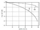
도 4a-4c에 도시된 바와 같이, 전형적인 가우시안 베셀 빔 (빔 전파 방향을 따름)의 피크 세기 프로파일은 매우 불균일하다. 초점 라인 (4)의 직경은 각도 β와 관련되고, 초점 라인의 직경 D는 각도 β'와 관련된다. 각도 β는 또한 초점 라인의 작은 섹션을 조명하거나 생성하는 광학 빔의 특정 부분의 개구수 (NA)의 척도로 간주될 수 있다. 광학 물리학에서 알려진 바와 같이, 광학 빔에 의해 형성된 스폿 직경 (D)은 그 광학 빔의 개구 수에 반비례한다. 따라서, 각도 β가 초점 라인의 길이를 따라 변화하는 경우, 이는 초점 라인의 길이를 따라 NA가 변하거나 초점 라인의 길이를 따라 스폿 직경이 변한다는 것과 동일하다. 예를 들어, 도 4a에 도시된 바와 같이, 굴절 액시콘, 동일한 기능을 수행하는 위상 요소, 또는 회절 Dammann 격자가 입력 가우시안 빔으로부터 초점 라인 (4')을 생성하는데 활용될 때, 빔 전파 축 (광학 축 OA)을 따른 광학 빔 세기 (I) 분포는 광학 축 OA (라인 z)를 따라 몇몇 영역에서 존재하는 과잉 에너지를 초래하고, 빔을 따른 다른 영역에서는 충분치 않다. 가우스-베셀 빔의 이러한 불균일한 세기 분포는 추가의 에너지를 수용하는 유리 가공물의 구역에서 원치 않는 마이크로-크랙 형성을 야기하고, 너무 적은 에너지를 수용하는 영역에서 재료의 불충분한 변형을 야기할 수 있다. 가우스-베셀 빔의 불균일한 피크 세기 분포 (광학 축 OA를 따름)는 또한 단면 크기가 균일하지 않은 홀의 형성을 야기할 수 있거나, 유리 가공물 (7)의 일 부분이 필요한 크기 홀을 형성하는 광학 파워를 불충분하게 수용하는 경우 불완전한 홀을 야기할 수 있다.As shown in Figures 4a-4c, the peak intensity profile of a typical Gaussian Bessel beam (along the beam propagation direction) is highly non-uniform. The diameter of the
보다 구체적으로, 도 4a는 도 2에 도시된 비교 광학 시스템의 가우스-베셀 빔에 의해 형성된 광학 축 OA을 따른 (그리고 초점 라인 (4')의 길이를 따른) 거리 z 대 모델링된 피크 빔 세기 프로파일의 플롯이다. 도 4a에 도시된 바와 같이, 거리 L는 0.5Imax 지점들 (최대 파워 절반에 대응되기도 하는 최대 피크 절반 세기 지점들) 사이의 빔 전파 방향을 따른 거리이다. 도 4a의 피크 세기 곡선은, 예를 들어, 마지막 렌즈 구성요소 (6b)로부터 0.25 mm 떨어진 거리 z에서 비교 광학 빔 (가우스-베셀 빔)의 중심에서 피크 세기가 렌즈 구성요소 (6b)로부터 약 0.8mm 떨어져 광학 축 OA를 따라 일어나는 최대 세기 Imax의 약 40%인 것을 도시한다. 그러나, 가우시안 베셀 빔의 피크 세기 I≤0.4Imax는 전형적인 유리 기판을 절단 또는 변형시키기에 충분치 않을 수 있고, 기판(들) 내의 결함 라인의 불완전한 형성을 초래할 수 있다. 이로써, 비교 가우스-베셀 빔의 테일 엔드 (tail ends)에 위치한 광학 에너지는 전형적으로 유리 절단 적용에 사용될 수 없다.More specifically, FIG. 4A shows a modeled peak beam intensity profile versus distance z along the optical axis OA (and along the length of
도 4b는 광학 축 AO 상의 상이한 위치 (마지막 렌즈 구성요소 (6b)로부터 떨어진 상이한 거리 z)에서 도 2의 대표적인 비교 광학 시스템에 의해 만들어진 측정된 피크 세기 I의 플롯을 도시한다. 보다 구체적으로, 도 4b는 초점 라인 (4')이 광학 축 OA를 따른 거리의 함수로서 위치되는 광학 축 OA를 따라 측정된 광학 빔의 측정된 피크 강도의 플롯이다. 도 4b의 플롯에 대응하는 가우스-베셀 빔은 대략 2 mm의 길이 L를 갖는 초점 라인 (4')을 생성하는 2-렌즈 시스템 (6) 및 액시콘 렌즈 (3)를 사용하여 형성되었다. 즉, 이 예시에서는, 도 4b에 도시된 바와 같이, 최대 세기의 ½ (즉, 0.5Imax)에 대응하는 세기 지점 (A, A')은 약 2 mm 떨어져 있다. 도 4b에 도시된 바와 같이, 가우스-베셀 빔의 측정된 피크 세기는 초점 라인 (4')의 길이를 따라 매우 불균일하며, 도 4a에 도시된 것과 유사한 형상을 가진다.FIG. 4b shows a plot of the measured peak intensity I made by the representative comparative optical system of FIG. 2 at different positions on the optical axis AO (different distance z away from the
도 4c는 도 4a 및 4b의 것과 유사하며, 광학 축을 따른 거리 z의 함수로서, 가우스-베셀 빔에 의해 생성된 또 다른 비교 초점 라인의 피크 세기 분포를 도시하고, 여기서 z 값은 0 내지 12 mm이다 (거리 z는 재이미징 시스템 (6)의 마지막 광학 구성요소 뒤의 거리이다). 도 4c에서, 실선은 모델링된 결과에 대응하며, 원형은 측정된 데이터에 대응한다. 음영 영역에 대응하는 광학 세기는 유리 기판의 주어진 두께 내에서 (즉, 결함 라인 (120), 예를 들어, 홀을 만들기 위해) 유리를 변형시키는데 필요한 세기이다. 이러한 예시에서, 유리 기판 (7)은

파워 밀도의 관점에서, 유리 재료의 경우, 레이저 에너지 밀도가 재료 응집력 (cohesion forces)보다 높을 때, 재료는 휘발되어, 치밀화, 크랙, 손상 트랙 또는 홀을 형성할 수 있는 재료의 변형을 생성한다. 이로써, 초점 라인 (4')의 길이를 따른 각각의 세그먼트에서의 파워 밀도가 유리 기판과 같은 가공물 (7)을 통과하는 모든 홀을 생성하기 위해 주어진 임계치 Po (단위 Watts/micron3 )보다 높은 것이 바람직하다. 도 4c에 도시된 예시에서, 홀 생성을 가능케 하는 광학 축 위치 주위의 극소 체적 영역에서의 파워 밀도에 대응하는 빔 단면 내의 임계치 세기는 세기 임계치 (Io=0.6Imax)에 대응하고, 0.6Pmax/μm3의 파워 밀도는 유리 내에서 원하는 변경을 생성한다. 이러한 비교 예시에서, 광학 파워 밀도가 Io< 0.6Imax에 대응되도록 떨어질 때, 초점 라인 (4')은 단일 레이저 펄스 또는 단일 펄스 버스트로 치밀화, 크랙, 손상 트랙 또는 홀을 신뢰성있게 생성하지 않는다.In terms of power density, in the case of glass materials, when the laser energy density is higher than the material cohesion forces, the material volatilizes, creating deformation of the material that can form densification, cracks, damage tracks or holes. Thereby, the power density at each segment along the length of the focal line 4' is higher than a given thresholdPo (in Watts/micron3 ) to create all holes through the
다음과 같이 달성하는 것보다 유리 분리 또는 유리 공정의 방법을 가지는 것이 바람직하다:It is desirable to have a method of glass separation or glass processing rather than achieving:
I.) 기판 (7) 내의 재료 깊이의 함수로서 레이저 빔의 보다 균일한 피크 세기 및 보다 균일한 파워 밀도; 및/또는I.) more uniform peak intensity and more uniform power density of the laser beam as a function of material depth in the
II.) 전형적인 가우스-베셀 빔에 의해 생성되는 것보다 빔 전파 방향을 따라 양호한 피크 세기 균일성을 갖는 초점 라인 (4').II.) Focal line (4') with better peak intensity uniformity along the beam propagation direction than that produced by a typical Gaussian-Bessel beam.
이에 따라서, 레이저 에너지 밀도가 초점 라인의 필요한 길이 영역에 대해 재료의 원하는 두께에 걸쳐 재료 응집력보다 높아지지만 대량의 빔 파워가 낭비되는 것만큼 매우 높지 않도록 초점 라인 (4')을 생성하는 것이 바람직한데, 이는 치밀화, 크랙, 손상 트랙, 또는 홀을 형성할 수 있는 재료 변형을 생성하는 것에 필요한 것보다 초점 라인 내의 재료 상에 보다 많은 에너지가 입사되기 때문이다. 아래에서 보다 상세히 기술되는 바와 같이, 광학 시스템 (125)의 실시예는 초점 라인 (4')의 필요한 길이를 따라 실질적으로 균일한 광학 세기 분포를 갖는 변형된 가우스 베셀 빔 (MGB 빔)을 유리하게 제공한다.Accordingly, it is desirable to create the focal line 4' such that the laser energy density is higher than the material cohesion over the desired thickness of the material for the required length region of the focal line, but not so high that a large amount of beam power is wasted. , because more energy is incident on the material in the focal line than is necessary to create material deformations that can form densification, cracks, damage tracks, or holes. As will be described in more detail below, embodiments of
이로써, 여기에 기술된 광학 시스템 (125)의 실시예는, 실질적으로 일정한 피크 세기 - 즉, 식 1.2에 의해 기술된 광학 가우시안 베셀 세기 분포의 것보다 더 일정한 피크 세기 분포를 가진 개선된 레이저 빔 초점 라인 (4')을 형성하도록 구성된다. 이 개선된 피크 세기 분포는, 예를 들어, 도 5a에 도시되고, 변형된 가우스 베셀 (Modified Gauss Bessel, MGB) 빔 세기 분포, 또는 여기에서 또한 "탑-햇 (top-hat)" 분포로 지칭된다. 여기에 기술된 실시예 중 적어도 몇몇에 따르면, 광학 시스템 (125)에 의해 형성된 개선된 레이저 빔 초점 라인 (4')은 실질적으로 일정한 빔 직경 D를 유리하게 가진다.As such, an embodiment of the
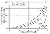
보다 구체적으로는, 도 5a는 전형적인 가우스-베셀 (GB) 레이저 빔의 피크 세기 분포 (W/μm2), 이뿐 아니라 여기에 기술된 적어도 하나의 실시예 (예를 들어, 여기에 기술된 MGB)에 따른 광학 빔의 광학 축을 따른 피크 세기 분포를 도시하고, 이때 양쪽 세기 분포는 동일한 구역으로 표준화된다 (각 분포의 총 에너지 = 1). 도 5a는 가우시안-베셀 빔에 의해 제공된 것보다, 광학 축을 따른 상당히 더 균일한 피크 세기 분포를 갖는 초점 라인 (4')을 제공하도록 구성되는 광학 시스템 (125) (또한, 여기에서, 초점 라인 세기 맵핑 광학 시스템 (Focal Line Intensity Mapping optical system, FLIMOS)으로 지칭됨)의 실시예를 도시한다. 도 5a는 또한 레이저 빔 에너지의 실질적으로 더 많은 부분이 가우스-베셀 빔에 포함된 것보다 MGB 빔 내의 0.5Imax 지점들 사이 (지점 A와 A'사이)에 포함된다는 것을 도시한다. 이는 MGB 빔이 동등한 가우스-베셀 빔보다 유리 변형에 대해 더 많은 부분의 레이저 빔 에너지를 활용할 수 있음을 나타낸다. MGB 빔의 형성을 위한 대표적인 실시예는 이하 명세서에서 기술된다.More specifically, FIG. 5A shows the peak intensity distribution (W/μm2 ) of a typical Gaussian-Bessel (GB) laser beam, as well as at least one embodiment described herein (eg, MGB described herein). Plot the peak intensity distribution along the optical axis of the optical beam according to , where both intensity distributions are normalized to the same region (total energy of each distribution = 1). 5A shows an optical system 125 (also here, focal line intensity) configured to provide a
도 5b는 도 5a에 대응하는 MGB 및 가우스-베셀 분포에 포함된 총 에너지 대 주어진 세기 임계치 (피크 세기 %) 플롯을 도시한다. 도 5b에 도시된 바와 같이, 임의의 주어진 파워 임계치에 대해, 광학 시스템 (125)에 의해 만들어진 세기 분포 내에 포함된 총 에너지는 항상 더 높다.FIG. 5B shows a plot of the total energy contained in the MGB and Gaussian-Bessel distributions corresponding to FIG. 5A versus a given intensity threshold (% peak intensity). As shown in FIG. 5B , for any given power threshold, the total energy contained within the intensity distribution made by the
도 5b는 적어도 초기에 상승 세기 임계치가 광학 시스템 (125)을 통해 (예를 들어, MGB 에너지 분포와 같은) 개선된 피크 에너지 분포에 의해 제공된% 파워에 거의 영향을 미치지 않는 것을 도시한다. 예를 들어, 유리 기판을 변형시키는 임계치 세기가 최대 피크 세기 Imax의 60%이고, 초점 라인이 가우시안-베셀 빔에 의해 형성될 때, 0.6Imax 지점들 (60% 임계치) 사이의 초점 라인에 포함된 광학 에너지의 양은 총 에너지의 약 70%이다 (즉, 포함된 파워비율은 0.7이다). 이와 달리, MGB 빔을 형성하는 대표적인 광학 시스템 (125) (FLIMOS)에 의해 형성된 초점 라인에서의 피크 세기가 최대 피크 세기의 60%에 있을 때, 0.6Imax 사이의 초점 라인에 포함된 파워의 양은 총 파워의 약 95%이다 (즉, 포함된 파워의 비율은 0.95 임). 즉, 가우스-베셀 빔을 사용할 때 30%의 파워 손실과는 달리, MGB 빔을 활용할 때 파워 또는 펄스 에너지의 약 5%만 손실된다. 또한 예를 들어, 유리 기판을 변형시키는 임계치 파워가 최대 피크 세기 Imax의 80%이고, 초점 라인이 가우시안-베셀 빔에 의해 형성된 경우, 0.8Imax 지점들 사이의 초점 라인에 포함된 광학 파워의 양은 총 광학 파워의 단지 약 50%이다. 이와 달리, (MGB 빔을 갖는) 대표적인 광학 시스템 (125)에 의해 형성된 초점 라인에서의 0.8Imax지점들 사이의 초점 라인에 포함된 광학 파워의 양은 총 파워의 약 95%이다. 즉, 가우스-베셀 (GB) 빔을 사용할 때 50%의 에너지 손실과는 달리, MGB 빔을 활용할 때 에너지의 약 10%만 손실된다.5B shows that, at least initially, the rising intensity threshold has little effect on the % power provided by the improved peak energy distribution (eg, such as the MGB energy distribution) through the
도 5a에 도시된 MGB 세기 프로파일은 추가 이점을 가진다. 기판 상의 민감한 코팅, 그 예로 중합체 층, 블랙 매트릭스 코팅, 금속 트레이스 등에 가까운 영역에서 기판을 절단하려고 시도할 때, 기판 그 자체에 있지 않은 초점 라인의 일부를 형성하는 임의의 에너지는 낭비될 뿐만 아니라 인근 코팅을 가열 또는 손상시키는 역할을 할 수 있다. 예를 들어, GB 빔 초점 라인의 테일 엔드를 형성하는 광선은 초점 라인의 테일 엔드에서 강렬한 코어를 형성하기 위해 포커싱하기 전에, 큰 환형 개구에 걸쳐 기판에 충돌한다. 동일한 조건이 초점 라인의 맨 위 또는 상위에서 발생하고, 이 경우 광선은 우선 밀도가 높은 코어를 형성하기 위해 포커싱하고 그 후에 발산하고, 여전히 기판 상에 충돌할 고리를 형성한다. 이로써, 기판 자체를 절단하기에 단지 충분히 긴 분포로 에너지를 제한함으로써, MGB 빔은 유리하게도 인근 코팅에 최소한의 손상 (또는 손상 없음)으로 최적의 절단을 허용하고, 그러므로 GB 빔으로 하는 것보다 코팅에 더 가깝게 절단하는 것을 허용한다. 이로써, 여기에 개시된 디바이스(들) 및/또는 방법(들)의 실시예 중 몇몇에 따라서, 가공물은 코팅 (예를 들어, 중합체 층, 블랙 매트릭스 코팅, 금속 또는 임의의 다른 코팅(들))을 포함하는 일 부분, 및 코팅을 포함하지 않는 일 부분을 포함한다. 몇몇 실시예에 따르면, n 비코팅된 부분은 두께 d를 가지고, 초점 라인의 중심과 코팅 (즉, 초점 라인에 근접한 코팅) 사이의 거리는 500 μm 미만, 바람직하게 350 μm 미만, 예를 들어 10 μm 내지 250 μm, 또는 10 μm 내지 200 μm, 또는 예를 들어 10 μm 내지 300 μm, 또는 10 μm 내지 500 μm, 또는 15 μm 내지 400 μm, 또는 20 μm 내지 500 μm, 또는 20 μm 내지 350 μm, 또는 20 μm 내지 250 μm, 또는 25μm 내지 400 μm, 또는 25μm 내지 250 μm이다. 몇몇 실시예에 따르면, 여기에 기술된 방법(들) 및/또는 디바이스는 코팅을 포함하지 않는 가공물의 일 부분 내에 (상기 초점 라인을 통해) 복수의 천공 또는 결함을 생성하고, 천공 또는 결함은 가공물의 코팅된 부분으로부터 거리 Zd가 형성된다. 거리 Zd는 에지-대-에지 - 즉, 천공(들) 또는 결함(들)의 에지로부터 천공(들) 또는 결함(들)에 인접한 코팅의 에지까지 측정된다. 몇몇 실시예에 따르면, Zd≤d/3이고 Zd>5 μm, 예를 들어 Zd>10 μm, 또는 >15 μm이고, 이 경우 d는 가공물의 비코팅된 부분의 두께이다. 몇몇 실시예에 따르면, Zd≤d/4이고 Zd>5 μm, 예를 들어 Zd>10 μm, 또는 Zd>15 μm, Zd>25 μm이고, 이 경우 d는 가공물의 비코팅된 부분의 두께이다.The MGB intensity profile shown in Figure 5a has additional advantages. When attempting to cut the substrate in areas close to sensitive coatings on the substrate, such as polymer layers, black matrix coatings, metal traces, etc., any energy forming part of the focal line that is not on the substrate itself is not only wasted but also wasted nearby. It can serve to heat or damage the coating. For example, a ray forming the tail end of a GB beam focal line strikes the substrate across a large annular aperture before focusing to form an intense core at the tail end of the focal line. The same condition occurs at the top or above the focal line, in which case the rays focus first to form a dense core and then diverge, forming rings that will still impinge on the substrate. Thereby, by limiting the energy to a distribution that is only long enough to cut the substrate itself, the MGB beam advantageously allows optimal cutting with minimal (or no damage) damage to the nearby coating, and therefore more coating than with the GB beam. Allows cutting closer to the As such, in accordance with some of the embodiments of the device(s) and/or method(s) disclosed herein, the workpiece may be coated with a coating (eg, a polymer layer, a black matrix coating, a metal or any other coating(s)). It includes a portion that includes, and a portion that does not include a coating. According to some embodiments, n uncoated portions have a thickness d, and the distance between the center of the focal line and the coating (ie the coating close to the focal line) is less than 500 μm, preferably less than 350 μm, for example 10 μm. to 250 μm, or from 10 μm to 200 μm, or for example from 10 μm to 300 μm, or from 10 μm to 500 μm, or from 15 μm to 400 μm, or from 20 μm to 500 μm, or from 20 μm to 350 μm, or 20 μm to 250 μm, or 25 μm to 400 μm, or 25 μm to 250 μm. According to some embodiments, the method(s) and/or device described herein creates a plurality of perforations or defects (via the focal line) in a portion of a workpiece that does not include a coating, wherein the perforations or defects are A distance Zd is formed from the coated part of The distance Zd is measured edge-to-edge - ie from the edge of the perforation(s) or defect(s) to the edge of the coating adjacent to the perforation(s) or defect(s). According to some embodiments, Zd ≤ d/3 and Zd >5 μm, for example Zd >10 μm, or >15 μm, where d is the thickness of the uncoated part of the workpiece. According to some embodiments, Zd≤d/4 and Zd>5 μm, for example Zd>10 μm, or Zd>15 μm, Zd>25 μm, where d is the thickness of the uncoated part of the workpiece .
더욱이, 도 5a의 MGB로 도시된 바와 같은 평평한-상부 에너지 분포로, 포커싱 또는 기판 높이 변화에 대한 절단 공정의 민감도는 최소화될 것이다. 도 5a에 도시된 GB의 경우, 기판 위치가 광학 축을 따라 이동되는 경우, 기판의 상이한 깊이는 GB 함수가 광학 축을 따라 세기에 변화함에 따라 증가되거나 감소된 에너지 밀도를 나타낼 것이다. 그러나, MGB의 경우, 기판이 MGB 세기 프로파일의 폭 내에 완전히 포함되어있는 한, 여기에 기술된 실시예에 따르면, 포커싱에서의 작은 변화는 기판을 수용하는 임의의 깊이 및 다소의 세기를 초래하지 않을 것이다. 이는 MGB 빔이 보다 일관된 절단 또는 드릴링 공정을 바람직하게 제공하고, 이 경우, 작은 초점 변화 (초점 라인의 평평한 상부 에너지 분포 또는 길이의 범위 내의 것)가 최종 산출물 또는 가공물의 품질 또는 공정에 크게 영향을 미치지 않음을 의미한다.Moreover, with a flat-top energy distribution as shown by MGB in Fig. 5a, the sensitivity of the cutting process to focusing or substrate height changes will be minimized. For the GB shown in FIG. 5A , if the substrate position is moved along the optical axis, different depths of the substrate will exhibit increased or decreased energy density as the GB function changes with intensity along the optical axis. However, in the case of MGB, as long as the substrate is completely contained within the width of the MGB intensity profile, according to the embodiments described herein, a small change in focusing will not result in any depth of receiving the substrate and some intensity. will be. This means that MGB beams desirably provide a more consistent cutting or drilling process, in which case small changes in focus (those within the range of the flat upper energy distribution or length of the focal line) significantly affect the quality or process of the final product or workpiece. means not reaching.
적어도 몇몇 실시예에 따르면, 유리 기판 내의 초점 라인은 그 광학 축을 따른 레이저 빔 초점 라인의 피크 세기가 0.5Imax 지점들 사이에 위치된 초점 라인 (4')의 길이 L의 적어도 80%에 대한 최대 피크 세기 Imax에 대해 35% 초과, 또는 30% 초과, 또는 25% 초과, 바람직하게 20% 이하로 변화하지 않도록 실질적으로 균일한 세기 프로파일을 가진다. (길이 L는 빔 전파 방향에서 초점의 중심을 따른 0.5Imax 지점들 (A, A') 사이의 거리이다). 몇몇 대표적인 실시예에 따르면, 레이저 빔 초점 라인 (4')의 광학 축을 따른 레이저 빔 초점 라인의 피크 세기는 초점 라인의 길이의 적어도 80%에 대해 그의 최대 피크 강도 (Imax)에 대해 10% 초과로 변하지 않는다. 적어도 몇몇 실시예에 따르면, 유리 기판 내에 형성된 초점 라인은 레이저 빔 초점 라인의 광학 축을 따른 레이저 빔 초점 라인의 피크 세기가 적어도 초점 라인 (4')에 의해 형성된 결함 라인의 길이 L에 대한 최대 피크 세기 Imax에 대해 25% 초과 (바람직하게 15% 미만, 예를 들어 10% 미만, 또는 5% 이하)로 변화하지 않도록 거리의 함수로서 실질적으로 균일한 프로파일을 가진다.According to at least some embodiments, the focal line in the glass substrate is a maximum for at least 80% of the length L of the
적어도 몇몇 실시예에 따르면, 유리 기판 (7) 내의 초점 라인 (4')은 그 광학 축을 따른 레이저 빔 초점 라인의 피크 세기가 초점 라인 (4')의 길이 L의 적어도 85%에 대한 최대 피크 세기 Imax에 대해 25% 초과 (예를 들어, 변화는 ≤ 20%, ≤ 15%, ≤10%, ≤ 5%, 및 심지어 ≤ 3%이다)로 변화되지 않도록 실질적으로 균일한 세기 프로파일을 가진다. 적어도 몇몇 실시예에 따르면, 유리 기판 내의 초점 라인은 그 광학 축을 따른 레이저 빔 초점 라인의 피크 세기가 초점 라인 (4')의 길이 L의 적어도 90%에 대한 최대 피크 세기 Imax에 대해 25% 초과 (예를 들어, 변화는 ≤ 20%, ≤ 15%, ≤10%, ≤ 5%, 및 심지어 ≤ 3%이다)로 변화되지 않도록 실질적으로 균일한 세기 프로파일을 가진다.According to at least some embodiments, the
유리 가공물을 가공하는 방법은 유리를 절단하고, 유리 조각을 서로 분리시키는데 사용될 수 있다. 레이저 절단 공정은 에지에 대한 낮은 표면 아래의 손상 및 최소 결함 및 무시할 수 있을 정도의 잔해로 제어할 수 있는 방식으로 유리 부품을 분리하여 부품 강도를 보존한다.Methods of processing glass workpieces can be used to cut glass and separate pieces of glass from each other. The laser cutting process preserves part strength by separating the glass parts in a controllable manner with low subsurface damage to the edge and minimal defects and negligible debris.
여기에 기술된 레이저 가공 방법은 선택된 레이저 파장에 대해 투명한 재료에 매우 적합하다. 이러한 파장은 예를 들어, 1064, 1030, 532, 530, 355, 343, 또는 266 나노미터일 수 있다. 가공물은 바람직하게 선택된 레이저 파장에 대해 실질적으로 투명하다 (예를 들어, 재로 깊이의 mm당 약 20% 미만, 바람직하게 10% 미만, 및 바람직하게 약 1% 미만의 흡수). 여기에 기술된 공정 단계는 원하는 형상을 묘사하고 크랙 전파를 위한 최소의 저항 경로를 확립하는 단층 라인 또는 윤곽 (110)을 생성하여, 그 기판 매트릭스로부터의 형상을 분리 및 이탈하기 위한 것이다. 레이저 분리 방법은 원래 기판에서 유리 형상의 수동 또는 기계 분리, 열 분리 및 부분 분리 또는 전체 분리가 가능하도록 튜닝 및 구성될 수 있다.The laser processing methods described herein are well suited for materials that are transparent to the selected laser wavelength. This wavelength may be, for example, 1064, 1030, 532, 530, 355, 343, or 266 nanometers. The workpiece is preferably substantially transparent to the selected laser wavelength (eg, less than about 20%, preferably less than 10%, and preferably less than about 1% absorption per mm of ash depth). The process steps described herein are for separating and departing the shape from its substrate matrix by creating a fault line or
몇몇 실시예에 따르면, 예를 들어 도 5b에 도시된 바와 같이, 변형 가우스-베셀 빔 (MGB 빔)에 의해 형성된 초점 라인 (4')에서의 총 광학 파워의 0.85 (또는 85%) 이상이 (½)Imax 지점들 사이에 포함된다 (즉, 세기 임계치 = (½)Imax일 때). 몇몇 실시예에 따르면, MGB 빔에 의해 형성된 초점 라인 (4')에서의 총 파워의 90% 이상, 및 몇몇 실시예에서 95% 이상이 0.5Imax 지점들 사이에 포함된다. 예를 들어, 몇몇 실시예에서, 변형 가우스-베셀 (MGB) 빔에 의해 형성된 초점 라인 (4')에서의 총 에너지의 85% 내지 99%가 0.5Imax 지점들 사이에 포함된다. 이와 달리, 총 파워의 80%만이 보통의 가우스-베셀 빔에 의해 형성된 초점 라인 (4')에서 0.5Imax 지점들 사이에 포함된다.According to some embodiments, 0.85 (or 85%) or more ( contained between the ½)Imax points (ie, when the intensity threshold = (½)Imax ). According to some embodiments, at least 90%, and in some embodiments at least 95% of the total power at the focal line 4' formed by the MGB beam is comprised between the 0.5Imax points. For example, in some embodiments 85% to 99% of the total energy at the
몇몇 실시예에 따르면, 변형 가우스-베셀 (MGB) 빔에 의해 형성된 초점 라인 (4')에서 총 광학 파워의 60% 이상이 0.8Imax 지점들 사이에 포함된다 (즉, 세기 임계치 = (0.8)Imax일 때). 이와 달리, 총 파워의 55% 미만이 보통의 가우스-베셀 빔에 의해 형성된 초점 라인 (4')에서 0.8Imax 지점들 사이에 포함된다.According to some embodiments, at least 60% of the total optical power at the focal line 4' formed by the modified Gaussian-Bessel (MGB) beam is contained between the 0.8Imax points (ie, intensity threshold = (0.8) when Imax ). In contrast, less than 55% of the total power is contained between the 0.8Imax points in the focal line 4' formed by a normal Gaussian-Bessel beam.
몇몇 실시예에 따르면, 변형 가우스-베셀 빔에 의해 형성된 초점 라인 (4')에서 총 광학 파워의 70% 이상이 0.8Imax 지점들 사이에 포함된다. 몇몇 실시예에 따르면, MGB 빔에 의해 형성된 초점 라인 (4')에서 총 파워의 80% 이상, 몇몇 실시예에서, 85% 이상이 0.8Imax 지점들 사이에 포함된다. 예를 들어, 몇몇 실시예에서, MGB 빔에 의해 형성된 초점 라인 (4')에서 총 파워의 70% 내지 90%는 0.8Imax 지점들 사이에 포함된다. 또한, 예를 들어, 도 5b에 대응하는 실시예에서, MGB 빔에 의해 형성된 초점 라인 (4')에서 총 광학 파워의 90% 이상 (예를 들어, ≥ 95%) (및 이로써 빔 에너지의 90% 이상 (예를 들어, ≥ 95%))은 0.4Imax 지점들 사이에 포함된다 (즉, 세기 임계치 =0.4Imax일 때).According to some embodiments, at least 70% of the total optical power at the focal line 4' formed by the modified Gaussian-Bessel beam is comprised between the 0.8Imax points. According to some embodiments, 80% or more, and in some embodiments, 85% or more, of the total power at the
도 6은 (동일한 영역 내의 평균 피크 세기의 %로서) 광학 축을 따른 레이저 빔 초점 라인의 % 피크 세기 변화 대 그 영역 내에 포함된 광학 세기의 총 %의 플롯이다. 여기에 기술된 변형 가우스-베셀 빔 실시예는 가우스-베셀 빔에 의해 형성된 초점 라인보다 작은 세기 변동성 (세기 변화의 보다 작은 %)을 가진 초점 라인을 항상 형성할 것이다. 예를 들어, 도 6에 도시된 바와 같이, 도 5a에 도시된 이상적인 가우스-베셀 (GB) 빔에 대해, 총 광학 에너지의 80%를 포함하는 영역은 그 영역 내의 평균 피크 세기에 대해 적어도 63%의 세기 변동성을 가질 것이다. (평균 피크 세기는, 예를 들어 초점 라인의 피크 세기를, 최소한 5 개 (예를 들어, 5 내지 10 또는 5 내지 15 개)의 등거리 위치에서 측정함으로써 (이 경우, 이들 지점들 사이의 총 거리는 길이 L을 따라 거리 L의 적어도 90%를 포함함), 그리고 얻어진 피크 세기 값을 평균화함으로써, 계산될 수 있다. 유사하게, 동일한 가우스-베셀 (GB) 빔에 대해, 총 광학 에너지의 90%를 포함하는 영역은 그 영역 내의 평균 (평균화) 피크 세기에 대해) 적어도 100% 세기 변동성을 가질 것이다. 완벽한 가우스-베셀 (GB) 빔이 아닌 가우스-베셀 빔은 도 6의 가우스-베셀에 대해 도시된 것보다 훨씬 더% 세기 변동성을 가질 수 있다. 즉, 가우스-베셀 빔이 덜 이상적일수록, 보다 큰 가변성을 가질 것이며, 그 가변성 곡선은 가우스-베셀 빔 곡선 (예를 들어, 도 6에 도시된 곡선 A 참조)의 것보다 높은 영역에 위치될 것이다. 도 6의 가우스-베셀 곡선 (A)은, 예를 들어, 액시콘이 완전한 원뿔형 팁 (conical tip)이 아닌 둥근형을 가질 때, 또는 초점 라인을 형성하는 광학 격자에서의 결함에 의해 형성될 수있다.6 is a plot of the % peak intensity change of a laser beam focal line along the optical axis (as % of average peak intensity within the same region) versus the total % of optical intensity contained within that region. The modified Gaussian-Bessel beam embodiments described herein will always form a focal line with less intensity variability (smaller % of intensity change) than the focal line formed by the Gaussian-Bessel beam. For example, as shown in FIG. 6 , for the ideal Gaussian-Bessel (GB) beam shown in FIG. will have intensity variability of (The average peak intensity can be determined by, for example, measuring the peak intensity of the focal line at at least 5 (eg, 5 to 10 or 5 to 15) equidistant positions (in this case, the total distance between these points is including at least 90% of the distance L along the length L), and averaging the resulting peak intensity values. Similarly, for the same Gaussian-Bessel (GB) beam, 90% of the total optical energy The containing region will have at least 100% intensity variability (relative to the average (averaged) peak intensity within that region). A Gaussian-Bessel beam, which is not a perfect Gaussian-Bessel (GB) beam, can have much greater % intensity variability than that shown for the Gaussian-Bessel in FIG. 6 . That is, the less ideal a Gaussian-Bessel beam will have greater variability, and its variability curve will be located in a region higher than that of the Gaussian-Bessel beam curve (see, for example, curve A shown in FIG. 6 ). . The Gaussian-Bessel curve (A) of Fig. 6 can be formed, for example, when the axicon has a rounded shape rather than a perfectly conical tip, or by defects in the optical grating forming the focal line. .
이와 달리, 여기에 기술된 실시예에 따른 광학 빔 (MGB 빔 (2'))에 의해 형성된 레이저 빔 초점 라인 (4')은 가우스-베셀 (GB) 빔의 것 아래에 위치된 변동성 곡선을 가질 것이다. 이는, 예를 들어, 도 6의 B, C 및 MGB로 표시된 MGB 곡선에 의해 도시된다. (도 6에서 MGB로 표시된 곡선은 도 5a의 대표적인 MGB 곡선에 대응한다). 이로써, 여기에 기술된 실시예에 따르면, 총 광학 에너지의 80%를 포함하는 초점 라인 (4')의 영역이 그 영역 내의 평균 피크 세기에 대해 55% 미만, 바람직하게 50% 미만의 세기 변동성을 가질 것이고; 그리고 총 광학 에너지의 90%를 포함하는 영역은 (이 영역 내의 평균 피크 세기에 대해) 그 영역 내의 약 90% 미만 (예를 들어, 0 내지 80%, 또는 0 내지 70%, 또는 0 내지 60%, 또는 0 내지 50%, 0 내지 25%)의 세기 변동성을 가질 것이다. 이로써, 실시예에 따르면, MGB 빔에 의해 형성된 초점 라인의 세기 변동성 곡선은 가우스-베셀 (GB) 빔의 것 아래에 위치된다. 예를 들어, 여기에 기술된 실시예에 따르면, 총 광학 에너지의 80%를 포함하는 초점 라인 (4')의 영역은 그 영역 내의 평균 피크 세기에 대해 50% 미만 (예를 들어, 0% 내지 50%, 또는 0% 내지 40%, 또는 심지어 0 내지 25%)의 세기 변동성을 가질 것이고, 총 광학 에너지의 90%를 포함하는 영역은 (이 영역 내의 평균 피크 세기에 대해) 그 영역 내의 약 70 미만, 몇몇 실시예에서 50% 미만 (예를 들어, 0% 내지 50%, 또는 0 내지 40%)의 세기 변동성을 가질 것이다. 여기에 기술된 실시예 중 적어도 몇몇에 따르면, 총 광학 에너지의 60%를 포함하는 초점 라인 (4')의 영역은 그 영역 내의 평균 피크 세기에 대해 0 내지 25% 세기 변동성을 가질 것이다.In contrast, the laser beam focal line 4' formed by the optical beam (MGB beam 2') according to the embodiment described herein would have a variability curve located below that of the Gaussian-Bessel (GB) beam. will be. This is illustrated, for example, by the MGB curves labeled B, C and MGB in FIG. 6 . (The curve labeled MGB in FIG. 6 corresponds to the representative MGB curve in FIG. 5A). Thus, according to the embodiment described herein, the region of focal line 4' comprising 80% of the total optical energy exhibits an intensity variability of less than 55%, preferably less than 50%, relative to the average peak intensity within that region. will have; and a region comprising 90% of the total optical energy is less than about 90% (e.g., 0-80%, or 0-70%, or 0-60%) within that region (relative to the average peak intensity within that region). , or 0-50%, 0-25%). Thus, according to an embodiment, the intensity variability curve of the focal line formed by the MGB beam is located below that of the Gaussian-Bessel (GB) beam. For example, according to embodiments described herein, the region of
예를 들어, 도 6에 MGB 곡선으로 도시된 몇몇 실시예에 따르면, 초점 라인의 개선된 에너지 분포 (예를 들어, 도 5a에 도시된, 거의, 그러나 매우 완벽하지는 않은 탑 햇 (top hat) 에너지 분포)에 대하여, 총 광학 에너지의 80%를 포함하는 영역은 그 영역 내의 평균 피크 세기에 대해 약 1% 세기 변동성을 가질 것이고, 총 광학 에너지의 90%를 포함하는 영역은 그 영역 내의 약 30% 미만의 피크 세기 변동성을 가질 것이다.For example, according to some embodiments shown as MGB curves in FIG. 6 , improved energy distribution of the focal line (eg, the near, but not very perfect top hat energy shown in FIG. 5A ) distribution), a region containing 80% of the total optical energy will have about 1% intensity variability with respect to the average peak intensity within that region, and a region containing 90% of the total optical energy will have about 30% within that region. will have less than peak intensity variability.
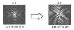
여기에 기술된 본 발명의 몇몇 실시예에서, 초점 라인은 원형 단면보다 오히려 비-축대칭 빔 단면을 가진다. 이로써, 몇몇 실시예에서, 투명 가공물 (7)로 지향된 펄스 레이저 빔의 일 부분은 파장 λ, 유효 스폿 크기


예를 들어, 초점 라인 빔 단면은 타원형일 수 있고, 그러한 실시예에서 초점 라인 (4')의 중심 부분 (4a')은 2 개의 직경 - 타원의 장축을 따른 최대 직경 및 타원의 단축을 따른 최소 직경을 가질 것이다. 적어도 몇몇 실시예에서, 최대 직경 대 최소 직경의 비는 1.1보다 크고, 예를 들어 1.3 (예를 들어, 1.2 내지 15.0, 또는 1.5 내지 3.0)보다 크다.For example, the focal line beam cross-section may be elliptical, in such an embodiment the
준 (quasi)-비 회절 빔 또는 초점 라인이 타원형 단면과 같은 비-축대칭 단면을 가질 때, 초점 라인에 의해 형성된 비-축대칭 스폿 내에서의 광학 세기는 전형적으로는 축대칭 초점 라인에 의해 형성된 원형 스폿 내의 세기보다 작은데, 이는 에너지가 타원의 장축 또는 또 다른 오블롱 (oblong) 단면 형상에 의해 더 넓어지기 때문이다. 부가적으로, 그러한 비 축-대칭 빔을 발생하는데 사용될 수 있는 많은 방법은 또 다른 것으로부터의 빔의 한 섹션을 디코셔링하는 단계를 포함한다. 이는 비 축-대칭 빔에 의해 형성된 2 개의 빔 세그먼트의 비간섭 성 (incoherent) 부가 때문에 세기가 부가적으로 손실된다는 것을 의미하며, 이는 일반적으로 축대칭 스폿을 형성하는 광의 간섭성 부가에 의해 만들어진 것보다 스폿 내에서 약해진 평균 세기를 초래한다. 이 2 개의 효과는 비 축-대칭 빔 형성 방법이 더 많은 대칭 비-회절 빔에 비해 고유의 에너지 단점을 겪는다는 것을 의미한다. GB 빔의 경우, 그러한 에너지 불이익은 특정 재료를 절단할 수 있는 것 또는 그렇지 않는 것, 에너지가 보다 긴 라인 길이에 걸쳐 퍼져 나가야 하는 재료의 보다 두꺼운 조각을 절단할 수 있는 것, 또는 하나의 레이저 빔을 2 개로 분할하여 장비 비용을 보다 효율적으로 만들 수 있는 것 사이의 차이를 만들 수 있다. 그러나, GB 빔보다 에너지 효율이 높은 MGB 빔의 사용은 MGB가 비 축-대칭 준-비 회절 빔인 경우 특히 유리할 수 있다. MGB 빔 프로파일을 사용하면, 비 축-대칭 빔을 사용하여 손실되는 에너지 효율 일부를 (초점 라인 내에서) 복구할 수 있다.When a quasi-non-diffracted beam or focal line has a non-axial cross-section, such as an elliptical cross-section, the optical intensity within the non-axially symmetric spot formed by the focal line is typically reduced by the axisymmetric focal line. It is less than the intensity in the formed circular spot, because the energy is broadened by the long axis of the ellipse or another oblong cross-sectional shape. Additionally, many of the methods that can be used to generate such a non-axially-symmetric beam include decorating one section of the beam from another. This means that the intensity is additionally lost due to the incoherent addition of the two beam segments formed by the non-axially-symmetrical beam, which is usually created by the coherent addition of light forming an axisymmetrical spot. resulting in a weaker average intensity within the spot. These two effects mean that non-axially-symmetric beamforming methods suffer from inherent energy disadvantages compared to more symmetric non-diffracted beams. In the case of a GB beam, such an energy penalty may or may not cut certain materials, the energy may cut thicker pieces of material that must be spread over a longer line length, or a single laser beam can be split in two to make the difference between what can make the equipment cost more efficient. However, the use of an MGB beam, which is more energy efficient than a GB beam, may be particularly advantageous when the MGB is a non-axial-symmetric quasi-non-diffracted beam. Using the MGB beam profile, it is possible to recover (within the focal line) some of the energy efficiency lost using a non-axially-symmetric beam.
여기에 도시된 플롯에서, 피크 세기 백분율 (y 축)은 또한 피크 광학 파워의 동일한 백분율에 대응한다는 것을 유의해야 한다. 피크 세기 및 피크 파워 둘 다는 (일반적으로 광학 축을 따른) 초점 라인의 주어진 빔 단면 내에서 관찰되는 최대 값이다.It should be noted that in the plots shown here, the peak intensity percentage (y-axis) also corresponds to the same percentage of the peak optical power. Both peak intensity and peak power are the maximum values observed within a given beam cross-section of the focal line (generally along the optical axis).
상기에서 논의된 바와 같이, 유리 기판에 홀을 생성하거나 유리를 절단하기 위해, 길이 L의 적어도 80%, 85%, 또는 90%를 따라 실질적으로 균일한 피크 세기 프로파일을 가진 초점 라인 (4')을 활용하는 것이 유리하다. MGB 빔을 갖는 (도 5a에 도시된 "탑 햇" 에너지 분포를 가진 초점 라인 (4')을 만들어 내는) 대표적인 광학 시스템 (125) (FLIMOS)에 대한 적절한 광학 표면을 계산할 때 고려해야 할 광학 시스템 특징은 도 7에 개략적으로 도시된다. 이러한 대표적인 실시예의 광학 시스템 (FLIMOS)은 입력 가우시안 베셀 빔 (2)을 MGB 빔 (2')으로 변환한다. 보다 구체적으로, 이러한 실시예에서, 가우시안 빔 (2)의 적어도 1/e2 세기 영역은 광학 시스템 (125) (FLIMOS)에 의해 초점 라인 (4')에 맵핑되어, 초점 라인 (4')의 길이 L을 따라 실질적으로 균일한 피크 세기 분포를 가진다. 몇몇 실시예에서, 광학 시스템 (125)은 입력 가우시안 빔의 1/e2의 적어도 1.2 배 사이에 포함된 에너지를 초점 라인 (4')에 맵핑한다. 몇몇 실시예에서, 광학 시스템 (125)은 입력 가우시안 빔 (2)의 1/e2 영역의 적어도 1.3 배 사이에 포함된 에너지를 초점 라인 (4')에 맵핑한다. 몇몇 실시예에서, 광학 시스템 (125)은 입력 가우시안 빔의 1/e2 영역의 적어도 1.5 배 사이에 포함된 에너지를 초점 라인 (4')에 맵핑한다. 몇몇 실시예에서, 광학 시스템 (125)은 입력 가우시안 빔의 1/e2 영역의 적어도 1.7 배 사이에 포함된 에너지를 초점 라인 (4')에 맵핑하고, 몇몇 실시예에서, 광학 시스템 (125)은 입력 가우시안 빔 (2)의 1/e2 영역의 적어도 2 배 사이에 포함된 에너지를 초점 라인 (4')에 맵핑한다. 광학 시스템 (125), 맵핑 및 실시예의 대표적인 특징, 상술된 맵핑 기능을 수행하는 광학 시스템(들) (125)뿐만 아니라, 도 7은 본 명세서에서 더 상세하게 개시된다.As discussed above, a focal line 4' having a substantially uniform peak intensity profile along at least 80%, 85%, or 90% of the length L for creating a hole in a glass substrate or cutting glass. It is advantageous to use Optical system characteristics to consider when calculating an appropriate optical surface for a representative optical system 125 (FLIMOS) with an MGB beam (which produces a focal line 4' with a "top hat" energy distribution shown in Figure 5a) is schematically illustrated in FIG. 7 . The optical system (FLIMOS) of this exemplary embodiment converts the input Gaussian Bessel beam (2) into an MGB beam (2'). More specifically, in this embodiment, the at least 1/e2 intensity region of the
몇몇 실시예에 따르면, 초점 라인 (4')은 레이저 빔 초점 라인의 광학 축을 따른 레이저 빔 초점 라인의 피크 세기가 결함 라인 (120)의 길이 L의 적어도 90%에 대해, 35%, 30%, 25%, 20%, 또는 15%, 또는 10% 또는 심지어 5% 초과로 변화하지 않도록 균일한 세기 프로파일을 가진다.According to some embodiments, the
적어도 몇몇 실시예에 따르면, 초점 라인의 직경 D은 길이 L에 대응하는 초점 라인 영역 내의 평균 직경으로부터 20% 초과로 변하지 않는다. 적어도 몇몇 실시예에 따르면, 초점 라인 (4')의 영역 L 내의 직경 D는 이 영역 내의 최대 직경으로부터 20% 초과로 변화하지 않는다. 초점 라인 (4')이 타원형 단면과 같은 비 축대칭 단면을 가지는 경우, 상기의 조건은 초점 라인의 중심을 포함하는 - 즉, 초점 라인의 피크 세기 코어 부분을 포함하는 임의의 초점 라인 단면에 대해 여전히 충족될 수 있다. 예를 들어, 초점 라인 (4')의 단면이 축대칭 (예를 들어, 타원형)이고, 초점 라인의 직경 D가 길이 L에 대응하는 초점 라인 영역 내의 평균 직경으로부터 20% 초과로 변화하지 않는 조건을 초점 라인이 만족하는 경우, 이는, 1) 초점 라인의 초점 라인의 최대 직경 Dmax이 길이 L에 대응하는 초점 라인 영역 내의 평균 최대 직경으로부터 20% 초과로 변화하지 않는 것; 및 2) 초점 라인의 타원형의 최소 직경은 또한 길이 L에 대응하는 초점 라인 영역 내의 평균 최소 직경으로부터 20% 초과로 변화하지 않는 것을 의미한다. 유사하게, 초점 라인 (4')의 단면이 타원형이고, 초점 라인의 직경 D가 길이 L에 대응하는 초점 라인 영역 내에서 이러한 영역 내의 최대 직경으로부터 20% 초과로 변화하지 않는 조건을 초점 라인이 만족하는 경우, 이는 다음을 의미한다:According to at least some embodiments, the diameter D of the focal line does not vary by more than 20% from the average diameter in the focal line region corresponding to the length L. According to at least some embodiments, the diameter D in the region L of the
1) 초점 라인의 초점 라인의 최대 직경 Dmax은 길이 L에 대응하는 초점 라인 영역 내의 평균 최대 값으로부터 20% 초과로 변화하지 않는 것; 및1) the maximum diameter Dmax of the focal line of the focal line does not vary by more than 20% from the average maximum in the focal line area corresponding to the length L; and
2) 초점 라인의 타원형의 최소 직경은 또한 길이 L에 대응하는 초점 라인 영역 내의 최대 값으로부터 20% 초과로 변화하지 않는 것2) the minimum diameter of the ellipse of the focal line also does not vary by more than 20% from the maximum in the focal line area corresponding to length L
적어도 몇몇 실시예에 따르면, 초점 라인 (4')의 직경 D는 초점 라인 (4')을 형성하는 광선의 각도 β'의 변동성을 제어함으로써 제어된다. 적어도 몇몇 실시예에 따르면, 초점 라인 (4')을 형성하는 광선의 각도 β'는 길이 L에 대응하는 초점 라인 영역 내의 광선의 평균 각도 (평균 β')로부터 10% 초과로 변화하지 않는다. 적어도 몇몇 실시예에 따르면, 초점 라인 (4')을 형성하는 광선의 각도 β'는 초점 라인 (4')의 길이 L에 대응하는 초점 라인 영역 내의 광선의 평균 각도 β'로부터 5% 초과로 변화하지 않는다. 초점 라인 (4')이 타원형 단면을 가지는 경우, 상기의 조건은 임의의 초점 라인 단면에 대해 만족된다. 예를 들어, 타원형의 최대 직경에 대응하는 초점 라인의 단면에서, 초점 라인 (4')을 형성하는 광선의 각도 β'는 15% 초과로 변화하지 않고, 보다 바람직하게 길이 L에 대응하는 초점 라인 영역 내의 광선의 평균 각도 β로부터 10% 초과로 변화하지 않는다. 또한, 타원형의 최대 직경에 대응하는 초점 라인의 단면에서, 초점 라인 (4')을 형성하는 광선의 각도 (β')는 길이 L에 대응하는 (이 단면의) 초점 라인 영역 내의 광선의 평균 각도 β로부터 10% 초과로 변화하지 않는다.According to at least some embodiments, the diameter D of the focal line 4' is controlled by controlling the variability of the angle β' of the rays forming the focal line 4'. According to at least some embodiments, the angle β′ of the rays forming the
적어도 몇몇 실시예에 따르면, 광학 빔 (2')의 (초점 라인의 중심을 포함하는) 주어진 단면에 대해, 초점 라인 (4')을 형성하고 광선 높이 hi에 대응하는 광선의 각도 β'는 광학 빔 (2)의 1/e2지점 내에 위치하는 임의의 광선에 대해 광선 높이 hi-1에 대응하는 광선의 수렴 각도 β'로부터 10% 초과로 변화하지 않는다. 적어도 몇몇 실시예에 따르면, 초점 라인 (4')을 형성하고 광선 높이 hi에 대응하는 광선의 각도 β'는 반경 Rz' 내에 위치된 광학 빔 (2)의 임의의 광선 위치에 대해, 광선 높이 hi-1에 대응하는 광선의 각도 β'로부터 10% 초과로 변화하지 않고 (예를 들어 7% 미만 또는 심지어 5% 미만, 또는 3% 이하), 여기서 Rz=1.1Rz이다. 적어도 몇몇 실시예에 따르면, 초점 라인 (4')을 형성하고 광선 높이 hi에 대응하는 수렴 광선의 각도 β'는 반경 Rz' 내에 위치된 광학 빔 (2)의 임의의 광선에 대해, 광선 높이 hi-1에 대응하는 광선의 각도 β'로부터 10% 초과로 변화하지 않고, 여기서 Rz'=1.2Rz이다. 적어도 몇몇 실시예에 따르면, 초점 라인 (4')을 형성하고 광선 높이 hi에 대응하는 광선의 수렴 각도 β'는 반경 Rz' 내에 위치된 광학 빔 (2)의 임의의 광선에 대해, 광선 높이 hi-1에 대응하는 광선의 각도 β'로부터 10% 초과로 변화하지 않고 (예를 들어, 7% 미만 또는 심지어 5% 미만), 여기서 Rz'=1.3Rz이다.According to at least some embodiments, for a given cross-section (including the center of the focal line) of the optical beam 2', the angle β' of the ray forming the focal line 4' and corresponding to the ray height hi is For any ray located within the
도 7은 본 발명의 몇몇 실시예에 따른 광학 시스템 (125) (FLIMOS)의 일 실시예를 개략적으로 도시한다. 광학 시스템 (125)은 레이저 소스 (5)에 의해 제공된 입사 가우시안 빔 (2)으로부터 변형 가우스-베셀 (MGB) 빔 (2')을 발생시키고, 특정 거리 z에 대해 결함 라인 (120)의 길이를 적어도 따른 광학 축 상에서 실질적으로 균일한 광학 세기 프로파일 (예를 들어, 거의 "탑 햇" 세기 분포)을 갖는 초점 라인 (4')을 생성한다.7 schematically illustrates one embodiment of an optical system 125 (FLIMOS) in accordance with some embodiments of the present invention. The
광학 축을 따라 실질적으로 일정한 피크 세기를 가짐과 동시에 초점 라인 (4')의 각각의 서브-섹션에서 실질적으로 일정한 빔 직경 D를 가진 초점 라인 (4')을 생성하기 위해, 광학 시스템 (125)은 다음의 두 가지 조건을 바람직하게 만족한다.To produce a focal line 4' having a substantially constant peak intensity along the optical axis while at the same time having a substantially constant beam diameter D in each sub-section of the focal line 4', the
우선, 빔 (2) 내의 동일한 에너지 양 부분이 동일한 또는 실질적으로 동일한 길이 X'의 섹션을 따라 초점 라인 영역 (4') 내의 광학 축으로 재이미징화되는 것이 바람직하다 (조건 1). 이 조건은 초점 라인 (4')의 부분 L의 적어도 90% 내에서 실질적으로 일정한 피크 세기를 생성한다.First of all, it is preferred that a portion of the same amount of energy in the
둘째, 초점 라인 (4')을 형성하는 수렴 광선의 각도 β는 또한 서로 실질적으로 동일해야 한다 (조건 2). 이 조건은 초점 라인 (4)의 부분 L의 적어도 90% 내에서 실질적으로 일정한 직경 D을 생성하는 것을 돕는다.Second, the angles β of the converging rays forming the focal line 4' must also be substantially equal to each other (condition 2). This condition helps to produce a substantially constant diameter D within at least 90% of the portion L of the
이로써, 빔 (2)의 가우시안 에너지 분포가 동일한 파워의 환형 링 으로 세분화될 때 (그러나 반드시 동일한 폭 wi일 필요는 없음), 광학 시스템 (125)은 각각의 링 내의 에너지를 이미지화하여, 폭 wi의 각 링 내의 에너지가 동일하거나 실질적으로 동일한 길이를 가진 초점 라인 (4')의 영역 내에 포함된다 (Xi'
일 실시예에 따르면, 이러한 이들 조건을 만족시키기 위해, 다음과 같이 진행한다:According to one embodiment, to satisfy these conditions, proceed as follows:
● 입력 가우시안 빔 (2)은 광선 높이 hi에 각각 대응하는 일련의 링으로 이산화되며, i는 1로부터 임의의 수 N까지 가고, N은 바람직하게 100 미만 (예를 들어, 5≤N≤20), 최대 광선 높이 Rz'=hiMax, 여기서 Rz'≥0.9Rz이다. 바람직하게는, 초점 라인 (4 및/또는 4')의 말단부에서 일어날 수 있는 원치 않는 에너지 스파이크(들)를 최소화하기 위해, 방사상 거리 Rz'는 가우시안 빔 (2)의 1/e2 반경에 대응하는 반경과 적어도 동일하다 (즉, Rz'≥Rz). 몇몇 실시예에 따르면, Rz'는 가우시안 에너지 (세기)가 적어도 1.1 배의 1/e2 반경인 빔 (2) 내의 방사상 거리에 대응한다 (즉, Rz'≥1.1Rz). 몇몇 실시예에 따르면, Rz'≤2 배의 1/e2 반경이다 (즉, Rz'=2Rz). 몇몇 실시예에 따르면, Rz≤1.7 x1/e2 (즉, Rz'≤1.7Rz)이다. 몇몇 실시예에 따르면, Rz'는 1.1 배의 1/e2과 1.5 배의 1/e2사이의 (즉, 1.1 Rz≤Rz'≤1.5Rz) 세기 레벨에 대응하는 빔 (2) 내의 방사상 거리이다. 몇몇 실시예에 따르면, Rz'는 1.1 내지 1.3 배의 1/e2 (즉, 1.1 Rz≤Rz'≤1.3Rz)인 세기 레벨에 대응하는 빔 (2) 내의 방사상 거리이다.• The input
● 상술된 각 링의 높이 hi(예를 들어, 도 8a 참조)는 2 개의 인접한 링 (hi 및 hi+1) 사이의 임의의 고리 안에 포함된 광학 파워 또는 세기가 일정하도록 하는 방식으로 선택되거나 계산된다.The height hi of each ring described above (see, for example, FIG. 8A ) is such that the optical power or intensity contained within any ring between two adjacent rings (hi and hi+1 ) is constant. selected or calculated.
● 광학 시스템 (125)으로 전파될 때, 각 링 hi으로부터 비롯된 광선은 초점 라인 (4')을 따라 광학 축 OA 상의 위치 xi에서 광학 시스템 (125)에 의해 이미징된다. 초점 라인 (4')의 길이를 따라 실질적으로 균일한 조사 프로파일 (실질적으로 균일한 피크 세기 분포)을 달성하기 위해, 제 1 조건은, 각 세트의 광선 [i, i+1]에 대한 광학 축 교차 지점 [xi, xi+1]에 의해 정의된 각 서브-섹션의 길이가 실질적으로 동일한 길이 Xi'를 가진다 (예를 들어, 공차 ±15%, 바람직하게 ±10%, 및 몇몇 실시예에 따르면, ±5% 이하)는 것이다.When propagating into the
둘째, 초점 라인의 각 서브-섹션에서 빔의 직경은 광선 각도 β'에 의해 결정된다. 이로써, 여기에서 기술된 적어도 몇몇 대표적인 실시예에 따라서, 초점 라인을 따른 일정한 빔 직경을 확보하기 위해서, 광학 시스템 (125) (FLIMOS)에 의해 만족되는 제 2 조건은, 각 광선 [i]에 대한 각도 β'가 예를 들어, 공차 ±20%, 또는 ±15%, 바람직하게 ±10% 또는 심지어 ±10% 또는 ±5%, 또는 그 미만으로 일정해질 필요가 있다는 것이다. 각도 β'를 실질적으로 일정하게 만드는 조건이 제시되는데, 이는 그러한 제약 없이, 초점 라인 (4')의 직경 D가 변화할 것이기 때문이다. 직경 D에서의 변화는 초점 라인의 그 섹션 내에서 광학 세기에서 상응하는 변화를 야기시킬 것이다. 직경 D에서의 매우 심각한 변화 (큰 변화)는 유리 영역 중 몇몇에서, 또는 유리를 손상시키거나, 일관성 없는 손상을 만들어낼 수 있는 너무 많은 마이크로 크랙에서, 유리 내의 어떠한 손상도 초래하지 않을 수 있다 (예를 들어, 어떠한 홀 형성도 없음).Second, the diameter of the beam in each sub-section of the focal line is determined by the ray angle β'. Thus, in accordance with at least some representative embodiments described herein, in order to ensure a constant beam diameter along the focal line, the second condition satisfied by the optical system 125 (FLIMOS) is that for each ray [i] that the angle β' needs to be constant, for example with a tolerance of ±20%, or ±15%, preferably ±10% or even ±10% or ±5%, or less. A condition is given to make the angle β' substantially constant, since without such constraint, the diameter D of the focal line 4' will change. A change in diameter D will cause a corresponding change in optical intensity within that section of the focal line. A very severe change (large change) in diameter D may not cause any damage in the glass, in some of the glass areas, or in too many microcracks that can damage the glass or create inconsistent damage ( For example, no hole formation).
도 8a는 광학 시스템 (125)의 광학 구성요소 (3')를 도시한다. 이러한 실시예에서, 광학 구성요소 (3')는 변형 액시콘이다. 도 8a에 도시된 실시예에서 알 수 있는 바와 같이, 광학 구성요소 (3')는 일정한 경사를 가진 액시콘의 전형적인 원뿔형 표면이 아닌, 대신에 보다 복잡한 프로파일 (예를 들어, 표면의 경사가 방사상 방향으로 8 개의 변화가 있을 시에 표면에 걸쳐 변화하도록 형상화된 비구면 프로파일)을 가진 표면인 표면 (3a')을 가진다. 이러한 실시예에서, 도면에서 알 수 있는 바와 같이, 광학 구성요소 (3')의 표면 (3a')은 거리 z에 대해 초점 라인 (4') 내에서 광 빔의 피크 세기를 실질적으로 균일하게 유지시키는 약간의 기복 (단면으로 도시된 경사 변화)을 가진다. 보다 상세하게는, 이 실시예에서, 광학 구성요소 (3')의 표면 (3a')은 가변 곡률 반경을 가진다 - 표면 (3a')의 형상은, 이 표면에서 충돌하는 광선이 약간 상이한 표면 형상과 부딪히고 굽혀져 초점 라인을 향해 수렴되어 초점 라인 (4)의 길이를 따라 실질적으로 균일한 피크 세기 프로파일을 달성하고, 이로써 길이 초점 라인 (4')을 따라 균일한 피크 세기 프로파일을 달성하도록 변화된다. 그러나, 도 8b에 개략적으로 도시된 바와 같이, 적어도 하나의 광학 표면 (3a')을 갖는 상이한 광학 구성요소 (3') 그 예로 변형 왁시콘 (waxicon), 변형 반전 액시콘 (굴절 또는 반사), 또는 비구면 구성요소 (원뿔형 또는 비-원뿔형) 또한 활용될 수 있고, 상기 광학 표면은 이 표면에 충돌하는 광선이 약간 상이한 표면 형상과 부딪히고 굽혀져 초점 라인을 향해 수렴되어 초점 라인의 길이 L을 따라 실질적으로 균일한 조사 프로파일 (이로써 실질적으로 균일한 피크 세기 프로파일)을 달성하도록 변화한다. 광학 구성요소 (3')는 예를 들어 상기 2 개의 조건을 만족시키는 공간 광 변조기 또는 격자일 수 있다.8A shows the
보다 상세하게는, 도 8a 실시예에서, 광학 구성요소 (3')는, 서브-섹션당 일정한 에너지 (이로써 일정한 피크 세기)가 있도록, 즉 각 세트의 광선 [i, i+1]에 대한 광학 축 교차 지점 [xi, xi+1]에 의해 정의된 각 서브-섹션의 길이 모두가 실질적으로 동일한 길이 Xi'를 가지도록 (공차 약 ±10%로), 광선을 포갠다 (folds). 광학 구성요소 (3')의 표면 (3a')은, 예를 들어, 도 1에 도시된 것과 유사한 액시콘 구성요소로 시작함으로써, 그 후에 특정 높이 (hi)를 가진 특정 광선이 광학 축과 교차하여 표면 (3a')을 정의해야 하는 곳을 명시하면서 표면의 비구면 계수를 변화시켜 (상용 렌즈 설계 프로그램을 사용하여 설계의 사용을 통해) 구성요소의 표면 (3a)을 최적화시킴으로써, 설계될 수 있다. 대안적인 해결책은, 점 (xi, xi+1)을 거쳐 광선을 거꾸로 추적하고 이들 광선이 광학 구성요소 (3')의 입력 측 상의 광선 높이 (hi,...hN)에 대응하도록 광학 표면 (3a')과 교차해야 하는 곳을 계산하는 것이다. 교차 지점은 광학 구성요소 (3')의 표면 (3a')을 정의할 것이다.More particularly, in the FIG. 8a embodiment, the optical component 3' is configured such that there is a constant energy per sub-section (and thus a constant peak intensity), ie the optics for each set of rays [i, i+1]. The rays are folded such that all of the lengths of each sub-section defined by the axis intersection [xi , xi+1 ] have substantially the same length Xi ' (with a tolerance of about ±10%). The
도 8a에 도시된 바와 같이, 그 결과로 변형된 액시콘 (3')이 동공 높이 (pupil height) hi를 각각 갖는 일련의 링으로 i 분할되는 가우시안 빔 (2)으로 제공될 때 (i는 1로부터 임의의 수 N까지 가고 (각 링의 높이는 2 개의 인접한 링 (hi 및 hi+1) 사이에 임의의 고리 안에 포함된 에너지 (파워)가 일정하도록 하는 방식으로 계산됨)), 각 세트의 광선 [i, i+1]에 대한 광학 축 교차 지점 [xi, xi+1]에 의해 정의된 각 서브-섹션의 길이가 실질적으로 서로 동일하다 (예를 들어, 공차 ±15%, 바람직하게 ±10%, ±5%, 또는 그 미만).As shown in Fig. 8a, when the resulting deformed axicon 3' is provided as a
그러나, 도 8a에서 알 수 있는 바와 같이, 초점 라인 (4)을 형성하는 각 광선 [i]에 대한 각도 β는 광선이 광학 구성요소 (3')를 빠져나갈 때 일정하지 않다. 즉, 도 8a의 변형 액시콘은, (적당하게 설계된 재-이미징 시스템 (6) 없이) 단독으로 사용될 때, 상기의 두 조건 중 하나만을 만족시킨다. 초점 라인 (4)에서 각 단위 길이로부터 일정한 에너지 (일정한 피크 세기)를 달성할 수 있지만, 광선은 초점 라인 (4)의 직경에 영향을 미칠 약간 상이한 수렴 각도 β로 변형 액시콘으로 수렴하고 있다. 예를 들어, 광선은 서로 평행을 유지하기보다는 오히려 상이한 각도로 수렴하고 있다. 부가적으로, 광학 구성요소 (3')의 팁에 인접한 광선은 발산한다. 이 구역이 비교적 큰 경우, 광학 구성요소의 팁 근처에서 바람직하지 않은 에너지 스파이크를 생성할 수 있다. 초점 라인 (4)을 형성하는 수렴 광선의 상이한 광선 각도 β를 보정하지 않는 광학 시스템 (6)에 의해 초점 라인이 재이미징화되는 경우, 그 결과적인 초점 라인 (4')은 실질적으로 일정한 직경 D를 가지지 않을 것이다.However, as can be seen in FIG. 8A , the angle β for each ray [i] forming the
이에 따라서 상기에서 논의된 제2 조건을 충족시키기 위해서 - 즉, 광학 시스템 (125) (FLIMOS)을 빠져나가는 각 광선에 대해 실질적으로 동일한 각도 β'를 가지기 위해서, 비구면 표면을 갖는 또 다른 광학 구성 요소를 활용하는 것이 유익할 수 있다. 이러한 구성요소는, 예를 들어, 재이미징 시스템 (6')의 비구면 렌즈일 수 있다. 도 9a는 재이미징 광학 시스템 (6') 및 대표적인 광학 구성요소 (6a 및 6b)을 도시하며, 그 중 하나는 비구면 표면을 갖는 렌즈이다. 이러한 구성요소는 또한, 예를 들어, n 비구면을 갖는 반사 구성요소일 수 있다.Thus another optical component having an aspherical surface in order to satisfy the second condition discussed above - ie to have substantially the same angle β' for each ray exiting the optical system 125 (FLIMOS). It may be beneficial to use This component may be, for example, an aspherical lens of the
보다 구체적으로, 몇몇 실시예 (예를 들어, 도 9b 참조)에서, 변형 액시콘 (3')은 재-이미징 렌즈 시스템 (6')의 적어도 하나의 구성요소와 함께 사용되어, 초점 라인 (4')을 형성하는 방사상 거리 Rz' 내에 포함된 빔 (2) 내의 광선에 대응하는 각 광선 [i]에 대해 실질적으로 일정한 각도 β'를 제공할 수 있다 (예를 들어, 모든 각도 β'는 서로 ±15% 내에 있음). 바람직하게, 여기에 기술된 실시예에 도시된 바와 같이, 초점 라인 (4')을 형성하도록 수렴하는 모든 광선은 서로 ±10% 내에, 보다 바람직하게 ±5% 내에 있는 각도 β'로 수렴된다. 이들 실시예에서, 재-이미징 렌즈 시스템 (6')은 도 2에 도시된 것과 유사한 광학 구성요소 (6a' 및 6b')를 포함하지만, 광학 구성요소 (6a', 6b') 중 적어도 하나는 비구면 표면을 가진다. 이로써, 이미징 시스템 (6')의 광학 구성요소 (6a', 6b')는 레이저 빔 초점 라인 (4')으로서 연장된 포커스 (즉 초점 라인)을 재이미징화하여, 광선이 광학 구성요소 (6b')를 빠져나갈 때에 초점 라인 (4')을 형성하기 위해 수렴된 각 광선[i]에 대한 각도 β'는 실질적으로 일정하다. 몇몇 실시예에서 Rz'=Rz이고, 몇몇 실시예에서Rz'는 Rz보다 크지만 3Rz보다 작다. 몇몇 실시예에서, Rz'는 Rz보다 크지만 2Rz이하이다. 몇몇 실시예에서, Rz'≤1.5Rz이다. 몇몇 실시예에서Rz'는 적어도 1.2Rz이다.More specifically, in some embodiments (see, eg, FIG. 9B ), the
바람직하게, 몇몇 실시예에 따르면, 광학 시스템 (125) (FLIMOS)은 서로 이격된 적어도 2 개의 비구면 광학 구성요소를 활용하고, 광학 시스템 설계 중에, 하나 또는 둘 광학 구성요소의 하나 이상의 비구면 계수 (하기에 기술된 고차 비구면 계수 또는 비구면 계수 (a2-a12)로도 지칭됨)을 조정하여 두 조건을 충족시킨다. 예를 들어, 광학 시스템 (125) (FLIMOS)의 적어도 하나의 광학 구성요소는 예를 들어 예제 1 실시예에 도시되고 표 1을 참조하여 기술된 바와 같이 하나 이상의 비-제로 비구면 계수 (a2-a12)에 의해 기술된 비구면 표면을 가질 수 있다.Preferably, according to some embodiments, optical system 125 (FLIMOS) utilizes at least two aspherical optical components spaced apart from each other and, during optical system design, one or more aspherical coefficients of one or both optical components (below Both conditions are met by adjusting the higher-order aspheric coefficients or aspheric coefficients (also referred to as a2 -a12 ) described in . For example, at least one optical component of optical system 125 (FLIMOS) may have one or more non-zero aspherical coefficients (a2 - a12 ) as described by ).
하기에 기술된 실시예는 한 쌍의 그러한 비구면 구성요소를 활용한다. 그러나, 2 개 초과의 비구면 구성요소 또한 활용될 수 있고, 광학 시스템 (125)의 비구면 구성요소는 하나 또는 두 개의 비구면 표면을 가질 수 있다.The embodiments described below utilize a pair of such aspherical components. However, more than two aspherical components may also be utilized, and the aspherical component of
다양한 실시예는 다음 예제에 의해 더 명확해질 것이다.Various embodiments will be further clarified by the following examples.
예제 1Example 1실시예Example
도 9a는 다음의 특성을 가진 변형 가우스-베셀 빔을 형성하도록 구성된 굴절 광학 시스템 (125)을 도시한다: (i) 적어도 거리 Z (또는 초점 라인의 길이 L)에 대한 실질적으로 균일한 파워 분포 및 (ii) 실질적으로 일정한 직경 D. 도 9a는 광학 시스템 (125)의 이러한 실시예가 비구면 표면 (3a')을 갖는 변형 액시콘 (3') 및 적어도 2 개의 광학 구성요소 (6a' 및 6b')를 포함하는 재-이미징 렌즈 시스템 (6')을 포함하는 것을 도시한다. 광학 구성요소 (6a')는 이 실시예에서 광학 구성요소 (6b')를 향하는 비구면 표면 (이 도면에서는 L1 비구면으로 나타냄)을 포함한다. 이러한 실시예에서, 제2 광학 구성요소 (6b')는 비구면 표면을 가지지 않고, 상이한 초점 길이의 또 다른 렌즈 구성요소로 쉽게 대체될 수 있어서, 초점 라인의 배율을 변화시킨다. 그러나, 몇몇 실시예에서, 이는 비구면 표면을 가질 수 있다. 도 9b는 도 9a의 대표적인 광학 구성요소의 형상을 도시한다. 이 도면에서, T1, T2, T3, T4는 각 유리 요소의 두께이고, S1, S2 및 S3는 광학 축을 따르는 광학 요소들 사이의 공간 (이들은 축척대로 도시되지 않음)이고, R1-R8은 각각의 광학 요소의 곡률 반경을 나타낸다. 구성요소 또는 요소는 "그룹"에 위치된다. 예를 들어, 도 9b에 도시된 바와 같이, 그룹 "A"는 변형 액시콘 (3')에 대응되고, 그룹 "B"는 렌즈 구성요소 (6a)에 대응되며, 그리고 그룹 "C"는 렌즈 구성요소 (6b)에 대응된다 (더블릿, doublet). 하기의 표 1은 도 9a 및 도 9b에 도시된 굴절 광학 시스템 (125)의 실시예에 대한 광학 파라미터를 제공한다.9A shows a refractive
이 실시예에서 F1=125 mm; F2=40 mm, 및 F1+F2=165 mm이다. 표 1의 실시예의 반경 R2 and R4에 대응하는 표면에 대한 원뿔 상수 (원뿔 상수)/비구면 계수가 하기에 제공되며, 식 1.3으로 기술된다.F1 = 125 mm in this example; F2=40 mm, and F1+F2=165 mm. The conic constants (conic constants)/aspheric coefficients for the surfaces corresponding to the radii R2 and R4 of the examples in Table 1 are given below and are described in Equation 1.3.
비구면 표면은 형상이 다음 식에 의해 기술되는 표면이다An aspherical surface is a surface whose shape is described by the equation


여기서 z'는 표면 새그 (surface sag)이고, r은 방사상 방향에서 광학 축으로부터의 표면 높이 (예를 들어, 표면 단면에 의존하여 x 또는 y 높이)이고, c는 표면 곡률 (즉, ci=1/Ri)이고, k는 원뿔 상수이며, 그리고 계수 ai는 표면을 기술하는 1 차 내지 12 차 비구면 계수 또는 고차 비구면 계수 (다항식 비구면)이다.where z' is the surface sag, r is the surface height from the optical axis in the radial direction (e.g., x or y height depending on the surface cross-section), and c is the surface curvature (i.e. ci = 1/Ri ), k is the conic constant, and the coefficient ai is the first to twelfth order aspheric coefficient or higher order aspheric coefficient (polynomial aspheric) describing the surface.
표 1 실시예에서, 광학 구성요소 (3')는 다음 계수 a1-a7, 각각: -0.085274788; 0.065748845; 0.077574995; -0.054148636; 0.022077021; -0.0054987472; 0.0006682955에 기술된 표면 (3a') (표 1에서 R2에 대응됨)을 가지며; 그리고 비구면 계수 a8-a12는 0이다. 이러한 실시예에서, 이러한 표면 (3a')은 원뿔 상수 K=0을 가지지만, 그러나 a1 계수는 비-제로 값을 갖는 원뿔 상수 K를 가지는 것과 동등한 0이 아닌 값을 가진다. 이에 따라서, 동등한 표면은 비-제로인 원뿔 상수 K 또는 계수 a1 계수에 대한 비-제로 제로 값 (또는 비 제로 K 및 a1의 조합)을 규정함으로써 기술될 수 있다.In the Table 1 example, the optical component 3' has the following coefficients a1 -a7 , respectively: -0.085274788; 0.065748845; 0.077574995; -0.054148636; 0.022077021; -0.0054987472; has the surface (3a') described in 0.0006682955 (corresponding to R2 in Table 1); and the aspheric coefficient a8 -a12 is zero. In this embodiment, this
표 1의 실시예에서, R4에 대응하는 광학 요소의 표면 (그룹 B 구성요소)는 원뿔 상수 K= 4.518096을 가지며; 그리고 계수 a1-a12은 0이다. 구성요소 (6a)의 대안 실시예에서, 표면들 중 하나는 고차 비구면 계수 a2 내지 a12에 의해 정의되고, 그 중 적어도 하나는 비-제로 값을 가진다.In the example of Table 1, the surface of the optical element corresponding to R4 (group B component) has a conical constant K=4.518096; And the coefficient a1 -a12 is zero. In an alternative embodiment of
표 1의 실시예에서, 표면 중 적어도 하나는 비-제로 값 (즉, a2,a3,... , a12≠0 중 적어도 하나)을 갖는 적어도 하나의 고차 비구면 계수 a2-a12에 의해 기술되거나 정의되며, 그리고 적어도 하나의 또 다른 표면은 비 제로 원뿔 상수 또는 a2 내지 a12로부터 선택된 적어도 하나의 비-제로 더 높은 비구면 계수 (즉, K≠0 및/또는 적어도 하나의 a2 내지 a12은 0이 아님)에 의해 기술된다.In the examples of Table 1, at least one of the surfaces has a non-zero value (ie, a2 ,a3 ,.____ at least onenon- zero higher aspheric coefficient selected from
예제 2Example 2
도 10a 및 10b는 다음 특성을 가진 변형 가우스-베셀 빔을 형성하고 있는 반사 광학 시스템 (125)의 실시예를 도시한다: (i) 적어도 초점 라인 (4')의 거리 0.9L에 대해 실질적으로 균일한 피크 세기 분포; 및 (ii) 실질적으로 일정한 직경 D. 이러한 실시예에서, 직경 D는 적어도 초점 라인 (4')의 거리 0.9L에 대해 최대 값으로부터 20% 초과로 변화하지 않는다. 도 10a는 광학 시스템 (125)의 이 실시 예가 반사 비구면 표면 (3a')을 갖는 변형 반사 액시콘 (3'), 및 비구면 표면을 갖는 단일 반사 구성요소 (6a')를 포함하는 재-이미징 시스템 (6')을 포함하는 것을 도시한다. 도 10a 및 도 10b의 반사 실시예는 도 9a 및 9b에 도시된 굴절 실시예와 광학적으로 동등하며, 그리고 도 5a에 도시된 것과 유사한 "탑 햇" 유형의 세기 프로파일을 제공하기 위하여, 유사한 방식으로 설계된다. 반사 구성요소 중 적어도 하나가 적어도 하나의 고차 비구면 계수 (비-제로인 a2, a3, ..., a12)에 의해 적어도 부분적으로 정의되는 표면을 가진다는 것을 유의한다.Figures 10a and 10b show an embodiment of a reflective
상술된 바와 같이, 적어도 몇몇 대표적인 실시예에 따르면, 광학 시스템 (125)의 설계는 입사 가우시안 빔 (2)을 일련의 링으로 분할 또는 이산화하여 광선이 광학 축을 따라 이미징화되는 것을 포함한다: 1) 적당한 곳에서 (at the right place) (즉, 각각의 링 내에 포함된 빔 부분이 실질적으로 동일한 길이 (즉, 사전 섹션의 것의 플러스 또는 마이너스 15%, 10%, 및 바람직하게는 5% 또는 심지어 2% 이내)를 가진 광학 축의 섹션을 따라 맵핑되도록); 및 2) 적당한 각도로 (즉, 실질적으로 동일한 각도 (β'), 예를 들어 플러스 또는 마이너스 15%, 10%, 및 바람직하게 5% 또는 심지어 2% 이내). 즉, 적어도 반경 Rz'≥1Rz (및 보다 바람직하게Rz≤Rz'≤1.7Rz, 예를 들어, 1.1Rz≤ Rz'≤1.3Rz일 때)의 가우시안 빔 (2)에 대해, 입사 가우시안 빔 (2)이 일련의 링으로 분할되어 동일한 양의 광학 파워 (또는 세기)가 레이저 빔 초점 라인을 형성하는 광선 각 링에 위치될 때, 광선은 광학 축을 따른 광학 시스템 (125) (FLIMOS)에 의해 이미징화되고 그 결과: 각 링 내에 포함된 연속하는 빔 부분은, 실질적으로 동일하고 실질적으로 동일한 출사 각 (β')을 가진 광학 축의 섹션을 따라 맵핑된다는 것을 결정했다.As described above, according to at least some representative embodiments, the design of the
초점 라인 (4')의 발생은, 상술된 바와 같이, MGB (변형 가우시안 빔)를 통해 수행될 수 있다. 그러나, 예를 들어, 변형 에어리얼 (Airy) 빔, 또는 타원형 중앙 스폿을 가지기 위해 변형된 가우스-베셀 빔과 같은 다른 형태의 변형 저속 회절 또는 준 비-회절 빔이 또한 사용될 수 있다. 이로써, 다른 실시예에 따르면, 광학 구성요소 (3')는 변형 액시콘일 필요는 없지만, 광학 구성요소 (3')가 실질적으로 균일한 피크 세기 분포를 제공하도록 구성되는 한, 변형 저속 회절 또는 비-회절 빔을 제공하도록 구성된 임의의 광학 구성요소일 수 있고, 그 결과 입사되는 저속 회절 또는 비-회절 빔 내의 동일한 에너지의 링은, 동일한 또는 실질적으로 동일한 길이 Xi' (예를 들어, 30%, 25%, 20% 이내, 및 바람직하게는 15% 이하 이내)를 가지기 위해, 초점 라인 (4')을 따른 광학 구성요소 (3')에 의해 (또는 광학 구성요소 (3')를 포함하는 광학 시스템 (125)에 의해) 광학 축을 따라 맵핑된다.Generation of the focal line 4' can be performed via MGB (modified Gaussian beam), as described above. However, other types of modified slow diffracted or quasi-diffracted beams may also be used, such as, for example, a modified Airy beam, or a Gauss-Bessel beam modified to have an elliptical central spot. Thus, according to another embodiment, the optical component 3' need not be a modified axicon, but as long as the optical component 3' is configured to provide a substantially uniform peak intensity distribution, a strained slow diffraction or ratio -can be any optical component configured to provide a diffracted beam, such that rings of equal energy in an incident slow diffracted or non-diffracted beam have the same or substantially equal length Xi ' (eg, 30% , within 25%, within 20%, and preferably within 15%) by (or including the optical component 3') along the focal line 4', by the optical system 125) along the optical axis.
하기의 표 2는 굴절 광학 시스템 (125)의 또 다른 실시예에 대한 광학 파라미터를 제공한다.Table 2 below provides optical parameters for another embodiment of a refractive
이 실시예에서, F1=120 mm; F2=29.115 mm, 및 F1+F2=149.115 mm이다. 표 2의 대표적인 실시예에 대한 원뿔 상수/비구면 계수는 식 1.3에 의해 기술되고 다음과 같다:In this example, F1=120 mm; F2=29.115 mm, and F1+F2=149.115 mm. The conic constant/aspheric modulus for the representative example in Table 2 is described by Equation 1.3 and is:
그룹 A에 대한 비구면 조건 (표 2에서의 해당 반경 R2)은 다음과 같다:The aspheric conditions for group A (corresponding radius R2 in Table 2) are as follows:
k=0 및 a1= -0.085274788 ; a2= - 0.065748845 ; a3=0.077574995;k=0 and a1 = -0.085274788 ; a2 = - 0.065748845 ; a3 =0.077574995;
a4= -0.054148636 ; a5=0.022077021 ; a6= -0.0054987472 ; a7=0.0006682955.a4 = -0.054148636 ; a5 =0.022077021 ; a6 = -0.0054987472 ; a7 =0.0006682955.
R4에 대응하는 광학 요소의 표면 (그룹 B 구성요소)은 원뿔 상수 k= 9.331346를 가지며; 그리고 계수 a1-a12는 0이다.The surface of the optical element corresponding to R4 (group B component) has a conical constant k=9.331346; And the coefficient a1 -a12 is zero.
실험 결과Experiment result
파라미터 Rz' (파라미터 Rz'는 초점 라인 (4')을 따른 세기가 맵핑되어 가장 균일하게 되도록 빔 (2)의 최대 높이임)에 대한 상이한 값을 초점 라인의 품질에 관한 선택 영향이 평가되고 실험적으로 검증되었다.Different values for the parameter Rz' (parameter Rz' is the maximum height of the
도 9a에서와 유사한 여러 굴절 광학 시스템 (125) (FLIMOS)이 광학 구성요소 (3') 및 렌즈 구성요소 (6a')의 비구면 표면 (3a')을 형성하기 위해 BaF2 재료를 다이아몬드 턴닝함으로써 (diamond turning) 제조되어, 제조된 광학 시스템 (125)의 실시예는 두 조건 둘 다를 15% 공차 이내로 만족시켰다. 도 9a의 대표적인 실시예에서, 표면 (3a')은 도 8a의 표면 (3a')과 형상이 유사하고, 부가적으로 구성요소 (6a')의 비구면 표면은 초점 라인 (4')을 형성하는 수렴 광선이 서로 실질적으로 평행하도록 광학 구성요소 (6b')를 빠져나가는 광선을 재이미징하는 것을 돕는다. 광학 시스템 (125)은 가우시안 세기 프로파일을 가진 입사 시준 레이저 빔 (2)을 사용하여 테스트되었다. 그러나, 광학 시스템 (125)의 상이한 실시예에서, 조정가능한 직경 아이리스 (iris)를 사용하여, 상이한 방사상 높이 (Rz')에서 가우시안 빔 (2)의 끝을 절단하였다 (truncated). 상술된 바와 같이, 방사상 높이 (Rz')까지의 가우시안 빔 (2)은 동일한 파워의 복수의 링으로 세분화되었다. 링 N의 수는 예를 들어 4 내지 100이지만, 바람직하게 4 내지 20, 예를 들어 5 내지 15, 또는 5 내지 10일 수 있다. 광학 시스템 (125)의 성능은 그 후에 초점 라인 (4')을 이미지화하기 위해 CCD 카메라 및 60X 현미경 대물렌즈를 사용하여 실험실에서 평가되었다. 광학 축을 따라 현미경 대물렌즈 및 CCD 카메라를 스캔함으로써, 초점 라인 (4')의 일련의 단면 프로파일이 조립되고, 광학 축을 따른 위치의 함수로서 피크 세기가 계산되었다.Several refractive optical systems 125 (FLIMOS), similar to those in FIG. 9A, by diamond turning BaF2 material to form the
도 11a는 광학 시스템 (125)의 제1 대표적인 실시예에 의해 만들어진 광학 축 OA의 거리의 함수로서, 초점 라인 (4')의 피크 세기의 측정된 결과를 도시한다. 광학 시스템 (125)의 이러한 실시예에서, Rz' = Rz =1.5 mm이다. 즉, 광학 구성요소 (3', 6a')는 입력 가우시안 빔을 초점 라인으로 맵핑하도록 설계되었고, 그 결과 1/e2 지점 내에 포함된 입력 빔 (2)의 부분에 대해: 1) 실질적으로 동일한 길이를 가진 (예를 들어, 플러스 또는 마이너스 15% 이내) 광학 축의 섹션에 대응된 각 링 내에 포함된 광학 파워 (및 1/e2지점까지 다른 링 각각 내의 광학 파워와 동일한 각 링 내의 광학 파워); 및 2) 광학 시스템을 빠져나가는 각 광선에 대해 실질적으로 동일한 각도 β'를 가진 (예를 들어, 플러스 또는 마이너스 15% 이내) 마지막 재이미징 구성요소를 빠져나갈 때, 1/e2지점의 t 내에 포함된 모든 광선. 이로써, 광학 시스템 (125)의 제조된 이러한 실시예에서, 2 개의 조건은 1/e2에서 직경 내에 포함된 링에 대해서만 만족되었다. 도 11a에 도시된 실험 결과는 대부분의 초점 라인의 길이에 대해 대부분의 초첨 라인 (4')이 실질적으로 균일한 세기 프로파일을 가진다는 것을 도시한다. 이는 예를 들어 도 4a에 도시된 전형적인 가우시안 베셀 세기 분포 프로파일에 대한 개선이다. 그러나, 도 11a는 약 23mm 내지 약 23.8mm 의 거리에서 최대 피크 세기가 일어나는 초점 라인의 말단부에 높은 세기 스파이크가 있다는 것을 도시한다. 이러한 실시예에서, 스파이크의 폭은 초점 라인의 길이의 약 10%에 대응하고, 초점 라인의 나머지는 광학 축을 따른 거리 z의 함수로서 실질적으로 균일한 세기를 가진다.11A shows the measured result of the peak intensity of the
도 11b는 도 11a의 초점 라인 세기 프로파일에서 표시된 위치에 대응하는 2개의 상이한 광학 축 위치 (라인 B-B 및 B'-B'로 나타남)에서, 측정된 빔 단면 프로파일을 도시한다. 좌측 상에 도시된 빔 단면 프로파일은 초점 라인의 대략 중심 부분에서의 - 즉, z
초점 라인의 말단부에 형성된 스파이크를 고의로 최소화 또는 제거하는 것이 바람직하다. 도 11a에 도시된 스파이크의 소스를 이해하기 위해, 광학 구성요소 (3')에 진입하는 광학 빔 (2)의 다수의 광선에 대해, 각 광선이 광학 축을 가로지르는 위치 (초점 라인 (4')을 따른 위치 z)에 대한 입력 광선 높이 hi (광학 구성요소 (3')에 진입하는 광선의 반경)가 플롯된다. 이는, 수평 축이 입사 광선 높이 hi를 나타내고, 수직 축은 이러한 광선이 광학 축을 가로지르는 위치를 나타내는 도 11c에 도시된다. x-축 상의 0.5mm 내지 1.5mm에 대응하는 섹션은 실질적으로 직선의 기울기를 가지며, 일정한 에너지 밀도에 대응하여 광학 축을 따라 간격이 거의 균등하게 분포 된 광선을 나타낸다. 그러나, 1.5mm 이상의 x-축 위치에 대해, 곡선의 상부 "롤 오버" 부분이 존재하고, 이는 도 11a에 도시된 스파이크에 대응하여, 광학 축을 따라 작은 범위의 위치에 부딪치는 광선의 밀도가 더 높다는 것을 나타낸다.It is desirable to deliberately minimize or eliminate spikes formed at the distal end of the focal line. In order to understand the source of the spike shown in Fig. 11a, for a number of rays of
도 11c는 약 1.5mm 내지 약 1.75mm의 광선 높이에 대응하는 광선이 함께 가까이에서 광학 축을 교차하여, 도 11a에 도시된 에너지 스파이크를 초래하는 것을 도시한다. 보다 구체적으로, 도 11c에 도시된 곡선의 기울기는, 초점 라인의 세그먼트 또는 서브-섹션 각각이 얼마나 큰지를 나타낸다. h = 0 근처에서 각각의 고리가 매우 작은 구역을 포함하고 매우 큰 반경에서는 입력 빔이 매우 적은 세기를 가지기 때문에, 입구 동공 (entrance pupil)의 중심 (h=0) 주위에서, 그리고 가우시안 분포의 꼬리에서 (1/e2 반경=1.5 mm에 가까운 hi)에서, 맵핑 곡선의 기울기는 곡선의 다른 영역에서보다 작게 유지될 필요가 있다. 그러므로, 이들 작은 반경 및 극도로 큰 반경 영역에서, 각 서브-고리 (광학 시스템의 입사 동공의 반경 wi의 링)에 걸쳐 통합된 에너지가 낮아질 것이기 때문에, 광학 축을 따라 더 작은 세그먼트로 광을 집중시킬 필요가 있다. 특히, 이 특별한 설계는 빔 세기=1.5 mm의 빔 반경 Rz'=Rz=1/e2에 대응하는 입력 빔 내에서만 최적화되었다. 도 11c는 또한 곡선이 최대에 도달하는 것을 도시하였는데, 이는 1.5 mm 내지 약 1.75 mm의 입사 동공에 부딪히는 광선이 거의 동일한 위치, 즉 초점 라인의 말단부에 매우 가까운 위치에 이미징된다는 것을 의미한다. 이는 도 11a의 초점 라인 (4')의 말단부에서 밝은 피크 ("핫 스폿")를 설명하는 그 위치에서의 에너지 밀도를 증가시킨다.11C shows that rays corresponding to ray heights of about 1.5 mm to about 1.75 mm cross the optical axis close together, resulting in the energy spike shown in FIG. 11A . More specifically, the slope of the curve shown in FIG. 11C indicates how large each segment or sub-section of the focal line is. Since each ring contains a very small region near h = 0 and the input beam has very little intensity at very large radii, around the center of the entrance pupil (h = 0) and the tail of the Gaussian distribution At (hi close to 1/e2 radius=1.5 mm), the slope of the mapping curve needs to be kept smaller than in other regions of the curve. Therefore, in these small radius and extremely large radius regions, the energy integrated across each sub-ring (ring of radius wi of the entrance pupil of the optical system) will be lowered, thus focusing the light into smaller segments along the optical axis. There is a need. In particular, this particular design was optimized only within the input beam corresponding to a beam radius Rz'=Rz=1/e2 of beam intensity=1.5 mm. 11C also shows that the curve reaches a maximum, meaning that the rays striking the entrance pupil of 1.5 mm to about 1.75 mm are imaged at approximately the same location, ie very close to the distal end of the focal line. This increases the energy density at that location, which accounts for a bright peak (“hot spot”) at the distal end of
초점 라인 (4')에서 전체 또는 대부분의 빔 에너지의 사용을 최대화하면서, 제거 또는 최소화 핫 스폿 또는 스파이크에 대한 3 가지 상이한 가능한 해결책이 있음이 밝혀졌다. 물론, 초점 라인 (4')의 품질을 개선시키기 위해 이들 접근법 또는 해결책의 조합을 활용할 수도 있다. 이들 해결책은 하기에서 기술된다:It has been found that there are three different possible solutions to eliminating or minimizing hot spots or spikes, while maximizing the use of all or most of the beam energy at the focal line 4'. Of course, it is also possible to utilize a combination of these approaches or solutions to improve the quality of the focal line 4'. These solutions are described below:
1) 입력 빔 (2)의 끝을 절단하는 조리개 (아이리스) 활용. 조리개 또는 아이리스를 활용함으로써, 1/e2 지점과 같은 주어진 반경 밖에서 광을 필터링할 수 있으므로, 핫 스폿 및 간섭 프린지 둘 다를 생성하는 광을 제거함으로써 실질적으로 균일 한 세기 프로파일을 생성할 수 있다.1) Utilize an aperture (iris) to cut the end of the input beam (2). By utilizing an aperture or iris, it is possible to filter light outside a given radius, such as the 1/e2 point, thereby producing a substantially uniform intensity profile by eliminating light that creates both hot spots and interference fringes.
2) 광축 교차 위치 대 입력 광선 높이 곡선의 기울기가 항상 양이 되도록 광학 시스템 (125)을 설계/구조화한다. 상기에서 설명된 바와 같이, 핫 스폿 및 간섭 프린지는 사전 플롯의 기울기가 음의 기울기 및/또는 0에 가까운 기울기를 갖는 몇몇 부분들을 가진다는 점 때문에 일어난다. 기울기가 항상 양이 되도록 광학 시스템을 구성함으로써, 스파이크는 본질적으로 제거될 수 있다. 그러한 시스템의 설계는, 최종 사용자가 최적화에 앞서 메리트 기능 요건을 설정하는 것을 허용하는 상업적으로 이용가능한 렌즈 설계 프로그램 중 임의의 것에서, 메리트 기능 요건 중 하나로서 기울기가 양인 요건을 지정함으로써 달성될 수 있다. 도 12a는 그러한 기술의 예제를 도시한다. 도 12a에 도시된 바와 같이, 광학 시스템 (125)의 이러한 실시예에서, 광선 위치 (xi) 대 입력 광선 높이 (hi)는 항상 양이다. 보다 구체적으로, 이러한 실시예에서, 광학 시스템 (125)은 Rz'=1.2 RZ까지 상기의 두 맵핑 조건을 만족하도록 구성된다 (즉, 광학 시스템은 1.2 배의 1/e2지점 내에 포함된 가우시안 빔 부분에 대한 맵핑 조건의 만족을 제공하기 위해, 이뿐 아니라 곡선의 기울기가 초점 라인 내의 모든 곳에서 양의 값이 되도록 광선 높이 (hi)를 제공하기 위해 설계되었다).2) Design/structure the
3) 조건 1 및 2가 매우 큰 입사 동공 직경 (DEP=2Rz'≥1/e2 직경, 및 바람직하게 ≥ 1.2 배의 1/e2 직경)에 대해 충족되도록 광학 시스템 (125)을 설계하여, 그 직경을 벗어난 빔 (2)에 존재하는 광학 에너지는 무시할 정도가 된다. 도 12b는 1/e2 직경의 1.5x 직경 내에서 작동하도록 설계된 광학 시스템 (125)의 실시 예에 대한 광학 축 교차 위치 (xi) 대 입력 광선 높이 (hi)의 기울기를 도시한다. 이 도면으로부터 알 수 있는 바와 같이, 이 도면에 대응하는 광학 시스템 (125)의 실시예는 초점 라인 (4')을 형성하여 기울기 (광학 축 교차 위치 대 입력 광선 높이 (hi))가 제로에 가깝지만 여전히 핫 스폿을 피하기에 충분한 양으로 유지된다.3) designing the
도 12c는 광학 시스템 (125)의 여전히 또 다른 실시예로부터 얻어진 모델링 결과뿐만 아니라 측정 결과를 도시한다. 모델링 결과는 밝은 회색 곡선으로 나타내고, 측정 결과는 어두운 회색 곡선으로 나타낸다. 모델링 결과가 초점 라인의 말단부에서 매우 얇은 스파이크의 존재를 예측하였지만 (도 11a의 우측 상에 도시된 것보다 훨씬 좁음), 이 스파이크는 실제 시스템의 측정 동안 검출되지 않았다. 특히, 도 12c의 모델링 곡선의 좌측은 (광학기기로부터 가장 먼) 초점 라인의 "말단부"를 나타내고, 우측은 (광학기기에 가장 가까운) 초점 라인의 시작을 나타낸다. 광학 시스템 (125)의 이 실시예에서, 파라미터 Rz'는 1.2Rz로 선택되고 광학 시스템 (125)은 입사 광선 높이에 대한 광학 축 교차 위치의 기울기가 전체 초점 라인 (4')에 대해 모든 곳에서 양의 값을 유지하도록 구성되었다.12C shows the measurement results as well as the modeling results obtained from still another embodiment of the
도 13은 광학 시스템 (125)의 여전히 또 다른 실시예에 대한 측정 결과 (광학 축을 따른 거리 대 세기)를 도시한다. 이러한 실시예에서, Rz'는 1.5mm이었고, 광 파장은 1064 nm이었고, 그리고 형성된 초점 라인 (4')의 길이 L은 약 1.2mm이었다. 도 13은 피크 세기 IP의 약 20% 내에서의 및 평균 피크 세기로부터 약 ±15% 이하 내에서의 초점 라인의 길이를 따른 피크 세기의 변화를 도시한다 (평균 세기는, 예를 들어, 초점 라인 (4')의 길이 L (초점 라인 길이 L의 적어도 90%에 걸쳐 퍼짐)를 따라 적어도 10, 바람직하게는 적어도 15 개의 등거리 피크 세기 측정을 취함으로써 계산될 수 있고, 평균 (평균화) 피크 세기를 계산할 수 있다).13 shows the measurement results (distance along the optical axis versus intensity) for yet another embodiment of the
마지막으로, 탑-햇 빔 프로파일의 길이를 조정하는 것이 바람직할 수 있다. 일반적으로 가우스 베셀 빔으로 생성된 초점 라인의 길이는 광학 구성요소 (3') 상의 입력 빔 직경에 따라 조정된다 (scales). 그러나, 유의되어야 하는 바와 같이, 광 구성요소 (3') 상의 입력 빔 직경을 변화시킬 때 그 결과는 결과적인 초점 라인 (4')에 대한 불균일한 파워 또는 세기 분포가 될 것인데, 이는 광학 구성요소 (3')가 매우 특정한 입력 빔 1/e2 직경 및 특정한 Rz'에 기초하여 에너지를 분포시키도록 설계되었기 때문이다. 즉, 광학 구성요소 (3')는 광학 시스템 (125)에 도달하는 특정 크기의 가우시안 빔을 위해 설계되어야 한다. 예를 들어, 광학 구성요소 (3')가 1.6 mm에서 1/e2 지점을 가진 가우시안 빔 (2)에 대해 설계되고, 1/e2세기 지점이 이제 1.65 mm (Rz=1.65mm)에 대응하도록 입사 가우시안 빔 (2)이 변화된 경우, 초점 라인 (4')의 세기 플롯은 도 14에 도시된 것과 유사한 세기 스파이크를 가질 것이다. 보다 구체적으로, 도 14는 동일한 실시예의 광학 시스템 (125)으로 사용된 3 개의 상이한 가우시안 빔에 대해 광학 축을 따른 거리 대 정규화 세기 분포 (Imax=1)를 도시한다. 광학 시스템 (125)의 최대 광선 높이 hi는 광학 구성요소 (3')의 투명한 구멍 (clear aperture)에 의해 결정되고 이로써서 동일하게 유지되었다. 유일한 차이점은 가우시안 빔 (2)이 약간 상이한 1/e2 지점 (즉, 약간 상이한 Rz)를 가지는데, 이는 단지 수 밀리미터 (a fraction of a millimeter) (예를 들어, Rz는 1.5mm 내지 1.8mm)만큼 상이하다는 점이다. 도 14에 도시된 바와 같이, 동일한 광학 시스템 (125) (FLIMOS)이 3 개의 상이한 가우시안 빔으로 사용되었을 때, 광학 시스템이 설계된 가우시안 빔의 Rz가 1/e2 지점 (Rz)이 아니도록 가우시안 빔이 변화되었을 때, 초점 라인을 따른 피크 세기는 Rz의 차이가 증가함에 따라 감소하였고, 최종 스파이크는 초점 라인의 평균 피크 세기에 비해 더 높아졌다. 이로써, 광학 시스템 (125)은 입사 가우시안 빔 (2)의 특정 직경 Rz에 대해 설계되어야 한다.Finally, it may be desirable to adjust the length of the top-hat beam profile. In general, the length of the focal line generated with a Gaussian Bessel beam scales according to the input beam diameter on the optical component 3'. However, as should be noted, when changing the input beam diameter on the optical component 3' the result will be a non-uniform power or intensity distribution for the resulting focal line 4', which is the optical component This is because (3') is designed to distribute the energy based on a very
탑-햇 빔 피크 세기 프로파일의 길이 (L)는 상술된 스파이크 형성을 피하기 위해 상이한 1/e2 직경 (상이한 Rz)을 갖는 가우시안 빔을 수용하도록 구성요소 (3')를 재설계함으로써 조정 또는 변화될 수 있다. 그러나, 도 14에 도시된 스파이크 형성을 생성함 없이, 광학 시스템이 동일한 광학 구성요소 (3')를 활용할 수 있게 하고, 필요에 따라 초점 라인의 길이를 여전히 증가시키게 하는 보다 실제적인 해결책을 발견했다. 재이미징 시스템 (6')과 더불어, 2 차 릴레이 텔레스코프 (relay 텔레스코프)와 같은 부가적인 재이미징 광학 시스템 (광학 재이미징 시스템 (6 및 6')의 것과 유사한 광학 재이미징 시스템)은 상이한 위치 상에서, 상이한 배율로 탑-햇 초점 라인 (4')을 중계할 수 있다. 2 차 재-이미징 시스템의 텔레스코프 배율 M'은 광학 구성요소 (3')에 의해 형성된 초점 라인 (4)의 직경 D를 계수 M'만큼, 그리고 초점 라인 (4)의 길이를 부가적인 계수 M'2만큼 증가 또는 감소시킬 것이다. 그러나, 입력 빔 1/e2 직경을 변화시키는 경우와 달리, 탑-햇 에너지 분포는 이제 왜곡됨 없이 단지 조정되어, 동일한 광학 구성요소 (3')를 활용하면서 많은 상이한 초점 라인 길이를 생성할 수 있게 해결을 한다. 예를 들어, 그러한 릴레이 텔레스코프는 2 개의 렌즈 (6a', 6b')의 초점 길이 F3 및 F4를 F3 + F4의 거리로 벌어놓아 F4/F3의 배율 M'을 달성함으로써 제조될 수 있다. 초점 라인 (4')의 전형적인 길이 L은 예를 들어, 275 μm 내지 100mm이다. 초점 라인 (4')의 직경 D는 예를 들어, 0.3 μm 내지 5 μm, 그 예로 0.5μm 내지 4μm, 또는 1μm 내지 2.5μm, 또는 0.3 μm 내지 3 μm, 또는 0.3 μm 내지 4 μm일 수 있다.The length (L) of the top-hat beam peak intensity profile is adjusted by redesigning component (3') to accommodate Gaussian beams with different 1/e2 diameters (different Rz ) to avoid the above-mentioned spike formation or can be changed However, a more practical solution has been found that allows the optical system to utilize the same optical component 3', and still increases the length of the focal line as needed, without creating the spike formation shown in FIG. 14 . . In addition to the re-imaging system 6', additional re-imaging optical systems such as secondary relay telescopes (optical re-imaging systems similar to those of optical
도 15a-15b에 도시된 바와 같이, 투명 재료, 보다 구체적으로 유리 조성물을 절단 및 분리하는 방법은 본질적으로 초-단 펄스 레이저 (5)와 함께 사용되는 광학 시스템 (125) (FLIMOS)에 의해 생성된 초점 라인 (4')으로 가공될 가공물 (7)의 재료 (130)에 복수의 수직 결함 라인 (120)으로 형성된 단층 라인 (110)을 생성하는 것에 기초한다. 결함 라인 (120)은, 예를 들어, 유리 시트의 두께를 통해 연장되고, 유리 시트의 주요 (평평한) 표면 (7a, 7b)과 직교한다. "단층 라인" (110)은 여기에서 "윤곽"으로 지칭되기도 한다. 도 15a에 도시된 단층 라인 (110)과 같은 단층 라인 또는 윤곽이 선형일 수 있지만, 단층 라인 또는 윤곽 (110)은 또한 곡률을 갖는 비선형일 수 있다. 예를 들어, 1 차원 대신에 2 차원으로 다른 것에 대해 가공물 (7) 또는 초점 라인 (4')을 병진 이동시킴으로써 곡선화된 단층 라인 또는 윤곽은 만들어질 수 있다. 가공물 (7)의 재료 (130)를 가공하기 위해 선택된 재료 속성 (흡수, CTE, 응력, 조성물 등) 및 레이저 파라미터에 의존하여, 단층 라인 (110) 단독 생성은 자기-분리를 유도하기에 충분할 수 있다. 이 경우, 예를 들어 CO2 레이저에 의해 생성된 인장력/휨력 또는 열 응력과 같은 2 차 분리 공정은 필요하지 않다. 도 15a에 도시된 바와 같이, 복수의 결함 라인은 윤곽을 정의할 수 있다. 결함 라인을 갖는 표면 또는 분리된 에지는 윤곽으로 정의된다. 결함 라인을 생성하는 유도 흡수는 3 미크론 미만 (예를 들어, 0.3 내지 2 미크론)의 평균 직경을 갖는 표면 또는 분리된 에지 상에 입자를 만들어 낼 수 있어, 매우 깨끗한 절단 공정을 초래한다.15A-15B , the method for cutting and separating transparent materials, more specifically glass compositions, is essentially created by an optical system 125 (FLIMOS) used in conjunction with an
몇몇 경우에, 생성된 단층 라인은, 재료를 자발적으로 분리하기에 충분하지 않아, 2차 단계는 필요할 수 있다. 그러한 경우에, 예를 들어, 제2 레이저는 열 응력을 생성하여 윤곽을 따라 유리를 분리시키기 위해 사용될 수 있다. 몇몇 유리 조성물의 경우에서, 분리는, 단층 라인의 생성 후에, 재료의 힘 분리 및 열 응력을 생성하기 위해, 기계적 힘의 적용에 의해 또는 열 소스 (예를 들어, 적외선 레이저, 예를 들어, CO또는 CO2 레이저)를 사용하여 달성될 수 있다. 또 다른 옵션은 오직 CO2 레이저로 분리를 시작한 다음 수동으로 분리를 마감하는 것이다. 옵션의 CO2 레이저 분리는, 예를 들어, 10.6 미크론으로 방출되는 디포커싱된 연속파 (CW) 레이저로, 및 듀티 사이클 (duty cycle)을 제어하여 조정된 파워로, 달성된다. 포커스 변화 (즉, 포커싱 스폿 크기를 포함 및 까지의 디포커싱의 정도)는, 스폿 크기를 변화시켜 유도된 열 응력을 변화시키는데 사용된다. 디포커싱된 레이저 빔은 대략 레이저 파장의 크기의 최소, 회절-제한 스폿 크기보다 큰 스폿 크기를 만들어내는 레이저 빔을 포함한다. 예를 들어, 1 내지 20 mm, 예를 들어 1 내지 12 mm, 3 내지 8 mm, 또는 약 7 mm, 2 mm, 및 20 mm의 CO2 레이저 스폿 크기는 예를 들어, CO2 10.6 μm 파장 레이저를 갖는 CO2 레이저에 대해 사용될 수 있다. 예를 들어, 9-11 미크론 범위로 방출하는 파장을 갖는 레이저와 같은, 방출 파장이 또한 유리에 의해 흡수되는 다른 레이저도 사용될 수 있다. 그러한 경우에, 100 내지 400 와트의 파워 수준을 갖는 CO2 레이저는 사용될 수 있고, 및 빔은 결함 라인을 따라 또는 인접하게 50-500 mm/sec의 속도로 스캔될 수 있고, 이는 분리를 유도하기에 충분한 열 응력을 생성한다. 특정 범위 내에서 선택된 정확한 파워 수준, 스폿 크기, 및 스캔 속도는, 재료 사용, 이의 두께, 열 팽창 계수 (CTE), 탄성 계수에 의존할 수 있는데, 이는 이들 요인 모두가 주어진 공간 위치에서 에너지 침착의 특정 속도에 의해 부여된 열 응력의 양에 영향을 미치기 때문이다. 스폿 크기가 너무 작거나 (즉, <1mm), 또는 CO2 레이저 파워가 너무 높거나 (>400W), 또는 스캔 속도가 너무 느린 경우 (10mm/sec 미만), 유리는 과열될 수 있어, 유리에서 삭마 (ablation), 용융 또는 열적으로 발생된 크랙을 생성하며, 이는 이들이 분리된 부분의 에지 강도를 감소시키기 때문에 바람직하지 않다. 바람직하게는, CO2 레이저 빔 스캔 속도는, 효율적이고 신뢰할 수 있는 부분 분리를 유도하기 위해, >50 mm/sec이다. 그러나, CO2 레이저로 생성된 스폿 크기가 너무 크거나 (>20mm), 또는 레이저 출력이 너무 낮거나 (<10W, 또는 몇몇 경우에서 <30W), 또는 스캔 속도가 너무 빠른 경우 (>500mm/sec), 신뢰성 있는 부분 분리를 유도하기에 너무 낮은 열 응력을 초래하는 불충분한 가열이 일어난다.In some cases, the resulting fault line is not sufficient to spontaneously separate the material, so a second step may be necessary. In such a case, for example, a second laser may be used to create a thermal stress to separate the glass along the contour. In the case of some glass compositions, the separation, after creation of the fault line, is by application of a mechanical force or a heat source (eg, an infrared laser, eg, CO or a CO2 laser). Another option is to start the separation only with a CO2 laser and then manually finish the separation. Optional CO2 laser separation is achieved, for example, with a defocused continuous wave (CW) laser emitting at 10.6 microns, and with power tuned by controlling the duty cycle. The focus change (ie, the degree of defocusing including and up to the focusing spot size) is used to change the thermal stress induced by changing the spot size. A defocused laser beam includes a laser beam that produces a spot size that is greater than a minimum, diffraction-limited spot size on the order of the size of the laser wavelength. For example, a CO2 laser spot size of 1 to 20 mm, such as 1 to 12 mm, 3 to 8 mm, or about 7 mm, 2 mm, and 20 mm, is, for example, a CO2 10.6 μm wavelength laser. can be used for CO2 lasers with Other lasers whose emission wavelength is also absorbed by the glass may be used, such as, for example, lasers with wavelengths emitting in the 9-11 micron range. In such a case, a CO2 laser with a power level of 100 to 400 watts can be used, and the beam can be scanned along or adjacent the defect line at a speed of 50-500 mm/sec, which induces separation. to generate sufficient thermal stress. The exact power level, spot size, and scan rate selected within a certain range may depend on the material used, its thickness, its coefficient of thermal expansion (CTE), and its modulus of elasticity, all of which depend on the rate of energy deposition at a given spatial location. This is because it affects the amount of thermal stress imparted by a particular rate. If the spot size is too small (i.e. <1 mm), or the CO2 laser power is too high (>400 W), or the scan rate is too slow (less than 10 mm/sec), the glass may overheat, They produce ablation, melting or thermally generated cracks, which are undesirable as they reduce the edge strength of the separated parts. Preferably, the CO2 laser beam scan speed is >50 mm/sec to induce efficient and reliable partial separation. However, if the spot size generated by the CO2 laser is too large (>20 mm), or the laser power is too low (<10 W, or in some cases < 30 W), or the scan rate is too fast (> 500 mm/sec) ), insufficient heating results in thermal stresses that are too low to induce reliable partial separation.
예를 들어, 몇몇 실시예에서, 상술된 psec 레이저로 천공된, 0.7 mm 두께의 Corning Eagle XG® 유리에 대해 부분 분리를 유도하기 위해, 대략 6 mm의 유리 표면에서의 스폿 직경 및 250 mm/sec의 스캐닝 속도로, 200 와트의 CO2 레이저 파워가 사용될 수 있다. 천공 라인에 따른 분리는, CO2 스폿이 주어진 위치를 통과한 후에, 매우 빠르게 (1초 미만), 예를 들어, 100 밀리초 내, 50 밀리초 내, 또는 25 밀리초 내에서 일어날 것이다.For example, in some embodiments, for inducing partial separation for 0.7 mm thick Corning Eagle XG® glass, perforated with the psec laser described above, a spot diameter at the glass surface of approximately 6 mm and 250 mm/sec With a scanning speed of , 200 watts of CO2 laser power can be used. Separation along the perforation line will occur very quickly (less than 1 second), eg, within 100 milliseconds, within 50 milliseconds, or within 25 milliseconds, after the CO2 spot has passed a given location.
몇몇 실시예에서, 예를 들어, 단층 라인 (110)의 방향을 따라 인접한 결함 라인들 (120) 사이에, 거리 또는 주기성은, 0.1 미크론 초과 또는 약 20 미크론 이하일 수 있다. 예를 들어, 몇몇 실시예에서, 인접한 결함 라인들 (120) 사이에 주기성은, 0.5 내지 15 미크론, 또는 3 내지 10 미크론, 또는 0.5 미크론 내지 3.0 미크론일 수 있다. 예를 들어, 몇몇 실시예에서, 인접한 결함 라인들 (120) 사이에 주기성은, 0.5 미크론 내지 1.0 미크론일 수 있다.In some embodiments, for example, the distance or periodicity between
비선형 광학 효과를 통해, 기판 재료 또는 유리 가공물의 파괴를 생성하도록 포커스 영역에서 기판 재료의 파괴를 생성하기에 충분한 광학 세기가 도달하는 한, 상이한 유형의 레이저 (5) (피코초, 펨토초 등) 및 상이한 파장 (IR, 가시성 (예를 들어, 녹색, 청색 등), UV 등)은 또한 활용될 수 있다. 바람직하게는, 레이저는 주어진 버스트 내의 펄스의 수를 조정하여 시간에 따른 에너지 침착의 제어를 허용하는 펄스 버스트 레이저이다.Different types of lasers (5) (picoseconds, femtoseconds, etc.), as long as sufficient optical intensity is reached to produce destruction of the substrate material in the focus region, through the non-linear optical effect, to produce destruction of the substrate material or glass work piece; Different wavelengths (IR, visibility (eg, green, blue, etc.), UV, etc.) may also be utilized. Preferably, the laser is a pulsed burst laser that allows control of energy deposition over time by adjusting the number of pulses in a given burst.
몇몇 실시예에서, 초-단 펄스 레이저 소스 (5)는 광학 시스템 (125)을 통해 피크 세기의 고 균일성을 갖는 초점 라인 (4')을 생성하기 위해 사용된다. 이 개념의 하나의 버전은, 초-단 (피코초 또는 펨토 지속기간) 레이저 빔 (2')을 사용하여 고 종횡비의, 테이퍼-없는 마이크로채널 (taper-free microchannels)의 영역을 생성하도록 광학 렌즈 시스템 (125) (FLIMOS)에서 변형 액시콘 렌즈 구성요소 (3')를 사용하는데 있다. 다른 실시예에 따르면, 상술된 조건 1을 만족시키기 위해 설계된/구성된 변형 왁시콘, 변형 반전 액시콘, 또는 또 다른 비구면 구성요소가 또한 활용될 수 있다. 변형 액시콘 (3') 또는 유사 광학 구성요소 (3')는 레이저 빔을 초점 라인 (4')으로 집중시킨다 - 즉 상술된 바와 같이 실질적으로 균일한 세기 분포도 가진 고 세기 영역의 원통형 형상 및 고 종횡비 (장 길이 및 단 직경). 집중된 레이저 빔으로 생성된 고 세기로 인해, 레이저의 전자기장과 기판 재료의 비선형 상호작용은 일어나고 레이저 에너지는 가공물 (7)로 전달되어 단층 라인을 구성하는 결함의 형성을 이룬다.In some embodiments, the ultra-short
도 16으로 돌아가서, 재료를 레이저 가공하는 방법은 펄스 레이저 빔 (2)을 빔 전파 방향을 따라 배향된 레이저 빔 초점 라인 (4')으로 포커싱하는 단계를 포함한다. 도 16에 도시된 바와 같이, 레이저 (5) (도시되지 않음)는, 광학 시스템 (125) (여기에서 광학 어셈블리로도 지칭됨)에 입사되는 부분 (2a)을 가진 레이저 빔 (2)을 방출한다. 광학 시스템 (125)은 입사된 레이저 빔 (2)을 빔 방향을 따라 정의된 확장 범위 (초점 라인의 길이 L)에 걸쳐 출력 측 상의 광범위한 레이저 빔 초점 라인 (4')으로 전환시킨다. 이러한 대표적인 실시예에서, 평면 기판 (7)은, 레이저 빔 (2)의 레이저 빔 초점 라인 (4')이 적어도 부분적으로 중첩되도록 빔 경로 내에 위치된다. 레이저 빔 초점 라인은 이로써 기판으로 지향된다. 참조 번호 7a는 광학 어셈블리 (125) 또는 레이저 각각을 대면하는 평면 기판의 표면을 지명하며, 참조 부호 7b는 기판 (1)의 뒷 표면을 지명한다. 기판 또는 가공물 두께 (이 실시예에서, 평면 (7a 및 7b), 즉, 기판 평면에 수직으로 측정됨)는 d로 표시된다. 기판 또는 가공물은 또한 재료로 지칭될 수 있으며, 예를 들어, 레이저 빔 (2)의 파장에 대해 실질적으로 투명한 유리 물품일 수 있다.Returning to FIG. 16 , a method of laser machining a material includes focusing a
도 16에 도시된 바와 같이, 기판 (7) (또는 유리 합성 가공물)은, 길이 방향의 빔 축에 수직으로, 이로써 광학 어셈블리 (125) (기판은 도면의 평면에 수직함)에 의해 생성된 동일한 초점 라인 (4') 뒤에 정렬된다. 초점 라인은 빔 방향을 따라 배향되거나 정렬되며, 기판은 초점 라인 (4')이 기판의 표면 (7a) 앞에 시작하여 기판의 표면 (7b) 앞 또는 뒤에서 정지하는 방식으로, 초점 라인 (4')에 대해 위치된다. 도 16에 도시된 실시예에서, 초점 라인 (4')은 기판 내에서 종결되고, 표면 (7b)을 넘어 연장되지 않는다.As shown in FIG. 16 , the substrate 7 (or the glass composite workpiece) is perpendicular to the beam axis in the longitudinal direction, and thereby the same produced by the optical assembly 125 (the substrate is perpendicular to the plane of the drawing). It is aligned behind the focal line (4'). The focal line is oriented or aligned along the beam direction, and the substrate is positioned such that the focal line 4' starts in front of the
유의해야 하는 바와 같이, 기판 또는 유리 부분이 길이 방향의 빔 축에 대해 비-수직인 각도, 그 예로 5 도 또는 15 도에서 제시될 수도 있다. 그러나, 각도 > 15 도, 또는 특히 각도 > 20 도와 같이, 길이 방향의 빔 축에 대한 기판의 각도가 증가함에 따라, 수차 증가가 광선에 도입되어, 초점 라인을 저하시키고 기판을 변형시키는 능력을 떨어뜨린다. 절단 또는 드릴링을 방지하기 위해 너무 많은 저하가 일어나는 정확한 각도는 최종 포커싱 렌즈의 개구수, 이용가능한 레이저 펄스 파워의 양, 기판의 조성물 및 기판의 두께에 의존한다.As should be noted, the substrate or glass portion may be presented at an angle that is non-perpendicular to the beam axis in the longitudinal direction, eg 5 degrees or 15 degrees. However, as the angle of the substrate relative to the longitudinal beam axis increases, such as an angle > 15 degrees, or particularly an angle > 20 degrees, an increase in aberration is introduced into the ray, which degrades the focal line and reduces the ability to deform the substrate. open The exact angle at which too much degradation occurs to prevent cutting or drilling depends on the numerical aperture of the final focusing lens, the amount of laser pulse power available, the composition of the substrate and the thickness of the substrate.
더욱이, 초점 라인 (4')의 길이 L은 기판 두께 d를 초과하는 방식으로 (예를 들어, 2, 3 등의 계수로) 조정될 수 있다. 기판 (7)이 초점 라인 (4') 중앙에 위치되는 경우 (길이 방향의 빔 방향으로 보았음), 유도 흡수는 전체 기판 두께에 걸쳐 발생된다. 레이저 빔 초점 라인 (4')은 예를 들어 약 0.01 mm 내지 약 100 mm 사이의 범위에 있는, 또는 약 0.1 mm 내지 약 10 mm의 범위에 있는, 또는 0.5 mm 내지 10 mm의 범위에 있는 길이 L를 가질 수 있다. 다양한 실시예는 예를 들어, 약 0.1 mm, 0.2 mm, 0.3 mm, 0.4 mm, 0.5 mm 내지 5 mm, 예를 들어, 0.5 mm, 0.7 mm, 1 mm, 2 mm, 3 mm, 4 mm, 5 mm, 또는 10 mm의 길이 L를 가지도록 구성될 수 있다. 몇몇 실시예에서, 길이 L은 0.275mm 내지 50 mm이고, 몇몇 실시예에서 길이 L은 0.3 mm 내지 50 mm이며, 그리고 몇몇 실시예에서 0.3 mm 내지 100 mm이고, 그리고 몇몇 실시예에서 0.5 mm 내지 100 mm, 또는 0.7 mm 내지 100 mm이다.Moreover, the length L of the focal line 4' can be adjusted (eg, by a factor of 2, 3, etc.) in such a way that it exceeds the substrate thickness d. When the
기판 (7)과 레이저 빔 초점 라인 (4')의 중첩 구역에서, 즉, 초점 라인 (4')에 의해 덮인 기판 재료에서, 넓은 범위에 걸친 레이저 빔 초점 라인 (4')은 유도 흡수가 기판 재료에서 발생되는, (길이 방향의 빔 방향을 따라 정렬된) 넓은 범위에 걸친 섹션 (4'c)을 발생시킨다. 유도 흡수는 섹션 (4'c)를 따라 기판 재료에서 결함 라인 형성을 만들어 낸다. 결함 라인은, 다수의 레이저 펄스의 단일의 고에너지 버스트를 사용하여 발생된 실질적으로 투명한 재료, 기판, 또는 가공물 내에 초소형의 (예를 들어, 직경이 >100 nm 및 <0.5 미크론) 가늘고 긴 "홀" (또한, 소위 천공 또는 결함 라인이라 함)이다. 개별적인 천공은, 예를 들어, 수백 킬로헤르츠의 속도 (초당 수십만 개의 천공)로 생성될 수 있다. 소스와 재료 사이의 상대적인 운동으로, 이들 천공은, 서로 인접하게 위치될 수 있다 (공간 분리는 원하는 대로 서브-미크론으로부터 수 미크론까지 변화됨). 이러한 공간 분리 (피치)는, 재료 또는 가공물의 분리를 용이하게 하기 위해 선택될 수 있다. 몇몇 실시예에서, 결함 라인은, 실질적으로 투명한 재료의 상부에서 하부로 연장된 홀 또는 개구 채널인, "관통 구멍 (through hole)"이다. 결함 라인 형성은, 국소적일 뿐만 아니라 유도 흡수의 넓은 범위에 걸친 섹션 (4'c)의 전체 길이에 걸쳐 있다. (레이저 빔 초점 라인 (4')과 기판 (7)의 중첩의 길이에 대응하는) 섹션 (4'c)의 길이는, 참조부호 L'로 표시된다. 유도 흡수의 섹션 (4'c)의 평균 직경 또는 범위는 기본적으로 레이저 빔 초점 라인 (4')의 평균 직경 D, 즉, 약 0.1 미크론 내지 약 5 미크론의 범위에 있는 평균 스폿 직경에 대응한다.In the region of overlap of the
도 16에 도시된 바와 같이, (레이저 빔 (2)의 파장 (λ)에 대해 투명한) 기판 재료는, 초점 라인 (4') 내의 레이저 빔의 고 세기와 연관된 비선형 효과로부터 발생하는 초점 라인 (4')을 따라 유도 흡수로 인핸 가열된다. 가열된 기판 재료가 결국 확장되어 대응하는 유도된 인장력이 마이크로-크랙 형성을 발생시킬 것이다.As shown in FIG. 16 , the substrate material (transparent with respect to the wavelength λ of the laser beam 2 ) has a
레이저 소스 (3)의 선택은, 투명한 재료에서 다-광자 흡수 (MPA)를 생성하는 능력에 근거를 두게 된다. MPA는, 하나의 상태 (보통 기저 상태)로부터 보다 높은 에너지 전자 상태 (이온화)로 분자를 여기시키기 위해 동일하거나 상이한 주파수의 둘 이상의 광자의 동시 흡수이다. 분자의 관련된 하단 상태와 상단 상태 사이에 에너지 차이는 두 광자의 에너지의 합과 같을 수 있다. 또한, 유도 흡수라고도 불리는 MPA는, 예를 들어, 선형 흡수보다 10의 몇 승배가 더 약한, 2-차 또는 3-차 공정, 또는 더 높은 고-차 공정일 수 있다. MPA는, 유도 흡수의 강도가, 예를 들어, 광 세기 자체에 비례함 대신에, 광 세기의 제곱 또는 세제곱 (또는 더 높은 거듭 제곱식 (power law))에 비례할 수 있다는 점에서 선형 흡수와는 상이하다. 이로써, MPA는 비선형 광학 공정이다.The choice of
분리가 일어나는, 분리된 부분의 표면의 (파괴 강도, 기하학적 정밀도, 거칠기 및 재-기계가공 요건의 회피와 관련한) 고품질을 보장하기 위해, 분리의 선을 따라 기판 표면 상에 위치된 개별적인 초점 라인은, 후술하는 광학 어셈블리 (이하에서, 광학 어셈블리는 대안적으로 레이저 광학기기라고도 함)를 사용하여 발생되어야 한다. 분리된 표면 (또는 절단 에지)의 거칠기는, 특히 초점 라인의 스폿 크기 또는 스폿 직경에 기인한다. 예를 들어, 0.25 내지 1 미크론일 수 있는, 분리된 (절단된) 표면의 거칠기는, 예를 들어, Ra 표면 거칠기 통계 (초점 라인의 스폿 직경에 기인하는 범프 (bumps)의 높이를 포함하는, 샘플 표면의 높이의 절대 값의 거칠기 산술 평균)를 특징으로 할 수 있다. (기판 (1)의 재료와 상호작용하는) 레이저 (5)의 주어진 파장 (λ)의 경우에서, 예를 들어, 0.5 미크론 내지 2 미크론의 작은 스폿 크기를 달성하기 위해서, 소정의 요건은 보통 광학 어셈블리 (125)의 개구수에 대해 부과되어야 한다.In order to ensure high quality (with respect to breaking strength, geometrical precision, roughness and avoidance of re-machining requirements) of the surface of the separated part on which the separation takes place, individual focal lines located on the substrate surface along the line of separation are , must be generated using the optical assembly described below (hereinafter, the optical assembly is alternatively referred to as laser optics). The roughness of the separated surface (or cutting edge) is due, inter alia, to the spot size or spot diameter of the focal line. For example, the roughness of the separated (cut) surface, which can be between 0.25 and 1 micron, includes, for example, Ra surface roughness statistics (including the height of bumps due to the spot diameter of the focal line, roughness arithmetic mean of the absolute values of the heights of the sample surfaces). In the case of a given wavelength λ of the laser 5 (which interacts with the material of the substrate 1 ), for example, to achieve a small spot size of 0.5 microns to 2 microns, certain requirements are usually optical It should be imposed on the numerical aperture of the
스폿 크기는 초점 라인 (4')을 따라 가공물 (예를 들어, 유리 기판)과의 광학 빔의 균일한 상호작용의 목적을 위해 너무 강하게 변하지 않아야 한다. 이는, 예를 들어, 상술된 바와 같이 직경 D를 실질적으로 일정하게 유지함으로써 확보될 수 있다. 이로써, 바람직하게, 레이저 빔은 상술된 빔 반경 Rz'에 대응하는 요구된 개구까지 광학 시스템 (125)을 조명해야 한다.The spot size should not vary too strongly for the purpose of uniform interaction of the optical beam with the workpiece (eg glass substrate) along the
여기에 기술된 그러한 피코초 레이저의 전형적인 동작은 펄스 (500A)의 "버스트" (500)를 생성하는 것을 유의한다. (예를 들어, 도 17a 및 17b 참조). 각 "버스트" (여기에서 또한 "펄스 버스트" (500)라고도 함)는, 매우 짧은 지속 기간의 다수의 개별 펄스 (500A) (예로서 적어도 2 펄스, 적어도 3 펄스, 적어도 4 펄스, 적어도 5 펄스, 적어도 10 펄스, 적어도 15 펄스, 적어도 20 펄스, 또는 그 초과의 펄스)를 포함한다. 즉, 펄스 버스트는 펄스의 "포켓 (pocket)"이며, 버스트는, 각 버스트 내에서 개별적으로 인접한 펄스의 분리보다 더 긴 지속시간에 의해 서로 분리된다. 펄스 (500A)는 100 psec까지 (예를 들어, 0.1 psec, 5 psec, 10 psec, 15 psec, 18 psec, 20 psec, 22 psec, 25 psec, 30 psec, 50 psec, 75 psec, 또는 이들 사이)의 펄스 지속 기간 (Td)을 가진다. 버스트 내에 각 개별 펄스 (500A)의 에너지 또는 세기는, 버스트 내에 다른 펄스의 것과 같지 않을 수 있으며, 버스트 (500) 내에 다수의 펄스의 세기 분포는, 종종 레이저 설계에 의해 지배되는 시간에서 지수적 감쇠 (exponential decay)를 따른다. 바람직하게, 여기에 기재된 대표적인 실시예의 버스트 (500) 내에 각 펄스 (500A)는 1 nsec 내지 50 nsec (예를 들어, 레이저 캐비티 설계에 의해 종종 지배되는 시간인, 10-50 nsec, 또는 10-30 nsec)의 지속 기간 (Tp)에 의해 버스트의 후속 펄스로부터 시간에서 분리된다. 주어진 레이저에 대해, 버스트 (500) 내에 인접한 펄스들 사이에 시간 분리 (time separation) (Tp) (펄스-대-펄스 분리)는 상대적으로 균일하다 (±10%). 예를 들어, 몇몇 실시예에서, 버스트 내에 각 펄스는, 후속 펄스로부터 대략 20 nsec (50 MHz)만큼 시간에서 분리된다. 예를 들어, 약 20 nsec의 펄스 분리 (Tp)를 만들어내는 레이저의 경우, 버스트 내에 펄스 대 펄스 분리 (Tp)는 약 ±10%, 또는 약 ±2 nsec 내에서 유지된다. 펄스의 각 "버스트" 사이의 시간 (즉, 버스트들 사이에 시간 분리 (Tb))은 훨씬 길어질 것이다 (예를 들어, 0.25≤Tb≤1000 마이크로초, 예를 들어 1-10 마이크로초, 또는 3-8 마이크로초). 여기에 기재된 레이저의 몇몇의 대표적인 실시예에서, 시간 분리 (Tb)는 약 200kHz의 주파수 또는 버스트 반복률을 갖는 레이저에 대해 약 5 마이크로초이다. 레이저 버스트 반복률은 버스트 내의 제1 펄스와 후속 버스트 내의 제1 펄스 사이에 시간 (Tb)과 관련된다 (레이저 버스트 반복률 = 1/Tb). 몇몇 실시예에서, 레이저 버스트 반복 주파수는 약 1 kHz 내지 약 4 MHz의 범위에 있을 수 있다. 보다 바람직하게, 레이저 버스트 반복률은, 예를 들어, 약 10 kHz 내지 650 kHz의 범위에 있을 수 있다. 각 버스트 내의 제1 펄스와 후속 버스트 내의 제1 펄스 사이의 시간 (Tb)은, 0.25 마이크로초 (4 MHz 버스트 반복률) 내지 1000 마이크로초 (1 kHz 버스트 반복률), 예를 들어 0.5 마이크로초 (2 MHz 버스트 반복률) 내지 40 마이크로초 (25 kHz 버스트 반복률), 또는 2 마이크로초 (500 kHz 버스트 반복률) 내지 20 마이크로초 (50 kHz 버스트 반복률)일 수 있다. 정확한 타이밍, 펄스 지속 기간, 및 버스트 반복률은, 레이저 설계에 의존하여 변할 수 있지만, 고 세기의 짧은 펄스 (Td <20 psec, 및 바람직하게는 Td≤15 psec)는 특히 잘 작동하는 것으로 나타났다.Note that typical operation of such a picosecond laser described herein produces a “burst” 500 of
재료를 변형시키는데 필요한 에너지는, 버스트 에너지 - 버스트 내에 포함된 에너지 (각 버스트 (500)는 일련의 펄스 (500A)를 포함함)의 관점에서, 또는 단일 레이저 펄스 (이의 다수는 버스트를 포함할 수 있음) 내에 포함된 에너지의 관점에서 기술될 수 있다. 이들 적용에 대해, 버스트 당 에너지는 25-750 μJ, 보다 바람직하게 50-500 μJ, 또는 50-250 μJ일 수 있다. 몇몇 실시예에서, 에너지 당 버스트는 100-250 μJ이다. 펄스 버스트 내에 개별 펄스의 에너지는, 작을 것이고, 정확한 개별 레이저 펄스 에너지는, 펄스 버스트 (500) 내에 펄스 (500A)의 수 및 시간에 따른 레이저 펄스의 감쇠율 (예를 들어, 지수 감쇄율)에 의존할 것이다. 예를 들어, 일정한 에너지/버스트에 대해 펄스 버스트가 10개의 개별 레이저 펄스 (500A)를 포함하는 경우, 각 개별 레이저 펄스 (500A)는, 동일한 펄스 버스트 (500)가 단지 2개의 개별 레이저 펄스를 갖는 경우보다 적은 에너지를 포함할 것이다.The energy required to deform the material can be measured in terms of burst energy - the energy contained within a burst (each burst 500 contains a series of
그러한 펄스 버스트를 발생시킬 수 있는 레이저의 사용은, 투명 재료, 예를 들어, 유리를 절단 또는 변형시키는데 유리하다. 단일-펄스 레이저의 반복률에 의해 시간에서 이격된 단일 펄스의 사용과는 달리, 버스트 (500) 내에 빠른 펄스의 시퀀스에 걸쳐 레이저 에너지를 확산시키는 펄스 버스트 시퀀스의 사용은, 단일-펄스 레이저로 가능한 것보다 재료와의 고 세기상호작용의 보다 큰 시간척도 (timescales)에 접근을 허용한다. 단일-펄스가 시간에서 확장될 수 있는 반면, 이렇게 하면 펄스 내에 세기는 펄스 폭에 걸쳐 대략 1만큼 떨어져야 한다. 이로써, 10 psec 단일 펄스가 10 nsec 펄스로 확장되는 경우, 세기는 거의 10의 3승배 (three orders of magnitude) 만큼 떨어진다. 그러한 감소는, 비-선형 흡수가 더 이상 의미 있지 않으며, 및 가벼운 재료 상호작용이 더 이상 절단을 허용하기에 충분히 강하지 않은 지점으로 광학 세기를 감소시킬 수 있다. 이와 달리, 펄스 버스트 레이저를 사용하여, 버스트 (500) 내에 각 펄스 (500A) 동안의 세기가 매우 높게 유지될 수 있고 - 예를 들어, 대략 10 nsec 만큼 시간으로 이격된 3개의 10 psec 펄스들 (500A)은 여전히, 단일 10 psec 펄스의 것보다 대략 3배 높게 각 펄스 내의 세기를 허용하고, 반면에, 레이저는 현재 10의 3승배 더 큰 시간척도에 걸쳐 재료와 상호작용을 가능하게 한다. 이로써, 버스트 내에 다수의 펄스 (500A)의 이러한 조정은, 기존의 플라즈마 플룸 (plasma plume)과의 다소의 광 상호작용, 초기 또는 사전의 레이저 펄스에 의해 미리-여기된 원자 및 분자와의 다소의 광-재료 상호작용, 및 마이크로크랙의 제어된 성장을 촉진할 수 있는 재료 내에서 다소의 가열 효과를 용이하게 할 수 있는 방식으로 레이저-재료 상호작용의 시간-척도의 조작을 허용한다. 재료를 변형시키기 위해 요구되는 버스트 에너지의 양은, 기판과 상호작용하기 위해 사용된 초점 라인의 길이 및 기판 재료 조성물에 의존할 것이다. 상호작용 영역이 길수록, 보다 많은 에너지가 퍼지고, 및 보다 높은 버스트 에너지가 요구될 것이다. 정확한 타이밍, 펄스 지속 기간, 및 버스트 반복률은, 레이저 설계에 의존하여 변화할 수 있지만, 고 세기의 짧은 펄스 (<15 psec, 또는 ≤10 psec)는 이 기술로 잘 작동하는 것으로 나타난다. 결함 라인 또는 홀은, 펄스의 단일 버스트가 유리 상의 동일 위치에 본질적으로 부딪칠 때 재료에 형성된다. 즉, 단일 버스트 내에 다수의 레이저 펄스는, 유리 내에 단일 결함 라인 또는 홀 위치에 대응한다. 물론, 유리가 (예를 들어, 일정하게 이동하는 스테이지에 의해) 병진 이동되기 때문에 (또는 빔이 유리에 대해 이동되기 때문에), 버스트 내에 개별 펄스는 정확히 유리 상의 동일 공간 위치에 있을 수 없다. 그러나, 이들은 서로 1μm 이내에 알맞게 있다 - 즉, 이들은 본질적으로 동일 위치에서 유리에 부딪친다. 예를 들어, 이들은 서로 간격 (sp), 여기서 0 < sp ≤ 500 nm에서 유리에 부딪칠 수 있다. 예를 들어, 유리 위치가 20 펄스의 버스트로 타격을 받을 때, 버스트 내에 개별 펄스는 서로 250 nm 내에서 유리에 부딪친다. 이로써, 몇몇 실시예에서, 1 nm<sp<250 nm이다. 몇몇 실시예에서, 1 nm<sp<100 nm이다.The use of a laser capable of generating such pulse bursts is advantageous for cutting or deforming transparent materials, such as glass. Unlike the use of single pulses spaced in time by the repetition rate of single-pulse lasers, the use of pulse burst sequences to spread the laser energy over a sequence of fast pulses within
기판 (가공물 (7))이 충분한 응력을 가지는 경우 (예를 들어, 이온 교환된 유리), 상기 부분은 레이저 공정에 의해 윤곽이 그려진 천공된 손상의 경로를 따라 자발적으로 크랙 발생 및 분리될 것이다. 그러나, (Corning Eagle XG® 조성물의 경우에서와 같이) 기판에 대한 고유의 응력이 많지 않는 경우, 피코초 레이저는 가공물에 손상 트랙을 간단히 형성할 것이다. 이들 손상 트랙은 일반적으로 약 0.1-1.5 미크론, 또는 0.2 미크론 내지 2 미크론 (예를 들어, 몇몇 실시예에서, 0.2 내지 0.7 미크론, 또는 0.3 내지 0.6 미크론)의 내부 치수를 갖는 홀의 형태를 취한다. 바람직하게, 홀은 치수가 매우 작다 (1 미크론 이하).If the substrate (workpiece 7) has sufficient stress (eg ion exchanged glass), the part will crack and separate spontaneously along the path of perforated damage outlined by the laser process. However, if there are not many inherent stresses on the substrate (as is the case with the Corning Eagle XG® composition), the picosecond laser will simply form damage tracks in the workpiece. These damage tracks generally take the form of holes having an internal dimension of about 0.1-1.5 microns, or 0.2 microns to 2 microns (eg, in some embodiments, 0.2 to 0.7 microns, or 0.3 to 0.6 microns). Preferably, the holes are very small in dimension (less than 1 micron).
홀 또는 결함 라인은 재료의 전체 두께를 천공할 수 있으며, 재료의 깊이 전체에 걸쳐 연속적인 개구일 수도 있고 그렇지 않을 수도 있다.A hole or defect line may perforate the entire thickness of the material and may or may not be a continuous opening throughout the depth of the material.
또한, 유리의 스택된 시트를 천공하는 것은 가능하다. 이러한 경우에, 초점 라인 길이는 스택 높이보다 길어야할 필요가 있다.It is also possible to perforate stacked sheets of glass. In this case, the focal line length needs to be longer than the stack height.
일반적으로, 이용가능한 레이저 파워가 높을수록, 상기의 공정으로 재료를 더 빨리 절단할 수 있다. 여기에 개시된 공정은 0.4 m/sec 이상의 절단/천공 속도로 유리를 절단할 수 있다. 절단/천공 속도는 투명 재료 (예를 들어, 유리)의 표면에 대해 레이저 빔이 다수의 홀 또는 변형된 영역을 생성하면서 이동하는 속도이다. 예를 들어 400 mm/sec, 500 mm/sec, 750 mm/sec, 1 m/sec, 1.2 m/sec, 1.5 m/sec, 또는 2 m/sec, 또는 심지어 3.4 m/sec 내지 4 m/sec와 같은 빠른 절단/천공 속도는, 종종 제조를 위한 자본 투자를 최소화하고, 및 장비 가동률을 최적화하는데 요구된다. 레이저 파워는, 버스트 에너지에 레이저의 버스트 반복 주파수 (반복률)를 곱한 것과 같다. 일반적으로, 빠른 절단 속도로 그러한 유리 재료를 절단하기 위해, 손상 트랙은 전형적으로 1-25 미크론만큼 이격되고, 몇몇 실시예에서, 상기 간격은 바람직하게 3 미크론 이상 - 예를 들어 3-12 미크론, 또는 예를 들어 5-10 미크론이다.In general, the higher the available laser power, the faster the process can cut the material. The process disclosed herein is capable of cutting glass at cut/pierce speeds of 0.4 m/sec or greater. The cut/perforation speed is the speed at which the laser beam travels relative to the surface of a transparent material (eg, glass) creating a number of holes or deformed areas. for example 400 mm/sec, 500 mm/sec, 750 mm/sec, 1 m/sec, 1.2 m/sec, 1.5 m/sec, or 2 m/sec, or even 3.4 m/sec to 4 m/sec A fast cutting/drilling speed, such as , is often required to minimize capital investment for manufacturing, and to optimize equipment utilization. The laser power is equal to the burst energy multiplied by the burst repetition frequency (repetition rate) of the laser. In general, for cutting such glass materials at high cutting speeds, the damage tracks are typically spaced apart by 1-25 microns, and in some embodiments, the spacing is preferably at least 3 microns—for example 3-12 microns; or, for example, 5-10 microns.
예를 들어, 4μm 피치 (결함 라인 간격, 또는 손상 트랙 간격 사이) 및 100 μJ/burst로 0.4 m/sec 절단/천공 속도를 달성하기 위해서는 적어도 10 Watt 레이저를 필요로 하고, 4μm 피치 및 100 μJ/burst로 0.5 m/sec 절단/천공 속도를 달성하기 위해서는 적어도 12 Watt 레이저를 필요로 할 것이다. 예를 들어, 3 μm 피치 및 40 μJ/burst로 1m/sec의 절단/천공 속도를 달성하기 위해서, 적어도 13 Watt 레이저를 필요로 할 것이다. 또한, 예를 들어, 4 μm 피치 및 400 μJ/burst로의 1m/sec 절단 속도는 적어도 100 Watt 레이저를 필요로 할 것이다. 손상 트랙과 정확한 버스트 에너지 사이에 최적 피치는 재료 의존성이며, 및 경험적으로 결정될 수 있다. 그러나, 유의해야하는 바와 같이, 레이저 펄스 에너지를 높이거나 또는 보다 가까운 피치로 손상 트랙을 만드는 것이 항상 기판 재료를 보다 낫게 분리하거나 또는 에지 품질을 개선시키는 조건이 아니다. 손상 트랙 사이에 피치를 너무 조밀하게 하는 것 (예를 들어 <0.1 미크론, 몇몇 대표적인 실시예에서 <1 μm, 또는 몇몇 실시예에서 < 2 μm)은 때때로 인근의 후속 손상 트랙의 형성을 억제할 수 있고, 및 종종 천공된 윤곽 주위에서 재료의 분리를 억제할 수 있으며, 또한 유리 내에서 원치않는 마이크로크랙을 증가시킬 수 있다. 너무 긴 피치 (> 50 μm, 몇몇 유리에서 >25 μm 또는 심지어 >20 μm)는, "제어되지 않은 마이크로크랙발생"을 초래할 수 있는데 - 즉, 이 경우에 홀 간으로 전파되는 대신에, 마이크로크랙은 상이한 경로를 따라 전파되고, 유리의 크랙을 상이한 (원치않는) 방향으로 발생시킨다. 이는, 잔여 마이크로크랙이 유리를 약화시키는 흠으로 작용할 것이기 때문에, 분리된 유리 부분의 강도를 궁극적으로 낮출 수 있다. 각 손상 트랙을 형성하는데 사용되는 너무 높은 버스트 에너지 (예를 들어, >2500 μJ/burst, 및 몇몇 실시예에서 >500 μJ/burst)는, 인접한 손상 트랙의 이미 형성된 마이크로크랙의 "메움 (healing)" 또는 재-용융을 야기할 수 있으며, 이는 유리의 분리를 억제할 것이다. 이에 따라서, 버스트 에너지는 <2500 μJ/burst, 예를 들어, ≤500 μJ/burst인 것이 바람직하다. 또한, 너무 높은 버스트 에너지를 사용하면, 매우 큰 마이크로크랙이 형성될 수 있으며, 및 분리 후에 부분의 에지 강도를 감소시키는 흠을 생성할 수 있다. 버스트 에너지가 너무 낮으면 (<40 μJ/burst), 유리 내에 주목할만한 어떠한 손상 트랙도 형성하지 않아, 매우 높은 분리 강도를 초래하거나 또는 천공된 윤곽을 따라 완전하게 분리할 수 없게 된다.For example, to achieve a 0.4 m/sec cut/puncture speed with a 4 μm pitch (between defect line spacing, or damage track spacing) and 100 μJ/burst requires at least a 10 Watt laser, 4 μm pitch and 100 μJ/burst Achieving a 0.5 m/sec cut/pierce speed in burst would require at least a 12 Watt laser. For example, to achieve a cut/puncture speed of 1 m/sec with a 3 μm pitch and 40 μJ/burst would require at least a 13 Watt laser. Also, for example, a 1 m/sec cut speed with 4 μm pitch and 400 μJ/burst would require at least a 100 Watt laser. The optimal pitch between the damage track and the exact burst energy is material dependent and can be determined empirically. However, as should be noted, increasing the laser pulse energy or making the damage tracks at a closer pitch is not always a condition for better separating the substrate material or improving the edge quality. Too dense a pitch between damage tracks (eg <0.1 microns, in some exemplary embodiments <1 μm, or in some embodiments <2 μm) can sometimes inhibit the formation of nearby subsequent damage tracks. and may inhibit material separation around the perforated contour, and may also increase unwanted microcracks in the glass. A pitch that is too long (> 50 μm, in some glasses >25 μm or even >20 μm) can lead to “uncontrolled microcracking” - ie in this case instead of propagating from hole to hole, microcracks propagates along different paths, cracking the glass in different (unwanted) directions. This can ultimately lower the strength of the separated glass portion, as the residual microcracks will act as flaws that weaken the glass. Burst energies that are too high (eg, >2500 μJ/burst, and in some embodiments >500 μJ/burst) used to form each damage track “healing” of already formed microcracks in adjacent damage tracks. "or re-melting, which will inhibit the separation of the glass. Accordingly, it is desirable for the burst energy to be <2500 μJ/burst, eg ≦500 μJ/burst. Also, using too high burst energy can form very large microcracks and create flaws that reduce the edge strength of the part after separation. If the burst energy is too low (<40 μJ/burst), it will not form any notable damage tracks in the glass, resulting in very high separation strength or inability to completely separate along the perforated contour.
이 공정으로 가능하게 하는 전형적인 대표적인 절단/천공 속도는 예를 들어, 0.4 m/sec 이상이다. 여기에 기술된 몇몇 실시예에서, 절단 속도는 500 mm/sec 내지 2000 mm/sec, 또는 심지어 그 초과이다 (예를 들어, 2m/s-5 m/s). 몇몇 실시예에서, 피코초 (ps) 레이저는 0.5 미크론 내지 13 미크론, 예를 들어 0.5 내지 3 미크론의 주기성을 갖는 결함 라인을 만들어 내기 위해 펄스 버스트를 활용한다. 몇몇 실시예에서, 펄스 레이저는 10 W-100 W의 레이저 파워를 가지며, 재료 및/또는 레이저 빔은 적어도 0.25 m/sec 속도로, 예를 들어 0.25 내지 0.35 m/sec, 또는 0.4 m/sec 내지 5 m/sec의 속도로 서로에 대해 병진 이동된다. 바람직하게, 펄스 레이저 빔의 각 펄스 버스트는 가공물의 mm 두께 당 40 microJoules/burst보다 큰, 가공물에서 측정된 평균 레이저 에너지를 가진다. 바람직하게, 펄스 레이저 빔의 각 펄스 버스트는 가공물의 mm 두께 당 2500 microJoules/burst보다 큰 작은, 바람직하게는, mm 당 약 2000 microJoules/burst보다 작은, 몇몇 실시예에서 가공물의 mm 두께 당 1500 microJoules/burst보다 작은, 예를 들어, 가공물의 mm 두께 당 500 microJoules/burst 이하의, 가공물에서 측정된 평균 레이저 에너지를 가진다.Typical representative cut/pierce speeds enabled by this process are, for example, 0.4 m/sec or more. In some embodiments described herein, the cutting speed is between 500 mm/sec and 2000 mm/sec, or even greater (eg, 2 m/s-5 m/s). In some embodiments, picosecond (ps) lasers utilize pulse bursts to produce defect lines with periodicity between 0.5 microns and 13 microns, for example between 0.5 and 3 microns. In some embodiments, the pulsed laser has a laser power of 10 W-100 W, and the material and/or laser beam travels at a speed of at least 0.25 m/sec, such as between 0.25 and 0.35 m/sec, or between 0.4 m/sec and They are translated relative to each other at a speed of 5 m/sec. Preferably, each pulse burst of the pulsed laser beam has an average laser energy measured at the workpiece greater than 40 microJoules/burst per mm thickness of the workpiece. Preferably, each pulse burst of the pulsed laser beam is less than 2500 microJoules/burst per mm thickness of workpiece, preferably less than about 2000 microJoules/burst per mm, in some embodiments 1500 microJoules/burst per mm thickness of workpiece. It has an average laser energy measured at the workpiece that is less than the burst, eg no more than 500 microJoules/burst per mm thickness of the workpiece.
이에 따라서, 레이저가 버스트 당 적어도 2 펄스를 갖는 펄스 버스트를 만드는 것이 바람직하다. 예를 들어, 몇몇 실시예에서, 펄스 레이저는 10W-150W (예를 들어, 10-100W)의 레이저 파워를 가지며, 버스트 당 적어도 2 펄스 (예를 들어, 버스트 당 2 - 25 펄스)를 갖는 펄스 버스트를 만들어 낸다. 몇몇 실시예에서, 펄스 레이저는 25 W-60 W의 파워를 가지며, 및 버스트 당 적어도 2-25 펄스를 갖는 펄스 버스트를 만들어내고, 레이저 버스트에 의해 만들어진 인접한 결함 라인들 사이에 거리 또는 주기성은 2-10 미크론이다. 몇몇 실시예에서 펄스 레이저는 10 W-100 W의 레이저 파워를 가지며, 버스트 당 적어도 2 펄스를 갖는 펄스 버스트를 만들어내며, 그리고 가공물 및 레이저 빔은 적어도 0.25 m/sec의 속도로 서에 대해 병진 이동된다. 몇몇 실시예에서, 가공물 및/또는 레이저 빔은 적어도 0.4 m/sec의 속도로 서로에 대해 병진 이동된다.Accordingly, it is desirable for the laser to produce pulse bursts with at least two pulses per burst. For example, in some embodiments, the pulsed laser has a laser power of 10W-150W (eg, 10-100W), pulses having at least 2 pulses per burst (eg, 2-25 pulses per burst) creates a burst In some embodiments, the pulsed laser has a power of 25 W-60 W, and produces pulse bursts with at least 2-25 pulses per burst, and the distance or periodicity between adjacent defect lines produced by the laser burst is 2 -10 microns. In some embodiments the pulsed laser has a laser power of 10 W-100 W, producing pulse bursts with at least 2 pulses per burst, and the workpiece and laser beam are translated relative to each other at a speed of at least 0.25 m/sec. do. In some embodiments, the workpiece and/or the laser beam are translated relative to each other at a speed of at least 0.4 m/sec.
가공물은 예를 들어, 100 μm 두께 이상, 예를 들어, 0.2 mm to 10mm일 수 있다. 또한, 유리의 스택된 시트를 천공하는 것이 가능하다. 이 경우, 초점 라인 길이 L은 스택 높이보다 길어야 할 필요가 있다.The workpiece may be, for example, at least 100 μm thick, for example 0.2 mm to 10 mm. It is also possible to perforate stacked sheets of glass. In this case, the focal line length L needs to be longer than the stack height.
홀들 또는 결함 라인들 사이에 측 방향 간격 (피치)은, 기판이 포커싱된 레이저 빔 아래로 병진 이동됨에 따라 레이저의 펄스 속도에 의해 결정된다. 오직 단일 피코초 레이저 펄스 버스트가 보통 전체 홀을 형성하는데 필요하지만, 원한다면 다수의 버스트가 사용될 수 있다. 상이한 피치로 홀을 형성하기 위해, 레이저는 보다 길거나 또는 보다 짧은 간격으로 발사하도록 작동될 수 있다. 절단 동작의 경우, 레이저 작동 (laser triggering)은 일반적으로 빔 아래에 가공물의 스테이지 구동 이동과 동기화되므로, 레이저 펄스 버스트는, 예를 들어, 매 1 미크론 또는 매 5 미크론과 같이, 고정된 간격으로 작동된다. 단층 라인의 방향을 따라 인접한 천공들 또는 결함 라인들 사이에, 거리 또는 주기성은, 예를 들어, 몇몇 실시예에서, 0.1 미크론보다 크고 약 20 미크론 이하일 수 있다. 예를 들어, 인접한 천공들 또는 결함 라인들 사이에 간격 또는 주기성은 0.5 내지 15 미크론, 또는 3 내지 10 미크론, 또는 0.5 미크론 내지 3.0 미크론이다. 예를 들어, 몇몇 실시예에서, 주기성은 0.5 미크론 내지 1.0 미크론일 수 있다.The lateral spacing (pitch) between holes or defect lines is determined by the pulse speed of the laser as the substrate is translated under the focused laser beam. Only a single picosecond laser pulse burst is usually required to form an entire hole, although multiple bursts can be used if desired. To form holes at different pitches, the laser can be operated to fire at longer or shorter intervals. For cutting operations, laser triggering is usually synchronized with the stage-driven movement of the workpiece under the beam, so laser pulse bursts are triggered at fixed intervals, for example every 1 micron or every 5 microns. do. Between adjacent perforations or defect lines along the direction of the fault line, the distance or periodicity may be, for example, greater than 0.1 microns and less than or equal to about 20 microns in some embodiments. For example, the spacing or periodicity between adjacent perforations or defect lines is 0.5 to 15 microns, or 3 to 10 microns, or 0.5 microns to 3.0 microns. For example, in some embodiments, the periodicity may be between 0.5 microns and 1.0 microns.
몇몇 실시예에 따르면, 유리 가공물 (7)을 레이저 가공하는 방법은:According to some embodiments, a method of laser processing a
(i) 빔 전파 방향을 따라 배향되고 유리 가공물 (7)에 지향된 레이저 빔 초점 라인 (4')으로 펄스 레이저 빔 (2')을 포커싱하는 단계 - 상기 레이저 빔 초점 라인 (4')은 재료 내에서 유도 흡수를 발생시키고, 상기 유도 흡수는 상기 가공물 (7) 내에서 레이저 빔 초점 라인 (4')을 따라 결함 라인 (120)을 만들어 내고, 상기 초점 라인 (4')은 초점 라인의 길이 L의 적어도 85%에 대해, 그리고 바람직하게 초점 라인의 길이 L의 적어도 90%, 또는 심지어 95%에 대해, 그 광학 축을 따른 레이저 빔 초점 라인의 피크 세기가 40%를 초과하여 변화하지 않도록, 그리고 바람직하게, 몇몇 실시예에 따르면, 35%를 초과하여 변화하지 않도록, 그리고 30%를 초과하여 변화하지 않도록, 그리고 심지어 보다 바람직하게 25% 또는 20%를 초과 또는 10% 이하로 변화하지 않도록 실질적으로 균일한 세기 프로파일을 가짐; 및(i) focusing a pulsed laser beam (2') into a laser beam focal line (4') oriented along the beam propagation direction and directed to a glass workpiece (7), said laser beam focal line (4') being the material induced absorption in the
(ii) 윤곽을 따라 서로에 대해 가공물 (7) 및/또는 포커싱된 레이저 빔 (2')을 병진 이동시켜, 레이저가 가공물 (7) 내에서 윤곽을 따라 복수의 결함 라인 (120)을 형성하는 단계;를 포함한다.(ii) translating the
몇몇 실시예에 따르면, 인접한 결함 라인들 (120) 사이의 주기성은 0.1 미크론 내지 20 미크론이다.According to some embodiments, the periodicity between
MGB 빔으로 가공물 (7) 내의 윤곽을 따라 복수의 결함 라인 (120)을 형성하는 레이저는 분리 표면을 형성하기 위해 윤곽에 의해 정의된 표면을 따라 가공물의 분리를 용이하게 할 수 있다. 유도 흡수는 약 0.5 미크론 이하의 절단 및 분리 에지의 Ra 표면 거칠기를 만들어 낼 수 있다. 유도 흡수는 또한 3 미크론 미만의 평균 직경을 갖는 분리 표면 상에서 특징부를 만들어 낼 수 있다.A laser that forms a plurality of
몇몇 실시예에 따르면, 초점 라인 (4')은, 초점 라인의 길이 L의 적어도 90%에 대해 그의 광학 축 (또는 빔 전파 축)을 따른 레이저 빔 초점 라인의 피크 세기가 10% 또는 심지어 5%를 초과하여 변화하지 않도록 실질적으로 균일한 세기 프로파일을 가진다. 또한, 몇몇 실시예에 따르면, 초점 라인 (4')의 전체 광학 에너지의 총 광학 에너지의 60%를 포함하는 초점 라인 (4') 영역은 그 영역 내의 평균 피크 세기에 대해, 0 내지 25% 피크 세기 변동성에 의해 특징지어진다. 또한, 적어도 몇몇 실시예에 따르면, 초점 라인 (4')의 직경 D는 길이 L에 대응하는 초점 라인 영역 내에서 그의 평균 직경으로부터 20%를 초과하여 변화하지 않는다. 예를 들어, 적어도 몇몇 실시예에 따르면, 초점 라인 (4')의 직경 D는 초점 라인 (4')의 길이 L에 대응하는 초점 라인 영역 내에서 그의 평균 직경으로부터 15% 또는 10%를 초과하여 변화하지 않는다.According to some embodiments, the
일 실시예에 따르면, 유리 가공물 (7) (예를 들어, 유리 기판, 사파이어 기판, 실리콘 재료, 또는 투명 플라스틱)을 레이저 가공하는 방법은: (i) 빔 전파 방향을 따라 배향되고 유리 가공물에 지향된 레이저 빔 초점 라인 (4')으로, 레이저 (5)에 의해 제공된 펄스 레이저 빔 (2')을 포커싱하는 단계 - 상기 레이저 빔 초점 라인 (4')은 유리 가공물 (7)의 재료 내에서 유도 흡수를 발생시키고, 상기 유도 흡수는 상기 가공물 (7) 내에서 레이저 빔 초점 라인 (4')을 따라 결함 라인 (120)을 만들어 내고, 상기 초점 라인 (4')은 결함 라인 (120)의 길이를 따라 실질적으로 광학 파워 분포를 적어도 가지며; 그리고 (ii) 윤곽을 따라 서로에 대해 가공물 (7) 및 레이저 빔 (2')을 병진 이동시켜, 레이저가 가공물 (7) 내에서 윤곽을 따라 복수의 결함 라인 (120)을 형성하는 단계;를 포함한다. 몇몇 실시예에 따르면, 레이저 빔 초점 라인 (4')의 광학 축 (또는 빔 전파 축)을 따른 레이저 빔 초점 라인의 피크 세기는 초점 라인의 길이의 적어도 90%에 대해, 평균 피크 세기로부터 20%를 초과하여, 또는 15%를 초과하여, 또는 10%를 초과하여, 또는 심지어 5%를 초과하여 변화하지 않는다.According to one embodiment, a method of laser processing a glass workpiece 7 (eg, a glass substrate, a sapphire substrate, a silicon material, or a transparent plastic) comprises: (i) oriented along a beam propagation direction and directed at the glass workpiece focusing a pulsed laser beam (2') provided by a laser (5) to a laser beam focal line (4'), said laser beam focal line (4') being guided in the material of a glass workpiece (7) The induced absorption produces a
일 실시예에 따르면, 레이저가 적어도 하나의 가공물 또는 유리 물품 (7)을 절단하는 방법은 다음을 포함한다:According to one embodiment, a method for a laser to cut at least one workpiece or
(I) 레이저 소스 (5)로, 예를 들어 펌토초 또는 피코초 레이저 소스 (5)로 가우시안 레이저 빔 (2)을 만들어 내는 단계,(I) producing a Gaussian laser beam (2) with a laser source (5), for example with a permtosecond or picosecond laser source (5),
(II) 준 비-회절 레이저 빔이 결함 라인 (120)의 길이를 따라 적어도 실질적으로 균일한 세기 프로파일 (예를 들어, 결함 라인 (120)의 길이 내에서 최대 세기에 대해, 변동성 ≤20%, ≤15%, 예를 들어 ≤10% 또는 심지어 ≤5%)을 가지도록 비-회절 레이저 빔 (2')을 만들어 내기 위해 가우시안 레이저 빔을 변형시키는 단계; 또는 ii) 초점 라인 (4')의 거리 L의 적어도 85%에 대해 (예를 들어, 거리 L의 적어도 85%에 대해 초점 라인 내의 최대 세기에 대해, 변동성 ≤25%, ≤20%, 예를 들어 ≤15% 또는 심지어 ≤ 10%); 및(II) the quasi-non-diffracting laser beam has an intensity profile that is at least substantially uniform along the length of the defect line 120 (eg, for maximum intensity within the length of the
(III) 가공물 또는 유리 물품을 변경된 빔 스폿에 공급하여 스폿이 가공물 또는 유리 물품 내의 적어도 하나의 결함 라인 (120), 손상 영역 또는 천공을 달성하는 단계.(III) feeding the workpiece or glass article to the modified beam spot so that the spot achieves at least one defect line (120), damage area or perforation in the workpiece or glass article.
적어도 하나의 실시예에 따르면, 하나의 실시예의 비-회절 레이저 빔 (2')은 예를 들어, MGB 빔 또는 탑 햇 세기 분포 빔이다. 적어도 몇몇 실시예에 따르면, 가우시안 레이저 빔의 변형은 준 비-회절 레이저 빔이 초점 라인 (4')의 거리 L의 적어도 90%에 대해 실질적으로 균일한 세기 프로파일 (예를 들어, 몇몇 실시예에서, 평균 피크 세기의 25% 내에 또는 20% 내에, 몇몇 실시예에서 평균 최대 피크 세기의 20% 내에)을 가지도록 준-비-회절 레이저 빔 (2')을 만들어 낸다.According to at least one embodiment, the
적어도 몇몇 실시예에 따르면, 실질적으로 균일한 세기 프로파일은 초점 라인 (4')의 세기 분포의 ½ Imax지점들 사이에 위치된 초점 라인의 길이 L의 적어도 85%에 대한 (바람직하게 적어도 90%에 대한) Imax에 대하여 40% 미만, 35% 미만, 30% 미만, 25% 미만, 및 심지어 20% 미만의 세기 변화를 가진다. 적어도 몇몇 실시예에 따르면, 실질적으로 균일한 세기 프로파일은 초점 라인 (4')의 세기 분포의 ½ Imax 지점들 사이에 위치된 초점 라인의 길이 L의 적어도 85%에 대해 (그리고 바람직하게 적어도 90%에 대해), 초점 라인 (4')의 세기 분포의 ½ Imax 지점들 사이에 위치된 피크 세기에 대한 평균 피크 세기에 대하여 15% 미만의 세기 변화를 가진다.According to at least some embodiments, a substantially uniform intensity profile for at least 85% (preferably at least 90%) of the length L of the focal line located between ½ Imax points of the intensity distribution of the focal line 4' for Imax ) less than 40%, less than 35%, less than 30%, less than 25%, and even less than 20% change in intensity. According to at least some embodiments, a substantially uniformintensity profile for at least 85% (and preferably at least 90 %), with an intensity change of less than 15% relative to the average peak intensity for the peak intensity located between the ½ Imax points of the intensity distribution of the focal line 4'.
일 실시예에 따르면, 유리 재료를 가공하는 디바이스 (100)는 다음을 포함한다:According to one embodiment, a
(i) 가우시안 세기 프로파일을 가진 광 빔 (2)을 발생시키는 레이저 소스 (5),(i) a laser source (5) for generating a beam of light (2) with a Gaussian intensity profile;
(ii) 광 빔 (2)을 변형 가우스-베셀 빔 (2')으로 변환시키고 다음의 특성을 가진 초점 라인 (4')을 형성하는 광학 시스템 (125) (FLIMOS): (i) 적어도 초점 라인 (4')의 거리 (길이) L에 대한 실질적으로 균일한 파워 및/또는 피크 세기 분포; 및 (ii) 실질적으로 일정한 직경 D (즉, 평균 직경의 ±25% 내에, 그리고 바람직하게 ±20% 내에, ±15% 내에, 또는 심지어 ±10% 내에); 및 광학 시스템은 1/e2 (방사상) 지점들 사이에 위치된 광학 빔 (2)의 적어도 중앙 부분이 통과할 수 있게 하는 투명한 구멍 (clear apertures)을 갖는 광학 구성요소를 가짐. 적어도 몇몇 실시예에 따르면, 광학 시스템 (125) (FLIMOS)은 초점 라인 (4')의 길이 L의 적어도 90%에 대해, 실질적으로 일정한 초점 라인 직경 D (즉, 최대 직경의 ±25% 내에, 그리고 바람직하게 최대 초점 라인 직경의 ±20% 내에, ±15% 내에, 또는 심지어 ±10% 내에 또는 10% 내에, 또는 5% 내에, 또는 심지어 2% 내에)를 제공하도록 구성된다.(ii) an optical system 125 (FLIMOS) that converts the
일 실시예에 따르면, 유리 재료를 가공하는 디바이스 (100)는 다음을 포함한다:According to one embodiment, a
(i) 가우시안 세기 프로파일을 가진 광 빔 (2)을 발생시키는 레이저 소스 (5),(i) a laser source (5) for generating a beam of light (2) with a Gaussian intensity profile;
(ii) 광 빔 (2)을 변형 가우스-베셀 빔 (2')으로 변환시키고 다음의 특성을 가진 초점 라인 (4')을 형성하는 광학 시스템 (125) (FLIMOS): (i) 적어도 초점 라인 (4') 내의 거리 d=0.85L (예를 들어, d=0.9L, 또는 d=0.9L)에 대한 실질적으로 균일한 파워 및/또는 피크 세기 분포; 및 (ii) 적어도 이러한 거리 d를 따른 실질적으로 일정한 직경 D (즉, 평균 직경의 ±25% 내에, 그리고 바람직하게 ±20% 내에, ±15% 내에, 또는 심지어 ±10% 내에); 및 광학 시스템은 1/e2 (방사상) 지점들 사이에 위치된 광학 빔 (2)의 적어도 중앙 부분이 통과할 수 있게 하는 투명한 구멍을 갖는 광학 구성요소를 가짐.(ii) an optical system 125 (FLIMOS) that converts the
추가 대표적인 실시예는 다음 단락 표시 A1 내지 G17에 기술된다:Further representative examples are described in the following paragraph marks A1 to G17:
A1. 가공물을 레이저 가공하는 방법은:A1. How to laser machine a workpiece:
상기 가공물에 지향된 레이저 빔 초점 라인으로 펄스 레이저 빔을 포커싱하는 단계 - 상기 레이저 빔 초점 라인은 상기 재료 내에서 유도 흡수를 발생시키고, 상기 유도 흡수는 상기 가공물 내에서 상기 레이저 빔 초점 라인을 따라 결함 라인을 만들어 냄;을 포함하며, 상기 초점 라인은 길이 L과, 그리고 상기 초점 라인의 길이 L의 적어도 85%에 걸친 피크 세기 분포가 평균 피크 세기로부터 40%를 초과하여 변화하지 않도록 (바람직하게 35%를 초과하여 변화하지 않도록, 바람직하게 30%를 초과하여 변화하지 않도록, 바람직하게 20%를 초과하여 변화하지 않도록, 바람직하게 20%를 초과하여 변화하지 않도록, 및 심지어 보다 바람직하게 10%를 초과하여 변화하지 않도록) 실질적으로 균일한 세기 프로파일을 가진다.focusing a pulsed laser beam into a laser beam focal line directed to the workpiece, wherein the laser beam focal line generates induced absorption in the material, the induced absorption is a defect along the laser beam focal line in the workpiece creating a line, wherein the focal line is such that the length L and the distribution of peak intensity over at least 85% of the length L of the focal line do not vary by more than 40% from the average peak intensity (preferably 35 not to change by more than %, preferably not to change by more than 30%, preferably not to change by more than 20%, preferably not to change by more than 20%, and even more preferably not to change by more than 10%. to have a substantially uniform intensity profile).
A2. 단락 A1에 있어서, 적어도 하나의 비구면 표면을 포함하는 광학 시스템을 더욱 활용한다.A2. The paragraph A1 further utilizes an optical system comprising at least one aspherical surface.
A3. 단락 A1에 있어서, 적어도 2 개의 비구면 표면을 포함하는 광학 시스템을 더욱 활용한다.A3. The paragraph A1 further utilizes an optical system comprising at least two aspherical surfaces.
A4. 단락 A1 또는 A2에 있어서, 상기 비구면 표면은 굴절 또는 반사 요소의 곡선 표면이다.A4. Paragraph A1 or A2, wherein the aspherical surface is a curved surface of a refractive or reflective element.
A5. 단락 A1-A4 중 어느 한 단락에 있어서, 상기 초점 라인은, 상기 초점 라인의 길이 L의 적어도 90%에 걸친 피크 세기 분포가 평균 피크 세기로부터 40%를 초과하여 변화하지 않도록 (또는 35%를 초과하여 또는 30%를 초과하여, 또는 25%를 초과하여, 또는 20%를 초과하여, 또는 10%를 초과하여 변화하지 않도록) 실질적으로 균일한 세기 프로파일을 가진다.A5. The focal line of any of paragraphs A1-A4, wherein the focal line is such that the distribution of peak intensity over at least 90% of the length L of the focal line does not vary by more than 40% (or more than 35%) from the average peak intensity. (or greater than 30%, or greater than 25%, or greater than 20%, or greater than 10%) has a substantially uniform intensity profile.
A6. 단락 A1-A4 중 어느 한 단락에 있어서, 상기 초점 라인은, 상기 초점 라인의 길이 L에 걸친 세기 분포가 평균 피크 세기로부터 30%를 초과하여 변화하지 않도록 (바람직하게 20%를 초과하여 변화하지 않도록) 실질적으로 균일한 세기 프로파일을 가진다.A6. The focal line according to any one of paragraphs A1-A4, wherein the focal line is such that the intensity distribution over the length L of the focal line does not change by more than 30% (preferably not by more than 20%) from the average peak intensity. ) has a substantially uniform intensity profile.
A7. 단락 A1-A4 중 어느 한 단락에 있어서, 상기 초점 라인은, 상기 초점 라인의 길이 L의 적어도 90%에 걸친 피크 세기 분포가 평균 피크 세기로부터 15%를 초과하여 변화하지 않도록 실질적으로 균일한 세기 프로파일을 가진다.A7. The focal line of any of paragraphs A1-A4, wherein the focal line has a substantially uniform intensity profile such that the peak intensity distribution over at least 90% of the length L of the focal line does not vary by more than 15% from the average peak intensity. have
A8. 단락 A1-A4 중 어느 한 단락에 있어서, 상기 초점 라인은, 상기 초점 라인의 길이 L의 적어도 90%에 걸친 피크 세기 분포가 평균 피크 세기로부터 10%를 초과하여 변화하지 않도록 실질적으로 균일한 세기 프로파일을 가진다.A8. The focal line of any of paragraphs A1-A4, wherein the focal line has a substantially uniform intensity profile such that the peak intensity distribution over at least 90% of the length L of the focal line does not vary by more than 10% from the average peak intensity. have
A9. 단락 A1-A8 중 어느 한 단락에 있어서, 광학 시스템 (125) (FLIMOS)을 활용하고, 상기 광학 시스템은, 상기 빔 초점 라인의 임의의 주어진 단면에 대해, 상기 레이저 빔 초점 라인의 직경 D가 상기 결함 라인의 길이 L의 적어도 90%에 대한 최대 직경으로부터 15%를 초과하여 변화하지 않도록 상기 레이저 빔 초점 라인을 형성하도록 구성된다.A9. The method of any one of paragraphs A1-A8, which utilizes an optical system (125) (FLIMOS), wherein, for any given cross-section of the beam focal line, the diameter D of the laser beam focal line is the and form the laser beam focal line not to vary more than 15% from a maximum diameter for at least 90% of the length L of the defect line.
A10. 단락 A9에 있어서, 상기 빔 초점 라인의 임의의 주어진 단면에 대해, 상기 직경 D는 상기 결함 라인의 길이 L에 대한 최대 직경으로부터 10%를 초과하여 변화하지 않는다.A10. The paragraph A9, wherein for any given cross-section of the beam focal line, the diameter D does not vary by more than 10% from the maximum diameter for the length L of the defect line.
B1. 가공물을 레이저 가공하는 방법은:B1. How to laser machine a workpiece:
상기 가공물에 지향된 레이저 빔 초점 라인으로 펄스 레이저 빔을 포커싱하는 단계 - 상기 레이저 빔 초점 라인은 상기 재료 내에서 유도 흡수를 발생시키고, 상기 유도 흡수는 상기 가공물 내에서 상기 레이저 빔 초점 라인을 따라 결함 라인을 만들어 냄;을 포함하며,focusing a pulsed laser beam into a laser beam focal line directed to the workpiece, wherein the laser beam focal line generates induced absorption in the material, the induced absorption is a defect along the laser beam focal line in the workpiece creating a line; including;
상기 초점 라인은 길이 L을 가지며, 빔 전파의 방향으로 상기 초점 라인의 길이 L의 적어도 85%에 걸친 피크 세기 분포가 최대 피크 세기로부터 20%를 초과하여 변화하지 않도록 실질적으로 균일한 세기 프로파일을 가진다.The focal line has a length L and has a substantially uniform intensity profile such that the peak intensity distribution over at least 85% of the length L of the focal line in the direction of beam propagation does not vary by more than 20% from the maximum peak intensity. .
B2. 단락 A1-B1 중 어느 한 단락에 있어서, 상기 가공물 (7)은 유리 가공물이다.B2. The workpiece (7) according to any one of paragraphs A1-B1, wherein the workpiece (7) is a glass workpiece.
B3. 단락 B1-B2 중 어느 한 단락에 있어서, 윤곽을 따라 상기 가공물 및 상기 레이저 빔을 서로에 대해 병진 이동시켜, 상기 가공물 내의 윤곽을 따라 레이저가 복수의 결함 라인을 형성하는 단계;를 더욱 포함한다.B3. The method of any of paragraphs B1-B2, further comprising: translating the workpiece and the laser beam relative to each other along a contour so that the laser forms a plurality of defect lines along the contour within the workpiece.
B4. 단락 B1-B3 중 어느 한 단락에 있어서, 상기 초점 라인은, 빔 전파의 방향으로 상기 초점 라인의 길이 L의 적어도 90%에 걸친 피크 세기 분포가 최대 피크 세기로부터 20%를 초과하여 변화하지 않도록 실질적으로 균일한 세기 프로파일을 가진다.B4. The focal line of any of paragraphs B1-B3, wherein the focal line is substantially configured such that the peak intensity distribution over at least 90% of the length L of the focal line in the direction of beam propagation does not vary by more than 20% from the maximum peak intensity. has a uniform intensity profile.
B5. 단락 B4에 있어서, 상기 초점 라인은, 빔 전파의 방향으로 상기 초점 라인의 길이 L의 적어도 90%에 걸친 피크 세기 분포가 최대 피크 세기로부터 10%를 초과하여 변화하지 않도록 실질적으로 균일한 세기 프로파일을 가진다.B5. The focal line of paragraph B4, wherein the focal line has a substantially uniform intensity profile such that the peak intensity distribution over at least 90% of the length L of the focal line in the direction of beam propagation does not vary by more than 10% from the maximum peak intensity. have
B6. 단락 B1-B5 중 어느 한 단락에 있어서, 상기 초점 라인은, 빔 전파의 방향으로 상기 초점 라인의 길이 L의 적어도 90%에 걸친 피크 세기 분포가 최대 피크 세기로부터 5%를 초과하여 변화하지 않도록 실질적으로 균일한 세기 프로파일을 가진다.B6. The focal line of any of paragraphs B1-B5, wherein the focal line is configured such that the peak intensity distribution over at least 90% of the length L of the focal line in the direction of beam propagation does not vary by more than 5% from the maximum peak intensity. has a uniform intensity profile.
B7. 단락 B1-B6 중 어느 한 단락에 있어서, 상기 빔 초점 라인의 임의의 주어진 단면에 대해, 상기 레이저 빔 초점 라인이 직경 D를 가지고, 상기 직경 D가 상기 길이 L의 적어도 90%에 대한 최대 직경으로부터 15%를 초과하여 변화하지 않도록 상기 레이저 빔 초점 라인을 형성하기 위해 구성된 광학 시스템을 더욱 활용한다.B7. The laser beam focal line of any of paragraphs B1-B6, wherein for any given cross-section of the beam focal line, the laser beam focal line has a diameter D, wherein the diameter D is from a maximum diameter for at least 90% of the length L. It further utilizes an optical system configured to form the laser beam focal line such that it does not vary by more than 15%.
B8. 단락 B7에 있어서, 상기 직경 D는 상기 결함 라인의 길이 L에 대한 최대 직경으로부터 10%를 초과하여 변화하지 않는다.B8. The paragraph B7, wherein the diameter D does not vary by more than 10% from the maximum diameter for the length L of the defect line.
B9. 단락 B8에 있어서, 상기 직경 D는 상기 결함 라인의 길이 L에 대한 최대 직경으로부터 5%를 초과하여 변화하지 않는다.B9. The paragraph B8, wherein the diameter D does not vary by more than 5% from the maximum diameter for the length L of the defect line.
B7-2. 단락 B1-B6 중 어느 한 단락에 있어서, 상기 빔 초점 라인의 임의의 주어진 단면에 대해, 상기 레이저 빔 초점 라인이 직경 D를 가지고, 상기 직경 D가 상기 길이 L의 적어도 90%에 대한 중간 직경으로부터 15%를 초과하여 변화하지 않도록 상기 레이저 빔 초점 라인을 형성하기 위해 구성된 광학 시스템을 더욱 활용한다.B7-2. The laser beam focal line of any of paragraphs B1-B6, wherein for any given cross-section of the beam focal line, the laser beam focal line has a diameter D, wherein the diameter D is from a median diameter for at least 90% of the length L. It further utilizes an optical system configured to form the laser beam focal line such that it does not vary by more than 15%.
B8-2. 단락 B7에 있어서, 상기 직경 D는 상기 결함 라인의 길이 L에 대한 평균 (평균화) 직경으로부터 10%를 초과하여 변화하지 않는다.B8-2. The paragraph B7, wherein the diameter D does not vary by more than 10% from the average (averaged) diameter over the length L of the defect line.
B9-2. 단락 B8에 있어서, 상기 직경 D는 상기 결함 라인의 길이 L에 대한 평균 (평균화) 직경으로부터 5%를 초과하여 변화하지 않는다.B9-2. The paragraph B8, wherein the diameter D does not vary by more than 5% from the average (averaged) diameter over the length L of the defect line.
B10. 단락 B1 내지 B9, B7-2 내지 B9-2 중 어느 한 단락에 있어서, 상기 광학 시스템은 적어도 2 개의 비구면 구성요소를 포함한다.B10. The optical system of any one of paragraphs B1 to B9, B7-2 to B9-2, wherein the optical system comprises at least two aspherical components.
B10-1. 단락 B1 내지 B9, B7-2 내지 B9-2 중 어느 한 단락에 있어서, 상기 광학 시스템은 적어도 하나의 곡선 표면을 각각 가진 적어도 2 개의 비구면 구성요소를 포함한다.B10-1. The optical system of any one of paragraphs B1 to B9, B7-2 to B9-2, wherein the optical system includes at least two aspherical components each having at least one curved surface.
B10-2. 단락 A1-A9, 또는 B1-B9, 또는 B7 내지 B9-2 중 어느 한 단락에 있어서, 상기 광학 시스템은 곡선 표면을 갖는 적어도 하나의 비구면 구성요소를 포함하고, 상기 비구면 구성요소는 적어도 하나의 비-제로 고 차수 비구면 계수 a2-a12에 의해 정의된다.B10-2. The optical system of any one of paragraphs A1-A9, or B1-B9, or B7-B9-2, wherein the optical system comprises at least one aspherical component having a curved surface, the aspheric component comprising at least one non-spherical component. -defined by the zero high-order aspherical coefficient a2 -a12 .
C1. 가공물을 레이저 가공하는 방법은:C1. How to laser machine a workpiece:
(i) 빔 전파 축을 따라 배향된 레이저 빔 초점 라인으로 펄스 레이저 빔을 포커싱하는 단계;(i) focusing the pulsed laser beam into a laser beam focal line oriented along the beam propagation axis;
(ii) 상기 레이저 빔 초점 라인을 상기 가공물에 지향시키는 단계 - 상기 레이저 빔 초점 라인은 상기 가공물 재료 내에서 유도 흡수를 발생시키고, 상기 유도 흡수는 상기 가공물 내에서 상기 레이저 빔 초점 라인을 따라 결함 라인을 만들어 내고, 상기 초점 라인은 L 및 피크 축상 광학 파워 프로파일을 가지고, 상기 레이저 빔 초점 라인의 광학 파워는 상기 파워의 80%가 상기 전파 축을 따른 파워 분포의 절반-최대 파워 지점들 사이에 포함되도록 상기 전파 축을 따른 영역에 한정됨;을 포함한다.(ii) directing the laser beam focal line to the workpiece, wherein the laser beam focal line generates induced absorption in the workpiece material, the induced absorption being a defect line along the laser beam focal line in the workpiece wherein the focal line has an L and peak on-axis optical power profile, and the optical power of the laser beam focal line is such that 80% of the power is contained between the half-maximum power points of the power distribution along the propagation axis. limited to an area along the propagation axis.
C2. 단락 C1에 있어서, 상기 초점 라인은 단위 길이 당 에너지 밀도에 의해 특징지어지며, 상기 전파 축을 따른 단위 길이 당 초점 라인의 에너지 밀도는 상기 초점 라인의 길이 L의 적어도 90%에 걸쳐 20%를 초과하여 변화하지 않는다.C2. The focal line of paragraph C1, wherein the focal line is characterized by an energy density per unit length, wherein the energy density of the focal line per unit length along the propagation axis is greater than 20% over at least 90% of the length L of the focal line. does not change
C3. 단락 C1에 있어서, 상기 초점 라인은 단위 길이 당 에너지 밀도에 의해 특징지어지며, 상기 전파 축을 따른 단위 길이 당 초점 라인의 에너지 밀도는 상기 초점 라인의 길이 L의 적어도 90%에 걸쳐 10%를 초과하여 변화하지 않는다.C3. The focal line of paragraph C1, wherein the focal line is characterized by an energy density per unit length, wherein the energy density of the focal line per unit length along the propagation axis is greater than 10% over at least 90% of the length L of the focal line. does not change
C4. 단락 C1 내지 C3 중 어느 한 단락에 있어서, 상기 레이저 빔 초점 라인이 길이 L 및 직경 D를 가지고 상기 빔 초점 라인의 임의의 주어진 단면에 대한 직경 D가 상기 길이 L의 적어도 90%에 대한 최대 직경으로부터 15%를 초과하여 변화하지 않도록, 상기 레이저 빔 초점 라인을 형성하도록 구성된 광학 시스템을 더욱 활용한다.C4. The laser beam focal line of any of paragraphs C1 to C3, wherein the laser beam focal line has a length L and a diameter D and the diameter D for any given cross-section of the beam focal line is from a maximum diameter for at least 90% of the length L It further utilizes an optical system configured to form the laser beam focal line so as not to vary by more than 15%.
C5. 단락 C1 내지 C4 중 어느 한 단락에 있어서, 상기 직경 D는 상기 결함 라인의 길이 L에 대한 최대 직경으로부터 10%를 초과하여 변화하지 않는다.C5. The any of paragraphs C1 to C4, wherein the diameter D does not vary by more than 10% from the maximum diameter for the length L of the defect line.
C6. 단락 C5에 있어서, 상기 직경 D는 상기 결함 라인의 길이 L에 대한 최대 직경으로부터 5%를 초과하여 변화하지 않는다.C6. The paragraph C5, wherein the diameter D does not vary more than 5% from the maximum diameter for the length L of the defect line.
C7. 단락 C1 내지 C4 중 어느 한 단락에 있어서, 상기 광학 시스템 (125)은 적어도 2 개의 비구면 광학 구성요소를 포함한다.C7. The optical system (125) of any of paragraphs C1-C4, wherein the optical system (125) comprises at least two aspherical optical components.
C7-1. 단락 C1 내지 C4 중 어느 한 단락에 있어서, 상기 광학 시스템 (125)은 곡선 표면을 가진 적어도 하나의 비구면 광학 구성요소를 포함하고, 상기 비구면 구성요소는 적어도 하나의 비-제로 고차 비구면 계수 a2-a12에 의해 정의된다.C7-1. The optical system (125) of any of paragraphs C1 to C4, wherein the optical system (125) comprises at least one aspherical optical component having a curved surface, the aspheric component having at least one non-zero higher order aspherical coefficient a2 - It is defined by a12 .
C8. 단락 C1 내지 C7 중 어느 한 단락에 있어서, 상기 광학 시스템 (125)의 비구면 구성요소(들)는 적어도 하나의 비구면 표면을 가진 반사 또는 굴절 광학 구성요소(들)이다.C8. The aspheric component(s) of the optical system (125) is a reflective or refractive optical component(s) having at least one aspherical surface.
C9. 단락 C1 내지 C8 및 C7-1 중 어느 한 단락에 있어서, 상기 광학 시스템 (125)은, 상기 광학 시스템을 빠져나가는 광학 빔이 상기 초점 라인에 대한 상이한 높이에 있는 임의의 단면에 대해, 서로 10% 내의 실질적으로 동일한 각도 β'로 상기 초점 라인을 향해 수렴하도록 구성된다.C9. The optical system (125) of any of paragraphs C1 to C8 and C7-1, wherein the optical system (125) for any cross section in which the optical beam exiting the optical system is at a different height relative to the focal line, 10% of each other are configured to converge towards the focal line at substantially the same angle β′ in
D0. 유리 가공물을 레이저 가공하는 방법은:D0. How to laser process a glass workpiece:
(i) 빔 전파 축을 따라 배향된 레이저 빔 초점 라인으로 펄스 레이저 빔을 포커싱하는 단계;(i) focusing the pulsed laser beam into a laser beam focal line oriented along the beam propagation axis;
(ii) 상기 레이저 빔 초점 라인을 상기 유리 가공물에 지향시키는 단계 - 상기 레이저 빔 초점 라인은 상기 재료 내에서 유도 흡수를 발생시키고, 상기 유도 흡수는 상기 가공물 내에서 상기 레이저 빔 초점 라인을 따라 결함 라인을 만들어 내고, 상기 초점 라인은 축상 피크 세기 프로파일을 가지고, 상기 레이저 빔 초점 라인의 광학 에너지는 총 세기의 80% 초과 (>80%)가 상기 전파 축을 따른 피크 세기 분포의 절반-최대 피크 세기 지점들 사이에 포함되도록 상기 전파 축을 따른 영역에 한정됨;를 포함한다.(ii) directing the laser beam focal line to the glass workpiece, wherein the laser beam focal line generates induced absorption in the material, the induced absorption being a defect line along the laser beam focal line in the workpiece wherein the focal line has an on-axis peak intensity profile, wherein the optical energy of the laser beam focal line is greater than 80% (>80%) of the total intensity at the half-maximum peak intensity point of the peak intensity distribution along the propagation axis. limited to an area along the propagation axis to be included between them.
D0-1. 유리 가공물을 레이저 가공하는 방법은:D0-1. How to laser process a glass workpiece:
(i) 빔 전파 축을 따라 배향된 레이저 빔 초점 라인으로 펄스 레이저 빔을 포커싱하는 단계;(i) focusing the pulsed laser beam into a laser beam focal line oriented along the beam propagation axis;
(ii) 상기 레이저 빔 초점 라인을 상기 유리 가공물에 지향시키는 단계 - 상기 레이저 빔 초점 라인은 상기 재료 내에서 유도 흡수를 발생시키고, 상기 유도 흡수는 상기 가공물 내에서 상기 레이저 빔 초점 라인을 따라 결함 라인을 만들어 내고, 상기 초점 라인은 축상 피크 세기 프로파일을 가지고, 상기 레이저 빔 초점 라인의 광학 에너지는 총 에너지의 60%초과 (>60%), 65% 초과, 70% 초과, 80% 초과, 또는 >85% (예를 들어, 85% 초과) 또는 90% 초과가 상기 전파 축을 따른 피크 세기 분포의 절반-최대 피크 세기 지점들 사이에 포함되도록 상기 전파 축을 따른 영역에 한정됨;를 포함한다.(ii) directing the laser beam focal line to the glass workpiece, wherein the laser beam focal line generates induced absorption in the material, the induced absorption being a defect line along the laser beam focal line in the workpiece wherein the focal line has an on-axis peak intensity profile, wherein the optical energy of the laser beam focal line is greater than 60% (>60%), greater than 65%, greater than 70%, greater than 80%, or > defined in the region along the propagation axis such that 85% (eg, greater than 85%) or greater than 90% is included between half-maximal peak intensity points of the peak intensity distribution along the propagation axis.
D1. 단락 D0 또는 D0-1에 있어서, 상기 레이저 빔 초점 라인이 직경 D를 가지고 상기 빔 초점 라인의 임의의 주어진 단면에 대한 직경 D가 상기 결함 라인의 길이 L의 적어도 90%에 대한 최대 직경으로부터 15%를 초과하여 변화하지 않도록, 상기 레이저 빔 초점 라인을 형성하도록 구성된 광학 시스템 (125)을 더욱 활용한다.D1. The paragraphs D0 or D0-1, wherein the laser beam focal line has a diameter D and the diameter D for any given cross-section of the beam focal line is 15% from the maximum diameter for at least 90% of the length L of the defect line. It further utilizes an
D2. 단락 D1에 있어서, 상기 광학 시스템 (125)은 적어도 2 개의 비구면 구성요소를 포함하고, 상기 비구면 구성요소 중 적어도 하나는 비구면 계수 a2-a12로부터 선택된 적어도 하나의 비-제로 비구면 계수에 의해 정의된 표면을 가진다.D2. The optical system (125) of paragraph D1, wherein the optical system (125) comprises at least two aspherical components, wherein at least one of the aspherical components is defined by at least one non-zero aspherical coefficient selected from aspheric coefficients a2 -a12 . has a surface that has been
D2A. 단락 D1에 있어서, 상기 광학 시스템 (125)은 비구면 계수 a2-a12로부터 선택된 적어도 하나의 비-제로 비구면 계수에 의해 정의된 비구면 표면을 가진 하나 이상의 비구면 구성요소를 포함한다.D2A. The optical system (125) of paragraph D1, wherein the optical system (125) comprises one or more aspherical components having an aspherical surface defined by at least one non-zero aspheric coefficient selected from aspheric coefficients a2 -a12 .
D2B. 단락 D1A에 있어서, 상기 비구면 표면은 곡선 표면이다.D2B. The paragraph D1A, wherein the aspherical surface is a curved surface.
D3. 단락 D1, D2A, D2B, 또는 D2에 있어서, 광학 시스템을 빠져나가는 광학 빔이 상기 초점 라인에 대한 상이한 높이에 있는 임의의 단면에 대해, 서로 10% 내의 실질적으로 동일한 각도 β'로 상기 초점 라인을 향해 수렴하도록 상기 광학 시스템을 활용하는 단계;를 더욱 포함한다.D3. The focal line of paragraphs D1, D2A, D2B, or D2, wherein the optical beam exiting the optical system is at a substantially equal angle β' within 10% of each other for any cross-section at different elevations relative to the focal line. utilizing the optical system to converge toward
D4. 단락 D2A, D2, 또는 D2B에 있어서, 광학 시스템을 빠져나가는 광학 빔이 상기 초점 라인에 대한 상이한 높이로 서로 5% 내의 실질적으로 동일한 각도 β'로 상기 초점 라인을 향해 수렴하도록 상기 광학 시스템을 활용하는 단계;를 더욱 포함한다.D4. The optical system of paragraphs D2A, D2, or D2B, wherein the optical system is utilized such that optical beams exiting the optical system converge towards the focal line at substantially equal angles β′ within 5% of each other at different heights relative to the focal line. step; further includes.
D5. 투명 재료를 레이저 가공하는 디바이스는:D5. Devices for laser processing transparent materials include:
(i) 가우시안 세기 프로파일 빔을 발생시키는 레이저 소스,(i) a laser source for generating a Gaussian intensity profile beam;
(ii) 변형 가우스-베셀 빔을 형성하는 광학 시스템 (125) - 상기 광학 시스템은 적어도 2 개의 비구면 구성요소를 포함하고 상기 빔 전파 축을 따라 배향된 레이저 빔 초점 라인을 제공하도록 구성됨;을 포함하며,(ii) an optical system (125) for forming a modified Gaussian-Bessel beam, the optical system comprising at least two aspherical components and configured to provide a laser beam focal line oriented along the beam propagation axis;
상기 레이저 빔 초점 라인은 축상 피크 세기 프로파일을 가지고 상기 레이저 빔 초점 라인의 광학 에너지는 총 세기의 80% 초과가 상기 전파 축을 따른 피크 세기 분포의 절반-최대 파워 지점들 사이에 포함되도록 상기 전파 축을 따른 영역에 한정된다.the laser beam focal line has an on-axis peak intensity profile and the optical energy of the laser beam focal line is along the propagation axis such that more than 80% of the total intensity is comprised between the half-maximum power points of the peak intensity distribution along the propagation axis. limited to the area
D6. 단락 D5에 있어서, 상기 레이저 빔 초점 라인이 길이 L 및 직경 D를 가지고 상기 빔 초점 라인의 임의의 주어진 단면에 대한 직경 D가 상기 길이 L의 적어도 90%에 대한 최대 직경으로부터 20%를 초과하여 변화하지 않도록, 상기 레이저 빔 초점 라인을 형성하도록 구성된 광학 시스템 (125)을 더욱 활용한다.D6. The paragraph D5, wherein the laser beam focal line has a length L and a diameter D and the diameter D for any given cross-section of the beam focal line varies by more than 20% from a maximum diameter for at least 90% of the length L To avoid this, it further utilizes an
D7. 단락 D5 또는 D6에 있어서, 상기 광학 시스템 (125)은 적어도 하나의 비구면 표면을 포함한다.D7. The paragraphs D5 or D6, wherein the optical system (125) comprises at least one aspherical surface.
D7-1. 단락 D5 내지 D7 중 어느 한 단락에 있어서, 상기 광학 시스템 (125)은적어도 2 개의 비구면 표면을 포함한다.D7-1. The optical system (125) of any of paragraphs D5 to D7, wherein the optical system (125) comprises at least two aspherical surfaces.
D8. 단락 D5 내지 D7 중 어느 한 단락에 있어서, 상기 비구면 표면은 굴절 또는 반사 요소의 곡선 표면 상에 형성된다. 바람직하게 상기 광학 시스템 (125)은 비구면 계수s a2-a12로부터 선택된 적어도 하나의 비-제로 비구면 계수에 의해 정의된 적어도 하나의 비구면을 가진다.D8. The clauses of any of paragraphs D5 to D7, wherein the aspherical surface is formed on a curved surface of the refractive or reflective element. Preferably the
D9. 단락 D5, D6, D7, D7-1, 또는 D8에 있어서, 상기 레이저 소스는 펌토초 또는 피코초 레이저이다.D9. The clauses D5, D6, D7, D7-1, or D8, wherein the laser source is a permtosecond or picosecond laser.
D10. 단락 D0 내지 D9 중 어느 한 단락에 있어서, 펄스 레이저는 10W-150W의 레이저 파워를 가지며, 펄스 퍼스트 당 적어도 2 개의 펄스를 갖는 펄스 버스트를 만들어 낸다.D10. The pulsed laser of any one of paragraphs D0 to D9, wherein the pulsed laser has a laser power of 10W-150W, producing pulse bursts with at least two pulses per pulse first.
D11. 단락 D0 내지 D10 중 어느 한 단락에 있어서, 상기 펄스 레이저는 10W-100W의 레이저 파워를 가지며, 펄스 퍼스트 당 적어도 2-25 개의 펄스를 갖는 펄스 버스트를 만들어 낸다.D11. The pulsed laser of any of paragraphs D0 to D10, wherein the pulsed laser has a laser power of 10W-100W and produces pulse bursts having at least 2-25 pulses per pulse first.
D12. 단락 D0 내지 D11 중 어느 한 단락에 있어서, (i) 상기 펄스 레이저는 10W-100W의 레이저 파워를 가지며; 그리고 (ii) 상기 가공물 또는 상기 레이저 빔은 적어도 0.4 m/sec의 속도로 서로에 대해 병진 이동된다.D12. The method of any of paragraphs D0 to D11, wherein (i) the pulsed laser has a laser power of 10W-100W; and (ii) the workpiece or the laser beam is translated relative to each other at a speed of at least 0.4 m/sec.
E0. 투명 재료를 레이저 가공하는 디바이스는:E0. Devices for laser processing transparent materials include:
(i) 가우시안 세기 프로파일 빔을 발생시키는 레이저 소스,(i) a laser source for generating a Gaussian intensity profile beam;
(ii) 변형 가우스-베셀 빔을 형성하는 광학 시스템 (125) - 상기 광학 시스템은 적어도 하나의 비구면 구성요소를 포함하고 상기 빔 전파 축을 따라 배향된 레이저 빔 초점 라인을 제공하도록 구성되되, 상기 레이저 빔 초점 라인은 길이 L 및 직경 D를 가지고, 상기 빔 초점 라인의 임의의 주어진 단면에 대한 직경 D가 상기 길이 L의 적어도 90%에 대한 상기 초점 라인의 최대 직경으로부터 20%를 초과하여 변화하지 않음;을 포함한다.(ii) an optical system (125) for forming a modified Gaussian-Bessel beam, the optical system comprising at least one aspherical component and configured to provide a laser beam focal line oriented along the beam propagation axis, the laser beam the focal line has a length L and a diameter D, wherein the diameter D for any given cross-section of the beam focal line does not vary by more than 20% from the maximum diameter of the focal line for at least 90% of the length L; includes
E1. 단락 E0에 있어서, 상기 레이저 빔 초점 라인이 길이 L 및 직경 D를 가지고 상기 빔 초점 라인의 임의의 주어진 단면에 대한 직경 D가 상기 길이 L의 적어도 90%에 대한 상기 초점 라인의 최대 직경으로부터 10%를 초과하여 변화하지 않도록, 상기 레이저 빔 초점 라인을 형성하도록 구성된 광학 시스템 (125)을 더욱 활용한다.E1. The paragraph E0, wherein the laser beam focal line has a length L and a diameter D and the diameter D for any given cross-section of the beam focal line is 10% from the maximum diameter of the focal line for at least 90% of the length L It further utilizes an
E2. 단락 E0 또는 E1에 있어서, 적어도 하나의 비구면 표면을 포함하는 광학 시스템 (125)을 더욱 활용한다.E2. The further utilization of paragraphs E0 or E1 is an optical system (125) comprising at least one aspherical surface.
E3. 단락 E0 내지 E2 중 어느 한 단락에 있어서, 적어도 2 개의 비구면 표면을 포함하는 광학 시스템 (125)을 더욱 활용한다.E3. The further utilized is the optical system (125) of any of paragraphs E0-E2, comprising at least two aspherical surfaces.
E5. 단락 E2에 있어서, 상기 비구면 표면은 상기 광학 시스템 (125)의 굴절 또는 반사 요소의 곡선 표면 상에 형성된다.E5. The paragraph E2, wherein the aspherical surface is formed on a curved surface of a refractive or reflective element of the optical system (125).
E6. 단락 E1 내지 E5 중 어느 한 단락에 있어서, 상기 광학 시스템은 곡선 표면을 갖는 적어도 하나의 비구면 구성요소를 포함하고, 상기 비구면 구성요소는적어도 하나의 (및 바람직하게 적어도 2 개의) 비- 제로 고차 비구면 계수(들) a2-a12에 의해 정의된다.E6. The optical system according to any one of paragraphs E1 to E5, wherein the optical system comprises at least one aspherical component having a curved surface, the aspheric component comprising at least one (and preferably at least two) non-zero higher order aspherical surfaces. The coefficient(s) is defined by a2 -a12 .
E7. 단락 A1 내지 C9 중 어느 한 단락에 있어서, 상기 펄스 레이저 빔은 펄스 레이저 소스에 의해 만들어지며, 상기 레이저 소스는 펌토초 또는 피코초 레이저이다.E7. The pulsed laser beam of any of paragraphs A1 to C9, wherein the pulsed laser beam is produced by a pulsed laser source, the laser source being a permtosecond or picosecond laser.
E8. 단락 E7에 있어서, 펄스 레이저 소스 (즉, 펄스 레이저)는 10W-150W의 레이저 파워를 가지며, 펄스 퍼스트 당 적어도 2 개의 펄스를 갖는 펄스 버스트를 만들어 낸다.E8. The paragraph E7, wherein the pulsed laser source (ie, pulsed laser) has a laser power of 10W-150W, producing pulse bursts with at least two pulses per pulse first.
E8. 단락 E7에 있어서, 상기 펄스 레이저는 10W-100W의 레이저 파워를 가지며, 펄스 퍼스트 당 적어도 2-25 개의 펄스를 갖는 펄스 버스트를 만들어 낸다.E8. The paragraph E7, wherein the pulsed laser has a laser power of 10W-100W and produces pulse bursts with at least 2-25 pulses per pulse first.
E9. 단락 E7에 있어서, (i) 상기 펄스 레이저는 10W-100W의 레이저 파워를 가지며; 그리고 (ii) 상기 가공물 또는 상기 레이저 빔은 적어도 0.4 m/sec의 속도로 서로에 대해 병진 이동된다..E9. The paragraph E7, wherein (i) the pulsed laser has a laser power of 10W-100W; and (ii) the workpiece or the laser beam is translated relative to each other at a speed of at least 0.4 m/sec.
F1. 투명 가공물을 레이저 가공하는 방법은:F1. How to laser process a transparent workpiece:
상기 투명 가공물에 윤곽 라인을 형성하는 단계;를 포함하며, 상기 윤곽 라인은 상기 투명 가공물에 결함을 포함하고, 상기 윤곽 라인을 형성하는 단계는: 빔 경로를 따라 배향되고 원뿔형 (예를 들어, 액시콘, 왁시콘 등) 또는 대략적인 원뿔형 (예를 들어, 비-제로 고차 비구면 계수(들) a2-a12를 가진적어도 하나의 비구면 표면을 갖는, 변형 액시콘 또는 변형 왁시콘, 또는 또 다른 비구면 요소) 파면 생성 광학 요소를 통해 빔 소스에 의해 출력된 펄스 레이저 빔을 상기 투명 가공물에 지향시키는 단계를 포함하고, 상기 투명 가공물에 지향된 펄스 레이저 빔의 부분은 초점 라인을 형성하고 상기 투명 가공물 내에 유도 흡수를 발생시키고 상기 유도 흡수는 상기 투명 가공물 내에 결함을 만들어 내고, 상기 투명 가공물에 지향된 펄스 레이저 빔의 일 부분은:forming a contour line in the transparent workpiece, wherein the contour line comprises a defect in the transparent workpiece, wherein the forming the contour line is oriented along a beam path and is conical (eg, an ax cones, wax cones, etc.) or approximately conical (eg, with non-zero higher order aspheric modulus(s) a2 -a12 )directing a pulsed laser beam output by a beam source through a wavefront generating optical element (modified axicon or modified waxicon, or another aspherical element) having at least one aspherical surface at the transparent workpiece, wherein A portion of the pulsed laser beam directed at the transparent workpiece forms a focal line and generates induced absorption in the transparent workpiece, the induced absorption creates a defect in the transparent workpiece, a portion of the pulsed laser beam directed at the transparent workpiece silver:
파장 λ;wavelength λ;
유효 스폿 크기
단면 x-방향으로의 최소 레일리 범위


F2. 단락 F1에 있어서, 상기 빔 초점 라인의 임의의 주어진 단면에 대해서, 상기 레이저 빔 초점 라인의 직경 D는 상기 결함 라인의 길이 L의 적어도 90%에 대한 최대 직경으로부터 15%를 초과하여 변화하지 않는다.F2. The paragraph F1, wherein for any given cross-section of the beam focal line, the diameter D of the laser beam focal line does not vary by more than 15% from the maximum diameter for at least 90% of the length L of the defect line.
F3. 단락 F1 또는 F2에 있어서, 상기 원뿔형 파면 생성 광학 요소는 빔 경로로부터 방사상 방향으로 오프셋으로 위치된다 (즉, 빔의 중심 상에 중심 위치되지 않는다).F3. The conical wavefront generating optical element of paragraphs F1 or F2, wherein the conical wavefront generating optical element is positioned radially offset from the beam path (ie not centered on the center of the beam).
F4. 단락 F3 또는 F2에 있어서, 상기 빔 경로로부터 방사상 방향으로 오프셋 위치된 광학 요소는 상술된 광학 구성요소 (3')이다.F4. The optical element according to paragraphs F3 or F2, which is positioned radially offset from the beam path is the aforementioned optical element (3').
F5. 단락 F1 또는 F2에 있어서, 상기 빔 소스와 상기 투명 가공물 사이에 위치된 디코셔링 광학 요소를 사용하여 상기 펄스 레이저 빔의 제2 빔 부분으로부터 상기 펄스 레이저 빔의 제1 빔 부분을 디코셔링하는 단계를 더욱 포함한다. 예를 들어, 몇몇 실시예에 따르면, 제1 빔 부분을 제1 편광으로 편광시키고, 제2 빔 부분을 제2 빔 부분과 직교하는 제2 편광으로 편광시키는 것은 제2 빔 부분으로부터 제1 빔 부분을 디코셔링한다.F5. The method of paragraphs F1 or F2, comprising the step of decoding a first beam portion of the pulsed laser beam from a second beam portion of the pulsed laser beam using a decorating optical element positioned between the beam source and the transparent workpiece. include more. For example, according to some embodiments, polarizing the first beam portion with a first polarization and polarizing the second beam portion with a second polarization orthogonal to the second beam portion may result from the first beam portion from the second beam portion. to decode
F6. 단락 F5에 있어서, 디코셔링 광학 요소는 적어도 하나의 파장판 (예를 들어, SQW (split quarter waveplate))을 포함하고, 상기 제1 빔 부분을 상기 제2 빔 부분으로부터 디코셔링하는 단계 (비간섭성을 만드는 단계)는:F6. The method of paragraph F5, wherein the decorating optical element comprises at least one waveplate (eg, split quarter waveplate (SQW)), and decoding the first beam portion from the second beam portion (non-interfering). Steps to create a castle) are:
(a) 펄스 레이저 빔의 제1 빔 부분이 상기 투명 가공물에서 제1 편광을 포함하도록 상기 펄스 레이저 빔의 제1 빔 부분을 편광시키는 단계; 및(a) polarizing a first beam portion of the pulsed laser beam such that the first beam portion comprises a first polarization in the transparent workpiece; and
(b) 상기 펄스 레이저 빔의 제2 빔 부분이 상기 투명 가공물에서 제2 편광을 포함하도록 상기 펄스 레이저 빔의 제2 빔 부분을 편광시키는 단계 - 상기 제1 편광은상기 제2 편광과 직교한다.(b) polarizing a second beam portion of the pulsed laser beam such that the second beam portion of the pulsed laser beam includes a second polarization in the transparent workpiece, the first polarization being orthogonal to the second polarization.
예를 들어, SQW는 광학 시스템 (125) (FLIMOS)과 함께 활용되어 오블롱 (예를 들어, 타원형 단면)을 갖는 빔 초점 라인을 생성할 수 있다. 몇몇 실시예에서, SQW는 광학 시스템 (125) (FLIMOS) 앞에 위치된다. 몇몇 실시예에서, SQW는 광학 시스템 (125) (FLIMOS) 내부에 위치되거나, 광학 시스템 (125) (FLIMOS)과 초점 라인 사이에 위치될 수 있다. 이러한 실시예에서, 부가적인 1/4 파장 (quarter wave) 판은 SQW의 상류에 위치되어 원형 편광의 광을 생성한다. 몇몇 실시예에서, SQW (split quarter waveplate)는 제1 고속 (fast) 축 (SQW1a) 및 제1 저속 (slow) 축 (SWQ1a')을 가진 제1 판 부분 (SQW1)을 포함한다. SQW은 또한 제2 고속 축 (SQW2b) 및 제2 저속 축 (SQW2b')을 가진 제2 판 부분 (SQW2)을 포함한다. 추가로, 제1 고속 축 (QW1a)은 제2 고속 축 (SQW2b)과 직교하고 제1 저속 축 (SWQ1a')은 제2 저속 축 (SQW2b')과 직교한다. 상기 펄스 레이저 빔이 SQW를 반전시킬 때, 제1 고속 축 (SQW1a), 제1 저속 축 (SWQ1a')을 가진 제1 판 부분 (SQW1)은 펄스 레이저 빔의 제1 빔 부분을 제1 편광 (예를 들어, 특정 수평, 수직, 또는 원형 편광)으로 편광시키고, 제2 고속 축 (SQW2b)을 가진 제2 판 부분 (SQW1)은 펄스 레이저 빔의 제2 빔 부분을 제2 편광 (예를 들어, 또 다른 특정 수평, 수직 또는 원형 편광)으로 편광시킨다. 제1 빔 부분을 제1 편광으로 편광시키고, 제2 빔 부분을 제2 빔 부분과 직교하는 제2 편광으로 편광시키는 것은 제2 빔 부분으로부터 제1 빔 부분을 디코셔링한다. SQW (split quarter waveplate)가 2 개의 판 부분 (예를 들어, 제1 및 제2 판 부분 (SQW1, SQW2))을 포함하는 것으로 도시되었지만, SQW (split quarter waveplate)의 다른 실시예는 임의의 수의 판 부분을 포함할 수 있다. 이전에 기술된 차단 요소와 마찬가지로, SQW (split quarter waveplate)의 이들 부분은 단면 코드 (chord) 부분, 또는 보다 바람직하게는 섹터의 형태로 이루어질 수 있다. 이들 실시예에서, 제1 복수의 판 부분은 제1 고속 축 (SQW1a) 및 제1 저속 축 (SWQ1a')을 포함하고 제2 복수의 판 부분은 제2 고속 축 (SQW2b) 및 제2 저속 축 (SQW2b')을 포함한다. 추가로, 제1 복수의 판 부분은 집합적으로 SQW (split quarter waveplate)의 약 50%를 포함할 수 있고, 제2 복수의 판 부분은 집합적으로 SQW (split quarter waveplate)의 또 다른 50%를 포함할 수 있다. 광학 빔을 디코셔링하는 다른 구성 요소가 SQW (예를 들어, 광학 빔의 일 부분을 차단하고 바람직하게는 광학 시스템 (125) (FLIMOS) 내에 위치된 차단 요소) 대신에 활용될 수 있음을 유의한다. 다른 방식은 비-축대칭 빔 단면을 생성하기 위해 나머지 빔과 하나의 빔 부분을 디코셔링하는 것이다. 바람직하게, 상기 비-축대칭 빔 단면은 단면 x-방향으로의 최소 레일리 범위


F7. 단락 F1 또는 F2 또는 F5에 있어서, 상기 방법은 광학 차단 요소를 넘어서 펄스 레이저 빔을 지향시키는 단계를 더욱 포함하고, 상기 광학 차단 요소는 원뿔형 파면 생성 광학 요소와 투명 가공물 사이에 위치된다. 바람직하게, 빔 단면은 단면 x-방향으로의 최소 레일리 범위


F8. 단락 F1 또는 F2에 있어서, 또 다른 부분 (펄스 레이저 빔의 제2 부분)에 대해, 펄스 레이저 빔의 제1 부분으로 특정 광학 지연 (지체)을 유도하도록 구성된 광학 지연 판을 더욱 활용한다. 예를 들어, 상기 광학 지연 판은 펄스 레이저 빔의 절반에 걸쳐 π의 광학 지체 (이 경우, 레이저 파장의 일 광학 주기는 광학 위상의 2π 라디안을 커버하는 것으로 간주되므로, π의 광학 지체는 광학 주기의 이분의 일의 지연이다), 펄스 레이저 빔 (112)의 절반에 걸쳐 0.875π의 광학 지체, 및 몇몇 실시예에서 레이저 빔의 절반에 걸쳐 0.5π의 광학 지체를 유도할 수 있다. 바람직하게, 빔 단면은 단면 x-방향으로의 최소 레일리 범위


G1. 가공물을 레이저 가공하는 방법은:G1. How to laser machine a workpiece:
상기 가공물에 지향된 레이저 빔 초점 라인으로 펄스 레이저 빔을 포커싱하는 단계 - 상기 레이저 빔 초점 라인은 상기 재료 내에서 유도 흡수를 발생시키고, 상기 유도 흡수는 상기 가공물 내에서 상기 레이저 빔 초점 라인을 따라 결함 라인을 만들어 냄;을 포함하며,focusing a pulsed laser beam into a laser beam focal line directed to the workpiece, wherein the laser beam focal line generates induced absorption in the material, the induced absorption is a defect along the laser beam focal line in the workpiece creating a line; including;
상기 초점 라인은 길이 L과, 그리고 상기 초점 라인의 길이 L의 적어도 85%에 걸친 피크 세기 분포가 평균 피크 세기로부터 40%를 초과하여, 또는 35%를 초과하여, 또는 30%를 초과하여, 또는 25%를 초과하여, 또는 20%를 초과하여, 또는 10%를 초과하여 변화하지 않도록 실질적으로 균일한 세기 프로파일을 가진다.wherein the focal line has a length L and a peak intensity distribution over at least 85% of the length L of the focal line is greater than 40%, or greater than 35%, or greater than 30% from an average peak intensity, or It has a substantially uniform intensity profile that does not vary by more than 25%, or by more than 20%, or by more than 10%.
G2. 단락 G1에 있어서, 적어도 하나의 비구면 표면을 포함하는 광학 시스템을 더욱 활용한다.G2. The paragraph G1 further utilizes an optical system comprising at least one aspherical surface.
G3. 단락 G2에 있어서, 상기 비구면 표면은 굴절 또는 반사 요소의 곡선 표면이다.G3. The paragraph G2, wherein the aspherical surface is a curved surface of a refractive or reflective element.
G4. 단락 G1에 있어서, (i) 상기 초점 라인은 상기 초점 라인의 길이 L의 적어도 90%에 걸친 피크 세기 분포가 평균 피크 세기로부터 20%를 초과하여 변화하지 않도록, 상기 초점 라인의 길이 L의 적어도 90%에 걸친 피크 세기 분포가 평균 피크 세기로부터 15%를 초과하여 변화하지 않도록 또는 15%를 초과하여 변화하지 않도록 실질적으로 균일한 세기 프로파일을 가지거나; 또는 (ii) 상기 초점 라인은 상기 초점 라인의 길이 L에 걸친 세기 분포가 평균 피크 세기로부터 40%를 초과하여, 또는 35%를 초과하여, 또는 30%를 초과하여, 또는 25%를 초과하여, 또는 20%를 초과하여 변화하지 않도록, 그리고 바람직하게는 평균 피크 세기로부터 15%를 초과하여 또는 10%를 초과하여 변화하지 않도록 실질적으로 균일한 세기 프로파일을 가진다.G4. The focal line of paragraph G1, wherein (i) the focal line is at least 90 of the length L of the focal line such that the distribution of peak intensity over at least 90% of the length L of the focal line does not vary by more than 20% from the average peak intensity. has a substantially uniform intensity profile such that the peak intensity distribution over the % does not vary by more than 15% or by more than 15% from the average peak intensity; or (ii) the focal line has an intensity distribution over the length L of the focal line greater than 40%, or greater than 35%, or greater than 30%, or greater than 25% from the average peak intensity, or has a substantially uniform intensity profile that does not vary by more than 20%, and preferably does not vary by more than 15% or more than 10% from the average peak intensity.
G5. 단락 G1-G4 중 어느 한 단락에 있어서, 상기 광학 시스템은: (i) 상기 빔 초점 라인의 임의의 주어진 단면에 대해, 상기 레이저 빔 초점 라인의 직경 D가 상기 결함 라인의 길이 L의 적어도 90%에 대한 최대 직경으로부터 15%를 초과하여 변화하지 않도록; 또는 (ii) 상기 빔 초점 라인의 임의의 주어진 단면에 대해, 상기 직경 D가 상기 결함 라인의 길이 L에 대한 최대 직경으로부터 10%를 초과하여 변화하지 않도록, 상기 레이저 빔 초점 라인을 형성하도록 구성된다.G5. The optical system of any of paragraphs G1-G4, wherein the optical system: (i) for any given cross-section of the beam focal line, a diameter D of the laser beam focal line is at least 90% of the length L of the defect line not to vary more than 15% from the maximum diameter for ; or (ii) form the laser beam focal line such that, for any given cross-section of the beam focal line, the diameter D does not vary by more than 10% from a maximum diameter for a length L of the defect line. .
G6. 단락 G1-G5 중 어느 한 단락에 있어서, 상기 초점 라인은 단위 길이 당 에너지 밀도에 의해 특징지어지며, 상기 전파 축을 따른 단위 길이 당 초점 라인의 에너지 밀도는 상기 초점 라인의 길이 L의 적어도 90%에 걸쳐 적어도 15%를 초과하여 변화하지 않고, 바람직하게 상기 초점 라인의 길이 L의 적어도 90%에 걸쳐 적어도 10%를 초과하여 (또는 5%를 이하로) 변화하지 않는다. 몇몇 실시예에 따르면, 상기 전파 축을 따른 단위 길이 당 초점 라인의 에너지 밀도는 초점 라인의 길이 L의 25%를 초과하여 변화하지 않는다. 몇몇 실시예에 따르면, 상기 전파 축을 따른 단위 길이 당 초점 라인의 에너지 밀도는 초점 라인의 길이 L의 20%를 초과하여 변화하지 않는다. 몇몇 실시예에 따르면, 상기 전파 축을 따른 단위 길이 당 초점 라인의 에너지 밀도는 초점 라인의 길이 L의 15%를 초과하여 변화하지 않는다. 몇몇 실시예에 따르면, 상기 전파 축을 따른 단위 길이 당 초점 라인의 에너지 밀도는 초점 라인의 길이 L의 10%를 초과하여 변화하지 않는다.G6. The focal line of any of paragraphs G1-G5, wherein the focal line is characterized by an energy density per unit length, wherein the energy density of the focal line per unit length along the propagation axis is at least 90% of the length L of the focal line does not vary more than at least 15% across, and preferably does not vary more than at least 10% (or no more than 5%) over at least 90% of the length L of the focal line. According to some embodiments, the energy density of the focal line per unit length along the propagation axis does not vary by more than 25% of the length L of the focal line. According to some embodiments, the energy density of the focal line per unit length along the propagation axis does not vary by more than 20% of the length L of the focal line. According to some embodiments, the energy density of the focal line per unit length along the propagation axis does not vary by more than 15% of the length L of the focal line. According to some embodiments, the energy density of the focal line per unit length along the propagation axis does not vary by more than 10% of the length L of the focal line.
G7. 단락 G1-G6 중 어느 한 단락에 있어서, 상기 광학 시스템은 적어도 2 개의 비구면 광학 구성요소를 포함한다.G7. The optical system of any of paragraphs G1-G6, wherein the optical system comprises at least two aspherical optical components.
G8. 단락 G1-G7 중 어느 한 단락에 있어서, 상기 광학 시스템은, 상기 광학 시스템을 빠져나가는 광학 빔이 상기 초점 라인에 대한 상이한 높이에 있는 임의의 단면에 대해, 서로 10% 내의 실질적으로 동일한 각도 β'로 상기 초점 라인을 향해 수렴하도록 구성된다.G8. The optical system of any of paragraphs G1-G7, wherein the optical system is at substantially equal angles β' within 10% of each other for any cross-section in which the optical beam exiting the optical system is at a different height relative to the focal line. is configured to converge toward the focal line.
G9. 투명 재료를 레이저 가공하는 디바이스는:G9. Devices for laser processing transparent materials include:
(i) 가우시안 세기 프로파일 빔을 발생시키는 레이저 소스,(i) a laser source for generating a Gaussian intensity profile beam;
변형 가우스-베셀 빔을 형성하는 광학 시스템 - 상기 광학 시스템은 적어도 2 개의 비구면 구성요소를 포함하고, 상기 빔 전파 축을 따라 배향된 레이저 빔 초점 라인을 제공하도록 구성됨;를 포함하며,an optical system for forming a modified Gaussian-Bessel beam, the optical system comprising at least two aspherical components and configured to provide a laser beam focal line oriented along the beam propagation axis;
상기 레이저 빔 초점 라인은 축상 피크 세기 프로파일을 가지고, 상기 레이저 빔 초점 라인의 광학 에너지는:The laser beam focal line has an on-axis peak intensity profile, and the optical energy of the laser beam focal line is:
(i) 총 세기의 75% 초과, 또는 심지어 80% 초과가 상기 전파 축을 따른 피크 세기 분포의 절반-최대 파워 지점들 사이에 포함되도록; 및/또는 (ii) 상기 빔 초점 라인의 임의의 주어진 단면에 대한 직경 D가 상기 길이 L의 적어도 90%에 대한 최대 직경으로부터 20%를 초과하여, 바람직하게 10% 이하로 변화하지 않도록, 상기 전파 축을 따른 영역에 한정된다.(i) more than 75%, or even more than 80% of the total intensity is included between the half-maximum power points of the peak intensity distribution along the propagation axis; and/or (ii) the diameter D for any given cross-section of the beam focal line does not vary by more than 20%, preferably no more than 10%, from the maximum diameter for at least 90% of the length L. confined to the area along the axis.
G10. 단락 G9에 있어서, 적어도 하나의 비구면 표면을 포함하는 광학 시스템을 더욱 활용한다.G10. The paragraph G9 further utilizes an optical system comprising at least one aspherical surface.
G11. 단락 G8 또는 G10에 있어서, 적어도 2 개의 비구면 표면을 포함하는 광학 시스템을 더욱 활용한다.G11. The further utilized is the optical system of paragraphs G8 or G10, comprising at least two aspherical surfaces.
G11. 단락 G11에 있어서, 상기 비구면 표면은 굴절 또는 반사 요소의 곡선 표면 상에 형성된다.G11. The clause G11, wherein the aspherical surface is formed on a curved surface of the refractive or reflective element.
G12. 단락 G9 내지 G11 중 어느 한 단락에 있어서, 상기 레이저 소스는 펌토초 또는 피코초 레이저이다.G12. The clauses of any of paragraphs G9 to G11, wherein the laser source is a permtosecond or picosecond laser.
G13. 단락 G12에 있어서, 펄스 레이저는 10W-150W의 레이저 파워를 가지며, 펄스 퍼스트 당 적어도 2 개의 펄스를 갖는 펄스 버스트를 만들어 낸다.G13. The paragraph G12, wherein the pulsed laser has a laser power of 10W-150W, producing pulse bursts with at least two pulses per pulse first.
G14. 단락 A1 내지 G13 중 어느 한 단락 (디바이스 또는 방법)에 있어서, 상기 빔 초점 라인은, 단면 x-방향으로의 최소 레일리 범위


G15. 단락 A1 내지 G14 중 어느 한 단락 (디바이스 또는 방법)에 있어서, 상기 가공물은 코팅을 포함하는 일 부분, 및 코팅을 포함하지 않는 일 부분을 포함한다.G15. The method of any one of paragraphs A1 to G14 (device or method), wherein the workpiece comprises a portion comprising a coating and a portion not comprising a coating.
G16. 단락 G15 (디바이스 또는 방법)에 있어서, 상기 코팅되지 않은 가공물 부분은 두께 d를 가지며, 상기 초점 라인의 중심과 코팅 사이의 (즉, 초점 라인에 인접한 코팅의) 거리는 500 μm 미만, 바람직하게 350 μm 미만, 예를 들어 10 μm 내지 250 μm, 또는 10 μm 내지 200 μm, 20 μm 내지 500 μm, 또는 20 μm 내지 400 μm, 또는 20 μm 내지 300 μm, 또는 20 μm 내지 250 μm, 또는 15 μm 내지 300 μm, 또는 15 μm 내지 400 μm, 또는 15 μm 내지 500 μm이다.G16. Paragraph G15 (device or method), wherein the uncoated workpiece portion has a thickness d, and the distance between the center of the focal line and the coating (ie of the coating adjacent to the focal line) is less than 500 μm, preferably 350 μm. less than, for example 10 μm to 250 μm, or 10 μm to 200 μm, 20 μm to 500 μm, or 20 μm to 400 μm, or 20 μm to 300 μm, or 20 μm to 250 μm, or 15 μm to 300 μm, or 15 μm to 400 μm, or 15 μm to 500 μm.
G17. 단락 G15 또는 G16 (디바이스 또는 방법)에 있어서, 복수의 천공 또는 결함은 코팅을 포함하지 않는 가공물의 적어도 하나의 부분 내에서 상기 초점 라인을 통해 형성되고, 상기 복수의 천공 또는 결함은 상기 코팅된 부분으로부터 거리 Zd로 떨어져 형성되고 (거리 Zd는 에지 간, 즉 천공(들) 또는 결함(들)의 에지로부터 천공(들) 또는 결함(들)에 인접한 코팅의 에지까지 측정됨), 상기 코팅되지 않은 가공물 부분은 두께 d를 가지며, Zd≤d/3 및 Zd>5 μm, 예를 들어 Zd>10 μm, 또는 >15 μm이다. 몇몇 실시예에 따르면, Zd≤d/4이고, 몇몇 실시예에 따르면, Zd≤d/5이다.G17. The device or method of paragraphs G15 or G16 (device or method), wherein a plurality of perforations or defects are formed through the focal line in at least one portion of a workpiece not including a coating, and wherein the plurality of perforations or defects are formed in the coated portion. formed at a distance Zd from (distance Zd measured from edge to edge, ie from the edge of the perforation(s) or defect(s) to the edge of the coating adjacent to the perforation(s) or defect(s)), said uncoated The workpiece portion has a thickness d, with Zd≤d/3 and Zd>5 μm, for example Zd>10 μm, or >15 μm. According to some embodiments, Zd≦d/4, and according to some embodiments, Zd≦d/5.
달리 명시적으로 언급되지 않는 한, 여기에 기재된 임의의 방법은 그 단계가 특정 순서로 수행되는 것을 요구하는 것으로서 해석되는 것은 결코 아니다. 이에 따라서, 방법 청구항이 그 단계에 뒤따라야 할 순서를 실제로 암시하지 않거나 또는 단계가 특정 순서에 제한되어야 한다는 것이 청구항 또는 설명에 달리 명시적으로 언급되지 않은 경우, 임의의 특정 순서가 유추되는 것은 결코 아니다.Unless explicitly stated otherwise, any method described herein is in no way to be construed as requiring that the steps be performed in a particular order. Accordingly, no particular order is inferred, unless a method claim does not actually imply the order in which the steps are to be followed or that the steps are to be limited to a specific order, unless expressly stated otherwise in the claim or description. .
통상의 기술자는 본 발명의 기술 사상 및 권리 범위를 벗어나지 않고 다양한 수정 및 변형이 이루어질 수 있음을 명백히 인식할 수 있을 것이다. 본 발명의 기술 사상 및 내용을 통합하는 개시된 실시예의 변형 조합, 서브-조합 및 변형이 통상의 기술자에게 일어날 수 있으므로, 본 발명은 첨부된 청구항 및 그 등가물의 권리 범위 내에 있는 모든 것을 포함하는 것으로 해석되어야 한다.Those skilled in the art will clearly recognize that various modifications and variations can be made without departing from the spirit and scope of the present invention. Since variations combinations, sub-combinations and variations of the disclosed embodiments incorporating the spirit and content of the present invention may occur to those skilled in the art, the present invention is to be construed to include everything falling within the scope of the appended claims and their equivalents. should be
Claims (67)
Translated fromKorean상기 가공물에 지향된 레이저 빔 초점 라인으로 펄스 레이저 빔을 포커싱하는 단계, 여기서, 상기 레이저 빔 초점 라인은 상기 가공물의 재료 내에서 유도 흡수를 발생시키며, 상기 유도 흡수는 상기 가공물 내에서 상기 레이저 빔 초점 라인을 따라 결함 라인을 만들어 냄;를 포함하며,
여기서, 상기 레이저 빔 초점 라인은 길이 L과, 상기 레이저 빔 초점 라인의 길이 L의 적어도 85%에 걸친 피크 세기 분포가 평균 피크 세기로부터 20%를 초과하여 변화하지 않도록, 실질적으로 균일한 세기 프로파일을 가지는, 가공물 레이저 가공 방법.In the method of laser processing a workpiece,
focusing a pulsed laser beam into a laser beam focal line directed at the workpiece, wherein the laser beam focal line generates induced absorption in a material of the workpiece, the induced absorption causing the laser beam focus within the workpiece creating a defect line along the line;
wherein the laser beam focal line has a length L and a substantially uniform intensity profile such that the peak intensity distribution over at least 85% of the length L of the laser beam focal line does not vary by more than 20% from the average peak intensity. Eggplant, the laser processing method of the workpiece.
적어도 하나의 비구면 표면을 포함하는 광학 시스템을 더욱 활용하는, 가공물 레이저 가공 방법.The method according to claim 1,
A method of laser processing a workpiece, further utilizing an optical system comprising at least one aspherical surface.
상기 비구면 표면은 굴절 또는 반사 요소의 곡선 표면인, 가공물 레이저 가공 방법.3. The method according to claim 2,
wherein the aspherical surface is a curved surface of a refractive or reflective element.
(i) 상기 레이저 빔 초점 라인은, 레이저 빔 초점 라인의 길이 L의 적어도 90%에 걸친 피크 세기 분포가 평균 피크 세기로부터 20%를 초과하여 변화하지 않도록 실질적으로 균일한 세기 프로파일을 갖고; 또는
(ii) 상기 레이저 빔 초점 라인은, 레이저 빔 초점 라인의 길이 L의 적어도 90%에 걸친 피크 세기 분포가 평균 피크 세기로부터 15%를 초과하여 변화하지 않도록 실질적으로 균일한 세기 프로파일을 가지며; 또는
(iii) 상기 레이저 빔 초점 라인은, 레이저 빔 초점 라인의 길이 L에 걸친 피크 세기 분포가 평균 피크 세기로부터 20%를 초과하여 변화하지 않도록 실질적으로 균일한 세기 프로파일을 갖는, 가공물 레이저 가공 방법.The method according to claim 1,
(i) the laser beam focal line has a substantially uniform intensity profile such that the peak intensity distribution over at least 90% of the length L of the laser beam focal line does not vary by more than 20% from the average peak intensity; or
(ii) the laser beam focal line has a substantially uniform intensity profile such that the peak intensity distribution over at least 90% of the length L of the laser beam focal line does not vary by more than 15% from the average peak intensity; or
(iii) the laser beam focal line has a substantially uniform intensity profile such that the peak intensity distribution over the length L of the laser beam focal line does not vary by more than 20% from the average peak intensity.
상기 광학 시스템은:
(i) 상기 레이저 빔 초점 라인의 임의의 주어진 단면에 대해, 상기 레이저 빔 초점 라인의 직경 D가 결함 라인의 길이 L의 적어도 90%에 대한 최대 직경으로부터 15%를 초과하여 변화하지 않도록 상기 레이저 빔 초점 라인을 형성하도록 구성되며, 또는
(ii) 상기 레이저 빔 초점 라인의 임의의 주어진 단면에 대해, 상기 레이저 빔 초점 라인의 직경 D가 결함 라인의 길이 L의 적어도 90%에 대한 최대 직경으로부터 10%를 초과하여 변화하지 않도록 상기 레이저 빔 초점 라인을 형성하도록 구성되는, 가공물 레이저 가공 방법.4. The method of claim 2 or 3,
The optical system comprises:
(i) for any given cross-section of the laser beam focal line, the diameter D of the laser beam focal line does not vary by more than 15% from the maximum diameter for at least 90% of the length L of the defect line. configured to form a focal line, or
(ii) for any given cross-section of the laser beam focal line, the diameter D of the laser beam focal line does not vary by more than 10% from the maximum diameter for at least 90% of the length L of the defect line. A method of laser processing a workpiece, configured to form a focal line.
상기 레이저 빔 초점 라인은 단위 길이 당 에너지 밀도에 의해 특징지어지며, 전파 축을 따른 단위 길이 당 레이저 빔 초점 라인의 에너지 밀도는 상기 레이저 빔 초점 라인의 길이 L의 적어도 90%에 걸쳐 15%를 초과하여 변화하지 않는, 가공물 레이저 가공 방법.5. The method according to any one of claims 1 to 4,
wherein the laser beam focal line is characterized by an energy density per unit length, wherein the energy density of the laser beam focal line per unit length along the propagation axis is greater than 15% over at least 90% of the length L of the laser beam focal line; Unchanging, workpiece laser processing method.
상기 광학 시스템은 적어도 2개의 비구면 광학 구성요소를 포함하는, 가공물 레이저 가공 방법.4. The method of claim 2 or 3,
wherein the optical system comprises at least two aspherical optical components.
상기 광학 시스템은, 광학 시스템을 빠져나가는 광학 빔이 상기 레이저 빔 초점 라인에 대한 상이한 높이에 있는 임의의 단면에 대해, 서로 10% 내의 실질적으로 동일한 각도 β'로 상기 레이저 빔 초점 라인을 향해 수렴하도록 구성되는, 가공물 레이저 가공 방법.4. The method of claim 2 or 3,
The optical system is configured such that the optical beam exiting the optical system converges towards the laser beam focal line at substantially equal angles β′ within 10% of each other for any cross-section at different elevations relative to the laser beam focal line. Consisting of, a method of laser processing a workpiece.
상기 가공물은: (a) 코팅을 포함하는 적어도 하나의 부분, 및 (b) 코팅을 포함하지 않는 적어도 하나의 부분을 포함하는, 가공물 레이저 가공 방법.5. The method according to any one of claims 1 to 4,
wherein the workpiece comprises: (a) at least one portion comprising a coating, and (b) at least one portion not comprising a coating.
상기 코팅되지 않은 가공물 부분은 두께 d를 가지며, 상기 레이저 빔 초점 라인의 중심과 코팅 사이의 거리는 500 μm 미만인, 가공물 레이저 가공 방법.10. The method of claim 9,
wherein the uncoated workpiece portion has a thickness d, and the distance between the center of the laser beam focal line and the coating is less than 500 μm.
상기 코팅되지 않은 가공물 부분은 두께 d를 가지며, 여기서, 복수의 천공 또는 결함은 코팅을 포함하지 않는 가공물의 적어도 하나의 부분 내에서 상기 레이저 빔 초점 라인을 통해 형성되며, 상기 복수의 천공 또는 결함은 상기 코팅된 부분으로부터 거리 Zd로 떨어져 형성되고, Zd≤d/3 및 Zd> 5 μm인, 가공물 레이저 가공 방법.10. The method of claim 9,
The uncoated workpiece portion has a thickness d, wherein a plurality of perforations or defects are formed through the laser beam focal line in at least one portion of the workpiece not comprising a coating, wherein the plurality of perforations or defects are and Zd ≤ d/3 and Zd > 5 μm, formed at a distance Zd from the coated part.
상기 레이저 빔 초점 라인은, 단면 x-방향으로의 최소 레일리 범위


The laser beam focal line is the minimum Rayleigh range in the cross-sectional x-direction
상기 가공물은: (a) 코팅을 포함하는 적어도 하나의 부분, 및 (b) 코팅을 포함하지 않는 적어도 하나의 부분을 포함하는, 가공물 레이저 가공 방법.13. The method of claim 12,
wherein the workpiece comprises: (a) at least one portion comprising a coating, and (b) at least one portion not comprising a coating.
상기 코팅되지 않은 가공물 부분은 두께 d를 가지며, 상기 레이저 빔 초점 라인의 중심과 코팅 사이의 거리는 500 μm 미만인, 가공물 레이저 가공 방법.14. The method of claim 13,
wherein the uncoated workpiece portion has a thickness d, and the distance between the center of the laser beam focal line and the coating is less than 500 μm.
상기 코팅되지 않은 가공물 부분은 두께 d를 가지며, 여기서, 복수의 천공 또는 결함은 코팅을 포함하지 않는 가공물의 적어도 하나의 부분 내에서 상기 레이저 빔 초점 라인을 통해 형성되며, 상기 복수의 천공 또는 결함은 상기 코팅된 부분으로부터 거리 Zd로 떨어져 형성되고, Zd≤d/3 및 Zd> 5 μm인, 가공물 레이저 가공 방법.14. The method of claim 13,
The uncoated workpiece portion has a thickness d, wherein a plurality of perforations or defects are formed through the laser beam focal line in at least one portion of the workpiece not comprising a coating, wherein the plurality of perforations or defects are and Zd ≤ d/3 and Zd > 5 μm, formed at a distance Zd from the coated part.
(i) 가우시안 세기 프로파일 빔을 발생시키는 레이저 소스,
(ii) 변형 가우스-베셀 빔을 형성하는 광학 시스템 - 상기 광학 시스템은 적어도 두 개의 비구면 구성요소를 포함하고 빔 전파 축을 따라 배향된 레이저 빔 초점 라인을 제공하도록 구성됨,
여기서, 상기 레이저 빔 초점 라인은 축상 피크 세기 프로파일을 가지고 상기 레이저 빔 초점 라인의 광학 에너지는:
(a) 총 세기의 80% 초과가 빔 전파 축을 따른 피크 세기 분포의 절반-최대 파워 지점들 사이에 포함되도록 빔 전파 축을 따른 영역에 한정됨,
(b) 상기 레이저 빔 초점 라인의 임의의 주어진 단면에 대한 직경 D가 길이 L의 적어도 90%에 대한 최대 직경으로부터 20%를 초과하여 변화하지 않도록 전파 축을 따른 영역에 한정됨, (a)와 (b) 중 적어도 하나인, 투명 재료 가공물을 레이저 가공하는 디바이스.A device for laser processing a workpiece of a transparent material, comprising:
(i) a laser source for generating a Gaussian intensity profile beam;
(ii) an optical system for forming a modified Gaussian-Bessel beam, the optical system comprising at least two aspherical components and configured to provide a laser beam focal line oriented along a beam propagation axis;
wherein the laser beam focal line has an on-axis peak intensity profile and the optical energy of the laser beam focal line is:
(a) confined to the region along the beam propagation axis such that more than 80% of the total intensity is included between the half-maximum power points of the peak intensity distribution along the beam propagation axis;
(b) confined to a region along the propagation axis such that the diameter D for any given cross-section of the laser beam focal line does not vary by more than 20% from the maximum diameter for at least 90% of the length L, (a) and (b) ) of at least one, a device for laser processing a transparent material workpiece.
적어도 하나의 비구면 표면을 포함하는 광학 시스템을 더욱 활용하는, 투명 재료 가공물을 레이저 가공하는 디바이스.17. The method of claim 16,
A device for laser machining a transparent material workpiece further utilizing an optical system comprising at least one aspherical surface.
적어도 2개의 비구면 표면을 포함하는 광학 시스템을 더욱 활용하는, 투명 재료 가공물을 레이저 가공하는 디바이스.18. The method of claim 16 or 17,
A device for laser machining a transparent material workpiece further utilizing an optical system comprising at least two aspherical surfaces.
비구면 표면은 굴절 또는 반사 요소의 곡선 표면 상에 형성되는, 투명 재료 가공물을 레이저 가공하는 디바이스.17. The method of claim 16,
A device for laser machining a transparent material workpiece, wherein the aspherical surface is formed on a curved surface of a refractive or reflective element.
상기 레이저 소스는 펨토초 또는 피코초 레이저인, 투명 재료 가공물을 레이저 가공하는 디바이스.17. The method of claim 16,
wherein the laser source is a femtosecond or picosecond laser.
펄스 레이저는 10W-150W의 레이저 파워를 가지며, 펄스 퍼스트 당 적어도 2개의 펄스를 갖는 펄스 버스트를 만들어 내는, 투명 재료 가공물을 레이저 가공하는 디바이스.21. The method of claim 16 or 20,
A device for laser processing transparent material workpieces, the pulse laser has a laser power of 10W-150W and produces pulse bursts with at least two pulses per pulse first.
상기 디바이스는 상기 레이저 빔 초점 라인이, 단면 x-방향으로의 최소 레일리 범위


The device is such that the laser beam focal line is a minimum Rayleigh range in the cross-section x-direction.
상기 가공물은: (a) 코팅을 포함하는 적어도 하나의 부분, 및 (b) 코팅을 포함하지 않는 적어도 하나의 부분을 포함하는, 투명 재료 가공물을 레이저 가공하는 디바이스.18. The method of claim 16 or 17,
A device for laser machining a transparent material workpiece, wherein the workpiece comprises: (a) at least one portion comprising a coating, and (b) at least one portion not comprising a coating.
상기 코팅되지 않은 가공물 부분은 두께 d를 가지며, 상기 레이저 빔 초점 라인의 중심과 코팅 사이의 거리는 500 μm 미만인, 투명 재료 가공물을 레이저 가공하는 디바이스.25. The method of claim 24,
wherein the uncoated workpiece portion has a thickness d and the distance between the coating and the center of the laser beam focal line is less than 500 μm.
상기 코팅되지 않은 가공물 부분은 두께 d를 가지며, 여기서, 복수의 천공 또는 결함은 코팅을 포함하지 않는 가공물의 적어도 하나의 부분 내에서 상기 레이저 빔 초점 라인을 통해 형성되며, 상기 복수의 천공 또는 결함은 상기 코팅된 부분으로부터 거리 Zd로 떨어져 형성되고, Zd≤d/3 및 Zd> 5 μm인, 투명 재료 가공물을 레이저 가공하는 디바이스.25. The method of claim 24,
The uncoated workpiece portion has a thickness d, wherein a plurality of perforations or defects are formed through the laser beam focal line in at least one portion of the workpiece not comprising a coating, wherein the plurality of perforations or defects are A device for laser machining a transparent material workpiece, formed at a distance Zd from the coated part, Zd ≤ d/3 and Zd > 5 μm.
Applications Claiming Priority (5)
| Application Number | Priority Date | Filing Date | Title |
|---|---|---|---|
| US201662381345P | 2016-08-30 | 2016-08-30 | |
| US62/381,345 | 2016-08-30 | ||
| US201662402337P | 2016-09-30 | 2016-09-30 | |
| US62/402,337 | 2016-09-30 | ||
| PCT/US2017/049030WO2018044843A1 (en) | 2016-08-30 | 2017-08-29 | Laser processing of transparent materials |
Publications (2)
| Publication Number | Publication Date |
|---|---|
| KR20190043586A KR20190043586A (en) | 2019-04-26 |
| KR102423775B1true KR102423775B1 (en) | 2022-07-22 |
Family
ID=59846661
Family Applications (1)
| Application Number | Title | Priority Date | Filing Date |
|---|---|---|---|
| KR1020197009085AActiveKR102423775B1 (en) | 2016-08-30 | 2017-08-29 | Laser processing of transparent materials |
Country Status (6)
| Country | Link |
|---|---|
| US (1) | US10522963B2 (en) |
| EP (1) | EP3507057A1 (en) |
| JP (1) | JP2019532908A (en) |
| KR (1) | KR102423775B1 (en) |
| CN (1) | CN110121398B (en) |
| WO (1) | WO2018044843A1 (en) |
Families Citing this family (64)
| Publication number | Priority date | Publication date | Assignee | Title |
|---|---|---|---|---|
| EP2754524B1 (en) | 2013-01-15 | 2015-11-25 | Corning Laser Technologies GmbH | Method of and apparatus for laser based processing of flat substrates being wafer or glass element using a laser beam line |
| EP2781296B1 (en) | 2013-03-21 | 2020-10-21 | Corning Laser Technologies GmbH | Device and method for cutting out contours from flat substrates using a laser |
| US10293436B2 (en) | 2013-12-17 | 2019-05-21 | Corning Incorporated | Method for rapid laser drilling of holes in glass and products made therefrom |
| US10442719B2 (en) | 2013-12-17 | 2019-10-15 | Corning Incorporated | Edge chamfering methods |
| US11556039B2 (en) | 2013-12-17 | 2023-01-17 | Corning Incorporated | Electrochromic coated glass articles and methods for laser processing the same |
| CN106687419A (en) | 2014-07-08 | 2017-05-17 | 康宁股份有限公司 | Methods and apparatuses for laser processing materials |
| KR20170028943A (en) | 2014-07-14 | 2017-03-14 | 코닝 인코포레이티드 | System for and method of processing transparent materials using laser beam focal lines adjustable in length and diameter |
| HUE055461T2 (en) | 2015-03-24 | 2021-11-29 | Corning Inc | Laser cutting and processing of display glass compositions |
| CN107922259B (en) | 2015-09-04 | 2021-05-07 | Agc株式会社 | Method for producing glass plate, method for producing glass article, and apparatus for producing glass article |
| DE102015116846A1 (en)* | 2015-10-05 | 2017-04-06 | Schott Ag | Process for filamentizing a workpiece with a shape deviating from the nominal contour and workpiece produced by filamentation |
| US11123822B2 (en)* | 2016-03-31 | 2021-09-21 | AGC Inc. | Manufacturing method for glass substrate, method for forming hole in glass substrate, and apparatus for forming hole in glass substrate |
| US10410883B2 (en) | 2016-06-01 | 2019-09-10 | Corning Incorporated | Articles and methods of forming vias in substrates |
| US10134657B2 (en) | 2016-06-29 | 2018-11-20 | Corning Incorporated | Inorganic wafer having through-holes attached to semiconductor wafer |
| US10794679B2 (en) | 2016-06-29 | 2020-10-06 | Corning Incorporated | Method and system for measuring geometric parameters of through holes |
| EP3507057A1 (en)* | 2016-08-30 | 2019-07-10 | Corning Incorporated | Laser processing of transparent materials |
| JP6996508B2 (en) | 2016-09-01 | 2022-01-17 | Agc株式会社 | Manufacturing method of glass articles and glass articles |
| US10366904B2 (en) | 2016-09-08 | 2019-07-30 | Corning Incorporated | Articles having holes with morphology attributes and methods for fabricating the same |
| US10730783B2 (en) | 2016-09-30 | 2020-08-04 | Corning Incorporated | Apparatuses and methods for laser processing transparent workpieces using non-axisymmetric beam spots |
| EP3529214B1 (en) | 2016-10-24 | 2020-12-23 | Corning Incorporated | Substrate processing station for laser-based machining of sheet-like glass substrates |
| CN110291051B (en) | 2017-02-21 | 2022-04-29 | Agc株式会社 | Glass plate and method for manufacturing glass plate |
| US11078112B2 (en)* | 2017-05-25 | 2021-08-03 | Corning Incorporated | Silica-containing substrates with vias having an axially variable sidewall taper and methods for forming the same |
| US10580725B2 (en) | 2017-05-25 | 2020-03-03 | Corning Incorporated | Articles having vias with geometry attributes and methods for fabricating the same |
| US12180108B2 (en) | 2017-12-19 | 2024-12-31 | Corning Incorporated | Methods for etching vias in glass-based articles employing positive charge organic molecules |
| DE102018126381A1 (en)* | 2018-02-15 | 2019-08-22 | Schott Ag | Method and device for inserting a dividing line into a transparent brittle material, as well as according to the method producible, provided with a dividing line element |
| US11554984B2 (en) | 2018-02-22 | 2023-01-17 | Corning Incorporated | Alkali-free borosilicate glasses with low post-HF etch roughness |
| US10424606B1 (en) | 2018-04-05 | 2019-09-24 | Corning Incorporated | Systems and methods for reducing substrate surface disruption during via formation |
| US11152294B2 (en) | 2018-04-09 | 2021-10-19 | Corning Incorporated | Hermetic metallized via with improved reliability |
| US11344973B2 (en) | 2018-04-19 | 2022-05-31 | Corning Incorporated | Methods for forming holes in substrates |
| US11059131B2 (en) | 2018-06-22 | 2021-07-13 | Corning Incorporated | Methods for laser processing a substrate stack having one or more transparent workpieces and a black matrix layer |
| JP6536724B1 (en)* | 2018-07-04 | 2019-07-03 | ウシオ電機株式会社 | Light source device, projector |
| WO2020061437A1 (en) | 2018-09-20 | 2020-03-26 | Industrial Technology Research Institute | Copper metallization for through-glass vias on thin glass |
| KR20210124384A (en) | 2019-02-08 | 2021-10-14 | 코닝 인코포레이티드 | How to Laser Machining Transparent Workpieces Using Pulsed Laser Beam Focus Lines and Vapor Etching |
| US11344972B2 (en) | 2019-02-11 | 2022-05-31 | Corning Incorporated | Laser processing of workpieces |
| CN113474311B (en) | 2019-02-21 | 2023-12-29 | 康宁股份有限公司 | Glass or glass ceramic article with copper-metallized through-holes and process for making same |
| US20200283325A1 (en)* | 2019-03-05 | 2020-09-10 | Corning Incorporated | Methods for linear laser processing of transparent workpieces using pulsed laser beam focal lines and chemical etching solutions |
| KR20210141570A (en) | 2019-03-21 | 2021-11-23 | 코닝 인코포레이티드 | System and method for forming micro-holes in glass-based objects using an annular vortex laser beam |
| JP7203658B2 (en)* | 2019-03-27 | 2023-01-13 | 古河電気工業株式会社 | laser device |
| EP3969220A1 (en)* | 2019-05-17 | 2022-03-23 | Corning Incorporated | Phase-modified quasi-non-diffracting laser beams for high angle laser processing of transparent workpieces |
| DE112020002981A5 (en)* | 2019-06-21 | 2022-03-03 | Trumpf Laser- Und Systemtechnik Gmbh | Process for machining a workpiece |
| EP3990209B1 (en) | 2019-07-01 | 2023-10-04 | Corning Incorporated | Method of laser processing of transparent workpieces using curved quasi-non-diffracting laser beams |
| WO2021011225A1 (en)* | 2019-07-18 | 2021-01-21 | Corning Incorporated | Methods for separating transparent articles from a transparent mother sheet using an open ended pressure assembly |
| US20210060707A1 (en)* | 2019-08-28 | 2021-03-04 | Lumentum Operations Llc | Bessel beam with axicon for cutting transparent material |
| DE102019128362B3 (en) | 2019-10-21 | 2021-02-18 | Trumpf Laser- Und Systemtechnik Gmbh | Segmented beam shaping element and laser processing system |
| CN110850591B (en)* | 2019-10-25 | 2021-08-27 | 昆明理工大学 | Analytic description method of annular structured light |
| DE102019217021A1 (en)* | 2019-11-05 | 2021-05-06 | Photon Energy Gmbh | Laser cutting process and associated laser cutting device |
| DE102019218995A1 (en)* | 2019-12-05 | 2021-06-10 | Trumpf Laser- Und Systemtechnik Gmbh | Method and optical system for laser beam modification of a material that is at least largely transparent to the laser beam |
| DE102019135283A1 (en)* | 2019-12-19 | 2021-06-24 | Trumpf Laser- Und Systemtechnik Gmbh | Process for laser material processing and laser processing system |
| EP3875436B1 (en)* | 2020-03-06 | 2024-01-17 | Schott Ag | Substrate element and method for preparing and / or performing the separation of a substrate element |
| JP2021137869A (en)* | 2020-03-09 | 2021-09-16 | 株式会社タムロン | Laser processing device and optical system of laser processing device |
| KR20210131510A (en)* | 2020-04-23 | 2021-11-03 | 삼성디스플레이 주식회사 | Apparatus for forming line beam |
| CN113634877A (en)* | 2020-04-27 | 2021-11-12 | 大族激光科技产业集团股份有限公司 | Laser processing device and method |
| CN116057370A (en) | 2020-06-03 | 2023-05-02 | 康宁公司 | Apparatus and method for inspecting laser defects in transparent materials |
| US12011781B2 (en)* | 2020-06-10 | 2024-06-18 | Corning Incorporated | Phase-modified quasi-non-diffracting laser beams for high angle laser processing of transparent workpieces |
| DE102020122598A1 (en)* | 2020-08-28 | 2022-03-03 | Trumpf Laser- Und Systemtechnik Gmbh | Method of processing a material |
| US12434331B2 (en) | 2020-09-11 | 2025-10-07 | Corning Incorporated | Laser forming non-square edges in transparent workpieces using modified airy beams |
| US12006245B2 (en)* | 2020-09-11 | 2024-06-11 | Corning Incorporated | Laser forming non-square edges in transparent workpieces using low intensity airy beams |
| DE102020133145A1 (en)* | 2020-12-11 | 2022-06-15 | Trumpf Laser- Und Systemtechnik Gmbh | LASER PROCESSING OF A PARTIALLY TRANSPARENT WORKPIECE WITH A VISIBLE NON-DIFFRACING LASER BEAM |
| FR3118025B3 (en) | 2020-12-17 | 2022-12-09 | Arc France | Method of manufacturing a hollow glass article |
| TW202302477A (en)* | 2021-02-26 | 2023-01-16 | 美商康寧公司 | Methods for laser processing transparent material using pulsed laser beam focal lines |
| JP7420768B2 (en)* | 2021-07-01 | 2024-01-23 | フタバ産業株式会社 | Method for manufacturing tailored blanks and manufacturing method for automobile parts |
| CN115673453A (en)* | 2021-07-22 | 2023-02-03 | 台达电子工业股份有限公司 | Laser soldering system and light beam shaping method thereof |
| US20250019294A1 (en) | 2021-11-30 | 2025-01-16 | Corning Incorporated | Laser defined recesses in transparent laminate substrates |
| CN114633035B (en)* | 2022-05-11 | 2022-08-12 | 东莞市盛雄激光先进装备股份有限公司 | Method and system for manufacturing positive pole piece and positive pole piece |
| DE102024103217A1 (en)* | 2024-02-06 | 2025-08-07 | TRUMPF Laser SE | Device and method for machining a workpiece made of a birefringent material |
Citations (3)
| Publication number | Priority date | Publication date | Assignee | Title |
|---|---|---|---|---|
| WO2014079478A1 (en) | 2012-11-20 | 2014-05-30 | Light In Light Srl | High speed laser processing of transparent materials |
| WO2014094898A1 (en) | 2012-12-21 | 2014-06-26 | Electrolux Home Products Corporation N. V. | Stemware holder unit, dishwasher cup shelf comprising a stemware holder unit, and a dishwasher basket assembly comprising a dishwasher cup shelf |
| WO2016010054A1 (en) | 2014-07-16 | 2016-01-21 | ブラザー工業株式会社 | Handwritten content processing system, information processing device, program, reading device, and notebook |
Family Cites Families (410)
| Publication number | Priority date | Publication date | Assignee | Title |
|---|---|---|---|---|
| US1790397A (en) | 1931-01-27 | Glass workins machine | ||
| US2682134A (en) | 1951-08-17 | 1954-06-29 | Corning Glass Works | Glass sheet containing translucent linear strips |
| US2749794A (en) | 1953-04-24 | 1956-06-12 | Corning Glass Works | Illuminating glassware and method of making it |
| GB1242172A (en) | 1968-02-23 | 1971-08-11 | Ford Motor Co | A process for chemically cutting glass |
| US3647410A (en) | 1969-09-09 | 1972-03-07 | Owens Illinois Inc | Glass ribbon machine blow head mechanism |
| US3729302A (en) | 1970-01-02 | 1973-04-24 | Owens Illinois Inc | Removal of glass article from ribbon forming machine by vibrating force |
| US3775084A (en) | 1970-01-02 | 1973-11-27 | Owens Illinois Inc | Pressurizer apparatus for glass ribbon machine |
| US3695497A (en) | 1970-08-26 | 1972-10-03 | Ppg Industries Inc | Method of severing glass |
| US3695498A (en) | 1970-08-26 | 1972-10-03 | Ppg Industries Inc | Non-contact thermal cutting |
| DE2231330A1 (en) | 1972-06-27 | 1974-01-10 | Agfa Gevaert Ag | METHOD AND DEVICE FOR GENERATING A SHARP FOCUS |
| DE2757890C2 (en) | 1977-12-24 | 1981-10-15 | Fa. Karl Lutz, 6980 Wertheim | Method and device for producing containers from tubular glass, in particular ampoules |
| JPS56169347A (en)* | 1980-05-31 | 1981-12-26 | Toshiba Corp | Laser scribing device |
| US4441008A (en) | 1981-09-14 | 1984-04-03 | Ford Motor Company | Method of drilling ultrafine channels through glass |
| US4546231A (en) | 1983-11-14 | 1985-10-08 | Group Ii Manufacturing Ltd. | Creation of a parting zone in a crystal structure |
| US4646308A (en) | 1985-09-30 | 1987-02-24 | Spectra-Physics, Inc. | Synchronously pumped dye laser using ultrashort pump pulses |
| JPS6318756A (en) | 1986-07-09 | 1988-01-26 | Fujiwara Jiyouki Sangyo Kk | Method and device for supervising controlled temperature in organism rearing and microorganism cultivation |
| US4749400A (en) | 1986-12-12 | 1988-06-07 | Ppg Industries, Inc. | Discrete glass sheet cutting |
| DE3789858T2 (en) | 1986-12-18 | 1994-09-01 | Nippon Sheet Glass Co Ltd | Light control plates. |
| US4918751A (en) | 1987-10-05 | 1990-04-17 | The University Of Rochester | Method for optical pulse transmission through optical fibers which increases the pulse power handling capacity of the fibers |
| IL84255A (en) | 1987-10-23 | 1993-02-21 | Galram Technology Ind Ltd | Process for removal of post- baked photoresist layer |
| US4764930A (en) | 1988-01-27 | 1988-08-16 | Intelligent Surgical Lasers | Multiwavelength laser source |
| US4907586A (en) | 1988-03-31 | 1990-03-13 | Intelligent Surgical Lasers | Method for reshaping the eye |
| US4929065A (en) | 1988-11-03 | 1990-05-29 | Isotec Partners, Ltd. | Glass plate fusion for macro-gradient refractive index materials |
| US4891054A (en) | 1988-12-30 | 1990-01-02 | Ppg Industries, Inc. | Method for cutting hot glass |
| US5112722A (en) | 1989-04-12 | 1992-05-12 | Nippon Sheet Glass Co., Ltd. | Method of producing light control plate which induces scattering of light at different angles |
| US5104210A (en) | 1989-04-24 | 1992-04-14 | Monsanto Company | Light control films and method of making |
| US5035918A (en) | 1989-04-26 | 1991-07-30 | Amp Incorporated | Non-flammable and strippable plating resist and method of using same |
| US5040182A (en) | 1990-04-24 | 1991-08-13 | Coherent, Inc. | Mode-locked laser |
| CA2123008C (en) | 1991-11-06 | 2003-01-21 | Shui T. Lai | Corneal surgery device and method |
| US5265107A (en) | 1992-02-05 | 1993-11-23 | Bell Communications Research, Inc. | Broadband absorber having multiple quantum wells of different thicknesses |
| JPH05323110A (en) | 1992-05-22 | 1993-12-07 | Hitachi Koki Co Ltd | Multi-beam generator |
| US6016223A (en) | 1992-08-31 | 2000-01-18 | Canon Kabushiki Kaisha | Double bessel beam producing method and apparatus |
| CA2112843A1 (en) | 1993-02-04 | 1994-08-05 | Richard C. Ujazdowski | Variable repetition rate picosecond laser |
| JP3293136B2 (en) | 1993-06-04 | 2002-06-17 | セイコーエプソン株式会社 | Laser processing apparatus and laser processing method |
| US6489589B1 (en) | 1994-02-07 | 2002-12-03 | Board Of Regents, University Of Nebraska-Lincoln | Femtosecond laser utilization methods and apparatus and method for producing nanoparticles |
| JP3531199B2 (en) | 1994-02-22 | 2004-05-24 | 三菱電機株式会社 | Optical transmission equipment |
| US5436925A (en) | 1994-03-01 | 1995-07-25 | Hewlett-Packard Company | Colliding pulse mode-locked fiber ring laser using a semiconductor saturable absorber |
| US5400350A (en) | 1994-03-31 | 1995-03-21 | Imra America, Inc. | Method and apparatus for generating high energy ultrashort pulses |
| US5778016A (en) | 1994-04-01 | 1998-07-07 | Imra America, Inc. | Scanning temporal ultrafast delay methods and apparatuses therefor |
| US5656186A (en) | 1994-04-08 | 1997-08-12 | The Regents Of The University Of Michigan | Method for controlling configuration of laser induced breakdown and ablation |
| DE19513354A1 (en) | 1994-04-14 | 1995-12-14 | Zeiss Carl | Surface processing equipment |
| JP2526806B2 (en) | 1994-04-26 | 1996-08-21 | 日本電気株式会社 | Semiconductor laser and its operating method |
| WO1995031023A1 (en) | 1994-05-09 | 1995-11-16 | Massachusetts Institute Of Technology | Dispersion-compensated laser using prismatic end elements |
| US5434875A (en) | 1994-08-24 | 1995-07-18 | Tamar Technology Co. | Low cost, high average power, high brightness solid state laser |
| US5776220A (en) | 1994-09-19 | 1998-07-07 | Corning Incorporated | Method and apparatus for breaking brittle materials |
| US5696782A (en) | 1995-05-19 | 1997-12-09 | Imra America, Inc. | High power fiber chirped pulse amplification systems based on cladding pumped rare-earth doped fibers |
| JPH09106243A (en) | 1995-10-12 | 1997-04-22 | Dainippon Printing Co Ltd | Hologram duplication method |
| EP0845323B1 (en)* | 1996-04-26 | 2002-08-07 | Servicio Industrial de Marcaje y Codificacion, S.A. | System and process for marking or perforating |
| US5736709A (en) | 1996-08-12 | 1998-04-07 | Armco Inc. | Descaling metal with a laser having a very short pulse width and high average power |
| US5854751A (en)* | 1996-10-15 | 1998-12-29 | The Trustees Of Columbia University In The City Of New York | Simulator and optimizer of laser cutting process |
| US7353829B1 (en) | 1996-10-30 | 2008-04-08 | Provectus Devicetech, Inc. | Methods and apparatus for multi-photon photo-activation of therapeutic agents |
| US6301932B1 (en) | 1996-11-13 | 2001-10-16 | Corning Incorporated | Method for forming an internally channeled glass article |
| US6033583A (en) | 1997-05-05 | 2000-03-07 | The Regents Of The University Of California | Vapor etching of nuclear tracks in dielectric materials |
| US6156030A (en) | 1997-06-04 | 2000-12-05 | Y-Beam Technologies, Inc. | Method and apparatus for high precision variable rate material removal and modification |
| BE1011208A4 (en) | 1997-06-11 | 1999-06-01 | Cuvelier Georges | Capping METHOD FOR GLASS PIECES. |
| DE19728766C1 (en) | 1997-07-07 | 1998-12-17 | Schott Rohrglas Gmbh | Use of a method for producing a predetermined breaking point in a vitreous body |
| US6078599A (en) | 1997-07-22 | 2000-06-20 | Cymer, Inc. | Wavelength shift correction technique for a laser |
| JP3264224B2 (en) | 1997-08-04 | 2002-03-11 | キヤノン株式会社 | Illumination apparatus and projection exposure apparatus using the same |
| DE19750320C1 (en) | 1997-11-13 | 1999-04-01 | Max Planck Gesellschaft | Light pulse amplification method |
| GB2335603B (en) | 1997-12-05 | 2002-12-04 | Thermolase Corp | Skin enhancement using laser light |
| US6501578B1 (en) | 1997-12-19 | 2002-12-31 | Electric Power Research Institute, Inc. | Apparatus and method for line of sight laser communications |
| JPH11197498A (en) | 1998-01-13 | 1999-07-27 | Japan Science & Technology Corp | Method for selectively modifying the inside of inorganic material and inorganic material in which the inside is selectively modified |
| US6272156B1 (en) | 1998-01-28 | 2001-08-07 | Coherent, Inc. | Apparatus for ultrashort pulse transportation and delivery |
| JPH11240730A (en) | 1998-02-27 | 1999-09-07 | Nec Kansai Ltd | Break cutting of brittle material |
| JPH11269683A (en) | 1998-03-18 | 1999-10-05 | Armco Inc | Method and apparatus for removing oxide from metal surface |
| US6160835A (en) | 1998-03-20 | 2000-12-12 | Rocky Mountain Instrument Co. | Hand-held marker with dual output laser |
| DE69931690T2 (en) | 1998-04-08 | 2007-06-14 | Asml Netherlands B.V. | Lithographic apparatus |
| US6256328B1 (en) | 1998-05-15 | 2001-07-03 | University Of Central Florida | Multiwavelength modelocked semiconductor diode laser |
| JPH11347758A (en) | 1998-06-10 | 1999-12-21 | Mitsubishi Heavy Ind Ltd | Super precision machining device |
| US6407360B1 (en) | 1998-08-26 | 2002-06-18 | Samsung Electronics, Co., Ltd. | Laser cutting apparatus and method |
| DE19851353C1 (en) | 1998-11-06 | 1999-10-07 | Schott Glas | Method and apparatus for cutting a laminate consisting of a brittle material and a plastic |
| JP3178524B2 (en) | 1998-11-26 | 2001-06-18 | 住友重機械工業株式会社 | Laser marking method and apparatus and marked member |
| US7649153B2 (en) | 1998-12-11 | 2010-01-19 | International Business Machines Corporation | Method for minimizing sample damage during the ablation of material using a focused ultrashort pulsed laser beam |
| US6445491B2 (en) | 1999-01-29 | 2002-09-03 | Irma America, Inc. | Method and apparatus for optical sectioning and imaging using time-gated parametric image amplification |
| US6381391B1 (en) | 1999-02-19 | 2002-04-30 | The Regents Of The University Of Michigan | Method and system for generating a broadband spectral continuum and continuous wave-generating system utilizing same |
| DE19908630A1 (en) | 1999-02-27 | 2000-08-31 | Bosch Gmbh Robert | Shielding against laser beams |
| DE19983939B4 (en) | 1999-03-05 | 2005-02-17 | Mitsubishi Denki K.K. | laser beam machine |
| US6484052B1 (en) | 1999-03-30 | 2002-11-19 | The Regents Of The University Of California | Optically generated ultrasound for enhanced drug delivery |
| EP1661656B1 (en) | 1999-04-02 | 2008-03-19 | Murata Manufacturing Co., Ltd. | Laser method for machining through holes only in a ceramic green sheet, the latter provided with a carrier film |
| US6373565B1 (en) | 1999-05-27 | 2002-04-16 | Spectra Physics Lasers, Inc. | Method and apparatus to detect a flaw in a surface of an article |
| CN2388062Y (en) | 1999-06-21 | 2000-07-19 | 郭广宗 | Double-glazing window for vehicle and ship |
| US6449301B1 (en) | 1999-06-22 | 2002-09-10 | The Regents Of The University Of California | Method and apparatus for mode locking of external cavity semiconductor lasers with saturable Bragg reflectors |
| US6259151B1 (en) | 1999-07-21 | 2001-07-10 | Intersil Corporation | Use of barrier refractive or anti-reflective layer to improve laser trim characteristics of thin film resistors |
| US6573026B1 (en) | 1999-07-29 | 2003-06-03 | Corning Incorporated | Femtosecond laser writing of glass, including borosilicate, sulfide, and lead glasses |
| DE19952331C1 (en) | 1999-10-29 | 2001-08-30 | Schott Spezialglas Gmbh | Method and device for quickly cutting a workpiece from brittle material using laser beams |
| JP2001138083A (en) | 1999-11-18 | 2001-05-22 | Seiko Epson Corp | Laser processing apparatus and laser irradiation method |
| JP4592855B2 (en) | 1999-12-24 | 2010-12-08 | 株式会社半導体エネルギー研究所 | Method for manufacturing semiconductor device |
| US6339208B1 (en) | 2000-01-19 | 2002-01-15 | General Electric Company | Method of forming cooling holes |
| US6552301B2 (en) | 2000-01-25 | 2003-04-22 | Peter R. Herman | Burst-ultrafast laser machining method |
| JP3530114B2 (en) | 2000-07-11 | 2004-05-24 | 忠弘 大見 | Single crystal cutting method |
| JP2002040330A (en) | 2000-07-25 | 2002-02-06 | Olympus Optical Co Ltd | Optical element changeover controller |
| US6376797B1 (en)* | 2000-07-26 | 2002-04-23 | Ase Americas, Inc. | Laser cutting of semiconductor materials |
| JP4659300B2 (en) | 2000-09-13 | 2011-03-30 | 浜松ホトニクス株式会社 | Laser processing method and semiconductor chip manufacturing method |
| KR100673073B1 (en) | 2000-10-21 | 2007-01-22 | 삼성전자주식회사 | Method and apparatus for cutting nonmetallic substrate using laser beam |
| US20020110639A1 (en) | 2000-11-27 | 2002-08-15 | Donald Bruns | Epoxy coating for optical surfaces |
| US20020082466A1 (en) | 2000-12-22 | 2002-06-27 | Jeongho Han | Laser surgical system with light source and video scope |
| JP4880820B2 (en) | 2001-01-19 | 2012-02-22 | 株式会社レーザーシステム | Laser assisted machining method |
| JP2002228818A (en) | 2001-02-05 | 2002-08-14 | Taiyo Yuden Co Ltd | Diffraction optical device for laser beam machining and device and method for laser beam machining |
| JP3725805B2 (en) | 2001-07-04 | 2005-12-14 | 三菱電線工業株式会社 | Fiber wiring sheet and manufacturing method thereof |
| SG108262A1 (en) | 2001-07-06 | 2005-01-28 | Inst Data Storage | Method and apparatus for cutting a multi-layer substrate by dual laser irradiation |
| JP3775250B2 (en) | 2001-07-12 | 2006-05-17 | セイコーエプソン株式会社 | Laser processing method and laser processing apparatus |
| CN1283409C (en) | 2001-08-10 | 2006-11-08 | 三星钻石工业股份有限公司 | Brittle material substrate chamfering method and chamfering device |
| JP3795778B2 (en) | 2001-08-24 | 2006-07-12 | 株式会社ノリタケカンパニーリミテド | Resinoid grinding wheel using hydrogenated bisphenol A type epoxy resin |
| JP2003114400A (en) | 2001-10-04 | 2003-04-18 | Sumitomo Electric Ind Ltd | Laser optical system and laser processing method |
| JP2003154517A (en) | 2001-11-21 | 2003-05-27 | Seiko Epson Corp | Method and apparatus for cleaving brittle material, and method for manufacturing electronic component |
| US6720519B2 (en) | 2001-11-30 | 2004-04-13 | Matsushita Electric Industrial Co., Ltd. | System and method of laser drilling |
| US6973384B2 (en) | 2001-12-06 | 2005-12-06 | Bellsouth Intellectual Property Corporation | Automated location-intelligent traffic notification service systems and methods |
| JP2003238178A (en) | 2002-02-21 | 2003-08-27 | Toshiba Ceramics Co Ltd | Gas introducing shower plate and method of manufacturing the same |
| WO2003076119A1 (en) | 2002-03-12 | 2003-09-18 | Hamamatsu Photonics K.K. | Method of cutting processed object |
| US6787732B1 (en) | 2002-04-02 | 2004-09-07 | Seagate Technology Llc | Method for laser-scribing brittle substrates and apparatus therefor |
| US6744009B1 (en) | 2002-04-02 | 2004-06-01 | Seagate Technology Llc | Combined laser-scribing and laser-breaking for shaping of brittle substrates |
| US7116283B2 (en) | 2002-07-30 | 2006-10-03 | Ncr Corporation | Methods and apparatus for improved display of visual data for point of sale terminals |
| CA2396831A1 (en) | 2002-08-02 | 2004-02-02 | Femtonics Corporation | Microstructuring optical wave guide devices with femtosecond optical pulses |
| JP2004209675A (en) | 2002-12-26 | 2004-07-29 | Kashifuji:Kk | Press cutting device and press cutting method |
| KR100497820B1 (en) | 2003-01-06 | 2005-07-01 | 로체 시스템즈(주) | Glass-plate cutting machine |
| JP3775410B2 (en) | 2003-02-03 | 2006-05-17 | セイコーエプソン株式会社 | Laser processing method, laser welding method and laser processing apparatus |
| DE60315515T2 (en) | 2003-03-12 | 2007-12-13 | Hamamatsu Photonics K.K., Hamamatsu | LASER PROCESSING PROCEDURES |
| US7511886B2 (en) | 2003-05-13 | 2009-03-31 | Carl Zeiss Smt Ag | Optical beam transformation system and illumination system comprising an optical beam transformation system |
| FR2855084A1 (en) | 2003-05-22 | 2004-11-26 | Air Liquide | FOCUSING OPTICS FOR LASER CUTTING |
| JP2005000952A (en) | 2003-06-12 | 2005-01-06 | Nippon Sheet Glass Co Ltd | Laser beam machining method and device |
| EP1642165A1 (en) | 2003-06-26 | 2006-04-05 | RIS National Laboratory | Generation of a desired wavefront with a plurality of phase contrast filters |
| CN101862907B (en) | 2003-07-18 | 2014-01-22 | 浜松光子学株式会社 | Laser beam machining method, laser beam machining apparatus, and laser machined product |
| JP2005104819A (en) | 2003-09-10 | 2005-04-21 | Nippon Sheet Glass Co Ltd | Method and apparatus for cutting laminated glass |
| JP2005138143A (en) | 2003-11-06 | 2005-06-02 | Disco Abrasive Syst Ltd | Machining apparatus using laser beam |
| JP2005144487A (en) | 2003-11-13 | 2005-06-09 | Seiko Epson Corp | Laser processing apparatus and laser processing method |
| US7633033B2 (en) | 2004-01-09 | 2009-12-15 | General Lasertronics Corporation | Color sensing for laser decoating |
| JP4951241B2 (en) | 2004-01-16 | 2012-06-13 | 独立行政法人科学技術振興機構 | Fine processing method |
| JP4074589B2 (en) | 2004-01-22 | 2008-04-09 | Tdk株式会社 | Laser processing apparatus and laser processing method |
| EP1721695A4 (en) | 2004-03-05 | 2009-04-01 | Olympus Corp | Laser processing equipment |
| JP4418282B2 (en) | 2004-03-31 | 2010-02-17 | 株式会社レーザーシステム | Laser processing method |
| US7486705B2 (en) | 2004-03-31 | 2009-02-03 | Imra America, Inc. | Femtosecond laser processing system with process parameters, controls and feedback |
| JP4890746B2 (en) | 2004-06-14 | 2012-03-07 | 株式会社ディスコ | Wafer processing method |
| US7804043B2 (en) | 2004-06-15 | 2010-09-28 | Laserfacturing Inc. | Method and apparatus for dicing of thin and ultra thin semiconductor wafer using ultrafast pulse laser |
| US7136227B2 (en) | 2004-08-06 | 2006-11-14 | Matsushita Electric Industrial Co., Ltd. | Fresnel zone plate based on elastic materials |
| JP3887394B2 (en) | 2004-10-08 | 2007-02-28 | 芝浦メカトロニクス株式会社 | Brittle material cleaving system and method |
| WO2006046525A1 (en) | 2004-10-25 | 2006-05-04 | Mitsuboshi Diamond Industrial Co., Ltd. | Method and device for forming crack |
| JP4692717B2 (en) | 2004-11-02 | 2011-06-01 | 澁谷工業株式会社 | Brittle material cleaving device |
| JP4222296B2 (en) | 2004-11-22 | 2009-02-12 | 住友電気工業株式会社 | Laser processing method and laser processing apparatus |
| US7201965B2 (en) | 2004-12-13 | 2007-04-10 | Corning Incorporated | Glass laminate substrate having enhanced impact and static loading resistance |
| WO2006073098A1 (en) | 2005-01-05 | 2006-07-13 | Thk Co., Ltd. | Method and device for breaking work, method for scribing and breaking work, and scribing device with breaking function |
| JPWO2006082738A1 (en) | 2005-02-03 | 2008-06-26 | 株式会社ニコン | Optical integrator, illumination optical apparatus, exposure apparatus, and exposure method |
| JP2006248885A (en) | 2005-02-08 | 2006-09-21 | Takeji Arai | Cutting method of quartz by ultrashort pulse laser |
| US20060261118A1 (en) | 2005-05-17 | 2006-11-23 | Cox Judy K | Method and apparatus for separating a pane of brittle material from a moving ribbon of the material |
| US7402773B2 (en) | 2005-05-24 | 2008-07-22 | Disco Corporation | Laser beam processing machine |
| KR100915273B1 (en)* | 2005-06-01 | 2009-09-03 | 페톤 가부시끼가이샤 | Laser processing apparatus and laser processing method |
| JP4490883B2 (en) | 2005-07-19 | 2010-06-30 | 株式会社レーザーシステム | Laser processing apparatus and laser processing method |
| DE102005039833A1 (en) | 2005-08-22 | 2007-03-01 | Rowiak Gmbh | Device and method for material separation with laser pulses |
| US7626138B2 (en) | 2005-09-08 | 2009-12-01 | Imra America, Inc. | Transparent material processing with an ultrashort pulse laser |
| US9138913B2 (en) | 2005-09-08 | 2015-09-22 | Imra America, Inc. | Transparent material processing with an ultrashort pulse laser |
| WO2007032501A1 (en) | 2005-09-12 | 2007-03-22 | Nippon Sheet Glass Company, Limited | Solution for separation of interlayer film and interlayer film separation method |
| KR100792593B1 (en) | 2005-10-12 | 2008-01-09 | 한국정보통신대학교 산학협력단 | Method and system for forming single pulse pattern using ultra short pulse laser |
| JP2007142001A (en) | 2005-11-16 | 2007-06-07 | Denso Corp | Laser beam machine and laser beam machining method |
| US7838331B2 (en) | 2005-11-16 | 2010-11-23 | Denso Corporation | Method for dicing semiconductor substrate |
| US20070111480A1 (en) | 2005-11-16 | 2007-05-17 | Denso Corporation | Wafer product and processing method therefor |
| US7977601B2 (en) | 2005-11-28 | 2011-07-12 | Electro Scientific Industries, Inc. | X and Y orthogonal cut direction processing with set beam separation using 45 degree beam split orientation apparatus and method |
| WO2007069516A1 (en) | 2005-12-16 | 2007-06-21 | Semiconductor Energy Laboratory Co., Ltd. | Laser irradiation apparatus, laser irradiation method, and manufacturing method of semiconductor device |
| JP4483793B2 (en) | 2006-01-27 | 2010-06-16 | セイコーエプソン株式会社 | Microstructure manufacturing method and manufacturing apparatus |
| US7418181B2 (en) | 2006-02-13 | 2008-08-26 | Adc Telecommunications, Inc. | Fiber optic splitter module |
| KR100985428B1 (en) | 2006-02-15 | 2010-10-05 | 아사히 가라스 가부시키가이샤 | Method and apparatus for chamfering glass substrates |
| US7535634B1 (en) | 2006-02-16 | 2009-05-19 | The United States Of America As Represented By The National Aeronautics And Space Administration | Optical device, system, and method of generating high angular momentum beams |
| JP4672689B2 (en) | 2006-02-22 | 2011-04-20 | 日本板硝子株式会社 | Glass processing method and processing apparatus using laser |
| EP1990125B1 (en) | 2006-02-22 | 2011-10-12 | Nippon Sheet Glass Company, Limited | Glass processing method using laser |
| US20090176034A1 (en) | 2006-02-23 | 2009-07-09 | Picodeon Ltd. Oy | Surface Treatment Technique and Surface Treatment Apparatus Associated With Ablation Technology |
| JP2007253203A (en) | 2006-03-24 | 2007-10-04 | Sumitomo Electric Ind Ltd | Optical device for laser processing |
| US20070298529A1 (en) | 2006-05-31 | 2007-12-27 | Toyoda Gosei, Co., Ltd. | Semiconductor light-emitting device and method for separating semiconductor light-emitting devices |
| EP1875983B1 (en) | 2006-07-03 | 2013-09-11 | Hamamatsu Photonics K.K. | Laser processing method and chip |
| DE102006035555A1 (en) | 2006-07-27 | 2008-01-31 | Eliog-Kelvitherm Industrieofenbau Gmbh | Arrangement and method for the deformation of glass panes |
| US8168514B2 (en) | 2006-08-24 | 2012-05-01 | Corning Incorporated | Laser separation of thin laminated glass substrates for flexible display applications |
| CN101516566B (en) | 2006-09-19 | 2012-05-09 | 浜松光子学株式会社 | Laser processing method and laser processing apparatus |
| DE102006051105B3 (en) | 2006-10-25 | 2008-06-12 | Lpkf Laser & Electronics Ag | Device for processing a workpiece by means of laser radiation |
| AT504726A1 (en) | 2007-01-05 | 2008-07-15 | Lisec Maschb Gmbh | METHOD AND DEVICE FOR MANUFACTURING A DIVIDER IN A GLASS PANEL |
| WO2008102848A1 (en) | 2007-02-22 | 2008-08-28 | Nippon Sheet Glass Company, Limited | Glass for anodic bonding |
| JP5784273B2 (en) | 2007-04-05 | 2015-09-24 | チャーム エンジニアリング株式会社 | Laser processing method, cutting method, and method for dividing structure having multilayer substrate |
| DE102007018674A1 (en) | 2007-04-18 | 2008-10-23 | Lzh Laserzentrum Hannover E.V. | Method for forming through-holes in glass components |
| US8236116B2 (en) | 2007-06-06 | 2012-08-07 | Centre Luxembourgeois De Recherches Pour Le Verre Et Al Ceramique S.A. (C.R.V.C.) | Method of making coated glass article, and intermediate product used in same |
| US8169587B2 (en) | 2007-08-16 | 2012-05-01 | Apple Inc. | Methods and systems for strengthening LCD modules |
| JP2009056482A (en) | 2007-08-31 | 2009-03-19 | Seiko Epson Corp | Substrate dividing method and display device manufacturing method |
| JP5113462B2 (en) | 2007-09-12 | 2013-01-09 | 三星ダイヤモンド工業株式会社 | Method for chamfering a brittle material substrate |
| US20100276505A1 (en) | 2007-09-26 | 2010-11-04 | Roger Earl Smith | Drilling in stretched substrates |
| WO2009050938A1 (en) | 2007-10-16 | 2009-04-23 | Mitsuboshi Diamond Industrial Co., Ltd. | Method of machining u-shaped groove of substrate of fragile material, removal method, boring method and chamfering method using the same method |
| KR20090057161A (en) | 2007-12-01 | 2009-06-04 | 주식회사 이엔팩 | Super Water Repellent Toilet Seat |
| CN101462822B (en) | 2007-12-21 | 2012-08-29 | 鸿富锦精密工业(深圳)有限公司 | Friable non-metal workpiece with through hole and method of processing the same |
| US20090183764A1 (en) | 2008-01-18 | 2009-07-23 | Tenksolar, Inc | Detachable Louver System |
| JP5098665B2 (en) | 2008-01-23 | 2012-12-12 | 株式会社東京精密 | Laser processing apparatus and laser processing method |
| US8237080B2 (en) | 2008-03-27 | 2012-08-07 | Electro Scientific Industries, Inc | Method and apparatus for laser drilling holes with Gaussian pulses |
| JP5345334B2 (en) | 2008-04-08 | 2013-11-20 | 株式会社レミ | Thermal stress cleaving method for brittle materials |
| JP5274085B2 (en) | 2008-04-09 | 2013-08-28 | 株式会社アルバック | Laser processing apparatus, laser beam pitch variable method, and laser processing method |
| US8358888B2 (en) | 2008-04-10 | 2013-01-22 | Ofs Fitel, Llc | Systems and techniques for generating Bessel beams |
| PL2119512T3 (en) | 2008-05-14 | 2018-02-28 | Gerresheimer Glas Gmbh | Method and device for removing contaminating particles from containers on automatic production system |
| US8053704B2 (en) | 2008-05-27 | 2011-11-08 | Corning Incorporated | Scoring of non-flat materials |
| JP2009297734A (en) | 2008-06-11 | 2009-12-24 | Nitto Denko Corp | Adhesive sheet for laser processing and laser processing method |
| US8514476B2 (en) | 2008-06-25 | 2013-08-20 | View, Inc. | Multi-pane dynamic window and method for making same |
| US7810355B2 (en) | 2008-06-30 | 2010-10-12 | Apple Inc. | Full perimeter chemical strengthening of substrates |
| JP2010017990A (en) | 2008-07-14 | 2010-01-28 | Seiko Epson Corp | Substrate dividing method |
| JP5155774B2 (en) | 2008-08-21 | 2013-03-06 | 株式会社ノリタケカンパニーリミテド | Resinoid superabrasive wheel for plateau surface processing |
| JP2010075991A (en) | 2008-09-29 | 2010-04-08 | Fujifilm Corp | Laser beam machining apparatus |
| JP5297139B2 (en) | 2008-10-09 | 2013-09-25 | 新光電気工業株式会社 | Wiring board and manufacturing method thereof |
| US8895892B2 (en) | 2008-10-23 | 2014-11-25 | Corning Incorporated | Non-contact glass shearing device and method for scribing or cutting a moving glass sheet |
| US8092739B2 (en) | 2008-11-25 | 2012-01-10 | Wisconsin Alumni Research Foundation | Retro-percussive technique for creating nanoscale holes |
| US9346130B2 (en) | 2008-12-17 | 2016-05-24 | Electro Scientific Industries, Inc. | Method for laser processing glass with a chamfered edge |
| EP2202545A1 (en) | 2008-12-23 | 2010-06-30 | Karlsruher Institut für Technologie | Beam transformation module with an axicon in a double-pass mode |
| KR101020621B1 (en) | 2009-01-15 | 2011-03-09 | 연세대학교 산학협력단 | Optical device manufacturing method using optical fiber, optical device using optical fiber and optical tweezer using same |
| US8277060B2 (en)* | 2009-01-26 | 2012-10-02 | Raytheon Company | Apparatus and method of shaping a laser beam profile |
| US8347651B2 (en) | 2009-02-19 | 2013-01-08 | Corning Incorporated | Method of separating strengthened glass |
| US8341976B2 (en) | 2009-02-19 | 2013-01-01 | Corning Incorporated | Method of separating strengthened glass |
| US8327666B2 (en) | 2009-02-19 | 2012-12-11 | Corning Incorporated | Method of separating strengthened glass |
| US8245540B2 (en) | 2009-02-24 | 2012-08-21 | Corning Incorporated | Method for scoring a sheet of brittle material |
| EP2402984B1 (en) | 2009-02-25 | 2018-01-10 | Nichia Corporation | Method of manufacturing a semiconductor element, and corresponding semicondutor element |
| CN201357287Y (en) | 2009-03-06 | 2009-12-09 | 苏州德龙激光有限公司 | Novel picosecond laser processing device |
| CN101502914A (en) | 2009-03-06 | 2009-08-12 | 苏州德龙激光有限公司 | Picosecond laser machining apparatus for processing nozzle micropore |
| JP5300544B2 (en) | 2009-03-17 | 2013-09-25 | 株式会社ディスコ | Optical system and laser processing apparatus |
| KR101041140B1 (en) | 2009-03-25 | 2011-06-13 | 삼성모바일디스플레이주식회사 | Substrate Cutting Method |
| US20100252959A1 (en) | 2009-03-27 | 2010-10-07 | Electro Scientific Industries, Inc. | Method for improved brittle materials processing |
| US20100279067A1 (en) | 2009-04-30 | 2010-11-04 | Robert Sabia | Glass sheet having enhanced edge strength |
| US8697228B2 (en) | 2009-05-06 | 2014-04-15 | Corning Incorporated | Carrier for glass substrates |
| EP2251310B1 (en) | 2009-05-13 | 2012-03-28 | Corning Incorporated | Methods and systems for forming continuous glass sheets |
| US8132427B2 (en) | 2009-05-15 | 2012-03-13 | Corning Incorporated | Preventing gas from occupying a spray nozzle used in a process of scoring a hot glass sheet |
| US8269138B2 (en) | 2009-05-21 | 2012-09-18 | Corning Incorporated | Method for separating a sheet of brittle material |
| DE102009023602B4 (en) | 2009-06-02 | 2012-08-16 | Grenzebach Maschinenbau Gmbh | Device for the industrial production of elastically deformable large-area glass plates in large quantities |
| US9701581B2 (en) | 2009-06-04 | 2017-07-11 | Corelase Oy | Method and apparatus for processing substrates using a laser |
| TWI395630B (en) | 2009-06-30 | 2013-05-11 | Mitsuboshi Diamond Ind Co Ltd | Apparatus for processing glass substrate by laser beam |
| US8592716B2 (en) | 2009-07-22 | 2013-11-26 | Corning Incorporated | Methods and apparatus for initiating scoring |
| CN201471092U (en) | 2009-08-07 | 2010-05-19 | 苏州德龙激光有限公司 | High-precision Z-axis objective table of picosecond laser machining equipment |
| CN101637849B (en) | 2009-08-07 | 2011-12-07 | 苏州德龙激光有限公司 | High-precision Z-axis carrier platform of picosecond laser process equipment |
| JP5500914B2 (en) | 2009-08-27 | 2014-05-21 | 株式会社半導体エネルギー研究所 | Laser irradiation device |
| KR20120073249A (en) | 2009-08-28 | 2012-07-04 | 코닝 인코포레이티드 | Methods for laser cutting articles from chemically strengthened glass substrates |
| US8932510B2 (en) | 2009-08-28 | 2015-01-13 | Corning Incorporated | Methods for laser cutting glass substrates |
| KR101094284B1 (en) | 2009-09-02 | 2011-12-19 | 삼성모바일디스플레이주식회사 | Substrate cutting device and substrate cutting method using same |
| JP2011079690A (en) | 2009-10-06 | 2011-04-21 | Leo:Kk | Laser thermal stress dividing of thick plate glass using diffraction grating |
| US20110088324A1 (en) | 2009-10-20 | 2011-04-21 | Wessel Robert B | Apparatus and method for solar heat gain reduction in a window assembly |
| TWI472494B (en) | 2009-11-03 | 2015-02-11 | Corning Inc | Laser scoring of a moving glass ribbon having a non-constant speed |
| US20120234807A1 (en) | 2009-12-07 | 2012-09-20 | J.P. Sercel Associates Inc. | Laser scribing with extended depth affectation into a workplace |
| US8338745B2 (en) | 2009-12-07 | 2012-12-25 | Panasonic Corporation | Apparatus and methods for drilling holes with no taper or reverse taper |
| KR20120113245A (en) | 2009-12-30 | 2012-10-12 | 지에스아이 그룹 코포레이션 | Link processing with high speed beam deflection |
| TWI438162B (en) | 2010-01-27 | 2014-05-21 | Wintek Corp | Cutting method and preparatory cutting structure for reinforced glass |
| US8743165B2 (en) | 2010-03-05 | 2014-06-03 | Micronic Laser Systems Ab | Methods and device for laser processing |
| JP5249979B2 (en) | 2010-03-18 | 2013-07-31 | 三星ダイヤモンド工業株式会社 | Method of processing brittle material substrate and laser processing apparatus used therefor |
| CN102844143B (en) | 2010-03-24 | 2016-05-25 | Limo专利管理有限及两合公司 | For applying the device of laser emission |
| US8654538B2 (en) | 2010-03-30 | 2014-02-18 | Ibiden Co., Ltd. | Wiring board and method for manufacturing the same |
| TWI433745B (en) | 2010-04-16 | 2014-04-11 | Qmc Co Ltd | Laser processing method and laser processing apparatus |
| EP2562805A1 (en) | 2010-04-20 | 2013-02-27 | Asahi Glass Company, Limited | Glass substrate for semiconductor device via |
| KR101259349B1 (en) | 2010-04-21 | 2013-04-30 | 주식회사 엘지화학 | Device for Cutting of Glass Sheet |
| DE202010006047U1 (en) | 2010-04-22 | 2010-07-22 | Trumpf Werkzeugmaschinen Gmbh + Co. Kg | Beam shaping unit for focusing a laser beam |
| US8245539B2 (en) | 2010-05-13 | 2012-08-21 | Corning Incorporated | Methods of producing glass sheets |
| WO2011145589A1 (en) | 2010-05-19 | 2011-11-24 | 三菱化学株式会社 | Sheet for cards and card |
| WO2011145081A1 (en) | 2010-05-21 | 2011-11-24 | Novartis Ag | Influenza virus reassortment method |
| GB2481190B (en) | 2010-06-04 | 2015-01-14 | Plastic Logic Ltd | Laser ablation |
| JP5844361B2 (en) | 2010-06-29 | 2016-01-13 | コーニング インコーポレイテッド | Multi-layer glass plate manufactured by co-stretching using overflow, downdraw and fusion methods |
| DE102010025967B4 (en) | 2010-07-02 | 2015-12-10 | Schott Ag | Method for producing a multiplicity of holes, device for this and glass interposer |
| DE102010025965A1 (en) | 2010-07-02 | 2012-01-05 | Schott Ag | Method for the low-stress production of perforated workpieces |
| DE202010013161U1 (en) | 2010-07-08 | 2011-03-31 | Oerlikon Solar Ag, Trübbach | Laser processing with several beams and suitable laser optics head |
| JP6121901B2 (en) | 2010-07-12 | 2017-04-26 | ロフィン−シナー テクノロジーズ インコーポレーテッド | Material processing by laser filament formation |
| JP5772827B2 (en) | 2010-07-12 | 2015-09-02 | 旭硝子株式会社 | TiO2-containing quartz glass substrate for imprint mold and manufacturing method thereof |
| CN101895051A (en)* | 2010-07-15 | 2010-11-24 | 宁国斌 | Laser resonator for outputting flattop beam through forward and backward Gaussian oscillation |
| KR20120015366A (en) | 2010-07-19 | 2012-02-21 | 엘지디스플레이 주식회사 | Tempered glass cutting method and cutting device |
| JP5580129B2 (en) | 2010-07-20 | 2014-08-27 | 株式会社アマダ | Solid state laser processing equipment |
| JP2012024983A (en) | 2010-07-21 | 2012-02-09 | Shibuya Kogyo Co Ltd | Method and device for chamfering brittle material |
| JP5669001B2 (en) | 2010-07-22 | 2015-02-12 | 日本電気硝子株式会社 | Glass film cleaving method, glass roll manufacturing method, and glass film cleaving apparatus |
| WO2012014724A1 (en) | 2010-07-26 | 2012-02-02 | 浜松ホトニクス株式会社 | Substrate processing method |
| US8828260B2 (en) | 2010-07-26 | 2014-09-09 | Hamamatsu Photonics K.K. | Substrate processing method |
| JP2012031018A (en) | 2010-07-30 | 2012-02-16 | Asahi Glass Co Ltd | Tempered glass substrate, method for grooving tempered glass substrate, and method for cutting tempered glass substrate |
| US8604380B2 (en) | 2010-08-19 | 2013-12-10 | Electro Scientific Industries, Inc. | Method and apparatus for optimally laser marking articles |
| US8584354B2 (en) | 2010-08-26 | 2013-11-19 | Corning Incorporated | Method for making glass interposer panels |
| TWI513670B (en) | 2010-08-31 | 2015-12-21 | Corning Inc | Methods of separating strengthened glass substrates |
| TWI402228B (en) | 2010-09-15 | 2013-07-21 | Wintek Corp | Cutting method and thin film process for reinforced glass, preparatory cutting structure of reinforced glass and reinforced glass block |
| US8887529B2 (en) | 2010-10-29 | 2014-11-18 | Corning Incorporated | Method and apparatus for cutting glass ribbon |
| JP5617556B2 (en) | 2010-11-22 | 2014-11-05 | 日本電気硝子株式会社 | Strip glass film cleaving apparatus and strip glass film cleaving method |
| US8607590B2 (en) | 2010-11-30 | 2013-12-17 | Corning Incorporated | Methods for separating glass articles from strengthened glass substrate sheets |
| JP5905899B2 (en) | 2010-11-30 | 2016-04-20 | コーニング インコーポレイテッド | Method for forming a high-density array of holes in glass |
| US8616024B2 (en) | 2010-11-30 | 2013-12-31 | Corning Incorporated | Methods for forming grooves and separating strengthened glass substrate sheets |
| TW201226345A (en) | 2010-12-27 | 2012-07-01 | Liefco Optical Inc | Method of cutting tempered glass |
| KR101298019B1 (en) | 2010-12-28 | 2013-08-26 | (주)큐엠씨 | Laser processing apparatus |
| US10081075B2 (en) | 2011-01-05 | 2018-09-25 | Yuki Engineering System Co. Ltd. | Beam processor |
| WO2012096053A1 (en) | 2011-01-11 | 2012-07-19 | 旭硝子株式会社 | Method for cutting reinforced glass plate |
| CN102248302A (en) | 2011-01-13 | 2011-11-23 | 苏州德龙激光有限公司 | Device and method for abnormally cutting toughened glass by ultra-short pulse laser |
| JP2012159749A (en) | 2011-02-01 | 2012-08-23 | Nichia Chem Ind Ltd | Bessel beam generator |
| US8539794B2 (en) | 2011-02-01 | 2013-09-24 | Corning Incorporated | Strengthened glass substrate sheets and methods for fabricating glass panels from glass substrate sheets |
| US8933367B2 (en) | 2011-02-09 | 2015-01-13 | Sumitomo Electric Industries, Ltd. | Laser processing method |
| CN103380482B (en) | 2011-02-10 | 2016-05-25 | 信越聚合物株式会社 | Single crystallization base plate manufacture method and inner upgrading layer form single crystals parts |
| KR20130103623A (en) | 2011-02-10 | 2013-09-23 | 신에츠 폴리머 가부시키가이샤 | Production method for monocrystalline substrate and production method for monocrystalline member with modified layer formed therein |
| DE102011000768B4 (en) | 2011-02-16 | 2016-08-18 | Ewag Ag | Laser processing method and laser processing apparatus with switchable laser arrangement |
| US8584490B2 (en) | 2011-02-18 | 2013-11-19 | Corning Incorporated | Laser cutting method |
| JP5193326B2 (en) | 2011-02-25 | 2013-05-08 | 三星ダイヤモンド工業株式会社 | Substrate processing apparatus and substrate processing method |
| JP2012187618A (en) | 2011-03-11 | 2012-10-04 | V Technology Co Ltd | Laser machining apparatus for glass substrate |
| CN103183462B (en) | 2011-03-31 | 2016-01-20 | 安瀚视特控股株式会社 | The manufacture method of sheet glass |
| KR101256931B1 (en) | 2011-04-07 | 2013-04-19 | (주) 네톰 | Rfid tag and pcb of electronic product provided with the rfid tag and management system for electronic product |
| US8986072B2 (en) | 2011-05-26 | 2015-03-24 | Corning Incorporated | Methods of finishing an edge of a glass sheet |
| WO2012164649A1 (en) | 2011-05-27 | 2012-12-06 | 浜松ホトニクス株式会社 | Laser machining method |
| TWI547454B (en) | 2011-05-31 | 2016-09-01 | 康寧公司 | High-speed micro-hole fabrication in glass |
| DE112012002487T5 (en) | 2011-06-15 | 2014-03-13 | Asahi Glass Company, Limited | Method for cutting a glass plate |
| JP2013007842A (en) | 2011-06-23 | 2013-01-10 | Toyo Seikan Kaisha Ltd | Structure forming device, structure forming method, and structure |
| KR101519867B1 (en) | 2011-06-28 | 2015-05-13 | 가부시키가이샤 아이에이치아이 | Device and method for cutting brittle member |
| TWI572480B (en) | 2011-07-25 | 2017-03-01 | 康寧公司 | Laminated and ion-exchanged strengthened glass laminates |
| US9527158B2 (en) | 2011-07-29 | 2016-12-27 | Ats Automation Tooling Systems Inc. | Systems and methods for producing silicon slim rods |
| KR101120471B1 (en) | 2011-08-05 | 2012-03-05 | (주)지엘코어 | Apparatus for cleaving brittle materials by using the pulse laser of multi-focusing method |
| US8635887B2 (en) | 2011-08-10 | 2014-01-28 | Corning Incorporated | Methods for separating glass substrate sheets by laser-formed grooves |
| JP2013043808A (en) | 2011-08-25 | 2013-03-04 | Asahi Glass Co Ltd | Holder for tempered glass plate cutting, and method for cutting tempered glass plate |
| WO2013031655A1 (en) | 2011-08-29 | 2013-03-07 | 旭硝子株式会社 | Cutting method for reinforced glass plate and reinforced glass plate cutting device |
| DE112012003627T5 (en) | 2011-08-31 | 2014-05-15 | Asahi Glass Co., Ltd. | Method for cutting a glass plate with increased strength and apparatus for cutting a glass plate with increased strength |
| MY169296A (en) | 2011-09-09 | 2019-03-21 | Hoya Corp | Method of manufacturing an ion-exchanged glass article |
| US9010151B2 (en) | 2011-09-15 | 2015-04-21 | Nippon Electric Glass Co., Ltd. | Glass sheet cutting method |
| KR101904797B1 (en) | 2011-09-15 | 2018-10-05 | 니폰 덴키 가라스 가부시키가이샤 | Glass plate cutting method and glass plate cutting device |
| WO2013043173A1 (en) | 2011-09-21 | 2013-03-28 | Raydiance, Inc. | Systems and processes that singulate materials |
| US10239160B2 (en) | 2011-09-21 | 2019-03-26 | Coherent, Inc. | Systems and processes that singulate materials |
| FR2980859B1 (en) | 2011-09-30 | 2013-10-11 | Commissariat Energie Atomique | LITHOGRAPHY METHOD AND DEVICE |
| JP5864988B2 (en) | 2011-09-30 | 2016-02-17 | 浜松ホトニクス株式会社 | Tempered glass sheet cutting method |
| DE102011084128A1 (en) | 2011-10-07 | 2013-04-11 | Schott Ag | Method for cutting a thin glass with special formation of the edge |
| JP2013091578A (en) | 2011-10-25 | 2013-05-16 | Mitsuboshi Diamond Industrial Co Ltd | Scribing method for glass substrate |
| KR101269474B1 (en) | 2011-11-09 | 2013-05-30 | 주식회사 모린스 | Method for cutting tempered glass |
| US20130129947A1 (en) | 2011-11-18 | 2013-05-23 | Daniel Ralph Harvey | Glass article having high damage resistance |
| US8677783B2 (en) | 2011-11-28 | 2014-03-25 | Corning Incorporated | Method for low energy separation of a glass ribbon |
| KR20130065051A (en) | 2011-12-09 | 2013-06-19 | 삼성코닝정밀소재 주식회사 | Cutting method of tempered glass and method of manufacturing touch screen panel using the same |
| KR101987039B1 (en) | 2011-12-12 | 2019-06-10 | 니폰 덴키 가라스 가부시키가이샤 | Method for cutting and separating plate glass |
| WO2013089125A1 (en) | 2011-12-12 | 2013-06-20 | 日本電気硝子株式会社 | Method for cutting and separating plate glass and device for cutting and separating plate glass |
| JP2013152986A (en) | 2012-01-24 | 2013-08-08 | Disco Abrasive Syst Ltd | Method for processing wafer |
| WO2013130581A1 (en) | 2012-02-28 | 2013-09-06 | Electro Scientific Industries, Inc. | Method and apparatus for separation of strengthened glass and articles produced thereby |
| KR20140138134A (en) | 2012-02-28 | 2014-12-03 | 일렉트로 싸이언티픽 인더스트리이즈 인코포레이티드 | Method and apparatus for separation of strengthened glass and articles produced thereby |
| US9895771B2 (en) | 2012-02-28 | 2018-02-20 | General Lasertronics Corporation | Laser ablation for the environmentally beneficial removal of surface coatings |
| WO2013130608A1 (en) | 2012-02-29 | 2013-09-06 | Electro Scientific Industries, Inc. | Methods and apparatus for machining strengthened glass and articles produced thereby |
| US9082764B2 (en) | 2012-03-05 | 2015-07-14 | Corning Incorporated | Three-dimensional integrated circuit which incorporates a glass interposer and method for fabricating the same |
| JP2013187247A (en) | 2012-03-06 | 2013-09-19 | Nippon Hoso Kyokai <Nhk> | Interposer and method for manufacturing the same |
| TW201343296A (en) | 2012-03-16 | 2013-11-01 | Ipg Microsystems Llc | Laser scribing system and method with extended depth affectation into a workpiece |
| TW201339111A (en) | 2012-03-29 | 2013-10-01 | Global Display Co Ltd | Method for cutting tempered glass |
| JP2013203631A (en) | 2012-03-29 | 2013-10-07 | Asahi Glass Co Ltd | Method for cutting tempered glass plate and apparatus for cutting tempered glass plate |
| JP2013203630A (en) | 2012-03-29 | 2013-10-07 | Asahi Glass Co Ltd | Method for cutting tempered glass plate |
| JP2013216513A (en) | 2012-04-05 | 2013-10-24 | Nippon Electric Glass Co Ltd | Method for cutting glass film and glass film lamination body |
| EP2834036B1 (en) | 2012-04-05 | 2020-04-29 | Sage Electrochromics, Inc. | Method of thermal laser scribe cutting for electrochromic device production ; corresponding electrochromic panel |
| JP2015120604A (en) | 2012-04-06 | 2015-07-02 | 旭硝子株式会社 | Method and system for cutting tempered glass plate |
| FR2989294B1 (en) | 2012-04-13 | 2022-10-14 | Centre Nat Rech Scient | DEVICE AND METHOD FOR NANO-MACHINING BY LASER |
| US20130288010A1 (en) | 2012-04-27 | 2013-10-31 | Ravindra Kumar Akarapu | Strengthened glass article having shaped edge and method of making |
| KR20130124646A (en) | 2012-05-07 | 2013-11-15 | 주식회사 엠엠테크 | Method for cutting tempered glass |
| US9365446B2 (en) | 2012-05-14 | 2016-06-14 | Richard Green | Systems and methods for altering stress profiles of glass |
| CN102672355B (en) | 2012-05-18 | 2015-05-13 | 杭州士兰明芯科技有限公司 | Scribing method of LED (light-emitting diode) substrate |
| DE102012010635B4 (en) | 2012-05-18 | 2022-04-07 | Leibniz-Institut für Oberflächenmodifizierung e.V. | Process for 3D structuring and shaping of surfaces made of hard, brittle and optical materials |
| JP6009225B2 (en) | 2012-05-29 | 2016-10-19 | 浜松ホトニクス株式会社 | Cutting method of tempered glass sheet |
| US9938180B2 (en) | 2012-06-05 | 2018-04-10 | Corning Incorporated | Methods of cutting glass using a laser |
| JP6022223B2 (en) | 2012-06-14 | 2016-11-09 | 株式会社ディスコ | Laser processing equipment |
| WO2014010490A1 (en)* | 2012-07-09 | 2014-01-16 | 旭硝子株式会社 | Method for cutting tempered glass plate |
| AT13206U1 (en) | 2012-07-17 | 2013-08-15 | Lisec Maschb Gmbh | Method and arrangement for dividing flat glass |
| TW201417928A (en) | 2012-07-30 | 2014-05-16 | Raydiance Inc | Cutting of brittle materials with tailored edge shape and roughness |
| KR101395054B1 (en) | 2012-08-08 | 2014-05-14 | 삼성코닝정밀소재 주식회사 | Cutting method and stage for cutting of tempered glass |
| KR20140022981A (en) | 2012-08-14 | 2014-02-26 | (주)하드램 | Laser cutting apparatus for tempered glass comprising substrate edge protection unit and method for cutting tempered glass |
| KR20140022980A (en) | 2012-08-14 | 2014-02-26 | (주)하드램 | Laser cutting apparatus for tempered glass and method for cutting tempered glass |
| WO2014028022A1 (en) | 2012-08-16 | 2014-02-20 | Hewlett-Packard Development Company, L.P. | Diagonal openings in photodefinable glass |
| US20140047957A1 (en) | 2012-08-17 | 2014-02-20 | Jih Chun Wu | Robust Torque-Indicating Wrench |
| JP5727433B2 (en) | 2012-09-04 | 2015-06-03 | イムラ アメリカ インコーポレイテッド | Transparent material processing with ultrashort pulse laser |
| CN102923939B (en) | 2012-09-17 | 2015-03-25 | 江西沃格光电股份有限公司 | Method for cutting tempered glass |
| CN102898014A (en) | 2012-09-29 | 2013-01-30 | 江苏太平洋石英股份有限公司 | Method for non-contact laser cutting of quartz glass product and device thereof |
| CN102916081B (en) | 2012-10-19 | 2015-07-08 | 张立国 | Edge deletion method for thin-film solar cells |
| LT6046B (en) | 2012-10-22 | 2014-06-25 | Uab "Lidaris" | Change-over device for adjustable optical mounts and a system comprising such devices |
| US20140110040A1 (en) | 2012-10-23 | 2014-04-24 | Ronald Steven Cok | Imprinted micro-louver structure method |
| DE102012110971B4 (en) | 2012-11-14 | 2025-03-20 | Schott Ag | Method for producing linearly arranged damage points in a transparent workpiece and method and device for separating a workpiece |
| KR20140064220A (en) | 2012-11-20 | 2014-05-28 | 에스케이씨 주식회사 | Process for the preparation of film for security |
| CN105246850B (en) | 2012-11-29 | 2018-01-30 | 康宁股份有限公司 | Pass through the method for laser damage and etching manufacture glassware |
| CN105228788A (en) | 2012-11-29 | 2016-01-06 | 康宁股份有限公司 | For sacrifice cover layer and the method thereof of laser drill base material |
| CN203021443U (en) | 2012-12-24 | 2013-06-26 | 深圳大宇精雕科技有限公司 | Water jet cutter for glass plate |
| CN103013374B (en) | 2012-12-28 | 2014-03-26 | 吉林大学 | Bionic anti-sticking lyophobic and oleophobic pasting film |
| CN108198577B (en) | 2012-12-29 | 2019-04-23 | Hoya株式会社 | Glass substrate for disc and disk |
| EP2754524B1 (en)* | 2013-01-15 | 2015-11-25 | Corning Laser Technologies GmbH | Method of and apparatus for laser based processing of flat substrates being wafer or glass element using a laser beam line |
| EP2950968A4 (en) | 2013-02-04 | 2016-10-19 | Newport Corp | Method and apparatus for laser cutting transparent and semitransparent substrates |
| WO2014124057A1 (en) | 2013-02-05 | 2014-08-14 | Massachusetts Institute Of Technology | 3-d holographic imaging flow cytometry |
| US9498920B2 (en) | 2013-02-12 | 2016-11-22 | Carbon3D, Inc. | Method and apparatus for three-dimensional fabrication |
| US10179952B2 (en)* | 2013-03-08 | 2019-01-15 | Rutgers, The State University Of New Jersey | Patterned thin films by thermally induced mass displacement |
| CN103143841B (en) | 2013-03-08 | 2014-11-26 | 西北工业大学 | Method for hole machining with picosecond laser |
| KR102209964B1 (en) | 2013-03-13 | 2021-02-02 | 삼성디스플레이 주식회사 | Picosecond laser processing device |
| WO2014144322A1 (en) | 2013-03-15 | 2014-09-18 | Kinestral Technologies, Inc. | Laser cutting strengthened glass |
| EP2781296B1 (en) | 2013-03-21 | 2020-10-21 | Corning Laser Technologies GmbH | Device and method for cutting out contours from flat substrates using a laser |
| CN105189024B (en) | 2013-04-04 | 2018-01-30 | Lpkf激光电子股份公司 | Method and apparatus for separating substrates |
| CN103316990B (en) | 2013-05-28 | 2015-06-10 | 江苏大学 | Micro-blanking automation device of pulsed laser driven flying sheet loading plate and method thereof |
| CN103273195B (en) | 2013-05-28 | 2015-03-04 | 江苏大学 | Micro-blanking automation device and method of sheet metal under indirect impact of laser |
| US9776891B2 (en) | 2013-06-26 | 2017-10-03 | Corning Incorporated | Filter and methods for heavy metal remediation of water |
| KR101344368B1 (en) | 2013-07-08 | 2013-12-24 | 정우라이팅 주식회사 | Cutting device for glass tube using laser |
| CN103359948A (en) | 2013-07-12 | 2013-10-23 | 深圳南玻伟光导电膜有限公司 | Method for cutting tempered glass |
| US9102011B2 (en) | 2013-08-02 | 2015-08-11 | Rofin-Sinar Technologies Inc. | Method and apparatus for non-ablative, photoacoustic compression machining in transparent materials using filamentation by burst ultrafast laser pulses |
| US20150034613A1 (en) | 2013-08-02 | 2015-02-05 | Rofin-Sinar Technologies Inc. | System for performing laser filamentation within transparent materials |
| CN203509350U (en) | 2013-09-27 | 2014-04-02 | 东莞市盛雄激光设备有限公司 | Picosecond laser processing device |
| CN103531414B (en) | 2013-10-14 | 2016-03-02 | 南京三乐电子信息产业集团有限公司 | A kind of picosecond pulse laser cutting preparation method of grid-control TWT aperture plate |
| US10017410B2 (en) | 2013-10-25 | 2018-07-10 | Rofin-Sinar Technologies Llc | Method of fabricating a glass magnetic hard drive disk platter using filamentation by burst ultrafast laser pulses |
| US10005152B2 (en) | 2013-11-19 | 2018-06-26 | Rofin-Sinar Technologies Llc | Method and apparatus for spiral cutting a glass tube using filamentation by burst ultrafast laser pulses |
| US9517929B2 (en) | 2013-11-19 | 2016-12-13 | Rofin-Sinar Technologies Inc. | Method of fabricating electromechanical microchips with a burst ultrafast laser pulses |
| US11053156B2 (en) | 2013-11-19 | 2021-07-06 | Rofin-Sinar Technologies Llc | Method of closed form release for brittle materials using burst ultrafast laser pulses |
| DE102013223637B4 (en) | 2013-11-20 | 2018-02-01 | Trumpf Laser- Und Systemtechnik Gmbh | A method of treating a laser transparent substrate for subsequently separating the substrate |
| US9835442B2 (en) | 2013-11-25 | 2017-12-05 | Corning Incorporated | Methods for determining a shape of a substantially cylindrical specular reflective surface |
| US10144088B2 (en) | 2013-12-03 | 2018-12-04 | Rofin-Sinar Technologies Llc | Method and apparatus for laser processing of silicon by filamentation of burst ultrafast laser pulses |
| CN103746027B (en) | 2013-12-11 | 2015-12-09 | 西安交通大学 | A method of etching ultra-fine electrical isolation grooves on the surface of ITO conductive film |
| US20150165560A1 (en) | 2013-12-17 | 2015-06-18 | Corning Incorporated | Laser processing of slots and holes |
| US9815730B2 (en)* | 2013-12-17 | 2017-11-14 | Corning Incorporated | Processing 3D shaped transparent brittle substrate |
| US9687936B2 (en) | 2013-12-17 | 2017-06-27 | Corning Incorporated | Transparent material cutting with ultrafast laser and beam optics |
| US20150166393A1 (en) | 2013-12-17 | 2015-06-18 | Corning Incorporated | Laser cutting of ion-exchangeable glass substrates |
| US10293436B2 (en)* | 2013-12-17 | 2019-05-21 | Corning Incorporated | Method for rapid laser drilling of holes in glass and products made therefrom |
| US9676167B2 (en)* | 2013-12-17 | 2017-06-13 | Corning Incorporated | Laser processing of sapphire substrate and related applications |
| US20150165563A1 (en)* | 2013-12-17 | 2015-06-18 | Corning Incorporated | Stacked transparent material cutting with ultrafast laser beam optics, disruptive layers and other layers |
| US9850160B2 (en)* | 2013-12-17 | 2017-12-26 | Corning Incorporated | Laser cutting of display glass compositions |
| US10442719B2 (en) | 2013-12-17 | 2019-10-15 | Corning Incorporated | Edge chamfering methods |
| US9701563B2 (en)* | 2013-12-17 | 2017-07-11 | Corning Incorporated | Laser cut composite glass article and method of cutting |
| WO2015127583A1 (en) | 2014-02-25 | 2015-09-03 | Schott Ag | Chemically toughened glass article with low coefficient of thermal expansion |
| US11780029B2 (en) | 2014-03-05 | 2023-10-10 | Panasonic Connect North America, division of Panasonic Corporation of North America | Material processing utilizing a laser having a variable beam shape |
| US11204506B2 (en) | 2014-03-05 | 2021-12-21 | TeraDiode, Inc. | Polarization-adjusted and shape-adjusted beam operation for materials processing |
| CN106687419A (en)* | 2014-07-08 | 2017-05-17 | 康宁股份有限公司 | Methods and apparatuses for laser processing materials |
| LT2965853T (en) | 2014-07-09 | 2016-11-25 | High Q Laser Gmbh | Processing of material using elongated laser beams |
| CN105481236A (en) | 2014-07-14 | 2016-04-13 | 康宁股份有限公司 | System and method for cutting laminated structures |
| KR20170028943A (en) | 2014-07-14 | 2017-03-14 | 코닝 인코포레이티드 | System for and method of processing transparent materials using laser beam focal lines adjustable in length and diameter |
| CN104344202A (en) | 2014-09-26 | 2015-02-11 | 张玉芬 | Porous glass |
| KR102138964B1 (en)* | 2014-11-19 | 2020-07-28 | 트룸프 레이저-운트 시스템테크닉 게엠베하 | System for asymmetric optical beam shaping |
| US9873628B1 (en)* | 2014-12-02 | 2018-01-23 | Coherent Kaiserslautern GmbH | Filamentary cutting of brittle materials using a picosecond pulsed laser |
| HUE055461T2 (en) | 2015-03-24 | 2021-11-29 | Corning Inc | Laser cutting and processing of display glass compositions |
| JP2018516215A (en) | 2015-03-27 | 2018-06-21 | コーニング インコーポレイテッド | Gas permeable window and manufacturing method thereof |
| KR20190035805A (en)* | 2016-07-29 | 2019-04-03 | 코닝 인코포레이티드 | Apparatus and method for laser processing |
| EP3507057A1 (en)* | 2016-08-30 | 2019-07-10 | Corning Incorporated | Laser processing of transparent materials |
| US10668561B2 (en)* | 2016-11-15 | 2020-06-02 | Coherent, Inc. | Laser apparatus for cutting brittle material |
- 2017
- 2017-08-29EPEP17764962.1Apatent/EP3507057A1/enactivePending
- 2017-08-29KRKR1020197009085Apatent/KR102423775B1/enactiveActive
- 2017-08-29WOPCT/US2017/049030patent/WO2018044843A1/ennot_activeCeased
- 2017-08-29JPJP2019531567Apatent/JP2019532908A/ennot_activeAbandoned
- 2017-08-29CNCN201780067436.4Apatent/CN110121398B/enactiveActive
- 2017-08-29USUS15/689,456patent/US10522963B2/enactiveActive
Patent Citations (3)
| Publication number | Priority date | Publication date | Assignee | Title |
|---|---|---|---|---|
| WO2014079478A1 (en) | 2012-11-20 | 2014-05-30 | Light In Light Srl | High speed laser processing of transparent materials |
| WO2014094898A1 (en) | 2012-12-21 | 2014-06-26 | Electrolux Home Products Corporation N. V. | Stemware holder unit, dishwasher cup shelf comprising a stemware holder unit, and a dishwasher basket assembly comprising a dishwasher cup shelf |
| WO2016010054A1 (en) | 2014-07-16 | 2016-01-21 | ブラザー工業株式会社 | Handwritten content processing system, information processing device, program, reading device, and notebook |
Also Published As
| Publication number | Publication date |
|---|---|
| US20180062342A1 (en) | 2018-03-01 |
| EP3507057A1 (en) | 2019-07-10 |
| CN110121398B (en) | 2022-02-08 |
| WO2018044843A1 (en) | 2018-03-08 |
| US10522963B2 (en) | 2019-12-31 |
| KR20190043586A (en) | 2019-04-26 |
| JP2019532908A (en) | 2019-11-14 |
| CN110121398A (en) | 2019-08-13 |
Similar Documents
| Publication | Publication Date | Title |
|---|---|---|
| KR102423775B1 (en) | Laser processing of transparent materials | |
| KR102270486B1 (en) | Laser processing of slots and holes | |
| US10392290B2 (en) | Processing 3D shaped transparent brittle substrate | |
| US10252931B2 (en) | Laser cutting of thermally tempered substrates | |
| US20180179100A1 (en) | Laser cutting of display glass compositions | |
| KR102287200B1 (en) | Laser cut composite glass article and method of cutting | |
| US20160311717A1 (en) | 3-d forming of glass | |
| TW201919805A (en) | Apparatuses and methods for laser processing transparent workpieces using an afocal beam adjustment assembly | |
| KR20190070340A (en) | Creation of holes and slots in glass substrates | |
| US20230373034A1 (en) | Method for separating a workpiece | |
| WO2024076857A1 (en) | Low numerical aperture optics to enable laser cutting of textured substrates |
Legal Events
| Date | Code | Title | Description |
|---|---|---|---|
| PA0105 | International application | St.27 status event code:A-0-1-A10-A15-nap-PA0105 | |
| P11-X000 | Amendment of application requested | St.27 status event code:A-2-2-P10-P11-nap-X000 | |
| P13-X000 | Application amended | St.27 status event code:A-2-2-P10-P13-nap-X000 | |
| R15-X000 | Change to inventor requested | St.27 status event code:A-3-3-R10-R15-oth-X000 | |
| R16-X000 | Change to inventor recorded | St.27 status event code:A-3-3-R10-R16-oth-X000 | |
| PG1501 | Laying open of application | St.27 status event code:A-1-1-Q10-Q12-nap-PG1501 | |
| E13-X000 | Pre-grant limitation requested | St.27 status event code:A-2-3-E10-E13-lim-X000 | |
| P11-X000 | Amendment of application requested | St.27 status event code:A-2-2-P10-P11-nap-X000 | |
| P13-X000 | Application amended | St.27 status event code:A-2-2-P10-P13-nap-X000 | |
| PA0201 | Request for examination | St.27 status event code:A-1-2-D10-D11-exm-PA0201 | |
| E902 | Notification of reason for refusal | ||
| PE0902 | Notice of grounds for rejection | St.27 status event code:A-1-2-D10-D21-exm-PE0902 | |
| E13-X000 | Pre-grant limitation requested | St.27 status event code:A-2-3-E10-E13-lim-X000 | |
| P11-X000 | Amendment of application requested | St.27 status event code:A-2-2-P10-P11-nap-X000 | |
| P13-X000 | Application amended | St.27 status event code:A-2-2-P10-P13-nap-X000 | |
| E701 | Decision to grant or registration of patent right | ||
| PE0701 | Decision of registration | St.27 status event code:A-1-2-D10-D22-exm-PE0701 | |
| R17-X000 | Change to representative recorded | St.27 status event code:A-3-3-R10-R17-oth-X000 | |
| GRNT | Written decision to grant | ||
| PR0701 | Registration of establishment | St.27 status event code:A-2-4-F10-F11-exm-PR0701 | |
| PR1002 | Payment of registration fee | St.27 status event code:A-2-2-U10-U12-oth-PR1002 Fee payment year number:1 | |
| PG1601 | Publication of registration | St.27 status event code:A-4-4-Q10-Q13-nap-PG1601 | |
| PR1001 | Payment of annual fee | St.27 status event code:A-4-4-U10-U11-oth-PR1001 Fee payment year number:4 |