KR102423497B1 - Controlling Method of Robot Cleaner - Google Patents
Controlling Method of Robot CleanerDownload PDFInfo
- Publication number
- KR102423497B1 KR102423497B1KR1020200081415AKR20200081415AKR102423497B1KR 102423497 B1KR102423497 B1KR 102423497B1KR 1020200081415 AKR1020200081415 AKR 1020200081415AKR 20200081415 AKR20200081415 AKR 20200081415AKR 102423497 B1KR102423497 B1KR 102423497B1
- Authority
- KR
- South Korea
- Prior art keywords
- robot cleaner
- charging device
- obstacle detection
- robot
- obstacle
- Prior art date
- Legal status (The legal status is an assumption and is not a legal conclusion. Google has not performed a legal analysis and makes no representation as to the accuracy of the status listed.)
- Active
Links
Images


Classifications
- A—HUMAN NECESSITIES
- A47—FURNITURE; DOMESTIC ARTICLES OR APPLIANCES; COFFEE MILLS; SPICE MILLS; SUCTION CLEANERS IN GENERAL
- A47L—DOMESTIC WASHING OR CLEANING; SUCTION CLEANERS IN GENERAL
- A47L9/00—Details or accessories of suction cleaners, e.g. mechanical means for controlling the suction or for effecting pulsating action; Storing devices specially adapted to suction cleaners or parts thereof; Carrying-vehicles specially adapted for suction cleaners
- A47L9/28—Installation of the electric equipment, e.g. adaptation or attachment to the suction cleaner; Controlling suction cleaners by electric means
- A47L9/2836—Installation of the electric equipment, e.g. adaptation or attachment to the suction cleaner; Controlling suction cleaners by electric means characterised by the parts which are controlled
- A47L9/2852—Elements for displacement of the vacuum cleaner or the accessories therefor, e.g. wheels, casters or nozzles
- A—HUMAN NECESSITIES
- A47—FURNITURE; DOMESTIC ARTICLES OR APPLIANCES; COFFEE MILLS; SPICE MILLS; SUCTION CLEANERS IN GENERAL
- A47L—DOMESTIC WASHING OR CLEANING; SUCTION CLEANERS IN GENERAL
- A47L11/00—Machines for cleaning floors, carpets, furniture, walls, or wall coverings
- A47L11/40—Parts or details of machines not provided for in groups A47L11/02 - A47L11/38, or not restricted to one of these groups, e.g. handles, arrangements of switches, skirts, buffers, levers
- A47L11/4011—Regulation of the cleaning machine by electric means; Control systems and remote control systems therefor
- A—HUMAN NECESSITIES
- A47—FURNITURE; DOMESTIC ARTICLES OR APPLIANCES; COFFEE MILLS; SPICE MILLS; SUCTION CLEANERS IN GENERAL
- A47L—DOMESTIC WASHING OR CLEANING; SUCTION CLEANERS IN GENERAL
- A47L11/00—Machines for cleaning floors, carpets, furniture, walls, or wall coverings
- A47L11/40—Parts or details of machines not provided for in groups A47L11/02 - A47L11/38, or not restricted to one of these groups, e.g. handles, arrangements of switches, skirts, buffers, levers
- A47L11/4061—Steering means; Means for avoiding obstacles; Details related to the place where the driver is accommodated
- A—HUMAN NECESSITIES
- A47—FURNITURE; DOMESTIC ARTICLES OR APPLIANCES; COFFEE MILLS; SPICE MILLS; SUCTION CLEANERS IN GENERAL
- A47L—DOMESTIC WASHING OR CLEANING; SUCTION CLEANERS IN GENERAL
- A47L9/00—Details or accessories of suction cleaners, e.g. mechanical means for controlling the suction or for effecting pulsating action; Storing devices specially adapted to suction cleaners or parts thereof; Carrying-vehicles specially adapted for suction cleaners
- A47L9/28—Installation of the electric equipment, e.g. adaptation or attachment to the suction cleaner; Controlling suction cleaners by electric means
- A47L9/2805—Parameters or conditions being sensed
- A—HUMAN NECESSITIES
- A47—FURNITURE; DOMESTIC ARTICLES OR APPLIANCES; COFFEE MILLS; SPICE MILLS; SUCTION CLEANERS IN GENERAL
- A47L—DOMESTIC WASHING OR CLEANING; SUCTION CLEANERS IN GENERAL
- A47L9/00—Details or accessories of suction cleaners, e.g. mechanical means for controlling the suction or for effecting pulsating action; Storing devices specially adapted to suction cleaners or parts thereof; Carrying-vehicles specially adapted for suction cleaners
- A47L9/28—Installation of the electric equipment, e.g. adaptation or attachment to the suction cleaner; Controlling suction cleaners by electric means
- A47L9/2868—Arrangements for power supply of vacuum cleaners or the accessories thereof
- A47L9/2873—Docking units or charging stations
- G—PHYSICS
- G05—CONTROLLING; REGULATING
- G05D—SYSTEMS FOR CONTROLLING OR REGULATING NON-ELECTRIC VARIABLES
- G05D1/00—Control of position, course, altitude or attitude of land, water, air or space vehicles, e.g. using automatic pilots
- G05D1/02—Control of position or course in two dimensions
- G05D1/021—Control of position or course in two dimensions specially adapted to land vehicles
- G05D1/0212—Control of position or course in two dimensions specially adapted to land vehicles with means for defining a desired trajectory
- G05D1/0225—Control of position or course in two dimensions specially adapted to land vehicles with means for defining a desired trajectory involving docking at a fixed facility, e.g. base station or loading bay
- G—PHYSICS
- G05—CONTROLLING; REGULATING
- G05D—SYSTEMS FOR CONTROLLING OR REGULATING NON-ELECTRIC VARIABLES
- G05D1/00—Control of position, course, altitude or attitude of land, water, air or space vehicles, e.g. using automatic pilots
- G05D1/02—Control of position or course in two dimensions
- G05D1/021—Control of position or course in two dimensions specially adapted to land vehicles
- G05D1/0231—Control of position or course in two dimensions specially adapted to land vehicles using optical position detecting means
- G05D1/0238—Control of position or course in two dimensions specially adapted to land vehicles using optical position detecting means using obstacle or wall sensors
- G—PHYSICS
- G05—CONTROLLING; REGULATING
- G05D—SYSTEMS FOR CONTROLLING OR REGULATING NON-ELECTRIC VARIABLES
- G05D1/00—Control of position, course, altitude or attitude of land, water, air or space vehicles, e.g. using automatic pilots
- G05D1/02—Control of position or course in two dimensions
- G05D1/021—Control of position or course in two dimensions specially adapted to land vehicles
- G05D1/0231—Control of position or course in two dimensions specially adapted to land vehicles using optical position detecting means
- G05D1/0242—Control of position or course in two dimensions specially adapted to land vehicles using optical position detecting means using non-visible light signals, e.g. IR or UV signals
- G—PHYSICS
- G05—CONTROLLING; REGULATING
- G05D—SYSTEMS FOR CONTROLLING OR REGULATING NON-ELECTRIC VARIABLES
- G05D1/00—Control of position, course, altitude or attitude of land, water, air or space vehicles, e.g. using automatic pilots
- G05D1/02—Control of position or course in two dimensions
- G05D1/021—Control of position or course in two dimensions specially adapted to land vehicles
- G05D1/0268—Control of position or course in two dimensions specially adapted to land vehicles using internal positioning means
- G—PHYSICS
- G05—CONTROLLING; REGULATING
- G05D—SYSTEMS FOR CONTROLLING OR REGULATING NON-ELECTRIC VARIABLES
- G05D1/00—Control of position, course, altitude or attitude of land, water, air or space vehicles, e.g. using automatic pilots
- G05D1/60—Intended control result
- G05D1/617—Safety or protection, e.g. defining protection zones around obstacles or avoiding hazards
- G05D1/622—Obstacle avoidance
- G05D1/628—Obstacle avoidance following the obstacle profile, e.g. a wall or undulated terrain
- G—PHYSICS
- G05—CONTROLLING; REGULATING
- G05D—SYSTEMS FOR CONTROLLING OR REGULATING NON-ELECTRIC VARIABLES
- G05D1/00—Control of position, course, altitude or attitude of land, water, air or space vehicles, e.g. using automatic pilots
- G05D1/60—Intended control result
- G05D1/656—Interaction with payloads or external entities
- G05D1/661—Docking at a base station
- A—HUMAN NECESSITIES
- A47—FURNITURE; DOMESTIC ARTICLES OR APPLIANCES; COFFEE MILLS; SPICE MILLS; SUCTION CLEANERS IN GENERAL
- A47L—DOMESTIC WASHING OR CLEANING; SUCTION CLEANERS IN GENERAL
- A47L2201/00—Robotic cleaning machines, i.e. with automatic control of the travelling movement or the cleaning operation
- A47L2201/02—Docking stations; Docking operations
- A47L2201/022—Recharging of batteries
- A—HUMAN NECESSITIES
- A47—FURNITURE; DOMESTIC ARTICLES OR APPLIANCES; COFFEE MILLS; SPICE MILLS; SUCTION CLEANERS IN GENERAL
- A47L—DOMESTIC WASHING OR CLEANING; SUCTION CLEANERS IN GENERAL
- A47L2201/00—Robotic cleaning machines, i.e. with automatic control of the travelling movement or the cleaning operation
- A47L2201/04—Automatic control of the travelling movement; Automatic obstacle detection
- A—HUMAN NECESSITIES
- A47—FURNITURE; DOMESTIC ARTICLES OR APPLIANCES; COFFEE MILLS; SPICE MILLS; SUCTION CLEANERS IN GENERAL
- A47L—DOMESTIC WASHING OR CLEANING; SUCTION CLEANERS IN GENERAL
- A47L2201/00—Robotic cleaning machines, i.e. with automatic control of the travelling movement or the cleaning operation
- A47L2201/06—Control of the cleaning action for autonomous devices; Automatic detection of the surface condition before, during or after cleaning
- G—PHYSICS
- G05—CONTROLLING; REGULATING
- G05D—SYSTEMS FOR CONTROLLING OR REGULATING NON-ELECTRIC VARIABLES
- G05D2111/00—Details of signals used for control of position, course, altitude or attitude of land, water, air or space vehicles
- G05D2111/10—Optical signals
- G05D2111/14—Non-visible signals, e.g. IR or UV signals
- G05D2201/0203—
Landscapes
- Engineering & Computer Science (AREA)
- Physics & Mathematics (AREA)
- Aviation & Aerospace Engineering (AREA)
- Radar, Positioning & Navigation (AREA)
- Remote Sensing (AREA)
- General Physics & Mathematics (AREA)
- Automation & Control Theory (AREA)
- Mechanical Engineering (AREA)
- Electromagnetism (AREA)
- Robotics (AREA)
- Control Of Position, Course, Altitude, Or Attitude Of Moving Bodies (AREA)
- Electric Vacuum Cleaner (AREA)
Abstract
Translated fromKoreanDescription
Translated fromKorean본 발명은 로봇 청소기의 제어 방법에 관한 것이다. 보다 구체적으로, 본 발명은 장애물 감지 센서를 이용하여 근접 도킹 단계를 수행하는 로봇 청소기의 제어 방법에 관한 것이다.The present invention relates to a control method of a robot cleaner. More specifically, the present invention relates to a control method of a robot cleaner that performs a proximity docking step using an obstacle detection sensor.
일반적으로 로봇 청소기는 사용자의 조작 없이 일정 범위의 작업영역 내를 스스로 주행하면서 바닥면으로부터 먼지, 이물 등을 흡입하는 청소장치로 센서나 카메라 등을 통해 장애물이나 벽의 위치를 판별하고 판별된 정보를 이용하여 장애물이나 벽을 회피하여 주행하면서 청소작업이 수행된다.In general, a robot vacuum cleaner is a cleaning device that sucks dust and foreign substances from the floor while driving within a certain range of work without user intervention. The cleaning operation is performed while driving while avoiding obstacles or walls.
상기 로봇 청소기는 청소작업이 수행된 후 충전을 위해 로봇 청소기용 충전장치로 이동하게 되는데, 종래 로봇청소기의 제어 방법에 의하면 상기 로봇 청소기는 상기 로봇 청소기용 충전장치로부터 송신되는 IR 신호를 수신하여 이동하게 된다.After the cleaning operation is performed, the robot cleaner moves to a charging device for a robot cleaner for charging. According to a control method of a conventional robot cleaner, the robot cleaner receives an IR signal transmitted from the charging device for a robot cleaner and moves will do
이와 관련하여, 한국 공개특허 20100136904 A(이하 선행기술 1이라 함)에서는 3개의 IR LED를 이용하여 로봇 청소기의 위치를 감지하여 로봇 청소기용 충전장치의 중앙으로 접근하도록 유도하는 제어 방법을 개시하고 있으나, IR 신호를 이용한 로봇 청소기의 제어 방법은 실내조명, 햇빛 등의 영향을 많이 받아 상기 로봇 청소기의 세밀한 동작 제어가 어렵고, 상기 로봇 청소기와 상기 로봇 청소기용 충전장치가 근접한 상태에서 IR 신호의 세기가 최대 강도를 갖게 되어 상기 로봇 청소기용 충전장치의 특정 영역을 구분하기가 불가능하기 때문에, 상기 로봇 청소기와 상기 로봇 청소기용 충전장치의 충전을 위한 도킹이 정밀하게 이루어질 수 없다는 단점이 있다.In this regard, Korean Patent Laid-Open Publication No. 20100136904 A (hereinafter referred to as Prior Art 1) discloses a control method for inducing approach to the center of a charging device for a robot cleaner by detecting the position of the robot cleaner using three IR LEDs. , In the control method of the robot cleaner using the IR signal, it is difficult to control the detailed operation of the robot cleaner due to the influence of indoor lighting, sunlight, etc., and the intensity of the IR signal is low when the robot cleaner and the charging device for the robot cleaner are close to each other. Since it has the maximum strength and it is impossible to distinguish a specific area of the charging device for the robot cleaner, there is a disadvantage that the docking for charging the robot cleaner and the charging device for the robot cleaner cannot be precisely performed.
한편, 한국 공개특허 20180079054 A(이하 선행기술 2라 함)에서는 로봇 청소기용 충전장치의 전방면에 흑백 색상의 패턴들을 적용하고, 로봇 청소기에 IR line Laser 및 카메라를 포함하는 3D 센서를 적용함으로써, 상기 패턴들과 상기 3D 센서를 통해 상기 로봇 청소기가 근접거리에서 상기 로봇 청소기용 충전장치에 도킹되는 것을 개시하고 있다. 하지만, 상기 선행기술 2에 의하는 경우, 상기 로봇 청소기에 적용되는 상기 3D 센서가 고가의 비용을 필요로 하고, 또한 상기 패턴들이 상기 로봇 청소기용 충전장치의 모든 전방면에 적용되어야 하므로 비효율적인 비용지출이 요구된다는 단점이 있다.On the other hand, in Korean Patent Publication 20180079054 A (hereinafter referred to as Prior Art 2), patterns of black and white colors are applied to the front surface of a charging device for a robot cleaner, and a 3D sensor including an IR line laser and a camera is applied to the robot cleaner, It discloses that the robot cleaner is docked to the charging device for the robot cleaner at a close distance through the patterns and the 3D sensor. However, in the case of the prior art 2, the 3D sensor applied to the robot cleaner requires a high cost, and the patterns must be applied to all front surfaces of the charging device for the robot cleaner, so the cost is inefficient. The downside is that it requires spending.
본 발명의 다양한 과제 중 하나는, 장애물 감지 센서를 이용하여 세밀한 동작 제어가 가능한 로봇 청소기의 제어 방법을 제공하는 것이다.One of the various problems of the present invention is to provide a control method of a robot cleaner capable of detailed motion control using an obstacle detection sensor.
본 발명의 예시적인 실시예들에 따른 로봇 청소기의 제어 방법은, 복수 개의 장애물 감지 센서들을 포함하는 로봇 청소기가, 상기 로봇 청소기의 충전을 위한 충전 단자를 포함하는 로봇 청소기용 충전장치로부터 송신되는 IR 신호를 따라 상기 로봇 청소기용 충전장치로 접근하는 제1단계; 상기 로봇 청소기와 상기 로봇 청소기용 충전장치 사이의 최단거리가 제1거리 이하인지 여부를 확인하는 제2단계; 상기 복수 개의 장애물 감지 센서들을 통해 상기 로봇 청소기와 상기 로봇 청소기용 충전장치의 중심선이 정렬되었는지 여부를 확인하고, 상기 로봇 청소기와 상기 로봇 청소기용 충전장치의 중심선을 정렬하는 제3단계; 및 상기 로봇 청소기와 상기 로봇 청소기용 충전장치의 중심선이 정렬되면, 상기 로봇 청소기가 상기 로봇 청소기용 충전장치를 향해 직진하는 제4단계;를 포함할 수 있다.In the method for controlling a robot cleaner according to exemplary embodiments of the present invention, the robot cleaner including a plurality of obstacle detection sensors is IR transmitted from a charging device for a robot cleaner including a charging terminal for charging the robot cleaner A first step of approaching the charging device for the robot cleaner according to the signal; a second step of confirming whether the shortest distance between the robot cleaner and the charging device for the robot cleaner is less than or equal to a first distance; a third step of confirming whether the center lines of the robot cleaner and the charging device for the robot cleaner are aligned through the plurality of obstacle detection sensors, and aligning the center lines of the robot cleaner and the charging device for the robot cleaner; and when the center lines of the robot cleaner and the charging device for the robot cleaner are aligned, a fourth step of moving the robot cleaner straight toward the charging device for the robot cleaner.
상기 로봇 청소기의 제어 방법은, 상기 로봇 청소기와 상기 로봇 청소기용 충전장치의 중심선이 정렬된 상태에서, 상기 로봇 청소기와 상기 로봇 청소기용 충전장치 사이의 최단거리가 상기 제1거리보다 작은 제2거리 이하인지 여부를 확인하는 제5단계; 상기 복수 개의 장애물 감지 센서들을 통해 상기 로봇 청소기와 상기 로봇 청소기용 충전장치 사이에 방향각 차이가 발생하였는지 여부를 확인하고, 상기 로봇 청소기와 상기 로봇 청소기용 충전장치 사이의 방향각 차이를 보정하는 제6단계; 및 상기 로봇 청소기와 상기 로봇 청소기용 충전장치의 방향각이 보정되면, 상기 로봇 청소기가 상기 충전 단자가 접촉하는 제7단계;를 더 포함할 수 있다.In the control method of the robot cleaner, in a state in which the center lines of the robot cleaner and the charging device for the robot cleaner are aligned, the shortest distance between the robot cleaner and the charging device for the robot cleaner is a second distance smaller than the first distance a fifth step of checking whether or not the Checking whether a difference in direction angle occurs between the robot cleaner and the charging device for the robot cleaner through the plurality of obstacle detection sensors, and correcting the difference in the direction angle between the robot cleaner and the charging device for the
본 발명의 예시적인 실시예들에 따른 로봇 청소기의 제어 방법은, 복수 개의 장애물 감지 센서들을 포함하는 로봇 청소기가, 상기 로봇 청소기의 충전을 위한 충전 단자를 포함하는 로봇 청소기용 충전장치로부터 송신되는 IR 신호를 따라 상기 로봇 청소기용 충전장치로 접근하는 제1단계; 상기 복수 개의 장애물 감지 센서들을 통해 상기 로봇 청소기와 상기 로봇 청소기용 충전장치 사이의 최단거리가 제1거리 이하인지 여부를 확인하는 제2단계; 상기 복수 개의 장애물 감지 센서들을 통해 상기 로봇 청소기와 상기 로봇 청소기용 충전장치의 중심선이 정렬되었는지 여부를 확인하고, 상기 로봇 청소기와 상기 로봇 청소기용 충전장치의 중심선을 정렬하는 제3단계; 및 상기 로봇 청소기와 상기 로봇 청소기용 충전장치의 중심선이 정렬되면, 상기 로봇 청소기가 상기 로봇 청소기용 충전장치를 향해 직진하는 제4단계;를 포함할 수 있다.In the method for controlling a robot cleaner according to exemplary embodiments of the present invention, the robot cleaner including a plurality of obstacle detection sensors is IR transmitted from a charging device for a robot cleaner including a charging terminal for charging the robot cleaner A first step of approaching the charging device for the robot cleaner according to the signal; a second step of checking whether the shortest distance between the robot cleaner and the charging device for the robot cleaner is less than or equal to a first distance through the plurality of obstacle detection sensors; a third step of confirming whether the center lines of the robot cleaner and the charging device for the robot cleaner are aligned through the plurality of obstacle detection sensors, and aligning the center lines of the robot cleaner and the charging device for the robot cleaner; and when the center lines of the robot cleaner and the charging device for the robot cleaner are aligned, a fourth step of moving the robot cleaner straight toward the charging device for the robot cleaner.
상기 제3단계에서, 상기 로봇 청소기와 상기 로봇 청소기용 충전장치의 중심선이 정렬되었는지 여부는, 상기 로봇 청소기용 충전장치의 위치를 감지한 장애물 감지 센서의 거리 측정값과 상기 로봇 청소기용 충전장치의 위치를 감지하지 못한 장애물 감지 센서의 거리 측정값을 통해 결정될 수 있다.In the third step, whether the center lines of the robot cleaner and the charging device for the robot cleaner are aligned is determined by the distance measurement value of the obstacle detection sensor detecting the position of the charging device for the robot cleaner and the charging device for the robot cleaner. It may be determined through a distance measurement value of an obstacle detection sensor that does not detect a location.
상기 제3단계에서, 상기 로봇 청소기용 충전장치의 위치를 감지한 장애물 감지 센서의 거리 측정값보다 이에 인접한 장애물 감지 센서의 거리 측정값이 더 큰 경우, 상기 로봇 청소기용 충전장치의 일 단부가 이들 사이에 위치한 것으로 판단할 수 있으며, 상기 로봇 청소기의 중심을 원점으로 하는 2차원 직교좌표계를 통해, 상기 로봇 청소기용 충전장치의 일 단부의 위치를 기초로 상기 로봇 청소기의 중심선과 상기 로봇 청소기용 충전장치의 중심선 사이의 중심 이격거리를 추정할 수 있다.In the third step, when the distance measurement value of the obstacle detection sensor adjacent thereto is larger than the distance measurement value of the obstacle detection sensor detecting the position of the charging device for the robot cleaner, one end of the charging device for the robot cleaner is It can be determined that it is located between The center separation distance between the center lines of the device can be estimated.
상기 제3단계에서, 상기 중심 이격거리의 절대값이 특정값보다 작은 경우 상기 로봇 청소기와 상기 로봇 청소기용 충전장치의 중심선이 정렬된 것으로 판단할 수 있고, 상기 중심 이격거리의 절대값이 특정값보다 큰 경우 상기 로봇 청소기와 상기 로봇 청소기용 충전장치의 중심선이 정렬되지 않은 것으로 판단할 수 있다.In the third step, when the absolute value of the center separation distance is smaller than a specific value, it may be determined that the center lines of the robot cleaner and the charging device for the robot cleaner are aligned, and the absolute value of the center separation distance is a specific value If larger, it may be determined that the center lines of the robot cleaner and the charging device for the robot cleaner are not aligned.
상기 제3단계에서, 상기 중심 이격거리 값이 양수인 경우 상기 로봇 청소기가 상기 로봇 청소기용 충전장치의 중심선으로부터 좌측에 위치된 것으로 판단할 수 있고, 상기 중심 이격거리 값이 음수인 경우 상기 로봇 청소기가 상기 로봇 청소기용 충전장치의 중심선으로부터 우측에 위치된 것으로 판단할 수 있다.In the third step, when the center separation distance value is positive, it can be determined that the robot cleaner is located on the left side from the center line of the charging device for the robot cleaner, and when the center separation distance value is negative, the robot cleaner is It can be determined that the robot cleaner is located on the right side from the center line of the charging device.
상기 복수 개의 장애물 감지 센서들은 측방 장애물을 감지하기 위한 한 쌍의 제1장애물 감지 센서, 및 상기 한 쌍의 제1장애물 감지 센서 사이에 배치되어 전방 장애물을 감지하기 위한 제2장애물 감지 센서를 포함할 수 있으며, 상기 제3단계에서, 상기 로봇 청소기와 상기 로봇 청소기용 충전장치의 중심선이 정렬되었는지 여부는 상기 제1장애물 감지 센서와 상기 제2장애물 감지 센서가 상기 로봇 청소기용 충전장치를 감지하였는지 여부에 따라 결정될 수 있다.The plurality of obstacle detection sensors may include a pair of first obstacle detection sensors for detecting a lateral obstacle, and a second obstacle detection sensor disposed between the pair of first obstacle detection sensors to detect a front obstacle. In the third step, whether the center lines of the robot cleaner and the charging device for the robot cleaner are aligned is determined whether the first obstacle detecting sensor and the second obstacle detecting sensor detect the charging device for the robot cleaner. can be determined according to
상기 제3단계에서, 상기 복수 개의 장애물 감지 센서들 중 상기 제2장애물 감지 센서만 상기 로봇 청소기용 충전장치를 감지한 상태를, 상기 로봇 청소기와 상기 로봇 청소기용 충전장치의 중심선이 정렬된 것으로 판단할 수 있다.In the third step, the state in which only the second obstacle detecting sensor among the plurality of obstacle detecting sensors detects the charging device for the robot cleaner is determined that the center lines of the robot cleaner and the charging device for the robot cleaner are aligned can do.
상기 제3단계에서, 상기 한 쌍의 제1장애물 감지 센서 중 적어도 하나의 제1장애물 감지 센서가 상기 로봇 청소기용 충전장치를 감지한 상태를, 상기 로봇 청소기와 상기 로봇 청소기용 충전장치의 중심선이 정렬되지 않은 것으로 판단할 수 있다.In the third step, at least one of the first obstacle detection sensor of the pair of first obstacle detection sensors detects the charging device for the robot cleaner, the center line of the robot cleaner and the charging device for the robot cleaner It can be judged that it is not sorted.
상기 제3단계에서, 상기 한 쌍의 제1장애물 감지 센서 중 우측에 배치된 제1장애물 감지 센서만 상기 로봇 청소기용 충전장치를 감지한 상태를, 상기 로봇 청소기의 중심선이 상기 로봇 청소기용 충전장치의 중심선으로부터 좌측으로 이격된 것으로 판단할 수 있다.In the third step, only the first obstacle detecting sensor disposed on the right side of the pair of first obstacle detecting sensors detects the charging device for the robot cleaner, and the center line of the robot cleaner is the charging device for the robot cleaner. It can be determined that it is spaced apart to the left from the center line of
상기 제3단계에서, 상기 로봇 청소기의 중심선이 상기 로봇 청소기용 충전장치의 중심선으로부터 좌측으로 이격된 것으로 판단되면, 상기 로봇 청소기는 우측으로 이동할 수 있다.In the third step, when it is determined that the center line of the robot cleaner is spaced apart from the center line of the charging device for the robot cleaner to the left, the robot cleaner may move to the right.
상기 제3단계에서, 상기 한 쌍의 제1장애물 감지 센서 중 좌측에 배치된 제1장애물 감지 센서만 상기 로봇 청소기용 충전장치를 감지한 상태를, 상기 로봇 청소기의 중심선이 상기 로봇 청소기용 충전장치의 중심선으로부터 우측으로 이격된 것으로 판단할 수 있다.In the third step, only the first obstacle detecting sensor disposed on the left of the pair of first obstacle detecting sensors detects the charging device for the robot cleaner, and the center line of the robot cleaner is the charging device for the robot cleaner. It can be determined that it is spaced apart to the right from the center line of
상기 제3단계에서, 상기 로봇 청소기의 중심선이 상기 로봇 청소기용 충전장치의 중심선으로부터 우측으로 이격된 것으로 판단되면, 상기 로봇 청소기는 좌측으로 이동할 수 있다.In the third step, if it is determined that the center line of the robot cleaner is spaced apart from the center line of the charging device for the robot cleaner to the right, the robot cleaner may move to the left.
상기 로봇 청소기의 제어 방법은, 상기 로봇 청소기와 상기 로봇 청소기용 충전장치의 중심선이 정렬된 상태에서, 상기 로봇 청소기와 상기 로봇 청소기용 충전장치 사이의 최단거리가 상기 제1거리보다 작은 제2거리 이하인지 여부를 확인하는 제5단계; 상기 복수 개의 장애물 감지 센서들을 통해 상기 로봇 청소기와 상기 로봇 청소기용 충전장치 사이에 방향각 차이가 발생하였는지 여부를 확인하고, 상기 로봇 청소기와 상기 로봇 청소기용 충전장치 사이의 방향각 차이를 보정하는 제6단계; 및 상기 로봇 청소기와 상기 로봇 청소기용 충전장치의 방향각이 보정되면, 상기 로봇 청소기가 상기 충전 단자가 접촉하는 제7단계;를 더 포함할 수 있다.In the control method of the robot cleaner, in a state in which the center lines of the robot cleaner and the charging device for the robot cleaner are aligned, the shortest distance between the robot cleaner and the charging device for the robot cleaner is a second distance smaller than the first distance a fifth step of checking whether or not the Checking whether a difference in direction angle occurs between the robot cleaner and the charging device for the robot cleaner through the plurality of obstacle detection sensors, and correcting the difference in the direction angle between the robot cleaner and the charging device for the
상기 제6단계에서, 상기 로봇 청소기와 상기 로봇 청소기용 충전장치 사이에 방향각 차이가 발생하였는지 여부는, 상기 로봇 청소기용 충전장치의 위치를 감지한 장애물 감지 센서들의 거리 측정값들 중 가장 작은 거리 측정값과 이에 가장 근접한 거리 측정값을 이용하여 결정될 수 있다.In the sixth step, whether a difference in direction angle has occurred between the robot cleaner and the charging device for the robot cleaner is the smallest distance among the distance measurement values of the obstacle detection sensors detecting the position of the charging device for the robot cleaner. It may be determined using the measured value and the closest distance measured value.
상기 복수 개의 장애물 감지 센서들은 측방 장애물을 감지하기 위한 한 쌍의 제1장애물 감지 센서, 및 상기 한 쌍의 제1장애물 감지 센서 사이에 배치되어 전방 장애물을 감지하기 위한 제2장애물 감지 센서를 포함할 수 있으며, 상기 제6단계에서, 상기 로봇 청소기와 상기 로봇 청소기용 충전장치의 방향각 차이가 발생하였는지 여부는 상기 한 쌍의 제1장애물 감지 센서 중 적어도 하나가 상기 로봇 청소기용 충전장치를 감지하였는지 여부에 따라 결정될 수 있다.The plurality of obstacle detection sensors may include a pair of first obstacle detection sensors for detecting a lateral obstacle, and a second obstacle detection sensor disposed between the pair of first obstacle detection sensors to detect a front obstacle. In the sixth step, whether a difference in direction angle between the robot cleaner and the charging device for the robot cleaner has occurred is determined whether at least one of the pair of first obstacle detection sensors detects the charging device for the robot cleaner. may be determined depending on whether
상기 제6단계에서, 상기 한 쌍의 제1장애물 감지 센서 중 우측에 배치된 제1장애물 감지 센서만 상기 로봇 청소기용 충전장치를 감지한 상태를, 상기 로봇 청소기가 상기 로봇 청소기용 충전장치의 중심선으로부터 반시계 방향을 따라 특정 각도만큼 방향각 차이가 발생한 것으로 판단할 수 있다.In the sixth step, the state in which only the first obstacle detection sensor disposed on the right side of the pair of first obstacle detection sensors detects the charging device for the robot cleaner, the robot cleaner is the center line of the charging device for the robot cleaner It can be determined that the directional angle difference has occurred by a specific angle along the counterclockwise direction.
상기 제6단계에서, 상기 로봇 청소기가 상기 로봇 청소기용 충전장치의 중심선으로부터 반시계 방향을 따라 특정 각도만큼 방향각 차이가 발생한 것으로 판단되면, 상기 로봇 청소기는 시계방향으로 회전하여 상기 방향각 차이를 보정할 수 있다.In the sixth step, when it is determined that the difference in direction angle has occurred by a specific angle in the counterclockwise direction from the center line of the charging device for the robot cleaner, the robot cleaner rotates clockwise to measure the difference in the direction angle. can be corrected.
상기 제6단계에서, 상기 한 쌍의 제1장애물 감지 센서 중 좌측에 배치된 제1장애물 감지 센서만 상기 로봇 청소기용 충전장치를 감지한 상태를, 상기 로봇 청소기가 상기 로봇 청소기용 충전장치의 중심선으로부터 시계 방향을 따라 특정 각도만큼 방향각 차이가 발생한 것으로 판단할 수 있다.In the sixth step, the state in which only the first obstacle detection sensor disposed on the left of the pair of first obstacle detection sensors detects the charging device for the robot cleaner, the robot cleaner is the center line of the charging device for the robot cleaner It can be determined that the directional angle difference has occurred by a specific angle along the clockwise direction.
상기 제6단계에서, 상기 로봇 청소기가 상기 로봇 청소기용 충전장치의 중심선으로부터 시계 방향을 따라 특정 각도만큼 방향각 차이가 발생한 것으로 판단되면, 상기 로봇 청소기는 반시계방향으로 회전하여 상기 방향각 차이를 보정할 수 있다.In the sixth step, when it is determined that a difference in direction angle has occurred by a specific angle in the clockwise direction from the center line of the charging device for the robot cleaner, the robot cleaner rotates counterclockwise to measure the difference in direction angle. can be corrected.
본 발명의 예시적인 실시예들에 따른 로봇 청소기의 제어 방법에 의하면, 로봇 청소기용 충전장치로부터 발생한 IR 신호를 따라 장애물 감지 센서를 포함하는 로봇 청소기의 원거리 도킹이 수행된 후, 상기 로봇 청소기가 상기 로봇 청소기용 충전장치에 근접한 상태에서 상기 장애물 감지 센서를 통해 상기 로봇 청소기의 근거리 도킹이 추가적으로 수행될 수 있다.According to the control method of the robot cleaner according to the exemplary embodiments of the present invention, after the remote docking of the robot cleaner including the obstacle detection sensor is performed according to the IR signal generated from the charging device for the robot cleaner, the robot cleaner is In a state close to the charging device for the robot cleaner, the short-distance docking of the robot cleaner may be additionally performed through the obstacle detection sensor.
이때, 상기 장애물 감지 센서를 통한 로봇 청소기의 근거리 도킹은 외부 환경 예를 들어, 실내조명, 햇빛 등의 영향을 받지 않을 수 있으며, 또한 IR 신호의 최대 강도에 따른 상기 로봇 청소기용 충전장치의 특정 영역을 구분하기가 어렵다는 단점이 극복될 수 있다. 이에 따라, 상기 로봇 청소기와 상기 로봇 청소기용 충전장치의 충전을 위한 근거리 도킹이 정밀하게 이루어질 수 있다.In this case, the short-distance docking of the robot cleaner through the obstacle detection sensor may not be affected by external environments, for example, indoor lighting, sunlight, etc., and a specific area of the charging device for the robot cleaner according to the maximum intensity of the IR signal. The disadvantage of being difficult to distinguish can be overcome. Accordingly, the short-distance docking for charging the robot cleaner and the charging device for the robot cleaner can be precisely performed.
도 1 및 도 2는 본 발명의 일 실시예에 따른 로봇 청소기를 설명하기 위한 도면들이다.
도 3은 본 발명의 일 실시예에 따른 로봇 청소기용 충전장치를 설명하기 위한 도면이다.
도 4 및 도 5는 본 발명의 예시적인 실시예들에 따른 로봇 청소기의 장애물 감지 센서를 설명하기 위한 도면이다.
도 6 및 도 7은 본 발명의 일 실시예에 따른 로봇 청소기의 중심선 정렬 방법을 설명하기 위한 도면들이다.
도 8 및 도 9는 본 발명의 일 실시예에 따른 로봇 청소기의 방향각 보정 방법을 설명하기 위한 도면들이다.
도 10은 본 발명의 일 실시예에 따른 로봇 청소기의 중심선 정렬 방법을 설명하기 위한 순서도이다.
도 11은 본 발명의 일 실시예에 따른 로봇 청소기의 방향각 보정 방법을 설명하기 위한 순서도이다.1 and 2 are views for explaining a robot cleaner according to an embodiment of the present invention.
3 is a view for explaining a charging device for a robot cleaner according to an embodiment of the present invention.
4 and 5 are diagrams for explaining an obstacle detecting sensor of a robot cleaner according to exemplary embodiments of the present invention.
6 and 7 are views for explaining a method of aligning a center line of a robot cleaner according to an embodiment of the present invention.
8 and 9 are views for explaining a direction angle correction method of a robot cleaner according to an embodiment of the present invention.
10 is a flowchart illustrating a method for aligning a center line of a robot cleaner according to an embodiment of the present invention.
11 is a flowchart for explaining a direction angle correction method of a robot cleaner according to an embodiment of the present invention.
이하, 도면을 참조하여 본 발명의 구체적인 실시형태를 설명하기로 한다. 이하의 상세한 설명은 본 명세서에서 기술된 방법, 장치 및/또는 시스템에 대한 포괄적인 이해를 돕기 위해 제공된다. 그러나 이는 예시에 불과하며 본 발명은 이에 제한되지 않는다.Hereinafter, specific embodiments of the present invention will be described with reference to the drawings. The following detailed description is provided to provide a comprehensive understanding of the methods, apparatus, and/or systems described herein. However, this is merely an example and the present invention is not limited thereto.
본 발명의 실시예들을 설명함에 있어서, 본 발명과 관련된 공지기술에 대한 구체적인 설명이 본 발명의 요지를 불필요하게 흐릴 수 있다고 판단되는 경우에는 그 상세한 설명을 생략하기로 한다. 그리고, 후술되는 용어들은 본 발명에서의 기능을 고려하여 정의된 용어들로서 이는 사용자, 운용자의 의도 또는 관례 등에 따라 달라질 수 있다. 그러므로 그 정의는 본 명세서 전반에 걸친 내용을 토대로 내려져야 할 것이다. 상세한 설명에서 사용되는 용어는 단지 본 발명의 실시예들을 기술하기 위한 것이며, 결코 제한적이어서는 안 된다. 명확하게 달리 사용되지 않는 한, 단수 형태의 표현은 복수 형태의 의미를 포함한다. 본 설명에서, "포함" 또는 "구비"와 같은 표현은 어떤 특성들, 숫자들, 단계들, 동작들, 요소들, 이들의 일부 또는 조합을 가리키기 위한 것이며, 기술된 것 이외에 하나 또는 그 이상의 다른 특성, 숫자, 단계, 동작, 요소, 이들의 일부 또는 조합의 존재 또는 가능성을 배제하도록 해석되어서는 안 된다.In describing the embodiments of the present invention, if it is determined that the detailed description of the known technology related to the present invention may unnecessarily obscure the gist of the present invention, the detailed description thereof will be omitted. And, the terms to be described later are terms defined in consideration of functions in the present invention, which may vary according to intentions or customs of users and operators. Therefore, the definition should be made based on the content throughout this specification. The terminology used in the detailed description is for the purpose of describing embodiments of the present invention only, and should in no way be limiting. Unless explicitly used otherwise, expressions in the singular include the meaning of the plural. In this description, expressions such as “comprising” or “comprising” are intended to indicate certain features, numbers, steps, acts, elements, some or a combination thereof, one or more other than those described. It should not be construed to exclude the presence or possibility of other features, numbers, steps, acts, elements, or any part or combination thereof.
또한, 본 발명의 실시예의 구성 요소를 설명하는 데 있어서, 제 1, 제 2, A, B, (a), (b) 등의 용어를 사용할 수 있다. 이러한 용어는 그 구성 요소를 다른 구성 요소와 구별하기 위한 것일 뿐, 그 용어에 의해 해당 구성 요소의 본질이나 차례 또는 순서 등이 한정되지 않는다.In addition, in describing the components of the embodiment of the present invention, terms such as first, second, A, B, (a), (b), etc. may be used. These terms are only for distinguishing the elements from other elements, and the essence, order, or order of the elements are not limited by the terms.
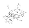
도 1 및 도 2는 본 발명의 일 실시예에 따른 로봇 청소기를 설명하기 위한 도면이다. 보다 구체적으로, 도 1은 로봇 청소기의 전체적인 외형을 설명하기 위한 사시도이며, 도 2는 로봇 청소기의 하부 구조를 설명하기 위한 저면도이다.1 and 2 are diagrams for explaining a robot cleaner according to an embodiment of the present invention. More specifically, FIG. 1 is a perspective view for explaining the overall appearance of the robot cleaner, and FIG. 2 is a bottom view for explaining the lower structure of the robot cleaner.
도 1 및 도 2를 참조하면, 로봇 청소기(100)는 본체(110)를 포함할 수 있다. 이하에서는, 본체(110)의 각부분을 정의함에 있어서, 주행구역 내의 천장을 향하는 부분을 상면부로 정의하고, 주행구역 내의 바닥을 향하는 부분을 저면부로 정의하며, 상기 상면부와 상기 저면부 사이에서 본체(110)의 둘레를 이루는 부분 중 주행방향을 향하는 부분을 정면부라고 정의한다. 또한, 본체(110)의 상기 정면부로부터 반대 방향을 향하는 부분을 후면부로 정의한다. 본체(110)는 로봇 청소기(100)를 구성하는 각종 부품들이 수용되는 공간을 형성하는 케이스(111)를 포함할 수 있다.1 and 2 , the
로봇 청소기(100)는 현재의 상태 정보를 획득하기 위해 감지를 수행하는 센싱부(130)를 포함할 수 있다. 센싱부(130)는 로봇 청소기(100)의 주행 중 로봇 청소기(100)의 주변 상황을 감지할 수 있으며, 또한 센싱부(130)는 로봇 청소기(100)의 상태를 감지할 수도 있다.The
센싱부(130)는 주행 구역에 대한 정보를 감지할 수 있다. 센싱부(130)는 주행면 상의 벽면, 가구, 및 낭떠러지 등의 장애물을 감지할 수 있다. 센싱부(130)는 후술되는 로봇 청소기용 충전장치(200)를 감지할 수 있다. 센싱부(130)는 천장에 대한 정보를 감지할 수 있다. 센싱부(130)가 감지한 정보를 통해, 로봇 청소기(100)는 주행 구역을 맵핑(Mapping)할 수 있다.The
센싱부(130)는, 장애물 감지 센서(131), 낭떠러지 감지 센서(132), 외부 신호 감지 센서(미도시), 충격 감지 센서(미도시), 영상 감지 센서(138), 3D 센서(138a, 139a, 139b) 및 도킹 여부 감지 센서 중 적어도 하나를 포함할 수 있다.The
센싱부(130)는 주변 물체까지의 거리를 감지하는 장애물 감지 센서(131)를 포함할 수 있다. 장애물 감지 센서(131)는 본체(110)의 정면부에 배치될 수 있고, 측방부에 배치될 수도 있다. 장애물 감지 센서(131)는 주변의 장애물을 감지할 수 있다. 장애물 감지 센서(131)는 복수 개로 구비될 수 있다.The
도 2에서는 2개의 장애물 감지 센서(131)가 로봇 청소기(100)의 정면부 내지 측방부에 구비된 것을 도시하고 있으나, 본 발명의 개념은 반드시 이에 한정되지 않는다. 즉, 장애물 감지 센서(131)는 로봇 청소기(100)의 정면부와 측방부에 각각 구비될 수 있으며, 장애물 감지 센서(131)의 개수 역시 제한되지 않을 수 있다.2 illustrates that the two
예를 들어, 장애물 감지 센서(131)는, 발광부와 수광부를 구비한 적외선센서, 초음파 센서, RF 센서, 지자기 센서 등일 수 있다. 초음파 또는 적외선 등을 이용하여 장애물 감지 센서(131)가 구현될 수 있다. 카메라를 이용하여 장애물 감지 센서(131)가 구현될 수 있다. 장애물 감지 센서(131)는 두 가지 종류 이상의 센서로 구현될 수도 있다.For example, the
장애물 감지 센서(131)는 거리 감지 센서(131)로 지칭될 수도 있다.The
센싱부(130)는 주행구역 내 바닥의 장애물을 감지하는 낭떠러지 감지 센서(132)를 포함할 수 있다. 낭떠러지 감지 센서(132)는 바닥에 낭떠러지의 존재 여부를 감지할 수 있다.The
낭떠러지 감지 센서(132)는 복수 개로 구비되어 로봇 청소기(100)의 저면부에 배치될 수 있다.A plurality of
낭떠러지 감지 센서(132)는 발광부와 수광부를 구비한 적외선 센서, 초음파 센서, RF 센서, PSD(Position Sensitive Detector) 센서 등일 수 있다. 예를 들어, 낭떠러지 감지 센서는 PSD 센서일 수 있으나, 복수의 서로 다른 종류의 센서로 구성될 수도 있다. PSD 센서는 장애물에 적외선을 발광하는 발광부와, 장애물로부터 반사되어 돌아오는 적외선을 수광하는 수광부를 포함한다.The
센싱부(130)는 로봇 청소기(100)가 외부의 물건과 접촉에 의한 충격을 감지하는 상기 충격 감지 센서를 포함할 수 있다.The
센싱부(130)는 로봇 청소기(100)의 외부로부터 발송된 신호를 감지하는 상기 외부 신호 감지 센서를 포함할 수 있다. 상기 외부 신호 감지 센서는, 외부로부터의 적외선 신호를 감지하는 적외선 센서(Infrared Ray Sensor), 외부로부터의 초음파 신호를 감지하는 초음파 센서(Ultra Sonic Sensor), 외부로부터의 RF신호를 감지하는 RF 센서(Radio Frequency Sensor) 중 적어도 어느 하나를 포함할 수 있다.The
센싱부(130)는 로봇 청소기(100) 외부의 영상을 감지하는 영상 감지 센서(138)를 포함할 수 있다.The
영상 감지 센서(138)는 디지털 카메라를 포함할 수 있다. 상기 디지털카메라는 적어도 하나의 광학렌즈와, 상기 광학렌즈를 통과한 광에 의해 상이 맺히는 다수개의 광다이오드(photodiode, 예를 들어, pixel)를 포함하여 구성된 이미지센서(예를 들어, CMOS image sensor)와, 상기 광다이오드들로부터 출력된 신호를 바탕으로 영상을 구성하는 디지털 신호 처리기(DSP: Digital Signal Processor)를 포함할 수 있다. 상기 디지털 신호 처리기는 정지영상은 물론이고, 정지영상으로 구성된 프레임들로 이루어진 동영상을 생성하는 것도 가능하다.The
영상 감지 센서(138)는 로봇 청소기(100)의 전방으로의 영상을 감지하는 전방 영상 센서(138a)를 포함할 수 있다. 전방 영상 센서(138a)는 장애물이나 로봇 청소기용 충전장치(200) 등 주변 물건의 영상을 감지할 수 있다.The
영상 감지 센서(138)는 로봇 청소기(100)의 상측 방향으로의 영상을 감지하는 상방 영상 센서(138b)를 포함할 수 있다. 상방 영상 센서(138b)는 천장 또는 로봇 청소기(100)의 상측에 배치된 가구의 하측면 등의 영상을 감지할 수 있다.The
영상 감지 센서(138)는 로봇 청소기(100)의 하측 방향으로의 영상을 감지하는 하방 영상 센서(138c)를 포함할 수 있다. 하방 영상 센서(138c)는 바닥의 영상을 감지할 수 있다.The
그 밖에도, 영상 감지 센서(138)는 측방 또는 후방으로 영상을 감지하는 센서를 포함할 수 있다.In addition, the
센싱부(130)는 외부 환경의 3차원 정보를 감지하는 3D 센서(138a, 139a, 139b)를 포함할 수 있다.The
3D 센서(138a, 139a, 139b)는 로봇 청소기(100)와 피촬영 대상체의 원근거리를 산출하는 3차원 뎁스 카메라(3D Depth Camera)(138a)를 포함할 수 있다.The
본 실시예에서, 3D 센서(138a, 139a, 139b)는, 본체(110)의 전방을 향해 소정 패턴의 광을 조사하는 패턴 조사부(139), 및 본체(110)의 전방의 영상을 획득하는 전방 영상 센서(138a)를 포함한다. 상기 패턴 조사부(139)는, 본체(110)의 전방 하측으로 제 1패턴의 광을 조사하는 제 1패턴 조사부(139a)와, 본체(110)의 전방 상측으로 제 2패턴의 광을 조사하는 제 2패턴 조사부(139b)를 포함할 수 있다. 전방 영상 센서(138a)는 상기 제 1패턴의 광과 상기 제 2패턴의 광이 입사된 영역의 영상을 획득할 수 있다.In this embodiment, the 3D sensors (138a, 139a, 139b), the
상기 패턴 조사부(139)는 적외선 패턴을 조사하게 구비될 수 있다.The
이 경우, 전방 영상 센서(138a)는 상기 적외선 패턴이 피촬영 대상체에 투영된 모양을 캡쳐함으로써, 상기 3D 센서와 피촬영 대상체 사이의 거리를 측정할 수 있다.In this case, the
상기 제 1패턴의 광 및 상기 제 2패턴의 광은 서로 교차하는 직선 형태로 조사될 수 있다. 상기 제 1패턴의 광 및 상기 제 2패턴의 광은 상하로 이격된 수평의 직선 형태로 조사될 수 있다.The light of the first pattern and the light of the second pattern may be irradiated in the form of a straight line crossing each other. The light of the first pattern and the light of the second pattern may be irradiated in the form of a horizontal straight line spaced up and down.
센싱부(130)는 로봇 청소기(100)의 로봇 청소기용 충전장치(200)에 대한 도킹 성공 여부를 감지하는 도킹 감지 센서(미도시)를 포함할 수 있다. 상기 도킹 감지 센서는, 대응 단자(190)와 충전 단자(215)의 접촉에 의해 감지되게 구현될 수도 있고, 대응 단자(190)와는 별도로 배치된 감지 센서로 구현될 수도 있으며, 배터리(177)의 충전 중 상태를 감지함으로써 구현될 수도 있다. 도킹 감지 센서에 의해, 도킹 성공 상태 및 도킹 실패 상태를 감지할 수 있다.The
로봇 청소기(100)는 각 구성들에 구동 전원을 공급하기 위한 배터리(177)를 포함한다. 배터리(177)는 로봇 청소기(100)가 선택된 행동 정보에 따른 행동을 수행하기 위한 전원을 공급한다. 배터리(177)는 본체(110)에 장착된다. 배터리(177)는 본체(110)에 착탈 가능하게 구비될 수 있다.The
배터리(177)는 로봇 청소기(100)가 로봇 청소기용 충전장치(200)에 도킹되어 충전 단자(215)와 대응 단자(190)가 접속함에 따라 충전 가능하도록 구비될 수 있다. 배터리(177)의 충전량이 소정치 이하가 되면, 로봇 청소기(100)는 충전을 위해 도킹 모드를 시작할 수 있다. 상기 도킹 모드에서, 로봇 청소기(100)는 로봇 청소기용 충전장치(200)로 복귀하는 주행을 실시한다.The
로봇 청소기(100)는 바닥에 대해 본체(110)를 이동시키는 주행부를 포함한다. 상기 주행부는 본체(110)를 이동시키는 적어도 하나의 구동 바퀴(166)와 이를 구동시키기 위한 구동 모터(미도시)를 포함할 수 있다. 구동 바퀴(166)는 본체(110)의 좌, 우 측에 각각 구비되는 좌륜(166(L)) 및 우륜(166(R))을 포함할 수 있다.The
좌륜(166(L))과 우륜(166(R))은 하나의 구동 모터에 의해 구동될 수도 있으나, 필요에 따라 좌륜(166(L))을 구동시키는 좌륜 구동 모터와 우륜(166(R))을 구동시키는 우륜 구동 모터가 각각 구비될 수도 있다. 좌륜(166(L))과 우륜(166(R))의 회전 속도에 차이를 두어 좌측 또는 우측으로 본체(110)의 주행방향을 전환할 수 있다.The left wheel 166(L) and the right wheel 166(R) may be driven by one driving motor, but if necessary, the left wheel drive motor and the right wheel 166(R) for driving the left wheel 166(L) ) may be provided with right-wheel drive motors respectively. The traveling direction of the
상기 주행부는 별도의 구동력을 제공하지 않되, 보조적으로 바닥에 대해 본체를 지지하는 보조 바퀴(168)를 더 포함할 수 있다.The driving unit does not provide a separate driving force, but may further include an
로봇 청소기(100)는 소정의 작업을 수행하는 작업부를 포함한다. 로봇 청소기(100)는 주행 구역을 이동하며 상기 작업부에 의해 바닥을 청소할 수 있다. 상기 작업부는 이물질의 흡입을 수행할 수 있으며, 걸레질을 수행할 수 있다.The
상기 작업부는, 이물질을 흡입하는 흡입 장치, 비질을 수행하는 브러시(184, 185), 흡입장치나 브러시에 의해 수거된 이물질을 저장하는 먼지통(미도시) 및/또는 걸레질을 수행하는 걸레부(미도시) 등을 포함할 수 있다.The work unit includes a suction device for sucking foreign substances, brushes 184 and 185 for brooming, a dust bin (not shown) for storing foreign substances collected by the suction device or brush, and/or a mop part (not shown) for mopping. city), and the like.
본체(110)의 저면부에는 공기의 흡입이 이루어지는 흡입구(180h)가 형성될 수 있다. 본체(110) 내에는 흡입구(180h)를 통해 공기가 흡입될 수 있도록 흡입력을 제공하는 흡입장치(미도시)와, 흡입구(180h)를 통해 공기와 함께 흡입된 먼지를 집진하는 먼지통(미도시)이 구비될 수 있다.A
케이스(111)에는 상기 먼지통의 삽입과 탈거를 위한 개구부가 형성될 수 있고, 상기 개구부를 여닫는 먼지통 커버(112)가 케이스(111)에 대해 회전가능하게 구비될 수 있다.An opening for inserting and removing the dust container may be formed in the
상기 작업부는, 흡입구(180h)를 통해 노출되는 솔들을 갖는 롤형의 메인 브러시(184)와, 본체(110)의 저면부 전방측에 위치하며, 방사상으로 연장된 다수개의 날개로 이루어진 솔을 갖는 보조 브러시(185)를 포함할 수 있다. 이들 브러시(184, 185)들의 회전에 의해 주행구역내 바닥으로부터 먼지들이 제거되며, 이렇게 바닥으로부터 분리된 먼지들은 흡입구(180h)를 통해 흡입되어 먼지통에 모인다.The work unit, a roll-type
로봇 청소기(100)는 로봇 청소기용 충전장치(200)에 도킹시 배터리(177)의 충전을 위한 대응 단자(190)를 포함한다. 대응 단자(190)는 로봇 청소기(100)의 도킹 성공상태에서 로봇 청소기용 충전장치(200)의 충전 단자(215)에 접속 가능한 위치에 배치된다. 일 실시예에 있어서, 본체(110)의 저면부에는 한 쌍의 대응 단자(190)가 배치될 수 있다.The
로봇 청소기(100)는 정보를 입력하는 입력부(171)를 포함할 수 있다. 입력부(171)는 On/Off 또는 각종 명령을 입력받을 수 있다. 입력부(171)는 버튼, 키 또는 터치형 디스플레이 등을 포함할 수 있다. 입력부(171)는 음성 인식을 위한 마이크를 포함할 수 있다.The
로봇 청소기(100)는 정보를 출력하는 출력부(미도시), 외부의 다른 기기와 정보를 송수신하는 통신부(미도시), 및 각종 정보를 저장하는 저장부(미도시)를 포함할 수 있다.The
로봇 청소기(100)는 내부에 맵핑 및/또는 현재 위치를 인식하는 등 각종 정보를 처리하고 판단하는 제어부(미도시)를 포함할 수 있으며, 상기 제어부는 로봇 청소기(100)의 각종 구성들의 제어를 통해, 로봇 청소기(100)의 동작 전반을 제어할 수 있다.The
도 3은 본 발명의 일 실시예에 따른 로봇 청소기용 충전장치를 설명하기 위한 도면이다. 보다 구체적으로, 도 3은 로봇 청소기용 충전장치의 전체적인 외형을 설명하기 위한 사시도이다.3 is a view for explaining a charging device for a robot cleaner according to an embodiment of the present invention. More specifically, FIG. 3 is a perspective view for explaining the overall appearance of a charging device for a robot cleaner.
도 3을 참조하면, 로봇 청소기용 충전장치(200)는 바닥에 놓여지도록 구비될 수 있으며, 로봇 청소기(100)의 도킹 성공 상태에서 대응 단자(190)와 접속되게 구비되는 충전 단자(215)를 포함할 수 있다.Referring to FIG. 3 , the charging
구체적으로, 로봇 청소기용 충전장치(200)는 외관을 형성하며 복수 개의 장애물 감지 센서들(131)을 포함하는 로봇 청소기(100)의 충전을 위해 마련되는 본체(210), 및 본체(210)의 하부를 구성하며 상부면에 로봇 청소기(100)의 충전을 위한 충전 단자(215)가 마련되는 배열판(220)을 포함할 수 있다Specifically, the charging
로봇 청소기용 충전장치(200)의 본체(210)는 필요에 따라 다양한 소재로 이루어질 수 있다. 예시적인 실시예들에 있어서, 본체(210)는 외부로부터 시각적으로 차단될 수 있는 불투명 소재로 이루어질 수도 있고, 혹은 외부로부터 시각적으로 노출될 수 있는 투명 또는 반투명한 소재로 이루어질 수도 있다.The
한편, 로봇 청소기용 충전장치(200)의 본체(210) 내부에는 로봇 청소기(100)의 충전을 위한 여러 가지 부품들 예를 들어, 인쇄회로기판, 센서, 가이드 부재 등이 구비될 수 있으며, 로봇 청소기(100)의 도킹 여부를 확인하는 도킹 확인부(미도시)가 더 구비될 수 있다.On the other hand, various parts for charging the
로봇 청소기용 충전장치(200)의 배열판(220)은 편평한 상부면을 가질 수 있으며, 지면에 대해 소정의 각도로 경사지도록 구비될 수 있다. 예시적인 실시예들에 있어서, 배열판(220)의 본체(210)에 인접한 부분은 본체(210)의 하부면보다 높은 상부면을 가질 수 있으며, 상기 배열판(220)의 상부면은 본체(210)에 인접한 부분으로부터 본체(210)로부터 이격된 부분까지 일정한 각도를 갖도록 형성될 수 있다. 일 실시예에 있어서, 상기 배열판(220)의 본체(210)로부터 이격된 부분은 부분적으로 본체(210)의 하부면과 동일한 높이를 가질 수 있다.The
배열판(220)의 형상 및 재질은 특별히 제한되지 않으며, 로봇 청소기용 충전장치(200)는 배열판(220)을 포함하지 않을 수도 있다. 로봇 청소기용 충전장치(200)는 배열판(220)을 포함하지 않는 경우, 본체(210)의 하부에는 충전 단자(215)가 배치되도록 별도의 단자부(미도시)가 마련될 수 있다.The shape and material of the
도 4 및 도 5는 본 발명의 예시적인 실시예들에 따른 로봇 청소기의 장애물 감지 센서를 설명하기 위한 도면이다.4 and 5 are diagrams for explaining an obstacle detecting sensor of a robot cleaner according to exemplary embodiments of the present invention.
도 4 및 도 5를 참조하면, 로봇 청소기(100)는 측방 장애물을 감지하기 위한 한 쌍의 제1장애물 감지 센서(131a), 및 상기 한 쌍의 제1장애물 감지 센서(131a) 사이에 배치되어 전방 장애물을 감지하기 위한 제2장애물 감지 센서(131b)를 포함할 수 있다.4 and 5 , the
도 4는 제2장애물 감지 센서(131b)가 2개 형성된 것을 도시하고 있고, 도 5는 제2장애물 감지 센서(131b)가 4개 형성된 것을 도시하고 있으나, 본 발명의 개념은 반드시 이에 한정되지 않는다. 즉, 제2장애물 감지 센서(131b)의 개수는 특별히 제한되지 않으며, 제1장애물 감지 센서(131a)의 개수 역시 특별히 제한되지 않는다.4 shows that two second
예시적인 실시예들에 있어서, 로봇 청소기(100)의 중심선과 로봇 청소기용 충전장치(200)의 중심선이 정렬된 상태에서, 제2장애물 감지 센서(131b)는 로봇 청소기용 충전장치(200)의 본체(210)를 감지하도록 배치될 수 있으나, 제1장애물 감지 센서(131a)는 로봇 청소기용 충전장치(200)의 본체(210)를 감지하지 못하도록 배치될 수 있다.In exemplary embodiments, in a state where the center line of the
일 실시예에 있어서, 로봇 청소기(100)의 중심선과 로봇 청소기용 충전장치(200)의 중심선이 정렬된 상태에서, 제1장애물 감지 센서(131a)는 로봇 청소기용 충전장치(200)의 본체(210)보다 먼 거리 위치하는 벽면을 감지하도록 배치될 수 있다.In one embodiment, in a state in which the center line of the
이하에서는, 복수 개의 장애물 감지 센서들(131)을 이용한 로봇 청소기(100)의 중심선과 로봇 청소기용 충전장치(200)의 중심선의 정렬 방법을 설명하기로 한다.Hereinafter, a method of aligning the center line of the
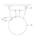
도 6은 본 발명의 일 실시예에 따른 로봇 청소기의 중심선 정렬 방법을 설명하기 위한 도면이다. 도 6에서는, 설명의 편의를 위하여, 로봇 청소기(100)가 총 4개의 장애물 감지 센서들(131), 보다 구체적으로, 한 쌍의 제1장애물 감지 센서(131a) 및 한 쌍의 제2장애물 감지 센서(131b)를 포함하는 것을 도시하고 있으며, 이를 기초로 로봇 청소기(100)의 중심선과 로봇 청소기용 충전장치(200)의 중심선의 정렬 방법을 설명하기로 한다.6 is a view for explaining a method of aligning a center line of a robot cleaner according to an embodiment of the present invention. In FIG. 6 , for convenience of explanation, the
도 6을 참조하면, 로봇 청소기(100)의 중심을 원점으로 하는 2차원 직교좌표계를 통해, 로봇 청소기용 충전장치(200)의 일 단부의 위치를 기초로 로봇 청소기(100)의 중심선과 로봇 청소기용 충전장치(100)의 중심선 사이의 중심 이격거리를 추정할 수 있다.Referring to FIG. 6 , based on the position of one end of the
구체적으로, 로봇 청소기(100)가 IR 신호를 통해 로봇 청소기용 충전장치(200)로 제1거리(Da) 예를 들어, 30cm 미만의 거리만큼 접근했을 때, 로봇 청소기용 충전장치(200)를 감지한 장애물 감지 센서(131)와 로봇 청소기용 충전장치(200)를 감지하지 않은 장애물 감지 센서(131) 각각의 거리 측정값을 이용하여 로봇 청소기용 충전장치(200)의 일 단부 위치를 추정할 수 있다.Specifically, when the robot cleaner 100 approaches the
예를 들어, 로봇 청소기(100)가 로봇 청소기용 충전장치(200)의 본체(210)로부터 좌측에 위치하는 경우 즉, 로봇 청소기(100)의 중심선이 본체(210)의 중심선으로부터 좌측에 위치하는 경우, 좌측에 배치된 제1장애물 감지 센서(131a)와 제2장애물 감지 센서(131b)는 각각 본체(210)의 후방에 위치하는 벽면을 감지할 수 있으며, 우측에 배치된 제1장애물 감지 센서(131a)와 제2장애물 감지 센서(131b)는 각각 본체(210)를 감지할 수 있다. 이에 따라, 본체(210)의 좌측 단부는 좌측에 배치된 제2장애물 감지 센서(131b)와 우측에 배치된 제2장애물 감지 센서(131b) 사이에 위치하는 것으로 추정될 수 있다.For example, when the
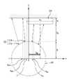
예시적인 실시예들에 있어서, 상기 좌측에 배치된 제2장애물 감지 센서(131b)의 거리 측정값을 제1측정 거리(D1)라 하고, 상기 좌측에 배치된 제2장애물 감지 센서(131b)가 상기 로봇 청소기(100)의 중심으로부터 x축 방향을 따라 이격된 거리를 제1장착 거리(Am1)라 하고, 상기 좌측에 배치된 제2장애물 감지 센서(131b)의 장착 각도를 제1각도(θ1)라 할 때, 상기 본체(210)의 좌측 단부가 위치 가능한 범위의 최소값은 제1추정 거리(Am2)로 추정될 수 있다. 이때, 상기 제1추정 거리(Am2)는 다음과 같은 수식으로 표현될 수 있다.In exemplary embodiments, a distance measurement value of the second
<수학식 1><Equation 1>
Am2 = Am1 - D1Sinθ1Am2 = Am1 - D1 Sinθ1
이와 유사하게, 상기 우측에 배치된 제2장애물 감지 센서(131b)의 거리 측정값을 제2측정 거리(D2)라 하고, 상기 우측에 배치된 제2장애물 감지 센서(131b)가 상기 로봇 청소기(100)의 중심으로부터 x축 방향을 따라 이격된 거리를 제2장착 거리(An1)라 하고, 상기 우측에 배치된 제2장애물 감지 센서(131b)의 장착 각도를 제2각도(θ2)라 할 때, 상기 본체(210)의 좌측 단부가 위치 가능한 범위의 최대값은 제2추정 거리(An2)로 추정될 수 있다. 이때, 상기 제2추정 거리(Am2)는 다음과 같은 수식으로 표현될 수 있다.Similarly, a distance measurement value of the second
<수학식 2><Equation 2>
An2 = An1+ D2Sinθ2An2 = An1 + D2 Sinθ2
따라서, 상기 본체(210)의 좌측 단부의 x축 위치를 제1위치(L)라 할 때, 상기 제1위치(L)의 범위는 다음과 같이 추정될 수 있다.Accordingly, when the x-axis position of the left end of the
<수학식 3><Equation 3>
Am1 - D1Sinθ1 < L < An1+ D2Sinθ2Am1 - D1 Sinθ1 < L < An1 + D2 Sinθ2
이후, 본체(210)의 상하폭을 제1폭(W1)이라 하고, 본체(210)의 좌우폭을 제2폭(W2)이라 할 때, 로봇 청소기(100)의 중심이 원점이므로, 본체(210) 중심선의 x축 위치가 곧 로봇 청소기(100)와 로봇 청소기용 충전장치(200)의 중심 이격거리(Dan)일 수 있으며, 상기 중심 이격거리(Dan)는 다음과 같이 추정될 수 있다.Thereafter, when the upper and lower widths of the
<수학식 4><Equation 4>
Dan = L + W2/2Dan = L + W2 /2
즉, 결과적으로, 로봇 청소기(100)와 로봇 청소기용 충전장치(200)의 중심 이격거리는 로봇 청소기(100)의 중심과 로봇 청소기용 충전장치(200)의 중심 사이의 x축 위치 차이로 표현될 수 있다.That is, as a result, the distance between the centers of the
비록 도시하지는 않았으나, 상기 수학식 1 내지 수학식 4를 통한 로봇 청소기(100)와 로봇 청소기용 충전장치(200)의 중심 이격거리를 추정하는 방법은, 로봇 청소기(100)가 로봇 청소기용 충전장치(200)의 본체(210)로부터 우측에 위치하는 경우 즉, 로봇 청소기(100)의 중심선이 본체(210)의 중심선으로부터 우측에 위치하는 경우에도, 실질적으로 동일하거나 유사하게 적용될 수 있다.Although not shown, the method of estimating the center separation distance between the
예시적인 실시예들에 있어서, 상기 중심 이격거리(Dan)의 절대값이 특정값보다 작은 경우 로봇 청소기(100)와 로봇 청소기용 충전장치(200)의 중심선이 정렬된 것으로 판단할 수 있으며, 상기 중심 이격거리(Dan)의 절대값이 특정값보다 큰 경우 로봇 청소기(100)와 로봇 청소기용 충전장치(200)의 중심선이 정렬되지 않은 것으로 판단할 수 있다. 일 실시예에 있어서, 상기 특정값은 약 5cm일 수 있다.In exemplary embodiments, when the absolute value of the center separation distance Dan is smaller than a specific value, it may be determined that the center lines of the
예시적인 실시예들에 있어서, 상기 중심 이격거리(Dan) 값이 양수인 경우 로봇 청소기(100)가 로봇 청소기용 충전장치(200)의 중심선으로부터 좌측에 위치된 것으로 판단할 수 있으며, 상기 중심 이격거리(Dan) 값이 음수인 경우 로봇 청소기(100)가 로봇 청소기용 충전장치(200)의 중심선으로부터 우측에 위치된 것으로 판단할 수 있다.In exemplary embodiments, when the center separation distance Dan value is positive, it may be determined that the
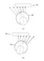
도 7은 본 발명의 일 실시예에 따른 로봇 청소기의 중심선이 미정렬된 상태를 설명하기 위한 도면이다.7 is a view for explaining a state in which the center line of the robot cleaner is not aligned according to an embodiment of the present invention.
도 7(a) 내지 도 7(b)를 참조하면, 로봇 청소기(100)가 IR 신호를 통해 로봇 청소기용 충전장치(200)로 제1거리(Da)만큼 접근했을 때, 로봇 청소기(100)와 로봇 청소기용 충전장치(200)의 중심선이 정렬되었는지 여부는 복수 개의 장애물 감지 센서들(131)이 로봇 청소기용 충전장치(200)를 감지하였는지 여부에 따라 결정될 수 있다. 이때, 상기 복수 개의 장애물 감지 센서들(131)은 측방 장애물을 감지하기 위한 한 쌍의 제1장애물 감지 센서(131a), 및 상기 한 쌍의 제1장애물 감지 센서들(131a) 사이에 배치되어 전방 장애물을 감지하기 위한 제2장애물 감지 센서(131b)를 포함할 수 있으며, 제2장애물 감지 센서(131b)는 총 4개로 구성될 수 있다.7(a) to 7(b), when the robot cleaner 100 approaches the
예시적인 실시예들에 있어서, 도 5에 도시된 바와 같이, 로봇 청소기(100)는 상기 복수 개의 장애물 감지 센서들(131) 중 상기 제2장애물 감지 센서(131b)만 상기 로봇 청소기용 충전장치를 감지한 상태를, 로봇 청소기(100)와 로봇 청소기용 충전장치(200)의 중심선이 정렬된 것으로 판단할 수 있다.In exemplary embodiments, as shown in FIG. 5 , in the
이와는 달리, 도 7(a) 내지 도 7(b)에 각각 도시된 바와 같이, 상기 한 쌍의 제1장애물 감지 센서(131a) 중 적어도 하나의 제1장애물 감지 센서(131a)가 로봇 청소기용 충전장치(200)를 감지한 상태를, 로봇 청소기(100)와 로봇 청소기용 충전장치(200)의 중심선이 정렬되지 않은 것으로 판단할 수 있다.On the contrary, as shown in each of FIGS. 7(a) to 7(b), at least one of the pair of first
예를 들어, 로봇 청소기(100)는, 상기 한 쌍의 제1장애물 감지 센서(131a) 중 우측에 배치된 제1장애물 감지 센서(131a)만 로봇 청소기용 충전장치(200)를 감지한 상태를, 로봇 청소기(100)의 중심선이 로봇 청소기용 충전장치(200)의 중심선으로부터 좌측으로 이격된 것으로 판단할 수 있다. 이 경우, 로봇 청소기(100)는 우측으로 이동하여 로봇 청소기(100)와 로봇 청소기용 충전장치(200)의 중심선을 정렬할 수 있다.For example, the
이와 유사하게, 로봇 청소기(100)는, 상기 한 쌍의 제1장애물 감지 센서(131a) 중 좌측에 배치된 제1장애물 감지 센서(131a)만 로봇 청소기용 충전장치(200)를 감지한 상태를, 로봇 청소기(100)의 중심선이 로봇 청소기용 충전장치(200)의 중심선으로부터 우측으로 이격된 것으로 판단할 수 있다. 이 경우, 로봇 청소기(100)는 좌측으로 이동하여 로봇 청소기(100)와 로봇 청소기용 충전장치(200)의 중심선을 정렬할 수 있다.Similarly, the
이때, 로봇 청소기(100)는 전술한 중심 이격거리(Dan)만큼 우측 또는 좌측으로 이동하도록 제어될 수 있다.At this time, the
도 7(a)는 로봇 청소기(100)의 중심선이 로봇 청소기용 충전장치 본체(210)의 중심선으로부터 좌측으로 제1중심 이격거리(Da1)만큼 이격된 것을 도시하고 있고, 도 7(b)는 로봇 청소기(100)의 중심선이 로봇 청소기용 충전장치 본체(210)의 중심선으로부터 제1중심 이격거리(Da1)보다 큰 제2중심 이격거리(Da2)만큼 이격된 것을 도시하고 있으며, 도 7(c)는 도 7(b)는 로봇 청소기(100)의 중심선이 로봇 청소기용 충전장치 본체(210)의 중심선으로부터 제2중심 이격거리(Da2)보다 큰 제3중심 이격거리(Da3)만큼 이격된 것을 도시하고 있다. 이때, 로봇 청소기(100)와 로봇 청소기용 충전장치(200)의 중심 이격거리(Dan)는, 전술한 수학식 1 내지 4를 이용하여 추정하는 방법 이외에도, 어느 장애물 감지 센서(131)가 로봇 청소기용 충전장치(200)를 감지하였는지 여부를 비교함으로써 간접적으로 추정될 수 있다.7 (a) shows that the center line of the
예를 들어, 도 7(a)에 도시된 바와 같이, 로봇 청소기(100)는, 상기 복수 개의 장애물 감지 센서들(131) 중 가장 좌측에 배치된 장애물 감지 센서와 이에 인접한 장애물 감지 센서가 본체(210)를 감지하지 못하고, 나머지 장애물 감지 센서들이 본체(210)를 감지한 상태를, 로봇 청소기(100)의 중심선이 로봇 청소기용 충전장치 본체(210)의 중심선으로부터 좌측으로 제1중심 이격거리(Da1)만큼 이격된 것으로 판단할 수 있다.For example, as shown in FIG. 7A , the
예를 들어, 도 7(b)에 도시된 바와 같이, 로봇 청소기(100)는, 상기 복수 개의 장애물 감지 센서들(131) 중 좌측에 배치된 장애물 감지 센서들이 본체(210)를 감지하지 못하고, 우측에 배치된 장애물 감지 센서들이 본체(210)를 감지한 상태를, 로봇 청소기(100)의 중심선이 로봇 청소기용 충전장치 본체(210)의 중심선으로부터 좌측으로 제2중심 이격거리(Da2)만큼 이격된 것으로 판단할 수 있다.For example, as shown in Figure 7 (b), the
예를 들어, 도 7(c)에 도시된 바와 같이, 로봇 청소기(100)는, 상기 복수 개의 장애물 감지 센서들(131) 중 가장 우측에 배치된 장애물 감지 센서와 이에 인접한 장애물 감지 센서가 본체(210)를 감지하고, 나머지 장애물 감지 센서들이 본체(210)를 감지하지 못한 상태를, 로봇 청소기(100)의 중심선이 로봇 청소기용 충전장치 본체(210)의 중심선으로부터 좌측으로 제3중심 이격거리(Da3)만큼 이격된 것으로 판단할 수 있다.For example, as shown in FIG. 7(c), the
이하에서는, 복수 개의 장애물 감지 센서들(131)을 이용한 로봇 청소기(100)와 로봇 청소기용 충전장치(200) 사이의 방향각 보정 방법을 설명하기로 한다.Hereinafter, a direction angle correction method between the
도 8 및 도 9는 본 발명의 일 실시예에 따른 로봇 청소기의 방향각 보정 방법을 설명하기 위한 도면들이다.8 and 9 are views for explaining a direction angle correction method of a robot cleaner according to an embodiment of the present invention.
도 8(a) 및 도 8(b)를 참조하면, 로봇 청소기(100)는 로봇 청소기(100) 로봇 청소기용 충전장치(200)의 중심선이 정렬된 상태에서, 로봇 청소기(100)와 로봇 청소기용 충전장치(200) 사이의 최단거리가 상기 제1거리(Da)보다 작은 제2거리(Db) 이하인지 여부를 확인한 후, 상기 복수 개의 장애물 감지 센서들(131)을 통해 로봇 청소기(100)와 로봇 청소기용 충전장치(200) 사이에 방향각 차이가 발생하였는지 여부를 확인할 수 있으며, 상기 방향각 차이를 보정할 수 있다. 일 실시예에 있어서, 제2거리(Db)는 약 15cm일 수 있다.8 (a) and 8 (b), the
이때, 로봇 청소기(100)와 로봇 청소기용 충전장치(200) 사이에 방향각 차이가 발생하였는지 여부는, 상기 한 쌍의 제1장애물 감지 센서(131a) 중 적어도 하나가 로봇 청소기용 충전장치(200)를 감지하였는지 여부에 따라 결정될 수 있다.At this time, whether a difference in direction angle occurs between the
예를 들어, 도 8(a)에 도시된 바와 같이, 로봇 청소기(100)는, 상기 한 쌍의 제1장애물 감지 센서(131a) 중 우측에 배치된 제1장애물 감지 센서(131a)만 상기 로봇 청소기용 충전장치의 본체(210)를 감지한 상태를, 로봇 청소기(100)가 로봇 청소기용 충전장치(200)의 중심선으로부터 반시계 방향을 따라 특정 각도만큼 방향각 차이가 발생한 것으로 판단할 수 있다. 이 경우, 로봇 청소기(100)는 시계방향으로 회전하여 로봇 청소기(100)와 로봇 청소기용 충전장치(200) 사이의 방향각 차이를 보정할 수 있다.For example, as shown in FIG. 8(a), the
이와는 달리, 도 8(b)에 도시된 바와 같이, 로봇 청소기(100)는, 상기 한 쌍의 제1장애물 감지 센서(131a) 중 좌측에 배치된 제1장애물 감지 센서(131a)만 상기 로봇 청소기용 충전장치의 본체(210)를 감지한 상태를, 로봇 청소기(100)가 로봇 청소기용 충전장치(200)의 중심선으로부터 시계 방향을 따라 특정 각도만큼 방향각 차이가 발생한 것으로 판단할 수 있다. 이 경우, 로봇 청소기(100)는 반시계방향으로 회전하여 로봇 청소기(100)와 로봇 청소기용 충전장치(200) 사이의 방향각 차이를 보정할 수 있다.Contrary to this, as shown in FIG. 8(b) , in the
도 9를 참조하면, 로봇 청소기(100)와 로봇 청소기용 충전장치(200) 사이에 발생한 방향각 차이는 로봇 청소기용 충전장치(200)의 위치를 감지한 장애물 감지 센서들(131)의 거리 측정값들 중 가장 작은 거리 측정값과 이에 가장 근접한 거리 측정값을 이용하여 결정될 수 있다.Referring to FIG. 9 , the difference in direction angle generated between the
구체적으로, 로봇 청소기용 충전장치 본체(210)의 위치를 감지한 장애물 감지 센서들(131)의 거리 측정값들 중 가장 작은 거리 측정값을 제3측정 거리(Db1)이라 하고, 이에 가장 근접한 거리 측정값을 제4측정 거리(Db2)라 할 때, 상기 로봇 청소기용 충전장치 본체(210)의 위치를 감지한 장애물 감지 센서들(131)과 로봇 청소기용 충전장치 본체(210) 사이에 발생한 제1방향각(α)은 다음과 같이 추정될 수 있다.Specifically, the smallest distance measurement value among the distance measurement values of the
<수학식 5><Equation 5>
α = tan-1(|Db1 - Db2|/장애물 감지 센서간 거리)α = tan-1 (|Db1 - Db2 |/distance between obstacle detection sensors)
이후, 상기 로봇 청소기용 충전장치 본체(210)의 위치를 감지한 장애물 감지 센서들(131)의 배치 각도를 제2방향각(β)이라 할 때, 로봇 청소기(100)와 로봇 청소기용 충전장치 본체(210) 사이에 발생한 전체 방향각 차이는 제1방향각(α)과 제2방향각(β)의 합으로 추정될 수 있다.Thereafter, when the arrangement angle of the
이에 따라, 로봇 청소기(100)는 상기 전체 방향각 즉, 제1방향각(α)과 제2방향각(β)의 합에 해당하는 각도만큼 시계 방향 또는 반시계 방향으로 회전하여 로봇 청소기(100)와 로봇 청소기용 충전장치(200) 사이에 발생한 방향각 차이를 보정할 수 있다.Accordingly, the
한편, 도 9는 가장 근접한 거리 측정값을 갖는 장애물 감지 센서가 제1장애물 감지 센서(131a)이고, 이에 가장 근접한 거리 측정값을 갖는 장애물 감지 센서가 제2장애물 감지 센서(131b)인 것을 도시하고 있으나, 본 발명의 개념은 반드시 이에 한정되지 않는다. 즉, 가장 근접한 거리 측정값과 이에 가장 근접한 거리 측정값을 갖는 장애물 감지 센서는 모두 제2장애물 감지 센서(131b)일 수도 있다.On the other hand, FIG. 9 shows that the obstacle detection sensor having the closest distance measurement value is the first
도 10은 본 발명의 일 실시예에 따른 로봇 청소기의 중심선 정렬 방법을 설명하기 위한 순서도이다.10 is a flowchart illustrating a method of aligning a center line of a robot cleaner according to an embodiment of the present invention.
도 10을 참조하면, 본 발명의 일 실시예에 따른 로봇 청소기의 제어 방법은, 로봇 청소기(100)가 IR 신호를 통해 로봇 청소기용 충전장치(200)로 접근하는 제1단계(S1), 로봇 청소기(100)와 로봇 청소기용 충전장치(200) 사이의 거리가 제1거리(D1) 미만인지 여부를 확인하는 제2단계(S2), 로봇 청소기(100)가 로봇 청소기용 충전장치(200)로부터 발생된 근접 도킹 IR 신호를 수신하였는지 여부를 확인하는 제3단계(S3), 장애물 감지 센서(131)를 통해 로봇 청소기(100)와 로봇 청소기용 충전장치(200)의 중심선이 정렬되었는지 여부를 확인(S4a)하고, 상기 중심선을 정렬(S4b)하는 제4단계(S4), 및 로봇 청소기(100)와 로봇 청소기용 충전장치(200)의 중심선이 정렬되면, 로봇 청소기(100)가 로봇 청소기용 충전장치(200)를 향해 직진하는 제5단계(S5)를 포함할 수 있다.Referring to FIG. 10 , in the method for controlling a robot cleaner according to an embodiment of the present invention, the robot cleaner 100 approaches the
이때, 상기 제4단계(S4)는 도 6 및 도 7을 참조로 설명한 로봇 청소기(100)의 중심선 정렬 방법을 통해 수행될 수 있다.In this case, the fourth step ( S4 ) may be performed through the center line alignment method of the
한편, 상기 제1단계(S1)는 원거리 도킹 단계로 지칭될 수 있고, 상기 제2단계(S2) 내지 상기 제5단계(S5)는 중심선 정렬 단계로 지칭될 수 있다.Meanwhile, the first step (S1) may be referred to as a remote docking step, and the second step (S2) to the fifth step (S5) may be referred to as a centerline alignment step.
예시적인 실시예들에 있어서, 상기 제1거리(D1)는 약 30cm일 수 있다.In example embodiments, the first distance D1 may be about 30 cm.
도 11은 본 발명의 일 실시예에 따른 로봇 청소기의 방향각 보정 방법을 설명하기 위한 순서도이다.11 is a flowchart for explaining a direction angle correction method of a robot cleaner according to an embodiment of the present invention.
도 11을 참조하면, 본 발명의 일 실시예에 따른 로봇 청소기의 제어 방법은, 상기 중심선 정렬 단계 이후 로봇 청소기(100)가 로봇 청소기용 충전장치(200)로 접근하는 제6단계(S6), 로봇 청소기(100)와 로봇 청소기용 충전장치(200) 사이의 거리가 상기 제1거리(D1)보다 작은 제2거리(D2) 미만인지 여부를 확인하는 제7단계(S7), 장애물 감지 센서(131)를 통해 로봇 청소기(100)와 로봇 청소기용 충전장치(200) 사이의 방향각을 측정하는 제8단계(S8),장애물 감지 센서(131)를 통해 로봇 청소기(100)와 로봇 청소기용 충전장치(200) 사이에 방향각 차이가 발생하였는지 여부를 확인(S9a)하고, 상기 방향각 차이를 보정(S9b)하는 제9단계(S9), 및 로봇 청소기(100)와 로봇 청소기용 충전장치(200)의 방향각이 보정되면, 로봇 청소기(100)와 충전 단자(215)가 접촉하는 제10단계(S10)를 더 포함할 수 있다.Referring to FIG. 11 , the control method of the robot cleaner according to an embodiment of the present invention includes a sixth step (S6) in which the robot cleaner 100 approaches the
이때, 상기 제8단계(S8) 및 제9단계(S9)는 도 6 및 도 7을 참조로 설명한 로봇 청소기(100)의 중심선 정렬 방법을 통해 수행될 수 있다.In this case, the eighth step ( S8 ) and the ninth step ( S9 ) may be performed through the center line alignment method of the
한편, 상기 제6단계(S6) 내지 상기 제10단계(S10)는 방향각 보정 단계로 지칭될 수 있으며, 상기 제2단계(S2) 내지 상기 제10 단계(S10)는 함께 근거리 도킹 단계로 지칭될 수 있다.Meanwhile, the sixth step (S6) to the tenth step (S10) may be referred to as a direction angle correction step, and the second step (S2) to the tenth step (S10) are also referred to as a short-distance docking step. can be
예시적인 실시예들에 있어서, 상기 제2거리(D1)는 약 15cm일 수 있다.In example embodiments, the second distance D1 may be about 15 cm.
전술한 바와 같이, 로봇 청소기(100)의 원거리 도킹 단계는 로봇 청소기용 충전장치(200)로부터 발생한 IR 신호를 따라 수행될 수 있으며, 로봇 청소기(100)의 근거리 도킹 단계는 장애물 감지 센서(131)를 통해 로봇 청소기용 충전장치(200)의 위치를 추정함으로써 수행될 수 있다.As described above, the remote docking step of the
이때, 로봇 청소기(100)가 로봇 청소기용 충전장치(200)에 근접한 상태에서의 도킹이 IR 신호에 의해 수행되지 않을 수 있으므로, 외부 환경 예를 들어, 실내조명, 햇빛 등의 영향을 받지 않을 수 있으며, IR 신호의 최대 강도에 따른 로봇 청소기용 충전장치(200)의 특정 영역을 구분하기가 어렵다는 단점이 극복될 수 있다. 따라서, 로봇 청소기(100)와 로봇 청소기용 충전장치(200)의 충전을 위한 근거리 도킹이 정밀하게 이루어질 수 있다.At this time, since docking in a state in which the
이상에서 본 발명의 다양한 실시예들을 상세하게 설명하였으나, 본 발명이 속하는 기술분야에서 통상의 지식을 가진 자는 상술한 실시예에 대하여 본 발명의 범주에서 벗어나지 않는 한도 내에서 다양한 변형이 가능함을 이해할 것이다. 그러므로 본 발명의 권리범위는 설명된 실시예에 국한되어 정해져서는 안 되며, 후술하는 특허청구범위뿐만 아니라 이 특허청구범위와 균등한 것들에 의해 정해져야 한다.Although various embodiments of the present invention have been described in detail above, those of ordinary skill in the art will understand that various modifications are possible within the limits without departing from the scope of the present invention with respect to the above-described embodiments. . Therefore, the scope of the present invention should not be limited to the described embodiments, and should be defined by the claims described below as well as the claims and equivalents.
100: 로봇 청소기131: 장애물 감지 센서
200: 로봇 청소기용 충전장치210: 본체
215: 충전 단자220: 배열판100: robot cleaner 131: obstacle detection sensor
200: charging device for robot cleaner 210: main body
215: charging terminal 220: arrangement plate
Claims (19)
Translated fromKorean상기 복수 개의 장애물 감지 센서들을 통해 상기 로봇 청소기와 상기 로봇 청소기용 충전장치 사이의 최단거리가 제1거리 이하인지 여부를 확인하는 제2단계;
상기 복수 개의 장애물 감지 센서들을 통해 상기 로봇 청소기와 상기 로봇 청소기용 충전장치의 중심선이 정렬되었는지 여부를 확인하고, 상기 로봇 청소기와 상기 로봇 청소기용 충전장치의 중심선을 정렬하는 제3단계; 및
상기 로봇 청소기와 상기 로봇 청소기용 충전장치의 중심선이 정렬되면, 상기 로봇 청소기가 상기 로봇 청소기용 충전장치를 향해 직진하는 제4단계;를 포함하고,
상기 제3단계에서,
상기 로봇 청소기용 충전장치의 위치를 감지한 장애물 감지 센서의 거리 측정값보다 이에 인접한 장애물 감지 센서의 거리 측정값이 더 큰 경우, 상기 로봇 청소기용 충전장치의 일 단부가 이들 사이에 위치한 것으로 판단하고,
상기 로봇 청소기의 중심을 원점으로 하는 2차원 직교좌표계를 통해, 상기 로봇 청소기용 충전장치의 일 단부의 위치를 기초로 상기 로봇 청소기의 중심선과 상기 로봇 청소기용 충전장치의 중심선 사이의 중심 이격거리를 추정하는 로봇 청소기의 제어 방법.A first step of a robot cleaner including a plurality of obstacle detection sensors approaching the charging device for the robot cleaner according to the IR signal transmitted from the charging device for the robot cleaner including a charging terminal for charging the robot cleaner;
a second step of checking whether the shortest distance between the robot cleaner and the charging device for the robot cleaner is less than or equal to a first distance through the plurality of obstacle detection sensors;
a third step of confirming whether the center lines of the robot cleaner and the charging device for the robot cleaner are aligned through the plurality of obstacle detection sensors, and aligning the center lines of the robot cleaner and the charging device for the robot cleaner; and
When the center lines of the robot cleaner and the charging device for the robot cleaner are aligned, a fourth step of moving the robot cleaner straight toward the charging device for the robot cleaner includes;
In the third step,
When the distance measurement value of the obstacle detection sensor adjacent thereto is larger than the distance measurement value of the obstacle detection sensor detecting the position of the charging device for the robot cleaner, it is determined that one end of the charging device for the robot cleaner is located between them, and ,
Through a two-dimensional Cartesian coordinate system with the center of the robot cleaner as the origin, based on the position of one end of the charging device for the robot cleaner, the center separation distance between the center line of the robot cleaner and the center line of the charging device for the robot cleaner The control method of the estimated robot vacuum cleaner.
상기 제3단계에서,
상기 로봇 청소기와 상기 로봇 청소기용 충전장치의 중심선이 정렬되었는지 여부는, 상기 로봇 청소기용 충전장치의 위치를 감지한 장애물 감지 센서의 거리 측정값과 상기 로봇 청소기용 충전장치의 위치를 감지하지 못한 장애물 감지 센서의 거리 측정값을 통해 결정되는 로봇 청소기의 제어 방법.According to claim 1,
In the third step,
Whether the center lines of the robot cleaner and the charging device for the robot cleaner are aligned is determined by the distance measurement value of the obstacle detecting sensor detecting the position of the charging device for the robot cleaner and the obstacle that does not detect the position of the charging device for the robot cleaner A control method of a robot cleaner that is determined through the distance measurement value of the detection sensor.
상기 제3단계에서,
상기 중심 이격거리의 절대값이 특정값보다 작은 경우 상기 로봇 청소기와 상기 로봇 청소기용 충전장치의 중심선이 정렬된 것으로 판단하고, 그리고
상기 중심 이격거리의 절대값이 특정값보다 큰 경우 상기 로봇 청소기와 상기 로봇 청소기용 충전장치의 중심선이 정렬되지 않은 것으로 판단하는 로봇 청소기의 제어 방법.According to claim 1,
In the third step,
When the absolute value of the center separation distance is smaller than a specific value, it is determined that the center lines of the robot cleaner and the charging device for the robot cleaner are aligned, and
When the absolute value of the center separation distance is greater than a specific value, the control method of the robot cleaner for determining that the center lines of the robot cleaner and the charging device for the robot cleaner are not aligned.
상기 제3단계에서,
상기 중심 이격거리 값이 양수인 경우 상기 로봇 청소기가 상기 로봇 청소기용 충전장치의 중심선으로부터 좌측에 위치된 것으로 판단하고, 그리고
상기 중심 이격거리 값이 음수인 경우 상기 로봇 청소기가 상기 로봇 청소기용 충전장치의 중심선으로부터 우측에 위치된 것으로 판단하는 로봇 청소기의 제어 방법.5. The method of claim 4,
In the third step,
If the center separation distance value is positive, it is determined that the robot cleaner is located on the left side from the center line of the charging device for the robot cleaner, and
When the value of the center separation distance is negative, the control method of the robot cleaner determines that the robot cleaner is located on the right side from the center line of the charging device for the robot cleaner.
상기 복수 개의 장애물 감지 센서들은 측방 장애물을 감지하기 위한 한 쌍의 제1장애물 감지 센서, 및 상기 한 쌍의 제1장애물 감지 센서 사이에 배치되어 전방 장애물을 감지하기 위한 제2장애물 감지 센서를 포함하고, 그리고
상기 제3단계에서, 상기 로봇 청소기와 상기 로봇 청소기용 충전장치의 중심선이 정렬되었는지 여부는 상기 제1장애물 감지 센서와 상기 제2장애물 감지 센서가 상기 로봇 청소기용 충전장치를 감지하였는지 여부에 따라 결정되는 로봇 청소기의 제어 방법.According to claim 1,
The plurality of obstacle detection sensors include a pair of first obstacle detection sensors for detecting a lateral obstacle, and a second obstacle detection sensor disposed between the pair of first obstacle detection sensors to detect a front obstacle, , and
In the third step, whether the center lines of the robot cleaner and the charging device for the robot cleaner are aligned is determined depending on whether the first obstacle detecting sensor and the second obstacle detecting sensor detect the charging device for the robot cleaner How to control a robot vacuum cleaner.
상기 제3단계에서, 상기 복수 개의 장애물 감지 센서들 중 상기 제2장애물 감지 센서만 상기 로봇 청소기용 충전장치를 감지한 상태를, 상기 로봇 청소기와 상기 로봇 청소기용 충전장치의 중심선이 정렬된 것으로 판단하는 로봇 청소기의 제어 방법.7. The method of claim 6,
In the third step, the state in which only the second obstacle detecting sensor among the plurality of obstacle detecting sensors detects the charging device for the robot cleaner is determined that the center lines of the robot cleaner and the charging device for the robot cleaner are aligned How to control a robot vacuum cleaner.
상기 제3단계에서, 상기 한 쌍의 제1장애물 감지 센서 중 적어도 하나의 제1장애물 감지 센서가 상기 로봇 청소기용 충전장치를 감지한 상태를, 상기 로봇 청소기와 상기 로봇 청소기용 충전장치의 중심선이 정렬되지 않은 것으로 판단하는 로봇 청소기의 제어 방법.8. The method of claim 7,
In the third step, at least one of the first obstacle detection sensor of the pair of first obstacle detection sensors detects the charging device for the robot cleaner, the center line of the robot cleaner and the charging device for the robot cleaner A control method of a robot vacuum cleaner that judges that it is not aligned.
상기 제3단계에서, 상기 한 쌍의 제1장애물 감지 센서 중 우측에 배치된 제1장애물 감지 센서만 상기 로봇 청소기용 충전장치를 감지한 상태를, 상기 로봇 청소기의 중심선이 상기 로봇 청소기용 충전장치의 중심선으로부터 좌측으로 이격된 것으로 판단하는 로봇 청소기의 제어 방법.9. The method of claim 8,
In the third step, only the first obstacle detecting sensor disposed on the right side of the pair of first obstacle detecting sensors detects the charging device for the robot cleaner, and the center line of the robot cleaner is the charging device for the robot cleaner. A control method of a robot cleaner that is determined to be spaced apart from the center line of the
상기 제3단계에서, 상기 로봇 청소기의 중심선이 상기 로봇 청소기용 충전장치의 중심선으로부터 좌측으로 이격된 것으로 판단되면, 상기 로봇 청소기는 우측으로 이동하는 로봇 청소기의 제어 방법.10. The method of claim 9,
In the third step, when it is determined that the center line of the robot cleaner is spaced apart from the center line of the charging device for the robot cleaner to the left, the robot cleaner moves to the right.
상기 제3단계에서, 상기 한 쌍의 제1장애물 감지 센서 중 좌측에 배치된 제1장애물 감지 센서만 상기 로봇 청소기용 충전장치를 감지한 상태를, 상기 로봇 청소기의 중심선이 상기 로봇 청소기용 충전장치의 중심선으로부터 우측으로 이격된 것으로 판단하는 로봇 청소기의 제어 방법.9. The method of claim 8,
In the third step, only the first obstacle detecting sensor disposed on the left of the pair of first obstacle detecting sensors detects the charging device for the robot cleaner, and the center line of the robot cleaner is the charging device for the robot cleaner. A control method of a robot cleaner that is determined to be spaced apart to the right from the center line of
상기 제3단계에서, 상기 로봇 청소기의 중심선이 상기 로봇 청소기용 충전장치의 중심선으로부터 우측으로 이격된 것으로 판단되면, 상기 로봇 청소기는 좌측으로 이동하는 로봇 청소기의 제어 방법.12. The method of claim 11,
In the third step, when it is determined that the center line of the robot cleaner is spaced apart from the center line of the charging device for the robot cleaner to the right, the robot cleaner moves to the left.
상기 로봇 청소기와 상기 로봇 청소기용 충전장치의 중심선이 정렬된 상태에서, 상기 로봇 청소기와 상기 로봇 청소기용 충전장치 사이의 최단거리가 상기 제1거리보다 작은 제2거리 이하인지 여부를 확인하는 제5단계;
상기 복수 개의 장애물 감지 센서들을 통해 상기 로봇 청소기와 상기 로봇 청소기용 충전장치 사이에 방향각 차이가 발생하였는지 여부를 확인하고, 상기 로봇 청소기와 상기 로봇 청소기용 충전장치 사이의 방향각 차이를 보정하는 제6단계; 및
상기 로봇 청소기와 상기 로봇 청소기용 충전장치의 방향각이 보정되면, 상기 로봇 청소기가 상기 충전 단자가 접촉하는 제7단계;를 더 포함하는 로봇 청소기의 제어 방법.According to claim 1,
A fifth for confirming whether the shortest distance between the robot cleaner and the charging device for the robot cleaner is less than or equal to a second distance smaller than the first distance in a state in which the center lines of the robot cleaner and the charging device for the robot cleaner are aligned step;
Checking whether a direction angle difference has occurred between the robot cleaner and the charging device for the robot cleaner through the plurality of obstacle detection sensors, and correcting the difference in the direction angle between the robot cleaner and the charging device for the robot cleaner Step 6; and
When the direction angle of the robot cleaner and the charging device for the robot cleaner is corrected, a seventh step of contacting the charging terminal of the robot cleaner with the robot cleaner.
상기 제6단계에서,
상기 로봇 청소기와 상기 로봇 청소기용 충전장치 사이에 방향각 차이가 발생하였는지 여부는, 상기 로봇 청소기용 충전장치의 위치를 감지한 장애물 감지 센서들의 거리 측정값들 중 가장 작은 거리 측정값과 이에 가장 근접한 거리 측정값을 이용하여 결정되는 로봇 청소기의 제어 방법.14. The method of claim 13,
In the sixth step,
Whether a difference in direction angle occurs between the robot cleaner and the charging device for the robot cleaner is determined by the smallest distance measurement value among the distance measurement values of the obstacle detection sensors detecting the position of the charging device for the robot cleaner and the closest to it. A control method of a robot cleaner that is determined using distance measurements.
상기 복수 개의 장애물 감지 센서들은 측방 장애물을 감지하기 위한 한 쌍의 제1장애물 감지 센서, 및 상기 한 쌍의 제1장애물 감지 센서 사이에 배치되어 전방 장애물을 감지하기 위한 제2장애물 감지 센서를 포함하고, 그리고
상기 제6단계에서, 상기 로봇 청소기와 상기 로봇 청소기용 충전장치의 방향각 차이가 발생하였는지 여부는 상기 한 쌍의 제1장애물 감지 센서 중 적어도 하나가 상기 로봇 청소기용 충전장치를 감지하였는지 여부에 따라 결정되는 로봇 청소기의 제어 방법.14. The method of claim 13,
The plurality of obstacle detection sensors include a pair of first obstacle detection sensors for detecting a lateral obstacle, and a second obstacle detection sensor disposed between the pair of first obstacle detection sensors to detect a front obstacle, , and
In the sixth step, whether a difference in direction angle between the robot cleaner and the charging device for the robot cleaner occurs is determined according to whether at least one of the pair of first obstacle detection sensors detects the charging device for the robot cleaner. The control method of the robot vacuum cleaner determined.
상기 제6단계에서, 상기 한 쌍의 제1장애물 감지 센서 중 우측에 배치된 제1장애물 감지 센서만 상기 로봇 청소기용 충전장치를 감지한 상태를, 상기 로봇 청소기가 상기 로봇 청소기용 충전장치의 중심선으로부터 반시계 방향을 따라 특정 각도만큼 방향각 차이가 발생한 것으로 판단하는 로봇 청소기의 제어 방법.16. The method of claim 15,
In the sixth step, the state in which only the first obstacle detection sensor disposed on the right side of the pair of first obstacle detection sensors detects the charging device for the robot cleaner, the robot cleaner is the center line of the charging device for the robot cleaner A control method of a robot cleaner that determines that a direction angle difference has occurred by a specific angle along a counterclockwise direction.
상기 제6단계에서, 상기 로봇 청소기가 상기 로봇 청소기용 충전장치의 중심선으로부터 반시계 방향을 따라 특정 각도만큼 방향각 차이가 발생한 것으로 판단되면, 상기 로봇 청소기는 시계방향으로 회전하여 상기 방향각 차이를 보정하는 로봇 청소기의 제어 방법.17. The method of claim 16,
In the sixth step, when it is determined that the difference in direction angle has occurred by a specific angle in the counterclockwise direction from the center line of the charging device for the robot cleaner, the robot cleaner rotates clockwise to measure the difference in the direction angle. A control method of a robot vacuum cleaner that calibrates.
상기 제6단계에서, 상기 한 쌍의 제1장애물 감지 센서 중 좌측에 배치된 제1장애물 감지 센서만 상기 로봇 청소기용 충전장치를 감지한 상태를, 상기 로봇 청소기가 상기 로봇 청소기용 충전장치의 중심선으로부터 시계 방향을 따라 특정 각도만큼 방향각 차이가 발생한 것으로 판단하는 로봇 청소기의 제어 방법.16. The method of claim 15,
In the sixth step, the state in which only the first obstacle detection sensor disposed on the left of the pair of first obstacle detection sensors detects the charging device for the robot cleaner, the robot cleaner is the center line of the charging device for the robot cleaner A control method of a robot cleaner that determines that a difference in direction angle has occurred by a specific angle along the clockwise direction.
상기 제6단계에서, 상기 로봇 청소기가 상기 로봇 청소기용 충전장치의 중심선으로부터 시계 방향을 따라 특정 각도만큼 방향각 차이가 발생한 것으로 판단되면, 상기 로봇 청소기는 반시계방향으로 회전하여 상기 방향각 차이를 보정하는 로봇 청소기의 제어 방법.
19. The method of claim 18,
In the sixth step, when it is determined that a difference in direction angle has occurred by a specific angle in the clockwise direction from the center line of the charging device for the robot cleaner, the robot cleaner rotates counterclockwise to measure the difference in direction angle. A control method of a robot vacuum cleaner that calibrates.
Priority Applications (3)
| Application Number | Priority Date | Filing Date | Title |
|---|---|---|---|
| KR1020200081415AKR102423497B1 (en) | 2020-07-02 | 2020-07-02 | Controlling Method of Robot Cleaner |
| PCT/KR2020/013543WO2022004949A1 (en) | 2020-07-02 | 2020-10-06 | Method for controlling robot cleaner |
| US18/013,430US12402767B2 (en) | 2020-07-02 | 2020-10-06 | Method for controlling robot cleaner |
Applications Claiming Priority (1)
| Application Number | Priority Date | Filing Date | Title |
|---|---|---|---|
| KR1020200081415AKR102423497B1 (en) | 2020-07-02 | 2020-07-02 | Controlling Method of Robot Cleaner |
Publications (2)
| Publication Number | Publication Date |
|---|---|
| KR20220003781A KR20220003781A (en) | 2022-01-11 |
| KR102423497B1true KR102423497B1 (en) | 2022-07-21 |
Family
ID=79315426
Family Applications (1)
| Application Number | Title | Priority Date | Filing Date |
|---|---|---|---|
| KR1020200081415AActiveKR102423497B1 (en) | 2020-07-02 | 2020-07-02 | Controlling Method of Robot Cleaner |
Country Status (3)
| Country | Link |
|---|---|
| US (1) | US12402767B2 (en) |
| KR (1) | KR102423497B1 (en) |
| WO (1) | WO2022004949A1 (en) |
Families Citing this family (2)
| Publication number | Priority date | Publication date | Assignee | Title |
|---|---|---|---|---|
| KR20240042269A (en)* | 2022-09-22 | 2024-04-02 | 엘지전자 주식회사 | A robot cleaner system having the charge stations and control method thereof |
| KR102854533B1 (en)* | 2024-12-04 | 2025-09-03 | 주식회사 고퀄 | Method for processing automatic water supply and drain using mobile robot and system using the same |
Citations (2)
| Publication number | Priority date | Publication date | Assignee | Title |
|---|---|---|---|---|
| JP2008181177A (en)* | 2007-01-23 | 2008-08-07 | Matsushita Electric Ind Co Ltd | Charger for mobile unit with rechargeable battery |
| KR101080366B1 (en)* | 2009-01-30 | 2011-11-04 | (주)하기소닉 | Localization Method of Mobile Robots using Ultrasonic Sensors and Device Thereby |
Family Cites Families (20)
| Publication number | Priority date | Publication date | Assignee | Title |
|---|---|---|---|---|
| KR100492590B1 (en) | 2003-03-14 | 2005-06-03 | 엘지전자 주식회사 | Auto charge system and return method for robot |
| US20070271011A1 (en)* | 2006-05-12 | 2007-11-22 | Samsung Electronics Co., Ltd. | Indoor map building apparatus, method, and medium for mobile robot |
| KR101672787B1 (en) | 2009-06-19 | 2016-11-17 | 삼성전자주식회사 | Robot cleaner and docking station and robot cleaner system having the same and control method thereof |
| US8352114B2 (en) | 2011-05-20 | 2013-01-08 | VGO Communications, Inc | Method and apparatus for docking a robotic device with a charging station |
| KR102404258B1 (en)* | 2015-02-06 | 2022-06-02 | 삼성전자주식회사 | Apparatus for returning of robot and returning method thereof |
| US9630319B2 (en)* | 2015-03-18 | 2017-04-25 | Irobot Corporation | Localization and mapping using physical features |
| CN107437830B (en)* | 2016-05-27 | 2021-01-01 | 华硕电脑股份有限公司 | Automatic walking device and control method thereof |
| KR101897730B1 (en) | 2016-12-30 | 2018-09-12 | 엘지전자 주식회사 | Charging stating for robot cleaner |
| US11274929B1 (en)* | 2017-10-17 | 2022-03-15 | AI Incorporated | Method for constructing a map while performing work |
| US10422648B2 (en)* | 2017-10-17 | 2019-09-24 | AI Incorporated | Methods for finding the perimeter of a place using observed coordinates |
| CN109976324B (en)* | 2017-12-27 | 2022-06-28 | 深圳市优必选科技有限公司 | Method for controlling robot charging, robot, and computer-readable storage medium |
| JP7262076B2 (en)* | 2018-06-28 | 2023-04-21 | パナソニックIpマネジメント株式会社 | Mobile robot and control method |
| US11199853B1 (en)* | 2018-07-11 | 2021-12-14 | AI Incorporated | Versatile mobile platform |
| CN110757446B (en)* | 2018-07-25 | 2021-08-27 | 深圳市优必选科技有限公司 | Robot recharging login method and device and storage device |
| KR102599876B1 (en)* | 2018-09-21 | 2023-11-08 | 삼성전자주식회사 | Robot cleaner, charging apparatus and charging system |
| CN109586360B (en)* | 2018-11-09 | 2020-09-22 | 深圳市银星智能科技股份有限公司 | Robot automatic charging method and device, charging pile and robot |
| CN109240312B (en)* | 2018-11-23 | 2020-09-15 | 珠海市一微半导体有限公司 | Cleaning control method and chip of robot and cleaning robot |
| CN112214011B (en)* | 2019-07-11 | 2022-05-10 | 珠海一微半导体股份有限公司 | System and method for positioning charging seat of self-moving robot |
| KR102810058B1 (en)* | 2019-11-20 | 2025-05-21 | 삼성전자주식회사 | Moving robot device and method for controlling moving robot device thereof |
| EP4136517B1 (en)* | 2020-04-16 | 2025-03-19 | Globe (Jiangsu) Co., Ltd. | Navigating a robotic mower along a guide wire |
- 2020
- 2020-07-02KRKR1020200081415Apatent/KR102423497B1/enactiveActive
- 2020-10-06WOPCT/KR2020/013543patent/WO2022004949A1/ennot_activeCeased
- 2020-10-06USUS18/013,430patent/US12402767B2/enactiveActive
Patent Citations (2)
| Publication number | Priority date | Publication date | Assignee | Title |
|---|---|---|---|---|
| JP2008181177A (en)* | 2007-01-23 | 2008-08-07 | Matsushita Electric Ind Co Ltd | Charger for mobile unit with rechargeable battery |
| KR101080366B1 (en)* | 2009-01-30 | 2011-11-04 | (주)하기소닉 | Localization Method of Mobile Robots using Ultrasonic Sensors and Device Thereby |
Also Published As
| Publication number | Publication date |
|---|---|
| WO2022004949A1 (en) | 2022-01-06 |
| KR20220003781A (en) | 2022-01-11 |
| US20230248203A1 (en) | 2023-08-10 |
| US12402767B2 (en) | 2025-09-02 |
Similar Documents
| Publication | Publication Date | Title |
|---|---|---|
| US11547255B2 (en) | Cleaning robot | |
| KR101822942B1 (en) | Robot cleaner and controlling method of the same | |
| US10624514B2 (en) | Cleaner and controlling method thereof | |
| EP3409177B1 (en) | Moving robot and controlling method thereof | |
| KR102203439B1 (en) | a Moving robot and Controlling method for the moving robot | |
| US10765284B2 (en) | Cleaning robot | |
| US11998159B2 (en) | Vacuum cleaner and control method thereof | |
| KR102281346B1 (en) | Robot Cleaner and Controlling method for the same | |
| EP3949818B1 (en) | Robot cleaner | |
| KR20250036753A (en) | Robot | |
| KR102423497B1 (en) | Controlling Method of Robot Cleaner | |
| KR20210015126A (en) | Moving Robot | |
| JP2005216022A (en) | Autonomous run robot cleaner | |
| JP2018153375A (en) | Electric apparatus, autonomous traveling vacuum cleaner as electric apparatus and system including electric apparatus and base | |
| KR20220104185A (en) | mobile robot | |
| KR20220003780A (en) | Charging Device For Robot Cleaner and Controlling Method of Robot Cleaner using the same | |
| KR20210090447A (en) | Robot Cleaner and Controlling method for the same | |
| KR102358758B1 (en) | Recharging apparatus for Robot Cleaner | |
| KR20210090446A (en) | Robot Cleaner and Controlling method for the same |
Legal Events
| Date | Code | Title | Description |
|---|---|---|---|
| PA0109 | Patent application | Patent event code:PA01091R01D Comment text:Patent Application Patent event date:20200702 | |
| PA0201 | Request for examination | ||
| PE0902 | Notice of grounds for rejection | Comment text:Notification of reason for refusal Patent event date:20211020 Patent event code:PE09021S01D | |
| PG1501 | Laying open of application | ||
| E701 | Decision to grant or registration of patent right | ||
| PE0701 | Decision of registration | Patent event code:PE07011S01D Comment text:Decision to Grant Registration Patent event date:20220420 | |
| GRNT | Written decision to grant | ||
| PR0701 | Registration of establishment | Comment text:Registration of Establishment Patent event date:20220718 Patent event code:PR07011E01D | |
| PR1002 | Payment of registration fee | Payment date:20220719 End annual number:3 Start annual number:1 | |
| PG1601 | Publication of registration |