KR102423471B1 - Manipulating Apparatus for Combine - Google Patents
Manipulating Apparatus for CombineDownload PDFInfo
- Publication number
- KR102423471B1 KR102423471B1KR1020170175474AKR20170175474AKR102423471B1KR 102423471 B1KR102423471 B1KR 102423471B1KR 1020170175474 AKR1020170175474 AKR 1020170175474AKR 20170175474 AKR20170175474 AKR 20170175474AKR 102423471 B1KR102423471 B1KR 102423471B1
- Authority
- KR
- South Korea
- Prior art keywords
- harvesting
- limiting
- combine
- lever
- traveling
- Prior art date
- Legal status (The legal status is an assumption and is not a legal conclusion. Google has not performed a legal analysis and makes no representation as to the accuracy of the status listed.)
- Active
Links
Images


Classifications
- A—HUMAN NECESSITIES
- A01—AGRICULTURE; FORESTRY; ANIMAL HUSBANDRY; HUNTING; TRAPPING; FISHING
- A01D—HARVESTING; MOWING
- A01D41/00—Combines, i.e. harvesters or mowers combined with threshing devices
- A01D41/12—Details of combines
- A01D41/127—Control or measuring arrangements specially adapted for combines
- A—HUMAN NECESSITIES
- A01—AGRICULTURE; FORESTRY; ANIMAL HUSBANDRY; HUNTING; TRAPPING; FISHING
- A01D—HARVESTING; MOWING
- A01D41/00—Combines, i.e. harvesters or mowers combined with threshing devices
- A01D41/12—Details of combines
- A01D41/14—Mowing tables
- B—PERFORMING OPERATIONS; TRANSPORTING
- B60—VEHICLES IN GENERAL
- B60Y—INDEXING SCHEME RELATING TO ASPECTS CROSS-CUTTING VEHICLE TECHNOLOGY
- B60Y2200/00—Type of vehicle
- B60Y2200/20—Off-Road Vehicles
- B60Y2200/22—Agricultural vehicles
Landscapes
- Life Sciences & Earth Sciences (AREA)
- Environmental Sciences (AREA)
- Harvester Elements (AREA)
Abstract
Translated fromKoreanDescription
Translated fromKorean본 발명은 농작물을 수확하는 수확작업에 이용되는 콤바인을 조작하기 위한 콤바인용 조작장치에 관한 것이다.The present invention relates to an operating device for a combine for operating a combine used in a harvesting operation to harvest crops.
콤바인(Combine)은 벼, 보리, 밀, 콩 등의 농작물을 절단하여 이송하는 예취작업 및 예취한 농작물을 탈곡하는 탈곡작업을 동시에 수행하는 점에서 설치의 의미로 쓰인 명칭으로, 벼, 보리, 밀, 콩 등의 농작물을 수확하는 수확작업을 수행하는 수확기계이다.Combine is a name used in the sense of installation in that it simultaneously performs mowing work to cut and transport crops such as rice, barley, wheat, and soybeans, and threshing work to thresh the harvested crops. It is a harvesting machine that performs harvesting operations to harvest crops such as beans and beans.
도 1은 종래 기술에 따른 콤바인의 개략적인 블록도이다.1 is a schematic block diagram of a combine according to the prior art.
도 1을 참고하면, 종래 기술에 따른 콤바인(100)은 농작물을 절단하여 이송하는 예취부(110), 콤바인본체(120)를 주행시키는 주행부(130), 상기 예취부(110)를 제어하기 위한 예취조작부(140), 및 상기 주행부(130)를 제어하기 위한 주행조작부(150)를 포함한다. 작업자는 운전석에 탑승하여 상기 예취조작부(140) 및 상기 주행조작부(150) 중에서 적어도 하나를 조작함으로써, 상기 예취부(110) 및 상기 주행부(130)를 제어한다.1, the
여기서, 종래 기술에 따른 콤바인(100)은 상기 예취조작부(140) 및 상기 주행조작부(150)가 상호 간에 독립적으로 조작 가능하도록 구현되었다. 이에 따라, 종래 기술에 따른 콤바인(100)은 상기 주행조작부(150)의 조작을 통한 상기 콤바인본체(120)의 고속주행 및 상기 예취조작부(140)의 조작을 통한 상기 예취부(110)의 작동이 병행하여 이루어질 수 있다. 따라서, 종래 기술에 따른 콤바인(100)은 상기 콤바인본체(120)가 고속주행하면서 상기 예취부(110)가 작동될 수 있으므로, 상기 예취부(110)를 구성하는 부품들에 과다한 부하가 작용하여 해당 부품들에 대한 내구한도를 저하시키는 문제가 있다.
본 발명의 배경이 되는 기술은 대한민국 등록특허공보 제10-1710753호(2017.2.27.)에 개시되어 있다.Here, the
The technology that is the background of the present invention is disclosed in Republic of Korea Patent Publication No. 10-1710753 (2017.2.27.).
본 발명은 상술한 바와 같은 문제점을 해결하고자 안출된 것으로, 콤바인본체의 고속주행 및 예취부의 작동이 병행하여 이루어지는 것을 방지할 수 있는 콤바인용 조작장치를 제공하기 위한 것이다.The present invention has been devised to solve the problems as described above, and to provide an operation device for a combine that can prevent the operation of the high-speed running and harvesting unit of the combine body from being performed in parallel.
상기와 같은 과제를 해결하기 위해서, 본 발명은 다음과 같은 구성을 포함할 수 있다.In order to solve the above problems, the present invention may include the following configuration.
본 발명에 따른 콤바인용 조작장치는 콤바인본체의 운전석에 배치된 예취조작레버를 포함하고, 농작물을 절단하여 이송하는 예취부를 제어하기 위한 예취조작부; 상기 운전석에 배치된 주행조작레버를 포함하고, 상기 콤바인본체를 주행시키는 주행부를 제어하기 위한 주행조작부; 및 상기 예취조작레버 및 상기 주행조작레버의 상대적인 위치에 따라 상기 예취조작레버 및 상기 주행조작레버 각각의 이동을 선택적으로 제한하는 제한부를 포함할 수 있다.The operation device for a combine according to the present invention includes a harvesting operation lever disposed on the driver's seat of the combine body, and a harvesting operation part for controlling the harvesting part for cutting and transporting crops; a traveling operation unit including a traveling operation lever disposed on the driver's seat and configured to control the traveling unit for driving the combine body; and a limiting unit selectively restricting the movement of each of the harvesting operation lever and the traveling operation lever according to the relative positions of the harvesting operation lever and the traveling operation lever.
본 발명에 따르면, 다음과 같은 효과를 도모할 수 있다.According to the present invention, the following effects can be achieved.
첫째, 본 발명은 예취조작레버가 조작되어 예취조작부가 예취부를 작동시킨 상태에서, 제한부가 주행조작레버의 이동을 제한하도록 구현된다. 이에 따라, 본 발명은 예취부가 예취작업을 수행하는 도중에 작업자가 주행조작레버를 조작하더라도, 주행조작레버의 이동이 제한됨으로써 콤바인본체가 주행하는 속력을 제한할 수 있다. 따라서, 본 발명은 예취부가 예취작업을 수행하기 위해 바닥에 접촉된 상태에서 콤바인본체가 주행하는 속력이 증대됨에 따라 예취부가 고장, 파손되는 경우를 방지함으로써, 예취부의 유지보수작업에 대한 주기를 증대시켜 가동률을 증대시킬 수 있다. 또한, 본 발명은 예취작업을 수행하는 도중에 작업자가 실수로 주행조작레버를 조작함에 따라 발생 가능한 안전사고를 미연에 방지하는 효과가 있으므로, 예취부의 예취작업에 대한 안전성을 증대시키는데 기여할 수 있다.First, the present invention is implemented so that the harvesting operation lever is operated to limit the movement of the driving operation lever in a state in which the harvesting operation unit operates the harvesting unit. Accordingly, the present invention can limit the speed at which the combine body travels by limiting the movement of the travel operation lever, even if the operator operates the travel operation lever while the harvesting unit is performing the mowing operation. Therefore, the present invention prevents the case where the harvesting part is broken or damaged as the speed at which the combine body travels increases in a state in which the harvesting part is in contact with the floor to perform the mowing work, thereby reducing the cycle for the maintenance work of the mowing part. can be increased to increase the operating rate. In addition, the present invention has an effect of preventing in advance a safety accident that may occur as the operator accidentally manipulates the driving control lever while performing the mowing operation, so it can contribute to increasing the safety for the mowing operation of the mowing unit.
둘째, 본 발명은 주행조작레버가 조작되어 주행조작부가 주행부를 작동시킨 상태에서, 제한부가 예취조작레버의 이동을 제한하도록 구현된다. 이에 따라, 본 발명은 콤바인본체가 주행하는 도중에 작업자가 예취조작레버를 조작하더라도, 예취조작레버의 이동이 제한됨으로써 예취부가 예취작업을 수행하는 것을 제한할 수 있다. 따라서, 본 발명은 콤바인본체가 주행하고 있는 상태에서 예취부가 예취작업을 수행하기 위해 바닥에 접촉됨에 따라 예취부가 고장, 파손되는 경우를 방지함으로써, 예취부의 유지보수작업에 대한 주기를 증대시켜 가동률을 증대시킬 수 있다. 또한, 본 발명은 주행 도중에 작업자가 실수로 예취조작레버를 조작함에 따라 발생 가능한 안전사고를 미연에 방지하는 효과가 있으므로, 주행부가 콤바인본체를 주행시키는 주행작업에 대한 안전성을 증대시키는데 기여할 수 있다.Second, the present invention is implemented to limit the movement of the harvesting operation lever in a state in which the driving operation lever is operated and the driving operation unit operates the driving unit. Accordingly, in the present invention, even if the operator operates the harvesting operation lever while the combine body is traveling, the movement of the harvesting operation lever is limited, thereby limiting the harvesting unit performing the harvesting operation. Therefore, the present invention by preventing the case where the harvesting part is broken or damaged as the harvesting part is in contact with the floor to perform the mowing work in the state that the combine main body is running, by increasing the cycle for the mowing part maintenance work, the operation rate can increase In addition, the present invention has the effect of preventing in advance a safety accident that may occur as the operator accidentally manipulates the harvesting operation lever during driving, so that the driving unit can contribute to increasing the safety of the driving operation in which the combine body is driven.
도 1은 종래 기술에 따른 콤바인용 조작장치에 대한 개략적인 블록도
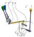
도 2는 본 발명에 따른 콤바인용 조작장치가 설치된 콤바인에 대한 개략적인 사시도
도 3은 본 발명에 따른 콤바인용 조작장치에 대한 개략적인 블록도
도 4은 본 발명에 따른 콤바인용 조작장치에 대한 개략적인 측면도
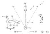
도 5는 본 발명에 따른 콤바인용 조작장치에 있어서, 예취조작레버가 예취대기위치 및 예취조작위치 간에 이동되는 모습을 나타낸 개략적인 측면도
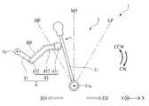
도 6는 본 발명에 따른 콤바인용 조작장치에 있어서, 예취조작레버가 예취대기위치에 위치한 경우 예취조작부 및 제한부를 나타낸 개략적인 측면도
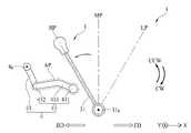
도 7은 본 발명에 따른 콤바인용 조작장치에 있어서, 예취조작레버가 예취조작위치에 위치한 경우 예취조작부 및 제한부를 나타낸 개략적인 측면도
도 8은 본 발명에 따른 콤바인용 조작장치에 있어서, 주행조작레버가 고속조작위치, 중속조작위치, 및 저속조작위치 간에 이동되는 모습을 나타낸 개략적인 측면도
도 9는 본 발명에 따른 콤바인용 조작장치에 있어서, 제한부가 회피위치에 위치한 모습을 나타낸 개략적인 측면도
도 10은 본 발명에 따른 콤바인용 조작장치에 있어서, 제한부가 제한위치에 위치한 모습을 나타낸 개략적인 측면도
도 11은 본 발명에 따른 콤바인용 조작장치에 있어서, 제한부가 제한위치에 위치한 상태에서 주행조작레버가 고속조작위치로 이동됨에 따라 주행조작레버가 제한부에 걸린 모습을 나타낸 개략적인 측면도
도 12는 본 발명에 따른 콤바인용 조작장치에 있어서, 주행조작레버가 고속조작위치에 위치한 모습을 나타낸 개략적인 측면도
도 13은 본 발명에 따른 콤바인용 조작장치에 있어서, 주행조작레버가 고속조작위치에 위치한 상태에서 제한부가 제한위치로 이동됨에 따라 제한부가 주행조작레버에 걸린 모습을 나타낸 개략적인 측면도
도 14는 본 발명에 따른 콤바인용 조작장치에 있어서, 제한부가 제한위치에 위치한 상태에서 주행조작레버가 중속조작위치 및 저속조작위치 간에 이동 가능한 모습을 나타낸 개략적인 측면도
도 15는 본 발명에 따른 콤바인용 조작장치에 있어서, 제한부에 대한 개략적인 사시도
도 16은 본 발명에 따른 콤바인용 조작장치에 있어서, 링크기구가 제1회전방향으로 회전되도록 주행조작레버가 제한위치에 위치한 제한부를 가압하는 모습을 나타낸 개략적인 측면도
도 17은 본 발명에 따른 콤바인용 조작장치에 있어서, 이동제한부재가 제1주행회전경로로부터 이격된 거리가 증대되도록 제2이음부재가 제1이음부재로부터 경사지게 형성된 모습을 나타낸 개략적인 측면도1 is a schematic block diagram of an operation device for a combine according to the prior art;
Figure 2 is a schematic perspective view of a combine in which the operation device for the combine according to the present invention is installed;
Figure 3 is a schematic block diagram of the operation device for the combine according to the present invention
Figure 4 is a schematic side view of the operation device for the combine according to the present invention
5 is a schematic side view showing a state in which the harvesting operation lever is moved between the harvesting standby position and the harvesting operation position in the operation device for a combine according to the present invention;
6 is a schematic side view showing a harvesting operation part and a limiting part when the harvesting operation lever is located in the harvesting standby position in the operation device for a combine according to the present invention;
7 is a schematic side view showing the harvesting operation part and the limiting part when the harvesting operation lever is located at the harvesting operation position in the operation device for the combine according to the present invention;
8 is a schematic side view showing a state in which the traveling operation lever is moved between the high-speed operation position, the medium-speed operation position, and the low-speed operation position in the operation device for a combine according to the present invention;
9 is a schematic side view showing a state in which the limiting part is located in the avoiding position in the operation device for the combine according to the present invention;
10 is a schematic side view showing a state in which the limiting part is located in the limiting position in the operation device for the combine according to the present invention;
11 is a schematic side view showing a state in which the driving control lever is caught in the limiting part as the driving control lever is moved to the high-speed operation position in the state where the limiting part is located in the limiting position in the operation device for the combine according to the present invention;
12 is a schematic side view showing a state in which the driving operation lever is located in the high-speed operation position in the operation device for the combine according to the present invention;
13 is a schematic side view showing a state in which the limiting part is caught on the driving control lever as the limiting part is moved to the limiting position in a state in which the driving operation lever is located in the high-speed operation position in the operation device for the combine according to the present invention;
14 is a schematic side view showing a state in which, in the operation device for a combine according to the present invention, the traveling operation lever is movable between the medium-speed operation position and the low-speed operation position in a state where the limiting part is located in the limiting position;
15 is a schematic perspective view of a limiting unit in the operation device for a combine according to the present invention;
16 is a schematic side view showing a state in which the travel operation lever presses the limiting part located at the limiting position so that the link mechanism rotates in the first rotational direction in the operation device for the combine according to the present invention;
17 is a schematic side view showing a state in which the second joint member is inclined from the first joint member so that the distance that the movement limiting member is spaced apart from the first travel rotation path is increased in the operation device for the combine according to the present invention;
이하에서는 본 발명에 따른 콤바인용 조작장치의 실시예를 첨부된 도면을 참조하여 상세히 설명한다. 본 발명에 따른 콤바인용 조작장치는 콤바인에 구비되므로, 콤바인에 관해 설명하면서 함께 설명한다.Hereinafter, an embodiment of the operation device for a combine according to the present invention will be described in detail with reference to the accompanying drawings. Since the operation device for the combine according to the present invention is provided in the combine, it will be described together while explaining the combine.
콤바인(Combine)은 벼, 보리, 밀, 콩 등의 농작물을 절단하고 수집하는 예취작업 및 예취한 농작물을 탈곡하는 탈곡작업을 동시에 수행하는 점에서 설치의 의미로 쓰인 명칭으로, 벼, 보리, 밀, 콩 등의 농작물을 수확하는 작업을 수행하는 수확기계이다. 콤바인은 콤바인본체(10), 운전석(11), 예취부(12), 및 주행부(13)를 포함할 수 있다.Combine is a name used in the sense of installation in that it simultaneously performs mowing work to cut and collect crops such as rice, barley, wheat, and soybeans, and threshing work to thresh the harvested crops. It is a harvesting machine that performs the work of harvesting crops such as beans, beans, etc. The combine may include a
도 1 및 도 2를 참고하면, 상기 콤바인본체(10)는 콤바인의 본체로 기능하는 것이다. 상기 콤바인본체(10)는 작업자의 조작에 따라 전진 및 후진될 수 있다. 상기 콤바인본체(10)는 작업자의 조작에 따라 주행하는 속력이 조절될 수도 있다. 상기 운전석(11)은 작업자가 탑승하기 위한 것이다. 상기 운전석(11)은 상기 콤바인본체(10)에 배치될 수 있다. 상기 예취부(12)는 농작물을 절단하여 이송하는 예취작업을 수행하기 위한 것이다. 상기 예취부(12)는 상기 콤바인본체(10)에 배치될 수 있다. 상기 주행부(13)는 상기 콤바인본체(10)를 주행시키는 것이다. 작업자는 상기 주행부(13)를 조작함으로써, 상기 콤바인본체(10)를 전진 및 후진시키거나 정지시킬 수 있다. 작업자는 상기 주행부(13)를 조작함으로써, 상기 콤바인본체(10)가 주행하는 속력을 조절할 수도 있다.1 and 2, the
도 3 내지 도 17을 참고하면, 본 발명에 따른 콤바인용 조작장치(1)는 콤바인에 설치되는 것이다. 본 발명에 따른 콤바인용 조작장치(1)는 상기 예취부(12)가 예취작업을 수행하거나, 상기 콤바인본체(10)가 전후진 주행하도록 작업자에 의해 조작될 수 있다.Referring to Figures 3 to 17, the combine operation device (1) according to the present invention is to be installed in the combine. The
이를 위해, 본 발명에 따른 콤바인용 조작장치(1)는 상기 운전석(11)에 배치된 예취조작레버(21)를 포함하되 상기 예취부(12)를 제어하기 위한 예취조작부(2), 상기 운전석(11)에 배치된 주행조작레버(31)를 포함하되 상기 주행부(13)를 제어하기 위한 주행조작부(3), 및 상기 예취조작레버(21) 및 상기 주행조작레버(31)의 상대적인 위치에 따라 상기 예취조작레버(21) 및 상기 주행조작레버(31) 각각의 이동을 선택적으로 제한하는 제한부(4)를 포함할 수 있다.To this end, the
이에 따라, 본 발명에 따른 콤바인용 조작장치(1)는 다음과 같은 작용효과를 도모할 수 있다.Accordingly, the operation device for a combine (1) according to the present invention can achieve the following operational effects.
첫째, 본 발명에 따른 콤바인용 조작장치(1)는 상기 예취조작레버(21)가 조작되어 상기 예취조작부(2)가 상기 예취부(12)를 작동시킨 상태에서, 상기 제한부(4)가 상기 주행조작레버(31)의 이동을 제한하도록 구현된다. 이에 따라, 본 발명에 따른 콤바인용 조작장치(1)는 상기 예취부(12)가 예취작업을 수행하는 도중에 작업자가 상기 주행조작레버(31)를 조작하더라도, 상기 주행조작레버(31)의 이동이 제한됨으로써 상기 콤바인본체(10)가 주행하는 속력을 제한할 수 있다. 따라서, 본 발명에 따른 콤바인용 조작장치(1)는 상기 예취부(12)가 예취작업을 수행하기 위해 바닥에 접촉된 상태에서 상기 콤바인본체(10)가 주행하는 속력이 증대됨에 따라 상기 예취부(12)가 고장, 파손되는 경우를 방지함으로써, 상기 예취부(12)의 유지보수작업에 대한 주기를 증대시켜 가동률을 증대시킬 수 있다. 또한, 본 발명에 따른 콤바인용 조작장치(1)는 예취작업을 수행하는 도중에 작업자가 실수로 상기 주행조작레버(31)를 조작함에 따라 발생 가능한 안전사고를 미연에 방지하는 효과가 있으므로, 상기 예취부(12)의 예취작업에 대한 안전성을 증대시키는데 기여할 수 있다.First, in the combine operation device (1) according to the present invention, the
둘째, 본 발명에 따른 콤바인용 조작장치(1)는 상기 주행조작레버(31)가 조작되어 상기 주행조작부(3)가 상기 주행부(13)를 작동시킨 상태에서, 상기 제한부(4)가 상기 예취조작레버(21)의 이동을 제한하도록 구현된다. 이에 따라, 본 발명에 따른 콤바인용 조작장치(1)는 상기 콤바인본체(10)가 주행하는 도중에 작업자가 상기 예취조작레버(21)를 조작하더라도, 상기 예취조작레버(21)의 이동이 제한됨으로써 상기 예취부(12)가 예취작업을 수행하는 것을 제한할 수 있다. 따라서, 본 발명에 따른 콤바인용 조작장치(1)는 상기 콤바인본체(10)가 주행하고 있는 상태에서 상기 예취부(12)가 예취작업을 수행하기 위해 바닥에 접촉됨에 따라 상기 예취부(12)가 고장, 파손되는 경우를 방지함으로써, 상기 예취부(12)의 유지보수작업에 대한 주기를 증대시켜 가동률을 증대시킬 수 있다. 또한, 본 발명에 따른 콤바인용 조작장치(1)는 주행 도중에 작업자가 실수로 상기 예취조작레버(21)를 조작함에 따라 발생 가능한 안전사고를 미연에 방지하는 효과가 있으므로, 상기 주행부(13)가 상기 콤바인본체(10)를 주행시키는 주행작업에 대한 안전성을 증대시키는데 기여할 수 있다.Second, in the operation device for a combine (1) according to the present invention, in a state in which the
이하에서는 상기 예취조작부(2), 주행조작부(3), 및 제한부(4)에 관해, 첨부된 도면을 참조하여 구체적으로 설명한다.Hereinafter, the
도 3 내지 도 7을 참고하면, 상기 예취조작부(2)는 상기 예취부(12)를 제어하기 위한 것이다. 상기 예취조작부(2)는 작업자에 의해 조작될 수 있다. 상기 예취조작부(2)는 예취조작레버(21)를 포함할 수 있다. 상기 예취조작레버(21)는 작업자가 상기 운전석(11)에 탑승한 상태에서 상기 예취조작부(2)를 조작할 수 있도록 상기 운전석(11)에 배치된 것이다. 작업자가 상기 예취조작레버(21)를 조작함에 따라, 상기 예취조작부(2)는 상기 예취부(12)가 예취작업을 수행하거나 예취작업을 중단하도록 상기 예취부(12)를 제어할 수 있다.Referring to FIGS. 3 to 7 , the
도 3 내지 도 7을 참고하면, 상기 예취조작레버(21)는 예취조작위치(OP) 및 예취대기위치(SP) 간에 이동 가능하게 설치될 수 있다. 상기 예취조작레버(21)가 상기 예취조작위치(OP)에 위치하면, 상기 예취조작부(2)는 상기 예취부(12)가 예취작업을 수행하도록 상기 예취부(12)를 제어할 수 있다. 상기 예취조작레버(21)가 상기 예취대기위치(SP)에 위치하면, 상기 예취조작부(2)는 상기 예취부(12)가 예취작업을 중단하도록 상기 예취부(12)를 제어할 수 있다.3 to 7, the
상기 예취조작레버(21)는 예취레버축(21a)을 중심으로 회전 가능하게 설치될 수 있다. 상기 예취조작레버(21)는 상기 예취레버축(21a)을 중심으로 제1회전방향(CCW 화살표 방향) 및 제2회전방향(CW 화살표 방향)으로 회전될 수 있다. 상기 예취조작레버(21)는 상기 예취레버축(21a)을 중심으로 회전됨에 따라 상기 예취조작위치(OP) 및 상기 예취대기위치(SP) 간에 이동될 수 있다. 예컨대, 도 5에 도시된 바와 같이, 상기 예취조작레버(21)는 상기 예취레버축(21a)을 중심으로 상기 제2회전방향(CW 화살표 방향)으로 회전됨에 따라 상기 예취대기위치(SP)에서 상기 예취조작위치(OP)로 이동될 수 있다. 반대로, 상기 예취조작레버(21)는 상기 예취레버축(21a)을 중심으로 상기 제1회전방향(CCW 화살표 방향)으로 회전됨에 따라 상기 예취조작위치(OP)에서 상기 예취대기위치(SP)로 이동될 수 있다.The
도 6 내지 도 7을 참고하면, 상기 예취조작부(2)는 회전기구(22) 및 전달기구(23)를 포함할 수 있다.Referring to FIGS. 6 to 7 , the
상기 회전기구(22)는 상기 예취조작레버(21)가 이동됨에 따라 회전되는 것이다. 상기 회전기구(22)는 상기 예취레버축(21a)을 중심으로 회전 가능하게 설치될 수 있다. 도 6 및 도 7을 기준으로, 상기 예취조작레버(21)가 상기 예취대기위치(SP)에서 상기 예취조작위치(OP)로 이동됨에 따라, 상기 회전기구(22)는 상기 예취레버축(21a)을 중심으로 상기 제2회전방향(CW 화살표 방향)으로 회전될 수 있다. 반대로, 상기 예취조작레버(21)가 상기 예취조작위치(OP)에서 상기 예취대기위치(SP)로 이동됨에 따라, 상기 회전기구(22)는 상기 예취레버축(21a)을 중심으로 제1회전방향(CCW 화살표 방향)으로 회전될 수 있다.The
상기 회전기구(22)는 상기 예취조작레버(21)에 설치될 수 있다. 상기 회전기구(22)에는 상기 전달기구(23)가 설치될 수 있다. 상기 회전기구(22)는 상기 전달기구(23)가 상기 예취레버축(21a)으로부터 이격된 위치에 설치되도록 상기 예취레버축(21a)으로부터 이격되는 방향으로 연장되어 형성될 수 있다. 상기 회전기구(22)는 판(Plate) 형태로 형성될 수 있으나, 이에 한정되지 않으며 상기 예취조작레버(21) 및 상기 전달기구(23) 상호간을 연결할 수 있는 형태이면 다른 형태로 형성될 수도 있다. 예컨대, 상기 회전기구(22)는 장방형의 봉 형태로 형성될 수도 있다.The
상기 전달기구(23)는 상기 회전기구(22)에 설치된 것이다. 상기 전달기구(23)는 상기 예취레버축(21a)을 중심으로 이격된 위치에서 상기 회전기구(22)에 설치될 수 있다. 상기 전달기구(23)는 상기 회전기구(22)가 상기 예취레버축(21a)을 중심으로 회전됨에 따라 이동될 수 있다. 예컨대, 상기 전달기구(23)는 상기 회전기구(22)가 상기 예취레버축(21a)을 중심으로 제2회전방향(CW 화살표 방향)으로 회전됨에 따라 상기 회전기구(22)에 의해 당겨질 수 있다. 반대로, 상기 전달기구(23)는 상기 회전기구(22)가 상기 예취레버축(21a)을 중심으로 제1회전방향(CCW 화살표 방향)으로 회전됨에 따라 상기 회전기구(22)에 의해 밀릴 수 있다. 상기 전달기구(23)는 판(Plate) 형태로 형성될 수 있으나, 이에 한정되지 않으며 상기 회전기구(22)에 연결되어 상기 회전기구(22)가 상기 예취레버축(21a)을 중심으로 회전됨에 따라 이동될 수 있는 형태이면 다른 형태로 형성될 수도 있다. 예컨대, 상기 전달기구(23)는 장방형의 봉 형태로 형성될 수도 있다.The
도 6, 도 7 및 도 13을 참고하면, 상기 예취조작부(2)는 링크기구(24)를 포함할 수 있다.Referring to FIGS. 6, 7 and 13 , the
상기 링크기구(24)는 상기 제한부(4)가 설치된 것이다. 상기 링크기구(24)는 상기 예취조작레버(21)가 이동됨에 따라 상기 제한부(4)를 이동시키는 링크의 기능을 수행할 수 있다.The
상기 링크기구(24)는 상기 주행조작레버(31)로부터 제1축방향(X축 방향)을 따라 이격된 위치에 배치될 수 있다. 상기 제1축방향(X축 방향)은 상기 예취조작레버(21)로부터 상기 주행조작레버(31)를 향하는 방향에 대해 평행한 방향일 수 있다. 상기 링크기구(24)는 상기 주행조작레버(31)로부터 제2축방향(Y축 방향)을 따라 이격된 위치에 배치될 수 있다. 상기 제2축방향(Y축 방향)은 상기 제1축방향(X축 방향)에 대해 수직한 방향에 해당할 수 있다.The
상기 링크기구(24)는 상기 전달기구(23)에 설치될 수 있다. 따라서, 상기 링크기구(24)는 상기 회전기구(22), 및 상기 전달기구(23)를 통해 상기 예취조작레버(21)에 연결될 수 있다. 상기 링크기구(24)는 제한회전축(4a)을 중심으로 회전 가능하게 설치될 수 있다. 따라서, 상기 링크기구(24)는 상기 전달기구(23)가 상기 제1축방향(X축 방향)을 따라 이동되는 과정에서 밀리거나 당겨져 상기 제한회전축(4a)을 중심으로 상기 제1회전방향(CW 화살표 방향) 및 상기 제2회전방향(CCW 화살표 방향)으로 회전될 수 있다.The
도 6 및 도 7을 참고하면, 상기 예취조작부(2)는 작동기구(25)를 포함할 수 있다.Referring to FIGS. 6 and 7 , the
상기 작동기구(25)는 상기 링크기구(24)가 회전됨에 따라 작동하는 것이다. 상기 작동기구(25)는 상기 예취부(12)에 연결될 수 있다. 따라서, 상기 작동기구(25)는 상기 링크기구(24)가 회전됨에 따라 작동되어 상기 예취부(12)를 제어할 수 있다. 예컨대, 상기 작동기구(25)는 상기 링크기구(24)가 상기 제한회전축(4a)을 중심으로 제1회전방향(CCW 화살표 방향)으로 회전됨에 따라 상기 제1방향(FD 화살표 방향)으로 이동되어 상기 예취부(12)가 예취작업을 수행하도록 제어할 수 있다. 반대로, 상기 작동기구(25)는 상기 링크기구(24)가 상기 제한회전축(4a)을 중심으로 제2회전방향(CW 화살표 방향)으로 회전됨에 따라 상기 제2방향(BD 화살표 방향)으로 이동되어 상기 예취부(12)가 예취작업을 중단하도록 제어할 수 있다. 상기 제1방향(FD 화살표 방향)은 상기 예취조작레버(21)로부터 상기 주행조작레버(31)를 향하는 방향으로, 제1축방향(X축 방향)에 대해 평행한 방향이다. 상기 제2방향(BD 화살표 방향)은 상기 제1방향(FD 화살표 방향)에 대해 반대되는 방향이다.The
상기 작동기구(25)는 상기 제한부(4)로부터 이격된 위치에서 작동될 수 있다. 상기 작동기구(25)는 와이어(Wire) 형태로 형성될 수 있으나, 이에 한정되지 않으며 상기 링크기구(24)가 회전됨에 따라 상기 예취부(12)가 제어되도록 상기 링크기구(24) 및 상기 예취부(12) 각각에 연결될 수 있으면 다른 형태로 형성될 수도 있다.The
도 3 내지 도 17을 참고하면, 상기 주행조작부(3)는 상기 주행부(13)를 제어하기 위한 것이다. 상기 주행조작부(3)는 작업자에 의해 조작될 수 있다. 상기 주행조작부(3)는 주행조작레버(31)를 포함할 수 있다. 상기 주행조작레버(31)는 작업자가 상기 운전석(11)에 탑승한 상태에서 상기 주행조작부(3)를 조작할 수 있도록 상기 운전석(11)에 배치된 것이다. 상기 주행조작레버(321)는 상기 콤바인본체(10)에 설치될 수 있다. 작업자가 상기 주행조작레버(31)를 조작함에 따라, 상기 주행조작부(3)는 상기 주행부(13)가 상기 콤바인본체(10)를 주행시키거나 주행을 정지시키도록 상기 주행부(13)를 제어할 수 있다.3 to 17 , the traveling
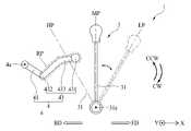
도 8을 참고하면, 상기 주행조작레버(31)는 고속조작위치(HP), 중속조작위치(MP), 및 저속조작위치(LP) 간에 이동 가능하게 설치될 수 있다. 상기 주행조작레버(31)가 상기 고속조작위치(HP)에 위치하면, 상기 주행부(13)는 상기 콤바인본체(10)를 고속주행시킬 수 있다. 상기 주행조작레버(31)가 상기 중속조작위치(MP)에 위치하면, 상기 주행부(13)는 상기 콤바인본체(10)를 중속주행시킬 수 있다. 상기 주행조작레버(31)가 상기 저속조작위치(LP)에 위치하면, 상기 주행부(13)는 상기 콤바인본체(10)를 저속주행시킬 수 있다. 상기 중속조작위치(MP)는 상기 고속조작위치(HP) 및 상기 저속조작위치(LP) 사이에 배치될 수 있다. 즉, 상기 고속조작위치(HP) 및 상기 저속조작위치(LP)는 상기 중속조작위치(MP)를 기준으로 서로 반대쪽에 배치될 수 있다. 따라서, 작업자는 상기 주행조작레버(31)를 상기 저속조작위치(LP)에서 상기 고속조작위치(HP)로, 혹은 상기 고속조작위치(HP)에서 상기 저속조작위치(LP)로 순차적으로 이동시킴으로써, 점진적으로 상기 콤바인본체(10)의 속력을 증대시키거나 감소시킬 수 있다.Referring to FIG. 8 , the driving
상기 주행조작레버(31)는 주행레버축(31a)을 중심으로 회전 가능하게 상기 콤바인본체(10)에 설치될 수 있다. 상기 주행조작레버(31)는 상기 주행레버축(31a)을 중심으로 회전됨에 따라 상기 고속조작위치(HP), 중속조작위치(MP), 및 저속조작위치(LP) 간에 이동될 수 있다. 예컨대, 도 8에 도시된 바와 같이, 상기 주행조작레버(31)는 상기 주행레버축(31a)을 중심으로 제1회전방향(CCW 화살표 방향)으로 회전됨에 따라 상기 저속조작위치(LP)에서 상기 중속조작위치(MP)를 거쳐 상기 고속조작위치(HP)로 순차적으로 이동될 수 있다. 반대로, 상기 주행조작레버(31)는 상기 주행레버축(31a)을 중심으로 제2회전방향(CW 화살표 방향)으로 회전됨에 따라 상기 고속조작위치(HP)에서 상기 중속조작위치(MP)를 거쳐 상기 저속조작위치(LP)로 순차적으로 이동될 수 있다.The traveling
상기 주행조작레버(31)는 제1주행회전경로 및 제2주행회전경로를 따라 회전될 수 있다. 상기 제1주행회전경로는 상기 고속조작위치(HP) 및 상기 중속조작위치(MP) 간에 상기 주행조작레버(31)가 회전되기 위한 경로이다. 상기 주행조작레버(31)는 상기 제1주행회전경로를 따라 회전됨으로써, 상기 고속조작위치(HP)로부터 상기 중속조작위치(MP)로 이동되거나 상기 중속조작위치(MP)로부터 상기 고속조작위치(HP)로 이동될 수 있다. 상기 제2주행회전경로는 상기 중속조작위치(MP) 및 상기 저속조작위치(LP) 간에 상기 주행조작레버(31)가 회전되기 위한 경로이다. 상기 주행조작레버(31)는 상기 제2주행회전경로를 따라 회전됨으로써, 상기 중속조작위치(MP)로부터 상기 저속조작위치(LP)로 이동되거나 상기 저속조작위치(LP)로부터 상기 중속조작위치(MP)로 이동될 수 있다.The driving
도 3 내지 도 17을 참고하면, 상기 제한부(4)는 상기 예취조작레버(21) 및 상기 주행조작레버(31)의 상대적인 위치에 따라 상기 예취조작레버(21) 및 상기 주행조작레버(31) 각각의 이동을 선택적으로 제한하는 것이다. 상기 제한부(4)는 상기 예취조작레버(21) 및 상기 주행조작레버(31)의 상대적인 위치가 변동됨에 따라, 상기 예취조작레버(21) 및 상기 주행조작레버(31) 중에서 어느 하나가 이동되는 것을 제한할 수 있다. 이에 따라, 본 발명에 따른 콤바인용 조작장치(1)는 다음과 같은 작용효과를 도모할 수 있다.Referring to FIGS. 3 to 17 , the limiting
첫째, 본 발명에 따른 콤바인용 조작장치(1)는 상기 예취조작레버(21)가 조작되어 상기 예취조작부(2)가 상기 예취부(12)를 작동시킨 상태에서, 상기 제한부(4)가 상기 주행조작레버(31)의 이동을 제한하도록 구현된다. 이에 따라, 본 발명에 따른 콤바인용 조작장치(1)는 상기 예취부(12)가 예취작업을 수행하는 도중에 작업자가 상기 주행조작레버(31)를 조작하더라도, 상기 주행조작레버(31)의 이동이 제한됨으로써 상기 콤바인본체(10)가 주행하는 속력을 제한할 수 있다. 따라서, 본 발명에 따른 콤바인용 조작장치(1)는 상기 예취부(12)가 예취작업을 수행하기 위해 바닥에 접촉된 상태에서 상기 콤바인본체(10)가 주행하는 속력이 증대됨에 따라 상기 예취부(12)가 고장, 파손되는 경우를 방지함으로써, 상기 예취부(12)의 유지보수작업에 대한 주기를 증대시켜 가동률을 증대시킬 수 있다. 또한, 본 발명에 따른 콤바인용 조작장치(1)는 예취작업을 수행하는 도중에 작업자가 실수로 상기 주행조작레버(31)를 조작함에 따라 발생 가능한 안전사고를 미연에 방지하는 효과가 있으므로, 상기 예취부(12)의 예취작업에 대한 안전성을 증대시키는데 기여할 수 있다.First, in the combine operation device (1) according to the present invention, the
둘째, 본 발명에 따른 콤바인용 조작장치(1)는 상기 주행조작레버(31)가 조작되어 상기 주행조작부(3)가 상기 주행부(13)를 작동시킨 상태에서, 상기 제한부(4)가 상기 예취조작레버(21)의 이동을 제한하도록 구현된다. 이에 따라, 본 발명에 따른 콤바인용 조작장치(1)는 상기 콤바인본체(10)가 주행하는 도중에 작업자가 상기 예취조작레버(21)를 조작하더라도, 상기 예취조작레버(21)의 이동이 제한됨으로써 상기 예취부(12)가 예취작업을 수행하는 것을 제한할 수 있다. 따라서, 본 발명에 따른 콤바인용 조작장치(1)는 상기 콤바인본체(10)가 주행하고 있는 상태에서 상기 예취부(12)가 예취작업을 수행하기 위해 바닥에 접촉됨에 따라 상기 예취부(12)가 고장, 파손되는 경우를 방지함으로써, 상기 예취부(12)의 유지보수작업에 대한 주기를 증대시켜 가동률을 증대시킬 수 있다. 또한, 본 발명에 따른 콤바인용 조작장치(1)는 주행 도중에 작업자가 실수로 상기 예취조작레버(21)를 조작함에 따라 발생 가능한 안전사고를 미연에 방지하는 효과가 있으므로, 상기 주행부(13)가 상기 콤바인본체(10)를 주행시키는 주행작업에 대한 안전성을 증대시키는데 기여할 수 있다.Second, in the operation device for a combine (1) according to the present invention, in a state in which the traveling
상기 제한부(4)는 상기 예취조작레버(21)에 연결되어 상기 예취조작레버(21)가 이동됨에 따라 함께 이동될 수 있다. 상기 제한부(4)는 상기 예취조작레버(21)가 이동됨에 따라 제한위치(RP) 및 회피위치(AP) 간에 제한회전경로를 따라 이동될 수 있다. 상기 제한위치(RP)는 상기 제1주행회전경로 상에서 상기 제한부(4)가 상기 주행조작레버(31)의 이동을 제한하는 위치이다. 상기 회피위치(AP)는 상기 제1주행회전경로로부터 벗어난 위치로, 상기 제한부(4)가 상기 주행조작레버(31)의 이동을 제한하지 않도록 상기 주행조작레버(31)를 회피하기 위한 위치이다. 상기 제한회전경로는 상기 제한위치(RP) 및 상기 회피위치(AP) 간에 상기 예취조작레버(21)가 이동되는 경로이다.The limiting
이에 따라, 본 발명에 따른 콤바인용 조작장치(1)는 상기 예취조작레버(21)가 이동됨에 따라 상기 제한부(4)가 상기 제한위치(RP) 및 상기 회피위치(AP) 간에 이동 가능하게 구현됨으로써, 작업자가 상기 제한부(4)를 별도로 조작하지 않고 상기 예취조작레버(21)를 조작하는 것만으로도 상기 예취조작레버(21) 및 상기 주행조작레버(31) 각각의 이동을 선택적으로 제한할 수 있다. 따라서, 본 발명에 따른 콤바인용 조작장치(1)는 상기 제한부(4)를 조작하기 위해 걸리는 시간을 감소시킴으로써, 상기 제한부(4)의 조작작업에 대한 용이성을 증대시킬 수 있다.Accordingly, the combine operation device (1) according to the present invention as the
상기 제한부(4)는 상기 예취조작레버(21)가 상기 예취조작위치(OP)로 이동됨에 따라 상기 제한위치(RP)로 이동되어 상기 주행조작레버(31)가 상기 중속조작위치(MP)에서 상기 고속조작위치(HP)로 이동되는 것을 제한할 수 있다. 이하에서는 상기 제한부(4)가 상기 주행조작레버(31)의 이동을 제한하는 과정에 대해 첨부된 도면을 참조하여 구체적으로 설명한다.The limiting
먼저, 도 7에 도시된 바와 같이, 작업자는 상기 예취부(12)를 작동시키기 위해 상기 예취조작레버(21)를 상기 예취대기위치(SP)로부터 상기 예취조작위치(OP)로 이동시킬 수 있다. 이에 따라, 상기 예취조작레버(21)는 상기 예취레버축(21a)을 중심으로 상기 제2회전방향(CW 화살표 방향)으로 회전될 수 있다.First, as shown in Figure 7, the operator can move the
다음, 상기 예취조작레버(21)가 상기 예취레버축(21a)을 중심으로 상기 제2회전방향(CW 화살표 방향)으로 회전됨에 따라, 상기 회전기구(22)는 상기 예취레버축(21a)을 중심으로 상기 제2회전방향(CW 화살표 방향)으로 회전될 수 있다. 이에 따라, 상기 회전기구(22)는 상기 전달기구(23)를 제2방향(BD 화살표 방향)으로 당길 수 있다.Next, as the
다음, 상기 전달기구(23)는 상기 제2방향(BD 화살표 방향)으로 이동될 수 있다. 이에 따라, 상기 전달기구(23)는 상기 링크기구(24)의 일측을 상기 제2방향(BD 화살표 방향)으로 당길 수 있다.Next, the
다음, 상기 링크기구(24)는 일측이 상기 제2방향(BD 화살표 방향)으로 당겨져 상기 제한회전축(4a)을 중심으로 상기 제1회전방향(CCW 화살표 방향)으로 회전될 수 있다. 이에 따라, 상기 링크기구(24)는 상기 제한부(4)를 상기 제한회전축(4a)을 중심으로 상기 제1회전방향(CCW 화살표 방향)으로 회전시킬 수 있다. 이 경우, 상기 예취부(12)는 상기 작동기구(25)를 통해 작동되어 예취작업을 수행할 수 있다.Next, one side of the
다음, 도 7 및 도 10에 도시된 바와 같이, 상기 제한부(4)는 상기 회피위치(AP)에서 상기 제한회전경로를 따라 회전되어 상기 제한위치(RP)로 이동될 수 있다. 이 경우, 상기 제한위치(RP)가 상기 제1주행회전경로 상에 위치하여서, 상기 제한부(4)는 상기 제1주행회전경로 상에 위치할 수 있다.Next, as shown in FIGS. 7 and 10 , the limiting
다음, 도 11에 도시된 바와 같이, 작업자는 상기 주행조작레버(31)를 상기 중속조작위치(MP)로부터 상기 고속조작위치(HP)로 이동시키기 위해 상기 주행조작레버(31)를 상기 제1주행회전경로를 따라 회전시킬 수 있다. 이 과정에서, 상기 주행조작레버(31)는 상기 제1주행회전경로 상에 위치한 상기 제한부(4)에 걸림에 따라, 상기 고속조작위치(HP)로의 이동이 제한될 수 있다.Next, as shown in FIG. 11 , the operator moves the traveling
상기와 같은 과정을 통해, 본 발명에 따른 콤바인용 조작장치(1)는 상기 예취부(12)가 작동되는 도중에 상기 콤바인본체(10)가 고속주행하는 것을 방지할 수 있다. 따라서, 본 발명에 따른 콤바인용 조작장치(1)는 상기 예취부(12)가 예취작업을 수행하기 위해 바닥에 접촉된 상태에서 상기 콤바인본체(10)가 고속주행함에 따라 상기 예취부(12)가 고장, 파손되는 경우를 방지함으로써, 상기 예취부(12)의 유지보수작업에 대한 주기를 증대시켜 가동률을 증대시킬 수 있다. 또한, 본 발명에 따른 콤바인용 조작장치(1)는 예취작업을 수행하는 도중에 작업자가 실수로 상기 주행조작레버(31)를 조작하여 상기 콤바인본체(10)가 고속주행함에 따라 발생 가능한 안전사고를 미연에 방지하는 효과가 있으므로, 상기 예취부(12)의 예취작업에 대한 안전성을 증대시키는데 기여할 수 있다.Through the above process, the
한편, 상기 제한부(4)는 상기 주행조작레버(31)가 상기 고속조작위치(HP)로 이동됨에 따라 상기 예취조작레버(21)가 상기 예취조작위치(OP)로 이동되는 것을 제한할 수 있다. 이하에서는 상기 제한부(4)가 상기 예취조작레버(21)의 이동을 제한하는 과정에 대해 첨부된 도면을 참조하여 구체적으로 설명한다.On the other hand, the
먼저, 도 12에 도시된 바와 같이, 작업자는 상기 주행부(13)를 고속주행시키기 위해 상기 주행조작레버(31)를 상기 고속조작위치(HP)로 이동시킬 수 있다. 이에 따라, 상기 주행조작레버(31)는 상기 주행레버축(31a)을 중심으로 상기 제1회전방향(CCW 화살표 방향)으로 회전될 수 있다. 이 경우, 상기 콤바인본체(10)는 고속주행할 수 있다.First, as shown in FIG. 12 , the operator may move the traveling
다음, 작업자는 상기 예취조작레버(21)를 상기 예취대기위치(SP)에서 상기 예취조작위치(OP)로 이동시키기 위해 상기 예취조작레버(21)를 조작할 수 있다. 이에 따라, 상기 예취조작레버(21)는 상기 예취레버축(21a)을 중심으로 상기 제2회전방향(CW 화살표 방향)으로 회전될 수 있다.Next, the operator may operate the
다음, 상기 예취조작레버(21)가 상기 예취레버축(21a)을 중심으로 상기 제2회전방향(CW 화살표 방향)으로 회전됨에 따라, 상기 회전기구(22)는 상기 예취레버축(21a)을 중심으로 상기 제2회전방향(CW 화살표 방향)으로 회전될 수 있다. 이에 따라, 상기 회전기구(22)는 상기 전달기구(23)를 제2방향(BD 화살표 방향)으로 당길 수 있다.Next, as the
다음, 상기 전달기구(23)는 상기 제2방향(BD 화살표 방향)으로 이동될 수 있다. 이에 따라, 상기 전달기구(23)는 상기 링크기구(24)의 일측을 상기 제2방향(BD 화살표 방향)으로 당길 수 있다.Next, the
다음, 상기 링크기구(24)는 일측이 상기 제2방향(BD 화살표 방향)으로 당겨져 상기 제한회전축(4a)을 중심으로 상기 제1회전방향(CCW 화살표 방향)으로 회전될 수 있다. 이에 따라, 상기 링크기구(24)는 상기 제한부(4)를 상기 제한회전축(4a)을 중심으로 상기 제1회전방향(CCW 화살표 방향)으로 회전시킬 수 있다.Next, one side of the
다음, 도 13에 도시된 바와 같이, 상기 제한부(4)는 상기 주행조작부(3)에 걸릴 수 있다. 상기 제한부(4)는 상기 제한회전경로를 따라 회전되다가 상기 주행조작레버(31)에 걸림으로써, 상기 제한위치(RP)로 회전되는 것이 제한될 수 있다. 이에 따라, 상기 제한부(4)는 상기 예취조작레버(21)가 상기 예취조작위치(OP)로 이동되는 것을 제한할 수 있다.Next, as shown in FIG. 13 , the limiting
상기와 같은 과정을 통해, 본 발명에 따른 콤바인용 조작장치(1)는 상기 콤바인본체(10)가 고속주행하는 도중에 상기 예취부(12)가 작동되는 것을 방지할 수 있다. 이에 따라, 본 발명에 따른 콤바인용 조작장치(1)는 상기 콤바인본체(10)가 고속주행하는 도중에 작업자가 상기 예취조작레버(21)를 조작하더라도, 상기 예취부(12)가 예취작업을 수행하는 것을 방지할 수 있다. 따라서, 본 발명에 따른 콤바인용 조작장치(1)는 상기 콤바인본체(10)가 고속주행하고 있는 상태에서 상기 예취부(12)가 예취작업을 수행하기 위해 바닥에 접촉됨에 따라 상기 예취부(12)가 고장, 파손되는 경우를 방지함으로써, 상기 예취부(12)의 유지보수작업에 대한 주기를 증대시켜 가동률을 증대시킬 수 있다. 또한, 본 발명에 따른 콤바인용 조작장치(1)는 고속주행 도중에 상기 예취부(12)가 작동됨에 따라 발생 가능한 안전사고를 미연에 방지하는 효과가 있으므로, 상기 콤바인본체(10)의 주행작업에 대한 안전성을 증대시키는데 기여할 수 있다.Through the above process, the
도 14를 참고하면, 상기 제한부(4)는 상기 제2주행회전경로로부터 이격된 위치에서 상기 제한회전경로를 따라 회전될 수 있다. 즉, 상기 제한부(4)가 상기 회피위치(AP) 또는 상기 제한위치(RP)에 위치하는 경우에도, 상기 주행조작레버(31)는 상기 중속조작위치(MP) 및 상기 저속조작위치(LP) 간에 상기 제2주행회전경로를 따라 회전될 수 있다.Referring to FIG. 14 , the limiting
이에 따라, 본 발명에 따른 콤바인용 조작장치(1)는 상기 콤바인본체(10)가 중속주행 또는 저속주행하는 경우에 상기 예취조작레버(21) 및 상기 주행조작레버(31)가 독립적으로 이동되도록 구현된다. 따라서, 본 발명에 따른 콤바인용 조작장치(1)는 상기 예취부(12)가 예취작업을 수행하는 도중에 상기 콤바인본체(10)를 중속주행 또는 저속주행시키거나, 상기 콤바인본체(10)가 중속주행 또는 저속주행하는 도중에 상기 예취부(12)를 작동시킬 수 있다. 이에 따라, 본 발명에 따른 콤바인용 조작장치(1)는 상기 예취부(12)가 예취작업을 수행하는 과정에서 상기 콤바인본체(10)가 고속주행하는 것을 방지하면서도, 상기 콤바인본체(10)가 적절한 속력으로 주행하면서 상기 예취부(12)가 연속적으로 예취작업을 수행할 수 있어 예취작업에 대한 용이성을 증대시킬 수 있다.Accordingly, the
도 4 내지 도 17을 참고하면, 상기 제한부(4)는 설치기구(41)를 포함할 수 있다.4 to 17 , the limiting
상기 설치기구(41)는 상기 예취조작부(2)에 설치된 것이다. 상기 제한부(4)는 상기 설치기구(41)를 통해 상기 예취조작부(2)에 설치될 수 있다. 상기 설치기구(41)는 상기 링크기구(24)에 설치될 수 있다. 상기 설치기구(41)는 상기 링크기구(24)가 상기 제한회전축(4a)을 중심으로 회전됨에 따라 상기 제한회전축(4a)을 중심으로 회전될 수 있다.The
상기 설치기구(41)는 상기 링크기구(24)로부터 돌출되도록 상기 예취조작부(2)에 설치된 것이다. 상기 설치기구(41)가 상기 링크기구(24)로부터 돌출됨에 따라, 상기 제한부(4)는 상기 링크기구(24)에 설치된 상기 작동기구(25)로부터 이격된 위치에서 상기 제한회전경로를 따라 회전될 수 있다. 이 경우, 상기 작동기구(25)는 상기 링크기구(24)가 상기 제한회전축(4a)을 중심으로 회전됨에 따라 작동되되, 상기 제한회전경로로부터 이격된 위치에서 작동될 수 있다.The
이에 따라, 본 발명에 따른 콤바인용 조작장치(1)는 상기 제한부(4)가 상기 작동기구(25)의 작동범위를 벗어난 위치에서 상기 제한위치(RP) 및 상기 회피위치(AP) 간에 회전되도록 구현된다. 따라서, 본 발명에 따른 콤바인용 조작장치(1)는 상기 제한회전경로가 상기 작동기구(25)의 작동범위에 간섭됨으로써, 제한부(4)가 상기 작동기구(25)에 충돌하는 경우를 방지할 수 있다. 이에 따라, 본 발명에 따른 콤바인용 조작장치(1)는 상기 작동기구(25) 및 상기 제한부(4)가 고장, 파손되는 경우를 감소시킴으로써, 상기 작동기구(25) 및 상기 제한부(4)의 가동수명을 증대시켜 유지 비용을 절감시킬 수 있을 뿐만 아니라 상기 작동기구(25) 및 상기 제한부(4)의 유지보수작업에 대한 주기를 증대시켜 가동률을 증대시킬 수 있다.Accordingly, the operation device for the combine (1) according to the present invention is rotated between the limiting position (RP) and the avoiding position (AP) in the position where the limiting part (4) is out of the operating range of the operating mechanism (25) implemented as much as possible. Therefore, the operation device for a combine (1) according to the present invention by the limited rotation path interferes with the operating range of the operating mechanism (25), the limiting portion (4) to prevent the case of colliding with the operating mechanism (25) can do. Accordingly, the operation device for a combine (1) according to the present invention by reducing the case of failure and damage to the
도 4 및 도 15를 참고하면, 상기 제한부(4)는 연결기구(42)를 포함할 수 있다.4 and 15 , the limiting
상기 연결기구(42)는 상기 설치기구(41)에 연결된 것이다. 상기 연결기구(42)는 상기 설치기구(41)가 상기 회피위치(AP) 및 상기 제한위치(RP) 간에 상기 제한회전경로를 따라 회전됨에 따라 상기 회피위치(AP) 및 상기 제한위치(RP) 간에 회전될 수 있다. 상기 연결기구(42)는 상기 제2축방향(Y축 방향)을 따라 상기 설치기구(41)로부터 돌출되도록 상기 설치기구(41)에 연결될 수 있다. 이 경우, 상기 연결기구(42)는 상기 주행조작레버(31)로부터 이격된 거리가 감소되도록 상기 제2축방향(Y축 방향)을 따라 상기 설치기구(41)로부터 돌출될 수 있다.The
이에 따라, 본 발명에 따른 콤바인용 조작장치(1)는 상기 링크기구(24) 및 상기 주행조작레버(31)가 상기 제2축방향(Y축 방향)을 기준으로 서로 이격되더라도, 상기 연결기구(42)를 통해 상기 제2축방향(Y축 방향)을 기준으로 이격된 거리를 보상함으로써 상기 제한위치(RP)가 상기 제1주행회전경로 상에 위치 가능하도록 구현된다.Accordingly, in the
상기 연결기구(42) 및 상기 설치기구(41)는 일체로 형성될 수 있다. 이 경우, 상기 연결기구(42) 및 상기 설치기구(41)는 단일의 봉 부재를 절곡(切曲) 가공함으로써 형성될 수 있다. 상기 설치기구(41)가 상기 링크기구(24)로부터 돌출되도록 형성된 경우, 상기 연결기구(42)는 상기 설치기구(41)를 통해 상기 작동기구(25)의 작동범위를 벗어난 위치에서 상기 제한위치(RP) 및 상기 회피위치(AP) 간에 회전될 수 있다.The
도 4 내지 도 17을 참고하면, 상기 제한부(4)는 이동제한기구(43)를 포함할 수 있다.4 to 17 , the limiting
상기 이동제한기구(43)는 상기 연결기구(42)에 연결된 것이다. 상기 연결기구(42)가 상기 설치기구(41) 및 상기 연결기구(42) 각각에 연결됨으로써, 상기 이동제한기구(43)는 상기 연결기구(42)를 통해 상기 설치기구(41)에 연결될 수 있다. 상기 이동제한기구(43)는 상기 설치기구(41)가 상기 제한회전축(4a)을 중심으로 회전됨에 따라 상기 회피위치(AP) 및 상기 제한위치(RP) 간에 이동될 수 있다. 예컨대, 상기 이동제한기구(43)는 상기 설치기구(41)가 상기 제한회전축(4a)을 중심으로 상기 제1회전방향(CCW 화살표 방향)으로 회전됨에 따라 상기 제한위치(RP)에 위치할 수 있다. 상기 이동제한기구(43)는 상기 설치기구(41)가 상기 제한회전축(4a)을 중심으로 상기 제2회전방향(CW 화살표 방향)으로 회전됨에 따라 상기 회피위치(AP)에 위치할 수 있다. 상기 이동제한기구(43)가 상기 제한위치(RP)에 위치하면 상기 고속조작위치(HP)로 회전되는 상기 주행조작레버(31)는 상기 이동제한기구(43)에 걸릴 수 있다.The
상기 이동제한기구(43)는 상기 제1축방향(X축 방향)을 따라 상기 연결기구(42)로부터 돌출되도록 형성될 수 있다. 이에 따라, 본 발명에 따른 콤바인용 조작장치(1)는 상기 링크기구(24) 및 상기 주행조작레버(31)가 상기 제1축방향(X축 방향)을 기준으로 서로 이격되더라도, 상기 이동제한기구(43)를 통해 상기 제1축방향(X축 방향)을 기준으로 이격된 거리를 보상함으로써 상기 제한위치(RP)가 상기 제1주행회전경로 상에 위치 가능하도록 구현된다.The
상기 이동제한기구(43) 및 상기 연결기구(42)는 일체로 형성될 수 있다. 이 경우, 상기 이동제한기구(43) 및 상기 연결기구(42)는 단일의 봉 부재를 절곡 가공함으로써 형성될 수 있다. 상기 설치기구(41)가 상기 링크기구(24)로부터 돌출되도록 형성된 경우, 상기 이동제한기구(43)는 상기 설치기구(41)를 통해 상기 작동기구(25)의 작동범위를 벗어난 위치에서 상기 제한위치(RP) 및 상기 회피위치(AP) 간에 회전될 수 있다.The
도 4 내지 도 17을 참고하면, 상기 이동제한기구(43)는 이동제한부재(431)를 포함할 수 있다.4 to 17 , the
상기 이동제한부재(431)는 상기 주행조작레버(31) 쪽을 향하는 일단에 배치된 것이다. 상기 이동제한부재(431)가 상기 제한위치(RP)에 위치한 경우 상기 제1주행회전경로를 따라 상기 고속조작위치(HP)로 회전되는 상기 주행조작레버(31)는 상기 이동제한부재(431)에 걸릴 수 있다.The
도 15를 참고하면, 상기 이동제한부재(431)는 상기 이동제한기구(43)의 상기 주행조작레버(31) 쪽을 향하는 일단에서 양측으로 돌출될 수 있다. 이에 따라, 본 발명에 따른 콤바인용 조작장치(1)는 상기 이동제한부재(431)에 있어서, 상기 주행조작레버(31)가 걸리기 위한 면적이 증대되도록 구현된다. 따라서, 본 발명에 따른 콤바인용 조작장치(1)는 외부로부터 충격, 진동 등이 가해짐에 따라, 상기 제한위치(RP)에 위치한 상기 이동제한부재(431)가 상기 주행조작레버(31)로부터 어긋나게 되어 상기 주행조작레버(31)가 상기 이동제한부재(431)에 걸리지 못하고 상기 고속조작위치(HP)로 이동되는 경우를 방지할 수 있다. 이에 따라, 본 발명에 따른 콤바인용 조작장치(1)는 상기 이동제한부재(431)를 통해 상기 주행조작레버(31)에 걸림을 형성하는 작업에 대한 안정성을 증대시키는데 기여할 수 있다.Referring to FIG. 15 , the
도 16을 참고하면, 상기 이동제한부재(431)는 상기 제한위치(RP)에 위치하는 경우, 상기 주행조작레버(31)가 상기 고속조작위치(HP)로 이동되는 과정에서 상기 주행조작레버(31)에 의해 가압될 수 있다. 이 경우, 상기 주행조작레버(31)는 상기 설치기구(41)를 상기 제1회전방향(CCW 화살표 방향)으로 회전시키는 방향으로 상기 제한위치(RP)에 위치한 상기 이동제한부재(431)를 가압할 수 있다.Referring to FIG. 16 , when the
이에 따라, 본 발명에 따른 콤바인용 조작장치(1)는 상기 주행조작레버(31)가 상기 제한위치(RP)에 위치한 상기 이동제한부재(431)를 가압함에 따라 상기 이동제한부재(431)가 가압력에 의해 상기 제2회전방향(CW 화살표 방향)으로 회전되는 경우를 방지할 수 있다. 따라서, 본 발명에 따른 콤바인용 조작장치(1)는 상기 주행조작레버(31)가 상기 고속조작위치(HP)로 이동되는 과정에서 상기 이동제한부재(431)가 상기 주행조작레버(31)가 이동되는 것을 제한하지 못하고 상기 회피위치(AP)로 이동되는 것을 방지함으로써, 상기 주행조작레버(31)가 상기 고속조작위치(HP)로 이동되는 것을 제한하는 작업에 대한 안정성을 증대시킬 수 있다. 또한, 본 발명에 따른 콤바인용 조작장치(1)는 상기 예취조작레버(21)가 상기 예취조작위치(OP)에 위치하여 상기 예취부(12)가 예취작업을 수행하고 있는 상태에서 작업자가 상기 주행조작레버(31)를 상기 고속조작위치(HP)로 이동시킴에 따라, 상기 예취조작레버(21)가 상기 예취대기위치(SP)로 이동되어 상기 예취부(12)가 예취작업을 중단하는 것을 방지할 수 있다. 따라서, 본 발명에 따른 콤바인용 조작장치(1)는 콤바인이 예취가 예정된 농작물의 전방에서 예취작업을 중단한 채 고속주행하는 것을 방지하여 예취가 예정된 농작물이 콤바인에 밟혀 손상되는 것을 방지할 수 있다.Accordingly, in the
상기 이동제한부재(431)는 상기 제한위치(RP)에 위치하는 경우 상기 제한회전축(4a)에 대해 상측에 위치할 수 있다. 상기 이동제한부재(431)는 상기 회피위치(AP)에 위치하는 경우 상기 제한회전축(4a)에 대해 하측에 위치할 수 있다. 상기 이동제한부재(431)는 상기 주행조작레버(31)가 걸리게 되는 과정에서 상기 주행조작레버(31)로부터 전달되는 충격을 완화하는 완충부재를 구비할 수 있다. 이에 따라, 본 발명에 따른 콤바인용 조작장치(1)는 상기 이동제한부재(431) 및 상기 주행조작레버(31)의 가동수명을 증대시킬 수 있을 뿐만 아니라, 상기 주행조작레버(31)가 상기 이동제한부재(431)에 걸리는 과정에서 발생하는 소음 등을 감소시킬 수 있다는 장점이 있다.The
도 4 내지 도 17을 참고하면, 상기 이동제한기구(43)는 제1이음부재(432) 및 제2이음부재(433)를 포함할 수 있다.4 to 17 , the
상기 제1이음부재(432)는 상기 연결기구(42)에 연결된 것이다. 상기 제1이음부재(432)는 상기 연결기구(42)로부터 상기 주행조작레버(31) 쪽으로 돌출되어 형성될 수 있다. 상기 제1이음부재(432)는 상기 연결기구(42)가 회전됨에 따라 상기 제한회전축(4a)을 중심으로 회전될 수 있다. 상기 제1이음부재(432)는 봉 형태로 형성될 수 있으나, 이에 한정되지 않으며 상기 연결기구(42)에 연결될 수 있는 형태이면 다른 형태로 형성될 수 있다.The first
상기 제2이음부재(433)는 상기 제1이음부재(432)로부터 상기 주행조작레버(31) 쪽으로 돌출된 것이다. 상기 제2이음부재(433)는 상기 제1이음부재(432)에 연결될 수 있다.The second
도 17을 참고하면, 상기 제2이음부재(433)는 상기 회피위치(AP)에 위치한 경우 상기 제1주행회전경로로부터 이격된 거리가 증대되도록 상기 제1이음부재(432)로부터 경사지게 돌출될 수 있다. 따라서, 도 17에 도시된 바와 같이, 상기 제2이음부재(433)는 상기 제1이음부재(432)로부터 경사지게 돌출되지 않은 비교예에 대비할 때, 상기 회피위치(AP)에서 상기 제1주행회전경로로부터 이격된 거리가 증대될 수 있다.Referring to FIG. 17 , when the second
이에 따라, 본 발명에 따른 콤바인용 조작장치(1)는 상기 주행조작레버(31)가 상기 제1주행회전경로를 따라 이동되는 과정에서 외부로부터 가해지는 충격, 진동 등으로 인해 임의로 소정 거리만큼 더 이동되어 상기 회피위치(AP)에 위치한 상기 이동제한기구(43)에 충돌되는 경우를 감소시킬 수 있다. 따라서, 본 발명에 따른 콤바인용 조작장치(1)는 상기 예취부(12)가 예취작업을 수행하지 않는 동안에 작업자가 상기 주행조작레버(31)를 상기 제1주행회전경로를 따라 조작하는 작업에 대한 안정성을 더 증대시킬 수 있을 뿐만 아니라, 상기 이동제한기구(43)의 가동수명을 증대시킴으로써 상기 이동제한기구(43)에 대한 유지보수작업에 대한 주기를 증대시킬 수도 있다.Accordingly, the operation device for the combine according to the present invention (1) is arbitrarily further by a predetermined distance due to the shock, vibration, etc. applied from the outside in the process of the traveling
상기 제2이음부재(433) 및 상기 제1이음부재(432)는 일체로 형성될 수 있다. 도 17에 도시된 바와 같이, 상기 제2이음부재(433)에는 상기 이동제한부재(431)가 설치될 수 있다. 상기 제2이음부재(433)는 상기 제1이음부재(432) 및 상기 이동제한부재(431) 사이에 위치할 수 있다. 상기 제2이음부재(433) 및 상기 제1이음부재(432)를 통해, 상기 이동제한부재(431)는 상기 연결기구(42)가 회전됨에 따라 함께 회전될 수 있다.The second
이상에서 설명한 본 발명은 전술한 실시예 및 첨부된 도면에 한정되는 것이 아니고, 본 발명의 기술적 사상을 벗어나지 않는 범위 내에서 여러 가지 치환, 변형 및 변경이 가능하다는 것이 본 발명이 속하는 기술 분야에서 통상의 지식을 가진 자에게 있어 명백할 것이다.The present invention described above is not limited to the above-described embodiments and the accompanying drawings, and it is common in the technical field to which the present invention pertains that various substitutions, modifications, and changes are possible without departing from the technical spirit of the present invention. It will be clear to those who have the knowledge of
1 : 콤바인용 조작장치2 : 예취조작부
3 : 주행조작부4 : 제한부
10 : 콤바인본체11 : 운전석
12 : 예취부13 : 주행부
21 : 예취조작레버22 : 회전기구
23 : 전달기구24 : 링크기구
25 : 작동기구31 : 주행조작레버
41 : 설치기구42 : 연결기구
43 : 이동제한기구431 : 이동제한부재
432 : 제1이음부재433 : 제2이음부재1: operation device for combine 2: mowing operation part
3: driving control unit 4: limiting unit
10: combine body 11: driver's seat
12: harvesting unit 13: driving unit
21: mowing control lever 22: rotary mechanism
23: transmission mechanism 24: link mechanism
25: operating mechanism 31: driving control lever
41: installation mechanism 42: connection mechanism
43: movement limiting mechanism 431: movement limiting member
432: first joint member 433: second joint member
Claims (15)
Translated fromKorean상기 운전석(11)에 배치된 주행조작레버(31)를 포함하고, 상기 콤바인본체(10)를 주행시키는 주행부(13)를 제어하기 위한 주행조작부(3); 및
상기 예취조작레버(21) 및 상기 주행조작레버(31)의 상대적인 위치에 따라 상기 예취조작레버(21) 및 상기 주행조작레버(31) 각각의 이동을 선택적으로 제한하는 제한부(4)를 포함하는 것을 특징으로 하는 콤바인용 조작장치.It includes a harvesting operation lever 21 disposed on the driver's seat 11 of the combine body 10, and a harvesting operation unit 2 for controlling the harvesting unit 12 for cutting and transporting crops;
a traveling operation unit (3) including a traveling operation lever (31) disposed on the driver's seat (11) and configured to control the traveling unit (13) for traveling the combine body (10); and
According to the relative positions of the harvesting operation lever 21 and the travel operation lever 31, the harvesting operation lever 21 and the travel operation lever 31 each include a limiting part 4 for selectively restricting movement. An operation device for a combine, characterized in that.
상기 제한부(4)는 상기 예취조작레버(21)가 이동됨에 따라 함께 이동되도록 상기 예취조작부(2)에 설치되되, 상기 예취부(12)를 작동시키기 위해 상기 예취조작레버(21)가 예취조작위치(OP)로 이동된 경우, 상기 주행조작레버(31)가 상기 콤바인본체(10)를 고속주행시키기 위해 고속조작위치(HP)로 이동되는 것을 제한하고,
상기 주행조작레버(31)는 상기 고속조작위치(HP)로 이동되는 과정에서 상기 제한부(4)에 걸림에 따라 상기 고속조작위치(HP)로 이동되는 것이 제한되는 것을 특징으로 하는 콤바인용 조작장치.According to claim 1,
The limiting part 4 is installed in the harvesting operation part 2 so as to move together as the harvesting operation lever 21 is moved, and the harvesting operation lever 21 to operate the harvesting part 12 is mowing. When moved to the operation position (OP), the traveling operation lever 31 limits the movement to the high-speed operation position (HP) in order to make the combine main body 10 travel at high speed,
Combine operation, characterized in that the travel operation lever 31 is restricted from moving to the high-speed operation position (HP) as it is caught by the limiter (4) in the process of moving to the high-speed operation position (HP) Device.
상기 주행조작레버(31)는 상기 고속조작위치(HP), 중속조작위치(MP), 및 저속조작위치(LP) 간에 회전 가능하게 상기 콤바인본체(10)에 설치되되, 상기 고속조작위치(HP)와 상기 저속조작위치(LP)가 상기 중속조작위치(MP)를 기준으로 서로 반대쪽에 배치되고,
상기 제한부(4)는 상기 예취조작레버(21)가 상기 예취조작위치(OP)로 이동됨에 따라 상기 주행조작레버(31)가 상기 중속조작위치(MP)와 상기 고속조작위치(HP) 간에 회전되기 위한 제1주행회전경로 상에 배치되어서 상기 주행조작레버(31)가 상기 중속조작위치(MP)에서 상기 고속조작위치(HP)로 이동되는 것을 제한하는 것을 특징으로 하는 콤바인용 조작장치.3. The method of claim 2,
The traveling control lever 31 is installed in the combine body 10 so as to be rotatable between the high-speed operation position (HP), the medium-speed operation position (MP), and the low-speed operation position (LP), the high-speed operation position (HP) ) and the low-speed operation position (LP) are disposed opposite to each other with respect to the medium-speed operation position (MP),
The limiting unit 4 is configured such that as the harvesting operation lever 21 is moved to the harvesting operation position OP, the traveling operation lever 31 moves between the medium-speed operation position MP and the high-speed operation position HP. The combine operation device, characterized in that it is disposed on the first travel rotation path to be rotated to limit the movement of the travel operation lever (31) from the medium-speed operation position (MP) to the high-speed operation position (HP).
상기 제한부(4)는 상기 예취조작레버(21)가 이동됨에 따라 함께 이동되도록 상기 예취조작부(2)에 설치되되, 상기 콤바인본체(10)를 고속주행시키기 위해 상기 주행조작레버(31)가 고속조작위치(HP)로 이동된 경우, 상기 예취조작레버(21)가 상기 예취부(12)를 작동시키기 위해 예취조작위치(OP)로 이동되는 것을 제한하고,
상기 예취조작레버(21)는 상기 예취조작위치(OP)로 이동되는 과정에서 상기 제한부(4)가 상기 주행조작부(3)에 걸림에 따라 상기 예취조작위치(OP)로 이동되는 것이 제한되는 것을 특징으로 하는 콤바인용 조작장치.According to claim 1,
The limiting part 4 is installed in the harvesting operation part 2 so as to move together as the harvesting operation lever 21 is moved, and the traveling operation lever 31 is installed in order to drive the combine body 10 at high speed. When moved to the high-speed operation position (HP), the harvesting operation lever 21 is limited to move to the harvesting operation position (OP) to operate the harvesting unit 12,
In the process of moving the harvesting operation lever 21 to the harvesting operation position OP, as the limiting part 4 is caught by the traveling operation part 3, the movement to the harvesting operation position OP is restricted. An operation device for a combine, characterized in that.
상기 주행조작레버(31)는 상기 콤바인본체(10)를 고속주행시키기 위해 중속조작위치(MP)와 고속조작위치(HP) 간에 회전되기 위한 제1주행회전경로를 따라 회전되어 상기 고속조작위치(HP)에 위치하고,
상기 제한부(4)는 상기 예취조작레버(21)의 위치에 따라 상기 제1주행회전경로 상에 배치된 제한위치(RP) 및 상기 제1주행회전경로로부터 벗어난 회피위치(AP) 간에 제한회전경로를 따라 회전되도록 상기 예취조작부(2)에 설치된 것을 특징으로 하는 콤바인용 조작장치.According to claim 1,
The traveling operation lever 31 is rotated along the first traveling rotation path for rotation between the medium-speed operation position (MP) and the high-speed operation position (HP) in order to drive the combine body 10 at high speed, and the high-speed operation position ( HP) is located in
The limiting part 4 rotates limited between a limiting position RP disposed on the first running rotation path and an avoiding position AP deviating from the first driving rotation path according to the position of the harvesting operation lever 21 . An operation device for a combine, characterized in that it is installed in the harvesting operation unit (2) so as to rotate along the path.
상기 주행조작레버(31)는 상기 고속조작위치(HP)에 위치함에 따라 상기 제한회전경로 상에 위치하여 상기 제한부(4)가 상기 제한위치(RP)로 회전되는 것을 제한하고,
상기 예취조작레버(21)는 상기 제한부(4)가 상기 제한위치(RP)로 회전되는 것이 제한됨에 따라 상기 예취부(12)를 작동시키기 위한 예취조작위치(OP)로의 이동이 제한되는 것을 특징으로 하는 콤바인용 조작장치.6. The method of claim 5,
The traveling control lever 31 is positioned on the limited rotation path as it is positioned at the high-speed operation position HP to limit rotation of the limiting part 4 to the limited position RP,
The harvesting operation lever 21 is that the movement to the harvesting operation position (OP) for operating the harvesting unit 12 is limited as the rotation of the limiting part 4 to the limiting position RP is limited. An operation device for a combine characterized by its features.
상기 예취조작레버(21)는 상기 예취부(12)를 작동시키기 위해 예취조작위치(OP)로 이동됨에 따라 상기 제한부(4)를 상기 제한위치(RP)로 회전시키고,
상기 제한부(4)는 상기 제한위치(RP)에 위치함에 따라 상기 제1주행회전경로 상에 위치하여 상기 주행조작레버(31)가 상기 고속조작위치(HP)로 회전되는 것을 제한하는 것을 특징으로 하는 콤바인용 조작장치.6. The method of claim 5,
The harvesting operation lever 21 rotates the limiting part 4 to the limiting position RP as it moves to the harvesting operation position OP to operate the harvesting part 12,
The limiting part 4 is positioned on the first running rotation path as it is positioned at the limiting position RP to restrict rotation of the driving control lever 31 to the high-speed operation position HP. operation device for the combine.
상기 주행조작레버(31)는 상기 제1주행회전경로를 따라 회전함과 아울러 상기 중속조작위치(MP)와 저속조작위치(LP) 간에 제2주행회전경로를 따라 회전되되, 상기 제1주행회전경로와 상기 제2주행회전경로가 상기 중속조작위치(MP)를 기준으로 서로 반대쪽에 배치되고,
상기 제한부(4)는 상기 제한위치(RP)에 위치한 상태에서 상기 주행조작레버(31)가 상기 제2주행회전경로를 따라 독립적으로 회전 가능하도록 상기 제2주행회전경로로부터 이격된 위치에서 상기 제한회전경로를 따라 회전되는 것을 특징으로 하는 콤바인용 조작장치.6. The method of claim 5,
The travel control lever 31 rotates along the first travel rotation path and rotates along a second travel rotation path between the medium speed operation position MP and the low speed operation position LP, and the first travel rotation path The path and the second driving rotation path are disposed opposite to each other with respect to the medium speed operation position (MP),
The limiting part 4 is positioned at the position spaced apart from the second driving rotation path so that the driving operation lever 31 can independently rotate along the second driving rotation path in a state in the limiting position RP. An operation device for a combine, characterized in that it rotates along a limited rotation path.
상기 예취조작부(2)에 설치된 설치기구(41);
상기 제한위치(RP)에 위치하면 상기 고속조작위치(HP)로 회전되는 주행조작레버(31)의 이동을 제한하는 이동제한기구(43); 및
상기 설치기구(41)와 상기 이동제한기구(43) 각각에 설치된 연결기구(42)를 포함하는 것을 특징으로 하는 콤바인용 조작장치.6. The method according to claim 5, wherein the limiting part (4) is
The installation mechanism 41 installed in the harvesting operation unit (2);
a movement limiting mechanism 43 for limiting the movement of the traveling operation lever 31 which is rotated to the high-speed operation position HP when it is located at the limiting position RP; and
The operation device for a combine, characterized in that it comprises a connection mechanism (42) installed on each of the installation mechanism (41) and the movement limiting mechanism (43).
상기 이동제한기구(43)는 상기 주행조작레버(31) 쪽을 향하는 일단에서 양측으로 돌출된 이동제한부재(431)를 포함하는 것을 특징으로 하는 콤바인용 조작장치.10. The method of claim 9,
The movement limiting mechanism 43 is an operation device for a combine, characterized in that it includes a movement limiting member (431) protruding from one end toward the traveling operation lever (31) to both sides.
상기 예취조작부(2)는 상기 설치기구(41)가 설치된 링크기구(24), 및 상기 링크기구(24)가 회전함에 따라 작동하는 작동기구(25)를 포함하고,
상기 설치기구(41)는 상기 연결기구(42) 및 상기 이동제한기구(43)가 상기 작동기구(25)의 작동범위를 벗어난 위치에서 상기 제한위치(RP) 및 상기 회피위치(AP) 간에 회전되도록 상기 링크기구(24)로부터 돌출된 것을 특징으로 하는 콤바인용 조작장치.10. The method of claim 9,
The harvesting operation unit 2 includes a link mechanism 24 in which the installation mechanism 41 is installed, and an operation mechanism 25 that operates as the link mechanism 24 rotates,
The installation mechanism 41 rotates between the limiting position RP and the avoiding position AP at a position where the connecting mechanism 42 and the movement limiting mechanism 43 are out of the operating range of the operation mechanism 25 . An operation device for a combine, characterized in that it protrudes from the link mechanism (24) as much as possible.
상기 예취조작부(2)는 상기 설치기구(41)가 설치된 링크기구(24)를 포함하고,
상기 링크기구(24)는 상기 주행조작레버(31)로부터 제1축방향(X축 방향)을 따라 이격됨과 아울러 상기 제1축방향(X축 방향)에 대해 수직한 제2축방향(Y축 방향)을 따라 상기 주행조작레버(31)로부터 이격된 위치에 배치되며,
상기 연결기구(42)는 상기 제2축방향(Y축 방향)을 따라 상기 설치기구(41)로부터 돌출되고,
상기 이동제한기구(43)는 상기 제1축방향(X축 방향)을 따라 상기 연결기구(42)로부터 돌출된 것을 특징으로 하는 콤바인용 조작장치.10. The method of claim 9,
The harvesting operation unit (2) includes a link mechanism (24) in which the installation mechanism (41) is installed,
The link mechanism 24 is spaced apart from the traveling operation lever 31 in a first axial direction (X-axis direction) and in a second axial direction (Y-axis) perpendicular to the first axial direction (X-axis direction). direction) is disposed at a position spaced apart from the driving control lever 31 along the
The connection mechanism 42 protrudes from the installation mechanism 41 along the second axial direction (Y-axis direction),
The movement limiting mechanism 43 is an operation device for a combine, characterized in that it protrudes from the connecting mechanism 42 along the first axial direction (X-axis direction).
상기 설치기구(41)는 제한회전축(4a)을 중심으로 제1회전방향(CCW 화살표 방향)으로 회전되어 상기 이동제한기구(43)를 상기 제한위치(RP)에 위치시키고, 상기 제한회전축(4a)을 중심으로 상기 제1회전방향(CCW 화살표 방향)에 대해 반대되는 제2회전방향(CW 화살표 방향)으로 회전되어 상기 이동제한기구(43)를 상기 회피위치(AP)에 위치시키며,
상기 이동제한기구(43)는 상기 주행조작레버(31) 쪽을 향하는 일단에 배치된 이동제한부재(431)를 포함하되, 상기 고속조작위치(HP)로 회전되는 주행조작레버(31)가 상기 설치기구(41)를 상기 제1회전방향(CCW 화살표 방향)으로 회전시키는 방향으로 상기 이동제한부재(431)를 가압하도록 상기 연결기구(42)로부터 돌출된 것을 특징으로 하는 콤바인용 조작장치.10. The method of claim 9,
The installation mechanism 41 is rotated in the first rotation direction (CCW arrow direction) about the limiting rotation shaft 4a to position the movement limiting mechanism 43 in the limiting position RP, and the limiting rotation shaft 4a ) is rotated in a second rotational direction (CW arrow direction) opposite to the first rotational direction (CCW arrow direction) to position the movement limiting mechanism 43 in the avoidance position (AP),
The movement limiting mechanism 43 includes a movement limiting member 431 disposed at one end facing the travel operation lever 31, and the travel operation lever 31 rotated to the high-speed operation position HP is the An operation device for a combine, characterized in that it protrudes from the connecting mechanism (42) to press the movement limiting member (431) in a direction for rotating the installation mechanism (41) in the first rotational direction (CCW arrow direction).
상기 이동제한기구(43)는 상기 회피위치(AP)에서 상기 이동제한부재(431)가 상기 제1주행회전경로의 하측에 위치하고, 상기 제한위치(RP)에서 상기 이동제한부재(431)가 상기 제한회전축(4a)에 비해 상측에 위치하도록 상기 연결기구(42)로부터 돌출된 것을 특징으로 하는 콤바인용 조작장치.14. The method of claim 13,
In the movement limiting mechanism 43, in the avoiding position AP, the movement limiting member 431 is located below the first driving rotation path, and in the limiting position RP, the movement limiting member 431 is the A combine operation device, characterized in that it protrudes from the connecting mechanism (42) so as to be located on the upper side compared to the limiting rotation shaft (4a).
상기 이동제한기구(43)는 상기 연결기구(42)에 설치된 제1이음부재(432), 및 상기 제1이음부재(432)로부터 상기 주행조작레버(31) 쪽으로 돌출된 제2이음부재(433)를 포함하고,
상기 제2이음부재(433)는 상기 회피위치(AP)에 위치한 경우 상기 제1주행회전경로로부터 이격된 거리가 증대되도록 상기 제1이음부재(432)로부터 경사지게 돌출된 것을 특징으로 하는 콤바인용 조작장치.10. The method of claim 9,
The movement limiting mechanism 43 includes a first joint member 432 installed on the connecting mechanism 42 , and a second joint member 433 protruding from the first joint member 432 toward the travel control lever 31 . ), including
When the second joint member 433 is located at the avoiding position (AP), the combine operation, characterized in that it protrudes obliquely from the first joint member 432 so that the distance spaced apart from the first driving rotation path is increased. Device.
Priority Applications (1)
| Application Number | Priority Date | Filing Date | Title |
|---|---|---|---|
| KR1020170175474AKR102423471B1 (en) | 2017-12-19 | 2017-12-19 | Manipulating Apparatus for Combine |
Applications Claiming Priority (1)
| Application Number | Priority Date | Filing Date | Title |
|---|---|---|---|
| KR1020170175474AKR102423471B1 (en) | 2017-12-19 | 2017-12-19 | Manipulating Apparatus for Combine |
Publications (2)
| Publication Number | Publication Date |
|---|---|
| KR20190074093A KR20190074093A (en) | 2019-06-27 |
| KR102423471B1true KR102423471B1 (en) | 2022-07-20 |
Family
ID=67057322
Family Applications (1)
| Application Number | Title | Priority Date | Filing Date |
|---|---|---|---|
| KR1020170175474AActiveKR102423471B1 (en) | 2017-12-19 | 2017-12-19 | Manipulating Apparatus for Combine |
Country Status (1)
| Country | Link |
|---|---|
| KR (1) | KR102423471B1 (en) |
Citations (2)
| Publication number | Priority date | Publication date | Assignee | Title |
|---|---|---|---|---|
| US20140100743A1 (en) | 2012-10-04 | 2014-04-10 | Cnh America Llc | Travel speed control system for work vehicle |
| JP5894510B2 (en) | 2012-06-29 | 2016-03-30 | ヤンマー株式会社 | Combine |
Family Cites Families (6)
| Publication number | Priority date | Publication date | Assignee | Title |
|---|---|---|---|---|
| JPS59159710A (en)* | 1983-03-03 | 1984-09-10 | 井関農機株式会社 | Operation apparatus of combine |
| JPH0749011Y2 (en)* | 1988-08-03 | 1995-11-13 | 臼井国際産業株式会社 | Fuel delivery pipe |
| JP2582937B2 (en)* | 1990-11-30 | 1997-02-19 | 日立建機株式会社 | Lever lock device |
| KR100348801B1 (en)* | 1998-12-21 | 2002-12-11 | 동양물산기업 주식회사 | Combine with automatic rising function of mowing section and interlocking stopping function of mowing feed chain |
| JP5781757B2 (en)* | 2010-12-20 | 2015-09-24 | 株式会社クボタ | Combine |
| KR101710753B1 (en)* | 2014-08-08 | 2017-02-27 | 엘에스엠트론 주식회사 | combine |
- 2017
- 2017-12-19KRKR1020170175474Apatent/KR102423471B1/enactiveActive
Patent Citations (2)
| Publication number | Priority date | Publication date | Assignee | Title |
|---|---|---|---|---|
| JP5894510B2 (en) | 2012-06-29 | 2016-03-30 | ヤンマー株式会社 | Combine |
| US20140100743A1 (en) | 2012-10-04 | 2014-04-10 | Cnh America Llc | Travel speed control system for work vehicle |
Also Published As
| Publication number | Publication date |
|---|---|
| KR20190074093A (en) | 2019-06-27 |
Similar Documents
| Publication | Publication Date | Title |
|---|---|---|
| JP5418792B2 (en) | Combine | |
| KR102423471B1 (en) | Manipulating Apparatus for Combine | |
| CA2940714C (en) | Multi head windrower | |
| JP2010051217A (en) | Combined harvester | |
| JP2019010027A (en) | Combine | |
| US20140083068A1 (en) | Lawn mower deck lifting link | |
| KR102211589B1 (en) | Cutting Apparatus for Conventional Combine | |
| JP5244071B2 (en) | Combine | |
| JP5034680B2 (en) | Combine | |
| JP6318824B2 (en) | Combiner power structure | |
| JP2019083770A (en) | Mowing machine | |
| JP6728031B2 (en) | Harvester | |
| KR20110047121A (en) | combine | |
| JP4245154B2 (en) | Work vehicle | |
| JP6928349B2 (en) | Mower | |
| JP6524946B2 (en) | Combine | |
| JP2727603B2 (en) | Agricultural work vehicle load control device | |
| JP6141225B2 (en) | Combine | |
| CN110432004B (en) | Steering mechanism | |
| JP6280844B2 (en) | Harvesting machine | |
| JP4301969B2 (en) | Follow-up driving device for self-propelled transport vehicles | |
| JP6280843B2 (en) | Harvesting machine | |
| US1425365A (en) | Attachment for binders | |
| JP6821159B2 (en) | Mower | |
| JP4241723B2 (en) | Combine harvester drive structure |
Legal Events
| Date | Code | Title | Description |
|---|---|---|---|
| PA0109 | Patent application | Patent event code:PA01091R01D Comment text:Patent Application Patent event date:20171219 | |
| PG1501 | Laying open of application | ||
| A201 | Request for examination | ||
| PA0201 | Request for examination | Patent event code:PA02012R01D Patent event date:20200427 Comment text:Request for Examination of Application Patent event code:PA02011R01I Patent event date:20171219 Comment text:Patent Application | |
| E902 | Notification of reason for refusal | ||
| PE0902 | Notice of grounds for rejection | Comment text:Notification of reason for refusal Patent event date:20220217 Patent event code:PE09021S01D | |
| E701 | Decision to grant or registration of patent right | ||
| PE0701 | Decision of registration | Patent event code:PE07011S01D Comment text:Decision to Grant Registration Patent event date:20220713 | |
| GRNT | Written decision to grant | ||
| PR0701 | Registration of establishment | Comment text:Registration of Establishment Patent event date:20220718 Patent event code:PR07011E01D | |
| PR1002 | Payment of registration fee | Payment date:20220718 End annual number:3 Start annual number:1 | |
| PG1601 | Publication of registration | ||
| PR1001 | Payment of annual fee | Payment date:20250520 Start annual number:4 End annual number:4 |