KR102421578B1 - Flexible display device - Google Patents
Flexible display deviceDownload PDFInfo
- Publication number
- KR102421578B1 KR102421578B1KR1020150170659AKR20150170659AKR102421578B1KR 102421578 B1KR102421578 B1KR 102421578B1KR 1020150170659 AKR1020150170659 AKR 1020150170659AKR 20150170659 AKR20150170659 AKR 20150170659AKR 102421578 B1KR102421578 B1KR 102421578B1
- Authority
- KR
- South Korea
- Prior art keywords
- flexible display
- display panel
- disposed
- unit
- deformable
- Prior art date
- Legal status (The legal status is an assumption and is not a legal conclusion. Google has not performed a legal analysis and makes no representation as to the accuracy of the status listed.)
- Active
Links
Images


Classifications
- H—ELECTRICITY
- H10—SEMICONDUCTOR DEVICES; ELECTRIC SOLID-STATE DEVICES NOT OTHERWISE PROVIDED FOR
- H10K—ORGANIC ELECTRIC SOLID-STATE DEVICES
- H10K59/00—Integrated devices, or assemblies of multiple devices, comprising at least one organic light-emitting element covered by group H10K50/00
- H10K59/40—OLEDs integrated with touch screens
- G—PHYSICS
- G09—EDUCATION; CRYPTOGRAPHY; DISPLAY; ADVERTISING; SEALS
- G09F—DISPLAYING; ADVERTISING; SIGNS; LABELS OR NAME-PLATES; SEALS
- G09F9/00—Indicating arrangements for variable information in which the information is built-up on a support by selection or combination of individual elements
- G09F9/30—Indicating arrangements for variable information in which the information is built-up on a support by selection or combination of individual elements in which the desired character or characters are formed by combining individual elements
- G09F9/301—Indicating arrangements for variable information in which the information is built-up on a support by selection or combination of individual elements in which the desired character or characters are formed by combining individual elements flexible foldable or roll-able electronic displays, e.g. thin LCD, OLED
- G—PHYSICS
- G02—OPTICS
- G02F—OPTICAL DEVICES OR ARRANGEMENTS FOR THE CONTROL OF LIGHT BY MODIFICATION OF THE OPTICAL PROPERTIES OF THE MEDIA OF THE ELEMENTS INVOLVED THEREIN; NON-LINEAR OPTICS; FREQUENCY-CHANGING OF LIGHT; OPTICAL LOGIC ELEMENTS; OPTICAL ANALOGUE/DIGITAL CONVERTERS
- G02F1/00—Devices or arrangements for the control of the intensity, colour, phase, polarisation or direction of light arriving from an independent light source, e.g. switching, gating or modulating; Non-linear optics
- G02F1/01—Devices or arrangements for the control of the intensity, colour, phase, polarisation or direction of light arriving from an independent light source, e.g. switching, gating or modulating; Non-linear optics for the control of the intensity, phase, polarisation or colour
- G02F1/13—Devices or arrangements for the control of the intensity, colour, phase, polarisation or direction of light arriving from an independent light source, e.g. switching, gating or modulating; Non-linear optics for the control of the intensity, phase, polarisation or colour based on liquid crystals, e.g. single liquid crystal display cells
- G02F1/133—Constructional arrangements; Operation of liquid crystal cells; Circuit arrangements
- G02F1/1333—Constructional arrangements; Manufacturing methods
- G02F1/133305—Flexible substrates, e.g. plastics, organic film
- G—PHYSICS
- G06—COMPUTING OR CALCULATING; COUNTING
- G06F—ELECTRIC DIGITAL DATA PROCESSING
- G06F1/00—Details not covered by groups G06F3/00 - G06F13/00 and G06F21/00
- G06F1/16—Constructional details or arrangements
- G06F1/1613—Constructional details or arrangements for portable computers
- G06F1/1633—Constructional details or arrangements of portable computers not specific to the type of enclosures covered by groups G06F1/1615 - G06F1/1626
- G06F1/1637—Details related to the display arrangement, including those related to the mounting of the display in the housing
- G06F1/1652—Details related to the display arrangement, including those related to the mounting of the display in the housing the display being flexible, e.g. mimicking a sheet of paper, or rollable
- G—PHYSICS
- G06—COMPUTING OR CALCULATING; COUNTING
- G06F—ELECTRIC DIGITAL DATA PROCESSING
- G06F3/00—Input arrangements for transferring data to be processed into a form capable of being handled by the computer; Output arrangements for transferring data from processing unit to output unit, e.g. interface arrangements
- G06F3/01—Input arrangements or combined input and output arrangements for interaction between user and computer
- G06F3/03—Arrangements for converting the position or the displacement of a member into a coded form
- G06F3/041—Digitisers, e.g. for touch screens or touch pads, characterised by the transducing means
- G06F3/0412—Digitisers structurally integrated in a display
- G—PHYSICS
- G09—EDUCATION; CRYPTOGRAPHY; DISPLAY; ADVERTISING; SEALS
- G09F—DISPLAYING; ADVERTISING; SIGNS; LABELS OR NAME-PLATES; SEALS
- G09F9/00—Indicating arrangements for variable information in which the information is built-up on a support by selection or combination of individual elements
- H01L51/0097—
- H—ELECTRICITY
- H05—ELECTRIC TECHNIQUES NOT OTHERWISE PROVIDED FOR
- H05K—PRINTED CIRCUITS; CASINGS OR CONSTRUCTIONAL DETAILS OF ELECTRIC APPARATUS; MANUFACTURE OF ASSEMBLAGES OF ELECTRICAL COMPONENTS
- H05K1/00—Printed circuits
- H05K1/02—Details
- H05K1/0277—Bendability or stretchability details
- H05K1/028—Bending or folding regions of flexible printed circuits
- H—ELECTRICITY
- H10—SEMICONDUCTOR DEVICES; ELECTRIC SOLID-STATE DEVICES NOT OTHERWISE PROVIDED FOR
- H10K—ORGANIC ELECTRIC SOLID-STATE DEVICES
- H10K50/00—Organic light-emitting devices
- H10K50/80—Constructional details
- H10K50/84—Passivation; Containers; Encapsulations
- H—ELECTRICITY
- H10—SEMICONDUCTOR DEVICES; ELECTRIC SOLID-STATE DEVICES NOT OTHERWISE PROVIDED FOR
- H10K—ORGANIC ELECTRIC SOLID-STATE DEVICES
- H10K50/00—Organic light-emitting devices
- H10K50/80—Constructional details
- H10K50/84—Passivation; Containers; Encapsulations
- H10K50/844—Encapsulations
- H10K50/8445—Encapsulations multilayered coatings having a repetitive structure, e.g. having multiple organic-inorganic bilayers
- H—ELECTRICITY
- H10—SEMICONDUCTOR DEVICES; ELECTRIC SOLID-STATE DEVICES NOT OTHERWISE PROVIDED FOR
- H10K—ORGANIC ELECTRIC SOLID-STATE DEVICES
- H10K50/00—Organic light-emitting devices
- H10K50/80—Constructional details
- H10K50/86—Arrangements for improving contrast, e.g. preventing reflection of ambient light
- H—ELECTRICITY
- H10—SEMICONDUCTOR DEVICES; ELECTRIC SOLID-STATE DEVICES NOT OTHERWISE PROVIDED FOR
- H10K—ORGANIC ELECTRIC SOLID-STATE DEVICES
- H10K59/00—Integrated devices, or assemblies of multiple devices, comprising at least one organic light-emitting element covered by group H10K50/00
- H10K59/10—OLED displays
- H10K59/12—Active-matrix OLED [AMOLED] displays
- H—ELECTRICITY
- H10—SEMICONDUCTOR DEVICES; ELECTRIC SOLID-STATE DEVICES NOT OTHERWISE PROVIDED FOR
- H10K—ORGANIC ELECTRIC SOLID-STATE DEVICES
- H10K59/00—Integrated devices, or assemblies of multiple devices, comprising at least one organic light-emitting element covered by group H10K50/00
- H10K59/80—Constructional details
- H10K59/87—Passivation; Containers; Encapsulations
- H10K59/873—Encapsulations
- H10K59/8731—Encapsulations multilayered coatings having a repetitive structure, e.g. having multiple organic-inorganic bilayers
- H—ELECTRICITY
- H10—SEMICONDUCTOR DEVICES; ELECTRIC SOLID-STATE DEVICES NOT OTHERWISE PROVIDED FOR
- H10K—ORGANIC ELECTRIC SOLID-STATE DEVICES
- H10K59/00—Integrated devices, or assemblies of multiple devices, comprising at least one organic light-emitting element covered by group H10K50/00
- H10K59/80—Constructional details
- H10K59/8791—Arrangements for improving contrast, e.g. preventing reflection of ambient light
- H—ELECTRICITY
- H10—SEMICONDUCTOR DEVICES; ELECTRIC SOLID-STATE DEVICES NOT OTHERWISE PROVIDED FOR
- H10K—ORGANIC ELECTRIC SOLID-STATE DEVICES
- H10K77/00—Constructional details of devices covered by this subclass and not covered by groups H10K10/80, H10K30/80, H10K50/80 or H10K59/80
- H10K77/10—Substrates, e.g. flexible substrates
- H10K77/111—Flexible substrates
- H—ELECTRICITY
- H10—SEMICONDUCTOR DEVICES; ELECTRIC SOLID-STATE DEVICES NOT OTHERWISE PROVIDED FOR
- H10K—ORGANIC ELECTRIC SOLID-STATE DEVICES
- H10K2102/00—Constructional details relating to the organic devices covered by this subclass
- H10K2102/301—Details of OLEDs
- H10K2102/311—Flexible OLED
- Y—GENERAL TAGGING OF NEW TECHNOLOGICAL DEVELOPMENTS; GENERAL TAGGING OF CROSS-SECTIONAL TECHNOLOGIES SPANNING OVER SEVERAL SECTIONS OF THE IPC; TECHNICAL SUBJECTS COVERED BY FORMER USPC CROSS-REFERENCE ART COLLECTIONS [XRACs] AND DIGESTS
- Y02—TECHNOLOGIES OR APPLICATIONS FOR MITIGATION OR ADAPTATION AGAINST CLIMATE CHANGE
- Y02E—REDUCTION OF GREENHOUSE GAS [GHG] EMISSIONS, RELATED TO ENERGY GENERATION, TRANSMISSION OR DISTRIBUTION
- Y02E10/00—Energy generation through renewable energy sources
- Y02E10/50—Photovoltaic [PV] energy
- Y02E10/549—Organic PV cells
Landscapes
- Engineering & Computer Science (AREA)
- Physics & Mathematics (AREA)
- Optics & Photonics (AREA)
- Theoretical Computer Science (AREA)
- General Physics & Mathematics (AREA)
- Chemical & Material Sciences (AREA)
- Computer Hardware Design (AREA)
- Nonlinear Science (AREA)
- Microelectronics & Electronic Packaging (AREA)
- Inorganic Chemistry (AREA)
- General Engineering & Computer Science (AREA)
- Human Computer Interaction (AREA)
- Crystallography & Structural Chemistry (AREA)
- Mathematical Physics (AREA)
- Electroluminescent Light Sources (AREA)
- Devices For Indicating Variable Information By Combining Individual Elements (AREA)
Abstract
Translated fromKoreanDescription
Translated fromKorean본 발명은 플렉서블 디스플레이 장치에 관한 것이다.The present invention relates to a flexible display device.
통상적으로, 디스플레이 장치는 스마트 폰, 랩 탑 컴퓨터, 디지털 카메라, 캠코더, 휴대 정보 단말기, 노트북, 태블릿 퍼스널 컴퓨터와 같은 모바일 장치나, 데스크 탑 컴퓨터, 텔레비전, 옥외 광고판, 전시용 디스플레이 장치와 같은 전자 장치에 이용할 수 있다.In general, the display device is a mobile device such as a smart phone, a laptop computer, a digital camera, a camcorder, a portable information terminal, a notebook computer, a tablet personal computer, or an electronic device such as a desktop computer, a television, an outdoor billboard, an exhibition display device. Available.
최근 들어서는, 보다 슬림화된 디스플레이 장치가 출시되고 있다.Recently, a slimmer display device has been released.
플렉서블 디스플레이 장치(flexible display device)는 휴대하기가 용이하고, 다양한 형상의 장치에 적용할 수 있다. 이중에서, 유기 발광 디스플레이 기술을 기반으로 하는 플렉서블 디스플레이 장치가 가장 유력한 플렉서블 디스플레이 장치이다. 플렉서블 디스플레이 장치는 여러 방향으로 접을 수 있다.A flexible display device is easy to carry and can be applied to devices having various shapes. Among them, a flexible display device based on an organic light emitting display technology is the most promising flexible display device. The flexible display device may be folded in several directions.
본 발명의 실시예들은 벤딩성이 향상된 플렉서블 디스플레이 장치를 제공하는 것이다.SUMMARY Embodiments of the present invention provide a flexible display device having improved bendability.
본 발명의 일 측면에 따른 플렉서블 디스플레이 장치는, 활성 영역과, 상기 활성 영역의 바깥으로 연장되며, 제 1 방향으로 접는 벤딩 영역을 가지는 비활성 영역을 구비한 플렉서블 디스플레이 기판과, 상기 플렉서블 디스플레이 기판 상에 배치된 봉지층을 포함하는 플렉서블 디스플레이 패널과, 상기 플렉서블 디스플레이 패널의 일면에 배치되며, 상기 플렉서블 디스플레이 패널의 접혀진 단부가 배치된 기능층과, 상기 플렉서블 디스플레이 패널에 전기적으로 접속하는 구동부를 포함하되, 상기 벤딩 영역에는 상기 플렉서블 디스플레이 패널을 제 2 방향으로 접는 복수의 단위 변형부를 구비하는 변형부가 배치될 수 있다.A flexible display device according to an aspect of the present invention includes a flexible display substrate including an active region and an inactive region extending outside the active region and having a bending region folded in a first direction, the flexible display substrate being disposed on the flexible display substrate. A flexible display panel including an encapsulation layer disposed thereon, a functional layer disposed on one surface of the flexible display panel and having a folded end of the flexible display panel disposed thereon, and a driving unit electrically connected to the flexible display panel, A deformable unit including a plurality of unit deformable units for folding the flexible display panel in the second direction may be disposed in the bending area.
일 실시예에 있어서, 상기 제 1 방향은 상기 플렉서블 디스플레이 패널의 수평 방향이며, 상기 제 2 방향은 상기 플렉서블 디스플레이 패널의 수직 방향일 수 있다.In an embodiment, the first direction may be a horizontal direction of the flexible display panel, and the second direction may be a vertical direction of the flexible display panel.
일 실시예에 있어서, 상기 변형부는 상기 플렉서블 디스플레이 기판의 일 가장자리를 따라 배치되며, 상기 벤딩 영역의 적어도 일부를 절개할 수 있다.In an embodiment, the deformable part may be disposed along one edge of the flexible display substrate, and may cut at least a portion of the bending area.
일 실시예에 있어서, 복수의 단위 변형부는 상기 플렉서블 디스플레이 기판의 일 가장자리를 따라 배치된 복수의 날개부에 대응될 수 있다.In an embodiment, the plurality of unit deformation portions may correspond to a plurality of wing portions disposed along one edge of the flexible display substrate.
일 실시예에 있어서, 상기 단위 변형부는 상기 플렉서블 디스플레이 기판의 가장자리에 접하는 하부와, 상기 플렉서블 디스플레이 기판의 가장자리로부터 멀어지게 배치된 상부와, 상기 하부와 상부를 서로 연결하는 복수의 측부를 포함하며, 상기 상부 및 복수의 측부는 이와 대응되는 벤딩 영역의 3 영역을 절개한 3-컷부에 대응될 수 있다.In one embodiment, the unit deformation part includes a lower portion in contact with the edge of the flexible display substrate, an upper portion disposed away from the edge of the flexible display substrate, and a plurality of side portions connecting the lower portion and the upper portion to each other, The upper portion and the plurality of side portions may correspond to a three-cut portion in which three areas of the corresponding bending area are cut.
일 실시예에 있어서, 상기 단위 변형부는 상기 플렉서블 디스플레이 기판의 가장자리에 접하는 하부로부터 멀어지는 방향으로 좁아질 수 있다.In an embodiment, the unit deformable portion may be narrowed in a direction away from a lower portion in contact with an edge of the flexible display substrate.
일 실시예에 있어서, 상기 플렉서블 디스플레이 기판의 가장자리와 변형부의 경계에는 플렉서블 디스플레이 패널을 가로질러서, 상기 플렉서블 디스플레이 패널을 제 1 방향으로 접는 가상의 제 1 벤딩 라인이 배치될 수 있다.In an embodiment, a virtual first bending line that crosses the flexible display panel and folds the flexible display panel in a first direction may be disposed at a boundary between the edge of the flexible display substrate and the deformable portion.
일 실시예에 있어서, 이웃하는 단위 변형부 사이에는 상기 플렉서블 디스플레이 패널을 가로질러서, 상기 플렉서블 디스플레이 패널을 제 2 방향으로 접는 가상의 제 2 벤딩 라인이 배치될 수 있다.In an embodiment, a virtual second bending line that crosses the flexible display panel and folds the flexible display panel in a second direction may be disposed between the adjacent unit deformable units.
일 실시예에 있어서, 상기 플렉서블 디스플레이 패널은 제 1 벤딩 라인을 따라 접고, 상기 벤딩 영역이 접히는 방향의 수직 방향으로 제 2 벤딩 라인을 따라 추가적으로 접을 수 있다.In an embodiment, the flexible display panel may be folded along a first bending line and additionally folded along a second bending line in a direction perpendicular to a direction in which the bending area is folded.
일 실시예에 있어서, 복수의 단위 변형부는 상기 플렉서블 디스플레이 기판의 일 가장자리를 따라 이격되게 배치될 수 있다.In an embodiment, the plurality of unit deformable parts may be disposed to be spaced apart from each other along one edge of the flexible display substrate.
일 실시예에 있어서, 복수의 단위 변형부는 간격이 균일하거나, 간격이 불균일하거나, 형상이 동일하거나, 형상이 서로 다른 것중에서 적어도 어느 하나일 수 있다.In an embodiment, the plurality of unit deformation units may have at least one of uniform spacing, non-uniform spacing, the same shape, or different shapes.
일 실시예에 있어서, 이웃하는 단위 변형부는 적어도 일부가 서로 접할 수 있다.In an embodiment, at least some of the adjacent unit deformable parts may contact each other.
일 실시예에 있어서, 복수의 단위 변형부는 상기 플렉서블 디스플레이 기판의 가장자리를 따라서 연장된 벤딩 영역에 배치된 복수의 홀에 대응될 수 있다.In an embodiment, the plurality of unit deformation parts may correspond to a plurality of holes disposed in a bending area extending along an edge of the flexible display substrate.
일 실시예에 있어서, 상기 단위 변형부는 상기 벤딩 영역에 둘러싸인 홀일 수 있다.In an embodiment, the unit deformation part may be a hole surrounded by the bending area.
일 실시예에 있어서, 복수의 단위 변형부는 상기 벤딩 영역의 일 방향으로 이격되게 배치될 수 있다.In an embodiment, the plurality of unit deformation parts may be disposed to be spaced apart from each other in one direction of the bending area.
일 실시예에 있어서, 상기 플렉서블 디스플레이 기판에는 상기 플렉서블 디스플레이 기판을 가로질러서 상기 플렉서블 디스플레이 패널을 제 1 방향으로 접는 가상의 제 1 벤딩 라인이 배치될 수 있다.In an embodiment, a first virtual bending line crossing the flexible display substrate and folding the flexible display panel in a first direction may be disposed on the flexible display substrate.
일 실시예에 있어서, 상기 플렉서블 디스플레이 기판에는 상기 플렉서블 디스플레이 기판에 배치된 복수의 단위 변형부의 공간을 가로질러서, 상기 플렉서블 디스플레이 패널을 제 2 방향으로 접는 가상의 제 2 벤딩 라인이 배치될 수 있다.In an embodiment, a virtual second bending line for folding the flexible display panel in a second direction may be disposed on the flexible display substrate to cross the space of the plurality of unit deformation units disposed on the flexible display substrate.
일 실시예에 있어서, 상기 단위 변형부는 상기 벤딩 영역에 복수의 열로 배치되며, 상기 활성 영역에 가장 인접하게 배치된 일열의 단위 변형부를 가로질러 제 1 방향으로 접는 가상의 제 1 벤딩 라인이 배치될 수 있다.In an embodiment, the unit deformable part is arranged in a plurality of rows in the bending area, and a virtual first bending line that is folded in a first direction across the unit deformable part in one row disposed closest to the active area is disposed. can
일 실시예에 있어서, 복수의 단위 변형부는 간격이 균일하거나, 간격이 불균일하거나, 형상이 동일하거나, 형상이 서로 다른 것중에서 적어도 하나일 수 있다.In an embodiment, the plurality of unit deformation units may be at least one of uniform spacing, non-uniform spacing, the same shape, or different shapes.
일 실시예에 있어서, 상기 기능층은 상기 플렉서블 디스플레이 패널에 마주보는 제 1 면과, 상기 제 1 면에 반대되는 제 2 면을 가지며, 상기 제 2 면에는 인입된 홈이 배치되며, 상기 플렉서블 디스플레이 패널의 접혀진 단부는 상기 기능층의 측면을 경유하여 상기 인입된 홈에 위치할 수 있다.In an embodiment, the functional layer has a first surface facing the flexible display panel and a second surface opposite to the first surface, and a recess is disposed on the second surface, and the flexible display The folded end of the panel may be positioned in the recessed groove via the side of the functional layer.
이상과 같이, 본 발명의 플렉서블 디스플레이 장치는 플렉서블 디스플레이 패널을 여러 방향으로 접을 수 있다. 본 발명의 효과는 상술한 내용 이외에도, 도면을 참조하여 이하에서 설명할 내용으로부터도 도출될 수 있음은 물론이다.As described above, in the flexible display apparatus of the present invention, the flexible display panel can be folded in various directions. Of course, the effects of the present invention can be derived from the contents to be described below with reference to the drawings in addition to the above-described contents.
도 1은 본 발명의 일 실시예에 따른 플렉서블 디스플레이 장치가 펴진 것을 도시한 사시도이다.
도 2는 도 1의 플렉서블 디스플레이 장치가 감긴 것을 도시한 사시도이다.
도 3은 본 발명의 일 실시예에 따른 플렉서블 디스플레이 장치를 일부 절제하여 도시한 단면도이다.
도 4는 도 3의 플렉서블 디스플레이 패널의 접기 이전을 도시한 평면도이다.
도 5a는 도 4의 플렉서블 디스플레이 패널을 접은 것의 전면을 도시한 평면도이다.
도 5b는 도 5a의 플렉서블 디스플레이 패널의 배면을 도시한 평면도이다.
도 6은 도 4의 플렉서블 디스플레이 패널을 추가적으로 접은 것을 도시한 사시도이다.
도 7은 본 발명의 다른 실시예에 따른 플렉서블 디스플레이 패널의 접기 이전을 도시한 평면도이다.
도 8a 내지 도 8c는 도 4의 플렉서블 디스플레이 패널의 변형예를 도시한 평면도이다.
도 9a 내지 도 9c는 도 7의 플렉서블 디스플레이 패널의 변형예를 도시한 평면도이다.
도 10은 본 발명의 일 실시예에 따른 유기 발광 디스플레이 장치의 일 서브 픽셀을 도시한 단면도이다.1 is a perspective view illustrating an unfolded flexible display device according to an embodiment of the present invention.
FIG. 2 is a perspective view illustrating the flexible display device of FIG. 1 being wound.
3 is a cross-sectional view illustrating a flexible display device according to an embodiment of the present invention by partially excising the flexible display device.
4 is a plan view illustrating the flexible display panel of FIG. 3 before folding.
FIG. 5A is a plan view illustrating the front of the folded flexible display panel of FIG. 4 .
FIG. 5B is a plan view illustrating a rear surface of the flexible display panel of FIG. 5A .
6 is a perspective view illustrating the flexible display panel of FIG. 4 being additionally folded.
7 is a plan view illustrating a flexible display panel before folding according to another embodiment of the present invention.
8A to 8C are plan views illustrating a modified example of the flexible display panel of FIG. 4 .
9A to 9C are plan views illustrating a modified example of the flexible display panel of FIG. 7 .
10 is a cross-sectional view illustrating a sub-pixel of an organic light emitting display device according to an embodiment of the present invention.
본 발명은 다양한 변환을 가할 수 있고 여러 가지 실시예를 가질 수 있는 바, 특정 실시예들을 도면에 예시하고, 상세한 설명에 상세하게 설명하고자 한다. 그러나, 이는 본 발명을 특정한 실시 형태에 대해 한정하려는 것이 아니며, 본 발명의 사상 및 기술 범위에 포함되는 모든 변환, 균등물 내지 대체물을 포함하는 것으로 이해되어야 한다. 본 발명을 설명함에 있어서 관련된 공지 기술에 대한 구체적인 설명이 본 발명의 요지를 흐릴 수 있다고 판단되는 경우 그 상세한 설명을 생략한다.Since the present invention can apply various transformations and can have various embodiments, specific embodiments are illustrated in the drawings and will be described in detail in the detailed description. However, this is not intended to limit the present invention to specific embodiments, and should be understood to include all modifications, equivalents, and substitutes included in the spirit and scope of the present invention. In describing the present invention, if it is determined that a detailed description of a related known technology may obscure the gist of the present invention, the detailed description thereof will be omitted.
제 1, 제 2 등의 용어는 다양한 구성 요소들을 설명하는데 사용될 수 있지만, 구성 요소들은 용어들에 의하여 한정되어서는 안된다. 용어들은 하나의 구성 요소를 다른 구성 요소로부터 구별하는 목적으로만 사용된다.Terms such as first, second, etc. may be used to describe various components, but the components should not be limited by the terms. The terms are used only for the purpose of distinguishing one component from another.
본 출원에서 사용한 용어는 단지 특정한 실시예를 설명하기 위해 사용된 것으로, 본 발명을 한정하려는 의도가 아니다. 단수의 표현은 문맥상 명백하게 다르게 뜻하지 않는 한, 복수의 표현을 포함한다. 본 출원에서, “포함한다” 또는 “가지다” 등의 용어는 명세서상에 기재된 특징, 숫자, 단계, 동작, 구성 요소, 부품 또는 이들을 조합한 것이 존재함을 지정하려는 것이지, 하나 또는 그 이상의 다른 특징들이나, 숫자, 단계, 동작, 구성 요소, 부품 또는 이들을 조합한 것들의 존재 또는 부가 가능성을 미리 배제하지 않는 것으로 이해되어야 한다.
The terms used in the present application are only used to describe specific embodiments, and are not intended to limit the present invention. The singular expression includes the plural expression unless the context clearly dictates otherwise. In the present application, terms such as “comprises” or “have” are intended to designate that the features, numbers, steps, operations, components, parts, or combinations thereof described in the specification exist, but one or more other features It is to be understood that this does not preclude the possibility of the presence or addition of elements, numbers, steps, operations, components, parts, or combinations thereof.
이하, 본 발명에 따른 플렉서블 디스플레이 장치의 일 실시예를 첨부 도면을 참조하여 상세히 설명하기로 하며, 첨부 도면을 참조하여 설명함에 있어, 동일하거나 대응하는 구성 요소는 동일한 도면 번호를 부여하고 이에 대한 중복되는 설명은 생략하기로 한다.
Hereinafter, an embodiment of a flexible display device according to the present invention will be described in detail with reference to the accompanying drawings, and in the description with reference to the accompanying drawings, the same or corresponding components are given the same reference numerals and overlapped therewith. A description will be omitted.
도 1은 본 발명의 일 실시예에 따른 플레서블 디스플레이 장치(100)가 펴진 것을 도시한 사시도이고, 도 2는 도 1의 플레서블 디스플레이 장치(100)가 감긴 것을 도시한 사시도이다.FIG. 1 is a perspective view showing the
도 1 및 도 2를 참조하면, 상기 플렉서블 디스플레이 장치(100)는 플렉서블 디스플레이 패널(110)을 포함한다. 상기 디스플레이 패널(110)은 화상을 표시하는 활성 영역(active area, AA, 111)과, 상기 활성 영역(111)의 바깥으로 연장된 비활성 영역(inactive area, IAA, 112)을 포함한다.1 and 2 , the
상기 플렉서블 디스플레이 패널(110)은 플렉서블한 디스플레이 기판 뿐만 아니라, 터치 스크린(touch screen), 편광판, 커버 윈도우(cover window) 등 다양한 기능성 필름을 포함한다.The
상기 디스플레이 장치(100)는 펼쳐진 상태나, 커브드 상태나, 원통형으로 감겨진 상태등 다양한 각도에서 화상을 감상할 수 있다.The
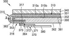
도 3은 본 발명의 일 실시예에 따른 플렉서블 디스플레이 장치(300)를 일부 절제하여 도시한 단면도이다.3 is a cross-sectional view illustrating the
일 실시예에 있어서, 상기 플렉서블 디스플레이 장치(300)는 유기 발광 디스플레이 장치(organic light emitting display device, OLED)을 예를 들어 설명하나, 액정 디스플레이(liquid crystal display, LCD)나, 전계 방출 디스플레이(field emission display, FED)이나, 전자 종이 디스플레이(electronic paper display, EDP) 등의 디스플레이 장치일 수 있다.In an embodiment, the
일 실시예에 있어서, 상기 플렉서블 디스플레이 패널(300)은 플렉서블 디스플레이 기판, 플렉서블 디스플레이 기판 상에 배치된 적어도 하나의 박막 트랜지스터(TFT), 박막 트랜지스터에 연결된 적어도 하나의 발광 소자, 및 플렉서블 디스플레이 기판 상에 배치된 봉지층(encapsulation)을 포함하며, 이에 대해서는 추후 설명하기로 한다.In an embodiment, the
도면을 참조하면, 상기 플렉서블 디스플레이 장치(300)는 플렉서블 디스플레이 패널(310)을 포함한다.Referring to the drawings, the
상기 플렉서블 디스플레이 패널(310)은 화상을 표시하는 제 1 면(310a)과, 상기 제 1 면(310a)에 반대되는 제 2 면(310b)을 포함한다. 상기 플렉서블 디스플레이 패널(310)은 일 방향으로 접히는 벤딩 영역(bending area, 315)을 포함한다.The
상기 플렉서블 디스플레이 패널(310)의 제 1 면(310a) 상에는 기능 필름(340)이 배치될 수 있다. 상기 기능 필름(340)은 편광판, 터치 스크린, 커버 윈도우 등 다양한 필름을 포함한다.A
상기 플렉서블 디스플레이 패널(310)과 기능 필름(340) 사이에는 접착층(351)이 개재될 수 있다.An
상기 플렉서블 디스플레이 패널(310)의 제 2 면(310a) 상에는 기능층(360)이 배치될 수 있다. 상기 기능층(360)은 빛을 흡수하는 블랙층이나, 충격을 완화하는 쿠션층이나, 열을 방출하는 방열층이나, 안테나층 등을 포함한다. 상기 기능층(360)은 다양한 기능을 가지는 층을 포함할 수 있다.A
상기 기능층(360)은 상기 플렉서블 디스플레이 패널(310)에 마주보는 제 1 면(361)과, 상기 제 1 면(361)에 반대되는 제 2 면(362)을 포함한다. 상기 제 2 면(362)에는 인입된 홈(364)이 배치될 수 있다. 상기 홈(364)은 상기 제 2 면(362)의 표면으로부터 소정 깊이 인입될 수 있다. 상기 플렉서블 디스플레이 패널(310)의 접혀진 단부(316)는 상기 기능층(360)의 측면(363)을 경유하여 상기 인입된 홈(364)에 위치할 수 있다. 상기 단부(316)는 접착층(316)에 의하여 인입된 홈(364)에 고정될 수 있다.The
다른 일 실시예에 있어서, 상기 기능층(360)은 인입된 홈(364)을 구비하지 않고, 상기 플렉서블 디스플레이 패널(310)의 단부(316)는 상기 기능층(360)의 제 2 면(362) 상에 위치할 수 있다.In another embodiment, the
일 실시예에 있어서, 상기 플렉서블 디스플레이 패널(310)의 벤딩 영역(315)과 상기 기능층(360)의 측면(363) 사이에는 간격(g)이 존재하고, 상기 간격(g)에는 공기층이 존재할 수 있다.In an embodiment, a gap g exists between the bending
다른 일 실시예에 있어서, 상기 간격(g)없이, 상기 기능층(360)의 측면(363)이 연장되어서, 상기 플렉서블 디스플레이 패널(310)의 벤딩 영역(315)에 직접적으로 접촉할 수 있다.In another embodiment, without the gap g, the
다른 일 실시예에 있어서, 상기 간격(g)에는 레진이 배치될 수 있다.In another embodiment, a resin may be disposed in the gap g.
상기 기능층(360)의 하부에는 구동부(370)가 배치될 수 있다. 상기 구동부(370)는 상기 플렉서블 디스플레이 패널(310)에 전기적으로 접속할 수 있다. 상기 구동부(370)는 구동 회로를 포함하며, 칩 온 필름(chip on film, COF) 구조일 수 있다.A driving
상기 구동부(370)는 플렉서블 필름(371), 상기 플렉서블 필름(371) 상에 배치된 구동 IC(372), 및 상기 플렉서블 필름(371)의 일 가장자리에 배치된 복수의 구동 단자(373)를 포함한다. 상기 구동 단자(373)는 상기 플렉서블 디스플레이 패널(310)의 단부(316)에 배치된 패드 단자(317)에 전기적으로 접속될 수 있다.The driving
상기 구동부(370)는 회로 보드(380)에 전기적으로 연결될 수 있다. 상기 회로 보드(380)는 유연성을 가지는 인쇄 회로 기판(flexible printed circuit board, FPCB)일 수 있다.The driving
한편, 상기 플렉서블 디스플레이 패널(310)과 기능층(360) 사이에는 접착층(352)이 개재될 수 있다. 상기 접착층(352)은 상기 플렉서블 디스플레이 패널(310)을 지지하기 위하여 후막의 고분자 필름을 포함할 수 있다.Meanwhile, an
다른 일 실시예에 있어서, 공정의 단순화를 위하여, 상기 접착층(352)은 박막의 광학용 투명 접착제(optical clear adhesive, OCA)일 수 있다.In another embodiment, in order to simplify the process, the
도 4는 도 3의 플렉서블 디스플레이 패널(310)의 접기 이전의 것을 도시한 평면도이며, 도 5a는 도 4의 플렉서블 디스플레이 패널(310)을 접은 것의 전면을 도시한 평면도이며, 도 5b는 도 5a의 플렉서블 디스플레이 패널(310)의 배면을 도시한 평면도이며, 도 6은 도 4의 플렉서블 디스플레이 패널(310)을 추가적으로 접은 것을 도시한 사시도이다.FIG. 4 is a plan view illustrating the
도 4, 도 5a, 도 5b, 및 도 6을 참조하면, 상기 플렉서블 디스플레이 패널(310)은 복수의 소자를 구비하는 플렉서블 디스플레이 기판(311)과, 상기 플렉서블 디스플레이 기판(311) 상에 배치된 봉지층(312)을 포함한다. 일 실시예에 있어서, 상기 봉지층(312)은 박막의 봉지층(thin film encapsulation, TFE)일 수 있다.4, 5A, 5B, and 6 , the
상기 플렉서블 디스플레이 기판(311)은 화상을 표시하는 활성 영역(313)과, 상기 활성 영역(313)의 바깥으로 연장된 비활성 영역(314)을 포함한다.The
상기 활성 영역(313)은 봉지층(312)이 커버할 수 있다.The
상기 비활성 영역(314)은 활성 영역(313)을 둘러싸고 있다. 상기 비활성 영역(314)은 상기 플렉서블 디스플레이 기판(311)을 제 1 방향으로 접는 벤딩 영역(315)을 포함한다. 제 1 방향은 상기 플렉서블 디스플레이 패널(310)을 도 4의 X 방향, 또는, Y 방향을 포함하는 수평 방향에 대응될 수 있다.The
상기 플렉서블 디스플레이 기판(311)은 X 방향으로 서로 마주보게 배치된 제 1 가장자리(311a)와 제 2 가장자리(311b) 및 Y 방향으로 서로 마주보게 배치된 제 3 가장자리(311c)와, 제 4 가장자리(311d)를 포함한다. 상기 벤딩 영역(315)은 제 1 가장자리(311a), 제 2 가장자리(311b), 제 3 가장자리(311c), 및 제 4 가장자리(311d)중 적어도 어느 하나를 벤딩할 수 있다.The
상기 벤딩 영역(315)은 상기 플렉서블 디스플레이 기판(311)을 제 2 방향으로 접는 복수의 단위 변형부(321)(322)를 구비하는 변형부(320)를 포함한다. 제 2 방향은 상기 플렉서블 디스플레이 패널(310)을 도 6의 Z 방향을 포함하는 수직 방향에 대응될 수 있다.The bending
상기 변형부(320)는 상기 플렉서블 디스플레이 기판(311)의 제 1 가장자리(311a), 제 2 가장자리(311b), 제 3 가장자리(311c), 및 제 4 가장자리(311d)중 적어도 어느 하나의 가장자리를 따라 배치될 수 있다. 본 실시예에 있어서, 상기 변형부(320)는 제 1 가장자리(311b), 제 2 가장자리(311b), 제 4 가장자리(311d)에 각각 배치될 수 있다.The
상기 변형부(320)는 상기 벤딩 영역(315)의 적어도 일부를 절개할 수 있다. 구체적으로, 복수의 단위 변형부(321)(322)는 상기 플렉서블 디스플레이 기판(311)의 제 1 가장자리(311a)와 제 2 가장자리(311b)를 따라 배치되며, 날개부에 대응되는 복수의 제 1 단위 변형부(321)와, 상기 플렉서블 디스플레이 기판(311)의 제 4 가장자리(311d)를 따라 배치되며, 날개부에 대응되는 복수의 제 2 단위 변형부(322)를 포함한다.The
일 실시예에 있어서, 상기 제 1 단위 변형부(321)는 상기 플렉서블 디스플레이 기판(311)의 제 1 가장자리(311a)에 접하는 하부(323)와, 상기 플렉서블 디스플레이 기판(311)의 제 1 가장자리(311a)로부터 멀어지게 배치된 상부(324)와, 상기 하부(323)와 상부(324)를 서로 연결하는 복수의 측부(325)를 포함한다. 상기 하부(323), 상부(324), 및 측부(325)는 이와 대응되는 벤딩 영역(315)의 3 영역을 절개한 3-컷부에 대응될 수 있다.In an embodiment, the first
상기 제 1 단위 변형부(321)는 상기 플렉서블 디스플레이 기판(311)의 제 1 가장자리(311a)에 접하는 하부(323)로부터 멀어지는 방향으로 좁아질 수 있다. 본 실시예에 있어서, 상기 변형부(320)는 사다리꼴의 형상일 수 있다. 상기 제 2 단위 변형부(322)도 동일한 형상일 수 있다.The first
상기 플렉서블 디스플레이 기판(311)의 가장자리(311a, 311b, 311d)와 변형부(320)의 경계에는 가상의 제 1 벤딩 라인(BL1)이 배치될 수 있다. 상기 제 1 벤딩 라인(BL1)은 상기 플렉서블 디스플레이 패널(310)의 길이 방향(Y 방향)으로 가로질러 배치될 수 있다. 상기 플렉서블 디스플레이 기판(311)은 제 1 벤딩 라인(BL1)을 따라서 접을 수 있다.A virtual first bending line BL1 may be disposed at a boundary between the
일 실시예에 있어서, 상기 제 1 벤딩 라인(BL1)은 도 4에 도시된 바와 같이 조립 공차에 따라 좌우로 소정 간격 좌(左)벤딩 라인(BL1L)이나, 우(右)벤딩 라인(BL1R)으로 이동배치될 수 있다.In one embodiment, the first bending line BL1 is a left bending line BL1L or a right bending line BL1R at a predetermined interval left and right according to the assembly tolerance as shown in FIG. 4 . can be moved to
일 실시예에 있어서, 상기 구동부(370)가 배치된 플렉서블 디스플레이 기판(311)의 제 3 가장자리(311c)에서도 접혀짐은 물론이다.In one embodiment, of course, the
상기 플렉서블 디스플레이 기판(311)은 이웃하는 변형부(320) 사이, 예컨대, 플렉서블 디스플레이 기판(311)의 제 1 가장자리(311a) 및 제 2 가장자리(311b)를 따라 배치된 이웃하는 제 1 단위 변형부(321) 사이의 간격(d)에는 가상의 제 2 벤딩 라인(BL2)이 배치될 수 있다. 상기 제 2 벤딩 라인(BL2)은 상기 플렉서블 디스플레이 패널(310)의 폭 방향(X 방향)으로 가로질러 배치될 수 있다.The
제 2 벤딩 라인(BL2)은 이웃하는 한 쌍의 제 1 단위 변형부(321) 사이에 배치될 수 있다. 상기 플렉서블 디스플레이 기판(311)은 제 2 벤딩 라인(BL2)을 따라서 제 2 방향으로 접을 수 있다.The second bending line BL2 may be disposed between a pair of adjacent first unit
일 실시예에 있어서, 상기 플렉서블 디스플레이 기판(311)의 제 4 가장자리(311d)를 따라 배치된 이웃하는 제 2 단위 변형부(322) 사이에도 제 2 벤딩 라인(BL2)이 배치될 수 있음은 물론이다.In one embodiment, the second bending line BL2 may also be disposed between the adjacent second unit
일 실시예에 있어서, 상기 활성 영역(313)은 베젤을 더욱 줄이기 위하여 벤딩 영역(315)를 경유하여 변형부(320)으로 연장될 수 있다. 상기 벤딩 영역(315)을 제 1 방향으로 접게 되면, 상기 활성 영역(313)은 플렉서블 디스플레이 패널(310)의 윗면뿐만 아니라, 측면에도 추가적으로 배치될 수 있다.In one embodiment, the
일 실시예에 있어서, 상기 변형부(320)에는 상기 활성 영역(313)으로부터 인출된 배선(미도시)이 배치될 수 있다.In an embodiment, a wiring (not shown) drawn out from the
상기 플렉서블 디스플레이 패널(310)은 수평 및 수직 방향으로 적어도 2번 접을 수 있다. 구체적으로, 상기 플렉서블 디스플레이 패널(310)은 이의 수평 방향으로 1번 접을 수 있으며, 추가적으로 이의 수직 방향으로 1번 적을 수 있다.The
도 4, 도 5a 및 도 5b에 도시된 바와 같이, 상기 플렉서블 디스플레이 패널(310)은 가상의 제 1 벤딩 라인(BL1)을 따라 제 1 방향으로 접을 수 있다. 상기 벤딩 영역(315)은 제 1 가장자리(311a), 제 2 가장자리(311b), 제 3 가장자리(311c), 및 제 4 가장자리(311d)를 다같이 플렉서블 디스플레이 패널(3010)의 X 방향 및 Y 방향으로 접을 수 있다.4, 5A, and 5B , the
실질적으로, 상기 플렉서블 디스플레이 패널(310)을 제 1 방향으로 접게 되면, 상기 단위 변형부(321)(322)를 가지는 변형부(320)는 도 5b에 도시된 바와 같이 상기 플렉서블 디스플레이 패널(310)의 배면(326)으로 접힐 수 있다. 상기 구동부(370)와, 상기 구동부(370)에 전기적으로 연결된 회로 보드(380)도 상기 플렉서블 디스플레이 패널(310)의 배면(326)으로 접힐 수 있다.Substantially, when the
이에 따라, 도 5a에 도시된 바와 같이, 상기 플렉서블 디스플레이 패널(310)은 베젤이 최소화된 구조일 수 있다.Accordingly, as shown in FIG. 5A , the
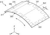
도 6에 도시된 바와 같이, 상기 플렉서블 디스플레이 패널(310)은 가상의 제 2 벤딩 라인(BL2)을 따라 추가적으로 접을 수 있다. 상기 플렉서블 디스플레이 패널(310)은 제 1 방향(X 방향 및 Y 방향)의 수직 방향인 제 2 방향(Z 방향)으로 접을 수 있다.As shown in FIG. 6 , the
일 실시예에 있어서, 상기 플렉서블 디스플레이 패널(310)은 제 1 가장자리(311a), 제 2 가장자리(311b), 제 3 가장자리(311c), 및 제 4 가장자리(311d)을 따라 복수의 단위 변형부(321)(322)가 이격되게 배치되므로, 다양한 각도로 접을 수 있다.In one embodiment, the
이처럼, 상기 플렉서블 디스플레이 패널(310)은 가상의 제 1 벤딩 라인(BL1)을 따라 접고, 가상의 제 2 벤딩 라인(B2)을 따라 추가적으로 접을 수 있다.As such, the
일 실시예에 있어서, 상기 변형부(320)는 다양한 형상으로 제조할 수 있다.In one embodiment, the
예컨대, 도 8a에 도시된 바와 같이, 변형부(803)는 플렉서블 디스플레이 기판(801)의 일 가장자리(802)로부터 돌출될 수 있다. 상기 변형부(303)는 서로 동일한 형상의 복수의 단위 변형부(804)(805)를 포함한다. 이웃하는 한 쌍의 단위 변형부(804)(805) 사이에는 이격된 간격이 없고, 적어도 일부가 서로 연결될 수 있다.For example, as shown in FIG. 8A , the
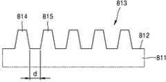
도 8b에 도시된 바와 같이, 변형부(813)는 플렉서블 디스플레이 기판(811)의 일 가장자리(812)로부터 돌출될 수 있다. 상기 변형부(813)는 서로 동일한 형상의 복수의 단위 변형부(814)(815)를 포함한다. 이웃하는 한 쌍의 단위 변형부(814)(815) 사이에는 이격된 간격(d)이 있을 수 있다.As shown in FIG. 8B , the
도 8c에 도시된 바와 같이, 변형부(823)는 플렉서블 디스플레이 기판(821)의 일 가장자리(822)로부터 돌출될 수 있다 .상기 변형부(823)는 서로 다른 형상의 복수의 단위 변형부(824)(825)(826)(827)를 포함한다. 이웃하는 한 쌍의 단위 변형부(824)(825) 사이의 간격(d1)과, 이웃하는 다른 한 쌍의 단위 변형부(826)(827) 사이의 간격(d2)은 서로 다를 수 있다.As shown in FIG. 8C , the
이처럼, 상기 변형부(803, 813, 823)은 간격이 균일하거나, 간격이 불균일하거나, 형상이 동일하거나, 형상이 서로 다를 수 있다.As such, the
일 실시예에 있어서, 상기 변형부(803, 813, 823)는 원형이나, 타원형이나, 정사각형이나, 직사각형이나, 다각형이나, 지그재그형등 다양한 형상을 포함한다.In one embodiment, the
도 7은 본 발명의 다른 실시예에 따른 플렉서블 디스플레이 패널(710)의 접기 이전을 도시한 평면도이다.7 is a plan view illustrating the
도면을 참조하면, 상기 플렉서블 디스플레이 패널(710)은 플렉서블 디스플레이 기판(711)과, 상기 플렉서블 디스플레이 기판(711) 상에 배치된 봉지층(712)을 포함한다.Referring to the drawings, the
상기 플렉서블 디스플레이 기판(711)은 화상을 표시하는 활성 영역(713)과, 상기 활성 영역(713)의 바깥으로 연장된 비활성 영역(714)을 포함한다.The
상기 비활성 영역(714)은 상기 활성 영역(713)을 둘러싸고 있다. 상기 비활성 영역(714)은 상기 플렉서블 디스플레이 기판(711)을 제 1 방향으로 접는 벤딩 영역(715)을 포함한다. 제 1 방향은 상기 플렉서블 디스플레이 기판(711)의 수평 방향에 대응될 수 있다.The
상기 벤딩 영역(715)에는 상기 플렉서블 디스플레이 기판(711)을 제 2 방향으로 접는 복수의 단위 변형부(722, 724, 729)을 구비하는 변형부(720)를 포함한다. 제 2 방향은 상기 플렉서블 디스플레이 기판(711)의 수직 방향에 대응될 수 있다.The bending
상기 변형부(720)는 상기 벤딩 영역(715)의 적어도 일부를 절개할 수 있다.The
복수의 단위 변형부(722, 724, 729)는 플렉서블 디스플레이 기판(711)의 가장자리를 따라서 연장된 벤딩 영역(715)에 배치된 복수의 홀에 대응될 수 있다. 복수의 단위 변형부(722, 724, 729)는 상기 벤딩 영역(715)에 둘러싸인 홀일 수 있다.The plurality of
복수의 단위 변형부(722, 724, 729)는 상기 플렉서블 디스플레이 기판(711)의 좌우 배치된 벤딩 영역(721)의 일 방향, 예컨대, X 방향, 또는, Y 방향으로 이격되게 배치될 수 있다.The plurality of
상기 플렉서블 디스플레이 기판(711)은 상기 변형부(720)가 배치된 벤딩 영역(715)의 가장자리를 따라 가상의 제 1 벤딩 라인(BL1)이 배치될 수 있다. 상기 제 1 벤딩 라인(BL1)은 상기 플렉서블 디스플레이 패널(710)의 길이 방향(Y 방향)을 가로질러 배치될 수 있다. 상기 플렉서블 디스플레이 기판(711)은 제 1 벤딩 라인(BL1)을 따라서 제 1 방향으로 접을 수 있다.In the
일 실시예에 있어서, 상기 단위 변형부(724)는 상기 벤딩 영역(715)에 복수의 열로 배치될 수 있다. 구체적으로, 상기 플렉서블 디스플레이 기판(711)의 하부벤딩 영역(723)에 배치된 단위 변형부(724)는 상기 활성 영역(713)에 가장 인접하게 배치된 복수의 제 1 단위 변형부(725)와, 상기 제 1 단위 변형부(725)의 하부에 배치된 복수의 제 2 단위 변형부(726)와, 상기 제 2 단위 변형부(726)의 하부에 배치된 복수의 제 3 단위 변형부(727)를 포함한다.In an embodiment, the
복수의 제 1 단위 변형부(725), 복수의 제 2 단위 변형부(726), 및 복수의 제 3 단위 변형부(727)는 X 방향으로 각각 이격되게 배치되며, 이와 교차하는 Y 방향으로 제 1 단위 변형부(725), 제 2 단위 변형부(726), 및 제 3 단위 변형부(727)는 각각 이격되게 배치될 수 있다.The plurality of first unit
베젤을 최소화하기 위하여, 상기 활성 영역(713)에 가장 인접하게 배치된 일열의 제 1 단위 변형부(725)를 가로질러 제 1 방향으로 접는 제 1 벤딩 라인(BL1)이 배치될 수 있다.In order to minimize the bezel, a first bending line BL1 that is folded in the first direction may be disposed across the first
일 실시예에 있어서, 상기 플렉서블 디스플레이 기판(711)의 상부 벤딩 영역(728)에 배치된 단위 변형부(729)는 X 방향으로 이격되게 배치된 복수의 단위 변형부(729)를 가로질러 제 1 방향으로 접는 가상의 제 1 벤딩 라인(BL1)이 배치될 수 있다.In an embodiment, the unit
상기 플렉서블 디스플레이 기판(771)의 상부 벤딩 영역(728)에는 구동 IC(772)를 가지는 구동부(770)와, 상기 구동부(770)에 전기적으로 연결된 회로 보드(780)가 배치될 수 있다. 상기 상부 벤딩 영역(728)에는 배선을 회피하여 상기 단위 변형부(729)를 패터닝하는 것에 의하여 벤딩성을 향상시킬 수 있다.A driving
상기 플렉서블 디스플레이 기판(711)의 폭 방향(X 방향)으로 복수의 단위 변형부(722)의 공간을 가로질러 제 2 방향으로 접는 가상의 제 2 벤딩 라인(BL2)이 배치될 수 있다. 상기 플렉서블 디스플레이 기판(711)을 수직 방향으로 접을 때, 상기 플렉서블 디스플레이 기판(711)의 폭 방향의 양쪽에 복수의 단위 변형부(722)가 설치되어 있으므로, 스트레스를 완화시킬 수 있다.A virtual second bending line BL2 that crosses the space of the plurality of
이처럼, 상기 플렉서블 디스플레이 패널(710)은 가상의 제 1 벤딩 라인(BL1)을 따라 접고, 가상의 제 2 벤딩 라인(BL2)을 따라 추가적으로 접을 수 있다.As such, the
일 실시예에 있어서, 상기 활성 영역(713)은 베젤을 더욱 줄이기 위하여 변형부(720)가 배치된 벤딩 영역(715)으로 연장될 수 있다. 상기 벤딩 영역(715)을 제 1 방향으로 접게 되면, 상기 활성 영역(713)은 플렉서블 디스플레이 패널(710)의 측면에 추가적으로 배치될 수 있다.In one embodiment, the
일 실시예에 있어서, 상기 변형부(720)가 배치된 벤딩 영역(715)에는 상기 활성 영역(713)으로부터 인출된 배선(미도시)이 배치될 수 있다.In an embodiment, a wiring (not shown) drawn out from the
일 실시예에 있어서, 상기 변형부(720)는 다양한 형상으로 제조할 수 있다.In one embodiment, the
예컨대, 도 9a에 도시된 바와 같이, 변형부(904)는 플렉서블 디스플레 기판(901)의 일 가장자리(912)로부터 연장된 벤딩 영역(903)에 배치될 수 있다. 상기 변형부(904)는 서로 동일한 형상이며, 이웃하는 변형부(904) 사이에는 소정의 간격(d)이 존재한다.For example, as shown in FIG. 9A , the
도 9b에 도시된 바와 같이, 변형부(914 내지 917)는 플렉서블 디스플레이 기판(911)의 일 가장자리(912)로부터 연장된 벤딩 영역(913)에 배치될 수 있다. 상기 변형부(914 내지 917)는 서로 동일한 형상일 수 있다. 이웃하는 한 쌍의 변형부(914)(915) 사이의 간격(d1)은 이웃하는 다른 한 쌍의 변형부(916)(917) 사이의 간격(d2)과 다를 수 있다.As shown in FIG. 9B , the
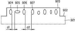
도 9c에 도시된 바와 같이, 변형부(924 내지 927)는 플렉서블 디스플레이 기판(921)의 일 가장자리(922)로부터 연장된 벤딩 영역(923)에 배치될 수 있다. 상기 변형부(924 내지 927)는 서로 다른 형상일 수 있다. 이웃하는 한 쌍의 변형부(924)(925) 사이의 간격(d1)은 이웃하는 다른 한 쌍의 변형부(926)(926) 사이의 간격(d2)과 다를 수 있다.As shown in FIG. 9C , the
이처럼, 상기 변형부(904, 914 내지 917, 924 내지 927)는 간격이 균일하거나, 간격이 불균일하거나, 형상이 동일하거나, 형상이 서로 다를 수 있다.As such, the
일 실시예에 있어서, 상기 변형부(904, 914 내지 917, 924 내지 927)는 원형이나, 타원형이나, 정사각형이나, 직사각형이나, 마름모형이나, 다각형이나, 지그재그형등 다양한 형상을 포함한다.In one embodiment, the
도 10은 본 발명의 일 실시예에 따른 유기 발광 디스플레이 장치(1000)의 일 서브 픽셀을 도시한 것이다.10 illustrates one sub-pixel of the organic light emitting
본 실시예에 있어서, 서브 픽셀들은 적어도 하나의 박막 트랜지스터(TFT)와, 유기 발광 소자(OLED)를 가진다. 상기 박막 트랜지스터는 반드시 도 10의 구조로만 가능한 것은 아니며, 그 수와 구조는 다양하게 변형가능하다.In this embodiment, the sub-pixels include at least one thin film transistor (TFT) and an organic light emitting diode (OLED). The thin film transistor is not necessarily possible only with the structure of FIG. 10, and the number and structure thereof may be variously modified.
도면을 참조하면, 상기 유기 발광 디스플레이 패널(1000)은 디스플레이 기판(1011)과, 상기 디스플레이 기판(1011) 상에 형성되는 봉지층(1040)을 포함한다.Referring to the drawings, the organic light emitting
상기 디스플레이 기판(1011)은 플렉서블한 글래스 기판이나, 플렉서블한 폴리머 기판일 수 있다. 상기 디스플레이 기판(1011)은 투명하거나, 반투명하거나, 불투명할 수 있다.The
상기 디스플레이 기판(1011) 상에는 버퍼막(1012)이 배치될 수 있다. 상기 버퍼막(1012)은 상기 디스플레이 기판(1011)의 윗면을 전체적으로 덮을 수 있다. 상기 버퍼막(1012)은 무기물, 또는, 유기물로 형성될 수 있다. 상기 버퍼막(1012)은 단일막, 또는, 다층막일 수 있다.A
상기 버퍼막(1012) 상에는 박막 트랜지스터(thin film transistor, TFT)가 배치될 수 있다. 일 실시예에 있어서, 박막 트랜지스터는 탑 게이트 트랜지스터(top gate transistor)를 설명하나, 바텀 게이트 트랜지스터(bottom gate transistor) 등 다른 구조의 박막 트랜지스터가 구비될 수 있다.A thin film transistor (TFT) may be disposed on the
상기 버퍼막(1012) 상에는 반도체 활성층(1013)이 배치될 수 있다.A semiconductor
상기 반도체 활성층(1013)은 N형 불순물 이온, 또는, P형 불순물 이온을 도핑하는 것에 의하여 배치되는 소스 영역(1014)과, 드레인 영역(1015)을 포함한다. 상기 소스 영역(1014)과, 드레인 영역(1015) 사이는 불순물이 도핑되지 않는 채널 영역(1016)일 수 있다. 상기 반도체 활성층(1013)은 유기 반도체나, 무기 반도체나, 비정질 실리콘(amorphous silicon)으로 형성될 수 있다. 일 실시예에 있어서, 상기 반도체 활성층(1013)은 산화물 반도체로 형성될 수 있다.The semiconductor
상기 반도체 활성층(1013) 상에는 게이터 절연막(1017)이 증착될 수 있다. 상기 게이트 절연막(1017)은 무기막으로 형성될 수 있다. 상기 게이트 절연막(1017)은 단일층, 또는, 다층막일 수 있다.A
상기 게이트 절연막(1017) 상에는 게이트 전극(1018)이 배치될 수 있다. 상기 게이트 전극(1018)은 도전성이 우수한 금속재로 형성될 수 있다. 상기 게이트 전극(1018)은 단일막, 또는, 다층막일 수 있다.A
상기 게이트 전극(1018) 상에는 층간 절연막(1019)이 배치될 수 있다. 상기 층간 절연막(1019)은 무기막, 또는, 유기막으로 형성될 수 있다.An interlayer insulating
상기 층간 절연막(1019) 상에는 소스 전극(1020)과, 드레인 전극(1021)이 배치될 수 있다. 구체적으로, 상기 게이트 절연막(1017) 및 층간 절연막(1019)의 일부를 제거하는 것에 의하여 콘택 홀을 형성하고, 콘택 홀을 통하여 소스 영역(1014)에 대하여 소스 전극(1020)이 전기적으로 연결되고, 드레인 영역(1015)에 대하여 드레인 전극(1021)이 전기적으로 연결될 수 있다.A
상기 소스 전극(1020)과, 드레인 전극(1021) 상에는 패시베이션막(1022)이 배치될 수 있다. 상기 패시베이션막(1022)은 무기막, 또는, 유기막으로 형성될 수 있다. 상기 패시베이션막(1022) 상에는 평탄화막(1023)이 배치될 수 있다. 상기 패시베이션막(1022)과, 평탄화막(1023)중 어느 하나는 생략할 수 있다.A
상기 박막 트랜지스터는 유기 발광 소자(organic light emitting display device, OLED)에 전기적으로 연결될 수 있다.The thin film transistor may be electrically connected to an organic light emitting display device (OLED).
유기 발광 소자(OLED)는 상기 평탄화막(1023) 상에 배치될 수 있다. 상기 유기 발광 소자(OLED)는 제 1 전극(1025), 중간층(1026), 및 제 2 전극(1027)을 포함한다.The organic light emitting diode OLED may be disposed on the
제 1 전극(1025)은 애노우드로 기능하며, 다양한 도전성 소재로 형성할 수 있다. 상기 제 1 전극(1025)은 투명 전극, 또는, 반사형 전극을 포함한다. 이를테면, 상기 제 1 전극(1025)이 투명 전극으로 사용시, 상기 제 1 전극(1025)은 투명 도전막을 포함한다. 상기 제 1 전극(1025)이 반사형 전극으로 사용시, 상기 제 1 전극(1025)은 반사막과, 상기 반사막 상에 배치된 투명 도전막을 포함한다.The
상기 평탄화막(1023) 상에는 픽셀 정의막(1024)이 배치될 수 있다. 상기 픽셀 정의막(1024)은 제 1 전극(1025)의 일부를 덮을 수 있다. 구체적으로, 상기 픽셀 정의막(1024)은 상기 제 1 전극(1025)의 가장자리를 둘러싸는 것에 의하여 각 서브 픽셀의 발광 영역을 한정한다. 상기 제 1 전극(1025)은 서브 픽셀마다 패터닝될 수있다.A
상기 픽셀 정의막(1024)은 유기막, 또는, 무기막으로 형성될 수 있다. 상기 픽셀 정의막(1024)은 단일막, 또는, 다중막일 수 있다.The
상기 제 1 전극(1025) 상에는 상기 픽셀 정의막(1024)의 일부를 에칭하여 노출되는 영역에 중간층(1026)이 배치될 수 있다. 상기 중간층(1026)은 증착 공정에 의하여 형성될 수 있다.An
상기 중간층(1026)은 유기 발광층을 구비할 수 있다.The
선택적인 다른 예로서, 상기 중간층(1026)은 유기 발광층(emissive layer)을 구비하고, 그 외에 정공 주입층(hole injection layer, HIL), 정공 수송층(hole transport layer, HTL), 전자 수송층(electron transport layer, ETL), 전자 주입층(electron injection layer, EIL)중 적어도 어느 하나를 더 구비할 수 있다. 본 실시예에서는 이에 한정되지 않고, 상기 중간층(1026)이 유기 발광층을 구비하고, 기타 다양한 기능층을 더 구비할 수 있다.As another optional example, the
상기 제 2 전극(1027)은 상기 중간층(1026) 상에 배치될 수 있다.The
상기 제 2 전극(1027)은 캐소우드로 기능할 수 있다. 상기 제 2 전극(1027)은 투명 전극, 또는, 반사형 전극을 포함한다. 예컨대, 상기 제 2 전극(1027)이 투명 전극으로 사용시, 상기 제 2 전극(1027)은 금속막과, 상기 금속막 상에 배치된 투명 도전막을 포함한다. 상기 제 2 전극(1027)이 반사형 전극으로 사용시, 상기 제 2 전극(1027)은 금속막을 포함한다.The
일 실시예에 있어서, 상기 디스플레이 기판(1011) 상에는 복수의 서브 픽셀이 배치될 수 있다. 예컨대, 각 서브 픽셀별로 적색, 녹색, 청색, 또는, 백색의 색을 구현할 수 있다. 그러나, 본 개시는 이에 한정되지 않는다.In an embodiment, a plurality of sub-pixels may be disposed on the
상기 봉지층(1040)은 유기 발광 소자(OLED)를 커버할 수 있다. 상기 봉지층(1040)은 무기막(1041)과 유기막(1042)이 교대로 적층할 수 있다. 예컨대, 상기 무기막(1041)은 제 1 무기막(1043), 제 2 무기막(1044), 및 제 3 무기막(1045)을 포함한다. 상기 유기막(1042)은 제 1 유기막(1046) 및 제 2 유기막(1047)을 포함한다.The
300...플렉서블 디스플레이 장치 310...플렉서블 디스플레이 패널
311...플렉서블 디스플레이 기판312...봉지층
313...활성 영역314...비활성 영역
315...벤딩 영역320...변형부
321, 322...단위 변형부340...기능 필름
360...기능층370...구동부
380...회로 보드300...
311...
313...
315...bending
321, 322...
360...
380...circuit board
Claims (20)
Translated fromKorean상기 플렉서블 디스플레이 패널의 일면에 배치되며, 상기 플렉서블 디스플레이 패널의 접혀진 단부가 배치된 기능층; 및
상기 플렉서블 디스플레이 패널에 전기적으로 접속하는 구동부;를 포함하되,
상기 벤딩 영역에는 상기 플렉서블 디스플레이 패널을 상기 제 1 방향과 수직 방향인 제 2 방향으로 접는 복수의 단위 변형부를 구비하는 변형부가 배치되며,
상기 복수의 단위 변형부는 상기 플렉서블 디스플레이 기판의 일 가장자리를 따라 배치된 복수의 날개부에 대응되는 플렉서블 디스플레이 장치.A flexible display panel comprising: a flexible display panel including an active area, an inactive area extending outside the active area and having a bending area folded in a first direction, and an encapsulation layer disposed on the flexible display board;
a functional layer disposed on one surface of the flexible display panel and having a folded end of the flexible display panel; and
Including; a driving unit electrically connected to the flexible display panel;
A deformable unit including a plurality of unit deformable units for folding the flexible display panel in a second direction perpendicular to the first direction is disposed in the bending area;
The plurality of unit deformation portions correspond to a plurality of wings disposed along one edge of the flexible display substrate.
상기 제 1 방향은 상기 플렉서블 디스플레이 패널의 수평 방향이며, 상기 제 2 방향은 상기 플렉서블 디스플레이 패널의 수직 방향인 플렉서블 디스플레이 장치.The method of claim 1,
The first direction is a horizontal direction of the flexible display panel, and the second direction is a vertical direction of the flexible display panel.
상기 변형부는 상기 벤딩 영역의 적어도 일부를 절개한 플렉서블 디스플레이 장치.3. The method of claim 2,
The deformable portion is a flexible display device in which at least a portion of the bending area is cut.
상기 단위 변형부는 상기 플렉서블 디스플레이 기판의 가장자리에 접하는 하부와, 상기 플렉서블 디스플레이 기판의 가장자리로부터 멀어지게 배치된 상부와, 상기 하부와 상부를 서로 연결하는 복수의 측부를 포함하며,
상기 상부 및 복수의 측부는 이와 대응되는 벤딩 영역의 3 영역을 절개한 3-컷부에 대응되는 플렉서블 디스플레이 장치.The method of claim 1,
The unit deformation portion includes a lower portion in contact with the edge of the flexible display substrate, an upper portion disposed away from the edge of the flexible display substrate, and a plurality of side portions connecting the lower portion and the upper portion to each other,
The upper portion and the plurality of side portions correspond to a three-cut portion in which three portions of a corresponding bending area are cut.
상기 단위 변형부는 상기 플렉서블 디스플레이 기판의 가장자리에 접하는 하부로부터 멀어지는 방향으로 좁아지는 플렉서블 디스플레이 장치.6. The method of claim 5,
The unit deformable portion is narrowed in a direction away from a lower portion in contact with an edge of the flexible display substrate.
상기 플렉서블 디스플레이 기판의 가장자리와 변형부의 경계에는 플렉서블 디스플레이 패널을 가로질러서, 상기 플렉서블 디스플레이 패널을 제 1 방향으로 접는 가상의 제 1 벤딩 라인이 배치된 플렉서블 디스플레이 장치.The method of claim 1,
A first virtual bending line that crosses the flexible display panel and folds the flexible display panel in a first direction is disposed at an edge of the flexible display substrate and a boundary of the deformable portion.
이웃하는 단위 변형부 사이에는 상기 플렉서블 디스플레이 패널을 가로질러서, 상기 플렉서블 디스플레이 패널을 제 2 방향으로 접는 가상의 제 2 벤딩 라인이 배치된 플렉서블 디스플레이 장치.8. The method of claim 7,
A flexible display device in which a second virtual bending line crossing the flexible display panel and folding the flexible display panel in a second direction is disposed between adjacent unit deformable units.
상기 플렉서블 디스플레이 패널은 제 1 벤딩 라인을 따라 접고, 상기 벤딩 영역이 접히는 방향의 수직 방향으로 제 2 벤딩 라인을 따라 추가적으로 접는 플렉서블 디스플레이 장치.9. The method of claim 8,
The flexible display panel is folded along a first bending line and further folded along a second bending line in a direction perpendicular to a direction in which the bending area is folded.
복수의 단위 변형부는 상기 플렉서블 디스플레이 기판의 일 가장자리를 따라 이격되게 배치된 플렉서블 디스플레이 장치.The method of claim 1,
A plurality of unit deformation portions are arranged to be spaced apart along one edge of the flexible display substrate.
복수의 단위 변형부는 간격이 균일하거나, 간격이 불균일하거나, 형상이 동일하거나, 형상이 서로 다른 것중에서 적어도 어느 하나인 플렉서블 디스플레이 장치.The method of claim 1,
The flexible display device, wherein the plurality of unit deformation units are at least one of uniform spacing, non-uniform spacing, the same shape, and different shapes.
이웃하는 단위 변형부는 적어도 일부가 서로 접하는 플렉서블 디스플레이 장치.The method of claim 1,
A flexible display device in which at least some of the adjacent unit deformation units are in contact with each other.
상기 플렉서블 디스플레이 패널의 일면에 배치되며, 상기 플렉서블 디스플레이 패널의 접혀진 단부가 배치된 기능층; 및
상기 플렉서블 디스플레이 패널에 전기적으로 접속하는 구동부;를 포함하되,
상기 벤딩 영역에는 상기 플렉서블 디스플레이 패널을 상기 제 1 방향과 수직 방향인 제 2 방향으로 접는 복수의 단위 변형부를 구비하는 변형부가 배치되며,
상기 복수의 단위 변형부는 상기 플렉서블 디스플레이 기판의 가장자리를 따라서 연장된 벤딩 영역에 배치된 복수의 홀에 대응되는 플렉서블 디스플레이 장치.A flexible display panel comprising: a flexible display panel including an active area, an inactive area extending outside the active area and having a bending area folded in a first direction, and an encapsulation layer disposed on the flexible display board;
a functional layer disposed on one surface of the flexible display panel and having a folded end of the flexible display panel; and
Including; a driving unit electrically connected to the flexible display panel;
A deformable unit including a plurality of unit deformable units for folding the flexible display panel in a second direction perpendicular to the first direction is disposed in the bending area;
The plurality of unit deformation portions correspond to a plurality of holes disposed in bending areas extending along edges of the flexible display substrate.
상기 단위 변형부는 상기 벤딩 영역에 둘러싸인 홀인 플렉서블 디스플레이 장치.14. The method of claim 13,
The unit deformable portion is a hole surrounded by the bending area.
복수의 단위 변형부는 상기 벤딩 영역의 일 방향으로 이격되게 배치된 플렉서블 디스플레이 장치.15. The method of claim 14,
A plurality of unit deformation portions are arranged to be spaced apart from each other in one direction of the bending area.
상기 플렉서블 디스플레이 기판에는 상기 플렉서블 디스플레이 기판을 가로질러서 상기 플렉서블 디스플레이 패널을 제 1 방향으로 접는 가상의 제 1 벤딩 라인이 배치된 플렉서블 디스플레이 장치.16. The method of claim 15,
A flexible display device having a virtual first bending line disposed on the flexible display substrate to cross the flexible display substrate and fold the flexible display panel in a first direction.
상기 플렉서블 디스플레이 기판에는 상기 플렉서블 디스플레이 기판에 배치된 복수의 단위 변형부의 공간을 가로질러서, 상기 플렉서블 디스플레이 패널을 제 2 방향으로 접는 가상의 제 2 벤딩 라인이 배치된 플렉서블 디스플레이 장치.17. The method of claim 16,
A second virtual bending line is disposed on the flexible display substrate to cross the space of the plurality of unit deformation units disposed on the flexible display substrate and fold the flexible display panel in a second direction.
상기 단위 변형부는 상기 벤딩 영역에 복수의 열로 배치되며, 상기 활성 영역에 가장 인접하게 배치된 일열의 단위 변형부를 가로질러 제 1 방향으로 접는 가상의 제 1 벤딩 라인이 배치된 플렉서블 디스플레이 장치.16. The method of claim 15,
The unit deformable portion is arranged in a plurality of rows in the bending area, and a virtual first bending line is disposed to cross the unit deformable unit in a row disposed closest to the active area and fold in a first direction.
복수의 단위 변형부는 간격이 균일하거나, 간격이 불균일하거나, 형상이 동일하거나, 형상이 서로 다른 것중에서 적어도 하나인 플렉서블 디스플레이 장치.15. The method of claim 14,
The plurality of unit deformable units is at least one of uniform spacing, non-uniform spacing, the same shape, and different shapes.
상기 기능층은 상기 플렉서블 디스플레이 패널에 마주보는 제 1 면과, 상기 제 1 면에 반대되는 제 2 면을 가지며, 상기 제 2 면에는 인입된 홈이 배치되며,
상기 플렉서블 디스플레이 패널의 접혀진 단부는 상기 기능층의 측면을 경유하여 상기 인입된 홈에 위치하는 플렉서블 디스플레이 장치.The method of claim 1,
The functional layer has a first surface facing the flexible display panel and a second surface opposite to the first surface, and a recess is disposed on the second surface,
The folded end of the flexible display panel is positioned in the recessed groove via a side surface of the functional layer.
Priority Applications (2)
| Application Number | Priority Date | Filing Date | Title |
|---|---|---|---|
| KR1020150170659AKR102421578B1 (en) | 2015-12-02 | 2015-12-02 | Flexible display device |
| US15/238,582US10121988B2 (en) | 2015-12-02 | 2016-08-16 | Flexible display device |
Applications Claiming Priority (1)
| Application Number | Priority Date | Filing Date | Title |
|---|---|---|---|
| KR1020150170659AKR102421578B1 (en) | 2015-12-02 | 2015-12-02 | Flexible display device |
Publications (2)
| Publication Number | Publication Date |
|---|---|
| KR20170065058A KR20170065058A (en) | 2017-06-13 |
| KR102421578B1true KR102421578B1 (en) | 2022-07-18 |
Family
ID=58798594
Family Applications (1)
| Application Number | Title | Priority Date | Filing Date |
|---|---|---|---|
| KR1020150170659AActiveKR102421578B1 (en) | 2015-12-02 | 2015-12-02 | Flexible display device |
Country Status (2)
| Country | Link |
|---|---|
| US (1) | US10121988B2 (en) |
| KR (1) | KR102421578B1 (en) |
Families Citing this family (35)
| Publication number | Priority date | Publication date | Assignee | Title |
|---|---|---|---|---|
| KR20180057773A (en)* | 2016-11-21 | 2018-05-31 | 엘지디스플레이 주식회사 | Display apparatus and manufacturing method for the same |
| JP6945994B2 (en)* | 2016-12-05 | 2021-10-06 | 株式会社ジャパンディスプレイ | Display device |
| JP2018155999A (en)* | 2017-03-21 | 2018-10-04 | 株式会社ジャパンディスプレイ | Display device |
| US11031573B2 (en)* | 2017-11-30 | 2021-06-08 | Wuhan China Star Optoelectronics Semiconductor Display Technology Co., Ltd. | Encapsulation layer of flexible display panel and flexible display |
| CN108054188B (en)* | 2017-12-20 | 2020-11-20 | 上海天马微电子有限公司 | flexible display device |
| KR102529077B1 (en)* | 2018-03-06 | 2023-05-09 | 삼성디스플레이 주식회사 | Display device |
| CN208077535U (en)* | 2018-04-28 | 2018-11-09 | 京东方科技集团股份有限公司 | A kind of flexible display panels and flexible display apparatus |
| CN108766977B (en)* | 2018-05-24 | 2021-04-13 | 京东方科技集团股份有限公司 | OLED display substrate, display panel and preparation method thereof |
| KR102678482B1 (en)* | 2018-10-12 | 2024-06-27 | 삼성디스플레이 주식회사 | Display panel |
| US10651120B1 (en)* | 2018-12-03 | 2020-05-12 | Wuhan China Star Optoelectronics Semiconductor Display Technology Co., Ltd. | Display panel, display module, and electronic device |
| CN109637382A (en)* | 2018-12-12 | 2019-04-16 | 武汉华星光电半导体显示技术有限公司 | Display panel and display device |
| CN109559649B (en)* | 2019-01-02 | 2022-01-11 | 京东方科技集团股份有限公司 | Display panel, display device, display control method and preparation method |
| TWI869365B (en) | 2019-01-11 | 2025-01-11 | 韓商Lg伊諾特股份有限公司 | Substrate for display |
| WO2020147079A1 (en)* | 2019-01-17 | 2020-07-23 | 京东方科技集团股份有限公司 | Display apparatus and manufacturing method therefor |
| KR102604070B1 (en) | 2019-02-14 | 2023-11-20 | 삼성디스플레이 주식회사 | Display device |
| KR102668904B1 (en)* | 2019-03-28 | 2024-05-24 | 삼성디스플레이 주식회사 | Display device |
| KR102797660B1 (en)* | 2019-06-21 | 2025-04-18 | 삼성디스플레이 주식회사 | Display device and method of manufacturing the same |
| JP7341863B2 (en)* | 2019-11-12 | 2023-09-11 | 新光電気工業株式会社 | Electronics |
| KR102728003B1 (en)* | 2019-11-14 | 2024-11-12 | 삼성디스플레이 주식회사 | Foldable glass substrate, and foldable display device including the thereof |
| KR20210083903A (en) | 2019-12-27 | 2021-07-07 | 엘지디스플레이 주식회사 | Flexible display device |
| CN111200082B (en)* | 2020-01-10 | 2022-08-23 | 京东方科技集团股份有限公司 | Flexible display substrate and flexible display device |
| CN113260148B (en)* | 2020-02-13 | 2022-11-08 | 群创光电股份有限公司 | Electronic device with a detachable cover |
| CN111292620A (en)* | 2020-02-24 | 2020-06-16 | 京东方科技集团股份有限公司 | A display panel, its manufacturing method, and display device |
| CN111584596B (en)* | 2020-05-26 | 2024-06-04 | 京东方科技集团股份有限公司 | Display substrate, display device and manufacturing method |
| KR102769137B1 (en)* | 2020-06-01 | 2025-02-19 | 삼성디스플레이 주식회사 | Display panel and display apparatus including the same |
| CN111812877B (en)* | 2020-08-13 | 2023-07-21 | 京东方科技集团股份有限公司 | Display panel and display device |
| CN213183388U (en)* | 2020-11-06 | 2021-05-11 | 京东方科技集团股份有限公司 | Display module and display device |
| KR20220097772A (en)* | 2020-12-31 | 2022-07-08 | 삼성디스플레이 주식회사 | Display panel, display device including the same, and method for manufacturing the display panel |
| KR20220096755A (en)* | 2020-12-31 | 2022-07-07 | 엘지디스플레이 주식회사 | Foldable display device |
| KR102333985B1 (en)* | 2021-01-12 | 2021-12-02 | 배현진 | Wearable smart device |
| CN112969280B (en)* | 2021-02-20 | 2022-08-26 | 京东方科技集团股份有限公司 | Flexible circuit board and display panel |
| CN113160708A (en)* | 2021-04-07 | 2021-07-23 | 京东方科技集团股份有限公司 | Flexible display module and electronic equipment |
| KR20220165319A (en) | 2021-06-07 | 2022-12-15 | 삼성디스플레이 주식회사 | Display device |
| CN113707021B (en)* | 2021-08-30 | 2023-07-04 | 京东方科技集团股份有限公司 | display panel, display device |
| TWI811142B (en)* | 2022-10-28 | 2023-08-01 | 友達光電股份有限公司 | Display apparatus and method of fabricating the same |
Citations (1)
| Publication number | Priority date | Publication date | Assignee | Title |
|---|---|---|---|---|
| JP2011047977A (en)* | 2009-08-25 | 2011-03-10 | Seiko Epson Corp | Electrooptical device, and electronic equipment |
Family Cites Families (12)
| Publication number | Priority date | Publication date | Assignee | Title |
|---|---|---|---|---|
| KR20060125326A (en) | 2005-06-02 | 2006-12-06 | 엘지.필립스 엘시디 주식회사 | Liquid crystal display |
| JP2007248689A (en)* | 2006-03-15 | 2007-09-27 | Hitachi Displays Ltd | Image display |
| KR101736930B1 (en) | 2012-11-19 | 2017-05-17 | 엘지디스플레이 주식회사 | Flexible organic light emitting display device |
| KR102005484B1 (en)* | 2012-12-05 | 2019-07-31 | 삼성디스플레이 주식회사 | Cubic display and manufacturing method thereof |
| US9348362B2 (en)* | 2013-02-08 | 2016-05-24 | Samsung Electronics Co., Ltd. | Flexible portable terminal |
| KR102037694B1 (en)* | 2013-02-28 | 2019-10-30 | 엘지디스플레이 주식회사 | Flexible display device and method for manufacturing thereof |
| KR102053411B1 (en)* | 2013-03-07 | 2019-12-09 | 삼성디스플레이 주식회사 | Organic light emitting diode display |
| KR101969101B1 (en) | 2013-03-28 | 2019-04-15 | 엘지디스플레이 주식회사 | Flexible display device and method of fabrication the same |
| KR102076666B1 (en) | 2013-04-11 | 2020-02-12 | 엘지디스플레이 주식회사 | Flexible display panel |
| US9430180B2 (en)* | 2013-11-15 | 2016-08-30 | Semiconductor Energy Laboratory Co., Ltd | Display panel and electronic device |
| KR102114319B1 (en) | 2014-01-22 | 2020-05-25 | 삼성디스플레이 주식회사 | Display apparatus |
| US9379355B1 (en)* | 2014-12-15 | 2016-06-28 | Lg Display Co., Ltd. | Flexible display device having support layer with rounded edge |
- 2015
- 2015-12-02KRKR1020150170659Apatent/KR102421578B1/enactiveActive
- 2016
- 2016-08-16USUS15/238,582patent/US10121988B2/enactiveActive
Patent Citations (1)
| Publication number | Priority date | Publication date | Assignee | Title |
|---|---|---|---|---|
| JP2011047977A (en)* | 2009-08-25 | 2011-03-10 | Seiko Epson Corp | Electrooptical device, and electronic equipment |
Also Published As
| Publication number | Publication date |
|---|---|
| US20170162821A1 (en) | 2017-06-08 |
| US10121988B2 (en) | 2018-11-06 |
| KR20170065058A (en) | 2017-06-13 |
Similar Documents
| Publication | Publication Date | Title |
|---|---|---|
| KR102421578B1 (en) | Flexible display device | |
| KR102432349B1 (en) | flexible display device | |
| KR102550697B1 (en) | flexible display device | |
| US11675450B2 (en) | Flexible display apparatus | |
| US11997901B2 (en) | Display apparatus having grooved terminals | |
| KR102313366B1 (en) | Flexible display device and the fabrication method thereof | |
| US10236471B2 (en) | Flexible display device | |
| US10748853B2 (en) | Flexible display device | |
| US10510821B2 (en) | Display device | |
| KR102427669B1 (en) | Flexible display device | |
| KR102570551B1 (en) | display device | |
| CN108666354A (en) | Display panel and display device | |
| KR20170140754A (en) | display device | |
| KR102322766B1 (en) | display device | |
| KR102575480B1 (en) | display device | |
| KR20250139951A (en) | Display device and method of fabricating the same |
Legal Events
| Date | Code | Title | Description |
|---|---|---|---|
| PA0109 | Patent application | Patent event code:PA01091R01D Comment text:Patent Application Patent event date:20151202 | |
| PG1501 | Laying open of application | ||
| A201 | Request for examination | ||
| PA0201 | Request for examination | Patent event code:PA02012R01D Patent event date:20201201 Comment text:Request for Examination of Application Patent event code:PA02011R01I Patent event date:20151202 Comment text:Patent Application | |
| E902 | Notification of reason for refusal | ||
| PE0902 | Notice of grounds for rejection | Comment text:Notification of reason for refusal Patent event date:20211029 Patent event code:PE09021S01D | |
| E701 | Decision to grant or registration of patent right | ||
| PE0701 | Decision of registration | Patent event code:PE07011S01D Comment text:Decision to Grant Registration Patent event date:20220425 | |
| GRNT | Written decision to grant | ||
| PR0701 | Registration of establishment | Comment text:Registration of Establishment Patent event date:20220712 Patent event code:PR07011E01D | |
| PR1002 | Payment of registration fee | Payment date:20220713 End annual number:3 Start annual number:1 | |
| PG1601 | Publication of registration | ||
| PR1001 | Payment of annual fee | Payment date:20250625 Start annual number:4 End annual number:4 |