KR102420810B1 - A power meter for sealing and preventing an allegal use of electricity - Google Patents
A power meter for sealing and preventing an allegal use of electricityDownload PDFInfo
- Publication number
- KR102420810B1 KR102420810B1KR1020190104667AKR20190104667AKR102420810B1KR 102420810 B1KR102420810 B1KR 102420810B1KR 1020190104667 AKR1020190104667 AKR 1020190104667AKR 20190104667 AKR20190104667 AKR 20190104667AKR 102420810 B1KR102420810 B1KR 102420810B1
- Authority
- KR
- South Korea
- Prior art keywords
- power meter
- terminal cover
- power
- terminal
- sealing
- Prior art date
- Legal status (The legal status is an assumption and is not a legal conclusion. Google has not performed a legal analysis and makes no representation as to the accuracy of the status listed.)
- Active
Links
- 238000007789sealingMethods0.000titleclaimsabstractdescription102
- 230000005611electricityEffects0.000titledescription2
- 238000004891communicationMethods0.000claimsabstractdescription44
- 238000005259measurementMethods0.000claimsabstractdescription18
- 238000004078waterproofingMethods0.000claimsabstractdescription4
- 238000000034methodMethods0.000claimsdescription22
- OKTJSMMVPCPJKN-UHFFFAOYSA-NCarbonChemical compound[C]OKTJSMMVPCPJKN-UHFFFAOYSA-N0.000claimsdescription11
- 229910002804graphiteInorganic materials0.000claimsdescription11
- 239000010439graphiteSubstances0.000claimsdescription11
- 229910000859α-FeInorganic materials0.000claimsdescription11
- 230000005294ferromagnetic effectEffects0.000claimsdescription6
- 230000005291magnetic effectEffects0.000description28
- 230000002265preventionEffects0.000description24
- 238000001514detection methodMethods0.000description12
- 230000005856abnormalityEffects0.000description9
- 230000008859changeEffects0.000description7
- 238000013459approachMethods0.000description6
- 230000000694effectsEffects0.000description6
- 238000009434installationMethods0.000description6
- XLYOFNOQVPJJNP-UHFFFAOYSA-NwaterSubstancesOXLYOFNOQVPJJNP-UHFFFAOYSA-N0.000description6
- 230000002159abnormal effectEffects0.000description5
- 230000009977dual effectEffects0.000description4
- 238000005516engineering processMethods0.000description4
- 238000012544monitoring processMethods0.000description4
- 230000005540biological transmissionEffects0.000description3
- 238000010586diagramMethods0.000description3
- 239000003302ferromagnetic materialSubstances0.000description2
- 230000004907fluxEffects0.000description2
- 238000009413insulationMethods0.000description2
- 238000012806monitoring deviceMethods0.000description2
- 230000035945sensitivityEffects0.000description2
- 101150020229Apcs geneProteins0.000description1
- RYGMFSIKBFXOCR-UHFFFAOYSA-NCopperChemical compound[Cu]RYGMFSIKBFXOCR-UHFFFAOYSA-N0.000description1
- 101100352289Drosophila melanogaster Ptx1 geneProteins0.000description1
- 101150031628PITX2 geneProteins0.000description1
- 230000009471actionEffects0.000description1
- 238000004458analytical methodMethods0.000description1
- 238000004364calculation methodMethods0.000description1
- 229910052802copperInorganic materials0.000description1
- 239000010949copperSubstances0.000description1
- 101150006779crp geneProteins0.000description1
- 230000005684electric fieldEffects0.000description1
- 230000007717exclusionEffects0.000description1
- 230000014509gene expressionEffects0.000description1
- WABPQHHGFIMREM-UHFFFAOYSA-Nlead(0)Chemical compound[Pb]WABPQHHGFIMREM-UHFFFAOYSA-N0.000description1
- 230000005389magnetismEffects0.000description1
- 238000012986modificationMethods0.000description1
- 230000004048modificationEffects0.000description1
- 101150103310pitx1 geneProteins0.000description1
- 230000001681protective effectEffects0.000description1
Images


Classifications
- G—PHYSICS
- G01—MEASURING; TESTING
- G01R—MEASURING ELECTRIC VARIABLES; MEASURING MAGNETIC VARIABLES
- G01R11/00—Electromechanical arrangements for measuring time integral of electric power or current, e.g. of consumption
- G01R11/02—Constructional details
- G01R11/24—Arrangements for avoiding or indicating fraudulent use
- G—PHYSICS
- G01—MEASURING; TESTING
- G01R—MEASURING ELECTRIC VARIABLES; MEASURING MAGNETIC VARIABLES
- G01R11/00—Electromechanical arrangements for measuring time integral of electric power or current, e.g. of consumption
- G01R11/02—Constructional details
- G01R11/04—Housings; Supporting racks; Arrangements of terminals
- G—PHYSICS
- G01—MEASURING; TESTING
- G01R—MEASURING ELECTRIC VARIABLES; MEASURING MAGNETIC VARIABLES
- G01R15/00—Details of measuring arrangements of the types provided for in groups G01R17/00 - G01R29/00, G01R33/00 - G01R33/26 or G01R35/00
- G01R15/14—Adaptations providing voltage or current isolation, e.g. for high-voltage or high-current networks
- G01R15/18—Adaptations providing voltage or current isolation, e.g. for high-voltage or high-current networks using inductive devices, e.g. transformers
- G—PHYSICS
- G01—MEASURING; TESTING
- G01R—MEASURING ELECTRIC VARIABLES; MEASURING MAGNETIC VARIABLES
- G01R22/00—Arrangements for measuring time integral of electric power or current, e.g. electricity meters
- G01R22/06—Arrangements for measuring time integral of electric power or current, e.g. electricity meters by electronic methods
- G01R22/061—Details of electronic electricity meters
- G01R22/063—Details of electronic electricity meters related to remote communication
- G—PHYSICS
- G01—MEASURING; TESTING
- G01R—MEASURING ELECTRIC VARIABLES; MEASURING MAGNETIC VARIABLES
- G01R22/00—Arrangements for measuring time integral of electric power or current, e.g. electricity meters
- G01R22/06—Arrangements for measuring time integral of electric power or current, e.g. electricity meters by electronic methods
- G01R22/061—Details of electronic electricity meters
- G01R22/066—Arrangements for avoiding or indicating fraudulent use
- Y—GENERAL TAGGING OF NEW TECHNOLOGICAL DEVELOPMENTS; GENERAL TAGGING OF CROSS-SECTIONAL TECHNOLOGIES SPANNING OVER SEVERAL SECTIONS OF THE IPC; TECHNICAL SUBJECTS COVERED BY FORMER USPC CROSS-REFERENCE ART COLLECTIONS [XRACs] AND DIGESTS
- Y04—INFORMATION OR COMMUNICATION TECHNOLOGIES HAVING AN IMPACT ON OTHER TECHNOLOGY AREAS
- Y04S—SYSTEMS INTEGRATING TECHNOLOGIES RELATED TO POWER NETWORK OPERATION, COMMUNICATION OR INFORMATION TECHNOLOGIES FOR IMPROVING THE ELECTRICAL POWER GENERATION, TRANSMISSION, DISTRIBUTION, MANAGEMENT OR USAGE, i.e. SMART GRIDS
- Y04S20/00—Management or operation of end-user stationary applications or the last stages of power distribution; Controlling, monitoring or operating thereof
- Y04S20/30—Smart metering, e.g. specially adapted for remote reading
Landscapes
- Physics & Mathematics (AREA)
- General Physics & Mathematics (AREA)
- Engineering & Computer Science (AREA)
- Power Engineering (AREA)
- Arrangements For Transmission Of Measured Signals (AREA)
Abstract
Translated fromKoreanDescription
Translated fromKorean본 발명은 전력 계량기의 봉인 및 도전 방지 방법에 관한 것으로서, 보다 상세하게는 정밀하게 봉인함으로써 내구성 및 방수성을 향상시킬 수 있는 전력 계량기의 봉인 및 도전 방지 방법에 관한 것이다.The present invention relates to a method for sealing and preventing conduction of a power meter, and more particularly, to a method for sealing and preventing conduction of a power meter that can improve durability and waterproofness by sealing precisely.
최근 개별 가구의 전력 사용량이나 사용 습관을 PC나 스마트폰을 통하여 모니터링하는 기술들이 활발하게 개발되고 있다. 특히, 인터넷망 또는 블루투스, 지그비(Zigbee) 등의 연결 장치를 통해 전력량을 확인하는 기술들이 활발하게 개발되고 있다. 이러한 기술들은 사용자의 전력 측정 장치와 통신 장치의 연결이 필수적이다.Recently, technologies for monitoring power consumption or usage habits of individual households through PCs or smartphones are being actively developed. In particular, technologies for checking the amount of power through an Internet network or a connection device such as Bluetooth or Zigbee are being actively developed. For these technologies, it is essential to connect a user's power measuring device and a communication device.
이를 해결하기 위하여 예컨대, 한국등록특허 제10-1555942호는 분전반 내 분기차단기에 호환가능한 전력 측정 장치를 분전반에 장착하고 수집된 전력 사용량을 무선 통신으로 모니터링 장치에 전송하는 장치를 제안하고 있다.In order to solve this problem, for example, Korean Patent Registration No. 10-1555942 proposes a device for mounting a power measuring device compatible with a branch breaker in the distribution board on the distribution board and transmitting the collected power usage to the monitoring device through wireless communication.
그러나, 이러한 전력 측정 장치를 전기 요금 과금을 위한 전력 계량기로 사용하기 위해서는 전력 사용량을 추출하기 위하여 허가되지 않은 침입 가능성을 배제하여야 한다. 즉, 설치된 이후에 무단으로 전력 측정 장치가 제거되거나 또는 무단으로 전력 사용량 측정에 영향을 주는 요소들이 배제될 수 있도록, 실링 수단(봉인수단)과 도전 방지 기술들이 적용되어야 한다. 이러한 실링 수단(봉인수단)을 이용한 침입 가능성의 배제는 법적인 의무 사항이다.However, in order to use such a power measuring device as a power meter for electricity billing, the possibility of unauthorized intrusion must be excluded in order to extract power usage. That is, sealing means (sealing means) and conduction prevention technologies must be applied so that the power measuring device can be removed without permission after installation or factors affecting the power usage measurement can be excluded without permission. Exclusion of the possibility of intrusion using these sealing means (sealing means) is a legal obligation.
단, 최근 개발된 네트워크를 이용한 전력 측정 장치에는 이러한 실링 수단이 없어서 과금 산정의 기준이 되는 계량기로 사용되기는 어려웠으나, 정확하고 편리한 검침을 위하여 네트워크 기반의 전력 계량기가 절실히 요구되고 있다.However, the recently developed network-based power measuring device does not have such a sealing means, so it is difficult to use it as a standard meter for billing calculation. However, a network-based power meter is desperately needed for accurate and convenient meter reading.
본 발명이 해결하고자 하는 과제는 분전반 내에 설치하는 전력 계량기를 봉인하여 법적으로 계량기로서 설치가 가능한 전력 측정 장치를 제공하는 것이다.An object of the present invention is to provide a power measuring device that can be legally installed as a meter by sealing a power meter installed in a distribution board.
본 발명이 해결하고자 또 다른 과제는 봉인할 때에 내구성 및 방수성이 향상된 전력 계량기를 제공하는 것이다.Another object to be solved by the present invention is to provide a power meter with improved durability and waterproofness when sealed.
전술한 바와 같은 과제를 해결하기 위하여 본 발명의 실시예에 따른 도전 방지가 가능한 전력 계량 장치는 네트워크를 통하여 서버와 연결될 수 있는 통신 회로 및 분전반의 부스바와 전기적으로 연결되는 연결부 및 전력을 측정하는 전력 측정 회로를 포함하는 인쇄회로기판; 분전반의 분기차단기와 호환되며 인쇄회로기판을 수용하는 전력 계량기 하우징; 연결부와 연결되며 부스바를 고정하는 고정 나사 홈을 포함하는 부스바 단자 접지부; 부스바 단자 접지부를 수용하며 부스바 단자 접지부를 고정하며 고정 나사 홈과 연결되는 고정 나사 체결 홀을 구비하는 절연 방수 지지 부재; 절연 방수 지지 부재와 전력 계량기 하우징의 지지턱에 의하여 지지되며, 전력 계량기 하우징 내에 수용된 인쇄회로기판을 방수시키는 방수링; 및 전력 계량기 하우징과 결합되며 전력 계량기 하우징의 일부와 함께 절연 방수 지지부재를 커버하는 단자 커버를 포함하며, 단자 커버는 전력 계량기 하우징과 결합될 때 고정 나사 홈 및 고정 나사 체결 홀이 외부에 노출되지 않도록 하며, 단자 커버는 제1 단자커버 봉인홀, 제2 단자커버 봉인홀 및 단자 커버 봉인 나사를 포함하고, 제1 봉인씰은 제1 단자커버 봉인홀, 단자 커버 봉인 나사 봉인홀 및 제2 단자커버 봉인홀을 통과하여 단자 커버가 전력 계량기 하우징으로부터 분리되는 경우에 파괴된다. 이에, 분전반 내에 설치되는 전력 계량기의 도전 방지 구조를 개선하여 측정 왜곡률을 현저하게 감소시킬 수 있다.In order to solve the above problems, the electric power metering device capable of preventing conduction according to an embodiment of the present invention is a communication circuit that can be connected to a server through a network, a connection part electrically connected to a busbar of a distribution board, and power for measuring power a printed circuit board including a measurement circuit; a power meter housing that is compatible with a branch breaker of a distribution panel and accommodates a printed circuit board; a busbar terminal grounding part connected to the connection part and including a fixing screw groove for fixing the busbar; an insulating waterproof support member accommodating the busbar terminal grounding part, fixing the busbar terminal grounding part, and having a fixing screw fastening hole connected to the fixing screw groove; a waterproof ring supported by the insulating waterproof support member and the support jaw of the power meter housing and waterproofing the printed circuit board accommodated in the power meter housing; and a terminal cover coupled to the power meter housing and covering the insulating waterproof support member together with a part of the power meter housing, wherein the terminal cover has a fixing screw groove and a fixing screw fastening hole not exposed to the outside when combined with the power meter housing. and the terminal cover includes a first terminal cover sealing hole, a second terminal cover sealing hole, and a terminal cover sealing screw, and the first sealing seal includes a first terminal cover sealing hole, a terminal cover sealing screw sealing hole and a second terminal When the terminal cover is separated from the power meter housing through the cover sealing hole, it is destroyed. Accordingly, it is possible to significantly reduce the measurement distortion by improving the conduction prevention structure of the power meter installed in the distribution panel.
본 발명의 다른 특징에 따르면, 제품 본체 봉인부를 더 포함하며, 제품 본체 봉인부는 제품 본체 봉인 커버, 제품 본체 봉인 나사 및 제품 본체 봉인홀을 포함하며, 제2 봉인씰은 제품 본체 봉인 커버가 전력 계량기 하우징과 결합된 상태에서 제품 본체 봉인홀 및 제품 본체 봉인 나사 봉인홀을 통과하여 전력 계량기 하우징의 하판과 상판이 분리되는 경우에 파괴할 수 있다.According to another feature of the present invention, it further includes a product body sealing part, the product body sealing part includes a product body sealing cover, a product body sealing screw, and a product body sealing hole, and the second sealing seal is the product body sealing cover is a power meter It can be destroyed when the lower plate and upper plate of the power meter housing are separated by passing through the product body sealing hole and the product body sealing screw sealing hole in the state of being coupled to the housing.
본 발명의 또 다른 특징에 따르면, 절연 방수 지지 부재는 부스 바 단자 고정 나사에 의하여 고정되며, 단자커버는 전력 계량기 하우징과 결합될 때 부스바 단자 고정나사가 노출되지 않도록 할 수 있다.According to another feature of the present invention, the insulating waterproof support member is fixed by the bus bar terminal fixing screw, and the terminal cover can prevent the bus bar terminal fixing screw from being exposed when the terminal cover is coupled to the power meter housing.
본 발명의 또 다른 특징에 따르면, 부스 바 단자 고정 나사는 부스 바 단자 고정 나사의 머리에 암나사부를 포함하며, 단자 커버 봉인 나사는 단자커버가 전력 계량기 하우징과 결합될 때 암나사부와 결합할 수 있다.According to another feature of the present invention, the bus bar terminal fixing screw includes a female screw portion on the head of the bus bar terminal fixing screw, and the terminal cover sealing screw may engage with the female screw portion when the terminal cover is coupled with the power meter housing. .
본 발명의 또 다른 특징에 따르면, 통신 회로는 유선 통신 수단 및 무선 통신 수단을 포함하며, 유선 통신 수단은 전력 계량기 하우징에 마련된 케이블구를 기밀하게 막는 방수캡을 통과하는 유선 통신 케이블에 의하여 외부 장치에 연결할 수 있다.According to another feature of the present invention, the communication circuit includes a wired communication means and a wireless communication means, and the wired communication means is an external device by a wired communication cable passing through a waterproof cap that airtightly blocks the cable hole provided in the power meter housing. can be connected to
본 발명의 또 다른 특징에 따르면, 전류를 측정하는 CT 센서를 더 포함하되, CT 센서는 부스바와 분전반의 주차단기를 연결하는 연결 케이블에 설치되며, 방수캡을 통과하는 CT 케이블에 의하여 인쇄회로기판과 연결할 수 있다.According to another feature of the present invention, it further comprises a CT sensor for measuring current, wherein the CT sensor is installed on a connecting cable connecting the bus bar and the main circuit breaker of the distribution panel, and is installed on the printed circuit board by the CT cable passing through the waterproof cap. can be connected with
본 발명의 또 다른 특징에 따르면, CT 센서는 링 형태 및 ZMFFLQ 형쌍 중 어느 하나로 형성될 수 있다.According to another feature of the present invention, the CT sensor may be formed in any one of a ring type and a ZMFFLQ type pair.
본 발명의 또 다른 특징에 따르면, CT 센서는 도전 방지 케이스를 포함하며, 도전 방지 케이스는 흑연 시트 층, 페라이트 시트 층 및 구형의 도전 방지 케이스 하우징을 포함할 수 있다.According to another feature of the present invention, the CT sensor may include a conductive protection case, and the conductive protection case may include a graphite sheet layer, a ferrite sheet layer, and a spherical conductive protection case housing.
본 발명의 또 다른 특징에 따르면, 도전 방지 케이스는 CT 센서의 강자성체 코어를 둘러쌓고 있으며, 도전 방지 케이스는 흑연 시트층 및 페라이트 시트층이 구형 도전 방지 케이스 하우징의 표면의 모양에 따라 설치될 수 있도록 하는 구형 지지체를 더 포함할 수 있다.According to another feature of the present invention, the conductive protection case surrounds the ferromagnetic core of the CT sensor, and the conductive protection case includes a graphite sheet layer and a ferrite sheet layer so that the graphite sheet layer and the ferrite sheet layer can be installed according to the shape of the surface of the spherical conductive protection case housing. It may further include a spherical support.
기타 실시예의 구체적인 사항들은 상세한 설명 및 도면들에 포함되어 있다.The details of other embodiments are included in the detailed description and drawings.
본 발명은 분전반 내에 설치하는 전력 계량기를 봉인하여 외부의 침입으로부터 측정의 무결성을 유지할 수 있다.The present invention can seal the power meter installed in the distribution panel to maintain the integrity of the measurement from intrusion from the outside.
본 발명은 분전반 내에 설치되는 전력 계량기의 도전 방지 구조를 개선하여 외부의 도전에 의한 측정 왜곡을 현저하게 감소시킬 수 있다.The present invention can significantly reduce measurement distortion due to external conduction by improving the conduction prevention structure of a power meter installed in a distribution panel.
본 발명에 따른 효과는 이상에서 예시된 내용에 의해 제한되지 않으며, 더욱 다양한 효과들이 본 명세서 내에 포함되어 있다.The effect according to the present invention is not limited by the contents exemplified above, and more various effects are included in the present specification.
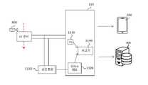
도 1은 본 발명의 실시예에 따른 전력 계량 시스템에 대한 전체 구성도이다.
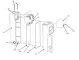
도 2는 본 발명의 실시예에 따른 분전반의 사시도이다.
도 3은 본 발명의 실시예에 따른 전력 계량기에 대한 확대 사시도이다.
도 4a는 본 발명의 실시예에 따른 전력 계량기의 방수 구조를 설명하기 위한 분해 사시도이다.
도 4b는 본 발명의 실시예에 따른 전력 계량기의 봉인 구조를 설명하기 위한 분해 사시도이다.
도 5는 본 발명의 실시예에 따른 전력 계량기의 단자 봉인 방법을 설명하기 위한 도면이다.
도 6은 본 발명의 실시예에 따른 전력 계량기의 CT센서에 대한 사시도이다.
도 7은 본 발명의 다른 실시예에 따른 전력 계량기의 CT센서에 대한 사시도이다.
도 8은 본 발명의 실시예에 따른 분전반의 사시도이다.
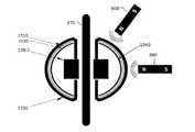
도 9는 본 발명의 실시예에 따른 자계 인식 센서를 포함하는 도전 방지 수단을 포함하는 전력 계량기를 설명하기 위한 도면이다.
도 10은 본 발명의 실시예에 따른 듀얼 CT센서를 이용한 도전 방지 수단을 포함하는 전력 계량기를 설명하기 위한 도면이다.
도 11은 본 발명의 실시예에 따른 공진회로를 이용한 도전 방지 수단을 포함하는 전력 계량기를 설명하기 위한 도면이다.
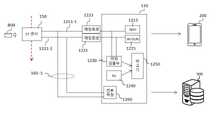
도 12는 본 발명의 실시예에 따른 무선 통신 수단을 이용하는 도전 방지 수단을 포함하는 전력 계량기를 설명하기 위한 도면이다.
도 13은 본 발명의 실시예에 따른 다이버시티를 이용한 도전 방지 수단을 구비하는 전력 계량기를 설명하기 위한 도면이다.
도 14는 본 발명의 실시예에 따른 더미부하를 이용한 도전 방지 수단을 포함하는 전력 계량기를 설명하기 위한 도면이다.
도 15 내지 도 17은 본 발명의 실시예에 따른 구형 도전 방지 케이스를 포함하는 전력 계량기를 설명하기 위한 도면이다.1 is an overall configuration diagram of a power metering system according to an embodiment of the present invention.
2 is a perspective view of a distribution board according to an embodiment of the present invention.
3 is an enlarged perspective view of a power meter according to an embodiment of the present invention.
4A is an exploded perspective view illustrating a waterproof structure of a power meter according to an embodiment of the present invention.
4B is an exploded perspective view illustrating a sealing structure of a power meter according to an embodiment of the present invention.
5 is a view for explaining a method of sealing terminals of a power meter according to an embodiment of the present invention.
6 is a perspective view of a CT sensor of a power meter according to an embodiment of the present invention.
7 is a perspective view of a CT sensor of a power meter according to another embodiment of the present invention.
8 is a perspective view of a distribution board according to an embodiment of the present invention.
9 is a view for explaining a power meter including a conduction prevention means including a magnetic field recognition sensor according to an embodiment of the present invention.
10 is a view for explaining a power meter including a conduction prevention means using a dual CT sensor according to an embodiment of the present invention.
11 is a view for explaining a power meter including a conduction prevention means using a resonance circuit according to an embodiment of the present invention.
12 is a view for explaining a power meter including a conduction prevention means using a wireless communication means according to an embodiment of the present invention.
13 is a view for explaining a power meter having a conduction prevention means using diversity according to an embodiment of the present invention.
14 is a view for explaining a power meter including a conduction prevention means using a dummy load according to an embodiment of the present invention.
15 to 17 are diagrams for explaining a power meter including a spherical conductive protection case according to an embodiment of the present invention.
이하의 내용은 단지 발명의 원리를 예시한다. 그러므로 당업자는 비록 본 명세서에 명확히 설명되거나 도시되지 않았지만 발명의 원리를 구현하고 발명의 개념과 범위에 포함된 다양한 장치를 발명할 수 있는 것이다. 또한, 본 명세서에 열거된 모든 조건부 용어 및 실시예들은 원칙적으로, 발명의 개념이 이해되도록 하기 위한 목적으로만 명백히 의도되고, 이와 같이 특별히 열거된 실시예들 및 상태들에 제한적이지 않는 것으로 이해되어야 한다.The following is merely illustrative of the principles of the invention. Therefore, those skilled in the art will be able to devise various devices that, although not explicitly described or shown herein, embody the principles of the invention and are included in the spirit and scope of the invention. It should also be understood that all conditional terms and examples listed herein are, in principle, expressly intended only for the purpose of understanding the inventive concept, and not limited to the specifically enumerated embodiments and states as such. do.
또한, 이하의 설명에서 제1, 제2 등과 같은 서수식 표현은 서로 동등하고 독립된 객체를 설명하기 위한 것이며, 그 순서에 주(main)/부(sub) 또는 주(master)/종(slave)의 의미는 없는 것으로 이해되어야 한다.In addition, in the following description, ordinal expressions such as first, second, etc. are for describing objects that are equal and independent of each other, and in the order of main/sub or master/slave It should be understood as meaningless.
상술한 목적, 특징 및 장점은 첨부된 도면과 관련한 다음의 상세한 설명을 통하여 보다 분명해질 것이며, 그에 따라 발명이 속하는 기술분야에서 통상의 지식을 가진 자가 발명의 기술적 사상을 용이하게 실시할 수 있을 것이다.The above-described objects, features, and advantages will become more apparent through the following detailed description in relation to the accompanying drawings, and accordingly, those of ordinary skill in the art to which the invention pertains will be able to easily practice the technical idea of the invention. .
본 발명의 여러 실시예들의 각각 특징들이 부분적으로 또는 전체적으로 서로 결합 또는 조합 가능하며, 당업자가 충분히 이해할 수 있듯이 기술적으로 다양한 연동 및 구동이 가능하며, 각 실시예들이 서로에 대하여 독립적으로 실시 가능할 수도 있고 연관 관계로 함께 실시 가능할 수도 있다.Each feature of the various embodiments of the present invention may be partially or wholly combined or combined with each other, and as those skilled in the art will fully understand, technically various interlocking and driving are possible, and each embodiment may be independently implemented with respect to each other, It may be possible to implement together in a related relationship.
이하, 첨부된 도면을 참조하여 본 발명의 다양한 실시예들을 상세히 설명한다.Hereinafter, various embodiments of the present invention will be described in detail with reference to the accompanying drawings.
먼저, 본 발명의 실시예에 따른 전력 계량기가 설치되는 환경인 분전반에 대하여 도 1 내지 도 3을 참조하여 상세하게 설명한다.First, a distribution board, which is an environment in which a power meter according to an embodiment of the present invention is installed, will be described in detail with reference to FIGS. 1 to 3 .
도 1은 본 발명의 실시예에 따른 전력 계량 시스템에 대한 전체 구성도이다. 도 2는 본 발명의 실시예에 따른 분전반의 개략적인 평면도이다. 도 3은 본 발명의 실시예에 따른 전력 계량기에 대한 확대 사시도이다.1 is an overall configuration diagram of a power metering system according to an embodiment of the present invention. 2 is a schematic plan view of a distribution board according to an embodiment of the present invention. 3 is an enlarged perspective view of a power meter according to an embodiment of the present invention.
도 1을 참조하면, 본 발명에 따른 전력 계량 시스템의 전력 계량기(110)는 가전 기구(600) 및 서버(900)와 연결되며, 분전반(100) 내에 설치될 수 있다. 바람직하게는 본 발명에 따른 전력 계량기(110)은 분전반(100)으로부터 측정한 데이터들을 네트워크를 통해 서버(900)로 전송하기 위하여 공유기 또는 홈 게이트웨이와 연결되어 인터넷 등의 외부 네트워크과 연결될 수 있다.Referring to FIG. 1 , the
분전반(100)은 인입한 전력을 다수의 분기회로로 전력을 분기하고 이상전류 발생시 회로를 차단하기 위해 배선용 차단기, 누전 차단기, 서지보호장치(Surge Protective Device, SPD) 등을 포함하는 전기적 안전장치로서, 주차단기(140), 다수의 분기차단기(130) 및 전력 계량기(110)를 포함한다.The
보다 상세하게, 주차단기(140)는 분전반(100) 내부에 설치되어 총 전력을 차단하는 기능을 수행한다.In more detail, the
분기차단기(130)는 분전반 내부에 설치되어 분전반(100)과 전기적으로 연결된 가전 기구(600)별로 전력을 차단하기 위한 구성으로서, 복수의 분기차단기(130)가 분전반(100)의 부스바(120)에 고정된다.The
부스바(120)는 복수의 분기차단기(130)의 전력 입력단을 쉽게 연결할 수 있도록 제작된 동판으로 구성되며 각각의 분기차단기(130) 및 본 발명에 따른 전력 계량기(110)의 전력 입력단과 연결된다. 다시 말해, 부스바(120)는 미리 설계된 위치에 설치되는 분기차단기(130)의 전력 입력단과 부스바(120) 고정단을 통해 연결되게 된다.The
전력 계량기(110)는 가전 기구(600) 등 분전반을 통하여 전력이 공급되는 모든 기기의 전력 사용량을 측정하고, 측정된 데이터를 네트워크를 통해 서버(900)로 전송하는 기능을 수행한다. 전력 계량기(110)는 도 2와 같이, 분전반(100)내에 설치된 부스바(120)에 고정된다. 한편, 전력 계량기(110)는 도 3과 같이, 하판(111), 상판(112), 단자커버(114) 및 방수캡(113)를 포함하여 봉인되며, 전력 계량기(110)의 세부 구성에 대한 구체적인 설명은 후술하기로 한다.The
일반적으로 외부 모니터링 장치와 연결되는 전력 측정 장치는 전류 측정을 위하여 CT 케이블을 통해 CT센서와 연결되는데 전선 길이의 한계로 분전반 내에 고정을 시키는 것이 유리하지만, 분전반마다 내부 공간이 서로 상이할 수 있으므로, 분전반 내의 여유 공간을 확보하지 못한 경우에는 설치 공간의 제약으로 장착이 불가능한 경우가 생길 수 있다.In general, the power measuring device connected to the external monitoring device is connected to the CT sensor through the CT cable for current measurement. It is advantageous to fix it in the distribution board due to the limitation of the wire length, but since the internal space may be different for each distribution board, If free space in the distribution board is not secured, installation may not be possible due to the limitation of the installation space.
또한, 분전반 내부에 전력 측정 장치 설치 시 허용 공간의 한계로 인하여 모든 경우에 무선 통신 안테나를 공급자가 요구하는 방향으로 맞추어 시공이 불가능하다. 또한 제품의 무선 안테나가 공급자가 제시한 방향과 달리 설치되는 경우 통신 감도가 현저히 떨어지는 문제점이 있다.In addition, it is impossible to install the wireless communication antenna in the direction required by the supplier in all cases due to the limitation of the allowable space when installing the power measuring device inside the distribution board. In addition, when the wireless antenna of the product is installed in a different direction from the direction suggested by the supplier, there is a problem in that the communication sensitivity is significantly lowered.
따라서, 본 발명에 따른 전력 계량기(110)는 상술한 문제점을 해결하기 위하여 분기차단기(130)와 호환되며 부스바(120)에 고정될 수 있으므로, 제품 설치의 불편함을 해소하면서 전력 계량기를 분전반 내에 용이하게 체결할 수 있다.Therefore, the
한편, 서버(900)는 전력 계량기(110)로부터 측정 데이터를 수신하고, 수신한 측정 데이터를 기초로 수용가의 전력 사용량 및 전력 사용 패턴을 분석하여 저장할 수 있다. 추가적으로, 전력 계량기(110)에 연결된 기기들의 전력을 NILM(Non-Intrusive Load Monitoring)을 통하여 각 기기들의 전력으로 분석하는 것도 가능하다. 또는 각 기기들의 전력 분석에 기초하여 전력 계량기(110)와 연결된 가전 기구(600)들을 각각 제어하거나, 각 기기들의 전력 사용량에 대한 절력 절감 가이드를 생성하여 전송할 수도 있다.Meanwhile, the
이하에서는 도 4a 내지 도 4b를 참조하여, 전력 계량기(110)의 내부 봉인 구조를 설명하기로 한다.Hereinafter, an internal sealing structure of the
도 4a는 본 발명의 실시예에 따른 전력 계량기 내부 구조를 설명하기 위한 분해 사시도이다. 도 4b는 본 발명의 실시예에 따른 전력 계량기의 전체적인 방수 구조를 설명하기 위한 분해 사시도이다.4A is an exploded perspective view illustrating an internal structure of a power meter according to an embodiment of the present invention. Figure 4b is an exploded perspective view for explaining the overall waterproof structure of the power meter according to the embodiment of the present invention.
도 4a를 참조하면, 전력 계량기(110)의 내부에는 절연 방수 지지 부재(410), 단자 접지부(440) 및 연결부(430)를 포함한다.Referring to FIG. 4A , the inside of the
절연 방수 지지 부재(410)는 분전반(100)으로부터 전력 계량기(110)로 전력 인입 시 절연 및 방수 기능을 수행하는 구조체로서, 분전반(100)의 부스바(120)가 밀봉 및 고정될 수 있도록 분전반(100)의 단자 접지부(440), 부스 바 단자 고정 나사(450) 및 방수링(O 링) 가이드(470)를 포함한다.The insulating
절연 방수 지지 부재(410)는 도 4a와 같이, 인쇄 회로 기판(420) 상부에 두개의 연결부(430)를 통해 연결부(430) 상부에 배치되어 연결부(430)에 물이 들어가는 것을 방지하는 방수링(460)을 정위치에 거치 시킬 수 있다. 또한, 절연 방수 지지 부재(410)의 상면에는 분전반 부스바 단자 홀(445)이 형성되며, 절연 방수 지지 부재(410)의 전면에는 분전반의 부스바의 분기 또는 부스바와 연결된 도선(125)이 단자 접지부(440)에 체결될 수 있도록 부스바 단자 고정 나사(450)가 체결될 수 있는 두개의 고정 나사 체결 홀(443)이 형성된다.The insulating
따라서, 부스바(120)를 통해 인입된 전력은 단자 접지부(440) 및 연결부(430)을 통해 전력 계량기(110)으로 인가되며, 전력 계량기에서는 이를 통해 전압 등의 수용가의 다양한 전력 정보를 수집할 수 있다.Accordingly, the power input through the
구체적으로, 부스바 단자 접지부(440)는 절연 방수 지지 부재(410)의 상면의 분전반 부스바 단자 홀(445)에 삽입되면서 절연 방수 지지 부재(410)에 수용된다. 이때, 절연 방수 지지 부재(410)의 방수링 거치대(470)가 방수링(460)을 정위치에 거치 시키고 설치 시 방수링(460)과 기밀하게 접촉된다. 따라서, 상부 또는 측부에서 물이 유입되려고 할 때, 방수링(460) 및 방수링 거치대(470)가 인쇄 회로 기판(420) 내부까지 물이 유입되는 것을 방지할 수 있다. 방수링 거치대(470)는 절연 방수 지지 부재(410)의 일 측면으로 돌출되며, 바람직하게는 단자커버(114)와 결합될 방향으로 돌출되어 하판과 상판의 결합시에 방수 구조를 유지하게 한다. 이렇게 방수링 거치대(470)를 절연 방수 지지 부재(440)에 배치하는 것은 단자커버에 봉인을 위한 구멍이 어쩔 수 없이 필요하기 때문에, 단자커버의 봉인 구멍을 통하여 유입되는 물을 방지하게 위하여 절연 방수 지지 부재(410)에 방수링 거치대(470)를 마련하였다.Specifically, the busbar
이때, 인쇄 회로 기판(420) 상에는 예를 들어, WiFi 등의 무선 통신 수단(423), RS-232 등의 시리얼 통신을 위한 유선 통신 수단(427) 및 무선 통신 수단(423)의 안테나 수단(425) 및 마이크로프로세서 등으로 구현된 제어부(426)가 구비될 수 있다. 이 경우, 유선 통신 수단(427)은 유선으로 외부 모니터링 수단(미도시)과 연결할 때 사용하며, 무선 통신 수단(423)은 외부 모니터링 수단(미도시)이나 서버(900)과 연결할 때 사용될 수 있다. 한편, 안테나 수단(425)는 바람직하게는 명패(121) 방향의 지향성을 가지는 안테나 일 수 있으며, 고정된 지향성을 가지기 때문에 무선 통신 수단(423)의 수신 감도를 높일 수 있다.At this time, on the printed
이어서, 단자 접지부(440)의 하부와 연결부(430)의 상부가 서로 연결된다. 이 경우, 단자 접지부(440)의 하부와 연결부(430)의 상부의 체결구에 별도의 나사(미도시)로 고정될 수도 있다. Subsequently, the lower portion of the
한편, 도 4b를 참조하면, 전력 계량기(110)는 상판(112), 하판(111), 인쇄 회로 기판(420), 방수링(460) 및 단자커버(114)를 포함한다.Meanwhile, referring to FIG. 4B , the
하판(111)은 분전반(100)의 부스바(120)와 체결되기 위해 상면에 두 개의 부스바 단자 홀을 포함하며, 인쇄 회로 기판(420), 방수링(460) 및 상판(112)을 지지하기 위한 지지부이다.The
인쇄 회로 기판(420)은 상술한 바와 같이 절연 방수 지지 부재(410)에 체결되어 하판(111)에 고정될 수 있다.The printed
방수링(460)은 전력 계량기(110)의 방수 기능을 향상시키기 위한 고무 재질의 링으로서, 전력 계량기(110)의 내부로 물이 들어가지 않도록 상판(112)과 하판(111) 사이에 배치된다. 방수링(460)은 도 4b와 같이, 방수구조체의 하면에서부터 인쇄 회로 기판(420)의 가장자리에 대응하도록 배치된다.The
상판(112)에는 전력 계량기(110)를 작동시키기 위한 다양한 구성이 배치될 수 있다. 예컨대, LCD 표시창(116), 통신(Wi-Fi) 리셋키(118), 제품 리셋키(119), CT 케이블(160-1), 명판(121, 스펙 내용 표기), 제품 본체 봉인부(128)를 포함한다.Various configurations for operating the
이하에서는, 도 5를 참조하여 본 발명의 실시예에 따른 단자 봉인 수단을 설명하기로 한다. 도 5는 본 발명의 실시예에 따른 전력 계량기의 단자 봉인 방법을 설명하기 위한 도면이다.Hereinafter, a terminal sealing means according to an embodiment of the present invention will be described with reference to FIG. 5 . 5 is a view for explaining a method of sealing terminals of a power meter according to an embodiment of the present invention.
도 5 (a), (b), (c)를 참조하면, 전력 계량기(110)는 분전반 고정 나사(450)로 고정 후 단자커버(114)를 닫고 별도의 단자커버 봉인나사(115)를 조여서 분전반(100) 내부에 장착할 수 있고, 분전반 고정 나사(450)를 없이 단자커버(114)를 닫고 단자커버 봉인나사(115)만으로 분전반(100)에 고정시킬 수도 있다.5 (a), (b), (c), the
도 5 (a), (b)를 참조하면, 전력 계량기(110)는 분전반 고정 나사(450)를 통해 분전반(100)에 고정되고, 단자커버(114)는 별도의 단자커버 봉인 나사(115)에 의해 전력 계량기(110)에 고정될 수 있다.5 (a), (b), the
이 경우, 도 5(b)는 분전반 고정 나사(450)의 머리 내부에 단자커버 봉인 나사(115)와 결합할 수 있는 암나사부(452)를 포함하고, 단자커버 봉인 나사(115)와 분전반 고정 나사(115)가 결합되면 함께 움직여서 분전반(100)에 전력 계량기(110)를 고정함과 동시에 단자커버(114)를 전력 계량기(110)에 고정할 수도 있다. 단자커버 봉인 나사(115)는 나사 봉인홀(115-1)을 구비하며, 단자커버(114)는 단자커버 봉인홀(114-1)을 구비한다. 이 때, 도 3과 같이, 봉인씰(114-3)은 제1 단자커버 봉인홀(114-1), 나사 봉인홀(115-1)을 거쳐 다시 제2 단자커버 봉인홀(114-2)를 통과하여 전력 계량기(110)의 단자를 봉인하게 된다. 이때 단자커버(114)는 전력 계량기 하우징과 결합될 때 고정 나사 홈 및In this case, Fig. 5 (b) includes a
절연 방수 지지 부재의 고정 나사 체결 홀(443)이 외부에 노출되지 않도록 한다. 따라서, 상기 단자커버(114)가 상기 전력 계량기(110)으로부터 분리되는 경우에 봉인씰(114-3)은 파괴된다. 여기서 "파괴된다"라는 것은 봉인씰의 적어도 일부(봉인씰로부터 연장된 실처럼 생긴 부위 포함)가 끊어지는 경우까지 모두 포함하며, 봉인씰이 파괴되는 경우에는 전력 계량기(110)에 외부 침입이 있었던 것으로 간주될 수 있다.The fixing
한편, 본 발명은 도 5 (c)와 같이 도 5 (a), (b)에 도시된 봉인 나사(115)의 길이보다 긴 봉인 나사(115)로 단자커버(114) 및 전력 계량기(110)를 한번에 고정시킬 수도 있다.On the other hand, the present invention is a
이때, 단자커버(114)는 도 5 (a), (b) 또는 도 5 (c)에 도시된 바와 같이 분전반 고정 나사(450)의 유무 및 종류에 따라 크기가 서로 상이할 수 있다.At this time, the size of the
한편, 제품 본체 봉인부(128)는 제품 본체 봉인 커버(128-1), 제품 본체 봉인 나사(128-2) 및 제품 본체 봉인홀(128-3)을 포함할 수 있다. 이 경우, 도 5(a), 도 5(b) 및 도 5(c)와 유사한 구조로 제품 본체를 봉인할 수 있다. 또한, 이때 제품 본체 봉인 나사(128-2)는 전력 계량기(110)의 하판의 암나사부(128-4, 도 4b 참조)와 결합되며, 제품의 외부로부터의 침해를 원천적으로 방지할 수 있도록 이 중으로 봉인될 수 있다.Meanwhile, the product
이 경우에도 제품 본체 봉인부(128)는 단자 커버 봉인부와 동일하게 별도의 봉인씰에 의하여 봉인될 수 있으며, 파괴되는 경우에는 전력 계량기(110)에 외부 침입이 있었던 것으로 간주될 수 있다.Even in this case, the product
따라서, 본 발명의 실시예에 따른 전력 계량기(110)는 분전반(100) 고정 나사(450)와 단자커버 봉인나사(115) 및 제품본체 봉인나사(128-1)를 이용하여 분전반(100)의 내/외에 기밀하게 봉인할 수 있는 효과가 있다.Therefore, the
또한, 본 발명은 전력 계량기(110) 내에 절연 방수 지지 부재(410) 및 방수링(460)을 설치함으로써 전력 계량기(110) 내부로 물이 들어가는 것을 효과적으로 방지할 수 있는 방수 기능을 구현할 수 있다.In addition, the present invention can implement a waterproof function capable of effectively preventing water from entering the
이하에서는, 도 6 및 도 7을 참조하여 본 발명의 실시예에 따른 전력 계량기(110)의 CT센서(150)를 설명하기로 한다.Hereinafter, the
도 6은 본 발명의 실시예에 따른 분전반 내의 CT센서에 대한 사시도이다. 도 7은 본 발명의 다른 실시예에 따른 전력 계량기의 CT센서에 대한 사시도이다.6 is a perspective view of a CT sensor in a distribution board according to an embodiment of the present invention. 7 is a perspective view of a CT sensor of a power meter according to another embodiment of the present invention.
본 발명에서는 CT센서(150)가 도 6과 같이 클립 형태로 형성되는 것으로 설명하였으나, 도 7과 같이 링 형태로 형성될 수도 있다.In the present invention, it has been described that the
CT센서의 클립부(150, 650)는 클립 형태 또는 링 형태이며, CT센서의 클립부(150, 650)는 주차단기(140)와 부스바(120)의 연결 케이블(170)에 결합되고, 특히, 클립 형태의 클립부(150)은 연결 케이블(170)에 설치가 용이하도록 'n'자 형상을 갖는 상단부를 포함한다. CT센서의 클립부(150, 650)는 CT 케이블(160-1) 및 시리얼 통신 케이블(160-2)과 연결되고, 전력 계량기(110)의 측면부 하단에 배치된 방수캡(113)를 통해 인쇄 회로 기판(420)과 연결될 수 있다. 방수캡(113)은 하판의 케이블구(113-1)를 기밀하게 막을 수 있다. 이에, 본 발명은 CT센서(750)를 링 형태로 형성할 경우 공간을 효율적으로 활용할 수 있는 효과가 있다.The
한편, 지금까지 본 발명에 따른 전력 계량기(110)의 물리적인 외부 침입을 막고, 전력 계량의 무결성을 확보하는 방법에 대하여 설명하였으며, 이하에서는 도전(전력 측정값을 왜곡하여 계량의 무결성을 침해하는 행위)에 대한 방어 방법에 대하여 집중적으로 설명한다.On the other hand, the method of preventing the physical external intrusion of the
도 8은 자석에 의한 도전 행위를 설명하기 위한 도면이다. 도 8을 참조하면, CT 센서의 클립(150)으로부터 근접한 곳에 자석(800)이 위치할 경우, CT센서를 이용한 전력 측정에 오류(왜곡)가 발생할 수 있다. CT 센서(Current Transformer Sensor)는 연결 케이블(170)에 교류 전류가 흐름에 따라 강자성체 코어(예컨대, CT 센서의 클립(150) 또는 링(650))에 생성되는 자력에 의하여 유기되는 2차 전류를 측정하는 원리에 의하여 교류 전류를 측정한다. 따라서, CT 센서 근방에 도 8과 같이 자석이 놓이는 경우에는 전류 측정량이 왜곡될 수 있다. 결과적으로 전력 계량기(110)에서 측정되는 전력량이 자석에 의하여 상당히 왜곡될 수 있는 경우가 발생한다.8 is a view for explaining the conduction action by the magnet. Referring to FIG. 8 , when the
이러한 왜곡을 방지하기 위하여 본 발명에 따른 전력 계량기(110)는 도전 방지 수단을 구비하여 이상 전류 발생 시 서버에 계량기 이상 발생 여부를 알릴 수 있으며, 추가적으로 계량을 중단시키는 수단을 구비할 수 있다.In order to prevent such distortion, the
본 발명의 일 실시예에 따른 도전 방지 수단은, 자석(800)의 근접을 센싱할 수 있는 자력 감지기를 구비함으로써 이상 전류 발생 시 CT 센서의 연결을 차단할 수 있다.The conduction prevention means according to an embodiment of the present invention can block the connection of the CT sensor when an abnormal current occurs by providing a magnetic force sensor capable of sensing the proximity of the
여기서, 자력 감지기는 CT센서의 일 측에 배치되어 자기를 감지하는 자기 감지 센서 방식, 듀얼 CT 센서 방식, 공진 회로 방식 또는 연결성 무선 통신을 이용하는 방식, 연결성 무선 통신의 다이버시티(Diversity)를 이용하는 방식 및 더미 부하를 이용한 방식 중 어느 적어도 어느 하나의 방식을 활용하여 자력에 의한 도전 시도를 감지할 수 있다.Here, the magnetic force detector is disposed on one side of the CT sensor and detects magnetism using a magnetic sensing sensor method, a dual CT sensor method, a resonance circuit method or a method using connected wireless communication, and a method using diversity of connected wireless communication. and a method using a dummy load may be used to detect a challenge attempt by magnetic force.
먼저, 도 9(a) 및 도9(b)의 자기 감지 센서 방식은 도전 방지 수단이 자력 감지기(970), 스위칭 장치(973), 단선검출회로(980)을 포함하는 방식이다. 이때, 자력 감지기(970)는 CT센서의 일 측에 위치시킨다. 그리고, 스위칭 장치(973)가 자기 감지 센서(970)에 의하여 측정에 방해가 되는 소정의 자기장이 발견되는 경우에 감지 센서(970) 또는 자기 감지 센서(970)와 연결된 전력 계량기(110)에 의해 CT 센서의 클립(150)과 연결된 CT 케이블(160-1)을 차단할 수 있다.First, in the magnetic detection sensor method of FIGS. 9A and 9B , the conduction prevention means includes a
예를 들어, 도 9(a)를 참조하면, 자력 감지기(970)가 측정에 방해가 되는 소정의 자기장을 발견하는 경우에, 스위칭 장치(973)를 개방하여 CT 케이블(160-1)을 단선시키고, 단선 검출 회로(980)가 단선 여부를 검출하게 된다. 또는, 도 9(b)를 참조하면, 자력 감지기(970)가 측정에 방해가 되는 소정의 자기장을 발견하는 경우에 제어부(426)에 통보하고, 제어부(426)는 스위칭 장치(973)를 개방하여 CT 케이블(160-1)을 단선시키고, 단선 검출 회로(980)가 단선 여부를 검출하게 된다.For example, referring to FIG. 9A , when the
이 경우, 단선 검출 회로(980)는 서버(900) 또는 단말기(200)에 이상 유무 발생을 통지할 수 있다.In this case, the
여기서, 자기 감지 센서(970)는 전기장 센서, 마그네틱 잉크(착색 시트), 홀(Hall) 센서, MR 센서 등을 사용할 수 있지만, 자석(800)을 인지할 수 있는 센서라면 이에 제한되지 않는다.Here, the
도 10을 참조하면, 듀얼 CT 센서 방식은 도전 방지 수단이 복수의 CT 센서(클립 (150)) 및 비교기(1020)를 포함한다. 이 경우, 기본적으로는 하나의 연결 케이블(170)에 CT 센서(150)가 설치되어 있으므로, 동일한 자력이 유기되어 센싱되어야 하지만, 자석(800)이 어느 하나의 CT 센서(150)에 근접하는 경우에는 측정되는 전류값의 차이가 나게 된다. 이러한 차이를 이용하여 CT 센서(150)에서 측정하는 전류값을 비교하고 비교된 차이 값이 소정의 값을 초과하는 경우에는 서버(900) 또는 단말기(200)에 이상 유무 발생을 통지할 수 있다. 추가적으로 일시적으로 계량 또는 전력 공급을 중단할 수도 있다. 한편, 도 10에서는 두 개의 CT센서가 서로 이격 배치된 것으로 도시하였으나, CT센서의 개수는 3개 이상 일 수도 있다.Referring to FIG. 10 , in the dual CT sensor method, the conduction prevention means includes a plurality of CT sensors (clip 150 ) and a
도 11을 참조하면, 듀얼 CT 센서 방식은 도전 방지 수단이 CT 센서(150)의 CT 케이블(160-1)과 연결된 공진 회로(1110), 주파수 체크 회로(1120), 비교기(1130) 및 기본 공진 주파수 생성기(1130)를 포함할 수 있다.Referring to FIG. 11 , in the dual CT sensor method, a
이 경우, 자석(800)이 CT센서에 근접하게 되면 자속의 변화로 인해 CT센서의 인덕턴스 값이 변화하게 되고, 공진 회로(LC 공진 회로)를 이용하여 주파수 변화를 센싱할 수 있다.In this case, when the
여기서, 주파수는 일반적으로 아래 수학식 1을 이용하여 연산할 수 있다.Here, the frequency can be generally calculated using Equation 1 below.
(수학식 1)(Equation 1)

여기서, L은 인덕턴스(Inductance), C는 커패시턴스(Capacitance)를 나타낸다.Here, L represents inductance and C represents capacitance.
즉, 자석(800)의 근접에 따라 자속이 변화하면, 전체적으로 CT 센서의 인덕턴스에 변화가 발생하게 되며, 자석(800)의 자계가 센싱하여 소정의 값 이상의 주파수 변화가 발생한 경우, 도전 시도가 있는 것으로 판단하여, 서버(900) 또는 단말기(200)에 이상 유무 발생을 통지할 수 있다. 추가적으로 일시적으로 계량 또는 전력 공급을 중단할 수도 있다. 이때, 본 발명은 공진 회로를 포함하는 공진기만 사용하는 것이 아니라 PLL(Phase Lock Loop) 등으로 변형하여 사용할 수도 있다.That is, when the magnetic flux changes according to the proximity of the
한편, 본 실시예에서는 기준 공진 주파수 생성기(1130)를 구비하고 기준 공진 주파수와 하드웨어적으로 비교하는 것으로 기재하였으나, 기준 공진 주파수 생성기(1130) 없이 전력 계량기(110) 내에 구비된 마이크로프로세서를 이용하여 기준 값과 소프트웨어적으로 비교할 수도 있다. 이 경우, 비교기(1140)는 소프트웨어 모듈일 수 있다.Meanwhile, in this embodiment, it has been described that the reference
도 12는 전력 계량기가 융복합형 전력량계인 경우에 연결성(Connectivity) 무선 통신을 이용하는 방식에 관한 것이다. 이때, 도전 방지 수단은 연결성 무선 통신(1213, 1215, 예컨대, WiFi, WiSun), 연결성 무선 통신에 대응하는 매칭회로(1223, 1225), 파워 검출부(1230), 비교기(1250) 및 기준 파워 공급부(1240)를 포함할 수 있다.12 relates to a method of using connectivity wireless communication when the power meter is a convergence type power meter. At this time, the conduction prevention means is a connectivity wireless communication (1213, 1215, for example, WiFi, WiSun), a matching circuit (1223, 1225) corresponding to the connectivity wireless communication, a
전력 계량기 내부의 연결성 무선 통신은 CT 센서(150) 및 CT 케이블(160-1)을 무선통신 안테나로서 활용할 수 있다. 이 때, 연결성 무선 통신에 대응되는 안테나(1211-1 및 1211-2)는 대부분의 주파수를 커버할 수 있도록 약 3 내지 20cm 길이로 형성되는 것이 바람직하다.Connectivity wireless communication inside the power meter may utilize the
이때, 매칭회로가 대응하는 주파수에 맞는 최대 전력 전송 조건 기준으로 초기에 안테나를 매칭한 후, CT 센서(150) 및 CT 케이블(160-1)은 정상 사용 시 내부 RF 회로의 안테나 역할을 수행할 수 있다.At this time, after the matching circuit initially matches the antenna on the basis of the maximum power transmission condition for the corresponding frequency, the
한편, 이 경우에 자석(800)이 접근하여 센서의 임피던스 변화가 발생하면 매칭회로 특성이 변화되어 RF 송신 전력이 변화되고, PD(Power Detector) 값이 변화될 수 있다. 이때, PD 값에 변화가 있으면 자석(800)의 접근을 감지하고, 이상이 있음을 알리기 위한 이상 신호를 모바일 단말(200) 또는 서버(900)로 전송할 수 있다.On the other hand, in this case, when the
본 실시예에서는 PD 값은 기준 파워인 기준 파워 생성기(1240)의 회로에서 생성된 기준 파워(Po)와 하드웨어적으로 비교되고 있는데, 전력 계량기(110) 내의 마이크로프로세서를 이용하여 소프트웨어적으로 비교하는 것도 가능하다. 이 경우, 비교기(1250)는 소프트웨어 모듈일 수 있다.In this embodiment, the PD value is compared in hardware with the reference power Po generated in the circuit of the
한편, 도전 방지 수단이 다양한 주파수를 사용하는 복수의 연결성 무선 통신(WiFi, Wi-Sun)을 동시에 활용할 수도 있다. 예를 들어, WiFi는 2.4GHz, Wi-SUN은 920MHz, IoT용 ISM 밴드는 400MHz를 사용하는데, 도전 방지 수단은 이렇게 다른 주파수를 사용하는 복수의 연결성 무선 통신을 활용할 수도 있다. 이렇게 복수의 연결성 무선 통신을 동시에 활용하면, 예를 들어, 전력 계량기(110) 외부의 자력이 자체적인 주파수를 가지고 변화하는 경우에 다양한 주파수를 가진 통신 수단을 통하여 보다 정밀한 도전 방지가 가능하다.On the other hand, the conduction prevention means may simultaneously utilize a plurality of connectivity wireless communications (WiFi, Wi-Sun) using various frequencies. For example, WiFi uses 2.4GHz, Wi-SUN uses 920MHz, and ISM band for IoT uses 400MHz. When a plurality of connectivity wireless communication is utilized simultaneously, for example, when the magnetic force outside the
한편, 도13은 연결성 무선 통신의 다이버시티(Diversity)를 이용하는 방식에 관한 것이다. 이 경우, 도전 방지 수단은, 2개의 CT 케이블(160-1)에 연결된 안테나(1211-1 및 1211-2), 연결성 무선 통신(1313), 매칭회로(1323), 안테나 스위치(1333), 파워검출부(1230) 및 비교기(1250)을 포함할 수 있다. 하나의 CT 센서(150)는 통상 2개의 CT 케이블(160-1)과 연결된다.Meanwhile, FIG. 13 relates to a method of using diversity of connectivity wireless communication. In this case, the conduction prevention means includes the antennas 1211-1 and 1211-2 connected to the two CT cables 160-1, the
연결성 무선 통신(1313)에 대응하는 매칭회로는 안테나 스위치(1333)에 의하여 제1 안테나(1211-1) 및 제2 안테나(1211-2)와 선택적으로 연결될 수 있다. 이때 파워검출부(1230)는 제1 안테나(1211-1)에 연결될 때 송신되는 제1 파워(Ptx1)와 제2 안테나(1211-2)에 연결될 때 송신되는 제2 파워(Ptx2)를 순차적으로 측정하여 비교한다.The matching circuit corresponding to the
이 경우에 자석(800)이 접근하여 센서의 임피던스 변화가 발생하면 매칭회로 특성이 변화되어 RF 송신 전력이 변화되게 되며, 자석(800)의 위치에 따라 각 안테나에서의 매칭회로의 매칭값이 달라지게 되어 되고, 제1 파워와 제2 파워의 값이 달라지게 된다. 따라서, 제1 파워와 제2 파워의 차이가 소정의 값 이상이 되는 경우에는 도전 방지 수단은 이상이 있음을 알리기 위한 이상 신호를 모바일 단말(200) 또는 서버(900)로 전송할 수 있다.In this case, when the
도 14는 더미 부하를 이용한 도전 방지 수단을 나타낸다. 이 경우, 도전 방지 수단은, 더미 부하(1410), 동기회로(1430), 더미 부하 스위치(1440), 비교기(1250)를 포함한다.14 shows a conduction prevention means using a dummy load. In this case, the conduction preventing means includes a
더미 부하(1410)를 이용한 방식에서, 동기회로(1430)는 제어부(426)에 동기 신호를 송신하며, 제어부(426)는 더미 부하(1410)가 선택적으로 연결 케이블(170)과 연결되도록 제어한다.In the method using the
이때, 비교기(1250)는 동기회로(1430)의 신호에 따라 전력 측정부(1260)에서 순차적으로 측정된 전류값을 비교한다. 즉, 더미 부하(1410)가 연결되었을 때의 제1 전류값과 더미 부하(1410)가 연결되지 않았을 때의 제2 전류값을 비교한다.At this time, the
더미 부하를 이용한 방식은 전류값이 낮은 경우, 예를 들어, 수용가의 전력 소모가 낮은 경부하 시간대를 이용할 수 있다. 이때, 수용가의 전력 소모가 낮을 때에는 더미 부하(1410)가 연결되는 경우에는 일정 정도의 전류가 흐르게 된다. 한편, 자석(800)이 CT 센서에 접근하는 경우에는 CT 센서에서 측정되는 전류값이 평소의 경부하 시간대의 전류와는 큰 차이를 나타내게 된다.The method using the dummy load may use a light load time period when the current value is low, for example, when the consumer's power consumption is low. At this time, when the consumer's power consumption is low, when the
따라서, 제1 전류값과 제2 전류값의 차이가 일정 이상인 경우에는 이상을 탐지하여, 도전 방지 수단은 이상이 있음을 알리기 위한 이상 신호를 모바일 단말(200) 또는 서버(900)로 전송할 수 있다.Therefore, when the difference between the first current value and the second current value is equal to or greater than a certain level, the abnormality is detected, and the conduction prevention means may transmit an abnormality signal to inform that there is an abnormality to the
한편, 도 15 내지 도 17에 나타낸 바와 같이, 자석에 의한 물리적인 도전 방지도 가능하다.On the other hand, as shown in Figs. 15 to 17, it is also possible to prevent physical conduction by the magnet.
도 15 및 도16 를 참조하면, 도전 방지 수단은 구형의 도전 방지 케이스(150-1)를 포함할 수 있다. 도전 방지 케이스(150-1)는, 흑연 시트 층(1510), 페라이트 시트 층(1520) 및 구형의 도전 방지 케이스 하우징(1530)을 포함한다. 이 경우, 도전 방지 케이스(150-1)는 CT 센서의 강자성체 코어(150-2)를 둘러쌓고 있다.15 and 16 , the conduction prevention means may include a spherical conduction prevention case 150-1. The conductive protection case 150 - 1 includes a
따라서, CT 센서(150)는 흑연 시트 층(1510) 및 페라이트 시트 층(1520)에 의하여 주변의 자석(800)의 영향을 받지 않게 된다. 이 경우, 구형의 도전 방지 케이스(150-1)를 사용하는 목적은 CT 센서의 외곽면이 자석의 자기장과 일정거리를 유지하거나, 간격을 넓힘으로써 자기장이 CT센서의 코어(강자성체)에 미치는 영향을 최소화시키기 위해서이다.Accordingly, the
한편, 구 형태가 아니더라도 CT센서의 코어(강자성체)에서 일정 거리를 유지하여 자기장이 미치지 못하게 뾰쪽한 형태나 타원, 나선형태 등도 유사한 효과를 거둘 수 있다. 중요한 점은 CT센서의 코어에 자기장이 미치지 않는 범위까지 외면을 확대시켜 자기장이 미치지 않게 하는 외곽 형태를 구현하는 것이다.On the other hand, even if it is not a spherical shape, a sharp shape, an ellipse, a spiral shape, etc. can achieve a similar effect by maintaining a certain distance from the core (ferromagnetic material) of the CT sensor so that the magnetic field does not reach. The important point is to expand the outer surface to the extent that the magnetic field does not reach the core of the CT sensor to implement an outer shape that prevents the magnetic field from reaching the core.
도 16을 참조하면, 도전 방지 케이스(150-1)는 흑연 시트 층(1510), 페라이트 시트 층(1520) 및 구형 도전 방지 케이스 하우징(1530)을 포함하고, 흑연 시트층(1510) 및 페라이트 시트층(1520)이 구형 도전 방지 케이스 하우징의 표면의 모양에 따라 설치될 수 있도록 하는 구형 지지체(1540)을 더 포함한다.Referring to FIG. 16 , the conductive protection case 150 - 1 includes a
이 경우, 흑연 시트층(1510) 및 페라이트 시트층(1520)이 구형으로 설치됨으로써, 자석(800)과 강자성체 코어(150-2) 사이에 균일한 거리가 확보될 수 있고, 자석(800)이 놓인 방향에 관계 없이 물리적으로 CT 센서를 더 잘 보호할 수 있게 된다.In this case, since the
따라서, 본 발명에 따르면, 분전반(100) 내에 설치되는 전력 계량기(110)를 외부 침입이나, 도전 시도로부터 방어하여 전력 계량기의 측정의 무결성을 담보할 수 있는 효과가 있다.Therefore, according to the present invention, there is an effect that the
이상 첨부된 도면을 참조하여 본 발명의 실시예들을 더욱 상세하게 설명하였으나, 본 발명은 반드시 이러한 실시예로 국한되는 것은 아니고, 본 발명의 기술사상을 벗어나지 않는 범위 내에서 다양하게 변형실시될 수 있다. 따라서, 본 발명에 개시된 실시예들은 본 발명의 기술 사상을 한정하기 위한 것이 아니라 설명하기 위한 것이고, 이러한 실시예에 의하여 본 발명의 기술 사상의 범위가 한정되는 것은 아니다. 그러므로, 이상에서 기술한 실시예들은 모든 면에서 예시적인 것이며 한정적이 아닌 것으로 이해해야만 한다. 본 발명의 보호 범위는 아래의 청구범위에 의하여 해석되어야 하며, 그와 동등한 범위 내에 있는 모든 기술 사상은 본 발명의 권리범위에 포함되는 것으로 해석되어야 할 것이다.Although the embodiments of the present invention have been described in more detail with reference to the accompanying drawings, the present invention is not necessarily limited to these embodiments, and various modifications may be made within the scope without departing from the technical spirit of the present invention. . Therefore, the embodiments disclosed in the present invention are not intended to limit the technical spirit of the present invention, but to explain, and the scope of the technical spirit of the present invention is not limited by these embodiments. Therefore, it should be understood that the embodiments described above are illustrative in all respects and not restrictive. The protection scope of the present invention should be interpreted by the following claims, and all technical ideas within the scope equivalent thereto should be construed as being included in the scope of the present invention.
100: 분전반110: 전력 계량기
111: 하판112: 상판
113: 방수캡113-1: 하판의 케이블구
114: 단자커버114-1: 단자커버 봉인홀
114-2: 제2 단자커버 봉인홀114-3: 봉인씰
115: 봉인 나사115-1: 나사 봉인홀
116: LCD 표시창117:펄스
118: 통신 리셋키119: 제품 리셋키
120: 부스바121: 명판
125: 도선128: 제품 본체 봉인부
128-1: 제품 본체 봉인 커버128-2: 제품 본체 봉인 나사
128-3: 제품 본체 봉인홀128-4: 하판의 암나사부
130: 분기차단기140: 주차단기
150, 750: CT센서150-1: 도전 방지 케이스
160: 케이블160-1: CT 케이블
160-2: 시리얼 통신 케이블170: 연결 케이블
200: 단말기300: 전원 공급 장치
400: 제어 장치410: 절연 방수 지지 부재
420: 인쇄 회로 기판430: 연결부
440: 단자 접지부445: 분전반 부스바 단자 홀
450: 고정 나사452: 암나사부
460: 방수링470: 방수링 거치대
500: 공유기600: 가전 기구
800: 자석900: 서버
970: 자기 감지 센서973: 스위칭 장치
980: 단선 검출 회로1020, 1140, 1250: 비교기
1110: 공진 회로1120: 주파수 회로
1130: 기본 공진 주파수 생성기
1211-1, 1211-2: 안테나
1213, 1215: 연결성 무선 통신
1223, 1225, 1323: 매칭회로1230: 파워 검출부
1240: 기준 파워 공급부 1260: 전류 측정
1510: 흑연 시트 층1520: 페라이트 시트 층
1530: 도전 방지 케이스 하우징1540: 구형 지지체100: distribution panel 110: power meter
111: lower plate 112: upper plate
113: waterproof cap 113-1: cable port of the lower plate
114: terminal cover 114-1: terminal cover sealing hole
114-2: second terminal cover sealing hole 114-3: sealing seal
115: sealing screw 115-1: screw sealing hole
116: LCD display 117: pulse
118: communication reset key 119: product reset key
120: bus bar 121: name plate
125: lead wire 128: product body sealing part
128-1: Product body sealing cover 128-2: Product body sealing screw
128-3: Product body sealing hole 128-4: Female thread part of the lower plate
130: branch breaker 140: parking breaker
150, 750: CT sensor 150-1: conductive case
160: cable 160-1: CT cable
160-2: serial communication cable 170: connection cable
200: terminal 300: power supply
400: control unit 410: insulating waterproof support member
420: printed circuit board 430: connection part
440: terminal grounding part 445: distribution board bus bar terminal hole
450: fixing screw 452: female thread part
460: waterproof ring 470: waterproof ring holder
500: router 600: home appliance
800: magnet 900: server
970: magnetic detection sensor 973: switching device
980:
1110: resonant circuit 1120: frequency circuit
1130: fundamental resonant frequency generator
1211-1, 1211-2: antenna
1213, 1215: Connectivity Wireless Communication
1223, 1225, 1323: matching circuit 1230: power detection unit
1240: reference power supply 1260: current measurement
1510: graphite sheet layer 1520: ferrite sheet layer
1530: conductive case housing 1540: spherical support
Claims (9)
Translated fromKorean상기 분전반의 분기차단기와 호환되며 상기 인쇄회로기판을 수용하는 전력 계량기 하우징;
상기 연결부와 연결되며 상기 부스바를 고정하는 고정 나사 홈을 포함하는 부스바 단자 접지부;
상기 부스바 단자 접지부를 수용하고 상기 부스바 단자 접지부를 고정하며 상기 고정 나사 홈과 연결되는 고정 나사 체결 홀을 구비하는 절연 방수 지지 부재;
상기 절연 방수 지지 부재와 상기 전력 계량기 하우징의 지지턱에 의하여 지지되며, 상기 전력 계량기 하우징 내에 수용된 인쇄회로기판을 방수시키는 방수링; 및
상기 전력 계량기 하우징과 결합되며 상기 전력 계량기 하우징의 일부와 함께 상기 절연 방수 지지부재를 커버하는 단자 커버를 포함하며,
상기 부스바와 상기 분전반의 주차단기를 연결하는 연결 케이블에 설치되는 CT 센서;를 더 포함하고,
상기 CT센서는 도전 방지 케이스를 포함하고, 상기 도전 방지 케이스는 상기 CT센서의 강자성체 코어를 둘러싸고 있으며, 흑연 시트 층, 페라이트 시트 층, 상기 강자성체 코어로부터 일정거리 이격된 도전 방지 케이스 하우징, 상기 흑연 시트층과 페라이트 시트층이 상기 도전 방지 케이스 하우징의 표면 모양에 따라 설치될 수 있도록 하는 지지체를 포함하는, 전력 계량 장치.a printed circuit board including a communication circuit that can be connected to a server through a network, a connection part electrically connected to a bus bar of a distribution board, and a power measurement circuit for measuring power;
a power meter housing compatible with the branch breaker of the distribution board and accommodating the printed circuit board;
a busbar terminal grounding part connected to the connection part and including a fixing screw groove for fixing the busbar;
an insulating waterproof support member accommodating the busbar terminal grounding part, fixing the busbar terminal grounding part, and having a fixing screw fastening hole connected to the fixing screw groove;
a waterproof ring supported by the insulating waterproof support member and the support jaws of the power meter housing and waterproofing the printed circuit board accommodated in the power meter housing; and
a terminal cover coupled to the power meter housing and covering the insulating waterproof support member together with a portion of the power meter housing;
A CT sensor installed on a connection cable connecting the bus bar and the main circuit breaker of the distribution panel; further comprising,
The CT sensor includes a conductive protection case, the conductive protection case surrounds the ferromagnetic core of the CT sensor, and a graphite sheet layer, a ferrite sheet layer, and a conductive protection case housing spaced apart from the ferromagnetic core by a certain distance, the graphite sheet and a support for allowing the layer and the ferrite sheet layer to be installed according to the shape of the surface of the anti-conduction case housing.
상기 도전 방지 케이스 하우징은 구형, 나선형, 타원형 중 하나의 표면 모양으로 형성된, 전력 계량 장치.According to claim 1,
The conductive protection case housing is formed in a surface shape of one of a spherical shape, a spiral shape, and an oval shape, the power metering device.
상기 CT 센서는, 상기 방수캡을 통과하는 CT 케이블에 의하여 상기 인쇄회로기판과 연결되는, 전력 계량 장치.6. The method of claim 5,
The CT sensor is connected to the printed circuit board by a CT cable passing through the waterproof cap.
상기 CT 센서는 링 형태 및 클립 형상 중 어느 하나로 형성되는,
전력 계량 장치.7. The method of claim 6,
The CT sensor is formed in any one of a ring shape and a clip shape,
power metering device.
상기 단자 커버는,
상기 전력 계량기 하우징과 결합될 때 상기 고정 나사 홈 및 상기 고정 나사 체결 홀이 외부에 노출되지 않도록 하며, 제1 단자커버 봉인홀, 제2 단자커버 봉인홀 및 단자 커버 봉인 나사를 포함하고, 제1 봉인씰은 상기 제1 단자커버 봉인홀, 단자 커버 봉인 나사 봉인홀 및 제2 단자커버 봉인홀을 통과하여 상기 단자 커버가 상기 전력 계량기 하우징으로부터 분리되는 경우에 파괴되는, 전력 계량 장치.The method of claim 1,
The terminal cover is
When coupled to the power meter housing, the fixing screw groove and the fixing screw fastening hole are not exposed to the outside, and a first terminal cover sealing hole, a second terminal cover sealing hole, and a terminal cover sealing screw are included. The sealing seal passes through the first terminal cover sealing hole, the terminal cover sealing screw sealing hole and the second terminal cover sealing hole and is destroyed when the terminal cover is separated from the power meter housing.
제품 본체 봉인부를 더 포함하며, 상기 제품 본체 봉인부는 제품 본체 봉인 커버, 제품 본체 봉인 나사 및 제품 본체 봉인홀을 포함하며, 제2 봉인씰은 상기 제품 본체 봉인 커버가 상기 전력 계량기 하우징과 결합된 상태에서 상기 제품 본체 봉인홀 및 제품 본체 봉인 나사 봉인홀을 통과하여 상기 전력 계량기 하우징의 하판과 상판이 분리되는 경우에 파괴되는, 전력 계량 장치.9. The method of claim 8,
It further includes a product body sealing part, wherein the product body sealing part includes a product body sealing cover, a product body sealing screw, and a product body sealing hole, and the second sealing seal is a state in which the product body sealing cover is coupled to the power meter housing. The power metering device is destroyed when the lower plate and the upper plate of the power meter housing are separated by passing through the product body sealing hole and the product body sealing screw sealing hole.
Priority Applications (2)
| Application Number | Priority Date | Filing Date | Title |
|---|---|---|---|
| KR1020190104667AKR102420810B1 (en) | 2018-12-21 | 2019-08-26 | A power meter for sealing and preventing an allegal use of electricity |
| KR1020200123062AKR102664572B1 (en) | 2019-08-26 | 2020-09-23 | A Method For Sealing A Power Meter And Preventing An Illegal Use Of Electricity |
Applications Claiming Priority (2)
| Application Number | Priority Date | Filing Date | Title |
|---|---|---|---|
| KR1020180167450AKR102075406B1 (en) | 2018-12-21 | 2018-12-21 | A Method For Sealing A Power Meter And Preventing An Illegal Use Of Electricity |
| KR1020190104667AKR102420810B1 (en) | 2018-12-21 | 2019-08-26 | A power meter for sealing and preventing an allegal use of electricity |
Related Parent Applications (1)
| Application Number | Title | Priority Date | Filing Date |
|---|---|---|---|
| KR1020180167450ADivisionKR102075406B1 (en) | 2018-12-21 | 2018-12-21 | A Method For Sealing A Power Meter And Preventing An Illegal Use Of Electricity |
Related Child Applications (1)
| Application Number | Title | Priority Date | Filing Date |
|---|---|---|---|
| KR1020200123062ADivisionKR102664572B1 (en) | 2019-08-26 | 2020-09-23 | A Method For Sealing A Power Meter And Preventing An Illegal Use Of Electricity |
Publications (2)
| Publication Number | Publication Date |
|---|---|
| KR20200078305A KR20200078305A (en) | 2020-07-01 |
| KR102420810B1true KR102420810B1 (en) | 2022-07-14 |
Family
ID=82407136
Family Applications (1)
| Application Number | Title | Priority Date | Filing Date |
|---|---|---|---|
| KR1020190104667AActiveKR102420810B1 (en) | 2018-12-21 | 2019-08-26 | A power meter for sealing and preventing an allegal use of electricity |
Country Status (1)
| Country | Link |
|---|---|
| KR (1) | KR102420810B1 (en) |
Families Citing this family (3)
| Publication number | Priority date | Publication date | Assignee | Title |
|---|---|---|---|---|
| CN112382506B (en)* | 2020-11-27 | 2025-02-14 | 天津市百利纽泰克电气科技有限公司 | A current transformer insulation wrapping shaping mold |
| KR102420254B1 (en)* | 2020-12-31 | 2022-07-13 | 주식회사 에너테크글로벌 | Sealing system for electronic meter and sealing method thereof |
| CN112964919B (en)* | 2021-03-22 | 2022-09-20 | 北京合众科创科技有限公司 | Waterproof and anti-theft structure for three-phase electric energy meter and use method thereof |
Citations (9)
| Publication number | Priority date | Publication date | Assignee | Title |
|---|---|---|---|---|
| KR200191896Y1 (en) | 2000-03-22 | 2000-08-16 | 김정훈 | A wattmeter housing by plastic |
| KR200301261Y1 (en) | 2002-09-30 | 2003-01-24 | 주식회사 남전사 | Electronic Watt Hour Meters |
| KR200357254Y1 (en) | 2004-05-08 | 2004-07-27 | 주식회사삼신정공 | Electronic watt-hour meter equipped with tamper-proof function |
| JP2006275792A (en) | 2005-03-29 | 2006-10-12 | Tokyo Electric Power Co Inc:The | Communication device for watt-hour meter |
| KR100850421B1 (en) | 2006-12-29 | 2008-08-04 | 엘에스산전 주식회사 | Apparatus for electricity meter |
| CN104809950A (en) | 2015-03-20 | 2015-07-29 | 华立仪表集团股份有限公司 | Embedded type lead sealing component, threading type lead sealing component and outer shell for meter |
| KR101555942B1 (en) | 2014-06-26 | 2015-09-25 | 주식회사 인코어드 테크놀로지스 | Energy measuring unit compatible with circuit breaker in the distribution board |
| CN105611771A (en) | 2014-11-13 | 2016-05-25 | 萨基姆通讯能源及电信联合股份公司 | Box for performing secure closure by seal line and electricity meter comprising the same |
| KR101773398B1 (en) | 2017-05-29 | 2017-08-31 | 주식회사 한산에이엠에스텍크 | Separated type watt-hour meter |
Family Cites Families (3)
| Publication number | Priority date | Publication date | Assignee | Title |
|---|---|---|---|---|
| KR100972499B1 (en)* | 2008-06-27 | 2010-07-26 | 엘에스산전 주식회사 | Sealing device for power meter |
| KR20120090695A (en)* | 2011-02-08 | 2012-08-17 | 엘에스산전 주식회사 | Electronic power meter |
| KR20190081128A (en)* | 2017-12-29 | 2019-07-09 | (주)메티스 | Watt-hour meter for distribution panel and monitoring system therewith |
- 2019
- 2019-08-26KRKR1020190104667Apatent/KR102420810B1/enactiveActive
Patent Citations (9)
| Publication number | Priority date | Publication date | Assignee | Title |
|---|---|---|---|---|
| KR200191896Y1 (en) | 2000-03-22 | 2000-08-16 | 김정훈 | A wattmeter housing by plastic |
| KR200301261Y1 (en) | 2002-09-30 | 2003-01-24 | 주식회사 남전사 | Electronic Watt Hour Meters |
| KR200357254Y1 (en) | 2004-05-08 | 2004-07-27 | 주식회사삼신정공 | Electronic watt-hour meter equipped with tamper-proof function |
| JP2006275792A (en) | 2005-03-29 | 2006-10-12 | Tokyo Electric Power Co Inc:The | Communication device for watt-hour meter |
| KR100850421B1 (en) | 2006-12-29 | 2008-08-04 | 엘에스산전 주식회사 | Apparatus for electricity meter |
| KR101555942B1 (en) | 2014-06-26 | 2015-09-25 | 주식회사 인코어드 테크놀로지스 | Energy measuring unit compatible with circuit breaker in the distribution board |
| CN105611771A (en) | 2014-11-13 | 2016-05-25 | 萨基姆通讯能源及电信联合股份公司 | Box for performing secure closure by seal line and electricity meter comprising the same |
| CN104809950A (en) | 2015-03-20 | 2015-07-29 | 华立仪表集团股份有限公司 | Embedded type lead sealing component, threading type lead sealing component and outer shell for meter |
| KR101773398B1 (en) | 2017-05-29 | 2017-08-31 | 주식회사 한산에이엠에스텍크 | Separated type watt-hour meter |
Also Published As
| Publication number | Publication date |
|---|---|
| KR20200078305A (en) | 2020-07-01 |
Similar Documents
| Publication | Publication Date | Title |
|---|---|---|
| KR102075401B1 (en) | A Method For Sealing A Power Meter And Preventing An Illegal Use Of Electricity | |
| KR102420810B1 (en) | A power meter for sealing and preventing an allegal use of electricity | |
| BR112020004755B1 (en) | CHARGING CABLE AND ADAPTER FOR ELECTRICALLY CHARGING A POWER SOURCE STORED IN A POWER SUPPLY DEVICE | |
| CN104965109B (en) | For measuring the module of the electric current flowed in the conductor of low-voltage distribution device | |
| KR102664572B1 (en) | A Method For Sealing A Power Meter And Preventing An Illegal Use Of Electricity | |
| US12087998B2 (en) | Wireless intelligent electronic device | |
| US11515677B2 (en) | Power connector with integrated status monitoring | |
| US10873163B2 (en) | Power connector with integrated power monitoring | |
| CN108710062A (en) | A kind of wireless monitoring device of cable | |
| KR102434378B1 (en) | IoT-based underground cable connection monitoring and self-diagnosis system | |
| KR101386406B1 (en) | Distributing board having wireless temperature sensor module for detecting surface temperature on busbar | |
| JP2015129647A (en) | Remote meter-reading device | |
| KR102753188B1 (en) | A Method For Sealing A Power Meter And Preventing An Illegal Use Of Electricity | |
| KR102075406B1 (en) | A Method For Sealing A Power Meter And Preventing An Illegal Use Of Electricity | |
| KR101349657B1 (en) | The mold case current breaker equipped with current transformer and measuring module and the electrical safety management system using it | |
| US20240429591A1 (en) | Wireless intelligent electronic device | |
| US20240039218A1 (en) | Apparatus and methods for monitoring the temperature of high voltage electrical cable connectors | |
| JP2016192848A (en) | Distribution board | |
| CN216386046U (en) | Wireless temperature measurement sensor | |
| CN220019830U (en) | Three-phase power supply detection device | |
| CN116559717A (en) | Three-phase power supply detection system |
Legal Events
| Date | Code | Title | Description |
|---|---|---|---|
| PA0107 | Divisional application | Comment text:Divisional Application of Patent Patent event date:20190826 Patent event code:PA01071R01D Filing date:20181221 Application number text:1020180167450 | |
| PG1501 | Laying open of application | ||
| A107 | Divisional application of patent | ||
| PA0107 | Divisional application | Comment text:Divisional Application of Patent Patent event date:20200923 Patent event code:PA01071R01D Filing date:20181221 Application number text:1020180167450 | |
| PA0201 | Request for examination | Patent event code:PA02012R01D Patent event date:20211221 Comment text:Request for Examination of Application Patent event code:PA02011R04I Patent event date:20200923 Comment text:Divisional Application of Patent Patent event code:PA02011R04I Patent event date:20190826 Comment text:Divisional Application of Patent | |
| E902 | Notification of reason for refusal | ||
| PE0902 | Notice of grounds for rejection | Comment text:Notification of reason for refusal Patent event date:20220118 Patent event code:PE09021S01D | |
| E701 | Decision to grant or registration of patent right | ||
| PE0701 | Decision of registration | Patent event code:PE07011S01D Comment text:Decision to Grant Registration Patent event date:20220414 | |
| GRNT | Written decision to grant | ||
| PR0701 | Registration of establishment | Comment text:Registration of Establishment Patent event date:20220711 Patent event code:PR07011E01D | |
| PR1002 | Payment of registration fee | Payment date:20220711 End annual number:3 Start annual number:1 | |
| PG1601 | Publication of registration |