KR102419559B1 - Mechanical locking system for floor panels - Google Patents
Mechanical locking system for floor panelsDownload PDFInfo
- Publication number
- KR102419559B1 KR102419559B1KR1020177016968AKR20177016968AKR102419559B1KR 102419559 B1KR102419559 B1KR 102419559B1KR 1020177016968 AKR1020177016968 AKR 1020177016968AKR 20177016968 AKR20177016968 AKR 20177016968AKR 102419559 B1KR102419559 B1KR 102419559B1
- Authority
- KR
- South Korea
- Prior art keywords
- tongue
- flexible tongue
- edge
- flexible
- locking system
- Prior art date
- Legal status (The legal status is an assumption and is not a legal conclusion. Google has not performed a legal analysis and makes no representation as to the accuracy of the status listed.)
- Active
Links
Images


Classifications
- E—FIXED CONSTRUCTIONS
- E04—BUILDING
- E04F—FINISHING WORK ON BUILDINGS, e.g. STAIRS, FLOORS
- E04F15/00—Flooring
- E04F15/02—Flooring or floor layers composed of a number of similar elements
- E04F15/02038—Flooring or floor layers composed of a number of similar elements characterised by tongue and groove connections between neighbouring flooring elements
- E—FIXED CONSTRUCTIONS
- E04—BUILDING
- E04F—FINISHING WORK ON BUILDINGS, e.g. STAIRS, FLOORS
- E04F15/00—Flooring
- E04F15/02—Flooring or floor layers composed of a number of similar elements
- E04F15/10—Flooring or floor layers composed of a number of similar elements of other materials, e.g. fibrous or chipped materials, organic plastics, magnesite tiles, hardboard, or with a top layer of other materials
- E04F15/102—Flooring or floor layers composed of a number of similar elements of other materials, e.g. fibrous or chipped materials, organic plastics, magnesite tiles, hardboard, or with a top layer of other materials of fibrous or chipped materials, e.g. bonded with synthetic resins
- E—FIXED CONSTRUCTIONS
- E04—BUILDING
- E04F—FINISHING WORK ON BUILDINGS, e.g. STAIRS, FLOORS
- E04F15/00—Flooring
- E04F15/02—Flooring or floor layers composed of a number of similar elements
- E04F15/10—Flooring or floor layers composed of a number of similar elements of other materials, e.g. fibrous or chipped materials, organic plastics, magnesite tiles, hardboard, or with a top layer of other materials
- E04F15/107—Flooring or floor layers composed of a number of similar elements of other materials, e.g. fibrous or chipped materials, organic plastics, magnesite tiles, hardboard, or with a top layer of other materials composed of several layers, e.g. sandwich panels
- E—FIXED CONSTRUCTIONS
- E04—BUILDING
- E04F—FINISHING WORK ON BUILDINGS, e.g. STAIRS, FLOORS
- E04F2201/00—Joining sheets or plates or panels
- E04F2201/01—Joining sheets, plates or panels with edges in abutting relationship
- E04F2201/0138—Joining sheets, plates or panels with edges in abutting relationship by moving the sheets, plates or panels perpendicular to the main plane
- E04F2201/0146—Joining sheets, plates or panels with edges in abutting relationship by moving the sheets, plates or panels perpendicular to the main plane with snap action of the edge connectors
- E—FIXED CONSTRUCTIONS
- E04—BUILDING
- E04F—FINISHING WORK ON BUILDINGS, e.g. STAIRS, FLOORS
- E04F2201/00—Joining sheets or plates or panels
- E04F2201/05—Separate connectors or inserts, e.g. pegs, pins, keys or strips
- E04F2201/0523—Separate tongues; Interlocking keys, e.g. joining mouldings of circular, square or rectangular shape
- E04F2201/0547—Separate tongues; Interlocking keys, e.g. joining mouldings of circular, square or rectangular shape adapted to be moved perpendicular to the joint edge
- E—FIXED CONSTRUCTIONS
- E04—BUILDING
- E04F—FINISHING WORK ON BUILDINGS, e.g. STAIRS, FLOORS
- E04F2201/00—Joining sheets or plates or panels
- E04F2201/05—Separate connectors or inserts, e.g. pegs, pins, keys or strips
- E04F2201/0523—Separate tongues; Interlocking keys, e.g. joining mouldings of circular, square or rectangular shape
- E04F2201/0564—Separate tongues; Interlocking keys, e.g. joining mouldings of circular, square or rectangular shape depending on the use of specific materials
- E04F2201/057—Separate tongues; Interlocking keys, e.g. joining mouldings of circular, square or rectangular shape depending on the use of specific materials of wood
- E—FIXED CONSTRUCTIONS
- E04—BUILDING
- E04F—FINISHING WORK ON BUILDINGS, e.g. STAIRS, FLOORS
- E04F2201/00—Joining sheets or plates or panels
- E04F2201/05—Separate connectors or inserts, e.g. pegs, pins, keys or strips
- E04F2201/0523—Separate tongues; Interlocking keys, e.g. joining mouldings of circular, square or rectangular shape
- E04F2201/0564—Separate tongues; Interlocking keys, e.g. joining mouldings of circular, square or rectangular shape depending on the use of specific materials
- E04F2201/0582—Separate tongues; Interlocking keys, e.g. joining mouldings of circular, square or rectangular shape depending on the use of specific materials of fibres or chips, e.g. bonded with synthetic resins
- E—FIXED CONSTRUCTIONS
- E04—BUILDING
- E04F—FINISHING WORK ON BUILDINGS, e.g. STAIRS, FLOORS
- E04F2201/00—Joining sheets or plates or panels
- E04F2201/05—Separate connectors or inserts, e.g. pegs, pins, keys or strips
- E04F2201/0523—Separate tongues; Interlocking keys, e.g. joining mouldings of circular, square or rectangular shape
- E04F2201/0564—Separate tongues; Interlocking keys, e.g. joining mouldings of circular, square or rectangular shape depending on the use of specific materials
- E04F2201/0588—Separate tongues; Interlocking keys, e.g. joining mouldings of circular, square or rectangular shape depending on the use of specific materials of organic plastics with or without reinforcements or filling materials
- F—MECHANICAL ENGINEERING; LIGHTING; HEATING; WEAPONS; BLASTING
- F16—ENGINEERING ELEMENTS AND UNITS; GENERAL MEASURES FOR PRODUCING AND MAINTAINING EFFECTIVE FUNCTIONING OF MACHINES OR INSTALLATIONS; THERMAL INSULATION IN GENERAL
- F16B—DEVICES FOR FASTENING OR SECURING CONSTRUCTIONAL ELEMENTS OR MACHINE PARTS TOGETHER, e.g. NAILS, BOLTS, CIRCLIPS, CLAMPS, CLIPS OR WEDGES; JOINTS OR JOINTING
- F16B5/00—Joining sheets or plates, e.g. panels, to one another or to strips or bars parallel to them
- F16B5/0004—Joining sheets, plates or panels in abutting relationship
- F16B5/0084—Joining sheets, plates or panels in abutting relationship characterised by particular locking means
- F16B5/0088—Joining sheets, plates or panels in abutting relationship characterised by particular locking means with locking means moving substantially perpendicular to the main plane, e.g. pins, screws
Landscapes
- Engineering & Computer Science (AREA)
- Architecture (AREA)
- Civil Engineering (AREA)
- Structural Engineering (AREA)
- General Engineering & Computer Science (AREA)
- Mechanical Engineering (AREA)
- Floor Finish (AREA)
Abstract
Translated fromKoreanDescription
Translated fromKorean본 개시물은 일반적으로 플로어 패널들(floor panels) 및 건축 패널들(building panels)용 기계적 잠금 시스템들(locking systems)의 분야에 관한 것이다. 본 개시물은 마루판들(floorboards), 잠금 시스템들 및 제조 방법들을 도시한다.The present disclosure relates generally to the field of mechanical locking systems for floor panels and building panels. This disclosure shows floorboards, locking systems and manufacturing methods.
본 발명의 실시예들은, 특히, 플로어 패널들로 형성되는 얇은 플로팅(floating) 플로어들에 사용하기에 적합하며, 이 플로어 패널들은 바람직하게는 플로어 패널과 일체형(integrated with)이고, 즉 공장에서 장착되는 잠금 시스템과 기계적으로 결합되고, 열가소성 또는 열경화성 재료 또는 목재 베니어(wood veneer)의 하나 또는 그 초과의 상부 층들(upper layers), 목재-섬유-기반 재료 또는 플라스틱 재료의 중간 코어(intermediate core), 그리고 바람직하게는, 코어의 후방 측 상에 하부 밸런싱 층(lower balancing layer)으로 구성된다. 본 발명의 실시예들은 또한 바람직하게는, 예를 들어 벽 패널들, 천정들(ceilings), 가구 컴포넌트들, 및 유사한 것과 같은 보드 재료(board material)를 포함하는 건축 패널들을 결합하기 위해 사용될 수 있다. 이는 또한, 세라믹 타일들을 연결하기 위해 사용될 수 있다.Embodiments of the present invention are particularly suitable for use on thin floating floors formed of floor panels, which are preferably integrated with the floor panel, ie factory mounted. one or more upper layers of a thermoplastic or thermoset material or wood veneer, an intermediate core of a wood-fiber-based material or a plastic material, and preferably a lower balancing layer on the rear side of the core. Embodiments of the present invention may also be preferably used to join building panels comprising board material, such as for example wall panels, ceilings, furniture components, and the like. . It can also be used to connect ceramic tiles.
따라서, 종래 기술의 다음 설명, 공지된 시스템들의 문제점들 및 본 발명의 실시예들의 목적들 및 특징들은, 비 제한적인 예로서, 무엇보다도 이 적용 분야, 특히 플로어 패널들, 그리고 특별하게 이른바 고급 비닐 타일들(luxury vinyl tiles), 일반적으로 LVT로 지칭되며, 긴 에지와 짧은 에지 양자 모두에서 서로 기계적으로 결합되도록 의도되는 긴 에지 및 짧은 에지를 갖는 직사각형 플로어 패널들로서 형성되는 것과 같은 얇은 탄성(resilient) 열가소성 플로어 패널들 및 라미네이트 플로어들을 목표로 할 것이다.Accordingly, the following description of the prior art, the problems of the known systems and the objects and features of the embodiments of the present invention, by way of non-limiting example, are set forth, by way of non-limiting example, in this field of application, in particular in floor panels, and in particular in the so-called high-grade vinyl Luxury vinyl tiles, commonly referred to as LVT, are thin resilient, such as formed as rectangular floor panels with long and short edges, which are intended to be mechanically joined together at both long and short edges. Thermoplastic floor panels and laminate floors will be targeted.
긴 에지 및 짧은 에지는 주로 본 발명의 실시예들의 설명을 단순화하기 위해 사용된다. 패널들은 정사각형일 수 있다. 플로어 패널들은 일반적으로 코어 재료의 두께 허용 공차들을 제거하기 위해 표면 층이 하방을 향하도록 제조된다. 실시예들의 주요 부분은, 설명을 단순화하기 위해 표면이 상방을 향하도록 도시된다.Long edge and short edge are mainly used to simplify the description of embodiments of the present invention. The panels may be square. Floor panels are generally manufactured with the surface layer facing downwards to eliminate thickness tolerances of the core material. Major parts of the embodiments are shown with the surface facing upwards to simplify the description.
본 발명의 실시예들은 긴 및/또는 짧은 에지들 상의 임의의 플로어 패널에 사용될 수 있음을 강조해야 하며, 이는 패널들을 수평 및/또는 수직 방향으로 잠금시키는 긴 또는 짧은 에지들 상의 공지된 모든 종류들의 잠금 시스템과 조합될 수 있다.It should be emphasized that embodiments of the present invention can be used with any floor panel on long and/or short edges, which is of all known types on long or short edges that lock the panels in the horizontal and/or vertical direction. It can be combined with a locking system.
이 종래 기술 설명의 관련 부분들은 또한 본 발명의 실시예들의 일 부분이다.Relevant portions of this prior art description are also part of embodiments of the present invention.
시판중인 수 개의 플로어 패널들은 긴 그리고 짧은 에지들에 기계적 잠금 시스템들이 형성되는 플로팅 방식으로 설치된다. 이러한 시스템들은 패널들을 수평 및 수직으로 잠금하는 잠금 수단을 포함한다. 기계적 잠금 시스템들은 보통 패널의 코어의 기계 가공에 의해 형성된다. 대안으로, 잠금 시스템의 부분들은 별도의 재료, 예를 들어, 알루미늄 또는 플라스틱 재료로 형성될 수 있으며, 이는 플로어 패널과 통합되고, 즉, 그의 제조와 관련하여 플로어 패널과 결합된다.Several floor panels on the market are installed in a floating manner where mechanical locking systems are formed on the long and short edges. These systems include locking means for locking the panels horizontally and vertically. Mechanical locking systems are usually formed by machining the core of the panel. Alternatively, the parts of the locking system may be formed of a separate material, for example aluminum or plastic material, which is integrated with the floor panel, ie is combined with the floor panel in connection with its manufacture.
라미네이트 플로어링(laminate flooring)은 보통 6 내지 8 밀리미터( mm) 목재 기반의 코어, 0.2 mm 두께의 라미네이트의 상부 장식 표면층 및 0.1 mm 두께의 라미네이트, 플라스틱, 종이 또는 유사한 재료의 하부 밸런싱 층을 포함한다. 라미네이트 표면은 멜라민 함침지(melamine-impregnated paper)를 포함한다. 가장 보편적인 코어 재료는 보통 HDF(High Density Fibreboard)로 불리는 고밀도 및 우수한 안정성을 갖는 섬유판(fibreboard)이다. 함침지는 열과 압력을 사용하여 코어에 적층된다. HDF 재료는 경질이고(hard) 그리고 특별히 섬유 배향에 대해 수직인 수직 방향(vertical direction)으로 낮은 가요성(flexibility)을 갖는다.Laminate flooring usually comprises a 6 to 8 millimeter (mm) wood based core, a 0.2 mm thick upper decorative surface layer of laminate and a 0.1 mm thick lower balancing layer of laminate, plastic, paper or similar material. The laminate surface comprises melamine-impregnated paper. The most common core material is fiberboard with high density and good stability, commonly called HDF (High Density Fiberboard). The impregnated paper is laminated to the core using heat and pressure. HDF materials are hard and have low flexibility, especially in the vertical direction perpendicular to the fiber orientation.
최근에는, 일반적으로 WFF 플로어들(Wood Fibre Floors)로서 지칭되는 새로운 유형의 분말 기반의 라미네이트 플로어들이 도입되고 있다. 함침지는 목재 섬유들(wood fibres), 멜라민 입자들(melamine particles), 산화 알루미늄(aluminium oxide) 및 안료들(pigments)을 포함하는 건식 분말 혼합물로 대체된다. 분말이 HDF 코어 상에 적용되고 열과 압력 하에 경화된다(cured). 일반적으로, 고품질 HDF는 높은 수지 함량 및 낮은 물 팽창과 함께 사용된다. 고급 장식들은 디지털 인쇄에 의해 형성될 수 있다. 수성 잉크(water based ink)가 프레싱(pressing) 이전에 분말의 상부 표면에 주입되거나 수 개의 투명한 분말 층들에 주입되어 내마모성이 높은 3D 프린트가 얻어질 수 있다. 또한, 일반적으로, "BAP 방법"으로서 지칭되는 디지털 바인더(digital binder) 및 분말 인쇄가 사용되어 고급 3D 프린트들을 만들 수 있다. 착색된 분말(pigmented powder) 또는 소위 건식 잉크는 안료들이 없는 블랭크(blank) 잉크를 포함하는 디지털식으로 적용되는 바인더 패턴으로 수 개의 층들에 접합될 수 있다. 높은 내마모성은 종종 돌(stone)과 타일들의 카피들(copies)을 제조하기 위해 사용된다. 이러한 WFF 플로어들은 다소 넓을 수 있으며, 짧은 에지 잠금 시스템에 대한 재료 비용은 다소 높을 수 있다.Recently, a new type of powder-based laminate floors, commonly referred to as WFF Floors (Wood Fiber Floors), has been introduced. The impregnated paper is replaced with a dry powder mixture comprising wood fibers, melamine particles, aluminum oxide and pigments. The powder is applied onto the HDF core and cured under heat and pressure. In general, high quality HDFs are used with high resin content and low water swelling. Fine decorations can be formed by digital printing. A water based ink may be injected into the upper surface of the powder prior to pressing or injected into several transparent powder layers to obtain a 3D print with high abrasion resistance. In addition, digital binders and powder printing, commonly referred to as "BAP methods", can be used to make advanced 3D prints. Pigmented powder or so-called dry ink can be bonded in several layers with a digitally applied binder pattern comprising a blank ink without pigments. The high wear resistance is often used to make copies of stone and tiles. These WFF floors can be rather wide, and the material cost for a short edge lock system can be rather high.
3 내지 6 mm의 두께를 갖는 LVT 플로어링은 보통 투명한 포일 아래에 자외선(UV), 경화된 폴리우레탄(PU), 래커(lacquer) 및 장식용 플라스틱 포일로 코팅될 수 있는 투명한 마모 층을 포함한다. 마모 층 및 장식용 포일은 열가소성 재료 및 미네랄 충전제들(mineral fillers)의 혼합물을 포함하는 하나 또는 수 개의 코어 층들에 적층된다. 플라스틱 코어는 일반적으로 연질이고 매우 가요적이다.LVT flooring with a thickness of 3 to 6 mm usually comprises under a transparent foil a transparent wear layer which can be coated with ultraviolet (UV), cured polyurethane (PU), lacquer and decorative plastic foils. The wear layer and the decorative foil are laminated to one or several core layers comprising a mixture of a thermoplastic material and mineral fillers. The plastic core is generally soft and very flexible.
일반적으로, WPC 플로어들로 지칭되는 목재 플라스틱 복합재 플로어들은 LVT 플로어들과 유사하다. 코어는 목재 섬유 충전제들과 혼합되는 열경화성 재료를 포함하며 일반적으로 미네랄 기반 LVT 코어보다 더 강하고 훨씬 더 강성이 있다.Wood plastic composite floors, commonly referred to as WPC floors, are similar to LVT floors. The core contains a thermoset material that is blended with wood fiber fillers and is generally stronger and much stiffer than a mineral based LVT core.
폴리염화비닐(PVC), 폴리프로필렌(PP), 또는 폴리에틸렌(PE)과 같은 열가소성 재료는 목재 섬유들과 미네랄 입자들의 혼합물과 조합될 수 있으며, 이는 상이한 밀도들 및 가요성들을 갖는 광범위한 플로어 패널들을 제공할 수 있다.Thermoplastic materials such as polyvinyl chloride (PVC), polypropylene (PP), or polyethylene (PE) can be combined with a mixture of wood fibers and mineral particles, which can be used to create a wide range of floor panels with different densities and flexibility. can provide
높은 수지 함량을 갖는 내습성(moisture resistant) HDF, LVT 플로어들, 및 WPC 플로어들은 기존의 HDF 기반 라미네이트 플로어들보다 강하고 훨씬 가요적인 코어 재료들을 포함하며, 이들은 일반적으로 더 얇은 두께로 제조된다.Moisture resistant HDF, LVT floors, and WPC floors with high resin content include core materials that are stronger and more flexible than conventional HDF-based laminate floors, which are generally manufactured at a thinner thickness.
상기 언급된 플로어 유형들 중 수 개의 유형의 최소 두께는 주로 잠금 시스템을 형성하기 위해 요구된다. 패널 자체는 일반적으로 강하고 가요적이며, 약 3 내지 5 mm의 두께가 많은 응용들에서 충분할 것이지만, 그러한 얇은 플로어들에서 강한 잠금 시스템들을 형성하는 것이 불가능하기 때문에 사용될 수는 없다.The minimum thickness of several of the above mentioned floor types is primarily required to form the locking system. The panel itself is generally strong and flexible, and a thickness of about 3-5 mm will be sufficient for many applications, but cannot be used as it is impossible to form strong locking systems on such thin floors.
상기 언급된 플로어 유형들은 상이한 가요성, 밀도 및 강도들을 갖는 상이한 코어 재료들을 포함한다. 강하고 비용 효율적인 잠금 기능을 제공하기 위해서 잠금 시스템들은 이러한 상이한 재료 특징들에 적응되어야 한다.The above mentioned floor types include different core materials with different flexibility, density and strength. In order to provide a strong and cost-effective locking function, locking systems must be adapted to these different material characteristics.
일부 용어들의 정의Definitions of some terms
다음 텍스트에서는, 설치된 플로어 패널의 가시적인 표면을 "전방 측" 또는 "플로어 표면"으로 부르는 한편, 서브 플로어에 마주하는 플로어 패널의 대향 측은 "후방 측"으로 부른다. 전방 측과 후방 측 사이의 에지는 "조인트 에지(joint edge)"로 부른다. "수평 평면"은 전방 측에 대해 평행하게 연장하는 평면을 의미한다. 2 개의 결합된 플로어 패널들의 2 개의 인접한 조인트 에지들의 바로 병치된(juxtaposed) 상부 부분들은 함께 수평 평면에 대해 수직인 "수직 평면(vertical plane)"을 규정한다. "수직 잠금"은 수직 평면에 대해 평행하게 잠금하는 것을 의미한다. "수평 잠금"은 수평 평면에 대해 평행하게 잠금하는 것을 의미한다.In the following text, the visible surface of the installed floor panel is referred to as the "front side" or "floor surface", while the opposite side of the floor panel facing the sub-floor is referred to as the "rear side". The edge between the front side and the rear side is called a "joint edge". "Horizontal plane" means a plane extending parallel to the anterior side. The immediately juxtaposed upper portions of two adjacent joint edges of two joined floor panels together define a “vertical plane” perpendicular to the horizontal plane. By "vertical lock" is meant locking parallel to a vertical plane. "Horizontal lock" means locking parallel to a horizontal plane.
"위(up)"는 전방 측을 향하는 것을 의미하고, "아래(down)"는 후방 측을 향하는 것을 의미하며, "내측방으로"는 주로 수평으로 패널의 내부 및 중앙 부분을 향하는 것 그리고 "외측방으로"는 주로 수평으로 패널의 중심으로부터 멀어지는 것을 의미한다."up" means facing the front side, "down" means facing the rear side, "medially" means facing the inner and central portion of the panel mainly horizontally, and " "Outwardly" means away from the center of the panel mainly horizontally.
에지들에 대해 수직인 수직 및 수평 방향의 짧은 에지들뿐만 아니라 긴 에지들의 기계적 결합을 위해서, 수 개의 방법들이 사용될 수 있다. 가장 많이 사용되는 방법들 중 하나는 앵글-스냅 방법(angle-snap method)이다. 긴 에지들은 앵글링(angling)에 의해 설치된다. 짧은 에지들은 수평 스내핑(horizontal snapping)에 의해 잠금된다. 수직 연결부는 일반적으로 설형부(tongue) 및 홈(groove)이고, 수평 연결부는 인접한 에지의 잠금 홈과 협동하는 에지 상에 잠금 요소를 갖는 스트립(strip)이다. 스내핑은 가요성 스트립으로 얻어진다.For the mechanical bonding of long edges as well as short edges in the vertical and horizontal directions perpendicular to the edges, several methods can be used. One of the most used methods is the angle-snap method. The long edges are installed by angling. The short edges are locked by horizontal snapping. A vertical connection is generally a tongue and a groove, and a horizontal connection is a strip with a locking element on an edge cooperating with the locking groove of an adjacent edge. Snapping is achieved with a flexible strip.
유사한 잠금 시스템들은 또한 강성 스트립으로 제조될 수 있으며, 그리고 이들은 짧은 및 긴 에지들 양자 모두가 잠금 위치로 경사지는(angled) 앵글-앵글링 방법으로 연결된다.Similar locking systems can also be made of rigid strips, and they are connected in an angled-angle way in which both the short and long edges are angled into the locking position.
짧은 에지들 상에 별도의 그리고 가요성 설형부를 갖는 고급 소위 "폴드 다운(fold down) 잠금 시스템들"은 짧은 및 긴 에지들 양자 모두가 단일 앵글링 작용으로 잠금되는 경우에 도입되었다. 이러한 유형의 플로어 패널은, WO 2006/043893에 제시되어 있다. 이는 수평 잠금을 위한 잠금 홈과 협동하는 잠금 요소, 및 수직 방향 잠금을 위한 설형부 홈과 협동하는 가요성 활(bow) 형상의 소위 "바나나 설형부(banana tongue)"를 포함하는 짧은 에지 잠금 시스템을 갖는 플로어 패널을 개시한다. 가요성 활 형상의 설형부는, 제조 중에, 에지에 형성되는 변위 홈에 삽입된다. 설형부는 연결 중에 에지를 따라 수평으로 구부러지며 그리고 수직 움직임(movement)에 의해 패널들을 설치하는 것이 가능하다. 긴 에지들은 앵글링으로 연결되고 동일한 앵글링 작용에 의해 유발되는 수직 가위 움직임(vertical scissor movement)이 짧은 에지들을 연결한다. 이러한 잠금은 일반적으로 "수직 폴딩"으로 지칭된다.Advanced so-called “fold down locking systems” with a separate and flexible tongue on the short edges have been introduced where both the short and long edges are locked in a single angling action. A floor panel of this type is presented in WO 2006/043893. It is a short-edge locking system comprising a locking element cooperating with a locking groove for horizontal locking and a so-called "banana tongue" in the shape of a flexible bow cooperating with a tongue groove for vertical locking. Disclosed is a floor panel having a. The flexible bow-shaped tongue is inserted into a displacement groove formed in the edge during manufacture. The tongue bends horizontally along the edge during connection and it is possible to install the panels by vertical movement. The long edges are joined by angling and a vertical scissor movement caused by the same angling action joins the short edges. This locking is commonly referred to as "vertical folding".
유사한 플로어 패널들이 WO 2007/015669에 추가로 설명되어 있다. 이 문헌은 실질적으로 설형부의 전체 길이에 걸쳐 직선 외부 설형부 에지를 포함하는 "강모 설형부(bristle tongue)"로 불리는 개선된 가요성 설형부를 갖는 폴드 다운 잠금 시스템을 제공한다. 설형부의 내부 부분은 설형부 에지를 따라 수평으로 연장하는 굽힘 가능한 돌기들을 포함한다.Similar floor panels are further described in WO 2007/015669. This document provides a fold down locking system having an improved flexible tongue, referred to as a “bristle tongue,” comprising a straight outer tongue edge over substantially the entire length of the tongue. The inner portion of the tongue includes bendable protrusions extending horizontally along the tongue edge.
WO 2013/151493은 패널 에지의 재료로 형성되고 홈 내로 삽입되어 폴드 다운 잠금 시스템을 형성하는 설형부를 갖는 잠금 시스템을 설명한다. 이는 충분한 가요성을 얻기 위해 설형부가 어떻게 형성되어야 하는지, 그리고 설형부가 비용 효율적인 방식으로 홈에 어떻게 삽입되어야 하는지를 설명하지 않는다.WO 2013/151493 describes a locking system having a tongue formed of the material of the panel edge and inserted into a groove to form a fold down locking system. This does not explain how the tongue should be formed in order to obtain sufficient flexibility, and how the tongue should be inserted into the groove in a cost effective manner.
별도의 가요성 설형부는 폴드 다운 잠금 시스템의 중요한 부분이다. 가요성 및 별도의 설형부가 제조되어 보다 비용 효율적인 방식으로 에지에 삽입될 수 있다면 이점이 될 것이다. 매우 얇은 플로어 패널들에 폴드 다운 잠금 시스템이 형성될 수 있도록 설형부의 폭 및 두께가 감소될 수 있다면 또한 이점이 될 것이다.The separate flexible tongue is an important part of the fold down lock system. It would be advantageous if the flexible and separate tongue could be manufactured and inserted into the edge in a more cost effective manner. It would also be advantageous if the width and thickness of the tongue could be reduced such that a fold down locking system could be formed on very thin floor panels.
본 발명의 실시예들의 목적은, 얇은 플로어 패널들의 주로 인접한 짧은 에지들에 대한 가요성 설형부를 포함하는 개선되고 보다 비용 효율적인 폴드 다운 잠금 시스템을 제공하는 것이다.It is an object of embodiments of the present invention to provide an improved and more cost effective fold down locking system comprising a flexible tongue for predominantly adjacent short edges of thin floor panels.
제 1 특정 목적은, 공지된 설형부들보다 더 콤팩트하고 비용 효율적이며 얇은 패널들을 잠금하는데 적합한 별도의 가요성 설형부를 제공하는 것이다.A first specific object is to provide a separate flexible tongue that is more compact and cost-effective than the known tongues and is suitable for locking thin panels.
제 2 특정 목적은, 간단하고 직선이며 그리고 로드 형상의 컴포넌트로 형성될 수 있는 가요성 및 굽힘 가능한 설형부를 갖는 잠금 시스템을 제공하는 것이다.A second specific object is to provide a locking system that is simple, straight and has a flexible and bendable tongue that can be formed of rod-shaped components.
제 3 특정 목적은, 플로어 패널의 코어 재료로부터 진보된 가요성 설형부를 형성하고 바람직하게는 동일한 제조 라인에서 패널의 홈으로 형성한 이후에 설형부를 삽입하는 비용 효율적인 방법을 제공하는 것이다.A third specific object is to provide a cost effective method of forming an advanced flexible tongue from the core material of a floor panel and inserting the tongue after forming it into the groove of the panel, preferably on the same manufacturing line.
본 발명의 개별적 또는 전체적인 상기 목적들은 본 발명의 실시예들에 의해 달성될 수 있다.The above objects individually or as a whole of the present invention can be achieved by embodiments of the present invention.
본 발명의 제 1 양태에 따르면, 본질적으로 동일한 플로어 패널들의 세트에는 제 1 패널의 제 1 에지에서 변위 홈에 그리고 인접한 제 2 패널의 제 2 에지에서 설형부 홈에 배열되는 가요성 설형부를 포함하는 기계적 잠금 시스템이 제공된다. 가요성 설형부는 제 1 및 제 2 에지를 수직 방향으로 잠금하기 위해 설형부 홈과 협동하도록 구성된다. 기계적 잠금 시스템은 수평 방향으로 잠금하기 위해 제 1 또는 제 2 에지 중 다른 하나에서 잠금 홈과 협동하도록 구성되는 잠금 요소가 제공되는 잠금 스트립을 제 1 에지 또는 제 2 에지에 더 포함한다. 가요성 설형부는 변위 홈에서 수평 방향으로 변위 가능하다. 가요성 설형부의 외부 부분은 잠금 동안 제 2 에지와 협동하도록 구성되는 슬라이딩 표면(sliding surface) 및 설형부 홈 내로 및/또는 설형부 홈에 대해 잠금하도록 구성되는 잠금 표면(locking surface)을 각각 포함하는 2 개 또는 그 초과의 만곡된 에지 섹션들을 포함한다. 설형부 섹션들은 잠금 및 잠금 해제 위치에서 만곡되어 있는 가요성 설형부의 길이 방향으로 서로 이격되어 있다. 제 1 에지의 외부 상부 에지로부터 가요성 설형부의 외부 에지까지의 제 1 수평 거리, 및 제 1 에지의 외부 상부 에지로부터 가요성 설형부의 내부 에지까지의 제 2 수평 거리는 가요성 설형부의 길이에 따라 변한다. 설형부 섹션들은, 만곡된 섹션들이 본질적으로 가요성 설형부의 전체 길이를 따라 본질적으로 동일한 폭을 갖는 본질적으로 직선 로드 형상 섹션들로 적어도 부분적으로 직선화되고 변형되도록 제 2 에지에 의해 잠금 동안 내측방으로 가압되고, 그리고 잠금 표면들이 설형부 홈 내로 삽입되도록 최종 잠금 단계에서 이들의 초기 위치들을 향해 되돌아가도록(move back) 구성된다.According to a first aspect of the present invention, a set of essentially identical floor panels comprises a flexible tongue arranged in a displacement groove at a first edge of a first panel and in a tongue groove at a second edge of an adjacent second panel. A mechanical locking system is provided. The flexible tongue is configured to cooperate with the tongue groove to lock the first and second edges in a vertical direction. The mechanical locking system further comprises a locking strip at the first or second edge provided with a locking element configured to cooperate with a locking groove at the other of the first or second edge for locking in the horizontal direction. The flexible tongue is displaceable in the horizontal direction in the displacement groove. the outer portion of the flexible tongue each comprising a sliding surface configured to cooperate with the second edge during locking and a locking surface configured to lock into and/or against the tongue groove two or more curved edge sections. The tongue sections are spaced apart from each other in the longitudinal direction of the curved flexible tongue in the locked and unlocked positions. A first horizontal distance from an outer upper edge of the first edge to an outer edge of the flexible tongue and a second horizontal distance from an outer upper edge of the first edge to an inner edge of the flexible tongue vary with the length of the flexible tongue . The tongue sections are inwardly during locking by the second edge such that the curved sections are at least partially straightened and deformed into essentially straight rod-shaped sections having essentially the same width along the entire length of the flexible tongue. pressed, and configured to move back toward their initial positions in a final locking step such that the locking surfaces are inserted into the tongue groove.
만곡된 섹션들은 본질적으로 가요성 설형부의 전체 길이를 따라 본질적으로 동일한 폭을 갖는 본질적으로 직선 로드 형상 섹션들로 직선화되고 변형될 수 있다.The curved sections can be straightened and deformed into essentially straight rod-shaped sections having essentially the same width along the essentially entire length of the flexible tongue.
설형부 섹션들은, 잠금 표면들이 설형부 홈 내로 삽입되도록 최종 잠금 단계에서 설형부 섹션들의 초기 위치들을 향하여 스프링 백(spring back)하도록 구성될 수 있다.The tongue sections may be configured to spring back towards the initial positions of the tongue sections in a final locking step such that the locking surfaces are inserted into the tongue groove.
여기서 그리고 다음에서, 용어 "제 2 패널 에지"는 달리 언급되지 않는 한, 용어 "제 2 에지" 또는 "인접 에지"와 상호 교환 가능하게 사용될 것이다.Here and in the following, the term “second panel edge” will be used interchangeably with the term “second edge” or “adjacent edge” unless otherwise stated.
"본질적으로 직선(essentially straight)"은 본원에서 만곡된 섹션이 직선 섹션을 향하여 적어도 부분적으로 직선화되는 것을 의미한다. 예시로서, 만곡된 섹션은 완전히 직선 섹션으로 직선화될 수 있다. 제 1 만곡된 섹션은 제 2 만곡된 섹션으로 직선화됨으로써 직선 섹션을 향해 직선화될 수 있고, 여기서, 제 1 및 제 2 만곡된 섹션들은 제 1 및 제 2 만곡된 섹션의 길이 방향을 따라 볼록한 또는 오목한 외부 에지를 갖는다. 직선화(straightening) 동안, 제 1 만곡된 섹션의 볼록한 또는 오목한 외부 에지의 외부 에지 지점은 변위 홈을 향해 이동하고, 여기서, 외부 에지 지점은 변위 홈으로부터 가장 멀리 떨어진 제 1 만곡된 섹션 상의 지점이다. 이에 의해, 제 1 만곡된 섹션의 외부 에지 지점이 결과적으로 변위 홈에 가까워지는 제 2 만곡된 섹션의 외부 에지 지점으로 이동하고, 여기서, 외부 에지 포인트는 이제 변위 홈으로부터 가장 멀리 떨어져 있는 제 2 만곡된 섹션 상의 지점이다.By “essentially straight” is meant herein that the curved section is at least partially straightened towards the straight section. As an example, a curved section can be straightened into a fully straight section. The first curved section may be straightened towards the straight section by straightening into the second curved section, wherein the first and second curved sections are convex or concave along the longitudinal direction of the first and second curved sections. It has an outer edge. During straightening, the outer edge point of the convex or concave outer edge of the first curved section moves towards the displacement groove, where the outer edge point is the point on the first curved section furthest away from the displacement groove. Thereby, the outer edge point of the first curved section moves to the outer edge point of the second curved section which consequently approaches the displacement groove, where the outer edge point is now the second curved line furthest away from the displacement groove. A point on a given section.
최종 잠금 단계에서, 설형부 섹션들은 이들의 초기 위치들로 되돌아간다. 제 1 예에서, 설형부 섹션들은 부분적으로(partly) 이들의 초기 위치들로 되돌아간다. 제 2 예에서, 설형부 섹션들은 완전하게(completely) 이들의 초기 위치들로 되돌아간다. 제 3 예에서, 일부 설형부 섹션들은 완전하게 이들의 초기 위치들로 되돌아가고 그리고 일부 설형부 섹션들은 부분적으로 이들의 초기 위치들로 되돌아간다.In the final locking step, the tongue sections return to their initial positions. In a first example, the tongue sections are partially returned to their initial positions. In a second example, the tongue sections completely return to their initial positions. In a third example, some tongue sections completely return to their initial positions and some tongue sections partially return to their initial positions.
설형부 섹션들은 스프링 백함으로써 이들의 초기 위치들을 향해 되돌아갈 수 있다.The tongue sections may return towards their initial positions by spring backing.
슬라이딩 표면은 설형부 홈의 하부 벽의 일부분의 형상과 본질적으로 대응하는 형상을 가질 수 있다. 또한, 잠금 표면은 설형부 홈의 상부 벽의 일부분의 형상에 본질적으로 대응하는 형상을 가질 수 있다.The sliding surface may have a shape that essentially corresponds to the shape of a portion of the lower wall of the tongue groove. Further, the locking surface may have a shape that essentially corresponds to the shape of a portion of the upper wall of the tongue groove.
바람직하게는, 가요성 설형부는 변위 홈에 자유롭게 배열된다. 이에 의해, 예컨대, 접착제 또는 마찰 연결에 의해 가요성 설형부의 어떠한 부분도 패널에 부착되지 않는다.Preferably, the flexible tongue is freely arranged in the displacement groove. Thereby, no part of the flexible tongue is attached to the panel, for example by means of an adhesive or friction connection.
그러나, 대안으로, 가요성 설형부 중 하나 또는 그 초과의 부분들이 패널에 부착될 수 있다. 예컨대, 가요성 설형부의 제 1 길이 방향 단부 부분 및/또는 제 2 길이 방향 단부 부분은 변위 홈에 부착될 수 있다. 설형부의 부착은 접착제, 클립에 의해, 또는 패널에, 예를 들면, 변위 홈에 제공된 슬롯에 이를 삽입함으로써 제공될 수 있다.Alternatively, however, portions of one or more of the flexible tongues may be attached to the panel. For example, the first longitudinal end portion and/or the second longitudinal end portion of the flexible tongue may be attached to the displacement groove. Attachment of the tongue may be provided by adhesive, clips, or by inserting it into the panel, for example in a slot provided in a displacement groove.
설형부는 마찰 연결부에 의해 패널에 부착될 수 있다. 마찰 연결부는 설형부의 길이 방향을 따라 설형부의 하나 또는 그 초과의 상부 및/또는 하부 부분들에 제공될 수 있다.The tongue may be attached to the panel by a friction connection. A friction connection may be provided in one or more upper and/or lower portions of the tongue along the longitudinal direction of the tongue.
제 1 예에서, 만곡된 에지 섹션들은 본질적으로 동일하다. 제 2 예에서, 만곡된 에지 섹션들은 상이하다.In a first example, the curved edge sections are essentially identical. In a second example, the curved edge sections are different.
가요성 설형부는 플라스틱 재료를 포함할 수 있다. 플라스틱 재료는 열가소성 재료 또는 열경화성 플라스틱 재료일 수 있다. 특히, 플라스틱 재료는 가교 결합된(cross-linked) 열가소성, 이를테면, 가교 결합된 PE일 수 있다. "가교 결합된 열가소성"은, 본원에서, 열가소성 재료의 적어도 일부가 가교 결합들(cross-links)을 포함하는 것을 의미한다.The flexible tongue may comprise a plastic material. The plastic material may be a thermoplastic material or a thermosetting plastic material. In particular, the plastic material may be a cross-linked thermoplastic, such as cross-linked PE. "Crosslinked thermoplastic" as used herein means that at least a portion of the thermoplastic material comprises cross-links.
슬라이딩 표면은 경사 표면일 수 있다. 슬라이딩 표면은 본질적으로 평면일 수 있다. 슬라이딩 표면은 상방으로 지향될 수 있다. 일 실시예에 따르면, 슬라이딩 표면은 수직 평면에 대해 0 ° 내지 60 °의 각도를 형성한다.The sliding surface may be an inclined surface. The sliding surface may be essentially planar. The sliding surface may be directed upwards. According to one embodiment, the sliding surface forms an angle between 0° and 60° with respect to the vertical plane.
잠금 표면은 경사 표면일 수 있다. 잠금 표면은 본질적으로 평면일 수 있다. 잠금 표면은 하방으로 지향될 수 있다. 일 실시예에 따르면, 잠금 표면은 수직 평면에 대해 0 ° 내지 60 °의 각도를 형성한다.The locking surface may be an inclined surface. The locking surface may be essentially planar. The locking surface may be directed downward. According to one embodiment, the locking surface forms an angle between 0° and 60° with respect to the vertical plane.
가요성 설형부의 폭은 가요성 설형부의 길이의 90 % 초과와 본질적으로 동일할 수 있다. 측정에 대한 "본질적으로 동일한"은 다른 측정의 ± 10 % 이내를 의미한다.The width of the flexible tongue may be essentially equal to greater than 90% of the length of the flexible tongue. “Essentially the same” for a measurement means within ±10% of the other measurements.
가요성 설형부는 제 1 수평 거리가 제 2 수평 거리와 본질적으로 동일하도록 횡단면들을 갖는 설형부 섹션들을 포함할 수 있다.The flexible tongue may include tongue sections having cross-sections such that the first horizontal distance is essentially equal to the second horizontal distance.
가요성 설형부의 주요 부분은 본질적으로 동일한 수평 폭 및 수직 두께를 갖는 단면들을 포함할 수 있다. "주요 부분"은 설형부의 길이의 적어도 50 %를 의미한다. 예들에서, 주요 부분은 설형부의 길이의 70 %, 80 % 또는 90 %일 수 있다. 특정 예에서, 주요 부분은 설형부의 전체 길이일 수 있다.A major portion of the flexible tongue may include sections having essentially the same horizontal width and vertical thickness. "Major portion" means at least 50% of the length of the tongue. In examples, the major portion may be 70%, 80% or 90% of the length of the tongue. In certain instances, the major portion may be the entire length of the tongue.
가요성 설형부의 수직 두께는 약 1.5 mm 미만일 수 있다.The vertical thickness of the flexible tongue may be less than about 1.5 mm.
단순한 단면 및 내부 위치에서의 직선 로드 형상의 기하학을 갖는 만곡된 설형부는 얇은 플로어 패널들의 잠금에 적합한 매우 콤팩트한 가요성 설형부를 설계하기 위해 사용될 수 있는 수개의 이점들을 제공한다. 얇은 플로어 패널은 본원에서, 패널의 두께가 6 내지 10 mm인 것을 의미한다. 매우 얇은 플로어 패널은 6 mm 미만, 예컨대, 3, 4 또는 5 mm의 두께를 갖는다.A curved tongue with a simple cross-section and straight rod-like geometry in an internal position provides several advantages that can be used to design a very compact flexible tongue suitable for locking thin floor panels. A thin floor panel here means that the thickness of the panel is 6 to 10 mm. Very thin floor panels have a thickness of less than 6 mm, for example 3, 4 or 5 mm.
본 발명의 제 2 양태에 따르면, 본질적으로 동일한 플로어 패널들의 세트에는 제 1 패널의 제 1 에지에서 변위 홈에 그리고 인접한 제 2 패널의 제 2 에지에서 설형부 홈에 배열되는 가요성 설형부를 포함하는 기계적 잠금 시스템이 제공된다. 가요성 설형부는 제 1 및 제 2 에지를 수직 방향으로 잠금하기 위해 설형부 홈과 협동하도록 구성된다. 가요성 설형부는 슬라이딩 표면 및 잠금 표면을 포함한다. 변위 홈(displacement groove)은 상부, 내부 및 하부 공동 벽들 및 수평 개구를 포함하는 공동을 포함한다. 제 2 플로어 패널은 잠금 동안 슬라이딩 표면과 협동하고 가요성 설형부 섹션을 공동 내로 가압하여 구부리도록 구성되는 슬라이딩 에지를 포함하는 돌기를 포함한다. 가요성 설형부 섹션은 잠금 표면이 설형부 홈 내로 삽입되도록 외측방으로 되돌아가도록 구성된다.According to a second aspect of the present invention, a set of essentially identical floor panels comprises a flexible tongue arranged in a displacement groove at a first edge of a first panel and in a tongue groove at a second edge of an adjacent second panel. A mechanical locking system is provided. The flexible tongue is configured to cooperate with the tongue groove to lock the first and second edges in a vertical direction. The flexible tongue includes a sliding surface and a locking surface. A displacement groove includes a cavity including upper, inner and lower cavity walls and a horizontal opening. The second floor panel includes a protrusion comprising a sliding edge configured to cooperate with the sliding surface during locking and to flex the flexible tongue section by pressing it into the cavity. The flexible tongue section is configured to return outwardly such that the locking surface is inserted into the tongue groove.
설형부 섹션들은 스프링 백함으로써 이들의 초기 위치들을 향해 되돌아갈 수 있다.The tongue sections may return towards their initial positions by spring backing.
내부 공동 벽은 만곡된 표면 또는 평면 표면일 수 있다. 상부, 내부 및 하부 공동 벽들은 그의 길이 방향을 따라 변위 홈에서 시작 및 종료할 수 있다. 상부, 내부 및 하부 공동 벽들은 연속적인 상부, 내부 및 하부 공동 벽들일 수 있으며, 이로써 벽들이 매끄러워지며, 매끄러운 전이에 의해 임의의 중단들 없이 변위 홈에 연결된다. 연속 벽들은 회전 카빙(carving) 또는 점핑 공구(jumping tool)에 의해 형성될 수 있다.The interior cavity wall may be a curved surface or a planar surface. The upper, inner and lower cavity walls may start and end in a displacement groove along their longitudinal direction. The upper, inner and lower cavity walls may be continuous upper, inner and lower cavity walls, whereby the walls are smoothed and connected to the displacement groove without any interruptions by a smooth transition. The continuous walls may be formed by rotary carving or jumping tools.
가요성 설형부는 직선(straight)일 수 있다. 이로써, 간단하고 비용 효율적인 설형부가 제공된다. 대안으로, 그러나, 설형부는 만곡될 수 있다.The flexible tongue may be straight. Thereby, a simple and cost-effective tongue is provided. Alternatively, however, the tongue may be curved.
설형부의 단면은 그의 길이 방향을 따라 일정할 수 있다.The cross-section of the tongue may be constant along its longitudinal direction.
제 1 예에서, 설형부 섹션은 부분적으로 설형부 섹션의 초기 형상으로 되돌아간다. 제 2 예에서, 설형부 섹션은 설형부 섹션의 초기 형상으로 완전히 되돌아간다.In a first example, the tongue section partially returns to the initial shape of the tongue section. In the second example, the tongue section is completely returned to the initial shape of the tongue section.
잠금 시스템은 2 개 또는 그 초과의 공동들 및 돌기들을 포함할 수 있다.The locking system may include two or more cavities and protrusions.
기계적 잠금 시스템은 수평 방향으로 잠금하기 위해 제 1 또는 제 2 에지 중 다른 하나에서 잠금 홈과 협동하도록 구성되는 잠금 요소가 제공된 제 1 또는 제 2 에지에 잠금 스트립을 포함할 수 있다.The mechanical locking system may comprise a locking strip at the first or second edge provided with a locking element configured to cooperate with a locking groove at the other of the first or second edge for locking in the horizontal direction.
본 발명의 제 3 양태에 따르면, 본질적으로 동일한 플로어 패널들의 세트에는 제 1 패널의 제 1 에지의 변위 홈 및 인접한 제 2 패널의 제 2 에지의 설형부 홈에 배열되는 가요성 설형부를 포함하는 기계적 잠금 시스템이 제공된다. 가요성 설형부는 제 1 및 제 2 에지를 수직 방향으로 잠금하기 위해 설형부 홈과 협동하도록 구성된다. 가요성 설형부의 외부 부분은 슬라이딩 표면 및 잠금 표면을 포함하는 돌기를 포함한다. 변위 홈(displacement groove)은 상부, 내부 및 하부 공동 벽들 및 수평 개구를 포함하는 공동(cavity)을 포함한다. 제 2 플로어 패널은 잠금 동안 슬라이딩 표면과 협동하고 가요성 설형부 섹션을 공동 내로 가압하여 구부리도록 구성되는 슬라이딩 에지를 포함한다. 가요성 설형부 섹션은 잠금 표면이 설형부 홈 내로 삽입되도록 외측방으로 되돌아가도록 구성된다.According to a third aspect of the invention, the essentially identical set of floor panels includes a mechanical flexible tongue arranged in a displacement groove of a first edge of a first panel and a tongue groove of a second edge of an adjacent second panel. A locking system is provided. The flexible tongue is configured to cooperate with the tongue groove to lock the first and second edges in a vertical direction. The outer portion of the flexible tongue includes a protrusion comprising a sliding surface and a locking surface. The displacement groove includes a cavity comprising upper, inner and lower cavity walls and a horizontal opening. The second floor panel includes a sliding edge configured to cooperate with the sliding surface during locking and to flex the flexible tongue section by pressing it into the cavity. The flexible tongue section is configured to return outwardly such that the locking surface is inserted into the tongue groove.
상부, 내부 및 하부 공동 벽들은 연속적인 상부, 내부 및 하부 공동 벽들일 수 있다.The upper, inner and lower cavity walls may be continuous upper, inner and lower cavity walls.
설형부 섹션들은 스프링 백함으로써 이들의 초기 위치들을 향해 되돌아갈 수 있다.The tongue sections may return towards their initial positions by spring backing.
잠금 시스템은 2 개 또는 그 초과의 공동들 및 돌기들을 포함할 수 있다.The locking system may include two or more cavities and protrusions.
기계적 잠금 시스템은 수평 방향으로 잠금하기 위해 제 1 또는 제 2 에지 중 다른 하나에서 잠금 홈과 협동하도록 구성되는 잠금 요소가 제공된 제 1 또는 제 2 에지에 잠금 스트립을 포함할 수 있다.The mechanical locking system may comprise a locking strip at the first or second edge provided with a locking element configured to cooperate with a locking groove at the other of the first or second edge for locking in the horizontal direction.
공동들은 설형부가 얇은 플로어 패널들의 잠금에 적합한 콤팩트한 기하학적 구조를 갖는 매우 단순한 본질적으로 직선 로드 형상의 컴포넌트로서 형성될 수 있다는 이점들을 제공한다.The cavities offer the advantages that the tongue can be formed as a very simple essentially straight rod-shaped component with a compact geometry suitable for the locking of thin floor panels.
본 발명의 제 4 양태에 따르면, 코어를 포함하는 건축 패널들의 에지들에 잠금 시스템을 제조하는 방법이 제공된다. 이 방법은,According to a fourth aspect of the present invention, there is provided a method of manufacturing a locking system at the edges of building panels comprising a core. This way,
ㆍ 제 1 에지의 하부 부분에 스트립을 그리고 돌출 스트립의 외부 부분에 잠금 요소를 형성하는 단계;• forming the strip in the lower part of the first edge and the locking element in the outer part of the protruding strip;
ㆍ 제 1 에지의 외부 부분에서 코어로부터 설형부를 형성하는 단계;• forming a tongue from the core at the outer portion of the first edge;
ㆍ 제 1 에지에서 삽입 홈을 형성하는 단계 - 상기 삽입 홈은 측 방향으로 개방되고 수평 방향으로 연장함 -;• forming an insertion groove at the first edge, the insertion groove opening laterally and extending in the horizontal direction;
ㆍ 설형부(10)를 수직 및 수평 변위로 적어도 부분적으로 삽입 홈 내로 변위시키는 단계; 및• displacing the
ㆍ 인접한 제 2 에지에 설형부 홈과 잠금 홈을 형성하는 단계를 포함한다.• forming a tongue groove and a lock groove in the adjacent second edge.
설형부는 수직 잠금을 위해 설형부 홈과 협동하도록 구성되고, 잠금 요소는 수평 잠금을 위해 잠금 홈과 협동하도록 구성된다.The tongue is configured to cooperate with the tongue groove for vertical locking and the locking element is configured to cooperate with the lock groove for horizontal locking.
이 방법은 제 1 에지의 외부 및 하부 부분에 설형부를 형성하는 단계를 포함할 수 있다.The method may include forming tongues in the outer and lower portions of the first edge.
이 방법은 하부 부분 및 상부 부분을 갖는 설형부를 형성하는 단계를 포함할 수 있으며, 여기서, 하부 및 상부 부분은 서로에 대해 수직 및 수평 방향으로 오프셋된다.The method may include forming a tongue having a lower portion and an upper portion, wherein the lower and upper portions are offset in vertical and horizontal directions relative to each other.
이 방법은 설형부를 회전 휠들로 변위시키는 단계를 포함할 수 있다.The method may include displacing the tongue with rotating wheels.
이 제조 방법은, 설형부가 플로어 패널의 코어 재료로부터 형성될 수 있고 그리고 패널의 짧은 에지에 해당하는 적절한 길이를 항상 가질 가요성 설형부를 제조하기 위해 추가의 별도 재료가 요구되지 않는다는 이점들을 제공한다.This manufacturing method offers the advantages that the tongue can be formed from the core material of the floor panel and no additional separate material is required to produce the flexible tongue that will always have a suitable length corresponding to the short edge of the panel.
본 발명의 제 5 양태에 따르면, 본질적으로 동일한 플로어 패널들의 세트에는 제 1 패널의 제 1 에지에서 변위 홈에 그리고 인접한 제 2 패널의 제 2 에지에서 설형부 홈에 배열되는 가요성 설형부를 포함하는 기계적 잠금 시스템이 제공된다. 가요성 설형부는 제 1 및 제 2 에지를 수직 방향으로 잠금하기 위해 설형부 홈과 협동하도록 구성되며, 여기서, 기계적 잠금 시스템은 수평 방향으로 잠금하기 위해 제 1 또는 제 2 에지 중 다른 하나에서 잠금 홈과 협동하도록 구성되는 잠금 요소가 제공되는 잠금 스트립을 제 1 에지 및 제 2 에지에 더 포함한다. 가요성 설형부는 하부 부분 및 상부 부분을 포함한다. 하부 및 상부 부분은 서로에 대해 수직 및 수평으로 오프셋되고, 하부 부분은 수직 하방으로 연장하는 하부 돌기를 포함한다.According to a fifth aspect of the present invention, a set of essentially identical floor panels comprises a flexible tongue arranged in a displacement groove at a first edge of a first panel and in a tongue groove at a second edge of an adjacent second panel. A mechanical locking system is provided. The flexible tongue is configured to cooperate with the tongue groove to lock the first and second edges in a vertical direction, wherein the mechanical locking system comprises a locking groove at the other of the first or second edge for locking in a horizontal direction. The first edge and the second edge further include a locking strip provided with a locking element configured to cooperate with the locking element. The flexible tongue includes a lower portion and an upper portion. The lower and upper portions are offset vertically and horizontally with respect to each other, and the lower portion includes a lower protrusion extending vertically downward.
하부 부분은 그의 길이를 따라 적어도 2 개의 하부 돌기들을 포함할 수 있다.The lower portion may include at least two lower protrusions along its length.
하부 부분은 내측방으로 수평으로 연장되고 변위 가능한 설형부를 따라 서로 이격되는 적어도 두 개의 내부 돌기들을 포함할 수 있다.The lower portion may include at least two internal projections extending inwardly horizontally and spaced apart from each other along the displaceable tongue.
오프셋된 상부 및 하부 부분들을 갖는 설형부는, 설형부가 잠금 시스템을 형성하기 위해 사용되는 동일한 코어 재료로부터 인라인으로(in line) 형성될 때 비용 효율적인 방식으로 설형부 상에 돌기들 및 공동들이 형성될 수 있다는 이점들을 제공한다.A tongue having offset upper and lower portions allows protrusions and cavities to be formed on the tongue in a cost effective manner when the tongue is formed in line from the same core material used to form the locking system. It offers the advantages of being
상기 개시된 모든 실시예들은 부분적으로 또는 완전히 서로 조합될 수 있음이 강조된다.It is emphasized that all embodiments disclosed above can be partially or fully combined with each other.
본 개시물은, 이하에서, 예시적인 실시예들과 관련되어 그리고 첨부된 예시적인 도면들을 참조하여 보다 상세히 설명될 것이다.
도 1a 내지 도 1e는 공지된 원리들에 따른 폴드 다운 잠금 시스템들을 예시한다.
도 2a 내지 도 2f는 홈들 및 공동들을 형성하기 위해 사용될 수 있는 제조 방법들의 실시예들을 예시한다.
도 3a 내지 도 3f는 일 실시예에 따른 가요성 설형부의 굽힘(bending)을 예시한다.
도 4a 내지 도 4f는 본 발명의 일 실시예에 따른 압출된(extruded) 설형부 블랭크 또는 시트 재료로부터의 가요성 설형부의 형성을 예시한다.
도 5a 내지 도 5f는 일 실시예에 따른 패널들에 제공된 공동들 및 돌기들을 포함하는 잠금 시스템을 예시한다.
도 6a 내지 도 6i는 일 실시예에 따른 로드 형상의 별도의 설형부의 변위 및 굽힘을 예시한다.
도 7a 및 도 7b는 일 실시예에 따른 가요성 설형부를 분리하고 홈에 삽입하는 방법을 예시한다.
도 8a 내지 도 8c는 일 실시예에 따른 돌기들을 포함하는 가요성 설형부의 형성 및 삽입을 예시한다.
도 9a 내지 도 9d는 다양한 실시예들에 따른 가요성 설형부를 삽입하고 구부리기 위한 대안의 방법들을 예시한다.
도 10a 내지 도 10c는 일 실시예에 따른 가요성 설형부의 형성을 예시한다.
도 11a 및 도 11b는 일 실시예에 따른 변위된 상부 및 하부 부분들을 포함하는 가요성 설형부의 형성을 예시한다.
도 12a 내지 도 12e는 다양한 실시예들에 따른 변위된 상부 및 하부 부분들을 포함하는 가요성 설형부의 형성을 예시한다.
도 13a 내지 도 13h는 본 발명의 일 양태에 따른 다양한 실시예들을 예시한다.
도 14a 내지 도 14d는 일 실시예에 따른 가요성 설형부를 보강하는 방법을 예시한다.
도 15a 및 도 15b는 2 개의 실시예들에 따른 가구 컴포넌트들 및 세라믹 타일들의 잠금 시스템들을 예시한다.
도 16a 내지 도 16c는 일 실시예에 따른 만곡된 가요성 설형부의 형성을 예시한다.BRIEF DESCRIPTION OF THE DRAWINGS The present disclosure will hereinafter be described in more detail in connection with exemplary embodiments and with reference to the accompanying exemplary drawings.
1A-1E illustrate fold down locking systems according to known principles.
2A-2F illustrate embodiments of manufacturing methods that may be used to form grooves and cavities.
3A-3F illustrate bending of a flexible tongue according to one embodiment.
4A-4F illustrate the formation of a flexible tongue from an extruded tongue blank or sheet material in accordance with an embodiment of the present invention.
5A-5F illustrate a locking system including cavities and protrusions provided in panels according to one embodiment.
6A-6I illustrate the displacement and bending of separate tongues in the shape of a rod according to an embodiment.
7A and 7B illustrate a method of removing and inserting a flexible tongue into a groove according to one embodiment.
8A-8C illustrate the formation and insertion of a flexible tongue including protrusions in accordance with one embodiment.
9A-9D illustrate alternative methods for inserting and flexing a flexible tongue in accordance with various embodiments.
10A-10C illustrate the formation of a flexible tongue in accordance with one embodiment.
11A and 11B illustrate the formation of a flexible tongue comprising displaced upper and lower portions in accordance with one embodiment.
12A-12E illustrate the formation of a flexible tongue including displaced upper and lower portions in accordance with various embodiments.
13A-13H illustrate various embodiments in accordance with an aspect of the present invention.
14A-14D illustrate a method of reinforcing a flexible tongue in accordance with one embodiment.
15A and 15B illustrate locking systems of furniture components and ceramic tiles according to two embodiments.
16A-16C illustrate the formation of a curved flexible tongue in accordance with one embodiment.
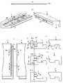
도 1a 내지 도 1e는 공지된 원리들에 따른 수직 변위를 갖는 제 1(1) 패널 에지 및 제 2(1’) 패널 에지의 잠금 및 가요성 설형부들(10)을 도시한다. 설형부 본체(20) 및 도 1b에 도시된 바와 같이 그 내부 부분에 또는 도 1c에 도시된 바와 같이 그 외부 부분에, 가요성 돌기들(21)을 포함하는 가요성 강모 설형부(flexible bristle tongue)(10)는, 도 1a에 도시된 바와 같이 잠금 동안 변위 홈(11) 내로 내측방으로 그리고 최종 잠금 단계 동안 외측방으로 변위되어, 가요성 설형부(10)의 외부 부분들이 설형부 홈(9) 내로 삽입되고, 제 1(1) 및 제 2(1’) 패널의 인접한 에지들은 수직 평면(VP)에 대해 수직으로 잠금된다. 패널 에지들은 인접한 에지에 형성되는 잠금 홈(14)과 협동하는 에지들 중 하나에 잠금 요소(8)를 갖는 스트립(6)을 포함하고 패널 표면에 대해 평행한 수평 방향으로 그리고 수직 평면에 대해 수직으로 에지들을 잠금한다.1A-1E show the locking and
도 1b는 설형부 본체(20) 및 그의 내부 부분에 가요성 돌기들(21)을 갖는 강모 설형부(10)를 도시한다. 도 1c는 설형부 본체(20) 및 그의 외부 부분에 가요성 돌기들(21)을 갖는 강모 설형부(10)를 도시한다.1B shows a
가요성 설형부는 에지를 따라 길이 방향(L), 에지에 대해 수직으로 수평으로 연장하는 폭(W), 및 수직 방향으로 설형부 두께(TT)를 갖는다. 설형부 두께(TT)는 일반적으로 변위 홈(11)의 홈 두께(GT)와 동일하다. 최대 폭(W)은 변위 홈(11)의 홈 깊이(GD)보다 크다.The flexible tongue has a longitudinal direction (L) along the edge, a width (W) extending horizontally and perpendicular to the edge, and a tongue thickness (TT) in the vertical direction. The tongue thickness TT is generally equal to the groove thickness GT of the
가요성 설형부는 복잡한 기하학적 형상을 포함하며, 따라서, 가요성과 함께 조합되는 고강도를 달성하기 위해 사용되는 유리 섬유들을 포함하는 사출 성형된(injected moulded) 열가소성-기반 컴포넌트로서 형성된다. 설형부의 길이 방향으로 돌기들을 구부리는 것은 이러한 진보된 가요성 설형부들의 본질적인 특징이다.The flexible tongue includes complex geometries and is thus formed as an injection molded thermoplastic-based component comprising glass fibers used to achieve high strength combined with flexibility. Bending the protrusions in the longitudinal direction of the tongue is an essential feature of these advanced flexible tongues.
도 1d 및 도 1e는 가요성 설형부(10)가 예컨대, 8 개 내지 32 개의 설형부들을 포함하는 설형부 블랭크들(30)로서 제조되고 전달되는 것을 도시한다. 플라스틱 재료는 제조 비용들을 줄이기 위해서 일반적으로 단지 일측으로부터 주입 채널들(injection channels)(31)을 통해 공구에 주입된다. 채널 재료는 사출 형성(injection forming) 후에 제거되고 재용융되어 다시 사용될 수 있다.1D and 1E show that the
유리 섬유들을 포함하는 열가소성 재료로 사출 성형하는 것은, 제조 허용공차들이 매우 낮은 고품질 컴포넌트들을 제공하는 비용 효율적인 방법이다. 그러나, 가요성 설형부의 제조 방법 및 기하학은 폴드 다운 설비가 요망되는 새로운 유형의 플로어 패널들 및 코어 재료들에 가요성 설형부들을 포함하는 비용 효율적인 잠금 시스템들을 제조할 수 있는 가능성을 제한하는 수 개의 단점들을 갖는다.Injection molding into a thermoplastic material comprising glass fibers is a cost effective way to provide high quality components with very low manufacturing tolerances. However, the manufacturing method and geometry of the flexible tongue has several limitations that limit the possibility of making cost-effective locking systems that include the flexible tongue in core materials and new types of floor panels and core materials for which a fold down facility is desired. It has drawbacks.
하나의 단점은 가요성 설형부가 짧은 에지에 형성된 홈에 삽입되기 때문에 패널의 폭에 상응하는 길이(L)를 가져야 한다는 것이다.One disadvantage is that the flexible tongue must have a length (L) corresponding to the width of the panel as it is inserted into the groove formed at the short edge.
플라스틱 재료는 설형부(10)의 길이(L)를 따라 설형부 본체(20)를 통해 유동해야 하고, 돌기들(21)과 설형부 본체(20) 사이에 공간(S)이 있어야 한다(도 1d 및 도 1e 참조). 이는 설형부의 기하학에 대한 소정의 비용 관련 제한들을 제공한다. 예컨대, 폭(W)이 4 mm 미만이고, 두께(TT)가 1.5 mm 미만이고, 길이가 약 300 mm를 초과하면, 생산 시간 및 공구 비용이 상당히 증가할 수 있다.The plastic material must flow through the
또 다른 문제점은, 홈 깊이(GD)가 약 4 mm이면 약 1.5 mm보다 작은 홈 두께(GT)를 갖는 변위 홈을 형성하는 것이 어렵다는 것이다.Another problem is that if the groove depth GD is about 4 mm, it is difficult to form a displacement groove having a groove thickness GT smaller than about 1.5 mm.
기계적 잠금 시스템들은 일반적으로 에지에 대해 그리고 전체 에지를 따라 평행한 홈들 및 돌출 부분들을 형성하는 큰 회전 공구들과 함께 형성된다.Mechanical locking systems are generally formed with large rotating tools forming grooves and protrusions parallel to and along the entire edge.
도 2a 내지 2e는 본 발명의 일 양태에 따라 에지(1)에 대해 수직으로 배열된 공동들(22) 및 돌기들(21)을 포함하는 잠금 시스템들 및 설형부들을 형성하기 위해 사용될 수 있는 제조 방법들의 실시예들을 도시한다.2A-2E show manufacturing that may be used to form tongues and locking
도 2a는 패널 에지(1)에 대해서 그리고 다시 반대로 변위되는 회전하는 톱날들(saw blades)(40)을 포함하는 공구를 도시하는 평면도이다. 대안으로, 패널(1)은 톱날들(40)에 대해 그리고 다시 반대로 변위될 수 있다. 이 제조 방법은, 도 2b 및 2c에 도시된 바와 같이, 공동들(22) 또는 돌기들(21)을 형성하도록 사용될 수 있으며, 여기서 상부 도면들은 사시도들을 예시하고 하부 도면들은 패널 에지(1)의 평면도들을 예시한다.FIG. 2a is a plan view showing a tool comprising rotating saw
도 2d는 이동 패널 에지(1)에 대해 수직 또는 수평으로 변위될 수 있는 소위 회전하는 점핑 공구 헤드(rotating jumping tool head)(41)의 측면도를 도시한다. 이에 의해, 국부적인 공동들(22)이 형성될 수 있다.FIG. 2d shows a side view of a so-called rotating
도 2e는 회전하는 카빙 공구(45)로 공동들(22)을 형성하기 위해 비용 효율적인 방법을 도시한다. 카빙 공구(45)는 카빙 공구(45)의 외부 에지를 따라 배열되는 치형부들(teeth)(46)을 포함한다. 공구 회전 속도는 패널(1)의 변위와 동기화되고, 각각의 치 형부들(46)은 패널(1)의 에지를 따라 미리 정해진 위치에서 그리고 미리 정해진 수평 연장을 갖는 하나의 공동(22)을 형성한다. 공구를 수직으로 변위시킬 필요는 없다. 카빙 공구(45)는 수 세트들의 치형부들(46)을 가질 수 있고 각각의 세트가 하나의 공동을 형성하기 위해 사용될 수 있다. 공동들(22)은 치형부들(46)의 기하학적 형상에 따라 상이한 단면들을 가질 수 있다.FIG. 2E shows a cost effective method for forming
도 2f는 소위 스크류 커터(screw cutter)(42)의 평면도를 도시한다. 이것은 스크류 커터(42)에 대해 고속으로 변위되는 에지에 대해 수직인 돌기들 및 공동들의 고정밀 및 비용 효율적인 형성을 허용하는 진보된 제조 기술이다. WO 2010/087752는 스크류 커터 원리에 대한 상세한 설명을 제공한다.FIG. 2f shows a plan view of a so-called
도 3a는 일 실시예에 따른 가요성 설형부(10)를 도시한다. 가요성 설형부(10)의 폭(W)은 실질적으로 가요성 설형부(10)의 전체 길이(L)에 걸쳐 본질적으로 동일하다.3A shows a
도 3b 및 도 3c는 도 3a에 도시된 설형부 부분(Ts1)의 확대도 및 패널 에지(1)에 제공된 변위 홈(11)에 삽입된 가요성 설형부(10)의 단면(A-A)을 도시한다.3b and 3c show an enlarged view of the tongue portion Ts1 shown in FIG. 3a and a cross section A-A of the
도 3b는 잠금 해제 및 잠금 위치에 있는 가요성 설형부(10)를 도시한다. 잠금 해제 위치는 파선으로 표시된 상부 패널 에지(1')에 의해 예시되는 한편, 잠금 위치는 파선으로 표시된 하부 패널 에지(1')에 의해 예시된다. 가요성 설형부(10)는 상부 립(lip)(12)을 포함하는 변위 홈(11)에 삽입된다. 수직 평면(VP)은 상부 립(12)의 상부 및 외부 부분과 교차한다. 설형부는 적어도 2 개의 설형부 섹션들(Ts1, Ts2)을 포함하고, 각각은 잠금 동안 인접한 에지(1')의 슬라이딩 에지(17)와 협동하는 슬라이딩 표면(15)과 설형부 홈(9)으로 잠금하는 잠금 표면(16)을 포함한다. 본 실시예에 따르면, 슬라이딩 표면(15)은 가요성 설형부(10)의 상부 부분에 제공된다. 보다 구체적으로, 슬라이딩 표면(15)은 가요성 설형부(10)의 외부 및 상부 경사 부분이다. 또한, 본 실시예에 따르면, 잠금 표면(16)이 가요성 설형부(10)의 하부 부분에 제공된다. 보다 구체적으로, 잠금 표면(16)은 가요성 설형부(10)의 외부 및 하부 경사 부분이다. 슬라이딩 표면(15)은 잠금 표면(16) 위에 배열된다. 설형부 섹션들(Ts1, Ts2)은 가요성 설형부(10)의 길이 방향(L)으로 서로 이격되어 있다. 설형부는, 수직 평면(VP)으로부터 가요성 설형부(10)의 외부 부분까지의 제 1 수평 거리(D1) 및 상기 수직 평면(VP)으로부터 가요성 설형부(10)의 내부 부분까지의 제 2 수평 거리(D2)가 설형부의 길이(L)를 따라 변하도록 잠금 및 잠금 해제 위치에서 만곡된다.3B shows the
가요성 설형부(10)의 형상은 설형부의 내부 부분으로부터 설형부의 최내각 지점들을 연결하는 내부 수평선까지의 제 3 수평 거리(D3)에 의해 추가로 규정될 수 있다. 내부 선은 가요성 설형부(10)의 길이 방향과 본질적으로 평행하다. 각각의 설형부 섹션들(Ts1, Ts2, ...)이 동일한 형상을 갖는다면, 내부선은 직선(straight line)이다. 제 1 예에서, D1은 가요성 설형부(10)의 전체 길이 방향을 따라 D3에 대응하고, 이에 의해 가요성 설형부(10)의 일정한 폭(W)을 제공한다. 제 2 예에서, D1은 적어도 가요성 설형부(10)의 길이 방향의 일부를 따라 D3과 상이하며, 이에 의해 가변 폭(W)을 제공한다.The shape of the
본 출원의 예시된 실시예들이 설형부 섹션들의 수에 대해서 비 제한적이라는 것은 명백하다. 실제로, 하나 또는 그 초과의 설형부 섹션들(Ts1, Ts2, ..., TsN)이 있을 수 있는데, 여기서 N은 1보다 크거나 같은 임의의 정수, 즉, N=1, 2, 3, 4, ...이다.It is clear that the illustrated embodiments of the present application are non-limiting with respect to the number of tongue sections. Indeed, there may be one or more tongue sections Ts1, Ts2, ..., TsN, where N is any integer greater than or equal to 1, ie N=1, 2, 3, 4 , ...to be.
도 3c는 잠금 동안 내부 위치에 있는 가요성 설형부(10)를 도시한다. 본 실시예에 따르면, 인접한 에지(1')는 잠금 동안 제 1 패널 에지(1)를 향해 본질적으로 수직 하방으로 변위되어, 인접한 에지(1')에 제공되는 잠금 홈(14)이 제 1 패널 에지(1)에 제공되는 잠금 요소(8)를 향해 낮춰지며 이와 협동한다. 가요성 설형부(10)는 인접한 패널(1')의 슬라이딩 에지(17)에 의해 내측방으로 가압되고, 만곡된 섹션들(Ts1, Ts2)은 가요성 설형부(10)가 가요성 설형부의 주요 부분을 따라 본질적으로 동일한 설형부 폭(W)을 갖는 본질적으로 직선 로드 형상 컴포넌트로 형성되도록 직선화된다. 일 실시예에서, 설형부 섹션의 잠금 동안, 거리(D3)는 잠금 해제된 거리로부터 잠금 해제된 거리의 20 % 미만으로 변할 수 있다. 도 3b에 예시된 바와 같이 잠금 위치뿐만 아니라 잠금 해제 위치에서 수직 평면(VP)을 지나 외측방으로 돌출하는 슬라이딩 표면(15)이, 도 3c에 예시된 바와 같이 잠금 동안 변위 홈(11)을 향해 가압되는 것에 주목한다. 이에 의해, 슬라이딩 표면(15)은 잠금 동안 수직 평면(VP)의 내측방으로 부분적으로 또는 전체적으로 가압될 수 있다.3C shows the
도 3b에 도시된 바와 같이, 가요성 설형부(10)는 각각 설형부의 내부 부분 및 외부 부분에서 설형부의 길이 방향을 따라 배열되는 내부 돌기들(21a) 및 외부 돌기들(21b)을 포함한다. 도 3b에서, 외부 돌기(21b)를 포함하는 설형부 섹션(Ts1)이 본질적으로 직선 섹션으로 직선화되었다는 것을 알 수 있다.As shown in FIG. 3B , the
도 3d는 패널들이 짧은 에지들(1, 1') 및 긴 에지들(4)을 포함하는 실시예를 도시한다. 패널의 긴 에지(4)의 앵글링에 의해 야기되는 인접한 짧은 에지(1')의 가위 움직임(scissor movement)은 패널 에지를 따라 내측방으로 설형부 섹션들을 점진적으로 가압하고 가요성 설형부(10)를 본질적으로 직선 컴포넌트를 향해 변형시킬 것이다. 예컨대, 설형부 섹션의 길이 방향을 따라 볼록한 또는 오목한 외부 에지를 갖는 가요성 설형부(10)의 적어도 하나의 설형부 섹션은, 볼록하거나 오목한 외부 에지의 외부 에지 지점이 변위 홈(11)을 향해 이동하도록 직선화될 수 있으며, 여기서, 외부 에지 지점은 변위 홈(11)으로부터 가장 먼 설형부 섹션 상의 지점이다. 도 3b에서, 외부 에지 지점은 그 길이 방향을 따라 볼록한 설형부 섹션(Ts1)의 중앙 부분에 로케이팅되며, 여기서 변위 홈(11)의 내벽까지의 거리(XM)가 최대가 된다. 오목한 설형부 섹션(Ts0)에서, 도 3b에 도시된 바와 같이, 외부 에지 지점은 그의 길이 방향을 따라 오목한 설형부 섹션의 에지 부분에 로케이팅될 수 있으며, 여기서 변위 홈(11)의 내부 벽까지의 거리가 최대가 되는 것에 주목한다. 예로써, 외부 에지 지점은 설형부(10)의 최대 폭의 20 내지 60 %, 바람직하게는 40 내지 50 %에 해당하는 거리만큼 적어도 변위 홈(11)을 향해 이동할 수 있다. 특히, 가요성 설형부(10)는 본질적으로 직선 컴포넌트, 예컨대, 그의 전체 길이를 따라 직선 컴포넌트로 직선화될 수 있다. 바람직하게는, 가요성 설형부(10) 및 설형부 홈(9)의 외부 부분들은, 에지(1b)의 외부 부분과 제 2 설형부 부분(Ts2), 바람직하게는 제 1 설형부 부분(Ts1)과 가장 멀리 있는 설형부 부분이 도 3f에 도시된 바와 같이 그의 내부 위치에 로케이팅될 때, 도 3e에 도시된 바와 같이, 에지(1a)의 내부 부분 및 제 1 설형부 부분(Ts1)이 그의 최종 잠금 위치에 근접하게 로케이팅되도록 구성된다. 에지 섹션들(Ts1, Ts2)은 수직 폴딩 동안 설형부 홈(9) 내로 점진적으로 이동할 것이고, 잠금 저항 및 분리 힘들 - 이는 설형부의 굽힘으로 인해 서로 짧은 에지들을 멀리 가압할 수 있음 - 이 감소될 것이다. 이는, 쉬운 잠금을 용이하게 한다.3d shows an embodiment in which the panels comprise
가요성 설형부(10)는 바람직하게는 설형부의 상부 및/또는 하부 부분에 로케이팅되는 마찰 연결부들(23)을 포함할 수 있다. 마찰 연결부들(23)은 세장형(elongated)일 수 있다. 요구되는 가요성은 잠금 동안 변위 홈(11) 내로 주로 수평 및 내측방으로 구부러지는 설형부의 만곡된 설형부 본체(20)에 의해 주로 얻어진다.The
가요성 설형부(10)는 횡단면들을 갖는 설형부 부분들을 포함할 수 있고, 여기서, 제 1 수평 거리(D1)는 제 2 수평 거리(D2)와 본질적으로 동일하여, 설형부 폭(W)은 수직 평면(VP)을 넘어서 돌출하는 슬라이딩 표면(15)의 폭의 약 2 배일 수 있다. 가요성 설형부(10)는 설형부의 폭(W)이 설형부의 두께(TT)와 본질적으로 동일하도록 매우 컴팩트한 단면으로 형성될 수 있다.The
설명된 실시예는 수개의 이점들을 제공한다. 직선형 내부 위치는 매우 작은 깊이의 변위 홈들을 형성하는 것을 가능하게 한다. 설형부의 단순한 기하학은, 플라스틱 재료가 사출 성형 동안 용이하게 부유할 수 있기 때문에 비용 효율적인 제조를 허용하며, 이는 설형부 폭(W) 및 설형부 두께(TT)를 감소시키고 설형부 길이(L)를 증가시키는 것을 가능케 할 수 있다. 1.5 mm 미만인 두께(TT), 예컨대, 약 1.0 내지 1.5 mm의 두께 및 약 1.5 내지 3 mm의 폭(W)을 갖는 사출 성형된 설형부를 제조하는 것이 가능하다. 또한 설형부(tongue) 두께(TT)가 0.5 내지 1.0 mm인 극도로 얇은 가요성 설형부들을 제조하는 것이 가능하다. 이러한 설형부들은 매우 얇은 플로어 패널들, 예컨대, LVT 또는 WPC 플로어 패널들을 약 3 mm의 두께로 잠금하기 위해 사용될 수 있다.The described embodiment provides several advantages. The straight inner position makes it possible to form displacement grooves of very small depth. The simple geometry of the tongue allows for cost-effective manufacturing as the plastic material can easily float during injection molding, which reduces the tongue width (W) and the tongue thickness (TT) and reduces the tongue length (L). can make it possible to increase It is possible to produce an injection molded tongue having a thickness TT of less than 1.5 mm, for example a thickness of about 1.0 to 1.5 mm and a width W of about 1.5 to 3 mm. It is also possible to manufacture extremely thin flexible tongues with a tongue thickness TT of 0.5 to 1.0 mm. These tongues can be used to lock very thin floor panels, such as LVT or WPC floor panels to a thickness of about 3 mm.
가요성 설형부의 강성은 횡단 스프링 상수(transverse spring constant)에 의해 규정될 수 있다. 비 제한적인 예에 따르면, 가요성 설형부의 횡단 스프링 상수는 설형부 길이 100 mm 당 5 내지 50 N/mm이다. 또 다른 비 제한적인 예에 따르면, 횡단 스프링 상수는 설형부의 길이 100 mm 당 15 내지 25 N/mm이다. 가요성 설형부의 횡단 스프링 상수는 당업자에게 공지된 표준 방법들에 의해 시험될 수 있다.The stiffness of the flexible tongue may be defined by a transverse spring constant. According to a non-limiting example, the transverse spring constant of the flexible tongue is between 5 and 50 N/mm per 100 mm of tongue length. According to another non-limiting example, the transverse spring constant is between 15 and 25 N/mm per 100 mm length of the tongue. The transverse spring constant of the flexible tongue can be tested by standard methods known to those skilled in the art.
도 4a는 일 실시예에 따른 설형부 블랭크(30)의 평면도 및 단면도를 예시한다. 도 4a 및 도 4b는 가요성 설형부(10)가 설형부 블랭크의 전체 길이를 따라 동일한 단면을 포함하는 압출 플라스틱 또는 금속 컴포넌트인 설형부 블랭크(30)로 형성될 수 있음을 도시한다. 특히, 설형부 블랭크(30)는 그 길이 방향을 따라 일정한 폭을 갖는다. 펀칭 휠(43)은 가요성 설형부(10)의 만곡된 부분들을 형성할 수 있다. 만곡된 부분들은 설형부 블랭크(30)로부터 재료를 제거함으로써 형성된다. 본 실시예에 따르면, 결과적인 가요성 설형부(10)의 폭이 가요성 설형부(10)의 길이 방향을 따라 본질적으로 일정해지도록 설형부 블랭크(30)의 내부 부분 및 외부 부분으로부터 제거된다. 가요성 설형부(10)는 수직 상향 또는 하향으로 돌출하는 마찰 연결부들(friction connections)(23)을 가질 수 있다. 이것은 도 4b의 실시예에 따른 가요성 설형부(10)의 평면도에 예시되어 있다.4A illustrates a top view and a cross-sectional view of a tongue blank 30 according to an embodiment. Figures 4a and 4b show that the
대안의 실시예에 따르면, 재료는 결과적인 가요성 설형부(10)의 폭이 가요성 설형부(10)의 길이 방향을 따라 일정하지 않게 되도록 설형부 블랭크(30)의 내부 부분으로부터 및/또는 외부 부분으로부터 제거될 수 있다. 일정하지 않은 폭들을 갖는 가요성 설형부들(10)의 예들이 도 9b, 도 9c 및 도 12c의 실시예들과 관련하여 아래에서 더 설명될 것이다.According to an alternative embodiment, the material is removed from the inner portion of the tongue blank 30 and/or such that the width of the resulting
대안의 실시예들에 따르면, 가요성 설형부(10)의 만곡된 부분들은 절단, 카빙, 펀칭 또는 밀링 또는 이들 수단의 임의의 조합과 같은 다른 수단에 의해 형성될 수 있다.According to alternative embodiments, the curved portions of
설형부 블랭크(30) 및/또는 가요성 설형부(10)는 사출 성형, 압출, 연속적인 층들 형성에 의한 3D 인쇄, 보강 재료에 의한 인발(pultrusion)에 의해 형성될 수 있다.The tongue blank 30 and/or the
일반적으로, 설형부 블랭크(30) 및/또는 가요성 설형부(10)는 열가소성 플라스틱 또는 열경화성 플라스틱과 같은 플라스틱, WPC, 금속 또는 패널 코어 재료 또는 패널의 적어도 하나의 층으로부터의 재료와 같은 패널 재료로 이루어진 그룹으로부터 선택되는 적어도 하나의 재료를 포함할 수 있다. 재료는 보강 재료를 더 포함할 수 있다 이에 의해, 재료가 보다 강성이 될 수 있다. 예컨대, 보강 재료는 열경화성 수지들과 같은 섬유들 또는 수지들을 포함할 수 있다. 대안으로, 또는 추가로, 재료는 이를테면, 가교 결합된 중합체들을 갖는 플라스틱과 같은 가교결합된 재료를 포함할 수 있다.In general, the tongue blank 30 and/or the
열가소성 재료는 PVC, PE, PP, CPVC 또는 유사한 재료들을 포함할 수 있다. 비 제한적인 예들에서, 폴리에틸렌은 저밀도 PE, 선형 저밀도 PE, 중간 밀도 PE 또는 고밀도 PE일 수 있다. 특히, 열가소성 재료는 가교 결합된 폴리에틸렌(또한, PEX 또는 XLPE라고 함)과 같은 가교 결합된 열가소성 재료일 수 있다. 더욱이, 열가소성 재료는 보강된 열가소성 재료일 수 있다. 보강된 열가소성 재료는 섬유들과 같은 보강 재료를 포함할 수 있다. 섬유들은 유리 섬유들, 탄소 섬유들, 아라미드(aramid) 섬유들, 목재 섬유들, 현무암(basalt) 섬유들, 부직(non-woven) 섬유들 또는 텍스타일(textile) 섬유들 중 적어도 하나를 포함할 수 있다. 대안으로, 섬유들은 금속 섬유들, 예컨대, 철 또는 자성 합금(magnetic alloy)과 같은 자성 금속 섬유들을 포함할 수 있다. 이에 의해, 섬유들은 재활용 중에 플라스틱으로부터 보다 용이하게 분리될 수 있다. 섬유들은 특정 배향을 가질 수 있다. 예컨대, 섬유들은 가요성 설형부(10)의 길이 방향을 따라 배향될 수 있다. 대안으로, 섬유들은 무작위로(randomly) 배향될 수 있다. 섬유들은 가요성 설형부(10)에 무작위로 분포될 수 있다. 대안으로, 섬유들은 예컨대, 가요성 설형부(10)의 중앙 부분에서, 직물(fabric)과 같은 가요성 설형부(10)에 매트 형상(mat-shaped) 층의 형태로 배열될 수 있다.The thermoplastic material may include PVC, PE, PP, CPVC or similar materials. In non-limiting examples, the polyethylene can be low density PE, linear low density PE, medium density PE, or high density PE. In particular, the thermoplastic material may be a cross-linked thermoplastic material such as cross-linked polyethylene (also referred to as PEX or XLPE). Furthermore, the thermoplastic material may be a reinforced thermoplastic material. The reinforced thermoplastic material may include a reinforcing material such as fibers. The fibers may include at least one of glass fibers, carbon fibers, aramid fibers, wood fibers, basalt fibers, non-woven fibers or textile fibers. have. Alternatively, the fibers may include metal fibers, for example magnetic metal fibers such as iron or a magnetic alloy. Thereby, the fibers can be more easily separated from the plastic during recycling. The fibers may have a specific orientation. For example, the fibers may be oriented along the longitudinal direction of the
따라서, 가요성 설형부(10)는 바람직하게는, 시간에 걸쳐 임의의 상당한 정도로 크리프(creep) 또는 변형되지 않는 저 크리프(low-creep) 재료를 포함한다. 이에 의해, 잠금 기능은 시간에 걸쳐, 예컨대, 1 개월, 1 년 또는 10 년 후에 열화되지 않는다. 상기 설명된 보강된 그리고 가교 결합된 재료들은 양자 모두가 크리핑을 방해할 수 있다. 도 4d 내지 도 4f는 설형부 블랭크들(30)이 시트 형상 재료(50)로 형성될 수 있음을 도시한다. 단일 층 시트의 경우에 도 4d에 예시된 시트 형상 재료(50)는, 바람직하게는 광물 또는 목재 충전제들(fillers)을 포함하는 열가소성 재료일 수 있다. 바람직하게는, 적어도 3 개의 층들이 함께 적층되거나(laminated) 융합된다(fused). 상기 설명된 유리 섬유들 또는 임의의 다른 섬유들이 시트 형상 재료를 보강하기 위해 사용될 수 있다. 시트 형상 재료는 또한 바람직하게는, 목재 섬유들과 혼합된 열경화성 수지들을 포함할 수 있다. 도 4f는 적어도 3 개의 층들을 포함하는 시트 형상 재료(50)를 도시한다. 상부 층(51a) 및 하부 층(51c)은 열가소성 재료를 포함하고, 중간 층(51b)은 섬유들, 예컨대, 유리 섬유들을 포함하는 보강 층이다. 중간 층(51b)은 섬유들을 포함하는 매트 형상의 층이다. 그러나, 상기 설명된 다른 재료들이 층들(51a 내지 51c)에 사용될 수 있음은 명백하다. 예컨대, 상부 층(51a) 및 하부 층(51c)은 열경화성 플라스틱을 포함할 수 있고 그리고/또는 중간 층(51b)은 무작위로 분포된 섬유들을 포함할 수 있다. 도 4e의 실시예에 따르면, 가요성 설형부(10)는 상이한 재료 특징들을 갖는 재료들의 적어도 3 개의 층들을 포함한다. 층들 및 보강 층들은 가열 및/또는 가압에 의해 서로 결합될 수 있다. 분리 이후에, 가요성 설형부(10)의 외부 부분 및/또는 내부 부분을 형성하는 시트 형상 재료(50)에 직선 시트 홈(52a) 또는 만곡 시트 홈(52b)을 형성하도록, 핫 엠보싱된 롤러들(hot embossed rollers)이 사용될 수 있다. 홈들은 또한 회전 절단 또는 카빙 공구들로 형성될 수 있다. 펀칭 공구(43), 또는 펀칭 휠(43)이 또한 가요성 설형부들(10)을 형성하기 위해 사용될 수 있다. 이 모든 제조 방법들이 조합될 수 있다. 가요성 설형부들(10)은 또한 종래의 3D 인쇄 방법들로 형성될 수 있다. 도 4d 내지 도 4f와 관련하여, 3 개의 층들이 단지 예시적인 목적들을 위해 선택되었으며, 그리고 임의의 수의 층들, 예컨대 1 개, 2 개, 3 개, 4 개, 5 개, 6 개 또는 7 개 층들이 선택될 수 있음이 명백하다. 게다가, 복수 개의 보강 층들이 있을 수 있다. 예컨대, 제 1 및 제 2 보강 층의 내부 표면 사이에 개재된 중앙 층(centre layer), 그리고 제 1 및 제 2 보강 층의 외부 표면들에 각각 배열된 상부 및 하부 층이 있을 수 있다.Accordingly, the
도 5a는 가요성 설형부(10)가 직선 로드 형상 컴포넌트로서 형성될 수 있음을 도시한다. 도 5b는 공동들(22a, 22b)이 제 1 패널(1)의 변위 홈(11)의 내부 부분에 형성될 수 있고, 돌기들(21)이 인접한 제 2 패널(1')에 형성될 수 있음을 도시한다. 공동들(22a, 22b) 및 돌기들(21)은 패널들(1, 1')의 사이드 에지들의 부분들을 따라 이들의 길이 방향으로 형성된다. 각각의 공동은 수직 평면(VP)을 향해, 연속적인 상부(26), 내부(27) 및 하부(28) 공동 벽 및 수평 공동 개구(29)를 포함한다. 공동 벽들은 바람직하게는, 이 벽들이 바람직하게는, 회전 카빙 또는 점핑 공구로 형성되기 때문에 에지를 따라 연속적이다. 내부 공동 벽(27)의 적어도 일부는 만곡되어 있다. 각각의 돌기(21)는 상부 수평 벽 및 외부 벽을 포함한다. 본 실시예에 따르면, 외부 벽은 경사져 있다. 그러나, 대안의 실시예에 따르면, 외부 벽은 수직일 수 있고, 돌기는 또한 상부 벽과 본질적으로 평행한 하부 수평 벽을 포함할 수 있다. 공동들(22a, 22b)은 변위 홈(11)과 동일한 수직 연장부를 가질 수 있다. 대안으로, 공동들(22a, 22b)은 변위 홈(11)보다 더 큰 수직 연장부를 가질 수 있다. 이는 보다 비용 효율적인 생산을 제공하는데, 왜냐하면, 더 크고 그리고 보다 효율적인 점핑 공구들 또는 톱날들이 사용될 수 있고 잠금 기능에 부정적인 영향들을 주지 않으면서 제조 허용공차들이 증가될 수 있기 때문이다. 대안의 실시예에 따르면, 공동들(22a, 22b)은 변위 홈(11) 보다 더 작은 수직 연장부를 가질 수 있다.5A shows that the
도 5c 내지 도 5f는 돌기들(21) 및 공동들(22)이 패널 에지들을 따라 그리고 서로 인접하게 로케이팅되어, 돌기(21)가 설형부 섹션(Ts1)의 일부를 공동(22) 내로 변위시키고 구부릴 수 있는 것을 도시한다. 도 5d는 변위 홈(11)의 두께(GT)와 거의 동일한 수직 연장부 또는 공동 두께(Ct)를 갖는 공동(22a)을 포함하는 단면(A-A)을 도시한다. 도 5e는 단면(A-A)의 대안의 실시예를 도시하며, 여기서, 공동(22b)은 변위 홈(11)보다 큰 공동 두께를 가지며 변위 홈의 상부 부분 또는 하부 부분 아래에서 수직으로 오프셋된다. 변위 가능한 설형부(10)는 내부 부분의 설형부의 두께(TTb)보다 더 큰 외부 설형부의 두께(TTa)를 갖는 외부 부분을 가질 수 있다. 성형 공구의 수직 위치가 변위 홈(11)의 상부 부분과 정렬되지 않을지라도, 설형부의 내부 부분이 공동 내로 변위될 수 있다는 것이 장점이다. 대안의 실시예에 따르면, 공동(22b)은 변위 홈(11) 보다 더 작은 공동 두께를 가질 수 있다. 도 5f는 어떠한 공동 및 돌기도 형성되지 않고 변위 홈(11)에서 가요성 설형부(10)의 어떠한 변위도 본질적으로 발생하지 않는 단면(B-B)을 도시한다. 에지의 이 부분은 설형부 섹션(Ts1)의 내측방 굽힘을 위한 지지부로서 사용된다.5c - 5f show that the
도 6a 내지 도 6i는 도 5a 내지 도 5f에 따른 가요성 로드 형상 설형부(10)의 변위를 상세히 도시한다. 도 6a는 도 6b 및 도 6c에 따른 수평 평면들(HP1 및 HP1')에서의 제 1(1) 및 제 2(1’) 에지 섹션의 평면도를 도시한다. 여기에서, 설형부는 본질적으로 직선이다. 도 6d 내지 도 6f는 가요성 설형부(10)의 부분들이 돌기들(21)에 의해 공동들(22) 내로 가압된 구부러진 내부 위치에서의 가요성 설형부(10)를 도시한다. 도 6g 내지 도 6i는 외부 및 잠금된 위치에서의 가요성 설형부(10)를 도시하며, 여기서, 가요성 설형부(10)의 외부 부분들이 설형부 홈(9) 내로 삽입되도록 설형부 홈(9) 및 변위 홈(11)이 수직 정렬된다. 본 실시예에 따르면, 가요성 설형부(10)는 외부 및 잠금된 위치에서 본질적으로 직선이다. 대안의 실시예(도시되지 않음)에 따르면, 그러나, 가요성 설형부(10)의 적어도 일부는 외부 및 잠금된 위치에서 구부러질 수 있다. 예컨대, 가요성 설형부(10)는 섹션들로 구부러질 수 있다.6a to 6i show the displacement of the flexible rod-shaped
도 7a 및 도 7b는 바람직하게는 잠금 시스템을 형성하기 위해서 사용되는 동일한 제조 라인에서, 패널(1)의 에지 부분으로부터 설형부, 바람직하게는 가요성 설형부(10)를 형성하고 그리고 설형부를 홈, 바람직하게는 변위 홈(11) 내로 삽입하기 위한 방법을 도시한다. 가요성 설형부(10)는 이 실시예에서, 스트립(6)의 외부 부분에 형성된다. 가압 휠들(44a, 44b, 및 44c)이 설형부(10)를 에지(1)로부터 분리시키고 설형부를 홈(11) 내로 수직 및 수평으로 변위시키기 위해 사용될 수 있다. 설형부의 부분(P1)은 다른 부분(P2)이 홈(11)에 삽입되어 고정될 때 에지(1)에 연결되는 것이 바람직하다. 설형부(10)는 또한 바람직하게는, 패널 에지(1)와 동일한 속도로, 에지(1)로부터 해제되어 휠들(44a, 44b)로 변위되고, 휠들(44c) 또는 일부 가압 유닛들을 사용하여 변위 홈(11)에 삽입될 수 있다. 상부 및 하부 지지 유닛들은 설형부를 홈에 정렬시키고 위치시키기 위해 사용될 수 있다. 설형부는 도 5a 내지 도 5f에 설명된 바와 같이 잠금 시스템에 사용될 수 있다.7a and 7b show, in the same production line preferably used for forming the locking system, a tongue, preferably a flexible tongue, 10 being formed from an edge portion of a
이러한 제조 방법은 수개의 이점들을 제공한다. 설형부 블랭크들은 필요하지 않으며 설형부(10)는 항상 패널 에지에 대응하는 적절한 길이를 가질 것이다. 매우 광범위한 코어 재료들, 이를테면, HDF, 증가된 수지 함량을 포함하는 고밀도 내수성 HDF, 미네랄 또는 목재 섬유 충전제들이 혼합된 열가소성 재료, 소위 LVT 또는 WPC 재료, 발포 열가소성 재료 등이 시장에 도입되고 있다. 상기 언급된 재료들 중 임의의 재료가 도 7a 및 도 7b의 실시예에 따른 가요성 설형부(10)를 형성하기 위해 사용될 수 있다. 열가소성 플로어 재료들은 열 수축 및 팽창을 감소시키기 위해서 유리 섬유들로 종종 보강된다. 유리 섬유들(47)은 가요성 설형부(10)가 형성되는 코어(6)의 부분에 로케이팅될 수 있으며 가요성 설형부(10)의 강도 및 스프링 특징들을 증가시키는데 기여할 수 있다. 이러한 재료들은 충분한 가요성을 가지며 강한 그리고 가요성 설형부 본체를 제공할 수 있다. 엔지니어링된 목재 플로어링들은 일반적으로 짧은 측 상에 합판(plywood)과 같은 별도의 재료를 가지며, 이 별도의 재료는 또한 가요성 설형부를 형성하기 위해 사용될 수 있다. 열가소성 플로어 재료들은 열 수축 및 팽창을 감소시키기 위해 종종 유리 섬유들로 보강된다. 이러한 유리 섬유 층들은 코어(6)의 중간 부분들에 위치된다. 유리 섬유들(47)은 가요성 설형부(10)가 형성되는 코어(6)의 부분, 바람직하게는 하부 부분에 위치될 수 있으며, 가요성 설형부(10)의 강도 및 스프링 특징들을 증가시키는데 기여할 수 있다.This manufacturing method provides several advantages. No tongue blanks are needed and the
도 8a 내지 8c는 다소 복잡한 만곡된 설형부들(10)이 스크류 커터들, 점핑 공구 헤드들 또는 펀칭 휠들로 형성될 수 있으며, 패널 에지들에 형성된 공동들 및 돌기들이 변위 홈(11)에서 가요성 설형부(10)를 변위시키기 위해 필요하지 않음을 도시한다. 도 8a는 스트립(6)의 외부 부분에 형성되고 연결된 설형부(10)를 도시한다. 도 8b는 스트립(6)으로부터 해제되는 가요성 설형부(10)를 도시하고 그리고 도 8c는 변위 홈(11) 내로 삽입되는 변위 가능한 설형부(10)를 도시한다.8a to 8c show that the rather complex
만곡된 설형부는 설형부의 적어도 하나의 섹션이 만곡되는 것을 의미한다. 만곡된 설형부는 임의의 수의 만곡된 섹션들, 예컨대, 3 개, 4 개, 5 개, 6 개, ...를 포함할 수 있다. 만곡된 섹션들은 서로 직접 연결될 수 있다. 그러나, 선택적으로, 직선 섹션들은 만곡된 섹션들을 연결할 수 있다.A curved tongue means that at least one section of the tongue is curved. The curved tongue may include any number of curved sections, such as 3, 4, 5, 6, ... The curved sections can be directly connected to each other. Optionally, however, straight sections may connect curved sections.
도 9a 내지 도 9d는 잠금 시스템들 및 가요성 설형부들(10)의 바람직한 실시예들을 도시한다. 도 9a는 공동들(22)을 포함하는 패널 에지(1)의 변위 홈(11)에 삽입되는 잠금 표면들(16) 및 미끄럼 표면들(15)을 포함하는 직선 로드 형상의 가요성 설형부(10)를 도시한다. 도 9a는 또한 돌기들(21)을 포함하는 인접한 에지(1')를 도시한다. 도 9b는 인접한 에지(1') 상의 돌기들이 가요성 설형부(10)의 외부 부분 상에 형성되는 외측방으로 연장하는 돌기들(21)로 대체될 수 있음을 도시한다. 이러한 돌기들(21)은 압출물들에 의해 제조되거나 시트 형상 재료로 제조되는 가요성 설형부(10) 상에 형성하기 쉽다. 단지 비용 효율적인 회전 카빙 공구만이 고품질 잠금 시스템을 형성하는데 충분할 수 있다. 도 9b의 실시예에 따르면, 가요성 설형부(10)는 돌기들(21)이 공동들(22)을 등지는(facing away from) 변위 홈(11)의 공동들(22) 내로 삽입 가능하다. 이에 의해, 슬라이딩 에지(17)와 같은 패널 에지(1')의 외부 표면은 돌기들(21)과 접촉하며 가요성 설형부(10)의 설형부 섹션의 일부를 내측방으로 변위시키고 구부릴 수 있다. 도 9c는 공동들(22)이 설형부(10)의 내부 부분 상에 형성되는 내부 돌기들(21a)로 대체될 수 있음을 도시한다. 이에 의해, 패널 에지(1') 상의 돌기들(21)은 가요성 설형부(10)의 설형부 섹션의 일부를 내측방으로 변위시켜 구부릴 수 있다. 변위는 설형부(10)와 변위 홈(11)의 내부 벽 사이에 공간이 있는 내부 돌기들(21a) 사이에서 발생할 수 있다. 이 실시예에서, 내부 벽은 평탄한 표면이지만, 다른 형상들이 마찬가지로 가능할 수 있다. 도 9d는 공동들 및 돌기들 양자 모두가 가요성 설형부(10)의 내부 부분 및 외부 부분에 각각 내부 돌기들(21a) 및 외부 돌기들(21b)을 포함하는 만곡된 가요성 설형부(10)로 대체될 수 있음을 도시한다. 이에 의해, 슬라이딩 에지(17)와 같은 패널 에지(1')의 외부 표면이 돌기들(21)과 접촉하여 가요성 설형부(10)의 설형부 섹션의 일부를 변위 홈(11)의 내부 벽을 향해 내측방으로 변위하고 구부릴 수 있다. 이 실시예에서, 내부 벽은 평탄한 표면이지만, 다른 형상들이 마찬가지로 가능할 수 있다.9A-9D show preferred embodiments of locking systems and
비 제한적인 예들에서, 가요성 설형부(10)의 내부 부분 및/또는 외부 부분은 본질적으로 사인파(sine wave)의 일부, 톱니파(saw-tooth)의 일부로서 형상이 정해질 수 있고, 단차식(step-wise) 일정 프로파일을 가질 수 있거나 직선 프로파일을 가질 수 있다.In non-limiting examples, an inner portion and/or an outer portion of
상기 그리고 이하의 실시예들 전부에서, 각각의 돌기(21, 21a, 21b)가 가요성 설형부(10)의 하부 수직 부분, 상부 수직 부분 또는 중앙 부분에 제공될 수 있음은 명백하다.It is clear that in all of the above and below embodiments, each
도 10a는 예컨대, 도 8a 내지 도 8c에 도시된 것과 같은 만곡된 설형부가 스크류 커터(42) 및 점핑 공구 헤드(41)를 사용하여 형성될 수 있음을 도시한다. 도 10b는 설형부(10)가 점핑 공구 헤드들(41)을 사용하여 에지의 상부 부분에 형성될 수 있음을 도시한다. 이러한 실시예는 재료를 절약할 것이다. 도 10c는 설형부(10)가 스크류 커터(42) 및 점핑 공구(41)를 사용하여 스트립(6)의 외부 부분 위에 형성될 수 있음을 도시한다. 점핑 공구들(41)은 본 발명의 모든 실시예들에서 회전 카빙 공구들(45)로 대체될 수 있다.FIG. 10A shows that a curved tongue, for example as shown in FIGS. 8A-8C , can be formed using a
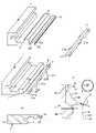
도 11a는 표면 층(2), 및 상부 코어 층(5a)과 하부 코어 층(5b)을 포함하는 코어를 포함하는 패널(1)을 도시한다. 비 제한적인 예에서, 패널(1)은 LVT 패널일 수 있다. 하부 코어 층(5b)은 상부 코어 층(5a) 보다 높은 열가소성 재료 함량을 포함한다. 가요성 설형부(10)는 하부 코어 층(5b)으로부터 형성된다. 이는, 가요성 설형부(10)가 하부 코어 층(5b)과 동일한 재료 조성물을 포함하는 것을 의미한다. 도 11a는, 또한 변위 홈(11) 내로 삽입되고 있는 가요성 설형부(10)를 도시한다.11a shows a
도 11a 및 도 11b는 만곡된 가요성 설형부(10)가 2 개의 스크류 커터들, 즉 제 1 스크류 커터(42a) 및 제 2 스크류 커터(42b)를 사용하여 비용 효율적인 방식으로 형성될 수 있음을 도시한다. 가요성 설형부(10)는 바람직하게는, 서로에 대해 수직 및 수평으로 변위되는 내부 및 하부 부분(10a)과 상부 및 외부 부분(10b)을 포함한다. 상부 부분(10b)은, 바람직하게는, 하부 부분(10a)보다 변위 홈(11)의 내부 부분에 대해 더 떨어져 있다(more distant). 외부 돌기(21b)는 제 1 스크류 커터(42a)가 설형부로부터 재료를 제거할 때 상부 부분(10b)에 형성되고, 내부 돌기(21a)는 제 2 스크류 커터(42b)가 설형부(10a)의 하부 부분으로부터 재료를 제거할 때 설형부(10a)의 하부 부분에 형성된다. 설형부의 내부 부분은 또한 상부 부분으로서 형성될 수 있고 외부 부분은 또한 하부 부분으로서 형성될 수 있다. 이러한 설형부들은, 예컨대, 설형부가 잠금 홈(14)을 포함하는 제 2 패널(1')의 에지 내로 삽입될 때 사용될 수 있다.11a and 11b show that the curved
도 12a 내지 도 12c는 도 11a, 도 11b에 도시된 잠금 시스템의 보다 상세한 설명을 제공한다. 도 12a는, 2 개의 인접한 패널 에지들 중 하나에 형성되는 잠금 시스템의 일부를 포함하는 패널(1)의 에지 섹션을 도시한다. 홈(11), 잠금 요소(8)를 갖는 스트립(6) 및 설형부(10)는 회전 공구들로 형성된다. 설형부는 바람직하게는, 스트립(6)의 외부 부분에 형성된다. 잠금 시스템 및 설형부(10)는, 패널 에지(1)의 길이 방향을 따라 본질적으로 동일하고 연속적인 단면을 포함한다. 설형부(10)는 서로에 대해 수직 및 수평 방향으로 변위되는 상부 부분(10b) 및 하부 부분(10a)을 포함한다. 상부 부분(10b)은 잠금 표면(16)을 포함한다. 하부 부분(10a)은 하방으로 연장하는 하부 돌기들(21c)을 포함한다. 도 12b는 외부 돌기들(21b) 및 내부 돌기들(21a)이 형성되도록 제 1 스크류 커터(42a) 및 제 2 스크류 커터(42b)가 설형부(10)의 외부 및 상부 부분들(10b)과 내부 및 하부 부분들(10a)로부터 재료를 제거하기 위해 사용될 수 있음을 도시한다. 도 12c는 잠금 시스템의 제조 중에 변위 홈(11) 내로 삽입될 수 있도록 스트립(6)으로부터 해제되는 가요성 설형부(10)를 도시한다. 가요성 설형부는 내부 돌기들(21a)이 설형부(10)의 상부 부분 아래에 수직으로 로케이팅되는 것을 특징으로 한다.12A-12C provide a more detailed description of the locking system shown in FIGS. 11A-11B . Figure 12a shows an edge section of a
도 12d 및 도 12e는 체인(48) 및 상부 벨트(49)를 포함하는 더블 엔드 테너 머신(double-end tenor machine)에서 쉬운 기계 가공을 용이하게 하기 위해 설형부(10)가 수평 평면(Hp1)에 대해서 경사진 설형부 본체(20)로 형성될 수 있음을 도시한다. 패널(1)은 표면 층(2)이 하방을 향하는 상태로 더블 엔드 테너에 위치된다. 설형부(10)로부터 상부 벨트(49)까지의 수평 거리(D4)는 점핑 공구 헤드(41), 스크류 커터 공구 헤드(45) 또는 스크류 커터(42)의 반경(R)보다 작을 수 있다.12d and 12e show that the
도 13a 내지 도 13h는 상이한 실시예들을 도시한다. 도 13a는 제 1 패널(1)의 스트립(6) 상에 형성되는 잠금 요소(8)와 협동하는 잠금 홈(14)을 포함하는 제 2 패널(1'), 폴드 패널, 상의 가요성 설형부(10)를 포함하는 잠금 시스템을 도시한다. 도 13b 내지 도 13d는 가요성 설형부(10)가 코어(5)의 상부, 중간 또는 하부 부분에 로케이팅될 수 있는 폴드 패널(1')의 코어 섹션으로 형성될 수 있음을 도시한다. 도 13e는 제 2 폴드 패널(1') 상의 잠금 홈(14)의 내부 벽에 형성되는 변위 홈(11)에 부착되는 가요성 설형부(10)를 갖는 잠금 시스템을 도시한다. 설형부(10)는 도 13f에 도시된 바와 같이 코어의 하부 부분에 로케이팅되는 코어 섹션으로 형성될 수 있다. 도 13g는 제 1 패널(1)의 스트립(6)의 외부 부분에 형성되는 변위 홈(11)을 포함하는 잠금 시스템을 도시한다. 도 13h는 설형부(10)가 스트립(6) 위에 로케이팅되는 코어 부분으로 형성될 수 있음을 도시한다.13A-13H show different embodiments. 13a shows a flexible tongue on a second panel 1', a fold panel, comprising a locking
도 14a 내지 도 14d는 코어 재료(5)가 가요성 설형부(10)를 형성하는데 보다 적합하게 되도록 국부적으로 변형될 수 있음을 도시한다. 이 방법은 별도의 가요성 설형부가 없는 일체형 잠금 시스템들로 형성되는 이러한 시스템들일지라도, 임의의 유형의 기계적 잠금 시스템들의 강도 및 가요성을 증가시키는 데 사용될 수 있다. 도 14a는 예컨대, 열경화성 수지(24), 예컨대, 멜라민 포름알데히드, 우레아 포름알데히드 또는 페놀 포름알데히드 수지와 같은 수지가 예컨대, 멜라민 포름알데히드 함침된 밸런싱 페이퍼(3) 상에 또는 코어 재료(6) 상에 직접 액체 또는 건식 분말 형태로 적용될 수 있음을 도시한다. 도 14b는 코어 재료(5), 바람직하게는 목재 기반 패널, 예컨대, HDF 보드 또는 파티클 보드가 라미네이션 이전에 첨가된 수지(24)로 함침된 페이퍼(3) 상에 적용될 수 있음을 도시한다. 도 14c는 표면 층들(2) 및 밸런싱 층(3)이 코어(6)에 라미네이팅되었을 때 라미네이션 후의 플로어 보드를 도시한다. 수지들(24)은 코어(5) 내로 관통되어 가열 및 가압 하에 라미네이션 동안 경화된다. 도 14d는 코어(5)와 일체로 형성된 설형부(10)를 포함하는 제 1 패널(1)의 에지를 도시한다. 설형부(10)는 보다 가요성이며 코어(5)의 다른 부분들보다 더 높은 수지 함량을 포함한다. 증가된 수지 함량은 제조 중에 변위 홈(11)에 삽입될 수 있는 강한 가요성 설형부(10)를 형성하는데 매우 적합한 재료를 제공한다.14A-14D show that the
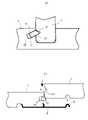
도 15a는 본 개시의 각각의 실시예에 따른 가요성 설형부(10) 및 잠금 시스템이 가구 컴포넌트들(1, 1')을 서로 수직으로 잠금시키기 위해 사용될 수 있음을 도시한다. 공동들(22)이 경사 변위 홈(11)에 형성될 수 있고 돌기들이 설형부 홈(9) 아래에 형성될 수 있다. 가요성 설형부는 상기 설명된 바와 같이 만곡된 로드 형상의 컴포넌트일 수 있으며, 또한 이는 패널 코어의 코어 부분으로 형성될 수 있다.15A shows that the
도 15b는 본 개시의 각각의 실시예에 따른 가요성 설형부(10) 및 잠금 시스템이 또한 세라믹 타일들(1, 1')을 잠금시키기 위해 사용될 수 있음을 도시한다. 스트립(6) 및 잠금 요소(8)는 제 1 타일(1)의 에지에 부착되는 별도의 플라스틱 또는 금속 부분으로 형성될 수 있다. 공동들(22) 및 돌기들(21)은 또한 다이아몬드 공구들을 사용하여 세라믹 재료로 형성될 수 있다. 개시된 가요성 설형부(10)의 모든 실시예들이 사용될 수 있다. 제 2 타일(1')은 설형부 홈(9) 및 잠금 홈(14)을 포함한다. 가요성 설형부(10)는 수직 방향으로 제 1 및 제 2 에지의 잠금을 위해 상기 설명된 바와 같은 설형부 홈(9)과 협동하도록 구성된다. 또한, 별도의 스트립(6)의 잠금 요소(8)가 수평 방향 잠금을 위해서 잠금 홈(14)과 협동하도록 구성된다.15B shows that the
도시된 모든 잠금 시스템들은 이들이 수직 변위 및/또는 앵글링 및/또는 수평 스내핑(snapping)으로 잠금될 수 있도록 적응될 수 있다. 이들은 또한 에지를 따라 상방 앵글링 또는 변위를 사용하여 해제될 수 있다. 수직 잠금은 가요성 스트립(6), 그리고 바람직하게는 잠금 중에 구부러지는 가요성 잠금 요소(8)와 결합될 수 있다. 바람직하게는, 스트립(6)의 외부 부분이 하방으로 구부러지고, 잠금 요소(8)의 상부 부분이 외측방으로 수평으로 구부러지거나 회전된다(turned).All of the locking systems shown are adaptable such that they can be locked by vertical displacement and/or angling and/or horizontal snapping. They can also be released using upward angling or displacement along the edge. The vertical locking can be combined with a
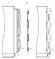
도 16a 내지 도 16c에 개략적으로 예시된 바와 같이, 만곡된 가요성 설형부(10)는 먼저 설형부 블랭크(30) 또는 본질적으로 직선 설형부를 제공하고, 그 다음에 변형에 의해 원하는 형상의 만곡된 가요성 설형부로 이를 구부림으로써 형성될 수 있다. 설형부 블랭크(30)는 상기 설명된 바와 같이 보강을 갖거나 갖지 않는 플라스틱, 바람직하게는 열가소성 재료 또는 열경화성 재료로 제조된다. 그러나, 다른 재료들이 똑같이 상상할 수 있다. 이 방법은 설형부의 길이 방향을 따라 본질적으로 일정한 단면을 갖는 만곡된 가요성 설형부들을 제조하기 위해 특히 적합하다. 그러나, 설형부 블랭크(30)는 또한 설형부의 길이 방향을 따라 다양한 단면을 가질 수 있다. 선택적으로, 설형부 블랭크(30)는 그 길이 방향을 따라 내부 및/또는 외부 돌기들을 포함할 수 있다As schematically illustrated in FIGS. 16A-16C , the curved
도 16a에 도시된 바와 같이, 설형부 블랭크(30)는 롤(32) 상에 제공되고 당업자에게 공지된 공급 방법에 따라 벤딩 디바이스(34) 내로 공급된다. 그 다음에, 설형부 블랭크(30)는 도 16b에 도시된 바와 같이 구부러진 상태로 배열된다. 본 실시예에 따르면, 설형부 블랭크(30)는 설형부 블랭크의 부분들이 구부러지게 되도록 굽힘 요소들(50)의 시퀀스 또는 매트릭스에 배열된다. 도 16b에서, 굽힘 요소들(50)은 기재(substrate)(52)에 고정되는 로드들, 못들 또는 스크류들이고, 설형부 블랭크(30)는 굽힘 요소들(50) 사이에서 지그재그 패턴으로 배열된다. 그러나, 대안으로, 벤딩 요소들(50)은 롤러들 또는 실린더들일 수 있다. 선택적으로, 설형부 블랭크(30)의 종단점들은 예컨대, 기재(52)에 고정될 수 있다. 설형부의 최종 형상은 굽힘 요소들(50)의 패턴에 의해 결정된다. 벤딩 요소들(50) 사이의 수평 및/또는 수직 거리들은 일정하거나 대안으로, 가변적일 수 있다.As shown in FIG. 16A , the tongue blank 30 is provided on a
그 다음에, 설형부 블랭크(30)는 일정 시간 기간 동안 구부러진 상태로 고정된다. 선택적으로, 가열 디바이스(60)에 의해 굽힘 상태 이전 및/또는 굽힘 상태 동안 가열 프로세스에서 설형부 블랭크(30)에 열이 제공될 수 있다. 이에 의해, 만곡된 설형부의 성형이 가속화될 수 있다. 선택적으로, 설형부 블랭크는 또한 냉각 디바이스(70)에 의한 가열 프로세스 이후에 냉각 프로세스를 수행할 수 있다. 가열 및 냉각 프로세스는 당업자에게 주지된 방법들에 의해 구현될 수 있다. 임계 시간 기간이 경과된 이후에, 설형부 블랭크(30)는 구부러진 형상을 취하여 영구적으로 또는 반 영구적으로 변형되게 되며, 만곡된 설형부 요소가 되게 된다. 변형은 인장력들, 압축력들, 전단, 굽힘 또는 비틀림으로 인해 발생할 수 있다. 영구 변형은 소성(plastic), 비가역적(irreversible) 변형일 수 있다. "반영구적인"은 본원에서, 성형 직후에 제공되는 구부러진 형상이 1 달, 1 년 또는 10 년과 같은 최소 시간량 동안 적어도 본질적으로 보존된다는 것을 의미한다. 만곡된 설형부 요소는 최종적으로 절단 디바이스(80)에 의해 미리 결정된 길이들을 갖는 하나 또는 그 초과의 만곡된 가요성 설형부들(10)로 절단된다. 상기 프로세스로부터 발생하는 만곡된 가요성 설형부(10)는 도 16c에 개략적으로 예시되어 있다.Then, the tongue blank 30 is held in a bent state for a period of time. Optionally, heat may be provided to the tongue blank 30 in a heating process prior to and/or during the bending by means of the
상기 개시된 모든 실시예들은 부분적으로 또는 완전히 서로 조합될 수 있음이 강조된다. 특히, 도 4a 내지 도 4c의 실시예와 관련하여 제시된 가요성 설형부의 재료들 및 보강들의 다양한 선택들이 또한 본 출원의 다른 가요성 설형부들 - 직선 또는 만곡됨 - 의 실시예들에 사용될 수 있다.It is emphasized that all embodiments disclosed above can be partially or fully combined with each other. In particular, the various selections of materials and reinforcements of the flexible tongue presented in connection with the embodiment of FIGS. 4A-4C may also be used with embodiments of other flexible tongues - straight or curved - of the present application.
Claims (20)
Translated fromKorean상기 가요성 설형부는 제 1 패널(1)의 제 1 에지에서 변위 홈(11)에 그리고 인접한 제 2 패널(1')의 제 2 에지에서 설형부 홈(9)에 배열되고, 상기 가요성 설형부(10)는 상기 제 1 및 제 2 에지들을 수직 방향으로 잠금하기 위해 상기 설형부 홈(9)과 협동하도록 구성되고, 상기 가요성 설형부(10)는 슬라이딩 표면(sliding surface)(15) 및 잠금 표면(locking surface)(16)을 포함하며,
상기 제 2 패널(1')은, 상기 제 2 패널(1')의 제2 측 에지의 부분들을 따라 그들의 길이 방향으로 형성되는 2개 또는 그 초과의 돌기들(21)을 포함하고, 상기 돌기들(21)은 잠금 동안 상기 가요성 설형부(10)의 상기 슬라이딩 표면(15)과 협동하도록 구성되는 슬라이딩 에지(sliding edge)(17)를 포함하고,
상기 잠금 시스템은, 상기 제 1 패널(1)의 제 1 측 에지의 부분들을 따라 그들의 길이 방향으로 형성되고 상기 2개 또는 그 초과의 돌기들(21)에 인접하게 위치되는 2개 또는 그 초과의 공동들(22a, 22b)을 포함하고,
상기 공동들(22a, 22b)은 상부, 내부 및 하부 공동 벽들(26, 27, 28) 및 수평 개구(29)를 포함하고,
상기 돌기들(21)의 상기 슬라이딩 에지(17)는 상기 가요성 설형부(10)의 가요성 설형부 섹션들(Ts1, Ts2)을 상기 공동들(22a, 22b) 내로 가압 및 구부리도록 구성되고,
상기 가요성 설형부 섹션들(Ts1, Ts2)은, 상기 잠금 표면(16)이 상기 설형부 홈(9) 내로 삽입되도록 최종 잠금 단계에서 외측방으로 되돌아가게 구성되는,
가요성 설형부를 포함하는 기계적 잠금 시스템이 제공된 동일한 플로어 패널들의 세트.A set of identical floor panels (1, 1') provided with a mechanical locking system comprising a flexible tongue (10),
The flexible tongue is arranged in the displacement groove 11 at the first edge of the first panel 1 and in the tongue groove 9 at the second edge of the adjacent second panel 1', the flexible tongue The tongue (10) is configured to cooperate with the tongue groove (9) for locking the first and second edges in a vertical direction, the flexible tongue (10) having a sliding surface (15) and a locking surface (16);
The second panel (1') comprises two or more projections (21) which are formed along portions of a second lateral edge of the second panel (1') in their longitudinal direction, the projections (21) The arms (21) comprise a sliding edge (17) configured to cooperate with the sliding surface (15) of the flexible tongue (10) during locking,
The locking system comprises two or more protrusions positioned adjacent to the two or more protrusions 21 and formed along portions of the first side edge of the first panel 1 in their longitudinal direction. cavities 22a, 22b;
said cavities (22a, 22b) comprise upper, inner and lower cavity walls (26, 27, 28) and a horizontal opening (29);
The sliding edge 17 of the protrusions 21 is configured to press and bend the flexible tongue sections Ts1 , Ts2 of the flexible tongue 10 into the cavities 22a, 22b and ,
wherein the flexible tongue sections (Ts1, Ts2) are configured to be turned outwardly in a final locking step such that the locking surface (16) is inserted into the tongue groove (9),
A set of identical floor panels provided with a mechanical locking system comprising a flexible tongue.
상기 공동들(22a, 22b)은 상기 변위 홈(11)과 동일한 수직 연장부를 갖는,
가요성 설형부를 포함하는 기계적 잠금 시스템이 제공된 동일한 플로어 패널들의 세트.The method of claim 1,
the cavities (22a, 22b) have the same vertical extension as the displacement groove (11),
A set of identical floor panels provided with a mechanical locking system comprising a flexible tongue.
상기 공동들(22a, 22b)은 상기 변위 홈(11)보다 더 큰 수직 연장부를 갖는,
가요성 설형부를 포함하는 기계적 잠금 시스템이 제공된 동일한 플로어 패널들의 세트.The method of claim 1,
the cavities (22a, 22b) have a larger vertical extension than the displacement groove (11),
A set of identical floor panels provided with a mechanical locking system comprising a flexible tongue.
상기 기계적 잠금 시스템은 상기 제 1 또는 제 2 에지에 잠금 스트립(locking strip)(6)을 더 포함하고, 상기 잠금 스트립에는 수평 방향으로 잠금하기 위해 상기 제 1 또는 제 2 에지 중 다른 하나에서 잠금 홈(14)과 협동하도록 구성되는 잠금 요소(8)가 제공되는,
가요성 설형부를 포함하는 기계적 잠금 시스템이 제공된 동일한 플로어 패널들의 세트.The method of claim 1,
The mechanical locking system further comprises a locking strip (6) at said first or second edge, said locking strip having a locking groove at the other of said first or second edge for locking in a horizontal direction provided with a locking element (8) configured to cooperate with (14),
A set of identical floor panels provided with a mechanical locking system comprising a flexible tongue.
상기 설형부 섹션들(Ts1, Ts2)은 스프링 백(springing back)하는 것에 의해 그들의 초기 위치들로 되돌아가도록 구성되는,
가요성 설형부를 포함하는 기계적 잠금 시스템이 제공된 동일한 플로어 패널들의 세트.The method of claim 1,
the tongue sections (Ts1, Ts2) are configured to return to their initial positions by springing back;
A set of identical floor panels provided with a mechanical locking system comprising a flexible tongue.
상기 내부 공동 벽(27)은 만곡된 표면인,
가요성 설형부를 포함하는 기계적 잠금 시스템이 제공된 동일한 플로어 패널들의 세트.The method of claim 1,
wherein the inner cavity wall (27) is a curved surface,
A set of identical floor panels provided with a mechanical locking system comprising a flexible tongue.
상기 가요성 설형부(10)는 직선(straight)인,
가요성 설형부를 포함하는 기계적 잠금 시스템이 제공된 동일한 플로어 패널들의 세트.The method of claim 1,
wherein the flexible tongue 10 is straight,
A set of identical floor panels provided with a mechanical locking system comprising a flexible tongue.
상기 가요성 설형부(10)는 만곡된,
가요성 설형부를 포함하는 기계적 잠금 시스템이 제공된 동일한 플로어 패널들의 세트.The method of claim 1,
The flexible tongue 10 is curved,
A set of identical floor panels provided with a mechanical locking system comprising a flexible tongue.
상기 가요성 설형부(10)의 단면은 그것의 길이 방향을 따라 일정한,
가요성 설형부를 포함하는 기계적 잠금 시스템이 제공된 동일한 플로어 패널들의 세트.The method of claim 1,
The cross-section of the flexible tongue 10 is constant along its longitudinal direction,
A set of identical floor panels provided with a mechanical locking system comprising a flexible tongue.
상기 슬라이딩 에지(17)는 돌기(21)의 경사진 외부 벽인,
가요성 설형부를 포함하는 기계적 잠금 시스템이 제공된 동일한 플로어 패널들의 세트.The method of claim 1,
The sliding edge (17) is the beveled outer wall of the projection (21),
A set of identical floor panels provided with a mechanical locking system comprising a flexible tongue.
상기 제 1 에지 및 상기 제 2 에지는, 공동과 돌기가 형성되지 않으며 상기 변위 홈(11)에서 상기 가요성 설형부(10)의 변위가 발생하지 않는 부분을 포함하고, 상기 부분은 가요성 설형부 섹션(Ts1, Ts2)의 공동(22a, 22b) 내부로의 내측 굽힘을 위한 지지부로서 사용되도록 구성되고, 상기 가요성 설형부(10)는 상기 패널들(1, 1')의 측 에지들의 전체 길이를 따라 연장되고 직선 로드로서 형성되는,
가요성 설형부를 포함하는 기계적 잠금 시스템이 제공된 동일한 플로어 패널들의 세트.The method of claim 1,
The first edge and the second edge include a portion in which a cavity and a protrusion are not formed and a displacement of the flexible tongue portion (10) in the displacement groove (11) does not occur, wherein the portion is a flexible tongue configured to be used as a support for inward bending of the mold sections Ts1 , Ts2 into the cavities 22a , 22b , the flexible tongue 10 comprising the side edges of the panels 1 , 1 ′ extending along its entire length and formed as a straight rod,
A set of identical floor panels provided with a mechanical locking system comprising a flexible tongue.
상기 가요성 설형부(10)는, 내부 부분의 설형부 두께(TTb)보다 더 큰 외부 설형부 두께(TTa)를 갖는 외부 부분을 갖는,
가요성 설형부를 포함하는 기계적 잠금 시스템이 제공된 동일한 플로어 패널들의 세트.The method of claim 1,
wherein the flexible tongue (10) has an outer portion having an outer tongue thickness (TTa) greater than a tongue thickness (TTb) of the inner portion;
A set of identical floor panels provided with a mechanical locking system comprising a flexible tongue.
상기 가요성 설형부(10)는 외부 및 잠금된 위치에서 직선인 것으로 구성되는,
가요성 설형부를 포함하는 기계적 잠금 시스템이 제공된 동일한 플로어 패널들의 세트.The method of claim 1,
wherein the flexible tongue (10) is configured to be straight in an external and locked position;
A set of identical floor panels provided with a mechanical locking system comprising a flexible tongue.
Applications Claiming Priority (3)
| Application Number | Priority Date | Filing Date | Title |
|---|---|---|---|
| SE1451438-4 | 2014-11-27 | ||
| SE1451438 | 2014-11-27 | ||
| PCT/SE2015/051270WO2016085397A1 (en) | 2014-11-27 | 2015-11-25 | Mechanical locking system for floor panels |
Publications (2)
| Publication Number | Publication Date |
|---|---|
| KR20170091642A KR20170091642A (en) | 2017-08-09 |
| KR102419559B1true KR102419559B1 (en) | 2022-07-11 |
Family
ID=56074776
Family Applications (1)
| Application Number | Title | Priority Date | Filing Date |
|---|---|---|---|
| KR1020177016968AActiveKR102419559B1 (en) | 2014-11-27 | 2015-11-25 | Mechanical locking system for floor panels |
Country Status (10)
| Country | Link |
|---|---|
| US (3) | US10138636B2 (en) |
| EP (3) | EP3594429B1 (en) |
| JP (1) | JP6900313B2 (en) |
| KR (1) | KR102419559B1 (en) |
| CN (1) | CN107002411B (en) |
| BR (1) | BR112017010662B1 (en) |
| CA (1) | CA2968208C (en) |
| EA (1) | EA033977B1 (en) |
| MY (1) | MY183052A (en) |
| WO (1) | WO2016085397A1 (en) |
Families Citing this family (56)
| Publication number | Priority date | Publication date | Assignee | Title |
|---|---|---|---|---|
| ATE467015T1 (en) | 2002-04-03 | 2010-05-15 | Vaelinge Innovation Ab | FLOOR PANEL WITH INTEGRATED CONNECTING MEANS AND METHOD FOR THE PRODUCTION THEREOF |
| ES2378330T3 (en) | 2004-10-22 | 2012-04-11 | Välinge Innovation AB | A method of providing floor panels with a mechanical locking system |
| US7841144B2 (en) | 2005-03-30 | 2010-11-30 | Valinge Innovation Ab | Mechanical locking system for panels and method of installing same |
| US8061104B2 (en) | 2005-05-20 | 2011-11-22 | Valinge Innovation Ab | Mechanical locking system for floor panels |
| SE533410C2 (en) | 2006-07-11 | 2010-09-14 | Vaelinge Innovation Ab | Floor panels with mechanical locking systems with a flexible and slidable tongue as well as heavy therefore |
| US11725394B2 (en) | 2006-11-15 | 2023-08-15 | Välinge Innovation AB | Mechanical locking of floor panels with vertical folding |
| US8689512B2 (en) | 2006-11-15 | 2014-04-08 | Valinge Innovation Ab | Mechanical locking of floor panels with vertical folding |
| SE531111C2 (en) | 2006-12-08 | 2008-12-23 | Vaelinge Innovation Ab | Mechanical locking of floor panels |
| US8353140B2 (en) | 2007-11-07 | 2013-01-15 | Valinge Innovation Ab | Mechanical locking of floor panels with vertical snap folding |
| US8499521B2 (en) | 2007-11-07 | 2013-08-06 | Valinge Innovation Ab | Mechanical locking of floor panels with vertical snap folding and an installation method to connect such panels |
| MY152779A (en) | 2008-01-31 | 2014-11-28 | Valinge Innovation Ab | Mechanical locking of floor panels, methods to install and uninstall panels, a method and an equipment to produce the locking system, a method to connect a displaceable tongue to a panel and a tongue blank |
| WO2010087752A1 (en) | 2009-01-30 | 2010-08-05 | Välinge Innovation Belgium BVBA | Mechanical lockings of floor panels and a tongue blank |
| BR112012016569A2 (en) | 2010-01-12 | 2016-04-05 | Vaelinge Innovation Ab | mechanical locking system for floor panels |
| US8806832B2 (en) | 2011-03-18 | 2014-08-19 | Inotec Global Limited | Vertical joint system and associated surface covering system |
| UA114715C2 (en) | 2011-07-05 | 2017-07-25 | Сералок Інновейшн Аб | Mechanical locking of floor panels with a glued tongue |
| US9725912B2 (en) | 2011-07-11 | 2017-08-08 | Ceraloc Innovation Ab | Mechanical locking system for floor panels |
| US8650826B2 (en) | 2011-07-19 | 2014-02-18 | Valinge Flooring Technology Ab | Mechanical locking system for floor panels |
| US8857126B2 (en) | 2011-08-15 | 2014-10-14 | Valinge Flooring Technology Ab | Mechanical locking system for floor panels |
| US8596013B2 (en) | 2012-04-04 | 2013-12-03 | Valinge Innovation Ab | Building panel with a mechanical locking system |
| US9216541B2 (en) | 2012-04-04 | 2015-12-22 | Valinge Innovation Ab | Method for producing a mechanical locking system for building panels |
| PL2923012T3 (en) | 2012-11-22 | 2020-04-30 | Ceraloc Innovation Ab | Mechanical locking system for floor panels |
| US9194134B2 (en) | 2013-03-08 | 2015-11-24 | Valinge Innovation Ab | Building panels provided with a mechanical locking system |
| PT3014034T (en) | 2013-06-27 | 2019-11-29 | Vaelinge Innovation Ab | Building panel with a mechanical locking system |
| CN106460394B (en) | 2014-05-14 | 2019-09-17 | 瓦林格创新股份有限公司 | Building panel with mechanical locking system |
| US10246883B2 (en) | 2014-05-14 | 2019-04-02 | Valinge Innovation Ab | Building panel with a mechanical locking system |
| JP6900313B2 (en) | 2014-11-27 | 2021-07-07 | ベーリンゲ、イノベイション、アクチボラグVaelinge Innovation Ab | Mechanical locking system for floor panels |
| BR112017012681B1 (en) | 2014-12-22 | 2022-05-03 | Ceraloc Innovation Ab | Set of essentially identical floor panels |
| WO2016114712A1 (en) | 2015-01-16 | 2016-07-21 | Ceraloc Innovation Ab | Mechanical locking system for floor panels |
| DE202015101572U1 (en)* | 2015-03-27 | 2015-04-21 | Guido Schulte | Coating of composite rectangular or square panels |
| US10660432B2 (en)* | 2015-12-02 | 2020-05-26 | John I Trujillo | Shelf system |
| WO2018004440A1 (en) | 2016-06-29 | 2018-01-04 | Välinge Innovation AB | A method and device for managing and separating a tongue from a tongue blank |
| BR112018076069B1 (en) | 2016-06-29 | 2023-01-17 | Vãlinge Innovation Ab | METHOD AND DEVICE FOR INSERTING A TAG |
| MY193272A (en) | 2016-06-29 | 2022-09-29 | Valinge Innovation Ab | Method and device for inserting a tongue |
| CN109311179B (en) | 2016-06-30 | 2021-09-17 | 瓦林格创新股份有限公司 | Device for inserting a tongue |
| FR3054419B1 (en)* | 2016-07-26 | 2018-12-07 | Inovame | FURNITURE BOX |
| DK3558609T3 (en) | 2016-12-22 | 2022-01-03 | Vaelinge Innovation Ab | DEVICE FOR INSERTING A FER IN AN INSERTING NOTICE IN A PANEL |
| US10400458B1 (en)* | 2017-02-10 | 2019-09-03 | David W Moeller | Interlocking flooring system using locking strips |
| NO20172047A1 (en)* | 2017-12-24 | 2019-06-25 | Humeneq As | The invention relates to a click arrangement for countertop and other plate joints. |
| SE542114C2 (en)* | 2018-01-27 | 2020-02-25 | Ipendor Ab | Joining system for floor panels |
| EA202092409A1 (en) | 2018-04-18 | 2021-02-26 | Велинге Инновейшн Аб | SYMMETRIC TONGUE AND T-SHAPED KNOT |
| CN108657033B (en)* | 2018-05-17 | 2024-03-01 | 麦克英孚(宁波)婴童用品有限公司 | Safety seat with adjustable headrest |
| EP3891350B1 (en)* | 2018-12-05 | 2024-11-13 | Välinge Innovation AB | Subfloor joint |
| US11060302B2 (en) | 2019-01-10 | 2021-07-13 | Valinge Innovation Ab | Unlocking system for panels |
| BE1027083B1 (en)* | 2019-02-26 | 2020-09-24 | Flooring Ind Ltd Sarl | Sliding or pressure shoe for a continuous milling machine and method for manufacturing panels |
| KR102824603B1 (en) | 2019-03-05 | 2025-06-23 | 세라록 이노베이션 에이비 | Method for forming a home in a board element and associated panels |
| EP3718437A1 (en) | 2019-04-05 | 2020-10-07 | Välinge Innovation AB | Method for assembling a piece of furniture |
| NL2023587B1 (en)* | 2019-07-29 | 2021-02-18 | I4F Licensing Nv | Decorative panel and method of producing such a panel |
| EP3798386A1 (en) | 2019-09-24 | 2021-03-31 | Välinge Innovation AB | Set of panels with mechanically locking edges |
| CN114514356A (en) | 2019-09-25 | 2022-05-17 | 瓦林格创新股份有限公司 | Panel with locking device |
| WO2021059177A1 (en) | 2019-09-25 | 2021-04-01 | Välinge Innovation AB | A set of panels comprising a flexing groove |
| EP4034733A4 (en) | 2019-09-25 | 2023-11-08 | Välinge Innovation AB | A set of panels comprising a flexing groove |
| EP3971365A1 (en)* | 2020-09-17 | 2022-03-23 | Surface Technologies GmbH & Co. KG | Panel |
| EP3971364A1 (en)* | 2020-09-17 | 2022-03-23 | Surface Technologies GmbH & Co. KG | Panel |
| EP4232655A4 (en)* | 2020-10-23 | 2024-10-16 | Välinge Innovation AB | BUILDING PLATE WITH FIRST AND SECOND LOCKING SYSTEM |
| JP2024511969A (en)* | 2021-03-19 | 2024-03-18 | ベーリンゲ、イノベイション、アクチボラグ | Building panels with mechanical locking system |
| EP4314437A4 (en)* | 2021-04-01 | 2025-03-05 | Välinge Innovation AB | BUILDING PANEL OR ASSEMBLY OF BUILDING PANELS AND LOCKING DEVICES THEREFOR |
Citations (1)
| Publication number | Priority date | Publication date | Assignee | Title |
|---|---|---|---|---|
| US20070193178A1 (en) | 2006-02-10 | 2007-08-23 | Flooring Technologies Ltd. | Device and method for locking two building boards |
Family Cites Families (502)
| Publication number | Priority date | Publication date | Assignee | Title |
|---|---|---|---|---|
| US87853A (en) | 1869-03-16 | Improved mosaic floor | ||
| US2732706A (en) | 1956-01-31 | Friedman | ||
| US316176A (en) | 1885-04-21 | Fbank h | ||
| US108068A (en) | 1870-10-04 | Improvement in tiles for roofing | ||
| US1194636A (en) | 1916-08-15 | Silent door latch | ||
| US213740A (en) | 1879-04-01 | Improvement in wooden roofs | ||
| US274354A (en) | 1883-03-20 | Carthy | ||
| US124228A (en) | 1872-03-05 | Improvement in skate-fastenings | ||
| US634581A (en) | 1898-11-21 | 1899-10-10 | Robert H Miller | Carpenter's square. |
| DE138992C (en) | 1901-07-20 | 1903-02-26 | Gebhard Dietrich | MACHINE FOR THE MANUFACTURE OF WOODEN MOSAIC PANELS FROM WOODEN BLOCKS CONNECTED BY SPRINGS |
| DE142293C (en) | 1902-07-11 | 1903-07-04 | A. Wächter-Leuzinger | METHOD OF MANUFACTURING BASE PLATES FROM PRISM PIECES THAT ARE HELD TOGETHER BY CROSSING CONNECTING BARS |
| US861911A (en) | 1905-11-04 | 1907-07-30 | William Stewart | Joint for articles of furniture or woodwork. |
| SE57493C1 (en) | 1923-10-01 | 1924-09-16 | ||
| US1723306A (en) | 1927-08-02 | 1929-08-06 | Harry E Sipe | Resilient attaching strip |
| US1743492A (en) | 1927-08-02 | 1930-01-14 | Harry E Sipe | Resilient plug, dowel, and coupling pin |
| US1809393A (en) | 1929-05-09 | 1931-06-09 | Byrd C Rockwell | Inlay floor construction |
| GB376352A (en) | 1931-04-10 | 1932-07-11 | Charles Harry Hart | Improvements in or relating to wood block floors |
| US1902716A (en) | 1931-09-08 | 1933-03-21 | Midland Creosoting Company | Flooring |
| US2027292A (en) | 1932-03-25 | 1936-01-07 | Bradley Lumber Company Of Arka | Block flooring |
| BE398364A (en) | 1932-09-13 | |||
| US2110728A (en) | 1933-01-03 | 1938-03-08 | Certain Teed Prod Corp | Construction material and method of making same |
| US2026511A (en) | 1934-05-14 | 1935-12-31 | Storm George Freeman | Floor and process of laying the same |
| US2204675A (en) | 1937-09-29 | 1940-06-18 | Frank A Grunert | Flooring |
| US2266464A (en) | 1939-02-14 | 1941-12-16 | Gen Tire & Rubber Co | Yieldingly joined flooring |
| US2277758A (en) | 1941-08-28 | 1942-03-31 | Frank J Hawkins | Shield |
| US2430200A (en) | 1944-11-18 | 1947-11-04 | Nina Mae Wilson | Lock joint |
| US2596280A (en) | 1947-03-21 | 1952-05-13 | Standard Railway Equipment Mfg | Metal covered walls |
| US2740167A (en) | 1952-09-05 | 1956-04-03 | John C Rowley | Interlocking parquet block |
| US2863185A (en) | 1954-02-16 | 1958-12-09 | Arnold T Riedi | Joint construction including a fastener for securing two structural members together in edge-to-edge closely abutting relation |
| US2858584A (en) | 1954-11-03 | 1958-11-04 | Eugene F Gaines | Spline for hanging tile |
| US2865058A (en) | 1955-04-12 | 1958-12-23 | Gustaf Kahr | Composite floors |
| US2889016A (en) | 1955-04-13 | 1959-06-02 | Warren Jack | Chassis construction strip and a chassis |
| FR1138595A (en) | 1955-12-15 | 1957-06-17 | Tool for working with wooden heel blanks | |
| US3099110A (en) | 1957-09-17 | 1963-07-30 | Dur O Wal National Inc | Control joint |
| US3023681A (en) | 1958-04-21 | 1962-03-06 | Edoco Technical Products | Combined weakened plane joint former and waterstop |
| US3077703A (en) | 1959-04-17 | 1963-02-19 | Wood Conversion Co | Roof deck structure |
| US3172237A (en) | 1960-04-25 | 1965-03-09 | Detroit Macoid Corp | Waterstop with provision for flexing |
| US3147522A (en) | 1960-06-01 | 1964-09-08 | Schumm Erich | Flexible tie |
| US3276797A (en) | 1961-12-06 | 1966-10-04 | Parametrics Res & Dev Co Inc | Spline fastening device |
| US3187612A (en) | 1962-12-18 | 1965-06-08 | Robert W Hervey | Method for simultaneously cutting overlapping boards from a single sheet |
| DE1400905A1 (en) | 1963-10-17 | 1969-06-26 | Schuermann & Co Heinz | Holder for the tolerance-compensating attachment of cover profiles, wall cladding and other components on frames, walls, floors or the like. |
| CH426190A (en) | 1963-12-23 | 1966-12-15 | Vilin Vertrieb Vissing & Linsm | Fixing device for wall and ceiling cladding |
| US3271787A (en) | 1964-04-06 | 1966-09-13 | Arthur L Clary | Resilient swimming pool coping |
| US3325585A (en) | 1966-03-15 | 1967-06-13 | John H Brenneman | Combined panel fastener and electrical conduit |
| US3396640A (en) | 1966-04-25 | 1968-08-13 | Grace W R & Co | Joint sealing devices |
| US3378958A (en) | 1966-09-21 | 1968-04-23 | Goodrich Co B F | Extrusions having integral portions of different stiffness |
| GB1171337A (en) | 1967-01-28 | 1969-11-19 | Transitoria Trading Company Ab | A Latching Means for Cupboard Doors, Locker Doors, Drawers and like Openable Members |
| US3512324A (en) | 1968-04-22 | 1970-05-19 | Lola L Reed | Portable sectional floor |
| US4037377A (en) | 1968-05-28 | 1977-07-26 | H. H. Robertson Company | Foamed-in-place double-skin building panel |
| US3517927A (en) | 1968-07-24 | 1970-06-30 | William Kennel | Helical spring bouncing device |
| DE1800775C3 (en) | 1968-10-03 | 1979-06-28 | Friedrich Maurer Soehne, 8000 Muenchen | Sealing insert for expansion joints in road pavements and method for manufacturing the sealing insert |
| US3572224A (en) | 1968-10-14 | 1971-03-23 | Kaiser Aluminium Chem Corp | Load supporting plank system |
| US3579941A (en) | 1968-11-19 | 1971-05-25 | Howard C Tibbals | Wood parquet block flooring unit |
| US3526071A (en) | 1969-02-17 | 1970-09-01 | Kogyo Gomu Co Ltd | Panel for curtain walls and method of jointing corners of the same |
| SE0001325L (en) | 2000-04-10 | 2001-06-25 | Valinge Aluminium Ab | Locking systems for joining floorboards and floorboards provided with such locking systems and floors formed from such floorboards |
| SE515324C2 (en) | 2000-06-22 | 2001-07-16 | Tarkett Sommer Ab | Floor board with connecting means |
| US3640191A (en) | 1969-07-25 | 1972-02-08 | John H Hendrich | Decking system |
| US3760547A (en) | 1969-08-13 | 1973-09-25 | J Brenneman | Spline and seat connector assemblies |
| US3535844A (en) | 1969-10-30 | 1970-10-27 | Glaros Products Inc | Structural panels |
| DE2108141A1 (en) | 1970-02-20 | 1971-09-30 | Bruun & Soerensen A/S, Aarhus (Dänemark) | Floor construction |
| DE2021503A1 (en) | 1970-05-02 | 1971-11-25 | Freudenberg Carl Fa | Floor panels and methods of joining them |
| US3694983A (en) | 1970-05-19 | 1972-10-03 | Pierre Jean Couquet | Pile or plastic tiles for flooring and like applications |
| US3722379A (en) | 1970-09-19 | 1973-03-27 | Mauer F Soehne | Method of constructing an expansion gap device and lost casing for such expansion gap |
| DE2111324C3 (en) | 1971-03-10 | 1979-07-05 | Migua-Mitteldeutsche Gummi Und Asbestgesellschaft Hammerschmidt & Co, 5628 Heiligenhaus | Device for sealing joints between components |
| GB1398709A (en) | 1971-07-12 | 1975-06-25 | Bpb Industries Ltd | Building panel |
| US3760548A (en) | 1971-10-14 | 1973-09-25 | Armco Steel Corp | Building panel with adjustable telescoping interlocking joints |
| DE2159042C3 (en) | 1971-11-29 | 1974-04-18 | Heinrich 6700 Ludwigshafen Hebgen | Insulating board, in particular made of rigid plastic foam |
| US3764767A (en) | 1971-12-16 | 1973-10-09 | A Randolph | Induction embossing |
| US4007767A (en) | 1972-01-07 | 1977-02-15 | Colledgewood, Ltd. | Highspeed rotary branding process having increased die life |
| US3778954A (en) | 1972-09-07 | 1973-12-18 | Johns Manville | Method of replacing a damaged bulkhead panel |
| US3919820A (en) | 1973-12-13 | 1975-11-18 | Johns Manville | Wall structure and device for sealing thereof |
| FR2256807A1 (en) | 1974-01-07 | 1975-08-01 | Merzeau Jean Alain | Woodworking tool forming slots - has multiple sets of toothed rotary cutters and spacers altered to vary spacing of slots |
| CA1012731A (en) | 1974-08-30 | 1977-06-28 | Beaconfield Consulting Services Limited | Attaching means for members at an angle to one another |
| AT341738B (en) | 1974-12-24 | 1978-02-27 | Hoesch Werke Ag | CONNECTING ELEMENT WITH SLOT AND SPRING CONNECTION |
| DE2505489A1 (en) | 1975-02-10 | 1976-08-19 | Franz Buchmayer | Demountable sectioned dance floor slab - with dovetail shaped connectors and grooves and tool engaging end hooked attachments |
| AR207658A1 (en) | 1975-07-15 | 1976-10-22 | Gen Tire & Rubber Co | REINFORCED ELASTOMERIC SEAL AND A METHOD OF MANUFACTURING IT |
| US4080086A (en) | 1975-09-24 | 1978-03-21 | Watson-Bowman Associates, Inc. | Roadway joint-sealing apparatus |
| US3994609A (en) | 1975-11-06 | 1976-11-30 | Acme Highway Products Corporation | Elastomeric expansion seal |
| GB1572696A (en) | 1975-11-22 | 1980-07-30 | Vredestein Nv | Injection-sealable water-stop and method of installing same |
| US4007994A (en) | 1975-12-18 | 1977-02-15 | The D. S. Brown Company | Expansion joint with elastomer seal |
| US4169688A (en) | 1976-03-15 | 1979-10-02 | Sato Toshio | Artificial skating-rink floor |
| US4154041A (en) | 1976-08-25 | 1979-05-15 | Soletanche S.A. | Wall with extensible joints between panels |
| USRE30154E (en) | 1976-09-02 | 1979-11-20 | Bose Corporation | Joining |
| US4064571A (en) | 1976-09-13 | 1977-12-27 | Timerax Holdings Ltd. | Pool liner retainer |
| US4082129A (en) | 1976-10-20 | 1978-04-04 | Morelock Donald L | Method and apparatus for shaping and planing boards |
| US4104840A (en) | 1977-01-10 | 1978-08-08 | Inryco, Inc. | Metal building panel |
| US4113399A (en) | 1977-03-02 | 1978-09-12 | Hansen Sr Wray C | Knob spring |
| US4107892A (en) | 1977-07-27 | 1978-08-22 | Butler Manufacturing Company | Wall panel unit |
| ES230786Y (en) | 1977-08-27 | 1978-03-16 | GASKET FOR ROOF PANELS. | |
| SE407174B (en) | 1978-06-30 | 1979-03-19 | Bahco Verktyg Ab | TURNING HAND TOOLS WITH SHAFT HALL ROOM FOR STORAGE OF TOOL ELEMENT |
| DE2828769A1 (en) | 1978-06-30 | 1980-01-03 | Oltmanns Heinrich Fa | BOX-SHAPED BUILDING BOARD MADE OF EXTRUDED PLASTIC |
| EP0013852A1 (en) | 1979-01-25 | 1980-08-06 | Claude Delfolie | Door consisting of slightly elastically deformable plastic profile members |
| US4426820A (en) | 1979-04-24 | 1984-01-24 | Heinz Terbrack | Panel for a composite surface and a method of assembling same |
| GB2051916A (en) | 1979-05-02 | 1981-01-21 | Ludford D | Structural Panels, Connectors Therefor and a Structure Erected Therefrom |
| US4304083A (en) | 1979-10-23 | 1981-12-08 | H. H. Robertson Company | Anchor element for panel joint |
| US4447172A (en) | 1982-03-18 | 1984-05-08 | Structural Accessories, Inc. | Roadway expansion joint and seal |
| DK149498C (en) | 1983-04-07 | 1986-12-01 | Inter Ikea As | CLOTHING OF BREADS FOR EX. FLOORS OR PANELS |
| US4512131A (en) | 1983-10-03 | 1985-04-23 | Laramore Larry W | Plank-type building system |
| DE3343601C2 (en) | 1983-12-02 | 1987-02-12 | Bütec Gesellschaft für bühnentechnische Einrichtungen mbH, 4010 Hilden | Removable flooring |
| US4648165A (en) | 1984-11-09 | 1987-03-10 | Whitehorne Gary R | Metal frame (spring puller) |
| US4622784A (en) | 1984-12-18 | 1986-11-18 | Black David A | Pressurized waterstops |
| JPH0690465B2 (en) | 1985-04-30 | 1994-11-14 | 富士写真フイルム株式会社 | Silver halide color photographic light-sensitive material |
| US4819932A (en) | 1986-02-28 | 1989-04-11 | Trotter Jr Phil | Aerobic exercise floor system |
| US5373674A (en) | 1987-04-27 | 1994-12-20 | Winter, Iv; Amos G. | Prefabricated building panel |
| IL86461A (en) | 1988-05-20 | 1990-11-05 | Dan Pal Tech Plastic Ind | Light-transmitting wall panels |
| US5135597A (en) | 1988-06-23 | 1992-08-04 | Weyerhaeuser Company | Process for remanufacturing wood boards |
| US5007222A (en) | 1988-11-14 | 1991-04-16 | Raymond Harry W | Foamed building panel including an internally mounted stud |
| US5071282A (en) | 1988-11-17 | 1991-12-10 | The D. S. Brown Company, Inc. | Highway expansion joint strip seal |
| US5247773A (en) | 1988-11-23 | 1993-09-28 | Weir Richard L | Building structures |
| US5148850A (en) | 1989-06-28 | 1992-09-22 | Paneltech Ltd. | Weatherproof continuous hinge connector for articulated vehicular overhead doors |
| DE3923427A1 (en) | 1989-07-15 | 1991-01-24 | Clouth Gummiwerke Ag | BODY SOUND INSULATING MAT |
| JPH03110258A (en) | 1989-09-25 | 1991-05-10 | Matsushita Electric Works Ltd | Structure of access floor |
| DE3932980A1 (en) | 1989-10-03 | 1991-11-28 | Hoelscher & Leuschner Gmbh | Plastic panels for emergency shelters - form walls, floors, roofs with edge grooves having recesses linked by separate barbed PVC connectors |
| US5026112A (en) | 1990-06-21 | 1991-06-25 | James S. Waldron | Truck trailer with removable side panels |
| US5348778A (en) | 1991-04-12 | 1994-09-20 | Bayer Aktiengesellschaft | Sandwich elements in the form of slabs, shells and the like |
| US5272850A (en) | 1991-05-06 | 1993-12-28 | Icon, Incorporated | Panel connector |
| JPH0518028A (en) | 1991-07-15 | 1993-01-26 | Inax Corp | Coupling method for wall panel |
| US5182892A (en) | 1991-08-15 | 1993-02-02 | Louisiana-Pacific Corporation | Tongue and groove board product |
| US5344700A (en) | 1992-03-27 | 1994-09-06 | Aliquot, Ltd. | Structural panels and joint connector arrangement therefor |
| DE4215273C2 (en) | 1992-05-09 | 1996-01-25 | Dietmar Groeger | Covering for covering floor, wall and / or ceiling surfaces, in particular in the manner of a belt floor |
| US5634309A (en) | 1992-05-14 | 1997-06-03 | Polen; Rodney C. | Portable dance floor |
| US5295341A (en) | 1992-07-10 | 1994-03-22 | Nikken Seattle, Inc. | Snap-together flooring system |
| US5281055C1 (en) | 1992-07-17 | 2001-08-14 | Marine Floats Inc | Floating dock |
| US5293728A (en) | 1992-09-17 | 1994-03-15 | Texas Aluminum Industries, Inc. | Insulated panel |
| JP2550466B2 (en) | 1992-11-02 | 1996-11-06 | 大建工業株式会社 | Floor material |
| DE4242530C2 (en) | 1992-12-16 | 1996-09-12 | Walter Friedl | Building element for walls, ceilings or roofs of buildings |
| US5274979A (en) | 1992-12-22 | 1994-01-04 | Tsai Jui Hsing | Insulating plate unit |
| JP2900115B2 (en) | 1993-02-02 | 1999-06-02 | 未来工業 株式会社 | Wiring / pipe floor structure and floor support used for it |
| JP3060082B2 (en) | 1993-03-31 | 2000-07-04 | 西川ゴム工業株式会社 | Vibrantly colored architectural gaskets |
| JP2884993B2 (en) | 1993-04-23 | 1999-04-19 | 豊田合成株式会社 | Sealing material for wall panels |
| JPH06306691A (en) | 1993-04-26 | 1994-11-01 | Chuo Seisakusho Ltd | Device for opening and closing clamper of plating hanger |
| US20020178674A1 (en) | 1993-05-10 | 2002-12-05 | Tony Pervan | System for joining a building board |
| SE501014C2 (en) | 1993-05-10 | 1994-10-17 | Tony Pervan | Grout for thin liquid hard floors |
| US7121059B2 (en) | 1994-04-29 | 2006-10-17 | Valinge Innovation Ab | System for joining building panels |
| JPH06322848A (en) | 1993-05-11 | 1994-11-22 | Sekisui Chem Co Ltd | Waterproof structure of vertical outer wall joint |
| JPH0748879A (en) | 1993-08-05 | 1995-02-21 | Takeshige Shimonohara | Connecting method and connecting structure for member |
| US5598682A (en) | 1994-03-15 | 1997-02-04 | Haughian Sales Ltd. | Pipe retaining clip and method for installing radiant heat flooring |
| US5485702A (en) | 1994-03-25 | 1996-01-23 | Glenn Sholton | Mortarless glass block assembly |
| JP3461569B2 (en) | 1994-05-02 | 2003-10-27 | 大建工業株式会社 | Floor material |
| US5465546A (en) | 1994-05-04 | 1995-11-14 | Buse; Dale C. | Portable dance floor |
| US5587218A (en) | 1994-05-18 | 1996-12-24 | Betz; Richard T. | Surface covering |
| US5502939A (en) | 1994-07-28 | 1996-04-02 | Elite Panel Products | Interlocking panels having flats for increased versatility |
| SE503917C2 (en) | 1995-01-30 | 1996-09-30 | Golvabia Ab | Device for joining by means of groove and chip of adjacent pieces of flooring material and a flooring material composed of a number of smaller pieces |
| SE9500810D0 (en) | 1995-03-07 | 1995-03-07 | Perstorp Flooring Ab | Floor tile |
| US6421970B1 (en) | 1995-03-07 | 2002-07-23 | Perstorp Flooring Ab | Flooring panel or wall panel and use thereof |
| US6588166B2 (en) | 1995-03-07 | 2003-07-08 | Pergo (Europe) Ab | Flooring panel or wall panel and use thereof |
| US5618602A (en) | 1995-03-22 | 1997-04-08 | Wilsonart Int Inc | Articles with tongue and groove joint and method of making such a joint |
| US5577357A (en) | 1995-07-10 | 1996-11-26 | Civelli; Ken | Half log siding mounting system |
| US5616389A (en) | 1995-10-30 | 1997-04-01 | Blatz; Warren J. | Surface covering tile |
| JP3331424B2 (en) | 1995-10-31 | 2002-10-07 | ワイケイケイアーキテクチュラルプロダクツ株式会社 | Vertical frame reinforcement structure |
| US5755068A (en) | 1995-11-17 | 1998-05-26 | Ormiston; Fred I. | Veneer panels and method of making |
| US5658086A (en) | 1995-11-24 | 1997-08-19 | Brokaw; Paul E. | Furniture connector |
| BR7502683U (en) | 1995-11-24 | 1996-04-09 | Jacob Abrahams | Constructive arrangements in joints of strips for laminate floors or ceilings |
| JP3954673B2 (en) | 1996-11-01 | 2007-08-08 | 株式会社ヤマックス | Joint for water stop of concrete joints |
| JP3693752B2 (en) | 1996-05-24 | 2005-09-07 | 株式会社ヤマックス | Method and structure for joining concrete members |
| BE1010487A6 (en) | 1996-06-11 | 1998-10-06 | Unilin Beheer Bv | FLOOR COATING CONSISTING OF HARD FLOOR PANELS AND METHOD FOR MANUFACTURING SUCH FLOOR PANELS. |
| US6210512B1 (en) | 1996-06-25 | 2001-04-03 | Intercraft Company | Embossing of laminated picture frame molding |
| US5950389A (en) | 1996-07-02 | 1999-09-14 | Porter; William H. | Splines for joining panels |
| US6203653B1 (en) | 1996-09-18 | 2001-03-20 | Marc A. Seidner | Method of making engineered mouldings |
| US5694730A (en) | 1996-10-25 | 1997-12-09 | Noranda Inc. | Spline for joining boards |
| SE507737C2 (en) | 1996-11-08 | 1998-07-06 | Golvabia Ab | Device for joining of flooring material |
| US6808777B2 (en) | 1996-11-08 | 2004-10-26 | Ab Golvabia | Flooring |
| SE508165C2 (en) | 1996-11-18 | 1998-09-07 | Golvabia Ab | Device for joining of flooring material |
| US5857304A (en) | 1997-04-07 | 1999-01-12 | Abex Display Systems | Slidable locking system for disengageable panels |
| EP0874105B1 (en) | 1997-04-22 | 2004-08-04 | Mondo S.p.A. | A layered flooring, in particular for athletic facilities |
| AT405560B (en) | 1997-06-18 | 1999-09-27 | Kaindl M | ARRANGEMENT OF COMPONENTS AND COMPONENTS |
| IT237576Y1 (en) | 1997-07-11 | 2000-09-13 | Unifor Spa | PERFECTED CONNECTION SYSTEM BETWEEN MODULAR PANELS |
| US6345481B1 (en) | 1997-11-25 | 2002-02-12 | Premark Rwp Holdings, Inc. | Article with interlocking edges and covering product prepared therefrom |
| US6324809B1 (en) | 1997-11-25 | 2001-12-04 | Premark Rwp Holdings, Inc. | Article with interlocking edges and covering product prepared therefrom |
| US6295779B1 (en) | 1997-11-26 | 2001-10-02 | Fred C. Canfield | Composite frame member and method of making the same |
| US5970675A (en) | 1997-12-05 | 1999-10-26 | James D. Wright | Modular panel assembly |
| SE513151C2 (en) | 1998-02-04 | 2000-07-17 | Perstorp Flooring Ab | Guide heel at the joint including groove and spring |
| CO4870729A1 (en) | 1998-02-09 | 1999-12-27 | Steven C Meyerson | CONSTRUCTION PANELS |
| US6145261A (en) | 1998-03-20 | 2000-11-14 | Weyerhaeuser Company Limited | Tongue and groove board including a water drainage system |
| US7428858B2 (en) | 1998-04-01 | 2008-09-30 | William M Owens | Feedworks device |
| US6098354A (en) | 1998-04-07 | 2000-08-08 | Dante Design Associates, Inc. | Modular floor tile having reinforced interlocking portions |
| US6173548B1 (en) | 1998-05-20 | 2001-01-16 | Douglas J. Hamar | Portable multi-section activity floor and method of manufacture and installation |
| SE512313E (en) | 1998-06-03 | 2004-03-16 | Valinge Aluminium Ab | Locking system and floorboard |
| SE512290C2 (en) | 1998-06-03 | 2000-02-28 | Valinge Aluminium Ab | Locking system for mechanical joining of floorboards and floorboard provided with the locking system |
| US7386963B2 (en) | 1998-06-03 | 2008-06-17 | Valinge Innovation Ab | Locking system and flooring board |
| BE1012141A6 (en) | 1998-07-24 | 2000-05-02 | Unilin Beheer Bv | FLOOR COVERING, FLOOR PANEL THEREFOR AND METHOD for the realization of such floor panel. |
| SE515789C2 (en) | 1999-02-10 | 2001-10-08 | Perstorp Flooring Ab | Floor covering material comprising floor elements which are intended to be joined vertically |
| SE514645C2 (en) | 1998-10-06 | 2001-03-26 | Perstorp Flooring Ab | Floor covering material comprising disc-shaped floor elements intended to be joined by separate joint profiles |
| SE513189C2 (en) | 1998-10-06 | 2000-07-24 | Perstorp Flooring Ab | Vertically mountable floor covering material comprising sheet-shaped floor elements which are joined together by means of separate joint profiles |
| DE19940837A1 (en) | 1998-10-26 | 2000-11-23 | Karl Boeckl | Floor laying system comprises alignment elements and plate elements with cutouts which are dimensioned so that the alignment elements are easily slidable into their respective cutouts |
| US6134854A (en) | 1998-12-18 | 2000-10-24 | Perstorp Ab | Glider bar for flooring system |
| WO2000043281A2 (en) | 1999-01-07 | 2000-07-27 | Aviation Tectonics, Inc. | Fastening, bundling and closure device and dispensing arrangements therefor |
| US6254301B1 (en) | 1999-01-29 | 2001-07-03 | J. Melvon Hatch | Thermoset resin-fiber composites, woodworking dowels and other articles of manufacture made therefrom, and methods |
| DE19911379A1 (en) | 1999-03-15 | 2000-10-12 | Hekuma Herbst Maschinenbau Gmb | Cable ties and method of making cable ties |
| SE517478C2 (en) | 1999-04-30 | 2002-06-11 | Valinge Aluminium Ab | Locking system for mechanical hoisting of floorboards, floorboard provided with the locking system and method for producing mechanically foldable floorboards |
| US6122879A (en) | 1999-04-07 | 2000-09-26 | Worldwide Refrigeration Industries, Inc. | Snap together insulated panels |
| IL129834A (en) | 1999-05-06 | 2001-09-13 | Ackerstein Ind Ltd | Ground surface cover system with flexible interlocking joint for erosion control |
| US6358352B1 (en) | 1999-06-25 | 2002-03-19 | Wyoming Sawmills, Inc. | Method for creating higher grade wood products from lower grade lumber |
| DE29911462U1 (en) | 1999-07-02 | 1999-11-18 | Akzenta Paneele & Profile Gmbh | Fastening system for panels |
| EP1243721A3 (en) | 1999-06-30 | 2003-07-09 | Akzenta Paneele + Profile GmbH | Floor covering, panel and panel fastening system |
| SE517009C2 (en) | 1999-07-05 | 2002-04-02 | Perstorp Flooring Ab | Floor element with controls |
| AT413227B (en) | 1999-07-23 | 2005-12-15 | Kaindl M | PANEL OR LUMINOUS COMPONENTS OR ARRANGEMENT WITH SUCH COMPONENTS AND CLAMPS HIEFÜR |
| US7614197B2 (en) | 1999-11-08 | 2009-11-10 | Premark Rwp Holdings, Inc. | Laminate flooring |
| US20020194807A1 (en) | 1999-11-08 | 2002-12-26 | Nelson Thomas J. | Multipanel floor system with sealing elements |
| US6449918B1 (en) | 1999-11-08 | 2002-09-17 | Premark Rwp Holdings, Inc. | Multipanel floor system panel connector with seal |
| DE29920656U1 (en) | 1999-11-24 | 2000-02-17 | Vincent, Irvin G., Luxemburg, Wis. | Universal component |
| DE19958225A1 (en) | 1999-12-03 | 2001-06-07 | Lindner Ag | Locking device for wall, ceiling or floor plates has lock sleeve engaging in bore on fixing part and containing magnetically displaceable element which spreads out sleeve to lock plate until released by magnetic force |
| US7169460B1 (en) | 1999-12-14 | 2007-01-30 | Mannington Mills, Inc. | Thermoplastic planks and methods for making the same |
| US6761008B2 (en) | 1999-12-14 | 2004-07-13 | Mannington Mills, Inc. | Connecting system for surface coverings |
| US6617009B1 (en) | 1999-12-14 | 2003-09-09 | Mannington Mills, Inc. | Thermoplastic planks and methods for making the same |
| US20020189190A1 (en) | 1999-12-22 | 2002-12-19 | Charmat Didier Robert Louis | Construction element and joining member |
| US6332733B1 (en) | 1999-12-23 | 2001-12-25 | Hamberger Industriewerke Gmbh | Joint |
| AU4743800A (en) | 1999-12-23 | 2001-07-09 | Hamberger Industriewerke Gmbh | Joint |
| DE20001788U1 (en) | 2000-02-02 | 2000-06-29 | Kronospan Technical Co. Ltd., Nikosai | Panel with plug profile |
| DE29922649U1 (en) | 1999-12-27 | 2000-03-23 | Kronospan Technical Co. Ltd., Nikosia | Panel with plug profile |
| DE19963203A1 (en) | 1999-12-27 | 2001-09-20 | Kunnemeyer Hornitex | Plate section, especially a laminate floor plate, consists of a lignocellulose containing material with a coated surface and an edge impregnation agent |
| EP1157176B1 (en) | 1999-12-27 | 2003-10-22 | Kronospan Technical Company Ltd. | Panels with coupling means |
| DE10001076C1 (en) | 2000-01-13 | 2001-10-04 | Huelsta Werke Huels Kg | Panel element to construct floor covering; has groove and spring on opposite longitudinal sides and has groove and tongue on opposite end faces, to connect and secure adjacent panel elements |
| EP1120515A1 (en) | 2000-01-27 | 2001-08-01 | Triax N.V. | A combined set comprising a locking member and at least two building panels |
| SE522860C2 (en) | 2000-03-10 | 2004-03-09 | Pergo Europ Ab | Vertically joined floor elements comprising a combination of different floor elements |
| SE518184C2 (en) | 2000-03-31 | 2002-09-03 | Perstorp Flooring Ab | Floor covering material comprising disc-shaped floor elements which are joined together by means of interconnecting means |
| US6363677B1 (en) | 2000-04-10 | 2002-04-02 | Mannington Mills, Inc. | Surface covering system and methods of installing same |
| US6324796B1 (en) | 2000-04-10 | 2001-12-04 | Homeland Vinyl Products, Inc. | Modular decking planks |
| US6553724B1 (en) | 2000-05-05 | 2003-04-29 | Robert A. Bigler | Panel and trade show booth made therefrom |
| DE20008708U1 (en) | 2000-05-16 | 2000-09-14 | Kronospan Technical Co. Ltd., Nikosia | Panels with coupling agents |
| AT411374B (en) | 2000-06-06 | 2003-12-29 | Kaindl M | COATING, COVERING OR THE LIKE, PANELS FOR ITS EDUCATION AND METHOD AND DEVICE FOR PRODUCING THE PANELS |
| FR2810060A1 (en) | 2000-06-08 | 2001-12-14 | Ykk France | Wooden floor paneling, for parquet floor, has elastic strip with lateral flanges forming stop faces for recessed surfaces on panels |
| PT1676720E (en) | 2000-06-13 | 2011-02-28 | Flooring Ind Ltd | Floor covering |
| BE1013569A3 (en) | 2000-06-20 | 2002-04-02 | Unilin Beheer Bv | Floor covering. |
| DE10031639C2 (en) | 2000-06-29 | 2002-08-14 | Hw Ind Gmbh & Co Kg | Floor plate |
| US6339908B1 (en) | 2000-07-21 | 2002-01-22 | Fu-Ming Chuang | Wood floor board assembly |
| JP2002047782A (en) | 2000-08-04 | 2002-02-15 | Yasumoku:Kk | Floor plate fixture |
| US6576079B1 (en) | 2000-09-28 | 2003-06-10 | Richard H. Kai | Wooden tiles and method for making the same |
| US7806624B2 (en) | 2000-09-29 | 2010-10-05 | Tripstop Technologies Pty Ltd | Pavement joint |
| US6455712B1 (en) | 2000-12-13 | 2002-09-24 | Shell Oil Company | Preparation of oxirane compounds |
| US6546691B2 (en) | 2000-12-13 | 2003-04-15 | Kronospan Technical Company Ltd. | Method of laying panels |
| NZ527354A (en) | 2001-01-12 | 2004-09-24 | Valinge Aluminium Ab | Floorboards and methods for production and installation thereof |
| US6851241B2 (en) | 2001-01-12 | 2005-02-08 | Valinge Aluminium Ab | Floorboards and methods for production and installation thereof |
| DE10101912C1 (en) | 2001-01-16 | 2002-03-14 | Johannes Schulte | Rectangular floor panel laying method uses fitting wedge for movement of floor panel in longitudinal and transverse directions for interlocking with adjacent floor panel and previous floor panel row |
| CA2331800A1 (en) | 2001-01-22 | 2002-07-22 | Moritz F. Gruber | Portable graphic floor system |
| DE10103505B4 (en) | 2001-01-26 | 2008-06-26 | Pergo (Europe) Ab | Floor or wall panel |
| SE520084C2 (en) | 2001-01-31 | 2003-05-20 | Pergo Europ Ab | Procedure for making merge profiles |
| ATE307941T1 (en) | 2001-02-02 | 2005-11-15 | Fritz Egger Gmbh & Co | COMPONENT AND METHOD FOR PRODUCING SUCH A COMPONENT |
| US6854234B2 (en) | 2001-02-02 | 2005-02-15 | Skyline Displays, Inc. | Panel connector system |
| US6450235B1 (en) | 2001-02-09 | 2002-09-17 | Han-Sen Lee | Efficient, natural slat system |
| AT410815B (en) | 2001-04-05 | 2003-08-25 | Kaindl M | CONNECTION OF PANEL-SHAPED COMPONENTS |
| US20020170259A1 (en) | 2001-05-15 | 2002-11-21 | Ferris Stephen M. | Interlocking sidewalk block system |
| DE20109840U1 (en) | 2001-06-17 | 2001-09-06 | Kronospan Technical Co. Ltd., Nikosia | Plates with push-in profile |
| EP1251219A1 (en) | 2001-07-11 | 2002-10-23 | Kronotec Ag | Method for laying and locking floor panels |
| EP1277896A1 (en) | 2001-07-16 | 2003-01-22 | Ulf Palmberg | Floorboards |
| SE519791C2 (en) | 2001-07-27 | 2003-04-08 | Valinge Aluminium Ab | System for forming a joint between two floorboards, floorboards therefore provided with sealing means at the joint edges and ways of manufacturing a core which is processed into floorboards |
| US8028486B2 (en) | 2001-07-27 | 2011-10-04 | Valinge Innovation Ab | Floor panel with sealing means |
| DE20112474U1 (en) | 2001-07-28 | 2002-12-19 | M. Kaindl, Wals | Panel, for example for floor, wall and / or ceiling cladding |
| DE20122778U1 (en) | 2001-08-10 | 2007-10-25 | Akzenta Paneele + Profile Gmbh | Panel and fastening system for panels |
| US6684592B2 (en) | 2001-08-13 | 2004-02-03 | Ron Martin | Interlocking floor panels |
| SE525558C2 (en) | 2001-09-20 | 2005-03-08 | Vaelinge Innovation Ab | System for forming a floor covering, set of floorboards and method for manufacturing two different types of floorboards |
| US6651400B1 (en) | 2001-10-18 | 2003-11-25 | Rapid Displays, Inc. | Foam core panel connector |
| FR2831908B1 (en) | 2001-11-02 | 2004-10-22 | Europ De Laquage Et De Faconna | DEVICE FOR ASSEMBLING THE EDGES OF PANELS, SLATS OR PANELS |
| FR2832470B1 (en) | 2001-11-21 | 2006-10-20 | Grosfillex Sarl | PROFILE BLADE DEVICE |
| DE10159284B4 (en) | 2001-12-04 | 2005-04-21 | Kronotec Ag | Building plate, in particular floor panel |
| US7108031B1 (en) | 2002-01-31 | 2006-09-19 | David Secrest | Method of making patterns in wood and decorative articles of wood made from said method |
| DE10206877B4 (en) | 2002-02-18 | 2004-02-05 | E.F.P. Floor Products Fussböden GmbH | Panel, especially floor panel |
| AU2002254932A1 (en) | 2002-03-07 | 2003-09-16 | Fritz Egger Gmbh And Co. | Panels provided with a friction-based fixing |
| ATE467015T1 (en) | 2002-04-03 | 2010-05-15 | Vaelinge Innovation Ab | FLOOR PANEL WITH INTEGRATED CONNECTING MEANS AND METHOD FOR THE PRODUCTION THEREOF |
| DE10214972A1 (en) | 2002-04-04 | 2003-10-30 | Akzenta Paneele & Profile Gmbh | Panel and locking system for panels |
| ES2327502T5 (en) | 2002-04-05 | 2013-03-14 | Tilo Gmbh | Floor boards |
| DE20205774U1 (en) | 2002-04-13 | 2002-08-14 | Kronospan Technical Co. Ltd., Nikosia | Panels with rubberized edging |
| EP1520947B1 (en) | 2002-04-13 | 2010-11-17 | Kronoplus Technical AG | Panelling with edging and laying aid |
| US7051486B2 (en) | 2002-04-15 | 2006-05-30 | Valinge Aluminium Ab | Mechanical locking system for floating floor |
| US7739849B2 (en) | 2002-04-22 | 2010-06-22 | Valinge Innovation Ab | Floorboards, flooring systems and methods for manufacturing and installation thereof |
| DK1497510T4 (en) | 2002-04-22 | 2009-04-14 | Vaelinge Innovation Ab | Floorboards |
| DE10231921A1 (en) | 2002-06-28 | 2004-01-22 | E.F.P. Floor Products Fussböden GmbH | Laminate floor panels are held together by interlocking sections, upper section having tongue which fits into a groove in lower section which is locked in place by tab with slot behind to provide flexibility |
| DE10233731A1 (en) | 2002-07-24 | 2004-04-08 | M. Kaindl | Arrangement of components with connecting elements |
| DE10237397A1 (en) | 2002-08-09 | 2004-02-19 | Profilex Ag | Method for edge joining flat panels has profiled grooves in the adjoining edges gripped by an elastic profile with at least one grip section which cannot be released by external force |
| US20040031225A1 (en) | 2002-08-14 | 2004-02-19 | Gregory Fowler | Water resistant tongue and groove flooring |
| WO2004016873A1 (en) | 2002-08-14 | 2004-02-26 | Shaw Industries Group, Inc. | Pre-glued tongue and groove flooring |
| AT413228B (en) | 2002-08-19 | 2005-12-15 | Kaindl M | COVER PLATE |
| US8375673B2 (en) | 2002-08-26 | 2013-02-19 | John M. Evjen | Method and apparatus for interconnecting paneling |
| US6792727B2 (en) | 2002-09-12 | 2004-09-21 | Commercial And Architectural Products, Inc. | Curved wall panel system |
| DE10243196B4 (en) | 2002-09-18 | 2007-03-22 | Kaindl Flooring Gmbh | Panels with connection bracket |
| US7617651B2 (en) | 2002-11-12 | 2009-11-17 | Kronotec Ag | Floor panel |
| DE50309830D1 (en) | 2002-11-15 | 2008-06-26 | Flooring Technologies Ltd | Device consisting of two interconnected construction panels and an insert for locking these building panels |
| BE1015223A3 (en) | 2002-11-25 | 2004-11-09 | Flooring Ind Ltd | Floor panel, covering it formed, method for the installation of such floor panels and method for manufacturing same. |
| DE10318093A1 (en) | 2002-12-02 | 2004-06-17 | Kronospan Ag | Process for gluing an element |
| SE525622C2 (en) | 2002-12-09 | 2005-03-22 | Pergo Europ Ab | Procedure for installation of panels with joints, encapsulated agent and glue |
| DE20320022U1 (en) | 2003-01-09 | 2004-04-01 | Flooring Industries Ltd. | Set of floor panels to form a floor covering |
| US7533500B2 (en) | 2003-01-27 | 2009-05-19 | Deceuninck North America, Llc | Deck plank and method of production |
| GB0303136D0 (en) | 2003-02-12 | 2003-03-19 | Temp A Store Ltd | Improvements in or relating to flooring systems |
| US6948716B2 (en) | 2003-03-03 | 2005-09-27 | Drouin Gerard | Waterstop having improved water and moisture sealing features |
| SE525430C2 (en) | 2003-03-04 | 2005-02-22 | Sandvik Ab | Neck adapter for rock drills |
| ATE471415T1 (en) | 2003-03-06 | 2010-07-15 | Vaelinge Innovation Ab | FLOORING SYSTEMS AND INSTALLATION METHODS |
| US7845140B2 (en) | 2003-03-06 | 2010-12-07 | Valinge Innovation Ab | Flooring and method for installation and manufacturing thereof |
| US7677001B2 (en) | 2003-03-06 | 2010-03-16 | Valinge Innovation Ab | Flooring systems and methods for installation |
| AT501440A1 (en) | 2003-03-07 | 2006-09-15 | Kaindl Flooring Gmbh | COVER PLATE |
| EP1601845A1 (en) | 2003-03-07 | 2005-12-07 | Akzo Nobel Coatings International BV | Interlocking unit |
| SE0300642D0 (en) | 2003-03-11 | 2003-03-11 | Pergo Europ Ab | Process for sealing a joint |
| SE526691C2 (en) | 2003-03-18 | 2005-10-25 | Pergo Europ Ab | Panel joint with friction raising means at longitudinal side joint |
| DE10313112B4 (en) | 2003-03-24 | 2007-05-03 | Fritz Egger Gmbh & Co. | Covering with a plurality of panels, in particular floor covering, and method for laying panels |
| DE20304761U1 (en) | 2003-03-24 | 2004-04-08 | Kronotec Ag | Device for connecting building boards, in particular floor panels |
| US7152383B1 (en) | 2003-04-10 | 2006-12-26 | Eps Specialties Ltd., Inc. | Joining of foam core panels |
| US20040238001A1 (en) | 2003-05-28 | 2004-12-02 | Risden Roger V. | Carpet kicker head cover |
| DE10329686B4 (en) | 2003-07-02 | 2008-02-28 | Akzenta Paneele + Profile Gmbh | Panel with locking system |
| PL1639215T3 (en) | 2003-07-02 | 2011-11-30 | Interglarion Ltd | Panels comprising interlocking snap-in profiles |
| KR100566083B1 (en) | 2003-08-07 | 2006-03-30 | 주식회사 한솔홈데코 | Prefab flooring |
| DE20313661U1 (en) | 2003-09-05 | 2003-11-13 | Kronospan Technical Co. Ltd., Nikosia | Panel with protected V-groove |
| SE526688C2 (en) | 2003-11-20 | 2005-10-25 | Pergo Europ Ab | Method of joining panels where a locking rod is inserted into a locking groove or locking cavity |
| US7886497B2 (en) | 2003-12-02 | 2011-02-15 | Valinge Innovation Ab | Floorboard, system and method for forming a flooring, and a flooring formed thereof |
| SE526179C2 (en) | 2003-12-02 | 2005-07-19 | Vaelinge Innovation Ab | Flooring and method of laying |
| DE102004001363A1 (en) | 2004-01-07 | 2005-08-04 | Hamberger Industriewerke Gmbh | Floor units interconnection, has panel with interlocking projection having spring blade, which lies in interlocked position with abutting face of active surface of vertical interlocking projection |
| US7516588B2 (en) | 2004-01-13 | 2009-04-14 | Valinge Aluminium Ab | Floor covering and locking systems |
| DE102005002297A1 (en) | 2004-01-16 | 2005-08-04 | Hamberger Industriewerke Gmbh | Tile-shaped building parts e.g. laminated floor tiles, joint, has devices for horizontal and vertical interlocking, which is provided along part`s leading edges formed independent of elasticity of materials with which parts are made |
| DE202004001037U1 (en) | 2004-01-24 | 2004-04-29 | Kronotec Ag | Panel, in particular floor panel |
| DE102004005047B3 (en) | 2004-01-30 | 2005-10-20 | Kronotec Ag | Method and device for introducing a strip forming the spring of a plate |
| US20050183370A1 (en) | 2004-02-06 | 2005-08-25 | Cripps Milo F. | Interlocking Tile |
| US7849642B2 (en) | 2004-03-12 | 2010-12-14 | Connor Sport Court International, Inc. | Tile with wide coupling configuration and method for the same |
| US7520092B2 (en) | 2004-03-16 | 2009-04-21 | Ray Showers | Resin deck board with water drainage top surface |
| AT500407B8 (en) | 2004-03-23 | 2007-02-15 | Kaindl Flooring Gmbh | CONNECTION PLATE |
| US7556849B2 (en) | 2004-03-25 | 2009-07-07 | Johns Manville | Low odor faced insulation assembly |
| US7398628B2 (en) | 2004-05-13 | 2008-07-15 | Van Horne Jr Jefferson | Method and apparatus for laying floors |
| US7219392B2 (en) | 2004-06-28 | 2007-05-22 | Wayne-Dalton Corp. | Breakaway track system for an overhead door |
| BE1016216A5 (en) | 2004-09-24 | 2006-05-02 | Flooring Ind Ltd | FLOOR PANEL AND FLOOR COVERING COMPOSED OF SUCH FLOOR PANELS. |
| ES2378330T3 (en) | 2004-10-22 | 2012-04-11 | Välinge Innovation AB | A method of providing floor panels with a mechanical locking system |
| US7841144B2 (en) | 2005-03-30 | 2010-11-30 | Valinge Innovation Ab | Mechanical locking system for panels and method of installing same |
| US7454875B2 (en) | 2004-10-22 | 2008-11-25 | Valinge Aluminium Ab | Mechanical locking system for floor panels |
| DE102004054368A1 (en) | 2004-11-10 | 2006-05-11 | Kaindl Flooring Gmbh | trim panel |
| US20060174577A1 (en) | 2005-01-27 | 2006-08-10 | O'neil John P | Hidden stiffening panel connector and connecting method |
| US20060179754A1 (en) | 2005-02-02 | 2006-08-17 | Feng-Ling Yang | Combinable floor plate |
| US20060185287A1 (en) | 2005-02-24 | 2006-08-24 | Glazer Kenneth B | Portable floor and method of manufacture and installation |
| US8061104B2 (en) | 2005-05-20 | 2011-11-22 | Valinge Innovation Ab | Mechanical locking system for floor panels |
| DE102005024366A1 (en) | 2005-05-27 | 2006-11-30 | Kaindl Flooring Gmbh | Method for laying and mechanically connecting panels |
| BE1016613A3 (en) | 2005-06-06 | 2007-02-06 | Flooring Ind Ltd | METHOD, DEVICE AND ACCESSORIES FOR MANUFACTURING FLOOR PANELS. |
| EP1734202A1 (en) | 2005-06-14 | 2006-12-20 | Tarkett SAS | Panel provided with a repositionable adhesive, in particular to cover floors, walls or ceilings |
| DE102005028072B4 (en) | 2005-06-16 | 2010-12-30 | Akzenta Paneele + Profile Gmbh | floor panel |
| US20070022689A1 (en) | 2005-07-07 | 2007-02-01 | The Parallax Group International, Llc | Plastic flooring with improved seal |
| SE529076C2 (en) | 2005-07-11 | 2007-04-24 | Pergo Europ Ab | A joint for panels |
| WO2007019957A1 (en) | 2005-08-16 | 2007-02-22 | Johannes Schulte | Method for production of panels |
| DE102005038975B3 (en) | 2005-08-16 | 2006-12-14 | Johannes Schulte | Panel production process for floor, wall or ceiling panels has initial board with parallel grooves in upper and lower surfaces |
| DE102005045261B3 (en) | 2005-09-22 | 2007-05-03 | Kronotec Ag | connecting element |
| US7543417B2 (en) | 2005-10-04 | 2009-06-09 | Comc, Llc | Modular flooring assemblies |
| DE102005054725A1 (en) | 2005-11-17 | 2007-05-24 | Agro Federkernproduktions Gmbh | innerspring |
| CN2844300Y (en) | 2005-11-24 | 2006-12-06 | 张维翔 | Tongued and grooved structure of wooden floor |
| DE102005063034B4 (en) | 2005-12-29 | 2007-10-31 | Flooring Technologies Ltd. | Panel, in particular floor panel |
| US20070151189A1 (en) | 2006-01-03 | 2007-07-05 | Feng-Ling Yang | Securing device for combining floor plates |
| US8464489B2 (en) | 2006-01-12 | 2013-06-18 | Valinge Innovation Ab | Laminate floor panels |
| SE530653C2 (en) | 2006-01-12 | 2008-07-29 | Vaelinge Innovation Ab | Moisture-proof floor board and floor with an elastic surface layer including a decorative groove |
| DE102006011887A1 (en) | 2006-01-13 | 2007-07-19 | Akzenta Paneele + Profile Gmbh | Blocking element, panel with separate blocking element, method of installing a panel covering of panels with blocking elements, and method and device for pre-assembling a blocking element on a panel |
| US7156383B1 (en) | 2006-01-26 | 2007-01-02 | Jacobs Charles A | Installation tool for interlocking grooved flooring panels |
| SE529506C2 (en) | 2006-02-03 | 2007-08-28 | Pergo Europ Ab | A joint cover for panels |
| CA2576889A1 (en) | 2006-02-06 | 2007-08-06 | Insca Internacional, S.L. | Device for joining parquet-type plaques or pieces |
| CA2644121C (en) | 2006-03-10 | 2010-10-05 | Mannington Mills, Inc. | A process and system for sub-dividing a laminated flooring substrate |
| US7900416B1 (en) | 2006-03-30 | 2011-03-08 | Connor Sport Court International, Inc. | Floor tile with load bearing lattice |
| HUE027794T2 (en) | 2006-04-14 | 2016-11-28 | Yekalon Ind Inc | A floor block, a floor system and a laying method therefor |
| DE102006024184A1 (en) | 2006-05-23 | 2007-11-29 | Hipper, August, Dipl.-Ing. (FH) | Connection for panel boards forms a groove/spring connection along edges to be connected so as to fix in a vertical direction |
| BE1017157A3 (en) | 2006-06-02 | 2008-03-04 | Flooring Ind Ltd | FLOOR COVERING, FLOOR ELEMENT AND METHOD FOR MANUFACTURING FLOOR ELEMENTS. |
| SE530048C2 (en) | 2006-06-09 | 2008-02-19 | Burseryd Innovation Ab | Fasteners and method of joining dynamic bodies by means of the fastener |
| SE533410C2 (en) | 2006-07-11 | 2010-09-14 | Vaelinge Innovation Ab | Floor panels with mechanical locking systems with a flexible and slidable tongue as well as heavy therefore |
| US7861482B2 (en) | 2006-07-14 | 2011-01-04 | Valinge Innovation Ab | Locking system comprising a combination lock for panels |
| US7654055B2 (en) | 2006-08-08 | 2010-02-02 | Ricker Michael B | Glueless panel locking system |
| DE102006037614B3 (en) | 2006-08-10 | 2007-12-20 | Guido Schulte | Floor covering, has head spring pre-assembled in slot and protruding over end of slot, and wedge surface formed at slot or head spring such that head spring runs into wedge surface by shifting projecting end of head spring into slot |
| US7257926B1 (en) | 2006-08-24 | 2007-08-21 | Kirby Mark E | Tile spacer and leveler |
| BE1017350A6 (en) | 2006-10-31 | 2008-06-03 | Flooring Ind Ltd | Panel for floor covering, has space that defines predetermined distance between upper edges of floor panels which are locked through coupler |
| US8689512B2 (en) | 2006-11-15 | 2014-04-08 | Valinge Innovation Ab | Mechanical locking of floor panels with vertical folding |
| PL2570565T3 (en) | 2006-11-15 | 2019-05-31 | Vaelinge Innovation Ab | Mechanical locking of floor panels with vertical folding |
| DE102006057491A1 (en) | 2006-12-06 | 2008-06-12 | Akzenta Paneele + Profile Gmbh | Panel and flooring |
| SE531111C2 (en) | 2006-12-08 | 2008-12-23 | Vaelinge Innovation Ab | Mechanical locking of floor panels |
| CN201024635Y (en)* | 2007-01-18 | 2008-02-20 | 柯诺(北京)地板有限公司 | Elastic clip strip right angle fastener impregnated paper laminated wood floor |
| US7984600B2 (en) | 2007-02-02 | 2011-07-26 | Mohawk Carpet Corporation | Groutless tile system and method for making the same |
| DE202007018998U1 (en) | 2007-02-21 | 2010-03-04 | Hamberger Industriewerke Gmbh | Connection for plate-shaped components |
| SE532207C2 (en) | 2007-03-14 | 2009-11-17 | Kaehr Ab G | Floor-laying system, profile rail and floor-board for such floor-laying system Procedure for laying conduit elements in the floor-laying system as well as uses of the floor-laying system for various purposes |
| DE202007018662U1 (en)* | 2007-03-26 | 2009-02-19 | Kronotec Ag | Panel, in particular floor panel |
| DE102007016533A1 (en) | 2007-04-05 | 2008-10-09 | Hülsta-Werke Hüls Gmbh & Co. Kg | Floor, wall or ceiling panels and method for connecting floor, wall or ceiling panels |
| DE102007017087B4 (en) | 2007-04-10 | 2009-06-25 | Kronotec Ag | Panel, in particular floor panel |
| DE102007026342B4 (en) | 2007-06-06 | 2013-11-28 | Laminatepark Gmbh & Co. Kg | Set of tabular panels with movable locking element |
| DE102007032885B4 (en) | 2007-07-14 | 2016-01-14 | Flooring Technologies Ltd. | Panel, in particular floor panel and means for locking interconnected panels |
| US8220217B2 (en) | 2007-07-20 | 2012-07-17 | Innovaris Ag | Flooring system |
| US7726088B2 (en) | 2007-07-20 | 2010-06-01 | Moritz Andre Muehlebach | Flooring system |
| DE102007035648A1 (en) | 2007-07-27 | 2009-01-29 | Agepan-Tarkett Laminatepark Eiweiler Gmbh & Co. Kg | Board-like panel used as a floor panel comprises a locking element fixed to a holding profile by inserting or sliding |
| DE102007049792A1 (en) | 2007-08-10 | 2009-02-19 | Hamberger Industriewerke Gmbh | connection |
| DE102007042250B4 (en) | 2007-09-06 | 2010-04-22 | Flooring Technologies Ltd. | Device for connecting and locking two building panels, in particular floor panels |
| DE102007043308B4 (en) | 2007-09-11 | 2009-12-03 | Flooring Technologies Ltd. | Device for connecting and locking two building panels, in particular floor panels |
| US8499521B2 (en) | 2007-11-07 | 2013-08-06 | Valinge Innovation Ab | Mechanical locking of floor panels with vertical snap folding and an installation method to connect such panels |
| US8353140B2 (en) | 2007-11-07 | 2013-01-15 | Valinge Innovation Ab | Mechanical locking of floor panels with vertical snap folding |
| BE1018600A5 (en) | 2007-11-23 | 2011-04-05 | Flooring Ind Ltd Sarl | FLOOR PANEL. |
| US7805903B2 (en) | 2007-12-13 | 2010-10-05 | Liu David C | Locking mechanism for flooring boards |
| DE102008003550B4 (en) | 2008-01-09 | 2009-10-22 | Flooring Technologies Ltd. | Device and method for locking two floor panels |
| US8505257B2 (en) | 2008-01-31 | 2013-08-13 | Valinge Innovation Ab | Mechanical locking of floor panels |
| MY152779A (en) | 2008-01-31 | 2014-11-28 | Valinge Innovation Ab | Mechanical locking of floor panels, methods to install and uninstall panels, a method and an equipment to produce the locking system, a method to connect a displaceable tongue to a panel and a tongue blank |
| US20090241460A1 (en) | 2008-03-26 | 2009-10-01 | Charles Beaulieu | Fastening Device Template |
| BE1018480A3 (en) | 2008-04-16 | 2011-01-11 | Flooring Ind Ltd Sarl | FLOOR PANELS, FLOOR CLADDING MADE UP OF THEM, AND METHOD FOR MANUFACTURING SUCH FLOOR PANELS. |
| US8112967B2 (en) | 2008-05-15 | 2012-02-14 | Valinge Innovation Ab | Mechanical locking of floor panels |
| DE102008031167B4 (en) | 2008-07-03 | 2015-07-09 | Flooring Technologies Ltd. | Method for connecting and locking glueless laying floor panels |
| WO2010012116A1 (en) | 2008-07-29 | 2010-02-04 | Giesbrecht + Partner Ag | Surface cladding system |
| DE202008011589U1 (en) | 2008-09-01 | 2008-11-27 | Akzenta Paneele + Profile Gmbh | Plastic floor panel with mechanical locking edges |
| DE102008047099B4 (en) | 2008-09-12 | 2010-05-12 | Guido Schulte | flooring |
| WO2010042182A1 (en) | 2008-10-08 | 2010-04-15 | Armstrong World Industries, Inc. | Flooring panel with first and second decorative surfaces |
| BE1018389A3 (en) | 2008-12-17 | 2010-10-05 | Unilin Bvba | COMPOSITE ELEMENT, MULTI-LAYER PLATE AND PANEL-SHAPED ELEMENT FOR FORMING SUCH COMPOSITE ELEMENT. |
| BE1018382A3 (en) | 2008-12-22 | 2010-09-07 | Wybo Carlos | UPHOLSTERY PANEL. |
| US7998549B2 (en) | 2009-01-08 | 2011-08-16 | Thermwood Corporation | Structure and method of assembly thereof |
| BE1018627A5 (en) | 2009-01-16 | 2011-05-03 | Flooring Ind Ltd Sarl | FLOOR PANEL. |
| BE1018632A3 (en) | 2009-01-26 | 2011-05-03 | Flooring Ind Ltd Sarl | FLOOR PANEL, METHODS FOR MANUFACTURING LAMINATE PANELS AND METHOD FOR TREATING MATERIAL SHEETS USED HEREIN. |
| PL2213812T3 (en) | 2009-01-28 | 2012-07-31 | Vaelinge Innovation Ab | Panelling, in particular floor panelling |
| WO2010087752A1 (en) | 2009-01-30 | 2010-08-05 | Välinge Innovation Belgium BVBA | Mechanical lockings of floor panels and a tongue blank |
| KR101945269B1 (en)* | 2009-01-30 | 2019-02-13 | 뵈린게 이노베이션 에이비이 | Mechanical lockings of floor panels and a tongue blank |
| PL2226447T3 (en) | 2009-02-27 | 2012-10-31 | Vaelinge Innovation Ab | Panelling, in particular floor panelling |
| EP2236694A1 (en) | 2009-03-25 | 2010-10-06 | Spanolux N.V.- DIV. Balterio | A fastening system and a panel |
| US8070382B2 (en) | 2009-05-01 | 2011-12-06 | Unity Creations, Ltd. | Interlocking rubber tiles for playgrounds |
| DE102009022483A1 (en) | 2009-05-25 | 2010-12-02 | Pergo (Europe) Ab | Set of panels, in particular floor panels |
| EP2270291B1 (en) | 2009-06-08 | 2011-05-18 | Flooring Technologies Ltd. | Set of building panels with device for locking two of these panels |
| US8782989B2 (en) | 2009-06-11 | 2014-07-22 | Comc, Llc | Narrow lined modular flooring assemblies |
| BE1018802A3 (en) | 2009-06-29 | 2011-09-06 | Flooring Ind Ltd Sarl | PANEL, MORE SPECIAL FLOOR PANEL. |
| TWM373948U (en) | 2009-07-22 | 2010-02-11 | Feng-Ling Yang | Assembly floor |
| DE102009034902B4 (en) | 2009-07-27 | 2015-10-01 | Guido Schulte | Surface made of mechanically interconnectable panels |
| DE102009034903B3 (en)* | 2009-07-27 | 2011-01-20 | Guido Schulte | Surface made of mechanically interconnectable panels |
| US8322104B2 (en) | 2009-08-31 | 2012-12-04 | Fleming Iii Joseph C | Method and system for interconnecting structural panels |
| US8365499B2 (en) | 2009-09-04 | 2013-02-05 | Valinge Innovation Ab | Resilient floor |
| DE102009041297B4 (en) | 2009-09-15 | 2018-10-11 | Guido Schulte | Coating of mechanically interconnectable elements and a process for the production of elements |
| CN201588375U (en) | 2009-09-29 | 2010-09-22 | 钟玉东 | Embedded type combined solid wood flooring |
| DE102009048050B3 (en) | 2009-10-02 | 2011-01-20 | Guido Schulte | Surface made of mechanical interconnectable elements |
| US9181697B2 (en) | 2009-10-30 | 2015-11-10 | Macneil Ip Llc | Floor tile having a latch and loop structure |
| US8359794B2 (en) | 2009-11-04 | 2013-01-29 | Walter Biro | Extruded plastic members for covering wood surfaces |
| BE1019008A3 (en) | 2009-11-20 | 2011-12-06 | Flooring Ind Ltd Sarl | FLOOR PANEL. |
| US8429870B2 (en) | 2009-12-04 | 2013-04-30 | Mannington Mills, Inc. | Connecting system for surface coverings |
| PL2333195T3 (en) | 2009-12-14 | 2014-12-31 | Barlinek Sa | Floor made of floor panels with separate connection components |
| PL2518237T3 (en) | 2009-12-23 | 2018-03-30 | Hong Kong Mei Li Sheng Flooring Co., Limited | Conveniently paved floor |
| PL4092213T3 (en) | 2010-01-11 | 2024-03-25 | Välinge Innovation AB | Floor covering with interlocking design |
| BR112012016569A2 (en) | 2010-01-12 | 2016-04-05 | Vaelinge Innovation Ab | mechanical locking system for floor panels |
| BR112012017589B1 (en) | 2010-01-14 | 2019-11-12 | Spanolux N V Div Balterio | floor panel mounting |
| DE102010004717A1 (en) | 2010-01-15 | 2011-07-21 | Pergo (Europe) Ab | Set of panels comprising retaining profiles with a separate clip and method for introducing the clip |
| US8234830B2 (en) | 2010-02-04 | 2012-08-07 | Välinge Innovations AB | Mechanical locking system for floor panels |
| CA2786680C (en) | 2010-02-04 | 2018-06-12 | Vaelinge Innovation Ab | Mechanical locking system for floor panels and a tongue therefore |
| US20110197535A1 (en) | 2010-02-13 | 2011-08-18 | Geoffrey Alan Baker | Laying and mechanically joining building panels or construction elements |
| KR101245963B1 (en) | 2010-03-02 | 2013-03-21 | 오광석 | Floorboard and rotation member used to the same |
| CN102844506B (en) | 2010-04-15 | 2015-08-12 | 巴尔特利奥-斯巴诺吕克斯股份公司 | floor components |
| CN104831904B (en)* | 2010-05-10 | 2017-05-24 | 佩尔戈(欧洲)股份公司 | Set of panels |
| BE1019747A3 (en) | 2010-07-15 | 2012-12-04 | Flooring Ind Ltd Sarl | UPHOLSTERY AND PANELS AND ACCESSORIES USED THEREIN. |
| EP2575542B1 (en) | 2010-06-03 | 2021-03-10 | Unilin, BV | Composed element and corner connection applied herewith |
| EP2397623B1 (en) | 2010-06-17 | 2018-01-31 | Unilin, BVBA | A panel coupling assembly |
| US8997423B2 (en) | 2010-07-09 | 2015-04-07 | Matthew Mann | Panel veneer system with cage-type embedded rail |
| DE102010047915A1 (en) | 2010-10-11 | 2012-04-12 | Sat Gmbh & Co. Kg | stamper |
| EP2674547B1 (en) | 2010-10-20 | 2018-05-02 | Kronoplus Technical AG | Surface covering comprising laminate panels and an extraneous locking element and method for laying the surface |
| DE202011110452U1 (en) | 2011-01-28 | 2014-02-11 | Akzenta Paneele + Profile Gmbh | paneling |
| CN102155083B (en) | 2011-01-29 | 2014-07-23 | 刘谦益 | Floor connection structure |
| GB2483525B (en) | 2011-02-03 | 2013-05-01 | Oliver James Furniture Ltd | A panel connection system |
| US8806832B2 (en) | 2011-03-18 | 2014-08-19 | Inotec Global Limited | Vertical joint system and associated surface covering system |
| US20120240502A1 (en) | 2011-03-21 | 2012-09-27 | Steven Wilson | Floating, groutable vinyl floor tile |
| US9476202B2 (en) | 2011-03-28 | 2016-10-25 | Owens Corning Intellectual Capital Llc | Foam board with pre-applied sealing material |
| US9322421B2 (en) | 2011-04-13 | 2016-04-26 | Geoffrey Alan Baker | Spring-loaded split-tongue connector system |
| UA109938C2 (en) | 2011-05-06 | 2015-10-26 | MECHANICAL LOCKING SYSTEM FOR CONSTRUCTION PANELS | |
| US8522505B2 (en) | 2011-05-31 | 2013-09-03 | Permatrak North America Llc | Connector for boardwalk system |
| UA114715C2 (en) | 2011-07-05 | 2017-07-25 | Сералок Інновейшн Аб | Mechanical locking of floor panels with a glued tongue |
| US8631622B2 (en) | 2011-07-07 | 2014-01-21 | Chinafloors Holding Limited | Non-squeaking wood flooring systems and methods |
| US9725912B2 (en) | 2011-07-11 | 2017-08-08 | Ceraloc Innovation Ab | Mechanical locking system for floor panels |
| HUE030211T2 (en)* | 2011-07-19 | 2017-04-28 | Ceraloc Innovation Ab | Mechanical locking system for building elements |
| US8650826B2 (en) | 2011-07-19 | 2014-02-18 | Valinge Flooring Technology Ab | Mechanical locking system for floor panels |
| US20130025964A1 (en) | 2011-07-27 | 2013-01-31 | Armstrong World Industries, Inc. | Sound reducing tongue and groove member sound reducing fabrication process and sound reducing blend |
| DE102012105793A1 (en) | 2011-07-29 | 2013-01-31 | Hamberger Industriewerke Gmbh | Connection for elastic or plate-shaped components and floor covering |
| DE102012102339A1 (en) | 2011-07-29 | 2013-01-31 | Hamberger Industriewerke Gmbh | Connection for elastic or plate-shaped components, profile slides and floor coverings |
| US8769905B2 (en) | 2011-08-15 | 2014-07-08 | Valinge Flooring Technology Ab | Mechanical locking system for floor panels |
| US8763340B2 (en) | 2011-08-15 | 2014-07-01 | Valinge Flooring Technology Ab | Mechanical locking system for floor panels |
| UA110987C2 (en) | 2011-08-15 | 2016-03-10 | Велінге Флорінг Текнолоджи Аб | Mechanical interlock system for floor panels |
| US8857126B2 (en) | 2011-08-15 | 2014-10-14 | Valinge Flooring Technology Ab | Mechanical locking system for floor panels |
| CN103748298B (en) | 2011-08-15 | 2016-08-17 | 塞拉洛克创新股份有限公司 | Mechanical locking system for floor panels |
| JP6105587B2 (en)* | 2011-08-29 | 2017-04-05 | セラロック、イノベーション、アクチボラグ | Mechanical locking system for floor panels |
| EP2570564A3 (en) | 2011-09-16 | 2014-08-20 | Spanolux N.V. Div. Balterio | An apparatus and a method for assembling panels and locking elements |
| DE202011108752U1 (en)* | 2011-12-06 | 2012-01-24 | Akzenta Paneele + Profile Gmbh | Locking system for panels and panel with locking system |
| DE102011056494A1 (en) | 2011-12-15 | 2013-06-20 | Pergo (Europe) Ab | Set of panels with clip |
| BE1020433A3 (en) | 2012-01-05 | 2013-10-01 | Flooring Ind Ltd Sarl | PANEL. |
| US9540825B2 (en) | 2012-02-23 | 2017-01-10 | Afi Licensing Llc | Floating floor system, floor panel, and installation method for the same |
| US9394698B2 (en)* | 2012-02-23 | 2016-07-19 | Admiral Composite Technologies, Inc. | Deck system and components |
| US8596013B2 (en) | 2012-04-04 | 2013-12-03 | Valinge Innovation Ab | Building panel with a mechanical locking system |
| KR102149416B1 (en) | 2012-04-04 | 2020-08-28 | 뵈린게 이노베이션 에이비이 | Method for producing a mechanical locking system for building panels |
| US9216541B2 (en) | 2012-04-04 | 2015-12-22 | Valinge Innovation Ab | Method for producing a mechanical locking system for building panels |
| CA2870306C (en) | 2012-04-13 | 2017-05-16 | Armstrong World Industries, Inc. | Floating floor system, floor panel, and installation method for the same |
| CA2889242C (en) | 2012-11-16 | 2017-05-23 | Keystone Retaining Wall Systems Llc | Connection surface for a structural unit |
| PL2923012T3 (en)* | 2012-11-22 | 2020-04-30 | Ceraloc Innovation Ab | Mechanical locking system for floor panels |
| WO2014108875A1 (en)* | 2013-01-11 | 2014-07-17 | Flooring Industries Limited, Sarl | Floor panel for forming a floor covering, floor covering formed of such floor panels and method for manufacturing such floor panels |
| US9194134B2 (en) | 2013-03-08 | 2015-11-24 | Valinge Innovation Ab | Building panels provided with a mechanical locking system |
| EA201992325A1 (en)* | 2013-03-25 | 2020-05-31 | Велинге Инновейшн Аб | FLOOR PANELS EQUIPPED WITH MECHANICAL FIXING SYSTEM AND METHOD FOR PRODUCING SUCH FIXING SYSTEM |
| EP2989269B1 (en) | 2013-04-24 | 2020-10-07 | MXF Holding GmbH | Floor board, in particular for flooring |
| PT3014034T (en) | 2013-06-27 | 2019-11-29 | Vaelinge Innovation Ab | Building panel with a mechanical locking system |
| US20150047278A1 (en) | 2013-08-15 | 2015-02-19 | Brian M. Blount | Thin cementitious decking members |
| KR102314032B1 (en) | 2013-10-25 | 2021-10-15 | 세라록 이노베이션 에이비 | Mechanical locking system for floor panels |
| WO2015070890A1 (en) | 2013-11-12 | 2015-05-21 | Grigorij Wagner | Flooring component |
| MY175150A (en) | 2014-01-10 | 2020-06-11 | Valinge Innovation Ab | Panels comprising a mechanical locking device and an assembled product comprising the panels |
| ES2822958T3 (en) | 2014-04-10 | 2021-05-05 | Berryalloc Nv | Floor board with universal connection system |
| DE102014106492A1 (en) | 2014-05-08 | 2015-11-12 | Akzenta Paneele + Profile Gmbh | paneling |
| EP3851684A1 (en) | 2014-05-09 | 2021-07-21 | Välinge Innovation AB | Mechanical locking system for building panels |
| US10246883B2 (en) | 2014-05-14 | 2019-04-02 | Valinge Innovation Ab | Building panel with a mechanical locking system |
| CN106460394B (en)* | 2014-05-14 | 2019-09-17 | 瓦林格创新股份有限公司 | Building panel with mechanical locking system |
| JP6900313B2 (en) | 2014-11-27 | 2021-07-07 | ベーリンゲ、イノベイション、アクチボラグVaelinge Innovation Ab | Mechanical locking system for floor panels |
| US20160160502A1 (en) | 2014-12-03 | 2016-06-09 | Groupe Isolofoam Inc. | Insulating panel with alignment assembly and insulating panel assembly including same |
| NO3031998T3 (en) | 2014-12-08 | 2018-02-24 | ||
| BR112017012681B1 (en) | 2014-12-22 | 2022-05-03 | Ceraloc Innovation Ab | Set of essentially identical floor panels |
| WO2016114712A1 (en) | 2015-01-16 | 2016-07-21 | Ceraloc Innovation Ab | Mechanical locking system for floor panels |
| DE202016009050U1 (en) | 2015-05-12 | 2021-10-07 | Aladdin Manufacturing Corporation | Floor board |
| UA125554C2 (en) | 2015-09-22 | 2022-04-20 | Велінге Інновейшн Аб | Panels comprising a mechanical locking device and an assembled product comprising the panels |
| MY193272A (en) | 2016-06-29 | 2022-09-29 | Valinge Innovation Ab | Method and device for inserting a tongue |
| WO2018004440A1 (en) | 2016-06-29 | 2018-01-04 | Välinge Innovation AB | A method and device for managing and separating a tongue from a tongue blank |
| BR112018076069B1 (en) | 2016-06-29 | 2023-01-17 | Vãlinge Innovation Ab | METHOD AND DEVICE FOR INSERTING A TAG |
| CN109311179B (en) | 2016-06-30 | 2021-09-17 | 瓦林格创新股份有限公司 | Device for inserting a tongue |
| DK3558609T3 (en) | 2016-12-22 | 2022-01-03 | Vaelinge Innovation Ab | DEVICE FOR INSERTING A FER IN AN INSERTING NOTICE IN A PANEL |
| US11060302B2 (en) | 2019-01-10 | 2021-07-13 | Valinge Innovation Ab | Unlocking system for panels |
| EP3718437A1 (en) | 2019-04-05 | 2020-10-07 | Välinge Innovation AB | Method for assembling a piece of furniture |
| EP3798386A1 (en) | 2019-09-24 | 2021-03-31 | Välinge Innovation AB | Set of panels with mechanically locking edges |
| EP4034733A4 (en) | 2019-09-25 | 2023-11-08 | Välinge Innovation AB | A set of panels comprising a flexing groove |
| CN114514356A (en) | 2019-09-25 | 2022-05-17 | 瓦林格创新股份有限公司 | Panel with locking device |
| WO2021059177A1 (en) | 2019-09-25 | 2021-04-01 | Välinge Innovation AB | A set of panels comprising a flexing groove |
- 2015
- 2015-11-25JPJP2017527338Apatent/JP6900313B2/enactiveActive
- 2015-11-25EPEP19195822.2Apatent/EP3594429B1/enactiveActive
- 2015-11-25EPEP21168281.0Apatent/EP3868978B1/enactiveActive
- 2015-11-25WOPCT/SE2015/051270patent/WO2016085397A1/enactiveApplication Filing
- 2015-11-25KRKR1020177016968Apatent/KR102419559B1/enactiveActive
- 2015-11-25USUS14/951,976patent/US10138636B2/enactiveActive
- 2015-11-25EPEP15862298.5Apatent/EP3224427B1/enactiveActive
- 2015-11-25EAEA201791120Apatent/EA033977B1/ennot_activeIP Right Cessation
- 2015-11-25BRBR112017010662-0Apatent/BR112017010662B1/enactiveIP Right Grant
- 2015-11-25MYMYPI2017701558Apatent/MY183052A/enunknown
- 2015-11-25CNCN201580063442.3Apatent/CN107002411B/enactiveActive
- 2015-11-25CACA2968208Apatent/CA2968208C/enactiveActive
- 2018
- 2018-10-17USUS16/163,088patent/US10731358B2/enactiveActive
- 2020
- 2020-06-23USUS16/908,902patent/US11261608B2/enactiveActive
Patent Citations (1)
| Publication number | Priority date | Publication date | Assignee | Title |
|---|---|---|---|---|
| US20070193178A1 (en) | 2006-02-10 | 2007-08-23 | Flooring Technologies Ltd. | Device and method for locking two building boards |
Also Published As
| Publication number | Publication date |
|---|---|
| EA201791120A1 (en) | 2017-09-29 |
| CN107002411B (en) | 2020-06-16 |
| CA2968208C (en) | 2022-12-06 |
| EP3594429A1 (en) | 2020-01-15 |
| JP6900313B2 (en) | 2021-07-07 |
| WO2016085397A1 (en) | 2016-06-02 |
| KR20170091642A (en) | 2017-08-09 |
| MY183052A (en) | 2021-02-09 |
| BR112017010662B1 (en) | 2022-05-10 |
| CN107002411A (en) | 2017-08-01 |
| EP3224427B1 (en) | 2019-09-11 |
| EP3868978A1 (en) | 2021-08-25 |
| US10138636B2 (en) | 2018-11-27 |
| CA2968208A1 (en) | 2016-06-02 |
| EP3224427A1 (en) | 2017-10-04 |
| US20160153200A1 (en) | 2016-06-02 |
| EA033977B1 (en) | 2019-12-16 |
| US11261608B2 (en) | 2022-03-01 |
| US20190048596A1 (en) | 2019-02-14 |
| US10731358B2 (en) | 2020-08-04 |
| BR112017010662A2 (en) | 2017-12-26 |
| US20210071428A1 (en) | 2021-03-11 |
| JP2017535700A (en) | 2017-11-30 |
| EP3594429B1 (en) | 2021-04-21 |
| EP3224427A4 (en) | 2018-07-04 |
| EP3868978B1 (en) | 2025-05-21 |
Similar Documents
| Publication | Publication Date | Title |
|---|---|---|
| KR102419559B1 (en) | Mechanical locking system for floor panels | |
| US11649642B2 (en) | Mechanical locking system for floor panels | |
| US11274453B2 (en) | Mechanical locking system for floor panels | |
| EP2744953B1 (en) | Mechanical locking system for floor panels | |
| KR101274135B1 (en) | Building panel with compressed edges | |
| KR100972485B1 (en) | Mechanical locking system for floorboards | |
| CN105143573B (en) | Floorboards with mechanical locking system and method for producing such a locking system | |
| CN107724641B (en) | Building panel, method of producing a floor panel and wood based floor panel | |
| EP3901392B1 (en) | Panel |
Legal Events
| Date | Code | Title | Description |
|---|---|---|---|
| PA0105 | International application | Patent event date:20170620 Patent event code:PA01051R01D Comment text:International Patent Application | |
| PG1501 | Laying open of application | ||
| A201 | Request for examination | ||
| PA0201 | Request for examination | Patent event code:PA02012R01D Patent event date:20201109 Comment text:Request for Examination of Application | |
| E902 | Notification of reason for refusal | ||
| PE0902 | Notice of grounds for rejection | Comment text:Notification of reason for refusal Patent event date:20211130 Patent event code:PE09021S01D | |
| E701 | Decision to grant or registration of patent right | ||
| PE0701 | Decision of registration | Patent event code:PE07011S01D Comment text:Decision to Grant Registration Patent event date:20220617 | |
| GRNT | Written decision to grant | ||
| PR0701 | Registration of establishment | Comment text:Registration of Establishment Patent event date:20220706 Patent event code:PR07011E01D | |
| PR1002 | Payment of registration fee | Payment date:20220706 End annual number:3 Start annual number:1 | |
| PG1601 | Publication of registration | ||
| PR1001 | Payment of annual fee | Payment date:20250630 Start annual number:4 End annual number:4 |