KR102417002B1 - An electronic apparatus using two display device and method for operating a screen in the same - Google Patents
An electronic apparatus using two display device and method for operating a screen in the sameDownload PDFInfo
- Publication number
- KR102417002B1 KR102417002B1KR1020170081956AKR20170081956AKR102417002B1KR 102417002 B1KR102417002 B1KR 102417002B1KR 1020170081956 AKR1020170081956 AKR 1020170081956AKR 20170081956 AKR20170081956 AKR 20170081956AKR 102417002 B1KR102417002 B1KR 102417002B1
- Authority
- KR
- South Korea
- Prior art keywords
- display
- housing
- screen
- processor
- electronic device
- Prior art date
- Legal status (The legal status is an assumption and is not a legal conclusion. Google has not performed a legal analysis and makes no representation as to the accuracy of the status listed.)
- Active
Links
Images


Classifications
- G—PHYSICS
- G06—COMPUTING OR CALCULATING; COUNTING
- G06F—ELECTRIC DIGITAL DATA PROCESSING
- G06F1/00—Details not covered by groups G06F3/00 - G06F13/00 and G06F21/00
- G06F1/16—Constructional details or arrangements
- G06F1/1613—Constructional details or arrangements for portable computers
- G06F1/1615—Constructional details or arrangements for portable computers with several enclosures having relative motions, each enclosure supporting at least one I/O or computing function
- G06F1/1616—Constructional details or arrangements for portable computers with several enclosures having relative motions, each enclosure supporting at least one I/O or computing function with folding flat displays, e.g. laptop computers or notebooks having a clamshell configuration, with body parts pivoting to an open position around an axis parallel to the plane they define in closed position
- G—PHYSICS
- G06—COMPUTING OR CALCULATING; COUNTING
- G06F—ELECTRIC DIGITAL DATA PROCESSING
- G06F3/00—Input arrangements for transferring data to be processed into a form capable of being handled by the computer; Output arrangements for transferring data from processing unit to output unit, e.g. interface arrangements
- G06F3/14—Digital output to display device ; Cooperation and interconnection of the display device with other functional units
- G06F3/1423—Digital output to display device ; Cooperation and interconnection of the display device with other functional units controlling a plurality of local displays, e.g. CRT and flat panel display
- G06F3/1431—Digital output to display device ; Cooperation and interconnection of the display device with other functional units controlling a plurality of local displays, e.g. CRT and flat panel display using a single graphics controller
- G—PHYSICS
- G06—COMPUTING OR CALCULATING; COUNTING
- G06F—ELECTRIC DIGITAL DATA PROCESSING
- G06F3/00—Input arrangements for transferring data to be processed into a form capable of being handled by the computer; Output arrangements for transferring data from processing unit to output unit, e.g. interface arrangements
- G06F3/14—Digital output to display device ; Cooperation and interconnection of the display device with other functional units
- G06F3/1423—Digital output to display device ; Cooperation and interconnection of the display device with other functional units controlling a plurality of local displays, e.g. CRT and flat panel display
- G06F3/1446—Digital output to display device ; Cooperation and interconnection of the display device with other functional units controlling a plurality of local displays, e.g. CRT and flat panel display display composed of modules, e.g. video walls
- G—PHYSICS
- G06—COMPUTING OR CALCULATING; COUNTING
- G06F—ELECTRIC DIGITAL DATA PROCESSING
- G06F1/00—Details not covered by groups G06F3/00 - G06F13/00 and G06F21/00
- G06F1/16—Constructional details or arrangements
- G06F1/1601—Constructional details related to the housing of computer displays, e.g. of CRT monitors, of flat displays
- G—PHYSICS
- G06—COMPUTING OR CALCULATING; COUNTING
- G06F—ELECTRIC DIGITAL DATA PROCESSING
- G06F1/00—Details not covered by groups G06F3/00 - G06F13/00 and G06F21/00
- G06F1/16—Constructional details or arrangements
- G06F1/1613—Constructional details or arrangements for portable computers
- G06F1/1633—Constructional details or arrangements of portable computers not specific to the type of enclosures covered by groups G06F1/1615 - G06F1/1626
- G06F1/1637—Details related to the display arrangement, including those related to the mounting of the display in the housing
- G06F1/1647—Details related to the display arrangement, including those related to the mounting of the display in the housing including at least an additional display
- G—PHYSICS
- G06—COMPUTING OR CALCULATING; COUNTING
- G06F—ELECTRIC DIGITAL DATA PROCESSING
- G06F1/00—Details not covered by groups G06F3/00 - G06F13/00 and G06F21/00
- G06F1/16—Constructional details or arrangements
- G06F1/1613—Constructional details or arrangements for portable computers
- G06F1/1633—Constructional details or arrangements of portable computers not specific to the type of enclosures covered by groups G06F1/1615 - G06F1/1626
- G06F1/1637—Details related to the display arrangement, including those related to the mounting of the display in the housing
- G06F1/1654—Details related to the display arrangement, including those related to the mounting of the display in the housing the display being detachable, e.g. for remote use
- G—PHYSICS
- G06—COMPUTING OR CALCULATING; COUNTING
- G06F—ELECTRIC DIGITAL DATA PROCESSING
- G06F1/00—Details not covered by groups G06F3/00 - G06F13/00 and G06F21/00
- G06F1/16—Constructional details or arrangements
- G06F1/1613—Constructional details or arrangements for portable computers
- G06F1/1633—Constructional details or arrangements of portable computers not specific to the type of enclosures covered by groups G06F1/1615 - G06F1/1626
- G06F1/1675—Miscellaneous details related to the relative movement between the different enclosures or enclosure parts
- G06F1/1681—Details related solely to hinges
- G—PHYSICS
- G06—COMPUTING OR CALCULATING; COUNTING
- G06F—ELECTRIC DIGITAL DATA PROCESSING
- G06F3/00—Input arrangements for transferring data to be processed into a form capable of being handled by the computer; Output arrangements for transferring data from processing unit to output unit, e.g. interface arrangements
- G06F3/002—Specific input/output arrangements not covered by G06F3/01 - G06F3/16
- G06F3/005—Input arrangements through a video camera
- G—PHYSICS
- G06—COMPUTING OR CALCULATING; COUNTING
- G06F—ELECTRIC DIGITAL DATA PROCESSING
- G06F3/00—Input arrangements for transferring data to be processed into a form capable of being handled by the computer; Output arrangements for transferring data from processing unit to output unit, e.g. interface arrangements
- G06F3/01—Input arrangements or combined input and output arrangements for interaction between user and computer
- G06F3/048—Interaction techniques based on graphical user interfaces [GUI]
- G06F3/0481—Interaction techniques based on graphical user interfaces [GUI] based on specific properties of the displayed interaction object or a metaphor-based environment, e.g. interaction with desktop elements like windows or icons, or assisted by a cursor's changing behaviour or appearance
- G—PHYSICS
- G06—COMPUTING OR CALCULATING; COUNTING
- G06F—ELECTRIC DIGITAL DATA PROCESSING
- G06F3/00—Input arrangements for transferring data to be processed into a form capable of being handled by the computer; Output arrangements for transferring data from processing unit to output unit, e.g. interface arrangements
- G06F3/14—Digital output to display device ; Cooperation and interconnection of the display device with other functional units
- G06F3/1423—Digital output to display device ; Cooperation and interconnection of the display device with other functional units controlling a plurality of local displays, e.g. CRT and flat panel display
- G—PHYSICS
- G06—COMPUTING OR CALCULATING; COUNTING
- G06F—ELECTRIC DIGITAL DATA PROCESSING
- G06F3/00—Input arrangements for transferring data to be processed into a form capable of being handled by the computer; Output arrangements for transferring data from processing unit to output unit, e.g. interface arrangements
- G06F3/14—Digital output to display device ; Cooperation and interconnection of the display device with other functional units
- G06F3/147—Digital output to display device ; Cooperation and interconnection of the display device with other functional units using display panels
- G—PHYSICS
- G06—COMPUTING OR CALCULATING; COUNTING
- G06F—ELECTRIC DIGITAL DATA PROCESSING
- G06F3/00—Input arrangements for transferring data to be processed into a form capable of being handled by the computer; Output arrangements for transferring data from processing unit to output unit, e.g. interface arrangements
- G06F3/01—Input arrangements or combined input and output arrangements for interaction between user and computer
- G06F3/048—Interaction techniques based on graphical user interfaces [GUI]
- G06F3/0487—Interaction techniques based on graphical user interfaces [GUI] using specific features provided by the input device, e.g. functions controlled by the rotation of a mouse with dual sensing arrangements, or of the nature of the input device, e.g. tap gestures based on pressure sensed by a digitiser
- G06F3/0488—Interaction techniques based on graphical user interfaces [GUI] using specific features provided by the input device, e.g. functions controlled by the rotation of a mouse with dual sensing arrangements, or of the nature of the input device, e.g. tap gestures based on pressure sensed by a digitiser using a touch-screen or digitiser, e.g. input of commands through traced gestures
- G06F3/04883—Interaction techniques based on graphical user interfaces [GUI] using specific features provided by the input device, e.g. functions controlled by the rotation of a mouse with dual sensing arrangements, or of the nature of the input device, e.g. tap gestures based on pressure sensed by a digitiser using a touch-screen or digitiser, e.g. input of commands through traced gestures for inputting data by handwriting, e.g. gesture or text
- G—PHYSICS
- G09—EDUCATION; CRYPTOGRAPHY; DISPLAY; ADVERTISING; SEALS
- G09G—ARRANGEMENTS OR CIRCUITS FOR CONTROL OF INDICATING DEVICES USING STATIC MEANS TO PRESENT VARIABLE INFORMATION
- G09G2300/00—Aspects of the constitution of display devices
- G09G2300/02—Composition of display devices
- G09G2300/026—Video wall, i.e. juxtaposition of a plurality of screens to create a display screen of bigger dimensions
Landscapes
- Engineering & Computer Science (AREA)
- Theoretical Computer Science (AREA)
- General Engineering & Computer Science (AREA)
- Physics & Mathematics (AREA)
- Computer Hardware Design (AREA)
- Human Computer Interaction (AREA)
- General Physics & Mathematics (AREA)
- Multimedia (AREA)
- Mathematical Physics (AREA)
- Computer Graphics (AREA)
- Telephone Set Structure (AREA)
Abstract
Translated fromKoreanDescription
Translated fromKorean본원 발명은 자성에 의해 두 개의 디스플레이를 탈착 또는 부착하는 전자 장치 및 이의 화면 운용 방법에 관한 것이다.The present invention relates to an electronic device for detaching or attaching two displays by magnetism and a screen operation method thereof.
디스플레이는, 대형의 전자 장치뿐만 아니라 소형, 휴대용 전자 장치에 구비된 장치이며, 휴대용 전자 장치와 같이, 크기에 제약이 있는 전자 장치는 디스플레이 역시 제한적인 크기로 구현된다. 통신 및 전자 기술이 발전함에 따라 최신 트렌드 또는 사용자의 니즈(needs)가 다양하게 변화되고 있다. 이에 따라, 디스플레이 역시, 다양한 형태로 진화되고 있으며, 디스플레이를 확장하거나, 디스플레이의 활용도를 개선하기 위한 다양한 기술 개발이 요구되고 있다.A display is a device included in small and portable electronic devices as well as large electronic devices, and an electronic device having a size limitation, such as a portable electronic device, is also implemented with a limited size display. With the development of communication and electronic technologies, the latest trends or user needs are changing in various ways. Accordingly, displays are also evolving into various forms, and development of various technologies for expanding displays or improving display utilization is required.
본 발명의 다양한 실시예에 따르면, 전자 장치는, 두 개의 디스플레이로 분리된 전자 장치를 외부의 힌지 구조물 없이, 자성에 의해 다양한 각도를 갖는 결합 형태를 구현하며, 두 개의 디스플레이 장치의 결합 형태에 대응하여 두 개의 디스플레이 중 어느 하나 또는 동시에 화면을 출력하도록 제어할 수 있는 장치를 제안한다.According to various embodiments of the present disclosure, the electronic device implements a coupling shape having various angles by magnetism without an external hinge structure for the electronic device separated into two displays, and corresponds to the coupling shape of the two display devices Thus, a device capable of controlling to output a screen on either one of two displays or at the same time is proposed.
본 발명의 다양한 실시예들에 따른 두 개의 디스플레이를 구비하는 전자 장치에 있어서, 복수의 면을 포함하는 제1 하우징과, 상기 제1 하우징의 일 면을 통해 노출되는 제1 디스플레이와, 상기 제1 하우징 내에 배치되는 제1 무선 통신 모듈과, 상기 제1 하우징의 적어도 일 끝단에 배치되며, 인접하는 자성의 인력에 의해 축이 회전하도록 구성된 적어도 하나의 제1 원형 자석과, 상기 제1 하우징과 물리적으로 분리되며, 복수의 면들을 포함하는 제2 하우징과, 상기 제2 하우징의 일 면을 통해 노출되는 제2 디스플레이와, 상기 제2 하우징 내에 배치되며, 상기 제1 무선 통신 모듈과 무선 통신하는 제2 무선 통신 모듈과, 상기 제2 하우징의 적어도 일 끝단에 배치되며, 인접하는 자성의 인력에 의해 축이 회전하도록 구성된 적어도 하나의 제2 원형 자석과, 상기 제1 하우징 및 제2 하우징 중 적어도 하나에 배치되는 적어도 하나의 프로세서와 그리고 상기 적어도 하나의 프로세서와 연결되는 메모리를 포함하며, 실행 시에 상기 프로세서는, 상기 제1 원형 자석과 제2 원형 자석의 자성 인력에 의해 제1 하우징과 제2 하우징이 부착되는 결합 형태를 판단하고, 디스플레이의 화면 표시 요청에 응답하여 상기 제1 하우징과 제2 하우징의 결합 형태에 따라 상기 제1 디스플레이 및 제2 디스플레이 중 화면을 표시할 적어도 하나의 디스플레이를 선택하고, 상기 선택된 디스플레이에 표시할 화면 구성에 기반하여, 상기 제1 디스플레이 및 상기 제2 디스플레이 중 어느 하나 또는 동시에 화면을 출력하도록 제어하는 인스트럭션들을 메모리에 저장할 수 있다.In an electronic device having two displays according to various embodiments of the present disclosure, a first housing including a plurality of surfaces, a first display exposed through one surface of the first housing, and the first A first wireless communication module disposed in the housing, at least one first circular magnet disposed at at least one end of the first housing and configured to rotate an axis by an adjacent magnetic attraction; A second housing separated into a second housing including a plurality of surfaces, a second display exposed through one surface of the second housing, and a second housing disposed in the second housing and communicating wirelessly with the first wireless communication module 2 wireless communication module, at least one second circular magnet disposed at at least one end of the second housing and configured to rotate an axis by an adjacent magnetic attraction, and at least one of the first housing and the second housing at least one processor disposed in the Determining a coupling shape to which the housing is attached, and selecting at least one display for displaying a screen among the first display and the second display according to the coupling shape of the first housing and the second housing in response to a screen display request of the display and, based on a screen configuration to be displayed on the selected display, instructions for controlling to output a screen in either one of the first display and the second display or simultaneously may be stored in the memory.
본 발명의 다양한 실시예들은 두 개의 디스플레이를 구비하는 전자 장치는 일 측면에 자석의 축이 변경되도록 회전 가능한 원형 자석을 배치하고, 인접하는 자석과의 자성 인력에 의해 자석의 축이 회전함으로써, 두 개의 디스플레이 간 다양한 각도를 갖도록 결합할 수 있다.According to various embodiments of the present invention, an electronic device having two displays arranges a rotatable circular magnet on one side so that the axis of the magnet changes, and the axis of the magnet rotates by magnetic attraction with an adjacent magnet, It can be combined to have various angles between the displays.
본 발명의 다양한 실시예들은 자성 인력에 의해 결합된 두 개의 디스플레이의 결합 형태를 판단하여 결합 형태 및 화면 출력 정보에 따라 두 개의 디스플레이 중 화면을 표시할 적어도 하나의 디스플레이를 선택하고, 선택된 디스플레이에 최적의 화면을 출력하도록 제어할 수 있다.Various embodiments of the present invention determine the combined form of two displays coupled by magnetic attraction, select at least one display to display a screen among two displays according to the combined form and screen output information, and optimize the selected display You can control to output the screen of
이에 따라, 사용자는 화면의 분할 요청 또는 화면의 온/오프에 대한 별도의 요청 입력 없이, 두 개의 디스플레이의 결합 형태를 변경하는 것만으로 화면의 출력 정보를 변경할 수 있으며, 이에 따라서, 사용자의 UX 경험 편의성, 전자 장치의 이용성을 향상시킬 수 있다.Accordingly, the user can change the output information of the screen only by changing the combination form of the two displays, without a request for splitting the screen or a separate request input for on/off of the screen, and accordingly, the user's UX experience Convenience and usability of the electronic device may be improved.
도 1은 다양한 실시예에 따른 네트워크 환경 내의 전자 장치를 도시한다.
도 2는 다양한 실시예에 따른 전자 장치의 블록도이다.
도 3a 내지 도3f는 본 발명의 다양한 실시예에 따른 두 개의 디스플레이 장치의 자성 결합 구조를 도시한다.
도 4a 내지 도4c는 본 발명의 다양한 실시예에 따른 두 개의 디스플레이 장치의 자성 결합 구조를 도시한다.
도 5a 및 도 5b는 본 발명의 다양한 실시예에 따른 두 개의 디스플레이 장치의 자성 결합 구조를 도시한다.
도 6은 본 발명의 다양한 실시예에 따른 자성에 의해 두 개의 디스플레이를 탈/부착하는 전자 장치의 화면 운용 방법을 도시한다.
도 7은 본 발명의 다양한 실시예에 따른 자성에 의해 결합된 두 개의 디스플레이의 화면 운용 예시를 도시한다.
도 8 및 도 9는 본 발명의 다양한 실시예에 따라, 전자 장치 상에 UX가 표시된 화면의 일 예를 도시한 것이다.
도 10은 본 발명의 다양한 실시예에 따른 자성에 의해 결합된 두 개의 디스플레이의 화면 운용 예시를 도시한다.
도 11은 본 발명의 다양한 실시예에 따른 자성에 의해 두 개의 디스플레이를 탈/부착하는 전자 장치의 화면 운용 방법을 도시한다.
도 12은 본 발명의 다양한 실시예에 따른 자성에 의해 두 개의 디스플레이를 탈/부착하는 전자 장치의 화면 운용 방법을 도시한다.
도 13은 본 발명의 다양한 실시예에 따른 자성에 의해 두 개의 디스플레이를 탈/부착하는 전자 장치의 화면 운용 방법을 도시한다.1 illustrates an electronic device in a network environment according to various embodiments of the present disclosure.
2 is a block diagram of an electronic device according to various embodiments of the present disclosure;
3A to 3F illustrate a magnetic coupling structure of two display devices according to various embodiments of the present disclosure.
4A to 4C illustrate a magnetic coupling structure of two display devices according to various embodiments of the present disclosure.
5A and 5B illustrate a magnetic coupling structure of two display devices according to various embodiments of the present disclosure.
6 is a diagram illustrating a screen operation method of an electronic device in which two displays are detached/attached by magnetism according to various embodiments of the present disclosure.
7 illustrates an example of screen operation of two displays coupled by a magnet according to various embodiments of the present disclosure.
8 and 9 are diagrams illustrating an example of a screen on which a UX is displayed on an electronic device, according to various embodiments of the present disclosure.
10 illustrates an example of screen operation of two displays coupled by magnetism according to various embodiments of the present disclosure.
11 illustrates a screen operation method of an electronic device for attaching/detaching two displays by magnetism according to various embodiments of the present disclosure.
12 is a diagram illustrating a screen operation method of an electronic device in which two displays are detached/attached by magnetism according to various embodiments of the present disclosure.
13 illustrates a screen operation method of an electronic device for attaching/detaching two displays by magnetism according to various embodiments of the present disclosure.
도 1은, 다양한 실시예들에 따른, 네트워크 환경(100) 내의 전자 장치(101)의 블럭도이다.1 is a block diagram of an
도 1을 참조하면, 네트워크 환경(100)에서 전자 장치(101)는 제 1 네트워크(198)(예: 근거리 무선 통신)를 통하여 전자 장치(102)와 통신하거나, 또는 제 2 네트워크(199)(예: 원거리 무선 통신)를 통하여 전자 장치(104) 또는 서버(108)와 통신할 수 있다. 일실시예에 따르면, 전자 장치(101)는 서버(108)를 통하여 전자 장치(104)와 통신할 수 있다. 일실시예에 따르면, 전자 장치(101)는 프로세서(120), 메모리(130), 입력 장치(150), 음향 출력 장치(155), 표시 장치(160), 오디오 모듈(170), 센서 모듈(176), 인터페이스(177), 햅틱 모듈(179), 카메라 모듈(180), 전력 관리 모듈(188), 배터리(189), 통신 모듈(190), 가입자 식별 모듈(196), 및 안테나 모듈(197)을 포함할 수 있다. 어떤 실시예에서는, 전자 장치(101)에는, 이 구성요소들 중 적어도 하나(예: 표시 장치(160) 또는 카메라 모듈(180))가 생략되거나 다른 구성 요소가 추가될 수 있다. 어떤 실시예에서는, 예를 들면, 표시 장치(160)(예: 디스플레이)에 임베디드된 센서 모듈(176)(예: 지문 센서, 홍채 센서, 또는 조도 센서)의 경우와 같이, 일부의 구성요소들이 통합되어 구현될 수 있다.Referring to FIG. 1 , in a
프로세서(120)는, 예를 들면, 소프트웨어(예: 프로그램(140))를 구동하여 프로세서(120)에 연결된 전자 장치(101)의 적어도 하나의 다른 구성요소(예: 하드웨어 또는 소프트웨어 구성요소)을 제어할 수 있고, 다양한 데이터 처리 및 연산을 수행할 수 있다. 프로세서(120)는 다른 구성요소(예: 센서 모듈(176) 또는 통신 모듈(190))로부터 수신된 명령 또는 데이터를 휘발성 메모리(132)에 로드하여 처리하고, 결과 데이터를 비휘발성 메모리(134)에 저장할 수 있다. 일실시예에 따르면, 프로세서(120)는 메인 프로세서(121)(예: 중앙 처리 장치 또는 어플리케이션 프로세서), 및 이와는 독립적으로 운영되고, 추가적으로 또는 대체적으로, 메인 프로세서(121)보다 저전력을 사용하거나, 또는 지정된 기능에 특화된 보조 프로세서(123)(예: 그래픽 처리 장치, 이미지 시그널 프로세서, 센서 허브 프로세서, 또는 커뮤니케이션 프로세서)를 포함할 수 있다. 여기서, 보조 프로세서(123)는 메인 프로세서(121)와 별개로 또는 임베디드되어 운영될 수 있다.The
이런 경우, 보조 프로세서(123)는, 예를 들면, 메인 프로세서(121)가 인액티브(예: 슬립) 상태에 있는 동안 메인 프로세서(121)를 대신하여, 또는 메인 프로세서(121)가 액티브(예: 어플리케이션 수행) 상태에 있는 동안 메인 프로세서(121)와 함께, 전자 장치(101)의 구성요소들 중 적어도 하나의 구성요소(예: 표시 장치(160), 센서 모듈(176), 또는 통신 모듈(190))와 관련된 기능 또는 상태들의 적어도 일부를 제어할 수 있다. 일실시예에 따르면, 보조 프로세서(123)(예: 이미지 시그널 프로세서 또는 커뮤니케이션 프로세서)는 기능적으로 관련 있는 다른 구성 요소(예: 카메라 모듈(180) 또는 통신 모듈(190))의 일부 구성 요소로서 구현될 수 있다. 메모리(130)는, 전자 장치(101)의 적어도 하나의 구성요소(예: 프로세서(120) 또는 센서모듈(176))에 의해 사용되는 다양한 데이터, 예를 들어, 소프트웨어(예: 프로그램(140)) 및, 이와 관련된 명령에 대한 입력 데이터 또는 출력 데이터를 저장할 수 있다. 메모리(130)는, 휘발성 메모리(132) 또는 비휘발성 메모리(134)를 포함할 수 있다. In this case, the
프로그램(140)은 메모리(130)에 저장되는 소프트웨어로서, 예를 들면, 운영 체제(142), 미들 웨어(144) 또는 어플리케이션(146)을 포함할 수 있다.The
입력 장치(150)는, 전자 장치(101)의 구성요소(예: 프로세서(120))에 사용될 명령 또는 데이터를 전자 장치(101)의 외부(예: 사용자)로부터 수신하기 위한 장치로서, 예를 들면, 마이크, 마우스, 또는 키보드를 포함할 수 있다.The
음향 출력 장치(155)는 음향 신호를 전자 장치(101)의 외부로 출력하기 위한 장치로서, 예를 들면, 멀티미디어 재생 또는 녹음 재생과 같이 일반적인 용도로 사용되는 스피커와 전화 수신 전용으로 사용되는 리시버를 포함할 수 있다. 일실시예에 따르면, 리시버는 스피커와 일체 또는 별도로 형성될 수 있다.The
표시 장치(160)는 전자 장치(101)의 사용자에게 정보를 시각적으로 제공하기 위한 장치로서, 예를 들면, 디스플레이, 홀로그램 장치, 또는 프로젝터 및 해당 장치를 제어하기 위한 제어 회로를 포함할 수 있다. 일실시예에 따르면, 표시 장치(160)는 터치 회로(touch circuitry) 또는 터치에 대한 압력의 세기를 측정할 수 있는 압력 센서를 포함할 수 있다.The display device 160 is a device for visually providing information to a user of the
오디오 모듈(170)은 소리와 전기 신호를 쌍방향으로 변환시킬 수 있다. 일실시예에 따르면, 오디오 모듈(170)은, 입력 장치(150)를 통해 소리를 획득하거나, 음향 출력 장치(155), 또는 전자 장치(101)와 유선 또는 무선으로 연결된 외부 전자 장치(예: 전자 장치(102)(예: 스피커 또는 헤드폰))를 통해 소리를 출력할 수 있다.The
센서 모듈(176)은 전자 장치(101)의 내부의 작동 상태(예: 전력 또는 온도), 또는 외부의 환경 상태에 대응하는 전기 신호 또는 데이터 값을 생성할 수 있다. 센서 모듈(176)은, 예를 들면, 제스처 센서, 자이로 센서, 기압 센서, 마그네틱 센서, 가속도 센서, 그립 센서, 근접 센서, 컬러 센서, IR(infrared) 센서, 생체 센서, 온도 센서, 습도 센서, 또는 조도 센서를 포함할 수 있다.The
인터페이스(177)는 외부 전자 장치(예: 전자 장치(102))와 유선 또는 무선으로 연결할 수 있는 지정된 프로토콜을 지원할 수 있다. 일실시예에 따르면, 인터페이스(177)는 HDMI(high definition multimedia interface), USB(universal serial bus) 인터페이스, SD카드 인터페이스, 또는 오디오 인터페이스를 포함할 수 있다.The
연결 단자(178)는 전자 장치(101)와 외부 전자 장치(예: 전자 장치(102))를 물리적으로 연결시킬 수 있는 커넥터, 예를 들면, HDMI 커넥터, USB 커넥터, SD 카드 커넥터, 또는 오디오 커넥터(예: 헤드폰 커넥터)를 포함할 수 있다.The
햅틱 모듈(179)은 전기적 신호를 사용자가 촉각 또는 운동 감각을 통해서 인지할 수 있는 기계적인 자극(예: 진동 또는 움직임) 또는 전기적인 자극으로 변환할 수 있다. 햅틱 모듈(179)은, 예를 들면, 모터, 압전 소자, 또는 전기 자극 장치를 포함할 수 있다.The
카메라 모듈(180)은 정지 영상 및 동영상을 촬영할 수 있다. 일실시예에 따르면, 카메라 모듈(180)은 하나 이상의 렌즈, 이미지 센서, 이미지 시그널 프로세서, 또는 플래시를 포함할 수 있다.The
전력 관리 모듈(188)은 전자 장치(101)에 공급되는 전력을 관리하기 위한 모듈로서, 예를 들면, PMIC(power management integrated circuit)의 적어도 일부로서 구성될 수 있다.The
배터리(189)는 전자 장치(101)의 적어도 하나의 구성 요소에 전력을 공급하기 위한 장치로서, 예를 들면, 재충전 불가능한 1차 전지, 재충전 가능한 2차 전지 또는 연료 전지를 포함할 수 있다.The
통신 모듈(190)은 전자 장치(101)와 외부 전자 장치(예: 전자 장치(102), 전자 장치(104), 또는 서버(108))간의 유선 또는 무선 통신 채널의 수립, 및 수립된 통신 채널을 통한 통신 수행을 지원할 수 있다. 통신 모듈(190)은 프로세서(120)(예: 어플리케이션 프로세서)와 독립적으로 운영되는, 유선 통신 또는 무선 통신을 지원하는 하나 이상의 커뮤니케이션 프로세서를 포함할 수 있다. 일실시예에 따르면, 통신 모듈(190)은 무선 통신 모듈(192)(예: 셀룰러 통신 모듈, 근거리 무선 통신 모듈, 또는 GNSS(global navigation satellite system) 통신 모듈) 또는 유선 통신 모듈(194)(예: LAN(local area network) 통신 모듈, 또는 전력선 통신 모듈)을 포함하고, 그 중 해당하는 통신 모듈을 이용하여 제 1 네트워크(198)(예: 블루투스, WiFi direct 또는 IrDA(infrared data association) 같은 근거리 통신 네트워크) 또는 제 2 네트워크(199)(예: 셀룰러 네트워크, 인터넷, 또는 컴퓨터 네트워크(예: LAN 또는 WAN)와 같은 원거리 통신 네트워크)를 통하여 외부 전자 장치와 통신할 수 있다. 상술한 여러 종류의 통신 모듈(190)은 하나의 칩으로 구현되거나 또는 각각 별도의 칩으로 구현될 수 있다.The
일실시예에 따르면, 무선 통신 모듈(192)은 가입자 식별 모듈(196)에 저장된 사용자 정보를 이용하여 통신 네트워크 내에서 전자 장치(101)를 구별 및 인증할 수 있다.According to an embodiment, the
안테나 모듈(197)은 신호 또는 전력을 외부로 송신하거나 외부로부터 수신하기 위한 하나 이상의 안테나들을 포함할 수 있다. 일시예에 따르면, 통신 모듈(190)(예: 무선 통신 모듈(192))은 통신 방식에 적합한 안테나를 통하여 신호를 외부 전자 장치로 송신하거나, 외부 전자 장치로부터 수신할 수 있다.The
상기 구성요소들 중 일부 구성요소들은 주변 기기들간 통신 방식(예: 버스, GPIO(general purpose input/output), SPI(serial peripheral interface), 또는 MIPI(mobile industry processor interface))를 통해 서로 연결되어 신호(예: 명령 또는 데이터)를 상호간에 교환할 수 있다.Some of the components are connected to each other through a communication method between peripheral devices (eg, a bus, general purpose input/output (GPIO), serial peripheral interface (SPI), or mobile industry processor interface (MIPI)) to signal (eg commands or data) can be exchanged with each other.
일실시예에 따르면, 명령 또는 데이터는 제 2 네트워크(199)에 연결된 서버(108)를 통해서 전자 장치(101)와 외부의 전자 장치(104)간에 송신 또는 수신될 수 있다. 전자 장치(102, 104) 각각은 전자 장치(101)와 동일한 또는 다른 종류의 장치일 수 있다. 일실시예에 따르면, 전자 장치(101)에서 실행되는 동작들의 전부 또는 일부는 다른 하나 또는 복수의 외부 전자 장치에서 실행될 수 있다. 일실시예에 따르면, 전자 장치(101)가 어떤 기능이나 서비스를 자동으로 또는 요청에 의하여 수행해야 할 경우에, 전자 장치(101)는 기능 또는 서비스를 자체적으로 실행시키는 대신에 또는 추가적으로, 그와 연관된 적어도 일부 기능을 외부 전자 장치에게 요청할 수 있다. 상기 요청을 수신한 외부 전자 장치는 요청된 기능 또는 추가 기능을 실행하고, 그 결과를 전자 장치(101)로 전달할 수 있다. 전자 장치(101)는 수신된 결과를 그대로 또는 추가적으로 처리하여 요청된 기능이나 서비스를 제공할 수 있다. 이를 위하여, 예를 들면, 클라우드 컴퓨팅, 분산 컴퓨팅, 또는 클라이언트-서버 컴퓨팅 기술이 이용될 수 있다. According to an embodiment, the command or data may be transmitted or received between the
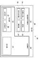
도 2는 다양한 실시예들에 따른, 표시 장치(160)의 블록도(200)이다.2 is a block diagram 200 of a display device 160 according to various embodiments of the present disclosure.
도 2를 참조하면, 표시 장치(160)는 디스플레이(210), 및 이를 제어하기 위한 디스플레이 드라이버 IC(DDI)(230)를 포함할 수 있다. DDI(230)는 인터페이스 모듈(231), 메모리(233)(예: 버퍼 메모리), 이미지 처리 모듈(235), 또는 맵핑 모듈(237)을 포함할 수 있다. DDI(230)은, 예를 들면, 인터페이스 모듈(231)을 통하여 프로세서(120)(예: 메인 프로세서(121)(예: 어플리케이션 프로세서) 또는 메인 프로세서(121)의 기능과 독립적으로 운영되는 보조 프로세서(123))로부터 영상 데이터, 또는 상기 영상 데이터를 제어하기 위한 명령에 대응하는 영상 제어 신호를 포함하는 영상 정보를 수신할 수 있다. DDI(230)는 터치 회로(250) 또는 센서 모듈(176) 등과 상기 인터페이스 모듈(231)을 통하여 커뮤니케이션할 수 있다. 또한, DDI(230)는 상기 수신된 영상 정보 중 적어도 일부를 메모리(233)에, 예를 들면, 프레임 단위로 저장할 수 있다. 이미지 처리 모듈(235)은, 예를 들면, 상기 영상 데이터의 적어도 일부를 상기 영상 데이터의 특성 또는 디스플레이(210)의 특성에 적어도 기반하여 전처리 또는 후처리(예: 해상도, 밝기, 또는 크기 조정)를 수행할 수 있다. 맵핑 모듈(237)은 디스플레이(210)의 픽셀들의 속성(예: 픽셀들의 배열(RGB stripe 또는 pentile), 또는 서브 픽셀들 각각의 크기)에 적어도 일부 기반하여, 이미지 처리 모듈(135)를 통해 전처리 또는 후처리된 상기 영상 데이터를 상기 픽셀들을 구동할 수 있는 전압 값 또는 전류 값으로 변환할 수 있다. 디스플레이(210)의 적어도 일부 픽셀들은, 예를 들면, 상기 전압 값 또는 전류 값에 기반하여 구동됨으로써 상기 영상 데이터에 대응하는 시각적 정보(예: 텍스트, 이미지, 또는 아이콘)가 디스플레이(210)에 표시될 수 있다.Referring to FIG. 2 , the display device 160 may include a
일실시예에 따르면, 표시 장치(160)는 터치 회로(250)를 더 포함할 수 있다. 터치 회로(250)는 터치 센서(251) 및 이를 제어하기 위한 터치 센서 IC(253)를 포함할 수 있다. 터치 센서 IC(253)는 터치 센서(251)를 제어하여, 예를 들면, 디스플레이(210)의 특정 위치에 대한 신호(예: 전압, 광량, 저항, 또는 전하량)의 변화를 측정함으로써 상기 특정 위치에 대한 터치 입력 또는 호버링 입력을 감지하고, 감지된 터치 입력 또는 호버링 입력에 관한 정보(예: 위치, 면적, 압력, 또는 시간)를 프로세서(120) 에 제공할 수 있다. 일실시예에 따르면, 터치 회로(250)의 적어도 일부(예: 터치 센서 IC(253))는 디스플레이 드라이버 IC(230), 또는 디스플레이(210)의 일부로, 또는 표시 장치(160)의 외부에 배치된 다른 구성요소(예: 보조 프로세서(123))의 일부로 포함될 수 있다.According to an embodiment, the display device 160 may further include a
일실시예에 따르면, 표시 장치(160)는 센서 모듈(176)의 적어도 하나의 센서(예: 지문 센서, 홍채 센서, 압력 센서 또는 조도 센서), 또는 이에 대한 제어 회로를 더 포함할 수 있다. 이 경우, 상기 적어도 하나의 센서 또는 이에 대한 제어 회로는 표시 장치(160)의 일부(예: 디스플레이(210) 또는 DDI(230)) 또는 터치 회로(250)의 일부에 임베디드되어 구현될 수 있다. 예를 들면, 표시 장치(160)에 임베디드된 센서 모듈(176)이 생체 센서(예: 지문 센서)를 포함할 경우, 상기 생체 센서는 디스플레이(210)의 일부 영역을 통해 터치 입력과 연관된 생체 정보(예: 지문 이미지)를 획득할 수 있다. 다른 예를 들면, 표시 장치(160)에 임베디드된 센서 모듈(176)이 압력 센서를 포함할 경우, 상기 압력 센서는 디스플레이(210)의 일부 또는 전체 영역을 통해 터치 입력에 대한 압력 정보를 획득할 수 있다. 일실시예에 따르면, 터치 센서(251) 또는 센서 모듈(176)은 디스플레이(210)의 픽셀 레이어의 픽셀들 사이에, 또는 상기 픽셀 레이어의 위에 또는 아래에 배치될 수 있다. According to an embodiment, the display device 160 may further include at least one sensor (eg, a fingerprint sensor, an iris sensor, a pressure sensor, or an illuminance sensor) of the
본 문서에 개시된 다양한 실시예들에 따른 전자 장치는 다양한 형태의 장치가 될 수 있다. 전자 장치는, 예를 들면, 휴대용 통신 장치 (예: 스마트폰), 컴퓨터 장치, 휴대용 멀티미디어 장치, 휴대용 의료 기기, 카메라, 웨어러블 장치, 또는 가전 장치 중 적어도 하나를 포함할 수 있다. 본 문서의 실시예에 따른 전자 장치는 전술한 기기들에 한정되지 않는다.The electronic device according to various embodiments disclosed in this document may have various types of devices. The electronic device may include, for example, at least one of a portable communication device (eg, a smart phone), a computer device, a portable multimedia device, a portable medical device, a camera, a wearable device, and a home appliance device. The electronic device according to the embodiment of the present document is not limited to the above-described devices.
본 문서의 다양한 실시예들 및 이에 사용된 용어들은 본 문서에 기재된 기술을 특정한 실시 형태에 대해 한정하려는 것이 아니며, 해당 실시예의 다양한 변경, 균등물, 및/또는 대체물을 포함하는 것으로 이해되어야 한다. 도면의 설명과 관련하여, 유사한 구성요소에 대해서는 유사한 참조 부호가 사용될 수 있다. 단수의 표현은 문맥상 명백하게 다르게 뜻하지 않는 한, 복수의 표현을 포함할 수 있다. 본 문서에서, "A 또는 B", "A 및/또는 B 중 적어도 하나", "A, B 또는 C" 또는 "A, B 및/또는 C 중 적어도 하나" 등의 표현은 함께 나열된 항목들의 모든 가능한 조합을 포함할 수 있다. "제 1", "제 2", "첫째" 또는 "둘째" 등의 표현들은 해당 구성요소들을, 순서 또는 중요도에 상관없이 수식할 수 있고, 한 구성요소를 다른 구성요소와 구분하기 위해 사용될 뿐 해당 구성요소들을 한정하지 않는다. 어떤(예: 제 1) 구성요소가 다른(예: 제 2) 구성요소에 "(기능적으로 또는 통신적으로) 연결되어" 있다거나 "접속되어" 있다고 언급된 때에는, 상기 어떤 구성요소가 상기 다른 구성요소에 직접적으로 연결되거나, 다른 구성요소(예: 제 3 구성요소)를 통하여 연결될 수 있다.The various embodiments of this document and the terms used therein are not intended to limit the technology described in this document to a specific embodiment, but it should be understood to cover various modifications, equivalents, and/or substitutions of the embodiments. In connection with the description of the drawings, like reference numerals may be used for like components. The singular expression may include the plural expression unless the context clearly dictates otherwise. In this document, expressions such as “A or B”, “at least one of A and/or B”, “A, B or C” or “at least one of A, B and/or C” refer to all of the items listed together. Possible combinations may be included. Expressions such as "first", "second", "first" or "second" can modify the corresponding elements regardless of order or importance, and are used only to distinguish one element from another element. The components are not limited. When an (eg, first) component is referred to as being “(functionally or communicatively) connected” or “connected” to another (eg, second) component, that component is It may be directly connected to the component or may be connected through another component (eg, a third component).
본 문서에서 사용된 용어 "모듈"은 하드웨어, 소프트웨어 또는 펌웨어로 구성된 유닛을 포함하며, 예를 들면, 로직, 논리 블록, 부품, 또는 회로 등의 용어와 상호 호환적으로 사용될 수 있다. 모듈은, 일체로 구성된 부품 또는 하나 또는 그 이상의 기능을 수행하는 최소 단위 또는 그 일부가 될 수 있다. 예를 들면, 모듈은 ASIC(application-specific integrated circuit)으로 구성될 수 있다.As used herein, the term “module” includes a unit composed of hardware, software, or firmware, and may be used interchangeably with terms such as, for example, logic, logic block, component, or circuit. A module may be an integrally formed part or a minimum unit or a part of performing one or more functions. For example, the module may be configured as an application-specific integrated circuit (ASIC).
본 문서의 다양한 실시예들은 기기(machine)(예: 컴퓨터)로 읽을 수 있는 저장 매체(machine-readable storage media)(예: 내장 메모리(136) 또는 외장 메모리(138))에 저장된 명령어를 포함하는 소프트웨어(예: 프로그램(140))로 구현될 수 있다. 기기는, 저장 매체로부터 저장된 명령어를 호출하고, 호출된 명령어에 따라 동작이 가능한 장치로서, 개시된 실시예들에 따른 전자 장치(예: 전자 장치(101))를 포함할 수 있다. 상기 명령이 프로세서(예: 프로세서(120))에 의해 실행될 경우, 프로세서가 직접, 또는 상기 프로세서의 제어하에 다른 구성요소들을 이용하여 상기 명령에 해당하는 기능을 수행할 수 있다. 명령은 컴파일러 또는 인터프리터에 의해 생성 또는 실행되는 코드를 포함할 수 있다. 기기로 읽을 수 있는 저장매체는, 비일시적(non-transitory) 저장매체의 형태로 제공될 수 있다. 여기서, ‘비일시적’은 저장매체가 신호(signal)를 포함하지 않으며 실재(tangible)한다는 것을 의미할 뿐 데이터가 저장매체에 반영구적 또는 임시적으로 저장됨을 구분하지 않는다.Various embodiments of the present document include instructions stored in a machine-readable storage media (eg,
일시예에 따르면, 본 문서에 개시된 다양한 실시예들에 따른 방법은 컴퓨터 프로그램 제품(computer program product)에 포함되어 제공될 수 있다. 컴퓨터 프로그램 제품은 상품으로서 판매자 및 구매자 간에 거래될 수 있다. 컴퓨터 프로그램 제품은 기기로 읽을 수 있는 저장 매체(예: compact disc read only memory (CD-ROM))의 형태로, 또는 어플리케이션 스토어(예: 플레이 스토어TM)를 통해 온라인으로 배포될 수 있다. 온라인 배포의 경우에, 컴퓨터 프로그램 제품의 적어도 일부는 제조사의 서버, 어플리케이션 스토어의 서버, 또는 중계 서버의 메모리와 같은 저장 매체에 적어도 일시 저장되거나, 임시적으로 생성될 수 있다.According to an example, the method according to various embodiments disclosed in this document may be included and provided in a computer program product. Computer program products may be traded between sellers and buyers as commodities. The computer program product may be distributed in the form of a machine-readable storage medium (eg compact disc read only memory (CD-ROM)) or online through an application store (eg Play StoreTM ). In the case of online distribution, at least a portion of the computer program product may be temporarily stored or temporarily generated in a storage medium such as a memory of a server of a manufacturer, a server of an application store, or a relay server.
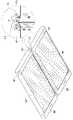
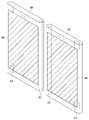
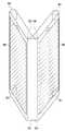
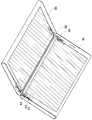
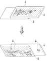
도 3a 내지 도 3f는 본 발명의 다양한 실시예에 따른 두 개의 디스플레이 장치의 자성 결합 구조를 도시한다.3A to 3F illustrate a magnetic coupling structure of two display devices according to various embodiments of the present disclosure.
본 발명의 다양한 실시예에 따른 전자 장치는 도 1 내지 도 2의 적어도 일부 또는 전체 구성이 실장된 제1 하우징(301) 또는 제1 전자 장치(예, 도 1의 101) 과, 상기 제1 하우징(302)과 분리되며, 제1 하우징(301)에 실장된 구성과 동일하거나 도 1 내지 도 2의 적어도 일부 구성 중 제1 하우징(301)에 실장되지 않은 다른 구성들이 실장된 제2 하우징(302)로 구성될 수 있다. 또는 일 실시예에 따르면 제1 하우징 및 제2 하우징은 서로 무선 통신이 가능하며 독립적으로 운용하는 각각의 전자 장치일 수 있으나, 두 개의 디스플레이가 하나의 세트(set)로 구성된 전자 장치일 수 있다. 이하, 도 3a 내지 도 3f의 도면에서는 설명의 편의를 위해 필요한 구성만을 도식화하여 설명하기로 한다.An electronic device according to various embodiments of the present disclosure includes a
일 실시예에 따르면, 제1 하우징(301)은 전면에 풀 스크린 구조의 제1 디스플레이(361), 제1 하우징(301)의 적어도 하나의 일측 끝단에 자성에 의해 N극와 S극의 위치가 회전 변경되도록 구성된 제1 원형 자석(310)을 포함할 수 있다. 제2 하우징(302)은 전면에 풀 스크린 구조의 제2 디스플레이(362), 제2 하우징(302)의 적어도 하나의 일측 끝단에 제1 하우징(301)에 포함된 제1 원형 자석(310)과 자성 결합하기 위해 회전되도록 구성된 제2 원형 자석(312)을 포함할 수 있다.According to one embodiment, the
일 실시예에 따르면, 제1 하우징(301) 내에 상기 제1 원형 자석(310)을 지지하고, 인접한 자석의 자성에 반응하여 N극와 S극의 축 변경을 위해 회전 가능하도록 구성된 고정부(미도시)를 포함할 수 있다. 제2 하우징(302) 내에, 제2 원형 자석(312)을 지지하고, 인접한 자석(예를 들어, 제1 하우징(301) 내의 상기 제1 원형 자석(310))과의 자성에 반응하여 N극와 S극의 축 변경을 위해 회전 가능하도록 구성된 고정부(미도시)를 포함할 수 있다.According to an embodiment, a fixing part (not shown) configured to support the first
일 실시예에 따르면, 제1 하우징(301)과 제2 하우징(302)이 제1 원형 자석(310)과 제2 원형 자석(312)이 실장된 각각의 측면을 서로 일정거리 이내에 인접하면, 자성에 의한 인력이 커짐에 따라 제1 하우징(301)과 제2 하우징(302)이 서로 자성으로 맞닿아 떨어지지 않을 수 있다. 예를 들면, 제1 하우징(301)과 제2 하우징(302)이 인접한 경우, 자성의 인력에 의해 제1 원형 자석(310)의 N극 과 제2 원형 자석(312)의 S극이 대향되도록 회전될 수 있으며, 두 개의 원형 자석(310,312)의 극성이 서로 조정됨에 따라 두 장치가 서로 맞닿아 결합 형태를 유지할 수 있다. 이 후, 사용자가 제1 하우징(301)과 제2 하우징(302)을 서로 떨어지도록 제1 원형 자석(310)과 제2 원형 자석(312) 간의 자성의 힘보다 상대적으로 크게 자성의 반대방향으로 힘을 가할 경우, 제1 하우징(301)과 제2 하우징(302)은 서로 분리될 수 있다.According to one embodiment, when the
일 실시예에 따르면, 도 3a 내지 도 3f의 결합 형태의 유지하기 위해 제1 하우징(301)과 제2 하우징(302)은 원형 자석(310,312)이 배치되지 않은 다른 측 끝단에 적어도 하나의 홀더 자석(311,313)을 더 포함할 수 있다. 일 예를 들어, 홀더 자석(311,313)은 원형 자석(310,312)이 배치되지 않는 다른 측 끝단 모서리 각각에 배치될 수도 있다. 홀더 자석(311,312)은 제1 하우징(301)과 제2 하우징(302)의 홀딩 형태의 결합력을 높이기 위한 것으로 하나의 극을 갖는 자석일 수 있다. 예를 들어, 제1 하우징(301)에 설치된 홀더 자석(311)과 제2 하우징(301)에 설치된 홀더 자석(313)은 서로 대향되는 위치에 전면과 후면이 서로 상단되는 극을 갖는 구조일 수 있다.According to one embodiment, in order to maintain the mated form of FIGS. 3A to 3F , the
일 실시예에 따르면, 제1 하우징(301)과 제2 하우징(302)은 일정 각도를 갖는 형태로 자성 결합될 수 있다. 예컨대, 물리적인 힘에 의해 제1 하우징(301)과 제2 하우징(302) 간 자성 결합 각도가 변경되는 경우, 제1 원형 자석(310) 및 제2 원형 자석(312)은 각각 제1 하우징(301)과 제2 하우징(302) 내부에서 회전하여 서로 반대의 극성들이 최대 인력을 유지하는 위치로 회전될 수 있다. 제1 원형 자석(310) 및 제2 원형 자석(312) 간의 S극와 N극의 위치가 회전됨에 따라 제1 하우징(301)과 제2 하우징(302)은 일정 각도를 갖는 형태를 유지하면서 자성 결합될 수 있다.According to an embodiment, the
일 실시예에 따르면, 도3a 에 도시된 바와 같이, 제1 하우징(301)과 제2 하우징(302)은, 제1 디스플레이(361)와 제2 디스플레이(362)가 서로 동일한 방향으로 바라보는 형태로 각각의 측면에서 자성 결합될 수 있다. 또는 제1 디스플레이(361)와 제2 디스플레이(362)가 서로 다른 방향으로 바라보는 형태로 각각의 측면에서 자성 결합될 수도 있다. 예를 들어, 제1 디스플레이(361)가 전방을 바라볼 경우, 제2 디스플레이(362)는 후방을 바라보는 형태로 각각의 측면에서 자성 결합될 수 있다.According to an embodiment, as shown in FIG. 3A , the
일 실시예에 따르면, 제1 원형 자석(310) 및 제2 원형 자석(312) 각각은 하우징(301,302)의 적어도 하나의 일측 끝단에 단일 축을 중심으로 회전 가능한 원통형일 수 있으며, 하우징(301,302)의 외곽(예컨대, 하우징)과 기 설정된 거리(d1) 이내에 배치될 수 있다. 기 설정된 거리 이내에 원형 자석들(310,312)이 배치됨으로써, 제1 하우징(301)과 제2 하우징(302) 간의 자성 결합에 의한 인력이 증가될 수 있으며, 자성 인력을 유지하여 제1 하우징(301)과 제2 하우징(302)의 결합 형태를 다양하게 구현할 수 있다.According to one embodiment, each of the first
일 실시예에 따르면, 제1 원형 자석(310) 및 제2 원형 자석(312) 각각은 제1 하우징(301)과 제2 하우징(302)이 자성 결합된 상태에서 제1 원형 자석(310)과 제2 원형 자석(312) 사이의 자성 인력보다 상대적으로 큰 힘이 반대 방향으로 가해질 경우, 도 3b에 도시된 바와 같이, 제1 하우징(301)과, 제2 하우징(302)은 서로 분리될 수 있다.According to an embodiment, each of the first
일 실시예에 따르면, 도 3c에 도시된 바와 같이 제1 하우징(301)과 제2 하우징(302)은 외부의 방향으로 서로 대향되어 제1 디스플레이(361) 및 제2 디스플레이(362)가 노출되는 인 폴딩(in- folding) 형태로 자성 결합될 수 있다. 다른 실시예에 따르면, 도 3d에 도시된 바와 제1 하우징(301)과 제2 하우징(302)은 내부의 방향으로 제1 디스플레이(361) 및 제2 디스플레이(362)가 서로 마주보는 아웃 폴딩(out folding) 형태로 부착할 수 있다. 도 3d에 도시된 바와 같이 각각의 디스플레이가 내부의 방향으로 서로 대향되는 인 폴딩 형태의 경우, 폴딩된 내부 안쪽에 디스플레이가 위치하게 되므로, 외부 환경으로부터 디스플레이를 보호할 수 있다.According to an embodiment, as shown in FIG. 3C , the
일 실시예에 따르면, 3e에 도시된 바와 같이, 제1 디스플레이(361) 및 제2 디스플레이(362)가 외부의 방향으로 노출되며, 제1 하우징(301)과 제2 하우징(302)의 결합 내각이 90 각도 이하에서 자성 결합될 수 있다. 도 3e의 결합 형태일 경우, 제1 하우징(301)과 제2 하우징(302)은 제1 원형 자석(310) 및 제2 원형 자석(312) 간의 S극와 N극의 위치가 회전됨에 따라 제1 하우징(301)과 제2 하우징(302)은 일정 각도를 갖는 형태를 유지하면서 서로 지탱이 가능하게 되므로, 별도의 지지대 없이, 지면에 고정될 수 있다.According to one embodiment, as shown in 3e , the
일 실시예에 따르면 도 3f에 도시된 바와 같이, 동일한 방향으로, 제1 디스플레이(361) 및 제2 디스플레이(362)가 노출되고, 1 하우징(301)과 제2 하우징(302)의 결합 내각이 90 각도를 초과하여 부착될 경우, 제1 하우징(301)에 실장된 제1 원형 자석(310)과, 제2 하우징(302)의 제2 원형 자석(312)과의 자성 인력은 중력의 힘보다 상대적으로 큰 힘으로 작용하여 자성 결합 형태를 유지할 수 있다.According to an embodiment, as shown in FIG. 3F , in the same direction, the
본 발명의 실시예에 따른 전자 장치는 제1 하우징(301) 및 제2 하우징(302)의 결합 형태에 따라 제1 디스플레이(361) 및 제2 디스플레이(362) 중 적어도 하나를 단독으로 또는 둘 다를 활용하면 화면 출력을 제어할 수 있다.In the electronic device according to an embodiment of the present invention, at least one of the
본 발명의 다양한 실시예에 따른 제1 하우징(301) 및 제2 하우징(302) 각각에 포함된 제1 원형 자석(310) 및 제2 원형 자석(302)은 하우징의 길이에 대응하는 하나의 원형 자석 또는 일정 크기로 분할된 복수개의 원형 자석이 배치될 수 있다. 복수개의 원형 자석은 하나의 축에 의해 각각 회전이 가능하도록 결합되는 결합부를 더 포함할 수 있고, 또는, 동일한 극성으로 복수개의 원형 자석이 결합된 형태일 수도 있다. 복수 개의 원형 자석은 제1 하우징(301) 및 제2 하우징(302) 일 측 끝단에서 하나의 라인형태로 배치되거나, 접근하는 다른 자석과 서로 반대극으로 인력에 의해 재배열되도록 회전 가능한 형태로 구현될 수 있다.The first
일 예에서, 자성의 척력에 의해, 제1 하우징(301)과 제2 하우징(302)이 서로 어긋나는 형태로 결합되는 것을 방지하기 위해 제1 하우징(301) 및 제2 하우징(302) 내지, 홀수 개의 원형 자석으로 구현될 수 있다.In one example, in order to prevent the
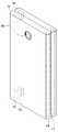
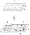
도 4a 내지 도4c는 본 발명의 다양한 실시예에 따른 두 개의 디스플레이 장치의 자성 결합 구조를 도시한다.4A to 4C illustrate a magnetic coupling structure of two display devices according to various embodiments of the present disclosure.
도 4a 내지 도4c를 참조하면, 본 발명의 다양한 실시예에 따르면, 제1 디스플레이(461)를 포함한 제1 하우징(401) 및 제2 디스플레이(462)를 포함한 제2 하우징(402)은 적어도 일 측면의 모서리가 일정 각도로 커팅된 3면의 단면을 갖도록 구성될 수 있다.4A to 4C , according to various embodiments of the present disclosure, the
일 예를 들어, 측면 모서리는 제1 하우징(401)과 제2 하우징(401)은 원형 자석들의 자성 결합력을 향상시키기 위해 적어도 3면의 단면을 갖도록 구성될 수 있다. 예컨대, 측면 모서리가 제1 각도의 단면(40a), 제2 각도 단면(40b), 제3 각도의 단면(40c)으로 제작된 경우, 도 4a에 도시된 바와 같이, 제1 하우징(401)과 제2 하우징(402)의 제1 디스플레이(461) 및 제2 디스플레이(462) 가 서로 외부로 방향으로 노출되고 제3 각도의 단면(40c)이 서로 맞닿은 형태로 자성 결합될 수 있다. 그러면, 제1 원형 자석(410)과 제2 원형 자석(412)은 제3 각도의 단면(40c)들이 맞닿은 방향으로 서로 반대극이 최대의 인력으로 재배열되도록 각각 회전될 수 있다. 측면 모서리의 컷팅 단면은 자석의 인력 이외에 맞닿은 면들의 마찰력을 증가시켜 제1 하우징(401)과 제2 하우징(401)간의 자성 결합의 고정력을 향상시킬 수 있다.For example, the side edge of the
다른 실시예에 따르면, 도 4b에 도시된 바와 같이, 제1 하우징(401)과 제2 하우징(402)의 제1 디스플레이(461) 및 제2 디스플레이(462) 동일한 방향을 바라보는 상태에서 제1 하우징(401)과 제2 하우징(402)의 일 측면에서 제2 각도의 단면(40b)이 서로 맞닿은 형태로 결합될 수 있다. 이에 따라, 제2 각도의 단면(40b)의 방향으로 제1 원형 자석(410) 및 제2 원형 자석(4123)의 회전되어 자성 인력의 축이 변경될 수 있다.According to another embodiment, as shown in FIG. 4B , in a state in which the
다른 실시예에 따르면, 도 4c에 도시된 바와 같이, 제1 하우징(401)과 제2 하우징(402)의 제1 디스플레이(461) 및 제2 디스플레이(462) 동일한 방향을 바라보는 상태에서 제1 단면(30)이 서로 맞닿은 형태로 자성 결합될 수 있다. 제1 하우징(401)과 제2 하우징(402)의 제1 단면(40a)이 서로 맞닿은 형태로 결합됨에 따라, 제1 원형 자석(410) 및 제2 원형 자석(412)이 제1 단면(40a)이 서로 맞닿은 방향으로 회전하여 제1 하우징(401)과 제2 하우징(402)을 자성 결합시킬 수 있다. 제1 하우징(401)과 제2 하우징(402)간 제1 단면의 접촉 마찰력(40a)은 제1 원형 자석(410)과 제2 원형 자석(412)의 자성 인력의 힘을 제1 하우징(401)의 무게 및 중력의 힘의 크기보다 크도록 증가시켜 제1 하우징(401)과 제2 하우징(402) 간 자성 결합의 고정력을 향상시킬 수 있다.According to another embodiment, as shown in FIG. 4C , the
도면에 도시되지는 않았으나 다른 실시예에 따르면, 제1 하우징(401)과 제2 하우징(401)이 서로 결합하는 측면 모서리를 각도를 갖는 단면 형태 이외에 톱니 형태로 구성할 수 있다. 예컨대, 제1 하우징과, 제2 하우징 각각 원형 자석이 배치된 측면의 외형이 서로 맞물리는 형태의 톱니 모양으로 구성되어, 일정 각도로 제1 하우징(401) 및 제2 하우징(402)가 서로 결합하여 지탱하는 자성 결합의 고정력을 향상시킬 수 있다.Although not shown in the drawings, according to another embodiment, the side edges at which the
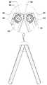
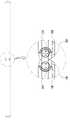
도 5a 및 도 5b는 본 발명의 다양한 실시예에 따른 두 개의 디스플레이 장치의 자성 결합 구조를 도시한다.5A and 5B illustrate a magnetic coupling structure of two display devices according to various embodiments of the present disclosure.
도 5a 및 도 5b를 참조하면, 본 발명의 다양한 실시예에 따르면, 제1 디스플레이(561)을 포함하는 제1 하우징(501) 및 제2 디스플레이(562) 제2 하우징(502) 내부에는 각각의 원형 자석(512,510)을 내부에서 회전 가능하도록 지지하는 힌지 부(514)를 더 포함할 수 있다.Referring to FIGS. 5A and 5B , according to various embodiments of the present disclosure, each of the
일 실시예에 따르면, 제1 하우징(512)은 내부에 배치된 제1 원형 자석(510)은 톱니 형태로 다수의 홈을 갖도록 형성된 힌지부(514)와, 힌지부(514)와 결합하여 제1 원형 자석(510)을 지지하고, 힌지부(514)에 포함된 복수의 홈 중 어느 하나의 홈과 맞물리는 형태로 돌출되는 돌출부(515)와, 홈의 굴곡으로 인해 돌출부(515)의 탄성을 조절하는 스프링(513)과, 힌지부(514)의 돌출부(515)와 홈의 결합으로 인해 제1 원형 자석(510)과 제2 원형 자석(512) 간의 자성 결합의 축 각도를 조절하는 각도 조절부(516)를 포함할 수 있다.According to one embodiment, in the
예를 들어, 힌지부(514) 및 각도 조절부(516)는 연결된 형태로 형성될 수 있으며, 분리된 형태에서 연결 및 고정을 위한 원형의 고정부재(미도시)를 포함할 수 도 있다. 각도 조절부(516)는 제1 하우징(501)에 고정될 수 있으며, 톱니 형태의 힌지부(514)가 회전 가능하게 결합될 수 있다. 제1 원형 자석(510)과 인접하여 제2 원형 자석(512)이 인접하고, 제1 하우징(501)과, 제2 하우징(502)이 일정 각도를 갖는 위치에 배치되면, 자성의 인력에 의해 원형 자석들(510,512)이 회전하여 자석의 축 방향이 회전되면서 변경될 수 있다. 자석의 축 회전에 대응하여 톱니 형태의 힌지부(514) 역시 회전됨에 따라, 힌지부(514)의 홈들 중 어느 하나의 홈 체결된 돌출부(515)는 스프링(513)에 의해 일시적으로 탄성이 생성되어 다음의 홈에 체결될 수 있다. 예컨대, 스프링(513)의 탄력성에 의해 돌출부(515)가 힌지부 회전에 의해 탄력적으로 변경되어 체결되는 홈의 위치가 변경될 수 있다.For example, the
일 실시예에 따르면, 힌지부는 외부의 톱니 형태 이외에, 내부의 볼 베어링 형태로 형성될 수 있다. 예를 들어, 힌지의 내부의 홀 안쪽으로 다수의 이탈 방지 요철과, 원형 자석과 연결되어 원형 자석의 회전축을 회전 가능하도록 지지하는 베어링을 포함할 수 있으며, 회전축에 의해 회전하면서 이탈 방지 요청과 베어링이 결합하여 자성 결합의 고정력을 향상시킬 수 있다. 이에 따라, 본 발명에 따르면 사용자의 의도 하에 제1 하우징(401) 및 제2 하우징(402)의 결합 각도를 원하는 형태로 변경하더라도, 제1 하우징(401) 및 제2 하우징(402) 내부에서 최대의 자성 인력으로 자석 축이 회전하도록 변경되며, 변경된 회전 축을 힌지부에 의해 고정시켜, 자성 결합의 고정력을 향상시킬 수 있다.According to one embodiment, the hinge part may be formed in the form of an internal ball bearing in addition to the external tooth shape. For example, it may include a plurality of separation prevention irregularities inside the hole inside the hinge, and a bearing connected to the circular magnet to support the rotation shaft of the circular magnet so as to be rotatable, and the separation prevention request and bearing while rotating by the rotation shaft This coupling can improve the fixing force of the magnetic coupling. Accordingly, according to the present invention, even if the coupling angle of the
본 발명의 실시예에 따른 전자 장치는 제1 하우징(301,401,501) 및 제2 하우징(302,402,502)의 결합 형태에 따라 제1 디스플레이(361,461,561) 및 제2 디스플레이(362,462,562) 중 적어도 하나를 단독으로 또는 둘 다를 활용하여 화면 출력을 제어할 수 있다.In the electronic device according to an embodiment of the present invention, at least one of the first displays 361,461,561 and the second displays 362,462,562 alone or both, depending on the combination of the first housings 301,401,501 and the second housings 302,402,502. You can use it to control the screen output.
본 발명의 실시예에 따른 전자 장치는 본 발명의 실시예에 따른 전자 장치는 제1 하우징(301,401,501) 및 제2 하우징(302,402,502)의 결합 형태에 따라 상기 제1 하우징(301,401,501) 및 제2 하우징(302,402,502) 중 적어도 일부 구성 또는 기능을 실행하도록 제어할 수 있다. 이하, 제 제1 디스플레이(361) 및 제2 디스플레이(362) 중 적어도 하나를 단독으로 또는 둘 다를 활용하는 전자 장치의 운용 방법에 대해서는 도 6 내지 도 13에서 설명하기로 한다.In the electronic device according to the embodiment of the present invention, the
도 6은 본 발명의 다양한 실시예에 따른 자성에 의해 두 개의 디스플레이를 탈/부착하는 전자 장치의 화면 운용 방법을 도시한다.6 is a diagram illustrating a screen operation method of an electronic device in which two displays are detached/attached by magnetism according to various embodiments of the present disclosure.
도 6을 참조하면, 본 발명의 실시예에 따른 전자 장치(예, 도 1의 101)의 프로세서(도 1의 120)는 제1 하우징(예, 도 의 301,도 4의 401, 도 5의 501) 및 제2 하우징(예, 도 3의 302, 도 4의 402, 도 5의 502)의 결합 형태 및 제1 디스플레이 및 제2 디스플레이의 배치 방향, 실행된 어플리케이션 정보, 실행 화면 정보 중 적어도 하나를 기반으로 1 디스플레이 및 제2 디스플레이의 적어도 하나를 선택하고, 선택된 디스플레이를 제어하여 제1 하우징과 제2 하우징의 결합 형태에 따라 화면을 다양하게 출력할 수 있다. 일 실시예에 따르면, 프로세서는 제1 하우징 또는 제2 하우징 중 적어도 어느 하나에 실장되거나, 둘 다 실장될 수 있다. 예컨대, 다수의 프로세서가 존재할 경우, 하나의 프로세서가 무선 통신부를 통해 다른 프로세서와 서로 통신할 수 있으며, 이로 인해 각각의 하우징 내에 실장된 구성들을 통합적으로 제어할 수 있음은 당연하다.Referring to FIG. 6 , the processor ( 120 in FIG. 1 ) of the electronic device (eg, 101 in FIG. 1 ) according to the embodiment of the present invention includes a first housing (eg, 301 in FIG. , 401 in FIG. 4 , and 401 in FIG. 5 ). 501) and the second housing (eg, 302 in FIG. 3 , 402 in FIG. 4 , and 502 in FIG. 5 ), and at least one of the arrangement direction of the first display and the second display, information on the executed application, and information on the execution screen Based on the selection, at least one of the first display and the second display may be selected, and the selected display may be controlled to variously output a screen according to a combination shape of the first housing and the second housing. According to an embodiment, the processor may be mounted on at least one of the first housing and the second housing, or both. For example, when a plurality of processors exist, one processor may communicate with another processor through a wireless communication unit, and thus, it is natural that components mounted in each housing can be integrally controlled.
구체적으로, 610 동작 에서, 적어도 하나의 프로세서(도 1의 120)는, 디스플레이(예, 도 1의 155, 도 2의 210 등)의 턴 온을 요청하는 이벤트를 수신할 수 있다. 예를 들어, 프로세서()는 터치 입력, 버튼 입력, 음성 입력 등을 통해 사용자로부터 디스플레이의 턴 온을 요청하는 입력 이벤트를 수신하거나, 알림 정보를 수신하여 디스플레이에 출력하는 알림 이벤트의 발생을 검출할 수 있다.Specifically, in
620 동작에서 프로세서는, 디스플레이의 턴 온 요청에 응답하여 센서 모듈(예, 도1의 176, 도 2의 276)부터 센싱 정보를 획득할 수 있다. 예를 들어, 제1 하우징 및/ 또는 제2 하우징 내에 실장된 센서 모듈은 센서, 자이로 센서, 지자기 센서 이외에 중력 센서, 모션 센서, 기울임(inclination) 센서, 밝기 센서, 고도 센서, 후각 센서, 온도 센서, 뎁스 센서, 압력 센서, 밴딩 센서, 오디오 센서, 비디오 센서, GPS 센서, 터치 센서 중 적어도 하나를 포함할 수 있다.In
630 동작에서, 프로세서는, 센서 모듈로부터 획득한 센싱 정보를 기반으로 제1 하우징과 제2 하우징 각각 실장된 원형 자석의 인력에 의한 결합 형태를 판단할 수 있다.In
일 실시예에 따르면, 프로세서는, 제1 하우징과 제2 하우징과의 결합 형태 뿐만 아니라 센싱 정보를 통해 제1 하우징에 위치한 제1 디스플레이와 제2 하우징에 위치한 제2 디스플레이의 위치 방향, 사용자를 인식하는 디스플레이 위치를 판단할 수 있다.According to an embodiment, the processor recognizes the position direction and the user of the first display positioned in the first housing and the second display positioned in the second housing through sensing information as well as the coupling shape between the first housing and the second housing It is possible to determine the display position.
635동작에서, 프로세서는, 디스플레이에 출력할 실행 화면 정보 또는 어플리케이션의 실행 정보를 획득할 수 있다. 예를 들어, 사용자는 입력 모듈을 통해 특정 어플리케이션의 실행을 요청하거나, 실행된 어플리케이션의 화면 변경 요청을 입력 할 수 있다.In
640 동작에서, 프로세서는 판단된 디스플레이들의 결합 형태에 따라 정보를 표시할 디스플레이를 결정하고, 동작에서 정보를 출력하기 위한 화면의 크기 및 분할 정보를 결정할 수 있다.In
일 예를 들어, 도 3a에 도시된 바와 같이, 제1 하우징과 제2 하우징의 측면이 서로 접촉되고, 동일한 방향으로 제1 디스플레이와 제2 디스플레이가 위치한 경우, 프로세서는 도 3a와 같은 제1 하우징과 제2 하우징이 측면으로의 결합 형태를 인지할 수 있다. 프로세서는, 제1 디스플레이 및 제2 디스플레이가 동일한 방향 예컨대, 사용자를 모두 바라보는 방향으로 위치되어 있으므로, 제1 디스플레이와 제2 디스플레이 모두 정보를 표시할 디스플레이로 결정하고, 제1 디스플레이와 제2 디스플레이 각각으로 출력될 화면의 구성, 화면 크기 및 분할 정보 중 적어도 하나를 결정할 수 있다.For example, as shown in FIG. 3A , when side surfaces of the first housing and the second housing are in contact with each other and the first display and the second display are positioned in the same direction, the processor operates the first housing as shown in FIG. 3A And the second housing can recognize the coupling form to the side. Since the first display and the second display are positioned in the same direction, for example, a direction facing the user, the processor determines that both the first display and the second display are displays to display information, and the first display and the second display At least one of a configuration, a screen size, and division information of a screen to be output may be determined.
650 동작에서, 프로세서는, 결정된 화면의 구성, 화면 크기 및 분할 정보 중 적어도 하나에 기반하여 결정된 적어도 하나의 디스플레이를 화면을 출력하도록 제어할 수 있다.In
예를 들어, 사용자가 영화 재생을 요청할 경우, 프로세서는, 두 하우징이 도3a 의 형태인 자성 결합된 형태로 판단되면, 영화 재생의 화면 출력 정보를 분할하여 제1 디스플레이와 제2 디스플레이 둘 다 에서 출력되도록 제어할 수 있다. 이에 따라 전자 장치는, 사용자에게 제1 디스플레이와 제2 디스플레이를 통해 확장된 화면으로 영화를 시청할 수 있는 시각적 효과를 제공할 수 있다.For example, when the user requests to play a movie, the processor, if it is determined that the two housings are magnetically coupled in the form of FIG. 3A, divides the screen output information of the movie playing in both the first display and the second display output can be controlled. Accordingly, the electronic device may provide the user with a visual effect of watching a movie on the screen extended through the first display and the second display.
일 실시예에 따르면, 제1 하우징 및 제2 하우징 중 어느 하나에 실장된 프로세서에서 상술한의 동작을 수행할 수 있으며, 제1 하우징 및 제2 하우징 각각에 포함된 무선 통신 모듈을 통해 서로 무선 통신하여 디스플레이의 화면 제어 명령, 화면 정보의 데이터를 송수신할 수 있다. 예를 들면, 제1 디스플레이 및 제2 디스플레이를 제어하는 프로세서는, 제1 하우징 또는 제2 하우징 각각에 독립적으로 운용되는 프로세서일 수 있으며, 제1 하우징 또는 제2 하우징 중 어느 하나에 실장된 메인 프로세서에서 연산하여 디스플레이를 제어하기 위한 각각의 디스플레이 드라이버IC로 디스플레이의 제어 명령을 전달할 수 도 있다.According to an embodiment, the above-described operation may be performed by a processor mounted in any one of the first housing and the second housing, and wireless communication with each other through the wireless communication module included in each of the first housing and the second housing Thus, it is possible to transmit and receive screen control commands of the display and data of screen information. For example, the processor controlling the first display and the second display may be a processor independently operated in each of the first housing or the second housing, and a main processor mounted in either the first housing or the second housing. It is also possible to transmit a control command of the display to each display driver IC for controlling the display by calculating in .
도 7은 본 발명의 다양한 실시예에 따른 자성에 의해 결합된 두 개의 디스플레이의 화면 운용 예시를 도시한다.7 illustrates an example of screen operation of two displays coupled by a magnet according to various embodiments of the present disclosure.
도 7을 참조하면, 본 발명의 다양한 실시예에 따른, 전자 장치는, 두 하우징의 자석 인력에 의한 결합 형태를 인지하고, 결합 형태에 따라 화면 크기 및 화면을 분할하여 제1 디스플레이 또는 제2 디스플레이 중 적어도 하나에 출력할 수 있다.Referring to FIG. 7 , an electronic device according to various embodiments of the present disclosure recognizes a coupling shape of two housings by magnetic attraction, and divides the screen size and screen according to the coupling shape to display a first display or a second display. can be output to at least one of
일 실시예에 따른 전자 장치는 701에 도시된 바와 같이, 홈 화면을 디스플레이에 출력하는 데 있어서, 제1 페이지의 홈 화면을 제1 디스플레이에 표시하고, 제2 페이지의 홈 화면을 제2 디스플레이에 표시하도록 제어할 수 있다. 전자 장치는, 사용자의 의한 페이지 변경 입력이 검출되면, 제1 디스플레이에 제3 페이지의 홈 화면을 표시하고, 제2 디스플레이에 제4 페이지의 홈 화면을 표시하도록 제어할 수 있다.As illustrated in 701 , the electronic device displays the home screen of the first page on the first display and the home screen of the second page on the second display in outputting the home screen to the display. You can control the display. When a page change input by the user is detected, the electronic device may control to display the home screen of the third page on the first display and display the home screen of the fourth page on the second display.
다른 실시예에 따르면, 702에 도시된 바와 같이, 전자 장치는 두 하우징의 자석 인력에 의한 결합 형태에 따라 제1 디스플레이 및 제2 디스플레이 중 하나만 정보를 표시하기 위해 선택할 수 있으며, 선택된 디스플레이에만 실행 화면을 출력할 수도 있다.According to another embodiment, as shown in 702 , the electronic device may select only one of the first display and the second display to display information according to the coupling form by the magnetic attraction of the two housings, and only the selected display may display the execution screen. can also be printed.
다른 실시예에 따르면 전자 장치는 도 3c와 같은 형태와 같이, 제1 디스플레이 및 제2 디스플레이 중 어느 하나만 사용자를 바라보는 방향으로 위치된 경우, 사용자를 바라보고 있는 디스플레이 예컨대, 제2 디스플레이에만 실행 화면을 표시하도록 제어할 수 있다.According to another embodiment, as in the form of FIG. 3C , when only one of the first display and the second display is positioned in the direction facing the user, the display facing the user, for example, the execution screen only on the second display can be controlled to display.
다른 실시예에 따르면, 703에 도시된 바와 같이, 전자 장치는 제1 디스플레이만 실행 화면을 출력하는 도중에, 실행 화면으로부터 파생된 정보를 출력해야 할 이벤트가 검출되면, 제2 디스플레이에 파생된 정보 예컨대, 보조 화면을 출력하도록 제어할 수 있다. 제어할 수 있다. 예를 들어, 사용자가 제1 디스플레이에 출력된 웹 페이지 화면을 통해 특정 키워드에 대한 검색을 요청할 경우, 프로세서는, 특정키워드에 대한 검색 화면을 제2 디스플레이에 출력되도록 제어할 수 잇다.According to another embodiment, as illustrated in 703 , when an event for outputting information derived from the execution screen is detected while only the first display outputs the execution screen, the electronic device detects information derived from the second display, such as , can be controlled to output a sub screen. can be controlled For example, when a user requests a search for a specific keyword through a web page screen output on the first display, the processor may control the search screen for the specific keyword to be output on the second display.
다른 실시예에 따르면, 704에 도시된 바와 같이, 전자 장치는, 서로 분리된 개개의 화면을 제1 디스플레이 및 제2 디스플레이에 출력하도록 제어할 수 있다. 예를 들어, 전자 장치는, 제1 디스플레이에 제1 앱 실행 화면을 출력하고, 제2 디스플레이에 제2 앱 실행 화면을 출력하도록 제어할 수 있다.According to another embodiment, as illustrated in 704 , the electronic device may control to output separate screens separated from each other on the first display and the second display. For example, the electronic device may control to output a first app execution screen on the first display and output a second app execution screen on the second display.
다른 실시예에 따르면, 705에 도시된 바와 같이, 전자 장치는, 싱글 디스플레이에 출력할 화면 정보를 분할하여 제1 디스플레이와 제2 디스플레이 둘 다 에서 출력되도록 제어할 수 있다. 예를 들어, 전자 장치는, 영화 재생의 화면 출력 정보를 분할하여 제1 디스플레이와 제2 디스플레이 둘 다 에서 출력되도록 제어할 수 있다.According to another embodiment, as shown in 705 , the electronic device may divide screen information to be output on a single display and control the division to be output on both the first display and the second display. For example, the electronic device may divide screen output information of movie reproduction to be output on both the first display and the second display.
도 8 및 도 9는 본 발명의 다양한 실시예에 따라, 전자 장치 상에 UX가 표시된 화면의 일 예를 도시한 것이다.8 and 9 are diagrams illustrating an example of a screen on which a UX is displayed on an electronic device, according to various embodiments of the present disclosure.
도 8을 참조하면, 다양한 실시예에 따르면, 전자 장치의 프로세서(예, 도 120), 제1 하우징(801) 및 제2 하우징(802)의 결합 상태에 따라 제1 디스플레이와 제2 디스플레이를 협업하여 제1 화면 및 제2 화면을 또는 동시에 출력하거나, 제1 화면으로부터 파생된 제2 화면을 출력하도록 제어할 수 있다.Referring to FIG. 8 , according to various embodiments, the first display and the second display are collaborated according to the coupling state of the processor (eg, FIG. 120 ) of the electronic device, the
사용자는 두 개의 디스플레이가 사용자를 향하도록 제1 하우징(801)과 제2 하우징(802)의 자성 결합 형태를 변경하고, 디스플레이를 온 하는 요청 입력을 수행할 수 있다. 전자 장치의 프로세서는 디스플레이를 온 하는 요청 입력에 응답하여 제1 디스플레이와 제2 디스플레이 둘다 화면을 출력하도록 선택할 수 있다.The user may change the magnetic coupling shape of the
일 예를 들어, 전자 장치의 프로세서는 제1 하우징(801)의 제1 디스플레이에 홈 화면(811)을 표시하도록 제어하고, 제2 하우징(802)의 제2 디스플레이에 보조 화면(82)을 표시하도록 제어할 수 있다. 여기서, 보조 화면은 사용자에게 알림 정보를 제공하는 알림 정보, 최신 뉴스를 제공하는 뉴스 정보, 사용자의 라이프 패턴을 분석하여 제공되는 하우징의 사용 정보, 자주 사용하는 앱 정보, 사용자 설정 정보 중 적어도 하나를 포함하여 구성될 수 있다.For example, the processor of the electronic device controls to display the
일 실시예에 따르면, 전자 장치의 프로세서는, 도 3c 도시된 바와 같이, 외부로 디스플레이가 노출되어 중첩되는 아웃 폴딩 상태에서는 하나의 화면 즉, 제1 디스플레이 또는 제2 디스플레이 중 하나의 디스플레이를 이용하여 화면을 출력하다가 도 3a, 3e 또는 3f에 도시된 바와 같이, 제1 디스플레이와 제2 디스플레이와 서로 측면으로 접촉된 결합 상태일 경우, 제1 디스플레이와 제2 디스플레이 모두 실행 화면을 출력하도록 제어할 수 있다.According to an embodiment, the processor of the electronic device uses one screen, that is, one display among the first display and the second display, in an out-folding state in which the display is exposed to the outside and overlaps, as shown in FIG. 3C . As shown in FIG. 3a, 3e or 3f while outputting the screen, when the first display and the second display are in a combined state in side contact with each other, both the first display and the second display can be controlled to output the execution screen have.
도 9를 참조하면, 사용자는 제1 디스플레이에 출력된 제1 앱 실행 화면(911)을 이용할 수 있다. 예를 들어, 제1 앱 실행 화면(911)이 웹 페이지인 경우, 사용자는 웹 페이지의 특정 키워드에 대한 검색을 요청할 수 있다. 그러면, 전자 장치의 프로세서는, 제1 디스플레이와 제2 디스플레이가 동일한 방향으로 노출되며 서로 측면으로 접촉된 자성 결합 형태임을 인지하고, 제2 디스플레이에 검색 키워드에 대한 검색 결과 화면(902)을 출력하도록 제어할 수 있다.Referring to FIG. 9 , the user may use the first
다양한 실시예에 따르면, 사용자가 제1 디스플레이를 통해 웹 페이지를 서핑하는 경우, 현재 출력된 웹페이지로부터 파생된 광고 팝업에 대한 정보를 수신할 수 있다. 그러면, 전자 장치는, 전자 장치의 프로세서는, 제1 디스플레이와 제2 디스플레이가 동일한 방향으로 노출되며 서로 측면으로 접촉된 자성 결합 형태임을 인지하고, 제2 디스플레이에 광고 팝업 화면을 출력하도록 제어할 수 있다.According to various embodiments, when a user surfs a web page through the first display, information on an advertisement pop-up derived from a currently output web page may be received. Then, the electronic device, the processor of the electronic device, recognizes that the first display and the second display are exposed in the same direction and are in a form of magnetic coupling in contact with each other laterally, and control to output an advertisement pop-up screen to the second display have.
도 10은 본 발명의 다양한 실시예에 따른 자성에 의해 결합된 두 개의 디스플레이의 화면 운용 예시를 도시한다.10 is a diagram illustrating an example of screen operation of two displays coupled by magnetism according to various embodiments of the present disclosure.
도 10을 참조하면, 발명의 실시예에 따르면, 적어도 하나의 프로세서(도 1의 120)는, 디스플레이(예, 도 1의 155, 도 2의 210 등)는 1010 동작에서 카메라 온(on)을 요청하는 입력을 검출할 수 있다. 예컨대, 프로세서는 카메라 앱 실행을 요청하는 사용자 입력(예, 터치, 음성 입력 등)을 수신하거나, 제1 디스플레이 및 제2 디스플레이가 서로 대향되어 외부로 노출된 자성 결합 형태에서 제1 하우징 및 상기 제2 하우징의 배면의 일부가 노출되도록 슬라이딩된 결합 형태로 변경되는 변경 신호인 수신하는 경우, 카메라 온(on)을 요청하는 입력을 검출할 수 있다.Referring to FIG. 10 , according to an embodiment of the present invention, at least one processor ( 120 in FIG. 1 ), a display (eg, 155 in FIG. 1 , 210 in FIG. 2 ) performs camera on in
1030동작에서 프로세서는 카메라 온 요청을 검출한 경우, 카메라 모듈(예, 도 1의 180, 이미지 센서 등)로부터 획득한 카메라 이미지를 출력할 수 있다.In
다른 실시예에 따르면, 프로세서는 제1 디스플레이 및 제2 디스플레이가 서로 대향되어 외부로 노출된 자성 결합 형태에서 제1 하우징 및 상기 제2 하우징의 배면의 일부가 노출되도록 슬라이딩된 결합 형태로 변경되는 변경 신호에 응답하여 카메라 모드로 진입하고, 제1 디스플레이에 카메라 이미지를 출력할 수 있으나, 이에 한정하지 않고, 제1 디스플레이에 대향되는 제2 디스플레이에도 카메라 모듈로부터 획득한 카메라 이미지를 출력할 수도 있다.According to another embodiment, the processor is changed from a magnetic coupling form in which the first display and the second display are exposed to each other to the outside, to a sliding coupling form so that a portion of the rear surface of the first housing and the second housing is exposed In response to the signal, the camera mode may be entered and the camera image may be output to the first display, but the present invention is not limited thereto, and the camera image obtained from the camera module may also be output to a second display opposite to the first display.
예를 들어, 사용자가 인물 사진을 위해 상대방을 촬영할 경우, 사용자가는 제1 디스플레이에 출력된 카메라 이미지를 통해 상대방의 영상을 확인할 수 있음과 동시에, 상대방 역시, 제2 디스플레이 출력된 카메라 이미지를 통해 자신의 영상을 확인할 수 있다.For example, when the user takes a picture of the other party for a portrait, the user can check the image of the other party through the camera image output on the first display, and at the same time, the other party also sees himself or herself through the camera image output on the second display You can check the video of
1035 동작에서, 프로세서는, 제1 디스플레이 및 제2 디스플레이의 배치 방향이 회전되는지를 판단하고, 회전 방향이 변경됐는지를 검출할 수 있다. 1040 동작에서, 제1 디스플레이의 배치 방향의 변경에 응답하여 제2 디스플레이에 카메라 이미지를 출력하도록 제어할 수 있다.In
일 실시예에 따르면, 프로세서는, 제1 하우징과 제2 하우징의 자성 결합 형태가 변경됐음을 감지하거나, 카메라 센서가 사용자를 바라보도록 제1 디스플레이의 배치 방향이 회전된 움직임을 검출할 수 있다.According to an embodiment, the processor may detect that the magnetic coupling shape of the first housing and the second housing is changed, or detect a movement in which the arrangement direction of the first display is rotated so that the camera sensor faces the user.
도 11은 본 발명의 다양한 실시예에 따른 자성에 의해 두 개의 디스플레이를 탈/부착하는 전자 장치의 화면 운용 방법을 도시한다.11 illustrates a screen operation method of an electronic device for attaching/detaching two displays by magnetism according to various embodiments of the present disclosure.
도 11을 참조하면, 사용자는 제1 디스플레이(1161) 및 제2 디스플레이(1162)가 서로 대향되어 외부로 노출된 자성 결합 형태에서 제1 하우징(1101) 및 상기 제2 하우징(1102)의 배면의 일부가 노출되도록 슬라이딩된 결합 형태로 변경시킬 수 있다.Referring to FIG. 11 , the user can view the rear surfaces of the
그러면, 전자 장치는, 제1 디스플레이(1161) 및 제2 디스플레이(1162)가 서로 대향되어 외부로 노출된 자성 결합 형태에서 제1 하우징(1101) 및 상기 제2 하우징(1102)의 배면의 일부가 노출되도록 슬라이딩되는 결합 형태로 변경되는 변경 신호가 검출되는 경우, 카메라 실행 모드로 진입하고, 제1 디스플레이(1161)를 카메라 모듈(1180)로부터 획득된 카메라 이미지를 출력할 수 있다.Then, in the electronic device, in a magnetic coupling form in which the
일 실시예에 따르면, 전자 장치는, 제1 디스플레이뿐만 아니라 제2 디스플레이에도 카메라 모듈로부터 획득한 카메라 이미지를 동시에 출력할 수도 있다.According to an embodiment, the electronic device may simultaneously output the camera image acquired from the camera module to the second display as well as the first display.
다음에, 사용자는 제1 하우징(1101) 및 제2 하우징(102)의 배면의 일부가 노출되도록 슬라이딩된 결합된 형태에서 제2 디스플레이(1162) 및 카메라 모듈(1180)이 자신을 바라보도록 제1 하우징(1101) 및 제2 하우징(102)의 디스플레이 방향을 회전시킬 수 있다.Next, the user can view the
그러면, 전자 장치는 카메라 모듈(1810)로부터 획득한 카메라이미지를 제2 디스플레이(1162)에 출력하도록 제어할 수 있다. 예컨대, 카메라 모듈(1180)은 사용자의 영상을 획득할 수 있으며, 사용자는 자신을 바라보는 제2 디스플레이(1162)를 통해 사용자의 셀피 이미지를 확인할 수 있으므로, 별도의 셀피 모드로 변경하기 위한 입력을 수행하지 않을 수 있다.Then, the electronic device may control to output the camera image obtained from the camera module 1810 to the
도 12은 본 발명의 다양한 실시예에 따른 자성에 의해 두 개의 디스플레이를 탈/부착하는 전자 장치의 화면 운용 방법을 도시한다.12 is a diagram illustrating a screen operation method of an electronic device in which two displays are detached/attached by magnetism according to various embodiments of the present disclosure.
도 12를 참조하면, 사용자는 제1 디스플레이(1261) 및 제2 디스플레이(1262)가 서로 동일한 방향으로 노출되며, 제1 하우징(1201)과 제2 하우징(1208)의 일 측면에서 자성 결합된 형태로 전자 장치를 운용할 수 있다. 그러면, 전자 장치는, 제1 디스플레이(1261) 및 제2 디스플레이(1262)를 통해 실행 화면을 출력할 수 있다.Referring to FIG. 12 , the user indicates that the
다음에, 사용자가 자신의 셀피 이미지를 확인하고자 할 경우, 제1 하우징(1201)과 제2 하우징(1202)의 자성 결합을 분리한 후, 제2 디스플레이(1202)는 사용자를 바라보는 방향으로, 제1 디스플레이(1201)는 제2 디스플레이와 대향되어 카메라 모듈(1280)이 사용자를 바라보는 자성 결합 형태로 변경할 수 있다.Next, when the user wants to check his/her selfie image, after the magnetic coupling between the
그러면, 전자 장치는 제1 디스플레이(1201)의 배치 위치가 회전하여 변경됐음을 인지하고, 카메라 모듈을 통해 획득한 사용자의 카메라 이미지를 제2 디스플레이(1262)에 출력하도록 제어할 수 있다.Then, the electronic device may recognize that the arrangement position of the
도 13은 본 발명의 다양한 실시예에 따른 자성에 의해 두 개의 디스플레이를 탈/부착하는 전자 장치의 화면 운용 방법을 도시한다.13 illustrates a screen operation method of an electronic device for attaching/detaching two displays by magnetism according to various embodiments of the present disclosure.
도 13을 참조하면, 사용자는 제1 디스플레이(1361) 및 제2 디스플레이(1362)가 동일한 방향으로 배치하되, 제1 디스플레이의 배면과, 제2 디스플레이의 전면이 중첩된 제1 자성 결합 형태에서 사용자는 메시지 작성 화면 또는 텍스트 입력 화면의 표시를 요청할 수 있다.Referring to FIG. 13 , the user is in a first magnetic coupling form in which the
다음에, 사용자가 제1 디스플레이(1361) 및 제2 디스플레이(1362)가 중첩된 제1 자성 결합 형태에서 상기 제2 하우징(1302)의 제2 디스플레이의 일부가 외부로 노출되도록 슬라이딩된 제2 결합 형태로 변경시킬 수 있다.Next, the user slides the second display so that a portion of the second display of the
그러면, 전자 장치는, 제1 자성 결합 형태에서 제2 결합 형태로 변경됐음을 감지하고, 제1 디스플레이(1361) 텍스트 입력 화면 또는 문서 입력 화면을 출력하고, 전자 장치는, 외부로 노출된 제2 디스플레이(1362)의 크기를 감지하고, 노출된 크기에 대응하여 터치 입력을 터치 키 패드 화면을 제2 디스플레이(1362)에 출력하도록 제어할 수 있다.Then, the electronic device detects that the first magnetic coupling type is changed to the second coupling type, and outputs a text input screen or a document input screen on the
본 문서에서 사용된 용어 "모듈"은 하드웨어, 소프트웨어 또는 펌웨어로 구성된 유닛을 포함하며, 예를 들면, 로직, 논리 블록, 부품, 또는 회로 등의 용어와 상호 호환적으로 사용될 수 있다. "모듈"은, 일체로 구성된 부품 또는 하나 또는 그 이상의 기능을 수행하는 최소 단위 또는 그 일부가 될 수 있다. "모듈"은 기계적으로 또는 전자적으로 구현될 수 있으며, 예를 들면, 어떤 동작들을 수행하는, 알려졌거나 앞으로 개발될, ASIC(application-specific integrated circuit) 칩, FPGAs(field-programmable gate arrays), 또는 프로그램 가능 논리 장치를 포함할 수 있다. 다양한 실시예에 따른 장치(예: 모듈들 또는 그 기능들) 또는 방법(예: 동작들)의 적어도 일부는 프로그램 모듈의 형태로 컴퓨터로 판독 가능한 저장 매체(예: 메모리(130))에 저장된 명령어로 구현될 수 있다. 상기 명령어가 프로세서(예: 프로세서(120))에 의해 실행될 경우, 프로세서가 상기 명령어에 해당하는 기능을 수행할 수 있다. 컴퓨터로 판독 가능한 기록 매체는, 하드디스크, 플로피디스크, 마그네틱 매체(예: 자기테이프), 광기록 매체(예: CD-ROM, DVD, 자기-광 매체 (예: 플롭티컬 디스크), 내장 메모리 등을 포함할 수 있다. 명령어는 컴파일러에 의해 만들어지는 코드 또는 인터프리터에 의해 실행될 수 있는 코드를 포함할 수 있다. 다양한 실시예에 따른 모듈 또는 프로그램 모듈은 전술한 구성요소들 중 적어도 하나 이상을 포함하거나, 일부가 생략되거나, 또는 다른 구성요소를 더 포함할 수 있다. 다양한 실시예에 따른, 모듈, 프로그램 모듈 또는 다른 구성요소에 의해 수행되는 동작들은 순차적, 병렬적, 반복적 또는 휴리스틱((heuristic)하게 실행되거나, 적어도 일부 동작이 다른 순서로 실행되거나, 생략되거나, 또는 다른 동작이 추가될 수 있다.As used herein, the term “module” includes a unit composed of hardware, software, or firmware, and may be used interchangeably with terms such as, for example, logic, logic block, component, or circuit. A “module” may be an integrally formed part or a minimum unit or a part that performs one or more functions. A “module” may be implemented mechanically or electronically, for example, known or to be developed, application-specific integrated circuit (ASIC) chips, field-programmable gate arrays (FPGAs), or It may include a programmable logic device. At least a portion of an apparatus (eg, modules or functions thereof) or a method (eg, operations) according to various embodiments includes instructions stored in a computer-readable storage medium (eg, memory 130 ) in the form of a program module can be implemented as When the instruction is executed by a processor (eg, the processor 120), the processor may perform a function corresponding to the instruction. Computer-readable recording media include hard disks, floppy disks, magnetic media (eg, magnetic tape), optical recording media (eg, CD-ROM, DVD, magneto-optical media (eg, floppy disks), built-in memory, etc.) An instruction may include a code generated by a compiler or a code that can be executed by an interpreter A module or program module according to various embodiments may include at least one or more of the above-described components or , some may be omitted, or other components may be further included According to various embodiments, operations performed by a module, a program module, or other components are sequential, parallel, repetitive, or heuristic. may be executed, or at least some operations may be executed in a different order, may be omitted, or other operations may be added.
도 3a 내지 도 3f는 본 발명의 다양한 실시예에 따른 두 개의 디스플레이 장치의 자성 결합 구조를 도시한다.
본 발명의 다양한 실시예에 따른 전자 장치는 도 1 내지 도 2의 적어도 일부 또는 전체 구성이 실장된 제1 하우징(301) 또는 제1 전자 장치(예, 도 1의 101) 과, 상기 제1 하우징(302)과 분리되며, 제1 하우징(301)에 실장된 구성과 동일하거나 도 1 내지 도 2의 적어도 일부 구성 중 제1 하우징(301)에 실장되지 않은 다른 구성들이 실장된 제2 하우징(302) 또는 제2 전자 장치(예, 도 1의 101)을 포함하여 구성될 수 있다. 일 실시예에 따르면 제1 하우징 및 제2 하우징은 서로 무선 통신이 가능하며 독립적으로 운용하는 각각의 전자 장치일 수 있으나, 한 쌍의 전자 장치로 구성될 수도 있다.
이하, 도 3a 내지 도 3f의 도면에서는 설명의 편의를 위해 필요한 구성만을 도식화하여 설명하기로 한다.
일 실시예에 따르면, 제1 하우징(301)은 전면에 풀 스크린 구조의 제1 디스플레이(361), 제1 하우징(301)의 적어도 하나의 일측 끝단에 자성에 의해 N극와 S극의 위치가 회전 변경되도록 구성된 제1 원형 자석(310)을 포함할 수 있다. 제2 하우징(302)은 전면에 풀 스크린 구조의 제2 디스플레이(362), 제2 하우징(302)의 적어도 하나의 일측 끝에 제1 하우징(301)에 포함된 제1 원형 자석(310)과 자성 결합하기 위해 회전되도록 구성된 제2 원형 자석(312)을 포함할 수 있다.
일 실시예에 따르면, 제1 하우징(301)과 제2 하우징(302)은 상기 제1 원형 자석(310)과 제2 원형 자석(312)을 각각의 제1 하우징(301)과 제2 하우징(302) 내에 고정시키되, 인접한 자석의 자성 하에 N극와 S극의 축 변경을 위해 회전 가능하도록 구성된 고정부(미도시)를 포함할 수 있다.
일 실시예에 따르면, 제1 하우징(301)과 제2 하우징(302)은 측면 끝단에 포함된 제1 원형 자석(310)과 제2 원형 자석(312)이 서로 일정거리 이내에 인접한 경우, 자력에 의한 인력이 커짐에 따라 제1 하우징(301)과 제2 하우징(302)이 서로 자성으로 결합될 수 있다. 예를 들면, 제1 하우징(301)과 제2 하우징(302)이 인접한 경우, 자성의 인력에 의해 제1 원형 자석(310)의 N극 과 제2 원형 자석(312)의 S극이 대향되도록 회전될 수 있으며, 두 개의 원형 자석(310,312)의 극성이 서로 조정됨에 따라 두 장치가 서로 부착된 결합 형태를 유지할 수 있다.
일 실시예에 따르면, 도 3a 내지 도 3f의 결합 형태의 유지하기 위해 제1 하우징(301)과 제2 하우징(302)은 원형 자석(310,312)이 배치되지 않은 다른 측 끝단에 적어도 하나의 홀더 자석(311,313)을 더 포함할 수 있다. 일 예를 들어, 홀더 자석(311,313)은 원형 자석(310,312)이 배치되지 않는 다른 측 끝단 모서리 각각에 배치될 수도 있다. 홀더 자석(311,312)은 제1 하우징(301)과 제2 하우징(302)의 홀딩 형태의 결합력을 높이기 위한 것으로 하나의 극을 갖는 자석일 수 있다. 예를 들어, 제1 하우징(301)에 설치된 홀더 자석(311)과 제2 하우징(301)에 설치된 홀더 자석(313)은 서로 대향되는 위치에 전면과 후면이 서로 상단되는 극을 갖는 구조일 수 있다.
일 실시예에 따르면, 제1 하우징(301)과 제2 하우징(302)은 일정 각도를 갖는 형태로 자성 결합될 수 있다. 예컨대, 물리적인 힘에 의해 제1 하우징(301)과 제2 하우징(302) 간 자성 결합 각도가 변경되는 경우, 제1 원형 자석(310) 및 제2 원형 자석(312) 각각 내부에서 회전하여 서로 반대의 극성들이 최대 인력을 유지하는 위치로 재배열 되어, 변경된 일정 각도를 유지하면서 자성 결합될 수 있다
일 실시예에 따르면, 도3a 에 도시된 바와 같이, 제1 하우징(301)과 제2 하우징(302)은, 제1 디스플레이(361)와 제2 디스플레이(362)가 서로 동일한 방향으로 바라보는 형태로 측면에서 자성 결합 될 수 있다. 또는 제1 디스플레이(361)와 제2 디스플레이(362)가 서로 다른 방향으로 바라보는 형태로 측면에서 자성 결합될 수도 있다. 예를 들어, 제1 디스플레이(361)가 전방을 바라볼 경우, 제2 디스플레이(362)는 후방을 바라보는 형태로 측면에서 자성 결합될 수 있다.
일 실시예에 따르면, 제1 원형 자석(310) 및 제2 원형 자석(312) 각각은 하우징(301,302)의 적어도 하나의 일측 끝단에 단일 축을 중심으로 회전 가능한 원통형일 수 있으며, 하우징(301,302)의 외곽(예컨대, 하우징)과 기 설정된 거리(d1) 이내에 배치될 수 있다. 기 설정된 거리 이내에 원형 자석들(310.312)이 배치됨으로써, 제1 하우징(301)과 제2 하우징(302) 간의 자성 결합에 의한 인력이 증가될 수 있으며, 자성 인력을 유지하여 제1 하우징(301)과 제2 하우징(302)의 결합 형태를 다양하게 구현할 수 있다.
일 실시예에 따르면, 제1 원형 자석(310) 및 제2 원형 자석(312) 각각은 제1 하우징(301)과 제2 하우징(302)이 자성 결합된 상태에서 제1 원형 자석(310)과 제2 원형 자석(312) 사이의 자성 인력보다 상대적으로 큰 힘이 가해질 경우, 도 3b에 도시된 바와 같이, 제1 하우징(301)과, 제2 하우징(302)은 서로 분리될 수 있다.
일 실시예에 따르면, 도 3c에 도시된 바와 같이 제1 하우징(301)과 제2 하우징(302)은 외부의 방향으로 서로 대향되어 제1 디스플레이(361) 및 제2 디스플레이(362)가 노출되는 인 폴딩 형태로 자성 결합될 수 있다. 다른 실시예에 따르면, 도 3d에 도시된 바와 제1 하우징(301)과 제2 하우징(302)은 내부의 방향으로 제1 디스플레이(361) 및 제2 디스플레이(362)가 서로 마주보는 폴딩 형태로 부착할 수 있다. 도 3d에 도시된 바와 같이 각각의 디스플레이가 내부의 방향으로 서로 대향되는 폴딩 형태의 경우, 폴딩된 내부 안쪽에 디스플레이가 위치하게 되므로, 외부 환경으로부터 디스플레이를 보호할 수 있다.
일 실시예에 따르면, 3e에 도시된 바와 같이, 제1 디스플레이(361) 및 제2 디스플레이(362)가 외부의 방향으로 노출되며, 제1 하우징(301)과 제2 하우징(302)의 결합 내각이 90 각도 이하에서 자성 결합될 수 있다. 도 3e의 결합 형태일 경우, 제1 하우징과 제2 하우징은 서로 지탱이 가능하게 되므로, 별도의 지지대 없이, 지면에 고정될 수 있다.
일 실시예에 따르면 도 3f에 도시된 바와 같이, 동일한 방향으로, 제1 디스플레이(361) 및 제2 디스플레이(362)가 노출되고, 1 하우징(301)과 제2 하우징(302)의 결합 내각이 90 각도를 초과하여 부착될 경우, 제1 하우징(301)에 실장된 제1 원형 자석(310)과, 제2 하우징(302)의 제2 원형 자석(312)과의 자성 인력은 중력의 힘보다 상대적으로 큰 힘으로 작용하여 자성 결합 형태를 유지할 수 있다.
본 발명의 실시예에 따른 전자 장치는 제1 하우징(301) 및 제2 하우징(302)의 결합 형태에 따라 제1 디스플레이(361) 및 제2 디스플레이(362) 중 적어도 하나를 단독으로 또는 둘 다를 활용하면 화면 출력을 제어할 수 있다. 이하, 제 제1 디스플레이(361) 및 제2 디스플레이(362) 중 적어도 하나를 단독으로 또는 둘 다를 활용하는 전자 장치의 운용 방법에 대해서는 도 6 내지 도 13에서 설명하기로 한다.
본 발명의 다양한 실시예에 따른 제1 하우징(301) 및 제2 하우징(302) 각각에 포함된 제1 원형 자석(310) 및 제2 원형 자석(302)은 하우징의 길이에 대응하는 하나의 원형 자석 또는 일정 크기로 분할된 복수개의 원형 자석이 배치될 수 있다. 복수개의 원형 자석은 하나의 축에 의해 각각 회전이 가능하도록 결합되는 결합부를 더 포함할 수 있고 또는, 동일한 극성으로 복수개의 원형 자석이 결합된 형태일 수도 있다. 복수 개의 원형 자석은 제1 하우징(301) 및 제2 하우징(302) 일 측 끝단에서 하나의 라인형태로 배치되거나, 접근하는 다른 자석과 서로 반대극으로 인력에 의해 재배열되도록 회전 가능한 형태로 구현될 수 있다.
일 예에서, 자성의 척력에 의해, 제1 하우징(301)과 제2 하우징(302)이 서로 어긋나는 형태로 결합되는 것을 방지하기 위해 제1 하우징(301) 및 제2 하우징(302) 내지, 홀수 개의 원형 자석으로 구현될 수 있다.
도 4a 내지 도4c는 본 발명의 다양한 실시예에 따른 두 개의 디스플레이 장치의 자성 결합 구조를 도시한다.
도 4a 내지 도4c를 참조하면, 본 발명의 다양한 실시예에 따르면, 제1 하우징(401) 및 제2 하우징(402) 측면 모서리가 일정 각도로 커팅된 3면의 단면을 갖도록 구성될 수 있다.
일 예를 들어, 측면 모서리는 제1 하우징(401)과 제2 하우징(401)은 원형 자석들의 자성 결합력을 향상시키기 위해 적어도 3면의 단면적을 갖도록 구성될 수 있다. 예컨대, 측면 모서리가 제1 각도의 단면(40a), 제2 각도 단면(40b), 제3 각도의 단면(40c)으로 제작된 경우, 도 4a에 도시된 바와 같이, 제1 하우징(401)과 제2 하우징(402)의 제1 디스플레이(461) 및 제2 디스플레이(462) 가 서로 외부로 방향으로 노출되고 제3 각도의 단면(40c)이 서로 맞닿은 형태로 자성 결합될 수 있다. 그러면, 제1 원형 자석(410)과 제2 원형 자석(412)은 제3 각도의 단면(40c)들이 맞닿은 방향으로 서로 반대극이 최대의 인력으로 재배열되도록 각각 회전될 수 있다. 측면 모서리의 컷팅 단면은 자석의 인력 이외에 맞닿은 면들의 마찰력을 증가시켜 제1 하우징(401)과 제2 하우징(401)간의 자성 결합의 고정력을 향상시킬 수 있다.
다른 실시예에 따르면, 도 4b에 도시된 바와 같이, 제1 하우징(401)과 제2 하우징(402)의 제1 디스플레이(461) 및 제2 디스플레이(462) 동일한 방향을 바라보는 상태에서 제1 하우징(401)과 제2 하우징(402)의 일 측면에서 제2 각도의 단면(40b)이 서로 맞닿은 형태로 결합될 수 있다. 이에 따라, 제2 각도의 단면(40b)의 방향으로 제1 원형 자석(410) 및 제2 원형 자석(4123)의 회전되어 자성 인력의 축이 변경될 수 있다.
다른 실시예에 따르면, 도 4c에 도시된 바와 같이, 제1 하우징(401)과 제2 하우징(402)의 제1 디스플레이(461) 및 제2 디스플레이(462) 동일한 방향을 바라보는 상태에서 제1 단면(30)이 서로 맞닿은 형태로 자성 결합될 수 있다. 제1 하우징(401)과 제2 하우징(402)의 제1 단면(40a)이 서로 맞닿은 형태로 결합됨에 따라, 제1 원형 자석(410) 및 제2 원형 자석(412)이 제1 단면(40a)이 서로 맞닿은 방향으로 회전하여 제1 하우징(401)과 제2 하우징(402)을 자성 결합시킬 수 있다. 제1 하우징(401)과 제2 하우징(402)간 제1 단면의 접촉 마찰력(40a)은 제1 원형 자석(410)과 제2 원형 자석(412)의 자성 인력의 힘을 제1 하우징(401)의 무게 및 중력의 힘의 크기보다 크도록 증가시켜 제1 하우징(401)과 제2 하우징(402) 간 자성 결합의 고정력을 향상시킬 수 있다.
도면에 도시되지는 않았으나 다른 실시예에 따르면, 제1 하우징(401)과 제2 하우징(401)이 서로 결합하는 측면 모서리를 각도를 갖는 단면 형태 이외에 톱니 형태로 구성할 수 있다. 예컨대, 제1 하우징과, 제2 하우징 각각 원형 자석이 배치된 측면의 외형이 서로 맞물리는 형태의 톱니 모양으로 구성되어, 일정 각도로 제1 하우징(401) 및 제2 하우징(402)가 서로 결합하여 지탱하는 자성 결합의 고정력을 향상시킬 수 있다.
도 5a 및 도 5b는 본 발명의 다양한 실시예에 따른 두 개의 디스플레이 장치의 자성 결합 구조를 도시한다.
도 5a 및 도 5b를 참조하면, 본 발명의 다양한 실시예에 따르면, 제1 하우징(501) 및 제2 하우징(502) 내부에는 각각의 원형 자석(512,510)를 내부에서 회전가능 하되, 내부에서 지지되는 힌지 구조물을 더 포함할 수 있다.
일 실시예에 따르면, 제1 하우징(512) 내부에 배치된 제1 원형 자석(510)은 톱니 형태로 다수의 홈을 갖도록 형성된 힌지부(514)와, 힌지부(514)와 결합하여 제1 원형 자석(510)을 지지하고, 힌지부(514)에 포함된 복수의 홈 중 어느 하나의 홈과 맞물리는 형태로 돌출되는 돌출부(515)와, 홈의 굴곡으로 인해 돌출부(515)의 탄성을 조절하는 스프링(513)과, 힌지부(514)의 돌출부(515)와 홈의 결합으로 인해 제1 원형 자석(510)과 제2 원형 자석(512) 간의 자성 결합의 축 각도를 조절하는 각도 조절부(516)를 포함할 수 있다.
예를 들어, 힌지부(514) 및 각도 조절부(516)는 연결된 형태로 형성될 수 있으며, 분리된 형태에서 연결 및 고정을 위한 원형의 고정부재(미도시)를 포함할 수 도 있다. 각도 조절부(516)는 제1 하우징(501)에 고정될 수 있으며, 톱니 형태의 힌지부(514)가 회전 가능하게 결합될 수 있다. 제1 원형 자석(510)과 인접하여 제2 원형 자석(512)이 인접하고, 제1 하우징(501)과, 제2 하우징(502)이 일정 각도를 갖는 위치에 배치되면, 자성의 인력에 의해 원형 자석들(510,512)이 회전하여 자석의 축 방향이 회전되면서 변경될 수 있다. 자석의 축 회전에 대응하여 톱니 형태의 힌지부(514) 역시 회전됨에 따라, 힌지부(514)의 홈들 중 어느 하나의 홈 체결된 돌출부(515)는 스프링(513)에 의해 일시적으로 탄성이 생성되어 다음의 홈에 체결될 수 있다. 예컨대, 스프링(513)의 탄력성에 의해 돌출부(515)가 힌지부 회전에 의해 탄력적으로 변경되어 체결되는 홈의 위치가 변경될 수 있다.
일 실시예에 따르면, 힌지부는 외부의 톱니 형태 이외에, 내부의 볼 베이링 형태로 형성될 수 있다. 예를 들어, 힌지의 내부의 홀 안쪽으로 다수의 이탈 방지 요철과, 원형 자석과 연결되어 원형 자석의 회전축을 회전 가능하도록 지지하는 베어링을 포함할 수 있으며, 회전축에 의해 회전하면서 이탈 방지 요청과 베어링이 결합하여 자성 결합의 고정력을 향상시킬 수다. 이에 따라, 사용자는 의도 하에 제1 하우징(401) 및 제2 하우징(402)의 결합 각도를 원하는 형태로 변경하더라도, 제1 하우징(401) 및 제2 하우징(402) 내부에서 최대의 자성 인력으로 자석 축이 회전하하도록 변경되며, 변경된 회전 축을 힌지부에 의해 고정시켜, 자성 결합의 고정력을 향상시킬 수 있다.
도 6은 본 발명의 다양한 실시예에 따른 자성에 의해 두 개의 디스플레이를 탈/부착하는 전자 장치의 화면 운용 방법을 도시한다.
도 6을 참조하면, 본 발명의 실시예에 따른 전자 장치(예, 도 1의 101)는 제1 하우징 및 제2 하우징의 결합 형태 및 제1 디스플레이 및 제2 디스플레이의 배치 방향, 실행된 어플리케이션 정보, 실행 화면 정보 중 적어도 하나를 기반으로 1 디스플레이 및 제2 디스플레이의 적어도 하나를 선택하고, 선택된 디스플레이를 제어하여 제1 하우징과 제2 하우징의 결합 형태에 따라 화면을 다양하게 출력할 수 있다.
610 동작 에서, 적어도 하나의 프로세서(도 1의 120)는, 디스플레이(예, 도 1의 155, 도 2의 210 등)의 턴 온을 요청하는 이벤트를 수신할 수 있다. 예를 들어, 프로세서는 터치 입력, 버튼 입력, 음성 입력 등을 통해 사용자로부터 디스플레이의 턴 온을 요청하는 입력 이벤트를 수신하거나, 알림 정보를 수신하여 디스플레이에 출력하는 알림 이벤트의 발생을 검출할 수 있다.
620 동작에서 프로세서(120)는, 디스플레이의 턴 온 요청에 응답하여 센서 모듈(예, 도 1의 176, 도 2의 276)부터 센싱 정보를 획득할 수 있다. 예를 들어, 제1 하우징 및/ 또는 제2 하우징 내에 실장된 센서 모듈은 센서, 자이로 센서, 지자기 센서 이외에 중력 센서, 모션 센서, 기울임(inclination) 센서, 밝기 센서, 고도 센서, 후각 센서, 온도 센서, 뎁스 센서, 압력 센서, 밴딩 센서, 오디오 센서, 비디오 센서, GPS 센서, 터치 센서 중 적어도 하나를 포함할 수 있다.
630 동작에서, 프로세서(120)는, 센서 모듈로부터 획득한 센싱 정보를 기반으로 제1 하우징과 제2 하우징 각각 실장된 원형 자석의 인력에 의한 결합 형태를 판단할 수 있다.
일 실시예에 따르면, 프로세서(120)는, 제1 하우징과 제2 하우징과의 결합 형태 뿐만 아니라 센싱 정보를 통해 제1 하우징에 위치한 제1 디스플레이와 제2 하우징에 위치한 제2 디스플레이의 위치 방향, 사용자를 인식하는 디스플레이 위치를 판단할 수 있다.
635 동작에서, 프로세서(120)는, 디스플레이에 출력할 실행 화면 정보 또는 어플리케이션(또는 앱) 실행 정보를 획득할 수 있다. 예를 들어, 사용자는 입력 모듈을 통해 특정 어플리케이션의 실행을 요청하거나, 실행된 어플리케이션의 화면 변경 요청을 입력 할 수 있다.
640 동작에서, 프로세서(120)는 판단된 제1 하우징과 제2 하우징과의 결합 형태에 따라 제1 디스플레이와 제2 디스플레이 중 정보를 표시할 적어도 하나의 디스플레이를 결정하고, 650 동작에서 정보를 출력하기 위한 화면의 크기 및 분할 정보를 결정할 수 있다.
일 예를 들어, 도 3a에 도시된 바와 같이, 제1 하우징과 제2 하우징의 측면이 서로 접촉되고, 동일한 방향으로 제1 디스플레이와 제2 디스플레이가 위치한 경우, 프로세서는 도 3a와 같은 제1 하우징과 제2 하우징이 측면으로의 결합 형태를 인지할 수 있다. 프로세서는, 제1 디스플레이 및 제2 디스플레이가 동일한 방향 예컨대, 사용자를 모두 바라보는 방향으로 위치되어 있으므로, 제1 디스플레이와 제2 디스플레이 모두 정보를 표시할 디스플레이로 결정하고, 제1 디스플레이와 제2 디스플레이 각각으로 출력될 화면의 구성, 화면 크기 및 분할 정보 중 적어도 하나를 결정할 수 있다.
660 동작에서, 프로세서(120)는, 결정된 화면의 구성, 화면 크기 및 분할 정보 중 적어도 하나에 기반하여 결정된 적어도 하나의 디스플레이를 화면을 출력하도록 제어할 수 있다.
예를 들어, 사용자가 영화 재생을 요청할 경우, 프로세서는, 두 하우징이 도3a 의 형태인 자성 결합된 형태로 판단되면, 영화 재생의 화면 출력 정보를 분할하여 제1 디스플레이와 제2 디스플레이 둘 다 에서 출력되도록 제어할 수 있다. 이에 따라 전자 장치는, 사용자에게 제1 디스플레이와 제2 디스플레이를 통해 확장된 화면으로 영화를 시청할 수 있는 시각적 효과를 제공할 수 있다.
일 실시예에 따르면, 제1 하우징 및 제2 하우징 중 어느 하나에 실장된 프로세서에서 상술한 동작을 수행할 수 있으며, 제1 하우징 및 제2 하우징 각각에 포함된 무선 통신 모듈을 통해 서로 무선 통신하여 디스플레이의 화면 제어 명령, 화면 정보의 데이터를 송수신할 수 있다. 예를 들면, 제1 디스플레이 및 제2 디스플레이를 제어하는 프로세서는, 제1 하우징 또는 제2 하우징 각각에 독립적으로 운용되는 프로세서일 수 있으며, 제1 하우징 또는 제2 하우징 중 어느 하나에 실장된 메인 프로세서에서 연산하여 디스플레이를 제어하기 위한 각각의 디스플레이 드라이버IC로 디스플레이의 제어 명령을 전달할 수 도 있다.
본 발명의 다른 실시예에 따르면, 프로세서(120)는 판단된 제1 하우징과 제2 하우징과의 결합 형태에 따라 제1 하우징 및 제2 하우징 내에 구비한 적어도 일부 구성 중 기능을 실행할 구성을 결정하고, 결정된 구성을 기반으로 한 기능이 실행되도록 제어할 수 있다.
예를 들어, 제1 하우징 내에 카메라 모듈이 노출된 면과 제2 하우징이 아웃 폴딩된 상태로 자성 결합된 경우, 프로세서는, 실행할 구성으로 카메라 모듈을 결정하고, 카메라 모듈을 기반으로 영상 촬영 기능이 실행되도록 제어할 수 있다. 이를 위해, 전자 장치는 제1 하우징 및 제2 하우징의 결합 상태를 정의하는 데이터와, 결합 상태에 따라 자동으로 실행할 기능이 매칭된 데이터를 저장할 수 있으며, 설정에 따라 실행될 기능이 변경될 수 있다.
본 발명의 다른 실시예에 따르면, 프로세서(120)는 판단된 제1 하우징과 제2 하우징과의 결합 형태에 따라 제1 디스플레이와 제2 디스플레이 중 적어도 일부 화면에 정보가 표시되도록 제어할 수 있다. 예를 들어, 제1 디스플레이와 제2 디스플레이가 도 13의 형태와 같이 결합된 경우, 프로세서(120)는 제2 디스플레이가 노출된 부분을 확인하고, 제2 디스플레이가 노출된 부분에만 정보가 표시되도록 제어할 수 있다.
도 7은 본 발명의 다양한 실시예에 따른 자성에 의해 결합된 두 개의 디스플레이의 화면 운용 예시를 도시한다.
도 7을 참조하면, 본 발명의 다양한 실시예에 따른, 전자 장치의 프로세서(도 1의 120)는, 두 하우징의 자석 인력에 의한 결합 형태를 인지하고, 결합 형태에 따라 화면 크기 및 화면을 분할하여 제1 디스플레이 또는 제2 디스플레이 중 적어도 하나에 출력할 수 있다.
일 실시예에 따른 전자 장치의 프로세서(120)는 701에 도시된 바와 같이, 홈 화면을 디스플레이에 출력하는 데 있어서, 제1 페이지의 홈 화면을 제1 디스플레이에 표시하고, 제2 페이지의 홈 화면을 제2 디스플레이에 표시하도록 제어할 수 있다. 전자 장치는, 사용자의 의한 페이지 변경 입력이 검출되면, 제1 디스플레이에 제3 페이지의 홈 화면을 표시하고, 제2 디스플레이에 제4 페이지의 홈 화면을 표시하도록 제어할 수 있다.
다른 실시예에 따르면, 702에 도시된 바와 같이, 전자 장치의 프로세서(120)는 두 하우징의 자석 인력에 의한 결합 형태에 따라 제1 디스플레이 및 제2 디스플레이 중 하나만 정보를 표시하기 위해 선택할 수 있으며, 선택된 디스플레이에만 실행 화면을 출력할 수도 있다.
다른 실시예에 따르면 전자 장치의 프로세서(120)는 도 3c와 같은 형태와 같이, 제1 디스플레이 및 제2 디스플레이 중 어느 하나만 사용자를 바라보는 방향으로 위치된 경우, 사용자를 바라보고 있는 디스플레이 예컨대, 제2 디스플레이에만 실행 화면을 표시하도록 제어할 수 있다.
다른 실시예에 따르면, 703에 도시된 바와 같이, 전자 장치의 프로세서(120)는 제1 디스플레이만 실행 화면을 출력하는 도중에, 실행 화면으로부터 파생된 정보를 출력해야 할 이벤트가 검출되면, 제2 디스플레이에 파생된 정보 예컨대, 보조 화면을 출력하도록 제어할 수 있다. 예를 들어, 사용자가 제1 디스플레이에 출력된 웹 페이지 화면을 통해 특정 키워드에 대한 검색을 요청할 경우, 전자 장치의 프로세서(120)는, 특정키워드에 대한 검색 화면을 제2 디스플레이에 출력되도록 제어할 수 잇다.
다른 실시예에 따르면, 704에 도시된 바와 같이, 전자 장치의 프로세서(120)는, 서로 분리된 개개의 화면을 제1 디스플레이 및 제2 디스플레이에 출력하도록 제어할 수 있다. 예를 들어, 전자 장치의 프로세서(120)는, 제1 디스플레이에 제1 앱 실행 화면을 출력하고, 제2 디스플레이에 제2 앱 실행 화면을 출력하도록 제어할 수 있다.
다른 실시예에 따르면, 705에 도시된 바와 같이, 전자 장치의 프로세서(120)는, 싱글 디스플레이에 출력할 화면 정보를 분할하여 제1 디스플레이와 제2 디스플레이 둘 다 에서 출력되도록 제어할 수 있다. 예를 들어, 전자 장치의 프로세서(120)는, 영화 재생의 화면 출력 정보를 분할하여 제1 디스플레이와 제2 디스플레이 둘 다 에서 출력되도록 제어할 수 있다.
도 8 및 도 9는 본 발명의 다양한 실시예에 따라, 전자 장치 상에 UX가 표시된 화면의 일 예를 도시한 것이다.
도 8을 참조하면, 다양한 실시예에 따르면, 전자 장치의 프로세서(예, 도 120), 제1 하우징(801) 및 제2 하우징(802)의 결합 상태에 따라 제1 디스플레이와 제2 디스플레이를 협업하여 제1 화면 및 제2 화면을 또는 동시에 출력하거나, 제1 화면으로부터 파생된 제2 화면을 출력하도록 제어할 수 있다.
사용자는 두 개의 디스플레이가 사용자를 향하도록 제1 하우징(801)과 제2 하우징(802)의 자성 결합 형태를 변경하고, 디스플레이를 온 하는 요청 입력을 수행할 수 있다. 전자 장치의 프로세서는 디스플레이를 온 하는 요청 입력에 응답하여 제1 디스플레이와 제2 디스플레이 둘다 화면을 출력하도록 선택할 수 있다.
일 예를 들어, 전자 장치의 프로세서는 제1 하우징(801)의 제1 디스플레이에 홈 화면(811)을 표시하도록 제어하고, 제2 하우징(802)의 제2 디스플레이에 보조 화면(812)을 표시하도록 제어할 수 있다. 여기서, 보조 화면(812)은 사용자에게 알림 정보를 제공하는 알림 정보, 최신 뉴스를 제공하는 뉴스 정보, 사용자의 라이프 패턴을 분석하여, 자주 사용하는 앱 정보, 사용자 설정 정보 중 적어도 하나를 포함하여 구성될 수 있다.
일 실시예에 따르면, 전자 장치의 프로세서는, 도 3c 도시된 바와 같이, 외부로 디스플레이가 노출되어 중첩되는 아웃 폴딩 상태에서는 하나의 화면 즉, 제1 디스플레이 또는 제2 디스플레이 중 하나의 디스플레이를 이용하여 화면을 출력하다가 도 3a, 3e 또는 3f에 도시된 바와 같이, 제1 디스플레이와 제2 디스플레이와 서로 측면으로 접촉된 결합 상태일 경우, 제1 디스플레이와 제2 디스플레이 모두 실행 화면을 출력하도록 제어할 수 있다.
도 9를 참조하면, 사용자는 제1 디스플레이에 출력된 제1 앱 실행 화면(911)을 이용할 수 있다. 예를 들어, 제1 앱 실행 화면(911)이 웹 페이지인 경우, 사용자는 웹 페이지의 특정 키워드에 대한 검색을 요청할 수 있다. 그러면, 전자 장치의 프로세서는, 제1 디스플레이와 제2 디스플레이가 동일한 방향으로 노출되며 서로 측면으로 접촉된 자성 결합 형태임을 인지하고, 제2 디스플레이에 검색 키워드에 대한 검색 결과 화면(902)을 출력하도록 제어할 수 있다.
다양한 실시예에 따르면, 사용자가 제1 디스플레이를 통해 웹 페이지를 서핑하는 경우, 현재 출력된 웹페이지로부터 파생된 광고 팝업에 대한 정보를 수신할 수 있다. 그러면, 전자 장치는, 전자 장치의 프로세서는, 제1 디스플레이와 제2 디스플레이가 동일한 방향으로 노출되며 서로 측면으로 접촉된 자성 결합 형태임을 인지하고, 제2 디스플레이에 광고 팝업 화면을 출력하도록 제어할 수 있다.
도 10은 본 발명의 다양한 실시예에 따른 자성에 의해 결합된 두 개의 디스플레이의 화면 운용 예시를 도시한다.
도 10을 참조하면, 발명의 실시예에 따르면, 적어도 하나의 프로세서(도 1의 120)는, 디스플레이(예, 도 1의 155, 도 2의 210 등)는 1010 동작에서 카메라 온(on)을 요청하는 입력을 검출할 수 있다. 예컨대, 프로세서는 카메라 앱 실행을 요청하는 사용자 입력(예, 터치, 음성 입력 등)을 수신하거나, 제1 디스플레이 및 제2 디스플레이가 서로 대향되어 외부로 노출된 자성 결합 형태에서 제1 하우징 및 상기 제2 하우징의 배면의 일부가 노출되도록 슬라이딩된 결합 형태로 변경되는 변경 신호인 수신하는 경우, 카메라 온(on)을 요청하는 입력을 검출할 수 있다.
본 발명의 다른 실시예에 따르면, 도면에 도시되지 않았으나, 1010 동작 이전에, 프로세서(120)는 제1 하우징과 제2 하우징과의 결합 형태를 판단하고, 제1 하우징과 제2 하우징과의 결합 형태가 카메라 기능 실행에 매칭되는 결합 형태인 경우, 카메라 모듈을 활성화하여 영상 촬영 기능이 실행되도록 제어하는 동작을 더 포함할 수 있다.
1030 동작에서 프로세서(120)는 카메라 온 요청을 검출한 경우, 카메라 모듈(예, 도 1의 180, 이미지 센서 등)로부터 획득한 카메라 이미지를 출력할 수 있다.
다른 실시예에 따르면, 프로세서(120)는 제1 디스플레이 및 제2 디스플레이가 서로 대향되어 외부로 노출된 자성 결합 형태에서 제1 하우징 및 상기 제2 하우징의 배면의 일부가 노출되도록 슬라이딩된 결합 형태로 변경되는 변경 신호에 응답하여 카메라 모드로 진입하고, 제1 디스플레이에 카메라 이미지를 출력할 수 있으나, 이에 한정하지 않고, 제1 디스플레이에 대향되는 제2 디스플레이에도 카메라 모듈로부터 획득한 카메라 이미지를 출력할 수도 있다.
예를 들어, 사용자가 인물 사진을 위해 상대방을 촬영할 경우, 사용자는 제1 디스플레이에 출력된 카메라 이미지를 통해 상대방의 영상을 확인할 수 있음과 동시에, 상대방 역시, 제2 디스플레이 출력된 카메라 이미지를 통해 자신의 영상을 확인할 수 있다.
1035 동작에서, 프로세서(120)는, 제1 디스플레이 및 제2 디스플레이의 배치 방향이 회전되는지를 판단하고, 회전 방향이 변경됐는지를 검출할 수 있다. 1040 동작에서, 제1 디스플레이의 배치 방향의 변경에 응답하여 제2 디스플레이에 카메라 이미지를 출력하도록 제어할 수 있다.
일 실시예에 따르면, 프로세서(120)는, 제1 하우징과 제2 하우징의 자성 결합 형태가 변경됐음을 감지하거나, 카메라 센서가 사용자를 바라보도록 제1 디스플레이의 배치 방향이 회전된 움직임을 검출할 수 있다.
도 11은 본 발명의 다양한 실시예에 따른 자성에 의해 두 개의 디스플레이를 탈/부착하는 전자 장치의 화면 운용 방법을 도시한다.
도 11을 참조하면, 사용자는 제1 디스플레이(1161) 및 제2 디스플레이(1162)가 서로 대향되어 외부로 노출된 자성 결합 형태에서 제1 하우징(1101) 및 상기 제2 하우징(1102)의 배면의 일부가 노출되도록 슬라이딩된 결합 형태로 변경시킬 수 있다.
그러면, 전자 장치의 프로세서(도 1의 120)는, 제1 디스플레이(1161) 및 제2 디스플레이(1162)가 서로 대향되어 외부로 노출된 자성 결합 형태에서 제1 하우징(1101) 및 상기 제2 하우징(1102)의 배면의 일부가 노출되도록 슬라이딩되는 결합 형태로 변경되는 변경 신호가 검출되는 경우, 카메라 실행 모드로 진입하고, 제1 디스플레이(1161)를 카메라 모듈(1180)로부터 획득된 카메라 이미지를 출력할 수 있다.
일 실시예에 따르면, 전자 장치의 프로세서(120)는, 제1 디스플레이뿐만 아니라 제2 디스플레이에도 카메라 모듈로부터 획득한 카메라 이미지를 동시에 출력할 수도 있다.
다음에, 사용자는 제1 하우징(1101) 및 제2 하우징(102)의 배면의 일부가 노출되도록 슬라이딩된 결합된 형태에서 제2 디스플레이(1162) 및 카메라 모듈(1180)이 자신을 바라보도록 제1 하우징(1101) 및 제2 하우징(102)의 디스플레이 방향을 회전시킬 수 있다.
전자 장치의 프로세서(도 1의 120)는 카메라 모듈(1810)로부터 획득한 카메라이미지를 제2 디스플레이(1162)에 출력하도록 제어할 수 있다. 예컨대, 카메라 모듈(1180)은 사용자의 영상을 획득할 수 있으며, 사용자는 자신을 바라보는 제2 디스플레이(1162)를 통해 사용자의 셀피 이미지를 확인할 수 있으므로, 별도의 셀피 모드로 변경하기 위한 입력을 수행하지 않을 수 있다.
도 12는 본 발명의 다양한 실시예에 따른 자성에 의해 두 개의 디스플레이를 탈/부착하는 전자 장치의 화면 운용 방법을 도시한다.
도 12를 참조하면, 사용자는 제1 디스플레이(1261) 및 제2 디스플레이(1262)가 서로 동일한 방향으로 노출되며, 제1 하우징(1201)과 제2 하우징(1208)의 일 측면에서 자성 결합된 형태로 전자 장치를 운용할 수 있다. 그러면, 전자 장치의 프로세서(도 1의 120)는, 제1 디스플레이(1261) 및 제2 디스플레이(1262)를 통해 실행 화면을 출력할 수 있다.
다음에, 사용자가 자신의 셀피 이미지를 확인하고자 할 경우, 제1 하우징(1201)과 제2 하우징(1202)의 자성 결합을 분리한 후, 제2 디스플레이(1202)는 사용자를 바라보는 방향으로, 제1 디스플레이(1201)는 제2 디스플레이와 대향되어 카메라 모듈(1280)이 사용자를 바라보는 자성 결합 형태로 변경할 수 있다.
그러면, 전자 장치의 프로세서(120)는 제1 디스플레이(1201)의 배치 위치가 회전하여 변경됐음을 인지하고, 카메라 모듈을 통해 획득한 사용자의 카메라 이미지를 제2 디스플레이(1262)에 출력하도록 제어할 수 있다.
도 13은 본 발명의 다양한 실시예에 따른 자성에 의해 두 개의 디스플레이를 탈/부착하는 전자 장치의 화면 운용 방법을 도시한다.
도 13을 참조하면, 사용자는 제1 디스플레이(1361) 및 제2 디스플레이(1362)가 동일한 방향으로 배치하되, 제1 디스플레이의 배면과, 제2 디스플레이의 전면이 중첩된 제1 자성 결합 형태에서 사용자는 메시지 작성 화면 또는 텍스트 입력 화면의 표시를 요청할 수 있다.
다음에, 사용자가 제1 디스플레이(1361) 및 제2 디스플레이(1362)가 중첩된 제1 자성 결합 형태에서 상기 제2 하우징(1302)의 제2 디스플레이의 일부가 외부로 노출되도록 슬라이딩된 제2 결합 형태로 변경시킬 수 있다.
전자 장치의 프로세서(도 1의 120)는, 제1 자성 결합 형태에서 제2 결합 형태로 변경됐음을 감지하고, 제1 디스플레이(1361) 텍스트 입력 화면 또는 문서 입력 화면을 출력하고, 전자 장치의 프로세서(도 1의 120)는, 외부로 노출된 제2 디스플레이(1362)의 영역에 대응하여 터치 입력을 터치 키 패드 화면을 제2 디스플레이(1362)이 적어도 일부에 출력하도록 제어할 수 있다. 예컨대, 프로세서(120)는 제1 하우징(1301)과 제2 하우징(1302)과의 결합 형태에 따라 제2 디스플레이(1362)의 일부만 외부로 노출된 상태임을 인지하고, 제2 제2 디스플레이(1362)가 노출된 영역을 확인하고, 제2 디스플레이가 노출된 영역에만 정보가 표시되도록 제어할 수 있다.
본 문서에서 사용된 용어 "모듈"은 하드웨어, 소프트웨어 또는 펌웨어로 구성된 유닛을 포함하며, 예를 들면, 로직, 논리 블록, 부품, 또는 회로 등의 용어와 상호 호환적으로 사용될 수 있다. "모듈"은, 일체로 구성된 부품 또는 하나 또는 그 이상의 기능을 수행하는 최소 단위 또는 그 일부가 될 수 있다. "모듈"은 기계적으로 또는 전자적으로 구현될 수 있으며, 예를 들면, 어떤 동작들을 수행하는, 알려졌거나 앞으로 개발될, ASIC(application-specific integrated circuit) 칩, FPGAs(field-programmable gate arrays), 또는 프로그램 가능 논리 장치를 포함할 수 있다. 다양한 실시예에 따른 장치(예: 모듈들 또는 그 기능들) 또는 방법(예: 동작들)의 적어도 일부는 프로그램 모듈의 형태로 컴퓨터로 판독 가능한 저장 매체(예: 메모리(130))에 저장된 명령어로 구현될 수 있다. 상기 명령어가 프로세서(예: 프로세서(120))에 의해 실행될 경우, 프로세서가 상기 명령어에 해당하는 기능을 수행할 수 있다. 컴퓨터로 판독 가능한 기록 매체는, 하드디스크, 플로피디스크, 마그네틱 매체(예: 자기테이프), 광기록 매체(예: CD-ROM, DVD, 자기-광 매체 (예: 플롭티컬 디스크), 내장 메모리 등을 포함할 수 있다. 명령어는 컴파일러에 의해 만들어지는 코드 또는 인터프리터에 의해 실행될 수 있는 코드를 포함할 수 있다. 다양한 실시예에 따른 모듈 또는 프로그램 모듈은 전술한 구성요소들 중 적어도 하나 이상을 포함하거나, 일부가 생략되거나, 또는 다른 구성요소를 더 포함할 수 있다. 다양한 실시예에 따른, 모듈, 프로그램 모듈 또는 다른 구성요소에 의해 수행되는 동작들은 순차적, 병렬적, 반복적 또는 휴리스틱((heuristic)하게 실행되거나, 적어도 일부 동작이 다른 순서로 실행되거나, 생략되거나, 또는 다른 동작이 추가될 수 있다.3A to 3F illustrate a magnetic coupling structure of two display devices according to various embodiments of the present disclosure.
An electronic device according to various embodiments of the present disclosure includes a
Hereinafter, in the drawings of FIGS. 3A to 3F, only the necessary components will be schematically described for convenience of description.
According to one embodiment, the
According to one embodiment, the
According to one embodiment, when the first and second
According to one embodiment, in order to maintain the mated form of FIGS. 3A to 3F , the
According to an embodiment, the
According to an embodiment, as shown in FIG. 3A , the
According to one embodiment, each of the first
According to an embodiment, each of the first
According to an embodiment, as shown in FIG. 3C , the
According to one embodiment, as shown in 3e , the
According to an embodiment, as shown in FIG. 3F , in the same direction, the
In the electronic device according to an embodiment of the present invention, at least one of the
The first
In one example, in order to prevent the
4A to 4C illustrate a magnetic coupling structure of two display devices according to various embodiments of the present disclosure.
4A to 4C , according to various embodiments of the present disclosure, side edges of the
For example, the side edge of the
According to another embodiment, as shown in FIG. 4B , in a state in which the
According to another embodiment, as shown in FIG. 4C , the
Although not shown in the drawings, according to another embodiment, the side edges at which the
5A and 5B illustrate a magnetic coupling structure of two display devices according to various embodiments of the present disclosure.
Referring to FIGS. 5A and 5B , according to various embodiments of the present invention, each of the
According to an embodiment, the first
For example, the
According to one embodiment, the hinge part may be formed in the form of an internal ball bearing in addition to the external sawtooth shape. For example, it may include a plurality of separation prevention irregularities inside the hole inside the hinge, and a bearing connected to the circular magnet to support the rotation shaft of the circular magnet so as to be rotatable, and the separation prevention request and bearing while rotating by the rotation shaft This coupling can improve the fixing force of the magnetic coupling. Accordingly, even if the user intentionally changes the coupling angle of the
6 is a diagram illustrating a screen operation method of an electronic device in which two displays are detached/attached by magnetism according to various embodiments of the present disclosure.
Referring to FIG. 6 , in the electronic device (eg, 101 of FIG. 1 ) according to an embodiment of the present invention, the combination of the first housing and the second housing, the arrangement direction of the first display and the second display, and information about the executed application , may select at least one of the first display and the second display based on at least one of the execution screen information, and control the selected display to variously output a screen according to a combination shape of the first housing and the second housing.
In
In
In
According to an embodiment, the
In
In
For example, as shown in FIG. 3A , when side surfaces of the first housing and the second housing are in contact with each other and the first display and the second display are positioned in the same direction, the processor operates the first housing as shown in FIG. 3A And the second housing can recognize the coupling form to the side. Since the first display and the second display are positioned in the same direction, for example, the direction facing the user, the processor determines that both the first display and the second display are displays to display information, and the first display and the second display At least one of a configuration, a screen size, and division information of a screen to be respectively output may be determined.
In
For example, when the user requests to play a movie, the processor, if it is determined that the two housings are magnetically coupled in the form of FIG. 3A, divides the screen output information of the movie playing in both the first display and the second display output can be controlled. Accordingly, the electronic device may provide the user with a visual effect of watching a movie on the screen extended through the first display and the second display.
According to an embodiment, the above-described operation may be performed by a processor mounted in any one of the first housing and the second housing, and wirelessly communicate with each other through a wireless communication module included in each of the first housing and the second housing. It is possible to transmit and receive screen control commands of the display and data of screen information. For example, the processor controlling the first display and the second display may be a processor independently operated in each of the first housing or the second housing, and a main processor mounted in either the first housing or the second housing. It is also possible to transmit a control command of the display to each display driver IC for controlling the display by calculating in .
According to another embodiment of the present invention, the
For example, when the exposed surface of the camera module in the first housing and the second housing are magnetically coupled in an out-folded state, the processor determines a camera module as a configuration to be executed, and an image capturing function is performed based on the camera module You can control it to run. To this end, the electronic device may store data defining the coupling state of the first housing and the second housing and data in which a function to be automatically executed according to the coupling state is matched, and the function to be executed may be changed according to a setting.
According to another embodiment of the present invention, the
7 illustrates an example of screen operation of two displays coupled by a magnet according to various embodiments of the present disclosure.
Referring to FIG. 7 , according to various embodiments of the present disclosure, the processor ( 120 in FIG. 1 ) of the electronic device recognizes the coupling shape by the magnetic attraction of the two housings, and divides the screen size and the screen according to the coupling shape. to output to at least one of the first display and the second display.
As illustrated in 701 , the
According to another embodiment, as shown in 702, the
According to another embodiment, as in the form of FIG. 3C , when only one of the first display and the second display is positioned in a direction facing the user, the
According to another embodiment, as illustrated in 703 , when an event for outputting information derived from the execution screen is detected while only the first display is outputting the execution screen, the
According to another embodiment, as shown in 704 , the
According to another embodiment, as shown in 705 , the
8 and 9 are diagrams illustrating an example of a screen on which a UX is displayed on an electronic device, according to various embodiments of the present disclosure.
Referring to FIG. 8 , according to various embodiments, the first display and the second display are collaborated according to the coupling state of the processor (eg, FIG. 120 ) of the electronic device, the
The user may change the magnetic coupling shape of the
For example, the processor of the electronic device controls to display the
According to an embodiment, the processor of the electronic device uses one screen, that is, one display among the first display and the second display, in an out-folding state in which the display is exposed to the outside and overlaps, as shown in FIG. 3C . As shown in FIG. 3a, 3e or 3f while outputting the screen, when the first display and the second display are in a combined state in side contact with each other, both the first display and the second display can be controlled to output the execution screen have.
Referring to FIG. 9 , the user may use the first
According to various embodiments, when a user surfs a web page through the first display, information on an advertisement pop-up derived from a currently output web page may be received. Then, the electronic device, the processor of the electronic device, recognizes that the first display and the second display are exposed in the same direction and are in a form of magnetic coupling in contact with each other laterally, and control to output an advertisement pop-up screen to the second display have.
10 illustrates an example of screen operation of two displays coupled by magnetism according to various embodiments of the present disclosure.
Referring to FIG. 10 , according to an embodiment of the present invention, at least one processor (120 of FIG. 1 ), a display (eg, 155 of FIG. 1 , 210 of FIG. 2 , etc.) performs camera on in
According to another embodiment of the present invention, although not shown in the drawings, before
In
According to another exemplary embodiment, the
For example, when the user takes a picture of the other party for a portrait, the user can check the image of the other party through the camera image output on the first display, and at the same time, the other party also sees himself/herself through the camera image output on the second display You can check the video of
In
According to an embodiment, the
11 illustrates a screen operation method of an electronic device for attaching/detaching two displays by magnetism according to various embodiments of the present disclosure.
Referring to FIG. 11 , the user can view the rear surfaces of the
Then, the processor ( 120 in FIG. 1 ) of the electronic device performs the
According to an embodiment, the
Next, the user can view the
The processor ( 120 of FIG. 1 ) of the electronic device may control to output the camera image obtained from the camera module 1810 to the
12 illustrates a screen operation method of an electronic device for attaching/detaching two displays by magnetism according to various embodiments of the present disclosure.
Referring to FIG. 12 , the user indicates that the
Next, when the user wants to check his/her selfie image, after the magnetic coupling between the
Then, the
13 illustrates a screen operation method of an electronic device for attaching/detaching two displays by magnetism according to various embodiments of the present disclosure.
Referring to FIG. 13 , the user is in a first magnetic coupling form in which the
Next, the user slides the second display so that a portion of the second display of the
The processor ( 120 of FIG. 1 ) of the electronic device detects that the first magnetic coupling type is changed to the second coupling type, and outputs a text input screen or a document input screen on the
As used herein, the term “module” includes a unit composed of hardware, software, or firmware, and may be used interchangeably with terms such as, for example, logic, logic block, component, or circuit. A “module” may be an integrally formed part or a minimum unit or a part that performs one or more functions. A “module” may be implemented mechanically or electronically, for example, known or to be developed, application-specific integrated circuit (ASIC) chips, field-programmable gate arrays (FPGAs), or It may include a programmable logic device. At least a portion of an apparatus (eg, modules or functions thereof) or method (eg, operations) according to various embodiments includes instructions stored in a computer-readable storage medium (eg, memory 130) in the form of a program module can be implemented as When the instruction is executed by a processor (eg, the processor 120), the processor may perform a function corresponding to the instruction. Computer-readable recording media include hard disks, floppy disks, magnetic media (eg, magnetic tape), optical recording media (eg, CD-ROM, DVD, magneto-optical media (eg, floppy disks), built-in memory, etc.) An instruction may include a code generated by a compiler or a code that can be executed by an interpreter A module or program module according to various embodiments may include at least one or more of the above-described components or , some may be omitted, or other components may be further included According to various embodiments, operations performed by a module, a program module, or other components are sequential, parallel, repetitive, or heuristic. may be executed, or at least some operations may be executed in a different order, may be omitted, or other operations may be added.
Claims (20)
Translated fromKorean복수의 면을 포함하는 제1 하우징;
상기 제1 하우징의 일 면을 통해 노출되는 제1 디스플레이;
상기 제1 하우징 내에 배치되는 제1 무선 통신 모듈;
상기 제1 하우징의 적어도 일 끝단에 배치되며, 인접하는 자성의 인력에 의해 축이 회전하도록 구성된 적어도 하나의 제1 원형 자석;
상기 제1 하우징과 물리적으로 분리되며, 복수의 면들을 포함하는 제2 하우징;
상기 제2 하우징의 일 면을 통해 노출되는 제2 디스플레이;
상기 제2 하우징 내에 배치되며, 상기 제1 무선 통신 모듈과 무선 통신하는 제2 무선 통신 모듈;
상기 제2 하우징의 적어도 일 끝단에 배치되며, 인접하는 자성의 인력에 의해 축이 회전하도록 구성된 적어도 하나의 제2 원형 자석;
상기 제1 하우징 및 제2 하우징 중 적어도 하나에 배치되는 적어도 하나의 프로세서; 및
상기 적어도 하나의 프로세서와 연결되는 메모리를 포함하며,
상기 메모리는 실행 시에, 상기 프로세서가,
상기 제1 원형 자석과 제2 원형 자석의 자성 인력에 의해 제1 하우징과 제2 하우징이 부착되는 결합 형태 및 위치를 확인하고,
상기 제1 하우징과 상기 제2 하우징의 전면 또는 배면 중 적어도 하나가 접촉된 제1 결합 형태에서 상기 제1 디스플레이 또는 상기 제2 디스플레이의 적어도 일부가 노출되도록 슬라이딩된 제2 결합 형태로 변경되는 것에 기반하여, 상기 슬라이딩된 제2 결합 형태 및 위치에 따라 상기 제1 디스플레이 및 상기 제2 디스플레이에서 적어도 일부가 외부로 노출되는 표시 영역의 크기를 감지하고,
상기 제1 디스플레이 및 상기 제2 디스플레이에서 노출된 표시 영역의 크기에 대응하는 화면을 구성하고, 상기 제1 디스플레이 및 상기 제2 디스플레이에 표시할 화면 구성에 기반하여 화면을 출력하도록 제어하는 인스트럭션들이 저장된 전자 장치.An electronic device having two displays, comprising:
a first housing including a plurality of surfaces;
a first display exposed through one surface of the first housing;
a first wireless communication module disposed in the first housing;
at least one first circular magnet disposed at at least one end of the first housing and configured to rotate a shaft by an adjacent magnetic attraction;
a second housing physically separated from the first housing and including a plurality of surfaces;
a second display exposed through one surface of the second housing;
a second wireless communication module disposed in the second housing and in wireless communication with the first wireless communication module;
at least one second circular magnet disposed at at least one end of the second housing and configured to rotate a shaft by an adjacent magnetic attraction;
at least one processor disposed in at least one of the first housing and the second housing; and
a memory coupled to the at least one processor;
When the memory is executed, the processor
Check the coupling form and position in which the first housing and the second housing are attached by the magnetic attraction of the first circular magnet and the second circular magnet,
Based on a change from a first coupling shape in which at least one of the front or rear surfaces of the first housing and the second housing is in contact to a sliding second coupling shape so that at least a portion of the first display or the second display is exposed to detect the size of the display area at least partially exposed to the outside in the first display and the second display according to the sliding second combination shape and position;
Instructions for configuring a screen corresponding to the sizes of the exposed display areas in the first display and the second display and controlling to output a screen based on the screen configuration to be displayed on the first display and the second display are stored electronic device.
상기 인스트럭션들은, 상기 프로세서가,
상기 제1 디스플레이 및 상기 제2 디스플레이에서 적어도 일부가 외부로 노출된 표시 영역에 출력할 실행 화면 정보 또는 어플리케이션의 실행 정보를 판단하고,
상기 제1 디스플레이에서 외부로 노출된 표시 영역 및 상기 제2 디스플레이에서 외부로 노출되는 표시 영역에 대응하는 각각의 화면 정보를 구성하도록 더 저장된 전자 장치.The method of claim 1,
The instructions, the processor,
determining execution screen information or execution information of an application to be output to a display area at least partially exposed to the outside in the first display and the second display;
The electronic device further stored to configure respective screen information corresponding to the display area exposed to the outside in the first display and the display area exposed to the outside in the second display.
상기 인스트럭션들은, 상기 프로세서가,
상기 제1 디스플레이와 상기 제2 디스플레이가 서로 반대 방향으로 대향되어 접촉된 제1 결합 형태일 시, 상기 제1 디스플레이와 상기 제2 디스플레이 중 센싱 정보를 통해 사용자가 감지된 방향에 위치한 어느 하나의 디스플레이에 실행 화면을 표시하도록 제어하고,
상기 제1 디스플레이와 상기 제2 디스플레이가 동일한 방향으로 위치하고, 제1 하우징의 일 측면과 제2 하우징의 일 측면이 접촉된 다른 결합 형태일 시, 상기 제1 디스플레이와 상기 제2 디스플레이 각각에 실행 화면을 표시하도록 더 저장된 전자 장치.The method of claim 1,
The instructions, the processor,
When the first display and the second display are in a first combined form in which the first display and the second display are in contact with each other in opposite directions, any one of the first display and the second display located in the direction sensed by the user through the sensing information control to display the run screen on
When the first display and the second display are positioned in the same direction, and in a different combination type in which one side of the first housing and one side of the second housing are in contact, an execution screen is displayed on each of the first display and the second display More stored electronic devices to display.
상기 인스트럭션들은, 상기 프로세서가,
상기 실행 화면이 홈 화면일 경우, 상기 제1 디스플레이에 홈 화면을 출력하도록 제어하고, 상기 제2 디스플레이에 특정 정보를 알림하는 알림 정보, 최신 뉴스를 제공하는 뉴스 정보, 사용자의 라이프 패턴을 분석하여 제공되는 전자 장치의 사용 정보, 자주 사용하는 앱 정보 및 사용자 설정 정보 중 적어도 하나를 포함하여 구성된 보조 화면을 동시에 출력하도록 저장된 전자 장치.4. The method of claim 3,
The instructions, the processor,
When the execution screen is a home screen, control to output a home screen on the first display, and analyzing notification information for notifying specific information on the second display, news information providing the latest news, and a user's life pattern An electronic device stored to simultaneously output a configured auxiliary screen including at least one of the provided electronic device usage information, frequently used app information, and user setting information.
상기 인스트럭션들은, 상기 프로세서가,
멀티 앱 요청 입력에 응답하여 상기 제1 디스플레이에 제1 앱 실행 화면을 출력하고, 상기 제2 디스플레이에 제2 앱 실행 화면을 출력하도록 저장된 전자 장치.4. The method of claim 3,
The instructions, the processor,
An electronic device stored to output a first app execution screen to the first display in response to a multi-app request input and to output a second app execution screen to the second display.
상기 인스트럭션들은, 상기 프로세서가,
상기 제1 디스플레이에 제1 앱 실행 화면을 출력하고, 상기 제1 앱 실행 화면과 관련된 컨텐츠 표시 요청이 감지되는 경우, 제1 앱 실행 화면과 관련된 컨텐츠 추가 제공 화면을 상기 제2 디스플레이에 출력하도록 저장된 전자 장치,4. The method of claim 3,
The instructions, the processor,
Outputs a first app execution screen to the first display, and when a content display request related to the first app execution screen is detected, an additional content providing screen related to the first app execution screen is stored to output to the second display electronic device,
상기 제1 하우징 및 상기 제2 하우징 중 적어도 일 면을 통해 노출되고, 이미지 데이터를 생성하도록 구성된 적어도 하나의 이미지 센서; 및
주변의 센싱 정보를 획득하는 적어도 하나의 센서 모듈; 을 더 포함하며,
상기 인스트럭션들은, 상기 프로세서가,
카메라 온 요청에 응답하여 상기 이미지 센서를 통해 이미지를 획득하고,
상기 제1 하우징과 상기 제2 하우징의 배면이 접촉된 제1 결합 형태일 시, 상기 제1 디스플레이에 상기 이미지 센서를 통해 획득한 이미지를 출력하고,
상기 센서 모듈을 통해 획득한 적어도 하나의 센서 정보에 기반하여 상기 이미지 센서의 방향이 반대 방향으로 회전되는 움직임을 검출한 경우, 상기 이미지 센서로부터 획득한 이미지를 상기 제2 디스플레이로 전환하여 출력하도록 저장된 전자 장치.4. The method of claim 3,
at least one image sensor exposed through at least one surface of the first housing and the second housing and configured to generate image data; and
at least one sensor module for acquiring surrounding sensing information; further comprising,
The instructions, the processor,
Obtaining an image through the image sensor in response to a camera-on request,
outputting an image acquired through the image sensor on the first display when the first housing and the rear surface of the second housing are in contact with each other in the first combination;
When a movement in which the direction of the image sensor rotates in the opposite direction is detected based on at least one sensor information obtained through the sensor module, the image obtained from the image sensor is converted to the second display and output electronic device.
상기 제1 하우징 및 제2 하우징 중 적어도 일 면을 통해 노출되고, 이미지 데이터를 생성하도록 구성된 적어도 하나의 이미지 센서를 더 포함하며,
상기 인스트럭션들은, 상기 프로세서가,
상기 제1 하우징과 제2 하우징의 배면이 접촉된 제1 결합 형태일 시, 상기 제1 하우징 및 상기 제2 하우징의 배면의 일부가 노출되도록 슬라이딩된 제2 결합 형태로 변경되는 것에 기반하여, 카메라 기능을 활성화하고, 상기 제1 디스플레이 및 상기 제2 디스플레이에 상기 이미지 센서를 통해 획득한 이미지를 동시에 출력하도록 저장된 전자 장치.4. The method of claim 3,
at least one image sensor exposed through at least one surface of the first housing and the second housing and configured to generate image data;
The instructions, the processor,
When the rear surfaces of the first housing and the second housing are in the first combined form, the first and second housings are changed to a sliding second combined form so that a portion of the rear surfaces of the housing is exposed. An electronic device stored to activate a function and simultaneously output an image acquired through the image sensor on the first display and the second display.
상기 제1 디스플레이 및 제2 디스플레이 중 적어도 하나는 터치 입력을 수신하는 터치 패널을 더 포함하며,
상기 인스트럭션들은, 상기 프로세서가,
상기 제1 디스플레이의 배면과 상기 제2 디스플레이의 전면이 중첩된 제1 결합 상태에서 상기 제2 디스플레이의 적어도 일부가 노출되도록 슬라이딩된 제2 결합 상태로 변경된 것에 반응하여,
상기 제1 디스플레이 전면에 제1 화면을 표시하고,
상기 제2 디스플레이 중 외부로 노출된 적어도 일부의 표시 영역의 크기를 확인하고, 상기 외부로 노출된 적어도 일부의 표시 영역에만 제2 화면을 표시하도록 제어하도록 더 저장되며,
상기 제1 화면이 텍스트 입력 화면일 경우, 제2 화면은 키 패드 화면인 것을 특징으로 하는 전자 장치.4. The method of claim 3,
At least one of the first display and the second display further comprises a touch panel for receiving a touch input,
The instructions, the processor,
In response to a change from a first combined state in which the rear surface of the first display and the front surface of the second display overlap to a second combined state in which at least a portion of the second display is exposed,
Displaying a first screen on the front of the first display,
It is further stored to check the size of at least a portion of the display area exposed to the outside of the second display and control to display the second screen only on the at least some display area exposed to the outside,
When the first screen is a text input screen, the second screen is a keypad screen.
상기 인스트럭션들은, 상기 프로세서가,
상기 제1 디스플레이와 상기 제2 디스플레이가 마주보는 방향으로 상기 제1 하우징과 상기 제2 하우징의 전면 또는 배면이 중첩된 제3 결합 형태의 검출에 응답하여 상기 제1 디스플레이 및 상기 제2 디스플레이의 화면 출력을 종료하도록 저장된 전자 장치.4. The method of claim 3,
The instructions, the processor,
Screens of the first display and the second display in response to detection of a third coupling form in which the front or rear surfaces of the first housing and the second housing overlap in a direction in which the first display and the second display face each other Electronic device stored to terminate output.
상기 제1 하우징 내에 제1 프로세서가 배치되며, 상기 제2 하우징 내에 상기 제1 프로세서와 상기 제1 무선 통신 모듈 및 제2 무선 통신 모듈을 통해 통신하도록 구성된 제2 프로세서가 배치되며,
상기 인스트럭션들은,
상기 제1 프로세서 및 제2 프로세서 중 적어도 하나가 상기 제1 디스플레이 및 제2 디스플레이의 화면 제어 명령을 결정하고, 다른 하나의 프로세서로 상기 결정된 화면 제어 명령을 전달하도록 저장된 전자 장치.3. The method of claim 2,
A first processor is disposed in the first housing, and a second processor configured to communicate with the first processor through the first wireless communication module and the second wireless communication module is disposed in the second housing,
The instructions are
an electronic device stored such that at least one of the first processor and the second processor determines a screen control command for the first display and the second display, and transmits the determined screen control command to the other processor.
상기 인스트럭션들은, 상기 프로세서가
상기 제1 하우징과 상기 제2 하우징의 자성 결합에 응답하여 상기 제1 하우징 및 제2 하우징 내에 실장된 구성들 중 적어도 일부를 활성화하여 특정 기능을 실행하도록 저장되며, 상기 제1 하우징 및 상기 제2 하우징 내에 실장된 구성들은 카메라 모듈, 센서 모듈, 디스플레이, 통신 모듈, 오디오 모듈 중 적어도 하나를 포함하는 전자 장치.According to claim 1,
The instructions allow the processor to
and activating at least some of the components mounted in the first housing and the second housing in response to the magnetic coupling of the first housing and the second housing to execute a specific function, wherein the first housing and the second housing are stored The components mounted in the housing include at least one of a camera module, a sensor module, a display, a communication module, and an audio module.
상기 제1 원형 자석은 상기 제1 하우징에 고정되지 않으며, 상기 제1 하우징 내부에서 회전 가능하도록 형성되고, 상기 제2 원형 자석은 상기 제2하우징에 고정되지 않으며, 상기 제2 하우징 내부에서 회전 가능하도록 형성되고,
상기 제1 하우징의 일 측면과 상기 제2 하우징의 일 측면이 인접한 경우, 상기 제1 원형 자석과 상기 제2 원형 자석이 서로 반대의 극으로 자성 인력이 발생되도록 각 하우징 내부에서 회전하여 상기 제1 하우징과 상기 제2 하우징이 부착되거나, 상기 제1 원형 자석과 상기 제2 원형 자석의 자성 인력의 축의 위치가 변경되도록 회전하여 상기 제1 하우징과 상기 제2 하우징이 일정 각도를 갖도록 부착되거나, 상기 제1 원형 자석과 상기 제2 원형 자석에 의해 발생된 자성 인력보다 상대적으로 큰 물리적 힘에 의해 상기 제1 하우징과 상기 제2 하우징이 서로 분리되도록 구성된 전자 장치.According to claim 1,
The first circular magnet is not fixed to the first housing and is rotatable inside the first housing, and the second circular magnet is not fixed to the second housing and is rotatable inside the second housing formed to do
When one side surface of the first housing and one side surface of the second housing are adjacent to each other, the first circular magnet and the second circular magnet rotate inside each housing so that magnetic attraction is generated with opposite poles to the first The housing and the second housing are attached, or the first and second housings are attached to have a predetermined angle by rotating to change the positions of the axes of magnetic attraction between the first and second circular magnets, or An electronic device configured to separate the first housing and the second housing from each other by a physical force that is relatively greater than a magnetic attraction generated by the first circular magnet and the second circular magnet.
상기 제1 원형 자석 및 상기 제2 원형 자석 각각은 일정 크기로 분할된 홀 수 개의 원형 자석들이 하나의 축을 갖도록 자성 연결되도록 구성된 전자 장치.16. The method of claim 15,
The first circular magnet and the second circular magnet are each configured to be magnetically connected so that an odd number of circular magnets divided into a predetermined size have one axis.
상기 제1 원형 자석 및 제2 원형 자석 각각의 양 끝단에 연결되며, 톱니 형태로 다수의 홈을 갖도록 형성된 힌지부와,
상기 힌지부와 결합하여 하우징 내에 자석을 지지하고, 상기 힌지부에 포함된 복수의 홈 중 어느 하나의 홈과 맞물리는 형태로 돌출되는 돌출부와, 홈의 굴곡으로 인해 돌출부의 탄성을 조절하는 스프링과, 상기 힌지부와 상기 돌출부와 홈의 결합으로 인해 상기 원형 자석의 자성 인력의 축 각도를 조절하는 각도 조절부를 더 포함하는 전자 장치.16. The method of claim 15,
a hinge portion connected to both ends of each of the first and second circular magnets and formed to have a plurality of grooves in a sawtooth shape;
A protrusion that is coupled to the hinge part to support a magnet in the housing, a protrusion that protrudes in a manner that meshes with any one of a plurality of grooves included in the hinge part, and a spring that adjusts the elasticity of the protrusion due to the bending of the groove; , The electronic device further comprising an angle adjusting unit for adjusting the axial angle of the magnetic attraction of the circular magnet due to the combination of the hinge portion and the protrusion and the groove.
상기 제1 하우징 및 제2 하우징 각 측면의 모서리는 적어도 3면의 단면적을 갖도록 구성되며, 상기 제1 원형 자석과 제2 원형 자석이 각각 배치된 일 측면에서 모서리의 제1 단면이 서로 접촉하여 제1 결합 형태로 부착되고, 모서리의 제2 단면이 서로 접촉하여 제2 결합 형태로 부착되고, 모서리의 제3 단면이 서로 접촉하여 제3 결합 형태로 부착되도록 구성된 전자 장치.According to claim 1,
The corners of each side of the first housing and the second housing are configured to have a cross-sectional area of at least three sides, and the first end surfaces of the corners are in contact with each other at one side where the first and second circular magnets are respectively disposed to form a second housing. An electronic device configured to be attached in a first coupling form, second end surfaces of the corners are in contact with each other to be attached in a second coupled form, and third end faces of the corners are attached in a third coupling form by contacting each other.
제1 디스플레이 및 제2 디스플레이 중 적어도 하나에서, 디스플레이의 화면 표시 요청을 검출하는 동작;
제1 원형 자석이 일 측 끝단에 배치된 제1 디스플레이와, 상기 제1 원형 자석과 제2 원형 자석의 자성 인력에 의해 결합되는 제2 디스플레이와의 결합 형태 및 결합 위치를 확인하는 동작;
상기 제1 원형 자석 및 상기 제1 디스플레이를 포함하는 제1 하우징과 상기 제2 원형 자석 및 상기 제2 디스플레이를 포함하는 제2 하우징의 전면 또는 배면 중 적어도 하나가 접촉된 제1 결합 형태에서 상기 제1 디스플레이 또는 상기 제2 디스플레이의 적어도 일부가 노출되도록 슬라이딩된 제2 결합 형태로 변경되는 것에 기반하여, 상기 슬라이딩된 제2 결합 형태 및 위치에 따라 상기 제1 디스플레이 및 상기 제2 디스플레이 중 적어도 일부가 외부로 노출되는 표시 영역의 크기를 감지하는 동작;
상기 제1 디스플레이 또는 상기 제2 디스플레이에서 노출된 표시 영역의 크기에 대응하는 화면을 구성하고 상기 제1 디스플레이 및 상기 제2 디스플레이에 표시할 화면 구성에 기반하여, 화면을 출력하도록 제어하는 동작을 더 포함하고,
상기 제어하는 동작은, 상기 제1 디스플레이와, 상기 제2 디스플레이가 상호 무선 통신하여 상기 제1 디스플레이 및 상기 제2 디스플레이에 표시되는 화면을 제어하는 것을 특징으로 하는 방법.
In the method of operating a screen of an electronic device having two displays and capable of detaching/attaching due to magnetic attraction between circular magnets disposed on each display,
detecting a screen display request of the display in at least one of the first display and the second display;
An operation of confirming a coupling form and a coupling position of a first display having a first circular magnet disposed at one end thereof and a second display coupled by a magnetic attraction between the first circular magnet and the second circular magnet;
In a first coupling form in which at least one of a front surface or a rear surface of a first housing including the first circular magnet and the first display and a second housing including the second circular magnet and the second display is in contact Based on the change to the sliding second coupling shape so that at least a part of the first display or the second display is exposed, at least a portion of the first display and the second display is changed according to the sliding second coupling shape and position detecting the size of the display area exposed to the outside;
configuring a screen corresponding to the size of the exposed display area on the first display or the second display and controlling the output of the screen based on the screen configuration to be displayed on the first display and the second display; including,
In the controlling, the first display and the second display communicate wirelessly with each other to control screens displayed on the first display and the second display.
Priority Applications (2)
| Application Number | Priority Date | Filing Date | Title |
|---|---|---|---|
| KR1020170081956AKR102417002B1 (en) | 2017-06-28 | 2017-06-28 | An electronic apparatus using two display device and method for operating a screen in the same |
| US16/022,100US10860274B2 (en) | 2017-06-28 | 2018-06-28 | Electronic device having two display devices and method of operating screen thereof |
Applications Claiming Priority (1)
| Application Number | Priority Date | Filing Date | Title |
|---|---|---|---|
| KR1020170081956AKR102417002B1 (en) | 2017-06-28 | 2017-06-28 | An electronic apparatus using two display device and method for operating a screen in the same |
Publications (2)
| Publication Number | Publication Date |
|---|---|
| KR20190001822A KR20190001822A (en) | 2019-01-07 |
| KR102417002B1true KR102417002B1 (en) | 2022-07-05 |
Family
ID=64738759
Family Applications (1)
| Application Number | Title | Priority Date | Filing Date |
|---|---|---|---|
| KR1020170081956AActiveKR102417002B1 (en) | 2017-06-28 | 2017-06-28 | An electronic apparatus using two display device and method for operating a screen in the same |
Country Status (2)
| Country | Link |
|---|---|
| US (1) | US10860274B2 (en) |
| KR (1) | KR102417002B1 (en) |
Families Citing this family (54)
| Publication number | Priority date | Publication date | Assignee | Title |
|---|---|---|---|---|
| USD811382S1 (en)* | 2015-12-29 | 2018-02-27 | Lenovo (Beijing) Co., Ltd. | Multi-mode electronic device with display screen |
| KR102435011B1 (en)* | 2017-05-22 | 2022-08-23 | 삼성전자주식회사 | Electronic device including accessory |
| USD915394S1 (en)* | 2017-11-22 | 2021-04-06 | Compal Electronics, Inc. | Notebook computer |
| USD860990S1 (en)* | 2018-01-30 | 2019-09-24 | Zte Corporation | Mobile terminal |
| KR102410217B1 (en)* | 2018-02-08 | 2022-06-17 | 엘지전자 주식회사 | Mobile terminal |
| USD915395S1 (en)* | 2018-02-13 | 2021-04-06 | Compal Electronics, Inc. | Notebook computer |
| USD917460S1 (en)* | 2018-02-13 | 2021-04-27 | Compal Electronics, Inc. | Notebook computer |
| USD885379S1 (en)* | 2018-02-14 | 2020-05-26 | Compal Electronics, Inc. | Notebook computer |
| US11354030B2 (en)* | 2018-02-22 | 2022-06-07 | Kyocera Corporation | Electronic device, control method, and program |
| CN108600428B (en)* | 2018-04-02 | 2021-03-16 | 京东方科技集团股份有限公司 | Display device |
| USD890748S1 (en)* | 2018-04-19 | 2020-07-21 | Compal Electronics, Inc. | Notebook computer |
| EP3804828B1 (en) | 2018-05-31 | 2023-08-09 | Zeon Corporation | Connection unit |
| KR102488408B1 (en) | 2018-06-22 | 2023-01-16 | 삼성전자주식회사 | Electronic device including magnetic member |
| TWI676130B (en)* | 2018-07-05 | 2019-11-01 | 和碩聯合科技股份有限公司 | Display device |
| US11353934B2 (en)* | 2018-11-02 | 2022-06-07 | Hewlett-Packard Development Company, L.P. | Magnetic suspensions for displays |
| CN109803503B (en)* | 2018-12-29 | 2021-03-16 | 维沃移动通信有限公司 | Terminal device |
| USD934239S1 (en)* | 2019-01-25 | 2021-10-26 | Semiconductor Energy Laboratory Co., Ltd. | Portable information terminal |
| EP3930298B1 (en) | 2019-02-19 | 2025-07-02 | LG Electronics Inc. | Mobile terminal and electronic device having mobile terminal |
| CN112369005B (en) | 2019-02-19 | 2022-04-15 | Lg电子株式会社 | Mobile terminal and electronic device with same |
| WO2020171252A1 (en)* | 2019-02-19 | 2020-08-27 | 엘지전자 주식회사 | Mobile terminal and electronic apparatus including mobile terminal |
| CN111654562B (en)* | 2019-03-04 | 2021-01-26 | 宁波团团工业设计有限公司 | Detachable flexible screen mobile phone |
| BR112021016868A2 (en) | 2019-03-27 | 2021-11-03 | Intel Corp | Apparatus for controlling a display of an electronic device, an electronic device that has a display screen and at least one non-temporary computer-readable storage medium |
| KR102779686B1 (en)* | 2019-04-05 | 2025-03-12 | 삼성전자 주식회사 | Electronic device for improving visibility of bent portion of display and method for the same |
| US11924363B2 (en)* | 2019-04-12 | 2024-03-05 | Jaire Omar FLORES CORTES | Device for displaying images captured by a smartphone camera in real time in enlarged form and higher resolution |
| KR102702937B1 (en)* | 2019-05-09 | 2024-09-05 | 삼성전자주식회사 | Foldable apparatus and method for controlling photographing using a plurality of cameras |
| US11379016B2 (en) | 2019-05-23 | 2022-07-05 | Intel Corporation | Methods and apparatus to operate closed-lid portable computers |
| DE102019113924A1 (en)* | 2019-05-24 | 2020-11-26 | BohnenIT GmbH | Alignment aid for screens |
| US10831244B1 (en)* | 2019-09-18 | 2020-11-10 | Robert Charles DeMaio | Hinge mechanism for electronic devices |
| US11237601B2 (en)* | 2019-09-18 | 2022-02-01 | Robert Charles DeMaio | Magnetically connectible smartphones and mobile devices with rotatable mechanisms |
| US11543873B2 (en) | 2019-09-27 | 2023-01-03 | Intel Corporation | Wake-on-touch display screen devices and related methods |
| CN112687187B (en)* | 2019-10-18 | 2022-12-20 | Oppo广东移动通信有限公司 | Display module and electronic equipment |
| KR102754838B1 (en)* | 2019-10-29 | 2025-01-14 | 삼성전자주식회사 | Display apparatus and method of controlling the same |
| US11733761B2 (en) | 2019-11-11 | 2023-08-22 | Intel Corporation | Methods and apparatus to manage power and performance of computing devices based on user presence |
| US11467630B2 (en)* | 2019-11-19 | 2022-10-11 | Ricoh Company, Ltd. | Information display device |
| US11809535B2 (en) | 2019-12-23 | 2023-11-07 | Intel Corporation | Systems and methods for multi-modal user device authentication |
| US11360528B2 (en) | 2019-12-27 | 2022-06-14 | Intel Corporation | Apparatus and methods for thermal management of electronic user devices based on user activity |
| CN113271368A (en)* | 2020-02-17 | 2021-08-17 | 华为技术有限公司 | Detachable mobile terminal |
| WO2021201315A1 (en)* | 2020-03-31 | 2021-10-07 | 엘지전자 주식회사 | Mobile terminal for displaying image and control method therefor |
| CN111654564B (en)* | 2020-05-25 | 2021-02-09 | 维沃移动通信有限公司 | Screen components and electronic equipment |
| KR102815810B1 (en)* | 2020-06-05 | 2025-06-02 | 삼성전자주식회사 | foldable device capable of being easily unfolded |
| CN111594514A (en)* | 2020-06-24 | 2020-08-28 | 京东方科技集团股份有限公司 | Electronic display board system, electronic display board and supporting table |
| US12346191B2 (en) | 2020-06-26 | 2025-07-01 | Intel Corporation | Methods, systems, articles of manufacture, and apparatus to dynamically schedule a wake pattern in a computing system |
| CN112164313B (en)* | 2020-09-28 | 2022-07-26 | 维沃移动通信有限公司 | Electronic device |
| CN114430431A (en)* | 2020-10-29 | 2022-05-03 | 北京小米移动软件有限公司 | A foldable electronic device |
| WO2022119194A1 (en) | 2020-12-03 | 2022-06-09 | 삼성전자 주식회사 | Electronic device and multichannel audio output method using same |
| US12189452B2 (en) | 2020-12-21 | 2025-01-07 | Intel Corporation | Methods and apparatus to improve user experience on computing devices |
| CN112711302B (en)* | 2021-01-21 | 2024-04-16 | 维沃移动通信有限公司 | Electronic equipment |
| WO2022174910A1 (en)* | 2021-02-19 | 2022-08-25 | Huawei Technologies Co., Ltd. | Vehicle infotainment system |
| KR20220142843A (en) | 2021-04-15 | 2022-10-24 | 삼성전자주식회사 | Electronic device and operation method thereof |
| US12050754B2 (en)* | 2021-11-18 | 2024-07-30 | Samsung Electronics Co., Ltd. | Electronic device including magnet array |
| KR102858362B1 (en)* | 2022-02-10 | 2025-09-12 | 엘지전자 주식회사 | Display system |
| KR20230138331A (en)* | 2022-03-23 | 2023-10-05 | 에이치디현대인프라코어 주식회사 | System for operating applications of construction equipment and operation method thereof |
| KR20250042335A (en)* | 2023-09-20 | 2025-03-27 | 삼성전자주식회사 | Display appartus and mothod for controlling thereof |
| CN118358487B (en)* | 2024-04-29 | 2025-02-18 | 镁佳(武汉)科技有限公司 | Vehicle central control system, central control screen connection method, device and equipment |
Citations (1)
| Publication number | Priority date | Publication date | Assignee | Title |
|---|---|---|---|---|
| JP2012502372A (en)* | 2008-09-08 | 2012-01-26 | クゥアルコム・インコーポレイテッド | Multi-panel electronic device |
Family Cites Families (19)
| Publication number | Priority date | Publication date | Assignee | Title |
|---|---|---|---|---|
| KR100501132B1 (en) | 2003-08-30 | 2005-07-18 | 현대자동차주식회사 | Rotation adjusting apparatus of arm rest for automobile |
| US7163346B2 (en)* | 2004-09-22 | 2007-01-16 | Hui Pin Lian | Keyboard augmenting hot key structure |
| KR20090036191A (en)* | 2007-10-09 | 2009-04-14 | 삼성전자주식회사 | Dual display device and multi display device using the same |
| US20100238620A1 (en)* | 2009-03-23 | 2010-09-23 | Ram David Adva Fish | Magnetic Notebooks and Tablets |
| US8390412B2 (en)* | 2010-09-17 | 2013-03-05 | Apple Inc. | Protective cover |
| US9182935B2 (en)* | 2011-09-27 | 2015-11-10 | Z124 | Secondary single screen mode activation through menu option |
| US9426905B2 (en)* | 2012-03-02 | 2016-08-23 | Microsoft Technology Licensing, Llc | Connection device for computing devices |
| KR102104515B1 (en)* | 2013-05-14 | 2020-04-27 | 엘지전자 주식회사 | Electronic device and control method thereof |
| US9158135B1 (en)* | 2013-09-25 | 2015-10-13 | Amazon Technologies, Inc. | Hinged ancillary displays |
| TWI535365B (en) | 2013-11-13 | 2016-05-21 | 仁寶電腦工業股份有限公司 | Electronic device and locking structure thereof |
| WO2015070321A1 (en) | 2013-11-13 | 2015-05-21 | Szeto Timothy Jing Yin | Magnetic connectors |
| KR20150060278A (en)* | 2013-11-26 | 2015-06-03 | 삼성전자주식회사 | Multistage folding display apparatus and function controlling method thereof |
| US9798359B2 (en)* | 2014-02-21 | 2017-10-24 | Samsung Electronics Co., Ltd. | Foldable device |
| US10120420B2 (en)* | 2014-03-21 | 2018-11-06 | Microsoft Technology Licensing, Llc | Lockable display and techniques enabling use of lockable displays |
| KR102187027B1 (en)* | 2014-06-25 | 2020-12-04 | 엘지전자 주식회사 | Mobile terminal and method for controlling the same |
| CN105200373A (en) | 2015-09-14 | 2015-12-30 | 京东方科技集团股份有限公司 | Filling device and method used in organic light emitting diode evaporation system |
| MY201278A (en) | 2015-09-14 | 2024-02-14 | Wing Acoustics Ltd | Improvements in or relating to audio transducers |
| US10312719B2 (en)* | 2017-01-11 | 2019-06-04 | Dell Products L.P. | Wirelessly transmitting power from a first transceiver to a second transceiver in a computing device using pivoting hinges |
| US10175922B2 (en)* | 2017-01-17 | 2019-01-08 | Dell Products L.P. | Wirelessly communicating data between two housings of a computing device |
- 2017
- 2017-06-28KRKR1020170081956Apatent/KR102417002B1/enactiveActive
- 2018
- 2018-06-28USUS16/022,100patent/US10860274B2/enactiveActive
Patent Citations (1)
| Publication number | Priority date | Publication date | Assignee | Title |
|---|---|---|---|---|
| JP2012502372A (en)* | 2008-09-08 | 2012-01-26 | クゥアルコム・インコーポレイテッド | Multi-panel electronic device |
Also Published As
| Publication number | Publication date |
|---|---|
| US10860274B2 (en) | 2020-12-08 |
| US20190004764A1 (en) | 2019-01-03 |
| KR20190001822A (en) | 2019-01-07 |
Similar Documents
| Publication | Publication Date | Title |
|---|---|---|
| KR102417002B1 (en) | An electronic apparatus using two display device and method for operating a screen in the same | |
| KR102703500B1 (en) | Method for providing image using foldable display and electronic device for supporting the same | |
| KR102527064B1 (en) | Flexible display and electronic device with the same | |
| KR102746218B1 (en) | Foldable apparatus and method for controlling photographing using a plurality of cameras | |
| KR102330027B1 (en) | Elelectronic device and method for driving display thereof | |
| KR102481894B1 (en) | Electronic device and method for sharing screen thereof | |
| KR102488408B1 (en) | Electronic device including magnetic member | |
| KR102500666B1 (en) | Method for configuring input interface and electronic device using the same | |
| KR102754883B1 (en) | Electronic device including touch sensor and method for driving touch sensor included in electronic device | |
| KR20190127074A (en) | Electronic device including foldable housing and flexible display | |
| KR102789170B1 (en) | Electronic device and method including a sub display | |
| KR102664716B1 (en) | Electronic device, method, and computer readable medium for display of screen in deformable display panel | |
| KR102731971B1 (en) | Electronic device and Method of controlling thereof | |
| KR102542398B1 (en) | Foldable electronic device and method for displaying information in the foldable electronic device | |
| KR102862357B1 (en) | An electronic device including a display and method measuring moving distance of the display | |
| KR102765379B1 (en) | Electronic device for dynamically adjusting the refresh rate of the display | |
| KR102592124B1 (en) | Electronic device and method for extending time interval performing up-scaling based on horitontal synchronization signal | |
| KR20200052679A (en) | Flexible electronic device and operating method thereof | |
| KR20210072351A (en) | Foldable electronic device including rotating camera and method for taking pictures in the foldable electronic device | |
| KR102783667B1 (en) | Electronic device and method of controlling display operation of electronic device | |
| KR20200050274A (en) | Electronic device controlling position or area of image based on a change of contents of image | |
| KR20210138923A (en) | Electronic device for providing augmented reality service and operating method thereof | |
| KR20190033407A (en) | Electronic device and method for preventing deterioration of pixel | |
| KR102510841B1 (en) | A method for driving a plurality of pixel lines and an electronic device thereof | |
| KR102514729B1 (en) | Electronic device comprising display including restricted area and operation method of thereof |
Legal Events
| Date | Code | Title | Description |
|---|---|---|---|
| PA0109 | Patent application | Patent event code:PA01091R01D Comment text:Patent Application Patent event date:20170628 | |
| PG1501 | Laying open of application | ||
| A201 | Request for examination | ||
| PA0201 | Request for examination | Patent event code:PA02012R01D Patent event date:20200424 Comment text:Request for Examination of Application Patent event code:PA02011R01I Patent event date:20170628 Comment text:Patent Application | |
| E902 | Notification of reason for refusal | ||
| PE0902 | Notice of grounds for rejection | Comment text:Notification of reason for refusal Patent event date:20210715 Patent event code:PE09021S01D | |
| E90F | Notification of reason for final refusal | ||
| PE0902 | Notice of grounds for rejection | Comment text:Final Notice of Reason for Refusal Patent event date:20211018 Patent event code:PE09021S02D | |
| E701 | Decision to grant or registration of patent right | ||
| PE0701 | Decision of registration | Patent event code:PE07011S01D Comment text:Decision to Grant Registration Patent event date:20220330 | |
| GRNT | Written decision to grant | ||
| PR0701 | Registration of establishment | Comment text:Registration of Establishment Patent event date:20220630 Patent event code:PR07011E01D | |
| PR1002 | Payment of registration fee | Payment date:20220701 End annual number:3 Start annual number:1 | |
| PG1601 | Publication of registration |