KR102416242B1 - Camera module - Google Patents
Camera moduleDownload PDFInfo
- Publication number
- KR102416242B1 KR102416242B1KR1020200116748AKR20200116748AKR102416242B1KR 102416242 B1KR102416242 B1KR 102416242B1KR 1020200116748 AKR1020200116748 AKR 1020200116748AKR 20200116748 AKR20200116748 AKR 20200116748AKR 102416242 B1KR102416242 B1KR 102416242B1
- Authority
- KR
- South Korea
- Prior art keywords
- ois
- camera module
- cover
- base
- coil
- Prior art date
- Legal status (The legal status is an assumption and is not a legal conclusion. Google has not performed a legal analysis and makes no representation as to the accuracy of the status listed.)
- Active
Links
- 230000003287optical effectEffects0.000claimsdescription22
- 238000000034methodMethods0.000claimsdescription20
- 230000004044responseEffects0.000claimsdescription4
- 238000005452bendingMethods0.000claimsdescription3
- 101001045744Sus scrofa Hepatocyte nuclear factor 1-betaProteins0.000claims1
- 230000008569processEffects0.000description6
- 230000006641stabilisationEffects0.000description2
- 238000011105stabilizationMethods0.000description2
- 239000003381stabilizerSubstances0.000description2
- 239000000758substrateSubstances0.000description2
- 230000008901benefitEffects0.000description1
- 230000005540biological transmissionEffects0.000description1
- 239000000969carrierSubstances0.000description1
- 230000008859changeEffects0.000description1
- 238000011109contaminationMethods0.000description1
- 238000013016dampingMethods0.000description1
- 238000009429electrical wiringMethods0.000description1
- 230000005672electromagnetic fieldEffects0.000description1
- 239000000314lubricantSubstances0.000description1
- 230000000704physical effectEffects0.000description1
Images


Classifications
- G—PHYSICS
- G03—PHOTOGRAPHY; CINEMATOGRAPHY; ANALOGOUS TECHNIQUES USING WAVES OTHER THAN OPTICAL WAVES; ELECTROGRAPHY; HOLOGRAPHY
- G03B—APPARATUS OR ARRANGEMENTS FOR TAKING PHOTOGRAPHS OR FOR PROJECTING OR VIEWING THEM; APPARATUS OR ARRANGEMENTS EMPLOYING ANALOGOUS TECHNIQUES USING WAVES OTHER THAN OPTICAL WAVES; ACCESSORIES THEREFOR
- G03B30/00—Camera modules comprising integrated lens units and imaging units, specially adapted for being embedded in other devices, e.g. mobile phones or vehicles
- G—PHYSICS
- G02—OPTICS
- G02B—OPTICAL ELEMENTS, SYSTEMS OR APPARATUS
- G02B27/00—Optical systems or apparatus not provided for by any of the groups G02B1/00 - G02B26/00, G02B30/00
- G02B27/64—Imaging systems using optical elements for stabilisation of the lateral and angular position of the image
- G02B27/646—Imaging systems using optical elements for stabilisation of the lateral and angular position of the image compensating for small deviations, e.g. due to vibration or shake
- G—PHYSICS
- G02—OPTICS
- G02B—OPTICAL ELEMENTS, SYSTEMS OR APPARATUS
- G02B7/00—Mountings, adjusting means, or light-tight connections, for optical elements
- G02B7/02—Mountings, adjusting means, or light-tight connections, for optical elements for lenses
- G02B7/04—Mountings, adjusting means, or light-tight connections, for optical elements for lenses with mechanism for focusing or varying magnification
- G02B7/09—Mountings, adjusting means, or light-tight connections, for optical elements for lenses with mechanism for focusing or varying magnification adapted for automatic focusing or varying magnification
- G—PHYSICS
- G03—PHOTOGRAPHY; CINEMATOGRAPHY; ANALOGOUS TECHNIQUES USING WAVES OTHER THAN OPTICAL WAVES; ELECTROGRAPHY; HOLOGRAPHY
- G03B—APPARATUS OR ARRANGEMENTS FOR TAKING PHOTOGRAPHS OR FOR PROJECTING OR VIEWING THEM; APPARATUS OR ARRANGEMENTS EMPLOYING ANALOGOUS TECHNIQUES USING WAVES OTHER THAN OPTICAL WAVES; ACCESSORIES THEREFOR
- G03B13/00—Viewfinders; Focusing aids for cameras; Means for focusing for cameras; Autofocus systems for cameras
- G03B13/32—Means for focusing
- G03B13/34—Power focusing
- G03B13/36—Autofocus systems
- G—PHYSICS
- G03—PHOTOGRAPHY; CINEMATOGRAPHY; ANALOGOUS TECHNIQUES USING WAVES OTHER THAN OPTICAL WAVES; ELECTROGRAPHY; HOLOGRAPHY
- G03B—APPARATUS OR ARRANGEMENTS FOR TAKING PHOTOGRAPHS OR FOR PROJECTING OR VIEWING THEM; APPARATUS OR ARRANGEMENTS EMPLOYING ANALOGOUS TECHNIQUES USING WAVES OTHER THAN OPTICAL WAVES; ACCESSORIES THEREFOR
- G03B5/00—Adjustment of optical system relative to image or object surface other than for focusing
- H04N5/2253—
- H04N5/2254—
- H04N5/23287—
- G—PHYSICS
- G03—PHOTOGRAPHY; CINEMATOGRAPHY; ANALOGOUS TECHNIQUES USING WAVES OTHER THAN OPTICAL WAVES; ELECTROGRAPHY; HOLOGRAPHY
- G03B—APPARATUS OR ARRANGEMENTS FOR TAKING PHOTOGRAPHS OR FOR PROJECTING OR VIEWING THEM; APPARATUS OR ARRANGEMENTS EMPLOYING ANALOGOUS TECHNIQUES USING WAVES OTHER THAN OPTICAL WAVES; ACCESSORIES THEREFOR
- G03B2205/00—Adjustment of optical system relative to image or object surface other than for focusing
- G03B2205/0007—Movement of one or more optical elements for control of motion blur
- G—PHYSICS
- G03—PHOTOGRAPHY; CINEMATOGRAPHY; ANALOGOUS TECHNIQUES USING WAVES OTHER THAN OPTICAL WAVES; ELECTROGRAPHY; HOLOGRAPHY
- G03B—APPARATUS OR ARRANGEMENTS FOR TAKING PHOTOGRAPHS OR FOR PROJECTING OR VIEWING THEM; APPARATUS OR ARRANGEMENTS EMPLOYING ANALOGOUS TECHNIQUES USING WAVES OTHER THAN OPTICAL WAVES; ACCESSORIES THEREFOR
- G03B2205/00—Adjustment of optical system relative to image or object surface other than for focusing
- G03B2205/0053—Driving means for the movement of one or more optical element
- G03B2205/0069—Driving means for the movement of one or more optical element using electromagnetic actuators, e.g. voice coils
Landscapes
- Physics & Mathematics (AREA)
- General Physics & Mathematics (AREA)
- Optics & Photonics (AREA)
- Lens Barrels (AREA)
- Adjustment Of Camera Lenses (AREA)
Abstract
Translated fromKoreanDescription
Translated fromKorean본 발명은 소형 카메라 모듈에 관한 것으로서, 보다 자세하게는, 손떨림 보정 기능 및 회로 구성을 종래보다 더 컴팩트한 구조로 형성할 수 있는 카메라 모듈에 관한 것이다.The present invention relates to a small camera module, and more particularly, to a camera module capable of forming a camera shake correction function and circuit configuration in a more compact structure than in the prior art.
피사체의 촬영시 렌즈의 초점이 자동으로 조절되는 오토 포커싱(AF: auto focusing) 기능을 갖는 카메라 모듈이 일반적인 디지털 카메라는 물론 핸드폰이나 태블릿 PC 등의 모바일 기기에 많이 적용되고 있다.A camera module with an auto focusing (AF) function that automatically adjusts the focus of a lens when photographing a subject is widely used in general digital cameras as well as mobile devices such as cell phones and tablet PCs.
최근에는 오토 포커싱(AF) 기능에 한정되지 않고 카메라 모듈이 손떨림 방지 기능을 채용하고 있다. 손떨림 방지 방식은 전자식과 광학식으로 구분할 수 있다. 전자적 보정 방식(EIS : Electronic Image Stabilizer)은 이미지 센서에서 출력되는 이미지 신호를 프로그램으로 보정하여 처리하는 방식이다. 반면, 광학식 손떨림 보정 방식(OIS : Optical Image Stabilizer)은 이미지 센서나 렌즈 광학계의 위치나 각도를 기구적으로 조절하는 방식이다.Recently, the camera module is not limited to the auto-focusing (AF) function and employs an anti-shake function. The anti-shake method can be divided into an electronic type and an optical type. Electronic Image Stabilizer (EIS) is a method of processing an image signal output from an image sensor by correcting it with a program. On the other hand, the optical image stabilization method (OIS: Optical Image Stabilizer) is a method of mechanically adjusting the position or angle of an image sensor or a lens optical system.
OIS 장치가 장착된 카메라 모듈은 구조가 복잡하고 부피가 커서 모바일 기기용으로 채용되기에 많은 어려움이 있었다. 예를 들어, 한국공개특허 제10-2007-0065195호에는 상 치우침 보정에 대한 장치가 기재되어 있지만 구조적으로 스마트폰과 같은 모바일 기기용에는 적용될 수 없었다.A camera module equipped with an OIS device has a complex structure and a large volume, so it is difficult to be adopted for a mobile device. For example, Korean Patent Application Laid-Open No. 10-2007-0065195 discloses an apparatus for correcting image skew, but structurally, it cannot be applied to a mobile device such as a smart phone.
하지만, OIS 장치를 소형화하는 것이 가능함에 따라 한국공개특허 제10-2011-0097122호와 같이 OIS 기능을 포함하면서도 소형인 카메라 모듈이 개발되었다. 하지만, 상기 카메라 모듈은 AF 및 OIS 기능을 위해서 4개의 마그네트를 모듈의 4면에 장착하고 있다.However, as it is possible to miniaturize the OIS device, a camera module that is compact while including an OIS function as in Korean Patent Application Laid-Open No. 10-2011-0097122 has been developed. However, the camera module is equipped with four magnets on four sides of the module for AF and OIS functions.
한국공개특허 제10-2015-0059997호(2015.06.03. 공개)에도 광학조절장치가 개시되어 있다. 상기 광학조절장치는 베이스, OIS 구동부, AF 구동부 및 렌즈 배럴을 차례로 장착하며, 베이스와 OIS 구동부 사이에 복수의 볼 베어링을 제공하고, OIS 구동부와 AF 구동부 사이에도 복수의 볼 베어링을 제공하는 것을 특징으로 한다. 하지만, 상기 광학조절장치에서 베이스와 OIS 구동부 사이에 많은 전기적 연결장치 및 구동부가 제공되기 때문에 두께를 축소하기가 매우 어렵고, 실질적으로 전기적 연결에 있어 해결할 수 없는 부분이 많이 있다.Korea Patent Publication No. 10-2015-0059997 (published on March 3, 2015) also discloses an optical control device. The optical control device sequentially mounts a base, an OIS driving unit, an AF driving unit, and a lens barrel, providing a plurality of ball bearings between the base and the OIS driving unit, and providing a plurality of ball bearings also between the OIS driving unit and the AF driving unit do it with However, since many electrical connection devices and driving units are provided between the base and the OIS driving unit in the optical control device, it is very difficult to reduce the thickness, and there are many unresolved parts in the electrical connection.
본 발명은 자동 초점과 손떨림 보정 기능을 모두 구현할 수 있으면서, 회로 구성에 있어서 수평하게 움직이는 OIS 모듈을 구현할 수 있는 카메라 모듈을 제공한다.The present invention provides a camera module capable of implementing both an auto focus and an image stabilization function while implementing an OIS module that moves horizontally in a circuit configuration.
본 발명은 코일과 자석 조합의 구동부를 구성함에 있어서, 조립 순서를 간단하게 하고, 구동부 간의 간섭을 최소로 할 수 있는 카메라 모듈을 제공한다.The present invention provides a camera module capable of simplifying the assembly sequence and minimizing interference between the driving units in configuring the driving unit of the coil and magnet combination.
상술한 본 발명의 목적들을 달성하기 위한 본 발명의 예시적인 일 실시예에 따르면, 본 실시예에 따른 카메라 모듈은 베이스, 베이스보다 상부에 위치하여 수평 방향으로 이동 가능하며 카메라 모듈의 작동을 위한 제1 회로를 포함하는 OIS 몸체, 및 OIS 몸체의 수평 복원력을 제공하기 위해 OIS 몸체와 베이스 사이에 제공되는 복수개의 와이어 스프링을 포함하며, 와이어 스프링은 각각 전기적으로 분리되어 있되, 일단은 제1 회로와 연결되고, 타단은 외부의 장치와 연결될 수 있다.According to an exemplary embodiment of the present invention for achieving the above-described objects of the present invention, the camera module according to this embodiment is located above the base, the base, is movable in the horizontal direction, and is a first for the operation of the camera module. An OIS body including one circuit, and a plurality of wire springs provided between the OIS body and the base to provide horizontal restoring force of the OIS body, wherein the wire springs are electrically separated from each other, and one end of the first circuit and connected, and the other end may be connected to an external device.
와이어 스프링은 물리적으로 분리되어 있지만 하나의 OIS 몸체를 대상으로 작용하여 OIS 몸체가 원위치로 이동하게 하거나 일정 복원력을 제공할 수 있으며, 각 와이어 스프링은 움직이는 OIS 몸체에 장착된 AF 구동부에 전류나 전기적 신호를 전달하기 위한 전달 수단으로도 기능할 수 있다.Although the wire springs are physically separated, they can act on one OIS body to make the OIS body move to its original position or provide a certain restoring force. It can also function as a delivery means for delivering
와이어 스프링은 일단에 대응하여 OIS 몸체에 고정되는 제1 고정편, 제1 고정편으로부터 연장된 제1 웨이브, 타단에 대응하여 베이스에 고정되는 제2 고정편, 및 제2 고정편으로부터 연장되며 제1 웨이브와 교차하며 연결되는 제2 웨이브를 포함할 수 있다.The wire spring includes a first fixing piece fixed to the OIS body corresponding to one end, a first wave extending from the first fixing piece, a second fixing piece fixed to the base corresponding to the other end, and a second fixing piece extending from the second fixing piece. A second wave that intersects and is connected to the first wave may be included.
와이어 스프링은 OIS 몸체의 수평 방향, 즉 광축에 수직한 방향으로 복원력을 제공하기 위한 것으로서, 상하로의 움직임보다 전후 좌우의 움직임에 대해 유동성을 가질 수 있다. 이를 위해 제1 웨이브 및 제2 웨이브 각각은 약 60~120㎛의 폭 및 약 30~50㎛의 두께로 형성될 수 있다. 각 웨이브의 폭이 두께보다 큰 직사각형의 단면으로 제공될 수 있지만, 상대적으로 치수가 작기 때문에 전후 좌우의 수평 방향으로 유동성을 가질 수 있다.The wire spring is intended to provide a restoring force in the horizontal direction of the OIS body, that is, in a direction perpendicular to the optical axis, and may have fluidity for forward, backward, left, and right movements rather than vertical movement. To this end, each of the first wave and the second wave may be formed to have a width of about 60 to 120 μm and a thickness of about 30 to 50 μm. Although the width of each wave may be provided as a cross section of a rectangle larger than the thickness, it may have fluidity in the horizontal direction in the front, back, left, and right directions because of its relatively small dimension.
또한, 이를 위해 제1 웨이브 및 제2 웨이브 각각은 적어도 2회 이상 90도 이상 절곡되는 절곡 부분을 포함할 수 있다.In addition, to this end, each of the first wave and the second wave may include a bent portion that is bent at least twice or more by 90 degrees or more.
추가로, 카메라 모듈은 OIS 몸체의 중앙 공간에 제공되어 광축 방향으로 이동하는 렌즈 캐리어 및 OIS 몸체와 렌즈 캐리어 사이에 제공되는 AF 구동부를 포함할 수 있으며, 제1 회로는 AF 구동부의 작동을 제어할 수 있다.Additionally, the camera module may include a lens carrier provided in the central space of the OIS body to move in the optical axis direction, and an AF driving unit provided between the OIS body and the lens carrier, and the first circuit may control the operation of the AF driving unit. can
베이스보다 상부에 위치하는 OIS 몸체 및 렌즈 캐리어를 위한 커버, OIS 몸체를 렌즈 캐리어의 광축에 수직하게 이동시키기 위한 OIS 구동부 및 커버와 OIS 몸체 사이에 개재되는 제1 볼 베어링을 더 포함할 수도 있다. 제1 볼 베어링은 커버의 내부 천장과 OIS 몸체의 상면에 직접 접촉하면서 지지되기 때문에, OIS 몸체 하부에 볼 베어링이 제공되는 구조에 비해 전체적인 모듈의 두께를 더 얇게 형성할 수가 있다.It may further include a cover for the OIS body and the lens carrier positioned above the base, an OIS driving unit for moving the OIS body perpendicular to the optical axis of the lens carrier, and a first ball bearing interposed between the cover and the OIS body. Since the first ball bearing is supported while in direct contact with the inner ceiling of the cover and the upper surface of the OIS body, the overall thickness of the module can be made thinner than that of the structure in which the ball bearing is provided under the OIS body.
OIS 몸체는 커버의 내부 천장에 밀착하려는 경향을 갖도록 할 수 있다. 이는 후술하는 자석과 요크의 조합을 이용할 수 있지만, 이 외에도 스프링 등을 이용한 다양한 방법을 사용할 수 있다. 이와 관련하여, OIS 구동부는 OIS 몸체의 상면에 장착되는 제1 마그네트, 제1 마그네트에 대응하여 커버의 내부 천장에 장착되는 제1 코일, 및 제1 코일과 커버 사이에 개재되는 제1 요크를 포함할 수 있으며, 제1 코일은 제1 마그네트에 대응하여 OIS 몸체를 렌즈 캐리어의 광축에 수직한 방향으로 이동시키고, 제1 요크는 제1 마그네트에 대응하여 OIS 몸체를 커버에 밀착시킬 수 있다.The OIS body may have a tendency to adhere to the inner ceiling of the cover. This may use a combination of a magnet and a yoke, which will be described later, but in addition to this, various methods using a spring or the like may be used. In this regard, the OIS driving unit includes a first magnet mounted on the upper surface of the OIS body, a first coil mounted on the inner ceiling of the cover corresponding to the first magnet, and a first yoke interposed between the first coil and the cover The first coil may move the OIS body in a direction perpendicular to the optical axis of the lens carrier in response to the first magnet, and the first yoke may correspond to the first magnet to bring the OIS body into close contact with the cover.
커버의 내부 천장에 제1 볼 베어링을 수용하기 위한 포켓부가 형성될 수 있으며, 포켓부에 대응하는 OIS 몸체의 상면은 평면으로 제공될 수 있다. 카메라 모듈이 사각형의 평면을 갖는 경우, 포켓부와 제1 볼 베어링은 네 모서리에 제공될 수 있으며, 중앙의 원형의 렌즈 캐리어에 대응하여 네 모서리의 공간을 효율적으로 이용할 수 있다.A pocket portion for accommodating the first ball bearing may be formed on the inner ceiling of the cover, and an upper surface of the OIS body corresponding to the pocket portion may be provided as a flat surface. When the camera module has a rectangular flat surface, the pocket portion and the first ball bearing may be provided at four corners, and the space of the four corners may be efficiently used in correspondence with the central circular lens carrier.
OIS 구동부는 제1 코일과 커버 사이에 제공되는 제1 연성회로기판(FPCB)을 포함하며, 제1 연성회로기판은 제1 코일과 전기적으로 연결되며, 제1 연성회로기판의 제1 단부는 커버의 내면을 타고 하부로 연장되어 베이스의 주변에서 노출되고, 제1 연성회로기판의 제1 단부에는 제1 단자가 형성될 수 있다.The OIS driver includes a first flexible printed circuit board (FPCB) provided between the first coil and the cover, the first flexible printed circuit board is electrically connected to the first coil, and the first end of the first flexible printed circuit board has a cover The first terminal may be formed at the first end of the first flexible printed circuit board, extending downward along the inner surface of the circuit board to be exposed around the base.
베이스 상에 제공되며 베이스의 주변으로 노출되는 제2 단부를 제공하는 제2 연성회로기판 및 제2 연성회로기판의 상면에 장착된 홀 센서를 더 포함할 수 있으며, 제2 연성회로기판의 제2 단부에 제2 단자가 형성되고, 홀 센서는 제1 마그네트의 하부에 위치하여 제1 마그네트의 이동을 이용하여 OIS 몸체의 위치를 감지할 수 있다.It may further include a second flexible circuit board provided on the base and providing a second end exposed to the periphery of the base, and a Hall sensor mounted on the upper surface of the second flexible printed circuit board, the second flexible printed circuit board of the second flexible printed circuit board. A second terminal is formed at the end, and the hall sensor is located under the first magnet to detect the position of the OIS body by using the movement of the first magnet.
AF 구동부는 OIS 몸체의 중앙 공간의 내면에 장착되는 제2 코일 및 제2 코일에 대응하여 렌즈 캐리어의 측면에 장착되는 제2 마그네트를 포함할 수 있으며, 상술한 제1 회로는 제2 코일과 전기적으로 연결될 수 있다. OIS 몸체의 중앙 공간은 상하 연장 없이 OIS 몸체의 두께 내에 형성될 수 있다.The AF driving unit may include a second coil mounted on the inner surface of the central space of the OIS body and a second magnet mounted on the side of the lens carrier corresponding to the second coil, wherein the first circuit is electrically connected to the second coil can be connected to The central space of the OIS body may be formed within the thickness of the OIS body without vertical extension.
AF 구동부는 제2 코일과 외부 회로를 연결하기 위한 제3 연성회로기판을 포함할 수 있으며, 상술한 제1 회로는 제3 연성회로기판에 형성될 수 있다.The AF driver may include a third flexible circuit board for connecting the second coil and an external circuit, and the above-described first circuit may be formed on the third flexible circuit board.
와이어 스프링은 제2 고정편에서 절곡 형성되어 베이스의 주변에 노출되는 제3 단자를 포함할 수 있으며, 와이어 스프링은 제1 고정편으로부터 연장 및 절곡 형성되며, 제1 회로와 전기적으로 연결되는 제4 단자를 더 포함할 수 있다.The wire spring may include a third terminal that is bent from the second fixing piece and exposed to the periphery of the base, and the wire spring is formed by extending and bending from the first fixing piece and is electrically connected to the first circuit. It may further include a terminal.
제2 고정편은 L-자 형상으로 형성되어 베이스 중 2 변에 걸쳐 고정될 수 있다.The second fixing piece may be formed in an L-shape and be fixed across two sides of the base.
본 발명의 카메라 모듈은 자동 초점과 손떨림 보정 기능을 모두 구현함에 있어서, 수평하게 움직이는 OIS 부속 상에 자동 초점을 구현할 수 있는 회로적 해결책을 제시할 수 있다.The camera module of the present invention can present a circuit solution that can implement autofocus on the horizontally moving OIS part in implementing both the autofocus and the handshake correction function.
본 발명의 카메라 모듈은 카메라 모듈을 조립함에 있어서, 전기적 배선과 물리적 장착을 동시에 완료할 수 있다.In the camera module of the present invention, in assembling the camera module, electrical wiring and physical mounting can be completed at the same time.
본 발명의 카메라 모듈은 종래와 다르게 다양한 부속의 전기적 연결을 구현하되, 마치 하나의 칩과 같이 기판에 장착될 수 있다.The camera module of the present invention implements electrical connection of various parts differently from the prior art, but may be mounted on a substrate like a single chip.
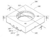
도 1은 본 발명의 일 실시예에 따른 카메라 모듈을 설명하기 위한 도면이다.
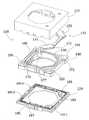
도 2는 도 1의 카메라 모듈의 분해된 구조를 설명하기 위한 도면이다.
도 3은 도 1의 카메라 모듈에서 베이스 및 와이어 스프링을 구체적으로 설명하기 위한 도면이다.
도 4는 도 1의 카메라 모듈에서 와이어 스프링의 평면 구조를 설명하기 위한 도면이다.
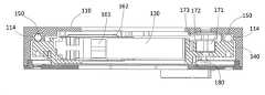
도 5는 도 1의 카메라 모듈의 A-A 단면을 설명하기 위한 도면이다.
도 6은 도 1의 카메라 모듈의 B-B 단면을 설명하기 위한 도면이다.
도 7은 도 1의 카메라 모듈에서 커버에 OIS 몸체를 조립하는 과정을 설명하기 위한 도면이다.
도 8은 도 1의 카메라 모듈에서 OIS 몸체를 커버에 조립하고 베이스를 더 조립하는 과정을 설명하기 위한 도면이다.1 is a view for explaining a camera module according to an embodiment of the present invention.
FIG. 2 is a view for explaining an exploded structure of the camera module of FIG. 1 .
FIG. 3 is a view for explaining in detail a base and a wire spring in the camera module of FIG. 1 .
FIG. 4 is a view for explaining a planar structure of a wire spring in the camera module of FIG. 1 .
FIG. 5 is a view for explaining a cross section AA of the camera module of FIG. 1 .
FIG. 6 is a view for explaining a cross-section BB of the camera module of FIG. 1 .
FIG. 7 is a view for explaining a process of assembling the OIS body to the cover in the camera module of FIG. 1 .
8 is a view for explaining a process of assembling the OIS body to the cover and further assembling the base in the camera module of FIG. 1 .
이하 첨부된 도면들을 참조하여 본 발명의 바람직한 실시예를 상세하게 설명하지만, 본 발명이 실시예에 의해 제한되거나 한정되는 것은 아니다. 참고로, 본 설명에서 동일한 번호는 실질적으로 동일한 요소를 지칭하며, 상기 규칙하에서 다른 도면에 기재된 내용은 인용하여 설명할 수 있고, 당업자에게 자명하다고 판단되거나 반복되는 내용은 생략될 수 있다.Hereinafter, preferred embodiments of the present invention will be described in detail with reference to the accompanying drawings, but the present invention is not limited or limited by the embodiments. For reference, in the present description, the same numbers refer to substantially the same elements, and contents described in other drawings under the above rules may be cited and described, and contents determined to be obvious to those skilled in the art or repeated may be omitted.
도 1은 본 발명의 일 실시예에 따른 카메라 모듈을 설명하기 위한 도면이고, 도 2는 도 1의 카메라 모듈의 분해된 구조를 설명하기 위한 도면이고, 도 3은 도 1의 카메라 모듈에서 베이스 및 와이어 스프링을 구체적으로 설명하기 위한 도면이고, 도 4는 도 1의 카메라 모듈에서 와이어 스프링의 평면 구조를 설명하기 위한 도면이고, 도 5는 도 1의 카메라 모듈의 A-A 단면을 설명하기 위한 도면이고, 도 6은 도 1의 카메라 모듈의 B-B 단면을 설명하기 위한 도면이고, 도 7은 도 1의 카메라 모듈에서 커버에 OIS 몸체를 조립하는 과정을 설명하기 위한 도면이고, 도 8은 도 1의 카메라 모듈에서 OIS 몸체를 커버에 조립하고 베이스를 더 조립하는 과정을 설명하기 위한 도면이다.FIG. 1 is a view for explaining a camera module according to an embodiment of the present invention, FIG. 2 is a view for explaining an exploded structure of the camera module of FIG. 1, and FIG. 3 is a base and a base in the camera module of FIG. It is a view for explaining the wire spring in detail, Fig. 4 is a view for explaining the planar structure of the wire spring in the camera module of Fig. 1, Fig. 5 is a view for explaining the cross section A-A of the camera module of Fig. 1, FIG. 6 is a view for explaining a cross section B-B of the camera module of FIG. 1 , FIG. 7 is a view for explaining a process of assembling the OIS body to the cover in the camera module of FIG. 1 , and FIG. 8 is the camera module of FIG. It is a drawing for explaining the process of assembling the OIS body to the cover and further assembling the base.
도 1 내지 도 8을 참조하면, 카메라 모듈(100)은 커버(110), 커버(110)와 결속되는 베이스(120), 커버(110)와 베이스(120) 사이에서 제공되는 렌즈 캐리어(130), 커버(110)의 내부에 제공되는 슬림한 OIS 몸체(140), 커버(110)와 슬림한 OIS 몸체(140) 사이에 개재되는 4개의 제1 볼 베어링(150), OIS 몸체(140)와 렌즈 캐리어(130) 사이에 제공되는 AF 구동부(160), 및 OIS 몸체(140)를 렌즈 캐리어(130)의 광축에 수직하게 이동시키기 위한 OIS 구동부(170)를 포함할 수 있다.1 to 8 , the
참고로, 본 실시예에서 카메라 모듈(100)은 종래의 이미지 센서(미도시)가 장착된 종래의 기판(미도시)에 장착될 수 있으며, 렌즈 캐리어(130) 내에 제공되는 렌즈 또는 렌즈 그룹을 이용하여 이미지 센서에 맺히는 상을 조절할 수 있다. 하지만, 다른 실시예에서는 카메라 모듈 내부에 이미지 센서를 같이 포함할 수도 있다.For reference, in this embodiment, the
또한, '광축'은 렌즈의 중심에 대응하는 선으로 이해될 수 있으며, 도면에서는 커버(110) 및 베이스(120)의 중심을 통과하는 수직한 선으로 이해될 수도 있다. 이에 '광축 방향'은 광축과 일치하거나 광축에 나란하거나 실질적으로 평행을 이루는 방향으로 이해될 수 있다. 이에 따라 '수평 방향'은 광축에 수직하거나 광축에 거의 수직인 방향으로 이해될 수 있다. 일 예로, x축, y축 및 z축을 이루는 좌표계를 가정할 때, z축이 광축이라면, x축 및 y축은 물론 (x, y)만 표현되는 방향은 수평 방향이라 할 수 있다.In addition, the 'optical axis' may be understood as a line corresponding to the center of the lens, and may be understood as a vertical line passing through the centers of the
도시된 바에 따르면, 본 실시예에 따른 카메라 모듈(100)은 전체적으로 납작한 박스 형상으로 제공될 수 있으며, 그 내부에 수용되는 OIS 몸체(140)도 전체적으로 납작한 사각 박스 형상으로 제공되며, 그 중앙에 중앙 공간을 제공할 수 있다. 렌즈 캐리어(130) 중 원통형의 공간에는 렌즈, 렌즈 그룹, 필터 등이 더 제공될 수 있다.As shown, the
4개의 제1 볼 베어링(150)은 OIS 몸체(140)의 상면 모서리에 각각 제공될 수 있으며, 커버(110)의 내부 천장과 OIS 몸체(140)의 상면에 직접 접촉할 수 있다. 이러한 구조는 OIS 몸체 하부에 볼 베어링이 제공되는 구조에 비해 전체적인 모듈의 두께를 더 얇게 형성하는 데에 유리할 수 있다.The four
도 5에 도시된 바와 같이, 커버(110)의 천장 중앙에는 중앙 홀(112)이 형성되며, 중앙 홀(112)의 안쪽, 즉 커버(110)의 내부 천장에는 제1 볼 베어링(150)을 수용하기 위한 4개의 포켓부(114)가 형성될 수 있다. 그리고 포켓부(114)에 대응하는 OIS 몸체(140)의 상면은 평면으로 제공될 수 있다. 카메라 모듈(100)이 전체적으로 사각형으로 형성되기 때문에, 포켓부(114)와 제1 볼 베어링(150)은 OIS 몸체(140) 상의 네 모서리에 제공될 수 있으며, 중앙의 렌즈 캐리어(130) 주변에 대응하여 네 모서리의 공간을 효율적으로 이용할 수 있다.As shown in FIG. 5 , a
또한, 도 7에 도시된 바와 같이, 커버(110)의 포켓부(114)에 제1 볼 베어링(150)을 위치시키고, 자력으로 당겨지는 OIS 몸체(140) 및 렌즈 캐리어(130)를 장착하는 간단한 작업으로 볼 베어링을 용이하게 조립할 수 있다. 이러한 장점은 윤활제 등의 사용을 더욱 자제할 수 있어 모듈의 오염이나 댐핑으로 인한 제어의 어려움, 물성 변화에 따른 이동 특성의 변화 등을 함께 해결할 수도 있다.In addition, as shown in Fig. 7, the
본 실시예에서 OIS 구동부(170)는 커버(110)와 OIS 몸체(140) 사이에 제공될 수 있다. 구체적으로 OIS 구동부(170)는 OIS 몸체(140)의 상면 중 두 코너에 매립 장착되는 2세트의 제1 마그네트(171), 제1 마그네트(171)에 대응하여 커버(110)의 내부 천장에 장착되는 2개의 제1 코일(172), 제1 코일(172)과 커버(110) 사이에 개재되는 제1 요크(173), 및 제1 요크(173)의 후방에서 2개의 제1 코일(172)과 전기적으로 연결되는 제1 연성회로기판(175)을 포함할 수 있다.In this embodiment, the
제1 코일(172)은 제1 마그네트(171)에 대응하여 OIS 몸체(140)를 렌즈 캐리어(130)의 광축(z 축)에 수직한 방향, 즉 수평한 x, y 축 방향으로 이동시킬 수 있으며, 제1 코일(172)의 후방에 위치한 제1 요크(173)는 제1 마그네트(171)와의 인력을 이용하여 OIS 몸체(140)를 커버(110)에 밀착시키는 기능을 할 수 있다. 다른 선행기술에서는 OIS 몸체와 베이스를 밀착시키는 마그네트가 OIS 구동부의 마그네트와 별도로 제공되는 경우도 있지만, 이러한 구조에서는 하나의 제1 마그네트(171)를 이용하여 OIS 기능 및 밀착 기능을 동시에 구현할 수 있다.The
제1 연성회로기판(175)은 커버(110)의 내부 천장에 밀착되며, 제1 코일(172)과 전기적으로 연결되어 OIS 제어를 위한 전기적 신호를 전달할 수 있다. 이를 위해 제1 연성회로기판(175)의 제1 단부(176)는 양측으로 연장될 수 있으며, 커버(110)의 내면을 타고 하부로 연장될 수 있으며, 베이스(120)의 주변, 바람직하게는 제1 단자(177), 제2 단자(187) 및 제3 단자(197)가 서로 인접하게 노출되도록 한 위치에 집중적으로 형성될 수 있다. 그리고 제1 연성회로기판(175)의 제1 단부(176)에는 외부와의 연결을 위한 제1 단자(177)가 형성될 수 있다.The first
본 실시예와 달리, 다른 실시예에서는 제1 코일과 제1 마그네트의 위치가 반대로 적용될 수도 있다. 예를 들어, OIS 구동부는 커버의 내부 천장에 장착되는 제1 마그네트, 제1 마그네트에 대응하여 OIS 몸체의 상면에 장착되는 제1 코일, 및 제1 코일과 OIS 몸체 사이에 개재되는 제1 요크를 포함할 수도 있다.Unlike this embodiment, in another embodiment, the positions of the first coil and the first magnet may be reversed. For example, the OIS driving unit includes a first magnet mounted on the inner ceiling of the cover, a first coil mounted on the upper surface of the OIS body in response to the first magnet, and a first yoke interposed between the first coil and the OIS body. may include
도 2 및 도 3을 보면, 홀 센서(180) 등의 제어를 위한 제2 연성회로기판(185)이 베이스(120) 상에 제공될 수 있다. 제2 연성회로기판(185)은 베이스(120)의 주변으로 하방으로 연장되는 제2 단부(186)를 제공할 수 있으며, 제2 단부(186)에는 홀 센서(180)와 전기적 신호를 송수신하기 위한 제2 단자(187)가 제공될 수 있다.2 and 3 , a second flexible printed
제2 연성회로기판(185)의 상면에는 OIS 몸체(140)의 제1 마그네트(171)에 대응하여 홀 센서(180)가 각각 제공될 수 있다. 홀 센서(180)는 OIS 몸체(140)에 고정된 제1 마그네트(171)의 이동을 감지하여 OIS 구동부(170)의 제어에 사용될 정보를 제공할 수 있다.A
특히, 홀 센서(180)는 제1 코일(172)과 제1 마그네트(171)를 사이에 두고 분리될 수 있으며, 제1 코일(172)에 흐르는 전류에 따른 전자기장의 변화로부터 영향을 차단할 수 있다.In particular, the
상술한 바와 같이, 제1 연성회로기판(175)으로부터의 제1 단자(177)와 제2 연성회로기판(185)의 제2 단자(187)는 후술하는 와이어 스프링(190-1~190-4)의 제3 단자(197-1~197-4)와 서로 인접하게 배열되어 외부에서 마치 하나의 기판에 형성된 단자들처럼 연결될 수 있다. 이는 카메라 모듈(100)을 외부의 회로 또는 기판과 연결하는 과정에서 매우 유익한 편의를 제공할 수 있다.As described above, the first terminal 177 from the first
도 2를 보면, AF 구동부(160)는 두 모서리에 배치되는 OIS 구동부(170)에 대응하여, 그 반대측에 위치할 수 있다. 또한, AF 구동부(160)는 OIS 몸체(140)와 렌즈 캐리어(130) 사이에 제공되며, 구체적으로 OIS 몸체(140)의 중앙 공간의 내면에 장착되는 제2 코일(162) 및 제2 코일(162)에 대응하여 렌즈 캐리어(130)의 측면에 장착되는 제2 마그네트(161)를 포함할 수 있다.Referring to FIG. 2 , the
구체적으로 AF 구동부(160)는 홀 센서, 요크 등을 더 포함할 수 있으며, 제2 코일(162)과 제2 마그네트(161)의 양측으로 수직한 가이드 레일을 따라 움직이는 제2 볼 베어링을 더 포함할 수 있다.Specifically, the
도시된 바와 같이, 렌즈 캐리어(130)도 OIS 몸체(140)와 거의 유사한 두께로 제공될 수 있으며, OIS 몸체(140)의 중앙 공간도 상하 연장 구조물 없이 OIS 몸체(140)의 두께 내에 형성될 수 있다. 상술한 구조들에 힘입어, 본 실시예와 같이 OIS 몸체(140)와 렌즈 캐리어(130)를 슬림하게 형성할 수 있다.As shown, the
OIS 몸체(140)의 수평 복원력을 제공하기 위해 OIS 몸체(140)와 베이스(120) 사이에는 복수개의 와이어 스프링(190-1~190-4)이 물리적으로 분리되어 제공될 수 있다. 본 실시예에서 와이어 스프링(190-1~190-4)은 물리적으로 분리되어 있지만 하나의 OIS 몸체(140)를 대상으로 작용하여 OIS 몸체(140)가 원위치로 이동하게 하거나 OIS 몸체(140)의 수평 이동에 일정 복원력을 제공할 수 있다.A plurality of wire springs 190-1 to 190-4 may be physically separated between the
또한, 각 와이어 스프링(190-1~190-4)은 움직이는 OIS 몸체(140)에 장착된 AF 구동부(160)에 전류나 전기적 신호를 전달하기 위한 전달 미디어로 기능할 수 있다. 이를 위해 각 와이어 스프링(190-1~190-4)의 일단은 AF 구동부(160)에 회로적으로 연결될 수 있고, 타단은 다른 단자들과 마찬가지로 베이스(120)의 주변에 노출되어 제3 단자(197-1~197-4)를 형성할 수 있다.In addition, each of the wire springs 190-1 to 190-4 may function as a transmission medium for transmitting a current or an electrical signal to the
4개의 와이어 스프링 중 하나의 와이어 스프링(190-1)을 기준으로 설명하면, 와이어 스프링(190-1)은 일단에 대응하여 OIS 몸체(140)의 저면에 고정되는 제1 고정편(191-1), 제1 고정편(191-1)으로부터 연장된 제1 웨이브(192-1), 타단에 대응하여 베이스(120) 및 커버(110)에 고정되는 제2 고정편(194-1), 및 제2 고정편(194-1)으로부터 연장되며 제1 웨이브(192-1)와 수직하게 연결되는 제2 웨이브(193-1)를 포함할 수 있다. 그리고 제3 단자(197-1)는 제2 고정편(194-1)에서 아래로 절곡되고, 베이스(120)의 제3 단자(197-1~197-4)를 위한 안착홈(126)에 밀착될 수 있다. 제3 단자(197-1~197-4)에 인접하게는 제1 단부(176)를 위한 다른 안착홈(128)이 더 제공될 수 있으며, 도 8의 조립 과정에서 커버(110)와 함께 제1 연성회로기판(175)의 제1 단부(176)가 마지막 안착홈(128)에 위치할 수 있다.When describing one wire spring 190-1 among the four wire springs as a reference, the wire spring 190-1 is a first fixing piece 191-1 fixed to the bottom surface of the
와이어 스프링(190-1)은 상하로의 움직임보다 전후 좌우의 움직임에 대해 유동성을 가질 수 있다. 이를 위해 제1 웨이브(192-1) 및 제2 웨이브(193-1) 각각은 약 60~120㎛의 폭 및 약 30~50㎛의 두께로 형성될 수 있으며, 각 웨이브의 폭이 두께보다 큰 직사각형의 단면으로 제공될 수 있다. 도 4에서 원형 점선으로 표시된 바와 같이, 본 실시예의 웨이브(192,-1, 193-1)들은 4회 이상 180도 정도로 절곡될 수 있다. 이 외에도 하나의 웨이브에서 적어도 2회 이상 90도 이상 절곡되는 절곡 부분을 포함할 수 있으며, 이를 통해 와이어 스프링은 상하 움직임보다 수평 방향 움직임을 제어하기 위한 것임을 알 수 있다.The wire spring 190-1 may have fluidity with respect to a forward, backward, left, and right movement rather than a vertical movement. To this end, each of the first wave 192-1 and the second wave 193-1 may be formed to have a width of about 60 to 120 μm and a thickness of about 30 to 50 μm, and the width of each wave is greater than the thickness. It may be provided with a rectangular cross section. As indicated by a circular dotted line in FIG. 4 , the waves 192 , -1 , and 193 - 1 of the present embodiment may be bent at least four times by about 180 degrees. In addition to this, it may include a bent portion that is bent at least twice or more by 90 degrees or more in one wave, through which it can be seen that the wire spring is for controlling horizontal movement rather than vertical movement.
도 3, 도 4 및 도 8을 보면, OIS 몸체(140)의 저면에는 제1 고정편(191-1~191-4)과 결속되는 돌기(146)가 형성될 수 있으며, OIS 몸체(140)의 돌기(146)를 통해서 와이어 스프링(190-1~190-4)의 제1 고정편(191-1~191-4)이 물리적으로 고정될 수 있다.Referring to FIGS. 3, 4 and 8 , a
또한, 와이어 스프링(190-1~190-4)의 반대측에 위치하는 제2 고정편(194-1~194-4)은 베이스(120)의 단턱(122)에 지지되며, 대략 ㄴ-자 또는 L-자 형상으로 형성되어 베이스(120)의 2변에 걸치도록 고정될 수 있다. 그리고 커버(110)에는 제2 고정편(194-1~194-4)에 대응한 다수의 돌기(116, 117)가 형성될 수 있으며, 이들 커버(110)의 돌기(116, 117)는 제2 고정편(194-1~194-4)의 양측에 형성된 홀을 통과 및 고정함으로써 커버(110)와 베이스(120) 사이에서 와이어 스프링(190-1~190-4)의 타단이 물리적으로 고정되게 할 수 있다.In addition, the second fixing pieces 194-1 to 194-4 located on the opposite side of the wire springs 190-1 to 190-4 are supported on the
AF 구동부(160)는 제2 코일(162)과 전기적으로 연결되는 제3 연성회로기판(165)을 더 포함할 수 있으며, 와이어 스프링(190-1~190-4)은 제1 고정편(191-1~191-4)으로부터 연장 및 절곡 형성되며, 제3 연성회로기판(165)의 단자(166, 167)와 전기적으로 연결되는 제4 단자(198-1~198-4)를 포함할 수 있다.The
상술한 바와 같이, 본 발명의 바람직한 실시예를 참조하여 설명하였지만 해당 기술분야의 숙련된 당업자라면 하기의 청구범위에 기재된 본 발명의 사상 및 영역으로부터 벗어나지 않는 범위 내에서 본 발명을 다양하게 수정 및 변경시킬 수 있음을 이해할 수 있을 것이다.As described above, although described with reference to preferred embodiments of the present invention, those skilled in the art can variously modify and change the present invention without departing from the spirit and scope of the present invention as set forth in the claims below. You will understand that it can be done.
100 : 카메라 모듈 110 : 커버
120 : 베이스 130 : 렌즈 캐리어
140 : OIS 몸체 150 : 제1 볼 베어링
160 : AF 구동부 170 : OIS 구동부
171 : 제1 마그네트 172 : 제1 코일
173 : 제1 요크 175 : 제1 연성회로기판
180 : 홀 센서 180 : 제2 연성회로기판
190-1~190-4 : 와이어 스프링100: camera module 110: cover
120: base 130: lens carrier
140: OIS body 150: first ball bearing
160: AF driver 170: OIS driver
171: first magnet 172: first coil
173: first yoke 175: first flexible circuit board
180: Hall sensor 180: second flexible circuit board
190-1~190-4: wire spring
Claims (15)
Translated fromKorean베이스;
상기 베이스보다 상부에 위치하여 수평 방향으로 이동 가능하며, 카메라 모듈의 작동을 위한 제1 회로를 포함하는 OIS 몸체;
상기 OIS 몸체의 수평 복원력을 제공하기 위해 상기 OIS 몸체와 상기 베이스 사이에 제공되는 복수개의 와이어 스프링;
상기 OIS 몸체의 중앙 공간에 제공되어 광축 방향으로 이동하는 렌즈 캐리어;
상기 OIS 몸체와 상기 렌즈 캐리어 사이에 제공되는 AF 구동부;
상기 OIS 몸체 및 상기 렌즈 캐리어를 커버하기 위한 커버;
상기 OIS 몸체를 상기 렌즈 캐리어의 광축에 수직하게 이동시키기 위해 상기 커버와 상기 OIS 몸체 사이에 제공되는 OIS 구동부; 및
상기 커버와 상기 OIS 몸체 사이에 개재되는 제1 볼 베어링;을 포함하며,
상기 와이어 스프링은 각각 전기적으로 분리되어 있되, 일단은 상기 제1 회로와 연결되고, 타단은 외부의 장치와 연결되는 것을 특징으로 하는 카메라 모듈.In the camera module,
Base;
an OIS body positioned above the base, movable in the horizontal direction, and including a first circuit for operating the camera module;
a plurality of wire springs provided between the OIS body and the base to provide a horizontal restoring force of the OIS body;
a lens carrier provided in the central space of the OIS body and moving in the optical axis direction;
an AF driver provided between the OIS body and the lens carrier;
a cover for covering the OIS body and the lens carrier;
an OIS driver provided between the cover and the OIS body to move the OIS body perpendicular to the optical axis of the lens carrier; and
Includes; a first ball bearing interposed between the cover and the OIS body;
The wire springs are electrically separated from each other, and one end is connected to the first circuit and the other end is connected to an external device.
상기 와이어 스프링은 상기 일단에 대응하여 상기 OIS 몸체에 고정되는 제1 고정편, 상기 제1 고정편으로부터 연장된 제1 웨이브, 상기 타단에 대응하여 상기 베이스에 고정되는 제2 고정편, 및 상기 제2 고정편으로부터 연장되며 상기 제1 웨이브와 교차하며 연결되는 제2 웨이브를 포함하는 것을 특징으로 하는 카메라 모듈.According to claim 1,
The wire spring includes a first fixing piece fixed to the OIS body corresponding to the one end, a first wave extending from the first fixing piece, a second fixing piece fixed to the base corresponding to the other end, and the second 2 The camera module comprising a second wave extending from the fixing piece and intersecting the first wave and connected thereto.
상기 제1 웨이브 및 상기 제2 웨이브 각각은 60~120㎛의 폭 및 30~50㎛의 두께로 형성되는 것을 특징으로 하는 카메라 모듈.3. The method of claim 2,
The camera module, characterized in that each of the first wave and the second wave is formed to have a width of 60 ~ 120㎛ and a thickness of 30 ~ 50㎛.
상기 제1 웨이브 및 상기 제2 웨이브 각각은 적어도 2회 이상 90도 이상 절곡되는 절곡 부분을 포함하는 것을 특징으로 하는 카메라 모듈.3. The method of claim 2,
Each of the first wave and the second wave includes a bent portion that is bent at least twice or more by 90 degrees or more.
상기 OIS 구동부는 상기 OIS 몸체의 상면에 장착되는 제1 마그네트, 상기 제1 마그네트에 대응하여 상기 커버의 내부 천장에 장착되는 제1 코일, 및 상기 제1 코일과 상기 커버 사이에 개재되는 제1 요크를 포함하며,
상기 제1 코일은 상기 제1 마그네트에 대응하여 상기 OIS 몸체를 상기 렌즈 캐리어의 광축에 수직한 방향으로 이동시키고, 상기 제1 요크는 상기 제1 마그네트에 대응하여 상기 OIS 몸체를 상기 커버에 밀착시키는 것을 특징으로 하는 카메라 모듈.According to claim 1,
The OIS driving unit includes a first magnet mounted on the upper surface of the OIS body, a first coil mounted on the inner ceiling of the cover corresponding to the first magnet, and a first yoke interposed between the first coil and the cover. includes,
The first coil moves the OIS body in a direction perpendicular to the optical axis of the lens carrier in response to the first magnet, and the first yoke corresponds to the first magnet to bring the OIS body into close contact with the cover A camera module, characterized in that.
상기 커버의 상기 내부 천장에 상기 제1 볼 베어링을 수용하기 위한 포켓부가 형성되며, 상기 포켓부에 대응하는 상기 OIS 몸체의 상면은 평면으로 제공되는 것을 특징으로 하는 카메라 모듈.8. The method of claim 7,
A pocket portion for accommodating the first ball bearing is formed in the inner ceiling of the cover, and an upper surface of the OIS body corresponding to the pocket portion is provided as a flat camera module.
상기 OIS 구동부는 상기 제1 코일과 상기 커버 사이에 제공되는 제1 연성회로기판(FPCB)을 포함하며, 상기 제1 연성회로기판은 상기 제1 코일과 전기적으로 연결되며, 상기 제1 연성회로기판의 제1 단부는 상기 커버의 내면을 타고 하부로 연장되어 상기 베이스의 주변에서 노출되고, 상기 제1 연성회로기판의 제1 단부에는 제1 단자가 형성된 것을 특징으로 하는 카메라 모듈.8. The method of claim 7,
The OIS driver includes a first flexible circuit board (FPCB) provided between the first coil and the cover, the first flexible circuit board being electrically connected to the first coil, and the first flexible circuit board being electrically connected to the first coil. a first end of the cover is extended downward along the inner surface of the cover to be exposed around the base, and a first terminal is formed at the first end of the first flexible circuit board.
상기 베이스 상에 제공되며 상기 베이스의 주변으로 노출되는 제2 단부를 제공하는 제2 연성회로기판 및 상기 제2 연성회로기판의 상면에 장착된 홀 센서를 더 포함하고,
상기 제2 연성회로기판의 상기 제2 단부에 제2 단자가 형성되고,
상기 홀 센서는 상기 제1 마그네트의 하부에 위치하여 상기 제1 마그네트의 이동을 이용하여 상기 OIS 몸체의 위치를 감지하는 것을 특징으로 하는 카메라 모듈.8. The method of claim 7,
A second flexible printed circuit board provided on the base and provided with a second end exposed to the periphery of the base, and a Hall sensor mounted on an upper surface of the second flexible printed circuit board,
a second terminal is formed at the second end of the second flexible circuit board;
The hall sensor is located under the first magnet, the camera module, characterized in that for detecting the position of the OIS body using the movement of the first magnet.
상기 AF 구동부는 상기 OIS 몸체의 상기 중앙 공간의 내면에 장착되는 제2 코일 및 상기 제2 코일에 대응하여 상기 렌즈 캐리어의 측면에 장착되는 제2 마그네트를 포함하며, 상기 제1 회로는 상기 제2 코일과 전기적으로 연결된 것을 특징으로 하는 카메라 모듈.According to claim 1,
The AF driving unit includes a second coil mounted on an inner surface of the central space of the OIS body and a second magnet mounted on a side surface of the lens carrier corresponding to the second coil, wherein the first circuit includes the second A camera module, characterized in that electrically connected to the coil.
상기 AF 구동부는 상기 제1 회로를 포함하는 제3 연성회로기판을 더 포함하는 것을 특징으로 하는 카메라 모듈.12. The method of claim 11,
The AF driving unit camera module, characterized in that it further comprises a third flexible circuit board including the first circuit.
상기 와이어 스프링은 상기 제2 고정편에서 절곡 형성되어 상기 베이스의 주변에 노출되는 제3 단자를 포함하는 것을 특징으로 하는 카메라 모듈.3. The method of claim 2,
The wire spring is bent from the second fixing piece and the camera module, characterized in that it comprises a third terminal exposed to the periphery of the base.
상기 와이어 스프링은 상기 제1 고정편으로부터 연장 및 절곡 형성되며, 상기 제1 회로와 전기적으로 연결되는 제4 단자를 포함하는 것을 특징으로 하는 카메라 모듈.14. The method of claim 13,
The wire spring is formed by extending and bending from the first fixing piece, the camera module characterized in that it comprises a fourth terminal electrically connected to the first circuit.
상기 제2 고정편은 L-자 형상으로 형성되어 상기 베이스 중 2변에 걸쳐 고정되는 것을 특징으로 하는 카메라 모듈.3. The method of claim 2,
The second fixing piece is formed in an L-shape and is fixed over two sides of the base.
Priority Applications (1)
| Application Number | Priority Date | Filing Date | Title |
|---|---|---|---|
| KR1020200116748AKR102416242B1 (en) | 2020-09-11 | 2020-09-11 | Camera module |
Applications Claiming Priority (1)
| Application Number | Priority Date | Filing Date | Title |
|---|---|---|---|
| KR1020200116748AKR102416242B1 (en) | 2020-09-11 | 2020-09-11 | Camera module |
Publications (2)
| Publication Number | Publication Date |
|---|---|
| KR20220034964A KR20220034964A (en) | 2022-03-21 |
| KR102416242B1true KR102416242B1 (en) | 2022-07-06 |
Family
ID=80937508
Family Applications (1)
| Application Number | Title | Priority Date | Filing Date |
|---|---|---|---|
| KR1020200116748AActiveKR102416242B1 (en) | 2020-09-11 | 2020-09-11 | Camera module |
Country Status (1)
| Country | Link |
|---|---|
| KR (1) | KR102416242B1 (en) |
Citations (1)
| Publication number | Priority date | Publication date | Assignee | Title |
|---|---|---|---|---|
| JP2014160195A (en) | 2013-02-20 | 2014-09-04 | Alps Electric Co Ltd | Lens driving device |
Family Cites Families (4)
| Publication number | Priority date | Publication date | Assignee | Title |
|---|---|---|---|---|
| KR20130044438A (en)* | 2011-10-24 | 2013-05-03 | 연세대학교 산학협력단 | Hand trembling compensation actuator and camera module containing the same |
| KR20170110298A (en)* | 2016-03-23 | 2017-10-11 | 자화전자(주) | Apparatus for driving lens |
| KR102612540B1 (en)* | 2016-10-05 | 2023-12-12 | 엘지이노텍 주식회사 | A lens moving unit, and camera module and optical instrument including the same |
| CN108508678B (en)* | 2017-02-27 | 2021-11-09 | 纳木加有限公司 | OIS camera module and dual-camera system comprising same |
- 2020
- 2020-09-11KRKR1020200116748Apatent/KR102416242B1/enactiveActive
Patent Citations (1)
| Publication number | Priority date | Publication date | Assignee | Title |
|---|---|---|---|---|
| JP2014160195A (en) | 2013-02-20 | 2014-09-04 | Alps Electric Co Ltd | Lens driving device |
Also Published As
| Publication number | Publication date |
|---|---|
| KR20220034964A (en) | 2022-03-21 |
Similar Documents
| Publication | Publication Date | Title |
|---|---|---|
| US11709374B2 (en) | Lens driving apparatus, and camera module and optical device including same | |
| US11696032B2 (en) | Camera device with OIS function by moving an image sensor and optical instrument | |
| US11968454B2 (en) | Sensor driving apparatus | |
| CN109073857B (en) | Lens driving device, camera module and optical device | |
| US12013589B2 (en) | Lens driving device, and camera module and optical device comprising same | |
| US12124054B2 (en) | Lens driving device, and camera module and optical device comprising same | |
| KR20190001299A (en) | Camera module | |
| CN112887525A (en) | Lens moving device, camera module and portable terminal including the same | |
| US20210297596A1 (en) | Lens driving device, camera module, and camera-mounted apparatus | |
| CN105204176A (en) | Camera Lens Module In Portable Terminal | |
| EP2975443A1 (en) | Lens moving apparatus | |
| KR101679785B1 (en) | Optical integral actuator | |
| US12101541B2 (en) | Lens driving apparatus, and camera module and optical device comprising same | |
| TWM545928U (en) | Dual lens camera module | |
| US20230176318A1 (en) | Lens driving device, and camera module and optical device including same | |
| CN114520858A (en) | Optical anti-shake camera module | |
| KR102416241B1 (en) | Camera module | |
| KR102416242B1 (en) | Camera module | |
| JP2023541178A (en) | Camera equipment and optical equipment | |
| KR20220136827A (en) | Lens driving device |
Legal Events
| Date | Code | Title | Description |
|---|---|---|---|
| PA0109 | Patent application | Patent event code:PA01091R01D Comment text:Patent Application Patent event date:20200911 | |
| PA0201 | Request for examination | ||
| PE0902 | Notice of grounds for rejection | Comment text:Notification of reason for refusal Patent event date:20211214 Patent event code:PE09021S01D | |
| PG1501 | Laying open of application | ||
| E701 | Decision to grant or registration of patent right | ||
| PE0701 | Decision of registration | Patent event code:PE07011S01D Comment text:Decision to Grant Registration Patent event date:20220610 | |
| GRNT | Written decision to grant | ||
| PR0701 | Registration of establishment | Comment text:Registration of Establishment Patent event date:20220629 Patent event code:PR07011E01D | |
| PR1002 | Payment of registration fee | Payment date:20220629 End annual number:3 Start annual number:1 | |
| PG1601 | Publication of registration |