KR102415008B1 - Geodetic survey system for improving precision of surveying according to reference point survey method - Google Patents
Geodetic survey system for improving precision of surveying according to reference point survey methodDownload PDFInfo
- Publication number
- KR102415008B1 KR102415008B1KR1020210156392AKR20210156392AKR102415008B1KR 102415008 B1KR102415008 B1KR 102415008B1KR 1020210156392 AKR1020210156392 AKR 1020210156392AKR 20210156392 AKR20210156392 AKR 20210156392AKR 102415008 B1KR102415008 B1KR 102415008B1
- Authority
- KR
- South Korea
- Prior art keywords
- reference point
- coupled
- unit
- horizontal
- housing
- Prior art date
- Legal status (The legal status is an assumption and is not a legal conclusion. Google has not performed a legal analysis and makes no representation as to the accuracy of the status listed.)
- Active
Links
Images


Classifications
- G—PHYSICS
- G01—MEASURING; TESTING
- G01C—MEASURING DISTANCES, LEVELS OR BEARINGS; SURVEYING; NAVIGATION; GYROSCOPIC INSTRUMENTS; PHOTOGRAMMETRY OR VIDEOGRAMMETRY
- G01C15/00—Surveying instruments or accessories not provided for in groups G01C1/00 - G01C13/00
- G01C15/02—Means for marking measuring points
- F—MECHANICAL ENGINEERING; LIGHTING; HEATING; WEAPONS; BLASTING
- F16—ENGINEERING ELEMENTS AND UNITS; GENERAL MEASURES FOR PRODUCING AND MAINTAINING EFFECTIVE FUNCTIONING OF MACHINES OR INSTALLATIONS; THERMAL INSULATION IN GENERAL
- F16F—SPRINGS; SHOCK-ABSORBERS; MEANS FOR DAMPING VIBRATION
- F16F15/00—Suppression of vibrations in systems; Means or arrangements for avoiding or reducing out-of-balance forces, e.g. due to motion
- F16F15/02—Suppression of vibrations of non-rotating, e.g. reciprocating systems; Suppression of vibrations of rotating systems by use of members not moving with the rotating systems
- F16F15/04—Suppression of vibrations of non-rotating, e.g. reciprocating systems; Suppression of vibrations of rotating systems by use of members not moving with the rotating systems using elastic means
- F—MECHANICAL ENGINEERING; LIGHTING; HEATING; WEAPONS; BLASTING
- F16—ENGINEERING ELEMENTS AND UNITS; GENERAL MEASURES FOR PRODUCING AND MAINTAINING EFFECTIVE FUNCTIONING OF MACHINES OR INSTALLATIONS; THERMAL INSULATION IN GENERAL
- F16M—FRAMES, CASINGS OR BEDS OF ENGINES, MACHINES OR APPARATUS, NOT SPECIFIC TO ENGINES, MACHINES OR APPARATUS PROVIDED FOR ELSEWHERE; STANDS; SUPPORTS
- F16M11/00—Stands or trestles as supports for apparatus or articles placed thereon ; Stands for scientific apparatus such as gravitational force meters
- F16M11/20—Undercarriages with or without wheels
- G—PHYSICS
- G06—COMPUTING OR CALCULATING; COUNTING
- G06Q—INFORMATION AND COMMUNICATION TECHNOLOGY [ICT] SPECIALLY ADAPTED FOR ADMINISTRATIVE, COMMERCIAL, FINANCIAL, MANAGERIAL OR SUPERVISORY PURPOSES; SYSTEMS OR METHODS SPECIALLY ADAPTED FOR ADMINISTRATIVE, COMMERCIAL, FINANCIAL, MANAGERIAL OR SUPERVISORY PURPOSES, NOT OTHERWISE PROVIDED FOR
- G06Q50/00—Information and communication technology [ICT] specially adapted for implementation of business processes of specific business sectors, e.g. utilities or tourism
- G06Q50/10—Services
- G06Q50/26—Government or public services
Landscapes
- Engineering & Computer Science (AREA)
- Business, Economics & Management (AREA)
- General Engineering & Computer Science (AREA)
- Physics & Mathematics (AREA)
- General Physics & Mathematics (AREA)
- Tourism & Hospitality (AREA)
- Mechanical Engineering (AREA)
- Development Economics (AREA)
- Economics (AREA)
- Acoustics & Sound (AREA)
- Remote Sensing (AREA)
- Educational Administration (AREA)
- Radar, Positioning & Navigation (AREA)
- Health & Medical Sciences (AREA)
- Aviation & Aerospace Engineering (AREA)
- General Health & Medical Sciences (AREA)
- Human Resources & Organizations (AREA)
- Marketing (AREA)
- Primary Health Care (AREA)
- Strategic Management (AREA)
- General Business, Economics & Management (AREA)
- Theoretical Computer Science (AREA)
- Position Fixing By Use Of Radio Waves (AREA)
Abstract
Translated fromKoreanDescription
Translated fromKorean본 발명은 측지측량시스템에 관한 것으로, 보다 상세하게는 기준점 측량 방법에 따라 측량 작업의 정밀도를 향상시킨 측지측량시스템에 관한 것이다.The present invention relates to a geodetic surveying system, and more particularly, to a geodetic surveying system in which the precision of a surveying operation is improved according to a reference point surveying method.
일반적으로 지적측량이나 토목측량 등과 같은 측지측량 작업을 할 때에는 정확한 측량 성과를 얻기 위해서 작업의 기준이 되는 측량기준점이 필요하다. 측량기준점은 측지측량의 정확도를 확보하고 효율성을 높이기 위해 특정 지점을 일정 기준에 따라 측정하고 좌표로 표시하여 기준으로 사용하는 점을 말한다.In general, when performing geodetic surveying such as cadastral surveying or civil surveying, in order to obtain accurate survey results, a surveying reference point, which is the standard for the work, is needed. A survey reference point refers to a point that is used as a reference point by measuring a specific point according to a certain standard and displaying it as coordinates in order to secure the accuracy of the geodetic survey and increase the efficiency.
측량기준점은 국가기준점, 공공기준점 및 지적기준점으로 크게 구분된다. 국가기준점은 측량의 정확도를 확보하고 효율성을 높이기 위하여 국토해양부장관이 전 국토를 대상으로 주요 지점마다 정한 측량의 기본이 되는 측량기준점이고, 공공기준점은 공공측량 시행자가 공공측량을 정확하고 효율적으로 시행하기 위하여 국가기준점을 기준으로 하여 따로 정하는 측량기준점이며, 지적기준점은 특별시장·광역시장·도지사 또는 특별자치도지사나 지적소관청이 지적측량을 정확하고 효율적으로 시행하기 위하여 국가기준점을 기준으로 하여 따로 정하는 측량기준점이다.Survey reference points are broadly divided into national reference points, public reference points, and cadastral reference points. The national reference point is the basic survey point set by the Minister of Land, Transport and Maritime Affairs at each major point for the entire land in order to secure the accuracy of the survey and increase the efficiency. The cadastral reference point is a surveying reference point separately determined based on the national reference point for is the reference point.
기존에 활용된 국가기준점들은 경위도원점(측지원점), 수준원점, 절대중력원점, 중력기준점, 중력보조기준점, 삼각점, 수준점, 자기점(지자기점), 통합기준점, GPS기준점 등이 있다.Existing national reference points used include longitude and latitude origin (geodedic point), level origin, absolute gravity origin, gravity reference point, gravity auxiliary reference point, triangle point, level point, magnetic point (geomagnetic point), integrated reference point, GPS reference point, etc.
국가기준점은 통상 국토지리정보원에서 유지 및 관리하므로 특정 지역의 사업수행 업체는 국가기준점의 이용을 위해 국토지리정보원으로부터 사업수행 해당 지역의 국가기준점 위치를 기록한 국가기준점 성과표를 발급받는다.Since the national reference point is usually maintained and managed by the National Geographic Information Service, a business carrying out a project in a specific area receives a national reference point scorecard that records the location of the national reference point in the area where the project is carried out from the National Geographic Information Service to use the national reference point.
그러나 국토지리정보원이 국가기준점에 대해 주기적으로 관리를 하고 있지만 국가기준점이 설치된 장소의 지반 침하는 예고 없이 수시로 발생할 수 있으므로 특정 지역의 사업수행 업체가 해당 지역의 국가기준점 성과표를 바탕으로 국가기준점을 이용하는 경우에 해당 국가기준점이 최초 시공 시의 정확한 위치를 유지하지 못하는 상황은 수시로 발생할 수 있다.However, although the National Geographic Information Service regularly manages the national reference point, ground subsidence at the location where the national reference point is installed may occur from time to time without notice. In some cases, the situation may arise from time to time in which the relevant national reference point cannot maintain the correct position at the time of initial construction.
그리고 이로 인해 사업수행 업체는 국가기준점의 정확한 위치를 찾거나 확인하기 어려운 문제가 있고 국가기준점의 신뢰성 문제에 기인한 작업 지연 및 추가 비용 발생 등의 어려움이 있었다.And because of this, there was a problem in that it was difficult for the project execution company to find or confirm the exact location of the national reference point, and there were difficulties such as delays in work and incurring additional costs due to the reliability problem of the national reference point.
다시 말해, 사업수행 업체는 사업수행 과정 중 이상이 있는 국가기준점을 이용하는 상황이 발생하더라도 해당 국가기준점의 설치 장소에 도착한 후에야 그 사실을 확인할 수 있고, 국토지리정보원도 이상이 발생된 국가기준점에 대해 해당 사실을 인지하지 못할 수 있으므로 사업수행 업체의 이상 신고나 유지보수 요청이 있은 후에 필요한 조치를 취하는 것이 일반적이다.In other words, even if a situation occurs using a national reference point with an abnormality during the project execution process, the project execution company can check the fact only after arriving at the installation site of the national reference point, and the National Geographic Information Service also provides information about the national reference point where the abnormality occurred. Since you may not be aware of this fact, it is common to take necessary measures after a business performing company reports an abnormality or requests for maintenance.
이는 측지측량 사업수행 업체의 입장에서 사업수행의 지연 원인이 되고 국토지리정보원의 입장에서는 국가기준점의 관리를 소홀히 하였다는 비난의 원인이 된다.This is a cause of delay in project execution from the perspective of the geodetic surveying company, and it is a cause of criticism from the point of view of the National Geographic Information Service for neglecting the management of the national reference point.
또한, 일부 측지측량 사업수행 업체는 침하 등의 이상이 발생한 사실을 모르거나, 사업수행 요구 기한을 맞춰야 하는 시간적인 문제 등에 의하여 정확도가 저하된 국가기준점을 기준으로 측지측량 작업을 진행할 수 있으므로 불량한 측량값을 얻게 되는 문제가 발생한다.In addition, some geodetic surveying companies are unaware of the fact that abnormalities such as subsidence have occurred, or may perform geodetic surveying work based on the national reference point whose accuracy has decreased due to the time problem of meeting the deadline for project implementation, so poor surveying There is a problem with getting the value.
위의 배경기술로서 설명된 사항들은 본 발명의 배경에 대해 이해 증진을 위한 것일 뿐, 이 기술분야에서 통상의 지식을 가진자에게 이미 알려진 종래기술에 해당함을 인정하는 것으로 받아들여져서는 안 될 것이다.The matters described as background art above are only for improving understanding of the background of the present invention, and should not be taken as acknowledging that they correspond to prior art already known to those of ordinary skill in the art.
본 발명은 전술한 종래기술의 문제점을 해결하기 위한 것으로서, 국가기준점의 기초구조물이 기울어진 상태가 되도록 지반의 침하가 진행되더라도 해당 국가기준점의 기준점 표주는 항시 수평 상태를 유지할 수 있는 기준점 측량 방법에 따라 측량 작업의 정밀도를 향상시킨 측지측량시스템을 제공하는데 그 목적이 있다.The present invention is to solve the problems of the prior art described above, and even if the subsidence of the ground proceeds so that the basic structure of the national reference point is in a tilted state, the reference point standard of the national reference point is always in a horizontal state. It is an object of the present invention to provide a geodetic surveying system with improved precision of surveying work.
또한, 본 발명은 작업자가 국가기준점의 기준점 표주를 원거리에서 필요한 각도만큼 원격 회전시켜 해당 기준점 표주의 눈금들이 측량장치와 정면으로 마주보는 상태로 자동 조정될 수 있도록 하는 기준점 측량 방법에 따라 측량 작업의 정밀도를 향상시킨 측지측량시스템을 제공하는데 또 다른 목적이 있다.In addition, the present invention is a reference point survey method that allows the operator to remotely rotate the reference point perimeter of the national reference point by a required angle from a distance so that the scales of the reference point can be automatically adjusted to face the surveying device. Precision of the surveying operation Another object is to provide a geodetic surveying system that has improved
본 발명이 이루고자 하는 기술적 과제들은 이상에서 언급한 기술적 과제들로 제한되지 않으며, 언급되지 않은 또 다른 기술적 과제들은 본 발명의 기재로부터 당해 분야에서 통상의 지식을 가진 자에게 명확하게 이해될 수 있을 것이다.The technical problems to be achieved by the present invention are not limited to the technical problems mentioned above, and other technical problems not mentioned will be clearly understood by those of ordinary skill in the art from the description of the present invention. .
위와 같은 목적을 달성하기 위한 본 발명의 구성은, 지면에 하부가 매립되는 형태로 설치되며, 상부가 개방된 수용공간이 상면으로부터 소정 깊이로 형성되고, 수용공간을 중심으로 상면의 양측에 빗물 수집홈이 형성되는 기초구조물; 상기 기초구조물의 수용공간에 설치되며, 상부가 개방되는 동시에 아래쪽 측면의 서로 마주하는 두 지점에 관 삽입홀이 각각 형성되고, 안쪽 측면에 수평 방향을 따라 간격을 유지하며 설치되는 복수의 탄성부재가 수직 방향을 기준으로 2열 이상으로 형성되는 고정 하우징; 길이방향의 일단이 한 쌍의 상기 관 삽입홀 중 어느 하나를 통해 고정 하우징의 내부와 통하고 길이방향의 타단이 기초구조물의 빗물 수집홈들 중 어느 하나와 통하는 상태로 기초구조물의 내측에 설치되며, 관 삽입홀별로 설치되는 것인 동시에 빗물 수집홈별로 설치되는 한 쌍의 빗물 유도관; 상기 고정 하우징의 내부에 한 쌍의 관 삽입홀 중 어느 하나와 대응되도록 각각 설치되어 빗물 유도관들 중 어느 하나와 연결되는 한 쌍의 빗물 저장 탱크 및 빗물 저장 탱크별로 설치되어 해당 빗물 저장 탱크의 빗물을 배출시키는 한 쌍의 펌프 그리고 펌프별로 설치되어 해당 펌프를 통해 배출되는 빗물을 수용하며 펌프를 통해 공급되는 빗물의 양에 따라 부피가 가변되는 빗물 주머니를 포함하는 빗물수평부; 상기 빗물 주머니의 상면에 하면이 거치되는 동시에 고정 하우징의 탄성부재들에 측면이 지지되는 상태로 고정 하우징의 내부에 설치되며, 상부가 개방되어 개방된 상부를 통해 부력 발생을 위한 액체가 내부에 수용되고, 안쪽 측면의 상단에 패킹부재가 수평 방향을 따라 연장되는 형태로 형성되며, 외측 하면에 각이 진 형태의 축 삽입홈이 형성되는 표주 하우징; 상기 표주 하우징의 내부에 수용되어 위쪽 일부는 표주 하우징 내 액체의 부력에 의해 표주 하우징의 상면으로부터 위쪽으로 돌출되며, 표주 하우징 내 액체의 부력에 의해 소정 높이로 유지되는 상태를 기준으로 패킹부재의 상단과 동일 높이에 위치되는 기준눈금 및 기준눈금으로부터 아래쪽으로 일정 간격을 유지하며 순차적으로 위치되는 복수의 침하 길이 측정눈금이 외면에 표시되는 기준점 표주; 상기 표주 하우징의 축 삽입홈과 대응되는 각이 진 형태의 회전축이 상면에 형성되어 회전축을 축 삽입홈에 삽입하는 상태로 고정 하우징의 내측 하면에 설치되는 턴테이블 및 턴테이블의 회전 동력을 발생시키기 위해 기초구조물에 설치되는 정역회전모터 그리고 정역회전모터의 구동축에 결합되는 동시에 그 구동축이 턴테이블에 결합되는 감속기를 포함하는 기준점 회전부; 상기 표주 하우징의 내부에 공급되기 위한 액체를 수용하는 상태로 기초구조물의 상면에 설치되며, 내부의 액체를 배출하기 위한 배출관이 패킹부재를 관통하여 표주 하우징의 내부까지 연장되는 상태로 연결되고, 배출관을 개폐하는 솔레노이드 밸브가 설치되는 액체탱크; 상기 기초구조물의 상면에 설치되어 기초구조물의 절대 위치를 기설정된 검출 주기에 따라 검출하는 절대위치센서; 상기 기준점 표주의 상면에 설치되어 기준점 표주의 수평 여부를 감지하는 수평센서; 상기 기준점 표주의 위쪽 측면에 설치되는 수광소자; 상기 기초구조물이 설치된 지반의 침하 여부를 판별하기 위한 임계값이 절대위치센서를 통해 감지되는 신호 값을 기준으로 설정되어 절대위치센서로부터 입력되는 신호 값 및 기설정된 임계값의 비교를 통해 기초구조물이 설치된 지반의 침하 여부를 판별하고 판별 결과에 따라 솔레노이드밸브의 개폐 및 개방 시간을 조정하여 기준점 표주의 높이가 지반 침하 전과 동일한 높이로 유지될 수 있도록 표주 하우징의 내부에 대한 액체탱크 내 액체의 공급 량을 조정하고, 수평센서로부터 입력되는 신호 값에 따라 펌프의 작동을 제어하여 기준점 표주가 항시 수평을 유지할 수 있도록 하며, 기준점 회전부의 정역회전모터 작동을 위해 입력되는 제어신호에 따라 정역회전모터를 작동시키고 수광소자로부터 입력되는 신호에 따라 작동 중인 정역회전모터의 작동을 정지시키는 제어부; 상기 제어부에 전기적으로 접속되어 제어부가 기초구조물이 설치된 지반의 침하에 따라 출력하는 신호를 수신하여 원거리에 위치한 국가기준점 관리서버에 무선 전송하며, 기준점 회전부의 정역회전모터 작동을 위해 전송되는 제어신호를 수신하여 제어부에 입력하고, 절대위치센서의 감지 신호를 수신하여 외부의 수신 대상에 전송하는 무선통신모듈을 포함하는 국가기준점; 상기 기준점 회전부의 정역회전모터 작동을 위한 신호를 무선전송부를 통해 무선통신모듈에 무선 전송하며, 수광소자와 대응되는 발광소자가 수직 방향을 따라 이동 및 이동된 위치에서의 선택적 고정이 가능하도록 설치되어 무선통신모듈을 통해 전송되는 절대위치센서의 신호에 따라 발광소자의 높이를 수광소자의 높이와 대응되도록 조정하고, 발광소자로부터 수광소자를 향해 광 신호가 방출되는 측지측량장치; 상기 무선통신모듈을 통해 전송되는 신호를 수신 후, 국가기준점이 설치된 지반의 침하 사실을 해당 국가기준점의 관리자가 휴대한 작업자 단말기에 통신망을 통해 전송하는 국가기준점 관리서버; 및 상기 통신망에 접속하여 국가기준점 관리서버로부터 전송되는 신호를 수신하여 기탑재된 GPS 수신기 및 전자지도를 이용하여 국가기준점의 좌표를 구하고 국가기준점의 좌료 관련 데이터를 저장하는 작업자 단말기; 를 포함하는 것을 특징으로 한다.The configuration of the present invention for achieving the above object is installed in a form in which the lower part is buried in the ground, the receiving space with an open upper part is formed to a predetermined depth from the upper surface, and rainwater is collected on both sides of the upper surface with the receiving space as the center. a base structure in which grooves are formed; A plurality of elastic members installed in the accommodating space of the base structure, the upper part is opened, and the tube insertion holes are respectively formed at two points facing each other on the lower side, and installed at intervals along the horizontal direction on the inner side. Fixed housings formed in two or more rows based on the vertical direction; One end in the longitudinal direction communicates with the inside of the fixed housing through any one of the pair of pipe insertion holes, and the other end in the longitudinal direction communicates with any one of the rainwater collection grooves of the base structure. , a pair of rainwater guide pipes installed for each pipe insertion hole and installed for each rainwater collection groove; A pair of rainwater storage tanks and rainwater storage tanks each installed to correspond to any one of the pair of pipe insertion holes inside the fixed housing and connected to any one of the rainwater guide pipes are installed to correspond to the rainwater of the corresponding rainwater storage tank a pair of pumps for discharging and a rainwater horizontal unit installed for each pump to receive rainwater discharged through the pump and including a rainwater bag whose volume varies according to the amount of rainwater supplied through the pump; It is installed inside the fixed housing while the lower surface is mounted on the upper surface of the rainwater bag and the side surfaces are supported by the elastic members of the fixed housing. And, the packing member is formed in a form extending in the horizontal direction on the upper end of the inner side, the outer lower surface of the shaft insertion groove of the angled form is formed; The top of the packing member is accommodated in the standard housing and the upper part protrudes upward from the upper surface of the standard housing by the buoyancy of the liquid in the standard housing, and is maintained at a predetermined height by the buoyancy of the liquid in the standard housing. and a reference point mark on the outer surface of which a plurality of subsidence length measurement scales are sequentially positioned while maintaining a predetermined interval downward from the reference scale and the reference scale positioned at the same height as the reference scale; An angled rotational shaft corresponding to the shaft insertion groove of the ball housing is formed on the upper surface, and the turntable is installed on the inner lower surface of the fixed housing in a state where the rotation shaft is inserted into the shaft insertion groove. Base to generate rotational power a reference point rotation unit including a speed reducer coupled to a forward/reverse rotation motor installed in the structure and a drive shaft of the forward/reverse rotation motor at the same time as the drive shaft is coupled to the turntable; It is installed on the upper surface of the base structure in a state of accommodating the liquid to be supplied to the inside of the standard housing, and a discharge pipe for discharging the liquid inside is connected in a state that extends through the packing member to the inside of the standard housing, and the discharge pipe a liquid tank in which a solenoid valve for opening and closing is installed; an absolute position sensor installed on the upper surface of the basic structure to detect the absolute position of the basic structure according to a preset detection period; a horizontal sensor installed on the upper surface of the reference point mark to detect whether the reference point mark is horizontal; a light receiving element installed on the upper side of the reference point; The threshold value for determining whether the ground on which the foundation structure is installed is subsidence is set based on the signal value detected through the absolute position sensor, and the foundation structure is Determine whether the installed ground has subsided and adjust the opening and closing times of the solenoid valve according to the determination result so that the height of the reference point can be maintained at the same height as before the subsidence of the ground. and control the operation of the pump according to the signal value input from the horizontal sensor so that the reference point mark can always be kept horizontal, and the forward and reverse rotation motor is operated according to the control signal input to operate the forward and reverse rotation motor of the reference point rotating part. and a control unit for stopping the operation of the forward/reverse rotation motor in operation according to a signal input from the light receiving element; Electrically connected to the control unit, the control unit receives a signal output according to the subsidence of the ground on which the basic structure is installed and wirelessly transmits it to the remote national reference point management server, and the control signal transmitted to operate the forward/reverse rotation motor of the reference point rotation unit. a national reference point including a wireless communication module for receiving and inputting the input to the control unit, receiving the detection signal of the absolute position sensor and transmitting it to an external reception target; A signal for operating the forward/reverse rotation motor of the reference point rotation unit is wirelessly transmitted to the wireless communication module through the wireless transmission unit, and the light-emitting element corresponding to the light-receiving element is installed so that it can be moved and selectively fixed at the moved position in the vertical direction. a geodesic surveying device that adjusts the height of the light emitting element to correspond to the height of the light receiving element according to the signal of the absolute position sensor transmitted through the wireless communication module, and emits an optical signal from the light emitting element toward the light receiving element; After receiving the signal transmitted through the wireless communication module, the national reference point management server for transmitting the fact of subsidence of the ground where the national reference point is installed to the operator terminal carried by the manager of the national reference point through a communication network; and a worker terminal that connects to the communication network and receives a signal transmitted from a national reference point management server, obtains coordinates of a national reference point using a pre-mounted GPS receiver and an electronic map, and stores data related to the coordinates of the national reference point; It is characterized in that it includes.
본 발명의 실시예에 따른 기준점 측량 방법에 따라 측량 작업의 정밀도를 향상시킨 측지측량시스템에서 상기 측지측량장치는, 거치대의 상부에 결합되는 한 쌍의 완충기구; 완충기구의 상부에 결합되는 수평조절부; 수평조절부의 상부에 결합되는 승강부; 승강부의 상부에 결합되는 회전부; 회전부와 통신하여 회전부를 제어할 수 있는 회전제어부; 및 회전부의 상부에 결합되며 발광소자 및 무선전송부가 탈착 가능하도록 장착되는 탈착고정부; 를 포함하는 것이 바람직하다.In a geodetic surveying system with improved precision of a surveying operation according to a reference point surveying method according to an embodiment of the present invention, the geodetic surveying device includes: a pair of buffer mechanisms coupled to the upper part of the cradle; a horizontal adjustment unit coupled to the upper portion of the buffer mechanism; a lifting unit coupled to an upper portion of the horizontal adjustment unit; a rotating unit coupled to an upper portion of the elevating unit; a rotation control unit capable of communicating with the rotating unit to control the rotating unit; and a detachable fixing unit coupled to the upper portion of the rotating unit and mounted such that the light emitting device and the wireless transmitting unit are detachably mounted; It is preferable to include
본 발명의 실시예에 따른 기준점 측량 방법에 따라 측량 작업의 정밀도를 향상시킨 측지측량시스템에서 상기 완충부는, 수평조절부의 하단에 결합되는 완충로드; 내부가 비어있는 원통형으로 형성되어 완충로드의 하단이 수용되며 기초대의 상부에 설치되는 완충케이스; 완충로드의 하단 외측면에 링 형태로 결합되는 완충스토퍼; 완충로드의 하부에 결합되며 완충로드와 완충케이스의 내측면 사이를 연결하는 완충연결부; 및 완충스토퍼의 외측면과 완충케이스의 내측면 사이에 결합되어 완충스토퍼와 완충케이스 사이를 서로 연결하는 완충굴곡부; 를 포함하는 것이 바람직하다.In the geodetic surveying system that improves the precision of the surveying operation according to the reference point surveying method according to an embodiment of the present invention, the buffer unit includes: a buffer rod coupled to the lower end of the horizontal adjustment unit; The buffer case is formed in a cylindrical shape with an empty interior, the lower end of the buffer rod is accommodated, and is installed on the upper part of the base; a buffer stopper coupled to the lower outer surface of the buffer rod in the form of a ring; a buffer connection part coupled to the lower portion of the buffer rod and connecting the buffer rod and the inner surface of the buffer case; And a buffer bent portion coupled between the outer surface of the buffer stopper and the inner surface of the buffer case to connect the buffer stopper and the buffer case to each other; It is preferable to include
본 발명의 실시예에 따른 기준점 측량 방법에 따라 측량 작업의 정밀도를 향상시킨 측지측량시스템에서 상기 완충굴곡부는, 완충스토퍼의 외측면에 결합되며 1자 형태로 형성되는 제1굴곡부; 제1굴곡부의 하단으로부터 비스듬히 상부를 향해 연장되는 제2굴곡부; 제2굴곡부의 상단으로부터 하부로 연장되며 1자 형태로 형성되는 제3굴곡부; 제3굴곡부의 하단으로부터 비스듬히 상부를 향해 연장되는 제4굴곡부; 및 제4굴곡부의 상단으로부터 하부로 연장되고 1자 형태로 형성되며 완충케이스의 내측면에 결합되는 제5굴곡부; 를 포함하는 것이 바람직하다.In the geodetic surveying system that improves the precision of the surveying operation according to the reference point surveying method according to an embodiment of the present invention, the buffer bending part is coupled to the outer surface of the buffer stopper and the first curved part is formed in a single shape; a second curved portion extending obliquely upward from the lower end of the first curved portion; a third curved part extending from the upper end of the second curved part to the lower part and formed in the shape of a figure; a fourth curved portion extending obliquely upward from the lower end of the third curved portion; and a fifth curved part extending from the upper end of the fourth curved part to the lower part, formed in the shape of a figure, and coupled to the inner surface of the buffer case; It is preferable to include
본 발명의 실시예에 따른 기준점 측량 방법에 따라 측량 작업의 정밀도를 향상시킨 측지측량시스템에서 상기 수평조절부는, 완충기구의 상부면에 결합되며 내부에 공간이 형성된 수평하우징; 수평하우징의 내부에 횡방향으로 배치되는 장착판; 장착판의 하면 중앙에 결합되며 구형 외주면을 가지는 구형부와 구형부의 상면에 일체로 형성되어 상단이 장착판의 중앙에 결합되는 수직봉을 구비한 회동체; 수평하우징의 내측 하부면에 고정되며 회동체의 구형부의 하부면에 대응하는 구형 내주면을 가지는 회동지지체; 회동지지체의 상부에 고정 결합되며 회동체의 구형부의 상부면에 대응하는 구형 내주면을 가지는 상측지지체; 및 일측은 장착판의 저면부를 지지하고 타측은 수평하우징의 상부면에 구름 접촉되어 장착판의 수평을 유지하는 수평유지부; 를 포함하는 것이 바람직하다.In the geodetic surveying system that improves the precision of the surveying according to the reference point surveying method according to an embodiment of the present invention, the horizontal adjustment unit includes: a horizontal housing coupled to the upper surface of the buffer mechanism and having a space therein; a mounting plate disposed in the horizontal direction on the inside of the horizontal housing; a rotating body having a vertical bar coupled to the center of the lower surface of the mounting plate and integrally formed with a spherical portion having a spherical outer circumferential surface and an upper surface of the spherical portion, the upper end of which is coupled to the center of the mounting plate; a rotation support fixed to the inner lower surface of the horizontal housing and having a spherical inner peripheral surface corresponding to the lower surface of the spherical part of the rotation body; an upper support having a spherical inner circumferential surface that is fixedly coupled to the upper portion of the pivot support and corresponds to the upper surface of the spherical part of the pivot; And one side supports the lower surface of the mounting plate and the other side is in rolling contact with the upper surface of the horizontal housing to maintain the horizontal maintaining portion of the mounting plate; It is preferable to include
본 발명의 실시예에 따른 기준점 측량 방법에 따라 측량 작업의 정밀도를 향상시킨 측지측량시스템에서 상기 수평유지부는, 장착판의 저면부에 마련되는 결합블록; 일측부가 결합블록에 회전 가능하게 결합되는 제1베이스바; 일측부가 제1베이스바의 내부에 배치되어 제1베이스바의 내부로 이동되는 제1실장바; 제1실장바에 마련되어 수평하우징의 하부면에 구름 접촉되는 제1수평롤러; 일측부는 제1베이스바의 내부에 결합되고 타측부는 제1실장바에 결합되어 제1실장바를 길이 조절되게 가이드하는 제1스프링부재; 일측부가 결합블록에 회전 가능하게 결합되는 제2베이스바; 일측부가 제2베이스바의 내부에 배치되어 제2베이스바의 내부로 이동되는 제2실장바; 제2실장바에 마련되어 수평하우징의 하부면에 구름 접촉되는 제2수평롤러; 일측부는 제2베이스바의 내부에 결합되고 타측부는 제2실장바에 결합되어 제2실장바를 길이 조절되게 가이드하는 제2스프링부재; 제1베이스바와 제2베이스바를 연결하여 제1베이스바와 제2베이스바의 간격을 유지시키는 바디연결스프링; 및 상기 제1수평롤러와 제2수평롤러가 접촉되는 영역의 수평하우징 하부면에 마련되어 제1수평롤러와 제2수평롤러의 접촉에 의해 전기를 발생시키는 압전소자부; 를 포함하는 것이 바람직하다.In the geodetic surveying system that improves the precision of the surveying operation according to the reference point surveying method according to an embodiment of the present invention, the horizontal maintenance unit includes: a coupling block provided on the bottom surface of the mounting plate; a first base bar having one side portion rotatably coupled to the coupling block; a first mounting bar in which one side is disposed inside the first base bar and moved to the inside of the first base bar; a first horizontal roller provided on the first mounting bar and in rolling contact with the lower surface of the horizontal housing; a first spring member having one side coupled to the inside of the first base bar and the other side coupled to the first mounting bar to guide the length of the first mounting bar to be adjusted; a second base bar, one side of which is rotatably coupled to the coupling block; a second mounting bar in which one side is disposed inside the second base bar and moved to the inside of the second base bar; a second horizontal roller provided on the second mounting bar and in rolling contact with the lower surface of the horizontal housing; a second spring member having one side coupled to the inside of the second base bar and the other side coupled to the second mounting bar to guide the second mounting bar to be adjusted in length; a body connection spring connecting the first base bar and the second base bar to maintain a gap between the first base bar and the second base bar; and a piezoelectric element part provided on a lower surface of the horizontal housing in an area where the first horizontal roller and the second horizontal roller are in contact and generating electricity by contact between the first horizontal roller and the second horizontal roller; It is preferable to include
본 발명의 실시예에 따른 기준점 측량 방법에 따라 측량 작업의 정밀도를 향상시킨 측지측량시스템에서 상기 승강부는, 수평조절부의 상부에 결합되는 승강구동부; 승강구동부의 상부에 결합되며 내부가 비어있는 구형의 승강하우징; 승강구동부에 연결되어 시계방향 또는 반시계방향으로 회전되고 상하로 승강하며 승강하우징의 내부에 배치되는 승강축; 승강축의 외벽에 힌지 결합되는 다수의 승강지지바디; 다수의 승강지지바디의 말단에 인출되게 장착되는 지지바; 지지바의 말단에 마련되어 승강하우징의 내벽에 지지되는 지지롤러; 일측부는 승강지지바디의 내부에 결합되고 타측부는 지지바에 결합되어 지지바를 탄성 지지하는 승강스프링; 및 다수의 승강지지바디를 서로 연결하여 다수의 승강지지바디가 지지될 수 있도록 하는 연결스프링; 을 포함하고, 상기 승강구동부의 작동시 승강 지지 바디, 지지바 및 지지롤러는 승강축과 함께 회전되면서 승강되고, 지지롤러는 승강하우징의 내벽에 구름 접촉되는 것이 바람직하다.In a geodetic surveying system that improves the precision of a surveying operation according to a reference point surveying method according to an embodiment of the present invention, the lifting unit includes: a lifting driving unit coupled to the upper part of the horizontal adjustment unit; a spherical elevating housing coupled to the upper part of the elevating drive and having an empty interior; an elevating shaft connected to the elevating drive unit, rotating clockwise or counterclockwise, elevating up and down, and disposed inside the elevating housing; A plurality of lifting support body hinged to the outer wall of the lifting shaft; a support bar mounted to be drawn out at the ends of the plurality of lifting support bodies; a support roller provided at the end of the support bar and supported on the inner wall of the elevating housing; an elevating spring having one side coupled to the inside of the elevating support body and the other side coupled to the supporting bar to elastically support the supporting bar; and a connection spring connecting the plurality of lifting support bodies to each other so that the plurality of lifting support bodies can be supported. And, it is preferable that the lifting support body, the support bar, and the support roller are raised and lowered while rotating together with the lifting shaft when the lifting driving unit is operated, and the support roller is in rolling contact with the inner wall of the lifting housing.
본 발명의 실시예에 따른 기준점 측량 방법에 따라 측량 작업의 정밀도를 향상시킨 측지측량시스템에서 상기 탈착고정수단은, 회전부의 상부에 결합되는 고정케이스; 고정케이스의 상부면에 결합되는 다수의 고정돌출부; 다수의 고정돌출부 내측에 각각 안착되는 제1플레이트 및 제2플레이트; 제1플레이트의 상부면에 결합되는 발광소자; 제2플레이트의 상부면에 결합되는 무선전송부; 및 제1플레이트와 제2플레이트의 상부에 배치되어 제1플레이트 및 제2플레이트의 상부면을 가압하는 고정가압부; 를 포함하는 것이 바람직하다.In the geodetic surveying system that improves the precision of the surveying operation according to the reference point surveying method according to the embodiment of the present invention, the detachable fixing means includes: a fixed case coupled to the upper part of the rotating part; a plurality of fixing protrusions coupled to the upper surface of the fixing case; a first plate and a second plate respectively seated inside the plurality of fixing protrusions; a light emitting device coupled to the upper surface of the first plate; a wireless transmitter coupled to the upper surface of the second plate; and a fixed pressing unit disposed on the first plate and the second plate to press the upper surfaces of the first plate and the second plate; It is preferable to include
본 발명의 실시예에 따른 기준점 측량 방법에 따라 측량 작업의 정밀도를 향상시킨 측지측량시스템에서 상기 고정가압부는, 제1플레이트와 제2플레이트의 상부면에 횡방향으로 배치되며 중앙으로부터 단부로 갈수록 하부를 향해 만곡되는 제1가압대; 제1플레이트와 제2플레이트의 상부면에 횡방향으로 배치되며 중앙으로부터 단부로 갈수록 하부를 향해 만곡되는 제2가압대; 제1가압대와 제2가압대 사이에 배치되어 제1가압대와 제2가압대를 연결하는 고정연결대; 고정연결대의 중앙에 결합되며 하부를 향해 연장되는 고정로드; 및 고정케이스의 상부면에 결합되며 고정로드의 하단이 삽입 체결되는 로드체결부; 를 포함하는 것이 바람직하다.In the geodetic surveying system that improves the precision of the surveying operation according to the reference point surveying method according to the embodiment of the present invention, the fixed pressing part is disposed in the transverse direction on the upper surfaces of the first plate and the second plate, and the lower part goes from the center to the end. a first pressure band that is curved toward; a second press bar disposed in the transverse direction on the upper surfaces of the first plate and the second plate and curved downward from the center toward the end; a fixed connecting rod disposed between the first and second presses to connect the first and second presses; a fixed rod coupled to the center of the fixed connecting rod and extending downward; and a rod fastening part coupled to the upper surface of the fixed case and to which the lower end of the fixed rod is inserted and fastened; It is preferable to include
위와 같은 구성을 가지는 본 발명은, 국가기준점의 기초구조물이 기울어진 상태가 되도록 지반의 침하가 진행되더라도 해당 국가기준점의 기준점 표주는 항시 수평 상태로 유지되고, 이에 따라 해당 국가기준점을 이용하는 측량 작업의 정밀도가 항시 확보되는 효과가 있다.The present invention having the above configuration, even if the subsidence of the ground proceeds so that the basic structure of the national reference point is in a tilted state, the reference point mark of the national reference point is always maintained in a horizontal state, and accordingly, the survey operation using the national reference point is There is an effect that precision is always secured.
또한, 본 발명은 작업자가 국가기준점의 기준점 표주를 원거리에서 필요한 각도만큼 원격 회전시켜 해당 기준점 표주의 눈금들이 측량장치와 정면으로 마주보는 상태로 자동 조정할 수 있어, 측량 작업의 작업성을 크게 향상시키는 동시에 이를 통해 측량 결과의 정확성이 향상되는 효과가 있다.In addition, the present invention enables the operator to remotely rotate the reference point girder of the national reference point by a required angle from a distance, so that the scales of the reference point mark can be automatically adjusted in a state facing the surveying device, greatly improving the workability of the surveying work At the same time, this has the effect of improving the accuracy of the survey results.
도 1은 본 발명의 일실시예에 따른 기준점 측량 방법에 따라 측량 작업의 정밀도를 향상시킨 측지측량시스템에서 국가기준점을 도시한 측단면도.
도 2는 본 발명의 일실시예에 따른 기준점 측량 방법에 따라 측량 작업의 정밀도를 향상시킨 측지측량시스템에서 국가기준점이 지반 침하에 따라 변화된 상태를 예시한 측단면도.
도 3은 본 발명의 일실시예에 따른 기준점 측량 방법에 따라 측량 작업의 정밀도를 향상시킨 측지측량시스템의 전기적 구성을 예시한 블록도.
도 4는 본 발명의 일실시예에 따른 기준점 측량 방법에 따라 측량 작업의 정밀도를 향상시킨 측지측량시스템에서 지반침하 및 그에 따른 기준점 표주의 높이 조정 과정을 보인 순서도.
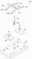
도 5는 본 발명의 일실시예에 따른 기준점 측량 방법에 따라 측량 작업의 정밀도를 향상시킨 측지측량시스템에서 국가기준점 및 그에 대응되는 측지측량장치를 예시한 측단면도.
도 6은 본 발명의 다른 실시예에 따른 기준점 측량 방법에 따라 측량 작업의 정밀도를 향상시킨 측지측량시스템의 전기적 구성을 예시한 블록도.
도 7은 본 발명의 일실시예에 따른 완충기구의 단면 모습을 도시한 도면.
도 8은 본 발명의 일실시예에 따른 수평조절부의 단면 모습을 도시한 도면.
도 9는 본 발명의 일실시예에 따른 수평유지부를 확대하여 도시한 도면.
도 10은 본 발명의 일실시예에 따른 승강부의 단면 모습을 도시한 도면.
도 11은 본 발명의 일실시예에 따른 회전제어부의 각 부품이 분해된 모습을 도시한 도면.
도 12는 본 발명의 일실시예에 따른 탈착고정부의 각 부품이 분해된 모습을 도시한 도면.1 is a side cross-sectional view showing a national reference point in a geodetic surveying system in which the precision of the surveying operation is improved according to the reference point surveying method according to an embodiment of the present invention.
Figure 2 is a side cross-sectional view illustrating a state in which the national reference point is changed according to the subsidence of the ground in the geodetic survey system in which the precision of the surveying operation is improved according to the reference point survey method according to an embodiment of the present invention.
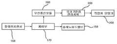
3 is a block diagram illustrating an electrical configuration of a geodetic surveying system in which the precision of a surveying operation is improved according to a reference point surveying method according to an embodiment of the present invention.
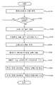
Figure 4 is a flow chart showing the ground subsidence and the process of adjusting the height of the reference point according to the ground subsidence in the geodetic survey system that improves the precision of the surveying operation according to the reference point survey method according to an embodiment of the present invention.
5 is a side cross-sectional view illustrating a national reference point and a geodesic surveying device corresponding thereto in a geodetic surveying system with improved precision of a surveying operation according to a reference point surveying method according to an embodiment of the present invention.
6 is a block diagram illustrating an electrical configuration of a geodetic surveying system in which the precision of a surveying operation is improved according to a reference point surveying method according to another embodiment of the present invention.
Figure 7 is a view showing a cross-sectional view of the buffer mechanism according to an embodiment of the present invention.
8 is a view showing a cross-sectional view of a horizontal adjustment unit according to an embodiment of the present invention.
9 is an enlarged view of a horizontal holding unit according to an embodiment of the present invention;
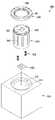
10 is a view showing a cross-sectional view of the lifting unit according to an embodiment of the present invention.
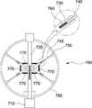
11 is a view showing an exploded state of each part of the rotation control unit according to an embodiment of the present invention.
12 is a view showing an exploded state of each part of the detachable fixing unit according to an embodiment of the present invention.
이하, 첨부된 도면에 의거하여 본 발명에 대하여 본 발명이 속하는 기술 분야에서 통상의 지식을 가진 자가 용이하게 실시할 수 있도록 상세히 설명한다. 그러나 본 발명은 여러 가지 상이한 형태로 구현될 수 있으며 여기에서 설명하는 실시예에 한정되지 않는다.Hereinafter, based on the accompanying drawings, the present invention will be described in detail so that those of ordinary skill in the art can easily carry out the present invention. However, the present invention may be embodied in several different forms and is not limited to the embodiments described herein.
본 발명을 명확하게 설명하기 위해서 설명과 관계없는 부분은 생략하였으며, 명세서 전체를 통하여 동일 또는 유사한 구성요소에 대해서는 동일한 참조 부호를 붙이도록 한다.In order to clearly explain the present invention, parts irrelevant to the description are omitted, and the same reference numerals are assigned to the same or similar components throughout the specification.
또한, 본 명세서 및 특허청구범위에 사용된 용어나 단어는 통상적이거나 사전적인 의미로 한정하여 해석되어서는 안 되며, 발명자는 그 자신의 발명을 가장 최선의 방법으로 설명하기 위해 용어의 개념을 적절하게 정의할 수 있다는 원칙에 입각하여 본 발명의 기술적 사상에 부합하는 의미와 개념으로 해석되어야만 한다.In addition, the terms or words used in the present specification and claims should not be construed as being limited to their ordinary or dictionary meanings, and the inventor must properly understand the concept of the term in order to best describe his invention. Based on the principle that it can be defined, it should be interpreted as meaning and concept consistent with the technical idea of the present invention.
도 1은 본 발명의 일실시예에 따른 기준점 측량 방법에 따라 측량 작업의 정밀도를 향상시킨 측지측량시스템에서 국가기준점을 도시한 측단면도이고, 도 2는 본 발명의 일실시예에 따른 기준점 측량 방법에 따라 측량 작업의 정밀도를 향상시킨 측지측량시스템에서 국가기준점이 지반 침하에 따라 변화된 상태를 예시한 측단면도이며, 도 3은 본 발명의 일실시예에 따른 기준점 측량 방법에 따라 측량 작업의 정밀도를 향상시킨 측지측량시스템의 전기적 구성을 예시한 블록도이다.1 is a cross-sectional side view showing a national reference point in a geodetic surveying system with improved precision of a surveying operation according to a reference point surveying method according to an embodiment of the present invention, and FIG. 2 is a reference point surveying method according to an embodiment of the present invention. It is a cross-sectional side view illustrating a state in which the national reference point is changed according to ground subsidence in the geodetic survey system that has improved the precision of the surveying operation according to It is a block diagram illustrating the electrical configuration of the improved geodetic survey system.
도시된 바와 같이, 본 발명에 따른 측지측량시스템은 기초구조물(110), 표주 하우징(120), 기준점 표주(130), 액체탱크(140), 절대위치센서(160)를 포함하여 이루어진다.As shown, the geodetic surveying system according to the present invention comprises a
기초구조물(110)은 국가기준점(100)을 설치할 장소의 지면에 설치되며, 이러한 기초구조물(110)은 상부를 개방한 수용공간이 상면으로부터 소정 깊이로 형성된다.The
표주 하우징은(120) 기초구조물(110)의 수용공간에 고정 설치되며, 이러한 표주 하우징(120)의 내측에는 부력 발생을 위한 액체(121)가 수용된다. 여기서 액체(121)는 표주 하우징(120)의 내측 상단까지 채워지는 것은 아니며, 액체탱크(140)로부터 추가로 액체를 공급받을 수 있는 여분의 공간을 남기는 상태로 수용된다.The
그리고 표주 하우징(120)의 상단에는 패킹부재(122)가 구비되는 것으로서, 이러한 패킹부재(122)는 표주 하우징(120)의 내측에 수용되어 액체(121)의 부력에 의해 띄워지는 기준점 표주(130)를 지지하는 동시에 수밀을 유지시키는 기능을 한다.And a packing
기준점 표주(130)는 표주 하우징(120)의 내측에 수용되어 상측 일부는 액체의 부력에 의해 표주 하우징(120)의 상측으로 돌출된다. 그리고 기준점 표주(130)가 표주 하우징(120)의 내측에서 액체(121)의 부력에 의해 소정 높이를 유지하는 상태를 기준으로, 기준점 표주(130)에는 패킹부재(122)의 상단과 같거나 유사한 높이로써 외면의 일부분에 기준눈금(131)이 표시되고, 또한 기준점 표주(130)에는 기준눈금(131)으로부터 하방향을 따라 일정 간격을 유지하며 순차적으로 침하길이 측정눈금(132)이 표시된다.The
그리고 이와 같은 기준눈금(131)과 침하길이 측정눈금(132)은 국가기준점(100)의 침하 현상 시 그 침하 정도를 계산하여 비교적 정확한 침하 길이를 계산할 수 있도록 하는 용도이다.In addition, the
액체탱크(140)는 표주 하우징(120)의 상부 쪽 측면에 위치하도록 기초구조물(110)에 고정 설치된다. 이러한 액체탱크(140)는 내측에 액체(142)를 수용하는 것으로서, 액체탱크(140)에 수용되는 액체(142)는 표주 하우징(120)의 내측에 공급되기 위한 용도이며, 이에 따라 액체탱크(140)는 표주 하우징(120)의 내부와 통하는 배출구(141)를 구비한다. 또한 액체탱크(140)는 그 배출구(141)의 개폐를 위한 솔레노이브밸브(150)를 구비한다.The
즉, 솔레노이드밸브(150)의 개폐에 따라 액체탱크(140) 내 액체(142)의 표주 하우징(120)에 대한 유입이 제어되고, 이렇게 표주 하우징(120) 내로 추가 공급되는 액체탱크(140)의 액체(142)로 인해 표주 하우징(120) 내의 기준점 표주(130)는 표주 하우징(120)을 기준으로 한 최초 높이보다 더 높은 상태에 위치하게 된다.That is, according to the opening and closing of the
절대위치센서(160)는 기초구조물(110)이나 표주 하우징(120)의 일부분에 설치되는 것으로서, 이러한 절대위치센서(160)는 국가기준점(100), 다시 말해 기초구조물(110)이나 표주 하우징(120)의 절대 위치를 감지하여 이를 통해 지반 침하에 따른 국가기준점(100)의 함몰이나 위치 변화가 있는지를 감지한다.The
절대위치센서(160)는 고도에 의한 절대위치 정보를 주변의 다른 위치에 설치된 레이저 송신장치로부터 직접 수신하므로 현재의 절대위치 변동상태를 감지 또는 판단할 수 있다.The
또한, 절대위치센서(160)는 고도에 의한 절대위치 정보를 GPS 정보를 수신하여 분석하므로 현재의 절대위치 변동상태를 감지할 수 있다.In addition, since the
한편, 절대위치센서(160)는 고도에 의한 절대위치 정보를 감지할 수 있는 일반적인 기술 및 새로운 기술이 모두 적용될 수 있음은 당연하다.On the other hand, it is natural that the
도면을 참조하여 부연 설명하면, 도 1은 국가기준점(100)을 형성하는 기초구조물(110), 표주 하우징(120), 기준점 표주(130) 등의 최초 설치 상태를 나타낸 것이고, 도 2는 국가기준점(100)이 설치된 영역에 소정의 지반 침하가 발생하여 국가기준점(100)을 형성하는 기초구조물(110), 표주 하우징(120), 기준점 표주(130) 등이 하방향으로 일정 길이 침하된 상태를 나타낸 것이다.When explaining in detail with reference to the drawings, FIG. 1 shows the initial installation state of the
다음은 도 3을 참조하여 제어부(170), 무선통신모듈(180), 국가기준점 관리서버(300), 작업자 단말기(200)에 대해 설명한다.Next, the
제어부(170)는 절대위치센서(160)로부터 입력되는 신호에 따라 솔레노이드밸브(150)의 개폐를 제어한다. 즉, 제어부(170)는 절대위치센서(160)로부터 입력되는 신호값에 따라 솔레노이드밸브(150)의 개폐 시간을 조정하여 배출구(141)를 통해 표주 하우징(120) 내로 유입되는 액체(142)의 량을 조정한다.The
여기서 액체탱크(140)로부터 표주 하우징(120) 내로 유입되는 액체(142)의 량은 기준점 표주(130)의 기준눈금(131)이 패킹부재(122)의 상단과 동일 높이를 이루도록 하는 량, 다시 말해 기준점 표주(130)가 표주 하우징(120) 내측에 띄워져 설치된 상태를 기준으로 기준점 표주(130)의 높이가 지반 침하 전의 최초 설치 높이에 위치할 수 있도록 하는 용량이다.Here, the amount of
또한, 제어부(170)는 절대위치센서(160)로부터 입력되는 신호값을 사전 설정된 임계 신호값과 비교하여 국가기준점(100)의 지반 침하 여부를 판별한다.In addition, the
무선통신모듈(180)은 제어부(170)에 전기적으로 접속되어 제어부(170)가 국가기준점(100)의 지반 침하 판단에 따라 출력하는 해당 신호를 원거리에 위치한 국가기준점 관리서버(300)에 무선 송출하는 기능을 한다.The
국가기준점 관리서버(300)는 무선통신모듈(180)을 통해 전송되는 신호를 수신 후, 국가기준점(100)의 지반 침하 사실을 해당 국가기준점의 관리자가 휴대한 작업자 단말기(200)에 유선 또는 무선 통신망을 통해 전송한다.After receiving the signal transmitted through the
작업자 단말기(200)는 상기 유무선 통신망에 접속하여 국가기준점 관리서버(300)로부터 전송되는 신호를 수신하며, 기탑재된 GPS 수신기 및 전자지도를 이용하여 상기 국가기준점(100)의 좌표를 정확하게 구하고, 국가기준점(100) 관련 데이터들을 입력 및 저장하는 기능을 한다.The
도 4는 본 발명의 일실시예에 따른 기준점 측량 방법에 따라 측량 작업의 정밀도를 향상시킨 측지측량시스템에서 지반침하 및 그에 따른 기준점 표주의 높이 조정 과정을 보인 순서도이다.4 is a flow chart showing the process of ground subsidence and the height adjustment process of the reference point in the geodetic surveying system with improved precision of the surveying according to the reference point surveying method according to an embodiment of the present invention.
먼저, 단계(S110)에서 절대위치센서(160)에서 감지되는 신호값이 제어부(170)에 입력된다.First, the signal value detected by the
이어서, 단계(S120)에서 제어부(170)는 절대위치센서(160)로부터 입력되는 신호값에 따라 국가기준점(100) 주변의 지반침하 여부를 판단한다.Next, in step (S120), the
이어서, 단계(S130)에서 단계(S120)의 판단결과 국가기준점(100) 주변의 지반이 소정 높이 침하된 것으로 판단되면, 제어부(170)는 액체탱크(140)의 솔레노이드밸브(150)를 개방하는 제어신호를 출력한다. 이에 따라 액체탱크(140)의 솔레노이드밸브(150)는 개방된다.Next, when it is determined that the ground around the
이어서, 단계(S140)에서 액체탱크(140)의 액체(142)가 그 배출구(141)를 통해 표주 하우징(120) 내로 공급된다.Subsequently, in step S140 , the
이어서, 단계(S150)에서 솔레노이드밸브(150)가 폐쇄된다. 다시 말해 제어부(170)는 솔레노이드밸브(150)를 폐쇄하는 제어신호를 솔레노이드밸브(150)에 출력하며, 이에 따라 솔레노이드밸브(150)는 다시 폐쇄 상태로 된다.Subsequently, the
이어서, 단계(S160)에서 제어부(170)는 단계(S120)의 판단 결과 국가기준점(100)의 주변 지면이 침하된 것으로 판단되었으므로, 해당 제어신호를 무선통신모듈(180)을 통해 국가기준점 관리서버(300)에 전송한다.Subsequently, in step S160, the
이이서, 단계(S170)에서 국가기준점 관리서버(300)는 제어부(170)로부터 전송되는 신호를 수신한다.Accordingly, in step S170 , the national reference
이어서, 단계(S180)에서 국가기준점 관리서버(300)는 국가기준점(100)의 관리자가 휴대하는 작업자 단말기(200), 다시 말해 지반침하가 발생한 국가기준점(100)의 해당 관리자가 휴대한 작업자 단말기(200)에 국가기준점(100)의 지반 침해 사실 정보를 전송한다.Next, in step (S180), the national reference
이어서, 단계(S190)에서 국가기준점(100)의 관리자는 자신의 작업자 단말기(200)를 통해 국가기준점(100)의 지반 침해 발생 사실 정보를 수신한다.Subsequently, in step S190, the manager of the
상술한 바와 같이, 본 발명은 국가기준점의 지반침하 상태 및 그 침하 정도를 육안으로 용이하게 확인하는 동시에 지반침하 전의 국가기준점 높이를 근사값의 수치로써 계산할 수 있어 시간이 부족한 사업수행 업체는 이렇게 계산된 수치로 측지 측량 작업을 수행할 수 있게 한다.As described above, the present invention can easily check the state of ground subsidence of the national reference point and the degree of subsidence with the naked eye, and at the same time calculate the height of the national reference point before ground subsidence as an approximate value. Enables you to perform geodetic surveying tasks numerically.
또한, 국가기준점의 지반 침하 상태를 육안으로 확인할 수 있는바, 사업수행 업체의 담당자 또는 해당 국가기준점의 관리자가 해당 사실을 신속히 원거리의 관리서버에 전송하여 조치를 취할 수 있게 한다.In addition, since the state of subsidence of the national reference point can be visually checked, the person in charge of the project performing company or the manager of the relevant national reference point can quickly transmit the fact to the remote management server to take action.
도 5는 본 발명의 일실시예에 따른 기준점 측량 방법에 따라 측량 작업의 정밀도를 향상시킨 측지측량시스템에서 국가기준점 및 그에 대응되는 측지측량장치를 예시한 측단면도이고, 도 6은 본 발명의 다른 실시예에 따른 기준점 측량 방법에 따라 측량 작업의 정밀도를 향상시킨 측지측량시스템의 전기적 구성을 예시한 블록도이다.5 is a side cross-sectional view illustrating a national reference point and a geodetic surveying device corresponding thereto in a geodetic surveying system with improved precision of a surveying operation according to a reference point surveying method according to an embodiment of the present invention. It is a block diagram illustrating the electrical configuration of a geodetic surveying system in which the precision of the surveying operation is improved according to the reference point surveying method according to the embodiment.
도시된 바와 같이, 국가기준점(100')은 기초구조물(110), 고정 하우징(115), 빗물 유도관(125), 빗물수평부(135), 표주 하우징(120), 기준점 표주(130), 기준점 회전부(155), 액체탱크(140), 절대위치센서(160), 수평센서(165), 수광소자(168), 제어부(170) 및 무선통신모듈(180)을 포함하여 구성된다.As shown, the national reference point 100 'is the
기초구조물(110)은 국가기준점(100')이 설치되는 장소의 지면에 하부가 매립되는 형태로 설치되어 국가기준점(100')의 모체를 형성하며, 이러한 기초구조물(110)은 상부가 개방된 수용공간(111)이 상면으로부터 소정 깊이로 형성된다. 그리고 기초구조물(110)은 수용공간(111)을 중심으로 상면의 양측에 빗물 수집홈(112)이 형성되되, 빗물 수집홈(112)과 상면은 빗물 수집홈(112)을 향한 빗물 유도 기능의 경사면(113)을 통해 연결된다.The
고정 하우징(115)은 기초구조물(110)의 수용공간(111)에 설치되며, 이러한 고정 하우징(115)은 상부가 개방되는 동시에 아래쪽 측면의 서로 마주하는 두 지점에 관 삽입홀(115a)이 각각 형성되고, 안쪽 측면에 수평 방향을 따라 간격을 유지하며 설치되어 각각이 쿠션 기능을 발휘하는 복수의 탄성부재(115b)가 수직 방향을 기준으로 2열 이상으로 형성된다.The fixed
빗물 유도관(125)은 한 쌍으로 이루어지며, 이러한 한 쌍의 빗물 유도관(125)은 각각 길이방향의 일단이 한 쌍의 관 삽입홀(115a) 중 어느 하나를 통해 고정 하우징(115)의 내부와 통하고 길이방향의 타단이 기초구조물(110)의 빗물 수집홈(112)들 중 어느 하나와 통하는 상태로 기초구조물(110)의 내측에 설치된다. 다시 말해, 빗물 유도관(125)은 고정 하우징(115)의 관 삽입홀(115a)별로 설치되는 것인 동시에 기초구조물(110)의 빗물 수집홈(112)별로 설치되는 한 쌍의 구성이다.The
빗물수평부(135)는 각각 한 쌍인 빗물 저장 탱크(135a), 펌프(135b) 및 빗물 주머니(135c)를 포함하여 구성된다. 빗물 저장 탱크(135a)는 고정 하우징(115)의 내부에 한 쌍의 관 삽입홀(115a) 중 어느 하나와 대응되도록 설치되어 빗물 유도관(125)들 중 어느 하나와 연결된다. 펌프(135b)는 빗물 저장 탱크(135a)별로 설치되어 해당 빗물 저장 탱크(135a)의 빗물을 배출시키는 기능을 한다. 빗물 주머니(135c)는 펌프(135b)별로 설치되어 해당 펌프(135b)를 통해 배출되는 빗물을 수용하며 펌프(135b)를 통해 공급되는 빗물의 양에 따라 부피가 가변된다.The rainwater
표주 하우징(120)은 빗물 주머니(135c)의 상면에 하면이 거치되는 동시에 고정 하우징(115)의 탄성부재(115b)들에 측면이 지지되는 상태로 고정 하우징(115)의 내부에 설치된다. 이러한 표주 하우징(120)은 상부가 개방되어 개방된 상부를 통해 부력 발생을 위한 액체(121)가 내부에 수용되고, 안쪽 측면의 상단에 패킹부재(122)가 수평 방향을 따라 연장되는 형태로 형성되며, 외측 하면에 각이 진 형태의 축 삽입홈(123)이 형성된다.The
기준점 표주(130)는 표주 하우징(120)의 내부에 수용되어 위쪽 일부는 표주 하우징(120) 내 액체(121)의 부력에 의해 표주 하우징(120)의 상면으로부터 위쪽으로 돌출되며, 표주 하우징(120) 내 액체(121)의 부력에 의해 소정 높이로 유지되는 상태를 기준으로 패킹부재(122)의 상단과 동일 높이에 위치되는 기준눈금(131) 및 이러한 기준눈금(131)으로부터 아래쪽으로 일정 간격을 유지하며 순차적으로 위치되는 복수의 침하 길이 측정눈금(132)이 외면에 표시된다.The
기준점 회전부(155)는 턴테이블(155a), 정역회전모터(155b) 및 감속기(155c)를 포함하여 구성된다. 턴테이블(155a)은 표주 하우징(120)의 축 삽입홈(123)과 대응되는 각이 진 형태의 회전축(155a-1)이 상면에 형성되어 이러한 회전축(155a-1)을 표주 하우징의 축 삽입홈(123)에 삽입하는 상태로 고정 하우징(115)의 내측 하면에 설치되는 된다. 정역회전모터(155b)는 턴테이블(155a)의 회전 동력을 발생시키기 위해 기초구조물(110)에 설치된다. 감속기(155c)는 정역회전모터(155b)의 구동축에 결합되는 동시에 그 구동축이 턴테이블(155a)에 결합된다.The reference
액체탱크(140)는 표주 하우징(120)의 내부에 공급되기 위한 액체(142)를 수용하는 상태로 기초구조물(110)의 상면에 설치되며, 내부의 액체(142)를 배출하기 위한 배출관(143)이 표주 하우징의 패킹부재(122)를 관통하여 표주 하우징(120)의 내부까지 연장되는 상태로 연결된다. 또한 액체탱크(140)는 그 배출관(143)을 개폐하는 솔레노이드 밸브(144)가 설치된다.The
절대위치센서(160)는 기초구조물(110)의 상면에 설치되어 기초구조물(110)의 절대 위치를 기설정된 검출 주기에 따라 검출한다.The
수평센서(165)는 기준점 표주(130)의 상면에 설치되어 기준점 표주(130)의 수평 여부를 감지한다.The
수광소자(168)는 기준점 표주(130)의 위쪽 측면에 설치된다.The
제어부(170)는 기초구조물(110)이 설치된 지반의 침하 여부를 판별하기 위한 임계값이 절대위치센서(160)를 통해 감지되는 신호 값을 기준으로 설정되어 절대위치센서(160)로부터 입력되는 신호 값 및 기설정된 상기 임계값의 비교를 통해 기초구조물(110)이 설치된 지반의 침하 여부를 판별하고, 판별 결과에 따라 솔레노이드밸브(144)의 개폐 및 개방 시간을 조정하여 기준점 표주(130)의 높이가 지반 침하 전과 동일한 높이로 유지될 수 있도록 표주 하우징(120)의 내부에 대한 액체탱크(140) 내 액체(142)의 공급 량을 조정한다.The
또한, 제어부(170)는 수평센서(165)로부터 입력되는 신호 값에 따라 펌프(135b)의 작동을 제어하여 기준점 표주(130)가 항시 수평을 유지할 수 있도록 한다.In addition, the
또한, 제어부(170)는 기준점 회전부(155)의 정역회전모터(155b) 작동을 위해 입력되는 제어신호에 따라 정역회전모터(155b)를 작동시키고, 수광소자(168)로부터 입력되는 신호에 따라 작동 중인 정역회전모터(155b)의 작동을 정지시킨다.In addition, the
무선통신모듈(180)은 제어부(170)에 전기적으로 접속되어 제어부(170)가 기초구조물(110)이 설치된 지반의 침하에 따라 출력하는 신호를 수신하여 원거리에 위치한 국가기준점 관리서버(300)에 무선 전송하며, 기준점 회전부(155)의 정역회전모터(155b) 작동을 위해 전송되는 제어신호를 수신하여 제어부(170)에 입력하며, 절대위치센서(160)의 감지 신호를 수신하여 외부의 수신 대상 다시 말해 측지측량장치(400)에 에 전송한다.The
측지측량장치(400)는 기준점 회전부(155)의 정역회전모터(155b) 작동을 위한 신호를 무선전송부(430)를 통해 무선통신모듈(180)에 무선 전송한다. 또한, 측지측량장치(400)는 국가기준점(100')의 수광소자(168)와 대응되는 발광소자(410)가 수직 방향을 따라 이동 및 이동된 다양한 위치에서의 선택적 고정이 가능하도록 설치되어 국가기준점(100')의 무선통신모듈(180)을 통해 전송되는 절대위치센서(160)의 신호에 따라 발광소자(410)의 높이를 수광소자(168)의 높이와 대응되도록 조정하며, 발광소자(410)로부터 수광소자(168)를 향해 광 신호가 방출되도록 한다.The
구체적으로 상기 측지측량장치(400)는, 거치대(420)의 상단에 결합되는 한 쌍의 완충기구(1000), 완충기구(1000)의 상부에 결합되는 수평조절부(800), 수평조절부(800)의 상부에 결합되는 승강부(700), 승강부(700)의 상부에 결합되는 회전부(1100), 회전부(1100)와 통신하여 회전부를 제어할 수 있는 회전제어부(500) 및 회전부(1100)의 상부에 결합되며 발광소자(410) 및 무선전송부(430)가 탈착 가능하도록 장착되는 탈착고정부(600)를 포함한다.Specifically, the
상기 완충기구(1000), 수평조절부(800), 승강부(700), 회전부(1100), 회전제어부(500) 및 탈착고정부(600)에 대한 상세한 구성은 아래에서 살펴보기로 한다.Detailed configurations of the
상술한 바와 같이, 본 발명은 국가기준점(100')의 기초구조물(110)이 기울어진 상태가 되도록 지반의 침하가 진행되더라도 국가기준점(100')의 기준점 표주(130)는 항시 수평 상태로 유지될 수 있게 된다.As described above, in the present invention, even if the subsidence of the ground proceeds so that the
또한, 작업자가 국가기준점(100')의 기준점 표주(130)를 원거리에서 필요한 각도만큼 원격 회전시켜 해당 기준점 표주(130)의 눈금들이 측지측량장치(400)와 정면으로 마주보는 상태로 자동 조정할 수 있게 된다.In addition, the operator remotely rotates the
그리고 이러한 작용들을 통해서 본 실시 예에 따른 국가기준점(100')을 이용하는 측량 작업의 정밀도 및 정확성이 항시 확보될 수 있는 동시에 측량 작업의 작업성이 크게 향상될 수 있게 된다.And through these actions, the precision and accuracy of the survey work using the
도 7은 본 발명의 일실시예에 따른 완충기구의 단면 모습을 도시한 도면이다.7 is a view showing a cross-sectional view of a buffer mechanism according to an embodiment of the present invention.
도시된 바와 같이, 상기 완충기구(1000)는 완충로드(1010), 완충케이스(1020), 완충스토퍼(1030), 완충연결부(1040) 및 완충굴곡부(1050)를 포함하여 이루어지며, 수평조절부(800)의 하단에 장착된다.As shown, the
상기 완충로드(1010)는 수평조절부(800)의 하단에 결합되며, 원판 형태의 완충체결부(1011) 및 완충체결부(1011)의 하부 중앙에 연장되는 원통 형태의 완충원통부(1012)로 이루어진다.The
상기 완충케이스(1020)는 내부가 비어있는 원통형으로 형성되며, 완충로드(1010)의 하단이 수용된다. 이러한 완충케이스(1020)의 하단에는 거치대(420)가 결합된다.The
상기 완충스토퍼(1030)는 완충로드(1010)의 완충원통부(1012)의 하부 외측면에 결합된다. 완충스토퍼(1030)는 링 형태로 형성되며, 완충케이스(1020)의 내부에 배치되어 있다. 지면으로부터 큰 진동이나 충격이 가해져서 완충로드(1010)가 크게 흔들릴때, 완충스토퍼(1030)는 완충케이스(1020)의 내측면에 접촉되어 대변위 제어를 수행한다. 상기 완충스토퍼(1030)의 외측면과 완충케이스(1020)의 내측면 사이에는 소정의 갭(G)이 형성된다.The
상기 완충연결부(1040)는 완충로드(1010)의 하부에 결합되며 완충로드(1010)와 완충케이스(1020)의 내측면 사이를 연결한다. 상기 완충스토퍼(1030)와 완충연결부(1040)는 고무 재질로 이루어진다.The
상기 완충연결부(1040)는 완충로드(1010)의 하단과 완충케이스(1020)의 내측 하부면 사이를 상하로 연결하는 완충상하부(1041) 및 완충상하부(1041)의 측부에 연장되어 완충케이스(1020)의 내측 측면 사이를 좌우로 연결하는 완충좌우부(1042)를 포함한다. 상기 완충연결부(1040)는 전체적으로 '십(十)'자 형태의 단면을 가진다.The
상기 완충스토퍼(1030)의 외측면과 완충케이스(1020)의 내측면 사이, 즉 갭(G)에는 완충굴곡부(1050)가 결합되어 완충스토퍼(1030)와 완충케이스(1020) 사이를 서로 연결한다.Between the outer surface of the
구체적으로 상기 완충굴곡부(1050)는 제1굴곡부(1051), 제2굴곡부(1052), 제3굴곡부(1053), 제4굴곡부(1054) 및 제5굴곡부(1055)를 포함하여 이루어지며, 전체적으로 '지그재그' 형태의 단면을 가진다.Specifically, the buffer curved
상기 제1굴곡부(1051)는 완충스토퍼(1030)의 외측면에 결합되며 1자 형태로 형성된다. 상기 제2굴곡부(1052)는 제1굴곡부(1051)의 하단으로부터 비스듬히 상부를 향해 연장된다. 상기 제3굴곡부(1053)는 제2굴곡부(1052)의 상단으로부터 하부로 연장되며 1자 형태로 형성된다. 상기 제4굴곡부(1054)는 제3굴곡부(1053)의 하단으로부터 비스듬히 상부를 향해 연장된다. 상기 제5굴곡부(1055)는 제4굴곡부(1054)의 상단으로부터 하부로 연장되고 1자 형태로 형성되며 완충케이스(1020)의 내측면에 결합된다.The first
이때, 상기 제1굴곡부(1051)의 상하 높이는 제3굴곡부(1053)의 상하 높이보다 상대적으로 높게 형성되고, 제3굴곡부(1053)의 상하 높이는 제5굴곡부(1055)의 상하 높이보다 상대적으로 높게 형성된다. 즉, 상기 제1굴곡부(1051)로부터 제5굴곡부(1055) 방향으로 갈수록 완충굴곡부(1050)의 전체적인 높이는 점차 낮아지게 된다.At this time, the vertical height of the first
또한, 상기 제1굴곡부(1051) 내지 제5굴곡부(1055)의 두께는 전체적으로 동일하게 형성되는 것이 바람직하다. 제1굴곡부(1051)와 제2굴곡부(1052) 사이의 각도, 제2굴곡부(1052)와 제3굴곡부(1053) 사이의 각도, 제3굴곡부(1053)와 제4굴곡부(1054) 사이의 각도 및 제4굴곡부(1054)와 제5굴곡부(1055) 사이의 각도는 전체적으로 거의 동일하게 설정되는 것이 바람직하다.In addition, the thickness of the first
이와 같이, 본 발명은 완충스토퍼(1030)와 완충케이스(1020) 사이의 물리적인 갭(G)은 그대로 유지하면서, 완충굴곡부(1050)를 이용하여 실질적으로 간격을 줄이는 효과를 얻을 수 있으므로, 완충스토퍼(1030)의 잦은 접촉으로 인한 소음은 줄이면서 대변위 진동 제어에는 유리한 특성이 있다.As such, the present invention can obtain the effect of substantially reducing the gap by using the
도 8은 본 발명의 일실시예에 따른 수평조절부의 단면 모습을 도시한 도면이고, 도 9는 본 발명의 일실시예에 따른 수평유지부를 확대하여 도시한 도면이다.8 is a view showing a cross-sectional view of the leveling unit according to an embodiment of the present invention, and FIG. 9 is an enlarged view showing the leveling unit according to an embodiment of the present invention.
도시된 바와 같이, 상기 수평조절부(800)는 완충기구(1000)의 상부에 결합되며, 수평하우징(810), 장착판(820), 회동체(830), 회동지지체(840), 상측지지체(850) 및 수평유지부(900)를 포함한다.As shown, the
측정 작업을 수행하는 과정에서 지면이 경사진 경우 장착판(820)이 기울어지게 되고, 이에 따라 그 상부에 결합된 발광소자(410) 등도 기울어지게 되는데, 이때 후술되는 수평유지부(900)의 제1실장바(921)와 제2실장바(931)의 길이가 늘어나거나 줄어들어 장착판(820)이 수평을 유지할 수 있다.In the process of performing the measurement, if the ground is inclined, the mounting
상기 수평하우징(810)은 완충기구(1000)의 상부면에 결합되며, 내부에 공간이 형성된다. 또한, 수평하우징(810)의 상부면은 개방되어 있으며, 이러한 개방된 공간을 통해 장착판(820)과 후술되는 승강부(700)가 결합될 수 있다.The
상기 장착판(820)은 수평하우징(810)의 내부에 횡방향으로 배치된다. 장착판(820)의 하면 중앙에는 회동체(830)가 결합된다. 회동체(830)는 장착판(820)의 하부에 결합되는 수직봉(831)과 수직봉의 하단에 일체로 형성되며 구형 외주면을 가지는 구형부(832)로 이루어진다.The mounting
상기 수평하우징(810)의 내측 하부면에는 회동체(830)의 구형부(832)의 하부면에 대응하는 구형 내주면을 가지는 회동지지체(840)가 고정된다. 상기 회동지지체(840)의 상부에는 회동체(830)의 구형부(832)의 상부면에 대응하는 구형 내주면을 가지는 상측지지체(850)가 고정 결합된다. 이러한 회동지지체(840)와 상측지지체(850)에 의해 회동체(830)의 구형부(832)는 회전 가능하도록 수평하우징(810)의 하부면에 결합될 수 있다.A
상기 수평유지부(900)는 다수 개로 구성되며, 장착판(820)의 저면에 결합된다. 수평유지부(900)의 일측은 장착판(820)의 저면부를 지지하고 타측은 수평하우징(810)의 내측 하부면에 구름 접촉되어 장착판(820)의 수평을 유지한다.The horizontal maintaining
상기 수평하우징(810)의 상부면에는 중심 방향을 향해 단면 'ㄱ'자 형태로 돌출되는 수직변위제한부(811)가 형성된다. 이러한 수직변위제한부(811)는 장착판(820)의 상방향으로 이동하는 크기를 제한하는 구성이다.A vertical
상기 수직변위제한부(811)의 하부면에는 수직감지센서부(860)가 장착된다. 수직감지센서부(860)는 장착판(820)이 접촉되면 신호를 검출할 수 있다. 수직감지센서부(860)에 신호가 검출되면, 해당 지면에 심한 요철 또는 깊은 웅덩이 또는 급경사 등이 형성되어 있는 것이므로, 이러한 지형에서는 정확한 측량정보를 수신하거나 검출할 수 없는 상태를 의미하는 것으로 설명될 수 있다.A
한편, 상기 장착판(820)의 양 단부에는 수평하우징(810)의 내측에서 상하로 이동 가능한 제1가이드바(870)가 결합되고, 제1가이드바(870)의 단부에는 각각 제1롤러(871)가 형성된다.On the other hand, a
상기 장착판(820)의 양 단부 내부에는 지지스프링(872)이 결합되며, 지지스프링(872)은 그 일단이 장착판(820)의 내부에 결합되고 타단이 제1가이드바(870)에 결합되어 제1가이드바(870)를 탄성 지지한다.A
상기 수평하우징(810)의 내측면에는 상하방향으로 길게 가이드레일(812)이 장착되며, 이러한 가이드레일(812)에 제1롤러(871)가 수용 지지되어 장착판(820)이 수평을 원활하게 유지할 수 있도록 가이드한다.A
상기 수평유지부(900)는, 장착판(820)의 저면부에 마련되는 결합블록(910), 일측부가 결합블록(910)에 회전 가능하게 결합되는 제1베이스바(920), 일측부가 제1베이스바(920)의 내부에 배치되어 제1베이스바(920)의 내부로 이동되는 제1실장바(921), 제1실장바(921)에 마련되어 수평하우징(810)의 하부면에 구름 접촉되는 제1수평롤러(922), 일측부는 제1베이스바(920)의 내부에 결합되고 타측부는 제1실장바(921)에 결합되어 제1실장바(921)를 길이 조절되게 가이드 하는 제1스프링부재(923), 일측부가 결합블록(910)에 회전 가능하게 결합되는 제2베이스바(930), 일측부가 제2베이스바(930)의 내부에 배치되어 제2베이스바(930)의 내부로 이동되는 제2실장바(931), 제2실장바(931)에 마련되어 수평하우징(810)의 하부면에 구름 접촉되는 제2수평롤러(932), 일측부는 제2베이스바(930)의 내부에 결합되고 타측부는 제2실장바(931)에 결합되어 제2실장바(931)를 길이 조절되게 가이드 하는 제2스프링부재(933), 제1베이스바(920)와 제2베이스바(930)를 연결하여 제1베이스바(920)와 제2베이스바(930)의 간격을 유지시키는 바디연결스프링(940)을 포함한다.The horizontal maintaining
상기 수평유지부(900)는 전기 에너지 없이 스프링을 이용한 기계적 구조로 작동될 수 있고, 수평하우징(810)이 기울어지거나 다시 원위치로 복귀되는 경우 수평유지부(900)에 마련된 제1스프링부재(923), 제2스프링부재(933) 및 바디연결스프링(940)이 완충 작용을 하여 수평유지부(900)나 다른 부품으로 전달되는 진동을 감쇄시킬 수 있다.The leveling
또한, 제1실장바(921)와 제2실장바(931)는 제1스프링부재(923)와 제2스프링부재(933)에 의해 장착판(820)의 기울기에 대응되게 자동으로 길이 조절될 수 있고, 장착판(820)이 원 위치로 복귀되는 경우 제1스프링부재(923)와 제2스프링부재(933)이 신축에 의해 원 위치로 복귀될 수 있다.In addition, the length of the first mounting
구체적으로 상기 장착판(820)이 도시된 실시예에서 좌측이 아래로 내려오도록 기울어지면, 처음에는 제1베이스바(920)와 제2베이스바(930) 사이의 간격이 벌어지고 제1실장바(921) 및 제2실장바(931)가 제1베이스바(920) 및 제2베이스바(930) 내부로 들어와서 길이가 짧아지게 되나, 제1스프링부재(923), 제2스프링부재(933) 및 바디연결스프링(940)의 탄성복원력에 의해 제1베이스바(920)와 제2베이스바(930) 사이의 간격이 다시 좁아지고 제1실장바(921) 및 제2실장바(931)가 제1베이스바(920) 및 제2베이스바(930) 외부로 나가면서 길이가 길어지게 되어 장착판(820)의 좌측이 위로 올라가게 되면서 수평이 맞추어진다.Specifically, when the mounting
나아가, 상기 제1수평롤러(922)와 제2수평롤러(932)가 접촉되는 영역의 수평하우징(810) 하부면에는 압전소자부(950)가 마련될 수 있다. 장착판(820)이 기울어짐시 제1수평롤러(922)와 제2수평롤러(932)가 압전소자부(950)의 상부를 지나가면서 전기 에너지를 발생시킬 수 있고, 이 전기 에너지는 다른 부품으로 공급될 수 있다.Furthermore, a
도 10은 본 발명의 일실시예에 따른 승강부의 단면 모습을 도시한 도면이다.10 is a view showing a cross-sectional view of the lifting unit according to an embodiment of the present invention.
도시된 바와 같이, 상기 승강부(700)는 수평조절부(800)의 상부에 결합되며, 승강부(700)의 상부에는 회전부(1100)가 결합된다. 승강부(700)에 의해 회전부(1100)와 그 상부에 결합된 발광소자(410) 등이 상하로 이동할 수 있다.As shown, the
상기 승강부(700)는 승강구동부(710), 승강하우징(780), 승강축(720), 다수의 승강지지바디(730), 지지바(740), 지지롤러(750), 승강스프링(760) 및 연결스프링(770)을 포함하여 이루어진다.The elevating
상기 승강구동부(710)는 수평조절부(800)의 상부에 장착되며, 모터 등으로 구성되어 승강축(720)을 시계 방향 또는 반시계 방향으로 회전시켜 승강(상승 또는 하강)시킬 수 있다.The elevating
상기 승강하우징(780)은 내부가 비어있는 구형으로 형성되며, 승강구동부(710)의 상부에 결합된다. 승강하우징(780)의 내부에는 승강축(720), 승강지지바디(730), 지지바(740), 지지롤러(750), 승강스프링(760) 및 연결스프링(770) 등이 내장될 수 있다.The elevating
상기 승강축(720)은 승강구동부(710)의 상부에 연결되며, 시계 방향 또는 반시계 방향으로 회전될 수 있다. 승강하우징(780)의 하단에는 승강축(720)이 관통할 수 있도록 홀이 형성되며, 승강축(720)은 이러한 홀을 관통하여 승강구동부(710)와 연결된다. 또한, 승강하우징(780)의 상단에도 승강축(720)이 관통할 수 있도록 홀이 형성되며, 승강축(720)의 상단은 이러한 홀을 관통하여 회전부(1100)와 연결된다.The elevating
상기 다수의 승강지지바디(730)는 승강축(720)의 외벽에 힌지 결합된다. 즉, 승강지지바디(730)는 승강축(720)에 결합된 부분을 기준으로 상하로 회전할 수 있으며, 이에 따라 지지바(740) 및 지지롤러(750)도 상하로 회전할 수 있다.The plurality of lifting
도시된 실시예에서 다수의 승강지지바디(730)는 4개로 구성되며, 승강지지바디(730)가 승강축(720)에 결합되는 부분을 기준으로 상측에 2개가 배치되고, 하측에 2개가 배치된다.In the illustrated embodiment, a plurality of lifting
상기 지지바(740)는 4개의 승강지지바디(730)의 각각의 말단에 인출 가능하도록 장착된다. 상기 지지바(740)가 인출 가능하므로 승강지지바디(730)의 단부로부터 지지바(740)의 단부까지의 전체 길이는 늘어나거나 줄어들 수 있다.The
상기 지지바(740)의 말단에는 각각 지지롤러(750)가 회전 가능하도록 장착된다. 상기 지지롤러(750)는 승강하우징(780)의 내측 벽에 구름 접촉되며, 지지바(740)를 지지한다.
상기 승강스프링(760)은 일측부가 승강지지바디(730)의 내부에 결합되고, 타측부가 지지바(740)에 결합되며, 지지바(740)에 탄성력을 제공한다. 상기 승강스프링(760)에 의해 지지바(740)는 승강하우징(780)의 내측 벽 방향으로 이동하려고 한다.One side of the
상기 연결스프링(770)은 4개의 승강지지바디(730)를 서로 연결하며, 다수의 승강지지바디(730)가 서로 지지될 수 있도록 한다. 상기 연결스프링(770)은 4개로 구성된다.The
구체적으로 승강지지바디(730)가 승강축(720)에 결합되는 부분을 기준으로 상측에 배치된 승강지지바디(730)를 서로 연결하는 연결스프링(770), 승강지지바디(730)가 승강축(720)에 결합되는 부분을 기준으로 하측에 배치된 승강지지바디(730)를 서로 연결하는 연결스프링(770), 승강지지바디(730)가 승강축(720)에 결합되는 부분을 기준으로 좌측에 배치된 승강지지바디(730)를 서로 연결하는 연결스프링(770) 및 승강지지바디(730)가 승강축(720)에 결합되는 부분을 기준으로 우측에 배치된 승강지지바디(730)를 서로 연결하는 연결스프링(770)으로 구성된다.Specifically, a
상기 승강구동부(710)의 작동시 승강지지바디(730), 지지바(740) 및 지지롤러(750)는 승강축(720)과 함께 회전되면서 승강되고, 지지롤러(750)는 승강하우징(780)의 내벽에 구름 접촉된다.When the lifting
구체적으로 승강구동부(710)의 작동에 의해 승강축(720)이 상승되면, 승강지지바디(730)가 승강축(720)에 결합되는 부분을 기준으로 상측에 배치된 한 쌍의 승강지지바디(730)에 각각 결합된 지지바(740)는 승강스프링(760)의 탄성력을 이겨내고 승강지지바디(730) 내측으로 이동하고, 이에 따라 승강지지바디(730) 및 지지바(740)의 전체적인 길이는 줄어들게 된다.Specifically, when the elevating
또한, 승강구동부(710)의 작동에 의해 승강축(720)이 상승되면, 승강지지바디(730)가 승강축(720)에 결합되는 부분을 기준으로 하측에 배치된 한 쌍의 승강지지바디(730)에 각각 결합된 지지바(740)는 승강스프링(760)의 탄성력에 의해 승강지지바디(730) 외측으로 이동하고, 이에 따라 승강지지바디(730) 및 지지바(740)의 전체적인 길이는 늘어나게 된다.In addition, when the lifting
상기 승강구동부(710)의 작동에 의해 승강축(720)이 하강되면, 승강지지바디(730)가 승강축(720)에 결합되는 부분을 기준으로 상측에 배치된 한 쌍의 승강지지바디(730)에 각각 결합된 지지바(740)는 승강스프링(760)의 탄성력에 의해 승강지지바디(730) 외측으로 이동하고, 이에 따라 승강지지바디(730) 및 지지바(740)의 전체적인 길이는 늘어나게 된다.When the elevating
또한, 승강구동부(710)의 작동에 의해 승강축(720)이 하강되면, 승강지지바디(730)가 승강축(720)에 결합되는 부분을 기준으로 하측에 배치된 한 쌍의 승강지지바디(730)에 각각 결합된 지지바(740)는 승강스프링(760)의 탄성력을 이겨내고 승강지지바디(730) 내측으로 이동하고, 이에 따라 승강지지바디(730) 및 지지바(740)의 전체적인 길이는 줄어들게 된다.In addition, when the elevating
이와 같이, 본 발명은 승강구동부(710)의 작동에 따라 승강축(720)이 승강되어 승강지지바디(730) 및 지지바(740)의 길이가 유기적으로 가변될 수 있으므로 승강이 안정적으로 이루어질 수 있다는 장점이 있다.As described above, according to the present invention, the elevating
또한, 승강축(720)의 승강 시 4개의 지지롤러(750)가 승강하우징(780)의 내벽에 구름 접촉되면서 승강축(720)을 지지하므로 안정적이며, 승강축(720)의 승강 중에 승강하우징(780)에 외부 충격이 가해져도 승강스프링(760)과 연결스프링(770)이 수축 또는 팽창하면서 충격을 흡수할 수 있으므로 안정적이다.In addition, when the lifting
도 11은 본 발명의 일실시예에 따른 회전제어부의 각 부품이 분해된 모습을 도시한 도면이다.11 is a view showing an exploded state of each part of the rotation control unit according to an embodiment of the present invention.
도시된 바와 같이, 상기 회전제어부(500)는, 원통형의 삽입구(511)가 형성된 회전케이스(510), 삽입구(511)의 내측 하부면에 장착되는 버튼통신부(520), 삽입구(511)에 상하 이동 및 회전 가능하도록 삽입되는 제어모듈(540), 제어모듈(540)의 하부면과 삽입구(511)의 하부면 사이에 장착되는 다수의 회전탄성부재(530) 및 삽입구(511)의 상단에 결합되는 링 형상의 회전제어커버(550)를 포함한다.As shown, the
상기 회전부(1100)는 일반적인 회전모터(1110) 및 회전스크류(1120) 등으로 구성되어, 그 상부에 결합된 발광소자(410) 등을 수평 회전시키는 기능을 수행한다.The
상기 회전제어부(500)는 회전부(1100)와 통신할 수 있으며, 회전부(1100)의 회전 각도를 제어하여 사용자가 원하는 각도로 발광소자(410)를 회전시킬 수 있도록 한다.The
즉, 사용자가 회전제어부(500)를 작동시키면 이와 유선 또는 무선으로 연결된 회전부(1100)가 회전하게 되고, 이에 따라 발광소자(410)가 원하는 각도로 조절될 수 있다.That is, when the user operates the
상기 회전케이스(510)는 전체적으로 육면체 형태로 형성되며, 회전부(1100)와 인접한 위치에 배치되거나 또는 사용자가 편리하게 사용할 수 있도록 원격지 등에 배치될 수 있다.The
한편, 상기 회전케이스(510)는 원격지 등에 배치될 수 있으므로 어느 정도의 내구성을 갖출 필요가 있다. 구체적으로 상기 회전케이스(510)는 그 표면에 코팅층을 구비하되, 상기 코팅층은 강성 알루미늄 재질 금속 100 중량부에 대하여 질코늄 함량 26.7 내지 50.3 중량부와 니오븀 함량 38.3 내지 69.7 중량부를 포함하고, 스칸디움 또는 이트륨 1.3 내지 2.3 중량부를 포함하는 합금분말을 스프레이 분사하여 형성될 수 있다. 위와 같은 코팅층을 구비하면, 그 비커스 경도는 750 내지 1,100 Hv(0.2)이고, 마찰계수는 100N의 하중에서 0.0008 내지 0.06 μ이 되므로, 내구성, 내부식성, 내마찰성 및 내마모성을 구비할 수 있다.On the other hand, since the
상기 회전케이스(510)에는 제어모듈(540)이 삽입될 수 있도록 원통형의 삽입구(511)가 형성된다. 상기 삽입구(511)의 상단에는 회전제어커버(550)가 안착될 수 있도록 안착구(512)가 형성된다. 상기 안착구(512)는 삽입구(511)보다 상대적으로 큰 직경을 가진다.A
상기 제어모듈(540)은 전체적으로 원통형으로 형성되며, 삽입구(511)에 상하 이동 및 회전 가능하도록 삽입된다. 상기 제어모듈(540)에는 사용자가 손을 넣어 제어모듈(540)을 회전시킬 수 있도록 투입구(541)가 형성된다.The
상기 제어모듈(540)의 외측면에는 다수의 회전감지부(543)가 종방향으로 배치된다. 다수의 회전감지부(543)는 서로 등간격으로 이격되어 있으며, 제어모듈(540)의 회전량을 감지할 수 있다.A plurality of
예컨대, 다수의 회전감지부(543)는 자석 등으로 구성될 수 있으며, 회전케이스(510)의 삽입구(511) 내측에 자력을 감지하는 모듈을 설치하여 회전감지부(543)의 이동에 따른 제어모듈(540)의 회전량을 감지할 수 있다.For example, the plurality of
상기 제어모듈(540)의 상단에는 다수의 제어톱니(542)가 돌출 형성된다. 다수의 제어톱니(542)는 후술되는 다수의 커버톱니(551)와 치합될 수 잇으며, 제어모듈(540)의 회전을 억제하는 기능을 한다.A plurality of
상기 제어모듈(540)의 하부면과 삽입구(511)의 하부면 사이에는 다수의 회전탄성부재(530)가 장착된다. 다수의 회전탄성부재(530)는 제어모듈(540)에 탄성력을 제공한다. 사용자가 투입구(541)에 손을 넣어 제어모듈(540)을 가압하지 않으면, 제어모듈(540)은 회전탄성부재(530)의 탄성력에 의해 상부로 이동한다.A plurality of rotation
상기 버튼통신부(520)는 삽입구(511)의 내측 하부면에 장착된다. 사용자가 투입구(541)에 손을 넣어 제어모듈(540)을 가압하였을 때, 제어모듈(540)의 하부면은 버튼통신부(520)의 상부면을 가압할 수 있다.The
상기 버튼통신부(520)는 사용자가 제어모듈(540)을 이용하여 회전부(1100)의 회전 정도를 변경하고자 한다는 신호를 생성하고, 제어모듈(540)의 회전량을 감지하여 회전부(1100)의 회전 각도를 연산하며, 회전제어부(500)에서 발생한 신호와 데이터를 회전부(1100)로 통신 전달하는 기능을 수행한다.The
상기 회전제어커버(550)는 링 형상으로 형성되며, 안착구(512)에 결합된다. 상기 회전제어커버(550)의 내측면에는 다수의 제어톱니(542)와 치합될 수 있도록 다수의 커버톱니(551)가 돌출 형성된다.The
또한, 상기 회전제어커버(550)의 상부면에는 다수의 제어눈금(552)이 형성되어, 사용자가 제어모듈(540)의 회전량을 쉽게 인지할 수 있도록 한다. 상기 회전제어커버(550)의 내측면 직경은 제어모듈(540)의 직경과 동일하고, 회전제어커버(550)의 외측면 직경은 안착구(512)의 직경과 동일하다.In addition, a plurality of
상기 회전제어부(500)의 작동 과정을 살펴보면 다음과 같다.The operation process of the
먼저, 사용자는 회전부(1100)의 회전 각도를 변경하기 위해, 제어모듈(540)의 투입구(541)에 손을 넣고 제어모듈(540)을 가압하면, 제어모듈(540)이 회전탄성부재(530)의 탄성력을 이겨내고 하부로 이동하여 제어모듈(540)의 하부면이 버튼통신부(520)에 접촉된다.First, when the user puts his hand into the
이에 따라, 상기 버튼통신부(520)는 회전제어부(500)의 작동 시작을 인식하여 회전부(1100)와 통신하고, 회전부(1100)는 회전모터(1110)를 작동시킬 준비를 한다.Accordingly, the
그 다음, 사용자가 제어모듈(540)을 회전시키면, 다수의 회전감지부(543)의 위치가 가변되어 제어모듈(540)의 회전량이 변경되고, 버튼통신부(520)는 이를 연산 처리하여 회전부(1100)의 회전 각도를 결정한다.Then, when the user rotates the
사용자가 원하는대로 제어모듈(540)의 회전이 모두 완료되면, 사용자는 투입구(541)로부터 손을 빼고, 회전탄성부재(530)의 탄성력에 의해 제어모듈(540)은 다시 상부로 이동한다.When all rotation of the
이때, 제어모듈(540)의 제어톱니(542)는 회전제어커버(550)의 내측면에 형성된 다수의 커버톱니(551)에 치합되고, 제어모듈(540)의 회전이 방지되며 제어모듈(540)의 회전 각도가 고정된다.At this time, the
상기 제어모듈(540)의 하부면이 버튼통신부(520)로부터 떨어지면, 버튼통신부(520)는 회전제어부(500)의 작동이 완료되었음을 인식하여 회전부(1100)와 통신하고, 회전부(1100)는 회전모터(1110)의 작동을 완료하여 발광소자(410)가 더 이상 회전하지 않도록 한다.When the lower surface of the
도 12는 본 발명의 일실시예에 따른 탈착고정부의 각 부품이 분해된 모습을 도시한 도면이다.12 is a view showing an exploded state of each part of the detachable fixing unit according to an embodiment of the present invention.
도시된 바와 같이, 상기 탈착고정부(600)는 고정케이스(610), 다수의 고정돌출부(611), 제1플레이트(620), 제2플레이트(630), 발광소자(410), 무선전송부(430) 및 고정가압부(640)를 포함하여 이루어진다.As shown, the
상기 고정케이스(610)는 회전부의 상부에 결합되며, 전체적으로 육면체 형태로 이루어진다. 상기 고정케이스(610)에는 통신모듈 등이 내장될 수 있다.The fixed
상기 다수의 고정돌출부(611)는 고정케이스(610)의 상부면에 결합된다. 도시된 실시예에서 다수의 고정돌출부(611)는 8개로 구성되나, 이에 한정되는 것은 아니고, 플레이트의 수에 따라 조절될 수 있다.The plurality of fixing
상기 제1플레이트(620)와 제2플레이트(630)는 다수의 고정돌출부(611)의 내측에 각각 안착된다. 제1플레이트(620)와 제2플레이트(630)가 고정돌출부(611)에 안착되어 있으므로 제1플레이트(620) 및 제2플레이트(630)의 전후좌우 이동이 방지된다.The
상기 제1플레이트(620)의 상부면에는 발광소자(410)가 결합되고, 제2플레이트(630)의 상부면에는 무선전송부(430)가 결합된다. 본 발명은 이와 같이 발광소자(410) 및 무선전송부(430) 같은 부품들이 제1플레이트(620) 및 제2플레이트(630)에 결합되어 자유롭게 탈부착 가능하므로 사용자가 원하는 형태 및 구성으로 다양한 부품을 활용할 수 있다는 장점이 있다.A
도시된 실시예에서 상기 고정케이스(610)의 상부에는 제1플레이트(620) 및 제2플레이트(630)가 탈착 가능하게 결합되나, 상황에 따라 통신모듈, 제어기판, 디스플레이 등의 다양한 부품을 다른 플레이트에 장착할 수도 있을 것이다.In the illustrated embodiment, the
상기 고정가압부(640)는 제1플레이트(620)와 제2플레이트(630)의 상부에 배치되며, 제1플레이트(620)와 제2플레이트(630)의 상부면을 가압하여 제1플레이트(620) 및 제2플레이트(630)가 안정적으로 고정될 수 있도록 한다.The fixed
구체적으로 상기 고정가압부(640)는 제1가압대(641), 제2가압대(642), 고정연결대(643), 고정로드(644) 및 로드체결부(645)를 포함하여 이루어진다.Specifically, the fixed
상기 제1가압대(641)는 제1플레이트(620)와 제2플레이트(630)의 상부면에 횡방향으로 배치되며, 중앙으로부터 단부로 갈수록 하부를 향해 만곡되는 형태로 이루어진다.The
상기 제1가압대(641)는 무선전송부(430) 및 발광소자(410)를 기준으로 전방 측에 배치된다. 제1가압대(641)의 양 단부에는 상부를 향해 만곡되는 제1가압만곡부(641a)가 형성된다.The
상기 제2가압대(642)는 제1플레이트(620)와 제2플레이트(630)의 상부면에 횡방향으로 배치되며, 중앙으로부터 단부로 갈수록 하부를 향해 만곡되는 형태로 이루어진다.The
상기 제2가압대(642)는 무선전송부(430) 및 발광소자(410)를 기준으로 후방 측에 배치된다. 제2가압대(642)의 양 단부에는 상부를 향해 만곡되는 제2가압만곡부(642a)가 형성된다.The
다시 말하면, 상기 제1가압대(641)와 제2가압대(642)는 무선전송부(430) 및 발광소자(410)를 기준으로 전후 양측에 나누어 배치되며, 제1가압만곡부(641a) 및 제2가압만곡부(642a)를 구비하여 제1플레이트(620) 및 제2플레이트(630)의 상부면을 강하게 가압할 수 있다.In other words, the
상기 제1가압대(641) 및 제2가압대(642)의 좌측에 위치한 제1가압만곡부(641a) 및 제2가압만곡부(642a)는 제1플레이트(620)의 상부면을 지지하고, 제1가압대(641) 및 제2가압대(642)의 우측에 위치한 제1가압만곡부(641a) 및 제2가압만곡부(642a)는 제2플레이트(630)의 상부면을 지지한다.The first and second pressure curves 641a and 642a located on the left side of the first and
상기 제1가압대(641) 및 제2가압대(642)는 탄성복원력을 가지며, 제1가압대(641) 및 제2가압대(642)의 탄성복원력에 의해 제1플레이트(620) 및 제2플레이트(630)의 상부면이 가압될 수 있다.The
구체적으로 상기 제1가압대(641) 및 제2가압대(642)는, Si:0.01 ~ 0.22 중량%, Fe:0.01 ~ 0.27 중량%, Cu:0.01 ~ 0.06 중량%, Mg:1.7 ~ 1.9 중량%, Zn:6.3 ~ 6.8 중량%, Ti:0.01 ~ 0.07 중량%, Zr:0.3 ~ 0.5 중량% 및 잔부 Al로 조성된 강성 알루미늄 재질로 형성될 수 있으며, 이와 같은 재질로 형성되면, 인장강도 451 MPa, 항복강도 414 Mpa 이상을 구비하게 되므로, 강성 및 안정성을 담보할 수 있다.Specifically, the first and
상기 고정연결대(643)는 제1가압대(641)와 제2가압대(642) 사이에 배치되며, 제1가압대(641)와 제2가압대(642) 사이를 서로 연결한다.The fixed connecting
상기 고정로드(644)는 고정연결대(643)의 중앙에 결합되며, 하부를 향해 연장된다. 상기 로드체결부(645)는 고정케이스(610)의 상부면에 결합되며 고정로드(644)의 하단이 삽입 체결된다.The fixing
상기 고정로드(644)의 하단에는 고정스크류(644a)가 형성되며, 고정스크류(644a)를 로드체결부(645)에 체결하는 정도에 따라 고정케이스(610)의 상부면으로부터 제1가압대(641) 및 제2가압대(642)까지의 높이가 가변될 수 있다.A fixing
즉, 사용자는 제1플레이트(620) 및 제2플레이트(630)의 높이, 무선전송부(430) 및 발광소자(410)의 무게, 요구되는 고정력, 플레이트의 개수 등 다양한 요인을 고려하여 고정케이스(610)의 상부면으로부터 제1가압대(641) 및 제2가압대(642)까지의 높이를 가변할 수 있다.That is, the user considers various factors such as the height of the
이상에서 설명한 본 발명은 전술한 실시예 및 첨부된 도면에 의해 한정되는 것이 아니고, 본 발명의 기술적 사상을 벗어나지 않는 범위 내에서 여러 가지 치환, 변형 및 변경할 수 있다는 것이 본 발명이 속하는 기술분야에서 통상의 지식을 가진 자에게 있어 명백할 것이다.The present invention described above is not limited by the above-described embodiments and the accompanying drawings, and it is common in the technical field to which the present invention pertains that various substitutions, modifications and changes can be made without departing from the technical spirit of the present invention. It will be clear to those who have the knowledge of
100' : 국가기준점110 : 기초구조물120 : 표주하우징
130 : 기준점 표주140 : 액체탱크150 : 기준점 회전
160 : 절대위치센서170 : 제어부180 : 무선통신모듈
200 : 작업자 단말기300 : 관리서버400 : 측지측량장치
410 : 발광소자420 : 거치대430 : 무선전송부
500 : 회전제어부510 : 회전케이스511 : 삽입구
512 : 안착구520 : 버튼통신부530 : 회전탄성부재
540 : 제어모듈541 : 투입구542 : 제어톱니
543 : 회전감지부550 : 회전제어커버551 : 커버톱니
552 : 제어눈금600 : 탈착고정부610 : 고정케이스
611 : 고정돌출부620 : 제1플레이트630 : 제2플레이트
640 : 고정가압부641 : 제1가압대641a : 제1가압만곡부
642 : 제2가압대642a : 제2가압만곡부643 : 고정연결대
644 : 고정로드644a : 고정스크류645 : 로드체결부
700 : 승강부710 : 승강구동부720 : 승강축
730 : 승강지지바디740 : 지지바750 : 지지롤러
760 : 승강스프링770 : 연결스프링780 : 승강하우징
800 : 수평조절부810 : 수평하우징811 : 수직변위제한부
812 : 가이드레일820 : 장착판830 : 회동체
831 : 수직봉832 : 구형부840 : 회동지지체
850 : 상측지지체860 : 수직감지센서부870 : 제1가이드바
871 : 제1롤러872 : 지지스프링900 : 수평유지부
910 : 결합블록920 : 제1베이스바921 : 제1실장바
922 : 제1수평롤러923 : 제1스프링부재930 : 제2베이스바
931 : 제2실장바932 : 제2수평롤러933 : 제2스프링부재
940 : 바디연결스프링950 : 압전소자부1000 : 완충기구
1010 : 완충로드1011 : 완충체결부1012 : 완충원통부
1020 : 완충케이스1030 : 완충스토퍼1040 : 완충연결부
1041 : 완충상하부1042 : 완충좌우부1050 : 완충굴곡부
1051 : 제1굴곡부1052 : 제2굴곡부1053 : 제3굴곡부
1054 : 제4굴곡부1055 : 제5굴곡부1100 : 회전부
1110 : 회전모터1120 : 회전스크류100': national reference point 110: basic structure 120: standard housing
130: reference point circumference 140: liquid tank 150: reference point rotation
160: absolute position sensor 170: control unit 180: wireless communication module
200: operator terminal 300: management server 400: geodetic surveying device
410: light emitting element 420: cradle 430: wireless transmission unit
500: rotation control unit 510: rotation case 511: insertion hole
512: seating port 520: button communication unit 530: rotation elastic member
540: control module 541: inlet 542: control tooth
543: rotation detection unit 550: rotation control cover 551: cover teeth
552: control scale 600: detachable and fixed part 610: fixed case
611: fixed protrusion 620: first plate 630: second plate
640: fixed pressing part 641: first
642: second pressing
644: fixed
700: lifting unit 710: lifting drive unit 720: lifting shaft
730: lifting support body 740: support bar 750: support roller
760: elevating spring 770: connecting spring 780: elevating housing
800: horizontal adjustment part 810: horizontal housing 811: vertical displacement limiting part
812: guide rail 820: mounting plate 830: rotating body
831: vertical bar 832: spherical part 840: rotation support
850: upper support 860: vertical sensing sensor 870: first guide bar
871: first roller 872: support spring 900: horizontal holding part
910: coupling block 920: first base bar 921: first mounting bar
922: first horizontal roller 923: first spring member 930: second base bar
931: second mounting bar 932: second horizontal roller 933: second spring member
940: body connection spring 950: piezoelectric element part 1000: buffer mechanism
1010: buffer rod 1011: buffer fastening part 1012: buffer cylinder part
1020: buffer case 1030: buffer stopper 1040: buffer connection part
1041: buffer upper and lower part 1042: buffer left and right parts 1050: buffer bent part
1051: first curved part 1052: second curved part 1053: third curved part
1054: fourth curved part 1055: fifth curved part 1100: rotating part
1110: rotation motor 1120: rotation screw
Claims (1)
Translated fromKorean상기 기초구조물의 수용공간에 설치되며, 상부가 개방되는 동시에 아래쪽 측면의 서로 마주하는 두 지점에 관 삽입홀이 각각 형성되고, 안쪽 측면에 수평 방향을 따라 간격을 유지하며 설치되는 복수의 탄성부재가 수직 방향을 기준으로 2열 이상으로 형성되는 고정 하우징;
길이방향의 일단이 한 쌍의 상기 관 삽입홀 중 어느 하나를 통해 고정 하우징의 내부와 통하고 길이방향의 타단이 기초구조물의 빗물 수집홈들 중 어느 하나와 통하는 상태로 기초구조물의 내측에 설치되며, 관 삽입홀별로 설치되는 것인 동시에 빗물 수집홈별로 설치되는 한 쌍의 빗물 유도관;
상기 고정 하우징의 내부에 한 쌍의 관 삽입홀 중 어느 하나와 대응되도록 각각 설치되어 빗물 유도관들 중 어느 하나와 연결되는 한 쌍의 빗물 저장 탱크 및 빗물 저장 탱크별로 설치되어 해당 빗물 저장 탱크의 빗물을 배출시키는 한 쌍의 펌프 그리고 펌프별로 설치되어 해당 펌프를 통해 배출되는 빗물을 수용하며 펌프를 통해 공급되는 빗물의 양에 따라 부피가 가변되는 빗물 주머니를 포함하는 빗물수평부;
상기 빗물 주머니의 상면에 하면이 거치되는 동시에 고정 하우징의 탄성부재들에 측면이 지지되는 상태로 고정 하우징의 내부에 설치되며, 상부가 개방되어 개방된 상부를 통해 부력 발생을 위한 액체가 내부에 수용되고, 안쪽 측면의 상단에 패킹부재가 수평 방향을 따라 연장되는 형태로 형성되며, 외측 하면에 각이 진 형태의 축 삽입홈이 형성되는 표주 하우징;
상기 표주 하우징의 내부에 수용되어 위쪽 일부는 표주 하우징 내 액체의 부력에 의해 표주 하우징의 상면으로부터 위쪽으로 돌출되며, 표주 하우징 내 액체의 부력에 의해 소정 높이로 유지되는 상태를 기준으로 패킹부재의 상단과 동일 높이에 위치되는 기준눈금 및 기준눈금으로부터 아래쪽으로 일정 간격을 유지하며 순차적으로 위치되는 복수의 침하 길이 측정눈금이 외면에 표시되는 기준점 표주;
상기 표주 하우징의 축 삽입홈과 대응되는 각이 진 형태의 회전축이 상면에 형성되어 회전축을 축 삽입홈에 삽입하는 상태로 고정 하우징의 내측 하면에 설치되는 턴테이블 및 턴테이블의 회전 동력을 발생시키기 위해 기초구조물에 설치되는 정역회전모터 그리고 정역회전모터의 구동축에 결합되는 동시에 그 구동축이 턴테이블에 결합되는 감속기를 포함하는 기준점 회전부;
상기 표주 하우징의 내부에 공급되기 위한 액체를 수용하는 상태로 기초구조물의 상면에 설치되며, 내부의 액체를 배출하기 위한 배출관이 패킹부재를 관통하여 표주 하우징의 내부까지 연장되는 상태로 연결되고, 배출관을 개폐하는 솔레노이드 밸브가 설치되는 액체탱크;
상기 기초구조물의 상면에 설치되어 기초구조물의 절대 위치를 기설정된 검출 주기에 따라 검출하는 절대위치센서;
상기 기준점 표주의 상면에 설치되어 기준점 표주의 수평 여부를 감지하는 수평센서;
상기 기준점 표주의 위쪽 측면에 설치되는 수광소자;
상기 기초구조물이 설치된 지반의 침하 여부를 판별하기 위한 임계값이 절대위치센서를 통해 감지되는 신호 값을 기준으로 설정되어 절대위치센서로부터 입력되는 신호 값 및 기설정된 임계값의 비교를 통해 기초구조물이 설치된 지반의 침하 여부를 판별하고 판별 결과에 따라 솔레노이드밸브의 개폐 및 개방 시간을 조정하여 기준점 표주의 높이가 지반 침하 전과 동일한 높이로 유지될 수 있도록 표주 하우징의 내부에 대한 액체탱크 내 액체의 공급 량을 조정하고, 수평센서로부터 입력되는 신호 값에 따라 펌프의 작동을 제어하여 기준점 표주가 항시 수평을 유지할 수 있도록 하며, 기준점 회전부의 정역회전모터 작동을 위해 입력되는 제어신호에 따라 정역회전모터를 작동시키고 수광소자로부터 입력되는 신호에 따라 작동 중인 정역회전모터의 작동을 정지시키는 제어부;
상기 제어부에 전기적으로 접속되어 제어부가 기초구조물이 설치된 지반의 침하에 따라 출력하는 신호를 수신하여 원거리에 위치한 국가기준점 관리서버에 무선 전송하며, 기준점 회전부의 정역회전모터 작동을 위해 전송되는 제어신호를 수신하여 제어부에 입력하고, 절대위치센서의 감지 신호를 수신하여 외부의 수신 대상에 전송하는 무선통신모듈을 포함하는 국가기준점;
상기 기준점 회전부의 정역회전모터 작동을 위한 신호를 무선전송부를 통해 무선통신모듈에 무선 전송하며, 수광소자와 대응되는 발광소자가 수직 방향을 따라 이동 및 이동된 위치에서의 선택적 고정이 가능하도록 설치되어 무선통신모듈을 통해 전송되는 절대위치센서의 신호에 따라 발광소자의 높이를 수광소자의 높이와 대응되도록 조정하고, 발광소자로부터 수광소자를 향해 광 신호가 방출되는 측지측량장치;
상기 무선통신모듈을 통해 전송되는 신호를 수신 후, 국가기준점이 설치된 지반의 침하 사실을 해당 국가기준점의 관리자가 휴대한 작업자 단말기에 통신망을 통해 전송하는 국가기준점 관리서버; 및
상기 통신망에 접속하여 국가기준점 관리서버로부터 전송되는 신호를 수신하여 기탑재된 GPS 수신기 및 전자지도를 이용하여 국가기준점의 좌표를 구하고 국가기준점의 좌료 관련 데이터를 저장하는 작업자 단말기; 를 포함하되,
상기 측지측량장치는,
거치대의 상부에 결합되는 한 쌍의 완충기구; 완충기구의 상부에 결합되는 수평조절부; 수평조절부의 상부에 결합되는 승강부; 승강부의 상부에 결합되는 회전부; 회전부와 통신하여 회전부를 제어할 수 있는 회전제어부; 및 회전부의 상부에 결합되며 발광소자 및 무선전송부가 탈착 가능하도록 장착되는 탈착고정부; 를 포함하고,
상기 완충기구는,
수평조절부의 하단에 결합되는 완충로드; 내부가 비어있는 원통형으로 형성되어 완충로드의 하단이 수용되며 기초대의 상부에 설치되는 완충케이스; 완충로드의 하단 외측면에 링 형태로 결합되는 완충스토퍼; 완충로드의 하부에 결합되며 완충로드와 완충케이스의 내측면 사이를 연결하는 완충연결부; 및 완충스토퍼의 외측면과 완충케이스의 내측면 사이에 결합되어 완충스토퍼와 완충케이스 사이를 서로 연결하는 완충굴곡부; 를 포함하고,
상기 완충굴곡부는,
완충스토퍼의 외측면에 결합되며 1자 형태로 형성되는 제1굴곡부; 제1굴곡부의 하단으로부터 비스듬히 상부를 향해 연장되는 제2굴곡부; 제2굴곡부의 상단으로부터 하부로 연장되며 1자 형태로 형성되는 제3굴곡부; 제3굴곡부의 하단으로부터 비스듬히 상부를 향해 연장되는 제4굴곡부; 및 제4굴곡부의 상단으로부터 하부로 연장되고 1자 형태로 형성되며 완충케이스의 내측면에 결합되는 제5굴곡부; 를 포함하며,
상기 수평조절부는,
완충기구의 상부면에 결합되며 내부에 공간이 형성된 수평하우징; 수평하우징의 내부에 횡방향으로 배치되는 장착판; 장착판의 하면 중앙에 결합되며 구형 외주면을 가지는 구형부와 구형부의 상면에 일체로 형성되어 상단이 장착판의 중앙에 결합되는 수직봉을 구비한 회동체; 수평하우징의 내측 하부면에 고정되며 회동체의 구형부의 하부면에 대응하는 구형 내주면을 가지는 회동지지체; 회동지지체의 상부에 고정 결합되며 회동체의 구형부의 상부면에 대응하는 구형 내주면을 가지는 상측지지체; 및 일측은 장착판의 저면부를 지지하고 타측은 수평하우징의 상부면에 구름 접촉되어 장착판의 수평을 유지하는 수평유지부; 를 포함하고,
상기 수평유지부는,
장착판의 저면부에 마련되는 결합블록; 일측부가 결합블록에 회전 가능하게 결합되는 제1베이스바; 일측부가 제1베이스바의 내부에 배치되어 제1베이스바의 내부로 이동되는 제1실장바; 제1실장바에 마련되어 수평하우징의 하부면에 구름 접촉되는 제1수평롤러; 일측부는 제1베이스바의 내부에 결합되고 타측부는 제1실장바에 결합되어 제1실장바를 길이 조절되게 가이드하는 제1스프링부재; 일측부가 결합블록에 회전 가능하게 결합되는 제2베이스바; 일측부가 제2베이스바의 내부에 배치되어 제2베이스바의 내부로 이동되는 제2실장바; 제2실장바에 마련되어 수평하우징의 하부면에 구름 접촉되는 제2수평롤러; 일측부는 제2베이스바의 내부에 결합되고 타측부는 제2실장바에 결합되어 제2실장바를 길이 조절되게 가이드하는 제2스프링부재; 제1베이스바와 제2베이스바를 연결하여 제1베이스바와 제2베이스바의 간격을 유지시키는 바디연결스프링; 및 상기 제1수평롤러와 제2수평롤러가 접촉되는 영역의 수평하우징 하부면에 마련되어 제1수평롤러와 제2수평롤러의 접촉에 의해 전기를 발생시키는 압전소자부; 를 포함하며,
상기 승강부는,
수평조절부의 상부에 결합되는 승강구동부; 승강구동부의 상부에 결합되며 내부가 비어있는 구형의 승강하우징; 승강구동부에 연결되어 시계방향 또는 반시계방향으로 회전되고 상하로 승강하며 승강하우징의 내부에 배치되는 승강축; 승강축의 외벽에 힌지 결합되는 다수의 승강지지바디; 다수의 승강지지바디의 말단에 인출되게 장착되는 지지바; 지지바의 말단에 마련되어 승강하우징의 내벽에 지지되는 지지롤러; 일측부는 승강지지바디의 내부에 결합되고 타측부는 지지바에 결합되어 지지바를 탄성 지지하는 승강스프링; 및 다수의 승강지지바디를 서로 연결하여 다수의 승강지지바디가 지지될 수 있도록 하는 연결스프링; 을 포함하고,
상기 승강구동부의 작동시 승강 지지 바디, 지지바 및 지지롤러는 승강축과 함께 회전되면서 승강되고, 지지롤러는 승강하우징의 내벽에 구름 접촉되며,
상기 탈착고정부는,
회전부의 상부에 결합되는 고정케이스; 고정케이스의 상부면에 결합되는 다수의 고정돌출부; 다수의 고정돌출부 내측에 각각 안착되는 제1플레이트 및 제2플레이트; 제1플레이트의 상부면에 결합되는 발광소자; 제2플레이트의 상부면에 결합되는 무선전송부; 및 제1플레이트와 제2플레이트의 상부에 배치되어 제1플레이트 및 제2플레이트의 상부면을 가압하는 고정가압부; 를 포함하고,
상기 고정가압부는,
제1플레이트와 제2플레이트의 상부면에 횡방향으로 배치되며 중앙으로부터 단부로 갈수록 하부를 향해 만곡되는 제1가압대; 제1플레이트와 제2플레이트의 상부면에 횡방향으로 배치되며 중앙으로부터 단부로 갈수록 하부를 향해 만곡되는 제2가압대; 제1가압대와 제2가압대 사이에 배치되어 제1가압대와 제2가압대를 연결하는 고정연결대; 고정연결대의 중앙에 결합되며 하부를 향해 연장되는 고정로드; 및 고정케이스의 상부면에 결합되며 고정로드의 하단이 삽입 체결되는 로드체결부; 를 포함하는 것을 특징으로 하는 기준점 측량 방법에 따라 측량 작업의 정밀도를 향상시킨 측지측량시스템.a basic structure installed in a form in which the lower part is buried in the ground, the receiving space having an open upper part is formed to a predetermined depth from the upper surface, and rainwater collecting grooves are formed on both sides of the upper surface around the receiving space;
A plurality of elastic members installed in the accommodating space of the base structure, the upper part is opened, and the tube insertion holes are respectively formed at two points facing each other on the lower side, and installed at intervals along the horizontal direction on the inner side. Fixed housings formed in two or more rows based on the vertical direction;
One end in the longitudinal direction communicates with the inside of the fixed housing through any one of the pair of pipe insertion holes, and the other end in the longitudinal direction communicates with any one of the rainwater collection grooves of the base structure. , a pair of rainwater guide pipes installed for each pipe insertion hole and installed for each rainwater collection groove;
A pair of rainwater storage tanks and rainwater storage tanks each installed to correspond to any one of the pair of pipe insertion holes inside the fixed housing and connected to any one of the rainwater guide pipes are installed to correspond to the rainwater of the corresponding rainwater storage tank a pair of pumps for discharging and a rainwater horizontal unit installed for each pump to receive rainwater discharged through the pump and including a rainwater bag whose volume varies according to the amount of rainwater supplied through the pump;
It is installed inside the fixed housing while the lower surface is mounted on the upper surface of the rainwater bag and the side surfaces are supported by the elastic members of the fixed housing. And, the packing member is formed in a form extending in the horizontal direction on the upper end of the inner side, the outer lower surface of the shaft insertion groove of the angled form is formed;
The top of the packing member is accommodated in the standard housing and the upper part protrudes upward from the upper surface of the standard housing by the buoyancy of the liquid in the standard housing, and is maintained at a predetermined height by the buoyancy of the liquid in the standard housing. and a reference point mark on the outer surface of which a plurality of subsidence length measurement scales are sequentially positioned while maintaining a predetermined interval downward from the reference scale and the reference scale positioned at the same height as the reference scale;
An angled rotational shaft corresponding to the shaft insertion groove of the ball housing is formed on the upper surface, and the turntable is installed on the inner lower surface of the fixed housing in a state where the rotation shaft is inserted into the shaft insertion groove. Base to generate rotational power a reference point rotation unit including a speed reducer coupled to a forward/reverse rotation motor installed in the structure and a drive shaft of the forward/reverse rotation motor and the drive shaft is coupled to the turntable;
It is installed on the upper surface of the base structure in a state of accommodating the liquid to be supplied to the inside of the standard housing, and a discharge pipe for discharging the liquid inside is connected in a state that extends through the packing member to the inside of the standard housing, and the discharge pipe a liquid tank in which a solenoid valve for opening and closing is installed;
an absolute position sensor installed on the upper surface of the basic structure to detect the absolute position of the basic structure according to a preset detection period;
a horizontal sensor installed on the upper surface of the reference point mark to detect whether the reference point mark is horizontal;
a light receiving element installed on the upper side of the reference point;
The threshold value for determining whether the ground on which the foundation structure is installed is subsidence is set based on the signal value detected through the absolute position sensor, and the foundation structure is Determine whether the installed ground has subsided and adjust the opening and closing times of the solenoid valve according to the determination result so that the height of the reference point can be maintained at the same height as before the subsidence of the ground. and control the operation of the pump according to the signal value input from the horizontal sensor so that the reference point mark can always be kept horizontal, and the forward and reverse rotation motor is operated according to the control signal input to operate the forward and reverse rotation motor of the reference point rotating part. and a control unit for stopping the operation of the forward/reverse rotation motor in operation according to a signal input from the light receiving element;
Electrically connected to the control unit, the control unit receives a signal output according to the subsidence of the ground on which the basic structure is installed and wirelessly transmits it to the remote national reference point management server, and the control signal transmitted to operate the forward/reverse rotation motor of the reference point rotation unit. a national reference point including a wireless communication module for receiving and inputting the input to the control unit, receiving the detection signal of the absolute position sensor and transmitting it to an external reception target;
A signal for operating the forward/reverse rotation motor of the reference point rotation unit is wirelessly transmitted to the wireless communication module through the wireless transmission unit, and the light-emitting element corresponding to the light-receiving element is installed so that it can be moved and selectively fixed at the moved position in the vertical direction. a geodesic surveying device that adjusts the height of the light emitting element to correspond to the height of the light receiving element according to the signal of the absolute position sensor transmitted through the wireless communication module, and emits an optical signal from the light emitting element toward the light receiving element;
After receiving the signal transmitted through the wireless communication module, the national reference point management server for transmitting the fact of subsidence of the ground where the national reference point is installed to the operator terminal carried by the manager of the national reference point through a communication network; and
a worker terminal for accessing the communication network, receiving a signal transmitted from the national reference point management server, obtaining the coordinates of the national reference point using a pre-mounted GPS receiver and an electronic map, and storing data related to the coordinates of the national reference point; including,
The geodetic surveying device,
A pair of buffer mechanisms coupled to the upper portion of the cradle; a horizontal adjustment unit coupled to the upper portion of the buffer mechanism; a lifting unit coupled to an upper portion of the horizontal adjustment unit; a rotating unit coupled to the upper portion of the lifting unit; a rotation control unit capable of communicating with the rotating unit to control the rotating unit; and a detachable fixing unit coupled to the upper portion of the rotating unit and mounted such that the light emitting device and the wireless transmitting unit are detachably mounted; including,
The buffer mechanism is
a buffer rod coupled to the lower end of the horizontal adjustment unit; The buffer case is formed in a cylindrical shape with an empty interior, the lower end of the buffer rod is accommodated, and is installed on the upper part of the base; a buffer stopper coupled to the lower outer surface of the buffer rod in the form of a ring; a buffer connection part coupled to the lower portion of the buffer rod and connecting the buffer rod and the inner surface of the buffer case; And a buffer bent portion coupled between the outer surface of the buffer stopper and the inner surface of the buffer case to connect the buffer stopper and the buffer case to each other; including,
The buffer bending part,
A first curved portion coupled to the outer surface of the buffer stopper and formed in a single shape; a second curved portion extending obliquely upward from the lower end of the first curved portion; a third curved part extending from the upper end of the second curved part to the lower part and formed in the shape of a figure; a fourth curved portion extending obliquely upward from the lower end of the third curved portion; and a fifth curved part extending from the upper end of the fourth curved part to the lower part, formed in the shape of a figure, and coupled to the inner surface of the buffer case; includes,
The horizontal adjustment unit,
a horizontal housing coupled to the upper surface of the buffer mechanism and having a space therein; a mounting plate disposed in the horizontal direction on the inside of the horizontal housing; a rotating body coupled to the center of the lower surface of the mounting plate and having a spherical part having a spherical outer circumferential surface and a vertical bar integrally formed on the upper surface of the spherical part and having an upper end coupled to the center of the mounting plate; a rotation support fixed to the inner lower surface of the horizontal housing and having a spherical inner peripheral surface corresponding to the lower surface of the spherical part of the rotation body; an upper support having a spherical inner circumferential surface that is fixedly coupled to the upper portion of the pivot support and corresponds to the upper surface of the spherical part of the pivot; And one side supports the lower surface of the mounting plate and the other side is in rolling contact with the upper surface of the horizontal housing to maintain the horizontal maintaining portion of the mounting plate; including,
The horizontal maintaining unit,
a coupling block provided on the lower surface of the mounting plate; a first base bar having one side portion rotatably coupled to the coupling block; a first mounting bar in which one side is disposed inside the first base bar and moved to the inside of the first base bar; a first horizontal roller provided on the first mounting bar and in rolling contact with the lower surface of the horizontal housing; a first spring member having one side coupled to the inside of the first base bar and the other side coupled to the first mounting bar to guide the length of the first mounting bar to be adjusted; a second base bar, one side of which is rotatably coupled to the coupling block; a second mounting bar in which one side is disposed inside the second base bar and moved to the inside of the second base bar; a second horizontal roller provided on the second mounting bar and in rolling contact with the lower surface of the horizontal housing; a second spring member having one side coupled to the inside of the second base bar and the other side coupled to the second mounting bar to guide the second mounting bar to be adjusted in length; a body connection spring connecting the first base bar and the second base bar to maintain a gap between the first base bar and the second base bar; and a piezoelectric element part provided on a lower surface of the horizontal housing in an area in which the first horizontal roller and the second horizontal roller are in contact to generate electricity by contact between the first horizontal roller and the second horizontal roller; includes,
The lifting unit,
Elevating driving unit coupled to the upper portion of the horizontal adjustment unit; a spherical elevating housing coupled to the upper part of the elevating drive and having an empty interior; an elevating shaft connected to the elevating drive unit, rotating clockwise or counterclockwise, elevating up and down, and disposed inside the elevating housing; A plurality of lifting support body hinged to the outer wall of the lifting shaft; a support bar mounted to be drawn out at the ends of the plurality of lifting support bodies; a support roller provided at the end of the support bar and supported on the inner wall of the elevating housing; an elevating spring having one side coupled to the inside of the elevating support body and the other side coupled to the supporting bar to elastically support the supporting bar; and a connection spring connecting the plurality of lifting support bodies to each other so that the plurality of lifting support bodies can be supported; including,
When the elevating driving unit is operated, the elevating support body, the support bar, and the support roller are raised and lowered while rotating together with the elevating shaft, and the support roller is in rolling contact with the inner wall of the elevating housing,
The detachable fixing unit,
a fixed case coupled to the upper part of the rotating part; a plurality of fixing protrusions coupled to the upper surface of the fixing case; a first plate and a second plate respectively seated inside the plurality of fixing protrusions; a light emitting device coupled to the upper surface of the first plate; a wireless transmitter coupled to the upper surface of the second plate; and a fixed pressing unit disposed on the first plate and the second plate to press the upper surfaces of the first plate and the second plate; including,
The fixed pressing unit,
a first press bar disposed in the transverse direction on the upper surfaces of the first plate and the second plate and curved downward from the center toward the end; a second press bar disposed in the transverse direction on the upper surfaces of the first plate and the second plate and curved downward from the center toward the end; a fixed connecting rod disposed between the first and second presses to connect the first and second presses; a fixed rod coupled to the center of the fixed connecting rod and extending downward; and a rod fastening part coupled to the upper surface of the fixed case and to which the lower end of the fixed rod is inserted and fastened; A geodetic surveying system that improves the precision of the surveying operation according to the reference point survey method, characterized in that it comprises a.
Priority Applications (1)
| Application Number | Priority Date | Filing Date | Title |
|---|---|---|---|
| KR1020210156392AKR102415008B1 (en) | 2021-11-15 | 2021-11-15 | Geodetic survey system for improving precision of surveying according to reference point survey method |
Applications Claiming Priority (1)
| Application Number | Priority Date | Filing Date | Title |
|---|---|---|---|
| KR1020210156392AKR102415008B1 (en) | 2021-11-15 | 2021-11-15 | Geodetic survey system for improving precision of surveying according to reference point survey method |
Publications (1)
| Publication Number | Publication Date |
|---|---|
| KR102415008B1true KR102415008B1 (en) | 2022-06-30 |
Family
ID=82214929
Family Applications (1)
| Application Number | Title | Priority Date | Filing Date |
|---|---|---|---|
| KR1020210156392AActiveKR102415008B1 (en) | 2021-11-15 | 2021-11-15 | Geodetic survey system for improving precision of surveying according to reference point survey method |
Country Status (1)
| Country | Link |
|---|---|
| KR (1) | KR102415008B1 (en) |
Cited By (4)
| Publication number | Priority date | Publication date | Assignee | Title |
|---|---|---|---|---|
| CN115371653A (en)* | 2022-08-09 | 2022-11-22 | 张兵 | But automatically regulated's height finding sighting rod |
| KR102630943B1 (en)* | 2023-04-26 | 2024-01-30 | 주식회사 대용 | Mobile geodetic surveying device for precise measuring level of ground |
| CN119197477A (en)* | 2024-09-24 | 2024-12-27 | 山东至信建设集团股份有限公司 | A surveying instrument for engineering surveying |
| CN120062509A (en)* | 2025-04-27 | 2025-05-30 | 山西省城市规划和发展研究有限公司 | Positioning device for urban planning terrain survey |
Citations (4)
| Publication number | Priority date | Publication date | Assignee | Title |
|---|---|---|---|---|
| KR101266083B1 (en)* | 2012-05-15 | 2013-05-27 | 주식회사 지아이에스이십일 | Underground line marker inserted qr code |
| KR101829034B1 (en)* | 2017-09-28 | 2018-02-13 | (주)에스지원정보기술 | System applying Geodetic Survey Processing Method of Base Station based on Total Station |
| KR101915290B1 (en)* | 2018-05-30 | 2018-11-05 | 주식회사 미래지중정보 | Geodetic surveying equipment for improved accuracy by the datum point |
| KR102336835B1 (en)* | 2021-06-10 | 2021-12-08 | (주)필공간정보 | Geodetic surveying system for improving precision of surveying using national control point |
- 2021
- 2021-11-15KRKR1020210156392Apatent/KR102415008B1/enactiveActive
Patent Citations (4)
| Publication number | Priority date | Publication date | Assignee | Title |
|---|---|---|---|---|
| KR101266083B1 (en)* | 2012-05-15 | 2013-05-27 | 주식회사 지아이에스이십일 | Underground line marker inserted qr code |
| KR101829034B1 (en)* | 2017-09-28 | 2018-02-13 | (주)에스지원정보기술 | System applying Geodetic Survey Processing Method of Base Station based on Total Station |
| KR101915290B1 (en)* | 2018-05-30 | 2018-11-05 | 주식회사 미래지중정보 | Geodetic surveying equipment for improved accuracy by the datum point |
| KR102336835B1 (en)* | 2021-06-10 | 2021-12-08 | (주)필공간정보 | Geodetic surveying system for improving precision of surveying using national control point |
Cited By (5)
| Publication number | Priority date | Publication date | Assignee | Title |
|---|---|---|---|---|
| CN115371653A (en)* | 2022-08-09 | 2022-11-22 | 张兵 | But automatically regulated's height finding sighting rod |
| KR102630943B1 (en)* | 2023-04-26 | 2024-01-30 | 주식회사 대용 | Mobile geodetic surveying device for precise measuring level of ground |
| CN119197477A (en)* | 2024-09-24 | 2024-12-27 | 山东至信建设集团股份有限公司 | A surveying instrument for engineering surveying |
| CN120062509A (en)* | 2025-04-27 | 2025-05-30 | 山西省城市规划和发展研究有限公司 | Positioning device for urban planning terrain survey |
| CN120062509B (en)* | 2025-04-27 | 2025-07-25 | 山西省城市规划和发展研究有限公司 | Positioning device for urban planning terrain survey |
Similar Documents
| Publication | Publication Date | Title |
|---|---|---|
| KR102415008B1 (en) | Geodetic survey system for improving precision of surveying according to reference point survey method | |
| KR102336835B1 (en) | Geodetic surveying system for improving precision of surveying using national control point | |
| KR101915290B1 (en) | Geodetic surveying equipment for improved accuracy by the datum point | |
| CN106959450B (en) | Surveying rod | |
| US20210238976A1 (en) | Ultrasonic borescope for drilled shaft inspection | |
| CN105937879A (en) | Slope displacement and inclination angle monitoring device and method | |
| CN103885467B (en) | Situation recognition methods, control system, detecting system and computer-readable medium | |
| CN104697608A (en) | Automatic measurement method and device of water level of observation well based on laser displacement sensor | |
| KR102455032B1 (en) | Method for settlement of ground | |
| KR102336834B1 (en) | Geodetic surveying system for level survey by collecting geographic information | |
| KR102606588B1 (en) | Geodetic survey system for improving precision of surveying according to reference point survey method | |
| KR102415007B1 (en) | Geodetic survey system whit significantly improved precision | |
| KR102415009B1 (en) | Eodetic survey system for minimizing error value of measured data | |
| KR100791069B1 (en) | Terrain Status Surveying Correction System using Ground Control Point and GPS | |
| KR102203452B1 (en) | Geodetic surveying device for measuring level of ground | |
| JP2000130068A (en) | Land subsidence measurement device and ground subsidence measurement method | |
| KR102396568B1 (en) | Geodetic survey system for managementing surveying data using equidistant observation method | |
| CN109374091B (en) | A groundwater level measuring device and measuring method | |
| EP3441560B1 (en) | Ultrasonic borescope for drilled shaft inspection | |
| KR102726026B1 (en) | Geodetic survey system for improving precision | |
| KR20250012862A (en) | apparatus for mesauring water level of reservoir | |
| JP5648311B2 (en) | Vertical accuracy measurement system for back struts | |
| US20210310806A1 (en) | System and method of tilt sensor tide and inland water level gauge | |
| CN209197722U (en) | The flat elevation TT&C system of bedding vibro-rammer | |
| CN214537903U (en) | Land subsidence measuring device for civil engineering design and investigation |
Legal Events
| Date | Code | Title | Description |
|---|---|---|---|
| PA0109 | Patent application | St.27 status event code:A-0-1-A10-A12-nap-PA0109 | |
| PA0201 | Request for examination | St.27 status event code:A-1-2-D10-D11-exm-PA0201 | |
| PA0302 | Request for accelerated examination | St.27 status event code:A-1-2-D10-D17-exm-PA0302 St.27 status event code:A-1-2-D10-D16-exm-PA0302 | |
| PE0902 | Notice of grounds for rejection | St.27 status event code:A-1-2-D10-D21-exm-PE0902 | |
| P11-X000 | Amendment of application requested | St.27 status event code:A-2-2-P10-P11-nap-X000 | |
| P13-X000 | Application amended | St.27 status event code:A-2-2-P10-P13-nap-X000 | |
| PE0701 | Decision of registration | St.27 status event code:A-1-2-D10-D22-exm-PE0701 | |
| GRNT | Written decision to grant | ||
| PR0701 | Registration of establishment | St.27 status event code:A-2-4-F10-F11-exm-PR0701 | |
| PR1002 | Payment of registration fee | St.27 status event code:A-2-2-U10-U11-oth-PR1002 Fee payment year number:1 | |
| PG1601 | Publication of registration | St.27 status event code:A-4-4-Q10-Q13-nap-PG1601 | |
| P14-X000 | Amendment of ip right document requested | St.27 status event code:A-5-5-P10-P14-nap-X000 | |
| P14-X000 | Amendment of ip right document requested | St.27 status event code:A-5-5-P10-P14-nap-X000 | |
| P14-X000 | Amendment of ip right document requested | St.27 status event code:A-5-5-P10-P14-nap-X000 | |
| P14-X000 | Amendment of ip right document requested | St.27 status event code:A-5-5-P10-P14-nap-X000 | |
| P14-X000 | Amendment of ip right document requested | St.27 status event code:A-5-5-P10-P14-nap-X000 | |
| P14-X000 | Amendment of ip right document requested | St.27 status event code:A-5-5-P10-P14-nap-X000 | |
| PR1001 | Payment of annual fee | St.27 status event code:A-4-4-U10-U11-oth-PR1001 Fee payment year number:4 | |
| P22-X000 | Classification modified | St.27 status event code:A-4-4-P10-P22-nap-X000 |