KR102413550B1 - Heater assembly, method for manufacturing heater assembly and aerosol generating device including heater assembly - Google Patents
Heater assembly, method for manufacturing heater assembly and aerosol generating device including heater assemblyDownload PDFInfo
- Publication number
- KR102413550B1 KR102413550B1KR1020190089213AKR20190089213AKR102413550B1KR 102413550 B1KR102413550 B1KR 102413550B1KR 1020190089213 AKR1020190089213 AKR 1020190089213AKR 20190089213 AKR20190089213 AKR 20190089213AKR 102413550 B1KR102413550 B1KR 102413550B1
- Authority
- KR
- South Korea
- Prior art keywords
- heater assembly
- sensor pattern
- generating device
- insulating layer
- cigarette
- Prior art date
- Legal status (The legal status is an assumption and is not a legal conclusion. Google has not performed a legal analysis and makes no representation as to the accuracy of the status listed.)
- Active
Links
- 239000000443aerosolSubstances0.000titleclaimsdescription83
- 238000000034methodMethods0.000titleclaimsdescription33
- 238000004519manufacturing processMethods0.000titleclaimsdescription21
- 238000010438heat treatmentMethods0.000claimsabstractdescription96
- 235000019504cigarettesNutrition0.000claimsabstractdescription85
- 230000005291magnetic effectEffects0.000claimsabstractdescription44
- 239000000463materialSubstances0.000claimsabstractdescription37
- KDLHZDBZIXYQEI-UHFFFAOYSA-NPalladiumChemical compound[Pd]KDLHZDBZIXYQEI-UHFFFAOYSA-N0.000claimsdescription16
- 229910052751metalInorganic materials0.000claimsdescription16
- 239000002184metalSubstances0.000claimsdescription16
- BQCADISMDOOEFD-UHFFFAOYSA-NSilverChemical compound[Ag]BQCADISMDOOEFD-UHFFFAOYSA-N0.000claimsdescription10
- 229910052709silverInorganic materials0.000claimsdescription10
- 239000004332silverSubstances0.000claimsdescription10
- 229910052763palladiumInorganic materials0.000claimsdescription7
- 229910052782aluminiumInorganic materials0.000claimsdescription5
- XAGFODPZIPBFFR-UHFFFAOYSA-NaluminiumChemical compound[Al]XAGFODPZIPBFFR-UHFFFAOYSA-N0.000claimsdescription5
- OKTJSMMVPCPJKN-UHFFFAOYSA-NCarbonChemical compound[C]OKTJSMMVPCPJKN-UHFFFAOYSA-N0.000claimsdescription4
- 239000011575calciumSubstances0.000claimsdescription4
- ZOXJGFHDIHLPTG-UHFFFAOYSA-NBoronChemical compound[B]ZOXJGFHDIHLPTG-UHFFFAOYSA-N0.000claimsdescription3
- 229910052796boronInorganic materials0.000claimsdescription3
- 229910052799carbonInorganic materials0.000claimsdescription3
- 239000000919ceramicSubstances0.000claimsdescription3
- 230000005294ferromagnetic effectEffects0.000claimsdescription3
- 238000007639printingMethods0.000claimsdescription3
- OYPRJOBELJOOCE-UHFFFAOYSA-NCalciumChemical compound[Ca]OYPRJOBELJOOCE-UHFFFAOYSA-N0.000claimsdescription2
- XUIMIQQOPSSXEZ-UHFFFAOYSA-NSiliconChemical compound[Si]XUIMIQQOPSSXEZ-UHFFFAOYSA-N0.000claimsdescription2
- 229910052791calciumInorganic materials0.000claimsdescription2
- VSZWPYCFIRKVQL-UHFFFAOYSA-Nselanylidenegallium;seleniumChemical compound[Se].[Se]=[Ga].[Se]=[Ga]VSZWPYCFIRKVQL-UHFFFAOYSA-N0.000claimsdescription2
- 239000004065semiconductorSubstances0.000claimsdescription2
- 229910052710siliconInorganic materials0.000claimsdescription2
- 239000010703siliconSubstances0.000claimsdescription2
- 239000000126substanceSubstances0.000claimsdescription2
- 241000208125NicotianaSpecies0.000description24
- 235000002637Nicotiana tabacumNutrition0.000description24
- 239000000696magnetic materialSubstances0.000description12
- 230000008569processEffects0.000description9
- 238000001816coolingMethods0.000description7
- PXHVJJICTQNCMI-UHFFFAOYSA-NNickelChemical compound[Ni]PXHVJJICTQNCMI-UHFFFAOYSA-N0.000description6
- 230000004308accommodationEffects0.000description5
- 239000011521glassSubstances0.000description5
- MCMNRKCIXSYSNV-UHFFFAOYSA-NZirconium dioxideChemical compoundO=[Zr]=OMCMNRKCIXSYSNV-UHFFFAOYSA-N0.000description4
- 239000002775capsuleSubstances0.000description4
- 230000008859changeEffects0.000description4
- 230000007423decreaseEffects0.000description4
- 239000000796flavoring agentSubstances0.000description4
- 230000006698inductionEffects0.000description4
- LYCAIKOWRPUZTN-UHFFFAOYSA-NEthylene glycolChemical compoundOCCOLYCAIKOWRPUZTN-UHFFFAOYSA-N0.000description3
- DNIAPMSPPWPWGF-UHFFFAOYSA-NPropylene glycolChemical compoundCC(O)CODNIAPMSPPWPWGF-UHFFFAOYSA-N0.000description3
- 239000004020conductorSubstances0.000description3
- MTHSVFCYNBDYFN-UHFFFAOYSA-Ndiethylene glycolChemical compoundOCCOCCOMTHSVFCYNBDYFN-UHFFFAOYSA-N0.000description3
- 235000019634flavorsNutrition0.000description3
- 229910052809inorganic oxideInorganic materials0.000description3
- PEDCQBHIVMGVHV-UHFFFAOYSA-NGlycerineChemical compoundOCC(O)COPEDCQBHIVMGVHV-UHFFFAOYSA-N0.000description2
- ZOKXTWBITQBERF-UHFFFAOYSA-NMolybdenumChemical compound[Mo]ZOKXTWBITQBERF-UHFFFAOYSA-N0.000description2
- 229910000990Ni alloyInorganic materials0.000description2
- 229910045601alloyInorganic materials0.000description2
- 239000000956alloySubstances0.000description2
- 238000005275alloyingMethods0.000description2
- 229920002301cellulose acetatePolymers0.000description2
- 239000010949copperSubstances0.000description2
- 239000003302ferromagnetic materialSubstances0.000description2
- 239000011888foilSubstances0.000description2
- 230000006870functionEffects0.000description2
- 239000010931goldSubstances0.000description2
- 239000012212insulatorSubstances0.000description2
- 238000003475laminationMethods0.000description2
- 239000007788liquidSubstances0.000description2
- 229910000625lithium cobalt oxideInorganic materials0.000description2
- BFZPBUKRYWOWDV-UHFFFAOYSA-Nlithium;oxido(oxo)cobaltChemical compound[Li+].[O-][Co]=OBFZPBUKRYWOWDV-UHFFFAOYSA-N0.000description2
- 150000002739metalsChemical class0.000description2
- 229910052750molybdenumInorganic materials0.000description2
- 239000011733molybdenumSubstances0.000description2
- 229910052759nickelInorganic materials0.000description2
- 229910052758niobiumInorganic materials0.000description2
- 239000010955niobiumSubstances0.000description2
- GUCVJGMIXFAOAE-UHFFFAOYSA-Nniobium atomChemical compound[Nb]GUCVJGMIXFAOAE-UHFFFAOYSA-N0.000description2
- 239000000615nonconductorSubstances0.000description2
- 238000012545processingMethods0.000description2
- 238000007650screen-printingMethods0.000description2
- HBMJWWWQQXIZIP-UHFFFAOYSA-Nsilicon carbideChemical compound[Si+]#[C-]HBMJWWWQQXIZIP-UHFFFAOYSA-N0.000description2
- 229910010271silicon carbideInorganic materials0.000description2
- 230000000391smoking effectEffects0.000description2
- 239000000243solutionSubstances0.000description2
- NOOLISFMXDJSKH-UTLUCORTSA-N(+)-NeomentholChemical compoundCC(C)[C@@H]1CC[C@@H](C)C[C@@H]1ONOOLISFMXDJSKH-UTLUCORTSA-N0.000description1
- ALSTYHKOOCGGFT-KTKRTIGZSA-N(9Z)-octadecen-1-olChemical compoundCCCCCCCC\C=C/CCCCCCCCOALSTYHKOOCGGFT-KTKRTIGZSA-N0.000description1
- 239000010752BS 2869 Class DSubstances0.000description1
- RYGMFSIKBFXOCR-UHFFFAOYSA-NCopperChemical compound[Cu]RYGMFSIKBFXOCR-UHFFFAOYSA-N0.000description1
- NOOLISFMXDJSKH-UHFFFAOYSA-NDL-mentholNatural productsCC(C)C1CCC(C)CC1ONOOLISFMXDJSKH-UHFFFAOYSA-N0.000description1
- 229910052493LiFePO4Inorganic materials0.000description1
- WHXSMMKQMYFTQS-UHFFFAOYSA-NLithiumChemical compound[Li]WHXSMMKQMYFTQS-UHFFFAOYSA-N0.000description1
- 239000004909MoisturizerSubstances0.000description1
- OAICVXFJPJFONN-UHFFFAOYSA-NPhosphorusChemical compound[P]OAICVXFJPJFONN-UHFFFAOYSA-N0.000description1
- RTAQQCXQSZGOHL-UHFFFAOYSA-NTitaniumChemical compound[Ti]RTAQQCXQSZGOHL-UHFFFAOYSA-N0.000description1
- 239000000654additiveSubstances0.000description1
- 229920002988biodegradable polymerPolymers0.000description1
- 239000004621biodegradable polymerSubstances0.000description1
- 239000011248coating agentSubstances0.000description1
- 238000000576coating methodMethods0.000description1
- 229910017052cobaltInorganic materials0.000description1
- 239000010941cobaltSubstances0.000description1
- GUTLYIVDDKVIGB-UHFFFAOYSA-Ncobalt atomChemical compound[Co]GUTLYIVDDKVIGB-UHFFFAOYSA-N0.000description1
- 238000007906compressionMethods0.000description1
- 230000006835compressionEffects0.000description1
- 229910052802copperInorganic materials0.000description1
- 230000008021depositionEffects0.000description1
- 238000000151depositionMethods0.000description1
- 238000013461designMethods0.000description1
- SZXQTJUDPRGNJN-UHFFFAOYSA-Ndipropylene glycolChemical compoundOCCCOCCCOSZXQTJUDPRGNJN-UHFFFAOYSA-N0.000description1
- 238000005516engineering processMethods0.000description1
- 238000001125extrusionMethods0.000description1
- 239000000835fiberSubstances0.000description1
- 239000000945fillerSubstances0.000description1
- 238000001914filtrationMethods0.000description1
- 235000013355food flavoring agentNutrition0.000description1
- 239000003205fragranceSubstances0.000description1
- 238000007429general methodMethods0.000description1
- 235000011187glycerolNutrition0.000description1
- PCHJSUWPFVWCPO-UHFFFAOYSA-NgoldChemical compound[Au]PCHJSUWPFVWCPO-UHFFFAOYSA-N0.000description1
- 229910052737goldInorganic materials0.000description1
- 229910002804graphiteInorganic materials0.000description1
- 239000010439graphiteSubstances0.000description1
- 238000002347injectionMethods0.000description1
- 239000007924injectionSubstances0.000description1
- 229910052744lithiumInorganic materials0.000description1
- GELKBWJHTRAYNV-UHFFFAOYSA-Klithium iron phosphateChemical compound[Li+].[Fe+2].[O-]P([O-])([O-])=OGELKBWJHTRAYNV-UHFFFAOYSA-K0.000description1
- 229940041616mentholDrugs0.000description1
- 229910052752metalloidInorganic materials0.000description1
- 150000002738metalloidsChemical class0.000description1
- 238000012986modificationMethods0.000description1
- 230000004048modificationEffects0.000description1
- 230000001333moisturizerEffects0.000description1
- 238000000465mouldingMethods0.000description1
- 229940055577oleyl alcoholDrugs0.000description1
- XMLQWXUVTXCDDL-UHFFFAOYSA-Noleyl alcoholNatural productsCCCCCCC=CCCCCCCCCCCOXMLQWXUVTXCDDL-UHFFFAOYSA-N0.000description1
- 150000007524organic acidsChemical class0.000description1
- 235000005985organic acidsNutrition0.000description1
- 229910052698phosphorusInorganic materials0.000description1
- 239000011574phosphorusSubstances0.000description1
- 229920000747poly(lactic acid)Polymers0.000description1
- 229920001223polyethylene glycolPolymers0.000description1
- 239000004626polylactic acidSubstances0.000description1
- 239000002861polymer materialSubstances0.000description1
- 239000000843powderSubstances0.000description1
- 238000011160researchMethods0.000description1
- 238000005096rolling processMethods0.000description1
- 238000005507sprayingMethods0.000description1
- 229910001220stainless steelInorganic materials0.000description1
- 239000010935stainless steelSubstances0.000description1
- JBQYATWDVHIOAR-UHFFFAOYSA-NtellanylidenegermaniumChemical compound[Te]=[Ge]JBQYATWDVHIOAR-UHFFFAOYSA-N0.000description1
- UWHCKJMYHZGTIT-UHFFFAOYSA-Ntetraethylene glycolChemical compoundOCCOCCOCCOCCOUWHCKJMYHZGTIT-UHFFFAOYSA-N0.000description1
- 238000012546transferMethods0.000description1
- 229910052723transition metalInorganic materials0.000description1
- 150000003624transition metalsChemical class0.000description1
- ZIBGPFATKBEMQZ-UHFFFAOYSA-Ntriethylene glycolChemical compoundOCCOCCOCCOZIBGPFATKBEMQZ-UHFFFAOYSA-N0.000description1
- WFKWXMTUELFFGS-UHFFFAOYSA-NtungstenChemical compound[W]WFKWXMTUELFFGS-UHFFFAOYSA-N0.000description1
- 229910052721tungstenInorganic materials0.000description1
- 239000010937tungstenSubstances0.000description1
- 239000000080wetting agentSubstances0.000description1
- 238000004804windingMethods0.000description1
- 229910000859α-FeInorganic materials0.000description1
Images


Classifications
- A—HUMAN NECESSITIES
- A24—TOBACCO; CIGARS; CIGARETTES; SIMULATED SMOKING DEVICES; SMOKERS' REQUISITES
- A24F—SMOKERS' REQUISITES; MATCH BOXES; SIMULATED SMOKING DEVICES
- A24F40/00—Electrically operated smoking devices; Component parts thereof; Manufacture thereof; Maintenance or testing thereof; Charging means specially adapted therefor
- A24F40/40—Constructional details, e.g. connection of cartridges and battery parts
- A24F40/46—Shape or structure of electric heating means
- A—HUMAN NECESSITIES
- A24—TOBACCO; CIGARS; CIGARETTES; SIMULATED SMOKING DEVICES; SMOKERS' REQUISITES
- A24D—CIGARS; CIGARETTES; TOBACCO SMOKE FILTERS; MOUTHPIECES FOR CIGARS OR CIGARETTES; MANUFACTURE OF TOBACCO SMOKE FILTERS OR MOUTHPIECES
- A24D3/00—Tobacco smoke filters, e.g. filter-tips, filtering inserts; Filters specially adapted for simulated smoking devices; Mouthpieces for cigars or cigarettes
- A24D3/17—Filters specially adapted for simulated smoking devices
- A—HUMAN NECESSITIES
- A24—TOBACCO; CIGARS; CIGARETTES; SIMULATED SMOKING DEVICES; SMOKERS' REQUISITES
- A24F—SMOKERS' REQUISITES; MATCH BOXES; SIMULATED SMOKING DEVICES
- A24F40/00—Electrically operated smoking devices; Component parts thereof; Manufacture thereof; Maintenance or testing thereof; Charging means specially adapted therefor
- A24F40/50—Control or monitoring
- A24F40/51—Arrangement of sensors
- A—HUMAN NECESSITIES
- A24—TOBACCO; CIGARS; CIGARETTES; SIMULATED SMOKING DEVICES; SMOKERS' REQUISITES
- A24F—SMOKERS' REQUISITES; MATCH BOXES; SIMULATED SMOKING DEVICES
- A24F47/00—Smokers' requisites not otherwise provided for
- H—ELECTRICITY
- H05—ELECTRIC TECHNIQUES NOT OTHERWISE PROVIDED FOR
- H05B—ELECTRIC HEATING; ELECTRIC LIGHT SOURCES NOT OTHERWISE PROVIDED FOR; CIRCUIT ARRANGEMENTS FOR ELECTRIC LIGHT SOURCES, IN GENERAL
- H05B6/00—Heating by electric, magnetic or electromagnetic fields
- H05B6/02—Induction heating
- H05B6/10—Induction heating apparatus, other than furnaces, for specific applications
- H05B6/105—Induction heating apparatus, other than furnaces, for specific applications using a susceptor
- H05B6/108—Induction heating apparatus, other than furnaces, for specific applications using a susceptor for heating a fluid
- A—HUMAN NECESSITIES
- A24—TOBACCO; CIGARS; CIGARETTES; SIMULATED SMOKING DEVICES; SMOKERS' REQUISITES
- A24F—SMOKERS' REQUISITES; MATCH BOXES; SIMULATED SMOKING DEVICES
- A24F40/00—Electrically operated smoking devices; Component parts thereof; Manufacture thereof; Maintenance or testing thereof; Charging means specially adapted therefor
- A24F40/40—Constructional details, e.g. connection of cartridges and battery parts
- A24F40/46—Shape or structure of electric heating means
- A24F40/465—Shape or structure of electric heating means specially adapted for induction heating
- A—HUMAN NECESSITIES
- A24—TOBACCO; CIGARS; CIGARETTES; SIMULATED SMOKING DEVICES; SMOKERS' REQUISITES
- A24F—SMOKERS' REQUISITES; MATCH BOXES; SIMULATED SMOKING DEVICES
- A24F40/00—Electrically operated smoking devices; Component parts thereof; Manufacture thereof; Maintenance or testing thereof; Charging means specially adapted therefor
- A24F40/50—Control or monitoring
- A24F40/57—Temperature control
- A—HUMAN NECESSITIES
- A24—TOBACCO; CIGARS; CIGARETTES; SIMULATED SMOKING DEVICES; SMOKERS' REQUISITES
- A24F—SMOKERS' REQUISITES; MATCH BOXES; SIMULATED SMOKING DEVICES
- A24F40/00—Electrically operated smoking devices; Component parts thereof; Manufacture thereof; Maintenance or testing thereof; Charging means specially adapted therefor
- A24F40/70—Manufacture
- H—ELECTRICITY
- H05—ELECTRIC TECHNIQUES NOT OTHERWISE PROVIDED FOR
- H05B—ELECTRIC HEATING; ELECTRIC LIGHT SOURCES NOT OTHERWISE PROVIDED FOR; CIRCUIT ARRANGEMENTS FOR ELECTRIC LIGHT SOURCES, IN GENERAL
- H05B3/00—Ohmic-resistance heating
- H05B3/40—Heating elements having the shape of rods or tubes
- H05B3/54—Heating elements having the shape of rods or tubes flexible
- H—ELECTRICITY
- H05—ELECTRIC TECHNIQUES NOT OTHERWISE PROVIDED FOR
- H05B—ELECTRIC HEATING; ELECTRIC LIGHT SOURCES NOT OTHERWISE PROVIDED FOR; CIRCUIT ARRANGEMENTS FOR ELECTRIC LIGHT SOURCES, IN GENERAL
- H05B6/00—Heating by electric, magnetic or electromagnetic fields
- H05B6/02—Induction heating
- H05B6/06—Control, e.g. of temperature, of power
- H—ELECTRICITY
- H05—ELECTRIC TECHNIQUES NOT OTHERWISE PROVIDED FOR
- H05B—ELECTRIC HEATING; ELECTRIC LIGHT SOURCES NOT OTHERWISE PROVIDED FOR; CIRCUIT ARRANGEMENTS FOR ELECTRIC LIGHT SOURCES, IN GENERAL
- H05B6/00—Heating by electric, magnetic or electromagnetic fields
- H05B6/02—Induction heating
- H05B6/10—Induction heating apparatus, other than furnaces, for specific applications
- H05B6/105—Induction heating apparatus, other than furnaces, for specific applications using a susceptor
- A—HUMAN NECESSITIES
- A24—TOBACCO; CIGARS; CIGARETTES; SIMULATED SMOKING DEVICES; SMOKERS' REQUISITES
- A24F—SMOKERS' REQUISITES; MATCH BOXES; SIMULATED SMOKING DEVICES
- A24F40/00—Electrically operated smoking devices; Component parts thereof; Manufacture thereof; Maintenance or testing thereof; Charging means specially adapted therefor
- A24F40/20—Devices using solid inhalable precursors
- H—ELECTRICITY
- H05—ELECTRIC TECHNIQUES NOT OTHERWISE PROVIDED FOR
- H05B—ELECTRIC HEATING; ELECTRIC LIGHT SOURCES NOT OTHERWISE PROVIDED FOR; CIRCUIT ARRANGEMENTS FOR ELECTRIC LIGHT SOURCES, IN GENERAL
- H05B2203/00—Aspects relating to Ohmic resistive heating covered by group H05B3/00
- H05B2203/03—Heaters specially adapted for heating hand held tools
Landscapes
- Physics & Mathematics (AREA)
- Electromagnetism (AREA)
- Resistance Heating (AREA)
Abstract
Translated fromKoreanDescription
Translated fromKorean본 개시는 히터 조립체, 히터 조립체를 제조하는 방법 및 히터 조립체를 포함하는 에어로졸 생성 장치에 관한 것이다. 보다 상세하게는, 본 개시는 외부 자기장에 의해 발열하는 서셉터 물질을 포함하는 히터 조립체와 그 제조 방법 및 그 히터 조립체를 포함하는 에어로졸 생성 장치에 관한 것이다.The present disclosure relates to a heater assembly, a method of making the heater assembly, and an aerosol generating device comprising the heater assembly. More particularly, the present disclosure relates to a heater assembly including a susceptor material that generates heat by an external magnetic field, a method for manufacturing the same, and an aerosol generating device including the heater assembly.
근래에 일반적인 궐련의 단점들을 극복하기 위한 대체 방법에 대한 수요가 증가하고 있다. 예를 들면, 궐련을 연소시켜 에어로졸을 생성하는 방식이 아닌, 궐련 내의 담배 매질을 가열하여 에어로졸을 생성하는 방식에 대한 수요가 증가하고 있다. 그에 따라, 가열식 궐련 및 가열식 에어로졸 생성 장치에 대한 연구가 활발히 진행되고 있다.In recent years, there has been an increasing demand for alternative methods to overcome the disadvantages of conventional cigarettes. For example, there is an increasing demand for a method of generating an aerosol by heating the tobacco medium in a cigarette rather than by burning a cigarette to generate an aerosol. Accordingly, studies on heated cigarettes and heated aerosol generating devices are being actively conducted.
에어로졸 생성 장치에 전기 저항체로 형성되는 히터를 배치하고, 히터에 전력을 공급하여 에어로졸 생성 장치에 수용되는 궐련을 가열하는 방식을 대체하기 위한 대안적인 가열 방식이 제안되고 있다. 예를 들면, 외부로부터 인가되는 자기장에 의해 발열하는 자성체를 활용하여 궐련을 가열하는 유도 가열 방식에 대한 연구가 진행되고 있다.An alternative heating method has been proposed to replace the method of disposing a heater formed of an electrical resistor in the aerosol-generating device and supplying electric power to the heater to heat the cigarette accommodated in the aerosol-generating device. For example, research on an induction heating method for heating a cigarette using a magnetic material that is heated by a magnetic field applied from the outside is being conducted.
자기장에 의해 발열하는 자성체로부터 궐련이 가열되는 경우, 에어로졸 생성 장치 내에 궐련 및 자성체 외에도 자성체에 자기장을 인가하기 위한 코일 등이 구비되어야 하므로, 에어로졸 생성 장치 내에 별도의 온도 센서를 추가로 배치하는 것이 공간 측면에서 어려울 수 있다. 그에 따라, 자성체의 온도를 직접적으로 측정하여 궐련이 가열되는 온도를 일정한 온도로 유지하는 것이 곤란할 수 있으므로, 궐련으로부터 에어로졸이 균일하지 않게 생성되어 흡연 품질이 저하될 수 있다.When a cigarette is heated from a magnetic body that generates heat by a magnetic field, a coil for applying a magnetic field to the magnetic body in addition to the cigarette and the magnetic body must be provided in the aerosol generating device. It can be difficult on the side. Accordingly, since it may be difficult to directly measure the temperature of the magnetic material to maintain the temperature at which the cigarette is heated at a constant temperature, aerosol may be non-uniformly generated from the cigarette, thereby reducing smoking quality.
따라서, 궐련이 가열되는 온도를 보다 정밀하게 제어함으로써 흡연 품질을 향상시키기 위해서는, 온도 센서 없이도 자성체에 의해 가열되는 궐련의 온도가 측정될 수 있도록 하는 자성체의 구조가 요구될 수 있다.Accordingly, in order to improve smoking quality by more precisely controlling the temperature at which the cigarette is heated, a structure of a magnetic material may be required so that the temperature of the cigarette heated by the magnetic material can be measured without a temperature sensor.
다양한 실시예들은 히터 조립체, 히터 조립체를 제조하는 방법 및 히터 조립체를 포함하는 에어로졸 생성 장치를 제공하기 위한 것이다. 본 개시가 이루고자 하는 기술적 과제는 전술한 바와 같은 기술적 과제들로 한정되지 않으며, 이하의 실시예들로부터 또 다른 기술적 과제들이 유추될 수 있다.Various embodiments are directed to providing a heater assembly, a method of manufacturing the heater assembly, and an aerosol generating device comprising the heater assembly. The technical problems to be achieved by the present disclosure are not limited to the technical problems described above, and other technical problems may be inferred from the following embodiments.
전술한 기술적 과제를 해결하기 위한 수단으로서, 본 개시의 일 측면에 따른 궐련을 가열하기 위한 히터 조립체는, 적어도 일부가 외부 자기장에 의해 발열하는 서셉터(susceptor) 물질로 형성되고, 내부에 상기 궐련을 수용하기 위한 수용공간이 형성되는 원통 형상을 갖는 발열층; 상기 발열층의 외측면의 적어도 일부를 둘러싸는 절연층; 및 상기 절연층의 내부에 매립(embed)되고, 상기 발열층의 온도를 측정하기 위해 이용되는 센서 패턴을 포함할 수 있다.As a means for solving the above technical problem, the heater assembly for heating a cigarette according to an aspect of the present disclosure is formed of a susceptor material, at least a portion of which is formed of a susceptor material that generates heat by an external magnetic field, therein a heating layer having a cylindrical shape in which an accommodating space for accommodating it is formed; an insulating layer surrounding at least a portion of an outer surface of the heating layer; and a sensor pattern embedded in the insulating layer and used to measure the temperature of the heating layer.
본 개시의 다른 측면에 따른 궐련을 가열하기 위한 히터 조립체를 제조하는 방법은, 적어도 일부가 외부 자기장에 의해 발열하는 서셉터 물질로 형성되는 발열층을 내부에 상기 궐련을 수용하기 위한 수용공간이 형성되는 원통 형상으로 형성하는 단계; 상기 발열층의 외측면의 적어도 일부를 둘러싸는 제1 절연층을 상기 발열층의 외측면에 도포하는 단계; 상기 제1 절연층의 외측면에 상기 발열층의 온도를 측정하기 위해 이용되는 센서 패턴을 인쇄하는 단계; 및 상기 센서 패턴이 매립되도록 상기 제1 절연층의 외측면에 제2 절연층을 도포하는 단계를 포함할 수 있다.In the method of manufacturing a heater assembly for heating a cigarette according to another aspect of the present disclosure, at least a portion of a heating layer formed of a susceptor material that generates heat by an external magnetic field, an accommodation space for accommodating the cigarette is formed therein forming a cylindrical shape to be; applying a first insulating layer surrounding at least a portion of the outer surface of the heating layer to the outer surface of the heating layer; printing a sensor pattern used to measure the temperature of the heating layer on the outer surface of the first insulating layer; and applying a second insulating layer to the outer surface of the first insulating layer so that the sensor pattern is buried.
본 개시의 또 다른 측면에 따른 히터 조립체를 포함하는 에어로졸 생성 장치는, 상기 히터 조립체에 교번 자기장을 인가하는 코일; 상기 코일에 전력을 공급하는 전원부; 및 상기 코일에 공급되는 전력을 제어하는 제어부를 더 포함할 수 있다.An aerosol generating device comprising a heater assembly according to another aspect of the present disclosure includes: a coil for applying an alternating magnetic field to the heater assembly; a power supply unit for supplying power to the coil; And it may further include a control unit for controlling the power supplied to the coil.
본 개시에 따른 히터 조립체의 경우, 서셉터 물질을 포함하는 발열층 및 발열층의 온도를 측정하기 위한 센서 패턴이 일체화될 수 있으므로, 별도의 온도 센서 없이도 궐련이 가열되는 온도가 측정될 수 있고, 그에 따라 에어로졸 생성 장치의 구조가 보다 단순화될 수 있다.In the case of the heater assembly according to the present disclosure, since the sensor pattern for measuring the temperature of the heating layer and the heating layer including the susceptor material can be integrated, the temperature at which the cigarette is heated can be measured without a separate temperature sensor, Accordingly, the structure of the aerosol generating device can be further simplified.
또한, 히터 조립체를 포함하는 에어로졸 생성 장치에서, 발열층과 일체로 형성되는 센서 패턴에 의해 궐련이 가열되는 온도가 비교적 정확하게 측정될 수 있으므로, 궐련이 가열되는 온도가 정밀하게 제어될 수 있고, 그로부터 에어로졸이 생성되는 품질이 개선될 수 있다.In addition, in the aerosol generating device including the heater assembly, since the temperature at which the cigarette is heated can be measured relatively accurately by the sensor pattern integrally formed with the heating layer, the temperature at which the cigarette is heated can be precisely controlled, therefrom The quality by which the aerosol is generated can be improved.
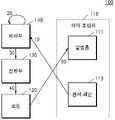
도 1은 일부 실시예에 따른 히터 조립체를 포함하는 에어로졸 생성 장치를 구성하는 요소들을 설명하기 위한 도면이다.
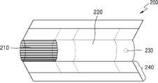
도 2는 일부 실시예에 따른 히터 조립체에 의해 가열되는 궐련을 설명하기 위한 도면이다.
도 3은 일부 실시예에 따른 궐련이 에어로졸 생성 장치에 수용되어 히터 조립체에 의해 가열되는 과정을 설명하기 위한 도면이다.
도 4는 일부 실시예에 따른 궐련을 가열하기 위한 히터 조립체를 설명하기 위한 도면이다.
도 5는 일부 실시예에 따른 에어로졸 생성 장치에서 궐련의 온도가 제어되는 과정을 설명하기 위한 도면이다.
도 6은 일부 실시예에 따른 궐련을 가열하기 위한 히터 조립체를 제조하는 방법을 구성하는 단계들을 나타내는 흐름도이다.1 is a view for explaining elements constituting an aerosol generating device including a heater assembly according to some embodiments.
2 is a view for explaining a cigarette heated by a heater assembly according to some embodiments.
3 is a view for explaining a process in which the cigarette is accommodated in the aerosol generating device according to some embodiments is heated by the heater assembly.
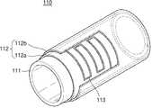
4 is a view for explaining a heater assembly for heating a cigarette according to some embodiments.
5 is a view for explaining a process of controlling the temperature of the cigarette in the aerosol generating device according to some embodiments.
6 is a flowchart illustrating steps constituting a method of manufacturing a heater assembly for heating a cigarette in accordance with some embodiments.
이하 첨부된 도면을 참조하면서 오로지 예시를 위한 실시예들을 상세히 설명하기로 한다. 아래의 설명은 실시예들을 구체화하기 위한 것일 뿐 발명의 권리 범위를 제한하거나 한정하는 것이 아님은 물론이다. 상세한 설명 및 실시예로부터 당해 기술분야의 전문가가 용이하게 유추할 수 있는 것은 권리범위에 속하는 것으로 해석된다.Hereinafter, exemplary embodiments will be described in detail with reference to the accompanying drawings. It goes without saying that the following description is only for specifying the embodiments and does not limit or limit the scope of the invention. What can be easily inferred by an expert in the art from the detailed description and examples is construed as belonging to the scope of the right.
본 명세서에서 사용되는 '구성된다' 또는 '포함한다' 등의 용어는 명세서 상에 기재된 여러 구성 요소들 또는 여러 단계들을 반드시 모두 포함하는 것으로 해석되지 않아야 하며, 그 중 일부 구성 요소들 또는 일부 단계들은 포함되지 않을 수 있고, 또는 추가적인 구성 요소들 또는 단계들이 더 포함될 수 있는 것으로 해석되어야 한다.As used herein, terms such as 'consisting of' or 'comprising' should not be construed as necessarily including all of the various components or various steps described in the specification, and some of the components or some steps are It should be construed that it may not be included, or that additional components or steps may be further included.
본 명세서에서 사용되는 '제 1' 또는 '제 2' 등과 같은 서수를 포함하는 용어는 다양한 구성 요소들을 설명하는데 사용될 수 있으나, 상기 구성 요소들은 상기 용어들에 의해 한정되지 않아야 한다. 상기 용어들은 하나의 구성 요소를 다른 구성 요소들로부터 구별하기 위한 목적으로만 사용된다.As used herein, terms including an ordinal number such as 'first' or 'second' may be used to describe various elements, but the elements should not be limited by the terms. The above terms are used only for the purpose of distinguishing one component from other components.
본 명세서에서 사용되는 용어는 본 발명에서의 기능을 고려하여 가능한 현재 널리 사용되는 일반적인 용어들로 선택되었으나, 이는 당 분야에 종사하는 기술자의 의도 또는 판례, 새로운 기술의 출현 등에 따라 달라질 수 있다. 또한, 특정한 경우 출원인이 임의로 선정한 용어도 있으며, 이 경우 해당하는 발명의 설명 부분에서 그 의미가 상세하게 기재될 것이다. 따라서, 본 발명에서 사용되는 용어는 단순한 용어의 명칭이 아닌, 그 용어가 가지는 의미와 본 발명의 전반에 걸친 내용을 토대로 정의되어야 한다.The terms used in this specification have been selected as general terms currently widely used as possible in consideration of the functions in the present invention, which may vary depending on the intention or precedent of a person skilled in the art, the emergence of new technology, and the like. In addition, in certain cases, there are also terms arbitrarily selected by the applicant, and in this case, the meaning will be described in detail in the description of the corresponding invention. Therefore, the terms used in the present invention should be defined based on the meaning of the term and the overall content of the present invention, rather than the simple name of the term.
본 실시예들은 히터 조립체, 히터 조립체를 제조하는 방법 및 히터 조립체를 포함하는 에어로졸 생성 장치에 관한 것으로서 이하의 실시예들이 속하는 기술 분야에서 통상의 지식을 가진 자에게 널리 알려져 있는 사항들에 관해서는 자세한 설명을 생략한다.The present embodiments relate to a heater assembly, a method for manufacturing a heater assembly, and an aerosol generating device including the heater assembly. Details of matters widely known to those of ordinary skill in the art to which the following embodiments belong A description is omitted.
도 1은 일부 실시예에 따른 히터 조립체를 포함하는 에어로졸 생성 장치를 구성하는 요소들을 설명하기 위한 도면이다.1 is a view for explaining elements constituting an aerosol generating device including a heater assembly according to some embodiments.
도 1을 참조하면, 에어로졸 생성 장치(100)는 히터 조립체(110), 코일(120), 전원부(130) 및 제어부(140)를 포함할 수 있다. 다만 이에 제한되는 것은 아니고, 도 1에 도시되는 요소들 외에 다른 범용적인 요소들이 에어로졸 생성 장치(100)에 더 포함될 수 있다.Referring to FIG. 1 , the
에어로졸 생성 장치(100)는 유도 가열(induction heating) 방식으로 에어로졸 생성 장치(100)에 수용되는 궐련을 가열함으로써 에어로졸을 생성할 수 있다. 유도 가열 방식은 외부 자기장에 의해 발열하는 자성체에 주기적으로 방향이 변하는 교번 자기장(alternating magnetic field)을 인가하여 자성체를 발열시키는 방식을 의미할 수 있다.The
자성체에 교번 자기장이 인가되는 경우, 자성체에는 와류손(eddy current loss) 및 히스테리시스손(hysteresis loss)에 따른 에너지 손실이 발생할 수 있고, 손실되는 에너지가 열에너지로서 자성체로부터 방출될 수 있다. 자성체에 인가되는 교번 자기장의 진폭 또는 주파수가 클수록 자성체로부터 많은 열에너지가 방출될 수 있다. 에어로졸 생성 장치(100)는 자성체에 교번 자기장을 인가함으로써 자성체로부터 열에너지를 방출시킬 수 있고, 자성체로부터 방출되는 열에너지를 궐련에 전달할 수 있다.When an alternating magnetic field is applied to the magnetic material, energy loss due to eddy current loss and hysteresis loss may occur in the magnetic material, and the lost energy may be emitted from the magnetic material as thermal energy. As the amplitude or frequency of the alternating magnetic field applied to the magnetic material increases, more thermal energy may be emitted from the magnetic material. The
외부 자기장에 의해 발열하는 자성체는 서셉터(susceptor)일 수 있다. 서셉터는 조각, 박편 또는 스트립 등의 형상으로 궐련 내부에 포함되는 대신, 에어로졸 생성 장치(100)에 구비될 수 있다. 예를 들면, 에어로졸 생성 장치(100)의 내부에 배치되는 히터 조립체(110)의 적어도 일부가 서셉터 물질로 형성될 수 있다.A magnetic material that generates heat by an external magnetic field may be a susceptor. The susceptor may be provided in the
서셉터 물질의 적어도 일부는 강자성체(ferromagnetic substance)로 형성될 수 있다. 예를 들면, 서셉터 물질은 금속 또는 탄소를 포함할 수 있다. 서셉터 물질은 페라이트(ferrite), 강자성 합금(ferromagnetic alloy), 스테인리스강(stainless steel) 및 알루미늄(Al) 중 적어도 하나를 포함할 수 있다. 또한, 서셉터 물질은 흑연(graphite), 몰리브덴(molybdenum), 실리콘 카바이드(silicon carbide), 니오븀(niobium), 니켈 합금(nickel alloy), 금속 필름(metal film), 지르코니아(zirconia) 등과 같은 세라믹, 니켈(Ni)이나 코발트(Co) 등과 같은 전이 금속, 붕소(B)나 인(P)과 같은 준금속 중 적어도 하나를 포함할 수도 있다.At least a portion of the susceptor material may be formed of a ferromagnetic substance. For example, the susceptor material may include a metal or carbon. The susceptor material may include at least one of ferrite, a ferromagnetic alloy, stainless steel, and aluminum (Al). In addition, the susceptor material is graphite, molybdenum (molybdenum), silicon carbide (silicon carbide), niobium (niobium), nickel alloy (nickel alloy), a metal film (metal film), ceramics such as zirconia (zirconia), At least one of a transition metal such as nickel (Ni) or cobalt (Co) and a metalloid such as boron (B) or phosphorus (P) may be included.
에어로졸 생성 장치(100)는 궐련을 수용할 수 있다. 에어로졸 생성 장치(100)에는 궐련을 수용하기 위한 공간이 형성될 수 있다. 궐련을 수용하기 위한 공간에는 히터 조립체(110)가 배치될 수 있다. 히터 조립체(110)는 내부에 궐련을 수용하기 위한 수용공간이 형성되는 원통 형상을 가질 수 있다. 따라서, 궐련이 에어로졸 생성 장치(100)에 수용되는 경우 궐련은 히터 조립체(110)의 수용공간에 수용될 수 있고, 궐련의 외측면의 적어도 일부를 둘러싸는 위치에 히터 조립체(110)가 배치될 수 있다.The
히터 조립체(110)는 에어로졸 생성 장치(100)에 수용되는 궐련의 외측면의 적어도 일부를 둘러쌀 수 있다. 예를 들면, 궐련에 포함되는 담배 매질의 위치에 대응되는 위치에서 히터 조립체(110)가 궐련의 외측면의 적어도 일부를 둘러쌀 수 있다. 그에 따라, 히터 조립체(110)로부터 궐련에 포함되는 담배 매질에 열이 보다 효율적으로 전달될 수 있다.The
히터 조립체(110)는 에어로졸 생성 장치(100)에 수용되는 궐련을 가열할 수 있다. 전술한 바와 같이, 히터 조립체(110)는 유도 가열 방식으로 궐련을 가열할 수 있다. 히터 조립체(110)는 외부 자기장에 의해 발열하는 서셉터 물질을 포함할 수 있고, 에어로졸 생성 장치(100)는 히터 조립체(110)에 교번 자기장을 인가할 수 있다.The
코일(120)이 에어로졸 생성 장치(100)에 구비될 수 있다. 코일(120)은 히터 조립체(110)에 교번 자기장을 인가할 수 있다. 에어로졸 생성 장치(100)로부터 코일(120)에 전력이 공급되는 경우 코일(120) 내부에 자기장이 형성될 수 있다. 코일(120)에 교류 전류가 인가되는 경우 코일(120) 내부에 형성되는 자기장의 방향은 지속적으로 변경될 수 있다. 히터 조립체(110)가 코일(120) 내부에 위치하여 주기적으로 방향이 변하는 교번 자기장에 노출되는 경우, 히터 조립체(110)가 발열할 수 있고, 히터 조립체(110)에 수용되는 궐련이 가열될 수 있다.A
코일(120)은 히터 조립체(110)의 외측면을 따라 권선될 수 있다. 코일(120)은 에어로졸 생성 장치(100)의 외부 하우징의 내면을 따라 권선될 수 있다. 코일(120)이 권선되어 형성되는 내부 공간에 히터 조립체(110)가 위치할 수 있고, 코일(120)에 전력이 공급되는 경우 코일(120)에 의해 생성되는 교번 자기장이 히터 조립체(110)에 인가될 수 있다.The
코일(120)은 에어로졸 생성 장치(100)의 길이 방향으로 연장될 수 있다. 코일(120)은 길이 방향을 따라 적정한 길이로 연장될 수 있다. 예를 들면, 코일(120)은 히터 조립체(110)의 길이에 대응되는 길이로 연장될 수 있고, 또는 히터 조립체(110)의 길이보다 긴 길이로 연장될 수 있다.The
코일(120)은 히터 조립체(110)에 교번 자기장을 인가하기에 적합한 위치에 배치될 수 있다. 예를 들면, 코일(120)은 히터 조립체(110)에 대응되는 위치에 배치될 수 있다. 이와 같은 코일(120)의 크기 및 배치에 의해 코일(120)의 교번 자기장이 히터 조립체(110)에 인가되는 효율이 향상될 수 있다.The
코일(120)에 의해 형성되는 교번 자기장의 진폭 또는 주파수가 변경되는 경우 히터 조립체(110)가 궐련을 가열하는 정도 또한 변경될 수 있다. 코일(120)에 의한 자기장의 진폭 또는 주파수는 코일(120)에 인가되는 전력에 의해 변경될 수 있으므로, 에어로졸 생성 장치(100)는 코일(120)에 인가되는 전력을 조정함으로써 궐련의 가열을 제어할 수 있다. 예를 들면, 에어로졸 생성 장치(100)는 코일(120)에 인가되는 교류 전류의 진폭 및 주파수를 제어할 수 있다.If the amplitude or frequency of the alternating magnetic field formed by the
하나의 예시로서, 코일(120)은 솔레노이드(solenoid)로 구현될 수 있다. 코일(120)은 에어로졸 생성 장치(100)의 외부 하우징의 내면을 따라 권선되는 솔레노이드일 수 있고, 솔레노이드의 내부 공간에 히터 조립체(110) 및 궐련이 위치할 수 있다. 솔레노이드를 구성하는 도선의 재질은 구리(Cu)일 수 있다. 다만 이에 제한되는 것은 아니고, 은(Ag), 금(Au), 알루미늄(Al), 텅스텐(W), 아연(Zn) 및 니켈(Ni) 중 어느 하나, 또는 적어도 하나를 포함하는 합금이 솔레노이드를 구성하는 도선의 재질이 될 수 있다.As an example, the
전원부(130)는 에어로졸 생성 장치(100)에 전력을 공급할 수 있다. 전원부(130)는 코일(120)에 전력을 공급할 수 있다. 전원부(130)는 에어로졸 생성 장치(100)에 직류를 공급하는 배터리 및 배터리로부터 공급되는 직류를 코일(120)에 공급되는 교류로 변환하는 변환부를 포함할 수 있다.The
배터리는 에어로졸 생성 장치(100)에 직류를 공급할 수 있다. 배터리는 리튬인산철(LiFePO4) 배터리일 수 있으나, 이에 제한되는 것은 아니다. 예를 들면, 배터리는 산화 리튬 코발트(LiCoO2) 배터리, 리튬 티탄산염 배터리 등일 수 있다.The battery may supply direct current to the
변환부는 배터리로부터 공급되는 직류에 대한 필터링을 수행하여 코일(120)에 공급되는 교류를 출력하는 저역 통과 필터(low-pass filter)를 포함할 수 있다. 변환부는 배터리로부터 공급되는 직류를 증폭하기 위한 증폭기(amplifier)를 더 포함할 수 있다. 예를 들면, 변환부는 D급 증폭기(class-D amplifier)의 부하 네트워크를 구성하는 저역 통과 필터를 통해 구현될 수 있다.The converter may include a low-pass filter that filters the DC supplied from the battery to output the AC supplied to the
제어부(140)는 코일(120)에 공급되는 전력을 제어할 수 있다. 제어부(140)는 코일(120)에 공급되는 전력이 조정되도록 전원부(130)를 제어할 수 있다. 예를 들면, 제어부(140)는 히터 조립체(110)의 온도에 기초하여 히터 조립체(110)가 궐련을 가열하는 온도를 일정하게 유지하기 위한 제어를 수행할 수 있다.The
제어부(140)는 다수의 논리 게이트들의 어레이로 구현될 수 있고, 범용적인 마이크로 프로세서와 마이크로 프로세서에서 실행될 수 있는 프로그램이 저장되는 메모리의 조합으로 구현될 수도 있다. 또한, 제어부(140)는 복수 개의 프로세싱 엘리먼트들(processing elements)로 구성될 수도 있다.The
에어로졸 생성 장치(100)에서, 히터 조립체(110)가 궐련을 가열하는 온도를 일정하게 유지하기 위해, 또는 궐련을 가열하는 온도를 특정 히팅 프로파일(heating profile)에 따라 변경시키기 위해, 히터 조립체(110)의 온도가 측정될 수 있다. 다만, 에어로졸 생성 장치(100)에는 히터 조립체(110)의 온도를 측정하기 위한 수단이 별도로 구비되지 않을 수 있고, 대신 히터 조립체(110)에 일체로서 포함되는 센서 패턴을 통해 히터 조립체(110)의 온도가 도출될 수 있다. 히터 조립체(110)에 포함되는 센서 패턴에 대한 구체적인 내용은 도 4를 통해 후술될 수 있다.In the
도 2는 일부 실시예에 따른 히터 조립체에 의해 가열되는 궐련을 설명하기 위한 도면이다.2 is a view for explaining a cigarette heated by a heater assembly according to some embodiments.
도 2를 참조하면, 궐련(200)은 담배 로드(210) 및 필터 로드(220)를 포함할 수 있다. 도 2에는 필터 로드(220)가 단일 영역으로 구성되는 것으로 도시되어 있으나, 이에 한정되는 것은 아니고, 필터 로드(220)는 복수의 세그먼트들로 구성될 수 있다. 예를 들면, 필터 로드(220)는 에어로졸을 냉각하는 제1 세그먼트 및 에어로졸에 포함되는 특정 성분을 여과하는 제2 세그먼트를 포함할 수 있다. 또한, 필터 로드(220)에는 다른 기능을 수행하는 적어도 하나의 세그먼트가 더 포함될 수도 있다.Referring to FIG. 2 , the
궐련(200)은 적어도 하나의 래퍼(240)에 의해 포장될 수 있다. 래퍼(240)에는 외부 공기가 유입되거나 내부 공기가 유출되는 적어도 하나의 구멍(hole)이 형성될 수 있다. 일 예로, 궐련(200)은 하나의 래퍼(240)에 의하여 포장될 수 있다. 다른 예로, 궐련(200)은 둘 이상의 래퍼들(240)에 의해 중첩적으로 포장될 수도 있다. 구체적으로, 제1 래퍼에 의하여 담배 로드(210)가 포장되고, 제2 래퍼에 의해 필터 로드(220)가 포장될 수 있다. 래퍼들 각각에 의해 포장되는 담배 로드(210) 및 필터 로드(220)가 결합되고, 제3 래퍼에 의하여 궐련(200) 전체가 재포장될 수 있다.The
담배 로드(210)는 에어로졸 생성 물질을 포함할 수 있다. 예를 들면, 에어로졸 생성 물질은 글리세린, 프로필렌 글리콜, 에틸렌 글리콜, 디프로필렌 글리콜, 디에틸렌 글리콜, 트리에틸렌 글리콜, 테트라에틸렌 글리콜 및 올레일 알코올 중 적어도 하나를 포함할 수 있으나, 이에 한정되지 않는다. 담배 로드(210)는 풍미제, 습윤제 및/또는 유기산(organic acid)과 같은 다른 첨가 물질을 함유할 수 있다. 담배 로드(210)에는 멘솔 또는 보습제 등의 가향액이 담배 로드(210)에 분사되어 첨가될 수 있다.
담배 로드(210)는 다양한 방식으로 제작될 수 있다. 예를 들면, 담배 로드(210)는 시트(sheet)로 제작될 수 있고, 가닥(strand)으로 제작될 수도 있다. 또는, 담배 로드(210)는 담배 시트가 잘게 잘린 각초로 제작될 수도 있다.
담배 로드(210)는 열 전도 물질에 의하여 둘러싸일 수 있다. 예를 들면, 열 전도 물질은 알루미늄 호일과 같은 금속 호일일 수 있으나, 이에 한정되는 것은 아니다. 담배 로드(210)를 둘러싸는 열 전도 물질은 담배 로드(210)에 전달되는 열을 고르게 분산시켜 담배 로드(210)에 가해지는 열 전도율을 향상시킬 수 있고, 그에 따라 담배 로드(210)로부터 생성되는 에어로졸의 풍미가 향상될 수 있다.
필터 로드(220)는 셀룰로오스 아세테이트 필터일 수 있다. 필터 로드(220)는 다양한 형상으로 형성될 수 있다. 예를 들면, 필터 로드(220)는 원통형 로드일 수 있고, 내부에 중공(hollow)을 포함하는 튜브형 로드일 수 있다. 또는, 필터 로드(220)는 내부에 공동(cavity)을 포함하는 리세스(recess) 형 로드일 수도 있다. 필터 로드(220)가 복수의 세그먼트들로 구성되는 경우, 복수의 세그먼트들은 서로 다른 형상으로 제작될 수도 있다.The
필터 로드(220)는 필터 로드(220)에서 향미가 발생하도록 제작될 수 있다. 예를 들면, 필터 로드(220)에 가향액이 분사될 수 있고, 가향액이 도포되는 별도의 섬유가 필터 로드(220)의 내부에 삽입될 수도 있다.The
필터 로드(220)에는 적어도 하나의 캡슐(230)이 포함될 수 있다. 캡슐(230)은 향미를 발생시킬 수 있고, 에어로졸을 발생시킬 수도 있다. 예를 들면, 캡슐(230)은 향료를 포함하는 액체를 피막으로 감싸는 구조로 형성될 수 있다. 캡슐(230)은 구형 또는 원통형의 형상을 가질 수 있으나, 이에 한정되는 것은 아니다.The
필터 로드(220)에 에어로졸을 냉각하는 냉각 세그먼트가 포함되는 경우, 냉각 세그먼트는 고분자 물질 또는 생분해성 고분자 물질로 제조될 수 있다. 예를 들면, 냉각 세그먼트는 순수한 폴리락트산(polylactic acid)만으로 제작될 수 있다. 또는, 냉각 세그먼트는 복수의 천공들을 포함하는 셀룰로오스 아세테이트 필터로 제작될 수 있다. 다만 이에 한정되는 것은 아니고, 냉각 세그먼트는 에어로졸을 냉각하는 구조 및 물질로 구성될 수 있다.When the
한편, 도 2를 참조하여 설명되는 궐련(200)은 하나의 예시에 불과하고, 에어로졸 생성 장치(100)에 수용되어 에어로졸을 생성할 수 있는 물품은 도 2의 궐련(200)에 제한되지 않을 수 있다. 따라서, 에어로졸을 생성할 수 있는 물품은 궐련(200)과는 상이한 다양한 구조 또는 성분을 가질 수 있다.On the other hand, the
도 3은 일부 실시예에 따른 궐련이 에어로졸 생성 장치에 수용되어 히터 조립체에 의해 가열되는 과정을 설명하기 위한 도면이다.FIG. 3 is a view for explaining a process in which a cigarette is accommodated in an aerosol generating device and heated by a heater assembly according to some embodiments.
도 3을 참조하면, 히터 조립체(110)를 포함하는 에어로졸 생성 장치(100)에 궐련(200)이 수용되는 예시가 도시되어 있다. 다만 도 3에 도시되는 에어로졸 생성 장치(100), 히터 조립체(110), 코일(120) 및 궐련(200)의 배치는 예시에 불과하고, 에어로졸 생성 장치(100)에 수용되는 궐련(200)이 히터 조립체(110) 및 코일(120)에 의해 가열되는 다른 배치 또한 가능할 수 있다. 특히, 코일(120)은 에어로졸 생성 장치(100)의 외부 하우징에 매립되는 것으로 예시되었으나, 코일(120)은 히터 조립체(110)의 외부에 위치하여 히터 조립체(110)에 자기장을 인가할 수 있는 다른 적절한 위치에 배치될 수 있다.Referring to FIG. 3 , an example in which the
에어로졸 생성 장치(100)에 궐련(200)이 수용되는 경우, 담배 로드(210)는 히터 조립체(110)에 의해 둘러싸일 수 있다. 이를 위해, 히터 조립체(110)는 담배 로드(210)에 대응되는 궐련(200)의 적어도 일부를 둘러싸도록 에어로졸 생성 장치(100) 내에 배치될 수 있다. 그와 같은 배치를 통해, 히터 조립체(110)로부터 담배 로드(210)에 열이 보다 직접적으로 전달될 수 있어, 에어로졸 생성 장치(100)의 전력 효율이 증대될 수 있다.When the
코일(120)은 히터 조립체(110)에 대응되는 크기 및 위치를 가질 수 있다. 코일(120)이 히터 조립체(110)에 대응되도록 배치됨에 따라, 코일(120)에 의해 형성되는 교번 자기장이 히터 조립체(110)에 보다 직접적으로 인가될 수 있고, 그에 따라 히터 조립체(110)가 가열되는 효율이 향상될 수 있다. 전술한 바와 같이, 히터 조립체(110) 및 담배 로드(210)의 배치 또한 상호 대응되므로, 히터 조립체(110), 코일(120) 및 담배 로드(210)의 배열에 의해 최적의 전력 효율이 달성될 수 있다.The
도 4는 일부 실시예에 따른 궐련을 가열하기 위한 히터 조립체를 설명하기 위한 도면이다.4 is a view for explaining a heater assembly for heating a cigarette according to some embodiments.
도 4를 참조하면, 히터 조립체(110)는 발열층(111), 절연층(112) 및 센서 패턴(113)을 포함할 수 있다. 다만 이에 제한되는 것은 아니고, 도 4에 도시되는 구성 요소들 외에 다른 범용적인 구성 요소들이 히터 조립체(110)에 더 포함될 수 있다.Referring to FIG. 4 , the
발열층(111)의 적어도 일부는 외부 자기장에 의해 발열하는 서셉터 물질로 형성될 수 있다. 따라서, 발열층(111)의 서셉터 물질에 코일(120)로부터 교번 자기장이 인가되는 경우, 발열층(111)의 서셉터 물질이 발열할 수 있고, 그에 따라 궐련(200)이 가열되어 에어로졸이 생성될 수 있다.At least a portion of the
발열층(111)의 서셉터 물질은 외부로부터 자기장이 인가되는 경우 발열하는 임의의 물질을 포함할 수 있다. 예를 들면, 서셉터 물질의 적어도 일부는 강자성체로 형성될 수 있다. 서셉터 물질의 적어도 일부가 강자성체로 형성되는 경우, 외부 자기장에 의해 발열층(111)으로부터 보다 많은 양의 열이 방출될 수 있다.The susceptor material of the
발열층(111)은 내부에 궐련(200)을 수용하기 위한 수용공간이 형성되는 원통 형상을 가질 수 있다. 에어로졸 생성 장치(100)에 궐련(200)이 수용되는 경우, 궐련(200)은 발열층(111)에 형성되는 수용공간에 수용될 수 있다. 수용공간에 수용되는 궐련(200)이 지지될 수 있도록, 수용공간의 단면 직경은 궐련(200)의 단면 직경과 실질적으로 동일하거나, 궐련(200)의 단면 직경보다 미소하게 클 수 있다. 한편, 원통 형상의 발열층(111)의 두께는 발열층(111)을 발열시키기 위해 요구되는 전력, 발열층(111)에 의해 궐련(200)이 가열되는 속도, 에어로졸 생성 장치(100)의 단면 직경 및 궐련(200)의 단면 직경 등을 고려하여 적절한 수치로 설정될 수 있다.The
절연층(112)은 발열층(111)의 외측면의 적어도 일부를 둘러쌀 수 있다. 절연층(112)은 발열층(111) 및 센서 패턴(113) 간의 전기적 접촉, 센서 패턴(113) 및 코일(120) 간의 전기적 접촉 등과 같이, 센서 패턴(113)과 에어로졸 생성 장치(100)의 다른 구성 요소가 전기적으로 연결되는 것을 방지할 수 있다. 이를 위해, 절연층(112)은 전기 절연체(insulator) 내지 부도체에 해당하는 물질을 포함할 수 있다.The insulating
절연층(112)은 제1 절연층(112a) 및 제2 절연층(112b)을 포함할 수 있다. 제1 절연층(112a) 및 제2 절연층(112b)에 의해 센서 패턴(113)이 매립될 수 있다. 예를 들면, 제1 절연층(112a)은 센서 패턴(113)의 내측면을 지지할 수 있고, 제2 절연층(112b)은 센서 패턴(113)의 외측면을 둘러쌀 수 있다. 제1 절연층(112a) 및 제2 절연층(112b)에 의한 매립을 통해 센서 패턴(113)이 에어로졸 생성 장치(100)의 다른 구성 요소와 접촉하는 것이 방지될 수 있다.The insulating
제1 절연층(112a) 및 제2 절연층(112b)은 서로 상이한 공정에 의해 형성될 수 있다. 예를 들면, 제1 절연층(112a)은 발열층(111)의 외측면의 적어도 일부를 둘러싸도록 발열층(111)의 외측면에 도포될 수 있고, 제1 절연층(112a) 상에 센서 패턴(113)이 인쇄된 이후에 제2 절연층(112b)이 센서 패턴(113)이 인쇄된 제1 절연층(112a) 상에 도포될 수 있다. 히터 조립체(110)의 제조 방법에 대한 구체적인 내용은 도 6을 통해 후술될 수 있다.The first insulating
절연층(112)은 글래스 프릿(glass frit) 내지 무기 산화물과 같은 재료로 형성될 수 있다. 글래스 프릿은 유리 분말 등과 같은 유리 재료를 의미할 수 있다. 무기 산화물은 실리콘(Si) 산화물, 붕소(B) 산화물, 칼슘(Ca) 산화물, 지르코늄(Zr) 산화물 및 알루미늄(Al) 산화물 중 적어도 하나를 포함할 수 있다. 절연층(112)이 글래스 프릿(glass frit) 내지 무기 산화물로 형성됨에 따라 절연층(112)이 전기 절연체 내지 부도체의 성질을 가질 수 있다.The insulating
센서 패턴(113)은 절연층(112)의 내부에 매립될 수 있고, 발열층(111)의 온도를 측정하기 위해 이용될 수 있다. 센서 패턴(113)이 절연층(112)의 내부에 매립됨에 따라 센서 패턴(113)에 의해 발열층(111)의 온도가 정확하게 측정될 수 있다. 예를 들면, 센서 패턴(113)이 에어로졸 생성 장치(100)의 다른 구성 요소와 전기적으로 연결되는 경우, 발열층(111)의 온도를 측정하기 위한 센서 패턴(113)의 특성 값으로서 센서 패턴(113)의 전기 저항 또는 양단의 전압 등이 변경될 수 있다. 따라서, 절연층(112)에 의한 매립에 의해 센서 패턴(113)의 특성 값이 부정확해지는 것이 방지될 수 있다.The
센서 패턴(113)은 발열층(111)의 온도를 측정하기 위해 활용될 수 있다. 예를 들면, 센서 패턴(113)은 발열층(111)의 온도를 도출하기 위한 저항 온도 계수(TCR, temperature coefficient of resistance)를 갖는 저항체가 인쇄되어 형성될 수 있다. 다만 이에 제한되는 것은 아니고, 센서 패턴(113)은 발열층(111)과 함께 일체로 형성되어 발열층(111)의 온도 측정에 활용될 수 있는 다른 수단으로 구현될 수도 있다.The
센서 패턴(113)이 저항체로 형성되는 경우, 발열층(111)의 온도는 센서 패턴(113)의 저항 온도 계수에 기초하여 산출될 수 있다. 저항 온도 계수를 갖는 센서 패턴(113)은 저항 온도 계수에 따른 온도와 저항값 간의 비례 관계에 기초하여, 센서 패턴(113)의 온도가 변경되면 센서 패턴(113)의 저항값도 비례하여 변경될 수 있다. 따라서, 센서 패턴(113)의 저항값이 측정되는 경우, 그에 대응되는 센서 패턴(113)의 온도가 산출될 수 있다. 결국, 센서 패턴(113)의 저항값으로부터 발열층(111)의 온도 및 발열층(111)에 의해 궐련(200)이 가열되는 온도가 도출될 수 있다. 한편, 센서 패턴(113)의 온도는 센서 패턴(113)의 저항값 외에도, 센서 패턴(113)의 저항값을 도출하기 위한 전압값 또는 전류값으로부터 결정될 수도 있다.When the
센서 패턴(113)을 형성하는 저항체의 온도는 저항체의 저항값 및 저항 온도 계수로부터 제어부(140)에 의해 실시간으로 계산될 수 있다. 또는, 제어부(140)는 저항체의 저항값 및 저항체의 온도 사이의 관계에 대해 미리 작성되는 테이블을 참조하여 센서 패턴(113) 저항체의 온도를 도출할 수도 있다.The temperature of the resistor forming the
센서 패턴(113)이 어떤 물질로 구성되는지에 따라 센서 패턴(113)에 의해 발열층(111)의 온도가 도출되는 특성이 달라질 수 있다. 센서 패턴(113)은 발열층(111)의 온도 측정에 활용될 수 있는 다양한 재료로 형성될 수 있다. 예를 들면, 센서 패턴(113)은 세라믹(ceramic), 반도체(semiconductor), 금속(metal), 카본(carbon) 및 서미스터(thermistor) 중 적어도 하나의 재료로 형성될 수 있다.Depending on what material the
센서 패턴(113)이 갖는 저항 온도 계수의 수치에 따라 센서 패턴(113)에 의해 발열층(111)의 온도가 도출되는 정확도가 달라질 수 있다. 저항 온도 계수는 온도 변화에 대한 저항값 변화의 비율을 의미할 수 있으므로, 저항 온도 계수의 수치가 클수록, 온도 변화에 따른 저항값의 변화가 커지고, 그에 따라 센서 패턴(113) 내지 발열층(111)의 온도가 더욱 세밀하게 도출될 수 있다. 따라서, 센서 패턴(113)이 높은 수치의 저항 온도 계수를 갖는 재료로 형성될 것이 요구될 수 있다.The accuracy in which the temperature of the
예를 들면, 센서 패턴(113)은 금속으로 형성될 수 있고, 센서 패턴(113)을 형성하는 금속은 은(Ag) 및 팔라듐(Pd) 중 적어도 하나를 포함할 수 있다. 은은 높은 전기 전도성을 가지며, 또한 높은 수치의 저항 온도 계수를 가질 수 있다. 따라서, 센서 패턴(113)이 은으로 형성되는 경우 발열층(111)의 온도가 도출되는 정확도가 향상될 수 있다. 한편, 팔라듐은 다양한 금속과의 합금에 이용되는 금속으로서 가벼우면서도 높은 경도를 가지므로, 은과 같이 무른 금속과의 합금을 통해 경도를 보강할 수 있다.For example, the
예시적인 수치로서, 센서 패턴(113)을 형성하는 금속은 45 내지 70 중량비의 은 및 10 내지 35 중량비의 팔라듐을 포함할 수 있다. 또는, 센서 패턴(113)을 형성하는 금속은 50 내지 55 중량비의 은 및 13 내지 33 중량비의 팔라듐을 포함할 수 있다. 또는, 센서 패턴(113)을 형성하는 금속은 65 내지 67 중량비의 은 및 10 내지 15 중량비의 팔라듐을 포함할 수 있다. 이와 같은 수치들에 따라 형성되는 센서 패턴(113)은 비교적 높은 저항 온도 계수를 가지면서도 히터 조립체(110)에 일체로 형성되기 위한 적정한 경도를 가질 수 있음이 실험적으로 확인될 수 있었다.As an exemplary value, the metal forming the
센서 패턴(113)은 다양한 패턴으로 형성될 수 있다. 센서 패턴(113)은 제1 절연층(112a)의 외측면 상에서 제1 절연층(112a)의 외측면의 길이 방향의 적어도 일부 및 원주 방향의 적어도 일부 상에 위치하도록 형성될 수 있다. 예를 들면, 센서 패턴(113)은 제1 절연층(112a)의 외측면 상에서 원주 방향을 따라 나선형으로 형성되며 길이 방향의 일부만을 따라 형성될 수 있다. 또는, 센서 패턴(113)은 제1 절연층(112a)의 외측면 상에서 길이 방향의 전부에 걸쳐 형성되고, 원주 방향으로는 일부만에 형성될 수 있다. 다만 이와 같은 예시들에 제한되는 것은 아니고, 센서 패턴(113)은 발열층(111)의 온도를 반영할 수 있는 다른 적절한 형상으로 형성될 수 있다.The
히터 조립체(110)는 센서 패턴(113)에 연결되어 센서 패턴(113)의 특성 값을 읽는 것에 이용되는 전극(미도시)를 더 포함할 수 있다. 전극은 센서 패턴(113)의 특성 값을 제어부(140)에 제공하기 위한 도선(미도시)에 연결될 수 있다. 히터 조립체(110)에 전극이 형성될 수 있으므로, 센서 패턴(113)이 절연층(112)에 매립됨에도 불구하고 센서 패턴(113)의 특성 값이 제어부(140)에 제공될 수 있다.The
센서 패턴(113)이 히터 조립체(110)에 일체로 형성됨에 따라, 히터 조립체(110) 또는 에어로졸 생성 장치(100)에 별도의 온도 센서 없이도 히터 조립체(110)의 온도가 측정될 수 있다. 따라서, 온도 센서를 별도로 구비하기 위한 공간이 요구되지 않을 수 있으므로, 에어로졸 생성 장치(100)의 설계가 단순해질 수 있고, 에어로졸 생성 장치(100)의 구성 요소들 간의 배치 관계가 보다 유연해질 수 있다. 또한, 센서 패턴(113)이 발열층(111)과 일체로 결합된다는 점에서, 발열층(111)의 온도가 센서 패턴(113)에 정확하게 반영될 수 있고, 그에 따라 히터 조립체(110)의 온도에 대한 제어가 높은 정확도를 가질 수 있다.As the
도 5는 일부 실시예에 따른 에어로졸 생성 장치에서 궐련의 온도가 제어되는 과정을 설명하기 위한 도면이다.5 is a view for explaining a process of controlling the temperature of the cigarette in the aerosol generating device according to some embodiments.
도 5를 참조하면, 에어로졸 생성 장치(100)가 히터 조립체(110)의 온도를 제어하는 과정에 대한 예시가 도시되어 있다.Referring to FIG. 5 , an example of a process in which the
단계 10에서, 제어부(140)는 센서 패턴(113)의 특성 값을 읽을 수 있다. 예를 들면, 센서 패턴(113)이 저항 온도 계수를 갖는 저항체로 형성되는 경우, 제어부(140)는 센서 패턴(113)에 전류를 인가하여 센서 패턴(113)에 형성되는 전압을 읽거나, 센서 패턴(113)에 전압을 인가하여 센서 패턴(113)에 흐르는 전압을 읽을 수 있다. 또는, 제어부(140)는 저항값 측정 수단을 구비하여 센서 패턴(113)의 저항값을 직접 읽을 수도 있다.In
단계 20에서, 제어부(140)는 센서 패턴(113)의 특성 값에 기초하여 발열층(111)의 온도를 도출할 수 있고, 발열층(111)의 온도에 기초하여 전원부(130)로부터 코일(120)에 공급되는 전력을 조정할 수 있다. 제어부(140)는 PID 제어(proportional-integral-differential control) 또는 온-오프 제어 등의 방식으로 전력을 조정할 수 있다. 예를 들면, 발열층(111)의 온도가 의도되는 온도보다 높은 경우, 제어부(140)는 코일(120)에 공급되는 전력을 감소시키거나, 코일(120)에 공급되는 전력을 차단할 수 있다.In
단계 30에서, 제어부(140)는 코일(120)에 공급되는 전력이 조정되도록 전원부(130)를 제어할 수 있다. 예를 들면, 발열층(111)의 온도가 의도되는 온도보다 높은 경우, 제어부(140)는 코일(120)에 공급되는 교류 전류의 진폭 또는 주파수가 감소하도록 전원부(130)를 제어할 수 있다.In
단계 40에서, 전원부(130)는 제어부(140)에 의해 코일(120)에 공급되는 전력을 조정할 수 있다. 예를 들면, 코일(120)에 공급되는 교류 전류의 진폭 또는 주파수가 감소하는 경우, 코일(120)에 의해 형성되는 교번 자기장의 진폭 또는 주파수가 감소할 수 있다.In
단계 50에서, 전원부(130)에 의해 코일(120)로부터 발열층(111)에 인가되는 교번 자기장이 조정될 수 있다. 예를 들면, 코일(120)에 의해 형성되는 교번 자기장의 진폭 또는 주파수가 감소하는 경우, 발열층(111)의 적어도 일부를 형성하는 서셉터 물질이 발열하는 정도가 감소할 수 있고, 그에 따라 히터 조립체(110) 및 궐련(200)의 온도가 감소할 수 있다.In
전술한 단계 10 내지 단계 50은 발열층(111)의 온도가 의도되는 온도보다 높은 경우에 대해 기술되었으나, 발열층(111)의 온도가 의도되는 온도보다 낮은 경우에도 단계 10 내지 단계 50은 대응되는 방식으로 수행될 수 있다. 에어로졸 생성 장치(100)는 단계 10 내지 단계 50을 주기적으로 반복함으로써 궐련(200)을 특정 히팅 프로파일에 따라 가열할 수 있다.Although the above-described
도 6은 일부 실시예에 따른 궐련을 가열하기 위한 히터 조립체를 제조하는 방법을 구성하는 단계들을 나타내는 흐름도이다.6 is a flowchart illustrating steps constituting a method of manufacturing a heater assembly for heating a cigarette in accordance with some embodiments.
도 6의 방법은 히터 조립체(110)를 제조하는 장치에 의해 수행될 수 있다. 통상의 기술자는 히터 조립체(110)를 제조하는 장치가 당해 기술 분야에서 히터를 제조하기 위해 일반적으로 이용되는 임의의 장치일 수 있음을 이해할 수 있다.The method of FIG. 6 may be performed by an apparatus for manufacturing the
도 6을 참조하면, 궐련(200)을 가열하기 위한 히터 조립체(110)를 제조하는 방법은 단계 610 내지 단계 630을 포함할 수 있다. 다만 이에 제한되는 것은 아니고, 도 6의 방법에 도시되는 단계들 외에 다른 범용적인 단계들이 궐련(200)을 가열하기 위한 히터 조립체(110)를 제조하는 방법에 더 포함될 수 있다.Referring to FIG. 6 , the method of manufacturing the
단계 610에서, 히터 조립체(110)를 제조하는 장치는, 적어도 일부가 외부 자기장에 의해 발열하는 서셉터 물질로 형성되는 발열층(111)을 내부에 궐련(200)을 수용하기 위한 수용공간이 형성되는 원통 형상으로 형성할 수 있다. 원통 형상으로 형성하는 과정은 다양한 방식으로 수행될 수 있다. 예를 들면, 금속을 성형하기 위한 일반적인 방식으로서 압축, 사출, 압출, 적층 또는 롤링 등의 방식이 적용될 수 있다.In
단계 620에서, 히터 조립체(110)를 제조하는 장치는, 발열층(111)의 외측면의 적어도 일부를 둘러싸는 제1 절연층(112a)을 발열층(111)의 외측면에 도포할 수 있다. 제1 절연층(112a)을 도포하는 과정은 증착, 분사, 적층 및 코팅 등과 같이 제1 절연층(112a)을 막(film)으로 형성하는 과정을 의미할 수 있다.In
단계 630에서, 히터 조립체(110)를 제조하는 장치는, 제1 절연층(112a)의 외측면에 발열층(111)의 온도를 측정하기 위해 이용되는 센서 패턴(113)을 인쇄할 수 있다. 센서 패턴(113)은 스크린 인쇄(screen printing) 내지 실크 스크린 인쇄(silk-screen printing) 방식으로 제1 절연층(112a)의 외측면 상에 형성될 수 있다.In
단계 640에서, 히터 조립체(110)를 제조하는 장치는, 센서 패턴(113)이 매립되도록 제1 절연층(112a)의 외측면에 제2 절연층(112b)을 도포할 수 있다. 전술한 바와 같이, 센서 패턴(113)이 제1 절연층(112a) 및 제2 절연층(112b)에 의해 매립됨에 따라, 센서 패턴(113)에 의해 발열층(111) 내지 히터 조립체(110)의 온도가 측정되는 정확도가 증대될 수 있고, 센서 패턴(113)이 발열층(111)과 일체로 형성될 수 있어 온도 센서 없이도 발열층(111)의 온도가 정확하게 측정될 수 있다.In
한편, 히터 조립체(110)를 제조하는 장치는, 히터 조립체(110)에 센서 패턴(113)에 연결되어 센서 패턴(113)의 특성 값을 읽는 것에 이용되는 전극을 추가적으로 형성할 수 있다. 히터 조립체(110)를 제조하는 장치가 전극을 형성하는 단계는 단계 620 및 단계 630 사이에 수행될 수 있고, 단계 630 및 단계 640 사이에 수행될 수도 있으며, 또는 단계 640 이후에 수행될 수도 있다.Meanwhile, the apparatus for manufacturing the
이상에서 실시예들에 대하여 상세하게 설명하였지만 본 발명의 권리범위는 이에 한정되는 것은 아니고 다음의 청구범위에서 정의하고 있는 본 발명의 기본 개념을 이용한 당업자의 여러 변형 및 개량 형태 또한 본 발명의 권리범위에 속한다.Although the embodiments have been described in detail above, the scope of the present invention is not limited thereto, and various modifications and improvements by those skilled in the art using the basic concept of the present invention as defined in the following claims are also included in the scope of the present invention. belongs to
100: 에어로졸 생성 장치
110: 히터 조립체
111: 발열층
112: 절연층
112a: 제1 절연층
112b: 제2 절연층
113: 센서 패턴
120: 코일
130: 전원부
140: 제어부100: aerosol generating device
110: heater assembly
111: heating layer
112: insulating layer
112a: first insulating layer
112b: second insulating layer
113: sensor pattern
120: coil
130: power unit
140: control unit
Claims (13)
Translated fromKorean적어도 일부가 외부 자기장에 의해 발열하는 서셉터(susceptor) 물질로 형성되고, 내부에 상기 궐련을 수용하기 위한 수용공간이 형성되는 원통 형상을 갖는 발열층;
상기 발열층의 외측면의 적어도 일부를 둘러싸는 절연층; 및
상기 절연층의 내부에 매립(embed)되고, 상기 발열층의 온도를 측정하기 위해 이용되는 센서 패턴을 포함하고,
상기 센서 패턴은
상기 발열층의 온도를 도출하기 위한 저항 온도 계수(TCR, temperature coefficient of resistance)를 갖는 저항체로 형성되는, 히터 조립체.A heater assembly for heating a cigarette comprising:
a heating layer, at least a portion of which is formed of a susceptor material that generates heat by an external magnetic field, and has a cylindrical shape in which an accommodating space for accommodating the cigarette is formed;
an insulating layer surrounding at least a portion of an outer surface of the heating layer; and
It is embedded in the insulating layer and includes a sensor pattern used to measure the temperature of the heating layer,
The sensor pattern is
A heater assembly formed of a resistor having a temperature coefficient of resistance (TCR) for deriving a temperature of the heating layer.
상기 센서 패턴은,
세라믹(ceramic), 반도체(semiconductor), 금속(metal), 카본(carbon) 및 서미스터(thermistor) 중 적어도 하나의 재료로 형성되는, 히터 조립체.The method of claim 1,
The sensor pattern is
A heater assembly formed of at least one material of a ceramic, a semiconductor, a metal, a carbon, and a thermistor.
상기 금속은,
은(Ag) 및 팔라듐(Pd) 중 적어도 하나를 포함하고,
상기 센서 패턴은,
45 내지 70 중량비의 상기 은 및 10 내지 35 중량비의 상기 팔라듐을 포함하는, 히터 조립체.4. The method of claim 3,
The metal is
At least one of silver (Ag) and palladium (Pd),
The sensor pattern is
A heater assembly comprising said silver in a weight ratio of 45 to 70 and palladium in a weight ratio of 10 to 35.
상기 절연층은,
상기 센서 패턴의 내측면을 지지하는 제1 절연층; 및
상기 센서 패턴의 외측면을 둘러싸는 제2 절연층을 포함하는, 히터 조립체.The method of claim 1,
The insulating layer is
a first insulating layer supporting an inner surface of the sensor pattern; and
and a second insulating layer surrounding an outer surface of the sensor pattern.
상기 절연층은,
실리콘(Si) 산화물, 붕소(B) 산화물, 칼슘(Ca) 산화물, 지르코늄(Zr) 산화물 및 알루미늄(Al) 산화물 중 적어도 하나의 재료로 형성되는, 히터 조립체.The method of claim 1,
The insulating layer is
A heater assembly formed of at least one of silicon (Si) oxide, boron (B) oxide, calcium (Ca) oxide, zirconium (Zr) oxide, and aluminum (Al) oxide.
상기 서셉터 물질은,
적어도 일부가 강자성체(ferromagnetic substance)로 형성되는, 히터 조립체.The method of claim 1,
The susceptor material is
A heater assembly, at least in part formed of a ferromagnetic substance.
상기 센서 패턴에 연결되어 상기 센서 패턴의 특성 값을 읽는 것에 이용되는 전극을 더 포함하는, 히터 조립체.The method of claim 1,
The heater assembly further comprising an electrode connected to the sensor pattern and used to read a characteristic value of the sensor pattern.
적어도 일부가 외부 자기장에 의해 발열하는 서셉터 물질로 형성되는 발열층을 내부에 상기 궐련을 수용하기 위한 수용공간이 형성되는 원통 형상으로 형성하는 단계;
상기 발열층의 외측면의 적어도 일부를 둘러싸는 제1 절연층을 상기 발열층의 외측면에 도포하는 단계;
상기 제1 절연층의 외측면에 상기 발열층의 온도를 측정하기 위해 이용되는 센서 패턴을 인쇄하는 단계; 및
상기 센서 패턴이 매립되도록 상기 제1 절연층의 외측면에 제2 절연층을 도포하는 단계를 포함하고,
상기 센서 패턴은
상기 발열층의 온도를 도출하기 위한 저항 온도 계수(TCR, temperature coefficient of resistance)를 갖는 저항체로 형성되는, 방법.A method of making a heater assembly for heating a cigarette comprising:
forming a heating layer, at least a portion of which is made of a susceptor material that generates heat by an external magnetic field, in a cylindrical shape in which an accommodating space for accommodating the cigarette is formed;
applying a first insulating layer surrounding at least a portion of the outer surface of the heating layer to the outer surface of the heating layer;
printing a sensor pattern used to measure the temperature of the heating layer on the outer surface of the first insulating layer; and
applying a second insulating layer to the outer surface of the first insulating layer so that the sensor pattern is buried;
The sensor pattern is
and a resistor having a temperature coefficient of resistance (TCR) for deriving the temperature of the heating layer.
상기 히터 조립체에 교번 자기장을 인가하는 코일;
상기 코일에 전력을 공급하는 전원부; 및
상기 코일에 공급되는 전력을 제어하는 제어부를 더 포함하는, 에어로졸 생성 장치.9. An aerosol generating device comprising the heater assembly of any one of claims 1 and 3 to 8, comprising:
a coil for applying an alternating magnetic field to the heater assembly;
a power supply unit for supplying power to the coil; and
Further comprising a control unit for controlling the power supplied to the coil, aerosol generating device.
상기 코일은,
상기 히터 조립체의 외측면을 따라 권선되어 상기 에어로졸 생성 장치의 길이 방향으로 연장되고, 상기 히터 조립체에 대응되는 위치에 배치되는, 에어로졸 생성 장치.11. The method of claim 10,
The coil is
The aerosol generating device, which is wound along the outer surface of the heater assembly, extends in the longitudinal direction of the aerosol generating device, and is disposed at a position corresponding to the heater assembly.
상기 전원부는,
상기 에어로졸 생성 장치에 직류를 공급하는 배터리; 및
상기 배터리로부터 공급되는 직류를 상기 코일에 인가되는 교류로 변환하는 변환부를 포함하는, 에어로졸 생성 장치.11. The method of claim 10,
The power supply unit,
a battery for supplying direct current to the aerosol generating device; and
An aerosol generating device comprising a converter for converting the direct current supplied from the battery into the alternating current applied to the coil.
상기 제어부는,
상기 센서 패턴으로부터 상기 발열층의 온도와 연관되는 상기 센서 패턴의 특성 값을 수신하고,
상기 발열층의 온도에 기초하여 상기 전원부로부터 상기 코일에 공급되는 전력을 조정하는, 에어로졸 생성 장치.11. The method of claim 10,
The control unit is
receiving a characteristic value of the sensor pattern associated with the temperature of the heating layer from the sensor pattern;
Adjusting the power supplied to the coil from the power supply unit based on the temperature of the heating layer, an aerosol generating device.
Priority Applications (7)
| Application Number | Priority Date | Filing Date | Title |
|---|---|---|---|
| KR1020190089213AKR102413550B1 (en) | 2019-07-23 | 2019-07-23 | Heater assembly, method for manufacturing heater assembly and aerosol generating device including heater assembly |
| JP2020551315AJP7359509B2 (en) | 2019-07-23 | 2020-07-17 | Heater assembly, method of manufacturing the heater assembly, and aerosol generation device including the heater assembly |
| PCT/KR2020/009413WO2021015496A1 (en) | 2019-07-23 | 2020-07-17 | Heater assembly, method for manufacturing heater assembly, and aerosol generating device including heater assembly |
| CN202080005689.0ACN112888327B (en) | 2019-07-23 | 2020-07-17 | Aerosol generating device and method of manufacturing the same |
| EP20785664.2AEP3818852A4 (en) | 2019-07-23 | 2020-07-17 | Heater assembly, method for manufacturing heater assembly, and aerosol generating device including heater assembly |
| US17/266,001US12022879B2 (en) | 2019-07-23 | 2020-07-17 | Heater assembly, method of manufacturing heater assembly, and aerosol generating device including heater assembly |
| JP2022181098AJP2023015276A (en) | 2019-07-23 | 2022-11-11 | Heater assembly, method for manufacturing heater assembly, and aerosol generating apparatus including heater assembly |
Applications Claiming Priority (1)
| Application Number | Priority Date | Filing Date | Title |
|---|---|---|---|
| KR1020190089213AKR102413550B1 (en) | 2019-07-23 | 2019-07-23 | Heater assembly, method for manufacturing heater assembly and aerosol generating device including heater assembly |
Publications (2)
| Publication Number | Publication Date |
|---|---|
| KR20210011830A KR20210011830A (en) | 2021-02-02 |
| KR102413550B1true KR102413550B1 (en) | 2022-06-27 |
Family
ID=74194040
Family Applications (1)
| Application Number | Title | Priority Date | Filing Date |
|---|---|---|---|
| KR1020190089213AActiveKR102413550B1 (en) | 2019-07-23 | 2019-07-23 | Heater assembly, method for manufacturing heater assembly and aerosol generating device including heater assembly |
Country Status (6)
| Country | Link |
|---|---|
| US (1) | US12022879B2 (en) |
| EP (1) | EP3818852A4 (en) |
| JP (2) | JP7359509B2 (en) |
| KR (1) | KR102413550B1 (en) |
| CN (1) | CN112888327B (en) |
| WO (1) | WO2021015496A1 (en) |
Families Citing this family (15)
| Publication number | Priority date | Publication date | Assignee | Title |
|---|---|---|---|---|
| CN112773000A (en)* | 2021-02-07 | 2021-05-11 | 深圳市吉迩科技有限公司 | Heating assembly for eddy heating and aerosol generating device |
| KR102637957B1 (en)* | 2021-04-16 | 2024-02-19 | 주식회사 이엠텍 | Heat source movement detection structure of portable heating equipment |
| CN113455712A (en)* | 2021-06-21 | 2021-10-01 | 深圳麦时科技有限公司 | Heating element assembly and aerosol generating device |
| KR102702978B1 (en)* | 2021-08-27 | 2024-09-05 | 주식회사 케이티앤지 | Aerosol generating device |
| CN113699830B (en)* | 2021-09-30 | 2023-10-24 | 湖北中烟工业有限责任公司 | Multi-layer cigarette paper for electromagnetic induction |
| CN114096026A (en)* | 2021-11-16 | 2022-02-25 | 长安大学 | an aerosol generating system |
| CN114052298B (en)* | 2021-11-26 | 2025-09-05 | 深圳麦时科技有限公司 | Heating assembly and aerosol generating device |
| GB202119029D0 (en)* | 2021-12-24 | 2022-02-09 | Nicoventures Trading Ltd | Method of manufacturing or assembling an aerosol generator |
| CN114521677A (en)* | 2022-03-17 | 2022-05-24 | 湖北中烟工业有限责任公司 | Polar plate interval adjusting structure and method for body heating non-combustion smoking set |
| CN114568761A (en)* | 2022-03-28 | 2022-06-03 | 惠州市沛格斯科技有限公司 | Electron cigarette heater and electron cigarette |
| KR102706698B1 (en)* | 2022-04-28 | 2024-09-19 | 주식회사 이노아이티 | Induction heating aerosol generator |
| CN115606866A (en)* | 2022-09-16 | 2023-01-17 | 深圳麦时科技有限公司 | Heating element and aerosol-generating device |
| CN115553507B (en)* | 2022-10-25 | 2025-07-25 | 四川三联新材料有限公司 | Airflow heating assembly and aerosol generating device |
| EP4415573A4 (en)* | 2022-12-30 | 2024-10-16 | KT&G Corporation | AEROSOL GENERATING DEVICE, AEROSOL GENERATING SYSTEM THEREOF AND METHOD FOR PRODUCING AN AEROSOL GENERATING DEVICE |
| CN120265166A (en)* | 2023-01-02 | 2025-07-04 | 韩国烟草人参公社 | Heater assembly for aerosol generating device and aerosol generating device including the same |
Citations (4)
| Publication number | Priority date | Publication date | Assignee | Title |
|---|---|---|---|---|
| JP2018529324A (en) | 2015-08-31 | 2018-10-11 | ブリティッシュ アメリカン タバコ (インヴェストメンツ) リミテッドBritish American Tobacco (Investments) Limited | Device for heating smoking material |
| WO2019030364A1 (en) | 2017-08-09 | 2019-02-14 | Philip Morris Products S.A. | Aerosol-generating device having an elastic susceptor |
| KR101989855B1 (en)* | 2017-04-18 | 2019-06-17 | 주식회사 아모센스 | heater for electronic cigarette |
| US20190230987A1 (en) | 2018-01-31 | 2019-08-01 | Shenzhen First Union Technology Co., Ltd. | Heating device and smoking set having same |
Family Cites Families (29)
| Publication number | Priority date | Publication date | Assignee | Title |
|---|---|---|---|---|
| EP2316286A1 (en)* | 2009-10-29 | 2011-05-04 | Philip Morris Products S.A. | An electrically heated smoking system with improved heater |
| GB2513637A (en)* | 2013-05-02 | 2014-11-05 | Nicoventures Holdings Ltd | Electronic cigarette |
| US9888719B2 (en)* | 2014-02-28 | 2018-02-13 | Altria Client Services Llc | Electronic vaping device and components thereof |
| GB201501429D0 (en)* | 2015-01-28 | 2015-03-11 | British American Tobacco Co | Apparatus for heating aerosol generating material |
| KR20170006253A (en)* | 2015-07-07 | 2017-01-17 | 주식회사 케이티앤지 | Electronic cigarette |
| PL3337342T3 (en) | 2015-08-17 | 2019-12-31 | Philip Morris Products S.A. | Aerosol-generating system and aerosol-generating article for use in such a system |
| US20170055575A1 (en)* | 2015-08-31 | 2017-03-02 | British American Tobacco (Investments) Limited | Material for use with apparatus for heating smokable material |
| US20170055584A1 (en)* | 2015-08-31 | 2017-03-02 | British American Tobacco (Investments) Limited | Article for use with apparatus for heating smokable material |
| US20170119046A1 (en)* | 2015-10-30 | 2017-05-04 | British American Tobacco (Investments) Limited | Apparatus for Heating Smokable Material |
| JP2017117525A (en) | 2015-12-21 | 2017-06-29 | 京セラ株式会社 | heater |
| US10757976B2 (en)* | 2016-02-12 | 2020-09-01 | Altria Client Services Llc | Aerosol-generating system with puff detector |
| MX2018009446A (en)* | 2016-02-12 | 2018-09-21 | Philip Morris Products Sa | Aerosol-generating system with puff detector. |
| CN109152894B (en)* | 2016-05-31 | 2021-11-23 | 菲利普莫里斯生产公司 | Aerosol-generating device with multiple heaters |
| UA126668C2 (en)* | 2016-10-19 | 2023-01-11 | Брітіш Амерікан Тобакко (Інвестментс) Лімітед | INDUCTION HEATING DEVICE |
| WO2018135888A1 (en)* | 2017-01-18 | 2018-07-26 | 주식회사 케이티앤지 | Aerosol generating device, method for controlling same, and charging system including same |
| WO2018194291A2 (en)* | 2017-04-18 | 2018-10-25 | 주식회사 아모센스 | Heater for cigarette-type electronic cigarette device |
| KR20190049391A (en)* | 2017-10-30 | 2019-05-09 | 주식회사 케이티앤지 | Aerosol generating apparatus having heater |
| GB201716735D0 (en)* | 2017-10-12 | 2017-11-29 | British American Tobacco Investments Ltd | Aerosol provision systems |
| US11700884B2 (en) | 2017-10-30 | 2023-07-18 | Kt&G Corporation | Aerosol generation device and heater for aerosol generation device |
| KR102141648B1 (en)* | 2017-10-30 | 2020-08-05 | 주식회사 케이티앤지 | An apparatus for generating aerosols and a method for controlling the apparatus |
| US11272741B2 (en)* | 2018-01-03 | 2022-03-15 | Cqens Technologies Inc. | Heat-not-burn device and method |
| US10750787B2 (en)* | 2018-01-03 | 2020-08-25 | Cqens Technologies Inc. | Heat-not-burn device and method |
| US11191298B2 (en)* | 2018-06-22 | 2021-12-07 | Rai Strategic Holdings, Inc. | Aerosol source member having combined susceptor and aerosol precursor material |
| US11753750B2 (en)* | 2018-11-20 | 2023-09-12 | R.J. Reynolds Tobacco Company | Conductive aerosol generating composite substrate for aerosol source member |
| US12336565B2 (en)* | 2019-01-24 | 2025-06-24 | Inno-It Co., Ltd. | Liquid cartridge that can be inserted into electrically heated smoking article, electrically heated smoking article including the same, and aerosol generating device and system therefor |
| US20200237018A1 (en)* | 2019-01-29 | 2020-07-30 | Rai Strategic Holdings, Inc. | Susceptor arrangement for induction-heated aerosol delivery device |
| US11324249B2 (en)* | 2019-03-06 | 2022-05-10 | R.J. Reynolds Tobacco Company | Aerosol delivery device with nanocellulose substrate |
| KR102360135B1 (en) | 2019-08-08 | 2022-02-08 | 주식회사 케이티앤지 | Aerosol generating system |
| US20230189404A1 (en)* | 2021-12-14 | 2023-06-15 | Inno-It Co., Ltd. | Surface Heating Heater Pipe and Aerosol Generating Device Including the Same |
- 2019
- 2019-07-23KRKR1020190089213Apatent/KR102413550B1/enactiveActive
- 2020
- 2020-07-17USUS17/266,001patent/US12022879B2/enactiveActive
- 2020-07-17EPEP20785664.2Apatent/EP3818852A4/enactivePending
- 2020-07-17CNCN202080005689.0Apatent/CN112888327B/enactiveActive
- 2020-07-17WOPCT/KR2020/009413patent/WO2021015496A1/ennot_activeCeased
- 2020-07-17JPJP2020551315Apatent/JP7359509B2/enactiveActive
- 2022
- 2022-11-11JPJP2022181098Apatent/JP2023015276A/ennot_activeAbandoned
Patent Citations (4)
| Publication number | Priority date | Publication date | Assignee | Title |
|---|---|---|---|---|
| JP2018529324A (en) | 2015-08-31 | 2018-10-11 | ブリティッシュ アメリカン タバコ (インヴェストメンツ) リミテッドBritish American Tobacco (Investments) Limited | Device for heating smoking material |
| KR101989855B1 (en)* | 2017-04-18 | 2019-06-17 | 주식회사 아모센스 | heater for electronic cigarette |
| WO2019030364A1 (en) | 2017-08-09 | 2019-02-14 | Philip Morris Products S.A. | Aerosol-generating device having an elastic susceptor |
| US20190230987A1 (en) | 2018-01-31 | 2019-08-01 | Shenzhen First Union Technology Co., Ltd. | Heating device and smoking set having same |
Also Published As
| Publication number | Publication date |
|---|---|
| KR20210011830A (en) | 2021-02-02 |
| WO2021015496A1 (en) | 2021-01-28 |
| US12022879B2 (en) | 2024-07-02 |
| CN112888327B (en) | 2024-04-23 |
| CN112888327A (en) | 2021-06-01 |
| EP3818852A1 (en) | 2021-05-12 |
| US20210161212A1 (en) | 2021-06-03 |
| JP2023015276A (en) | 2023-01-31 |
| JP7359509B2 (en) | 2023-10-11 |
| JP2021532727A (en) | 2021-12-02 |
| EP3818852A4 (en) | 2022-01-19 |
Similar Documents
| Publication | Publication Date | Title |
|---|---|---|
| KR102413550B1 (en) | Heater assembly, method for manufacturing heater assembly and aerosol generating device including heater assembly | |
| KR102342331B1 (en) | heater assembly for heating cigarette and aerosol generating device including thereof | |
| EP3855954B1 (en) | Inductively heatable aerosol-generating article comprising an aerosol-forming substrate and a susceptor assembly | |
| JP7307157B2 (en) | AEROSOL GENERATOR AND AEROSOL GENERATING SYSTEM INCLUDING THE SAME | |
| EP3855953B1 (en) | Heating assembly and method for inductively heating an aerosol-forming substrate | |
| KR102408932B1 (en) | Aerosol generating device and aerosol generating system | |
| JP7125201B2 (en) | AEROSOL GENERATOR, AEROSOL GENERATING SYSTEM AND METHOD FOR MANUFACTURING AEROSOL GENERATING DEVICE | |
| EP3855960B1 (en) | Susceptor assembly for inductively heating an aerosol-forming substrate | |
| TWI797454B (en) | Aerosol generating device including inductive coil | |
| KR102509093B1 (en) | Aerosol generating device and aerosol generating system | |
| JP7477619B2 (en) | Aerosol generating device and aerosol generating system | |
| CA3095322C (en) | Aerosol generating device including induction coil | |
| KR102544200B1 (en) | Heater assembly and aerosol generating device including the same | |
| RU2776506C1 (en) | Heating unit for heating a cigarette and aerosol generating apparatus containing such unit | |
| RU2835123C2 (en) | Heater assembly and containing it aerosol-generating device | |
| RU2816299C1 (en) | Heater assembly and aerosol-generating device containing thereof | |
| KR102775093B1 (en) | Aerosol generating device | |
| CN114502017A (en) | Heater assembly and aerosol-generating device comprising same |
Legal Events
| Date | Code | Title | Description |
|---|---|---|---|
| PA0109 | Patent application | Patent event code:PA01091R01D Comment text:Patent Application Patent event date:20190723 | |
| PA0201 | Request for examination | Patent event code:PA02012R01D Patent event date:20191029 Comment text:Request for Examination of Application Patent event code:PA02011R01I Patent event date:20190723 Comment text:Patent Application | |
| PG1501 | Laying open of application | ||
| E902 | Notification of reason for refusal | ||
| PE0902 | Notice of grounds for rejection | Comment text:Notification of reason for refusal Patent event date:20210224 Patent event code:PE09021S01D | |
| E902 | Notification of reason for refusal | ||
| PE0902 | Notice of grounds for rejection | Comment text:Notification of reason for refusal Patent event date:20210831 Patent event code:PE09021S01D | |
| E701 | Decision to grant or registration of patent right | ||
| PE0701 | Decision of registration | Patent event code:PE07011S01D Comment text:Decision to Grant Registration Patent event date:20220328 | |
| GRNT | Written decision to grant | ||
| PR0701 | Registration of establishment | Comment text:Registration of Establishment Patent event date:20220622 Patent event code:PR07011E01D | |
| PR1002 | Payment of registration fee | Payment date:20220623 End annual number:3 Start annual number:1 | |
| PG1601 | Publication of registration |