KR102405823B1 - Disposable electronic cigarette - Google Patents
Disposable electronic cigaretteDownload PDFInfo
- Publication number
- KR102405823B1 KR102405823B1KR1020200060079AKR20200060079AKR102405823B1KR 102405823 B1KR102405823 B1KR 102405823B1KR 1020200060079 AKR1020200060079 AKR 1020200060079AKR 20200060079 AKR20200060079 AKR 20200060079AKR 102405823 B1KR102405823 B1KR 102405823B1
- Authority
- KR
- South Korea
- Prior art keywords
- free
- guide tube
- smoke
- liquid
- case
- Prior art date
- Legal status (The legal status is an assumption and is not a legal conclusion. Google has not performed a legal analysis and makes no representation as to the accuracy of the status listed.)
- Active
Links
- 239000003571electronic cigaretteSubstances0.000titleclaimsabstractdescription50
- 239000007788liquidSubstances0.000claimsabstractdescription81
- 238000010438heat treatmentMethods0.000claimsabstractdescription49
- 238000003860storageMethods0.000claimsabstractdescription31
- 239000007791liquid phaseSubstances0.000claimsabstractdescription13
- 239000011248coating agentSubstances0.000claimsabstractdescription5
- 238000000576coating methodMethods0.000claimsabstractdescription5
- 238000000034methodMethods0.000claimsdescription10
- 238000012546transferMethods0.000claimsdescription6
- 238000005192partitionMethods0.000claimsdescription2
- 230000000391smoking effectEffects0.000abstractdescription21
- 239000000779smokeSubstances0.000abstractdescription7
- 230000000694effectsEffects0.000abstractdescription5
- 230000000149penetrating effectEffects0.000abstractdescription2
- 230000029058respiratory gaseous exchangeEffects0.000abstract1
- 239000003570airSubstances0.000description23
- 230000008878couplingEffects0.000description22
- 238000010168coupling processMethods0.000description22
- 238000005859coupling reactionMethods0.000description22
- 235000019504cigarettesNutrition0.000description15
- 230000002093peripheral effectEffects0.000description6
- 239000000835fiberSubstances0.000description5
- 230000004044responseEffects0.000description5
- 238000004519manufacturing processMethods0.000description4
- PXHVJJICTQNCMI-UHFFFAOYSA-NNickelChemical compound[Ni]PXHVJJICTQNCMI-UHFFFAOYSA-N0.000description2
- 241000208125NicotianaSpecies0.000description2
- 235000002637Nicotiana tabacumNutrition0.000description2
- 239000011532electronic conductorSubstances0.000description2
- 230000035515penetrationEffects0.000description2
- 241000196324EmbryophytaSpecies0.000description1
- 241000208292SolanaceaeSpecies0.000description1
- 239000012080ambient airSubstances0.000description1
- 230000037237body shapeEffects0.000description1
- 238000002485combustion reactionMethods0.000description1
- 239000004020conductorSubstances0.000description1
- 238000012217deletionMethods0.000description1
- 230000037430deletionEffects0.000description1
- 238000013461designMethods0.000description1
- 238000005516engineering processMethods0.000description1
- 239000002657fibrous materialSubstances0.000description1
- 239000006260foamSubstances0.000description1
- 235000008216herbsNutrition0.000description1
- 238000003780insertionMethods0.000description1
- 230000037431insertionEffects0.000description1
- 230000001788irregularEffects0.000description1
- 238000005461lubricationMethods0.000description1
- 239000000463materialSubstances0.000description1
- 229910052759nickelInorganic materials0.000description1
- 230000002265preventionEffects0.000description1
- 238000004088simulationMethods0.000description1
- 230000009469supplementationEffects0.000description1
Images


Classifications
- A—HUMAN NECESSITIES
- A24—TOBACCO; CIGARS; CIGARETTES; SIMULATED SMOKING DEVICES; SMOKERS' REQUISITES
- A24F—SMOKERS' REQUISITES; MATCH BOXES; SIMULATED SMOKING DEVICES
- A24F40/00—Electrically operated smoking devices; Component parts thereof; Manufacture thereof; Maintenance or testing thereof; Charging means specially adapted therefor
- A24F40/40—Constructional details, e.g. connection of cartridges and battery parts
- A—HUMAN NECESSITIES
- A24—TOBACCO; CIGARS; CIGARETTES; SIMULATED SMOKING DEVICES; SMOKERS' REQUISITES
- A24F—SMOKERS' REQUISITES; MATCH BOXES; SIMULATED SMOKING DEVICES
- A24F40/00—Electrically operated smoking devices; Component parts thereof; Manufacture thereof; Maintenance or testing thereof; Charging means specially adapted therefor
- A24F40/10—Devices using liquid inhalable precursors
- A—HUMAN NECESSITIES
- A24—TOBACCO; CIGARS; CIGARETTES; SIMULATED SMOKING DEVICES; SMOKERS' REQUISITES
- A24F—SMOKERS' REQUISITES; MATCH BOXES; SIMULATED SMOKING DEVICES
- A24F40/00—Electrically operated smoking devices; Component parts thereof; Manufacture thereof; Maintenance or testing thereof; Charging means specially adapted therefor
- A24F40/40—Constructional details, e.g. connection of cartridges and battery parts
- A24F40/42—Cartridges or containers for inhalable precursors
- A—HUMAN NECESSITIES
- A24—TOBACCO; CIGARS; CIGARETTES; SIMULATED SMOKING DEVICES; SMOKERS' REQUISITES
- A24F—SMOKERS' REQUISITES; MATCH BOXES; SIMULATED SMOKING DEVICES
- A24F40/00—Electrically operated smoking devices; Component parts thereof; Manufacture thereof; Maintenance or testing thereof; Charging means specially adapted therefor
- A24F40/40—Constructional details, e.g. connection of cartridges and battery parts
- A24F40/44—Wicks
- A—HUMAN NECESSITIES
- A24—TOBACCO; CIGARS; CIGARETTES; SIMULATED SMOKING DEVICES; SMOKERS' REQUISITES
- A24F—SMOKERS' REQUISITES; MATCH BOXES; SIMULATED SMOKING DEVICES
- A24F40/00—Electrically operated smoking devices; Component parts thereof; Manufacture thereof; Maintenance or testing thereof; Charging means specially adapted therefor
- A24F40/40—Constructional details, e.g. connection of cartridges and battery parts
- A24F40/48—Fluid transfer means, e.g. pumps
- A—HUMAN NECESSITIES
- A24—TOBACCO; CIGARS; CIGARETTES; SIMULATED SMOKING DEVICES; SMOKERS' REQUISITES
- A24F—SMOKERS' REQUISITES; MATCH BOXES; SIMULATED SMOKING DEVICES
- A24F40/00—Electrically operated smoking devices; Component parts thereof; Manufacture thereof; Maintenance or testing thereof; Charging means specially adapted therefor
- A24F40/50—Control or monitoring
- A24F40/51—Arrangement of sensors
Landscapes
- Battery Mounting, Suspending (AREA)
Abstract
Translated fromKoreanDescription
Translated fromKorean본 발명은 일회용 전자담배에 관한 것으로서, 보다 상세하게는 배터리에 연결된 기류감응센서가 흡입되는 기류에 반응하여 배터리를 작동시키고 이에 따라 상기 배터리에 연결된 제1, 2전선을 통해 액상흡인체의 액상을 가열하여 무연을 형성시킬 수 있도록 하는 일회용 전자담배에 관한 것이다.The present invention relates to a disposable electronic cigarette, and more particularly, an airflow sensor connected to a battery operates a battery in response to an airflow being sucked in, and thus the liquid phase of the liquid suction body is discharged through the first and second wires connected to the battery. It relates to a disposable e-cigarette that can be heated to form smokeless.
일반적으로, 담배는 쌍떡잎 식물목 가지과의 여러해 살이풀을 말하지만 최근에는 상기 담배의 잎을 궐련지로 싸고 일측에 필터부가 구성되어 흡연을 목적으로 제조된 제품을 통칭하기도 한다.In general, tobacco refers to perennial herbs of the Solanaceae family of dicotyledonous plants, but recently, the tobacco leaves are wrapped in cigarette paper and a filter unit is configured on one side to collectively refer to products manufactured for the purpose of smoking.
이러한 담배는 전 세계적으로 수천 종에 이르며, 모양이나 형태로 다양하게 출시되고 있다.There are thousands of these cigarettes worldwide, and they come in a variety of shapes and forms.
한편, 최근에는 일반적인 연소가 아닌 전자 가열을 통해 주위의 공기를 빨아들여서 흡연자가 흡입할 수 있도록 하여 흡연이 이루어지도록 하는 전자담배가 다양하게 제시되어 일반담배의 대용으로 널리 이용되고 있다.Meanwhile, in recent years, various electronic cigarettes have been proposed and widely used as a substitute for regular cigarettes by sucking ambient air through electronic heating rather than general combustion so that smokers can inhale so that they can smoke.
이와 같은, 전자담배는 일종의 전자 시뮬레이션 제품으로써, 주로 담배기름(액상)과 무화기와 배터리 등을 포함한다.As such, the electronic cigarette is a kind of electronic simulation product, and mainly includes cigarette oil (liquid), an atomizer, and a battery.
그리고, 전자담배는 거시적으로 일반 전자담배, 일회용 카트리지 전자담배, 일회용 전자담배로 구분된다.In addition, electronic cigarettes are macroscopically classified into general electronic cigarettes, disposable cartridge electronic cigarettes, and disposable electronic cigarettes.
이 중, 일반 전자담배는 담배기름 저장부와 무화기가 분리되어 담배기름 흡입 완료 후 담배기름 저장부를 폐기하는 방식이다.Among them, the general electronic cigarette is a method of disposing of the cigarette oil storage unit after the cigarette oil storage unit and the atomizer are separated and the cigarette oil suction is completed.
그리고, 일회용 카트리지 전자담배는 담배기름 저장부와 무화기의 일체화 설계로 담배기름 흡인 완료 후 담배기름 저장부와 무화기를 같이 폐기하는 방식이다.In addition, the disposable cartridge electronic cigarette is a method in which the cigarette oil storage unit and the atomizer are disposed of together after the cigarette oil suction is completed by the integrated design of the cigarette oil storage unit and the atomizer.
여기서, 일회용 카트리지 전자담배 또는 일회용 전자담배는 일반 전자담배와 비교시 전부 일회용 전자담배 무화기 기술을 사용하고 있다.Here, the disposable cartridge electronic cigarette or disposable electronic cigarette uses all disposable electronic cigarette atomizer technology when compared to a general electronic cigarette.
그리고, 일반 전자담배의 무화기와 담배기름 저장부(기름 저장 카트리지)가 분리되어 있어 무화기는 중복 사용이 가능하나 흡연을 하고 나면 기름저장 카트리지를 교체해야 한다.In addition, since the atomizer of the general e-cigarette and the cigarette oil storage unit (oil storage cartridge) are separated, the atomizer can be used repeatedly, but the oil storage cartridge must be replaced after smoking.
한편, 이러한 종래 기술의 무화기의 일반적인 구조를 개략적으로 살펴보면 다음과 같다.On the other hand, a general structure of the atomizer of the prior art will be schematically described as follows.
일례로, 종래 기술의 무화기는 발열저항선과, 도유섬유와, 도유포말니켈로 구성된 도유시스템이 포함되고, 발열저항선은 제어스위치 및 배터리와 연결되어 중공케이스 내부에 배치된다.For example, the atomizer of the prior art includes a heating resistance wire, an oil lubrication fiber, and an oil supply system composed of an oil coating foam nickel, and the heating resistance wire is connected to a control switch and a battery and is disposed inside the hollow case.
그리고, 일회용 카트리지 전자담배의 무화기와 담배기름 저장부는 일체형 구조로써, 흡입구가 있는 드립캡, 카트리지 케이스, 기름 저장섬유, 상하로 분리된 중공관 지지대, 중간에 세로 위치한 발열 저항선, 도유섬유, 커넥터, 전자도선 등이 포함된다.In addition, the atomizer and the cigarette oil storage unit of the disposable cartridge electronic cigarette have an integrated structure, including a drip cap with a suction port, a cartridge case, an oil storage fiber, a hollow tube support separated vertically, a heat resistance wire located vertically in the middle, an oiling fiber, a connector, Electromagnetic conductors and the like are included.
그리고, 그 작동 원리는 전자담배 기름이 기름 저장섬유에 저장되고 도유섬유를 통하여 발열 저항선의 중심에 도달한다.And, the principle of operation is that the e-cigarette oil is stored in the oil storage fiber and reaches the center of the heating resistance wire through the lubricated fiber.
그러고 나서, 담배 흡입시 내부의 제어스위치가 켜지고 전자도선과 커넥터를 통하여 발열 저항선과 중공케이스 내의 배터리가 연결된다.Then, when the cigarette is inhaled, the internal control switch is turned on, and the heating resistance wire and the battery in the hollow case are connected through the electronic conductor and the connector.
그런 다음, 발열 저항선이 작동하게 되고 공기는 중공관 지지대로 진입하여 발열 저항선이 담배기름 증발시킬 때 생성되는 무연을 드립팀의 흡입구로 안내하여 흡연이 이루어 지게 된다.Then, the heating resistance wire is activated and the air enters the hollow tube support and guides the smoke-free generated when the heating resistance wire evaporates the cigarette oil to the inlet of the drip team to smoke.
여기서, 상기 커넥터는 나사산, 이어플러그 또는 요철플러그를 이용하여 담배와 연결되고 내부 배터리와 전기적으로 연결된다.Here, the connector is connected to the cigarette using a screw thread, an ear plug, or a concave-convex plug and is electrically connected to the internal battery.
그러나, 이러한 종래 기술의 전자 담배는 발열 저항선이 모두 세로 방향으로 배열되어 있고, 일단부의 전자도선은 전부 중공관 지지대를 통해 커넥터로 연결되는 세로 배치 구조로 되어 있기 때문에, 중공관 지지대 분리 방식으로 조립시 중공 통로가 중심을 맞추지 못할 경우 무연의 막힘이 발생하여 누유나 흡연시 숨이 막히게 되는 등의 문제점을 갖고 있다.However, in this prior art electronic cigarette, all of the heating resistance wires are arranged in the vertical direction, and all the electronic conductor wires at one end have a vertical arrangement structure that is connected to a connector through a hollow tube support, so the hollow tube support is assembled in a separate manner If the city hollow passage is not centered, smoke-free clogging occurs, causing problems such as leakage of oil or choking when smoking.
또한, 발열 저항선이 중공관 지지대 외부에 배치된 상태, 즉 중공관 지지대가 발열 저항선을 감싸지 않아 방출된 열로 인하여 중공케이스가 가열되는 문제점을 갖고 있었다.In addition, there was a problem in that the hollow case is heated due to the heat emitted because the heating resistance wire is disposed outside the hollow tube support, that is, the hollow tube support does not wrap the heating resistance wire.
본 발명은 이러한 문제점을 해결하기 위해서 안출된 것으로써, 배터리에 연결된 기류감응센서가 흡입되는 기류에 반응하여 배터리를 작동시키고 이에 따라 상기 배터리에 연결된 제1, 2전선을 통해 액상흡인체의 액상을 가열하여 무연을 형성시키도록 함으로써, 기본적으로 무연 생성 및 흡연에 따른 일련의 과정들이 연속하여 전자동적으로 이루어지도록 하는 일회용 전자담배를 제공하는 데 그 목적이 있다.The present invention has been devised to solve this problem, and the airflow sensor connected to the battery operates the battery in response to the sucked airflow, and thus the liquid phase of the liquid suction body is removed through the first and second wires connected to the battery. An object of the present invention is to provide a disposable e-cigarette that allows a series of processes according to smokeless generation and smoking to be continuously and fully automatic by heating to form smokeless.
또한, 액상가열부가 무연안내관체의 무연 안내 방향과 일직선 상에 배치되도록 하여 액상가열부를 통해 생성되는 무연이 원활하게 드립팁으로 안내되도록 하는 일회용 전자담배를 제공하는 데 다른 목적이 있다.Another object of the present invention is to provide a disposable electronic cigarette that allows the liquid heating unit to be disposed in a straight line with the smoke-free guide direction of the smoke-free guide tube so that smoke-free generated through the liquid heating unit is smoothly guided to the drip tip.
또한, 액상가열부가 무연안내관체의 내부에 배치된 상태로 무연을 생성시키도록 하여 액상가열부의 발열이 제1케이스로 열전달되는 것을 방지할 수 있게 하는 일회용 전자담배를 제공하는 데 또 다른 목적이 있다.Another object of the present invention is to provide a disposable electronic cigarette capable of preventing the heat of the liquid heating unit from being transferred to the first case by generating smoke-free in a state in which the liquid heating unit is disposed inside the smoke-free guide tube body. .
또한, 드립팁에 흡입완화부를 마련함으로써, 흡연시 무연안내관체를 통해 안내되는 무연이 사용자에게 급격하게 흡입되는 것을 완화시킬 수 있도록 하는 일회용 전자담배를 제공하는 데 또 다른 목적이 있다.Another object of the present invention is to provide a disposable electronic cigarette capable of alleviating abrupt inhalation of smoke-free guide body guided through a smoke-free guide tube body to a user during smoking by providing a suction relief unit in the drip tip.
이와 같은, 본 발명의 일 실시예에 따른 일회용 전자담배는, 양단이 관통된 내부공간을 가지며 상기 개방된 양단 중 어느 일단을 차폐시키고 일측에 제1접속단자 및 제1통공이 마련된 차폐판을 갖는 제1케이스; 상기 제1케이스의 차폐판 인접 내부공간에 배치되고 일측에 상기 제1통공을 통해 유입된 공기가 상기 제1케이스의 타단부 외부로 안내되도록 하는 연결관체부를 갖는 커넥터; 상기 커넥터의 연결관체부와 일단부가 연결되고 타단부가 상기 제1케이스의 타단부로 연장되는 무연안내관체; 상기 무연안내관체의 외부를 감싼 상태로 중앙부가 상기 무연안내관체의 내부로 관통 배치되고 양단부가 상기 제1접속단자와 전기적으로 연결되며 상기 내부로 관통 배치된 일측에 피복이 탈피된 상태로 노출되는 액상가열부가 마련된 제1전선; 상기 무연안내관체의 외부를 감싼 상태로 결합되고 액상이 저장되어 있는 액상저장체; 상기 액상가열부와 상기 액상저장체 사이에 개재되어 상기 액상저장체의 액상을 상기 무연안내관체의 내부에 배치되어 있는 상기 액상가열부로 흡인 전달하는 액상흡인체; 상기 제1케이스의 개방된 타단부에 장착되고 상기 무연안내관체와 연통되는 무연흡입구가 마련된 드립팁; 및 상기 제1케이스의 제1접속단자와 전기적으로 접속되는 제2접속단자 및 제2통공이 일측벽면에 마련되고 타측벽면에 외부의 공기가 유입되도록 하는 공기유입구가 형성되며 내부공간에 기류감응센서 및 배터리가 배치되고 상기 제2접속단자와 기류감응센서와 배터리를 전기적으로 연결하여 회로를 구성하는 제2전선이 마련된 제2케이스;를 포함한다.As described above, the disposable electronic cigarette according to an embodiment of the present invention has an internal space through both ends, shields any one of the open ends, and has a shielding plate provided with a first connection terminal and a first through hole on one side. first case; a connector disposed in an inner space adjacent to the shielding plate of the first case and having a connecting tube body part on one side of which air introduced through the first through hole is guided to the outside of the other end of the first case; a lead-free guide tube having one end connected to a connecting tube portion of the connector and the other end extending to the other end of the first case; In a state that wraps around the outside of the lead-free guide tube body, a central part is disposed through the inside of the lead-free guide tube body, both ends are electrically connected to the first connection terminal, and exposed in a state in which the coating is peeled off one side that is disposed through the inside A first wire provided with a liquid heating unit; a liquid storage body coupled to the outside of the lead-free guide tube and storing the liquid; a liquid suction body interposed between the liquid heating unit and the liquid storage body to suck and transfer the liquid phase of the liquid storage body to the liquid heating unit disposed inside the lead-free guide tube; a drip tip mounted on the other open end of the first case and provided with a smoke-free suction port communicating with the smoke-free guide tube body; and a second connection terminal and a second through hole electrically connected to the first connection terminal of the first case are provided on one side wall surface, and an air inlet for allowing external air to flow in is formed on the other side wall surface, and an airflow sensitive sensor is formed in the inner space and a second case in which a battery is disposed and a second wire constituting a circuit is provided by electrically connecting the second connection terminal, the airflow sensor, and the battery.
또한, 본 발명의 일 실시예에 따른 일회용 전자담배에 있어서, 상기 제1케이스는 상기 차폐판과 상기 커넥터 사이에 상기 제1통공으로부터 유입된 공기가 상기 액상가열부에 도달하기 전에 미리 예열되도록 하는 예열챔버부가 더 마련된 것일 수 있다.In addition, in the disposable electronic cigarette according to an embodiment of the present invention, the first case is configured to be preheated before the air introduced from the first through hole between the shielding plate and the connector reaches the liquid heating unit. A preheating chamber may be further provided.
또한, 본 발명의 일 실시예에 따른 일회용 전자담배에 있어서, 상기 제1전선은 상기 예열챔버부의 내부를 경유하여 상기 예열챔버부의 내부 공기를 가열할 수 있도록 된 것일 수 있다.In addition, in the disposable electronic cigarette according to an embodiment of the present invention, the first wire may be configured to heat the air inside the preheating chamber part via the inside of the preheating chamber part.
또한, 본 발명의 일 실시예에 따른 일회용 전자담배에 있어서, 상기 제1전선은 상기 예열챔버부의 내부에 배치되는 일측이 상기 예열챔버부의 내벽면에 해당되는 상기 커넥터의 내벽면을 가열하기 위해 상기 내벽면에 밀착 배치되는 내벽가열부가 더 마련된 것일 수 있다.In addition, in the disposable electronic cigarette according to an embodiment of the present invention, the first wire is configured to heat the inner wall surface of the connector whose one side disposed inside the preheating chamber portion corresponds to the inner wall surface of the preheating chamber portion. An inner wall heating unit disposed in close contact with the inner wall surface may be further provided.
또한, 본 발명의 일 실시예에 따른 일회용 전자담배에 있어서, 상기 커넥터는 상기 제1전선이 상기 커넥터의 몸체 일측을 관통하여 지나가도록 하는 관통공이 마련되고, 상기 액상저장체로부터의 액상이 상기 관통공으로 침입되는 것을 차단하기 위해 상기 관통공과 상기 액상저장체 사이에 소정간격 이격된 공간을 갖도록 하는 액상누출방지부가 더 마련된 것일 수 있다.In addition, in the disposable electronic cigarette according to an embodiment of the present invention, the connector is provided with a through hole through which the first wire passes through one side of the body of the connector, and the liquid from the liquid storage body passes through the In order to block penetration into the ball, a liquid leakage preventing unit may be further provided to have a space spaced apart by a predetermined distance between the through hole and the liquid storage body.
또한, 본 발명의 일 실시예에 따른 일회용 전자담배에 있어서, 상기 커넥터의 연결관체부는 선단부에 상기 무연안내관체의 연결을 안내하기 위한 안내경사면이 더 마련된 것일 수 있다.In addition, in the disposable electronic cigarette according to an embodiment of the present invention, a guide inclined surface for guiding the connection of the smoke-free guide tube body may be further provided at the distal end of the connector body portion of the connector.
또한, 본 발명의 일 실시예에 따른 일회용 전자담배에 있어서, 상기 커넥터는 연결관체부의 외주면의 일단으로 갈수록 외측으로 확장되는 끼움경사면이 마련되고, 이에 대응되는 상기 무연안내관체의 내주면에 상기 끼움경사면과 맞물려 끼워지도록 하는 경사밀착면이 더 마련된 것일 수 있다.In addition, in the disposable electronic cigarette according to an embodiment of the present invention, the connector is provided with a fitting inclined surface that extends outward toward one end of the outer peripheral surface of the connection tube body, and the fitting inclined surface is provided on the inner peripheral surface of the lead-free guide tube corresponding to this. It may be that an inclined contact surface to engage and fit is further provided.
또한, 본 발명의 일 실시예에 따른 일회용 전자담배에 있어서, 상기 액상흡인체는 중앙부가 상기 무연안내관체의 내부공간에 배치되고 양단부가 상기 무연안내관체의 외주부에 배치되어 있는 액상저장체와 연결되어 액상을 흡인하도록 상기 양단부가 각각 여러 갈래로 나누어진 다분산돌기구조로 된 것일 수 있다.In addition, in the disposable electronic cigarette according to an embodiment of the present invention, the liquid suction body has a central portion disposed in the inner space of the smoke-free guide tube body and both ends are connected to a liquid storage body disposed on the outer periphery of the smoke-free guide tube body It may be of a polydisperse protrusion structure in which both ends are divided into several branches so as to suck the liquid phase.
또한, 본 발명의 일 실시예에 따른 일회용 전자담배에 있어서, 상기 제1전선의 액상가열부는 상기 액상흡인체의 외주부의 길이방향을 따라 연속 권취되는 코일 구조로 된 것일 수 있다.In addition, in the disposable electronic cigarette according to an embodiment of the present invention, the liquid heating unit of the first wire may have a coil structure continuously wound along the longitudinal direction of the outer periphery of the liquid suction body.
또한, 본 발명의 일 실시예에 따른 일회용 전자담배에 있어서, 상기 제1케이스는 상기 무연안내관체와 상기 드립팁 사이에 상기 무연안내관체로부터 안내되는 무연의 흡입 속도를 완화시키기 위해 소정간격 이격 공간을 갖는 흡입완화부가 더 마련된 것일 수 있다.In addition, in the disposable electronic cigarette according to an embodiment of the present invention, the first case is spaced apart by a predetermined interval between the smoke-free guide tube and the drip tip to relieve the smoke-free suction speed guided from the smoke-free guide tube. It may be that a suction reliever having a further provided.
또한, 본 발명의 일 실시예에 따른 일회용 전자담배에 있어서, 상기 드립팁은 상기 무연흡입구의 테두리에서 상기 무연안내관체 방향으로 연장되는 격벽관체부가 마련되고, 상기 격벽관체부와 상기 드립팁의 내벽면 사이에 상기 무연안내관체로부터 안내된 무연이 분산 저장되어 있다가 차후로 흡입되는 후발 무연에 저장되어 있던 무연이 보충될 수 있도록 하는 무연보충부가 더 마련된 것일 수 있다.In addition, in the disposable electronic cigarette according to an embodiment of the present invention, the drip tip is provided with a bulkhead tube body extending from the edge of the smoke-free suction port in the direction of the smoke-free guide tube body, the partition wall tube body part and the inside of the drip tip A lead-free replenishment unit may be further provided between the wall surfaces so that the lead-free guide tube body is dispersedly stored and then the lead-free smoke stored in the subsequent lead-free suction is replenished.
상기와 같이 기술된 본 발명의 일 실시예인 일회용 전자담배는 배터리에 연결된 기류감응센서가 흡입되는 기류에 반응하여 배터리를 작동시키고 이에 따라 상기 배터리에 연결된 제1, 2전선을 통해 액상흡인체의 액상을 가열하고 무연을 형성시켜 전반적인 무연 생성 및 흡연에 따른 일련의 과정들이 연속하여 전자동적으로 이루어도록 함으로써, 기본적으로 간단한 구성요소들에 대한 제작들이 수월하게 이루어짐은 물론 이에 따른 제조비용 절감 등을 도모할 수 있게 효과를 얻을 수 있다.In the disposable electronic cigarette according to an embodiment of the present invention described as described above, the air flow sensor connected to the battery operates the battery in response to the suction air flow, and accordingly, the liquid in the liquid suction body through the first and second wires connected to the battery By heating and forming smoke-free, the series of processes according to overall smoke-free generation and smoking are continuously and fully automatic, thereby making it easy to manufacture basic simple components, as well as reducing manufacturing costs. effect can be obtained.
또한, 액상가열부가 무연안내관체의 무연 안내 방향과 일직선 상에 배치되도록 하여 액상가열부를 통해 생성되는 무연이 원활하게 드립팁으로 안내되도록 함으로써, 흡연시 무연의 막힘없이 사용자로 하여금 흡연 호흡이 부드럽게 되면서 그 결과 사용상의 편리성을 제공할 수 있게 되는 등의 효과를 얻을 수 있다.In addition, the liquid heating unit is arranged in a straight line with the smoke-free guide direction of the smoke-free guide tube so that smoke generated through the liquid heating unit is smoothly guided to the drip tip. As a result, effects such as being able to provide convenience in use can be obtained.
또한, 액상가열부가 무연안내관체의 내부에 배치된 상태로 무연을 생성시키도록 하여 액상가열부의 발열이 제1케이스로 열전달되는 것을 방지할 수 있게 함으로써, 흡연시 기존의 케이스 외형으로 전달되었던 고열에 따른 불편함을 해소할 수 있게 되며, 이에 따라 사용자에게 흡연시 안전감을 제공할 수 있게 되는 등의 효과를 얻을 수 있다.In addition, by generating smoke-free in a state in which the liquid heating unit is disposed inside the lead-free guide tube body, it is possible to prevent heat transfer of the liquid heating unit to the first case, thereby reducing the high heat transmitted to the existing case when smoking. It is possible to solve the inconvenience caused, and thus it is possible to obtain effects such as being able to provide the user with a sense of safety when smoking.
또한, 드립팁에 흡입완화부를 마련함으로써, 흡연시 무연안내관체를 통해 안내되는 무연이 사용자에게 급격하게 흡입되는 것을 완화시킬 수 있도록 함으로써, 사용자에게 안정적이고 부드러운 흡연 상태를 제공할 수 있게 되면서 이에 따른 제품 경쟁력 및 선호도 향상 등을 도모할 수 있게 되는 효과를 얻을 수 있다.In addition, by providing a suction relief unit in the drip tip, it is possible to relieve the user from abruptly inhaling smoke-free guided tube through the smoke-free guide tube during smoking, thereby providing a stable and soft smoking state to the user. It is possible to obtain the effect of improving product competitiveness and preference.
도 1은 본 발명의 일 실시예에 따른 일회용 전자담배를 나타낸 사시도이다.
도 2는 본 발명의 일 실시예에 따른 일회용 전자담배를 나타낸 분해사시도이다.
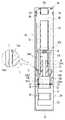
도 3은 본 발명의 일 실시예에 따른 일회용 전자담배를 나타낸 단면도이다.
도 4는 본 발명의 다른 실시예에 따른 전자담배의 결합구조를 나타낸 분해사시도이다.
도 5는 본 발명의 다른 실시예에 따른 전자담배의 결합구조 중 슬라이딩볼에 대한 작동과정을 나타낸 요부작동흐름도이다.
도 6은 본 발명의 다른 실시예에 따른 전자담배의 결합구조 중 복원스프링에 대한 작동과정을 나타낸 요부평단면이다.1 is a perspective view showing a disposable electronic cigarette according to an embodiment of the present invention.
2 is an exploded perspective view showing a disposable electronic cigarette according to an embodiment of the present invention.
3 is a cross-sectional view illustrating a disposable electronic cigarette according to an embodiment of the present invention.
4 is an exploded perspective view showing a coupling structure of an electronic cigarette according to another embodiment of the present invention.
5 is a flow chart showing the operation process of the sliding ball in the coupling structure of the electronic cigarette according to another embodiment of the present invention.
6 is a plan view showing the main part of the operation process of the restoration spring in the coupling structure of the electronic cigarette according to another embodiment of the present invention.
이하, 도 1 내지 도 3에 도시된 바와 같이, 본 발명의 일 실시예에 따른 일회용 전자담배는 제1케이스(10)와, 커넥터(11)와, 무연안내관체(12)와, 제1전선(13)과, 액상저장체(14)와, 액상흡인체(15)와, 드립팁(16)과, 제2케이스(20)를 포함하는 구성으로 되어 있다.Hereinafter, as shown in FIGS. 1 to 3 , the disposable electronic cigarette according to an embodiment of the present invention has a
상기 제1케이스(10)는 양단이 관통된 내부공간을 갖는 길다란 관체 형상으로, 상기 개방된 양단 중 어느 일단에는 이 일단의 개방부위를 차폐시키고 표면 양측에 한 쌍의 제1접속단자(10a1) 및 이 제1접속단자(10a1) 중앙에 제1통공(10a2)이 형성된 판재 형상의 차폐판(10a)이 마련된 구조로 되어 있다.The
상기 커넥터(11)는 상기 제1케이스(10)의 차폐판(10a) 인접 내부공간에 배치되는 불규칙 블록형상으로, 중앙부에 상기 제1통공(10a2)을 통해 유입된 공기가 상기 제1케이스의 타단부 외부로 안내되도록 하는 중공(11a1)이 형성된 연결관체부(11a)가 마련되어 있다.The
상기 무연안내관체(12)는 상기 커넥터(11)의 연결관체부(11a)와 일단부가 연결되고 타단부가 상기 제1케이스(10)의 타단부로 연장되는 길다란 원관체 구조로 되어 있다.The lead-free
상기 제1전선(13)은 상기 무연안내관체(12)의 외부를 감싼 상태로 중앙부가 상기 무연안내관체(12)의 내부로 관통 배치되고 양단부가 상기 제1접속단자(10a1)와 전기적으로 연결되며 상기 내부로 관통 배치된 일측에 피복이 탈피된 상태로 노출되는 액상가열부(13a)가 마련된 전선 형상으로 되어 있다.The
상기 액상저장체(14)는 상기 무연안내관체(12)의 외부를 감싼 상태로 결합되고 액상이 저장될 수 있도록 스폰지 등의 재질로 된 길다란 중공 스폰지블록 형상으로 되어 있다.The
상기 액상흡인체(15)는 상기 액상가열부(13a)와 상기 액상저장체(14) 사이에 개재되어 상기 액상저장체(14)의 액상을 상기 무연안내관체(12)의 내부에 배치되어 있는 상기 액상가열부(13a)로 흡인 전달하는 기능을 수행한다.The
보다 상세하게, 상기 액상흡인체(15)는 액상의 흡인이 용이하도록 섬유재질의 끈 토막 형상으로, 그 중앙부가 상기 무연안내관체(12)의 내부공간에 배치되고 그 양단부는 상기 무연안내관체(12)의 외주부에 배치되어 있는 액상저장체(14)와 연결되어 액상을 흡인하도록 각각 여러 갈래로 나누어진 다분산돌기(15a) 구조로 되어 있다.In more detail, the
그리고, 이와 대응하여, 상기 제1전선(13)의 액상가열부(13a)는 상기 액상흡인체(15)의 외주부의 길이방향을 따라 연속 권취되는 코일 구조로 되어 있다.And, in response to this, the liquid-
상기 드립팁(16)은 상기 제1케이스(10)의 개방된 타단부에 장착되고 상기 무연안내관체(12)와 연통되는 관통공 형상의 무연흡입구(16a)가 마련된 캡 구조로 되어 있다.The
상기 제2케이스(20)는 상기 제1케이스(10)의 제1접속단자(10a1)와 대응하여 전기적으로 접속되는 한 쌍의 제2접속단자(21) 및 그 중앙의 제2통공(22)이 일측벽면에 마련되고 타측벽면에 외부의 공기가 유입되도록 하는 공기유입구(23)가 형성되며 내부공간에 기류감응센서(24) 및 배터리(25)가 배치되고 상기 제2접속단자(21)와 기류감응센서(24)와 배터리(25)를 전기적으로 연결하여 회로를 구성하는 제2전선(26)이 마련된 장방형 박스 구조로 되어 있다.The second case (20) has a pair of second connection terminals (21) electrically connected to the first connection terminal (10a1) of the first case (10) and a second through hole (22) in the center thereof. An
그리고, 상기 제1케이스(10)는 상기 차폐판(10a)과 상기 커넥터(11) 사이에 상기 제1통공(10a2)으로부터 유입된 공기가 상기 액상가열부(13a)에 도달하기 전에 미리 예열되도록 하는 소정 공간을 갖는 예열챔버부(10b)가 마련되어 있다.And, the
보다 상세하게, 상기 예열챔버부(10b)는 상기 커넥터(11)의 하단부 저면이 상향 오목하게 패인 오목홈부 구조로 되고 이 오목홈부와 상기 차폐판(10a) 사이의 공간이 상기 예열챔버부(10b)가 되는 것이다.More specifically, the preheating
그리고, 상기 제1전선(13)은 상기 예열챔버부(10b)의 내부를 통과하여 상기 예열챔버부(10b)의 내부 공기를 가열할 수 있도록 되어 있다.Also, the
특히, 상기 제1전선(13)은 상기 예열챔버부(10b)의 내부에 배치되는 일측이 상기 예열챔버부(10b)의 내벽면에 해당되는 상기 커넥터(11)의 상기 오목홈부 내벽면을 가열하기 위해 상기 내벽면에 밀착 배치되는 내벽가열부(13b)가 형성된 절곡 구조로 되어 있다.In particular, the
그리고, 상기 커넥터(11)는 상기 제1전선(13)이 상기 커넥터(11)의 몸체 일측을 관통하여 지나가도록 하는 관통공(11b)이 마련되고, 상기 액상저장체(14)로부터의 액상이 상기 관통공(11b)으로 침입되는 것을 차단하기 위해 상기 관통공(11b)과 상기 액상저장체(14) 사이에 소정간격 이격된 공간을 갖도록 하는 액상누출방지부(11c)가 마련되어 있다.And, the
그리고, 상기 커넥터(11)의 연결관체부(11a)는 상기 액상가열부(13a)를 향하는 선단부에 상기 무연안내관체(12)가 상기 연결관체부(11a)의 외주부를 감싸 끼워질 때 이 무연안내관체(12)의 하단부가 상기 연결관체부(11a)의 선단부와 맞닿아 부딪히는 등의 간섭없이 상기 무연안내관체(12)의 결합이 원활하게 되도록 안내하기 위한 안내경사면(11a2)이 형성되어 있다.And, when the lead-
그리고, 상기 커넥터(11)는 연결관체부(11a)의 외주면이 하단부로 갈수록 외측으로 확장되는 원추 형상의 끼움경사면(11a3)이 마련되고, 이에 대응되는 상기 무연안내관체(12)의 내주면 하단부에는 상기 끼움경사면(11a3)과 맞물려 끼워지도록 하향 확장되는 경사밀착면(12a)이 형성되어 있다.In addition, the
그리고, 상기 제1케이스(11)는 상기 무연안내관체(12)와 상기 드립팁(16) 사이에 상기 무연안내관체(12)로부터 안내되는 무연의 흡입 속도를 완화시키기 위해 소정간격 이격 공간을 갖는 흡입완화부(10c)가 마련되어 있다.In addition, the
그리고, 상기 드립팁(16)은 상기 무연흡입구(16a)의 테두리에서 상기 무연안내관체(12) 방향으로 연장되는 격벽관체부(16b)가 마련되고, 상기 격벽관체부(16b)와 상기 드립팁(16)의 내벽면 사이에는 상기 무연안내관체(12)로부터 안내된 무연이 분산 저장되어 있다가 차후로 흡입되는 후발 무연에 저장되어 있던 상기 무연이 보충될 수 있도록 소정의 공간을 형성하는 무연보충부(16c)가 마련되어 있다.And, the
한편, 상기 제1, 2케이스(10,20)는 서로의 제1, 2접속단자(10a1,21)가 전기적으로 접속된 상태에서 별도의 일반적인 체결수단(미도시)이나 접착수단(미도시) 등에 의해 선택적으로 서로의 연결이 가능하게 될 것이다.On the other hand, the first and
이러한 구성에 따른 본 발명의 일 실시예인 일회용 전자담배의 사용예를 살펴보면 다음과 같다.An example of the use of a disposable electronic cigarette according to an embodiment of the present invention according to this configuration is as follows.
우선, 사용자가 드립팁(16)을 입에 물고 공기를 흡입하게 되면 제2케이스(20) 타단부의 공기유입구(23)를 통해 외부의 공기가 유입되고, 이 유입되는 공기의 기류 흐름을 상기 제2케이스(20) 내의 기류감응센서(24)가 감지하여 배터리(25)를 작동시킨다. First, when the user puts the
그러면, 상기 배터리(25)의 제2전선(26)을 통해 제1, 2접속단자(21)와 연결되어 있는 제1전선(13)이 배터리(11)의 전원을 공급받아 상기 무연안내관체(12)의 내부에 배치되어 있는 액상가열부(13a)의 발열에 의해 액상흡인체(15)의 액상이 가열되면서 무연이 발생하게 된다.Then, the
그리고, 이렇게 발생된 무연은 무연안내관체(12)를 통해 상방에 배치되어 있는 드립핀(16)의 격벽관체부(16b)를 거쳐 무연흡입구(16a)를 통해 사용자의 흡연이 가능하게 되는 것이다.And, the smoke-free generated in this way is through the smoke-free
이때, 상기 무연안내관체(12)를 통해 유입된 무연은 무연흡입구(16a)에 이르기 전에 흡입완화부(10c)를 거치면서 흡입 속도가 완화되어 사용자로 하여금 급격한 흡연을 방지할 수 있게 한다.At this time, the smoke-free introduced through the smoke-free
이와 같이, 사용자는 흡입을 함에 따라 기류감응센서(24)를 통해 배터리(25)가 작동하면서 액상가열부(13a)에 의해 무연을 생성시키는 일련의 과정을 통해 편리하고 안정적으로 흡연을 수행할 수 있게 되는 것이다.As such, the user can conveniently and stably smoke through a series of processes of generating smoke-free by the
한편, 본 발명의 다른 실시예로서, 도 4 내지 도 6에서 나타낸 것과 같이, 제1, 2케이스(40,55)의 착탈 결합 구조에 따른 실시예를 살펴보면 다음과 같다.Meanwhile, as another embodiment of the present invention, as shown in FIGS. 4 to 6 , an embodiment according to the detachable coupling structure of the first and
상기 제1케이스(40)의 결합돌기(50)는 제자리 축 회전 가능하게 되고 외주면에 슬라이딩볼(51)이 마련되며, 이에 대응되는 상기 제2케이스(55)의 결합홈(60)은 내주면을 따라 상기 슬라이딩볼(51)이 슬라이딩되도록 하는 나선홈 구조의 가이드레일(61)이 마련된 구조로 할 수 있다.The
여기서, 상기 슬라이딩볼(51)은 결합돌기(50)의 외주면 내외로 스프링(52)에 의해 탄성 출몰되는 구조로 되고, 상기 가이드레일(61)의 경로 후단부에는 상기 슬라이딩볼(51)이 탄성적으로 출몰되면서 걸리도록 하는 걸림턱(62)이 마련된 구조로 되어 있다.Here, the sliding
미 설명부호 63은 가이드레일(61)로 슬라이딩볼(51)의 원활한 진입을 위한 안내경사면을 나타낸 것이다.
그리고, 상기 결합돌기(50)는 상기 슬라이딩볼(51)이 상기 가이드레일(61)을 따라 탄력적으로 진행되었다가 원상 복귀되도록 하는 탄성복귀수단이 마련될 수 있다.In addition, the
여기서, 상기 탄성복귀수단은, 상기 결합돌기(50)의 하부에 해당되는 상기 제1포드하우징(21)의 상단면에 하방으로 오목하게 패인 대직경 구조의 스프링수용부(53)가 마련되고, 상기 결합돌기(50)의 중앙 저면에서 하방으로 돌출되고 상기 스프링수용부(53)의 내주면과 소정 간격 이격된 소직경 구조의 회전축(54)이 마련되며, 상기 스프링수용부(53)의 내주면에 일단부가 연결되고 타단부가 상기 회전축(54)에 연결되어 상기 회전축(54)의 축 회전에 의해 탄성복원력을 갖는 복원스프링(70)을 포함하는 구조로 되어 있다.Here, the elastic return means is provided with a
미 설명부호 80은 상기 회전축(54)이 결합되어 축회전되도록 하는 축베어링을 나타낸 것이다.
그리고, 상기 복원스프링(70)은 상기 회전축(54)의 외주면을 감싼 상태에서 상기 회전축(54)의 축 회전에 의해 상기 회전축(54)의 외주면으로부터 풀리면서 탄성을 갖게 되는 태엽 방식의 판 스프링 구조로 되어 있다.In addition, the
이러한 구성에 따른 본 발명의 다른 실시예의 상기 제1케이스(40)와 제2케이스(55)간의 연결구조에 관해서 상세히 살펴본다.A connection structure between the
기본적으로, 제1케이스(40)의 결합돌기(50)는 복원스프링(70)의 탄성력에 의해 제1케이스(40)의 결합돌기(50)의 슬라이딩볼(51)과 제2케이스(55)의 결합홈(60)의 가이드레일(61)이 동일선상에 놓여 있는 상태가 된다.Basically, the engaging
이러한 상태에서 상기 결합돌기(50)를 결합홈(60)으로 삽입시키면 이 결합돌기(50)의 슬라이딩볼(51)이 결합홈(60)의 가이드레일(61)을 따라 삽입방향으로 안내된다.When the
이때, 상기 슬라이딩볼(51)은 가이드레일(61)의 도입부에 형성되어 있는 안내경사면(63)에 의해 수월하게 가이드레일(61)로 안내된다.At this time, the sliding
그리고, 상기 슬라이딩볼(51)이 가이드레일(61)을 따라 진행되는 동안 결합돌기(50)는 제자리 축회전이 이루어지게 되며 이와 동시에 복원스프링(70)은 태엽이 풀리는 형상으로 탄성 변형이 이루어지면서 탄발력을 갖게 된다.And, while the sliding
계속해서, 상기 슬라이딩볼(51)이 가이드레일(61)을 따라 진행되다가 막바지인 걸림턱(62)에 다달으면 슬라이딩볼(51)은 이 걸림턱(62)에 의해 밀려 결합돌기(50)의 내측으로 밀렸다가 걸림턱(62)을 넘어서면 다시 스프링(52)의 탄발력에 의해 돌출되면서 최종적으로 걸림턱(62)에 걸려 결합돌기(50)가 결합홈(60) 내에 견고히 결합 고정된 상태가 된다.Subsequently, when the sliding
그런 다음, 결합돌기(50)의 분리를 위해 제1, 2포드(20,40)를 서로 반대방향을 향해 잡아당기게 되면 상기 슬라이딩볼(51)이 다시 걸림턱(62)을 넘어서면서 이탈이 이루어지게 되는 동시에 복원스프링(70)은 탄발력에 의해 회전축(54) 외주부를 감싸는 원상태로 복원되면서 이러한 스프링 복원력에 의해 결합돌기(50)의 결합홈(60)으로부터의 분리가 신속하고 원활하게 이루어지게 되는 것이다.Then, when the first and
이와 같이, 본 발명의 일 실시예에 따른 일회용 전자담배는 배터리에 연결된 기류감응센서가 흡입되는 기류에 반응하여 배터리를 작동시키고 이에 따라 상기 배터리에 연결된 제1, 2전선을 통해 액상흡인체의 액상을 가열하고 무연을 형성시켜 전반적인 무연 생성 및 흡연에 따른 일련의 과정들이 연속하여 전자동적으로 이루어도록 함으로써, 기본적으로 간단한 구성요소들에 대한 제작들이 수월하게 이루어짐은 물론 이에 따른 제조비용 절감 등을 도모할 수 있게 된다.As described above, in the disposable electronic cigarette according to an embodiment of the present invention, the air flow sensor connected to the battery operates the battery in response to the suction air flow, and accordingly, the liquid in the liquid suction body through the first and second wires connected to the battery By heating and forming smoke-free, the series of processes according to overall smoke-free generation and smoking are continuously and fully automatic, thereby making it easy to manufacture basic simple components, as well as reducing manufacturing costs. be able to do
또한, 액상가열부가 무연안내관체의 무연 안내 방향과 일직선상에 배치되도록 하여 액상가열부를 통해 생성되는 무연이 원활하게 드립팁으로 안내되도록 함으로써, 흡연시 무연의 막힘없이 사용자로 하여금 흡연 호흡이 부드럽게 되면서 그 결과 사용상의 편리성을 제공할 수 있게 된다.In addition, the liquid heating unit is arranged in a straight line with the smoke-free guide direction of the smoke-free guide tube so that smoke generated through the liquid heating unit is smoothly guided to the drip tip. As a result, it is possible to provide convenience in use.
또한, 액상가열부가 무연안내관체의 내부에 배치된 상태로 무연을 생성시키도록 하여 액상가열부의 발열이 제1케이스로 열전달되는 것을 방지할 수 있게 함으로써, 흡연시 기존의 케이스 외형으로 전달되었던 고열에 따른 불편함을 해소할 수 있게 되며, 이에 따라 사용자에게 흡연시 안전감을 제공할 수 있게 된다.In addition, by generating smoke-free in a state in which the liquid heating unit is disposed inside the lead-free guide tube body, it is possible to prevent heat transfer of the liquid heating unit to the first case, thereby reducing the high heat transmitted to the existing case when smoking. Accordingly, it is possible to solve the inconvenience caused, and accordingly, it is possible to provide the user with a sense of safety when smoking.
또한, 드립팁에 흡입완화부를 마련함으로써, 흡연시 무연안내관체를 통해 안내되는 무연이 사용자에게 급격하게 흡입되는 것을 완화시킬 수 있도록 함으로써, 사용자에게 안정적이고 부드러운 흡연 상태를 제공할 수 있게 되면서 이에 따른 제품 경쟁력 및 선호도 향상 등을 도모할 수 있게 된다.In addition, by providing a suction relief unit in the drip tip, it is possible to relieve the user from abruptly inhaling smoke-free guided tube through the smoke-free guide tube during smoking, thereby providing a stable and soft smoking state to the user. Product competitiveness and preference can be improved.
이상과 같이 본 발명의 일 실시예에 대하여 설명하였으나, 이를 기초로 해당 기술 분야에서 통상의 지식을 가진 자라면 청구범위에 기재된 본 발명의 사상으로부터 벗어나지 않는 범위 내에서, 구성 요소의 부가, 변경, 삭제 또는 추가 등에 의해 본 발명을 다양하게 수정 및 변경시킬 수 있을 것이며, 이 또한 본 발명의 권리범위 내에 포함된다 할 것이다.As described above, one embodiment of the present invention has been described, but based on this, those of ordinary skill in the art can add, change, The present invention may be variously modified and changed by deletion or addition, and this will also be included within the scope of the present invention.
10 : 제1케이스10a : 차폐판
10a1 : 제1접속단자10a2 : 제1통공
10b : 예열챔버부10c : 흡입완화부
11 : 커넥터11a : 연결관체부
11a1 : 중공11a2 : 안내경사면
11a3 : 끼움경사면11b : 관통공
11c : 액상누출방지부12 : 무연안내관체
12a : 경사밀착면13 : 제1전선
13a : 액상가열부13b : 내벽가열부
14 : 액상저장체15 : 액상흡인체
15a : 다분산돌기16 : 드립팁
16a : 무연흡입구16b : 격벽관체부
16c : 무연보충부20 : 제2케이스
21 : 제2접속단자22 : 제2통공
23 : 공기유입구24 : 기류감응센서
25 : 배터리26 : 제2전선
40 : 제1케이스50 : 결합돌기
51 : 슬라이딩볼52 : 스프링
53 : 스프링수용부54 : 회전축
55 : 제2케이스60 : 결합홈
61 : 가이드레일62 : 걸림턱
63 : 안내경사면70 : 복원스프링
80 : 축베어링10:
10a1: first connection terminal 10a2: first through hole
10b: preheating
11:
11a1: hollow 11a2: guide slope
11a3: Fitting slope 11b: Through hole
11c: liquid leakage prevention part 12: lead-free guide tube body
12a: inclined contact surface 13: first wire
13a:
14: liquid storage body 15: liquid suction body
15a: polydisperse projection 16: drip tip
16a: smoke-
16c: lead-free replenishment part 20: second case
21: second connection terminal 22: second through hole
23: air inlet 24: air flow sensor
25: battery 26: second wire
40: first case 50: coupling protrusion
51: sliding ball 52: spring
53: spring receiving part 54: rotating shaft
55: second case 60: coupling groove
61: guide rail 62: locking jaw
63: guide slope 70: restoration spring
80: shaft bearing
Claims (6)
Translated fromKorean상기 제1케이스의 차폐판 인접 내부공간에 배치되고 일측에 상기 제1통공을 통해 유입된 공기가 상기 제1케이스의 타단부 외부로 안내되도록 하는 연결관체부를 갖는 커넥터;
상기 커넥터의 연결관체부와 일단부가 연결되고 타단부가 상기 제1케이스의 타단부로 연장되는 무연안내관체;
상기 무연안내관체의 외부를 감싼 상태로 중앙부가 상기 무연안내관체의 내부로 관통 배치되고 양단부가 상기 제1접속단자와 전기적으로 연결되며 상기 내부로 관통 배치된 일측에 피복이 탈피된 상태로 노출되는 액상가열부가 마련된 제1전선;
상기 무연안내관체의 외부를 감싼 상태로 결합되고 액상이 저장되어 있는 액상저장체;
상기 액상가열부와 상기 액상저장체 사이에 개재되어 상기 액상저장체의 액상을 상기 무연안내관체의 내부에 배치되어 있는 상기 액상가열부로 흡인 전달하는 액상흡인체;
상기 제1케이스의 개방된 타단부에 장착되고 상기 무연안내관체와 연통되는 무연흡입구가 마련된 드립팁; 및
상기 제1케이스의 제1접속단자와 전기적으로 접속되는 제2접속단자 및 제2통공이 일측벽면에 마련되고 타측벽면에 외부의 공기가 유입되도록 하는 공기유입구가 형성되며 내부공간에 기류감응센서 및 배터리가 배치되고 상기 제2접속단자와 기류감응센서와 배터리를 전기적으로 연결하여 회로를 구성하는 제2전선이 마련된 제2케이스;
를 포함하고,
상기 제1케이스는 상기 차폐판과 상기 커넥터 사이에 상기 제1통공으로부터 유입된 공기가 상기 액상가열부에 도달하기 전에 미리 예열되도록 하는 예열챔버부가 더 마련되되,
상기 제1전선은 상기 예열챔버부의 내부를 경유하여 상기 예열챔버부의 내부 공기를 가열할 수 있도록 되고,
상기 제1전선은 상기 예열챔버부의 내부에 배치되는 일측이 상기 예열챔버부의 내벽면에 해당되는 상기 커넥터의 내벽면을 가열하기 위해 상기 내벽면에 밀착 배치되는 내벽가열부가 더 마련되며,
상기 커넥터의 연결관체부는 선단부에 상기 무연안내관체의 연결을 안내하기 위한 안내경사면이 더 마련되고,
상기 커넥터는 연결관체부의 외주면의 일단으로 갈수록 외측으로 확장되는 끼움경사면이 마련되고, 이에 대응되는 상기 무연안내관체의 내주면에 상기 끼움경사면과 맞물려 끼워지도록 하는 경사밀착면이 더 마련된 것을 특징으로 하는 일회용 전자담배.a first case having an internal space through both ends, shielding one end of the open both ends, and having a shielding plate provided with a first connection terminal and a first through hole on one side;
a connector disposed in an inner space adjacent to the shielding plate of the first case and having a connecting tube body part on one side of which air introduced through the first through hole is guided to the outside of the other end of the first case;
a lead-free guide tube having one end connected to a connecting tube portion of the connector and the other end extending to the other end of the first case;
In a state that wraps around the outside of the lead-free guide tube body, a central part is disposed through the inside of the lead-free guide tube body, both ends are electrically connected to the first connection terminal, and exposed in a state in which the coating is peeled off one side that is disposed through the inside A first wire provided with a liquid heating unit;
a liquid storage body coupled to the outside of the lead-free guide tube and storing the liquid;
a liquid suction body interposed between the liquid heating unit and the liquid storage body to suck and transfer the liquid phase of the liquid storage body to the liquid heating unit disposed inside the lead-free guide tube;
a drip tip mounted on the other open end of the first case and provided with a smoke-free suction port communicating with the smoke-free guide tube body; and
A second connection terminal and a second through hole electrically connected to the first connection terminal of the first case are provided on one side wall surface, an air inlet for allowing external air to flow in is formed on the other side wall surface, and an airflow sensor and a second case in which a battery is disposed and a second wire configured to form a circuit by electrically connecting the second connection terminal, the airflow sensor, and the battery;
including,
In the first case, a preheating chamber portion is further provided between the shielding plate and the connector to preheat the air introduced from the first through hole before reaching the liquid phase heating portion,
The first wire is configured to heat the air inside the preheating chamber part through the inside of the preheating chamber part,
The first wire further includes an inner wall heating unit disposed in close contact with the inner wall surface of the first wire to heat the inner wall surface of the connector, one side disposed inside the preheating chamber portion corresponding to the inner wall surface of the preheating chamber portion,
A guide inclined surface for guiding the connection of the lead-free guide tube is further provided at the distal end of the connector body portion of the connector,
The connector is provided with a fitting inclined surface that extends outward toward one end of the outer circumferential surface of the connector body portion, and an inclined contact surface for engaging and fitting the fitting inclined surface on the inner circumferential surface of the lead-free guide tube body corresponding thereto is further provided. Disposable, characterized in that e-cigarette.
상기 커넥터는 상기 제1전선이 상기 커넥터의 몸체 일측을 관통하여 지나가도록 하는 관통공이 마련되고, 상기 액상저장체로부터의 액상이 상기 관통공으로 침입되는 것을 차단하기 위해 상기 관통공과 상기 액상저장체 사이에 소정간격 이격된 공간을 갖도록 하는 액상누출방지부가 더 마련된 것을 특징으로 하는 일회용 전자담배.According to claim 1,
The connector is provided with a through hole through which the first wire passes through one side of the body of the connector, and between the through hole and the liquid storage body to block the liquid from the liquid storage body from entering the through hole. Disposable electronic cigarette, characterized in that the liquid leakage preventing portion to have a space spaced apart by a predetermined distance is further provided.
상기 액상흡인체는 중앙부가 상기 무연안내관체의 내부공간에 배치되고 양단부가 상기 무연안내관체의 외주부에 배치되어 있는 액상저장체와 연결되어 액상을 흡인하도록 상기 양단부가 각각 여러 갈래로 나누어진 다분산돌기구조로 된 것을 특징으로 하는 일회용 전자담배.According to claim 1,
The liquid suction body has a central portion disposed in the inner space of the lead-free guide tube body, and both ends are connected to a liquid reservoir disposed on the outer periphery of the lead-free guide tube body to suck the liquid so that both ends are divided into polydisperse. Disposable electronic cigarette characterized in that it has a protrusion structure.
상기 제1케이스는 상기 무연안내관체와 상기 드립팁 사이에 상기 무연안내관체로부터 안내되는 무연의 흡입 속도를 완화시키기 위해 소정간격 이격 공간을 갖는 흡입완화부가 더 마련된 것을 특징으로 하는 일회용 전자담배.According to claim 1,
The first case is a disposable electronic cigarette, characterized in that the suction reliever is further provided between the smoke-free guide tube body and the drip tip, the suction reliever having a space at a predetermined distance to relieve the smoke-free suction speed guided from the smoke-free guide tube body.
상기 드립팁은 상기 무연흡입구의 테두리에서 상기 무연안내관체 방향으로 연장되는 격벽관체부가 마련되고, 상기 격벽관체부와 상기 드립팁의 내벽면 사이에 상기 무연안내관체로부터 안내된 무연이 분산 저장되어 있다가 차후로 흡입되는 후발 무연에 저장되어 있던 무연이 보충될 수 있도록 하는 무연보충부가 더 마련된 것을 특징으로 하는 일회용 전자담배.6. The method of claim 5,
The drip tip is provided with a bulkhead tube body extending from the edge of the smoke-free suction port in the direction of the smoke-free guide tube, and lead-free guided from the lead-free guide tube body is dispersedly stored between the partition wall tube body and the inner wall surface of the drip tip. Disposable electronic cigarette, characterized in that the smoke-free replenishment unit is further provided so that the smoke-free stored in the smoke-free is subsequently inhaled can be replenished.
Priority Applications (1)
| Application Number | Priority Date | Filing Date | Title |
|---|---|---|---|
| KR1020200060079AKR102405823B1 (en) | 2020-05-20 | 2020-05-20 | Disposable electronic cigarette |
Applications Claiming Priority (1)
| Application Number | Priority Date | Filing Date | Title |
|---|---|---|---|
| KR1020200060079AKR102405823B1 (en) | 2020-05-20 | 2020-05-20 | Disposable electronic cigarette |
Publications (2)
| Publication Number | Publication Date |
|---|---|
| KR20210143399A KR20210143399A (en) | 2021-11-29 |
| KR102405823B1true KR102405823B1 (en) | 2022-06-03 |
Family
ID=78697897
Family Applications (1)
| Application Number | Title | Priority Date | Filing Date |
|---|---|---|---|
| KR1020200060079AActiveKR102405823B1 (en) | 2020-05-20 | 2020-05-20 | Disposable electronic cigarette |
Country Status (1)
| Country | Link |
|---|---|
| KR (1) | KR102405823B1 (en) |
Cited By (3)
| Publication number | Priority date | Publication date | Assignee | Title |
|---|---|---|---|---|
| KR20240029257A (en)* | 2022-08-26 | 2024-03-05 | 주식회사 이노아이티 | Aerosol generating apparatus |
| KR20240029154A (en)* | 2022-08-26 | 2024-03-05 | 주식회사 이노아이티 | Cartridge device for aerosol generating apparatus |
| KR20240148025A (en)* | 2023-04-03 | 2024-10-11 | 주식회사 이노아이티 | Disposable aerosol generator capable of battery separation and discharge |
Families Citing this family (2)
| Publication number | Priority date | Publication date | Assignee | Title |
|---|---|---|---|---|
| KR102688128B1 (en)* | 2022-01-19 | 2024-07-25 | 주식회사 이엠텍 | Hand effect prevention structure of aerosol generator |
| KR102658269B1 (en)* | 2022-03-03 | 2024-04-19 | 주식회사 이노아이티 | Aerosol generator using incoming air heating |
Citations (1)
| Publication number | Priority date | Publication date | Assignee | Title |
|---|---|---|---|---|
| KR101682319B1 (en)* | 2012-09-28 | 2016-12-12 | 킴르 하이테크 인코퍼레이티드 | Electronic cigarette and electronic cigarette device thereof |
Family Cites Families (5)
| Publication number | Priority date | Publication date | Assignee | Title |
|---|---|---|---|---|
| KR101369372B1 (en)* | 2011-05-27 | 2014-03-04 | 퓨처사이버 주식회사 | One-time electronic suction device |
| KR20110006928U (en)* | 2011-06-10 | 2011-07-07 | 남동환 | an electronic cigarette |
| US9854839B2 (en)* | 2012-01-31 | 2018-01-02 | Altria Client Services Llc | Electronic vaping device and method |
| CN108471809B (en)* | 2016-02-09 | 2021-05-14 | 菲利普莫里斯生产公司 | Component for an electrically operated aerosol-generating system having dual functionality |
| KR102224421B1 (en) | 2016-08-04 | 2021-03-05 | 차이나 토바코 후난 인더스트리얼 코포레이션 리미티드 | Disposable Cigarette Cartridges, Atoms, and Electronic Cigarettes |
- 2020
- 2020-05-20KRKR1020200060079Apatent/KR102405823B1/enactiveActive
Patent Citations (1)
| Publication number | Priority date | Publication date | Assignee | Title |
|---|---|---|---|---|
| KR101682319B1 (en)* | 2012-09-28 | 2016-12-12 | 킴르 하이테크 인코퍼레이티드 | Electronic cigarette and electronic cigarette device thereof |
Cited By (6)
| Publication number | Priority date | Publication date | Assignee | Title |
|---|---|---|---|---|
| KR20240029257A (en)* | 2022-08-26 | 2024-03-05 | 주식회사 이노아이티 | Aerosol generating apparatus |
| KR20240029154A (en)* | 2022-08-26 | 2024-03-05 | 주식회사 이노아이티 | Cartridge device for aerosol generating apparatus |
| KR102744089B1 (en) | 2022-08-26 | 2024-12-19 | 주식회사 이노아이티 | Aerosol generating apparatus |
| KR102754395B1 (en)* | 2022-08-26 | 2025-01-21 | 주식회사 이노아이티 | Cartridge device for aerosol generating apparatus |
| KR20240148025A (en)* | 2023-04-03 | 2024-10-11 | 주식회사 이노아이티 | Disposable aerosol generator capable of battery separation and discharge |
| KR102832992B1 (en)* | 2023-04-03 | 2025-07-11 | 주식회사 이노아이티 | Disposable aerosol generator capable of battery separation and discharge |
Also Published As
| Publication number | Publication date |
|---|---|
| KR20210143399A (en) | 2021-11-29 |
Similar Documents
| Publication | Publication Date | Title |
|---|---|---|
| KR102405823B1 (en) | Disposable electronic cigarette | |
| EP3793383B1 (en) | A consumable for a smoking substitute device | |
| AU2013382371B2 (en) | An aerosol-generating system with a replacable mouthpiece cover | |
| US11388929B2 (en) | Aerosol generating device with securing means | |
| EP3416507B1 (en) | Flavour delivery device | |
| KR100636287B1 (en) | Electric Cigarette Heaters | |
| EP3554291B1 (en) | Aerosol-generating system comprising multiple aerosol-forming substrates and a liquid transfer element | |
| CN106572706B (en) | Aerosol delivery system | |
| US10264819B2 (en) | Electronic smoking article | |
| KR20120098343A (en) | Electronic cigarette | |
| KR20210064256A (en) | Aerosol-generating system that provides preferential evaporation of nicotine | |
| KR200452359Y1 (en) | Electronic cigarette | |
| KR102419284B1 (en) | Disposable electronic cigarette | |
| KR20100006995U (en) | Liquid vaporizing and inhaling apparatus | |
| US12336570B2 (en) | Consumable for a smoking substitute device and a smoking substitute device containing same | |
| EP3787427B1 (en) | Smoking substitute device having a liquid impermeable filter between the mouthpiece and the liquid tank | |
| KR102646986B1 (en) | smoking jig | |
| KR102387627B1 (en) | Disposable electronic cigarette | |
| KR102445545B1 (en) | Disposable electronic cigarette | |
| EP3787426A1 (en) | A consumable for a smoking substitute device | |
| KR102553517B1 (en) | Electronic cigarette | |
| KR200472996Y1 (en) | Bundle type e-cigarette | |
| KR102175704B1 (en) | Smoking habit reformation device with liquid inflow preventing member | |
| KR20250111109A (en) | Aerosol generating device with 2-piece inner housing | |
| KR101710271B1 (en) | smoking cessation device and auxiliary device storage case |
Legal Events
| Date | Code | Title | Description |
|---|---|---|---|
| PA0109 | Patent application | Patent event code:PA01091R01D Comment text:Patent Application Patent event date:20200520 | |
| PA0201 | Request for examination | ||
| PG1501 | Laying open of application | ||
| E902 | Notification of reason for refusal | ||
| PE0902 | Notice of grounds for rejection | Comment text:Notification of reason for refusal Patent event date:20220214 Patent event code:PE09021S01D | |
| E701 | Decision to grant or registration of patent right | ||
| PE0701 | Decision of registration | Patent event code:PE07011S01D Comment text:Decision to Grant Registration Patent event date:20220525 | |
| GRNT | Written decision to grant | ||
| PR0701 | Registration of establishment | Comment text:Registration of Establishment Patent event date:20220531 Patent event code:PR07011E01D | |
| PR1002 | Payment of registration fee | Payment date:20220531 End annual number:3 Start annual number:1 | |
| PG1601 | Publication of registration |