KR102403826B1 - Magnetic field sensor providing a movement detector - Google Patents
Magnetic field sensor providing a movement detectorDownload PDFInfo
- Publication number
- KR102403826B1 KR102403826B1KR1020177014362AKR20177014362AKR102403826B1KR 102403826 B1KR102403826 B1KR 102403826B1KR 1020177014362 AKR1020177014362 AKR 1020177014362AKR 20177014362 AKR20177014362 AKR 20177014362AKR 102403826 B1KR102403826 B1KR 102403826B1
- Authority
- KR
- South Korea
- Prior art keywords
- magnetic field
- field sensor
- target object
- substrate
- sensing elements
- Prior art date
- Legal status (The legal status is an assumption and is not a legal conclusion. Google has not performed a legal analysis and makes no representation as to the accuracy of the status listed.)
- Active
Links
- 230000005291magnetic effectEffects0.000titleclaimsabstractdescription531
- 239000000758substrateSubstances0.000claimsdescription97
- 230000005294ferromagnetic effectEffects0.000claimsdescription91
- 230000004044responseEffects0.000claimsdescription24
- 230000005355Hall effectEffects0.000claimsdescription23
- 238000000034methodMethods0.000claimsdescription16
- 238000006243chemical reactionMethods0.000claimsdescription3
- 238000010586diagramMethods0.000description18
- 230000015556catabolic processEffects0.000description12
- 238000006731degradation reactionMethods0.000description12
- 230000006870functionEffects0.000description11
- 239000003302ferromagnetic materialSubstances0.000description9
- 230000005381magnetic domainEffects0.000description6
- 239000000463materialSubstances0.000description6
- 230000035945sensitivityEffects0.000description6
- 238000001514detection methodMethods0.000description5
- 230000000694effectsEffects0.000description5
- 238000004519manufacturing processMethods0.000description4
- 238000013459approachMethods0.000description3
- 239000000446fuelSubstances0.000description3
- 239000004065semiconductorSubstances0.000description3
- 238000000926separation methodMethods0.000description3
- 230000008859changeEffects0.000description2
- 238000013461designMethods0.000description2
- WPYVAWXEWQSOGY-UHFFFAOYSA-Nindium antimonideChemical compound[Sb]#[In]WPYVAWXEWQSOGY-UHFFFAOYSA-N0.000description2
- 238000002347injectionMethods0.000description2
- 239000007924injectionSubstances0.000description2
- 238000009434installationMethods0.000description2
- 230000005389magnetismEffects0.000description2
- 230000005415magnetizationEffects0.000description2
- 230000007704transitionEffects0.000description2
- JBRZTFJDHDCESZ-UHFFFAOYSA-NAsGaChemical compound[As]#[Ga]JBRZTFJDHDCESZ-UHFFFAOYSA-N0.000description1
- XUIMIQQOPSSXEZ-UHFFFAOYSA-NSiliconChemical compound[Si]XUIMIQQOPSSXEZ-UHFFFAOYSA-N0.000description1
- 239000003990capacitorSubstances0.000description1
- 230000000295complement effectEffects0.000description1
- 239000004020conductorSubstances0.000description1
- 229920005994diacetyl cellulosePolymers0.000description1
- 230000004907fluxEffects0.000description1
- 229910052732germaniumInorganic materials0.000description1
- GNPVGFCGXDBREM-UHFFFAOYSA-Ngermanium atomChemical compound[Ge]GNPVGFCGXDBREM-UHFFFAOYSA-N0.000description1
- 150000002472indium compoundsChemical class0.000description1
- 238000013507mappingMethods0.000description1
- 238000012545processingMethods0.000description1
- 229910052710siliconInorganic materials0.000description1
- 239000010703siliconSubstances0.000description1
- 230000003068static effectEffects0.000description1
- 230000002277temperature effectEffects0.000description1
- 238000013519translationMethods0.000description1
- 230000005641tunnelingEffects0.000description1
Images


Classifications
- G—PHYSICS
- G01—MEASURING; TESTING
- G01D—MEASURING NOT SPECIALLY ADAPTED FOR A SPECIFIC VARIABLE; ARRANGEMENTS FOR MEASURING TWO OR MORE VARIABLES NOT COVERED IN A SINGLE OTHER SUBCLASS; TARIFF METERING APPARATUS; MEASURING OR TESTING NOT OTHERWISE PROVIDED FOR
- G01D5/00—Mechanical means for transferring the output of a sensing member; Means for converting the output of a sensing member to another variable where the form or nature of the sensing member does not constrain the means for converting; Transducers not specially adapted for a specific variable
- G01D5/12—Mechanical means for transferring the output of a sensing member; Means for converting the output of a sensing member to another variable where the form or nature of the sensing member does not constrain the means for converting; Transducers not specially adapted for a specific variable using electric or magnetic means
- G01D5/14—Mechanical means for transferring the output of a sensing member; Means for converting the output of a sensing member to another variable where the form or nature of the sensing member does not constrain the means for converting; Transducers not specially adapted for a specific variable using electric or magnetic means influencing the magnitude of a current or voltage
- G01D5/142—Mechanical means for transferring the output of a sensing member; Means for converting the output of a sensing member to another variable where the form or nature of the sensing member does not constrain the means for converting; Transducers not specially adapted for a specific variable using electric or magnetic means influencing the magnitude of a current or voltage using Hall-effect devices
- G01D5/145—Mechanical means for transferring the output of a sensing member; Means for converting the output of a sensing member to another variable where the form or nature of the sensing member does not constrain the means for converting; Transducers not specially adapted for a specific variable using electric or magnetic means influencing the magnitude of a current or voltage using Hall-effect devices influenced by the relative movement between the Hall device and magnetic fields
- G—PHYSICS
- G01—MEASURING; TESTING
- G01D—MEASURING NOT SPECIALLY ADAPTED FOR A SPECIFIC VARIABLE; ARRANGEMENTS FOR MEASURING TWO OR MORE VARIABLES NOT COVERED IN A SINGLE OTHER SUBCLASS; TARIFF METERING APPARATUS; MEASURING OR TESTING NOT OTHERWISE PROVIDED FOR
- G01D5/00—Mechanical means for transferring the output of a sensing member; Means for converting the output of a sensing member to another variable where the form or nature of the sensing member does not constrain the means for converting; Transducers not specially adapted for a specific variable
- G01D5/12—Mechanical means for transferring the output of a sensing member; Means for converting the output of a sensing member to another variable where the form or nature of the sensing member does not constrain the means for converting; Transducers not specially adapted for a specific variable using electric or magnetic means
- G01D5/14—Mechanical means for transferring the output of a sensing member; Means for converting the output of a sensing member to another variable where the form or nature of the sensing member does not constrain the means for converting; Transducers not specially adapted for a specific variable using electric or magnetic means influencing the magnitude of a current or voltage
- G01D5/142—Mechanical means for transferring the output of a sensing member; Means for converting the output of a sensing member to another variable where the form or nature of the sensing member does not constrain the means for converting; Transducers not specially adapted for a specific variable using electric or magnetic means influencing the magnitude of a current or voltage using Hall-effect devices
- G01D5/147—Mechanical means for transferring the output of a sensing member; Means for converting the output of a sensing member to another variable where the form or nature of the sensing member does not constrain the means for converting; Transducers not specially adapted for a specific variable using electric or magnetic means influencing the magnitude of a current or voltage using Hall-effect devices influenced by the movement of a third element, the position of Hall device and the source of magnetic field being fixed in respect to each other
- G—PHYSICS
- G01—MEASURING; TESTING
- G01D—MEASURING NOT SPECIALLY ADAPTED FOR A SPECIFIC VARIABLE; ARRANGEMENTS FOR MEASURING TWO OR MORE VARIABLES NOT COVERED IN A SINGLE OTHER SUBCLASS; TARIFF METERING APPARATUS; MEASURING OR TESTING NOT OTHERWISE PROVIDED FOR
- G01D5/00—Mechanical means for transferring the output of a sensing member; Means for converting the output of a sensing member to another variable where the form or nature of the sensing member does not constrain the means for converting; Transducers not specially adapted for a specific variable
- G01D5/12—Mechanical means for transferring the output of a sensing member; Means for converting the output of a sensing member to another variable where the form or nature of the sensing member does not constrain the means for converting; Transducers not specially adapted for a specific variable using electric or magnetic means
- G01D5/14—Mechanical means for transferring the output of a sensing member; Means for converting the output of a sensing member to another variable where the form or nature of the sensing member does not constrain the means for converting; Transducers not specially adapted for a specific variable using electric or magnetic means influencing the magnitude of a current or voltage
- G01D5/20—Mechanical means for transferring the output of a sensing member; Means for converting the output of a sensing member to another variable where the form or nature of the sensing member does not constrain the means for converting; Transducers not specially adapted for a specific variable using electric or magnetic means influencing the magnitude of a current or voltage by varying inductance, e.g. by a movable armature
- G01D5/2006—Mechanical means for transferring the output of a sensing member; Means for converting the output of a sensing member to another variable where the form or nature of the sensing member does not constrain the means for converting; Transducers not specially adapted for a specific variable using electric or magnetic means influencing the magnitude of a current or voltage by varying inductance, e.g. by a movable armature by influencing the self-induction of one or more coils
- G01D5/2013—Mechanical means for transferring the output of a sensing member; Means for converting the output of a sensing member to another variable where the form or nature of the sensing member does not constrain the means for converting; Transducers not specially adapted for a specific variable using electric or magnetic means influencing the magnitude of a current or voltage by varying inductance, e.g. by a movable armature by influencing the self-induction of one or more coils by a movable ferromagnetic element, e.g. a core
Landscapes
- Physics & Mathematics (AREA)
- General Physics & Mathematics (AREA)
- Transmission And Conversion Of Sensor Element Output (AREA)
- Measuring Magnetic Variables (AREA)
- Measurement Of Length, Angles, Or The Like Using Electric Or Magnetic Means (AREA)
Abstract
Translated fromKoreanDescription
Translated fromKorean본 발명은 대체로 자기장 센서들에 관한 것이며, 보다 상세하게는 강자성 물체의 동작을 감지하도록 모두 다양한 상대적인 위치들로 배열되는 자기장 센싱 요소들을 상부에 구비하는 기판을 포함하는 자기장 센서들에 관한 것이다.FIELD OF THE INVENTION The present invention relates generally to magnetic field sensors, and more particularly to magnetic field sensors comprising a substrate having thereon magnetic field sensing elements arranged in various relative positions to sense motion of a ferromagnetic object.
홀 효과 요소들 및 자기저항 요소들을 포함하여 다양한 유형들의 자기장 센싱 요소들이 알려져 있다. 자기장 센서들은 일반적으로 자기장 센싱 요소 및 다른 전자 구성 요소들을 포함한다. 일부 자기장 센서들은 또한 다음에 보다 상세하게 설명하는 이른바 "백 바이어스(back biased)" 배치로 영구 자석(경질의 강자성 물체)을 포함한다. 다른 자기장 센서들은 자석의 동작을 감지한다.Various types of magnetic field sensing elements are known, including Hall effect elements and magnetoresistance elements. Magnetic field sensors generally include a magnetic field sensing element and other electronic components. Some magnetic field sensors also include permanent magnets (hard ferromagnetic objects) in a so-called "back biased" arrangement, which is described in more detail below. Other magnetic field sensors detect the movement of magnets.
자기장 센서들은 감지된 자기장을 나타내는 전기적 신호를 제공한다. 상기 자석(백-바이어스 배치들)을 포함하는 일부 실시예들에 있어서, 상기 감지된 자기장은 상기 자석에 의해 발생되는 자기장이며, 이 경우에 이동하는 강자성 물체의 존재에서, 상기 자석에 의해 발생되고 상기 자기장 센서에 의해 감지되는 자기장은 상기 이동하는 강자성 물체의 형상이나 프로파일에 따라 변화된다. 이에 비하여, 이동하는 자석을 감지하는 자기장 센서들은 상기 자석의 이동으로부터 야기되는 자기장 크기 및 방향의 변화들을 직접 감지한다.Magnetic field sensors provide an electrical signal indicative of the sensed magnetic field. In some embodiments comprising the magnet (back-bias arrangements), the sensed magnetic field is a magnetic field generated by the magnet, in this case being generated by the magnet in the presence of a moving ferromagnetic object and The magnetic field sensed by the magnetic field sensor is changed according to the shape or profile of the moving ferromagnetic object. In contrast, magnetic field sensors that detect a moving magnet directly detect changes in the magnitude and direction of a magnetic field resulting from the movement of the magnet.
자기장 센서들(백-바이어스)은 흔히 기어 톱니들 및/또는 기어 슬롯들이나 밸리들과 같은 강자성 기어의 특징들의 이동을 검출하는 데 사용된다. 이러한 응용에서 자기장 센서는 공통적으로 "기어 톱니(gear tooth)" 센서로 언급된다.Magnetic field sensors (back-bias) are often used to detect movement of gear teeth and/or features of ferromagnetic gears such as gear slots or valleys. In these applications the magnetic field sensor is commonly referred to as a “gear tooth” sensor.
일부 배치들에서, 상기 기어는 다른 물체, 예를 들면, 엔진 내의 캠샤프트 상에 배치된다. 따라서, 상기 기어의 이동하는 특징들의 방향에 의해 감지되는 것은 상기 타겟 물체(예를 들면, 기어) 및 상기 다른 물체(예를 들면, 캠샤프트) 모두의 회전이다. 기어 톱니 센서들은, 예를 들면, 점화 시기 제어, 연료 관리, 잠김 방지 브레이크 시스템들, 휠 속도 센서들 및 다른 동작들을 위한 엔진 제어 프로세서에 대한 정보를 제공하도록 자동차 응용들에 사용된다.In some arrangements, the gear is disposed on another object, for example a camshaft in an engine. Thus, what is sensed by the direction of the moving features of the gear is the rotation of both the target object (eg, a gear) and the other object (eg, a camshaft). Gear tooth sensors are used in automotive applications to provide information to an engine control processor for, for example, ignition timing control, fuel management, anti-lock brake systems, wheel speed sensors and other operations.
상기 기어 톱니 센서에 의해 상기 엔진 제어 프로세서로 제공되는 정보는, 이에 한정되는 것은 아니지만, 회전함에 따라 타겟 물체(예를 들면, 캠샤프트)의 회전의 절대 각도, 회전의 속도 및 회전의 방향을 포함할 수 있다. 이러한 정보로써, 상기 엔진 제어 프로세서는 점화 시스템의 점화의 시기 및 연료 주입 시스템에 의한 연료 주입의 시기를 조정할 수 있다.The information provided by the gear tooth sensor to the engine control processor includes, but is not limited to, the absolute angle of rotation of a target object (eg, camshaft) as it rotates, the speed of rotation and the direction of rotation. can do. With this information, the engine control processor can adjust the timing of ignition of the ignition system and timing of fuel injection by the fuel injection system.
많은 유형들의 자기장 센서들은 동력 인가, 영(zero)의 회전 속도로부터의 상기 강자성 타겟 물체의 이동 및/또는 영의 회전 속도까지 느려지는 이동에 따른 정확한 출력 신호(예를 들면, 회전의 절대 각도, 속도 또는 방향의 표시)를 즉시 제공하지는 못하지만, 대신에 상기 타겟 물체가 실질적인 회전을 통해 이동되었거나 실질적인 속도로 이동하고 있는 경우에만 정확한 출력 신호를 제공한다. 예를 들면, 2003년 2월 25일에 등록된 미국 특허 제6,525,531호(발명의 명칭: "검출 스레시홀드를 적용하면서 통과하는 자성 물품들의 검출(Detection of passing magnetic articles while adapting the detection threshold)")에 기재되어 있는 한 가지 유형의 자기장 센서에서, 양의 디지털-아날로그 컨버터(PDAC) 및 음의 디지털-아날로그 컨버터(NDAC)가 스레시홀드 신호를 발생시키는 데 사용되기 위해 각기 자기장 신호의 양의 및 음의 피크들을 추적한다. 변화하는 자기장 신호는 상기 스레시홀드 신호와 비교된다. 그러나, 상기 PDAC 및 상기 NDAC의 출력들은 상기 신호(즉, 신호 피크들)의 몇몇 사이클들이 일어날 때까지(즉, 몇몇 기어 톱니들이 통과하였을 때까지) 상기 자기장 신호의 양의 및 음의 피크들의 정확한 표시들이 되지 못할 수 있다. 완전히 정확하게 되는 데에 일반적으로 시간을 요구하는 이러한 유형의 자기장 센서는 여기서는 이른바 "정밀 회전 검출기(precision rotation detector)"로 언급된다.Many types of magnetic field sensors require an accurate output signal (e.g., absolute angle of rotation, It does not immediately provide an indication of speed or direction), but instead provides an accurate output signal only when the target object has been moved through substantial rotation or is moving at a substantial speed. For example, US Pat. No. 6,525,531, issued February 25, 2003, entitled "Detection of passing magnetic articles while adapting the detection threshold." ), in which a positive digital-to-analog converter (PDAC) and a negative digital-to-analog converter (NDAC) each have a positive and negative peaks. The changing magnetic field signal is compared to the threshold signal. However, the outputs of the PDAC and the NDAC are accurate of the positive and negative peaks of the magnetic field signal until several cycles of the signal (ie, signal peaks) have occurred (ie, several gear teeth have passed). Marks may not be available. Magnetic field sensors of this type, which generally require time to be fully accurate, are referred to herein as so-called "precision rotation detectors".
이에 비하여, "트루 파워 온 스테이트(true power on state: TPOS)" 검출기는 영의 회전 속도 또는 일부 응용들에서, 예를 들면, 100rpm 이하의 낮은 회전 속도로부터 강자성 타겟 물체(예를 들면, 캠샤프트)의 이동 후에 곧 또는 이동이 영의 회전 속도까지 느려지기 전에 곧 정확한 출력 신호를 제공할 수 있다. 또한, 심지어 상기 강자성 타겟 물체가 이동하고 있지 않을 때, 상기 TPOS 검출기는 상기 TPOS 검출기가 기어의 톱니 또는 밸리의 전면에 있는 지에 대한 표시를 제공할 수 있다. 그러나, 상기 강자성 타겟 물체가 정지하고 있을 때, 종래의 TPOS 검출기는 상기 강자성 타겟 물체의 회전의 절대 또는 상대 각도를 식별하지 못할 수 있다. 상기 TPOS 검출기는 공통 집적 회로 내에 정밀 회전 검출기와 함께 사용될 수 있으며, 각기 다른 시간들에서 상기 엔진 제어 프로세서에 정보를 제공할 수 있다. 간편성을 위하여, TPOS 검출기들 및 정밀 회전 검출기들은 여기서는 공통 집적 회로 내에 도시된다. 그러나, 상기 TPOS 검출기 또는 상기 정밀 회전 검출기는 또한 별도의 회로들 내에 단독으로 사용될 수 있다.In comparison, a “true power on state (TPOS)” detector is a ferromagnetic target object (e.g., a camshaft) from a zero rotational speed or low rotational speed in some applications, eg 100 rpm or less. ) can provide an accurate output signal soon after the movement or before the movement slows down to zero rotational speed. Also, even when the ferromagnetic target object is not moving, the TPOS detector may provide an indication of whether the TPOS detector is in front of a tooth or valley of a gear. However, when the ferromagnetic target object is stationary, a conventional TPOS detector may not be able to identify the absolute or relative angle of rotation of the ferromagnetic target object. The TPOS detector may be used with a precision rotation detector in a common integrated circuit, providing information to the engine control processor at different times. For simplicity, the TPOS detectors and the precision rotation detectors are shown here in a common integrated circuit. However, the TPOS detector or the precision rotation detector may also be used alone in separate circuits.
상술한 바와 같이, 종래의 TPOS 검출기는 상기 강자성 타겟 물체의 작은 초기 회전만으로 상기 정밀 회전 검출기가 정확한 출력 신호를 제공할 수 있기 전에 정확한 출력 신호를 제공한다. 상기 TPOS 검출기는 상기 강자성 타겟 물체의 회전의 개시와 종료(예를 들면, 상기 엔진 및 캠샤프트의 시동과 정지)에서의 시간 간격들 동안에 상기 정밀 회전 검출기에 의해 제공되는 정보보다 더 정확할 수 있는 정보를 상기 엔진 제어 프로세서에 제공할 수 있지만, 이는 상기 물체가 속도로 회전하고 있을 때에는 덜 정확할 수 있다. 공통 집적 회로 내에 TPOS 검출기 및 정밀 회전 검출기를 모두 포함하는 자기장 센서 배치들을 위하여, 상기 물체가 회전하고 있지 않거나 느리게 회전하고 있을 때, 상기 엔진 제어 프로세서는 상기 TPOS 검출기를 사용할 수 있다. 속도로 회전하고 있을 때, 상기 엔진 제어 프로세서는 주로 상기 정밀 회전 검출기에 의해 제공되는 회전 정보를 이용할 수 있다. 대부분의 종래의 응용들에서, 상기 자기장 센서가 상기 정밀 회전 검출기를 사용하는 것으로 전환되면, 이는 상기 강자성 타겟 물체가 회전을 정지하거나 거의 회전을 정지할 때까지 상기 TPOS 검출기를 사용하는 것으로 돌아가지 않는다.As described above, the conventional TPOS detector provides an accurate output signal before the precision rotation detector can provide an accurate output signal with only a small initial rotation of the ferromagnetic target object. The TPOS detector may be more accurate than information provided by the precision rotation detector during time intervals at the start and end of rotation of the ferromagnetic target object (eg, start and stop of the engine and camshaft). may be provided to the engine control processor, but this may be less accurate when the object is rotating at speed. For magnetic field sensor arrangements that include both a TPOS detector and a precision rotation detector in a common integrated circuit, the engine control processor may use the TPOS detector when the object is not rotating or is rotating slowly. When rotating at speed, the engine control processor may primarily use rotation information provided by the precision rotation detector. In most conventional applications, once the magnetic field sensor switches to using the precision rotation detector, it does not return to using the TPOS detector until the ferromagnetic target object stops rotating or nearly stops rotating. .
종래의 TPOS 검출기는 2008년 4월 22일에 등록된 미국 특허 제7,362,094호(발명의 명칭: "자성 물품 검출을 위한 방법 및 장치(Method and apparatus for magnetic article detection)")에 기재되어 있다. 종래의 TPOS 검출기는 상기 자기장 신호를 고정되고 때로는 트림된 스레시홀드 신호와 비교하기 위한 비교기를 포함한다. 종래의 TPOS 검출기는 함께 사용될 수 있고, 강자성 타겟 물체, 예를 들면, 엔진 캠샤프트 상에 배치되고 회전하도록 구성되는 TPOS 캠(기어와 같은)에 대한 회전 정보를 검출할 수 있다.A conventional TPOS detector is described in US Pat. No. 7,362,094, issued Apr. 22, 2008, entitled "Method and apparatus for magnetic article detection." Conventional TPOS detectors include a comparator for comparing the magnetic field signal to a fixed and sometimes trimmed threshold signal. Conventional TPOS detectors may be used together and may detect rotation information for a ferromagnetic target object, for example a TPOS cam (such as a gear) disposed on an engine camshaft and configured to rotate.
종래의 TPOS 검출기로부터의 출력 신호의 예는 통상적으로 하이 및 로우 상태인 적어도 두 상태들을 가진다. 종래의 TPOS 출력 신호의 상태는 상기 강자성 타겟 물체가 회전하면서, 상기 강자성 타겟 물체에 부착된 상기 TPOS 캠(또는 기어) 상의 특징들에 따라 때로는 하이이고 때로는 로우이다.An example of an output signal from a conventional TPOS detector has at least two states, typically a high and a low state. The state of the conventional TPOS output signal is sometimes high and sometimes low depending on the characteristics on the TPOS cam (or gear) attached to the ferromagnetic target object as the ferromagnetic target object rotates.
유사하게, 종래의 정밀 회전 검출기로부터의 출력 신호 또한 통상적으로 하이 및 로우 상태인 적어도 두 상태들을 가진다. 종래의 정밀 회전 검출기 출력 신호의 상태 또한 상기 강자성 타겟 물체가 회전하면서, 상기 강자성 타겟 물체에 부착된 상기 TPOS 캠(또는 기어) 상의 특징들에 따라 때로는 하이이고 때로는 로우이다.Similarly, an output signal from a conventional precision rotation detector also has at least two states, typically a high and a low state. The state of the conventional precision rotation detector output signal is also sometimes high and sometimes low depending on the characteristics on the TPOS cam (or gear) attached to the ferromagnetic target object as the ferromagnetic target object rotates.
상술한 바와 같이, 종래의 TPOS 검출기들은 기어 톱니를 기어 밸리(즉, "기어 특징(feature)들")와 구별하고, 상기 기어가 회전하고 있을 때와 상기 기어가 회전하지 않고 있을 때에 이러한 검출을 구현하는 능력을 가진다. 이에 비하여, 일부 종래의 정밀 회전 검출기들은 상기 기어가 회전하고 있을 때는 기어 톱니를 기어 밸리와 구별하는 능력을 가지지만, 상기 기어가 정지하고 있을 때는 그렇지 않다. 기어 밸리로부터 기어 톱니를 식별할 수 있는 검출기들은 때때로 "톱니 검출기(tooth detector)들"로 언급된다. 따라서, TPOS 검출기들은 통상적으로 톱니 검출기들이다. 일부 정밀 회전 검출기들은 또한 톱니 검출기들이 될 수 있다.As mentioned above, conventional TPOS detectors distinguish gear teeth from gear valleys (i.e., “gear features”) and make this detection when the gear is rotating and when the gear is not rotating. have the ability to implement. In contrast, some conventional precision rotation detectors have the ability to distinguish a gear tooth from a gear valley when the gear is rotating, but not when the gear is stationary. Detectors capable of identifying a gear tooth from a gear valley are sometimes referred to as "tooth detectors." Accordingly, TPOS detectors are typically sawtooth detectors. Some precision rotation detectors can also be sawtooth detectors.
기어 톱니들의 검출이 일부 자기장 센서들에 의해 사용될 수 있지만, 다른 자기장 센서들은 링 자석의 통과하는 자극들(즉, 특징들)을 감지할 수 있다. 따라서, 여기에 사용되는 바에 있어서, "특징 검출기(feature detector)"라는 용어는 톱니 검출기 또는 자극들의 검출기를 기술하는 데 사용된다.While detection of gear teeth may be used by some magnetic field sensors, other magnetic field sensors may sense the passing magnetic poles (ie, features) of the ring magnet. Thus, as used herein, the term "feature detector" is used to describe a sawtooth detector or a detector of magnetic poles.
일부 다른 종래의 정밀 회전 검출기들은 기어 톱니를 밸리와(또는 링 자석의 북극과 남극을) 구별할 수 없지만, 대신에 상기 기어의 톱니의 에지를 상기 톱니 또는 상기 밸리와 구별할 수 있다. 이러한 검출기들은 때때로 "에지 검출기(edge detector)들"로 언급된다. 통상적으로, TPOS 검출기들은 에지 검출기들은 아니다. 그러나, 일부 정밀 회전 검출기들은 에지 검출기들이 될 수 있다.Some other conventional precision rotation detectors cannot distinguish gear teeth from valleys (or the north and south poles of a ring magnet), but can instead distinguish the edges of the gear teeth from the teeth or valleys. Such detectors are sometimes referred to as "edge detectors". Typically, TPOS detectors are not edge detectors. However, some precision rotation detectors can be edge detectors.
종래의 자기장 센서는 설치들 사이에서 또는 때때로 변화될 수 있는 상기 자기장 센서와 상기 기어 사이의 에어 갭의 존재에서도 기어 톱니들과 기어 밸리들을 정확하게 구별하는 정확한 출력 신호를 구현해야 한다. 또한, 종래의 자기장 센서는 상기 자기장 센서 내의 자석 및 자기장 센싱 요소의 상대적인 위치들의 단위 간의 변화들의 존재에서도 이들 구별들을 구현해야 한다. 더욱이, 종래의 자기장 센서는 상기 자석에 의해 발생되는 자기장의 단위들 간의 변화들의 존재에서도 이들 구별들을 구현해야 한다. 또한, 종래의 자기장 센서는 상기 기어에 대한 자기장 센서의 축상의 회전의 변화들의 존재에서도 이들 구별들을 구현해야 한다. 또한, 종래의 자기장 센서는 상기 자기장 센서 주위의 온도의 변화들의 존재에서도 이들 구별들을 구현해야 한다.A conventional magnetic field sensor must implement an accurate output signal that accurately distinguishes gear teeth and gear valleys even in the presence of an air gap between the magnetic field sensor and the gear, which may vary between installations or from time to time. In addition, a conventional magnetic field sensor must implement these distinctions even in the presence of changes between units of the relative positions of the magnet and magnetic field sensing element within the magnetic field sensor. Moreover, a conventional magnetic field sensor must implement these distinctions even in the presence of variations between units of the magnetic field generated by the magnet. In addition, a conventional magnetic field sensor must implement these distinctions even in the presence of changes in the on-axis rotation of the magnetic field sensor with respect to the gear. In addition, a conventional magnetic field sensor must implement these distinctions even in the presence of changes in temperature around the magnetic field sensor.
전술한 효과들은 값비싼 설계 선택들을 가져온다. 특히, 전술한 효과들의 일부는 도 1과 함께 다음에 설명하는 값비싼 자석의 사용을 가져온다.The aforementioned effects result in expensive design choices. In particular, some of the effects described above result in the use of expensive magnets, described below in conjunction with FIG. 1 .
보다 간단하고 덜 비싼 자석을 사용하면서 기어 톱니들과 기어 밸리들을 정확하게 구별하는 정확한 출력 신호를 구현할 수 있는 자기장 센서를 제공하는 것이 바람직할 수 있다.It would be desirable to provide a magnetic field sensor that could implement an accurate output signal that accurately distinguishes gear teeth and gear valleys while using simpler and less expensive magnets.
자기장 센서는 보다 간단하고 덜 비싼 자석을 사용하면서 기어 톱니들과 기어 밸리들을 정확하게 구별하는 정확한 출력 신호를 구현한다. 상기 구별은 상기 자기장 센서와 관련되는 기계적 및 열적 변수들의 변화들의 존재에서도 구현된다.The magnetic field sensor produces an accurate output signal that accurately distinguishes gear teeth and gear valleys while using simpler and less expensive magnets. The distinction is also realized in the presence of changes in mechanical and thermal parameters associated with the magnetic field sensor.
본 발명의 측면을 이해하기 위한 유용한 예에 따르면, 타겟 물체의 이동을 측정하기 위한 자기장 센서에 있어서, 상기 이동은 x, y 및 z 직교축들을 갖는 x-y-z 카테시안(Cartesian) 좌표 내부의 x-z 평면 내이고, 상기 자기장 센서에 근접하는 상기 타겟 물체의 표면의 이동의 방향에 대한 접선은 상기 x 축에 실질적으로 평행하며, 상기 자기장 센서는 상기 x-z 평면에 평행한 것의 약 이십도 이내의 주요 평면 표면을 가지는 기판을 포함한다. 상기 자기장 센서는 또한 상기 기판의 상기 주요 평면 표면상에 배치되는 복수의 자기장 센싱 요소들을 포함한다. 각각의 상기 복수의 자기장 센싱 요소들은 상기 기판의 상기 주요 평면 표면에 실질적으로 평행한 주요 반응 축을 가진다. 상기 복수의 자기장 센싱 요소들은 각각의 복수의 자기장 신호들을 발생시키도록 구성된다.According to a useful example for understanding an aspect of the present invention, in a magnetic field sensor for measuring the movement of a target object, the movement is in the x-z plane inside x-y-z Cartesian coordinates with x, y and z orthogonal axes. and a tangent to the direction of movement of the surface of the target object proximate to the magnetic field sensor is substantially parallel to the x axis, the magnetic field sensor having a major planar surface within about twenty degrees of parallel to the x-z plane The branch includes a substrate. The magnetic field sensor also includes a plurality of magnetic field sensing elements disposed on the major planar surface of the substrate. Each of the plurality of magnetic field sensing elements has a major reaction axis substantially parallel to the major planar surface of the substrate. The plurality of magnetic field sensing elements are configured to generate a respective plurality of magnetic field signals.
일부 실시예들에 있어서, 상기 자기장 센서는 임의의 조합으로 다음 측면들의 하나 또는 그 이상을 포함할 수 있다.In some embodiments, the magnetic field sensor may include one or more of the following aspects in any combination.
상기 자기장 센서의 일부 실시예들에 있어서, 상기 복수의 자기장 센싱 요소들 복수의 자기저항 요소(magnetoresistance element)들을 포함한다.In some embodiments of the magnetic field sensor, the plurality of magnetic field sensing elements includes a plurality of magnetoresistance elements.
일부 실시예들에 있어서, 상기 자기장 센서는,In some embodiments, the magnetic field sensor,
상기 기판 상에 배치되고, 상기 복수의 자기장 센싱 요소들에 연결되는 전자 회로를 더 포함할 수 있으며, 상기 전자 회로는,An electronic circuit disposed on the substrate and coupled to the plurality of magnetic field sensing elements, the electronic circuit comprising:
상기 자기장 센서의 측정된 동작 특성을 나타내는 값을 저장하도록 동작할 수 있는 비휘발성 메모리 장치를 구비한다.and a nonvolatile memory device operable to store a value indicative of the measured operating characteristic of the magnetic field sensor.
상기 자기장 센서의 일부 실시예들에 있어서, 상기 저장된 값은 제1 시간 간격 동안에 저장되며, 상기 저장된 값은 상기 제1 시간 간격 후의 다른 제2 시간 간격 동안에 리콜되고 사용된다.In some embodiments of the magnetic field sensor, the stored value is stored during a first time interval, and the stored value is recalled and used during another second time interval after the first time interval.
일부 실시예들에 있어서, 상기 자기장 센서는,In some embodiments, the magnetic field sensor,
상기 기판 상에 배치되고, 상기 복수의 자기장 센싱 요소들에 연결되는 전자 회로를 더 포함할 수 있으며, 상기 전자 회로는,An electronic circuit disposed on the substrate and coupled to the plurality of magnetic field sensing elements, the electronic circuit comprising:
상기 타겟 물체의 이동의 방향을 결정하기 위해 상기 복수의 자기장 신호들을 사용하도록 동작할 수 있는 출력 프로토콜 모듈(output protocol module)을 구비한다.and an output protocol module operable to use the plurality of magnetic field signals to determine a direction of movement of the target object.
일부 실시예들에 있어서, 상기 자기장 센서는,In some embodiments, the magnetic field sensor,
상기 기판에 근접하여 배치되는 자석을 더 포함할 수 있으며, 상기 자석은 상기 기판의 상기 주요 평면 표면에 실질적으로 평행한 자기장을 발생시키도록 적어도 두 자극들을 가진다.It may further include a magnet disposed proximate the substrate, the magnet having at least two magnetic poles to generate a magnetic field substantially parallel to the major planar surface of the substrate.
상기 자기장 센서의 일부 실시예들에 있어서, 상기 기판의 상기 주요 평면 표면은 상기 기판의 상기 주요 평면 표면에 직교하는 라인이 상기 타겟 물체와 교차되도록 상기 타겟 물체와 중첩된다.In some embodiments of the magnetic field sensor, the major planar surface of the substrate overlaps the target object such that a line orthogonal to the major planar surface of the substrate intersects the target object.
상기 자기장 센서의 일부 실시예들에 있어서, 상기 타겟 물체 복수의 교번되는 북극 및 남극을 갖는 링 자석을 포함하며, 상기 타겟 물체는 상기 기판의 상기 주요 평면 표면에 실질적으로 평행한 자기장을 발생시킨다.In some embodiments of the magnetic field sensor, the target object includes a ring magnet having a plurality of alternating north and south poles, the target object generating a magnetic field substantially parallel to the major planar surface of the substrate.
상기 자기장 센서의 일부 실시예들에 있어서, 상기 기판의 상기 주요 평면 표면은 상기 기판의 상기 주요 평면 표면에 직교하는 라인이 상기 타겟 물체와 교차되도록 상기 타겟 물체와 중첩된다.In some embodiments of the magnetic field sensor, the major planar surface of the substrate overlaps the target object such that a line orthogonal to the major planar surface of the substrate intersects the target object.
상기 자기장 센서의 일부 실시예들에 있어서, 상기 복수의 자기장 센싱 요소들은 상기 타겟 물체의 이동의 방향에 대한 상기 접선에 평행한 것의 약 이십도 이내의 라인으로 배열된다.In some embodiments of the magnetic field sensor, the plurality of magnetic field sensing elements are arranged in a line within about twenty degrees parallel to the tangent to the direction of movement of the target object.
상기 자기장 센서의 일부 실시예들에 있어서, 상기 복수의 자기장 센싱 요소들은 두 개 내지 아홉 개의 자기장 센싱 요소들의 범위 내의 숫자의 자기장 센싱 요소들을 포함한다.In some embodiments of the magnetic field sensor, the plurality of magnetic field sensing elements includes a number of magnetic field sensing elements within a range of two to nine magnetic field sensing elements.
상기 자기장 센서의 일부 실시예들에 있어서, 상기 전자 회로는,In some embodiments of the magnetic field sensor, the electronic circuit comprises:
상기 타겟 물체의 이동의 방향을 결정하기 위해 상기 복수의 자기장 신호들을 사용하도록 동작할 수 있는 출력 프로토콜 모듈을 더 포함한다.and an output protocol module operable to use the plurality of magnetic field signals to determine a direction of movement of the target object.
일부 실시예들에 있어서, 상기 자기장 센서는,In some embodiments, the magnetic field sensor,
상기 자기장 센서의 측정된 동작 특성을 나타내는 값을 저장하도록 동작할 수 있는 비휘발성 메모리 장치를 더 포함할 수 있다.A non-volatile memory device operable to store a value representing the measured operating characteristic of the magnetic field sensor may be further included.
상기 자기장 센서의 일부 실시예들에 있어서, 상기 복수의 자기장 센싱 요소들은 복수의 자기저항 요소들을 포함한다.In some embodiments of the magnetic field sensor, the plurality of magnetic field sensing elements include a plurality of magnetoresistance elements.
상기 자기장 센서의 일부 실시예들에 있어서, 상기 복수의 자기장 센싱 요소들의 최대 반응 축들은 서로 실질적으로 평행하다.In some embodiments of the magnetic field sensor, the maximum response axes of the plurality of magnetic field sensing elements are substantially parallel to each other.
일부 실시예들에 있어서, 상기 자기장 센서는,In some embodiments, the magnetic field sensor,
상기 기판 상에 배치되고, 상기 복수의 자기장 센싱 요소들에 연결되는 전자 회로를 더 포함할 수 있으며, 상기 전자 회로는,An electronic circuit disposed on the substrate and coupled to the plurality of magnetic field sensing elements, the electronic circuit comprising:
복수의 이진 신호(binary signal)들을 발생시키기 위해 각각의 상기 복수의 자기장 신호들을 스레시홀드 신호(threshold signal)와 비교하도록 구성되는 복수의 아날로그 또는 디지털 비교기(comparator)들을 구비하고, 상기 복수의 이진 신호들의 상태들은 상기 복수의 자기장 센싱 요소들에 대한 상기 타겟 물체의 위치를 나타낸다.a plurality of analog or digital comparators configured to compare each of said plurality of magnetic field signals to a threshold signal to generate a plurality of binary signals, said plurality of binary signals comprising: The states of the signals are indicative of the position of the target object relative to the plurality of magnetic field sensing elements.
일부 실시예들에 있어서, 상기 자기장 센서는,In some embodiments, the magnetic field sensor,
상기 타겟 물체의 이동의 방향을 결정하기 위해 상기 복수의 이진 신호들을 사용하도록 동작할 수 있는 출력 프로토콜 모듈을 더 포함할 수 있다.and an output protocol module operable to use the plurality of binary signals to determine a direction of movement of the target object.
일부 실시예들에 있어서, 상기 자기장 센서는,In some embodiments, the magnetic field sensor,
상기 자기장 센서의 측정된 동작 특성을 나타내는 값을 저장하도록 동작할 수 있는 비휘발성 메모리 장치를 더 포함할 수 있다.A non-volatile memory device operable to store a value representing the measured operating characteristic of the magnetic field sensor may be further included.
일부 실시예들에 있어서, 상기 자기장 센서는,In some embodiments, the magnetic field sensor,
상기 기판 상에 배치되고, 상기 복수의 자기장 센싱 요소들에 연결되는 전자 회로를 더 포함할 수 있으며, 상기 전자 회로는 상기 복수의 자기장 센싱 요소들에 대한 상기 타겟 물체의 위치를 결정하도록 동작할 수 있다.An electronic circuit disposed on the substrate and coupled to the plurality of magnetic field sensing elements, the electronic circuit being operable to determine a position of the target object relative to the plurality of magnetic field sensing elements. have.
일부 실시예들에 있어서, 상기 자기장 센서는,In some embodiments, the magnetic field sensor,
상기 기판 상에 배치되고, 상기 복수의 자기장 센싱 요소들에 연결되는 전자 회로를 더 포함할 수 있으며, 상기 전자 회로는,An electronic circuit disposed on the substrate and coupled to the plurality of magnetic field sensing elements, the electronic circuit comprising:
복수의 이진 신호들을 발생시키기 위해 상기 복수의 자기장 신호들을 변환하도록 동작할 수 있는 적어도 하나의 아날로그-디지털 컨버터를 구비하고, 상기 복수의 이진 신호들의 상태들은 상기 복수의 자기장 센싱 요소들에 대한 상기 물체의 위치를 나타낸다.at least one analog-to-digital converter operable to convert the plurality of magnetic field signals to generate a plurality of binary signals, wherein states of the plurality of binary signals are determined by the object relative to the plurality of magnetic field sensing elements. indicates the location of
상기 자기장 센서의 일부 실시예들에 있어서, 상기 적어도 하나의 아날로그-디지털 컨버터는 복수의 아날로그-디지털 컨버터들을 포함하며, 각각의 상기 복수의 아날로그-디지털 컨버터들은 각각의 상기 복수의 자기장 센싱 요소들에 연결된다.In some embodiments of the magnetic field sensor, the at least one analog-to-digital converter comprises a plurality of analog-to-digital converters, each of the plurality of analog-to-digital converters being connected to each of the plurality of magnetic field sensing elements. connected
일부 실시예들에 있어서, 상기 자기장 센서는,In some embodiments, the magnetic field sensor,
상기 기판 상에 배치되고, 상기 복수의 자기장 센싱 요소들에 연결되는 전자 회로를 더 포함할 수 있으며, 상기 전자 회로는,An electronic circuit disposed on the substrate and coupled to the plurality of magnetic field sensing elements, the electronic circuit comprising:
복수의 이진 신호들을 발생시키기 위해 각각의 상기 복수의 자기장 신호들을 각각의 스레시홀드 신호와 비교하도록 구성되는 프로세서를 구비하고, 상기 복수의 이진 신호들의 상태들은 상기 복수의 자기장 센싱 요소들에 대한 상기 타겟 물체의 위치를 나타낸다.and a processor configured to compare each of the plurality of magnetic field signals to a respective threshold signal to generate a plurality of binary signals, wherein states of the plurality of binary signals are determined for the plurality of magnetic field sensing elements. Indicates the position of the target object.
일부 실시예들에 있어서, 상기 자기장 센서는,In some embodiments, the magnetic field sensor,
상기 복수의 자기장 신호들을 나타내는 신호들을 수신하도록 연결되는 스레시홀드 계산 모듈(threshold calculation module)을 더 포함할 수 있으며, 상기 스레시홀드 계산 모듈은 상기 복수의 자기장 신호들의 진폭들을 나타내는 복수의 스레시홀드 값들을 발생시키도록 구성되고,A threshold calculation module may further include a threshold calculation module coupled to receive signals representative of the plurality of magnetic field signals, wherein the threshold calculation module includes a plurality of thresholds representative of amplitudes of the plurality of magnetic field signals. configured to generate hold values;
상기 복수의 스레시홀드 값들을 저장하도록 동작할 수 있는 비휘발성 메모리 장치를 더 포함하며,a non-volatile memory device operable to store the plurality of threshold values;
복수의 아날로그 또는 디지털 비교기들을 더 포함하고, 상기 메모리 장치는 복수의 아날로그 또는 디지털 비교기들에 입력 값들로서 상기 복수의 스레시홀드 값들을 제공하도록 동작할 수 있다.Further comprising a plurality of analog or digital comparators, wherein the memory device is operable to provide the plurality of threshold values as input values to the plurality of analog or digital comparators.
상기 자기장 센서의 일부 실시예들에 있어서, 상기 복수의 스레시홀드 값들은 상기 전자 회로에 동력이 차단되는 시간 간격 동안에 저장되며, 상기 복수의 스레시홀드 값들은 상기 전자 회로에 동력이 인가될 때에 상기 복수의 아날로그 또는 디지털 비교기들에 제공된다.In some embodiments of the magnetic field sensor, the plurality of threshold values are stored during a time interval in which the electronic circuit is de-energized, and the plurality of threshold values are determined when the electronic circuit is energized. provided to the plurality of analog or digital comparators.
상기 자기장 센서의 일부 실시예들에 있어서, 상기 복수의 스레시홀드 값들은 제1 시간 간격 동안에 저장되며, 상기 복수의 스레시홀드 값들은 상기 제1 시간 간격 후의 다른 제2 시간 간격 동안에 입력 값들로서 상기 복수의 아날로그 또는 디지털 비교기들에 제공된다.In some embodiments of the magnetic field sensor, the plurality of threshold values are stored during a first time interval, wherein the plurality of threshold values are input values during another second time interval after the first time interval. provided to the plurality of analog or digital comparators.
일부 실시예들에 있어서, 상기 자기장 센서는,In some embodiments, the magnetic field sensor,
상기 프로세서에 연결되고, 상기 타겟 물체의 이동의 방향을 결정하기 위해 상기 복수의 이진 신호들을 사용하도록 동작할 수 있는 출력 프로토콜 모듈을 더 포함할 수 있다.It can further include an output protocol module coupled to the processor and operable to use the plurality of binary signals to determine a direction of movement of the target object.
일부 실시예들에 있어서, 상기 자기장 센서는,In some embodiments, the magnetic field sensor,
상기 프로세서에 연결되고, 상기 자기장 센서의 측정된 동작 특성을 나타내는 값을 저장하도록 동작할 수 있는 비휘발성 메모리 장치를 더 포함할 수 있다.A non-volatile memory device coupled to the processor and operable to store a value representing the measured operating characteristic of the magnetic field sensor may be further included.
상기 자기장 센서의 일부 실시예들에 있어서, 상기 복수의 자기장 센싱 요소들은 두 각각의 자기장 신호들을 발생시키도록 구성되는 두 개의 자기장 센싱 요소들을 포함하고, 상기 자기장 센서는,In some embodiments of the magnetic field sensor, the plurality of magnetic field sensing elements comprises two magnetic field sensing elements configured to generate two respective magnetic field signals, the magnetic field sensor comprising:
상기 기판 상에 배치되는 전자 회로를 더 포함하며, 상기 전자 회로는,An electronic circuit disposed on the substrate, the electronic circuit comprising:
상기 두 자기장 신호들을 나타내는 신호를 수신하도록 연결되고, 상기 복수의 자기장 센싱 요소들에 대한 상기 타겟 물체의 위치를 나타내는 출력 신호를 발생시키도록 구성되는 차동 증폭기(differential amplifier)를 구비한다.and a differential amplifier coupled to receive a signal indicative of the two magnetic field signals and configured to generate an output signal indicative of a position of the target object relative to the plurality of magnetic field sensing elements.
상기 자기장 센서의 일부 실시예들에 있어서, 상기 복수의 자기장 센싱 요소들은 적어도 하나의 원형 수직 홀(CVH) 센싱 요소로 형성된다.In some embodiments of the magnetic field sensor, the plurality of magnetic field sensing elements are formed of at least one circular vertical hall (CVH) sensing element.
상기 자기장 센서의 일부 실시예들에 있어서, 상기 복수의 자기장 센싱 요소들은 복수의 수직형 홀 효과 요소들을 포함한다.In some embodiments of the magnetic field sensor, the plurality of magnetic field sensing elements comprises a plurality of vertical Hall effect elements.
상기 자기장 센서의 일부 실시예들에 있어서, 상기 타겟 물체는 회전하도록 구성되는 기어의 강자성 톱니를 포함한다.In some embodiments of the magnetic field sensor, the target object comprises ferromagnetic teeth of a gear configured to rotate.
상기 자기장 센서의 일부 실시예들에 있어서, 상기 타겟 물체는 회전하도록 구성되는 강자성의 링 자석을 포함한다.In some embodiments of the magnetic field sensor, the target object comprises a ferromagnetic ring magnet configured to rotate.
상기 자기장 센서의 일부 실시예들에 있어서, 상기 복수의 자기장 센싱 요소들은 상기 타겟 물체에 근접하는 호(arc)로 배열되며, 상기 복수의 자기장 센싱 요소들의 최대 반응 축들은 서로 실질적으로 평행하다.In some embodiments of the magnetic field sensor, the plurality of magnetic field sensing elements are arranged in an arc proximate to the target object, and the maximum response axes of the plurality of magnetic field sensing elements are substantially parallel to each other.
상기 자기장 센서의 일부 실시예들에 있어서, 상기 복수의 자기장 센싱 요소들은 상기 타겟 물체에 근접하는 호로 배열되며, 상기 복수의 자기장 센싱 요소들의 최대 반응 축들은 서로 실질적으로 평행하지 않다.In some embodiments of the magnetic field sensor, the plurality of magnetic field sensing elements are arranged in an arc proximate to the target object, and the maximum response axes of the plurality of magnetic field sensing elements are not substantially parallel to each other.
상기 자기장 센서의 일부 실시예들에 있어서, 상기 기판은 상기 기판의 상기 주요 평면 표면에 직교하는 라인이 상기 타겟 물체와 교차되도록 상기 타겟 물체와 중첩된다.In some embodiments of the magnetic field sensor, the substrate overlaps the target object such that a line orthogonal to the major planar surface of the substrate intersects the target object.
일부 실시예들에 있어서, 상기 자기장 센서는,In some embodiments, the magnetic field sensor,
상기 복수의 자기장 센싱 요소들에 연결되고, 상기 자기장 센서의 측정된 동작 특성을 나타내는 값을 저장하도록 동작할 수 있는 비휘발성 메모리 장치를 더 포함할 수 있다.The apparatus may further include a nonvolatile memory device coupled to the plurality of magnetic field sensing elements and operable to store a value indicative of the measured operating characteristic of the magnetic field sensor.
상기 자기장 센서의 일부 실시예들에 있어서, 상기 타겟 물체는 강자성 타겟 물체를 포함한다.In some embodiments of the magnetic field sensor, the target object comprises a ferromagnetic target object.
상기 자기장 센서의 일부 실시예들에 있어서, 상기 타겟 물체는 강자성 기어를 포함한다.In some embodiments of the magnetic field sensor, the target object comprises a ferromagnetic gear.
상기 자기장 센서의 일부 실시예들에 있어서, 상기 타겟 물체는 강자성의 링 자석을 포함한다.In some embodiments of the magnetic field sensor, the target object comprises a ferromagnetic ring magnet.
상기 자기장 센서의 일부 실시예들에 있어서, 상기 타겟 물체는 비강자성의 도전성 타겟 물체를 포함한다.In some embodiments of the magnetic field sensor, the target object comprises a non-ferromagnetic conductive target object.
일부 실시예들에 있어서, 상기 자기장 센서는,In some embodiments, the magnetic field sensor,
상기 기판 상에 배치되고, 상기 복수의 자기장 센싱 요소들에 연결되는 전자 회로를 더 포함할 수 있으며, 상기 전자 회로는,An electronic circuit disposed on the substrate and coupled to the plurality of magnetic field sensing elements, the electronic circuit comprising:
복수의 이진 신호들을 발생시키기 위해 각각의 상기 복수의 자기장 신호들을 스레시홀드 신호와 비교하도록 구성되는 복수의 아날로그 또는 디지털 비교기들을 구비하고, 상기 복수의 이진 신호들의 상태들은 상기 복수의 자기장 센싱 요소들에 대한 상기 타겟 물체의 위치를 나타낸다.a plurality of analog or digital comparators configured to compare each of the plurality of magnetic field signals to a threshold signal to generate a plurality of binary signals, wherein states of the plurality of binary signals are determined by the plurality of magnetic field sensing elements. indicates the position of the target object with respect to .
일부 실시예들에 있어서, 상기 자기장 센서는,In some embodiments, the magnetic field sensor,
상기 기판 상에 배치되고, 상기 복수의 자기장 센싱 요소들에 연결되는 전자 회로를 더 포함할 수 있으며, 상기 전자 회로는,An electronic circuit disposed on the substrate and coupled to the plurality of magnetic field sensing elements, the electronic circuit comprising:
복수의 이진 신호들을 발생시키기 위해 상기 복수의 자기장 신호들을 변환하도록 동작할 수 있는 적어도 하나의 아날로그-디지털 컨버터를 구비하고, 상기 복수의 이진 신호들의 상태들은 상기 복수의 자기장 센싱 요소들에 대한 상기 물체의 위치를 나타낸다.at least one analog-to-digital converter operable to convert the plurality of magnetic field signals to generate a plurality of binary signals, wherein states of the plurality of binary signals are determined by the object relative to the plurality of magnetic field sensing elements. indicates the location of
전술한 본 발명의 특징들뿐만 아니라 본 발명 자체도 다음의 도면들의 상세한 설명으로부터 보다 상세하게 이해될 수 있을 것이며, 첨부된 도면들에 있어서,
도 1은 자기장 센싱 요소, 전자 회로 및 자석을 갖는 종래 기술의 자기장 센서의 블록도이고,
도 1a는 도 1의 전자 회로로 사용될 수 있는 전자 회로의 예의 블록도이며,
도 2는 세 개의 자기장 센싱 요소들, 전자 회로 및 자석을 갖는 다른 종래 기술의 자기장 센서의 블록도이고,
도 2a는 도 2의 전자 회로로 사용될 수 있는 전자 회로의 예의 블록도이며,
도 3은 기판 상에 모두 배치되는 두 개의 자기장 센싱 요소들 및 전자 회로를 가지고, 또한 자석을 가지는 자기장 센서의 예를 나타내는 블록도이고,
도 4는 기판 상에 모두 배치되는 두 개의 자기장 센싱 요소들 및 전자 회로를 가지고, 도 3의 자석과 다른 자석을 가지는 다른 자기장 센서의 예를 나타내는 블록도이며,
도 5는 두 개의 자기장 센싱 요소들의 예와 도 3 및 도 4의 전자 회로의 예를 나타내는 블록도이고,
도 6은 기판 상에 모두 배치되는 복수의 자기장 센싱 요소들 및 전자 회로를 가지고, 또한 자석을 가지는 자기장 센서의 예를 나타내는 블록도이며,
도 7은 기판 상에 모두 배치되는 복수의 자기장 센싱 요소들 및 전자 회로를 가지고, 도 3의 자석과 다른 자석을 가지는 다른 자기장 센서의 예를 나타내는 블록도이고,
도 8은 복수의 자기장 센싱 요소들의 예와 도 6 및 도 7의 전자 회로의 예를 나타내는 블록도이며,
도 9는 복수의 자기장 센싱 요소들의 다른 예와 도 6 및 도 7의 전자 회로의 다른 예를 나타내는 블록도이고,
도 10은 기판 상에 모두 배치되는 원형 수직 홀(CVH) 센싱 요소 및 전자 회로를 가지며, 또한 자석을 가지는 자기장 센서의 예를 나타내는 블록도이며,
도 11은 도 5의 전자 회로와 함께 사용될 수 있는 도 5와 비교해 두 개의 자기장 센싱 요소들의 선택적인 예를 나타내는 블록도이고,
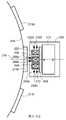
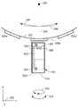
도 12는 내부에 포함되는 자기장 센싱 요소들이 감지된 강자성 물체와 중첩되는 자기장 센서들의 임의의 것의 선택적인 배치를 나타내는 블록도이며,
도 13은 도 12에 나타낸 자기장 센서의 선택적인 배치를 나타내는 블록도이고,
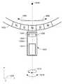
도 14는 감지된 강자성 물체가 링 자석인 자기장 센서들의 임의의 것의 선택적인 배치를 나타내는 블록도이며,
도 15는 내부에 포함되는 자기장 센싱 요소들이 링 자석과 중첩되는 도 14에 나타낸 자기장 센서들의 선택적인 배치를 나타내는 블록도이고,
도 16은 도 6 및 도 7에 도시된 라인으로 배열되는 자기장 센싱 요소들에 비해 호로 배열되는 자기장 센싱 요소들의 선택적인 배치를 나타내는 블록도이다.The present invention itself as well as the above-described features of the present invention will be understood in more detail from the detailed description of the following drawings, in the accompanying drawings,
1 is a block diagram of a prior art magnetic field sensor having a magnetic field sensing element, electronic circuitry and a magnet;
1A is a block diagram of an example of an electronic circuit that may be used as the electronic circuit of FIG. 1 ;
2 is a block diagram of another prior art magnetic field sensor having three magnetic field sensing elements, electronic circuitry and a magnet;
2A is a block diagram of an example of an electronic circuit that may be used as the electronic circuit of FIG. 2;
3 is a block diagram illustrating an example of a magnetic field sensor having two magnetic field sensing elements and electronic circuitry, all disposed on a substrate, and also having a magnet;
4 is a block diagram illustrating an example of another magnetic field sensor having a magnet different from the magnet of FIG. 3 , with two magnetic field sensing elements and electronic circuitry all disposed on a substrate;
5 is a block diagram showing an example of two magnetic field sensing elements and an example of the electronic circuit of FIGS. 3 and 4;
6 is a block diagram illustrating an example of a magnetic field sensor having a plurality of magnetic field sensing elements and an electronic circuit all disposed on a substrate, and also having a magnet;
7 is a block diagram illustrating an example of another magnetic field sensor having a magnet different from the magnet of FIG. 3 , with a plurality of magnetic field sensing elements and electronic circuitry all disposed on a substrate;
8 is a block diagram illustrating an example of a plurality of magnetic field sensing elements and an example of the electronic circuit of FIGS. 6 and 7 ;
9 is a block diagram illustrating another example of a plurality of magnetic field sensing elements and another example of the electronic circuit of FIGS. 6 and 7;
10 is a block diagram illustrating an example of a magnetic field sensor having a circular vertical Hall (CVH) sensing element and electronic circuitry all disposed on a substrate, and also having a magnet;
11 is a block diagram illustrating an alternative example of two magnetic field sensing elements compared to FIG. 5 that may be used with the electronic circuit of FIG.
12 is a block diagram illustrating an optional placement of any of the magnetic field sensors in which magnetic field sensing elements contained therein overlap with a sensed ferromagnetic object;
13 is a block diagram showing an optional arrangement of the magnetic field sensor shown in FIG. 12;
14 is a block diagram illustrating an optional placement of any of magnetic field sensors in which the sensed ferromagnetic object is a ring magnet;
15 is a block diagram showing an optional arrangement of magnetic field sensors shown in FIG. 14 in which magnetic field sensing elements included therein overlap a ring magnet;
16 is a block diagram illustrating a selective arrangement of magnetic field sensing elements arranged in an arc compared to the magnetic field sensing elements arranged in a line shown in FIGS. 6 and 7 .
본 발명을 설명하기 전에, 일부 도입되는 개념들 및 용어들을 설명한다.Before describing the present invention, some introduced concepts and terms are explained.
여기에 사용되는 바에 있어서, "자기장 센싱 요소(magnetic field sensing element)"라는 용어는 자기장을 감지할 수 있는 다양한 전자 요소들을 기술하는 데 사용된다. 상기 자기장 센싱 요소는, 이에 한정되는 것은 아니지만, 홀 효과 요소(Hall effect element), 자기저항 요소(magnetoresistance element) 또는 자기트랜지스터(magnetotransistor)가 될 수 있다. 알려진 바와 같이, 다른 유형들의 홀 효과 요소들, 예를 들면, 평면형(planar) 홀 요소, 수직형(vertical) 홀 요소 및 원형 수직 홀(circular vertical Hall: CVH) 요소가 존재한다. 또한, 알려진 바와 같이, 다른 유형들의 자기저항 요소들, 예를 들면 안티몬화인듐(InSb)과 같은 반도체 자기저항 요소, 거대 자기저항(GMR) 요소, 예를 들면 스핀 밸브(spin valve), 이방성 자기저항(AMR) 요소, 터널링 자기저항(TMR) 요소, 그리고 자기 터널 접합(MTJ)이 존재한다. 상기 자기장 센싱 요소는 단일의 요소가 될 수 있거나, 선택적으로는 다양한 구성들, 예를 들면, 하프 브리지 또는 풀(휘스톤(Wheatstone)) 브리지로 배열되는 둘 또는 그 이상의 자기장 센싱 요소들을 포함할 수 있다. 장치 유형과 다른 응용 요구 사항들에 따라, 상기 자기장 센싱 요소는 실리콘(Si)이나 게르마늄(Ge)과 같은 IV족 반도체 물질, 또는 갈륨-비소(GaAs) 혹은, 예를 들면 안티몬화인듐(InSb)과 같은 인듐 화합물과 같은 III-V족 반도체 물질로 이루어진 장치가 될 수 있다.As used herein, the term “magnetic field sensing element” is used to describe various electronic elements capable of sensing a magnetic field. The magnetic field sensing element may be, but is not limited to, a Hall effect element, a magnetoresistance element, or a magnetotransistor. As is known, there are different types of Hall effect elements, for example planar Hall elements, vertical Hall elements and circular vertical Hall (CVH) elements. Also, as is known, other types of magnetoresistance elements, such as semiconductor magnetoresistance elements such as indium antimonide (InSb), giant magnetoresistance (GMR) elements, such as spin valves, anisotropic magnetism There are resistive (AMR) elements, tunneling magnetoresistive (TMR) elements, and magnetic tunnel junctions (MTJs). The magnetic field sensing element may be a single element, or may optionally include two or more magnetic field sensing elements arranged in various configurations, for example, a half bridge or a full (Wheatstone) bridge. have. Depending on the device type and other application requirements, the magnetic field sensing element may be a group IV semiconductor material such as silicon (Si) or germanium (Ge), or gallium-arsenide (GaAs) or, for example, indium antimonide (InSb). The device may be made of a group III-V semiconductor material, such as an indium compound, such as
알려진 바와 같이, 전술한 자기장 센싱 요소들의 일부는 상기 자기장 센싱 요소를 지지하는 기판에 대해 평행한 최대 감도의 축을 갖는 경향이 있고, 전술한 자기장 센싱 요소들의 다른 것들은 상기 자기장 센싱 요소를 지지하는 기판에 대해 직교하는 최대 감도의 축을 갖는 경향이 있다. 특히, 평면형 홀 요소들은 기판에 대해 직교하는 감도의 축들을 갖는 경향이 있는 반면, 금속계 또는 금속성 자기저항 요소들(예를 들면, GMR, TMR, AMR)과 수직형 홀 요소들은 기판에 대해 평행한 감도의 축들을 갖는 경향이 있다.As is known, some of the magnetic field sensing elements described above tend to have an axis of maximum sensitivity parallel to the substrate supporting the magnetic field sensing element, and others of the magnetic field sensing elements described above are in the substrate supporting the magnetic field sensing element. tends to have an axis of maximum sensitivity that is orthogonal to In particular, planar Hall elements tend to have axes of sensitivity orthogonal to the substrate, whereas metallic or metallic magnetoresistance elements (eg GMR, TMR, AMR) and vertical Hall elements are parallel to the substrate. It tends to have axes of sensitivity.
여기에 사용되는 바에 있어서, "자기장 센서(magnetic field sensor)"라는 용어는 일반적으로 다른 회로들과 결합하여 자기장 센싱 요소를 사용하는 회로를 기술하는 데 사용된다. 자기장 센서들은, 이에 한정되는 것은 아니지만, 자기장의 방향의 각도를 감지하는 각도 센서, 전류를 운반하는 도체에 의해 운반되는 전류에 의해 발생되는 자기장을 감지하는 전류 센서, 강자성 물체의 근접을 감지하는 자기 스위치, 상기 자기장 센서가 백-바이어스(back-biased)되거나 다른 자석과 결합되어 사용되는 경우에 통과하는 강자성 물품들, 예를 들면 링 자석 또는 강자성 타겟(예를 들면, 기어 톱니들)의 자기 도메인들을 감지하는 회전 검출기, 그리고 자기장의 자기장 밀도를 감지하는 자기장 센서를 포함하는 다양한 응용들에 사용된다.As used herein, the term "magnetic field sensor" is generally used to describe a circuit that uses a magnetic field sensing element in combination with other circuits. Magnetic field sensors include, but are not limited to, an angle sensor that senses the angle of the direction of a magnetic field, a current sensor that senses a magnetic field generated by a current carried by a conductor carrying a current, and a magnetism that senses proximity of a ferromagnetic object. The magnetic domain of a switch, ferromagnetic objects, such as a ring magnet or a ferromagnetic target (eg, gear teeth), through which the magnetic field sensor is back-biased or used in conjunction with another magnet. It is used in a variety of applications, including rotational detectors to detect magnetic fields, and magnetic field sensors to sense the magnetic field density of magnetic fields.
여기에 사용되는 바에 있어서, "정확도(accuracy)"라는 용어는 자기장 센서에 대해 언급될 때에 상기 자기장 센서의 다양한 측면들을 기술하는 데 사용된다. 이들 측면들은, 이에 한정되는 것은 아니지만, 기어가 회전하고 있지 않을 때 및/또는 상기 기어가 회전하고 있을 때(또는 보다 일반적으로, 강자성 물체가 이동하고 있거나 이동하고 있지 않을 때)에 기어 톱니와 기어 밸리(valley)(또는 보다 일반적으로, 강자성 물체의 존재와 강자성 물체의 부존재)를 구별하는 상기 자기장 센서의 능력, 상기 기어의 톱니의 에지와 상기 기어의 톱니 또는 밸리(또는 보다 일반적으로, 강자성 물체의 에지 또는 경질의 강자성 물체의 자화 방향의 변화)를 구별하는 능력, 그리고 상기 기어 톱니의 에지가 식별되는 회전 정확도(또는 보다 일반적으로, 강자성 물체의 에지 또는 경질의 강자성 물체가 식별될 수 있는 위치 정확도)를 포함한다. 결국, 정확도는 상기 자기장 센서를 지나가는 기어 톱니 에지들에 대한 출력 신호 에지 배치 정확도 및 일치성을 언급한다.As used herein, the term “accuracy” is used to describe various aspects of a magnetic field sensor when referenced thereto. These aspects include, but are not limited to, gear teeth and gears when the gear is not rotating and/or when the gear is rotating (or more generally, when the ferromagnetic object is moving or not moving). The ability of the magnetic field sensor to distinguish a valley (or more generally, the presence of a ferromagnetic object and the absence of a ferromagnetic object), the edge of the teeth of the gear and the teeth or valleys of the gear (or more generally, the presence of a ferromagnetic object). the ability to discriminate the edge of or a change in the direction of magnetization of a hard ferromagnetic body), and the rotational accuracy at which the edge of the gear tooth is identified (or more generally, the edge of a ferromagnetic body or a location at which a hard ferromagnetic body can be identified) accuracy). Finally, accuracy refers to output signal edge placement accuracy and consistency for gear tooth edges passing through the magnetic field sensor.
"평행한" 및 "직교하는"이라는 용어들은 여기서의 다양한 내용들에서 사용된다. 평행한 및 직교하는 이라는 용어들이 정확한 직교성이나 정확한 평행성을 요구하지는 않지만, 대신에 정상 제조 공차들이 적용되며, 상기 공차들이 상기 용어들이 사용되는 본문에서 결정되는 점이 이해되어야 한다. 일부 예들에서, "실질적으로"라는 용어는 "평행한" 또는 "직교하는"이라는 용어들을 변경하는 데 사용된다. 일반적으로, "실질적으로"라는 용어의 사용은 제조 공차들을 넘어서는 각도들, 예를 들면, +/- 십도 이내를 반영한다.The terms “parallel” and “orthogonal” are used in various contexts herein. It should be understood that the terms parallel and orthogonal do not require exact orthogonality or exact parallelism, but instead, normal manufacturing tolerances apply, which tolerances are determined in the text in which the terms are used. In some examples, the term “substantially” is used to modify the terms “parallel” or “orthogonal”. In general, use of the term “substantially” reflects angles that are beyond manufacturing tolerances, eg, within +/- ten degrees.
자기장 센서들이 설치들 사이에서나 때때로 변화될 수 있는 상기 자기장 센서와 상기 기어 사이의 에어 갭(air gap)의 변화들이 존재하더라도 정확도의 특정한 레벨이나 양을 구현하는 것이 바람직하다. 또한, 자기장 센서들이 상기 자기장 센서 내의 자석 및 자기장 센싱 요소의 상대적인 위치들의 변화들이 존재하더라도 정확도를 구현하는 것이 바람직하다. 또한, 자기장 센서들이 상기 자기장 센서들 내의 자석에 의해 발생되는 자기장의 단위 간(unit-to-unit) 변화들이 존재하더라도 정확도를 구현하는 것이 바람직하다. 또한, 자기장 센서들이 상기 기어에 대한 상기 자기장 센서들의 축상 회전의 변화들이 존재하더라도 정확도를 구현하는 것이 바람직하다. 또한, 자기장 센서들이 상기 자기장 센서들의 온도 변화들이 존재하더라도 정확도를 구현하는 것이 바람직하다.It is desirable for magnetic field sensors to implement a certain level or amount of accuracy even if there are variations in the air gap between the magnetic field sensor and the gear that may vary between installations and from time to time. It is also desirable for magnetic field sensors to achieve accuracy even in the presence of changes in the relative positions of the magnet and magnetic field sensing element within the magnetic field sensor. In addition, it is desirable for magnetic field sensors to implement accuracy even in the presence of unit-to-unit changes in the magnetic field generated by the magnet in the magnetic field sensors. It is also desirable for magnetic field sensors to achieve accuracy even in the presence of changes in the on-axis rotation of the magnetic field sensors with respect to the gear. In addition, it is desirable that the magnetic field sensors implement accuracy even if there are temperature changes of the magnetic field sensors.
다음의 예들은 엔진 캠샤프트(camshaft)와 같은 강자성 타겟 물체 상에 사용될 수 있는 바와 같은 특정한 기어(또는 특정한 링 자석)을 설명한다. 그러나, 유사한 회로들 및 기술들이 상기 엔진 캠샤프트 상부, 엔진, 차량 또는 기계의 다른 회전하는 부품들(예를 들면, 크랭크 샤프트(crank shaft), 변속 기어, 잠김 방지 브레이크 장치(ABS)) 상부, 또는 엔진이 아닌 장치의 회전하는 부품들 상부에 배치되는 다른 캠들이나 기어들 또는 링 자석과 함께 사용될 수 있다. 다른 응용들은 상기 타겟이 회전하는 기어가 아닌 경우에 선형 병진 센서들이나 다른 센서들을 포함할 수 있다.The following examples illustrate a specific gear (or specific ring magnet) as may be used on a ferromagnetic target object, such as an engine camshaft. However, similar circuits and techniques may be applied above the engine camshaft, above the engine, vehicle or other rotating parts of a machine (eg, crankshaft, shift gear, antilock brake system (ABS)); Or it can be used with other cams or gears or ring magnets that are placed over the rotating parts of a non-engine device. Other applications may include linear translation sensors or other sensors where the target is not a rotating gear.
상기 기어(또는 타겟) 혹은 상기 링 자석은 다음에 설명하는 자기장 센서들의 부품이 아니다. 상기 기어는 강자성 기어 톱니들을 가질 수 있으며, 이들은 일반적으로 연질의 강자성 물체들이지만, 이들의 형상이 실제로 물리적 변화들을 가질 수 있거나 가지지 않을 수 있는 경질의 강자성 물체들, 패턴들, 또는 도메인들이 될 수도 있다.The gear (or target) or the ring magnet is not part of the magnetic field sensors described below. The gear may have ferromagnetic gear teeth, which are generally soft ferromagnetic objects, but may also be hard ferromagnetic objects, patterns, or domains whose shape may or may not actually have physical changes. have.
회전하도록 구성되는 기어 상에 기어 톱니들의 에지들을 갖는 강자성 기어 톱니들을 감지할 수 있는 자기장 센서들의 예들이 다음에 도시된다. 회전하도록 구성되는 링 자석 상에 자극 에지들을 갖는 북극 및 남극을 감지할 수 있는 자기장 센서들의 다른 예들이 다음에 도시된다. 그러나, 상기 자기장 센서들은 자른 응용들에 사용될 수 있다. 다른 응용들은, 이에 한정되는 것은 아니지만, 선형으로 이동하도록 구성되는 구조상의 강자성 물체들이나 자극들을 감지하는 것을 포함한다.Examples of magnetic field sensors capable of sensing ferromagnetic gear teeth having edges of the gear teeth on a gear configured to rotate are shown below. Other examples of magnetic field sensors capable of sensing north and south poles having magnetic pole edges on a ring magnet configured to rotate are shown below. However, the magnetic field sensors can be used in cropped applications. Other applications include, but are not limited to, sensing magnetic poles or ferromagnetic objects in a structure that are configured to move linearly.
여기에 사용되는 바에 있어서, "특징(feature)들"이라는 용어는 기어 상의 기어 톱니들 또는 기어 밸리들을 기술하는 데 사용되며, 링 자석 상의 북극 또는 남극을 기술하는 데에도 사용된다.As used herein, the term “features” is used to describe gear teeth or gear valleys on a gear, and is also used to describe a north or south pole on a ring magnet.
여기에 사용되는 바에 있어서, "베이스라인(baseline)"이라는 용어와 "베이스라인 레벨(baseline level)"이라는 표현은 자기장 센서가 시스템 내에서 동작하고 있을 때에 상기 자기장 센서 내의 자기장 센싱 요소가 겪는 자기장의 최소의 크기(거의 영(zreo)이 될 수 있거나 일부 다른 자기장이 될 수 있는)를 기술하는 데 사용된다. 일부 시스템들에서, 이러한 최소의 자기장은 자기장 센서가 기어 톱니에 대향되는 바와 같은 기어 밸리에 근접할 때에 발생된다.As used herein, the terms "baseline" and the expression "baseline level" refer to the magnetic field experienced by a magnetic field sensing element within the magnetic field sensor when the magnetic field sensor is operating in the system. It is used to describe the smallest magnitude (which could be near zero or some other magnetic field). In some systems, this minimum magnetic field is generated when the magnetic field sensor is close to the gear valley as opposed to the gear teeth.
일반적으로, 상기 베이스라인 레벨과, 예를 들면, 기어 톱니가 자기장 센서에 근접할 때에 구현되는 보다 높은 레벨 사이의 차이가 기어 톱니와 밸리를 구별하는 상기 자기장 센서의 능력과 관련되며, 이에 따라 상기 자기장 센서의 정확도와 관련되는 점이 이해될 것이다.In general, the difference between the baseline level and the higher level achieved, for example, when a gear tooth is in proximity to the magnetic field sensor, is related to the ability of the magnetic field sensor to differentiate between a gear tooth and a valley, and thus It will be appreciated that it relates to the accuracy of the magnetic field sensor.
베이스라인 레벨이 자기장 센서가 기어 밸리에 근접할 때에 발생되고, 보다 높은 레벨이 상기 자기장 센서가 기어 톱니에 근접할 때에 구현되는 것으로 앞서 설명하였지만, 다른 물리적인 배치들, 예를 들면, 베이스라인 레벨이 자기장 센서가 기어 톱니에 근접할 때에 발생되고, 보다 높은 레벨이 상기 자기장 센서가 기어 밸리에 근접할 때에 구현되기 위한 반대의 배치도 가능하다.While it has been previously described that a baseline level is generated when the magnetic field sensor is proximate to the gear valley and a higher level is realized when the magnetic field sensor is proximate to a gear tooth, other physical arrangements, such as the baseline level The reverse arrangement is also possible for this magnetic field sensor to be generated when the gear teeth are in proximity, and a higher level to be realized when the magnetic field sensor is close to the gear valley.
여기에 사용되는 바에 있어서, "프로세서(processor)"라는 용어는 기능, 동작 또는 일련의 동작들을 수행하는 전자 회로를 기술하는 데 사용된다. 상기 기능, 동작 또는 일련의 동작들은 상기 전자 회로 내로 하드 코드(code)될 수 있거나, 메모리 장치 내에 유지되는 명령들에 의해 소프트 코드될 수 있다. "프로세서"는 디지털 값들이나 아날로그 신호들을 이용하여 상기 기능, 동작 또는 일련의 동작들을 수행할 수 있다.As used herein, the term “processor” is used to describe an electronic circuit that performs a function, operation, or series of operations. The function, operation, or sequence of operations may be hard coded into the electronic circuitry, or may be soft coded by instructions maintained within a memory device. A “processor” may use digital values or analog signals to perform the function, operation, or series of operations.
일부 실시예들에 있어서, 상기 "프로세서"는 아날로그 응용 주문형 집적 회로(ASIC) 또는 디지털 응용 주문형 집적 회로(ASIC)가 될 수 있는 응용 주문형 집적 회로(ASIC) 내에 구현될 수 있다. 일부 실시예들에 있어서, 상기 "프로세서"는 프로그램 메모리와 연관된 마이크로프로세서 내에 구현될 수 있다. 일부 실시예들에 있어서, 상기 "프로세서"는 아날로그 또는 디지털이 될 수 있는 별도의 전자 회로 내에 구현될 수 있다.In some embodiments, the “processor” may be implemented in an application specific integrated circuit (ASIC), which may be an analog application specific integrated circuit (ASIC) or a digital application specific integrated circuit (ASIC). In some embodiments, the "processor" may be implemented within a microprocessor associated with a program memory. In some embodiments, the “processor” may be implemented in a separate electronic circuit that may be analog or digital.
여기에 사용되는 바에 있어서, "모듈(module)"이라는 용어는 "프로세서"를 기술하는 데 사용된다.As used herein, the term "module" is used to describe a "processor."
프로세서는 상기 프로세서의 기능, 동작 또는 일련의 동작들의 일부들을 수행하는 내부 프로세서들 또는 내부 모듈들을 포함할 수 있다. 유사하게, 모듈은 상기 모듈의 기능, 동작 또는 일련의 동작들의 일부들을 수행하는 내부 프로세서들 또는 내부 모듈들을 포함할 수 있다.A processor may include internal processors or internal modules that perform portions of a function, operation, or series of operations of the processor. Similarly, a module may include internal processors or internal modules that perform portions of a function, operation, or series of operations of the module.
다음에서 아날로그 기능들로 설명될 수 있는 전자적 기능들이 디지털 회로들, 프로세서들, 또는 모듈들 내에 대신 구현될 수 있는 점이 이해되어야 한다. 예를 들면, 비교기(comparator)가 아날로그 전압들을 비교하는 아날로그 비교기로서, 디지털 값들을 비교하는 디지털 비교기로서, 또는 디지털 값들을 비교하는 프로세서나 모듈로서 구현될 수 있는 점이 이해될 것이다. 여기서 아날로그 예들로 도시하는 예들은 설시되는 실시예들의 범주를 아날로그 실시예들만으로 한정하는 것은 아니다.It should be understood that electronic functions that may hereinafter be described as analog functions may instead be implemented in digital circuits, processors, or modules. For example, it will be appreciated that a comparator may be implemented as an analog comparator for comparing analog voltages, as a digital comparator for comparing digital values, or as a processor or module for comparing digital values. Examples shown here as analog examples do not limit the scope of the described embodiments to only analog examples.
여기에 사용되는 바에 있어서, "소정의"라는 용어는 값이나 신호에 대해 언급될 때에 제조의 시점에서 공장 내에서나 외부 수단들, 예를 들면, 이후의 프로그래밍에 의해 설정되거나 고정되는 값 또는 신호를 언급하는 데 사용된다. 여기에 사용되는 바에 있어서, "결정된"이라는 용어는 값 또는 신호에 대해 언급될 때에 제조 후의 동작 동안에 회로에 의해 확인되는 값 또는 신호를 언급하는 데 사용된다.As used herein, the term "predetermined", when referenced to a value or signal, refers to a value or signal that is set or fixed either within the factory or by external means, such as subsequent programming, at the time of manufacture. used to refer As used herein, the term “determined” is used to refer to a value or signal ascertained by a circuit during operation after manufacture when referenced to a value or signal.
여기에 사용되는 바에 있어서, "능동 전자 구성 요소"라는 용어는 적어도 하나의 p-n 접합을 가지는 전자 구성 요소를 기술하는 데 사용된다. 트랜지스터, 다이오드 및 로직 게이트는 능동 전자 구성 요소들의 예들이다. 이에 비하여, 여기에 사용되는 바에서, "수동 전자 구성 요소"라는 용어는 적어도 하나의 p-n 접합을 가지지 않는 전자 구성 요소를 기술하는 데 사용된다. 커패시터 또는 레지스터는 수동 전자 구성 요소들의 예들이다.As used herein, the term “active electronic component” is used to describe an electronic component having at least one p-n junction. Transistors, diodes and logic gates are examples of active electronic components. In contrast, as used herein, the term “passive electronic component” is used to describe an electronic component that does not have at least one p-n junction. Capacitors or resistors are examples of passive electronic components.
여기에 사용되는 바에 있어서, "타겟 물체(target object)"라는 용어는 위치 또는 이동이 여기서 설명되는 자기장 센서에 의해 검출되는 강자성 기어, 강자성의 링 자석, 비강자성의 도전성 물체, 또는 다른 유형의 타겟 물체를 언급하는 데 사용된다. 일부 실시예들에 있어서, 상기 타겟 물체는 다른 물체, 예를 들면, 엔진의 캠 샤프트에 연결될 수 있다. 따라서, 상기 타겟 물체의 검출된 위치 또는 이동은 다른 물체의 위치 또는 이동을 확인하는 데 이용될 수 있다.As used herein, the term “target object” refers to a ferromagnetic gear, a ferromagnetic ring magnet, a non-ferromagnetic conductive object, or other type of target whose position or movement is detected by a magnetic field sensor described herein. Used to refer to an object. In some embodiments, the target object may be connected to another object, for example a camshaft of an engine. Accordingly, the detected position or movement of the target object may be used to confirm the position or movement of another object.
도 1을 참조하면, 자기장 센서(10)의 예는 강자성 기어 톱니들, 예를 들면, 기어 톱니들(22a, 22b, 22c)을 갖는 기어(22)에 반응한다. 상기 기어(22)가 단지 상기 자기장 센서(10)가 반응할 수 있는 "강자성 타겟 물체(ferromagnetic target object)" 또는 간단히 "타겟(target)"의 하나의 유형인 점이 이해되어야 한다. 다른 자기 시스템들에서, 상기 강자성 타겟 물체는 영구 자석(또는 경질의 강자성 물질), 예를 들면, 교번하는 북극 및 남극을 갖는 전술한 링 자석을 포함할 수 있다. 링 자석들은 도 14-도 16과 함께 도시되고 다음에 설명된다.Referring to FIG. 1 , an example of a
상기 자기장 센서(10)는 전자 회로(16)에 연결되는 자기장 센싱 요소(12)를 포함한다. 상기 자기장 센싱 요소(12) 및 상기 전자 회로(16)는 기판(14) 상에 배치(즉, 내부 또는 상부에 집적)될 수 있다. 명료성을 위하여, 여기서 상기 자기장 센싱 요소(12)는 확대된 크기를 가지고, 상기 기판(14)의 평면 외부로 회전하는 홀 요소로 도시된다. 또한, 명료성을 위해, 상기 홀 요소(12)는 상기 기판(14) 상단 상에 있는 것으로 도시되지만, 홀 요소들이 통상적으로 집적 회로의 기판의 표면 상부 또는 내부에 배치되는 점이 이해될 것이다.The
상기 자기장 센서(10)는 또한 자석(18)(예를 들면, 영구 자석 또는 경질의 강자성 물질)을 포함할 수 있다. 상기 자석(18)은 자기장을 발생시키도록 구성되며, 상기 자기장은 대체로 상기 자기장 센싱 요소(12)의 위치에서 축(24)을 따라 향하고, 상기 자기장 센서(10)에 대한 상기 기어 톱니들(22a, 22b, 22c)의 위치들에 따라 방향 및 진폭 변화들을 겪는다. 그러나, 상기 자석(18)의 면들에서 상기 자기장의 구조는 코어(core)(20)로 인해 보다 복잡할 수 있다.The
상기 전자 회로(16)는 출력 신호(도시되지 않음)를 발생시키도록 구성된다. 상기 출력 신호는 상기 기어가 이동하고 있지 않을 때에 상기 자기장 센서(10)가 기어 톱니 또는 기어 밸리 상부에 있는 지를 나타낸다. 따라서, 상기 자기장 센서(10)는 때때로 "에지 검출기(edge detector)"에 대향되는 것으로 "톱니 검출기(tooth detector)"(또는 특징 검출기(feature detector))로 언급된다. 상기 출력 신호는 상기 기어가 회전하고 있을 때에 상기 기어의 회전의 속도를 나타내는 에지 속도(edge rate) 또는 주파수를 가진다. 상기 출력 신호의 상태들의 에지들이나 전이들은 이들이 상기 자기장 센서를 지나가면서 상기 기어 톱니들의 에지들의 위치들을 확인하는 데 사용될 수 있다.The
상기 자석(18)은 상기 자석(18) 내에 배치되는 연질의 강자성 물질로 구성되는 중심 코어(20)를 포함할 수 있다. 코어를 갖는 자석의 예는 2001년 8월 21일에 등록되었고, 본 발명의 양수인에게 양도되었으며, 그 개시 사항이 전체적으로 여기에 참조로 포함되는 미국 특허 제6,278,269호(발명의 명칭: "자석 구조(Magnet structure)")에 기재되어 있다. 미국 특허 제6,278,269호에 기재된 바와 같이, 상기 코어(20)를 갖는 자석(18)에 의해 제공되는 자극 구성은 상기 기어(22)의 밸리가 상기 자기장 센서(10)에 근접할 때 상기 코어(20)의 표면 상부의(예를 들면, 도시한 바와 같이 코어의 좌측에 대한) 일부 지점들에서 상기 자기장의 자속 밀도의 베이스 자기장(또는 베이스라인)을 낮춘다. 상기 자기장 센싱 요소(12)에서의 소정의 베이스라인(예를 들면, 약 +/ 육백 가우스(Gauss)의 범위 이내) 및 영(zreo) 부근의 결과적인 차동 자기장 신호(12a, 12b)(즉, 아날로그 차동 근접 신호)는 적절한 설계로 구현될 수 있다. The
이에 비하여, 상기 기어(22)의 기어 톱니가 상기 자기장 센싱 요소(12)에 근접할 때, 상기 자기장 센싱 요소(12)는 보다 높은 자기장을 겪으며, 보다 높은 값을 갖는 상기 차동 자기장 신호(12a, 12b)를 발생시킨다. 상술한 바와 같이, 상기 베이스라인 자기장 및 상기 보다 높은 자기장 사이의 차이는 상기 자기장 센서(10)의 결과적인 정확도외 관련된다.In contrast, when the gear teeth of the
상기 자기장 센서(10)가 상기 기어(22) 내의 밸리에 근접할 때에 발생될 수 있는 상기 베이스라인 자기장은 상기 기어(22)와 상기 자기장 센서(10) 사이의 에어 갭이 변화되는 경우에서도 낮은 변화들로 상대적으로 낮게 남는다. 에어 갭과 실질적으로 독립적인 낮은 베이스라인의 이러한 유리한 결과는 상기 코어(20)의 동작에 의해 구현되며, 이는 특히 상기 자기장 센싱 요소(12)가 상기 기어(22) 내의 밸리에 근접할 때에 상기 자기장 센싱 요소(12)에 근접하는 상기 코어(20)의 면(즉, 도시된 바와 같이 좌측)에 존재하는 대향되는 자극들의 결과로 된다. 이러한 효과는 또한 1998년 7월 14일에 등록되었고, 본 발명의 양수인에게 양도되었으며, 개시 사항이 전체적으로 여기에 참조로 포함되는 미국 특허 제5,781,005호(발명의 명칭: "홀 효과 강자성 물품 근접 센서(Hall-effect ferromagnetic-article-proximity sensor)")에 기재되어 있다.The baseline magnetic field, which may be generated when the
상기 자기장 센서가 기어 밸리에 근접할 때에 발생할 수 있는 상술한 낮은 베이스라인은 기어 밸리와 기어 톱니의 존재를 구별할 수 있는 상기 전자 회로(16)의 향상된 능력을 가져온다.The aforementioned low baseline, which can occur when the magnetic field sensor is proximate to the gear valley, results in an improved ability of the
상술한 낮은 베이스라인은 또한 상기 베이스라인 자기장이 상대적으로 작기 때문에 온도 효과들을 보다 용이하게 보상하는 능력을 제공하며, 이에 따라 상기 자기장 센서(10)가 상기 기어(22) 내의 밸리에 근접할 때에 온도로 인해 발생되는 회로 변화들이 영향을 덜 미칠 수 있다. 기본적으로, 상기 회로부 내의 임의의 에러(error)는 상기 에러의 임의의 곱(거의 영)이 보다 작기 때문에 상기 베이스라인 자기장 레벨 또는 범위 부근으로 우수하게 교정될 수 있다. 이에 따라, 톱니와 밸리를 구별하는 데 이용되는 자기장 스레시홀드(threshold)는 온도 또는 습도와 같은 그 동작 조건들에 걸쳐 상기 시스템 내에 노이즈(noise) 또는 에러가 적게 존재하기 때문에 정밀도를 유지하면서 보다 작게 구현될 수 있다.The low baseline described above also provides the ability to more easily compensate for temperature effects because the baseline magnetic field is relatively small, so that when the
앞서 설명하고 상기 코어(20)를 갖는 자석(18)에 의해 제공되는 자기장은 상기 자기장 센서(10)의 향상된 정확도를 가져온다. 예를 들면, 상기 낮은 베이스라인은 상기 자기장 센서(10)의 정확도를 희생시키지 않고 기계적인 정렬들의 단위 간 변화들로 인해 일어날 것인 바와 같이 상기 자기장 센싱 요소(12)가 상기 자석(18)의 중심으로부터 어느 정도 정적으로 오정렬되게 한다. 정확도는 상술한 바와 같다.The magnetic field provided by the
도 1a를 이제 참조하면, 종래 기술의 전자 회로(50)의 예는 도 1의 전자 회로(16)와 동일하거나 유사할 수 있다. 상기 전자 회로(50)는 도 1의 자기장 센싱 요소(12)에 의해 발생되는 차동 신호(12a, 12b)와 동일하거나 유사할 수 있는 차동 신호(52a, 52b)를 수신하도록 연결되는 증폭기(amplifier)(54)를 포함할 수 있다. 상기 증폭기(54)는 증폭된 신호(54a)를 발생시키도록 구성되며, 이는, 일부 실시예들에서, 두 채널들인 TPOS 검출기 채널 및 정밀 회전 검출기(precision rotation detector) 채널 내로 나누어질 수 있다.Referring now to FIG. 1A , an example of a prior art
상기 트루 파워 온 스테이트(TPOS) 채널에서, TPOS 검출기(56)는 상기 증폭된 신호(54a)를 수신하도록 연결될 수 있고, TPOS 출력 신호(56a)를 발생시키도록 구성될 수 있다. 일부 실시예들에 있어서, 상기 TPOS 검출기(56)는 상기 증폭된 신호(54a)를 고정(및 트림(trimmed)) 스레시홀드와 비교하도록 구성되는 비교기(comparator)(도시되지 않음)를 포함할 수 있다. 이들 실시예들에 있어서, 상기 TPOS 출력 신호(56a)는 하이(high) 상태가 도 1의 자기장 센서(10)에 근접하는 기어 톱니를 나타내고, 로우(low) 상태가 상기 자기장 센서(10)에 근접하는 기어 밸리를 나타내거나, 그 반대가 되는 2상태(two-state)의 이진 신호(binary signal)가 될 수 있다.In the true power on state (TPOS) channel, a
상기 정밀 회전 검출기 채널에서, 자동 이득 제어(automatic gain control: AGC)(58)는 상기 증폭된 신호(54a)를 수신하도록 연결될 수 있고, 이득 제어된 신호(58a)를 발생시키도록 구성될 수 있다. 정밀 회전 검출기(60)는 상기 이득 제어된 신호(58a)를 수신하도록 연결될 수 있고, 정밀 회전 검출기 출력 신호(60a)를 발생시키도록 구성될 수 있다. 상기 TPOS 출력 신호(56a)와 마찬가지로, 상기 정밀 회전 검출기 출력 신호(60a)는 하이 상태가 도 1의 자기장 센서(10)에 근접하는 기어 톱니를 나타내고, 로우 상태가 상기 자기장 센서(10)에 근접하는 기어 밸리를 나타내거나, 그 반대가 되는 2상태의 이진 신호가 될 수 있다. 따라서, 상기 TPOS 검출기(56) 및 상기 정밀 회전 검출기(60) 모두는 "톱니 검출기들"(즉, "특징 검출기들")이 될 수 있다. 그러나, 상기 정밀 회전 검출기 채널이 상기 AGC(58)를 이용하며, 이는 상기 기어(22)가 회전하고 있지 않을 때, 상기 기어(22)가 회전을 시작하게 되면, 이득(gain)이 부정확하고 상기 정밀 회전 검출기가 완전하게 정확하지 않은 기간 동안에 결과적인 원하지 않는 이득을 해결할 것인 점이 이해되어야 한다. 상기 AGC(58)가 사용되지 않았다고 하더라도, 여전히 상기 정밀 회전 검출기(60)는 상기 기어(22)가 회전하고 있을 때에만 적절하게 업데이트되는 내부 스레시홀드들을 이용한다. 그러나, 다른 실시예들에서, 상기 스레시홀드는 상기 전자 회로(50)의 외부로부터 제공될 수 있다.In the precision rotation detector channel, an automatic gain control (AGC) 58 may be coupled to receive the amplified
일부 실시예들에 있어서, 상기 TPOS 검출기(56) 및/또는 상기 정밀 회전 검출기(60)에 대한 스레시홀드들이 저장되고, 후에 리콜되고 사용된다. 스레시홀드들의 저장은 도 9와 함께 다음에 설명된다. 동일한 저장 기술들이 여기서 설명되는 모든 자기장 센서들과 함께 사용될 수 있다.In some embodiments, thresholds for the
일부 선택적인 실시예들에 있어서, 상기 정밀 회전 검출기(60)는 "에지 검출기"가 될 수 있으며, 이는 특히 상기 기어가 이동하고 있지 않을 때에 상기 자기장 센서(12)가 기어 톱니 또는 기어 밸리에 근접하는 지를 식별할 수 없지만, 기어 톱니들의 에지들이 상기 자기장 센서(10)를 지나 이동하면서 이들을 감지할 수 있다.In some alternative embodiments, the
정밀 회전 검출기들, 예를 들면, 상기 정밀 회전 검출기(60)는 다양한 구성들을 가질 수 있다. 일부 구성들은 앞서 언급한 미국 특허 제6,525,531호에 기재되어 있다. 그러나, 둘 또는 그 이상의 자기장 센싱 요소들을 가지는 일부를 포함하여 다른 형태들의 정밀 회전 검출기들도 알려져 있다.Precision rotation detectors, for example, the
일반적으로, 앞서의 논의로부터, 상기 기어, 예를 들면, 도 1의 기어(22)가 정지하고 있을 때라도 상기 TPOS 출력 신호(56a)가 상기 자기장 센싱 요소(12)가 기어 톱니 또는 기어 밸리에 근접하는 지를 나타내는 점이 이해될 것이다. 그러나, 상기 TPOS 검출기(56)가 고정 스레시홀드를 이용하기 때문에, 일부 실시예들에서, 동력 인가 시에 제한된 조정을 가짐으로써, 이에 한정되는 것은 아니지만, 온도 변화들 및 상기 자기장 센싱 요소(12)와 상기 기어(22) 사이의 에어 갭의 변화들을 포함하는 다양한 인자들로 인해 상기 TPOS 출력 신호(56a) 내의 에지 배치의 변화들이 일어날 것이다.In general, it can be seen from the preceding discussion that even when the gear, eg,
고정 스레시홀드들을 이용하는 상기 TPOS 검출기(56)와는 달리, 상기 정밀 회전 검출기(60)는 보다 우수한 기어 톱니들의 물리적인 위치들에 대한 상기 정밀 회전 검출기 출력 신호(60a)의 에지 배치들의 보다 우수한 정확도를 갖는 상기 정밀 회전 검출기 출력 신호(60a)를 제공하도록 스레시홀드들을 계속적으로 조정한다. 상술한 바와 같이, 부분적으로, 이들 조정들은 상기 정밀 회전 검출기를 처음에 동력이 인가될 때 또는 상기 기어(22)가 처음에 회전하기 시작할 때에 덜 정확하게 만든다.Unlike the
상기 TPOS 검출기(56) 및 상기 정밀 회전 검출기(60)가 공통 기판 상으로 집적되는 일부 실시예들에 있어서, 멀티플렉서/출력 모듈(multiplexer/output module)(62)은 상기 TPOS 출력 신호(56a)를 수신하도록 연결될 수 있고, 상기 정밀 회전 검출기 출력 신호(60a)를 수신하도록 연결될 수 있다. 선택 로직(select logic)(64)은 상기 멀티플렉서/출력 모듈(62)에 의해 수신되는 선택 신호(64a)를 제공할 수 있다. 상기 선택 신호(64a)의 상태에 따라, 상기 멀티플렉서/출력 모듈(62)은 상기 TPOS 출력 신호(56a) 또는 상기 정밀 회전 검출기 출력 신호(60a)의 선택된 것을 나타내는 출력 신호(62a)를 발생시키도록 구성된다. 상기 출력 신호(62a)는, 이에 한정되는 것은 아니지만, SENT 포맷, I2C 포맷, PWM 포맷, 또는 상기 TPOS 출력 신호(56a)와 상기 정밀 회전 검출기 출력 신호(60a)에 고유한 2상태(two-state)의 포맷을 포함하는 다양한 신호 포맷들로 제공될 수 있다.In some embodiments in which the
일부 예들에서, 상기 선택 로직(64)은 상기 TPOS 출력 신호(56a)에 의해 나타내어지는 바와 같이 상기 기어(22)가 회전을 시작한 후에 소정의 양의 시간 동안에 상기 TPOS 출력 신호(56a)를 나타내게 되는 상기 출력 신호(62a)를 선택한다. 이후에, 상기 선택 로직(64)은 상기 정밀 회전 검출기 출력 신호(60a)를 나타내게 되는 상기 출력 신호(62a)를 선택한다.In some examples, the
도 2를 이제 참조하면, 종래 기술의 자기장 센서(200)의 다른 예는 기어 톱니들, 예를 들면, 기어 톱니들(214a, 214b, 214c)을 가지는 기어(214)에 반응한다. 상기 자기장 센서(200)는 전자 회로(210)에 연결되는 세 개의 자기장 센싱 요소들(202, 204, 206)을 포함한다. 일부 실시예들에 있어서, 상기 자기장 센싱 요소들(202, 204)은 약 1.5밀리미터 내지 약 3.0밀리미터의 거리로 축(216)에 직교하는 방향으로 이격되며, 상기 자기장 센싱 요소(206)는 상기 자기장 센싱 요소들(202, 204) 사이의 중간에 위치한다.Referring now to FIG. 2 , another example of a prior art
상기 세 개의 자기장 센싱 요소들(202, 204, 206)과 전자 회로(210)는 기판(208) 상에 배치(즉, 내부 또는 상부에 집적)될 수 있다. 명료성을 위하여, 여기서는 상기 자기장 센싱 요소들(202, 204, 206)은 확대된 크기를 가지며, 상기 기판(208)의 평면의 외부로 회전하는 홀 요소들인 것으로 도시된다. 또한, 명료성을 위해, 상기 홀 요소들(202, 204, 206)은 상기 기판(208)의 상단에 있는 것으로 도시되지만, 홀 요소들이 통상적으로 집적 회로의 기판의 표면 상부 또는 내부에 배치되는 점이 이해될 것이다.The three magnetic
상기 자기장 센서(200)는 또한 자석(212)을 포함할 수 있다. 상기 자석(212)은 자기장을 발생시키도록 구성되며, 이는 대체로 상기 자기장 센싱 요소들(202, 204, 206)의 위치에서 축(216)을 따라 향한다.The
상기 전자 회로(210)는 출력 신호(도시되지 않음)를 발생시키도록 구성된다. 예시적인 전자 회로(210)는 도 2a와 함께 다음에 설명된다. 여기서는 상기 전자 회로가 신호들의 차이들을 발생시키는 것으로 말하면 충분하다. 따라서, 상기 자기장 센서(200)는 에지 검출기이고, 톱니 검출기가 아닌 점이 분명해질 것이다.The
상기 출력 신호는 상기 기어(214)가 회전하고 있을 때에 상기 기어(214)의 회전의 속도를 나타내며, 또한 상기 기어 톱니들의 에지들의 위치들을 나타낸다. 상기 자기장 센서(200)는 TPOS 기능을 제공하지 못하며, 상기 기어(214)가 정지하고 있을 때에 상기 자기장 센싱 요소들(202, 204, 206)이 상기 기어(214) 내의 기어 톱니 또는 밸리에 근접하는 지를 식별하지 못한다.The output signal indicates the speed of rotation of the
상기 자석(212)은 하나의 균일한 물질로 구성될 수 있고, 도 1과 함께 도시되고 설명된 중심 코어를 갖지 않을 수 있다. 그러나, 다른 실시예들에서, 상기 자석(212)은 도 1과 함께 도시되고 설명한 경우와 동일하거나 유사한 중심 코어를 가질 수 있다. 또 다른 실시예들에 있어서, 상기 자석(212)은 에어로 이루어진 코어 또는 비강자성 물질로 이루어진 코어를 가질 수 있다.The
상기 자기장 센서(200)는 각각의 세 차동 신호들(202a 및 202b, 204a 및 204b, 206a 및 206b)을 발생시키기 위해 상기 세 개의 자기장 센싱 요소들(202, 204, 206)을 사용한다. 비록 간단한 자석(212)은 상기 코어를 갖는 자석의 낮은 베이스라인을 제공하지 않지만, 앞서의 차동 신호들의 차이들은 낮은 베이스라인의 효과를 야기한다. 본질적으로, 상기 세 개의 자기장 센싱 요소들(202, 204, 206)이 동일한 자기장을 겪을 때, 앞서의 차동 신호들의 차분(differencing)은 영의 전자 신호의 결과로 된다.The
도 2a를 이제 참조하면, 종래 기술의 전자 회로(250)의 예는 도 2의 전자 회로(210)와 동일하거나 유사할 수 있다. 상기 전자 회로(250)는 각기 차동 신호들(252a 및 252b, 254a 및 254b, 256a 및 256b)을 수신하도록 구성되는 증폭기들(258, 260, 262)을 포함할 수 있다. 상기 차동 신호(252a, 252b)는 도 2의 자기장 센싱 요소들(202, 204, 206)에 의해 각기 발생되는 상기 차동 신호(202a, 202b)와 동일하거나 유사할 수 있고, 상기 차동 신호(254a, 254b)는 상기 차동 신호(204a, 204b)와 동일하거나 유사할 수 있으며, 상기 차동 신호(256a, 256b)는 상기 차동 신호(206a, 206b)와 동일하거나 유사할 수 있다. 상기 증폭기들(258, 260, 262)은 각기 증폭된 신호들(258a, 260a, 262a)을 발생시키도록 구성된다.Referring now to FIG. 2A , an example of a prior art
상기 증폭된 신호들(258a, 260a)은 제1 차이 신호(difference signal)(264a)를 발생시키도록 구성되는 제1 차분 모듈(differencing module)(264)에 의해 수신된다. 상기 증폭된 신호들(260a, 262a)은 제2 차이 신호(266a)를 발생시키도록 구성되는 제2 차분 모듈(266)에 의해 수신된다.The amplified signals 258a and 260a are received by a
상기 전자 회로(250)는 도 1a와 함께 상술한 두 개의 정밀 회전 검출기 채널들을 포함한다. AGC들(270, 276)은 도 1a의 AGC(56)와 동일하거나 유사할 수 있다. 정밀 회전 검출기들(272, 278)은 도 1a의 정밀 회전 검출기(60)와 동일하거나 유사할 수 있다. 상기 정밀 회전 검출기(272)는 정밀 회전 검출기 출력 신호(272a)를 발생시킬 수 있고, 상기 정밀 회전 검출기(278)는 정밀 회전 검출기 출력 신호(278a)를 발생시킬 수 있다. 상기 정밀 회전 검출기 출력 신호들(272a, 278a)은 도 1a의 정밀 회전 검출기 출력 신호(60a)와 동일하거나 유사할 수 있다.The
속도 및 방향 모듈(speed and direction module)(274)은 상기 정밀 회전 검출기 출력 신호들(272a, 278a)을 수신하도록 연결될 수 있다.A speed and
상기 정밀 회전 검출기 출력 신호들(272a, 278a)이 상기 기어(214)의 회전의 방향에 의해 결정되는 상대적 위상들에 있는 점이 분명해야 한다. 또한, 상기 정밀 회전 검출기 출력 신호들(272a, 278a)의 상태 전이 속도들이 상기 기어(214)의 회전의 속도를 나타내는 점이 분명해야 한다.It should be clear that the precision rotation
상기 속도 및 방향 모듈은 상기 기어(214)의 회전의 속도 또는 회전의 방향의 적어도 하나를 나타낼 수 있는 출력 신호를 발생시키도록 구성된다. 일부 실시예들에 있어서, 상기 출력 신호(62a)는 상기 회전의 속도 및 상기 회전의 방향 모두를 나타낸다.The speed and direction module is configured to generate an output signal that may indicate at least one of a speed of rotation or a direction of rotation of the
도 3을 이제 참조하면, 자기장 센서(300)는 기어 톱니들, 예를 들면, 기어 톱니들(322a, 322b, 322c)을 갖는 기어(322)에 반응한다. 상기 자기장 센서(300)는 전자 회로(314)에 연결되는 두 개의 자기장 센싱 요소들(304, 306)을 포함할 수 있다. 일부 실시예들에 있어서, 상기 자기장 센싱 요소들(304, 306)은 약 0.2 밀리미터 내지 약 3.0 밀리미터의 거리로 상기 두 개의 자기장 센싱 요소들(304, 306) 사이의 축(306)을 따른 방향으로 이격된다.Referring now to FIG. 3 , the
일부 실시예들에 있어서, 상기 두 개의 자기저항 요소들(304, 306)은 강자성 타겟 물체 특징(feature), 예를 들면, 강자성 기어(322)의 기어 톱니 또는 강자성의 링 자석의 자기 도메인의 폭의 약 1/2 내지 약 3/2의 분리를 가진다. 일부 다른 실시예들에 있어서, 상기 두 개의 자기저항 요소들(304, 306)은 상기 강자성 타겟 물체 특징의 폭의 약 1/2 내지 약 2배의 분리를 가진다. 그러나, 다른 실시예들에서, 상기 분리는 상기 폭보다 훨씬 작거나, 예를 들면, 상기 폭의 1/100이거나, 상기 폭의 2배보다 크다.In some embodiments, the two
상기 두 개의 자기장 센싱 요소들(304, 306) 및 상기 전자 회로(314)는 기판(302)의 주요 표면(302a) 상에 배치(즉, 내부 또는 상부에 집적)될 수 있다. 명료성을 위하여, 여기서 상기 자기장 센싱 요소들(304, 306)은 자기저항 요소들인 것으로 도시된다. 다른 실시예들에 있어서, 상기 자기장 센싱 요소들(304, 306)은 홀 효과 요소들, 예를 들면, 수직형 홀 효과 요소들이다.The two magnetic
상기 자기장 센서(300)는 또한 자석(332)을 포함할 수 있다. 상기 자석(332)은 자기장을 발생시키도록 구성되며, 이는 대체로 상기 자기장 센싱 요소들(304)의 위치에서 축(308)을 따라 향하며, 대체로 상기 기판(302)의 주요 표면(302a)에 평행하다.The
상기 두 개의 자기장 센싱 요소들(304, 306)은 상기 기판(302)의 주요 표면(302)에 평행한 각각의 최대 반응 축들을 가진다. 일부 실시예들에 있어서, 상기 최대 반응 축들은 서로 평행하다. 일부 실시예들에 있어서, 상기 최대 반응 축들은 상기 축(308)에 실질적으로 평행하다. 다른 실시예들에 있어서, 상기 최대 반응 축들은 상기 축(308)과 실질적으로 직교한다.The two magnetic
상기 기판의 주요 표면(302a)에 직교하고(즉, 도면 내로) 상기 기판(302)과 교차되는 라인은 상기 자석(332)과도 교차되며, 상기 기어(322)와 교차되지 않는다. 또한, 일부 실시예들에서, 상기 두 개의 자기장 센싱 요소들(304, 306)은 상기 두 개의 자기장 센싱 요소들(304, 306) 사이의(즉, 통과하는) 축(예를 들면, 308)이 상기 기어(322)와 교차되지 않는 위치들에 배치된다. 일부 실시예들에 있어서, 상기 두 개의 자기장 센싱 요소들(304, 306) 사이의(즉, 통과하는) 상기 축(예를 들면, 308)은 상기 기어(322)의 이동의 방향, 예를 들면, 326에 대한 접선(330)에 실질적으로 평행하다.Lines that are orthogonal to the
도시한 실시예에 있어서, 상기 자석(332)의 북극(N) 및 남극(S) 사이의 라인은 상기 기판(302)의 주요 표면(302a)에 실질적으로 평행하고, 상기 두 개의 자기장 센싱 요소들(304, 306) 사이의(즉, 통과하는) 상기 축(예를 들면, 308)에 실질적으로 평행하다. 일부 실시예들에 있어서, 상기 자석(332)의 북극 및 남극 사이의 라인은 상기 기어(322)와 교차되지 않으며, 상기 기어(322)를 향하는 방향으로 향하지 않는다.In the illustrated embodiment, the line between the north pole (N) and the south pole (S) of the
상기 전자 회로(314)는 출력 신호(도시되지 않음)를 발생시키도록 구성된다. 예시적인 전자 회로(314)는 도 5와 함께 다음에 설명된다. 여기서는 상기 전자 회로(314)가 도 5와 함께 다음에 설명되는 전자 회로에 따라 신호들의 차를 발생시킬 수 있는 것으로 말하면 충분하다. 따라서, 상기 자기장 센서(300)가 에지 검출기인 점이 분명해질 것이다. 그러나, 다른 전자 회로들을 사용하면, 상기 다른 전자 회로는 신호들의 합을 발생시킬 수 있고, 이 경우에 상기 자기장 센서(300)는 톱니 검출기(즉, 특징 검출기)가 될 수 있다.The
에지 검출기를 위해, 상기 출력 신호는 상기 기어(322)가 회전하고 있을 때에 상기 기어(322)의 회전의 속도를 나타내며, 상기 기어 톱니들의 에지들의 위치들도 나타낸다. 톱니 검출기를 위해, 상기 출력 신호는 상기 기어(322)가 회전하고 있을 때에 상기 기어(322)의 회전의 속도를 나타내며, 상기 기어 톱니들 또는 기어 밸리들의 중심들 부근의 위치들도 나타낸다.For the edge detector, the output signal indicates the speed of rotation of the
상기 기어(322)가 도시되지만, 도 14 및 도 15와 함께 다음에 설명되는 다른 실시예들에서, 상기 기어(322)는(그리고 또한 다음의 다른 도면들에서 설명되는 기어들은) 링 자석으로 대체될 수 있다.Although the
상기 자석(332)은 하나의 균일한 물질로 이루어질 수 있고, 도 1과 함께 도시되고 설명된 중심 코어를 가지지 않을 수 있다. 그러나, 다른 실시예들에서, 상기 자석(332)은 도 1과 함께 도시하고 설명한 경우와 동일하거나 유사한 중심 코어를 가질 수 있다. 또 다른 실시예들에 있어서, 상기 자석(332)은 에어로 구성되는 코어 또는 비강자성 물질로 이루어진 코어를 가질 수 있다. 이러한 코어는 축(324)과 정렬되는 축을 가질 수 있다.The
상기 자기장 센서(300)는 각각의 두 자기장 신호들을 발생시키기 위해 상기 두 개의 자기장 센싱 요소들(304, 306)을 사용한다. 비록 간단한 자석(332)은 코어를 구비하는 자석의 낮은 베이스라인을 제공하지 않지만, 앞서의 두 자기장 신호들의 차이는 낮은 베이스 라인과 유사한 효과를 야기한다. 기본적으로, 상기 두 개의 자기장 센싱 요소들(304, 306)이 동일한 자기장(즉, 기어 톱니 또는 기어 밸리에 근접한)을 겪을 때, 앞서의 차동 신호들의 차분은 영의 전자 신호를 야기한다.The
상기 자기장 센서(300)는 성능의 열화 없이 도시한 위치로부터 백팔십도 떨어진 다음 위치까지 방향(316)으로 회전될 수 있다. 그러나, 중간 회전들은 성능의 열화를 가져올 수 있다.The
상기 자기장 센서(600)는 성능의 실질적인 열화 없이 대략 +/- 이십도를 통해 라인(324)을 따라 어디서나 회전의 중심을 가지고 화살표(318)의 방향으로 회전될 수 있다.The
일부 실시예들에 있어서, 상기 자기장 센싱 요소들(304, 306)은 자기저항 요소들이다. 다른 실시예들에 있어서, 상기 자기장 센싱 요소들은 홀 효과 요소들, 예를 들면, 수직형 홀 효과 요소들이다. 그러나, 각각의 최대 감도의 축들이 상기 축(308)에 평행한 자기장 센싱 요소들을 사용하는 것이 유리하다.In some embodiments, the magnetic
도 3과 동일한 요소들이 동일한 참조 부호들을 가지는 것으로 도시된 도 4를 이제 참조하면, 상기 자기장 센서(400)는 도 3의 자기장 센서(300)와 동일하다. 그러나, 상기 자기장 센서(400)는 자석(402)의 북극(N) 및 남극(S) 사이의 라인이 상기 기판(302)의 주요 표면(302a)에 실질적으로 평행하지만, 상기 두 개의 자기장 센싱 요소들(304, 306) 사이의(즉, 통과하는) 축(예를 들면, 308)에 실질적으로 직교하는 다른 자석(402)을 가진다. 일부 실시예들에 있어서, 상기 자석(402)의 북극 및 남극 사이의 라인은 상기 기어(322)를 향하는 방향을 따른다.Referring now to FIG. 4 , where the same elements as FIG. 3 are shown having like reference numerals, the
일부 실시예들에 있어서, 상기 자석(402)은 도 1과 함께 상술한 코어와 같은 코어가 없는 간단한 자석이다. 다른 실시예들에 있어서, 상기 자석(402)은 도 1과 함께 상술한 코어(20)와 동일하거나 유사한 코어를 가진다. 또 다른 실시예들에 있어서, 상기 자석(402)은 에어로 이루어지는 코어 또는 비강자성 물질로 구성되는 코어를 가질 수 있다. 상기 코어는 상기 라인(324)을 따르거나 이에 평행하게 축과 정렬될 수 있다.In some embodiments, the
도 5를 이제 참조하면, 전자 회로(500)의 예는 도 3 및 도 4의 전자 회로(314)와 동일하거나 유사할 수 있으며, 도 3 및 도 4의 자기장 센싱 요소들(304, 306)과 동일하거나 유사할 수 있는 자기장 센싱 요소들(502, 508)에 연결될 수 있다. 상기 전자 회로(500)는 제1 하프 브리지(half bridge) 내에 고정 레지스터(fixed resistor)(506)와 연결되는 제1 자기저항 요소(502)를 포함할 수 있다. 상기 전자 회로(500)는 또한 제2 하프 브리지 내에 고정 레지스터(504)와 연결되는 제2 자기저항 요소(508)를 포함할 수 있다. 상기 두 하프 브리지들은 풀 브리지(full bridge) 회로를 형성하는 전압 소스(voltage source)(506)로부터 구동될 수 있다.Referring now to FIG. 5 , an example of an
상기 제1 하프 브리지는 외부 자기장에 반응하여 신호(510)를 발생시킨다. 상기 제2 하프 브리지는 상기 외부 자기장에 반응하여 신호(512)를 발생시킨다.The first half bridge generates a
차동 증폭기(differential amplifier)(512)는 상기 신호들(510, 512)을 수신하도록 연결될 수 있고, 증폭된 신호(512a)를 발생시키도록 구성될 수 있다. 상기 증폭된 신호(512a)가 상기 두 개의 자기저항 요소들(502, 508)에 의해 발생되는 신호들의 차이를 나타내는 점이 이해될 것이다.A
자동 이득 제어(automatic gain control)(514)는 상기 증폭된 신호(512a)를 수신하도록 연결될 수 있고, 이득 제어된 신호(514a)를 발생시키도록 구성될 수 있다. 정밀 회전 검출기(516)는 상기 이득 제어된 신호(514a)를 수신하도록 연결될 수 있고, 정밀 회전 검출기 출력 신호(516a)를 발생시키도록 구성될 수 있다. 일부 실시예들에 있어서, 상기 정밀 회전 검출기 출력 신호(516a)는, 예를 들면, 도 3 및 도 4의 강자성 기어와 동일하거나 유사할 수 있는 상기 강자성 기어의 기어 톱니들의 근접을 나타내는 하이(high) 상태들을 가지는 2상태(two-state) 신호이다.An
출력 모듈(output module)(518)은 상기 정밀 회전 검출기 출력 신호(516a)를 발생시키도록 연결될 수 있고, 응용을 위해, 예를 들면, 자동차 응용을 위해 적합한 포맷을 갖는 상기 정밀 회전 검출기 출력 신호(516a)를 나타내는 신호(518a)를 발생시키도록 구성될 수 있다.An
일부 실시예들에 있어서, 상기 전자 회로(500)는 또한 자동 이득 제어 값들(514a)을 수신하고 저장하며, 이후에 상기 자동 이득 제어(514)의 이득을 컨트롤하기 위해 자동 이득 제어 값들(520a)을 제공하는 메모리 장치(520), 예를 들면, EEPROM 또는 비휘발성 메모리 장치를 포함할 수 있다. 이러한 배치로써, 상기 전자 회로(500)는, 예를 들면, 동력이 차단되는 동안에 자동 이득 제어 값들을 유지할 수 있으며, 상기 저장된 자동 이득 제어 값들(520a)은 동력이 인가된 후에 적절한 이득을 보다 신속하게 구현하는 결과가 되도록 동력 인가에 따라 사용될 수 있다. 저장된 자동 이득 제어 값들을 갖는 유사한 메모리 장치가 다음에 설명하는 전자 회로들의 임의의 것에 사용될 수 있다.In some embodiments, the
상기 EEPROM(520)이 자동 이득 제어 값들을 유지하는 것으로 설명하지만, 다른 실시예들에서, 상기 EEPROM(520)은 다른 값들, 예를 들면, 도 9와 함께 다음에 설명하는 스레시홀드 값(threshold value)들, 또는 상기 자기장 센서의 측정된 동작 특성들을 나타내는 다른 값들도 유지할 수 있다.Although the
도 5의 블록들은 아날로그 회로들, 디지털 회로들, 또는 프로세서들 내에 구현될 수 있다.The blocks of FIG. 5 may be implemented in analog circuits, digital circuits, or processors.
상기 두 개의 자기저항 요소들(502, 508)이 동일한 자기장을 겪을 경우, 그러면 상기 증폭된 신호(512a)가 영(zero)이 아닌 점이 이해될 것이다. 기어 톱니의 에지가 상기 자기저항 요소들(502, 508)에 근접할 때에만 상기 증폭된 신호(512a)는 영이 아니게 될 것이다. 따라서, 상기 전자 회로(500)는 에지 검출기로서 동작한다. 이에 따라, 상기 전자 회로(500)는 도 1a와 함께 상술한 경우와 비교될 수 있는 트루 파워 온 스테이트(true power on state) 채널을 포함하지 않는다.If the two
그러나, 선택적인 배치에서, 톱니 검출기(즉, 특징 검출기)를 구현하도록 상기 자기저항 요소(506)와 상기 레지스터(502)가 유사한 전자 회로로 교환될 수 있거나, 상기 자기저항 요소(508)와 상기 레지스터(504)가 다른 유사한 회로로 교환될 수 있다. 상기 유사한 회로들은 도 1a와 함께 상술한 경우와 비교될 수 있는 트루 파워 온 스테이트 채널을 포함할 수 있다.However, in an alternative arrangement, the
두 개의 자기저항 요소들(502, 508)이 도시되지만, 다른 실시예들에서, 상기 자기저항 요소들(502, 508) 및 이들이 내부에서 연결되는 상기 브리지 회로는 두 개의 홀 효과 요소들, 예를 들면, 두 개의 수직형 홀 효과 요소들로 대체될 수 있다.Although two
도 6을 이제 참조하면, 자기장 센서(600)는 기어 톱니, 예를 들면, 기어 톱니들(622a, 622b, 622c)을 갖는 기어(622)에 반응한다. 상기 자기장 센서(600)는 전자 회로(614)에 연결되는 복수의, 즉 둘 또는 그 이상의(혹은 둘 이상의) 자기장 센싱 요소들, 예를 들면, 604a를 포함할 수 있다. 일부 실시예들에 있어서, 상기 자기장 센싱 요소들, 예를 들면, 604a는 약 0.05 밀리미터 내지 약 2.0 밀리미터의 거리로 상기 복수의 자기장 센싱 요소들, 예를 들면, 604a 사이의 축(606)을 따른 방향으로 이격된다.Referring now to FIG. 6 , the
상기 복수의 자기장 센싱 요소들, 예를 들면, 604a 및 상기 전자 회로(614)는 기판(602)의 주요 표면(602a) 상에 배치(즉, 내부 또는 상부에 집적)될 수 있다. 명료성을 위하여, 여기서는 상기 자기장 센싱 요소들, 예를 들면, 604a는 자기저항 요소들인 것으로 도시된다. 다른 실시예들에 있어서, 상기 자기장 센싱 요소들, 예를 들면, 604a는 홀 효과 요소들, 예를 들면, 수직형 홀 효과 요소들이다.The plurality of magnetic field sensing elements, eg, 604a and the
상기 자기장 센서(600)는 또한 자석(610)을 포함할 수 있다. 상기 자석(610)은 자기장을 발생시키도록 구성되며, 상기 자기장은 대체로 상기 복수의 자기장 센싱 요소들, 예를 들면, 604a의 위치에서 축(608)을 따라 향하고, 대체로 상기 기판(602)의 주요 표면(602a)에 평행하다.The
상기 복수의 자기장 센싱 요소들, 예를 들면, 604a는 상기 기판(602)의 주요 표면(602a)에 평행한 각각의 최대 반응 축들을 가진다. 일부 실시예들에 있어서, 상기 최대 반응 축들은 서로 평행하다. 일부 실시예들에 있어서, 상기 최대 반응 축들은 상기 축(606)에 실질적으로 평행하다. 다른 실시예들에 있어서, 상기 최대 반응 축들은 상기 축(606)에 실질적으로 직교한다.The plurality of magnetic field sensing elements, eg, 604a , have respective maximum response axes parallel to the
상기 기판의 주요 표면(602a)에 대해(즉, 도면 내로) 직교하는 라인은 상기 자석(610)과 교차되며, 상기 기어(622)와 교차되지 않는다. 또한, 상기 복수의 자기장 센싱 요소들, 예를 들면, 604a는 상기 복수의 자기장 센싱 요소들, 예를 들면 604a 사이의(즉, 통과하는) 축(예를 들면, 608)이 상기 기어(622)와 교차되지 않게 하는 위치에 배치된다. 일부 실시예들에 있어서, 상기 복수의 자기장 센싱 요소들, 예를 들면 604a 사이의(즉, 통과하는) 축(예를 들면, 606)은 상기 기어(622)의 이동의 방향, 예를 들면, 626에 대한 접선(630)에 실질적으로 평행하다.A line orthogonal to (ie into the drawing) the
도시한 실시예에 있어서, 상기 자석(610)의 북극(N) 및 남극(S) 사이의 라인은 상기 기판(602)의 주요 표면(602a)에 실질적으로 평행하고, 상기 복수의 자기장 센싱 요소들, 예를 들면 604a 사이의(즉, 통과하는) 축(예를 들면, 606)에 실질적으로 평행하다. 일부 실시예들에 있어서, 상기 북극 및 남극 사이의 라인은 상기 강자성 타겟 물체(622)와 교차되지 않는다.In the illustrated embodiment, the line between the north pole (N) and the south pole (S) of the
상기 전자 회로(614)는 출력 신호(도시되지 않음)를 발생시키도록 구성된다. 전자 회로의 예는 도 8 및 도 9와 함께 다음에 보다 상세하게 설명된다. 여기서는 상기 전자 회로(614)가 복수의 이진 신호(binary signal)들을 발생시키기 위해 상기 복수의 자기장 신호들의 각각의 것을 스레시홀드 신호와 비교하도록 구성되는 것으로 말하면 충분하다. 상기 복수의 이진 신호들의 복수의 상태들은 상기 강자성 타겟 물체(622)의 위치, 특히 상기 복수의 자기장 센싱 요소들에 대한 기어 톱니의 에지 또는 기어 밸리의 에지의 위치를 나타낸다. 따라서, 상기 자기장 센서(600)가 에지 검출기, 톱니 검출기, 또는 이들 모두로 동작할 수 있는 점이 분명해질 것이다.The
상기 출력 신호는 상기 기어(622)가 회전하고 있을 때에 상기 기어(622)의 회전의 속도를 나타내며, 또한 상기 기어 톱니들의 에지들의 위치들을 나타낸다. 상기 자기장 센서(600)는 TPOS 기능을 제공할 수 있으며, 상기 기어(622)가 정지하고 있을 때에 상기 복수의 자기장 센싱 요소들, 예를 들면, 604a의 개개의 것들이 상기 기어(622) 내의 기어 톱니 또는 밸리에 근접하는 지를 확인할 수 있다.The output signal indicates the speed of rotation of the
또한, 상기 자기장 센서(600)는 상기 복수의 자기장 센싱 요소들, 예를 들면, 604a에 의해 감지되는 자기장들의 검출된 진행을 통해 상기 기어(622)의 회전의 방향을 확인할 수 있다.In addition, the
상기 자석(610)은 하나의 균일한 물질로 구성될 수 있고, 도 1과 함께 도시되고 설명된 중심 코어를 갖지 않을 수 있다. 그러나, 다른 실시예들에서, 상기 자석(610)은 도 1과 함께 도시되고 설명한 경우와 동일하거나 유사한 중심 코어를 가질 수 있다. 또 다른 실시예들에 있어서, 상기 자석(610)은 에어로 이루어진 코어 또는 비강자성 물질로 이루어진 코어를 가질 수 있다. 상기 코어는 상기 축(606)에 평행하게 정렬될 수 있다.The
상기 자기장 센서(600)는 각각의 복수의 자기장 신호들을 발생시키도록 상기 복수의 자기장 센싱 요소들, 예를 들면, 604a를 사용한다.The
각각의 상기 복수의 자기장 신호들은 상기 자석(602)에 의해 발생되는 자기장에 반응하며, 각각의 상기 복수의 자기장 센싱 요소들의 위치에 대한 강자성 타겟 물체, 예를 들면, 기어 톱니들(622a, 622b, 622c)의 위치에 의해 영향을 받는다. 상기 강자성 타겟 물체(622)는 이동의 방향(626)으로 이동하도록 구성된다. 상기 복수의 자기장 센싱 요소들, 예를 들면, 604a는 상기 접선(630)에 실질적으로 평행한 상기 축(606)을 따라 배치된다.Each of the plurality of magnetic field signals is responsive to a magnetic field generated by the
일부 선택적인 실시예들에 있어서, 상기 복수의 자기장 센싱 요소들, 예를 들면, 604a는 상기 라인(606)을 따르기 보다는 호(arc)를 따라 배치된다. 상기 호의 직경은 상기 기어(622)의 직경과 동일하거나 유사할 수 있다. 상기 호는 상기 기어의 원주와 동일한 방향 또는 다른 방향으로 곡선이 될 수 있다. 호로 배치될 때, 상기 자기장 센싱 요소들의 최대 반응 축들은 서로 평행할 수 있거나, 이들은 서로 평행하지 않을 수 있다. 이러한 배치는 도 16과 함께 다음에 도시된다.In some alternative embodiments, the plurality of magnetic field sensing elements, eg, 604a, are disposed along an arc rather than along the
일부 실시예들에 있어서, 상기 복수의 자기장 센싱 요소들, 예를 들면, 604a는 서로 평행한 각각의 복수의 최대 반응 축들을 가진다. 일부 실시예들에 있어서, 상기 최대 반응 축들은 상기 축(606)에 실질적으로 평행하다. 다른 실시예들에 있어서, 상기 최대 반응 축들은 상기 축(606)에 실질적으로 직교한다.In some embodiments, the plurality of magnetic field sensing elements, eg, 604a, have respective plurality of maximum response axes parallel to each other. In some embodiments, the maximum response axes are substantially parallel to the
상기 자기장 센서(600)는 성능의 열화 없이 도시한 위치로부터 백팔십도 떨어진 다음 위치까지 방향(616)으로 회전될 수 있다. 그러나, 중간 회전들은 성능의 열화를 가져올 수 있다.The
상기 자기장 센서(600)는 성능의 실질적인 열화 없이 대략 +/- 이십도를 통해 라인(624)을 따라 어디서나 회전의 중심을 가지고 화살표(618)의 방향으로 회전될 수 있다.The
일부 실시예들에 있어서, 상기 자기장 센싱 요소들, 예를 들면, 604a는 자기저항 요소들이다. 다른 실시예들에 있어서, 상기 자기장 센싱 요소들은 홀 효과 요소들, 예를 들면, 수직형 홀 효과 요소들이다. 그러나, 각각의 최대 감도의 축들이 상기 축(606)에 평행한 자기장 센싱 요소들을 사용하는 것이 유리하다.In some embodiments, the magnetic field sensing elements, eg, 604a, are magnetoresistive elements. In other embodiments, the magnetic field sensing elements are Hall effect elements, for example vertical Hall effect elements. However, it is advantageous to use magnetic field sensing elements whose respective axes of maximum sensitivity are parallel to said
도 6과 동일한 요소들이 동일한 참조 부호들을 가지는 것으로 도시된 도 7을 이제 참조하면, 자기장 센서(700)는 도 6의 자기장 센서(600)와 동일하다. 그러나, 상기 자기장 센서(700)는 자석(702)의 북극(N) 및 남극(S) 사이의 라인이 상기 기판(602)의 주요 표면(602a)에 실질적으로 평행하고, 상기 복수의 자기장 센싱 요소들, 예를 들면 604a 사이의(즉, 통과하는) 축(예를 들면, 606)에 실질적으로 평행한 다른 자석(702)을 가진다. 일부 실시예들에 있어서, 상기 자석(702)의 북극 및 남극 사이의 라인은 상기 기어(622)를 향하는 방향을 따르며, 상기 기어(622)와 교차된다.Referring now to FIG. 7 , in which the same elements as FIG. 6 are shown having like reference numerals,
도 8을 이제 참조하면, 전자 회로(800)는 도 6 및 도 7의 전자 회로(614)와 동일하거나 유사할 수 있고, 도 6 및 도 7의 복수의 자기장 센싱 요소들, 예를 들면, 604a와 동일하거나 유사할 수 있는 복수의 자기저항 요소들에 연결될 수 있다.Referring now to FIG. 8 ,
상기 전자 회로(800)는 자기저항 요소(802) 및 고정 레지스터(804)가 단지 하나의 예인 복수의 전자 채널들을 포함할 수 있다. 상기 복수의 전자 채널들은 전압 조정기(voltage regulator)(806)로부터 전압을 수신하도록 연결될 수 있다. 분압기(voltage divider)를 형성하는 상기 자기저항 요소(802) 및 상기 고정 레지스터(804)를 상기 전자 채널들의 다른 것들의 요소들을 나타내는 것으로 취할 경우, 전압 신호(808)는 상기 자기저항 요소(802) 및 고정 레지스터(804) 사이의 접합에서 발생될 수 있다. 상기 전압 신호(808)는 상기 자기저항 요소(802)가 겪는 자기장의 크기를 나타내는 값을 가진다. 상기 전자 채널들의 다른 것들은 상기 자기저항 요소들의 다른 것들이 겪는 자기장들을 나타내는 값들을 갖는 전압 신호들을 발생시킨다.The
일부 실시예들에 있어서, 상기 자기저항 요소들의 숫자는 두 개 내지 아홉 개의 범위 이내가 될 수 있다.In some embodiments, the number of magnetoresistive elements may be in the range of two to nine.
다른 실시예들에 있어서, 상기 전압 소스는 각 저항 분배기(resistor divider), 예를 들면, 802, 804를 구동시키도록 전류 소스(current source) 또는 별도의 전류 소스들로 대체될 수 있다. 일부 실시예들에 있어서, 상기 별도의 전류 소스들은 각기 동일한 기준 레그(reference leg)를 갖는 전류 미러(current mirror)들의 별도의 컨트롤된 레그들이 될 수 있다.In other embodiments, the voltage source may be replaced with a current source or separate current sources to drive a respective resistor divider, eg, 802, 804. In some embodiments, the separate current sources may be separate controlled legs of current mirrors each having the same reference leg.
상기 전압 신호(808)는 증폭기(810)에 의해 수신된다. 상기 증폭기(810)는 증폭된 전압 신호(810a)를 발생시키도록 구성된다. 비교기(comparator)(812)는 상기 증폭된 전압 신호(810a)를 수신하도록 연결되고, 스레시홀드 신호(818)를 수신하도록 연결되며, 비교 신호(812a)(즉, 이진의 2상태 신호)를 발생시키도록 구성된다.The
일부 다른 실시예들에 있어서, 상기 증폭기들, 예를 들면, 810이 사용되지 않는다.In some other embodiments, the amplifiers, eg, 810 are not used.
비휘발성 메모리 장치, 예를 들면, EEPROM(electrically erasable read only memory)(814)은 다중-비트 어드레스 입력에서 복수의 이러한 비교 신호들을 수신하도록 연결된다. 상기 EEPROM(814)은 단일 비트 출력 신호 또는 다중 비트 출력 신호가 될 수 있는 출력 신호(814a)를 생성한다. 상기 출력 신호(814a)는 상기 복수의 자기저항 요소들에 대한 기어 톱니의 위치, 예를 들면, 도 6의 복수의 자기장 센싱 요소들의 위치에 대한 도 6의 기어 톱니(322b)의 위치를 나타내는 값, 즉 디지털 값을 가질 수 있다. 따라서, 상기 신호(814a)의 하나 또는 그 이상의 상태들은 상기 복수의 자기장 센싱 요소들에 근접하는 상기 기어 톱니(622b)의 에지를 나타낸다.A non-volatile memory device, eg, electrically erasable read only memory (EEPROM) 814 , is coupled to receive a plurality of such comparison signals at a multi-bit address input. The
상기 EEPROM(814)이 룩-업 테이블(look-up table)로 작용할 수 있고, 출력 신호(814a)에 대한 처리의 임의의 원하는 맵핑(mapping)을 제공할 수 있는 점이 이해될 것이다. 동일한 전자 회로가 도 6의 자기장 센서(600) 및 도 7의 자기장 센서(700) 모두에 적용될 수 있지만, 아마도 상기 EEPROM(814) 내에 저장된 다른 룩업 테이블들을 구비할 수 있다.It will be appreciated that the
상기 신호(814a)는 상기 강자성 타겟 물체, 예를 들면, 도 6의 622의 회전의 속도 및/또는 회전의 방향을 나타낼 수 있다.The
일부 다른 실시예들에 있어서, 상기 EEPROM(814)은 프로세서로 대체된다.In some other embodiments, the
일부 실시예들에 있어서, 상기 출력 신호(814a)는 출력 프로토콜 모듈(output protocol module)(816)에 의해 수신된다. 상기 출력 프로토콜 모듈(816)은, 이에 한정되는 것은 아니지만, SENT 포맷, I2C 포맷, PWM 포맷, 또는 이진 포맷을 포함하는 복수의 포맷들의 선택된 하나로 포맷된 신호(816a)를 발생시키도록 구성된다.In some embodiments, the
상기 포맷된 신호(816a)는 또한 상기 강자성 타겟 물체, 예를 들면, 도 6의 622의 회전의 속도 및/또는 회전의 방향을 나타낼 수 있다. 이를 위하여, 상기 출력 프로토콜 모듈(816)은 상기 강자성 타겟 물체의 회전의 속도 및/또는 회전의 방향을 확인하도록 상기 신호(814a)를 사용할 수 있다. 상기 신호(814a)의 특정한 디지털 값들은 상기 복수의 자기저항 요소들에 근접하는 강자성 타겟 특징(예를 들면, 기어 톱니)의 중심을 나타낼 수 있고, 상기 신호(814a)의 특정한 다른 디지털 값들은 상기 복수의 자기저항 요소들에 근접하는 강자성 타겟 물체 특징의 특정한 에지를 나타낼 수 있으며, 상기 신호(814a)의 특정한 다른 디지털 값들은 상기 복수의 자기저항 요소들에 근접하는 강자성 타겟 물체 특징의 다른 특정한 에지를 나타낼 수 있다.The formatted
상기 전자 회로(800)가 복수의 단일 분압기들, 예를 들면, 상기 고정 레지스터(804)를 구비하는 상기 자기저항 요소(802)로 형성되는 분압기를 가지는 것으로 도시되지만, 다른 실시예들에 있어서, 각 채널은 다른 배치, 예를 들면, 휘스톤(Wheatstone)(풀) 브리지를 사용할 수 있다.Although the
또 다른 실시예들에 있어서, 상기 전자 채널들의 각각의 것은 각각의 홀 효과 요소, 예를 들면, 각각의 수직형 홀 효과 요소를 사용할 수 있다. 도시한 바와 같이, 홀 요소는 수신할 수 있고, 즉 전압 소스 또는 전류 소스에 의해 구동될 수 있고, 상기 홀 효과 요소는 두 출력 신호 노드들로부터 차동 출력 신호를 발생시킬 수 있다. 어떻게 상기 전자 회로(800)가 자기저항 요소들 대신에 홀 효과 요소들을 사용하도록 변경될 수 있는 것인 지가 이해되어야 한다.In still other embodiments, each of the electron channels may use a respective Hall Effect element, eg, a respective vertical Hall Effect element. As shown, the Hall element is capable of receiving, ie driven by a voltage source or a current source, and the Hall effect element is capable of generating a differential output signal from both output signal nodes. It should be understood how the
복수의 비교기들(예를 들면, 812)이 도시되지만, 다른 실시예들에서, 평행한 채널들을 제공하기 위해 멀티플렉스되는(multiplexed) 하나 또는 그 이상의 비교기들이 존재할 수 있다. 유사하게, 복수의 증폭기들(810)이 도시되지만, 다른 실시예들에서, 하나 또는 그 이상의 증폭기들이 평행한 채널들을 제공하도록 멀티플렉스될 수 있다.Although multiple comparators (eg, 812 ) are shown, in other embodiments, there may be one or more comparators multiplexed to provide parallel channels. Similarly, although a plurality of
도 8과 동일한 요소들이 동일한 참조 부호들을 가지는 것으로 도시된 도 9를 이제 참조하면, 전자 회로(900)는 도 6 및 도 7의 전자 회로(614)와 동일하거나 유사할 수 있으며, 도 6 및 도 7의 복수의 자기장 센싱 요소들, 예를 들면, 604a와 동일하거나 유사할 수 있는 복수의 자기저항 요소들에 연결될 수 있다.Referring now to FIG. 9 , wherein the same elements as FIG. 8 are shown having like reference numerals,
상기 전자 회로(900)는 상기 자기저항 요소(802) 및 고정 레지스터(804)를 가지는 채널이 단지 하나의 예인 복수의 전자 채널들을 포함할 수 있다. 이러한 채널을 복수의 채널들의 다른 것들을 나타내는 것으로 취하면, 아날로그-디지털 컨버터(ADC)(912)는 상기 증폭된 전압 신호(810a)을 수신하도록 연결될 수 있고, 변환된 신호(902a)를 발생시키도록 구성될 수 있다.The
위치 계산 모듈(position calculation module)(904)(즉, 프로세서)은 상기 변환된 신호(902a)를 수신하도록 연결될 수 있다. 특히, 상기 위치 계산 모듈(904) 내의 디지털 비교기(906)가 상기 변환된 신호(902a)를 수신하도록 연결될 수 있다. 상기 디지털 비교기(906)는 또한 디지털 스레시홀드 값(905)을 수신하도록 연결될 수 있고, 비교 신호(906a)를 발생시키도록 구성될 수 있다.A position calculation module 904 (ie, a processor) may be coupled to receive the transformed signal 902a. In particular, a
일부 실시예들에 있어서, 비휘발성 메모리 장치, 예를 들면, EEPROM(908)은 상기 비교 신호(906a)를 다른 비교 신호들과 함께 수신하도록 연결될 수 있다. 상기 EEPROM(908)은 상기 비교 신호들을 수신하고, 단일 비트 또는 다중-비트 신호가 될 수 있는 신호(908a)를 발생시키도록 구성되는 룩업 테이블(909)을 포함할 수 있다. 상기 신호(908a)는 도 8의 신호(814a)와 동일하거나 유사할 수 있다.In some embodiments, a non-volatile memory device, eg,
상기 신호(908a)는 상기 강자성 타겟 물체, 예를 들면, 도 6의 622의 회전의 속도 및/또는 회전의 방향을 나타낼 수 있다.The signal 908a may indicate a speed of rotation and/or a direction of rotation of the ferromagnetic target object, eg, 622 of FIG. 6 .
출력 프로토콜 모듈(910)은 상기 신호(908a)를 수신할 수 있고, 도 8의 포맷된 신호(816a)와 동일하거나 유사할 수 있는 포맷된 신호(910a)를 발생시킬 수 있다.Output protocol module 910 may receive the signal 908a and may generate a formatted
상기 포맷된 신호(910a)는 상기 강자성 타겟 물체, 예를 들면, 도 6의 622의 회전의 속도 및/또는 회전의 방향을 나타낼 수 있다. 이를 위하여, 상기 출력 프로토콜 모듈(910)은 상기 강자성 타겟 물체의 회전의 속도 및/또는 회전의 방향을 확인하도록 상기 신호(908a)를 사용할 수 있다. 상기 신호(908a)의 특정한 디지털 값들은 상기 복수의 자기저항 요소들에 근접하는 강자성 타겟 특징(예를 들면, 기어 톱니)의 중심을 나타낼 수 있고, 상기 신호(908a)의 특정한 다른 디지털 값들은 상기 복수의 자기저항 요소들에 근접하는 강자성 타겟 물체 특징의 특정한 에지를 나타낼 수 있으며, 상기 신호(908a)의 특정한 다른 디지털 값들은 상기 복수의 자기저항 요소들에 근접하는 강자성 타겟 물체 특징의 다른 특정한 에지를 나타낼 수 있다.The formatted
일부 실시예들에 있어서, 상기 위치 계산 모듈(904)은 또한 상기 변환된 신호들(903)의 하나 또는 그 이상을 수신하도록 연결되는 스레시홀드 계산 모듈(threshold calculation module)(912)을 포함할 수 있다.In some embodiments, the
동작 시에, 상기 스레시홀드 계산 모듈(912)은 상기 디지털 비교기들, 예를 들면, 906에 대한 입력들로서 사용하도록 원하는 스레시홀드 값들, 예를 들면, 905를 확인할 수 있다. 예를 들면, 일부 실시예들에서, 상기 스레시홀드 계산 모듈(912)은 상기 변환된 신호들(903)의 양의 및 음의 피크 값들을 계산할 수 있고, 피크-투-피크(peak-to-peak) 값들을 계산할 수 있으며, 상기 피크-투-피크 값들에 대한 원하는 퍼센티지들로 각각의 스레시홀드 값들을 계산할 수 있다. 예를 들면, 일부 실시예들에서, 계산된 스레시홀드들은 상기 피크-투-피크 값들의 대략 육십 퍼센트 및 대략 사십 퍼센트가 될 수 있다. 이에 따라, 상기 위치 계산 모듈(904)은 상기 EEPROM(906)의 스레시홀드 저장 영역(911) 내에 상기 계산된 스레시홀드 값들을 저장할 수 있으며, 상기 스레시홀드 저장 영역(911)으로부터 상기 계산된 스레시홀드 값들을 상기 디지털 비교기들, 예를 들면, 906에 공급할 수 있다.In operation, the
전술한 배치로써, 상기 전자 회로(900)에 동력이 차단된 후, 다시 동력이 인가되면, 상기 저장된 스레시홀드 값들이 신속하게 사용될 수 있으며, 보다 빠른 동력 인가 반응 시간을 가져온다.With the above arrangement, when power is applied again after power is cut off to the
별도의 아날로그-디지털 컨버터들이 각 채널 상에 도시되지만, 다른 실시예들에서, 멀티플렉서(multiplexer)(도시되지 않음)를 통해 상기 증폭기들, 예를 들면, 810에 연결되는 하나 또는 그 이상의 아날로그-디지털 컨버터들이 있을 수 있다. 유사하게, 복수의 비교기들이 도시되지만, 다른 실시예들에서, 상기 하나 또는 그 이상의 아날로그-디지털 컨버터들에 연결되고, 멀티플렉서(도시되지 않음)를 통해 상기 프로세서(908)에 연결되는 하나 또는 그 이상의 비교기들이 존재할 수 있다.Although separate analog-to-digital converters are shown on each channel, in other embodiments one or more analog-to-digital coupled to the amplifiers, eg, 810, via a multiplexer (not shown) There may be converters. Similarly, while a plurality of comparators are shown, in other embodiments, one or more of them coupled to the one or more analog-to-digital converters and coupled to the
상기 EEPROM(908)이 상기 위치 계산 모듈(904) 내에 있는 것으로 도시되지만, 다른 실시예들에서, 상기 EEPROM(908)은 상기 위치 계산 모듈(904)의 외부에 있다.Although the
일부 다른 실시예들은 도 8 및 도 9의 부품들의 조합이다. 예를 들면, 일부 다른 실시예들에서, 상기 아날로그-디지털 컨버터들, 예를 들면, 902가 사용되지 않으며, 이 경우에 상기 복수의 비교기들, 예를 들면, 906은, 예를 들면, 상기 위치 계산 모듈(904)에 이진 신호들로서 비교 신호들, 예를 들면, 906을 제공하는, 예를 들면, 아날로그 비교기들이 될 수 있다. 이에 따라, 상기 EEPROM(908)(또는 상기 스레시홀드 계산 모듈(912))은 하나 또는 그 이상의 디지털-아날로그 컨버터들(DAC들, 도시되지 않음)을 통해 상기 비교기들에 아날로그 스레시홀드 신호들을 제공할 수 있다.Some other embodiments are combinations of the components of FIGS. 8 and 9 . For example, in some other embodiments, the analog-to-digital converters, eg 902, are not used, in which case the plurality of comparators, eg 906, are eg the position It can be, for example, analog comparators, which provide comparison signals, for example 906, as binary signals to the
또 다른 실시예들에 있어서, 상기 스레시홀드 계산 모듈(912)은 상기 증폭된 신호들, 예를 들면, 810a의 양의 및 음의 피크들을 확인하도록 동작할 수 있고, 상기 양의 및 음의 피크들 사이의 연관된 스레시홀드들을 제공하도록 동작할 수 있으며, 아날로그 스레시홀드들로서 상기 비교기들, 예를 들면, 906에 상기 스레시홀드들을 제공도록 동작할 수 있는 아날로그 모듈이 될 수 있다. 이러한 배치는 종래 기술의 특허들과 특허 출원들에 대해 앞서 참조로 언급된 도 1a와 함께 상술한 상기 정밀 회전 검출기들 의 부품들과 동일하거나 유사할 수 있다.In still other embodiments, the
도 10을 이제 참조하면, 자기장 센서(1000)는 기어 톱니들, 예를 들면, 기어 톱니들(1022a, 1022b, 1022c)을 갖는 기어(1022)에 반응한다. 상기 자기장 센서(1000)는 전자 회로(1014)에 연결되는 복수의 수직형 홀 요소들을 가지는 CVH 센싱 요소(1004)를 포함할 수 있다. 일부 실시예들에 있어서, 상기 CVH 센싱 요소(1004)의 직경은 약 0.1 밀리미터 내지 약 1.0 밀리미터이다.Referring now to FIG. 10 , the
상기 CVH 센싱 요소(1004)와 상기 전자 회로(1014)는 기판(1002)의 주요 표면(1002a) 상에 배치(즉, 내부 또는 상부에 집적)될 수 있다.The
상기 자기장 센서(1000)는 또한 자석(1010)을 포함한다. 상기 자석(1010)은 자기장을 발생시키도록 구성되며, 상기 자기장은 대체로 상기 CVH 센싱 요소(1004)의 위치에서 축(1024)을 따라 향하고, 상기 기판(1002)의 주요 표면(1002a)에 대체로 평행하다.The
상기 CVH 센싱 요소(1004) 내의 수직형 홀 효과 센싱 요소들은 상기 기판(1002)의 주요 표면(1002a)에 평행한 각각의 최대 반응 축들을 가진다.The vertical Hall effect sensing elements in the
상기 기판의 주요 표면(1002a)에 직교하는(즉, 도면 내로) 라인은 상기 자석(1010)과 교차되며, 상기 기어(1022)와 교차되지 않는다.A line orthogonal to the
도시한 실시예에 있어서, 상기 자석(1010)의 북극(N) 및 남극(S) 사이의 라인은 상기 기판(1002)의 주요 표면(1002a)에 실질적으로 평행하다. 일부 실시예들에 있어서, 상기 자석(1010)의 북극 및 남극 사이의 라인은 상기 기어(1022)와 교차되고, 상기 기어(1022)를 향하는 방향으로 있다. 일부 다른 실시예들에 있어서, 상기 자석(1010)의 북극 및 남극 사이의 라인은 상기 라인(1006)에 실질적으로 평행하며, 상기 기어(1022)와 교차되지 않는다.In the illustrated embodiment, the line between the north pole N and the south pole S of the
상기 전자 회로(1014)는 출력 신호(도시되지 않음)를 발생시키도록 구성된다. 여기서는 상기 전자 회로(1014)가 상기 CVH 센싱 요소(1004)가 겪는 자기장의 각도(즉, 방향)를 나타내는 x-z 각도 값들을 갖는 x-z 각도 신호를 발생시키도록 구성되는 것으로 말하면 충분하다. 따라서, 상기 자기장 센서(1000)가 에지 검출기로서나 톱니 검출기로서 동작할 수 있는 점이 분명해질 것이다.The
상기 출력 신호는 상기 기어(1022)가 회전하고 있을 때에 상기 기어(1022)의 회전의 속도를 나타내며, 또한 상기 기어 톱니들의 에지들의 위치들 및, 상기 기어 톱니들의 위치들도 나타낸다. 상기 자기장 센서(1000)는 TPOS 기능을 제공할 수 있으며, 상기 기어(1022)가 정지하고 있을 때, 상기 CVH 센싱 요소(1004)가 상기 기어(1022) 내의 기어 톱니 또는 밸리에 근접하는 지를 확인할 수 있다.The output signal indicates the speed of rotation of the
상기 자석(1010)은 하나의 균일한 물질로 구성될 수 있고, 도 1과 함께 도시되고 설명된 중심 코어를 갖지 않을 수 있다. 그러나, 다른 실시예들에서, 상기 자석(1010)은 도 1과 함께 도시되고 설명한 경우와 동일하거나 유사한 중심 코어를 가질 수 있다. 또 다른 실시예들에 있어서, 상기 자석(1010)은 에어로 이루어진 코어 또는 비강자성 물질로 이루어진 코어를 가질 수 있다. 일부 실시예들에 있어서, 상기 중심 코어는 축(1024)에 실질적으로 평행한 축을 가질 수 있다.The
상기 자기장 센서(1000)는 하나의 순차적 자기장 신호를 발생시키기 위해 상기 CVH 센싱 요소(1004)를 사용한다.The
상기 순차적 자기장 신호는 상기 자석(1010)에 의해 발생되는 자기장에 반응하며, 상기 복수의 자기장 센싱 요소들의 각각의 것의 위치에 대한 강자성 타겟 물체, 예를 들면, 기어 톱니들(1022a, 1022b, 1022c)의 위치에 의해 영향을 받는다. 상기 강자성 타겟 물체(1022)는 이동의 방향(1026)으로 이동하도록 구성된다. 상기 이동의 방향(1026)에 대한 접선(1030)이 도시된다.The sequential magnetic field signal is responsive to a magnetic field generated by the
상기 자기장 센서(1000)는 성능의 열화 없이 도시한 위치로부터 백팔십도 떨어진 다음 위치까지 방향(1016)으로 회전될 수 있다. 그러나, 중간 회전들은 성능의 열화를 가져올 수 있다.The
상기 자기장 센서(1000)는 성능의 실질적인 열화 없이 대략 +/- 이십도를 통해 라인(1024)을 따라 어디서나 회전의 중심을 가지고 화살표(1018)의 방향으로 회전될 수 있다.The
일부 선택적인 실시예들에 있어서, 상기 CVH 센싱 요소(1004)는 복수의 별도로 분리된 수직형 홀 효과 요소들로 대체된다.In some alternative embodiments, the
일부 선택적인 실시예들에 있어서, 실질적으로 상기 축(1006)을 따라 상기 기판 상에 배치되는 둘 또는 그 이상의 CVH 센싱 요소들이 존재할 수 있다.In some alternative embodiments, there may be two or more CVH sensing elements disposed on the substrate substantially along the
도 10의 CVH 센싱 요소(1004) 및 전자 회로(1014)의 전체 동작은 2008년 5월 28일에 출원되었고, PCT 공개 특허 제WO2008/145610호로서 영문으로 공개된 PCT 특허 출원 제PCT/EP2008/056517호(발명의 명칭: "평면 내의 자기장의 방향을 측정하기 위한 자기장 센서(Magnetic field sensor for measuring direction of a magnetic field in a plane)")에 보다 상세하게 기재되어 있다.The overall operation of the
도 11을 이제 참조하면, 도 5의 브리지 배치로 연결되는 두 개의 자기저항 요소들인 것으로 도시되는 도 3, 도 4 및 도 5의 두 개의 자기장 센싱 요소들은 각각의 전류 소스들에 연결되는 자기저항 요소들로 별로도 대체될 수 있다. 도 15의 두 개의 자기저항 요소들이 어떻게 도 5의 전자 회로에 연결될 수 있는 것인 지가 분명해야 한다. 신호 -V2가 도 5에 도시된 신호 V2에 대해 반전되며, 이에 따라 도 5의 에지 검출기로 설명되는 동일한 기능성을 구현하기 위해 도 5의 신호 V2로 연결되도록 반전되어야 하는 점에 유의해야 한다.Referring now to FIG. 11 , the two magnetic field sensing elements of FIGS. 3 , 4 and 5 , shown to be two magnetoresistive elements connected in the bridge arrangement of FIG. 5 , are magnetoresistive elements connected to respective current sources. may be substituted for them. It should be clear how the two magnetoresistive elements of FIG. 15 can be connected to the electronic circuit of FIG. 5 . It should be noted that the signal -V2 is inverted with respect to the signal V2 shown in FIG. 5, and thus must be inverted to lead to the signal V2 of FIG. 5 to implement the same functionality described with the edge detector of FIG.
도 12를 이제 참조하면, 자기장 센서(1200)는 도 3의 자기장 센서(300), 도 6의 자기장 센서(600), 또는 도 10의 자기장 센서(1000)와 동일하거나 유사할 수 있다(그러나 구십도 회전된 자석을 구비한다). 블록(1204)은 도 3의 자기장 센싱 요소들(304, 306), 도 6의 복수의 자기장 센싱 요소들, 예를 들면, 604a, 또는 도 10의 CVH 센싱 요소(1004)를 나타낸다. 블록(1214)은 도 3의 전자 회로(314), 도 6의 전자 회로(614), 또는 도 10의 전자 회로(1014)를 나타낸다.Referring now to FIG. 12 , the
상기 자기장 센싱 요소들을 나타내는 블록(1204)은 기판(1202)의 표면(1202a) 상에 배치된다. 상기 자기장 센서(1200)는 상기 기판(1202)에 직교하는 라인이 상기 자석(1232)과 교차되도록 도시한 바와 같이 상기 기판(1202) 뒤에 배치되는 자석(1232)을 포함할 수 있다. 상기 자석(1232)의 북극 및 남극은 도 3 및 도 6의 자석들(332, 610)과 각기 동일하거나, 도 10의 자석(1010)과 동일하지만 구십도 회전된 배치인 것으로 도시되는 바와 같이 배열될 수 있다.A
앞서 도시한 상기 자기장 센서들과는 달리, 여기서 상기 기판(1202) 및 상기 자기장 센싱 요소들을 나타내는 블록(1204)은 강자성 타겟 물체(1222)와 중첩된다. 상기 강자성 타겟 물체(1222)는 여기서는 기어 톱니들, 예를 들면, 1222a, 1222b, 1222c를 갖는 강자성 기어인 것으로 도시된다. 다른 실시예에 있어서, 상기 자석(1232)과 강자성 타겟 물체(1222)는 도 14 및 도 15와 함께 다음에 설명하는 바와 같이 링 자석 또는 영구 자석(경질의 강자성 물질)로 대체될 수 있다.Unlike the magnetic field sensors shown above, here the
상기 자기장 센서(1200)는 성능의 열화 없이 도시한 위치로부터 백팔십도 떨어진 다음 위치까지 방향(1216)으로 회전될 수 있다. 그러나, 중간 회전들은 성능의 열화를 가져올 수 있거나, 상기 강자성 타겟 물체(1222)와의 접촉으로 인해 가능하지 않을 수 있다.The
상기 자기장 센서(1200)는 성능의 실질적인 열화 없이 대략 +/- 이십도를 통해 라인(1224)을 따라 어디서나 회전의 중심을 가지고 화살표(1216)의 방향으로 회전될 수 있다.The
도 12와 동일한 요소들이 동일한 참조 부호들을 가지는 것으로 도시된 도 13을 이제 참조하면, 자기장 센서(1300)는 도 12의 자기장 센서(1200)와 동일하다. 그러나, 도 12의 자기장 센서(1200)와는 달리, 상기 자기장 센서(1300)는 도 12의 자석(1232)의 북극 및 남극 배치와 직교하는 도시된 바와 같이 배열되는 북극 및 남극을 가지는 자석(1302)을 포함한다.Referring now to FIG. 13 , where the same elements as FIG. 12 are shown having like reference numerals,
앞서 도시되고 설명된 모든 자기장 센서들은 기어 또는 캠의 형태인 강자성 타겟 물체의 이동을 감지하도록 도시된다. 그러나, 다음에 설명하는 도 14 및 도 15는 링 자석의 이동을 감지하기 위한 동일하거나 유사한 자기장 센서들을 도시한다. 에지 검출기들, 톱니 검출기들 및 TPOS 기능들에 대해 기술한 앞서의 설명들은 링 자석을 감지할 때에도 동일한 방식으로 적용된다.All magnetic field sensors shown and described above are shown to sense the movement of a ferromagnetic target object in the form of a gear or cam. However, FIGS. 14 and 15 described below show the same or similar magnetic field sensors for sensing the movement of the ring magnet. The preceding descriptions of edge detectors, sawtooth detectors and TPOS functions apply in the same way when sensing a ring magnet.
도 12와 동일한 요소들이 동일한 참조 부호들을 가지는 것으로 도시된 도 14를 이제 참조하면, 자기장 센서(1400)는 상술한 자기장 센서들과 동일하다. 그러나, 상기 자기장 센서(1400)는 내부 자석을 가지지 않는다. 대신에, 상기 자기장 센서(1400)는 링 자석(1402)의 통과하는 자기 도메인들에 반응한다. 도시된 N 및 S의 참조 부호들은 상기 링 자석 타겟과 연관되는 북극 및 남극을 나타낼 수 있다. S극 또는 N극은 자화가 도면에 직교할 경우에 도면의 타측 상에 존재할 수 있다. 다른 실시예들에 있어서, 상기 N 및 S는 상기 링 자석을 향해 외측 반경 치수 상에 있을 수 있지만, 상보적인 S 또는 N은 상기 링 자석의 내측 반경 상에 존재할 수 있다.Referring now to FIG. 14 , where the same elements as FIG. 12 are shown having like reference numerals,
일부 실시예들에 있어서, 상기 링 자석(1402)의 자기 도메인들은 도면에 평행하게 자화된다. 일부 다른 실시예들에 있어서, 상기 링 자석(1402)의 자기 도메인들은 도면에 직교하게 자화된다.In some embodiments, the magnetic domains of the
도 14와 동일한 요소들이 동일한 참조 부호들을 가지는 것으로 도시된 도 15를 이제 참조하면, 자기장 센서(1500)는 상술한 자기장 센서들과 동일하다. 그러나, 상기 자기장 센서(1500)는 내부 자석을 가지지 않는다. 대신에, 상기 자기장 센서(1500)는 상기 링 자석(1402)의 통과하는 자기 도메인들에 반응한다.Referring now to FIG. 15 , where the same elements as FIG. 14 are shown having the same reference numerals,
도 14의 자기장 센서(1400)와는 달리, 상기 기판(1202)은 상기 기판(1202)에 직교하는 라인이 상기 링 자석(1402)과 교차되도록 상기 링 자석(1402)과 중첩된다. 다른 실시예들에 있어서, 상기 기판(1202)의 보다 많은 부분 또는 전체 기판(1202)이 상기 링 자석(1402)과 중첩된다.Unlike the
도 16을 이제 참조하면, 복수의 자기장 센싱 요소들, 예를 들면, 1602a는 도 6 및 도 7의 자기장 센서들(600, 700)의 복수의 자기장 센싱 요소들, 예를 들면, 604a로 사용될 수 있다. 그러나, 도 6 및 도 7의 자기장 센서들(600, 700)의 복수의 자기장 센싱 요소들, 예를 들면, 604a와는 달리, 상기 자기장 센싱 요소들, 예를 들면, 1602a는 호(arc)(1600) 내에 배치될 수 있다. 일부 실시예들에 있어서, 상기 호(1600)의 곡률 반경은 상기 자기장 센싱 요소들, 예를 들면, 1602a가 반응하는 링 자석(1604)(또는 선택적으로는 기어)의 곡률 반경과 동일할 수 있다. 그러나, 다른 곡률 반경들로 가능하다.Referring now to FIG. 16 , a plurality of magnetic field sensing elements, eg, 1602a, may be used as a plurality of magnetic field sensing elements, eg, 604a, of
예를 들면, 도 15의 자기장 센서(1500)로 표시되는 일부 선택적인 배치들에서, 상기 자기장 센싱 요소들, 예를 들면, 1602a는 상기 링 자석(1604) 상부에 배치될 수 있고, 이에 중첩될 수 있다.For example, in some optional arrangements, indicated by
일부 실시예들에 있어서, 상기 복수의 자기장 센싱 요소들, 예를 들면, 1602a의 최대 반응 축들은 서로 평행하다.In some embodiments, the maximum response axes of the plurality of magnetic field sensing elements, eg, 1602a, are parallel to each other.
일부 실시예들에 있어서, 상기 복수의 자기장 센싱 요소들, 예를 들면, 1602a의 최대 반응 축들은 서로 평행하지 않다.In some embodiments, the maximum response axes of the plurality of magnetic field sensing elements, eg, 1602a, are not parallel to each other.
일부 다른 실시예들에 있어서, 상기 복수의 자기장 센싱 요소들은 상기 링 자석(1604)에 대한 접선에 평행하지 않은, 즉 상기 링 자석(1604)에 대해 사선인 직선으로 배열된다.In some other embodiments, the plurality of magnetic field sensing elements are arranged in a straight line that is not parallel to tangent to the
강자성 기어들 및 강자성 링 자석들의 형태로의 강자성 타겟 물체들이 앞서 설명되지만, 다른 실시예들에서, 상기 강자성 타겟 물체들의 임의의 것은 비강자성 타겟 물체로 대체될 수 있다. 이들 실시예들에 있어서, 상기 비강자성 타겟 물체는 맴돌이 전류(eddy current)들이 도 3 및 도 6의 자석들(332, 610)과 각기 동일하거나 유사하거나, 도 10의 자석(1010)과 동일하거나 유사한 자석에 의해 제공될 수 있는 자기장의 존재에서 비강자성의 도전성 타겟 물체의 회전에 의해 발생될 수 있는 전기적으로 도전성인 타겟 물체가 될 수 있다. 다른 실시예들에 있어서, 코일 또는 전자석이 상기 자기장을 제공할 수 있다. 상술한 자기장 센싱 요소들은 상기 비강자성의 도전성 타겟 물체들 내의 맴돌이 전류들에 의해 발생되는 자기장들에 반응할 수 있다. 맴돌이 전류들에 반응하는 배치들은, 예를 들면, 2013년 7월 19일에 출원되었고, 본 특허 출원의 양수인에게 양도되었으며, 그 개시 사항들이 전체적으로 여기에 참조로 포함되는 미국 특허 출원 제13/946,417호(발명의 명칭: "비강자성 타겟을 검출하는 집적된 코일 또는 자석을 갖는 자기 센서를 위한 방법들 및 장치들(Methods and apparatus for magnetic sensor having an integrated coil or magnet to detect a non-ferromagnetic target)")에 기재되어 있다.Although ferromagnetic target objects in the form of ferromagnetic gears and ferromagnetic ring magnets are described above, in other embodiments, any of the ferromagnetic target objects may be replaced with a non-ferromagnetic target object. In these embodiments, the non-ferromagnetic target object has eddy currents equal to or similar to the
상술한 바로부터, 여기서 설명되는 자기장 센서들로 감지되는 상기 타겟 물체가 can be a 강자성 타겟 물체(예를 들면, 기어 또는 링 자석) 혹은 비강자성의 도전성 물체(예를 들면, 기어)가 될 수 있는 점이 이해될 것이다.From the above, it can be seen that the target object sensed by the magnetic field sensors described herein can be a ferromagnetic target object (eg, a gear or ring magnet) or a non-ferromagnetic conductive object (eg, a gear). It will be understood that
상술한 자기장 센서들은 회전의 속도 및/또는 방향을 획인하기 위해 감지된 물체의 감지된 위치를 이용한다.The magnetic field sensors described above use the sensed position of the sensed object to determine the speed and/or direction of rotation.
여기에 언급되는 모든 참조 문헌들은 그 개시 사항들이 여기에 참조로 포함된다.All references cited herein are hereby incorporated by reference in their disclosures.
상술한 바에서는 본 발명의 주제인 다양한 개념들, 구조들 및 기술들을 예시하는 데 기여하는 바람직한 실시예들을 설명하였지만, 해당 기술 분야에서 통상의 지식을 가진 자에게는 이들 개념들, 구조들 및 기술들을 포괄하는 다른 실시예들도 이용될 수 있는 점이 명백할 것이다. 이에 따라, 본 발명의 범주가 설시된 실시예들에 한정되는 것은 아니며, 다음의 특허 청구 범위의 사상과 범주에 의해 한정되는 것으로 이해되어야 할 것이다.Although the foregoing has described preferred embodiments that serve to illustrate various concepts, structures, and techniques that are the subject of the present invention, those concepts, structures, and techniques will not be understood by those of ordinary skill in the art. It will be apparent that other encompassing embodiments may also be used. Accordingly, it should be understood that the scope of the present invention is not limited to the described embodiments, but is limited by the spirit and scope of the following claims.
Claims (42)
Translated fromKorean상기 x-z 평면에 평행한 것의 이십도 이내의 주요 평면 표면을 가지는 기판을 포함하고;
상기 기판의 상기 주요 평면 표면상에 배치되는 복수의 자기장 센싱 요소들을 포함하며, 각각의 상기 복수의 자기장 센싱 요소들은 상기 기판의 상기 주요 평면 표면에 평행한 주요 반응 축을 가지고, 상기 복수의 자기장 센싱 요소들은 각각의 복수의 자기장 신호들을 발생시키도록 구성되며;
상기 기판 상에 배치되고, 상기 복수의 자기장 센싱 요소들에 연결되는 전자 회로를 포함하며, 상기 전자 회로는,
복수의 이진 신호(binary signal)들을 각기 발생시키기 위해 상기 복수의 자기장 신호들의 각각의 것을 스레시홀드 신호(threshold signal)와 비교하도록 구성되는 적어도 하나의 아날로그 또는 디지털 비교기(comparator)를 구비하며, 상기 복수의 이진 신호들의 상태들은 상기 타겟 물체의 위치를 나타내고,
상기 복수의 이진 신호들에 연결되는 비휘발성 메모리 장치를 구비하며, 상기 비휘발성 메모리 장치는 대응되는 비휘발성 메모리 장치 출력 신호를 발생시키기 위해 상기 복수의 이진 신호들을 디코드(decode)하도록 동작할 수 있고, 상기 비휘발성 메모리 장치 출력 신호는 상기 타겟 물체의 이동의 속도 및 방향을 나타내는 것을 특징으로 하는 자기장 센서.A magnetic field sensor for measuring movement of a target object, wherein the movement is within an xz plane within xyz Cartesian coordinates having x, y and z orthogonal axes, the magnetic field sensor comprising:
a substrate having a major planar surface within twenty degrees of parallel to the xz plane;
a plurality of magnetic field sensing elements disposed on the major planar surface of the substrate, each of the plurality of magnetic field sensing elements having a major reaction axis parallel to the major planar surface of the substrate, the plurality of magnetic field sensing elements are configured to generate a respective plurality of magnetic field signals;
an electronic circuit disposed on the substrate and coupled to the plurality of magnetic field sensing elements, the electronic circuit comprising:
at least one analog or digital comparator configured to compare each of the plurality of magnetic field signals to a threshold signal to respectively generate a plurality of binary signals, the states of the plurality of binary signals indicate the location of the target object,
a non-volatile memory device coupled to the plurality of binary signals, the non-volatile memory device operable to decode the plurality of binary signals to generate a corresponding non-volatile memory device output signal; , wherein the non-volatile memory device output signal indicates the speed and direction of movement of the target object.
상기 비휘발성 메모리 장치는 상기 복수의 스레시홀드 값들을 저장하도록 더 동작할 수 있으며;
상기 비휘발성 메모리 장치는 상기 복수의 스레시홀드 값들을 상기 적어도 하나의 디지털 비교기에 제공하도록 더 동작할 수 있는 것을 특징으로 하는 자기장 센서.14. The electronic circuit of claim 13, wherein the electronic circuit further comprises a threshold calculation module coupled to receive the at least one converted signal, the threshold calculation module comprising: configured to generate a plurality of threshold values indicative of amplitudes;
the non-volatile memory device is further operable to store the plurality of threshold values;
and the non-volatile memory device is further operable to provide the plurality of threshold values to the at least one digital comparator.
상기 x-z 평면에 평행한 것의 이십도 이내의 주요 평면 표면을 가지는 기판을 포함하고;
상기 기판의 상기 주요 평면 표면상에 배치되는 복수의 자기장 센싱 요소들을 포함하며, 각각의 상기 복수의 자기장 센싱 요소들은 상기 기판의 상기 주요 평면 표면에 평행한 주요 반응 축을 가지고, 상기 복수의 자기장 센싱 요소들은 각각의 복수의 자기장 신호들을 발생시키도록 구성되며;
상기 기판 상에 배치되고, 상기 복수의 자기장 센싱 요소들에 연결되는 전자 회로를 포함하며, 상기 전자 회로는,
상기 복수의 자기장 센싱 신호들을 나타내는 신호들을 수신하도록 연결되고, 상기 복수의 자기장 센싱 신호들의 진폭들을 나타내는 복수의 스레시홀드 값들을 발생시키도록 구성되는 스레시홀드 계산 모듈을 구비하며;
상기 복수의 스레시홀드 값들을 저장하도록 동작할 수 있는 비휘발성 메모리 장치를 구비하고;
복수의 디지털 비교기들을 구비하며, 상기 비휘발성 메모리 장치는 입력 값들로서 상기 복수의 스레시홀드 값들을 상기 복수의 디지털 비교기들에 제공하도록 동작할 수 있고, 상기 복수의 디지털 비교기들은 복수의 이진 신호들을 발생시키기 위해 상기 복수의 자기장 신호들을 나타내는 신호들의 각각의 것을 상기 복수의 스레시홀드 값들과 비교하도록 구성되며, 상기 복수의 이진 신호들의 상태들은 상기 자기장 센싱 요소들에 대한 상기 타겟 물체의 위치 및 방향을 나타내는 것을 특징으로 하는 자기장 센서.A magnetic field sensor for measuring movement of a target object, wherein the movement is within an xz plane within xyz Cartesian coordinates having x, y and z orthogonal axes, the magnetic field sensor comprising:
a substrate having a major planar surface within twenty degrees of parallel to the xz plane;
a plurality of magnetic field sensing elements disposed on the major planar surface of the substrate, each of the plurality of magnetic field sensing elements having a major reaction axis parallel to the major planar surface of the substrate, the plurality of magnetic field sensing elements are configured to generate a respective plurality of magnetic field signals;
an electronic circuit disposed on the substrate and coupled to the plurality of magnetic field sensing elements, the electronic circuit comprising:
a threshold calculation module coupled to receive signals representative of the plurality of magnetic field sensing signals and configured to generate a plurality of threshold values indicative of amplitudes of the plurality of magnetic field sensing signals;
a non-volatile memory device operable to store the plurality of threshold values;
having a plurality of digital comparators, wherein the non-volatile memory device is operable to provide the plurality of threshold values as input values to the plurality of digital comparators, the plurality of digital comparators converting a plurality of binary signals and compare each of the signals representative of the plurality of magnetic field signals to the plurality of threshold values to generate states, wherein states of the plurality of binary signals are a position and orientation of the target object relative to the magnetic field sensing elements. Magnetic field sensor, characterized in that representing.
Applications Claiming Priority (3)
| Application Number | Priority Date | Filing Date | Title |
|---|---|---|---|
| US14/529,669US9823092B2 (en) | 2014-10-31 | 2014-10-31 | Magnetic field sensor providing a movement detector |
| US14/529,669 | 2014-10-31 | ||
| PCT/US2015/055233WO2016069254A1 (en) | 2014-10-31 | 2015-10-13 | Magnetic field sensor providing a movement detector |
Publications (2)
| Publication Number | Publication Date |
|---|---|
| KR20170074993A KR20170074993A (en) | 2017-06-30 |
| KR102403826B1true KR102403826B1 (en) | 2022-05-30 |
Family
ID=54360568
Family Applications (1)
| Application Number | Title | Priority Date | Filing Date |
|---|---|---|---|
| KR1020177014362AActiveKR102403826B1 (en) | 2014-10-31 | 2015-10-13 | Magnetic field sensor providing a movement detector |
Country Status (5)
| Country | Link |
|---|---|
| US (4) | US9823092B2 (en) |
| EP (4) | EP3611474B1 (en) |
| JP (1) | JP6616414B2 (en) |
| KR (1) | KR102403826B1 (en) |
| WO (1) | WO2016069254A1 (en) |
Families Citing this family (64)
| Publication number | Priority date | Publication date | Assignee | Title |
|---|---|---|---|---|
| US9817078B2 (en) | 2012-05-10 | 2017-11-14 | Allegro Microsystems Llc | Methods and apparatus for magnetic sensor having integrated coil |
| US10145908B2 (en) | 2013-07-19 | 2018-12-04 | Allegro Microsystems, Llc | Method and apparatus for magnetic sensor producing a changing magnetic field |
| US9823092B2 (en) | 2014-10-31 | 2017-11-21 | Allegro Microsystems, Llc | Magnetic field sensor providing a movement detector |
| JP2017044665A (en)* | 2015-08-28 | 2017-03-02 | アイシン精機株式会社 | Rotation sensor |
| JP2017138143A (en)* | 2016-02-02 | 2017-08-10 | Tdk株式会社 | Displacement detection device and angular speed detection device |
| US10151606B1 (en) | 2016-02-24 | 2018-12-11 | Ommo Technologies, Inc. | Tracking position and movement using a magnetic field |
| US10215590B2 (en)* | 2016-06-08 | 2019-02-26 | Allegro Microsystems, Llc | Magnetic field sensor for sensing a proximity and/or a location of an object |
| US10012518B2 (en) | 2016-06-08 | 2018-07-03 | Allegro Microsystems, Llc | Magnetic field sensor for sensing a proximity of an object |
| US9880026B1 (en) | 2016-07-14 | 2018-01-30 | Allegro Microsystems, Llc | Magnetic field sensor for detecting motion of an object |
| US10914566B2 (en)* | 2016-07-22 | 2021-02-09 | Regents Of The University Of Minnesota | Position sensing system with an electromagnet |
| US10837802B2 (en)* | 2016-07-22 | 2020-11-17 | Regents Of The University Of Minnesota | Position sensing system with an electromagnet |
| WO2018078856A1 (en) | 2016-10-31 | 2018-05-03 | 三菱電機株式会社 | Rotation angle detection device and rotation angle detection method |
| US10852163B2 (en)* | 2016-10-31 | 2020-12-01 | Mitsubishi Electric Corporation | Rotation angle detection device and rotation angle detection method |
| JP6757752B2 (en)* | 2017-01-11 | 2020-09-23 | 旭化成エレクトロニクス株式会社 | Magnetic sensor device, current sensor device, and system |
| US10996289B2 (en) | 2017-05-26 | 2021-05-04 | Allegro Microsystems, Llc | Coil actuated position sensor with reflected magnetic field |
| US10324141B2 (en) | 2017-05-26 | 2019-06-18 | Allegro Microsystems, Llc | Packages for coil actuated position sensors |
| US10641842B2 (en) | 2017-05-26 | 2020-05-05 | Allegro Microsystems, Llc | Targets for coil actuated position sensors |
| US10310028B2 (en) | 2017-05-26 | 2019-06-04 | Allegro Microsystems, Llc | Coil actuated pressure sensor |
| US11428755B2 (en) | 2017-05-26 | 2022-08-30 | Allegro Microsystems, Llc | Coil actuated sensor with sensitivity detection |
| US10837943B2 (en) | 2017-05-26 | 2020-11-17 | Allegro Microsystems, Llc | Magnetic field sensor with error calculation |
| US11125591B2 (en) | 2017-08-15 | 2021-09-21 | KSR IP Holdings, LLC | Systems and methods for correcting non-sinusoidal signals generated from non-circular couplers |
| US10539432B2 (en) | 2018-01-29 | 2020-01-21 | Infineon Technologies Ag | Differential top-read magnetic sensor with low cost back bias magnet |
| US10859643B2 (en) | 2018-01-30 | 2020-12-08 | Allegro Microsystems, Llc | Magnetic field sensor having sensing element placement for reducing stray field sensitivity |
| US10809094B2 (en) | 2018-01-30 | 2020-10-20 | Allegro Microsystems, Llc | Magnetic field sensor having compensation for magnetic field sensing element placement |
| US11199424B2 (en) | 2018-01-31 | 2021-12-14 | Allegro Microsystems, Llc | Reducing angle error in a magnetic field angle sensor |
| US10866117B2 (en) | 2018-03-01 | 2020-12-15 | Allegro Microsystems, Llc | Magnetic field influence during rotation movement of magnetic target |
| CN108414785B (en)* | 2018-05-03 | 2024-07-12 | 苏州微测电子有限公司 | Sensor and detection device |
| US10276289B1 (en) | 2018-06-01 | 2019-04-30 | Ommo Technologies, Inc. | Rotating a permanent magnet in a position detection system |
| DE102018210595A1 (en)* | 2018-06-28 | 2020-01-02 | Infineon Technologies Ag | Sensor devices and method for manufacturing sensor devices |
| US11255700B2 (en) | 2018-08-06 | 2022-02-22 | Allegro Microsystems, Llc | Magnetic field sensor |
| US11162815B2 (en)* | 2018-09-14 | 2021-11-02 | Allegro Microsystems, Llc | Angular magnetic field sensor and rotating target with stray field immunity |
| US11022464B2 (en)* | 2018-10-11 | 2021-06-01 | Allegro Microsystems, Llc | Back-biased magnetic field sensor having one or more magnetoresistance elements |
| US10921160B2 (en)* | 2018-11-22 | 2021-02-16 | Samsung Electro-Mechanics Co., Ltd. | Sensing circuit of moving body and moving body sensing device |
| US10823586B2 (en) | 2018-12-26 | 2020-11-03 | Allegro Microsystems, Llc | Magnetic field sensor having unequally spaced magnetic field sensing elements |
| US11061084B2 (en) | 2019-03-07 | 2021-07-13 | Allegro Microsystems, Llc | Coil actuated pressure sensor and deflectable substrate |
| US10955306B2 (en) | 2019-04-22 | 2021-03-23 | Allegro Microsystems, Llc | Coil actuated pressure sensor and deformable substrate |
| US11016150B2 (en)* | 2019-06-03 | 2021-05-25 | Honeywell International Inc. | Method, apparatus and system for detecting stray magnetic field |
| US11327127B2 (en) | 2019-07-10 | 2022-05-10 | Allegro Microsystems, Llc | Magnetic field sensor with reduced influence of external stray magnetic fields |
| US11215681B2 (en) | 2019-07-10 | 2022-01-04 | Allegro Microsystems, Llc | Magnetic field sensor with stray field immunity and large air gap performance |
| US11175359B2 (en) | 2019-08-28 | 2021-11-16 | Allegro Microsystems, Llc | Reducing voltage non-linearity in a bridge having tunneling magnetoresistance (TMR) elements |
| US11365691B2 (en) | 2019-09-05 | 2022-06-21 | Pratt & Whitney Canada Corp. | Blade angle position feedback system with embedded markers |
| US11597502B2 (en) | 2019-09-05 | 2023-03-07 | Pratt & Whitney Canada Corp. | Signal amplification in blade angle position feedback system |
| US11592592B2 (en)* | 2019-09-25 | 2023-02-28 | Disney Enterprises, Inc. | Tracking system for visual effect triggering using induced magnetic field and predictive analysis |
| US11280637B2 (en) | 2019-11-14 | 2022-03-22 | Allegro Microsystems, Llc | High performance magnetic angle sensor |
| US11237020B2 (en) | 2019-11-14 | 2022-02-01 | Allegro Microsystems, Llc | Magnetic field sensor having two rows of magnetic field sensing elements for measuring an angle of rotation of a magnet |
| CN112945292A (en)* | 2019-12-11 | 2021-06-11 | 上海磁宇信息科技有限公司 | Gear position/speed sensor |
| CN110988383A (en)* | 2019-12-20 | 2020-04-10 | 中国科学技术大学 | Method and system for detecting working state of ball mill through non-contact speed measurement |
| WO2021176296A1 (en)* | 2020-03-02 | 2021-09-10 | Crocus Technology Sa | Temperature compensated mtj-based sensing circuit for measuring an external magnetic field |
| US11467233B2 (en) | 2020-03-18 | 2022-10-11 | Allegro Microsystems, Llc | Linear bridges having nonlinear elements |
| US11408948B2 (en) | 2020-03-18 | 2022-08-09 | Allegro Microsystems, Llc | Linear bridge having nonlinear elements for operation in high magnetic field intensities |
| US11262422B2 (en) | 2020-05-08 | 2022-03-01 | Allegro Microsystems, Llc | Stray-field-immune coil-activated position sensor |
| US11493362B2 (en) | 2020-08-12 | 2022-11-08 | Analog Devices International Unlimited Company | Systems and methods for detecting magnetic turn counter errors |
| US11608109B2 (en) | 2020-08-12 | 2023-03-21 | Analog Devices International Unlimited Company | Systems and methods for detecting magnetic turn counter errors with redundancy |
| US11637482B2 (en) | 2020-10-08 | 2023-04-25 | Analog Devices International Unlimited Company | Magnetic sensor system for motor control |
| US11460323B2 (en) | 2021-02-05 | 2022-10-04 | Analog Devices International Unlimited Company | Magnetic field sensor package |
| US11493361B2 (en) | 2021-02-26 | 2022-11-08 | Allegro Microsystems, Llc | Stray field immune coil-activated sensor |
| EP4083577A1 (en)* | 2021-04-29 | 2022-11-02 | Melexis Technologies SA | Reliable position sensor |
| US12111153B2 (en) | 2021-06-10 | 2024-10-08 | Allegro Microsystems, Llc | Angle sensor |
| CN113418553B (en)* | 2021-06-11 | 2023-05-30 | 深圳大学 | Multi-mode sensor, preparation method thereof and intelligent device |
| US11578997B1 (en) | 2021-08-24 | 2023-02-14 | Allegro Microsystems, Llc | Angle sensor using eddy currents |
| US12092490B2 (en)* | 2021-11-05 | 2024-09-17 | Continental Automotive Systems, Inc. | Very high resolution speed and position sensor |
| US12348243B2 (en) | 2022-05-18 | 2025-07-01 | Allegro Microsystems, Llc | Method and apparatus for transmitting data concurrently with a pulse-encoded signal |
| US12332273B2 (en)* | 2022-05-18 | 2025-06-17 | Allegro Microsystems, Llc | High resolution sensing protocol |
| DE102023101505A1 (en) | 2023-01-23 | 2024-07-25 | Infineon Technologies Ag | DEVICE AND METHOD FOR MEASURING A MAGNETIC ANGLE |
Citations (2)
| Publication number | Priority date | Publication date | Assignee | Title |
|---|---|---|---|---|
| US20030062891A1 (en)* | 2001-10-02 | 2003-04-03 | Slates Richard Dale | Multi-coil proximity probe system: apparatus and method |
| US20100072988A1 (en)* | 2008-09-22 | 2010-03-25 | Infineon Technologies Ag | System that obtains a switching point with the encoder in a static position |
Family Cites Families (577)
| Publication number | Priority date | Publication date | Assignee | Title |
|---|---|---|---|---|
| US3132337A (en) | 1960-09-12 | 1964-05-05 | Ibm | Variable reluctance slotted drum position indicating device |
| US3195043A (en) | 1961-05-19 | 1965-07-13 | Westinghouse Electric Corp | Hall effect proximity transducer |
| DE1514822A1 (en) | 1964-08-14 | 1969-06-26 | Telefunken Patent | Method for manufacturing a semiconductor device |
| US3607528A (en) | 1968-02-08 | 1971-09-21 | James S Gassaway | Magnetic memory members and methods of making the same |
| US3661061A (en) | 1969-05-05 | 1972-05-09 | Atomic Energy Commission | Picture position finder |
| US3611138A (en) | 1970-03-05 | 1971-10-05 | Gen Motors Corp | Tachometer system including an rf signal modulator and detector |
| FR2114148A5 (en) | 1970-11-16 | 1972-06-30 | Crouzet Sa | |
| JPS576962Y2 (en) | 1974-07-26 | 1982-02-09 | ||
| DE2518054C2 (en) | 1975-04-23 | 1984-08-02 | Siemens AG, 1000 Berlin und 8000 München | Arrangement for determining the direction of rotation of a rotary movement |
| US4048670A (en) | 1975-06-30 | 1977-09-13 | Sprague Electric Company | Stress-free hall-cell package |
| DE2828605C3 (en) | 1977-06-29 | 1982-01-14 | Tokyo Shibaura Denki K.K., Kawasaki, Kanagawa | Semiconductor device |
| US4204317A (en) | 1977-11-18 | 1980-05-27 | The Arnold Engineering Company | Method of making a lead frame |
| US4180753A (en) | 1978-06-30 | 1979-12-25 | Ford Motor Company | Apparatus for generating electrically distinguishable bipolar signals using a magnetic sensor and an oval wheel with teeth and notches in its minor and major axis |
| US4188605A (en) | 1978-07-21 | 1980-02-12 | Stout Glenn M | Encapsulated Hall effect device |
| US4283643A (en) | 1979-05-25 | 1981-08-11 | Electric Power Research Institute, Inc. | Hall sensing apparatus |
| US4315523A (en) | 1980-03-06 | 1982-02-16 | American Flow Systems, Inc. | Electronically controlled flow meter and flow control system |
| DE3030620A1 (en) | 1980-08-13 | 1982-03-11 | Siemens AG, 1000 Berlin und 8000 München | ARRANGEMENT FOR CHANGING THE ELECTRICAL CIRCUIT CONFIGURATION OF INTEGRATED SEMICONDUCTOR CIRCUITS |
| JPS5855688A (en) | 1981-09-28 | 1983-04-02 | Kawasaki Heavy Ind Ltd | Heat accumulating system utilizing hydrogenated metal |
| JPS5886405A (en) | 1981-11-18 | 1983-05-24 | Nec Corp | Angle detector |
| US4670715A (en) | 1983-01-28 | 1987-06-02 | Caterpillar Inc. | Frictionally supported gear tooth sensor with self-adjusting air gap |
| CA1238389A (en) | 1983-02-07 | 1988-06-21 | Nl Industries, Inc. | Spinner transducer |
| CA1212997A (en) | 1983-12-16 | 1986-10-21 | Gerard Durou | Frequency scanning eddy current non destructive testing method and system |
| DE3346646A1 (en) | 1983-12-23 | 1985-07-04 | Standard Elektrik Lorenz Ag, 7000 Stuttgart | MAGNETIC SENSOR |
| JPS60152256A (en) | 1984-01-18 | 1985-08-10 | Atsugi Motor Parts Co Ltd | Manufacture of motor |
| JPS60257546A (en) | 1984-06-04 | 1985-12-19 | Mitsubishi Electric Corp | Semiconductor device and its manufacturing method |
| CH664632A5 (en) | 1984-08-16 | 1988-03-15 | Landis & Gyr Ag | CIRCUIT ARRANGEMENT FOR COMPENSATING VARIATIONS OF THE TRANSMISSION FACTOR OF A MAGNETIC FIELD SENSOR. |
| US4614111A (en) | 1985-02-15 | 1986-09-30 | Wolff George D | Position sensor for fuel injection apparatus |
| SE447608B (en) | 1985-04-03 | 1986-11-24 | Hightech Network Ab | PROCEDURE AND DEVICE FOR SETTING A DIGITAL REGULATOR |
| WO1986006878A1 (en) | 1985-05-10 | 1986-11-20 | Asahi Kasei Kogyo Kabushiki Kaisha | Magneto-electric converter element |
| JPH0729902B2 (en) | 1985-07-11 | 1995-04-05 | 住友化学工業株式会社 | Makeup cosmetics |
| US4719419A (en) | 1985-07-15 | 1988-01-12 | Harris Graphics Corporation | Apparatus for detecting a rotary position of a shaft |
| JPS6234316A (en) | 1985-08-07 | 1987-02-14 | Victor Co Of Japan Ltd | Magnetic head using magneto-resistance effect element and its manufacture |
| JPH0665967B2 (en) | 1985-08-27 | 1994-08-24 | 株式会社エスジー | Absolute rotational position detector |
| DE3686330T2 (en) | 1985-12-28 | 1993-02-18 | Yamaha Corp | CONTACTLESS MARKING SENSOR. |
| JPS62235523A (en) | 1986-03-19 | 1987-10-15 | Honda Motor Co Ltd | Manufacture of rotational angle sensor |
| US4833406A (en) | 1986-04-17 | 1989-05-23 | Household Commercial Financial Services Inc. | Temperature compensated Hall-effect sensor apparatus |
| CH669068A5 (en) | 1986-04-29 | 1989-02-15 | Landis & Gyr Ag | INTEGRATED HALL ELEMENT. |
| US4649796A (en) | 1986-06-18 | 1987-03-17 | The United States Of America As Represented By The Secretary Of The Army | Method and apparatus for setting a projectile fuze during muzzle exit |
| US4745363A (en) | 1986-07-16 | 1988-05-17 | North American Philips Corporation | Non-oriented direct coupled gear tooth sensor using a Hall cell |
| JP2587412B2 (en) | 1986-09-09 | 1997-03-05 | 日本電気株式会社 | Magnetic detector |
| DE3632624C1 (en) | 1986-09-25 | 1988-03-10 | Balluff Gebhard Feinmech | Proximity switch insensitive to interference fields |
| JPS6384176A (en) | 1986-09-29 | 1988-04-14 | Toshiba Corp | Magnetic field convergence type Hall element and its manufacturing method |
| JPH0610174B2 (en) | 1986-09-29 | 1994-02-09 | 株式会社大塚製薬工場 | Aminophenol derivative |
| US4746859A (en) | 1986-12-22 | 1988-05-24 | Sundstrand Corporation | Power and temperature independent magnetic position sensor for a rotor |
| US4772929A (en) | 1987-01-09 | 1988-09-20 | Sprague Electric Company | Hall sensor with integrated pole pieces |
| US4761569A (en) | 1987-02-24 | 1988-08-02 | Sprague Electric Company | Dual trigger Hall effect I.C. switch |
| US4789826A (en) | 1987-03-19 | 1988-12-06 | Ampex Corporation | System for sensing the angular position of a rotatable member using a hall effect transducer |
| US4760285A (en) | 1987-03-30 | 1988-07-26 | Honeywell Inc. | Hall effect device with epitaxal layer resistive means for providing temperature independent sensitivity |
| JPS63263782A (en) | 1987-04-22 | 1988-10-31 | Hitachi Ltd | magnetoelectric conversion element |
| FR2614695B1 (en) | 1987-04-28 | 1989-06-23 | Commissariat Energie Atomique | METHOD FOR THE DIGITIZATION AND LINEARIZATION OF A SENSOR WITH QUASI-SINUSOIDAL PERIODIC CHARACTERISTICS AND CORRESPONDING DEVICE |
| GB8711559D0 (en) | 1987-05-15 | 1987-06-17 | Ssd Ltd | Shaft encoders |
| US5012322A (en) | 1987-05-18 | 1991-04-30 | Allegro Microsystems, Inc. | Semiconductor die and mounting assembly |
| JPH0612266B2 (en) | 1987-05-30 | 1994-02-16 | 株式会社安川電機 | Multi-turn absolute value encoder |
| US4823075A (en) | 1987-10-13 | 1989-04-18 | General Electric Company | Current sensor using hall-effect device with feedback |
| US5078944A (en) | 1987-11-02 | 1992-01-07 | Matsushita Electric Industrial Co., Ltd. | Method for making permanent magnet type demagnetizing head |
| DE3743521A1 (en) | 1987-12-22 | 1989-07-06 | Foerster Inst Dr Friedrich | DEVICE FOR TESTING SEMI-PRODUCTS |
| US4983916A (en) | 1988-01-26 | 1991-01-08 | Yamaha Corporation | Compact magnetic encoder |
| EP0338122B1 (en) | 1988-04-21 | 1993-03-10 | Landis & Gyr Business Support AG | Integrated circuit comprising a semiconductor magnetic field sensor |
| JPH0267983A (en) | 1988-09-01 | 1990-03-07 | Nec Corp | Magnetoresistance element |
| EP0357013A3 (en) | 1988-09-02 | 1991-05-15 | Honeywell Inc. | Magnetic field measuring circuit |
| JPH0248882U (en) | 1988-09-30 | 1990-04-04 | ||
| US4910861A (en) | 1988-10-07 | 1990-03-27 | Emerson Electric Co. | Method of manufacturing retention structure for electric motor rotor magnets |
| KR930004094Y1 (en) | 1988-10-11 | 1993-06-30 | 미쓰비시전기 주식회사 | Hall Effect Sensor Device |
| JPH02116753A (en) | 1988-10-26 | 1990-05-01 | Mitsubishi Electric Corp | Rotation direction detection device |
| JP2598493B2 (en) | 1988-11-04 | 1997-04-09 | 大同特殊鋼株式会社 | Torque sensor |
| JPH02149013A (en) | 1988-11-30 | 1990-06-07 | Toshiba Corp | oscillation circuit |
| DE69004131T2 (en) | 1989-01-17 | 1994-03-24 | Alsthom Gec | Device for determining the position of a rotating steel shaft surrounded by an electrically discontinuously conductive strip, and method for producing the strip. |
| EP0379180B1 (en) | 1989-01-18 | 1996-11-20 | Nippondenso Co., Ltd. | Magnetic detection device and physical quantity detection device using same |
| KR910004884B1 (en) | 1989-02-01 | 1991-07-15 | 한국식품개발연구원 | Oxidation Inhibition Method |
| US5789915A (en) | 1989-02-17 | 1998-08-04 | Nartron Corporation | Magnetic field energy responsive position sensing apparatus and method |
| US4935698A (en) | 1989-03-03 | 1990-06-19 | Sprague Electric Company | Sensor having dual Hall IC, pole piece and magnet |
| JPH02236183A (en) | 1989-03-09 | 1990-09-19 | Mitsubishi Electric Corp | Hall sensor device and its manufacture |
| US5196794A (en) | 1989-03-14 | 1993-03-23 | Mitsubishi Denki K.K. | Hall-effect sensor with integrally molded frame, magnet, flux guide and insulative film |
| JPH0329817A (en) | 1989-06-28 | 1991-02-07 | Fanuc Ltd | Wireless manual encoder |
| JP2522214B2 (en) | 1989-10-05 | 1996-08-07 | 日本電装株式会社 | Semiconductor device and manufacturing method thereof |
| US5121289A (en) | 1990-01-31 | 1992-06-09 | Honeywell Inc. | Encapsulatable sensor assembly |
| US5021493A (en) | 1990-03-21 | 1991-06-04 | The Goodyear Tire & Rubber Company | Rubber composition and tire with component(s) thereof |
| US5045920A (en) | 1990-06-28 | 1991-09-03 | Allegro Microsystems, Inc. | Dual-Hall ferrous-article-proximity sensor |
| JP2734759B2 (en) | 1990-08-13 | 1998-04-02 | 株式会社デンソー | Rotation detection device |
| DE4031560C2 (en) | 1990-10-05 | 1993-10-14 | Dieter Prof Dr Ing Seitzer | Current sensor with components sensitive to magnetic fields and use |
| JPH04152688A (en) | 1990-10-17 | 1992-05-26 | Fujitsu Ltd | Magnetoresistance element |
| US5432444A (en) | 1990-10-23 | 1995-07-11 | Kaisei Engineer Co., Ltd. | Inspection device having coaxial induction and exciting coils forming a unitary coil unit |
| US5038130A (en) | 1990-11-06 | 1991-08-06 | Santa Barbara Research Center | System for sensing changes in a magnetic field |
| US5185919A (en) | 1990-11-19 | 1993-02-16 | Ford Motor Company | Method of manufacturing a molded fuel injector |
| US5139973A (en) | 1990-12-17 | 1992-08-18 | Allegro Microsystems, Inc. | Method for making a semiconductor package with the distance between a lead frame die pad and heat spreader determined by the thickness of an intermediary insulating sheet |
| US5216405A (en) | 1991-01-14 | 1993-06-01 | General Motors Corporation | Package for the magnetic field sensitive device |
| US5167896A (en) | 1991-01-16 | 1992-12-01 | Kyowa Electric & Chemical Co., Ltd. | Method of manufacturing a front cabinet for use with a display |
| DE4104902A1 (en) | 1991-02-18 | 1992-08-20 | Swf Auto Electric Gmbh | METHOD AND ARRANGEMENT FOR DETECTING A DIRECTION OF MOVEMENT, IN PARTICULAR A DIRECTION OF DIRECTION |
| US5349743A (en) | 1991-05-02 | 1994-09-27 | At&T Bell Laboratories | Method of making a multilayer monolithic magnet component |
| DE4114835A1 (en) | 1991-05-07 | 1992-11-12 | Vdo Schindling | SWITCHING DEVICE, IN PARTICULAR FOR USE IN MOTOR VEHICLES |
| US5491633A (en) | 1991-05-20 | 1996-02-13 | General Motors Corporation | Position sensor for electromechanical suspension |
| JP2682270B2 (en) | 1991-06-19 | 1997-11-26 | 日本電気株式会社 | Magnetoresistive element circuit |
| JP2958821B2 (en) | 1991-07-08 | 1999-10-06 | 株式会社村田製作所 | Solid inductor |
| DE69232236T2 (en) | 1991-07-16 | 2002-08-08 | Asahi Kasei Kogyo K.K., Osaka | SEMICONDUCTOR SENSOR AND ITS MANUFACTURING METHOD |
| US5220207A (en) | 1991-09-03 | 1993-06-15 | Allegro Microsystems, Inc. | Load current monitor for MOS driver |
| EP0537419A1 (en) | 1991-10-09 | 1993-04-21 | Landis & Gyr Business Support AG | Device comprising an integrated magnetic field sensor and first and second magnetic flux concentrator, and method to build into a container of synthetic material a plurality of these devices |
| KR940004952B1 (en) | 1991-11-08 | 1994-06-07 | 주식회사 금성사 | DC motor operation control device |
| US5247278A (en) | 1991-11-26 | 1993-09-21 | Honeywell Inc. | Magnetic field sensing device |
| DE4141959A1 (en) | 1991-12-19 | 1993-06-24 | Swf Auto Electric Gmbh | SPEED SENSOR, IN PARTICULAR GEAR SENSOR |
| CA2080177C (en) | 1992-01-02 | 1997-02-25 | Edward Allan Highum | Electro-magnetic shield and method for making the same |
| CA2128861A1 (en) | 1992-01-31 | 1993-08-05 | William R. Sheppard | Arrayed eddy current probe system |
| US5210493A (en) | 1992-02-27 | 1993-05-11 | General Motors Corporation | Method for embedding wires within a powder metal core and sensor assembly produced by such a method |
| EP0629834B1 (en) | 1992-03-02 | 1999-06-02 | Seiko Epson Corporation | Displacement sensor |
| US5286426A (en) | 1992-04-01 | 1994-02-15 | Allegro Microsystems, Inc. | Assembling a lead frame between a pair of molding cavity plates |
| US5304926A (en) | 1992-04-08 | 1994-04-19 | Honeywell Inc. | Geartooth position sensor with two hall effect elements |
| US5500904A (en) | 1992-04-22 | 1996-03-19 | Texas Instruments Incorporated | System and method for indicating a change between images |
| US5250925A (en) | 1992-05-11 | 1993-10-05 | General Motors Corporation | Package for speed sensing device having minimum air gap |
| US5332965A (en) | 1992-06-22 | 1994-07-26 | Durakool Incorporated | Contactless linear angular position sensor having an adjustable flux concentrator for sensitivity adjustment and temperature compensation |
| US5497081A (en) | 1992-06-22 | 1996-03-05 | Durakool Incorporated | Mechanically adjustable linear-output angular position sensor |
| US5757181A (en) | 1992-06-22 | 1998-05-26 | Durakool Incorporated | Electronic circuit for automatically compensating for errors in a sensor with an analog output signal |
| CH683469A5 (en) | 1992-07-03 | 1994-03-15 | Landis & Gyr Business Support | Semiconductor wafer contg. magnetic field sensor - is installed between pole shoes of laminated ferromagnetic magnetic flux concentrator to measure magnetic field in proximity |
| JP2691665B2 (en) | 1992-07-07 | 1997-12-17 | 日本精機株式会社 | Guideline manufacturing method |
| US5291133A (en)* | 1992-08-24 | 1994-03-01 | General Motors Corporation | Multi-bit encoder signal conditioning circuit having common mode disturbance compensation |
| US5691637A (en) | 1992-08-28 | 1997-11-25 | True Position Magnetics, Inc. | Magnetic field position transducer for two or more dimensions |
| US5341097A (en) | 1992-09-29 | 1994-08-23 | Honeywell Inc. | Asymmetrical magnetic position detector |
| US5331478A (en) | 1992-10-07 | 1994-07-19 | Silicon Systems, Inc. | Magnetoresistive head amplifier |
| US5289344A (en) | 1992-10-08 | 1994-02-22 | Allegro Microsystems Inc. | Integrated-circuit lead-frame package with failure-resistant ground-lead and heat-sink means |
| ES2110555T3 (en) | 1992-10-21 | 1998-02-16 | Bosch Gmbh Robert | DEVICE FOR THE DETECTION OF THE MOVEMENT OF A MOBILE PART. |
| US5497083A (en) | 1992-12-24 | 1996-03-05 | Kayaba Kogyo Kabushiki Kaisha | Rod axial position detector including a first scale having equidistant magnetic parts and a second scale having unequally distant parts and differing field strengths |
| JPH077196A (en) | 1992-12-29 | 1995-01-10 | Eastman Kodak Co | Magnetic field sensor and method of magnetic field detection |
| US5469058A (en) | 1992-12-30 | 1995-11-21 | Dunnam; Curt | Feedback enhanced sensor, alternating magnetic field detector |
| US5585574A (en) | 1993-02-02 | 1996-12-17 | Mitsubishi Materials Corporation | Shaft having a magnetostrictive torque sensor and a method for making same |
| JPH06273437A (en) | 1993-03-22 | 1994-09-30 | Yazaki Corp | Rotation detection apparatus |
| GB2276727B (en) | 1993-04-01 | 1997-04-09 | Rolls Royce & Ass | Improvements in and relating to magnetometers |
| US5424558A (en) | 1993-05-17 | 1995-06-13 | High Yield Technology, Inc. | Apparatus and a method for dynamically tuning a particle sensor in response to varying process conditions |
| DE4319146C2 (en) | 1993-06-09 | 1999-02-04 | Inst Mikrostrukturtechnologie | Magnetic field sensor, made up of a magnetic reversal line and one or more magnetoresistive resistors |
| US5351028A (en) | 1993-06-14 | 1994-09-27 | Honeywell Inc. | Magnetoresistive proximity sensor |
| JP2833964B2 (en) | 1993-06-28 | 1998-12-09 | 日本電気株式会社 | Foldable mobile phone |
| US5329416A (en) | 1993-07-06 | 1994-07-12 | Alliedsignal Inc. | Active broadband magnetic flux rate feedback sensing arrangement |
| US5541506A (en) | 1993-10-28 | 1996-07-30 | Nippondenso Co., Ltd. | Rotational position detector having initial setting function |
| JPH07203645A (en) | 1993-12-30 | 1995-08-04 | Mabuchi Motor Co Ltd | Manufacturing method of small motor and rotor thereof |
| US5477143A (en) | 1994-01-11 | 1995-12-19 | Honeywell Inc. | Sensor with magnetoresistors disposed on a plane which is parallel to and displaced from the magnetic axis of a permanent magnet |
| US5514953A (en) | 1994-02-24 | 1996-05-07 | Seagate Technology, Inc. | Wafer level test structure for detecting multiple domains and magnetic instability in a permanent magnet stabilized MR head |
| EP0696357B1 (en) | 1994-02-28 | 2003-05-14 | Koninklijke Philips Electronics N.V. | Device for measuring magnetic fields |
| US5414355A (en) | 1994-03-03 | 1995-05-09 | Honeywell Inc. | Magnet carrier disposed within an outer housing |
| US5434105A (en) | 1994-03-04 | 1995-07-18 | National Semiconductor Corporation | Process for attaching a lead frame to a heat sink using a glob-top encapsulation |
| US5508611A (en) | 1994-04-25 | 1996-04-16 | General Motors Corporation | Ultrathin magnetoresistive sensor package |
| DK0719779T3 (en) | 1994-07-18 | 2004-03-22 | Eisai Co Ltd | Substituted thiazolo [3,2-alpha] azepine derivatives |
| US6104231A (en) | 1994-07-19 | 2000-08-15 | Honeywell International Inc. | Temperature compensation circuit for a hall effect element |
| DE9414104U1 (en) | 1994-08-31 | 1994-11-03 | Siemens AG, 80333 München | Proximity switch with magnetically sensitive sensor |
| JPH0888425A (en) | 1994-09-19 | 1996-04-02 | Fujitsu Ltd | Hall effect magnetic sensor and thin film magnetic head |
| JPH0897486A (en) | 1994-09-22 | 1996-04-12 | Hitachi Cable Ltd | Hall sensor |
| JPH08105707A (en) | 1994-10-06 | 1996-04-23 | Nippondenso Co Ltd | Rotational position detector |
| US5581170A (en) | 1994-12-12 | 1996-12-03 | Unitrode Corporation | Battery protector |
| US5500589A (en) | 1995-01-18 | 1996-03-19 | Honeywell Inc. | Method for calibrating a sensor by moving a magnet while monitoring an output signal from a magnetically sensitive component |
| US5488294A (en) | 1995-01-18 | 1996-01-30 | Honeywell Inc. | Magnetic sensor with means for retaining a magnet at a precise calibrated position |
| JPH08201490A (en) | 1995-01-31 | 1996-08-09 | Mitsumi Electric Co Ltd | Sensor ic |
| DE59607223D1 (en) | 1995-02-02 | 2001-08-09 | Siemens Ag | DEVICE FOR MEASURING THE SPEED OR DETECTING THE DIRECTION OF A TURNING MAGNET |
| DE19510579C2 (en) | 1995-03-23 | 1997-08-21 | Inst Physikalische Hochtech Ev | Angle of rotation or speed sensor |
| US5627315A (en) | 1995-04-18 | 1997-05-06 | Honeywell Inc. | Accelerometer with a cantilever beam formed as part of the housing structure |
| JP3605880B2 (en) | 1995-05-12 | 2004-12-22 | 株式会社デンソー | Non-contact rotation sensor |
| US5844411A (en) | 1995-05-31 | 1998-12-01 | Borg-Warner Automotive, Inc. | Diagnostic detection for hall effect digital gear tooth sensors and related method |
| US5581179A (en) | 1995-05-31 | 1996-12-03 | Allegro Microsystems, Inc. | Hall-effect ferrous-article-proximity sensor assembly |
| US5818222A (en) | 1995-06-07 | 1998-10-06 | The Cherry Corporation | Method for adjusting ferrous article proximity detector |
| US5781005A (en) | 1995-06-07 | 1998-07-14 | Allegro Microsystems, Inc. | Hall-effect ferromagnetic-article-proximity sensor |
| US5719496A (en) | 1995-06-07 | 1998-02-17 | Durakool Incorporated | Dual-element proximity sensor for sensing the direction of rotation of a ferrous target wheel |
| US5572058A (en) | 1995-07-17 | 1996-11-05 | Honeywell Inc. | Hall effect device formed in an epitaxial layer of silicon for sensing magnetic fields parallel to the epitaxial layer |
| US5596272A (en) | 1995-09-21 | 1997-01-21 | Honeywell Inc. | Magnetic sensor with a beveled permanent magnet |
| US5696790A (en) | 1995-10-04 | 1997-12-09 | Tut Systems, Inc. | Method and apparatus for time dependent data transmission |
| US5712562A (en) | 1995-10-13 | 1998-01-27 | Bently Nevada Corporation | Encapsulated transducer with an alignment plug and method of manufacture |
| DE19539458C2 (en) | 1995-10-24 | 2001-03-15 | Bosch Gmbh Robert | Sensor with test input |
| DE59609089D1 (en) | 1995-10-30 | 2002-05-23 | Sentron Ag Zug | Magnetic field sensor and current or energy sensor |
| EP0772046B1 (en) | 1995-10-30 | 2002-04-17 | Sentron Ag | Magnetic field probe and current or energy probe |
| DE19540674C2 (en) | 1995-10-31 | 1999-01-28 | Siemens Ag | Adaptation procedure for correcting tolerances of an encoder wheel |
| US5621319A (en) | 1995-12-08 | 1997-04-15 | Allegro Microsystems, Inc. | Chopped hall sensor with synchronously chopped sample-and-hold circuit |
| JPH09166612A (en) | 1995-12-18 | 1997-06-24 | Nissan Motor Co Ltd | Magnetic sensor |
| US6100680A (en) | 1996-01-17 | 2000-08-08 | Allegro Microsystems, Inc. | Detecting the passing of magnetic articles using a transducer-signal detector having a switchable dual-mode threshold |
| US5694038A (en) | 1996-01-17 | 1997-12-02 | Allegro Microsystems, Inc. | Detector of passing magnetic articles with automatic gain control |
| US6232768B1 (en) | 1996-01-17 | 2001-05-15 | Allegro Microsystems Inc. | Centering a signal within the dynamic range of a peak detecting proximity detector |
| US6525531B2 (en) | 1996-01-17 | 2003-02-25 | Allegro, Microsystems, Inc. | Detection of passing magnetic articles while adapting the detection threshold |
| US6297627B1 (en) | 1996-01-17 | 2001-10-02 | Allegro Microsystems, Inc. | Detection of passing magnetic articles with a peak-to-peak percentage threshold detector having a forcing circuit and automatic gain control |
| US5619137A (en) | 1996-02-12 | 1997-04-08 | Allegro Microsystems, Inc. | Chopped low power magnetic-field detector with hysteresis memory |
| US5631557A (en) | 1996-02-16 | 1997-05-20 | Honeywell Inc. | Magnetic sensor with encapsulated magnetically sensitive component and magnet |
| FR2748105B1 (en) | 1996-04-25 | 1998-05-29 | Siemens Automotive Sa | MAGNETIC SENSOR AND METHOD FOR PRODUCING SUCH A SENSOR |
| CH690934A5 (en) | 1996-04-29 | 2001-02-28 | Suisse Electronique Microtech | A position detection and motion in magnetic field variation. |
| JP2816668B2 (en) | 1996-07-04 | 1998-10-27 | 愛知製鋼株式会社 | Method for manufacturing magnetically anisotropic resin-bonded magnet |
| JPH1028988A (en) | 1996-07-12 | 1998-02-03 | Nippon Biseibutsu:Kk | Water cleaner and water cleaning method |
| US6822443B1 (en) | 2000-09-11 | 2004-11-23 | Albany Instruments, Inc. | Sensors and probes for mapping electromagnetic fields |
| JPH1038988A (en) | 1996-07-30 | 1998-02-13 | Yazaki Corp | Integrated magnetoresistive element circuit |
| DE19634715A1 (en) | 1996-08-28 | 1998-03-05 | Teves Gmbh Alfred | Arrangement for detecting the turning behavior of a wheel |
| CA2236861C (en) | 1996-09-09 | 2004-03-23 | Physical Electronics Laboratory | Method for reducing the offset voltage of a hall device |
| US5912347A (en) | 1996-09-30 | 1999-06-15 | Mallinckrodt Inc. | Process for preparing a morphinan derivative |
| US6175233B1 (en) | 1996-10-18 | 2001-01-16 | Cts Corporation | Two axis position sensor using sloped magnets to generate a variable magnetic field and hall effect sensors to detect the variable magnetic field |
| US5912556A (en) | 1996-11-06 | 1999-06-15 | Honeywell Inc. | Magnetic sensor with a chip attached to a lead assembly within a cavity at the sensor's sensing face |
| US5729128A (en) | 1996-11-22 | 1998-03-17 | Honeywell Inc. | Magnetic sensor with a magnetically sensitive component that is movable during calibration and rigidly attachable to a formed magnet |
| US5859387A (en) | 1996-11-29 | 1999-01-12 | Allegro Microsystems, Inc. | Semiconductor device leadframe die attach pad having a raised bond pad |
| DE19650935A1 (en) | 1996-12-07 | 1998-06-10 | Teves Gmbh Alfred | Method and circuit arrangement for the transmission of speed information and additional data |
| US6323642B1 (en) | 1997-01-24 | 2001-11-27 | Diamond Electric Mfg. Co., Ltd. | Detector for determining rotational speed and position for an internal combustion engine |
| US5831513A (en) | 1997-02-04 | 1998-11-03 | United Microelectronics Corp. | Magnetic field sensing device |
| JPH10232242A (en) | 1997-02-19 | 1998-09-02 | Mitsubishi Electric Corp | Detector |
| US5839185A (en) | 1997-02-26 | 1998-11-24 | Sundstrand Corporation | Method of fabricating a magnetic flux concentrating core |
| JP4093381B2 (en) | 1997-04-01 | 2008-06-04 | 株式会社デンソー | Detection signal processing device for rotation sensor |
| FR2761772B1 (en) | 1997-04-07 | 1999-05-21 | Suisse Electronique Microtech | MICRO-MACHINED INDUCTIVE SENSOR, PARTICULARLY FOR MEASURING THE POSITION AND/OR MOVEMENT OF AN OBJECT |
| US5900773A (en) | 1997-04-22 | 1999-05-04 | Microchip Technology Incorporated | Precision bandgap reference circuit |
| DE69822030T2 (en) | 1997-04-28 | 2004-08-12 | Allegro Microsystems, Inc., Worcester | Detection of magnetic objects moving past with a threshold value detector, the threshold value being a percentage of the peak values |
| JPH10318784A (en) | 1997-05-20 | 1998-12-04 | Matsushita Electric Ind Co Ltd | Rotation detection device |
| WO1998054547A1 (en) | 1997-05-29 | 1998-12-03 | Laboratorium Für Physikalische Elektronik | Magnetic rotation sensor |
| JP3338455B2 (en) | 1997-06-21 | 2002-10-28 | マイクロエプシロン・メステクニク・ゲーエムベーハー・アンド・カンパニー・カーゲー | Eddy current sensor |
| US5963028A (en) | 1997-08-19 | 1999-10-05 | Allegro Microsystems, Inc. | Package for a magnetic field sensing device |
| US6198373B1 (en) | 1997-08-19 | 2001-03-06 | Taiyo Yuden Co., Ltd. | Wire wound electronic component |
| JPH1164363A (en) | 1997-08-25 | 1999-03-05 | Aisin Seiki Co Ltd | Rotation detector |
| JP3745509B2 (en) | 1997-08-27 | 2006-02-15 | 株式会社Neomax | Cylindrical resin magnet molding equipment |
| DE19738836A1 (en) | 1997-09-05 | 1999-03-11 | Hella Kg Hueck & Co | Inductive angle sensor |
| DE19738834A1 (en) | 1997-09-05 | 1999-03-11 | Hella Kg Hueck & Co | Inductive angle sensor for a motor vehicle |
| US6064202A (en) | 1997-09-09 | 2000-05-16 | Physical Electronics Laboratory | Spinning current method of reducing the offset voltage of a hall device |
| ATE322023T1 (en) | 1997-09-15 | 2006-04-15 | Ams Internat Ag | A POWER MONITORING DEVICE AND A METHOD FOR PRODUCING THE SAME |
| DE69828429T2 (en) | 1997-10-08 | 2005-12-08 | Kaneka Corp. | BALLOON CATHETER AND MANUFACTURING METHOD THEREFOR |
| US5883567A (en) | 1997-10-10 | 1999-03-16 | Analog Devices, Inc. | Packaged integrated circuit with magnetic flux concentrator |
| US6452381B1 (en) | 1997-11-28 | 2002-09-17 | Denso Corporation | Magnetoresistive type position detecting device |
| US6011770A (en) | 1997-12-10 | 2000-01-04 | Texas Instrumental Incorporated | Method and apparatus for high-order bandpass filter with linearly adjustable bandwidth |
| US6136250A (en) | 1998-01-30 | 2000-10-24 | Comair Rotron, Inc. | Apparatus and method of encapsulating motors |
| US6064199A (en) | 1998-02-23 | 2000-05-16 | Analog Devices, Inc. | Magnetic field change detection circuitry having threshold establishing circuitry |
| EP1064559A1 (en) | 1998-03-20 | 2001-01-03 | Continental Teves AG & Co. oHG | Sensor system for detecting movements |
| JPH11287669A (en)* | 1998-03-31 | 1999-10-19 | Tdk Corp | Magnetic field sensor |
| JPH11304414A (en) | 1998-04-21 | 1999-11-05 | Mitsubishi Electric Corp | Magnetic detector |
| US6242905B1 (en) | 1998-04-23 | 2001-06-05 | Siemens Aktiengesellschaft | Method for identifying the direction of rotation of a wheel using hall probes |
| JPH11304415A (en) | 1998-04-23 | 1999-11-05 | Mitsubishi Electric Corp | Magnetic detector |
| EP0954085A1 (en) | 1998-04-27 | 1999-11-03 | Roulements Miniatures S.A. | Vertical hall sensor and brushless electric motor with a vertical hall sensor |
| JP2000023423A (en) | 1998-06-30 | 2000-01-21 | Ykk Corp | Rotation angle detector for brushless motor and brushless motor using the same |
| DE69932942T2 (en) | 1998-07-02 | 2007-03-01 | Austria Mikro Systeme International (Ams) | Integrated hall facility |
| US6809515B1 (en) | 1998-07-31 | 2004-10-26 | Spinix Corporation | Passive solid-state magnetic field sensors and applications therefor |
| US6100754A (en) | 1998-08-03 | 2000-08-08 | Advanced Micro Devices, Inc. | VT reference voltage for extremely low power supply |
| US6356741B1 (en) | 1998-09-18 | 2002-03-12 | Allegro Microsystems, Inc. | Magnetic pole insensitive switch circuit |
| US6032536A (en) | 1998-09-28 | 2000-03-07 | Xerox Corporation | Pressure sensor and method for detecting pressure |
| US6297628B1 (en) | 1998-11-17 | 2001-10-02 | Honeywell Inc | Magnetoresistive bridge array |
| JP3378816B2 (en) | 1998-12-21 | 2003-02-17 | 三洋電機株式会社 | Semiconductor device and manufacturing method thereof |
| US6265864B1 (en) | 1999-02-24 | 2001-07-24 | Melexis, N.V. | High speed densor circuit for stabilized hall effect sensor |
| US20010009367A1 (en) | 1999-02-26 | 2001-07-26 | Dieter Seitzer | Sensor device to record speed and motion direction of an object, especially rotational speed and direction of a rotating object |
| US6278269B1 (en) | 1999-03-08 | 2001-08-21 | Allegro Microsystems, Inc. | Magnet structure |
| DE60007202T2 (en) | 1999-03-15 | 2004-11-04 | Goto, Atsutoshi, Fuchu | Inductive position detector |
| US6351506B1 (en) | 1999-04-19 | 2002-02-26 | National Semiconductor Corporation | Switched capacitor filter circuit having reduced offsets and providing offset compensation when used in a closed feedback loop |
| JP2001043475A (en) | 1999-07-27 | 2001-02-16 | Nsk Ltd | Transmission method of sensor detection signal |
| DE19937155A1 (en) | 1999-08-06 | 2001-03-15 | Bosch Gmbh Robert | System for generating a signal for superimposing information |
| US6291989B1 (en) | 1999-08-12 | 2001-09-18 | Delphi Technologies, Inc. | Differential magnetic position sensor with adaptive matching for detecting angular position of a toothed target wheel |
| US6436748B1 (en) | 1999-08-31 | 2002-08-20 | Micron Technology, Inc. | Method for fabricating CMOS transistors having matching characteristics and apparatus formed thereby |
| DE19943128A1 (en) | 1999-09-09 | 2001-04-12 | Fraunhofer Ges Forschung | Hall sensor arrangement for offset-compensated magnetic field measurement |
| DE60032617T2 (en)* | 1999-09-17 | 2007-10-11 | Melexis N.V. | MULTIMEDIAL HALL EFFECT SENSOR |
| JP2001141738A (en) | 1999-11-18 | 2001-05-25 | Sumitomo Electric Ind Ltd | Rotation sensor and method of manufacturing the same |
| FR2801445A1 (en) | 1999-11-23 | 2001-05-25 | Koninkl Philips Electronics Nv | AMPLIFIER WITH ADJUSTABLE BANDWIDTH |
| JP3506078B2 (en)* | 1999-11-25 | 2004-03-15 | 株式会社デンソー | Rotation detection device |
| JP4964358B2 (en) | 1999-12-07 | 2012-06-27 | 株式会社デンソー | Rotation sensor detection signal processing apparatus and rotation sensor detection signal output method |
| JP2001165995A (en) | 1999-12-09 | 2001-06-22 | Ando Electric Co Ltd | Burn-in test system, burn-in test method, and storage medium |
| JP2001165702A (en) | 1999-12-10 | 2001-06-22 | Sumitomo Electric Ind Ltd | Magnetic variable detection sensor |
| DE19961504A1 (en) | 1999-12-20 | 2001-06-28 | Bosch Gmbh Robert | Rotational speed signal error detection method for anti-slip or anti-lock regulation system of vehicle, involves detecting speed change based on specific condition involving pulse width of falling pulses of measurement signal |
| US6640451B1 (en) | 2000-01-28 | 2003-11-04 | Visteon Global Technologies, Inc. | System and method for sensing the angular position of a rotatable member |
| US6504363B1 (en) | 2000-03-07 | 2003-01-07 | Teodor Dogaru | Sensor for eddy current testing and method of use thereof |
| JP3600114B2 (en) | 2000-04-04 | 2004-12-08 | 株式会社デンソー | Rotation angle detector |
| US6492697B1 (en) | 2000-04-04 | 2002-12-10 | Honeywell International Inc. | Hall-effect element with integrated offset control and method for operating hall-effect element to reduce null offset |
| US6724191B1 (en) | 2000-05-09 | 2004-04-20 | Admiralty Corporation | Systems and methods useful for detecting presence and/or location of various materials |
| US6501270B1 (en) | 2000-05-15 | 2002-12-31 | Siemens Vdo Automotive Corporation | Hall effect sensor assembly with cavities for integrated capacitors |
| US6917321B1 (en) | 2000-05-21 | 2005-07-12 | Analog Devices, Inc. | Method and apparatus for use in switched capacitor systems |
| US6853178B2 (en) | 2000-06-19 | 2005-02-08 | Texas Instruments Incorporated | Integrated circuit leadframes patterned for measuring the accurate amplitude of changing currents |
| DE10032530C2 (en) | 2000-07-05 | 2002-10-24 | Infineon Technologies Ag | Amplifier circuit with offset compensation |
| JP2002026419A (en) | 2000-07-07 | 2002-01-25 | Sanken Electric Co Ltd | Magnetism-electricity conversion device |
| US7023205B1 (en) | 2000-08-01 | 2006-04-04 | General Dynamics Advanced Information Systems, Inc. | Eddy current sensor capable of sensing through a conductive barrier |
| JP4936299B2 (en) | 2000-08-21 | 2012-05-23 | メレクシス・テクノロジーズ・ナムローゼフェンノートシャップ | Magnetic field direction detection sensor |
| US6429640B1 (en) | 2000-08-21 | 2002-08-06 | The United States Of America As Represented By The Secretary Of The Air Force | GMR high current, wide dynamic range sensor |
| US6617846B2 (en) | 2000-08-31 | 2003-09-09 | Texas Instruments Incorporated | Method and system for isolated coupling |
| ATE263431T1 (en) | 2000-09-08 | 2004-04-15 | Asm Tech Singapore Pte Ltd | TOOL AND METHOD FOR ENCAPSULATING ELECTRONIC PARTS |
| JP3479275B2 (en) | 2000-10-05 | 2003-12-15 | 株式会社エヌ・ティ・ティ・データ | Air route setting device and recording medium |
| US6781926B2 (en) | 2000-10-10 | 2004-08-24 | Hitachi Maxell, Limited | Magneto-optical head having heat sink layer |
| JP2002149013A (en) | 2000-11-06 | 2002-05-22 | Minolta Co Ltd | Image forming apparatus |
| US7190784B2 (en) | 2000-12-29 | 2007-03-13 | Legerity, Inc. | Method and apparatus for adaptive DC level control |
| TW473951B (en) | 2001-01-17 | 2002-01-21 | Siliconware Precision Industries Co Ltd | Non-leaded quad flat image sensor package |
| DE10113871A1 (en) | 2001-03-21 | 2002-09-26 | Philips Corp Intellectual Pty | Arrangement for position, angle or speed determination |
| US6700813B2 (en) | 2001-04-03 | 2004-03-02 | Canon Kabushiki Kaisha | Magnetic memory and driving method therefor |
| EP1260825A1 (en) | 2001-05-25 | 2002-11-27 | Sentron Ag | Magnetic field probe |
| GB0126014D0 (en) | 2001-10-30 | 2001-12-19 | Sensopad Technologies Ltd | Modulated field position sensor |
| JP4168604B2 (en) | 2001-05-31 | 2008-10-22 | 日本ゼオン株式会社 | Development method and image forming method |
| US6498474B1 (en) | 2001-06-27 | 2002-12-24 | Kelsey-Hayes Company | Rotational velocity and direction sensing system |
| JP3775257B2 (en) | 2001-07-30 | 2006-05-17 | アイシン精機株式会社 | Angle sensor |
| EP1283409A1 (en) | 2001-08-08 | 2003-02-12 | Université de Liège | Detection device |
| US8107901B2 (en) | 2001-08-20 | 2012-01-31 | Motorola Solutions, Inc. | Feedback loop with adjustable bandwidth |
| DE10141371A1 (en) | 2001-08-23 | 2003-03-13 | Philips Corp Intellectual Pty | Magnetoresistive sensor device |
| DE10141877B4 (en) | 2001-08-28 | 2007-02-08 | Infineon Technologies Ag | Semiconductor device and converter device |
| US7109702B2 (en) | 2001-09-25 | 2006-09-19 | Daihatsu Motor Co., Ltd. | Non-destructive inspection method |
| DE10148042B4 (en) | 2001-09-28 | 2006-11-09 | Infineon Technologies Ag | Electronic component with a plastic housing and components of a height-structured metallic system carrier and method for their production |
| DE10150950C1 (en) | 2001-10-16 | 2003-06-18 | Fraunhofer Ges Forschung | Compact vertical Hall sensor |
| JP3835354B2 (en) | 2001-10-29 | 2006-10-18 | ヤマハ株式会社 | Magnetic sensor |
| CN1295514C (en) | 2001-11-01 | 2007-01-17 | 旭化成电子材料元件株式会社 | Current sensor and method for manufacturing the current sensor |
| JP3877998B2 (en) | 2001-11-05 | 2007-02-07 | 株式会社山武 | Temperature information detecting device and position detecting device for angle sensor |
| US20030107366A1 (en) | 2001-12-06 | 2003-06-12 | Busch Nicholas F. | Sensor with off-axis magnet calibration |
| JP2003177171A (en) | 2001-12-11 | 2003-06-27 | Sumitomo Electric Ind Ltd | Magnetic variable sensor and manufacturing method thereof |
| US6566872B1 (en) | 2001-12-31 | 2003-05-20 | Xenosensors, Inc. | Magnetic sensor device |
| JP2004005002A (en) | 2002-01-17 | 2004-01-08 | Ntt Docomo Inc | Electronic device manual providing method, electronic device manual providing system, and electronic device manual providing server |
| DE10203237B4 (en) | 2002-01-28 | 2006-08-17 | Siemens Ag | Method for magnetic resonance imaging with automatic adjustment of the measuring field |
| US6815944B2 (en) | 2002-01-31 | 2004-11-09 | Allegro Microsystems, Inc. | Method and apparatus for providing information from a speed and direction sensor |
| US6984978B2 (en) | 2002-02-11 | 2006-01-10 | Honeywell International Inc. | Magnetic field sensor |
| DE10210184A1 (en) | 2002-03-07 | 2003-09-18 | Philips Intellectual Property | Magnetic field arrangement for detection of the position and rotational velocity of a rotating element has a coil arrangement for generation of an additional time varying magnetic field to reduce finishing tolerance effects |
| JP4190780B2 (en) | 2002-03-18 | 2008-12-03 | 株式会社デンソー | Rotation detector |
| WO2003081182A1 (en) | 2002-03-22 | 2003-10-02 | Asahi Kasei Emd Corporation | Angle determining apparatus and angle determining system |
| JP3888200B2 (en) | 2002-03-27 | 2007-02-28 | 株式会社デンソー | Rotation detector |
| CN100439921C (en) | 2002-04-18 | 2008-12-03 | 大陆-特韦斯贸易合伙股份公司及两合公司 | Method and device for the detection of local displacements and rotations |
| DE10219091A1 (en) | 2002-04-29 | 2003-11-20 | Siemens Ag | Rotational movement detector comprises a hollow cylindrical induction element inside which are arranged an Eddy current excitation arrangement and an Eddy current sensor arrangement |
| DE10392748B4 (en) | 2002-06-18 | 2010-12-23 | Asahi Kasei Emd Corporation | Current measuring method and current measuring device |
| JP4169536B2 (en) | 2002-06-26 | 2008-10-22 | 株式会社日本自動車部品総合研究所 | Actuator |
| US6590804B1 (en) | 2002-07-16 | 2003-07-08 | Hewlett-Packard Development Company, L.P. | Adjustable current mode differential amplifier |
| JP4402865B2 (en) | 2002-07-22 | 2010-01-20 | 旭化成エレクトロニクス株式会社 | Magnetoelectric transducer and method for producing the same |
| WO2004013645A1 (en) | 2002-08-01 | 2004-02-12 | Sentron Ag | Magnetic field sensor and method for operating said magnetic field sensor |
| US6798193B2 (en) | 2002-08-14 | 2004-09-28 | Honeywell International Inc. | Calibrated, low-profile magnetic sensor |
| JP3980450B2 (en) | 2002-08-30 | 2007-09-26 | 株式会社東芝 | Radiation detector and radiation detection method |
| US20040046248A1 (en) | 2002-09-05 | 2004-03-11 | Corning Intellisense Corporation | Microsystem packaging and associated methods |
| CN100388523C (en) | 2002-09-10 | 2008-05-14 | 梅莱克塞斯技术股份有限公司 | Magnetic field sensor comprising Hall element |
| KR100564958B1 (en) | 2002-09-12 | 2006-03-30 | 가부시키가이샤 리코 | Color image forming apparatus |
| US20040062362A1 (en) | 2002-09-18 | 2004-04-01 | Yasuyuki Matsuya | Data communication method, data transmitting apparatus, data receiving apparatus, and data transmission program |
| US6781359B2 (en) | 2002-09-20 | 2004-08-24 | Allegro Microsystems, Inc. | Integrated current sensor |
| US6674679B1 (en) | 2002-10-01 | 2004-01-06 | Hewlett-Packard Development Company, L.P. | Adjustable current mode differential amplifier for multiple bias point sensing of MRAM having equi-potential isolation |
| FR2845469B1 (en) | 2002-10-07 | 2005-03-11 | Moving Magnet Tech | ANALOGUE POSITION SENSOR WITH VARIABLE RELUCTANCE |
| JP3720801B2 (en) | 2002-10-24 | 2005-11-30 | 三菱電機株式会社 | Magnetic detector |
| DE10250538B4 (en) | 2002-10-29 | 2008-02-21 | Infineon Technologies Ag | Electronic component as multichip module and method for its production |
| JP2004152688A (en) | 2002-10-31 | 2004-05-27 | Toshiba Plant Systems & Services Corp | Cable connection part and its insulation method |
| US6759843B2 (en) | 2002-11-15 | 2004-07-06 | Honeywell International Inc. | Sensing methods and systems for hall and/or MR sensors |
| JP2004207477A (en) | 2002-12-25 | 2004-07-22 | Sanken Electric Co Ltd | Semiconductor device having hall element |
| US6894485B2 (en) | 2003-02-10 | 2005-05-17 | Delphi Technologies, Inc. | Position sensing by measuring intensity of magnetic flux passing through an aperture in a movable element |
| US7259545B2 (en) | 2003-02-11 | 2007-08-21 | Allegro Microsystems, Inc. | Integrated sensor |
| JP4055609B2 (en) | 2003-03-03 | 2008-03-05 | 株式会社デンソー | Magnetic sensor manufacturing method |
| US6995957B2 (en) | 2003-03-18 | 2006-02-07 | Hitachi Global Storage Technologies Netherland B.V. | Magnetoresistive sensor having a high resistance soft magnetic layer between sensor stack and shield |
| DE10313642A1 (en) | 2003-03-26 | 2004-10-14 | Micronas Gmbh | Hall sensor with reduced offset |
| DE10314602B4 (en) | 2003-03-31 | 2007-03-01 | Infineon Technologies Ag | Integrated differential magnetic field sensor |
| JP4292571B2 (en) | 2003-03-31 | 2009-07-08 | 株式会社デンソー | Magnetic sensor adjustment method and magnetic sensor adjustment device |
| JP4034690B2 (en) | 2003-04-28 | 2008-01-16 | ミネベア株式会社 | Dual variable reluctance resolver and multi-speed resolver system using the same |
| JP2004356338A (en) | 2003-05-28 | 2004-12-16 | Res Inst Electric Magnetic Alloys | Thin film magnetic sensor and method of manufacturing the same |
| JP2004357858A (en) | 2003-06-03 | 2004-12-24 | Samii Kk | Attachment/detachment facilitating mechanism for game board |
| JP3857255B2 (en) | 2003-06-12 | 2006-12-13 | ローム株式会社 | Magnetic recording / reproducing device |
| US20050017709A1 (en) | 2003-07-25 | 2005-01-27 | Honeywell International Inc. | Magnetoresistive turbocharger compressor wheel speed sensor |
| DE10335153B4 (en) | 2003-07-31 | 2006-07-27 | Siemens Ag | Circuit arrangement on a substrate having a component of a sensor, and method for producing the circuit arrangement on the substrate |
| AU2003277879A1 (en) | 2003-08-22 | 2005-04-11 | Sentron Ag | Sensor for detecting the direction of a magnetic field in a plane |
| KR100666292B1 (en) | 2003-08-25 | 2007-01-11 | 아이치 세이코우 가부시키가이샤 | Magnetic sensor |
| US20060219436A1 (en) | 2003-08-26 | 2006-10-05 | Taylor William P | Current sensor |
| US7476816B2 (en) | 2003-08-26 | 2009-01-13 | Allegro Microsystems, Inc. | Current sensor |
| US20050122095A1 (en) | 2003-12-05 | 2005-06-09 | Dooley Kevin A. | Rotation sensor and method |
| JP2005171769A (en) | 2003-12-08 | 2005-06-30 | Kokusan Denki Co Ltd | Rotation information detecting device of engine |
| US20050146057A1 (en) | 2003-12-31 | 2005-07-07 | Khor Ah L. | Micro lead frame package having transparent encapsulant |
| JP2005241269A (en) | 2004-02-24 | 2005-09-08 | Aisin Seiki Co Ltd | Angle sensor |
| JP2005249488A (en) | 2004-03-02 | 2005-09-15 | Denso Corp | Detection signal processing circuit and detection signal processing device for rotation sensor |
| US7199579B2 (en) | 2004-03-08 | 2007-04-03 | Allegro Microsystems, Inc. | Proximity detector |
| WO2005088259A1 (en) | 2004-03-11 | 2005-09-22 | Robert Bosch Gmbh | Magnet sensor arrangement |
| US7202005B2 (en) | 2004-03-15 | 2007-04-10 | Konica Minolta Holdings, Inc. | Image forming method and an image forming apparatus |
| JP4605435B2 (en) | 2004-03-24 | 2011-01-05 | アイシン精機株式会社 | Rotation detector |
| US7193412B2 (en) | 2004-03-24 | 2007-03-20 | Stoneridge Control Devices, Inc. | Target activated sensor |
| US7365530B2 (en) | 2004-04-08 | 2008-04-29 | Allegro Microsystems, Inc. | Method and apparatus for vibration detection |
| US20050225318A1 (en) | 2004-04-08 | 2005-10-13 | Bailey James M | Methods and apparatus for vibration detection |
| CN101031977B (en) | 2004-05-18 | 2011-01-26 | Nxp股份有限公司 | Digital magnetic current sensor and logic |
| DE102004025776B3 (en) | 2004-05-26 | 2005-07-21 | Infineon Technologies Ag | Detecting faults in determining angular speed and/or rotation direction of rotor involves determining phase difference between first angular speed signal and first rotation direction signal to detect faults |
| JP2005337866A (en) | 2004-05-26 | 2005-12-08 | Asahi Kasei Corp | Magnetic detector and semiconductor package |
| US7961823B2 (en) | 2004-06-02 | 2011-06-14 | Broadcom Corporation | System and method for adjusting multiple control loops using common criteria |
| JP4274051B2 (en) | 2004-06-03 | 2009-06-03 | 株式会社デンソー | Rotation detection device and method of manufacturing rotation detection device |
| JP2006003116A (en) | 2004-06-15 | 2006-01-05 | Hitachi Metals Ltd | Magnetic sensor |
| JP4969026B2 (en) | 2004-06-15 | 2012-07-04 | 三菱電機株式会社 | Magnetic detector |
| US7112957B2 (en) | 2004-06-16 | 2006-09-26 | Honeywell International Inc. | GMR sensor with flux concentrators |
| US7184876B2 (en) | 2004-06-18 | 2007-02-27 | Siemens Vdo Automotive | Device and process for determining the position of an engine |
| JP4476717B2 (en) | 2004-06-30 | 2010-06-09 | オークマ株式会社 | Electromagnetic induction type position sensor |
| JP4039436B2 (en) | 2004-08-06 | 2008-01-30 | 株式会社デンソー | Rotation angle detector |
| US20060038559A1 (en) | 2004-08-20 | 2006-02-23 | Honeywell International, Inc. | Magnetically biased eddy current sensor |
| JP4792215B2 (en) | 2004-09-09 | 2011-10-12 | トヨタ自動車株式会社 | Control device for internal combustion engine |
| EP1637898A1 (en) | 2004-09-16 | 2006-03-22 | Liaisons Electroniques-Mecaniques Lem S.A. | Continuously calibrated magnetic field sensor |
| CN101065721B (en) | 2004-09-27 | 2010-08-11 | Nxp股份有限公司 | Magnetic sensor for input devices |
| JP2006098059A (en)* | 2004-09-28 | 2006-04-13 | Sony Corp | Detector and its method |
| US8288046B2 (en) | 2004-09-29 | 2012-10-16 | GM Global Technology Operations LLC | Integrated current sensors for a fuel cell stack |
| DE102005051306A1 (en) | 2004-10-28 | 2006-06-08 | Denso Corp., Kariya | Vertical Hall device and method for adjusting the offset voltage of a vertical Hall device |
| US7253613B2 (en) | 2004-11-02 | 2007-08-07 | Denso Corporation | Rotation detecting device |
| US7408343B2 (en) | 2004-11-18 | 2008-08-05 | Honeywell International Inc. | Position detection utilizing an array of magnetic sensors with irregular spacing between sensing elements |
| EP1662353B1 (en) | 2004-11-25 | 2007-05-02 | Alcatel Lucent | Method and device for recognition of the direction of travel |
| DE102004057163B3 (en) | 2004-11-26 | 2006-08-03 | A. Raymond & Cie | Arrangement for tightly covering a carrier part in the region of a recess |
| EP1679524A1 (en) | 2005-01-11 | 2006-07-12 | Ecole Polytechnique Federale De Lausanne Epfl - Sti - Imm - Lmis3 | Hall sensor and method of operating a Hall sensor |
| US7476953B2 (en) | 2005-02-04 | 2009-01-13 | Allegro Microsystems, Inc. | Integrated sensor having a magnetic flux concentrator |
| EP1850143A1 (en) | 2005-02-08 | 2007-10-31 | Rohm Co., Ltd. | Magnetic sensor circuit and portable terminal provided with such magnetic sensor circuit |
| DE102005047413B8 (en) | 2005-02-23 | 2012-05-10 | Infineon Technologies Ag | A magnetic field sensor element and method for performing an on-wafer function test, and methods of fabricating magnetic field sensor elements and methods of fabricating magnetic field sensor elements having an on-wafer function test |
| US7759931B2 (en) | 2005-03-14 | 2010-07-20 | National University Corporation, Okayama University | Device for measuring magnetic impedance |
| JP4613661B2 (en) | 2005-03-29 | 2011-01-19 | ヤマハ株式会社 | Manufacturing method of 3-axis magnetic sensor |
| DE102005014509B4 (en) | 2005-03-30 | 2007-09-13 | Austriamicrosystems Ag | Sensor arrangement and method for determining a rotation angle |
| JP2006300779A (en) | 2005-04-21 | 2006-11-02 | Denso Corp | Rotation detector |
| US7325175B2 (en) | 2005-05-04 | 2008-01-29 | Broadcom Corporation | Phase adjust using relative error |
| US7769110B2 (en) | 2005-05-13 | 2010-08-03 | Broadcom Corporation | Threshold adjust system and method |
| US7425824B2 (en)* | 2005-05-20 | 2008-09-16 | Honeywell International Inc. | Magnetoresistive sensor |
| JP4744248B2 (en) | 2005-05-30 | 2011-08-10 | 財団法人国際超電導産業技術研究センター | RE oxide superconducting wire joining method |
| DE102005027767A1 (en) | 2005-06-15 | 2006-12-28 | Infineon Technologies Ag | Integrated magnetic sensor component for e.g. measuring magnetic field intensity, has contact surfaces electrically connected with flat conductors by flip-chip-contacts and homogenization disk attached between semiconductor chip and magnet |
| US7269992B2 (en) | 2005-06-15 | 2007-09-18 | Honeywell International Inc. | Magnet orientation and calibration for small package turbocharger speed sensor |
| JP2007012682A (en) | 2005-06-28 | 2007-01-18 | Shinka Jitsugyo Kk | Manufacturing method of optical module |
| US7808074B2 (en) | 2005-07-08 | 2010-10-05 | Infineon Technologies Ag | Advanced leadframe having predefined bases for attaching passive components |
| WO2007007239A2 (en) | 2005-07-08 | 2007-01-18 | Nxp B.V. | Semiconductor device |
| US7126327B1 (en) | 2005-07-22 | 2006-10-24 | Honeywell International Inc. | Asymmetrical AMR wheatstone bridge layout for position sensor |
| US7915870B2 (en) | 2005-09-09 | 2011-03-29 | Semiconductor Components Industries, Llc | Method of forming a current sense circuit and structure therefor |
| US7361531B2 (en) | 2005-11-01 | 2008-04-22 | Allegro Microsystems, Inc. | Methods and apparatus for Flip-Chip-On-Lead semiconductor package |
| JP4809039B2 (en) | 2005-11-07 | 2011-11-02 | 偕成エンジニア株式会社 | Electromagnetic induction type inspection apparatus and electromagnetic induction type inspection method |
| US7323780B2 (en) | 2005-11-10 | 2008-01-29 | International Business Machines Corporation | Electrical interconnection structure formation |
| US20070110199A1 (en) | 2005-11-15 | 2007-05-17 | Afshin Momtaz | Receive equalizer with adaptive loops |
| FR2895526A1 (en) | 2005-12-22 | 2007-06-29 | Thomson Licensing Sas | BACKLIGHT SYSTEM FOR LIQUID CRYSTAL DISPLAY PANEL AND CORRESPONDING DISPLAY DEVICE |
| JP4674578B2 (en) | 2006-01-13 | 2011-04-20 | 株式会社デンソー | Magnetic sensor and magnetic detection method |
| US7362094B2 (en) | 2006-01-17 | 2008-04-22 | Allegro Microsystems, Inc. | Methods and apparatus for magnetic article detection |
| US7768083B2 (en) | 2006-01-20 | 2010-08-03 | Allegro Microsystems, Inc. | Arrangements for an integrated sensor |
| US7292095B2 (en) | 2006-01-26 | 2007-11-06 | Texas Instruments Incorporated | Notch filter for ripple reduction in chopper stabilized amplifiers |
| JP4754985B2 (en) | 2006-02-17 | 2011-08-24 | 旭化成エレクトロニクス株式会社 | Magnetic sensor module |
| JP4607049B2 (en) | 2006-02-23 | 2011-01-05 | 株式会社デンソー | Rotation angle detector |
| WO2007095971A1 (en) | 2006-02-24 | 2007-08-30 | Commissariat A L'energie Atomique | Method and device for non destructive evaluation of defects in a metallic object |
| JP2007240202A (en) | 2006-03-06 | 2007-09-20 | Alps Electric Co Ltd | Magnetic detector and electronic compass using it |
| EP1996928B1 (en) | 2006-03-10 | 2018-06-27 | Bruker EAS GmbH | System and method for the nondestructive testing of elongate bodies and their weldbond joints |
| JP4916821B2 (en) | 2006-03-31 | 2012-04-18 | 株式会社ダイヘン | Voltage detection printed circuit board and voltage detector using the same |
| JP2009539098A (en) | 2006-05-30 | 2009-11-12 | コーニンクレッカ フィリップス エレクトロニクス エヌ ヴィ | Adaptive magnetic field compensation sensor device |
| US7714570B2 (en) | 2006-06-21 | 2010-05-11 | Allegro Microsystems, Inc. | Methods and apparatus for an analog rotational sensor having magnetic sensor elements |
| DE102006032277B4 (en) | 2006-07-12 | 2017-06-01 | Infineon Technologies Ag | Magnetic field sensor device |
| US20080013298A1 (en) | 2006-07-14 | 2008-01-17 | Nirmal Sharma | Methods and apparatus for passive attachment of components for integrated circuits |
| DE102006037226B4 (en) | 2006-08-09 | 2008-05-29 | Fraunhofer-Gesellschaft zur Förderung der angewandten Forschung e.V. | Calibratable magnetic 3D-point sensor during measuring operation |
| DE102006045141B9 (en) | 2006-09-25 | 2009-02-19 | Infineon Technologies Ag | Magnetic field sensor device |
| GB0620307D0 (en) | 2006-10-16 | 2006-11-22 | Ami Semiconductor Belgium Bvba | Auto-calibration of magnetic sensor |
| CA2566933C (en) | 2006-10-17 | 2013-09-24 | Athena Industrial Technologies Inc. | Inspection apparatus and method |
| US7425821B2 (en) | 2006-10-19 | 2008-09-16 | Allegro Microsystems, Inc. | Chopped Hall effect sensor |
| WO2008062778A1 (en) | 2006-11-21 | 2008-05-29 | Hitachi Metals, Ltd. | Rotation angle detection device, rotation device, and rotation angle detection method |
| US7818890B2 (en) | 2006-11-27 | 2010-10-26 | Nxp B.V. | Magnetic field sensor circuit |
| FR2909756B1 (en) | 2006-12-06 | 2009-02-20 | Bosch Gmbh Robert | MOTION DETECTION SYSTEM FOR MOTOR VEHICLE. |
| US7729675B2 (en) | 2006-12-08 | 2010-06-01 | Silicon Laboratories Inc. | Reducing noise during a gain change |
| DE112007003025T5 (en) | 2006-12-13 | 2009-11-12 | Alps Electric Co., Ltd. | Magnetic sensor and magnetic encoder that uses it |
| JP2008180550A (en) | 2007-01-23 | 2008-08-07 | Denso Corp | Magnetic sensor device |
| US7915886B2 (en) | 2007-01-29 | 2011-03-29 | Honeywell International Inc. | Magnetic speed, direction, and/or movement extent sensor |
| US8128549B2 (en) | 2007-02-20 | 2012-03-06 | Neuronetics, Inc. | Capacitor failure detection |
| US7816772B2 (en) | 2007-03-29 | 2010-10-19 | Allegro Microsystems, Inc. | Methods and apparatus for multi-stage molding of integrated circuit package |
| CN101652671A (en) | 2007-03-30 | 2010-02-17 | Nxp股份有限公司 | Magneto-resistive sensor |
| DE102007018238A1 (en) | 2007-04-18 | 2008-10-23 | Robert Bosch Gmbh | Device for detecting the rotational speed of a rotatable part |
| JP2008286667A (en) | 2007-05-18 | 2008-11-27 | Okuma Corp | Electromagnetic induction type position sensor |
| EP2000813A1 (en) | 2007-05-29 | 2008-12-10 | Ecole Polytechnique Fédérale de Lausanne | Magnetic field sensor for measuring a direction of a magnetic field in a plane |
| CN101316218A (en) | 2007-05-29 | 2008-12-03 | 诺基亚西门子通信公司 | Method, system and server for implementing domain selection in communication system |
| DE102007025000B3 (en) | 2007-05-30 | 2008-12-11 | Infineon Technologies Ag | Magnetic field sensor for monitoring wheel movement in anti-skid system of automobiles, has magnetic field sensor arrangement and magnet body |
| EP2000814B1 (en) | 2007-06-04 | 2011-10-26 | Melexis NV | Magnetic field orientation sensor |
| JP4877095B2 (en) | 2007-06-25 | 2012-02-15 | Tdk株式会社 | Current sensor and manufacturing method thereof |
| US7982454B2 (en) | 2007-06-26 | 2011-07-19 | Allegro Microsystems, Inc. | Calibration circuits and methods for a proximity detector using a first rotation detector for a determined time period and a second rotation detector after the determined time period |
| DE102007029817B9 (en) | 2007-06-28 | 2017-01-12 | Infineon Technologies Ag | Magnetic field sensor and method for calibrating a magnetic field sensor |
| US7605580B2 (en) | 2007-06-29 | 2009-10-20 | Infineon Technologies Austria Ag | Integrated hybrid current sensor |
| US7800389B2 (en) | 2007-07-13 | 2010-09-21 | Allegro Microsystems, Inc. | Integrated circuit having built-in self-test features |
| US7694200B2 (en) | 2007-07-18 | 2010-04-06 | Allegro Microsystems, Inc. | Integrated circuit having built-in self-test features |
| US7839141B2 (en) | 2007-08-14 | 2010-11-23 | Infineon Technologies Ag | Method of biasing a magneto resistive sensor element |
| JP2009058240A (en) | 2007-08-30 | 2009-03-19 | Denso Corp | Rotation detector |
| DE102007041230B3 (en) | 2007-08-31 | 2009-04-09 | Fraunhofer-Gesellschaft zur Förderung der angewandten Forschung e.V. | Calibratable multi-dimensional magnetic point sensor and corresponding method and computer program therefor |
| US7973635B2 (en) | 2007-09-28 | 2011-07-05 | Access Business Group International Llc | Printed circuit board coil |
| US20090102467A1 (en) | 2007-10-22 | 2009-04-23 | Johnson Controls Inc. | Method and apparatus for sensing shaft rotation |
| WO2009052635A1 (en) | 2007-10-22 | 2009-04-30 | D-Wave Systems Inc. | Systems, methods, and apparatus for superconducting magnetic shielding |
| US8204564B2 (en) | 2007-11-07 | 2012-06-19 | Brookhaven Science Associates, Llc | High temperature interfacial superconductivity |
| EP2063229B1 (en) | 2007-11-21 | 2012-05-02 | Micronas GmbH | Magnetic field sensor system |
| US8587297B2 (en) | 2007-12-04 | 2013-11-19 | Infineon Technologies Ag | Integrated circuit including sensor having injection molded magnetic material |
| US8575920B2 (en) | 2007-12-05 | 2013-11-05 | Infineon Technologies Ag | Magneto-resistive magnetic field sensor |
| US8559139B2 (en) | 2007-12-14 | 2013-10-15 | Intel Mobile Communications GmbH | Sensor module and method for manufacturing a sensor module |
| JP5245114B2 (en) | 2007-12-19 | 2013-07-24 | 旭化成エレクトロニクス株式会社 | Position detection device |
| US8253414B2 (en) | 2007-12-27 | 2012-08-28 | Infineon Technologies Ag | Integrated circuit including a magnetic field sensitive element and a coil |
| JP2009164182A (en) | 2007-12-28 | 2009-07-23 | Hitachi Global Storage Technologies Netherlands Bv | Magnetoresistive element, magnetic head, and magnetic recording / reproducing apparatus |
| US8125216B2 (en) | 2008-01-04 | 2012-02-28 | Allegro Microsystems, Inc. | Methods and apparatus for angular position sensing using multiple quadrature signals |
| US9823090B2 (en) | 2014-10-31 | 2017-11-21 | Allegro Microsystems, Llc | Magnetic field sensor for sensing a movement of a target object |
| US8154278B2 (en) | 2008-01-26 | 2012-04-10 | Pepperl+Fuchs, Inc. | Metal face inductive proximity sensor |
| US7923996B2 (en) | 2008-02-26 | 2011-04-12 | Allegro Microsystems, Inc. | Magnetic field sensor with automatic sensitivity adjustment |
| US7936144B2 (en) | 2008-03-06 | 2011-05-03 | Allegro Microsystems, Inc. | Self-calibration algorithms in a small motor driver IC with an integrated position sensor |
| JP2009222524A (en) | 2008-03-14 | 2009-10-01 | Denso Corp | Rotation detecting apparatus |
| US8080993B2 (en) | 2008-03-27 | 2011-12-20 | Infineon Technologies Ag | Sensor module with mold encapsulation for applying a bias magnetic field |
| US8203335B2 (en) | 2008-03-28 | 2012-06-19 | Infineon Technologies Austria Ag | System and method for an inductive proximity switch on a common substrate |
| JP4577396B2 (en) | 2008-04-03 | 2010-11-10 | 株式会社デンソー | Rotation detector |
| EP2108966A1 (en) | 2008-04-08 | 2009-10-14 | Ecole Polytechnique Fédérale de Lausanne (EPFL) | Current sensor and assembly group for current measurement |
| US7619407B2 (en) | 2008-04-10 | 2009-11-17 | Magic Technologies, Inc. | Gear tooth sensor with single magnetoresistive bridge |
| JP2009250931A (en) | 2008-04-10 | 2009-10-29 | Rohm Co Ltd | Magnetic sensor, operation method thereof, and magnetic sensor system |
| US7605647B1 (en) | 2008-04-29 | 2009-10-20 | Allegro Microsystems, Inc. | Chopper-stabilized amplifier and magnetic field sensor |
| US8106654B2 (en) | 2008-05-27 | 2012-01-31 | Infineon Technologies Ag | Magnetic sensor integrated circuit device and method |
| US8058870B2 (en) | 2008-05-30 | 2011-11-15 | Infineon Technologies Ag | Methods and systems for magnetic sensing |
| US8610430B2 (en) | 2008-05-30 | 2013-12-17 | Infineon Technologies Ag | Bias field generation for a magneto sensor |
| US7816905B2 (en) | 2008-06-02 | 2010-10-19 | Allegro Microsystems, Inc. | Arrangements for a current sensing circuit and integrated current sensor |
| US7592803B1 (en) | 2008-06-23 | 2009-09-22 | Magic Technologies, Inc. | Highly sensitive AMR bridge for gear tooth sensor |
| US8203332B2 (en) | 2008-06-24 | 2012-06-19 | Magic Technologies, Inc. | Gear tooth sensor (GTS) with magnetoresistive bridge |
| US8886471B2 (en) | 2008-06-26 | 2014-11-11 | Infineon Technologies Ag | Rotation sensing method and system |
| JP2010014607A (en) | 2008-07-04 | 2010-01-21 | Aisin Seiki Co Ltd | Rotational angle detection apparatus |
| US7956604B2 (en) | 2008-07-09 | 2011-06-07 | Infineon Technologies, Ag | Integrated sensor and magnetic field concentrator devices |
| JP5105200B2 (en) | 2008-07-14 | 2012-12-19 | Tdk株式会社 | Angle detection apparatus and angle detection method |
| US8624588B2 (en) | 2008-07-31 | 2014-01-07 | Allegro Microsystems, Llc | Apparatus and method for providing an output signal indicative of a speed of rotation and a direction of rotation as a ferromagnetic object |
| US8063634B2 (en) | 2008-07-31 | 2011-11-22 | Allegro Microsystems, Inc. | Electronic circuit and method for resetting a magnetoresistance element |
| US8098062B2 (en) | 2008-08-22 | 2012-01-17 | Honeywell International Inc. | Comparator circuit having latching behavior and digital output sensors therefrom |
| US20100052424A1 (en) | 2008-08-26 | 2010-03-04 | Taylor William P | Methods and apparatus for integrated circuit having integrated energy storage device |
| US7764118B2 (en) | 2008-09-11 | 2010-07-27 | Analog Devices, Inc. | Auto-correction feedback loop for offset and ripple suppression in a chopper-stabilized amplifier |
| JP2010078366A (en) | 2008-09-24 | 2010-04-08 | Aisin Seiki Co Ltd | Angle detecting apparatus |
| FR2936307B1 (en) | 2008-09-24 | 2010-09-17 | Moving Magnet Tech Mmt | LINEAR OR PERMANENT MAGNET ROTATING POSITION SENSOR FOR DETECTION OF A FERROMAGNETIC TARGET |
| DE102008059401A1 (en) | 2008-11-27 | 2010-06-10 | Micronas Gmbh | Semiconductor chip and method for generating pulse edges that are synchronously associated with the movement of a mechanical part |
| US8486755B2 (en) | 2008-12-05 | 2013-07-16 | Allegro Microsystems, Llc | Magnetic field sensors and methods for fabricating the magnetic field sensors |
| US20100156397A1 (en) | 2008-12-23 | 2010-06-24 | Hitoshi Yabusaki | Methods and apparatus for an angle sensor for a through shaft |
| US20100188078A1 (en) | 2009-01-28 | 2010-07-29 | Andrea Foletto | Magnetic sensor with concentrator for increased sensing range |
| US8289019B2 (en) | 2009-02-11 | 2012-10-16 | Infineon Technologies Ag | Sensor |
| WO2010096367A1 (en) | 2009-02-17 | 2010-08-26 | Allegro Microsystems, Inc. | Circuits and methods for generating a self-test of a magnetic field sensor |
| EP2402719A1 (en) | 2009-02-26 | 2012-01-04 | Alps Electric Co., Ltd. | Rotation detection device |
| FR2944354B1 (en) | 2009-04-10 | 2011-06-24 | Commissariat Energie Atomique | DEVICE FOR NON-DESTRUCTIVE CONTROL OF AN ELECTRICALLY CONDUCTIVE STRUCTURE |
| US8253210B2 (en) | 2009-04-30 | 2012-08-28 | Infineon Technologies Ag | Semiconductor device including a magnetic sensor chip |
| US8362579B2 (en) | 2009-05-20 | 2013-01-29 | Infineon Technologies Ag | Semiconductor device including a magnetic sensor chip |
| JP5250108B2 (en) | 2009-06-12 | 2013-07-31 | アルプス・グリーンデバイス株式会社 | Magnetic balanced current sensor |
| US7990209B2 (en) | 2009-06-19 | 2011-08-02 | Allegro Microsystems, Inc. | Switched capacitor notch filter |
| US8473066B2 (en) | 2009-07-06 | 2013-06-25 | Boston Scientific Neuromodulation Company | External charger for a medical implantable device using field sensing coils to improve coupling |
| KR101673185B1 (en) | 2009-07-22 | 2016-11-07 | 알레그로 마이크로시스템스, 엘엘씨 | Circuits and methods for generating a diagnostic mode of operation in a magnetic field sensor |
| US8299783B2 (en) | 2009-08-27 | 2012-10-30 | Allegro Microsystems, Inc. | Circuits and methods for calibration of a motion detector |
| DE102009028956A1 (en) | 2009-08-28 | 2011-03-03 | Robert Bosch Gmbh | magnetic field sensor |
| US10107875B2 (en) | 2009-11-30 | 2018-10-23 | Infineon Technologies Ag | GMR sensor within molded magnetic material employing non-magnetic spacer |
| CH702340A2 (en) | 2009-12-15 | 2011-06-15 | Posic Sa | Arrangement comprising an inductive proximity sensor, and method using such a sensor. |
| CN102713654B (en) | 2009-12-28 | 2016-08-17 | Tdk株式会社 | Detector for magnetic field and current sensor |
| KR101093776B1 (en) | 2010-01-21 | 2011-12-19 | 충남대학교산학협력단 | Magnetic sensor |
| EP2360455B1 (en) | 2010-02-04 | 2012-12-26 | Nxp B.V. | Magnetic field angular sensor and sensing method |
| DE102011013398A1 (en) | 2010-03-10 | 2011-09-15 | Northern Digital Inc. | Magnetic location system |
| EP3486667B1 (en) | 2010-04-06 | 2022-11-16 | FMC Technologies, Inc. | Inductively interrogated passive sensor apparatus |
| DE102010016509A1 (en) | 2010-04-19 | 2011-10-20 | Roth & Rau Ag | Flowthrough system for processing substrate in atmosphere, has gas inlets and gas outlets arranged on line parallel to rollers, where one of gas outlets is fixed on channels at transport direction while other gas outlet is placed on chamber |
| JP5540882B2 (en) | 2010-05-19 | 2014-07-02 | 株式会社デンソー | Current sensor |
| US8680848B2 (en) | 2010-06-03 | 2014-03-25 | Allegro Microsystems, Llc | Motion sensor, method, and computer-readable storage medium providing a motion sensor that adjusts gains of two circuit channels to bring the gains close to each other |
| US8664943B2 (en) | 2010-07-07 | 2014-03-04 | Asahi Kasei Microdevices Corporation | Position detecting apparatus |
| US9678175B2 (en) | 2010-07-26 | 2017-06-13 | Radiation Monitoring Devices, Inc. | Eddy current detection |
| JP5518661B2 (en) | 2010-09-30 | 2014-06-11 | 株式会社フジクラ | Semiconductor integrated circuit, magnetic detector, electronic compass |
| DE102010043078A1 (en) | 2010-10-28 | 2012-05-03 | Robert Bosch Gmbh | Sensor device, in particular metal sensor, with field compensated magnetic field sensor |
| US9234552B2 (en)* | 2010-12-10 | 2016-01-12 | Means Industries, Inc. | Magnetic system for controlling the operating mode of an overrunning coupling assembly and overrunning coupling and magnetic control assembly having same |
| US9062989B2 (en) | 2010-12-15 | 2015-06-23 | Nxp B.V. | Magnetic field sensor for sensing rotation a reference component about the axis of rotation that is independent of alignment between the axis of rotation and the sensors |
| US8829900B2 (en) | 2011-02-08 | 2014-09-09 | Infineon Technologies Ag | Low offset spinning current hall plate and method to operate it |
| US8729892B2 (en) | 2011-04-01 | 2014-05-20 | Allegro Microsystems, Llc | Differential magnetic field sensor structure for orientation independent measurement |
| US8729890B2 (en) | 2011-04-12 | 2014-05-20 | Allegro Microsystems, Llc | Magnetic angle and rotation speed sensor with continuous and discontinuous modes of operation based on rotation speed of a target object |
| US8680846B2 (en) | 2011-04-27 | 2014-03-25 | Allegro Microsystems, Llc | Circuits and methods for self-calibrating or self-testing a magnetic field sensor |
| GB2481482B (en) | 2011-04-27 | 2012-06-20 | Univ Manchester | Improvements in sensors |
| JP5333513B2 (en) | 2011-05-16 | 2013-11-06 | 株式会社デンソー | Rotation sensor |
| CN102323554A (en) | 2011-05-17 | 2012-01-18 | 杭州电子科技大学 | Giant magnetoresistance magnetic sensor with integrated coil bias |
| DE102011102483A1 (en) | 2011-05-24 | 2012-11-29 | Austriamicrosystems Ag | Method for operating a Hall sensor arrangement and Hall sensor arrangement |
| JP5447444B2 (en) | 2011-07-05 | 2014-03-19 | 株式会社デンソー | Moving body detection device |
| US20130015845A1 (en)* | 2011-07-11 | 2013-01-17 | Honeywell International Inc. | Absolute angular position sensor using two magnetoresistive sensors |
| KR20130019872A (en) | 2011-08-18 | 2013-02-27 | (주)디엘정보기술 | Method of non-destructive test using impedance analysis technique |
| US8664941B2 (en) | 2011-08-24 | 2014-03-04 | Nxp B.V. | Magnetic sensor with low electric offset |
| US8922206B2 (en) | 2011-09-07 | 2014-12-30 | Allegro Microsystems, Llc | Magnetic field sensing element combining a circular vertical hall magnetic field sensing element with a planar hall element |
| DE102011114773B4 (en) | 2011-09-30 | 2017-09-21 | Infineon Technologies Ag | Device with a backbias magnet and a semiconductor chip element and associated manufacturing method |
| DE102011115566A1 (en) | 2011-10-10 | 2013-04-11 | Austriamicrosystems Ag | Hall sensor |
| US9121880B2 (en) | 2011-11-04 | 2015-09-01 | Infineon Technologies Ag | Magnetic sensor device |
| US9201123B2 (en) | 2011-11-04 | 2015-12-01 | Infineon Technologies Ag | Magnetic sensor device and a method for fabricating the same |
| US9395391B2 (en) | 2013-03-15 | 2016-07-19 | Allegro Microsystems, Llc | Magnetic field sensor and associated method that can store a measured threshold value in a memory device during a time when the magnetic field sensor is powered off |
| US9201122B2 (en) | 2012-02-16 | 2015-12-01 | Allegro Microsystems, Llc | Circuits and methods using adjustable feedback for self-calibrating or self-testing a magnetic field sensor with an adjustable time constant |
| US9182456B2 (en)* | 2012-03-06 | 2015-11-10 | Allegro Microsystems, Llc | Magnetic field sensor for sensing rotation of an object |
| US9817087B2 (en) | 2012-03-14 | 2017-11-14 | Analog Devices, Inc. | Sensor with magnetroesitive and/or thin film element abutting shorting bars and a method of manufacture thereof |
| US9494660B2 (en)* | 2012-03-20 | 2016-11-15 | Allegro Microsystems, Llc | Integrated circuit package having a split lead frame |
| US9081041B2 (en) | 2012-04-04 | 2015-07-14 | Allegro Microsystems, Llc | High accuracy differential current sensor for applications like ground fault interrupters |
| US9007054B2 (en) | 2012-04-04 | 2015-04-14 | Allegro Microsystems, Llc | Angle sensor with misalignment detection and correction |
| RU2568945C2 (en) | 2012-04-16 | 2015-11-20 | Абб Текнолоджи Лтд. | Electronic inductive circuit for power supply source of intercom system with double-wire bus and its arrangement |
| US9153369B2 (en) | 2012-04-23 | 2015-10-06 | Infineon Technologies Ag | Bias field generator including a body having two body parts and holding a packaged magnetic sensor |
| US9817078B2 (en) | 2012-05-10 | 2017-11-14 | Allegro Microsystems Llc | Methods and apparatus for magnetic sensor having integrated coil |
| US9329057B2 (en)* | 2012-05-31 | 2016-05-03 | Allegro Microsystems, Llc | Gear tooth sensor with peak and threshold detectors |
| US8860404B2 (en) | 2012-06-18 | 2014-10-14 | Allegro Microsystems, Llc | Magnetic field sensors and related techniques that can provide a self-test using signals and related thresholds |
| US8754640B2 (en) | 2012-06-18 | 2014-06-17 | Allegro Microsystems, Llc | Magnetic field sensors and related techniques that can provide self-test information in a formatted output signal |
| EP2685273A1 (en) | 2012-07-13 | 2014-01-15 | Université Montpellier 2, Sciences et Techniques | Micromagnetometry detection system and method for detecting magnetic signatures of magnetic materials |
| EP2713140B1 (en) | 2012-09-26 | 2014-10-08 | Nxp B.V. | Magnetic field sensor system with a biasing magnet producing a spatially symmetric magnetic field within a plane being defined by magnetoresistive sensor elements |
| US8723512B1 (en)* | 2012-11-26 | 2014-05-13 | Allegro Microsystems, Llc | Circuits and methods for generating a threshold signal used in a magnetic field sensor based on a peak signal associated with a prior cycle of a magnetic field signal |
| US8749005B1 (en)* | 2012-12-21 | 2014-06-10 | Allegro Microsystems, Llc | Magnetic field sensor and method of fabricating a magnetic field sensor having a plurality of vertical hall elements arranged in at least a portion of a polygonal shape |
| US9606190B2 (en)* | 2012-12-21 | 2017-03-28 | Allegro Microsystems, Llc | Magnetic field sensor arrangements and associated methods |
| US9417293B2 (en) | 2012-12-31 | 2016-08-16 | Texas Instruments Incorporated | Magnetic field sensor linearization architecture and method |
| US9548443B2 (en) | 2013-01-29 | 2017-01-17 | Allegro Microsystems, Llc | Vertical Hall Effect element with improved sensitivity |
| EP2770303B1 (en) | 2013-02-20 | 2017-04-12 | Nxp B.V. | Magnetic field sensor system with a magnetic wheel rotatable around a wheel axis and with magnetic sensor elements being arranged within a plane perpendicular to the wheel axis |
| US9157768B2 (en) | 2013-03-04 | 2015-10-13 | Texas Instruments Incorporated | Inductive sensing including inductance multiplication with series connected coils |
| US10725100B2 (en)* | 2013-03-15 | 2020-07-28 | Allegro Microsystems, Llc | Methods and apparatus for magnetic sensor having an externally accessible coil |
| US9664494B2 (en) | 2013-05-10 | 2017-05-30 | Allegro Microsystems, Llc | Magnetic field sensor with immunity to external magnetic influences |
| US9664752B2 (en) | 2013-05-24 | 2017-05-30 | Allegro Microsystems, Llc | Magnetic field sensor for detecting a magnetic field in any direction above thresholds |
| US9982989B2 (en) | 2013-07-17 | 2018-05-29 | Infineon Technologies Ag | Angle sensors, systems and methods |
| US10408892B2 (en)* | 2013-07-19 | 2019-09-10 | Allegro Microsystems, Llc | Magnet with opposing directions of magnetization for a magnetic sensor |
| US10495699B2 (en) | 2013-07-19 | 2019-12-03 | Allegro Microsystems, Llc | Methods and apparatus for magnetic sensor having an integrated coil or magnet to detect a non-ferromagnetic target |
| US9810519B2 (en) | 2013-07-19 | 2017-11-07 | Allegro Microsystems, Llc | Arrangements for magnetic field sensors that act as tooth detectors |
| US10145908B2 (en) | 2013-07-19 | 2018-12-04 | Allegro Microsystems, Llc | Method and apparatus for magnetic sensor producing a changing magnetic field |
| CZ304954B6 (en) | 2013-10-25 | 2015-02-04 | České Vysoké Učení Technické V Praze Univerzitní Centrum Energeticky Efektivních Budov | Contactless magnetic position sensor of magnetic or electrically conducting objects |
| JP6417699B2 (en)* | 2013-10-25 | 2018-11-07 | 株式会社リコー | Rotation detection device and rotation detection method |
| US9787495B2 (en) | 2014-02-18 | 2017-10-10 | Allegro Microsystems, Llc | Signaling between master and slave components using a shared communication node of the master component |
| JP6481254B2 (en)* | 2014-03-06 | 2019-03-13 | 株式会社リコー | Phase detection device, motor drive control device, and motor device |
| DE202014004425U1 (en) | 2014-04-28 | 2014-09-12 | Infineon Technologies Ag | Hall effect sensor arrangement |
| US9354284B2 (en) | 2014-05-07 | 2016-05-31 | Allegro Microsystems, Llc | Magnetic field sensor configured to measure a magnetic field in a closed loop manner |
| US9720854B2 (en) | 2014-06-05 | 2017-08-01 | Microsoft Technology Licensing, Llc | Hub-to-hub peripheral discovery |
| US9852832B2 (en) | 2014-06-25 | 2017-12-26 | Allegro Microsystems, Llc | Magnetic field sensor and associated method that can sense a position of a magnet |
| US9851416B2 (en) | 2014-07-22 | 2017-12-26 | Allegro Microsystems, Llc | Systems and methods for magnetic field sensors with self-test |
| US11226211B2 (en) | 2014-09-08 | 2022-01-18 | Texas Instruments Incorporated | Inductive position detection |
| US9823092B2 (en) | 2014-10-31 | 2017-11-21 | Allegro Microsystems, Llc | Magnetic field sensor providing a movement detector |
| US10712403B2 (en) | 2014-10-31 | 2020-07-14 | Allegro Microsystems, Llc | Magnetic field sensor and electronic circuit that pass amplifier current through a magnetoresistance element |
| US9719806B2 (en) | 2014-10-31 | 2017-08-01 | Allegro Microsystems, Llc | Magnetic field sensor for sensing a movement of a ferromagnetic target object |
| US9720054B2 (en) | 2014-10-31 | 2017-08-01 | Allegro Microsystems, Llc | Magnetic field sensor and electronic circuit that pass amplifier current through a magnetoresistance element |
| WO2016115093A1 (en) | 2015-01-14 | 2016-07-21 | Allegro Microsystems, Llc | Integrated magnetic field sensor and method of powering on and off a load |
| EP3300534B1 (en) | 2015-06-05 | 2020-11-11 | Allegro MicroSystems, LLC | Spin valve magnetoresistance element with improved response to magnetic fields |
| US9893119B2 (en) | 2016-03-15 | 2018-02-13 | Texas Instruments Incorporated | Integrated circuit with hall effect and anisotropic magnetoresistive (AMR) sensors |
| DE102016206686B4 (en) | 2016-04-20 | 2023-11-09 | Infineon Technologies Ag | Magnetic field sensor arrangement and method for processing a magnetic field sensor output signal |
| US10260905B2 (en) | 2016-06-08 | 2019-04-16 | Allegro Microsystems, Llc | Arrangements for magnetic field sensors to cancel offset variations |
| US10215590B2 (en) | 2016-06-08 | 2019-02-26 | Allegro Microsystems, Llc | Magnetic field sensor for sensing a proximity and/or a location of an object |
| US10041810B2 (en) | 2016-06-08 | 2018-08-07 | Allegro Microsystems, Llc | Arrangements for magnetic field sensors that act as movement detectors |
| DE102016124952B4 (en) | 2016-12-20 | 2019-05-29 | Infineon Technologies Ag | Magnetic angle detection system and operating method |
| EP3410075B1 (en) | 2017-05-30 | 2020-10-07 | MEAS France | Temperature compensation for magnetic field sensing devices and a magnetic field sensing device using the same |
| US10261138B2 (en)* | 2017-07-12 | 2019-04-16 | Nxp B.V. | Magnetic field sensor with magnetic field shield structure and systems incorporating same |
| US10921373B2 (en) | 2017-11-29 | 2021-02-16 | Allegro Microsystems, Llc | Magnetic field sensor able to identify an error condition |
- 2014
- 2014-10-31USUS14/529,669patent/US9823092B2/enactiveActive
- 2015
- 2015-10-13KRKR1020177014362Apatent/KR102403826B1/enactiveActive
- 2015-10-13WOPCT/US2015/055233patent/WO2016069254A1/enactiveApplication Filing
- 2015-10-13EPEP19198294.1Apatent/EP3611474B1/enactiveActive
- 2015-10-13EPEP22164480.0Apatent/EP4040115B1/enactiveActive
- 2015-10-13EPEP15787099.9Apatent/EP3209971B1/enactiveActive
- 2015-10-13EPEP21164122.0Apatent/EP3862728B1/enactiveActive
- 2015-10-13JPJP2017522907Apatent/JP6616414B2/enactiveActive
- 2017
- 2017-07-25USUS15/658,757patent/US10753768B2/enactiveActive
- 2018
- 2018-09-20USUS16/136,844patent/US10753769B2/enactiveActive
- 2020
- 2020-06-12USUS16/899,702patent/US11307054B2/enactiveActive
Patent Citations (2)
| Publication number | Priority date | Publication date | Assignee | Title |
|---|---|---|---|---|
| US20030062891A1 (en)* | 2001-10-02 | 2003-04-03 | Slates Richard Dale | Multi-coil proximity probe system: apparatus and method |
| US20100072988A1 (en)* | 2008-09-22 | 2010-03-25 | Infineon Technologies Ag | System that obtains a switching point with the encoder in a static position |
Also Published As
| Publication number | Publication date |
|---|---|
| WO2016069254A1 (en) | 2016-05-06 |
| US10753769B2 (en) | 2020-08-25 |
| EP3862728A1 (en) | 2021-08-11 |
| EP3611474A2 (en) | 2020-02-19 |
| US10753768B2 (en) | 2020-08-25 |
| JP2017533436A (en) | 2017-11-09 |
| EP4040115B1 (en) | 2024-06-12 |
| KR20170074993A (en) | 2017-06-30 |
| EP3209971B1 (en) | 2019-11-20 |
| US20200300666A1 (en) | 2020-09-24 |
| US9823092B2 (en) | 2017-11-21 |
| EP4040115A1 (en) | 2022-08-10 |
| EP3611474B1 (en) | 2023-03-01 |
| EP3862728B1 (en) | 2023-08-23 |
| US20160123771A1 (en) | 2016-05-05 |
| US20190033096A1 (en) | 2019-01-31 |
| EP3209971A1 (en) | 2017-08-30 |
| US20170328739A1 (en) | 2017-11-16 |
| EP3611474A3 (en) | 2020-05-06 |
| US11307054B2 (en) | 2022-04-19 |
| JP6616414B2 (en) | 2019-12-04 |
Similar Documents
| Publication | Publication Date | Title |
|---|---|---|
| KR102403826B1 (en) | Magnetic field sensor providing a movement detector | |
| US9719806B2 (en) | Magnetic field sensor for sensing a movement of a ferromagnetic target object | |
| US9823090B2 (en) | Magnetic field sensor for sensing a movement of a target object | |
| US8754640B2 (en) | Magnetic field sensors and related techniques that can provide self-test information in a formatted output signal | |
| US9664748B2 (en) | Systems and methods for providing signal encoding representative of a signature region in a target | |
| US20120249126A1 (en) | Circuits and methods for motion detection | |
| EP3674669B1 (en) | Magnetic field sensor having unequally spaced magnetic field sensing elements | |
| US11022464B2 (en) | Back-biased magnetic field sensor having one or more magnetoresistance elements |
Legal Events
| Date | Code | Title | Description |
|---|---|---|---|
| PA0105 | International application | Patent event date:20170526 Patent event code:PA01051R01D Comment text:International Patent Application | |
| PG1501 | Laying open of application | ||
| PA0201 | Request for examination | Patent event code:PA02012R01D Patent event date:20200709 Comment text:Request for Examination of Application | |
| E902 | Notification of reason for refusal | ||
| PE0902 | Notice of grounds for rejection | Comment text:Notification of reason for refusal Patent event date:20211029 Patent event code:PE09021S01D | |
| E701 | Decision to grant or registration of patent right | ||
| PE0701 | Decision of registration | Patent event code:PE07011S01D Comment text:Decision to Grant Registration Patent event date:20220428 | |
| GRNT | Written decision to grant | ||
| PR0701 | Registration of establishment | Comment text:Registration of Establishment Patent event date:20220525 Patent event code:PR07011E01D | |
| PR1002 | Payment of registration fee | Payment date:20220526 End annual number:3 Start annual number:1 | |
| PG1601 | Publication of registration |