KR102400997B1 - Ultrasonic probe and Method for working the Same and Mounting device - Google Patents
Ultrasonic probe and Method for working the Same and Mounting deviceDownload PDFInfo
- Publication number
- KR102400997B1 KR102400997B1KR1020140122032AKR20140122032AKR102400997B1KR 102400997 B1KR102400997 B1KR 102400997B1KR 1020140122032 AKR1020140122032 AKR 1020140122032AKR 20140122032 AKR20140122032 AKR 20140122032AKR 102400997 B1KR102400997 B1KR 102400997B1
- Authority
- KR
- South Korea
- Prior art keywords
- unit
- phase change
- heat
- change material
- heat storage
- Prior art date
- Legal status (The legal status is an assumption and is not a legal conclusion. Google has not performed a legal analysis and makes no representation as to the accuracy of the status listed.)
- Active
Links
- 239000000523sampleSubstances0.000titleclaimsabstractdescription73
- 238000000034methodMethods0.000titleclaimsdescription34
- 238000005338heat storageMethods0.000claimsabstractdescription60
- 239000012782phase change materialSubstances0.000claimsdescription107
- 230000008859changeEffects0.000claimsdescription52
- 230000017525heat dissipationEffects0.000claimsdescription24
- 238000003780insertionMethods0.000claimsdescription5
- 230000037431insertionEffects0.000claimsdescription5
- 238000002604ultrasonographyMethods0.000abstractdescription38
- 238000012546transferMethods0.000description15
- 230000008569processEffects0.000description13
- 239000000463materialSubstances0.000description9
- 239000007788liquidSubstances0.000description7
- 239000007787solidSubstances0.000description5
- 230000008901benefitEffects0.000description4
- 238000003745diagnosisMethods0.000description4
- RZJRJXONCZWCBN-UHFFFAOYSA-NoctadecaneChemical compoundCCCCCCCCCCCCCCCCCCRZJRJXONCZWCBN-UHFFFAOYSA-N0.000description4
- 239000010409thin filmSubstances0.000description4
- 208000027418Wounds and injuryDiseases0.000description3
- 239000003990capacitorSubstances0.000description3
- 230000006378damageEffects0.000description3
- 230000006870functionEffects0.000description3
- 208000014674injuryDiseases0.000description3
- 229940038384octadecaneDrugs0.000description3
- 239000004065semiconductorSubstances0.000description3
- RYGMFSIKBFXOCR-UHFFFAOYSA-NCopperChemical compound[Cu]RYGMFSIKBFXOCR-UHFFFAOYSA-N0.000description2
- 241001465754MetazoaSpecies0.000description2
- 229910052799carbonInorganic materials0.000description2
- 238000001816coolingMethods0.000description2
- 229910052802copperInorganic materials0.000description2
- 239000010949copperSubstances0.000description2
- GHVNFZFCNZKVNT-UHFFFAOYSA-Ndecanoic acidChemical compoundCCCCCCCCCC(O)=OGHVNFZFCNZKVNT-UHFFFAOYSA-N0.000description2
- 238000011161developmentMethods0.000description2
- HOWGUJZVBDQJKV-UHFFFAOYSA-NdocosaneChemical compoundCCCCCCCCCCCCCCCCCCCCCCHOWGUJZVBDQJKV-UHFFFAOYSA-N0.000description2
- 238000005516engineering processMethods0.000description2
- 229910010272inorganic materialInorganic materials0.000description2
- 239000011147inorganic materialSubstances0.000description2
- 238000004519manufacturing processMethods0.000description2
- 238000012986modificationMethods0.000description2
- 230000004048modificationEffects0.000description2
- LQERIDTXQFOHKA-UHFFFAOYSA-NnonadecaneChemical compoundCCCCCCCCCCCCCCCCCCCLQERIDTXQFOHKA-UHFFFAOYSA-N0.000description2
- 238000011017operating methodMethods0.000description2
- 239000011368organic materialSubstances0.000description2
- 229910052709silverInorganic materials0.000description2
- 239000004332silverSubstances0.000description2
- BGHCVCJVXZWKCC-UHFFFAOYSA-NtetradecaneChemical compoundCCCCCCCCCCCCCCBGHCVCJVXZWKCC-UHFFFAOYSA-N0.000description2
- 238000003325tomographyMethods0.000description2
- UXVMQQNJUSDDNG-UHFFFAOYSA-LCalcium chlorideChemical compound[Cl-].[Cl-].[Ca+2]UXVMQQNJUSDDNG-UHFFFAOYSA-L0.000description1
- 239000005632Capric acid (CAS 334-48-5)Substances0.000description1
- OKTJSMMVPCPJKN-UHFFFAOYSA-NCarbonChemical compound[C]OKTJSMMVPCPJKN-UHFFFAOYSA-N0.000description1
- 239000004215Carbon black (E152)Substances0.000description1
- 206010073306Exposure to radiationDiseases0.000description1
- 210000001015abdomenAnatomy0.000description1
- 230000003187abdominal effectEffects0.000description1
- 239000002253acidSubstances0.000description1
- 230000005540biological transmissionEffects0.000description1
- 230000000903blocking effectEffects0.000description1
- 230000017531blood circulationEffects0.000description1
- 210000004204blood vesselAnatomy0.000description1
- 210000004556brainAnatomy0.000description1
- 210000000481breastAnatomy0.000description1
- 229910001628calcium chlorideInorganic materials0.000description1
- 239000001110calcium chlorideSubstances0.000description1
- 230000000747cardiac effectEffects0.000description1
- 230000003247decreasing effectEffects0.000description1
- 238000002059diagnostic imagingMethods0.000description1
- 238000010586diagramMethods0.000description1
- 238000007599dischargingMethods0.000description1
- 238000006073displacement reactionMethods0.000description1
- 239000007789gasSubstances0.000description1
- 210000002216heartAnatomy0.000description1
- 229930195733hydrocarbonNatural products0.000description1
- 150000002430hydrocarbonsChemical class0.000description1
- 229910052739hydrogenInorganic materials0.000description1
- 239000001257hydrogenSubstances0.000description1
- 125000004435hydrogen atomChemical class[H]*0.000description1
- 238000003384imaging methodMethods0.000description1
- 210000004185liverAnatomy0.000description1
- 238000009206nuclear medicineMethods0.000description1
- 210000000056organAnatomy0.000description1
- 210000004872soft tissueAnatomy0.000description1
- 239000011232storage materialSubstances0.000description1
- 239000000758substrateSubstances0.000description1
- 238000001356surgical procedureMethods0.000description1
- 210000004291uterusAnatomy0.000description1
- XLYOFNOQVPJJNP-UHFFFAOYSA-NwaterSubstancesOXLYOFNOQVPJJNP-UHFFFAOYSA-N0.000description1
Images


Classifications
- G—PHYSICS
- G01—MEASURING; TESTING
- G01N—INVESTIGATING OR ANALYSING MATERIALS BY DETERMINING THEIR CHEMICAL OR PHYSICAL PROPERTIES
- G01N29/00—Investigating or analysing materials by the use of ultrasonic, sonic or infrasonic waves; Visualisation of the interior of objects by transmitting ultrasonic or sonic waves through the object
- G01N29/22—Details, e.g. general constructional or apparatus details
- G01N29/32—Arrangements for suppressing undesired influences, e.g. temperature or pressure variations, compensating for signal noise
- G01N29/326—Arrangements for suppressing undesired influences, e.g. temperature or pressure variations, compensating for signal noise compensating for temperature variations
- A—HUMAN NECESSITIES
- A61—MEDICAL OR VETERINARY SCIENCE; HYGIENE
- A61B—DIAGNOSIS; SURGERY; IDENTIFICATION
- A61B8/00—Diagnosis using ultrasonic, sonic or infrasonic waves
- A61B8/44—Constructional features of the ultrasonic, sonic or infrasonic diagnostic device
- A61B8/4444—Constructional features of the ultrasonic, sonic or infrasonic diagnostic device related to the probe
- A—HUMAN NECESSITIES
- A61—MEDICAL OR VETERINARY SCIENCE; HYGIENE
- A61B—DIAGNOSIS; SURGERY; IDENTIFICATION
- A61B8/00—Diagnosis using ultrasonic, sonic or infrasonic waves
- A61B8/54—Control of the diagnostic device
- A61B8/546—Control of the diagnostic device involving monitoring or regulation of device temperature
- G—PHYSICS
- G01—MEASURING; TESTING
- G01N—INVESTIGATING OR ANALYSING MATERIALS BY DETERMINING THEIR CHEMICAL OR PHYSICAL PROPERTIES
- G01N29/00—Investigating or analysing materials by the use of ultrasonic, sonic or infrasonic waves; Visualisation of the interior of objects by transmitting ultrasonic or sonic waves through the object
- G01N29/22—Details, e.g. general constructional or apparatus details
- G01N29/24—Probes
- G01N29/2406—Electrostatic or capacitive probes, e.g. electret or cMUT-probes
- A—HUMAN NECESSITIES
- A61—MEDICAL OR VETERINARY SCIENCE; HYGIENE
- A61B—DIAGNOSIS; SURGERY; IDENTIFICATION
- A61B8/00—Diagnosis using ultrasonic, sonic or infrasonic waves
- A61B8/44—Constructional features of the ultrasonic, sonic or infrasonic diagnostic device
- A61B8/4411—Device being modular
- A—HUMAN NECESSITIES
- A61—MEDICAL OR VETERINARY SCIENCE; HYGIENE
- A61B—DIAGNOSIS; SURGERY; IDENTIFICATION
- A61B8/00—Diagnosis using ultrasonic, sonic or infrasonic waves
- A61B8/44—Constructional features of the ultrasonic, sonic or infrasonic diagnostic device
- A61B8/4483—Constructional features of the ultrasonic, sonic or infrasonic diagnostic device characterised by features of the ultrasound transducer
- A—HUMAN NECESSITIES
- A61—MEDICAL OR VETERINARY SCIENCE; HYGIENE
- A61B—DIAGNOSIS; SURGERY; IDENTIFICATION
- A61B8/00—Diagnosis using ultrasonic, sonic or infrasonic waves
- A61B8/56—Details of data transmission or power supply
Landscapes
- Health & Medical Sciences (AREA)
- Life Sciences & Earth Sciences (AREA)
- Physics & Mathematics (AREA)
- Pathology (AREA)
- General Health & Medical Sciences (AREA)
- Immunology (AREA)
- General Physics & Mathematics (AREA)
- Biochemistry (AREA)
- Analytical Chemistry (AREA)
- Chemical & Material Sciences (AREA)
- Medical Informatics (AREA)
- Molecular Biology (AREA)
- Surgery (AREA)
- Animal Behavior & Ethology (AREA)
- Heart & Thoracic Surgery (AREA)
- Public Health (AREA)
- Veterinary Medicine (AREA)
- Biomedical Technology (AREA)
- Engineering & Computer Science (AREA)
- Radiology & Medical Imaging (AREA)
- Nuclear Medicine, Radiotherapy & Molecular Imaging (AREA)
- Biophysics (AREA)
- Ultra Sonic Daignosis Equipment (AREA)
Abstract
Translated fromKoreanDescription
Translated fromKorean본 발명은 초음파 프로브 및 그 작동 방법과 거치대에 관한 것이다.The present invention relates to an ultrasonic probe, an operating method thereof, and a cradle.
초음파 진단장치는 대상체의 표면에서 대상체 내부의 타겟 부위를 향해 초음파를 조사하고, 반사된 초음파 에코 신호를 수신하여 연부조직의 단층이나 혈류에 관한 이미지를 비침습으로 얻는 장치이다.The ultrasound diagnosis apparatus is a device that irradiates ultrasound waves from a surface of an object toward a target portion inside the object, receives a reflected ultrasound echo signal, and obtains an image of a tomography or blood flow of a soft tissue non-invasively.
초음파 진단장치는 X선 장치, CT스캐너(Computerized Tomography Scanner), MRI(Magnetic Resonance Image), 핵의학 진단장치 등의 다른 영상진단장치와 비교할 때, 소형이고 저렴하며, 실시간으로 진단 영상을 표시할 수 있다는 장점이 있다. 또한, 방사선 피폭 위험이 없기 때문에 안전성이 높은 장점이 있다. 따라서 산부인과 진단을 비롯하여, 심장, 복부, 비뇨기과 진단을 위해 널리 이용되고 있다.Compared with other imaging devices such as X-ray devices, CT scanners (Computerized Tomography Scanner), MRI (Magnetic Resonance Image), and nuclear medicine diagnostic devices, ultrasound diagnostic devices are compact and inexpensive, and can display diagnostic images in real time. There is an advantage that In addition, since there is no risk of radiation exposure, there is an advantage of high safety. Therefore, as well as obstetrics and gynecology diagnosis, it is widely used for cardiac, abdominal, and urological diagnosis.
초음파 진단장치는 대상체 내부의 영상을 얻기 위해 초음파를 대상체로 방출하고, 대상체로부터 반사된 초음파 에코신호를 수신하는 초음파 프로브를 포함한다.The ultrasound diagnosis apparatus includes an ultrasound probe that emits ultrasound to an object and receives an ultrasound echo signal reflected from the object in order to obtain an image of the inside of the object.
일반적으로 초음파 프로브에서 초음파를 생성하는 트랜스듀서로 전기적 에너지를 기계적 진동에너지로 변환하여 초음파를 생성하는 압전물질이 널리 사용되고 있다.In general, a piezoelectric material for generating ultrasonic waves by converting electrical energy into mechanical vibration energy as a transducer for generating ultrasonic waves from an ultrasonic probe is widely used.
최근에는 새로운 개념의 트랜스듀서인 정전 용량형 미세가공 초음파 트랜스듀서(capacitive Micromachined Ultrasonic Transducer; cMUT)가 개발되고 있다.Recently, a capacitive micromachined ultrasonic transducer (cMUT), which is a transducer of a new concept, has been developed.
cMUT은 미세 가공된 수백 또는 수천 개로 이루어진 박막의 진동을 이용하여 초음파를 송수신하는 새로운 개념의 초음파 트랜스듀서로서, 초소형 전자 기계 시스템(Micro Electro Mechanical System; MEMS) 기술을 기반으로 제작된다. 일반 반도체 공정에서 사용되는 반도체 기판에 하부전극 및 절연층을 형성하고 하부전극을 포함하는 절연층의 상부에 에어갭을 형성한 후, 에어갭 위에 수 내지 수천 Å 두께의 박막 및 상부전극을 형성하면 에어 갭을 사이에 두고 캐패시터가 형성된다.cMUT is a new concept ultrasonic transducer that transmits and receives ultrasonic waves using vibrations of hundreds or thousands of micro-machined thin films, and is manufactured based on Micro Electro Mechanical System (MEMS) technology. When a lower electrode and an insulating layer are formed on a semiconductor substrate used in a general semiconductor process, an air gap is formed on the insulating layer including the lower electrode, and then a thin film and an upper electrode with a thickness of several to several thousand Å are formed over the air gap. A capacitor is formed with an air gap interposed therebetween.
이렇게 제작된 캐패시터에 교류전류를 인가하면 박막이 진동하게 되고 이로 인해 초음파가 발생한다. 반대로 외부의 초음파에 의해 박막이 진동하게 되면 캐패시터의 정전용량이 변하게 되고, 이러한 정전용량의 변화를 검출함으로써 초음파를 수신한다.When an alternating current is applied to the capacitor manufactured in this way, the thin film vibrates, thereby generating ultrasonic waves. Conversely, when the thin film is vibrated by an external ultrasonic wave, the capacitance of the capacitor is changed, and the ultrasonic wave is received by detecting the change in the capacitance.
이러한 cMUT은 그 하나의 직경이 수십 ㎛에 불과하기 때문에 수 만개를 배열한다고 해도 그 크기가 수 mm에 불과하다. 또한 반도체 공정을 통해 한번의 제작 공정으로 수 만개의 센서를 동시에 정확하게 원하는 위치에 배열할 수 있고, cMUT에 전기적 신호의 인가를 위해 cMUT 엘리먼트를 플립칩 본딩과 같은 칩본딩 방식으로 ASIC(Application specific integrated circuit)에 연결하기 때문에, 기존의 와이어링으로 인한 공정의 복잡도 문제를 해결할 수 있는 장점이 있다.Since one of these cMUTs is only several tens of μm in diameter, even if tens of thousands are arranged, the size is only a few millimeters. In addition, through the semiconductor process, tens of thousands of sensors can be precisely arranged at a desired location at the same time in a single manufacturing process. In order to apply an electrical signal to the cMUT, the cMUT element is applied with a chip bonding method such as flip-chip bonding (ASIC). circuit), so it has the advantage of solving the problem of complexity of the process due to the existing wiring.
이러한 cMUT의 장점은 최근의 추세인 2D 어레이의 트랜스듀서 제작에 적합하여 다채널 트랜스듀서의 개발을 용이하게 한다.This advantage of cMUT facilitates the development of multi-channel transducers as it is suitable for the production of 2D array transducers, which is a recent trend.
그러나 트랜스듀서 채널이 적을 때는 프로브를 구동시키기 위한 전기회로 등에서 발생하는 발열량이 1W 수준으로 프로브 케이스를 통해 자연적으로 방출시킬 수 있는 정도였지만, 트랜스듀서가 다채널화되면서 그 발열량이 7W 수준으로 증가하여 초음파 프로브의 방열 및 냉각을 위한 기술의 개발이 요구되고 있다.However, when there are few transducer channels, the amount of heat generated in the electric circuit for driving the probe is 1W level, which can be naturally emitted through the probe case. The development of technology for heat dissipation and cooling of the ultrasonic probe is required.
본 발명은, 초음파 프로브의 방열을 위해 배치된 열저장부에 저장된 열량을 표시부에 표시하여 시술자가 초음파 프로브의 온도 및 열저장부의 잔여 열량 상태를 확인할 수 있으며, 이를 이용하여 시술 조건 및 시술 시간을 결정할 수 있는 초음파 프로브 및 초음파 프로브의 작동 방법을 제공한다.According to the present invention, the amount of heat stored in the heat storage unit disposed for heat dissipation of the ultrasound probe is displayed on the display unit so that the operator can check the temperature of the ultrasound probe and the state of the remaining heat amount of the heat storage unit, and by using this, the treatment conditions and treatment time can be adjusted. Provided are an ultrasonic probe capable of determining and a method of operating the ultrasonic probe.
더불어, 방열부 및 충전부를 구비하고 있는 거치대를 제공한다.In addition, there is provided a cradle having a heat dissipation unit and a charging unit.
본 발명의 일 실시예에 따른 초음파 프로브는, 초음파를 송수신하는 본체부; 상기 본체부로부터 발생된 열을 저장하는 상변화 물질을 포함하는 열저장부; 상기 열저장부에 저장된 열량을 표시하는 표시부; 를 포함할 수 있다.An ultrasonic probe according to an embodiment of the present invention includes: a main body for transmitting and receiving ultrasonic waves; a heat storage unit including a phase change material for storing heat generated from the main body; a display unit for displaying the amount of heat stored in the heat storage unit; may include
또한, 상기 본체부에 전원을 공급하는 배터리부를 더 포함할 수 있다.In addition, it may further include a battery unit for supplying power to the body unit.
또한, 상기 배터리부는 상기 열저장부에 고정되어 상기 본체부로부터 상기 열저장부와 함께 분리되거나 결합될 수 있다.In addition, the battery unit may be fixed to the heat storage unit and separated from or combined with the heat storage unit from the main body.
또한, 상기 열저장부는 상기 상변화 물질의 부피 변화에 따라 이동하는 피스톤부를 포함하고, 상기 배터리부는 상기 본체부와의 전기적 연결을 단속하는 스위치부를 포함하며, 상기 스위치부는 상기 상변화 물질의 부피 변화에 따른 상기 피스톤부의 이동 변위에 따라 온/오프(on/off)될 수 있다.In addition, the heat storage unit includes a piston unit that moves according to a change in volume of the phase change material, the battery unit includes a switch unit for intermittent electrical connection with the body unit, and the switch unit includes a change in volume of the phase change material may be turned on/off according to the movement displacement of the piston part according to the
또한, 상기 스위치부는 제1 연결부와 온(on) 상태에서 상기 제1 연결부와 접촉하는 제2 연결부를 포함하며, 상기 상기 피스톤부의 이동에 의해 상기 제2 연결부와 상기 피스톤부가 접함에 따라 상기 제1 연결부와 상기 제2 연결부의 접촉이 해제되어 상기 배터리부의 스위치부가 오프(off)될 수 있다.In addition, the switch part includes a first connection part and a second connection part contacting the first connection part in an on state, and as the second connection part and the piston part come into contact by the movement of the piston part, the first connection part The contact of the connection part and the second connection part may be released, and the switch part of the battery part may be turned off.
또한, 상기 상변화 물질의 상변화가 완료되는 시점에, 상기 배터리부의 스위치부가 오프(off)되어 상기 본체부에 공급되는 전원이 차단될 수 있다.Also, when the phase change of the phase change material is completed, the switch unit of the battery unit may be turned off to cut off the power supplied to the body unit.
또한, 상기 상변화 물질의 상변화 온도는 250C 이상 370C 이하일 수 있다.In addition, the phase change temperature of the phase change material may be 250 C or more and 370 C or less.
또한, 상기 피스톤부의 이동을 감지하여 상기 상변화 물질의 부피 변화를 감지하는 센서부를 더 포함할 수 있다.In addition, it may further include a sensor unit for detecting a change in volume of the phase change material by sensing the movement of the piston unit.
또한, 상기 표시부는 상기 센서부에 의해 감지된 상변화 물질의 부피 변화에 따라 색깔이 변화할 수 있다.Also, the color of the display unit may change according to a change in volume of the phase change material sensed by the sensor unit.
본 발명의 일 실시예에 따른, 제1 항 내지 제10 항 중 어느 한 에 따른 초음파 프로브를 사용하는 방법은, 상기 표시부를 통해 상변화 물질의 상태를 확인하는 단계; 시술 조건을 입력하는 단계; 상기 표시부를 통해 확인된 상기 상변화 물질의 상태 및 입력된 상기 시술 조건에 따라 상기 본체부의 작동 시간이 결정되는 단계;를 포함할 수 있다.According to an embodiment of the present invention, a method of using the ultrasonic probe according to any one of claims 1 to 10 includes: checking a state of a phase change material through the display unit; inputting treatment conditions; determining the operating time of the main body unit according to the state of the phase change material confirmed through the display unit and the inputted treatment condition;
여기서, 상기 시술 조건은 피검체의 수, 시술 종류, 상기 본체부의 프레임 속도 또는 채널 수 중 하나 이상일 수 있다.Here, the treatment condition may be one or more of the number of subjects, the type of treatment, the frame rate of the main body, or the number of channels.
본 발명의 일 실시예에 따른, 제1 항 또는 제2 항에 따른 초음파 프로브를 거치하는 거치대는, 상기 열 저장부가 삽입되는 삽입부; 상기 열저장부의 열을 전달받아 외부로 열을 방출시키는 방열부; 를 포함할 수 있다.According to an embodiment of the present invention, the cradle for mounting the ultrasound probe according to claim 1 or 2 includes: an insertion unit into which the heat storage unit is inserted; a heat dissipation unit receiving heat from the heat storage unit and dissipating heat to the outside; may include
또한, 상기 초음파 프로브는 배터리부를 더 포함하며, 상기 거치대는 상기 배터리부를 충전시키는 충전부를 더 포함할 수 있다.In addition, the ultrasonic probe may further include a battery unit, and the cradle may further include a charging unit for charging the battery unit.
또한, 상기 방열부에 의한 상기 열저장부의 방열과 상기 충전부에 의한 상기 배터리부의 충전이 동시에 진행될 수 있다.In addition, the heat dissipation of the heat storage unit by the heat dissipation unit and the charging of the battery unit by the charging unit may proceed simultaneously.
또한, 상기 방열부에 의한 상기 열저장부의 방열 정도가 상기 표시부에 표시될 수 있다.In addition, the degree of heat dissipation of the heat storage unit by the heat dissipation unit may be displayed on the display unit.
본 발명의 일 실시예들에 따르면, 시술자는 초음파 프로브의 현재 온도 및 및 열저장부의 잔여 열량을 용이하게 확인할 수 있으며, 이를 통해 피검체의 수 및 시술 조건에 따른 초음파 프로브의 사용방법을 용이하게 결정할 수 있는 초음파 프로브 및 초음파 프로브의 작동 방법을 제공할 수 있다.According to embodiments of the present invention, the operator can easily check the current temperature of the ultrasound probe and the amount of heat remaining in the heat storage unit, and through this, the method of using the ultrasound probe according to the number of subjects and operating conditions can be easily determined. An ultrasonic probe capable of determining and an operating method of the ultrasonic probe can be provided.
또한, 방열부 및 충전부를 구비하여 방열 기능 및 충전 기능을 동시에 수행할 수 있는 거치대를 제공할 수 있다.In addition, it is possible to provide a cradle capable of simultaneously performing a heat dissipation function and a charging function by having a heat dissipation unit and a charging unit.
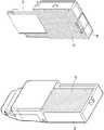
도 1은 본 발명의 일 실시예에 따른 초음파 프로브의 사시도이며, 도 2는 도1 에 도시된 초음파 프로브의 분해 사시도이다.
도 3은 본 발명의 일 실시예에 따른 열저장부와 배터리부의 분해 사시도이며, 도 4는 도 3에 도시된 열저장부와 배터리부의 단면도이다.
도 5는 상변화 물질의 온도와 부피의 상관관계를 나타내는 그래프이다.
도 6a 내지 도 6c 는 상변화 물질의 각 상태에 따른 열저장부와 배터리부의 부분 단면도이다.
도 7a 내지 도 7c 는 본 발명의 일 실시예에 따른 상변화 물질의 각 상태에 따른 표시부의 정면도이다.
도 8은 본 발명의 일 실시예에 따른 초음파 프로브의 사용 방법에 대한 순서도이다.
도 9a 내지 도 9c 는 본 발명의 다른 실시예에 따른 상변화 물질의 각 상태에 따른 표시부의 정면도이다.
도 10a는 거치대에 열저장부와 배터리부가 결합된 조립사시도이며, 도 10b는 도 10a에 도시된 거치대, 열저장부, 배터리부에 대한 단면도이다.1 is a perspective view of an ultrasound probe according to an embodiment of the present invention, and FIG. 2 is an exploded perspective view of the ultrasound probe shown in FIG. 1 .
3 is an exploded perspective view of the thermal storage unit and the battery unit according to an embodiment of the present invention, and FIG. 4 is a cross-sectional view of the thermal storage unit and the battery unit shown in FIG. 3 .
5 is a graph showing the correlation between the temperature and the volume of the phase change material.
6A to 6C are partial cross-sectional views of a heat storage unit and a battery unit according to respective states of the phase change material.
7A to 7C are front views of a display unit according to each state of a phase change material according to an embodiment of the present invention.
8 is a flowchart illustrating a method of using an ultrasound probe according to an embodiment of the present invention.
9A to 9C are front views of a display unit according to each state of a phase change material according to another exemplary embodiment of the present invention.
10A is an assembling perspective view in which the heat storage unit and the battery unit are coupled to the holder, and FIG. 10B is a cross-sectional view of the holder, the thermal storage unit, and the battery unit shown in FIG. 10A .
이하, 첨부된 도면을 참조하여 본 발명의 실시예를 상세하게 설명한다. 이 과정에서 도면에 도시된 층이나 영역들의 두께는 명세서의 명확성을 위해 과장되게 도시된 것이다. 명세서를 통하여 실질적으로 동일한 구성요소에는 동일한 참조번호를 사용하고 상세한 설명은 생략한다. 본 명세서에 기재된 “…부”와 같은 용어는 적어도 하나의 기능이나 동작을 처리하는 단위를 의미하며, 이는 하드웨어 또는 소프트웨어로 구현되거나 하드웨어와 소프트웨어의 결합으로 구현될 수 있다.Hereinafter, embodiments of the present invention will be described in detail with reference to the accompanying drawings. In this process, the thicknesses of the layers or regions shown in the drawings are exaggerated for clarity of the specification. Throughout the specification, substantially the same reference numerals are used to refer to the same components, and detailed descriptions thereof are omitted. As used herein, “… A term such as “unit” means a unit that processes at least one function or operation, which may be implemented as hardware or software, or a combination of hardware and software.
본 명세서에서 "피검체"는 사람 또는 동물, 또는 사람 또는 동물의 일부를 포함할 수 있다. 예를 들어, 피검체는 간, 심장, 자궁, 뇌, 유방, 복부 등의 장기, 또는 혈관을 포함할 수 있다. 또한, 본 명세서에서 "시술자"는 의료 전문가로서 의사, 간호사, 임상 병리사, 의료 영상 전문가 등이 될 수 있으며, 의료 장치를 수리하는 기술자가 될 수 있으나, 이에 한정되지 않는다..
As used herein, "subject" may include a human or animal, or a part of a human or animal. For example, the subject may include organs such as liver, heart, uterus, brain, breast, abdomen, or blood vessels. In addition, as used herein, the term "operator" may be a medical professional, such as a doctor, a nurse, a clinical pathologist, or a medical imaging specialist, and may be a technician repairing a medical device, but is not limited thereto.
도 1은 본 발명의 실시예에 따른 초음파 프로브(10)의 구조를 개략적으로 보여주는 사시도이며, 도 2는 도 1에 도시된 초음파 프로브(10)의 분리 사시도이다.1 is a perspective view schematically showing the structure of an
도 1을 참조하면, 초음파 프로브(10)는 피검체에 초음파 신호를 송신하고 피검체로부터 반사되는 에코 신호를 수신할 수 있는 본체부(20), 본체부(20)로부터 방출된 열을 저장하여 외부로 전달할 수 있는 열저장부(30) 및 본체부(20)에 전원을 공급할 수 있는 배터리부(40) 및 열저장부(30)에 저장된 열량을 표시하기 위한 표시부(50)를 포함한다. 본체부(20)는, 초음파 신호를 송신하고 에코 신호를 수신하는 과정에서 전기회로 등에 의해 열을 발생시킬 수 있다. 상술한 바와 같이 과거에 사용되던 초음파 프로브(10)에서 발생하는 발열량은 1W 수준으로 초음파 프로브 케이스를 통해 자연적으로 방출시킬 수 있는 정도였지만, 초음파 트랜스듀서가 다채널화되면서 그 발열량이 7W 수준으로 증가하였다. 이로 인해 본체부(20)는 작동을 시작한 후 10분 내지 15분만에 40도 내지 45도까지 상승할 수 있으며, 본체부(20)를 파지한 시술자에게 상해를 입힐 수 있다.Referring to FIG. 1 , the
열저장부(30)는 본체부(20)로부터 발생되는 열을 흡수하여 외부로 방출시키기 위한 방열 부재이다. 도 2를 참조하면, 본체부(20)의 일면에는 본체부(20)의 내부에 배치된 전기 회로 등에서 발생된 열을 외부로 전달하기 위한 제1 열전달부(21)가 형성되고, 열저장부(30)의 일면에는 제1 열전달부(21)와 접촉하는 제2 열전달부(31)가 형성된다. 제1 열전달부(21)와 제2 열전달부(31)는 열전도성이 우수한 물질, 예를 들어 구리, 은 등으로 형성될 수 있다. 초음파 프로브(10)가 사용되는 경우, 본체부(20)에서 발생된 열이 제1 열전달부(21)와 제2 열전달부(31)를 통해 열저장부(30)로 흡수될 수 있으며, 이로 인해 본체부(20)는 시술자에게 상해를 입히지 않을 정도의 온도가 유지될 수 있다. 열저장부(30)는, 방열을 위해 본체부(20)로부터 이격될 수 있는 분리형으로 형성될 수 있으나, 본 발명이 이에 한정되는 것은 아니며, 본체부(20)와 일체형으로 형성되어도 무방하다.The
배터리부(40)는 본체부(20)에 전원을 공급하기 위한 장치로서, 본체부(20)와 전기적으로 연결될 수 있다. 종래 사용되었던 초음파 프로브(10)는 유선 방식으로 형성되어 외부에서 직접 전원을 공급받을 수 있었으나, 시술자의 편의성을 확보하기 위해 무선 방식의 초음파 프로브(10)가 사용됨에 따라 본체부(20)에 전원을 공급하기 위한 별도의 배터리부(40)가 본체부(20)에 연결된다. 배터리부(40)는 분리형 또는 일체형으로 본체부(20)에 연결될 수 있다. 일 실시예에 따르면, 배터리부(40)는 열저장부(30)에 고정되어 열저장부(30)와 함께 본체부(20)에 부착 또는 탈거될 수 있으나, 본 발명이 이에 한정되는 것은 아니며, 배터리부(40)와 열저장부(30)가 각각 본체부(20)에 부착 또는 탈거되어도 무방하다.The
표시부(50)는 본체부(20)로부터 열저장부(30)에 전달될 열량을 표시하기 위한 장치로서 시술자는, 표시부(50)를 통해 열저장부(30)에 현재 저장된 열량 및 초음파 프로브(10)의 사용 가능 시간 등을 확인할 수 있다.The
도 3은, 본 발명의 일 실시예에 따른 열저장부(30)와 배터리부(40)의 분리 사시도를 나타내며, 도 4는 도 3에 도시된 열저장부(30)와 배터리부(40)의 단면도를 나타낸다.3 is an exploded perspective view showing the
열저장부(30)는 본체부(20)로부터 열을 전달받아 외부로 열을 방열시키기까지 임시적으로 열을 저장하고 있는 열 저장 부재, 예를 들어 상변화 물질(320; phase change material)을 포함할 수 있다. 도 3 및 도 4를 참조하면, 열저장부(30)는, 본체부(20)로부터 전달받은 열을 저장할 수 있는 상변화 물질(320), 상변화 물질(320)을 수용할 수 있는 하우징(310), 하우징(310)의 일 단부에 배치되어 상변화 물질(320)을 밀폐시키고, 하우징(310)의 길이방향으로 이동할 수 있는 피스톤부(330), 피스톤부(330)의 하단부에 배치되어 있는 탄성부재(340) 및 탄성부재(340)의 변화량을 감지할 수 있는 센서부(350)를 포함할 수 있다.The
하우징(310)은, 상변화 물질(320)을 수용할 수 있는 수용 부재로서, 하우징(310)의 일 면에 각각 배치된 제2 열전달부(31)와 피스톤부(330)를 이용하여 상변화 물질(320)을 밀폐 시킬 수 있다. 일 예로서, 하우징(310)은 실린더 형상으로 형성될 수 있으나, 본 발명이 이에 한정되는 것은 아니며, 상변화 물질(320)의 상변화 과정에서 피스톤부(330)가 이동할 수 있는 임의의 형상으로 형성될 수 있다.The
상변화 물질(320)은, 상변화 과정에서 열을 축적할 수 있는 잠열재, 축열재, 축냉재 등의 열 조절성 물질을 의미한다. 상변화 물질(320)은, 상변화 과정을 통하여 많은 양의 열 에너지를 축적하거나 저장된 열 에너지를 방출할 수 있다. 예를 들어, 상변화 물질(320)은, 어떤 물질이 고체에서 액체 상태, 액체에서 고체상태, 액체에서 기체 상태 등, 하나의 상태에서 다른 상태로 변하는 일종의 물리적 변화과정을 통해 열을 축적하거나 저장된 열을 방출할 수 있다. 상변화 물질(320)은 크게 유기 물질과 무기 물질로 분류할 수 있으며, 사용온도에 따라 고온 상변화 물질(40oC-150oC), 중온 상변화 물질(0oC-40oC), 저온 상변화 물질(-60oC-0oC)으로 분류할 수 있다. 유기 물질의 예로는 탄소와 수소로 이루어진 탄화수소계열의 테트라데칸, 옥타데칸, 노나데칸 등의 물질이 있으며, 무기 물질의 예로는 6개의 물분자가 결합된 수화물 형태의 염화칼슘 등이 있다. 본 발명의 일 실시예에 따르면, 초음파 프로브(10)는 시술자가 파지한 상태에서 시술이 진행되며, 시술자가 시술하는 과정에서 상해를 입지 않기 위해 초음파 프로브(10)는 25oC-37oC 정도의 온도 구간에서 상변화가 발생되어야 하기 때문에 중온 상변화 물질, 예를 들어 카르프산(Capric acid), 노멀 도코세인(n-docosane), 노멀 엔코세인(N-elcosane), 노멀 옥타데칸(N-octadecane)이 사용될 수 있다.The
피스톤부(330)는 하우징(310)의 바닥부에 배치되어 하우징(310) 내부에 상변화 물질(320)을 밀폐시킬 수 있으며, 하우징(310)의 길이 방향으로 상하 운동할 수 있다. 상변화 물질(320)과 접촉하지 않는 피스톤부(330)의 나머지 일 면에는 복수의 돌출부(331, 332)가 형성되고, 중앙부에는 오목홈(333; 도 4 참조)이 형성될 수 있다. 상변화 물질(320)이 상변화하여 그 부피가 증가하는 경우, 복수의 돌출부(331, 332)는 탄성 부재(340)에 압력을 가할 수 있으며, 오목홈(333)은 탄성 부재(340)에 구비된 고정부(343)와 접촉하여 피스톤부(330)가 일정 범위를 넘어서 하방으로 이동하는 것을 방지할 수 있다.The
탄성 부재(340)는 피스톤부(330)의 돌출부(331, 332)와 접촉하여 피스톤부(330)를 지지하는 제1 탄성 부재(341), 제2 탄성 부재(342) 및 복수의 탄성 부재(341, 342)를 지지하는 고정부(343)를 포함한다. 일 예로서, 고정부(343)는 하우징부(310)를 가로지르도록 연장되어 양 단부가 하우징부(310)의 내벽부에 고정되도록 배치될 수 있다. 제1 및 제2 탄성 부재(341, 342)는 평판 부재로서, 일 단부는 고정부(343)에 고정되고, 타 단부는, 피스톤부(330)를 지지할 수 있도록 복수의 돌출부(331, 332)와 각각 접촉되도록 배치된다. 상변화 물질(320)이 상변화하여 체적이 증가하는 경우, 제1 및 제2 탄성 부재(341, 342)는, 돌출부(331, 332)에 의해 압력을 인가받아 고정부(343)에 고정된 일 단부를 중심으로 시계 방향 또는 반시계 방향으로 각각 회전할 수 있다. 상변화 물질(320)이 상변화하여 체적이 감소하는 경우, 제1 및 제2 탄성 부재(341, 342)는 복원력에 의해 반대 방향으로 각각 회전하여 원래 위치로 복귀될 수 있다. 고정부(343)는, 피스톤부(330)의 오목홈(333)을 지지하여 피스톤부(330)가 일정 범위를 넘어서 하방으로 이동하는 것을 방지할 수 있다. 피스톤부(330)와 탄성부재(340)의 보다 상세한 구성과 동작은 도 5 및 도 6을 참조하여 설명한다.The
센서부(350)는, 피스톤부(330)의 이동 정도를 감지하여 상변화 물질(320)의 상변화 과정을 감지하기 위한 감지부재이다. 일 예로서, 센서부(350)로서 스트레인 게이지, FSR(Force Sensing Resistor) 센서 등이 사용되는 경우, 센서부(350)는 제1 또는 제2 탄성부재(341, 342)에 배치되어 피스톤부(330)의 이동에 따른 제1 또는 제2 탄성부재(341, 342)의 변형 정도 또는 제1 또는 제2 탄성부재(341, 342)에 인가되는 압력 정도를 감지하여 상변화 물질(320)의 상변화 상태를 감지할 수 있다. 또한 센서부(350)로서 압력 센서가 사용되는 경우, 상변화 물질(320)의 상변화에 따른 하우징(310) 내부의 압력 변화를 측정하여 상변화 물질(320)의 상변화 상태를 감지할 수 있다.The
표시부(50)는, 센서부(350)에 의해 감지된 상변화 물질(320)의 상변화 상태를 이용하여 상변화 물질(320)로 전달된 열량을 표시할 수 있다. 표시부(50)는 도형 숫자 등을 이용하여 상변화 물질(320)의 상태를 표시할 수 있을 뿐만 아니라 색채 변화 방식 등을 이용하여 상변화 물질(320)의 상태를 표시할 수 있다. 시술자는, 표시부(50)에 표시된 열저장부(30) 즉, 상변화 물질(320)에 저장된 열량을 고려하여 구체적인 시술 방법 및 시술 시간을 결정할 수 있다. 상변화 물질(320)의 상태 변화에 따른 표시부(50)의 표시 방법과 시술 방법 및 시술 시간의 결정 대한 보다 상세한 구성과 동작은 도 7 및 도 9를 참조하여 설명한다.The
도 3 및 도 4를 참조하면, 배터리부(40)는 본체부(20)에 전원을 공급하기 위한 부재로서, 배터리 본체(410), 본체부(20)에 형성된 단자부(미도시)접촉되어 전원을 공급하는 단자부(420) 및 단자부(420)의 전기적 연결을 차단할 수 있는 스위치부(430), 배터리 본체(410)를 커버하는 배터리 커버(440)를 포함할 수 있다.3 and 4 , the
스위치부(430)는, 단자부(420)의 각 단부에 연결된 도전성 제1 연결부(431) 및 제2 연결부(432)를 포함한다. 제2 연결부(432)는 상변화 물질(320)의 상변화에 의해 피스톤부(330)가 하강함에 따라 변형되는 제1 탄성 부재(341)와 접촉할 수 있다. 이 때, 제2 연결부(432)는 제1 연결부(431)와 접촉이 해제될 수 있으며, 이로 인해 본체부(20)에 대한 전원 공급이 차단될 수 있다. 스위치부(430)에 의한 본체부(20)로의 전원 공급 차단에 대한 보다 상세한 구성과 동작은 도 5 및 도 6을 참조하여 설명한다.The
도 5는, 상변화 물질(320)의 상변화 과정을 나타내는 T-V선도이며, 도 6a 내지 도 6c는 상변화 물질(320)의 상변화에 따른 열저장부(30) 및 배터리부(40)에 대한 제1 상태 내지 제3 상태(D1-D3)의 부분 단면도이다.5 is a T-V diagram showing a phase change process of the
시술자가 초음파 프로브(10)를 사용함에 따라, 제1 열전달부(21) 및 제2 열전달부(31)를 통해 상변화 물질(320)에 전달되는 열량이 증가되며, 이로 인해 상변화 물질(320)의 상 변화가 발생될 수 있다. 도 5를 참조하면, 시술자가 초음파 프로브(10)를 사용하기 이전 상태인 제1 상태(D1)에서 제1 상변화 물질(321)의 제1 온도(T1)는, 주변 온도, 예를 들어 25oC 와 동일하게 유지되며, 이 때, 제1 상변화 물질(321)의 상태는 고체 상태를 유지한다. 이에 따라, 제1 상변화 물질(321)의 체적(V1)은 가장 작은 상태로 유지될 수 있다.As the operator uses the
도 6a를 참조하면, 제1 상태(D1)에서 제1 상변화 물질(321)의 체적(V1)이 가장 작은 상태로 유지됨에 따라, 피스톤부(330)는 하방으로 이동되지 않는다. 따라서, 피스톤부(330)의 복수의 돌출부(331, 332)에 접하도록 배치된 제1 및 제2 탄성 부재(341, 342) 또한 변형되지 않으며, 제1 탄성 부재(341)와 인접하게 배치된 스위치부(430)의 제2 연결부(432) 또한 제1 탄성 부재(341)와 이격 상태를 유지할 수 있다. 제2 연결부(432)와 제1 탄성 부재(341)가 이격됨으로써 제1 연결부(431)와 제2 연결부(432)의 연결 상태는 유지되어 배터리부(40)로부터 본체부(20)로의 전원 공급은 이루어질 수 있다.Referring to FIG. 6A , as the volume V1 of the first phase change material 321 is maintained in the smallest state in the first state D1, the
도 5를 참조하면, 시술자가 초음파 프로브(10)를 사용한 이후의 상태인 제2 상태(D1)에서 제2 상변화 물질(322)의 제2 온도(T2)는, 상변화 온도(Tc)로 유지된다. 상변화 온도(Tc)는 상변화 물질(320)의 종류에 따라 상이할 수 있으며 초음파 프로브(10)의 사용목적 및 사용환경에 다양한 상변화 온도(Tc)를 갖는 상변화 물질(320)이 선택될 수 있다. 일 예로서, 초음파 프로브(10)가 시술자에 의해 파지되어 사용된다면, 시술자가 고온에 의해 상해를 입지 않도록 상변화 온도(Tc)가 37oC 이하인 물질이 선택될 수 있다. 이 때, 제2 상변화 물질(322)의 상태는 고체와 액체의 중간 상태를 유지하며, 제2 상변화 물질(322)의 제2 체적(V2)은 제1 상태의 제1 체적(V1) 보다 증가된다.Referring to FIG. 5 , the second temperature T2 of the second phase change material 322 in the second state D1, which is the state after the operator uses the
도 6b를 참조하면, 제2 상태(D2)에서 제2 상변화 물질(322)의 제2 체적(V2)이 제1 상태에서 제1 상변화 물질(321)의 제1 체적(V1) 보다 증가함에 따라 피스톤부(330)는 하방으로 이동된다. 이 때, 피스톤부(330)의 복수의 돌출부(331, 332)에 접하도록 배치된 제1 및 제2 탄성 부재(341, 342) 또한 하방으로 변형될 수 있다. 다만, 제1 탄성 부재(341)와 인접하게 배치된 스위치부(430)의 제2 연결부(432)는 여전히 제1 탄성 부재(341)와 이격 상태를 유지할 수 있으므로, 제1 연결부(431)와 제2 연결부(432)의 연결 상태는 유지되어 배터리부(40)로부터 본체부(20)로의 전원 공급은 지속적으로 이루어질 수 있다.Referring to FIG. 6B , the second volume V2 of the second phase change material 322 in the second state D2 is greater than the first volume V1 of the first phase change material 321 in the first state. As a result, the
도 5를 참조하면, 시술자가 초음파 프로브(10)를 사용한 이후의 상태인 제3 상태(D1)에서 제3 상변화 물질(322)의 제3 온도(T3)는, 상변화 온도(Tc)로 유지된다. 본체부(20)로부터 상변화 물질(320)으로 열이 지속적으로 공급되지만, 상변화 물질(320)의 상변화 즉, 고체에서 액체로의 상변화만이 진행될 뿐 제3 온도(T3)는 상변화 온도(Tc)인 제2 온도(T2)와 동일하게 유지될 수 있다. 이 때, 제3 상변화 물질(323)의 상태는 액체 상태이며, 제3 상변화 물질(323)의 제3 체적(V3)은 제2 상태의 제2 체적(V2) 보다 증가된다. 다만, 제3 상태에서 제3 상변화 물질(323)은 완전한 액체 상태이므로 본체(20)로부터 열이 추가적으로 인가된다면 상변화 물질(320)의 온도는 상변화 온도(Tc)보다 증가하여 시술자에게 상해를 입힐 수 있다.Referring to FIG. 5 , the third temperature T3 of the third phase change material 322 in the third state D1, which is the state after the operator uses the
도 6c를 참조하면, 제3 상태(D3)에서 제3 상변화 물질(323)의 제3 체적(V3)이 제2 상태에서 제2 상변화 물질(322)의 제2 체적(V2) 보다 증가함에 따라 피스톤부(330)는 하방으로 이동된다. 이 때, 피스톤부(330)의 복수의 돌출부(331, 332)에 접하도록 배치된 제1 및 제2 탄성 부재(341, 342) 또한 추가적으로 변형될 수 있다. 다만, 피스톤부(330)의 오목홈(333)이 탄성부재(340)의 고정부(343)에 접하여 지지됨에 따라 본체부(20)로부터 상변화 물질(320)으로 열이 추가적으로 인가되는 경우에도 피스톤부(330)는 하방으로 이동되지 않을 수 있다. 또한, 제1 탄성 부재(341)와 인접하게 배치된 스위치부(430)의 제2 연결부(432)는 제1 탄성 부재(341)와 접하여 하방으로 이동될 수 있으며, 이로 인해 제1 연결부(431)와 제2 연결부(432)의 연결 상태가 해제되어 배터리부(40)로부터 본체부(20)로의 전원 공급이 차단될 수 있다. 따라서, 시술자가 초음파 프로브(10)의 상태를 인지하지 못한 채 시술을 지속하는 경우에도 전원이 자동으로 차단되어 초음파 프로브(10)의 구동이 정지될 수 있다. 이로 인해 본체(20)로부터 상변화 물질(320)으로 열이 추가적 인가되지 않고, 상변화 물질(320)의 온도 상승을 방지할 수 있으므로 시술자의 상해를 방지할 수 있다.Referring to FIG. 6C , the third volume V3 of the third phase change material 323 in the third state D3 is greater than the second volume V2 of the second phase change material 322 in the second state. As a result, the
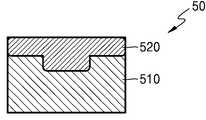
도 7a 내지 도 7c은 초음파 프로브의 제1 상태 내지 제3 상태(D1-D3)를 나타내는 초음파 프로브(10)의 부분 정면도이며, 도 8은 초음파 프로브(10)의 사용 방법을 결정하기 위한 순서도이다.7A to 7C are partial front views of the
상술한 바와 같이, 시술자가 초음파 프로브(10)를 함에 따라 상변화 물질(320)은 제1 상태 내지 제3 상태(D1-D3)로 변화한다. 이 때, 시술자가 센서부(350)로부터 감지된 상변화 물질(320)의 상태를 인지할 수 있다면, 시술 시간 및 시술에 필요한 조건 등을 변경할 수 있으므로 시술자는 최적의 환경에서 초음파 프로브(10)를 사용할 수 있다. 도 7a 내지 도 7c를 참조하면, 열저장부(30)의 정면부에 표시부(50)가 마련됨으로써 시술자는 상변화 물질(320)의 상태를 인지할 수 있다. 예를 들어, 표시부(50)는 하우징부(310)와 피스톤부(330)를 형상화하는 제1 표시부(510)와 제2 표시부(520)를 포함할 수 있다. 시술자가 초음파 프로브(10)를 사용하기 전, 제2 표시부(520)는 제1 표시부(510)의 상단부에 위치함으로써 상변화 물질(320)이 제1 상태(D1)임을 시술자에게 인지시킬 수 있다. 시술자가 초음파 프로브(10)를 사용하여 상변화 물질(320)에 열이 인가되는 경우, 제2 표시부(520)는 하방으로 이동하며, 이를 통해 시술자는 상변화 물질(320)이 제1 상태(D1)에서 제2 상태(D2)로 변화하는 것을 인지할 수 있다. 시술자가 초음파 프로브(10)를 사용하여 상변화 물질(320)에 열이 지속적으로 인가되는 경우, 제2 표시부(520)는 하단부로 이동하며, 이를 통해 시술자는, 상변화 물질(320)이 제2 상태(D2)에서 제3 상태(D3)로 변화하는 것을 인지할 수 있다. 이 때, 제1 연결부(431)와 제2 연결부(432)의 연결이 해제되며 이로 인해 배터리부(40)에서 본체부(20)로 공급되던 전원은 자동 차단되어 시술자의 상해를 방지할 수 있다.As described above, as the operator performs the
도 7a 내지 도 7c와 도 8을 참조하면, 본체부(20)로부터 상변화 물질(320)으로 인가되는 열량은 본체부(20)의 작동 시간 및 작동 환경에 의해 결정될 수 있다. 따라서 시술자는 표시부(50)를 통해 상변화 물질(320)의 상태를 확인하고 시술 방식 및 시술 시간을 결정할 수 있다.7A to 7C and 8 , the amount of heat applied from the
본 발명의 일 실시예에 따르면, 첫째, 표시부(50)를 통해 현재 상변화 물질(320)의 상태를 확인한다. (S410) 예를 들어, 시술자는, 표시부(50)를 통해 상변화 물질(320)의 상태를 확인하고, 상변화 물질(320)이 수용할 수 있는 잔여 열용량을 확인할 수 있다.According to an embodiment of the present invention, first, the current state of the
둘째, 초음파 프로브(10)의 사용환경을 고려하여 시술 조건을 입력한다. (S420) 예를 들어, 시술자는, 시술해야 할 피검체의 수, 시술 종류를 입력할 수 있다. 더불어 시술 종류 및 피검체의 상태에 따라 확보해야 하는 영상의 질이 상이할 수 있으며, 프레임 속도 또는 채널 수를 높인다면 보다 보다 우수한 해상도의 영상을 확보할 있으므로 필요로 하는 영상을 확보할 수 있는 프레임 속도 또는 채널 수를 입력할 수 있다.Second, the operating conditions are input in consideration of the environment of use of the
셋째, 상변화 물질(320)이 수용할 수 있는 잔여 열용량 및 입력된 시술 조건을 고려하여 초음파 프로브(10)의 작동시간이 결정된다. (S430)Third, the operating time of the
피검체의 수, 시술 종류, 프레임 속도 및 채널 수 에 따라 발생될 수 있는발열량은 메모리부(미도시)를 통해 저장될 수 있다. 따라서, 시술 조건을 입력함에 따라 시술 조건에 부합하는 전체 발열량이 계산될 수 있으며, 표시부(50) 표시된 상변화 물질(320)의 잔여 열용량을 고려하여 초음파 프로브(10)의 작동 시간이 결정될 수 있다. 따라서, 시술자는, 결정된 작동 시간 내에 시술을 완료할 수 있으며, 필요하다면, 시술 조건을 변경하여 초음파 프로브(10)의 작동 시간을 늘리거나 줄이는 등의 조절도 가능하다.The amount of heat generated according to the number of subjects, the type of treatment, the frame rate, and the number of channels may be stored through a memory unit (not shown). Accordingly, as the treatment conditions are input, the total amount of heat corresponding to the treatment conditions may be calculated, and the operating time of the
도 9a 내지 도 9c는 초음파 프로브의 제1 상태 내지 제3 상태(D1-D3)를 나타내는 초음파 프로브(10)의 정면도이다.9A to 9C are front views of the
상술한 바와 같이 표시부(50)는 도형, 숫자 뿐만 아니라 색채의 변화를 통해서도 상변화 물질(320)의 상태를 표시할 수 있다. 도 9a 내지 도 9c를 참조하면, 일 예로서, 열저장부의 하우징(310)의 색상을 변화시켜 상변화 물질(320)의 상태 변화를 표시할 수 있다. 하우징(310)은 제어 신호를 받아 색상을 변경할 수 있는 에플렉스 일렉트로닉스 스킨(eflex electronics skin), 피디에프 잉크(PDF ink) 로 형성될 수 있다. 하우징(310)은 센서부(350)로부터 감지된 상변화 물질(320)의 상태를 전달받아 하우징(310)의 색상을 변화시킬 수 있으며, 시술자는 하우징(310)의 색상 변화를 통해 상변화 물질(320)의 상태를 보다 용이하게 확인할 수 있다. 다만, 색상을 변화시킬 수 있는 영역이 하우징(310)으로 한정되는 것은 아니며, 시술자가 외관으로 식별할 수 있는 임의의 영역이면 무관하다.As described above, the
상변화 물질(320)의 각 상태에 따라 하우징(310)이 변화되는 과정 및 하우징(310)의 색상을 통해 확인된 상변화 물질(320)의 상태를 이용하여 초음파 프로브(10)의 사용 방법을 결정하는 단계는 도 7 및 도 8에 서술된 내용과 동일하므로 여기서는 설명을 생략한다.How to use the
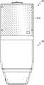
도 10a는 본 발명의 일 실시예에 따른 열저장부(30) 및 배터리부(40)가 거치대(60)에 거치된 상태의 조립 사시도이며, 도 10b는 도 10a에 도시된 거치대(60)의 단면도이다.10A is an assembled perspective view of the
열저장부(30)로부터 열을 외부로 방출하거나 배터리부(40)를 충전하기 위해 별도의 장치에 열저장부(30) 또는 배터리부(40)가 결합될 수 있다. 도 10a 및 도 10b를 참조하면, 거치대(60)는 배터리부(40)가 삽입되어 지지될 수 있는 삽입부(610), 배터리부(40)의 단자부(420)와 직접 접촉하여 배터리부(40)를 충전시킬 수 있는 유선 방식, 또는 예를 들어, 공진 주파수가 동일한 송신 코일과 수신 코일을 배터리부(40)와 충전부(620)에 각각 배치하여 배터리부(40)를 충전시킬 수 있는 무선 방식을 이용하는 충전부(620),를 포함할 수 있다. 또한, 거치대(60)는 열저장부(30)의 제2 열전달부(31)와 접촉하여 상변화 물질(320)으로부터 열을 전달받을 수 있는 제3 열전달부(630) 및 제3 열전달부(630)로부터 열을 전달 받아 외부로 방열시킬 수 있는 방열부(640)를 포함할 수 있다.In order to discharge heat from the
삽입부(610)는 열저장부(30) 및 배터리부(40)를 지지하기 위한 부재이다. 일 예로서 삽입부(610)는, 배터리부(40)만이 삽입될 수 있도록 형성되어 있으나, 본 발명이 이에 한정되는 것은 아니며 열저장부(30) 및 배터리부(40) 모두가 삽입되거나 본체부(20)와 열저장부(30) 및 배터리부(40)가 일체형으로 마련된다면, 초음파 프로브(10)가 삽입되도록 형성될 수 있다.The
제3 열전달부(630)는 제2 열전달부(31)와 접촉하여 상변화 물질(320)에 저장된 열을 방열핀(640)으로 전달하기 위한 부재로서 열 전도성이 높은 구리, 은 등으로 형성될 수 있다.The third
방열부(640)는 제3 열전달부(630)로부터 전달 받은 열을 외부로 방열 시키기 위한 방열 부재이다. 일 예로서 방열부(640)는 복수의 방열핀(641)을 포함할 수 있으며, 이로 인해 외부 공기와의 접촉 면적으로 넓혀 보다 효율적으로 제3 열전달부(630)로부터 전달된 열을 외부로 방출시킬 수 있다.The
거치대(60)에 열저장부(30) 및 배터리부(40)가 결합됨에 따라 열저장부(30)에 저장된 열은 방열부(640)를 통해 외부로 방열되어 상변화 물질(320)의 온도를 낮출 수 있다. 또한 배터리부(40)가 거치대(60)의 충전부(620)에 결합됨으로써 방열과 동시에 배터리부(40)를 충전시킬 수 있으므로 시술자는 시간을 효율적으로 사용할 수 있다. 더불어, 표시부(50) 또는 하우징부(310)의 색 변화를 통해 상변화 물질(320)의 상태를 확인할 수 있으므로, 보다 용이하게 상변화 물질(320)의 방열 정도를 확인하고 거치대(60)로부터 열저장부(30)를 분리하여 시술에 사용할 수 있다.
As the
본 발명은 도면에 도시된 실시예를 참고로 하여 설명되었으나, 이는 예시적인 것에 불과하며, 당해 기술이 속하는 분야에서 통상의 지식을 가진 자라면 이로부터 다양한 변형 및 균등한 타 실시예가 가능하다는 점을 이해할 것이다. 따라서, 본 발명의 진정한 기술적 보호범위는 아래의 특허청구범위에 의해서 정하여져야 할 것이다.Although the present invention has been described with reference to the embodiment shown in the drawings, this is merely an example, and those skilled in the art to which various modifications and equivalent other embodiments are possible. will understand Accordingly, the true technical protection scope of the present invention should be defined by the following claims.
발명의 명세서(특히 특허청구범위에서)에서 “상기”의 용어 및 이와 유사한 지시 용어의 사용은 단수 및 복수 모두에 해당하는 것일 수 있다. 또한 발명에서 범위(range)를 기재한 경우 상기 범위에 속하는 개별적인 값을 적용한 발명을 포함하는 것으로서(이에 반하는 기재가 없다면), 발명의 상세한 설명에 상기 범위를 구성하는 각 개별적인 값을 기재한 것과 같다. 마지막으로, 본 발명에 따른 방법을 구성하는 단계들에 대하여 명백하게 순서를 기재하거나 반하는 기재가 없다면, 상기 단계들은 적당한 순서로 행해질 수 있다. 반드시 상기 단계들의 기재 순서에 따라 본 발명이 한정되는 것은 아니다. 본 발명에서 모든 예들 또는 예시적인 용어(예들 들어, 등등)의 사용은 단순히 본 발명을 상세히 설명하기 위한 것으로서 특허청구범위에 의해 한정되지 않는 이상 상기 예들 또는 예시적인 용어로 인해 본 발명의 범위가 한정되는 것은 아니다. 또한 기술이 속한 분야의 통상의 지식을 갖는 자는 발명의 범위와 사상에서 벗어나지 않으면서도 다양한 수정과 변경이 용이하게 이루어질 수 있음을 명확히 알 수 있다.
In the specification of the invention (especially in the claims), the use of the term “above” and similar referential terms may be used in both the singular and the plural. In addition, when a range is described in the invention, it includes the invention to which individual values belonging to the range are applied (unless there is a description to the contrary), and each individual value constituting the range is described in the detailed description of the invention. . Finally, the steps constituting the method according to the present invention may be performed in an appropriate order unless the order is explicitly stated or there is no description to the contrary. The present invention is not necessarily limited to the order in which the steps are described. The use of all examples or exemplary terms (eg, etc.) in the present invention is merely for the purpose of describing the present invention in detail, and the scope of the present invention is limited by the examples or exemplary terms unless limited by the claims. it's not going to be In addition, those of ordinary skill in the art can clearly see that various modifications and changes can be easily made without departing from the scope and spirit of the invention.
10: 초음파 프로브20: 본체부
30: 열저장부40: 배터리부
50: 표시부60: 거치대
310: 하우징320: 상변화물질
330: 피스톤부340: 탄성 부재
430: 스위치부620: 충전부
640: 방열부10: ultrasonic probe 20: body part
30: heat storage unit 40: battery unit
50: display unit 60: cradle
310: housing 320: phase change material
330: piston 340: elastic member
430: switch unit 620: charging unit
640: heat dissipation unit
Claims (16)
Translated fromKorean상기 본체부에 전원을 공급하는 배터리부; 및
상기 본체부로부터 발생된 열을 저장하는 상변화 물질을 포함하는 열저장부;를 포함하고,
상기 배터리부는 상기 본체부와의 전기적 연결을 단속하는 스위치부를 포함하고,
상기 열저장부는 상기 상변화 물질의 부피 변화에 따라 이동하는 피스톤부를 포함하며,
상기 스위치부는 상기 피스톤부의 이동에 따라 온/오프(on/off)되는,
초음파 프로브.
a main body for transmitting and receiving ultrasonic waves;
a battery unit supplying power to the body unit; and
and a heat storage unit including a phase change material for storing heat generated from the body unit;
The battery unit includes a switch unit for intermittent electrical connection with the body unit,
The heat storage unit includes a piston unit that moves according to a change in the volume of the phase change material,
The switch unit is turned on/off according to the movement of the piston unit,
ultrasonic probe.
상기 배터리부는 상기 열저장부에 고정되어 상기 본체부로부터 상기 열저장부와 함께 분리되거나 결합되는,
초음파 프로브.
According to claim 1,
The battery unit is fixed to the heat storage unit and is separated from or combined with the heat storage unit from the body unit,
ultrasonic probe.
상기 스위치부는 제1 연결부와 온(on) 상태에서 상기 제1 연결부와 접촉하는 제2 연결부를 포함하며,
상기 상기 피스톤부의 이동에 의해 상기 제2 연결부와 상기 피스톤부가 접함에 따라 상기 제1 연결부와 상기 제2 연결부의 접촉이 해제되어 상기 배터리부의 스위치부가 오프(off) 되는,
초음파 프로브.According to claim 1,
The switch part includes a first connection part and a second connection part in contact with the first connection part in an on state,
As the second connection part and the piston part come into contact by the movement of the piston part, the contact of the first connection part and the second connection part is released so that the switch part of the battery part is turned off,
ultrasonic probe.
상기 상변화 물질의 상변화가 완료되는 시점에, 상기 배터리부의 스위치부가 오프(off)되어 상기 본체부에 공급되는 전원이 차단되는,
초음파 프로브.According to claim 1,
When the phase change of the phase change material is completed, the switch unit of the battery unit is turned off to cut off the power supplied to the body unit,
ultrasonic probe.
상기 상변화 물질의 상변화 온도는 250C 이상 370C 이하인,
초음파 프로브.According to claim 1,
The phase change temperature of the phase change material is 250 C or more and 370 C or less,
ultrasonic probe.
상기 피스톤부의 이동을 감지하여 상기 상변화 물질의 부피 변화를 감지하는 센서부를 더 포함하는,
초음파 프로브.According to claim 1,
Further comprising a sensor unit for detecting a volume change of the phase change material by sensing the movement of the piston unit,
ultrasonic probe.
상기 열저장부에 저장된 열량을 표시하는 표시부;를 더 포함하고,
상기 표시부는 상기 센서부에 의해 감지된 상변화 물질의 부피 변화에 따라 색깔이 변화하는,
초음파 프로브.9. The method of claim 8,
Further comprising; a display unit for displaying the amount of heat stored in the heat storage unit;
The display unit changes color according to the volume change of the phase change material sensed by the sensor unit,
ultrasonic probe.
상기 표시부를 통해 상변화 물질의 상태를 확인하는 단계;
시술 조건을 입력하는 단계;
상기 표시부를 통해 확인된 상기 상변화 물질의 상태 및 입력된 상기 시술 조건에 따라 상기 본체부의 작동 시간이 결정되는 단계;를 포함하는,
초음파 프로브의 사용 방법.A body part for transmitting and receiving ultrasonic waves, a battery part for supplying power to the body part, a heat storage part including a phase change material for storing heat generated from the body part, and a display part for displaying the amount of heat stored in the heat storage part Including, wherein the battery part includes a switch part for intermittent electrical connection with the body part, the heat storage part includes a piston part that moves according to a change in the volume of the phase change material, the switch part according to the movement of the piston part In the method of using an ultrasonic probe that is turned on / off (on / off),
checking the state of the phase change material through the display unit;
inputting treatment conditions;
Determining the operating time of the body unit according to the state of the phase change material confirmed through the display unit and the inputted treatment condition; including,
How to use an ultrasonic probe.
상기 시술 조건은 피검체의 수, 시술 종류, 상기 본체부의 프레임 속도 또는 채널 수 중 하나 이상인,
초음파 프로브의 사용 방법.11. The method of claim 10,
The treatment condition is at least one of the number of subjects, the type of treatment, the frame rate of the main body, or the number of channels,
How to use an ultrasonic probe.
상기 열 저장부가 삽입되는 삽입부;
상기 열저장부의 열을 전달받아 외부로 열을 방출시키는 방열부; 를 포함하는,
거치대.In the cradle for mounting the ultrasonic probe according to any one of claims 1, 3, 5 to 8,
an insertion unit into which the heat storage unit is inserted;
a heat dissipation unit receiving heat from the heat storage unit and dissipating heat to the outside; containing,
holder.
상기 초음파 프로브는 배터리부를 더 포함하며, 상기 거치대는 상기 배터리부를 충전시키는 충전부를 더 포함하는,
거치대.13. The method of claim 12,
The ultrasonic probe further includes a battery part, and the cradle further includes a charging part for charging the battery part,
holder.
상기 충전부는 무선 또는 유선 방식으로 상기 배터리부를 충전시키는,
거치대.14. The method of claim 13,
The charging unit charges the battery unit in a wireless or wired manner,
holder.
상기 방열부에 의한 상기 열저장부의 방열과 상기 충전부에 의한 상기 배터리부의 충전이 동시에 진행되는,
거치대.14. The method of claim 13,
The heat dissipation of the heat storage unit by the heat dissipation unit and the charging of the battery unit by the charging unit proceed at the same time,
holder.
상기 초음파 프로브는 상기 열저장부에 저장된 열량을 표시하는 표시부를 더 포함하고,
상기 방열부에 의한 상기 열저장부의 방열 정도가 상기 표시부에 표시되는,
거치대.13. The method of claim 12,
The ultrasonic probe further includes a display unit for displaying the amount of heat stored in the heat storage unit,
The degree of heat dissipation of the heat storage unit by the heat dissipation unit is displayed on the display unit,
holder.
Priority Applications (2)
| Application Number | Priority Date | Filing Date | Title |
|---|---|---|---|
| KR1020140122032AKR102400997B1 (en) | 2014-09-15 | 2014-09-15 | Ultrasonic probe and Method for working the Same and Mounting device |
| US14/851,040US10241089B2 (en) | 2014-09-15 | 2015-09-11 | Ultrasonic probe, method of working the same, and mounting device |
Applications Claiming Priority (1)
| Application Number | Priority Date | Filing Date | Title |
|---|---|---|---|
| KR1020140122032AKR102400997B1 (en) | 2014-09-15 | 2014-09-15 | Ultrasonic probe and Method for working the Same and Mounting device |
Publications (2)
| Publication Number | Publication Date |
|---|---|
| KR20160031825A KR20160031825A (en) | 2016-03-23 |
| KR102400997B1true KR102400997B1 (en) | 2022-05-23 |
Family
ID=55454500
Family Applications (1)
| Application Number | Title | Priority Date | Filing Date |
|---|---|---|---|
| KR1020140122032AActiveKR102400997B1 (en) | 2014-09-15 | 2014-09-15 | Ultrasonic probe and Method for working the Same and Mounting device |
Country Status (2)
| Country | Link |
|---|---|
| US (1) | US10241089B2 (en) |
| KR (1) | KR102400997B1 (en) |
Families Citing this family (8)
| Publication number | Priority date | Publication date | Assignee | Title |
|---|---|---|---|---|
| US10779801B2 (en) | 2016-09-21 | 2020-09-22 | Clarius Mobile Health Corp. | Ultrasound apparatus with improved heat dissipation and methods for providing same |
| WO2018075363A1 (en)* | 2016-10-18 | 2018-04-26 | Sonomotion, Inc. | Ultrasound devices incorporating phase change materials and systems and methods using the devices |
| US11083439B2 (en) | 2017-06-05 | 2021-08-10 | Clarius Mobile Health Corp. | Cooling unit for an ultrasound imaging apparatus, and related ultrasound systems |
| CN110960255A (en)* | 2018-09-30 | 2020-04-07 | 深圳迈瑞生物医疗电子股份有限公司 | Ultrasonic probe |
| US12396709B2 (en)* | 2018-12-07 | 2025-08-26 | General Electric Company | Ultrasound probe and method of making the same |
| US11986347B2 (en) | 2022-01-16 | 2024-05-21 | Clarius Mobile Health Corp. | Dual function cooling and charging unit for an ultrasound imaging apparatus, and related ultrasound systems |
| US20230233192A1 (en)* | 2022-01-25 | 2023-07-27 | GE Precision Healthcare LLC | Phase Change Insert for Ultrasound Imaging Probe |
| CN117100315A (en)* | 2023-09-06 | 2023-11-24 | 广州索诺康医疗科技有限公司 | Handheld ultrasonic system with temperature control function |
Citations (7)
| Publication number | Priority date | Publication date | Assignee | Title |
|---|---|---|---|---|
| JP2006198413A (en) | 2005-01-19 | 2006-08-03 | Siemens Medical Solutions Usa Inc | Method for using refrigerating system to remove waste heat from ultrasonic transducer |
| US20060191344A1 (en) | 2004-09-24 | 2006-08-31 | Shinichi Hashimoto | Ultrasonic probe |
| US20090112099A1 (en) | 2007-10-19 | 2009-04-30 | Panasonic Corporation | Ultrasonic probe, charger, ultrasonic diagnostic apparatus and ultrasonic diagnostic system |
| US20120006994A1 (en) | 2009-03-24 | 2012-01-12 | Konica Minolta Medical & Graphic, Inc. | Radiation image detecting system |
| JP2012228425A (en)* | 2011-04-27 | 2012-11-22 | Fujifilm Corp | Ultrasound diagnostic apparatus |
| JP2013052023A (en) | 2011-09-01 | 2013-03-21 | Toshiba Corp | Ultrasonic probe and ultrasonic diagnostic apparatus |
| US20140102662A1 (en) | 2012-10-10 | 2014-04-17 | Promethean Power Systems, Inc. | Thermal energy battery with enhanced heat exchange capability and modularity |
Family Cites Families (9)
| Publication number | Priority date | Publication date | Assignee | Title |
|---|---|---|---|---|
| JP2001236145A (en) | 2000-02-22 | 2001-08-31 | Hitachi Ltd | Battery and battery charger and cooling device |
| DE60138030D1 (en)* | 2000-09-14 | 2009-04-30 | Cook Urological Inc | MINIMALLY INVASIVE APPARATUS FOR COLLECTING OBJECTS IN HOLLOWERS |
| US6876550B2 (en) | 2002-12-13 | 2005-04-05 | Hitachi Global Storage Technologies Netherlands B.V. | Active heat sink for high power microprocessors |
| US7188484B2 (en) | 2003-06-09 | 2007-03-13 | Lg Electronics Inc. | Heat dissipating structure for mobile device |
| JP2006092894A (en) | 2004-09-24 | 2006-04-06 | Fuji Photo Film Co Ltd | Battery pack, electronic equipment, charger, battery-driven electronic equipment system |
| CN2750369Y (en) | 2004-11-19 | 2006-01-04 | 鸿富锦精密工业(深圳)有限公司 | Heat radiation module |
| US8206307B2 (en)* | 2010-03-10 | 2012-06-26 | Dbmedx Inc. | Ultrasound imaging probe and method |
| CN105188486B (en)* | 2013-03-20 | 2019-03-19 | 皇家飞利浦有限公司 | The device for being used to prepare hot beverage with automatic power down mechanism |
| CN104970822A (en)* | 2014-04-03 | 2015-10-14 | Ge医疗系统环球技术有限公司 | Wireless ultrasonic probe and ultrasonic machine |
- 2014
- 2014-09-15KRKR1020140122032Apatent/KR102400997B1/enactiveActive
- 2015
- 2015-09-11USUS14/851,040patent/US10241089B2/enactiveActive
Patent Citations (7)
| Publication number | Priority date | Publication date | Assignee | Title |
|---|---|---|---|---|
| US20060191344A1 (en) | 2004-09-24 | 2006-08-31 | Shinichi Hashimoto | Ultrasonic probe |
| JP2006198413A (en) | 2005-01-19 | 2006-08-03 | Siemens Medical Solutions Usa Inc | Method for using refrigerating system to remove waste heat from ultrasonic transducer |
| US20090112099A1 (en) | 2007-10-19 | 2009-04-30 | Panasonic Corporation | Ultrasonic probe, charger, ultrasonic diagnostic apparatus and ultrasonic diagnostic system |
| US20120006994A1 (en) | 2009-03-24 | 2012-01-12 | Konica Minolta Medical & Graphic, Inc. | Radiation image detecting system |
| JP2012228425A (en)* | 2011-04-27 | 2012-11-22 | Fujifilm Corp | Ultrasound diagnostic apparatus |
| JP2013052023A (en) | 2011-09-01 | 2013-03-21 | Toshiba Corp | Ultrasonic probe and ultrasonic diagnostic apparatus |
| US20140102662A1 (en) | 2012-10-10 | 2014-04-17 | Promethean Power Systems, Inc. | Thermal energy battery with enhanced heat exchange capability and modularity |
Also Published As
| Publication number | Publication date |
|---|---|
| US10241089B2 (en) | 2019-03-26 |
| US20160077059A1 (en) | 2016-03-17 |
| KR20160031825A (en) | 2016-03-23 |
Similar Documents
| Publication | Publication Date | Title |
|---|---|---|
| KR102400997B1 (en) | Ultrasonic probe and Method for working the Same and Mounting device | |
| CN105708499B (en) | Probe for ultrasonic diagnostic apparatus | |
| KR102271172B1 (en) | Ultrasonic backing elememt, ultrasonic probe including the same and the method of manufacturing thereof | |
| US10085717B2 (en) | Ultrasonic probe | |
| EP2932906B1 (en) | Ultrasonic probe | |
| US20180161002A1 (en) | Ultrasound delivery for diagnosis and/or therapy | |
| KR101496173B1 (en) | Heat Dissipation Structure for Portable Ultrasonic Diagnostic Device | |
| US20160174939A1 (en) | Ultrasonic probe | |
| US20140364742A1 (en) | Ultrasonic probe and manufacturing method thereof | |
| JP5399660B2 (en) | Ultrasound endoscope | |
| US10327735B2 (en) | Portable ultrasonic probe having a folder part | |
| US20080077017A1 (en) | Ultrasonic probe, ultrasonic endoscope, and ultrasonic diagnostic apparatus | |
| US10292680B2 (en) | Ultrasonic probe and manufacturing method thereof | |
| KR101953309B1 (en) | Probe for ultrasonic diagnostic apparatus | |
| EP2878269A1 (en) | Ultrasonic probe and ultrasonic imaging apparatus having the same | |
| KR20140144464A (en) | Portable Ultrasonic Probe | |
| JP6749933B2 (en) | Remote controlled ultrasonic transducer | |
| US20240138811A1 (en) | Casing for a portable ultrasonic imaging device | |
| US10251623B2 (en) | Support apparatus of ultrasound probe, handsfree ultrasound probe including the support apparatus, and method of operating the support apparatus | |
| CN212415767U (en) | Ultrasonic instrument | |
| CN111166374A (en) | A kind of multi-sound head and ultrasonic instrument | |
| CN117255643A (en) | Breast implant and apparatus for sensing abnormality of breast implant |
Legal Events
| Date | Code | Title | Description |
|---|---|---|---|
| PA0109 | Patent application | Patent event code:PA01091R01D Comment text:Patent Application Patent event date:20140915 | |
| PG1501 | Laying open of application | ||
| A201 | Request for examination | ||
| PA0201 | Request for examination | Patent event code:PA02012R01D Patent event date:20190916 Comment text:Request for Examination of Application Patent event code:PA02011R01I Patent event date:20140915 Comment text:Patent Application | |
| E902 | Notification of reason for refusal | ||
| PE0902 | Notice of grounds for rejection | Comment text:Notification of reason for refusal Patent event date:20210201 Patent event code:PE09021S01D | |
| E90F | Notification of reason for final refusal | ||
| PE0902 | Notice of grounds for rejection | Comment text:Final Notice of Reason for Refusal Patent event date:20210823 Patent event code:PE09021S02D | |
| E701 | Decision to grant or registration of patent right | ||
| PE0701 | Decision of registration | Patent event code:PE07011S01D Comment text:Decision to Grant Registration Patent event date:20220218 | |
| GRNT | Written decision to grant | ||
| PR0701 | Registration of establishment | Comment text:Registration of Establishment Patent event date:20220518 Patent event code:PR07011E01D | |
| PR1002 | Payment of registration fee | Payment date:20220519 End annual number:3 Start annual number:1 | |
| PG1601 | Publication of registration |