KR102398137B1 - Data processing device - Google Patents
Data processing deviceDownload PDFInfo
- Publication number
- KR102398137B1 KR102398137B1KR1020217018266AKR20217018266AKR102398137B1KR 102398137 B1KR102398137 B1KR 102398137B1KR 1020217018266 AKR1020217018266 AKR 1020217018266AKR 20217018266 AKR20217018266 AKR 20217018266AKR 102398137 B1KR102398137 B1KR 102398137B1
- Authority
- KR
- South Korea
- Prior art keywords
- housing
- data processing
- sensor
- display unit
- folded
- Prior art date
- Legal status (The legal status is an assumption and is not a legal conclusion. Google has not performed a legal analysis and makes no representation as to the accuracy of the status listed.)
- Active
Links
Images


Classifications
- G—PHYSICS
- G06—COMPUTING OR CALCULATING; COUNTING
- G06F—ELECTRIC DIGITAL DATA PROCESSING
- G06F3/00—Input arrangements for transferring data to be processed into a form capable of being handled by the computer; Output arrangements for transferring data from processing unit to output unit, e.g. interface arrangements
- G06F3/01—Input arrangements or combined input and output arrangements for interaction between user and computer
- G06F3/03—Arrangements for converting the position or the displacement of a member into a coded form
- G06F3/041—Digitisers, e.g. for touch screens or touch pads, characterised by the transducing means
- G06F3/044—Digitisers, e.g. for touch screens or touch pads, characterised by the transducing means by capacitive means
- G06F3/0446—Digitisers, e.g. for touch screens or touch pads, characterised by the transducing means by capacitive means using a grid-like structure of electrodes in at least two directions, e.g. using row and column electrodes
- G—PHYSICS
- G06—COMPUTING OR CALCULATING; COUNTING
- G06F—ELECTRIC DIGITAL DATA PROCESSING
- G06F1/00—Details not covered by groups G06F3/00 - G06F13/00 and G06F21/00
- G06F1/16—Constructional details or arrangements
- G06F1/1613—Constructional details or arrangements for portable computers
- G06F1/1626—Constructional details or arrangements for portable computers with a single-body enclosure integrating a flat display, e.g. Personal Digital Assistants [PDAs]
- G—PHYSICS
- G06—COMPUTING OR CALCULATING; COUNTING
- G06F—ELECTRIC DIGITAL DATA PROCESSING
- G06F1/00—Details not covered by groups G06F3/00 - G06F13/00 and G06F21/00
- G06F1/16—Constructional details or arrangements
- G06F1/1613—Constructional details or arrangements for portable computers
- G06F1/1633—Constructional details or arrangements of portable computers not specific to the type of enclosures covered by groups G06F1/1615 - G06F1/1626
- G06F1/1637—Details related to the display arrangement, including those related to the mounting of the display in the housing
- G06F1/1641—Details related to the display arrangement, including those related to the mounting of the display in the housing the display being formed by a plurality of foldable display components
- G—PHYSICS
- G06—COMPUTING OR CALCULATING; COUNTING
- G06F—ELECTRIC DIGITAL DATA PROCESSING
- G06F1/00—Details not covered by groups G06F3/00 - G06F13/00 and G06F21/00
- G06F1/16—Constructional details or arrangements
- G06F1/1613—Constructional details or arrangements for portable computers
- G06F1/1633—Constructional details or arrangements of portable computers not specific to the type of enclosures covered by groups G06F1/1615 - G06F1/1626
- G06F1/1637—Details related to the display arrangement, including those related to the mounting of the display in the housing
- G06F1/1643—Details related to the display arrangement, including those related to the mounting of the display in the housing the display being associated to a digitizer, e.g. laptops that can be used as penpads
- G—PHYSICS
- G06—COMPUTING OR CALCULATING; COUNTING
- G06F—ELECTRIC DIGITAL DATA PROCESSING
- G06F1/00—Details not covered by groups G06F3/00 - G06F13/00 and G06F21/00
- G06F1/16—Constructional details or arrangements
- G06F1/1613—Constructional details or arrangements for portable computers
- G06F1/1633—Constructional details or arrangements of portable computers not specific to the type of enclosures covered by groups G06F1/1615 - G06F1/1626
- G06F1/1675—Miscellaneous details related to the relative movement between the different enclosures or enclosure parts
- G06F1/1677—Miscellaneous details related to the relative movement between the different enclosures or enclosure parts for detecting open or closed state or particular intermediate positions assumed by movable parts of the enclosure, e.g. detection of display lid position with respect to main body in a laptop, detection of opening of the cover of battery compartment
- G—PHYSICS
- G06—COMPUTING OR CALCULATING; COUNTING
- G06F—ELECTRIC DIGITAL DATA PROCESSING
- G06F3/00—Input arrangements for transferring data to be processed into a form capable of being handled by the computer; Output arrangements for transferring data from processing unit to output unit, e.g. interface arrangements
- G06F3/01—Input arrangements or combined input and output arrangements for interaction between user and computer
- G06F3/03—Arrangements for converting the position or the displacement of a member into a coded form
- G06F3/041—Digitisers, e.g. for touch screens or touch pads, characterised by the transducing means
- G06F3/0412—Digitisers structurally integrated in a display
- G—PHYSICS
- G06—COMPUTING OR CALCULATING; COUNTING
- G06F—ELECTRIC DIGITAL DATA PROCESSING
- G06F3/00—Input arrangements for transferring data to be processed into a form capable of being handled by the computer; Output arrangements for transferring data from processing unit to output unit, e.g. interface arrangements
- G06F3/14—Digital output to display device ; Cooperation and interconnection of the display device with other functional units
- G06F3/1423—Digital output to display device ; Cooperation and interconnection of the display device with other functional units controlling a plurality of local displays, e.g. CRT and flat panel display
- G06F3/1431—Digital output to display device ; Cooperation and interconnection of the display device with other functional units controlling a plurality of local displays, e.g. CRT and flat panel display using a single graphics controller
- G—PHYSICS
- G06—COMPUTING OR CALCULATING; COUNTING
- G06F—ELECTRIC DIGITAL DATA PROCESSING
- G06F3/00—Input arrangements for transferring data to be processed into a form capable of being handled by the computer; Output arrangements for transferring data from processing unit to output unit, e.g. interface arrangements
- G06F3/14—Digital output to display device ; Cooperation and interconnection of the display device with other functional units
- G06F3/1423—Digital output to display device ; Cooperation and interconnection of the display device with other functional units controlling a plurality of local displays, e.g. CRT and flat panel display
- G06F3/1446—Digital output to display device ; Cooperation and interconnection of the display device with other functional units controlling a plurality of local displays, e.g. CRT and flat panel display display composed of modules, e.g. video walls
- G—PHYSICS
- G09—EDUCATION; CRYPTOGRAPHY; DISPLAY; ADVERTISING; SEALS
- G09G—ARRANGEMENTS OR CIRCUITS FOR CONTROL OF INDICATING DEVICES USING STATIC MEANS TO PRESENT VARIABLE INFORMATION
- G09G2300/00—Aspects of the constitution of display devices
- G09G2300/04—Structural and physical details of display devices
- G09G2300/0421—Structural details of the set of electrodes
- G09G2300/0426—Layout of electrodes and connections
- G—PHYSICS
- G09—EDUCATION; CRYPTOGRAPHY; DISPLAY; ADVERTISING; SEALS
- G09G—ARRANGEMENTS OR CIRCUITS FOR CONTROL OF INDICATING DEVICES USING STATIC MEANS TO PRESENT VARIABLE INFORMATION
- G09G2330/00—Aspects of power supply; Aspects of display protection and defect management
- G09G2330/04—Display protection
- G—PHYSICS
- G09—EDUCATION; CRYPTOGRAPHY; DISPLAY; ADVERTISING; SEALS
- G09G—ARRANGEMENTS OR CIRCUITS FOR CONTROL OF INDICATING DEVICES USING STATIC MEANS TO PRESENT VARIABLE INFORMATION
- G09G2340/00—Aspects of display data processing
- G09G2340/04—Changes in size, position or resolution of an image
- G09G2340/0442—Handling or displaying different aspect ratios, or changing the aspect ratio
- G—PHYSICS
- G09—EDUCATION; CRYPTOGRAPHY; DISPLAY; ADVERTISING; SEALS
- G09G—ARRANGEMENTS OR CIRCUITS FOR CONTROL OF INDICATING DEVICES USING STATIC MEANS TO PRESENT VARIABLE INFORMATION
- G09G2354/00—Aspects of interface with display user
- G—PHYSICS
- G09—EDUCATION; CRYPTOGRAPHY; DISPLAY; ADVERTISING; SEALS
- G09G—ARRANGEMENTS OR CIRCUITS FOR CONTROL OF INDICATING DEVICES USING STATIC MEANS TO PRESENT VARIABLE INFORMATION
- G09G2380/00—Specific applications
- G09G2380/02—Flexible displays
- Y—GENERAL TAGGING OF NEW TECHNOLOGICAL DEVELOPMENTS; GENERAL TAGGING OF CROSS-SECTIONAL TECHNOLOGIES SPANNING OVER SEVERAL SECTIONS OF THE IPC; TECHNICAL SUBJECTS COVERED BY FORMER USPC CROSS-REFERENCE ART COLLECTIONS [XRACs] AND DIGESTS
- Y02—TECHNOLOGIES OR APPLICATIONS FOR MITIGATION OR ADAPTATION AGAINST CLIMATE CHANGE
- Y02E—REDUCTION OF GREENHOUSE GAS [GHG] EMISSIONS, RELATED TO ENERGY GENERATION, TRANSMISSION OR DISTRIBUTION
- Y02E10/00—Energy generation through renewable energy sources
- Y02E10/50—Photovoltaic [PV] energy
- Y02E10/549—Organic PV cells
Landscapes
- Engineering & Computer Science (AREA)
- Theoretical Computer Science (AREA)
- General Engineering & Computer Science (AREA)
- Physics & Mathematics (AREA)
- General Physics & Mathematics (AREA)
- Human Computer Interaction (AREA)
- Computer Hardware Design (AREA)
- Computer Graphics (AREA)
- Multimedia (AREA)
- Devices For Indicating Variable Information By Combining Individual Elements (AREA)
- User Interface Of Digital Computer (AREA)
- Telephone Set Structure (AREA)
- Controls And Circuits For Display Device (AREA)
- Telephone Function (AREA)
- Electroluminescent Light Sources (AREA)
- Optical Filters (AREA)
- Power Sources (AREA)
Abstract
Translated fromKorean
Description
Translated fromKorean본 발명은 물건, 방법, 또는 제작 방법에 관한 것이다. 또한, 본 발명은 공정(process), 기계(machine), 제품(manufacture), 또는 조성물(composition of matter)에 관한 것이다. 특히, 본 발명은 예를 들어 휴먼 인터페이스, 반도체 장치, 표시 장치, 발광 장치, 축전 장치, 이들의 구동 방법, 또는 이들의 제작 방법에 관한 것이다. 특히, 본 발명은 예를 들어 이미지 데이터를 처리 및 표시하는 방법과 프로그램, 및 이 프로그램이 기록된 기록 매체를 포함하는 장치에 관한 것이다. 특히, 본 발명은 예를 들어 표시부가 제공된 데이터 처리 장치에 의하여 처리된 데이터를 포함하는 이미지가 표시되는, 이미지 데이터를 처리 및 표시하는 방법, 표시부가 제공된 데이터 처리 장치에 의하여 처리된 데이터를 포함하는 이미지를 표시하는 프로그램, 및 이 프로그램이 기록된 기록 매체를 포함하는 데이터 처리 장치에 관한 것이다.The present invention relates to an article, method, or method of making. The invention also relates to a process, machine, manufacture, or composition of matter. In particular, the present invention relates to, for example, a human interface, a semiconductor device, a display device, a light emitting device, a power storage device, a driving method thereof, or a manufacturing method thereof. In particular, the present invention relates to, for example, a method and program for processing and displaying image data, and an apparatus including a recording medium on which the program is recorded. In particular, the present invention relates to a method for processing and displaying image data, in which, for example, an image including data processed by a data processing device provided with a display unit is displayed, a method for processing and displaying image data comprising data processed by a data processing device provided with a display unit, for example. A data processing apparatus including a program for displaying an image, and a recording medium on which the program is recorded.
정보를 전달하는 수단에 관련된 사회 기반 시설이 발전되고 있다. 이에 의하여, 집이나 직장에서뿐만 아니라 다른 행선지에서도 데이터 처리 장치를 사용하여 다양한 정보를 대량으로 취득, 처리, 또는 발신할 수 있게 되었다.Infrastructure related to the means of conveying information is being developed. Accordingly, it has become possible to acquire, process, or transmit various types of information in large quantities not only at home or at work, but also at other destinations by using the data processing device.
이와 같은 상황에서, 휴대 가능한 데이터 처리 장치가 활발히 개발되고 있다.In such a situation, portable data processing apparatuses are being actively developed.
예를 들어 휴대 가능한 데이터 처리 장치는 옥외에서 사용되는 경우가 많고, 낙하로 인하여 뜻하지 않은 힘이 데이터 처리 장치와 이에 포함되는 표시 장치에 가해질 수 있다. 쉽게 파괴되지 않는 표시 장치의 일례로서, 발광층을 분리하는 구조체와 제 2 전극층 사이의 밀착성이 높은 표시 장치가 알려져 있다(특허문헌 1).For example, the portable data processing device is often used outdoors, and an unexpected force may be applied to the data processing device and a display device included therein due to a fall. As an example of a display device that is not easily destroyed, a display device with high adhesion between a structure for separating a light emitting layer and a second electrode layer is known (Patent Document 1).
다음과 같은 기능을 포함하는 멀티-패널 전자 기기가 알려져 있다. 전자 기기의 제 1 부분에 연결된 제 1 센서로부터 제 1 가속도 데이터가 수신된다. 또한, 전자 기기의 제 2 부분에 연결된 제 2 센서로부터 제 2 가속도 데이터가 더 수신되고, 제 2 부분의 위치에 대한 제 1 부분의 위치는 이동이 가능하다. 더욱이, 전자 기기의 구조는 또한 적어도 제 1 가속도 데이터의 일부 및 제 2 가속도 데이터의 일부에 기초하여 결정된다(특허문헌 2).A multi-panel electronic device having the following functions is known. First acceleration data is received from a first sensor coupled to the first portion of the electronic device. In addition, second acceleration data is further received from a second sensor connected to the second part of the electronic device, and the position of the first part with respect to the position of the second part is movable. Moreover, the structure of the electronic device is also determined based on at least a part of the first acceleration data and a part of the second acceleration data (Patent Document 2).
많은 정보가 표시될 수 있는 대화면 표시 장치는 열람성(browsability)이 뛰어나다. 그러므로, 그런 표시 장치는 데이터 처리 장치에 적합하다.A large screen display device capable of displaying a lot of information has excellent browsability. Therefore, such a display device is suitable for a data processing device.
한편, 대화면 표시 장치는 작은 화면을 가지는 표시 장치에 비하여 휴대성이 떨어진다.On the other hand, a large-screen display device is less portable than a display device having a small screen.
본 발명의 일 형태는 앞서 말한 기술적 배경을 고려하여 이루어진 것이다. 그래서, 하나의 목적은 열람성이 높은 데이터 처리 장치를 제공하는 것이다. 또는, 또 다른 목적은 휴대성이 높은 데이터 처리 장치를 제공하는 것이다.One embodiment of the present invention has been made in consideration of the aforementioned technical background. Then, one object is to provide a data processing apparatus with high browsing property. Another object is to provide a highly portable data processing apparatus.
또한, 이들 목적의 기재는 다른 목적의 존재를 방해하지 않는다. 본 발명의 일 형태에서 상술한 모든 목적을 달성할 필요는 없다. 다른 목적은 명세서, 도면, 및 청구항 등의 기재로부터 명백해질 것이고 명세서, 도면, 및 청구항 등의 기재로부터 추출될 수 있다.In addition, the description of these objects does not prevent the existence of other objects. It is not necessary to achieve all the objects mentioned above in one aspect of this invention. Other objects will become apparent from, and can be extracted from, the description of the specification, drawings, and claims, and the like.
본 발명의 일 형태는 데이터 처리 장치가 접혀 있는지 여부의 데이터(접힘 데이터)를 공급하고 이미지 데이터를 공급받는 입출력 유닛, 및 접힘 데이터를 공급받고 이미지 데이터를 공급하는 연산 유닛을 포함하는 데이터 처리 장치이다. 입출력 유닛은 2 이상의 상이한 상태로 접고 펼칠 수 있는 표시부, 및 표시부의 상태를 검지하고 접힘 데이터를 공급할 수 있는 센서부를 포함한다. 연산 유닛은 연산부, 및 연산부에 처리를 실행시키는 프로그램을 저장하는 메모리부를 포함한다. 프로그램은 연산부에 접힘 데이터에 따라 다른 처리를 실행시킨다.One aspect of the present invention is a data processing apparatus including an input/output unit for supplying data (folding data) indicating whether the data processing apparatus is folded and receiving image data, and an arithmetic unit for receiving folded data and supplying image data. . The input/output unit includes a display unit capable of being folded and unfolded in two or more different states, and a sensor unit capable of detecting the state of the display unit and supplying folding data. The arithmetic unit includes an arithmetic unit and a memory unit that stores a program for causing the arithmetic unit to execute processing. The program executes different processing according to the folding data in the arithmetic unit.
본 발명의 일 형태에 따른 데이터 처리 장치가 저장하는 프로그램은, 접힘 데이터에 기초하여 접힌 상태를 특정하는 제 1 단계; 접힌 상태에 할당된 처리용 애플리케이션을 로딩하는 제 2 단계; 인터럽트 처리를 허가하는 제 3 단계; 인터럽트 처리를 실행하고 소정의 데이터를 처리하는 제 4 단계; 종료 명령이 공급되는 경우에는 제 6 단계로 진행하지만 종료 명령이 공급되지 않는 경우에는 제 1 단계로 진행하는 제 5 단계; 및 프로그램을 종료하는 제 6 단계를 포함한다. 인터럽트 처리는, 접힘 데이터에 기초하여 접힌 상태를 특정하는 제 7 단계; 접힌 상태가 변화되는 경우에는 제 9 단계로 진행하지만 접힌 상태가 변화되지 않는 경우에는 제 10 단계로 진행하는 제 8 단계; 애플리케이션을 종료하는 제 9 단계; 및 인터럽트 처리로부터 복귀하는 제 10 단계를 포함한다.The program stored by the data processing apparatus according to one aspect of the present invention includes: a first step of specifying a folded state based on the folded data; a second step of loading an application for processing assigned to the folded state; a third step of permitting interrupt processing; a fourth step of executing interrupt processing and processing predetermined data; a fifth step of proceeding to
본 발명의 일 형태에 따른 데이터 처리 장치는, 접고 펼칠 수 있는 표시부, 및 표시부의 접힌 상태와 펼쳐진 상태를 검지할 수 있고 접힘 데이터를 공급할 수 있는 센서부가 제공된 입출력 유닛; 및 접힘 데이터에 따라 다른 처리를 실행하기 위한 프로그램을 저장하는 연산 유닛을 포함한다. 따라서, 열람성이 높은 데이터 처리 장치를 제공할 수 있다. 또는, 휴대성이 높은 데이터 처리 장치를 제공할 수 있다.A data processing apparatus according to one aspect of the present invention includes an input/output unit provided with a foldable display unit, and a sensor unit capable of detecting a folded state and an unfolded state of the display unit and supplying folded data; and an arithmetic unit storing a program for executing other processing according to the folding data. Accordingly, it is possible to provide a data processing device with high browsing properties. Alternatively, a highly portable data processing device can be provided.
본 발명의 다른 일 형태는 제 1 면과 제 1 면의 반대쪽인 제 2 면이 제공된 연결 하우징; 연결 하우징의 제 1 면에 근접할 수 있는 제 1 표지 및 제 2 표지, 및 연결 하우징의 제 2 면에 근접할 수 있는 제 3 표지 및 제 4 표지를 식별하는 센서부; 제 1 하우징으로서, 제 1 하우징의 제 1 면이 연결 하우징의 제 1 면을 마주보는 위치에서 제 1 하우징의 제 1 면의 반대쪽인 제 2 면이 연결 하우징의 제 2 면을 마주보는 위치까지 이동 가능하도록 연결 하우징에 연결된 제 1 하우징; 및 제 2 하우징으로서, 제 2 하우징의 제 1 면이 연결 하우징의 제 1 면을 마주보는 위치에서 제 2 하우징의 제 1 면의 반대쪽인 제 2 면이 연결 하우징의 제 2 면을 마주보는 위치까지 이동 가능하도록 연결 하우징에 연결된 제 2 하우징을 포함하는 데이터 처리 장치이다. 연결 하우징, 제 1 하우징, 및 제 2 하우징은 표시부가 접힐 수 있도록, 가요성을 가지는 표시부를 지지한다. 제 1 하우징은 제 1 면에 제 1 표지가, 제 2 면에 제 3 표지가 제공되어 있고, 제 2 하우징은 제 1 면에 제 2 표지가, 제 2 면에 제 4 표지가 제공되어 있다.Another aspect of the present invention is a connection housing provided with a first surface and a second surface opposite to the first surface; a sensor unit for identifying first and second marks proximate to the first surface of the connection housing and third and fourth marks proximate to the second surface of the connection housing; a first housing, wherein the first side of the first housing faces the first side of the connection housing to a position where a second side opposite the first side of the first housing faces the second side of the connection housing a first housing possibly connected to the connecting housing; and a second housing, from a position where the first side of the second housing faces the first side of the connection housing to a position where a second side opposite the first side of the second housing faces the second side of the connection housing A data processing device comprising a second housing movably coupled to the connecting housing. The connection housing, the first housing, and the second housing support the flexible display unit so that the display unit can be folded. The first housing is provided with a first indicia on a first side and a third indicia on a second side, and the second housing is provided with a second indicia on the first side and a fourth indicia on the second side.
본 발명의 다른 일 형태에 따른 데이터 처리 장치에서, 제 2 하우징은 제 1 면에 제 5 표지가, 제 2 면에 제 6 표지가 제공되어 있고, 센서부는 제 1 하우징의 제 1 면에 근접하는 제 6 표지 및 제 1 하우징의 제 2 면에 근접하는 제 5 표지를 식별한다.In the data processing apparatus according to another aspect of the present invention, the second housing is provided with a fifth mark on a first surface and a sixth mark on the second surface, and the sensor unit is adjacent to the first surface of the first housing. Identify a sixth indicia and a fifth indicia proximate the second side of the first housing.
본 발명의 다른 일 형태에 따른 데이터 처리 장치는 접고 펼칠 수 있는 표시부, 및 표시부의 접힌 상태와 펼쳐진 상태를 검지할 수 있고 접힘 데이터를 공급할 수 있는 센서부를 포함한다. 따라서, 열람성이 높은 데이터 처리 장치를 제공할 수 있다. 또는, 휴대성이 높은 데이터 처리 장치를 제공할 수 있다.A data processing apparatus according to another aspect of the present invention includes a display unit that can be folded and unfolded, and a sensor unit capable of detecting a folded state and an unfolded state of the display unit and supplying folded data. Accordingly, it is possible to provide a data processing device with high browsing properties. Alternatively, a highly portable data processing device can be provided.
본 발명의 일 형태에 따르면, 열람성이 높은 데이터 처리 장치를 제공할 수 있다. 또는, 휴대성이 높은 데이터 처리 장치를 제공할 수 있다.According to one aspect of the present invention, it is possible to provide a data processing device with high browsing properties. Alternatively, a highly portable data processing device can be provided.
도 1의 (A), (B1), (B2), (C1), 및 (C2)는 하나의 실시형태에 따른 데이터 처리 장치의 구조를 도시한 블록 다이어그램 및 개략도.
도 2의 (A) 및 (B)는 본 발명의 일 형태에 따른 데이터 처리 장치의 연산부에 의하여 실행되는 프로그램을 나타낸 흐름도.
도 3의 (A1), (A2), (B1), (B2), (C1), (C2), (D1), (D2), (E1), (E2), (F1), 및 (F2)는 하나의 실시형태에 따른 데이터 처리 장치의 접힌 표시부의, 2 이상의 상이한 상태를 도시한 개략도.
도 4의 (A) 및 (B)는 하나의 실시형태에 따른 펼쳐진 데이터 처리 장치를 도시한 도면.
도 5의 (A)~(D)는 하나의 실시형태에 따른 더블-폴드(double-fold)된 데이터 처리 장치를 도시한 도면.
도 6의 (A)~(D)는 하나의 실시형태에 따른 더블-폴드된 데이터 처리 장치를 도시한 도면.
도 7의 (A1), (A2), (B1), (B2), (C1), 및 (C2)는 하나의 실시형태에 따른 트라이-폴드(tri-fold)된 데이터 처리 장치를 도시한 도면.
도 8의 (A)~(C)는 하나의 실시형태에 따른 데이터 처리 장치에 적용될 수 있는 입출력 유닛의 구조를 도시한 도면.
도 9의 (A) 및 (B)는 하나의 실시형태에 따른 데이터 처리 장치에 적용될 수 있는 입출력 유닛의 구조를 도시한 도면.
도 10은 하나의 실시형태에 따른 데이터 처리 장치에 적용될 수 있는 입출력 유닛의 구조를 도시한 도면.1 (A), (B1), (B2), (C1), and (C2) are block diagrams and schematic diagrams showing the structure of a data processing apparatus according to one embodiment;
2A and 2B are flowcharts showing a program executed by an arithmetic unit of a data processing apparatus according to an embodiment of the present invention;
3 (A1), (A2), (B1), (B2), (C1), (C2), (D1), (D2), (E1), (E2), (F1), and (F2) ) is a schematic diagram showing two or more different states of a folded display portion of a data processing apparatus according to an embodiment.
4A and 4B are diagrams showing an unfolded data processing apparatus according to an embodiment;
5A to 5D are diagrams illustrating a double-folded data processing apparatus according to an embodiment.
6A to 6D are diagrams illustrating a double-folded data processing apparatus according to an embodiment.
7 (A1), (A2), (B1), (B2), (C1), and (C2) are diagrams illustrating a tri-folded data processing apparatus according to an embodiment. .
8A to 8C are diagrams illustrating the structure of an input/output unit applicable to a data processing apparatus according to an embodiment.
9A and 9B are diagrams showing the structure of an input/output unit applicable to a data processing apparatus according to an embodiment;
10 is a diagram illustrating a structure of an input/output unit applicable to a data processing apparatus according to an embodiment;
이하에서 설명하는 실시형태는, 2 이상의 상이한 상태로 접힐 수 있는 표시부, 및 표시부의 접힌 상태를 검지하는 센서부가 제공된 입출력 유닛에 중점을 두고 이루어진 본 발명의 일 형태를 포함한다.Embodiments described below include one embodiment of the present invention made with an emphasis on an input/output unit provided with a display unit that can be folded into two or more different states, and a sensor unit for detecting the folded state of the display unit.
본 발명의 일 형태에 따른 데이터 처리 장치는, 접고 펼칠 수 있는 표시부, 및 표시부의 접힌 상태와 펼쳐진 상태를 검지할 수 있고 접힘 데이터를 공급할 수 있는 센서부가 제공된 입출력 유닛; 및 접힘 데이터에 따라 다른 처리를 실행하기 위한 프로그램을 저장하는 연산 유닛을 포함한다.A data processing apparatus according to one aspect of the present invention includes an input/output unit provided with a foldable display unit, and a sensor unit capable of detecting a folded state and an unfolded state of the display unit and supplying folded data; and an arithmetic unit storing a program for executing other processing according to the folding data.
본 발명의 일 형태에 따른 데이터 처리 장치에 따르면 연산 유닛은 데이터 처리 장치의 접힌 상태에 따라 다른 처리를 실행할 수 있다. 따라서, 열람성이 높은 데이터 처리 장치를 제공할 수 있다. 또는, 휴대성이 높은 데이터 처리 장치를 제공할 수 있다.According to the data processing apparatus according to one aspect of the present invention, the arithmetic unit can execute different processing according to the folded state of the data processing apparatus. Accordingly, it is possible to provide a data processing device with high browsing properties. Alternatively, a highly portable data processing device can be provided.
실시형태에 대하여 도면을 참조하여 자세히 설명한다. 다만, 본 발명은 이하의 기재에 한정되지 않고, 본 발명의 취지 및 범위에서 벗어남이 없이 다양하게 변경과 수정이 가해질 수 있다는 것은 당업자라면 용이하게 이해할 수 있다. 따라서, 본 발명은 이하의 실시형태의 내용에 한정하여 해석되는 것은 아니다. 또한, 이하에 기재된 발명의 구조에서, 동일한 부분 또는 같은 기능을 가지는 부분은 다른 도면에서 동일한 부호로 나타내고, 그런 부분의 설명은 반복하지 않는다.EMBODIMENT OF THE INVENTION Embodiment is demonstrated in detail with reference to drawings. However, the present invention is not limited to the following description, and it can be easily understood by those skilled in the art that various changes and modifications can be made without departing from the spirit and scope of the present invention. Therefore, this invention is limited to the content of the following embodiment and is not interpreted. In addition, in the structure of the invention described below, the same parts or parts having the same functions are denoted by the same reference numerals in different drawings, and the description of such parts will not be repeated.
(실시형태 1)(Embodiment 1)
본 실시형태에서는 본 발명의 일 형태에 따른 데이터 처리 장치의 구조에 대하여 도 1의 (A), (B1), (B2), (C1), 및 (C2)와, 도 2의 (A) 및 (B)를 참조하여 설명한다.In the present embodiment, the structures of the data processing apparatus according to one embodiment of the present invention are shown in Figs. 1 (A), (B1), (B2), (C1), and (C2), and Fig. 2 (A) and It will be described with reference to (B).
도 1의 (A)는 본 발명의 일 형태에 따른 데이터 처리 장치(100)의 구조의 블록 다이어그램을 나타낸 것이다.FIG. 1A is a block diagram of a structure of a
도 1의 (B1) 및 (B2)는 본 발명의 일 형태에 따른 데이터 처리 장치(100)의 구조를 도시한 개략도이다.1 (B1) and (B2) are schematic diagrams showing the structure of a
도 1의 (C1) 및 (C2)는 본 발명의 일 형태에 따른 데이터 처리 장치(100)를 접는 동작을 도시한 개략도이다.1 (C1) and (C2) are schematic diagrams showing the folding operation of the
도 2의 (A) 및 (B)는 본 발명의 일 형태에 따른 데이터 처리 장치(100)의 연산부에 의하여 실행되는 프로그램을 나타낸 흐름도이다. 도 2의 (A)는 주된 처리를 도시한 흐름도이고, 도 2의 (B)는 인터럽트 처리를 도시한 흐름도이다.2A and 2B are flowcharts showing a program executed by the arithmetic unit of the
본 실시형태에 기재된 데이터 처리 장치(100)는 접힘 데이터(SENS)를 공급하고 이미지 데이터(VIDEO)를 공급받는 입출력 유닛(120), 및 접힘 데이터(SENS)를 공급받고 이미지 데이터(VIDEO)를 공급하는 연산 유닛(110)을 포함한다(도 1의 (A) 참조).The
입출력 유닛(120)은 2 이상의 상이한 상태로 접고 펼칠 수 있는 표시부(122), 및 표시부(122)의 상태를 검지하고 접힘 데이터(SENS)를 공급할 수 있는 센서부(123)를 포함한다.The input/
연산 유닛(110)은 연산부(111), 및 연산부(111)에 처리를 실행시키는 프로그램을 저장하는 메모리부(112)를 포함하고, 프로그램은 연산부(111)에 접힘 데이터(SENS)에 따라 다른 처리를 실행시킨다.The arithmetic unit 110 includes an
본 실시형태에 기재된 데이터 처리 장치(100)는, 접고 펼칠 수 있는 표시부(122), 및 표시부(122)의 접힌 상태와 펼쳐진 상태를 검지할 수 있고 접힘 데이터(SENS)를 공급할 수 있는 센서부(123)가 제공된 입출력 유닛(120); 및 접힘 데이터(SENS)에 따라 다른 처리를 실행하기 위한 프로그램을 저장하는 연산 유닛(110)을 포함한다. 따라서, 표시부(122)를 펼쳐서 사용할 수 있다. 이 결과, 열람성이 높은 데이터 처리 장치를 제공할 수 있다. 또는 표시부(122)를 접을 수 있다. 이와 같이, 휴대성이 높은 데이터 처리 장치를 제공할 수 있다.The
본 실시형태에서 예시하는 연산 유닛(110)은 입출력 인터페이스(115) 및 전송 경로(114)를 포함한다(도 1의 (A) 참조).The arithmetic unit 110 illustrated in this embodiment includes an input/
입출력 인터페이스(115)는 입출력 유닛(120)에 데이터를 공급하고 입출력 유닛(120)으로부터 데이터를 공급받을 수 있다.The input/
전송 경로(114)는 데이터를 연산부(111), 메모리부(112), 및 입출력 인터페이스(115)에 공급할 수 있다. 또한, 연산부(111), 메모리부(112), 및 입출력 인터페이스(115)는 데이터를 전송 경로(114)에 공급할 수 있다.The
입출력 유닛(120)은 입력 수단(121), 표지(129), 및 통신부(125) 등을 포함한다.The input/
입력 수단(121)은 종료 명령을 포함하는 조작 명령(INPUT) 등을 공급할 수 있다. 또한, 종료 명령은 프로그램을 종료하는 명령이다.The input means 121 may supply an operation command INPUT including an end command, and the like. Also, the end command is a command to end the program.
표지(129)는 표시부(122) 부근에 배치되고 센서부(123)에 의하여 검지된다. 따라서, 표시부의 접힌 상태를 검지할 수 있다.The
또한, 이들 부분은 명확히 구별될 수 없고, 하나의 부분이 다른 부분으로서도 기능하거나 다른 부분의 일부를 포함하는 경우가 있다. 예를 들어, 표시부가 터치 센서와 중첩된 터치 패널은 표시부(122)로서 기능함과 함께 입력 수단(121)으로서도 기능한다.In addition, these parts cannot be clearly distinguished, and there are cases in which one part also functions as another part or includes a part of another part. For example, the touch panel in which the display unit overlaps the touch sensor functions as the
본 실시형태에서 예시하는 데이터 처리 장치(100)는, 다음에 말하는 단계를 포함하는 프로그램을 저장하는 메모리부(112)를 포함한다(도 2의 (A) 및 (B) 참조).The
<<프로그램>><<Program>>
제 1 단계에서, 접힘 데이터(SENS)에 의하여 표시부(122)의 접힌 상태가 특정된다(도 2의 (A) 중 (S1) 참조).In the first step, the folded state of the
접힘 데이터(SENS)에 의하여 표시부(122)의 접힌 상태를 특정하는 방법에 대해서는 실시형태 2에서 자세히 설명한다.A method for specifying the folded state of the
제 2 단계에서, 접힌 상태에 할당된 처리용 애플리케이션을 로딩한다(도 2의 (A) 중 (S2) 참조).In the second step, the application for processing assigned to the folded state is loaded (refer to (S2) in (A) of FIG. 2).
또한, 접힌 상태에 할당되는 처리용 애플리케이션으로서는 데이터 처리 장치를 사용하여 전자 책의 열람, 음악의 재생, 방송, 또는 동영상의 열람을 하기 위한 애플리케이션이나 게임 또는 카메라 등의 애플리케이션을 들 수 있다.In addition, as an application for processing assigned to the folded state, an application for reading an e-book, playback of music, broadcasting, or reading of a moving picture using a data processing device, an application such as a game or a camera can be mentioned.
제 3 단계에서, 인터럽트 처리를 허가한다(도 2의 (A) 중 (S3) 참조).In the third step, interrupt processing is permitted (refer to (S3) in (A) of Fig. 2).
제 4 단계에서, 인터럽트 처리를 실행하고 소정의 데이터를 처리한다(도 2의 (A) 중 (S4) 참조).In the fourth step, interrupt processing is executed and predetermined data is processed (refer to (S4) in (A) of Fig. 2).
또한, 제 4 단계에서의 데이터 처리로서, 메모리부(112) 내의 데이터를 입출력 유닛(120)에 출력하는 처리를 들 수 있다. 구체적으로, 다음에 말하는 처리를 예로 들 수 있다: 압축되어 메모리부(112)에 저장된 이미지 데이터를 확대하고 이 이미지 데이터를 표시부(122)에 표시하는 처리; 압축되어 저장된 오디오 데이터를 확대하고 이 데이터를 스피커 등에 출력하는 처리; 및 레이아웃 데이터에 기초하여 텍스트 데이터를 조정하여 표시하는 처리.In addition, as the data processing in the fourth step, a processing for outputting data in the
제 5 단계에서 종료 명령이 공급되는 경우에는 제 5 단계는 제 6 단계로 진행하지만 종료 명령이 공급되지 않는 경우에는 제 5 단계는 제 1 단계로 진행한다(도 2의 (A) 중 (S5) 참조).When the end command is supplied in the fifth step, the fifth step proceeds to the sixth step, but when the end command is not supplied, the fifth step proceeds to the first step ((S5 in (A) of FIG. 2) reference).
제 6 단계에서 프로그램이 종료된다(도 2의 (A) 중 (S6) 참조).In
다음에, 인터럽트 처리에 대하여 설명한다(도 2의 (B) 참조). 또한, 인터럽트 처리가 허가되었을 때, 연산부는 인터럽트 처리를 실행하는 명령을 받을 수 있다. 인터럽트 처리를 실행하는 명령을 받은 연산부는 주된 처리를 정지하고 인터럽트 처리를 실행한다. 예를 들어, 명령에 관련된 이벤트를 받은 연산부는 인터럽트 처리를 실행하고, 실행 결과를 메모리부에 저장한다. 그리고, 인터럽트 처리로부터 복귀한 연산부는, 인터럽트 처리의 실행 결과에 기초하여 주된 처리를 재개할 수 있다.Next, interrupt processing will be described (refer to FIG. 2B). Further, when interrupt processing is permitted, the arithmetic unit can receive an instruction to execute interrupt processing. The arithmetic unit that has received the instruction to execute interrupt processing stops the main processing and executes the interrupt processing. For example, an operation unit that has received an event related to an instruction executes an interrupt process and stores the execution result in the memory unit. Then, the arithmetic unit returning from the interrupt processing can resume the main processing based on the execution result of the interrupt processing.
제 7 단계에서, 인터럽트 처리에 의하여 접힘 데이터(SENS)에 의하여 접힌 상태가 특정된다(도 2의 (B) 중 (T7) 참조).In the seventh step, the folded state is specified by the folded data SENS by interrupt processing (refer to (T7) in (B) of Fig. 2).
제 8 단계에서 접힌 상태가 변화되는 경우에는 제 8 단계는 제 9 단계로 진행하지만 접힌 상태가 변화되지 않는 경우에는 제 8 단계는 제 10 단계로 진행한다(도 2의 (B) 중 (T8) 참조).When the folded state is changed in the eighth step, the eighth step proceeds to the ninth step, but when the folded state does not change, the eighth step proceeds to the tenth step ((T8) in (B) of FIG. 2) reference).
또한, 접힌 상태의 변화는 제 1 단계에서 특정된 접힌 상태와 비교함으로써 판단될 수 있다.Also, the change in the folded state can be judged by comparing it with the folded state specified in the first step.
제 9 단계에서 애플리케이션이 종료된다(도 2의 (B) 중 (T9) 참조).In the ninth step, the application is terminated (refer to (T9) in (B) of FIG. 2).
제 10 단계에서 연산부는 인터럽트 처리로부터 복귀한다(도 2의 (B) 중 (T10) 참조).In the tenth step, the arithmetic unit returns from the interrupt processing (refer to (T10) in (B) of FIG. 2).
이하에서, 본 발명의 일 형태에 따른 데이터 처리 장치(100)에 포함되는 각 구성 요소에 대하여 설명한다.Hereinafter, each component included in the
<<입출력 유닛>><<I/O unit>>
입출력 유닛(120)은, 입출력 인터페이스(115)를 통하여 전송 경로(114)에 연결된다. 입출력 유닛(120)은 외부의 데이터를 데이터 처리 장치(100)에 공급할 수 있다. 또한, 데이터 처리 장치(100)의 내부의 데이터를 외부에 공급할 수 있다.The input/
<<센서부 및 표지>><<Sensor part and cover >>
센서부(123)는 적어도 표시부(122)의 접힌 상태를 검지하고 접힘 데이터(SENS)를 공급한다.The
센서부(123)에는 표시부(122) 부근에 배치된 표지(129)를 검지하는 센서가 제공된다. 따라서, 센서부(123)는 표시부(122)의 접힌 상태에 따라 접힘 신호를 공급할 수 있다.The
예를 들어, 돌출 등 물체의 형상 또는 장소, 광, 전파, 또는 자력 등의 전자기파 등이 표지(129)로서 기능할 수 있다. 구체적으로, 표지(129)로서 기능하는 상술한 것은 예를 들어 다른 극성(예를 들어 자석의 N극 및 S극) 또는 다른 신호(예를 들어 상이한 방법으로 변조된 전자기파들)를 가질 수 있다.For example, the shape or location of an object such as protrusion, electromagnetic waves such as light, radio waves, or magnetic force may function as the
센서부(123)에 포함되는 센서로서, 표지(129)를 식별할 수 있는 센서를 선택한다.As a sensor included in the
구체적으로, 표지(129)로서 상이한 형상을 가지거나 또는 장소가 상이한 구조(예를 들어 돌출)를 사용하는 경우, 상이한 형상을 가지거나 또는 장소가 상이한 개폐기 등을 센서에 사용함으로써 구조가 식별되도록 할 수 있다. 또는, 표지(129)로서 광을 사용하는 경우, 센서에 광전 변환 소자 등을 사용할 수 있다. 표지(129)로서 전파를 사용하는 경우, 센서에 안테나 등을 사용할 수 있다. 표지(129)로서 자력을 사용하는 경우, 센서에 자기 센서 등을 사용할 수 있다.Specifically, when a structure having a different shape or a different location (for example, protrusion) is used as the
표지를 검지하는 센서로부터 공급되는 신호에 의하여 표시부(122)의 접힌 상태를 특정하는 방법에 대해서는 실시형태 2에서 자세히 설명한다.A method of specifying the folded state of the
또한, 센서부(123)는, 가속도, 방향, GPS(global positioning system) 신호, 온도, 또는 습도 등을 검지하고 그 데이터를 공급하여도 좋다.In addition, the
<<입력 수단>><<Input means>>
입력 수단(121)으로서 다양한 휴먼 인터페이스 등 중 어느 것을 사용할 수 있다. 구체적으로는 키보드, 마우스, 터치 센서, 마이크로폰, 또는 카메라 등을 사용할 수 있다. 특히, 포인터를 사용하여 조작 명령을 공급하면 직관적인 조작이 가능해지므로 편리하다.Any of various human interfaces and the like can be used as the input means 121 . Specifically, a keyboard, mouse, touch sensor, microphone, or camera may be used. In particular, supplying an operation command using a pointer is convenient because intuitive operation is possible.
예를 들어, 표시부와 중첩되고 표시부와 일체로 형성된 입력 수단(121)으로서 터치 패널을 사용하는 경우, 데이터 처리 장치(100)의 사용자는 터치 패널에 접촉한 손가락을 포인터로서 사용하여 제스처(예를 들어 탭(tap), 드래그(drag), 스와이프(swipe), 및 핀치인(pinch-in))로 종료 명령을 포함하는 조작 명령(INPUT) 등을 입력할 수 있다.For example, when a touch panel is used as the input means 121 overlapping the display unit and formed integrally with the display unit, the user of the
<<표시부>><<Display part >>
표시부(122)는 가요성을 가지므로 구부러질 수 있다.Since the
평면상으로 제공된, 표시부(122)의 제 1 면(표면이라고도 함)을 도 1의 (B1)에 나타내었다. 제 1 면의 반대쪽인 제 2 면(뒷면이라고도 함)을 도 1의 (B2)에 나타내었다.A first surface (also referred to as a surface) of the
표시부(122)의 접힌 상태를 도 1의 (C1) 및 (C2)에 나타내었다.The folded state of the
본 실시형태에 적용될 수 있는 가요성을 가지는 표시부의 구조에 대해서는 실시형태 4 및 5에서 자세히 설명한다.The structure of the flexible display unit applicable to the present embodiment will be described in detail in the fourth and fifth embodiments.
또한, 본 실시형태에 기재된 데이터 처리 장치(100)에는 세 부분으로 접을 수 있는 표시부(122)가 제공되어 있지만, 본 발명의 일 형태에서 접을 수 있는 수는 3에 한정되지 않는다. 구체적으로, 표시부를 두 부분 또는 네 부분 이상으로 접을 수 있어도 좋다. 접을 수 있는 수가 클수록 열람성이 높은 데이터 처리 장치를 제공할 수 있다. 또는, 휴대성이 높은 데이터 처리 장치를 제공할 수 있다.In addition, although the
<<통신 유닛>><<Communication unit>>
통신부(125)는 외부 네트워크와 데이터 처리 장치(100)를 연결한다. 데이터 처리 장치(100)는 데이터(COM)를 외부로부터 취득하거나, 또는 외부에 공급한다. 구체적으로, 네트워크 연결 장치 또는 모뎀 등을 통신부(125)로서 사용할 수 있다.The
<<다른 구성 요소>><<Other components>>
입출력 유닛(120)으로서 예를 들어 카메라, 마이크로폰, 판독 전용 외부 메모리부, 외부 메모리부, 통신 유닛, 스캐너, 스피커, 및 프린터 등을 사용할 수 있다.As the input/
구체적으로는 카메라로서 디지털 카메라 또는 디지털 비디오 카메라 등을 사용할 수 있다.Specifically, a digital camera, a digital video camera, or the like can be used as the camera.
외부 메모리부로서는 하드 디스크 또는 리무버블 메모리(removable memory) 등을 사용할 수 있다. 판독 전용 외부 메모리부로서는 CD-ROM 또는 DVD-ROM 등을 사용할 수 있다.As the external memory unit, a hard disk or removable memory may be used. A CD-ROM or DVD-ROM or the like can be used as the read-only external memory unit.
본 실시형태는 본 명세서에서의 다른 실시형태 중 어느 것과 적절히 조합될 수 있다.This embodiment may be suitably combined with any of the other embodiments herein.
(실시형태 2)(Embodiment 2)
본 실시형태에서는 본 발명의 일 형태에 따른 데이터 처리 장치의 구조에 대하여 도 1의 (A)~(C2)와, 도 3의 (A1), (A2), (B1), (B2), (C1), (C2), (D1), (D2), (E1), (E2), (F1), 및 (F2)를 참조하여 설명한다.In the present embodiment, the structure of the data processing apparatus according to one embodiment of the present invention is shown in Figs. 1 (A) to (C2) and Figs. 3 (A1), (A2), (B1), (B2), ( It will be described with reference to C1), (C2), (D1), (D2), (E1), (E2), (F1), and (F2).
구체적으로, 접을 수 있는 표시부(122), 표시부(122)를 지지하며 접을 수 있는 하우징, 하우징에 배치된 표지(129), 및 표지(129)를 검지하는 센서부(123)를 포함하는 데이터 처리 장치(100)에 대하여 설명한다. 데이터 처리 장치(100)의 접힌 상태에 따라 센서부(123)에 의하여 공급되는 접힘 신호에 대하여 설명한다.Specifically, data processing including a
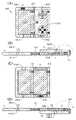
도 3의 (A1)~(F2)는 본 발명의 일 형태에 따른 데이터 처리 장치(100)의 표시부(122) 및 표시부(122)를 지지하는 하우징의 접힌 상태를 도시한 개략도이다. 구체적으로, 개략도들은 펼쳐진 상태와 10가지의 상이한 접힌 상태를 도시하고 있다.3 (A1) to (F2) are schematic diagrams showing the
본 실시형태에 기재된 데이터 처리 장치(100)는 제 1 면(표면이라고도 함; 도 1의 (B1) 참조) 및 제 1 면의 반대쪽인 제 2 면(뒷면이라고도 함; 도 1의 (B2) 참조)이 제공된 연결 하우징(C)을 포함한다.The
데이터 처리 장치(100)는 연결 하우징(C)의 제 1 면에 근접할 수 있는 제 1 표지(129(1)) 및 제 2 표지(129(2)), 및 연결 하우징(C)의 제 2 면에 근접할 수 있는 제 3 표지(129(3)) 및 제 4 표지(129(4))를 식별하는 센서부(123)를 포함한다. 또한, 센서부(123)는 센서(123L)를 포함한다.The
데이터 처리 장치(100)는 제 1 하우징(L)을 포함하고, 제 1 하우징(L)은 제 1 하우징(L)의 제 1 면이 연결 하우징(C)의 제 1 면을 마주보는 위치에서 제 1 하우징(L)의 제 1 면의 반대쪽인 제 2 면이 연결 하우징(C)의 제 2 면을 마주보는 위치까지 이동 가능하도록 연결 하우징(C)에 연결되어 있다(도 1의 (C1) 참조).The
데이터 처리 장치(100)는 제 2 하우징(R)을 더 포함하고, 제 2 하우징(R)은 제 2 하우징(R)의 제 1 면이 연결 하우징(C)의 제 1 면을 마주보는 위치에서 제 2 하우징(R)의 제 1 면의 반대쪽인 제 2 면이 연결 하우징(C)의 제 2 면을 마주보는 위치까지 이동 가능하도록 연결 하우징(C)에 연결되어 있다(도 1의 (C2) 참조).The
연결 하우징(C), 제 1 하우징(L), 및 제 2 하우징(R)은 표시부(122)가 접힐 수 있도록, 가요성을 가지는 표시부(122)를 지지한다.The connection housing C, the first housing L, and the second housing R support the
제 1 하우징(L)은 제 1 면에 제 1 표지(129(1))가, 제 2 면에 제 3 표지(129(3))가 제공되어 있다.The first housing L is provided with a first mark 129(1) on a first surface and a third mark 129(3) on a second surface.
제 2 하우징(R)은 제 1 면에 제 2 표지(129(2))가, 제 2 면에 제 4 표지(129(4))가 제공되어 있다.The second housing R is provided with a second mark 129(2) on a first surface and a fourth mark 129(4) on a second surface.
본 실시형태에 기재된 데이터 처리 장치(100)는 접고 펼칠 수 있는 표시부(122), 및 표시부(122)의 접힌 상태와 펼쳐진 상태를 검지할 수 있고 접힘 데이터를 공급할 수 있는 센서부(123)를 포함한다. 따라서, 열람성이 높은 데이터 처리 장치를 제공할 수 있다. 또는, 휴대성이 높은 데이터 처리 장치를 제공할 수 있다.The
본 실시형태에 기재된 데이터 처리 장치(100)에서, 제 2 하우징(R)은 제 1 면에 제 5 표지(129(5))가, 제 2 면에 제 6 표지(129(6))가 제공되어 있다. 센서부(123)는 제 1 하우징(L)의 제 1 면에 근접하는 제 6 표지(129(6)) 및 제 1 하우징(L)의 제 2 면에 근접하는 제 5 표지(129(5))를 식별한다. 또한, 센서부(123)는 센서(123U)를 포함한다.In the
본 실시형태에 기재된 데이터 처리 장치(100)는 표시부(122)의 접힌 상태와 펼쳐진 상태를 검지할 수 있고 접힘 데이터(SENS)를 공급할 수 있다. 구체적으로는 데이터 처리 장치(100)는 펼치거나 10가지의 상이한 형태로 접을 수 있고, 그 상태에 대응하는 상이한 접힘 데이터(SENS)를 공급할 수 있다. 따라서, 상이한 처리를 실행하기 위한 각 프로그램이 11가지의 상이한 상태에 할당될 수 있다. 이 결과 접는 방식을 바꿈으로써 다양한 기능 중 어느 것을 쉽게 선택하여 사용할 수 있는 데이터 처리 장치를 제공할 수 있다.The
데이터 처리 장치(100)의 표시부(122)의 2 이상의 상이한 접힌 상태에 대하여 도 3의 (A1)~(F2)를 참조하여 설명한다.Two or more different folded states of the
센서부(123)는 연결 하우징(C)에 센서(123L)가, 제 1 하우징(L)에 센서(123U)가 제공되어 있다. 또한, 센서(123L) 및 센서(123U)는 제 1 면에 근접하는 표지(129) 및 제 2 면에 근접하는 표지(129)를 식별할 수 있다.In the
센서부(123)는, 센서(123L) 및 센서(123U)로부터 공급된 신호의 조합에 따라 표시부(122)의 접힌 상태를 특정할 수 있는 접힘 데이터(SENS)를 생성하여 공급한다.The
또한, 제 1 면에 표지(129(x))가 근접하고 제 2 면에 표지(129(y))가 근접하는 경우에는 센서(123L) 및 센서(123U)는 신호(x,y)를 공급한다. 표지(129)가 제 1 면 또는 제 2 면에 근접하지 않는 경우에는 신호(0, 0)가 공급된다. 또한, 이 표현은 편의를 위한 것이며 제 1 면 또는 제 2 면에 근접하는 표지(129)가 식별될 수 있는 한 신호의 형식은 이에 한정되지 않는다.In addition, when the mark 129 (x ) is close to the first surface and the mark 129 (y ) is close to the second surface, the
<펼쳐진 상태><Unfolded state>
데이터 처리 장치(100)의 연결 하우징(C), 제 1 하우징(L), 및 제 2 하우징(R)의 펼쳐진 상태를 도 3의 (A1) 및 (A2)에 도시하였다. 또한, 도 3의 (A1)은 제 1 면(표면이라고도 함)으로부터 본 개략도이고, 도 3의 (A2)는 제 1 면의 반대쪽인 제 2 면(뒷면이라고도 함)으로부터 본 개략도이다.The unfolded state of the connection housing C, the first housing L, and the second housing R of the
또한, 복잡한 도면 때문에 발명의 이해가 방해되지 않게 하기 위하여, 도 3의 (B1)~(F2)에는 표지(129(1)~129(6)), 표시부(122), 센서(123L), 및 센서(123U)를 도시하지 않았다. 당업자라면 이들 도면을 도 3의 (A1) 및 (A2)와 비교하여 쉽게 이해할 수 있다.In addition, in order not to obstruct the understanding of the invention due to the complicated drawings, in (B1) to (F2) of FIG. The
데이터 처리 장치(100)의 연결 하우징(C), 제 1 하우징(L), 및 제 2 하우징(R)의 펼쳐진 상태에서는 센서(123U) 및 센서(123L)에 의하여 어느 표지도 검지되지 않는다. 따라서, 센서(123U)는 신호(0, 0)를 공급하고 센서(123L)는 신호(0, 0)를 공급한다.In the unfolded state of the connection housing C, the first housing L, and the second housing R of the
<더블-폴드된 상태><Double-folded state>
데이터 처리 장치(100)의 제 1 하우징(L)이 제 2 면 위로 접히는 경우에는 센서(123L)는 제 1 하우징(L)의 제 2 면에 배치된 제 3 표지(129(3))를 검지하여 신호(0, 3)를 공급한다(도 3의 (B1) 참조).When the first housing L of the
데이터 처리 장치(100)의 제 1 하우징(L)이 제 1 면 위로 접히는 경우에는 센서(123L)는 제 1 하우징(L)의 제 1 면에 배치된 제 1 표지(129(1))를 검지하여 신호(1, 0)를 공급한다(도 3의 (B2) 참조).When the first housing L of the
데이터 처리 장치(100)의 제 2 하우징(R)이 제 2 면 위로 접히는 경우에는 센서(123L)는 제 2 하우징(R)의 제 2 면에 배치된 제 4 표지(129(4))를 검지하여 신호(0, 4)를 공급한다(도 3의 (C1) 참조).When the second housing R of the
데이터 처리 장치(100)의 제 2 하우징(R)이 제 1 면 위로 접히는 경우에는 센서(123L)는 제 2 하우징(R)의 제 1 면에 배치된 제 2 표지(129(2))를 검지하여 신호(2, 0)를 공급한다(도 3의 (C2) 참조).When the second housing R of the
또한, 더블-폴드된 상태에서는 센서(123U)에 의하여 어느 표지도 검지되지 않는다. 따라서, 센서(123U)는 신호(0, 0)를 공급한다.Also, in the double-folded state, no mark is detected by the
<트라이-폴드된 상태><Tri-folded state>
데이터 처리 장치(100)의 제 1 하우징(L)이 제 2 면 위로 접히고 제 2 하우징(R)이 제 1 면 위로 접히는 경우에는 센서(123L)는 제 1 하우징(L)의 제 2 면에 배치된 제 3 표지(129(3)) 및 제 2 하우징(R)의 제 1 면에 배치된 제 2 표지(129(2))를 검지하여 신호(2, 3)를 공급한다(도 3의 (D1) 참조).When the first housing (L) of the
또한, 제 1 하우징(L)에 배치된 센서(123U)와 제 2 하우징(R)의 제 1 면에 배치된 제 5 표지(129(5)) 사이에 연결 하우징(C)이 제공된다. 따라서, 센서(123U)는 신호(0, 0)를 공급한다.Also, a connection housing C is provided between the
데이터 처리 장치(100)의 제 1 하우징(L)이 제 1 면 위로 접히고 제 2 하우징(R)이 제 2 면 위로 접히는 경우에는 센서(123L)는 제 1 하우징(L)의 제 1 면에 배치된 제 1 표지(129(1)) 및 제 2 하우징(R)의 제 2 면에 배치된 제 4 표지(129(4))를 검지하여 신호(1, 4)를 공급한다(도 3의 (D2) 참조).When the first housing (L) of the
또한, 제 1 하우징(L)에 배치된 센서(123U)와 제 2 하우징(R)의 제 2 면에 배치된 제 6 표지(129(6)) 사이에 연결 하우징(C)이 제공된다. 따라서, 센서(123U)는 신호(0, 0)를 공급한다.Further, a connection housing C is provided between the
데이터 처리 장치(100)의 제 1 하우징(L)이 제 2 면 위로 접히고 제 2 하우징(R)이 제 1 하우징(L)과 중첩되도록 제 2 면 위로 접히는 경우에는 센서(123L)는 제 1 하우징(L)의 제 2 면에 배치된 제 3 표지(129(3))를 검지하여 신호(0, 3)를 공급한다(도 3의 (E1) 참조). 센서(123U)는 제 2 하우징(R)의 제 2 면에 배치된 제 6 표지(129(6))를 검지하여 신호(6, 0)를 공급한다.When the first housing L of the
데이터 처리 장치(100)의 제 2 하우징(R)이 제 2 면 위로 접히고 제 1 하우징(L)이 제 2 하우징(R)과 중첩되도록 제 2 면 위로 접히는 경우에는 센서(123L)는 제 2 하우징(R)의 제 2 면에 배치된 제 4 표지(129(4))를 검지하여 신호(0, 4)를 공급한다(도 3의 (E2) 참조). 센서(123U)는 제 2 하우징(R)의 제 1 면에 배치된 제 5 표지(129(5))를 검지하여 신호(0, 5)를 공급한다.When the second housing R of the
데이터 처리 장치(100)의 제 1 하우징(L)이 제 1 면 위로 접히고 제 2 하우징(R)이 제 1 하우징(L)과 중첩되도록 제 1 면 위로 접히는 경우에는 센서(123L)는 제 1 하우징(L)의 제 1 면에 배치된 제 1 표지(129(1))를 검지하여 신호(1, 0)를 공급한다(도 3의 (F1) 참조). 센서(123U)는 제 2 하우징(R)의 제 1 면에 배치된 제 5 표지(129(5))를 검지하여 신호(0, 5)를 공급한다.When the first housing L of the
데이터 처리 장치(100)의 제 2 하우징(R)이 제 1 면 위로 접히고 제 1 하우징(L)이 제 2 하우징(R)과 중첩되도록 제 1 면 위로 접히는 경우에는 센서(123L)는 제 2 하우징(R)의 제 1 면에 배치된 제 2 표지(129(2))를 검지하여 신호(2, 0)를 공급한다(도 3의 (F2) 참조). 센서(123U)는 제 2 하우징(R)의 제 2 면에 배치된 제 6 표지(129(6))를 검지하여 신호(6, 0)를 공급한다.When the second housing R of the
본 실시형태는 본 명세서에서의 다른 실시형태 중 어느 것과 적절히 조합될 수 있다.This embodiment may be suitably combined with any of the other embodiments herein.
(실시형태 3)(Embodiment 3)
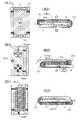
본 실시형태에서는 본 발명의 일 형태에 따른 데이터 처리 장치(200)의 구조에 대하여 도 4의 (A) 및 (B)와, 도 5의 (A)~(D)와, 도 6의 (A)~(D)와, 도 7의 (A1), (A2), (B1), (B2), (C1), 및 (C2)를 참조하여 설명한다.In the present embodiment, the structure of the
도 4의 (A)는 펼쳐진 본 발명의 일 형태에 따른 데이터 처리 장치(200)의 구조를 도시한 상면도이고, 도 4의 (B)는 그 측면도이다.4A is a top view showing the structure of the
도 5의 (A)는 더블-폴드된 본 발명의 일 형태에 따른 데이터 처리 장치(200)의 구조를 도시한 상면도이고, 도 5의 (B)는 그 측면도이다. 도 5의 (C)는 도 5의 (A)의 구조와는 다른 방식으로 더블-폴드된 본 발명의 일 형태에 따른 데이터 처리 장치(200)의 구조를 도시한 상면도이고, 도 5의 (D)는 그 측면도이다.FIG. 5A is a top view showing the structure of a double-folded
도 6의 (A)는 도 5의 (A) 및 (C)의 구조와는 다른 방식으로 더블-폴드된 본 발명의 일 형태에 따른 데이터 처리 장치(200)의 구조를 도시한 상면도이고, 도 6의 (B)는 그 측면도이다. 도 6의 (C)는 도 6의 (A)의 구조와는 다른 방식으로 더블-폴드된 본 발명의 일 형태에 따른 데이터 처리 장치(200)의 구조를 도시한 상면도이고, 도 6의 (D)는 그 측면도이다.6A is a top view showing the structure of a
도 7의 (A1)은 트라이-폴드된 본 발명의 일 형태에 따른 데이터 처리 장치(200)의 구조를 도시한 상면도이고, 도 7의 (A2)는 그 측면도이다.7A1 is a top view showing the structure of a
도 7의 (B1)은 도 7의 (A1)의 구조와는 다른 방식으로 트라이-폴드된 본 발명의 일 형태에 따른 데이터 처리 장치(200)의 구조를 도시한 상면도이고, 도 7의 (B2)는 그 측면도이다.FIG. 7(B1) is a top view showing the structure of the
도 7의 (C1)은 도 7의 (A1) 및 (B1)의 구조와는 다른 방식으로 트라이-폴드된 본 발명의 일 형태에 따른 데이터 처리 장치(200)의 구조를 도시한 상면도이고, 도 7의 (C2)는 그 측면도이다.7 (C1) is a top view showing the structure of the
본 실시형태에서 예시된 데이터 처리 장치(200)는 연결 하우징(C)을 포함한다. 연결 하우징(C)에는 표지의 근접을 식별하는 센서(123L)가 제공된다(도 4의 (A) 참조).The
데이터 처리 장치(200)는 제 1 하우징(L)을 포함한다. 제 1 하우징(L)은 링크(211)를 개재(介在)하여 연결 하우징(C)에 연결되어 있다. 따라서, 제 1 하우징(L)은 제 1 하우징(L)의 제 1 면이 연결 하우징(C)의 제 1 면을 마주보는 위치에서 제 1 하우징(L)의 제 1 면의 반대쪽인 제 2 면이 연결 하우징(C)의 제 2 면을 마주보는 위치까지 이동 가능하다(도 4의 (B) 참조). 이 결과, 데이터 처리 장치(200)는 접힐 수 있다.The
제 1 하우징(L)에는 센서(123U)가 제공된다. 제 1 하우징(L)은 제 1 면에 제 1 표지(129(1))가, 제 2 면에 제 3 표지(129(3))가 제공되어 있다.A
데이터 처리 장치(200)는 제 2 하우징(R)을 포함한다. 제 2 하우징(R)은 링크(212)를 개재하여 연결 하우징(C)에 연결되어 있다. 따라서, 제 2 하우징(R)은 제 2 하우징(R)의 제 1 면이 연결 하우징(C)의 제 1 면을 마주보는 위치에서 제 2 하우징(R)의 제 1 면의 반대쪽인 제 2 면이 연결 하우징(C)의 제 2 면을 마주보는 위치까지 이동 가능하다. 이 결과, 데이터 처리 장치(200)는 접힐 수 있다.The
제 2 하우징(R)에는 제 1 면에 제 2 표지(129(2)) 및 제 5 표지(129(5))가, 제 2 면에 제 4 표지(129(4)) 및 제 6 표지(129(6))가 제공되어 있다.The second housing R has a second mark 129(2) and a fifth mark 129(5) on the first surface, and a fourth mark 129(4) and a sixth mark on the second surface ( 129(6)) is provided.
데이터 처리 장치(200)에는 센서(123L) 및 센서(123U)를 포함하는 센서부가 제공되어 있다.The
센서(123L)는 연결 하우징(C)의 제 1 면에 근접하는 제 1 표지(129(1)) 및 제 2 표지(129(2)), 그리고 연결 하우징(C)의 제 2 면에 근접하는 제 3 표지(129(3)) 및 제 4 표지(129(4))를 식별한다.The
센서(123U)는 제 1 하우징(L)의 제 1 면에 근접하는 제 6 표지(129(6)) 및 제 1 하우징(L)의 제 2 면에 근접하는 제 5 표지(129(5))를 식별한다.The
데이터 처리 장치(200)의 연결 하우징(C), 제 1 하우징(L), 및 제 2 하우징(R)은 가요성을 가지는 표시부(222)를 지지한다. 또한, 도 4의 (B)에서의 화살표는 표시부(222)가 이미지를 표시하는 방향을 가리킨다.The connection housing C, the first housing L, and the second housing R of the
본 실시형태에 기재된 데이터 처리 장치(200)는 접고 펼칠 수 있는 표시부(222), 및 표시부(222)의 접힌 상태와 펼쳐진 상태를 검지할 수 있고 접힘 데이터를 공급할 수 있는 센서부(123)를 포함한다. 따라서, 열람성이 높은 데이터 처리 장치를 제공할 수 있다. 또는, 휴대성이 높은 데이터 처리 장치를 제공할 수 있다.The
<펼쳐진 상태><Unfolded state>
데이터 처리 장치(200)의 연결 하우징(C), 제 1 하우징(L), 및 제 2 하우징(R)의 펼쳐진 상태에서는 센서(123U) 및 센서(123L)에 의하여 어느 표지도 검지되지 않는다. 따라서, 센서(123U)는 신호(0, 0)를 공급하고 센서(123L)는 신호(0, 0)를 공급한다(도 4의 (A) 참조).In the unfolded state of the connection housing C, the first housing L, and the second housing R of the
<더블-폴드된 상태><Double-folded state>
데이터 처리 장치(200)의 제 1 하우징(L)이 제 1 면 위로 접히는 경우에는 센서(123L)는 제 1 하우징(L)의 제 1 면에 배치된 제 1 표지(129(1))를 검지하여 신호(0, 1)를 공급한다(도 5의 (A) 및 (B) 참조).When the first housing L of the
도 5의 (A) 및 (B)에 도시된 바와 같이 데이터 처리 장치(200)는, 제 1 하우징(L)의 제 2 면 및 제 2 하우징(R)의 제 1 면이 사용자를 향하도록 제 1 하우징(L)을 제 1 면 위로 접어서 사용할 수 있다.As shown in (A) and (B) of Figure 5, the
또한, 제 1 하우징(L)의 제 2 면에 입력 수단(예를 들어 키보드(121K))을 제공할 수 있다(도 5의 (A) 참조).In addition, an input means (eg, a
예를 들어, 데이터 처리 장치(200)가 이 상태로 접히는 경우에 센서부에 의하여 공급되는 접힘 신호를 이메일을 처리하기 위한 애플리케이션에 관련시킬 수 있다. 따라서, 사용자는 데이터 처리 장치(200)를 도 5의 (A) 및 (B)에 도시된 바와 같이 접어서 이메일을 처리할 수 있다. 구체적으로, 제 2 하우징(R)으로 지지된 표시부(222)를 사용하여 키보드(121K)로부터 텍스트 데이터 등을 입력할 수 있다. 또한, 제 1 하우징(L) 및 연결 하우징(C)으로 지지된 표시부(222)에서의 표시를 정지하여 전력 소비를 줄일 수 있다.For example, when the
데이터 처리 장치(200)의 제 1 하우징(L)이 제 2 면 위로 접히는 경우에는 센서(123L)는 제 1 하우징(L)의 제 2 면에 배치된 제 3 표지(129(3))를 검지하여 신호(0, 3)를 공급한다(도 5의 (C) 및 (D) 참조).When the first housing L of the
도 5의 (C) 및 (D)에 도시된 바와 같이 데이터 처리 장치(200)는, 연결 하우징(C) 및 제 2 하우징(R)의 제 1 면들이 사용자를 향하도록 제 1 하우징(L)을 제 2 면 위로 접어서 사용할 수 있다.As shown in (C) and (D) of FIG. 5 , the
예를 들어, 데이터 처리 장치(200)가 이 상태로 접히는 경우에 센서부에 의하여 공급되는 접힘 신호를 전자 책을 열람하기 위한 애플리케이션에 관련시킬 수 있다. 따라서, 사용자는 데이터 처리 장치(200)를 도 5의 (C) 및 (D)에 도시된 바와 같이 접어서 전자 책을 열람할 수 있다.For example, when the
또한, 제 1 하우징(L)으로 지지된 표시부(222)는 사용자를 향하지 않기 때문에, 이 상태로 접혀 있으며 제 1 하우징(L)으로 지지된 데이터 처리 장치(200)의 표시부(222)의 표시는 정지될 수 있다. 따라서, 전력 소비를 줄일 수 있다.In addition, since the
사용자를 향하지 않는 표시부(222)와 중첩되도록 터치 패널이 제공되는 경우, 터치 패널은 입력 수단으로서 사용될 수 있다. 따라서, 사용자 측의 엄지손가락 및 사용자를 향하지 않는 손가락으로 데이터 처리 장치(200)를 지지하거나 조작할 수 있다.When the touch panel is provided to overlap the
데이터 처리 장치(200)의 제 2 하우징(R)이 제 1 면 위로 접히는 경우에는 센서(123L)는 제 2 하우징(R)의 제 1 면에 배치된 제 2 표지(129(2))를 검지하여 신호(0, 2)를 공급한다(도 6의 (A) 및 (B) 참조).When the second housing R of the
또한, 제 2 하우징(R)의 제 2 면에 입력 수단(예를 들어 제어 버튼(121B))을 제공할 수 있다(도 6의 (A) 참조).In addition, an input means (eg, a
예를 들어, 데이터 처리 장치(200)가 이 상태로 접히는 경우에 센서부에 의하여 공급되는 접힘 신호를 게임의 애플리케이션에 관련시킬 수 있다. 따라서, 사용자는 데이터 처리 장치(200)를 도 6의 (A) 및 (B)에 도시된 바와 같이 접어서 게임을 즐길 수 있다. 구체적으로, 제 1 하우징(L)으로 지지된 표시부(222)를 사용하여 제어 버튼(121B)으로부터 데이터를 입력하여 캐릭터 등을 조작할 수 있다. 또한, 제 2 하우징(R) 및 연결 하우징(C)으로 지지된 표시부(222)에서의 표시를 정지하여 전력 소비를 줄일 수 있다.For example, when the
데이터 처리 장치(200)의 제 2 하우징(R)이 제 1 면 위로 접히는 경우에는 센서(123R)는 제 2 하우징(R)의 제 2 면에 배치된 제 4 표지(129(4))를 검지하여 신호(0, 4)를 공급한다(도 6의 (C) 및 (D) 참조).When the second housing R of the
예를 들어, 데이터 처리 장치(200)가 이 상태로 접히는 경우에 센서부에 의하여 공급되는 접힘 신호를 인터넷에서 웹사이트를 열람하기 위한 애플리케이션에 관련시킬 수 있다. 따라서, 사용자는 데이터 처리 장치(200)를 도 6의 (C) 및 (D)에 도시된 바와 같이 접어서 웹사이트를 열람할 수 있다.For example, when the
또한 도 5의 (A)~(D)에 도시된 바와 같이 접힌 데이터 처리 장치(200)에 할당된 애플리케이션과, 도 6의 (A)~(D)에 도시된 바와 같이 접힌 데이터 처리 장치(200)에 할당된 애플리케이션이 사용자에 의하여 선택 가능하여도 좋다. 예를 들어, 할당되는 애플리케이션은 사용자가 오른손잡이인지 왼손잡이인지에 따라 변경되어도 좋다.In addition, applications allocated to the
<트라이-폴드된 상태><Tri-folded state>
데이터 처리 장치(200)의 제 1 하우징(L)이 제 2 면 위로 접히고 제 2 하우징(R)이 제 1 하우징(L)과 중첩되도록 제 2 면 위로 접히는 경우에는 센서(123L)는 제 1 하우징(L)의 제 2 면에 배치된 제 3 표지(129(3))를 검지하여 신호(0, 3)를 공급한다(도 7의 (A1) 및 (A2) 참조). 도시되지 않은 센서(123U)는 제 2 하우징(R)의 제 2 면에 배치된 제 6 표지(129(6))를 검지하여 신호(6, 0)를 공급한다.When the first housing L of the
데이터 처리 장치(200)의 제 1 하우징(L)이 제 2 면 위로 접히고 제 2 하우징(R)이 제 1 면 위로 접히는 경우에는 센서(123L)는 제 1 하우징(L)의 제 2 면에 배치된 제 3 표지(129(3)) 및 제 2 하우징(R)의 제 1 면에 배치된 제 2 표지(129(2))를 검지하여 신호(2, 3)를 공급한다(도 7의 (B1) 및 (B2) 참조). 도시하지 않았지만, 제 1 하우징(L)에 배치된 센서(123U)와 제 2 하우징(R)의 제 1 면에 배치된 제 5 표지(129(5)) 사이에 연결 하우징(C)이 제공된다. 따라서, 센서(123U)는 신호(0, 0)를 공급한다.When the first housing (L) of the
또한, 제 2 하우징(R)의 제 2 면에 입력 수단(예를 들어 카메라(121C))을 제공할 수 있다(도 7의 (B1) 참조).In addition, an input means (eg, the
예를 들어, 데이터 처리 장치(200)가 이 상태로 접히는 경우에 센서부에 의하여 공급되는 접힘 신호를 이미지를 캡쳐하기 위한 애플리케이션에 관련시킬 수 있다. 따라서, 사용자는 데이터 처리 장치(200)를 도 7의 (B1) 및 (B2)에 도시된 바와 같이 접어서 이미지를 캡쳐할 수 있다. 구체적으로, 제 1 하우징(L)으로 지지된 표시부(222)를 사용하여 카메라(121C)로부터 이미지를 캡쳐할 수 있다. 또한, 제 2 하우징(R) 및 연결 하우징(C)으로 지지된 표시부(222)에서의 표시를 정지하여 전력 소비를 줄일 수 있다.For example, when the
데이터 처리 장치(200)의 제 2 하우징(R)이 제 1 면 위로 접히고 제 1 하우징(L)이 제 2 하우징(R)과 중첩되도록 제 1 면 위로 접히는 경우에는 센서(123L)는 제 2 하우징(R)의 제 1 면에 배치된 제 2 표지(129(2))를 검지하여 신호(2, 0)를 공급한다(도 7의 (C1) 및 (C2) 참조). 센서(123U)는 제 2 하우징(R)의 제 2 면에 배치된 제 6 표지(129(6))를 검지하여 신호(6, 0)를 공급한다.When the second housing R of the
예를 들어, 데이터 처리 장치(200)가 이 상태로 접히는 경우에 센서부에 의하여 공급되는 접힘 신호를 데이터 처리 장치를 대기 상태로 하는 명령에 관련시킬 수 있다. 따라서, 도 7의 (C1) 및 (C2)에 도시된 바와 같이 데이터 처리 장치(200)를 접어서 표시부(222)에서의 표시를 정지하여 전력 소비를 줄일 수 있다.For example, when the
본 실시형태는 본 명세서에서의 다른 실시형태 중 어느 것과 적절히 조합될 수 있다.This embodiment may be suitably combined with any of the other embodiments herein.
(실시형태 4)(Embodiment 4)
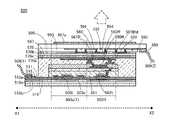
본 실시형태에서는 본 발명의 일 형태에 따른 데이터 처리 장치에 사용될 수 있는 입출력 유닛의 구조를 도 8의 (A)~(C)를 참조하여 설명한다.In this embodiment, the structure of an input/output unit that can be used in the data processing apparatus according to one embodiment of the present invention will be described with reference to FIGS. 8A to 8C .
도 8의 (A)는 본 발명의 일 형태에 따른 데이터 처리 장치에 사용될 수 있는 입출력 유닛의 구조를 도시한 상면도이다.8A is a top view showing the structure of an input/output unit that can be used in a data processing apparatus according to an embodiment of the present invention.
도 8의 (B)는 도 8의 (A)의 선 A-B 및 선 C-D를 따른 단면도이다.Fig. 8B is a cross-sectional view taken along lines A-B and C-D in Fig. 8A.
도 8의 (C)는 도 8의 (A)의 선 E-F를 따른 단면도이다.Fig. 8(C) is a cross-sectional view taken along line E-F of Fig. 8(A).
<상면도><top view>
본 실시형태에서 예시하는 입출력 유닛(300)은 표시부(301)를 포함한다(도 8의 (A) 참조).The input/output unit 300 illustrated in the present embodiment includes a display unit 301 (refer to FIG. 8(A) ).
표시부(301)는 복수의 화소(302) 및 복수의 이미징(imaging) 화소(308)를 포함한다. 이미징 화소(308)는 표시부(301)에 접촉되는 손가락 등을 검지할 수 있다. 이와 같이 이미징 화소(308)를 사용하여 터치 센서를 형성할 수 있다.The
각 화소(302)는 복수의 부화소(예를 들어 부화소(302R))를 포함한다. 또한, 부화소에는 발광 소자와, 발광 소자를 구동하기 위한 전력을 공급할 수 있는 화소 회로가 제공된다.Each
화소 회로는 선택 신호를 공급할 수 있는 배선 및 이미지 신호를 공급할 수 있는 배선에 전기적으로 연결된다.The pixel circuit is electrically connected to a wiring capable of supplying a selection signal and a wiring capable of supplying an image signal.
또한, 입출력 유닛(300)에는 선택 신호를 화소(302)에 공급할 수 있는 주사선 구동 회로(303g(1))와, 이미지 신호를 화소(302)에 공급할 수 있는 이미지 신호선 구동 회로(303s(1))가 제공된다. 또한, 이미지 신호선 구동 회로(303s(1))를 구부러질 수 있는 부분 이외의 부분에 배치하면 기능 불량을 억제할 수 있다.In addition, the input/output unit 300 includes a scan
이미징 화소(308)는 광전 변환 소자와, 광전 변환 소자를 구동시키는 이미징 화소 회로를 포함한다.The
이미징 화소 회로는 제어 신호를 공급할 수 있는 배선 및 전원 전위를 공급할 수 있는 배선에 전기적으로 연결된다.The imaging pixel circuit is electrically connected to a wiring capable of supplying a control signal and a wiring capable of supplying a power supply potential.
제어 신호의 예로서는, 기록된 이미징 신호가 판독되는 이미징 화소 회로를 선택하기 위한 신호, 이미징 화소 회로를 초기화하기 위한 신호, 및 이미징 화소 회로가 광을 검지하는 데 걸리는 시간을 결정하기 위한 신호를 들 수 있다.Examples of the control signal include a signal for selecting an imaging pixel circuit from which a recorded imaging signal is read, a signal for initializing the imaging pixel circuit, and a signal for determining the time it takes for the imaging pixel circuit to detect light. there is.
입출력 유닛(300)에는 제어 신호를 이미징 화소(308)에 공급할 수 있는 이미징 화소 구동 회로(303g(2))와, 이미징 신호를 판독하는 이미징 신호선 구동 회로(303s(2))가 제공된다. 또한, 이미징 신호선 구동 회로(303s(2))를 구부러질 수 있는 부분 이외의 부분에 배치하면 기능 불량을 억제할 수 있다.The input/output unit 300 is provided with an imaging
<단면도><Cross-section>
입출력 유닛(300)은 기판(310)과, 기판(310)의 반대쪽인 대향 기판(370)을 포함한다(도 8의 (B) 참조).The input/output unit 300 includes a
기판(310)은 가요성을 가지는 기판(310b), 발광 소자로의 의도하지 않은 불순물의 확산을 방지하는 배리어막(310a), 및 배리어막(310a)을 기판(310b)에 부착하는 접착층(310c)이 적층된 적층체이다.The
대향 기판(370)은 가요성을 가지는 기판(370b), 발광 소자로의 의도하지 않은 불순물의 확산을 방지하는 배리어막(370a), 및 배리어막(370a)을 기판(370b)에 부착하는 접착층(370c)을 포함하는 적층체이다(도 8의 (B) 참조).The opposing
실란트(360)에 의하여 대향 기판(370)이 기판(310)에 부착된다. 광학 접착층으로서도 기능하는 실란트(360)는 굴절률이 대기보다 크다. 화소 회로 및 발광 소자(예를 들어 제 1 발광 소자(350R)) 및 이미징 화소 회로 및 광전 변환 소자(예를 들어 광전 변환 소자(308p))는 기판(310)과 대향 기판(370) 사이에 제공된다.The
<<화소의 구조>><<The structure of the pixel>>
각 화소(302)는 부화소(302R), 부화소(302G), 및 부화소(302B)를 포함한다(도 8의 (C) 참조). 부화소(302R)는 발광 모듈(380R)을 포함하고, 부화소(302G)는 발광 모듈(380G)을 포함하고, 부화소(302B)는 발광 모듈(380B)을 포함한다.Each
예를 들어, 부화소(302R)는 제 1 발광 소자(350R)와, 제 1 발광 소자(350R)에 전력을 공급할 수 있으며 트랜지스터(302t)를 포함하는 화소 회로를 포함한다(도 8의 (B) 참조). 또한, 발광 모듈(380R)은 제 1 발광 소자(350R)와, 광학 소자(예를 들어 제 1 착색층(367R))를 포함한다.For example, the sub-pixel 302R includes a first
제 1 발광 소자(350R)는 제 1 하부 전극(351R), 상부 전극(352), 및 제 1 하부 전극(351R)과 상부 전극(352) 사이의 발광성 유기 화합물을 포함하는 층(353)을 포함한다(도 8의 (C) 참조).The first
발광성 유기 화합물을 포함하는 층(353)은 발광 유닛(353a), 발광 유닛(353b), 및 발광 유닛(353a)과 발광 유닛(353b) 사이의 중간층(354)을 포함한다.The layer 353 including the light-emitting organic compound includes a light-emitting unit 353a , a light-emitting
발광 모듈(380R)은 대향 기판(370) 상의 제 1 착색층(367R)을 포함한다. 착색층은 특정 파장의 광을 투과시키고, 예를 들어 적색, 녹색, 또는 청색의 광을 선택적으로 투과시키는 층이다. 발광 소자로부터 방출되는 광을 그대로 투과시키는 영역도 제공하여도 좋다.The
발광 모듈(380R)은 예를 들어, 제 1 발광 소자(350R) 및 제 1 착색층(367R)과 접촉되는 실란트(360)를 포함한다.The
제 1 착색층(367R)은 제 1 발광 소자(350R)와 중첩되는 영역에 배치된다. 그러므로, 제 1 발광 소자(350R)로부터 방출되는 광의 일부는 광학 접착층으로서도 기능하는 실란트(360) 및 제 1 착색층(367R)을 통과하여 도 8의 (B) 및 (C) 중 화살표로 가리킨 바와 같이 발광 모듈(380R) 외부로 방출된다.The first
<<입출력 유닛의 구조>><<Structure of I/O unit>>
입출력 유닛(300)은 대향 기판(370) 상의 차광층(367BM)을 포함한다. 차광층(367BM)은 착색층(예를 들어 제 1 착색층(367R))을 둘러싸도록 제공된다.The input/output unit 300 includes a light blocking layer 367BM on the
입출력 유닛(300)은 표시부(301)와 중첩되는 영역에 배치된 반사 방지층(367p)을 포함한다. 반사 방지층(367p)으로서 예를 들어 원편광판을 사용할 수 있다.The input/output unit 300 includes an
입출력 유닛(300)은 절연막(321)을 포함한다. 절연막(321)은 트랜지스터(302t)를 덮는다. 또한, 절연막(321)은 화소 회로에 기인하는 요철을 평탄화하기 위한 층으로서 사용될 수 있다. 트랜지스터(302t) 등으로의 불순물의 확산을 방지할 수 있는 층이 적층된 절연막을 절연막(321)으로서 사용할 수 있다.The input/output unit 300 includes an insulating
입출력 유닛(300)은 절연막(321) 위에 발광 소자(예를 들어 제 1 발광 소자(350R))를 포함한다.The input/output unit 300 includes a light emitting device (eg, a first
입출력 유닛(300)은 절연막(321) 위에, 제 1 하부 전극(351R)의 단부와 중첩되는 격벽(328)을 포함한다(도 8의 (C) 참조). 또한, 격벽(328) 상에 기판(310)과 대향 기판(370) 사이의 거리를 제어하는 스페이서(329)가 제공된다.The input/output unit 300 includes a
<<이미지 신호선 구동 회로의 구조>><<Structure of image signal line driving circuit>>
이미지 신호선 구동 회로(303s(1))는 트랜지스터(303t) 및 용량 소자(303c)를 포함한다. 또한, 이미지 신호선 구동 회로(303s(1))는 화소 회로와 동일한 공정으로 동일한 기판 위에 형성될 수 있다.The image signal
<<이미징 화소의 구조>><<Structure of imaging pixel>>
각 이미징 화소(308)는 광전 변환 소자(308p)와, 광전 변환 소자(308p)가 받는 광을 검지하기 위한 이미징 화소 회로를 포함한다. 이미징 화소 회로는 트랜지스터(308t)를 포함한다.Each
예를 들어, PIN 포토다이오드를 광전 변환 소자(308p)로서 사용할 수 있다.For example, a PIN photodiode can be used as the
<<다른 구조>><<Other Structures>>
입출력 유닛(300)은 신호를 공급할 수 있는 배선(311)을 포함한다. 배선(311)에는 단자(319)가 제공된다. 또한, 이미지 신호 또는 동기 신호 등의 신호를 공급할 수 있는 FPC(309(1))가 단자(319)에 전기적으로 연결된다. FPC(309(1))는 입출력 유닛(300)에서 구부러질 수 있는 부분 이외의 부분에 배치되는 것이 바람직하다. 또한, FPC(309(1))는 표시부(301)를 둘러싸는 영역의 한 변, 특히 접히는 쪽의 변(도 8의 (A) 중 긴 변)의 거의 중앙에 배치되는 것이 바람직하다. 따라서, 입출력 유닛(300)을 구동시키는 외부 회로와 입출력 유닛(300) 사이의 거리를 짧게 할 수 있고 이에 따라 연결이 쉬워진다. 또한, 외부 회로의 중력 중심을 입출력 유닛(300)의 그것과 거의 동일하게 할 수 있다. 이 결과, 데이터 처리 장치의 취급이 쉬워질 수 있고 떨어뜨리는 등의 실수를 방지할 수 있다.The input/output unit 300 includes a
또한, FPC(309(1))에 프린트 배선판(PWB)이 부착되어도 좋다.Further, a printed wiring board PWB may be attached to the FPC 309 ( 1 ).
본 실시형태는 본 명세서에서의 다른 실시형태 중 어느 것과 적절히 조합될 수 있다.This embodiment may be suitably combined with any of the other embodiments herein.
(실시형태 5)(Embodiment 5)
본 실시형태에서는 입력 수단으로서 터치 센서(접촉 검지 장치)가 표시부와 중첩되도록 제공되어 있고 접을 수 있는 터치 패널의 구조를 도 9의 (A) 및 (B)와 도 10을 참조하여 설명한다.In the present embodiment, the structure of a foldable touch panel in which a touch sensor (contact detecting device) is provided so as to overlap the display unit as an input means will be described with reference to FIGS. 9A and 9B and FIG. 10 .
도 9의 (A)는 본 실시형태에서 예시하는 터치 패널(500)의 개략 투시도이다. 또한, 명료화를 위하여 도 9의 (A) 및 (B)에는 주된 구성 요소만을 도시하였다. 도 9의 (B)는 터치 패널(500)의 개략 투시도의 전개도이다.Fig. 9A is a schematic perspective view of the
도 10은 도 9의 (A)의 선 X1-X2를 따른 터치 패널(500)의 단면도이다.10 is a cross-sectional view of the
터치 패널(500)은 표시부(501) 및 터치 센서(595)를 포함한다(도 9의 (B) 참조). 또한, 터치 패널(500)은 기판(510), 기판(570), 및 기판(590)을 포함한다. 또한, 기판(510), 기판(570), 및 기판(590)은 각각 가요성을 가진다.The
표시부(501)는 기판(510), 기판(510) 위의 복수의 화소, 및 화소들에 신호를 공급하는 복수의 배선(511)을 포함한다. 복수의 배선(511)은 기판(510) 외주부까지 리드(lead)되고, 복수의 배선(511)의 일부는 단자(519)를 형성한다. 단자(519)는 FPC(509(1))에 전기적으로 연결된다.The
<터치 센서><Touch sensor>
기판(590)은 터치 센서(595), 및 터치 센서(595)에 전기적으로 연결되는 복수의 배선(598)을 포함한다. 복수의 배선(598)은 기판(590) 외주까지 리드되고, 배선들(598)의 일부가 FPC(509(2))로의 전기적 연결을 위한 단자의 일부를 형성한다. 또한, 명료화를 위하여 도 9의 (B)에서는 기판(590)의 뒤쪽(다이어그램의 뒤쪽)에 제공되는 터치 센서(595)의 전극 및 배선 등을 실선으로 나타내었다.The
터치 센서(595)로서 사용되는 터치 센서로서 정전식 터치 센서를 사용하는 것이 바람직하다. 정전식 터치 센서의 예에는 표면 정전식 및 투영 정전식 등이 있다. 또한, 투영 정전식의 예에는 주로 구동 방법의 차이에 따라 자기 정전식 및 상호 정전식 등이 있다. 상호 정전식을 사용하면 복수의 지점을 동시에 검지할 수 있으므로 바람직하다.It is preferable to use a capacitive touch sensor as the touch sensor used as the
이하에서는 투영 정전식 터치 센서를 사용하는 예에 대하여 도 9의 (B)를 사용하여 설명한다. 또한, 손가락 등의 검지 대상의 근접 또는 접촉을 검지할 수 있는 다양한 센서를 사용할 수 있다.Hereinafter, an example using the projected capacitive touch sensor will be described with reference to FIG. 9B . In addition, various sensors capable of detecting proximity or contact of an index target such as a finger may be used.
투영 정전식 터치 센서(595)는 전극들(591) 및 전극들(592)을 포함한다. 전극들(591)은 복수의 배선(598) 중 어느 것에 전기적으로 연결되고, 전극들(592)은 나머지 배선들(598) 중 어느 것에 전기적으로 연결된다.The projected
전극들(592)은 도 9의 (A) 및 (B)에 도시된 바와 같이 일련의 사각형이 한 방향으로 배치된 형상이다. 각 전극(591)은 사각형이다. 배선(594)은 전극(592)이 연장되는 방향과 교차되는 방향으로 배치한 2개의 전극(591)을 전기적으로 연결한다. 전극(592)과 배선(594)의 교차 영역은 가능한 한 작은 것이 바람직하다. 이러한 구조로 하면 전극이 제공되지 않는 영역의 면적이 감소되어 투과율의 불균일을 저감할 수 있다. 이 결과 터치 센서(595)로부터의 광의 휘도의 불균일을 저감할 수 있다.The
또한, 전극(591) 및 전극(592)의 형상은 이에 한정되지 않고, 다양한 형상일 수 있다. 예를 들어, 복수의 전극(591)을 전극들(591) 사이의 틈이 가능한 한 감소되도록 배치하고, 전극(592)을, 전극(591)과 중첩되지 않는 영역을 가지도록 절연층을 개재하여 전극(591)으로부터 떨어지게 한 구조로 하여도 좋다. 이 경우, 인접한 2개의 전극(592) 사이에 이들 전극으로부터 전기적으로 절연된 더미(dummy) 전극을 제공하면 투과율이 다른 영역의 면적을 줄일 수 있으므로 바람직하다.In addition, the shapes of the
터치 패널(500)의 구조에 대하여 도 10을 참조하여 설명한다.The structure of the
터치 센서(595)는 기판(590), 기판(590) 상에 스태거드(staggered) 배열로 제공된 전극들(591) 및 전극들(592), 전극들(591) 및 전극들(592)을 덮는 절연층(593), 및 인접한 전극들(591)을 서로 전기적으로 연결하는 배선(594)을 포함한다.The
터치 센서(595)가 표시부(501)와 중첩되도록, 접착층(597)에 의하여 기판(590)이 기판(570)에 부착된다.The
전극들(591) 및 전극들(592)은 투광성 도전 재료를 사용하여 형성된다. 투광성 도전성 재료로서는 산화 인듐, 인듐 주석 산화물, 인듐 아연 산화물, 산화 아연, 또는 갈륨이 첨가된 산화 아연 등 도전성 산화물을 사용할 수 있다.The
기판(590) 상에 투광성 도전 재료를 스퍼터링법으로 퇴적한 다음, 포토리소그래피 등 공지의 패터닝 기술 중 어느 것에 의하여 불필요한 부분을 제거함으로써 전극들(591) 및 전극들(592)을 형성할 수 있다.
절연층(593)은 전극들(591) 및 전극들(592)을 덮는다. 절연층(593)의 재료의 예에는, 아크릴 또는 에폭시 수지 등의 수지, 실록산 결합을 가지는 수지, 및 산화 실리콘, 산화 질화 실리콘, 또는 산화 알루미늄 등의 무기 절연 재료를 들 수 있다.The insulating
또한, 절연층(593)에는 전극들(591)에 도달되는 개구들이 형성되고, 배선(594)에 의하여 인접한 전극들(591)이 전기적으로 연결된다. 투광성 도전 재료를 사용하여 배선(594)을 형성하면 터치 패널의 개구율을 높일 수 있으므로 바람직하다. 또한, 배선(594)은 전극들(591) 및 전극들(592)보다 도전성이 높은 재료를 사용하여 형성되는 것이 바람직하다.In addition, openings reaching the
하나의 전극(592)은 한 방향으로 연장되고, 복수의 전극(592)이 스트라이프 형태로 제공된다.One
배선(594)은 전극(592)과 교차된다.The
인접한 전극(591)은 하나의 전극(592)을 사이에 개재하여 제공되고, 배선(594)에 의하여 전기적으로 연결된다.The
또한, 복수의 전극(591)은 반드시 하나의 전극(592)과 직교되는 방향으로 배치될 필요는 없고, 90° 미만의 각도로 하나의 전극(592)과 교차되도록 배치되어도 좋다.In addition, the plurality of
하나의 배선(598)은 전극들(591 및 592) 중 어느 것에 전기적으로 연결된다. 배선(598)의 일부는 단자로서 기능한다. 배선(598)에는 알루미늄, 금, 백금, 은, 니켈, 타이타늄, 텅스텐, 크로뮴, 몰리브데넘, 철, 코발트, 구리, 또는 팔라듐 등의 금속 재료, 이들 금속 재료 중 어느 것을 포함하는 합금 재료를 사용할 수 있다.One
또한, 절연층(593) 및 배선(594)을 덮는 절연층을 제공하여 터치 센서(595)를 보호하여도 좋다.In addition, an insulating layer covering the insulating
또한, 연결층(599)에 의하여 배선(598)이 FPC(509(2))에 전기적으로 연결된다.Also, a
연결층(599)에는 공지의 이방성 도전 필름(ACF: anisotropic conductive film) 또는 공지의 이방성 도전 페이스트(ACP: anisotropic conductive paste) 등을 사용할 수 있다.A well-known anisotropic conductive film (ACF) or a well-known anisotropic conductive paste (ACP), etc. may be used for the
접착층(597)은 투광성을 가진다. 예를 들어, 열 경화성 수지 또는 자외선 경화성 수지를 사용할 수 있고; 구체적으로는 아크릴, 우레탄, 에폭시 수지, 또는 실록산 결합을 가지는 수지 등의 수지를 사용할 수 있다.The
<표시부><Display part>
터치 패널(500)은 매트릭스로 배치된 복수의 화소를 포함한다. 각 화소는 표시 소자와, 표시 소자를 구동시키는 화소 회로를 포함한다.The
본 실시형태에서는 백색 유기 전계 발광 소자를 표시 소자로서 사용하는 예를 설명하지만 표시 소자는 이러한 소자에 한정되지 않는다.Although this embodiment demonstrates the example which uses a white organic electroluminescent element as a display element, a display element is not limited to this element.
표시 소자로서 예를 들어, 유기 전계 발광 소자 외에, 전기 영동 방식 또는 전자 분류체 방식(electronic liquid powder method) 등에 의하여 표시를 하는 표시 소자(전자 잉크); MEMS 셔터 표시 소자; 및 광 간섭 방식의 MEMS 표시 소자 등, 다양한 표시 소자 중 어느 것을 사용할 수 있다. 또한, 사용하는 표시 소자에 적합한 구조를 공지의 화소 회로의 구조 중에서 선택할 수 있다.As a display element, for example, in addition to an organic electroluminescent element, the display element (electronic ink) which displays by the electrophoresis method, the electronic liquid powder method, etc.;; MEMS shutter indicator; and optical interference type MEMS display elements. Any of various display elements can be used. Moreover, a structure suitable for the display element to be used can be selected from the structure of a well-known pixel circuit.
기판(510)은 가요성을 가지는 기판(510b), 발광 소자로의 의도하지 않은 불순물의 확산을 방지하는 배리어막(510a), 및 배리어막(510a)을 기판(510b)에 부착하는 접착층(510c)이 적층된 적층체이다.The
기판(570)은 가요성을 가지는 기판(570b), 발광 소자로의 의도하지 않은 불순물의 확산을 방지하는 배리어막(570a), 및 배리어막(570a)을 기판(570b)에 부착하는 접착층(570c)이 적층된 적층체이다.The
실란트(560)에 의하여 기판(570)이 기판(510)에 부착된다. 광학 접착층으로서도 기능하는 실란트(560)는 굴절률이 대기보다 크다. 화소 회로 및 발광 소자(예를 들어 제 1 발광 소자(550R))는 기판(510)과 기판(570) 사이에 제공된다.The
<<화소의 구조>><<The structure of the pixel>>
화소는 부화소(502R)를 포함하고, 부화소(502R)는 발광 모듈(580R)을 포함한다.The pixel includes a sub-pixel 502R, and the sub-pixel 502R includes a
부화소(502R)는 제 1 발광 소자(550R)와, 제 1 발광 소자(550R)에 전력을 공급할 수 있으며 트랜지스터(502t)를 포함하는 화소 회로를 포함한다. 또한, 발광 모듈(580R)은 제 1 발광 소자(550R)와, 광학 소자(예를 들어 제 1 착색층(567R))를 포함한다.The sub-pixel 502R includes a first
제 1 발광 소자(550R)는 하부 전극, 상부 전극, 및 하부 전극과 상부 전극 사이의 발광성 유기 화합물을 포함하는 층을 포함한다.The first
발광 모듈(580R)은 기판(570) 상의 제 1 착색층(567R)을 포함한다. 착색층은 특정 파장의 광을 투과시키고, 예를 들어 적색, 녹색, 또는 청색의 광을 선택적으로 투과시키는 층이다. 발광 소자로부터 방출되는 광을 그대로 투과시키는 영역도 제공하여도 좋다.The
발광 모듈(580R)은 예를 들어, 제 1 발광 소자(550R) 및 제 1 착색층(567R)과 접촉되는 실란트(560)를 포함한다.The
제 1 착색층(567R)은 제 1 발광 소자(550R)와 중첩되는 영역에 배치된다. 그러므로, 제 1 발광 소자(550R)로부터 방출되는 광의 일부는 광학 접착층으로서도 기능하는 실란트(560) 및 제 1 착색층(567R)을 통과하여 도 10 중 화살표로 가리킨 바와 같이 발광 모듈(580R) 외부로 방출된다.The first
<<표시부의 구조>><<Structure of display part>>
표시부(501)는 기판(570) 상의 차광층(567BM)을 포함한다. 차광층(567BM)은 착색층(예를 들어 제 1 착색층(567R))을 둘러싸도록 제공된다.The
표시부(501)는 화소와 중첩되는 영역에 배치된 반사 방지층(567p)을 포함한다. 반사 방지층(567p)으로서 예를 들어 원편광판을 사용할 수 있다.The
표시부(501)는 절연막(521)을 포함한다. 절연막(521)은 트랜지스터(502t)를 덮는다. 또한, 절연막(521)은 화소 회로에 기인하는 요철을 평탄화하기 위한 층으로서 사용될 수 있다. 트랜지스터(502t) 등으로의 불순물의 확산을 방지할 수 있는 층이 적층된 절연막을 절연막(521)으로서 사용할 수 있다.The
표시부(501)는 절연막(521) 위에 발광 소자(예를 들어 제 1 발광 소자(550R))를 포함한다.The
표시부(501)는 절연막(521) 위에, 제 1 하부 전극의 단부와 중첩되는 격벽(528)을 포함한다. 또한, 격벽(528) 상에 기판(510)과 기판(570) 사이의 거리를 제어하는 스페이서가 제공된다.The
<<이미지 신호선 구동 회로의 구조>><<Structure of image signal line driving circuit>>
이미지 신호선 구동 회로(503s(1))는 트랜지스터(503t) 및 용량 소자(503c)를 포함한다. 또한, 이미지 신호선 구동 회로(503s(1))는 화소 회로와 동일한 공정으로 동일한 기판 위에 형성될 수 있다.The image signal
<<다른 구조>><<Other Structures>>
표시부(501)는 신호를 공급할 수 있는 배선(511)을 포함한다. 배선(511)에는 단자(519)가 제공된다. 또한, 이미지 신호 또는 동기 신호 등의 신호를 공급할 수 있는 FPC(509(1))가 단자(519)에 전기적으로 연결된다.The
또한, FPC(509(1))에는 프린트 배선판(PWB)이 부착되어도 좋다.A printed wiring board PWB may be attached to the FPC 509 ( 1 ).
본 실시형태는 본 명세서에서의 다른 실시형태 중 어느 것과 적절히 조합될 수 있다.This embodiment may be suitably combined with any of the other embodiments herein.
100: 데이터 처리 장치, 110: 연산 유닛, 111: 연산부, 112: 메모리부, 114: 전송 경로, 115: 입출력 인터페이스, 120: 입출력 유닛, 121: 입력 수단, 121B: 제어 버튼, 121C: 카메라, 121K: 키보드, 122: 표시부, 123: 센서부, 123L: 센서, 123R: 센서, 123U: 센서, 125: 통신부, 129: 표지, 200: 데이터 처리 장치, 211: 링크, 212: 링크, 222: 표시부, 300: 입출력 유닛, 301: 표시부, 302: 화소, 302B: 부화소, 302G: 부화소, 302R: 부화소, 302t: 트랜지스터, 303c: 용량 소자, 303g(1): 주사선 구동 회로, 303g(2): 이미징 화소 구동 회로, 303s(1): 이미지 신호선 구동 회로, 303s(2): 이미징 신호선 구동 회로, 303t: 트랜지스터, 308: 이미징 화소, 308p: 광전 변환 소자, 308t: 트랜지스터, 309: FPC, 310: 기판, 310a: 배리어막, 310b: 기판, 310c: 접착층, 311: 배선, 319: 단자, 321: 절연막, 328: 격벽, 329: 스페이서, 350R: 발광 소자, 351R: 하부 전극, 352: 상부 전극, 353: 층, 353a: 발광 유닛, 353b: 발광 유닛, 354: 중간층, 360: 실란트, 367BM: 차광층, 367p: 반사 방지층, 367R: 착색층, 370: 대향 기판, 370a: 배리어막, 370b: 기판, 370c: 접착층, 380B: 발광 모듈, 380G: 발광 모듈, 380R: 발광 모듈, 500: 터치 패널, 501: 표시부, 502R: 부화소, 502t: 트랜지스터, 503c: 용량 소자, 503s: 이미지 신호선 구동 회로, 503t: 트랜지스터, 509: FPC, 510: 기판, 510a: 배리어막, 510b: 기판, 510c: 접착층, 511: 배선, 519: 단자, 521: 절연막, 528: 격벽, 550R: 발광 소자, 560: 실란트, 567BM: 차광층, 567p: 반사 방지층, 567R: 착색층, 570: 기판, 570a: 배리어막, 570b: 기판, 570c: 접착층, 580R: 발광 모듈, 590: 기판, 591: 전극, 592: 전극, 593: 절연층, 594: 배선, 595: 터치 센서, 597: 접착층, 598: 배선, 599: 연결층, C: 연결 하우징, L: 제 1 하우징, R: 제 2 하우징.
본 출원은 2013년 7월 2일에 일본 특허청에 출원된 일련 번호 2013-138895의 일본 특허 출원에 기초하고, 본 명세서에 그 전문이 참조로 통합된다.100: data processing device, 110: arithmetic unit, 111: arithmetic unit, 112: memory unit, 114: transmission path, 115: input/output interface, 120: input/output unit, 121: input means, 121B: control button, 121C: camera, 121K : keyboard, 122: display unit, 123: sensor unit, 123L: sensor, 123R: sensor, 123U: sensor, 125: communication unit, 129: cover, 200: data processing device, 211: link, 212: link, 222: display unit, 300 input/output unit, 301 display unit, 302 pixel, 302B sub-pixel, 302G sub-pixel, 302R sub-pixel, 302t transistor, 303c capacitive element, 303g(1): scan line driver circuit, 303g(2) : imaging pixel driving circuit, 303s(1): image signal line driving circuit, 303s(2): imaging signal line driving circuit, 303t: transistor, 308: imaging pixel, 308p: photoelectric conversion element, 308t: transistor, 309: FPC, 310 : substrate, 310a: barrier film, 310b: substrate, 310c: adhesive layer, 311: wiring, 319: terminal, 321: insulating film, 328: barrier rib, 329: spacer, 350R: light emitting device, 351R: lower electrode, 352: upper electrode , 353: layer, 353a: light emitting unit, 353b: light emitting unit, 354: intermediate layer, 360: sealant, 367BM: light blocking layer, 367p: antireflection layer, 367R: colored layer, 370: counter substrate, 370a: barrier film, 370b: Substrate, 370c: adhesive layer, 380B: light-emitting module, 380G: light-emitting module, 380R: light-emitting module, 500: touch panel, 501: display unit, 502R: sub-pixel, 502t: transistor, 503c: capacitive element, 503s: image signal line driving circuit , 503t: transistor, 509: FPC, 510: substrate, 510a: barrier film, 510b: substrate, 510c: adhesive layer, 511: wiring, 519: terminal, 521: insulating film, 528: barrier rib, 550R: light emitting element, 560: Sealant, 567BM: light blocking layer, 567p: antireflection layer, 567R: colored layer, 570: substrate, 570a: barrier film, 570b: substrate, 570c: adhesive layer, 580R: light emitting module, 590: substrate, 591: electrode, 592: electrode , 593: insulating layer, 594: wiring, 595: touch sensor, 597: adhesive layer, 598: wiring, 599: connection layer, C: connection housing, L: first housing, R: second housing.
This application is based on the Japanese Patent Application of Serial No. 2013-138895 filed with the Japan Patent Office on July 2, 2013, the entirety of which is incorporated herein by reference.
Claims (8)
Translated fromKorean상기 제 1 하우징에 인접한 제 2 하우징; 및
적어도 상기 제 1 하우징의 상면 및 상기 제 2 하우징의 상면 위에 걸쳐 연속적으로 제공되는 표시부를 포함하는 플렉서블 표시 패널을 포함하는 접을 수 있는 장치로서,
상기 접을 수 있는 장치는 상기 제 1 하우징의 뒷면이 상기 제 2 하우징의 뒷면을 향하도록 접을 수 있고,
상기 접을 수 있는 장치는 상기 제 1 하우징의 상기 상면이 상기 제 2 하우징의 상기 상면을 향하도록 접을 수 있고,
상기 접을 수 있는 장치가 접히는 경우, 상기 접을 수 있는 장치의 사용자를 향하지 않는 상기 표시부의 일부가 표시를 정지하고,
상기 제 1 하우징의 상기 상면이 상기 제 2 하우징의 상기 상면을 향하도록 상기 접을 수 있는 장치가 접히는 경우:
상기 제 1 하우징의 상기 뒷면은 키보드로서 작동하고;
노출된 표시부는 상기 키보드로부터 제공되는 데이터에 해당하는 이미지를 표시하는, 접을 수 있는 장치.a first housing;
a second housing adjacent the first housing; and
A foldable device comprising: a flexible display panel including a display unit continuously provided over at least an upper surface of the first housing and an upper surface of the second housing;
the collapsible device is foldable such that the rear surface of the first housing faces the rear surface of the second housing;
the foldable device is foldable such that the upper surface of the first housing faces the upper surface of the second housing;
when the foldable device is folded, a portion of the display portion that is not facing the user of the foldable device stops displaying;
When the foldable device is folded such that the upper surface of the first housing faces the upper surface of the second housing:
the back side of the first housing acts as a keyboard;
The exposed display unit displays an image corresponding to data provided from the keyboard.
상기 키보드는 터치 센서를 사용하는, 접을 수 있는 장치.The method of claim 1,
The keyboard is a foldable device that uses a touch sensor.
상기 제 1 하우징에 인접한 제 2 하우징; 및
적어도 상기 제 1 하우징의 상면 및 상기 제 2 하우징의 상면 위에 걸쳐 연속적으로 제공되는 표시부를 포함하는 플렉서블 표시 패널을 포함하는 접을 수 있는 장치로서,
상기 접을 수 있는 장치는 상기 제 1 하우징의 뒷면이 상기 제 2 하우징의 뒷면을 향하도록 접을 수 있고,
상기 접을 수 있는 장치는 상기 제 1 하우징의 상기 상면이 상기 제 2 하우징의 상기 상면을 향하도록 접을 수 있고,
상기 접을 수 있는 장치가 접히는 경우, 상기 접을 수 있는 장치의 사용자를 향하지 않는 상기 표시부의 일부가 표시를 정지하고,
상기 제 1 하우징의 상기 상면이 상기 제 2 하우징의 상기 상면을 향하도록 상기 접을 수 있는 장치가 접히는 경우:
상기 제 1 하우징의 상기 뒷면은 제어 버튼으로서 작동하고;
노출된 표시부는 상기 제어 버튼으로부터 제공되는 데이터에 해당하는 이미지를 표시하는, 접을 수 있는 장치.a first housing;
a second housing adjacent the first housing; and
A foldable device comprising: a flexible display panel including a display unit continuously provided over at least an upper surface of the first housing and an upper surface of the second housing;
the collapsible device is foldable such that the rear surface of the first housing faces the rear surface of the second housing;
the foldable device is foldable such that the upper surface of the first housing faces the upper surface of the second housing;
when the foldable device is folded, a portion of the display portion that is not facing the user of the foldable device stops displaying;
When the foldable device is folded such that the upper surface of the first housing faces the upper surface of the second housing:
the back side of the first housing acts as a control button;
The exposed display unit displays an image corresponding to data provided from the control button.
상기 제어 버튼은 터치 센서를 사용하는, 접을 수 있는 장치.4. The method of claim 3,
The control button is a foldable device using a touch sensor.
상기 접을 수 있는 장치는 상기 제 2 하우징과 인접한 제 3 하우징을 더 포함하고,
상기 표시부를 포함하는 상기 플렉서블 표시 패널은 상기 제 1 하우징의 상기 상면, 상기 제 2 하우징의 상기 상면, 및 상기 제 3 하우징의 상면 위에 걸쳐 연속적으로 제공되는, 접을 수 있는 장치.4. The method of claim 1 or 3,
the collapsible device further comprising a third housing adjacent the second housing;
and the flexible display panel including the display unit is continuously provided over the upper surface of the first housing, the upper surface of the second housing, and the upper surface of the third housing.
상기 제 1 하우징에 인접한 제 2 하우징; 및
적어도 상기 제 1 하우징의 상면 및 상기 제 2 하우징의 상면 위에 걸쳐 연속적으로 제공되는 표시부를 포함하는 플렉서블 표시 패널을 포함하는, 접을 수 있는 장치를 구동하는 방법에 있어서,
상기 접을 수 있는 장치를 구동하는 방법은:
상기 제 1 하우징의 상기 상면이 상기 제 2 하우징의 상기 상면을 향하도록 상기 접을 수 있는 장치를 접는 단계;
상기 접을 수 있는 장치가 접히는 경우, 상기 접을 수 있는 장치의 사용자를 향하지 않는 상기 표시부가 표시를 정지하는 단계;
상기 제 1 하우징의 뒷면이 키보드 또는 제어 버튼으로서 작동하는 단계; 및
노출된 표시부에 상기 키보드 또는 상기 제어 버튼으로부터 제공되는 데이터에 해당하는 이미지를 표시하는 단계를 포함하는, 접을 수 있는 장치를 구동하는 방법.a first housing;
a second housing adjacent the first housing; and
A method of driving a foldable device comprising: a flexible display panel including a display unit continuously provided over at least an upper surface of the first housing and an upper surface of the second housing;
The method of driving the collapsible device comprises:
folding the foldable device such that the upper surface of the first housing faces the upper surface of the second housing;
stopping the display of the display unit not facing a user of the foldable device when the foldable device is folded;
actuating the rear side of the first housing as a keyboard or control button; and
and displaying an image corresponding to data provided from the keyboard or the control button on an exposed display unit.
상기 상기 키보드 또는 상기 제어 버튼은 터치 센서를 사용하는, 접을 수 있는 장치를 구동하는 방법.7. The method of claim 6,
wherein the keyboard or the control button uses a touch sensor.
상기 접을 수 있는 장치는 상기 제 2 하우징과 인접한 제 3 하우징을 더 포함하고,
상기 표시부를 포함하는 상기 플렉서블 표시 패널은 상기 제 1 하우징의 상기 상면, 상기 제 2 하우징의 상기 상면, 및 상기 제 3 하우징의 상면 위에 걸쳐 연속적으로 제공되는, 접을 수 있는 장치를 구동하는 방법.7. The method of claim 6,
the collapsible device further comprising a third housing adjacent the second housing;
and the flexible display panel including the display unit is continuously provided over the upper surface of the first housing, the upper surface of the second housing, and the upper surface of the third housing.
Priority Applications (1)
| Application Number | Priority Date | Filing Date | Title |
|---|---|---|---|
| KR1020227015486AKR102494178B1 (en) | 2013-07-02 | 2014-06-18 | Data processing device |
Applications Claiming Priority (4)
| Application Number | Priority Date | Filing Date | Title |
|---|---|---|---|
| JPJP-P-2013-138895 | 2013-07-02 | ||
| JP2013138895 | 2013-07-02 | ||
| KR1020167001993AKR20160028453A (en) | 2013-07-02 | 2014-06-18 | Data processing device |
| PCT/JP2014/066751WO2015002037A1 (en) | 2013-07-02 | 2014-06-18 | Data processing device |
Related Parent Applications (1)
| Application Number | Title | Priority Date | Filing Date |
|---|---|---|---|
| KR1020167001993ADivisionKR20160028453A (en) | 2013-07-02 | 2014-06-18 | Data processing device |
Related Child Applications (1)
| Application Number | Title | Priority Date | Filing Date |
|---|---|---|---|
| KR1020227015486ADivisionKR102494178B1 (en) | 2013-07-02 | 2014-06-18 | Data processing device |
Publications (2)
| Publication Number | Publication Date |
|---|---|
| KR20210075223A KR20210075223A (en) | 2021-06-22 |
| KR102398137B1true KR102398137B1 (en) | 2022-05-17 |
Family
ID=52132461
Family Applications (5)
| Application Number | Title | Priority Date | Filing Date |
|---|---|---|---|
| KR1020217018266AActiveKR102398137B1 (en) | 2013-07-02 | 2014-06-18 | Data processing device |
| KR1020227015486AActiveKR102494178B1 (en) | 2013-07-02 | 2014-06-18 | Data processing device |
| KR1020237038489AActiveKR102865522B1 (en) | 2013-07-02 | 2014-06-18 | Data processing device |
| KR1020237000722AActiveKR102601782B1 (en) | 2013-07-02 | 2014-06-18 | Data processing device |
| KR1020167001993ACeasedKR20160028453A (en) | 2013-07-02 | 2014-06-18 | Data processing device |
Family Applications After (4)
| Application Number | Title | Priority Date | Filing Date |
|---|---|---|---|
| KR1020227015486AActiveKR102494178B1 (en) | 2013-07-02 | 2014-06-18 | Data processing device |
| KR1020237038489AActiveKR102865522B1 (en) | 2013-07-02 | 2014-06-18 | Data processing device |
| KR1020237000722AActiveKR102601782B1 (en) | 2013-07-02 | 2014-06-18 | Data processing device |
| KR1020167001993ACeasedKR20160028453A (en) | 2013-07-02 | 2014-06-18 | Data processing device |
Country Status (6)
| Country | Link |
|---|---|
| US (6) | US9753495B2 (en) |
| JP (7) | JP6530894B2 (en) |
| KR (5) | KR102398137B1 (en) |
| CN (4) | CN105339887B (en) |
| TW (4) | TWI702592B (en) |
| WO (1) | WO2015002037A1 (en) |
Families Citing this family (61)
| Publication number | Priority date | Publication date | Assignee | Title |
|---|---|---|---|---|
| KR20220025259A (en) | 2013-07-19 | 2022-03-03 | 가부시키가이샤 한도오따이 에네루기 켄큐쇼 | Semiconductor device |
| TWI667644B (en) | 2013-07-19 | 2019-08-01 | 日商半導體能源研究所股份有限公司 | Data processing device |
| US9356049B2 (en) | 2013-07-26 | 2016-05-31 | Semiconductor Energy Laboratory Co., Ltd. | Display device with a transistor on an outer side of a bent portion |
| CN105452981B (en) | 2013-08-02 | 2021-08-24 | 株式会社半导体能源研究所 | display device |
| WO2015071800A1 (en) | 2013-11-15 | 2015-05-21 | Semiconductor Energy Laboratory Co., Ltd. | Data processor |
| KR102239367B1 (en) | 2013-11-27 | 2021-04-09 | 가부시키가이샤 한도오따이 에네루기 켄큐쇼 | Touch panel |
| TWI676125B (en) | 2013-11-28 | 2019-11-01 | 日商半導體能源研究所股份有限公司 | Electronic device and driving method thereof |
| KR20250002802A (en) | 2013-11-29 | 2025-01-07 | 가부시키가이샤 한도오따이 에네루기 켄큐쇼 | Data processing device and driving method thereof |
| US9229481B2 (en) | 2013-12-20 | 2016-01-05 | Semiconductor Energy Laboratory Co., Ltd. | Semiconductor device |
| US9711994B2 (en)* | 2014-01-31 | 2017-07-18 | Semiconductor Energy Laboratory Co., Ltd. | Electronic device and its operation system |
| KR20250083577A (en) | 2014-02-28 | 2025-06-10 | 가부시키가이샤 한도오따이 에네루기 켄큐쇼 | Electronic device |
| US9891743B2 (en) | 2014-05-02 | 2018-02-13 | Semiconductor Energy Laboratory Co., Ltd. | Driving method of an input device |
| US10073571B2 (en) | 2014-05-02 | 2018-09-11 | Semiconductor Energy Laboratory Co., Ltd. | Touch sensor and touch panel including capacitor |
| TWI679624B (en) | 2014-05-02 | 2019-12-11 | 日商半導體能源研究所股份有限公司 | Semiconductor device |
| CN105183203A (en)* | 2014-06-13 | 2015-12-23 | 宝宸(厦门)光学科技有限公司 | Touch control panel and touch control type electronic device |
| KR20190006101A (en) | 2014-10-28 | 2019-01-16 | 가부시키가이샤 한도오따이 에네루기 켄큐쇼 | Light-emitting device and electronic device |
| KR102471237B1 (en)* | 2015-01-21 | 2022-11-28 | 삼성디스플레이 주식회사 | Folderable display device |
| WO2016151426A1 (en)* | 2015-03-23 | 2016-09-29 | 株式会社半導体エネルギー研究所 | Display device, electronic equipment, and system |
| US11676518B2 (en) | 2015-04-29 | 2023-06-13 | Intel Corporation | Imaging for foldable displays |
| CN106325700B (en)* | 2015-06-30 | 2023-10-27 | 联想(北京)有限公司 | Electronic equipment and control method thereof |
| CN106325374B (en)* | 2015-06-30 | 2024-06-18 | 联想(北京)有限公司 | Electronic device and display processing method |
| CN106325728B (en)* | 2015-06-30 | 2024-05-28 | 联想(北京)有限公司 | Electronic apparatus and control method thereof |
| CN106325371B (en)* | 2015-06-30 | 2024-10-22 | 联想(北京)有限公司 | Electronic device and mode switching method |
| CN106325369B (en)* | 2015-06-30 | 2024-09-17 | 联想(北京)有限公司 | Electronic equipment and mode switching method |
| CN106325373B (en)* | 2015-06-30 | 2024-06-21 | 联想(北京)有限公司 | Electronic device and information processing method |
| CN106325372A (en) | 2015-06-30 | 2017-01-11 | 联想(北京)有限公司 | Electronic equipment and mode switching method |
| US9557772B1 (en) | 2015-07-21 | 2017-01-31 | Lenovo (Beijing) Co., Ltd. | Electronic device |
| CN106249850B (en)* | 2015-09-11 | 2020-03-17 | 北京智谷睿拓技术服务有限公司 | Interaction method and interaction device based on deformable equipment and user equipment |
| CN107024974B (en)* | 2015-09-11 | 2020-12-29 | 北京智谷睿拓技术服务有限公司 | Interaction method and interaction device based on deformable equipment and user equipment |
| US10503211B2 (en)* | 2015-09-13 | 2019-12-10 | Intel Corporation | Multi-orientation display device |
| US10481638B2 (en) | 2015-11-18 | 2019-11-19 | Semiconductor Energy Laboratory Co., Ltd. | Electronic device |
| KR102510395B1 (en)* | 2015-12-01 | 2023-03-16 | 삼성디스플레이 주식회사 | Display apparatus system |
| US10558265B2 (en) | 2015-12-11 | 2020-02-11 | Semiconductor Energy Laboratory Co., Ltd. | Input device and system of input device |
| WO2017111837A1 (en) | 2015-12-26 | 2017-06-29 | Intel Corporation | Bendable and foldable display screen to provide continuous display |
| KR102436383B1 (en)* | 2016-01-04 | 2022-08-25 | 삼성전자주식회사 | Electronic device and method of operating the same |
| CN106249864B (en)* | 2016-02-04 | 2019-01-04 | 北京智谷睿拓技术服务有限公司 | Exchange method, interactive device and user equipment |
| JP6918560B2 (en) | 2016-04-28 | 2021-08-11 | 株式会社半導体エネルギー研究所 | Information processing device |
| US10528079B2 (en)* | 2016-08-26 | 2020-01-07 | Semiconductor Energy Laboratory Co., Ltd. | Data processing device, display method, input/output method, server system, and computer program |
| US10627868B2 (en) | 2016-09-13 | 2020-04-21 | Sharp Kabushiki Kaisha | Flexible device |
| US10775849B2 (en) | 2016-09-20 | 2020-09-15 | Sharp Kabushiki Kaisha | Flexible device and method for manufacturing same |
| KR20180039342A (en)* | 2016-10-10 | 2018-04-18 | 삼성전자주식회사 | the Electronic Device including the Flexible Display |
| CN106504645B (en)* | 2016-10-24 | 2019-09-27 | 武汉华星光电技术有限公司 | Flexible display panels and flexible display device |
| JP7091601B2 (en)* | 2016-11-07 | 2022-06-28 | 富士フイルムビジネスイノベーション株式会社 | Display devices and programs |
| CN106657481A (en)* | 2017-02-22 | 2017-05-10 | 苏省玫 | Three-folding screen mobile phone and control method thereof |
| US11227543B2 (en) | 2017-03-10 | 2022-01-18 | Semiconductor Energy Laboratory Co., Ltd. | Touch panel system, electronic device, and semiconductor device having a neural network |
| KR102361436B1 (en)* | 2017-06-13 | 2022-02-11 | 삼성디스플레이 주식회사 | Display apparatus |
| CN108377277A (en)* | 2018-01-18 | 2018-08-07 | 努比亚技术有限公司 | Terminal |
| CN108766249B (en)* | 2018-08-09 | 2020-12-29 | 武汉天马微电子有限公司 | Foldable display panel and foldable display device |
| KR102609460B1 (en)* | 2018-11-20 | 2023-12-05 | 삼성디스플레이 주식회사 | Foldable display device and driving method of the same |
| TWI872058B (en) | 2019-04-19 | 2025-02-11 | 日商半導體能源研究所股份有限公司 | Flexible member support tool and display device |
| TWI703428B (en) | 2019-05-21 | 2020-09-01 | 兆利科技工業股份有限公司 | A folding-length-difference compensatory mechanism for the multi-step foldable device |
| KR102681664B1 (en)* | 2019-06-12 | 2024-07-05 | 엘지디스플레이 주식회사 | Foldable display and driving method thereof |
| JP6805308B2 (en)* | 2019-09-17 | 2020-12-23 | 株式会社半導体エネルギー研究所 | Display device |
| US11610877B2 (en)* | 2019-11-21 | 2023-03-21 | Semiconductor Energy Laboratory Co., Ltd. | Functional panel, display device, input/output device, and data processing device |
| CN112987957B (en)* | 2019-12-17 | 2025-09-05 | 群创光电股份有限公司 | electronic devices |
| CN112102729B (en)* | 2020-09-30 | 2022-05-20 | 武汉天马微电子有限公司 | Display device |
| KR20220099180A (en) | 2021-01-05 | 2022-07-13 | 삼성디스플레이 주식회사 | Display apparatus |
| TWI775547B (en)* | 2021-07-29 | 2022-08-21 | 宏碁股份有限公司 | Foldable electronic device and controlling method thereof |
| KR20230073404A (en)* | 2021-11-18 | 2023-05-26 | 삼성디스플레이 주식회사 | Display device and method of driving display device |
| US11775026B1 (en)* | 2022-08-01 | 2023-10-03 | Qualcomm Incorporated | Mobile device fold detection |
| WO2025028754A2 (en)* | 2023-07-31 | 2025-02-06 | 삼성전자 주식회사 | Electronic device, method, and storage medium for setting application displayed on display |
Family Cites Families (117)
| Publication number | Priority date | Publication date | Assignee | Title |
|---|---|---|---|---|
| EP1058181A4 (en) | 1998-02-25 | 2002-09-11 | Sharp Kk | Display device |
| JP3461716B2 (en) | 1998-03-23 | 2003-10-27 | シャープ株式会社 | Display device |
| EP1168143A1 (en) | 2000-06-27 | 2002-01-02 | Koninklijke Philips Electronics N.V. | Portable computer comprising a plurality of display modules with at least one display module foldable over a main display module |
| US7430025B2 (en) | 2000-08-23 | 2008-09-30 | Semiconductor Energy Laboratory Co., Ltd. | Portable electronic device |
| US6747290B2 (en) | 2000-12-12 | 2004-06-08 | Semiconductor Energy Laboratory Co., Ltd. | Information device |
| JP2002287900A (en) | 2000-12-12 | 2002-10-04 | Semiconductor Energy Lab Co Ltd | Information devices |
| US20130080909A1 (en) | 2011-09-27 | 2013-03-28 | Paul E. Reeves | Unified desktop docking behaviour for an auxillary monitor |
| US9152582B2 (en) | 2010-10-01 | 2015-10-06 | Z124 | Auto-configuration of a docked system in a multi-OS environment |
| US20130024812A1 (en) | 2011-07-13 | 2013-01-24 | Z124 | Foreground/background assortment of hidden windows |
| US20130080143A1 (en) | 2011-09-27 | 2013-03-28 | Paul E. Reeves | Unified desktop docking behavior with device as master |
| US8966379B2 (en) | 2010-10-01 | 2015-02-24 | Z124 | Dynamic cross-environment application configuration/orientation in an active user environment |
| US8990712B2 (en) | 2011-08-24 | 2015-03-24 | Z124 | Unified desktop triad control user interface for file manager |
| US20030167318A1 (en) | 2001-10-22 | 2003-09-04 | Apple Computer, Inc. | Intelligent synchronization of media player with host computer |
| US20080086494A1 (en) | 2006-09-11 | 2008-04-10 | Apple Computer, Inc. | Transfer and synchronization of media data |
| US8151259B2 (en) | 2006-01-03 | 2012-04-03 | Apple Inc. | Remote content updates for portable media devices |
| US9715500B2 (en) | 2004-04-27 | 2017-07-25 | Apple Inc. | Method and system for sharing playlists |
| US20060235864A1 (en) | 2005-04-14 | 2006-10-19 | Apple Computer, Inc. | Audio sampling and acquisition system |
| US20050203959A1 (en) | 2003-04-25 | 2005-09-15 | Apple Computer, Inc. | Network-based purchase and distribution of digital media items |
| US9213365B2 (en) | 2010-10-01 | 2015-12-15 | Z124 | Method and system for viewing stacked screen displays using gestures |
| US20040215534A1 (en) | 2003-04-25 | 2004-10-28 | Apple Computer, Inc. | Method and system for network-based allowance control |
| US20130198867A1 (en) | 2011-12-09 | 2013-08-01 | Z124 | A Docking Station for Portable Devices Providing Authorized Power Transfer and Facility Access |
| US20120081315A1 (en) | 2010-10-01 | 2012-04-05 | Imerj LLC | Keyboard spanning multiple screens |
| US7627343B2 (en) | 2003-04-25 | 2009-12-01 | Apple Inc. | Media player system |
| US8504936B2 (en) | 2010-10-01 | 2013-08-06 | Z124 | Changing stack when swapping |
| JP2005108825A (en)* | 2003-09-12 | 2005-04-21 | Semiconductor Energy Lab Co Ltd | Light emitting apparatus and method of manufacturing the same |
| US7816863B2 (en) | 2003-09-12 | 2010-10-19 | Semiconductor Energy Laboratory Co., Ltd. | Light emitting device and method for manufacturing the same |
| JP2005115536A (en) | 2003-10-06 | 2005-04-28 | Hitachi Medical Corp | Portable information terminal |
| JP2006053678A (en) | 2004-08-10 | 2006-02-23 | Toshiba Corp | Electronic equipment with universal human interface |
| US7706637B2 (en) | 2004-10-25 | 2010-04-27 | Apple Inc. | Host configured for interoperation with coupled portable media player device |
| US7714801B2 (en)* | 2005-01-05 | 2010-05-11 | Nokia Corporation | Foldable electronic device and a flexible display device |
| US11314378B2 (en) | 2005-01-07 | 2022-04-26 | Apple Inc. | Persistent group of media items for a media device |
| US7536565B2 (en) | 2005-01-07 | 2009-05-19 | Apple Inc. | Techniques for improved playlist processing on media devices |
| US7823214B2 (en) | 2005-01-07 | 2010-10-26 | Apple Inc. | Accessory authentication for electronic devices |
| JP2006243621A (en)* | 2005-03-07 | 2006-09-14 | Canon Inc | Display device |
| JP2006287982A (en)* | 2005-07-13 | 2006-10-19 | Columbus No Tamagotachi:Kk | Portable communication terminal with flexible display |
| JP3911515B2 (en) | 2005-10-13 | 2007-05-09 | パイオニア株式会社 | Display control apparatus, display method, display program, and recording medium |
| US20070097014A1 (en)* | 2005-10-31 | 2007-05-03 | Solomon Mark C | Electronic device with flexible display screen |
| US8706159B2 (en) | 2006-01-03 | 2014-04-22 | Apple Inc. | Media data transfer |
| US20120259876A1 (en) | 2006-05-15 | 2012-10-11 | Mathai Aji K | Database for Managing Contracts were Multiple Existing or Expiring Contracts are Replaced with a Combined Contract |
| AU2007336816C1 (en) | 2006-12-22 | 2011-10-06 | Apple Inc. | Tagging media assets, locations, and advertisements |
| US7787917B2 (en) | 2006-12-28 | 2010-08-31 | Intel Corporation | Folding electronic device with continuous display |
| JP2008294490A (en)* | 2007-05-22 | 2008-12-04 | Nec Tokin Corp | Folding electronic equipment, and case position detecting method of folding electronic equipment |
| JP4957507B2 (en) | 2007-10-25 | 2012-06-20 | 日本電気株式会社 | Mobile communication terminal |
| JP5028585B2 (en)* | 2007-12-28 | 2012-09-19 | 富士通モバイルコミュニケーションズ株式会社 | Electronics |
| TWI441116B (en) | 2008-04-22 | 2014-06-11 | Creator Technology Bv | An electronic apparatus with a flexible display having a body enabling further functionality |
| KR100978929B1 (en) | 2008-06-24 | 2010-08-30 | 한국전자통신연구원 | Method of registering reference gesture data, driving method of mobile terminal and mobile terminal performing the same |
| JP5092951B2 (en)* | 2008-07-09 | 2012-12-05 | ヤマハ株式会社 | Portable device |
| KR101472021B1 (en) | 2008-09-02 | 2014-12-24 | 엘지전자 주식회사 | Mobile terminal equipped with flexible display and controlling method thereof |
| US8773336B2 (en)* | 2008-09-05 | 2014-07-08 | Ketra, Inc. | Illumination devices and related systems and methods |
| US8836611B2 (en) | 2008-09-08 | 2014-09-16 | Qualcomm Incorporated | Multi-panel device with configurable interface |
| US9009984B2 (en) | 2008-09-08 | 2015-04-21 | Qualcomm Incorporated | Multi-panel electronic device |
| US8947320B2 (en) | 2008-09-08 | 2015-02-03 | Qualcomm Incorporated | Method for indicating location and direction of a graphical user interface element |
| US8866840B2 (en) | 2008-09-08 | 2014-10-21 | Qualcomm Incorporated | Sending a parameter based on screen size or screen resolution of a multi-panel electronic device to a server |
| US8860765B2 (en)* | 2008-09-08 | 2014-10-14 | Qualcomm Incorporated | Mobile device with an inclinometer |
| US8863038B2 (en) | 2008-09-08 | 2014-10-14 | Qualcomm Incorporated | Multi-panel electronic device |
| US8933874B2 (en) | 2008-09-08 | 2015-01-13 | Patrik N. Lundqvist | Multi-panel electronic device |
| US8803816B2 (en)* | 2008-09-08 | 2014-08-12 | Qualcomm Incorporated | Multi-fold mobile device with configurable interface |
| US8860632B2 (en) | 2008-09-08 | 2014-10-14 | Qualcomm Incorporated | Multi-panel device with configurable interface |
| JP2010140410A (en) | 2008-12-15 | 2010-06-24 | Sharp Corp | Mobile apparatus and method of controlling the same |
| CN104597651B (en) | 2009-05-02 | 2017-12-05 | 株式会社半导体能源研究所 | Display device |
| US8911653B2 (en) | 2009-05-21 | 2014-12-16 | Semiconductor Energy Laboratory Co., Ltd. | Method for manufacturing light-emitting device |
| KR101505705B1 (en)* | 2009-09-03 | 2015-03-24 | 퀄컴 인코포레이티드 | Method for indicating location and direction of a graphical user interface element |
| US9000442B2 (en) | 2010-01-20 | 2015-04-07 | Semiconductor Energy Laboratory Co., Ltd. | Light-emitting device, flexible light-emitting device, electronic device, and method for manufacturing light-emitting device and flexible-light emitting device |
| JP5515951B2 (en) | 2010-03-29 | 2014-06-11 | 日本電気株式会社 | Information processing apparatus, input control method, program, and recording medium |
| US20110241998A1 (en) | 2010-03-30 | 2011-10-06 | Mckinney Susan | Flexible portable communication device |
| TWM395340U (en)* | 2010-08-04 | 2010-12-21 | Micro Star Int Co Ltd | Foldable electronic apparatus |
| US9046992B2 (en) | 2010-10-01 | 2015-06-02 | Z124 | Gesture controls for multi-screen user interface |
| US20120218202A1 (en) | 2010-10-01 | 2012-08-30 | Sanjiv Sirpal | Windows position control for phone applications |
| US20130050265A1 (en) | 2011-08-31 | 2013-02-28 | Z124 | Gravity drop |
| US20120225694A1 (en) | 2010-10-01 | 2012-09-06 | Sanjiv Sirpal | Windows position control for phone applications |
| US8979159B2 (en) | 2011-11-16 | 2015-03-17 | Flextronics Ap, Llc | Configurable hardware unit for car systems |
| US9001149B2 (en) | 2010-10-01 | 2015-04-07 | Z124 | Max mode |
| US20120290946A1 (en) | 2010-11-17 | 2012-11-15 | Imerj LLC | Multi-screen email client |
| EP2456175B1 (en)* | 2010-11-19 | 2014-01-15 | BlackBerry Limited | Portable electronic device including flexible display |
| CN102645954A (en)* | 2011-02-16 | 2012-08-22 | 索尼爱立信移动通讯有限公司 | Portable terminal |
| KR102010429B1 (en) | 2011-02-25 | 2019-08-13 | 가부시키가이샤 한도오따이 에네루기 켄큐쇼 | Light-emitting device and electronic device using light-emitting device |
| EP2500898B1 (en) | 2011-03-18 | 2023-01-18 | BlackBerry Limited | System and method for foldable display |
| US9812074B2 (en)* | 2011-03-18 | 2017-11-07 | Blackberry Limited | System and method for foldable display |
| KR101878251B1 (en) | 2011-04-08 | 2018-07-13 | 삼성전자주식회사 | Bending sensor and fabrication method thereof |
| TWI438740B (en)* | 2011-04-13 | 2014-05-21 | Wistron Corp | Flexible electronic device |
| JP5620331B2 (en) | 2011-04-26 | 2014-11-05 | 京セラ株式会社 | Portable electronic device, control method, and control program |
| JP5661547B2 (en)* | 2011-04-26 | 2015-01-28 | 京セラ株式会社 | Portable terminal device and program |
| KR101794652B1 (en)* | 2011-04-28 | 2017-11-07 | 엘지디스플레이 주식회사 | Display device and manufacturing method of display panel |
| CN202058412U (en)* | 2011-06-01 | 2011-11-30 | 北京京东方光电科技有限公司 | Foldable display |
| KR101832958B1 (en) | 2011-06-01 | 2018-02-28 | 엘지전자 주식회사 | Mobile terminal and 3d image displaying method thereof |
| US9176535B2 (en)* | 2011-06-03 | 2015-11-03 | Microsoft Technology Licensing, Llc | Flexible display flexure assembly |
| KR101789625B1 (en) | 2011-06-23 | 2017-10-25 | 엘지전자 주식회사 | Apparatus having flexible display and method for controlling thereof |
| US8787016B2 (en)* | 2011-07-06 | 2014-07-22 | Apple Inc. | Flexible display devices |
| KR101900847B1 (en) | 2011-07-08 | 2018-09-20 | 가부시키가이샤 한도오따이 에네루기 켄큐쇼 | Display device |
| US20130268559A1 (en) | 2011-07-13 | 2013-10-10 | Z124 | Virtual file system remote search |
| JP2013025617A (en)* | 2011-07-22 | 2013-02-04 | Panasonic Corp | Image display device |
| EP2565751A1 (en) | 2011-08-31 | 2013-03-06 | Z124 | Multi-screen display control |
| US20160054757A1 (en) | 2012-02-29 | 2016-02-25 | Z124 | Unified desktop docking flow |
| US9182935B2 (en) | 2011-09-27 | 2015-11-10 | Z124 | Secondary single screen mode activation through menu option |
| TWM430653U (en)* | 2011-11-11 | 2012-06-01 | xi-yao Wu | Folding touch-control input device |
| JP2013105312A (en)* | 2011-11-14 | 2013-05-30 | Sony Corp | Information processing device, control method, and program |
| US20130203400A1 (en) | 2011-11-16 | 2013-08-08 | Flextronics Ap, Llc | On board vehicle presence reporting module |
| US20160189544A1 (en) | 2011-11-16 | 2016-06-30 | Autoconnect Holdings Llc | Method and system for vehicle data collection regarding traffic |
| US20130282946A1 (en) | 2012-04-23 | 2013-10-24 | Flextronics Ap, Llc | Controller area network bus |
| US20130200991A1 (en) | 2011-11-16 | 2013-08-08 | Flextronics Ap, Llc | On board vehicle media controller |
| US20130219039A1 (en) | 2011-11-16 | 2013-08-22 | Flextronics Ap, Llc | Network selector in a vehicle infotainment system |
| US20140143839A1 (en) | 2011-11-16 | 2014-05-22 | Flextronics Ap, Llc. | On board vehicle remote control module |
| US8949823B2 (en) | 2011-11-16 | 2015-02-03 | Flextronics Ap, Llc | On board vehicle installation supervisor |
| WO2013074899A1 (en) | 2011-11-16 | 2013-05-23 | Flextronics Ap, Llc | Configurable dash display |
| US9164544B2 (en) | 2011-12-09 | 2015-10-20 | Z124 | Unified desktop: laptop dock, hardware configuration |
| US20140310075A1 (en) | 2013-04-15 | 2014-10-16 | Flextronics Ap, Llc | Automatic Payment of Fees Based on Vehicle Location and User Detection |
| US20160086391A1 (en) | 2012-03-14 | 2016-03-24 | Autoconnect Holdings Llc | Fleetwide vehicle telematics systems and methods |
| US20160070527A1 (en) | 2012-03-14 | 2016-03-10 | Autoconnect Holdings Llc | Network connected vehicle and associated controls |
| US20170247000A1 (en) | 2012-03-14 | 2017-08-31 | Autoconnect Holdings Llc | User interface and virtual personality presentation based on user profile |
| TWI670553B (en) | 2012-05-16 | 2019-09-01 | 日商半導體能源研究所股份有限公司 | Semiconductor device and touch panel |
| CN103050064B (en) | 2013-01-09 | 2015-04-08 | 深圳市维世科技有限公司 | A freely foldable flexible LED screen |
| JP2016129271A (en)* | 2013-04-26 | 2016-07-14 | 京セラ株式会社 | Electronic apparatus |
| US10628103B2 (en) | 2013-06-07 | 2020-04-21 | Semiconductor Energy Laboratory Co., Ltd. | Information processor and program |
| DE102014212911A1 (en) | 2013-07-12 | 2015-01-15 | Semiconductor Energy Laboratory Co., Ltd. | Data processing device and data processing system |
| KR102790055B1 (en) | 2013-07-12 | 2025-04-03 | 가부시키가이샤 한도오따이 에네루기 켄큐쇼 | Light-emitting device |
| TWI667644B (en) | 2013-07-19 | 2019-08-01 | 日商半導體能源研究所股份有限公司 | Data processing device |
| KR20220025259A (en) | 2013-07-19 | 2022-03-03 | 가부시키가이샤 한도오따이 에네루기 켄큐쇼 | Semiconductor device |
- 2014
- 2014-06-18KRKR1020217018266Apatent/KR102398137B1/enactiveActive
- 2014-06-18KRKR1020227015486Apatent/KR102494178B1/enactiveActive
- 2014-06-18KRKR1020237038489Apatent/KR102865522B1/enactiveActive
- 2014-06-18CNCN201480037540.5Apatent/CN105339887B/enactiveActive
- 2014-06-18CNCN202310537593.4Apatent/CN116560607A/enactivePending
- 2014-06-18CNCN202210133259.8Apatent/CN114489254B/enactiveActive
- 2014-06-18KRKR1020237000722Apatent/KR102601782B1/enactiveActive
- 2014-06-18KRKR1020167001993Apatent/KR20160028453A/ennot_activeCeased
- 2014-06-18CNCN201910041998.2Apatent/CN109783042B/ennot_activeExpired - Fee Related
- 2014-06-18WOPCT/JP2014/066751patent/WO2015002037A1/ennot_activeApplication Discontinuation
- 2014-06-20JPJP2014126982Apatent/JP6530894B2/enactiveActive
- 2014-06-23USUS14/311,842patent/US9753495B2/enactiveActive
- 2014-06-24TWTW103121720Apatent/TWI702592B/enactive
- 2014-06-24TWTW109106551Apatent/TWI736156B/ennot_activeIP Right Cessation
- 2014-06-24TWTW110103543Apatent/TW202121159A/enunknown
- 2014-06-24TWTW112133230Apatent/TW202427110A/enunknown
- 2017
- 2017-09-05USUS15/695,195patent/US10452104B2/enactiveActive
- 2019
- 2019-05-20JPJP2019094682Apatent/JP6698915B2/enactiveActive
- 2019-09-17USUS16/572,908patent/US11221720B2/enactiveActive
- 2020
- 2020-04-28JPJP2020078974Apatent/JP2020144892A/ennot_activeWithdrawn
- 2021
- 2021-07-02JPJP2021110591Apatent/JP7181969B2/enactiveActive
- 2022
- 2022-01-06USUS17/569,640patent/US11720218B2/enactiveActive
- 2022-11-18JPJP2022184662Apatent/JP7378565B2/enactiveActive
- 2023
- 2023-08-02USUS18/229,228patent/US12067204B2/enactiveActive
- 2023-10-31JPJP2023186253Apatent/JP7556119B2/enactiveActive
- 2024
- 2024-08-14USUS18/804,189patent/US12429989B2/enactiveActive
- 2024-09-11JPJP2024157254Apatent/JP7717243B2/enactiveActive
Also Published As
Similar Documents
| Publication | Publication Date | Title |
|---|---|---|
| KR102398137B1 (en) | Data processing device | |
| KR20150007984A (en) | Data processing device and data processing system | |
| JP2025156383A (en) | Information processing device | |
| KR20250150150A (en) | Data processing device |
Legal Events
| Date | Code | Title | Description |
|---|---|---|---|
| A107 | Divisional application of patent | ||
| PA0104 | Divisional application for international application | Comment text:Divisional Application for International Patent Patent event code:PA01041R01D Patent event date:20210614 Application number text:1020167001993 Filing date:20160122 | |
| PA0201 | Request for examination | ||
| PG1501 | Laying open of application | ||
| E902 | Notification of reason for refusal | ||
| PE0902 | Notice of grounds for rejection | Comment text:Notification of reason for refusal Patent event date:20210716 Patent event code:PE09021S01D | |
| E701 | Decision to grant or registration of patent right | ||
| PE0701 | Decision of registration | Patent event code:PE07011S01D Comment text:Decision to Grant Registration Patent event date:20220210 | |
| A107 | Divisional application of patent | ||
| PA0104 | Divisional application for international application | Comment text:Divisional Application for International Patent Patent event code:PA01041R01D Patent event date:20220509 Application number text:1020167001993 Filing date:20160122 | |
| GRNT | Written decision to grant | ||
| PR0701 | Registration of establishment | Comment text:Registration of Establishment Patent event date:20220511 Patent event code:PR07011E01D | |
| PR1002 | Payment of registration fee | Payment date:20220512 End annual number:3 Start annual number:1 | |
| PG1601 | Publication of registration |