KR102397451B1 - Aerosol generating device - Google Patents
Aerosol generating deviceDownload PDFInfo
- Publication number
- KR102397451B1 KR102397451B1KR1020200001569AKR20200001569AKR102397451B1KR 102397451 B1KR102397451 B1KR 102397451B1KR 1020200001569 AKR1020200001569 AKR 1020200001569AKR 20200001569 AKR20200001569 AKR 20200001569AKR 102397451 B1KR102397451 B1KR 102397451B1
- Authority
- KR
- South Korea
- Prior art keywords
- heater
- temperature
- battery
- electrode
- generating device
- Prior art date
- Legal status (The legal status is an assumption and is not a legal conclusion. Google has not performed a legal analysis and makes no representation as to the accuracy of the status listed.)
- Active
Links
- 239000000443aerosolSubstances0.000titleclaimsabstractdescription89
- 238000010438heat treatmentMethods0.000claimsdescription73
- 238000000034methodMethods0.000claimsdescription33
- 239000003990capacitorSubstances0.000claimsdescription22
- 230000008859changeEffects0.000claimsdescription19
- 239000000463materialSubstances0.000claimsdescription17
- 238000001816coolingMethods0.000claimsdescription14
- 239000000758substrateSubstances0.000claimsdescription14
- 230000005684electric fieldEffects0.000claimsdescription10
- 230000000087stabilizing effectEffects0.000claimsdescription3
- 235000019504cigarettesNutrition0.000description26
- 230000000391smoking effectEffects0.000description12
- 239000004065semiconductorSubstances0.000description11
- 238000010586diagramMethods0.000description8
- 238000009834vaporizationMethods0.000description4
- 230000008016vaporizationEffects0.000description4
- 230000006698inductionEffects0.000description3
- 229910052782aluminiumInorganic materials0.000description2
- XAGFODPZIPBFFR-UHFFFAOYSA-NaluminiumChemical compound[Al]XAGFODPZIPBFFR-UHFFFAOYSA-N0.000description2
- 238000001514detection methodMethods0.000description2
- 230000000694effectsEffects0.000description2
- 238000005516engineering processMethods0.000description2
- 230000006870functionEffects0.000description2
- 229910052751metalInorganic materials0.000description2
- 239000002184metalSubstances0.000description2
- ZOXJGFHDIHLPTG-UHFFFAOYSA-NBoronChemical compound[B]ZOXJGFHDIHLPTG-UHFFFAOYSA-N0.000description1
- 229910000975Carbon steelInorganic materials0.000description1
- GYHNNYVSQQEPJS-UHFFFAOYSA-NGalliumChemical compound[Ga]GYHNNYVSQQEPJS-UHFFFAOYSA-N0.000description1
- 229910032387LiCoO2Inorganic materials0.000description1
- 229910052493LiFePO4Inorganic materials0.000description1
- WHXSMMKQMYFTQS-UHFFFAOYSA-NLithiumChemical compound[Li]WHXSMMKQMYFTQS-UHFFFAOYSA-N0.000description1
- OAICVXFJPJFONN-UHFFFAOYSA-NPhosphorusChemical compound[P]OAICVXFJPJFONN-UHFFFAOYSA-N0.000description1
- 206010053615Thermal burnDiseases0.000description1
- RTAQQCXQSZGOHL-UHFFFAOYSA-NTitaniumChemical compound[Ti]RTAQQCXQSZGOHL-UHFFFAOYSA-N0.000description1
- 229910045601alloyInorganic materials0.000description1
- 239000000956alloySubstances0.000description1
- 229910052787antimonyInorganic materials0.000description1
- WATWJIUSRGPENY-UHFFFAOYSA-Nantimony atomChemical compound[Sb]WATWJIUSRGPENY-UHFFFAOYSA-N0.000description1
- 229910052785arsenicInorganic materials0.000description1
- RQNWIZPPADIBDY-UHFFFAOYSA-Narsenic atomChemical compound[As]RQNWIZPPADIBDY-UHFFFAOYSA-N0.000description1
- 238000000889atomisationMethods0.000description1
- 230000008901benefitEffects0.000description1
- 229910052797bismuthInorganic materials0.000description1
- JCXGWMGPZLAOME-UHFFFAOYSA-Nbismuth atomChemical compound[Bi]JCXGWMGPZLAOME-UHFFFAOYSA-N0.000description1
- 229910052796boronInorganic materials0.000description1
- 239000002775capsuleSubstances0.000description1
- 239000010962carbon steelSubstances0.000description1
- 229910017052cobaltInorganic materials0.000description1
- 239000010941cobaltSubstances0.000description1
- GUTLYIVDDKVIGB-UHFFFAOYSA-Ncobalt atomChemical compound[Co]GUTLYIVDDKVIGB-UHFFFAOYSA-N0.000description1
- 239000004020conductorSubstances0.000description1
- 229910052733galliumInorganic materials0.000description1
- 239000008187granular materialSubstances0.000description1
- 229910052738indiumInorganic materials0.000description1
- APFVFJFRJDLVQX-UHFFFAOYSA-Nindium atomChemical compound[In]APFVFJFRJDLVQX-UHFFFAOYSA-N0.000description1
- 230000002452interceptive effectEffects0.000description1
- 239000007788liquidSubstances0.000description1
- 229910052744lithiumInorganic materials0.000description1
- GELKBWJHTRAYNV-UHFFFAOYSA-Klithium iron phosphateChemical compound[Li+].[Fe+2].[O-]P([O-])([O-])=OGELKBWJHTRAYNV-UHFFFAOYSA-K0.000description1
- FUJCRWPEOMXPAD-UHFFFAOYSA-Nlithium oxideChemical compound[Li+].[Li+].[O-2]FUJCRWPEOMXPAD-UHFFFAOYSA-N0.000description1
- 229910001947lithium oxideInorganic materials0.000description1
- 150000002739metalsChemical class0.000description1
- 229910052698phosphorusInorganic materials0.000description1
- 239000011574phosphorusSubstances0.000description1
- 230000008569processEffects0.000description1
- 230000004044responseEffects0.000description1
- 239000010935stainless steelSubstances0.000description1
- 229910001220stainless steelInorganic materials0.000description1
- 230000036575thermal burnsEffects0.000description1
- 230000000007visual effectEffects0.000description1
Images


Classifications
- A—HUMAN NECESSITIES
- A24—TOBACCO; CIGARS; CIGARETTES; SIMULATED SMOKING DEVICES; SMOKERS' REQUISITES
- A24F—SMOKERS' REQUISITES; MATCH BOXES; SIMULATED SMOKING DEVICES
- A24F40/00—Electrically operated smoking devices; Component parts thereof; Manufacture thereof; Maintenance or testing thereof; Charging means specially adapted therefor
- A24F40/40—Constructional details, e.g. connection of cartridges and battery parts
- A24F40/46—Shape or structure of electric heating means
- A—HUMAN NECESSITIES
- A24—TOBACCO; CIGARS; CIGARETTES; SIMULATED SMOKING DEVICES; SMOKERS' REQUISITES
- A24F—SMOKERS' REQUISITES; MATCH BOXES; SIMULATED SMOKING DEVICES
- A24F40/00—Electrically operated smoking devices; Component parts thereof; Manufacture thereof; Maintenance or testing thereof; Charging means specially adapted therefor
- A24F40/40—Constructional details, e.g. connection of cartridges and battery parts
- A—HUMAN NECESSITIES
- A24—TOBACCO; CIGARS; CIGARETTES; SIMULATED SMOKING DEVICES; SMOKERS' REQUISITES
- A24F—SMOKERS' REQUISITES; MATCH BOXES; SIMULATED SMOKING DEVICES
- A24F40/00—Electrically operated smoking devices; Component parts thereof; Manufacture thereof; Maintenance or testing thereof; Charging means specially adapted therefor
- A24F40/50—Control or monitoring
- A24F40/57—Temperature control
- A—HUMAN NECESSITIES
- A24—TOBACCO; CIGARS; CIGARETTES; SIMULATED SMOKING DEVICES; SMOKERS' REQUISITES
- A24F—SMOKERS' REQUISITES; MATCH BOXES; SIMULATED SMOKING DEVICES
- A24F40/00—Electrically operated smoking devices; Component parts thereof; Manufacture thereof; Maintenance or testing thereof; Charging means specially adapted therefor
- A24F40/90—Arrangements or methods specially adapted for charging batteries thereof
- Y—GENERAL TAGGING OF NEW TECHNOLOGICAL DEVELOPMENTS; GENERAL TAGGING OF CROSS-SECTIONAL TECHNOLOGIES SPANNING OVER SEVERAL SECTIONS OF THE IPC; TECHNICAL SUBJECTS COVERED BY FORMER USPC CROSS-REFERENCE ART COLLECTIONS [XRACs] AND DIGESTS
- Y02—TECHNOLOGIES OR APPLICATIONS FOR MITIGATION OR ADAPTATION AGAINST CLIMATE CHANGE
- Y02E—REDUCTION OF GREENHOUSE GAS [GHG] EMISSIONS, RELATED TO ENERGY GENERATION, TRANSMISSION OR DISTRIBUTION
- Y02E60/00—Enabling technologies; Technologies with a potential or indirect contribution to GHG emissions mitigation
- Y02E60/10—Energy storage using batteries
Landscapes
- Secondary Cells (AREA)
- Charge And Discharge Circuits For Batteries Or The Like (AREA)
Abstract
Translated fromKoreanDescription
Translated fromKorean본 개시는 에어로졸 생성 장치에 관한 것으로서, 보다 상세하게는 히터의 열을 이용하여 배터리를 충전할 수 있는 에어로졸 생성 장치에 관한 것이다.The present disclosure relates to an aerosol generating device, and more particularly, to an aerosol generating device capable of charging a battery using heat from a heater.
근래에 일반적인 궐련의 단점들을 극복하는 대체 방법에 관한 수요가 증가하고 있다. 예를 들어, 궐련을 연소시켜 에어로졸을 생성시키는 방법이 아닌 궐련 또는 액체 저장부 내의 에어로졸 생성물질이 가열됨에 따라 에어로졸을 생성하는 방법에 관한 수요가 증가하고 있다.In recent years, there has been an increasing demand for alternative methods that overcome the disadvantages of conventional cigarettes. For example, there is a growing demand for a method of generating an aerosol as the aerosol generating material in the cigarette or liquid reservoir is heated rather than a method of generating the aerosol by burning a cigarette.
이러한 에어로졸 생성 장치는 히터의 가열 시 많은 전력을 소비하므로, 에너지 효율을 극대화할 수 있는 기술이 요구된다.Since such aerosol generating device consumes a lot of power when heating a heater, a technology capable of maximizing energy efficiency is required.
본 개시의 기술적 과제는 히터의 열을 이용하여 에너지 효율을 극대화할 수 있는 에어로졸 생성 장치를 제공하는 데에 있다.An object of the present disclosure is to provide an aerosol generating device capable of maximizing energy efficiency by using the heat of a heater.
본 개시의 기술적 과제는 상술한 바에 한정되지 않으며 이하의 예들로부터 또 다른 기술적 과제들이 유추될 수 있다.The technical problems of the present disclosure are not limited to the above, and other technical problems may be inferred from the following examples.
일 측면에 따른 에어로졸 생성 장치는 에어로졸 생성 기질을 가열하는 히터, 상기 히터에 전력을 공급하는 배터리, 상기 히터에 인접하게 배치되며, 상기 히터로부터 열을 흡수하고, 상기 흡수된 열을 전력으로 변환하는 열전 소자 및 상기 히터의 가열 시간을 기초로, 상기 변환된 전력을 이용하여 상기 배터리를 충전하는 제어부를 포함한다.An aerosol-generating device according to one aspect includes a heater for heating an aerosol-generating substrate, a battery for supplying electric power to the heater, and disposed adjacent to the heater, absorbing heat from the heater, and converting the absorbed heat into electric power and a controller configured to charge the battery using the converted power based on a heating time of the thermoelectric element and the heater.
또한, 상기 제어부는 기 설정된 예열 시간이 도과한 시점부터 상기 변환된 전력을 상기 배터리에 공급한다.In addition, the controller supplies the converted power to the battery from a point in time when a preset preheating time has elapsed.
또한, 상기 제어부는 상기 히터의 가열이 종료되기 이전의 기 설정된 충전 시점부터 상기 변환된 전력을 상기 배터리에 공급한다.In addition, the control unit supplies the converted power to the battery from a preset charging time before the heating of the heater is terminated.
또한, 에어로졸 생성 장치는 상기 히터의 가열 시간을 카운트하는 타이머를 더 포함한다.In addition, the aerosol generating device further comprises a timer for counting the heating time of the heater.
다른 측면에 따른 에어로졸 생성 장치는 에어로졸 생성 기질을 가열하는 히터, 상기 히터에 전력을 공급하는 배터리, 상기 히터에 인접하게 배치되며, 상기 히터로부터 열을 흡수하고, 상기 흡수된 열을 전력으로 변환하는 열전 소자 및 상기 히터의 가열 온도를 기초로, 상기 변환된 전력을 이용하여 상기 배터리를 충전하는 제어부를 포함한다.An aerosol-generating device according to another aspect includes a heater for heating an aerosol-generating substrate, a battery for supplying power to the heater, and disposed adjacent to the heater, absorbing heat from the heater, and converting the absorbed heat into electric power and a controller configured to charge the battery using the converted power based on a thermoelectric element and a heating temperature of the heater.
또한, 상기 제어부는 상기 히터의 온도가 기 설정된 예열 온도에 도달한 경우, 상기 변환된 전력을 상기 배터리에 공급한다.Also, when the temperature of the heater reaches a preset preheating temperature, the controller supplies the converted power to the battery.
또한, 상기 제어부는 상기 히터의 단위 시간당 온도 변화량의 절대 값이 기 설정된 임계 값 미만인 경우, 상기 변환된 전력을 상기 배터리에 공급한다.In addition, when the absolute value of the amount of temperature change per unit time of the heater is less than a preset threshold value, the controller supplies the converted power to the battery.
또한, 상기 제어부는 상기 히터의 온도가 제1 온도에 도달한 이후에 상기 제1 온도 보다 낮은 제2 온도에 도달한 경우, 상기 변환된 전력을 상기 배터리에 공급한다.Also, when the temperature of the heater reaches a second temperature lower than the first temperature after the temperature of the heater reaches the first temperature, the controller supplies the converted power to the battery.
또한, 에어로졸 생성 장치는 상기 히터의 온도를 감지하는 온도 감지부를 더 포함한다.In addition, the aerosol generating device further includes a temperature sensing unit for sensing the temperature of the heater.
또 다른 측면에 따른 에어로졸 생성 장치는 에어로졸 생성 기질을 가열하는 히터, 상기 히터에 전력을 공급하는 배터리, 상기 히터에 인접하게 배치되는 제1 전극과, 상기 제1 전극과 이격되어 배치되는 제2 전극과, 상기 제1 전극 및 상기 제2 전극 사이에 배치되는 열전 재료를 포함하고, 상기 히터가 가열되는 경우, 상기 제1 전극에 여기된 전자가 상기 제2 전극으로 이동함에 따라 발생되는 전기장 및 상기 제1 전극에 여기된 정공이 상기 제2 전극으로 이동함에 따라 발생되는 전기장에 의한, 상기 제1 전극 및 상기 제2 전극의 페르미 준위차를 이용하여 전력을 생성하는 열전 소자 및 상기 전력을 이용하여 상기 배터리를 충전하는 제어부를 포함한다.An aerosol-generating device according to another aspect includes a heater for heating an aerosol-generating substrate, a battery for supplying power to the heater, a first electrode disposed adjacent to the heater, and a second electrode disposed apart from the first electrode and a thermoelectric material disposed between the first electrode and the second electrode, wherein when the heater is heated, an electric field generated as electrons excited by the first electrode move to the second electrode and the A thermoelectric element generating electric power using the Fermi level difference between the first electrode and the second electrode by an electric field generated as holes excited by the first electrode move to the second electrode, and the electric power using the electric power and a control unit for charging the battery.
또한, 열전 소자는 상기 제2 전극에 연결되며 상기 제2 전극에서 발생하는 열을 냉각하는 냉각부를 더 포함한다.In addition, the thermoelectric element is connected to the second electrode and further includes a cooling unit for cooling the heat generated from the second electrode.
또한, 열전 소자는 상기 제1 전극에 연결되며, 상기 히터에서 발생한 열을 흡열하여 상기 제1 전극에 전달하는 흡열부를 더 포함한다.In addition, the thermoelectric element is connected to the first electrode, and further includes a heat absorbing part that absorbs heat generated by the heater and transfers the heat to the first electrode.
또한, 에어로졸 생성 장치는 상기 열전 소자에 접속하며, 상기 전력을 저장하는 커패시터 소자 및 상기 커패시터 소자에 직렬 접속하며, 상기 제어부의 제어에 의해 온, 오프되는 스위칭 소자를 더 포함한다.In addition, the aerosol generating device is connected to the thermoelectric element, connected in series to the capacitor element and the capacitor element for storing the power, further comprising a switching element that is turned on and off by the control of the control unit.
또한, 상기 제어부는 상기 히터의 가열 시간, 상기 히터의 가열 온도 및 상기 배터리의 충전 레벨 중 적어도 어느 하나에 기초하여 상기 스위칭 소자의 온, 오프를 제어한다.In addition, the control unit controls on/off of the switching element based on at least one of a heating time of the heater, a heating temperature of the heater, and a charge level of the battery.
또한, 에어로졸 생성 장치는 상기 열전 소자 및 상기 커패시터 소자 사이에 접속하며, 상기 열전 소자가 출력한 전류를 안정화시키는 레귤레이터 회로부를 더 포함한다.In addition, the aerosol generating device is connected between the thermoelectric element and the capacitor element, and further includes a regulator circuit for stabilizing the current output by the thermoelectric element.
본 개시의 에어로졸 생성 장치는 히터의 가열 시 발생하는 열을 이용하여 배터리를 충전함으로써, 에너지 효율이 극대화된다는 이점이 있다.The aerosol generating device of the present disclosure has the advantage of maximizing energy efficiency by charging the battery using heat generated when the heater is heated.
또한, 열전 소자에 포함된 냉각 부재는 에어로졸 생성 장치 내부에서 발생된 열을 차폐 또는 방열시키므로, 에어로졸 생성 장치의 사용 시, 열상으로부터 사용자를 보호할 수 있다.In addition, since the cooling member included in the thermoelectric element shields or radiates heat generated inside the aerosol generating device, it is possible to protect the user from thermal burns when the aerosol generating device is used.
발명의 효과는 이상에서 예시된 내용에 의해 제한되지 않으며, 더욱 다양한 효과들이 본 명세서 내에 포함되어 있다.The effect of the invention is not limited by the contents exemplified above, and more various effects are included in the present specification.
도 1은 에어로졸 생성 장치에 궐련이 삽입된 예를 도시한 도면이다.
도 2는 본 개시에 따른 에어로졸 생성 장치의 내부 블록도이다.
도 3은 도 2의 열전 소자를 설명하기 위한 도면이다.
도 4는 도 2의 충전부의 회로도를 예시하는 도면이다.
도 5는 히터의 가열 시간에 기초한 전력 공급 방법을 설명하기 위한 도면이다.
도 6은 히터의 가열 온도에 기초한 전력 공급 방법을 설명하기 위한 도면이다.
도 7은 예열 시간에 기초한 전력 공급 방법을 설명하기 위한 순서도이다.
도 8은 히터의 가열 종료 시점에 기초한 전력 공급 방법을 설명하기 위한 순서도이다.
도 9는 히터의 예열 온도에 기초한 전력 공급 방법을 설명하기 위한 순서도이다.
도 10은 히터 온도의 단위 시간당 온도 변화량에 기초한 전력 공급 방법을 설명하기 위한 순서도이다.
도 11은 히터의 도달 온도에 기초한 전력 공급 방법을 설명하기 위한 순서도이다.
도 12는 배터리의 충전 레벨에 기초한 전력 공급 방법을 설명하기 위한 순서도이다.1 is a diagram illustrating an example in which a cigarette is inserted into an aerosol generating device.
2 is an internal block diagram of an aerosol generating device according to the present disclosure;
FIG. 3 is a view for explaining the thermoelectric element of FIG. 2 .
FIG. 4 is a diagram illustrating a circuit diagram of a charging unit of FIG. 2 .
5 is a view for explaining a power supply method based on a heating time of a heater.
6 is a view for explaining a power supply method based on the heating temperature of the heater.
7 is a flowchart illustrating a power supply method based on a preheating time.
8 is a flowchart for explaining a power supply method based on a heating end time of a heater.
9 is a flowchart illustrating a power supply method based on a preheating temperature of a heater.
10 is a flowchart for explaining a power supply method based on a temperature change amount per unit time of a heater temperature.
11 is a flowchart for explaining a power supply method based on the reached temperature of the heater.
12 is a flowchart illustrating a power supply method based on a charge level of a battery.
실시예들에서 사용되는 용어는 본 개시에서의 기능을 고려하면서 가능한 현재 널리 사용되는 일반적인 용어들을 선택하였으나, 이는 당 분야에 종사하는 기술자의 의도 또는 판례, 새로운 기술의 출현 등에 따라 달라질 수 있다. 또한, 특정한 경우는 출원인이 임의로 선정한 용어도 있으며, 이 경우 해당되는 개시의 설명 부분에서 상세히 그 의미를 기재할 것이다. 따라서 본 개시에서 사용되는 용어는 단순한 용어의 명칭이 아닌, 그 용어가 가지는 의미와 본 개시의 전반에 걸친 내용을 토대로 정의되어야 한다.Terms used in the embodiments are selected as currently widely used general terms as possible in consideration of functions in the present disclosure, but may vary depending on intentions or precedents of those of ordinary skill in the art, emergence of new technologies, and the like. In addition, in a specific case, there is a term arbitrarily selected by the applicant, and in this case, the meaning will be described in detail in the description of the corresponding disclosure. Therefore, the terms used in the present disclosure should be defined based on the meaning of the term and the contents of the present disclosure, rather than the simple name of the term.
명세서 전체에서 어떤 부분이 어떤 구성요소를 "포함"한다고 할 때, 이는 특별히 반대되는 기재가 없는 한 다른 구성요소를 제외하는 것이 아니라 다른 구성요소를 더 포함할 수 있음을 의미한다. 또한, 명세서에 기재된 "??부", "??모듈" 등의 용어는 적어도 하나의 기능이나 동작을 처리하는 단위를 의미하며, 이는 하드웨어 또는 소프트웨어로 구현되거나 하드웨어와 소프트웨어의 결합으로 구현될 수 있다.In the entire specification, when a part "includes" a certain element, this means that other elements may be further included, rather than excluding other elements, unless otherwise stated. In addition, terms such as "unit" and "module" described in the specification mean a unit that processes at least one function or operation, which may be implemented as hardware or software, or a combination of hardware and software. there is.
아래에서는 첨부한 도면을 참고하여 본 개시의 실시예에 대하여 본 개시가 속하는 기술 분야에서 통상의 지식을 가진 자가 용이하게 실시할 수 있도록 상세히 설명한다. 그러나 본 개시의 에어로졸 생성 장치 및 에어로졸 생성 시스템은 여러 가지 상이한 형태로 구현될 수 있으며 여기에서 설명하는 실시예에 한정되지 않는다.Hereinafter, with reference to the accompanying drawings, the embodiments of the present disclosure will be described in detail so that those of ordinary skill in the art to which the present disclosure pertains can easily implement them. However, the aerosol generating device and the aerosol generating system of the present disclosure may be implemented in several different forms and are not limited to the embodiments described herein.
이하에서는 도면을 참조하여 본 개시의 실시예들을 상세히 설명한다.Hereinafter, embodiments of the present disclosure will be described in detail with reference to the drawings.
도 1은 에어로졸 생성 장치에 궐련이 삽입된 예를 도시한 도면이다.1 is a diagram illustrating an example in which a cigarette is inserted into an aerosol generating device.
도면을 참조하면, 에어로졸 생성 장치(1)는 배터리(11), 제어부(12) 및 히터(13)를 포함한다. 또한, 에어로졸 생성 장치(1)의 내부 공간에는 궐련(2)이 삽입될 수 있다.Referring to the drawings, the
도 1에 도시된 에어로졸 생성 장치(1)에는 본 실시예와 관련된 구성요소들이 도시되어 있다. 따라서, 도 1에 도시된 구성요소들 외에 다른 범용적인 구성요소들이 에어로졸 생성 장치(1)에 더 포함될 수 있음은 본 실시예와 관련된 기술분야에서 통상의 지식을 가진 자라면 이해할 수 있다.The
도 1에는 배터리(11), 제어부(12), 히터(13)가 일렬로 배치된 것으로 도시되어 있다. 그러나, 에어로졸 생성 장치(1)의 내부 구조는 도 1에 도시된 것에 한정되지 않는다. 다시 말해, 에어로졸 생성 장치(1)의 설계에 따라, 배터리(11), 제어부(12) 및 히터(13)의 배치는 변경될 수 있다.1 illustrates that the
궐련(2)이 에어로졸 생성 장치(1)에 삽입되면, 에어로졸 생성 장치(1)는 히터(13)를 작동시켜, 에어로졸을 발생시킬 수 있다. 히터(13)에 의하여 발생된 에어로졸은 궐련(2)을 통과하여 사용자에게 전달된다.When the
필요에 따라, 궐련(2)이 에어로졸 생성 장치(1)에 삽입되지 않은 경우에도 에어로졸 생성 장치(1)는 히터(13)를 가열할 수 있다.If desired, the aerosol-generating
배터리(11)는 에어로졸 생성 장치(1)가 동작하는데 이용되는 전력을 공급한다. 예를 들어, 배터리(11)는 히터(13)가 가열될 수 있도록 전력을 공급할 수 있고, 제어부(12)가 동작하는데 필요한 전력을 공급할 수 있다. 또한, 배터리(11)는 에어로졸 생성 장치(1)에 설치된 디스플레이, 센서, 모터 등이 동작하는데 필요한 전력을 공급할 수 있다.The
제어부(12)는 에어로졸 생성 장치(1)의 동작을 전반적으로 제어한다. 구체적으로, 제어부(12)는 배터리(11) 및 히터(13)뿐 만 아니라 에어로졸 생성 장치(1)에 포함된 다른 구성들의 동작을 제어한다. 또한, 제어부(12)는 에어로졸 생성 장치(1)의 구성들 각각의 상태를 확인하여, 에어로졸 생성 장치(1)가 동작 가능한 상태인지 여부를 판단할 수도 있다.The
제어부(12)는 적어도 하나의 프로세서를 포함한다. 프로세서는 다수의 논리 게이트들의 어레이로 구현될 수도 있고, 범용적인 마이크로 프로세서와 이 마이크로 프로세서에서 실행될 수 있는 프로그램이 저장된 메모리의 조합으로 구현될 수도 있다. 또한, 다른 형태의 하드웨어로 구현될 수도 있음을 본 실시예가 속하는 기술분야에서 통상의 지식을 가진 자라면 이해할 수 있다.The
히터(13)는 배터리(11)로부터 공급된 전력에 의하여 가열될 수 있다. 예를 들어, 궐련(2)이 에어로졸 생성 장치(1)에 삽입되면, 히터(13)는 궐련의 외부에 위치할 수 있다. 따라서, 가열된 히터(13)는 궐련 내의 에어로졸 생성 물질의 온도를 상승시킬 수 있다.The
히터(13)는 전기 저항성 히터일 수 있다. 예를 들어, 히터(13)에는 전기 전도성 트랙(track)을 포함하고, 전기 전도성 트랙에 전류가 흐름에 따라 히터(13)가 가열될 수 있다. 그러나, 히터(13)는 상술한 예에 한정되지 않으며, 희망 온도까지 가열될 수 있는 것이라면 제한 없이 해당될 수 있다. 여기에서, 희망 온도는 에어로졸 생성 장치(1)에 기 설정되어 있을 수도 있고, 사용자에 의하여 원하는 온도로 설정될 수도 있다.The
한편, 다른 예로, 히터(13)는 유도 가열식 히터일 수 있다. 구체적으로, 히터(13)에는 궐련을 유도 가열 방식으로 가열하기 위한 전기 전도성 코일을 포함할 수 있으며, 궐련은 유도 가열식 히터에 의해 가열될 수 있는 서셉터를 포함할 수 있다.Meanwhile, as another example, the
예를 들어, 히터(13)는 관 형 가열 요소, 판 형 가열 요소, 침 형 가열 요소 또는 봉 형의 가열 요소를 포함할 수 있으며, 가열 요소의 모양에 따라 궐련(2)의 내부 또는 외부를 가열할 수 있다.For example, the
또한, 에어로졸 생성 장치(1)에는 히터(13)가 복수 개 배치될 수도 있다. 이때, 복수 개의 히터(13)들은 궐련(2)의 내부에 삽입되도록 배치될 수도 있고, 궐련(2)의 외부에 배치될 수도 있다. 또한, 복수 개의 히터(13)들 중 일부는 궐련(2)의 내부에 삽입되도록 배치되고, 나머지는 궐련(2)의 외부에 배치될 수 있다. 또한, 히터(13)의 형상은 도 1에 도시된 형상에 한정되지 않고, 다양한 형상으로 제작될 수 있다.In addition, a plurality of
도 1에는 도시되지 않았으나, 에어로졸 생성 장치(1)는 별도의 크래들과 함께 시스템을 구성할 수도 있다. 예를 들어, 크래들은 에어로졸 생성 장치(1)의 배터리(11)의 충전에 이용될 수 있다. 또는, 크래들과 에어로졸 생성 장치(1)가 결합된 상태에서 히터(13)가 가열될 수도 있다.Although not shown in FIG. 1 , the
궐련(2)은 일반적인 연소형 궐련과 유사할 수 있다. 예를 들어, 궐련(2)은 에어로졸 생성 물질을 포함하는 제 1 부분과 필터 등을 포함하는 제 2 부분으로 구분될 수 있다. 또는, 궐련(2)의 제 2 부분에도 에어로졸 생성 물질이 포함될 수도 있다. 예를 들어, 과립 또는 캡슐의 형태로 만들어진 에어로졸 생성 물질이 제 2 부분에 삽입될 수도 있다.The
에어로졸 생성 장치(1)의 내부에는 제 1 부분의 전체가 삽입되고, 제 2 부분은 외부에 노출될 수 있다. 또는, 에어로졸 생성 장치(1)의 내부에 제 1 부분의 일부만 삽입될 수도 있고, 제 1 부분의 전체 및 제 2 부분의 일부가 삽입될 수도 있다. 사용자는 제 2 부분을 입으로 문 상태에서 에어로졸을 흡입할 수 있다. 이때, 에어로졸은 외부 공기가 제 1 부분을 통과함으로써 생성되고, 생성된 에어로졸은 제 2 부분을 통과하여 사용자의 입으로 전달된다.The entire first part may be inserted into the
일 예로서, 외부 공기는 에어로졸 생성 장치(1)에 형성된 적어도 하나의 공기 통로를 통하여 유입될 수 있다. 예를 들어, 에어로졸 생성 장치(1)에 형성된 공기 통로의 개폐 및/또는 공기 통로의 크기는 사용자에 의하여 조절될 수 있다. 이에 따라, 무화량, 끽연감 등이 사용자에 의하여 조절될 수 있다. 다른 예로서, 외부 공기는 궐련(2)의 표면에 형성된 적어도 하나의 구멍(hole)을 통하여 궐련(2)의 내부로 유입될 수도 있다.As an example, external air may be introduced through at least one air passage formed in the
도 2는 본 개시에 따른 에어로졸 생성 장치의 내부 블록도이다.2 is an internal block diagram of an aerosol generating device according to the present disclosure;
도면을 참조하면, 에어로졸 생성 장치(1)는 에어로졸 생성 기질을 가열하는 히터(13), 히터(13)에 전력을 공급하는 배터리(11), 히터(13)에서 발생된 열을 전력으로 변환하는 열전 소자(14), 변환된 전력을 이용하여 배터리(11)를 충전하는 충전부(15), 히터(13)의 온도를 감지하는 온도 감지부(16), 히터(13)의 가열 시간을 카운트하는 타이머(17), 배터리(11)의 충전 레벨을 감지하는 충전 레벨 감지부(18) 및 제어부(12)를 포함할 수 있다.Referring to the drawings, the
한편, 에어로졸 생성 장치(1)는 도 2의 구성 외에 범용적인 구성들을 더 포함할 수 있다. 예를 들어, 에어로졸 생성 장치(1)는 시각 정보의 출력이 가능한 디스플레이, 촉각 정보의 출력을 위한 모터 및 에어로졸 생성 장치(1)의 동작을 위한 정보를 저장하는 메모리를 더 포함할 수 있다.Meanwhile, the
히터(13)는 에어로졸 기질을 가열할 수 있다. 히터(13)에 전원이 인가되면, 고유 저항에 의해 발열을 하고, 가열된 히터(13)에 에어로졸 생성 기질이 접촉(결합)되면, 에어로졸이 생성될 수 있다. 히터(13)는 도 1의 히터(13)에 대응하는 구성일 수 있다. 또한, 에어로졸 생성 기질은 도 1의 궐련(2)일 수 있다.The
배터리(11)는 히터(13)에 전력을 공급할 수 있다. 히터(13)에 공급되는 전력의 크기는 제어부(12)에 의해 조절될 수 있다.The
제어부(12)는 펄스 폭 변조(Pulse Width Modulation: PWM) 신호를 출력하여 히터(13)에 공급되는 전력을 제어할 수 있다. 이를 위해, 제어부(12)는 펄스 폭 변조기(Pulse Width Modulator)를 포함할 수 있다. 제어부(12)는 출력되는 펄스 폭 변조(PWM) 신호의 듀티(Duty)를 조절하여 히터(13)에 공급되는 전력을 조절할 수 있다. 예를 들어, 제어부(12)는 펄스 폭 변조(PWM) 신호의 듀티를 증가시켜 히터(13)에 공급되는 전력을 증가시킬 수 있다. 다른 예로, 제어부(12)는 펄스 폭 변조(PWM) 신호의 듀티를 감소시켜 히터(13)에 공급되는 전력을 감소시킬 수 있다.The
배터리(11)는 충전이 가능한 이차 전지(secondary cell)일 수 있다. 예를 들어, 배터리(11)는 리튬인산철(LiFePO4) 배터리, 산화 리튬 코발트(LiCoO2) 배터리, 리튬 티탄산염 배터리일 수 있으나, 이에 제한되지 않는다.The
열전 소자(14)는 히터(13)에 인접하게 배치되며, 히터(13)에서 발생된 열을 흡수하고, 흡수된 열을 전력으로 변환할 수 있다. 열전 소자(14)는 제1 전극(도 3의 310) 및 제2 전극(320)을 포함하고, 제1 전극(310) 및 제2 전극(320)의 온도차에 기초하여 기전력(electromotive force, electromotance)을 발생시킬 수 있다. 열전 소자(14)의 전력 생성 방법에 대해서는 도 3에서 보다 상세하게 살펴본다.The
충전부(15)는 열전 소자(14)가 생성한 전력에 기초하여 배터리(11)를 충전시킬 수 있다. 충전부(15)는 배터리(11)의 고속 충전이 가능하도록 설계될 수 있다.The charging
충전부(15)는 배터리(11)의 안정적인 충전을 위한 레귤레이터 회로부(도 4의 410)를 포함할 수 있다. 또한, 충전부(15)는 열전 소자(14)가 생성한 전력을 저장하는 커패시터 소자(도 4의 C1)을 포함할 수 있다. 또한, 충전부(15)는 열전 소자(14)가 생성한 전력을 변환하는 컨버터(420)를 포함할 수 있다. 실시예에 따라, 충전부(15)는 역전압을 방지하기 위한 역전압 보호 회로를 더 포함할 수 있다.The charging
충전부(15)는 열전 소자(14)가 생성한 전력을 저장한 후, 제어부(12)의 제어에 의해 배터리(11)에 전력을 공급할 수 있다.After storing the power generated by the
제어부(12)는 열전 소자(14)가 생성한 전력을 이용하여 배터리(11)를 충전시킬 수 있다. 제어부(12)는 히터(13)의 가열 시간, 히터(13)의 가열 온도 및 배터리(11)의 충전 레벨에 기초하여 배터리(11)를 충전 시킬 수 있다. 이를 위하여, 에어로졸 생성 장치(1)는 히터(13)의 가열 시간을 카운트하는 타이머(17), 히터(13)의 가열 온도를 감지하는 온도 감지부(16) 및 배터리(11)의 충전 레벨을 감지하는 충전 레벨 감지부(18)를 포함할 수 있다.The
구체적으로, 제어부(12)는 히터(13)의 가열 시간을 기초로, 변환된 전력을 이용하여 배터리(11)를 충전할 수 있다.Specifically, the
예를 들어, 제어부(12)는 기 설정된 예열 시간이 도과한 시점부터 변환된 전력을 배터리(11)에 공급할 수 있다. 예열 시간은 에어로졸이 생성되는 온도를 고려하여 적절하게 설정될 수 있다.For example, the
다른 예로, 제어부(12)는 히터(13)의 가열이 종료되기 이전의 기 설정된 충전 시점부터 변환된 전력을 배터리(11)에 공급할 수 있다. 충전 시점은 에어로졸 생성에 지장을 주지 않으면서도, 히터(13)에서 발생된 잔열(residual heat)을 최대로 이용할 수 있는 시점을 고려하여 설정될 수 있다.As another example, the
제어부(12)는 히터(13)의 가열 온도를 기초로, 변환된 전력을 이용하여 배터리(11)를 충전할 수 있다.The
예를 들어, 제어부(12)는 히터(13)의 온도가 기 설정된 예열 온도에 도달한 경우, 변환된 전력을 배터리(11)에 공급할 수 있다. 예열 온도는 300도일 수 있으나 이에 제한되지 않는다.For example, when the temperature of the
다른 예로, 제어부(12)는 히터(13)의 단위 시간당 온도 변화량의 절대 값이 기 설정된 임계 값 미만인 경우, 변환된 전력을 배터리(11)에 공급할 수 있다. 임계 값은 히터(13)의 안정적인 가열을 고려하여 적절하게 설정될 수 있다.As another example, when the absolute value of the temperature change amount per unit time of the
또 다른 예로, 제어부(12)는 히터(13)의 온도가 제1 온도에 도달한 이후에 제1 온도 보다 낮은 제2 온도에 도달한 경우, 변환된 전력을 배터리(11)에 공급할 수 있다. 제1 온도는 예열 온도이고, 제2 온도는 히터(13)의 가열 종료 시점의 히터(13)의 온도일 수 있으나 이에 제한되지 않는다.As another example, when the temperature of the
제어부(12)는 배터리(11)의 충전 레벨이 기 설정된 기준 레벨 이하인 경우, 전력을 배터리(11)에 공급할 수 있다. 예를 들어, 기준 레벨은 배터리(11)의 총 용량의 30%일 수 있으나 이에 제한되지 않는다.When the charge level of the
도 3은 도 2의 열전 소자를 설명하기 위한 도면이다.FIG. 3 is a view for explaining the thermoelectric element of FIG. 2 .
도면을 참조하면, 열전 소자(14)는 히터(13)에 인접하게 배치되는 제1 전극(310), 제1 전극(310)과 이격되어 배치되는 제2 전극(320) 및 제1 전극(310) 및 제2 전극(320) 사이에 배치되는 열전 재료(330a, 330b, 이하, 구분의 필요가 없는 경우, 330이라 함)를 포함할 수 있다.Referring to the drawings, the
실시예에 따라, 열전 소자(14)는 제2 전극(320)에 연결되며, 제2 전극(320)에서 발생한 열을 냉각하는 냉각부(350)를 더 포함할 수 있다.According to an embodiment, the
실시예에 따라, 열전 소자(14)는 제1 전극(310)에 연결되며 히터(13)에서 발생한 열을 흡열하여 제1 전극(310)에 전달하는 흡열부(340)를 더 포함할 수 있다.According to an embodiment, the
제1 전극(310) 및 제2 전극(320)은 도전성 금속일 수 있다. 제1 전극(310)은 히터(13)에 인접하게 배치될 수 있다. 제2 전극(320)은 제1 전극(310)에 이격되어 배치될 수 있다. 제2 전극(320)은 히터(13)의 반대 방향에 배치되며, 에어로졸 생성 장치(1)의 케이스에 인접하게 배치될 수 있다.The
열전 재료(330)는 제1 전극(310) 및 제2 전극(320) 사이에 배치될 수 있다. 열전 재료(330)의 일측은 제1 전극(310)과 연결되고, 열전 재료(330)의 타측은 제2 전극에 연결될 수 있다.The thermoelectric material 330 may be disposed between the
열전 재료(330)는 n형 반도체(330a) 및 P형 반도체(330b)를 포함할 수 있다. 예를 들어, n형 반도체(330a)는 인(P), 비소(As), 안티몬(Sb), 비스무트(Bi) 등이 도핑된 반도체일 수 있다. 또한, P형 반도체(330b)는 붕소(B), 알루미늄(Al), 인듐(In), 갈륨(Ga) 등이 도핑된 반도체일 수 있다.The thermoelectric material 330 may include an n-
열전 재료(330)의 종류에 따라 제1 전극(310)의 극성이 결정될 수 있다.The polarity of the
예를 들어, n형 반도체(330a)의 경우, 제1 전극(310)과 n형 반도체(330a)가 접하는 영역에 전자가 여기될(excited) 수 있다. 또한, 여기된 전자는 전도대(conduction band)를 통해 제2 전극(320)에 전달되고, 전자의 이동에 따라 전기장이 발생될 수 있다. 전기장은 n형 반도체(330a) 내의 페르미 준위의 경사를 야기하고, 이에 따라, 제1 전극(310)의 극성은 양전위가 될 수 있다.For example, in the case of the n-
다른 예로, P형 반도체(330b)의 경우, 제1 전극(310)과 P형 반도체(330b)가 접하는 영역에 정공이 여기될 수 있다. 또한, 여기된 정공은 전도대를 통해 제2 전극(320)에 전달되고, 정공의 이동에 따라 전기장이 발생될 수 있다. 전기장은 열전 재료(330) 내의 페르미 준위의 경사를 야기하고, 이에 따라, 제1 전극(310)의 극성은 음전위가 될 수 있다.As another example, in the case of the P-
열전 재료(330) 내의 페르미 준위차에 의해 발생된 제1 전극(310) 및 제2 전극(320) 사이의 기전력은 배터리(11)의 충전에 사용될 수 있다.The electromotive force between the
한편, 열전 소자(14)가 생성한 기전력은 제1 전극(310) 및 제2 전극(320) 사이의 온도차에 비례하여 커질 수 있다. 따라서, 본 개시의 에어로졸 생성 장치(1)는 제1 전극(310) 및 제2 전극(320)의 온도 차이를 증가시키기 위하여, 제1 전극(310)에 연결되는 흡열부(340) 및 제2 전극(320)에 연결되는 냉각부(350)를 더 포함할 수 있다.Meanwhile, the electromotive force generated by the
흡열부(340)는 히터(13)에서 발생한 열을 흡열하여, 제1 전극(310)에 전달할 수 있다. 흡열부(340)의 일측은 히터(13)에 인접하고, 흡열부(340)의 타측은 제1 전극(310)에 접할 수 있다.The
냉각부(350)는 제2 전극(320)에서 발생한 열을 냉각시킬 수 있다. 냉각부(350)의 일측은 제2 전극(320)에 접할 수 있다. 냉각부(350)의 타측은 냉각 공기와의 접촉면적을 증가시키기 위하여, 다수의 돌기가 형성될 수 있다.The
제1 전극(310) 및 제2 전극(320)의 온도 차이를 극대화하기 위하여, 흡열부(340)의 두께(d1)는 냉각부(350)의 두께(d2)보다 작을 수 있다.In order to maximize the temperature difference between the
흡열부(340) 및 냉각부(350)는 열전도성 소재로 제작될 수 있다. 예를 들어, 냉각부(350)는 알루미늄, 탄소강, 스테인레스강 중 어느 하나 또는 상기 금속 군에서 선택된 합금으로 제작될 수 있으나, 이에 한정되지 않는다.The
도 4는 도 2의 충전부의 회로도를 예시하는 도면이다.FIG. 4 is a diagram illustrating a circuit diagram of the charging unit of FIG. 2 .
도면을 참조하면, 충전부(15)는 열전 소자(14)가 생성한 전력을 안정화시키는 레귤레이터 회로부(410), 열전 소자(14)가 생성한 전력을 저장하는 커패시터 소자(C1), 커패시터 소자(C1)에 저장된 전력의 공급을 제어하는 스위칭 소자(Sw) 및 배터리(11)에 공급되는 전압을 가변하는 컨버터(420)를 포함할 수 있다.Referring to the drawings, the charging
레귤레이터 회로부(410)는 열전 소자(14)의 출력단에 접속할 수 있다. 레귤레이터 회로부(410)는 열전 소자(14)가 출력한 전류를 안정화시킬 수 있다. 이를 위하여, 레귤레이터 회로부(410)는 정전류 회로를 포함할 수 있다.The
커패시터 소자(C1)는 레귤레이터 회로부(410)에 접속할 수 있다. 커패시터 소자(C1)는 레귤레이터 회로부(410)가 출력한 전류에 대응하여 전력을 저장할 수 있다. 커패시터 소자(C1)의 커패시턴스(capacitance) 크기는 열전 소자(14)의 열전 효율에 기초하여 설정될 수 있다.The capacitor C1 may be connected to the
스위칭 소자(Sw)는 커패시터 소자(C1)에 직렬 접속하며, 제어부(12)의 제어에 의해 온(on), 오프(off)될 수 있다.The switching element Sw is connected in series to the capacitor element C1 and may be turned on or off under the control of the
구체적으로, 제어부(12)는 제1 제어 신호(S1), 제2 제어 신호(S2) 및 제3 제어 신호 중 적어도 하나의 제어 신호를 출력할 수 있다.Specifically, the
제1 제어 신호(S1)는 히터(13)의 가열 시간에 기초한 제어 신호일 수 있다. 예를 들어, 제어부(12)는 기 설정된 예열 시간이 도과한 경우 제1 제어 신호(S1)를 출력할 수 있다. 다른 예로, 제어부(12)는 히터(13)의 가열이 종료되기 이전의 기 설정된 충전 시점에 제1 제어 신호(S1)를 출력할 수 있다.The first control signal S1 may be a control signal based on the heating time of the
제2 제어 신호(S2)는 히터(13)의 가열 온도에 기초한 제어 신호일 수 있다. 예를 들어, 제어부(12)는 히터(13)의 온도가 기 설정된 예열 온도에 도달한 경우 제2 제어 신호(S2)를 출력할 수 있다. 다른 예로, 제어부(12)는 히터(13)의 단위 시간당 온도 변화량의 절대 값이 기 설정된 임계 값 미만인 경우 제2 제어 신호(S2)를 출력할 수 있다. 또 다른 예로, 제어부(12)는 히터(13)의 온도가 제1 온도에 도달한 이후에 제1 온도 보다 낮은 제2 온도에 도달한 경우 제2 제어 신호(S2)를 출력할 수 있다.The second control signal S2 may be a control signal based on the heating temperature of the
제3 제어 신호(S3)는 배터리(11)의 충전 레벨에 기초한 제어 신호일 수 있다. 예를 들어, 제어부(12)는 배터리(11)의 충전 레벨이 기 설정된 기준 레벨 이하인 경우 제3 제어 신호(S3)를 출력할 수 있다.The third control signal S3 may be a control signal based on the charge level of the
스위칭 소자(Sw)는 제1 제어 신호(S1), 제2 제어 신호(S2) 및 제3 제어 신호(S3) 중 적어도 어느 하나의 제어 신호를 수신한 경우, 턴 온 될 수 있다. 스위칭 소자(Sw)가 턴 온 되는 경우, 커패시터 소자(C1)에 저장된 전력이 배터리(11)에 제공될 수 있다.The switching element Sw may be turned on when receiving at least one of the first control signal S1 , the second control signal S2 , and the third control signal S3 . When the switching element Sw is turned on, the power stored in the capacitor element C1 may be provided to the
컨버터(420)는 배터리(11)에 공급되는 전압을 가변할 수 있다. 컨버터(420)는 커패시터 소자(C1)에 저장된 전압을 승압 또는 강압할 수 있다. 예를 들어, 컨버터(420)는 커패시터 소자(C1)에 저장된 전압을 3.5V로 승압 또는 강압할 수 있으나, 이에 제한되지 않는다. 컨버터(420)는 가변된 전압을 배터리(11)에 공급할 수 있다.The
배터리(11)는 컨버터(420)가 출력한 전압을 이용하여 충전될 수 있다.The
도 5는 히터의 가열 시간에 기초한 전력 공급 방법을 설명하기 위한 도면이다.5 is a view for explaining a power supply method based on a heating time of a heater.
도면을 참조하면, 도 5에는 히터(13)의 가열 시간에 따른 히터(13)의 온도 변화 그래프(510)가 도시되어 있다. 도 5에서와 같이, 제어부(12)는 기 설정된 예열 시간(t1) 동안 히터(13)에 전력을 급속하게 공급하고, 예열 시간(t1) 이후 기 설정된 흡연 시간(t2)동안 히터(13)의 온도가 에어로졸 생성에 적절한 온도가 유지되도록 전력을 공급한다. 예를 들어, 예열 시간(t1)은 40초이고, 흡연 시간(t2)은 4분일 수 있으나, 이에 제한되지 않는다. 예열 시간(t1) 및 흡연 시간(t2)은 에어로졸 생성 기질의 기화 온도, 배터리(11)의 전력, 히터(13) 성능 등을 고려하여 설정될 수 있다.Referring to the drawings, a
제어부(12)는 히터(13)의 가열 시간을 기초로, 변환된 전력을 히터(13)에 공급할 수 있다.The
예를 들어, 제어부(12)는 기 설정된 예열 시간(t1)이 도과한 시점(p1)부터 변환된 전력을 배터리(11)에 공급할 수 있다. 이는 열전 소자(14)가 전력을 생성하기 위해서는 히터(13)의 온도가 열전 재료(330)의 전자 및 정공을 여기시키기에 충분한 온도 이상이어야 하고, 예열 시간(t1) 동안에는 단 시간에 많은 전력이 요구되므로, 열전 소자(14)가 제공한 전력에 의하여 배터리(11)의 출력 전압이 불안정해지는 것을 방지하기 위함이다.For example, the
다른 예로, 제어부(12)는 히터(13)의 가열이 종료되기 이전의 기 설정된 충전 시점(p2)부터 변환된 전력을 배터리(11)에 공급할 수 있다. 충전 시점(p2)은 가열 종료 시점(p3)으로부터 기 설정된 시간(ta) 앞선 시점일 수 있으며, 가열 종료 시점(p3)에 인접하게 설정될 수 있다. 기 설정된 시간(ta)은 2초일 수 있으나, 이에 제한되지 않는다. 이는 사용자에게 일정한 끽미감을 제공하기 위해서는 흡연 시간(t2) 동안 히터(13)의 온도가 정밀하게 유지되어야 하므로, 흡연 시간(t2) 동안 배터리(11)의 충전으로 인한 히터(13)의 온도 프로파일이 변경되는 것을 최대한 방지하는 한편 히터(13)의 가열 종료 시 발생하는 잔열을 이용하여 배터리(11)를 충전하도록 함으로써, 에너지 효율을 극대화하기 위함이다.As another example, the
도 6은 히터의 가열 온도에 기초한 전력 공급 방법을 설명하기 위한 도면이다.6 is a view for explaining a power supply method based on the heating temperature of the heater.
도면을 참조하면, 도 6에는 히터(13)의 온도 프로파일(610)이 도시되어 있다. 도 6에서와 같이, 제어부(12)는 히터(13)에 공급되는 전력을 제어하여 히터(13)의 온도를 기 설정된 예열 온도(tm1)까지 급속하게 증가시킨 후, 히터(13)의 온도가 예열 온도(tm1)에 도달한 경우 히터(13)의 온도를 에어로졸 생성에 적절한 온도인 흡연 온도(tm2)까지 감소시시킬 수 있다. 또한, 제어부(12)는 히터(13)의 온도가 흡연 온도(tm2)에 도달한 경우, 가열 종료 시까지 흡연 온도(tm2)를 유지할 수 있다. 예를 들어, 예열 온도(tm1)는 300도일 수 있고, 흡연 온도(tm2)는 250도일 수 있으나, 이에 제한되지 않는다. 예열 온도(tm1) 및 흡연 온도(tm2)는 에어로졸 생성 기질의 기화 온도, 배터리(11)의 전력, 히터(13) 성능 등을 고려하여 설정될 수 있다.Referring to the drawings, the
제어부(12)는 히터(13)의 가열 온도를 기초로, 변환된 전력을 히터(13)에 공급할 수 있다.The
예를 들어, 제어부(12)는 히터(13)의 온도가 기 설정된 예열 온도(tm1)에 도달한 경우, 변환된 전력을 배터리(11)에 공급할 수 있다. 배터리(11)의 충전 시점을 예열 시간(t1)이 아닌 예열 온도(tm1)에 기초하여 제어하는 경우, 배터리(11)의 충전 시 발생하는 출력 전압의 불안정에 의한 히터(13)의 불충분한 예열을 방지할 수 있다.For example, when the temperature of the
다른 예로, 제어부(12)는 히터(13)의 단위 시간당 온도 변화량의 절대 값이 기 설정된 임계 값 미만인 경우, 변환된 전력을 배터리(11)에 공급할 수 있다. 단위 시간당 온도 변화량이 크다는 의미는 배터리(11)에서 히터(13)로 공급되는 출력 전압의 변화가 크다는 의미와 동일하므로, 히터(13)의 단위 시간당 온도 변화량이 큰 상태에서, 배터리(11)가 충전되는 경우, 출력 전압의 불안정성이 더욱 증가될 우려가 있기 때문에, 임계 값은 예열 구간에서 히터(13)의 단위 시간당 온도 변화량의 절대 값(△|a|)과 동일할 수 있다.As another example, when the absolute value of the temperature change amount per unit time of the
또 다른 예로, 제어부(12)는 히터(13)의 온도가 제1 온도에 도달한 이후에, 제1 온도 보다 낮은 제2 온도에 도달한 경우, 변환된 전력을 배터리(11)에 공급할 수 있다. 제1 온도는 예열 온도(tm1)이고, 제2 온도는 흡연 온도(tm2)일 수 있다. 제1 온도를 예열 온도로 설정함에 따라, 히터(13)의 충분한 예열이 보장될 수 있을 뿐만 아니라, 배터리(11)의 충전이 출력 전압의 변화가 적은 구간에서 수행되므로, 보다 안정적으로 히터(13)의 제어가 가능하다.As another example, when the temperature of the
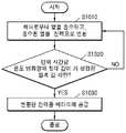
도 7은 예열 시간에 기초한 전력 공급 방법을 설명하기 위한 순서도이다.7 is a flowchart illustrating a power supply method based on a preheat time.
도면을 참조하면, S710 단계에서, 열전 소자(14)는 히터(13)로부터 열을 흡수하고, 흡수된 열을 전력으로 변환할 수 있다.Referring to the drawings, in step S710 , the
열전 소자(14)는 히터(13)에 인접하게 배치되는 제1 전극(310)과, 제1 전극(310)과 이격되어 배치되는 제2 전극(320)과, 제1 전극(310) 및 제2 전극(320) 사이에 배치되는 열전 재료(330)를 포함할 수 있다. 또한, 열전 소자(14)는 히터(13)가 가열되는 경우, 제1 전극(310)에 여기된 전자가 제2 전극(320)으로 이동함에 따라 발생되는 전기장 및 제1 전극(310)에 여기된 정공이 제2 전극(320)으로 이동함에 따라 발생되는 전기장에 의한, 제1 전극(310) 및 제2 전극(320)의 페르미 준위차를 이용하여 전력을 생성할 수 있다.The
S720 단계에서, 제어부(12)는 히터(13)의 가열 시간이 기 설정된 예열 시간을 도과하였는지 여부를 판단할 수 있다. 제어부(12)는 타이머(17)가 제공한 히터(13)의 가열 시간 정보에 기초하여 히터(13)의 가열 시간이 기 설정된 예열 시간을 도과하였는지 여부를 판단할 수 있다. 예를 들어, 예열 시간은 40초일 수 있으나, 이에 제한되지 않는다. 예열 시간은 에어로졸 생성 기질의 기화 온도, 배터리(11)의 전력, 히터(13) 성능 등을 고려하여 설정될 수 있다.In step S720 , the
S730 단계에서, 제어부(12)는 히터(13)의 가열 시간이 예열 시간을 도과한 경우, 변환된 전력을 배터리(11)에 공급할 수 있다. 제어부(12)는 스위칭 소자(SW)를 턴 온시켜, 커패시터 소자(C1)에 저장된 전력을 배터리(11)에 공급할 수 있다.In step S730 , when the heating time of the
도 8은 히터의 가열 종료 시점에 기초한 전력 공급 방법을 설명하기 위한 순서도이다.8 is a flowchart for explaining a power supply method based on a heating end time of a heater.
도면을 참조하면, S810 단계에서, 열전 소자(14)는 히터(13)로부터 열을 흡수하고, 흡수된 열을 전력으로 변환할 수 있다. 도 8의 S810 단계는 도 7의 S710 단계에 대응될 수 있다.Referring to the drawings, in step S810 , the
S820 단계에서, 제어부(12)는 히터의 가열 시간이 히터(13)의 가열이 종료되기 이전의 기 설정된 충전 시점인지 여부를 판단할 수 있다. 제어부(12)는 타이머(17)가 제공한 히터(13)의 가열 시간 정보에 기초하여 히터(13)의 가열 시간이 기 설정된 충전 시점에 도달하였는지 여부를 판단할 수 있다. 충전 시점은 가열 종료 시점에 인접하게 설정될 수 있다. 예를 들어, 충전 시점은 가열 종료 시점으로부터 2초 앞선 시점일 수 있으나, 이에 제한되지 않는다.In step S820 , the
S830 단계에서, 제어부(12)는 히터의 가열 시간이 가열이 종료되기 이전의 기 설정된 충전 시점에 도달한 경우, 변환된 전력을 배터리(11)에 공급할 수 있다. 제어부(12)는 스위칭 소자(SW)를 턴 온시켜, 커패시터 소자(C1)에 저장된 전력을 배터리(11)에 공급할 수 있다.In step S830 , the
도 9는 히터의 예열 온도에 기초한 전력 공급 방법을 설명하기 위한 순서도이다.9 is a flowchart illustrating a power supply method based on a preheating temperature of a heater.
도면을 참조하면, S910 단계에서, 열전 소자(14)는 히터(13)로부터 열을 흡수하고, 흡수된 열을 전력으로 변환할 수 있다. 도 9의 S910 단계는 도 7의 S710 및 도 8의 S810 단계에 대응될 수 있다.Referring to the drawings, in step S910 , the
S920 단계에서, 제어부(12)는 히터(13)의 가열 온도가 기 설정된 예열 온도에 도달하였는지 여부를 판단할 수 있다. 제어부(12)는 온도 감지부(16)가 제공한 히터(13)의 온도 정보에 기초하여 히터(13)의 가열 온도가 기 설정된 예열 온도에 도달하였는지 여부를 판단할 수 있다. 예를 들어, 예열 온도는 300도일 수 있으나, 이에 제한되지 않는다. 예열 온도는 에어로졸 생성 기질의 기화 온도, 배터리(11)의 전력, 히터(13) 성능 등을 고려하여 설정될 수 있다.In step S920 , the
S930 단계에서, 제어부(12)는 히터의 가열 온도가 기 설정된 예열 온도에 도달한 경우, 변환된 전력을 배터리(11)에 공급할 수 있다. 제어부(12)는 스위칭 소자(SW)를 턴 온시켜, 커패시터 소자(C1)에 저장된 전력을 배터리(11)에 공급할 수 있다.In step S930 , when the heating temperature of the heater reaches a preset preheating temperature, the
도 10은 히터 온도의 단위 시간당 온도 변화량에 기초한 전력 공급 방법을 설명하기 위한 순서도이다.10 is a flowchart for explaining a power supply method based on a temperature change amount per unit time of a heater temperature.
도면을 참조하면, S1010 단계에서, 열전 소자(14)는 히터(13)로부터 열을 흡수하고, 흡수된 열을 전력으로 변환할 수 있다. 도 10의 S1010 단계는 도 7의 S710, 도 8의 S810 및 도 9의 S910 단계에 대응될 수 있다.Referring to the drawings, in step S1010 , the
S1020 단계에서, 제어부(12)는 히터(13)의 단위 시간당 온도 변화량의 절대 값이 기 설정된 임계 값 미만인지 여부를 판단할 수 있다. 제어부(12)는 온도 감지부(16)가 제공한 히터(13)의 온도 정보에 기초하여 히터(13)의 단위 시간당 온도 변화량을 계산할 수 있다. 임계 값은 예열 구간에서 히터(13)의 단위 시간당 온도 변화량의 절대 값과 동일할 수 있다. 예를 들어, 단위 시간당 온도 변화량은 7.5 ℃/s 일 수 있으나, 이에 제한되지 않는다.In step S1020 , the
S1030 단계에서, 제어부(12)는 히터(13)의 단위 시간당 온도 변화량의 절대 값이 기 설정된 임계 값 미만인 경우, 변환된 전력을 배터리(11)에 공급할 수 있다. 제어부(12)는 스위칭 소자(SW)를 턴 온시켜, 커패시터 소자(C1)에 저장된 전력을 배터리(11)에 공급할 수 있다.In step S1030 , when the absolute value of the temperature change amount per unit time of the
도 11은 히터의 도달 온도에 기초한 전력 공급 방법을 설명하기 위한 순서도이다.11 is a flowchart for explaining a method of supplying power based on the reached temperature of the heater.
도면을 참조하면, S1110 단계에서, 열전 소자(14)는 히터(13)로부터 열을 흡수하고, 흡수된 열을 전력으로 변환할 수 있다. 도 11의 S1110 단계는 도 7의 S710, 도 8의 S810, 도 9의 S910 및 도 10의 S1010 단계에 대응될 수 있다.Referring to the drawings, in step S1110 , the
S1120 단계에서, 제어부(12)는 히터(13)의 온도가 제1 온도에 도달하였는지 여부를 판단할 수 있다. 제1 온도는 예열 온도일 수 있다. 예를 들어, 제1 온도는 300도일 수 있으나, 이에 제한되지 않는다.In step S1120 , the
S1130 단계에서, 제어부(12)는 히터의 온도가 제1 온도에 도달한 경우, 계속하여, 히터(13)의 온도가 제1 온도 보다 낮은 제2 온도에 도달하였는지 여부를 판단할 수 있다. 제2 온도는 흡열 온도일 수 있다. 예를 들어, 제2 온도는 250일 수 있으나, 이에 제한되지 않는다.In step S1130 , when the temperature of the heater reaches the first temperature, the
S1120 단계 및 S1130 단계에서, 제어부(12)는 온도 감지부(16)가 제공한 히터(13)의 온도 정보에 기초하여 히터(13)의 온도가 제1 온도 및 제2 온도에 도달하였는지 여부를 판단할 수 있다.In steps S1120 and S1130, the
S1140 단계에서, 제어부(12)는 히터(13)의 온도가 제2 온도에 도달한 경우, 변환된 전력을 배터리(11)에 공급할 수 있다. 제어부(12)는 스위칭 소자(SW)를 턴 온시켜, 커패시터 소자(C1)에 저장된 전력을 배터리(11)에 공급할 수 있다.In step S1140 , when the temperature of the
도 12는 배터리의 충전 레벨에 기초한 전력 공급 방법을 설명하기 위한 순서도이다.12 is a flowchart illustrating a power supply method based on a charge level of a battery.
도면을 참조하면, S1210 단계에서, 열전 소자(14)는 히터(13)로부터 열을 흡수하고, 흡수된 열을 전력으로 변환할 수 있다. 도 12의 S1210 단계는 도 7의 S710, 도 8의 S810, 도 9의 S910, 도 10의 S1010 및 도 11의 S1110 단계에 대응될 수 있다.Referring to the drawings, in step S1210 , the
S1220 단계에서, 제어부(12)는 배터리(11)의 충전 레벨이 기 설정된 기준 레벨 이하인지 여부를 판단할 수 있다. 기준 레벨은 배터리(11)의 총 용량 30%일 수 있으나, 이에 제한되지 않는다.In step S1220 , the
S1230 단계에서, 제어부(12)는 배터리(11)의 충전 레벨이 기 설정된 기준 레벨 이하인 경우, 변환된 전력을 배터리(11)에 공급할 수 있다. 제어부(12)는 스위칭 소자(SW)를 턴 온시켜, 커패시터 소자(C1)에 저장된 전력을 배터리(11)에 공급할 수 있다.In step S1230 , when the charge level of the
상술한 방법은 컴퓨터에서 실행될 수 있는 프로그램으로 작성 가능하고, 컴퓨터로 읽을 수 있는 기록매체를 이용하여 상기 프로그램을 동작시키는 범용 디지털 컴퓨터에서 구현될 수 있다. 또한, 상술한 방법에서 사용된 데이터의 구조는 컴퓨터로 읽을 수 있는 기록매체에 여러 수단을 통하여 기록될 수 있다. 상기 컴퓨터로 읽을 수 있는 기록매체는 마그네틱 저장매체(예를 들면, 롬, 램, USB, 플로피 디스크, 하드 디스크 등), 광학적 판독 매체(예를 들면, 시디롬, 디브이디 등)와 같은 저장매체를 포함한다.The above-described method can be written as a program that can be executed on a computer, and can be implemented in a general-purpose digital computer that operates the program using a computer-readable recording medium. In addition, the structure of the data used in the above-described method may be recorded in a computer-readable recording medium through various means. The computer-readable recording medium includes a storage medium such as a magnetic storage medium (eg, ROM, RAM, USB, floppy disk, hard disk, etc.) and an optically readable medium (eg, CD-ROM, DVD, etc.) do.
본 실시예와 관련된 기술 분야에서 통상의 지식을 가진 자는 상기된 기재의 본질적인 특성에서 벗어나지 않는 범위에서 변형된 형태로 구현될 수 있음을 이해할 수 있을 것이다. 그러므로 개시된 방법들은 한정적인 관점이 아니라 설명적인 관점에서 고려되어야 한다. 본 개시의 범위는 전술한 설명이 아니라 청구범위에 나타나 있으며, 그와 동등한 범위 내에 있는 모든 차이점은 본 개시에 포함된 것으로 해석되어야 할 것이다.A person of ordinary skill in the art related to this embodiment will understand that it can be implemented in a modified form within a range that does not deviate from the essential characteristics of the above description. Therefore, the disclosed methods are to be considered in an illustrative rather than a restrictive sense. The scope of the present disclosure is indicated in the claims rather than the foregoing description, and all differences within the scope equivalent thereto should be construed as included in the present disclosure.
1: 에어로졸 생성 장치
11: 배터리
12: 제어부
13: 히터
14: 열전소자1: aerosol generating device
11: battery
12: control
13: heater
14: thermoelectric element
Claims (15)
Translated fromKorean상기 히터에 전력을 공급하는 배터리;
상기 히터에 인접하게 배치되며, 상기 히터로부터 열을 흡수하고, 상기 흡수된 열을 전력으로 변환하는 열전 소자;
상기 변환된 전력을 저장하는 충전부; 및
상기 히터의 가열 시간을 기초로, 상기 충전부를 제어하여 상기 배터리를 충전하는 제어부;를 포함하는 에어로졸 생성 장치.a heater for heating the aerosol-generating substrate;
a battery for supplying power to the heater;
a thermoelectric element disposed adjacent to the heater, absorbing heat from the heater, and converting the absorbed heat into electric power;
a charging unit for storing the converted power; and
Aerosol generating device comprising a; based on the heating time of the heater, controlling the charging unit to charge the battery.
상기 제어부는
기 설정된 예열 시간이 도과한 시점부터 상기 변환된 전력을 상기 배터리에 공급하는 에어로졸 생성 장치.According to claim 1,
the control unit
An aerosol generating device for supplying the converted power to the battery from a point in time when a preset preheating time has elapsed.
상기 제어부는
상기 히터의 가열이 종료되기 이전의 기 설정된 충전 시점부터 상기 변환된 전력을 상기 배터리에 공급하는 에어로졸 생성 장치.According to claim 1,
the control unit
An aerosol generating device for supplying the converted power to the battery from a preset charging point before the heating of the heater is terminated.
상기 히터의 가열 시간을 카운트하는 타이머;를 더 포함하는 에어로졸 생성 장치.According to claim 1,
The aerosol generating device further comprising; a timer for counting the heating time of the heater.
상기 히터에 전력을 공급하는 배터리;
상기 히터에 인접하게 배치되며, 상기 히터로부터 열을 흡수하고, 상기 흡수된 열을 전력으로 변환하는 열전 소자;
상기 변환된 전력을 저장하는 충전부; 및
상기 히터의 가열 온도를 기초로, 상기 충전부를 제어하여 상기 배터리를 충전하는 제어부;를 포함하는 에어로졸 생성 장치.a heater for heating the aerosol-generating substrate;
a battery for supplying power to the heater;
a thermoelectric element disposed adjacent to the heater, absorbing heat from the heater, and converting the absorbed heat into electric power;
a charging unit for storing the converted power; and
Aerosol generating device comprising a; based on the heating temperature of the heater, controlling the charging unit to charge the battery.
상기 제어부는
상기 히터의 온도가 기 설정된 예열 온도에 도달한 경우, 상기 변환된 전력을 상기 배터리에 공급하는 에어로졸 생성 장치.6. The method of claim 5,
the control unit
When the temperature of the heater reaches a preset preheating temperature, an aerosol generating device for supplying the converted power to the battery.
상기 제어부는
상기 히터의 단위 시간당 온도 변화량의 절대 값이 기 설정된 임계 값 미만인 경우, 상기 변환된 전력을 상기 배터리에 공급하는 에어로졸 생성 장치.6. The method of claim 5,
the control unit
When the absolute value of the temperature change amount per unit time of the heater is less than a preset threshold value, the aerosol generating device for supplying the converted power to the battery.
상기 제어부는
상기 히터의 온도가 제1 온도에 도달한 이후에 상기 제1 온도 보다 낮은 제2 온도에 도달한 경우, 상기 변환된 전력을 상기 배터리에 공급하는 에어로졸 생성 장치.6. The method of claim 5,
the control unit
When the temperature of the heater reaches a second temperature lower than the first temperature after reaching the first temperature, the aerosol generating device supplies the converted power to the battery.
상기 히터의 온도를 감지하는 온도 감지부;를 더 포함하는 에어로졸 생성 장치.6. The method of claim 5,
Aerosol generating device further comprising; a temperature sensing unit for sensing the temperature of the heater.
상기 히터에 전력을 공급하는 배터리;
상기 히터에 인접하게 배치되는 제1 전극과, 상기 제1 전극과 이격되어 배치되는 제2 전극과, 상기 제1 전극 및 상기 제2 전극 사이에 배치되는 열전 재료를 포함하고, 상기 히터가 가열되는 경우, 상기 제1 전극에 여기된 전자가 상기 제2 전극으로 이동함에 따라 발생되는 전기장 및 상기 제1 전극에 여기된 정공이 상기 제2 전극으로 이동함에 따라 발생되는 전기장에 의한, 상기 제1 전극 및 상기 제2 전극의 페르미 준위차를 이용하여 전력을 생성하는 열전 소자;
상기 생성된 전력을 저장하는 충전부; 및
상기 히터의 가열 시간, 상기 히터의 가열 온도 및 상기 배터리의 충전 레벨 중 적어도 어느 하나를 기초로 상기 충전부를 제어하여 상기 배터리를 충전하는 제어부;를 포함하는 에어로졸 생성 장치.a heater for heating the aerosol-generating substrate;
a battery for supplying power to the heater;
A first electrode disposed adjacent to the heater, a second electrode disposed spaced apart from the first electrode, and a thermoelectric material disposed between the first electrode and the second electrode, wherein the heater is heated In this case, by an electric field generated as electrons excited by the first electrode move to the second electrode and an electric field generated as holes excited by the first electrode move to the second electrode, the first electrode and a thermoelectric element generating electric power using a Fermi level difference of the second electrode.
a charging unit for storing the generated power; and
An aerosol generating device comprising a; a control unit for charging the battery by controlling the charging unit based on at least one of a heating time of the heater, a heating temperature of the heater, and a charging level of the battery.
상기 열전 소자는
상기 제2 전극에 연결되며 상기 제2 전극에서 발생하는 열을 냉각하는 냉각부;를 더 포함하는 에어로졸 생성 장치.11. The method of claim 10,
The thermoelectric element is
The aerosol generating device further comprising; a cooling unit connected to the second electrode to cool the heat generated from the second electrode.
상기 열전 소자는
상기 제1 전극에 연결되며, 상기 히터에서 발생한 열을 흡열하여 상기 제1 전극에 전달하는 흡열부;를 더 포함하는 에어로졸 생성 장치.11. The method of claim 10,
The thermoelectric element is
The aerosol generating device further comprising a; is connected to the first electrode, and absorbs heat generated by the heater and transfers the heat to the first electrode.
상기 열전 소자에 접속하며, 상기 전력을 저장하는 커패시터 소자; 및
상기 커패시터 소자에 직렬 접속하며, 상기 제어부의 제어에 의해 온, 오프되는 스위칭 소자;를 더 포함하는 에어로졸 생성 장치.11. The method of claim 10,
a capacitor element connected to the thermoelectric element and configured to store the electric power; and
The aerosol generating device further comprising a; connected in series to the capacitor element, the switching element is turned on and off under the control of the control unit.
상기 제어부는
상기 히터의 가열 시간, 상기 히터의 가열 온도 및 상기 배터리의 충전 레벨 중 적어도 어느 하나에 기초하여 상기 스위칭 소자의 온, 오프를 제어하는 에어로졸 생성 장치.14. The method of claim 13,
the control unit
An aerosol generating device for controlling on/off of the switching element based on at least one of a heating time of the heater, a heating temperature of the heater, and a charge level of the battery.
상기 열전 소자 및 상기 커패시터 소자 사이에 접속하며, 상기 열전 소자가 출력한 전류를 안정화시키는 레귤레이터 회로부;를 더 포함하는 에어로졸 생성 장치.14. The method of claim 13,
The aerosol generating device further comprising a; connected between the thermoelectric element and the capacitor element, the regulator circuit for stabilizing the current output by the thermoelectric element.
Priority Applications (6)
| Application Number | Priority Date | Filing Date | Title |
|---|---|---|---|
| KR1020200001569AKR102397451B1 (en) | 2020-01-06 | 2020-01-06 | Aerosol generating device |
| CN202080013508.9ACN113412067B (en) | 2020-01-06 | 2020-12-10 | aerosol generating device |
| JP2021541561AJP7257527B2 (en) | 2020-01-06 | 2020-12-10 | aerosol generator |
| PCT/KR2020/018028WO2021141249A1 (en) | 2020-01-06 | 2020-12-10 | Aerosol generating device |
| US17/421,435US12063968B2 (en) | 2020-01-06 | 2020-12-10 | Aerosol generating device |
| EP20908462.3AEP3890525B1 (en) | 2020-01-06 | 2020-12-10 | Aerosol generating device |
Applications Claiming Priority (1)
| Application Number | Priority Date | Filing Date | Title |
|---|---|---|---|
| KR1020200001569AKR102397451B1 (en) | 2020-01-06 | 2020-01-06 | Aerosol generating device |
Publications (2)
| Publication Number | Publication Date |
|---|---|
| KR20210088299A KR20210088299A (en) | 2021-07-14 |
| KR102397451B1true KR102397451B1 (en) | 2022-05-12 |
Family
ID=76788806
Family Applications (1)
| Application Number | Title | Priority Date | Filing Date |
|---|---|---|---|
| KR1020200001569AActiveKR102397451B1 (en) | 2020-01-06 | 2020-01-06 | Aerosol generating device |
Country Status (6)
| Country | Link |
|---|---|
| US (1) | US12063968B2 (en) |
| EP (1) | EP3890525B1 (en) |
| JP (1) | JP7257527B2 (en) |
| KR (1) | KR102397451B1 (en) |
| CN (1) | CN113412067B (en) |
| WO (1) | WO2021141249A1 (en) |
Families Citing this family (9)
| Publication number | Priority date | Publication date | Assignee | Title |
|---|---|---|---|---|
| IL298052A (en)* | 2020-06-10 | 2023-01-01 | Esmoking Inst Sp Z O O | Aerosol provision device |
| CN115769914A (en)* | 2021-09-08 | 2023-03-10 | 深圳市合元科技有限公司 | Aerosol generating device and control method thereof |
| US20240407462A1 (en)* | 2021-10-19 | 2024-12-12 | Kt&G Corporation | Aerosol-generating device and operation method thereof |
| KR102688838B1 (en)* | 2021-10-20 | 2024-07-26 | 주식회사 케이티앤지 | Aerosol generating device and method thereof |
| US20250280894A1 (en)* | 2022-05-02 | 2025-09-11 | Kt&G Corporation | Aerosol generating device |
| WO2024029017A1 (en)* | 2022-08-04 | 2024-02-08 | 日本たばこ産業株式会社 | Aerosol generation system, control method, and program |
| WO2024175525A1 (en)* | 2023-02-20 | 2024-08-29 | Jt International Sa | Aerosol generating device comprising a charging assembly |
| WO2024258132A1 (en)* | 2023-06-16 | 2024-12-19 | 주식회사 케이티앤지 | Aerosol-generating device and control method therefor |
| WO2025172106A1 (en)* | 2024-02-15 | 2025-08-21 | Jt International Sa | An aerosol generating device |
Citations (3)
| Publication number | Priority date | Publication date | Assignee | Title |
|---|---|---|---|---|
| KR100373289B1 (en)* | 2000-12-19 | 2003-02-25 | 기아자동차주식회사 | Electric Power Sub-Supply Apparatus of Vehicle Using Thermo-Electric Semiconductor Module |
| JP2007159310A (en)* | 2005-12-07 | 2007-06-21 | Univ Kanagawa | Power supply |
| WO2018234792A1 (en)* | 2017-06-22 | 2018-12-27 | Nicoventures Holdings Limited | ELECTRONIC STEAM SUPPLY SYSTEM |
Family Cites Families (26)
| Publication number | Priority date | Publication date | Assignee | Title |
|---|---|---|---|---|
| US6161388A (en) | 1998-12-28 | 2000-12-19 | International Business Machines Corporation | Enhanced duty cycle design for micro thermoelectromechanical coolers |
| KR100356398B1 (en) | 2000-06-05 | 2002-10-19 | 주식회사 한 맥 | Refrigerated system with thermo electric module and heat pipe |
| JP5227583B2 (en)* | 2006-12-28 | 2013-07-03 | 株式会社半導体エネルギー研究所 | Power storage device and electronic device |
| US9814262B2 (en) | 2012-07-11 | 2017-11-14 | Sis Resources, Ltd. | Hot-wire control for an electronic cigarette |
| EP2701268A1 (en)* | 2012-08-24 | 2014-02-26 | Philip Morris Products S.A. | Portable electronic system including charging device and method of charging a secondary battery |
| DE202014011260U1 (en) | 2013-12-23 | 2018-11-13 | Juul Labs Uk Holdco Limited | Systems for an evaporation device |
| TWI681691B (en) | 2014-04-30 | 2020-01-01 | 瑞士商菲利浦莫里斯製品股份有限公司 | Electrically heated aerosol-generating system, device and method of controlling the same |
| KR20160091840A (en)* | 2015-01-24 | 2016-08-03 | 이정용 | An automobile cooling device using thermoelement |
| EP3533351B1 (en) | 2015-04-15 | 2020-11-18 | Philip Morris Products S.a.s. | Device and method for controlling an electrical heater to limit temperature according to desired temperature profile over time |
| KR20170020576A (en) | 2015-08-12 | 2017-02-23 | 신수현 | power supply device for electrical cigarette and electrical cigarette with the same |
| US10757973B2 (en)* | 2016-07-25 | 2020-09-01 | Fontem Holdings 1 B.V. | Electronic cigarette with mass air flow sensor |
| CN106213590A (en)* | 2016-09-06 | 2016-12-14 | 深圳市合元科技有限公司 | The operation control method of smoke generating device and smoke generating device |
| RU2742950C2 (en)* | 2016-11-18 | 2021-02-12 | Филип Моррис Продактс С.А. | Heating unit, an aerosol-generating device and a method of heating the aerosol-forming substrate |
| RU2750465C2 (en) | 2016-12-16 | 2021-06-28 | Кей Ти Энд Джи Корпорейшн | Aerosol-generating apparatus |
| KR102138873B1 (en)* | 2016-12-16 | 2020-07-29 | 주식회사 케이티앤지 | Aerosols generating system for pre-heating the heater |
| KR101910960B1 (en)* | 2017-02-17 | 2018-10-23 | 주식회사 블루시스 | Thermoelectric generation module |
| US12102131B2 (en) | 2017-04-11 | 2024-10-01 | Kt&G Corporation | Aerosol generating device and method for providing adaptive feedback through puff recognition |
| EP3610743A4 (en) | 2017-04-11 | 2021-04-28 | KT & G Coporation | PREHEATING ELEMENT AEROSOL GENERATION SYSTEM |
| TW201843553A (en)* | 2017-05-02 | 2018-12-16 | 瑞士商菲利浦莫里斯製品股份有限公司 | Heater assembly for aerosol generating device |
| JP7112427B2 (en)* | 2017-06-28 | 2022-08-03 | フィリップ・モーリス・プロダクツ・ソシエテ・アノニム | Electrical heating assembly, aerosol generator and method for resistively heating an aerosol-forming substrate |
| KR102374086B1 (en)* | 2017-09-29 | 2022-03-14 | 주식회사 케이티앤지 | System and apparatus for generating aerosols |
| WO2019115464A1 (en) | 2017-12-13 | 2019-06-20 | Philip Morris Products S.A. | Aerosol-generating device with feedback control |
| ES2941944T3 (en)* | 2018-01-15 | 2023-05-26 | Philip Morris Products Sa | Hookah device with cooling to improve the characteristics of the aerosol |
| BR112020018379A2 (en) | 2018-04-10 | 2020-12-29 | Philip Morris Products S.A. | AEROSOL GENERATOR ARTICLE UNDERSTANDING A HEATABLE ELEMENT |
| WO2020051385A1 (en)* | 2018-09-06 | 2020-03-12 | Bergstrom Sam | Vaporizer apparatuses and vaporizing methods |
| CN109123797A (en)* | 2018-09-08 | 2019-01-04 | 湖北中烟工业有限责任公司 | Have effects that the sheath body of heat to electricity conversion and the tobacco heating mechanism using the sheath body |
- 2020
- 2020-01-06KRKR1020200001569Apatent/KR102397451B1/enactiveActive
- 2020-12-10WOPCT/KR2020/018028patent/WO2021141249A1/ennot_activeCeased
- 2020-12-10USUS17/421,435patent/US12063968B2/enactiveActive
- 2020-12-10JPJP2021541561Apatent/JP7257527B2/enactiveActive
- 2020-12-10CNCN202080013508.9Apatent/CN113412067B/enactiveActive
- 2020-12-10EPEP20908462.3Apatent/EP3890525B1/enactiveActive
Patent Citations (3)
| Publication number | Priority date | Publication date | Assignee | Title |
|---|---|---|---|---|
| KR100373289B1 (en)* | 2000-12-19 | 2003-02-25 | 기아자동차주식회사 | Electric Power Sub-Supply Apparatus of Vehicle Using Thermo-Electric Semiconductor Module |
| JP2007159310A (en)* | 2005-12-07 | 2007-06-21 | Univ Kanagawa | Power supply |
| WO2018234792A1 (en)* | 2017-06-22 | 2018-12-27 | Nicoventures Holdings Limited | ELECTRONIC STEAM SUPPLY SYSTEM |
Also Published As
| Publication number | Publication date |
|---|---|
| US12063968B2 (en) | 2024-08-20 |
| WO2021141249A1 (en) | 2021-07-15 |
| EP3890525B1 (en) | 2025-02-19 |
| CN113412067A (en) | 2021-09-17 |
| JP7257527B2 (en) | 2023-04-13 |
| EP3890525A1 (en) | 2021-10-13 |
| EP3890525A4 (en) | 2022-02-23 |
| US20220369712A1 (en) | 2022-11-24 |
| CN113412067B (en) | 2023-12-22 |
| KR20210088299A (en) | 2021-07-14 |
| JP2022519467A (en) | 2022-03-24 |
Similar Documents
| Publication | Publication Date | Title |
|---|---|---|
| KR102397451B1 (en) | Aerosol generating device | |
| JP6845131B2 (en) | Adaptive Battery Charging Methods and Systems | |
| US11937357B2 (en) | Aerosol generation device comprising voltage converter and method for controlling same | |
| KR102603409B1 (en) | Electric aerosol generation system with rechargeable power source | |
| KR102142635B1 (en) | Method and device for supplying power | |
| CN101969800B (en) | Electrically heated aerosol generating system and method | |
| JP2017527249A (en) | Rechargeable device with short circuit prevention | |
| JP2009142069A (en) | Temperature regulator of battery pack and temperature regulation method of battery pack | |
| RU2019115267A (en) | CHARGER FOR AEROSOL DELIVERY DEVICE | |
| CN117479857A (en) | Aerosol generating device power system comprising two battery cells | |
| KR20230042010A (en) | Aerosol generator with dual battery heating | |
| US20230397669A1 (en) | Aerosol Generation Device Power System | |
| CN116546896A (en) | Aerosol generating device power system | |
| KR102397450B1 (en) | Aerosol generating device for heating aerosol-generating article using thermoelectric element | |
| CN220545837U (en) | Aerosol generating device | |
| KR102498887B1 (en) | Energy harvesting device and aerosol generating system including the same | |
| CN116035284A (en) | Control method and device of electronic smoking set, electronic smoking set and storage medium | |
| WO2021052471A1 (en) | Smoking device | |
| KR20220022759A (en) | Aerosol generating device | |
| HK1237131B (en) | An adaptive battery charging method and system | |
| HK1237131A1 (en) | An adaptive battery charging method and system |
Legal Events
| Date | Code | Title | Description |
|---|---|---|---|
| PA0109 | Patent application | Patent event code:PA01091R01D Comment text:Patent Application Patent event date:20200106 | |
| PA0201 | Request for examination | ||
| PG1501 | Laying open of application | ||
| E902 | Notification of reason for refusal | ||
| PE0902 | Notice of grounds for rejection | Comment text:Notification of reason for refusal Patent event date:20210802 Patent event code:PE09021S01D | |
| E701 | Decision to grant or registration of patent right | ||
| PE0701 | Decision of registration | Patent event code:PE07011S01D Comment text:Decision to Grant Registration Patent event date:20220211 | |
| GRNT | Written decision to grant | ||
| PR0701 | Registration of establishment | Comment text:Registration of Establishment Patent event date:20220509 Patent event code:PR07011E01D | |
| PR1002 | Payment of registration fee | Payment date:20220510 End annual number:3 Start annual number:1 | |
| PG1601 | Publication of registration |