KR102393804B1 - A manufacturing apparatus for a tube filter and manufacturing method for the tube filter - Google Patents
A manufacturing apparatus for a tube filter and manufacturing method for the tube filterDownload PDFInfo
- Publication number
- KR102393804B1 KR102393804B1KR1020200050649AKR20200050649AKR102393804B1KR 102393804 B1KR102393804 B1KR 102393804B1KR 1020200050649 AKR1020200050649 AKR 1020200050649AKR 20200050649 AKR20200050649 AKR 20200050649AKR 102393804 B1KR102393804 B1KR 102393804B1
- Authority
- KR
- South Korea
- Prior art keywords
- tube filter
- rod
- filter
- nozzle
- tube
- Prior art date
- Legal status (The legal status is an assumption and is not a legal conclusion. Google has not performed a legal analysis and makes no representation as to the accuracy of the status listed.)
- Active
Links
- 238000004519manufacturing processMethods0.000titleclaimsabstractdescription66
- 239000007788liquidSubstances0.000claimsabstractdescription45
- 230000003020moisturizing effectEffects0.000claimsabstractdescription17
- 238000000465mouldingMethods0.000claimsdescription38
- 238000000034methodMethods0.000claimsdescription36
- 238000001816coolingMethods0.000claimsdescription29
- 230000000391smoking effectEffects0.000claimsdescription18
- 238000012546transferMethods0.000claimsdescription18
- 238000011144upstream manufacturingMethods0.000claimsdescription11
- 238000005507sprayingMethods0.000claimsdescription8
- 238000007493shaping processMethods0.000claimsdescription7
- 238000007599dischargingMethods0.000claimsdescription4
- 239000012530fluidSubstances0.000claimsdescription4
- 238000004891communicationMethods0.000claimsdescription3
- NOOLISFMXDJSKH-UTLUCORTSA-N(+)-NeomentholChemical compoundCC(C)[C@@H]1CC[C@@H](C)C[C@@H]1ONOOLISFMXDJSKH-UTLUCORTSA-N0.000description23
- NOOLISFMXDJSKH-UHFFFAOYSA-NDL-mentholNatural productsCC(C)C1CCC(C)CC1ONOOLISFMXDJSKH-UHFFFAOYSA-N0.000description23
- 229940041616mentholDrugs0.000description23
- 230000000052comparative effectEffects0.000description21
- 239000000796flavoring agentSubstances0.000description19
- 235000019634flavorsNutrition0.000description19
- 235000019504cigarettesNutrition0.000description15
- 238000000926separation methodMethods0.000description10
- DNIAPMSPPWPWGF-UHFFFAOYSA-NPropylene glycolChemical compoundCC(O)CODNIAPMSPPWPWGF-UHFFFAOYSA-N0.000description9
- 239000003205fragranceSubstances0.000description9
- 239000000463materialSubstances0.000description9
- 239000000443aerosolSubstances0.000description8
- 238000009792diffusion processMethods0.000description4
- 238000011156evaluationMethods0.000description4
- 239000004014plasticizerSubstances0.000description4
- 239000003795chemical substances by applicationSubstances0.000description3
- 238000010586diagramMethods0.000description3
- 238000002474experimental methodMethods0.000description3
- 230000000704physical effectEffects0.000description3
- PEDCQBHIVMGVHV-UHFFFAOYSA-NGlycerineChemical compoundOCC(O)COPEDCQBHIVMGVHV-UHFFFAOYSA-N0.000description2
- 238000002485combustion reactionMethods0.000description2
- 238000002425crystallisationMethods0.000description2
- 230000008025crystallizationEffects0.000description2
- 230000000694effectsEffects0.000description2
- 239000007921spraySubstances0.000description2
- 238000003860storageMethods0.000description2
- URAYPUMNDPQOKB-UHFFFAOYSA-NtriacetinChemical compoundCC(=O)OCC(OC(C)=O)COC(C)=OURAYPUMNDPQOKB-UHFFFAOYSA-N0.000description2
- SNICXCGAKADSCV-JTQLQIEISA-N(-)-NicotineChemical compoundCN1CCC[C@H]1C1=CC=CN=C1SNICXCGAKADSCV-JTQLQIEISA-N0.000description1
- 206010006326Breath odourDiseases0.000description1
- 238000010521absorption reactionMethods0.000description1
- 238000000889atomisationMethods0.000description1
- 229920002301cellulose acetatePolymers0.000description1
- 235000019506cigarNutrition0.000description1
- 238000011109contaminationMethods0.000description1
- 238000005520cutting processMethods0.000description1
- 238000005516engineering processMethods0.000description1
- 235000011187glycerolNutrition0.000description1
- 235000013773glyceryl triacetateNutrition0.000description1
- 239000001087glyceryl triacetateSubstances0.000description1
- 238000000227grindingMethods0.000description1
- 238000010438heat treatmentMethods0.000description1
- 230000001788irregularEffects0.000description1
- 238000002156mixingMethods0.000description1
- 229960002715nicotineDrugs0.000description1
- SNICXCGAKADSCV-UHFFFAOYSA-NnicotineNatural productsCN1CCCC1C1=CC=CN=C1SNICXCGAKADSCV-UHFFFAOYSA-N0.000description1
- 239000002304perfumeSubstances0.000description1
- 239000000049pigmentSubstances0.000description1
- 238000002203pretreatmentMethods0.000description1
- 238000012545processingMethods0.000description1
- 238000003672processing methodMethods0.000description1
- 238000011160researchMethods0.000description1
- 238000004904shorteningMethods0.000description1
- 239000000758substrateSubstances0.000description1
- 229960002622triacetinDrugs0.000description1
- 230000000007visual effectEffects0.000description1
- XLYOFNOQVPJJNP-UHFFFAOYSA-NwaterSubstancesOXLYOFNOQVPJJNP-UHFFFAOYSA-N0.000description1
Images


Classifications
- A—HUMAN NECESSITIES
- A24—TOBACCO; CIGARS; CIGARETTES; SIMULATED SMOKING DEVICES; SMOKERS' REQUISITES
- A24D—CIGARS; CIGARETTES; TOBACCO SMOKE FILTERS; MOUTHPIECES FOR CIGARS OR CIGARETTES; MANUFACTURE OF TOBACCO SMOKE FILTERS OR MOUTHPIECES
- A24D3/00—Tobacco smoke filters, e.g. filter-tips, filtering inserts; Filters specially adapted for simulated smoking devices; Mouthpieces for cigars or cigarettes
- A24D3/02—Manufacture of tobacco smoke filters
- A24D3/0229—Filter rod forming processes
- A—HUMAN NECESSITIES
- A24—TOBACCO; CIGARS; CIGARETTES; SIMULATED SMOKING DEVICES; SMOKERS' REQUISITES
- A24D—CIGARS; CIGARETTES; TOBACCO SMOKE FILTERS; MOUTHPIECES FOR CIGARS OR CIGARETTES; MANUFACTURE OF TOBACCO SMOKE FILTERS OR MOUTHPIECES
- A24D3/00—Tobacco smoke filters, e.g. filter-tips, filtering inserts; Filters specially adapted for simulated smoking devices; Mouthpieces for cigars or cigarettes
- A24D3/02—Manufacture of tobacco smoke filters
- A24D3/025—Final operations, i.e. after the filter rod forming process
- A—HUMAN NECESSITIES
- A24—TOBACCO; CIGARS; CIGARETTES; SIMULATED SMOKING DEVICES; SMOKERS' REQUISITES
- A24C—MACHINES FOR MAKING CIGARS OR CIGARETTES
- A24C5/00—Making cigarettes; Making tipping materials for, or attaching filters or mouthpieces to, cigars or cigarettes
- A24C5/46—Making paper tubes for cigarettes
- A24C5/465—Making paper tubes for cigarettes the paper tubes partially containing a filter element
- A—HUMAN NECESSITIES
- A24—TOBACCO; CIGARS; CIGARETTES; SIMULATED SMOKING DEVICES; SMOKERS' REQUISITES
- A24D—CIGARS; CIGARETTES; TOBACCO SMOKE FILTERS; MOUTHPIECES FOR CIGARS OR CIGARETTES; MANUFACTURE OF TOBACCO SMOKE FILTERS OR MOUTHPIECES
- A24D3/00—Tobacco smoke filters, e.g. filter-tips, filtering inserts; Filters specially adapted for simulated smoking devices; Mouthpieces for cigars or cigarettes
- A24D3/02—Manufacture of tobacco smoke filters
- A24D3/0204—Preliminary operations before the filter rod forming process, e.g. crimping, blooming
- A24D3/0212—Applying additives to filter materials
- A24D3/022—Applying additives to filter materials with liquid additives, e.g. application of plasticisers
- A—HUMAN NECESSITIES
- A24—TOBACCO; CIGARS; CIGARETTES; SIMULATED SMOKING DEVICES; SMOKERS' REQUISITES
- A24D—CIGARS; CIGARETTES; TOBACCO SMOKE FILTERS; MOUTHPIECES FOR CIGARS OR CIGARETTES; MANUFACTURE OF TOBACCO SMOKE FILTERS OR MOUTHPIECES
- A24D3/00—Tobacco smoke filters, e.g. filter-tips, filtering inserts; Filters specially adapted for simulated smoking devices; Mouthpieces for cigars or cigarettes
- A24D3/02—Manufacture of tobacco smoke filters
- A24D3/0229—Filter rod forming processes
- A24D3/0233—Filter rod forming processes by means of a garniture
- A—HUMAN NECESSITIES
- A24—TOBACCO; CIGARS; CIGARETTES; SIMULATED SMOKING DEVICES; SMOKERS' REQUISITES
- A24D—CIGARS; CIGARETTES; TOBACCO SMOKE FILTERS; MOUTHPIECES FOR CIGARS OR CIGARETTES; MANUFACTURE OF TOBACCO SMOKE FILTERS OR MOUTHPIECES
- A24D3/00—Tobacco smoke filters, e.g. filter-tips, filtering inserts; Filters specially adapted for simulated smoking devices; Mouthpieces for cigars or cigarettes
- A24D3/02—Manufacture of tobacco smoke filters
- A24D3/0275—Manufacture of tobacco smoke filters for filters with special features
- A24D3/0279—Manufacture of tobacco smoke filters for filters with special features with tubes
- A—HUMAN NECESSITIES
- A24—TOBACCO; CIGARS; CIGARETTES; SIMULATED SMOKING DEVICES; SMOKERS' REQUISITES
- A24D—CIGARS; CIGARETTES; TOBACCO SMOKE FILTERS; MOUTHPIECES FOR CIGARS OR CIGARETTES; MANUFACTURE OF TOBACCO SMOKE FILTERS OR MOUTHPIECES
- A24D3/00—Tobacco smoke filters, e.g. filter-tips, filtering inserts; Filters specially adapted for simulated smoking devices; Mouthpieces for cigars or cigarettes
- A24D3/04—Tobacco smoke filters characterised by their shape or structure
- A24D3/048—Tobacco smoke filters characterised by their shape or structure containing additives
- A—HUMAN NECESSITIES
- A24—TOBACCO; CIGARS; CIGARETTES; SIMULATED SMOKING DEVICES; SMOKERS' REQUISITES
- A24D—CIGARS; CIGARETTES; TOBACCO SMOKE FILTERS; MOUTHPIECES FOR CIGARS OR CIGARETTES; MANUFACTURE OF TOBACCO SMOKE FILTERS OR MOUTHPIECES
- A24D3/00—Tobacco smoke filters, e.g. filter-tips, filtering inserts; Filters specially adapted for simulated smoking devices; Mouthpieces for cigars or cigarettes
- A24D3/06—Use of materials for tobacco smoke filters
- A24D3/061—Use of materials for tobacco smoke filters containing additives entrapped within capsules, sponge-like material or the like, for further release upon smoking
- A—HUMAN NECESSITIES
- A24—TOBACCO; CIGARS; CIGARETTES; SIMULATED SMOKING DEVICES; SMOKERS' REQUISITES
- A24D—CIGARS; CIGARETTES; TOBACCO SMOKE FILTERS; MOUTHPIECES FOR CIGARS OR CIGARETTES; MANUFACTURE OF TOBACCO SMOKE FILTERS OR MOUTHPIECES
- A24D3/00—Tobacco smoke filters, e.g. filter-tips, filtering inserts; Filters specially adapted for simulated smoking devices; Mouthpieces for cigars or cigarettes
- A24D3/06—Use of materials for tobacco smoke filters
- A24D3/067—Use of materials for tobacco smoke filters characterised by functional properties
- A—HUMAN NECESSITIES
- A24—TOBACCO; CIGARS; CIGARETTES; SIMULATED SMOKING DEVICES; SMOKERS' REQUISITES
- A24D—CIGARS; CIGARETTES; TOBACCO SMOKE FILTERS; MOUTHPIECES FOR CIGARS OR CIGARETTES; MANUFACTURE OF TOBACCO SMOKE FILTERS OR MOUTHPIECES
- A24D3/00—Tobacco smoke filters, e.g. filter-tips, filtering inserts; Filters specially adapted for simulated smoking devices; Mouthpieces for cigars or cigarettes
- A24D3/06—Use of materials for tobacco smoke filters
- A24D3/14—Use of materials for tobacco smoke filters of organic materials as additive
- B31C13/00—
- B—PERFORMING OPERATIONS; TRANSPORTING
- B31—MAKING ARTICLES OF PAPER, CARDBOARD OR MATERIAL WORKED IN A MANNER ANALOGOUS TO PAPER; WORKING PAPER, CARDBOARD OR MATERIAL WORKED IN A MANNER ANALOGOUS TO PAPER
- B31C—MAKING WOUND ARTICLES, e.g. WOUND TUBES, OF PAPER, CARDBOARD OR MATERIAL WORKED IN A MANNER ANALOGOUS TO PAPER
- B31C99/00—Subject matter not provided for in other groups of this subclass
- B—PERFORMING OPERATIONS; TRANSPORTING
- B31—MAKING ARTICLES OF PAPER, CARDBOARD OR MATERIAL WORKED IN A MANNER ANALOGOUS TO PAPER; WORKING PAPER, CARDBOARD OR MATERIAL WORKED IN A MANNER ANALOGOUS TO PAPER
- B31D—MAKING ARTICLES OF PAPER, CARDBOARD OR MATERIAL WORKED IN A MANNER ANALOGOUS TO PAPER, NOT PROVIDED FOR IN SUBCLASSES B31B OR B31C
- B31D5/00—Multiple-step processes for making three-dimensional articles ; Making three-dimensional articles
- B31D5/0086—Making hollow objects
Landscapes
- Chemical & Material Sciences (AREA)
- Engineering & Computer Science (AREA)
- Materials Engineering (AREA)
- Cigarettes, Filters, And Manufacturing Of Filters (AREA)
Abstract
Translated fromKorean
Description
Translated fromKorean본 발명은 튜브필터 제조장치 및 방법에 관한 것으로, 보다 상세하게는 중공을 통해 가향처리 및/또는 보습처리된 튜브필터의 제조장치 및 방법에 관한 것이다.The present invention relates to an apparatus and method for manufacturing a tube filter, and more particularly, to an apparatus and method for manufacturing a tube filter flavored and/or moisturized through a hollow.
궐련으로부터 제공되는 에어로졸에 향미를 부가하는 기술에 대한 연구가 진행되고 있다. 예를 들면, 에어로졸에 향미를 부가할 수 있도록, 궐련을 구성하는 필터에 향료를 분사한 TJNS(Transfer Jet Nozzle System) 필터 등이 궐련 제조에 활용되고 있다.Research on a technology for adding flavor to an aerosol provided from a cigarette is in progress. For example, in order to add flavor to the aerosol, a TJNS (Transfer Jet Nozzle System) filter in which a fragrance is sprayed on a filter constituting the cigarette, etc. is utilized in the manufacture of cigarettes.
한편, 종래와 같이 필터 외부면을 통해 필터 내부로 가향액을 첨가할 경우 필터 외부를 감싸는 궐련지로의 향액 전이를 통한 외부오염 등에 따른 제조 공정상 가향액 투입량에 한계가 존재하며, 궐련의 저장 기간이 경과함에 따라 필터 내에 적용된 멘솔이 인접한 무가향 튜브필터 등으로 전이되어 흡연 시 멘솔 이행량이 급격히 감소하는 문제가 발생할 수도 있다.On the other hand, when a flavoring solution is added to the inside of the filter through the outer surface of the filter as in the prior art, there is a limit to the amount of flavoring solution input in the manufacturing process due to external contamination through transfer of the flavoring solution to the cigarette covering the outside of the filter, and the storage period of the cigarette As this elapses, the menthol applied in the filter may be transferred to an adjacent unflavored tube filter, etc., and there may be a problem in that the amount of menthol transfer during smoking is rapidly reduced.
본 발명은 상술한 문제점을 해결하기 위해 안출된 것으로, 본 발명의 목적은 흡연 중 멘솔 이행량, 니코틴 이행량 및 무화량의 증대를 통해 끽미감을 극대화시킴과 동시에 향 소실율을 감소시키고, 흡연시의 향 지속성을 증대시킬 수 있는 튜브필터의 제조장치 및 튜브필터의 제조방법을 제공하는데 있다.The present invention has been devised to solve the above-described problems, and an object of the present invention is to maximize the taste and reduce the flavor loss rate by increasing the amount of menthol transfer, nicotine transfer and atomization during smoking, and An object of the present invention is to provide an apparatus for manufacturing a tube filter and a method for manufacturing a tube filter capable of increasing the durability of fragrance.
본 발명의 기술적 과제들은 이상에서 언급한 기술적 과제들로 제한되지 않으며, 언급되지 않은 또 다른 기술적 과제들은 아래의 기재로부터 본 발명이 속한 기술분야의 통상의 기술자에게 명확하게 이해될 수 있을 것이다.The technical problems of the present invention are not limited to the technical problems mentioned above, and other technical problems not mentioned will be clearly understood by those skilled in the art from the following description.
이러한 과제를 해결하기 위하여 본 발명의 일부 실시예들에 따르면, 하나 이상의 필터 토우가 유입되어 상기 하나 이상의 필터 토우로부터 형성된 튜브형 로드가 배출되는 튜브필터 외부성형 케이스; 상기 튜브형 로드의 중공을 형성하기 위해, 상기 튜브필터 외부성형 케이스의 내부 영역에서 연장되는 튜브필터 성형봉; 및 상기 튜브필터 외부성형 케이스의 내부 영역과 연통하는 적어도 하나의 스팀 노즐을 구비하며 상기 스팀 노즐을 통해 상기 하나 이상의 필터 토우에 스팀을 공급하는 스팀 챔버를 포함하며, 상기 튜브필터 성형봉에는 상기 튜브필터 성형봉의 길이 방향을 따라 연장되는 관로와, 상기 관로를 통해 공급된 가향액 또는 보습액을 상기 튜브형 로드의 중공에 전달하기 위해 상기 튜브필터 성형봉의 하류 말단 영역에 형성된 가향 노즐이 구비된, 흡연물품용 튜브필터를 제조하기 위한 튜브필터 제조장치가 제공된다.According to some embodiments of the present invention in order to solve this problem, one or more filter tows are introduced into the tube-shaped rod formed from the one or more filter tows is discharged from the outer molded case of the tube filter; a tube filter forming rod extending from an inner region of the outer tube filter case to form a hollow of the tubular rod; and a steam chamber having at least one steam nozzle communicating with the inner region of the tube filter outer molding case and supplying steam to the one or more filter tows through the steam nozzle, wherein the tube filter molding rod includes the tube A smoking article comprising: a pipe line extending along the longitudinal direction of the filter rod; and a flavoring nozzle formed in the downstream end region of the tube filter rod to deliver the flavoring or moisturizing liquid supplied through the pipe to the hollow of the tubular rod. A tube filter manufacturing apparatus for manufacturing a tube filter for use is provided.
상기 가향 노즐은 상기 관로를 통해 공급된 가향액 또는 보습액을 상기 튜브형 로드의 내측면 중 하부 영역으로 자유낙하 시키거나, 상기 관로를 통해 공급된 가향액 또는 보습액을 방사방향으로 분출하여 상기 튜브형 로드의 내측면 전체 영역으로 흡수시킬 수 있다.The flavoring nozzle allows the flavoring liquid or moisturizing liquid supplied through the conduit to freely fall to a lower region of the inner surface of the tubular rod, or by radially ejecting the flavoring liquid or moisturizing liquid supplied through the tube-type rod. It can be absorbed into the entire area of the inner surface.
일부 실시예들에서, 상기 튜브필터 성형봉은 성형봉 몸체부 및 상기 성형봉 몸체부의 하류 말단에 결합된 성형봉 팁을 포함하며, 상기 성형봉 팁에는 상기 성형봉 몸체부에 형성된 제1 관로와 유체연통하되 상기 제1 관로의 직경보다 작거나 같은 직경의 제2 관로가 형성될 수 있다. 여기서, 상기 제1 관로의 직경은 1.5mm 내지 4mm이고, 상기 제2 관로의 직경은 0.8mm 내지 2.5mm일 수 있다. 한편, 상기 성형봉 팁은 상기 성형봉 몸체부와 나사결합될 수 있다.In some embodiments, the tube filter forming rod includes a forming rod body and a forming rod tip coupled to a downstream end of the forming rod body, and the forming rod tip includes a first conduit and a fluid formed in the forming rod body. A second conduit having a diameter equal to or smaller than that of the first conduit may be formed in communication. Here, the first pipe may have a diameter of 1.5 mm to 4 mm, and the second pipe may have a diameter of 0.8 mm to 2.5 mm. On the other hand, the forming rod tip may be screw-coupled to the forming rod body portion.
일부 실시예들에서, 상기 성형봉 노즐은 상기 스팀 노즐로부터 하류 방향으로 180mm 내지 600mm 이격될 수 있다. 상기 스팀 챔버가 복수의 스팀 노즐들을 구비할 경우, 상기 성형봉 노즐은 상기 복수의 스팀 노즐들 중 최하류에 위치하는 제1 스팀 노즐로부터 하류 방향으로 180mm 내지 600mm 이격될 수 있다.In some embodiments, the forming rod nozzle may be spaced 180 mm to 600 mm downstream from the steam nozzle. When the steam chamber includes a plurality of steam nozzles, the forming rod nozzle may be spaced 180 mm to 600 mm downstream from a first steam nozzle located at the most downstream among the plurality of steam nozzles.
일부 실시예들에서, 상기 튜브필터 외부성형 케이스의 내경은 3mm 내지 10mm, 상기 튜브필터 성형봉의 외경은 2mm 내지 4.5mm, 상기 튜브필터 성형봉의 내경은 0.8mm 내지 2mm일 수 있다.In some embodiments, the inner diameter of the tube filter outer molding case may be 3 mm to 10 mm, the outer diameter of the tube filter forming rod may be 2 mm to 4.5 mm, and the inner diameter of the tube filter forming rod may be 0.8 mm to 2 mm.
한편, 튜브필터 제조장치는 상기 튜브형 로드를 직접적으로 또는 간접적으로 냉각시키는 냉각 부재를 더 포함하고, 상기 냉각 부재는 상기 스팀 노즐 및 상기 가향 노즐 사이에 위치할 수 있다.Meanwhile, the apparatus for manufacturing a tube filter may further include a cooling member for directly or indirectly cooling the tubular rod, and the cooling member may be positioned between the steam nozzle and the directional nozzle.
또한, 튜브필터 제조장치는 상기 튜브필터 외부성형 케이스에서 배출되는 상기 튜브형 로드를 이송하는 이송 부재를 더 포함하고, 상기 튜브필터 성형봉은 상기 튜브필터 외부성형 케이스의 하류 말단보다 더 돌출되도록 연장되며, 상기 가향 노즐은 상기 이송 부재와 오버랩되는 영역에 배치될 수 있다.In addition, the tube filter manufacturing apparatus further includes a transfer member for transporting the tubular rod discharged from the outer tube filter case, the tube filter forming rod extends to protrude further than the downstream end of the tube filter outer forming case, The directing nozzle may be disposed in an area overlapping the transfer member.
여기서, 상기 이송 부재는 상기 튜브형 로드의 내부 공기 및 내부 수분을 상기 튜브형 로드의 외부로 배출시키는 석션 유닛을 구비하는 석션 레일이고, 상기 가향 노즐은 상기 석션 레일의 상류 말단보다 상기 석션 레일의 하류 말단에 더 인접하도록 배치될 수 있다.Here, the transfer member is a suction rail having a suction unit for discharging internal air and internal moisture of the tubular rod to the outside of the tubular rod, and the directing nozzle is a downstream end of the suction rail rather than an upstream end of the suction rail It may be arranged to be more adjacent to.
또한, 본 발명의 일부 실시예들에 따르면, 적어도 하나의 필터 토우를 튜브형 로드의 외부 형상을 정의하는 튜브필터 외부성형 케이스 및 상기 튜브형 로드의 내부 중공을 정의하는 튜브필터 성형봉을 통해 상기 튜브형 로드의 형상으로 가이드하는 단계; 상기 튜브필터 외부성형 케이스의 내부와 연통되는 스팀 노즐을 통해 상기 적어도 하나의 필터 토우에 스팀을 분사하여 상기 튜브형 로드로 경화시키는 단계; 및 상기 튜브필터 성형봉의 내부 관로로부터 공급된 가향액 또는 보습액을 상기 튜브필터 성형봉의 하류 말단에 형성된 가향 노즐을 통해 상기 튜브형 로드의 중공으로 공급하는 단계를 포함하는, 튜브필터의 제조방법이 제공된다.Further, according to some embodiments of the present invention, at least one filter tow is passed through a tube filter forming case defining the outer shape of the tubular rod and a tube filter forming rod defining an inner hollow of the tubular rod through the tubular rod. guiding in the shape of; spraying steam to the at least one filter tow through a steam nozzle communicating with the inside of the tube filter outer molded case to harden the tube-type rod into the tubular rod; and supplying the flavoring liquid or moisturizing liquid supplied from the inner conduit of the tube filter shaping rod into the hollow of the tubular rod through a flavoring nozzle formed at a downstream end of the tube filter shaping rod. .
튜브필터의 제조방법은 상기 스팀을 분사하는 단계 및 상기 가향액 또는 보습액을 공급하는 단계 사이에서, 상기 튜브형 로드를 외부공기와 접촉시켜 자연냉각 시키거나 상기 스팀 노즐 및 상기 가향 노즐 사이에 별도로 구비된 냉각 부재에 의해 냉각시키는 단계를 더 포함할 수 있다.In the manufacturing method of the tube filter, between the step of spraying the steam and the step of supplying the flavoring liquid or the moisturizing liquid, the tubular rod is brought into contact with external air to cool naturally, or is provided separately between the steam nozzle and the flavoring nozzle. It may further comprise the step of cooling by a cooling member.
또한, 튜브필터의 제조방법은 상기 튜브필터 외부성형 케이스에서 배출되는 상기 튜브형 로드를 이송함과 동시에 상기 튜브형 로드의 내부 공기 및 내부 수분을 상기 튜브형 로드의 외부로 배출시키는 석션 단계를 더 포함하고, 상기 가향액 또는 보습액은 상기 석션 단계가 진행되는 과정 내에서 상기 튜브형 로드로 공급될 수 있다.In addition, the manufacturing method of the tube filter further comprises a suction step of discharging the internal air and internal moisture of the tubular rod to the outside of the tubular rod while transporting the tubular rod discharged from the outer molded case of the tube filter, The flavoring liquid or moisturizing liquid may be supplied to the tubular rod during the process of the suction step.
일부 실시예들에서, 상기 가향액 또는 보습액은 1mm당 0.3mg 내지 1.0mg의 양만큼 상기 튜브형 로드의 중공으로 공급될 수 있다.In some embodiments, the flavoring liquid or moisturizing liquid may be supplied into the hollow of the tubular rod in an amount of 0.3 mg to 1.0 mg per 1 mm.
본 발명의 실시예들에 따라 튜브필터를 내부가향 처리할 경우, 기존 TJNS 가향처리 방식 대비 필터 내로 더 많은 양의 최대가향액 적용이 가능하게 된다. 구체적으로, 기존 TJNS 가향처리 방식에 적용 가능한 최대가향량이 대략 0.5mg/mm 내지 0.8mg/mm임을 고려할 때, 기존 TJNS 가향처리 방식 대비 약 1.2배 내지 2배 많은 최대가향액 적용이 가능하게 된다.When the tube filter is internally flavored according to embodiments of the present invention, a larger amount of maximum flavoring liquid can be applied into the filter compared to the existing TJNS flavoring processing method. Specifically, considering that the maximum flavoring amount applicable to the existing TJNS flavoring method is approximately 0.5mg/mm to 0.8mg/mm, it is possible to apply about 1.2 to 2 times more maximum flavoring solution compared to the existing TJNS flavoring method. .
또한, 본 발명의 실시예들에 따른 내부가향 튜브필터의 궐련 채용 시 궐련 저장 기간 중 발생하는 TJNS 필터에 적용된 멘솔의 소실율을 감소시킬 수 있고, 이와 동시에 각초부로의 멘솔 전이량을 증가시킬 수 있어, 흡연 중 멘솔 끽미감을 증대시킬 수 있다.In addition, it is possible to reduce the loss rate of menthol applied to the TJNS filter that occurs during the storage period of the cigarette when the cigarette of the internally oriented tube filter according to the embodiments of the present invention is employed, and at the same time increase the amount of menthol transfer to the cuticle. This can enhance the menthol taste during smoking.
나아가, 본 발명의 실시예들에 따른 튜브필터의 내부가향은 튜브필터 중공으로 가향액을 자유낙하 시키므로, 튜브 중공 내 향액 분사를 위한 복잡한 스프레이 노즐 등이 없이 향액을 튜브 내로 고르게, 충분한 양으로 투입시킬 수 있게 되어 제조 공정의 단순화 및 경제성 확보 또한 가능하다.Furthermore, since the internal orientation of the tube filter according to the embodiments of the present invention allows the flavoring liquid to freely fall into the tube filter hollow, the hyangaek is evenly distributed into the tube without a complicated spray nozzle for spraying the hyangaek into the tube hollow in a sufficient amount. It is possible to input, simplifying the manufacturing process and securing economic feasibility.
또한, 본 발명의 가향처리방식, 가향액 처리 속도, 가향노즐의 직경 및 가향노즐와 스팀노즐의 이격거리 등을 튜브필터 제조공정에 적용하면, 고온스팀에 의한 향 소실을 최소화할 수 있게 된다.In addition, if the flavoring treatment method of the present invention, the flavoring liquid processing speed, the diameter of the flavoring nozzle, and the separation distance between the flavoring nozzle and the steam nozzle, etc. are applied to the tube filter manufacturing process, it is possible to minimize the loss of flavor due to high-temperature steam.
도 1은 본 발명의 일부 실시예들에 따른 튜브필터 제조장치를 설명하기 위한 개략도이며, 도 2는 도 1의 A영역 부분확대도이다.
도 3 내지 도 5는 본 발명의 다른 일부 실시예들에 따른 튜브필터 제조장치를 설명하기 위한 개략도들이다.
도 6은 본 발명의 실시예들에 따른 흡연물품용 튜브필터 내부에 가향처리가 되는 모습을 예시적으로 나타낸 도면이다.
도 7은 튜브필터 내부의 균일가향 여부를 확인하기 위해 튜브필터를 제2 영역에서 절취 및 전개한 사진들이다.1 is a schematic view for explaining an apparatus for manufacturing a tube filter according to some embodiments of the present invention, and FIG. 2 is a partial enlarged view of region A of FIG. 1 .
3 to 5 are schematic views for explaining an apparatus for manufacturing a tube filter according to some other embodiments of the present invention.
6 is a view exemplarily showing a state in which flavoring is applied to the inside of a tube filter for smoking articles according to embodiments of the present invention.
7 is a photograph of the tube filter cut out and unfolded in the second area in order to check whether the inside of the tube filter is uniformly oriented.
이하, 첨부된 도면을 참조하여 본 발명의 바람직한 실시예를 상세히 설명한다. 본 발명의 이점 및 특징, 그리고 그것들을 달성하는 방법은 첨부되는 도면과 함께 상세하게 후술되어 있는 실시예들을 참조하면 명확해질 것이다. 그러나 본 발명은 이하에서 게시되는 실시예들에 한정되는 것이 아니라 서로 다른 다양한 형태로 구현될 수 있으며, 단지 본 실시예들은 본 발명의 게시가 완전하도록 하고, 본 발명이 속하는 기술분야에서 통상의 지식을 가진 자에게 발명의 범주를 완전하게 알려주기 위해 제공되는 것이며, 본 발명은 청구항의 범주에 의해 정의될 뿐이다. 명세서 전체에 걸쳐 동일 참조 부호는 동일 구성 요소를 지칭한다.Hereinafter, preferred embodiments of the present invention will be described in detail with reference to the accompanying drawings. Advantages and features of the present invention and methods of achieving them will become apparent with reference to the embodiments described below in detail in conjunction with the accompanying drawings. However, the present invention is not limited to the embodiments published below, but may be implemented in various different forms, and only these embodiments make the publication of the present invention complete, and common knowledge in the art to which the present invention pertains It is provided to fully inform those who have the scope of the invention, and the present invention is only defined by the scope of the claims. Like reference numerals refer to like elements throughout.
다른 정의가 없다면, 본 명세서에서 사용되는 모든 용어(기술 및 과학적 용어를 포함)는 본 발명이 속하는 기술분야에서 통상의 지식을 가진 자에게 공통적으로 이해될 수 있는 의미로 사용될 수 있을 것이다. 또 일반적으로 사용되는 사전에 정의되어 있는 용어들은 명백하게 특별히 정의되어 있지 않는 한 이상적으로 또는 과도하게 해석되지 않는다.Unless otherwise defined, all terms (including technical and scientific terms) used herein may be used with the meaning commonly understood by those of ordinary skill in the art to which the present invention belongs. In addition, terms defined in a commonly used dictionary are not to be interpreted ideally or excessively unless clearly defined in particular.
또한, 본 명세서에서 단수형은 문구에서 특별히 언급하지 않는 한 복수형도 포함될 수 있다. 명세서에서 사용되는 "포함한다(comprises)" 및/또는 "포함하는(comprising)"은 언급된 구성요소, 단계, 동작 및/또는 소자는 하나 이상의 다른 구성요소, 단계, 동작 및/또는 소자의 존재 또는 추가를 배제하지 않는다.In addition, in this specification, the singular form may also include a plural form unless otherwise specified in the phrase. As used herein, "comprises" and/or "comprising" refers to the presence of one or more other components, steps, operations and/or elements mentioned. or addition is not excluded.
본 명세서에서 사용되는 '제 1' 또는 '제 2' 등과 같이 서수를 포함하는 용어는 다양한 구성 요소들을 설명하는데 사용할 수 있지만, 상기 구 성 요소들은 상기 용어들에 의해 한정되어서는 안 된다. 상기 용어들은 하나의 구성 요소를 다른 구성 요소로부터 구별하는 목적으로만 사용된다.As used herein, terms including ordinal numbers such as 'first' or 'second' may be used to describe various elements, but the elements should not be limited by the terms. The above terms are used only for the purpose of distinguishing one component from another.
명세서 전체에서 '흡연물품'은 담배(궐련), 시가 등과 같이, 에어로졸을 발생시킬 수 있는 물건을 의미할 수 있다. 흡연물품은 에어로졸 발생 물질 또는 에어로졸 형성 기질을 포함할 수 있다.Throughout the specification, 'smoking articles' may refer to articles that can generate aerosols, such as cigarettes (cigarettes) and cigars. Smoking articles may include an aerosol-generating material or an aerosol-forming substrate.
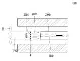
또한, 제조장치에 대한 설명에 있어서 '하류' 또는 '하류 방향'은 튜브 또는 튜브 제조를 위해 공급되는 토우가 진행되는 방향을 의미하고 '상류' 또는 '상류 방향'은 그 반대 방향을 의미한다. 예를 들어, 도 1에 도시된 튜브필터 제조장치(1000)에 있어서, 튜브형 로드(TF)는 튜브필터 제조장치(1000)의 상류에서부터 하류 방향(D1 방향)으로 토출되며, 가향 노즐(1310)은 스팀 챔버(1200) 또는 스팀 노즐(1210) 보다 하류에 위치한다.In addition, in the description of the manufacturing apparatus, 'downstream' or 'downstream direction' refers to a direction in which a tube or a tow supplied for manufacturing a tube proceeds, and 'upstream' or 'upstream direction' refers to the opposite direction. For example, in the tube
도 1은 본 발명의 일부 실시예들에 따른 튜브필터 제조장치를 설명하기 위한 개략도이며, 도 2는 도 1의 A영역 부분 확대도이다. 도 1 및 도 2에 도시된 튜브필터 제조장치(1000)는 설명의 명확화를 위해 각 구성이 단순화되고 과장되게 표현되었으며, 본 발명의 설명에 있어서 필수적이지 않은 구성은 생략되었다.1 is a schematic view for explaining an apparatus for manufacturing a tube filter according to some embodiments of the present invention, and FIG. 2 is an enlarged view of a region A of FIG. 1 . In the tube
도 1을 참조하면, 튜브필터 제조장치(1000)는 튜브필터 외부성형 케이스(1100), 스팀 챔버(1200) 및 튜브필터 성형봉(1300)을 포함할 수 있다.Referring to FIG. 1 , the tube
도시되지 않았으나, 튜브필터 제조장치(1000)는 튜브필터 외부성형 케이스(1100) 내로 튜브필터를 제조하는 데에 사용되는 소재인 필터 토우 2개를 튜브필터 성형봉(1300)을 사이에 두며 공급하는 토우 공급부 등을 포함할 수 있다.Although not shown, the tube
또한, 필터 토우들은 튜브필터 외부성형 케이스(1100) 내로 공급되기 이전에 전처리기 등을 통해 튜브필터로 제조되기 위해 필요한 전처리 과정을 거칠 수 있다. 예를 들어, 롤러를 통해 필터 토우들을 연신기로 이동시킬 수 있고, 연신기는 필터 토우들을 연신 처리한 후 튜브필터 외부성형 케이스(1100) 내로 공급할 수도 있다.In addition, the filter tows may undergo a pre-treatment process necessary to be manufactured into a tube filter through a pre-processor or the like before being supplied into the tube filter
나아가, 일부 실시예들에서, 튜브필터 외부성형 케이스(1100) 내로 필터 토우들이 원활히 유입되어 하류 방향으로 나아갈 수 있도록 하는 압축 공기가 튜브필터 외부성형 케이스(1100) 내로 공급될 수 있다.Further, in some embodiments, compressed air that allows the filter tows to smoothly flow into the tube filter outer molded
한편, 상기 필터 토우들은 튜브형 로드(TF)를 경화시켜 형상을 유지시킬 수 있는 트리아세틴 등의 가소제가 혼합된 필터 토우들일 수 있다. 본 발명의 튜브형 로드(TF) 제조 시 투입되는 가소제의 양은 비-튜브형 셀룰로오스 아세테이트 필터의 제조 시 투입되는 가소제의 양(예를 들어, 대략 6% 내지 15%)보다 많은, 대략 19% 내지 24%일 수 있다. Meanwhile, the filter tows may be filter tows in which a plasticizer such as triacetin capable of maintaining the shape by curing the tubular rod TF is mixed. The amount of the plasticizer added during the manufacture of the tubular rod (TF) of the present invention is greater than the amount of the plasticizer added during the manufacture of the non-tubular cellulose acetate filter (for example, approximately 6% to 15%), about 19% to 24% can be
튜브필터 제조장치(1000) 내에서 필터 토우들은 대략 500RPM(rod per minute) 내지 1200RPM의 속도로 이동할 수 있다. 1RPM은 1분당 1Rod를 지나가는 속도이며, 1Rod는 대략 60mm 내지 140mm의 범위일 수 있으나, 이에 제한되지 않는다.In the tube
튜브필터 외부성형 케이스(1100)의 내면은 원통 형상일 수 있으며, 이를 통해 튜브형 로드(TF)의 외면이 성형될 수 있다. 즉, 필터 토우들은 튜브필터 외부성형 케이스(1100)의 내부에서 이동되며 고온의 스팀에 의해 결합 경화되어 튜브형 로드(TF)로 형성될 수 있다.The inner surface of the tube filter
한편, 도시된 것과 같이 튜브필터 외부성형 케이스(1100)의 내부에는 봉 형상의 튜브필터 성형봉(1300)이 배치되며, 이에 따라 튜브형 로드(TF)는 내부에 중공이 형성된 원통 형상을 가질 수 있다. 튜브필터 제조장치(1000)에 의해 형성된 튜브형 로드(TF)는 절단 등의 후속공정을 통해 개별 튜브필터들로 완성될 수 있다.On the other hand, as shown, a rod-shaped tube
여기서, 튜브필터 외부성형 케이스(1100)는 튜브형 로드(TF)의 외면을 정의하고, 튜브필터 성형봉(1300)은 튜브형 로드(TF)의 내부 중공을 정의하는 역할을 수행할 수 있다.Here, the tube filter
이에 따라, 튜브필터 외부성형 케이스(1100)의 내경은 제조될 튜브필터의 외경에 따라 설정될 수 있으며, 튜브필터 성형봉(1300)의 외경은 제조될 튜브필터의 내경(즉, 중공 크기)에 따라 설정될 수 있으며, 튜브필터 성형봉(1300)의 내경(즉, 가향 노즐의 크기)은 튜브필터의 중공 내로의 가향 균일성 확보 및 관로막힘 현상 방지를 고려하여 가향량에 따라 적절히 설정될 수 있다. 예를 들어, 튜브필터 외부성형 케이스(1100)의 내경은 대략 3mm 내지 10mm, 튜브필터 성형봉(1300)의 외경은 대략 2mm 내지 4.5mm, 튜브필터 성형봉(1300)의 내경은 대략 0.8mm 내지 2mm일 수 있다.Accordingly, the inner diameter of the tube filter
스팀 챔버(1200)는 튜브필터 외부성형 케이스(1100)의 내부에서 이송되는 필터 토우들에 고온의 스팀을 공급하여 필터 토우들을 튜브형 로드로 결합 경화시키는 역할을 수행할 수 있다. 구체적으로, 필터 토우들에 공급되는 고온의 스팀은 필터 토우들에 혼합된 가소제를 경화시켜 튜브형 로드의 형상을 유지시킬 수 있다.The
스팀 챔버(1200)로부터의 스팀은 튜브필터 외부성형 케이스(1100)의 내부와 연통하는 스팀 노즐(1210)에 의해 필터 토우들로 공급될 수 있다. 스팀 노즐(1210)은 도시된 것과 같이 튜브필터 외부성형 케이스(1100)의 상측 내부 및 하측 내부 각각에 스팀을 공급할 수 있으나, 이에 제한되지 않는다. 도시되지 않았으나, 스팀 챔버(1200)에는 외부로부터 공급되는 고온의 증기를 스팀 챔버(1200) 내로 유입시키는 증기 커넥터들이 형성될 수 있다.Steam from the
일부 실시예들에서, 스팀 노즐(1210)은 필터 토우들에 대략 50℃ 내지 200℃의 스팀을 공급할 수 있으나, 이에 제한되지 않는다.In some embodiments, the
튜브필터 성형봉(1300)의 내부에는 튜브필터 성형봉(1300)의 길이 방향을 따라 연장되는 가향 관로(1320)가 형성되어 있다. 튜브필터 성형봉(1300)의 하류 말단(즉, 튜브형 로드(TF)의 출구쪽 말단)에는 튜브형 로드(TF)의 내부 중공으로 가향액 또는 보습제를 공급할 수 있는 가향 노즐(1310)이 형성될 수 있다. 가향 노즐(1310)은 상기 가향 관로(1320)를 통해 공급되는 가향액 또는 보습제를 튜브형 로드(TF)의 내부 중공으로 자유낙하시킬 수 있다. 자유낙하된 가향액 등은 튜브형 로드(TF)의 내측면(TF_IS)을 통해 튜브형 로드(TF)로 흡수 및 확산될 수 있다.A
한편, 본 명세서에서는 설명의 명확화 및 용어의 간략화를 위해 상기 가향액 또는 보습제를 공급하는 노즐을 가향 노즐(1310)로 칭하나, 가향 노즐(1310)은 멘솔 등의 향액 외에 글리세린 및/또는 프로필렌 글리콜 등의 보습액을 공급하는 노즐일 수도 있음은 물론이다.On the other hand, in the present specification, the nozzle for supplying the flavoring liquid or moisturizing agent is referred to as a
일부 실시예들에서, 튜브필터 성형봉(1300)은 도 2에 도시된 것처럼 성형봉 몸체부(1300a) 및 성형봉 팁(1300b)이 결합된 구조를 가질 수 있다. 예를 들어, 상기 성형봉 팁(1300b)은 성형봉 몸체부(1300a)에 나사결합될 수 있으며, 성형봉 몸체부(1300a)의 내부 관로는 성형봉 팁(1300b)의 내부 관로로 유체연통하며 연결될 수 있다. 이 경우, 가향 노즐(1310)은 성형봉 팁(1300b)의 하류 말단에 위치할 수 있다.In some embodiments, the tube
한편, 도 2에는 성형봉 몸체부(1300a)의 내부 관로의 내경 및 성형봉 팁(1300b)의 내부 관로의 내경이 동일한 것으로 도시되었으나, 이에 제한되지 않는다.Meanwhile, although the inner diameter of the inner tube of the forming
일부 실시예들에서, 성형봉 팁(1300b)의 내부 관로의 내경은 성형봉 몸체부(1300a)의 내부 관로의 내경보다 작을 수 있다. 즉, 튜브필터 성형봉(1300)의 가향 관로(1320)의 내경은 성형봉 몸체부(1300a) 및 성형봉 팁(1300b) 사이 영역에서 그 크기가 변경될 수 있다. 예를 들어, 성형봉 몸체부(1300a)의 관로 내경은 대략 1.5mm 내지 4mm이고, 성형봉 팁(1300b)의 관로 내경(즉, 가향 노즐(1310)의 내경)은 대략 0.8mm 내지 2.5mm일 수 있다. 이 경우, 가향액 등의 유체흐름을 원활이 하기 위해, 성형봉 팁(1300b)의 관로는 하류측으로 갈수록 내경이 점차적으로 작아질 수 있다.In some embodiments, the inner diameter of the inner conduit of the forming
일부 실시예들에서, 가향 노즐(1310)은 도시된 것처럼 스팀 노즐(1210)보다 하류에 배치되되, 가향 노즐(1310)은 스팀 노즐(1210)로부터 대략 180mm 내지 600mm, 바람직하게는 대략 300mm 내지 600mm 이격되도록 배치될 수 있다. 즉, 가향 노즐(1310)과 스팀 노즐(1210)의 이격 거리(L1)는 대략 180mm 내지 600mm일 수 있다. 도 1에 도시된 것과 같이 복수개의 스팀 노즐들이 구비된 경우, 상기 이격 거리는 스팀 노즐들 중 최하류에 위치하는 스팀 노즐(즉, 스팀 노즐들 중 가향 노즐과 가장 가까운 스팀 노즐)을 기준으로 할 수 있다.In some embodiments, the
상기와 같은 가향 노즐(1310)과 스팀 노즐(1210)의 이격 거리(L1)를 가질 경우 튜브필터의 향 소실율을 최소화시킬 수 있으며, 이에 대한 상세한 설명은 후술하도록 한다.When the above-described separation distance L1 between the
일부 실시예들에서, 가향 노즐(1310)의 직경은 0.1mm 내지 5mm, 바람직하게는 0.8mm 내지 2.5mm일 수 있다.In some embodiments, the diameter of the directing
한편, 가향 노즐(1310)의 직경과 튜브필터 성형봉(1300)에 형성된 관로의 직경은 서로 상이할 수도 있다. 예를 들어, 상기 관로의 직경은 4mm이고, 가향 노즐(1310)의 직경은 상기 관로의 직경보다 작은 수치, 예를 들면 2mm일 수 있다. 또한, 제조 공정상 필요성에 따라 용이하게 가향 노즐(1310)의 직경을 조절할 수 있도록, 튜브필터 성형봉(1300)에는 하류 말단에 나사결합 방식으로 결합된 성형봉 팁을 구비할 수도 있다. 성형봉 팁의 길이(L3)는 예를 들면 10mm 내지 50mm일 수 있으나, 이에 제한되지 않는다.Meanwhile, the diameter of the directing
일부 실시예들에서, 튜브필터 성형봉(1300)의 길이(L2)(여기서, L2는 튜브필터 성형봉(1300)의 하류 말단으로부터 튜브필터 외부성형 케이스(1100)의 상류측 입구까지의 이격 거리로도 정의될 수 있음)는 대략 300mm 내지 400mm일 수 있다. 한편, 상기와 같은 길이(L2)를 가지는 튜브필터 성형봉(1300)은 외경이 대략 5mm 이상인 봉의 내부에 가향 관로(1320)를 먼저 형성하고, 튜브필터 성형봉(1300)의 외경을 대략 5mm 이상으로부터 4.2mm이하로 그라인딩함으로써 제조될 수 있다.In some embodiments, the length L2 of the tube filter forming rod 1300 (where L2 is the distance from the downstream end of the tube
일부 실시예들에서, 가향 노즐(1310)은 도 1에 도시된 것처럼 튜브필터 외부성형 케이스(1100)의 하류 말단(1100E)보다 상류에 배치될 수 있으나, 이에 제한되지 않는다. 일 예로, 가향 노즐(1310)은 튜브필터 외부성형 케이스(1100)의 하류 말단(1100E)과 실질적으로 동일선상에 위치할 수 있다. 다른 예로, 가향 노즐(1310)은 도 5에 도시된 것처럼 튜브필터 외부성형 케이스(1100)의 하류 말단보다 하류에 배치될 수도 있다.In some embodiments, the directing
도 3은 본 발명의 다른 일부 실시예들에 따른 튜브필터 제조장치의 튜브필터 성형봉을 설명하기 위한 개략도이다.3 is a schematic diagram for explaining a tube filter forming rod of an apparatus for manufacturing a tube filter according to some other embodiments of the present invention.
도 3을 참조하면, 튜브필터 성형봉(2300)은 성형봉 몸체부(2300a) 및 성형봉 팁(2300b)이 결합된 구조를 가질 수 있으며, 상기 성형봉 팁(2300b)에는 가향 관로(1320)로부터 전달된 향액을 방사방향으로 분출하는 가향 노즐(2310)이 구비될 수 있다.Referring to FIG. 3 , the tube
일 예로, 상기 가향 노즐(2310)은 향액을 일정 압력으로 스프레잉할 수 있다. 이 경우 스프레잉된 향액은 튜브형 로드(TF)의 내측면(TF_IS) 전 영역에서 고르게 흡수될 수 있다. 다른 예로, 상기 가향 노즐(2310)은 향액을 방사 방향으로 분출하되, 분출된 향액은 성형봉 팁(2300b)의 벽면을 타고 흘러내리며 튜브형 로드(TF)의 내측면(TF_IS) 중 하부 영역으로 자유낙하 될 수 있다. 이 경우, 튜브형 로드(TF)의 내측면(TF_IS) 중 하부 영역으로 흡수된 향액은 도 2에 도시된 가향 노즐(1310)의 경우와 같이 튜브형 로드(TF)의 하측 영역으로부터 상측 영역으로 고르게 확산될 수 있다.For example, the
도 4는 본 발명의 다른 일부 실시예들에 따른 튜브필터 제조장치를 설명하기 위한 개략도이다.4 is a schematic diagram for explaining an apparatus for manufacturing a tube filter according to some other embodiments of the present invention.
도 4를 참조하면, 튜브필터 제조장치(3000)는 튜브필터 외부성형 케이스(3100), 스팀 챔버(3200), 튜브필터 성형봉(3300) 및 냉각 부재(3400)를 포함할 수 있다.Referring to FIG. 4 , the tube
튜브필터 제조장치(3000)의 튜브필터 외부성형 케이스(3100), 스팀 챔버(3200) 및 튜브필터 성형봉(3300) 각각은 도 1 및 도 2를 참조하여 설명한 튜브필터 제조장치(1000)의 튜브필터 외부성형 케이스(1100), 스팀 챔버(1200) 및 튜브필터 성형봉(1300) 각각과 실질적으로 동일 유사한 구성을 가질 수 있으며, 이하에서는 설명의 간략화를 위해 도 1 및 도 2를 참조하여 설명한 튜브필터 제조장치(1000)와의 차이점만을 위주로 설명하도록 한다.Each of the tube filter
스팀 챔버(3200)의 스팀 노즐(3210) 및 튜브필터 성형봉(3300)의 가향 노즐(3310) 사이에는, 스팀에 의해 가열된 튜브형 로드(TF)를 냉각시키기 위한 냉각 부재(3400)가 구비될 수 있다.Between the
냉각 부재(3400)에 의해, 튜브형 로드(TF)는 가향액의 흡수 및 확산에 최적화된 온도 및 경도를 가질 수 있으며, 냉각 부재(3400)가 구비됨으로써 가향 노즐(3310)과 스팀 노즐(3210)의 최적의 이격 거리(L1)를 좁힐 수 있고, 이에 따라 튜브필터 제조장치(3000)의 크기를 감소시키고 냉각시간을 단축시켜 공정효율성을 보다 극대화할 수 있게 된다.By the cooling
일부 실시예들에서, 스팀 노즐(3210) 및 튜브필터 성형봉(3300)의 가향 노즐(3310) 사이에 냉각 부재(3400)가 구비된 경우 가향 노즐(3310)과 스팀 노즐(3210)의 이격 거리(L1)는 대략 180mm 내지 300mm일 수 있다.In some embodiments, when the cooling
한편, 냉각 부재(3400)는 도 4에 도시된 것처럼 튜브필터 외부성형 케이스(1100)를 냉각함으로써 튜브형 로드(TF)를 간접적으로 냉각할 수 있으나, 이와 달리 튜브필터 외부성형 케이스(1100) 내부로 차가운 공기를 공급하는 등 튜브형 로드(TF)를 직접적으로 냉각할 수도 있다. 냉각 부재(3400)의 냉각 방식은 공랭식(air cooling) 또는 수랭식(water cooling)일 수 있으나, 이에 제한되지 않는다.On the other hand, the cooling
도 5는 본 발명의 또다른 일부 실시예들에 따른 튜브필터 제조장치를 설명하기 위한 개략도이다.5 is a schematic diagram for explaining an apparatus for manufacturing a tube filter according to some other embodiments of the present invention.
도 5를 참조하면, 튜브필터 제조장치(4000)는 튜브필터 외부성형 케이스(4100), 스팀 챔버(4200), 튜브필터 성형봉(4300) 및 이송 부재(4500)를 포함할 수 있다.Referring to FIG. 5 , the tube
튜브필터 제조장치(4000)의 튜브필터 외부성형 케이스(4100), 스팀 챔버(4200) 및 튜브필터 성형봉(4300) 각각은 도 1 및 도 2를 참조하여 설명한 튜브필터 제조장치(1000)의 튜브필터 외부성형 케이스(1100), 스팀 챔버(1200) 및 튜브필터 성형봉(1300) 각각과 실질적으로 동일 유사한 구성을 가질 수 있으며, 이하에서는 설명의 간략화를 위해 도 1 및 도 2를 참조하여 설명한 튜브필터 제조장치(1000)와의 차이점만을 위주로 설명하도록 한다.Each of the tube filter
튜브필터 성형봉(4300)은 튜브필터 외부성형 케이스(4100)의 하류 말단 (4100E)보다 더 돌출되도록 연장될 수 있다. 즉, 튜브필터 성형봉(4300)의 가향 노즐(4310)은 튜브필터 외부성형 케이스(4100)의 하류 말단(4100E)보다 하류에 배치될 수 있다. 달리 말하면, 가향 노즐(4310)에 의한 가향액 투입은 튜브형 로드(TF)가 외부성형 케이스(4100)에서 배출된 후 이송 부재(4500)에 의해 이송되는 과정에서 수행될 수 있다.The tube
일부 실시예들에서, 튜브형 로드(TF)는 이송 부재(4500)에 의해 이송되는 과정에서 외부 공기에 의해 자연냉각 될 수 있다.In some embodiments, the tubular rod TF may be naturally cooled by external air in the process of being transported by the
다른 일부 실시예에서, 이송 부재(4500)는 튜브형 로드(TF)를 냉각시키는 냉각유닛(미도시)을 구비할 수 있다. 일 예로, 상기 냉각유닛은 튜브형 로드(TF) 내 수분 및 공기를 빨아들이는 석션(suction) 유닛일 수 있다. 즉, 상기 이송 부재(4500)는 튜브형 로드(TF)를 냉각시키며 이송하기 위한 석션 레일일 수 있다.In some other embodiments, the
이송 부재(4500)가 석션 레일인 경우, 석션 레일은 튜브형 로드(TF)의 길이방향(즉, 튜브형 로드(TF)의 진행방향(D1))으로 대략 100mm 내지 1,000mm 연장(L2)될 수 있다.When the
이 경우, 가향 노즐(4310)에 의한 가향처리는 석션 레일에 의한 석션 공정과 함께 수행될 수 있다. 여기서, "석션공정과 가향처리와 함께 수행된다"는 의미는 넓게 해석될 수 있다. 즉, 가향 노즐(4310)에 의한 가향 처리는 석션 레일에 의한 석션 공정이 진행되는 도중에, 석션 공정이 시작된 직후에, 석션 공정이 시작됨과 동시에, 또는 석션 공정이 시작되기 전에 수행될 수 있다.In this case, the steering process by the
바람직하게는, 가향 노즐(4310)에 의한 가향 처리는 석션 레일에 의한 석션공정이 약 70% 내지 90%, 바람직하게는 약 75% 내지 85%) 진행된 시점에서 수행될 수 있다. 즉, 가향 노즐(4310)은 석션 레일(즉, 이송 부재(4500))의 상류 말단보다 하류 말단에 더 인접하도록 배치될 수 있다. 석션 레일의 길이(L2)가 약 500mm인 경우를 예로 들면, 가향 노즐(4310)은 석션 레일의 상류 말단으로부터 대략 350mm 내지 450mm(예를 들어, 약 400mm) 이격되고 하류 말단으로부터 대략 50mm 내지 150mm(예를 들어, 약 100mm) 이격된 위치에 배치될 수 있다.Preferably, the steering treatment by the
이 경우, 가향액 낙하 전의 석션 공정은 튜브형 로드(TF)를 이송함과 동시에 튜브형 로드(TF)를 냉각시키는 역할을, 가향액 낙하 후의 석션 공정은 튜브형 로드(TF)를 이송함과 동시에 투입된 가향액이 튜브형 로드(TF)의 내부영역으로 보다 고르게 확산시키는 역할을 수행할 수 있다.In this case, the suction process before the fall of the flavoring solution serves to cool the tubular rod (TF) while transporting the tubular rod (TF). It can serve to more evenly spread the liquid into the inner region of the tubular rod (TF).
도시하지 않았지만, 상기한 실시예들 각각에 따른 튜브필터 제조장치에 의해 제조된 내부가향 튜브필터는, 연소형 궐련 또는 에어로졸 생성 장치 등에 삽입 및 가열되어 에어로졸을 생성하는 비연소형 궐련의 일 구성요소로 사용될 수 있다.Although not shown, the internally oriented tube filter manufactured by the apparatus for manufacturing a tube filter according to each of the above embodiments is inserted and heated in a combustion cigarette or an aerosol generating device, etc. One component of a non-combustible cigarette to generate an aerosol can be used as
일부 실시예들에서, 상기 내부가향 튜브필터는 연소형 궐련의 필터부에 포함될 수 있다. 구체적인 예로, 상기 필터부가 모노 필터인 경우 필터부는 상기 내부가향 튜브필터로 구성될 수 있고, 상기 필터부가 2개 이상의 다중 필터로 이루어진 경우 상기 다중 필터 중 적어도 하나는 상기 내부가향 튜브필터로 구성될 수 있다.In some embodiments, the inwardly directed tube filter may be included in the filter unit of the combustion type cigarette. As a specific example, when the filter unit is a mono filter, the filter unit may be composed of the internally oriented tube filter, and when the filter unit consists of two or more multiple filters, at least one of the multiple filters is composed of the internally oriented tube filter can be
다른 일부 실시예들에서, 상기 내부가향 튜브필터는 비연소형 궐련의 일 구성요소일 수 있다. 구체적으로 상기 내부가향 튜브필터는, 비연소형 궐련이 에어로졸 생성 장치에 삽입되는 과정에서 흡연물질부의 내부 물질이 하류 방향으로 밀리는 현상을 방지하는 지지구조체, 에어로졸 생성 장치가 흡연물질부를 가열함으로써 생성된 에어로졸을 냉각시키는 냉각구조체, 및 흡연물질부 내부 물질이 궐련 외부로 이탈하는 것을 방지하기 위해 흡연물질부의 상류에서 흡연물질부와 접경하는 전단 플러그 중 적어도 하나 이상의 구성으로 채용될 수 있다.In some other embodiments, the internally oriented tube filter may be a component of a non-combustible cigarette. Specifically, the internally oriented tube filter is a support structure that prevents the internal material of the smoking material from being pushed in the downstream direction while the non-combustible cigarette is inserted into the aerosol generating device, and the aerosol generating device is generated by heating the smoking material section. It may be employed as at least one configuration of a cooling structure for cooling the aerosol, and a shear plug bordering the smoking material portion upstream of the smoking material portion in order to prevent the material inside the smoking material portion from escaping to the outside of the cigarette.
이하, 실시예와 비교예를 통하여 본 발명의 구성 및 그에 따른 효과를 보다 상세히 설명하고자 한다. 그러나, 본 실시예는 본 발명을 보다 구체적으로 설명하기 위한 것이며, 본 발명의 범위가 이들 실시예에 한정되는 것은 아니다.Hereinafter, the configuration of the present invention and its effects will be described in more detail through Examples and Comparative Examples. However, these examples are for explaining the present invention in more detail, and the scope of the present invention is not limited to these examples.
후술할 실험예들에 대한 보다 명확한 이해를 위해, 이하에서는 도 6 내지 도 7을 상호 참조하여 설명하도록 한다.For a clearer understanding of the experimental examples to be described later, the following description will be made with cross-reference to FIGS. 6 to 7 .
도 6은 본 발명의 실시예들에 따른 흡연물품용 튜브필터 내부에 가향처리가 되는 모습을 예시적으로 나타낸 도면이고, 도 7은 튜브필터 내부의 균일가향 여부를 확인하기 위해 튜브필터를 제2 영역에서 절취 및 전개한 사진들이다.6 is a view exemplarily showing a state in which flavoring is performed inside a tube filter for smoking articles according to embodiments of the present invention, and FIG. These are photos that have been cut out and unfolded in the area.
도 6에 도시된 튜브형 로드(TF)와, 튜브형 로드(TF) 내부의 중공(TF_H) 형성 및 튜브필터 성형봉(1300)의 형상, 구조 및 크기 등은 설명의 명확화를 위해 단순화되어 도시되었으므로, 이에 제한되지 않음은 물론이다.The shape, structure and size of the tubular rod (TF) and the tubular rod (TF) shown in FIG. 6 and the hollow (TF_H) inside the tubular rod (TF) and the tube
또한, 도 6에 도시된 튜브형 로드(TF)는 설명의 명확화를 위해 2개의 영역, 즉 튜브형 로드 하단의 제1 영역(TF1) 및 튜브형 로드 상단의 제2 영역(TF2)으로 구획 도시하였으나, 상기 제1 및 제2 영역이 물리적으로 구획된 것이 아님은 물론이다. 상기 튜브형 로드(TF)는 단위 튜브필터로 절단되기 전 상태를 의미할 수 있으며, 필요에 따라 튜브형 로드 및 튜브필터를 용어적으로 혼용하여 설명하도록 한다.In addition, for clarity of explanation, the tubular rod TF shown in FIG. 6 is divided into two regions, that is, a first region TF1 at the bottom of the tubular rod and a second region TF2 at the top of the tubular rod. It goes without saying that the first and second regions are not physically partitioned. The tubular rod (TF) may mean a state before being cut into a unit tube filter, and, if necessary, the tubular rod and the tube filter will be described by mixing terms.
실시예 1Example 1
튜브필터 성형봉을 이용하여, 튜브형 로드 내부(즉, 중공(TF_H))에 멘솔 약 70중량% 및 PG(Propylene Glycol) 약 30중량%를 포함하는 가향액을 이용하여 가향 처리를 진행하였고, 육안에 의한 균일가향 평가를 위해 유색의 색소가 가향액에 소량 첨가되었다.Using a tube filter molding rod, a flavoring solution containing about 70% by weight of menthol and about 30% by weight of PG (Propylene Glycol) in the inside of the tubular rod (ie, hollow (TF_H)) was used for flavoring, and the visual A small amount of colored pigment was added to the flavoring solution for the evaluation of uniform flavor.
외경이 약 7.2mm이고 내경이 약 2.5mm인 튜브형 로드가 제조되었으며, 튜브형 로드가 튜브필터 형성 장치에서 길이 방향(D1)으로 이동함에 따라 튜브형 로드에 투입되는 mm당 가향량은 약 0.1mg이며, 사용된 가향 노즐의 직경은 약 1.0mm이다.A tubular rod having an outer diameter of about 7.2 mm and an inner diameter of about 2.5 mm was manufactured, and as the tubular rod moves in the longitudinal direction (D1) in the tube filter forming device, the amount of adjustment per mm input to the tubular rod is about 0.1 mg, The diameter of the directing nozzle used was about 1.0 mm.
도시되지 않았으나, 상술한 것처럼 튜브형 로드에는 상기 가향액이 투입되기 이전에 스팀 노즐에 의해 고온 고압의 스팀이 분사될 수 있으며, 가향 노즐은 스팀 노즐로부터 길이 방향(D1)으로 약 500mm 이격되도록 배치되었다. 가향액은 가향 노즐로부터 자유낙하되어 튜브형 로드의 제1 영역(TF1)에 흡수되었다.Although not shown, as described above, high-temperature and high-pressure steam may be sprayed to the tubular rod by a steam nozzle before the flavoring liquid is injected, and the flavoring nozzle is disposed to be spaced apart from the steam nozzle by about 500 mm in the longitudinal direction (D1). . The flavoring liquid was free-falling from the flavoring nozzle and absorbed into the first area TF1 of the tubular rod.
실시예 2Example 2
튜브형 로드에 투입되는 mm당 가향량이 약 0.3mg인 점을 제외하고 실시예 1과 동일한 조건으로 튜브형 로드를 제조하였다.A tubular rod was manufactured under the same conditions as in Example 1, except that the amount of flavor per mm input to the tubular rod was about 0.3 mg.
실시예 3Example 3
직경이 약 1.3mm인 가향 노즐을 사용하였고, 튜브형 로드에 투입되는 mm당 가향량이 약 1.2mg인 점을 제외하고는, 실시예 1과 동일한 조건으로 튜브형 로드를 제조하였다.A tubular rod was manufactured under the same conditions as in Example 1, except that a steering nozzle having a diameter of about 1.3 mm was used, and the amount of steering was about 1.2 mg per mm input to the tubular rod.
실시예 4Example 4
튜브형 로드에 투입되는 mm당 가향량이 약 1.5mg인 점을 제외하고 실시예 3과 동일한 조건으로 튜브형 로드를 제조하였다.A tubular rod was prepared under the same conditions as in Example 3, except that the amount of flavor per mm input to the tubular rod was about 1.5 mg.
실험예 1: 튜브필터 내부 균일 가향을 위한 가향량 설정Experimental Example 1: Setting of flavoring amount for uniform flavoring inside tube filter
튜브필터 내 균일가향 여부를 평가하기 위해, 상술한 실시예 1 내지 4와 같이 가향량을 조절하여 제조된 튜브형 로드들의 평가를 진행하였다.In order to evaluate the uniform flavor in the tube filter, the tubular rods manufactured by adjusting the amount of flavor as in Examples 1 to 4 described above were evaluated.
도 7은 튜브필터 내부의 균일가향 여부를 확인하기 위해 튜브형 로드를 제1 영역(TF1, 보다 구체적으로, 자유낙하에 의해 가향액이 직접적으로 투입되는 하단부 영역)에서 절취 및 전개한 사진들이며, 표 1은 실시예 1 내지 4에 따른 균일가향여부에 대한 결과를 나타낸다.7 is a photograph showing the tubular rod cut out and developed in the first area (TF1, more specifically, the lower end area where the flavoring liquid is directly injected by free fall) in order to check whether the inside of the tube filter is uniformly flavored, Table 1 represents the results of whether or not the uniform flavoring according to Examples 1 to 4.
표 1 및 도 7의 (a)에 나타난 것과 같이, mm당 가향량이 0.1mg인 실시예 1의 튜브형 로드에서는 D1 방향에서의 향 끊김이 발생하였고, 이에 따라 튜브형 로드 내에 길이 방향으로 균일한 가향이 되지 않았음을 확인할 수 있었다. 도 7의 (b)에 나타난 것과 같이, 실시예 2의 튜브형 로드에서는 향 끊김이 발생하지 않았으며, 도 7의 (c)에 나타난 실시예 3의 튜브형 로드에서는 향 끊김이 발생하지 않았을 뿐 아니라 가향액이 튜브형 로드 내에 더욱 균일하게 처리되었음을 확인할 수 있다. 실시예 4의 튜브형 로드 또한 균일가향 처리되었음을 확인하였으나, 내부가향된 가향액이 튜브형 로드의 외측면까지 과하게 확산됨에 따라 튜브형 로드 외부로 가향액이 흘러내리는 현상이 발생하였다. 이에 따라, mm당 가향량이 약 0.3mg 내지 1.2mg, 바람직하게는 0.5mg 내지 0.9mg인 경우 가향 특성이 우수해짐을 확인할 수 있었다.As shown in Table 1 and Fig. 7 (a), in the tubular rod of Example 1 having an orientation amount of 0.1 mg per mm, orientation breakage occurred in the D1 direction, and accordingly, uniform orientation in the longitudinal direction in the tubular rod was obtained. I could confirm that it wasn't. As shown in (b) of FIG. 7, in the tubular rod of Example 2, no breakage occurred, and in the tubular rod of Example 3 shown in FIG. It can be seen that the liquid was treated more uniformly in the tubular rod. It was confirmed that the tubular rod of Example 4 was also uniformly flavored, but as the internally oriented flavoring solution was excessively diffused to the outer surface of the tubular rod, a phenomenon occurred that the flavoring solution flowed down to the outside of the tubular rod. Accordingly, it was confirmed that when the flavoring amount per mm was about 0.3 mg to 1.2 mg, preferably 0.5 mg to 0.9 mg, the flavor properties were improved.
한편, 실시예로 언급되지 않았으나, 가향 노즐(1310)의 직경이 0.7mm이고 mm당 가향량이 약 0.3mg 내지 1.2mg인 실험에서는 멘솔 결정화 발생에 의한 노즐 막힘 문제가 발생하였고, 이에 따라 해당 실험결과는 상기 표 1에서 제외되었다. 또한, 가향 노즐(1310)의 직경이 1.3mm이고 mm당 가향량이 약 0.1mg 내지 0.7mg인 실험에서는 가향액의 표면장력에 의한 불규칙적 가향액 낙하 현상이 발생하여, 이 또한 상기 표 1에서 제외되었다.On the other hand, although not mentioned as an embodiment, in an experiment in which the diameter of the
상술한 결과를 통해, 튜브필터 내부에 적용되는 mm당 가향량이 0.3mg 내지 1.0mg인 경우에서 균일가향 특성이 가장 우수하고, 보다 바람직하게는 직경이 0.8mm 내지 1.1mm인 가향 노즐(1310)을 사용하여 0.3mg 내지 0.7mg 범위의 mm당 가향량을 적용하거나, 직경이 1.2mm 내지 1.4mm인 가향 노즐(1310)을 사용하여 0.7mg 내지 1.0mg 범위의 mm당 가향량을 적용하는 것이 멘솔 결정화 발생 이슈 해소 및 균일가향성 확보에 가장 유리한 것으로 확인되었다.Through the above-mentioned results, the uniform orientation characteristic is the best when the amount of flavor per mm applied to the inside of the tube filter is 0.3 mg to 1.0 mg, and more preferably, a
실시예 5Example 5
mm당 가향량이 약 0.6mg인 점을 제외하고 실시예 1과 동일한 조건으로 튜브형 로드를 제조하였다. 제조된 튜브형 로드를 약 48시간동안 보관한 이후, 튜브필터의 제1 영역(TF1) 및 제2 영역(TF2)을 물리적으로 절단하였다.A tubular rod was prepared under the same conditions as in Example 1, except that the amount of flavor per mm was about 0.6 mg. After the prepared tubular rod was stored for about 48 hours, the first area (TF1) and the second area (TF2) of the tube filter were physically cut.
실험예 2: 튜브필터 내부 가향 확산 평가Experimental Example 2: Evaluation of directional diffusion inside tube filter
튜브필터 내 가향 확산 여부를 확인하기 위해, 실시예 5 및 6 각각에서의 절단된 튜브 영역에 포함된 멘솔 함량을 분석하여 표 2에 나타내었다.In order to check whether or not the direction diffusion in the tube filter, the menthol content contained in the cut tube region in Examples 5 and 6, respectively, was analyzed and shown in Table 2.
(mg/80mm)total amount of flavoring liquid
(mg/80mm)
(mg/80mm)input menthol amount
(mg/80mm)
(mg)content
(mg)
(%)CV
(%)
(mg)content
(mg)
(%)ratio
(%)
(mg)content
(mg)
(%)ratio
(%)
표 2에 나타난 바와 같이, 튜브형 로드에 투입된 총 멘솔량 대비 약 96% 수준의 멘솔이 튜브형 로드 내에 잔존하는 것을 확인할 수 있으며, 이에 따라 가향처리 공정에서의 향액 소실량 및 튜브형 로드 제조 후 보관기간동안의 향액 소실량이 매우 경미한 수준(4% 미만)임을 확인할 수 있다.또한, 튜브의 하부영역인 제1영역(TF1) 내 멘솔 잔존량(약 52.5%)과 튜브의 상부영역인 제2영역(TF2) 내 멘솔 잔존량(약 47.5%)은 크게 차이나지 않았으며, 이를 통해 제1영역(TF1)의 중공으로 투입된 가향액에 포함된 멘솔이 제1영역(TF1)으로, 즉 튜브필터 전체로 고르게 확산되었음을 확인할 수 있었다.As shown in Table 2, it can be seen that about 96% of menthol relative to the total amount of menthol added to the tubular rod remains in the tubular rod. It can be seen that the amount of hyangaek loss is very slight (less than 4%). In addition, the remaining amount of menthol (about 52.5%) in the first region TF1, which is the lower region of the tube, and the second region TF2, which is the upper region of the tube. My menthol residual amount (about 47.5%) was not significantly different, indicating that the menthol contained in the flavoring solution injected into the hollow of the first region TF1 was evenly spread to the first region TF1, that is, throughout the tube filter. could check
비교예 1Comparative Example 1
가향 노즐이 스팀 노즐로부터 약 200mm 이격되도록 배치된 점을 제외하고, 실시예 5와 동일한 조건으로 튜브형 로드를 제조하였다.A tubular rod was manufactured under the same conditions as in Example 5, except that the directing nozzle was disposed to be spaced apart from the steam nozzle by about 200 mm.
비교예 2Comparative Example 2
가향 노즐이 스팀 노즐로부터 약 800mm 이격되도록 배치된 점을 제외하고, 실시예 5와 동일한 조건으로 튜브형 로드를 제조하였다.A tubular rod was manufactured under the same conditions as in Example 5, except that the directing nozzle was disposed to be spaced apart from the steam nozzle by about 800 mm.
비교예 3Comparative Example 3
200mm 길이의 석션레일을 사용하되, 가향 노즐이 석션레일의 하류말단과 약 100mm 이격되도록 배치된 점을 제외하고, 실시예 5와 동일한 조건으로 튜브형 로드를 제조하였다.A tubular rod was manufactured under the same conditions as in Example 5, except that a 200 mm long suction rail was used, and the directional nozzle was disposed to be spaced apart from the downstream end of the suction rail by about 100 mm.
실시예 6Example 6
500mm 길이의 석션레일을 사용하되, 가향 노즐이 석션레일의 하류말단과 약 100mm 이격되도록 배치된 점을 제외하고, 비교예 3과 동일한 조건으로 튜브형 로드를 제조하였다.A tubular rod was manufactured under the same conditions as in Comparative Example 3, except that a 500 mm-long suction rail was used, and the directional nozzle was disposed to be spaced apart from the downstream end of the suction rail by about 100 mm.
실시예 7Example 7
가향 노즐이 석션레일의 하류말단과 약 250mm 이격되도록 배치된 점을 제외하고 실시예 6과 동일한 조건으로 튜브형 로드를 제조하였다.A tubular rod was manufactured under the same conditions as in Example 6, except that the directional nozzle was disposed to be spaced apart from the downstream end of the suction rail by about 250 mm.
비교예 4Comparative Example 4
가향 노즐이 석션레일의 하류말단과 약 400mm 이격되도록 배치된 점을 제외하고 실시예 6과 동일한 조건으로 튜브형 로드를 제조하였다.A tubular rod was manufactured under the same conditions as in Example 6, except that the directional nozzle was disposed to be spaced apart from the downstream end of the suction rail by about 400 mm.
비교예 5Comparative Example 5
1,000mm 길이의 석션레일을 사용하되, 가향 노즐이 석션레일의 하류말단과 약 600mm 이격되도록 배치된 점을 제외하고, 비교예 4와 동일한 조건으로 튜브형 로드를 제조하였다.A tubular rod was manufactured under the same conditions as in Comparative Example 4, except that a suction rail with a length of 1,000 mm was used, and the directional nozzle was disposed to be spaced about 600 mm from the downstream end of the suction rail.
실험예 3: 가향조건별 향 소실 평가Experimental Example 3: Evaluation of flavor loss by flavoring conditions
튜브필터 내부가향 공정 조건에 따른 향소실 정도를 확인하기 위해, 튜브필터 제조 시 투입된 멘솔량과 제조가 완료된 튜브필터에 함유된 멘솔량을 분석하여 표 3에 나타내었다.In order to confirm the degree of fragrance loss according to the internal flavoring process conditions of the tube filter, the amount of menthol added during the manufacture of the tube filter and the amount of menthol contained in the tube filter after the manufacture were analyzed are shown in Table 3.
가향노즐
이격거리
(mm)steam nozzle/
flavoring nozzle
separation distance
(mm)
길이
(mm)Suction rail
Length
(mm)
하류말단/
가향노즐
이격거리
(mm)Suction rail
downstream end/
flavoring nozzle
separation distance
(mm)
(mg)menthol remaining
(mg)
(%)compared to input
(%)
표 3을 참조하면, 내부가향 방식을 채용 시 비교예들 및 실시예들 모두 전반적으로 튜브 필터의 성형 및 제조 공정에 필수적으로 수반되는 고온스팀에 의한 향 소실이 크지 않음을 확인할 수 있었다.Referring to Table 3, it was confirmed that when the inward orientation method was adopted, the loss of flavor due to high-temperature steam essential in the molding and manufacturing process of the tube filter was not large in all of the Comparative Examples and Examples.
다만, 가향 공정에서 동일한 양(33.6mg/80mm)의 멘솔이 투입되었음에도, 가향 노즐과 스팀 노즐의 이격거리, 석션레일의 길이, 석션레일과 가향 노즐의 상대적 위치관계에 따라 실시예들 및 비교예들간 멘솔 잔존량에서 유의미한 차이가 나타나는 것을 확인할 수 있다.However, although the same amount (33.6 mg/80 mm) of menthol was added in the flavoring process, the separation distance between the flavoring nozzle and the steam nozzle, the length of the suction rail, and the relative positional relationship between the suction rail and the flavoring nozzle in Examples and Comparative Examples It can be seen that there is a significant difference in the amount of menthol remaining between the two groups.
구체적으로, 비교예 1,2 및 실시예 5의 결과를 살펴보면, 가향 노즐과 스팀 노즐의 이격거리가 약 300mm 내지 600mm인 경우 향소실 특성이 가장 우수함을 확인할 수 있으며, 특히 비교예 2의 경우 상당히 큰 수치의 향 소실율(약 19.6%)이 나타났는데 이는 스팀분사 이후 향액 분사 위치가 필요 이상 멀어지면 가향노즐까지 튜브가 이송되는 동안 향 투입 및 확산에 최적화된 것보다 더 많이 튜브 경화가 이루어진 것 때문으로 추측된다.Specifically, looking at the results of Comparative Examples 1, 2 and 5, it can be seen that the fragrance dissipation characteristic is the most excellent when the separation distance between the flavoring nozzle and the steam nozzle is about 300 mm to 600 mm, and in particular, in Comparative Example 2, it is significantly A large number of fragrance loss rate (about 19.6%) was observed, because if the spraying position of the fragrance liquid was farther than necessary after steam spraying, the tube was hardened more than optimized for incense input and diffusion while the tube was transported to the flavoring nozzle. is presumed to be
비교예 3 내지 5 및 실시예 6 내지 7의 결과를 살펴보면, 대체적으로 가향처리 시 석션레일이 함께 사용될 경우 향 잔존량이 증대되는 것을 확인할 수 있다. 특히, 석션레일 길이가 약 300mm 내지 700mm이고 가향노즐이 석션레일의 하류측 또는 중간영역에 위치할 경우(실시예 6 또는 실시예 7) 향소실 특성이 가장 우수한 것을 확인할 수 있다. 석션레일 길이가 기준치 미달인 경우(비교예 3) 석션처리에 따른 유의미한 효과가 나타나지 않았으며, 석션레일 길이가 기준치를 초과하고 석션레일 상류측에서 가향처리 시(비교예 5) 비교예 2에서와 유사한 이유로 향소실 특성에 불리한 것을 알 수 있다. Looking at the results of Comparative Examples 3 to 5 and Examples 6 to 7, it can be confirmed that, in general, when the suction rail is used together during the flavoring treatment, the residual amount of fragrance is increased. In particular, it can be seen that when the length of the suction rail is about 300 mm to 700 mm and the flavoring nozzle is located on the downstream side or in the middle of the suction rail (Example 6 or Example 7), the scent dissipation characteristic is the best. When the length of the suction rail was less than the standard value (Comparative Example 3), there was no significant effect according to the suction treatment, and when the length of the suction rail exceeded the standard value and the direction treatment was performed at the upstream side of the suction rail (Comparative Example 5), as in Comparative Example 2 It can be seen that, for a similar reason, it is unfavorable to the fragrance loss property.
실험예 4: 가향조건별 튜브필터 물리성 평가Experimental Example 4: Evaluation of tube filter physical properties for each flavoring condition
가향조건별 튜브필터의 물리성 변화를 검토하기 위해, 상술한 실시예 7 내지 12의 튜브형 로드들에 대한 무게, 원주, 내경, 진원도 및 경도를 분석하여 표 4에 나타내었다.In order to examine the change in the physical properties of the tube filter for each flavoring condition, the weight, circumference, inner diameter, roundness, and hardness of the tubular rods of Examples 7 to 12 were analyzed and shown in Table 4.
(mm)Won-ju
(mm)
(mm)inner diameter
(mm)
(mg)weight
(mg)
(%)roundness
(%)
(%)Hardness
(%)
표 4에 나타난 바와 같이, 실시예 5 내지 7의 튜브형 필터들 모두 가향조건에 따른 물리성의 큰 차이 없이 모든 양산 규격 기준에 부합함을 확인하였다.이상과 같이 본 발명의 실시예에 따른 흡연용품용 필터 및 이를 포함하는 흡연물품에 따르면, 흡연자의 흡연 후 발생되는 손냄새와 입냄새를 모두 저감시킬 수 있는 효과가 있다.As shown in Table 4, it was confirmed that all of the tubular filters of Examples 5 to 7 met all standards for mass production without significant difference in physical properties depending on the flavoring conditions. As described above, for smoking articles according to the embodiment of the present invention According to the filter and the smoking article including the same, it is possible to reduce both hand and breath odors generated after smoking by a smoker.
본 실시예와 관련된 기술 분야에서 통상의 지식을 가진 자는 상기된 기재의 본질적인 특성에서 벗어나지 않는 범위에서 변형된 형태로 구현될 수 있음을 이해할 수 있을 것이다. 그러므로 개시된 방법들은 한정적인 관점이 아니라 설명적인 관점에서 고려되어야 한다. 본 발명의 범위는 전술한 설명이 아니라 특허청구범위에 나타나 있으며, 그와 동등한 범위 내에 있는 모든 차이점은 본 발명에 포함된 것으로 해석되어야 할 것이다.A person of ordinary skill in the art related to this embodiment will understand that it can be implemented in a modified form without departing from the essential characteristics of the above description. Therefore, the disclosed methods are to be considered in an illustrative rather than a restrictive sense. The scope of the present invention is indicated in the claims rather than the foregoing description, and all differences within the scope equivalent thereto should be construed as being included in the present invention.
1000: 튜브필터 제조장치
1100: 튜브필터 외부성형 케이스1200: 스팀 챔버
1210: 스팀 노즐1300: 튜브필터 성형봉
1310: 가향 노즐3400: 냉각 부재
4500: 이송 부재1000: tube filter manufacturing device
1100: tube filter outer molded case 1200: steam chamber
1210: steam nozzle 1300: tube filter forming rod
1310: directing nozzle 3400: cooling member
4500: transfer member
Claims (15)
Translated fromKorean하나 이상의 필터 토우가 유입되어 상기 하나 이상의 필터 토우로부터 형성된 튜브형 로드가 배출되는 튜브필터 외부성형 케이스;
상기 튜브형 로드의 중공을 형성하기 위해, 성형봉 몸체부 및 성형봉 팁이 결합된 구조로 상기 튜브필터 외부성형 케이스의 내부 영역에서 연장되는 튜브필터 성형봉; 및
상기 튜브필터 외부성형 케이스의 내부 영역과 연통하는 적어도 하나의 스팀 노즐을 구비하며 상기 스팀 노즐을 통해 상기 하나 이상의 필터 토우에 스팀을 공급하는 스팀 챔버를 포함하며,
상기 튜브필터 성형봉에는 상기 튜브필터 성형봉의 길이 방향을 따라 연장되는 관로와, 상기 관로를 통해 공급된 가향액 또는 보습액을 내부에 중공이 형성된 상기 튜브형 로드의 내측면에 전달하기 위해 상기 가향액 또는 보습액을 방사방향으로 분출하도록 가향 노즐이 구비된 것을 특징으로 하는, 튜브필터 제조장치.
A tube filter manufacturing apparatus for manufacturing a tube filter for smoking articles, the apparatus comprising:
a tube filter outer molded case into which one or more filter tows are introduced and a tubular rod formed from the one or more filter tows is discharged;
a tube filter forming rod extending from the inner region of the outer tube filter case in a structure in which a forming rod body portion and a forming rod tip are combined to form a hollow of the tubular rod; and
and a steam chamber having at least one steam nozzle communicating with the inner region of the tube filter outer molding case and supplying steam to the one or more filter tows through the steam nozzle,
The tube filter forming rod has a pipe line extending along the longitudinal direction of the tube filter forming rod, and the flavoring liquid or A tube filter manufacturing apparatus, characterized in that a directional nozzle is provided to eject the moisturizing liquid in a radial direction.
상기 성형봉 팁에는 상기 성형봉 몸체부에 형성된 제1 관로와 유체연통하되 상기 제1 관로의 직경보다 작거나 같은 직경의 제2 관로가 형성된 것을 특징으로 하는, 튜브필터 제조장치.
According to claim 1,
The forming rod tip is in fluid communication with the first conduit formed in the forming rod body portion, and a second conduit having a diameter smaller than or equal to the diameter of the first conduit is formed, the tube filter manufacturing apparatus.
상기 제1 관로의 직경은 1.5mm 내지 4mm이고, 상기 제2 관로의 직경은 0.8mm 내지 2.5mm인 것을 특징으로 하는, 튜브필터 제조장치.
4. The method of claim 3,
The first pipe has a diameter of 1.5 mm to 4 mm, and the second pipe has a diameter of 0.8 mm to 2.5 mm.
상기 성형봉 팁은 상기 성형봉 몸체부와 나사결합되는 것을 특징으로 하는, 튜브필터 제조장치.
5. The method of claim 4,
The forming rod tip is a tube filter manufacturing apparatus, characterized in that it is screwed with the forming rod body portion.
상기 가향 노즐은 상기 스팀 노즐로부터 하류 방향으로 180mm 내지 600mm 이격된 것을 특징으로 하는, 튜브필터 제조장치.
According to claim 1,
The direction nozzle is a tube filter manufacturing apparatus, characterized in that spaced 180mm to 600mm in a downstream direction from the steam nozzle.
상기 스팀 챔버는 복수의 스팀 노즐들을 구비하며,
상기 가향 노즐은 상기 복수의 스팀 노즐들 중 최하류에 위치하는 제1 스팀 노즐로부터 하류 방향으로 180mm 내지 600mm 이격된 것을 특징으로 하는, 튜브필터 제조장치.
According to claim 1,
The steam chamber is provided with a plurality of steam nozzles,
The direction nozzle is a tube filter manufacturing apparatus, characterized in that the distance 180mm to 600mm in the downstream direction from the first steam nozzle located at the most downstream of the plurality of steam nozzles.
상기 튜브필터 외부성형 케이스의 내경은 3mm 내지 10mm, 상기 튜브필터 성형봉의 외경은 2mm 내지 4.5mm, 상기 튜브필터 성형봉의 내경은 0.8mm 내지 2mm인 것을 특징으로 하는, 튜브필터 제조장치.
According to claim 1,
The tube filter forming apparatus has an inner diameter of 3mm to 10mm, the outer diameter of the tube filter forming rod is 2mm to 4.5mm, and the inner diameter of the tube filter forming rod is 0.8mm to 2mm.
상기 튜브형 로드를 직접적으로 또는 간접적으로 냉각시키는 냉각 부재를 더 포함하고,
상기 냉각 부재는 상기 스팀 노즐 및 상기 가향 노즐 사이에 위치하는 것을 특징으로 하는, 튜브필터 제조장치.
According to claim 1,
Further comprising a cooling member for cooling the tubular rod directly or indirectly,
The cooling member is an apparatus for manufacturing a tube filter, characterized in that located between the steam nozzle and the direction nozzle.
상기 튜브필터 외부성형 케이스에서 배출되는 상기 튜브형 로드를 이송하는 이송 부재를 더 포함하고,
상기 튜브필터 성형봉은 상기 튜브필터 외부성형 케이스의 하류 말단보다 더 돌출되도록 연장되며,
상기 가향 노즐은 상기 이송 부재와 오버랩되는 영역에 배치된 것을 특징으로 하는, 튜브필터 제조장치.
According to claim 1,
Further comprising a transfer member for transferring the tubular rod discharged from the outer molded case of the tube filter,
The tube filter forming rod extends to protrude further than the downstream end of the tube filter outer forming case,
The directional nozzle is an apparatus for manufacturing a tube filter, characterized in that it is disposed in a region overlapping with the transfer member.
상기 이송 부재는 상기 튜브형 로드의 내부 공기 및 내부 수분을 상기 튜브형 로드의 외부로 배출시키는 석션 유닛을 구비하는 석션 레일이고,
상기 가향 노즐은 상기 석션 레일의 상류 말단보다 상기 석션 레일의 하류 말단에 더 인접하도록 배치된 것을 특징으로 하는, 튜브필터 제조장치.
11. The method of claim 10,
The transfer member is a suction rail having a suction unit for discharging the internal air and internal moisture of the tubular rod to the outside of the tubular rod,
The tube filter manufacturing apparatus, characterized in that the directing nozzle is disposed closer to the downstream end of the suction rail than the upstream end of the suction rail.
적어도 하나의 필터 토우를, 튜브형 로드의 외부 형상을 정의하는 튜브필터 외부성형 케이스 및 성형봉 몸체부 및 성형봉 팁이 결합된 구조로 상기 튜브형 로드의 내부 중공을 정의하는 튜브필터 성형봉을 통해 상기 튜브형 로드의 형상으로 가이드하는 단계;
상기 튜브필터 외부성형 케이스의 내부와 연통되는 스팀 노즐을 통해 상기 적어도 하나의 필터 토우에 스팀을 분사하여 상기 튜브형 로드로 경화시키는 단계; 및
상기 튜브필터 성형봉의 내부 관로로부터 공급된 가향액 또는 보습액을 상기 튜브필터 성형봉의 하류 말단에 형성된 가향 노즐을 통해 방사방향으로 분출하여 상기 튜브형 로드의 내측면에 공급하는 단계를 포함하는, 튜브필터의 제조방법.
A method for manufacturing a tube filter for smoking articles, the method comprising:
At least one filter tow is passed through the tube filter forming case defining the outer shape of the tubular rod and the tube filter forming rod defining the inner hollow of the tubular rod in a structure in which the forming rod body and the forming rod tip are combined. guiding in the shape of a tubular rod;
spraying steam to the at least one filter tow through a steam nozzle communicating with the inside of the tube filter outer molding case to harden the tube-shaped rod; and
Including the step of spraying the flavoring liquid or moisturizing liquid supplied from the inner pipe of the tube filter shaping rod in a radial direction through a flavoring nozzle formed at the downstream end of the tube filter shaping rod and supplying it to the inner surface of the tubular rod. manufacturing method.
상기 스팀을 분사하는 단계 및 상기 가향액 또는 보습액을 공급하는 단계 사이에서, 상기 튜브형 로드를 외부공기와 접촉시켜 자연냉각 시키거나 상기 스팀 노즐 및 상기 가향 노즐 사이에 별도로 구비된 냉각 부재에 의해 냉각시키는 단계를 더 포함하는 것을 특징으로 하는, 튜브필터의 제조방법.
13. The method of claim 12,
Between the step of spraying the steam and the step of supplying the flavoring liquid or moisturizing liquid, the tubular rod is brought into contact with external air to cool naturally or cooled by a cooling member provided separately between the steam nozzle and the flavoring nozzle. Method of manufacturing a tube filter, characterized in that it further comprises the step.
상기 튜브필터 외부성형 케이스에서 배출되는 상기 튜브형 로드를 이송함과 동시에 상기 튜브형 로드의 내부 공기 및 내부 수분을 상기 튜브형 로드의 외부로 배출시키는 석션 단계를 더 포함하고,
상기 가향액 또는 보습액은 상기 석션 단계가 진행되는 과정 내에서 상기 튜브형 로드로 공급되는 것을 특징으로 하는, 튜브필터의 제조방법.
13. The method of claim 12,
Further comprising a suction step of discharging the internal air and internal moisture of the tubular rod to the outside of the tubular rod while transporting the tubular rod discharged from the outer molded case of the tube filter,
The method for manufacturing a tube filter, characterized in that the flavoring liquid or moisturizing liquid is supplied to the tubular rod in the process of the suction step.
상기 가향액 또는 보습액은 1mm당 0.3mg 내지 1.0mg의 양만큼 상기 튜브형 로드의 중공으로 공급되는 것을 특징으로 하는, 튜브필터의 제조방법.13. The method of claim 12,
The method of manufacturing a tube filter, characterized in that the flavoring liquid or moisturizing liquid is supplied into the hollow of the tubular rod in an amount of 0.3mg to 1.0mg per 1mm.
Priority Applications (5)
| Application Number | Priority Date | Filing Date | Title |
|---|---|---|---|
| JP2020559443AJP7063500B2 (en) | 2019-12-19 | 2020-08-27 | Tube filter manufacturing equipment and tube filter manufacturing method |
| EP20811950.3AEP3864973B1 (en) | 2019-12-19 | 2020-08-27 | Tube filter manufacturing apparatus and tube filter manufacturing method |
| CN202080004783.4ACN113226072B (en) | 2019-12-19 | 2020-08-27 | Tube filter manufacturing device and tube filter manufacturing method |
| US17/264,398US11992040B2 (en) | 2019-12-19 | 2020-08-27 | Tube filter production device and tube filter production method |
| PCT/KR2020/011440WO2021125497A1 (en) | 2019-12-19 | 2020-08-27 | Tube filter manufacturing apparatus and tube filter manufacturing method |
Applications Claiming Priority (2)
| Application Number | Priority Date | Filing Date | Title |
|---|---|---|---|
| KR20190170671 | 2019-12-19 | ||
| KR1020190170671 | 2019-12-19 |
Publications (2)
| Publication Number | Publication Date |
|---|---|
| KR20210079166A KR20210079166A (en) | 2021-06-29 |
| KR102393804B1true KR102393804B1 (en) | 2022-05-03 |
Family
ID=76626910
Family Applications (1)
| Application Number | Title | Priority Date | Filing Date |
|---|---|---|---|
| KR1020200050649AActiveKR102393804B1 (en) | 2019-12-19 | 2020-04-27 | A manufacturing apparatus for a tube filter and manufacturing method for the tube filter |
Country Status (5)
| Country | Link |
|---|---|
| US (1) | US11992040B2 (en) |
| EP (1) | EP3864973B1 (en) |
| JP (1) | JP7063500B2 (en) |
| KR (1) | KR102393804B1 (en) |
| CN (1) | CN113226072B (en) |
Families Citing this family (7)
| Publication number | Priority date | Publication date | Assignee | Title |
|---|---|---|---|---|
| KR102385868B1 (en)* | 2019-12-18 | 2022-04-12 | 주식회사 케이티앤지 | A smoking article including tube filter and manufacturing method thereof |
| GB202009509D0 (en)* | 2020-02-27 | 2020-08-05 | Essentra Filter Products Dev Copte Ltd | A method for making a filter element for mouthpiece |
| CN113712253B (en)* | 2021-08-31 | 2024-09-17 | 南通烟滤嘴有限责任公司 | Filter rod with suspended inner core and preparation device and method thereof |
| KR102726920B1 (en)* | 2021-10-18 | 2024-11-08 | 주식회사 케이티앤지 | The manufacturing method of cigarette filter |
| CN113925202B (en)* | 2021-11-12 | 2023-10-31 | 南通金源新材料有限公司 | Preparation method of functional tube and functional tube |
| CN116349917A (en)* | 2021-12-28 | 2023-06-30 | 江苏大亚滤嘴材料有限公司 | A grooved hollow filter rod for cigarettes and its forming process |
| GB202300834D0 (en)* | 2023-01-19 | 2023-03-08 | Nicoventures Holdings Ltd | Methods and assembilies for the manufacture of a hollow component for use in or with an aerosol provision system |
Citations (1)
| Publication number | Priority date | Publication date | Assignee | Title |
|---|---|---|---|---|
| JP2005537814A (en)* | 2002-09-11 | 2005-12-15 | ハウニ・マシイネンバウ・アクチエンゲゼルシヤフト | Injection of media into the filter segment |
Family Cites Families (22)
| Publication number | Priority date | Publication date | Assignee | Title |
|---|---|---|---|---|
| US3774508A (en)* | 1968-05-08 | 1973-11-27 | American Filtrona Corp | Apparatus for making filter means |
| US3847064A (en)* | 1972-09-11 | 1974-11-12 | American Filtrona Corp | Tobacco smoke filter |
| US4179323A (en)* | 1973-08-27 | 1979-12-18 | Liggett Group Inc. | Method for making a hollow filter rod |
| GB2020158B (en)* | 1978-04-21 | 1982-11-24 | Cigarette Components Ltd | Production of tobacco smoke filters |
| US4312698A (en)* | 1980-01-11 | 1982-01-26 | Philip Morris, Inc. | Fibrous rod forming device |
| GB2074052A (en)* | 1980-04-17 | 1981-10-28 | Hauni Werke Koerber & Co Kg | Apparatus for applying atomized plasticizer to a running web of filamentary filter |
| US4525385A (en)* | 1983-02-18 | 1985-06-25 | R. J. Reynolds Tobacco Company | Application of additives to cigarette filter tow |
| US4476807A (en)* | 1983-02-18 | 1984-10-16 | R. J. Reynolds Tobacco Company | Apparatus for application of additives to cigarette filter tow |
| US5203757A (en)* | 1986-11-29 | 1993-04-20 | Rhone Poulenc Rhodia Ag | Method and apparatus for producing tobacco smoke filter rods |
| US5911224A (en)* | 1997-05-01 | 1999-06-15 | Filtrona International Limited | Biodegradable polyvinyl alcohol tobacco smoke filters, tobacco smoke products incorporating such filters, and methods and apparatus for making same |
| US7074170B2 (en) | 2002-03-29 | 2006-07-11 | Philip Morris Usa Inc. | Method and apparatus for making cigarette filters with a centrally located flavored element |
| KR100556295B1 (en) | 2003-07-01 | 2006-03-07 | 주식회사 셀 | Tobacco filter manufacturing apparatus and method |
| US8353811B2 (en)* | 2007-05-30 | 2013-01-15 | Phillip Morris Usa Inc. | Smoking articles enhanced to deliver additives incorporated within electroprocessed microcapsules and nanocapsules, and related methods |
| ES2702964T3 (en) | 2010-03-16 | 2019-03-06 | Japan Tobacco Inc | Training device for a filter making machine |
| WO2013164286A1 (en)* | 2012-04-30 | 2013-11-07 | Philip Morris Products S.A. | Venturi assisted transportation system and method for solid objects |
| CA2887527C (en) | 2012-10-11 | 2018-01-02 | Celanese Acetate Llc | Apparatuses, systems, and associated methods for forming porous masses for smoke filters |
| EP2910133B1 (en) | 2012-12-26 | 2020-03-04 | Japan Tobacco, Inc. | Filter rod manufacturing machine and filter rod manufacturing method |
| EP3171717B1 (en)* | 2014-07-22 | 2020-10-21 | JT International SA | Method and apparatus for forming a filter rod |
| GB201420733D0 (en)* | 2014-11-21 | 2015-01-07 | British American Tobacco Co | Apparatus and method for filter manufacture |
| RU2714790C2 (en)* | 2015-11-27 | 2020-02-19 | Филип Моррис Продактс С.А. | Apparatus for making filters |
| KR102330284B1 (en) | 2017-09-29 | 2021-11-24 | 주식회사 케이티앤지 | Apparatus and method for filter molding |
| US20190315500A1 (en)* | 2018-04-17 | 2019-10-17 | Raytheon Company | Thermally-enhanced and deployable structures |
- 2020
- 2020-04-27KRKR1020200050649Apatent/KR102393804B1/enactiveActive
- 2020-08-27USUS17/264,398patent/US11992040B2/enactiveActive
- 2020-08-27JPJP2020559443Apatent/JP7063500B2/enactiveActive
- 2020-08-27CNCN202080004783.4Apatent/CN113226072B/enactiveActive
- 2020-08-27EPEP20811950.3Apatent/EP3864973B1/enactiveActive
Patent Citations (1)
| Publication number | Priority date | Publication date | Assignee | Title |
|---|---|---|---|---|
| JP2005537814A (en)* | 2002-09-11 | 2005-12-15 | ハウニ・マシイネンバウ・アクチエンゲゼルシヤフト | Injection of media into the filter segment |
Also Published As
| Publication number | Publication date |
|---|---|
| JP2022517157A (en) | 2022-03-07 |
| CN113226072A (en) | 2021-08-06 |
| EP3864973A4 (en) | 2022-01-12 |
| US11992040B2 (en) | 2024-05-28 |
| US20220304370A1 (en) | 2022-09-29 |
| KR20210079166A (en) | 2021-06-29 |
| JP7063500B2 (en) | 2022-05-09 |
| EP3864973A1 (en) | 2021-08-18 |
| CN113226072B (en) | 2023-08-18 |
| EP3864973B1 (en) | 2024-05-01 |
Similar Documents
| Publication | Publication Date | Title |
|---|---|---|
| KR102393804B1 (en) | A manufacturing apparatus for a tube filter and manufacturing method for the tube filter | |
| KR102403222B1 (en) | Cigarette and aerosol generating apparatus therefor | |
| KR102445429B1 (en) | An aerosol-generating article comprising a method and apparatus for making an aerosol-generating rod and an aerosol-generating rod produced by the method and apparatus | |
| KR102533111B1 (en) | A smoking article including flavored tube filter and manufacturing method thereof | |
| ES2740878T3 (en) | Filter manufacturing apparatus | |
| US20170325496A1 (en) | Apparatus and Method for Filter Manufacture | |
| WO2016079468A1 (en) | Filter, and apparatus and method for filter manufacture | |
| CN112165869A (en) | Aerosol-generating article comprising a hollow rod of an aerosol-generating substrate | |
| US20150164133A1 (en) | Filter for a Smoking Article | |
| KR102386396B1 (en) | Filter element and method for manufacturing the same | |
| EP3847915A1 (en) | Cigarette and aerosol generation device for cigarette | |
| JP3816394B2 (en) | Tobacco regeneration | |
| KR20210078343A (en) | A smoking article including tube filter and manufacturing method thereof | |
| KR102386860B1 (en) | Article and system for generating aerosol | |
| KR20160144057A (en) | filter of cigarette and method for manufacturing thereof | |
| WO2021125497A1 (en) | Tube filter manufacturing apparatus and tube filter manufacturing method | |
| KR20180088791A (en) | Filter manufacturing equipment | |
| CN223380009U (en) | An aerosol-generating article comprising a disordered aerosol-generating substrate having a coating layer | |
| US20230118618A1 (en) | Method and apparatus for delivery of active pharmaceutical ingredients into smokable structures | |
| KR102830114B1 (en) | Aerosol generating article and aerosol generating system | |
| WO2013175613A1 (en) | Manufacturing machine and method for manufacturing | |
| WO2024084627A1 (en) | Production machine and production method for hollow rod used in flavor inhalation article | |
| KR20230112958A (en) | Aerosol generating article and device for generating aerosol receiving the same | |
| CN120360299A (en) | Method and apparatus for manufacturing aerosol-generating substrate |
Legal Events
| Date | Code | Title | Description |
|---|---|---|---|
| PA0109 | Patent application | Patent event code:PA01091R01D Comment text:Patent Application Patent event date:20200427 | |
| PA0201 | Request for examination | ||
| PG1501 | Laying open of application | ||
| E902 | Notification of reason for refusal | ||
| PE0902 | Notice of grounds for rejection | Comment text:Notification of reason for refusal Patent event date:20211220 Patent event code:PE09021S01D | |
| E701 | Decision to grant or registration of patent right | ||
| PE0701 | Decision of registration | Patent event code:PE07011S01D Comment text:Decision to Grant Registration Patent event date:20220222 | |
| GRNT | Written decision to grant | ||
| PR0701 | Registration of establishment | Comment text:Registration of Establishment Patent event date:20220428 Patent event code:PR07011E01D | |
| PR1002 | Payment of registration fee | Payment date:20220428 End annual number:3 Start annual number:1 | |
| PG1601 | Publication of registration |