KR102392887B1 - Wireless power transmitting device, electronic device for wirelessly receiving power and operation method thereof - Google Patents
Wireless power transmitting device, electronic device for wirelessly receiving power and operation method thereofDownload PDFInfo
- Publication number
- KR102392887B1 KR102392887B1KR1020170051476AKR20170051476AKR102392887B1KR 102392887 B1KR102392887 B1KR 102392887B1KR 1020170051476 AKR1020170051476 AKR 1020170051476AKR 20170051476 AKR20170051476 AKR 20170051476AKR 102392887 B1KR102392887 B1KR 102392887B1
- Authority
- KR
- South Korea
- Prior art keywords
- electronic device
- power
- charging
- wireless power
- power transmission
- Prior art date
- Legal status (The legal status is an assumption and is not a legal conclusion. Google has not performed a legal analysis and makes no representation as to the accuracy of the status listed.)
- Active
Links
- 238000000034methodMethods0.000titleclaimsdescription394
- 230000005540biological transmissionEffects0.000claimsabstractdescription358
- 238000004891communicationMethods0.000claimsdescription68
- 238000012360testing methodMethods0.000claimsdescription68
- 230000004044responseEffects0.000claimsdescription14
- 238000001514detection methodMethods0.000claimsdescription8
- 238000009774resonance methodMethods0.000description67
- 230000006698inductionEffects0.000description31
- 238000011017operating methodMethods0.000description30
- 238000010586diagramMethods0.000description26
- 230000008859changeEffects0.000description15
- 230000001939inductive effectEffects0.000description11
- 239000003990capacitorSubstances0.000description7
- 230000003321amplificationEffects0.000description5
- 238000005516engineering processMethods0.000description5
- 230000014509gene expressionEffects0.000description5
- 238000003199nucleic acid amplification methodMethods0.000description5
- 238000006243chemical reactionMethods0.000description4
- 230000006870functionEffects0.000description4
- 230000008569processEffects0.000description4
- 230000004071biological effectEffects0.000description3
- 230000015572biosynthetic processEffects0.000description3
- 238000012544monitoring processMethods0.000description3
- 238000002583angiographyMethods0.000description2
- 238000002591computed tomographyMethods0.000description2
- 230000005684electric fieldEffects0.000description2
- 230000002452interceptive effectEffects0.000description2
- 238000001646magnetic resonance methodMethods0.000description2
- 238000012986modificationMethods0.000description2
- 230000004048modificationEffects0.000description2
- 230000005236sound signalEffects0.000description2
- XLYOFNOQVPJJNP-UHFFFAOYSA-NwaterSubstancesOXLYOFNOQVPJJNP-UHFFFAOYSA-N0.000description2
- WQZGKKKJIJFFOK-GASJEMHNSA-NGlucoseNatural productsOC[C@H]1OC(O)[C@H](O)[C@@H](O)[C@@H]1OWQZGKKKJIJFFOK-GASJEMHNSA-N0.000description1
- 101710162453Replication factor AProteins0.000description1
- 102100035729Replication protein A 70 kDa DNA-binding subunitHuman genes0.000description1
- 238000010521absorption reactionMethods0.000description1
- 230000009471actionEffects0.000description1
- 238000003491arrayMethods0.000description1
- 238000013473artificial intelligenceMethods0.000description1
- 230000033228biological regulationEffects0.000description1
- 230000004397blinkingEffects0.000description1
- 239000008280bloodSubstances0.000description1
- 210000004369bloodAnatomy0.000description1
- 230000036772blood pressureEffects0.000description1
- 230000036760body temperatureEffects0.000description1
- 230000001419dependent effectEffects0.000description1
- 230000005611electricityEffects0.000description1
- -1electricitySubstances0.000description1
- 230000005520electrodynamicsEffects0.000description1
- 238000002474experimental methodMethods0.000description1
- 239000000446fuelSubstances0.000description1
- 239000008103glucoseSubstances0.000description1
- 238000002595magnetic resonance imagingMethods0.000description1
- 230000003287optical effectEffects0.000description1
- 230000002093peripheral effectEffects0.000description1
- 238000002360preparation methodMethods0.000description1
- 230000035945sensitivityEffects0.000description1
- 238000006467substitution reactionMethods0.000description1
- 239000004753textileSubstances0.000description1
- 238000002604ultrasonographyMethods0.000description1
- 238000005406washingMethods0.000description1
- 238000004804windingMethods0.000description1
Images


Classifications
- H—ELECTRICITY
- H02—GENERATION; CONVERSION OR DISTRIBUTION OF ELECTRIC POWER
- H02J—CIRCUIT ARRANGEMENTS OR SYSTEMS FOR SUPPLYING OR DISTRIBUTING ELECTRIC POWER; SYSTEMS FOR STORING ELECTRIC ENERGY
- H02J50/00—Circuit arrangements or systems for wireless supply or distribution of electric power
- H02J50/10—Circuit arrangements or systems for wireless supply or distribution of electric power using inductive coupling
- H02J50/12—Circuit arrangements or systems for wireless supply or distribution of electric power using inductive coupling of the resonant type
- H—ELECTRICITY
- H01—ELECTRIC ELEMENTS
- H01Q—ANTENNAS, i.e. RADIO AERIALS
- H01Q9/00—Electrically-short antennas having dimensions not more than twice the operating wavelength and consisting of conductive active radiating elements
- H01Q9/04—Resonant antennas
- H01Q9/0407—Substantially flat resonant element parallel to ground plane, e.g. patch antenna
- H01Q9/0414—Substantially flat resonant element parallel to ground plane, e.g. patch antenna in a stacked or folded configuration
- H—ELECTRICITY
- H02—GENERATION; CONVERSION OR DISTRIBUTION OF ELECTRIC POWER
- H02J—CIRCUIT ARRANGEMENTS OR SYSTEMS FOR SUPPLYING OR DISTRIBUTING ELECTRIC POWER; SYSTEMS FOR STORING ELECTRIC ENERGY
- H02J50/00—Circuit arrangements or systems for wireless supply or distribution of electric power
- H02J50/20—Circuit arrangements or systems for wireless supply or distribution of electric power using microwaves or radio frequency waves
- H02J50/23—Circuit arrangements or systems for wireless supply or distribution of electric power using microwaves or radio frequency waves characterised by the type of transmitting antennas, e.g. directional array antennas or Yagi antennas
- H—ELECTRICITY
- H02—GENERATION; CONVERSION OR DISTRIBUTION OF ELECTRIC POWER
- H02J—CIRCUIT ARRANGEMENTS OR SYSTEMS FOR SUPPLYING OR DISTRIBUTING ELECTRIC POWER; SYSTEMS FOR STORING ELECTRIC ENERGY
- H02J50/00—Circuit arrangements or systems for wireless supply or distribution of electric power
- H02J50/40—Circuit arrangements or systems for wireless supply or distribution of electric power using two or more transmitting or receiving devices
- H—ELECTRICITY
- H02—GENERATION; CONVERSION OR DISTRIBUTION OF ELECTRIC POWER
- H02J—CIRCUIT ARRANGEMENTS OR SYSTEMS FOR SUPPLYING OR DISTRIBUTING ELECTRIC POWER; SYSTEMS FOR STORING ELECTRIC ENERGY
- H02J50/00—Circuit arrangements or systems for wireless supply or distribution of electric power
- H02J50/80—Circuit arrangements or systems for wireless supply or distribution of electric power involving the exchange of data, concerning supply or distribution of electric power, between transmitting devices and receiving devices
- H—ELECTRICITY
- H02—GENERATION; CONVERSION OR DISTRIBUTION OF ELECTRIC POWER
- H02J—CIRCUIT ARRANGEMENTS OR SYSTEMS FOR SUPPLYING OR DISTRIBUTING ELECTRIC POWER; SYSTEMS FOR STORING ELECTRIC ENERGY
- H02J50/00—Circuit arrangements or systems for wireless supply or distribution of electric power
- H02J50/90—Circuit arrangements or systems for wireless supply or distribution of electric power involving detection or optimisation of position, e.g. alignment
- H—ELECTRICITY
- H02—GENERATION; CONVERSION OR DISTRIBUTION OF ELECTRIC POWER
- H02J—CIRCUIT ARRANGEMENTS OR SYSTEMS FOR SUPPLYING OR DISTRIBUTING ELECTRIC POWER; SYSTEMS FOR STORING ELECTRIC ENERGY
- H02J7/00—Circuit arrangements for charging or depolarising batteries or for supplying loads from batteries
- H02J7/00032—Circuit arrangements for charging or depolarising batteries or for supplying loads from batteries characterised by data exchange
- H02J7/00034—Charger exchanging data with an electronic device, i.e. telephone, whose internal battery is under charge
- H02J7/025—
- H—ELECTRICITY
- H04—ELECTRIC COMMUNICATION TECHNIQUE
- H04B—TRANSMISSION
- H04B5/00—Near-field transmission systems, e.g. inductive or capacitive transmission systems
- H04B5/20—Near-field transmission systems, e.g. inductive or capacitive transmission systems characterised by the transmission technique; characterised by the transmission medium
- H04B5/24—Inductive coupling
- H04B5/26—Inductive coupling using coils
- H—ELECTRICITY
- H04—ELECTRIC COMMUNICATION TECHNIQUE
- H04B—TRANSMISSION
- H04B5/00—Near-field transmission systems, e.g. inductive or capacitive transmission systems
- H04B5/70—Near-field transmission systems, e.g. inductive or capacitive transmission systems specially adapted for specific purposes
- H04B5/79—Near-field transmission systems, e.g. inductive or capacitive transmission systems specially adapted for specific purposes for data transfer in combination with power transfer
- H—ELECTRICITY
- H02—GENERATION; CONVERSION OR DISTRIBUTION OF ELECTRIC POWER
- H02J—CIRCUIT ARRANGEMENTS OR SYSTEMS FOR SUPPLYING OR DISTRIBUTING ELECTRIC POWER; SYSTEMS FOR STORING ELECTRIC ENERGY
- H02J50/00—Circuit arrangements or systems for wireless supply or distribution of electric power
- H02J50/60—Circuit arrangements or systems for wireless supply or distribution of electric power responsive to the presence of foreign objects, e.g. detection of living beings
Landscapes
- Engineering & Computer Science (AREA)
- Computer Networks & Wireless Communication (AREA)
- Power Engineering (AREA)
- Signal Processing (AREA)
- Charge And Discharge Circuits For Batteries Or The Like (AREA)
Abstract
Translated fromKoreanDescription
Translated fromKorean본 발명의 다양한 실시예들은, 무선으로 전력을 송신하는 무선 전력 송신 장치, 무선으로 전력을 수신하는 전자 장치 및 그 동작 방법에 관한 것이다.Various embodiments of the present disclosure relate to a wireless power transmission device for wirelessly transmitting power, an electronic device for wirelessly receiving power, and an operating method thereof.
현대를 살아가는 많은 사람들에게 휴대용 디지털 통신기기들은 하나의 필수 요소가 되었다. 소비자들은 언제 어디서나 자신이 원하는 다양한 고품질의 서비스를 제공받고 싶어한다. 뿐만 아니라 최근 IoT (Internet of Thing)로 인하여 우리 생활 속에 존재하는 각종 센서, 가전기기, 통신기기 등은 하나로 네트워크화 되고 있다. 이러한 각종 센서들을 원활하게 동작시키기 위해서는 무선 전력 송신 시스템이 필요하다.Portable digital communication devices have become an essential element for many people living in modern times. Consumers want to be provided with a variety of high-quality services that they want anytime, anywhere. In addition, due to the recent IoT (Internet of Thing), various sensors, home appliances, and communication devices that exist in our lives are being networked into one. In order to smoothly operate these various sensors, a wireless power transmission system is required.
무선 전력 송신은 자기유도, 자기공진, 그리고 전자기파 방식이 있다. 자기유도 또는 자기공진 방식은, 무선 전력 송신 장치에 상대적으로 근거리에 위치한 전자 장치를 충전하는데 유리하다. 전자기파 방식은, 자기유도 또는 자기 공진 방식에 수 m에 이르는 원거리 전력 전송에 보다 유리하다. 전자기파 방식은 주로 원거리 전력 전송에 사용되며, 원거리에 있는 전력 수신기의 정확한 위치를 파악하여 전력을 가장 효율적으로 전달할 수 있다.Wireless power transmission includes magnetic induction, magnetic resonance, and electromagnetic wave methods. The magnetic induction or magnetic resonance method is advantageous for charging an electronic device located relatively close to the wireless power transmitter. The electromagnetic wave method is more advantageous for long-distance power transmission up to several meters in a magnetic induction or magnetic resonance method. The electromagnetic wave method is mainly used for long-distance power transmission, and it can transmit power most efficiently by identifying the exact location of a power receiver at a long distance.
무선 전력 송신 장치의 위치는 주로 고정되어 있으며, 이에 따라 무선 전력 송신 장치로부터 전자 장치까지의 거리는 자주 변경된다. 예를 들어, 사용자가 모바일 장치와 같은 전자 장치를 소지하고, 무선 전력 송신 장치에 가까이 위치할 수도 있으며, 무선 전력 송신 장치로부터 멀리 위치할 수도 있다.The location of the wireless power transmitter is mainly fixed, and accordingly, the distance from the wireless power transmitter to the electronic device is frequently changed. For example, the user may have an electronic device such as a mobile device and may be located close to the wireless power transmission device or may be located far from the wireless power transmission device.
무선 전력 송신 장치가 하나의 충전 방식에 따라 충전을 수행한다면, 무선 전력 송신 장치 및 전자 장치 사이의 거리에 따라 상대적으로 낮은 효율로 충전을 수행하는 문제가 발생할 수 있다. 예를 들어, 무선 전력 송신 장치가 원거리 전력 전송에 유리한 전자기파 방식을 이용하는 경우에는, 전자 장치가 근접한 경우에도 전자기파 방식을 이용하여야 한다. 하지만, 전자 장치가 근접한 경우에는, 유도 방식 또는 공진 방식이 더 높은 전송 효율을 가질 수 있다.If the wireless power transmitter performs charging according to one charging method, a problem of charging with relatively low efficiency may occur according to a distance between the wireless power transmitter and the electronic device. For example, when the wireless power transmitter uses an electromagnetic wave method advantageous for remote power transmission, the electromagnetic wave method must be used even when the electronic device is close to the electronic device. However, when the electronic devices are close to each other, the induction method or the resonance method may have higher transmission efficiency.
본 발명의 다양한 실시예는, 원거리 전송에 유리한 전자기파 방식의 전력 송신 회로와, 근거리 전송에 유리한 유도 방식 또는 공진 방식의 전력 송신 회로를 포함하는 무선 전력 송신 장치 및 그 동작 방법을 제공할 수 있다. 본 발명의 다양한 실시예는, 원거리 전송에 유리한 전자기파 방식의 전력 수신 회로와, 근거리 전송에 유리한 유도 방식 또는 공진 방식의 전력 수신 회로를 포함하는 전자 장치 및 그 동작 방법을 제공할 수 있다.Various embodiments of the present invention may provide a wireless power transmission device including an electromagnetic wave type power transmission circuit advantageous for long-distance transmission, and an inductive or resonance type power transmission circuit advantageous for short-distance transmission, and an operating method thereof. Various embodiments of the present invention may provide an electronic device including an electromagnetic wave type power receiving circuit advantageous for long-distance transmission, an inductive or resonance type power receiving circuit advantageous for short-distance transmission, and an operating method thereof.
본 발명의 다양한 실시예에 따른 무선 전력 송신 장치는, 복수 개의 패치 안테나; 코일; 및 프로세서를 포함하고, 상기 프로세서는, 전자 장치를 검출하고, 상기 복수 개의 패치 안테나 또는 상기 코일 중 적어도 하나를, 상기 전자 장치를 충전하기 위한 전력을 송신하기 위한 전력 송신 회로로 선택하고, 상기 선택에 따라 상기 복수 개의 패치 안테나 또는 상기 코일 중 적어도 하나를 통하여, 상기 전력을 송신하도록 제어할 수 있다.A wireless power transmission apparatus according to various embodiments of the present invention includes: a plurality of patch antennas; coil; and a processor, wherein the processor detects an electronic device, and selects at least one of the plurality of patch antennas or the coil as a power transmission circuit for transmitting power for charging the electronic device, and the selection Accordingly, the power may be transmitted through at least one of the plurality of patch antennas or the coil.
본 발명의 다양한 실시예에 따른 전자 장치는, 복수 개의 패치 안테나, 코일, 통신 회로 및 프로세서를 포함하고, 상기 프로세서는, 상기 복수 개의 패치 안테나 또는 상기 코일 중 적어도 하나를, 무선 전력 송신 장치로부터 전력을 수신하기 위한 전력 수신 회로로 선택하고, 상기 선택된 전력 수신 회로에 대한 정보를, 상기 통신 회로를 통하여, 상기 무선 전력 송신 장치로 송신하고, 상기 선택에 따라 상기 복수 개의 패치 안테나 또는 상기 코일 중 적어도 하나를 통하여, 상기 전력을 수신하도록 제어할 수 있다.An electronic device according to various embodiments of the present disclosure includes a plurality of patch antennas, a coil, a communication circuit, and a processor, wherein the processor transmits power to at least one of the plurality of patch antennas or the coil from a wireless power transmitter is selected as a power receiving circuit for receiving Through one, it is possible to control to receive the power.
본 발명의 다양한 실시예에 따른 복수 개의 패치 안테나 및 코일을 포함하는 무선 전력 송신 장치의 동작 방법은, 전자 장치를 검출하는 동작; 상기 복수 개의 패치 안테나 또는 상기 코일 중 적어도 하나를, 상기 전자 장치를 충전하기 위한 전력을 송신하기 위한 전력 송신 회로로 선택하는 동작; 및 상기 선택에 따라 상기 복수 개의 패치 안테나 또는 상기 코일 중 적어도 하나를 통하여, 상기 전력을 송신하도록 제어하는 동작을 포함할 수 있다.According to various embodiments of the present disclosure, a method of operating a wireless power transmission apparatus including a plurality of patch antennas and coils includes: detecting an electronic device; selecting at least one of the plurality of patch antennas or the coil as a power transmission circuit for transmitting power for charging the electronic device; and controlling to transmit the power through at least one of the plurality of patch antennas or the coil according to the selection.
본 발명의 다양한 실시예에 따른 복수 개의 패치 안테나 및 코일을 포함하는 전자 장치의 동작 방법은, 상기 복수 개의 패치 안테나 또는 상기 코일 중 적어도 하나를, 무선 전력 송신 장치로부터 전력을 수신하기 위한 전력 수신 회로로 선택하는 동작; 상기 선택된 전력 수신 회로에 대한 정보를, 상기 무선 전력 송신 장치로 송신하는 동작; 및 상기 선택에 따라 상기 복수 개의 패치 안테나 또는 상기 코일 중 적어도 하나를 통하여, 상기 전력을 수신하는 동작을 포함할 수 있다.In a method of operating an electronic device including a plurality of patch antennas and coils according to various embodiments of the present disclosure, at least one of the plurality of patch antennas or the coils is a power receiving circuit for receiving power from a wireless power transmitting device action to select with; transmitting information on the selected power receiving circuit to the wireless power transmitting apparatus; and receiving the power through at least one of the plurality of patch antennas or the coil according to the selection.
본 발명의 다양한 실시예에 따라, 거리에 따라 전자기파 방식이나 또는 공진 방식 또는 유도 방식 중 적어도 하나의 방식에 따라 전력을 송신하는 무선 전력 송신 장치 및 그 동작 방법이 제공될 수 있다. 본 발명의 다양한 실시예에 따라, 거리뿐만 아니라 전자 장치가 지원하는 충전 방식, 전자 장치가 수신하는 전력과 관련된 정보, 전자 장치의 충전 관련 정보, 무선 전력 송신 효율, 무선 전력 송신 관련 규약, 장애물 위치 여부 등의 다양한 정보에 따라 전자기파 방식이나 또는 공진 방식 또는 유도 방식 중 적어도 하나의 방식에 따라 전력을 송신하는 무선 전력 송신 장치 및 그 동작 방법이 제공될 수 있다. 본 발명의 다양한 실시예에 따라, 거리에 따라 전자기파 방식이나 또는 공진 방식 또는 유도 방식 중 적어도 하나의 방식에 따라 전력을 수신하는 전자 장치 및 그 동작 방법이 제공될 수 있다. 본 발명의 다양한 실시예에 따라, 거리뿐만 아니라 전자 장치가 지원하는 충전 방식, 전자 장치가 수신하는 전력과 관련된 정보, 전자 장치의 충전 관련 정보, 무선 전력 송신 효율, 무선 전력 송신 관련 규약, 장애물 위치 여부 등의 다양한 정보에 따라 전자기파 방식이나 또는 공진 방식 또는 유도 방식 중 적어도 하나의 방식에 따라 전력을 수신하는 전자 장치 및 그 동작 방법이 제공될 수 있다.According to various embodiments of the present disclosure, a wireless power transmission apparatus for transmitting power according to at least one of an electromagnetic wave method, a resonance method, or an induction method according to a distance, and an operating method thereof may be provided. According to various embodiments of the present disclosure, not only the distance but also the charging method supported by the electronic device, information related to power received by the electronic device, information related to charging of the electronic device, wireless power transmission efficiency, wireless power transmission related protocol, obstacle location A wireless power transmitter for transmitting power according to at least one of an electromagnetic wave method, a resonance method, or an induction method according to various information such as whether or not, and an operating method thereof may be provided. According to various embodiments of the present disclosure, an electronic device receiving power according to at least one of an electromagnetic wave method, a resonance method, or an induction method according to a distance, and an operating method thereof may be provided. According to various embodiments of the present disclosure, not only the distance but also the charging method supported by the electronic device, information related to power received by the electronic device, information related to charging of the electronic device, wireless power transmission efficiency, wireless power transmission related protocol, obstacle location An electronic device that receives power according to at least one of an electromagnetic wave method, a resonance method, or an induction method according to various information such as whether or not there is an electronic device and an operating method thereof may be provided.
도 1은 본 발명의 다양한 실시예에 따른 무선 전력 송신 장치 및 전자 장치를 설명하기 위한 개념도를 도시한다.
도 2는 본 발명의 다양한 실시예에 따른 무선 전력 송신 시스템의 개념도를 도시한다.
도 3a는 본 발명의 다양한 실시예에 따른 무선 전력 송신 장치 및 전자 장치의 동작 방법을 설명하기 위한 흐름도를 도시한다.
도 3b는 본 발명의 다양한 실시예에 따른 무선 전력 송신 장치 및 전자 장치의 동작 방법을 설명하기 위한 흐름도를 도시한다.
도 4a는 본 발명의 다양한 실시예에 따른 무선 전력 송신 장치 및 전자 장치의 블록도를 도시한다.
도 4b는 본 발명의 다양한 실시예에 따른 무선 전력 송신 장치의 블록도를 도시한다.
도 4c는 본 발명의 다양한 실시예에 따른 무선 전력 송신 장치 및 전자 장치의 블록도를 도시한다.
도 4d는 본 발명의 다양한 실시예에 따른 무선 전력 송신 장치의 블록도를 도시한다.
도 5는 본 발명의 다양한 실시예에 따른 무선 전력 송신 장치의 동작 방법을 설명하기 위한 흐름도를 도시한다.
도 6a는 본 발명의 다양한 실시예에 따른 무선 전력 송신 장치 및 전자 장치의 동작 방법을 설명하기 위한 흐름도를 도시한다.
도 6b는 본 발명의 다양한 실시예에 따른 무선 전력 송신 장치 및 전자 장치의 동작 방법을 설명하기 위한 흐름도를 도시한다.
도 7a는 본 발명의 다양한 실시예에 따른 무선 전력 송신 장치 및 전자 장치의 동작 방법을 설명하기 위한 흐름도를 도시한다.
도 7b는 본 발명의 다양한 실시예에 따른 무선 전력 송신 장치 및 전자 장치의 동작 방법을 설명하기 위한 흐름도를 도시한다.
도 7c는 본 발명의 다양한 실시예에 따른 전자 장치의 충전 방식 선택 입력을 위한 사용자 인터페이스를 도시한다.
도 8a는 본 발명의 다양한 실시예에 따른 무선 전력 송시 장치 및 전자 장치의 동작 방법을 설명하기 위한 흐름도를 도시한다.
도 8b는 본 발명의 다양한 실시예에 따른 무선 전력 송시 장치 및 전자 장치의 동작 방법을 설명하기 위한 흐름도를 도시한다.
도 9는 본 발명의 다양한 실시예에 따른 무선 전력 송신 장치의 동작 방법을 설명하기 위한 흐름도를 도시한다.
도 10a는 본 발명의 다양한 실시예에 따른 무선 전력 송신 장치의 동작 방법을 설명하기 위한 흐름도를 도시한다.
도 10b는 본 발명의 다양한 실시예에 따른 무선 전력 송신 장치 및 생체의 배치를 설명하기 위한 개념도를 도시한다.
도 11은 본 발명의 다양한 실시예에 따른 무선 전력 송신 장치 또는 전자 장치의 동작 방법을 설명하기 위한 흐름도를 도시한다.
도 12는 본 발명의 다양한 실시예에 따른 무선 전력 송신 장치 또는 전자 장치의 충전 방식 변경을 유도하기 위한 사용자 인터페이스를 도시한다.
도 13은 본 발명의 다양한 실시예에 따른 무선 전력 송신 장치 또는 전자 장치의 동작 방법을 설명하기 위한 흐름도를 도시한다.
도 14는 본 발명의 다양한 실시예에 따른 전자 장치에 표시되는 충전 방식과 연관된 정보를 도시한다.
도 15는 본 발명의 다양한 실시예에 따른 무선 전력 송신 장치 또는 전자 장치의 동작 방법을 설명하기 위한 흐름도를 도시한다.
도 16a 내지 16c는 본 발명의 다양한 실시예에 따른 충전 방식 변경 과정을 설명하기 위한 개념도들을 도시한다.
도 17은 본 발명의 다양한 실시예에 따른 무선 전력 송신 장치 및 복수 개의 전자 장치의 동작 방법을 설명하기 위한 흐름도를 도시한다.
도 18은 본 발명의 다양한 실시예에 따른 무선 전력 송신 장치의 동작 방법을 설명하기 위한 흐름도를 도시한다.
도 19는 본 발명의 다양한 실시예에 따른 무선 전력 송신 장치의 동작 방법을 설명하기 위한 흐름도를 도시한다.
도 20a는 본 발명의 다양한 실시예에 따른 무선 전력 송신 장치의 전자 장치의 충전을 설명하기 위한 개념도를 도시한다.
도 20b 및 20c는 본 발명의 다양한 실시예에 따른 복수 개의 위치에 대한 RF 웨이브 형성을 설명하기 위한 개념도를 도시한다.
도 21은 본 발명의 다양한 실시예에 따른 전자 장치의 동작 방법을 설명하기 위한 흐름도를 도시한다.
도 22a 내지 22f는 본 발명의 다양한 실시예에 따른 무선 전력 송신 장치의 배치를 설명하기 위한 개념도를 도시한다.
도 23은 본 발명의 다양한 실시예에 따른 근거리 충전 및 원거리 충전의 판단 기준을 설명하기 위한 개념도를 도시한다.
도 24a는 본 발명의 다양한 실시예에 따른 코일 및 패치 안테나 어레이의 위치를 설명하기 위한 평면도를 도시한다.
도 24b는 본 발명의 다양한 실시예에 따른 코일 및 패치 안테나 어레이의 위치를 설명하기 위한 제 1 방향에서 바라본 제 1 측면도이다.
도 24c는 본 발명의 다양한 실시예에 따른 코일 및 패치 안테나 어레이의 위치를 설명하기 위한 사시도이다.
도 24d는 본 발명의 다양한 실시예에 따른 코일 및 패치 안테나 어레이의 위치를 설명하기 위한 제 2 방향에서 바라본 제 2 측면도를 도시한다.
도 24e 는 본 발명의 다양한 실시예에 따른 패치 안테나 어레이에 의하여 형성된 RF 웨이브를 도시한다.
도 24f는 본 발명의 다양한 실시예에 따른 코일에 의하여 형성된 자기장을 도시한다.
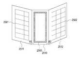
도 25는 본 발명의 다양한 실시예에 따른 코일 및 패치 안테나 어레이의 위치를 설명하기 위한 개념도를 도시한다.1 is a conceptual diagram illustrating a wireless power transmission apparatus and an electronic device according to various embodiments of the present disclosure.
2 is a conceptual diagram illustrating a wireless power transmission system according to various embodiments of the present invention.
3A is a flowchart illustrating an operating method of an apparatus for transmitting power wirelessly and an electronic device according to various embodiments of the present disclosure;
3B is a flowchart illustrating an operating method of an apparatus for transmitting power wirelessly and an electronic device according to various embodiments of the present disclosure;
4A is a block diagram of a wireless power transmitter and an electronic device according to various embodiments of the present disclosure.
4B is a block diagram of an apparatus for transmitting power wirelessly according to various embodiments of the present disclosure.
4C is a block diagram of a wireless power transmission apparatus and an electronic device according to various embodiments of the present disclosure.
4D is a block diagram of an apparatus for transmitting power wirelessly according to various embodiments of the present disclosure.
5 is a flowchart illustrating an operating method of an apparatus for transmitting power wirelessly according to various embodiments of the present disclosure.
6A is a flowchart illustrating an operating method of an apparatus for transmitting power wirelessly and an electronic device according to various embodiments of the present disclosure;
6B is a flowchart illustrating an operating method of an apparatus for transmitting power wirelessly and an electronic device according to various embodiments of the present disclosure;
7A is a flowchart illustrating a method of operating a wireless power transmitter and an electronic device according to various embodiments of the present disclosure.
7B is a flowchart illustrating an operating method of an apparatus for transmitting power wirelessly and an electronic device according to various embodiments of the present disclosure;
7C illustrates a user interface for inputting a charging method selection input of an electronic device according to various embodiments of the present disclosure.
8A is a flowchart illustrating a method of operating a wireless power transmitting device and an electronic device according to various embodiments of the present disclosure;
8B is a flowchart illustrating a method of operating a wireless power transmitting device and an electronic device according to various embodiments of the present disclosure.
9 is a flowchart illustrating an operating method of an apparatus for transmitting power wirelessly according to various embodiments of the present disclosure.
10A is a flowchart illustrating a method of operating an apparatus for transmitting power wirelessly according to various embodiments of the present disclosure.
10B is a conceptual diagram illustrating the arrangement of a wireless power transmitter and a living body according to various embodiments of the present invention.
11 is a flowchart illustrating a method of operating a wireless power transmitter or an electronic device according to various embodiments of the present disclosure.
12 illustrates a user interface for inducing a change in a charging method of a wireless power transmitter or an electronic device according to various embodiments of the present disclosure.
13 is a flowchart illustrating a method of operating a wireless power transmitter or an electronic device according to various embodiments of the present disclosure.
14 illustrates information related to a charging method displayed on an electronic device according to various embodiments of the present disclosure.
15 is a flowchart illustrating a method of operating a wireless power transmitter or an electronic device according to various embodiments of the present disclosure.
16A to 16C are conceptual diagrams illustrating a charging method change process according to various embodiments of the present disclosure.
17 is a flowchart illustrating an operating method of an apparatus for transmitting power wirelessly and a plurality of electronic devices according to various embodiments of the present disclosure;
18 is a flowchart illustrating an operating method of an apparatus for transmitting power wirelessly according to various embodiments of the present disclosure.
19 is a flowchart illustrating an operating method of an apparatus for transmitting power wirelessly according to various embodiments of the present disclosure.
20A is a conceptual diagram illustrating charging of an electronic device of an apparatus for transmitting power wirelessly according to various embodiments of the present disclosure.
20B and 20C are conceptual diagrams for explaining RF wave formation for a plurality of positions according to various embodiments of the present disclosure.
21 is a flowchart illustrating a method of operating an electronic device according to various embodiments of the present disclosure.
22A to 22F are conceptual diagrams for explaining the arrangement of a wireless power transmission apparatus according to various embodiments of the present invention.
23 is a conceptual diagram illustrating a criterion for determining short-range charging and long-distance charging according to various embodiments of the present disclosure.
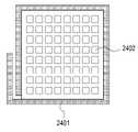
24A is a plan view illustrating a location of a coil and a patch antenna array according to various embodiments of the present disclosure.
24B is a first side view viewed from a first direction for explaining a position of a coil and a patch antenna array according to various embodiments of the present disclosure;
24C is a perspective view illustrating a position of a coil and a patch antenna array according to various embodiments of the present disclosure;
24D is a second side view viewed from the second direction for explaining the position of the coil and patch antenna array according to various embodiments of the present disclosure.
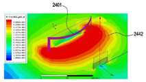
24E illustrates an RF wave formed by a patch antenna array according to various embodiments of the present invention.
24F illustrates a magnetic field formed by a coil in accordance with various embodiments of the present invention.
25 is a conceptual diagram illustrating a position of a coil and a patch antenna array according to various embodiments of the present invention.
이하, 본 문서의 다양한 실시예들이 첨부된 도면을 참조하여 기재된다. 실시예 및 이에 사용된 용어들은 본 문서에 기재된 기술을 특정한 실시 형태에 대해 한정하려는 것이 아니며, 해당 실시예의 다양한 변경, 균등물, 및/또는 대체물을 포함하는 것으로 이해되어야 한다. 도면의 설명과 관련하여, 유사한 구성요소에 대해서는 유사한 참조 부호가 사용될 수 있다. 단수의 표현은 문맥상 명백하게 다르게 뜻하지 않는 한, 복수의 표현을 포함할 수 있다. 본 문서에서, "A 또는 B" 또는 "A 및/또는 B 중 적어도 하나" 등의 표현은 함께 나열된 항목들의 모든 가능한 조합을 포함할 수 있다. "제 1," "제 2," "첫째," 또는 "둘째,"등의 표현들은 해당 구성요소들을, 순서 또는 중요도에 상관없이 수식할 수 있고, 한 구성요소를 다른 구성요소와 구분하기 위해 사용될 뿐 해당 구성요소들을 한정하지 않는다. 어떤(예: 제 1) 구성요소가 다른(예: 제 2) 구성요소에 "(기능적으로 또는 통신적으로) 연결되어" 있다거나 "접속되어" 있다고 언급된 때에는, 상기 어떤 구성요소가 상기 다른 구성요소에 직접적으로 연결되거나, 다른 구성요소(예: 제 3 구성요소)를 통하여 연결될 수 있다.Hereinafter, various embodiments of the present document will be described with reference to the accompanying drawings. The examples and terms used therein are not intended to limit the technology described in this document to a specific embodiment, but should be understood to include various modifications, equivalents, and/or substitutions of the embodiments. In connection with the description of the drawings, like reference numerals may be used for like components. The singular expression may include the plural expression unless the context clearly dictates otherwise. In this document, expressions such as “A or B” or “at least one of A and/or B” may include all possible combinations of items listed together. Expressions such as "first," "second," "first," or "second," can modify the corresponding elements, regardless of order or importance, and to distinguish one element from another element. It is used only and does not limit the corresponding components. When an (eg, first) component is referred to as being “(functionally or communicatively) connected” or “connected” to another (eg, second) component, that component is It may be directly connected to the component, or may be connected through another component (eg, a third component).
본 문서에서, "~하도록 구성된(또는 설정된)(configured to)"은 상황에 따라, 예를 들면, 하드웨어적 또는 소프트웨어적으로 "~에 적합한," "~하는 능력을 가지는," "~하도록 변경된," "~하도록 만들어진," "~를 할 수 있는," 또는 "~하도록 설계된"과 상호 호환적으로(interchangeably) 사용될 수 있다. 어떤 상황에서는, "~하도록 구성된 장치"라는 표현은, 그 장치가 다른 장치 또는 부품들과 함께 "~할 수 있는" 것을 의미할 수 있다. 예를 들면, 문구 "A, B, 및 C를 수행하도록 구성된(또는 설정된) 프로세서"는 해당 동작을 수행하기 위한 전용 프로세서(예: 임베디드 프로세서), 또는 메모리 장치에 저장된 하나 이상의 소프트웨어 프로그램들을 실행함으로써, 해당 동작들을 수행할 수 있는 범용 프로세서(예: CPU 또는 application processor)를 의미할 수 있다.In this document, "configured (or configured to)" means "suitable for," "having the ability to," "modified to," depending on the context, for example, hardware or software. ," "made to," "capable of," or "designed to," may be used interchangeably. In some circumstances, the expression “a device configured to” may mean that the device is “capable of” with other devices or parts. For example, the phrase "a processor configured (or configured to perform) A, B, and C" refers to a dedicated processor (eg, an embedded processor) for performing the corresponding operations, or by executing one or more software programs stored in a memory device. , may refer to a general-purpose processor (eg, a CPU or an application processor) capable of performing corresponding operations.
본 문서의 다양한 실시예들에 따른 무선 전력 송신 장치 또는 전자 장치는, 예를 들면, 스마트폰, 태블릿 PC, 이동 전화기, 영상 전화기, 전자책 리더기, 데스크탑 PC, 랩탑 PC, 넷북 컴퓨터, 워크스테이션, 서버, PDA, PMP(portable multimedia player), MP3 플레이어, 의료기기, 카메라, 또는 웨어러블 장치 중 적어도 하나를 포함할 수 있다. 웨어러블 장치는 액세서리형(예: 시계, 반지, 팔찌, 발찌, 목걸이, 안경, 콘택트 렌즈, 또는 머리 착용형 장치(head-mounted-device(HMD)), 직물 또는 의류 일체형(예: 전자 의복), 신체 부착형(예: 스킨 패드 또는 문신), 또는 생체 이식형 회로 중 적어도 하나를 포함할 수 있다. 어떤 실시예들에서, 무선 전력 송신 장치 또는 전자 장치는, 예를 들면, 텔레비전, DVD(digital video disk) 플레이어, 오디오, 냉장고, 에어컨, 청소기, 오븐, 전자레인지, 세탁기, 공기 청정기, 셋톱 박스, 홈 오토매이션 컨트롤 패널, 보안 컨트롤 패널, 미디어 박스, 게임 콘솔, 전자 사전, 전자 키, 캠코더, 또는 전자 액자 중 적어도 하나를 포함할 수 있다.The wireless power transmission device or electronic device according to various embodiments of the present document may include, for example, a smartphone, a tablet PC, a mobile phone, a video phone, an e-book reader, a desktop PC, a laptop PC, a netbook computer, a workstation, It may include at least one of a server, a PDA, a portable multimedia player (PMP), an MP3 player, a medical device, a camera, and a wearable device. A wearable device may be an accessory (e.g., watch, ring, bracelet, anklet, necklace, eyewear, contact lens, or head-mounted-device (HMD)), a textile or clothing integral (e.g. electronic garment); It may include at least one of a body-worn (eg, skin pad or tattoo), or a bioimplantable circuit In some embodiments, the wireless power transmission device or electronic device may include, for example, a television, digital video disk) player, audio, refrigerator, air conditioner, vacuum cleaner, oven, microwave oven, washing machine, air purifier, set-top box, home automation control panel, security control panel, media box, game console, electronic dictionary, electronic key, camcorder , or may include at least one of an electronic picture frame.
다른 실시예에서, 무선 전력 송신 장치 또는 전자 장치는, 각종 의료기기(예: 각종 휴대용 의료측정기기(혈당 측정기, 심박 측정기, 혈압 측정기, 또는 체온 측정기 등), MRA(magnetic resonance angiography), MRI(magnetic resonance imaging), CT(computed tomography), 촬영기, 또는 초음파기 등), 네비게이션 장치, 위성 항법 시스템(GNSS(global navigation satellite system)), EDR(event data recorder), FDR(flight data recorder), 자동차 인포테인먼트 장치, 선박용 전자 장비(예: 선박용 항법 장치, 자이로 콤파스 등), 항공 전자기기(avionics), 보안 기기, 차량용 헤드 유닛(head unit), 산업용 또는 가정용 로봇, 드론(drone), 금융 기관의 ATM, 상점의 POS(point of sales), 또는 사물 인터넷 장치 (예: 전구, 각종 센서, 스프링클러 장치, 화재 경보기, 온도조절기, 가로등, 토스터, 운동기구, 온수탱크, 히터, 보일러 등) 중 적어도 하나를 포함할 수 있다. 어떤 실시예에 따르면, 무선 전력 송신 장치 또는 전자 장치는 가구, 건물/구조물 또는 자동차의 일부, 전자 보드(electronic board), 전자 사인 수신 장치(electronic signature receiving device), 프로젝터, 또는 각종 계측 기기(예: 수도, 전기, 가스, 또는 전파 계측 기기 등) 중 적어도 하나를 포함할 수 있다. 다양한 실시예에서, 무선 전력 송신 장치 또는 전자 장치는 플렉서블하거나, 또는 전술한 다양한 장치들 중 둘 이상의 조합일 수 있다. 본 문서의 실시예에 따른 무선 전력 송신 장치 또는 전자 장치는 전술한 기기들에 한정되지 않는다. 본 문서에서, 사용자라는 용어는 전자 장치를 사용하는 사람 또는 무선 전력 송신 장치 또는 전자 장치를 사용하는 장치(예: 인공지능 전자 장치)를 지칭할 수 있다.In another embodiment, the wireless power transmission device or the electronic device includes various medical devices (eg, various portable medical devices (eg, a blood glucose meter, a heart rate monitor, a blood pressure monitor, or a body temperature monitor), magnetic resonance angiography (MRA), MRI (magnetic resonance angiography), magnetic resonance imaging), computed tomography (CT), imager, or ultrasound machine, etc.), navigation devices, global navigation satellite system (GNSS), event data recorder (EDR), flight data recorder (FDR), automotive infotainment devices, marine electronic equipment (e.g. marine navigation systems, gyro compasses, etc.), avionics, security devices, vehicle head units, industrial or domestic robots, drones, ATMs in financial institutions; Includes at least one of a store's point of sales (POS) or Internet of Things (IoT) devices (e.g. light bulbs, sensors, sprinkler devices, fire alarms, thermostats, street lights, toasters, exercise equipment, hot water tanks, heaters, boilers, etc.) can do. According to some embodiments, the wireless power transmitting device or electronic device is a piece of furniture, building/structure or automobile, an electronic board, an electronic signature receiving device, a projector, or various measuring devices (eg : water, electricity, gas, or radio wave measuring device, etc.) may be included. In various embodiments, the wireless power transmission device or electronic device may be flexible or a combination of two or more of the various devices described above. The wireless power transmitter or electronic device according to the embodiment of this document is not limited to the above-described devices. In this document, the term user may refer to a person using an electronic device or a wireless power transmission device or a device using the electronic device (eg, an artificial intelligence electronic device).
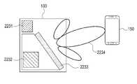
도 1은 본 발명의 다양한 실시예에 따른 무선 전력 송신 장치 및 전자 장치를 설명하기 위한 개념도를 도시한다.1 is a conceptual diagram illustrating a wireless power transmission apparatus and an electronic device according to various embodiments of the present disclosure.
무선 전력 송신 장치(100)는 제 1 전력 송신 회로(101) 및 제 2 전력 송신 회로(102)를 포함할 수 있다. 제 1 전력 송신 회로(101)는, 예를 들어 유도 방식에 의한 전력 송신 회로로 구현될 수 있다. 유도 방식에 의한 전력 송신 회로로 구현되는 경우에는, 제 1 전력 송신 회로(101)는, 예를 들어 전력 소스, 직류-교류 변환 회로, 증폭 회로, 임피던스 매칭 회로, 적어도 하나의 커패시터, 적어도 하나의 코일, 통신 변복조 회로 등을 포함할 수 있다. 적어도 하나의 커패시터는 적어도 하나의 코일과 함께 공진 회로를 구성할 수 있다. 제 1 전력 송신 회로(101)는, WPC(wireless power consortium) 표준 (또는, Qi 표준)에서 정의된 방식으로 구현될 수 있다. 제 1 전력 송신 회로(101)는, 예를 들어 공진 방식에 의한 전력 송신 회로로 구현될 수도 있다. 공진 방식에 의한 전력 송신 회로로 구현되는 경우에는, 제 1 전력 송신 회로(101)는, 예를 들어 전력 소스, 직류-교류 변환 회로, 증폭 회로, 임피던스 매칭 회로, 적어도 하나의 커패시터, 적어도 하나의 코일, 아웃 밴드 통신 회로(예: BLE(bluetooth low energy) 통신 회로) 등을 포함할 수 있다. 적어도 하나의 커패시터 및 적어도 하나의 코일은 공진 회로를 구성할 수 있다. 제 1 전력 송신 회로(101)는, A4WP(Alliance for Wireless Power) 표준 (또는, AFA(air fuel alliance) 표준)에서 정의된 방식으로 구현될 수 있다. 제 1 전력 송신 회로(101)는, 공진 방식 또는 유도 방식에 따라 전류가 흐르면 유도 자기장(130)을 생성할 수 있는 코일을 포함할 수 있다. 실시예에 따라, 제 1 전력 송신 회로(101)는, 유도 방식에 의한 전력 송신 회로 및 공진 방식에 의한 전력 송신 회로를 모두 포함할 수도 있다.The wireless
제 2 전력 송신 회로(102)는, 예를 들어 전자기파 방식에 의한 전력 송신 회로로 구현될 수 있다. 제 2 전력 송신 회로(102)는, 예를 들어 전력 소스, 직류-교류 변환 회로, 증폭 회로, 분배 회로, 위상 쉬프터, 복수 개의 패치 안테나를 포함하는 전력 송신용 안테나 어레이, 아웃 밴드 방식의 통신 모듈(예: BLE 통신 모듈)등을 포함할 수 있다. 복수 개의 패치 안테나 각각은 RF(radio frequency) 웨이브를 형성할 수 있다.The second
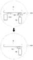
예를 들어, 전자 장치(150)가 무선 전력 송신 장치(100)로부터 제 1 거리(X1)만큼 떨어져 위치한 경우에는, 무선 전력 송신 장치(100)는 제 1 전력 송신 회로(101)를 통하여 전력을 전자 장치(150)로 송신할 수 있다. 제 1 전력 송신 회로(101)에 포함된 코일로부터 발생되는 자기장(130)이 전자 장치(150)로 전달될 수 있으며, 이에 따라 코일을 통하여 전력(130)을 송신하는 것은, 코일을 통하여 자기장(130)을 발생시키는 것으로 명명될 수도 있다. 자기장(130)은 시간에 따라 크기가 변경될 수 있다. 아울러, 코일을 통하여 전력을 송신하는 것은, 코일을 통하여 에너지를 전달하는 것으로 명명될 수도 있다. 전자 장치(150)는, 코일을 포함할 수 있으며, 주변에 생성된 시간에 따라 크기가 변경되는 자기장(130)에 의하여 코일에서는 유도 기전력이 발생될 수 있다. 유도 기전력이 발생되는 과정을, 전자 장치(150)가 코일을 통하여 전력 또는 에너지를 수신하는 것으로 명명할 수도 있다. 제 1 거리(X1)만큼 떨어진 경우에, 유도 방식 또는 공진 방식에 따른 제 1 전력 송신 회로(101)를 통하여 전력을 송신하는 것은, 무선 전력 송신 장치(100)가 결정할 수도 있고, 또는 전자 장치(150)가 결정할 수도 있다.For example, when the
예를 들어, 전자 장치(150)가 무선 전력 송신 장치(100)로부터 제 2 거리(X2)만큼 떨어져 위치한 경우에는, 무선 전력 송신 장치(100)는 제 2 전력 송신 회로(102)를 통하여 전력을 전자 장치(150)로 송신할 수 있다. 제 2 전력 송신 회로(102)에 포함된 복수 개의 패치 안테나로부터 발생되는 RF 웨이브(131)가 전자 장치(150)로 전달될 수 있으며, 이에 따라 복수 개의 패치 안테나를 통하여 전력을 송신하는 것은, 복수 개의 패치 안테나를 통하여 RF 웨이브(131)를 발생시키는 것으로 명명될 수도 있다. RF 웨이브(131)는 시간에 따라 크기가 변경될 수 있다. 아울러, 복수 개의 패치 안테나를 통하여 전력을 송신하는 것은, 복수 개의 패치 안테나를 통하여 에너지를 전달하는 것으로 명명될 수도 있다. RF 웨이브(131)의 형성에 대하여서는 도 2를 참조하여 더욱 상세하게 설명하도록 한다. 전자 장치(150)는, 수신을 위한 복수 개의 패치 안테나를 포함할 수 있으며, 주변에 생성된 시간에 따라 크기가 변경되는 RF 웨이브(131)에 의하여 패치 안테나는 전류 또는 전압을 발생시킬 수 있다. 복수 개의 패치 안테나가 전류 또는 전압을 발생시키는 과정을, 전자 장치(150)가 복수 개의 패치 안테나를 통하여 전력 또는 에너지를 수신하는 것으로 명명할 수도 있다. 제 2 거리(X2)만큼 떨어진 경우에, 전자기파 방식에 따른 제 2 전력 송신 회로(102)를 통하여 전력을 송신하는 것은, 무선 전력 송신 장치(100)가 결정할 수도 있고, 또는 전자 장치(150)가 결정할 수도 있다.For example, when the
본 발명의 다양한 실시예에서, 전자 장치(150)가 제 1 거리(X1)만큼 떨어져서 위치하다가, 제 2 거리(X2)만큼 떨어져서 위치하도록 이동하면, 무선 전력 송신 장치(100)는, 전력 송신 회로를 제 1 전력 송신 회로(101)로부터 제 2 전력 송신 회로(102)로 변경할 수도 있다.In various embodiments of the present disclosure, when the
본 발명의 다양한 실시예에서, 무선 전력 송신 장치(100)는, 전자 장치(150)가 제 1 거리(X1)만큼 떨어져서 위치한 경우에, 제 1 전력 송신 회로(101) 및 제 2 전력 송신 회로(102)를 모두 이용하여 에너지를 송신할 수도 있다. 예를 들어, 전자 장치(150)에 대한 급속 충전이 요구되는 경우에는, 무선 전력 송신 장치(100)는 복수 개의 전력 송신 회로를 이용하여 에너지를 송신할 수도 있다.In various embodiments of the present disclosure, the wireless
본 발명의 다양한 실시예에서, 무선 전력 송신 장치(100)는, 전자 장치(150)가 제 1 거리(X1)만큼 떨어져 위치한 경우에도, 제 2 전력 송신 회로(102)를 통하여 전자기파 방식으로 에너지를 송신할 수도 있다. 예를 들어, 전자 장치(150)가 전자기파 방식만을 지원하는 경우에는, 무선 전력 송신 장치(100)는 지원 방식에 대한 정보에 기초하여 제 2 전력 송신 회로(102)를 통하여 에너지를 송신할 수 있다. 무선 전력 송신 장치(100) 또는 전자 장치(150)는, 전자 장치가 지원하는 충전 방식, 전자 장치가 수신하는 전력과 관련된 정보, 전자 장치의 충전 관련 정보, 무선 전력 송신 효율, 무선 전력 송신 관련 규약, 장애물 위치 여부 등의 다양한 정보에 따라, 충전 방식을 결정할 수 있다. 무선 전력 송신 장치(100)는, 결정된 충전 방식에 대응하는 전력 송신 회로를 이용하여 에너지를 송신할 수 있다.In various embodiments of the present disclosure, the wireless
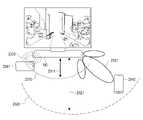
도 2는 본 발명의 다양한 실시예에 따른 무선 전력 송신 시스템의 개념도를 도시한다.2 is a conceptual diagram illustrating a wireless power transmission system according to various embodiments of the present invention.
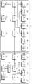
제 2 전력 송신 회로(102)는 적어도 하나의 전자장치(150,160)에 무선으로 전력을 송신할 수 있다. 본 발명의 다양한 실시예에서, 제 2 전력 송신 회로(102)는 복수 개의 패치 안테나(patch antenna)(111 내지 126)를 포함할 수 있다. 패치 안테나(111 내지 126)는 각각이 RF 웨이브(131 또는 132)를 발생시킬 수 있는 안테나라면 제한이 없다. 패치 안테나(111 내지 126)가 발생시키는 RF 웨이브의 진폭 및 위상 중 적어도 하나는 제 2 전력 송신 회로(102), 또는 무선 전력 송신 장치(100)의 프로세서에 의하여 조정될 수 있다. 설명의 편의를 위하여, 패치 안테나(111 내지 126) 각각이 발생시키는 RF 웨이브를 서브 RF 웨이브라 명명하도록 한다.The second
본 발명의 다양한 실시예에서, 제 2 전력 송신 회로(102)는 패치 안테나(111 내지 126)에서 발생되는 서브 RF 웨이브 각각의 진폭 및 위상 중 적어도 하나를 조정할 수 있다. 한편, 서브 RF 웨이브들은 서로 간섭될 수 있다. 예를 들어, 어느 한 지점에서는 서브 RF 웨이브들이 서로 보강 간섭될 수 있으며, 또 다른 지점에서는 서브 RF 웨이브들이 서로 상쇄 간섭될 수 있다. 본 발명의 다양한 실시예에 의한 제 2 전력 송신 회로(102)는 제 1 지점(x1,y1,z1)에서 서브 RF 웨이브들이 서로 보강 간섭될 수 있도록, 패치 안테나(111 내지 126)가 발생하는 서브 RF 웨이브 각각의 진폭 및 위상 중 적어도 하나를 조정할 수 있다.In various embodiments of the present disclosure, the second
예를 들어, 무선 전력 송신 장치(100)는 제 1 지점(x1,y1,z1)에 전자장치(150)가 배치된 것을 판단할 수 있다. 여기에서, 전자장치(150)의 위치는, 예를 들어 전자장치(150)의 전력 수신용 안테나가 위치한 지점일 수 있다. 무선 전력 송신 장치(100)는, 전자 장치(150)의 위치를 다양한 방식에 따라 판단할 수 있다. 예를 들어, 무선 전력 송신 장치(100)는 비전 인식 또는 레이더 인식에 따라 전자 장치(150)의 위치를 판단할 수 있다. 예를 들어, 무선 전력 송신 장치(100)는 전자 장치(150)로부터 수신되는 통신 신호(예: BLE 통신 신호)를 복수 개의 통신용 안테나를 통하여 수신할 수 있으며, 복수 개의 통신용 안테나 각각에서의 수신 시점에 대한 정보를 이용하여 전자 장치(150)의 위치를 판단할 수도 있다. 무선 전력 송신 장치(100)는 TDOA(time difference of arrival) 또는 FDOA(frequency difference of arrival) 등의 다양한 방식으로 전자 장치(150)가 위치한 방향을 판단할 수 있다. 무선 전력 송신 장치(100)는, 통신 신호내에 포함된 송신 세기와, 통신용 안테나에서 수신된 수신 세기와의 차이에 기초하여 무선 전력 송신 장치(100)와 전자 장치(150) 사이의 거리를 판단할 수 있다. 무선 전력 송신 장치(100)는, 판단된 방향 및 판단된 거리에 기초하여 전자 장치(150)의 위치를 판단할 수 있다. 예를 들어, 무선 전력 송신 장치(100)는 시험용 RF 웨이브를 복수 개의 방향 및 복수 개의 거리에 따라 형성할 수 있다. 전자 장치(150)는, 수신된 전력의 크기에 대한 정보(예: 전자 장치(150)의 정류기의 출력단에서의 전압 등의 정보)를 무선 전력 송신 장치(100)로 보고할 수 있다. 무선 전력 송신 장치(100)는, 최적의 전력을 수신하는 것으로 보고된 위치에 전자 장치(150)가 위치한 것으로 판단할 수도 있다. 전자 장치(150)는, 통신 신호에 따라 전자 장치(150)가 위치한 방향을 먼저 판단하고, 해당 방향으로 시험용 RF 웨이브를 형성할 수도 있다. 예를 들어, 무선 전력 송신 장치(100)는, 시험용 RF 웨이브를 변조하여, 시험용 RF 웨이브에 방향에 대한 식별 정보 또는 거리에 대한 식별 정보 중 적어도 하나를 포함시킬 수도 있다. 전자 장치(150)는, 수신된 시험용 RF 웨이브를 복조할 수 있으며, 복조 결과 포함된 방향에 대한 식별 정보 또는 거리에 대한 식별 정보 중 적어도 하나를 통신 회로를 통하여 무선 전력 송신 장치(100)로 보고할 수 있다. 무선 전력 송신 장치(100)는 보고 결과에 포함된 방향에 대한 식별 정보 또는 거리에 대한 식별 정보 중 적어도 하나에 기초하여 전자 장치(150)의 위치를 판단할 수 있다. 무선 전력 송신 장치(100)는, 복수 개의 방향으로 파일럿용 RF 웨이브를 형성하였다가 이에 대한 반사파에 대한 정보(예: 위상 오차, TOF(time of flight) 등)를 레퍼런스 정보로 저장할 수 있다. 무선 전력 송신 장치(100)는, 주기적 또는 비주기적으로 파일럿용 RF 웨이브를 형성하고 반사파를 수신할 수 있으며, 반사파에 대한 정보가 기존에 저장되었던 레퍼런스 정보와 차이가 있음이 검출되면, 해당 방향에 전자 장치(150)가 위치한 것으로 판단할 수도 있다. 예를 들어, 무선 전력 송신 장치(100)는 다른 외부 전자 장치로부터 전자 장치(150)의 위치에 대한 정보를 수신할 수도 있다. 예를 들어, 무선 전력 송신 장치(100)는 전자 장치(150)로부터 직접 위치에 대한 정보를 수신할 수도 있다. 상술한 무선 전력 송신 장치(100)의 전자 장치(150)의 위치 판단 방법은 단순히 예시적인 것으로, 위치를 판단할 수 있는 기술이라면 제한이 없음을 당업자는 용이하게 이해할 수 있을 것이다.For example, the
전자 장치(150)가 높은 송신 효율로 무선으로 전력을 수신하기 위하여서는, 제 1 지점(x1,y1,z1)에서 서브 RF 웨이브들이 보강 간섭되어야 한다. 이에 따라, 제 2 전력 송신 회로(102)는 제 1 지점(x1,y1,z1)에서 서브 RF 웨이브들이 서로 보강 간섭이 되도록 패치 안테나(111 내지 126)를 제어할 수 있다. 여기에서, 패치 안테나(111 내지 126)를 제어한다는 것은, 패치 안테나(111 내지 126) 각각으로 입력되는 신호의 크기를 제어하거나 또는 패치 안테나(111 내지 126) 각각으로 입력되는 신호의 위상(또는 딜레이)을 제어하는 것을 의미할 수 있다. 한편, 특정 지점에서 RF 웨이브가 보강 간섭되도록 제어하는 기술인 빔-포밍(beam forming)에 대해서는 당업자가 용이하게 이해할 수 있을 것이다. 아울러, 본 발명에서 이용되는 빔-포밍의 종류에 대하여 제한이 없음 또한 당업자가 용이하게 이해할 수 있을 것이다. 예를 들어, 미국 공개특허 2016/0099611, 미국 공개특허 2016/0099755, 미국 공개특허 2016/0100124 등에 개시된 바와 같은, 다양한 빔 포밍 방법이 이용될 수 있다. 빔-포밍에 의하여 형성된 RF 웨이브의 형태를, 에너지 포켓(pockets of energy)이라 명명할 수도 있다.In order for the
이에 따라, 서브 RF 웨이브들에 의하여 형성된 RF 웨이브(131)는 제 1 지점(x1,y1,z1)에서 진폭이 최대가 될 수 있으며, 이에 따라 전자장치(150)는 높은 효율로 전력을 무선으로 수신할 수 있다. 한편, 제 2 전력 송신 회로(102)는 제 2 지점(x2,y2,z2)에 전자장치(160)가 배치된 것을 감지할 수도 있다. 제 2 전력 송신 회로(102)는 전자장치(160)를 충전하기 위하여 서브 RF 웨이브들이 제 2 지점(x2,y2,z2)에서 보강 간섭이 되도록 패치 안테나(111 내지 126)를 제어할 수 있다. 이에 따라, 서브 RF 웨이브들에 의하여 형성된 RF 웨이브(132)는 제 2 지점(x2,y2,z2)에서 진폭이 최대가 될 수 있으며, 전자장치(160)는 높은 송신 효율로 무선 전력을 수신할 수 있다.Accordingly, the
더욱 상세하게, 전자장치(150)는 상대적으로 우측에 배치될 수 있다. 이 경우, 제 2 전력 송신 회로(102)는 상대적으로 우측에 배치된 패치 안테나(예를 들어, 114,118,122,126)로부터 형성되는 서브 RF 웨이브들에 상대적으로 더 큰 딜레이를 적용할 수 있다. 즉, 상대적으로 좌측에 배치된 패치 안테나(예를 들어, 111,115,119,123)로부터 형성되는 서브 RF 웨이브들이 먼저 형성된 이후에, 소정의 시간이 흐른 후에 상대적으로 우측에 배치된 패치 안테나(예를 들어, 114,118,122,126)로부터 서브 RF 웨이브가 발생될 수 있다. 이에 따라, 상대적으로 우측의 지점에서 서브 RF 웨이브들이 동시에 만날 수 있으며, 즉 상대적으로 우측의 지점에서 서브 RF 웨이브들이 보강 간섭될 수 있다. 만약, 상대적으로 중앙의 지점에 빔-포밍을 수행하는 경우에는, 제 2 전력 송신 회로(102)는 좌측의 패치 안테나(예를 들어, 111,115,119,123)와 우측의 패치 안테나(예를 들어, 114,118,122,126)와 실질적으로 동일한 딜레이를 적용할 수 있다. 또한, 상대적으로 좌측의 지점에 빔-포밍을 수행하는 경우에는, 제 2 전력 송신 회로(102)는 좌측의 패치 안테나(예를 들어, 111,115,119,123)에 우측의 패치 안테나(예를 들어, 114,118,122,126)보다 더 큰 딜레이를 적용할 수 있다. 한편, 다른 실시예에서는, 제 2 전력 송신 회로(102)는 패치 안테나(111 내지 126) 전체에서 서브 RF 웨이브들을 실질적으로 동시에 발진시킬 수 있으며, 상술한 딜레이에 대응되는 위상을 조정함으로써 빔-포밍을 수행할 수도 있다. 상술한 바에 따라, 무선 전력 송신 장치(100)는, 제 2 전력 송신 회로(102)에 포함된 복수 개의 패치 안테나(111 내지 126)를 통하여 위치한 전자 장치(150)에 전력 또는 에너지를 송신할 수 있다.In more detail, the
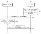
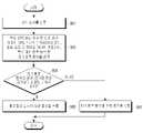
도 3a는 본 발명의 다양한 실시예에 따른 무선 전력 송신 장치 및 전자 장치의 동작 방법을 설명하기 위한 흐름도를 도시한다.3A is a flowchart illustrating an operating method of an apparatus for transmitting power wirelessly and an electronic device according to various embodiments of the present disclosure;
301 동작에서, 무선 전력 송신 장치(100)는 전자 장치(150)를 검출할 수 있다. 본 문서에서, 무선 전력 송신 장치(100) 또는 전자 장치(150)가 특정 동작을 수행하는 것은, 무선 전력 송신 장치(100) 또는 전자 장치(150)에 포함된 다양한 하드웨어, 예를 들어 프로세서와 같은 제어 회로가 특정 동작을 수행하는 것을 의미할 수 있다. 또는, 무선 전력 송신 장치(100) 또는 전자 장치(150)가 특정 동작을 수행하는 것은, 프로세서가 다른 하드웨어로 하여금 특정 동작을 수행하도록 제어하는 것을 의미할 수도 있다. 또는, 무선 전력 송신 장치(100) 또는 전자 장치(150)가 특정 동작을 수행하는 것은, 무선 전력 송신 장치(100) 또는 전자 장치(150)의 저장 회로(예: 메모리)에 저장되었던 특정 동작을 수행하기 위한 인스트럭션이 수행됨에 따라, 프로세서 또는 다른 하드웨어가 특정 동작을 수행하도록 야기하는 것을 의미할 수도 있다. 무선 전력 송신 장치(100)는, 다양한 방식에 따라 전자 장치(150)를 검출할 수 있다. 예를 들어, 무선 전력 송신 장치(100)는 비젼 인식 또는 레이더 인식에 따라 전자 장치(150)를 검출할 수 있다. 예를 들어, 무선 전력 송신 장치(100)는 공진 방식의 표준 또는 유도 방식의 표준에서 정의된 방식에 따라 전자 장치(150)를 검출할 수 있다. WCP 표준(또는, Qi 표준)에 따르는 경우에는, 무선 전력 송신 장치(100)는 핑(ping) 신호를 송신하고, 이에 대한 응답을 인-밴드 통신에 따라 수신하면, 전자 장치(150)가 검출된 것으로 판단할 수 있다. 무선 전력 송신 장치(100)는, 코일에 인가되는 전류 또는 전압에 대하여 온/오프 키잉(on/off keying) 복조를 수행하여 응답을 획득할 수 있다. A4WP 표준(또는, AFA 표준)에 따르는 경우에는, 무선 전력 송신 장치(100)는 전자 장치(150)의 검출을 위한 비콘을 코일(또는, 공진 회로)에 인가할 수 있다. 여기에서, 비콘은 예를 들어 AFA 표준에서 정의된, 충전 영역에 배치되는 물체에 의한 로드 변경을 검출하기 위한 숏-비콘(short beacon) 또는 전자 장치의 통신 회로로 하여금 소정의 신호(예를 들어, BLE 통신 방식에서의 Advertisement 신호)를 송신하는데 이용되는 롱-비콘 중 적어도 하나를 포함할 수 있다. 무선 전력 송신 장치(100)는, 비콘 인가 기간 동안에 로드 변경이 검출되거나, BLE 표준에 의하여 정의된 애드버타이즈먼트(Advertisement) 신호가 수신되거나, 애드버타이즈먼트 신호의 수신 세기(예:RSSI(received signal strength indication))가 임계치 이상인 조건 등의 다양한 조건 또는 조건의 조합에 기초하여 전자 장치(150)를 검출할 수 있다. 전자기파 방식에 따른 경우에는, 통신 신호(예: 애드버타이즈먼트 신호)를 수신하거나, 파일럿 RF 웨이브에 대한 반사파의 분석을 통하여 전자 장치(150)를 검출할 수 있다. 본 발명의 다양한 실시예에 따른 무선 전력 송신 장치(100)는, 상술한 다양한 전자 장치(150)의 검출 방법의 조합을 이용하여서 전자 장치(150)를 검출할 수도 있다. 예를 들어, 무선 전력 송신 장치(150)는, 비전 인식 또는 레이더 인식으로 전자 장치(150)가 충전 가능한 영역에 위치하는 것을 검출할 수 있으며, 이후에 전자기파를 형성하고 반사되는 반사파를 이용하는 방식으로 보다 정확한 위치를 파악할 수도 있다. 또는, 무선 전력 송신 장치(150)는, 핑 신호에 대한 응답으로 전자 장치(150)가 충전 가능한 영역에 위치한 것을 검출하고, 이후에 전자기파를 형성하고 반사되는 반사파를 이용하는 방식으로 보다 정확한 위치를 파악할 수도 있다. 전자 장치(150)의 검출 방법에는 제한이 없다.In
303 동작에서, 무선 전력 송신 장치(100)는, 전자 장치(150)를 복수 개의 패치 안테나를 이용하여 충전할지 또는 전자 장치(150)를 근거리 충전을 위한 코일을 이용하여 충전할지를 선택할 수 있다. 본 발명의 다양한 실시예에 따른 무선 전력 송신 장치(100)는, 전자기파 방식에 따라 전력을 송신할 수 있는 복수 개의 패치 안테나와, 유도 방식 또는 공진 방식에 따라 전력을 송신할 수 있는 적어도 하나의 코일을 포함할 수 있다. 즉, 무선 전력 송신 장치(100)는, 충전 방식을 선택할 수 있으며, 선택된 충전 방식에 대응하는 전력 송신 회로를 복수 개의 패치 안테나 또는 코일 중 적어도 하나로 결정할 수 있다. 예를 들어, 무선 전력 송신 장치(100)는, 전자 장치(150)까지의 거리를 획득할 수 있으며, 거리에 기초하여 충전 방식을 판단할 수 있다. 또 다른 예에서, 무선 전력 송신 장치(100)는, 전자 장치가 지원하는 충전 방식, 전자 장치가 수신하는 전력과 관련된 정보, 전자 장치의 충전 관련 정보, 무선 전력 송신 효율, 무선 전력 송신 관련 규약, 장애물 위치 여부 등의 다양한 정보에 기초하여 충전 방식을 선택할 수도 있다. 무선 전력 송신 장치(100)가 다양한 정보에 기초하여 충전 방식을 선택하는 실시예들에 대하여서는 더욱 상세하게 후술하도록 한다.In
305 동작에서, 무선 전력 송신 장치(100)는, 선택된 전력 송신 회로를 이용하여 에너지를 송신할 수 있다. 307 동작에서, 전자 장치(150)는 무선 전력 송신 장치로부터의 에너지를 이용하여 충전을 수행할 수 있다. 예를 들어, 전자 장치(150)는 무선 전력 송신 장치(100)로부터 선택된 충전 방식에 대한 정보를 수신할 수도 있으며, 수신된 정보에 따라 전력 수신 회로를 선택할 수 있다. 또는, 전자 장치(150)는 복수 개의 전력 송신 회로를 이용하여 전력을 수신하고, 수신 결과 크기가 큰 전력이 수신되는 전력 수신 회로를 선택하여 충전을 수행할 수도 있다. 본 발명의 다양한 실시예에서, 무선 전력 송신 장치(100)는, 305 동작에서 에너지를 송신하기 이전 또는 이후에, 전자 장치(150)로 선택된 충전 방식에 대한 정보를 송신할 수 있다. 무선 전력 송신 장치(100)는, 305 동작에서 에너지를 송신하기 이전 또는 이후에, 전자 장치(150)와 선택된 충전 방식을 수행하기 위하여 요구되는 정보(예를 들어, 표준에서 정의된 교환하여야 하는 정보)를 교환할 수 있다. 무선 전력 송신 장치(100)와 전자 장치(150)는, 선택된 충전 방식에서 요구되는 동작(예를 들어, 표준에서 정의된 충전을 위한 준비 동작)을 수행할 수 있다.In
상술한 바와 같이, 충전 방식 또는 에너지를 송신할 전력 송신 회로가 무선 전력 송신 장치(100)에 의하여 선택될 수 있다.As described above, a charging method or a power transmission circuit to transmit energy may be selected by the wireless
도 3b는 본 발명의 다양한 실시예에 따른 무선 전력 송신 장치 및 전자 장치의 동작 방법을 설명하기 위한 흐름도를 도시한다.3B is a flowchart illustrating an operating method of an apparatus for transmitting power wirelessly and an electronic device according to various embodiments of the present disclosure;
311 동작에서, 무선 전력 송신 장치(100)는, 전자 장치(150)를 검출할 수 있다. 313 동작에서, 무선 전력 송신 장치(100)는 무선 전력 송신 장치(100)로부터 전자 장치(150)까지의 거리와 관련된 정보를 획득할 수 있다. 예를 들어, 무선 전력 송신 장치(100)는, 비젼 인식 또는 레이더 인식 결과에 기초하여 전자 장치(150)까지의 거리를 판단할 수 있다. 예를 들어, 무선 전력 송신 장치(100)는 전자 장치(150)로부터 통신 신호를 수신하고, 수신된 통신 신호의 세기와 통신 신호에 포함되어 있는 송신 세기를 비교함으로써, 전자 장치(150)까지의 거리를 판단할 수 있다. 예를 들어, 무선 전력 송신 장치(100)는 전자 장치(150) 또는 다른 전자 장치로부터 전자 장치(150)의 위치에 대한 정보를 수신할 수 있으며, 전자 장치(150)의 위치에 대한 정보에 기초하여 무선 전력 송신 장치(100)로부터 전자 장치(150)까지의 거리를 판단할 수도 있다. 예를 들어, 실내 위치 측정 장치 등은, 전자 장치(150)의 실내에서의 좌표를 측정할 수 있으며, 이에 대한 위치 정보를 무선 전력 송신 장치(100)로 송신할 수도 있다. 실내 위치 측정 장치는, 비전 인식 또는 레이더 방식에 특화된 전자 장치일 수 있으며, 보다 정확하게 전자 장치(150)의 위치에 대한 정보를 측정할 수 있다. 무선 전력 송신 장치(100)는, 전자 장치(150)로부터 직접 위치에 대한 정보를 수신할 수도 있다. 전자 장치(150)는, Wi-fi 신호 기반 실내 측위 기술, 지자기 맵을 이용한 실내 측위 기술, NFC 태그 방식의 실내 측위 기술 등의 다양한 방식에 따라, 현재 위치를 판단할 수도 있으며, 이를 무선 전력 송신 장치(100)로 송신할 수도 있다. 무선 전력 송신 장치(100)는, 자신의 실내 좌표 및 수신된 전자 장치(150)의 실내 좌표를 비교함에 따라 전자 장치(150)까지의 거리를 판단할 수 있다. 무선 전력 송신 장치(100)는, 상술한 바와 같이 다양한 방식에 따라 전자 장치(100)까지의 거리를 판단할 수 있으며, 거리를 판단하는 방법에는 제한이 없다.In
본 발명의 다양한 실시예에서 거리와 관련된 정보는, 무선 전력 송신 장치(100)와 전자 장치(150) 사이의 거리에 대하여 종속적인 정보도 포함될 수 있다. 예를 들어, 전자 장치(150)가 무선 전력 송신 장치(100)로부터 더 멀리 위치할수록, 전자 장치(150)가 무선 전력 송신 장치(100)로부터 무선으로 수신하는 전력 또는 에너지의 크기가 감소할 수 있다. 이에 따라, 전자 장치(150)가 수신하는 전력의 크기에 대한 정보 또한 거리와 관련된 정보일 수 있으며, 이를 수신 전력 관련 정보라 명명할 수 있다. 수신 전력 관련 정보는, 전자장치가 무선 전력 송신기로부터 수신한 전력과 관련된 정보로서, 예를 들어 전자 장치(150)의 특정 지점(예: 정류기의 출력단 또는 정류기의 입력단)에서의 전압, 전류, 전력의 크기 등일 수 있다. 예를 들어, 전자 장치(150)는 정류기의 출력단에서의 전압에 대한 정보를 무선 전력 송신 장치(100)로 송신할 수도 있으며, 무선 전력 송신 장치(100)는 수신되는 정류기의 출력단에서의 전압에 따라 충전 방식을 선택할 수도 있다. 한편, 전압, 전류, 전력의 크기를 측정하는 특정 지점에는 제한이 없음을 당업자는 용이하게 이해할 수 있을 것이다.In various embodiments of the present disclosure, distance-related information may also include information dependent on the distance between the
315 동작에서, 무선 전력 송신 장치(100)는 획득된 정보를 이용하여, 전자 장치를 복수 개의 패치 안테나를 이용하여 충전할지 또는 전자 장치를 근거리 충전을 위한 코일을 이용하여 충전할지를 선택할 수 있다. 즉, 무선 전력 송신 장치(100)는 획득된 정보를 이용하여 전자기파 방식으로 전자 장치(100)를 충전할지 또는 공진 방식 또는 유도 방식으로 전자 장치(100)를 충전할지를 선택할 수 있다. 예를 들어, 무선 전력 송신 장치(100)로부터 전자 장치(150)까지의 거리가 임계치를 초과하는 것으로 판단되면, 무선 전력 송신 장치(100)는 전자 장치(150)를 전자기파 방식으로 충전할 것으로, 즉 복수 개의 패치 안테나를 이용하여 충전할 것으로 선택할 수 있다. 예를 들어, 무선 전력 송신 장치(100)로부터 전자 장치(150)까지의 거리가 임계치 이하인 것으로 판단되면, 무선 전력 송신 장치(100)는 전자 장치(150)를 유도 방식 또는 공진 방식으로 충전할 것으로, 즉 근거리 충전을 위하여 구비된 코일을 이용하여 충전할 것으로 선택할 수 있다.In
317 동작에서, 무선 전력 송신 장치(100)는 선택된 전력 송신 회로에 대응하는 충전 방식과 관련된 정보를 전자 장치로 송신할 수 있다. 319 동작에서, 전자 장치(150)는 수신된 정보를 이용하여, 에너지를 수신할 전력 수신 회로를 선택할 수 있다. 321 동작에서, 무선 전력 송신 장치(100)는 선택된 전력 송신 회로를 이용하여 에너지를 송신할 수 있다. 323 동작에서, 전자 장치(150)는 무선 전력 송신 장치(100)로부터의 에너지를 이용하여 충전을 수행할 수 있다. 전자 장치(150)는 선택된 전력 수신 회로를 통하여 에너지를 전류, 전압 또는 전력으로 변환할 수 있다.In
상술한 바와 같이, 무선 전력 송신 장치(100)는 전자 장치(150)까지의 거리와 관련된 정보를 이용하여 충전 방식을 선택할 수 있다. 또 다른 실시예에서 전자 장치(150)가 무선 전력 송신 장치(100) 및 전자 장치(150) 사이의 거리를 판단할 수도 있으며, 전자 장치(150)가 충전 방식을 선택하고, 이를 무선 전력 송신 장치(100)에 통지할 수도 있다. 무선 전력 송신 장치(100)는 통지 받은 충전 방식에 따라, 전력 송신 회로를 선택할 수 있다.As described above, the
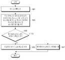
도 3c는 본 발명의 다양한 실시예에 따른 무선 전력 송신 장치 및 전자 장치의 동작 방법을 설명하기 위한 흐름도를 도시한다.3C is a flowchart illustrating an operating method of an apparatus for transmitting power wirelessly and an electronic device according to various embodiments of the present disclosure;
331 동작에서, 전자 장치(150)는 복수 개의 패치 안테나로부터 에너지를 수신할지 또는 코일로부터 에너지를 수신할지 여부를 선택할 수 있다. 본 발명의 다양한 실시예에 따른 전자 장치(150)는, 전자기파 방식에 따라 전력을 수신할 수 있는 복수 개의 패치 안테나와, 유도 방식 또는 공진 방식에 따라 전력을 수신할 수 있는 적어도 하나의 코일을 포함할 수 있다. 즉, 전자 장치(150)는, 충전 방식을 선택할 수 있으며, 선택된 충전 방식에 대응하는 전력 수신 회로를 복수 개의 패치 안테나 또는 코일 중 적어도 하나로 결정할 수 있다. 예를 들어, 무선 전력 송신 장치(100)는, 복수 개의 충전 방식에 따라 시험용 전력을 송신할 수 있다. 무선 전력 송신 장치(100)는 공진 방식에 따라 제 1 시험용 전력을 송신할 수 있으며, 순차적이거나 또는 동시에 전자기파 방식에 따라 제 2 시험용 전력을 송신할 수 있다. 본 발명의 다양한 실시예에서, 무선 전력 송신 장치(100)는 전자 장치(150)의 위치를 미리 판단할 수 있으며, 이에 따라 RF 웨이브가 전자 장치(150)의 위치에서 빔 포밍되도록 제어할 수도 있다. 전자 장치(150)는, 순차적이거나 또는 동시에 제 1 시험용 전력 및 제 2 시험용 전력을 수신할 수 있다. 전자 장치(150)는 수신된 전력의 크기(예: 전류의 크기, 전압의 크기, 또는 전력의 크기)를 비교하여 더 큰 전력을 송신하는 충전 방식을 선택할 수 있다.In
333 동작에서, 전자 장치(150)는 선택된 충전 방식에 대한 정보를 무선 전력 송신 장치(100)로 송신할 수 있다. 시험용 전력이 제공됨에 따라, 전자 장치(150)의 배터리가 완전 방전된 경우에도, 전자 장치(150)가 구동되어 정보를 송신할 수 있다. 335 동작에서, 무선 전력 송신 장치(100)는 수신된 정보에 대응하는 전력 송신용 회로를 이용하여 에너지를 송신할 수 있다. 337 동작에서, 전자 장치(101)는 선택된 충전 방식에 대응하는 전력 수신용 회로를 이용하여 에너지를 수신할 수 있다. 상술한 바와 같이, 충전 방식의 선택 주체가 전자 장치(150)일 수도 있다.In
도 4a는 본 발명의 다양한 실시예에 따른 무선 전력 송신 장치 및 전자 장치의 블록도를 도시한다.4A is a block diagram of a wireless power transmission apparatus and an electronic device according to various embodiments of the present disclosure;
본 발명의 다양한 실시예에 따른 무선 전력 송신 장치(100)는, 제 1 전력 소스(source)(401), 제 1 증폭 회로(402), 분배 회로(403), 위상 쉬프터(phase shifter)(404), 전력 송신용 안테나 어레이(405), 프로세서(410), 통신 회로(420), 메모리(430), 제 2 전력 소스(411), 제 2 증폭 회로(421) 및 코일(422)을 포함할 수 있다. 전자 장치(150)는, 전력 수신용 안테나(451), 제 1 정류 회로(452), 제 1 컨버팅 회로(453), 차저(charger)(454), 프로세서(455), 메모리(457), 통신 회로(460), 제 1 센싱 회로(461), 제 2 센싱 회로(466), 코일(471), 제 2 정류 회로(472) 및 제 2 컨버팅 회로(473)를 포함할 수 있다.The wireless
제 1 전력 소스(401)는, 전자기파 방식에 대응되는 주파수(예: 5.8GHz)를 가지는 교류 전력을 제공할 수 있다. 제 1 전력 소스(401)는, 예를 들어 직류 전력을 제공하는 장치 및 직류 전력을 교류 전력으로 변환하는 인버터(inverter)(미도시)를 포함할 수도 있다. 프로세서(410)는 예를 들어 제 1 전력 소스(401)의 출력을 제어할 수 있다. 제 1 증폭 회로(402)는, 수신된 전력을 증폭하여 분배 회로(403)로 제공할 수 있다. 프로세서(410)는, 수신된 전력의 증폭 이득을 제어할 수도 있다. 제 1 증폭 회로(402)는 적어도 하나의 증폭기(amplifier)를 포함할 수 있다. 제 1 증폭 회로(402), 제 2 증폭 회로(421)는, DA(drive amplifier), HPA(high power amplifier), GBA(Gain Block Amplifier) 등의 다양한 증폭기 또는 그 조합으로 구현될 수 있으며, 구현예에는 제한이 없다. 분배 회로(403)는, 제 1 증폭 회로(402)로부터 출력되는 전력을 복수 개의 경로로 분배할 수 있다. 입력되는 전력 또는 신호를 복수 개의 경로로 분배할 수 있는 회로라면 제한이 없다. 예를 들어, 분배 회로(403)는 전력 송신용 안테나 어레이(405)에 포함된 패치 안테나의 개수만큼의 경로로 전력을 분배할 수 있다.The
위상 쉬프터(404)는 분배 회로(403)로부터 제공되는 복수 개의 교류 전력 각각의 위상(또는, 딜레이)을 쉬프팅시킬 수 있다. 위상 쉬프터(404)는 복수 개일 수 있으며, 예를 들어 전력 송신용 안테나 어레이(405)에 포함된 패치 안테나의 개수일 수 있다. 위상 쉬프터(404)는 예를 들어 HMC642 또는 HMC1113 등과 같은 하드웨어 소자가 이용될 수 있다. 위상 쉬프터(404) 각각의 쉬프트 정도는 프로세서(410)에 의하여 제어될 수 있다. 프로세서(410)는, 전자 장치(150)의 위치를 판단할 수 있으며, 전자 장치(150)의 위치(또는, 전자 장치(150)의 전력 수신용 안테나(451)의 위치)에서 서브 RF 웨이브들이 보강 간섭되도록, 복수 개의 교류 전력들 각각의 위상을 쉬프팅시킬 수 있다. 전력 송신용 안테나 어레이(405)에 포함된 복수 개의 패치 안테나들 각각은 수신된 전력에 기초하여 서브 RF 웨이브들을 생성할 수 있다. 서브 RF 웨이브가 간섭된 RF 웨이브는 전력 수신용 안테나(451)에서 전류, 전압 또는 전력으로 변환되어 출력될 수 있다.The
전력 수신용 안테나(451)는 복수 개의 패치 안테나를 포함할 수 있으며, 주변에 형성된 RF 웨이브, 즉 전자기파를 이용하여 교류 파형의 전류, 전압 또는 전력을 발생시킬 수 있으며, 이를 수신된 전력으로 명명할 수 있다. 제 1 정류 회로(452)는, 수신된 전력을 직류 파형으로 정류할 수 있다. 제 1 컨버팅 회로(453)는, 직류 파형의 전력의 전압을 기설정된 값으로 증가 또는 감소시켜 출력할 수 있다. 차저(454)는, 컨버팅된 전력의 전압의 크기 또는 전류의 크기를 조정하여 배터리를 충전할 수 있다. 구현에 따라, 차저(454)가 전자 장치(150)에 포함되지 않을 수도 있으며, 이 경우에는 제 1 컨버팅 회로(453)가 배터리의 충전에 적합하도록 전력의 전압 또는 전류의 크기를 조정하여 배터리를 직접 충전할 수도 있다.The
제 1 센싱 회로(461)는, 제 1 정류 회로(452)의 출력단에서의 전압의 크기, 전류의 크기 또는 전력의 크기를 센싱할 수 있다. 예를 들어, 제 1 센싱 회로(461)는, 전류력계형(electro dynamic instrument) 전압계, 정전기형 전압계, 디지털 전압계 등의 다양한 형태의 전압계 또는 직류 전류계, 교류 전류계, 디지털 전류계 등으로 다양한 형태의 전류계 또는 ADC(analog to digital converter) 등을 포함할 수 있다. 프로세서(455)는, 제 1 센싱 회로(461)에서 센싱된 전류의 크기, 전압의 크기 또는 전력의 크기를 확인할 수 있다. 프로세서(455)는, 센싱된 전류의 크기, 전압의 크기 또는 전력의 크기를 제 1 수신 전력 관련 정보로서 통신 회로(460)로 제공할 수 있다. 통신 회로(460)는, 제 1 수신 전력 관련 정보를 포함한 통신 신호를 무선 전력 송신 장치(100)의 통신 회로(420)로 송신할 수 있다. 프로세서(455) 또는 프로세서(410)는, CPU와 같은 범용 프로세서, 미니 컴퓨터, 마이크로 프로세서, MCU(micro controlling unit), FPGA(field programmable gate array) 등의 연산을 수행할 수 있는 다양한 회로로 구현될 수 있으며, 그 종류에는 제한이 없다.The
프로세서(410)는, 통신 회로(420)가 수신한 통신 신호에 포함된 제 1 수신 전력 관련 정보에 기초하여, 전력 송신용 안테나 어레이(405)를 통하여 송신되는 전력이 전자 장치(150)에서 수신되는 크기에 대한 정보를 판단할 수 있다.The
제 2 전력 소스(411)는, 공진 방식에 대응되는 주파수(예: 6.78MHz) 또는 유도 방식에 대응되는 주파수(100 내지 205 kHz)를 가지는 교류 전력을 제공할 수 있다. 제 2 전력 소스(411)는, 예를 들어 직류 전력을 제공하는 장치 및 직류 전력을 교류 전력으로 변환하는 인버터(inverter)(미도시)를 포함할 수도 있다. 프로세서(410)는 예를 들어 제 2 전력 소스(411)의 출력을 제어할 수 있다. 제 2 증폭 회로(421)는, 수신된 전력을 증폭하여 코일(422)로 제공할 수 있다. 프로세서(410)는, 수신된 전력의 증폭 이득을 제어할 수도 있다. 제 2 증폭 회로(421)는 적어도 하나의 증폭기(amplifier)를 포함할 수 있다. 코일(422)은 수신한 전력을 이용하여 자기장을 생성할 수 있다. 예를 들어, 코일(422)에 교류 전류가 흐르면 이에 따라 시간에 따라 크기가 변화하는 유도 자기장이 생성될 수 있다. 도시되지는 않았지만, 코일(422)에는 적어도 하나의 커패시터가 연결될 수도 있으며, 코일(422) 및 커패시터는 공진 회로를 구성할 수도 있다. 공진 회로는 공진 방식 또는 유도 방식의 주파수에 대응되는 공진 주파수를 가질 수 있다. 제 2 전력 소스(411)는 제 1 전력 소스(401)와 병합 설계될 수도 있다.The
전자 장치(150)의 코일(471) 내에서는, 주변에 생성되는 시간에 따라 크기가 변화하는 자기장에 기초하여 유도 기전력이 생성될 수 있으며, 이를 수신된 전력으로 명명할 수도 있다. 코일(471)로부터 출력되는 교류 전력은 제 2 정류 회로(472)에 의하여 정류될 수 있다. 제 2 컨버팅 회로(473)는 정류된 전력의 전압 또는 전류의 크기를 조정하여 차저(454)로 출력할 수 있다. 도시되지는 않았지만, 예를 들어, 전자 장치(150)는 제 1 컨버팅 회로(453) 및 제 2 컨버팅 회로(473)로부터의 전력을 합산하는 컴바이너(combiner)를 더 포함할 수도 있으며, 이 경우에는 컴바이너에서 합산된 직류 전력이 차저(454)로 제공될 수도 있다. 구현에 따라, 차저(454)가 전자 장치(150)에 포함되지 않은 경우에는, 제 2 컨버팅 회로(473)는 배터리의 충전에 적합하도록 전류의 크기 또는 전압의 크기를 조정하여 배터리를 직접 충전할 수도 있다. 제 2 센싱 회로(466)는 제 2 정류 회로(472)의 출력단에서의 전류의 크기, 전압의 크기 또는 전력의 크기를 센싱할 수 있다. 프로세서(455)는, 제 2 센싱 회로(466)에서 센싱된 전류의 크기, 전압의 크기 또는 전력의 크기를 확인할 수 있다. 프로세서(455)는, 센싱된 전류의 크기, 전압의 크기 또는 전력의 크기를 제 2 수신 전력 관련 정보로서 통신 회로(460)로 제공할 수 있다. 통신 회로(460)는, 제 2 수신 전력 관련 정보를 포함한 통신 신호를 무선 전력 송신 장치(100)의 통신 회로(420)로 송신할 수 있다. 통신 회로(460)는 제 1 수신 전력 관련 정보 및 제 2 수신 전력 관련 정보를 하나의 통신 신호에 포함시켜 송신할 수도 있으며, 또는 다른 통신 신호에 각각 포함시켜 송신할 수도 있다. 프로세서(410)는, 통신 회로(420)에서 수신한 통신 신호에 포함된 제 2 수신 전력 관련 정보에 기초하여, 코일(422)를 통하여 송신되는 전력이 전자 장치(150)에서 수신되는 크기에 대한 정보를 판단할 수 있다.In the
본 발명의 다양한 실시예에 따른 프로세서(410)는, 전력 송신용 안테나 어레이(405)를 통하여 송신되는 전력이 전자 장치(150)에서 수신되는 크기와 코일(422)을 통하여 송신되는 전력이 전자 장치(150)에서 수신되는 크기를 비교할 수 있다. 프로세서(410)는 더 큰 크기에 대응하는 전력 송신 회로를 이용하여 충전을 수행하도록 선택할 수 있다. 즉, 프로세서(410)는 충전 방식을 선택할 수 있으며, 선택된 충전 방식에 대한 정보를 통신 회로(420)를 통하여 전자 장치(150)로 송신할 수 있다. 프로세서(455)는, 통신 회로(460)를 통하여 수신되는 정보에 기초하여 전력 수신용 안테나(451) 및 코일(471) 중 어느 하나를 전력을 수신할 전력 수신 회로로 선택할 수 있다.In the
본 발명의 다양한 실시예에 따른 프로세서(455)는, 제 1 수신 전력 관련 정보 및 제 2 수신 전력 관련 정보를 비교하여, 직접 충전 방식을 선택할 수도 있다. 프로세서(455)는 선택된 충전 방식에 대한 정보를 통신 회로(460)를 제공할 수 있으며, 통신 회로(460)는 선택된 충전 방식에 대한 정보를 포함하는 통신 신호를 통신 회로(420)로 송신할 수 있다. 프로세서(410)는, 수신된 충전 방식에 대한 정보를 이용하여 전력 송신용 안테나 어레이(405) 또는 코일(422) 중 어느 하나를 전력을 송신할 전력 송신 회로로 선택할 수 있다.The
메모리(430) 또는 메모리(457)에는, 프로세서(410) 또는 프로세서(455)가 상술한 동작을 수행하도록 야기하는 인스트럭션을 저장할 수 있다. 메모리(430)는, ROM(read only memory), RAM(random access memory), 또는 플래시 메모리 등의 다양한 형태로 구현될 수 있으며, 구현 형태에는 제한이 없다. 도 4a와 같은 무선 전력 송신 장치(100)를 수동형(passive) 무선 전력 송신 장치로 명명할 수도 있다.The
본 발명의 다양한 실시예에 따른 프로세서(410) 또는 프로세서(455)는, 무선 전력 송신 장치(100) 및 전자 장치(150) 사이의 거리, 전자 장치(150)가 지원하는 충전 방식, 전자 장치(150)의 충전 관련 정보, 무선 전력 송신 효율, 무선 전력 송신 관련 규약, 장애물 위치 여부 등의 다양한 정보에 따라 충전 방식을 선택할 수도 있다.The
도 4b는 본 발명의 다양한 실시예에 따른 무선 전력 송신 장치의 블록도를 도시한다.4B is a block diagram of an apparatus for transmitting power wirelessly according to various embodiments of the present disclosure.
도 4b를 참조하면, 무선 전력 송신 장치는, MCU(461), 디코더(Decoder)(462), I/O 확장기(I/O Expander)(463), 디지털-아날로그 컨버터(digital to analog converter: DAC)(464), RF 증폭기(power amplifier: PA)(465), 위상 쉬프터(phase shifter)(466), 6.78MHz 증폭기(467), 복수 개의 패치 안테나를 포함하는 전력 송신용 안테나 어레이(470) 및 코일(472)을 포함할 수 있다.Referring to FIG. 4B , the wireless power transmission device includes an
MCU(461)는, 예를 들어 도 4a에서의 프로세서(410)의 일종일 수도 있으며, 디코더(462)로 I/O 익스팬더(I/O expander)(463)의 어드레스(address) 관련 정보를 출력할 수 있다. 예를 들어, MCU(461)는 GPIO(general-purpose input/output)를 통하여 어드레스 관련 정보를 출력할 수 있다. 디코더(462)는, 수신된 어드레스 관련 정보를 디코딩하고, 디코딩 결과인 어드레스 관련 정보를 이용하여, I/O 익스팬더(463)를 어드레스 별로 제어할 수 있다. MCU(461)는, 위상 조정 정보를 I/O 익스팬더(463)로 출력할 수 있다. MCU(461)는, 예를 들어 SPI(serial peripheral interface)를 통하여 위상 조정 정보를 송신할 수 있다. I/O 익스팬더(463)는, 수신된 위상 조정 정보를 디지털화하여, DAC(464)로 출력할 수 있다. I/O 익스팬더(463)는 입력 채널보다 많은 개수의 출력 채널을 통하여 디지털 형태의 위상 조정 정보를 DAC(464)로 출력할 수 있다. 예를 들어, I/O 익스팬더(463)와 디코더(462) 사이의 채널이 16개인 경우에, I/O 익스팬더(463)와 DAC(464)의 채널은 64개일 수 있다. DAC(464) 및 위상 쉬프터(466), 전력 송신용 안테나 어레이(470)에 포함된 패치 안테나의 개수는, 예를 들어 64개일 수 있다. I/O 익스팬더(463)는, 예를 들어 GPIO를 통하여 DAC(464)로 디지털 형태의 위상 조정 정보를 출력할 수 있다. DAC(464)는, 수신된 디지털 형태의 위상 조정 정보를 아날로그 형태로 변환하고, 아날로그 형태의 위상 조정 정보를 위상 쉬프터(466)로 출력할 수 있다. 위상 쉬프터(466)는 예를 들어 핀 다이오드(pin-diode 기반의 위상 쉬프터일 수 있다. 위상 쉬프터(466)는 RF PA(465)로부터 전자기파 방식에 따른 교류 전력, 예를 들어 5.8 GHz의 교류 전력을 복수 개의 채널을 통하여 수신할 수 있다. 위상 쉬프터(466)는 수신된 위상 조정 정보를 이용하여 복수 개의 채널을 통하여 수신되는 복수 개의 전력 각각의 위상을 조정할 수 있다. 위상 쉬프터(466)는, 위상이 조정된 전력을 전력 송신용 안테나 어레이(470)의 복수 개의 패치 안테나들 각각으로 출력할 수 있다. 복수 개의 패치 안테나들 각각은 위상이 조정된 전력들 각각을 수신하여 서브 RF 웨이브들을 형성할 수 있으며, 서브 RF 웨이브가 빔-포밍 또는 간섭됨으로써 RF 웨이브(471)가 형성될 수 있다. 상술한 바와 같이, RF PA(465)로부터의 전력을 위상 쉬프팅하여 패치 안테나로 전달하는 방식을 수동(passive) 방식으로 명명할 수도 있다. 6.78MHz 증폭기(467)는, 공진 방식(예:AFA 방식)에 따른 6.78 MHz의 교류 전력을 코일(472)에 제공할 수 있으며, 코일(472)은 이를 이용하여 자기장(473)을 형성할 수 있다.The
도 4c는 본 발명의 다양한 실시예에 따른 무선 전력 송신 장치 및 전자 장치의 블록도를 도시한다. 도 4a의 무선 전력 송신기와는 대조적으로, 도 4c의 무선 전력 송신기는 어테뉴에이터(attenuator)(407), 제 3 증폭 회로(409)를 포함할 수 있다. 제 1 증폭 회로(402)에서 증폭된 교류 전력은 분배 회로(403)를 통하여 복수 개의 위상 쉬프터(404)로 제공될 수 있다. 아울러, 복수 개의 어테뉴에이터 (407) 각각이 복수 개의 위상 쉬프터(404) 각각에 연결될 수 있다. 상술한 바와 같이, 프로세서(410)는, 특정 지점에서 빔포밍이 되도록 전력 송신용 안테나 어레이(405)의 복수 개의 패치 안테나 각각으로 입력되는 교류 전력의 위상 또는 진폭 중 적어도 하나를 조정할 수 있다. 프로세서(410)는, 복수 개의 위상 쉬프터(404) 각각의 쉬프팅 정도 또는 복수 개의 어테뉴에이터(407) 각각의 감쇠 정도 중 적어도 하나를 조정함으로써, 복수 개의 패치 안테나 각각으로 입력되는 교류 전력의 위상 또는 진폭 중 적어도 하나를 조정할 수 있다. 어테뉴에이터(407)는 디지털로 동작할 수 있다. 프로세서(410)에는 I/O 익스팬더(미도시)가 연결될 수도 있으며, I/O 익스팬더(미도시)는 위상 쉬프터(404)와 어테뉴에이터(407)가 연결될 수 있다. 이에 따라, 프로세서(410)로부터의 신호는, 복수 개로 확장되며, 확장된 복수 개의 신호들 각각은 복수 개의 위상 쉬프터(404) 각각 또는 복수 개의 어테뉴에이터(407) 각각으로 전달될 수도 있다. 진폭 또는 위상 중 적어도 하나가 조정된 복수 개의 교류 전력은 제 3 증폭 회로(409)로 입력될 수 있으며, 제 3 증폭 회로(409)는 제공받은 복수 개의 교류 전력을 증폭하여 전력 송신용 안테나 어레이(405)에 포함된 복수 개의 패치 안테나 각각으로 전달할 수 있다. 도 4c와 같은 무선 전력 송신 장치(100)를 능동(active) 방식의 무선 전력 송신 장치로 명명할 수도 있다.4C is a block diagram of a wireless power transmission apparatus and an electronic device according to various embodiments of the present disclosure. In contrast to the wireless power transmitter of FIG. 4A , the wireless power transmitter of FIG. 4C may include an
도 4d는 본 발명의 다양한 실시예에 따른 무선 전력 송신 장치의 블록도를 도시한다.4D is a block diagram of an apparatus for transmitting power wirelessly according to various embodiments of the present disclosure.
도 4d를 참조하면, 무선 전력 송신 장치는, 제어 회로(483), 위상 쉬프터(484), RF PA(485), DC-DC 제어기(control)(486), 6.78MHz PA(487), 전력 송신용 안테나 어레이(490) 및 코일(492)을 포함할 수 있다. 제어 회로(483)는, MCU(481) 및 제어 박스(control box)(482)를 포함할 수 있다. MCU(481)는 전력 송신용 안테나 어레이(490)에 포함된 패치 안테나 각각으로 입력되는 전기적인 신호의 위상 조정 정보 또는 진폭 조정 정보 중 적어도 하나를 판단할 수 있으며, 이를 제어 박스(482)로 출력할 수 있다. 제어 박스(482)는, 위상 쉬프터(484)로 위상 조정을 위한 제어 신호를 출력할 수 있으며, RF PA(485)에 대하여 진폭 조정을 위한 제어 신호를 출력할 수 있다. 이에 따라, 전력 송신용 안테나 어레이(490)에 포함된 패치 안테나 각각으로 입력되는 전기적인 신호의 위상 또는 진폭 중 적어도 하나가 조정될 수 있어, RF 웨이브(491)의 빔-포밍 위치가 제어될 수 있다. 상술한 바와 같이, 패치 안테나로 입력되는 전기적인 신호의 위상 또는 진폭 중 적어도 하나가 조정되는 방식을 능동(active) 방식으로 명명할 수도 있다.Referring to FIG. 4D , the wireless power transmission device includes a
MCU(481)는 공진 방식에 따른 자기장(493) 크기의 조정을 위하여 코일에 인가되는 전력의 크기 정보를 판단할 수 있으며, 이를 제어 박스(482)로 전달할 수 있다. 제어 박스(482)는 DC-DC 제어기(486)로, 코일 인가 전력 크기 제어 신호를 전달할 수 있으며, DC-DC 제어기(486)는, 제어 신호를 이용하여 6.78 MHz PA(487)에서 출력되는 전력의 크기를 제어할 수 있다. 이에 따라, 코일(492)로부터 형성되는 자기장(493)의 크기가 제어될 수 있다.The
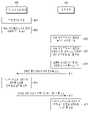
도 5는 본 발명의 다양한 실시예에 따른 무선 전력 송신 장치의 동작 방법을 설명하기 위한 흐름도를 도시한다.5 is a flowchart illustrating an operating method of an apparatus for transmitting power wirelessly according to various embodiments of the present disclosure.
501 동작에서, 무선 전력 송신 장치(100)는 전자 장치(150)를 검출할 수 있다. 503 동작에서, 무선 전력 송신 장치(100)는 무선 전력 송신 장치(100)로부터 전자 장치(150)까지의 거리를 판단할 수 있다. 505 동작에서, 무선 전력 송신 장치(100)는 거리가 임계치를 초과하는지 여부를 판단할 수 있다. 임계치는, 전자기파 방식으로 전력을 송신하는 것이 공진 방식 또는 유도 방식으로 전력을 송신하는 것보다 유리한 것으로 실험등을 통하여 정하여진 수치일 수 있다. 예를 들어, 전자기파 방식으로 전력을 송신하는 경우의 효율이 공진 방식 또는 유도 방식으로 전력을 송신하는 경우의 효율과 동일한 경우의 거리가 임계치로 설정될 수 있다. 또는, 전자기파 방식으로 전력을 송신하는 경우의 수신 세기가 공진 방식 또는 유도 방식으로 전력을 송신하는 경우의 수신 세기와 동일한 경우의 거리가 임계치로 설정될 수 있다. 임계치는, 다양한 조건에 의하여 설정될 수 있다.In
거리가 임계치 초과인 것으로 판단되면, 507 동작에서, 무선 전력 송신 장치(100)는 복수 개의 패치 안테나를 이용하여 전력을 송신할 수 있다. 즉, 무선 전력 송신 장치(100)는 충전 방식을 전자기파 방식으로 선택할 수 있다. 거리가 임계치 이하인 것으로 판단되면, 509 동작에서, 무선 전력 송신 장치(100)는 코일 또는 공진 회로를 이용하여 전력을 송신할 수 있다. 즉, 무선 전력 송신 장치(100)는 충전 방식을 공진 방식 또는 유도 방식으로 선택할 수 있다.If it is determined that the distance exceeds the threshold, in
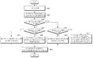
도 6a는 본 발명의 다양한 실시예에 따른 무선 전력 송신 장치 및 전자 장치의 동작 방법을 설명하기 위한 흐름도를 도시한다.6A is a flowchart illustrating an operating method of an apparatus for transmitting power wirelessly and an electronic device according to various embodiments of the present disclosure;
601 동작에서, 무선 전력 송신 장치(100)는 전자 장치(150)를 검출할 수 있다. 603 동작에서, 무선 전력 송신 장치(100)는 복수 개의 충전 방식에 따라 시험용 전력을 송신할 수 있다. 예를 들어, 무선 전력 송신 장치(100)는, 전자기파 방식에 따라 복수 개의 패치 안테나를 통하여 제 1 시험용 전력을 송신할 수 있으며, 동시에 또는 순차적으로 공진 방식에 따라 코일(또는, 공진 회로)을 통하여 제 2 시험용 전력을 송신할 수 있다.In
605 동작에서, 전자 장치(150)는 복수 개의 전력 수신 회로를 통하여 전력을 수신할 수 있다. 전자 장치(101)는 복수 개의 패치 안테나를 통하여 제 1 시험용 전력을 수신하며, 코일(또는, 공진 회로)을 통하여 제 2 시험용 전력을 수신할 수 있다. 607 동작에서, 전자 장치(150)는 복수 개의 전력 수신 회로와 연관된 전압, 전류 또는 전력의 크기 중 적어도 하나를 검출할 수 있다. 상술한 바와 같이, 전자 장치(150)는, 복수 개의 전력 수신 회로로부터 출력되는 전압, 전류, 또는 전력의 크기 중 적어도 하나를 검출할 수 있으며, 예를 들어 복수 개의 전력 수신 회로 각각에 연결되는 정류 회로의 입력단 또는 출력단에서의 전압, 전류, 또는 전력의 크기 중 적어도 하나를 검출할 수도 있으며, 검출 지점에는 제한이 없음을 당업자는 용이하게 이해할 수 있을 것이다.In
609 동작에서, 전자 장치(150)는, 검출된 수치의 비교 결과에 기초하여, 충전 방식을 선택할 수 있다. 전자 장치(150)는, 예를 들어 제 1 시험용 전력을 정류하는 제 1 정류 회로(예: 도 4a의 452)의 출력단에서의 전압의 크기가 제 2 시험용 전력을 정류하는 제 2 정류 회로(예: 도 4a의 472)의 출력단에서의 전압의 크기보다 큰 것으로 판단되면, 전자 장치(150)는 제 1 시험용 전력에 대응하는 전자기파 방식을 충전 방식으로 선택할 수 있다. 또는, 전자 장치(150)는, 예를 들어 제 1 시험용 전력을 정류하는 제 1 정류 회로(예: 도 4a의 452)의 출력단에서의 전압의 크기가 제 2 시험용 전력을 정류하는 제 2 정류 회로(예: 도 4a의 472)의 출력단에서의 전압의 크기보다 작은 것으로 판단되면, 전자 장치(150)는 제 2 시험용 전력에 대응하는 공진 방식 또는 유도 방식을 충전 방식으로 선택할 수 있다. 전력이 가장 큰 크기로 수신되는 충전 방식이 선택되며, 이는 충전 시간이 가장 짧은 충전 방식이 선택되는 것일 수도 있다. 즉, 무선 전력 송신 장치(100) 또는 전자 장치(150)는, 충전 시간이 가장 짧을 것으로 예상되는 충전 방식을 선택할 수도 있다.In
본 발명의 다양한 실시예에서, 전자 장치(150)는 임계치 비교 방식에 따라 충전 방식을 선택할 수 있다. 전자 장치(150)는, 제 1 정류 회로(예: 도 4a의 452)의 출력단에서의 전압의 크기가 임계치를 초과하면, 전자기파 방식을 충전 방식으로 선택할 수 있다. 전자 장치(150)는, 제 2 시험용 전력을 정류하는 제 2 정류 회로(예: 도 4a의 472)의 출력단에서의 전압의 크기가 임계치보다 큰 것으로 판단되면, 제 2 시험용 전력에 대응하는 유도 방식 또는 공진 방식을 충전 방식으로 선택할 수 있다. 제 1 정류 회로(예: 도 4a의 452)의 출력단에서의 전압의 크기와 제 2 시험용 전력을 정류하는 제 2 정류 회로(예: 도 4a의 472)의 출력단에서의 전압의 크기가 모두 임계치를 초과하면 전자 장치(150)는, 두 개의 전자기파 방식과, 유도 방식 또는 공진 방식을 모두 충전 방식으로 선택할 수도 있다. 본 발명의 다양한 실시예에서, 제 1 정류 회로(예: 도 4a의 452)의 출력단의 전압에 대응하는 임계치와 제 2 정류 회로(예: 도 4a의 472)의 출력단의 전압에 대응하는 임계치는 서로 동일할 수도 있고, 또는 다를 수도 있다. 예를 들어, 전자기파 방식을 이용하기 위한 최저 전압값과 유도 방식 또는 공진 방식을 이용하기 위한 최저 전압값이 서로 다를 수도 있다. 본 발명의 다양한 실시예에서, 제 1 정류 회로(예: 도 4a의 452)의 출력단에서의 전압의 크기와 제 2 시험용 전력을 정류하는 제 2 정류 회로(예: 도 4a의 472)의 출력단에서의 전압의 크기가 모두 임계치 이하인 경우에는, 무선 전력 송신 장치(100)는, 충전을 수행하지 않거나, 또는 상대적인 비교 방식에 따라 더 큰 전압값을 가지는 충전 방식을 선택할 수도 있다.In various embodiments of the present disclosure, the
611 동작에서, 전자 장치(150) 선택된 충전 방식에 대한 정보를 무선 전력 송신 장치(100)로 송신할 수 있다. 선택된 충전 방식에 따라 정보를 송신하기 위한 네트워크가 상이할 수도 있다. 예를 들어, 공진 방식 또는 전자기파 방식인 경우에는, 전자 장치(150)는 BLE 통신 모듈 등의 아웃 밴드 통신을 위한 하드웨어를 통하여 정보를 송신할 수 있다. 예를 들어, 유도 방식인 경우에는, 전자 장치(150)는 내부에 배치된 온/오프 키잉 변조 방식을 위한 스위치를 온/오프함에 따라 정보를 송신할 수도 있다. 613 동작에서, 무선 전력 송신 장치(100)는 수신된 정보에 기초하여, 전력을 송신할 전력 송신 회로를 선택할 수 있다. 615 동작에서, 무선 전력 송신 장치(100)는 선택된 전력 송신 회로를 이용하여 에너지를 송신할 수 있다. 617 동작에서, 전자 장치(150)는 선택된 충전 방식에 대응하는 전력 수신 회로를 이용하여 에너지를 수신할 수 있다.In
도 6b는 본 발명의 다양한 실시예에 따른 무선 전력 송신 장치 및 전자 장치의 동작 방법을 설명하기 위한 흐름도를 도시한다. 601 동작 내지 607 동작에 대하여서는 도 6a를 통하여 설명하였기 때문에, 여기에서의 설명은 생략하도록 한다.6B is a flowchart illustrating an operating method of an apparatus for transmitting power wirelessly and an electronic device according to various embodiments of the present disclosure; Since
621 동작에서, 전자 장치(101)는 검출된 수치를 통신 신호에 포함시켜 무선 전력 송신 장치(100)로 송신할 수 있다. 623 동작에서, 무선 전력 송신 장치(100)는 검출된 수치의 비교 결과에 기초하여, 충전 방식을 선택할 수 있다. 도 6a에서 설명한 바와 같이, 예를 들어 제 1 시험용 전력을 정류하는 제 1 정류 회로(예: 도 4a의 452)의 출력단에서의 전압의 크기가 제 2 시험용 전력을 정류하는 제 2 정류 회로(예: 도 4a의 472)의 출력단에서의 전압의 크기보다 큰 것으로 판단되면, 무선 전력 송신 장치(100)는 제 1 시험용 전력에 대응하는 전자기파 방식을 충전 방식으로 선택할 수 있다.In
625 동작에서, 무선 전력 송신 장치(100)는 선택된 충전 방식에 대응하는 전력을 송신할 전력 송신 회로를 선택할 수 있다. 예를 들어, 전자기파 방식을 충전 방식으로 선택한 경우에, 무선 전력 송신 장치(100)는 복수 개의 패치 안테나를 전력을 송신할 전력 송신 회로로 선택할 수 있다. 627 동작에서, 무선 전력 송신 장치(100)는 선택된 충전 방식에 대한 정보를 송신할 수 있다. 629 동작에서, 무선 전력 송신 장치(100)는 선택된 전력 송신 회로를 이용하여 에너지를 송신할 수 있다. 631 동작에서, 전자 장치(150)는 선택된 충전 방식에 대응하는 전력 수신 회로를 이용하여 에너지를 수신할 수 있다.In
도 6a 및 6b에서 설명한 바와 같이, 다양한 실시예들에 따라서 충전 방식은 무선 전력 송신 장치(100)가 선택할 수도 있으며, 또는 전력을 수신하는 전자 장치(150)가 선택할 수도 있다.As described with reference to FIGS. 6A and 6B , according to various embodiments, the charging method may be selected by the
도 7a는 본 발명의 다양한 실시예에 따른 무선 전력 송신 장치 및 전자 장치의 동작 방법을 설명하기 위한 흐름도를 도시한다.7A is a flowchart illustrating an operating method of an apparatus for transmitting power wirelessly and an electronic device according to various embodiments of the present disclosure;
701 동작에서, 전자 장치(150)는 전자 장치(150)가 지원하는 충전 방식에 대한 정보를 송신할 수 있다. 예를 들어, 전자 장치(150)가 BLE 기반 통신 회로를 포함하는 경우에는, 전자 장치(150)는 BLE 표준에서 정의된 애드버타이즈먼트 신호에 충전 방식에 대한 정보를 포함시켜 송신할 수 있다. 전자 장치(150)는 충전 방식에 대한 정보를 코드화하여 송신할 수 있다. 본 발명의 다양한 실시예에서, 전자 장치(150)는, BLE 표준에서 정의된 다른 신호에 충전 방식에 대한 정보를 포함시켜 송신할 수도 있다. 또는, 전자 장치(150)는 다양한 통신 방식에서 정의된 신호에 충전 방식에 대한 정보를 포함시켜 송신할 수 있다.In
703 동작에서, 무선 전력 송신 장치(100)는 수신된 정보에 기초하여, 전자 장치(150)를 복수 개의 패치 안테나를 이용하여 충전할지 또는 전자 장치(150)를 근거리 충전을 위한 코일을 이용하여 충전할지를 선택할 수 있다. 예를 들어, 전자 장치(150)가 공진 방식만을 지원하는 경우에는, 무선 전력 송신 장치(100)는 전자 장치(150)까지의 거리가 도 5에서 설명하였던 임계치를 초과하는 경우에도, 공진 방식을 충전 방식으로 선택할 수 있다. 705 동작에서, 무선 전력 송신 장치(100)는 선택된 전력 송신 회로를 이용하여 에너지를 송신할 수 있다. 707 동작에서, 전자 장치(150)는 무선 전력 송신 장치(150)로부터의 에너지를 이용하여 충전을 수행할 수 있다.In
도 7b는 본 발명의 다양한 실시예에 따른 무선 전력 송신 장치 및 전자 장치의 동작 방법을 설명하기 위한 흐름도를 도시한다. 도 7b의 실시예는 도 7c를 참조하여 더욱 상세하게 설명하도록 한다. 도 7c는 본 발명의 다양한 실시예에 따른 전자 장치의 충전 방식 선택 입력을 위한 사용자 인터페이스를 도시한다.7B is a flowchart illustrating an operating method of an apparatus for transmitting power wirelessly and an electronic device according to various embodiments of the present disclosure; The embodiment of FIG. 7B will be described in more detail with reference to FIG. 7C. 7C illustrates a user interface for inputting a charging method selection input of an electronic device according to various embodiments of the present disclosure.
710 동작에서, 전자 장치(150)는 충전 방식 선택을 수신할 수 있다. 예를 들어, 도 7c에서와 같이, 전자 장치(150)는 충전 방식 선택 입력을 위한 사용자 인터페이스(730)를 터치스크린 상에 표시할 수 있다. 본 발명의 다양한 실시예에서, 전자 장치(150)는 무선 전력 송신 장치(100)가 지원하는 충전 방식에 대한 정보를 수신할 수도 있으며, 무선 전력 송신 장치(100)가 지원하는 충전 방식과 전자 장치(150)가 지원하는 충전 방식 중 공통된 충전 방식들로 사용자 인터페이스(730)를 구성할 수 있다. 사용자 인터페이스(730)에는 충전 방식 식별 정보(731,733)와, 충전 방식 선택을 위한 키(732,734)를 포함할 수 있다. 사용자 인터페이스(730)는 충전 방식 식별 정보(731,733) 필드에 해당 충전 방식에 대응하는 완충 예상 시간을 포함할 수도 있다. 도 7c에서는 근거리 충전이 충전 방식으로 충전을 수행할 것으로 선택될 수 있다.In
711 동작에서, 전자 장치(150)는 선택된 충전 방식에 대한 정보를 무선 전력 송신 장치(100)로 송신할 수 있다. 713 동작에서, 무선 전력 송신 장치(100)는 수신된 정보에 기초하여, 전자 장치(150)를 복수 개의 패치 안테나를 이용하여 충전할지 또는 전자 장치(150)를 근거리 충전을 위한 코일을 이용하여 충전할지를 선택할 수 있다. 예를 들어, 사용자가 근거리 충전을 선택한 경우에는, 무선 전력 송신 장치(100)는, 공진 방식 또는 유도 방식을 충전 방식으로 선택할 수 있다. 715 동작에서, 무선 전력 송신 장치(100)는 선택된 전력 송신 회로를 이용하여 에너지를 송신할 수 있다. 717 동작에서, 전자 장치(150)는 무선 전력 송신 장치(150)로부터의 에너지를 이용하여 충전을 수행할 수 있다.In
도 8a는 본 발명의 다양한 실시예에 따른 무선 전력 송시 장치 및 전자 장치의 동작 방법을 설명하기 위한 흐름도를 도시한다.8A is a flowchart illustrating a method of operating a wireless power transmitting device and an electronic device according to various embodiments of the present disclosure;
801 동작에서, 무선 전력 송신 장치(100)는 전자 장치를 검출할 수 있다. 803 동작에서, 무선 전력 송신 장치(100)는 복수 개의 충전 방식에 따라 시험용 전력을 동시에 또는 순차적으로 송신할 수 있다. 예를 들어, 무선 전력 송신 장치는 전자기파 방식으로 제 1 시험용 전력을 송신하고, 공진 방식으로 제 2 시험용 전력을 송신할 수 있다. 805 동작에서, 전자 장치(150)는 복수 개의 전력 수신 회로를 통하여 전력을 수신할 수 있다. 807 동작에서, 전자 장치(150)는 복수 개의 전력 수신 회로와 연관된 전압, 전류 또는 전력의 크기 중 적어도 하나를 검출할 수 있다.In
809 동작에서, 무선 전력 송신 장치(100)는 에너지 송신 세기에 대한 정보를 송신할 수 있다. 예를 들어, 무선 전력 송신 장치(100)는 제 1 시험용 전력의 송신 세기에 대한 정보 및 제 2 시험용 전력의 송신 세기에 대한 정보를 하나의 통신 신호 또는 복수 개의 통신 신호로 전자 장치(150)로 송신할 수 있다. 811 동작에서, 전자 장치(150)는 검출된 수치 및 에너지 송신 세기에 대한 정보를 이용하여, 복수 개의 충전 방식 각각에 대한 효율을 판단할 수 있다. 다른 실시예에서는, 전자 장치(150)는 에너지의 수신 세기를 측정할 수도 있으며, 에너지 송신 세기 및 에너지 수신 세기를 이용하여 송신 효율을 판단할 수도 있다.In
813 동작에서, 전자 장치(150)는 판단된 효율에 기초하여, 충전 방식을 선택할 수 있다. 예를 들어, 전자 장치(150)는 더 높은 효율을 가지는 충전 방식을 선택할 수 있다. 815 동작에서, 전자 장치(150)는 선택된 충전 방식에 대한 정보를 무선 전력 송신 장치(100)로 송신할 수 있다. 817 동작에서, 무선 전력 송신 장치(100)는 수신된 정보에 기초하여, 전력을 송신할 전력 송신 회로를 선택할 수 있다. 즉, 무선 전력 송신 장치(100)는 충전 방식을 수신된 정보에 기초하여 선택할 수 있다. 819 동작에서, 무선 전력 송신 장치(100)는 선택된 전력 송신 회로를 이용하여 에너지를 송신할 수 있다. 821 동작에서, 전자 장치(150)는 선택된 충전 방식에 대응하는 전력 수신 회로를 이용하여 에너지를 수신할 수 있다. 상술한 바에 따라서, 최적의 효율로 전력이 송신될 수 있으며, 이에 따라 절전 관리가 가능할 수 있다.In
도 8b는 본 발명의 다양한 실시예에 따른 무선 전력 송시 장치 및 전자 장치의 동작 방법을 설명하기 위한 흐름도를 도시한다. 801 동작 내지 807 동작에 대하여서는 도 8a를 통하여 설명하였기 때문에, 여기에서의 설명은 생략하도록 한다.8B is a flowchart illustrating a method of operating a wireless power transmitting device and an electronic device according to various embodiments of the present disclosure. Since
831 동작에서, 전자 장치(150)는 검출 결과를 송신할 수 있다. 본 발명의 다양한 실시예에서, 전자 장치(150)는 에너지의 수신 세기를 검출하고, 전력의 수신 세기를 무선 전력 송신 장치(100)로 송신할 수도 있다. 833 동작에서, 무선 전력 송신 장치(100)는 에너지 송신 세기 및 수신된 검출 결과를 이용하여 복수 개의 충전 방식 각각에 대한 효율을 판단할 수 있다. 또는, 무선 전력 송신 장치(100)는 에너지 송신 세기 및 전자 장치(150)에서의 에너지의 수신 세기에 기초하여 송신 효율을 판단할 수 있다. 835 동작에서, 무선 전력 송신 장치(100)는 판단된 효율에 기초하여, 충전 방식을 선택할 수 있다. 예를 들어, 무선 전력 송신 장치(100)는 더 높은 효율을 가지는 충전 방식을 선택할 수 있다. 837 동작에서, 무선 전력 송신 장치(100)는 선택된 충전 방식에 대한 정보를 송신할 수 있다. 839 동작에서, 무선 전력 송신 장치(100)는 수신된 정보에 기초하여, 전력을 송신할 전력 송신 회로를 선택할 수 있다. 841 동작에서, 무선 전력 송신 장치(100)는 선택된 전력 송신 회로를 이용하여 에너지를 송신할 수 있다. 843 동작에서, 전자 장치(150)는 선택된 충전 방식에 대응하는 전력 수신 회로를 이용하여 에너지를 수신할 수 있다.In
도 8a 및 8b에서 설명한 바와 같이, 다양한 실시예들에 따라서 충전 방식은 송신 효율에 기초하여 무선 전력 송신 장치(100)가 선택할 수도 있으며, 또는 전력을 수신하는 전자 장치(150)가 선택할 수도 있다.As described with reference to FIGS. 8A and 8B , according to various embodiments, the charging method may be selected by the
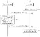
도 9는 본 발명의 다양한 실시예에 따른 무선 전력 송신 장치의 동작 방법을 설명하기 위한 흐름도를 도시한다.9 is a flowchart illustrating an operating method of an apparatus for transmitting power wirelessly according to various embodiments of the present disclosure.
901 동작에서, 무선 전력 송신 장치(100)는 전자 장치(150)를 검출할 수 있다. 903 동작에서, 상술한 바와 같이, 무선 전력 송신 장치(100)는 무선 전력 송신 장치(100) 및 전자 장치(150) 사이의 거리, 전자 장치(150)에서 수신되는 에너지의 크기, 또는 효율 중 적어도 하나에 기초하여, 복수 개의 충전 방식 중 제 1 충전 방식을 선택할 수 있다.In
905 동작에서, 무선 전력 송신 장치(100)는 제 1 충전 방식인 경우, 전기장 또는 자기장과 관련된 규약을 위배하는지 여부를 판단할 수 있다. 예를 들어, FCC(federal communications commission) 등의 단체에서는, 전기장 또는 자기장의 간섭(electromagnetic interference: EMI)과 관련된 규약을 배포하였으며, 무선 전력 송신 장치(100)는 관련된 규약을 준수하여야 한다. 아울러, 무선 충전 관련 표준(예: WPC 표준 또는 A4WP 표준)에서도, 최대 전송량 또는 최소 전송량 등에 대하여 규제를 하고 있으며, 무선 전력 송신 장치(100)는 해당 규제를 준수하여야 한다. 이에 따라, 무선 전력 송신 장치(100)는, 결정된 제 1 충전 방식에 따라 송신하는 경우에 관련 규약을 위배하는지 여부를 판단할 수 있다. 관련 규약에 대한 파라미터들과, 파라미터의 수치에 대한 조건이 무선 전력 송신 장치(100)에 미리 저장될 수 있으며, 무선 전력 송신 장치(100)는 미리 저장된 파라미터에 대응하는 수치를 검출하고, 검출 결과가 미리 저장된 조건을 만족하는지 여부를 판단함으로써 규약 준수 또는 위배 여부를 판단할 수 있다.In
규약을 준수하는 것으로 판단되면, 907 동작에서, 무선 전력 송신 장치(100)는 선택된 제 1 충전 방식에 따라 충전을 수행할 수 있다. 규약을 위배하는 것으로 판단되면, 909 동작에서, 무선 전력 송신 장치(100)는, 제 1 충전 방식에서 제 2 충전 방식으로 변경하고, 제 2 충전 방식에 따라 충전을 수행할 수 있다.If it is determined that the protocol is complied with, in
본 발명의 다양한 실시예에서, 무선 전력 송신 장치(100)는 제 1 충전 방식 및 제 2 충전 방식을 모두 이용하여 충전을 수행하도록 결정할 수도 있다. 예를 들어, 전자 장치(150)가 급속 충전을 요구하는 경우에, 무선 전력 송신 장치(100)는 복수 개의 충전 방식을 동시에 이용하여 전자 장치(150)에 전력을 송신할 수도 있다. 무선 전력 송신 장치(100)는, 전자 장치(150)에 대한 동시 충전 조건이 충족된 것으로 판단되면, 제 1 충전 방식 및 제 2 충전 방식을 모두 이용하여 충전을 수행하도록 결정할 수 있다. 복수 개의 충전 방식으로 동시에 전력을 송신하는 경우에도, 무선 전력 송신 장치(100)는 관련 규약 위배 여부를 판단할 수 있으며, 만약 관련 규약을 위배하는 것으로 판단되면, 복수 개의 충전 방식 중 적어도 하나의 충전 방식을 이용한 전력 송신을 중단하고, 나머지 충전 방식을 이용하여 전력을 송신할 수도 있다.In various embodiments of the present disclosure, the
도 10a는 본 발명의 다양한 실시예에 따른 무선 전력 송신 장치의 동작 방법을 설명하기 위한 흐름도를 도시한다. 도 10a의 실시예는 도 10b를 참조하여 더욱 상세하게 설명하도록 한다. 도 10b는 본 발명의 다양한 실시예에 따른 무선 전력 송신 장치 및 생체의 배치를 설명하기 위한 개념도를 도시한다.10A is a flowchart illustrating an operating method of an apparatus for transmitting power wirelessly according to various embodiments of the present disclosure. The embodiment of FIG. 10A will be described in more detail with reference to FIG. 10B. 10B is a conceptual diagram illustrating the arrangement of a wireless power transmitter and a living body according to various embodiments of the present invention.
1001 동작에서, 무선 전력 송신 장치(100)는 전자 장치(150)를 검출할 수 있다. 1003 동작에서, 무선 전력 송신 장치(100)는 무선 전력 송신 장치(100) 및 전자 장치(150) 사이의 거리, 전자 장치(150)에서 수신되는 에너지의 크기, 또는 효율 중 적어도 하나에 기초하여, 복수 개의 충전 방식 중 제 1 충전 방식을 선택할 수 있다.In
1005 동작에서, 무선 전력 송신 장치(100)는 제 1 충전 방식으로 충전을 수행하는 경우에, 생체에 영향을 미치는지 여부를 판단할 수 있다. 예를 들어, 도 10b에서와 같이 생체(1030)가 무선 전력 송신 장치(100)의 주변에 위치할 수 있다. 무선 전력 송신 장치(100)는 비젼 인식 또는 레이더 인식 등의 다양한 방법에 따라 생체(1030)의 위치를 판단할 수 있다. 생체에 영향을 미치지 않는 것으로 판단되면, 1007 동작에서, 무선 전력 송신 장치(100)는 제 1 충전 방식에 따라 충전을 수행할 수 있다. 생체에 영향을 미치는 것으로 판단되면, 1009 동작에서, 무선 전력 송신 장치(100)는 제 2 충전 방식에 따라 충전을 수행할 수 있다.In
예를 들어, 도 10b에서와 같이, 무선 전력 송신 장치(100)는 TV(1011)의 근처에 위치할 수 있다. 무선 전력 송신 장치(100)는 제 1 범위(1022)에 전자 장치(150)가 위치한 경우에는 공진 방식을 통하여 전자 장치(150)를 충전하고, 제 1 범위(1022)를 벗어나 제 2 범위(1023)에 전자 장치(150)가 위치한 경우에는 전자기파 방식을 통하여 전자 장치(150)를 충전하도록 설정될 수 있다. 전자 장치(150)가 제 1 범위(1022)에 포함된 것으로 판단되므로, 무선 전력 송신 장치(100)는 공진 방식에 기초하여 자기장(1021)을 형성할 수 있다. 다만, 자기장(1021)이 생체(1030)에 영향을 미치는 것으로 판단되면, 무선 전력 송신 장치(100)는 도 10b의 오른쪽에서와 같이 전자 장치(150)를 전자기파 방식을 통하여 충전하도록 판단할 수 있다. 무선 전력 송신 장치(100)는 RF 웨이브(1024)를 형성할 수 있으며, RF 웨이브(1024)는 전자 장치(150)의 위치에 빔-포밍되므로, 생체(1030)에 영향을 미치지 않을 수 있다. 도시되지는 않았지만, 무선 전력 송신 장치(100)는 전자기파 방식으로 충전 방식을 선택하였다가 공진 방식으로 충전 방식을 변경할 수도 있다. 예를 들어, 무선 전력 송신 장치(100)는 빔 포밍된 RF 웨이브가 형성되는 방향에 생체가 위치하는 것을 검출할 수도 있다. 이 경우, 무선 전력 송신 장치(100)는 공진 방식으로 충전 방식을 변경하여 전자 장치(150)에 전력을 송신할 수도 있다.For example, as shown in FIG. 10B , the
본 발명의 다양한 실시예에서, 무선 전력 송신 장치 또는 전자 장치는, 생체가 검출된다 하더라도 FCC 단체에서 제언된 SAR(specific absorption rate) 관련 규약이 위배되지 않는 것으로 판단되면, 선택된 충전 방식을 변경하지 않고 전력을 송신할 수도 있다.In various embodiments of the present invention, if it is determined that the wireless power transmission device or the electronic device does not violate the SAR (specific absorption rate) related protocol suggested by the FCC even if a living body is detected, the selected charging method is not changed It may transmit power.
도 11은 본 발명의 다양한 실시예에 따른 무선 전력 송신 장치 또는 전자 장치의 동작 방법을 설명하기 위한 흐름도를 도시한다. 도 11의 실시예는 도 12를 참조하여 더욱 상세하게 설명하도록 한다. 도 12는 본 발명의 다양한 실시예에 따른 무선 전력 송신 장치 또는 전자 장치의 충전 방식 변경을 유도하기 위한 사용자 인터페이스를 도시한다.11 is a flowchart illustrating a method of operating a wireless power transmission device or an electronic device according to various embodiments of the present disclosure. The embodiment of FIG. 11 will be described in more detail with reference to FIG. 12 . 12 illustrates a user interface for inducing a change in a charging method of a wireless power transmitter or an electronic device according to various embodiments of the present disclosure.
1101 동작에서, 무선 전력 송신 장치(100) 또는 전자 장치(150)는 제 1 충전 방식에 따라 충전을 수행할 수 있다. 무선 전력 송신 장치(100)는, 제 1 충전 방식에 대응하는 전력 송신 회로를 통하여 전력을 송신할 수 있으며, 전자 장치(150)는 제 1 충전 방식에 대응하는 전력 수신 회로를 통하여 전력을 수신할 수 있다. 1103 동작에서, 무선 전력 송신 장치(100) 또는 전자 장치(150)는 제 2 충전 방식을 유도하기 위한 UI를 제공할 수 있다. 무선 전력 송신 장치(100) 또는 전자 장치(150)는 제 1 충전 방식에 의한 송신 효율이 임계치 미만이거나, 또는 제 1 충전 방식에 의하여 전자 장치(150)에서 수신되는 전력의 세기가 임계치 미만인 경우에 제 2 충전 방식으로의 전환을 위한 UI를 제공할 수 있다. 또는, 무선 전력 송신 장치(100) 또는 전자 장치(150)는, 전자 장치(150)의 배터리 잔량이 기준치 미만인 경우에, 제 2 충전 방식으로의 전환을 위한 UI를 제공할 수 있다. 또는, 무선 전력 송신 장치(100) 또는 전자 장치(150)는, 전자 장치(150)의 전력 소모량이 증가하는 경우에, 제 2 충전 방식으로의 전환을 위한 UI를 제공할 수 있다. 이 경우에는, 어플리케이션 사용 중에도, 전자 장치(150)가 제 2 충전 방식으로의 전환을 위한 UI를 제공할 수 있다. 또는, 무선 전력 송신 장치(100) 또는 전자 장치(150)는, 무선 전력 송신 장치(100)에서 제 2 충전 방식으로 충전가능한 전력의 크기가 임계치를 초과하는 경우에, 제 2 충전 방식으로의 전환을 위한 UI를 제공할 수 있다. 예를 들어, 무선 전력 송신 장치(100)가 제 2 충전 방식으로 다른 전자 장치를 충전하다가, 다른 전자 장치가 완충되면, 제 2 충전 방식으로의 전환을 위한 UI를 제공할 수 있다.In
예를 들어, 도 12에서와 같이, 무선 전력 송신 장치(100)는 TV(1210)에 데이터(1211)를 송신할 수 있다. 무선 전력 송신 장치(100)는 제 2 충전 방식으로의 전환을 유도하는 UI(1232)를 표시하도록 하는 명령을 포함하는 데이터(1211)를 TV(1210)로 송신할 수 있다. 무선 전력 송신 장치(100)가 디스플레이를 포함한다면, 무선 전력 송신 장치(100)가 제 2 충전 방식으로의 전환을 유도하는 UI를 표시할 수도 있다. 또는, 무선 전력 송신 장치(100)는 제 2 충전 방식으로의 전환을 유도하는 UI(1231)를 표시하도록 하는 명령을 포함하는 데이터(1200)를 전자 장치(150)로 송신할 수도 있다. 예를 들어, “one-connect box”는 무선 전력 송신 장치(100)를 포함하는 장치의 모델명일 수 있으며, 사용자에게 친숙한 명칭으로 UI(1231)가 구성될 수 있다. 또는, 전자 장치(150)는, 제 1 충전 방식에 의한 송신 효율이 임계치 미만이거나, 또는 제 1 충전 방식에 의하여 전자 장치(150)에서 수신되는 전력의 세기가 임계치 미만인 경우에 제 2 충전 방식으로의 전환을 위한 UI(1231)를 표시할 수도 있다. 본 발명의 다양한 실시예에서, 무선 전력 송신 장치(100)는, 화면뿐만 아니라, 소리, 진동, LED 점멸 등의 다양한 방식을 통하여 제 2 충전 방식으로의 전환을 유도하는 UI를 제공할 수도 있다.For example, as shown in FIG. 12 , the wireless
1105 동작에서, 무선 전력 송신 장치(100) 또는 전자 장치(150)는 충전 방식 변경 조건이 만족되는지 여부를 판단할 수 있다. 예를 들어, 충전 방식 변경 조건은, 무선 전력 송신 장치(100) 및 전자 장치(150) 사이의 거리가 임계치 이하이다가 임계치를 초과하는 것이거나 또는 무선 전력 송신 장치(100) 및 전자 장치(150) 사이의 거리가 임계치 초과다가 임계치 이하로 감소하는 것일 수 있다. 사용자는 UI를 확인하고, 전자 장치(150)를 무선 전력 송신 장치(100) 측으로 이동시킬 수 있다. 이에 따라, 전자 장치(150)가 무선 전력 송신 장치(100)에 상대적으로 근접하여 위치할 수 있다. 무선 전력 송신 장치(100) 또는 전자 장치(150)는, 무선 전력 송신 장치(100) 및 전자 장치(150) 사이의 거리가 임계치 이하인 것을 판단할 수 있다. 1107 동작에서, 무선 전력 송신 장치(100) 또는 전자 장치(150)는 제 2 충전 방식에 따라 충전을 수행할 수 있다.In
도 13은 본 발명의 다양한 실시예에 따른 무선 전력 송신 장치 또는 전자 장치의 동작 방법을 설명하기 위한 흐름도를 도시한다. 도 13의 실시예는 도 14를 참조하여 더욱 상세하게 설명하도록 한다. 도 14는 본 발명의 다양한 실시예에 따른 전자 장치에 표시되는 충전 방식과 연관된 정보를 도시한다.13 is a flowchart illustrating a method of operating a wireless power transmitter or an electronic device according to various embodiments of the present disclosure. The embodiment of FIG. 13 will be described in more detail with reference to FIG. 14 . 14 illustrates information related to a charging method displayed on an electronic device according to various embodiments of the present disclosure.
1301 동작에서, 무선 전력 송신 장치(100) 또는 전자 장치(150)는 제 1 충전 방식에 따라 충전을 수행할 수 있다. 예를 들어, 무선 전력 송신 장치(100)는 전자기파 방식에 따라 복수 개의 패치 안테나를 통하여 전력을 송신할 수 있으며, 전자 장치(150)는 전자기파 방식에 따라 복수 개의 패치 안테나를 통하여 전력을 수신할 수 있다. 1303 동작에서, 무선 전력 송신 장치(100) 또는 전자 장치(150)는 제 1 충전 방식과 연관된 정보 및 제 2 충전 방식과 연관된 정보를 표시할 수 있다. 예를 들어, 도 14에서와 같이, 전자 장치(150)는 충전 방식들과 연관된 정보들(1401,1403)을 표시할 수 있다. 제 1 충전 방식과 연관된 정보(1401)는, 전자기파 방식을 나타내는 식별 정보(예: 원거리 충전), 전자기파 방식에 따라 충전 중인지 여부를 나타내는 정보(예: 충전 중), 충전율을 나타내는 정보(예: 83%), 완충 예상 시간(예: 약 59분 후 충전 완료) 등을 포함할 수 있다. 제 2 충전 방식과 연관된 정보(1402)는, 공진 방식을 나타내는 식별 정보(예: 공진 고속 충전), 공진 방식 충전 가부를 나타내는 정보(예: 충전 가능), 완충 예상 시간(예: 약 9분 후 충전 완료) 등을 포함할 수 있다. 도시되지는 않았지만, 무선 전력 송신 장치(100) 또한 충전 방식과 연관된 정보를 직접 표시하거나 또는 TV 등의 다른 전자 장치를 통하여 표시하도록 제어할 수도 있다. 또는, 충전 전력의 크기, 감도 등 또한 표시될 수도 있다.In
1305 동작에서, 무선 전력 송신 장치(100) 또는 전자 장치(150)는 무선 충전 방식 변경 명령이 입력되는지 판단할 수 있다. 예를 들어, 도 14b에서 사용자가 제 2 충전 방식과 연관된 정보(1402)를 지정할 수 있다. 전자 장치(150)는, 충전 방식과 연관된 정보가 지정되는 것을, 지정된 방식으로 충전 방식을 변경하는 것으로 미리 설정될 수 있다. 이에 따라, 제 2 충전 방식과 연관된 정보(1402)의 지정에 대응하여, 전자 장치(150)는 제 1 충전 방식으로부터 제 2 충전 방식으로 충전 방식을 변경할 수 있다. 1307 동작에서, 전자 장치(150)는 제 2 충전 방식에 따라 충전을 수행할 수 있다.In
본 발명의 다양한 실시예에서, 전자 장치(150)는 도 14와 같은 정보를, 충전 시작 시에 애니메이션으로 표시할 수도 있으며, 또는 상태 표시 줄 등에 표시할 수도 있다. 전자 장치(150)는 다른 어플리케이션 실행 중에도, 관련 정보를 표시할 수도 있다.According to various embodiments of the present disclosure, the
도 15는 본 발명의 다양한 실시예에 따른 무선 전력 송신 장치 또는 전자 장치의 동작 방법을 설명하기 위한 흐름도를 도시한다.15 is a flowchart illustrating a method of operating a wireless power transmitter or an electronic device according to various embodiments of the present disclosure.
1501 동작에서, 무선 전력 송신 장치(100) 또는 전자 장치(150)는 제 1 충전 방식에 따라 충전을 수행할 수 있다. 예를 들어, 무선 전력 송신 장치(100)는 전자기파 방식에 따라 복수 개의 패치 안테나를 통하여 전력을 송신할 수 있으며, 전자 장치(150)는 전자기파 방식에 따라 복수 개의 패치 안테나를 통하여 전력을 수신할 수 있다. 1503 동작에서, 무선 전력 송신 장치(100) 또는 전자 장치(150)는, 무선 전력 송신 장치(100) 및 전자 장치(150) 사이의 거리, 전자 장치(150)에서 수신되는 에너지의 크기, 효율, 규약 위배 여부 또는 생체 영향 여부 중 적어도 하나를 모니터링할 수 있다.In
1505 동작에서, 무선 전력 송신 장치(100) 또는 전자 장치(150)는 모니터링 결과에 기초하여, 제 2 충전 방식이 제 1 충전 방식에 비하여 유리한지를 판단할 수 있다. 무선 전력 송신 장치(100) 또는 전자 장치(150)가 제 2 충전 방식이 제 1 충전 방식에 비하여 유리하다고 판단되는 예시들은 도 16a 내지 16c를 참조하여 더욱 상세하게 설명하도록 하나. 제 2 충전 방식이 제 1 충전 방식에 비하여 유리하다고 판단되면, 1507 동작에서 무선 전력 송신 장치(100) 또는 전자 장치(150)는 제 2 충전 방식에 따라 충전을 수행할 수 있다.In
도 16a 내지 16c는 본 발명의 다양한 실시예에 따른 충전 방식 변경 과정을 설명하기 위한 개념도들을 도시한다.16A to 16C are conceptual diagrams illustrating a charging method change process according to various embodiments of the present disclosure.
도 16a를 참조하면, 무선 전력 송신 장치(100)는 제 1 범위(1600) 내에 전자 장치(150)가 위치하면 공진 방식에 따라 충전하도록 설정되고, 제 1 범위(1600) 밖에 전자 장치(150)가 위치하면 전자기파 방식에 따라 충전하도록 설정될 수 있다. 무선 전력 송신 장치(100)는, 제 1 시점에 전자 장치(150)가 제 1 범위(1600) 내에 위치한 것으로 판단할 수 있다. 무선 전력 송신 장치(100)는 공진 방식에 따라 코일(또는, 공진 회로)을 통하여 자기장(1611)을 형성함으로써 전자 장치(150)로 전력을 송신할 수 있다. 무선 전력 송신 장치(100)는, 무선 전력 송신 장치(100) 및 전자 장치(150) 사이의 거리를 모니터링할 수 있다.Referring to FIG. 16A , the
제 2 시점에서, 전자 장치(150)는 제 1 범위(600) 밖으로 이동(1601)할 수 있다. 예를 들어, 사용자는 전자 장치(150)를 가지고 제 1 범위(600) 밖으로 이동할 수 있다. 무선 전력 송신 장치(100)는 무선 전력 송신 장치(100) 및 전자 장치(150) 사이의 거리가 증가하여, 전자 장치(150)가 제 1 범위(1600) 밖에 위치하는 것을 판단할 수 있다. 무선 전력 송신 장치(100)는, 이에 따라 전자 장치(150)를 전자기파 방식으로 충전하는 것으로 판단할 수 있다. 무선 전력 송신 장치(100)는 전자기파 방식에 대응하는 복수 개의 패치 안테나를 통하여 RF 웨이브(1612)를 형성함으로써 전자 장치(150)로 전력을 송신할 수 있다.At a second time point, the
도 16b를 참조하면, 무선 전력 송신 장치(100)는 제 1 범위(1600) 내에 전자 장치(150)가 위치하면 공진 방식에 따라 충전하도록 설정되고, 제 1 범위(1600) 밖에 전자 장치(150)가 위치하면 전자기파 방식에 따라 충전하도록 설정될 수 있다. 제 1 시점에서, 무선 전력 송신 장치(100)는 다른 전자 장치(1620)를 식별하여 충전을 수행할 수 있다. 무선 전력 송신 장치(100)는 다른 전자 장치(1620)가 제 1 범위(1600) 내에 포함되었음에 따라, 다른 전자 장치(1620)를 공진 방식으로 충전할 수 있다. 무선 전력 송신 장치(100)는 코일(또는, 공진 회로)을 통하여 자기장(1621)을 형성함으로써 다른 전자 장치(1620)로 전력을 송신할 수 있다. 제 2 시점에서, 전자 장치(150)가 제 1 범위(1600) 내에 배치될 수 있다. 무선 전력 송신 장치(100)는, 전자 장치(150)가 제 1 범위(1600) 내에 배치됨을 판단할 수 있으며, 이에 따라 전자 장치(150)를 공진 방식을 충전 방식으로 선택할 수 있다. 무선 전력 송신 장치(100)는 공진 방식으로 충전 시에 규약이 위배되는지 여부를 판단할 수 있다. 예를 들어, 공진 방식의 표준에서는 무선 전력 수신 장치에서 수신하여야 할 충전 전력의 최솟값을 제언할 수 있다. 무선 전력 송신 장치(100)는 전자 장치(150) 및 다른 전자 장치(1620)를 동시에 공진 방식으로 충전하는 경우에, 전자 장치(150)에 제언된 전력의 최솟값 미만의 전력이 송신됨을 판단할 수 있다. 이에 따라, 무선 전력 송신 장치(100)는 전자 장치(150)를 전자기파 방식으로 충전할 것으로 선택할 수 있다. 무선 전력 송신 장치(100)는 복수 개의 패치 안테나를 통하여 RF 웨이브(1622)를 형성함으로써 전자 장치(150)에 전력을 송신할 수 있다.Referring to FIG. 16B , the
제 3 시점에서, 다른 전자 장치(1620)가 제 1 범위(1600)의 외부로 이동할 수 있다. 무선 전력 송신 장치(100)는, 규약 위배 여부를 모니터링할 수 있다. 예를 들어, 무선 전력 송신 장치(100)는, 전자 장치(150)를 단독으로 충전하는 경우에는, 제언된 전력의 최솟값 이상의 전력이 전자 장치(150)로 송신 가능한 것으로 판단할 수 있다. 무선 전력 송신 장치(100)는, 공진 방식으로 충전을 수행하더라도 규약이 위배되지 않는 것에 기초하여, 전자 장치(150)를 공진 방식으로 충전할 수 있다. 무선 전력 송신 장치(100)는 코일(또는, 공진 회로)을 통하여 자기장(1621)을 형성함으로써 전자 장치(150)로 전력을 송신할 수 있다.At the third time point, the other
또는, 무선 전력 송신기(100)는, 제 2 시점에서는 공진 방식에 의하면 무선 전력 송신기(100)로부터 전자 장치(150)로 송신되는 전력의 송신 효율이 임계치 이하인 것에 기초하여, 전자 장치(150)를 전자기파 방식에 따라 충전할 수 있다. 무선 전력 송신기(100)는 공진 방식에 대응하는 송신 효율을 모니터링할 수 있다. 예를 들어, 무선 전력 송신기(100)는, 주기적으로 공진 방식에 따라 충전을 수행하고, 전자 장치(100)로부터 수신 세기 또는 검출된 전류, 전압 또는 전력의 크기 등에 기초하여 공진 방식에 따른 송신 효율을 모니터링할 수도 있다. 다른 전자 장치(1620)가 사라진 제 3 시점에서, 무선 전력 송신기(100)는 공진 방식에 의하면 무선 전력 송신기(100)로부터 전자 장치(150)로 송신되는 전력의 송신 효율이 임계치 초과인 것으로 판단할 수 있다. 무선 전력 송신기(100)는, 이에 대응하여 충전 방식을 공진 방식으로 변경하고, 자기장(1621)을 형성함으로써 전자 장치(150)를 충전할 수도 있다.Alternatively, at the second time point, the
도 16c를 참조하면, 무선 전력 송신 장치(100)는 제 1 범위(1600) 내에 전자 장치(150)가 위치하면 공진 방식에 따라 충전하도록 설정되고, 제 1 범위(1600) 밖에 전자 장치(150)가 위치하면 전자기파 방식에 따라 충전하도록 설정될 수 있다. 제 1 시점에서, 전자 장치(150)가 제 1 범위(1600) 안에 배치될 수 있다. 제 1 시점에서, 제 1 범위(1600) 안에는 생체(1632)가 위치할 수도 있다. 무선 전력 송신 장치(100)는, 전자 장치(150)가 제 1 범위(1600) 안에 배치된 것에 따라 충전 방식을 공진 방식으로 선택할 수 있다. 무선 전력 송신 장치(100)는 공진 방식에 의하여 자기장을 형성한 경우에, 생체(1632)에 자기장이 영향을 미치는 것을 판단할 수 있다. 이에 따라, 무선 전력 송신 장치(100)는 생체(1632)에 영향을 미치지 않도록, 충전 방식을 전자기파 방식으로 선택할 수 있다. 무선 전력 송신 장치(100)는, 전자 장치(150)의 위치에 RF 웨이브(1631)를 빔 포밍할 수 있으며, 생체(1632)는 자기장 또는 전기장의 영향을 받지 않을 수 있다.Referring to FIG. 16C , the
무선 전력 송신 장치(100)는, 생체 영향 여부를 모니터링할 수 있다. 제 2 시점에서, 생체(1632)는 제 1 범위(1600) 밖으로 이동할 수 있다. 예를 들어, 무선 전력 송신 장치(100)는 비젼 인식 또는 레이더 인식에 따라 생체(1632)가 제 2 시점에서 제 1 범위(1600) 밖으로 이동하는 것을 판단할 수 있으며, 무선 전력 송신 장치(100)가 생체(1632)의 이동 여부를 판단하는 방법에는 제한이 없다. 무선 전력 송신 장치(100)는 공진 방식에 의하여 자기장을 형성하여도 생체(1632)에 영향을 미치지 않음을 확인할 수 있으며, 이에 대응하여 공진 방식을 충전 방식으로 선택할 수 있다. 무선 전력 송신 장치(100)는 공진 방식에 따라 자기장(1633)을 형성함으로써, 전자 장치(150)로 전력을 송신할 수 있다.The wireless
도 16a 내지 16c와 관련하여 무선 전력 송신 장치(100)가, 모니터링 및 충전 방식을 변경하는 것과 같이 설명되었지만, 이는 단순히 예시적인 것으로 상술한 바와 같이, 전자 장치(100)가 모니터링 및 충전 방식 변경을 수행할 수도 있다.Although the wireless
도 17은 본 발명의 다양한 실시예에 따른 무선 전력 송신 장치 및 복수 개의 전자 장치의 동작 방법을 설명하기 위한 흐름도를 도시한다.17 is a flowchart illustrating an operating method of an apparatus for transmitting power wirelessly and a plurality of electronic devices according to various embodiments of the present disclosure;
1701 동작에서, 무선 전력 송신 장치(100)는 제 1 전자 장치(1701)를 검출할 수 있다. 1703 동작에서, 무선 전력 송신 장치(100)는 제 1 전자 장치를 제 1 충전 방식에 따라 충전하기로 판단할 수 있다. 상술한 바와 같이, 무선 전력 송신 장치(100)는, 무선 전력 송신 장치(100) 및 제 1 전자 장치(1701) 사이의 거리, 제 1 전자 장치(1701)에서 수신되는 에너지의 크기, 효율, 규약 위배 여부 또는 생체 영향 여부 중 적어도 하나에 기초하여 제 1 충전 방식을 선택할 수 있다. 1705 동작에서, 무선 전력 송신 장치(100)는 제 1 충전 방식에 대응하는 전력 송신 회로를 이용하여 에너지를 송신할 수 있다.In
1707 동작에서, 무선 전력 송신 장치(100)는 제 2 전자 장치(1702)를 검출할 수 있다. 1709 동작에서, 무선 전력 송신 장치(100)는 제 1 전자 장치의 충전을 고려하여, 제 2 전자 장치의 충전 방식을 제 1 충전 방식 또는 제 2 충전 방식 중 어느 하나로 선택할 수 있다. 예를 들어, 무선 전력 송신 장치(100)는, 무선 전력 송신 장치(100) 및 제 2 전자 장치(1702) 사이의 거리, 제 2 전자 장치(1702)에서 수신되는 에너지의 크기, 효율, 규약 위배 여부 또는 생체 영향 여부 중 적어도 하나에 기초하여, 제 2 전자 장치(1702)의 충전 방식을 제 1 충전 방식으로 선택할 수 있다. 무선 전력 송신 장치(100)는 제 1 충전 방식에 따라 제 1 전자 장치(1701) 및 제 2 전자 장치(1702) 모두를 충전하는 경우에, 양 전자 장치에 충분한 전력이 송신될 수 없음을 판단할 수 있다. 이에 따라, 무선 전력 송신 장치(100)는 제 2 전자 장치(1702)의 충전 방식을 제 2 충전 방식으로 선택할 수도 있다. 1711 동작에서, 무선 전력 송신 장치(100)는 선택된 충전 방식에 대응하는 전력 송신 회로를 이용하여 에너지를 송신할 수 있다. 무선 전력 송신 장치(100)는 전자 장치들(1701,1702)별로 식별자(ID)를 할당할 수도 있으며, 식별자별로 충전 방식, 충전 시간, 충전량 등을 관리할 수 있다. 무선 전력 송신 장치(100)는, 식별자 인식을 수신된 명령에 따라 수행할 수도 있다.In
도 18은 본 발명의 다양한 실시예에 따른 무선 전력 송신 장치의 동작 방법을 설명하기 위한 흐름도를 도시한다.18 is a flowchart illustrating an operating method of an apparatus for transmitting power wirelessly according to various embodiments of the present disclosure.
1801 동작에서, 무선 전력 송신 장치(100)는 제 1 전자 장치 및 제 2 전자 장치를 동시에 충전할 수 있다. 1803 동작에서, 무선 전력 송신 장치(100)는 제 1 전자 장치의 충전 완료 또는 제 1 전자 장치의 회수를 검출할 수 있다. 1805 동작에서, 무선 전력 송신 장치(100)는 제 2 전자 장치의 충전 방식을 다시 판단할 수 있다. 예를 들어, 무선 전력 송신 장치(100)는, 제 1 전자 장치는 제 1 충전 방식으로 충전하고, 제 2 전자 장치는 제 2 충전 방식으로 충전할 수 있다. 무선 전력 송신 장치(100)는, 제 1 전자 장치의 회수를 검출할 수 있으며, 제 2 전자 장치를 제 1 충전 방식에 따라 충전할지 또는 제 2 충전 방식에 따라 충전할지 판단할 수 있다. 예를 들어, 무선 전력 송신 장치(100)는 제 2 전자 장치를 제 1 충전 방식에 따라 충전하는 것이 더 효율이 높은 것을 판단할 수 있으며, 이에 따라 제 2 전자 장치의 충전 방식을 제 1 충전 방식으로 변경할 수 있다. 1807 동작에서, 무선 전력 송신 장치(100)는 다시 판단된 충전 방식에 대응하는 전력 송신 회로를 이용하여 에너지를 송신할 수 있다. 본 발명의 다양한 실시예에서, 무선 전력 송신 장치(100)는, 제 1 전자 장치가 완충된 경우에 보충전(auxiliary charging)을 수행할 수도 있다. 무선 전력 송신 장치(100)는, 제 1 전자 장치에 기존의 충전 전력의 크기보다 작은 보충전 전력을 송신함으로써, 제 1 전자 장치가 충전 완료 이후에 다시 방전되지 않고, 완충 상태를 유지할 수 있도록 할 수도 있다.In
도 19는 본 발명의 다양한 실시예에 따른 무선 전력 송신 장치의 동작 방법을 설명하기 위한 흐름도를 도시한다.19 is a flowchart illustrating an operating method of an apparatus for transmitting power wirelessly according to various embodiments of the present disclosure.
1901 동작에서, 무선 전력 송신 장치(100)는 전자 장치(150)를 검출할 수 있다. 1903 동작에서, 무선 전력 송신 장치(100)는 제 1 충전 방식에 따른 효율 및 제 2 충전 방식에 따른 효율을 판단할 수 있다. 1905 동작에서, 무선 전력 송신 장치(100)는 제 1 충전 방식의 효율이 임계 효율을 초과하는지 여부를 판단할 수 있다. 제 1 충전 방식의 효율이 임계 효율을 초과하는 것으로 판단되면, 1907 동작에서, 무선 전력 송신 장치(100)는 제 2 충전 방식 효율이 임계 효율을 초과하는지 여부를 판단할 수 있다. 제 1 충전 방식의 효율이 임계 효율을 초과하고, 제 2 충전 방식의 효율이 임계 효율을 초과하는 것으로 판단되면, 1909 동작에서 무선 전력 송신 장치(100)는 제 1 충전 방식 및 제 2 충전 방식을 동시에 이용하여 전자 장치(150)를 충전하기로 판단할 수 있다. 제 1 충전 방식 효율이 임계 효율을 초과하고, 제 2 충전 방식 효율이 임계 효율 이하인 것으로 판단되면, 1911 동작에서 무선 전력 송신 장치(100)는 제 1 충전 방식에 따라 전자 장치(150)를 충전하는 것으로 판단할 수 있다. 1905 동작에서 제 1 충전 방식 효율이 임계 효율 이하인 것으로 판단되면, 1913 동작에서 무선 전력 송신 장치(100)는 제 2 충전 방식의 효율이 임계 효율을 초과하는지 여부를 판단할 수 있다. 제 1 충전 방식 효율이 임계 효율 이하이고, 제 2 충전 방식 효율이 임계 효율을 초과하면, 1915 동작에 무선 전력 송신 장치(100)는 제 2 충전 방식에 따라 전자 장치를 충전하는 것으로 판단할 수 있다. 제 1 충전 방식 효율이 임계 효율 이하이고, 제 2 충전 방식 효율이 임계 효율 이하이면, 1917 동작에서 무선 전력 송신 장치(100)는 제 1 충전 방식의 효율 및 제 2 충전 방식의 효율을 비교하여, 더 높은 효율의 충전 방식에 따라 전자 장치(150)를 충전하는 것으로 판단할 수 있다. 1919 동작에서, 무선 전력 송신 장치(100)는 판단된 충전 방식에 대응하는 전력 송신 회로를 이용하여 에너지를 송신할 수 있다. 예를 들어, 제 1 충전 방식 및 제 2 충전 방식 모두를 이용하여 충전을 수행하도록 결정된 경우에는, 무선 전력 송신 장치(100)는 복수 개의 패치 안테나를 이용하여 RF 웨이브를 형성하면서, 코일(또는, 공진 회로)을 이용하여 자기장을 형성함으로써 전자 장치(150)에 전력을 송신할 수 있다.In
도 20a는 본 발명의 다양한 실시예에 따른 무선 전력 송신 장치의 전자 장치의 충전을 설명하기 위한 개념도를 도시한다.20A is a conceptual diagram illustrating charging of an electronic device of an apparatus for transmitting power wirelessly according to various embodiments of the present disclosure.
무선 전력 송신 장치(100)는 제 1 범위(2000) 내에 포함된 전자 장치에 대하여서는 공진 방식에 따라 충전을 수행하도록 설정되고, 제 1 범위(200) 밖에 위치한 전자 장치에 대하여서는 전자기파 방식에 따라 충전을 수행하도록 설정될 수 있다. 무선 전력 송신 장치(100)는, 공진 방식에 따라 자기장(2011)을 형성함으로써, TV(2002)에 전력을 송신할 수 있다. 무선 전력 송신 장치(100)는, 공진 방식 및 전자기파 방식을 모두 이용하여 제 1 전자 장치(2001)를 충전할 수 있다. 무선 전력 송신 장치(100)는, 공진 방식에 따라 자기장(2012)을 형성하고, 전자기파 방식에 따라 RF 웨이브(2013)를 형성함으로써 제 1 전자 장치(2001)에 전력을 송신할 수 있다. 무선 전력 송신 장치(100)는, 전자기파 방식에 따라 RF 웨이브(2014)를 형성함으로써 제 2 전자 장치(2003)에 전력을 송신할 수 있다. 무선 전력 송신기(100)는, 제 1 전자 장치(2001)의 위치에 빔 포밍을 수행하여 RF 웨이브(2013)를 형성할 수 있으며, 제 2 전자 장치(2003)의 위치에 빔 포밍을 수행하여 RF 웨이브(2014)를 형성할 수 있다.The
도 20b 및 20c는 본 발명의 다양한 실시예에 따른 복수 개의 위치에 대한 RF 웨이브 형성을 설명하기 위한 개념도를 도시한다.20B and 20C are conceptual diagrams for explaining RF wave formation for a plurality of positions according to various embodiments of the present disclosure.
도 20b를 참조하면, 본 발명의 다양한 실시예에서, 무선 전력 송신 장치(100)는 복수 개의 전자장치(2001,2003)의 위치를 결정할 수 있다. 예를 들어, 무선 전력 송신 장치(100)는 제1 전자장치(2001)로부터의 통신 신호에 기초하여 전자장치(2001)의 방향을 결정하고, 제2 전자장치(2003)로부터의 통신 신호에 기초하여 전자장치(2003)의 방향을 결정할 수 있다. 무선 전력 송신 장치(100)는 복수 개의 전자장치(2001,2003) 각각을 충전하기 위한 패치 안테나 그룹(2221,2222)을 판단할 수 있다. 무선 전력 송신 장치(100)는 패치 안테나 그룹(2221,2222)을 이용하여 복수 개의 전자장치(2001,2003)에 무선 충전을 수행할 수 있다. 무선 전력 송신 장치(100)는 패치 안테나 그룹(2221)을 이용하여 무선 충전을 수행할 수 있다. 또한, 무선 전력 송신 장치(100)는 패치 안테나 그룹(2222)을 이용하여 무선 충전을 수행할 수 있다.Referring to FIG. 20B , in various embodiments of the present disclosure, the
한편, 다른 실시예에서는, 상술한 바와 같이, 무선 전력 송신 장치(100)는 복수 개의 전자장치(2001,2003) 각각의 방향에 따라 패치 안테나 그룹(2221,2222)을 선택할 수 있다. 예를 들어, 무선 전력 송신 장치(100)의 상대적으로 좌측에 배치된 것으로 판단된 제 1 전자장치(2001)에 대하여서는 상대적으로 좌측에 배치되는 패치 안테나 그룹(2221)을 선택할 수 있으며, 무선 전력 송신 장치(100)의 상대적으로 우측에 배치된 것으로 판단된 제 2 전자장치(2003)에 대하여서는 상대적으로 우측에 배치되는 패치 안테나 그룹(2222)을 선택할 수 있다. 패치 안테나 그룹(2221)은 제 1 전자장치(2001)을 충전하기 위한 RF 웨이브(2013)를 형성할 수 있으며, 패치 안테나 그룹(2222)은 제 2 전자장치(2003)를 충전하기 위한 RF 웨이브(2014)를 형성할 수 있다.Meanwhile, in another embodiment, as described above, the
아울러, 무선 전력 송신 장치(100)는 복수 개의 전자장치(2001,2003) 각각의 정격 전력에 기초하여 패치 안테나 그룹에 포함되는 패치 안테나 개수를 선택할 수 있다. 예를 들어, 상대적으로 높은 정격 전력의 전자장치에 대하여서는 상대적으로 많은 개수의 패치 안테나를 할당할 수 있다. 상술한 바에 따라서, 복수 개의 전자장치(2001,2003)가 동시에 충전될 수 있다.In addition, the
도 20c를 참조하면, 무선 전력 송신 장치(100)는 복수 개의 전자장치(2001,2003)의 방향을 결정할 수 있다. 무선 전력 송신 장치(100)는 복수 개의 전자장치(2001,2003) 각각을 충전하기 위한 충전 시간을 분배할 수 있다. 무선 전력 송신 장치(100)는 분배된 충전 시간에 기초하여 복수 개의 전자장치(2001,2003)에 무선 충전을 수행할 수 있다. 예를 들어, 제 1 시간(t1) 동안에는 모든 패치 안테나(2223) 각각이 서브 RF 웨이브를 형성하도록 제어하여 제 1 전자장치(2001)를 충전하기 위한 RF 웨이브(2013)를 형성할 수 있으며, 제 2 시간(t2) 동안에는 패치 안테나 전체(2223)를 이용하여 제 2 전자장치(2003)를 충전하기 위한 RF 웨이브(2014)를 형성할 수 있다. 본 발명의 다양한 실시예에서, 무선 전력 송신 장치(100)는 복수 개의 전자 장치들(2001,2003)을 번갈아가면서 RF 웨이브를 형성할 수 있다.Referring to FIG. 20C , the
도 21은 본 발명의 다양한 실시예에 따른 전자 장치의 동작 방법을 설명하기 위한 흐름도를 도시한다.21 is a flowchart illustrating a method of operating an electronic device according to various embodiments of the present disclosure;
2101 동작에서, 전자 장치(150)는 무선 전력 송신 장치(100)를 검출할 수 있다. 2103 동작에서, 전자 장치(150)는 급속 충전 명령을 수신할 수 있다. 예를 들어, 전자 장치(150)는 급속 충전 명령을 입력할 수 있는 사용자 인터페이스를 표시할 수 있으며, 사용자 인터페이스를 통하여 급속 충전 명령을 수신할 수 있다. 또 다른 실시예에서, 전자 장치(150)는 급속 충전 개시 조건이 검출되면, 이에 대응하여 급속 충전을 개시할 수도 있다. 2105 동작에서, 전자 장치(150)는 급속 충전 요청을 송신할 수 있다.In
2107 동작에서, 무선 전력 송신 장치(100)는, 수신된 급속 충전 요청에 대응하여, 전자 장치(150)를 복수 개의 충전 방식에 따라 충전하는 것으로 판단할 수 있다. 2109 동작에서, 무선 전력 송신 장치(100)는, 복수 개의 충전 방식에 대응하는 복수 개의 전력 송신 회로를 통하여 에너지를 송신할 수 있다. 2111 동작에서, 전자 장치(150)는, 복수 개의 충전 방식에 대응하는 복수 개의 전력 수신 회로를 통하여 에너지를 수신할 수 있다. 이에 따라, 전자 장치(150)는 상대적으로 큰 크기의 전력을 수신할 수 있다.In operation 2107 , the
도 22a 내지 22f는 본 발명의 다양한 실시예에 따른 무선 전력 송신 장치의 배치를 설명하기 위한 개념도를 도시한다.22A to 22F are conceptual diagrams for explaining the arrangement of a wireless power transmission apparatus according to various embodiments of the present invention.
도 22a를 참조하면, 무선 전력 송신 장치(100)는, 데이터 송수신 장치(2200)에 포함될 수 있다. 데이터 송수신 장치(2200)는, TV(2201)와 데이터를 무선으로 송수신할 수 있다. 예를 들어, 데이터 송수신 장치(2200)는, 외부로부터 수신한 비디오 신호 또는 오디오 신호 중 적어도 하나를, 무선으로 TV(2201)로 송신할 수 있다. 무선 전력 송신 장치(100)는, 데이터 송수신 장치(2200)의 형상에 따라 좌우로 신장된 형상을 가질 수 있다. 아울러, 데이터 송수신 장치(2200)에 포함된 무선 전력 송신 장치(100)는, 무선으로 전력을 TV(2201)로 송신할 수 있다. 이에 따라, TV(2201)는 유선 연결 없이, 무선으로 전력과, 비디오 신호 또는 오디오 신호 중 적어도 하나를 수신할 수 있다. 예를 들어, 무선 전력 송신 장치(100)는, 공진 방식에 따라 자기장(2211,2212,2213)을 형성함으로써, TV(2201)로 전력을 송신할 수 있다. TV(2201)는 무선 전력 수신 장치(2203)를 포함할 수 있으며, 무선 전력 수신 장치(2203)는 예를 들어 주변에 생성된 자기장(2211,2212,2213)을 전류, 전압 또는 전력으로 변환할 수 있다. 예를 들어, 무선 전력 수신 장치(2203)는, 무선 전력 송신 장치(100)의 형상에 대응되도록 좌우로 신장된 형상을 가질 수 있다. 다양한 실시예에서, 무선 전력 송신 장치(100)는, 전자기파 방식에 따라 충전을 수행할 수도 있으며, 예를 들어 상대적으로 원거리에 위치한 전자 장치(2202)의 위치에 대하여 RF 웨이브(2214)를 형성할 수 있다. 한편, TV(2201)가 턴 오프된 경우에는, 무선 전력 송신 장치(100)는, 자기장을 형성함으로써 전자 장치(2202)를 충전할 수도 있다.Referring to FIG. 22A , the wireless
도 22b를 참조하면, 무선 전력 송신 장치(100)는, 오디오 장치(2214)에 포함될 수도 있다. 무선 전력 송신 장치(100)는, 오디오 장치(2214)의 형상에 따라 상하로 신장된 형상을 가질 수 있다. TV(2201)에 포함된 무선 전력 수신 장치(2205)는 무선 전력 송신 장치(100)의 형상에 따라 상하로 신장된 형상을 가질 수 있다. 무선 전력 송신 장치(100)는, 자기장(2215)을 형성함으로써 무선 전력 수신 장치(2205)로 전력을 송신할 수 있다. 무선 전력 송신 장치(100)는 RF 웨이브(2216)를 형성함으로써 전자 장치(2202)로 전력을 송신할 수 있다.Referring to FIG. 22B , the
도 22c를 참조하면, 무선 전력 송신 장치(100)는, 공진 방식 또는 유도 방식에 따른 전력 송신 회로(2231), 제어 회로(2232) 및 전자기파 방식에 따른 전력 송신 회로(2233)를 포함할 수 있다. 상술한 바와 같이, 전력 송신 회로(2231)는, 예를 들어, 100 내지 205 kHz, 또는 6.78 MHz의 주파수를 가지는 전력을 제공하는 전력 소스, 증폭 회로, 코일, 또는 커패시터 중 적어도 하나를 포함할 수 있다. 전력 송신 회로(2233)는, 예를 들어, 5.8 GHz의 주파수를 가지는 전력을 제공하는 전력 소스, 증폭 회로, 분배 회로, 위상 쉬프터, 또는 패치 안테나 어레이 중 적어도 하나를 포함할 수 있다. 전력 송신 회로(2233)는, 상대적으로 상측 방향으로 RF 웨이브(2234)를 향하여 형성되도록 배치될 수 있다. 무선 전력 송신 장치(100)가 예를 들어 바닥에 배치되는 경우에는, 전자 장치(150)가 무선 전력 송신 장치(100)에 비하여 상측에 위치할 가능성이 크다. 이에 따라, RF 웨이브(2234)가 상측 방향을 향할 수 있도록 패치 안테나 어레이가 바닥면에 대하여 경사지게 배치될 수도 있다. 제어 회로(2232)는, 예를 들어 통신 회로 또는 프로세서를 포함할 수 있으며, 전자 장치(150)와의 통신을 수행하거나 또는 전력 송신 회로(2231) 또는 전력 송신 회로(2233)의 전력 송신을 제어할 수 있다. 도 22d를 참조하면, 전력 송신 회로(2233)이 바닥에 대하여 실질적으로 수직하도록 배치될 수도 있다. 예를 들어, 무선 전력 송신 장치(100)가 배치된 높이가, 전자 장치(150)가 주로 배치되는 높이와 유사한 경우에는, RF 웨이브(2234)가 바닥에 대하여 평행하게 형성될 수 있다. 도 22c 및 22d에서 도시된 바와 같이, 무선 전력 송신 장치(100)의 배치 위치에 따라 전자기파 방식의 패치 안테나 어레이의 배치 방향이 달라질 수도 있다. 본 발명의 다양한 실시예에 따른 무선 전력 송신 장치(100)는 패치 안테나 어레이의 배치 방향을 기계적으로 조정하기 위한 액츄에이터를 포함할 수도 있다. 무선 전력 송신 장치(100)는 전자 장치가 위치하는 위치 또는 방향에 따라 패치 안테나 어레이의 배치 방향을 기계적으로 변경할 수도 있다.Referring to FIG. 22C , the wireless
도 22e를 참조하면, TV(2240)는 디스플레이(2241) 및 본체(2242)를 포함할 수 있다. 본체(2242) 내에는 자기장(2245)을 생성할 수 있는 전력 송신 회로 및 RF 웨이브(2246)를 생성할 수 있는 전력 송신 회로를 포함할 수 있다. 이에 따라, 본체(2242)로부터 형성된 자기장(2245) 및 RF 웨이브(2246)를 이용하여 전자 장치들(2243,2244)이 충전될 수 있다. 도 22f를 참조하면, TV(2240)는 지지 구조(2250)에 의하여 지지될 수 있다. 지지 구조(2250) 내에 배치되는 무선 전력 송신 장치(100)는 자기장(2247)을 생성하는 전력 송신 회로 및 RF 웨이브(2248)를 형성하는 전력 송신 회로를 포함할 수 있다. 이에 따라, 무선 전력 송신 장치(100)로부터 형성된 자기장(2247) 및 RF 웨이브(2248)를 이용하여 전자 장치들(2243,2244)이 충전될 수 있다. 무선 전력 송신 장치(100)의 배치 형태에 대하여서는 제한이 없으며, 예를 들어 무선 전력 송신 장치(100)는 책상 위 또는 책상 아래에 배치될 수도 있으며, 스마트 폰, 키보드, 마우스 등의 다양한 책상 상에 위치한 전자 장치들을 공진 방식, 유도 방식 또는 전자기파 방식 중 적어도 하나에 기초하여 충전할 수도 있다.Referring to FIG. 22E , a
도 23은 본 발명의 다양한 실시예에 따른 근거리 충전 및 원거리 충전의 판단 기준을 설명하기 위한 개념도를 도시한다.23 is a conceptual diagram illustrating a criterion for determining short-range charging and long-distance charging according to various embodiments of the present disclosure.
도 23에 도시된 바와 같이, 무선 전력 송신 장치(100)로부터의 거리가 제 1 거리(2311) 이하인 제 1 영역(2310)은, 근거리 충전 영역으로 설정될 수 있다. 무선 전력 송신 장치(100)의 거리가 제 1 거리(2311)를 초과하고 제 2 거리(2311) 이하인 제 2 영역(2320)은, 원거리 충전 영역으로 설정될 수 있다. 근거리 충전 영역에서는, 무선 전력 송신 장치(100)는 공진 방식 또는 유도 방식에 따라 자기장(2230)을 형성함으로써 전자 장치(2341)를 충전할 수 있다. 원거리 충전 영역에서는, 무선 전력 송신 장치(100)는 전자기파 방식에 따라 RF 웨이브(2331)를 형성함으로써 전자 장치(2342)를 충전할 수 있다. 본 발명의 다양한 실시예에서, 무선 전력 송신 장치(100)는, 예를 들어 공진 방식의 효율이 전자기파 방식의 효율보다 높은 범위, 공진 방식에 의하여 전자 장치가 수신하는 전력의 세기가 전자기파 방식에 의하여 전자 장치가 수신하는 전력의 세기보다 높은 범위 등을 제 1 영역(2310)으로 설정할 수 있다. 또는, 무선 전력 송신 장치(100)는, 공진 방식에 의한 전력 송신이 최적의 EMI 조건을 만족하는 범위 또는 자계의 크기가 기설정된 수치(예: 6.25μT) 이하인 범위 등을 제 1 영역(2310)으로 설정할 수 있다. 다양한 실시예에서, 무선 전력 송신 장치(100)는, 전자 장치의 종류에 따라 제 1 거리(2311)를 판단할 수도 있다. 예를 들어, TV와 같은 상대적으로 높은 리액턴스를 가지는 코일을 포함하는 전자 장치에 대하여서는, 무선 전력 송신 장치(100)는 제 1 거리(2311)를 상대적으로 크게 설정할 수 있다. 또는, 스마트폰과 같은 상대적으로 낮은 리액턴스를 가지는 코일을 포함하는 전자 장치에 대하여서는, 무선 전력 송신 장치(100)는 제 1 거리(2311)를 상대적으로 작게 설정할 수 있다.As shown in FIG. 23 , the
도 24a는 본 발명의 다양한 실시예에 따른 코일 및 패치 안테나 어레이의 위치를 설명하기 위한 평면도를 도시한다. 도 24a에 도시된 바와 같이, 복수 개의 패치 안테나를 포함하는 패치 안테나 어레이(2402)의 주변에 코일(2401)이 위치할 수 있다. 코일(2401)은 2회 권선된 것과 같이 도시되어 있지만, 이는 단순히 예시적인 것이며, 코일(2401)의 권선 횟수는 제한이 없다. 도 24b는 본 발명의 다양한 실시예에 따른 코일 및 패치 안테나 어레이의 위치를 설명하기 위한 제 1 방향에서 바라본 제 1 측면도이며, 도 24c는 사시도이며, 도 24d는 제 2 방향에서 바라본 제 2 측면도를 도시한다. 도 24b 내지 24d에 도시된 바와 같이, 코일(2401)의 좌우 방향으로 연장되는 일부는 곡선의 형태를 가질 수 있다. 곡선의 형태를 가지는 코일(2401)의 일부는 패치 안테나 어레이(2402)로부터 지정된 거리만큼 이격될 수 있다. 이에 따라, 코일(2401)에 의한 자기장과 패치 안테나 어레이(2402)로부터의 RF 웨이브가 간섭되지 않을 수 있다. 도 24e에서 도시된 바와 같이, 패치 안테나 어레이(2402)로부터의 RF 웨이브(2441)가 코일(2401)의 영향 없이 양호하게 형성될 수 있으며, 도 24f에서 도시된 바와 같이, 코일(2401)에서 형성된 자기장(2442)이 패치 안테나 어레이(2402)의 영향 없이 양호하게 형성될 수 있다. 본 발명의 다양한 실시예에 따른 전자 장치 또한 코일(2401) 및 패치 안테나 어레이(2402)를 포함할 수도 있다. 본 발명의 다양한 실시예에서, 코일(2401)은, 원형, 타원형 등의 다양한 형태로 구현될 수 있으며, 패치 안테나 어레이는 상대적으로 소형으로 제작될 수도 있으며, 플립 타입(flip type) 등으로 구현될 수도 있다.24A is a plan view illustrating a location of a coil and a patch antenna array according to various embodiments of the present disclosure. As shown in FIG. 24A , a
도 25는 본 발명의 다양한 실시예에 따른 코일 및 패치 안테나 어레이의 위치를 설명하기 위한 개념도를 도시한다. 도 25에 도시된 바와 같이, 제 1 면(2510)에는 코일(2500)이 배치될 수 있다. 제 2 면(2511)에는 패치 안테나 어레이(2501)가 배치될 수 있으며, 제 3 면(2512)에는 패치 안테나 어레이(2502)가 배치될 수 있다. 제 1 면(2510) 및 제 2 면(2511)이 이루는 제 1 각도(θ1) 및 제 1 면(2510) 및 제 3 면(2512)이 이루는 제 2 각도(θ2)는 동일하거나 상이할 수 있다. 제 1 각도(θ1) 또는 제 2 각도(θ2) 중 적어도 하나는, 프로세서에 의하여 기계적으로 조정될 수도 있으며, 무선 전력 송신 장치(100)는 각도들을 조정하기 위한 액츄에이터를 더 포함할 수도 있다.25 is a conceptual diagram illustrating a position of a coil and a patch antenna array according to various embodiments of the present invention. 25 , a
상기 전자 장치의 전술한 구성요소들 각각은 하나 또는 그 이상의 부품(component)으로 구성될 수 있으며, 해당 구성 요소의 명칭은 전자 장치의 종류에 따라서 달라질 수 있다. 다양한 실시예에서, 전자 장치는 전술한 구성요소 중 적어도 하나를 포함하여 구성될 수 있으며, 일부 구성요소가 생략되거나 또는 추가적인 다른 구성요소를 더 포함할 수 있다. 또한, 다양한 실시예에 따른 전자 장치의 구성 요소들 중 일부가 결합되어 하나의 개체(entity)로 구성됨으로써, 결합되기 이전의 해당 구성 요소들의 기능을 동일하게 수행할 수 있다.Each of the above-described components of the electronic device may be composed of one or more components, and the name of the corresponding component may vary depending on the type of the electronic device. In various embodiments, the electronic device may be configured to include at least one of the above-described components, and some components may be omitted or may further include additional other components. In addition, since some of the components of the electronic device according to various embodiments are combined to form a single entity, the functions of the components prior to being combined may be identically performed.
본 문서에서 사용된 용어 "모듈"은, 예를 들면, 하드웨어, 소프트웨어 또는 펌웨어(firmware) 중 하나 또는 둘 이상의 조합을 포함하는 단위(unit)를 의미할 수 있다. "모듈"은, 예를 들면, 유닛(unit), 로직(logic), 논리 블록(logical block), 부품(component), 또는 회로(circuit) 등의 용어와 바꾸어 사용(interchangeably use)될 수 있다. "모듈"은, 일체로 구성된 부품의 최소 단위 또는 그 일부가 될 수 있다. "모듈"은 하나 또는 그 이상의 기능을 수행하는 최소 단위 또는 그 일부가 될 수도 있다. "모듈"은 기계적으로 또는 전자적으로 구현될 수 있다. 예를 들면,"모듈"은, 알려졌거나 앞으로 개발될, 어떤 동작들을 수행하는 ASIC(application-specific integrated circuit) 칩, FPGAs(field-programmable gate arrays) 또는 프로그램 가능 논리 장치(programmable-logic device) 중 적어도 하나를 포함할 수 있다.As used herein, the term “module” may refer to, for example, a unit including one or a combination of two or more of hardware, software, and firmware. The term “module” may be used interchangeably with terms such as, for example, unit, logic, logical block, component, or circuit. A “module” may be a minimum unit or a part of an integrally configured component. A “module” may be a minimum unit or a part of performing one or more functions. A “module” may be implemented mechanically or electronically. For example, a “module” may be one of an application-specific integrated circuit (ASIC) chip, field-programmable gate arrays (FPGAs) or programmable-logic device, known or to be developed, that performs certain operations. It may include at least one.
다양한 실시예에 따른 장치(예: 모듈들 또는 그 기능들) 또는 방법(예: 동작들)의 적어도 일부는, 예컨대, 프로그램 모듈의 형태로 컴퓨터로 읽을 수 있는 저장매체(computer-readable storage media)에 저장된 명령어로 구현될 수 있다. 상기 명령어는, 프로세서에 의해 실행될 경우, 상기 하나 이상의 프로세서가 상기 명령어에 해당하는 기능을 수행할 수 있다. 컴퓨터로 읽을 수 있는 저장매체는, 예를 들면, 메모리가 될 수 있다.At least a portion of an apparatus (eg, modules or functions thereof) or a method (eg, operations) according to various embodiments is, for example, a computer-readable storage medium in the form of a program module It can be implemented as a command stored in . When the instruction is executed by a processor, the one or more processors may perform a function corresponding to the instruction. The computer-readable storage medium may be, for example, a memory.
본 발명의 다양한 실시예에 따르면, 명령들을 저장하고 있는 저장 매체에 있어서, 상기 명령들은 적어도 하나의 프로세서에 의하여 실행될 때에 상기 적어도 하나의 프로세서로 하여금 적어도 하나의 동작을 수행하도록 설정된 것으로서, 상기 적어도 하나의 동작은, 전자 장치를 검출하는 동작; 복수 개의 패치 안테나 또는 코일 중 적어도 하나를, 상기 전자 장치를 충전하기 위한 전력을 송신하기 위한 전력 송신 회로로 선택하는 동작; 및 상기 선택에 따라 상기 복수 개의 패치 안테나 또는 상기 코일 중 적어도 하나를 통하여, 상기 전력을 송신하도록 제어하는 동작을 포함할 수 있다.According to various embodiments of the present disclosure, in a storage medium storing instructions, the instructions are configured to cause the at least one processor to perform at least one operation when executed by the at least one processor, wherein the at least one The operation may include detecting an electronic device; selecting at least one of a plurality of patch antennas or coils as a power transmission circuit for transmitting power for charging the electronic device; and controlling to transmit the power through at least one of the plurality of patch antennas or the coil according to the selection.
본 발명의 다양한 실시예에 따르면, 명령들을 저장하고 있는 저장 매체에 있어서, 상기 명령들은 적어도 하나의 프로세서에 의하여 실행될 때에 상기 적어도 하나의 프로세서로 하여금 적어도 하나의 동작을 수행하도록 설정된 것으로서, 상기 적어도 하나의 동작은, 복수 개의 패치 안테나 또는 코일 중 적어도 하나를, 무선 전력 송신 장치로부터 전력을 수신하기 위한 전력 수신 회로로 선택하는 동작; 상기 선택된 전력 수신 회로에 대한 정보를, 상기 무선 전력 송신 장치로 송신하는 동작; 및 상기 선택에 따라 상기 복수 개의 패치 안테나 또는 상기 코일 중 적어도 하나를 통하여, 상기 전력을 수신하는 동작을 포함할 수 있다.According to various embodiments of the present disclosure, in a storage medium storing instructions, the instructions are configured to cause the at least one processor to perform at least one operation when executed by the at least one processor, wherein the at least one The operation may include selecting at least one of a plurality of patch antennas or coils as a power receiving circuit for receiving power from a wireless power transmitting apparatus; transmitting information on the selected power receiving circuit to the wireless power transmitting apparatus; and receiving the power through at least one of the plurality of patch antennas or the coil according to the selection.
상술한 바와 같은, 명령들은 외부 서버에 저장될 수 있으며, 무선 전력 송신기와 같은 전자 장치에 다운로드되어 설치될 수도 있다. 즉, 본 발명의 다양한 실시예에 의한 외부 서버는, 무선 전력 송신기가 다운로드할 수 있는 명령들을 저장할 수 있다.As described above, the commands may be stored in an external server, or downloaded and installed in an electronic device such as a wireless power transmitter. That is, the external server according to various embodiments of the present invention may store commands that the wireless power transmitter can download.
상기 컴퓨터로 판독 가능한 기록 매체는, 하드디스크, 플로피디스크, 마그네틱 매체(magnetic media)(예: 자기테이프), 광기록 매체(optical media)(예: CD-ROM(compact disc read only memory), DVD(digital versatile disc), 자기-광 매체(magneto-optical media)(예: 플롭티컬 디스크(floptical disk)), 하드웨어 장치(예: ROM(read only memory), RAM(random access memory), 또는 플래시 메모리 등) 등을 포함할 수 있다. 또한, 프로그램 명령에는 컴파일러에 의해 만들어지는 것과 같은 기계어 코드뿐만 아니라 인터프리터 등을 사용해서 컴퓨터에 의해서 실행될 수 있는 고급 언어 코드를 포함할 수 있다. 상술한 하드웨어 장치는 다양한 실시예의 동작을 수행하기 위해 하나 이상의 소프트웨어 모듈로서 작동하도록 구성될 수 있으며, 그 역도 마찬가지다.The computer-readable recording medium includes a hard disk, a floppy disk, magnetic media (eg, magnetic tape), optical media (eg, compact disc read only memory (CD-ROM), DVD). (digital versatile disc), magneto-optical media (eg, floptical disk), hardware device (eg, read only memory (ROM), random access memory (RAM), or flash memory etc.), etc. In addition, the program instructions may include not only machine language codes such as those generated by a compiler, but also high-level language codes that can be executed by a computer using an interpreter, etc. The above-described hardware device includes It may be configured to act as one or more software modules to perform the operations of various embodiments, and vice versa.
다양한 실시예에 따른 모듈 또는 프로그램 모듈은 전술한 구성요소들 중 적어도 하나 이상을 포함하거나, 일부가 생략되거나, 또는 추가적인 다른 구성요소를 더 포함할 수 있다. 다양한 실시예에 따른 모듈, 프로그램 모듈 또는 다른 구성요소에 의해 수행되는 동작들은 순차적, 병렬적, 반복적 또는 휴리스틱(heuristic)한 방법으로 실행될 수 있다. 또한, 일부 동작은 다른 순서로 실행되거나, 생략되거나, 또는 다른 동작이 추가될 수 있다.A module or a program module according to various embodiments may include at least one or more of the above-described components, some may be omitted, or may further include additional other components. Operations performed by a module, a program module, or other components according to various embodiments may be executed sequentially, in parallel, iteratively, or in a heuristic manner. Also, some operations may be executed in a different order, omitted, or other operations may be added.
그리고 본 문서에 개시된 실시예는 개시된, 기술 내용의 설명 및 이해를 위해 제시된 것이며, 본 개시의 범위를 한정하는 것은 아니다. 따라서, 본 개시의 범위는, 본 개시의 기술적 사상에 근거한 모든 변경 또는 다양한 다른 실시예를 포함하는 것으로 해석되어야 한다.In addition, the embodiments disclosed in this document are provided for description and understanding of the disclosed and technical content, and do not limit the scope of the present disclosure. Accordingly, the scope of the present disclosure should be construed to include all modifications or various other embodiments based on the technical spirit of the present disclosure.
Claims (37)
Translated fromKorean제2 충전 방식에 따라 상기 전자 장치로 전력을 전송하도록 구성된 코일;
통신 회로; 및
프로세서를 포함하고,
상기 프로세서는,
전자 장치를 검출하고,
상기 전자 장치의 검출에 대응하여, 상기 복수 개의 패치 안테나를 통한 제1 시험용 전력 및 상기 코일을 통한 제2 시험용 전력을 전송하고,
상기 제1 시험용 전력 및 상기 제2 시험용 전력의 전송에 대응하여, 상기 전자 장치를 충전하기 위한 적어도 하나의 충전 방식을 나타내는 정보를 상기 통신 회로를 통해 상기 전자 장치로부터 수신하고, 상기 적어도 하나의 충전 방식은 상기 제1 충전 방식 또는 상기 제2 충전 방식 중 적어도 하나를 포함하며,
상기 적어도 하나의 충전 방식을 나타내는 정보의 수신에 대응하여, 상기 복수 개의 패치 안테나 또는 상기 코일 중 적어도 하나의 전력 송신 회로를 선택하고,
상기 선택된 전력 송신 회로를 이용하여 상기 전자 장치를 충전하기 위한 전력을 송신하도록 제어하는 무선 전력 송신 장치.a plurality of patch antennas configured to transmit power to the electronic device according to the first charging scheme;
a coil configured to transmit power to the electronic device according to a second charging scheme;
communication circuit; and
including a processor;
The processor is
detecting electronic devices,
In response to the detection of the electronic device, transmitting the first test power through the plurality of patch antennas and the second test power through the coil,
In response to the transmission of the first test power and the second test power, information indicating at least one charging method for charging the electronic device is received from the electronic device through the communication circuit, and the at least one charging method is received from the electronic device. The method includes at least one of the first charging method or the second charging method,
In response to receiving the information indicating the at least one charging method, selecting at least one power transmission circuit among the plurality of patch antennas or the coil,
A wireless power transmission device for controlling to transmit power for charging the electronic device by using the selected power transmission circuit.
상기 무선 전력 송신 장치 및 상기 전자 장치 사이의 거리를 판단하고,
상기 거리에 기초하여, 상기 복수 개의 패치 안테나 또는 상기 코일 중 적어도 하나를, 상기 전자 장치를 충전하기 위한 전력 송신 회로로 선택하는 무선 전력 송신 장치.The method of claim 1, wherein the processor comprises:
determining a distance between the wireless power transmitter and the electronic device;
A wireless power transmission device for selecting at least one of the plurality of patch antennas and the coil as a power transmission circuit for charging the electronic device based on the distance.
상기 거리가 임계 거리를 초과하면, 상기 복수 개의 패치 안테나를 상기 전자 장치를 충전하기 위한 전력을 송신하기 위한 전력 송신 회로로 선택하거나, 또는
상기 거리가 상기 임계 거리 이하이면, 상기 코일을 상기 전자 장치를 충전하기 위한 전력을 송신하기 위한 전력 송신 회로로 선택하는 무선 전력 송신 장치.The method of claim 2, wherein the processor comprises:
When the distance exceeds the threshold distance, the plurality of patch antennas are selected as a power transmission circuit for transmitting power for charging the electronic device, or
If the distance is equal to or less than the threshold distance, the wireless power transmitter selects the coil as a power transmitter circuit for transmitting power for charging the electronic device.
미리 지정된 상기 임계 거리를 이용하여 상기 전자 장치를 충전하기 위한 전력을 송신하기 위한 전력 송신 회로로 선택하거나, 또는 상기 전자 장치에 대응하는 상기 임계 거리를 이용하여 상기 전자 장치를 충전하기 위한 전력을 송신하기 위한 전력 송신 회로로 선택하는 무선 전력 송신 장치.The method of claim 3, wherein the processor comprises:
Selecting as a power transmission circuit for transmitting power for charging the electronic device using the predetermined threshold distance, or transmitting power for charging the electronic device using the threshold distance corresponding to the electronic device A wireless power transmission device selected as a power transmission circuit for
상기 통신 회로를 통하여, 상기 제 1 시험용 전력이 상기 전자 장치에서 수신된 크기에 대한 제 1 정보 및 상기 제 2 시험용 전력이 상기 전자 장치에서 수신된 크기에 대한 제 2 정보를 수신하고,
상기 제 1 정보 및 상기 제 2 정보를 이용하여, 상기 복수 개의 패치 안테나 또는 상기 코일 중 적어도 하나를, 상기 전자 장치를 충전하기 위한 전력을 송신하기 위한 전력 송신 회로로 선택하는 무선 전력 송신 장치.The method of claim 1, wherein the processor comprises:
Receive, through the communication circuit, first information on the magnitude of the first test power received by the electronic device and second information on the magnitude of the second test power received by the electronic device,
A wireless power transmission apparatus for selecting at least one of the plurality of patch antennas and the coil as a power transmission circuit for transmitting power for charging the electronic device by using the first information and the second information.
상기 제 1 시험용 전력의 송신 세기 및 상기 제 2 시험용 전력의 송신 세기를, 상기 통신 회로를 통하여, 상기 전자 장치로 송신하고,
상기 전자 장치는, 상기 제 1 시험용 전력의 수신 세기 및 상기 제 2 시험용 전력의 수신 세기를 검출하고, 상기 제 1 시험용 전력의 송신 세기 및 상기 제 1 시험용 전력의 수신 세기에 기초하여 상기 제 1 시험용 전력의 송신 효율을 판단하고, 상기 제 2 시험용 전력의 송신 세기 및 상기 제 2 시험용 전력의 수신 세기에 기초하여 상기 제 2 시험용 전력의 송신 효율을 판단하고, 상기 제 1 시험용 전력의 송신 효율 및 상기 제 2 시험용 전력을 이용하여 상기 복수 개의 패치 안테나 또는 상기 코일 중 적어도 하나를, 상기 전자 장치를 충전하기 위한 전력을 송신하기 위한 전력 송신 회로로 선택하고, 상기 선택된 전자 장치를 충전하기 위한 전력을 송신하기 위한 전력 송신 회로에 대한 정보를 상기 무선 전력 송신 장치의 통신 회로로 송신하고,
상기 프로세서는, 상기 통신 회로를 통하여 수신된 정보에 기초하여, 상기 복수 개의 패치 안테나 또는 상기 코일 중 적어도 하나를, 상기 전자 장치를 충전하기 위한 전력을 송신하기 위한 전력 송신 회로로 선택하는 무선 전력 송신 장치.The method of claim 1, wherein the processor comprises:
transmitting the transmission strength of the first test power and the transmission strength of the second test power to the electronic device through the communication circuit;
The electronic device is configured to detect a reception intensity of the first test power and a reception intensity of the second test power, and based on the transmission intensity of the first test power and the reception intensity of the first test power, the first test power Determine the transmission efficiency of power, and determine the transmission efficiency of the second test power based on the transmission intensity of the second test power and the reception intensity of the second test power, the transmission efficiency of the first test power and the Using the second test power, at least one of the plurality of patch antennas or the coil is selected as a power transmission circuit for transmitting power for charging the electronic device, and transmitting power for charging the selected electronic device Transmitting information about the power transmission circuit to the communication circuit of the wireless power transmission device,
The processor, based on the information received through the communication circuit, wireless power transmission for selecting at least one of the plurality of patch antennas or the coil as a power transmission circuit for transmitting power for charging the electronic device Device.
상기 통신 회로를 통하여, 상기 제 1 시험용 전력의 상기 전자 장치에서의 수신 세기 및 상기 제 2 시험용 전력의 상기 전자 장치에서의 수신 세기를 수신하고,
상기 제 1 시험용 전력의 송신 세기 및 상기 제 1 시험용 전력의 수신 세기에 기초하여 상기 제 1 시험용 전력의 송신 효율을 판단하고, 상기 제 2 시험용 전력의 송신 세기 및 상기 제 2 시험용 전력의 수신 세기에 기초하여 상기 제 2 시험용 전력의 송신 효율을 판단하고,
상기 제 1 시험용 전력의 송신 효율 및 상기 제 2 시험용 전력을 이용하여 상기 복수 개의 패치 안테나 또는 상기 코일 중 적어도 하나를, 상기 전자 장치를 충전하기 위한 전력을 송신하기 위한 전력 송신 회로로 선택하는 무선 전력 송신 장치.The method of claim 1, wherein the processor comprises:
receiving, through the communication circuit, a reception intensity of the first test power in the electronic device and a reception intensity of the second test power in the electronic device;
The transmission efficiency of the first test power is determined based on the transmission intensity of the first test power and the reception intensity of the first test power, and the transmission intensity of the second test power and the reception intensity of the second test power Determining the transmission efficiency of the second test power based on,
Wireless power for selecting at least one of the plurality of patch antennas or the coil as a power transmission circuit for transmitting power for charging the electronic device by using the transmission efficiency of the first test power and the second test power sending device.
상기 제 1 시험용 전력의 송신 및 상기 제 2 시험용 전력의 송신에 따라, 지정된 규약의 위배 여부를 판단하고,
상기 판단 결과에 따라, 상기 복수 개의 패치 안테나 또는 상기 코일 중 적어도 하나를, 상기 전자 장치를 충전하기 위한 전력을 송신하기 위한 전력 송신 회로로 선택하는 무선 전력 송신 장치.The method of claim 1, wherein the processor comprises:
According to the transmission of the first test power and the second test power, it is determined whether a specified rule is violated;
A wireless power transmission apparatus for selecting at least one of the plurality of patch antennas or the coil as a power transmission circuit for transmitting power for charging the electronic device according to the determination result.
상기 무선 전력 송신 장치의 근처에 위치하는 생체를 검출하고,
상기 생체에 대한 영향 여부에 기초하여, 상기 복수 개의 패치 안테나 또는 상기 코일 중 적어도 하나를, 상기 전자 장치를 충전하기 위한 전력을 송신하기 위한 전력 송신 회로로 선택하는 무선 전력 송신 장치.The method of claim 1, wherein the processor comprises:
Detecting a living body located in the vicinity of the wireless power transmission device,
A wireless power transmission device for selecting at least one of the plurality of patch antennas or the coil as a power transmission circuit for transmitting power for charging the electronic device, based on whether the living body is affected.
상기 통신 회로를 통하여, 상기 전자 장치에 대한 정보를 수신하고,
상기 전자 장치에 대한 정보를 이용하여, 상기 복수 개의 패치 안테나 또는 상기 코일 중 적어도 하나를, 상기 전자 장치를 충전하기 위한 전력을 송신하기 위한 전력 송신 회로로 선택하는 무선 전력 송신 장치.The method of claim 1, wherein the processor comprises:
Receive information about the electronic device through the communication circuit,
A wireless power transmission apparatus for selecting at least one of the plurality of patch antennas or the coil as a power transmission circuit for transmitting power for charging the electronic device by using the information on the electronic device.
상기 통신 회로를 통하여, 상기 전자 장치의 사용자에 의하여 지정된 충전 방식에 대한 정보를 수신하고,
상기 수신된 지정된 충전 방식에 대한 정보에 기초하여, 상기 복수 개의 패치 안테나 또는 상기 코일 중 적어도 하나를, 상기 전자 장치를 충전하기 위한 전력을 송신하기 위한 전력 송신 회로로 선택하는 무선 전력 송신 장치.The method of claim 1, wherein the processor comprises:
receiving information on a charging method specified by a user of the electronic device through the communication circuit;
A wireless power transmission device for selecting at least one of the plurality of patch antennas or the coil as a power transmission circuit for transmitting power for charging the electronic device, based on the received information on the specified charging method.
상기 전력 송신 회로에 대한 정보는, 상기 전자 장치에서 상기 전력 송신 회로에 대한 정보에 대응하는 무선 전력 수신 회로를 통해, 상기 전력을 수신하는데 이용되는 무선 전력 송신 장치.The method of claim 1, wherein the processor transmits information on the selected power transmission circuit to the electronic device;
The information on the power transmission circuit is used to receive the power through a wireless power reception circuit corresponding to the information on the power transmission circuit in the electronic device.
제 1 시점에서, 상기 복수 개의 패치 안테나를 통하여 상기 전력을 송신하도록 제어하고,
제 2 시점에서, 상기 코일을 통하여 상기 전력을 송신하도록 제어하는 무선 전력 송신 장치.The method of claim 1, wherein the processor comprises:
At a first time point, control to transmit the power through the plurality of patch antennas,
At a second time point, a wireless power transmission device for controlling to transmit the power through the coil.
상기 전자 장치에 대한 동시 충전 조건이 충족된 것으로 판단되면,
상기 복수 개의 패치 안테나 및 상기 코일을 이용하여 상기 전력을 송신하도록 제어하는 무선 전력 송신 장치.The method of claim 1, wherein the processor comprises:
When it is determined that the simultaneous charging condition for the electronic device is satisfied,
A wireless power transmission apparatus for controlling to transmit the power using the plurality of patch antennas and the coil.
상기 복수 개의 패치 안테나를 통하여 상기 전자 장치로 상기 전력을 송신하고,
다른 전자 장치를 검출하고,
상기 코일을 통하여 상기 다른 전자 장치를 충전하기 위한 다른 전력을 송신하도록 제어하는 무선 전력 송신 장치.The method of claim 1, wherein the processor comprises:
transmitting the power to the electronic device through the plurality of patch antennas;
to detect other electronic devices,
A wireless power transmission device for controlling to transmit other power for charging the other electronic device through the coil.
상기 전자 장치가 회수된 것으로 판단되면, 상기 복수 개의 패치 안테나를 통하여 상기 다른 전자 장치를 충전하기 위한 또 다른 전력을 송신하도록 제어하는 무선 전력 송신 장치.The method of claim 17, wherein the processor comprises:
When it is determined that the electronic device has been recovered, the wireless power transmitter controls to transmit another power for charging the other electronic device through the plurality of patch antennas.
상기 코일은, 상기 복수 개의 패치 안테나를 둘러싸도록 권선된 무선 전력 송신 장치.The method of claim 1,
The coil is a wireless power transmission device wound to surround the plurality of patch antennas.
상기 코일의 일부는, 상기 패치 안테나로부터 지정된 거리만큼 이격될 수 있도록 곡선의 형태를 가지는 무선 전력 송신 장치.20. The method of claim 19,
A portion of the coil is a wireless power transmitter having a curved shape to be spaced apart from the patch antenna by a specified distance.
전자 장치를 검출하는 동작;
상기 전자 장치의 검출에 대응하여, 상기 복수 개의 패치 안테나를 통한 제1 시험용 전력 및 상기 코일을 통한 제2 시험용 전력을 전송하는 동작;
상기 제1 시험용 전력 및 상기 제2 시험용 전력의 전송에 대응하여, 상기 전자 장치를 충전하기 위한 적어도 하나의 충전 방식을 나타내는 정보를 통신 회로를 통해 상기 전자 장치로부터 수신하는 동작; 상기 적어도 하나의 충전 방식은 상기 복수 개의 패치 안테나를 통해 상기 전자 장치로 전력을 전송하는 제1 충전 방식 또는 상기 코일을 통해 상기 전자 장치로 전력을 전송하는 제2 충전 방식 중 적어도 하나를 포함하며,
상기 적어도 하나의 충전 방식을 나타내는 정보의 수신에 대응하여, 상기 복수 개의 패치 안테나 또는 상기 코일 중 적어도 하나의 전력 송신 회로로 선택하는 동작; 및
상기 선택된 전력 송신 회로를 이용하여 상기 전자 장치를 충전하기 위한 전력을 송신하도록 제어하는 동작을 포함하는 무선 전력 송신 장치의 동작 방법.A method of operating a wireless power transmission device including a plurality of patch antennas and coils, the method comprising:
detecting the electronic device;
transmitting first test power through the plurality of patch antennas and second test power through the coil in response to detection of the electronic device;
receiving information indicating at least one charging method for charging the electronic device from the electronic device through a communication circuit in response to transmission of the first test power and the second test power; The at least one charging method includes at least one of a first charging method for transmitting power to the electronic device through the plurality of patch antennas or a second charging method for transmitting power to the electronic device through the coil,
selecting at least one of the plurality of patch antennas and the coil as the power transmission circuit in response to the reception of the information indicating the at least one charging method; and
and controlling to transmit power for charging the electronic device by using the selected power transmission circuit.
Priority Applications (5)
| Application Number | Priority Date | Filing Date | Title |
|---|---|---|---|
| KR1020170051476AKR102392887B1 (en) | 2017-02-22 | 2017-04-21 | Wireless power transmitting device, electronic device for wirelessly receiving power and operation method thereof |
| PCT/KR2018/002066WO2018155881A1 (en) | 2017-02-22 | 2018-02-20 | Wireless power transmitter, electronic device receiving power wirelessly, and method for operating same |
| EP18757957.8AEP3565087B1 (en) | 2017-02-22 | 2018-02-20 | Wireless power transmitter |
| CN201880013381.3ACN110383630B (en) | 2017-02-22 | 2018-02-20 | Wireless power transmitter, electronic device wirelessly receiving power, and operating method thereof |
| US16/488,155US11183882B2 (en) | 2017-02-22 | 2018-02-20 | Wireless power transmitter, electronic device receiving power wirelessly, and method for operating same |
Applications Claiming Priority (3)
| Application Number | Priority Date | Filing Date | Title |
|---|---|---|---|
| US201762462020P | 2017-02-22 | 2017-02-22 | |
| US62/462,020 | 2017-02-22 | ||
| KR1020170051476AKR102392887B1 (en) | 2017-02-22 | 2017-04-21 | Wireless power transmitting device, electronic device for wirelessly receiving power and operation method thereof |
Publications (2)
| Publication Number | Publication Date |
|---|---|
| KR20180097111A KR20180097111A (en) | 2018-08-30 |
| KR102392887B1true KR102392887B1 (en) | 2022-05-03 |
Family
ID=63252837
Family Applications (1)
| Application Number | Title | Priority Date | Filing Date |
|---|---|---|---|
| KR1020170051476AActiveKR102392887B1 (en) | 2017-02-22 | 2017-04-21 | Wireless power transmitting device, electronic device for wirelessly receiving power and operation method thereof |
Country Status (2)
| Country | Link |
|---|---|
| KR (1) | KR102392887B1 (en) |
| WO (1) | WO2018155881A1 (en) |
Families Citing this family (5)
| Publication number | Priority date | Publication date | Assignee | Title |
|---|---|---|---|---|
| WO2020085519A1 (en)* | 2018-10-22 | 2020-04-30 | 삼성전기 주식회사 | Vehicle having data communication and power transmission functions relating to unmanned aerial vehicle, and signal transmission or reception method of vehicle |
| EP3861620A4 (en)* | 2018-11-06 | 2022-11-09 | Humavox Ltd. | A bi-functional receiving/ transmitting element for wireless charging |
| KR102146431B1 (en)* | 2018-12-05 | 2020-08-20 | 정도훈 | Bidirectional communication apparatus using digital information display |
| EP4156455A4 (en)* | 2020-11-04 | 2024-03-06 | Samsung Electronics Co., Ltd. | WIRELESS POWER SYSTEM, WIRELESS POWER TRANSMISSION APPARATUS, AND WIRELESS POWER TRANSMISSION APPARATUS CONTROL METHOD |
| KR20220140197A (en)* | 2021-04-09 | 2022-10-18 | 삼성전자주식회사 | electronic device including antenna and method for controlling antenna |
Citations (2)
| Publication number | Priority date | Publication date | Assignee | Title |
|---|---|---|---|---|
| US20150371771A1 (en)* | 2014-06-24 | 2015-12-24 | Board Of Trustees Of The University Of Alabama | Wireless power transfer systems and methods |
| US20160099756A1 (en)* | 2012-07-06 | 2016-04-07 | Energous Corporation | Systems and methods for wireless power transmission |
Family Cites Families (11)
| Publication number | Priority date | Publication date | Assignee | Title |
|---|---|---|---|---|
| EP2277252A4 (en)* | 2008-04-21 | 2017-04-26 | Qualcomm Incorporated | Short range efficient wireless power transfer |
| US9407327B2 (en)* | 2009-02-13 | 2016-08-02 | Qualcomm Incorporated | Wireless power for chargeable and charging devices |
| US8338991B2 (en)* | 2009-03-20 | 2012-12-25 | Qualcomm Incorporated | Adaptive impedance tuning in wireless power transmission |
| US8928284B2 (en)* | 2009-09-10 | 2015-01-06 | Qualcomm Incorporated | Variable wireless power transmission |
| KR101672736B1 (en)* | 2010-05-14 | 2016-11-04 | 삼성전자주식회사 | Apparatus and method for power and data transmission using mobile device |
| US20110309689A1 (en)* | 2010-06-17 | 2011-12-22 | Semiconductor Energy Laboratory Co., Ltd. | Electric power transmitting device, electric power receiving device, and power supply method using electric power transmitting and receiving devices |
| US9893768B2 (en) | 2012-07-06 | 2018-02-13 | Energous Corporation | Methodology for multiple pocket-forming |
| US9941754B2 (en) | 2012-07-06 | 2018-04-10 | Energous Corporation | Wireless power transmission with selective range |
| KR101428360B1 (en)* | 2013-01-24 | 2014-08-14 | 서울대학교산학협력단 | Method, system and computer-readable recording medium for wireless power transfer |
| US9843763B2 (en) | 2013-05-10 | 2017-12-12 | Energous Corporation | TV system with wireless power transmitter |
| KR20160125048A (en)* | 2015-04-21 | 2016-10-31 | 엘지이노텍 주식회사 | Wireless power control method based on network, and apparatus and system thereof |
- 2017
- 2017-04-21KRKR1020170051476Apatent/KR102392887B1/enactiveActive
- 2018
- 2018-02-20WOPCT/KR2018/002066patent/WO2018155881A1/ennot_activeCeased
Patent Citations (2)
| Publication number | Priority date | Publication date | Assignee | Title |
|---|---|---|---|---|
| US20160099756A1 (en)* | 2012-07-06 | 2016-04-07 | Energous Corporation | Systems and methods for wireless power transmission |
| US20150371771A1 (en)* | 2014-06-24 | 2015-12-24 | Board Of Trustees Of The University Of Alabama | Wireless power transfer systems and methods |
Also Published As
| Publication number | Publication date |
|---|---|
| KR20180097111A (en) | 2018-08-30 |
| WO2018155881A1 (en) | 2018-08-30 |
Similar Documents
| Publication | Publication Date | Title |
|---|---|---|
| EP3565087B1 (en) | Wireless power transmitter | |
| US11444481B2 (en) | Wireless power transmitter, electronic device and controlling method thereof | |
| KR102392887B1 (en) | Wireless power transmitting device, electronic device for wirelessly receiving power and operation method thereof | |
| KR102592492B1 (en) | Wireless power transmitter and method for controlling thereof | |
| KR102472543B1 (en) | Electronic device for wirelessly receiving power and operation method thereof | |
| US10075008B1 (en) | Systems and methods for manually adjusting when receiving electronic devices are scheduled to receive wirelessly delivered power from a wireless power transmitter in a wireless power network | |
| KR20220150867A (en) | Method and apparutus for controlling a power transmission coverage of wireless power transmission network | |
| US10090886B1 (en) | System and method for enabling automatic charging schedules in a wireless power network to one or more devices | |
| KR20180108317A (en) | Wireless power transmitter and method for transmitting wireless power according to an aspect of a cradle in a wireless power transmitter | |
| US20190372399A1 (en) | Wireless power transmitter and control method therefor | |
| US10312734B2 (en) | Power supply apparatus, control method, and storage medium | |
| US20160336809A1 (en) | System and methods for sensor based coil monitoring of a wireless power receiver | |
| US11411438B2 (en) | Wireless power transmission device, electronic device capable of wirelessly receiving power, and control method thereof | |
| KR102374467B1 (en) | Wireless power transmitter and method for operating thereof | |
| US11355970B2 (en) | Wireless power transmission device, and electronic device for wirelessly receiving power and operating method therefor | |
| US9985475B2 (en) | Power supply apparatus and method | |
| US11894692B2 (en) | Wireless power receiving device, wireless power transmitting device, and control method therefor | |
| KR20180036010A (en) | A wireless power transmitter and thereof operation method |
Legal Events
| Date | Code | Title | Description |
|---|---|---|---|
| PA0109 | Patent application | Patent event code:PA01091R01D Comment text:Patent Application Patent event date:20170421 | |
| PG1501 | Laying open of application | ||
| A201 | Request for examination | ||
| PA0201 | Request for examination | Patent event code:PA02012R01D Patent event date:20200421 Comment text:Request for Examination of Application Patent event code:PA02011R01I Patent event date:20170421 Comment text:Patent Application | |
| E902 | Notification of reason for refusal | ||
| PE0902 | Notice of grounds for rejection | Comment text:Notification of reason for refusal Patent event date:20210923 Patent event code:PE09021S01D | |
| E701 | Decision to grant or registration of patent right | ||
| PE0701 | Decision of registration | Patent event code:PE07011S01D Comment text:Decision to Grant Registration Patent event date:20220210 | |
| GRNT | Written decision to grant | ||
| PR0701 | Registration of establishment | Comment text:Registration of Establishment Patent event date:20220427 Patent event code:PR07011E01D | |
| PR1002 | Payment of registration fee | Payment date:20220428 End annual number:3 Start annual number:1 | |
| PG1601 | Publication of registration |