KR102389347B1 - Untrasound dianognosis apparatus and operating method thereof - Google Patents
Untrasound dianognosis apparatus and operating method thereofDownload PDFInfo
- Publication number
- KR102389347B1 KR102389347B1KR1020150018096AKR20150018096AKR102389347B1KR 102389347 B1KR102389347 B1KR 102389347B1KR 1020150018096 AKR1020150018096 AKR 1020150018096AKR 20150018096 AKR20150018096 AKR 20150018096AKR 102389347 B1KR102389347 B1KR 102389347B1
- Authority
- KR
- South Korea
- Prior art keywords
- ultrasound
- data
- interest
- diagnosis apparatus
- image
- Prior art date
- Legal status (The legal status is an assumption and is not a legal conclusion. Google has not performed a legal analysis and makes no representation as to the accuracy of the status listed.)
- Active
Links
- 238000011017operating methodMethods0.000titleclaimsdescription5
- 238000002604ultrasonographyMethods0.000claimsabstractdescription746
- 238000003745diagnosisMethods0.000claimsabstractdescription222
- 230000005540biological transmissionEffects0.000claimsabstractdescription87
- 238000000034methodMethods0.000claimsabstractdescription58
- 239000000523sampleSubstances0.000description55
- 238000004891communicationMethods0.000description29
- 238000010586diagramMethods0.000description28
- 238000012545processingMethods0.000description21
- 230000033001locomotionEffects0.000description11
- 230000006870functionEffects0.000description7
- 238000005516engineering processMethods0.000description5
- 241001465754MetazoaSpecies0.000description4
- 230000003287optical effectEffects0.000description4
- 238000002591computed tomographyMethods0.000description3
- 238000002059diagnostic imagingMethods0.000description3
- 238000003384imaging methodMethods0.000description3
- 238000005259measurementMethods0.000description3
- 238000010295mobile communicationMethods0.000description3
- 238000005070samplingMethods0.000description3
- 230000017531blood circulationEffects0.000description2
- 239000000284extractSubstances0.000description2
- 239000000835fiberSubstances0.000description2
- 210000004185liverAnatomy0.000description2
- 238000002595magnetic resonance imagingMethods0.000description2
- 208000027418Wounds and injuryDiseases0.000description1
- 210000001015abdomenAnatomy0.000description1
- 210000004204blood vesselAnatomy0.000description1
- 210000004556brainAnatomy0.000description1
- 210000000481breastAnatomy0.000description1
- 238000006243chemical reactionMethods0.000description1
- 238000004590computer programMethods0.000description1
- 230000006378damageEffects0.000description1
- 238000013500data storageMethods0.000description1
- 238000006073displacement reactionMethods0.000description1
- 239000003814drugSubstances0.000description1
- 230000000694effectsEffects0.000description1
- 210000002216heartAnatomy0.000description1
- 208000014674injuryDiseases0.000description1
- 238000013507mappingMethods0.000description1
- 239000000463materialSubstances0.000description1
- 238000000691measurement methodMethods0.000description1
- 239000013307optical fiberSubstances0.000description1
- 210000000056organAnatomy0.000description1
- 238000009877renderingMethods0.000description1
- 230000029058respiratory gaseous exchangeEffects0.000description1
- 239000004065semiconductorSubstances0.000description1
- 230000035945sensitivityEffects0.000description1
- 230000003595spectral effectEffects0.000description1
- 238000007619statistical methodMethods0.000description1
- 239000000126substanceSubstances0.000description1
- 230000009466transformationEffects0.000description1
- 238000012285ultrasound imagingMethods0.000description1
- 210000004291uterusAnatomy0.000description1
Images


Classifications
- A—HUMAN NECESSITIES
- A61—MEDICAL OR VETERINARY SCIENCE; HYGIENE
- A61B—DIAGNOSIS; SURGERY; IDENTIFICATION
- A61B8/00—Diagnosis using ultrasonic, sonic or infrasonic waves
- A61B8/54—Control of the diagnostic device
- A—HUMAN NECESSITIES
- A61—MEDICAL OR VETERINARY SCIENCE; HYGIENE
- A61B—DIAGNOSIS; SURGERY; IDENTIFICATION
- A61B8/00—Diagnosis using ultrasonic, sonic or infrasonic waves
- A61B8/46—Ultrasonic, sonic or infrasonic diagnostic devices with special arrangements for interfacing with the operator or the patient
- A61B8/461—Displaying means of special interest
- A—HUMAN NECESSITIES
- A61—MEDICAL OR VETERINARY SCIENCE; HYGIENE
- A61B—DIAGNOSIS; SURGERY; IDENTIFICATION
- A61B8/00—Diagnosis using ultrasonic, sonic or infrasonic waves
- A61B8/46—Ultrasonic, sonic or infrasonic diagnostic devices with special arrangements for interfacing with the operator or the patient
- A61B8/467—Ultrasonic, sonic or infrasonic diagnostic devices with special arrangements for interfacing with the operator or the patient characterised by special input means
- A61B8/469—Ultrasonic, sonic or infrasonic diagnostic devices with special arrangements for interfacing with the operator or the patient characterised by special input means for selection of a region of interest
- A—HUMAN NECESSITIES
- A61—MEDICAL OR VETERINARY SCIENCE; HYGIENE
- A61B—DIAGNOSIS; SURGERY; IDENTIFICATION
- A61B8/00—Diagnosis using ultrasonic, sonic or infrasonic waves
- A61B8/52—Devices using data or image processing specially adapted for diagnosis using ultrasonic, sonic or infrasonic waves
- A61B8/5215—Devices using data or image processing specially adapted for diagnosis using ultrasonic, sonic or infrasonic waves involving processing of medical diagnostic data
- A61B8/5238—Devices using data or image processing specially adapted for diagnosis using ultrasonic, sonic or infrasonic waves involving processing of medical diagnostic data for combining image data of patient, e.g. merging several images from different acquisition modes into one image
- A61B8/5246—Devices using data or image processing specially adapted for diagnosis using ultrasonic, sonic or infrasonic waves involving processing of medical diagnostic data for combining image data of patient, e.g. merging several images from different acquisition modes into one image combining images from the same or different imaging techniques, e.g. color Doppler and B-mode
- A—HUMAN NECESSITIES
- A61—MEDICAL OR VETERINARY SCIENCE; HYGIENE
- A61B—DIAGNOSIS; SURGERY; IDENTIFICATION
- A61B8/00—Diagnosis using ultrasonic, sonic or infrasonic waves
- A61B8/52—Devices using data or image processing specially adapted for diagnosis using ultrasonic, sonic or infrasonic waves
- A61B8/5269—Devices using data or image processing specially adapted for diagnosis using ultrasonic, sonic or infrasonic waves involving detection or reduction of artifacts
- A61B8/5276—Devices using data or image processing specially adapted for diagnosis using ultrasonic, sonic or infrasonic waves involving detection or reduction of artifacts due to motion
- G—PHYSICS
- G01—MEASURING; TESTING
- G01S—RADIO DIRECTION-FINDING; RADIO NAVIGATION; DETERMINING DISTANCE OR VELOCITY BY USE OF RADIO WAVES; LOCATING OR PRESENCE-DETECTING BY USE OF THE REFLECTION OR RERADIATION OF RADIO WAVES; ANALOGOUS ARRANGEMENTS USING OTHER WAVES
- G01S7/00—Details of systems according to groups G01S13/00, G01S15/00, G01S17/00
- G01S7/52—Details of systems according to groups G01S13/00, G01S15/00, G01S17/00 of systems according to group G01S15/00
- G01S7/52017—Details of systems according to groups G01S13/00, G01S15/00, G01S17/00 of systems according to group G01S15/00 particularly adapted to short-range imaging
- G01S7/52085—Details related to the ultrasound signal acquisition, e.g. scan sequences
- A—HUMAN NECESSITIES
- A61—MEDICAL OR VETERINARY SCIENCE; HYGIENE
- A61B—DIAGNOSIS; SURGERY; IDENTIFICATION
- A61B8/00—Diagnosis using ultrasonic, sonic or infrasonic waves
- A61B8/44—Constructional features of the ultrasonic, sonic or infrasonic diagnostic device
- A61B8/4444—Constructional features of the ultrasonic, sonic or infrasonic diagnostic device related to the probe
- A61B8/4472—Wireless probes
- A—HUMAN NECESSITIES
- A61—MEDICAL OR VETERINARY SCIENCE; HYGIENE
- A61B—DIAGNOSIS; SURGERY; IDENTIFICATION
- A61B8/00—Diagnosis using ultrasonic, sonic or infrasonic waves
- A61B8/48—Diagnostic techniques
- A61B8/483—Diagnostic techniques involving the acquisition of a 3D volume of data
Landscapes
- Health & Medical Sciences (AREA)
- Life Sciences & Earth Sciences (AREA)
- Engineering & Computer Science (AREA)
- Physics & Mathematics (AREA)
- Medical Informatics (AREA)
- Biomedical Technology (AREA)
- Veterinary Medicine (AREA)
- Public Health (AREA)
- General Health & Medical Sciences (AREA)
- Biophysics (AREA)
- Nuclear Medicine, Radiotherapy & Molecular Imaging (AREA)
- Pathology (AREA)
- Radiology & Medical Imaging (AREA)
- Animal Behavior & Ethology (AREA)
- Heart & Thoracic Surgery (AREA)
- Surgery (AREA)
- Molecular Biology (AREA)
- Computer Vision & Pattern Recognition (AREA)
- Computer Networks & Wireless Communication (AREA)
- Remote Sensing (AREA)
- General Physics & Mathematics (AREA)
- Radar, Positioning & Navigation (AREA)
- Ultra Sonic Daignosis Equipment (AREA)
Abstract
Translated fromKoreanDescription
Translated fromKorean본원은 복수의 초음파 데이터들 상에서 관심 객체의 위치에 기초하여 초음파 빔의 송수신 조건을 변경하는 초음파 진단장치, 그에 따른 초음파 진단 방법 및 그에 따른 컴퓨터 판독 가능한 저장매체에 관한 것이다.The present application relates to an ultrasound diagnosis apparatus for changing a transmission/reception condition of an ultrasound beam based on a position of an object of interest on a plurality of ultrasound data, an ultrasound diagnosis method according thereto, and a computer-readable storage medium according thereto.
초음파 진단 장치는 프로브(probe)의 트랜스듀서(transducer)로부터 생성되는 초음파 신호를 대상체로 조사하고, 대상체로부터 반사된 초음파 에코 신호의 정보를 수신하여 대상체 내부의 부위에 대한 영상을 얻는다. 특히, 초음파 진단 장치는 대상체 내부의 관찰, 이물질 검출, 및 상해 측정 등 의학적 목적으로 사용된다. 이러한 초음파 진단 장치는 X선을 이용하는 진단 장치에 비하여 안정성이 높고, 실시간으로 영상의 디스플레이가 가능하며, 방사능 피폭이 없어 안전하다는 장점이 있어서 다른 화상 진단 장치와 함께 널리 이용된다.The ultrasound diagnosis apparatus irradiates an ultrasound signal generated from a transducer of a probe to an object, and receives information of an ultrasound echo signal reflected from the object to obtain an image of an internal portion of the object. In particular, the ultrasound diagnosis apparatus is used for medical purposes, such as observing the inside of an object, detecting a foreign substance, and measuring an injury. These ultrasound diagnostic apparatuses are widely used together with other imaging apparatuses because they have higher stability than diagnostic apparatuses using X-rays, display images in real time, and are safe because there is no radiation exposure.
종래의 초음파 진단 장치는 고정된 위치에 초음파를 송신/수신했다. 따라서, 해당 위치에 관심 객체가 위치한 경우에만, 관심 객체에 대한 초음파 영상을 획득할 수 있었다. 또한, 사용자의 숙련도에 따라 초음파 영상 획득의 시간, 초음파 영상의 신뢰도, 초음파 영상의 품질 등의 편차가 심했다. 또한 관심 객체가 초음파 영상에 잘 나타났더라도, 관심 객체 또는 프로브의 움직임에 따라 초음파 영상 상에서 관심 객체의 위치가 변경되었다. 따라서 사용자가 초음파 영상에 기초하여 진단하는데 어려움을 가질 수 있었다.A conventional ultrasound diagnosis apparatus transmits/receives ultrasound at a fixed location. Therefore, only when the object of interest is located at the corresponding position, the ultrasound image of the object of interest can be acquired. In addition, there were significant variations in ultrasound image acquisition time, ultrasound image reliability, and ultrasound image quality depending on the user's skill level. Also, although the object of interest appears well in the ultrasound image, the position of the object of interest on the ultrasound image is changed according to the movement of the object of interest or the probe. Therefore, the user may have difficulty in making a diagnosis based on the ultrasound image.
또한, 종래의 초음파 진단 장치에 의하면 사용자가 장시간에 걸쳐 관심 객체에 대한 초음파 영상을 획득하는 경우, 동일한 관심 객체에 대한 초음파 영상을 얻기 위해 많은 시간과 노력이 필요하였다. 또한, 종래의 초음파 진단 장치에 의하면 관심 객체에 대한 특정 각도에서의 초음파 영상을 획득하는데 어려움이 있었다.Also, according to the conventional ultrasound diagnosis apparatus, when a user acquires an ultrasound image of an object of interest over a long period of time, much time and effort are required to obtain an ultrasound image of the same object of interest. In addition, according to the conventional ultrasound diagnosis apparatus, it is difficult to obtain an ultrasound image at a specific angle with respect to the object of interest.
본 개시는 복수의 초음파 데이터 내에서 관심 객체의 위치를 획득하고, 관심 객체의 위치에 기초하여 초음파 빔의 송수신 조건을 변경하는 초음파 진단 장치, 그에 따른 초음파 진단 방법 및 그에 따른 컴퓨터 판독 가능한 저장매체에 관한 것이다.The present disclosure provides an ultrasound diagnosis apparatus for acquiring a position of an object of interest within a plurality of ultrasound data and changing an ultrasound beam transmission/reception condition based on the position of the object of interest, an ultrasound diagnosis method according thereto, and a computer-readable storage medium according thereto it's about
본 개시에 따르면, 사용자의 측정 능력에 따른 진단 편차를 줄일 수 있다. 또한 본 개시에 따르면, 관심 객체 또는 프로브의 움직임에 의해 초음파 영상 내에서 관심 객체가 사라지는 것과 같은 초음파 진단 장치의 사용 시에 나타나는 어려움이 줄어들 수 있다.According to the present disclosure, it is possible to reduce a diagnosis deviation according to a user's measurement ability. Also, according to the present disclosure, difficulties occurring when using the ultrasound diagnosis apparatus, such as the object of interest disappearing from the ultrasound image due to the movement of the object of interest or the probe, may be reduced.
또한, 사용자가 장시간에 걸쳐 관심 객체에 대한 초음파 영상을 획득하는 경우, 동일한 관심 객체에 대한 초음파 영상을 용이하게 얻을 수 있다. 또한, 관심 객체에 대한 특정 각도에서의 초음파 영상을 용이하게 획득할 수 있다.Also, when a user acquires an ultrasound image of an object of interest over a long period of time, an ultrasound image of the same object of interest may be easily obtained. Also, it is possible to easily acquire an ultrasound image at a specific angle with respect to the object of interest.
상술한 바와 같은 목적을 달성하기 위하여 본 개시의 일 실시예에 따른 초음파 진단 장치는 대상체에 대한 제 1 초음파 데이터 및 제 2 초음파 데이터를 획득하는 데이터 획득부, 및 제 1 초음파 데이터 상에서, 대상체에 포함되는 관심 객체의 제 1 위치를 검출하고, 제 2 초음파 데이터 상에서, 제 1 위치에 기초하여 관심 객체의 제 2 위치를 검출하고, 제 2 위치에 기초하여 초음파 빔의 송수신 조건을 변경하는 제어부를 포함할 수 있다.In order to achieve the above object, an ultrasound diagnosis apparatus according to an embodiment of the present disclosure includes a data acquisition unit that acquires first ultrasound data and second ultrasound data for an object, and includes the first ultrasound data in the object. and a controller configured to detect a first position of the object of interest, detect a second position of the object of interest based on the first position on the second ultrasound data, and change an ultrasound beam transmission/reception condition based on the second position can do.
또한, 제어부는 제 1 초음파 데이터 상의 관심 객체의 픽셀 값들 및 복셀 값들 중 적어도 하나 및 제 2 초음파 데이터 상의 픽셀 값들 및 복셀 값들 중 적어도 하나의 상관도에 기초하여, 제 2 초음파 데이터 상에서 관심 객체의 제 2 위치를 검출할 수 있다.In addition, the controller is configured to control the second object of interest on the second ultrasound data based on a correlation of at least one of pixel values and voxel values of the object of interest on the first ultrasound data and at least one of pixel values and voxel values on the second ultrasound data. 2 positions can be detected.
또한, 제어부는 제 1 위치에 더 기초하여 초음파 빔의 송수신 조건을 변경할 수 있다.Also, the controller may change the ultrasound beam transmission/reception condition further based on the first position.
또한, 제어부는 제 1 초음파 데이터 상에서 제 1 위치를 나타내는 제 1 좌표값을 획득할 수 있다. 또한 제어부는 제 2 초음파 데이터 상에서 제 2 위치를 나타내는 제 2 좌표값을 획득할 수 있다. 또한 제어부는 제 1 좌표값 및 제 2 좌표값의 차이값 에 기초하여 초음파 빔의 송수신 조건을 변경할 수 있다.Also, the controller may acquire a first coordinate value indicating a first position on the first ultrasound data. Also, the controller may acquire a second coordinate value indicating the second position on the second ultrasound data. Also, the controller may change the ultrasound beam transmission/reception condition based on the difference between the first coordinate value and the second coordinate value.
또한, 제어부는 제 1 초음파 데이터 상에서 관심 객체의 중심점의 좌표값을 제 1 좌표값으로 획득할 수 있다. 또한 제어부는 제 2 초음파 데이터 상에서 관심 객체의 중심점의 좌표값을 제 2 좌표값으로 획득할 수 있다.Also, the controller may obtain a coordinate value of the center point of the object of interest on the first ultrasound data as the first coordinate value. Also, the controller may acquire a coordinate value of the center point of the object of interest on the second ultrasound data as the second coordinate value.
또한, 제어부는 제 2 위치를 나타내는 좌표값 및 기 설정된 좌표값위치의 차이값에 기초하여 초음파 빔의 송수신 조건을 변경할 수 있다.Also, the controller may change the ultrasound beam transmission/reception condition based on a difference value between a coordinate value indicating the second position and a preset coordinate value position.
또한, 본 개시의 일 실시예에 따른 초음파 진단 장치는 사용자로부터 제 1 초음파 데이터에 기초한 제 1 초음파 영상 상에 관심 영역(ROI: Region of Interest)을 설정하는 입력을 수신하는 입력부를 더 포함할 수 있다. 또한 제어부는 관심 영역 내에서 관심 객체 의 제 1 위치를 검출할 수 있다.Also, the ultrasound diagnosis apparatus according to an embodiment of the present disclosure may further include an input unit configured to receive an input from a user for setting a region of interest (ROI) on the first ultrasound image based on the first ultrasound data. there is. Also, the controller may detect a first position of the object of interest in the region of interest.
또한, 본 개시의 일 실시예에 따른 초음파 진단 장치에서 초음파 빔의 송수신 조건은, 초음파 빔의 수신 깊이, 초음파 빔의 폭, 초음파 빔의 스티어링 각 및 초음파 빔의 집속 위치 중 적어도 하나를 포함할 수 있다.In addition, the ultrasound beam transmission/reception condition in the ultrasound diagnosis apparatus according to an embodiment of the present disclosure may include at least one of a reception depth of an ultrasound beam, a width of an ultrasound beam, a steering angle of the ultrasound beam, and a focusing position of the ultrasound beam. there is.
또한, 제어부는 대상체로 송신하는 초음파 빔의 송수신 조건을 실시간으로 변경할 수 있다.Also, the controller may change the transmission/reception condition of the ultrasound beam transmitted to the object in real time.
또한, 본 개시의 일 실시예에 따른 초음파 진단 장치는, 제 2 초음파 데이터에 기초하여 관심 객체를 포함한 제 2 초음파 영상을 표시하고, 초음파 빔의 송수신 조건의 변경에 따라, 제 1 초음파 영상의 형상, 크기, 위치 중 적어도 하나를 변경하여 제 2 초음파 영상을 표시하는 디스플레이부를 더 포함할 수 있다.Also, the ultrasound diagnosis apparatus according to an embodiment of the present disclosure displays a second ultrasound image including an object of interest based on second ultrasound data, and changes the shape of the first ultrasound image according to a change in ultrasound beam transmission/reception conditions. , a display unit for displaying a second ultrasound image by changing at least one of a size and a position may be further included.
또한, 상술한 바와 같은 목적을 달성하기 위하여 본 개시의 일 실시예에 따른 초음파 진단 장치의 동작 방법은 관심 객체 를 포함하는 대상체에 대한 제 1 초음파 데이터를 획득하는 단계, 제 1 초음파 데이터 상에서 관심 객체의 제 1 위치를 검출하는 단계, 대상체에 대한 제 2 초음파 데이터를 획득하는 단계, 제 2 초음파 데이터 상에서 제 1 위치에 기초하여 관심 객체의 제 2 위치를 검출하는 단계, 및 제 2 위치에 기초하여, 대상체로 송신하는 초음파 빔의 송수신 조건 을 변경하는 단계를 포함할 수 있다.In addition, in order to achieve the above object, a method of operating an ultrasound diagnosis apparatus according to an embodiment of the present disclosure includes acquiring first ultrasound data for an object including an object of interest, and using the object of interest on the first ultrasound data. detecting a first position of , acquiring second ultrasound data of the object, detecting a second position of the object of interest based on the first position on the second ultrasound data, and based on the second position , changing the transmission/reception condition of the ultrasound beam transmitted to the object.
또한, 제 2 위치를 검출하는 단계는 제 1 초음파 데이터 상의 관심 객체의 픽셀 값들 및 복셀 값들 중 적어도 하나, 및 제 2 초음파 데이터 상의 픽셀 값들 및 복셀 값들 중 적어도 하나의 상관도에 기초할 수 있다.Also, the detecting of the second position may be based on a correlation of at least one of pixel values and voxel values of the object of interest on the first ultrasound data and at least one of pixel values and voxel values on the second ultrasound data.
또한, 송수신 조건을 변경하는 단계는 제 1 위치에 더 기초하여 초음파 빔의 송수신 조건을 변경할 수 있다.In addition, the changing of the transmission/reception condition may change the transmission/reception condition of the ultrasound beam further based on the first position.
또한, 제 1 위치를 검출하는 단계는 제 1 초음파 데이터 상에서 제 1 위치를 나타내는 제 1 좌표값을 획득하는 단계를 포함할 수 있다. 또한, 제 2 위치를 검출하는 단계는 제 2 초음파 데이터 상에서 제 2 위치를 나타내는 제 2 좌표값을 획득하는 단계를 포함할 수 있다. 또한, 송수신 조건을 변경하는 단계는 제 1 좌표값 및 제 2 좌표값의 차이값에 기초하여 초음파 빔의 송수신 조건을 변경하는 단계를 포함할 수 있다.Also, the detecting of the first position may include obtaining a first coordinate value indicating the first position on the first ultrasound data. Also, the detecting of the second position may include obtaining a second coordinate value indicating the second position on the second ultrasound data. Also, the changing of the transmission/reception condition may include changing the transmission/reception condition of the ultrasound beam based on a difference value between the first coordinate value and the second coordinate value.
또한, 제 1 위치를 검출하는 단계는 제 1 초음파 데이터 상에서 관심 객체의 중심점의 좌표값을 제 1 좌표값으로 획득하는 단계를 포함할 수 있다. 또한, 제 2 위치를 검출하는 단계는 제 2 초음파 데이터 상에서 관심 객체의 중심점의 좌표값을 제 2 좌표값으로 획득하는 단계를 포함할 수 있다.Also, the detecting of the first position may include acquiring a coordinate value of the center point of the object of interest on the first ultrasound data as the first coordinate value. Also, the detecting of the second position may include obtaining a coordinate value of the center point of the object of interest on the second ultrasound data as the second coordinate value.
또한, 송수신 조건을 변경하는 단계는 제 2 위치 및 기 설정된 위치 의 차이값에 기초하여 초음파 빔의 송수신 조건을 변경하는 단계를 포함할 수 있다.Also, the changing of the transmission/reception condition may include changing the transmission/reception condition of the ultrasound beam based on a difference value between the second position and the preset position.
또한, 본 개시의 일 실시예에 따른 초음파 진단 장치의 동작 방법은 사용자로부터 제 1 초음파 데이터에 기초한 제 1 초음파 영상 상에 관심 영역(ROI: Region of Interest)을 설정하는 입력을 수신하는 단계를 더 포함할 수 있다. 또한, 제 1 위치를 검출하는 단계는 관심 영역 내에서 관심 객체의 제 1 위치를 검출하는 단계를 포함할 수 있다.In addition, the method of operating an ultrasound diagnosis apparatus according to an embodiment of the present disclosure further includes receiving an input for setting a region of interest (ROI) on a first ultrasound image based on first ultrasound data from a user. may include Also, the detecting of the first position may include detecting the first position of the object of interest within the ROI.
또한, 본 개시의 일 실시예에 따른 초음파 진단 장치의 동작 방법에 있어서, 초음파 빔의 송수신 조건은 초음파 빔의 수신 깊이, 초음파 빔의 폭, 초음파 빔의 스티어링 각 및 초음파 빔의 집속 위치 중 적어도 하나를 포함할 수 있다.Also, in the method of operating an ultrasound diagnosis apparatus according to an embodiment of the present disclosure, the ultrasound beam transmission/reception condition is at least one of a reception depth of an ultrasound beam, a width of an ultrasound beam, a steering angle of an ultrasound beam, and a focal point of the ultrasound beam. may include
또한, 대상체로 송신하는 초음파 빔의 송수신 조건을 변경하는 단계는 실시간일 수 있다.Also, changing the transmission/reception condition of the ultrasound beam transmitted to the object may be performed in real time.
또한, 본 개시의 일 실시예에 따른 초음파 진단 장치의 동작 방법은 제 2 초음파 데이터에 기초하여 대상체를 포함한 제 2 초음파 영상 표시하는 단계, 및 초음파 빔의 송수신 조건의 변경에 따라, 제 1 초음파 영상의 형상, 크기, 위치 중 적어도 하나를 변경하여 제 2 초음파 영상을 표시하는 단계를 더 포함할 수 있다.In addition, the method of operating an ultrasound diagnosis apparatus according to an exemplary embodiment of the present disclosure includes displaying a second ultrasound image including an object based on second ultrasound data, and according to a change in an ultrasound beam transmission/reception condition, the first ultrasound image The method may further include displaying the second ultrasound image by changing at least one of the shape, size, and position of the .
또한, 상술한 바와 같은 목적을 달성하기 위하여 본 개시의 일 실시예에 따른 프로그램이 기록된 컴퓨터로 판독 가능한 기록 매체는 상술한 바와 같은 초음파 진단 장치의 동작 방법을 구현할 수 있다.In addition, in order to achieve the above object, the computer-readable recording medium in which the program is recorded according to an embodiment of the present disclosure may implement the method of operating the ultrasound diagnosis apparatus as described above.
본 발명은, 다음의 자세한 설명과 그에 수반되는 도면들의 결합으로 쉽게 이해될 수 있으며, 참조 번호(reference numerals)들은 구조적 구성요소(structural elements)를 의미한다.
도 1 은 본원의 일 실시예와 관련된 초음파 진단 장치의 구성을 도시한 블록도이다.
도 2 는 본원의 일 실시예와 관련된 무선 프로브의 구성을 도시한 블록도이다.
도 3 은 본원의 일 실시예와 관련된 초음파 진단 장치의 구성을 나타낸 블록도이다.
도 4a 및 도 4b 는 본원의 일 실시예와 관련된 초음파 데이터를 획득하는 과정을 나타낸 도면이다.
도 5a 및 도 5b 는 본원의 일 실시예와 관련된 초음파 데이터에 기초하여 획득된 초음파 영상을 나타낸 도면이다.
도 6 은 본원의 일 실시예와 관련된 초음파 진단 장치의 동작을 나타낸 도면이다.
도 7a 및 도 7b 는 본원의 일 실시예와 관련된 초음파 영상을 나타낸 도면이다.
도 8a 및 도 8b 는 본원의 일 실시예와 관련된 초음파 데이터를 획득하는 과정을 나타낸 도면이다.
도 9a 및 도 9b 는 본원의 일 실시예와 관련된 초음파 영상을 나타낸 도면이다.
도 10 은 본원의 일 실시예와 관련된 제 1 초음파 데이터를 나타낸 도면이다.
도 11은 본원의 일 실시예에 관련된 초음파 진단 장치가 제 2 초음파 데이터 내에서 관심 객체를 찾는 과정을 나타낸 도면이다.
도 12 은 본원의 일 실시예와 관련된 제 2 초음파 데이터를 나타낸 도면이다.
도 13 은 본원의 일 실시예와 관련된 볼륨 데이터 상에서 제 1 위치 및 제 2 위치를 나타낸 도면이다.
도 14 는 본원의 일 실시예와 관련된 공간 상에서 제 1 위치 및 제 2 위치를 나타낸 도면이다.
도 15 는 본원의 일 실시예에 관련된 초음파 진단 장치의 송수신 조건 변경 방법을 나타낸 도면이다.
도 16a 및 도 16b 는 본원의 일 실시예에 관련된 초음파 진단 장치의 송수신 조건 변경 방법을 나타낸 도면이다.
도 17 은 본원의 일실시예에 따른 초음파 진단 장치의 동작 방법을 나타낸 흐름도이다.BRIEF DESCRIPTION OF THE DRAWINGS The present invention can be easily understood by the following detailed description and combination of the accompanying drawings, in which reference numerals mean structural elements.
1 is a block diagram illustrating a configuration of an ultrasound diagnosis apparatus according to an exemplary embodiment of the present disclosure.
2 is a block diagram illustrating a configuration of a wireless probe related to an embodiment of the present application.
3 is a block diagram illustrating a configuration of an ultrasound diagnosis apparatus according to an exemplary embodiment of the present disclosure.
4A and 4B are diagrams illustrating a process of acquiring ultrasound data related to an embodiment of the present application.
5A and 5B are diagrams illustrating ultrasound images obtained based on ultrasound data related to an exemplary embodiment of the present disclosure.
6 is a diagram illustrating an operation of an ultrasound diagnosis apparatus according to an exemplary embodiment of the present disclosure.
7A and 7B are diagrams illustrating ultrasound images according to an exemplary embodiment of the present disclosure.
8A and 8B are diagrams illustrating a process of acquiring ultrasound data related to an exemplary embodiment of the present disclosure.
9A and 9B are diagrams illustrating ultrasound images according to an exemplary embodiment of the present disclosure.
10 is a view showing first ultrasound data related to an embodiment of the present application.
11 is a diagram illustrating a process in which an ultrasound diagnosis apparatus according to an exemplary embodiment finds an object of interest in second ultrasound data.
12 is a diagram illustrating second ultrasound data related to an embodiment of the present application.
13 is a diagram illustrating a first position and a second position on volume data related to an embodiment of the present application.
14 is a view showing a first position and a second position in space related to an embodiment of the present application.
15 is a diagram illustrating a method of changing a transmission/reception condition of an ultrasound diagnosis apparatus according to an exemplary embodiment of the present disclosure.
16A and 16B are diagrams illustrating a method of changing a transmission/reception condition of an ultrasound diagnosis apparatus according to an exemplary embodiment of the present disclosure.
17 is a flowchart illustrating a method of operating an ultrasound diagnosis apparatus according to an exemplary embodiment of the present disclosure.
본 발명에서 사용되는 용어는 본 발명에서의 기능을 고려하면서 가능한 현재 널리 사용되는 일반적인 용어들을 선택하였으나, 이는 당 분야에 종사하는 기술자의 의도 또는 판례, 새로운 기술의 출현 등에 따라 달라질 수 있다. 또한, 특정한 경우는 출원인이 임의로 선정한 용어도 있으며, 이 경우 해당되는 발명의 설명 부분에서 상세히 그 의미를 기재할 것이다. 따라서 본 발명에서 사용되는 용어는 단순한 용어의 명칭이 아닌, 그 용어가 가지는 의미와 본 발명의 전반에 걸친 내용을 토대로 정의되어야 한다.The terms used in the present invention have been selected as currently widely used general terms as possible while considering the functions in the present invention, but these may vary depending on the intention or precedent of a person skilled in the art, the emergence of new technology, and the like. In addition, in a specific case, there is a term arbitrarily selected by the applicant, and in this case, the meaning will be described in detail in the description of the corresponding invention. Therefore, the term used in the present invention should be defined based on the meaning of the term and the overall content of the present invention, rather than the name of a simple term.
명세서 전체에서 어떤 부분이 어떤 구성요소를 “포함”한다고 할 때, 이는 특별히 반대되는 기재가 없는 한 다른 구성요소를 제외하는 것이 아니라 다른 구성요소를 더 포함할 수 있음을 의미한다. 또한, 명세서에 기재된 “…부”, “…모듈” 등의 용어는 적어도 하나의 기능이나 동작을 처리하는 단위를 의미하며, 이는 하드웨어 또는 소프트웨어로 구현되거나 하드웨어와 소프트웨어의 결합으로 구현될 수 있다.In the entire specification, when a part “includes” a certain element, it means that other elements may be further included, rather than excluding other elements, unless otherwise stated. In addition, the “… wealth", "… The term “module” means a unit that processes at least one function or operation, which may be implemented as hardware or software, or a combination of hardware and software.
명세서 전체에서 "초음파 영상"이란 초음파를 이용하여 획득된 대상체(object)에 대한 영상을 의미한다. 또한, 대상체는 사람 또는 동물, 또는 사람 또는 동물의 일부를 포함할 수 있다. 예를 들어, 대상체는 간, 심장, 자궁, 뇌, 유방, 복부 등의 장기, 및 혈관 중 적어도 하나를 포함할 수 있다. 또한, 대상체는 팬텀(phantom)일 수도 있으며, 팬텀은 생물의 밀도와 실효 원자 번호에 아주 근사하고 생물의 부피와 아주 근사한 물질을 의미할 수 있다. 예를 들어, 팬텀은, 인체와 유사한 특성을 갖는 구형 팬텀일 수 있다.Throughout the specification, the term “ultrasound image” refers to an image of an object obtained using ultrasound. Also, a subject may include a human or animal, or part of a human or animal. For example, the object may include at least one of organs, such as a liver, heart, uterus, brain, breast, and abdomen, and blood vessels. In addition, the object may be a phantom, and the phantom may refer to a material that closely approximates the density and effective atomic number of an organism and closely approximates the volume of the organism. For example, the phantom may be a spherical phantom having characteristics similar to those of a human body.
본 개시에서는 대상체와 관심 객체를 구분한다. 예를 들어 대상체는 피검사자가 될 수 있다. 즉 대상체는 사람 또는 동물이 될 수 있다. 관심 객체는 대상체에 포함된 것으로서 사용자가 초음파 영상을 획득하고자 하는 사람 또는 동물의 일부일 수 있다.In the present disclosure, an object and an object of interest are distinguished. For example, the subject may be a subject. That is, the subject may be a human or an animal. The object of interest is included in the object and may be a part of a person or an animal from which the user wants to acquire an ultrasound image.
또한, 명세서 전체에서 "사용자"는 의료 전문가로서 의사, 간호사, 임상 병리사, 의료 영상 전문가 등이 될 수 있으며, 의료 장치를 수리하는 기술자가 될 수 있으나, 이에 한정되지는 않는다.In addition, throughout the specification, a "user" may be a medical professional, such as a doctor, a nurse, a clinical pathologist, a medical imaging specialist, or a technician repairing a medical device, but is not limited thereto.
이하에서는 도면을 참조하여 본 발명의 실시 예 들을 상세히 설명한다.Hereinafter, embodiments of the present invention will be described in detail with reference to the drawings.
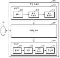
도 1은 본원의 일 실시 예와 관련된 초음파 진단 장치(100)의 구성을 도시한 블록도이다. 일 실시 예에 의한 초음파 진단 장치(100)는 프로브(20), 초음파 송수신부(110), 영상 처리부(120), 통신부(130), 디스플레이부(140), 메모리(150), 입력 디바이스(160), 및 제어부(170)를 포함할 수 있으며, 상술한 여러 구성들은 버스(180)를 통해 서로 연결될 수 있다.1 is a block diagram illustrating a configuration of an
초음파 진단 장치(100)는 카트형뿐만 아니라 휴대형으로도 구현될 수 있다. 휴대형 초음파 진단 장치의 예로는 팩스 뷰어(PACS, Picture Archiving and Communication System viewer), 스마트 폰(smartphone), 랩탑 컴퓨터, PDA, 태블릿 PC 등이 있을 수 있으나, 이에 제한되지 않는다.The
프로브(20)는, 초음파 송수신부(110)로부터 인가된 구동 신호(driving signal)에 따라 대상체(10)로 초음파 신호를 송출하고, 대상체(10)로부터 반사된 에코 신호를 수신한다. 프로브(20)는 복수의 트랜스듀서를 포함하며, 복수의 트랜스듀서는 전달되는 전기적 신호에 따라 진동하며 음향 에너지인 초음파를 발생시킨다. 또한, 프로브(20)는 초음파 진단 장치(100)의 본체와 유선 또는 무선으로 연결될 수 있으며, 초음파 진단 장치(100)는 구현 형태에 따라 복수 개의 프로브(20)를 구비할 수 있다.The
송신부(111)는 프로브(20)에 구동 신호를 공급하며, 펄스 생성부(117), 송신 지연부(118), 및 펄서(119)를 포함한다. 펄스 생성부(117)는 소정의 펄스 반복 주파수(PRF, Pulse Repetition Frequency)에 따른 송신 초음파를 형성하기 위한 펄스(1pulse)를 생성하며, 송신 지연부(118)는 송신 지향성(transmission directionality)을 결정하기 위한 지연 시간(delay time)을 펄스에 적용한다. 지연 시간이 적용된 각각의 펄스는, 프로브(20)에 포함된 복수의 압전 진동자(piezoelectric vibrators)에 각각 대응된다. 펄서(119)는, 지연 시간이 적용된 각각의 펄스에 대응하는 타이밍(timing)으로, 프로브(20)에 구동 신호(또는, 구동 펄스(driving pulse))를 인가한다.The
수신부(112)는 프로브(20)로부터 수신되는 에코 신호를 처리하여 초음파 데이터를 생성하며, 증폭기(113), ADC(아날로그 디지털 컨버터, Analog Digital converter)(114), 수신 지연부(115), 및 합산부(116)를 포함할 수 있다. 증폭기(113)는 에코 신호를 각 채널(channel) 마다 증폭하며, ADC(114)는 증폭된 에코 신호를 아날로그-디지털 변환한다. 수신 지연부(115)는 수신 지향성(reception directionality)을 결정하기 위한 지연 시간을 디지털 변환된 에코 신호에 적용하고, 합산부(116)는 수신 지연부(115)에 의해 처리된 에코 신호를 합산함으로써 초음파 데이터를 생성한다. 한편, 수신부(112)는 그 구현 형태에 따라 증폭기(113)를 포함하지 않을 수도 있다. 즉, 프로브(20)의 감도가 향상되거나 ADC(114)의 처리 비트(bit) 수가 향상되는 경우, 증폭기(113)는 생략될 수도 있다.The
영상 처리부(120)는 초음파 송수신부(110)에서 생성된 초음파 데이터에 대한 주사 변환(scan conversion) 과정을 통해 초음파 영상을 생성하고 디스플레이한다. 한편, 초음파 영상은 A 모드(amplitude mode), B 모드(brightness mode) 및 M 모드(motion mode)에서 대상체를 스캔하여 획득된 그레이 스케일(gray scale)의 영상뿐만 아니라, 도플러 효과(doppler effect)를 이용하여 움직이는 대상체를 표현하는 도플러 영상일 수도 있다. 도플러 영상은, 혈액의 흐름을 나타내는 혈류 도플러 영상 (또는, 컬러 도플러 영상으로도 불림), 조직의 움직임을 나타내는 티슈 도플러 영상, 또는 대상체의 이동 속도를 파형으로 표시하는 스펙트럴 도플러 영상일 수 있다.The
B 모드 처리부(123)는, 초음파 데이터로부터 B 모드 성분을 추출하여 처리한다. 영상 생성부(122)는, B 모드 처리부(123)에 의해 추출된 B 모드 성분에 기초하여 신호의 강도가 휘도(1brightness)로 표현되는 초음파 영상을 생성할 수 있다.The B-mode processing unit 123 extracts and processes the B-mode component from the ultrasound data. The
마찬가지로, 도플러 처리부(124)는, 초음파 데이터로부터 도플러 성분을 추출하고, 영상 생성부(122)는 추출된 도플러 성분에 기초하여 대상체의 움직임을 컬러 또는 파형으로 표현하는 도플러 영상을 생성할 수 있다.Similarly, the
일 실시 예에 의한 영상 생성부(122)는, 볼륨 데이터에 대한 볼륨 렌더링 과정을 거쳐 3차원 초음파 영상을 생성할 수 있으며, 압력에 따른 대상체(10)의 변형 정도를 영상화한 탄성 영상을 생성할 수도 있다. 나아가, 영상 생성부(122)는 초음파 영상 상에 여러 가지 부가 정보를 텍스트, 그래픽으로 표현할 수도 있다. 한편, 생성된 초음파 영상은 메모리(150)에 저장될 수 있다.The
디스플레이부(140)는 생성된 초음파 영상을 표시 출력한다. 디스플레이부(140)는, 초음파 영상뿐 아니라 초음파 진단 장치(100)에서 처리되는 다양한 정보를 GUI(Graphical User Interface)를 통해 화면 상에 표시 출력할 수 있다. 한편, 초음파 진단 장치(100)는 구현 형태에 따라 둘 이상의 디스플레이부(140)를 포함할 수 있다.The
통신부(130)는, 유선 또는 무선으로 네트워크(30)와 연결되어 외부 디바이스나 서버와 통신한다. 통신부(130)는 의료 영상 정보 시스템(PACS)을 통해 연결된 병원 서버나 병원 내의 다른 의료 장치와 데이터를 주고 받을 수 있다. 또한, 통신부(130)는 의료용 디지털 영상 및 통신(DICOM, Digital Imaging and Communications in Medicine) 표준에 따라 데이터 통신할 수 있다.The
통신부(130)는 네트워크(30)를 통해 대상체(10)의 초음파 영상, 초음파 데이터, 도플러 데이터 등 대상체의 진단과 관련된 데이터를 송수신할 수 있으며, CT 장치, MRI 장치, X-ray 장치 등 다른 의료 장치에서 촬영한 의료 영상 또한 송수신할 수 있다. 나아가, 통신부(130)는 서버로부터 환자의 진단 이력이나 치료 일정 등에 관한 정보를 수신하여 대상체(10)의 진단에 활용할 수도 있다. 나아가, 통신부(130)는 병원 내의 서버나 의료 장치뿐만 아니라, 의사나 환자의 휴대용 단말과 데이터 통신을 수행할 수도 있다.The
통신부(130)는 유선 또는 무선으로 네트워크(30)와 연결되어 서버(32), 의료 장치(34), 또는 휴대용 단말(36)과 데이터를 주고 받을 수 있다. 통신부(130)는 외부 디바이스와 통신을 가능하게 하는 하나 이상의 구성 요소를 포함할 수 있으며, 예를 들어 근거리 통신 모듈(131), 유선 통신 모듈(132), 및 이동 통신 모듈(133)을 포함할 수 있다.The
근거리 통신 모듈(131)은 소정 거리 이내의 근거리 통신을 위한 모듈을 의미한다. 본 발명의 일 실시 예에 따른 근거리 통신 기술에는 무선 랜(Wireless LAN), 와이파이(Wi-Fi), 블루투스, 지그비(ZigBee), WFD(Wi-Fi Direct), UWB(ultra wideband), 적외선 통신(IrDA, infrared Data Association), BLE (Bluetooth Low Energy), NFC(Near Field Communication) 등이 있을 수 있으나, 이에 한정되는 것은 아니다.The short-
유선 통신 모듈(132)은 전기적 신호 또는 광 신호를 이용한 통신을 위한 모듈을 의미하며, 일 실시 예에 의한 유선 통신 기술에는 트위스티드 페어 케이블(twisted pair cable), 동축 케이블, 광섬유 케이블, 이더넷(ethernet) 케이블 등이 있을 수 있다.The
이동 통신 모듈(133)은, 이동 통신망 상에서 기지국, 외부의 단말, 서버 중 적어도 하나와 무선 신호를 송수신한다. 여기에서, 무선 신호는, 음성 호 신호, 화상 통화 호 신호 또는 문자/멀티미디어 메시지 송수신에 따른 다양한 형태의 데이터일 수 있다.The
메모리(150)는 초음파 진단 장치(100)에서 처리되는 여러 가지 정보를 저장한다. 예를 들어, 메모리(150)는 입/출력되는 초음파 데이터, 초음파 영상 등 대상체의 진단에 관련된 의료 데이터를 저장할 수 있고, 초음파 진단 장치(100) 내에서 수행되는 알고리즘이나 프로그램을 저장할 수도 있다.The
메모리(150)는 플래시 메모리, 하드디스크, EEPROM 등 여러 가지 종류의 저장매체로 구현될 수 있다. 또한, 초음파 진단 장치(100)는 웹 상에서 메모리(150)의 저장 기능을 수행하는 웹 스토리지(web storage) 또는 클라우드 서버를 운영할 수도 있다.The
입력 디바이스(160)는, 사용자로부터 초음파 진단 장치(100)를 제어하기 위한 데이터를 입력받는 수단을 의미한다. 입력 디바이스(160)의 예로는 키 패드, 마우스, 터치 패드, 터치 스크린, 트랙볼, 조그 스위치 등 하드웨어 구성을 포함할 수 있으나 이에 한정되는 것은 아니며, 심전도 측정 모듈, 호흡 측정 모듈, 음성 인식 센서, 제스쳐 인식 센서, 지문 인식 센서, 홍채 인식 센서, 깊이 센서, 거리 센서 등 다양한 입력 수단을 더 포함할 수 있다.The
제어부(170)는 초음파 진단 장치(100)의 동작을 전반적으로 제어한다. 즉, 제어부(170)는 도 1에 도시된 프로브(20), 초음파 송수신부(110), 영상 처리부(120), 통신부(130), 디스플레이부(140), 메모리(150), 및 입력 디바이스(160) 간의 동작을 제어할 수 있다.The
프로브(20), 초음파 송수신부(110), 영상 처리부(120), 통신부(130), 디스플레이부(140), 메모리(150), 입력 디바이스(160) 및 제어부(170) 중 일부 또는 전부는 소프트웨어 모듈에 의해 동작할 수 있으나 이에 제한되지 않으며, 상술한 구성 중 일부가 하드웨어에 의해 동작할 수도 있다. 또한, 초음파 송수신부(110), 영상 처리부(120), 및 통신부(130) 중 적어도 일부는 제어부(170)에 포함될 수 있으나, 이러한 구현 형태에 제한되지는 않는다.Some or all of the
도 2는 본원의 일 실시 예와 관련된 무선 프로브(200)의 구성을 도시한 블록도이다. 무선 프로브(200)는, 도 1에서 설명한 바와 같이 복수의 트랜스듀서를 포함하며, 구현 형태에 따라 도 1의 초음파 송수신부(110)의 구성을 일부 또는 전부 포함할 수 있다.2 is a block diagram illustrating a configuration of a
도 2에 도시된 실시 예에 의한 무선 프로브(200)는, 송신부(210), 트랜스듀서(220), 및 수신부(230)를 포함하며, 각각의 구성에 대해서는 1에서 설명한 바 있으므로 자세한 설명은 생략한다. 한편, 무선 프로브(200)는 그 구현 형태에 따라 수신 지연부(233)와 합산부(234)를 선택적으로 포함할 수도 있다.The
무선 프로브(200)는, 대상체(10)로 초음파 신호를 송신하고 에코 신호를 수신하며, 초음파 데이터를 생성하여 도 1의 초음파 진단 장치(100)로 무선 전송할 수 있다.The
종래의 초음파 진단 장치는 고정된 위치에 초음파를 송신/수신했다. 따라서, 해당 위치에 관심 객체가 위치한 경우에만, 관심 객체에 대한 초음파 영상을 획득할 수 있었다. 또한, 사용자의 숙련도에 따라 초음파 영상 획득의 시간, 초음파 영상의 신뢰도, 초음파 영상의 품질 등의 편차가 심했다. 또한 관심 객체가 초음파 영상에 잘 나타났더라도, 관심 객체 또는 프로브의 움직임에 따라 초음파 영상 상에서 관심 객체의 위치가 변경되었다. 따라서 사용자가 초음파 영상에 기초하여 진단하는데 어려움을 가질 수 있었다. 따라서 사용자가 보다 용이하게 초음파 영상을 얻을 수 있는 초음파 진단 장치 및 초음파 진단 장치의 동작 방법이 요구된다.A conventional ultrasound diagnosis apparatus transmits/receives ultrasound at a fixed location. Therefore, only when the object of interest is located at the corresponding position, the ultrasound image of the object of interest can be acquired. In addition, there were significant variations in ultrasound image acquisition time, ultrasound image reliability, and ultrasound image quality depending on the user's skill level. Also, although the object of interest appears well in the ultrasound image, the position of the object of interest on the ultrasound image is changed according to the movement of the object of interest or the probe. Therefore, the user may have difficulty in making a diagnosis based on the ultrasound image. Accordingly, there is a need for an ultrasound diagnosis apparatus that allows a user to more easily obtain an ultrasound image, and an operating method of the ultrasound diagnosis apparatus.
이하에서는 도 3 및 도 17 을 참조하여 본원 발명의 일 실시예에 따른 초음파 진단 장치, 초음파 진단 장치의 동작 방법 및 컴퓨터 판독 가능 저장매체를 상세히 설명한다.Hereinafter, an ultrasound diagnosis apparatus, an operating method of the ultrasound diagnosis apparatus, and a computer-readable storage medium according to an exemplary embodiment of the present invention will be described in detail with reference to FIGS. 3 and 17 .
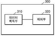
도 3 은 본원의 일 실시예와 관련된 초음파 진단 장치의 구성을 나타낸 블록도이다.3 is a block diagram illustrating a configuration of an ultrasound diagnosis apparatus according to an exemplary embodiment of the present disclosure.
초음파 진단 장치(300)는 초음파 영상을 수신, 처리 및/또는 출력할 수 있는 모든 전자기기를 뜻하며, 초음파 영상 장치, 컴퓨터단층촬영(Computed Tomography: CT) 장치 또는 자기공명영상(Magnetic Resonance Imaging: MRI) 장치 등의 의료 영상 장치를 위해 사용될 수 있다. 예를 들어, 초음파 진단 장치(300)는 의료 영상 장치에 포함될 수 있다.The
도 3 을 참조하면, 초음파 진단 장치(300)는 데이터 획득부(310) 및 제어부(320)를 포함할 수 있다.Referring to FIG. 3 , the
데이터 획득부(310)는 대상체에 대한 제 1 초음파 데이터 및 제 2 초음파 데이터를 획득할 수 있다. 데이터 획득부(310)는 초음파 신호 등을 이용하여 대상체를 스캔함으로써 초음파 데이터를 획득할 수 있으나, 이에 제한되는 것은 아니다. 일 예로, 데이터 획득부(310)는 도 1에서 도시한 초음파 송수신부(110)에 동일 대응될 수 있으며, 프로브(20)에서 전송되는 초음파 에코 신호를 수신하고, 수신된 초음파 에코 신호를 이용하여 자체적으로 초음파 데이터를 획득할 수 있다.The
다른 예로, 데이터 획득부(310)는 초음파 진단 장치(300) 외부의 스캔 장치에서 대상체를 스캔한 스캔 정보, 예를 들어, 초음파 에코 신호를 변환하여 생성한 초음파 데이터를 전달받고, 스캔 정보를 기반으로 초음파 데이터를 획득할 수 있다. 또 다른 예로, 데이터 획득부(310)는 네트워크(30)를 통하여 외부 장치로부터 초음파 영상 데이터를 전달받을 수도 있다. 다만, 이에 한정되는 것은 아니고, 초음파 진단 장치(300)는 다양한 방법으로 초음파 데이터를 획득할 수 있다.As another example, the
제 1 초음파 데이터 및 제 2 초음파 데이터는 3 차원 데이터인 볼륨 데이터 일 수 있다. 제 1 초음파 데이터 및 제 2 초음파 데이터는 복수의 복셀(voxel) 값을 포함할 수 있다. 복셀 값은 대응하는 복셀의 밝기 값(luminance value), 색상 값 중 적어도 하나를 포함할 수 있다. 볼륨 데이터는 복수의 2 차원 데이터를 포함할 수 있다.The first ultrasound data and the second ultrasound data may be volume data that is 3D data. The first ultrasound data and the second ultrasound data may include a plurality of voxel values. The voxel value may include at least one of a luminance value and a color value of a corresponding voxel. The volume data may include a plurality of two-dimensional data.
또한, 제 1 초음파 데이터 및 제 2 초음파 데이터는 2 차원 데이터인 평면 데이터 일 수 있다. 제 1 초음파 데이터 및 제 2 초음파 데이터는 복수의 픽셀 값을 포함할 수 있다. 픽셀 값은 대응하는 픽셀의 밝기 값, 색상 값 중 적어도 하나를 포함할 수 있다.Also, the first ultrasound data and the second ultrasound data may be two-dimensional data, that is, planar data. The first ultrasound data and the second ultrasound data may include a plurality of pixel values. The pixel value may include at least one of a brightness value and a color value of the corresponding pixel.
본 개시의 일 실시예에 따르면 초음파 진단 장치(300)는 소정의 샘플링 주기로 초음파 빔을 송신 및 수신하여 볼륨 데이터를 획득할 수 있다. 초음파 진단 장치(300)는 제 1 초음파 데이터를 획득 후에 제 2 초음파 데이터를 획득 할 수 있다. 예를 들어 제 1 초음파 데이터가 제 1 주기에 획득된 볼륨 데이터라면 제 2 초음파 데이터는 제 1 주기 다음 주기에 획득된 볼륨 데이터 일 수 있다. 일반적으로 샘플링 주기는 ms 의 단위를 가질 수 있다. 따라서, 샘플링 주기 사이에 관심 객체 및 프로브의 움직임은 크지 않을 수 있으며, 제 1 초음파 데이터와 제 2 초음파 데이터는 비교적 유사한 위치에 관심 객체의 영상을 포함할 수 있다. 또한 관심 객체의 영상은 유사한 픽셀 값들 혹은 복셀 값들을 포함할 수 있다.According to an embodiment of the present disclosure, the
또한, 초음파 진단 장치(300)의 영상 처리 능력에 따라, 제 1 초음파 데이터를 획득한 후 소정의 주기가 지난 후에 제 2 초음파 데이터를 획득할 수 있다. 예를 들어 초음파 진단 장치(300)의 영상 처리 능력이 좋지 않을 경우, 제 1 초음파 데이터 및 제 2 초음파 데이터 사이에 획득된 볼륨 데이터에는 본 개시에 따른 영상처리가 이루어 지지 않을 수 있다. 즉, 초음파 진단 장치(300)는 제 1 초음파 데이터 및 제 2 초음파 데이터 사이에 획득된 볼륨 데이터에서 관심 객체의 위치를 획득하지 않을 수 있다. 하지만 제 1 초음파 데이터 및 제 2 초음파 데이터 사이에 획득된 볼륨 데이터는 도 1 의 디스플레이부(140)에 표시될 수 있다. 초음파 진단 장치(300)는 제 1 초음파 데이터 및 제 2 초음파 데이터에만 본 개시에 따른 영상처리를 하여 효율성을 높일 수 있다. 또한 제 1 초음파 데이터를 획득한 시간 및 제 2 초음파 데이터를 획득한 시간 사이는 여전히 짧으므로, 제 1 초음파 데이터와 제 2 초음파 데이터는 비교적 유사한 위치에 관심 객체의 영상을 포함할 수 있다. 또한 관심 객체는 유사한 픽셀 값 혹은 복셀 값을 가지고 있을 수 있다.Also, according to the image processing capability of the
제어부(320)는 제 1 초음파 데이터 상에서 대상체에 포함되는 관심 객체의 제 1 위치를 검출할 수 있다. 또한 제어부(320)는 제 2 초음파 데이터 상에서 제 1 위치에 기초하여 관심 객체의 제 2 위치를 검출할 수 있다. 또한 제어부(320)는 제 2 위치에 기초하여 초음파 빔의 송수신 조건을 변경할 수 있다.The
제어부(320)는 도 1 의 제어부(170) 및 영상 처리부(120) 중 적어도 하나의 기능을 수행할 수 있다. 제어부(320)는 제어부(170) 및 영상 처리부(120) 중 적어도 하나일 수 있다. 또한 제어부(320)는 제어부(170) 및 영상 처리부(120)와 다른 별도의 하드웨어 일 수 있다.The
제 1 위치 및 제 2 위치는 볼륨 데이터 상에서 관심 객체 내에 포함되는 소정의 위치 또는 영역일 수 있다. 예를 들어 제 1 위치 및 제 2 위치는 관심 객체 내의 중심점, 오른쪽 끝 점, 왼쪽 끝 점, 위쪽 끝 점 및 아래쪽 끝 점 등이 될 수 있다. 또한 제 1 위치 및 제 2 위치는 관심 객체 내의 소정의 영역일 수 있다. 또한, 제 1 위치 및 제 2 위치는 볼륨 데이터 상의 복셀의 좌표값으로 나타낼 수 있다.The first position and the second position may be predetermined positions or regions included in the object of interest on the volume data. For example, the first position and the second position may be a center point, a right end point, a left end point, an upper end point, and a lower end point within the object of interest. Also, the first location and the second location may be a predetermined area within the object of interest. Also, the first position and the second position may be expressed as coordinate values of voxels on the volume data.
상술한 바와 같이 제 1 초음파 데이터를 획득한 시간과 및 제 2 초음파 데이터를 획득한 시간 사이는 짧을 수 있으므로, 제 1 초음파 데이터와 제 2 초음파 데이터는 비교적 유사한 위치에 관심 객체의 영상을 포함할 수 있다. 예를 들어 제어부(320)는 제 1 초음파 데이터 상에서 관심 객체의 제 1 위치를 검출할 수 있다. 제 1 위치가 볼륨 데이터 상의 복셀의 제 1 좌표값이 경우, 제어부(320)는 제 2 초음파 데이터 상에서 제 1 좌표값 근처에서 관심 객체를 찾을 수 있다. 또한 제어부(320)는 관심 객체를 찾은 경우 제 2 위치를 검출할 수 있다.As described above, since the time period for acquiring the first ultrasound data and the time period for acquiring the second ultrasound data may be short, the first ultrasound data and the second ultrasound data may include images of the object of interest at relatively similar positions. there is. For example, the
제어부(320)는 제 2 위치에 기초하여 초음파 빔의 송수신 조건을 변경할 수 있다. 초음파 빔의 송수신 조건은, 초음파 빔의 수신 깊이, 초음파 빔의 폭, 초음파 빔의 스티어링 각 및 초음파 빔의 집속 위치 중 적어도 하나를 포함할 수 있다.The
예를 들어 제어부(320)는 제 2 위치를 스캔할 수 있도록 초음파 빔의 수신 깊이를 조절할 수 있다. 또한 제어부(320)는 제 2 위치를 스캔할 수 있도록 초음파 빔의 폭을 조절할 수 있다.For example, the
또한 제어부(320)는 제 2 위치를 향하도록 초음파 빔을 출력하도록 제어 할 수 있다. 제어부(320)는 초음파 빔의 스티어링 각을 변경할 수 있다. 스티어링 각은 프로브에 포함된 트랜스듀서들이 이루는 면과 초음파 빔이 이루는 각이다. 관심 객체가 초음파 영상 상에서 오른쪽으로 쏠려있는 경우 제어부(320)는 스티어링 각을 변경하여 관심 객체가 초음파 영상의 중심에 오도록 할 수 있다. 또한 제어부(320)는 초음파 빔의 집속(focusing) 위치를 변경할 수 있다. 따라서 초음파 진단 장치(300)는 관심 객체에 대하여 선명한 초음파 영상을 획득할 수 있다.Also, the
또한 제어부(320)는 초음파 빔의 송수신 조건을 실시간으로 변경할 수 있다. 따라서 사용자는 실시간으로 송수신 조건이 변경된 초음파 영상을 실시간으로 확인할 수 있다.Also, the
이하에서는 본 개시의 일 실시예에 따른 초음파 진단 장치 및 초음파 진단 장치의 동작 방법에 대하여 도 3 과 함께 보다 자세히 설명한다.Hereinafter, an ultrasound diagnosis apparatus and an operating method of the ultrasound diagnosis apparatus according to an exemplary embodiment of the present disclosure will be described in more detail with reference to FIG. 3 .
도 4a 및 도 4b 는 본원의 일 실시예와 관련된 초음파 데이터를 획득하는 과정을 나타낸 도면이다.4A and 4B are diagrams illustrating a process of acquiring ultrasound data related to an embodiment of the present application.
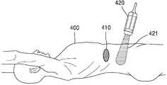
도 4a 를 참조하면, 초음파 진단 장치(300)는 프로브(420)를 이용하여 대상체(400)를 스캔하여 볼륨 데이터를 획득할 수 있다. 프로브(420)는 초음파 빔(421)을 출력할 수 있다. 출력된 초음파 빔(422)은 대상체(400)에 반사될 수 있다. 초음파 진단 장치(300)는 반사된 신호를 수신하여 볼륨 데이터를 획득할 수 있다.Referring to FIG. 4A , the
도 4a 를 참조하면, 초음파 빔(421)은 관심 객체(410)를 향하고 있지 않으므로 획득된 볼륨 데이터에는 관심 객체(410)와 관련된 정보가 담겨있지 않을 수 있다. 초음파 진단 장치(300)는 볼륨 데이터에 기초하여 초음파 영상을 생성할 수 있다. 사용자는 초음파 영상을 확인하면서 프로브의 위치 및 각도를 수정할 수 있다.Referring to FIG. 4A , since the
도 4b 를 참조하면, 초음파 진단 장치(300)는 프로브(420)를 이용하여 대상체(400)를 스캔하여 볼륨 데이터를 획득할 수 있다. 초음파 빔(422)은 관심 객체(410)를 향하고 있으므로 획득된 볼륨 데이터에는 관심 객체(410)와 관련된 정보가 담겨있을 수 있다. 초음파 진단 장치(300)는 볼륨 데이터에 기초하여 초음파 영상을 생성할 수 있다. 도 4b 에서와 같이 프로브가 관심 객체를 향하고 있는 경우, 초음파 진단 장치(300)는 볼륨 데이터를 획득할 수 있다. 예를 들어 볼륨 데이터는 제 1 초음파 데이터일 수 있다.Referring to FIG. 4B , the
도 5a 및 도 5b 는 본원의 일 실시예와 관련된 초음파 데이터에 기초하여 획득된 초음파 영상을 나타낸 도면이다.5A and 5B are diagrams illustrating ultrasound images obtained based on ultrasound data related to an exemplary embodiment of the present disclosure.
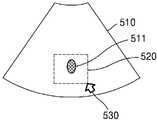
도 4b 에서와 같이 프로브가 관심 객체를 향하고 있는 경우, 도 5a 에 도시된 바와 같은 초음파 영상(510)이 획득될 수 있다. 획득된 초음파 영상(510)에는 관심 객체의 영상(511)이 나타날 수 있다.When the probe is facing the object of interest as shown in FIG. 4B , an
도 5b 를 참조하면, 초음파 진단 장치(300)는 볼륨 데이터를 획득할 수 있으며, 볼륨 데이터는 제 1 초음파 데이터일 수 있다. 초음파 진단 장치(300)는 제 1 초음파 데이터에 기초하여 초음파 영상(510)을 획득할 수 있다. 초음파 진단 장치(300)는 사용자로부터 입력을 수신할 수 있는 입력부를 포함할 수 있다. 입력부는 사용자로부터 제 1 초음파 데이터에 기초한 제 1 초음파 영상 상에 관심 영역(ROI: Region of Interest)을 설정하는 입력을 수신할 수 있다. 입력부는 도 1 의 입력 디바이스(160)에 동일 대응될 수 있다.Referring to FIG. 5B , the
입력부는 사용자 입력을 수신할 수 있다. 초음파 진단 장치(300)는 사용자의 입력에 기초하여 표시자(530)를 초음파 영상(510) 상에서 이동시킬 수 있다. 또한 초음파 진단 장치(300)는 사용자의 입력에 기초하여 소정의 관심 영역(520)을 설정할 수 있다. 관심 영역(520)은 관심 객체의 영상(511)을 포함하는 영역일 수 있다.The input unit may receive a user input. The
제어부(320)는 관심 영역(520) 내에서 관심 객체의 영상(511)의 제 1 위치를 검출할 수 있다. 예를 들어 초음파 진단 장치(300)는 관심 영역(520)을 소정의 영상과 비교하여 관심 객체의 영상(511)을 획득할 수 있다. 소정의 영상은 초음파 진단 장치(300)가 이전에 획득한 피검사자의 관심 객체의 영상일 수 있다. 또한 소정의 영상은 초음파 진단 장치(300)가 저장하고 있는 관심 객체가 가장 잘 나타난 표준 관심 객체 영상일 수 있다. 초음파 진단 장치(300)는 관심 객체의 영상(511)이 잘 나타나도록 초음파 영상(510) 내의 관심 영역(520)을 영상 처리할 수 있다. 예를 들어 초음파 진단 장치(300)는 관심 영역(520)을 영상 처리하여 윤곽선을 획득할 수 있다. 또한 초음파 진단 장치(300)는 관심 영역(520) 자체를 관심 객체의 영상(511)으로서 획득할 수 있다.The
초음파 진단 장치(300)는 획득된 관심 객체의 영상(511)에 기초하여 관심 객체의 제 1 위치를 검출할 수 있다. 제 1 위치에 대해서는 상술하였으므로 자세한 설명은 생략한다.The
초음파 진단 장치(300)는 제 1 위치에 기초하여 관심 객체의 제 2 위치를 검출할 수 있다. 또한, 초음파 진단 장치(300)는 제 2 위치에 기초하여 초음파 빔의 송수신 조건을 변경할 수 있다. 또한 초음파 진단 장치(300)는 제 1 위치에 더 기초하여 초음파 빔의 송수신 조건을 변경할 수 있다. 이하에서는 초음파 진단 장치(300)의 동작에 대하여 도 10 내지 도 16 과 함께 자세히 설명한다.The
도 10 은 본원의 일 실시예와 관련된 제 1 초음파 데이터를 나타낸 도면이다.10 is a view showing first ultrasound data related to an embodiment of the present application.
초음파 진단 장치(300)는 제 1 초음파 데이터 상에서 제 1 위치를 나타내는 제 1 좌표값을 획득할 수 있다. 또한 초음파 진단 장치(300)는 제 2 초음파 데이터 상에서 제 2 위치를 나타내는 제 2 좌표값을 획득할 수 있다. 또한 초음파 진단 장치(300)는 제 1 좌표값 및 제 2 좌표값의 차이값에 기초하여 초음파 빔의 송수신 조건을 변경할 수 있다.The
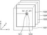
도 10 을 참조하면 제 1 초음파 데이터는 복수의 2 차원 데이터(1021, 1022, 1023, 1024)를 포함할 수 있다. 또한 초음파 진단 장치(300)는 2 차원 데이터(1022)에 기초하여 도 5a 및 도 5b 의 초음파 영상(510)을 획득할 수 있다. 즉 도 5a 및 도 5b의 초음파 영상(510)은 2 차원 데이터(1022)에 대응될 수 있다.Referring to FIG. 10 , the first ultrasound data may include a plurality of two-
복수의 2차원 데이터는 볼륨 데이터에 포함된 평행한 평면들을 의미할 수 있다. 또한 2 차원 데이터는 볼륨 데이터에 포함된 한 슬라이스(slice)의 데이터 일 수 있다.The plurality of 2D data may refer to parallel planes included in the volume data. Also, the 2D data may be data of one slice included in the volume data.
제어부(320)는 관심 영역 내에서 관심 객체(1010)의 제 1 위치를 검출할 수 있다. 또한 제어부(320)는 제 1 초음파 데이터 상에서 제 1 위치를 나타내는 제 1 좌표값을 획득할 수 있다.The
제 1 위치는 제 1 초음파 데이터 상에서 관심 객체 내에 포함되는 소정의 위치 또는 영역일 수 있다. 예를 들어 제 1 위치는 관심 객체 내의 중심점, 오른쪽 끝 점, 왼쪽 끝 점, 위쪽 끝 점 및 아래쪽 끝 점 등이 될 수 있다. 또한 제 1 위치는 관심 객체 내의 소정의 영역일 수 있다. 예를 들어 초음파 진단 장치(300)는 제 1 위치를 관심 객체 내의 원, 사각형 등의 도형으로 나타낼 수 있다. 또한 초음파 진단 장치(300)는 도형 내의 임의의 점들을 제 1 위치로 획득할 수 있다. 또한, 제 1 위치는 제 1 초음파 데이터 상의 복셀의 좌표값으로 나타낼 수 있다.The first location may be a predetermined location or region included in the object of interest on the first ultrasound data. For example, the first position may be a center point, a right end point, a left end point, an upper end point, and a lower end point within the object of interest. Also, the first location may be a predetermined area within the object of interest. For example, the
상술한 바와 같이 제 1 위치는 제 1 초음파 데이터 내의 복셀 좌표값으로 나타낼 수 있다. 복수의 2 차원 데이터(1021, 1022, 1023, 1024) 각각은 서로 다른 y 좌표 값을 가질 수 있다. 예를 들어 2 차원 데이터(1021)의 y 좌표값은 y0 일 수 있다. 또한 관심 객체(1010)가 포함된 2 차원 데이터(1022)의 y 좌표값은 y1 일 수 있다.As described above, the first position may be expressed as a voxel coordinate value in the first ultrasound data. Each of the plurality of
2 차원 데이터(1022) 내에서 각 복셀은 x, z 축에 대한 좌표값을 가질 수 있다. 관심 객체(1010)의 제 1 위치는 관심 객체(1010)의 중심점(1011)이 될 수 있다. 중심점(1011)은 관심 객체(1010)에 포함된 복셀들의 좌표값들의 평균으로서 계산될 수 있다. 관심 객체(1010)의 중심점(1011)은 예를 들어 2 차원 데이터(1022) 내에서 (x1, z1)의 좌표값을 가질 수 있다. 초음파 진단 장치(300)는 관심 객체(1010)의 제 1 위치를 (x1, y1, z1)으로 획득할 수 있다.Each voxel in the two-
도 11은 본원의 일 실시예에 관련된 초음파 진단 장치가 제 2 초음파 데이터 내에서 관심 객체를 찾는 과정을 나타낸 도면이다.11 is a diagram illustrating a process in which an ultrasound diagnosis apparatus according to an exemplary embodiment finds an object of interest in second ultrasound data.
초음파 진단 장치(300)는 제 1 초음파 데이터를 획득한 후 소정의 시간이 지난 후 제 2 초음파 데이터를 획득할 수 있다. 소정의 시간 동안 사용자는 프로브의 위치를 변경할 수 있다. 또한 프로브는 가만히 있지만, 대상체가 움직일 수 있다. 초음파 진단 장치(300)는 프로브의 위치가 변경되거나 대상체가 움직인 후에 제 2 초음파 데이터를 획득할 수 있다.The
제 1 초음파 데이터를 획득한 시간과 제 2 초음파 데이터를 획득한 시간 사이인 소정의 시간은 짧으므로, 제 1 초음파 데이터와 제 2 초음파 데이터는 비교적 유사한 위치에 관심 객체의 영상 정보를 포함할 수 있다. 초음파 진단 장치(300)는 제 2 초음파 데이터에 포함된 2 차원 데이터(1110)에 기초하여 제 2 초음파 데이터에 내의 관심 객체의 위치를 검출할 수 있다. 또한, 초음파 진단 장치(300)는 제 2 초음파 데이터에 기초하여 초음파 영상을 획득할 수 있다. 사용자는 초음파 영상을 확인하면서 초음파 진단 장치(300)가 관심 객체를 검출하는 과정을 확인할 수 있다. 또한 초음파 진단 장치(300)는 사용자로부터 입력을 수신하고, 사용자의 입력에 기초하여 제 2 초음파 데이터 내에서 관심 객체의 위치를 검출할 수 있다.Since the predetermined time between the first ultrasound data acquisition time and the second ultrasound data acquisition time is short, the first ultrasound data and the second ultrasound data may include image information of the object of interest at relatively similar positions. . The
초음파 진단 장치(300)는 관심 객체 제 1 위치(1121)에 기초하여 관심 객체의 제 2 위치(1122)를 검출할 수 있다. 예를 들어 상술한 바와 같이 제 1 초음파 데이터를 획득한 시간과 제 2 초음파 데이터를 획득한 시간 사이인 소정의 시간은 짧으므로, 제 1 위치(1121) 주변에서 제 2 위치(1122)를 검출할 수 있다.The
보다 구체적으로 도 10 및 도 11 을 참조하면, 제 1 위치(1121)는 도 10 에서 설명한 바와 같이 좌표값 (x1, y1, z1)으로 나타낼 수 있다. 초음파 진단 장치(300)는 제 2 초음파 데이터 상에서 제 1 위치(1121)인 좌표값 (x1, y1, z1) 주변에서 관심 객체를 찾을 수 있다. 예를 들어 초음파 진단 장치(300)는 제 2 초음파 데이터 상에서 좌표값(x1, y1, z1)을 중심으로 소정의 거리 내에서 관심 객체의 존재 유무를 검출할 수 있다.More specifically, referring to FIGS. 10 and 11 , the
초음파 진단 장치(300)는 제 2 초음파 데이터 상에서 제 1 위치(1121)를 포함하는 영역(1131)에 관심 객체가 있는지 검색할 수 있다. 초음파 진단 장치(300)는 제어부는 제 1 초음파 데이터 상의 관심 객체의 픽셀 값들 및 복셀 값들 중 적어도 하나 및 제 2 초음파 데이터 상의 픽셀 값들 및 복셀 값들 중 적어도 하나의 상관도에 기초하여, , 제 2 초음파 데이터 상에서 관심 객체의 제 2 위치를 검출할 수 있다. 초음파 진단 장치(300)가 제 2 위치를 검출하기 위하여, 초음파 진단 장치(300)는 제 2 초음파 데이터 상에서 관심 객체가 존재하는지 판단할 수 있다.The
상술한 바와 같이 제 1 초음파 데이터를 획득한 시간과 제 2 초음파 데이터를 획득한 시간 사이인 소정의 시간은 짧을 것이므로, 제 1 초음파 데이터와 제 2 초음파 데이터는 유사할 것이다. 또한 제 1 초음파 데이터에서 관심 객체의 영상에 포함된 픽셀 값들은 제 2 초음파 데이터에서 관심 객체의 영상에 포함된 픽셀 값들과 유사할 것이다. 따라서 초음파 진단 장치(300)는 제 1 초음파 데이터의 관심 객체의 영상에 포함된 픽셀 값들과 유사한 픽셀값들을 제 2 초음파 데이터 상에서 검색할 수 있다.As described above, since the predetermined time between the acquisition time of the first ultrasound data and the acquisition time of the second ultrasound data will be short, the first ultrasound data and the second ultrasound data will be similar. Also, pixel values included in the image of the object of interest in the first ultrasound data may be similar to pixel values included in the image of the object of interest in the second ultrasound data. Accordingly, the
예를 들어, 초음파 진단 장치(300)는 제 2 초음파 데이터의 영역(1131)의 영상과 제 1 초음파 데이터에서 관심 객체의 영상을 비교하여, 영역(1131)에 관심 객체가 존재하는지 판단할 수 있다. 영역(1131)은 제 1 초음파 데이터 상에서 관심 객체의 위치의 좌표에 대응하는 제 2 초음파 데이터 상의 좌표를 포함하는 영역일 수 있다.For example, the
영역(1131)의 영상에 포함된 픽셀들과 제 1 초음파 데이터에서 관심 객체의 영상에 포함된픽셀 값들의 상관도가 임계값(threshold value) 이상인 경우, 초음파 진단 장치(300)는 영역(1131)에 관심 객체가 존재한다고 판단할 수 있다. 또는 영역(1131)과 도 5b 의 관심 영역을 비교하여 영역(1131)에 관심 객체가 존재하는지 판단할 수 있다. 초음파 진단 장치(300)는 상관 관계(correlation)와 같은 통계적인 방법을 이용하여 상관도를 계산할 수 있다. 하지만 이에 한정되는 것은 아니며 다양한 상관도 측정 방법을 사용할 수 있다.When the correlation between the pixels included in the image of the
초음파 진단 장치(300)는 제 1 초음파 데이터 내에서 관심 객체의 영상에 대한 윤곽선을 획득할 수 있다. 또한 초음파 진단 장치(300)는 영역(1131)에 나타난 영상의 윤곽선을 제 1 초음파 데이터의 관심 객체의 윤곽선과 비교할 수 있다. 초음파 진단 장치(300)가 윤곽선만을 비교하는 경우, 데이터 처리의 효율이 높아질 수 있다.The
또한 초음파 진단 장치(300)는 관심 객체가 가장 잘 나타난 표준 관심 객체 영상과 영역(1131)을 비교하여 영역(1131)에 관심 객체가 존재하는지 판단할 수 있다. 또한 초음파 진단 장치(300)는 제 1 초음파 데이터 이전에 획득한 복수의 볼륨 데이터를 고려하여 영역(1131)에 관심 객체가 존재하는지 판단할 수 있다.Also, the
도 11 에 도시된 바와 같이 초음파 진단 장치(300)는 영역(1131)에 관심 객체가 없다고 판단할 수 있다. 초음파 진단 장치(300)는 영역(1131) 주위의 다른 영역에서 관심 객체가 존재하는지 판단할 수 있다. 초음파 진단 장치(300)는 영역(1131) 주위의 임의의 영역에 대하여 관심 객체가 존재하는지 판단할 수 있다. 또한 초음파 진단 장치(300)는 프로브의 움직임을 감지하거나 대상체의 움직임에 대한 통계적 데이터에 기초하여 영역(1131) 주위의 임의의 영역에 대하여 관심 객체가 존재하는지 판단할 수 있다.11 , the
도 11 을 참조하면, 초음파 진단 장치는 영역(1132)에 대하여 관심 객체가 존재하는지 판단할 수 있다. 초음파 진단 장치는 영역(1132)에 관심 객체가 존재하지 않는다고 판단할 수 있다. 하지만 초음파 진단 장치(300)는 영역(1132)의 좌측 상단에 관심 객체의 일부가 있음 추정할 수 있다. 따라서 초음파 진단 장치(300)는 영역(1132)의 좌측 상단에 있는 영역(1133)에 대하여 관심 객체가 존재하는지 판단할 수 있다. 또한, 초음파 진단 장치(300)는 영역(1133)에 관심 객체가 있음을 판단할 수 있다. 또한 초음파 진단 장치(300)는 영역(1133)에 있는 관심 객체의 제 2 위치를 검출할 수 있다.Referring to FIG. 11 , the ultrasound diagnosis apparatus may determine whether an object of interest exists in a
도 11 에서는 설명의 편의를 위하여 2 차원에서 설명하였으나 이에 한정되는 것은 아니다. 초음파 진단 장치(300)는 3 차원의 제 2 초음파 데이터 상에서 관심 객체의 제 2 위치를 검출할 수 있다. 제어부(320)는 제 1 초음파 데이터 상의 관심 객체의 복셀 값들 및 제 2 초음파 데이터 상의 복셀 값들의 상관도에 기초하여, 제 2 초음파 데이터 상에서 관심 객체의 제 2 위치를 검출할 수 있다. 또한, 제 2 초음파 데이터에서 관심 객체의 위치를 찾는 과정은 상술한 바와 같은 방법이 아닌 다양한 공지된 방법에 의하여 수행될 수 있다.11 has been described in two dimensions for convenience of description, but is not limited thereto. The
도 12 은 본원의 일 실시예와 관련된 제 2 초음파 데이터를 나타낸 도면이다.12 is a diagram illustrating second ultrasound data related to an embodiment of the present application.
도 12 를 참조하면, 제어부(320)는 관심 영역 내에서 관심 객체(1210)의 제 2 위치를 검출할 수 있다. 또한 제어부(320)는 제 2 초음파 데이터 상에서 제 2 위치를 나타내는 제 2 좌표값을 획득할 수 있다.Referring to FIG. 12 , the
제 2 위치는 제 2 초음파 데이터 상에서 관심 객체 내에 포함되는 소정의 위치 또는 영역일 수 있다. 예를 들어 제 2 위치는 관심 객체 내의 중심점, 오른쪽 끝 점, 왼쪽 끝 점, 위쪽 끝 점 및 아래쪽 끝 점 등이 될 수 있다. 또한 제 2 위치는 관심 객체 내의 소정의 영역일 수 있다. 또한, 제 2 위치는 제 2 초음파 데이터 상의 복셀의 좌표값으로 나타낼 수 있다.The second location may be a predetermined location or region included in the object of interest on the second ultrasound data. For example, the second position may be a center point, a right end point, a left end point, an upper end point, and a lower end point within the object of interest. Also, the second location may be a predetermined area within the object of interest. Also, the second position may be expressed as a coordinate value of a voxel on the second ultrasound data.
상술한 바와 같이 제 2 위치는 제 2 초음파 데이터 내의 복셀 좌표값으로 나타낼 수 있다. 복수의 2 차원 데이터(1221, 1222, 1223, 1224) 각각은 서로 다른 y 좌표 값을 가질 수 있다. 예를 들어 2 차원 데이터(1221)의 y 좌표값은 y0 일 수 있다. 또한 관심 객체(1010)가 포함된 2 차원 데이터(1022)의 y 좌표값은 y2 일 수 있다.As described above, the second position may be expressed as a voxel coordinate value in the second ultrasound data. Each of the plurality of
2 차원 데이터(1222) 내에서 각 복셀은 x, z 축에 대한 좌표값을 가질 수 있다. 관심 객체(1210)의 제 2 위치는 관심 객체의 중심점(1211)이 될 수 있다. 관심 객체의 중심점(1211)은 예를 들어 2 차원 데이터(1222) 내에서 (x2, z2)의 좌표값을 가질 수 있다. 초음파 진단 장치(300)는 관심 객체(1010)의 제 1 위치를 (x2, y2, z2)으로 획득할 수 있다.Each voxel in the two-
도 13 은 본원의 일 실시예와 관련된 볼륨 데이터 상에서 제 1 위치 및 제 2 위치를 나타낸 도면이다.13 is a diagram illustrating a first position and a second position on volume data related to an embodiment of the present application.
도 13 을 참조하면, 초음파 진단 장치(300)는 제 1 초음파 데이터에 포함된 하나의 2 차원 데이터(1301) 상에 관심 객체(1310)의 영상 정보를 포함할 수 있다. 또한 초음파 진단 장치(300)는 2 차원 데이터(1301) 상에서 관심 객체(1310)의 중심점의 복셀 좌표를 획득할 수 있다. 제 1 초음파 데이터 상에서 관심 객체(1310)의 중심점의 복셀 좌표는 (x1, y1, z1) 일 수 있다.Referring to FIG. 13 , the
또한, 초음파 진단 장치(300)는 제 2 초음파 데이터에 포함된 하나의 2 차원 데이터(1302) 상에 관심 객체(1320)의 영상 정보를 포함할 수 있다. 또한 초음파 진단 장치(300)는 2 차원 데이터(1302) 상에서 관심 객체(1320)의 중심점의 복셀 좌표를 획득할 수 있다. 제 2 초음파 데이터 상에서 관심 객체(1320)의 중심점의 복셀 좌표는 (x2, y2, z2) 일 수 있다.Also, the
초음파 진단 장치(300)는 제 1 초음파 데이터 상의 제 1 위치를 나타내는 복셀 좌표값 및 제 2 초음파 데이터 상의 제 2 위치를 나타내는 복셀 좌표값의 차이값에 기초하여 초음파 빔의 송수신 조건을 변경할 수 있다. 차이값은 좌표값의 차(difference) 또는 변위(displacement)가 될 수 있다. 또한, 복셀 좌표값의 차이값은 벡터로 나타낼 수 있으며 벡터는 (x2-x1, y1-y2, z1-z3)가 될 수 있다. 초음파 진단 장치(300)는 벡터의 방향과 크기에 기초하여 초음파 빔의 송수신 조건을 변경할 수 있다.The
도 14 는 본원의 일 실시예와 관련된 공간 상에서 제 1 위치 및 제 2 위치를 나타낸 도면이다.14 is a view showing a first position and a second position in space related to an embodiment of the present application.
도 14 를 참조하면, 초음파 진단 장치(300)는 프로브(1410)를 포함할 수 있다. 프로브(1410)는 트랜스듀서들의 배열(1411)을 가질 수 있다. 초음파 진단 장치(300)는 트랜스듀서들의 배열(1411)을 이용하여 초음파 빔을 스티어링 할 수 있다. 초음파 진단 장치(300)는 볼륨 데이터 상의 복셀의 좌표를 공간상의 좌표와 대응시킬 수 있다.Referring to FIG. 14 , the
도 10 내지 도 13 에서는 볼륨 데이터 상의 복셀의 좌표를 x축, y축, z축 상에서 표시하였다. 도 14 에서 공간 상의 좌표는 a축, b축, c축으로 나타낼 수 있다. a축, b축, c축의 원점은 트랜스듀서들의 배열(1411)의 왼쪽 아래 지점이 될 수 있다. 하지만 이에 한정되는 것은 아니며, 트랜스듀서들의 배열(1411)의 중심, 왼쪽 아래 오른쪽 위 등이 될 수 있다. a축, b축, c축의 단위는 길이의 단위로서 mm, cm 등이 될 수 있다. x축은 a축에 대응될 수 있다. 또한 y축은 b축에 대응될 수 있다. 또한 z축은 c축에 대응될 수 있다.10 to 13 , coordinates of voxels on volume data are displayed on the x-axis, y-axis, and z-axis. In FIG. 14 , coordinates in space may be represented by an a-axis, a b-axis, and a c-axis. The origin of the a-axis, b-axis, and c-axis may be a lower left point of the
초음파 진단 장치(300)는 도 13 의 볼륨 데이터 상의 복셀의 좌표인 제 1 위치 및 제 2 위치를 공간상의 좌표에 대응시킬 수 있다. 예를 들어 초음파 진단 장치(300)는 복셀의 좌표를 공간 좌표로 변환하는 맵핑 데이터를 가지고 있을 수 있으며, 복셀의 좌표를 공간 좌표로 변환하는 변환 식을 가지고 있을 수 있다. 초음파 진단 장치(300)는 제 1 초음파 데이터 상의 제 1 위치를 공간 상의 지점(1401)에 대응할 수 있다. 또한 지점(1401)의 공간상의 좌표는 (a1, b1, c1)이 될 수 있다. 또한, 초음파 진단 장치(300)는 제 2 초음파 데이터 상의 제 2 위치를 공간 상의 지점(1402)에 대응할 수 있다. 또한 지점(1402)의 공간상의 좌표는 (a2, b2, c2)이 될 수 있다.The
초음파 진단 장치(300)는 제 1 초음파 데이터 상의 제 1 위치에 대응되는 공간 좌표값 및 제 2 초음파 데이터 상의 제 2 위치에 대응되는 공간 좌표값의 차이값에 기초하여 초음파 빔의 송수신 조건을 변경할 수 있다. 공간 좌표값의 차이값은 벡터로 나타낼 수 있으며 벡터는 (a2-a1, b2-b1, c2-c1)가 될 수 있다. 초음파 진단 장치(300)는 공간 좌표값의 차이값에 기초하여 초음파 빔의 송수신 조건을 변경할 수 있다. 또한 초음파 진단 장치(300)는 공간 좌표값의 차이값에 관심 객체(1400)에 초음파 빔이 집속되도록 할 수 있다.The
도 15 는 본원의 일 실시예에 관련된 초음파 진단 장치의 송수신 조건 변경 방법을 나타낸 도면이다.15 is a diagram illustrating a method of changing a transmission/reception condition of an ultrasound diagnosis apparatus according to an exemplary embodiment of the present disclosure.
제어부(320)는 제 2 위치에 기초하여 초음파 빔의 송수신 조건을 변경할 수 있다. 또한, 제어부(320)는 제 1 위치에 더 기초하여 초음파 빔의 송수신 조건을 변경할 수 있다. 또한, 제어부(320)는 제 1 초음파 데이터 상에서 제 1 위치를 나타내는 제 1 좌표값을 획득할 수 있다. 또한 제어부(320)는 제 2 초음파 데이터 상에서 제 2 위치를 나타내는 제 2 좌표값을 획득할 수 있다. 또한 제어부(320)는 제 1 좌표값 및 제 2 좌표값의 차이값에 기초하여 초음파 빔의 송수신 조건을 변경할 수 있다.The
도 13 및 도 15를 참조하면 복수의 볼륨 데이터 상에서 관심 객체의 위치는 변경될 수 있다. 초음파 진단 장치(300)는 제 1 초음파 데이터 상에서 관심 객체(1310)의 제 1 위치(1311)를 검출할 수 있다. 또한 초음파 진단 장치(300)는 제 2 초음파 데이터 상에서 관심 객체(1320)의 제 2 위치(1321)를 검출할 수 있다. 초음파 진단 장치(300)는 제 1 위치 및 제 2 위치의 차이값에 기초하여 초음파 빔의 송수신 조건을 변경할 수 있다.13 and 15 , the location of the object of interest on the plurality of volume data may be changed. The
볼륨 데이터는 복수의 2 차원 데이터를 포함할 수 있다. 도 15 에서는 설명의 편의를 위하여 제 1 위치 및 제 2 위치가 동일한 2 차원 데이터(1300) 상에 있는 경우를 도시한다. 초음파 진단 장치(300)는 2 차원 데이터(1300) 상에서 관심 객체(1310)의 제 1 위치(1311)를 획득할 수 있다. 제 1 위치(1311)는 관심 객체(1310)의 중심점일 수 있다. 또한 제 1 위치(1311)는 좌표값 (x1, z1)으로 나타낼 수 있다. 또한 초음파 진단 장치(300)는 2 차원 데이터(1300) 상에서 관심 객체(1310)의 제 2 위치(1321)를 획득할 수 있다. 제 2 위치(1321)는 관심 객체(1320)의 중심점일 수 있다. 또한 제 2 위치(1321)는 좌표값 (x2, z2)으로 나타낼 수 있다.The volume data may include a plurality of two-dimensional data. 15 illustrates a case in which the first position and the second position are on the same two-
초음파 진단 장치(300)는 제 1 위치(1311)와 제 2 위치(1321) 사이의 차이값을 획득할 수 있다. 차이값은 벡터 있을 수 있다. 벡터는 (x2-x1, z2-z1) 로 나타낼 수 있다. 초음파 진단 장치(300)는 z 축과 벡터가 이루는 각(1510)을 구할 수 있다. 초음파 진단 장치(300)는 각(1510)을 atan(|x2-x1|/|z2-z1|)으로 계산할 수 있다. 초음파 진단 장치(300)는 각(1510)에 기초하여 초음파 빔의 스티어링 각(1520)을 변경할 수 있다. 또한 초음파 진단 장치(300)는 변경된 스티어링 각(1520)에 의하여 볼륨 데이터를 획득할 수 있다. 또한 획득된 볼륨 데이터에는 2 차원 데이터(1530)가 포함될 수 있다.The
도 16a 및 도 16b 는 본원의 일 실시예에 관련된 초음파 진단 장치의 송수신 조건 변경 방법을 나타낸 도면이다.16A and 16B are diagrams illustrating a method of changing a transmission/reception condition of an ultrasound diagnosis apparatus according to an exemplary embodiment of the present disclosure.
제어부(320)는 제 2 위치에 기초하여 초음파 빔의 송수신 조건을 변경할 수 있다. 또한 제어부(320)는 제 2 초음파 데이터 상에서 제 2 위치를 나타내는 제 2 좌표값을 획득할 수 있다. 또한 제어부(320)는 제 2 위치 및 기 설정된 위치의 차이값에 기초하여 상기 초음파 빔의 송수신 조건을 변경할 수 있다.The
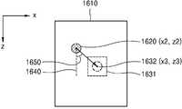
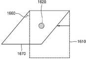
도 16a 를 참조하면 복수의 볼륨 데이터 상에서 관심 객체의 위치는 변경될 수 있다. 초음파 진단 장치(300)는 제 2 초음파 데이터 상에서 관심 객체의 제 2 위치(1620)를 검출할 수 있다. 도 10 내지 도 11 에서 설명한 바와 같이, 제 2 위치는 제 1 위치에 기초하여 검출될 수 있다.Referring to FIG. 16A , the location of the object of interest on the plurality of volume data may be changed. The
초음파 진단 장치(300)는 기 설정된 위치를 가지고 있을 수 있다. 예를 들어 초음파 진단 장치(300)는 기 설정된 위치를 도 1 의 메모리(150)에 저장하고 있을 수 있다. 또한 초음파 진단 장치(300)는 사용자의 입력에 기초하여 기 설정된 위치을 획득할 수 있다. 기 설정된 위치는 관심 객체를 관찰하기에 좋은 볼륨 데이터 상의 위치가 될 수 있다. 또한 기 설정된 위치는 관심 객체를 관찰하기에 좋은 초음파 영상 상의 위치가 될 수 있다. 기 설정된 위치는 영역(1631) 또는 위치(1632)일 수 있다.The
기 설정된 위치가 영역(1631)일 경우 초음파 진단 장치(300)는 관심 객체의 적어도 일부가 영역(1631) 내에 들어오도록, 초음파 빔의 송수신 조건을 변경할 수 있다. 또한 기 설정된 위치가 위치(1632)일 경우 초음파 진단 장치(300)는 관심 객체가 위치(1632)에 위치하도록 초음파 빔의 송수신 조건을 변경할 수 있다.When the preset location is the
초음파 진단 장치(300)는 제 2 위치를 나타내는 좌표값을 (x2, z2)으로 획득할 수 있다. 또한 초음파 진단 장치(300)는 기 설정된 위치를 나타내는 좌표값을 (x3, z3)으로 획득할 수 있다. 초음파 진단 장치(300)는 제 2 위치를 나타내는 좌표값 및 기 설정된 위치를 나타내는 좌표값의 차이값을 획득할 수 있다. 예를 들어 차이값을 나타내는 벡터는 (x3-x2, z3-z2) 일 수 있다.The
초음파 진단 장치(300)는 z 축과 벡터가 이루는 각(1650)을 구할 수 있다. 초음파 진단 장치(300)는 각(1650)을 atan(|x3-x2|/|z3-z2|)으로 계산할 수 있다.The
도 16b 를 참조하면 초음파 진단 장치(300)는 각(1650)에 기초하여 초음파 빔의 스티어링 각(1660)을 변경할 수 있다. 또한 초음파 진단 장치(300)는 변경된 스티어링 각(1660)에 의하여 볼륨 데이터를 획득할 수 있다. 또한 획득된 볼륨 데이터에는 2 차원 데이터(1670)가 포함될 수 있다.Referring to FIG. 16B , the
도 6 은 본원의 일 실시예와 관련된 초음파 진단 장치의 동작을 나타낸 도면이다.6 is a diagram illustrating an operation of an ultrasound diagnosis apparatus according to an exemplary embodiment of the present disclosure.
도 6 을 참조하면, 사용자는 프로브(610)의 위치를 이동시킬 수 있다. 초음파 진단 장치(300)는 도 10 내지 도 16에서 설명한 바와 같이 초음파 빔(611)의 송수신 조건을 변경할 수 있다. 따라서 프로브(610)는 이동하였으나 초음파 빔(611)은 여전히 관심 객체(601)를 향할 수 있다.Referring to FIG. 6 , the user may move the position of the
도 7a 및 도 7b 는 본원의 일 실시예와 관련된 초음파 영상을 나타낸 도면이다.7A and 7B are diagrams illustrating ultrasound images according to an exemplary embodiment of the present disclosure.
도 6 에서 설명한 바와 같이 초음파 진단 장치(300)는 초음파 빔의 송수신 조건을 변경할 수 있다. 도 7a 는 도 6 의 프로브(610)의 위치에서 초음파 진단 장치(300)가 획득한 초음파 영상(700)을 나타낸다. 도 5a 의 초음파 영상(510)은 제 1 데이터에 기초한 제 1 초음파 영상일 수 있고, 도 7a의 초음파 영상(700)은 제 2 데이터에 기초한 제 2 초음파 영상일 수 있다.As described with reference to FIG. 6 , the
초음파 영상(700)은 관심 객체의 영상(701)이 나타날 수 있다. 관심 객체의 영상(701) 및 도 5a 의 관심 객체의 영상(511)은 관심 객체의 서로 다른 각도에서 바라본 영상일 수 있다. 관심 객체의 영상(701) 및 도 5a 의 관심 객체의 영상(511)이 서로 다른 이유는, 프로브의 위치가 이동되었고, 초음파 진단 장치(300)가 초음파 빔의 송수신 조건을 변경했기 때문이다. 관심 객체의 영상(701)은 도 6 의 프로브(610)의 위치에서 바라본 영상이다. 또한 도 5a 의 관심 객체의 영상(511)은 도 4b 의 프로브(420)의 위치에서 바라본 영상이다. 사용자는 프로브의 위치를 변경하는 것 만으로, 관심 객체의 서로 다른 위치에서 바라본 영상을 용이하게 획득할 수 있다.The
도 7b 는 도 6 의 프로브(610)의 위치에서 초음파 진단 장치(300)가 획득한 초음파 영상(710)을 나타낸다. 도 5a 의 초음파 영상(510)은 제 1 데이터에 기초한 제 1 초음파 영상일 수 있고, 도 7b의 초음파 영상(710)은 제 2 데이터에 기초한 제 2 초음파 영상일 수 있다.FIG. 7B illustrates an
초음파 영상(710)에는 관심 객체의 영상(711)이 나타날 수 있다. 관심 객체의 영상(711) 및 도 5a 의 관심 객체의 영상(511)은 관심 객체를 서로 다른 각도에서 바라본 영상일 수 있다.An
도 1 의 디스플레이부(140)는 제 2 초음파 데이터에 기초하여 관심 객체를 포함한 제 2 초음파 영상을 표시할 수 있다. 또한, 디스플레이부(140)는 초음파 빔의 송수신 조건의 변경에 따라, 제 1 초음파 영상의 형상, 크기, 위치 중 적어도 하나를 변경하여 제 2 초음파 영상을 표시할 수 있다.The
초음파 진단 장치(300)는 초음파 빔의 수신 깊이, 초음파 빔의 폭, 초음파 빔의 스티어링 각 및 초음파 빔의 집속 위치 중 적어도 하나를 포함하는 초음파 빔의 송수신 조건을 변경할 수 있다.The
초음파 진단 장치(300)는 초음파 빔이 대상체의 깊숙이 도달하도록 송신 조건을 변경할 수 있다. 예를 들어 초음파 진단 장치(300)는 주파수가 낮은 초음파 빔을 송신할 수 있다. 또한, 초음파 진단 장치(300)는 초음파 빔을 송신 후 대상체로부터 반사된 초음파 에코 신호를 수신한다. 초음파 진단 장치(300)는 소정의 거리 미만에서 반사된 초음파 에코 신호만을 수신할 수 있다. 이때 소정의 거리는 초음파 빔의 수신 깊이가 될 수 있다. 또한 초음파 진단 장치(300)는 초음파 빔의 수신 깊이 미만에서 반사된 초음파 에코 신호에 기초하여 초음파 영상(710)을 획득할 수 있다. 초음파 빔의 수신 깊이는 초음파 영상(710)의 상하 길이와 관련될 수 있다.The
초음파 빔의 폭은 초음파 영상(710)의 좌우 길이와 관련될 수 있다. 초음파 진단 장치(300)는 트랜스듀서들을 이용하여, 초음파 빔의 좌우 폭을 결정할 수 있다. 또한 초음파 진단 장치(300)는 반사된 초음파 에코 신호 중 소정의 폭 미만의 초음파 에코 신호를 수신할 수 있다. 또한 초음파 진단 장치(300)는 소정의 폭 미만의 초음파 에코 신호에 기초하여 초음파 영상(710)을 획득할 수 있다.The width of the ultrasound beam may be related to the left and right lengths of the
또한 초음파 빔의 스티어링 각은 초음파 영상(710)의 기울기와 관련될 수 있다. 초음파 진단 장치(300)는 소정의 스티어링 각으로 초음파 빔을 송신할 수 있다. 초음파 진단 장치(300)는 초음파 빔의 스티어링 각에 대해서는 도 3 과 함께 설명하였으므로 자세한 설명은 생략한다.Also, the steering angle of the ultrasound beam may be related to the inclination of the
또한 초음파 빔의 집속 위치는 초음파 영상(710) 상에서 해상도가 높은 영역과 관련될 수 있다. 초음파 빔이 집속되는 위치 부근의 영역이 일반적으로 초음파 영상(710) 상에서 해상도가 높은 영역이다.Also, the focused position of the ultrasound beam may be related to a high-resolution area on the
또한 초음파 영상(710) 및 도 5a 의 초음파 영상(510)은 서로 다른 영상 폭 및 서로 다른 상하 길이를 가질 수 있다. 예를 들어 초음파 영상(710)은 도 5a 의 초음파 영상(510) 보다 상하 길이가 더 길 수 있다. 도 6 의 초음파 빔(611)의 도달 거리가 도 4b의 초음파 빔(422)의 도달 거리보다 길기 때문이다.Also, the
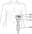
도 8a 및 도 8b 는 본원의 일 실시예와 관련된 초음파 데이터를 획득하는 과정을 나타낸 도면이다.8A and 8B are diagrams illustrating a process of acquiring ultrasound data related to an exemplary embodiment of the present disclosure.
도 4b 는 대상체(400)를 측면에서 본 도면이고 도 8a 는 대상체(800)를 정면에서 본 도면이다. 도 8a 의 프로브(810)의 위치는 도 4b 의 프로브(420)의 위치와 대응된다. 도 8a 의 초음파 빔(811)은 도 4b 의 초음파 빔(422)과 대응된다.4B is a view of the
프로브 도 8a 를 참조하면, 초음파 진단 장치(300)는 프로브(810)를 이용하여 대상체(800)를 스캔하여 볼륨 데이터를 획득할 수 있다. 초음파 빔(811)은 관심 객체(801)를 향하고 있으므로 획득된 볼륨 데이터에는 관심 객체(801)와 관련된 정보가 담겨있을 수 있다. 초음파 진단 장치(300)는 볼륨 데이터에 기초하여 초음파 영상을 생성할 수 있다.Probe Referring to FIG. 8A , the
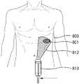
도 8b 를 참조하면, 사용자는 프로브(810)의 위치를 이동시킬 수 있다. 초음파 진단 장치(300)는 도 10 내지 도 16에서 설명한 바와 같이 초음파 빔(812)의 송수신 조건을 변경할 수 있다. 따라서 프로브(810)는 이동하였으나 초음파 빔(812)은 여전히 관심 객체(801)를 향할 수 있다.Referring to FIG. 8B , the user may move the position of the
도 9a 및 도 9b 는 본원의 일 실시예와 관련된 초음파 영상을 나타낸 도면이다.9A and 9B are diagrams illustrating ultrasound images according to an exemplary embodiment of the present disclosure.
도 8b 에서 설명한 바와 같이 초음파 진단 장치(300)는 초음파 빔의 송수신 조건을 변경할 수 있다. 도 9a 은 도 8b 의 프로브(810)의 위치에서 초음파 진단 장치(300)가 획득한 초음파 영상(900)을 나타낸다. 도 5a 의 초음파 영상(510)은 제 1 데이터에 기초한 제 1 초음파 영상일 수 있고, 도 9a의 초음파 영상(900)은 제 2 데이터에 기초한 제 2 초음파 영상일 수 있다. 초음파 영상(900)에는 관심 객체의 영상(901)이 나타날 수 있다. 관심 객체의 영상(901) 및 도 5a 의 관심 객체의 영상(511)은 관심 객체의 서로 다른 각도에서 바라본 영상일 수 있다. 사용자는 프로브의 위치를 변경하는 것 만으로, 관심 객체의 서로 다른 위치에서 바라본 영상을 용이하게 획득할 수 있다. 도 9a 와 관련된 설명 중 도 7a 에서 이미 설명한 부분은 설명을 생략한다.As described with reference to FIG. 8B , the
도 9b 는 도 8b 의 프로브(810)의 위치에서 초음파 진단 장치(300)가 획득한 초음파 영상(910)을 나타낼 수 있다. 도 5a 의 초음파 영상(510)은 제 1 데이터에 기초한 제 1 초음파 영상일 수 있고, 도 9b의 초음파 영상(910)은 제 2 데이터에 기초한 제 2 초음파 영상일 수 있다. 초음파 영상(910)에는 관심 객체의 영상(911)이 나타날 수 있다. 관심 객체의 영상(911) 및 도 5a 의 관심 객체의 영상(511)은 관심 객체를 서로 다른 각도에서 바라본 영상일 수 있다.FIG. 9B may show an
또한, 도 1 의 디스플레이부(140)는 제 2 초음파 데이터에 기초하여 관심 객체를 포함한 제 2 초음파 영상을 표시할 수 있다. 또한, 디스플레이부(140)는 초음파 빔의 송수신 조건의 변경에 따라, 제 1 초음파 영상의 형상, 크기, 위치 중 적어도 하나를 변경하여 제 2 초음파 영상을 표시할 수 있다.Also, the
예를 들어, 초음파 영상(910) 및 도 5a 의 초음파 영상(510)은 서로 다른 기울기를 가질 수 있다. 초음파 영상(910)은 도 5a 의 초음파 영상(510)에 비하여 오른쪽으로 기울어진 영상일 수 있다. 도 8 에서와 같이 초음파 진단 장치(300)는 초음파 빔(812)의 스티어링 각을 변경할 수 있으며, 변경된 스티어링 각에 기초하여 초음파 진단 장치는 초음파 영상(510)을 오른쪽으로 기울여서 표시할 수 있다. 다만 이에 한정되는 것은 아니며, 초음파 진단 장치(300)는 영상 처리를 통하여, 초음파 영상(510)을 기울이지 않게 표시할 수 있다. 또한, 위에서는 스티어링 각을 변경하는 경우에 대하여 설명하였으나, 초음파 진단 장치(300)가 초음파 빔의 수신 깊이, 초음파 빔의 폭, 초음파 빔의 스티어링 각 및 초음파 빔의 집속 위치와 같은 송수신 조건을 변경함에 따라, 디스플레이부(140)는 제 2 초음파 영상의 형상, 크기, 위치 중 적어도 하나를 변경하여 표시할 수 있다.For example, the
도 17 은 본원의 일실시예에 따른 초음파 진단 장치의 동작 방법을 나타낸 흐름도이다.17 is a flowchart illustrating a method of operating an ultrasound diagnosis apparatus according to an exemplary embodiment of the present disclosure.
단계(S1710)는 데이터 획득부(310)에 의하여 수행될 수 있다. 단계(S1720)는 제어부(320)에 의하여 수행될 수 있다. 단계(S1730)는 데이터 획득부(310)에 의하여 수행될 수 있다. 단계(S1740)는 제어부(320)에 의하여 수행될 수 있다. 단계(S1750)는 제어부에 의하여 수행될 수 있다.Step S1710 may be performed by the
단계(S1710)에서 본 개시의 일 실시예에 따른 초음파 진단 장치(300)는 관심 객체를 포함하는 대상체에 대한 제 1 초음파 데이터를 획득할 수 있다. 또한 단계(S1720)에서 본 개시의 일 실시예에 따른 초음파 진단 장치(300)는 제 1 초음파 데이터 상에서 관심 객체의 제 1 위치를 검출할 수 있다. 또한, 단계(S1730)에서 본 개시의 일 실시예에 따른 초음파 진단 장치(300)는 대상체에 대한 제 2 초음파 데이터를 획득할 수 있다. 단계(S1740)에서 본 개시의 일 실시예에 따른 초음파 진단 장치(300)는 제 2 초음파 데이터 상에서 제 1 위치에 기초하여 관심 객체의 제 2 위치를 검출할 수 있다. 단계(S1750)에서 본 개시의 일 실시예에 따른 초음파 진단 장치(300)는 제 2 위치에 기초하여, 대상체로 송신하는 초음파 빔의 송수신 조건을 변경할 수 있다.In operation S1710, the
또한 제 2 위치를 검출하는 단계는, 제 1 초음파 데이터 상의 관심 객체의 픽셀 값 혹은 복셀 값과의 상관도 에 기초할 수 있다.Also, the detecting of the second position may be based on a correlation with a pixel value or a voxel value of the object of interest on the first ultrasound data.
또한, 송수신 조건을 변경하는 단계는 제 1 위치에 더 기초하여 초음파 빔의 송수신 조건을 변경할 수 있다.In addition, the changing of the transmission/reception condition may change the transmission/reception condition of the ultrasound beam further based on the first position.
또한, 제 1 위치를 검출하는 단계는 제 1 초음파 데이터 상에서 제 1 위치를 나타내는 제 1 좌표값을 획득하는 단계를 포함할 수 있다. 또한, 제 2 위치를 검출하는 단계는 제 2 초음파 데이터 상에서 제 2 위치를 나타내는 제 2 좌표값을 획득하는 단계를 포함할 수 있다. 또한, 송수신 조건을 변경하는 단계는 제 1 좌표값 및 제 2 좌표값의 차이값에 기초하여 초음파 빔의 송수신 조건을 변경할 수 있다.Also, the detecting of the first position may include obtaining a first coordinate value indicating the first position on the first ultrasound data. Also, the detecting of the second position may include obtaining a second coordinate value indicating the second position on the second ultrasound data. In addition, the changing of the transmission/reception condition may include changing the transmission/reception condition of the ultrasound beam based on a difference value between the first coordinate value and the second coordinate value.
또한, 제 1 위치를 검출하는 단계는 제 1 초음파 데이터 상에서 관심 객체의 중심점의 좌표값을 제 1 좌표값으로 획득하는 단계를 포함할 수 있다. 또한, 제 2 위치를 검출하는 단계는 제 2 초음파 데이터 상에서 관심 객체의 중심점의 좌표값을 제 2 좌표값으로 획득하는 단계를 포함할 수 있다.Also, the detecting of the first position may include acquiring a coordinate value of the center point of the object of interest on the first ultrasound data as the first coordinate value. Also, the detecting of the second position may include obtaining a coordinate value of the center point of the object of interest on the second ultrasound data as the second coordinate value.
또한, 송수신 조건을 변경하는 단계는 제 2 위치 및 기 설정된 위치 의 차이값에 기초하여 초음파 빔의 송수신 조건을 변경하는 단계를 포함할 수 있다.Also, the changing of the transmission/reception condition may include changing the transmission/reception condition of the ultrasound beam based on a difference value between the second position and the preset position.
또한, 본 개시의 일 실시예에 따른 초음파 진단 장치의 동작 방법은 사용자로부터 제 1 초음파 데이터에 기초한 제 1 초음파 영상 상에 관심 영역(ROI: Region of Interest)을 설정하는 입력을 수신하는 단계를 더 포함할 수 있다. 또한, 제 1 위치를 검출하는 단계는 관심 영역 내에서 관심 객체의 제 1 위치를 검출하는 단계를 포함할 수 있다.In addition, the method of operating an ultrasound diagnosis apparatus according to an embodiment of the present disclosure further includes receiving an input for setting a region of interest (ROI) on a first ultrasound image based on first ultrasound data from a user. may include Also, the detecting of the first position may include detecting the first position of the object of interest within the ROI.
또한, 초음파 빔의 송수신 조건은, 초음파 빔의 수신 깊이, 초음파 빔의 폭, 초음파 빔의 스티어링 각 및 초음파 빔의 집속 위치 중 적어도 하나를 포함할 수 있다.In addition, the ultrasound beam transmission/reception condition may include at least one of a reception depth of the ultrasound beam, a width of the ultrasound beam, a steering angle of the ultrasound beam, and a focusing position of the ultrasound beam.
또한, 대상체로 송신하는 초음파 빔의 송수신 조건을 변경하는 단계는 실시간일 수 있다.Also, changing the transmission/reception condition of the ultrasound beam transmitted to the object may be performed in real time.
또한, 본 개시의 일 실시예에 따른 초음파 진단 장치의 동작 방법은 제 2 초음파 데이터에 기초하여 대상체를 포함한 제 2 초음파 영상 표시하는 단계, 및 초음파 빔의 송수신 조건의 변경에 따라, 제 1 초음파 영상의 형상, 크기, 위치 중 적어도 하나를 변경하여 제 2 초음파 영상을 표시하는 단계를 더 포함할 수 있다.In addition, the method of operating an ultrasound diagnosis apparatus according to an exemplary embodiment of the present disclosure includes displaying a second ultrasound image including an object based on second ultrasound data, and according to a change in an ultrasound beam transmission/reception condition, a first ultrasound image The method may further include displaying the second ultrasound image by changing at least one of the shape, size, and position of the .
또한, 본 개시의 일 실시예에 따른 초음파 진단 장치의 동작 방법을 구현하기 위한 프로그램은, 컴퓨터로 판독 가능한 기록 매체에 기록될 수 있다.Also, a program for implementing the method of operating an ultrasound diagnosis apparatus according to an exemplary embodiment of the present disclosure may be recorded in a computer-readable recording medium.
본 개시에 따른 초음파 진단 장치는 프로브 움직임에 따라, 또는 관심 객체에 대한 다른 각도에서의 초음파 영상을 용이하게 획득할 수 있다. 또한 본 개시에 따른 초음파 진단 장치는 관심 객체의 위치를 추적하여 해당 관심 객체를 중심으로 초음파 영상을 용이하게 획득할 수 있다.The ultrasound diagnosis apparatus according to the present disclosure may easily acquire an ultrasound image from a different angle with respect to the object of interest or according to the movement of the probe. Also, the ultrasound diagnosis apparatus according to the present disclosure may track the location of the object of interest to easily acquire an ultrasound image centering on the object of interest.
하드웨어는 프로세서 및 메모리 중 적어도 하나를 포함할 수 있다. 용어 "프로세서" 는 범용 프로세서, 중앙 처리 장치 (CPU), 마이크로프로세서, 디지털 신호 프로세서 (DSP), 제어기, 마이크로제어기, 상태 머신, 및 등을 포함하도록 넓게 해석되어야 한다. 몇몇 환경에서는, "프로세서" 는 주문형 반도체 (ASIC), 프로그램가능 로직 디바이스 (PLD), 필드 프로그램가능 게이트 어레이 (FPGA), 등을 지칭할 수도 있다. 용어 "프로세서" 는, 예를 들어, DSP 와 마이크로프로세서의 조합, 복수의 마이크로프로세서들의 조합, DSP 코어와 결합한 하나 이상의 마이크로프로세서들의 조합, 또는 임의의 다른 그러한 구성들의 조합과 같은 처리 디바이스들의 조합을 지칭할 수도 있다.The hardware may include at least one of a processor and a memory. The term “processor” should be interpreted broadly to include general purpose processors, central processing units (CPUs), microprocessors, digital signal processors (DSPs), controllers, microcontrollers, state machines, and the like. In some circumstances, a “processor” may refer to an application specific semiconductor (ASIC), a programmable logic device (PLD), a field programmable gate array (FPGA), or the like. The term “processor” refers to a combination of processing devices, such as, for example, a combination of a DSP and a microprocessor, a combination of a plurality of microprocessors, a combination of one or more microprocessors in combination with a DSP core, or any other such configurations. may refer to.
용어 "메모리" 는 전자 정보를 저장 가능한 임의의 전자 컴포넌트를 포함하도록 넓게 해석되어야 한다. 용어 메모리는 임의 액세스 메모리 (RAM), 판독-전용 메모리 (ROM), 비-휘발성 임의 액세스 메모리 (NVRAM), 프로그램가능 판독-전용 메모리 (PROM), 소거-프로그램가능 판독 전용 메모리 (EPROM), 전기적으로 소거가능 PROM (EEPROM), 플래쉬 메모리, 자기 또는 광학 데이터 저장장치, 레지스터들, 등과 같은 프로세서-판독가능 매체의 다양한 유형들을 지칭할 수도 있다. 프로세서가 메모리에 메모리로부터 정보를 판독하고/하거나 메모리에 정보를 기록할 수 있다면 메모리는 프로세서와 전자 통신 상태에 있다고 불린다. 프로세서에 집적된 메모리는 프로세서와 전자 통신 상태에 있다.The term “memory” should be interpreted broadly to include any electronic component capable of storing electronic information. The term memory includes random access memory (RAM), read-only memory (ROM), non-volatile random access memory (NVRAM), programmable read-only memory (PROM), erase-programmable read only memory (EPROM), electrical may refer to various types of processor-readable media, such as erasable PROM (EEPROM), flash memory, magnetic or optical data storage, registers, and the like. A memory is said to be in electronic communication with the processor if the processor is capable of reading information from, and/or writing information to, the memory into the memory. A memory integrated in the processor is in electronic communication with the processor.
용어 "명령들" 및 "코드" 는 컴퓨터-판독가능 문구(들) 의 임의의 유형을 포함하도록 넓게 해석되어야 한다. 예를 들어, 용어 "명령들" 및 "코드" 는 하나 이상의 프로그램들, 루틴들, 서브-루틴들, 기능들, 절차들, 등을 지칭할 수도 있다. "명령들" 및 "코드" 는 단일 컴퓨터-판독가능 문구 또는 많은 컴퓨터-판독가능 문구들을 포함할 수도 있다.The terms “instructions” and “code” should be interpreted broadly to include any type of computer-readable phrase(s). For example, the terms “instructions” and “code” may refer to one or more programs, routines, sub-routines, functions, procedures, or the like. “Instructions” and “code” may include a single computer-readable phrase or many computer-readable phrases.
본원에 설명된 기능들은 하드웨어, 소프트웨어, 펌웨어 또는 그들의 임의의 조합으로 구현될 수도 있다. 소프트웨어로 구현된다면, 기능들은 컴퓨터로 판독 가능한 기록 매체 상에 하나 이상의 명령들 또는 코드로 저장될 수도 있다. 용어 "컴퓨터로 판독 가능한 기록 매체" 또는 "컴퓨터-프로그램 제품" 은 컴퓨터에 의하여 액세스될 수 있는 임의의 이용가능한 매체를 지칭한다. 제한이 아닌, 예의 방법으로써, 컴퓨터로 판독 가능한 기록 매체는 RAM, ROM, EEPROM, CD-ROM 또는 다른 광학 디스크 저장장치, 자기 디스크 저장장치 또는 다른 자기 저장 디바이스들, 또는 명령들 또는 데이터 구조들의 형태로 원하는 프로그램 코드를 저장하거나 유지할 수 있고 컴퓨터에 의하여 액세스될 수 있는 임의의 다른 매체를 포함할 수도 있다. 디스크 (Disk) 및 디스크 (Disc) 는, 본원에 사용된 대로, 디스크 (disc) 가 레이저로 데이터를 광학적으로 재생하는 반면, 디스크 (disk) 는 보통 데이터를 자기적으로 재생하며 콤팩트 디스크 (CD), 레이저 디스크, 광학 디스크, 디지털 다용도 디스크 (DVD), 플로피 디스크 및 블루레이 (Blu-ray®) 디스크를 포함한다.The functions described herein may be implemented in hardware, software, firmware, or any combination thereof. If implemented in software, the functions may be stored as one or more instructions or codes on a computer-readable recording medium. The term "computer-readable recording medium" or "computer-program product" refers to any available medium that can be accessed by a computer. By way of example and not limitation, a computer-readable recording medium may be in the form of RAM, ROM, EEPROM, CD-ROM or other optical disk storage, magnetic disk storage or other magnetic storage devices, or instructions or data structures. It may include any other medium that can store or hold desired program code and can be accessed by a computer. Disc and Disc, as used herein, are compact discs (CDs) that normally reproduce data magnetically, whereas discs reproduce data optically with a laser. , laser discs, optical discs, digital versatile discs (DVD), floppy discs and Blu-ray® discs.
컴퓨터로 판독 가능한 기록 매체에 기록되는 소프트웨어 또는 명령들은 송신 매체 상에서 또한 송신될 수도 있다. 예를 들어, 소프트웨어가 동축 케이블, 광 섬유 케이블, 트위스티드 페어 (twisted pair), 디지털 가입자 회선 (DSL), 또는 적외선, 라디오, 및 마이크로파 (microwave) 와 같은 무선 기술들을 이용하여 웹사이트, 서버 또는 다른 원격 소스로부터 송신된다면, 동축 케이블, 광 섬유 케이블, 트위스티드 페어, DSL, 또는 적외선, 라디오, 및 마이크로파와 같은 무선 기술들은 송신 매체의 정의에 포함된다.Software or instructions recorded on a computer-readable recording medium may also be transmitted on a transmission medium. For example, if the software uses a coaxial cable, fiber optic cable, twisted pair, digital subscriber line (DSL), or wireless technologies such as infrared, radio, and microwave to be used on a website, server or other If transmitted from a remote source, coaxial cable, fiber optic cable, twisted pair, DSL, or wireless technologies such as infrared, radio, and microwave are included in the definition of transmission medium.
본원 발명의 실시예들과 관련된 기술 분야에서 통상의 지식을 가진 자는 상기 기재의 본질적인 특성에서 벗어나지 않는 범위에서 변형된 형태로 구현될 수 있음을 이해할 수 있을 것이다. 그러므로, 개시된 방법들은 한정적인 관점이 아닌 설명적 관점에서 고려되어야 한다. 본 발명의 범위는 발명의 상세한 설명이 아닌 특허청구 범위에 나타나며, 그와 동등한 범위 내에 있는 모든 차이점은 본 발명의 범위에 포함되는 것으로 해석되어야 한다.Those of ordinary skill in the art related to the embodiments of the present invention will understand that it can be implemented in a modified form within a range that does not depart from the essential characteristics of the description. Therefore, the disclosed methods are to be considered in an illustrative rather than a restrictive sense. The scope of the present invention is indicated in the claims rather than the detailed description of the invention, and all differences within the scope of equivalents thereto should be construed as being included in the scope of the present invention.
Claims (21)
Translated fromKorean상기 제 1 초음파 데이터 상에서, 상기 대상체에 포함되는 관심 객체의 제 1 위치를 검출하고, 상기 제 2 초음파 데이터 상에서, 상기 제 1 위치에 기초하여 상기 관심 객체의 제 2 위치를 검출하고, 상기 제 2 위치에 기초하여 초음파 빔의 송수신 조건을 변경하고, 변경된 초음파 빔의 송수신 조건에 기초하여 상기 대상체의 초음파 영상을 획득하는 제어부; 및
상기 제1 초음파 데이터에 기초하여 제1 초음파 영상을 디스플레이하고, 상기 제2 초음파 데이터에 기초하여 제2 초음파 영상을 디스플레이하는 디스플레이부; 를 포함하고,
상기 변경된 초음파 빔의 송수신 조건은 초음파 빔의 스티어링 각을 포함하고,
상기 제어부는: 상기 제1 위치와 상기 제2 위치 간 차이에 기초하여 초음파 빔의 스티어링 각을 변경하고, 상기 제2 초음파 영상은 변경된 초음파 빔의 스티어링 각에 기초하여 획득된 상기 제2 초음파 데이터에 기초하여 획득되고, 상기 제2 초음파 영상 내 상기 대상체의 포즈(pose)가 변경되도록, 변경된 스티어링 각에 대응하여 상기 제2 초음파 영상을 회전시키고,
상기 디스플레이부는 회전된 상기 제2 초음파 영상을 디스플레이하는, 초음파 진단 장치.A data acquisition unit acquiring ultrasound data for an object, wherein the ultrasound data includes first ultrasound data and second ultrasound data, and the first ultrasound data may be configured by the data acquisition unit being disposed at a first acquisition position with respect to the object. data obtained when the second ultrasound data is data obtained when the data obtaining unit is disposed at a second obtaining position different from the first obtaining position with respect to the object;
detecting a first location of the object of interest included in the object on the first ultrasound data, detecting a second location of the object of interest based on the first location on the second ultrasound data, and a control unit that changes an ultrasound beam transmission/reception condition based on a location and acquires an ultrasound image of the object based on the changed ultrasound beam transmission/reception condition; and
a display unit configured to display a first ultrasound image based on the first ultrasound data and a second ultrasound image based on the second ultrasound data; including,
The changed ultrasound beam transmission/reception condition includes a steering angle of the ultrasound beam,
The controller is configured to: change a steering angle of an ultrasound beam based on a difference between the first position and the second position, and the second ultrasound image is applied to the second ultrasound data obtained based on the changed steering angle of the ultrasound beam. and rotating the second ultrasound image in response to the changed steering angle so that a pose of the object in the second ultrasound image is changed,
and the display unit displays the rotated second ultrasound image.
상기 제어부는,
상기 제 1 초음파 데이터 상의 상기 관심 객체의 픽셀 값들 및 복셀 값들 중 적어도 하나, 및 상기 제 2 초음파 데이터 상의 픽셀 값들 및 복셀 값들 중 적어도 하나의 상관도에 기초하여, 상기 제 2 초음파 데이터 상에서 상기 관심 객체의 제 2 위치를 검출하는 초음파 진단 장치.The method of claim 1,
The control unit is
The object of interest on the second ultrasound data based on a correlation of at least one of pixel values and voxel values of the object of interest on the first ultrasound data, and at least one of pixel values and voxel values on the second ultrasound data An ultrasonic diagnostic device for detecting the second position of the
상기 제어부는
상기 제 1 초음파 데이터 상에서 상기 제 1 위치를 나타내는 제 1 좌표값을 획득하고,
상기 제 2 초음파 데이터 상에서 상기 제 2 위치를 나타내는 제 2 좌표값을 획득하며,
상기 제 1 좌표값 및 상기 제 2 좌표값의 차이값에 기초하여 상기 초음파 빔의 송수신 조건을 변경하는 초음파 진단 장치.3. The method of claim 2,
the control unit
obtaining a first coordinate value indicating the first position on the first ultrasound data;
obtaining a second coordinate value indicating the second position on the second ultrasound data;
An ultrasound diagnosis apparatus for changing a condition for transmitting and receiving the ultrasound beam based on a difference value between the first coordinate value and the second coordinate value.
상기 제어부는,
상기 제 1 초음파 데이터 상에서 상기 관심 객체의 중심점의 좌표값을 상기 제 1 좌표값으로 획득하고,
상기 제 2 초음파 데이터 상에서 상기 관심 객체의 중심점의 좌표값을 상기 제 2 좌표값으로 획득하는 초음파 진단 장치.5. The method of claim 4
The control unit is
obtaining a coordinate value of a center point of the object of interest on the first ultrasound data as the first coordinate value;
An ultrasound diagnosis apparatus configured to obtain a coordinate value of a center point of the object of interest on the second ultrasound data as the second coordinate value.
상기 제어부는,
상기 제 2 위치 및 기 설정된 위치의 차이값에 기초하여 상기 초음파 빔의 송수신 조건을 변경하는 초음파 진단 장치.The method of claim 1,
The control unit is
An ultrasound diagnosis apparatus for changing a condition for transmitting and receiving the ultrasound beam based on a difference value between the second position and a preset position.
사용자로부터 상기 제 1 초음파 영상 상에 관심 영역(ROI: Region of Interest)을 설정하는 입력을 수신하는 입력부를 더 포함하고,
상기 제어부는,
상기 관심 영역 내에서 상기 관심 객체의 제 1 위치를 검출하는 초음파 진단 장치.The method of claim 1,
Further comprising an input unit for receiving an input for setting a region of interest (ROI) on the first ultrasound image from a user,
The control unit is
An ultrasound diagnosis apparatus configured to detect a first position of the object of interest within the region of interest.
상기 초음파 빔의 송수신 조건은, 초음파 빔의 수신 깊이, 초음파 빔의 폭, 및 초음파 빔의 집속 위치 중 적어도 하나를 더 포함하는 초음파 진단 장치.The method of claim 1,
The ultrasound beam transmission/reception condition may further include at least one of a reception depth of an ultrasound beam, a width of an ultrasound beam, and a focal point of the ultrasound beam.
상기 제어부는
상기 대상체로 송신하는 초음파 빔의 송수신 조건을 실시간으로 변경하는 것을 특징으로 하는 초음파 진단 장치.The method of claim 1,
the control unit
The ultrasound diagnosis apparatus of claim 1, wherein the transmission/reception condition of the ultrasound beam transmitted to the object is changed in real time.
상기 초음파 빔의 송수신 조건의 변경에 따라, 상기 제 1 초음파 영상의 형상, 크기, 위치 중 적어도 하나를 변경하여 상기 제 2 초음파 영상을 표시하는 디스플레이부를 더 포함하는 초음파 진단 장치.The method of claim 1,
and a display unit configured to display the second ultrasound image by changing at least one of a shape, size, and position of the first ultrasound image according to a change in the condition for transmitting and receiving the ultrasound beam.
상기 제 1 초음파 데이터 상에서 상기 관심 객체의 제 1 위치를 검출하는 단계;
상기 데이터 획득부가 상기 대상체에 대한 제 2 초음파 데이터를 획득하는 단계-상기 제2 초음파 데이터는 상기 데이터 획득부가 상기 대상체에 대하여 상기 제1 획득 위치와는 다른 제2 획득 위치에 배치될 때 획득된 데이터임-;
상기 제 2 초음파 데이터 상에서 상기 제 1 위치에 기초하여 상기 관심 객체의 제 2 위치를 검출하는 단계;
상기 제 2 위치에 기초하여, 상기 대상체로 송신하는 초음파 빔의 송수신 조건을 변경하는 단계;
변경된 초음파 빔의 송수신 조건에 기초하여 상기 대상체의 초음파 영상을 획득하는 단계; 및
상기 제1 초음파 데이터 또는 상기 제2 초음파 데이터에 기초하여 획득된 초음파 영상을 디스플레이하는 단계; 를 포함하고,
상기 초음파 영상을 디스플레이하는 단계는, 상기 제1 초음파 데이터에 기초하여 제1 초음파 영상을 디스플레이하는 단계 및 상기 제2 초음파 데이터에 기초하여 제2 초음파 영상을 디스플레이하는 단계를 포함하고,
상기 변경된 초음파 빔의 송수신 조건은 초음파 빔의 스티어링 각을 포함하고,
상기 초음파 빔의 송수신 조건을 변경하는 단계는, 상기 제1 위치와 상기 제2 위치 간 차이에 기초하여 초음파 빔의 스티어링 각을 변경하는 단계를 포함하고,
상기 제2 초음파 영상은 변경된 초음파 빔의 스티어링 각을 이용하여 획득된 상기 제2 초음파 데이터에 기초하여 획득되고,
상기 초음파 영상을 디스플레이하는 단계는, 상기 제2 초음파 영상 내 상기 대상체의 포즈가 변경되도록 변경된 스티어링 각에 대응하여 회전된 상기 제2 초음파 영상을 디스플레이하는, 초음파 진단 장치의 동작 방법.acquiring, by a data acquisition unit, first ultrasound data for an object including an object of interest, wherein the first ultrasound data is data obtained when the data acquisition unit is disposed at a first acquisition position with respect to the object;
detecting a first position of the object of interest on the first ultrasound data;
obtaining, by the data obtaining unit, second ultrasound data for the object, wherein the second ultrasound data is data obtained when the data obtaining unit is disposed at a second obtaining position different from the first obtaining position with respect to the object lim-;
detecting a second position of the object of interest based on the first position on the second ultrasound data;
changing a transmission/reception condition of an ultrasound beam transmitted to the object based on the second location;
acquiring an ultrasound image of the object based on the changed ultrasound beam transmission/reception condition; and
displaying an ultrasound image obtained based on the first ultrasound data or the second ultrasound data; including,
The displaying of the ultrasound image includes displaying a first ultrasound image based on the first ultrasound data and displaying a second ultrasound image based on the second ultrasound data,
The changed ultrasound beam transmission/reception condition includes a steering angle of the ultrasound beam,
The changing of the ultrasound beam transmission/reception condition includes changing a steering angle of the ultrasound beam based on a difference between the first position and the second position,
The second ultrasound image is obtained based on the second ultrasound data obtained by using the changed steering angle of the ultrasound beam,
The displaying of the ultrasound image includes displaying the second ultrasound image rotated in response to a steering angle changed to change the pose of the object in the second ultrasound image.
상기 제 2 위치를 검출하는 단계는,
상기 제 1 초음파 데이터 상의 상기 관심 객체의 픽셀 값들 및 복셀 값들 중 적어도 하나, 및
상기 제 2 초음파 데이터 상의 픽셀 값들 및 복셀 값들 중 적어도 하나의 상관도에 기초하는 것을 특징으로 하는 초음파 진단 장치의 동작 방법.12. The method of claim 11,
Detecting the second position comprises:
at least one of pixel values and voxel values of the object of interest on the first ultrasound data, and
The method of operating an ultrasound diagnosis apparatus according to claim 1, wherein the method is based on a correlation of at least one of pixel values and voxel values on the second ultrasound data.
상기 송수신 조건을 변경하는 단계는,
상기 제 1 위치에 더 기초하여 상기 초음파 빔의 송수신 조건을 변경하는 초음파 진단 장치의 동작 방법.12. The method of claim 11,
The step of changing the transmission/reception condition includes:
The operating method of the ultrasound diagnosis apparatus further changes a condition for transmitting and receiving the ultrasound beam based on the first position.
상기 제 1 위치를 검출하는 단계는,
상기 제 1 초음파 데이터 상에서 상기 제 1 위치를 나타내는 제 1 좌표값을 획득하는 단계를 포함하고,
상기 제 2 위치를 검출하는 단계는,
상기 제 2 초음파 데이터 상에서 상기 제 2 위치를 나타내는 제 2 좌표값을 획득하는 단계를 포함하고,
상기 송수신 조건을 변경하는 단계는,
상기 제 1 좌표값 및 상기 제 2 좌표값의 차이값에 기초하여 상기 초음파 빔의 송수신 조건을 변경하는 단계를 포함하는 초음파 진단 장치의 동작 방법.14. The method of claim 13,
The step of detecting the first position comprises:
obtaining a first coordinate value indicating the first position on the first ultrasound data;
Detecting the second position comprises:
obtaining a second coordinate value indicating the second position on the second ultrasound data;
The step of changing the transmission/reception condition includes:
and changing a condition for transmitting and receiving the ultrasound beam based on a difference between the first coordinate value and the second coordinate value.
상기 제 1 위치를 검출하는 단계는,
상기 제 1 초음파 데이터 상에서 상기 관심 객체의 중심점의 좌표값을 상기 제 1 좌표값으로 획득하는 단계를 포함하고,
상기 제 2 위치를 검출하는 단계는,
상기 제 2 초음파 데이터 상에서 상기 관심 객체의 중심점의 좌표값을 상기 제 2 좌표값으로 획득하는 단계를 포함하는 초음파 진단 장치의 동작 방법.15. The method of claim 14,
The step of detecting the first position comprises:
acquiring a coordinate value of a center point of the object of interest on the first ultrasound data as the first coordinate value,
Detecting the second position comprises:
and acquiring a coordinate value of a center point of the object of interest on the second ultrasound data as the second coordinate value.
상기 송수신 조건을 변경하는 단계는,
상기 제 2 위치 및 기 설정된 위치의 차이값에 기초하여 상기 초음파 빔의 송수신 조건을 변경하는 단계를 포함하는 초음파 진단 장치의 동작 방법.12. The method of claim 11,
The step of changing the transmission/reception condition includes:
and changing a condition for transmitting and receiving the ultrasound beam based on a difference value between the second position and a preset position.
사용자로부터 상기 제 1 초음파 영상 상에 관심 영역(ROI: Region of Interest)을 설정하는 입력을 수신하는 단계를 더 포함하고,
상기 제 1 위치를 검출하는 단계는,
상기 관심 영역 내에서 상기 관심 객체의 제 1 위치를 검출하는 단계를 포함하는 초음파 진단 장치의 동작 방법.12. The method of claim 11,
Receiving an input for setting a region of interest (ROI) on the first ultrasound image from a user,
The step of detecting the first position comprises:
and detecting a first position of the object of interest within the region of interest.
상기 초음파 빔의 송수신 조건은, 초음파 빔의 수신 깊이, 초음파 빔의 폭, 및 초음파 빔의 집속 위치 중 적어도 하나를 더 포함하는 초음파 진단 장치의 동작 방법.12. The method of claim 11,
The ultrasound beam transmission/reception condition further includes at least one of a reception depth of an ultrasound beam, a width of an ultrasound beam, and a focal point of the ultrasound beam.
상기 대상체로 송신하는 초음파 빔의 송수신 조건을 변경하는 단계는 실시간인 것을 특징으로 하는 초음파 진단 장치의 동작 방법.12. The method of claim 11,
The method of operating an ultrasound diagnosis apparatus, wherein the changing of the transmission/reception condition of the ultrasound beam transmitted to the object is in real time.
상기 제2 초음파 영상을 디스플레이하는 단계는, 상기 초음파 빔의 송수신 조건의 변경에 따라, 상기 제 1 초음파 영상의 형상, 크기, 위치 중 적어도 하나를 변경하여 상기 제 2 초음파 영상을 디스플레이하는 단계를 포함하는 초음파 진단 장치의 동작 방법.12. The method of claim 11,
The displaying of the second ultrasound image may include displaying the second ultrasound image by changing at least one of a shape, a size, and a position of the first ultrasound image according to a change in the transmission/reception condition of the ultrasound beam. How to operate an ultrasound diagnostic device.
Priority Applications (4)
| Application Number | Priority Date | Filing Date | Title |
|---|---|---|---|
| KR1020150018096AKR102389347B1 (en) | 2015-02-05 | 2015-02-05 | Untrasound dianognosis apparatus and operating method thereof |
| EP15202807.2AEP3053528B1 (en) | 2015-02-05 | 2015-12-28 | Ultrasound diagnosis apparatus and operating method thereof |
| EP18181565.5AEP3409210B1 (en) | 2015-02-05 | 2015-12-28 | Ultrasound diagnosis apparatus and operating method thereof |
| US15/014,777US20160228098A1 (en) | 2015-02-05 | 2016-02-03 | Ultrasound diagnosis apparatus and operating method thereof |
Applications Claiming Priority (1)
| Application Number | Priority Date | Filing Date | Title |
|---|---|---|---|
| KR1020150018096AKR102389347B1 (en) | 2015-02-05 | 2015-02-05 | Untrasound dianognosis apparatus and operating method thereof |
Publications (2)
| Publication Number | Publication Date |
|---|---|
| KR20160096442A KR20160096442A (en) | 2016-08-16 |
| KR102389347B1true KR102389347B1 (en) | 2022-04-22 |
Family
ID=55066416
Family Applications (1)
| Application Number | Title | Priority Date | Filing Date |
|---|---|---|---|
| KR1020150018096AActiveKR102389347B1 (en) | 2015-02-05 | 2015-02-05 | Untrasound dianognosis apparatus and operating method thereof |
Country Status (3)
| Country | Link |
|---|---|
| US (1) | US20160228098A1 (en) |
| EP (2) | EP3409210B1 (en) |
| KR (1) | KR102389347B1 (en) |
Families Citing this family (3)
| Publication number | Priority date | Publication date | Assignee | Title |
|---|---|---|---|---|
| JP6711715B2 (en) | 2016-07-19 | 2020-06-17 | キヤノン株式会社 | Image processing apparatus and image processing method |
| KR102111453B1 (en)* | 2018-05-21 | 2020-05-15 | 주식회사 오스테오시스 | Apparatus for Extracorporeal Shock Wave Therapy |
| US11813106B2 (en)* | 2018-05-29 | 2023-11-14 | National University Corporation Ehime University | Image processing device, and image processing method utilizing time-series computed tomography (CT) images |
Citations (4)
| Publication number | Priority date | Publication date | Assignee | Title |
|---|---|---|---|---|
| US20030105401A1 (en) | 2001-12-05 | 2003-06-05 | James Jago | Ultrasonic image stabilization system and method |
| US20050096538A1 (en)* | 2003-10-29 | 2005-05-05 | Siemens Medical Solutions Usa, Inc. | Image plane stabilization for medical imaging |
| US20100245360A1 (en) | 2009-03-31 | 2010-09-30 | Ting Song | System and method for center point trajectory mapping |
| US20140187946A1 (en)* | 2012-12-31 | 2014-07-03 | General Electric Company | Active ultrasound imaging for interventional procedures |
Family Cites Families (1)
| Publication number | Priority date | Publication date | Assignee | Title |
|---|---|---|---|---|
| KR101097607B1 (en)* | 2010-01-12 | 2011-12-22 | 삼성메디슨 주식회사 | Ultrasound system and method for setting scan angle, scan depth and scan speed |
- 2015
- 2015-02-05KRKR1020150018096Apatent/KR102389347B1/enactiveActive
- 2015-12-28EPEP18181565.5Apatent/EP3409210B1/enactiveActive
- 2015-12-28EPEP15202807.2Apatent/EP3053528B1/enactiveActive
- 2016
- 2016-02-03USUS15/014,777patent/US20160228098A1/ennot_activeAbandoned
Patent Citations (5)
| Publication number | Priority date | Publication date | Assignee | Title |
|---|---|---|---|---|
| US20030105401A1 (en) | 2001-12-05 | 2003-06-05 | James Jago | Ultrasonic image stabilization system and method |
| US6589176B2 (en) | 2001-12-05 | 2003-07-08 | Koninklijke Philips Electronics N.V. | Ultrasonic image stabilization system and method |
| US20050096538A1 (en)* | 2003-10-29 | 2005-05-05 | Siemens Medical Solutions Usa, Inc. | Image plane stabilization for medical imaging |
| US20100245360A1 (en) | 2009-03-31 | 2010-09-30 | Ting Song | System and method for center point trajectory mapping |
| US20140187946A1 (en)* | 2012-12-31 | 2014-07-03 | General Electric Company | Active ultrasound imaging for interventional procedures |
Also Published As
| Publication number | Publication date |
|---|---|
| EP3409210A1 (en) | 2018-12-05 |
| US20160228098A1 (en) | 2016-08-11 |
| EP3409210B1 (en) | 2020-12-09 |
| EP3053528B1 (en) | 2018-08-29 |
| EP3053528A1 (en) | 2016-08-10 |
| KR20160096442A (en) | 2016-08-16 |
Similar Documents
| Publication | Publication Date | Title |
|---|---|---|
| KR102297346B1 (en) | Medical image apparatus and displaying medical image thereof | |
| KR101630763B1 (en) | Ultrasound image display appratus and method for displaying ultrasound image | |
| KR102490069B1 (en) | Ultrasonic diagnostic apparatus and operating method for the same | |
| US10806433B2 (en) | Ultrasound apparatus and method of operating the same | |
| KR102862350B1 (en) | Ultrasound diagnostic apparatus, and control method for same | |
| US20170215838A1 (en) | Method and apparatus for displaying ultrasound image | |
| US10163228B2 (en) | Medical imaging apparatus and method of operating same | |
| KR102389347B1 (en) | Untrasound dianognosis apparatus and operating method thereof | |
| KR101611443B1 (en) | Method for Controlling Ultrasound Imaging Apparatus and Ultrasound Imaging Apparatus Thereof | |
| EP3040031B1 (en) | Ultrasound diagnosis apparatus and method of operating the same | |
| EP3025650B1 (en) | Volume rendering apparatus and volume rendering method | |
| KR102270718B1 (en) | Untrasound dianognosis apparatus, operating method thereof and computer-readable storage medium | |
| KR102617894B1 (en) | Ultrasound imaging apparatus and method for generating ultrasound image | |
| KR101563501B1 (en) | Apparatus and method for measuring vessel stress | |
| KR20150047416A (en) | Ultrasound apparatus and method for setting tgc thereof | |
| KR102416511B1 (en) | Method and apparatus for generating a body marker | |
| US20240225612A1 (en) | Ultrasonic imaging apparatus and control method thereof | |
| KR20160086126A (en) | Ultrasonic diagnosing method and apparatus therefor |
Legal Events
| Date | Code | Title | Description |
|---|---|---|---|
| PA0109 | Patent application | Patent event code:PA01091R01D Comment text:Patent Application Patent event date:20150205 | |
| PG1501 | Laying open of application | ||
| A201 | Request for examination | ||
| PA0201 | Request for examination | Patent event code:PA02012R01D Patent event date:20200128 Comment text:Request for Examination of Application Patent event code:PA02011R01I Patent event date:20150205 Comment text:Patent Application | |
| E902 | Notification of reason for refusal | ||
| PE0902 | Notice of grounds for rejection | Comment text:Notification of reason for refusal Patent event date:20210804 Patent event code:PE09021S01D | |
| E701 | Decision to grant or registration of patent right | ||
| PE0701 | Decision of registration | Patent event code:PE07011S01D Comment text:Decision to Grant Registration Patent event date:20220224 | |
| GRNT | Written decision to grant | ||
| PR0701 | Registration of establishment | Comment text:Registration of Establishment Patent event date:20220418 Patent event code:PR07011E01D | |
| PR1002 | Payment of registration fee | Payment date:20220419 End annual number:3 Start annual number:1 | |
| PG1601 | Publication of registration | ||
| PR1001 | Payment of annual fee | Payment date:20250325 Start annual number:4 End annual number:4 |