KR102387258B1 - Device to be charged and charging method - Google Patents
Device to be charged and charging methodDownload PDFInfo
- Publication number
- KR102387258B1 KR102387258B1KR1020217014756AKR20217014756AKR102387258B1KR 102387258 B1KR102387258 B1KR 102387258B1KR 1020217014756 AKR1020217014756 AKR 1020217014756AKR 20217014756 AKR20217014756 AKR 20217014756AKR 102387258 B1KR102387258 B1KR 102387258B1
- Authority
- KR
- South Korea
- Prior art keywords
- charging
- adapter
- current
- voltage
- cell
- Prior art date
- Legal status (The legal status is an assumption and is not a legal conclusion. Google has not performed a legal analysis and makes no representation as to the accuracy of the status listed.)
- Active
Links
Images


Classifications
- H—ELECTRICITY
- H02—GENERATION; CONVERSION OR DISTRIBUTION OF ELECTRIC POWER
- H02J—CIRCUIT ARRANGEMENTS OR SYSTEMS FOR SUPPLYING OR DISTRIBUTING ELECTRIC POWER; SYSTEMS FOR STORING ELECTRIC ENERGY
- H02J7/00—Circuit arrangements for charging or depolarising batteries or for supplying loads from batteries
- H02J7/0013—Circuit arrangements for charging or depolarising batteries or for supplying loads from batteries acting upon several batteries simultaneously or sequentially
- H02J7/0014—Circuits for equalisation of charge between batteries
- H02J7/0019—Circuits for equalisation of charge between batteries using switched or multiplexed charge circuits
- H—ELECTRICITY
- H01—ELECTRIC ELEMENTS
- H01M—PROCESSES OR MEANS, e.g. BATTERIES, FOR THE DIRECT CONVERSION OF CHEMICAL ENERGY INTO ELECTRICAL ENERGY
- H01M10/00—Secondary cells; Manufacture thereof
- H01M10/42—Methods or arrangements for servicing or maintenance of secondary cells or secondary half-cells
- H01M10/4207—Methods or arrangements for servicing or maintenance of secondary cells or secondary half-cells for several batteries or cells simultaneously or sequentially
- H—ELECTRICITY
- H01—ELECTRIC ELEMENTS
- H01M—PROCESSES OR MEANS, e.g. BATTERIES, FOR THE DIRECT CONVERSION OF CHEMICAL ENERGY INTO ELECTRICAL ENERGY
- H01M10/00—Secondary cells; Manufacture thereof
- H01M10/42—Methods or arrangements for servicing or maintenance of secondary cells or secondary half-cells
- H01M10/44—Methods for charging or discharging
- H01M10/441—Methods for charging or discharging for several batteries or cells simultaneously or sequentially
- H—ELECTRICITY
- H02—GENERATION; CONVERSION OR DISTRIBUTION OF ELECTRIC POWER
- H02J—CIRCUIT ARRANGEMENTS OR SYSTEMS FOR SUPPLYING OR DISTRIBUTING ELECTRIC POWER; SYSTEMS FOR STORING ELECTRIC ENERGY
- H02J7/00—Circuit arrangements for charging or depolarising batteries or for supplying loads from batteries
- H02J7/00032—Circuit arrangements for charging or depolarising batteries or for supplying loads from batteries characterised by data exchange
- H02J7/00036—Charger exchanging data with battery
- H—ELECTRICITY
- H02—GENERATION; CONVERSION OR DISTRIBUTION OF ELECTRIC POWER
- H02J—CIRCUIT ARRANGEMENTS OR SYSTEMS FOR SUPPLYING OR DISTRIBUTING ELECTRIC POWER; SYSTEMS FOR STORING ELECTRIC ENERGY
- H02J7/00—Circuit arrangements for charging or depolarising batteries or for supplying loads from batteries
- H02J7/0013—Circuit arrangements for charging or depolarising batteries or for supplying loads from batteries acting upon several batteries simultaneously or sequentially
- H02J7/0014—Circuits for equalisation of charge between batteries
- H02J7/0016—Circuits for equalisation of charge between batteries using shunting, discharge or bypass circuits
- H—ELECTRICITY
- H02—GENERATION; CONVERSION OR DISTRIBUTION OF ELECTRIC POWER
- H02J—CIRCUIT ARRANGEMENTS OR SYSTEMS FOR SUPPLYING OR DISTRIBUTING ELECTRIC POWER; SYSTEMS FOR STORING ELECTRIC ENERGY
- H02J7/00—Circuit arrangements for charging or depolarising batteries or for supplying loads from batteries
- H02J7/0013—Circuit arrangements for charging or depolarising batteries or for supplying loads from batteries acting upon several batteries simultaneously or sequentially
- H02J7/0024—Parallel/serial switching of connection of batteries to charge or load circuit
- H—ELECTRICITY
- H02—GENERATION; CONVERSION OR DISTRIBUTION OF ELECTRIC POWER
- H02J—CIRCUIT ARRANGEMENTS OR SYSTEMS FOR SUPPLYING OR DISTRIBUTING ELECTRIC POWER; SYSTEMS FOR STORING ELECTRIC ENERGY
- H02J7/00—Circuit arrangements for charging or depolarising batteries or for supplying loads from batteries
- H02J7/0029—Circuit arrangements for charging or depolarising batteries or for supplying loads from batteries with safety or protection devices or circuits
- H02J7/00302—Overcharge protection
- H—ELECTRICITY
- H02—GENERATION; CONVERSION OR DISTRIBUTION OF ELECTRIC POWER
- H02J—CIRCUIT ARRANGEMENTS OR SYSTEMS FOR SUPPLYING OR DISTRIBUTING ELECTRIC POWER; SYSTEMS FOR STORING ELECTRIC ENERGY
- H02J7/00—Circuit arrangements for charging or depolarising batteries or for supplying loads from batteries
- H02J7/0029—Circuit arrangements for charging or depolarising batteries or for supplying loads from batteries with safety or protection devices or circuits
- H02J7/00309—Overheat or overtemperature protection
- H—ELECTRICITY
- H02—GENERATION; CONVERSION OR DISTRIBUTION OF ELECTRIC POWER
- H02J—CIRCUIT ARRANGEMENTS OR SYSTEMS FOR SUPPLYING OR DISTRIBUTING ELECTRIC POWER; SYSTEMS FOR STORING ELECTRIC ENERGY
- H02J7/00—Circuit arrangements for charging or depolarising batteries or for supplying loads from batteries
- H02J7/0068—Battery or charger load switching, e.g. concurrent charging and load supply
- H—ELECTRICITY
- H02—GENERATION; CONVERSION OR DISTRIBUTION OF ELECTRIC POWER
- H02J—CIRCUIT ARRANGEMENTS OR SYSTEMS FOR SUPPLYING OR DISTRIBUTING ELECTRIC POWER; SYSTEMS FOR STORING ELECTRIC ENERGY
- H02J7/00—Circuit arrangements for charging or depolarising batteries or for supplying loads from batteries
- H02J7/007—Regulation of charging or discharging current or voltage
- H02J7/00712—Regulation of charging or discharging current or voltage the cycle being controlled or terminated in response to electric parameters
- H02J7/00714—Regulation of charging or discharging current or voltage the cycle being controlled or terminated in response to electric parameters in response to battery charging or discharging current
- H—ELECTRICITY
- H02—GENERATION; CONVERSION OR DISTRIBUTION OF ELECTRIC POWER
- H02J—CIRCUIT ARRANGEMENTS OR SYSTEMS FOR SUPPLYING OR DISTRIBUTING ELECTRIC POWER; SYSTEMS FOR STORING ELECTRIC ENERGY
- H02J7/00—Circuit arrangements for charging or depolarising batteries or for supplying loads from batteries
- H02J7/007—Regulation of charging or discharging current or voltage
- H02J7/00712—Regulation of charging or discharging current or voltage the cycle being controlled or terminated in response to electric parameters
- H02J7/007182—Regulation of charging or discharging current or voltage the cycle being controlled or terminated in response to electric parameters in response to battery voltage
- H—ELECTRICITY
- H02—GENERATION; CONVERSION OR DISTRIBUTION OF ELECTRIC POWER
- H02J—CIRCUIT ARRANGEMENTS OR SYSTEMS FOR SUPPLYING OR DISTRIBUTING ELECTRIC POWER; SYSTEMS FOR STORING ELECTRIC ENERGY
- H02J7/00—Circuit arrangements for charging or depolarising batteries or for supplying loads from batteries
- H02J7/02—Circuit arrangements for charging or depolarising batteries or for supplying loads from batteries for charging batteries from AC mains by converters
- H02J7/04—Regulation of charging current or voltage
- H—ELECTRICITY
- H02—GENERATION; CONVERSION OR DISTRIBUTION OF ELECTRIC POWER
- H02J—CIRCUIT ARRANGEMENTS OR SYSTEMS FOR SUPPLYING OR DISTRIBUTING ELECTRIC POWER; SYSTEMS FOR STORING ELECTRIC ENERGY
- H02J2207/00—Indexing scheme relating to details of circuit arrangements for charging or depolarising batteries or for supplying loads from batteries
- H02J2207/40—Indexing scheme relating to details of circuit arrangements for charging or depolarising batteries or for supplying loads from batteries adapted for charging from various sources, e.g. AC, DC or multivoltage
- H—ELECTRICITY
- H02—GENERATION; CONVERSION OR DISTRIBUTION OF ELECTRIC POWER
- H02J—CIRCUIT ARRANGEMENTS OR SYSTEMS FOR SUPPLYING OR DISTRIBUTING ELECTRIC POWER; SYSTEMS FOR STORING ELECTRIC ENERGY
- H02J7/00—Circuit arrangements for charging or depolarising batteries or for supplying loads from batteries
- H02J7/00032—Circuit arrangements for charging or depolarising batteries or for supplying loads from batteries characterised by data exchange
- H02J7/00034—Charger exchanging data with an electronic device, i.e. telephone, whose internal battery is under charge
- H—ELECTRICITY
- H02—GENERATION; CONVERSION OR DISTRIBUTION OF ELECTRIC POWER
- H02J—CIRCUIT ARRANGEMENTS OR SYSTEMS FOR SUPPLYING OR DISTRIBUTING ELECTRIC POWER; SYSTEMS FOR STORING ELECTRIC ENERGY
- H02J7/00—Circuit arrangements for charging or depolarising batteries or for supplying loads from batteries
- H02J7/0029—Circuit arrangements for charging or depolarising batteries or for supplying loads from batteries with safety or protection devices or circuits
- H02J7/0031—Circuit arrangements for charging or depolarising batteries or for supplying loads from batteries with safety or protection devices or circuits using battery or load disconnect circuits
- Y—GENERAL TAGGING OF NEW TECHNOLOGICAL DEVELOPMENTS; GENERAL TAGGING OF CROSS-SECTIONAL TECHNOLOGIES SPANNING OVER SEVERAL SECTIONS OF THE IPC; TECHNICAL SUBJECTS COVERED BY FORMER USPC CROSS-REFERENCE ART COLLECTIONS [XRACs] AND DIGESTS
- Y02—TECHNOLOGIES OR APPLICATIONS FOR MITIGATION OR ADAPTATION AGAINST CLIMATE CHANGE
- Y02E—REDUCTION OF GREENHOUSE GAS [GHG] EMISSIONS, RELATED TO ENERGY GENERATION, TRANSMISSION OR DISTRIBUTION
- Y02E60/00—Enabling technologies; Technologies with a potential or indirect contribution to GHG emissions mitigation
- Y02E60/10—Energy storage using batteries
Landscapes
- Engineering & Computer Science (AREA)
- Power Engineering (AREA)
- Manufacturing & Machinery (AREA)
- Chemical & Material Sciences (AREA)
- Chemical Kinetics & Catalysis (AREA)
- Electrochemistry (AREA)
- General Chemical & Material Sciences (AREA)
- Charge And Discharge Circuits For Batteries Or The Like (AREA)
- Secondary Cells (AREA)
- Crystals, And After-Treatments Of Crystals (AREA)
Abstract
Translated fromKoreanDescription
Translated fromKorean본 발명은 충전 기술 분야에 관한 것으로, 보다 상세하게는 충전 대기 설비와 충전 방법에 관한 것이다.The present invention relates to the field of charging technology, and more particularly, to a charging standby facility and a charging method.
현재 이동 단말기(예: 스마트폰)는 갈수록 소비자들의 주목을 받고 있지만 전력을 많이 소비하는 이유로 이동 단말기는 빈번하게 충전해야 한다.Currently, a mobile terminal (eg, a smartphone) is attracting more and more attention from consumers, but the mobile terminal needs to be charged frequently due to consumption of a lot of power.
충전 속도를 높이기 위해 하나의 실시 가능한 방안에 따르면 큰 전류를 사용하여 충전 대기 설비를 충전하는 것이다. 충전 전류가 클수록 충전 대기 설비의 충전 속도가 더 빨라지지만 충전 대기 설비의 발열 문제는 더 심각해진다. 따라서 충전 속도를 보장하는 전제하에 충전 대기 설비의 발열을 어떻게 줄이는 것이 현재 시급히 해결되어야 하는 문제이다.One feasible way to speed up the charging speed is to use a large current to charge the charging standby device. The larger the charging current, the faster the charging speed of the charging standby equipment, but the heat problem of the charging standby equipment becomes more serious. Therefore, how to reduce the heat generated by the charging standby equipment under the premise of guaranteeing the charging speed is a problem that needs to be urgently solved at present.
본 출원에서는 충전 대기 설비 및 충전 방법을 제공하고 있으며, 충전 속도를 보장하는 전제하에서 충전 대기 설비의 발열량을 줄일 수 있다.The present application provides a charging standby device and a charging method, and it is possible to reduce the amount of heat generated by the charging standby device under the premise that the charging speed is guaranteed.
제 1 관점에 따라서, 충전 대기 설비를 제공하며, 상기 충전 대기 설비는 충전 인터페이스; 상기 충전 인터페이스와 연결되고, 상기 충전 인터페이스를 통해 어댑터의 출력 전압 및 출력 전류를 수신하고, 상기 어댑터의 출력 전압 및 출력 전류를 상기 충전 대기 설비 내의 서로 직렬로 연결된 멀티 셀의 양단에 직접 로딩시켜 상기 멀티 셀을 직접 충전시키는 제1 충전 회로를 포함한다.According to a first aspect, there is provided a charging standby device, the charging standby device comprising: a charging interface; connected to the charging interface, receiving the output voltage and output current of the adapter through the charging interface, and directly loading the output voltage and output current of the adapter into both ends of the multi-cells connected in series with each other in the charging standby facility, and a first charging circuit for directly charging the multi-cell.
제1 관점과 연계하여, 제1 관점에 따른 일부 구현 방식에서, 상기 충전 대기 설비는 또한, 입력 단이 상기 멀티 셀의 양단과 연결되고, 상기 멀티 셀의 총 전압을 제1 전압 V1 로 변환하는 데에 사용되는 강압 회로 (이중에서, a≤V1≤b, a는 상기 충전 대기 설비의 최소 작동 전압을 나타내고, b는 상기 충전 대기 설비의 최대 작동 전압을 나타냄); 상기 강압 회로의 출력단과 연결되어 상기 제1 전압을 기준으로 하여 상기 충전 대기 설비에 전원 공급하는 전원 공급 회로를 포함한다.In conjunction with the first aspect, in some implementation manners according to the first aspect, the charging standby device further includes an input terminal connected to both ends of the multi-cells, and converting the total voltage of the multi-cells into a first voltage V1 . a step- down circuit used to and a power supply circuit connected to the output terminal of the step-down circuit to supply power to the charging standby device based on the first voltage.
제1 관점과 연계하여, 제1 관점에 따른 일부 실시예에서, 상기 강압 전압회로는 차지 펌프이고, 상기 제1 전압은 상기 멀티 셀의 총 전압의 1/N이고, 이중에서, N는 해당 멀티 셀에 포함되어 있는 셀의 수를 나타낸다.In conjunction with the first aspect, in some embodiments according to the first aspect, the step-down voltage circuit is a charge pump, and the first voltage is 1/N of the total voltage of the multi-cell, where N is the multi-cell Indicates the number of cells contained in a cell.
제1 관점과 연계하여, 제1 관점에 따른 일부 실시예에서, 상기 충전 대기 설비는 또한 전원 공급 회로를 포함하며, 상기 전원 공급 회로의 입력 단이 상기 멀티 셀 중의 임의의 단일 셀의 양단과 연결되고, 상기 전원 공급 회로는 상기 단일 셀의 전압을 기준으로 하여 상기 충전 대기 설비 내의 소자에 전원 공급한다.In conjunction with the first aspect, in some embodiments according to the first aspect, the charging standby device also includes a power supply circuit, wherein an input end of the power supply circuit is connected to both ends of any single cell in the multi-cell and the power supply circuit supplies power to the device in the charging standby facility based on the voltage of the single cell.
제1 관점과 연계하여, 제1 관점에 따른 일부 실시예에서, 상기 충전 대기설비는 또한 균형회로를 포함하며, 상기 균형회로는 상기 멀티 셀과 연결되어 상기 멀티 셀 중의 각 셀간의 전압을 밸런싱하는 데에 사용된다.In conjunction with the first aspect, in some embodiments according to the first aspect, the charging standby device also includes a balancing circuit, wherein the balancing circuit is connected to the multi-cells to balance a voltage between each cell in the multi-cells is used for
제1 관점과 연계하여, 제1 관점에 따른 일부 실시예에서, 상기 제1 충전 회로는 상기 어댑터로부터 수신되는 출력 전류는 맥동 직류 전류, 교류 전류 또는 일정한 직류 전류이다.In conjunction with the first aspect, in some embodiments according to the first aspect, in the first charging circuit, the output current received from the adapter is a pulsating direct current, an alternating current or a constant direct current.
제1 관점과 연계하여, 제1 관점에 따른 일부 실시예에서, 상기 제1 충전 회로는 상기 충전 인터페이스를 통해 수신되는 상기 어댑터의 출력 전압과 출력 전류는 상기 어댑터가 정전류 모드에서 출력하는 전압 및 전류이다.In conjunction with the first aspect, in some embodiments according to the first aspect, the first charging circuit is configured such that the output voltage and the output current of the adapter received through the charging interface are the voltage and current that the adapter outputs in the constant current mode. am.
제1 관점과 연계하여, 제1 관점에 따른 일부 실시예에서, 상기 충전 대기 설비는 또한 제2 충전 회로를 포함하며, 상기 제2 충전 회로는 승압 회로를 포함하고, 상기 승압 회로의 양단은 각각 상기 충전 인터페이스 및 상기 멀티 셀과 연결되며, 상기 승압 회로는 상기 충전 인터페이스를 통해 어댑터의 출력 전압을 수신하여 상기 어댑터의 출력 전압을 제2 전압으로 승압시키고, 또한 상기 제2 전압을 상기 멀티 셀의 양단에 로딩시켜 상기 멀티 셀을 충전시키는 바, 상기 제2 충전 회로가 상기 어댑터로부터 수신되는 출력 전압은 상기 멀티 셀의 총 전압보다 작고, 상기 제2 전압은 상기 멀티 셀의 총 전압보다 크다.In conjunction with the first aspect, in some embodiments according to the first aspect, the charging standby device also includes a second charging circuit, wherein the second charging circuit includes a boosting circuit, wherein both ends of the boosting circuit are each It is connected to the charging interface and the multi-cell, and the boosting circuit receives the output voltage of the adapter through the charging interface to boost the output voltage of the adapter to a second voltage, and further increases the second voltage to the multi-cell voltage. When the multi-cells are charged by loading both ends, the output voltage received by the second charging circuit from the adapter is less than the total voltage of the multi-cells, and the second voltage is greater than the total voltage of the multi-cells.
제1 관점과 연계하여, 제1 관점에 따른 일부 실시예에서, 상기 제2 충전 회로가 상기 어댑터로부터 수신되는 출력 전압은 5V이다.In conjunction with the first aspect, in some embodiments according to the first aspect, the output voltage the second charging circuit receives from the adapter is 5V.
제1 관점과 연계하여, 제1 관점에 따른 일부 실시예에서, 상기 어댑터는 제1 충전 모드와 제2 충전 모드를 지원하고, 상기 제2 충전 모드에서의 충전 대기 설비를 위한 상기 어댑터의 충전 속도는 상기 제1 충전 모드에서의 상기 충전 대기설비를 위한 상기 어댑터의 충전 속도보다 빠르다. 상기 제1 충전 모드에서, 상기 어댑터는 상기 제2 충전 회로를 통해 상기 멀티 셀을 충전시키고, 상기 제2 충전 모드에서, 상기 어댑터는 상기 제1 충전 회로를 통해 상기 멀티 셀을 충전시킨다.In conjunction with the first aspect, in some embodiments according to the first aspect, the adapter supports a first charging mode and a second charging mode, and a charging speed of the adapter for a charging standby facility in the second charging mode is faster than the charging speed of the adapter for the charging standby device in the first charging mode. In the first charging mode, the adapter charges the multi-cells through the second charging circuit, and in the second charging mode, the adapter charges the multi-cells through the first charging circuit.
제1 관점과 연계하여, 제1 관점에 따른 일부 실시예에서, 상기 충전 인터페이스는 데이터 선을 포함하고, 상기 충전 대기 설비는 또한 제어 유닛을 포함하며, 상기 제어 유닛은 상기 데이터 선을 통해 상기 어댑터와 쌍방향 통신하여 상기 제2 충전 모드에서의 상기 어댑터의 출력을 제어하도록 한다. In conjunction with the first aspect, in some embodiments according to the first aspect, the charging interface includes a data line, and the charging standby device also includes a control unit, wherein the control unit connects the adapter through the data line to control the output of the adapter in the second charging mode in two-way communication with
제1 관점과 연계하여, 제1 관점에 따른 일부 실시예에서, 상기 제어 유닛은 상기 데이터 선을 통해 상기 어댑터와 쌍방향 통신하여 상기 제2 충전 모드에서의 상기 어댑터의 출력을 제어하도록 하는 과정은, 상기 제어 유닛이 상기 어댑터와 쌍방향 통신하여 상기 어댑터와 상기 충전 대기 설비간의 충전 모드를 협의하도록 하는 것을 포함한다.In conjunction with the first aspect, in some embodiments according to the first aspect, causing the control unit to interactively communicate with the adapter through the data line to control the output of the adapter in the second charging mode, and causing the control unit to interactively communicate with the adapter to negotiate a charging mode between the adapter and the charging standby device.
제1 관점과 연계하여, 제1 관점에 따른 일부 실시예에서, 상기 제어 유닛은 상기 어댑터와 쌍방향 통신하여 상기 어댑터와 상기 충전 대기 설비간의 충전 모드를 협의하도록 하는 것은, 상기 제어 유닛은 상기 어댑터로부터 송신되는 제1 명령어를 수신하고, 상기 제1 명령어는 상기 충전 대기 설비가 상기 제2 충전 모드를 작동할지를 문의하는 데에 사용되고; 상기 제어 유닛은 상기 어댑터에 상기 제1 명령어의 응답 명령어를 송신하고, 상기 제1 명령어의 응답 명령어는 상기 충전 대기 설비가 상기 제2 충전 모드의 작동을 동의하는 것을 지시하는 데에 사용되고; 상기 충전 대기 설비가 상기 제2 충전 모드의 작동을 동의하는 상황에서 상기 제어 유닛은 상기 어댑터를 제어하여 상기 제1 충전 회로를 통해 상기 멀티 셀을 충전시키도록 하는 것을 포함한다.In conjunction with the first aspect, in some embodiments according to the first aspect, the control unit is configured to interactively communicate with the adapter to negotiate a charging mode between the adapter and the charging standby facility, wherein the control unit is configured to: receive a first instruction to be sent, the first instruction being used to inquire whether the charging standby device operates the second charging mode; the control unit sends a response command of the first command to the adapter, wherein the response command of the first command is used to instruct the charging standby device to agree to the operation of the second charging mode; In a situation where the charging standby device agrees to operate the second charging mode, the control unit controls the adapter to charge the multi-cell through the first charging circuit.
제1 관점과 연계하여, 제1 관점에 따른 일부 실시예에서, 상기 제어 유닛은 상기 데이터 선을 통해 상기 어댑터와 쌍방향 통신하여 상기 제2 충전 모드에서의 상기 어댑터의 출력을 제어하도록 하는 과정은, 상기 제어 유닛이 상기 어댑터와 쌍방향 통신하여 제2 충전 모드에서의 상기 어댑터에 의해 출력되는 상기 충전 대기 설비의 충전을 위한 충전 전압을 결정하도록 하는 것을 포함한다.In conjunction with the first aspect, in some embodiments according to the first aspect, causing the control unit to interactively communicate with the adapter through the data line to control the output of the adapter in the second charging mode, and causing the control unit to interactively communicate with the adapter to determine a charging voltage for charging of the charging standby device output by the adapter in a second charging mode.
제1 관점과 연계하여, 제1 관점에 따른 일부 실시예에서, 상기 제어 유닛이 상기 어댑터와 쌍방향 통신하여 제2 충전 모드에서의 상기 어댑터에 의해 출력되는 상기 충전 대기 설비의 충전을 위한 충전 전압을 결정하도록 하는 것은, 상기 제어 유닛이 상기 어댑터로부터 송신되는 제2 명령어를 수신하고, 상기 제2 명령어는 상기 어댑터의 출력 전압이 상기 충전 대기 설비의 멀티 셀의 현재 총 전압과 일치하는 지를 문의하는 데에 사용되고; 상기 제어 유닛은 상기 어댑터에 상기 제2 명령어의 응답 명령어를 송신하고, 상기 제2 명령어의 응답 명령어는 상기 어댑터의 출력 전압이 상기 멀티 셀의 현재 총 전압과 일치하거나 높거나 또는 낮다는 것을 지시하는 데에 사용되는 것을 포함한다.In conjunction with the first aspect, in some embodiments according to the first aspect, the control unit interactively communicates with the adapter to determine a charging voltage for charging of the charging standby device output by the adapter in a second charging mode to determine, wherein the control unit receives a second command sent from the adapter, the second command to query whether an output voltage of the adapter matches a current total voltage of the multi-cells of the charging standby facility used for; the control unit sends a response command of the second command to the adapter, wherein the response command of the second command indicates that the output voltage of the adapter is equal to, higher or lower than the current total voltage of the multi-cell including those used for
제1 관점과 연계하여, 제1 관점에 따른 일부 실시예에서, 상기 제어 유닛이 상기 데이터 선을 통해 상기 어댑터와 쌍방향 통신하여 상기 제2 충전 모드에서의 상기 어댑터의 출력을 제어하도록 하는 과정은, 상기 제어 유닛이 상기 어댑터와 쌍방향 통신하여 제2 충전 모드에서의 상기 어댑터에 의해 출력되는 상기 충전 대기 설비의 충전을 위한 충전 전류를 결정하도록 하는 것을 포함한다.In conjunction with the first aspect, in some embodiments according to the first aspect, the process of causing the control unit to interactively communicate with the adapter via the data line to control the output of the adapter in the second charging mode comprises: and causing the control unit to interactively communicate with the adapter to determine a charging current for charging of the charging standby device output by the adapter in a second charging mode.
제1 관점과 연계하여, 제1 관점에 따른 일부 실시예에서, 상기 제어 유닛이 상기 어댑터와 쌍방향 통신하여 제2 충전 모드에서의 상기 어댑터에 의해 출력되는 상기 충전 대기 설비의 충전을 위한 충전 전류를 결정하도록 하는 것은, 상기 제어 유닛이 상기 어댑터로부터 송신되는 제3 명령어를 수신하고, 상기 제3 명령어는 상기 충전 대기 설비가 현재 지원하고 있는 최대 충전 전류를 문의하는 데에 사용되고; 상기 제어 유닛은 상기 어댑터에 상기 제3 명령어의 응답 명령어를 송신하고, 상기 제3 명령어의 응답 명령어는 상기 충전 대기 설비가 현재 지원하고 있는 최대 충전 전류를 지시하는 데에 사용되어 상기 충전 대기 설비가 현재 지원하고 있는 최대 충전 전류를 기준으로 하여 상기 제2 충전 모드에서의 상기 어댑터에 의해 출력되는 상기 대기 충전 설비의 충전을 위한 충전 전류를 어댑터에 의해 결정하도록 하는 것을 포함한다.In conjunction with the first aspect, in some embodiments according to the first aspect, the control unit interactively communicates with the adapter to control the charging current for charging of the charging standby device output by the adapter in the second charging mode to determine, the control unit receives a third command sent from the adapter, the third command is used to inquire the maximum charging current currently supported by the charging standby device; The control unit sends a response command of the third command to the adapter, and the response command of the third command is used to indicate the maximum charging current currently supported by the charging standby device, so that the charging standby device and determining, by the adapter, a charging current for charging the standby charging equipment output by the adapter in the second charging mode based on the maximum charging current currently supported.
제1 관점과 연계하여, 제1 관점에 따른 일부 실시예에서, 상기 제어 유닛이 상기 데이터 선을 통해 상기 어댑터와 쌍방향 통신하여 상기 제2 충전 모드에서의 상기 어댑터의 출력을 제어하도록 하는 과정은, 상기 제2 충전 모드로 충전하는 과정에서 상기 제어유닛이 상기 어댑터와 쌍방향 통신하여 상기 어댑터의 출력 전류를 조절하도록 하는 것을 포함한다.In conjunction with the first aspect, in some embodiments according to the first aspect, the process of causing the control unit to interactively communicate with the adapter via the data line to control the output of the adapter in the second charging mode comprises: and allowing the control unit to interactively communicate with the adapter to adjust an output current of the adapter in the process of charging in the second charging mode.
제1 관점과 연계하여, 제1 관점에 따른 일부 실시예에서, 상기 제어 유닛 상기 어댑터와 쌍방향 통신하여 상기 어댑터의 출력 전류를 조절하도록 하는 것은, 상기 제어 유닛이 상기 어댑터로부터 송신되는 제4 명령어를 수신하고, 상기 제4 명령어는 상기 멀티 셀의 현재 총 전압을 문의하는 데에 사용되고; 상기 제어 유닛은 상기 어댑터에 상기 제4 명령어의 응답 명령어를 송신하고, 상기 제4 명령어의 응답 명령어는 상기 멀티 셀의 현재 총 전압을 지시하는 데에 사용되어 상기 어댑터가 상기 멀티 셀의 현재 총 전압에 따라 상기 어댑터의 출력 전류를 조절하도록 하는 것을 포함한다. In conjunction with the first aspect, in some embodiments according to the first aspect, the control unit bidirectionally communicating with the adapter to adjust an output current of the adapter comprises: the control unit executing a fourth command sent from the adapter receive, the fourth command is used to query the current total voltage of the multi-cell; The control unit sends a response command of the fourth command to the adapter, wherein the response command of the fourth command is used to indicate the current total voltage of the multi-cells so that the adapter causes the current total voltage of the multi-cells and adjusting the output current of the adapter according to the
제2 관점에 따라서, 충전 인터페이스를 포함하는 충전 대기 설비를 충전하는 충전 방법을 제공하며,, 상기 방법은 상기 충전 인터페이스를 통해 상기 어댑터의 출력 전압과 출력 전류를 수신하고; 상기 어댑터의 출력 전압과 출력 전류를 상기 충전 대기 설비 내의 서로 직렬로 연결된 멀티 셀의 양단에 직접 로딩시켜 상기 멀티 셀을 직접 충전시키는 것을 포함한다.According to a second aspect, there is provided a charging method for charging a charging standby device comprising a charging interface, the method comprising: receiving an output voltage and an output current of the adapter through the charging interface; Directly loading the output voltage and the output current of the adapter at both ends of the multi-cells connected in series with each other in the charging standby facility to directly charge the multi-cells.
제2 관점과 연계하여 제2 관점에 따른 일부 실시예에서, 상기 방법은 또한 상기 멀티 셀 중의 단일 셀의 전압을 기준으로 하여 상기 충전 대기 설비 내의 소자에 전원 공급하는 것을 포함하고, 상기 단일 셀은 상기 멀티 셀 중의 어느 하나인 것을 포함한다.In connection with the second aspect, in some embodiments according to the second aspect, the method further comprises supplying power to a device in the charging standby facility based on a voltage of a single cell of the multi-cell, wherein the single cell comprises: Including any one of the multi-cell.
제2 관점과 연계하여 제2 관점에 따른 일부 실시예에서, 상기 방법은 또한 상기 멀티 셀 중의 각 셀간의 전압을 밸런싱하는 것을 포함한다.In some embodiments according to the second aspect in conjunction with the second aspect, the method also includes balancing a voltage between each cell of the multi-cell.
제2 관점과 연계하여 제2 관점에 따른 일부 실시예에서, 상기 방법은 또한 상기 어댑터의 출력 전압을 제2 전압으로 승압시키고, 또한 상기 제2 전압을 상기 멀티 셀의 양단에 로딩시켜 상기 멀티 셀을 충전시키는 것을 포함하며, 여기서 상기 제2 전압은 상기 멀티 셀의 총 전압보다 크다. In some embodiments according to the second aspect in conjunction with the second aspect, the method further increases the output voltage of the adapter to a second voltage, and also loads the second voltage across the multi-cells to load the multi-cell charging, wherein the second voltage is greater than the total voltage of the multi-cells.
제2 관점과 연계하여 제2 관점에 따른 일부 실시예에서, 상기 어댑터는 제1 충전 모드와 제2 충전 모드를 지원하고, 상기 제2 충전 모드에서의 충전 대기 설비를 위한 상기 어댑터의 충전 속도는 상기 제1 충전 모드에서의 상기 충전 대기설비를 위한 상기 어댑터의 충전 속도보다 빠르다.In some embodiments according to the second aspect in conjunction with the second aspect, the adapter supports a first charging mode and a second charging mode, and the charging speed of the adapter for the charging standby facility in the second charging mode is It is faster than the charging speed of the adapter for the charging standby equipment in the first charging mode.
제2 관점과 연계하여 제2 관점에 따른 일부 실시예에서, 상기 충전 인터페이스는 데이터 선을 포함하고, 상기 방법은 또한 상기 데이터 선을 통해 상기 어댑터와 쌍방향 통신하여 상기 제2 충전 모드에서의 상기 어댑터의 출력을 제어하도록 하는 것을 포함한다.In some embodiments according to a second aspect in conjunction with the second aspect, the charging interface comprises a data line, and the method further comprises two-way communication with the adapter via the data line to communicate with the adapter in the second charging mode to control the output of
제2 관점과 연계하여 제2 관점에 따른 일부 실시예에서, 상기 데이터 선을 통해 상기 어댑터와 쌍방향 통신하여 상기 제2 충전 모드에서의 상기 어댑터의 출력을 제어하도록 하는 과정은, 상기 어댑터와 쌍방향 통신하여 상기 어댑터와 상기 충전 대기 설비간의 충전 모드를 협의하도록 하는 것을 포함한다.In some embodiments according to the second aspect in conjunction with the second aspect, the process of bidirectionally communicating with the adapter through the data line to control the output of the adapter in the second charging mode comprises: bidirectional communication with the adapter to negotiate a charging mode between the adapter and the charging standby device.
제2 관점과 연계하여 제2 관점에 따른 일부 실시예에서, 상기 어댑터와 쌍방향 통신하여 상기 어댑터와 상기 충전 대기 설비간의 충전 모드를 협의하도록 하는 것은, 상기 어댑터로부터 송신되는 제1 명령어를 수신하고, 상기 제1 명령어는 상기 충전 대기 설비가 상기 제2 충전 모드를 작동할지를 문의하는 데에 사용되고; 상기 어댑터에 상기 제1 명령어의 응답 명령어를 송신하고, 상기 제1 명령어의 응답 명령어는 상기 충전 대기 설비가 상기 제2 충전 모드의 작동을 동의하는 것을 지시하는 데에 사용되고; 상기 충전 대기 설비가 상기 제2 충전 모드의 작동을 동의하는 상황에서 상기 어댑터를 제어하여 상기 제1 충전 회로를 통해 상기 멀티 셀을 충전시키도록 하는 것을 포함한다.In some embodiments according to the second aspect in conjunction with the second aspect, the interactive communication with the adapter to negotiate a charging mode between the adapter and the charging standby device comprises: receiving a first instruction sent from the adapter; the first instruction is used to inquire whether the charging standby device operates the second charging mode; send a response command of the first command to the adapter, wherein the response command of the first command is used to instruct the charging standby device to agree to the operation of the second charging mode; and controlling the adapter to charge the multi-cell through the first charging circuit by controlling the adapter in a situation in which the charging standby device agrees to operate the second charging mode.
제2 관점과 연계하여 제2 관점에 따른 일부 실시예에서, 상기 데이터 선을 통해 상기 어댑터와 쌍방향 통신하여 상기 제2 충전 모드에서의 상기 어댑터의 출력을 제어하도록 하는 과정은, 상기 어댑터와 쌍방향 통신하여 제2 충전 모드에서의 상기 어댑터에 의해 출력되는 상기 충전 대기 설비의 충전을 위한 충전 전압을 결정하도록 하는 것을 포함한다.In some embodiments according to the second aspect in conjunction with the second aspect, the process of bidirectionally communicating with the adapter through the data line to control the output of the adapter in the second charging mode comprises: bidirectional communication with the adapter and determining a charging voltage for charging of the charging standby device output by the adapter in the second charging mode.
제2 관점과 연계하여 제2 관점에 따른 일부 실시예에서, 상기 어댑터와 쌍방향 통신하여 제2 충전 모드에서의 상기 어댑터에 의해 출력되는 상기 충전 대기 설비의 충전을 위한 충전 전압을 결정하도록 하는 것은, 상기 어댑터로부터 송신되는 제2 명령어를 수신하고, 상기 제2 명령어는 상기 어댑터의 출력 전압이 상기 충전 대기 설비의 멀티 셀의 현재 총 전압과 일치하는 지를 문의하는 데에 사용되고; 상기 어댑터에 상기 제2 명령어의 응답 명령어를 송신하고, 상기 제2 명령어의 응답 명령어는 상기 어댑터의 출력 전압이 상기 멀티 셀의 현재 총 전압과 일치하거나 높거나 또는 낮다는 것을 지시하는 데에 사용되는 것을 포함한다.In some embodiments according to the second aspect in conjunction with the second aspect, the interactive communication with the adapter to determine a charging voltage for charging of the charging standby device output by the adapter in a second charging mode comprises: receive a second command sent from the adapter, the second command being used to inquire whether the output voltage of the adapter matches the current total voltage of the multi-cells of the charging standby device; sending a response command of the second command to the adapter, wherein the response command of the second command is used to indicate that the output voltage of the adapter is equal to, higher or lower than the current total voltage of the multi-cell include that
제2 관점과 연계하여 제2 관점에 따른 일부 실시예에서, 상기 데이터 선을 통해 상기 어댑터와 쌍방향 통신하여 상기 제2 충전 모드에서의 상기 어댑터의 출력을 제어하도록 하는 과정은, 상기 어댑터와 쌍방향 통신하여 제2 충전 모드에서의 상기 어댑터에 의해 출력되는 상기 충전 대기 설비의 충전을 위한 충전 전류를 결정하도록 하는 것을 포함한다.In some embodiments according to the second aspect in conjunction with the second aspect, the process of bidirectionally communicating with the adapter through the data line to control the output of the adapter in the second charging mode comprises: bidirectional communication with the adapter and determining a charging current for charging of the charging standby device output by the adapter in the second charging mode.
제2 관점과 연계하여 제2 관점에 따른 일부 실시예에서, 상기 어댑터와 쌍방향 통신하여 제2 충전 모드에서의 상기 어댑터에 의해 출력되는 상기 충전 대기 설비의 충전을 위한 충전 전류를 결정하도록 하는 것은, 상기 어댑터로부터 송신되는 제3 명령어를 수신하고, 상기 제3 명령어는 상기 충전 대기 설비가 현재 지원하고 있는 최대 충전 전류를 문의하는 데에 사용되고; 상기 어댑터에 상기 제3 명령어의 응답 명령어를 송신하고, 상기 제3 명령어의 응답 명령어는 상기 충전 대기 설비가 현재 지원하고 있는 최대 충전 전류를 지시하는 데에 사용되어 상기 충전 대기 설비가 현재 지원하고 있는 최대 충전 전류를 기준으로 하여 상기 제2 충전 모드에서의 상기 어댑터에 의해 출력되는 상기 대기 충전 설비의 충전을 위한 충전 전류를 어댑터에 의해 결정하도록 하는 것을 포함한다.In some embodiments according to the second aspect in conjunction with the second aspect, interactive communication with the adapter to determine a charging current for charging of the charging standby device output by the adapter in a second charging mode comprises: receive a third command transmitted from the adapter, wherein the third command is used to inquire the maximum charging current currently supported by the charging standby device; Sends a response command of the third command to the adapter, and the response command of the third command is used to indicate the maximum charging current currently supported by the charging standby device, so that the charging standby device currently supports and determining, by the adapter, a charging current for charging of the standby charging equipment output by the adapter in the second charging mode based on the maximum charging current.
제2 관점과 연계하여 제2 관점에 따른 일부 실시예에서, 상기 데이터 선을 통해 상기 어댑터와 쌍방향 통신하여 상기 제2 충전 모드에서의 상기 어댑터의 출력을 제어하도록 하는 과정은, 상기 제2 충전 모드로 충전하는 과정에서 상기 어댑터와 쌍방향 통신하여 상기 어댑터의 출력 전류를 조절하도록 하는 것을 포함한다.In some embodiments according to the second aspect in conjunction with the second aspect, the process of interactively communicating with the adapter through the data line to control the output of the adapter in the second charging mode comprises: and bidirectionally communicating with the adapter in the process of charging the battery to adjust the output current of the adapter.
제2 관점과 연계하여 제2 관점에 따른 일부 실시예에서, 상기 어댑터와 쌍방향 통신하여 상기 어댑터의 출력 전류를 조절하도록 하는 것은, 상기 어댑터로부터 송신되는 제4 명령어를 수신하고, 상기 제4 명령어는 상기 멀티 셀의 현재 총 전압을 문의하는 데에 사용되고; 상기 어댑터에 상기 제4 명령어의 응답 명령어를 송신하고, 상기 제4 명령어의 응답 명령어는 상기 멀티 셀의 현재 총 전압을 지시하는 데에 사용되어 상기 어댑터가 상기 멀티 셀의 현재 총 전압에 따라 상기 어댑터의 출력 전류를 조절하도록 하는 것을 포함한다. In some embodiments according to the second aspect in conjunction with the second aspect, the bidirectional communication with the adapter to adjust an output current of the adapter comprises: receiving a fourth command sent from the adapter, the fourth command comprising: used to query the current total voltage of the multi-cell; send a response command of the fourth command to the adapter, wherein the response command of the fourth command is used to indicate the current total voltage of the multi-cells so that the adapter is configured according to the current total voltage of the multi-cells to regulate the output current of
본 출원은 우선 제1 충전 회로를 통해 멀티 셀을 직접 충전시키고, 또한 직접 충전 방안에 기초하여 충전 대기 설비 내부의 셀 구조를 개조시켜 서로 직렬로 연결된 멀티 셀을 도입하고 있는데, 단일 셀의 방안과 비교하였을 때 동일한 충전 속도를 달성하는 것을 기대한다면 멀티 셀에서 요구되는 충전 전류는 단일 셀에서 요구되는 충전 전류의 1/N이고, 즉, 단일 셀의 방안과 비교하였을 때 동일한 충전 속도가 보장되는 전제하에서 본 출원은 충전 전류의 크기를 대폭 줄일 수 있으므로 충전 과정 중의 충전 대기 설비의 발열량을 감소시킬 수 있다.The present application first directly charges the multi-cells through the first charging circuit, and also introduces the multi-cells connected in series with each other by remodeling the cell structure inside the charging standby facility based on the direct charging method. If it is expected to achieve the same charging rate when compared, the charging current required in the multi-cell is 1/N of the charging current required in the single cell, that is, the premise that the same charging rate is guaranteed when compared to the single-cell method. Under the present application, since the size of the charging current can be significantly reduced, the calorific value of the charging standby equipment during the charging process can be reduced.
도 1은 본 발명의 일 실시예에 따른 충전 대기 설비의 개략적인 구조도이고;
도 2는 본 발명의 다른 실시예에 따른 충전 대기 설비의 개략적인 구조도이며;
도 3a은 본 발명의 또 다른 실시예에 따른 충전 대기 설비의 개략적인 구조도이고;
도 3b는 본 발명의 또 다른 실시예에 따른 충전 대기 설비의 구조 설명도이며;
도 4는 본 발명의 실시예에 따른 맥동 직류 전류의 파형 설명도이고;
도 5는 본 발명의 또 다른 실시예에 따른 충전 대기 설비의 개략적인 구조도이며;
도 6은 본 발명의 또 다른 실시예에 따른 충전 대기 설비의 개략적인 구조도이고;
도 7은 본 발명의 또 다른 실시예에 따른 충전 대기 설비의 개략적인 구조도이며;
도 8은 본 발명의 실시예에 따른 고속 충전 과정의 흐름도이고;
도 9는 본 발명의 실시예에 따른 충전 방법의 개략적인 흐름도이다.1 is a schematic structural diagram of a charging standby facility according to an embodiment of the present invention;
2 is a schematic structural diagram of a charging standby facility according to another embodiment of the present invention;
3A is a schematic structural diagram of a charging standby facility according to another embodiment of the present invention;
3B is a structural explanatory diagram of a charging standby facility according to another embodiment of the present invention;
4 is a waveform explanatory diagram of a pulsating direct current according to an embodiment of the present invention;
5 is a schematic structural diagram of a charging standby facility according to another embodiment of the present invention;
6 is a schematic structural diagram of a charging standby facility according to another embodiment of the present invention;
7 is a schematic structural diagram of a charging standby facility according to another embodiment of the present invention;
8 is a flowchart of a fast charging process according to an embodiment of the present invention;
9 is a schematic flowchart of a charging method according to an embodiment of the present invention.
관련 기술에서 충전 대기 설비를 위한 충전의 어댑터를 언급하였다. 해당 어댑터는 정전압 모드에서 작동된다. 정전압 모드에서 해당 어댑터에서 출력되는 전압은 기본적으로 5V, 9V, 12V 또는 20V와 같이 일정하다.In the related art, an adapter of charging for charging standby equipment is mentioned. The adapter operates in constant voltage mode. In constant voltage mode, the voltage output from the adapter is essentially constant, such as 5V, 9V, 12V, or 20V.
관련 어댑터에서 출력되는 전압을 배터리 양단에 직접 로딩하기에는 적합하지 않고, 충전 대기 설비 내의 배터리가 기대하는 충전 전압 및/또는 충전 전류를 얻기 위해서는 먼저 충전 대기 설비 내의 변환 회로에 의해 변환될 필요가 있다.The voltage output from the relevant adapter is not suitable for directly loading both ends of the battery, and in order to obtain the expected charging voltage and/or charging current of the battery in the charging standby device, it needs to be first converted by a conversion circuit in the charging standby device.
배터리가 기대하는 충전 전압 및/또는 충전 전류의 요구를 충족시키기 위해 변환 회로는 관련 어댑터에서 출력되는 전압을 변환시키는 데에 사용된다.A conversion circuit is used to convert the voltage output from the associated adapter in order to meet the requirements of the charging voltage and/or charging current expected by the battery.
하나의 예시로서, 해당 변환 회로는 충전 관리 모듈일 수 있으며, 예를 들어, 충전 집적회로(integrated circuit, IC)일 수 있다. 이는 배터리의 충전 과정에서 배터리의 충전 전압 및/또는 충전 전류를 관리하는 데에 사용된다. 해당 변환 회로는 배터리의 충전 전압 및/또는 충전 전류에 대한 관리를 실현하기 위해 충전 전압 피드백 모듈의 기능, 및/또는 전류 피드백 모듈의 기능을 갖는다.As an example, the conversion circuit may be a charge management module, for example, a charge integrated circuit (IC). It is used to manage the charging voltage and/or charging current of the battery during the charging process of the battery. The conversion circuit has a function of a charging voltage feedback module and/or a function of a current feedback module to realize management of the charging voltage and/or charging current of the battery.
예를 들어, 배터리의 충전과정은 트리클 충전 단계, 정전류 충전 단계 및 정 전압 충전 단계 중의 하나 이상을 포함할 수 있다. 트리클 충전 단계에서, 변환 회로는 트리클 충전 단계에서 배터리에 들어가는 전류가 배터리가 기대하는 충전 전류 크기(예컨대, 제1 충전 전류)를 충족시키기 위해 전류 피드백 루프를 이용할 수 있다. 정전류 충전 단계에서 변환 회로는 전류 피드백 루프를 이용할 수 있어 정전류 충전 단계에서 배터리에 들어가는 전류가 배터리가 기대하는 충전 전류 크기(예컨대, 제2 충전 전류, 해당 제2 충전 전류는 제1 충전 전류보다 클 수 있음)를 충족시키도록 한다. 정전압 충전 단계에서 변환 회로는 전압 피드백 루프를 사용할 수 있어 정전압 충전 단계에서 배터리 양단에 로딩된 전압이 배터리가 기대하는 충전 전압 크기를 충족시키도록 한다.For example, the charging process of the battery may include at least one of a trickle charging step, a constant current charging step, and a constant voltage charging step. In the trickle charging phase, the conversion circuit may use a current feedback loop to ensure that the current entering the battery in the trickle charging phase meets the charging current magnitude expected by the battery (eg, the first charging current). In the constant current charging stage, the conversion circuit may use a current feedback loop, so that the current entering the battery in the constant current charging stage is the amount of charging current expected by the battery (eg, the second charging current, the second charging current is greater than the first charging current) possible) to be satisfied. During the constant voltage charging phase, the conversion circuit may use a voltage feedback loop to ensure that the voltage loaded across the battery during the constant voltage charging phase meets the expected charge voltage magnitude of the battery.
하나의 예시로서, 어댑터에서 출력되는 전압이 배터리가 기대하는 충전 전압보다 클 경우, 변환 회로는 어댑터에서 출력되는 전압에 대한 강압 처리 시에 사용될 수 있어, 강압 전환 후의 충전 전압이 배터리가 기대하는 충전 전압 요구를 충족시키도록 한다. 또 하나의 예시로서, 어댑터에서 출력되는 전압이 배터리가 기대하는 충전 전압보다 작을 경우, 변환 회로는 관련 어댑터의 전압을 승압 처리 시에 사용될 수 있어, 승압 전환 후의 충전 전압이 배터리가 기대하는 충전 전압 요구를 충족시키도록 한다.As an example, when the voltage output from the adapter is greater than the charging voltage expected by the battery, the conversion circuit may be used in step-down processing for the voltage output from the adapter, so that the charging voltage after step-down switching is the charging voltage expected by the battery to meet voltage requirements. As another example, when the voltage output from the adapter is smaller than the charging voltage expected by the battery, the conversion circuit may be used in step-up processing for the voltage of the relevant adapter, so that the charging voltage after step-up conversion is the charging voltage expected by the battery to satisfy the needs.
또 하나의 예시로서, 어댑터에서 5V 정전압을 출력하는 것을 예로 들면, 배터리가 단일 셀(리튬 배터리 셀일 경우, 단일 셀의 충전 차단 전압은 4.2V임)일 경우, 변환 회로(예컨대, Buck 강압 회로)는 어댑터에서 출력되는 전압을 강압 처리할 수 있어 강압 처리 후의 충전 전압이 배터리가 기대하는 충전 전압 요구를 충족시키도록 한다.As another example, when outputting a constant voltage of 5V from the adapter as an example, when the battery is a single cell (in the case of a lithium battery cell, the charge cut-off voltage of the single cell is 4.2V), a conversion circuit (eg, Buck step-down circuit) can step-down the voltage output from the adapter, ensuring that the charging voltage after step-down meets the expected charging voltage demand of the battery.
또 하나의 예시로서, 어댑터에서 5V 정전압을 출력하는 것을 예로 들면, 어댑터에 의해 두 개 이상의 단일 셀이 직렬로 연결된 배터리(리튬 배터리 셀일 경우, 단일 셀의 충전 차단 전압은 4.2V임)가 충전될 경우, 변환 회로(예컨대, Boost 승압 회로)는 어댑터에서 출력되는 전압을 승압 처리를 할 수 있어, 승압 후의 충전 전압이 배터리가 기대하는 충전 전압 요구를 충족시키도록 한다.As another example, when outputting a 5V constant voltage from the adapter as an example, a battery in which two or more single cells are connected in series by the adapter (in the case of a lithium battery cell, the charge cut-off voltage of a single cell is 4.2V) will be charged In this case, the conversion circuit (eg, Boost boost circuit) may boost the voltage output from the adapter, so that the charging voltage after boosting meets the charging voltage requirement expected by the battery.
변환 회로는 회로 전환 효율 저하로 인해 미 전환된 일부 전기 에너지를 열량으로 손실하게 하며, 이 부분의 열량은 충전 대기 설비 내부에 축적된다. 충전 대기 설비의 설계 공간 및 산열 공간이 모두 협소(예컨대, 사용자가 사용하는 이동 단말기의 물리적 크기가 갈수록 얇아지고 있고, 또한 이동 단말기의 성능을 향상하기 위해 이동 단말기 내부에 다수의 전자 부품이 조밀하게 배치되어 있음)하기에 이는 변환 회로의 설계 난이도를 향상시킬 뿐만 아니라 충전 대기 설비 내부에 축적된 열량도 적시 제거되지 못하게 하고, 충전 대기 설비의 이상을 유발한다.The conversion circuit causes some unconverted electrical energy to be lost as heat due to reduced circuit conversion efficiency, and the heat amount of this portion is accumulated inside the charging standby facility. Both the design space and the heat dissipation space of the charging standby facility are narrow (eg, the physical size of the mobile terminal used by the user is getting thinner, and a plurality of electronic components are densely packed inside the mobile terminal to improve the performance of the mobile terminal. Therefore, this not only improves the design difficulty of the conversion circuit, but also prevents the heat accumulated inside the charging standby equipment from being removed in a timely manner, and causes abnormalities in the charging standby equipment.
예를 들어, 변환 회로에 축적된 열량으로 인해 변환 회로 부근에 있는 전자 부품에 열적 간섭이 일어나 전자 부품의 비정상적인 작동을 야기할 수 있다. 다른 예로는 변환 회로에 축적된 열량으로 인해 변환 회로 및 부근에 있는 전자 부품의 사용 수명을 단축시킬 수 있다. 다른 예로는 변환 회로에 축적된 열량으로 인해 배터리에 열적 간섭이 일어나 배터리의 비정상적인 충전과 방전을 야기할 수 있다. 또 다른 예로는 변환 회로에 축적된 열량으로 인해 충전 대기 설비의 온도가 상승되어 충전 과정 중 사용자의 사용 경험에 영향을 끼칠 수 있다. 또 다른 예로는 변환 회로에 축적된 열량으로 인해 변환 회로 자체의 단락이 발생해 어댑터에서 출력되는 전압이 배터리 양단에 직접 로딩되어 비정상적인 충전을 일으키며, 배터리가 장기간 과전압 상태에 처할 경우 심지어 배터리의 폭발을 일으켜 사용자의 안전을 위협할 수 있다.For example, the amount of heat accumulated in the conversion circuit may cause thermal interference to electronic components in the vicinity of the conversion circuit, which may cause abnormal operation of the electronic components. As another example, the amount of heat accumulated in the conversion circuit may shorten the service life of the conversion circuit and electronic components in the vicinity. As another example, the amount of heat accumulated in the conversion circuit may cause thermal interference in the battery, which may cause abnormal charging and discharging of the battery. As another example, the temperature of the charging standby equipment may rise due to the amount of heat accumulated in the conversion circuit, which may affect the user's experience during the charging process. Another example is the amount of heat accumulated in the conversion circuit causing a short circuit in the conversion circuit itself, causing the voltage output from the adapter to be loaded directly across the battery, causing abnormal charging, and even causing the battery to explode if the battery is subjected to overvoltage for a long period of time. This may endanger the safety of users.
본 발명의 실시예에서 출력 전압이 조잘 가능한 어댑터를 제공하고 있다. 해당 어댑터는 배터리의 상태 정보를 획득할 수 있다. 배터리의 상태 정보는 배터리의 현재 전량 정보 전기량 정보 및/또는 전압 정보를 포함하고 있으며, 해당 어댑터는 얻은 배터리의 상태 정보에 따라 어댑터 자체의 출력 전압을 조절하여 배터리가 기대하는 충전 전압 및/또는 충전 전류의 요구를 충족시키도록 하고, 어댑터가 조절 후에 출력되는 전압은 배터리 양단에 직접 로딩되어 배터리를 충전(이하, 직접 충전으로 함)할 수 있 있다. 또한, 배터리 충전 과정의 정전류 충전 단계에서 어댑터가 조절 후에 출력되는 전압은 배터리의 양단에 직접 로딩되어 배터리를 충전할 수 있다.In an embodiment of the present invention, an adapter capable of tunable output voltage is provided. The corresponding adapter may obtain battery status information. The battery status information includes the current total amount information and/or voltage information of the battery, and the adapter adjusts the output voltage of the adapter itself according to the obtained battery status information to determine the expected charging voltage and/or charging voltage of the battery. In order to satisfy the demand of current, the voltage output after the adapter adjusts can be directly loaded across the battery to charge the battery (hereinafter referred to as direct charging). Also, in the constant current charging step of the battery charging process, the voltage output after the adapter is adjusted may be directly loaded at both ends of the battery to charge the battery.
해당 어댑터는 전압 피드백 모듈의 기능과 전류 피드백 모듈의 기능을 갖고 있어 배터리의 충전 전압 및/또는 충전 전류에 대한 관리를 실현하도록 한다.The adapter has a function of a voltage feedback module and a function of a current feedback module to realize the management of the charging voltage and/or charging current of the battery.
해당 어댑터가 획득한 배터리의 상태 정보에 따라 어댑터 자체의 출력 전압을 조절하는 것은, 해당 어댑터가 배터리의 상태 정보를 실시간으로 획득할 수 있고, 매번 획득한 배터리의 실시간 상태 정보에 따라 어댑터 자체의 출력 전압을 조절하여 배터리가 기대하는 충전 전압 및/또는 충전 전류를 충족시키도록 하는 것을 의미할 수 있다.Adjusting the output voltage of the adapter itself according to the battery status information acquired by the adapter allows the adapter to acquire the battery status information in real time, and the output of the adapter itself according to the real-time status information of the battery acquired each time It may mean adjusting the voltage so that the battery meets the expected charging voltage and/or charging current.
해당 어댑터가 실시간으로 획득한 배터리의 상태 정보에 따라 어댑터 자체의 출력 전압을 조절하는 것은, 충전 과정 중에 배터리의 충전 전압이 계속 상승함에 따라 어댑터가 충전 과정 중에 상이한 시각의 배터리의 현재 상태 정보를 획득할 수 있고, 배터리의 현재 상태 정보에 따라 어댑터 자체의 출력 전압을 실시간으로 조절하여 배터리가 기대하는 충전 전압 및/또는 충전 전류의 요구를 충족시키도록 한다.Adjusting the output voltage of the adapter itself according to the battery status information acquired by the adapter in real time means that the adapter acquires the current status information of the battery at different times during the charging process as the charging voltage of the battery continues to rise during the charging process. and adjusts the output voltage of the adapter itself in real time according to the current state information of the battery to satisfy the battery's expected charging voltage and/or charging current requirements.
예를 들어, 배터리의 충전 과정은 트리클 충전 단계, 정전류 충전 단계 및 정 전압 충전 단계 중의 하나 이상을 포함할 수 있다. 트리클 충전 단계에서, 어댑터는 트리클 충전 단계에서 제1 충전 전류를 출력하여 배터리를 충전시켜 배터리가 기대하는 충전 전류의 요구를 충족시킬 수 있다(제1 충전 전류는 일정한 직류 전류일 수 있음). 정전류 충전 단계에서 어댑터는 전류 피드백 루프를 이용할 수 있어 정전류 충전 단계에서 어댑터에 의해 출력되어 배터리에 들어가는 전류가 배터리가 기대하는 충전 전류 크기를 충족시킨다(예컨대, 맥동 파형의 전류인 제2 충전전류, 해당 제2 충전 전류는 제1 충전 전류보다 클 수 있으며, 정전류 단계의 맥동 파형의 전류 피크가 트리클 충전 단계의 맥동 파형의 전류 피크보다 클 수 있다). 정전압 단계에서 어댑터는 전압 피드백 루프를 사용할 수 있어 정전압 충전 단계에서 어댑터에서 충전 대기 설비로 출력되는 전압(즉, 일정한 직류 전압)이 일정하게 유지하도록 한다.For example, the charging process of the battery may include one or more of a trickle charging step, a constant current charging step, and a constant voltage charging step. In the trickle charging step, the adapter may output the first charging current in the trickle charging step to charge the battery to meet the demand of the charging current expected by the battery (the first charging current may be a constant direct current). In the constant current charging phase, the adapter may use a current feedback loop so that the current output by the adapter and entering the battery in the constant current charging phase meets the expected charging current magnitude of the battery (eg, the second charging current, which is a pulsating waveform current; The corresponding second charging current may be greater than the first charging current, and the current peak of the pulsation waveform in the constant current stage may be greater than the current peak of the pulsation waveform in the trickle charging stage). In the constant voltage phase, the adapter may use a voltage feedback loop, so that the voltage (ie, a constant DC voltage) output from the adapter to the charging standby device during the constant voltage charging phase is kept constant.
예를 들어, 본 발명의 실시예에서 언급된 어댑터는 주로 충전 대기 설비 내부 전류의 정전류 충전단계를 제어하는 데에 사용될 수 있다. 다른 실시예에서, 충전 대기 설비 내부 전류의 트리클 충전 단계와 정전압 충전 단계의 제어 기능은 본 발명의 실시예에서 언급된 어댑터와 충전 대기 설비 내부 별도의 충전 칩의 협조에 의해 구현될 수 있으며, 정전류 충전 단계에 비해, 배터리는 트리클 충전단계 및 정전압 단계에서 더 작은 충전 전력을 수신하고, 충전 대기 설비의 내부 충전 칩의 효율 전환 손실 및 열량 축적은 허용될 수 있다. 하기 설명되는 바와 같이, 본 발명의 실시예에서 언급된 정전류 충전단계와 정전류 단계는 어댑터에서 출력되는 전류를 제어하는 충전 모드를 지칭할 수 있으며, 어댑터에서 출력되는 전류가 완전히 일정하게 유지를 요구하지는 않고, 예를 들어, 일반적으로 어댑터에서 출력되는 맥동 파형의 전류 피크 또는 평균값이 그대로 유지되거나 어느 시간대에 그대로 유지되는 것을 가리킬 수 있다. 예를 들어, 실제로 정전류 충전 단계에서는 어댑터가 일반적으로 다단식 정전류 충전을 이용한다.For example, the adapter mentioned in the embodiment of the present invention can be mainly used to control the constant current charging stage of the internal current of the charging standby equipment. In another embodiment, the control function of the trickle charging stage and the constant voltage charging stage of the internal current of the charging standby equipment may be implemented by the cooperation of the adapter mentioned in the embodiment of the present invention and a separate charging chip inside the charging standby equipment, and the constant current Compared with the charging stage, the battery receives less charging power in the trickle charging stage and the constant voltage stage, and the efficiency conversion loss and heat accumulation of the internal charging chip of the charging standby facility can be tolerated. As will be described below, the constant current charging step and the constant current step mentioned in the embodiment of the present invention may refer to a charging mode that controls the current output from the adapter, and does not require that the current output from the adapter be kept completely constant. Instead, for example, it may indicate that the current peak or average value of the pulsation waveform output from the adapter is maintained as it is, or maintained as it is at any time period. In practice, for example, in the constant current charging phase, the adapter usually uses multi-stage constant current charging.
다단식 정전류 충전(Multi-stage constant current charging)은 N 개의 정전류 단계(N은 2 이상의 정수)를 가질 수 있으며, 다단식 정전류 충전은 소정의 충전 전류로 제1 단계의 충전을 시작하고, 상기 다단식 정전류 충전의 N개의 정전류 단계는 제1 단계로부터 제(N-1) 단계까지 순차적으로 수행되며, 정전류 단계 중 이전 정전류 단계에서 다음 정전류 단계로 이동 후, 맥동 파형의 전류 피크 또는 평균값이 작아질 수 있고; 배터리 전압이 충전 전압 종단 전압 문턱 값에 도달 시 정전류 단계 중의 이전 정전류 단계가 다음 정전류 단계로 이동된다. 인접한 2개의 정전류 단계 사이의 전류 전환 과정은 점차 변화일 수 있고, 또는 스텝식의 점프 변화일 수도 있다.Multi-stage constant current charging may have N constant current stages (N is an integer greater than or equal to 2), and multi-stage constant current charging starts the charging of the first stage with a predetermined charging current, and the multi-stage constant current charging N constant current steps are sequentially performed from the first step to the (N-1) step, and after moving from the previous constant current step to the next constant current step during the constant current step, the current peak or average value of the pulsation waveform may become smaller; When the battery voltage reaches the charging voltage termination voltage threshold, the previous constant current phase during the constant current phase is moved to the next constant current phase. The current switching process between two adjacent constant current steps may be a gradual change or may be a step-type jump change.
또한, 어댑터의 출력 전류가 맥동 직류 전류일 경우, 정전류 모드는 맥동 직류 전류의 피크 또는 평균값을 제어하는 충전 모드를 뜻할 수 있다. 즉 어댑터의 출력 전류의 피크가 정전류 모드에 대응하는 전류를 초과하지 않도록 제어한다. 또한 어댑터의 출력 전류가 교류 전류일 경우, 정전류 모드는 교류 전류의 피크를 제어하는 충전 모드를 뜻할 수 있다.Also, when the output current of the adapter is a pulsating DC current, the constant current mode may refer to a charging mode that controls a peak or average value of the pulsating DC current. That is, it is controlled so that the peak of the output current of the adapter does not exceed the current corresponding to the constant current mode. Also, when the output current of the adapter is an AC current, the constant current mode may refer to a charging mode that controls the peak of the AC current.
또한 설명해야 할 것은 본 발명의 실시예에서 사용된 충전 대기 설비는 단말기를 뜻할 수 있고, 해당"단말기"는 유선 선로를 통해 접속(예를 들어, 공중교환전화망(public switched telephone netowrk, PSTN), 디지털 가입자 회선(digital subscriber line, DSL), 디지털 케이블, 직접적인 케이블 접속, 및/또는 다른 데이터 접속/네트워크를 통함) 및/또는 (예를 들어, 셀룰러 네트워크, 무선 랜(wireless local area network, WLAN), 휴대용 디지털 비디오 방송(digital video broadcasting handheld, DVB-H) 네트워크와 같은 디지털 TV 네트워크, 위성 네트워크, 진파 변조-주파수 변조(amplitude modulation-frequency modulation, AM-FM) 방송 송신기 및/또는 다른 통신 단말기를 위한)무선 인터페이스를 통해 통신 신호를 수신/발신할 수 있도록 설정된 장치를 포함할 수 있지만 이에 제한되지는 않는다. 무선 인터페이스를 통해 통신하도록 설정된 단말기는 "무선 통신 단말기", "무선 단말기" 및/또는 "이동 단말기"로 지칭할 수 있다. 이동 단말기의 예시로는 위성 또는 셀룰러 전화; 셀룰러 무선 전화와 데이터 처리, 팩스 및 데이터 통신 능력을 결합할 수 있는 개인 통신 시스템(personal communication system, PCS)단말기; 무선 전화, 무선 호출기, 인터넷/ 인트라넷 접속, 웹 브라우저, 일기 및/또는 위성 위치 확인 시스템(global positioning system, GPS)수신기를 포함하는 개인용 정보 단말기(Personal Digital Assistant, PDA); 및 일반적인 랩톱 및/또는 팜톱 수신기 또는 무선 전화 수신기의 기타 전자 장치를 포함하되 이에 제한되지는 않는다. 또한, 본 발명의 실시예에서 사용된 충전 대기 설비 또는 단말기는 보조 배터리(power bank)를 포함할 수도 있다. 해당 보조 배터리는 어댑터의 충전을 수용할 수 있으므로 에너지를 저장하여 다른 전자 장치에 에너지를 제공할 수 있다.It should also be explained that the charging standby facility used in the embodiment of the present invention may refer to a terminal, and the "terminal" is connected through a wired line (eg, public switched telephone network (PSTN)); via digital subscriber line (DSL), digital cable, direct cable connection, and/or other data connection/network) and/or (eg, cellular network, wireless local area network (WLAN)) , digital TV networks such as digital video broadcasting handheld (DVB-H) networks, satellite networks, amplitude modulation-frequency modulation (AM-FM) broadcast transmitters, and/or other communication terminals. for) a device configured to receive/transmit a communication signal through a wireless interface, but is not limited thereto. A terminal configured to communicate via a wireless interface may be referred to as a "wireless communication terminal", a "wireless terminal" and/or a "mobile terminal". Examples of mobile terminals include satellite or cellular telephones; a personal communication system (PCS) terminal capable of combining cellular radiotelephone and data processing, fax and data communication capabilities; Personal Digital Assistants (PDAs) including wireless telephones, pagers, Internet/intranet access, web browsers, diaries and/or global positioning system (GPS) receivers; and other electronic devices in typical laptop and/or palmtop receivers or cordless telephone receivers. In addition, the charging standby device or terminal used in the embodiment of the present invention may include an auxiliary battery (power bank). That spare battery can accept the adapter's charge, so it can store energy and provide energy to other electronic devices.
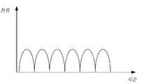
또한, 본 발명의 실시예에서, 어댑터에서 출력되는 맥동 파형의 전압이 단말기의 배터리에 직접 로딩된 후 배터리를 충전할 경우, 충전 전류는 맥동 파(예컨대, 만두형태 파형)로 나타나다. 충전 전류는 간헐적으로 배터리를 충전시키는 것으로 이해될 수 있고, 해당 충전 전류의 주기는 입력된 교류 전류(예컨대, 교류 전류 망의 주파수)에 따라 변화되고, 예를 들어, 충전 전류의 주기에 대응하는 주파수는 전력망 주파수의 정수 배 또는 역수 배이다. 또한, 충전 저류는 간헐적으로 배터리를 충전시킬 경우, 해당 충전 전류에 대응하는 전류 파형은 전력망과 동기화된 하나 또는 한 그룹의 펄스로 구성될 수 있다.In addition, in the embodiment of the present invention, when the voltage of the pulsating waveform output from the adapter is directly loaded into the battery of the terminal and then the battery is charged, the charging current appears as a pulsating wave (eg, dumpling-shaped waveform). The charging current may be understood as intermittently charging the battery, and the cycle of the corresponding charging current is changed according to the input AC current (eg, the frequency of the AC current network), for example, corresponding to the cycle of the charging current. The frequency is an integer multiple or inverse multiple of the power grid frequency. In addition, when the charge storage intermittently charges the battery, a current waveform corresponding to the corresponding charging current may be composed of one or a group of pulses synchronized with the power grid.
하나의 예시로서, 본 발명의 실시예에서 배터리가 충전 과정 중(예를 들어, 트리클 충전 단계, 정전류 충전 단계 및 정 전압 충전 단계 중 적어도 하나)에 어댑터에서 출력되는 맥동 직류 전류(방향은 변하지 않고, 진폭 크기는 시간에 따라 변함), 교류 전류(방향과 진폭 크기 모두 시간에 따라 변함), 직류 전류(즉 일정한 직류이며, 진푹 크기와 방향은 모두 시간에 따라 변하지 않음)를 수용할 수 있다.As an example, in an embodiment of the present invention, a pulsating direct current (direction unchanged) output from the adapter during a battery charging process (eg, at least one of a trickle charging stage, a constant current charging stage, and a constant voltage charging stage) , the amplitude magnitude changes with time), alternating current (both direction and amplitude magnitude change with time), and direct current (ie constant direct current, both amplitude and direction not changing with time).
종래 기술에서 충전 대기 설비는 일반적으로 단일 셀만 포함하며 비교적 큰 충전 전류로 해당 단일 셀을 충전하는 경우 충전 대기 설비의 발열 현상이 심각해진다. 충전 대기 설비의 충전 속도를 보장하기 위해 또한 충전 과정 중에 충전 대기 설비의 발열 문제 현상을 완화시키기 위해 본 발명의 실시예에서 충전 대기 설비 내의 셀 구조를 개조시켜 서로 직렬로 연결된 멀티 셀을 도입해 해당 멀티 셀을 직접 충전시킨다. 이하 도1을 결합하여 본 발명의 실시예을 상세히 설명하도록 한다.In the prior art, the charging standby equipment generally includes only a single cell, and when the single cell is charged with a relatively large charging current, the heating phenomenon of the charging standby equipment becomes serious. In order to ensure the charging speed of the charging standby equipment and to alleviate the heat problem of the charging standby equipment during the charging process, the cell structure in the charging standby equipment is modified in an embodiment of the present invention to introduce multi-cells connected in series with each other. Directly charge the multi-cell. Hereinafter, an embodiment of the present invention will be described in detail in conjunction with FIG. 1 .
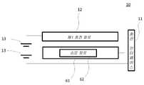
도 1은 본 발명의 일 실시예에 따른 충전 대기 설비의 개략적인 구조도이다. 도 1의 충전 대기 설비(10)는 충전 인터페이스(11)와 제1 충전 회로(12)를 포함한다. 제1 충전 회로(12)는 충전 인터페이스와 연결된다. 제1 충전 회로(12)가 충전 인터페이스(11)를 통해 어댑터의 출력 전압과 출력 전류를 수신하고, 또한 어댑터의 출력 전압 및 출력 전류를 충전 대기 설비 내의 서로 직렬로 연결된 멀티 셀(13)의 양단에 직접 로딩시켜 상기 멀티 셀(13)을 직접 충전시킨다.1 is a schematic structural diagram of a charging standby facility according to an embodiment of the present invention. The charging
변환 회로로 인한 발열 문제를 해결하기 위해 또한 전기 에너지의 손실을 감소시키기 위해 본 발명의 실시예는 제1 충전 회로(2)를 통해 직접 충전 방식으로 멀티 셀(13)을 충전시킨다.In order to solve the heating problem caused by the conversion circuit and to reduce the loss of electrical energy, the embodiment of the present invention charges the multi-cell 13 through the
직접 충전 방안은 충전 대기 설비의 발열량을 어느 정도 줄일 수 있지만 어댑터의 출력 전력이 너무 클 경우, 예를 들어, 어댑터의 출력 전류가 5A-10A 사이에 도달할 경우, 충전 대기 설비의 발열 문제가 여전히 심각하므로 잠재적 안전 문제를 유발할 수 있다. 충전 속도를 보장하기 위해 또한 충전 또한 충전 과정 중에 충전 대기 설비의 발열 문제 현상을 완화시키기 위해 볼 발명의 실시예에서 충전 대기 설비 내부의 셀 구조를 더 개조하여 서로 직렬로 연결된 멀티 셀을 도입하고 있으며 단일 셀의 방안과 비교하였을 때 동일한 충전 속도를 달성하는 것을 기대한다면, 멀티 셀에서 요구되는 충전 전류는 단일 셀에서 요구되는 충전 전류의 1/N(N은 충전 대기 설배 내의 서로 직렬로 연결된 셀의 수)이고, 즉, 단일 셀의 방안과 비교하였을 때 동일한 충전 속도가 보장되는 전제하에서 본 발명의 실시예는 충전 전류의 크기를 대폭 줄일 수 있으므로 더 나아가 충전 과정에서의 충전 대기 설비의 발열량을 감소시킬 수 있다.The direct charging method can reduce the heating value of the charging standby equipment to some extent, but when the output power of the adapter is too large, for example, when the output current of the adapter reaches between 5A-10A, the heating problem of the charging standby equipment is still It is serious and can cause potential safety issues. In order to ensure the charging speed and also to alleviate the heat problem of the charging standby equipment during the charging process, the cell structure inside the charging standby equipment is further modified in the embodiment of the ball invention to introduce multi-cells connected in series with each other, If one expects to achieve the same charging rate as compared to the single-cell approach, the charging current required in a multi-cell is 1/N of the charging current required in a single cell (N is that of cells connected in series with each other in the standby-to-charge configuration). number), that is, under the premise that the same charging speed is guaranteed as compared with the single cell method, the embodiment of the present invention can significantly reduce the size of the charging current, further reducing the calorific value of the charging standby equipment in the charging process can do it
예를 들어, 3000mAh의 단일 셀인 경우, 3C의 충전 배율을 달성하기 위해서는 9A의 충전 전류를 필요하고, 동일한 충전 속도를 달성하기 위해 또한 충전 과정 중의 충전 대기 설비의 발열량을 줄이기 위해 2개의 1500mAH의 단일 셀을 직렬로 연결시켜 3000mAh의 단일 셀을 교체할 수 있다. 따라서 4.5A의 충전 전류만으로 3C의 충전 배율을 달성할 수 있게 되고 또한 9A의 충전 전류와 비교하였을 때 4.5A의 충전 전류로 인한 발열량이 현저히 낮다.For example, in the case of a single cell of 3000mAh, a charging current of 9A is required to achieve a charging multiplier of 3C, and to achieve the same charging rate and to reduce the calorific value of the charging stand-by equipment during the charging process, two single cells of 1500mAH are required. A single cell of 3000 mAh can be replaced by connecting the cells in series. Therefore, it is possible to achieve a charging multiplier of 3C with only a charging current of 4.5A, and also, compared to a charging current of 9A, the heating value due to the charging current of 4.5A is significantly lower.
설명해야 할 것은, 제1 충전 회로(12)가 직접 충전 방식으로 멀티 셀(13)을 충전하므로 제1 충전 회로(12)에서 수신되는 어댑터의 출력 전압이 멀티 셀(13)의 총 전압보다 커야 한다. 일반적으로 단일 셀의 작동 전압은 3.0V-4.35V사이에 있고, 직렬로 연결되는 더블 셀을 예로 보면, 어댑터의 출력 전압을 10V이상으로 설정할 수 있다.What should be explained is that since the
더 설명해야 할 것은, 본 발명의 실시예는 충전 인터페이스(11)의 종류에 대해 구체적으로 제한한지 않는다. 예를 들어, 범용직렬버스(Universal Serial Bus, USB) 인터페이스일 수 있고, USB 인터페이스는 표준 USB 인터페이스일 수 있고 micro USB 인터페이스일 수도 있으며 또한 Type-C 인터페이스일 수도 있다. 제1 충전 회로(12)는 USB 인터페이스 중의 전원 선을 통해 멀티 셀(13)을 충전할 수 있고, 이중에서 USB 인터페이스 중의 전원 선은 USB 인터페이스 중의 VBus 선 및/또는 접지선일 수 있다.It should be further explained that the embodiment of the present invention does not specifically limit the type of the charging
본 발명의 실시예에 따른 멀티 셀(13)은 사양, 파라미터가 동일하거나 유사한 셀일 수 있으며, 사양이 동일하거나 유사한 셀은 통합 관리하기에 편하고, 또한 사양, 파라미터가 동일하거나 유사한 셀을 선택 시 멀티 셀(13)의 전체 성능 및 사용 수명을 향상시킬 수 있다.The multi-cell 13 according to the embodiment of the present invention may be a cell with the same or similar specifications and parameters, and it is convenient to integrate and manage a cell with the same or similar specifications and parameters. The overall performance and service life of the
서로 직렬로 연결된 멀티 셀(13)은 어댑터의 출력 전압을 분압시킬 수 있는 것으로 이해된다.It is understood that
현재 충전 대기 설비(또는 충전 대기 설비 내의 소자, 혹은 충전 대기 설비 내의 칩)은 일반적으로 단일 셀로 전원 공급한다. 본 발명의 실시예에서 서로 직렬로 연결된 멀티 셀을 도입하고 있지만 멀티 셀의 총 전압이 비교적 높으므로 충전 대기 설비(또는 충전 대기 설비 내의 소자, 혹은 충전 대기 설비 내의 칩)의 전원 공급에 직접 사용되는 것은 적합하지 않다. 이 문제를 해결하기 위해 실시 가능한 하나의 구현 방식으로는 충전 대기 설비의 작동 전압을 조절하여 멀티 셀의 전원 공급을 지원할 수 있도록 하는 것이다. 그러나 이러한 구현 방식은 충전 대기 설비에 대한 변경이 비교적 크고 비용도 비교적 높다. 이하 도 2, 도 3a와 도 3b를 결합하여 본 발명의 실시예의 구현 방식을 상세히 설명하여 멀티 셀 방안 중의 전원 공급 방법의 문제를 해결하도록 한다.Currently, a standby device (or a device in a standby device, or a chip in a standby device) is typically powered by a single cell. Although the embodiment of the present invention introduces multi-cells connected in series with each other, since the total voltage of the multi-cells is relatively high, it is directly used for power supply of a charging standby device (or a device in a charging standby device, or a chip in a charging standby device). it is not suitable One possible implementation method to solve this problem is to adjust the operating voltage of the charging standby equipment to support the multi-cell power supply. However, this implementation method requires relatively large changes to the charging standby facility and relatively high cost. Hereinafter, an implementation method of an embodiment of the present invention will be described in detail by combining FIGS. 2, 3A and 3B to solve the problem of a power supply method in a multi-cell scheme.
선택적 일부 실시예에서, 도 2에 도시된 바와 같이, 충전 대기 설비(10)는 또한 강압 회로(21)와 전원 공급 회로(22)를 포함할 수 있다. 강압 회로(21)의 입력 단은 멀티 셀(13)의 양단과 연결된다. 강압 회로(21)는 멀티 셀(13)의 총 전압을 제1 전압(V1)로 변환시키는 데에 사용되고, 이중에서 a≤V1≤b. a는 충전 대기 설비(10)(또는 충전 대기 설비(10) 내의 소자, 혹은 충전 대기 설비(10) 내의 칩)의 최소 작동 전압을 나타낸다. b는 충전 대기 설비(10)(또는 충전 대기 설비(10) 내의 소자, 혹은 충전 대기 설비(10) 내의 칩)의 최대 작동 전압을 나타낸다. 전원 공급 회로(22)는 승압 회로(21)의 출력 단과 연결된다. 전원 공급 회로(22)는 제1 전압을 기준으로 하여 충전 대기 설비(1)에 전원 공급한다.In some optional embodiments, as shown in FIG. 2 , the charging
본 발명의 실시예는 도 1에 설명하고 있는 실시예에 기초하여 강압 회로(21)를 도입하고 있다. 충전 대기 설비가 작동 상태에 처할 때 멀티 셀(13)의 충 전압이 먼저 강압 회로(21)에 의해 강압되어 제1 전압을 얻게 되며 제1 전압은 충전 대기 설비(10)의 최소 작동 전압과 최대 작동 전압 사이에 있으므로 충전 대기 설비에 전원 공급하는 데에 직접 사용될 수 있어 멀티 셀 방안 중의 전원 공급 방법의 문제를 해결할 수 있다.The embodiment of the present invention introduces the step-
하기 설명되는 바와 같이, 멀티 셀(13)의 총 전압은 멀티 셀(13)의 전기량의 변화에 따라 달라진다. 따라서 전술한 멀티 셀(13)의 총 전압은 멀티 셀(13)의 현재 총 전압을 뜻할 수 있다. 예를 들어, 단일 셀의 작동 전압은 3.0V-4.35V 사이에 있을 수 있고, 멀티 셀이 2개의 셀을 포함하고 또한 2개의 셀의 현재 전압은 모두 3.V일 경우, 전술한 멀티 셀(13)의 총 전압은 7V이다.As will be described below, the total voltage of the multi-cell 13 varies according to a change in the amount of electricity of the multi-cell 13 . Therefore, the above-described total voltage of the multi-cell 13 may mean the current total voltage of the multi-cell 13 . For example, the operating voltage of a single cell may be between 3.0V-4.35V, and when the multi-cell includes two cells and the current voltage of both cells is 3.V, the above-described multi-cell ( 13) the total voltage is 7V.
단일 셀의 작동 전압 값의 범위를 3.0V-4.35로 취하는 것을 예로 할 때, a=3.0V, b=4.35V이다. 충전 대기 설비 내의 소자의 전원 공급이 정상인 것을 보장하기 위해 강압 회로(21)는 멀티 셀(13)의 총 전압을 3.0V-4.35V 구간 중 임의의 값으로 다운시킬 할 수 있다. 강압 회로(21)의 구현 방식은 여러 가지가 있으며, 예를 들어, Buck 회로, 차지 펌프 등의 회로 형식으로 강압을 실현할 수 있다.Taking the range of the operating voltage value of a single cell as 3.0V-4.35 as an example, a=3.0V, b=4.35V. In order to ensure that the power supply of the device in the charging standby facility is normal, the step-
설명되는 바와 같이, 회로의 구현을 단순화하기 위해 강압 회로(21)는 차지 펌프일 수 있으며 차지 펌프를 통해 멀티 셀(13)의 총 전압을 현재 총 전압의 1/N으로 직접 다운 시킬 수 있고, 여기서 N는 해당 멀티 셀(13)에 포함되어 있는 셀의 수를 나타낸다. 종래의 Buck 회로는 스위치 튜브와 인덕터 등의 소자를 포함한다. 인덕터의 전력 손실이 비교적 크므로 Buck 회로로 강압 시 전력 손실이 비교적 크다. Buck 회로에 비해 차지 펌프는 주로 스위치 튜브와 커패시터를 이용하여 강압하기 때문에 커패시터는 추가적인 에너지를 소비하지는 않는다. 따라서 차지 펌프를 사용하면 강압 과정에서 발생한 전력 손실을 줄일 수 있다. 구체적으로 차지 펌프 내부의 스위치 튜브는 소정의 방식으로 커패시터의 충전과 방전을 제어하여 입력 전압을 소정의 인수(본 발명의 실시예에서 선택된 인수는 1/N임)만큼 다운 시켜 필요한 전압을 얻을 수 있게 된다.As will be described, in order to simplify the implementation of the circuit, the step-
선택 가능한 다른 일부 실시예에서 도 3a에 도시된 바와 같이 충전 대기 설비(10)는 또한 전원 공급 회로(32)를 포함한다. 전원 공급 회로(32)의 입력 단은 멀티 셀(13) 중의 임의의 단일 셀의 양단과 연결된다. 전원 공급 회로(32)는 단일 셀(13)의 전압을 기준으로 하여 충전 대기 설비(10) 내의 소자에 전원 공급한다.In some other optional embodiments, as shown in FIG. 3A , the charging
강압 회로의 강압 처리를 마친 전압에는 리플이 발생할 수 있어 충전 대기 설비의 충전 품질에 영향을 끼칠 수 있는 것이로 이해된다. 본 발명의 실시예에서는 멀티 셀(13) 중의 어느 하나의 단일 셀의 양단에서 전원 공급 전압을 직접 인출하여 충전 대기 설비 내의 소자에 전원 공급하고 셀에서 출력되는 전압이 비교적 안정적이라서 본 발명의 실시예는 멀티 셀 방안 중의 전원 공급 문제를 해결하는 동시에 충전 대기 설비의 충전 품질도 보장할 수 있다.It is understood that ripple may occur in the voltage that has been subjected to the step-down treatment of the step-down circuit, which may affect the charging quality of the charging standby facility. In the embodiment of the present invention, the power supply voltage is directly drawn from both ends of any single cell of the multi-cell 13 to supply power to the device in the charging standby facility, and the voltage output from the cell is relatively stable. can solve the power supply problem in the multi-cell scheme, while also ensuring the charging quality of the charging standby equipment.
또한, 도 3a의 실시예에 기초하여 도 3b에 도시된 바와 같이, 충전 대기 설비(10)는 또한 균형회로(33)를 포함할 수 있다. 균형회로(33)는 멀티 셀(13)과 연결된다. 균형 회로(33)는 멀티 셀(13) 중의 각 셀간의 전압을 밸런싱하는 데에 사용된다.In addition, as shown in FIG. 3B based on the embodiment of FIG. 3A , the charging
도 3a에 도시된 전원 공급 방식을 사용한 후, 충전 대기 설비 내의 소자에 전원 공급하는 셀(이하, 마스터 셀로 하고, 너머지 셀은 슬레이브 셀이라고 함)은 계속 전기량을 소비할 것이고 마스터 셀과 슬레이브 셀 간의 전압이 불균형(또는 전압 불일치라고도 함)됨을 야기한다. 멀티 셀(13)간의 전압의 불균형은 멀티 셀(13)의 전체 성능을 낮출 수 있어 멀티 셀(13)의 사용 수명에 영향을 끼친다. 멀티 셀(13)간의 전압의 불균형은 또한 멀티 셀(13)의 통합 관리를 어려워지게 한다. 따라서 본 발명의 실시예에서 균형회로(33)를 도입하여 멀티 셀(13) 중의 각 셀 간의 전압을 밸런싱하도록 함으로써 멀티 셀(13)의 전체 성능을 향상시키고 또한 멀티 셀(13)의 통합 관리를 용이하게 한다.After using the power supply method shown in FIG. 3A, the cell that supplies power to the device in the charging standby facility (hereinafter, referred to as the master cell, the cell beyond that is referred to as the slave cell) will continue to consume electricity, and the master cell and the slave cell It causes the voltages between them to become unbalanced (also called voltage mismatch). The voltage imbalance between the multi-cells 13 may lower the overall performance of the multi-cells 13 , thereby affecting the service life of the multi-cells 13 . The voltage imbalance between the multi-cells 13 also makes it difficult to manage the multi-cells 13 in an integrated manner. Therefore, by introducing the balancing
균형회로(33)의 구현 방식은 여러 가지가 있다. 예를 들어, 부하를 셀 양단에 연결시켜 셀의 전기량을 소비하여 마스터 셀의 전기량과 동일하게 유지될 수 있게 함으로써 마스터 셀과 슬레이브 셀의 전압이 일치할 수 있도록 한다. 또는 마스터 셀과 슬레이브 셀의 전압이 일치될 때 까지 슬레이브 셀을 사용하여 마스터 셀을 충전할 수 있다.There are several implementation methods of the balancing
배터리의 출력 전력이 커짐에 따라 어댑터에 의해 충전 대기 설비 내의 셀이 충전될 때 리튬 석출 현상을 유발하기 쉬워 셀의 수명을 단축시킬 수 있다.As the output power of the battery increases, it is easy to cause lithium precipitation when the cell in the charging standby facility is charged by the adapter, thereby shortening the life of the cell.
셀의 신뢰성과 안전성을 높이기 위해 일부 실시예에서 어댑터를 제어하여 맥동 직류 전류(또는 단일 방향 맥동의 출력 전류, 혹은 맥동 파형의 전류 또는 만두형태 웨이브 전류라고도 함)를 출력할 수 있도록 한다. 제1 충전 회로(12)는 직접 충전 방식으로 멀티 셀(13)을 충전하기 때문에 어댑터에서 출력되는 맥동 직류 전류는 멀티 셀(13)의 양단에 직접 로딩될 수 있다. 도 4에 도시된 바와 같이, 맥동 직류 전류의 전류 크기는 주기적으로 변환된다. 일정한 직류 전류에 비해 맥동 직류 전류는 리튬 셀의 리튬 석출 현상을 감소시키고 셀의 사용 수명을 향상시킬 수 있다. 또한 일정한 직류 전류에 비해 맥동 직류 전류는 충전 인터페이스 접점의 아크의 확률과 강도를 감소시켜 충전 인터페이스의 수명을 향상시킬 수 있다.In order to increase the reliability and safety of the cell, in some embodiments, the adapter is controlled to output a pulsating direct current (also referred to as a unidirectional pulsating output current, or a pulsating waveform current or dumpling wave current). Since the
어댑터의 출력 전류를 맥동 직류 전류로 설정하는 방식은 여러 가지가 있다. 예를 들어 어댑터 중의 1차 필터 회로와 2차 필터 회로를 제거할 수 있으며, 얻게 된 어댑터의 출력 전류가 바로 맥동 직류 전류이다.There are several ways to set the adapter's output current to a pulsating DC current. For example, the primary filter circuit and the secondary filter circuit in the adapter can be removed, and the resulting adapter output current is a pulsating DC current.
선택적 일부 실시예에서 제1 충전 회로(12)에서 수신되는 어댑터의 출력 전류는 또한 교류 전류(예를 들어, 어댑터의 1차 필터 회로와 2차 정류 회로를 제거한 후 얻게 된 어댑터의 출력 전류는 바로 교류 전류임)일 수 있고, 교류 전류도 똑같이 리튬 석출 현상을 감소시키고 셀의 사용 수명을 향상시킬 수 있다.In some optional embodiments, the output current of the adapter received in the
선택적 일부 실시예에서 제1 충전 회로(12)는 충전 인터페이스(11)를 통해 수신되는 어댑터의 출력 전압과 출력 전류는 정전류 모드(정전류 충전 모드 또는 정전류 충전 단계)에서 어댑터가 출력되는 전압과 전류일 수 있다.Optionally, in some embodiments, the
선택적 일부 실시예에서 멀티 셀(13)은 하나의 배터리(51)에 함께 패키징될 수 있다. 또한 해당 배터리(51)는 배터리 보호 보드(52)를 포함할 수 있으며 배터리 보호 보드(52)를 통해 과전압 및 과전류 보호, 전기량 균형 관리와 전기량 관리 등 기능을 실현할 수 있다.In some optional embodiments,
선택적 일부 실시예에서 멀티 셀(13)은 여러 개의 배터리에 패키징될 수 있다.In some optional embodiments, the multi-cell 13 may be packaged in multiple batteries.
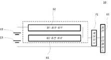
선택적 일부 실시예에서 도 6에 도시된 바와 같이, 충전 대기 설비(10)은 또한 제2 충전 회로(61)를 포함할 수 있다. 제2 충전 회로(61)는 승압 회로(62)를 포함할 수 있다. 승압 회로(62)의 양단은 각각 충전 인터페이스(11) 및 멀티 셀(13)과 연결된다. 승압 회로(62)는 충전 인터페이스(11)를 통해 어댑터의 출력 전압을 수신할 수 있고, 어댑터의 출력 전압을 제2 전압으로 승압시키고 또한 제2 전압을 멀티 셀(13)의 양단에 로딩시켜 멀터 셀(13)을 충전시킨다. 제2 충전 회로(61)에서 수신되는 어댑터의 출력 전압은 멀티 셀(13)의 총 전압보다 작고, 제2 전압은 멀티 셀(13)의 총 전압보다 크다.In some optional embodiments, as shown in FIG. 6 , the charging
전술한 바에 따르면 제1 충전 회로(12)가 멀티 셀(13)을 직접 충전하는 것을 알 수 있고, 이러한 충전 방식은 어댑터의 출력 전압이 멀티 셀(13)의 총 전압보다 높은 것을 요구한다. 예를 들어, 직렬로 연결된 2개의 셀의 방안인 경우, 각 셀의 현재 전압이 4V로 가정하면 제1 충전 회로(12)로 해당 2개의 셀을 충전할 때 어댑터의 출력 전압이 적어도 8V보다 커야 한다. 그러나 일반 어댑터(전술한 해당 어댑터)의 출력 전압은 일반적으로 5V이므로 제1 충전 회로(12)를 통해 멀티 셀(13)을 충전할 수 없다. 일반 어댑터와 호환 가능하도록 본 발명의 실시예에서는 제2 충전 회로(61)를 도입한다. 해당 제2 충전 회로(61)은 승압 회로(62)를 포함하고 승압 회로(62)는 어댑터의 출력 전압을 제2 전압으로 승압시킬 수 있으며 멀티 셀(13)의 총 전압보다 크게 하고 따라서 일반 어댑터에 의해 서로 직렬로 연결된 셀(13)을 충전할 수 없는 문제를 해결할 수 있게 된다.As described above, it can be seen that the
본 발명의 실시예에서 제2 충전 회로(61)에서 수신되는 어댑터의 출력 전압의 전압 값을 구체적으로 제한하지 않으며 어댑터의 출력 전압이 멀티 셀(13)의 총 전압보다 작으면 제2 충전 회로(61)를 통해 승압된 후 해당 멀티 셀(13)을 충전할 수 있다.In the embodiment of the present invention, the voltage value of the output voltage of the adapter received from the
본 발명의 실시예에서 승압 회로의 구체적 형식에 대해 제한하지 않는다. 예를 들어, Boost 승압 회로를 사용할 수 있고, 또한 차지 펌프로 승압할 수도 있다. 선택적 일부 실시예에서 제2 충전 회로(61)는 종래의 충전 회로 설계 방식을 사용할 수 있으며, 즉 충전 인터페이스와 셀 사이에 변환회로(예컨대 충전 IC)를 설정할 수 있다. 해당 변환 회로는 어댑터의 충전 과정에 대해 정전압, 정전류 제어할 수 있고, 또한 실제 요구에 따라 어댑터의 출력 전압을 승압 또는 강압 같은 조절을 해야 한다. 본 발명의 실시예는 해당 변환회로의 승압 기능을 이용하여 어댑터의 출력 전압을 멀티 셀(13)의 총 전압보다 높은 제2 전압으로 승압시킬 수 있다. 이해해야 할 것은, 제1 충전 회로(12)와 제2 충전 회로(61)간의 전환은 스위치 또는 제어 유닛을 통해 실현될 수 있다. 예를 들어, 충전 대기 설비 내에 제어 유닛을 설정하고, 해당 제어 유닛은 실제 요구(예컨대, 어댑터의 종류)에 따라 제1 충전 회로(12)와 제2 충전회로(61) 사이에서 유연하게 전환될 수 있다.In the embodiment of the present invention, there is no limitation on the specific type of the step-up circuit. For example, a boost boost circuit can be used, and the boost can also be boosted with a charge pump. In some optional embodiments, the
선택적 일부 실시예에서, 어댑터는 제1 충전 모드와 제2 충전 모드를 지원하고, 제2 충전 모드에서의 충전 대기 설비를 위한 어댑터의 충전 속도는 제1 충전 모드에서의 충전 대기설비를 위한 어댑터의 충전 속도보다 빠르다. 즉, 제1 충전 모드에서 작동되는 어댑터에 비해, 제2 충전 모드에서 작동되는 어댑터가 같은 용량의 배터리를 완전히 충전하는 데 더 짧은 시간이 소요된다. 또한 일부 실시예에서 제1 충전 모드에서, 어댑터는 상기 제2 충전 회로(61)를 통해 상기 멀티 셀(13)을 충전시키고, 제2 충전 모드에서, 어댑터는 제1 충전 회로(12)를 통해 멀티 셀(13)을 충전시킨다.Optionally, in some embodiments, the adapter supports the first charging mode and the second charging mode, and the charging speed of the adapter for the charging standby device in the second charging mode is that of the adapter for the charging standby device in the first charging mode. faster than the charging speed. That is, compared to the adapter operated in the first charging mode, the adapter operated in the second charging mode takes a shorter time to fully charge the battery of the same capacity. Also in some embodiments in the first charging mode, the adapter charges the multi-cell 13 via the
제1 충전 모드는 일반 충전 모드일 수 있고, 제2 충전 모드는 고속 충전 모드일 수 있다. 해당 일반 충전 모드는 어댑터에서 비교적 작은 전류 값(일반적으로 2.5V보다 작음) 또는 비교적 작은 전력(일반적으로 15W보다 작음)을 출력하여 충전 대기 설비 중의 배터리를 충전하는 것을 뜻하며 일반 충전 모드에서 비교적 큰 용량의 배터리(예컨대, 3000mAh인 용량의 배터리)를 완전히 충전하는데 보통 몇 시간이 걸리는데; 고속 충전 모드에서는 어댑터가 비교적 큰 전류(일반적으로 2.5A보다 크고, 예컨대, 4.5A, 5A 또는 그 이상) 또는 비교적 큰 전력(일반적으로 15W이상)을 출력하여 충전 대기 설비 중의 배터리를 충전하며, 일반 충전 모드에 비해 고속 충전 모드에서의 어댑터가 같은 용량의 배터리를 완전히 충전하는 데에 소요되는 시간이 현저히 단축될 수 있고, 충전 속도도 더 빨라지게 된다.The first charging mode may be a normal charging mode, and the second charging mode may be a fast charging mode. This normal charging mode means that the adapter outputs a relatively small current value (generally less than 2.5V) or a relatively small power (typically less than 15W) to charge the battery in the charging standby facility, and in the normal charging mode, the relatively large capacity It usually takes several hours to fully charge a battery in a battery (eg, a battery with a capacity of 3000 mAh); In fast charging mode, the adapter outputs a relatively large current (generally greater than 2.5A, such as 4.5A, 5A or more) or a relatively large power (typically 15W or more) to charge the battery in standby equipment, Compared to the charging mode, the time it takes for the adapter to fully charge a battery of the same capacity in the fast charging mode can be significantly reduced, and the charging speed is also faster.
또한, 도 7에 도시된 바와 같이, 충전 인터페이스(11)는 데이터 선을 포함할 수 있으며 충전 대기 설비(10)는 또한 제어 유닛(71)을 포함하고 제어 유닛(71)은 데이터 선을 통해 어댑터와 쌍방향 통신하여 제2 충전 모드에서의 어댑터의 출력을 제어하도록 한다. 충전 인터페이스가 USB 인터페이스인 것을 예로 할 때 데이터 선은 USB 인터페이스 중의 D+선 및/또는 D-선일 수 있다.In addition, as shown in Fig. 7, the charging
본 발명의 실시예에서 어댑터와 제어 유닛(71)간의 통신 내용, 및 제2 충전 모드에서의 어댑터의 출력을 제어하는 제어 유닛(71)의 방식에 대해 구체적으로 제한하지 않으며, 예를 들어 제어 유닛(71)은 어댑터와 통신하여 충전 대기 설비 중의 멀티 셀(13)의 현재 총 전압 또는 현재 총 전기량을 서로 교류할 수 있고, 또한 멀티 셀(13)의 현재 총 전압 또는 현재 총 전기량을 기준으로 하여 어댑터의 출력 전압 또는 출력 전류를 조절한다. 이하 구체적인 실시예에서, 제어 유닛(71)과 어댑터 간의 통신 내용 및 제2 충전 모드에서의 어댑터의 출력을 제어하는 제어 유닛(71)의 방식에 대해 상세히 설명하도록 한다.The embodiment of the present invention does not specifically limit the communication content between the adapter and the
본 발명의 상기 설명에서는 어댑터와 충전 대기 설비(또는 충전 대기 설비 중의 제어 유닛(71))의 마스터-슬레이브 성격을 제한하지 않을 것이다. 즉 어댑터와 충전 대기 설비 중의 어느 하나가 모두 마스터 설비로서 통신 세션을 개시할 수 있으며, 그에 상응하게 다른 하나는 슬레이브 설비로서 마스터 설비에 의해 개시되는 통신 세션에 대해 제1 반응 또는 제1 응답을 할 수 있고 동시에 마스터 설비는 상기 슬레이브 설비의 제1 반응 또는 제1 응답에 대해 제2 반응을 할 수 있으며, 즉 마스터 설비와 슬레이브 설비간의 충전 모드 협의 과정을 한 번 마친 것으로 볼 수 있다. 실시 가능한 하나의 방식으로서, 마스터 설비와 슬레이브 설비 사이에 여러 번의 충전 모드 협의 과정을 마친 후에 마스터 설비와 슬레이브 설비간의 충전 작업을 실행할 수 있어 협의 후의 충전 과정이 더 안전하고 신뢰성 있게 수행될 수 있도록 한다.The above description of the present invention will not limit the master-slave nature of the adapter and the charging standby device (or the
마스터 설비로서, 통신 세션에 대한 상기 슬레이브 설비의 제1 반응 또는 제1 응답에 따라 제2 반응을 하는 하나의 방식은, 마스터 설비가 통신 세션에 대한 상기 슬레이브 설비의 제1 반응 또는 제1 응답을 수신할 수 있고, 또한 수신된 상기 슬레이브 설비의 제1 반응 또는 제1 응답에 따라 목표성 있는 제2 반응을 하는 것일 수 있다. 예를 들어, 마스터 설비가 미리 설정된 시간 내에 통신 세션에 대한 상기 슬레이브 설비의 제1 반응 또는 제1 응답을 수신하고 마스터 설비가 상기 슬레이브 설비의 제1 반응 또는 제1 응답에 대해 목표성 있는 제2 반응을 하는 것은, 구체적으로 마스터 설비와 슬레이브 설비가 충전 모드의 협의를 한 번 마치고 마스터 설비와 슬레이브 설비 사이에 협의 결과에 의거하여 제1 충전 모드 또는 제2 충전 모드에 따라 충전 작업을 실행하는 것이고, 즉 어댑터가 협의 결과에 의거하여 제1 충전 모드나 제2 충전 모드에서 작동되어 충전 대기 설비를 충전시킨다.One way, as a master device, of a first response or a second response of the slave device to the communication session, is that the master device receives the first response or first response of the slave device to the communication session. may be received, and may also be to perform a targeted second reaction according to the received first response or the first response of the slave device. For example, the master device receives the first response or first response of the slave device to the communication session within a preset time period, and the master device responds to the first response or the first response of the slave device a second targeted response. To react, specifically, the master equipment and the slave equipment have negotiated the charging mode once, and based on the result of the agreement between the master equipment and the slave equipment, the charging operation is performed according to the first charging mode or the second charging mode. That is, the adapter is operated in the first charging mode or the second charging mode according to the result of the consultation to charge the charging standby device.
통신 세션에 대한 상기 슬레이브 설비의 제1 반응 또는 제1 응답에 따라 제2 반응을 하는 하나의 방식은, 또한 마스터 설비가 미리 설정된 시간 내에 통신 세션에 대한 상기 슬레이브 설비의 제1 반응 또는 제1 응답을 수신하지 못할 때도 마스터 설비가 상기 슬레이브 설비의 제1 반응 또는 제1 응답에 대해 목표성 있는 제2 반응을 할 수 있는 것일 수 있다. 예를 들어, 마스터 설비가 미리 설정된 시간 내에 통신 세션에 대한 상기 슬레이브 설비의 제1 반응 또는 제1 응답을 수신하지 못할 때도 마스터 설비가 상기 슬레이브 설비의 제1 반응 또는 제1 응답에 대해 목표성 있는 제2 반응을 할 수 있는 것은, 구체적으로 마스터 설비와 슬레이브 설비가 충전 모드의 협의를 한 번 마치고 마스터 설비와 슬레이브 설비 사이에 제1 충전 모드에 따라 충전 작업을 실행하는 것이고, 즉 어댑터가 제1 충전 모드에서 작동되어 충전 대기 설비를 충전시킨다.One manner in which a first response or a second response of the slave device to the communication session is performed according to the first response is further provided that the master device provides a first response or first response of the slave device to the communication session within a preset time period. The master device may be capable of making a targeted second response to the first response or the first response of the slave device even when it does not receive For example, the master device may target the first response or first response of the slave device even when the master device does not receive the first response or first response from the slave device to the communication session within a preset time period. The second reaction may be, specifically, that the master device and the slave device have negotiated the charging mode once, and the charging operation is performed between the master device and the slave device according to the first charging mode, that is, the adapter is connected to the first Operates in charging mode to charge the charging stand-by equipment.
선택적 일부 실시예에서, 충전 대기 설비가 마스터 설비로서 통신 세션을 개시할 때 어댑터는 슬레이브 설비로서 마스터 설비에 의해 개시되는 통신 세션에 대해 제1 반응 또는 제1 응답을 안 후 어댑터의 제1 반응 또는 제1 응답에 대한 충전 대기 설비의 목표성 있는 제2 반응을 기다릴 필요 없이 어댑터와 충전 대기 설비간의 충전 모드의 협의를 한 번 마칠 수 있고, 따라서 어댑터가 협의 결과에 의거하여 제1 모드 아니면 제2 모드로 충전 대기 설비를 충전시키는 것을 결정할 수 있다.Optionally, in some embodiments, when the charging standby device initiates a communication session as the master device, the adapter receives a first response or a first response to the communication session initiated by the master device as the slave device, and then the first response of the adapter or Negotiation of the charging mode between the adapter and the charging standby device can be completed once without having to wait for the target second response of the charging standby device to the first response, so that if the adapter is not in the first mode according to the result of the negotiation, the second It may be decided to charge the charging standby equipment in the mode.
선택적 일부 실시예에서 제어 유닛(71)은 데이터 선을 통해 어댑터와 쌍방향 통신하여 제2 충전 모드에서의 어댑터의 출력을 제어하도록 하는 과정은 제어 유닛(71)이 어댑터와 쌍방향 통신하여 어댑터와 충전 대기 설비간의 충전 모드를 협의하도록 하는 것을 포함한다.Optionally, in some embodiments, the
선택적 일부 실시예에서 제어 유닛(71)은 어댑터와 쌍방향 통신하여 어댑터와 충전 대기 설비간의 충전 모드를 협의하도록 하는 것은, 제어 유닛(71)은 어댑터로부터 송신되는 제1 명령어를 수신하고, 제1 명령어는 충전 대기 설비가 제2 충전 모드를 작동할지를 문의하는 데에 사용되고; 제어 유닛(71)은 어댑터에 제1 명령어의 응답 명령어를 송신하고, 제1 명령어의 응답 명령어는 충전 대기 설비가 제2 충전 모드의 작동을 동의하는 것을 지시하는 데에 사용되고; 충전 대기 설비가 제2 충전 모드의 작동을 동의하는 상황에서 제어 유닛(71)은 어댑터를 제어하여 제1 충전 회로(12)를 통해 멀티 셀을 충전시키도록 하는 것을 포함한다.Optionally, in some embodiments, the
선택적 일부 실시예에서 제어 유닛(71)은 데이터 선을 통해 어댑터와 쌍방향 통신하여 제2 충전 모드에서의 어댑터의 출력을 제어하도록 하는 과정은, 제어 유닛(71)이 어댑터와 쌍방향 통신하여 제2 충전 모드에서의 어댑터에 의해 출력되는 충전 대기 설비의 충전을 위한 충전 전압을 결정하도록 하는 것을 포함한다.Optionally, in some embodiments, the
선택적 일부 실시예에서 제어 유닛(71)이 어댑터와 쌍방향 통신하여 제2 충전 모드에서의 어댑터에 의해 출력되는 충전 대기 설비의 충전을 위한 충전 전압을 결정하도록 하는 것은, 제어 유닛(71)이 어댑터로부터 송신되는 제2 명령어를 수신하고, 제2 명령어는 어댑터의 출력 전압이 충전 대기 설비의 멀티 셀(13)의 현재 총 전압과 일치하는 지를 문의하는 데에 사용되고; 제어 유닛(71)은 어댑터에 제2 명령어의 응답 명령어를 송신하고, 제2 명령어의 응답 명령어는 어댑터의 출력 전압이 멀티 셀(13)의 현재 총 전압과 일치하거나 높거나 또는 낮다는 것을 지시하는 데에 사용되는 것을 포함한다. 대체 가능하게 제2 명령어는 어댑터의 현재 출력 전압이 제2 충전 모드에서의 어댑터에 의해 출력되는 충전 대기 설비의 충전을 위한 전압으로 적합한지를 문의하는데 사용될 수 있고, 제2 명령어의 응답 명령어는 현재 어댑터의 출력 전압이 적합하거나 높거나 또는 낮다는 것을 지시하는 데에 사용될 수 있다. 어댑터의 현재 출력 전압이 멀티 셀의 현재 충 전압과 일치하거나, 어댑터의 현재 출력 전압이 제2 충전 모드에서의 어댑터에 의해 출력되는 충전 대기 설비의 충전을 위한 충전 전압으로 적합하다는 것은, 어댑터의 현재 출력 전압이 멀티 셀의 현재 총 전압보다 약간 높고, 또한 어댑터의 출력 전압과 멀티 셀의 현재 총 전압간의 차이 값이 미리 설정된 범위 내(일반적으로 수백 밀리볼트의 등급)에 있다는 것을 의미할 수 있다.Optionally, in some embodiments, the
선택적 일부 실시예에서, 제어 유닛(71)이 데이터 선을 통해 어댑터와 쌍방향 통신하여 제2 충전 모드에서의 어댑터의 출력을 제어하도록 하는 과정은, 제어 유닛(71)이 어댑터와 쌍방향 통신하여 제2 충전 모드에서의 어댑터에 의해 출력되는 충전 대기 설비의 충전을 위한 충전 전류를 결정하도록 하는 것을 포함할 수 있다.In some optional embodiments, causing the
선택적 일부 실시예에서, 제어 유닛(71)이 어댑터와 쌍방향 통신하여 제2 충전 모드에서의 어댑터에 의해 출력되는 충전 대기 설비의 충전을 위한 충전 전류를 결정하도록 하는 것은, 제어 유닛(71)이 어댑터로부터 송신되는 제3 명령어를 수신하고, 제3 명령어는 충전 대기 설비가 현재 지원하고 있는 최대 충전 전류를 문의하는 데에 사용되고; 제어 유닛(71)은 어댑터에 제3 명령어의 응답 명령어를 송신하고, 제3 명령어의 응답 명령어는 충전 대기 설비가 현재 지원하고 있는 최대 충전 전류를 지시하는 데에 사용되어 충전 대기 설비가 현재 지원하고 있는 최대 충전 전류를 기준으로 하여 제2 충전 모드에서의 어댑터에 의해 출력되는 대기 충전 설비의 충전을 위한 충전 전류를 어댑터에 의해 결정하도록 하는 것을 포함할 수 있다. 제어 유닛(71)이 충전 대기 설비의 최대 충전 전류에 따라 제2 충전 모드에서의 어댑터에 의해 출력되는 충전 대기 설비의 충전을 위한 충전 전류를 결정하는 방식이 여러 가지가 있는 것으로 알려져 있다. 예를 들어, 어댑터가 충전 대기 설비의 최대 충전 전류를 제2 충전 모드에서의 어댑터에 의해 출력되는 충전 대기 설비의 충전을 위한 충전 전류로 결정할 수 있고, 또한 충전 대기 설비의 현재 최대 충전 전류와 자체의 전류 출력 능력 등 요소를 종합적으로 고려한 뒤 제2 충전 모드에서의 어댑터에 의해 출력되는 충전 대기 설비의 충전을 위한 충전 전류를 결정할 수 있다.In some optional embodiments, the
선택적 일부 실시예에서, 제어 유닛(71)이 데이터 선을 통해 어댑터와 쌍방향 통신하여 제2 충전 모드에서의 어댑터의 출력을 제어하도록 하는 과정은, 제2 충전 모드로 충전하는 과정에서 제어유닛(71)이 어댑터와 쌍방향 통신하여 어댑터의 출력 전류를 조절하도록 하는 것을 포함할 수 있다.In some optional embodiments, the process of causing the
구체적으로 제어 유닛(71)이 어댑터와 쌍방향 통신하여 어댑터의 출력 전류를 조절하도록 하는 것은, 제어 유닛(71)이 어댑터로부터 송신되는 제4 명령어를 수신하고, 제4 명령어는 멀티 셀의 현재 총 전압을 문의하는 데에 사용되고; 제어 유닛(71)은 어댑터에 제4 명령어의 응답 명령어를 송신하고, 제4 명령어의 응답 명령어는 멀티 셀의 현재 총 전압을 지시하는 데에 사용되어 어댑터가 멀티 셀의 현재 총 전압에 따라 어댑터의 출력 전류를 조절하도록 하는 것을 포함할 수 있다.Specifically, to cause the
선택적 일부 실시예에서 제어 유닛(71)은 데이터 선을 통해 어댑터와 쌍방향 통신하여 제2 충전 모드에서의 어댑터의 출력을 제어하도록 하는 과정은, 제어 유닛(71)이 어댑터와 쌍방향 통신하여 충전 인터페이스가 접촉 불량인지를 확인하도록 하는 것을 포함할 수 있다.In some optional embodiments, the
구체적으로, 제어 유닛(71)이 어댑터와 쌍방향 통신하여 충전 인터페이스가 접촉 불량인지를 결정하도록 하는 것은, 제어 유닛(71)이 어댑터로부터 송신되는 제4 명령어를 수신하고, 제4 명령어는 충전 대기 설비의 배터리의 현재 전압을 문의하는 데에 사용되고; 제어 유닛(71)은 어댑터에 제4 명령어의 응답 명령어를 송신하고, 제4 명령어의 응답 명령어는 충전 대기 설비의 배터리의 현재 전압을 지시하는 데에 사용되어 충전 인터페이스가 불량인지를 확인하도록 하는 것을 포함할 수 있다. 예를 들어, 어댑터에 의해 어댑터의 출력 전압과 충전 대기 설비의 현재 총 전압의 압차가 미리 설정된 전압 문턱 값보다 크다는 것을 확인되었을 경우, 이때의 압차를 어댑터에서 출력되는 현재 전류 값으로 나누어 얻은 임피던스가 미리 설정된 임피던스 문턱 값보다 크면, 충전 인터페이스가 접촉 불량인 것으로 확인될 수 있다.Specifically, to cause the
선택적 일부 실시예에서 충전 인터페이스의 접촉 불량은 또한 충전 대기 설비에 의해 확인될 수 있다. 예를 들어, 제어 유닛(71)이 어댑터에 제6 명령어를 송신하고, 제6 명령어는 어댑터의 출력 전압을 문의하는 데에 사용되고; 제어 유닛(71)이 어댑터로부터 송신되는 제6 명령어의 응답 명령어를 수신하고, 제6 명령어의 응답 명령어는 어댑터의 출력 전압을 지시하는 데에 사용되고; 제어 유닛(71)은 배터리의 현재 전압과 어댑터의 출력 전압에 따라 충전 인터페이스가 접촉 불량인지를 확인한다. 제어 유닛(71)에 의해 충전 인터페이스의 접촉 불량이 확인된 후 제어 유닛(71)은 어댑터에 제5 명령어를 송신하고, 제5 명령어는 충전 인터페이스의 접촉 불량을 지시하는 데에 사용된다. 어댑터가 제5 명령어를 수신한 후 제2 충전 모드를 종료할 수 있다.Optionally, in some embodiments, the poor contact of the charging interface may also be identified by the charging standby facility. For example, the
이하, 도 8을 결합하여 어댑터와 충전 대기 설비(구체적으로 충전 대기 설비의 제어 유닛에 의해 실행될 수 있음)간의 통신 과정을 보다 상세히 설명하도록 한다. 주의해야 할 것은, 도 8의 예시는 본 영역의 기술자라면 본 발명의 실시예를 이해하도록 돕기 위한 것일 뿐, 본 발명의 실시예를 예시된 구체적인 수치 또는 구체적인 장면으로 제한하려는 것은 아니다. 본 영역의 기술자라면 도 8에 주어진 예시에 따라 다양한 등가의 수정 또는 변동을 실행할 수 있어 이러한 수정 또는 변동도 본 발명의 실시예의 범위 내에 속한다.Hereinafter, a communication process between the adapter and the charging standby facility (which may be specifically executed by the control unit of the charging standby equipment) will be described in more detail by combining FIG. 8 . It should be noted that the illustration of FIG. 8 is only to help those skilled in the art understand the embodiment of the present invention, and is not intended to limit the embodiment of the present invention to the illustrated specific figures or specific scenes. Those skilled in the art may make various equivalent modifications or variations according to the example given in FIG. 8, and such modifications or variations also fall within the scope of the embodiments of the present invention.
도 8에 도시된 바와 같이, 어댑터와 충전 대기 설비간의 통신 프로세스(또는 고속 충전 과정의 통신 프로세서)는 다음의 5개의 단계를 포함할 수 있다.As shown in FIG. 8 , the communication process between the adapter and the charging standby device (or the communication processor of the fast charging process) may include the following five steps.
단계1:Step 1:
충전 대기 설비와 전원 공급 장치가 연결된 후, 충전 대기 설비가 데이터 선 D+, D-를 통해 전원 공급 장치의 유형을 검출할 수 있다. 전원 공급 장치가 어댑터로 검출될 때 충전 대기 설비의 전류는 미리 설정된 전류 문턱 값 I2(예를 들어, 1A일 수 있음)보다 클 수 있다. 미리 설정된 기간(예를 들어, 연속 T1 시간일 수 있음)내에 어댑터의 출력 전류가 I2보다 크거나 같음을 검출할 경우, 어댑터는 충전 대기 설비를 통한 전원 공급 장치의 유형 식별이 완료된 것으로 간주할 수 있다. 이어서, 어댑터가 충전 대기 설비와의 협의 과정을 작동하고 충전 대기 설비에 명령어 1 (상기 제1 명령어와 대응)을 송신하여 어댑터가 제2 충전 모드로 충전 대기 설비를 충전하는 것에 대해 동의하는지를 충전 대기 설비에 문의하도록 한다.After the charging standby device and the power supply are connected, the charging standby device can detect the type of the power supply through the data lines D+ and D-. When the power supply is detected as an adapter, the current of the charging standby device may be greater than a preset current threshold I2 (eg, may be 1A). If the adapter detects that the output current of the adapter is greater than or equal to I2 within a preset period (for example, it may be continuous T1 time), the adapter may consider that the type identification of the power supply through the charging standby facility has been completed. there is. Then, the adapter operates a negotiation process with the charging standby device and sends a command 1 (corresponding to the first command) to the charging standby device to determine whether the adapter agrees to charge the charging standby device in the second charging mode. Please contact the facility.
어댑터가 충전 대기설비로부터 송신된 명령어 1의 응답 명령어를 수신할 때, 또한 해당 명령어 1의 응답 명령어가 충전 대기 설비를 지시하여 어댑터가 제2 충전 모드로 충전 대기 설비를 충전하는 것을 동의하지 못하게 할 때, 어댑터는 다시 어댑터의 출력 전류를 검출한다. 어댑터의 출력 전류가 미리 설정된 기간(예를 들어, 연속 T1 시간일 수 있음)내에 여전히 I2보다 크거나 같을 경우, 어댑터는 충전 대기 설비에 다시 명령어 1을 송신하고, 어댑터가 제2 충전 모드로 충전 대기 설비를 충전하는 것에 대해 동의하는지를 충전 대기 설비에 문의한다. 어댑터가 제2 충전 모드로 충전 대기 설비를 충전하는 것이 충전 대기 설비로부터 동의될 때까지 또는 어댑터의 출력 전류가 더 이상 I2보다 크거나 같은 조건을 충족하지 않을 때까지 어댑터는 단계 1의 상기 절차를 반복한다.When the adapter receives the response command of
어댑터가 제2 충전 모드로 충전 대기 설비를 충전하는 것이 충전 대기 설비로부터 동의된 후 통신 프로세스가 제2 단계에 진입한다.After the adapter has agreed from the charging standby equipment to charge the charging standby equipment in the second charging mode, the communication process enters the second stage.
단계 2:Step 2:
어댑터의 출력 전압은 다수의 텝 포지션을 포함할 수 있다. 어댑터는 충전 대기 설비에 명령어 2(상기 제2 명령어와 대응)를 송신하여 어댑터의 출력 전압(현재 출력 전압)이 충전 대기 설비의 배터리의 현재 전압(멀티 셀의 현대 총 전압)과 일치하는지를 문의한다.The output voltage of the adapter may include multiple tap positions. The adapter sends command 2 (corresponding to the second command) to the charging standby device to inquire whether the output voltage (current output voltage) of the adapter matches the current voltage of the battery of the charging standby device (modern total voltage of the multi-cell) .
충전 대기 설비가 어댑터에 명령어 2의 응답 명령어를 송신하여, 어댑터의 출력 전압이 충전 대기 설비의 현재 전압(멀티 세의 현재 총 전압)보다 높거나 낮거나 또는 일치하는지를 지시한다. 어댑터의 출력 전압이 높거나 낮다는 것을 지시하는 명령어 2의 응답을 수신할 경우, 어댑터는 어댑터의 출력 전압의 탭 포지션을 한 단 조절하여 다시 충전 대기 설비에 명령어2를 송신하고, 어댑터의 출력 전압이 배터리의 현재 전압(멀티 셀의 현재 총 전압)과 일치하는 지를 다시 문의할 수 있다.The charging standby device sends a response command of
어댑터의 출력 전압이 충전 대기 설비의 배터리의 현재 전압(멀티 셀의 현재 총 전압)과 일치하는 것을 충전 대기 설비에 의해 확인될 때까지 상기 단계 2를 반복한 후 제3 단계에 진입한다.
단계 3:Step 3:
어댑터가 충전 대기 설비에 명령어 3(상기 제3 명령어와 대응)을 송신하고, 충전 대기 설비가 현재 지원하고 있는 최대 충전 전류를 문의한다. 충전 대기 설비가 어댑터에 명령어 3의 응답 명령어를 송신하여 충전 대기 설비가 현재 지원하고 있는 최대 충전 전류를 지시하도록 하고 단계 4에 진입한다.The adapter sends command 3 (corresponding to the third command) to the charging standby device, and inquires about the maximum charging current currently supported by the charging standby device. The charging standby device sends a response command of
단계 4:Step 4:
어댑터는 충전 대기 설비가 현재 지원하고 있는 최대 충전 전류에 따라 제2 충전 모드에서의 어댑터에 의해 출력되는 충전 대기 설비의 충전을 위한 충전 전류를 결정한 후 단계 5, 즉 정전류 충전 단계에 진입한다.After determining the charging current for charging of the charging standby device output by the adapter in the second charging mode according to the maximum charging current currently supported by the charging standby device, the adapter enters step 5, that is, a constant current charging phase.
단계 5:Step 5:
정전류 충전 단계에 진입한 후 어댑터는 일정한 기간마다 충전 대기 설비에 명령어 4(상기 제4 명령어와 대응)를 송신하고, 충전 대기 설비의 배터리의 현재 전압을 문의할 수 있다. 충전 대기 설비가 어댑터에 명령어 4의 응답 명령어를 송신하여 배터리의 현재 전압(멀티 셀의 현재 총 전압)을 피드백을 줄 수 있다. 어댑터는 배터리의 현재 전압(멀티 셀의 현재 총 전압)에 따라 충전 인터페이스의 접촉이 양호한지 그리고 어댑터의 출력 전류를 낮출 필요 여부를 판단할 수 있다. 어댑터에 의해 충전 인터페이스의 접촉 불량이 판정될 경우, 충전 대기 설비에 명령어 5(상기 제5 명령어와 대응)를 송신할 수 있고, 어댑터는 제2 충전 모드를 종료한 후 리셋하여 단계 1에 다시 진입한다.After entering the constant current charging phase, the adapter may transmit command 4 (corresponding to the fourth command) to the charging standby device at regular intervals, and inquire about the current voltage of the battery of the charging standby device. The charging standby device may send a response command of command 4 to the adapter to give a feedback of the current voltage of the battery (the current total voltage of the multi-cell). The adapter can determine whether the contact of the charging interface is good and whether the adapter's output current needs to be lowered according to the current voltage of the battery (the current total voltage of the multi-cell). When the adapter determines that the charging interface is defective, command 5 (corresponding to the fifth command) may be sent to the charging standby facility, and the adapter resets after terminating the second charging mode and
선택적 일부 실시예에서 단계 1에서는 충전 대기 설비가 명령어 1의 응답 명령어를 송신할 때 명령어 1의 응답 명령어에는 해당 충전 대기 설비의 경로 임피던스 데이터(또는 정보)가 덧붙일 수 있다. 충전 대기 설비의 경로 임피던스 데이터는 단계 5에서의 충전 인터페이스의 접촉 양호 여부를 판단하는 데에 사용될 수 있다.Optionally, in some embodiments, in
선택적 일부 실시예에서 단계 2에서는 어댑터가 제2 충전 모드에서 충전 대기 설비를 충전하는 것이 충전 대기 설비로부터 동의된 후부터 어댑터의 출력 전압을 어댑터의 의해 적합한 충전 전압으로 조절할 때까지 소요되는 시간이 일정한 범위 내로 제어할 수 있다. 해당 시간이 미리 설정된 범위를 벗어날 경우, 어댑터 또는 충전 대기 설비는 통신 과정의 이상으로 판정하고, 리셋하여 단계 1에 진입할 수 있다.Optionally, in some embodiments, in
선택적 일부 실시예에서 단계 2에서는 어댑터의 출력 전압이 충전 대기 설비의 배터리의 현재 전압(멀티 셀의 현재 총 전압)보다 ΔV(ΔV은 200~500mV로 설정될 수 있음)만큼 클 겨우, 충전 대기 설비는 어댑터에 명령어 2의 응답 명령어를 송신할 수 있어 어댑터의 출력 전압이 충전 대기 설비의 배터리의 전압(멀티 셀의 총 전압)과 일치하는 것을 지시하도록 한다.Optionally, in some embodiments, in
선택적 일부 실시예에서 단계 4에서는 어댑터의 출력 전류의 조절 속도를 일정한 범위 내에서 제어할 수 있으므로 빠른 조절 속도로 인한 충전 과정의 비정상적인 중단을 피할 수 있다.In some optional embodiments, in step 4, the regulating speed of the output current of the adapter can be controlled within a certain range, so that abnormal interruption of the charging process due to the fast regulating speed can be avoided.
선택적 일부 실시예에서 단계 5에서는 어댑터의 출력 전류의 변화 폭을 5% 이내로 제어할 수 있다.Optionally, in some embodiments, in step 5, the range of change in the output current of the adapter may be controlled within 5%.
선택적 일부 실시예에서 단계 5에서는 어댑터는 충전 회로의 경로 임피던스를 실시간으로 모니터링할 수 있다. 구체적으로는 어댑터가 어댑터의 출력 전압, 출력 전류 및 충전 대기 설비로부터 픽드백을 보낸 배터리의 현재 전압(멀티 셀의 현재 총 전압)에 따라 충전 회로의 경로 임피던스를 모니터링할 수 있다. "충전 회로의 경로 임피던스" > "충전 대기 설비의 경로 임피던스 + 충전 케이블의 임피던스"일 경우, 충전 인터페이스의 불량으로 간주될 수 있고, 어댑터는 제2 충전 모드에서 충전 대기 설비를 충전한 것을 정지한다.Optionally, in some embodiments, in step 5, the adapter may monitor the path impedance of the charging circuit in real time. Specifically, the adapter may monitor the path impedance of the charging circuit according to the output voltage of the adapter, the output current and the current voltage of the battery (the current total voltage of the multi-cell) that has sent a pick-back from the charging standby device. If "path impedance of charging circuit" > "path impedance of charging standby equipment + charging cable impedance", it may be considered as a failure of the charging interface, and the adapter stops charging the charging standby equipment in the second charging mode .
선택적 일부 실시예에서, 어댑터가 제2 충전 모드를 작동하여 충전 대기 설비를 충전한 후, 어댑터와 충전 대기 설비간의 통신 시간 간격을 일정한 범위 내에서 제어할 수 있어 통신 간격이 너물 짧은 이유로 통신 과정의 이상을 피할 수 있다.In some optional embodiments, after the adapter operates the second charging mode to charge the charging standby equipment, the communication time interval between the adapter and the charging standby equipment can be controlled within a certain range, so that the communication process is delayed because the communication interval is too short. abnormalities can be avoided.
선택적 일부 실시예에서 충전 과정의 정지(또는 어댑터가 제2 충전 모드에서 충전 대기 설비에 대한 충전 과정을 정지)는 복구 가능한 정지와 복구 불가능한 정지 두 가지로 나눌 수 있다.Optionally, in some embodiments, the stop of the charging process (or the adapter stops the charging process for the charging standby device in the second charging mode) may be divided into a recoverable stop and an unrecoverable stop.
예를 들어, 충전 대기 설비의 배터리(멀티 셀)가 완전히 충전되거나 충전 인터페이스의 접촉 불량이 검출될 경우, 충전 과정이 정지되고, 충전 통신 과정이 리셋되며, 충전 과정이 다시 단계 1에 진입된다. 그 다음, 어댑터가 제2 충전 모드에서 충전 대기 설비를 충전하는 것이 충전 대기 설비로부터 동의되지 않으면 통신 프로세스는 단계 2에 진입하지 않는다. 이러한 상황에서의 충전 과정의 정지는 복구 불가능한 정지로 간주될 수 있다.For example, when the battery (multi-cell) of the charging standby facility is fully charged or a contact failure of the charging interface is detected, the charging process is stopped, the charging communication process is reset, and the charging process enters
다른 예로는, 어댑터와 충전 대기 설비 사이에 통신 이상이 발생할 때 충전 과정이 정지되고, 충전 통신 과정이 리셋되며, 충전 과정이 다시 단계 1에 진입된다. 단계 1의 요구를 충족한 후, 어댑터가 제2 충전 모드에서 충전 대기 설비를 충전하는 것이 충전 대기 설비로부터 동의된다. 이러한 상황에서의 충전 과정의 정지는 복구 가능한 정지로 간주될 수 있다.As another example, when a communication error occurs between the adapter and the charging standby device, the charging process is stopped, the charging communication process is reset, and the charging process enters
다른 예로는, 충전 대기 설비에 의해 배터리(멀티 셀)의 이상이 검출될 때, 충전 과정인 정지되고, 리셋되며 다시 단계 1에 진입한다. 그 다음, 어댑터가 제2 충전 모드에서 충전 대기 설비를 충전하는 것이 충전 대기 설비로부터 동의되지 않는다. 배터리(멀티 셀)이 정상적으로 복구되고, 또한 단계 1의 요구를 충족한 뒤, 충전 대기 설비를 충전하는 것이 충전 대기 설비로부터 동의된다. 이러한 상황에서의 충전 과정의 정지는 복구 가능한 정지로 간주될 수 있다.As another example, when an abnormality of the battery (multi-cell) is detected by the charging standby device, the charging process is stopped, reset, and enters
도 8에 도시된 통신 절차 또는 동작은 예시일 뿐, 예를 들어, 단계 1에서 충전 대기 설비와 어댑터가 연결 된 후, 충전 대기 설비와 어댑터 사이의 핸드 셰이크 통신이 충전 대기 설비에 의해 개시될 수 있고, 즉, 충전 대기 설비가 어댑터에 명령어 1을 송신하여 어댑터가 제 2 충전 모드를 작동하는 지를 문의한다. 충전 대기 설비가 제2 충전모드에서의 어댑터에 의해 충전 대기 설비를 위한 충전이 어댑터로부터 동의되는 것을 지시하는 어댑터의 응답 명령어를 수신할 때 어댑터는 제2 모드에서 충전 대기 설비의 배터리(멀티 셀)을 위한 충전을 시작한다.The communication procedure or operation shown in FIG. 8 is only an example, and for example, after the charging standby device and the adapter are connected in
다른 예로는 단계 5 이후에 또한 정전압 충전단계를 포함할 수 있고, 구체적으로는, 단계 5에서, 충전 대기 설비는 어댑터에 배터리의 현재 전압(멀티 셀의 현재 총 전압)에 대한 피드백을 보낼 수 있고, 배터리의 현재 전압(멀티 셀의 현재 총 전압)이 정전압 충전 전압 문턱 값에 도달 시 충전 단계는 정전류 단계에서 정전압 충전 단계로 전환된다. 정전압 충전 단계에서 충전 전류는 점차 감소되고, 전류가 일정한 문턱 값까지 떨어질 때 충전 대기 설비의 배터리(멀티 셀)가 완전히 충전된 것을 나타내며 전체 충전 과정을 정지한다.Another example may also include a constant voltage charging step after step 5, specifically, in step 5, the charging standby device may send a feedback to the adapter about the current voltage of the battery (the current total voltage of the multi-cell), , when the current voltage of the battery (the current total voltage of the multi-cell) reaches the constant voltage charging voltage threshold, the charging phase is switched from the constant current phase to the constant voltage charging phase. In the constant voltage charging phase, the charging current is gradually reduced, and when the current falls to a certain threshold, it indicates that the battery (multi-cell) of the charging standby equipment is fully charged, and the entire charging process is stopped.
이상 도 1 내지 도 8과 연계하여 본 발명의 따른 장치의 실시예를 상세히 설명하였으며 이하, 도 9를 참조하여 본 발명의 실시예에 따른 방법 실시예를 설명하도록 한다. 방법에 관한 설명은 장치에 관한 설명과 서로 대응되므로 간결함을 위해 반복되는 설명을 적절히 생략하도록 한다.An embodiment of the apparatus according to the present invention has been described in detail above in connection with FIGS. 1 to 8 , and an embodiment of a method according to an embodiment of the present invention will be described with reference to FIG. 9 . Since the description of the method corresponds to the description of the device, repeated descriptions will be appropriately omitted for the sake of brevity.
도 9은 본 발명의 실시예에 따른 충전 방법의 개략적인 흐름도이다. 도 9에 따른 방법은 충전 대기 설비를 충전하는 데에 사용될 수 있고, 상기 충전 대기 설비는 충전 인터페이스를 포함한다.9 is a schematic flowchart of a charging method according to an embodiment of the present invention. The method according to FIG. 9 can be used for charging a charging standby device, the charging standby device comprising a charging interface.
도 9에 따른 방법은 하기 단계를 포함한다.The method according to FIG. 9 comprises the following steps.
910, 충전 인터페이스를 통해 어댑터의 출력 전압 및 출력 전류를 수신한다.910 , receive an output voltage and an output current of the adapter through the charging interface.
920, 상기 어댑터의 출력 전압과 출력 전류를 상기 충전 대기 설비 내의 서로 직렬로 연결된 멀티 셀의 양단에 직접 로딩시켜 상기 멀티 셀을 직접 충전시킨다.920, by directly loading the output voltage and output current of the adapter into both ends of the multi-cells connected in series with each other in the charging standby facility to directly charge the multi-cells.
선택적 일부 실시예에서, 도 9에 따른 방법은 또한 상기 멀티 셀 중의 단일 셀의 전압을 기준으로 하여 상기 충전 대기 설비 내의 소자에 전원 공급하는 것을 포함하고, 상기 단일 셀은 상기 멀티 셀 중의 어느 하나인 것을 포함할 수 있다.In some optional embodiments, the method according to FIG. 9 also comprises supplying power to a device in the charging standby facility based on the voltage of a single cell of the multi-cell, wherein the single cell is any one of the multi-cells. may include
선택적 일부 실시예에서, 도 9에 따른 방법은 또한 상기 방법은 또한 상기 멀티 셀 중의 각 셀간의 전압을 밸런싱하는 것을 포함할 수 있다.In some optional embodiments, the method according to FIG. 9 may also include balancing the voltage between each cell of the multi-cell.
선택적 일부 실시예에서, 도 9에 따른 방법은 또한 상기 어댑터의 출력 전압을 제2 전압으로 승압시키고, 또한 상기 제2 전압을 상기 멀티 셀의 양단에 로딩시켜 상기 멀티 셀을 충전시키는 것을 포함하고, 이중에서 상기 제2 전압은 상기 멀티 셀의 총 전압보다 크다. In some optional embodiments, the method according to FIG. 9 also comprises boosting the output voltage of the adapter to a second voltage, and loading the second voltage across the multi-cells to charge the multi-cells, Among them, the second voltage is greater than the total voltage of the multi-cell.
선택적 일부 실시예에서, 상기 어댑터는 제1 충전 모드와 제2 충전 모드를 지원하고, 상기 제2 충전 모드에서의 충전 대기 설비를 위한 상기 어댑터의 충전 속도는 상기 제1 충전 모드에서의 상기 충전 대기설비를 위한 상기 어댑터의 충전 속도보다 빠르다.In some optional embodiments, the adapter supports a first charging mode and a second charging mode, and the charging speed of the adapter for the charging standby device in the second charging mode is determined by the charging standby in the first charging mode. faster than the charging rate of the adapter for installation.
선택적 일부 실시예에서, 도 9에 따른 방법은 또한 상기 충전 인터페이스는 데이터 선을 포함하고, 상기 방법은 또한 상기 데이터 선을 통해 상기 어댑터와 쌍방향 통신하여 상기 제2 충전 모드에서의 상기 어댑터의 출력을 제어하도록 하는 것을 포함할 수 있다.In some optional embodiments, the method according to FIG. 9 also includes the charging interface comprising a data line, the method further comprising two-way communication with the adapter via the data line to obtain the output of the adapter in the second charging mode It may include controlling.
선택적 일부 실시예에서, 상기 데이터 선을 통해 상기 어댑터와 쌍방향 통신하여 상기 제2 충전 모드에서의 상기 어댑터의 출력을 제어하도록 하는 과정은, 상기 어댑터와 쌍방향 통신하여 상기 어댑터와 상기 충전 대기 설비간의 충전 모드를 협의하도록 하는 것을 포함할 수 있다.In some optional embodiments, the process of interactively communicating with the adapter through the data line to control the output of the adapter in the second charging mode includes: interactively communicating with the adapter to charge between the adapter and the charging standby device This may include allowing the mode to be negotiated.
선택적 일부 실시예에서, 상기 어댑터와 쌍방향 통신하여 상기 어댑터와 상기 충전 대기 설비간의 충전 모드를 협의하도록 하는 것은, 상기 어댑터로부터 송신되는 제1 명령어를 수신하고, 상기 제1 명령어는 상기 충전 대기 설비가 상기 제2 충전 모드를 작동할지를 문의하는 데에 사용되고; 상기 어댑터에 상기 제1 명령어의 응답 명령어를 송신하고, 상기 제1 명령어의 응답 명령어는 상기 충전 대기 설비가 상기 제2 충전 모드의 작동을 동의하는 것을 지시하는 데에 사용되고; 상기 충전 대기 설비가 상기 제2 충전 모드의 작동을 동의하는 상황에서 상기 어댑터를 제어하여 상기 제1 충전 회로를 통해 상기 멀티 셀을 충전시키도록 하는 것을 포함할 수 있다.In some optional embodiments, the interactive communication with the adapter to negotiate a charging mode between the adapter and the charging standby device includes receiving a first command transmitted from the adapter, wherein the first command is configured by the charging standby device used to inquire whether to activate the second charging mode; send a response command of the first command to the adapter, wherein the response command of the first command is used to instruct the charging standby device to agree to the operation of the second charging mode; Controlling the adapter in a situation in which the charging standby equipment agrees to the operation of the second charging mode may include charging the multi-cell through the first charging circuit.
선택적 일부 실시예에서, 상기 데이터 선을 통해 상기 어댑터와 쌍방향 통신하여 상기 제2 충전 모드에서의 상기 어댑터의 출력을 제어하도록 하는 과정은, 상기 어댑터와 쌍방향 통신하여 제2 충전 모드에서의 상기 어댑터에 의해 출력되는 상기 충전 대기 설비의 충전을 위한 충전 전압을 결정하도록 하는 것을 포함할 수 있다.In some optional embodiments, the process of interactively communicating with the adapter through the data line to control the output of the adapter in the second charging mode comprises: bidirectionally communicating with the adapter to provide the adapter in the second charging mode It may include determining a charging voltage for charging of the charging standby device output by the device.
선택적 일부 실시예에서, 상기 어댑터와 쌍방향 통신하여 제2 충전 모드에서의 상기 어댑터에 의해 출력되는 상기 충전 대기 설비의 충전을 위한 충전 전압을 결정하도록 하는 것은, 상기 어댑터로부터 송신되는 제2 명령어를 수신하고, 상기 제2 명령어는 상기 어댑터의 출력 전압이 상기 충전 대기 설비의 멀티 셀의 현재 총 전압과 일치하는 지를 문의하는 데에 사용되고; 상기 어댑터에 상기 제2 명령어의 응답 명령어를 송신하고, 상기 제2 명령어의 응답 명령어는 상기 어댑터의 출력 전압이 상기 멀티 셀의 현재 총 전압과 일치하거나 높거나 또는 낮다는 것을 지시하는 데에 사용되는 것을 포함할 수 있다.Optionally, in some embodiments, interactively communicating with the adapter to determine a charging voltage for charging of the charging standby device output by the adapter in a second charging mode, receiving a second command sent from the adapter and the second command is used to inquire whether the output voltage of the adapter matches the current total voltage of the multi-cells of the charging standby facility; sending a response command of the second command to the adapter, wherein the response command of the second command is used to indicate that the output voltage of the adapter is equal to, higher than, or lower than the current total voltage of the multi-cell may include
선택적 일부 실시예에서, 상기 데이터 선을 통해 상기 어댑터와 쌍방향 통신하여 상기 제2 충전 모드에서의 상기 어댑터의 출력을 제어하도록 하는 과정은, 상기 어댑터와 쌍방향 통신하여 제2 충전 모드에서의 상기 어댑터에 의해 출력되는 상기 충전 대기 설비의 충전을 위한 충전 전류를 결정하도록 하는 것을 포함할 수 있다.In some optional embodiments, the process of interactively communicating with the adapter through the data line to control the output of the adapter in the second charging mode comprises: bidirectionally communicating with the adapter to provide the adapter in the second charging mode It may include determining a charging current for charging of the charging standby device output by the device.
선택적 일부 실시예에서, 상기 어댑터와 쌍방향 통신하여 제2 충전 모드에서의 상기 어댑터에 의해 출력되는 상기 충전 대기 설비의 충전을 위한 충전 전류를 결정하도록 하는 과정은, 상기 어댑터로부터 송신되는 제3 명령어를 수신하고, 상기 제3 명령어는 상기 충전 대기 설비가 현재 지원하고 있는 최대 충전 전류를 문의하는 데에 사용되고; 상기 어댑터에 상기 제3 명령어의 응답 명령어를 송신하고, 상기 제3 명령어의 응답 명령어는 상기 충전 대기 설비가 현재 지원하고 있는 최대 충전 전류를 지시하는 데에 사용되어 상기 충전 대기 설비가 현재 지원하고 있는 최대 충전 전류를 기준으로 하여 상기 제2 충전 모드에서의 상기 어댑터에 의해 출력되는 상기 대기 충전 설비의 충전을 위한 충전 전류를 어댑터에 의해 결정하도록 하는 것을 포함할 수 있다.In some optional embodiments, the process of interactively communicating with the adapter to determine a charging current for charging of the charging standby device output by the adapter in the second charging mode includes: a third command transmitted from the adapter; receive, the third command is used to inquire the maximum charging current currently supported by the charging standby device; Sends a response command of the third command to the adapter, and the response command of the third command is used to indicate the maximum charging current currently supported by the charging standby device, so that the charging standby device currently supports and determining, by the adapter, a charging current for charging of the standby charging equipment output by the adapter in the second charging mode based on the maximum charging current.
선택적 일부 실시예에서, 상기 데이터 선을 통해 상기 어댑터와 쌍방향 통신하여 상기 제2 충전 모드에서의 상기 어댑터의 출력을 제어하도록 하는 과정은, 상기 제2 충전 모드로 충전하는 과정에서 상기 어댑터와 쌍방향 통신하여 상기 어댑터의 출력 전류를 조절하도록 하는 것을 포함할 수 있다.In some optional embodiments, the process of bidirectionally communicating with the adapter through the data line to control the output of the adapter in the second charging mode includes two-way communication with the adapter during charging in the second charging mode to adjust the output current of the adapter.
선택적 일부 실시예에서, 상기 어댑터와 쌍방향 통신하여 상기 어댑터의 출력 전류를 조절하도록 하는 것은, 상기 어댑터로부터 송신되는 제4 명령어를 수신하고, 상기 제4 명령어는 상기 멀티 셀의 현재 총 전압을 문의하는 데에 사용되고; 상기 어댑터에 상기 제4 명령어의 응답 명령어를 송신하고, 상기 제4 명령어의 응답 명령어는 상기 멀티 셀의 현재 총 전압을 지시하는 데에 사용되어 상기 어댑터가 상기 멀티 셀의 현재 총 전압에 따라 상기 어댑터의 출력 전류를 조절하도록 하는 것을 포함할 수 있다. In some optional embodiments, the bidirectional communication with the adapter to adjust the output current of the adapter includes receiving a fourth command transmitted from the adapter, the fourth command querying the current total voltage of the multi-cell used for; send a response command of the fourth command to the adapter, wherein the response command of the fourth command is used to indicate the current total voltage of the multi-cells so that the adapter is configured according to the current total voltage of the multi-cells may include adjusting the output current of
본 영역의 일반 기술자라면 본문에서 공개된 실시예에서 설명된 각 예시의 유닛과 알고리즘 절차가 전자 하드웨어, 또는 컴퓨터 소프트웨어와 전자 하드웨어의 결합에 의해 구현될 수 있다는 것을 인식할 수 있다. 이러한 기능이 하드웨어 또는 소프트웨어로 실행되는지는 기술 방안의 특정 애플리케이션과 설계 제약 조건에 따라 다르다. 전문 기술자라면, 기술된 기능을 구현하기 위해, 각 애플리케이션에 대해 상이한 방법을 사용할 수 있지만, 이러한 구현은 본 발명의 범위를 벗어난 것으로 간주되어서는 안 된다.A person skilled in the art may recognize that each example unit and algorithm procedure described in the embodiments disclosed herein may be implemented by electronic hardware, or a combination of computer software and electronic hardware. Whether these functions are implemented as hardware or software depends on the specific application of the technical solution and design constraints. A person skilled in the art may use different methods for each application to implement the described functions, but such implementation should not be considered as departing from the scope of the present invention.
본 발명이 속한 분야의 기술자라면, 설명의 편리 또는 간략화를 위해, 상기 설명된 시스템, 장치 및 유닛의 구체적인 동작 과정은 전술한 방법 실시예에서의 대응하는 프로세스를 참조할 수 있음을 명확히 이해할 수 있고, 상세한 설명은 여기서 생량하도록 한다.A person skilled in the art to which the present invention pertains can clearly understand that, for convenience or simplification of description, the specific operating procedures of the above-described systems, apparatuses and units may refer to corresponding processes in the above-described method embodiments, and , a detailed description is omitted here.
본 출원에서 제공되는 몇몇 실시예에서, 개시된 시스템, 장치 및 방법은 다른 방식으로 구현할 수 있다는 것을 이해해야 한다. 예를 들어, 상기 설명된 장치의 실시예는 단지 설명적인 것이며, 예를 들어, 논리적인 기능 분할일 뿐, 실제 구현에서는 다른 분할 방식이 있을 수 있으며, 예들 들어, 여러 개의 유닛 또는 컴포넌트가 결합되거나 다른 시스템에 통합될 수 있고, 또는 일부 기능은 무시되거나 실행되지 않을 수 있다. 또한, 표시되거나 논의된 결합 또는 직접 결합 또는 통신 연결은 일부 인터페이스, 장치 또는 유닛을 통한 간접적 결합 또는 통신 연결일 수 있으며, 전기적, 기계적 또는 다른 형태일 수 있다.In some embodiments provided in this application, it should be understood that the disclosed systems, apparatus, and methods may be implemented in other ways. For example, the above-described embodiment of the apparatus is merely illustrative, for example, logical function division, there may be other division methods in actual implementation, for example, several units or components are combined or It may be integrated into other systems, or some functions may be ignored or not executed. Further, the coupling or direct coupling or communication connection shown or discussed may be an indirect coupling or communication connection through some interface, device or unit, and may be in an electrical, mechanical, or other form.
분리된 구성 요소로 설명된 유닛은 물리적으로 분리되거나 분리되지 않을 수도 있고, 유닛으로 표시되는 구성 요소는 물리적 유닛일 수 있고 아닐 수도 있으며, 한 위치에 배치되거나 여러 네트워크 유닛에 분포되어 있을 수도 있다. 본 실시예 방안의 목적을 달성하기 위해 실제 요구에 따라 그중의 일부 또는 모든 유닛을 선택할 수 있다.A unit described as a separate component may or may not be physically separated, and a component indicated as a unit may or may not be a physical unit, and may be located in one location or distributed in several network units. In order to achieve the purpose of this embodiment, some or all units may be selected according to actual needs.
또한, 본 발명의 각 실시예에서의 각 기능 유닛은 하나의 처리 유닛에 통합될 수 있고, 또는 각각의 유닛이 물리적으로 별도로 존재할 수도 있고, 또는 2개 이상의 유닛이 하나의 유닛에 통합될 수도 있다.In addition, each functional unit in each embodiment of the present invention may be integrated into one processing unit, or each unit may exist physically separately, or two or more units may be integrated into one unit. .
상기 기능은 소프트웨어 기능 유닛 형태로 구현되어 별도의 제품으로 판매되거나 사용되는 경우, 컴퓨터로 읽을 수 있는 저장 매체에 저장될 수 있다. 이러한 이해를 기초로 하여 본 발명의 기술방안의 본질, 혹은 기술 분야에 기여하는 부분 또는 기술적 방안의 일부를 소프트웨어 제품의 형태로 구현될 수 있다. 해당 컴퓨터 소프트웨어는 하나의 저장 매체에 저장되며, 컴퓨터 장치(개인용 컴퓨터, 서버 또는 네트워크 장치일 수 있음)가 본 발명의 각 실시예에 따른 방법의 전부 또는 일부를 실행할 수 있도록 하는 다수의 명령어를 포함한다. 전술한 저장 매체는 USB, 외장 하드, 읽기 전용 기억 장치(ROM, Read-Only Memory), 랜덤 액세스 메모리(RAM, Random Access Memory), 디스크 또는 광 디스크 등과 같은 프로그램 코드를 저장할 수 있는 다양한 매체를 포함한다.When the function is implemented in the form of a software function unit and sold or used as a separate product, it may be stored in a computer-readable storage medium. Based on this understanding, the essence of the technical solution of the present invention, a part contributing to the technical field, or a part of the technical solution may be implemented in the form of a software product. The computer software is stored in a single storage medium, and includes a plurality of instructions that enable a computer device (which may be a personal computer, a server, or a network device) to execute all or part of the method according to each embodiment of the present invention. do. The aforementioned storage medium includes various media capable of storing a program code, such as a USB, external hard drive, read-only memory (ROM), random access memory (RAM), disk or optical disk, etc. do.
Claims (13)
Translated fromKorean충전 인터페이스;
상기 충전 인터페이스와 연결되고, 상기 충전 인터페이스를 통해 어댑터의 출력 전압 및 출력 전류를 수신하고, 상기 어댑터의 출력 전압 및 출력 전류를 충전 대기 설비 내의 서로 직렬로 연결된 멀티 셀의 양단에 로딩시켜 상기 멀티 셀을 충전시키는 제1 충전 회로;
상기 멀티 셀과 연결되어 상기 멀티 셀 중의 각 셀간의 전압을 밸런싱하는 데에 사용되는 균형회로를 포함하고,
상기 충전 대기 설비는 제2 충전 회로를 더 포함하며, 상기 제2 충전 회로는 승압 회로를 포함하고, 상기 승압 회로의 양단은 각각 상기 충전 인터페이스 및 상기 멀티 셀과 연결되며, 상기 승압 회로는 상기 충전 인터페이스를 통해 어댑터의 출력 전압을 수신하여 상기 어댑터의 출력 전압을 제2 전압으로 승압시키고, 또한 상기 제2 전압을 상기 멀티 셀의 양단에 로딩시켜 상기 멀티 셀을 충전시키고, 상기 제2 충전 회로가 상기 어댑터로부터 수신되는 출력 전압은 상기 멀티 셀의 총 전압보다 작고, 상기 제2 전압은 상기 멀티 셀의 총 전압보다 크며,
상기 어댑터는 제1 충전 모드와 제2 충전 모드를 지원하고, 상기 제2 충전 모드에서의 충전 대기 설비를 위한 상기 어댑터의 충전 속도는 상기 제1 충전 모드에서의 상기 충전 대기설비를 위한 상기 어댑터의 충전 속도보다 빠르고, 상기 제1 충전 모드에서, 상기 어댑터는 상기 제2 충전 회로를 통해 상기 멀티 셀을 충전시키고, 상기 제2 충전 모드에서, 상기 어댑터는 상기 제1 충전 회로를 통해 상기 멀티 셀을 충전시키는 것을 특징으로 하는 충전 대기 설비.A charging standby device comprising:
charging interface;
It is connected to the charging interface, receives the output voltage and output current of the adapter through the charging interface, and loads the output voltage and output current of the adapter at both ends of the multi-cells connected in series with each other in the charging standby facility to load the multi-cells a first charging circuit for charging;
a balancing circuit connected to the multi-cell and used for balancing a voltage between each cell in the multi-cell;
The charging standby device further includes a second charging circuit, wherein the second charging circuit includes a boosting circuit, both ends of the boosting circuit are connected to the charging interface and the multi-cell, respectively, and the boosting circuit is the charging receiving the output voltage of the adapter through the interface to boost the output voltage of the adapter to a second voltage, and loading the second voltage to both ends of the multi-cell to charge the multi-cell, the second charging circuit The output voltage received from the adapter is less than the total voltage of the multi-cells, the second voltage is greater than the total voltage of the multi-cells,
The adapter supports a first charging mode and a second charging mode, and the charging speed of the adapter for the charging standby device in the second charging mode is the rate of the adapter for the charging standby device in the first charging mode. faster than the charging speed, in the first charging mode, the adapter charges the multi-cell through the second charging circuit, and in the second charging mode, the adapter charges the multi-cell through the first charging circuit Charging standby equipment, characterized in that charging.
전원 공급 회로를 더 포함하며, 상기 전원 공급 회로의 입력 단이 상기 멀티 셀 중의 임의의 단일 셀의 양단과 연결되고, 상기 전원 공급 회로는 상기 단일 셀의 전압을 기준으로 하여 상기 충전 대기 설비 내의 소자에 전원 공급하는 것을 특징으로 하는 충전 대기 설비.According to claim 1,
The device further comprises a power supply circuit, wherein an input terminal of the power supply circuit is connected to both ends of any single cell among the multi-cells, and the power supply circuit is based on the voltage of the single cell as a reference for the device in the charging standby facility. Charging standby equipment, characterized in that for supplying power to.
상기 멀티 셀은 마스터 셀과 적어도 하나의 슬레이브 셀을 포함하고, 상기 균형회로는 각 셀 양단에 연결된 부하를 포함하며, 상기 슬레이브 셀의 전기량을 소비하는 데에 사용되며, 상기 슬레이브 셀과 상기 마스터 셀의 전기량이 동일하게 유지될 수 있게 함으로써 상기 마스터 셀과 상기 슬레이브 셀의 전압이 일치할 수 있도록 하는 것을 특징으로 하는 충전 대기 설비.According to claim 1,
The multi-cell includes a master cell and at least one slave cell, the balancing circuit includes a load connected to both ends of each cell, and is used to consume electricity of the slave cell, the slave cell and the master cell Charging standby equipment, characterized in that the voltage of the master cell and the slave cell can match by allowing the amount of electricity to be maintained the same.
상기 제1 충전 회로는 상기 어댑터로부터 수신되는 출력 전류는 맥동 직류 전류, 교류 전류 또는 일정한 직류 전류인 것을 특징으로 하는 충전 대기 설비.4. The method according to any one of claims 1 to 3,
In the first charging circuit, the output current received from the adapter is a pulsating direct current, alternating current, or constant direct current.
상기 충전 인터페이스는 데이터 선을 포함하고, 상기 충전 대기 설비는 또한 제어 유닛을 포함하며, 상기 제어 유닛은 상기 데이터 선을 통해 상기 어댑터와 쌍방향 통신하여 상기 제2 충전 모드에서의 상기 어댑터의 출력을 제어하도록 하는 것을 특징으로 하는 충전 대기 설비.According to claim 1,
The charging interface includes a data line, and the charging standby device also includes a control unit, wherein the control unit interactively communicates with the adapter through the data line to control the output of the adapter in the second charging mode. Charging standby equipment, characterized in that to do.
상기 제어 유닛은 상기 데이터 선을 통해 상기 어댑터와 쌍방향 통신하여 상기 제2 충전 모드에서의 상기 어댑터의 출력을 제어하도록 하는 과정은,
상기 제어 유닛이 상기 어댑터와 쌍방향 통신하여 상기 어댑터와 상기 충전 대기 설비간의 충전 모드를 협의하도록 하는 것을 포함하는 것을 특징으로 하는 충전 대기 설비.6. The method of claim 5,
The control unit interactively communicates with the adapter through the data line to control the output of the adapter in the second charging mode,
and causing the control unit to interactively communicate with the adapter to negotiate a charging mode between the adapter and the charging standby device.
상기 제어 유닛은 상기 어댑터와 쌍방향 통신하여 상기 어댑터와 상기 충전 대기 설비간의 충전 모드를 협의하도록 하는 것은,
상기 제어 유닛은 상기 어댑터로부터 송신되는 제1 명령어를 수신하고, 상기 제1 명령어는 상기 충전 대기 설비가 상기 제2 충전 모드를 작동할지를 문의하는 데에 사용되고;
상기 제어 유닛은 상기 어댑터에 상기 제1 명령어의 응답 명령어를 송신하고, 상기 제1 명령어의 응답 명령어는 상기 충전 대기 설비가 상기 제2 충전 모드의 작동을 동의하는 것을 지시하는 데에 사용되고; 및
상기 충전 대기 설비가 상기 제2 충전 모드의 작동을 동의하는 상황에서 상기 제어 유닛은 상기 어댑터를 제어하여 상기 제1 충전 회로를 통해 상기 멀티 셀을 충전시키도록 하는 것을 포함하는 충전 대기 설비.7. The method of claim 6,
The control unit interactively communicates with the adapter to negotiate a charging mode between the adapter and the charging standby facility,
the control unit receives a first command sent from the adapter, the first command is used to inquire whether the charging standby device operates the second charging mode;
the control unit sends a response command of the first command to the adapter, wherein the response command of the first command is used to instruct the charging standby device to agree to the operation of the second charging mode; and
In a situation where the charging standby equipment agrees to the operation of the second charging mode, the control unit controls the adapter to charge the multi-cell through the first charging circuit.
상기 제어 유닛은 상기 데이터 선을 통해 상기 어댑터와 쌍방향 통신하여 상기 제2 충전 모드에서의 상기 어댑터의 출력을 제어하도록 하는 과정은,
상기 제어 유닛이 상기 어댑터와 쌍방향 통신하여 제2 충전 모드에서의 상기 어댑터에 의해 출력되는 상기 충전 대기 설비의 충전을 위한 충전 전압을 결정하도록 하는 것을 포함하는 것을 특징으로 하는 충전 대기 설비.8. The method according to any one of claims 5 to 7,
The control unit interactively communicates with the adapter through the data line to control the output of the adapter in the second charging mode,
and causing the control unit to interactively communicate with the adapter to determine a charging voltage for charging of the charging standby device output by the adapter in a second charging mode.
상기 제어 유닛이 상기 어댑터와 쌍방향 통신하여 제2 충전 모드에서의 상기 어댑터에 의해 출력되는 상기 충전 대기 설비의 충전을 위한 충전 전압을 결정하도록 하는 것은,
상기 제어 유닛이 상기 어댑터로부터 송신되는 제2 명령어를 수신하고, 상기 제2 명령어는 상기 어댑터의 출력 전압이 상기 멀티 셀의 현재 총 전압과 일치하는 지를 문의하는 데에 사용되고; 및
상기 제어 유닛은 상기 어댑터에 상기 제2 명령어의 응답 명령어를 송신하고, 상기 제2 명령어의 응답 명령어는 상기 어댑터의 출력 전압이 상기 멀티 셀의 현재 총 전압과 일치하거나 높거나 또는 낮다는 것을 지시하는 데에 사용되는 것을 포함하는 것을 특징으로 하는 충전 대기 설비.9. The method of claim 8,
causing the control unit to interactively communicate with the adapter to determine a charging voltage for charging of the charging standby device output by the adapter in a second charging mode,
the control unit receives a second command sent from the adapter, the second command is used to inquire whether an output voltage of the adapter matches a current total voltage of the multi-cell; and
the control unit sends a response command of the second command to the adapter, wherein the response command of the second command indicates that the output voltage of the adapter is equal to, higher or lower than the current total voltage of the multi-cell Charging stand-by equipment, characterized in that it includes those used for
상기 제어 유닛이 상기 데이터 선을 통해 상기 어댑터와 쌍방향 통신하여 상기 제2 충전 모드에서의 상기 어댑터의 출력을 제어하도록 하는 과정은,
상기 제어 유닛이 상기 어댑터와 쌍방향 통신하여 제2 충전 모드에서의 상기 어댑터에 의해 출력되는 상기 충전 대기 설비의 충전을 위한 충전 전류를 결정하도록 하는 것을 포함하는 것을 특징으로 하는 충전 대기 설비.6. The method of claim 5,
causing the control unit to interactively communicate with the adapter through the data line to control the output of the adapter in the second charging mode,
and causing the control unit to interactively communicate with the adapter to determine a charging current for charging of the charging standby device output by the adapter in a second charging mode.
상기 제어 유닛이 상기 어댑터와 쌍방향 통신하여 제2 충전 모드에서의 상기 어댑터에 의해 출력되는 상기 충전 대기 설비의 충전을 위한 충전 전류를 결정하도록 하는 것은,
상기 제어 유닛이 상기 어댑터로부터 송신되는 제3 명령어를 수신하고, 상기 제3 명령어는 상기 충전 대기 설비가 현재 지원하고 있는 최대 충전 전류를 문의하는 데에 사용되고; 및
상기 제어 유닛은 상기 어댑터에 상기 제3 명령어의 응답 명령어를 송신하고, 상기 제3 명령어의 응답 명령어는 상기 충전 대기 설비가 현재 지원하고 있는 최대 충전 전류를 지시하는 데에 사용되어 상기 충전 대기 설비가 현재 지원하고 있는 최대 충전 전류를 기준으로 하여 상기 제2 충전 모드에서의 상기 어댑터에 의해 출력되는 상기 충전 대기 설비의 충전을 위한 충전 전류를 어댑터에 의해 결정하도록 하는 것을 포함하는 것을 특징으로 하는 충전 대기 설비.11. The method of claim 10,
causing the control unit to interactively communicate with the adapter to determine a charging current for charging of the charging standby device output by the adapter in a second charging mode,
the control unit receives a third command sent from the adapter, the third command is used to inquire the maximum charging current currently supported by the charging standby device; and
The control unit sends a response command of the third command to the adapter, and the response command of the third command is used to indicate the maximum charging current currently supported by the charging standby device, so that the charging standby device Standby for charging, comprising allowing the adapter to determine a charging current for charging of the charging standby device output by the adapter in the second charging mode based on the maximum charging current currently supported equipment.
상기 제어 유닛이 상기 데이터 선을 통해 상기 어댑터와 쌍방향 통신하여 상기 제2 충전 모드에서의 상기 어댑터의 출력을 제어하도록 하는 과정은,
상기 제2 충전 모드로 충전하는 과정에서 상기 제어 유닛이 상기 어댑터와 쌍방향 통신하여 상기 어댑터의 출력 전류를 조절하도록 하는 것을 포함하는 것을 특징으로 하는 충전 대기 설비.6. The method of claim 5,
causing the control unit to interactively communicate with the adapter through the data line to control the output of the adapter in the second charging mode,
In the process of charging in the second charging mode, the control unit interactively communicates with the adapter to adjust the output current of the adapter.
상기 제어 유닛 상기 어댑터와 쌍방향 통신하여 상기 어댑터의 출력 전류를 조절하도록 하는 것은,
상기 제어 유닛이 상기 어댑터로부터 송신되는 제4 명령어를 수신하고, 상기 제4 명령어는 상기 멀티 셀의 현재 총 전압을 문의하는 데에 사용되고; 및
상기 제어 유닛은 상기 어댑터에 상기 제4 명령어의 응답 명령어를 송신하고, 상기 제4 명령어의 응답 명령어는 상기 멀티 셀의 현재 총 전압을 지시하는 데에 사용되어 상기 어댑터가 상기 멀티 셀의 현재 총 전압에 따라 상기 어댑터의 출력 전류를 조절하도록 하는 것을 포함하는 것을 특징으로 하는 충전 대기 설비.13. The method of claim 12,
wherein the control unit interactively communicates with the adapter to regulate the output current of the adapter,
the control unit receives a fourth command sent from the adapter, the fourth command is used to inquire the current total voltage of the multi-cell; and
The control unit sends a response command of the fourth command to the adapter, wherein the response command of the fourth command is used to indicate the current total voltage of the multi-cells so that the adapter causes the current total voltage of the multi-cells Charging standby equipment comprising adjusting the output current of the adapter according to the
Applications Claiming Priority (4)
| Application Number | Priority Date | Filing Date | Title |
|---|---|---|---|
| CNPCT/CN2016/101944 | 2016-10-12 | ||
| PCT/CN2016/101944WO2018068243A1 (en) | 2016-10-12 | 2016-10-12 | Mobile terminal |
| PCT/CN2017/073653WO2018068454A1 (en) | 2016-10-12 | 2017-02-15 | Device to be charged and charging method |
| KR1020187004656AKR102255189B1 (en) | 2016-10-12 | 2017-02-15 | Charging standby equipment and charging method |
Related Parent Applications (1)
| Application Number | Title | Priority Date | Filing Date |
|---|---|---|---|
| KR1020187004656ADivisionKR102255189B1 (en) | 2016-10-12 | 2017-02-15 | Charging standby equipment and charging method |
Publications (2)
| Publication Number | Publication Date |
|---|---|
| KR20210059805A KR20210059805A (en) | 2021-05-25 |
| KR102387258B1true KR102387258B1 (en) | 2022-04-18 |
Family
ID=61024554
Family Applications (6)
| Application Number | Title | Priority Date | Filing Date |
|---|---|---|---|
| KR1020217014756AActiveKR102387258B1 (en) | 2016-10-12 | 2017-02-15 | Device to be charged and charging method |
| KR1020187004656AActiveKR102255189B1 (en) | 2016-10-12 | 2017-02-15 | Charging standby equipment and charging method |
| KR1020187006367AActiveKR102213689B1 (en) | 2016-10-12 | 2017-02-24 | Charging standby equipment and charging method |
| KR1020177031391AActiveKR102189156B1 (en) | 2016-10-12 | 2017-02-24 | Standby device and charging method |
| KR1020197001193AActiveKR102290478B1 (en) | 2016-10-12 | 2017-06-09 | Battery management circuits, charging standby equipment and power management methods |
| KR1020197013084AActiveKR102221498B1 (en) | 2016-10-12 | 2017-06-09 | Battery management circuits and methods, balancing circuits and methods, and equipment waiting for charging |
Family Applications After (5)
| Application Number | Title | Priority Date | Filing Date |
|---|---|---|---|
| KR1020187004656AActiveKR102255189B1 (en) | 2016-10-12 | 2017-02-15 | Charging standby equipment and charging method |
| KR1020187006367AActiveKR102213689B1 (en) | 2016-10-12 | 2017-02-24 | Charging standby equipment and charging method |
| KR1020177031391AActiveKR102189156B1 (en) | 2016-10-12 | 2017-02-24 | Standby device and charging method |
| KR1020197001193AActiveKR102290478B1 (en) | 2016-10-12 | 2017-06-09 | Battery management circuits, charging standby equipment and power management methods |
| KR1020197013084AActiveKR102221498B1 (en) | 2016-10-12 | 2017-06-09 | Battery management circuits and methods, balancing circuits and methods, and equipment waiting for charging |
Country Status (14)
| Country | Link |
|---|---|
| US (7) | US10727679B2 (en) |
| EP (8) | EP3334005B1 (en) |
| JP (10) | JP6886966B2 (en) |
| KR (6) | KR102387258B1 (en) |
| CN (11) | CN209488195U (en) |
| AU (1) | AU2017297856B2 (en) |
| ES (2) | ES2873773T3 (en) |
| HK (1) | HK1254751A1 (en) |
| IL (1) | IL258933B2 (en) |
| MY (1) | MY195768A (en) |
| SG (1) | SG11201801125YA (en) |
| TW (4) | TWI631793B (en) |
| WO (3) | WO2018068243A1 (en) |
| ZA (1) | ZA201800934B (en) |
Families Citing this family (72)
| Publication number | Priority date | Publication date | Assignee | Title |
|---|---|---|---|---|
| JP5545970B2 (en)* | 2009-03-26 | 2014-07-09 | 株式会社半導体エネルギー研究所 | Light emitting device and manufacturing method thereof |
| HUE042719T2 (en)* | 2016-01-05 | 2019-07-29 | Guangdong Oppo Mobile Telecommunications Corp Ltd | Rapid charging method, mobile terminal and adapter |
| WO2018068243A1 (en) | 2016-10-12 | 2018-04-19 | 广东欧珀移动通信有限公司 | Mobile terminal |
| US11056896B2 (en) | 2016-10-12 | 2021-07-06 | Guangdong Oppo Mobile Telecommunications Corp., Ltd. | Terminal and device |
| EP3571753B1 (en)* | 2017-01-23 | 2024-04-24 | Rafael Advanced Defense Systems Ltd. | System for balancing a series of cells |
| WO2018184285A1 (en) | 2017-04-07 | 2018-10-11 | 广东欧珀移动通信有限公司 | Wireless charging system, apparatus, method, and device to be charged |
| EP3462564A4 (en)* | 2017-04-07 | 2019-05-08 | Guangdong Oppo Mobile Telecommunications Corp., Ltd. | SYSTEM, APPARATUS AND METHOD FOR WIRELESS LOADING, AND DEVICE FOR CHARGING |
| CN114784923A (en) | 2017-04-13 | 2022-07-22 | Oppo广东移动通信有限公司 | Equipment to be charged and charging method |
| CN107204493B (en)* | 2017-04-28 | 2020-09-29 | 宁德时代新能源科技股份有限公司 | Battery charging method, device and equipment |
| CN108769088B (en)* | 2018-03-14 | 2021-01-08 | 维沃移动通信有限公司 | Communication method and communication device |
| CN108448673B (en)* | 2018-03-29 | 2020-08-18 | 维沃移动通信有限公司 | A charging method, mobile terminal and charger |
| WO2019218162A1 (en)* | 2018-05-15 | 2019-11-21 | Oppo广东移动通信有限公司 | Device to be charged and wireless charging method and system |
| CN108767919B (en)* | 2018-05-25 | 2021-05-28 | 维沃移动通信有限公司 | A charging device, terminal equipment and charging method |
| BR112019026187B1 (en)* | 2018-05-31 | 2024-01-16 | Guangdong Oppo Mobile Telecommunications Corp., Ltd | CHARGING METHOD AND CHARGING APPARATUS |
| CN110677041B (en)* | 2018-07-03 | 2022-03-18 | 株式会社村田制作所 | Control method and control device for DC converter |
| DE102018214612A1 (en)* | 2018-08-29 | 2020-03-05 | Robert Bosch Gmbh | Method for detecting contact errors in a battery pack and system for carrying out the method |
| CN108973758A (en)* | 2018-08-31 | 2018-12-11 | 金华安靠电源科技有限公司 | A kind of charging recognition methods of charging system for electric automobile and electric car charging circuit |
| US11342764B2 (en)* | 2018-11-28 | 2022-05-24 | Shenzhen Innokin Technology Co., Ltd. | Low voltage charging control and protection circuit for electronic cigarette and method of charging the electronic cigarette using the circuit |
| TWI681286B (en)* | 2018-11-29 | 2020-01-01 | 群光電能科技股份有限公司 | Power supply apparatus |
| US11018512B2 (en)* | 2018-12-06 | 2021-05-25 | Hitachi Automotive Systems Americas, Inc. | Energy storage device charge balancing |
| CN109510272B (en)* | 2018-12-07 | 2022-04-29 | 青岛海信移动通信技术股份有限公司 | Charging control method and charging circuit |
| CN113056855B (en)* | 2018-12-21 | 2024-06-04 | Oppo广东移动通信有限公司 | Charging control device and method, and electronic equipment |
| BR112020002467A2 (en)* | 2018-12-21 | 2021-07-13 | Guangdong Oppo Mobile Telecommunications Corp., Ltd. | battery supply circuit, device to be charged, and charging control method |
| WO2020143020A1 (en)* | 2019-01-11 | 2020-07-16 | Oppo广东移动通信有限公司 | Charging device and charging method |
| US11221663B2 (en)* | 2019-02-07 | 2022-01-11 | Datalogic Ip Tech S.R.L. | Removal prediction of a data reader from a charging base unit |
| CN113491030B (en) | 2019-03-22 | 2024-10-18 | Oppo广东移动通信有限公司 | Charging and discharging control method and equipment to be charged |
| WO2020228026A1 (en)* | 2019-05-16 | 2020-11-19 | Oppo广东移动通信有限公司 | Power supply circuit, charging-discharging circuit and intelligent terminal |
| US12278508B2 (en)* | 2019-06-17 | 2025-04-15 | Renesas Electronics America Inc. | Single inductor multiple output charger for multiple battery applications |
| CN110635186B (en)* | 2019-08-29 | 2021-06-01 | 华为技术有限公司 | A charging method and electronic device |
| CN110838742A (en)* | 2019-10-25 | 2020-02-25 | 深圳市道通智能航空技术有限公司 | Charging device, charging system, and charging method |
| CN110729790B (en)* | 2019-10-28 | 2023-03-21 | Oppo广东移动通信有限公司 | Charging method and device, computer equipment and storage medium |
| US11545841B2 (en)* | 2019-11-18 | 2023-01-03 | Semiconductor Components Industries, Llc | Methods and apparatus for autonomous balancing and communication in a battery system |
| KR102857396B1 (en) | 2019-11-29 | 2025-09-11 | 삼성전자 주식회사 | Electronic device for managing a plurality of batteries connected in series and operating method thereof |
| CN112994126B (en) | 2019-12-13 | 2025-06-03 | 北京小米移动软件有限公司 | Charging circuit, electronic device, charging method and device |
| US11498446B2 (en)* | 2020-01-06 | 2022-11-15 | Ford Global Technologies, Llc | Plug-in charge current management for battery model-based online learning |
| CN111327097B (en)* | 2020-03-09 | 2023-08-08 | Oppo广东移动通信有限公司 | Charging circuit and electronic equipment |
| US11733747B2 (en)* | 2020-05-07 | 2023-08-22 | Google Llc | Multi-battery support for wearables |
| US11245268B1 (en) | 2020-07-24 | 2022-02-08 | Inventus Power, Inc. | Mode-based disabling of communiction bus of a battery management system |
| US11476677B2 (en) | 2020-06-02 | 2022-10-18 | Inventus Power, Inc. | Battery pack charge cell balancing |
| US11133690B1 (en) | 2020-06-02 | 2021-09-28 | Inventus Power, Inc. | Large-format battery management system |
| US12301031B1 (en) | 2020-06-02 | 2025-05-13 | Inventus Power, Inc. | Large-format battery management systems with gateway PCBA |
| US11552479B2 (en) | 2020-06-02 | 2023-01-10 | Inventus Power, Inc. | Battery charge balancing circuit for series connections |
| US11594892B2 (en) | 2020-06-02 | 2023-02-28 | Inventus Power, Inc. | Battery pack with series or parallel identification signal |
| US11489343B2 (en) | 2020-06-02 | 2022-11-01 | Inventus Power, Inc. | Hardware short circuit protection in a large battery pack |
| US11509144B2 (en) | 2020-06-02 | 2022-11-22 | Inventus Power, Inc. | Large-format battery management system with in-rush current protection for master-slave battery packs |
| US12224603B2 (en) | 2020-06-02 | 2025-02-11 | Inventus Power, Inc. | Mode-based disabling of communication bus of a battery management system |
| US11588334B2 (en) | 2020-06-02 | 2023-02-21 | Inventus Power, Inc. | Broadcast of discharge current based on state-of-health imbalance between battery packs |
| CN113937837B (en)* | 2020-07-14 | 2024-07-19 | Oppo广东移动通信有限公司 | Charging circuit and electronic equipment |
| CN111817387B (en)* | 2020-07-14 | 2024-06-11 | Oppo广东移动通信有限公司 | Charging circuit and control method thereof, and electronic device |
| CN111817388B (en)* | 2020-07-14 | 2024-06-11 | Oppo广东移动通信有限公司 | Charging circuit and electronic equipment |
| CN111864843A (en)* | 2020-07-27 | 2020-10-30 | Oppo广东移动通信有限公司 | Dual battery charging device and mobile terminal |
| US11828807B2 (en) | 2020-09-01 | 2023-11-28 | Samsung Electronics Co., Ltd. | Method and apparatus with battery state estimation |
| US11646597B2 (en)* | 2020-09-08 | 2023-05-09 | Southwest Research Institute | Fast charging for lithium-ion batteries using pulse width modulated charging and cooling |
| CN112319296B (en)* | 2020-10-13 | 2022-08-30 | 武汉蔚来能源有限公司 | Charging protection method and system and rechargeable battery |
| CN112350397A (en)* | 2020-10-21 | 2021-02-09 | 成都芯源系统有限公司 | Battery charging circuit and charging method for the same |
| KR20220057368A (en)* | 2020-10-29 | 2022-05-09 | 주식회사 엘지에너지솔루션 | Apparatus and method for managing battery, battery managing system |
| CN114094647B (en)* | 2020-12-29 | 2022-11-11 | 荣耀终端有限公司 | A connection state switching method of a battery cell, a power supply system and an electronic device |
| KR20220100332A (en)* | 2021-01-08 | 2022-07-15 | 주식회사 엘지에너지솔루션 | Battery apparatus and method of supplying voltage |
| CN114844135A (en)* | 2021-02-02 | 2022-08-02 | 北京小米移动软件有限公司 | Charging method, charging device, terminal and storage medium |
| US12078682B2 (en) | 2021-03-03 | 2024-09-03 | Samsung Electronics Co., Ltd. | Method and apparatus for estimating state of battery |
| US11904727B2 (en)* | 2021-03-03 | 2024-02-20 | Ford Global Technologies, Llc | Battery thermal management via current control |
| US11846679B2 (en)* | 2021-05-04 | 2023-12-19 | International Business Machines Corporation | Battery control using non-linear rate-of-change failure threshold(s) |
| WO2022246771A1 (en)* | 2021-05-27 | 2022-12-01 | 华为技术有限公司 | Charging and discharging circuit and terminal device |
| JP7682585B2 (en)* | 2021-08-26 | 2025-05-26 | 株式会社今仙電機製作所 | Active Balancer |
| KR102464670B1 (en)* | 2021-09-06 | 2022-11-09 | 울산대학교 산학협력단 | Apparatus and method for balancing charging of battery cells |
| TWI838654B (en)* | 2021-10-19 | 2024-04-11 | 廣達電腦股份有限公司 | Smart battery device and fast charging method thereof |
| EP4178068B1 (en)* | 2021-10-29 | 2024-04-17 | Nanjing Chervon Industry Co., Ltd. | Charging device |
| WO2023146128A1 (en)* | 2022-01-25 | 2023-08-03 | 삼성전자 주식회사 | Electronic device for suppressing heating |
| EP4422020A4 (en)* | 2022-01-26 | 2024-12-04 | Contemporary Amperex Technology (Hong Kong) Limited | BATTERY MANAGEMENT METHOD AND BATTERY MANAGEMENT APPARATUS |
| CN114498866B (en)* | 2022-04-19 | 2022-07-29 | 伏达半导体(合肥)有限公司 | Dual battery charging device, method and controller thereof |
| CN115425711B (en)* | 2022-09-09 | 2024-10-01 | Oppo广东移动通信有限公司 | Method, device, terminal equipment and storage medium for obtaining charging current |
| CN116914878B (en)* | 2023-02-23 | 2024-08-23 | 荣耀终端有限公司 | Electronic equipment and charging method |
Citations (4)
| Publication number | Priority date | Publication date | Assignee | Title |
|---|---|---|---|---|
| JP2009033879A (en) | 2007-07-27 | 2009-02-12 | Lenovo Singapore Pte Ltd | Charging system and charging method |
| JP2010124682A (en) | 2008-11-19 | 2010-06-03 | Huawei Device Co Ltd | Voltage equalization apparatus and voltage equalization method for battery system |
| JP2012249410A (en) | 2011-05-27 | 2012-12-13 | Sharp Corp | Battery charger and charging device for electric vehicle charging |
| CN103762702A (en) | 2014-01-28 | 2014-04-30 | 广东欧珀移动通信有限公司 | Charging device of electronic equipment and power adapter of charging device |
Family Cites Families (164)
| Publication number | Priority date | Publication date | Assignee | Title |
|---|---|---|---|---|
| GB2242793B (en)* | 1990-04-05 | 1994-08-10 | Technophone Ltd | Battery charging apparatus |
| JPH0773413B2 (en)* | 1990-07-31 | 1995-08-02 | 三洋電機株式会社 | External battery adapter and battery system |
| EP0484745B1 (en)* | 1990-11-07 | 1999-01-07 | Kabushiki Kaisha Toshiba | Apparatus for controlling the power supply in a computer system |
| EP0494780B1 (en)* | 1991-01-11 | 1997-03-26 | Kabushiki Kaisha Toshiba | An adapter unit for adaptively supplying a portable radio telephone with power |
| JPH0624357U (en)* | 1992-08-20 | 1994-03-29 | 株式会社アイチコーポレーション | Power supply |
| JP2601974B2 (en)* | 1992-09-16 | 1997-04-23 | インターナショナル・ビジネス・マシーンズ・コーポレイション | Power supply for electronic equipment and electronic equipment system |
| JP3421373B2 (en)* | 1992-11-26 | 2003-06-30 | 三洋電機株式会社 | Attachment, charging device and power supply device |
| GB2284127B (en) | 1993-11-22 | 1998-08-12 | Matsushita Electric Industrial Co Ltd | Cordless telephone system |
| JP3185502B2 (en)* | 1993-11-22 | 2001-07-11 | 松下電器産業株式会社 | Cordless telephone equipment |
| US5532524A (en)* | 1994-05-11 | 1996-07-02 | Apple Computer, Inc. | Distributed power regulation in a portable computer to optimize heat dissipation and maximize battery run-time for various power modes |
| JP3620118B2 (en)* | 1995-10-24 | 2005-02-16 | 松下電器産業株式会社 | Constant current / constant voltage charger |
| US6008620A (en)* | 1996-04-05 | 1999-12-28 | Sony Corporation | Battery charging device, method for charging battery pack and battery pack |
| US5877564A (en) | 1997-02-18 | 1999-03-02 | Nokia Mobile Phones Limited | Mobile station voltage supply using level shift of base band operating voltages |
| US6040684A (en)* | 1997-06-30 | 2000-03-21 | Compaq Computer Corporation | Lithium ion fast pulse charger |
| US6835491B2 (en) | 1998-04-02 | 2004-12-28 | The Board Of Trustees Of The University Of Illinois | Battery having a built-in controller |
| US6326767B1 (en) | 1999-03-30 | 2001-12-04 | Shoot The Moon Products Ii, Llc | Rechargeable battery pack charging system with redundant safety systems |
| JP2000333377A (en)* | 1999-05-21 | 2000-11-30 | Sony Computer Entertainment Inc | Entertainment system and charging system |
| CA2380586A1 (en)* | 2002-04-05 | 2003-10-05 | Robert S. Feldstein | Fast pulse battery charger |
| US6841971B1 (en) | 2002-05-29 | 2005-01-11 | Alpha Technologies, Inc. | Charge balancing systems and methods |
| US7076375B2 (en)* | 2002-06-27 | 2006-07-11 | Spx Corporation | Apparatus and method for incorporating the use of a processing device into a battery charger and tester |
| EP1568114B1 (en)* | 2002-11-25 | 2013-01-16 | Tiax Llc | Cell balancing system for equalizing state of charge among series-connected electrical energy storage units |
| US6873134B2 (en)* | 2003-07-21 | 2005-03-29 | The Boeing Company | Autonomous battery cell balancing system with integrated voltage monitoring |
| US20050077875A1 (en)* | 2003-10-14 | 2005-04-14 | Bohley Thomas K. | Battery cell balancing circuit |
| KR20050106745A (en) | 2004-05-06 | 2005-11-11 | 삼성전자주식회사 | Apparatus for supplying power in portable device |
| DE102004031216A1 (en) | 2004-06-28 | 2006-01-19 | Siemens Ag | Apparatus and method for charge equalization in series connected energy storage |
| JP2006166615A (en)* | 2004-12-08 | 2006-06-22 | Fuji Heavy Ind Ltd | Voltage equalization control system for power storage devices |
| JP2006353010A (en) | 2005-06-16 | 2006-12-28 | Renesas Technology Corp | Secondary battery pack and manufacturing method therefor |
| US20070139012A1 (en)* | 2005-11-01 | 2007-06-21 | Aerovironment, Inc. | Motive power dual battery pack |
| JP2007336664A (en) | 2006-06-14 | 2007-12-27 | Mitsumi Electric Co Ltd | Secondary battery charging circuit |
| CN101150327A (en) | 2006-09-22 | 2008-03-26 | 鸿富锦精密工业(深圳)有限公司 | Portable equipment borrowing system and portable equipment |
| KR101380748B1 (en) | 2006-10-10 | 2014-04-02 | 삼성전자 주식회사 | Computer system and control method thereof capable of changing battery charging mode according to user's selection |
| JP2008182809A (en)* | 2007-01-24 | 2008-08-07 | Matsushita Electric Ind Co Ltd | Battery circuit, battery pack, and battery system |
| US7598706B2 (en) | 2007-01-26 | 2009-10-06 | General Electric Company | Cell balancing battery pack and method of balancing the cells of a battery |
| CN101022179A (en)* | 2007-03-15 | 2007-08-22 | 淮阴工学院 | Storage battery fast charging method |
| US8098048B2 (en) | 2007-06-15 | 2012-01-17 | The Gillette Company | Battery charger with integrated cell balancing |
| CN101442209A (en)* | 2007-11-22 | 2009-05-27 | 威海科益达电子有限公司 | Cascade combined protection equilibrium module for large-capacity lithium ion battery |
| JP2009159726A (en)* | 2007-12-26 | 2009-07-16 | Honda Motor Co Ltd | Discharge control device |
| CN101557118B (en) | 2008-04-09 | 2012-05-30 | 鹏智科技(深圳)有限公司 | Charging control circuit for secondary battery |
| TWI377758B (en)* | 2008-06-20 | 2012-11-21 | Green Solution Tech Co Ltd | The battery charging controller and battery module thereof |
| CN201298737Y (en)* | 2008-09-23 | 2009-08-26 | 何远强 | Battery balancing device |
| JP4691171B2 (en)* | 2009-03-11 | 2011-06-01 | 本田技研工業株式会社 | Charge / discharge device |
| US8129952B2 (en)* | 2009-04-16 | 2012-03-06 | Valence Technology, Inc. | Battery systems and operational methods |
| JP4966998B2 (en) | 2009-06-18 | 2012-07-04 | パナソニック株式会社 | Charge control circuit, battery pack, and charging system |
| CN101986502A (en) | 2009-07-28 | 2011-03-16 | 深圳富泰宏精密工业有限公司 | Mobile phone battery charging circuit |
| JP2011055308A (en) | 2009-09-02 | 2011-03-17 | Ricoh Co Ltd | Imaging apparatus |
| US8405362B2 (en) | 2009-12-04 | 2013-03-26 | Linear Technology Corporation | Method and system for minimum output-voltage battery charger |
| KR101097262B1 (en) | 2009-12-28 | 2011-12-21 | 삼성에스디아이 주식회사 | Battery pack, how to charge it |
| KR101211756B1 (en) | 2010-02-11 | 2012-12-12 | 삼성에스디아이 주식회사 | Battery Pack |
| EP2367258B1 (en)* | 2010-03-16 | 2018-06-27 | CTEK Sweden AB | A combined battery charger and battery equalizer |
| US20110140662A1 (en) | 2010-03-31 | 2011-06-16 | Guoxing Li | Balancing system for a battery pack |
| TWI414125B (en) | 2010-04-14 | 2013-11-01 | Simplo Technology Co Ltd | Charging device and charging method |
| US9054385B2 (en) | 2010-07-26 | 2015-06-09 | Energyor Technologies, Inc | Passive power management and battery charging for a hybrid fuel cell / battery system |
| US9331499B2 (en)* | 2010-08-18 | 2016-05-03 | Volterra Semiconductor LLC | System, method, module, and energy exchanger for optimizing output of series-connected photovoltaic and electrochemical devices |
| CN102377203B (en)* | 2010-08-26 | 2015-11-25 | 联想(北京)有限公司 | A kind of electronic equipment and charge control method thereof |
| US8878492B2 (en)* | 2010-10-19 | 2014-11-04 | Sanyo Electric Co., Ltd. | Power source apparatus, vehicle and power storage system using the power source apparatus |
| TWM402554U (en)* | 2010-11-10 | 2011-04-21 | Richtek Technology Corp | Charger circuit |
| US8810207B2 (en) | 2010-11-17 | 2014-08-19 | Texas Instruments Incorporated | Communication systems and methods for transmitting communications between a charge system and an AC adapter |
| KR20120059247A (en)* | 2010-11-30 | 2012-06-08 | 현대자동차주식회사 | System for cell balance control of battery pack and method thereof |
| CN102545278A (en)* | 2010-12-14 | 2012-07-04 | 西安众智惠泽光电科技有限公司 | Storage battery pack equalizing charging system |
| CN102064702B (en)* | 2010-12-31 | 2013-09-11 | 刘闯 | Bidirectionally isolating type series resonance DC/DC converter |
| TWI412205B (en) | 2011-01-28 | 2013-10-11 | Acbel Polytech Inc | Battery pack potential balance circuit |
| CN102651563B (en)* | 2011-02-25 | 2014-06-18 | 香港理工大学 | Battery energy balancing circuit |
| TW201246751A (en)* | 2011-05-12 | 2012-11-16 | Lite On Clean Energy Technology Corp | A battery system and a battery equalizer |
| EP2538519B1 (en)* | 2011-06-15 | 2022-12-07 | Analog Devices International Unlimited Company | Stackable bi-directional multicell battery balancer |
| JP5830971B2 (en)* | 2011-06-30 | 2015-12-09 | ソニー株式会社 | Battery monitor circuit, power storage device, electric vehicle, and power system |
| US8947048B2 (en)* | 2011-07-29 | 2015-02-03 | Infineon Technologies Ag | Power supply system with charge balancing |
| CN103733471B (en)* | 2011-08-26 | 2016-06-22 | 本田技研工业株式会社 | Charge and discharge device |
| JP5789846B2 (en)* | 2011-09-05 | 2015-10-07 | 三洋電機株式会社 | Power supply device for vehicle and vehicle equipped with this power supply device |
| US9225179B2 (en) | 2011-10-12 | 2015-12-29 | Texas Instruments Incorporated | Capacitor-based active balancing for batteries and other power supplies |
| CN103094939A (en) | 2011-11-01 | 2013-05-08 | 宏碁股份有限公司 | Battery management circuit |
| TW201325014A (en) | 2011-12-02 | 2013-06-16 | Emerald Battery Technologies Co Ltd | Isolation-type battery balancing device |
| DE112012005145T5 (en)* | 2011-12-08 | 2014-10-16 | Institute For Energy Application Technologies Co., Ltd. | Rapid charging power supply system |
| US8837170B2 (en)* | 2011-12-13 | 2014-09-16 | Busek Company | Passive resonant bidirectional converter with galvanic barrier |
| CN103248077B (en)* | 2012-02-08 | 2016-05-18 | 东莞赛微微电子有限公司 | Battery equalizing circuit |
| CN103247821A (en)* | 2012-02-10 | 2013-08-14 | 联想(北京)有限公司 | Battery and charging and discharging method |
| JP5737207B2 (en) | 2012-02-15 | 2015-06-17 | 三菱自動車工業株式会社 | Voltage balance control device |
| CN103311562B (en) | 2012-03-12 | 2015-06-03 | 联想(北京)有限公司 | Charging battery, and charging control method and discharging control method thereof |
| JP5773920B2 (en)* | 2012-03-19 | 2015-09-02 | ルネサスエレクトロニクス株式会社 | Charger |
| CN102655346B (en)* | 2012-04-25 | 2016-04-20 | 浙江大学 | There is Smart battery module and the battery pack of autobalance ability |
| US20140042815A1 (en)* | 2012-06-10 | 2014-02-13 | The Regents of the University of Colorado, A Body Corporate | Balancing, filtering and/or controlling series-connected cells |
| US9711962B2 (en)* | 2012-07-09 | 2017-07-18 | Davide Andrea | System and method for isolated DC to DC converter |
| TWI501507B (en) | 2012-07-13 | 2015-09-21 | Fu Sheng Tsai | Method and apparatus for performing battery cell control with aid of virtual battery mechanism |
| US10346567B2 (en) | 2012-07-13 | 2019-07-09 | Fu-Sheng Tsai | Method and apparatus for performing battery cell control with aid of virtual battery mechanism |
| EP2733814B1 (en)* | 2012-08-07 | 2019-10-09 | Huawei Device Co., Ltd. | Device, method and user equipment for power supply |
| JP2014087200A (en)* | 2012-10-25 | 2014-05-12 | Nec Personal Computers Ltd | Charger, charging method, program, and information processing apparatus |
| CN103107575B (en) | 2013-01-18 | 2015-07-29 | 华为终端有限公司 | Charging method, mobile device, charging device and charging system |
| CN204992789U (en) | 2013-01-21 | 2016-01-20 | 株式会社村田制作所 | Power transmission system |
| JP2014158346A (en)* | 2013-02-15 | 2014-08-28 | Omron Automotive Electronics Co Ltd | Voltage monitoring apparatus for battery pack |
| JP6028625B2 (en)* | 2013-02-28 | 2016-11-16 | ミツミ電機株式会社 | Charge / discharge control circuit and charge / discharge control method |
| TWI482391B (en)* | 2013-04-02 | 2015-04-21 | Wistron Corp | Charging circuit for electronic device and related charging method |
| CN103219769B (en) | 2013-04-17 | 2015-12-02 | 广东欧珀移动通信有限公司 | Method for charging batteries, batter-charghing system and mobile terminal |
| KR101470735B1 (en)* | 2013-05-15 | 2014-12-08 | 주식회사 엘지씨엔에스 | Apparatus and Method with an active balancing control circuit and an active balancing algorithm for charging and discharging the series connected secondary batteries |
| JP6127290B2 (en)* | 2013-05-28 | 2017-05-17 | 国立研究開発法人宇宙航空研究開発機構 | Charger / discharger with equalization function using both converter and multi-stage voltage doubler rectifier circuit |
| CN103326552B (en)* | 2013-06-28 | 2016-03-30 | 成都多林电器有限责任公司 | The current balance system of super high power IGBT induction heating equipment and full-bridge inverting unit |
| CN103441542B (en)* | 2013-08-13 | 2015-02-11 | 天津谷泰科技有限公司 | Lithium battery distributed charging equalization circuit and control method thereof |
| JP2015065795A (en)* | 2013-09-26 | 2015-04-09 | ソニー株式会社 | Power storage, power storage controller and power storage control method |
| WO2015072374A1 (en)* | 2013-11-13 | 2015-05-21 | 株式会社村田製作所 | Frequency characteristic measuring method |
| JP6301637B2 (en)* | 2013-11-20 | 2018-03-28 | Necプラットフォームズ株式会社 | Electronic device and charging method |
| EP2879266A1 (en)* | 2013-11-28 | 2015-06-03 | Dialog Semiconductor GmbH | Power management method for a stacked cell rechargeable energy storage and stacked cell rechargeable energy storage device |
| CN203674762U (en) | 2014-01-09 | 2014-06-25 | 成都芯源系统有限公司 | Mobile power supply circuit |
| KR20150085642A (en) | 2014-01-16 | 2015-07-24 | 삼성전자주식회사 | Power supply, electronic apparatus including the same and method for power supplying |
| CN106385094B (en)* | 2014-01-28 | 2019-02-12 | Oppo广东移动通信有限公司 | Fast charging control method and system |
| CN106787024B (en)* | 2014-01-28 | 2019-05-10 | Oppo广东移动通信有限公司 | Charging mode switching circuit and method |
| CN104810877B (en)* | 2014-01-28 | 2016-12-14 | 广东欧珀移动通信有限公司 | Battery charging device and method |
| CN108134432B (en)* | 2014-01-28 | 2021-01-15 | Oppo广东移动通信有限公司 | Electronic equipment charging control device and method |
| CN203747451U (en) | 2014-01-28 | 2014-07-30 | 广东欧珀移动通信有限公司 | battery charging device |
| CN103762690B (en)* | 2014-01-28 | 2016-08-24 | 广东欧珀移动通信有限公司 | Charging system |
| TWI492482B (en) | 2014-02-27 | 2015-07-11 | Hycon Technology Corp | Master-slave type battery management system for accurate capacity gauge of battery pack |
| JP2015180179A (en)* | 2014-02-27 | 2015-10-08 | 日立工機株式会社 | Charger |
| TWI536706B (en) | 2014-03-11 | 2016-06-01 | 登騰電子股份有限公司 | Smart power adaptor and control method of power supplay thereof |
| WO2015147503A1 (en)* | 2014-03-28 | 2015-10-01 | Samsung Electronics Co., Ltd. | Method for charging battery and electronic device |
| TW201539935A (en) | 2014-04-03 | 2015-10-16 | Lausdeo Corp | Mobile power bank |
| US20150295426A1 (en)* | 2014-04-11 | 2015-10-15 | Kabushiki Kaisha Toshiba | Battery and electronic device |
| CN203813491U (en) | 2014-04-29 | 2014-09-03 | 深圳市前海富达科技有限公司 | Charging adapter device |
| US9800075B2 (en)* | 2014-06-04 | 2017-10-24 | Societe Bic | Smart charging cable and method for operating a portable electronic device |
| CN104065147B (en)* | 2014-06-27 | 2017-06-06 | 宇龙计算机通信科技(深圳)有限公司 | A kind of charging adapter, terminal, charge control method |
| CN104124734B (en)* | 2014-07-22 | 2016-09-14 | 深圳市富满电子集团股份有限公司 | A kind of charging system and charging method |
| CN104167780B (en) | 2014-07-30 | 2016-06-08 | 广州益维电动汽车有限公司 | A kind of continuous controlled isolating active active equalization charging module and charge system thereof |
| CN105471001A (en)* | 2014-08-19 | 2016-04-06 | 中兴通讯股份有限公司 | Mobile terminal using multi-cathode mix battery and charging and discharging circuit thereof |
| US10033204B2 (en)* | 2014-09-03 | 2018-07-24 | Mophie, Inc. | Systems and methods for battery charging and management |
| JP6400407B2 (en)* | 2014-09-18 | 2018-10-03 | Ntn株式会社 | Charger |
| JP6428107B2 (en)* | 2014-09-29 | 2018-11-28 | 株式会社村田製作所 | Power storage device, electronic device, electric vehicle and power system |
| KR101712244B1 (en)* | 2014-10-08 | 2017-03-13 | 주식회사 엘지화학 | System and method for balancing a battery cell using LC resonance |
| TWI640145B (en) | 2014-10-13 | 2018-11-01 | 力智電子股份有限公司 | Adapter, portable electronic device and charge control method thereof |
| CN204243803U (en) | 2014-10-14 | 2015-04-01 | 深圳市坤兴科技有限公司 | A multifunctional mobile power supply |
| CN105576306A (en)* | 2014-10-17 | 2016-05-11 | 东莞新能源科技有限公司 | battery fast charging method |
| WO2016074159A1 (en) | 2014-11-11 | 2016-05-19 | 广东欧珀移动通信有限公司 | Communication method, power adaptor and terminal |
| DK3131171T3 (en)* | 2014-11-11 | 2019-04-15 | Guangdong Oppo Mobile Telecommunications Corp Ltd | POWER ADAPTERS, TERMINAL AND CHARGING SYSTEM |
| DK3142220T3 (en)* | 2014-11-11 | 2019-09-02 | Guangdong Oppo Mobile Telecommunications Corp Ltd | POWER ADAPTER AND TERMINAL |
| CN108667094B (en)* | 2014-11-11 | 2020-01-14 | Oppo广东移动通信有限公司 | Communication method, power adapter and terminal |
| TWI524626B (en)* | 2014-12-05 | 2016-03-01 | 利佳興業股份有限公司 | Modularized bidirectional push/pull type battery balancing monitoring system |
| WO2016098631A1 (en) | 2014-12-15 | 2016-06-23 | 日本電気株式会社 | Battery pack, electronic instrument, cell balance device, cell balance method, and program |
| US9929582B2 (en)* | 2014-12-23 | 2018-03-27 | Intel Corporation | Adaptive charge current for a battery |
| CN105762884B (en)* | 2014-12-24 | 2020-01-17 | Oppo广东移动通信有限公司 | Method and electronic device for charging an electronic device |
| JP6222744B2 (en) | 2015-01-16 | 2017-11-01 | オムロンオートモーティブエレクトロニクス株式会社 | Power control device |
| CN204481505U (en) | 2015-01-30 | 2015-07-15 | 深圳众思康科技有限公司 | Multisection lithium battery series connection quick charge device |
| US9678528B2 (en) | 2015-02-15 | 2017-06-13 | Skyworks, Solutions Inc. | Voltage supply system with boost converter and charge pump |
| CN104659885B (en) | 2015-03-23 | 2017-01-04 | 阳光电源股份有限公司 | A kind of balanced system for storage battery pack and balance control method |
| CN204668976U (en)* | 2015-03-26 | 2015-09-23 | 深圳市力可普尔电子有限公司 | Portable power source and charging system |
| CN106160038B (en) | 2015-03-31 | 2018-11-09 | 鸿富锦精密工业(武汉)有限公司 | Charging circuit |
| AU2015397728B2 (en) | 2015-06-01 | 2018-08-30 | Guangdong Oppo Mobile Telecommunications Corp., Ltd. | Charging circuit and mobile terminal |
| WO2016192007A1 (en) | 2015-06-01 | 2016-12-08 | 广东欧珀移动通信有限公司 | Charging circuit and mobile terminal |
| CN104917271A (en) | 2015-06-19 | 2015-09-16 | 李�昊 | Adapter |
| CN105071451A (en)* | 2015-07-14 | 2015-11-18 | 合肥华信电动科技发展有限公司 | Battery management system |
| CN104993182B (en)* | 2015-08-05 | 2018-01-09 | 青岛海信移动通信技术股份有限公司 | A kind of mobile terminal, can directly charge source adapter and charging method |
| CN104967201B (en) | 2015-08-05 | 2018-10-02 | 青岛海信移动通信技术股份有限公司 | Fast charge method, mobile terminal and the source adapter that can directly charge |
| CN104993565B (en)* | 2015-08-05 | 2017-12-05 | 青岛海信移动通信技术股份有限公司 | Can directly be charged source adapter |
| CN105140985B (en)* | 2015-08-05 | 2017-08-25 | 青岛海信移动通信技术股份有限公司 | Mobile terminal, can directly charge source adapter and charging method |
| CN105098900B (en) | 2015-08-05 | 2018-05-29 | 青岛海信移动通信技术股份有限公司 | Mobile terminal, can directly charge source adapter and charging method |
| CN105048602B (en)* | 2015-08-31 | 2017-12-05 | 矽力杰半导体技术(杭州)有限公司 | Cell balancing circuit and cell apparatus |
| CN105162206B (en) | 2015-09-30 | 2018-03-23 | 环旭电子股份有限公司 | The charge control method of rechargeable battery |
| TWM518824U (en) | 2015-10-14 | 2016-03-11 | Reduce Carbon Energy Develop Co Ltd | Charging device with active charge equalization |
| CN105375597A (en)* | 2015-12-08 | 2016-03-02 | 重庆瑞升康博电气有限公司 | Unmanned aerial vehicle intelligent charger |
| CN105471033B (en)* | 2015-12-21 | 2018-06-26 | 南京信息职业技术学院 | Intelligent charging method and intelligent charging system based on charging curve |
| US20170201101A1 (en)* | 2016-01-12 | 2017-07-13 | Richtek Technology Corporation | Mobile device charger for charging mobile device and related adaptive charging voltage generator |
| MY181704A (en) | 2016-02-05 | 2021-01-04 | Guangdong Oppo Mobile Telecommunications Corp Ltd | Charge method, adapter and mobile terminal |
| CN105720645A (en)* | 2016-04-11 | 2016-06-29 | 浙江德景电子科技有限公司 | Charging method, charging device and charger |
| CN105896670A (en)* | 2016-05-25 | 2016-08-24 | 乐视控股(北京)有限公司 | Charging device and mobile terminal |
| CN106021155B (en) | 2016-05-25 | 2018-12-21 | 深圳市昂宇电子有限公司 | A kind of USB power supply port that audio-visual video output can be achieved |
| CN105958581B (en)* | 2016-05-31 | 2024-01-09 | 零度智控(北京)智能科技有限公司 | Charging method, charging device and unmanned aerial vehicle |
| EP3723231B1 (en)* | 2016-07-26 | 2021-10-06 | Guangdong Oppo Mobile Telecommunications Corp., Ltd. | Charging system, charging method, and power adapter |
| CN106230083B (en) | 2016-08-22 | 2018-12-04 | 维沃移动通信有限公司 | Charger charging circuit, mobile terminal charging circuit, charger and mobile terminal |
| CN106208260B (en) | 2016-08-31 | 2018-12-04 | 维沃移动通信有限公司 | A kind of charging circuit, data line and charging interface |
| WO2018068243A1 (en)* | 2016-10-12 | 2018-04-19 | 广东欧珀移动通信有限公司 | Mobile terminal |
- 2016
- 2016-10-12WOPCT/CN2016/101944patent/WO2018068243A1/ennot_activeCeased
- 2016-10-12CNCN201690001726.XUpatent/CN209488195U/enactiveActive
- 2017
- 2017-02-15MYMYPI2018700222Apatent/MY195768A/enunknown
- 2017-02-15KRKR1020217014756Apatent/KR102387258B1/enactiveActive
- 2017-02-15KRKR1020187004656Apatent/KR102255189B1/enactiveActive
- 2017-02-15CNCN201780001422.2Apatent/CN108604808A/enactivePending
- 2017-02-15EPEP17793560.8Apatent/EP3334005B1/enactiveActive
- 2017-02-15ESES17793560Tpatent/ES2873773T3/enactiveActive
- 2017-02-15WOPCT/CN2017/073653patent/WO2018068454A1/ennot_activeCeased
- 2017-02-15HKHK18113794.1Apatent/HK1254751A1/enunknown
- 2017-02-15AUAU2017297856Apatent/AU2017297856B2/enactiveActive
- 2017-02-15JPJP2018507539Apatent/JP6886966B2/enactiveActive
- 2017-02-15SGSG11201801125YApatent/SG11201801125YA/enunknown
- 2017-02-15USUS15/555,399patent/US10727679B2/enactiveActive
- 2017-02-15CNCN202111136156.9Apatent/CN113872285A/enactivePending
- 2017-02-15EPEP21159537.6Apatent/EP3849045A1/enactivePending
- 2017-02-24CNCN202010921607.9Apatent/CN112152282B/enactiveActive
- 2017-02-24EPEP17751226.6Apatent/EP3340425B1/enactiveActive
- 2017-02-24CNCN201780001361.XApatent/CN108604807B/enactiveActive
- 2017-02-24USUS15/565,512patent/US10536006B2/enactiveActive
- 2017-02-24CNCN202110007785.5Apatent/CN112838634B/enactiveActive
- 2017-02-24CNCN201780001071.5Apatent/CN107996014B/enactiveActive
- 2017-02-24EPEP17793559.0Apatent/EP3334004B1/enactiveActive
- 2017-02-24ESES17793559Tpatent/ES2868000T3/enactiveActive
- 2017-02-24EPEP22186937.3Apatent/EP4117141A3/enactivePending
- 2017-02-24JPJP2017557166Apatent/JP6518989B2/enactiveActive
- 2017-02-24JPJP2018514886Apatent/JP6605719B2/enactiveActive
- 2017-02-24EPEP21158640.9Apatent/EP3843237B1/enactiveActive
- 2017-02-24KRKR1020187006367Apatent/KR102213689B1/enactiveActive
- 2017-02-24KRKR1020177031391Apatent/KR102189156B1/enactiveActive
- 2017-02-24USUS15/556,025patent/US10826303B2/enactiveActive
- 2017-06-09CNCN201780032618.8Apatent/CN109417298A/enactivePending
- 2017-06-09JPJP2019518290Apatent/JP2019537409A/enactivePending
- 2017-06-09CNCN202110394294.0Apatent/CN113131570B/enactiveActive
- 2017-06-09KRKR1020197001193Apatent/KR102290478B1/enactiveActive
- 2017-06-09JPJP2019503560Apatent/JP6696044B2/enactiveActive
- 2017-06-09EPEP17861114.1Apatent/EP3451438B1/enactiveActive
- 2017-06-09CNCN201780034386.XApatent/CN109417208B/enactiveActive
- 2017-06-09KRKR1020197013084Apatent/KR102221498B1/enactiveActive
- 2017-06-09WOPCT/CN2017/087828patent/WO2018068522A1/ennot_activeCeased
- 2017-06-09EPEP17859439.6Apatent/EP3451484B1/enactiveActive
- 2017-07-19TWTW106124046Apatent/TWI631793B/enactive
- 2017-07-20TWTW106124422Apatent/TWI657644B/enactive
- 2017-07-20TWTW106124338Apatent/TWI657637B/enactive
- 2017-07-20TWTW106124383Apatent/TWI625912B/enactive
- 2017-10-09CNCN201710937914.4Apatent/CN107749648B/enactiveActive
- 2018
- 2018-02-12ZAZA2018/00934Apatent/ZA201800934B/enunknown
- 2018-04-25ILIL258933Apatent/IL258933B2/enunknown
- 2018-11-30USUS16/206,117patent/US11322949B2/enactiveActive
- 2018-12-04USUS16/209,946patent/US20190115769A1/ennot_activeAbandoned
- 2019
- 2019-03-28JPJP2019062905Apatent/JP6864022B2/enactiveActive
- 2019-06-17JPJP2019112263Apatent/JP6761077B2/enactiveActive
- 2019-06-26JPJP2019118903Apatent/JP6752943B2/enactiveActive
- 2019-12-03USUS16/701,264patent/US10916951B2/enactiveActive
- 2021
- 2021-04-01JPJP2021062991Apatent/JP2021106495A/enactivePending
- 2021-05-19JPJP2021084849Apatent/JP2021153384A/enactivePending
- 2022
- 2022-04-01USUS17/711,820patent/US11670947B2/enactiveActive
Patent Citations (4)
| Publication number | Priority date | Publication date | Assignee | Title |
|---|---|---|---|---|
| JP2009033879A (en) | 2007-07-27 | 2009-02-12 | Lenovo Singapore Pte Ltd | Charging system and charging method |
| JP2010124682A (en) | 2008-11-19 | 2010-06-03 | Huawei Device Co Ltd | Voltage equalization apparatus and voltage equalization method for battery system |
| JP2012249410A (en) | 2011-05-27 | 2012-12-13 | Sharp Corp | Battery charger and charging device for electric vehicle charging |
| CN103762702A (en) | 2014-01-28 | 2014-04-30 | 广东欧珀移动通信有限公司 | Charging device of electronic equipment and power adapter of charging device |
Also Published As
Similar Documents
| Publication | Publication Date | Title |
|---|---|---|
| KR102387258B1 (en) | Device to be charged and charging method | |
| JP7008013B2 (en) | Equalization circuit, charge target device and charge control method | |
| JP6713558B2 (en) | apparatus | |
| KR102227157B1 (en) | Adapter and charging control method | |
| JP7187632B2 (en) | Equipment to be charged and charging method |
Legal Events
| Date | Code | Title | Description |
|---|---|---|---|
| A107 | Divisional application of patent | ||
| PA0104 | Divisional application for international application | Comment text:Divisional Application for International Patent Patent event code:PA01041R01D Patent event date:20210514 Application number text:1020187004656 Filing date:20180214 | |
| PG1501 | Laying open of application | ||
| PA0201 | Request for examination | Patent event code:PA02012R01D Patent event date:20211124 Comment text:Request for Examination of Application | |
| E701 | Decision to grant or registration of patent right | ||
| PE0701 | Decision of registration | Patent event code:PE07011S01D Comment text:Decision to Grant Registration Patent event date:20220217 | |
| GRNT | Written decision to grant | ||
| PR0701 | Registration of establishment | Comment text:Registration of Establishment Patent event date:20220412 Patent event code:PR07011E01D | |
| PR1002 | Payment of registration fee | Payment date:20220413 End annual number:3 Start annual number:1 | |
| PG1601 | Publication of registration | ||
| PR1001 | Payment of annual fee | Payment date:20250403 Start annual number:4 End annual number:4 |