KR102386014B1 - Tensioner module and stent driving apparatus including the same - Google Patents
Tensioner module and stent driving apparatus including the sameDownload PDFInfo
- Publication number
- KR102386014B1 KR102386014B1KR1020210097631AKR20210097631AKR102386014B1KR 102386014 B1KR102386014 B1KR 102386014B1KR 1020210097631 AKR1020210097631 AKR 1020210097631AKR 20210097631 AKR20210097631 AKR 20210097631AKR 102386014 B1KR102386014 B1KR 102386014B1
- Authority
- KR
- South Korea
- Prior art keywords
- wire
- guide
- driving
- gripper
- stent
- Prior art date
- Legal status (The legal status is an assumption and is not a legal conclusion. Google has not performed a legal analysis and makes no representation as to the accuracy of the status listed.)
- Active
Links
- 238000000034methodMethods0.000claimsdescription23
- 230000002093peripheral effectEffects0.000claimsdescription8
- 238000003825pressingMethods0.000description5
- 230000005855radiationEffects0.000description3
- 238000010586diagramMethods0.000description2
- 230000002452interceptive effectEffects0.000description2
- 238000013152interventional procedureMethods0.000description2
- 230000004308accommodationEffects0.000description1
- 230000005540biological transmissionEffects0.000description1
- 238000009795derivationMethods0.000description1
- 230000002526effect on cardiovascular systemEffects0.000description1
- 238000005516engineering processMethods0.000description1
- 238000003384imaging methodMethods0.000description1
- 238000003780insertionMethods0.000description1
- 230000037431insertionEffects0.000description1
- 238000002595magnetic resonance imagingMethods0.000description1
- 238000012986modificationMethods0.000description1
- 230000004048modificationEffects0.000description1
- 210000005259peripheral bloodAnatomy0.000description1
- 239000011886peripheral bloodSubstances0.000description1
Images


Classifications
- A—HUMAN NECESSITIES
- A61—MEDICAL OR VETERINARY SCIENCE; HYGIENE
- A61F—FILTERS IMPLANTABLE INTO BLOOD VESSELS; PROSTHESES; DEVICES PROVIDING PATENCY TO, OR PREVENTING COLLAPSING OF, TUBULAR STRUCTURES OF THE BODY, e.g. STENTS; ORTHOPAEDIC, NURSING OR CONTRACEPTIVE DEVICES; FOMENTATION; TREATMENT OR PROTECTION OF EYES OR EARS; BANDAGES, DRESSINGS OR ABSORBENT PADS; FIRST-AID KITS
- A61F2/00—Filters implantable into blood vessels; Prostheses, i.e. artificial substitutes or replacements for parts of the body; Appliances for connecting them with the body; Devices providing patency to, or preventing collapsing of, tubular structures of the body, e.g. stents
- A61F2/95—Instruments specially adapted for placement or removal of stents or stent-grafts
- A61F2/962—Instruments specially adapted for placement or removal of stents or stent-grafts having an outer sleeve
- A61F2/966—Instruments specially adapted for placement or removal of stents or stent-grafts having an outer sleeve with relative longitudinal movement between outer sleeve and prosthesis, e.g. using a push rod
- A—HUMAN NECESSITIES
- A61—MEDICAL OR VETERINARY SCIENCE; HYGIENE
- A61B—DIAGNOSIS; SURGERY; IDENTIFICATION
- A61B34/00—Computer-aided surgery; Manipulators or robots specially adapted for use in surgery
- A—HUMAN NECESSITIES
- A61—MEDICAL OR VETERINARY SCIENCE; HYGIENE
- A61B—DIAGNOSIS; SURGERY; IDENTIFICATION
- A61B34/00—Computer-aided surgery; Manipulators or robots specially adapted for use in surgery
- A61B34/70—Manipulators specially adapted for use in surgery
- A61B34/71—Manipulators operated by drive cable mechanisms
- A—HUMAN NECESSITIES
- A61—MEDICAL OR VETERINARY SCIENCE; HYGIENE
- A61F—FILTERS IMPLANTABLE INTO BLOOD VESSELS; PROSTHESES; DEVICES PROVIDING PATENCY TO, OR PREVENTING COLLAPSING OF, TUBULAR STRUCTURES OF THE BODY, e.g. STENTS; ORTHOPAEDIC, NURSING OR CONTRACEPTIVE DEVICES; FOMENTATION; TREATMENT OR PROTECTION OF EYES OR EARS; BANDAGES, DRESSINGS OR ABSORBENT PADS; FIRST-AID KITS
- A61F2/00—Filters implantable into blood vessels; Prostheses, i.e. artificial substitutes or replacements for parts of the body; Appliances for connecting them with the body; Devices providing patency to, or preventing collapsing of, tubular structures of the body, e.g. stents
- A61F2/95—Instruments specially adapted for placement or removal of stents or stent-grafts
- A61F2/958—Inflatable balloons for placing stents or stent-grafts
- A—HUMAN NECESSITIES
- A61—MEDICAL OR VETERINARY SCIENCE; HYGIENE
- A61M—DEVICES FOR INTRODUCING MEDIA INTO, OR ONTO, THE BODY; DEVICES FOR TRANSDUCING BODY MEDIA OR FOR TAKING MEDIA FROM THE BODY; DEVICES FOR PRODUCING OR ENDING SLEEP OR STUPOR
- A61M25/00—Catheters; Hollow probes
- A61M25/01—Introducing, guiding, advancing, emplacing or holding catheters
- A61M25/0105—Steering means as part of the catheter or advancing means; Markers for positioning
- A61M25/0113—Mechanical advancing means, e.g. catheter dispensers
- A—HUMAN NECESSITIES
- A61—MEDICAL OR VETERINARY SCIENCE; HYGIENE
- A61M—DEVICES FOR INTRODUCING MEDIA INTO, OR ONTO, THE BODY; DEVICES FOR TRANSDUCING BODY MEDIA OR FOR TAKING MEDIA FROM THE BODY; DEVICES FOR PRODUCING OR ENDING SLEEP OR STUPOR
- A61M25/00—Catheters; Hollow probes
- A61M25/01—Introducing, guiding, advancing, emplacing or holding catheters
- A61M25/09—Guide wires
- A61M25/09041—Mechanisms for insertion of guide wires
- A—HUMAN NECESSITIES
- A61—MEDICAL OR VETERINARY SCIENCE; HYGIENE
- A61B—DIAGNOSIS; SURGERY; IDENTIFICATION
- A61B34/00—Computer-aided surgery; Manipulators or robots specially adapted for use in surgery
- A61B34/70—Manipulators specially adapted for use in surgery
- A61B34/71—Manipulators operated by drive cable mechanisms
- A61B2034/715—Cable tensioning mechanisms for removing slack
- A—HUMAN NECESSITIES
- A61—MEDICAL OR VETERINARY SCIENCE; HYGIENE
- A61F—FILTERS IMPLANTABLE INTO BLOOD VESSELS; PROSTHESES; DEVICES PROVIDING PATENCY TO, OR PREVENTING COLLAPSING OF, TUBULAR STRUCTURES OF THE BODY, e.g. STENTS; ORTHOPAEDIC, NURSING OR CONTRACEPTIVE DEVICES; FOMENTATION; TREATMENT OR PROTECTION OF EYES OR EARS; BANDAGES, DRESSINGS OR ABSORBENT PADS; FIRST-AID KITS
- A61F2/00—Filters implantable into blood vessels; Prostheses, i.e. artificial substitutes or replacements for parts of the body; Appliances for connecting them with the body; Devices providing patency to, or preventing collapsing of, tubular structures of the body, e.g. stents
- A61F2/95—Instruments specially adapted for placement or removal of stents or stent-grafts
- A61F2002/9505—Instruments specially adapted for placement or removal of stents or stent-grafts having retaining means other than an outer sleeve, e.g. male-female connector between stent and instrument
- A61F2002/9511—Instruments specially adapted for placement or removal of stents or stent-grafts having retaining means other than an outer sleeve, e.g. male-female connector between stent and instrument the retaining means being filaments or wires
- A—HUMAN NECESSITIES
- A61—MEDICAL OR VETERINARY SCIENCE; HYGIENE
- A61M—DEVICES FOR INTRODUCING MEDIA INTO, OR ONTO, THE BODY; DEVICES FOR TRANSDUCING BODY MEDIA OR FOR TAKING MEDIA FROM THE BODY; DEVICES FOR PRODUCING OR ENDING SLEEP OR STUPOR
- A61M25/00—Catheters; Hollow probes
- A61M25/01—Introducing, guiding, advancing, emplacing or holding catheters
- A61M25/09—Guide wires
- A61M2025/09116—Design of handles or shafts or gripping surfaces thereof for manipulating guide wires
Landscapes
- Health & Medical Sciences (AREA)
- Engineering & Computer Science (AREA)
- Life Sciences & Earth Sciences (AREA)
- Biomedical Technology (AREA)
- Animal Behavior & Ethology (AREA)
- Veterinary Medicine (AREA)
- Heart & Thoracic Surgery (AREA)
- General Health & Medical Sciences (AREA)
- Public Health (AREA)
- Vascular Medicine (AREA)
- Transplantation (AREA)
- Oral & Maxillofacial Surgery (AREA)
- Cardiology (AREA)
- Hematology (AREA)
- Biophysics (AREA)
- Pulmonology (AREA)
- Anesthesiology (AREA)
- Surgery (AREA)
- Nuclear Medicine, Radiotherapy & Molecular Imaging (AREA)
- Molecular Biology (AREA)
- Medical Informatics (AREA)
- Robotics (AREA)
- Media Introduction/Drainage Providing Device (AREA)
Abstract
Description
Translated fromKorean이하의 설명은 텐셔너 모듈 및 이를 포함하는 스텐트 구동 장치에 관한 것이다.The following description relates to a tensioner module and a stent driving device including the same.
심혈관, 뇌혈관, 말초혈관을 치료하기 위해 카테터, 가이드 와이어를 이용하여 스텐트 등을 삽입하는 중재 시술이 널리 보급되어 있다. 시술은 일반적으로 CAG(coronary angiogram, 관상동맥 조영술)나 MRI(magnetic resonance imaging, 자기공명 영상법)을 이용하는데, 이러한 영상 장비들은 대부분 방사선을 이용한다. 따라서 장시간 시술을 진행할 경우, 환자는 물론 시술자까지 방사선에 과다하게 노출될 우려가 있다. 이를 해결하기 위해 시술자가 방사선 장비에서 떨어져 원격으로 시술을 진행할 수 있게 하는 로봇 장비나 로봇 기술들이 개발되고 있다.In order to treat cardiovascular, cerebrovascular, and peripheral blood vessels, an interventional procedure that inserts a stent using a catheter and a guide wire is widespread. The procedure generally uses a coronal angiogram (CAG) or magnetic resonance imaging (MRI), and most of these imaging devices use radiation. Therefore, if the procedure is performed for a long time, there is a risk that the patient as well as the operator may be excessively exposed to radiation. In order to solve this problem, robotic equipment or robotic technologies are being developed that allow the operator to remotely perform the procedure away from the radiation equipment.
중재시술 시 굵기가 얇은 가이드 와이어와 스텐트 벌룬을 제어하는 것이 쉽지 않다. 가이드 와이어를 따라 움직이는 스텐트 벌룬은 가이드 와이어를 감싸고 있는 상태로 움직이기 때문에 시술도구(가이드 와이어 or 스텐트 벌룬)가 움직이게 되면 꼬임, 마찰 등과 같은 외부 환경 변화에 따라 같이 따라 들어가거나 움직임의 영향을 끼치게 된다. 따라서, 시술자는 스텐트 벌룬 삽입 시 가이드 와이어가 더 이상 움직이지 못하도록 잡아준 상태로 스텐트 벌룬을 삽입하는 과정이 필요하지만, 원격 시술 과정에서는 이를 수행하기 어렵다는 문제점이 존재하였다.It is not easy to control the thin guide wire and the stent balloon during interventional procedures. Because the stent balloon moving along the guide wire moves while it wraps around the guide wire, when the surgical tool (guide wire or stent balloon) moves, it follows along with the external environment changes such as kinking or friction or affects the movement. . Therefore, the operator needs a process of inserting the stent balloon while holding the guide wire so that the guide wire is no longer moved during insertion of the stent balloon, but there is a problem in that it is difficult to perform this in the remote procedure.
전술한 배경기술은 발명자가 본 발명의 도출과정에서 보유하거나 습득한 것으로서, 반드시 본 발명의 출원 전에 일반 공중에 공개된 공지기술이라고 할 수는 없다.The above-mentioned background art is possessed or acquired by the inventor in the process of derivation of the present invention, and cannot necessarily be said to be a known art disclosed to the general public prior to the filing of the present invention.
일 실시 예의 목적은 텐셔너 모듈 및 이를 포함하는 스텐트 구동 장치를 제공하는 것이다.An object of one embodiment is to provide a tensioner module and a stent driving device including the same.
일 실시 예에 따른 텐셔너 모듈은, 길이 방향을 따라서 연장하는 가이드 와이어와, 상기 가이드 와이어에 합류하는 스텐트 와이어를 선택적으로 구동할 수 있다. 있어서, 구동 베이스; 상기 구동 베이스에 고정되고 상기 가이드 와이어 및 상기 스텐트 와이어가 합류하는 경로를 가이드하도록 수용하는 가이드 블록; 및 상기 구동 베이스에 대해 상기 길이 방향에 수직한 가로 방향을 따라서 슬라이딩 구동 가능하고, 슬라이딩 구동 위치에 따라 상기 가이드 와이어 및 상기 스텐트 와이어 중 어느 하나의 와이어에 접촉하여 상기 어느 하나의 와이어의 수행하는 구동 블록;을 포함할 수 있다.The tensioner module according to an embodiment may selectively drive a guide wire extending in a longitudinal direction and a stent wire joining the guide wire. In the driving base; a guide block fixed to the driving base and accommodated to guide a path where the guide wire and the stent wire join; And it is possible to slide sliding along a horizontal direction perpendicular to the longitudinal direction with respect to the driving base, and in contact with any one of the guide wire and the stent wire according to the sliding driving position to perform the driving of the any one wire block; may include.
상기 가이드 블록은, 상기 길이 방향을 따라서 상기 가이드 와이어가 통과하는 제 1 와이어 통로; 및 상기 길이 방향으로 갈수록 상기 제 1 와이어 통로에 비스듬한 각도로 수렴하고 상기 스텐트 와이어가 통과하는 제 2 와이어 통로;를 포함하고, 상기 구동 블록은, 상기 가이드 블록 중 상기 제 1 와이어 통로 및 상기 제 2 와이어 통로 사이에 설치되어 회전 구동하는 중앙 롤러를 구비하는 롤러 구동부를 포함하고, 상기 구동 블록의 슬라이딩 구동 위치에 따라 상기 중앙 롤러는 상기 가이드 와이어 및 상기 스텐트 와이어 중 어느 하나의 와이어에 접촉되는 위치 사이에서 슬라이딩할 수 있다.The guide block may include: a first wire passage through which the guide wire passes in the longitudinal direction; and a second wire passage which converges at an oblique angle to the first wire passage in the longitudinal direction and through which the stent wire passes; wherein the driving block includes, the first wire passage and the second of the guide blocks It is installed between the wire passages and includes a roller driving unit having a central roller for rotational driving, and according to the sliding driving position of the driving block, the central roller is between the positions in contact with any one wire of the guide wire and the stent wire. can slide from
상기 가이드 블록은, 상기 제 1 와이어 통로의 부분 중 상기 중앙 롤러의 슬라이딩 구동 축에 오버랩되는 위치에 설치되고 상기 가이드 와이어를 회전 가능하게 지지하는 제 1 가이드 롤러; 및 상기 제 2 와이어 통로의 부분 중 상기 중앙 롤러의 슬라이딩 구동 축에 오버랩되는 위치에 설치되고 상기 스텐트 와이어를 회전 가능하게 지지하는 제 2 가이드 롤러;를 더 포함할 수 있다.The guide block may include: a first guide roller installed at a position overlapping a sliding drive shaft of the central roller among portions of the first wire passage and rotatably supporting the guide wire; and a second guide roller installed at a position overlapping the sliding drive shaft of the central roller among portions of the second wire passage and rotatably supporting the stent wire.
상기 구동 블록의 슬라이딩 구동에 따라서, 상기 중앙 롤러가 상기 제 1 가이드 롤러에 접촉하는 부분은 상기 제 1 가이드 롤러의 외주면에 상기 가이드 와이어가 외접하는 부분이고, 상기 중앙 롤러가 상기 제 2 가이드 롤러에 접촉하는 부분은 상기 제 2 가이드 롤러의 외주면에 상기 스텐트 와이어가 외접하는 부분일 수 있다.According to the sliding driving of the driving block, the portion in which the center roller contacts the first guide roller is a portion in which the guide wire circumscribes the outer circumferential surface of the first guide roller, and the center roller is connected to the second guide roller The contact portion may be a portion in which the stent wire is in contact with the outer circumferential surface of the second guide roller.
상기 구동 블록은, 상기 길이 방향에 수직한 가로 방향을 따라서, 상기 가이드 블록 중 상기 제 1 와이어 통로의 바깥쪽에 위치하도록 설치되는 제 1 그리퍼와, 상기 제 2 와이어 통로의 바깥쪽에 위치하도록 설치되는 제 2 그리퍼를 더 포함하고, 상기 가로 방향을 따라서 상기 구동 블록이 일 방향으로 슬라이딩 하여 상기 중앙 롤러가 상기 가이드 와이어에 접촉할 경우 상기 제 2 그리퍼는 상기 스텐트 와이어를 제 2 와이어 통로의 내측으로 가압하여 고정시키고, 상기 구동 블록이 타 방향으로 슬라이딩 하여 상기 중앙 롤러가 상기 스텐트 와이어에 접촉할 경우 상기 제 1 그리퍼는 상기 가이드 와이어를 제 1 와이어 통로의 내측으로 가압하여 고정시킬 수 있다.The driving block includes a first gripper installed to be positioned outside the first wire passage among the guide blocks in a horizontal direction perpendicular to the longitudinal direction, and a first gripper installed to be positioned outside of the second wire passage. 2 further comprising a gripper, wherein the second gripper presses the stent wire to the inside of the second wire passage when the central roller comes into contact with the guide wire as the driving block slides in one direction along the transverse direction. When the central roller contacts the stent wire as the driving block slides in the other direction, the first gripper may press and fix the guide wire to the inside of the first wire passage.
상기 가이드 블록은, 가로 방향을 따라서 상기 제 1 와이어 통로의 바깥쪽 부분에 연통되고 상기 제 1 그리퍼가 수용되는 제 1 그리퍼 수용홈; 및 가로 방향을 따라서 상기 제 2 와이어 통로의 바깥쪽 부분에 연통되고 상기 제 2 그리퍼가 수용되는 제 2 그리퍼 수용홈;을 더 포함하고, 상기 제 1 그리퍼는, 상기 제 1 그리퍼 수용홈에 슬라이딩 가능하게 수용되는 제 1 그리퍼 하우징; 및 상기 제 1 그리퍼 하우징 내부에서 가로 방향을 따라서 슬라이디 가능하게 수용되고, 상기 가이드 와이어와 접촉하는 제 1 스토퍼;를 포함하고, 상기 제 2 그리퍼는, 상기 제 2 그리퍼 수용홈에 슬라이딩 가능하게 수용되는 제 2 그리퍼 하우징; 및 상기 제 2 그리퍼 하우징 내부에서 가로 방향을 따라서 슬라이디 가능하게 수용되고, 상기 스텐트 와이어와 접촉하는 제 2 스토퍼;를 포함할 수 있다.The guide block may include: a first gripper receiving groove communicating with an outer portion of the first wire passage along a horizontal direction and receiving the first gripper; and a second gripper receiving groove communicating with an outer portion of the second wire passage along a horizontal direction and receiving the second gripper, wherein the first gripper is slidable in the first gripper receiving groove a first gripper housing securely accommodated; and a first stopper slidably accommodated in the first gripper housing in a horizontal direction and in contact with the guide wire, wherein the second gripper is slidably received in the second gripper receiving groove a second gripper housing being and a second stopper slidably accommodated in the second gripper housing in a horizontal direction and in contact with the stent wire.
상기 제 2 그리퍼는, 상기 제 2 그리퍼 하우징의 내부에 설치되어 상기 제 2 스토퍼에 상기 가로 방향을 따라서 탄성력을 인가하는 그리퍼 탄성체;를 더 포함하고, 상기 그리퍼 탄성체는, 상기 제 2 스토퍼와 상기 스텐트 와이어가 접촉하는 과정에서 완충 작용을 할 수 있다.The second gripper may further include a gripper elastic body installed inside the second gripper housing to apply an elastic force to the second stopper in the horizontal direction, wherein the gripper elastic body includes the second stopper and the stent In the process of wire contact, it can act as a buffer.
상기 구동 베이스는, 상기 구동 블록을 상기 가로 방향을 따라서 구동시키는 슬라이딩 구동부;를 포함하고, 일 실시 예에 따른 텐셔너 모듈은, 상기 슬라이딩 구동부의 구동을 통해 상기 중앙 롤러로 하여금 상기 가이드 와이어 및 상기 스텐트 와이어 중 어느 하나의 와이어에 접촉하도록 이동시키고, 상기 롤러 구동부의 구동을 통해 상기 중앙 롤러에 접촉된 상기 어느 하나의 와이어의 병진 구동을 수행하는 제어부;를 더 포함할 수 있다.The driving base includes a sliding driving unit for driving the driving block in the horizontal direction, and the tensioner module according to an embodiment causes the central roller to cause the guide wire and the stent through the driving of the sliding driving unit. It may further include; a control unit which moves to contact any one of the wires and performs translational driving of the one of the wires in contact with the central roller through the driving of the roller driving unit.
상기 구동 베이스는, 상기 구동 블록이 상기 가로 방향을 따라 슬라이딩되도록 가이드하는 가이드 샤프트; 및 상기 가이드 샤프트의 일측에 설치되어 상기 구동 블록에 상기 가로 방향 중 어느 하나의 방향에 탄성력을 인가하는 가이드 탄성체;를 더 포함하고, 상기 슬라이딩 구동부는, 상기 가로 방향에 수직한 상하 방향을 따라서 연장된 구동축을 갖는 캠 회전 모터; 및 상기 구동축의 중심으로부터 방사상으로 상이한 돌출 반경을 갖는 외주면을 통해 구동 블록에 접촉하는 회전 캠;을 포함하고, 상기 가이드 탄성체의 탄성력에 의해 상기 구동 블록은 상기 회전 캠에 접촉되도록 가압될 수 있다.The driving base may include: a guide shaft guiding the driving block to slide in the horizontal direction; and a guide elastic body installed on one side of the guide shaft to apply an elastic force to the driving block in any one of the horizontal directions, wherein the sliding drive unit extends along a vertical direction perpendicular to the horizontal direction. a cam rotation motor having a used drive shaft; and a rotation cam contacting the driving block through an outer circumferential surface having a radially different protruding radius from the center of the driving shaft, wherein the driving block may be pressed into contact with the rotation cam by the elastic force of the guide elastic body.
상기 제어부가 상기 캠 회전 모터의 구동을 통해서, (i) 상기 회전 캠을 회전시켜, 상기 회전 캠의 부분 중 상대적으로 반경이 큰 외주 부분으로 하여금 상기 구동 블록에 간섭되도록 할 경우, 상기 중앙 롤러는 상기 가이드 와이어 및 상기 스텐트 와이어 중 어느 하나의 와이어에 접촉되도록 슬라이딩되고, (ii) 상기 회전 캠을 회전시켜, 상기 회전 캠의 부분 중 상대적으로 반경이 작은 외주 부분으로 하여금 상기 구동 블록에 간섭되도록 할 경우, 상기 중앙 롤러는 상기 가이드 와이어 및 상기 스텐트 와이어 중 나머지 하나의 와이어에 접촉되도록 슬라이딩될 수 있다.When the control unit (i) rotates the rotation cam through the driving of the cam rotation motor so that an outer peripheral portion of the rotation cam with a relatively large radius interferes with the driving block, the central roller is Sliding to contact any one wire of the guide wire and the stent wire, (ii) rotate the rotation cam so that a relatively small outer peripheral portion of the rotation cam portion interferes with the drive block In this case, the central roller may be slid in contact with the other one of the guide wire and the stent wire.
일 실시 예에 따른 스텐트 구동 장치는, 길이 방향을 따라서 연장하는 가이드 와이어와, 상기 가이드 와이어에 합류하는 스텐트 와이어를 선택적으로 구동하는 제1항 내지 제10항에 기재된 텐셔너 모듈; 상기 텐셔너 모듈의 전방으로 연장하는 상기 가이드 와이어 및 상기 가이드 와이어에 합류하여 상기 가이드 와이어를 감싸도록 연장하는 상기 스텐트 와이어를 지지하는 와이어 커넥터; 및 상기 텐셔너 모듈의 후방으로 돌출형성되는 상기 가이드 와이어를 파지하여 상기 가이드 와이어를 회전 구동하는 회전 모듈;을 포함할 수 있다.A stent driving device according to an embodiment includes: a guide wire extending in a longitudinal direction, and a tensioner module according to
일 실시 예의 텐셔너 모듈 및 이를 포함하는 스텐트 구동 장치에 의하면, 가이드 와이어 및 스텐트 와이어 중 어느 하나의 와이어를 전진 또는 후진 구동하는 동시에, 구동되지 않는 나머지 와이어를 움직이지 않도록 고정할수 있어서, 스텐트의 빠르고 정확한 기계적 포지셔닝을 가능하게 할 수 있다.According to an embodiment of the tensioner module and the stent driving device including the same, it is possible to fix any one of the guide wire and the stent wire forward or backward while driving the other wire not driven so as not to move, so that the stent is fast and accurate. It may enable mechanical positioning.
일 실시 예에 따른 텐셔너 모듈에 의하면, 구동 블록의 단순 슬라이딩 동작을 통해, 가이드 와이어 및 스텐트 와이어 중 구동할 와이어와 고정시킬 와이어를 신속하고 간단하게 전환할 수 있어서, 신속하고 간단한 구동 조작이 가능할 수 있다.According to the tensioner module according to an embodiment, through a simple sliding operation of the driving block, it is possible to quickly and simply switch the wire to be driven and the wire to be fixed among the guide wire and the stent wire, so that a quick and simple driving operation is possible. there is.
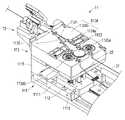
도 1은 일 실시 예에 따른 스텐트 구동 장치의 사시도이다.
도 2는 일 실시 예에 따른 텐셔너 모듈의 확대도이다.
도 3은 일 실시 예에 따른 텐셔너 모듈의 블록도이다.
도 4는 일 실시 예에 따른 텐셔너 모듈의 분리 사시도이다.
도 5는 일 실시 예에 따른 구동 블록이 구동 베이스에 연결되어 있는 구조를 개략적으로 도시하는 평면도이다.
도 6은 일 실시 예에 따른 텐셔너 모듈의 측 단면도이다.
도 7은 일 실시 예에 따른 구동 베이스에 대해서 구동 블록이 일 방향으로 슬라이딩된 모습을 도시하는 평면도이다.
도 8은 일 실시 예에 따른 가이드 블록에 대해서 구동 블록이 일 방향으로 슬라이링된 모습을 도시하는 평면도이다.
도 9는 일 실시 예에 따른 구동 베이스에 대해서 구동 블록이 타 방향으로 슬라이딩된 모습을 도시하는 평면도이다.
도 10은 일 실시 예에 따른 가이드 블록에 대해서 구동 블록이 타 방향으로 슬라이링된 모습을 도시하는 평면도이다.1 is a perspective view of a stent driving device according to an embodiment.
2 is an enlarged view of a tensioner module according to an embodiment.
3 is a block diagram of a tensioner module according to an embodiment.
4 is an exploded perspective view of a tensioner module according to an embodiment.
5 is a plan view schematically illustrating a structure in which a driving block is connected to a driving base according to an exemplary embodiment.
6 is a side cross-sectional view of a tensioner module according to an embodiment.
7 is a plan view illustrating a state in which a driving block is slid in one direction with respect to a driving base according to an exemplary embodiment.
8 is a plan view illustrating a state in which a driving block is slid in one direction with respect to a guide block according to an embodiment.
9 is a plan view illustrating a state in which a driving block is slid in another direction with respect to a driving base according to an exemplary embodiment.
10 is a plan view illustrating a state in which a driving block is slid in another direction with respect to a guide block according to an exemplary embodiment.
이하, 실시 예들을 예시적인 도면을 통해 상세하게 설명한다. 각 도면의 구성요소들에 참조부호를 부가함에 있어서, 동일한 구성요소들에 대해서는 비록 다른 도면상에 표시되더라도 가능한 한 동일한 부호를 가지도록 하고 있음에 유의해야 한다. 또한, 실시 예를 설명함에 있어, 관련된 공지 구성 또는 기능에 대한 구체적인 설명이 실시 예에 대한 이해를 방해한다고 판단되는 경우에는 그 상세한 설명은 생략한다.Hereinafter, embodiments will be described in detail with reference to exemplary drawings. In adding reference numerals to the components of each drawing, it should be noted that the same components are given the same reference numerals as much as possible even though they are indicated on different drawings. In addition, in the description of the embodiment, if it is determined that a detailed description of a related known configuration or function interferes with the understanding of the embodiment, the detailed description thereof will be omitted.
또한, 실시 예의 구성 요소를 설명하는 데 있어서, 제 1, 제 2, A, B, (a), (b) 등의 용어를 사용할 수 있다. 이러한 용어는 그 구성 요소를 다른 구성 요소와 구별하기 위한 것일 뿐, 그 용어에 의해 해당 구성 요소의 본질이나 차례 또는 순서 등이 한정되지 않는다. 어떤 구성 요소가 다른 구성요소에 "연결", "결합" 또는 "접속"된다고 기재된 경우, 그 구성 요소는 그 다른 구성요소에 직접적으로 연결되거나 접속될 수 있지만, 각 구성 요소 사이에 또 다른 구성 요소가 "연결", "결합" 또는 "접속"될 수도 있다고 이해되어야 할 것이다.In addition, in describing the components of the embodiment, terms such as first, second, A, B, (a), (b), etc. may be used. These terms are only for distinguishing the elements from other elements, and the essence, order, or order of the elements are not limited by the terms. When it is described that a component is "connected", "coupled" or "connected" to another component, the component may be directly connected or connected to the other component, but another component is between each component. It will be understood that may also be "connected", "coupled" or "connected".
어느 하나의 실시 예에 포함된 구성요소와, 공통적인 기능을 포함하는 구성요소는, 다른 실시 예에서 동일한 명칭을 사용하여 설명하기로 한다. 반대되는 기재가 없는 이상, 어느 하나의 실시 예에 기재한 설명은 다른 실시 예에도 적용될 수 있으며, 중복되는 범위에서 구체적인 설명은 생략하기로 한다.Components included in one embodiment and components having a common function will be described using the same names in other embodiments. Unless otherwise stated, descriptions described in one embodiment may be applied to other embodiments as well, and detailed descriptions within the overlapping range will be omitted.
도 1은 일 실시 예에 따른 스텐트 구동 장치의 사시도이고, 도 2는 일 실시 예에 따른 텐셔너 모듈의 확대도이고, 도 3은 일 실시 예에 따른 텐셔너 모듈의 블록도이고, 도 4는 일 실시 예에 따른 텐셔너 모듈의 분리 사시도이고, 도 5는 일 실시 예에 따른 구동 블록이 구동 베이스에 연결되어 있는 구조를 개략적으로 도시하는 평면도이고, 도 6은 일 실시 예에 따른 텐셔너 모듈의 측 단면도이다.1 is a perspective view of a stent driving device according to an embodiment, FIG. 2 is an enlarged view of a tensioner module according to an embodiment, FIG. 3 is a block diagram of a tensioner module according to an embodiment, and FIG. 4 is an embodiment An exploded perspective view of a tensioner module according to an embodiment, FIG. 5 is a plan view schematically illustrating a structure in which a driving block is connected to a driving base according to an embodiment, and FIG. 6 is a side cross-sectional view of the tensioner module according to an embodiment .
도 1 내지 도 6을 참조하면, 일 실시 예에 따른 스텐트 구동 장치(1)는 체내로 삽입되는 가이드 와이어(21)와, 가이드 와이어(21)에 의해 가이드되어 체내로 이송되는 스텐트 벌룬 또는 스텐트 카테터을 이동시키는 스텐트 와이어(22)를 파지하여 환자 체내에 삽입되는 가이드 와이어(21)와 스텐트 와이어(22)를 개별적으로 전/후 방향 병진 구동시키는 동시에, 가이드 와이어(21)를 회전 구동할 수 있다.1 to 6 , the
일 실시 예에 따른 스텐트 구동 장치(1)는, 길이 방향을 따라서 연장되는 가이드 와이어(21)를 회전 구동 가능하게 파지하는 회전 모듈(12)과, 길이 방향을 기준으로 회전 모듈(12)로부터 전방으로 연장되는 가이드 와이어(21) 및 가이드 와이어(21)에 합류하는 스텐트 와이어(22)를 파지하고 각각의 와이어를 개별적으로 병진 구동하는 텐셔너 모듈(11)과, 텐셔너 모듈(11)의 전방으로부터 합류된 가이드 와이어(21) 및 스텐트 와이어(22)를 지지하는 커넥터(13)를 포함할 수 있다.The
일 실시 예에 따른 텐셔너 모듈(11)은, 가이드 와이어(21)와 가이드 와이어(21)를 감싸는 스텐트 와이어(22)를 서로 독립적으로 구동시킴으로써 보다 정밀한 스텐트 포지셔닝을 가능하게 할 수 있다.The
일 실시 예에 따른 텐셔너 모듈(11)은, 길이 방향을 따라서 연장하는 가이드 와이어(21)와, 상기 가이드 와이어(21)에 비스듬하게 수렴하여 가이드 와이어(21)를 감싸도록 합류하는 스텐트 와이어(22)의 경로를 따라 가이드할 수 있고, 가이드 와이어(21) 및 스텐트 와이어(22) 중 어느 하나의 와이어(21, 22)를 전진 또는 후진 구동하는 동시에, 구동되지 않는 나머지 와이어를 움직이지 않도록 고정할수 있어서, 스텐트의 빠르고 정확한 기계적 포지셔닝을 가능하게 할 수 있다.The
예를 들어, 텐셔너 모듈(11)은 구동 베이스(111), 구동 블록(112), 가이드 블록(113) 및 제어부(16)를 포함할 수 있다.For example, the
구동 베이스(111)는, 구동 블록(112)을 길이 방향에 수직한 가로 방향을 따라서 슬라이딩 구동 가능하게 지지하는 동시에, 가이드 블록(113)을 고정적으로 지지할 수 있다. 예를 들어, 구동 베이스(111)는 길이 방향을 기준으로 회전 모듈(12)로부터 전방으로 이격된 위치에 설치될 수 있다.The
예를 들어, 구동 베이스(111)는, 고정부(1111)와, 고정부(1111)에 설치되어 구동 블록(112)을 길이 방향에 수직한 가로 방향으로 슬라이딩 구동하는 슬라이딩 구동부(1114)와, 고정부(1111)에 가로 방향을 따라서 연장되고 구동 블록(112)의 슬라이딩 구동을 가이드 샤프트(1113)와, 가이드 샤프트(1113)에 설치되는 가이드 탄성체(1115)를 포함할 수 있다.For example, the
고정부(1111)는, 구동 블록(112)의 슬라이딩 구동을 수행하기 위한 고정된 지지점을 제공할 수 있다. 예를 들어, 고정부(1111)는 길이 방향을 따라서 서로 평행하게 마주보면 연장되는 한 쌍의 부재를 포함할 수 있다.The fixing
가이드 샤프트(1113)는, 고정부(1111)에 설치되고 수직한 방향을 따라서 연장될 수 있다. 예를 들어, 도 5와 같이 고정부(1111)가 길이 방향을 따라서 연장되는 한 쌍의 레일 형태의 부재일 경우, 가이드 샤프트(1113)는 한 쌍의 부재 사이를 가로지르도록 연장될 수 있다.The
예를 들어, 가이드 샤프트(1113)에는 구동 블록(112), 즉 구동 플레이트(1121)가 가이드 샤프트(1113)의 길이 방향, 즉 가로 방향을 따라서 슬라이딩 가능하게 설치되어, 결과적으로 구동 플레이트(1121)는 가이드 샤프트(1113)를 따라서 가로 방향을 따라서 슬라이딩 구동 방향이 가이드될 수 있다.For example, in the
예를 들어, 도 5와 같이 가이드 샤프트(1113)는 길이 방향을 따라서 서로 평행하게 마주보도록 이격되는 2개 이상의 구성으로 설치될 수 있다.For example, as shown in FIG. 5 , the
가이드 탄성체(1115)는, 가이드 샤프트(1113)에 설치된 구동 블록(112), 즉 구동 플레이트(1121)에 가로 방향을 따라서 일 방향으로의 탄성력을 제공할 수 있다. 예를 들어, 가이드 탄성체(1115)는 가이드 샤프트(1113)에 설치되는 스프링형 부재일 수 있다.The guide
예를 들어, 가이드 탄성체(1115)는 구동 플레이트(1121)에 연결되어 있는 가이드 샤프트(1113)의 일측에 설치될 수 있어서, 구동 플레이트(1121)는 슬라이딩 구동 위치에 따라서 탄성력을 인가받을 수 있다.For example, the guide
가이드 탄성체(1115)에 의하면, 슬라이딩 구동부(1114)의 회전 캠(11142)으로 하여금 구동 플레이트(1121)의 캠 수용부(11211)에 항상 접촉될 수 있도록, 가로 방향을 따라서 구동 플레이트(1121)를 일방향으로 밀어내는 탄성력을 인가할 수 있다.According to the guide
예를 들어, 가이드 탄성체(1115)는 구동 블록(112)이 슬라이딩 구동하는 과정에서 중앙 롤러(11233)가 제 1 가이드 롤러(1135a) 또는 제 2 가이드 롤러(1135b)를 과도하게 가압하거나 충격이 발생하는걸 완화할 수 있다.For example, the guide
슬라이딩 구동부(1114)는, 구동 베이스(111)에 고정된 상태로 구동 블록(112)에 연결되어 구동 블록(112)을 슬라이딩 구동할 수 있다.The sliding
예를 들어, 슬라이딩 구동부(1114)의 일측은 고정부(1111)에 고정될 수 있고, 구동 단부는 구동 블록(112)에 연결되도록 설치되어 구동 블록(112)으로 하여금 구동 베이스(111)에 대해 가로 방향을 따라서 슬라이딩 구동시킬 수 있다.For example, one side of the sliding
예를 들어, 슬라이딩 구동부(1114)는, 고정부(1111)에 고정되고 가로 방향 및 길이 방향에 수직한 구동축을 갖는 캠 회전 모터(11141)와, 구동축의 중심으로부터 방사상으로 상이한 돌출 반경을 갖도록 돌출되어 구동 블록(112)에 접촉하는 회전 캠(11142)을 포함할 수 있다.For example, the sliding
예를 들어, 캠 회전 모터(11141)의 하우징은 고정부(1111)에 고정되되, 모터의 구동축은 하측을 향해 돌출되어 구동 플레이트(1121)의 캠 수용부(11211)를 하측으로 마주보도록 설치될 수 있다.For example, the housing of the
예를 들어, 캠 회전 모터(11141)의 구동축은 도 4와 같이 연직 방향을 따라서 연장될 수 있다. 예를 들어, 캠 회전 모터(11141)는 하측으로 구동 플레이트(1121)를 마주보도록 설치될 수 있다.For example, the drive shaft of the
회전 캠(11142)은 캠 회전 모터(11141)의 구동 축에 설치될 수 있고, 외주면을 통해 구동 플레이트(1121), 다시 말하면 구동 플레이트(1121)의 캠 수용부(11211)에 접촉될 수 있다.The
예를 들어, 캠 수용부(11211)는, 가이드 탄성체(1115)에 의해 가압되어 항상 회전 캠(11142)의 외주면에 접촉된 상태를 유지할 수 있다.For example, the
회전 캠(11142)은 구동축을 기준으로 방사상 반경이 상이하게 형성됨에 따라서, 회전 캠(11142)의 회전에 따라 회전 캠(11142)의 외주면을 통해 접촉되는 캠 수용부(11211), 즉 구동 플레이트(1121)는 가이드 샤프트(1113)에 가이드되어 가로 방향을 따라 슬라이딩 구동될 수 있다.As the
구동 블록(112)은, 구동 베이스(111)에 대해 가로 방향을 따라 슬라이딩 구동하여 가이드 블록(113)을 통과하는 가이드 와이어(21) 및 스텐트 와이어(22) 중 어느 하나의 와이어와 접촉하여 해당 와이어를 전진 또는 후진 구동할 수 있다.The
구동 블록(112)은, 가이드 샤프트(1113)에 가이드되어 가로 방향을 따라 슬라이딩 구동되는 구동 플레이트(1121)와, 구동 플레이트(1121)에 설치되고 가이드 와이어(21) 및 스텐트 와이어(22) 중 하나의 와이어에 접촉되어 와이어의 병진 구동을 수행하는 롤러 구동부(1123)와, 구동 플레이트(1121) 상에 가로 방향을 따라서 이격되도록 설치되어 구동 플레이트(1121)의 슬라이딩 구동 위치에 따라 가이드 와이어(21) 또는 스텐트 와이어(22)를 가압하여 고정하는 그리퍼부(1124)와, 가로 방향을 따라서 구동 블록(112)과 가이드 블록(113) 사이에 설치되는 완충 탄성체(1125)를 포함할 수 있다.The
구동 플레이트(1121)는, 가이드 샤프트(1113)에 연결되어 슬라이딩 가능하게 설치되는 부재일 수 있다. 예를 들어, 구동 플레이트(1121)는 슬라이딩 구동부(1114)의 구동에 따라 가로 방향을 따라서 슬라이딩 될 수 있다.The
예를 들어, 구동 플레이트(1121)가 가로 방향을 따라서 구동함에 따라, 구동 플레이트(1121)에 설치된 롤러 구동부(1123) 및 그리퍼부(1124) 모두 가로 방향을 따라서 슬라이딩 구동될 수 있다.For example, as the
예를 들어, 구동 플레이트(1121)는 슬라이딩 구동부(1114)의 회전 캠(11142)의 외주면에 간섭되도록 설치되는 캠 수용부(11211)를 포함할 수 있다.For example, the
캠 수용부(11211)는 슬라이딩 구동부(1114) 중 하측으로 돌출된 회전 캠(11142)을 상측으로부터 수용할 수 있는 공간을 형성할 수 있다. 예를 들어, 캠 수용부(11211)는 회전 캠(11142)의 외주면에 접촉될 수 있는 내벽 또는 단차를 포함할 수 있다.The cam
예를 들어, 도 5와 같이 가로 방향을 기준으로, 회전 캠(11142)은 가이드 탄성체(1115)로부터 탄성력이 인가되는 방향의 외주면 부분에서 캠 수용부(11211)와 접촉될 수 있다.For example, in the horizontal direction as shown in FIG. 5 , the
롤러 구동부(1123)는, 구동 플레이트(1121) 상에 설치되는 롤러 회전 모터(11231)와, 롤러 회전 모터(11231)에 의해 회전되고 상측으로 연장하는 회전축을 갖는 롤러 샤프트(11232)와, 롤러 샤프트(11232)에 설치되고 가이드 블록(113)에 삽입되는 중앙 롤러(11233)를 포함할 수 있다.The
롤러 회전 모터(11231)는, 구동 플레이트(1121) 상에 설치될 수 있다. 예를 들어, 롤러 회전 모터(11231)는 회전 구동 가능한 구동축 갖는 모터일 수 있다.The
롤러 샤프트(11232)는, 롤러 회전 모터(11231)의 구동축에 연결되어 회전 구동될 수 있다. 예를 들어, 롤러 샤프트(11232)는, 상측을 향해 연장된 회전축을 가질 수 있다.The
예를 들어, 롤러 샤프트(11232)는 상측을 향해 연장되어 가이드 블록(113)의 중앙 롤러 수용홈(1133)을 마주보도록 설치될 수 있다. 예를 들어, 텐셔너 모듈(11)을 상측으로 바라볼 때, 롤러 샤프트(11232)와 중앙 롤러 수용홈(1133)은 서로 오버랩될 수 있다.For example, the
예를 들어, 롤러 샤프트(11232)는 기어, 풀리, 체인 또는 스프로킷 등 별도의 동력 전달 요소가 롤러 회전 모터(11231) 사이에 연결되어 회전 동력을 전달받을 수 있다.For example, in the
다른 예로, 롤러 샤프트(11232)는 롤러 회전 모터(11231)의 구동축에 직결되어 연결될 수도 있다는 점을 밝혀둔다.As another example, it should be noted that the
중앙 롤러(11233)는, 롤러 샤프트(11232)에 연결되어 상측으로 돌출되도록 설치될 수 있고, 가이드 블록(113)의 중앙 롤러 수용홈(1133)에 수용될 수 있다.The
예를 들어, 중앙 롤러(11233)는 롤러 회전 모터(11231)가 구동함에 따라 롤러 샤프트(11232)를 통해 전달되는 회전 구동력을 통해 회전 구동될 수 있다.For example, the
예를 들어, 중앙 롤러(11233)가 가이드 와이어(21) 및 스텐트 와이어(22) 중 어느 하나의 와이어에 밀착된 상태에서 회전할 경우, 해당 와이어를 전후 방향을 따라서 병진 구동할 수 있다.For example, when the
그리퍼부(1124)는, 구동 플레이트(1121) 상에서 상측을 향해 돌출되도록 설치될 수 있고, 돌출되는 상단의 일부는 가이드 블록(113)에 형성된 제 1 그리퍼 수용홈(1134a) 및 제 2 그리퍼 수용홈(1134b)에 수용될 수 있다.The
그리퍼부(1124)는, 가로 방향으로 서로 마주보도록 이격되는 제 1 그리퍼(1124a)와 제 2 그리퍼(1124b)를 포함할 수 있다.The
예를 들어, 제 1 그리퍼(1124a) 및 제 2 그리퍼(1124b)는 가로 방향을 따라서 설정 간격으로 이격됨에 따라서, 제 1 그리퍼(1124a) 및 제 2 그리퍼(1124b) 중 어느 하나의 그리퍼(1124a, 1124b)가 가이드 와이어(21) 및 스텐트 와이어(22) 중 어느 하나의 와이어(21, 22)에 접촉할 경우, 서로 접촉되지 않은 나머지 하나의 그리퍼(21,22)와 나머지 하나의 와이어(21, 22)는 서로 접촉되지 않은 상태로 이격되어 있을 수 있다.For example, as the
즉, 구동 블록(112)의 슬라이딩 구동 위치에 따라서, 제 1 그리퍼(1124a) 또는 제 2 그리퍼(1124b)는 가이드 와이어(21) 및 스텐트 와이어(22) 중 어느 하나의 와이어에만 접촉하여 고정할 수 있다.That is, depending on the sliding driving position of the driving
제 1 그리퍼(1124a)는, 가로 방향을 기준으로 제 1 와이어 통로(1131)의 바깥쪽, 즉 제 1 그리퍼 수용홈(1134a)에 위치하도록 설치되고, 구동 블록(112)의 슬라이딩 구동 위치에 따라서, 제 1 와이어 통로(1131)를 통과하는 가이드 와이어(21)를 가압하여 고정할 수 있다.The
예를 들어, 제 1 그리퍼(1124a)는 구동 플레이트(1121)에 고정되고 가로 방향으로 연장된 가이드 공간을 갖는 제 1 그리퍼 하우징(11241a)과, 제 1 그리퍼 하우징(11241a)의 가이드 공간을 따라 슬라이딩 가능하게 설치되고 가이드 와이어(21)와 접촉하는 제 1 스토퍼(11242a)를 포함할 수 있다.For example, the
예를 들어, 제 1 스토퍼(11242a)의 접촉 단부는 가이드 와이어(21)에 평행한 평면 형태를 가짐으로써, 가이드 와이어(21)를 평행한 상태로 마주볼 수 있다.For example, the contact end of the
제 2 그리퍼(1124b)는, 가로 방향을 기준으로 제 2 와이어 통로(1132)의 바깥쪽, 즉 제 2 그리퍼 수용홈(1134b)에 위치하도록 설치되고, 구동 블록(112)의 슬라이딩 구동 위치에 따라서, 제 2 와이어 통로(1132)를 통과하는 스텐트 와이어(22)를 가압하여 고정할 수 있다.The
예를 들어, 제 2 그리퍼(1124b)는 구동 플레이트(1121)에 고정되고 가로 방향으로 연장된 공간을 갖는 제 2 그리퍼 하우징(11241b)과, 제 2 그리퍼 하우징(11241b)의 내부 공간을 따라 슬라이딩 가능하게 설치되고 가이드 와이어(21)와 접촉하는 제 2 스토퍼(11242b)와, 제 2 그리퍼 하우징(11241b)의 내부에 설치되어 제 2 스토퍼(11242b)를 외부로 밀어내는 탄성력을 제공하는 그리퍼 탄성체(11243b)를 포함할 수 있다.For example, the
예를 들어, 제 2 스토퍼(11242b)의 접촉 단부는 스텐트 와이어(22)에 평행한 평면 형태를 가질 수 있다.For example, the contact end of the
여기서, 스텐트 와이어(22) 및 제 2 와이어 통로(1132) 길이 방향에 비스듬한 각도를 형성하기 때문에, 제 2 스토퍼(11242b)의 접촉 단부 역시 스텐트 와이어(22)를 평행하게 마주볼 수 있도록, 길이 방향으로 갈수록 경사진 스텐트 구동 장치(1)사선 형태의 접촉면을 형성할 수 있다.Here, since the
그리퍼 탄성체(11243b)는 제 2 스토퍼(11242b)와 제 2 그리퍼 하우징(11241b) 사이의 공간에 설치되어 제 2 스토퍼(11242b)가 스텐트 와이어(22)에 접촉하는 과정에서 발생하는 충격을 완화시킬 수 있으며, 동시에 스텐트 와이어(22)가 과도하게 가압되어 파손되지 않도록 방지할 수 있다.The gripper
한편, 도면상에 도시되지는 않았지만 제 1 그리퍼(1124a) 역시 제 1 그리퍼 하우징(11241a) 내부에서 제 1 스토퍼(11242a)에 연결되는 그리퍼 탄성체의 구성을 포함할 수 있다는 점을 밝혀둔다.Meanwhile, although not shown in the drawings, it should be noted that the
예를 들어, 그리퍼부(1124)는, 제 1 그리퍼(1124a) 및 제 2 그리퍼(1124b)를 이격된 상태로 지지하는 지지 플레이트(11244)를 더 포함할 수 있다.For example, the
예를 들어, 지지 플레이트(11244)는 롤러 회전 모터(11231) 상에 설치될 수 있고, 상측으로 서로 가로 방향을 따라서 이격된 제 1 그리퍼(1124a)와 제 2 그리퍼(1124b)를 고정적으로 지지할 수 있다.For example, the
완충 탄성체(1125)는 가로 방향을 기준으로 가이드 탄성체(1115)에 대향하는 부분에서 구동 블록(112)과 가이드 블록(113) 사이에 설치될 수 있다.The cushioning
예를 들어, 완충 탄성체(1125)는 가이드 탄성체(1115)와 마찬가지로 구동 블록(112)이 일 방향으로 슬라이딩 될 경우 압축될 수 있어서, 롤러 구동부(1123) 또는 그리퍼부(1124)가 일 방향으로 슬라이딩하는 과정에서 가이드 와이어(21) 또는 스텐트 와이어(22)를 과도하게 가압하거나 충격이 발생하는 정도를 완충할 수 있다.For example, the cushioning
가이드 블록(113)은 구동 베이스(111)상에 고정되고 길이 방향으로 연장되는 가이드 와이어(21)와 가이드 와이어(21)에 합류하는 스텐트 와이어(22)의 경로를 형성하는 하우징 부재일 수 있다.The
예를 들어, 가이드 블록(113)은 구동 베이스(111) 및 구동 블록(112)에 탈부착 가능하게 설치될 수 있다. 예를 들어, 가이드 블록(113)은 도 4와 같이 상하 방향을 따라서 구동 베이스(111)로부터 탈부착 가능하게 분리될 수 있다.For example, the
예를 들어, 도 2와 같이 가이드 블록(113)이 구동 베이스(111)에 설치될 경우 구동 베이스(111)에 고정된 상태로 내부에 구동 블록(112)의 그리퍼부(1124) 및 롤러 구동부(1123)의 일부가 구동 블록(112) 내부에 수용될 수 있다.For example, when the
예를 들어, 가이드 블록(113)은, 제 1 와이어 통로(1131), 제 2 와이어 통로(1132), 제 1 그리퍼 수용홈(1134a), 제 2 그리퍼 수용홈(1134b), 제 1 가이드 롤러(1135a), 제 2 가이드 롤러(1135b) 및 중앙 롤러 수용홈(1133)을 포함할 수 있다.For example, the
제 1 와이어 통로(1131)는, 길이 방향을 따라서 가이드 와이어(21)가 통과하는 경로를 따라서 연장된 통로이다.The
예를 들어, 제 1 와이어 통로(1131)는 상측으로부터 함몰 형성된 공간일 수 있고, 이에 따라 가이드 와이어(21)는 가이드 블록(113)의 상측으로부터 도입되어 수용될 수 있다.For example, the
제 2 와이어 통로(1132)는, 길이 방향으로 갈수록 제 1 와이어 통로(1131)에 비스듬한 각도록 수렴하는 경로를 따라서 스텐트 와이어(22)가 통과하는 통로이다.The
예를 들어, 제 2 와이어 통로(1132)는 상측으로부터 함몰 형성된 공간일 수 있고, 이에 따라 스텐트 와이어(22)는 가이드 블록(113)의 상측으로부터 도입되어 수용될 수 있다.For example, the
예를 들어, 제 2 와이어 통로(1132)는 길이 방향을 갈수록 제 1 와이어 통로(1131)에 비스듬한 방향으로 수렴하여 연통되는 구조를 가질 수 있다.For example, the
이상의 구조에 의하면, 길이 방향을 기준으로 가이드 블록(113)의 후방에서는 제 2 와이어 통로(1132)의 후단은 제 1 와이어 후단으로부터 가로 방향을 따라 이격된 위치에 형성되어, 각각 스텐트 와이어(22)와 가이드 와이어(21)가 진입하는 별개의 개구로서 존재하지만, 가이드 블록(113)의 전방에서는 제 2 와이어 통로(1132)가 제 1 와이어 통로(1131)에 합쳐짐으로써 결과적으로 제 1 와이어 통로(1131)로부터 연통되는 개구만 존재할 수 있다.According to the above structure, at the rear of the
제 1 그리퍼 수용홈(1134a)은, 가로 방향을 따라서 제 1 와이어 통로(1131)의 외측 부분에 연통되는 공간으로서 제 1 그리퍼(1124a)가 수용되는 홈일 수 있다.The first
예를 들어, 제 1 그리퍼 수용홈(1134a)은 제 1 와이어 통로(1131)의 부분중, 가로 방향을 기준으로 제 2 와이어 통로(1132)에 대향하는 측부 부분에 형성되어 하측으로부터 구동 블록(112)의 제 1 그리퍼(1124a)가 수용될 수 있다.For example, the first
예를 들어, 제 1 그리퍼 수용홈(1134a)은 제 1 그리퍼(1124a)가 슬라이딩 구동되는 가로 방향을 따라서 구동 방향을 가이드하는 역할을 할 수 있다.For example, the first
이상의 구조에 의하면, 제 1 그리퍼(1124a)의 제 1 그리퍼 하우징(11241a)은 제 1 그리퍼 수용홈(1134a)을 따라서 슬라이딩되고, 제 1 스토퍼(11242a)는 제 1 그리퍼 수용홈(1134a)을 따라서 슬라이딩되는 구조를 가질 수 있다.According to the above structure, the
제 2 그리퍼 수용홈(1134b)은, 가로 방향을 따라서 제 2 와이어 통로(1132)의 외측 부분에 연통되는 공간으로서 제 2 그리퍼(1124b)가 수용되는 홈일 수 있다.The second
예를 들어, 제 2 그리퍼 수용홈(1134b)은 제 2 와이어 통로(1132)의 부분중, 가로 방향을 기준으로 제 1 와이어 통로(1131)에 대향하는 측부 부분에 형성되어 하측으로부터 구동 블록(112)의 제 2 그리퍼(1124b)가 수용될 수 있다.For example, the second
예를 들어, 제 2 그리퍼 수용홈(1134b)은 제 2 그리퍼(1124b)가 슬라이딩 구동되는 가로 방향을 따라서 구동 방향을 가이드하는 역할을 할 수 있다.For example, the second
이상의 구조에 의하면, 제 2 그리퍼(1124b)의 제 2 그리퍼 하우징(11241b)은 제 2 그리퍼 수용홈(1134b)을 따라서 슬라이딩되고, 제 2 스토퍼(11242b)는 제 2 그리퍼 수용홈(1134b)을 따라서 슬라이딩되는 구조를 가질 수 있다.According to the above structure, the
예를 들어, 텐셔너 모듈(11)을 상측에서 바라볼 때, 제 1 그리퍼 수용홈(1134a) 및 제 2 그리퍼 수용홈(1134b)은 가로 방향을 따라 동일 선상을 따라 이격된 위치에 형성될 수 있다.For example, when the
제 1 가이드 롤러(1135a)는, 제 1 와이어 통로(1131)의 부분 중 중앙 롤러(11233)의 슬라이딩 구동 축에 오버랩되는 위치에 설치되고 가이드 와이어(21)를 회전 가능하게 지지할 수 있다.The
예를 들어, 제 1 가이드 롤러(1135a)는 제 1 와이어 통로(1131)의 부분중, 가로 방향을 기준으로 제 2 와이어 통로(1132)에 대향하는 측부 부분에 노출되도록 설치될 수 있다.For example, the
예를 들어, 텐셔너 모듈(11)을 상측으로 바라 볼때, 제 1 와이어 통로(1131)를 통과하는 가이드 와이어(21)는 제 1 가이드 롤러(1135a)의 외주면에 외접하는 형태로 연장될 수 있다.For example, when the
예를 들어, 제 1 가이드 롤러(1135a)는 길이 방향에 수직한 상하 방향에 평행한 회전축을 가질 수 있고, 중앙 롤러(11233)가 가이드 와이어(21)를 향해 슬라이딩 할 경우, 제 1 가이드 롤러(1135a)의 외주면은 중앙 롤러(11233)의 외주면과 그 사이에 가이드 와이어(21)가 개재된 상태로 접촉하여 가이드 와이어(21)를 전진 또는 후진 구동되도록 회전될 수 있다.For example, the
제 2 가이드 롤러(1135b)는, 제 2 와이어 통로(1132)의 부분 중 중앙 롤러(11233)의 슬라이딩 구동 축에 오버랩되는 위치에 설치되고 스텐트 와이어(22)를 회전 가능하게 지지할 수 있다.The
예를 들어, 제 2 가이드 롤러(1135b)는 제 2 와이어 통로(1132)의 부분중, 가로 방향을 기준으로 제 1 와이어 통로(1131)에 대향하는 측부 부분에 노출되도록 설치될 수 있다.For example, the
예를 들어, 텐셔너 모듈(11)을 상측으로 바라 볼때, 제 2 와이어 통로(1132)를 통과하는 스텐트 와이어(22)는 제 2 가이드 롤러(1135b)의 외주면에 외접하는 형태로 연장될 수 있다.For example, when the
예를 들어, 제 2 가이드 롤러(1135b)는 길이 방향에 수직한 상하 방향에 평행한 회전축을 가질 수 있고, 중앙 롤러(11233)가 스텐트 와이어(22)를 향해 슬라이딩 할 경우, 제 2 가이드 롤러(1135b)의 외주면은 중앙 롤러(11233)의 외주면과 그 사이에 스텐트 와이어(22)가 개재된 상태로 접촉하여 가이드 와이어(21)를 전진 또는 후진 구동되도록 회전될 수 있다.For example, the
예를 들어, 길이 방햐을 기준으로, 가이드 블록(113)에서 제 1 가이드 롤러(1135a) 및 제 2 가이드 롤러(1135b)는 제 1 그리퍼 수용홈(1134a) 및 제 2 그리퍼 수용홈(1134b)보다 후방에 위치할 수 있다.For example, the
중앙 롤러 수용홈(1133)은, 가로 방향을 따라서 제 1 가이드 롤러(1135a) 및 제 2 가이드 롤러(1135b) 사이를 연통하는 공간으로서, 하측으로부터 중앙 롤러(11233)가 수용될 수 있다.The center
예를 들어, 중앙 롤러 수용홈(1133)은 제 1 와이어 통로(1131) 및 제 2 와이어 통로(1132)와 모두 연통되는 공간일 수 있고, 중앙 롤러 수용홈(1133)에서 중앙 롤러(11233)는 가로 방향을 따라 슬라이딩 구동함에 따라 선택적으로 제 1 가이드 롤러(1135a) 또는 제 2 가이드 롤러(1135b)에 접촉할 수 있다.For example, the central
예를 들어, 중앙 롤러 수용홈(1133)은 가이드 블록(113)의 상측으로 함몰 형성된 공간일 수 있고, 이에 따라 중앙 롤러(11233)는 상측으로부터 롤러 샤프트(11232) 탈부착 가능하게 설치될 수 있다.For example, the center
예를 들어, 중앙 롤러(11233)의 상단부는 회전하는 부분의 반경보다 상대적으로 크게 형성되는 단차가 형성되어 있을 수 있어서, 가이드 와이어(21) 또는 스텐트 와이어(22)에 접촉하여 구동할 시, 해당 와이어가 상측으로 이탈되는 것을 방지할 수 있다.For example, the upper end of the
제어부(16)는, 슬라이딩 구동부(1114) 및 롤러 구동부(1123)의 구동을 제어하여 가이드 와이어(21) 또는 스텐트 와이어(22)의 포지셔닝을 제어할 수 있다.The
구체적인, 텐셔너 모듈(11)의 작동 구조는 이하의 도 7 내지 도 10을 참조하여 후술하기로 한다.Specifically, the operating structure of the
도 7은 일 실시 예에 따른 구동 베이스에 대해서 구동 블록이 일 방향으로 슬라이딩된 모습을 도시하는 평면도이고, 도 8은 일 실시 예에 따른 가이드 블록에 대해서 구동 블록이 일 방향으로 슬라이링된 모습을 도시하는 평면도이고, 도 9는 일 실시 예에 따른 구동 베이스에 대해서 구동 블록이 타 방향으로 슬라이딩된 모습을 도시하는 평면도이고, 도 10은 일 실시 예에 따른 가이드 블록에 대해서 구동 블록이 타 방향으로 슬라이링된 모습을 도시하는 평면도이다.7 is a plan view illustrating a state in which the driving block is slid in one direction with respect to the driving base according to an embodiment, and FIG. 8 is a state in which the driving block is slid in one direction with respect to the guide block according to an embodiment. 9 is a plan view showing a state in which the driving block is slid in another direction with respect to the driving base according to an embodiment, and FIG. 10 is the driving block in the other direction with respect to the guide block according to an embodiment. It is a plan view showing the sliced state.
도 7 및 도 8을 참조하면, 제어부(16)가 슬라이딩 구동부(1114)의 구동을 통해 중앙 롤러(11233)로 하여금 가이드 와이어(21)와 접촉하여 가이드 와이어(21)를 구동하는 과정을 확인할 수 있다.7 and 8 , it can be confirmed that the
먼저 도 7과 같이, 제어부(16)는 슬라이딩 구동부(1114), 즉 캠 회전 모터(11141)를 구동하여 회전 캠(11142)의 부분 중 상대적으로 반경이 큰 부분으로 하여금 구동 블록(112)의 캠 수용홈(11211)에 간섭되도록 하여, 결과적으로 구동 플레이트(1121), 즉 구동 블록(112)은 가로 방향을 따라서 회전 캠(11142)의 구동축에 대해 상대적으로 멀어지는 방향으로 슬라이딩 될 수 있다.First, as shown in FIG. 7 , the
이 경우, 가이드 탄성체(1115)는 구동 플레이트(1121)의 슬라이딩 움직임을 완충하는 역할을 하여, 구동 블록(112)에 설치된 그리퍼부(1124) 또는 중앙 롤러(11233)가 가이드 와이어(21) 또는 스텐트 와이어(22)를 과도하게 가압하여, 와이어의 정상적인 동작을 방해하거나 파손되는 것을 방지할 수 있다.In this case, the guide
구동 블록(112)이 가이드 와이어(21)를 향해 슬라이딩 될 경우, 도 8과 같이 중앙 롤러(11233)는 제 1 가이드 롤러(1135a)에 맞물리도록 접촉하여 가이드 와이어(21) 와이어를 구동 가능한 상태로 파지할 수 있다.When the driving
동시에, 제 2 그리퍼(1124b) 역시 제 2 그리퍼 수용홈(1134b)으로부터 제 2 와이어 통로(1132)를 향해 슬라이딩 되어 제 2 그리퍼 수용홈(1134b)을 통과하는 스텐트 와이어(22) 와이어를 제 2 와이어 통로(1132)의 내벽에 대해 가압함으로써 스텐트 와이어(22)를 고정시킬 수 있다.At the same time, the
여기서, 제 2 그리퍼(1124b)의 제 2 스토퍼(11242b)가 스텐트 와이어(22)를 가압하는 경우, 그리퍼 탄성체(11243b)는 스텐트 와이어(22)가 제 2 스토퍼(11242b)에 의해 과도하게 가압되거나 충격에 의해서 파손되지 않도록 완충하는 역할을 할 수 있다.Here, when the second stopper (11242b) of the second gripper (1124b) presses the stent wire (22), the gripper elastic body (11243b) is the stent wire (22) is excessively pressed by the second stopper (11242b) or It can serve as a buffer so that it is not damaged by impact.
이와 동시에, 제 1 그리퍼(1124a)는 반대로 제 1 와이어 통로(1131)로부터 멀어지는 방향으로 슬라이딩 되어 가이드 와이어(21)를 간섭하지 않는 위치로 이동하게 된다.At the same time, the
결과적으로, 구동 블록(112)의 슬라이딩 구동에 의해 스텐트 와이어(22)는 와이어는 제 2 그리퍼(1124b)를 통해 고정된 상태로 구속되고, 가이드 와이어(21)는 중앙 롤러(11233)와 제 1 가이드 롤러(1135a) 사이에 맞물리게 됨으로써, 스텐트 와이어(22)의 움직임을 구속시킨 상태에서 가이드 와이어(21)의 병진 구동을 수행할 수 있게 된다.As a result, by the sliding driving of the driving
반대로, 도 9 및 도 10을 참조하면, 제어부(16)가 슬라이딩 구동부(1114)의 구동을 통해 중앙 롤러(11233)로 하여금 스텐트 와이어(22)와 접촉하여 스텐트 와이어(22)를 구동하는 과정을 확인할 수 있다.Conversely, referring to FIGS. 9 and 10 , the
먼저 도 9와 같이, 제어부(16)는 캠 회전 모터(11141)를 구동하여 회전 캠(11142)의 부분 중 상대적으로 반경이 작은 부분으로 하여금 구동 블록(112)의 캠 수용홈(11211)에 간섭되도록 함으로써, 결과적으로 구동 플레이트(1121), 즉 구동 블록(112)은 가로 방향을 따라서 회전 캠(11142)의 구동축에 대해 상대적으로 가까워지는 방향으로 슬라이딩 될 수 있다.First, as shown in FIG. 9 , the
이 경우, 도시되지는 않았지만 구동 블록(112)과 가이드 블록(113) 사이에 설치된 완충 스프링(, 도 6 참조)가 구동 플레이트(1121)의 슬라이딩 움직임을 완충하는 역할을 하여, 구동 블록(112)에 설치된 그리퍼부(1124) 또는 중앙 롤러(11233)가 가이드 와이어(21) 또는 스텐트 와이어(22)를 과도하게 가압하여, 와이어의 정상적인 동작을 방해하거나 파손되는 것을 방지할 수 있다.In this case, although not shown, a buffer spring (see FIG. 6 ) installed between the driving
구동 블록(112)이 스텐트 와이어(22)를 향해 슬라이딩 될 경우, 도 8과 같이 중앙 롤러(11233)는 제 2 가이드 롤러(1135b)에 맞물리도록 접촉하여 스텐트 와이어(22) 와이어를 구동 가능한 상태로 파지할 수 있다.When the driving
동시에, 제 1 그리퍼(1124a) 역시 제 1 그리퍼 수용홈(1134a)으로부터 제 1 와이어 통로(1131)를 향해 슬라이딩 되어 제 1 와이어 통로(1131)를 통과하는 스텐트 와이어(22) 와이어를 제 2 와이어 통로(1132)의 내벽에 대해 가압함으로써 스텐트 와이어(22)를 고정시킬 수 있다.At the same time, the
이와 동시에, 제 2 그리퍼(1124b)는 반대로 제 2 와이어 통로(1132)로부터 멀어지는 방향으로 슬라이딩 되어 스텐트 와이어(22)를 간섭하지 않는 위치로 이동하게 된다.At the same time, the
결과적으로, 구동 블록(112)의 슬라이딩 구동에 의해 가이드 와이어(21)는 와이어는 제 1 그리퍼(1124a)를 통해 고정된 상태로 구속되고, 스텐트 와이어(22)는 중앙 롤러(11233)와 제 2 가이드 롤러(1135b) 사이에 맞물리게 됨으로써, 가이드 와이어(21)의 움직임을 구속시킨 상태에서 스텐트 와이어(22)의 병진 구동을 수행할 수 있게 된다.As a result, by the sliding driving of the driving
한편, 캠 수용홈(11211)의 외주 부분 중, 돌출된 외주 반경의 크기가 가장 큰 부분과 가장 작은 부분 사이의 방사상 구간에서의 외주면의 반경의 크기는, 도 5에 도시된 바와 같이 그 사이의 크기를 가질 수 있다.On the other hand, the size of the radius of the outer circumferential surface in the radial section between the portion with the largest and the smallest size of the protruding outer circumferential radius of the outer circumferential portion of the
이 경우 중앙 롤러(11233)는 제 1 가이드 롤러(1135a) 및 제 2 가이드 롤러(1135b)에 간섭되지 않은 상태로 각각으로부터 이격된 상태를 유지할 수 있고, 제 1 그리퍼(1124a) 및 제 2 그리퍼(1124b) 역시 각각 가이드 와이어(21) 및 스텐트 와이어(22)에 간섭되지 않고, 각각으로부터 이격된 상태로 유지될 수 있다.In this case, the
일 실시 예에 따른 텐셔너 모듈(11)에 의하면, 가이드 와이어(21) 및 스텐트 와이어(22) 중 어느 하나의 와이어(21, 22)를 전진 또는 후진 구동하는 동시에, 구동되지 않는 나머지 와이어(21, 22)를 움직이지 않도록 고정할수 있어서, 스텐트의 빠르고 정확한 기계적 포지셔닝을 가능하게 할 수 있다.According to the
일 실시 예에 따른 텐셔너 모듈(11)에 의하면, 구동 블록(112)의 단순 슬라이딩 동작을 통해, 가이드 와이어(21) 및 스텐트 와이어(22) 중 구동할 와이어와 고정시킬 와이어를 신속하고 간단하게 전환할 수 있어서, 구동 조작이 신속하고 간단하게 수행될 수 있다.According to the
이상과 같이 비록 한정된 도면에 의해 실시 예들이 설명되었으나, 해당 기술분야에서 통상의 지식을 가진 자라면 상기의 기재로부터 다양한 수정 및 변형이 가능하다. 예를 들어, 설명된 기술들이 설명된 방법과 다른 순서로 수행되거나, 및/또는 설명된 구조, 장치 등의 구성요소들이 설명된 방법과 다른 형태로 결합 또는 조합되거나, 다른 구성요소 또는 균등물에 의하여 대치되거나 치환되더라도 적절한 결과가 달성될 수 있다.As described above, although the embodiments have been described with reference to the limited drawings, various modifications and variations can be made by those skilled in the art from the above description. For example, the described techniques are performed in an order different from the described method, and/or the described components of structures, devices, etc. are combined or combined in a different form than the described method, or other components or equivalents. An appropriate result can be achieved even if it is substituted or substituted by
Claims (11)
Translated fromKorean구동 베이스;
상기 구동 베이스에 고정되고 상기 가이드 와이어 및 상기 스텐트 와이어가 합류하는 경로를 가이드하도록 수용하는 가이드 블록; 및
상기 구동 베이스에 대해 상기 길이 방향에 수직한 가로 방향을 따라서 슬라이딩 구동 가능하고, 슬라이딩 구동 위치에 따라 상기 가이드 와이어 및 상기 스텐트 와이어 중 어느 하나의 와이어에 접촉하여 상기 어느 하나의 와이어의 병진 구동을 수행하는 구동 블록;을 포함하는 텐셔너 모듈.
In the tensioner module for selectively driving the guide wire extending along the longitudinal direction, and the stent wire joining the guide wire,
drive base;
a guide block fixed to the driving base and accommodated to guide a path where the guide wire and the stent wire join; and
A sliding drive is possible in a horizontal direction perpendicular to the longitudinal direction with respect to the driving base, and according to a sliding driving position, a translation drive of the one wire is performed by contacting any one wire of the guide wire and the stent wire A drive block that includes; a tensioner module.
상기 가이드 블록은,
상기 길이 방향을 따라서 상기 가이드 와이어가 통과하는 제 1 와이어 통로; 및
상기 길이 방향으로 갈수록 상기 제 1 와이어 통로에 비스듬한 각도로 수렴하고 상기 스텐트 와이어가 통과하는 제 2 와이어 통로;를 포함하고,
상기 구동 블록은,
상기 가이드 블록 중 상기 제 1 와이어 통로 및 상기 제 2 와이어 통로 사이에 설치되어 회전 구동하는 중앙 롤러를 구비하는 롤러 구동부를 포함하고,
상기 구동 블록의 슬라이딩 구동 위치에 따라 상기 중앙 롤러는 상기 가이드 와이어 및 상기 스텐트 와이어 중 어느 하나의 와이어에 접촉되는 위치 사이에서 슬라이딩하는 텐셔너 모듈.
The method of claim 1,
The guide block is
a first wire passage through which the guide wire passes along the longitudinal direction; and
Converging at an oblique angle to the first wire passage in the longitudinal direction, the second wire passage through which the stent wire passes; includes,
The driving block is
and a roller driving unit provided between the first wire passage and the second wire passage of the guide block and having a central roller rotationally driven,
According to the sliding driving position of the driving block, the central roller slides between positions in contact with any one of the guide wire and the stent wire.
상기 가이드 블록은,
상기 제 1 와이어 통로의 부분 중 상기 중앙 롤러의 슬라이딩 구동 축에 오버랩되는 위치에 설치되고 상기 가이드 와이어를 회전 가능하게 지지하는 제 1 가이드 롤러; 및
상기 제 2 와이어 통로의 부분 중 상기 중앙 롤러의 슬라이딩 구동 축에 오버랩되는 위치에 설치되고 상기 스텐트 와이어를 회전 가능하게 지지하는 제 2 가이드 롤러;를 더 포함하는 텐셔너 모듈.
3. The method of claim 2,
The guide block is
a first guide roller installed at a position overlapping the sliding drive shaft of the central roller among portions of the first wire passage and rotatably supporting the guide wire; and
A tensioner module further comprising a; a second guide roller installed at a position overlapping the sliding drive shaft of the central roller among the portions of the second wire passage and rotatably supporting the stent wire.
상기 구동 블록의 슬라이딩 구동에 따라서, 상기 중앙 롤러가 상기 제 1 가이드 롤러에 접촉하는 부분은 상기 제 1 가이드 롤러의 외주면에 상기 가이드 와이어가 외접하는 부분이고, 상기 중앙 롤러가 상기 제 2 가이드 롤러에 접촉하는 부분은 상기 제 2 가이드 롤러의 외주면에 상기 스텐트 와이어가 외접하는 부분인 것을 특징으로 하는 텐셔너 모듈.
4. The method of claim 3,
According to the sliding driving of the driving block, the portion in which the center roller contacts the first guide roller is a portion in which the guide wire circumscribes the outer circumferential surface of the first guide roller, and the center roller is connected to the second guide roller The contacting part is a tensioner module, characterized in that the stent wire is in external contact with the outer circumferential surface of the second guide roller.
상기 구동 블록은,
상기 길이 방향에 수직한 가로 방향을 따라서, 상기 가이드 블록 중 상기 제 1 와이어 통로의 바깥쪽에 위치하도록 설치되는 제 1 그리퍼와, 상기 제 2 와이어 통로의 바깥쪽에 위치하도록 설치되는 제 2 그리퍼를 더 포함하고,
상기 가로 방향을 따라서 상기 구동 블록이 일 방향으로 슬라이딩 하여 상기 중앙 롤러가 상기 가이드 와이어에 접촉할 경우 상기 제 2 그리퍼는 상기 스텐트 와이어를 제 2 와이어 통로의 내측으로 가압하여 고정시키고, 상기 구동 블록이 타 방향으로 슬라이딩 하여 상기 중앙 롤러가 상기 스텐트 와이어에 접촉할 경우 상기 제 1 그리퍼는 상기 가이드 와이어를 제 1 와이어 통로의 내측으로 가압하여 고정시키는 것을 특징으로 하는 텐셔너 모듈.
3. The method of claim 2,
The driving block is
In a horizontal direction perpendicular to the longitudinal direction, the guide block further includes a first gripper installed to be positioned outside the first wire passage, and a second gripper installed to be positioned outside the second wire passage. do,
When the driving block slides in one direction along the transverse direction and the central roller contacts the guide wire, the second gripper presses and fixes the stent wire to the inside of the second wire passage, and the driving block When the central roller contacts the stent wire by sliding in the other direction, the first gripper presses the guide wire to the inside of the first wire passage to fix it.
상기 가이드 블록은,
가로 방향을 따라서 상기 제 1 와이어 통로의 바깥쪽 부분에 연통되고 상기 제 1 그리퍼가 수용되는 제 1 그리퍼 수용홈; 및
가로 방향을 따라서 상기 제 2 와이어 통로의 바깥쪽 부분에 연통되고 상기 제 2 그리퍼가 수용되는 제 2 그리퍼 수용홈;을 더 포함하고,
상기 제 1 그리퍼는,
상기 제 1 그리퍼 수용홈에 슬라이딩 가능하게 수용되는 제 1 그리퍼 하우징; 및
상기 제 1 그리퍼 하우징 내부에서 가로 방향을 따라서 슬라이디 가능하게 수용되고, 상기 가이드 와이어와 접촉하는 제 1 스토퍼;를 포함하고,
상기 제 2 그리퍼는,
상기 제 2 그리퍼 수용홈에 슬라이딩 가능하게 수용되는 제 2 그리퍼 하우징; 및
상기 제 2 그리퍼 하우징 내부에서 가로 방향을 따라서 슬라이디 가능하게 수용되고, 상기 스텐트 와이어와 접촉하는 제 2 스토퍼;를 포함하는 텐셔너 모듈.
6. The method of claim 5,
The guide block is
a first gripper receiving groove communicating with an outer portion of the first wire passage along a transverse direction and receiving the first gripper; and
a second gripper receiving groove communicating with the outer portion of the second wire passage along the transverse direction and receiving the second gripper;
The first gripper,
a first gripper housing slidably received in the first gripper receiving groove; and
a first stopper slidably accommodated in the first gripper housing along a transverse direction and in contact with the guide wire; and
the second gripper,
a second gripper housing slidably accommodated in the second gripper receiving groove; and
and a second stopper slidably accommodated in the second gripper housing along a transverse direction and in contact with the stent wire.
상기 제 2 그리퍼는,
상기 제 2 그리퍼 하우징의 내부에 설치되어 상기 제 2 스토퍼에 상기 가로 방향을 따라서 탄성력을 인가하는 그리퍼 탄성체;를 더 포함하고,
상기 그리퍼 탄성체는, 상기 제 2 스토퍼와 상기 스텐트 와이어가 접촉하는 과정에서 완충 작용을 하는 것을 특징으로 하는 텐셔너 모듈.
7. The method of claim 6,
the second gripper,
a gripper elastic body installed inside the second gripper housing to apply an elastic force to the second stopper in the horizontal direction;
The gripper elastic body, the tensioner module, characterized in that the second stopper and the stent wire, characterized in that the buffer action during the contact process.
상기 구동 베이스는,
상기 구동 블록을 상기 가로 방향을 따라서 구동시키는 슬라이딩 구동부;를 포함하고,
상기 텐셔너 모듈은,
상기 슬라이딩 구동부의 구동을 통해 상기 중앙 롤러로 하여금 상기 가이드 와이어 및 상기 스텐트 와이어 중 어느 하나의 와이어에 접촉하도록 이동시키고, 상기 롤러 구동부의 구동을 통해 상기 중앙 롤러에 접촉된 상기 어느 하나의 와이어의 병진 구동을 수행하는 제어부;를 더 포함하는 텐셔너 모듈.
3. The method of claim 2,
The driving base is
and a sliding driving unit for driving the driving block in the horizontal direction.
The tensioner module is
Movement of the central roller so as to contact any one of the guide wire and the stent wire through the driving of the sliding driving unit, and translation of the any one wire in contact with the central roller through the driving of the roller driving unit The tensioner module further comprising; a control unit for performing driving.
상기 구동 베이스는,
상기 구동 블록이 상기 가로 방향을 따라 슬라이딩되도록 가이드하는 가이드 샤프트; 및
상기 가이드 샤프트의 일측에 설치되어 상기 구동 블록에 상기 가로 방향 중 어느 하나의 방향에 탄성력을 인가하는 가이드 탄성체;를 더 포함하고,
상기 슬라이딩 구동부는,
상기 가로 방향에 수직한 상하 방향을 따라서 연장된 구동축을 갖는 캠 회전 모터; 및
상기 구동축의 중심으로부터 방사상으로 상이한 돌출 반경을 갖는 외주면을 통해 구동 블록에 접촉하는 회전 캠;을 포함하고,
상기 가이드 탄성체의 탄성력에 의해 상기 구동 블록은 상기 회전 캠에 접촉되도록 가압되는 것을 특징으로 하는 텐셔너 모듈.
9. The method of claim 8,
The driving base is
a guide shaft guiding the driving block to slide in the transverse direction; and
It further includes; a guide elastic body installed on one side of the guide shaft to apply an elastic force to the driving block in any one of the horizontal directions,
The sliding drive unit,
a cam rotation motor having a drive shaft extending along a vertical direction perpendicular to the horizontal direction; and
a rotation cam contacting the drive block through an outer circumferential surface having a radially different protruding radius from the center of the drive shaft;
The tensioner module, characterized in that the driving block is pressed to contact the rotation cam by the elastic force of the guide elastic body.
상기 제어부가 상기 캠 회전 모터의 구동을 통해서, (i) 상기 회전 캠을 회전시켜, 상기 회전 캠의 부분 중 상대적으로 반경이 큰 외주 부분으로 하여금 상기 구동 블록에 간섭되도록 할 경우, 상기 중앙 롤러는 상기 가이드 와이어 및 상기 스텐트 와이어 중 어느 하나의 와이어에 접촉되도록 슬라이딩되고, (ii) 상기 회전 캠을 회전시켜, 상기 회전 캠의 부분 중 상대적으로 반경이 작은 외주 부분으로 하여금 상기 구동 블록에 간섭되도록 할 경우, 상기 중앙 롤러는 상기 가이드 와이어 및 상기 스텐트 와이어 중 나머지 하나의 와이어에 접촉되도록 슬라이딩되는 것을 특징으로 하는 텐셔너 모듈.
10. The method of claim 9,
When the control unit drives the cam rotation motor, (i) rotates the rotation cam to cause a relatively large outer peripheral portion of the rotation cam to interfere with the drive block, the central roller is Sliding to contact any one wire of the guide wire and the stent wire, (ii) rotate the rotation cam so that a relatively small outer peripheral portion of the rotation cam portion interferes with the drive block In this case, the central roller is a tensioner module, characterized in that the sliding so as to contact the other one of the guide wire and the stent wire.
상기 텐셔너 모듈의 전방으로 연장하는 상기 가이드 와이어 및 상기 가이드 와이어에 합류하여 상기 가이드 와이어를 감싸도록 연장하는 상기 스텐트 와이어를 지지하는 와이어 커넥터; 및
상기 텐셔너 모듈의 후방으로 돌출형성되는 상기 가이드 와이어를 파지하여 상기 가이드 와이어를 회전 구동하는 회전 모듈;을 포함하는 스텐트 구동 장치.A guide wire extending along the longitudinal direction, and the tensioner module according to any one of claims 1 to 10 for selectively driving the stent wire joining the guide wire;
a wire connector for supporting the guide wire extending forward of the tensioner module and the stent wire extending to join the guide wire and surround the guide wire; and
A stent driving device comprising a; a rotation module for rotationally driving the guide wire by gripping the guide wire protruding to the rear of the tensioner module.
Priority Applications (2)
| Application Number | Priority Date | Filing Date | Title |
|---|---|---|---|
| KR1020210097631AKR102386014B1 (en) | 2021-07-26 | 2021-07-26 | Tensioner module and stent driving apparatus including the same |
| PCT/KR2022/006890WO2023008706A1 (en) | 2021-07-26 | 2022-05-13 | Tensioner module and stent driving device comprising same |
Applications Claiming Priority (1)
| Application Number | Priority Date | Filing Date | Title |
|---|---|---|---|
| KR1020210097631AKR102386014B1 (en) | 2021-07-26 | 2021-07-26 | Tensioner module and stent driving apparatus including the same |
Publications (2)
| Publication Number | Publication Date |
|---|---|
| KR102386014B1true KR102386014B1 (en) | 2022-04-14 |
| KR102386014B9 KR102386014B9 (en) | 2023-04-12 |
Family
ID=81211158
Family Applications (1)
| Application Number | Title | Priority Date | Filing Date |
|---|---|---|---|
| KR1020210097631AActiveKR102386014B1 (en) | 2021-07-26 | 2021-07-26 | Tensioner module and stent driving apparatus including the same |
Country Status (2)
| Country | Link |
|---|---|
| KR (1) | KR102386014B1 (en) |
| WO (1) | WO2023008706A1 (en) |
Cited By (3)
| Publication number | Priority date | Publication date | Assignee | Title |
|---|---|---|---|---|
| WO2023008706A1 (en)* | 2021-07-26 | 2023-02-02 | 주식회사 메디픽셀 | Tensioner module and stent driving device comprising same |
| WO2024085638A1 (en)* | 2022-10-20 | 2024-04-25 | (주)엘엔로보틱스 | Surgical tool guide connected to surgical tool control device |
| WO2025070933A1 (en)* | 2023-09-27 | 2025-04-03 | (주)엘엔로보틱스 | Surgical instrument control device |
Citations (5)
| Publication number | Priority date | Publication date | Assignee | Title |
|---|---|---|---|---|
| JPH0473069A (en)* | 1990-07-16 | 1992-03-09 | Terumo Corp | Wire manipulator |
| JP2009527344A (en)* | 2006-02-22 | 2009-07-30 | ハンセン メディカル,インク. | System and apparatus for measuring distal force of a work implement |
| WO2009125744A1 (en)* | 2008-04-10 | 2009-10-15 | Ntn株式会社 | Linear object operation controller which controls operation of linear object by operator |
| WO2014010177A1 (en)* | 2012-07-10 | 2014-01-16 | パナソニック株式会社 | Force measurement device, force measurement method, master/slave device, force measurement program, and electronic integrated circuit |
| KR20170000178A (en)* | 2015-06-23 | 2017-01-02 | 한양대학교 에리카산학협력단 | Robot for Vascular Intervention and System thereof |
Family Cites Families (5)
| Publication number | Priority date | Publication date | Assignee | Title |
|---|---|---|---|---|
| JP4225704B2 (en)* | 2001-05-24 | 2009-02-18 | オリンパス株式会社 | Wire insertion device |
| JP6837774B2 (en)* | 2016-08-05 | 2021-03-03 | 前沿産業設計研究(深セン)有限公司 | Catheter and guide wire interlocking insertion system |
| AT520359B1 (en)* | 2017-07-11 | 2019-09-15 | Sw Automatisierung Gmbh | Wire handling device |
| KR102184889B1 (en)* | 2018-04-19 | 2020-12-01 | (주)엘엔로보틱스 | Roller module for medical robot, driving apparatus for medical robot and medical robot |
| KR102386014B1 (en)* | 2021-07-26 | 2022-04-14 | 주식회사 메디픽셀 | Tensioner module and stent driving apparatus including the same |
- 2021
- 2021-07-26KRKR1020210097631Apatent/KR102386014B1/enactiveActive
- 2022
- 2022-05-13WOPCT/KR2022/006890patent/WO2023008706A1/ennot_activeCeased
Patent Citations (5)
| Publication number | Priority date | Publication date | Assignee | Title |
|---|---|---|---|---|
| JPH0473069A (en)* | 1990-07-16 | 1992-03-09 | Terumo Corp | Wire manipulator |
| JP2009527344A (en)* | 2006-02-22 | 2009-07-30 | ハンセン メディカル,インク. | System and apparatus for measuring distal force of a work implement |
| WO2009125744A1 (en)* | 2008-04-10 | 2009-10-15 | Ntn株式会社 | Linear object operation controller which controls operation of linear object by operator |
| WO2014010177A1 (en)* | 2012-07-10 | 2014-01-16 | パナソニック株式会社 | Force measurement device, force measurement method, master/slave device, force measurement program, and electronic integrated circuit |
| KR20170000178A (en)* | 2015-06-23 | 2017-01-02 | 한양대학교 에리카산학협력단 | Robot for Vascular Intervention and System thereof |
Cited By (3)
| Publication number | Priority date | Publication date | Assignee | Title |
|---|---|---|---|---|
| WO2023008706A1 (en)* | 2021-07-26 | 2023-02-02 | 주식회사 메디픽셀 | Tensioner module and stent driving device comprising same |
| WO2024085638A1 (en)* | 2022-10-20 | 2024-04-25 | (주)엘엔로보틱스 | Surgical tool guide connected to surgical tool control device |
| WO2025070933A1 (en)* | 2023-09-27 | 2025-04-03 | (주)엘엔로보틱스 | Surgical instrument control device |
Also Published As
| Publication number | Publication date |
|---|---|
| KR102386014B9 (en) | 2023-04-12 |
| WO2023008706A1 (en) | 2023-02-02 |
Similar Documents
| Publication | Publication Date | Title |
|---|---|---|
| KR102386014B1 (en) | Tensioner module and stent driving apparatus including the same | |
| KR102511036B1 (en) | Treatment tool control device | |
| JP6024046B2 (en) | Macro observation device | |
| JP2011240444A (en) | Moving mechanism and pick and place device using the same | |
| JP5900857B2 (en) | Clamping device | |
| JP4615149B2 (en) | Wafer notch aligner | |
| JP5874652B2 (en) | Work reversing device and work reversing method | |
| CN115634025B (en) | Automatic puncture device for robot puncture operation | |
| KR102432625B1 (en) | Bending System | |
| CN218852788U (en) | Puncture needle fixing clamp and puncture needle fixing device | |
| CN108687557B (en) | Grip Arm and Machine Tool | |
| CA3128260A1 (en) | Rod handler apparatus in core drilling | |
| KR102461480B1 (en) | A system for transfering a medical instrument | |
| CN106514317B (en) | Four sides hole milling fixture | |
| JP2019192682A (en) | Frame positioning device | |
| KR102416826B1 (en) | Apparatus for rotating a longitudinal member | |
| JP3587225B2 (en) | Method and apparatus for assembling coil conductor in rotor of rotating electric machine | |
| CN222492937U (en) | Bearing mounting device | |
| JP2000042969A (en) | Parts holding device | |
| JP7555637B2 (en) | Treatment tool control device | |
| KR102303445B1 (en) | Cellular phone shield box | |
| KR20230130946A (en) | Treatment tool control device | |
| TWI505051B (en) | A plurality of electronic components can be positioned at the same time positioning device and its application of the operating equipment | |
| CN117506370A (en) | Automatic positioning rotating shaft penetrating equipment | |
| KR100333607B1 (en) | Disk clamping apparatus |
Legal Events
| Date | Code | Title | Description |
|---|---|---|---|
| PA0109 | Patent application | Patent event code:PA01091R01D Comment text:Patent Application Patent event date:20210726 | |
| PA0201 | Request for examination | ||
| PA0302 | Request for accelerated examination | Patent event date:20210726 Patent event code:PA03022R01D Comment text:Request for Accelerated Examination | |
| PE0902 | Notice of grounds for rejection | Comment text:Notification of reason for refusal Patent event date:20220207 Patent event code:PE09021S01D | |
| E701 | Decision to grant or registration of patent right | ||
| PE0701 | Decision of registration | Patent event code:PE07011S01D Comment text:Decision to Grant Registration Patent event date:20220315 | |
| GRNT | Written decision to grant | ||
| PR0701 | Registration of establishment | Comment text:Registration of Establishment Patent event date:20220408 Patent event code:PR07011E01D | |
| PR1002 | Payment of registration fee | Payment date:20220408 End annual number:3 Start annual number:1 | |
| PG1601 | Publication of registration | ||
| G170 | Re-publication after modification of scope of protection [patent] | ||
| PG1701 | Publication of correction | Patent event code:PG17011E01I Patent event date:20230405 Comment text:Request for Publication of Correction Publication date:20230412 |