KR102385406B1 - Apparatus and method for generating an aerosol to block heat generation of a heater due to malfunction - Google Patents
Apparatus and method for generating an aerosol to block heat generation of a heater due to malfunctionDownload PDFInfo
- Publication number
- KR102385406B1 KR102385406B1KR1020210048023AKR20210048023AKR102385406B1KR 102385406 B1KR102385406 B1KR 102385406B1KR 1020210048023 AKR1020210048023 AKR 1020210048023AKR 20210048023 AKR20210048023 AKR 20210048023AKR 102385406 B1KR102385406 B1KR 102385406B1
- Authority
- KR
- South Korea
- Prior art keywords
- processor
- switch
- heater
- control signal
- generating device
- Prior art date
- Legal status (The legal status is an assumption and is not a legal conclusion. Google has not performed a legal analysis and makes no representation as to the accuracy of the status listed.)
- Active
Links
- 239000000443aerosolSubstances0.000titleclaimsabstractdescription85
- 230000007257malfunctionEffects0.000titleclaimsdescription32
- 238000000034methodMethods0.000titledescription14
- 230000020169heat generationEffects0.000titledescription2
- 239000003990capacitorSubstances0.000claimsabstractdescription20
- 230000005540biological transmissionEffects0.000claimsdescription3
- 235000019504cigarettesNutrition0.000description43
- 238000010438heat treatmentMethods0.000description31
- 241000208125NicotianaSpecies0.000description26
- 235000002637Nicotiana tabacumNutrition0.000description26
- 239000007788liquidSubstances0.000description25
- 238000004891communicationMethods0.000description24
- 239000006200vaporizerSubstances0.000description18
- 239000000203mixtureSubstances0.000description12
- 239000002775capsuleSubstances0.000description10
- 238000010586diagramMethods0.000description10
- 239000000463materialSubstances0.000description9
- 239000000796flavoring agentSubstances0.000description8
- 230000006870functionEffects0.000description8
- DNIAPMSPPWPWGF-UHFFFAOYSA-NPropylene glycolChemical compoundCC(O)CODNIAPMSPPWPWGF-UHFFFAOYSA-N0.000description6
- 239000004020conductorSubstances0.000description5
- 235000019634flavorsNutrition0.000description5
- PEDCQBHIVMGVHV-UHFFFAOYSA-NGlycerineChemical compoundOCC(O)COPEDCQBHIVMGVHV-UHFFFAOYSA-N0.000description4
- 230000002159abnormal effectEffects0.000description4
- 230000006698inductionEffects0.000description4
- LYCAIKOWRPUZTN-UHFFFAOYSA-NEthylene glycolChemical compoundOCCOLYCAIKOWRPUZTN-UHFFFAOYSA-N0.000description3
- 239000000919ceramicSubstances0.000description3
- MTHSVFCYNBDYFN-UHFFFAOYSA-Ndiethylene glycolChemical compoundOCCOCCOMTHSVFCYNBDYFN-UHFFFAOYSA-N0.000description3
- 235000013355food flavoring agentNutrition0.000description3
- 239000003205fragranceSubstances0.000description3
- 229910052751metalInorganic materials0.000description3
- 239000002184metalSubstances0.000description3
- NOOLISFMXDJSKH-UTLUCORTSA-N(+)-NeomentholChemical compoundCC(C)[C@@H]1CC[C@@H](C)C[C@@H]1ONOOLISFMXDJSKH-UTLUCORTSA-N0.000description2
- GVJHHUAWPYXKBD-UHFFFAOYSA-N(±)-α-TocopherolChemical compoundOC1=C(C)C(C)=C2OC(CCCC(C)CCCC(C)CCCC(C)C)(C)CCC2=C1CGVJHHUAWPYXKBD-UHFFFAOYSA-N0.000description2
- CIWBSHSKHKDKBQ-JLAZNSOCSA-NAscorbic acidChemical compoundOC[C@H](O)[C@H]1OC(=O)C(O)=C1OCIWBSHSKHKDKBQ-JLAZNSOCSA-N0.000description2
- NOOLISFMXDJSKH-UHFFFAOYSA-NDL-mentholNatural productsCC(C)C1CCC(C)CC1ONOOLISFMXDJSKH-UHFFFAOYSA-N0.000description2
- 208000032368Device malfunctionDiseases0.000description2
- LFQSCWFLJHTTHZ-UHFFFAOYSA-NEthanolChemical compoundCCOLFQSCWFLJHTTHZ-UHFFFAOYSA-N0.000description2
- 238000005516engineering processMethods0.000description2
- 230000005669field effectEffects0.000description2
- 239000011888foilSubstances0.000description2
- 235000011187glycerolNutrition0.000description2
- 239000004615ingredientSubstances0.000description2
- 229940041616mentholDrugs0.000description2
- 230000002093peripheral effectEffects0.000description2
- 230000000391smoking effectEffects0.000description2
- 229930003231vitaminNatural products0.000description2
- 239000011782vitaminSubstances0.000description2
- 235000013343vitaminNutrition0.000description2
- 229940088594vitaminDrugs0.000description2
- 150000003722vitamin derivativesChemical class0.000description2
- ALSTYHKOOCGGFT-KTKRTIGZSA-N(9Z)-octadecen-1-olChemical compoundCCCCCCCC\C=C/CCCCCCCCOALSTYHKOOCGGFT-KTKRTIGZSA-N0.000description1
- FPIPGXGPPPQFEQ-UHFFFAOYSA-N13-cis retinolNatural productsOCC=C(C)C=CC=C(C)C=CC1=C(C)CCCC1(C)CFPIPGXGPPPQFEQ-UHFFFAOYSA-N0.000description1
- 229920000742CottonPolymers0.000description1
- ZZZCUOFIHGPKAK-UHFFFAOYSA-ND-erythro-ascorbic acidNatural productsOCC1OC(=O)C(O)=C1OZZZCUOFIHGPKAK-UHFFFAOYSA-N0.000description1
- 244000246386Mentha pulegiumSpecies0.000description1
- 235000016257Mentha pulegiumNutrition0.000description1
- 235000004357Mentha x piperitaNutrition0.000description1
- FPIPGXGPPPQFEQ-BOOMUCAASA-NVitamin ANatural productsOC/C=C(/C)\C=C\C=C(\C)/C=C/C1=C(C)CCCC1(C)CFPIPGXGPPPQFEQ-BOOMUCAASA-N0.000description1
- 229930003270Vitamin BNatural products0.000description1
- 229930003268Vitamin CNatural products0.000description1
- 229930003427Vitamin ENatural products0.000description1
- 239000000654additiveSubstances0.000description1
- 230000000996additive effectEffects0.000description1
- FPIPGXGPPPQFEQ-OVSJKPMPSA-Nall-trans-retinolChemical compoundOC\C=C(/C)\C=C\C=C(/C)\C=C\C1=C(C)CCCC1(C)CFPIPGXGPPPQFEQ-OVSJKPMPSA-N0.000description1
- 229910052782aluminiumInorganic materials0.000description1
- XAGFODPZIPBFFR-UHFFFAOYSA-NaluminiumChemical compound[Al]XAGFODPZIPBFFR-UHFFFAOYSA-N0.000description1
- 238000000889atomisationMethods0.000description1
- 229920002301cellulose acetatePolymers0.000description1
- 239000003795chemical substances by applicationSubstances0.000description1
- 238000013461designMethods0.000description1
- SZXQTJUDPRGNJN-UHFFFAOYSA-Ndipropylene glycolChemical compoundOCCCOCCCOSZXQTJUDPRGNJN-UHFFFAOYSA-N0.000description1
- 235000013399edible fruitsNutrition0.000description1
- 239000000835fiberSubstances0.000description1
- 239000000945fillerSubstances0.000description1
- WIGCFUFOHFEKBI-UHFFFAOYSA-Ngamma-tocopherolNatural productsCC(C)CCCC(C)CCCC(C)CCCC1CCC2C(C)C(O)C(C)C(C)C2O1WIGCFUFOHFEKBI-UHFFFAOYSA-N0.000description1
- 239000003365glass fiberSubstances0.000description1
- 239000008187granular materialSubstances0.000description1
- 235000001050hortel pimentaNutrition0.000description1
- 239000001683mentha spicata herb oilSubstances0.000description1
- 230000003020moisturizing effectEffects0.000description1
- 229910001120nichromeInorganic materials0.000description1
- 229940055577oleyl alcoholDrugs0.000description1
- XMLQWXUVTXCDDL-UHFFFAOYSA-Noleyl alcoholNatural productsCCCCCCC=CCCCCCCCCCCOXMLQWXUVTXCDDL-UHFFFAOYSA-N0.000description1
- 150000007524organic acidsChemical class0.000description1
- 235000005985organic acidsNutrition0.000description1
- 239000000419plant extractSubstances0.000description1
- 229920001223polyethylene glycolPolymers0.000description1
- 238000011160researchMethods0.000description1
- 239000002904solventSubstances0.000description1
- 235000019721spearmint oilNutrition0.000description1
- 239000000126substanceSubstances0.000description1
- UWHCKJMYHZGTIT-UHFFFAOYSA-Ntetraethylene glycolChemical compoundOCCOCCOCCOCCOUWHCKJMYHZGTIT-UHFFFAOYSA-N0.000description1
- 238000012546transferMethods0.000description1
- ZIBGPFATKBEMQZ-UHFFFAOYSA-Ntriethylene glycolChemical compoundOCCOCCOCCOZIBGPFATKBEMQZ-UHFFFAOYSA-N0.000description1
- 230000000007visual effectEffects0.000description1
- 235000019155vitamin ANutrition0.000description1
- 239000011719vitamin ASubstances0.000description1
- 235000019156vitamin BNutrition0.000description1
- 239000011720vitamin BSubstances0.000description1
- 235000019154vitamin CNutrition0.000description1
- 239000011718vitamin CSubstances0.000description1
- 235000019165vitamin ENutrition0.000description1
- 229940046009vitamin EDrugs0.000description1
- 239000011709vitamin ESubstances0.000description1
- 229940045997vitamin aDrugs0.000description1
- XLYOFNOQVPJJNP-UHFFFAOYSA-NwaterSubstancesOXLYOFNOQVPJJNP-UHFFFAOYSA-N0.000description1
- 239000000080wetting agentSubstances0.000description1
Images


Classifications
- H—ELECTRICITY
- H05—ELECTRIC TECHNIQUES NOT OTHERWISE PROVIDED FOR
- H05B—ELECTRIC HEATING; ELECTRIC LIGHT SOURCES NOT OTHERWISE PROVIDED FOR; CIRCUIT ARRANGEMENTS FOR ELECTRIC LIGHT SOURCES, IN GENERAL
- H05B1/00—Details of electric heating devices
- H05B1/02—Automatic switching arrangements specially adapted to apparatus ; Control of heating devices
- H—ELECTRICITY
- H05—ELECTRIC TECHNIQUES NOT OTHERWISE PROVIDED FOR
- H05B—ELECTRIC HEATING; ELECTRIC LIGHT SOURCES NOT OTHERWISE PROVIDED FOR; CIRCUIT ARRANGEMENTS FOR ELECTRIC LIGHT SOURCES, IN GENERAL
- H05B6/00—Heating by electric, magnetic or electromagnetic fields
- H05B6/02—Induction heating
- H05B6/06—Control, e.g. of temperature, of power
Landscapes
- Physics & Mathematics (AREA)
- Electromagnetism (AREA)
- Disinfection, Sterilisation Or Deodorisation Of Air (AREA)
Abstract
Translated fromKoreanDescription
Translated fromKorean에어로졸 생성 장치에 관한 것으로, 보다 상세하게는 프로세서 등의 오작동으로 인해 히터가 발열하는 것을 차단하는 에어로졸 생성 장치에 관한 것이다.It relates to an aerosol generating device, and more particularly, to an aerosol generating device for preventing a heater from generating heat due to a malfunction of a processor or the like.
근래에 일반적인 궐련의 단점들을 극복하는 대체 방법에 관한 수요가 증가하고 있다. 예를 들어, 궐련을 연소시켜 에어로졸을 생성시키는 방법이 아닌 궐련 내의 에어로졸 생성 물질이 가열됨에 따라 에어로졸이 생성하는 방법에 관한 수요가 증가하고 있다. 이에 따라, 가열식 궐련 또는 가열식 에어로졸 생성 장치에 대한 연구가 활발히 진행되고 있다.In recent years, there has been an increasing demand for alternative methods that overcome the disadvantages of conventional cigarettes. For example, there is an increasing demand for a method of generating an aerosol as the aerosol-generating material in the cigarette is heated rather than a method of burning a cigarette to produce an aerosol. Accordingly, research into a heated cigarette or a heated aerosol generating device is being actively conducted.
에어로졸 생성 장치의 히터는 에어로졸 생성 장치에 삽입되는 궐련을 가열한다. 에어로졸 생성 장치는 미리 설정된 온도 프로파일에 기초하여 히터에 공급되는 전력을 제어할 수 있다.The heater of the aerosol-generating device heats a cigarette inserted into the aerosol-generating device. The aerosol generating device may control the power supplied to the heater based on a preset temperature profile.
그런데, 히터를 제어하는 프로세서 등에 고장이 발생하여도 히터가 발열할 수 있다. 이러한 경우, 히터가 온도 프로파일과 다르게 발열할 수 있으며, 사용자에게 최적의 끽미를 제공할 수 없을 뿐만 아니라 에어로졸 생성 장치의 안전한 사용에도 문제가 될 수 있다. 이에 따라, 에어로졸 생성 장치의 오작동으로 인해 히터가 발열하는 것을 차단하기 위한 기술이 요구되는 실정이다.However, the heater may generate heat even if a failure occurs in the processor for controlling the heater. In this case, the heater may generate heat differently from the temperature profile, and it may not be possible to provide an optimal taste to the user, but also may be a problem for the safe use of the aerosol-generating device. Accordingly, there is a need for a technology for preventing the heater from generating heat due to a malfunction of the aerosol generating device.
오작동으로 인해 히터가 발열하는 것을 차단하는 에어로졸 생성 장치 및 방법을 제공하고자 한다.An object of the present invention is to provide an aerosol generating apparatus and method for preventing a heater from generating heat due to a malfunction.
기술적 과제는 상술한 바에 한정되지 않으며, 이하의 예들로부터 또 다른 기술적 과제들이 유추될 수 있다.The technical problems are not limited to the above, and other technical problems may be inferred from the following examples.
일 측면에 따른 에어로졸 생성 장치는, 히터; 상기 히터와 전기적으로 직렬로 연결되는 제1 스위치; 상기 히터 및 상기 제1 스위치와 전기적으로 직렬로 연결되는 제2 스위치; 상기 제1 스위치의 개폐상태를 제어하는 제1 제어신호 및 상기 제2 스위치의 개폐상태를 제어하는 제2 제어신호를 출력하는 프로세서; 상기 프로세서 및 상기 제1 스위치와 전기적으로 연결되는 정류회로; 및 상기 프로세서 및 상기 제2 스위치와 전기적으로 연결되는 커패시터를 포함한다.An aerosol generating device according to one aspect, the heater; a first switch electrically connected in series with the heater; a second switch electrically connected in series with the heater and the first switch; a processor outputting a first control signal for controlling an open/close state of the first switch and a second control signal for controlling an open/close state of the second switch; a rectifier circuit electrically connected to the processor and the first switch; and a capacitor electrically connected to the processor and the second switch.
프로세서와 상기 제1, 2 스위치 사이에 정류회로 또는 커패시터가 연결됨에 따라, 프로세서가 오작동으로 직류신호를 출력하더라도 히터가 비정상적으로 동작하는 것을 차단할 수 있다.As the rectifier circuit or capacitor is connected between the processor and the first and second switches, it is possible to block the abnormal operation of the heater even if the processor outputs a DC signal due to a malfunction.
도 1 내지 도 3은 에어로졸 생성 장치에 궐련이 삽입된 예들을 도시한 도면들이다.
도 4 및 도 5는 궐련의 예들을 도시한 도면들이다.
도 6은 에어로졸 생성 장치의 히터 제어 회로의 일 예를 개략적으로 나타낸 도면이다.
도 7은 에어로졸 생성 장치의 히터 제어 회로의 일 예를 개략적으로 나타낸 도면이다.
도 8은 에어로졸 생성 장치의 히터 제어 회로의 일 예를 개략적으로 나타낸 도면이다.
도 9는 정류회로의 일 예를 나타낸 도면이다.
도 10은 에어로졸 생성 장치의 히터 제어 회로의 일 예를 개략적으로 나타낸 도면이다.
도 11은 제1 제어신호 및 제2 제어신호의 파형의 예들을 나타낸 도면이다.
도 12는 에어로졸 생성 장치의 히터를 제어하는 방법의 일 예를 나타낸 순서도이다.1 to 3 are views showing examples in which cigarettes are inserted into an aerosol generating device.
4 and 5 are views showing examples of cigarettes.
6 is a diagram schematically illustrating an example of a heater control circuit of an aerosol generating device.
7 is a diagram schematically illustrating an example of a heater control circuit of an aerosol generating device.
8 is a diagram schematically illustrating an example of a heater control circuit of an aerosol generating device.
9 is a diagram illustrating an example of a rectifier circuit.
10 is a diagram schematically illustrating an example of a heater control circuit of an aerosol generating device.
11 is a diagram illustrating examples of waveforms of a first control signal and a second control signal.
12 is a flowchart illustrating an example of a method for controlling a heater of an aerosol generating device.
실시예들에서 사용되는 용어는 본 발명에서의 기능을 고려하면서 가능한 현재 널리 사용되는 일반적인 용어들을 선택하였으나, 이는 당 분야에 종사하는 기술자의 의도 또는 판례, 새로운 기술의 출현 등에 따라 달라질 수 있다. 또한, 특정한 경우는 출원인이 임의로 선정한 용어도 있으며, 이 경우 해당되는 발명의 설명 부분에서 상세히 그 의미를 기재할 것이다. 따라서 본 발명에서 사용되는 용어는 단순한 용어의 명칭이 아닌, 그 용어가 가지는 의미와 본 발명의 전반에 걸친 내용을 토대로 정의되어야 한다.The terms used in the embodiments are selected as currently widely used general terms as possible while considering functions in the present invention, which may vary depending on the intention or precedent of a person skilled in the art, the emergence of new technology, and the like. In addition, in a specific case, there is a term arbitrarily selected by the applicant, and in this case, the meaning will be described in detail in the description of the corresponding invention. Therefore, the term used in the present invention should be defined based on the meaning of the term and the overall content of the present invention, rather than the name of a simple term.
명세서 전체에서 어떤 부분이 어떤 구성요소를 "포함"한다고 할 때, 이는 특별히 반대되는 기재가 없는 한 다른 구성요소를 제외하는 것이 아니라 다른 구성요소를 더 포함할 수 있음을 의미한다. 또한, 명세서에 기재된 "…부", "…모듈" 등의 용어는 적어도 하나의 기능이나 동작을 처리하는 단위를 의미하며, 이는 하드웨어 또는 소프트웨어로 구현되거나 하드웨어와 소프트웨어의 결합으로 구현될 수 있다.In the entire specification, when a part "includes" a certain element, this means that other elements may be further included, rather than excluding other elements, unless otherwise stated. In addition, terms such as “…unit” and “…module” described in the specification mean a unit that processes at least one function or operation, which may be implemented as hardware or software, or a combination of hardware and software.
아래에서는 첨부한 도면을 참고하여 본 발명의 실시예에 대하여 본 발명이 속하는 기술 분야에서 통상의 지식을 가진 자가 용이하게 실시할 수 있도록 상세히 설명한다. 그러나 본 발명은 여러 가지 상이한 형태로 구현될 수 있으며 여기에서 설명하는 실시예에 한정되지 않는다.Hereinafter, with reference to the accompanying drawings, the embodiments of the present invention will be described in detail so that those of ordinary skill in the art can easily implement them. However, the present invention may be embodied in several different forms and is not limited to the embodiments described herein.
이하에서는 도면을 참조하여 본 발명의 실시예들을 상세히 설명한다.Hereinafter, embodiments of the present invention will be described in detail with reference to the drawings.
도 1 내지 도 3은 에어로졸 생성 장치에 궐련이 삽입된 예들을 도시한 도면들이다.1 to 3 are views showing examples in which cigarettes are inserted into an aerosol generating device.
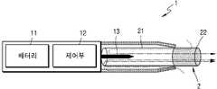
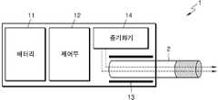
도 1을 참조하면, 에어로졸 생성 장치(1)는 배터리(11), 제어부(12) 및 히터(13)를 포함한다. 도 2 및 도 3을 참조하면, 에어로졸 생성 장치(1)는 증기화기(14)를 더 포함한다. 또한, 에어로졸 생성 장치(1)의 내부 공간에는 궐련(2)이 삽입될 수 있다.Referring to FIG. 1 , the
도 1 내지 도 3에 도시된 에어로졸 생성 장치(1)에는 본 실시예와 관련된 구성요소들이 도시되어 있다. 따라서, 도 1 내지 도 3에 도시된 구성요소들 외에 다른 범용적인 구성요소들이 에어로졸 생성 장치(1)에 더 포함될 수 있음을 본 실시예와 관련된 기술분야에서 통상의 지식을 가진 자라면 이해할 수 있다.The
도 1에는 배터리(11), 제어부(12) 및 히터(13)가 일렬로 배치된 것으로 도시되어 있다. 또한, 도 2에는 배터리(11), 제어부(12), 증기화기(14) 및 히터(13)가 일렬로 배치된 것으로 도시되어 있다. 또한, 도 3에는 증기화기(14) 및 히터(13)가 병렬로 배치된 것으로 도시되어 있다. 그러나, 에어로졸 생성 장치(1)의 내부 구조는 도 1 내지 도 3에 도시된 것에 한정되지 않는다. 다시 말해, 에어로졸 생성 장치(1)의 설계에 따라, 배터리(11), 제어부(12), 히터(13) 및 증기화기(14)의 배치는 변경될 수 있다.1 illustrates that the
궐련(2)이 에어로졸 생성 장치(1)에 삽입되면, 에어로졸 생성 장치(1)는 히터(13) 및/또는 증기화기(14)를 작동시켜, 에어로졸을 발생시킬 수 있다. 히터(13) 및/또는 증기화기(14)에 의하여 발생된 에어로졸은 궐련(2)을 통과하여 사용자에게 전달된다.When the
필요에 따라, 궐련(2)이 에어로졸 생성 장치(1)에 삽입되지 않은 경우에도 에어로졸 생성 장치(1)는 히터(13)를 가열할 수 있다.If desired, the aerosol-generating
배터리(11)는 에어로졸 생성 장치(1)가 동작하는데 이용되는 전력을 공급한다. 예를 들어, 배터리(11)는 히터(13) 또는 증기화기(14)가 가열될 수 있도록 전력을 공급할 수 있고, 제어부(12)가 동작하는데 필요한 전력을 공급할 수 있다. 또한, 배터리(11)는 에어로졸 생성 장치(1)에 설치된 디스플레이, 센서, 모터 등이 동작하는데 필요한 전력을 공급할 수 있다.The
제어부(12)는 에어로졸 생성 장치(1)의 동작을 전반적으로 제어한다. 구체적으로, 제어부(12)는 배터리(11), 히터(13) 및 증기화기(14)뿐 만 아니라 에어로졸 생성 장치(1)에 포함된 다른 구성들의 동작을 제어한다. 또한, 제어부(12)는 에어로졸 생성 장치(1)의 구성들 각각의 상태를 확인하여, 에어로졸 생성 장치(1)가 동작 가능한 상태인지 여부를 판단할 수도 있다.The
제어부(12)는 적어도 하나의 프로세서를 포함한다. 프로세서는 다수의 논리 게이트들의 어레이로 구현될 수도 있고, 범용적인 마이크로 프로세서와 이 마이크로 프로세서에서 실행될 수 있는 프로그램이 저장된 메모리의 조합으로 구현될 수도 있다. 또한, 다른 형태의 하드웨어로 구현될 수도 있음을 본 실시예가 속하는 기술분야에서 통상의 지식을 가진 자라면 이해할 수 있다.The
히터(13)는 배터리(11)로부터 공급된 전력에 의하여 가열될 수 있다. 예를 들어, 궐련이 에어로졸 생성 장치(1)에 삽입되면, 히터(13)는 궐련의 외부에 위치할 수 있다. 따라서, 가열된 히터(13)는 궐련 내의 에어로졸 생성 물질의 온도를 상승시킬 수 있다.The
히터(13)는 전기 저항성 히터일 수 있다. 예를 들어, 히터(13)에는 전기 전도성 트랙(track)을 포함하고, 전기 전도성 트랙에 전류가 흐름에 따라 히터(13)가 가열될 수 있다. 그러나, 히터(13)는 상술한 예에 한정되지 않으며, 희망 온도까지 가열될 수 있는 것이라면 제한 없이 해당될 수 있다. 여기에서, 희망 온도는 에어로졸 생성 장치(1)에 기 설정되어 있을 수도 있고, 사용자에 의하여 원하는 온도로 설정될 수도 있다.The
한편, 다른 예로, 히터(13)는 유도 가열식 히터일 수 있다. 구체적으로, 히터(13)에는 궐련을 유도 가열 방식으로 가열하기 위한 전기 전도성 코일을 포함할 수 있으며, 궐련은 유도 가열식 히터에 의해 가열될 수 있는 서셉터를 포함할 수 있다.Meanwhile, as another example, the
예를 들어, 히터(13)는 관 형 가열 요소, 판 형 가열 요소, 침 형 가열 요소 또는 봉 형의 가열 요소를 포함할 수 있으며, 가열 요소의 모양에 따라 궐련(2)의 내부 또는 외부를 가열할 수 있다.For example, the
또한, 에어로졸 생성 장치(1)에는 히터(13)가 복수 개 배치될 수도 있다. 이때, 복수 개의 히터(13)들은 궐련(2)의 내부에 삽입되도록 배치될 수도 있고, 궐련(2)의 외부에 배치될 수도 있다. 또한, 복수 개의 히터(13)들 중 일부는 궐련(2)의 내부에 삽입되도록 배치되고, 나머지는 궐련(2)의 외부에 배치될 수 있다. 또한, 히터(13)의 형상은 도 1 내지 도 3에 도시된 형상에 한정되지 않고, 다양한 형상으로 제작될 수 있다.In addition, a plurality of
증기화기(14)는 액상 조성물을 가열하여 에어로졸을 생성할 수 있으며, 생성된 에어로졸은 궐련(2)을 통과하여 사용자에게 전달될 수 있다. 다시 말해, 증기화기(14)에 의하여 생성된 에어로졸은 에어로졸 생성 장치(1)의 기류 통로를 따라 이동할 수 있고, 기류 통로는 증기화기(14)에 의하여 생성된 에어로졸이 궐련을 통과하여 사용자에게 전달될 수 있도록 구성될 수 있다.
예를 들어, 증기화기(14)는 액체 저장부, 액체 전달 수단 및 가열 요소를 포함할 수 있으나, 이에 한정되지 않는다. 예를 들어, 액체 저장부, 액체 전달 수단 및 가열 요소는 독립적인 모듈로서 에어로졸 생성 장치(1)에 포함될 수도 있다.For example, the
액체 저장부는 액상 조성물을 저장할 수 있다. 예를 들어, 액상 조성물은 휘발성 담배 향 성분을 포함하는 담배 함유 물질을 포함하는 액체일 수 있고, 비 담배 물질을 포함하는 액체일 수도 있다. 액체 저장부는 증기화기(14)로부터 탈/부착될 수 있도록 제작될 수도 있고, 증기화기(14)와 일체로서 제작될 수도 있다.The liquid reservoir may store the liquid composition. For example, the liquid composition may be a liquid comprising a tobacco-containing material comprising a volatile tobacco flavor component, or may be a liquid comprising a non-tobacco material. The liquid storage unit may be manufactured to be detachably/attached from the
예를 들어, 액상 조성물은 물, 솔벤트, 에탄올, 식물 추출물, 향료, 향미제, 또는 비타민 혼합물을 포함할 수 있다. 향료는 멘솔, 페퍼민트, 스피아민트 오일, 각종 과일향 성분 등을 포함할 수 있으나, 이에 제한되지 않는다. 향미제는 사용자에게 다양한 향미 또는 풍미를 제공할 수 있는 성분을 포함할 수 있다. 비타민 혼합물은 비타민 A, 비타민 B, 비타민 C 및 비타민 E 중 적어도 하나가 혼합된 것일 수 있으나, 이에 제한되지 않는다. 또한, 액상 조성물은 글리세린 및 프로필렌 글리콜과 같은 에어로졸 형성제를 포함할 수 있다.For example, the liquid composition may include water, a solvent, ethanol, a plant extract, a flavoring, flavoring agent, or a vitamin mixture. The fragrance may include, but is not limited to, menthol, peppermint, spearmint oil, various fruit flavoring ingredients, and the like. Flavoring agents may include ingredients capable of providing a user with a variety of flavors or flavors. The vitamin mixture may be a mixture of at least one of vitamin A, vitamin B, vitamin C, and vitamin E, but is not limited thereto. Liquid compositions may also include aerosol formers such as glycerin and propylene glycol.
액체 전달 수단은 액체 저장부의 액상 조성물을 가열 요소로 전달할 수 있다. 예를 들어, 액체 전달 수단은 면 섬유, 세라믹 섬유, 유리 섬유, 다공성 세라믹과 같은 심지(wick)가 될 수 있으나, 이에 한정되지 않는다.The liquid delivery means may deliver the liquid composition of the liquid reservoir to the heating element. For example, the liquid delivery means may be, but is not limited to, a wick such as cotton fiber, ceramic fiber, glass fiber, or porous ceramic.
가열 요소는 액체 전달 수단에 의해 전달되는 액상 조성물을 가열하기 위한 요소이다. 예를 들어, 가열 요소는 금속 열선, 금속 열판, 세라믹 히터 등이 될 수 있으나, 이에 한정되지 않는다. 또한, 가열 요소는 니크롬선과 같은 전도성 필라멘트로 구성될 수 있고, 액체 전달 수단에 감기는 구조로 배치될 수 있다. 가열 요소는, 전류 공급에 의해 가열될 수 있으며, 가열 요소와 접촉된 액체 조성물에 열을 전달하여, 액체 조성물을 가열할 수 있다. 그 결과, 에어로졸이 생성될 수 있다.The heating element is an element for heating the liquid composition delivered by the liquid delivery means. For example, the heating element may be, but is not limited to, a metal heating wire, a metal heating plate, a ceramic heater, or the like. In addition, the heating element may be composed of a conductive filament, such as a nichrome wire, and may be arranged to be wound around the liquid delivery means. The heating element may be heated by supplying an electrical current, and may transfer heat to the liquid composition in contact with the heating element, thereby heating the liquid composition. As a result, an aerosol may be generated.
예를 들어, 증기화기(14)는 카토마이저(cartomizer) 또는 무화기(atomizer)로 지칭될 수 있으나, 이에 한정되지 않는다.For example, the
한편, 에어로졸 생성 장치(1)는 배터리(11), 제어부(12), 히터(13) 및 증기화기(14) 외에 범용적인 구성들을 더 포함할 수 있다. 예를 들어, 에어로졸 생성 장치(1)는 시각 정보의 출력이 가능한 디스플레이 및/또는 촉각 정보의 출력을 위한 모터를 포함할 수 있다. 또한, 에어로졸 생성 장치(1)는 적어도 하나의 센서를 포함할 수 있다. 또한, 에어로졸 생성 장치(1)는 궐련(2)이 삽입된 상태에서도 외부 공기가 유입되거나, 내부 기체가 유출 될 수 있는 구조로 제작될 수 있다.Meanwhile, the
도 1 내지 도 3에는 도시되지 않았으나, 에어로졸 생성 장치(1)는 별도의 크래들과 함께 시스템을 구성할 수도 있다. 예를 들어, 크래들은 에어로졸 생성 장치(1)의 배터리(11)의 충전에 이용될 수 있다. 또는, 크래들과 에어로졸 생성 장치(1)가 결합된 상태에서 히터(13)가 가열될 수도 있다.Although not shown in FIGS. 1 to 3 , the
궐련(2)은 일반적인 연소형 궐련과 유사할 수 있다. 예를 들어, 궐련(2)은 에어로졸 생성 물질을 포함하는 제 1 부분과 필터 등을 포함하는 제 2 부분으로 구분될 수 있다. 또는, 궐련(2)의 제 2 부분에도 에어로졸 생성 물질이 포함될 수도 있다. 예를 들어, 과립 또는 캡슐의 형태로 만들어진 에어로졸 생성 물질이 제 2 부분에 삽입될 수도 있다.The
에어로졸 생성 장치(1)의 내부에는 제 1 부분의 전체가 삽입되고, 제 2 부분은 외부에 노출될 수 있다. 또는, 에어로졸 생성 장치(1)의 내부에 제 1 부분의 일부만 삽입될 수도 있고, 제 1 부분의 전체 및 제 2 부분의 일부가 삽입될 수도 있다. 사용자는 제 2 부분을 입으로 문 상태에서 에어로졸을 흡입할 수 있다. 이때, 에어로졸은 외부 공기가 제 1 부분을 통과함으로써 생성되고, 생성된 에어로졸은 제 2 부분을 통과하여 사용자의 입으로 전달된다.The entire first part may be inserted into the
일 예로서, 외부 공기는 에어로졸 생성 장치(1)에 형성된 적어도 하나의 공기 통로를 통하여 유입될 수 있다. 예를 들어, 에어로졸 생성 장치(1)에 형성된 공기 통로의 개폐 및/또는 공기 통로의 크기는 사용자에 의하여 조절될 수 있다. 이에 따라, 무화량, 끽연감 등이 사용자에 의하여 조절될 수 있다. 다른 예로서, 외부 공기는 궐련(2)의 표면에 형성된 적어도 하나의 구멍(hole)을 통하여 궐련(2)의 내부로 유입될 수도 있다.As an example, external air may be introduced through at least one air passage formed in the
이하, 도 4 및 도 5를 참조하여, 궐련(2)의 예들을 설명한다.Hereinafter, examples of the
도 4 및 도 5는 궐련의 예들을 도시한 도면들이다.4 and 5 are views showing examples of cigarettes.
도 4를 참조하면, 궐련(2)은 담배 로드(21) 및 필터 로드(22)를 포함한다. 도 1 내지 도 3을 참조하여 상술한 제 1 부분은 담배 로드(21)를 포함하고, 제 2 부분은 필터 로드(22)를 포함한다.Referring to FIG. 4 , the
도 4에는 필터 로드(22)가 단일 세그먼트로 도시되어 있으나, 이에 한정되지 않는다. 다시 말해, 필터 로드(22)는 복수의 세그먼트들로 구성될 수도 있다. 예를 들어, 필터 로드(22)는 에어로졸을 냉각하는 세그먼트 및 에어로졸 내에 포함된 소정의 성분을 필터링하는 세그먼트를 포함할 수 있다. 또한, 필요에 따라, 필터 로드(22)에는 다른 기능을 수행하는 적어도 하나의 세그먼트를 더 포함할 수 있다.4, the
궐련(2)은 적어도 하나의 래퍼(24)에 의하여 포장될 수 있다. 래퍼(24)에는 외부 공기가 유입되거나 내부 기체가 유출되는 적어도 하나의 구멍(hole)이 형성될 수 있다. 일 예로서, 궐련(2)은 하나의 래퍼(24)에 의하여 포장될 수 있다. 다른 예로서, 궐련(2)은 2 이상의 래퍼(24)들에 의하여 중첩적으로 포장될 수도 있다. 예를 들어, 제1 래퍼(241)에 의하여 담배 로드(21)가 포장되고, 래퍼들(242, 243, 244)에 의하여 필터 로드(22)가 포장될 수 있다. 그리고, 단일 래퍼(245)에 의하여 궐련(2) 전체가 재포장될 수 있다. 만약, 필터 로드(22)가 복수의 세그먼트들로 구성되어 있다면, 각각의 세그먼트가 래퍼들(242, 243, 244)에 의하여 포장될 수 있다.The
담배 로드(21)는 에어로졸 생성 물질을 포함한다. 예를 들어, 에어로졸 생성 물질은 글리세린, 프로필렌 글리콜, 에틸렌 글리콜, 디프로필렌 글리콜, 디에틸렌 글리콜, 트리에틸렌 글리콜, 테트라에틸렌 글리콜 및 올레일 알코올 중 적어도 하나를 포함할 수 있으나, 이에 한정되지 않는다. 또한, 담배 로드(21)는 풍미제, 습윤제 및/또는 유기산(organic acid)과 같은 다른 첨가 물질을 함유할 수 있다. 또한, 담배 로드(21)에는, 멘솔 또는 보습제 등의 가향액이, 담배 로드(21)에 분사됨으로써 첨가할 수 있다.The
담배 로드(21)는 다양하게 제작될 수 있다. 예를 들어, 담배 로드(21)는 시트(sheet)로 제작될 수도 있고, 가닥(strand)으로 제작될 수도 있다. 또한, 담배 로드(21)는 담배 시트가 잘게 잘린 각초로 제작될 수도 있다. 또한, 담배 로드(21)는 열 전도 물질에 의하여 둘러싸일 수 있다. 예를 들어, 열 전도 물질은 알루미늄 호일과 같은 금속 호일일 수 있으나, 이에 한정되지 않는다. 일 예로, 담배 로드(21)를 둘러싸는 열 전도 물질은 담배 로드(21)에 전달되는 열을 고르게 분산시켜 담배 로드에 가해지는 열 전도율을 향상시킬 수 있으며, 이로 인해 담배 맛을 향상시킬 수 있다. 또한, 담배 로드(21)를 둘러싸는 열 전도 물질은 유도 가열식 히터에 의해 가열되는 서셉터로서의 기능을 할 수 있다. 이때, 도면에 도시되지는 않았으나, 담배 로드(21)는 외부를 둘러싸는 열 전도 물질 이외에도 추가의 서셉터를 더 포함할 수 있다.
필터 로드(22)는 셀룰로오스 아세테이트 필터일 수 있다. 한편, 필터 로드(22)의 형상에는 제한이 없다. 예를 들어, 필터 로드(22)는 원기둥 형(type) 로드일 수도 있고, 내부에 중공을 포함하는 튜브 형(type) 로드일 수도 있다. 또한, 필터 로드(22)는 리세스 형(type) 로드일 수도 있다. 만약, 필터 로드(22)가 복수의 세그먼트들로 구성된 경우, 복수의 세그먼트들 중 적어도 하나가 다른 형상으로 제작될 수도 있다.The
또한, 필터 로드(22)에는 적어도 하나의 캡슐(23)이 포함될 수 있다. 여기에서, 캡슐(23)은 향미를 발생시키는 기능을 수행할 수도 있고, 에어로졸을 발생시키는 기능을 수행할 수도 있다. 예를 들어, 캡슐(23)은 향료를 포함하는 액체를 피막으로 감싼 구조일 수 있다. 캡슐(23)은 구형 또는 원통형의 형상을 가질 수 있으나, 이에 제한되지 않는다.In addition, the
도 5를 참조하면, 궐련(3)은 전단 플러그(33)를 더 포함할 수 있다. 전단 플러그(33)는 담배 로드(31)에 있어서, 필터 로드(32)에 대향하는 일 측에 위치할 수 있다. 전단 플러그(33)는 담배 로드(31)가 외부로 이탈하는 것을 방지할 수 있으며, 흡연 중에 담배 로드(31)로부터 액상화된 에어로졸이 에어로졸 발생 장치(도 1 내지 도 3의 1)로 흘러 들어가는 것을 방지할 수 있다.Referring to FIG. 5 , the
필터로드(32)은 제1 세그먼트(321) 및 제2 세그먼트(322)를 포함할 수 있다. 여기에서, 제1 세그먼트(321)은 도 4의 필터 로드(22)의 제1 세그먼트에 대응될 수 있고, 제2 세그먼트(322)는 도 4의 필터 로드(22)의 제3 세그먼트에 대응될 수 있다.The
궐련(3)은 적어도 하나의 래퍼(35)에 의하여 포장될 수 있다. 래퍼(35)에는 외부 공기가 유입되거나 내부 기체가 유출되는 적어도 하나의 구멍(hole)이 형성될 수 있다. 예를 들어, 제1 래퍼(351)에 의하여 전단 플러그(33)이 포장되고, 제2 래퍼(352)에 의하여 담배 로드(31)가 포장되고, 제3 래퍼(353)에 의하여 제1 세그먼트(321)이 포장되고, 제4 래퍼(354)에 의하여 제2 세그먼트(322)가 포장될 수 있다. 그리고, 제5 래퍼(355)에 의하여 궐련(3) 전체가 재포장될 수 있다.The
또한, 제2 세그먼트(322)에는 적어도 하나의 캡슐(34)이 포함될 수 있다. 여기에서, 캡슐(34)은 향미를 발생시키는 기능을 수행할 수도 있고, 에어로졸을 발생시키는 기능을 수행할 수도 있다. 예를 들어, 캡슐(34)은 향료를 포함하는 액체를 피막으로 감싼 구조일 수 있다. 캡슐(34)은 구형 또는 원통형의 형상을 가질 수 있으나, 이에 제한되지 않는다.Also, the
에어로졸 생성 장치에 고장이 발생한 상황에서도 히터가 발열할 수 있다. 예를 들어, 프로세서 오작동으로 인해 히터가 발열하지 않아야 하는 기간에도 발열하거나, 온도 프로파일과 다르게 과도하게 발열할 수 있다. 여기서, 히터의 온도 프로파일이란, 히터를 가열하기 위해 사전에 설정된 온도 프로파일을 의미한다. 그 외에도, 다양한 오작동으로 인해 히터가 발열할 수 있다. 이러한 경우, 사용자에게 최적의 끽미를 제공할 수 없을 뿐만 아니라 에어로졸 생성 장치의 안전한 사용에도 문제가 될 수 있다.The heater may generate heat even when the aerosol generating device fails. For example, due to a malfunction of the processor, the heater may generate heat even during a period during which it should not be heated, or it may generate excessive heat differently from the temperature profile. Here, the temperature profile of the heater means a preset temperature profile for heating the heater. In addition, the heater may generate heat due to various malfunctions. In this case, it may not be possible to provide an optimal taste to the user, but also the safe use of the aerosol-generating device may be a problem.
이하에서는, 에어로졸 생성 장치의 오작동으로 인해 히터가 발열하는 것을 차단하기 위한 히터 제어 회로 및 히터 제어 방법에 대해 살펴본다.Hereinafter, a heater control circuit and a heater control method for preventing the heater from generating heat due to a malfunction of the aerosol generating device will be described.
도 6은 에어로졸 생성 장치의 히터 제어 회로의 일 예를 개략적으로 나타낸 도면이다.6 is a diagram schematically illustrating an example of a heater control circuit of an aerosol generating device.
도 6을 참조하면, 히터 제어 회로는 히터(45), 제1 스위치(41), 제2 스위치(42), 제1 프로세서(43), 및 제2 프로세서(44)를 포함한다.Referring to FIG. 6 , the heater control circuit includes a
제1 프로세서(43), 및 제2 프로세서(44)는 도 1 내지 도 3에 도시된 제어부(12)에 포함될 수 있다. 제1 스위치(41) 및 제2 스위치(42)는 도 1 내지 도 3에 도시된 제어부(12)에 포함되거나, 제어부(12)가 제어하고자 하는 히터에 포함될 수 있다.The
히터 제어 회로는 에어로졸 생성 장치에 포함되는 모든 가열 요소에 적용 가능하다. 예를 들어, 히터(45)는 도 1 내지 도 3에 도시된 궐련을 가열하는 히터(3)일 수 있다. 다른 예로써, 히터(45)는 도 2 및 도 3에 도시된 증기화기(14)에 포함되는 가열 요소일 수 있다. 또 다른 예로써, 에어로졸 생성 장치가 도 1 내지 도 3에 도시된 가열 요소 외에 다른 가열 요소를 더 포함하는 경우, 히터(45)는 에어로졸 생성 장치에 더 포함되는 가열 요소일 수 있다.The heater control circuit is applicable to any heating element included in the aerosol generating device. For example, the
제1 스위치(41)는 히터(45)와 전기적으로 직렬로 연결될 수 있다. 예를 들어, 제1 스위치(41)는 히터(45)와 배터리(도 1 내지 도 3의 11)의 사이에 배치되어, 히터(45)와 전기적으로 직렬로 연결될 수 있다. 도 6에 도시된 것과 달리, 제1 스위치(41)는 히터(45)와 제2 스위치(42) 사이에 배치될 수 있으며, 제1 스위치(41)의 위치가 도 6에 도시된 위치로 한정되는 것은 아니다.The
제1 스위치(41)는 외부 입력 신호에 따라 개방상태 또는 폐쇄상태로 상태가 전환될 수 있다. 히터(45)는 제1 스위치(41)가 개방상태가 됨에 따라 배터리로부터 전력 수급이 차단될 수 있고, 폐쇄상태가 됨에 따라 배터리로부터 전력을 공급받을 수 있다.The state of the
제1 스위치(41)는 전계효과 트랜지스터(field effect transistor, FET)일 수 있다. 제1 스위치(41)는 소스(source)가 배터리 측에, 드레인(drain)이 히터(45) 측에, 게이트(gate)가 제1 프로세서(43) 측에 연결되도록 배치될 수 있다.The
제1 스위치(41)의 게이트로 전달되는 신호의 세기에 따라 제1 스위치(41)의 상태가 결정될 수 있다. 게이트로 기준값 이상의 신호가 인가되면, 소스에서 드레인으로 전류가 흐르며 제1 스위치(41)가 폐쇄될 수 있다. 반대로 게이트로 기준값 미만의 신호가 인가되면, 제1 스위치(41)가 개방될 수 있다.The state of the
제1 스위치(41)는 P채널 FET일 수 있으나, 이에 한정되는 것은 아니다. 즉, 제1 스위치(41)는 N채널 FET일 수 있다.The
또한, 제1 스위치(41)는 FET 이외의 외부 입력 신호에 따라 개방상태 또는 폐쇄상태로 상태 전환이 가능한 다른 전기 소자일 수 있다. 예를 들어, 제1 스위치(41)는 접합형 트렌지스터(bipolar junction transistor, BJT), 절연 게이트 양극성 트랜지스터(insulated gate bipolar transistor, IGBT), 또는 사일리스터(thyristor)일 수 있으며, 나열된 종류에 제한되지 않는다.In addition, the
제2 스위치(42)는 히터(45) 및 제1 스위치(41)와 전기적으로 직렬로 연결될 수 있다. 예를 들어, 제2 스위치(42)는 히터(45)와 접지부의 사이에 배치되어, 히터(45) 및 제1 스위치(41)와 전기적으로 직렬로 연결될 수 있다. 도 6에 도시된 것과 달리, 제2 스위치(42)는 히터(45)와 제1 스위치(41) 사이에 배치될 수 있으며, 제2 스위치(42)의 위치가 도 6에 도시된 위치로 한정되는 것은 아니다.The
제2 스위치(42)는 외부 입력 신호에 따라 개방상태 또는 폐쇄상태로 상태가 전환될 수 있다. 제2 스위치(42)의 상태는 짧은 기간 동안 개방상태와 폐쇄상태로 반복하여 전환될 수 있다. 제2 스위치(42)는 히터(45)가 요구하는 전력의 듀티 사이클에 기초하여 개방상태와 폐쇄상태로 상태가 반복하여 전환될 수 있다.The state of the
제2 스위치(42)는 제1 스위치(41)와 마찬가지로 전계효과 트랜지스터(field effect transistor, FET)일 수 있다. 제2 스위치(42)는 소스(source)가 히터(45) 측에, 드레인(drain)이 접지부 측에, 게이트(gate)가 제2 프로세서(44) 측에 연결되도록 배치될 수 있다.Like the
제2 스위치(42)는 N채널 FET일 수 있으나, 이에 한정되는 것은 아니다. 즉, 제2 스위치(42)는 P채널 FET일 수 있다.The
또한, 제2 스위치(42)는 제1 스위치(41)와 마찬가지로, FET 이외의 외부 입력 신호에 따라 개방상태 또는 폐쇄상태로 상태 전환이 가능한 다른 전기 소자일 수 있다. 예를 들어, 제2 스위치(42)는 접합형 트렌지스터(bipolar junction transistor, BJT), 절연 게이트 양극성 트랜지스터(insulated gate bipolar transistor, IGBT), 또는 사일리스터(thyristor)일 수 있으며, 나열된 종류에 제한되지 않는다.Also, like the
제1 프로세서(43)는 다수의 논리 게이트들의 어레이로 구현될 수 있고, 범용적인 마이크로 프로세서와 마이크로 프로세서에서 실행될 수 있는 프로그램이 저장된 메모리의 조합으로 구현될 수도 있다. 예를 들어, 제1 프로세서(43)는 마이크로 프로세서와 입출력 모듈을 포함하는 마이크로컨트롤러(micro controller unit)일 수 있다.The
제1 프로세서(43)는 제1 스위치(41)의 개폐상태를 제어하는 제1 제어신호를 출력할 수 있다. 제1 프로세서(43)는 히터(45)가 가열되어야 하는 기간 동안 제1 스위치(41)가 폐쇄되고, 그 외의 기간 동안 제1 스위치(41)가 개방되도록 제어하는 제1 제어신호를 출력할 수 있다.The
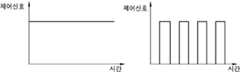
제1 제어신호는 직류신호(direct current signal, DC signal)일 수 있다. 예를 들어, 히터(45)가 가열되어야 하는 기간 동안 제1 프로세서(43)에서 출력하는 제1 제어신호의 파형은 도 11의 좌측에 도시된 그래프와 같을 수 있다. 또한, 히터(45)가 가열되어야 하는 기간 동안 제1 프로세서(43)는 제1 스위치(41)의 게이트 기준값보다 높은 값을 갖는 제1 제어신호를 출력할 수 있고, 그 외의 기간 동안 게이트 기준값보다 낮은 값을 갖는 제1 제어신호를 출력할 수 있다.The first control signal may be a direct current signal (DC signal). For example, the waveform of the first control signal output from the
제1 프로세서(43)는 히터(45)의 온도값을 입력 받을 수 있다. 예를 들어, 제1 프로세서(43)는 온도 센서가 측정한 히터(45)의 온도값을 입력 받을 수 있다.The
제1 프로세서(43)는 입력 받은 온도값을 기초로 제1 제어신호를 출력할 수 있다. 예를 들어, 제1 프로세서(43)는 입력 받은 온도값이 안전한 가열 온도 범위를 벗어난 경우 또는 온도 프로파일에서 벗어난 경우, 제1 스위치(41)가 개방되도록 제1 제어신호를 출력할 수 있다. 즉, 제1 프로세서(43)는 입력 받은 온도값이 비정상적인 경우, 히터(45), 제2 프로세서(44) 등의 고장으로 인해 에어로졸 생성 장치가 오작동하는 것으로 판단하고, 히터(45)가 발열하지 않도록 제1 스위치(41)를 개방시키는 제1 제어신호를 출력할 수 있다.The
제2 프로세서(44)는 제1 프로세서(43)와 독립하여 연산을 수행하는 프로세서일 수 있다. 제2 프로세서(44)는 다수의 논리 게이트들의 어레이로 구현될 수 있고, 범용적인 마이크로 프로세서와 마이크로 프로세서에서 실행될 수 있는 프로그램이 저장된 메모리의 조합으로 구현될 수도 있다. 예를 들어, 제2 프로세서(44)는 마이크로 프로세서와 입출력 모듈을 포함하는 마이크로컨트롤러(micro controller unit)일 수 있다.The
제2 프로세서(44)는 제2 스위치(42)의 개폐상태를 제어하는 제2 제어신호를 출력할 수 있다. 제2 프로세서(44)는 히터(45)가 온도 프로파일에 따라 발열하도록, 제2 스위치(42)의 상태를 개방상태 및 폐쇄상태로 반복하여 전환시키는 제2 제어신호를 출력할 수 있다.The
제2 제어신호는 교류신호(alternate current signal, AC signal)일 수 있다. 예를 들어, 제2 프로세서(44)에서 출력하는 제2 제어신호는 도 11의 우측에 도시된 그래프와 같은 펄스 폭 변조(pulse width modulation, PWM) 신호일 수 있다. 또한, 제2 프로세서(44)는 히터(45)가 요구하는 전력의 듀티 사이클에 따라, 제2 스위치(42)가 폐쇄상태이도록 제2 스위치(42)의 게이트 기준값보다 높은 값을 갖는 제2 제어신호를 출력할 수 있고, 개방상태이도록 게이트 기준값보다 낮은 값을 갖는 제2 제어신호를 출력할 수 있다.The second control signal may be an alternate current signal (AC signal). For example, the second control signal output from the
도 6에는 제1 프로세서(43)가 히터(45)의 온도값을 입력 받는 것으로 도시되어 있으나, 이와 달리 제2 프로세서(44)가 히터(45)의 온도값을 입력 받을 수 있다. 제2 프로세서(44)는 온도 센서로부터 히터(45)의 온도를 측정한 센싱값을 직접 입력 받거나, 또는 제1 프로세서(43)를 통해 간접적으로 입력 받을 수 있다. 또는, 제1 프로세서(43) 및 제2 프로세서(44)가 모두 히터(45)의 온도값을 입력 받을 수 있다.6 , the
제2 프로세서(44)는 입력 받은 온도값을 기초로 제2 제어신호를 출력할 수 있다. 예를 들어, 제2 프로세서(44)는 입력 받은 온도값이 안전한 가열 온도 범위를 벗어난 경우, 제2 스위치(42)가 개방되도록 제2 제어신호를 출력할 수 있다. 다른 예를 들어, 제2 프로세서(44)는 입력 받은 온도값이 히터(45)의 온도 프로파일을 기준으로 허용 가능한 오차 범위를 벗어난 경우, 제2 스위치(42)가 개방되도록 제2 제어신호를 출력할 수 있다. 즉, 제2 프로세서(44)는 입력 받은 온도값이 비정상적인 경우, 히터(45), 제1 프로세서(43) 등의 고장으로 인해 에어로졸 생성 장치가 오작동하는 것으로 판단하고, 히터(45)가 발열하지 않도록 제2 스위치(42)를 개방시키는 제2 제어신호를 출력할 수 있다.The
제1 프로세서(43)와 제2 프로세서(44)는 통신을 수행할 수 있다. 제1 프로세서(43)와 제2 프로세서(44)가 수행하는 통신 방식은 시리얼 통신(serial communication)일 수 있다. 예를 들어, 제1 프로세서(43)와 제2 프로세서(44)가 시리얼 통신을 수행하기 위해 universal asynchronous receiver transmitter(UART), serial peripheral interface(SPI), inter integrated circuit(I2C) 등이 사용될 수 있으나, 나열된 종류에 제한되지 않는다.The
제2 프로세서(44)는 제1 프로세서(43)와의 통신 상태에 따라, 제2 스위치(42)의 개폐상태가 변경되도록 제2 제어신호를 출력할 수 있다. 제1 프로세서(43)가 고장 등으로 인해 오작동하는 경우, 제1 프로세서(43)와 제2 프로세서(44)의 통신 상태가 불량일 수 있다. 예를 들어, 제1 프로세서(43)는 오작동으로 인해 화이트 노이즈(white noise), 통신 프로토콜에 맞지 않는 신호 등을 출력하거나 무응답 상태일 수 있으며, 이로 인해 제1 프로세서(43)와 제2 프로세서(44)의 통신 상태가 불량일 수 있다.The
제2 프로세서(44)는 제1 프로세서(43)와의 통신 상태가 불량이 되면, 히터(45)가 발열하지 않도록 제2 스위치(42)를 개방시키는 제2 제어신호를 출력할 수 있다. 즉, 제2 프로세서(44)는 제1 프로세서(43)와의 통신 상태가 불량이 되면, 제1 프로세서(43)가 오작동하고 있는 것으로 판단하고, 제1 프로세서(43)의 오작동 상태에서 히터(45)가 발열하는 것을 차단하기 위해, 제2 스위치(42)를 개방시키는 제2 제어신호를 출력할 수 있다.When the communication state with the
또한, 제1 프로세서(43)는 제2 프로세서(44)와의 통신 상태에 따라, 제1 스위치(41)의 개폐상태가 변경되도록 제1 제어신호를 출력할 수 있다. 제1 프로세서(43)는 제2 프로세서(44)와의 통신 상태가 불량이 되면, 제2 프로세서(44)가 오작동하고 있는 것으로 판단하고, 히터(45)가 발열하지 않도록 제1 스위치(41)를 개방시키는 제1 제어신호를 출력할 수 있다.Also, the
상술한 바와 같이, 에어로졸 생성 장치가 복수의 프로세서들을 포함하고, 제1 프로세서(43) 및 제2 프로세서(44)가 제1 스위치(41) 및 제2 스위치(42)를 각각 제어할 수 있다. 특히, 제1 프로세서(43) 및 제2 프로세서(44)가 서로의 고장을 통신 상태를 통해 판단함으로써, 제1 프로세서(43) 및 제2 프로세서(44) 중 어느 하나가 고장이 나더라도 히터(45)가 오작동하는 것이 차단될 수 있다.As described above, the aerosol generating device may include a plurality of processors, and the
도 7은 에어로졸 생성 장치의 히터 제어 회로의 일 예를 개략적으로 나타낸 도면이다.7 is a diagram schematically illustrating an example of a heater control circuit of an aerosol generating device.
도 7에 도시된 히터 제어 회로는 도 6에 도시된 히터 제어 회로와 비교하였을 때, 제2 프로세서(44)의 출력단과 제2 스위치(42)의 입력단 사이에 커패시터(C1)가 더 포함된다.Compared to the heater control circuit shown in FIG. 6 , the heater control circuit illustrated in FIG. 7 further includes a capacitor C1 between the output terminal of the
제2 프로세서(44)는 히터(45)가 요구하는 전력의 듀티 사이클에 따라, 제2 스위치(42)의 개폐상태를 변경시키는 제2 제어신호를 출력할 수 있으며, 제2 제어신호는 교류신호일 수 있다. 예를 들어, 제2 제어신호는 PWM 신호일 수 있다.The
커패시터(C1)는 입력 신호가 직류신호인 경우 입력 신호를 차단하고, 입력 신호가 교류신호인 경우 입력 신호를 통과시키는 특성을 갖는다.The capacitor C1 blocks the input signal when the input signal is a DC signal, and passes the input signal when the input signal is an AC signal.
제2 프로세서(44)는 정상상태에서 PWM의 제2 제어신호를 출력하다가, 오작동으로 직류신호인 제2 제어신호를 출력할 수 있다. 이러한 경우, 히터(45)가 온도 프로파일에서 벗어난 온도로 발열하거나 과열될 수 있다. 제2 프로세서(44)의 출력단에는 커패시터(C1)가 장착되어 있으므로, 제2 프로세서(44)가 오작동으로 직류신호를 출력하더라도, 커패시터(C1)에 의해 제2 스위치(42)로 제2 신호가 전달되는 것이 차단될 수 있다.The
따라서, 제1 프로세서(43) 및 제2 프로세서(44)가 모두 오작동으로 직류신호(예를 들어, 도 11의 좌측에 도시된 그래프와 같은 파형의 제어신호)를 출력하더라도, 커패시터(C1)에 의해 제2 제어신호가 차단되어 제2 스위치(42)가 개방되므로, 히터(45)가 발열하는 것이 차단될 수 있다.Therefore, even if the
도 8은 에어로졸 생성 장치의 히터 제어 회로의 일 예를 개략적으로 나타낸 도면이다.8 is a diagram schematically illustrating an example of a heater control circuit of an aerosol generating device.
에어로졸 생성 장치의 히터 제어 회로는 제1 스위치(41), 제2 스위치(42), 제1 프로세서(43), 히터(45), 및 정류회로(46)를 포함한다. 도 8에 도시된 히터 제어 회로는 도 7에 도시된 히터 제어 회로와 비교하였을 때, 제2 프로세서(44)를 포함하지 않고, 정류회로(46)를 더 포함하며, 나머지 구성은 동일하다.The heater control circuit of the aerosol generating device includes a
히터 제어 회로는 정류회로(46)를 포함할 수 있다. 정류회로(46)는 제1 스위치의 입력단들(L, M) 중 적어도 어느 하나 및 제1 프로세서(43)의 출력단(N)과 전기적으로 연결될 수 있다.The heater control circuit may include a rectifying
정류회로(46)는 입력 받은 신호가 교류신호인 경우, 이를 직류신호로 변환하여 출력할 수 있다. 또한, 정류회로(46)는 입력 받은 신호가 직류신호인 경우, 이를 차단하여 출력하지 않을 수 있다.When the received signal is an AC signal, the
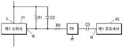
예를 들어, 정류회로(46)는 도 9에 도시된 것과 같이, 저항들(R1, R2), 커패시터들(C2, C3), 및 트랜지스터(transistor, TR)를 포함할 수 있다. 트랜지스터는 NPN 트랜지스터일 수 있으나, 이에 제한되는 것은 아니다.For example, as shown in FIG. 9 , the
저항(R1)과 커패시터(C2)는 제1 스위치(41)의 소스 입력단(L) 및 게이트 입력단(M)과 전기적으로 연결될 수 있다. 또한, 저항(R2), 트랜지스터(TR), 및 커패시터(C3)는 제1 스위치(41)의 게이트 입력단(M) 및 제1 프로세서 출력단(N)과 전기적으로 연결될 수 있다.The resistor R1 and the capacitor C2 may be electrically connected to the source input terminal L and the gate input terminal M of the
정류회로(46)는 도 9에 도시된 것과 다른 회로일 수 있으며, 저항, 커패시터, 트랜지스터 이외에도 다이오드 등 다른 전기 소자를 포함할 수 있다.The
도 8에 도시된 히터 제어 회로가 정류회로(46)를 더 포함함에 따라, 제1 프로세서(43)가 출력하는 제1 제어신호는 교류신호일 수 있다. 예를 들어, 제1 제어신호는 PWM 신호일 수 있다.As the heater control circuit shown in FIG. 8 further includes the rectifying
제1 프로세서(43)가 PWM 신호를 출력하면, 정류회로(46)에 의해 직류신호로 변환되어 제1 스위치(41)로 전달되므로, 제1 스위치(41)가 폐쇄상태를 유지할 수 있다.When the
또한, 정류회로(46)가 커패시터(C3)를 포함함에 따라, 제1 프로세서(43)가 출력하는 제1 제어신호가 직류신호인 경우, 제1 스위치(41)가 개방상태를 유지할 수 있다. 즉, 제1 제어신호가 직류신호인 경우 커패시터(C3)에 의해 차단되므로, 제1 스위치(41)가 개방상태를 유지할 수 있다. 따라서, 제1 프로세서(43)가 오작동으로 제1 제어신호를 직류신호로 출력하여도, 정류회로(46)에 의해 차단되어 제1 스위치(41)가 개방될 수 있다.Also, since the
제1 프로세서(43)는 정상상태에서 PWM 신호(예를 들어, 도 11의 우측에 도시된 그래프와 같은 파형)인 제1 제어신호를 출력하다가, 오작동으로 직류신호(예를 들어, 도 11의 좌측에 도시된 그래프와 같은 파형)인 제1 제어신호를 출력할 수 있다. 직류신호가 히터(45)로 전달되는 경우, 히터(45)가 온도 프로파일에서 벗어난 온도로 발열하거나 과열될 수 있다. 제1 프로세서(43)가 오작동으로 출력하는 제1 제어신호는 직류신호에 해당하므로, 정류회로(46)에 의해 제1 스위치(41)로 제1 제어신호가 전달되는 것이 차단될 수 있으며, 히터(45)가 발열하는 것이 차단될 수 있다.The
또한, 제1 프로세서(43)는 제2 스위치(42)를 제어하기 위해 정상상태에서 PWM 신호를 출력하다가, 오작동으로 직류신호를 출력할 수 있다. 이러한 경우에도, 커패시터(C1)에 의해 오작동으로 출력된 직류신호가 차단되어 제2 스위치(42)가 개방될 수 있으며, 히터(45)가 발열하는 것이 차단될 수 있다.Also, the
따라서, 하나의 프로세서로 제1 스위치(41) 및 제2 스위치(42)를 제어하더라도, 제1 프로세서(43)의 오작동으로 출력된 신호를 정류회로(46) 및 커패시터(C1)가 차단하므로, 제1 프로세서(43)의 오작동으로 인해 히터(45)가 발열하는 것이 차단될 수 있다.Therefore, even when one processor controls the
또한, 커패시터들(C1, C3) 중 어느 하나가 단락(short)되더라도, 다른 하나의 커패시터에 의해 직류신호가 차단되어, 히터(45)가 발열하는 것이 차단될 수 있다.Also, even if any one of the capacitors C1 and C3 is shorted, the DC signal is blocked by the other capacitor, so that the
도 10은 에어로졸 생성 장치의 히터 제어 회로의 일 예를 개략적으로 나타낸 도면이다.10 is a diagram schematically illustrating an example of a heater control circuit of an aerosol generating device.
도 10에 도시된 히터 제어 회로는 도 7에 도시된 히터 제어 회로와 비교하였을 때, 정류회로(46)를 더 포함한다.The heater control circuit shown in FIG. 10 further includes a rectifying
제1 프로세서(43)가 오작동하는 경우, 제1 프로세서(43)와 제2 프로세서(44)의 통신 상태가 불량이 될 수 있다. 제2 프로세서(44)는 제1 프로세서(43)와의 통신 상태가 불량인 경우, 제1 프로세서(43)가 오작동하는 것으로 판단하고, 제2 스위치(42)가 개방되도록 제2 제어신호를 출력할 수 있다. 제2 스위치(42)가 개방됨에 따라, 제1 프로세서(43)가 오작동하는 상태에서 히터(45)가 발열하는 것이 차단될 수 있다.When the
마찬가지로, 제2 프로세서(44)가 오작동하는 경우, 제1 프로세서(43)와 제2 프로세서(44)의 통신 상태가 불량이 될 수 있다. 제1 프로세서(43)는 제2 프로세서(44)와의 통신 상태가 불량인 경우, 제2 프로세서(44)가 오작동하는 것으로 판단하고, 제1 스위치(41)가 개방되도록 제1 제어신호를 출력할 수 있다. 제1 스위치(41)가 개방됨에 따라, 제2 프로세서(44)가 오작동하는 상태에서 히터(45)가 발열하는 것이 차단될 수 있다.Similarly, when the
또한, 제1 프로세서(43)와 제2 프로세서(44)는 오작동으로 제1 스위치(41)와 제2 스위치(42)가 모두 폐쇄상태가 되도록 하는 제어신호를 출력할 수 있다. 예를 들어, 제1 프로세서(43)와 제2 프로세서(44)는 오작동으로 도 11의 좌측에 도시된 그래프와 같은 직류신호를 출력할 수 있다. 이러한 경우, 제1 제어신호는 정류회로(46)에 의해, 제2 제어신호는 커패시터(C1)에 의해 차단되어, 제1 스위치(41) 및 제2 스위치(42)가 개방상태가 되도록 할 수 있다. 제1 스위치(41) 및 제2 스위치(42)가 개방상태가 됨에 따라, 제1 프로세서(43) 및 제2 프로세서(44)가 모두 오작동하는 경우에도 히터(45)가 발열하는 것이 차단될 수 있다.In addition, the
도 12는 에어로졸 생성 장치의 히터를 제어하는 방법의 일 예를 나타낸 순서도이다.12 is a flowchart illustrating an example of a method for controlling a heater of an aerosol generating device.
도 12를 참조하면, 히터를 제어하는 방법은 도 6 내지 도 8 및 도 10에 도시된 히터 제어 회로에서 시계열적으로 처리되는 단계들로 구성된다. 따라서, 이하에서 생략된 내용이라 하더라도 도 6 내지 도 8 및 도 10에 도시된 히터 제어 회로에 관하여 이상에서 기술된 내용은 도 12의 히터를 제어하는 방법에도 적용됨을 알 수 있다.Referring to FIG. 12 , the method for controlling a heater includes steps processed in time series in the heater control circuit illustrated in FIGS. 6 to 8 and 10 . Accordingly, it can be seen that the contents described above with respect to the heater control circuit shown in FIGS. 6 to 8 and 10 are also applied to the method for controlling the heater of FIG. 12, even if omitted below.
단계 S110에서, 제1 프로세서(43)는 제1 스위치(41)의 개폐상태를 제어하는 제1 제어신호를 출력할 수 있다. 제1 프로세서(43)는 히터(45)가 가열되어야 하는 기간 동안 제1 스위치(41)가 폐쇄되고, 그 외의 기간 동안 제1 스위치(41)가 개방되도록 제어하는 제1 제어신호를 출력할 수 있다.In step S110 , the
단계 S120에서, 제2 프로세서(44)는 제2 스위치(42)의 개폐상태를 제어하는 제2 제어신호를 출력할 수 있다. 제2 프로세서(44)는 히터(45)가 온도 프로파일에 따라 발열하도록, 제2 스위치(42)의 상태를 개방상태 및 폐쇄상태로 반복하여 전환시키는 제2 제어신호를 출력할 수 있다.In step S120 , the
단계 S130에서, 제1 프로세서(43)와 제2 프로세서(44)는 통신을 수행할 수 있다. 제1 프로세서(43)와 제2 프로세서(44)가 수행하는 통신 방식은 시리얼 통신(serial communication)일 수 있다. 예를 들어, 제1 프로세서(43)와 제2 프로세서(44)가 시리얼 통신을 수행하기 위해 universal asynchronous receiver transmitter(UART), serial peripheral interface(SPI), inter integrated circuit(I2C) 등이 사용될 수 있으나, 나열된 종류에 제한되지 않는다.In step S130 , the
단계 S140에서, 제2 프로세서(44)는 제1 프로세서(43)와의 통신 상태에 따라, 제2 스위치(42)의 개폐상태가 변경되도록 제2 제어신호를 출력할 수 있다. 또한, 제1 프로세서(43)는 제2 프로세서(44)와의 통신 상태에 따라, 제1 스위치(41)의 개폐상태가 변경되도록 제1 제어신호를 출력할 수 있다.In step S140 , the
상술한 바와 같이, 에어로졸 생성 장치가 복수의 프로세서들을 포함하고, 제1 프로세서(43) 및 제2 프로세서(44)가 제1 스위치(41) 및 제2 스위치(42)를 각각 제어할 수 있다. 특히, 제1 프로세서(43) 및 제2 프로세서(44)가 서로의 고장을 통신 상태를 통해 판단함으로써, 제1 프로세서(43) 및 제2 프로세서(44) 중 어느 하나가 오작동하더라도 히터(45)가 비정상적으로 동작하는 것을 차단할 수 있다.As described above, the aerosol generating device may include a plurality of processors, and the
본 실시예와 관련된 기술 분야에서 통상의 지식을 가진 자는 상기된 기재의 본질적인 특성에서 벗어나지 않는 범위에서 변형된 형태로 구현될 수 있음을 이해할 수 있을 것이다. 그러므로 개시된 방법들은 한정적인 관점이 아니라 설명적인 관점에서 고려되어야 한다. 본 발명의 범위는 전술한 설명이 아니라 청구범위에 나타나 있으며, 그와 동등한 범위 내에 있는 모든 차이점은 본 발명에 포함된 것으로 해석되어야 할 것이다.A person of ordinary skill in the art related to this embodiment will understand that it can be implemented in a modified form without departing from the essential characteristics of the above description. Therefore, the disclosed methods are to be considered in an illustrative rather than a restrictive sense. The scope of the present invention is indicated in the claims rather than the foregoing description, and all differences within the scope equivalent thereto should be construed as being included in the present invention.
1: 에어로졸 생성 장치2: 궐련
11: 배터리12: 제어부
13: 히터14: 증기화기
21, 31: 담배 로드22, 32: 필터 로드
33: 전단 플러그23, 34: 캡슐
24, 35: 래퍼41: 제1 스위치
42: 제2 스위치43: 제1 프로세서
44: 제2 프로세서45: 히터
46: 정류회로1: aerosol generating device 2: cigarette
11: battery 12: control
13: heater 14: vaporizer
21, 31:
33:
24, 35: wrapper 41: first switch
42: second switch 43: first processor
44: second processor 45: heater
46: rectifier circuit
Claims (7)
Translated fromKorean상기 히터와 전기적으로 직렬로 연결된 제1 스위치;
상기 히터 및 상기 제1 스위치와 전기적으로 직렬로 연결된 제2 스위치;
상기 제1 스위치의 개폐상태를 제어하는 제1 제어신호 및 상기 제2 스위치의 개폐상태를 제어하는 제2 제어신호를 출력하도록 구성된 프로세서;
상기 제1 제어신호가 상기 프로세서에서 상기 제1 스위치로 전달되는 것을 차단하거나, 상기 제1 제어신호를 상기 프로세서에서 상기 제1 스위치로 전달하도록, 상기 프로세서 및 상기 제1 스위치와 전기적으로 연결된 정류회로; 및
상기 프로세서 및 상기 제2 스위치와 전기적으로 연결된 커패시터를 포함하는, 에어로졸 생성 장치.heater;
a first switch electrically connected in series with the heater;
a second switch electrically connected in series with the heater and the first switch;
a processor configured to output a first control signal for controlling an open/close state of the first switch and a second control signal for controlling an open/close state of the second switch;
A rectifier circuit electrically connected to the processor and the first switch to block transmission of the first control signal from the processor to the first switch or to transmit the first control signal from the processor to the first switch ; and
and a capacitor electrically coupled to the processor and the second switch.
상기 제1 제어신호와 상기 제2 제어신호는 펄스 폭 변조(pulse width modulation) 신호인, 에어로졸 생성 장치.According to claim 1,
The first control signal and the second control signal are pulse width modulation (pulse width modulation) signal, aerosol generating device.
상기 프로세서가 정상 작동으로 출력하는 상기 제1 제어신호는 교류신호인, 에어로졸 생성 장치.According to claim 1,
The first control signal output by the processor during normal operation is an AC signal, an aerosol generating device.
상기 프로세서가 오작동으로 출력하는 상기 제1 제어신호는 직류신호인, 에어로졸 생성 장치.According to claim 1,
The first control signal output by the processor as a malfunction is a direct current signal, aerosol generating device.
상기 정류회로는 상기 프로세서의 정상 작동으로 출력된 교류신호를 직류신호로 변환하여 출력하도록 구성된, 에어로졸 생성 장치.According to claim 1,
The rectifier circuit is configured to convert the AC signal output through the normal operation of the processor into a DC signal and output it.
상기 정류회로는 상기 프로세서의 오작동으로 출력된 직류신호를 차단하도록 구성된, 에어로졸 생성 장치.According to claim 1,
The rectifying circuit is configured to block the DC signal output due to a malfunction of the processor, the aerosol generating device.
상기 제1 스위치는 소스 입력단 및 게이트 입력단을 포함하고,
상기 정류회로는 상기 제1 스위치의 상기 소스 입력단 및 상기 게이트 입력단과 전기적으로 연결된 적어도 하나의 전기 소자 및 상기 게이트 입력단 및 상기 프로세서와 전기적으로 연결된 적어도 하나의 전기 소자를 포함하는, 에어로졸 생성 장치.According to claim 1,
The first switch includes a source input terminal and a gate input terminal,
The rectifying circuit comprises at least one electrical element electrically connected to the source input and the gate input of the first switch and at least one electric element electrically connected to the gate input and the processor.
Priority Applications (1)
| Application Number | Priority Date | Filing Date | Title |
|---|---|---|---|
| KR1020210048023AKR102385406B1 (en) | 2018-12-13 | 2021-04-13 | Apparatus and method for generating an aerosol to block heat generation of a heater due to malfunction |
Applications Claiming Priority (2)
| Application Number | Priority Date | Filing Date | Title |
|---|---|---|---|
| KR1020180161180AKR102242309B1 (en) | 2018-12-13 | 2018-12-13 | Apparatus and method for generating an aerosol to block heat generation of a heater due to malfunction |
| KR1020210048023AKR102385406B1 (en) | 2018-12-13 | 2021-04-13 | Apparatus and method for generating an aerosol to block heat generation of a heater due to malfunction |
Related Parent Applications (1)
| Application Number | Title | Priority Date | Filing Date |
|---|---|---|---|
| KR1020180161180ADivisionKR102242309B1 (en) | 2018-12-13 | 2018-12-13 | Apparatus and method for generating an aerosol to block heat generation of a heater due to malfunction |
Publications (2)
| Publication Number | Publication Date |
|---|---|
| KR20210043536A KR20210043536A (en) | 2021-04-21 |
| KR102385406B1true KR102385406B1 (en) | 2022-04-11 |
Family
ID=81210175
Family Applications (1)
| Application Number | Title | Priority Date | Filing Date |
|---|---|---|---|
| KR1020210048023AActiveKR102385406B1 (en) | 2018-12-13 | 2021-04-13 | Apparatus and method for generating an aerosol to block heat generation of a heater due to malfunction |
Country Status (1)
| Country | Link |
|---|---|
| KR (1) | KR102385406B1 (en) |
Citations (1)
| Publication number | Priority date | Publication date | Assignee | Title |
|---|---|---|---|---|
| KR101619034B1 (en) | 2012-09-11 | 2016-05-18 | 필립모리스 프로덕츠 에스.에이. | Device and method for controlling an electrical heater to control temperature |
Family Cites Families (2)
| Publication number | Priority date | Publication date | Assignee | Title |
|---|---|---|---|---|
| TWI680726B (en)* | 2014-10-13 | 2020-01-01 | 瑞士商菲利浦莫里斯製品股份有限公司 | Method of controlling an electric heater in an electrically heated smoking system and electrically heated smoking system |
| ES2864663T3 (en)* | 2015-03-26 | 2021-10-14 | Philip Morris Products Sa | Heater management |
- 2021
- 2021-04-13KRKR1020210048023Apatent/KR102385406B1/enactiveActive
Patent Citations (1)
| Publication number | Priority date | Publication date | Assignee | Title |
|---|---|---|---|---|
| KR101619034B1 (en) | 2012-09-11 | 2016-05-18 | 필립모리스 프로덕츠 에스.에이. | Device and method for controlling an electrical heater to control temperature |
Also Published As
| Publication number | Publication date |
|---|---|
| KR20210043536A (en) | 2021-04-21 |
Similar Documents
| Publication | Publication Date | Title |
|---|---|---|
| KR102242309B1 (en) | Apparatus and method for generating an aerosol to block heat generation of a heater due to malfunction | |
| KR102467027B1 (en) | Aerosol generating device and operation method thereof | |
| JP7381162B2 (en) | Aerosol generation device using induction heating method and method for generating aerosol using induction heating method | |
| US11590303B2 (en) | Aerosol generating device having a first heater and a second heater, and a method of controlling the power of the first and second heaters in the aerosol generating device | |
| KR102140162B1 (en) | Aerosol generating device and method for controlling the same | |
| JP7319016B2 (en) | Aerosol generator and method of operation | |
| CN110892787B (en) | Aerosol generating device and method for realizing feedback control function thereof | |
| EP3704968B1 (en) | Device for generating aerosol | |
| KR20210042747A (en) | Aerosol generating device and operation method thereof | |
| KR20190051785A (en) | Method for providing smoking experience using aerosol generating apparatus and apparatus thereof | |
| CN112399805B (en) | Aerosol generating device and operating method thereof | |
| CN113507857B (en) | Aerosol generating device, method of controlling the same, and computer-readable recording medium | |
| KR102262492B1 (en) | Aerosol generating device and method for controlling the same | |
| JP2022119991A (en) | METHOD FOR CONTROLLING POWER OF HEATER OF AEROSOL GENERATOR WITH SIGNAL UNDER CONSTANT FREQUENCY AND AEROSOL GENERATOR THEREOF | |
| KR20210155688A (en) | Aerosol generating apparatus and method for operating the same | |
| KR102253051B1 (en) | Aerosol generating system | |
| KR20210001323A (en) | Method for controlling temperature of heater of aerosol generating device and the aerosol generating device | |
| KR102621761B1 (en) | Aerosol generating apparatus determining whether aerosol generating article is over-humid state | |
| KR102385406B1 (en) | Apparatus and method for generating an aerosol to block heat generation of a heater due to malfunction | |
| KR102487084B1 (en) | Aerosol generating device and operation method thereof | |
| RU2783731C1 (en) | Aerosol generation device and method for blocking of heater heat arising as result of incorrect operation | |
| KR20210000205A (en) | Method and system for producing aerosol for enhancing transition of nicotine from medium |
Legal Events
| Date | Code | Title | Description |
|---|---|---|---|
| A107 | Divisional application of patent | ||
| PA0107 | Divisional application | Comment text:Divisional Application of Patent Patent event date:20210413 Patent event code:PA01071R01D Filing date:20181213 Application number text:1020180161180 | |
| PA0201 | Request for examination | ||
| PG1501 | Laying open of application | ||
| E902 | Notification of reason for refusal | ||
| PE0902 | Notice of grounds for rejection | Comment text:Notification of reason for refusal Patent event date:20210713 Patent event code:PE09021S01D | |
| E701 | Decision to grant or registration of patent right | ||
| PE0701 | Decision of registration | Patent event code:PE07011S01D Comment text:Decision to Grant Registration Patent event date:20220112 | |
| GRNT | Written decision to grant | ||
| PR0701 | Registration of establishment | Comment text:Registration of Establishment Patent event date:20220406 Patent event code:PR07011E01D | |
| PR1002 | Payment of registration fee | Payment date:20220407 End annual number:3 Start annual number:1 | |
| PG1601 | Publication of registration |