KR102384843B1 - Electronic water meter - Google Patents
Electronic water meterDownload PDFInfo
- Publication number
- KR102384843B1 KR102384843B1KR1020210064361AKR20210064361AKR102384843B1KR 102384843 B1KR102384843 B1KR 102384843B1KR 1020210064361 AKR1020210064361 AKR 1020210064361AKR 20210064361 AKR20210064361 AKR 20210064361AKR 102384843 B1KR102384843 B1KR 102384843B1
- Authority
- KR
- South Korea
- Prior art keywords
- wire
- seating groove
- wire seating
- coupled
- base
- Prior art date
- Legal status (The legal status is an assumption and is not a legal conclusion. Google has not performed a legal analysis and makes no representation as to the accuracy of the status listed.)
- Active
Links
Images


Classifications
- G—PHYSICS
- G01—MEASURING; TESTING
- G01F—MEASURING VOLUME, VOLUME FLOW, MASS FLOW OR LIQUID LEVEL; METERING BY VOLUME
- G01F15/00—Details of, or accessories for, apparatus of groups G01F1/00 - G01F13/00 insofar as such details or appliances are not adapted to particular types of such apparatus
- G01F15/14—Casings, e.g. of special material
- G—PHYSICS
- G01—MEASURING; TESTING
- G01F—MEASURING VOLUME, VOLUME FLOW, MASS FLOW OR LIQUID LEVEL; METERING BY VOLUME
- G01F1/00—Measuring the volume flow or mass flow of fluid or fluent solid material wherein the fluid passes through a meter in a continuous flow
- G01F1/05—Measuring the volume flow or mass flow of fluid or fluent solid material wherein the fluid passes through a meter in a continuous flow by using mechanical effects
- G01F1/06—Measuring the volume flow or mass flow of fluid or fluent solid material wherein the fluid passes through a meter in a continuous flow by using mechanical effects using rotating vanes with tangential admission
- G01F1/075—Measuring the volume flow or mass flow of fluid or fluent solid material wherein the fluid passes through a meter in a continuous flow by using mechanical effects using rotating vanes with tangential admission with magnetic or electromagnetic coupling to the indicating device
- G—PHYSICS
- G01—MEASURING; TESTING
- G01F—MEASURING VOLUME, VOLUME FLOW, MASS FLOW OR LIQUID LEVEL; METERING BY VOLUME
- G01F15/00—Details of, or accessories for, apparatus of groups G01F1/00 - G01F13/00 insofar as such details or appliances are not adapted to particular types of such apparatus
- G01F15/06—Indicating or recording devices
Landscapes
- Physics & Mathematics (AREA)
- Fluid Mechanics (AREA)
- General Physics & Mathematics (AREA)
- Electromagnetism (AREA)
- Measuring Volume Flow (AREA)
Abstract
Translated fromKoreanDescription
Translated fromKorean본 발명은 전자식 수도미터에 관한 것으로, 더욱 상세하게는 본체 상부에 형성되는 계측부를 보호하고 동시에 커버 장착 시 계측부로부터 인출되는 전선과의 조립이 매우 용이하도록 한 전자식 수도미터에 관한 것이다.The present invention relates to an electronic water meter, and more particularly, to an electronic water meter that protects a measurement unit formed on an upper part of a body and at the same time makes it very easy to assemble with a wire drawn out from the measurement unit when a cover is mounted.
일반적으로 수도미터는 수도를 통하여 공급되는 물의 소비량을 재는 기구로, 수돗물 유입구와 유출구가 양단에 형성되는 본체부와, 상기 본체부의 내부에 장착되어 유량을 측정하는 계측부와, 상기 계측부를 본체부에 고정 결합하여 주는 체결부를 포함한다.In general, a water meter is a device for measuring the consumption of water supplied through a water supply, and includes a main body having a tap water inlet and an outlet formed at both ends, a measuring unit mounted inside the main body to measure the flow rate, and the measuring unit in the main body. It includes a fastening part that provides a fixed coupling.
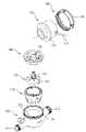
이와 같은 수도미터 중 전자식으로 계량을 수행하는 전자식 수도미터의 구성을 도 1 및 도 2를 참조하여 설명한다.Among such water meters, the configuration of an electronic water meter that performs electronic metering will be described with reference to FIGS. 1 and 2 .
종래, 전자식 수도미터는 본체부(110), 와류형성부(120), 임펠러부(130), 상부격판부(140), 계측부(150) 및 상단체결부(160)를 포함한다.Conventionally, the electronic water meter includes a
본체부(110)는 계측부(150)가 안착되는 중공부(111)와, 일측에 형성되고 수돗물이 유입되는 유입구(112)와, 타측에 형성되고 수돗물이 배출되는 유출구(113)와, 상단부에 형성되어 상단체결부(160)와 체결되는 체결부(114)로 구성된다.The
와류형성부(120)는 하단 및 상단에 다수개의 유입공 및 유출공이 형성되고 중앙에 형성된 회전축 돌기에 임펠러부(130)가 회전 가능하게 장착되도록 구성된다.The
임펠러부(130)는 회전축부(131)와 하단에 위치한 다수개의 날개(132)로 구성되고, 상기 회전축부(131) 상단에는 전자식 수량 계측을 위한 소정의 자성체가 설치된다.The
상부격판부(140)는 하부에 설치되는 임펠러부(130)를 보호하고 상부에 계측부(150)가 안착되는 격판부재로, 차폐부재가 내장되며 중앙에는 내측의 장착홈부(141)로 상기 임펠러부(130)의 회전축부(131) 및 자성체가 삽입 결합되도록 구성된다.The
계측부(150)는 수량을 계측하는 전자 계량장치로, 저면에 설치된 계측센서가 상기 임펠러부(130)의 자성체의 회전을 감지하면 이 신호를 기반으로 소정의 펄스신호가 생성되고 생성된 펄스신호는 표시창(153)에 숫자로 표시되어 지도록 구성된다.The
상단체결부(160)는 상기 본체부(110)의 상단 체결부에 체결되는 것으로, 상기 계측부(150)를 본체부(110)에 체결 고정하여 준다.The
그런데, 이와 같이 구성되는 전자식 수도미터는 계측부(150) 자체가 완전 방수 및 밀폐 구조를 가지고 있어서 기계식 수도미터와는 달리 상기 계측부(150)를 특별히 커버하는 외형 커버 자체가 전무하였다.However, in the electronic water meter configured in this way, the
따라서 종래의 전자식 수도미터는 계측부(150)와 본체부(110)의 상단부 체결부(114) 사이의 틈으로 이물질이 유입되는 문제점과, 상기 계측부(150)가 외부 충격에 의해 파손될 수 있는 문제점이 지적되었다.Therefore, in the conventional electronic water meter, there is a problem that foreign substances are introduced into the gap between the
본 발명은 상기한 문제점을 해결하기 위한 것으로, 본 발명의 목적은 본체 상부에 형성되는 계측부를 보호하고 동시에 커버 장착 시 계측부로부터 인출되는 전선과의 조립이 매우 용이하도록 한 전자식 수도미터를 제공하는 것에 있다.The present invention is to solve the above problems, and an object of the present invention is to provide an electronic water meter that protects the measuring unit formed on the upper part of the body and at the same time makes it very easy to assemble with the wire drawn out from the measuring unit when the cover is mounted. there is.
이와 같은 목적을 달성하기 위한 본 발명은 계측부가 돌출 형성되는 본체부의 상단체결부 끼움홈부에 회전 가능하도록 결합되는 커버를 포함하고,
상기 커버는,
중공형으로 상부에는 상단고정부가 끼움 결합되도록 일정길이 단차지게 형성된 결합부와, 상단고정부의 고정돌기가 끼움 결합되도록 상기 결합부에 적어도 하나 이상 형성되는 고정홈과, 계측부의 데이터 전송용 전선이 출입되도록 상기 결합부에 수직으로 형성된 절개부와, 상기 절개부의 아래에 상기 데이터 전송용 전선이 안착 고정되도록 형성된 제1전선안착홈으로 이루어진 베이스부;
상단에 형성된 개방부와, 뚜껑부의 제2힌지부와 결합되도록 일측으로 형성된 제1힌지부와, 상기 베이스부의 고정홈에 삽입되도록 상기 베이스부의 결합부와 결합되는 내주면에 형성된 고정돌기와, 일측 저면으로 상기 베이스부의 제1전선안착홈에 대응되도록 형성된 제2전선안착홈과, 상기 제2전선안착홈이 형성된 내주면 부위에 일정 간격을 두고 수직으로 형성되는 안내돌기부로 이루어진 상단고정부; 및
투명부와, 상기 투명부의 일측으로 상단고정부의 제1힌지부와 결합되는 제2힌지부로 이루어진 뚜껑부로 구성되고,
상기 제1전선안착홈과 제2전선안착홈은 계측부의 데이터 전송용 전선 인출용 전선구멍을 형성하며,
상기 안내돌기부는 상단고정부를 베이스부의 결합부에 결합 고정 할 때, 제2전선안착홈와 제1전선안착홈이 서로 맞닿아서 전선구멍을 이루도록 구성된 것을 특징으로 한다.The present invention for achieving the above object includes a cover that is rotatably coupled to the upper fastening part fitting groove part of the body part in which the measuring part is formed to protrude,
The cover is
In the upper part of the hollow type, the coupling part is formed to be stepped by a certain length so that the upper fixing part is fitted, and at least one fixing groove is formed in the coupling part so that the fixing protrusion of the upper fixing part is fitted, and the data transmission wire of the measuring part is provided. a base portion comprising a cutout formed vertically on the coupling portion to enter and exit, and a first wire seating groove formed to seat and fix the data transmission wire under the cutout;
An opening formed at the upper end, a first hinge portion formed on one side to be coupled to the second hinge portion of the lid portion, a fixing protrusion formed on an inner circumferential surface that is coupled to the coupling portion of the base portion so as to be inserted into the fixing groove of the base portion, and one bottom surface an upper fixing part comprising a second wire seating groove formed to correspond to the first wire seating groove of the base part, and a guide protrusion formed vertically at regular intervals on an inner peripheral surface where the second wire seating groove is formed; and
Consists of a transparent portion and a lid portion consisting of a second hinge portion coupled to the first hinge portion of the upper fixed portion on one side of the transparent portion,
The first wire seating groove and the second wire seating groove form a wire hole for taking out a wire for data transmission of the measurement unit,
The guide protrusion is characterized in that when the upper fixing part is coupled to the coupling part of the base part, the second wire seating groove and the first wire seating groove are in contact with each other to form a wire hole.
삭제delete
삭제delete
삭제delete
삭제delete
삭제delete
또한 본 발명에 따르면 상기 제1전선안착홈 및 제2전선안착홈은 반원형 형태로 구성된 것을 특징으로 한다.In addition, according to the present invention, the first wire seating groove and the second wire seating groove are characterized in that they are configured in a semicircular shape.
또한 본 발명에 따르면 상기 베이스부의 하단부는 계측부의 상단체결부를 커버하도록 구성되고, 내주면에는 상단체결부의 끼움홈부에 걸림 결합되는 다수개의 돌기부가 형성된 것을 특징으로 한다.In addition, according to the present invention, the lower end of the base part is configured to cover the upper fastening part of the measuring part, and a plurality of protrusions that are engaged with the fitting groove of the upper fastening part are formed on the inner circumferential surface.
또한 본 발명에 따르면 상기 상단고정부의 개방부가 형성되는 상면의 둘레에는 하방으로 수직돌기부가 90도 간격으로 4개 형성된 것을 특징으로 한다.In addition, according to the present invention, it is characterized in that four vertical protrusions are formed at intervals of 90 degrees downward around the periphery of the upper surface where the open portion of the upper fixing portion is formed.
이와 같이 본 발명은 전자식 수도미터의 계측부와 본체부의 상단부 체결부 사이의 틈으로 이물질이 유입되는 문제점을 해결한다.As described above, the present invention solves the problem that foreign substances are introduced into the gap between the measuring part of the electronic water meter and the fastening part of the upper end of the body part.
또한 본 발명은 계측부가 외부 충격에 의해 파손되지 않는 효과를 제공한다.In addition, the present invention provides an effect that the measurement unit is not damaged by an external impact.
또한 본 발명은 커버 장착 시 계측부로부터 인출되는 전선과의 조립이 매우 용이하도록 한 장점을 제공한다.In addition, the present invention provides the advantage of making it very easy to assemble with the wire drawn out from the measurement unit when the cover is mounted.
도 1은 종래의 전자식 수도미터의 사시도,
도 2는 종래의 전자식 수도미터의 분해 사시도,
도 3은 본 발명에 따른 전자식 수도미터의 사시도,
도 4는 상기 도 3의 본체부와 계측부의 분해 사시도,
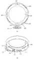
도 5는 본 발명에 따른 커버의 사시도,
도 6은 본 발명에 따른 커버의 측면도
도 7은 본 발명에 따른 커버의 분해사시도,
도 8의 (a)(b)는 본 발명에 따른 베이스부의 측면도 및 저면 사시도,
도 9의 (a)(b)는 본 발명에 따른 상단고정부의 저면도 및 저면 사시도,
도 10는 본 발명에 따른 뚜껑부의 저면 사시도,
도 11은 본 발명에 따른 커버의 저면 사시도이다.1 is a perspective view of a conventional electronic water meter;
2 is an exploded perspective view of a conventional electronic water meter;
3 is a perspective view of an electronic water meter according to the present invention;
4 is an exploded perspective view of the body part and the measurement part of FIG. 3;
5 is a perspective view of a cover according to the present invention;
6 is a side view of a cover according to the present invention;
7 is an exploded perspective view of the cover according to the present invention;
Figure 8 (a) (b) is a side view and a bottom perspective view of the base according to the present invention,
Figure 9 (a) (b) is a bottom view and a bottom perspective view of the top fixing part according to the present invention,
10 is a bottom perspective view of the lid according to the present invention;
11 is a bottom perspective view of a cover according to the present invention.
이하 첨부된 도면을 참조하여 본 발명의 바람직한 실시 예를 보다 상세히 설명한다.Hereinafter, preferred embodiments of the present invention will be described in more detail with reference to the accompanying drawings.
우선, 각 도면의 구성요소들에 참조부호를 부가함에 있어서, 동일한 구성요소들에 한해서는 비록 다른 도면상에 표시되더라도 가능한 한 동일한 부호를 가지도록 하고 있음에 유의해야 한다. 그리고 본 발명을 설명함에 있어서, 관련된 공지 기능 혹은 구성에 대한 구체적인 설명이 본 발명의 요지를 불필요하게 흐릴 수 있다고 판단되는 경우 그 상세한 설명을 생략한다.First of all, it should be noted that in adding reference numerals to the components of each drawing, the same components are provided with the same reference numerals as much as possible even though they are indicated on different drawings. In the description of the present invention, if it is determined that a detailed description of a related known function or configuration may unnecessarily obscure the gist of the present invention, the detailed description thereof will be omitted.
도 3은 본 발명에 따른 전자식 수도미터의 사시도, 도 4는 상기 도 3의 본체부와 계측부의 분해 사시도, 도 5는 본 발명에 따른 커버의 사시도, 도 6은 본 발명에 따른 커버의 측면도, 도 7은 본 발명에 따른 커버의 분해사시도이다.3 is a perspective view of an electronic water meter according to the present invention, FIG. 4 is an exploded perspective view of the body part and the measuring part of FIG. 3, FIG. 5 is a perspective view of the cover according to the present invention, FIG. 6 is a side view of the cover according to the present invention; 7 is an exploded perspective view of the cover according to the present invention.
도시된 바와 같이, 본 발명 전자식 수도미터는,As shown, the present invention electronic water meter,
계측부(150)가 돌출 형성된 본체부(110)의 상단에 커버(200)를 결합하여 구성된다.The
상기 커버(200)는 후술하겠지만 베이스부(210)의 하단부(211) 내주면으로 형성된 다수개의 돌기부(212)가 본체부(110)의 상단체결부(160)의 끼움홈부(161)에 끼움되어 회전 가능하게 결합되어 진다.Although the
상기 커버(200)는 베이스부(210), 상단고정부(220) 및 뚜껑부(230)를 포함한다.The
상기 베이스부(210)는 도 8의 (a)(b)에서와 같이 중공형으로 상부에는 상단고정부(220)가 끼움 결합되는 결합부(213)가 일정길이 단차지게 형성되고, 상기 결합부(213)에는 상단고정부(220)의 고정돌기(224)가 끼움 결합되는 적어도 하나 이상의 고정홈(214)이 형성된다.The
또한 상기 결합부(213)에는 계측부(150)의 데이터 전송용 전선(152)이 출입되는 절개부(215)가 수직으로 형성되고 상기 절개부(215)의 아래에는 상기 데이터 전송용 전선(152)이 안착 고정되는 제1전선안착홈(216)이 형성되도록 구성된다.In addition, a
상기 제1전선안착홈(216)은 상단고정부(220)에 형성된 제2전선안착홈(225)와 함께 전선구멍(240)을 형성하게 된다.The first
상기 제1전선안착홈(216)은 반원형 형태로 구성될 수 있으나 이에 반드시 한정되지는 않는다.The first
상기 절개부(215)는 데이터 전송용 전선(152)이 상기 제1전선안착홈(216)에 안착되거나 인출될 때 어떤 구조적 방해를 주지 않도록 가이드 역할을 수행하게 된다.The
상기 베이스부(210)의 하단부(211)는 본체부(110)의 상단체결부(160)를 커버하도록 구성되고, 내주면에는 상단체결부(160)의 끼움홈부(211)에 걸림 결합되는 다수개의 돌기부(212)가 형성된다.The
상기 상단고정부(220)는 상기 베이스부(210)의 결합부(213)에 결합 고정되는 것으로, 도 9의 (a)(b)에서와 같이 상단에는 개방부(221)가 형성되고 일측으로는 뚜껑부(230)의 제2힌지부(232)와 결합되는 제1힌지부(222)가 형성된다.The upper
또한 상기 상단고정부(220)는 상기 베이스부(210)의 결합부(213)와 결합되는 내주면에는 상기 베이스부(210)의 고정홈(214)에 삽입되는 고정돌기(224)가 형성되고, 일측 저면에는 상기 베이스부(210)의 제1전선안착홈(216)에 대응되는 제2전선안착홈(225)이 형성된다.In addition, the upper fixing
상기 제2전선안착홈(225)은 베이스부(210)에 형성된 제1전선안착홈(216)와 함께 전선구멍(240)을 형성하게 된다.The second
상기 제2전선안착홈(225)은 반원형 형태로 구성될 수 있으나 이에 반드시 한정되지는 않는다.The second
또한 상기 상단고정부(220)의 상기 제2전선안착홈(225)이 형성된 내주면 부위에는 일정 간격을 두고 안내돌기부(226)이 수직으로 형성된다.In addition, guide
상기 안내돌기부(226)는 상단고정부(220)를 베이스부(210)의 결합부(213)에 결합 고정 할 때, 제2전선안착홈(225)와 제1전선안착홈(216)이 서로 맞닿아서 전선구멍(240)을 이루도록 상기 베이스부(210)의 절개부(215)에 도 11에서와 같이 끼움되도록 구성된다.When the
따라서 상기 안내돌기부(226)는 상기 상단고정부(220)를 베이스부(210)에 결합할 때 전선구멍(240)이 용이하게 형성될 수 있도록 위치를 잡아주는 안내역할을 수행하게 된다.Accordingly, the
또한 상기 상단고정부(220)의 개방부(221)가 형성되는 상면의 둘레에는 하방으로 수직돌기부(227)가 90도 간격으로 4개 형성된다.In addition, four
상기 수직돌기부(227)는 상기 상단고정부(220)가 베이스부(210)에 고정 결합될 때, 내측에 위치하게 되는 계측부(150)의 상부면을 압박 지지하여 주어, 상기 계측부(150)의 유동을 방지하여 준다.When the upper fixing
상기 뚜껑부(230)는 도 10에서와 같이 투명 합성수지 소재로 구성되며, 상기 상단고정부(220)에 개폐 가능하도록 결합된다.The
상기 뚜껑부(230)는 투명부(231)와, 상기 투명부(231)의 일측으로 상단고정부(220)의 제1힌지부(222)와 결합되는 제2힌지부(232)로 구성된다.The
이와 같이 구성된 본 발명 전자식 수도미터의 커버의 조립과정과 작용을 이하 설명한다.The assembly process and operation of the cover of the electronic water meter of the present invention configured as described above will be described below.
먼저, 도 4에서와 같이 계측부(150) 등을 본체부(110)에 결합 완료하고, 커버(200)의 베이스부(210)를 상기 본체부(110)의 상단체결부(160)으로 힘껏 내리 눌러 상기 베이스부(210)의 돌기부(212)가 상단체결부(160)의 끼움홈부(161)에 삽입 결합되도록 하여준다.First, as shown in FIG. 4 , the
그런 다음 계측부(150)의 데이터 전송용 전선(152)을 베이스부(210)의 절개부(215)를 통해 제1전선안착홈(216)에 위치시켜준다.Then, the
그런 다음, 상단고정부(220)의 안내돌기부(226)를 상기 베이스부(210)의 절개부(215)에 끼워 맞춘 후 하방으로 눌러 고정돌기(224)를 베이스부(210) 결합부(313)의 고정홈(214)에 끼워준다.Then, after fitting the
이때 계측부(150)의 데이터 전송용 전선(152)은 상단고정부(220)의 제2전선안착홈(225)에 의해 고정된다.At this time, the
이와 같이 본 발명에서는 계측부(150)의 데이터 전송용 전선(152)을 용이하게 커버(200) 외부로 인출할 수 있는 구조를 제공하게 된다.As described above, the present invention provides a structure in which the
또한 상기 상단고정부(220)가 베이스부(210)에 고정되면 상기 상단고정부(220)의 수직돌기부(227)가 내부에 위치하는 계측부(150)의 상부면을 압박 지지하여 주어 계측부(150)의 유동을 방지하여 준다.In addition, when the
이와 같이 상기 상단고정부(220)가 베이스부(210)에 고정 결합되면, 뚜껑부(230)의 제2힌지부(232)를 상단고정부(220)의 제1힌지부(222)에 결합 한 후, 힌지축(223)으로 고정하여 모든 조립을 완료하게 된다.When the upper fixing
이상에서는 본 발명에 대한 한정된 실시예들을 설명한 것이나, 본 발명은 이에 한정되는 것은 아니고 다양한 실시예가 예상됨을 당업자는 주의해야 한다.In the above, limited embodiments of the present invention have been described, but the present invention is not limited thereto, and it should be noted by those skilled in the art that various embodiments are expected.
110: 본체부120: 와류형성부
130: 임펠러부140: 상부격판부
150: 계측부160: 상단체결부(160)
200: 커버210: 베이스부
211: 하단부212: 돌기부
213: 결합부214: 고정홈
215: 절개부216: 제1전선안착홈
220: 상단고정부221: 개방부
222: 제1힌지부223: 힌지축
224: 고정돌기225: 제2전선안착홈
230: 뚜껑부231: 투명부
232: 제2힌지부240: 전선구멍110: body part 120: vortex forming part
130: impeller portion 140: upper diaphragm portion
150: measurement unit 160:
200: cover 210: base portion
211: lower portion 212: protrusion
213: coupling portion 214: fixing groove
215: cutout 216: first wire seating groove
220: upper fixed part 221: open part
222: first hinge portion 223: hinge shaft
224: fixing protrusion 225: second wire seating groove
230: lid portion 231: transparent portion
232: second hinge unit 240: wire hole
Claims (5)
Translated fromKorean상기 커버는,
중공형으로 상부에는 상단고정부가 끼움 결합되도록 일정길이 단차지게 형성된 결합부와, 상단고정부의 고정돌기가 끼움 결합되도록 상기 결합부에 적어도 하나 이상 형성되는 고정홈과, 계측부의 데이터 전송용 전선이 출입되도록 상기 결합부에 수직으로 형성된 절개부와, 상기 절개부의 아래에 상기 데이터 전송용 전선이 안착 고정되도록 형성된 제1전선안착홈으로 이루어진 베이스부;
상단에 형성된 개방부와, 뚜껑부의 제2힌지부와 결합되도록 일측으로 형성된 제1힌지부와, 상기 베이스부의 고정홈에 삽입되도록 상기 베이스부의 결합부와 결합되는 내주면에 형성된 고정돌기와, 일측 저면으로 상기 베이스부의 제1전선안착홈에 대응되도록 형성된 제2전선안착홈과, 상기 제2전선안착홈이 형성된 내주면 부위에 일정 간격을 두고 수직으로 형성되는 안내돌기부로 이루어진 상단고정부; 및
투명부와, 상기 투명부의 일측으로 상단고정부의 제1힌지부와 결합되는 제2힌지부로 이루어진 뚜껑부로 구성되고,
상기 제1전선안착홈과 제2전선안착홈은 계측부의 데이터 전송용 전선 인출용 전선구멍을 형성하며,
상기 안내돌기부는 상단고정부를 베이스부의 결합부에 결합 고정 할 때, 제2전선안착홈와 제1전선안착홈이 서로 맞닿아서 전선구멍을 이루도록 상기 베이스부의 절개부에 끼움결합되도록 하고,
상기 제1전선안착홈 및 제2전선안착홈은 반원형 형태로 구성되며,
상기 베이스부의 하단부는 계측부의 상단체결부를 커버하도록 구성되고, 내주면에는 상단체결부의 끼움홈부에 걸림 결합되는 다수개의 돌기부가 형성되고,
상기 상단고정부의 개방부가 형성되는 상면의 둘레에는 하방으로 수직돌기부가 90도 간격으로 4개 형성된 것을 특징으로 하는 전자식 수도미터.
It includes a cover that is rotatably coupled to the upper fastening part fitting groove part of the body part in which the measuring part is formed to protrude,
The cover is
In the upper part of the hollow type, the coupling part is formed to be stepped by a certain length so that the upper fixing part is fitted, and at least one fixing groove is formed in the coupling part so that the fixing protrusion of the upper fixing part is fitted, and the data transmission wire of the measuring part is provided. a base portion comprising a cutout formed vertically on the coupling portion to enter and exit, and a first wire seating groove formed to seat and fix the data transmission wire under the cutout;
An opening formed at the upper end, a first hinge portion formed on one side to be coupled to the second hinge portion of the lid portion, a fixing protrusion formed on an inner circumferential surface that is coupled to the coupling portion of the base portion so as to be inserted into the fixing groove of the base portion, and one bottom surface an upper fixing part comprising a second wire seating groove formed to correspond to the first wire seating groove of the base part, and a guide protrusion formed vertically at regular intervals on an inner peripheral surface where the second wire seating groove is formed; and
Consists of a transparent portion and a lid portion consisting of a second hinge portion coupled to the first hinge portion of the upper fixed portion on one side of the transparent portion,
The first wire seating groove and the second wire seating groove form a wire hole for taking out a wire for data transmission of the measurement unit,
When the guide protrusion is coupled and fixed to the coupling part of the base part, the guide protrusion is fitted into the cutout of the base part so that the second wire seating groove and the first wire seating groove abut each other to form a wire hole,
The first wire seating groove and the second wire seating groove are configured in a semicircular shape,
The lower end of the base part is configured to cover the upper fastening part of the measuring part, and a plurality of protrusions are formed on the inner circumferential surface to be engaged with the fitting groove of the upper fastening part,
An electronic water meter, characterized in that four vertical protrusions are formed at intervals of 90 degrees downward around the upper surface where the opening of the upper fixing part is formed.
Priority Applications (1)
| Application Number | Priority Date | Filing Date | Title |
|---|---|---|---|
| KR1020210064361AKR102384843B1 (en) | 2021-05-18 | 2021-05-18 | Electronic water meter |
Applications Claiming Priority (1)
| Application Number | Priority Date | Filing Date | Title |
|---|---|---|---|
| KR1020210064361AKR102384843B1 (en) | 2021-05-18 | 2021-05-18 | Electronic water meter |
Publications (1)
| Publication Number | Publication Date |
|---|---|
| KR102384843B1true KR102384843B1 (en) | 2022-04-08 |
Family
ID=81182838
Family Applications (1)
| Application Number | Title | Priority Date | Filing Date |
|---|---|---|---|
| KR1020210064361AActiveKR102384843B1 (en) | 2021-05-18 | 2021-05-18 | Electronic water meter |
Country Status (1)
| Country | Link |
|---|---|
| KR (1) | KR102384843B1 (en) |
Cited By (1)
| Publication number | Priority date | Publication date | Assignee | Title |
|---|---|---|---|---|
| KR102688934B1 (en)* | 2023-06-07 | 2024-07-26 | 주식회사 대한계전 | Electronic water meter |
Citations (6)
| Publication number | Priority date | Publication date | Assignee | Title |
|---|---|---|---|---|
| JP2006058208A (en)* | 2004-08-23 | 2006-03-02 | Cmmd:Kk | Lid structure for water meter |
| JP2014055828A (en)* | 2012-09-12 | 2014-03-27 | Toshin Corp | Dry water meter |
| KR101439501B1 (en) | 2014-06-11 | 2014-09-12 | (주)엠파이브 | Housing of an electronic water meter |
| KR101560265B1 (en) | 2013-11-28 | 2015-10-14 | 차호준 | Electronic type water meter has been applied nonmagnetic material |
| KR102176781B1 (en) | 2020-05-18 | 2020-11-09 | 부경수도 주식회사 | Hybrid water meter and meter reading system using the same |
| KR102242453B1 (en)* | 2020-12-02 | 2021-04-20 | 주식회사 대한계전 | Large capacity electronic water meter |
- 2021
- 2021-05-18KRKR1020210064361Apatent/KR102384843B1/enactiveActive
Patent Citations (6)
| Publication number | Priority date | Publication date | Assignee | Title |
|---|---|---|---|---|
| JP2006058208A (en)* | 2004-08-23 | 2006-03-02 | Cmmd:Kk | Lid structure for water meter |
| JP2014055828A (en)* | 2012-09-12 | 2014-03-27 | Toshin Corp | Dry water meter |
| KR101560265B1 (en) | 2013-11-28 | 2015-10-14 | 차호준 | Electronic type water meter has been applied nonmagnetic material |
| KR101439501B1 (en) | 2014-06-11 | 2014-09-12 | (주)엠파이브 | Housing of an electronic water meter |
| KR102176781B1 (en) | 2020-05-18 | 2020-11-09 | 부경수도 주식회사 | Hybrid water meter and meter reading system using the same |
| KR102242453B1 (en)* | 2020-12-02 | 2021-04-20 | 주식회사 대한계전 | Large capacity electronic water meter |
Cited By (1)
| Publication number | Priority date | Publication date | Assignee | Title |
|---|---|---|---|---|
| KR102688934B1 (en)* | 2023-06-07 | 2024-07-26 | 주식회사 대한계전 | Electronic water meter |
Similar Documents
| Publication | Publication Date | Title |
|---|---|---|
| KR102242453B1 (en) | Large capacity electronic water meter | |
| KR102557469B1 (en) | Meter reading terminal integrated with digital water meter | |
| KR102384843B1 (en) | Electronic water meter | |
| KR102446434B1 (en) | Stainless steel electronic water meter | |
| KR200443454Y1 (en) | Flowmeter with contamination prevention member | |
| US2566220A (en) | Water meter | |
| KR102433655B1 (en) | Water meter of vertical waltman type | |
| JP2013104819A (en) | Inner case for impeller water meter, metering device for impeller water meter, and impeller water meter | |
| KR101991817B1 (en) | Water meter | |
| KR102688934B1 (en) | Electronic water meter | |
| KR0134434Y1 (en) | Double Breasted Water Meter | |
| KR102872605B1 (en) | Digital water meter | |
| JP6890787B2 (en) | Water meter | |
| KR200351181Y1 (en) | A rotary cover of propeller type water meter | |
| KR20020091734A (en) | Gear box and count wheel box assembly device and assembly method of water meter | |
| KR102843894B1 (en) | Electronic water meter preventing water-stealing | |
| JP4148446B2 (en) | Water meter and its inner case and inner unit | |
| KR102727752B1 (en) | Digital water meter | |
| KR102763076B1 (en) | Terminal integrated water meter | |
| KR20250097499A (en) | Digital water meter | |
| JP4345998B2 (en) | Dry water meter | |
| CN209542446U (en) | Saccharometer shell | |
| CN214341801U (en) | Drinking machine | |
| CN219935018U (en) | Electronic water meter | |
| CN223205761U (en) | Film developing equipment |
Legal Events
| Date | Code | Title | Description |
|---|---|---|---|
| PA0109 | Patent application | Patent event code:PA01091R01D Comment text:Patent Application Patent event date:20210518 | |
| PA0201 | Request for examination | ||
| PA0302 | Request for accelerated examination | Patent event date:20210526 Patent event code:PA03022R01D Comment text:Request for Accelerated Examination Patent event date:20210518 Patent event code:PA03021R01I Comment text:Patent Application | |
| PE0902 | Notice of grounds for rejection | Comment text:Notification of reason for refusal Patent event date:20210618 Patent event code:PE09021S01D | |
| PE0601 | Decision on rejection of patent | Patent event date:20211026 Comment text:Decision to Refuse Application Patent event code:PE06012S01D Patent event date:20210618 Comment text:Notification of reason for refusal Patent event code:PE06011S01I | |
| PX0901 | Re-examination | Patent event code:PX09011S01I Patent event date:20211026 Comment text:Decision to Refuse Application Patent event code:PX09012R01I Patent event date:20210823 Comment text:Amendment to Specification, etc. | |
| PX0701 | Decision of registration after re-examination | Patent event date:20220121 Comment text:Decision to Grant Registration Patent event code:PX07013S01D Patent event date:20211227 Comment text:Amendment to Specification, etc. Patent event code:PX07012R01I Patent event date:20211026 Comment text:Decision to Refuse Application Patent event code:PX07011S01I Patent event date:20210823 Comment text:Amendment to Specification, etc. Patent event code:PX07012R01I | |
| GRNT | Written decision to grant | ||
| PR0701 | Registration of establishment | Comment text:Registration of Establishment Patent event date:20220405 Patent event code:PR07011E01D | |
| PR1002 | Payment of registration fee | Payment date:20220405 End annual number:3 Start annual number:1 | |
| PG1601 | Publication of registration | ||
| PR1001 | Payment of annual fee | Payment date:20250331 Start annual number:4 End annual number:4 |