KR102383097B1 - Cover window of flexible display device and flexible display device having the same - Google Patents
Cover window of flexible display device and flexible display device having the sameDownload PDFInfo
- Publication number
- KR102383097B1 KR102383097B1KR1020150120916AKR20150120916AKR102383097B1KR 102383097 B1KR102383097 B1KR 102383097B1KR 1020150120916 AKR1020150120916 AKR 1020150120916AKR 20150120916 AKR20150120916 AKR 20150120916AKR 102383097 B1KR102383097 B1KR 102383097B1
- Authority
- KR
- South Korea
- Prior art keywords
- folding
- area
- coating layer
- hard coating
- flexible display
- Prior art date
- Legal status (The legal status is an assumption and is not a legal conclusion. Google has not performed a legal analysis and makes no representation as to the accuracy of the status listed.)
- Active
Links
- 239000011247coating layerSubstances0.000claimsabstractdescription183
- 239000010410layerSubstances0.000claimsabstractdescription82
- 230000002093peripheral effectEffects0.000claimsabstractdescription18
- 239000000463materialSubstances0.000claimsdescription22
- 238000000034methodMethods0.000claimsdescription11
- 238000010586diagramMethods0.000description22
- 238000005452bendingMethods0.000description17
- 230000003287optical effectEffects0.000description10
- 150000002894organic compoundsChemical class0.000description8
- 150000001875compoundsChemical class0.000description7
- 239000000853adhesiveSubstances0.000description4
- 230000001070adhesive effectEffects0.000description4
- 239000011248coating agentSubstances0.000description4
- 238000000576coating methodMethods0.000description4
- 238000007598dipping methodMethods0.000description4
- 229920003023plasticPolymers0.000description4
- 238000011084recoveryMethods0.000description4
- 239000000758substrateSubstances0.000description4
- 239000011521glassSubstances0.000description3
- 229910010272inorganic materialInorganic materials0.000description3
- 239000002985plastic filmSubstances0.000description3
- 230000001502supplementing effectEffects0.000description3
- 239000004925Acrylic resinSubstances0.000description2
- 229920000178Acrylic resinPolymers0.000description2
- 239000004593EpoxySubstances0.000description2
- 239000004642PolyimideSubstances0.000description2
- -1acrylChemical group0.000description2
- 239000002131composite materialSubstances0.000description2
- 238000005520cutting processMethods0.000description2
- 230000007423decreaseEffects0.000description2
- 238000001035dryingMethods0.000description2
- 230000000694effectsEffects0.000description2
- 239000003822epoxy resinSubstances0.000description2
- 238000004519manufacturing processMethods0.000description2
- 239000007769metal materialSubstances0.000description2
- 229920003229poly(methyl methacrylate)Polymers0.000description2
- 229920000647polyepoxidePolymers0.000description2
- 229920000139polyethylene terephthalatePolymers0.000description2
- 239000005020polyethylene terephthalateSubstances0.000description2
- 229920001721polyimidePolymers0.000description2
- 229920000642polymerPolymers0.000description2
- 239000004926polymethyl methacrylateSubstances0.000description2
- 150000003377silicon compoundsChemical class0.000description2
- 238000004528spin coatingMethods0.000description2
- 238000005507sprayingMethods0.000description2
- 238000001771vacuum depositionMethods0.000description2
- OAICVXFJPJFONN-UHFFFAOYSA-NPhosphorusChemical compound[P]OAICVXFJPJFONN-UHFFFAOYSA-N0.000description1
- 230000001154acute effectEffects0.000description1
- 239000006116anti-fingerprint coatingSubstances0.000description1
- 239000006117anti-reflective coatingSubstances0.000description1
- 239000000356contaminantSubstances0.000description1
- 230000006866deteriorationEffects0.000description1
- 150000002484inorganic compoundsChemical class0.000description1
- 230000000737periodic effectEffects0.000description1
- 239000004033plasticSubstances0.000description1
- 239000004417polycarbonateSubstances0.000description1
- 229920000515polycarbonatePolymers0.000description1
- 239000002990reinforced plasticSubstances0.000description1
- 238000012827research and developmentMethods0.000description1
- 230000035939shockEffects0.000description1
Images


Classifications
- G—PHYSICS
- G02—OPTICS
- G02F—OPTICAL DEVICES OR ARRANGEMENTS FOR THE CONTROL OF LIGHT BY MODIFICATION OF THE OPTICAL PROPERTIES OF THE MEDIA OF THE ELEMENTS INVOLVED THEREIN; NON-LINEAR OPTICS; FREQUENCY-CHANGING OF LIGHT; OPTICAL LOGIC ELEMENTS; OPTICAL ANALOGUE/DIGITAL CONVERTERS
- G02F1/00—Devices or arrangements for the control of the intensity, colour, phase, polarisation or direction of light arriving from an independent light source, e.g. switching, gating or modulating; Non-linear optics
- G02F1/01—Devices or arrangements for the control of the intensity, colour, phase, polarisation or direction of light arriving from an independent light source, e.g. switching, gating or modulating; Non-linear optics for the control of the intensity, phase, polarisation or colour
- G02F1/13—Devices or arrangements for the control of the intensity, colour, phase, polarisation or direction of light arriving from an independent light source, e.g. switching, gating or modulating; Non-linear optics for the control of the intensity, phase, polarisation or colour based on liquid crystals, e.g. single liquid crystal display cells
- G02F1/133—Constructional arrangements; Operation of liquid crystal cells; Circuit arrangements
- G02F1/1333—Constructional arrangements; Manufacturing methods
- G02F1/133305—Flexible substrates, e.g. plastics, organic film
- G—PHYSICS
- G09—EDUCATION; CRYPTOGRAPHY; DISPLAY; ADVERTISING; SEALS
- G09F—DISPLAYING; ADVERTISING; SIGNS; LABELS OR NAME-PLATES; SEALS
- G09F9/00—Indicating arrangements for variable information in which the information is built-up on a support by selection or combination of individual elements
- G09F9/30—Indicating arrangements for variable information in which the information is built-up on a support by selection or combination of individual elements in which the desired character or characters are formed by combining individual elements
- G09F9/301—Indicating arrangements for variable information in which the information is built-up on a support by selection or combination of individual elements in which the desired character or characters are formed by combining individual elements flexible foldable or roll-able electronic displays, e.g. thin LCD, OLED
- G—PHYSICS
- G02—OPTICS
- G02B—OPTICAL ELEMENTS, SYSTEMS OR APPARATUS
- G02B1/00—Optical elements characterised by the material of which they are made; Optical coatings for optical elements
- G02B1/10—Optical coatings produced by application to, or surface treatment of, optical elements
- G02B1/14—Protective coatings, e.g. hard coatings
- G—PHYSICS
- G09—EDUCATION; CRYPTOGRAPHY; DISPLAY; ADVERTISING; SEALS
- G09F—DISPLAYING; ADVERTISING; SIGNS; LABELS OR NAME-PLATES; SEALS
- G09F9/00—Indicating arrangements for variable information in which the information is built-up on a support by selection or combination of individual elements
- H—ELECTRICITY
- H05—ELECTRIC TECHNIQUES NOT OTHERWISE PROVIDED FOR
- H05K—PRINTED CIRCUITS; CASINGS OR CONSTRUCTIONAL DETAILS OF ELECTRIC APPARATUS; MANUFACTURE OF ASSEMBLAGES OF ELECTRICAL COMPONENTS
- H05K1/00—Printed circuits
- H05K1/02—Details
- H05K1/0277—Bendability or stretchability details
- H05K1/028—Bending or folding regions of flexible printed circuits
- H—ELECTRICITY
- H05—ELECTRIC TECHNIQUES NOT OTHERWISE PROVIDED FOR
- H05K—PRINTED CIRCUITS; CASINGS OR CONSTRUCTIONAL DETAILS OF ELECTRIC APPARATUS; MANUFACTURE OF ASSEMBLAGES OF ELECTRICAL COMPONENTS
- H05K1/00—Printed circuits
- H05K1/02—Details
- H05K1/14—Structural association of two or more printed circuits
- H05K1/147—Structural association of two or more printed circuits at least one of the printed circuits being bent or folded, e.g. by using a flexible printed circuit
- H—ELECTRICITY
- H05—ELECTRIC TECHNIQUES NOT OTHERWISE PROVIDED FOR
- H05K—PRINTED CIRCUITS; CASINGS OR CONSTRUCTIONAL DETAILS OF ELECTRIC APPARATUS; MANUFACTURE OF ASSEMBLAGES OF ELECTRICAL COMPONENTS
- H05K1/00—Printed circuits
- H05K1/18—Printed circuits structurally associated with non-printed electric components
- H05K1/181—Printed circuits structurally associated with non-printed electric components associated with surface mounted components
- H—ELECTRICITY
- H05—ELECTRIC TECHNIQUES NOT OTHERWISE PROVIDED FOR
- H05K—PRINTED CIRCUITS; CASINGS OR CONSTRUCTIONAL DETAILS OF ELECTRIC APPARATUS; MANUFACTURE OF ASSEMBLAGES OF ELECTRICAL COMPONENTS
- H05K1/00—Printed circuits
- H05K1/18—Printed circuits structurally associated with non-printed electric components
- H05K1/189—Printed circuits structurally associated with non-printed electric components characterised by the use of a flexible or folded printed circuit
- H—ELECTRICITY
- H05—ELECTRIC TECHNIQUES NOT OTHERWISE PROVIDED FOR
- H05K—PRINTED CIRCUITS; CASINGS OR CONSTRUCTIONAL DETAILS OF ELECTRIC APPARATUS; MANUFACTURE OF ASSEMBLAGES OF ELECTRICAL COMPONENTS
- H05K5/00—Casings, cabinets or drawers for electric apparatus
- H05K5/02—Details
- H05K5/03—Covers
- G—PHYSICS
- G02—OPTICS
- G02F—OPTICAL DEVICES OR ARRANGEMENTS FOR THE CONTROL OF LIGHT BY MODIFICATION OF THE OPTICAL PROPERTIES OF THE MEDIA OF THE ELEMENTS INVOLVED THEREIN; NON-LINEAR OPTICS; FREQUENCY-CHANGING OF LIGHT; OPTICAL LOGIC ELEMENTS; OPTICAL ANALOGUE/DIGITAL CONVERTERS
- G02F1/00—Devices or arrangements for the control of the intensity, colour, phase, polarisation or direction of light arriving from an independent light source, e.g. switching, gating or modulating; Non-linear optics
- G02F1/01—Devices or arrangements for the control of the intensity, colour, phase, polarisation or direction of light arriving from an independent light source, e.g. switching, gating or modulating; Non-linear optics for the control of the intensity, phase, polarisation or colour
- G02F1/13—Devices or arrangements for the control of the intensity, colour, phase, polarisation or direction of light arriving from an independent light source, e.g. switching, gating or modulating; Non-linear optics for the control of the intensity, phase, polarisation or colour based on liquid crystals, e.g. single liquid crystal display cells
- G02F1/133—Constructional arrangements; Operation of liquid crystal cells; Circuit arrangements
- G02F1/1333—Constructional arrangements; Manufacturing methods
- G02F1/133308—Support structures for LCD panels, e.g. frames or bezels
- G02F1/133331—Cover glasses
- H—ELECTRICITY
- H05—ELECTRIC TECHNIQUES NOT OTHERWISE PROVIDED FOR
- H05K—PRINTED CIRCUITS; CASINGS OR CONSTRUCTIONAL DETAILS OF ELECTRIC APPARATUS; MANUFACTURE OF ASSEMBLAGES OF ELECTRICAL COMPONENTS
- H05K2201/00—Indexing scheme relating to printed circuits covered by H05K1/00
- H05K2201/05—Flexible printed circuits [FPCs]
- H05K2201/055—Folded back on itself
- H—ELECTRICITY
- H05—ELECTRIC TECHNIQUES NOT OTHERWISE PROVIDED FOR
- H05K—PRINTED CIRCUITS; CASINGS OR CONSTRUCTIONAL DETAILS OF ELECTRIC APPARATUS; MANUFACTURE OF ASSEMBLAGES OF ELECTRICAL COMPONENTS
- H05K2201/00—Indexing scheme relating to printed circuits covered by H05K1/00
- H05K2201/05—Flexible printed circuits [FPCs]
- H05K2201/058—Direct connection between two or more FPCs or between flexible parts of rigid PCBs
- H—ELECTRICITY
- H05—ELECTRIC TECHNIQUES NOT OTHERWISE PROVIDED FOR
- H05K—PRINTED CIRCUITS; CASINGS OR CONSTRUCTIONAL DETAILS OF ELECTRIC APPARATUS; MANUFACTURE OF ASSEMBLAGES OF ELECTRICAL COMPONENTS
- H05K2201/00—Indexing scheme relating to printed circuits covered by H05K1/00
- H05K2201/10—Details of components or other objects attached to or integrated in a printed circuit board
- H05K2201/10007—Types of components
- H05K2201/10128—Display
Landscapes
- Physics & Mathematics (AREA)
- Engineering & Computer Science (AREA)
- Microelectronics & Electronic Packaging (AREA)
- General Physics & Mathematics (AREA)
- Nonlinear Science (AREA)
- Optics & Photonics (AREA)
- Mathematical Physics (AREA)
- Chemical & Material Sciences (AREA)
- Crystallography & Structural Chemistry (AREA)
- Devices For Indicating Variable Information By Combining Individual Elements (AREA)
- Theoretical Computer Science (AREA)
- Electroluminescent Light Sources (AREA)
Abstract
Translated fromKoreanDescription
Translated fromKorean본 발명은 표시 장치에 관한 것으로서, 더욱 상세하게는 플렉서블 표시 장치에 관한 것이다.The present invention relates to a display device, and more particularly, to a flexible display device.
최근 휘어지거나 접어지는 플렉서블 표시 장치에 대한 연구 및 개발이 진행되고 있다. 이러한 플렉서블 표시 장치 또는 폴더블(foldable) 표시 장치는 플렉서블 표시 패널과 이를 보호하는 커버 윈도우를 포함한다. 상기 커버 윈도우는 상기 플렉서블 표시 패널에 비해 굴곡 강성(bending stiffness)이 강하고 굴곡 자유도가 낮다. 따라서, 보통 상기 플렉서블 표시 패널은 비교적 자유롭게 접힐 수 있으나, 상기 커버 윈도우의 굽힘 및 접힘에는 제약이 있다. 특히, 상기 플렉서블 표시 장치가 한쪽 방향으로는 용이하게 접힐 수 있으나(예를 들어, 인-폴딩), 그 반대 방향(예를 들어, 아웃 폴딩)으로의 접힘 또는 구부림에는 어려움이 있으므로, 플렉서블 표시 장치의 다양한 디자인을 구현하는 데에 한계가 있다.Recently, research and development of a flexible display device that can be bent or folded is in progress. Such a flexible display device or a foldable display device includes a flexible display panel and a cover window protecting the flexible display panel. The cover window has higher bending stiffness and lower bending freedom than the flexible display panel. Accordingly, although the flexible display panel can be folded relatively freely, bending and folding of the cover window are limited. In particular, although the flexible display device can be easily folded in one direction (eg, in-folding), it is difficult to fold or bend in the opposite direction (eg, out-folding), so the flexible display device There is a limit to implementing various designs of
게다가, 커버 윈도우의 두께를 작게 가져감으로써 상기 굴곡 강성을 낮출 수는 있으나, 반대로 상기 커버 윈도우의 두께가 감소함에 따라 상기 커버 윈도우의 모듈러스 및 경도가 감소한다.In addition, the flexural rigidity may be lowered by reducing the thickness of the cover window, but conversely, as the thickness of the cover window decreases, the modulus and hardness of the cover window decrease.
따라서, 다양한 디자인의 플렉서블 표시 장치를 구현하기 위해서는 양방향으로 접기 용이한(즉, 인-폴딩 및 아웃-폴딩이 가능한) 소재의 개발이 필요하다.Accordingly, in order to implement a flexible display device having various designs, it is necessary to develop a material that is easily foldable in both directions (ie, in-folding and out-folding possible).
본 발명의 일 목적은 제2 하드코팅 층의 영역 별 두께를 달리 하여 인-폴딩 및 아웃-폴딩이 용이한 플렉서블 표시 장치의 커버 윈도우를 제공하는 것이다.It is an object of the present invention to provide a cover window of a flexible display device that is easily in-folding and out-folding by varying the thickness of the second hard coating layer for each region.
본 발명의 다른 목적은 상기 커버 윈도우를 포함하는 플렉서블 표시 장치를 제공하는 것이다.Another object of the present invention is to provide a flexible display device including the cover window.
다만, 본 발명의 목적은 상술한 목적들로 한정되는 것이 아니며, 본 발명의 사상 및 영역으로부터 벗어나지 않는 범위에서 다양하게 확장될 수 있을 것이다.However, the object of the present invention is not limited to the above-described objects, and may be expanded in various ways without departing from the spirit and scope of the present invention.
본 발명의 일 목적을 달성하기 위하여 본 발명의 실시예들에 따른 플렉서블 표시 장치의 커버 윈도우는 인-폴딩(In-folding) 영역, 아웃-폴딩(Out-folding) 영역 및 상기 인-폴딩 영역과 상기 아웃-폴딩 영역에 각각 인접하여 위치하는 주변 영역으로 구분되는 베이스 층, 상기 베이스 층의 전면에 균일한 두께로 배치되는 제1 하드코팅 층 및 상기 베이스 층의 상기 전면에 대향하는 후면에 배치되며, 상기 제1 하드코팅 층의 상기 두께와 다른 두께를 갖는 제2 하드코팅 층을 포함할 수 있다. 상기 인-폴딩 영역 및 상기 아웃-폴딩 영역에 각각 중첩되는 상기 제2 하드코팅 층의 제1 영역의 두께가 상기 주변 영역에 중첩되는 상기 제2 하드코팅 층의 제2 영역의 두께보다 작을 수 있다.In order to achieve one aspect of the present invention, a cover window of a flexible display device according to embodiments of the present invention includes an in-folding area, an out-folding area, and the in-folding area; A base layer divided into peripheral regions positioned adjacent to the out-folding region, a first hard coating layer disposed with a uniform thickness on the front surface of the base layer, and a rear surface opposite to the front surface of the base layer, , It may include a second hard coat layer having a thickness different from the thickness of the first hard coat layer. The thickness of the first region of the second hard coating layer overlapping the in-folding region and the out-folding region, respectively, may be smaller than the thickness of the second region of the second hard coating layer overlapping the peripheral region .
일 실시예에 의하면, 상기 제2 하드코팅 층의 상기 제2 영역의 두께가 상기 제1 하드코팅 층의 두께보다 작을 수 있다.According to one embodiment, the thickness of the second region of the second hard coating layer may be smaller than the thickness of the first hard coating layer.
일 실시예에 의하면, 상기 제1 영역은 상기 베이스 층 쪽으로 오목한 곡선 형태를 가질 수 있다.In an embodiment, the first region may have a curved shape concave toward the base layer.
일 실시예에 의하면, 상기 제1 영역은 상기 베이스 층 쪽으로 오목한 사각 형태를 가질 수 있다.In an embodiment, the first region may have a rectangular shape concave toward the base layer.
일 실시예에 의하면, 상기 제2 하드코팅 층의 제1 영역은 상기 제1 방향에 직교하는 제2 방향을 따라 주기적으로 배치되고, 상기 제1 영역으로부터 돌출된 돌출 패턴을 포함할 수 있다.According to an embodiment, the first region of the second hard coating layer is periodically disposed along a second direction orthogonal to the first direction, and may include a protruding pattern protruding from the first region.
일 실시예에 의하면, 상기 제2 하드코팅 층의 제1 영역은 상기 제1 방향에 직교하는 제2 방향을 따라 주기적으로 배치되고, 상기 베이스 층 쪽으로 오목한 오목 패턴을 포함할 수 있다.According to an embodiment, the first region of the second hard coating layer is periodically disposed along a second direction orthogonal to the first direction, and may include a concave pattern concave toward the base layer.
일 실시예에 의하면, 상기 아웃-폴딩 영역은 상기 커버 윈도우가 접혔을 때 상기 제2 하드코팅 층이 내측을 향하도록 접히는 영역에 상응할 수 있다. 상기 인-폴딩 영역은 상기 커버 윈도우가 접혔을 때 상기 제1 하드코팅 층이 상기 내측을 향하도록 접히는 영역에 상응할 수 있다.In one embodiment, the out-folding region may correspond to a region in which the second hard coating layer is folded to face inward when the cover window is folded. The in-folding region may correspond to a region in which the first hard coating layer is folded toward the inside when the cover window is folded.
일 실시예에 의하면, 상기 커버 윈도우가 완전히 접혔을 때, 상기 인-폴딩 영역의 곡률 반경은 상기 아웃-폴딩 영역의 곡률 반경과 서로 다를 수 있다.According to an embodiment, when the cover window is fully folded, the radius of curvature of the in-folding area may be different from the radius of curvature of the out-folding area.
일 실시예에 의하면, 상기 커버 윈도우가 완전히 접혔을 때, 상기 인-폴딩 영역의 곡률 반경과 상기 아웃-폴딩 영역의 곡률 반경은 서로 동일할 수 있다.According to an embodiment, when the cover window is fully folded, the radius of curvature of the in-folding area and the radius of curvature of the out-folding area may be the same.
일 실시예에 의하면, 상기 제1 하드코팅 층과 상기 제2 하드코팅 층은 동일한 물질로 형성될 수 있다.According to an embodiment, the first hard coating layer and the second hard coating layer may be formed of the same material.
일 실시예에 의하면, 상기 제1 하드코팅 층과 상기 제2 하드코팅 층은 서로 다른 물질로 형성될 수 있다.According to an embodiment, the first hard coating layer and the second hard coating layer may be formed of different materials.
일 실시예에 의하면, 상기 제2 하드코팅 층의 상기 제2 영역의 두께가 상기 제1 하드코팅 층의 두께보다 클 수 있다.According to one embodiment, the thickness of the second region of the second hard coating layer may be greater than the thickness of the first hard coating layer.
본 발명의 일 목적을 달성하기 위하여 본 발명의 실시예들에 따른 플렉서블 표시 장치는 평면 표시 영역인 메인 표시 영역, 인-폴딩(In-folding) 영역, 아웃-폴딩(Out-folding) 영역 및 상기 인-폴딩 영역과 상기 아웃-폴딩 영역에 각각 인접한 서브 표시 영역을 포함하는 플렉서블 표시 패널 및 상기 메인 표시 영역, 상기 인-폴딩 영역, 상기 아웃-폴딩 영역 및 상기 서브 표시 영역에 중첩되도록 상기 플렉서블 표시 패널의 발광면 상에 배치되는 커버 윈도우를 포함할 수 있다. 상기 커버 윈도우는 투명 필름을 포함하는 베이스 층, 상기 베이스 층의 전면에 균일한 두께로 배치되는 제1 하드코팅 층 및 상기 베이스 층의 상기 전면에 대향하는 후면에 배치되면서 상기 플렉서블 표시 패널의 상기 발광면 상에 위치하며, 상기 제1 하드코팅 층의 상기 두께보다 작은 두께를 갖는 제2 하드코팅 층을 포함할 수 있다. 상기 인-폴딩 영역 및 상기 아웃-폴딩 영역에 각각 중첩되는 상기 제2 하드코팅 층의 제1 영역의 두께가 상기 메인 표시 영역 및 상기 서브 표시 영역에 중첩되는 상기 제2 하드코팅 층의 제2 영역의 두께보다 작을 수 있다.In order to achieve one aspect of the present invention, a flexible display device according to embodiments of the present invention includes a main display area that is a flat display area, an in-folding area, an out-folding area, and the A flexible display panel including an in-folding area and a sub-display area adjacent to the out-folding area, respectively, and the flexible display to overlap the main display area, the in-folding area, the out-folding area, and the sub-display area It may include a cover window disposed on the light emitting surface of the panel. The cover window may include a base layer including a transparent film, a first hard coating layer disposed with a uniform thickness on the front surface of the base layer, and a rear surface of the base layer facing the front surface of the base layer, and the light emission of the flexible display panel It is located on the surface, and may include a second hard coating layer having a thickness smaller than the thickness of the first hard coating layer. A thickness of a first region of the second hard coating layer overlapping the in-folding region and the out-folding region, respectively, is a second region of the second hard coating layer overlapping the main display region and the sub-display region may be smaller than the thickness of
일 실시예에 의하면, 상기 서브 표시 영역은 상기 메인 표시 영역의 제1 측부로부터 제1 방향으로 연장되고, 상기 발광면에 대향하는 비발광면이 내측으로 향하도록 접히는 제1 서브 표시 영역, 상기 제1 서브 표시 영역으로부터 상기 제1 방향으로 연장되고, 상기 발광면이 내측으로 향하도록 접히는 제2 서브 표시 영역, 상기 메인 표시 영역의 상기 제1 측부에 대향하는 제2 측부로부터 상기 제1 방향의 반대 방향으로 연장되고, 상기 발광면에 대향하는 비발광면이 내측으로 향하도록 접히는 제3 서브 표시 영역, 상기 제3 서브 표시 영역으로부터 상기 제1 방향의 상기 반대 방향으로 연장되고, 상기 발광면이 내측으로 향하도록 접히는 제4 서브 표시 영역을 포함할 수 있다. 상기 제1 내지 제4 서브 표시 영역들 각각의 상기 제1 방향으로의 길이는 상기 메인 표시 영역의 상기 제1 방향으로의 길이의 절반보다 작을 수 있다.In example embodiments, the sub display area includes a first sub display area extending in a first direction from a first side of the main display area and folded such that a non-emission surface opposite to the light emitting surface faces inward; a second sub display area extending in the first direction from the first sub display area and folded so that the light emitting surface faces inward, a second side opposite to the first side of the main display area opposite to the first direction a third sub display area extending in a direction opposite to the first direction and folded such that a non-emission surface opposite to the light emitting surface faces inward; It may include a fourth sub display area that is folded toward the . A length of each of the first to fourth sub-display areas in the first direction may be less than half a length of the main display area in the first direction.
일 실시예에 의하면, 상기 아웃-폴딩 영역은 상기 메인 표시 영역의 상기 제1 측부와 상기 제1 서브 표시 영역 사이에 연결되는 제1 아웃-폴딩 영역 및 상기 메인 표시 영역의 상기 제2 측부와 상기 제3 서브 표시 영역 사이에 연결되는 제1 아웃-폴딩 영역을 포함할 수 있다. 상기 인-폴딩 영역은 상기 제1 서브 표시 영역과 상기 제2 서브 표시 영역 사이에 연결되는 제1 인-폴딩 영역 및 상기 제3 서브 표시 영역과 상기 제4 서브 표시 영역 사이에 연결되는 제2 인-폴딩 영역을 포함할 수 있다.In example embodiments, the out-folding area includes a first out-folding area connected between the first side of the main display area and the first sub-display area, and the second side of the main display area and the A first out-folding area connected between the third sub display areas may be included. The in-folding area includes a first in-folding area connected between the first sub display area and the second sub display area and a second phosphor connected between the third sub display area and the fourth sub display area. -Can include folding area.
일 실시예에 의하면, 상기 제2 하드코팅 층은 상기 제1 영역을 따라 주기적으로 배치되고, 상기 제1 영역으로부터 돌출된 돌출 패턴을 포함할 수 있다.According to an embodiment, the second hard coating layer may be periodically disposed along the first region and include a protruding pattern protruding from the first region.
일 실시예에 의하면, 상기 제2 하드코팅 층의 상기 제1 영역은 상기 베이스 층 쪽으로 오목할 수 있다.In one embodiment, the first region of the second hard coating layer may be concave toward the base layer.
일 실시예에 의하면, 플렉서블 표시 장치가 완전히 접힌 경우, 상기 제1 아웃-폴딩 영역의 곡률 반경과 상기 제2 아웃-폴딩 영역의 곡룔 반경이 서로 다를 수 있다.According to an exemplary embodiment, when the flexible display device is fully folded, a radius of curvature of the first out-folding area may be different from a radius of curvature of the second out-folding area.
일 실시예에 의하면, 상기 플렉서블 표시 장치가 완전히 접힌 경우, 상기 제1 아웃-폴딩 영역의 곡률 반경과 상기 제2 아웃-폴딩 영역의 곡룔 반경이 서로 동일할 수 있다.According to an embodiment, when the flexible display device is fully folded, a radius of curvature of the first out-folding area may be the same as a radius of curvature of the second out-folding area.
일 실시예에 의하면, 상기 플렉서블 표시 장치가 완전히 접힌 경우, 상기 제1 및 제2 아웃-폴딩 영역들의 곡률 반경과 상기 제1 및 제2 인-폴딩 영역들의 곡룔 반경이 서로 동일할 수 있다.According to an embodiment, when the flexible display device is fully folded, the radius of curvature of the first and second out-folding regions may be the same as the radius of curvature of the first and second in-folding regions.
일 실시예에 의하면, 상기 플렉서블 표시 장치가 완전히 접힌 경우, 상기 제1 및 제2 아웃-폴딩 영역들의 곡률 반경과 상기 제1 및 제2 인-폴딩 영역들의 곡룔 반경이 서로 다를 수 있다.According to an embodiment, when the flexible display device is fully folded, the curvature radii of the first and second out-folding regions may be different from the curvature radii of the first and second in-folding regions.
일 실시예에 의하면, 상기 플렉서블 표시 패널은 상기 제1 측부와 직교하는 상기 메인 표시 영역의 제3 측부, 상기 제1 아웃-폴딩 영역의 상기 제3 측부의 일부 및 상기 제2 아웃-폴딩 영역의 상기 제3 측부의 일부에 브릿지(bridge) 형태로 연결되는 제1 연성 회로 기판, 상기 제3 측부와 대향하는 상기 제1 서브 표시 영역의 제4 측부, 제2 서브 표시 영역의 상기 제4 측부 및 상기 제1 인-폴딩 영역의 상기 제4 측부의 일부에 상기 브릿지 형태로 연결되는 제2 연성 회로 기판 및 상기 제3 서브 표시 영역의 상기 제4 측부, 상기 제4 서브 표시 영역의 상기 제4 측부 및 상기 제2 인-폴딩 영역의 상기 제4 측부의 일부에 상기 브릿지 형태로 연결되는 제3 연성 회로 기판을 더 포함할 수 있다.In example embodiments, the flexible display panel includes a third side of the main display area orthogonal to the first side, a portion of the third side of the first out-folding area, and a portion of the second out-folding area a first flexible circuit board connected to a portion of the third side portion in a bridge form, a fourth side portion of the first sub display area facing the third side portion, the fourth side portion of the second sub display area, and a second flexible circuit board connected to a part of the fourth side of the first in-folding area in the form of a bridge, the fourth side of the third sub display area, and the fourth side of the fourth sub display area and a third flexible circuit board connected to a portion of the fourth side of the second in-folding region in the form of the bridge.
일 실시예에 의하면, 상기 제1 내지 제3 연성 회로 기판들 각각은 칩-온-필름(Chip-On-Film; COF) 형태로 실장되는 구동 칩을 포함할 수 있다.According to an embodiment, each of the first to third flexible circuit boards may include a driving chip mounted in the form of a Chip-On-Film (COF).
일 실시예에 의하면, 상기 플렉서블 표시 장치는 상기 플렉서블 표시 패널의 상기 제2 서브 표시 영역의 상기 비발광면에 배치되고, 상기 제1 및 제2 서브 표시 영역들의 이동 및 상기 제1 아웃-폴딩 영역 및 상기 제1 인-폴딩 영역의 접힘과 펼쳐짐을 가이드하는 제1 가이드 부재 및 상기 플렉서블 표시 패널의 상기 제4 서브 표시 영역의 상기 비발광면에 배치되고, 상기 제3 및 제4 서브 표시 영역들의 이동 및 상기 제2 아웃-폴딩 영역 및 상기 제2 인-폴딩 영역의 접힘과 펼쳐짐을 가이드하는 제2 가이드 부재를 더 포함할 수 있다.In example embodiments, the flexible display device is disposed on the non-emission surface of the second sub-display area of the flexible display panel, and includes movement of the first and second sub-display areas and the first out-folding area and a first guide member for guiding folding and unfolding of the first in-folding area, and disposed on the non-emission surface of the fourth sub-display area of the flexible display panel, the third and fourth sub-display areas It may further include a second guide member for guiding movement and folding and unfolding of the second out-folding area and the second in-folding area.
일 실시예에 의하면, 상기 제1 및 제2 인-폴딩 영역들이 각각 펴지는 경우, 상기 제1 및 제2 가이드 부재들은 각각 상기 메인 표시 영역의 상기 발광면에 직교하는 제3 방향으로 회전하여 상기 제2 및 제4 서브 표시 영역들의 상기 펼쳐짐을 가이드할 수 있다.According to an embodiment, when the first and second in-folding regions are respectively unfolded, the first and second guide members are respectively rotated in a third direction orthogonal to the light emitting surface of the main display area to make the The unfolding of the second and fourth sub-display areas may be guided.
일 실시예에 의하면, 상기 제1 및 제2 아웃-폴딩 영역들이 각각 펴지는 경우, 상기 제1 가이드 부재는 상기 제1 방향으로 확장되고, 상기 제2 가이드 부재는 상기 제1 방향의 상기 반대 방향으로 확장될 수 있다.According to an embodiment, when the first and second out-folding regions are respectively unfolded, the first guide member extends in the first direction, and the second guide member extends in the opposite direction to the first direction. can be expanded to
본 발명의 실시예들에 따른 플렉서블 표시 장치의 커버 윈도우는 고경도를 유지하면서 인/아웃 폴딩 영역들의 두께를 감소시켜 상기 인/아웃 폴딩 영역들의 곡률 반경을 최소화할 수 있다. 따라서, 커버 윈도우가 양방향으로 용이하게 접히거나 구부러질 수 있다. 이에 따라, 상기 플렉서블 표시 장치의 외관 변형 및 폴딩이 용이해지고, 휴대성이 향상될 수 있다. 나아가, 인-폴딩 영역과 아웃-폴딩 영역이 동일한 구조 및 동일한 물질로 형성되므로 제조 비용이 절감될 수 있다.The cover window of the flexible display device according to embodiments of the present invention may minimize the radius of curvature of the in/out folding regions by reducing the thickness of the in/out folding regions while maintaining high hardness. Accordingly, the cover window can be easily folded or bent in both directions. Accordingly, the appearance of the flexible display device may be easily deformed and folded, and portability may be improved. Furthermore, since the in-folding region and the out-folding region are formed of the same structure and the same material, manufacturing cost can be reduced.
또한, 본발명의 실시예들에 따른 플렉서블 표시 장치는 향상된 굴곡 자유도를 갖는 상기 커버 윈도우를 포함함으로써, 인/아웃 폴딩 영역들의 곡률 반경이 최소화되고, 인/아웃 폴딩이 용이해질 수 있다. 따라서, 상기 플렉서블 표시 장치의 외관 변형 및 폴딩이 용이해지고, 휴대성이 향상될 수 있다. 특히, 인/아웃 폴딩이 가능하고 휴대성이 향상된 상기 슬라이딩형 플렉서블 표시 장치가 구현될 수 있다.Also, since the flexible display device according to the exemplary embodiments includes the cover window having an improved degree of freedom in bending, the radius of curvature of the in/out folding regions may be minimized and in/out folding may be facilitated. Accordingly, the appearance of the flexible display device may be easily deformed and folded, and portability may be improved. In particular, the sliding type flexible display device capable of in/out folding and improved portability may be implemented.
다만, 본 발명의 효과는 상술한 효과에 한정되는 것이 아니며, 본 발명의 사상 및 영역으로부터 벗어나지 않는 범위에서 다양하게 확장될 수 있을 것이다.However, the effects of the present invention are not limited to the above-described effects, and may be variously expanded without departing from the spirit and scope of the present invention.
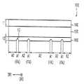
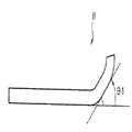
도 1a는 본 발명의 실시예들에 따른 플렉서블 표시 장치의 커버 윈도우를 나타내는 단면도이다.
도 1b는 도 1a의 커버 윈도우가 플렉서블 표시 장치에 적용된 일 예를 간략하게 나타내는 도면이다.
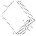
도 2a 내지 도 2d는 도 1의 커버 윈도우가 접힌 일 예를 나타내는 도면이다.
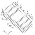
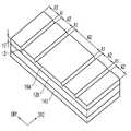
도 3은 도 1의 커버 윈도우의 일 예를 나타내는 사시도이다.
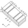
도 4는 도 1의 커버 윈도우의 다른 예를 나타내는 사시도이다.
도 5는 도 1의 커버 윈도우의 또 다른 예를 나타내는 사시도이다.
도 6은 도 1의 커버 윈도우의 또 다른 예를 나타내는 사시도이다.
도 7은 본 발명의 실시예들에 따른 플렉서블 표시 장치의 커버 윈도우를 나타내는 도면이다.
도 8은 도 7의 커버 윈도우를 I-I'방향으로 자른 일 예를 나타내는 부분 단면도이다.
도 9는 도 7의 커버 윈도우를 I-I'방향으로 자른 다른 예를 나타내는 부분 단면도이다.
도 10은 도 7의 커버 윈도우를 I-I'방향으로 자른 또 다른 예를 나타내는 부분 단면도이다.
도 11은 도 7의 커버 윈도우를 I-I'방향으로 자른 또 다른 예를 나타내는 부분 단면도이다.
도 12는 본 발명의 실시예들에 따른 플렉서블 표시 장치의 커버 윈도우를 나타내는 도면이다.
도 13a는 본 발명의 실시예들에 따른 플렉서블 표시 장치를 나타내는 도면이다.
도 13b는 도 13a의 플렉서블 표시 장치의 일 예를 나타내는 도면이다.
도 14는 도 13a의 플렉서블 표시 장치가 완전히 접힌 상태의 일 예를 나타내는 도면이다.
도 15는 도 13a의 플렉서블 표시 장치가 완전히 접힌 상태의 다른 예를 나타내는 도면이다.
도 16은 13a의 플렉서블 표시 장치의 플렉서블 표시 패널의 일 예를 나타내는 도면이다.
도 17은 도 13a의 플렉서블 표시 장치가 가이드 부재를 포함하는 일 예를 나타내는 도면이다.
도 18a 내지 도 18c는 도 17의 플렉서블 표시 장치가 펴지는 일 예를 나타내는 도면들이다.
도 19는 도 13의 플렉서블 표시 장치의 동작의 일 예를 나타내는 도면이다.
도 20a 내지 도 20d는 도 13의 플렉서블 표시 장치의 동작의 일 예를 나타내는 도면이다.
도 21은 도 13의 플렉서블 표시 장치의 일 부분의 일 예를 나타내는 단면도이다.1A is a cross-sectional view illustrating a cover window of a flexible display device according to example embodiments.
FIG. 1B is a diagram schematically illustrating an example in which the cover window of FIG. 1A is applied to a flexible display device.
2A to 2D are views illustrating an example in which the cover window of FIG. 1 is folded.
3 is a perspective view illustrating an example of the cover window of FIG. 1 .
4 is a perspective view illustrating another example of the cover window of FIG. 1 .
5 is a perspective view illustrating another example of the cover window of FIG. 1 .
6 is a perspective view illustrating another example of the cover window of FIG. 1 .
7 is a diagram illustrating a cover window of a flexible display device according to example embodiments.
8 is a partial cross-sectional view illustrating an example in which the cover window of FIG. 7 is cut in a direction I-I'.
9 is a partial cross-sectional view illustrating another example in which the cover window of FIG. 7 is cut in a direction I-I'.
FIG. 10 is a partial cross-sectional view illustrating another example in which the cover window of FIG. 7 is cut in a direction I-I'.
11 is a partial cross-sectional view illustrating another example of the cover window of FIG. 7 cut in a direction I-I'.
12 is a diagram illustrating a cover window of a flexible display device according to example embodiments.
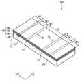
13A is a diagram illustrating a flexible display device according to example embodiments.
13B is a diagram illustrating an example of the flexible display device of FIG. 13A .
14 is a diagram illustrating an example of a state in which the flexible display device of FIG. 13A is fully folded.
15 is a diagram illustrating another example of a state in which the flexible display device of FIG. 13A is fully folded.
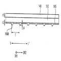
16 is a diagram illustrating an example of a flexible display panel of the flexible display device of FIG. 13A .
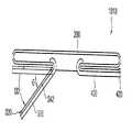
17 is a diagram illustrating an example in which the flexible display device of FIG. 13A includes a guide member.
18A to 18C are views illustrating an example in which the flexible display device of FIG. 17 is unfolded.
19 is a diagram illustrating an example of an operation of the flexible display device of FIG. 13 .
20A to 20D are diagrams illustrating an example of an operation of the flexible display device of FIG. 13 .
21 is a cross-sectional view illustrating an example of a portion of the flexible display device of FIG. 13 .
이하, 첨부한 도면들을 참조하여, 본 발명의 바람직한 실시예를 보다 상세하게 설명하고자 한다. 도면상의 동일한 구성요소에 대해서는 동일한 참조부호를 사용하고 동일한 구성요소에 대해서 중복된 설명은 생략한다.Hereinafter, preferred embodiments of the present invention will be described in more detail with reference to the accompanying drawings. The same reference numerals are used for the same components in the drawings, and repeated descriptions of the same components are omitted.
도 1a는 본 발명의 실시예들에 따른 플렉서블 표시 장치의 커버 윈도우를 나타내는 단면도이고, 도 1b는 도 1a의 커버 윈도우가 상기 플렉서블 표시 장치에 적용된 일 예를 간략하게 나타내는 도면이다.1A is a cross-sectional view illustrating a cover window of a flexible display device according to example embodiments, and FIG. 1B is a schematic diagram illustrating an example in which the cover window of FIG. 1A is applied to the flexible display device.
도 1a 및 도 1b를 참조하면, 플렉서블 표시 장치에 포함되는 커버 윈도우(100, 100A)는 베이스 층(120), 제1 하드코팅 층(140) 및 제2 하드코팅 층(160)을 포함할 수 있다. 이 때, 커버 윈도우(100, 100A)는 상기 플렉서블 표시 장치의 형태에 상응하여 적어도 일부분이 곡면을 이루도록 휘어지거나, 말려지거나, 특정 부분이 접힐 수 있다.1A and 1B , the
커버 윈도우(100A)는 아웃-폴딩(Out-folding) 영역(OF1, OF2), 인-폴딩(In-folding) 영역(IF1, IF2) 및 아웃-폴딩 영역(OF1, OF2)과 인-폴딩 영역(IF1, IF2)에 각각 인접한 주변 영역들로 구분될 수 있다. 아웃-폴딩(Out-folding) 영역(OF1, OF2), 인-폴딩(In-folding) 영역(IF1, IF2)에 의해 가상의 폴딩(folding) 축(FX)이 정의될 수 있다. 상기 주변 영역들은 메인 표시 영역(DA) 및 서브 표시 영역들(SA1, SA2, SA3, SA4)을 포함할 수 있다. 예를 들어, 도 1a에 도시된 바와 같이, 커버 윈도우(100A)(및 이를 포함하는 플렉서블 표시 장치)는 2개의 인-폴딩 영역(IF1, IF2), 2개의 아웃-폴딩 영역(OF1, OF2), 1개의 메인 표시 영역 및 4개의 서브 표시 영역들(SA1, SA2, SA3, SA4)을 포함할 수 있다. 일 실시예예서, 아웃-폴딩 영역(OF1, OF2)은 커버 윈도우(100)가 접혔을 때 제2 하드코팅 층(160)이 내측을 향하도록 접히는 영역에 상응하고, 인-폴딩 영역(IF1, IF2)은 커버 윈도우(100)가 접혔을 때 제1 하드코팅 층(160)이 상기 내측을 향하도록 접히는 영역에 상응하는 것을 의미한다.The
일 실시예에서, 커버 윈도우(100, 100A)가 인-폴딩 영역(IF1, IF2) 및 아웃-폴딩 영역(OF1, OF2)들을 따라 완전히 접히는 경우, 제1 내지 제4 서브 표시 영역들(SA1, SA2, SA3, SA4)은 메인 표시 영역(DA)의 하부에 중첩되도록 접힌다.In an embodiment, when the
베이스 층(120)은 인-폴딩 영역(IF1, IF2), 아웃-폴딩 영역(OF1, OF2) 및 인-폴딩 영역(IF1, IF2)과 아웃-폴딩 영역(OF1, OF2) 각각에 인접한 주변 영역들(DA, SA1, SA2, SA3, SA4)로 구분될 수 있다. 베이스 층(120)은 상기 플렉서블 표시 장치의 플렉서블 표시 패널을 보호한다. 베이스 층(120)은 투명 플라스틱 필름 또는 박형 유리 필름을 포함할 수 있다. 예를 들어, 베이스 층(120)은 폴리카보네이트(polycarbonate; PC), 폴리메틸메타크릴레이트(polymethylmethacrylate; PMMA) 폴리에틸렌테레프탈레이트(polyethylene-terephthalate; PET), 폴리이미드(polyimide; PI) 등을 포함할 수 있다. 이와 같이, 베이스 층(120)은 광특성, 기계적 경도, 굴곡성 및 탄성 회복력이 우수한 재료들로 형성될 수 있다.The
제1 하드코팅 층(140)은 베이스 층(120)의 전면에 균일한 두께로 배치될 수 있다. 제1 하드코팅 층(140)은 베이스 층(120)의 포함하는 커버 윈도우(100) 및 이를 포함하는 상기 플렉서블 표시 장치의 표면 강도 및 내충격성을 향상시키기 위해 배치된다. 제1 하드코팅 층(140)도 마찬가지로 광특성, 기계적 경도, 굴곡성 및 탄성 회복력이 우수한 재료들을 포함할 수 있다. 제1 하드코팅 층(140)은 유기 화합물 또는 유무기 복합 화합물을 포함할 수 있다. 예를 들어, 상기 유기 화합물은 아크릴계 화합물, 에폭시계 화합물 또는 이들의 조합을 포함하고, 상기 유무기 화합물은 규소 화합물을 포함할 수 있다.The first
일 실시예에서, 제1 하드코팅 층(140)은 베이스 층(120)의 상기 전면 상에 침지(dipping) 코팅, 스핀(spin) 코팅, 분사(spray) 코팅, 진공 증착 방법 등으로 형성될 수 있다. 예를 들어, 제1 하드코팅 층(140)은 베이스 층(120)의 상기 전면을 아크릴 수지, 에폭시 수지 등을 혼합한 고분자 용액에 침지하여 코팅한 후 건조함으로써 형성될 수 있다.In one embodiment, the first
제2 하드코팅 층(160)은 베이스 층의 상기 전면에 대향하는 후면에 배치될 수 있다. 제2 하드코팅 층(160) 또한 커버 윈도우(100) 및 이를 포함하는 상기 플렉서블 표시 장치의 표면 강도 및 내충격성을 향상시키기 위해 배치된다. 제2 하드코팅 층(160)은 인-폴딩 영역(IF1, IF2) 및 아웃-폴딩 영역(OF1, OF2)에 각각 중첩되는 제1 영역(A1)과 상기 주변 영역(DA, SA1, SA2, SA3, SA4)에 각각 중첩되는 제2 영역(A2)으로 구분될 수 있다. 제2 하드코팅 층(160)의 제1 영역(A1)의 두께(t3)가 제2 하드코팅 층(160)의 제2 영역(A2)의 두께(t2)보다 작게 형성될 수 있다. 따라서, 인-폴딩 영역(IF1, IF2) 및 아웃-폴딩 영역(OF1, OF2)에 중첩되는 커버 윈도우(100) 및 하드코팅 층들(140, 160)의 총 두께가 감소된다.The second
일 실시예에서, 제2 하드코팅 층(160)의 제1 영역(A1)은 제1 방향(DR1)에 직교하는 제2 방향(DR2)을 따라 주기적으로 배치되는 돌출 패턴을 포함할 수 있다. 상기 돌출 패턴은 제1 영역(A1)으로부터 베이스 층(120)과 대향하는 방향으로 돌출된다. 따라서, 폴딩 영역(FA)의 얇아진 두께를 보완하여 커버 윈도우의 모듈러스가 개선 또는 제어될 수 있다.In an embodiment, the first area A1 of the second
다른 실시예에서, 2 하드코팅 층(160)의 제1 영역(A1)은 제2 방향(DR2)을 따라 주기적으로 배치되는 오목 패턴을 포함할 수 있다. 상기 오목 패턴은 제1 영역(A1)으로부터 베이스 층(120) 방향으로 오목하게 형성된다. 따라서, 폴딩 영역(FA)의 굴곡성이 더욱 향상될 수 있다.In another embodiment, the first area A1 of the second
제2 하드코팅 층(160)의 두께(t2)는 제1 하드코팅 층(140)의 두께(t1)와 다르게 형성된다. 이 때, 제2 하드코팅 층(160)의 두께(t2)와 제1 하드코팅 층(140)의 두께(t1)의 합이 일정 두께 이상을 가져야 커버 윈도우(100)의 물리적 경도가 확보될 수 있다. 제2 하드코팅 층(160)은 유기 화합물 또는 유무기 복합 화합물을 포함할 수 있다. 예를 들어, 상기 유기 화합물은 아크릴계 화합물, 에폭시계 화합물 또는 이들의 조합을 포함하고, 상기 유무기 화합물은 규소 화합물을 포함할 수 있다. 제2 하드코팅 층(160)의 제1 영역(A1)의 두께가 감소되므로, 커버 윈도우(100)의 인-폴딩 영역(IF1, IF2)뿐만 아니라 아웃 폴딩 영역(OF1, OF2)이 최대로 접히는 곡률 반경이 감소될 수 있다. 따라서, 커버 윈도우(100)의 인-폴딩 및 아웃-폴딩이 용이하게 구현될 수 있다. 또한, 제2 하드코팅 층(160)의 두께(t2)와 제1 하드코팅 층(140)의 두께(t1)의 합이 종래의 커버 윈도우에 포함되는 하드코팅 층의 두께와 실질적으로 동일한 경우, 높은 수준의 커버 윈도우(100)의 경도가 유지될 수 있다. The thickness t2 of the second
일 실시예에서, 제2 하드코팅 층(160)은 베이스 층(120)의 상기 후면 상에 침지(dipping) 코팅, 스핀(spin) 코팅, 분사(spray) 코팅, 진공 증착 방법 등으로 형성될 수 있다. 예를 들어, 제2 하드코팅 층(160)은 베이스 층(120)의 상기 후면을 아크릴 수지, 에폭시 수지 등을 혼합한 고분자 용액에 침지하여 코팅한 후 건조함으로써 형성될 수 있다. 이 때, 제2 하드코팅 층(120)은 제1 영역(A1)들은 베이스 층(120)으로 오목한 형태를 가질 수 있다.In one embodiment, the second
일 실시예에서, 베이스 층(120)과 제1 하드코팅 층(140) 및 베이스 층(120)과 제2 하드코팅 층(160)은 점착제에 의해 접착될 수 있다.In one embodiment, the
일 실시예에서, 도 1a에 도시된 바와 같이, 제2 하드코팅 층(160)의 두께(t2)는 제1 하드코팅 층(140)의 두께(t1)보다 작다. 예를 들어, 제1 하드코팅 층(160)은 약 35μm의 두께를 가지고, 제2 하드코팅 층(140)의 제2 영역(A2)은 약 5μm의 두께를 가질 수 있다.In one embodiment, as shown in FIG. 1A , the thickness t2 of the second
일 실시예에서, 제1 하드코팅 층(140)과 제2 하드코팅 층(160)은 동일한 물질로 형성될 수 있다. 예를 들어, 제1 및 제2 하드코팅 층들(140, 160)은 모두 동일한 유기 화합물 또는 유무기 화합물을 포함할 수 있다. 다른 실시예에서, 제1 하드코팅 층(140)과 제2 하드코팅 층(160)은 서로 다른 물질로 형성될 수 있다. 예를 들어, 제1 하드코팅 층(140)은 표시 장치의 외부로 노출되므로, 제1 하드코팅 층(140)은 제2 하드코팅 층(160)보다 높은 모듈러스(modulus)를 갖는 유기 화합물 또는 유무기 화합물을 포함할 수 있다. 제2 하드코팅 층(160)은 제1 하드코팅 층(140)보다 곡률 반경이 더 작게 접히므로, 제2 하드코팅 층(160)은 이 제1 하드코팅 층(140)보다 작은 굴곡 강성(bending stiffness)을 갖는 물질을 포함할 수 있다.In one embodiment, the first
상술한 바와 같이, 상기 플렉서블 표시 장치에 포함되는 커버 윈도우(100, 100A)는 고경도를 유지하면서 인/아웃 폴딩 영역들(IF1, IF2, OF1, OF2)의 두께를 감소시켜 인/아웃 폴딩 영역들(IF1, IF2, OF1, OF2)의 곡률 반경을 최소화할 수 있다. 따라서, 커버 윈도우(100, 100A)가 양방향으로 용이하게 접히거나 구부러질 수 있다. 이에 따라, 플렉서블 표시 장치의 외관 변형 및 폴딩이 용이해지고, 휴대성이 향상될 수 있다. 나아가, 인-폴딩 영역(IF1, IF2)과 아웃-폴딩 영역(OF1, OF2)이 동일한 구조 및 동일한 물질로 형성되므로 제조 비용이 절감될 수 있다.As described above, the
도 2a 내지 도 2d는 도 1의 커버 윈도우가 접힌 일 예를 나타내는 도면이다.2A to 2D are views illustrating an example in which the cover window of FIG. 1 is folded.
도 2a 내지 도 2c를 참조하면, 커버 윈도우(100)는 인-폴딩되는 부분과 아웃-폴딩되는 부분을 포함할 수 있다.2A to 2C , the
이하, 도 2a 내지 도 2c에서는 커버 윈도우(100)가 플렉서블 표시 장치에 적용된 것으로 보고 설명하기로 한다. 이에 따라, 커버 윈도우(100)는 메인 표시 영역(DA), 제1 및 제2 인-폴딩 영역들(IF1, IF2), 제1 및 제2 아웃-폴딩 영역들(OF1, OF2) 및 제1 내지 제4 서브 표시 영역들(SA1, SA2, SA3, SA4)로 구분될 수 있다.Hereinafter, the
구체적으로, 도 2a는 커버 윈도우(100)의 일부가 인-폴딩되는 일 예를 보여준다. 일 실시예에서, 제1 인-폴딩 영역(IF1) 및/또는 제2 인-폴딩 영역(IF2)은 커버 윈도우(100)의 상면 방향(DU)으로 접힐 수 있다. 이 때, 제2 서브 표시 영역(SA2)은 제1 서브 표시 영역(SA1)과 중첩되도록 배치될 수 있다. 또한, 제1 하드코팅 층이 내측을 향하도록 접힌다. 다시 말하면, 제1 서브 표시 영역(SA1)의 상면과 제2 서브 표시 영역(SA2)의 상면이 서로 마주볼 수 있다. 마찬가지로, 제4 서브 표시 영역(SA4)은 제3 서브 표시 영역(SA3)과 중첩되도록 배치될 수 있다. 다시 말하면, 제4 서브 표시 영역(SA4)의 상면과 제3 서브 표시 영역(SA3)의 상면이 서로 마주볼 수 있다.Specifically, FIG. 2A shows an example in which a part of the
이 때, 제1 및 제2 인-폴딩 영역들(IF1, IF2)에 상응하는 제2 하드코팅 층 제1 영역은 제1 및 제2 인-폴딩 영역들(IF1, IF2)의 외측에 위치한다. 상기 제2 하드코팅 층의 제1 및 제2 인-폴딩 영역들(IF1, IF2)은 오목한 형태를 가지므로, 제1 및 제2 인-폴딩 영역들(IF1, IF2)은 다른 영역들과 비교하여 두께가 더 작다. 따라서, 인-폴딩 영역들(IF1, IF2)에서의 굴곡 반발력은 메인 표시 영역(DA) 및 제1 내지 제4 서브 표시 영역들(SA1, SA2, SA3, SA4)보다 작다. 상기 굴곡 반발력이 작아짐으로써, 인-폴딩 영역(IF1, IF2)의 곡률 반경(R1', R2')을 더욱 작게 형성할 수 있다. 인-폴딩 영역(IF1, IF2)의 작은 곡률 반경(R1', R2')으로 인해 좀 더 슬림한 형태의 플렉서블 디스플레이 장치가 구현될 수 있다.In this case, the first region of the second hard coating layer corresponding to the first and second in-folding regions IF1 and IF2 is located outside the first and second in-folding regions IF1 and IF2. . Since the first and second in-folding regions IF1 and IF2 of the second hard coating layer have a concave shape, the first and second in-folding regions IF1 and IF2 are compared with other regions. so the thickness is smaller. Accordingly, the bending repulsive force in the in-folding areas IF1 and IF2 is smaller than that of the main display area DA and the first to fourth sub-display areas SA1 , SA2 , SA3 and SA4 . As the bending repulsive force is reduced, the radius of curvature R1' and R2' of the in-folding regions IF1 and IF2 may be made smaller. Due to the small radius of curvature R1' and R2' of the in-folding areas IF1 and IF2, a slimmer flexible display device may be implemented.
일 실시예에서, 커버 윈도우(100)의 인-폴딩 영역들(IF1, IF2)이 완전히 접힌 경우, 제1 인-폴딩 영역(IF1)의 곡률 반경(R1')은 제2 인-폴딩 영역(IF2)의 곡률 반경(R2')과 동일할 수 있다. 이 경우, 커버 윈도우(100)가 접힌 상태에서의 양 단의 높이가 서로 동일할 수 있다.In an embodiment, when the in-folding areas IF1 and IF2 of the
다른 실시예에서, 커버 윈도우(100)의 인-폴딩 영역들(IF1, IF2)이 완전히 접힌 경우, 제1 인-폴딩 영역(IF1)의 곡률 반경(R1')은 제2 인-폴딩 영역(IF2)의 곡률 반경(R2')과 서로 다를 수 있다. 이 경우, 커버 윈도우(100)가 접힌 상태에서의 양 단의 높이가 서로 다를 수 있다. 커버 윈도우의 양 단의 높이가 서로 다르게 설계되는 경우, 그립감이 향상될 수 있다.In another embodiment, when the in-folding areas IF1 and IF2 of the
도 2b 및 도 2c에 도시된 바와 같이, 제1 및 제2 아웃-폴딩 영역들(OF1, OF2)은 커버 윈도우(100)의 하면 방향(DD)으로 접힐 수 있다. 이 때, 제1 서브 표시 영역(SA1)은 메인 표시 영역(DA)의 일부와 중첩되도록 배치되고, 제3 서브 표시 영역(SA3)은 메인 표시 영역(DA)의 다른 일부와 중첩되도록 배치될 수 있다. 또한, 제1 및 제3 서브 표시 영역들(SA1, SA3)에 상응하는 제2 하드코팅 층이 내측을 향하도록 접힌다. 다시 말하면, 메인 표시 영역(DA1)의 하면의 상기 일부와 제1 서브 표시 영역(SA1)의 하면이 서로 마주볼 수 있다. 마찬가지로, 메인 표시 영역의 상기 하면의 상기 다른 일부와 제3 서브 표시 영역(SA3)의 하면이 서로 마주볼 수 있다.2B and 2C , the first and second out-folding areas OF1 and OF2 may be folded in the lower surface direction DD of the
이 때, 제1 및 제2 아웃-폴딩 영역들(OF1, OF2)에 상응하는 상기 제2 하드코팅 층의 제1 영역은 제1 및 제2 아웃-폴딩 영역들(OF1, OF2)의 내측에 위치한다. 상기 제2 하드코팅 층의 제1 및 제2 아웃-폴딩 영역들(OF1, OF2)은 오목한 형태를 가지므로, 제1 및 제2 아웃-폴딩 영역들(OF1, OF2)은 다른 표시 영역들과 비교하여 두께가 더 작다. 따라서, 제1 및 제2 아웃-폴딩 영역들(OF1, OF2)에서의 굴곡 반발력은 메인 표시 영역(DA) 및 제1 내지 제4 서브 표시 영역들(SA1, SA2, SA3, SA4)보다 작다. 상기 굴곡 반발력이 작아짐으로써, 아웃-폴딩 영역의 곡률 반경(R1, R2)을 더욱 작게 형성할 수 있다. 폴딩 영역의 작은 곡률 반경(R1, R2)은 좀 더 슬림한 형태의 플렉서블 디스플레이 장치를 구현할 수 있다.At this time, the first region of the second hard coating layer corresponding to the first and second out-folding regions OF1 and OF2 is inside the first and second out-folding regions OF1 and OF2. Located. Since the first and second out-folding regions OF1 and OF2 of the second hard coating layer have a concave shape, the first and second out-folding regions OF1 and OF2 are separated from other display regions. In comparison, the thickness is smaller. Accordingly, the bending repulsive force in the first and second out-folding areas OF1 and OF2 is smaller than that of the main display area DA and the first to fourth sub-display areas SA1 , SA2 , SA3 and SA4 . As the bending repulsive force is reduced, the radius of curvature R1 and R2 of the out-folding region may be made smaller. The small radius of curvature R1 and R2 of the folding area may realize a slimmer flexible display device.
일 실시예에서, 커버 윈도우(100)의 아웃-폴딩 영역들(OF1, OF2)이 완전히 접힌 경우, 제1 아웃-폴딩 영역(OF1)의 곡률 반경(R1)은 제2 아웃-폴딩 영역(OF2)의 곡률 반경(R2)과 동일할 수 있다. 이 경우, 커버 윈도우(100)가 접힌 상태에서의 양 단의 높이가 서로 동일할 수 있다.In an embodiment, when the out-folding areas OF1 and OF2 of the
다른 실시예에서, 커버 윈도우(100)의 아웃-폴딩 영역들(OF1, OF2)이 완전히 접힌 경우, 제1 아웃-폴딩 영역(OF1)의 곡률 반경(R1)은 제2 아웃-폴딩 영역(OF2)의 곡률 반경(R2)과 서로 다를 수 있다. 이 경우, 커버 윈도우(100)가 접힌 상태에서의 양 단의 높이가 서로 다를 수 있다. 커버 윈도우의 양 단의 높이가 서로 다르게 설계되는 경우, 그립감이 향상될 수 있다.In another embodiment, when the out-folding areas OF1 and OF2 of the
또한, 일 실시예에서, 커버 윈도우(100)의 모든 폴딩 영역들이 완전히 접힌 경우, 제1 및 제2 아웃-폴딩 영역들(OF1, OF2)의 곡률 반경(R1, R2) 및 제1 및 제2 인-폴딩 영역들(IF1, IF2)의 곡률 반경(R1', R2') 중 적어도 하나의 곡률 반경이 다르게 형성될 수도 있다.Also, in an embodiment, when all folding areas of the
이와 같이, 제1 및 제2 인-폴딩 영역들(IF1, IF2) 및 제1 및 제2 아웃-폴딩 영역들(OF1, OF2)이 메인 및 서브 표시 영역들(DA, SA1, SA2, SA3, SA4)보다 더 얇게 형성됨으로써, 상기 폴딩 영역들의 곡률 반경이 최소화될 수 있다. 따라서, 양방향으로 슬라이딩되어 펼쳐지는 방식의 플렉서블 디스플레이의 구현이 가능해질 수 있다.As such, the first and second in-folding areas IF1 and IF2 and the first and second out-folding areas OF1 and OF2 are formed in the main and sub display areas DA, SA1, SA2, SA3, By forming thinner than SA4), the radius of curvature of the folding areas can be minimized. Accordingly, it may be possible to implement a flexible display that slides and unfolds in both directions.
도 3은 도 1의 커버 윈도우의 일 예를 나타내는 사시도이다. 도 4는 도 1의 커버 윈도우의 다른 예를 나타내는 사시도이다. 도 5는 도 1의 커버 윈도우의 또 다른 예를 나타내는 사시도이다. 도 6은 도 1의 커버 윈도우의 또 다른 예를 나타내는 사시도이다. 도 3 내지 도 6은 제2 하드코팅 층이 위를 향하도록 놓여진 커버 윈도우를 보여준다.3 is a perspective view illustrating an example of the cover window of FIG. 1 . 4 is a perspective view illustrating another example of the cover window of FIG. 1 . 5 is a perspective view illustrating another example of the cover window of FIG. 1 . 6 is a perspective view illustrating another example of the cover window of FIG. 1 . 3 to 6 show a cover window on which a second hardcoat layer is placed facing up.
도 3 내지 도 6에서는 도 1a를 참조하여 설명한 동일한 구성 요소들에 대해 동일한 참조 부호들을 사용하며, 이러한 구성 요소들에 대한 중복되는 설명은 생략하기로 한다. 또한, 도 3 내지 도 6의 커버 윈도우는 제2 하드코팅 층을 제외하면, 도 1a의 커버 윈도우(100)와 실질적으로 동일하거나 유사한 구성을 가질 수 있다.3 to 6, the same reference numerals are used for the same components described with reference to FIG. 1A, and overlapping descriptions of these components will be omitted. In addition, the cover window of FIGS. 3 to 6 may have a configuration substantially the same as or similar to that of the
도 1a, 도 1b 및 도 3 내지 도 6을 참조하면, 커버 윈도우는 베이스 층(120), 제1 하드코팅 층(140) 및 제2 하드코팅 층(161, 162, 163, 164)을 포함할 수 있다.1A, 1B and 3 to 6 , the cover window may include a
제2 하드코팅 층(161)은 제1 방향(DR1)을 따라 폴딩 영역(FA)에 중첩하는 제1 영역(A1)과 폴딩 영역(FA)의 주변 영역에 중첩하는 제2 영역(A2)으로 구분될 수 있다. 제2 하드코팅층(161, 162, 163, 164)의 제1 영역(A1)은 제2 영역(A2)보다 작은 두께를 갖는다. 여기서, 폴딩 영역(FA)은 제1 방향(DR1)에 직교하는 제2 방향(DR2)을 따라 연장되는 가상의 폴딩 축(FX)을 기준으로 접힐 수 있다. 폴딩 축(FX)은 제1 영역(A1)의 제2 방향(DR2)으로의 중심 축으로 정의될 수 있다.The second
도 3에 도시된 바와 같이, 제2 하드코팅 층(161)의 제1 영역(A1)은 베이스 층(120) 쪽으로 오목한 곡선 형태를 가질 수 있다. 하나의 제1 영역(A1)에서의 제2 하드코팅 층(161)의 제1 방향(DR1)으로의 두께(t3)는 균일하지 않을 수 있다. 예를 들어, 제1 영역(A1) 중 폴딩 축(FX)에 대응하는 선에 상응하는 중심 부분은 가장 얇은 두께(t3)를 가질 수 있다. 제2 하드코팅 층(161)의 제1 영역(A1)의 제2 방향(DR2)으로의 두께(t3)는 균일하게 형성될 수 있다. 일 실시예에서, 제2 하드코팅 층(161)의 제1 영역(A1)의 상기 중심 부분의 두께는 제2 영역(A2)의 두께(t2)의 약 20% 내지 약 80%에 상응할 수 있다.3 , the first area A1 of the second
커버 윈도우(100)가 접힐 때, 벤딩 스트레스는 실질적으로 폴딩 영역(FA)에 집중된다. 이 때, 폴딩 영역(FA)에 중첩되는 제1 영역(A1)의 두께(t3)가 제2 영역(A2)의 두께(t2)보다 작으므로, 폴딩 영역(FA)에 미치는 폴딩 스트레스(응력)가 감소된다.When the
도 4에 도시된 바와 같이, 제2 하드코팅 층(162)의 제1 영역(A1)은 제2 영역(A2)보다 작은 두께를 갖는다. 본 실시예에서, 제2 하드코팅 층(162)의 제1 영역은 베이스 층(120) 쪽으로 오목한 사각 형태를 가질 수 있다. 예를 들어, 제1 영역(A1)에서의 제2 하드코팅 층(162)의 제1 방향(DR1)으로의 두께(t3)가 균일하게 형성될 수 있다. 또한, 제2 하드코팅 층(161)의 제1 영역(A1)의 제2 방향(DR2)으로의 두께(t3)는 균일하게 형성될 수 있다. 일 실시예에서, 제2 하드코팅 층(161)의 제1 영역(A1)의 두께(t3)는 제2 영역(A2)의 두께(t2)의 약 20% 내지 약 80%에 상응할 수 있다. 즉, 폴딩 영역(FA)에 중첩되는 제1 영역(A1)의 두께(t3)가 제2 영역(A2)의 두께(t2)보다 작으므로, 폴딩 영역(FA)에 미치는 폴딩 스트레스(응력)가 감소된다.As shown in FIG. 4 , the first area A1 of the second
도 5에 도시된 바와 같이, 제2 하드코팅 층(163)의 제1 영역(A1)은 제2 영역(A2)보다 작은 두께를 갖는다. 본 실시예에서, 제2 하드코팅 층(163)의 제1 영역(A1)은 베이스 층(120) 쪽으로 오목한 사각 형태를 가질 수 있다. 제1 영역(A1)의 베이스 부재(120)로부터 가까운 제1 부분(W1)의 폭은 베이스 부재(120)로부터 더 먼 제2 부분(W2)의 폭보다 작게 형성될 수 있다. 즉, 제2 하드코팅 층(163)의 단면은 사다리꼴 모양을 가질 수 있다. 제1 부분(W1)의 두께(t3)는 제2 방향(DR2)으로 균일하게 형성될 수 있다. 일 실시예에서, 제2 하드코팅 층(161)의 제1 영역(A1)(또는, 제1 부분(W1))의 두께(t3)는 제2 영역(A2)의 두께(t2)의 약 20% 내지 약 80%에 상응할 수 있다. 즉, 폴딩 영역(FA)에 중첩되는 제1 영역(A1)의 두께(t3)가 제2 영역(A2)의 두께(t2)보다 작으므로, 폴딩 영역(FA)에 미치는 폴딩 스트레스(응력)가 감소된다.As shown in FIG. 5 , the first area A1 of the second hard coating layer 163 has a smaller thickness than the second area A2 . In this embodiment, the first area A1 of the second hard coating layer 163 may have a rectangular shape concave toward the
도 6에 도시된 바와 같이, 제2 하드코팅 층(163)의 제1 영역(A1)은 제2 영역(A2)보다 작은 두께를 갖는다. 본 실시예에서, 제2 하드코팅 층(164)의 제1 영역(A1)의 단면은 삼각 형태를 가질 수 있다. 예를 들어, 제1 영역(A1)의 제1 방향(DR1)으로의 중심 부분이 최소 두께(t3)를 가질 수 있다. 상기 중심 부분의 두께(t3)는 제2 방향으로 균일하게 형성될 수 있다. 일 실시예에서, 제2 하드코팅 층(161)의 제1 영역(A1)(즉, 상기 중심 부분) 의 두께(t3)는 제2 영역(A2)의 두께(t2)의 약 20% 내지 약 80%에 상응할 수 있다. 즉, 폴딩 영역(FA)에 중첩되는 제1 영역(A1)의 두께(t3)가 제2 영역(A2)의 두께(t2)보다 작으므로, 폴딩 영역(FA)에 미치는 폴딩 스트레스(응력)가 감소된다.As shown in FIG. 6 , the first area A1 of the second hard coating layer 163 has a smaller thickness than the second area A2 . In this embodiment, the cross-section of the first area A1 of the second hard coating layer 164 may have a triangular shape. For example, a central portion of the first area A1 in the first direction DR1 may have a minimum thickness t3 . The thickness t3 of the central portion may be uniformly formed in the second direction. In one embodiment, the thickness t3 of the first region A1 (ie, the central portion) of the second
도 7은 본 발명의 실시예들에 따른 플렉서블 표시 장치의 커버 윈도우를 나타내는 도면이다.7 is a diagram illustrating a cover window of a flexible display device according to example embodiments.
도 7에서는 도 1a를 참조하여 설명한 동일한 구성 요소들에 대해 동일한 참조 부호들을 사용하며, 이러한 구성 요소들에 대한 중복되는 설명은 생략하기로 한다. 또한, 도 7의 커버 윈도우는 제2 하드코팅 층을 제외하면, 도 1a의 커버 윈도우(100)와 실질적으로 동일하거나 유사한 구성을 가질 수 있다. 도 7은 제2 하드코팅 층이 위를 향하도록 놓여진 커버 윈도우를 보여준다.In FIG. 7 , the same reference numerals are used for the same components described with reference to FIG. 1A , and overlapping descriptions of these components will be omitted. In addition, the cover window of FIG. 7 may have a configuration substantially the same as or similar to that of the
도 7을 참조하면, 커버 윈도우(100A)는 베이스 층(120), 제1 하드코팅 층(140) 및 제2 하드코팅 층(165)을 포함할 수 있다.Referring to FIG. 7 , the
제2 하드코팅 층(165)은 제1 방향(DR1)을 따라 폴딩 영역(FA)에 중첩하는 제1 영역(A1)과 폴딩 영역(FA)의 주변 영역에 중첩하는 제2 영역(A2)으로 구분될 수 있다. 제2 하드코팅 층(165)의 제1 영역(A1)은 제2 영역(A2)보다 작은 두께를 갖는다. 폴딩 영역(FA)은 커버 윈도우(100A)의 제1 방향(DR1)에 직교하는 제2 방향(DR2)을 따라 연장될 수 있다. 일 실시예에서, 제2 하드코팅 층(165)의 제1 영역(A1)은 제1 방향에 직교하는 제2 방향(DR2)을 따라 주기적으로 배치되는 돌출 패턴을 포함할 수 있다. 상기 돌출 패턴은 제1 영역(A1)으로부터 베이스 층(120)의 반대 방향으로 돌출되어 형성될 수 있다. 따라서, 상기 돌출 패턴이 형성된 부분의 두께는 상기 돌출 패턴이 형성되지 않은 제1 영역(A1)의 다른 부분의 두께보다 크다. 예를 들어, 돌출 패턴이 형성된 부분의 두께는 제2 영역(A2) 두께와 실질적으로 동일할 수 있다.The second
제2 하드코팅 층(165)의 제1 영역(A1)에 상기 돌출 패턴이 형성됨에 따라 폴딩 영역(FA)의 두께 감소로 인한 모듈러스 악화가 개선될 수 있다. 또한, 상기 돌출 패턴 사이의 폭, 상기 돌출 패턴의 높이(두께)를 조절하여 제2 하드코팅 층(165)을 형성함으로써, 커버 윈도우(100A)의 폴딩 영역(FA)의 모듈러스 및 굴곡성을 제어할 수 있다.As the protrusion pattern is formed in the first area A1 of the second
다른 실시예에서, 제2 하드코팅 층(165)의 제1 영역(A1)은 제1 방향에 직교하는 제2 방향(DR2)을 따라 주기적으로 배치되는 오목 패턴을 포함할 수도 있다. 상기 오목 패턴은 제1 영역(A1)으로부터 베이스 층(120)의 쪽으로 오목하게 형성될 수 있다.In another embodiment, the first region A1 of the second
도 8은 도 7의 커버 윈도우를 I-I'방향으로 자른 일 예를 나타내는 부분 단면도이고, 도 9는 도 7의 커버 윈도우를 I-I'방향으로 자른 다른 예를 나타내는 부분 단면도이며, 도 10은 도 7의 커버 윈도우를 I-I'방향으로 자른 또 다른 예를 나타내는 부분 단면도이고, 도 11은 도 7의 커버 윈도우를 I-I'방향으로 자른 또 다른 예를 나타내는 부분 단면도이다.8 is a partial cross-sectional view illustrating an example in which the cover window of FIG. 7 is cut in the I-I' direction, FIG. 9 is a partial cross-sectional view illustrating another example in which the cover window of FIG. 7 is cut in the I-I' direction, and FIG. 10 is a partial cross-sectional view illustrating another example of cutting the cover window of FIG. 7 in the direction I-I', and FIG. 11 is a partial cross-sectional view illustrating another example of cutting the cover window of FIG. 7 in the direction I-I'.
도 8 내지 도 11에서는 도 1a 및 도 7을 참조하여 설명한 동일한 구성 요소들에 대해 동일한 참조 부호들을 사용하며, 이러한 구성 요소들에 대한 중복되는 설명은 생략하기로 한다. 또한, 도 8 내지 도 11의 커버 윈도우는 제2 하드코팅 층을 제외하면, 도 7의 커버 윈도우(100A)와 실질적으로 동일하거나 유사한 구성을 가질 수 있다.In FIGS. 8 to 11 , the same reference numerals are used for the same components described with reference to FIGS. 1A and 7 , and overlapping descriptions of these components will be omitted. In addition, the cover window of FIGS. 8 to 11 may have a configuration substantially the same as or similar to that of the
도 8 내지 도 11을 참조하면, 도 7의 커버 윈도우(100A)에 포함되는 제2 하드코팅 층(165)의 제1 영역(A1)은 돌출 패턴 또는 오목 패턴을 포함할 수 있다.8 to 11 , the first area A1 of the second
도 7의 커버 윈도우(100A)를 I-I'방향으로 자른 단면은 폴딩 영역(FA)에 상응하는 제1 영역(A1)을 나타낸다. 즉, 도 8 내지 도 11은 제1 영역이 제2 방향(DR2)으로 잘린 단면의 일부를 나타낼 수 있다.A cross-section of the
커버 윈도우(100A)는 베이스 층(120), 베이스 층(120)을 사이에 두고 배치된 제1 하드코팅 층(140) 및 제2 하드코팅 층(165)을 포함할 수 있다. 제2 하드코팅 층(165)의 두께(예를 들어, t3+t4)는 제1 하드코팅 층(140)의 두께(t1)보다 작게 형성된다.The
도 8에 도시된 바와 같이, 제2 하드코팅 층(165)의 제1 영역(A1)은 제2 방향(DR2)으로 주기적으로 배치되는 돌출 패턴(165A)을 포함할 수 있다. 일 실시예에서, 돌출 패턴(165A) 각각의 폭(W)은 수직 방향으로 균일하게 형성될 수 있다. 예를 들어, 돌출 패턴(165A)의 수평 방향으로의 평면은 원형 또는 사각형을 가질 수 있다. 또한, 돌출 패턴(165A)은 제2 방향(DR2)을 따라 소정을 주기(T)를 가지며 배치될 수 있다. 다만, 이는 예시적인 것으로서, 돌출 패턴(165A)의 모양 및 주기가 이에 한정되는 것은 아니며, 돌출 패턴은 비주기적으로 배치될 수도 있다.As shown in FIG. 8 , the first area A1 of the second
일 실시예에서, 제2 하드코팅 층(165)의 돌출 패턴(165A)의 두께(t4)는 제2 하드코팅 층(165)의 제2 영역(A2)의 두께(t2)와 실질적으로 동일할 수 있다. 다른 실시예에서, 2 하드코팅 층(165)의 돌출 패턴(165A)의 두께(t4)는 제2 하드코팅 층(165)의 제2 영역(A2)의 두께(t2)보다 작을 수 있다. 이와 같이, 제1 영역(A1)에 포함되는 돌출 패턴(165A)의 두께(t4)를 제어함으로써, 주변 영역들보다 상대적으로 얇은 폴딩 영역(FA)의 텐사일 모듈러스(tensile modulus)를 향상시키거나 조절할 수 있다.In one embodiment, the thickness t4 of the
도 9에 도시된 바와 같이, 제2 하드코팅 층(165)의 제1 영역(A1)은 제2 방향(DR2)으로 주기적으로 배치되는 돌출 패턴(165B)을 포함할 수 있다. 일 실시예에서, 돌출 패턴(165B) 각각은 소정의 테이퍼(taper)를 가지며 형성될 수 있다. 예를 들어, 돌출 패턴(165B)을 수직 방향으로의 단면은 사다리꼴 모양을 가질 수 있다. 또한, 돌출 패턴(165B)은 제2 방향(DR2)을 따라 소정을 주기(T)를 가지며 배치될 수 있다. 이와 반대로, 돌출 패턴(165B)은 비주기적으로 배치될 수도 있다. 일 실시예에서, 돌출 패턴(165B)의 두께(t4)는 제2 하드코팅 층(165)의 제2 영역(A2)의 두께(t2)와 실질적으로 동일할 수 있다. 다른 실시예에서, 돌출 패턴(165B)의 두께(t4)는 제2 하드코팅 층(165)의 제2 영역(A2)의 두께(t2)보다 작을 수도 있다.As shown in FIG. 9 , the first area A1 of the second
도 10에 도시된 바와 같이, 제2 하드코팅 층(165)의 제1 영역(A1)은 제2 방향(DR2)으로 주기적으로 배치되는 돌출 패턴(165C)을 포함할 수 있다. 본 실시예에서, 돌출 패턴(165B) 각각은 소정의 테이퍼(taper)를 가지며 형성될 수 있다. 예를 들어, 돌출 패턴(165B)은 볼록한 렌즈 형태를 가질 수 있다. 또한, 돌출 패턴(165C)은 제2 방향(DR2)을 따라 소정을 주기(T)를 가지며 배치될 수 있다. 이와 반대로, 돌출 패턴(165C)은 비주기적으로 배치될 수도 있다. 일 실시예에서, 돌출 패턴(165C)의 두께(t4)는 제2 하드코팅 층(165)의 제2 영역(A2)의 두께(t2)와 실질적으로 동일할 수 있다. 다른 실시예에서, 돌출 패턴(165B)의 두께(t4)는 제2 하드코팅 층(165)의 제2 영역(A2)의 두께(t2)보다 작을 수도 있다.As shown in FIG. 10 , the first area A1 of the second
도 11에 도시된 바와 같이, 제2 하드코팅 층(165)의 제1 영역(A1)은 제2 방향(DR2)으로 주기적으로 배치되는 오목 패턴(165D)을 포함할 수 있다. 오목 패턴(165D)은 베이스 층(120) 쪽으로 오목하게 형성될 수 있다. 오목 패턴(165D)은 제2 방향(DR2)을 따라 소정을 주기(T)를 가지며 배치될 수 있다. 이와 반대로, 오목 패턴(165D)은 비주기적으로 배치될 수도 있다. 오목 패턴(165D)의 두께(t4)는 오목 패턴(165D)이 형성되지 않은 제2 하드코팅 층(165)의 제1 영역(A1)의 두께(t3)보다 작다. 일 실시예에서, 제1 영역(A1)의 두께(t3)는 제2 영역(A2)의 두께(t2)와 실질적으로 동일할 수도 있다. 이와 같이, 제2 하드코팅 층(165)의 제1 영역(A1)에 오목 패턴(165D)을 구비하고, 오목 패턴(165D)의 두께를 제어함으로써, 폴딩 영역(FA)의 굴곡성 및 텐사일 모듈러스를 최적화할 수 있다.11 , the first region A1 of the second
상술한 바와 같이, 다른 부분에 비해 얇은 두께를 갖는 제2 하드코팅 층의 제1 영역(A1)(즉, 폴딩 영역(FA))에 주기적인 돌출 패턴 또는 오목 패턴을 포함함으로써, 커버 윈도우(100A)의 폴딩 영역(FA)의 굴곡성 및 모듈러스가 향상될 수 있다.As described above, by including a periodic protruding pattern or a concave pattern in the first area A1 (ie, the folding area FA) of the second hard coating layer having a thinner thickness than other portions, the
도 12는 본 발명의 실시예들에 따른 플렉서블 표시 장치의 커버 윈도우를 나타내는 도면이다.12 is a diagram illustrating a cover window of a flexible display device according to example embodiments.
도 12에서는 도 1a를 참조하여 설명한 동일한 구성 요소들에 대한 중복되는 설명은 생략하기로 한다. 도 12의 커버 윈도우(100B)는 제1 및 제2 하드코팅 층들을 제외하면, 도 1a의 커버 윈도우(100)와 실질적으로 동일하거나 유사한 구성을 갖는다.In FIG. 12 , overlapping descriptions of the same components described with reference to FIG. 1A will be omitted. The
도 12를 참조하면, 커버 윈도우(100B)는 베이스 층(120), 제1 하드코팅 층(140B) 및 제2 하드코팅 층(160B)을 포함할 수 있다.Referring to FIG. 12 , the
커버 윈도우(100B)는 인-폴딩 영역(IF1, IF2) 및 아웃-폴딩 영역(OF1, OF2)을 포함할 수 있다. 커버 위도우(100b)는 인-폴딩 영역(IF1, IF2), 아웃-폴딩 영역(OF1, OF2)과 인-폴딩 영역(IF1, IF2) 및 아웃-폴딩 영역(OF1, OF2)에 각각 인접한 주변 영역들로 구분될 수 있다. 상기 주변 영역들은 메인 표시 영역(DA) 및 서브 표시 영역들(SA1, SA2, SA3, SA4)을 포함할 수 있다.The
베이스 층(120)은 투명 플라스틱 필름 또는 박형 유리 필름을 포함할 수 있다. 베이스 층(120)은 광특성, 기계적 경도, 굴곡성 및 탄성 회복력이 우수한 재료들로 형성될 수 있다.The
제1 하드코팅 층(140B)은 베이스 층(120)의 전면에 균일한 두께로 배치될 수 있다. 제2 하드코팅 층(160B)은 베이스 층의 상기 전면에 대향하는 후면에 배치될 수 있다. 제2 하드코팅 층(160B)은 인-폴딩 영역(IF1, IF2) 및 아웃-폴딩 영역(OF1, OF2)에 각각 중첩되는 제1 영역(A1)과 상기 주변 영역(DA, SA1, SA2, SA3, SA4)에 각각 중첩되는 제2 영역(A2)으로 구분될 수 있다. 본 실시예에서, 제2 하드코팅 층(160B)의 제2 영역(A2)의 두께(t2)가 제1 하드코팅 층(140B)의 두께(t1)보다 크게 형성될 수 있다. 또한, 제2 하드코팅 층(160)의 제1 영역(A1)의 두께(t3)가 제2 하드코팅 층(160)의 제2 영역(A2)의 두께(t2)보다 작게 형성될 수 있다. 따라서, 인-폴딩 영역(IF1, IF2) 및 아웃-폴딩 영역(OF1, OF2)에 중첩되는 커버 윈도우(100B) 및 하드코팅 층들(140B, 160B)의 총 두께가 감소된다.The first
일 실시예에서, 제2 하드코팅 층(160B)의 제1 영역(A1)은 제1 방향(DR1)에 직교하는 제2 방향(DR2)을 따라 주기적으로 배치되는 돌출 패턴을 포함할 수 있다. 상기 돌출 패턴은 제1 영역(A1)으로부터 베이스 층(120)과 대향하는 방향으로 돌출된다. 따라서, 폴딩 영역(FA)의 얇아진 두께를 보완하여 커버 윈도우의 모듈러스가 개선 또는 제어될 수 있다.In one embodiment, the first area A1 of the second
상술한 바와 같이, 상기 플렉서블 표시 장치에 포함되는 커버 윈도우(100, 100A)는 고경도를 구비함과 동시에, 인/아웃 폴딩 영역들(IF1, IF2, OF1, OF2)의 두께를 감소시킴으로써 인/아웃 폴딩 영역들(IF1, IF2, OF1, OF2)의 곡률 반경을 최소화할 수 있다.As described above, the
도 13a는 본 발명의 실시예들에 따른 플렉서블 표시 장치를 나타내는 도면이고, 도 13b는 도 13a의 플렉서블 표시 장치의 일 예를 나타내는 도면이다.13A is a diagram illustrating a flexible display device according to embodiments of the present disclosure, and FIG. 13B is a diagram illustrating an example of the flexible display device of FIG. 13A .
도 13a 및 도 13b를 참조하면, 플렉서블 표시 장치(1000)는 플렉서블 표시 패널(200) 및 커버 윈도우(100)를 포함할 수 있다. 커버 윈도우(100)는 도 1a 내지 도 12를 참조하여 설명한 커버 윈도우들 중 어느 하나에 상응할 수 있다.13A and 13B , the
플렉서블 표시 장치(1000)는 적어도 일부분이 곡면을 이루도록 휘어지거나, 말려지거나, 특정 부분이 접힐 수 있다. 특히, 본 발명의 플렉서블 표시장치(1000)는, 제1 내지 제4 서브 표시 영역들(SA1, SA2, SA3, SA4)이 인/아웃-폴딩 영역들(IF1, IF2, OF1, OF2)에 의해 메인 표시 영역(DA)의 하부로 접혀 들어가고, 메인 표시 영역(DA)과 수평 방향으로 평행하도록 펼쳐지는 슬라이딩형 플렉서블 표시 장치의 일 예를 보여준다.At least a portion of the
플렉서블 표시 장치(1000)는 가상의 폴딩(folding) 축(FX)을 정의하는 인-폴딩 영역(IF1, IF2) 및 아웃-폴딩 영역(OF1, OF2)과 인-폴딩 영역(IF1, IF2) 및 아웃-폴딩 영역(OF1, OF2)에 각각 인접한 주변 영역들로 구분될 수 있다. 상기 주변 영역들은 메인 표시 영역(DA) 및 서브 표시 영역들(SA1, SA2, SA3, SA4)을 포함할 수 있다. 메인 표시 영역(DA)은 플렉서블 표시 장치(1000)가 완전히 접혔을 때 메인 이미지를 표시하는 영역을 의미한다. 아웃-폴딩 영역들(OF1, OF2)은 메인 표시 영역(DA)과 제1 서브 표시 영역(SA1) 사이 및 메인 표시 영역(DA)과 제3 서브 표시 영역(SA3) 사이의 접히는 영역들로 정의된다. 일 실시예에서, 아웃-폴딩 영역(IF1, IF2)은 플렉서블 표시 장치(1000)의 발광면에 대향하는 비 발광면이 내측을 향하도록 접히는 영역에 상응할 수 있다. 인-폴딩 영역(IF1, IF2)은 제1 서브 표시 영역(SA1)과 제2 서브 표시 영역(SA2)의 사이 및 제3 서브 표시 영역(SA3)과 제4 서브 표시 영역(SA4)의 사이의 접히는 영역들로 정의된다. 일 실시예에서, 인-폴딩 영역(IF1, IF2)은 플렉서블 표시 장치(1000)의 상기 발광면이 내측을 향하도록 접히는 영역에 상응할 수 있다.The
서브 표시 영역은 제1 내지 제4 서브 표시 영역들(SA1, SA2, SA3, SA4)을 포함할 수 있다. 제1 서브 표시 영역(SA1)은 메인 표시 영역(DA)의 제1 측부(S1)로부터 제1 방향(DR1)으로 연장되어 위치할 수 있다. 제1 서브 표시 영역(SA1)은 상기 발광면에 대향하는 비발광면이 내측으로 향하도록 접힐 수 있다. 제2 서브 표시 영역(SA2)은 제1 서브 표시 영역(SA1)으로부터 제1 방향(DR1)으로 연장되어 위치할 수 있다. 제2 서브 표시 영역(SA2)은 상기 발광면이 내측으로 향하도록 접힐 수 있다. 제3 서브 표시 영역(SA3)은 메인 표시 영역(DA)의 상기 제1 측부(S1)에 대향하는 제2 측부(S2)로부터 제1 방향(DR1)의 반대 방향으로 연장될 수 있다. 제3 서브 표시 영역(SA3)은 상기 발광면에 대향하는 비발광면이 내측으로 향하도록 접힐 수 있다. 제4 서브 표시 영역(SA4)은 제3 서브 표시 영역(SA3)으로부터 제1 방향(DR1)의 상기 반대 방향으로 연장되어 위치할 수 있다. 제4 서브 표시 영역(SA4)은 상기 발광면이 내측으로 향하도록 접힐 수 있다.The sub display area may include first to fourth sub display areas SA1 , SA2 , SA3 , and SA4 . The first sub display area SA1 may extend from the first side portion S1 of the main display area DA in the first direction DR1 . The first sub display area SA1 may be folded such that a non-emission surface opposite to the light emitting surface faces inward. The second sub display area SA2 may extend from the first sub display area SA1 in the first direction DR1 . The second sub display area SA2 may be folded such that the light emitting surface faces inward. The third sub display area SA3 may extend in a direction opposite to the first direction DR1 from the second side portion S2 opposite to the first side portion S1 of the main display area DA. The third sub display area SA3 may be folded such that a non-emission surface opposite to the light emitting surface faces inward. The fourth sub display area SA4 may extend from the third sub display area SA3 in a direction opposite to the first direction DR1 . The fourth sub display area SA4 may be folded so that the light emitting surface faces inward.
일 실시예에서, 제1 내지 제4 서브 표시 영역들(SA1, SA2, SA3, SA4) 각각의 제1 방향(DR1)으로의 길이는 메인 표시 영역(DA)의 제1 방향(DR1)으로의 길이의 절반보다 작을 수 있다. 따라서, 플렉서블 표시 장치(1000)가 완전히 접힌 경우, 제1 내지 제4 서브 표시 영역들(SA1, SA2, SA3, SA4)은 모두 메인 표시 영역(DA)에 의해 커버될 수 있다.In an embodiment, the length in the first direction DR1 of each of the first to fourth sub display areas SA1 , SA2 , SA3 , and SA4 is the same as the length of the main display area DA in the first direction DR1 . It may be less than half its length. Accordingly, when the
아웃-폴딩 영역(OF1, OF2)은 메인 표시 영역(DA)의 상기 제1 측부(S1)와 제1 서브 표시 영역(SA1) 사이에 연결되는 제1 아웃-폴딩 영역(OF1) 및 메인 표시 영역(DA)의 상기 제2 측부(S2)와 제3 서브 표시 영역(SA3) 사이에 연결되는 제2 아웃-폴딩 영역(OF2)을 포함할 수 있다.The out-folding areas OF1 and OF2 are a first out-folding area OF1 and a main display area connected between the first side portion S1 of the main display area DA and the first sub-display area SA1. A second out-folding area OF2 connected between the second side portion S2 of the DA and the third sub display area SA3 may be included.
인-폴딩 영역(IF1, IF2)은 제1 서브 표시 영역(SA1)과 제2 서브 표시 영역(SA2) 사이에 연결되는 제1 인-폴딩 영역(IF1) 및 제3 서브 표시 영역(SA3)과 제4 서브 표시 영역(SA4) 사이에 연결되는 제2 인-폴딩 영역(IF2)을 포함할 수 있다.The in-folding areas IF1 and IF2 include a first in-folding area IF1 and a third sub-display area SA3 connected between the first sub-display area SA1 and the second sub-display area SA2; A second in-folding area IF2 connected between the fourth sub display areas SA4 may be included.
플렉서블 표시 장치(1000)는 플렉서블 표시 패널(200) 및 커버 윈도우(100)를 포함할 수 있다. 플렉서블 표시 장치(1000)는 플렉서블 표시 패널(200)과 커버 윈도우(100)를 접착시키는 접착 부재(AM)를 더 포함할 수 있다. 일 실시예예서, 플렉서블 표시 장치(1000)는 플렉서블 표시 패널(200)과 커버 윈도우(100) 사이에 배치되는 다른 기능성 부재들을 포함할 수 있다. 또한, 플렉서블 표시 장치(200)는 플렉서블 표시 패널(100)의 제2 및 제4 서브 표시 영역들(SA2, SA4) 하부에 상기 플렉서블 표시 장치(1000)의 집힘 및 펴짐을 가이드하는 가이드 부재를 더 포함할 수 있다.The
플렉서블 표시 패널(200)은 플렉서블한 기판과 상기 기판 상에 배치된 신호 배선들 및 상기 신호 배선들에 전기적으로 연결된 화소들을 포함할 수 있다. 상기 화소들은 상기 신호 배선들로부터 인가받은 신호들에 기초하여 이미지를 생성할 수 있다. 플렉서블 표시 패널(200)은 상기 발광면 상으로 상기 이미지를 표시할 수 있다. 플렉서블 표시 패널(200)은 유기 발광 표시 패널, 전기 영동 표시 패널 등을 포함할 수 있다. 플렉서블 표시 패널(200)의 메인 표시 영역(DA), 서브 표시 영역들(SA1, SA2, SA3, SA4), 인-폴딩(In-folding) 영역(IF1, IF2) 및 아웃-폴딩(Out-folding) 영역(OF1, OF2)에는 모두 상기 이미지가 표시될 수 있다.The
윈도우 부재(100)는 플렉서블 표시 패널(200)의 상기 발광 면 상에 배치될 수 있다. 커버 윈도우(100)는 메인 표시 영역(DA), 인-폴딩 영역(IF1, IF2), 아웃-폴딩 영역(OF1, OF2) 및 서브 표시 영역들(SA1, SA2, SA3, SA4)에 중첩되도록 배치될 수 있다.The
커버 윈도우(100)는 투명 필름을 포함하는 베이스 층(120), 베이스 층(120)의 전면에 균일한 두께로 배치되는 제1 하드코팅 층(140) 및 베이스 층(120)의 전면에 대향하는 후면에 배치되면서 플렉서블 표시 패널(200)의 상기 발광면 상에 위치하는 제2 하드코팅 층을 포함할 수 있다.The
베이스 층(120)은 투명 플라스틱 필름 또는 박형 유리 필름을 포함할 수 있다. 베이스 층(120)은 광특성, 기계적 경도, 굴곡성 및 탄성 회복력이 우수한 재료들로 형성될 수 있다.The
제1 하드코팅 층(140)은 베이스 층(120)의 포함하는 커버 윈도우(100) 및 이를 포함하는 상기 플렉서블 표시 장치의 표면 강도 및 내충격성을 향상시키기 위해 배치된다.The first
제2 하드코팅 층(160) 또한 커버 윈도우(100) 및 이를 포함하는 상기 플렉서블 표시 장치의 표면 강도 및 내충격성을 향상시키기 위해 배치된다. 제2 하드코팅 층(160)은 인-폴딩 영역(IF1, IF2) 및 아웃-폴딩 영역(OF1, OF2)에 각각 중첩되는 제1 영역(A1)과 상기 주변 영역(DA, SA1, SA2, SA3, SA4)에 각각 중첩되는 제2 영역으로 구분될 수 있다. 제2 하드코팅 층(160)의 제1 영역(A1)의 두께가 제2 하드코팅 층(160)의 제2 영역의 두께보다 작게 형성될 수 있다. 따라서, 인-폴딩 영역(IF1, IF2) 및 아웃-폴딩 영역(OF1, OF2)에 중첩되는 커버 윈도우(100) 및 하드코팅 층들(140, 160)의 총 두께가 감소된다. 따라서, 인-폴딩 영역(IF1, IF2) 및 아웃-폴딩 영역(OF1, OF2)의 굴곡성이 향상되고, 인-폴딩 영역(IF1, IF2) 및 아웃-폴딩 영역(OF1, OF2)의 곡률 반경을 더욱 줄일 수 있다. 예를 들어, 플렉서블 표시 장치(1000)가 완전히 접힌 경우, 인-폴딩 영역(IF1, IF2) 및 아웃-폴딩 영역(OF1, OF2)은 약 0.1mm 내지 약 10mm의 곡률 반경을 가질 수 있다.The second
일 실시예에서, 제2 하드코팅 층(160)의 제1 영역(A1)은 제1 방향(DR1)에 직교하는 제2 방향(DR2)을 따라 주기적으로 배치되는 돌출 패턴을 포함할 수 있다. 상기 돌출 패턴은 제1 영역(A1)으로부터 베이스 층(120)과 대향하는 방향으로 돌출된다. 따라서, 폴딩 영역(FA)의 얇아진 두께를 보완하여 커버 윈도우의 모듈러스가 개선 또는 제어될 수 있다.In an embodiment, the first area A1 of the second
커버 윈도우(100) 및 제2 하드코팅 층(160)에 대해서는 도 1a 내지 도 12를 참조하여 상술한 바 있으므로, 그에 대한 중복되는 설명은 생략하기로 한다.Since the
도 13b에 도시된 바와 같이, 제1 및 제2 서브 표시 영역들(SA1, SA2)은 제1 방향(DR1)으로 펼쳐지고, 제1 방향(DR1)의 반대 방향으로 접힐 수 있다. 제1 인-폴딩 영역(IF1) 및 제1 아웃-폴딩 영역(OF1)이 완전히 접히는 경우, 제1 및 제2 서브 표시 영역들(SA1, SA2)은 메인 표시 영역(DA)의 하면의 일부와 중첩될 수 있다. 마찬가지로, 제3 및 제4 서브 표시 영역들(SA3, SA4)은 제1 방향(DR1)의 반대 방향으로 펼쳐지고, 제1 방향(DR1)으로 접힐 수 있다. 제2 인-폴딩 영역(IF2) 및 제2 아웃-폴딩 영역(OF2) 완전히 접히는 경우, 제3 및 제4 서브 표시 영역들(SA3, SA4)은 메인 표시 영역(DA)의 하면의 다른 일부와 중첩될 수 있다.As illustrated in FIG. 13B , the first and second sub display areas SA1 and SA2 may be unfolded in a first direction DR1 and folded in a direction opposite to the first direction DR1 . When the first in-folding area IF1 and the first out-folding area OF1 are completely folded, the first and second sub display areas SA1 and SA2 are formed with a portion of the lower surface of the main display area DA and can be nested. Similarly, the third and fourth sub-display areas SA3 and SA4 may be unfolded in a direction opposite to the first direction DR1 and may be folded in the first direction DR1 . When the second in-folding area IF2 and the second out-folding area OF2 are fully folded, the third and fourth sub-display areas SA3 and SA4 are formed with other portions of the lower surface of the main display area DA. can be nested.
제1 내지 제4 서브 표시 영역들(SA, SA2, SA3, SA4)이 모두 완전히 펴지는 경우, 플렉서블 표시 장치의 전체 표시 영역의 넓이는 메인 표시 영역(DA)의 넓이의 약 3배로 될 수 있다. 이 때, 메인 표시 영역(DA) 및 제1 내지 제4 서브 표시 영역들(SA, SA2, SA3, SA4)뿐만 아니라, 제1 및 제2 인-폴딩 영역들(IF1, IF2) 및 제1 및 제2 아웃-폴딩 영역들(OF1, OF2)도 이미지를 표시할 수 있다. 따라서, 양 표시 영역의 크기 조절이 용이해지고, 휴대성이 증대될 수 있다.When all of the first to fourth sub display areas SA, SA2, SA3, and SA4 are fully spread out, the entire display area of the flexible display may have an area approximately three times that of the main display area DA. . In this case, in addition to the main display area DA and the first to fourth sub-display areas SA, SA2, SA3, and SA4, the first and second in-folding areas IF1 and IF2 and the first and second The second out-folding areas OF1 and OF2 may also display an image. Accordingly, it is easy to adjust the size of both display areas, and portability can be increased.
또한, 제1 및 제2 인-폴딩 영역들(IF1, IF2) 및 제1 및 제2 아웃-폴딩 영역들(OF1, OF2)에 의해 표시 영역들이 양방향으로 슬라이딩되는 슬라이딩형 플렉서블 표시 장치가 구현될 수 있다.Also, a sliding type flexible display device in which display areas are slid in both directions by the first and second in-folding areas IF1 and IF2 and the first and second out-folding areas OF1 and OF2 will be implemented. can
상술한 바와 같이, 플렉서블 표시 장치(1000)는 향상된 굴곡 자유도를 갖는 커버 윈도우(100)를 포함함으로써, 인/아웃 폴딩 영역들(IF1, IF2, OF1, OF2)의 곡률 반경이 최소로 되고, 인/아웃 폴딩이 용이해질 수 있다. 따라서, 플렉서블 표시 장치(1000)의 외관 변형 및 폴딩이 용이해지고, 휴대성이 향상될 수 있다. 특히, 인/아웃 폴딩이 가능한 상기 슬라이딩형 플렉서블 표시 장치가 구현될 수 있다.As described above, since the
도 14는 도 13a의 플렉서블 표시 장치가 완전히 접힌 상태의 일 예를 나타내는 도면이다. 도 15는 도 13a의 플렉서블 표시 장치가 완전히 접힌 상태의 다른 예를 나타내는 도면이다.14 is a diagram illustrating an example of a state in which the flexible display device of FIG. 13A is fully folded. 15 is a diagram illustrating another example of a state in which the flexible display device of FIG. 13A is fully folded.
도 14 및 도 15를 참조하면, 플렉서블 표시 장치(1000)는 제1 및 제2 인-폴딩 영역들(IF1, IF2)과 제1 및 제2 아웃-폴딩 영역들(OF1, OF2)을 포함할 수 있다.14 and 15 , the
플렉서블 표시 장치(1000)는 인-폴딩 영역 및 아웃-폴딩 영역의 배치에 의해 서브 표시 영역들을 슬라이딩할 수 있다.The
일 실시예에서, 도 14에 도시된 바와 같이, 제1 및 제2 아웃-폴딩 영역들(OF1, OF2)과 제1 및 제2 인-폴딩 영역들(IF1, IF2)이 모두 완전히 접힌 경우, 제1 아웃-폴딩 영역(OF1)의 곡률 반경(R1)과 제2 아웃-폴딩 영역(OF2)의 곡룔 반경(R2)이 서로 동일할 수 있고, 제1 인-폴딩 영역(IF1)의 곡률 반경(R1')과 제2 인-폴딩 영역(IF2)의 곡률 반경(R2')이 서로 동일할 수 있다. 이 경우, 제1 인-폴딩 영역(IF1)의 곡률 반경(R1')과 제1 아웃-폴딩 영역(OF1)의 곡률 반경(R1)은 서로 동일하거나 다를 수 있다. 따라서, 제1 및 제2 인-폴딩 영역들(IF1, IF2)과 제1 및 제2 아웃-폴딩 영역들(OF1, OF2)이 모두 완전히 접힌 경우, 플렉서블 표시 장치(1000)의 좌측의 높이(H1)와 우측의 높이(H2)가 서로 동일할 수 있다.In one embodiment, as shown in FIG. 14 , when all of the first and second out-folding areas OF1 and OF2 and the first and second in-folding areas IF1 and IF2 are completely folded, The radius of curvature R1 of the first out-folding area OF1 and the radius of curvature R2 of the second out-folding area OF2 may be equal to each other, and the radius of curvature of the first in-folding area IF1 may be the same. A radius of curvature R2' of the second in-folding area IF2 may be the same as that of R1'. In this case, the radius of curvature R1 ′ of the first in-folding area IF1 may be the same as or different from the radius of curvature R1 of the first out-folding area OF1 . Accordingly, when all of the first and second in-folding areas IF1 and IF2 and the first and second out-folding areas OF1 and OF2 are completely folded, the height ( H1) and the right height H2 may be the same.
일 실시예에서, 도 15에 도시된 바와 같이, 제1 및 제2 인-폴딩 영역들(IF1, IF2)과 제1 및 제2 아웃-폴딩 영역들(OF1, OF2)이 모두 완전히 접힌 경우, 제1 아웃-폴딩 영역(OF1)의 곡률 반경(R1)과 제2 아웃-폴딩 영역(OF2)의 곡룔 반경(R2)이 서로 다를 수 있고, 제1 인-폴딩 영역(IF1)의 곡률 반경(R1')과 제2 인-폴딩 영역(IF2)의 곡률 반경(R2')이 서로 다를 수 있다. 또는, 제1 및 제2 인-폴딩 영역들(IF1, IF2)과 제1 및 제2 아웃-폴딩 영역들(OF1, OF2) 중 적어도 하나의 곡률 반경이 다를 수 있다. 따라서, 제1 및 제2 인-폴딩 영역들(IF1, IF2)과 제1 및 제2 아웃-폴딩 영역들(OF1, OF2)이 모두 완전히 접힌 경우, 플렉서블 표시 장치(1000)의 좌측의 높이(H1)와 우측의 높이(H2)가 서로 다를 수 있다. 플렉서블 표시 장치(1000)의 좌우측의 높이가 서로 다르게 설계되는 경우, 그립감이 향상될 수 있다.In one embodiment, as shown in FIG. 15 , when all of the first and second in-folding areas IF1 and IF2 and the first and second out-folding areas OF1 and OF2 are completely folded, The radius of curvature R1 of the first out-folding area OF1 and the radius of curvature R2 of the second out-folding area OF2 may be different from each other, and the radius of curvature R1 of the first in-folding area IF1 may be different from each other. R1') and a radius of curvature R2' of the second in-folding area IF2 may be different from each other. Alternatively, the radius of curvature of at least one of the first and second in-folding areas IF1 and IF2 and the first and second out-folding areas OF1 and OF2 may be different. Accordingly, when all of the first and second in-folding areas IF1 and IF2 and the first and second out-folding areas OF1 and OF2 are completely folded, the height ( H1) and the right height H2 may be different from each other. When the left and right sides of the
도 16은 13a의 플렉서블 표시 장치의 플렉서블 표시 패널의 일 예를 나타내는 도면이다.16 is a diagram illustrating an example of a flexible display panel of the flexible display device of FIG. 13A .
도 16을 참조하면, 플렉서블 표시 패널(200) 표시 패널(200)은 제1 내지 제3 연성 회로 기판들(220, 240, 260)을 포함할 수 있다.Referring to FIG. 16 , the
플렉서블 표시 패널(200)은 메인 표시 영역(DA), 인-폴딩(In-folding) 영역(IF1, IF2), 아웃-폴딩(Out-folding) 영역(OF1, OF2), 및 서브 표시 영역들(SA1, SA2, SA3, SA4)을 포함할 수 있다. 플렉서블 표시 패널(200)의 상기 표시 영역들 및 폴딩 영역들은 플렉서블한 기판과 상기 기판 상에 배치된 신호 배선들 및 상기 신호 배선들에 전기적으로 연결된 화소들을 포함할 수 있다.The
제1 연성 회로 기판(220)은 메인 표시 영역(DA)의 상기 제1 측부(S1)에 직교하는 제3 측부(S3), 제1 아웃-폴딩 영역(OF1)의 제3 측부(S3)의 일부 및 제2 아웃-폴딩 영역(OF2)의 제3 측부(S3) 일부에 브릿지 형태로 연결될 수 있다. 즉, 도 16에 도시된 바와 같이, 제1 연성 회로 기판(220)의 일 측이 메인 표시 영역(DA)과 제1 및 제2 아웃-폴딩 영역들(OF1, OF2)의 상기 제3 측부(S3) 전체에 연결되지 않는다. 예를 들어, 제1 연성 회로 기판(220)은 제1 아웃-폴딩 영역(OF1)의 일부 및 제2 아웃-폴딩 영역(OF2)의 일부에만 연결될 수 있다. 제1 및 제2 아웃-폴딩 영역들(OF1, OF2)이 접히는 경우, 제1 연성 회로 기판(220)의 제1 및 제2 아웃-폴딩 영역들(OF1, OF2)에 중첩되는 영역들을 최소화함으로써, 제1 연성 회로 기판(220)의 폴딩 스트레스를 저감 내지 방지할 수 있다. 이 경우, 도 16에 도시된 바와 같이, 제1 연성 회로 기판(220)과 표시 영역들(DA, IF1, IF2)을 전기적으로 연결하는 팬아웃부들(231,232, 233)은 균일한 저항을 갖도록 설계될 수 있다.The first
제1 연성 회로 기판(220)은 제1 및 제2 아웃-폴딩 영역들(OF1, OF2) 및 메인 표시 영역(DA)에서 표시되는 이미지를 제어하는 구동 칩(224)을 포함할 수 있다. 일 실시예에서, 구동 칩(224)은 스캔 드라이버, 데이터 드라이버 및 타이밍 컨트롤러 등을 포함할 수 있다.The first
제2 연성 회로 기판(240)은 상기 제3 측부(S3)와 대향하는 제1 서브 표시 영역(SA1)의 제4 측부(S4), 제2 서브 표시 영역(SA2)의 제4 측부(S4) 및 제1 인-폴딩 영역(IF1)의 제4 측부(S4)의 일부에 브릿지 형태로 연결될 수 있다. 예를 들어, 제2 연성 회로 기판(240)은 제1 인-폴딩 영역(IF1)의 일부에만 연결될 수 있다. 제1 인-폴딩 영역(IF1)이 접히는 경우, 제2 연성 회로 기판(240)의 제1 인-폴딩 영역(IF1)에 중첩되는 영역들을 최소화함으로써, 제2 연성 회로 기판(240)의 폴딩 스트레스를 저감 내지 방지할 수 있다. 이 경우, 도 16에 도시된 바와 같이, 제2 연성 회로 기판(240)과 표시 영역들(SA1, SA2, OF1)을 전기적으로 연결하는 팬아웃부들(251,252, 253)은 균일한 저항을 갖도록 설계될 수 있다.The second
제2 연성 회로 기판(240)은 제1 및 제2 서브 표시 영역들(SA1, SA2) 및 제1 인-폴딩 영역(IF1)에서 표시되는 이미지를 제어하는 구동 칩(244)을 포함할 수 있다. 일 실시예에서, 구동 칩(244)은 스캔 드라이버, 데이터 드라이버 및 타이밍 컨트롤러 등을 포함할 수 있다.The second
제3 연성 회로 기판(260)은 상기 제3 서브 표시 영역(SA3)의 제4 측부(S4), 제4 서브 표시 영역(SA2)의 제4 측부(S4) 및 제2 인-폴딩 영역(IF2)의 제4 측부(S4)의 일부에 브릿지 형태로 연결될 수 있다. 예를 들어, 제3 연성 회로 기판(260)은 제2 인-폴딩 영역(IF2)의 일부에만 연결될 수 있다. 제2 인-폴딩 영역(IF2)이 접히는 경우, 제3 연성 회로 기판(260)의 제2 인-폴딩 영역(IF2)에 중첩되는 영역들을 최소화함으로써, 제3 연성 회로 기판(260)의 폴딩 스트레스를 저감 내지 방지할 수 있다. 이 경우, 도 16에 도시된 바와 같이, 제3 연성 회로 기판(260)과 표시 영역들(SA3, SA4, OF2)을 전기적으로 연결하는 팬아웃부들(271,272, 273)은 균일한 저항을 갖도록 설계될 수 있다.The third
제3 연성 회로 기판(260)은 제3 및 제4 서브 표시 영역들(SA3, SA4) 및 제2 인-폴딩 영역(IF2)에서 표시되는 이미지를 제어하는 구동 칩(264)을 포함할 수 있다. 일 실시예에서, 구동 칩(264)은 스캔 드라이버, 데이터 드라이버 및 타이밍 컨트롤러 등을 포함할 수 있다.The third
일 실시예에서, 상기 구동 칩들(224, 244, 264)은 각각 제1 내지 제3 연성 회로 기판들(220, 240, 260)에 칩-온-필름(Chip-On-Film; COF) 형태로 실장될 수 있다.In one embodiment, the driving
이와 같이, 브릿지 모양의 연성 회로 기판들(220, 240, 260)이 플렉서블 표시 패널(200)에 구비됨으로써, 플렉서블 표시 장치의 인-폴딩 영역의 곡률 반경 및 아웃-폴딩 영역의 곡률 반경을 최소화할 수 있다.As such, bridge-shaped
도 17은 도 13a의 플렉서블 표시 장치가 가이드 부재를 포함하는 일 예를 나타내는 도면이고, 도 18a 내지 도 18c는 도 17의 플렉서블 표시 장치가 펴지는 일 예를 나타내는 도면들이다.17 is a diagram illustrating an example in which the flexible display device of FIG. 13A includes a guide member, and FIGS. 18A to 18C are views illustrating an example in which the flexible display device of FIG. 17 is unfolded.
도 13, 도 17 내지 도 18c를 참조하면, 플렉서블 표시 장치(1010)는 제1 가이드 부재(300) 및 제2 가이드 부재(400)를 더 포함할 수 있다. 나아가, 플렉서블 표시 장치(1010)는 버퍼 부재(500)를 더 포함할 수 있다.13 and 17 to 18C , the
제1 가이드 부재(300)는 제2 서브 표시 영역(SA2)의 비발광면에 배치될 수 있다. 예를 들어, 제1 가이드 부재(300)는 제2 서브 표시 영역(SA2)의 하면 및 측면들을 감싸도록 배치될 수 있다. 나아가, 제1 가이드 부재(300)는 제1 인-폴딩 영역(IF1)의 적어도 일부를 감싸도록 배치될 수도 있다. 제1 가이드 부재(300)는 제1 및 제2 서브 표시 영역들(SA1, SA2)의 이동 및 제1 인-폴딩 영역(IF1)과 제1 아웃-폴딩 영역(OF1)의 접힘과 펼쳐짐을 가이드할 수 있다. 제1 가이드 부재(300)는 플렉서블 표시 패널(200)의 이탈을 방지하고, 플렉서블 표시 패널(200)의 형태를 유지하기 위한 제1 고정 소재(320)를 포함할 수 있다. 제1 고정 소재(320)는 제2 서브 표시 영역(SA2)의 일 단부를 고정하는 역할을 할 수 있다. 예를 들어, 제1 고정 소재(320)는 플렉서블 표시 패널(200)이 완전히 접혔을 때 폴딩 영역이 펼쳐지거나 제2 서브 표시 영역(SA2)이 미끄러져 나오는 것을 방지할 수 있다.The
일 실시예에서, 제1 가이드 부재(300) 및 제1 고정 소재(320)는 강화 플라스틱 또는 메탈 소재를 포함할 수 있다.In one embodiment, the
제2 가이드 부재(400)는 제4 서브 표시 영역(SA4)의 비발광면에 배치될 수 있다. 예를 들어, 제2 가이드 부재(400)는 제4 서브 표시 영역(SA4)의 하면 및 측면들을 감싸도록 배치될 수 있다. 나아가, 제2 가이드 부재(400)는 제2 인-폴딩 영역(IF2)의 적어도 일부를 감싸도록 배치될 수도 있다. 제2 가이드 부재(400)는 제3 및 제4 서브 표시 영역들(SA3, SA4)의 이동 및 제2 인-폴딩 영역(IF2)과 제2 아웃-폴딩 영역(OF2)의 접힘과 펼쳐짐을 가이드할 수 있다. 제2 가이드 부재(400)는 플렉서블 표시 패널(200)의 이탈을 방지하고, 플렉서블 표시 패널(200)의 형태를 유지하기 위한 제2 고정 소재(420)를 포함할 수 있다. 제2 고정 소재(420)는 제4 서브 표시 영역(SA4)의 일 단부를 고정하는 역할을 할 수 있다. 예를 들어, 제2 고정 소재(420)는 플렉서블 표시 패널(200)이 완전히 접혔을 때 폴딩 영역이 펼쳐지거나 제4 서브 표시 영역(SA4)이 미끄러져 나오는 것을 방지할 수 있다.The
버퍼 부재(500)는 플렉서블 표시 패널(200)의 메인 표시 영역의 하부에 배치되어, 플렉서블 표시 장치(1010)의 형태를 유지 및 지지하고, 외부 충격 또는 오염 물질로부터 플렉서블 표시 패널(200)을 보호할 수 있다. 일 실시예에서, 버퍼 부재(500)는 고경도 플라스틱 또는 메탈 소재를 포함할 수 있다.The
도 18a에 도시된 바와 같이, 제1 인-폴딩 영역(IF1)이 펴지는 경우, 제1 가이드 부재(300)는 메인 표시 영역(DA)의 발광면에 직교하는 제3 방향(DD)으로 회전하여 제2 서브 표시 영역(SA2)의 펼쳐짐을 가이드할 수 있다. 이와 반대로, 제1 인-폴딩 영역(IF1)이 접히는 경우, 제1 가이드 부재(300)는 메인 표시 영역(DA)의 제3 방향(DD)의 반대 방향으로 회전하여 제2 서브 표시 영역(SA2)의 접힘을 가이드할 수 있다. 일 실시예에서, 제1 가이드 부재(300)가 회전하는 각도(θ)는 예각일 수 있다. 또한, 제1 가이드 부재(300)는 제1 인-폴딩 영역(IF1)을 감싸도록 배치되는 베어링 또는 힌지를 포함할 수 있다. 제1 가이드 부재(300)는 상기 베어링 또는 힌지의 회전에 의해 회전될 수 있다.As illustrated in FIG. 18A , when the first in-folding area IF1 is unfolded, the
도 18b에 도시된 바와 같이, 제1 아웃-폴딩 영역(OF1)이 펴지는 경우, 제1 가이드 부재(300)는 제1 방향(DR1)으로 확장될 수 있다. 제1 가이드 부재(300)가 제1 방향(DR1)으로 확장됨에 따라 제1 아웃-폴딩 영역(OF1) 및 제1 서브 표시 영역(SA1)이 제1 방향(DR1)으로 펼쳐질 수 있다. 제1 가이드 부재(300)가 확장 또는 축소되는 구조는 종래 공지된 다양한 방식으로 구현될 수 있다. 이와 반대로, 제1 아웃-폴딩 영역(OF1)이 접히는 경우, 제1 가이드 부재(300)는 제1 방향(DR1)의 반대 방향으로 축소될 수 있다. 제1 가이드 부재(300)가 축소됨에 따라 제1 아웃-폴딩 영역(OF1) 및 제1 서브 표시 영역(SA1)이 제1 방향(DR1)의 반대방향으로 접힐 수 있다.As illustrated in FIG. 18B , when the first out-folding area OF1 is unfolded, the
도 18c에 도시된 바와 같이, 제1 인-폴딩 영역(IF1), 제1 아웃-폴딩 영역(OF1) 및 제1 및 제2 서브 표시 영역들(SA1, SA2)이 완전히 펼쳐진 경우, 제1 가이드 부재(300)는 제1 방향(DD)의 반대 방향(DU)으로 회전하여 제2 표시 영역(SA2)을 들어올릴 수 있다. 따라서, 제1 및 제2 서브 표시 영역들(SA1, SA2)은 메인 표시 영역(DA)과 수평 방향으로 실질적으로 일직선을 이룰 수 있다. 이 때, 제1 고정 소재(320)는 플렉서블 표시 패널(200)이 접히지 않도록 고정할 수 있다.As illustrated in FIG. 18C , when the first in-folding area IF1 , the first out-folding area OF1 and the first and second sub display areas SA1 and SA2 are fully unfolded, the first guide The
제2 가이드 부재(400)는 상술한 제1 가이드 부재(300)와 실질적으로 동일하거나 유사한 구조를 가지므로, 이에 중복되는 내용에 대한 설명은 생략하기로 한다.Since the
이와 같이, 플렉서블 표시 장치(1010)는 가이드 부재들(1010)을 더 포함함으로써 슬라이딩형 플렉서블 표시 장치의 휴대성을 증대시킬 수 있다.As such, since the
도 19는 도 13의 플렉서블 표시 장치의 동작의 일 예를 나타내는 도면이다.19 is a diagram illustrating an example of an operation of the flexible display device of FIG. 13 .
도 13 및 도 19를 참조하면, 플렉서블 표시 장치(1000)가 완전히 접힌 경우(즉, 노멀 모드), 플렉서블 표시 장치(1000)는 이미지를 표시할 수 있다.13 and 19 , when the
도 19에 도시된 바와 같이, 플렉서블 표시 장치(1000)가 완전히 접힌 경우, 메인 디스플레이 영역(DA), 제1 아웃-폴딩 영역(OF1) 및 제2 아웃-폴딩 영역(OF2)은 각각 제1 이미지(IMAGE1), 제2 이미지(IMAGE2) 및 제3 이미지(IMAGE3)를 표시할 수 있다. 제1 아웃-폴딩 영역(OF1) 및 제2 아웃-폴딩 영역(OF2)은 곡면 표시 영역에 해당될 수 있다.19 , when the
도 20a 내지 도 20d는 도 13의 플렉서블 표시 장치의 동작의 일 예를 나타내는 도면이다.20A to 20D are diagrams illustrating an example of an operation of the flexible display device of FIG. 13 .
도 20a 내지 도 20d를 참조하면, 플렉서블 표시 장치(1000)는 코너 부분(CA1, CA2, CA3, CA4)에 대한 사용자의 터치 또는 코너 부분(CA1, CA2, CA3, CA4)의 구부러짐에 의해 디스플레이 되는 이미지가 제어될 수 있다. 구체적으로, 도 20b 및 도 20c는 도 20a의 플렉서블 표시 장치의 II 부분의 측면을 개략적으로 보여준다.20A to 20D , the
플렉서블 표시 장치(1000)가 완전히 펼쳐진 경우는 와이드(wide) 모드로 정의되고, 플렉서블 표시 장치(1000)가 완전히 접힌 경우(즉, 도 19에 도시됨)는 노멀 모드로 정의될 수 있다.A case in which the
일 실시예에서, 상기 코너 부분들이 구부러지는 정도에 따라 디스플레이 되는 이미지가 제어될 수 있다. 플렉서블 표시 장치의 일부분, 예를 들어, 상기 코너 부분이 구부려지는 각도 또는 터치 인식에 따라 디스플레이되는 이미지가 이동되거나, 확장되거나, 축소될 수 있다.In an embodiment, the displayed image may be controlled according to the degree to which the corner portions are bent. A displayed image may be moved, expanded, or reduced according to an angle at which a portion of the flexible display device, for example, the corner portion, is bent or touch recognition.
일 실시예에서, 도 20a에 도시된 바와 같이, 제1 코너 부분(CA1)이 a1 방향으로 구부러지거나, 사용자가 제1 코너 부분(CA1)을 a1 방향으로 드래그하는 경우, 이미지는 a1 방향으로 이동할 수 있다. 마찬가지로, b1 방향 또는 c1 방향으로의 구부러짐 또는 드래깅이 수행되는 경우, 상기 이미지는 b1 방향 또는 c1 방향으로 이동될 수 있다. 마찬가지로, 제2 내지 제4 코너 부분(CA2, CA3, CA4)이 각각의 방향들(a2, b2, c2, a3, b3, c3, a4, b4, c4)로 구부러지는 경우, 상기 이미지는 상기 각각의 방향들(a2, b2, c2, a3, b3, c3, a4, b4, c4)로 이동될 수 있다.In one embodiment, as shown in FIG. 20A , when the first corner part CA1 is bent in the a1 direction or the user drags the first corner part CA1 in the a1 direction, the image is moved in the a1 direction. can Similarly, when bending or dragging in the b1 direction or the c1 direction is performed, the image may be moved in the b1 direction or the c1 direction. Similarly, when the second to fourth corner portions CA2, CA3, CA4 are bent in respective directions a2, b2, c2, a3, b3, c3, a4, b4, c4, the image is may be moved in the directions a2, b2, c2, a3, b3, c3, a4, b4, c4.
도 20b에 도시된 바와 같이, 상기 와이드 모드에서 이미지가 최대화되어 표시될 수 있다. 일 실시예에서, 상기 코너 부분들 중 어느 하나가 기 설정된 범위의 각도로 구부러지는 경우, 이미지가 최대화될 수 있다. 예를 들어, 도 20c에 도시된 바와 같이, 상기 코너 부분들 중 어느 하나가 제1 기준 각도(θ1) 이상으로 플렉서블 표시 장치(1000)의 하방으로 구부러지거나 접히는 경우, 상기 이미지가 확장될 수 있다. 상기 코너 부분들 중 어느 하나가 제1 기준 각도(θ1)보다 작은 각도로 플렉서블 표시 장치의 상기 하방으로 구부러지거나 접히는 경우, 상기 구부러지는 방향에 상응하여 상기 이미지가 이동할 수 있다. 제1 기준 각도(θ1)는 예를 들어 약 45ㅀ로 설정될 수 있다. 또는, 상기 코너 부분들 중 어느 하나에 사용자의 연속적인 터치가 인식되는 경우, 상기 이미지가 최대화 또는 최소화될 수도 있다. 다만, 이는 예시적인 것으로서, 상기 이미지를 확장시키기 위한 패널의 구부러짐이 이에 한정되는 것은 아니다.As shown in FIG. 20B , an image may be maximized and displayed in the wide mode. In an embodiment, when any one of the corner portions is bent at an angle within a preset range, the image may be maximized. For example, as shown in FIG. 20C , when any one of the corner portions is bent or folded downward of the
일 실시예에서, 도 20d에 도시된 바와 같이, 상기 코너 부분들 중 어느 하나가 제2 기준 각도(θ2) 이상으로 플렉서블 표시 장치(1000)의 상방으로 구부러지거나 접히는 경우, 상기 이미지가 축소될 수 있다.In an embodiment, as shown in FIG. 20D , when any one of the corner portions is bent or folded upward of the
다만, 이는 예시적인 것으로서, 상기 이미지를 확장, 축소 이동시키기 위한 패널의 구부러짐이 이에 한정되는 것은 아니다.However, this is only an example, and bending of the panel for expanding or reducing the image is not limited thereto.
플렉서블 표시 장치(1000)의 특정 영역에 대한 터치 인식, 구부러짐 등에 의해 이미지가 확장, 축소 또는 이동됨으로써 플렉서블 표시 장치의 사용 편의성이 증대될 수 있다.As the image is expanded, reduced, or moved by touch recognition or bending of a specific area of the
도 21은 도 13의 플렉서블 표시 장치의 일 부분의 일 예를 나타내는 단면도이다.21 is a cross-sectional view illustrating an example of a portion of the flexible display device of FIG. 13 .
도 21을 참조하면, 플렉서블 표시 장치(1020)는 플렉서블 표시 패널(200), 플렉서블 표시 패널의 발광면 상에 배치되는 커버 윈도우(100) 및 기능성 부재들을 포함할 수 있다.Referring to FIG. 21 , the
상기 기능성 부재들은 플렉서블 표시 패널(200)과 커버 윈도우(100) 사이에 배치되는 터치 스크린(TSP) 및 광학 부재(LF)를 포함할 수 있다. 터치 스크린(TSP)은 외부 입력을 감지하고, 접착 부재(AM)를 통해 플렉서블 표시 패널(100)에 결합될 수 있다.The functional members may include a touch screen TSP and an optical member LF disposed between the
광학 부재(LF)는 접착 부재(AM)를 통해 터치 스크린(TSP)에 결합될 수 있다. 광학 부재(LF)는 편광 필름을 포함할 수 있다. 광학 부재(LF)는 위상차 필름을 더 포함할 수 있다. 광학 부재(LF)는 외부광의 반사를 방지할 수 있다. 광학 부재(LF)는 생략될 수 있고, 터치 스크린(TSP)에 포함될 수도 있다.The optical member LF may be coupled to the touch screen TSP through the adhesive member AM. The optical member LF may include a polarizing film. The optical member LF may further include a retardation film. The optical member LF may prevent reflection of external light. The optical member LF may be omitted or may be included in the touch screen TSP.
커버 윈도우(100)는 베이스 층, 제1 하드코팅 층 및 제2 하드코팅 층을 포함할 수 있다. 커버 윈도우(100)의 폴딩 영역(OF1)의 두께는 메인 표시 영역(DA) 및 서브 표시 영역(SA1)의 두께보다 작다.The
커버 윈도우(100)의 외면 상에는 기능성 코팅층(FC)이 배치될 수 있다. 기능성 코팅층(FC)은 지문 방지 코팅층(Anti-Finger Coating Layer), 반사 방지 코팅층(Anti-Reflection Coating Layer), 눈부심 방지 코팅층(Anti-Glare Coating Layer) 중 적어도 하나 이상을 포함할 수 있다.A functional coating layer FC may be disposed on the outer surface of the
일 실시예에서, 상기 제1 하드코팅 층은 상기 지문 방지 코팅층, 상기 반사 방지 코팅층, 상기 눈부심 방지 코팅층 중 적어도 하나 이상을 포함할 수 있다.In one embodiment, the first hard coating layer may include at least one of the anti-fingerprint coating layer, the anti-reflective coating layer, and the anti-glare coating layer.
본 발명은 플렉서블 표시 장치 및 이를 포함하는 휴대용 디바이스에 적용될 수 있다. 예를 들면, 플렉서블 표시 장치는 노트북 컴퓨터(Laptop Computer), 태블릿 컴퓨터(Table Computer), 휴대폰(Mobile Phone), 스마트 폰(Smart Phone), 개인 정보 단말기(personal digital assistant; PDA), 휴대용 멀티미디어 플레이어(portable multimedia player; PMP), 디지털 카메라(Digital Camera), 음악 재생기(Music Player), 휴대용 게임 콘솔(portable game console) 등과 같은 디스플레이 장치를 포함하는 임의의 휴대용 디바이스에 적용될 수 있을 것이다.The present invention may be applied to a flexible display device and a portable device including the same. For example, the flexible display device includes a laptop computer, a tablet computer, a mobile phone, a smart phone, a personal digital assistant (PDA), a portable multimedia player ( It may be applied to any portable device including a display device such as a portable multimedia player (PMP), a digital camera, a music player, and a portable game console.
이상에서는 본 발명의 실시예들을 참조하여 설명하였지만, 해당 기술 분야의 숙련된 당업자는 하기의 특허 청구의 범위에 기재된 본 발명의 사상 및 영역으로부터 벗어나지 않는 범위 내에서 본 발명을 다양하게 수정 및 변경시킬 수 있음을 이해할 수 있을 것이다.Although the above has been described with reference to the embodiments of the present invention, those skilled in the art can variously modify and change the present invention within the scope without departing from the spirit and scope of the present invention described in the claims below. You will understand that you can.
100, 100A, 100B: 커버 윈도우120: 베이스 층
140, 140B: 제1 하드코팅 층
160, 160B, 161, 162, 163, 164, 165: 제2 하드코팅 층
165A, 165B, 165C: 돌출 패턴165D: 오목 패턴
200: 플렉서블 표시 패널220: 제1 연성 회로 기판
240: 제2 연성 회로 기판260: 제3 연성 회로 기판
300: 제1 가이드 부재400: 제2 가이드 부재
500: 버퍼 부재
1000, 1010, 1020: 플렉서블 표시 장치
IF1, IF2: 제1 및 제2 인-폴딩 영역
OF1, OF2: 제1 및 제2 아웃-폴딩 영역100, 100A, 100B: cover window 120: base layer
140, 140B: first hard coating layer
160, 160B, 161, 162, 163, 164, 165: second hard coating layer
165A, 165B, 165C: Extruded pattern 165D: Concave pattern
200: flexible display panel 220: first flexible circuit board
240: second flexible circuit board 260: third flexible circuit board
300: first guide member 400: second guide member
500: no buffer
1000, 1010, 1020: flexible display device
IF1, IF2: first and second in-folding regions
OF1, OF2: first and second out-folding regions
Claims (26)
Translated fromKorean상기 베이스 층의 전면에 균일한 두께로 배치되는 제1 하드코팅 층; 및
상기 베이스 층의 상기 전면에 대향하는 후면에 배치되며, 상기 제1 하드코팅 층의 상기 두께와 다른 두께를 갖는 제2 하드코팅 층을 포함하며,
상기 아웃-폴딩 영역 및 상기 인-폴딩 영역에 각각 중첩되는 상기 제2 하드코팅 층의 제1 영역의 두께가 상기 주변 영역들에 중첩되는 상기 제2 하드코팅 층의 제2 영역의 두께보다 작은 것을 특징으로 하는 플렉서블 표시 장치의 커버 윈도우.a base layer divided into an out-folding region, an in-folding region, and peripheral regions positioned adjacent to the out-folding region and the in-folding region, respectively;
a first hard coating layer disposed with a uniform thickness on the entire surface of the base layer; and
A second hard coating layer disposed on the rear surface opposite to the front surface of the base layer and having a thickness different from the thickness of the first hard coating layer,
The thickness of the first region of the second hard coating layer overlapping the out-folding region and the in-folding region, respectively, is smaller than the thickness of the second region of the second hard coating layer overlapping the peripheral regions A cover window of a flexible display device.
상기 제1 영역을 정의하는 폴딩 축을 따라 주기적으로 배치되고, 상기 제1 영역으로부터 돌출된 돌출 패턴을 포함하는 것을 특징으로 하는 플렉서블 표시 장치의 커버 윈도우.3. The method of claim 2, wherein the first region of the second hard coating layer is
The cover window of the flexible display device of claim 1, wherein the cover window is periodically disposed along a folding axis defining the first area and includes a protrusion pattern protruding from the first area.
상기 제1 영역을 정의하는 폴딩 축을 따라 주기적으로 배치되고, 상기 베이스 층 쪽으로 오목한 오목 패턴을 포함하는 것을 특징으로 하는 플렉서블 표시 장치의 커버 윈도우.3. The method of claim 2, wherein the first region of the second hard coating layer is
The cover window of the flexible display device of claim 1, wherein the cover window is periodically disposed along a folding axis defining the first region and includes a concave pattern concave toward the base layer.
상기 인-폴딩 영역은 상기 커버 윈도우가 접혔을 때 상기 제1 하드코팅 층이 상기 내측을 향하도록 접히는 영역에 상응하는 것을 특징으로 하는 플렉서블 표시 장치의 커버 윈도우.3. The method of claim 2, wherein the out-folding area corresponds to an area in which the second hard coating layer is folded to face inward when the cover window is folded,
The in-folding area corresponds to an area in which the first hard coating layer is folded toward the inside when the cover window is folded.
상기 메인 표시 영역, 상기 아웃-폴딩 영역, 상기 인-폴딩 영역 및 상기 서브 표시 영역에 중첩되도록 상기 플렉서블 표시 패널의 발광면 상에 배치되는 커버 윈도우를 포함하고,
상기 커버 윈도우는
투명 필름을 포함하는 베이스 층;
상기 베이스 층의 전면에 균일한 두께로 배치되는 제1 하드코팅 층; 및
상기 베이스 층의 상기 전면에 대향하는 후면에 배치되면서 상기 플렉서블 표시 패널의 상기 발광면 상에 위치하며, 상기 제1 하드코팅 층의 상기 두께보다 작은 두께를 갖는 제2 하드코팅 층을 포함하며,
상기 아웃-폴딩 영역 및 상기 인-폴딩 영역에 각각 중첩되는 상기 제2 하드코팅 층의 제1 영역의 두께가 상기 메인 표시 영역 및 상기 서브 표시 영역에 중첩되는 상기 제2 하드코팅 층의 제2 영역의 두께보다 작은 것을 특징으로 하는 플렉서블 표시 장치.A flexible display including a main display area that is a flat display area, an out-folding area, an in-folding area, and a sub-display area adjacent to the in-folding area and the out-folding area, respectively panel; and
a cover window disposed on the light emitting surface of the flexible display panel to overlap the main display area, the out-folding area, the in-folding area, and the sub-display area;
the cover window
a base layer comprising a transparent film;
a first hard coating layer disposed with a uniform thickness on the entire surface of the base layer; and
a second hard coating layer disposed on a rear surface of the base layer opposite to the front surface and positioned on the light emitting surface of the flexible display panel, the second hard coating layer having a thickness smaller than the thickness of the first hard coating layer;
A thickness of a first region of the second hard coating layer overlapping the out-folding region and the in-folding region, respectively, is a second region of the second hard coating layer overlapping the main display region and the sub display region A flexible display device, characterized in that it is smaller than a thickness of
상기 메인 표시 영역의 제1 측부로부터 제1 방향으로 연장되고, 상기 발광면에 대향하는 비발광면이 내측으로 향하도록 접히는 제1 서브 표시 영역;
상기 제1 서브 표시 영역으로부터 상기 제1 방향으로 연장되고, 상기 발광면이 내측으로 향하도록 접히는 제2 서브 표시 영역;
상기 메인 표시 영역의 상기 제1 측부에 대향하는 제2 측부로부터 상기 제1 방향의 반대 방향으로 연장되고, 상기 발광면에 대향하는 비발광면이 내측으로 향하도록 접히는 제3 서브 표시 영역;
상기 제3 서브 표시 영역으로부터 상기 제1 방향의 상기 반대 방향으로 연장되고, 상기 발광면이 내측으로 향하도록 접히는 제4 서브 표시 영역을 포함하고,
상기 제1 내지 제4 서브 표시 영역들 각각의 상기 제1 방향으로의 길이는 상기 메인 표시 영역의 상기 제1 방향으로의 길이의 절반보다 작은 것을 특징으로 하는 플렉서블 표시 장치.14. The method of claim 13, wherein the sub display area is
a first sub-display area extending from a first side of the main display area in a first direction and folded such that a non-emission surface opposite to the light-emitting surface faces inward;
a second sub display region extending from the first sub display region in the first direction and folded so that the light emitting surface faces inward;
a third sub display area extending in a direction opposite to the first direction from a second side portion opposite to the first side portion of the main display area and being folded such that a non-emission surface opposite to the light emitting surface faces inward;
a fourth sub display region extending from the third sub display region in a direction opposite to the first direction and folded so that the light emitting surface faces inward;
The flexible display device of claim 1 , wherein a length of each of the first to fourth sub-display areas in the first direction is less than half a length of the main display area in the first direction.
상기 메인 표시 영역의 상기 제1 측부와 상기 제1 서브 표시 영역 사이에 연결되는 제1 아웃-폴딩 영역; 및
상기 메인 표시 영역의 상기 제2 측부와 상기 제3 서브 표시 영역 사이에 연결되는 제2 아웃-폴딩 영역을 포함하고,
상기 인-폴딩 영역은
상기 제1 서브 표시 영역과 상기 제2 서브 표시 영역 사이에 연결되는 제1 인-폴딩 영역; 및
상기 제3 서브 표시 영역과 상기 제4 서브 표시 영역 사이에 연결되는 제2 인-폴딩 영역을 포함하는 것을 특징으로 하는 플렉서블 표시 장치.15. The method of claim 14, wherein the out-folding region
a first out-folding area connected between the first side of the main display area and the first sub-display area; and
a second out-folding area connected between the second side of the main display area and the third sub-display area;
The in-folding area is
a first in-folding area connected between the first sub-display area and the second sub-display area; and
and a second in-folding area connected between the third sub-display area and the fourth sub-display area.
상기 제1 영역을 따라 주기적으로 배치되고, 상기 제1 영역으로부터 돌출된 돌출 패턴을 포함하는 것을 특징으로 하는 플렉서블 표시 장치.16. The method of claim 15, wherein the second hard coating layer is
and a protrusion pattern periodically disposed along the first area and protruding from the first area.
상기 제1 측부와 직교하는 상기 메인 표시 영역의 제3 측부, 상기 제1 아웃-폴딩 영역의 상기 제3 측부의 일부 및 상기 제2 아웃-폴딩 영역의 상기 제3 측부의 일부에 브릿지(bridge) 형태로 연결되는 제1 연성 회로 기판;
상기 제3 측부와 대향하는 상기 제1 서브 표시 영역의 제4 측부, 제2 서브 표시 영역의 상기 제4 측부 및 상기 제1 인-폴딩 영역의 상기 제4 측부의 일부에 상기 브릿지 형태로 연결되는 제2 연성 회로 기판; 및
상기 제3 서브 표시 영역의 상기 제4 측부, 상기 제4 서브 표시 영역의 상기 제4 측부 및 상기 제2 인-폴딩 영역의 상기 제4 측부의 일부에 상기 브릿지 형태로 연결되는 제3 연성 회로 기판을 더 포함하는 것을 특징으로 하는 플렉서블 표시 장치.16. The method of claim 15, wherein the flexible display panel comprises:
a bridge on a third side of the main display area orthogonal to the first side, a part of the third side of the first out-folding area and a part of the third side of the second out-folding area a first flexible circuit board connected in the form;
a fourth side of the first sub-display area opposite to the third side, the fourth side of the second sub-display area, and a part of the fourth side of the first in-folding area in the form of the bridge a second flexible circuit board; and
A third flexible circuit board connected to the fourth side of the third sub display area, the fourth side of the fourth sub display area, and a part of the fourth side of the second in-folding area in the form of a bridge The flexible display device further comprising a.
상기 플렉서블 표시 패널의 상기 제2 서브 표시 영역의 상기 비발광면에 배치되고, 상기 제1 및 제2 서브 표시 영역들의 이동 및 상기 제1 아웃-폴딩 영역 및 상기 제1 인-폴딩 영역의 접힘과 펼쳐짐을 가이드하는 제1 가이드 부재; 및
상기 플렉서블 표시 패널의 상기 제4 서브 표시 영역의 상기 비발광면에 배치되고, 상기 제3 및 제4 서브 표시 영역들의 이동 및 상기 제2 아웃-폴딩 영역 및 상기 제2 인-폴딩 영역의 접힘과 펼쳐짐을 가이드하는 제2 가이드 부재를 더 포함하는 것을 특징으로 하는 플렉서블 표시 장치.16. The method of claim 15,
is disposed on the non-emission surface of the second sub display area of the flexible display panel, and includes movement of the first and second sub display areas and folding of the first out-folding area and the first in-folding area; a first guide member for guiding the unfolding; and
It is disposed on the non-emission surface of the fourth sub display area of the flexible display panel, and includes movement of the third and fourth sub display areas and folding of the second out-folding area and the second in-folding area; The flexible display device further comprising a second guide member for guiding the unfolding.
Priority Applications (5)
| Application Number | Priority Date | Filing Date | Title |
|---|---|---|---|
| KR1020150120916AKR102383097B1 (en) | 2015-08-27 | 2015-08-27 | Cover window of flexible display device and flexible display device having the same |
| EP16171314.4AEP3136158B1 (en) | 2015-08-27 | 2016-05-25 | Cover window for a flexible display device |
| US15/180,111US10375839B2 (en) | 2015-08-27 | 2016-06-13 | Cover window of flexible display device and flexible display device having the same |
| CN201610561041.7ACN106486016B (en) | 2015-08-27 | 2016-07-15 | Cover window of flexible display device and flexible display device having the same |
| US16/521,660US10897826B2 (en) | 2015-08-27 | 2019-07-25 | Cover window of flexible display device and flexible display device having the same |
Applications Claiming Priority (1)
| Application Number | Priority Date | Filing Date | Title |
|---|---|---|---|
| KR1020150120916AKR102383097B1 (en) | 2015-08-27 | 2015-08-27 | Cover window of flexible display device and flexible display device having the same |
Publications (2)
| Publication Number | Publication Date |
|---|---|
| KR20170026747A KR20170026747A (en) | 2017-03-09 |
| KR102383097B1true KR102383097B1 (en) | 2022-04-07 |
Family
ID=56119300
Family Applications (1)
| Application Number | Title | Priority Date | Filing Date |
|---|---|---|---|
| KR1020150120916AActiveKR102383097B1 (en) | 2015-08-27 | 2015-08-27 | Cover window of flexible display device and flexible display device having the same |
Country Status (4)
| Country | Link |
|---|---|
| US (2) | US10375839B2 (en) |
| EP (1) | EP3136158B1 (en) |
| KR (1) | KR102383097B1 (en) |
| CN (1) | CN106486016B (en) |
Cited By (1)
| Publication number | Priority date | Publication date | Assignee | Title |
|---|---|---|---|---|
| KR20200068140A (en)* | 2018-12-04 | 2020-06-15 | 삼성디스플레이 주식회사 | Display device |
Families Citing this family (62)
| Publication number | Priority date | Publication date | Assignee | Title |
|---|---|---|---|---|
| KR102537297B1 (en)* | 2016-07-05 | 2023-05-30 | 삼성디스플레이 주식회사 | Rollable display device and electronic device including the same |
| US10147772B2 (en) | 2016-08-23 | 2018-12-04 | 3M Innovative Properties Company | Foldable OLED device with compatible flexural stiffness of layers |
| KR102614599B1 (en)* | 2016-11-07 | 2023-12-18 | 삼성디스플레이 주식회사 | Rollable display apparatus |
| CN106527814A (en)* | 2016-11-23 | 2017-03-22 | 业成科技(成都)有限公司 | Protective cover plate |
| US10303218B2 (en) | 2017-02-01 | 2019-05-28 | Apple Inc. | Foldable cover and display for an electronic device |
| CN210295728U (en)* | 2017-05-25 | 2020-04-10 | 深圳金立翔视效科技有限公司 | LED mask, LED bending screen |
| KR102342822B1 (en) | 2017-07-14 | 2021-12-23 | 삼성디스플레이 주식회사 | Display device |
| KR102401414B1 (en)* | 2017-10-31 | 2022-05-23 | 엘지디스플레이 주식회사 | Display apparatus |
| CN107984839A (en)* | 2017-12-04 | 2018-05-04 | 京东方科技集团股份有限公司 | A kind of composite protection layer and flexible display apparatus |
| KR102471758B1 (en)* | 2017-12-11 | 2022-11-29 | 삼성디스플레이 주식회사 | Display device |
| KR102554240B1 (en)* | 2018-02-14 | 2023-07-11 | 삼성디스플레이 주식회사 | Display device and manufacturing method thereof |
| US11081660B2 (en) | 2018-05-03 | 2021-08-03 | Samsung Display Co., Ltd. | Display device and support film structure for display device |
| KR102240876B1 (en)* | 2018-06-12 | 2021-04-16 | 삼성디스플레이 주식회사 | Window and display device comprising the same |
| KR102585391B1 (en)* | 2018-07-25 | 2023-10-06 | 삼성디스플레이 주식회사 | Cover glass, manufacturing method thereof, and display apparatus including the cover glass |
| KR102551050B1 (en)* | 2018-08-22 | 2023-07-03 | 엘지디스플레이 주식회사 | Flexible display device |
| KR102580792B1 (en) | 2018-09-27 | 2023-09-21 | 삼성디스플레이 주식회사 | Flexible display device and method of manufacturing of the same |
| US12035608B2 (en)* | 2018-10-26 | 2024-07-09 | Samsung Display Co., Ltd. | Foldable display device and manufacturing method thereof |
| KR102589994B1 (en) | 2018-12-12 | 2023-10-18 | 삼성디스플레이 주식회사 | Display device |
| CN109377886A (en)* | 2018-12-17 | 2019-02-22 | 武汉华星光电半导体显示技术有限公司 | Cover window construction and flexible display apparatus |
| KR102068685B1 (en)* | 2019-03-11 | 2020-01-21 | (주)유티아이 | Flexible Cover Window |
| KR102150392B1 (en)* | 2019-04-15 | 2020-09-02 | (주)유티아이 | Visibility Improvement Flexible Cover Window |
| KR102068729B1 (en)* | 2019-04-26 | 2020-01-28 | (주)유티아이 | Flexible Cover Window |
| EP3915783A4 (en) | 2019-05-20 | 2022-03-30 | Lg Chem, Ltd. | Cover window for flexible display device and flexible display device |
| KR102338348B1 (en)* | 2019-05-20 | 2021-12-13 | 주식회사 엘지화학 | Cover window for flexible display device and flexible display device |
| KR20200144629A (en) | 2019-06-18 | 2020-12-30 | 삼성디스플레이 주식회사 | Display device and method of manufacturing the same |
| US20200409420A1 (en)* | 2019-06-28 | 2020-12-31 | Semiconductor Energy Laboratory Co., Ltd. | Functional panel, semiconductor device, display device, input/output device, data processing device |
| KR102102688B1 (en) | 2019-07-03 | 2020-04-23 | (주)유티아이 | Flexible Cover Window |
| CN118015925A (en)* | 2019-07-29 | 2024-05-10 | Lg伊诺特有限公司 | Display substrate and display device including the same |
| US20210407341A1 (en)* | 2019-08-19 | 2021-12-30 | Boe Technology Group Co., Ltd. | Flexible display apparatus and fabrication method thereof |
| EP3785897B1 (en) | 2019-08-29 | 2021-12-29 | SHPP Global Technologies B.V. | Transparent, flexible, impact resistant, multilayer film comprising polycarbonate copolymers |
| KR102668512B1 (en)* | 2019-08-30 | 2024-05-22 | 엘지디스플레이 주식회사 | Foldable Display |
| KR102668620B1 (en)* | 2019-08-30 | 2024-05-22 | 엘지디스플레이 주식회사 | Foldable Display |
| DE102019215683A1 (en)* | 2019-10-11 | 2021-04-15 | Continental Automotive Gmbh | Cover plate and display with a cover plate |
| KR102688752B1 (en) | 2019-11-05 | 2024-07-26 | 삼성디스플레이 주식회사 | Cover window and method for manufacturing the same and display device comrpising cover window |
| KR102162567B1 (en)* | 2019-11-26 | 2020-10-08 | (주)유티아이 | Flexible Cover Window |
| KR20210071177A (en) | 2019-12-05 | 2021-06-16 | 삼성전자주식회사 | Foldable electronic device and operation method thereof |
| KR20210073662A (en) | 2019-12-10 | 2021-06-21 | 삼성디스플레이 주식회사 | Display device and method of manufacturing for display device |
| KR102150390B1 (en)* | 2020-02-19 | 2020-09-02 | (주)유티아이 | Flexible Cover Window |
| KR20210113512A (en)* | 2020-03-06 | 2021-09-16 | 삼성디스플레이 주식회사 | Cover window and display device including the same |
| KR102862216B1 (en) | 2020-03-19 | 2025-09-19 | 삼성디스플레이 주식회사 | Cover window and display device including the same |
| CN113539071A (en)* | 2020-04-16 | 2021-10-22 | 元太科技工业股份有限公司 | display device |
| CN113707007A (en)* | 2020-05-21 | 2021-11-26 | 华为技术有限公司 | Display panel and display device |
| US11395421B2 (en)* | 2020-05-26 | 2022-07-19 | Wuhan China Star Optoeleetronics Semiconductor Display Technology Co., Ltd. | Sliding flexible display device |
| KR102820118B1 (en)* | 2020-06-03 | 2025-06-13 | 삼성디스플레이 주식회사 | Method of fabricating cover window, cover window and display device comprising the same |
| CN111722674B (en)* | 2020-06-16 | 2024-01-30 | 京东方科技集团股份有限公司 | A backplane, flexible display screen and electronic device for a display module |
| KR20220014453A (en)* | 2020-07-28 | 2022-02-07 | 삼성디스플레이 주식회사 | Display device and manufacturing method of window |
| CN112419893A (en)* | 2020-11-18 | 2021-02-26 | 武汉华星光电半导体显示技术有限公司 | Display device |
| KR20220073968A (en)* | 2020-11-27 | 2022-06-03 | (주)솔잎기술 | Flexible composite cover window, manufacturing method thereof, and display device using the same |
| US20210120672A1 (en)* | 2020-12-24 | 2021-04-22 | Intel Corporation | Triangular board assembly for solid state drive |
| CN112863358B (en)* | 2021-01-26 | 2022-07-12 | 武汉华星光电半导体显示技术有限公司 | Display device |
| KR20220108846A (en)* | 2021-01-27 | 2022-08-04 | 삼성디스플레이 주식회사 | Display device |
| KR20220136540A (en)* | 2021-03-30 | 2022-10-11 | 삼성디스플레이 주식회사 | Display device, method of manufacturing window, and method of manufacturing display device |
| CN113470520B (en)* | 2021-06-16 | 2022-11-01 | 武汉华星光电技术有限公司 | Supporting substrate and display panel |
| CN113488516B (en)* | 2021-06-28 | 2022-05-03 | 武汉华星光电半导体显示技术有限公司 | Display panel and display device |
| CN113472924B (en)* | 2021-06-29 | 2022-11-01 | 武汉华星光电半导体显示技术有限公司 | Display module and mobile terminal |
| KR102654421B1 (en)* | 2021-08-20 | 2024-04-03 | 삼성에스디아이 주식회사 | Optical member and optical display apparatus comprising the same |
| KR20230040132A (en) | 2021-09-15 | 2023-03-22 | 삼성전자주식회사 | Foldable electronic device including connecting member for connecting electrical object |
| KR20230071840A (en)* | 2021-11-15 | 2023-05-24 | 삼성디스플레이 주식회사 | Window and electronic device including the same |
| KR20230071928A (en) | 2021-11-16 | 2023-05-24 | 삼성디스플레이 주식회사 | Display device |
| KR20230085988A (en) | 2021-12-07 | 2023-06-15 | 삼성디스플레이 주식회사 | Display device |
| KR20230111969A (en)* | 2022-01-19 | 2023-07-26 | 엘지이노텍 주식회사 | Flexible printed circuit board, cof module and electronic device comprising the same |
| CN115584219B (en)* | 2022-10-13 | 2024-01-30 | 昆山国显光电有限公司 | Bonding structure, preparation method thereof and foldable display module |
Family Cites Families (38)
| Publication number | Priority date | Publication date | Assignee | Title |
|---|---|---|---|---|
| WO2004049050A1 (en)* | 2002-11-22 | 2004-06-10 | Koninklijke Philips Electronics N.V. | Method of manufacturing a curved display |
| US8738537B2 (en) | 2003-11-21 | 2014-05-27 | Intel Corporation | System and method for relicensing content |
| TWI424194B (en)* | 2007-07-20 | 2014-01-21 | Ind Tech Res Inst | Electronic device, display and manufacturing method thereof |
| CN201409149Y (en)* | 2009-04-17 | 2010-02-17 | 中兴通讯股份有限公司 | Display screen and mobile phone employing same |
| US8390411B2 (en)* | 2010-09-17 | 2013-03-05 | Apple Inc. | Tablet device |
| US8242868B2 (en)* | 2010-09-17 | 2012-08-14 | Apple Inc. | Methods and apparatus for configuring a magnetic attachment system |
| EP3826278B1 (en)* | 2011-07-11 | 2024-06-12 | Samsung Electronics Co., Ltd. | Flexible display with guided plates to support the display in the open position |
| KR101876540B1 (en)* | 2011-12-28 | 2018-07-10 | 삼성디스플레이 주식회사 | Flexible display apparatus and the method of manufacturing the same |
| USD689035S1 (en) | 2011-12-29 | 2013-09-03 | Lg Electronics Inc. | Mobile phone |
| US20130328917A1 (en)* | 2012-06-08 | 2013-12-12 | Apple Inc. | Smart cover peek |
| US9326576B2 (en)* | 2012-08-08 | 2016-05-03 | Apple Inc. | Cover for an electronic device |
| USD706300S1 (en) | 2012-09-07 | 2014-06-03 | Apple Inc. | Electronic device with graphical user interface |
| KR101973778B1 (en)* | 2012-11-16 | 2019-04-30 | 삼성디스플레이 주식회사 | Flexible display device and method of manufacturing cover window of the same |
| USD721671S1 (en) | 2013-01-02 | 2015-01-27 | Samsung Display Co., Ltd. | Mobile phone |
| KR101447885B1 (en) | 2013-03-04 | 2014-10-08 | 주식회사 엘엠에스 | flexible display device |
| KR20140108971A (en) | 2013-03-04 | 2014-09-15 | 삼성디스플레이 주식회사 | Flexible display and method and apparatus for controlling the same |
| KR101801554B1 (en) | 2013-07-11 | 2017-11-27 | 삼성전자주식회사 | User terminal device for displaying contents and methods thereof |
| KR102105959B1 (en) | 2013-07-22 | 2020-04-29 | 엘지전자 주식회사 | Foldable display device providing image layer and method for controlling the same |
| KR102051803B1 (en)* | 2013-07-29 | 2020-01-09 | 삼성디스플레이 주식회사 | Foldable display device |
| KR102039496B1 (en)* | 2013-08-19 | 2019-11-04 | 삼성디스플레이 주식회사 | Foldable display device |
| KR20150025415A (en) | 2013-08-29 | 2015-03-10 | 엘지전자 주식회사 | Terminal and method for controlling the same |
| KR102190539B1 (en)* | 2013-08-30 | 2020-12-15 | 가부시키가이샤 한도오따이 에네루기 켄큐쇼 | Display device |
| CN103646611B (en)* | 2013-09-04 | 2015-11-11 | 京东方科技集团股份有限公司 | The method for making of a kind of array base palte, flexible display device and array base palte |
| KR102136392B1 (en)* | 2013-09-05 | 2020-07-22 | 삼성디스플레이 주식회사 | Manufacturing mehod of flexible display device and touch screen panel |
| KR102138753B1 (en)* | 2013-11-22 | 2020-07-29 | 삼성디스플레이 주식회사 | Folderble display |
| KR102132235B1 (en)* | 2013-11-28 | 2020-07-10 | 삼성디스플레이 주식회사 | Flexible display device |
| US9811120B2 (en)* | 2013-11-28 | 2017-11-07 | Samsung Display Co., Ltd. | Flexible display device |
| KR102151634B1 (en)* | 2013-11-28 | 2020-09-04 | 삼성디스플레이 주식회사 | Flexible display apparatus |
| US9516744B2 (en)* | 2014-04-16 | 2016-12-06 | Eastman Kodak Company | Wrap-around micro-wire circuit method |
| KR102234317B1 (en)* | 2014-06-10 | 2021-03-31 | 삼성디스플레이 주식회사 | Flexible display device including folding area |
| US10416721B2 (en)* | 2014-07-08 | 2019-09-17 | Samsung Display Co., Ltd. | Foldable display device |
| KR20160027679A (en)* | 2014-09-02 | 2016-03-10 | 삼성전자주식회사 | Display device |
| US20160105950A1 (en)* | 2014-10-10 | 2016-04-14 | Apple Inc. | Electronic Device Having Structured Flexible Substrates With Bends |
| CN204143779U (en)* | 2014-10-24 | 2015-02-04 | 昆山工研院新型平板显示技术中心有限公司 | A kind of display device |
| CN104460085B (en)* | 2014-12-11 | 2017-02-01 | 合肥鑫晟光电科技有限公司 | Display device, substrate for same, and method for manufacturing display device |
| US10254795B2 (en)* | 2015-05-06 | 2019-04-09 | Flexterra, Inc. | Attachable, flexible display device with flexible tail |
| KR102404370B1 (en)* | 2015-10-02 | 2022-06-03 | 삼성디스플레이 주식회사 | Window and display device having the same |
| US10303218B2 (en)* | 2017-02-01 | 2019-05-28 | Apple Inc. | Foldable cover and display for an electronic device |
- 2015
- 2015-08-27KRKR1020150120916Apatent/KR102383097B1/enactiveActive
- 2016
- 2016-05-25EPEP16171314.4Apatent/EP3136158B1/enactiveActive
- 2016-06-13USUS15/180,111patent/US10375839B2/enactiveActive
- 2016-07-15CNCN201610561041.7Apatent/CN106486016B/enactiveActive
- 2019
- 2019-07-25USUS16/521,660patent/US10897826B2/enactiveActive
Cited By (2)
| Publication number | Priority date | Publication date | Assignee | Title |
|---|---|---|---|---|
| KR20200068140A (en)* | 2018-12-04 | 2020-06-15 | 삼성디스플레이 주식회사 | Display device |
| KR102545020B1 (en) | 2018-12-04 | 2023-06-19 | 삼성디스플레이 주식회사 | Display device |
Also Published As
| Publication number | Publication date |
|---|---|
| US10897826B2 (en) | 2021-01-19 |
| CN106486016B (en) | 2020-12-22 |
| US10375839B2 (en) | 2019-08-06 |
| US20170064845A1 (en) | 2017-03-02 |
| EP3136158B1 (en) | 2021-10-13 |
| US20190350092A1 (en) | 2019-11-14 |
| EP3136158A1 (en) | 2017-03-01 |
| KR20170026747A (en) | 2017-03-09 |
| CN106486016A (en) | 2017-03-08 |
Similar Documents
| Publication | Publication Date | Title |
|---|---|---|
| KR102383097B1 (en) | Cover window of flexible display device and flexible display device having the same | |
| US10181576B2 (en) | Display device | |
| KR102587879B1 (en) | Foldable Display Device | |
| US9280176B2 (en) | Display device | |
| KR102676027B1 (en) | Display device | |
| US10429893B2 (en) | Flexible display device, foldable electronic device including the same, and method of manufacturing flexible display device | |
| KR102334807B1 (en) | Flexible window and flexible display device | |
| KR102604087B1 (en) | Window and display apparatus having the same | |
| KR20160116122A (en) | Display device | |
| CN113129739B (en) | Cover window and foldable display device including the cover window | |
| KR20220121270A (en) | Display device | |
| WO2020237518A1 (en) | Display device and preparation method therefor, and electronic apparatus | |
| KR20220153718A (en) | Display device | |
| EP3965179B1 (en) | Display device | |
| JP7721798B2 (en) | Foldable portable display device | |
| CN119923161B (en) | Display components and electronic devices | |
| KR20240056898A (en) | Display device | |
| WO2025102694A1 (en) | Flexible screen and foldable electronic device | |
| KR20250021943A (en) | Electronic device including flexible display | |
| KR20250055367A (en) | Electronic device including flexible display | |
| KR20250082426A (en) | Display device | |
| CN119486533A (en) | Windows and Displays |
Legal Events
| Date | Code | Title | Description |
|---|---|---|---|
| PA0109 | Patent application | Patent event code:PA01091R01D Comment text:Patent Application Patent event date:20150827 | |
| PG1501 | Laying open of application | ||
| A201 | Request for examination | ||
| PA0201 | Request for examination | Patent event code:PA02012R01D Patent event date:20200629 Comment text:Request for Examination of Application Patent event code:PA02011R01I Patent event date:20150827 Comment text:Patent Application | |
| E902 | Notification of reason for refusal | ||
| PE0902 | Notice of grounds for rejection | Comment text:Notification of reason for refusal Patent event date:20210726 Patent event code:PE09021S01D | |
| E701 | Decision to grant or registration of patent right | ||
| PE0701 | Decision of registration | Patent event code:PE07011S01D Comment text:Decision to Grant Registration Patent event date:20220110 | |
| PR0701 | Registration of establishment | Comment text:Registration of Establishment Patent event date:20220331 Patent event code:PR07011E01D | |
| PR1002 | Payment of registration fee | Payment date:20220401 End annual number:3 Start annual number:1 | |
| PG1601 | Publication of registration | ||
| PR1001 | Payment of annual fee | Payment date:20250224 Start annual number:4 End annual number:4 |