KR102380747B1 - Laser processing device and laser processing method - Google Patents
Laser processing device and laser processing methodDownload PDFInfo
- Publication number
- KR102380747B1 KR102380747B1KR1020167030723AKR20167030723AKR102380747B1KR 102380747 B1KR102380747 B1KR 102380747B1KR 1020167030723 AKR1020167030723 AKR 1020167030723AKR 20167030723 AKR20167030723 AKR 20167030723AKR 102380747 B1KR102380747 B1KR 102380747B1
- Authority
- KR
- South Korea
- Prior art keywords
- condensing
- aberration
- region
- laser light
- laser
- Prior art date
- Legal status (The legal status is an assumption and is not a legal conclusion. Google has not performed a legal analysis and makes no representation as to the accuracy of the status listed.)
- Active
Links
- 238000003672processing methodMethods0.000titleclaimsdescription41
- 230000004075alterationEffects0.000claimsabstractdescription172
- 230000003287optical effectEffects0.000claimsabstractdescription51
- 238000000034methodMethods0.000claimsdescription36
- 230000008569processEffects0.000claimsdescription21
- 239000000758substrateSubstances0.000description37
- 101100008049Caenorhabditis elegans cut-5 geneProteins0.000description36
- 230000002159abnormal effectEffects0.000description22
- 239000004973liquid crystal related substanceSubstances0.000description22
- XUIMIQQOPSSXEZ-UHFFFAOYSA-NSiliconChemical compound[Si]XUIMIQQOPSSXEZ-UHFFFAOYSA-N0.000description20
- 229910052710siliconInorganic materials0.000description20
- 239000010703siliconSubstances0.000description20
- 238000010586diagramMethods0.000description14
- 230000015572biosynthetic processEffects0.000description11
- 230000000052comparative effectEffects0.000description10
- 238000005520cutting processMethods0.000description8
- 238000002474experimental methodMethods0.000description7
- 239000000463materialSubstances0.000description6
- 239000011159matrix materialSubstances0.000description6
- 239000013078crystalSubstances0.000description5
- 238000004519manufacturing processMethods0.000description5
- 230000008859changeEffects0.000description4
- 239000011521glassSubstances0.000description4
- 238000002844meltingMethods0.000description4
- 230000008018meltingEffects0.000description4
- 238000006073displacement reactionMethods0.000description3
- 230000005684electric fieldEffects0.000description3
- 239000004065semiconductorSubstances0.000description3
- 230000008901benefitEffects0.000description2
- 230000007547defectEffects0.000description2
- 230000010287polarizationEffects0.000description2
- HBMJWWWQQXIZIP-UHFFFAOYSA-Nsilicon carbideChemical compound[Si+]#[C-]HBMJWWWQQXIZIP-UHFFFAOYSA-N0.000description2
- 239000004642PolyimideSubstances0.000description1
- 238000010521absorption reactionMethods0.000description1
- 229910052782aluminiumInorganic materials0.000description1
- XAGFODPZIPBFFR-UHFFFAOYSA-NaluminiumChemical compound[Al]XAGFODPZIPBFFR-UHFFFAOYSA-N0.000description1
- 230000015556catabolic processEffects0.000description1
- 239000004020conductorSubstances0.000description1
- 238000009826distributionMethods0.000description1
- 239000000835fiberSubstances0.000description1
- 238000010128melt processingMethods0.000description1
- 239000007769metal materialSubstances0.000description1
- TWNQGVIAIRXVLR-UHFFFAOYSA-Noxo(oxoalumanyloxy)alumaneChemical compoundO=[Al]O[Al]=OTWNQGVIAIRXVLR-UHFFFAOYSA-N0.000description1
- 230000000704physical effectEffects0.000description1
- 229920001721polyimidePolymers0.000description1
- 239000002861polymer materialSubstances0.000description1
- 238000002407reformingMethods0.000description1
- 229910052594sapphireInorganic materials0.000description1
- 239000010980sapphireSubstances0.000description1
- 238000004904shorteningMethods0.000description1
- 229910010271silicon carbideInorganic materials0.000description1
- 239000005341toughened glassSubstances0.000description1
- 230000007704transitionEffects0.000description1
- XLYOFNOQVPJJNP-UHFFFAOYSA-NwaterSubstancesOXLYOFNOQVPJJNP-UHFFFAOYSA-N0.000description1
Images


Classifications
- B—PERFORMING OPERATIONS; TRANSPORTING
- B23—MACHINE TOOLS; METAL-WORKING NOT OTHERWISE PROVIDED FOR
- B23K—SOLDERING OR UNSOLDERING; WELDING; CLADDING OR PLATING BY SOLDERING OR WELDING; CUTTING BY APPLYING HEAT LOCALLY, e.g. FLAME CUTTING; WORKING BY LASER BEAM
- B23K26/00—Working by laser beam, e.g. welding, cutting or boring
- B23K26/50—Working by transmitting the laser beam through or within the workpiece
- B23K26/53—Working by transmitting the laser beam through or within the workpiece for modifying or reforming the material inside the workpiece, e.g. for producing break initiation cracks
- B—PERFORMING OPERATIONS; TRANSPORTING
- B23—MACHINE TOOLS; METAL-WORKING NOT OTHERWISE PROVIDED FOR
- B23K—SOLDERING OR UNSOLDERING; WELDING; CLADDING OR PLATING BY SOLDERING OR WELDING; CUTTING BY APPLYING HEAT LOCALLY, e.g. FLAME CUTTING; WORKING BY LASER BEAM
- B23K26/00—Working by laser beam, e.g. welding, cutting or boring
- B23K26/02—Positioning or observing the workpiece, e.g. with respect to the point of impact; Aligning, aiming or focusing the laser beam
- B23K26/03—Observing, e.g. monitoring, the workpiece
- B—PERFORMING OPERATIONS; TRANSPORTING
- B23—MACHINE TOOLS; METAL-WORKING NOT OTHERWISE PROVIDED FOR
- B23K—SOLDERING OR UNSOLDERING; WELDING; CLADDING OR PLATING BY SOLDERING OR WELDING; CUTTING BY APPLYING HEAT LOCALLY, e.g. FLAME CUTTING; WORKING BY LASER BEAM
- B23K26/00—Working by laser beam, e.g. welding, cutting or boring
- B23K26/02—Positioning or observing the workpiece, e.g. with respect to the point of impact; Aligning, aiming or focusing the laser beam
- B23K26/06—Shaping the laser beam, e.g. by masks or multi-focusing
- B23K26/062—Shaping the laser beam, e.g. by masks or multi-focusing by direct control of the laser beam
- B23K26/0622—Shaping the laser beam, e.g. by masks or multi-focusing by direct control of the laser beam by shaping pulses
- B—PERFORMING OPERATIONS; TRANSPORTING
- B23—MACHINE TOOLS; METAL-WORKING NOT OTHERWISE PROVIDED FOR
- B23K—SOLDERING OR UNSOLDERING; WELDING; CLADDING OR PLATING BY SOLDERING OR WELDING; CUTTING BY APPLYING HEAT LOCALLY, e.g. FLAME CUTTING; WORKING BY LASER BEAM
- B23K26/00—Working by laser beam, e.g. welding, cutting or boring
- B23K26/02—Positioning or observing the workpiece, e.g. with respect to the point of impact; Aligning, aiming or focusing the laser beam
- B23K26/06—Shaping the laser beam, e.g. by masks or multi-focusing
- B23K26/064—Shaping the laser beam, e.g. by masks or multi-focusing by means of optical elements, e.g. lenses, mirrors or prisms
- B—PERFORMING OPERATIONS; TRANSPORTING
- B23—MACHINE TOOLS; METAL-WORKING NOT OTHERWISE PROVIDED FOR
- B23K—SOLDERING OR UNSOLDERING; WELDING; CLADDING OR PLATING BY SOLDERING OR WELDING; CUTTING BY APPLYING HEAT LOCALLY, e.g. FLAME CUTTING; WORKING BY LASER BEAM
- B23K26/00—Working by laser beam, e.g. welding, cutting or boring
- B23K26/02—Positioning or observing the workpiece, e.g. with respect to the point of impact; Aligning, aiming or focusing the laser beam
- B23K26/06—Shaping the laser beam, e.g. by masks or multi-focusing
- B23K26/073—Shaping the laser spot
- B23K26/0738—Shaping the laser spot into a linear shape
- B—PERFORMING OPERATIONS; TRANSPORTING
- B23—MACHINE TOOLS; METAL-WORKING NOT OTHERWISE PROVIDED FOR
- B23K—SOLDERING OR UNSOLDERING; WELDING; CLADDING OR PLATING BY SOLDERING OR WELDING; CUTTING BY APPLYING HEAT LOCALLY, e.g. FLAME CUTTING; WORKING BY LASER BEAM
- B23K26/00—Working by laser beam, e.g. welding, cutting or boring
- B23K26/08—Devices involving relative movement between laser beam and workpiece
- B23K26/082—Scanning systems, i.e. devices involving movement of the laser beam relative to the laser head
- C—CHEMISTRY; METALLURGY
- C03—GLASS; MINERAL OR SLAG WOOL
- C03B—MANUFACTURE, SHAPING, OR SUPPLEMENTARY PROCESSES
- C03B33/00—Severing cooled glass
- C03B33/02—Cutting or splitting sheet glass or ribbons; Apparatus or machines therefor
- C03B33/0222—Scoring using a focussed radiation beam, e.g. laser
- B—PERFORMING OPERATIONS; TRANSPORTING
- B23—MACHINE TOOLS; METAL-WORKING NOT OTHERWISE PROVIDED FOR
- B23K—SOLDERING OR UNSOLDERING; WELDING; CLADDING OR PLATING BY SOLDERING OR WELDING; CUTTING BY APPLYING HEAT LOCALLY, e.g. FLAME CUTTING; WORKING BY LASER BEAM
- B23K2101/00—Articles made by soldering, welding or cutting
- B23K2101/36—Electric or electronic devices
- B23K2101/40—Semiconductor devices
- B—PERFORMING OPERATIONS; TRANSPORTING
- B23—MACHINE TOOLS; METAL-WORKING NOT OTHERWISE PROVIDED FOR
- B23K—SOLDERING OR UNSOLDERING; WELDING; CLADDING OR PLATING BY SOLDERING OR WELDING; CUTTING BY APPLYING HEAT LOCALLY, e.g. FLAME CUTTING; WORKING BY LASER BEAM
- B23K2103/00—Materials to be soldered, welded or cut
- B23K2103/50—Inorganic material, e.g. metals, not provided for in B23K2103/02 – B23K2103/26
- B23K2103/52—Ceramics
- B—PERFORMING OPERATIONS; TRANSPORTING
- B23—MACHINE TOOLS; METAL-WORKING NOT OTHERWISE PROVIDED FOR
- B23K—SOLDERING OR UNSOLDERING; WELDING; CLADDING OR PLATING BY SOLDERING OR WELDING; CUTTING BY APPLYING HEAT LOCALLY, e.g. FLAME CUTTING; WORKING BY LASER BEAM
- B23K2103/00—Materials to be soldered, welded or cut
- B23K2103/50—Inorganic material, e.g. metals, not provided for in B23K2103/02 – B23K2103/26
- B23K2103/54—Glass
- B—PERFORMING OPERATIONS; TRANSPORTING
- B23—MACHINE TOOLS; METAL-WORKING NOT OTHERWISE PROVIDED FOR
- B23K—SOLDERING OR UNSOLDERING; WELDING; CLADDING OR PLATING BY SOLDERING OR WELDING; CUTTING BY APPLYING HEAT LOCALLY, e.g. FLAME CUTTING; WORKING BY LASER BEAM
- B23K2103/00—Materials to be soldered, welded or cut
- B23K2103/50—Inorganic material, e.g. metals, not provided for in B23K2103/02 – B23K2103/26
- B23K2103/56—Inorganic material, e.g. metals, not provided for in B23K2103/02 – B23K2103/26 semiconducting
- C—CHEMISTRY; METALLURGY
- C03—GLASS; MINERAL OR SLAG WOOL
- C03B—MANUFACTURE, SHAPING, OR SUPPLEMENTARY PROCESSES
- C03B33/00—Severing cooled glass
- C03B33/07—Cutting armoured, multi-layered, coated or laminated, glass products
Landscapes
- Physics & Mathematics (AREA)
- Optics & Photonics (AREA)
- Engineering & Computer Science (AREA)
- Plasma & Fusion (AREA)
- Mechanical Engineering (AREA)
- Chemical & Material Sciences (AREA)
- Chemical Kinetics & Catalysis (AREA)
- General Chemical & Material Sciences (AREA)
- Oil, Petroleum & Natural Gas (AREA)
- Materials Engineering (AREA)
- Organic Chemistry (AREA)
- Laser Beam Processing (AREA)
- Dicing (AREA)
Abstract
Translated fromKoreanDescription
Translated fromKorean본 발명은, 가공 대상물에 레이저광을 집광(集光)하는 것에 의해, 절단 예정 라인을 따라서 가공 대상물에 개질(改質) 영역을 형성하는 레이저 가공 장치 및 레이저 가공 방법에 관한 것이다.The present invention relates to a laser processing apparatus and a laser processing method for forming a modified region on an object to be processed along a line to be cut by focusing laser light on the object to be processed.
상기 기술 분야에서의 종래의 레이저 가공 장치로서, 가공 대상물에 레이저광을 집광하는 것에 기인하여 집광 위치에서 발생하는 구면(球面) 수차(收差)를 보정하여, 가공 대상물에 레이저광을 집광하는 것이 알려져 있다(예를 들면, 특허 문헌 1 참조).As a conventional laser processing apparatus in the above technical field, condensing the laser beam on the processing object by correcting the spherical aberration occurring at the condensing position due to condensing the laser beam on the processing object It is known (for example, refer patent document 1).
그런데, 표면에 복수의 기능 소자가 마련된 가공 대상물에 대해서는, 서로 이웃하는 기능 소자의 사이의 영역을 통과하도록 절단 예정 라인을 설정하고, 이면(裏面)으로부터 가공 대상물에 레이저광을 입사시켜, 절단 예정 라인을 따라서 가공 대상물에 개질 영역을 형성하는 경우가 있다. 그렇지만, 그러한 경우에, 레이저광의 집광 위치에서 발생하는 구면 수차를 보정하면, 레이저광의 입사측과는 반대측의 가공 대상물의 표면에서 절단 예정 라인으로부터 벗어난 부분(예를 들면, 기능 소자에 포함되는 배선 등)에 데미지가 발생할 우려가 있는 것을 알았다.However, for an object having a plurality of functional elements provided on the surface, a line to be cut is set so as to pass through a region between adjacent functional elements, and a laser beam is incident on the object to be cut from the back surface. A modified region may be formed in the object to be processed along the line. However, in such a case, if the spherical aberration occurring at the converging position of the laser light is corrected, a portion on the surface of the object to be processed on the opposite side to the incident side of the laser light that deviates from the line to be cut (for example, a wiring included in a functional element, etc.) ) was found to cause damage.
그래서, 본 발명은, 레이저광의 입사측과는 반대측의 가공 대상물의 표면에서 절단 예정 라인으로부터 벗어난 부분에 데미지가 발생하는 것을 억제할 수 있는 레이저 가공 장치 및 레이저 가공 방법을 제공하는 것을 목적으로 한다.Then, an object of this invention is to provide the laser processing apparatus and laser processing method which can suppress that damage occurs in the part deviating from the line to be cut on the surface of the object to be processed on the opposite side to the incident side of a laser beam.
본 발명의 일측면의 레이저 가공 장치는, 가공 대상물에 레이저광을 집광(集光)하는 것에 의해, 절단 예정 라인을 따라서 가공 대상물에 개질(改質) 영역을 형성하는 레이저 가공 장치로서, 레이저광을 출사(出射)하는 레이저 광원과, 레이저 광원에 의해 출사된 레이저광을 가공 대상물에 집광하는 집광 광학계와, 가공 대상물에 레이저광을 집광하는 것에 기인하여 집광 위치에서 발생하는 수차(收差)를 조정하는 수차 조정부를 구비하며, 수차 조정부는, 집광 위치로부터 레이저광의 광축을 따라 레이저광의 입사측으로 소정 거리만큼 이상(理想) 집광 위치를 어긋나게 한 상태에서의 수차 보정량으로 상기 집광 위치에 집광한 경우에 발생하는 수차를 기준 수차로 하여, 레이저광의 입사측과는 반대측의 가공 대상물의 제1 표면에 가장 가까운 제1 영역에 개질 영역을 형성하는 경우에는, 기준 수차의 기준 집광 길이보다도 긴 제1 집광 길이가 되고 또한 기준 수차의 기준 집광 강도보다도 약한 제1 집광 강도가 되도록 수차를 조정하며, 레이저광의 입사측의 가공 대상물의 제2 표면에 제1 영역보다도 가까운 제2 영역에 개질 영역을 형성하는 경우에는, 기준 집광 길이보다도 짧은 제2 집광 길이가 되고 또한 기준 집광 강도보다도 강한 제2 집광 강도가 되도록 수차를 조정한다.A laser processing apparatus of one aspect of the present invention is a laser processing apparatus for forming a modified region on an object to be processed along a line to be cut by condensing laser light on an object to be processed, and the laser beam A laser light source that emits a light, a condensing optical system for condensing the laser light emitted by the laser light source on an object to be processed, An aberration adjusting unit for adjusting is provided, wherein the aberration adjusting unit is an aberration correction amount in a state in which the condensing position is shifted by a predetermined distance from the condensing position to the incident side of the laser light along the optical axis of the laser light. Using the generated aberration as the reference aberration, when the modified region is formed in the first region closest to the first surface of the object opposite to the incident side of the laser light, the first condensing length longer than the reference condensing length of the reference aberration and the aberration is adjusted so that the first condensing intensity is weaker than the standard condensing intensity of the reference aberration, and the modified region is formed in the second region closer to the first region than the first region on the second surface of the object to be processed on the incident side of the laser light. , the aberration is adjusted so that the second condensing length is shorter than the reference condensing length and the second condensing intensity is stronger than the reference condensing intensity.
본 발명의 일측면의 레이저 가공 방법은, 가공 대상물에 레이저광을 집광하는 것에 의해, 절단 예정 라인을 따라서 가공 대상물에 개질 영역을 형성하는 레이저 가공 방법으로서, 가공 대상물에 레이저광을 집광하는 것에 기인하여 집광 위치에서 발생하는 수차를 조정하여, 가공 대상물에 레이저광을 집광하는 것에 의해, 레이저광의 입사측과는 반대측의 가공 대상물의 제1 표면에 가장 가까운 제1 영역에 개질 영역을 형성하는 제1 공정과, 집광 위치에서 발생하는 수차를 조정하여, 가공 대상물에 레이저광을 집광하는 것에 의해, 레이저광의 입사측의 가공 대상물의 제2 표면에 제1 영역보다도 가까운 제2 영역에 개질 영역을 형성하는 제2 공정을 포함하며, 제1 공정에서는, 집광 위치로부터 레이저광의 광축을 따라 레이저광의 입사측으로 소정 거리만큼 이상 집광 위치를 어긋나게 한 상태에서의 수차 보정량으로 상기 집광 위치에 집광한 경우에 발생하는 기준 수차의 기준 집광 길이보다도 긴 제1 집광 길이가 되고 또한 기준 수차의 기준 집광 강도보다도 약한 제1 집광 강도가 되도록 수차를 조정하고, 제2 공정에서는, 기준 집광 길이보다도 짧은 제2 집광 길이가 되고 또한 기준 집광 강도보다도 강한 제2 집광 강도가 되도록 수차를 조정한다.The laser processing method of one aspect of the present invention is a laser processing method for forming a modified region on an object to be processed along a line to be cut by condensing laser light on the object to be processed. to adjust the aberration occurring at the converging position and focus the laser light on the object to form a modified region in the first region closest to the first surface of the object to be processed on the opposite side to the incident side of the laser light process, and by focusing the laser light on the object to be processed by adjusting the aberration occurring at the converging position, forming a modified region in the second region closer to the first region than the first region on the second surface of the object to be processed on the incident side of the laser light a second step; in the first step, an aberration correction amount in a state in which the condensing position is shifted by a predetermined distance from the converging position to the incident side of the laser light along the optical axis of the laser light. The aberration is adjusted so that the first condensing length is longer than the reference condensing length of the aberration and the first condensing intensity is weaker than the reference condensing intensity of the reference aberration, and in the second step, the second condensing length is shorter than the reference condensing length, The aberration is adjusted so that the second light-converging intensity is stronger than the reference light-converging intensity.
이들 레이저 가공 장치 및 레이저 가공 방법에서는, 집광 위치로부터 레이저광의 광축을 따라 레이저광의 입사측으로 소정 거리만큼 이상 집광 위치를 어긋나게 한 상태에서의 수차 보정량으로 상기 집광 위치에 집광한 경우에 발생하는 수차를 기준 수차로 하고, 기준 수차의 기준 집광 길이보다도 긴 제1 집광 길이가 되고 또한 기준 수차의 기준 집광 강도보다도 약한 제1 집광 강도가 되도록 수차를 조정하여, 가공 대상물에 레이저광을 집광하는 것에 의해, 레이저광의 입사측과는 반대측의 가공 대상물의 제1 표면에 가장 가까운 제1 영역에 개질 영역을 형성한다. 이것에 의해, 레이저광의 입사측과는 반대측의 가공 대상물의 표면(즉, 제1 표면)에서 절단 예정 라인으로부터 벗어난 부분에 데미지가 발생하는 것을 억제할 수 있다. 또, 본 발명의 일측면의 레이저 가공 방법에서는, 제1 공정을 실시한 후에 제2 공정을 실시해도 괜찮고, 제2 공정을 실시한 후에 제1 공정을 실시해도 괜찮으며, 제1 공정과 제2 공정을 동시에 실시해도 괜찮다.In these laser processing apparatuses and laser processing methods, an aberration occurring when the light condensing at the converging position is based on the aberration correction amount in the state that the condensing position is shifted by a predetermined distance or more from the condensing position to the incident side of the laser light along the optical axis of the laser light. The aberration is adjusted so that the first condensing length is longer than the standard condensing length of the standard aberration and the first condensing intensity is weaker than the standard condensing intensity of the standard aberration. A modified region is formed in a first region closest to the first surface of the object to be processed opposite to the incident side of the light. Thereby, it can suppress that a damage arises in the part deviating from the line to be cut on the surface (ie, 1st surface) of the object to be processed on the opposite side to the incident side of a laser beam. In addition, in the laser processing method of one aspect of the present invention, the second process may be performed after performing the first process, and the first process may be performed after performing the second process, the first process and the second process It is okay to do it at the same time.
본 발명의 일측면의 레이저 가공 장치 및 레이저 가공 방법에서는, 제1 표면에는, 배선을 포함하는 복수의 기능 소자가 마련되어 있고, 절단 예정 라인은, 서로 이웃하는 기능 소자의 사이의 영역을 통과하도록 설정되어도 괜찮다. 이 경우, 기능 소자에 포함되는 배선에 데미지가 발생하는 것을 억제할 수 있다.In the laser processing apparatus and laser processing method of one aspect of the present invention, a plurality of functional elements including wirings are provided on the first surface, and the line to be cut is set to pass through a region between adjacent functional elements it's okay to be In this case, it is possible to suppress damage to the wiring included in the functional element.
본 발명의 일측면의 레이저 가공 장치 및 레이저 가공 방법에서는, 제1 영역은, 제1 표면으로부터의 거리가 60㎛ 이하의 영역에 설정되어도 괜찮다. 이 경우, 제1 표면에서 절단 예정 라인으로부터 벗어난 부분에 데미지가 발생하는 것을 보다 확실히 억제할 수 있음과 아울러, 제1 영역에 형성된 개질 영역으로부터 제1 표면측으로 신장되는 균열을 절단 예정 라인을 따라서 정밀도 좋게 제1 표면에 도달시킬 수 있다.In the laser processing apparatus and laser processing method of one aspect of this invention, the 1st area|region may be set to the area|region whose distance from a 1st surface is 60 micrometers or less. In this case, while it is possible to more reliably suppress the occurrence of damage in the portion deviating from the line to be cut on the first surface, the crack extending from the modified area formed in the first area to the first surface side is accurately cut along the line to be cut. It is possible to reach the first surface favorably.
본 발명의 일측면의 레이저 가공 장치 및 레이저 가공 방법에서는, 제2 영역은, 제1 표면으로부터의 거리가 40㎛ 이상의 영역에 설정되어도 괜찮다. 이 경우, 제1 표면에서 절단 예정 라인으로부터 벗어난 부분에 데미지가 발생하는 것을 보다 확실히 억제할 수 있음과 아울러, 제2 영역에 형성된 개질 영역으로부터 제1 표면측 및 제2 표면측으로 신장되는 균열의 길이를 길게 할 수 있다.In the laser processing apparatus and laser processing method of one aspect of this invention, the 2nd area|region may be set to the area|region whose distance from the 1st surface is 40 micrometers or more. In this case, it is possible to more reliably suppress the occurrence of damage to the portion deviating from the line to be cut on the first surface, and the length of cracks extending from the modified region formed in the second region to the first surface side and the second surface side can be lengthened.
본 발명의 일측면의 레이저 가공 장치 및 레이저 가공 방법에서는, 소정 거리는, 110㎛ 이상 140㎛ 이하라도 괜찮다. 이 경우, 집광 위치로부터 레이저광의 광축을 따라 레이저광의 입사측으로 소정 거리만큼 이상 집광 위치를 어긋나게 한 상태에서의 수차 보정량으로 상기 집광 위치에 집광한 경우에 발생하는 수차를 기준 수차로서 적절히 설정할 수 있다.In the laser processing apparatus and laser processing method of one aspect of this invention, the predetermined distance may be 110 micrometers or more and 140 micrometers or less. In this case, the aberration occurring when the light is converged at the converging position with the aberration correction amount in a state in which the condensing position is shifted more than a predetermined distance from the converging position to the incident side of the laser light along the optical axis of the laser light can be appropriately set as the reference aberration.
본 발명의 일측면의 레이저 가공 방법에서는, 제1 공정을 실시한 후에 제2 공정을 실시하는 경우에는, 제1 영역은, 제1 공정에서 개질 영역으로부터 레이저광의 입사측과는 반대측으로 신장되는 균열이 제1 표면에 도달하지 않도록 설정되어도 괜찮다. 본 발명의 일측면의 레이저 가공 방법에서는, 제1 공정을 실시한 후에 제2 공정을 실시하는 경우에는, 제2 영역은, 제1 공정에서 개질 영역으로부터 레이저광의 입사측으로 신장된 균열과 겹치지 않도록 설정되어도 괜찮다. 이들 경우, 제2 영역에 개질 영역을 형성할 때에, 제1 표면에서 절단 예정 라인으로부터 벗어난 부분에 데미지가 발생하는 것을 보다 확실히 억제할 수 있다.In the laser processing method of one aspect of the present invention, when the second process is performed after the first process, the first region has cracks extending from the modified region in the first process to the side opposite to the incident side of the laser beam. It may be set so that it may not reach a 1st surface. In the laser processing method of one aspect of the present invention, when the second process is performed after the first process, the second region is set so as not to overlap the cracks extending from the modified region to the incident side of the laser light in the first process. Okay. In these cases, when the modified region is formed in the second region, it is possible to more reliably suppress the occurrence of damage in the portion deviating from the line to be cut on the first surface.
본 발명의 일측면의 레이저 가공 장치는, 가공 대상물에 레이저광을 집광하는 것에 의해, 절단 예정 라인을 따라서 가공 대상물에 개질 영역을 형성하는 레이저 가공 장치로서, 레이저광을 출사하는 레이저 광원과, 레이저 광원에 의해 출사된 레이저광을 가공 대상물에 집광하는 집광 광학계와, 가공 대상물에 레이저광을 집광하는 것에 기인하여 집광 위치에서 발생하는 수차를 조정하는 수차 조정부를 구비하며, 수차 조정부는, 집광 위치로부터 레이저광의 광축을 따라 레이저광의 입사측으로 소정 거리만큼 이상 집광 위치를 어긋나게 한 상태에서의 수차 보정량으로 상기 집광 위치에 집광한 경우에 발생하는 수차를 기준 수차로 하여, 레이저광의 입사측과는 반대측의 가공 대상물의 제1 표면으로부터의 거리가 소정 거리 이하인 제1 영역에 개질 영역을 형성하는 경우에는, 기준 수차의 기준 집광 길이보다도 긴 제1 집광 길이가 되고 또한 기준 수차의 기준 집광 강도보다도 약한 제1 집광 강도가 되도록 수차를 조정한다.A laser processing apparatus of one aspect of the present invention is a laser processing apparatus for forming a modified region on an object to be processed along a line to be cut by condensing laser light on an object to be processed, a laser light source emitting a laser beam, and a laser A condensing optical system for condensing the laser light emitted by the light source onto a processing object, and an aberration adjustment unit for adjusting an aberration occurring at a condensing position due to condensing the laser light on the processing object, wherein the aberration adjusting unit is provided from the condensing position Using the aberration correction amount in a state where the condensing position of the laser light is shifted abnormally by a predetermined distance to the incident side of the laser light along the optical axis of the laser light. When the modified region is formed in the first region where the distance from the first surface of the object is less than or equal to a predetermined distance, the first condensing length is longer than the reference condensing length of the reference aberration, and the first condensing length is weaker than the reference condensing intensity of the reference aberration. Adjust the aberration to be the intensity.
본 발명의 일측면의 레이저 가공 방법은, 가공 대상물에 레이저광을 집광하는 것에 의해, 절단 예정 라인을 따라서 가공 대상물에 개질 영역을 형성하는 레이저 가공 방법으로서, 가공 대상물에 레이저광을 집광하는 것에 기인하여 집광 위치에서 발생하는 수차를 조정하여, 가공 대상물에 레이저광을 집광하는 것에 의해, 레이저광의 입사측과는 반대측의 가공 대상물의 제1 표면으로부터의 거리가 소정 거리 이하인 제1 영역에 개질 영역을 형성하는 제1 공정을 포함하며, 제1 공정에서는, 집광 위치로부터 레이저광의 광축을 따라 레이저광의 입사측으로 소정 거리만큼 이상 집광 위치를 어긋나게 한 상태에서의 수차 보정량으로 상기 집광 위치에 집광한 경우에 발생하는 기준 수차의 기준 집광 길이보다도 긴 제1 집광 길이가 되고 또한 기준 수차의 기준 집광 강도보다도 약한 제1 집광 강도가 되도록 수차를 조정한다.The laser processing method of one aspect of the present invention is a laser processing method for forming a modified region on an object to be processed along a line to be cut by condensing laser light on the object to be processed. By adjusting the aberration occurring at the condensing position and condensing the laser light on the object to be processed, a modified region is formed in the first region where the distance from the first surface of the object to be processed on the opposite side to the incident side of the laser light is a predetermined distance or less. a first step of forming, in the first step, an aberration correction amount in a state in which the converging position is shifted by a predetermined distance from the converging position to the incident side of the laser light along the optical axis of the laser light The aberration is adjusted so that the first condensing length is longer than the reference condensing length of the reference aberration, and the first condensing intensity is weaker than the reference condensing intensity of the reference aberration.
이들 레이저 가공 장치 및 레이저 가공 방법에서는, 집광 위치로부터 레이저광의 광축을 따라 레이저광의 입사측으로 소정 거리만큼 이상 집광 위치를 어긋나게 한 상태에서의 수차 보정량으로 상기 집광 위치에 집광한 경우에 발생하는 수차를 기준 수차로 하고, 기준 수차의 기준 집광 길이보다도 긴 제1 집광 길이가 되고 또한 기준 수차의 기준 집광 강도보다도 약한 제1 집광 강도가 되도록 수차를 조정하여, 가공 대상물에 레이저광을 집광하는 것에 의해, 레이저광의 입사측과는 반대측의 가공 대상물의 제1 표면으로부터의 거리가 소정 거리 이하의 제1 영역에 개질 영역을 형성한다. 이것에 의해, 레이저광의 입사측과는 반대측의 가공 대상물의 표면(즉, 제1 표면)에서 절단 예정 라인으로부터 벗어난 부분에 데미지가 발생하는 것을 억제할 수 있다.In these laser processing apparatuses and laser processing methods, an aberration occurring when the light condensing at the converging position is based on the aberration correction amount in the state that the condensing position is shifted by a predetermined distance or more from the condensing position to the incident side of the laser light along the optical axis of the laser light. The aberration is adjusted so that the first condensing length is longer than the standard condensing length of the standard aberration and the first condensing intensity is weaker than the standard condensing intensity of the standard aberration. A modified region is formed in a first region in which a distance from the first surface of the object to be processed on the opposite side to the incident side of the light is equal to or less than a predetermined distance. Thereby, it can suppress that a damage arises in the part deviating from the line to be cut on the surface (ie, 1st surface) of the object to be processed on the opposite side to the incident side of a laser beam.
본 발명에 의하면, 레이저광의 입사측과는 반대측의 가공 대상물의 표면에서 절단 예정 라인으로부터 벗어난 부분에 데미지가 발생하는 것을 억제할 수 있는 레이저 가공 장치 및 레이저 가공 방법을 제공하는 것이 가능해진다.ADVANTAGE OF THE INVENTION According to this invention, it becomes possible to provide the laser processing apparatus and laser processing method which can suppress that a damage generate|occur|produces in the part deviating from the line to be cut on the surface of the object to be processed on the opposite side to the incident side of a laser beam.
도 1은 개질 영역의 형성에 이용되는 레이저 가공 장치의 개략 구성도이다.
도 2는 개질 영역의 형성의 대상이 되는 가공 대상물의 평면도이다.
도 3은 도 2의 가공 대상물의 III-III선을 따른 단면도이다.
도 4는 레이저 가공 후의 가공 대상물의 평면도이다.
도 5는 도 4의 가공 대상물의 V-V선을 따른 단면도이다.
도 6은 도 4의 가공 대상물의 VI-VI선을 따른 단면도이다.
도 7은 본 발명의 일 실시 형태의 레이저 가공 장치의 개략 구성도이다.
도 8은 도 7의 레이저 가공 장치의 반사형 공간 광변조기(光變調器)의 부분 단면도이다.
도 9의 (a)는 본 발명의 일 실시 형태의 레이저 가공 방법의 대상이 되는 가공 대상물의 평면도 및 (b)는 일부 확대 평면도이다.
도 10은 레이저광의 집광(集光) 위치에서 발생하는 수차(收差)의 보정 상태와 개질 영역으로부터 신장되는 균열의 길이와의 관계를 나타내는 도면이다.
도 11은 레이저광의 입사측과는 반대측의 가공 대상물의 표면에 데미지가 발생한 것을 나타내는 도면이다.
도 12는 레이저광의 빠짐광의 폭과 데미지의 발생 위치와의 관계를 나타내는 도면이다.
도 13은 레이저광의 입사측과는 반대측의 가공 대상물의 표면에 데미지가 발생한 것을 나타내는 도면이다.
도 14는 가공 대상물에 미리 형성된 균열의 유무와 데미지의 발생량과의 관계를 나타내는 도면이다.
도 15는 레이저광에서의 집광 위치와 이상(理想) 집광 위치와의 관계를 나타내는 도면이다.
도 16은 레이저광에서의 어긋남량과 데미지의 폭과의 관계를 나타내는 도면이다.
도 17은 레이저광에서의 어긋남량과 데미지의 폭과의 관계를 나타내는 도면이다.
도 18은 레이저광에서의 집광 길이와 집광 강도와의 관계를 나타내는 도면이다.
도 19는 레이저광에서의 집광 위치와 가공 조건과의 관계를 나타내는 도면이다.
도 20은 본 발명의 일 실시 형태의 레이저 가공 방법의 각 공정을 나타내는 도면이다.
도 21은 레이저광에서의 집광 길이와 집광 강도와의 관계를 나타내는 도면이다.
도 22는 구면(球面) 수차 보정 패턴을 이용한 실시예의 결과와 구면 수차 보정 패턴을 이용하지 않았던 비교예의 결과와의 대비를 나타내는 도면이다.
도 23은 액시콘 렌즈(Axicon lens) 패턴을 이용한 실시예의 결과와 액시콘 렌즈 패턴을 이용하지 않았던 비교예의 결과와의 대비를 나타내는 도면이다.
도 24는 가공 에너지를 조정한 참고예의 결과를 나타내는 도면이다.
도 25는 개질 영역의 형성 순서를 나타내는 도면이다.
도 26은 개질 영역의 형성 순서를 나타내는 도면이다.
도 27은 개질 영역의 형성 순서를 나타내는 도면이다.
도 28은 개질 영역의 형성 순서를 나타내는 도면이다.BRIEF DESCRIPTION OF THE DRAWINGS It is a schematic block diagram of the laser processing apparatus used for formation of a modified area|region.
2 is a plan view of an object to be processed as a target for forming a modified region.
FIG. 3 is a cross-sectional view taken along line III-III of the object to be processed in FIG. 2 .
4 is a plan view of the object to be processed after laser processing.
5 is a cross-sectional view taken along the line V-V of the object to be processed in FIG. 4 .
FIG. 6 is a cross-sectional view taken along line VI-VI of the object to be processed in FIG. 4 .
7 is a schematic configuration diagram of a laser processing apparatus according to an embodiment of the present invention.
FIG. 8 is a partial cross-sectional view of a reflective spatial light modulator of the laser processing apparatus of FIG. 7 .
Fig.9 (a) is a top view of the object to be processed which becomes the target of the laser processing method of one Embodiment of this invention, (b) is a partially enlarged plan view.
Fig. 10 is a diagram showing the relationship between the corrected state of aberration generated at the converging position of laser light and the length of cracks extending from the modified region.
Fig. 11 is a diagram showing that damage has occurred on the surface of the object to be processed on the opposite side to the incident side of the laser beam.
It is a figure which shows the relationship between the width|variety of the missing light of a laser beam, and the generation|occurrence|production position of a damage.
Fig. 13 is a diagram showing that damage has occurred on the surface of the object to be processed on the opposite side to the incident side of the laser beam.
14 is a view showing the relationship between the presence or absence of cracks formed in advance in the object to be processed and the amount of damage generated.
It is a figure which shows the relationship between the condensing position in a laser beam, and an ideal condensing position.
It is a figure which shows the relationship between the shift|offset|difference amount in a laser beam, and the width|variety of a damage.
It is a figure which shows the relationship between the shift|offset|difference amount in a laser beam, and the width|variety of a damage.
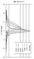
It is a figure which shows the relationship between the condensing length and condensing intensity|strength in a laser beam.
It is a figure which shows the relationship between the condensing position in a laser beam, and processing conditions.
It is a figure which shows each process of the laser processing method of one Embodiment of this invention.
It is a figure which shows the relationship between the condensing length and condensing intensity|strength in a laser beam.
22 is a diagram showing the contrast between the results of the Example using the spherical aberration correction pattern and the results of the comparative example in which the spherical aberration correction pattern is not used.
23 is a diagram illustrating a contrast between the results of the Example using the axicon lens pattern and the results of the comparative example in which the axicon lens pattern is not used.
It is a figure which shows the result of the reference example in which processing energy was adjusted.
25 is a diagram illustrating a formation procedure of a modified region.
26 is a diagram illustrating a formation procedure of a modified region.
Fig. 27 is a diagram showing the formation procedure of the modified region.
28 is a diagram showing the formation procedure of a modified region.
이하, 본 발명의 실시 형태에 대해서, 도면을 참조하여 상세하게 설명한다. 또, 각 도면에서 동일 또는 상당 부분에는 동일 부호를 부여하고, 중복하는 설명을 생략한다.EMBODIMENT OF THE INVENTION Hereinafter, embodiment of this invention is described in detail with reference to drawings. In addition, in each figure, the same code|symbol is attached|subjected to the same or equivalent part, and the overlapping description is abbreviate|omitted.
본 발명의 일 실시 형태의 레이저 가공 장치 및 레이저 가공 방법에서는, 가공 대상물에 레이저광을 집광(集光)하는 것에 의해, 절단 예정 라인을 따라서 가공 대상물에 개질(改質) 영역을 형성한다. 그래서, 먼저, 개질 영역의 형성에 대해서, 도 1~도 6을 참조하여 설명한다.In the laser processing apparatus and laser processing method of one embodiment of the present invention, a modified region is formed in the object to be processed along the line to be cut by focusing the laser beam on the object to be processed. So, first, formation of a modified region is demonstrated with reference to FIGS. 1-6.
도 1에 나타내어지는 바와 같이, 레이저 가공 장치(100)는, 레이저광(L)을 펄스 발진(發振)하는 레이저 광원(101)과, 레이저광(L)의 광축(광로)의 방향을 90° 바꾸도록 배치된 다이크로익 미러(dichroic mirror)(103)와, 레이저광(L)을 집광하기 위한 집광용 렌즈(105)를 구비하고 있다. 또, 레이저 가공 장치(100)는, 집광용 렌즈(105)에서 집광된 레이저광(L)이 조사되는 가공 대상물(1)을 지지하기 위한 지지대(107)와, 지지대(107)를 이동시키기 위한 스테이지(111)와, 레이저광(L)의 출력이나 펄스폭, 펄스 파형(波形) 등을 조절하기 위해서 레이저 광원(101)을 제어하는 레이저 광원 제어부(102)와, 스테이지(111)의 이동을 제어하는 스테이지 제어부(115)를 구비하고 있다.As shown in FIG. 1, the
이 레이저 가공 장치(100)에 있어서는, 레이저 광원(101)으로부터 출사된 레이저광(L)은, 다이크로익 미러(103)에 의해서 그 광축의 방향이 90° 바뀌며, 지지대(107) 상에 재치(載置)된 가공 대상물(1)의 내부에 집광용 렌즈(105)에 의해서 집광된다. 이것과 함께, 스테이지(111)가 이동시켜지고, 상기 가공 대상물(1)이 레이저광(L)에 대해서 절단 예정 라인(5)을 따라서 상대 이동시켜진다. 이것에 의해, 절단 예정 라인(5)을 따른 개질 영역이 가공 대상물(1)에 형성된다. 또, 여기에서는, 레이저광(L)을 상대적으로 이동시키기 위해서 스테이지(111)를 이동시켰지만, 집광용 렌즈(105)를 이동시켜도 괜찮고, 혹은 이들 양쪽 모두를 이동시켜도 괜찮다.In this
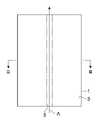
가공 대상물(1)로서는, 반도체 재료로 형성된 반도체 기판이나 압전(壓電) 재료로 형성된 압전 기판 등을 포함하는 판 모양의 부재(예를 들면, 기판, 웨이퍼 등)가 이용된다. 도 2에 나타내어지는 바와 같이, 가공 대상물(1)에는, 가공 대상물(1)을 절단하기 위한 절단 예정 라인(5)이 설정되어 있다. 절단 예정 라인(5)은, 직선 모양으로 연장된 가상선이다. 가공 대상물(1)의 내부에 개질 영역을 형성하는 경우, 도 3에 나타내어지는 바와 같이, 가공 대상물(1)의 내부에 집광점(집광 위치)(P)을 맞춘 상태에서, 레이저광(L)을 절단 예정 라인(5)을 따라서(즉, 도 2의 화살표 A방향으로) 상대적으로 이동시킨다. 이것에 의해, 도 4, 도 5 및 도 6에 나타내어지는 바와 같이, 개질 영역(7)이 절단 예정 라인(5)을 따라서 가공 대상물(1)의 내부에 형성되고, 절단 예정 라인(5)을 따라서 형성된 개질 영역(7)이 절단 기점(起点) 영역(8)이 된다.As the
또, 집광점(P)은, 레이저광(L)이 집광하는 개소이다. 또, 절단 예정 라인(5)은, 직선 모양에 한정되지 않고 곡선 모양이라도 괜찮으며, 이들이 조합시켜진 3차원 모양이라도 좋고, 좌표 지정된 것이라도 좋다. 또, 절단 예정 라인(5)은, 가상선에 한정되지 않고 가공 대상물(1)의 표면(3)에 실제로 그은 선이라도 된다. 개질 영역(7)은, 연속적으로 형성되는 경우도 있으며, 단속적으로 형성되는 경우도 있다. 또, 개질 영역(7)은 열(列) 모양이라도 점(点) 모양이라도 괜찮으며, 요점은, 개질 영역(7)은 적어도 가공 대상물(1)의 내부에 형성되어 있으면 좋다. 또, 개질 영역(7)을 기점으로 균열이 형성되는 경우가 있고, 균열 및 개질 영역(7)은, 가공 대상물(1)의 외표면(표면(3), 이면(裏面)(21), 혹은 외주면)에 노출하고 있어도 괜찮다. 또, 개질 영역(7)을 형성할 때의 레이저광 입사면은, 가공 대상물(1)의 표면(3)에 한정되는 것이 아니라, 가공 대상물(1)의 이면(21)이라도 괜찮다.In addition, the condensing point P is a location where the laser beam L is condensed. Moreover, the line to be cut 5 is not limited to a linear shape, a curved shape may be sufficient, and a three-dimensional shape in which these were combined may be sufficient, and a coordinate designation may be sufficient as it. In addition, the
덧붙여서, 여기서의 레이저광(L)은, 가공 대상물(1)을 투과함과 아울러 가공 대상물(1)의 내부의 집광점(P) 근방에서 특히 흡수되고, 이것에 의해, 가공 대상물(1)에 개질 영역(7)이 형성된다(즉, 내부 흡수형 레이저 가공). 따라서, 가공 대상물(1)의 표면(3)에서는 레이저광(L)이 거의 흡수되지 않으므로, 가공 대상물(1)의 표면(3)이 용융(溶融)하지는 않는다. 일반적으로, 표면(3)으로부터 용융되고 제거되어 구멍이나 홈 등의 제거부가 형성되는(표면 흡수형 레이저 가공) 경우, 가공 영역은 표면(3)측으로부터 서서히 이면측으로 진행한다.Incidentally, the laser beam L here passes through the
그런데, 본 실시 형태에서 형성되는 개질 영역(7)은, 밀도, 굴절률, 기계적 강도나 그 외의 물리적 특성이 주위와는 다른 상태가 된 영역을 말한다. 개질 영역(7)으로서는, 예를 들면, 용융 처리 영역(일단 용융후 재고체화한 영역, 용융 상태 중의 영역 및 용융으로부터 재고체화하는 상태 중의 영역 중 적어도 어느 하나를 의미함), 크랙 영역, 절연 파괴 영역, 굴절률 변화 영역 등이 있고, 이들이 혼재한 영역도 있다. 게다가, 개질 영역(7)으로서는, 가공 대상물(1)의 재료에서 개질 영역(7)의 밀도가 비개질 영역의 밀도와 비교하여 변화한 영역이나, 격자(格子) 결함이 형성된 영역이 있다(이들을 모두 '고밀전이 영역'이라고도 함).By the way, the modified
또, 용융 처리 영역이나 굴절률 변화 영역, 개질 영역(7)의 밀도가 비개질 영역의 밀도와 비교하여 변화한 영역, 격자 결함이 형성된 영역은, 또한, 그들 영역의 내부나 개질 영역(7)과 비개질 영역과의 계면(界面)에 균열(갈라짐, 마이크로 크랙)을 내포하고 있는 경우가 있다. 내포되는 균열은, 개질 영역(7)의 전면(全面)에 걸치는 경우나 일부분만이나 복수 부분에 형성되는 경우가 있다. 가공 대상물(1)로서는, 예를 들면 실리콘(Si), 유리, 실리콘카바이드(SiC), LiTaO3 또는 사파이어(Al2O3)를 포함하는, 또는 이들로 이루어지는 것을 들 수 있다.In addition, the molten processed region, the refractive index change region, the region in which the density of the modified
또, 본 실시 형태에서는, 절단 예정 라인(5)을 따라서 개질 스폿(spot)(가공 흔적)을 복수 형성하는 것에 의해서, 개질 영역(7)을 형성하고 있다. 개질 스폿이란, 펄스 레이저광의 1펄스의 쇼트(shot)(즉 1펄스의 레이저 조사:레이저 쇼트)로 형성되는 개질 부분이며, 개질 스폿이 모이는 것에 의해 개질 영역(7)이 된다. 개질 스폿으로서는, 크랙 스폿, 용융 처리 스폿 혹은 굴절률 변화 스폿, 또는 이들 중 적어도 1개가 혼재하는 것 등을 들 수 있다. 이 개질 스폿에 대해서는, 요구되는 절단 정밀도, 요구되는 절단면의 평탄성, 가공 대상물(1)의 두께, 종류, 결정(結晶) 방위(方位) 등을 고려하여, 그 크기나 발생하는 균열의 길이를 적절히 제어할 수 있다.Moreover, in this embodiment, the modified
다음으로, 본 발명의 일 실시 형태의 레이저 가공 장치 및 레이저 가공 방법에 대해 설명한다. 도 7에 나타내어지는 바와 같이, 레이저 가공 장치(300)는, 레이저 광원(202), 반사형 공간 광변조기(光變調器)(수차 조정부)(203), 4f 광학계(241) 및 집광 광학계(204)를 케이스(231) 내에 구비하고 있다. 레이저 가공 장치(300)는, 가공 대상물(1)에 레이저광(L)을 집광하는 것에 의해, 절단 예정 라인(5)을 따라서 가공 대상물(1)에 개질 영역(7)을 형성한다.Next, the laser processing apparatus and laser processing method of one Embodiment of this invention are demonstrated. As shown in FIG. 7 , the
레이저 광원(202)은, 예를 들면 1000nm~1500nm의 파장을 가지는 레이저광(L)을 출사하는 것이며, 예를 들면 파이버(fiber) 레이저이다. 여기서의 레이저 광원(202)은, 수평 방향으로 레이저광(L)을 출사하도록, 케이스(231)의 천판(天板)(236)에 나사 등에 의해 고정되어 있다.The
반사형 공간 광변조기(203)는, 레이저 광원(202)으로부터 출사된 레이저광(L)을 변조하는 것이며, 예를 들면 반사형 액정(LCOS:Liquid Crystal on Silicon)의 공간 광변조기(SLM:Spatial Light Modulator)이다. 여기서의 반사형 공간 광변조기(203)는, 수평 방향으로부터 입사하는 레이저광(L)을 변조함과 아울러, 수평 방향에 대해 경사지게 상부로 반사한다.The reflective spatial
도 8에 나타내어지는 바와 같이, 반사형 공간 광변조기(203)는, 실리콘 기판(213), 구동 회로층(914), 복수의 화소 전극(電極)(214), 유전체(誘電體) 다층막 미러 등의 반사막(215), 배향막(配向膜)(999a), 액정층(216), 배향막(999b), 투명 도전막(217), 및 유리 기판 등의 투명 기판(218)이 이 순서대로 적층됨으로써 구성되어 있다.As shown in Fig. 8, the reflective spatial
투명 기판(218)은, XY평면을 따른 표면(218a)을 가지고 있고, 이 표면(218a)은, 반사형 공간 광변조기(203)의 표면을 구성하고 있다. 투명 기판(218)은, 예를 들면 유리 등의 광 투과성 재료로 이루어지고, 반사형 공간 광변조기(203)의 표면(218a)으로부터 입사한 소정 파장의 레이저광(L)을, 반사형 공간 광변조기(203)의 내부로 투과한다. 투명 도전막(217)은, 투명 기판(218)의 이면(裏面) 상에 형성되어 있고, 레이저광(L)을 투과하는 도전성 재료(예를 들면 ITO)로 이루어진다.The
복수의 화소 전극(214)은, 투명 도전막(217)을 따라서 실리콘 기판(213) 상에 매트릭스 모양으로 배열되어 있다. 각 화소 전극(214)은, 예를 들면 알루미늄 등의 금속 재료로 이루어지고, 이들 표면(214a)은, 평탄하게 또한 매끄럽게 가공되어 있다. 복수의 화소 전극(214)은, 구동 회로층(914)에 마련된 액티브(active)·매트릭스 회로에 의해서 구동된다.The plurality of
액티브·매트릭스 회로는, 복수의 화소 전극(214)과 실리콘 기판(213)과의 사이에 마련되어 있고, 반사형 공간 광변조기(203)로부터 출력하려고 하는 광상(光像)을 따라 각 화소 전극(214)으로의 인가 전압을 제어한다. 이러한 액티브·매트릭스 회로는, 예를 들면 도시하지 않은 X축 방향으로 늘어선 각 화소열(畵素列)의 인가 전압을 제어하는 제1 드라이버 회로와, Y축방향으로 늘어선 각 화소열의 인가 전압을 제어하는 제2 드라이버 회로를 가지고 있으며, 제어부(250)(도 7 참조)에 의해서 쌍방의 드라이버 회로에 의해 지정된 화소의 화소 전극(214)에 소정 전압이 인가되도록 구성되어 있다.The active matrix circuit is provided between the plurality of
배향막(999a, 999b)은, 액정층(216)의 양단면에 배치되어 있고, 액정 분자군(分子群)을 일정 방향으로 배열시킨다. 배향막(999a, 999b)은, 예를 들면 폴리이미드 등의 고분자 재료로 이루어지고, 액정층(216)과의 접촉면에 러빙(rubbing) 처리 등이 실시되어 있다.The
액정층(216)은, 복수의 화소 전극(214)과 투명 도전막(217)과의 사이에 배치되어 있고, 각 화소 전극(214)과 투명 도전막(217)에 의해 형성되는 전계(電界)에 따라 레이저광(L)을 변조한다. 즉, 구동 회로층(914)의 액티브·매트릭스 회로에 의해서 각 화소 전극(214)에 전압이 인가되면, 투명 도전막(217)과 각 화소 전극(214)과의 사이에 전계가 형성되며, 액정층(216)에 형성된 전계의 크기에 따라 액정 분자(216a)의 배열 방향이 변화한다. 그리고, 레이저광(L)이 투명 기판(218)및 투명 도전막(217)을 투과하여 액정층(216)에 입사하면, 이 레이저광(L)은, 액정층(216)을 통과하는 동안에 액정 분자(216a)에 의해서 변조되고, 반사막(215)에서 반사한 후, 다시 액정층(216)에 의해 변조되어, 출사된다.The
이 때, 제어부(250)(도 7 참조)에 의해서 각 화소 전극(214)에 인가되는 전압이 제어되며, 그 전압에 따라서, 액정층(216)에서 투명 도전막(217)과 각 화소 전극(214) 사이에 끼워진 부분의 굴절률이 변화한다(각 화소에 대응한 위치의 액정층(216)의 굴절률이 변화한다). 이 굴절률의 변화에 의해, 인가한 전압에 따라서, 레이저광(L)의 위상(位相)을 액정층(216)의 화소마다 변화시킬 수 있다. 즉, 홀로그램 패턴에 따른 위상 변조를 화소마다 액정층(216)에 의해서 부여하는(즉, 변조를 부여하는 홀로그램 패턴으로서의 변조 패턴을 반사형 공간 광변조기(203)의 액정층(216)에 표시시키는) 것이 가능하다. 그 결과, 변조 패턴에 입사하여 투과하는 레이저광(L)은, 그 파면(波面)이 조정되고, 그 레이저광(L)을 구성하는 각 광선(光線)에서 진행 방향에 직교하는 소정 방향의 성분의 위상에 차이가 생긴다. 따라서, 반사형 공간 광변조기(203)에 표시시키는 변조 패턴을 적절히 설정하는 것에 의해, 레이저광(L)이 변조(예를 들면, 레이저광(L)의 강도, 진폭, 위상, 편광 등이 변조)가 가능해진다.At this time, the voltage applied to each
도 7로 되돌아와, 4f 광학계(241)는, 반사형 공간 광변조기(203)에 의해서 변조된 레이저광(L)의 파면 형상을 조정하는 것이며, 제1 렌즈(241a) 및 제2 렌즈(241b)를 가지고 있다. 렌즈(241a, 241b)는, 반사형 공간 광변조기(203)와 제1 렌즈(241a)와의 거리가 제1 렌즈(241a)의 초점 거리 f1가 되고, 또한 집광 광학계(204)와 렌즈(241b)와의 거리가 렌즈(241b)의 초점 거리 f2가 되며, 또한 제1 렌즈(241a)와 제2 렌즈(241b)와의 거리가 f1+f2가 되고, 또한 제1 렌즈(241a)와 제2 렌즈(241b)가 양측 텔레센트릭(telecentric) 광학계가 되도록, 반사형 공간 광변조기(203)와 집광 광학계(204)와의 사이에 배치되어 있다. 이 4f 광학계(241)에 의하면, 반사형 공간 광변조기(203)에서 변조된 레이저광(L)이 공간 전파에 의해서 파면 형상이 변화하고 수차가 증대하는 것을 억제할 수 있다.Returning to Fig. 7, the 4f
집광 광학계(204)는, 레이저 광원(202)에 의해 출사되어 반사형 공간 광변조기(203)에 의해 변조된 레이저광(L)을 가공 대상물(1)의 내부에 집광하는 것이다. 이 집광 광학계(204)는, 복수의 렌즈를 포함하여 구성되어 있고, 압전 소자 등을 포함하여 구성된 구동 유닛(232)을 매개로 하여 케이스(231)의 저판(底板)(233)에 설치되어 있다.The condensing
이상과 같이 구성된 레이저 가공 장치(300)에서는, 레이저 광원(202)으로부터 출사된 레이저광(L)은, 케이스(231) 내에서 수평 방향으로 진행한 후, 미러(205a)에 의해서 하부로 반사되고, 어테뉴에이터(attenuator)(207)에 의해서 광 강도가 조정된다. 그리고, 미러(205b)에 의해서 수평 방향으로 반사되고, 빔 호모지나이저(homogenizer)(260)에 의해서 레이저광(L)의 강도 분포가 균일화되어 반사형 공간 광변조기(203)에 입사한다.In the
반사형 공간 광변조기(203)에 입사한 레이저광(L)은, 액정층(216)에 표시된 변조 패턴을 투과하는 것에 의해 상기 변조 패턴에 따라 변조되고, 그 후, 미러(206a)에 의해서 상부로 반사되고, λ/2 파장판(228)에 의해서 편광 방향이 변경되며, 미러(206b)에 의해서 수평 방향으로 반사되어 4f 광학계(241)에 입사한다.The laser light L incident on the reflective spatial
4f 광학계(241)에 입사한 레이저광(L)은, 평행광으로 집광 광학계(204)에 입사하도록 파면 형상이 조정된다. 구체적으로는, 레이저광(L)은, 제1 렌즈(241a)를 투과하여 수렴되고, 미러(219)에 의해서 하부로 반사되어, 공초점(共焦点)(O)을 거쳐 발산함과 아울러, 제2 렌즈(241b)를 투과하여, 평행광이 되도록 다시 수렴된다. 그리고, 레이저광(L)은, 다이크로익 미러(210, 238)를 순차적으로 투과하여 집광 광학계(204)에 입사하고, 스테이지(111) 상에 재치된 가공 대상물(1) 내에 집광 광학계(204)에 의해서 집광된다.The wavefront shape of the laser light L incident on the 4f
또, 레이저 가공 장치(300)는, 가공 대상물(1)의 레이저광 입사면을 관찰하기 위한 표면 관찰 유닛(211)과, 집광 광학계(204)와 가공 대상물(1)과의 거리를 미세 조정하기 위한 AF(AutoFocus) 유닛(212)을, 케이스(231) 내에 구비하고 있다.In addition, the
표면 관찰 유닛(211)은, 가시광(VL1)을 출사하는 관찰용 광원(211a)과, 가공 대상물(1)의 레이저광 입사면에서 반사된 가시광(VL1)의 반사광(VL2)을 수광(受光)하여 검출하는 검출기(211b)를 가지고 있다. 표면 관찰 유닛(211)에서는, 관찰용 광원(211a)으로부터 출사된 가시광(VL1)이, 미러(208) 및 다이크로익 미러(209, 210, 238)에서 반사ㆍ투과되어, 집광 광학계(204)에서 가공 대상물(1)을 향해서 집광된다. 그리고, 가공 대상물(1)의 레이저광 입사면에서 반사된 반사광(VL2)이, 집광 광학계(204)에서 집광되어 다이크로익 미러(238, 210)에서 투과ㆍ반사된 후, 다이크로익 미러(209)를 투과하여 검출기(211b)에서 수광된다.The
AF유닛(212)은, AF용 레이저광(LB1)을 출사하고, 레이저광 입사면에서 반사된 AF용 레이저광(LB1)의 반사광(LB2)을 수광하여 검출함으로써, 절단 예정 라인(5)을 따른 레이저광 입사면의 변위 데이터를 취득한다. 그리고, AF유닛(212)은, 개질 영역(7)을 형성할 때, 취득한 변위 데이터에 근거하여 구동 유닛(232)을 구동시키고, 레이저광 입사면의 변위를 따르도록 집광 광학계(204)를 그 광축 방향으로 왕복 이동시킨다.The
게다가, 레이저 가공 장치(300)는, 상기 레이저 가공 장치(300)를 제어하기 위한 것으로서, CPU, ROM, RAM 등으로 이루어지는 제어부(250)를 구비하고 있다. 이 제어부(250)는, 레이저 광원(202)을 제어하고, 레이저 광원(202)으로부터 출사되는 레이저광(L)의 출력이나 펄스폭 등을 조절한다. 또, 제어부(250)는, 개질 영역(7)을 형성할 때, 레이저광(L)의 집광점(P)이 가공 대상물(1)의 표면(3) 또는 이면(21)으로부터 소정 거리에 위치하고 또한 레이저광(L)의 집광점(P)이 절단 예정 라인(5)을 따라서 상대적으로 이동하도록, 케이스(231), 스테이지(111)의 위치, 및 구동 유닛(232)의 구동 중 적어도 하나를 제어한다.Moreover, the
또, 제어부(250)는, 개질 영역(7)을 형성할 때, 반사형 공간 광변조기(203)에서의 각 화소 전극(214)에 소정 전압을 인가하고, 액정층(216)에 소정의 변조 패턴을 표시시키며, 이것에 의해, 레이저광(L)을 반사형 공간 광변조기(203)에서 원하는대로 변조시킨다. 여기서, 액정층(216)에 표시되는 변조 패턴은, 예를 들면, 개질 영역(7)을 형성하려고 하는 위치, 조사하는 레이저광(L)의 파장, 가공 대상물(1)의 재료, 및 집광 광학계(204)나 가공 대상물(1)의 굴절률 등에 근거하여 미리 도출되어, 제어부(250)에 기억되어 있다. 이 변조 패턴은, 레이저 가공 장치(300)에 생기는 개체차(예를 들면, 반사형 공간 광변조기(203)의 액정층(216)에 생기는 변형)을 보정하기 위한 개체차 보정 패턴, 구면 수차를 보정하기 위한 구면 수차 보정 패턴 등을 포함하고 있다. 이와 같이, 제어부(250) 및 반사형 공간 광변조기(203)는, 가공 대상물(1)에 레이저광(L)을 집광하는 것에 기인하여 집광 위치에서 발생하는 수차를 조정하는 수차 조정부로서 기능한다.In addition, when forming the modified
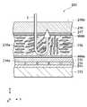
이상과 같이 구성된 레이저 가공 장치(300)에서 실시되는 레이저 가공 방법의 대상이 되는 가공 대상물(1)은, 도 9에 나타내어지는 바와 같이, 예를 들면 실리콘 등으로 이루어지는 기판(11)과, 기판(11)의 표면(11a)에 형성된 복수의 기능 소자(15)를 구비하고 있다. 복수의 기능 소자(15)는, 기판(11)의 표면(11a)에 매트릭스 모양으로 배열되어 있고, 배선(16)을 포함하고 있다. 이와 같이, 가공 대상물(1)은, 그 표면(제1 표면)(3)에, 배선(16)을 포함하는 복수의 기능 소자(15)가 마련된 것이다. 또, 기능 소자(15)는, 포토 다이오드 등의 수광 소자, 레이저 다이오드 등의 발광 소자, 혹은 회로로서 형성된 회로 소자 등이다.As shown in FIG. 9 , the
레이저 가공 장치(300)에서 실시되는 레이저 가공 방법은, 가공 대상물(1)을 기능 소자(15)마다 절단하는 것에 의해 복수의 칩을 제조하는 칩의 제조 방법으로서 이용된다. 그 때문에, 상기 레이저 가공 방법에서는, 가공 대상물(1)에 대해서, 서로 이웃하는 기능 소자(15)의 사이의 스트리트 영역(영역)(17)을 통과하도록(가공 대상물(1)의 두께 방향으로부터 본 경우에, 스트리트 영역(17)의 폭의 중심(中心)을 통과하도록) 복수의 절단 예정 라인(5)이 격자 모양으로 설정된다. 그리고, 기판(11)의 이면(11b)인 가공 대상물(1)의 이면(제2 표면)(21)으로부터 입사시켜진 레이저광(L)이 가공 대상물(1)에 집광되고, 각 절단 예정 라인(5)을 따라서 가공 대상물(1)에 개질 영역(7)이 형성된다.The laser processing method implemented by the
이하, 레이저 가공 장치(300)에서 실시되는 레이저 가공 방법에 대해서, 그 배경부터 설명한다. 도 10의 (a)의 상단에 나타내어지는 바와 같이, 레이저광(L)의 집광 위치(개질 영역의 형성을 예정하는 위치)에서 발생하는 수차를 보정하지 않으면, 구면 수차에 의해서 레이저광(L)의 광축을 따라 집광 영역(레이저광(L)을 구성하는 각 광선이 집광되는 영역)이 길어진다. 한편, 도 10의 (b)의 상단에 나타내어지는 바와 같이, 제어부(250) 및 반사형 공간 광변조기(203)를 이용하여 레이저광(L)의 집광 위치에서 발생하는 수차를 보정하면, 레이저광(L)은 집광점(P)에 집광한다. 그리고, 도 10의 (a) 및 (b)의 하단의 가공 대상물(1)의 단면(斷面) 사진에 나타내어지는 바와 같이, 개질 영역의 형성시에 개질 영역으로부터 레이저광(L)의 입사측 및 그 반대측으로 신장되는 균열의 길이는, 수차를 보정하지 않은 경우에 비해 수차를 보정한 경우의 쪽이 길어진다. 상기 균열의 길이가 길어지는 것은, 가공 대상물(1)을 절단하기 위해서 1개의 절단 예정 라인(5)에 대해서 형성해야 할 개질 영역의 열수(列數)를 줄일 수 있으므로, 가공에 필요로 하는 시간의 단축화를 도모하는데 있어서 유리하다.Hereinafter, the laser processing method implemented by the
그렇지만, 레이저광(L)의 집광 위치에서 발생하는 수차를 보정하면, 도 11의 (a) 및 (b)의 가공 대상물(1)의 평면 사진에 나타내어지는 바와 같이, 레이저광(L)의 입사측과는 반대측의 가공 대상물(1)의 표면(3)에서 절단 예정 라인(5)으로부터 벗어난 부분에 데미지(D)가 발생하는 경우가 있는 것을 알았다. 도 11의 (a) 및 (b)의 가공 대상물(1)의 평면 사진을 얻었을 때의 실험 조건은, 다음과 같다.However, if the aberration occurring at the converging position of the laser light L is corrected, as shown in the plan photographs of the
1. 가공 대상물1. object to be processed
(1) 두께 250㎛, 결정 방위(100)의 실리콘 기판의 표면에, 두께 300Å인 Au막을 형성했다.(1) An Au film having a thickness of 300 angstroms was formed on the surface of a silicon substrate having a thickness of 250 µm and a crystal orientation of 100.
(2) (a)에서는, 절단 예정 라인(5)을 덮도록 Au막을 형성하고, (b)에서는, 절단 예정 라인(5)을 따라서 폭 15㎛인 스트리트 영역이 형성되도록 Au막을 형성했다.(2) In (a), an Au film was formed so as to cover the line to be cut 5, and in (b), an Au film was formed to form a street region having a width of 15 µm along the line to be cut 5.
2. 레이저광의 조사 조건2. Laser light irradiation conditions
(1) 실리콘 기판의 이면을 레이저광 입사면으로 하여, 레이저광의 집광점을 실리콘 기판의 표면(즉, 실리콘 기판과 Au막과의 계면 근방)에 맞추고, 파장 1080nm, 반복 주파수 80kHz, 펄스폭 500ns, 출구 출력 1.2W, 스캔 속도(절단 예정 라인(5)을 따른 집광점의 상대적 이동 속도) 300mm/s의 조건으로 레이저광(L)을 조사했다.(1) Using the back surface of the silicon substrate as the laser light incident surface, the laser light converging point is aligned with the surface of the silicon substrate (that is, near the interface between the silicon substrate and the Au film), wavelength 1080 nm, repetition frequency 80 kHz, pulse width 500 ns , the laser beam L was irradiated under conditions of 1.2 W of exit output, and a scanning speed (relative movement speed of the light-converging point along the line to be cut 5) 300 mm/s.
이러한 데미지(D)의 발생 요인을 검토한다. 먼저, 도 12에 나타내어지는 바와 같이, 데미지(D)는, 레이저광(L)의 빠짐광의 폭을 넘는 영역(빠짐광의 폭의 외측의 영역)에서 발생했다. 이것으로부터, 레이저광(L)의 빠짐광은, 데미지(D)의 발생 요인은 아니라고 생각되어진다. 또, 도 12의 하단은, 가공 대상물(1)의 평면 사진이다.The cause of such damage (D) is examined. First, as shown in FIG. 12, the damage D generate|occur|produced in the area|region (region outside the width|variety of the fallout light) beyond the width|variety of the divergence light of the laser beam L. From this, it is thought that the missing light of the laser beam L is not a generation|occurrence|production factor of the damage D. In addition, the lower end of FIG. 12 is a plan photograph of the
또, 도 13의 가공 대상물(1)의 평면 사진에 나타내어지는 바와 같이, 개질 영역의 형성시에 개질 영역으로부터 신장된 균열이 가공 대상물(1)의 표면(3)에 도달하고 있는 경우에, 많은 데미지(D)가 발생했다. 게다가, 상기 균열이 가공 대상물(1)의 표면(3)에서 사행(蛇行, 구불구불함)하고 있으면, 상기 균열의 사행을 따라서 데미지(D)가 발생했다. 이 때문에, 개질 영역으로부터 신장된 균열은, 데미지(D)의 발생 요인 중 하나라고 생각되어진다. 도 13의 가공 대상물(1)의 평면 사진을 얻었을 때의 실험 조건은, 다음과 같다.Further, as shown in the plan photograph of the
1. 가공 대상물1. object to be processed
(1) 두께 250㎛, 결정 방위(100), 저항값 1Ω·cm인 실리콘 기판의 표면에, 두께 300Å인 Au막을 형성했다.(1) An Au film having a thickness of 300 angstroms was formed on the surface of a silicon substrate having a thickness of 250 µm, a crystal orientation (100), and a resistance value of 1 Ω·cm.
(2) 절단 예정 라인(5)을 덮도록 Au막을 형성했다.(2) An Au film was formed so as to cover the
2. 레이저광의 조사 조건2. Laser light irradiation conditions
(1) 실리콘 기판의 이면을 레이저광 입사면으로 하여, 레이저광의 집광점을 실리콘 기판의 표면(즉, 실리콘 기판과 Au막과의 계면 근방)에 맞추고, 파장 1342nm, 반복 주파수 90kHz, 펄스폭 90ns, 출구 출력 1.27W, 스캔 속도 340mm/s의 조건으로 레이저광(L)을 조사했다.(1) Using the back surface of the silicon substrate as the laser light incident surface, the laser light converging point is aligned with the surface of the silicon substrate (ie, near the interface between the silicon substrate and the Au film), wavelength 1342 nm, repetition frequency 90 kHz, pulse width 90 ns , The laser beam L was irradiated under the conditions of 1.27 W of exit output, and the scanning speed of 340 mm/s.
게다가, 도 14의 (a) 및 (b)의 상단의 가공 대상물(1)의 단면 사진에 나타내어지는 바와 같이, 절단 예정 라인(5)을 따라서 미리 균열이 형성되어 있지 않은 가공 대상물(1), 및 절단 예정 라인(5)을 따라서 미리 균열이 형성되어 있는 가공 대상물(1)을 준비하고, 레이저광(L)의 집광 위치에서 발생하는 수차를 보정하지 않고, 절단 예정 라인(5)을 따라서 각각의 가공 대상물(1)에 레이저광(L)을 조사했다. 그 결과, 도 14의 (a) 및 (b)의 하단의 가공 대상물(1)의 평면 사진에 나타내어지는 바와 같이, 가공 대상물(1)에 미리 균열이 형성되어 있지 않은 경우에 비해 가공 대상물(1)에 미리 균열이 형성되어 있는 경우의 쪽이, 많은 데미지(D)가 발생했다.In addition, as shown in the cross-sectional photograph of the
이상으로부터, 데미지(D)의 발생 요인으로서, 이하의 1~3을 들 수 있다.From the above, the following 1-3 are mentioned as a generation|occurrence|production factor of the damage D.
1. 1개의 절단 예정 라인(5)을 따라서 1열의 개질 영역을 형성한 후에, 상기 1개의 절단 예정 라인(5)을 따라서 다른 1열의 개질 영역을 형성하는 경우에, 형성이 끝난 1열의 개질 영역 또는 상기 개질 영역으로부터 신장된 균열에, 레이저광(L)의 집광 위치가 겹쳐져 있으면, 레이저광(L)의 조사시에, 형성이 끝난 1열의 개질 영역 또는 상기 개질 영역으로부터 신장된 균열이 경면(鏡面)과 같이 작용하고, 레이저광(L)의 일부에 대해서, 반사, 간섭, 회절, 산란 등이 일어나서, 상기 레이저광(L)의 일부가, 레이저광(L)의 빠짐광의 폭을 넘는 영역에 조사되고, 그 결과, 상기 레이저광(L)의 일부가 기능 소자(15)의 배선(16) 등에 의해 흡수되어, 배선(16) 등에 용융이 발생한다.1. In the case where one row of modified regions is formed along one line to be cut 5 and then another row of modified regions is formed along the one line to be cut 5, the reformed region in one row has been formed Alternatively, if the condensing position of the laser light L is superimposed on the cracks extending from the modified area, when the laser light L is irradiated, the formed one row of modified areas or cracks extending from the modified area are mirrored ( A region in which reflection, interference, diffraction, scattering, etc. occur with respect to a part of the laser beam L, and a part of the laser beam L exceeds the width of the missing beam of the laser beam L. As a result, a part of the laser beam L is absorbed by the
2. 전회(前回)의 1펄스의 레이저 조사에 의해 형성된 개질 영역 또는 상기 개질 영역으로부터 신장된 균열에, 금회(今回)의 1펄스의 레이저 조사의 집광 위치가 겹쳐져 있으면, 금회의 1펄스의 레이저 조사시에, 전회의 1펄스의 레이저 조사에 의해 형성된 개질 영역 또는 상기 개질 영역으로부터 신장된 균열이 경면과 같이 작용하고, 금회의 1펄스의 레이저 조사의 레이저광(L)의 일부에 대해서, 반사, 간섭, 회절, 산란 등이 일어나서, 상기 레이저광(L)의 일부가, 레이저광(L)의 빠짐광의 폭을 넘는 영역에 조사되며, 그 결과, 상기 레이저광(L)의 일부가 기능 소자(15)의 배선(16) 등에서 흡수되어, 배선(16) 등에 용융이 발생한다.2. If the condensing position of the current one pulse laser irradiation overlaps the modified region formed by the previous one pulse laser irradiation or the crack extended from the modified region, the current one pulse laser At the time of irradiation, the modified region formed by the previous one pulse of laser irradiation or cracks extending from the modified region act like a mirror surface, and a part of the laser beam L of this one pulse of laser irradiation is reflected , interference, diffraction, scattering, etc. occur, and a part of the laser beam L is irradiated to an area exceeding the width of the missing beam of the laser beam L. As a result, a part of the laser beam L is a functional element. It is absorbed in the
3. 전회의 1펄스의 레이저 조사에 의해 형성된 개질 영역으로부터 신장된 균열이 가공 대상물(1)의 표면(3) 또는 이면(21)에 도달한 상태에서, 상기 균열에 집광 위치가 겹치도록, 금회의 1펄스의 레이저 조사가 행하여지면, 금회의 1펄스의 레이저 조사시에, 전회의 1펄스의 레이저 조사에 의해 가공 대상물(1)의 표면(3) 또는 이면(21)에 도달한 균열이 경면과 같이 작용하고, 금회의 1펄스의 레이저 조사의 레이저광(L)의 일부에 대해서, 반사, 간섭, 회절, 산란 등이 일어나서, 상기 레이저광(L)의 일부가, 레이저광(L)의 빠짐광의 폭을 넘는 영역에 조사되며, 그 결과, 상기 레이저광(L)의 일부가 기능 소자(15)의 배선(16) 등에서 흡수되어, 배선(16) 등에 용융이 발생한다.3. In the state in which the crack extended from the modified region formed by the previous one-pulse laser irradiation reaches the
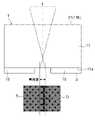
그래서, 레이저 가공 장치(300)에서 실시되는 레이저 가공 방법에서는, 도 15에 나타내어지는 바와 같이, 집광 위치(CP1)로부터 레이저광(L)의 광축을 따라 레이저광(L)의 입사측으로 소정 거리만큼 어긋나게 한 위치(CP0)에서 이상(理想) 집광되도록 수차 보정한 상태(이 경우, CP0는 이상 집광 위치가 됨)에서 집광 위치(CP1)에 집광했을 때에 발생하는 수차를 기준 수차로서 결정한다. 즉, 집광 위치(CP1)로부터 레이저광(L)의 광축을 따라 레이저광(L)의 입사측으로 소정 거리만큼 이상 집광 위치(CP0)를 어긋나게 한 상태에서의 수차 보정량으로 상기 집광 위치(CP1)에 집광한 경우에 발생하는 수차를 기준 수차로서 결정한다. 이 기준 수차는, 제어부(250)에 설정된다. 또, 집광 위치(CP1)는, 개질 영역의 형성을 예정하는 위치이며, 예를 들면, 형성을 예정하는 개질 영역 중 레이저광(L)의 입사측과는 반대측의 단부의 위치에 대응한다. 이상 집광 위치(CP0)는, 이상 집광(즉, 매질이 없다고 가정한 경우의 집광 상태에 가깝게 될 때까지 수차가 경감된 집광 상태)을 한 레이저광(L)의 집광점의 위치이다.Then, in the laser processing method implemented by the
그리고, 레이저 가공 장치(300)에서 실시되는 레이저 가공 방법에서는, 레이저광(L)의 입사측과는 반대측의 가공 대상물(1)의 표면(3)에 가장 가까운 제1 영역에 개질 영역을 형성하는 경우에는, 기준 수차의 기준 집광 길이보다도 긴 제1 집광 길이가 되고 또한 기준 수차의 기준 집광 강도보다도 약한 제1 집광 강도가 되도록, 집광 위치(CP1)에서 발생하는 수차를 조정한다. 또, 상기 레이저 가공 방법에서는, 레이저광(L)의 입사측의 가공 대상물(1)의 이면(21)에 제1 영역보다도 가까운 제2 영역에 개질 영역을 형성하는 경우에는, 기준 수차의 기준 집광 길이보다도 짧은 제2 집광 길이가 되고 또한 기준 수차의 기준 집광 강도보다도 강한 제2 집광 강도가 되도록, 집광 위치(CP1)에서 발생하는 수차를 조정한다. 이들 수차의 조정은, 제어부(250) 및 반사형 공간 광변조기(203)에 의해서 행하여진다. 또, 집광 길이는, 레이저광(L)의 광축을 따른 집광 영역(레이저광(L)을 구성하는 각 광선이 집광되는 영역)의 길이이다. 또, 집광 강도는, 집광 영역에서의 단위면적당 레이저광의 강도이다.And, in the laser processing method carried out in the
상술한 기준 수차를 실험에 의해 검토했다. 실험 조건은, 다음과 같다.The above-mentioned reference aberration was examined by experiment. Experimental conditions are as follows.
1. 가공 대상물1. object to be processed
(1) 두께 250㎛, 결정 방위(100), 저항값 1Ω·cm인 실리콘 기판을 준비했다.(1) A silicon substrate having a thickness of 250 µm, a crystal orientation (100), and a resistance value of 1 Ω·cm was prepared.
2. 레이저광의 조사 조건2. Laser light irradiation conditions
(1) 하기의 표 1의 조건으로 레이저광(L)에서의 집광 위치(CP1) 및 이상 집광 위치(CP0)를 조정하고, 파장 1080nm, 반복 주파수 80kHz, 펄스폭 500ns, 출구 출력 1.2W, 스캔 속도 300mm/s의 조건으로 레이저광(L)을 조사했다. 또, 표 1에서,「표면」은, 레이저광(L)의 입사측과는 반대측의 가공 대상물(1)의 표면(3)이며,「이면」은, 레이저광(L)의 입사측의 가공 대상물(1)의 이면(21)이다. 또,「어긋남량」은, 집광 위치(즉, 개질 영역을 형성하기 위해서 집광하고 싶은 위치)로부터 이상 집광 위치(즉, 수차 보정에 의해 이상 집광되는 집광 위치)까지의 거리이며, 집광 위치(CP1)를 기준으로 하여, 이상 집광 위치(CP0)가 레이저광(L)의 입사측으로 어긋나 있는 경우를「-」의 수치로 나타내고, 이상 집광 위치(CP0)가 레이저광(L)의 입사측과는 반대측으로 어긋나 있는 경우를「+」의 수치로 나타냈다.(1) Adjust the condensing position (CP1) and the abnormal condensing position (CP0) in the laser light (L) under the conditions of Table 1 below, with a wavelength of 1080 nm, a repetition frequency of 80 kHz, a pulse width of 500 ns, an exit output of 1.2 W, and a scan The laser beam L was irradiated on condition of the speed|rate of 300 mm/s. In addition, in Table 1, "surface" is the

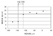
이 실험의 결과, 도 16 및 도 17에 나타내어지는 바와 같이, 이상 집광 위치(CP0)가 레이저광(L)의 입사측으로 어긋나 있는 경우에서, 어긋남량의 절대치가 110㎛ 보다도 작게 되면, 데미지(D)의 폭이 크게 되고, 어긋남량의 절대치가 140㎛ 보다도 크게 되면, 데미지(D)의 폭이 작게 되는 것을 알았다. 또, 도 17은, 가공 대상물(1)의 평면 사진이며, 각각, 표 1의 No.1~No.6의 경우의 결과이다.As a result of this experiment, as shown in Figs. 16 and 17, in the case where the abnormal condensing position CP0 is shifted toward the incident side of the laser light L, if the absolute value of the shift is smaller than 110 μm, the damage (D ) becomes large, and when the absolute value of the deviation is larger than 140 µm, it was found that the width of the damage D becomes small. In addition, FIG. 17 is a plan photograph of the
따라서, 이 경우에는, 집광 위치(CP1)로부터 레이저광(L)의 광축을 따라 레이저광(L)의 입사측으로 이상 집광 위치(CP0)를 어긋나게 한 상태에서, 어긋남량의 절대치가 110μm 이상 140㎛ 이하가 되는 수차를 기준 수차로서 결정하면 좋다. 그리고, 레이저광(L)의 입사측과는 반대측의 가공 대상물(1)의 표면(3)에 가장 가까운 제1 영역에 개질 영역을 형성하는 경우에는, 기준 수차의 기준 집광 길이보다도 긴 제1 집광 길이가 되고 또한 기준 수차의 기준 집광 강도보다도 약한 제1 집광 강도가 되도록, 집광 위치(CP1)에서 발생하는 수차를 조정하면 좋다. 또, 레이저광(L)의 입사측의 가공 대상물(1)의 이면(21)에 제1 영역보다도 가까운 제2 영역에 개질 영역을 형성하는 경우에는, 기준 수차의 기준 집광 길이보다도 짧은 제2 집광 길이가 되고 또한 기준 수차의 기준 집광 강도보다도 강한 제2 집광 강도가 되도록, 집광 위치(CP1)에서 발생하는 수차를 조정하면 된다.Therefore, in this case, in the state in which the abnormal light-converging position CP0 is shifted from the light-converging position CP1 to the incident side of the laser light L along the optical axis of the laser light L, the absolute value of the deviation is 110 µm or more and 140 µm What is necessary is just to determine the following aberrations as a reference aberration. Then, when the modified region is formed in the first region closest to the
또, 도 18에 나타내어지는 바와 같이, 집광 위치(CP1)로부터 레이저광(L)의 광축을 따라 레이저광(L)의 입사측으로 이상 집광 위치(CP0)를 어긋나게 한 상태에서, 레이저광(L)에서의 집광 길이는, 어긋남량의 절대치가 커질수록 길어지고, 레이저광(L)에서의 집광 강도는, 어긋남량의 절대치가 커질수록 약해진다. 이것으로부터, 레이저광(L)의 입사측과는 반대측의 가공 대상물(1)의 표면(3)에 가장 가까운 제1 영역에 개질 영역을 형성하는 경우에는, 기준 수차의 기준 어긋남량보다도 긴 제1 어긋남량이 되도록, 집광 위치(CP1)에서 발생하는 수차를 조정하면 된다고도 말할 수 있다. 또, 레이저광(L)의 입사측의 가공 대상물(1)의 이면(21)에 제1 영역보다도 가까운 제2 영역에 개질 영역을 형성하는 경우에는, 기준 수차의 기준 어긋남량보다도 짧은 제2 어긋남량이 되도록, 집광 위치(CP1)에서 발생하는 수차를 조정하면 된다고도 말할 수 있다.Moreover, as shown in FIG. 18, in the state which shifted|shifted the abnormal condensing position CP0 from the condensing position CP1 to the incident side of the laser beam L along the optical axis of the laser beam L, the laser beam L The light-converging length at , becomes longer as the absolute value of the deviation amount increases, and the light-converging intensity in the laser light L becomes weaker as the absolute value of the deviation amount increases. From this, when the modified region is formed in the first region closest to the
다음으로, 상술한 제1 영역 및 제2 영역을 실험에 의해 검토했다. 실험 조건은, 다음과 같다.Next, the above-mentioned 1st area|region and 2nd area|region were examined by experiment. Experimental conditions are as follows.
1. 가공 대상물1. object to be processed
(1) 두께 250㎛, 결정 방위(100), 저항값 1Ω·cm의 실리콘 기판을 준비했다.(1) A silicon substrate having a thickness of 250 µm, a crystal orientation (100), and a resistance value of 1 Ω·cm was prepared.
2. 레이저광의 조사 조건2. Laser light irradiation conditions
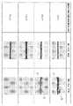
(1) 도 19에 나타내어지는 조건으로 레이저광(L)에서의 집광 위치(CP1) 및 이상 집광 위치(CP0)를 조정하고, 파장 1080nm, 반복 주파수 80kHz, 펄스폭 500ns, 출구 출력 1.2W, 스캔 속도 300mm/s의 조건으로 레이저광(L)을 조사했다. 또, 도 19에서,「표면」은, 레이저광(L)의 입사측과는 반대측의 가공 대상물(1)의 표면(3)이다. 또,「제1 가공 조건」은, 기준 수차의 기준 집광 길이보다도 긴 제1 집광 길이가 되고 또한 기준 수차의 기준 집광 강도보다도 약한 제1 집광 강도가 되도록, 집광 위치(CP1)에서 발생하는 수차를 조정한 조건이며,「제2 가공 조건」은, 기준 수차의 기준 집광 길이보다도 짧은 제2 집광 길이가 되고 또한 기준 수차의 기준 집광 강도보다도 강한 제2 집광 강도가 되도록, 집광 위치(CP1)에서 발생하는 수차를 조정한 조건이다.(1) Adjusting the condensing position CP1 and the abnormal condensing position CP0 in the laser light L under the conditions shown in Fig. 19, a wavelength of 1080 nm, a repetition frequency of 80 kHz, a pulse width of 500 ns, an exit output of 1.2 W, a scan The laser beam L was irradiated on condition of the speed|rate of 300 mm/s. In addition, in FIG. 19, "surface" is the
이 실험의 결과, 도 19에 나타내어지는 바와 같이, 제2 가공 조건에서는, 가공 대상물(1)의 표면(3)으로부터 집광 위치(CP1)까지의 거리가 0㎛인 경우, 및 상기 거리가 20㎛인 경우에는, 데미지(D)(즉, 가공 대상물(1)의 표면(3)에서 절단 예정 라인(5)으로부터 벗어난 부분에 발생하는 데미지)가 발생하고, 가공 대상물(1)의 표면(3)으로부터 집광 위치(CP1)까지의 거리가 60㎛인 경우에는, 데미지(D)가 발생하지 않았다. 또, 제1 가공 조건에서는, 어느 경우에도, 데미지(D)가 발생하지 않았다. 또, 도 19는, 가공 대상물(1)의 평면 사진이다.As a result of this experiment, as shown in FIG. 19 , under the second processing condition, when the distance from the
따라서, 레이저광(L)의 입사측과는 반대측의 가공 대상물(1)의 표면(3)에 가장 가까운 제1 영역에 개질 영역을 형성하는 경우에는, 제1 가공 조건(즉, 기준 수차의 기준 집광 길이보다도 긴 제1 집광 길이가 되고 또한 기준 수차의 기준 집광 강도보다도 약한 제1 집광 강도가 되도록, 집광 위치(CP1)에서 발생하는 수차를 조정한 조건)을 채용하고, 제1 영역을, 가공 대상물(1)의 표면(3)으로부터의 거리가 60㎛ 이하의 영역에 설정하면 좋다. 또, 레이저광(L)의 입사측의 가공 대상물(1)의 이면(21)에 제1 영역보다도 가까운 제2 영역에 개질 영역을 형성하는 경우에는, 제2 가공 조건(즉, 기준 수차의 기준 집광 길이보다도 짧은 제2 집광 길이가 되고 또한 기준 수차의 기준 집광 강도보다도 강한 제2 집광 강도가 되도록, 집광 위치(CP1)에서 발생하는 수차를 조정한 조건)을 채용하고, 제2 영역을, 가공 대상물(1)의 표면(3)으로부터의 거리가 40㎛ 이상의 영역에 설정하면 좋다.Therefore, when the modified region is formed in the first region closest to the
이상에 의해, 레이저 가공 장치(300)에서 실시되는 레이저 가공 방법에서는, 먼저, 도 20의 (a)에 나타내어지는 바와 같이, 기준 수차의 기준 집광 길이보다도 긴 제1 집광 길이가 되고 또한 기준 수차의 기준 집광 강도보다도 약한 제1 집광 강도가 되도록 수차를 조정하여, 가공 대상물(1)에 레이저광(L)을 집광하는 것에 의해, 레이저광(L)의 입사측과는 반대측의 가공 대상물(1)의 표면(3)에 가장 가까운 제1 영역에 개질 영역(7)을 형성한다(제1 공정). 이어서, 도 20의 (b)에 나타내어지는 바와 같이, 기준 수차의 기준 집광 길이보다도 짧은 제2 집광 길이가 되고 또한 기준 수차의 기준 집광 강도보다도 강한 제2 집광 강도가 되도록 수차를 조정하여, 가공 대상물(1)에 레이저광(L)을 집광하는 것에 의해, 레이저광(L)의 입사측의 가공 대상물(1)의 이면(21)에 제1 영역보다도 가까운 제2 영역에 개질 영역(7)을 형성한다(제2 공정).As described above, in the laser processing method implemented in the
또, 제1 영역은, 제1 영역에 개질 영역(7)을 형성했을 때에 상기 개질 영역(7)으로부터 레이저광(L)의 입사측과는 반대측으로 신장되는 균열이 가공 대상물(1)의 표면(3)에 도달하지 않도록 설정된다. 또, 제2 영역은, 제1 영역에 개질 영역(7)을 형성했을 때에 상기 개질 영역(7)으로부터 레이저광(L)의 입사측으로 신장된 균열과 겹치지 않도록 설정된다.Further, in the first region, when the modified
그 후, 가공 대상물(1)의 이면(21)에 익스팬드(expand) 테이프를 붙이고, 상기 익스팬드 테이프를 확장시킨다. 이것에 의해, 절단 예정 라인(5)을 따라서 형성된 개질 영역(7)으로부터 가공 대상물(1)의 두께 방향으로 신장된 균열을, 가공 대상물(1)의 표면(3) 및 이면(21)에 도달시켜서, 절단 예정 라인(5)을 따라서 가공 대상물(1)을 기능 소자(15)마다 절단하는 것에 의해, 복수의 칩을 얻는다.Thereafter, an expand tape is applied to the
이상, 설명한 바와 같이, 레이저 가공 장치(300), 및 레이저 가공 장치(300)에서 실시되는 레이저 가공 방법에서는, 집광 위치(CP1)로부터 레이저광(L)의 광축을 따라 레이저광(L)의 입사측으로 소정 거리만큼 이상 집광 위치(CP0)를 어긋나게 한 상태에서 상기 집광 위치(CP1)에서 발생하는 수차를 기준 수차로 하고, 기준 수차의 기준 집광 길이보다도 긴 제1 집광 길이가 되고 또한 기준 수차의 기준 집광 강도보다도 약한 제1 집광 강도가 되도록 수차를 조정하여, 가공 대상물(1)에 레이저광을 집광하는 것에 의해, 레이저광(L)의 입사측과는 반대측의 가공 대상물(1)의 표면(3)에 가장 가까운 제1 영역에 개질 영역(7)을 형성한다. 이것에 의해, 레이저광(L)의 입사측과는 반대측의 가공 대상물(1)의 표면(3)에서 절단 예정 라인(5)으로부터 벗어난 부분에 데미지(D)가 발생하는 것을 억제할 수 있다.As described above, in the
또, 기준 수차의 기준 집광 길이보다도 짧은 제2 집광 길이가 되고 또한 기준 수차의 기준 집광 강도보다도 강한 제2 집광 강도가 되도록 수차를 조정하여, 가공 대상물(1)에 레이저광을 집광하는 것에 의해, 레이저광(L)의 입사측의 가공 대상물(1)의 이면(21)에 제1 영역보다도 가까운 제2 영역에 개질 영역(7)을 형성한다. 이것에 의해, 제2 영역에 형성된 개질 영역(7)으로부터 표면(3)측 및 이면(21) 측으로 신장되는 균열의 길이를 길게 하여, 가공에 필요로 하는 시간의 단축화를 도모할 수 있다.In addition, the laser beam is focused on the
또, 가공 대상물(1)의 표면(3)에, 배선(16)을 포함하는 복수의 기능 소자(15)가 마련되어 있고, 절단 예정 라인(5)이, 서로 이웃하는 기능 소자(15)의 사이의 스트리트 영역(17)을 통과하도록 설정되어 있다. 이것에 의해, 기능 소자(15)에 포함되는 배선(16)에 데미지(D)가 발생하는 것을 억제할 수 있다.Further, a plurality of
또, 기준 수차의 기준 집광 길이보다도 긴 제1 집광 길이가 되고 또한 기준 수차의 기준 집광 강도보다도 약한 제1 집광 강도가 되도록 수차가 조정되는 제1 영역이, 가공 대상물(1)의 표면(3)으로부터의 거리가 60㎛ 이하의 영역에 설정된다. 이것에 의해, 가공 대상물(1)의 표면(3)에서 절단 예정 라인(5)으로부터 벗어난 부분에 데미지(D)가 발생하는 것을 보다 확실히 억제할 수 있음과 아울러, 제1 영역에 형성된 개질 영역(7)으로부터 가공 대상물(1)의 표면(3)측으로 신장되는 균열을 절단 예정 라인(5)을 따라서 정밀도 좋게 가공 대상물(1)의 표면(3)에 도달시킬 수 있다.In addition, the first region in which the aberration is adjusted so as to have a first condensing length longer than the reference condensing length of the reference aberration and a first condensing intensity weaker than the reference condensing intensity of the reference aberration is the
또, 기준 수차의 기준 집광 길이보다도 짧은 제2 집광 길이가 되고 또한 기준 수차의 기준 집광 강도보다도 강한 제2 집광 강도가 되도록 수차가 조정되는 제2 영역이, 가공 대상물(1)의 표면(3)으로부터의 거리가 40㎛ 이상의 영역에 설정된다. 이것에 의해, 가공 대상물(1)의 표면(3)에서 절단 예정 라인(5)으로부터 벗어난 부분에 데미지(D)가 발생하는 것을 보다 확실히 억제할 수 있음과 아울러, 제2 영역에 형성된 개질 영역(7)으로부터 표면(3)측 및 이면(21)측으로 신장되는 균열의 길이를 길게 할 수 있다.In addition, the second region in which the aberration is adjusted so as to have a second condensing length shorter than the reference condensing length of the reference aberration and a second condensing intensity stronger than the reference condensing intensity of the reference aberration is the
또, 집광 위치(CP1)로부터 레이저광(L)의 광축을 따라 레이저광(L)의 입사측으로 소정 거리만큼 이상 집광 위치(CP0)를 어긋나게 한 상태에서의 수차 보정량으로 상기 집광 위치(CP1)에 집광한 경우에 발생하는 수차를 기준 수차로서 결정할 때에, 상기 소정 거리를 110㎛ 이상 140㎛ 이하로 한다. 이것에 의해, 기준 수차를 적절히 설정할 수 있다.In addition, an aberration correction amount in a state in which the condensing position CP0 is shifted by a predetermined distance from the condensing position CP1 to the incident side of the laser light L along the optical axis of the laser light L. When determining the aberration that occurs when light is converged as the reference aberration, the predetermined distance is set to 110 mu m or more and 140 mu m or less. Thereby, the reference aberration can be appropriately set.
또, 제1 영역에 개질 영역(7)을 형성했을 때에 상기 개질 영역(7)으로부터 레이저광(L)의 입사측과는 반대측으로 신장되는 균열이 가공 대상물(1)의 표면(3)에 도달하지 않도록, 제1 영역이 설정된다. 또, 제1 영역에 개질 영역(7)을 형성했을 때에 상기 개질 영역(7)으로부터 레이저광(L)의 입사측으로 신장된 균열과 겹치지 않도록, 제2 영역이 설정된다. 이들에 의해, 제2 영역에 개질 영역(7)을 형성할 때에, 형성이 끝난 균열이 경면과 같이 작용하는 것이 억제되기 때문에, 가공 대상물(1)의 표면(3)에서 절단 예정 라인(5)으로부터 벗어난 부분에 데미지(D)가 발생하는 것을 보다 확실히 억제할 수 있다.In addition, when the modified
또, 반사형 공간 광변조기(203)의 액정층(216)에 변조 패턴으로서 액시콘 렌즈(Axicon lens) 패턴을 표시시켜 레이저광(L)을 변조해도, 도 21에 나타내어지는 바와 같이, 어긋남량(즉, 집광 위치(CP1)로부터 레이저광(L)의 광축을 따라 레이저광(L)의 입사측으로 이상 집광 위치(CP0)를 어긋나게 한 상태에서의「집광 위치로부터 이상 집광 위치까지의 거리」)을 길게 하는 경우와 마찬가지로, 기준 수차의 기준 집광 길이보다도 긴 제1 집광 길이가 되고 또한 기준 수차의 기준 집광 강도보다도 약한 제1 집광 강도가 되도록 수차를 조정할 수 있다.Moreover, even if the laser beam L is modulated by displaying an Axicon lens pattern as a modulation pattern on the
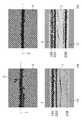
도 22는, 구면 수차 보정 패턴을 이용한 실시예의 결과와 구면 수차 보정 패턴을 이용하지 않았던 비교예의 결과와의 대비를 나타내는 도면이다. 도 22의 (a)의 상단이 실시예에 의한 가공 대상물(1)의 단면 사진이며, 도 22의 (a)의 하단이 실시예에 의한 가공 대상물(1)의 평면 사진이다. 또, 도 22의 (b)의 상단이 비교예에 의한 가공 대상물(1)의 단면 사진이며, 도 22의 (b)의 하단이 비교예에 의한 가공 대상물(1)의 평면 사진이다. 실험 조건은, 다음과 같다.Fig. 22 is a diagram showing the contrast between the results of the Example using the spherical aberration correction pattern and the results of the comparative example in which the spherical aberration correction pattern is not used. The upper end of Fig. 22 (a) is a cross-sectional photograph of the object to be processed 1 according to the embodiment, and the lower end of Fig. 22 (a) is a plan photograph of the object to be processed 1 according to the embodiment. In addition, the upper end of Fig. 22 (b) is a cross-sectional photograph of the
1. 가공 대상물1. object to be processed
(1) 두께 250㎛의 실리콘 기판을 준비했다.(1) A silicon substrate having a thickness of 250 µm was prepared.
2. 레이저광의 조사 조건2. Laser light irradiation conditions
(1) 하기의 표 2에 나타나는 조건으로 레이저광(L)에서의 집광 위치(CP1) 및 이상 집광 위치(CP0)를 조정하고, 파장 1080nm, 반복 주파수 92kHz, 펄스폭 500ns, 가공 에너지 15μJ, 스캔 속도 345mm/s의 조건으로 레이저광(L)을 조사했다. 또, 표 2에서,「이면」은, 레이저광(L)의 입사측의 가공 대상물(1)의 이면(21)이다. 또,「어긋남량」은, 집광 위치로부터 이상 집광 위치까지의 거리이며, 집광 위치(CP1)를 기준으로 하여, 이상 집광 위치(CP0)가 레이저광(L)의 입사측으로 어긋나 있는 경우를「-」의 수치로 나타내며, 이상 집광 위치(CP0)가 레이저광(L)의 입사측과는 반대측으로 어긋나 있는 경우를「+」의 수치로 나타냈다.(1) Adjust the condensing position (CP1) and the abnormal condensing position (CP0) in the laser light (L) under the conditions shown in Table 2 below, and a wavelength of 1080 nm, a repetition frequency of 92 kHz, a pulse width of 500 ns, a processing energy of 15 μJ, and a scan The laser beam L was irradiated on condition of the speed|rate of 345 mm/s. In addition, in Table 2, "back surface" is the

이 실험의 결과, 구면 수차 보정 패턴을 이용한 실시예에서는, 도 22의 (a)의 하단에 나타내어지는 바와 같이, 가공 대상물(1)의 표면(3)에서 절단 예정 라인(5)으로부터 벗어난 부분에 데미지(D)가 발생하지 않았다. 한편, 구면 수차 보정 패턴을 이용하지 않았던 비교예에서는, 도 22의 (b)의 하단에 나타내어지는 바와 같이, 가공 대상물(1)의 표면(3)에서 절단 예정 라인(5)으로부터 벗어난 부분에 데미지(D)가 발생했다.As a result of this experiment, in the example using the spherical aberration correction pattern, as shown in the lower part of FIG. No damage (D) occurred. On the other hand, in the comparative example in which the spherical aberration correction pattern was not used, as shown in the lower part of FIG. (D) occurred.
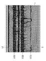
도 23은, 액시콘 렌즈 패턴을 이용한 실시예의 결과와 액시콘 렌즈 패턴을 이용하지 않았던 비교예의 결과와의 대비를 나타내는 도면이다. 도 23의 (a)의 상단이 실시예에 의한 가공 대상물(1)의 단면 사진이며, 도 23의 (a)의 하단이 실시예에 의한 가공 대상물(1)의 평면 사진이다. 또, 도 23의 (b)의 상단이 비교예에 의한 가공 대상물(1)의 단면 사진이며, 도 23의 (b)의 하단이 비교예에 의한 가공 대상물(1)의 평면 사진이다. 실험 조건은, 다음과 같다.FIG. 23 is a diagram showing a contrast between the results of the Example using the axicon lens pattern and the results of the comparative example in which the axicon lens pattern is not used. The upper end of Fig. 23 (a) is a cross-sectional photograph of the object to be processed 1 according to the embodiment, and the lower end of Fig. 23 (a) is a plan photograph of the object to be processed 1 according to the embodiment. In addition, the upper end of FIG. 23B is a cross-sectional photograph of the
1. 가공 대상물1. object to be processed
(1) 두께 250㎛의 실리콘 기판을 준비했다.(1) A silicon substrate having a thickness of 250 µm was prepared.
2. 레이저광의 조사 조건2. Laser light irradiation conditions
(1) 하기의 표 3에 나타내어지는 조건으로 레이저광(L)에서의 집광 위치(CP1) 및 이상 집광 위치(CP0)를 조정하고, 파장 1080nm, 반복 주파수 92kHz, 펄스폭 500ns, 가공 에너지 15μJ, 스캔 속도 345mm/s의 조건으로 레이저광(L)을 조사했다. 또, 표 3에서,「이면」은, 레이저광(L)의 입사측의 가공 대상물(1)의 이면(21)이다. 또,「어긋남량」은, 집광 위치로부터 이상 집광 위치까지의 거리이다.(1) Adjust the light-converging position (CP1) and the abnormal light-converging position (CP0) in the laser light L under the conditions shown in Table 3 below, a wavelength of 1080 nm, a repetition frequency of 92 kHz, a pulse width of 500 ns, a processing energy of 15 μJ, The laser beam L was irradiated on condition of the scan speed of 345 mm/s. In addition, in Table 3, "back surface" is the

이 실험의 결과, 액시콘 렌즈 패턴을 이용한 실시예에서는, 도 23의 (a)의 하단에 나타내어지는 바와 같이, 가공 대상물(1)의 표면(3)에서 절단 예정 라인(5)으로부터 벗어난 부분에 데미지(D)가 발생하지 않았다. 한편, 구면 수차 보정 패턴을 이용하지 않았던 비교예에서는, 도 23의 (b)의 하단에 나타내어지는 바와 같이, 가공 대상물(1)의 표면(3)에서 절단 예정 라인(5)으로부터 벗어난 부분에 데미지(D)가 발생했다.As a result of this experiment, in the example using the axicon lens pattern, as shown in the lower part of FIG. No damage (D) occurred. On the other hand, in the comparative example in which the spherical aberration correction pattern was not used, as shown in the lower part of Fig. 23 (b), the
도 24는, 에너지를 조정한 참고예의 결과를 나타내는 도면이며, 가공 대상물(1)의 단면 사진이다. 실험 조건은, 다음과 같다.24 is a diagram showing the result of a reference example in which energy is adjusted, and is a cross-sectional photograph of the
1. 가공 대상물1. object to be processed
(1) 두께 300㎛의 실리콘 기판을 준비했다.(1) A silicon substrate having a thickness of 300 µm was prepared.
2. 레이저광의 조사 조건2. Laser light irradiation conditions
(1) 하기의 표 4에 나타내어지는 조건으로 레이저광(L)에서의 집광 위치(CP1) 및 이상 집광 위치(CP0) 및 가공 에너지를 조정하고, 파장 1342nm, 반복 주파수 60kHz, 펄스폭 60ns, 스캔 속도 340mm/s의 조건으로 레이저광(L)을 조사했다. 또, 표 4에서,「이면」은, 레이저광(L)의 입사측의 가공 대상물(1)의 이면(21)이다. 또,「어긋남량」은, 집광 위치로부터 이상 집광 위치까지의 거리이다.(1) The condensing position (CP1) and the abnormal condensing position (CP0) and processing energy in the laser light L are adjusted under the conditions shown in Table 4 below, and the wavelength 1342 nm, repetition frequency 60 kHz, pulse width 60 ns, scan The laser beam L was irradiated on condition of the speed|rate of 340 mm/s. In addition, in Table 4, "back surface" is the

이 실험의 결과, 가공 대상물(1)의 표면(3)에서 절단 예정 라인(5)으로부터 벗어난 부분에 데미지(D)가 발생하는 것을 억제하기 위해서는, 이하의 사항이 유효하다라고 말할 수 있다.As a result of this experiment, it can be said that the following matters are effective in order to suppress the occurrence of the damage D on the
(1) 제1 영역(레이저광(L)의 입사측과는 반대측의 가공 대상물(1)의 표면(3)에 가장 가까운 제1 영역)에 개질 영역(7)을 형성하기 위한 가공 에너지를, 제2 영역(레이저광(L)의 입사측의 가공 대상물(1)의 이면(21)에 제1 영역보다도 가까운 제2 영역)에 개질 영역(7)을 형성하기 위한 가공 에너지에 비해, 작게 할 것.(1) processing energy for forming the modified
(2) 제1 영역에 개질 영역(7)을 형성하기 위한 가공 에너지를 10㎛ 이하로 할 것.(2) The processing energy for forming the modified
(3) 제1 영역에 형성된 개질 영역(7)과 제2 영역에 형성된 개질 영역(7)과의 사이에 흑근(黑筋, 검은 줄)이 형성될 것(도 24 참조).(3) Black roots should be formed between the modified
(4) 제1 영역에 형성된 개질 영역(7)과 제2 영역에 형성된 개질 영역(7)이 60㎛ 이상 떨어질 것.(4) The modified
(5) 제1 영역에 개질 영역(7)을 형성했을 때에, 상기 개질 영역(7)으로부터 신장된 균열이 가공 대상물(1)의 표면(3)에 도달하지 않고, 제2 영역에 개질 영역(7)을 형성했을 때에, 균열이 가공 대상물(1)의 표면(3)에 도달할 것.(5) When the modified
마지막으로, 개질 영역(7)의 형성 순서에 대해 설명한다. 도 25의 (a)에 나타내어지는 바와 같이, 절단 예정 라인(5)을 따라서 제1 영역에 개질 영역(7)을 형성하고, 그 후, 도 25의 (b)에 나타내어지는 바와 같이, 절단 예정 라인(5)을 따라서 제2 영역에 개질 영역(7)을 형성하며, 그 후, 가공 대상물(1)의 이면(21)에 붙여진 익스팬드 테이프를 확장시키는 것에 의해, 도 25의 (c)에 나타내어지는 바와 같이, 절단 예정 라인(5)을 따라서 형성된 개질 영역(7)으로부터 가공 대상물(1)의 두께 방향으로 신장된 균열을, 가공 대상물(1)의 표면(3) 및 이면(21)에 도달시켜도 괜찮다. 이 경우, 제2 영역에 개질 영역(7)을 형성한 시점에서는, 제1 영역에 형성된 개질 영역으로부터 신장된 균열과, 제2 영역에 형성된 개질 영역으로부터 신장된 균열이 연결되어 있지 않다. 또, 개질 영역(7)으로부터 가공 대상물(1)의 두께 방향으로 신장된 균열은, 제2 영역에 개질 영역(7)을 형성하고 있는 가장 가운데로부터 익스팬드 테이프를 확장시키기 전까지는, 가공 대상물(1)의 표면(3) 및 이면(21)에 도달하는 경우가 있다.Finally, the formation procedure of the modified
또, 도 26의 (a)에 나타내어지는 바와 같이, 절단 예정 라인(5)을 따라서 제1 영역에 개질 영역(7)을 형성하고, 그 후, 도 26의 (b)에 나타내어지는 바와 같이, 절단 예정 라인(5)을 따라서 제2 영역에 개질 영역(7)을 형성하며, 그 후, 가공 대상물(1)의 이면(21)에 붙여진 익스팬드 테이프를 확장시키는 것에 의해, 도 26의 (c)에 나타내어지는 바와 같이, 절단 예정 라인(5)을 따라서 형성된 개질 영역(7)으로부터 가공 대상물(1)의 두께 방향으로 신장된 균열을, 가공 대상물(1)의 표면(3) 및 이면(21)에 도달시켜도 괜찮다. 이 경우, 제2 영역에 개질 영역(7)을 형성한 시점에서, 제1 영역에 형성된 개질 영역으로부터 신장된 균열과, 제2 영역에 형성된 개질 영역으로부터 신장된 균열이 연결되어 있다. 또, 개질 영역(7)으로부터 가공 대상물(1)의 두께 방향으로 신장된 균열은, 제2 영역에 개질 영역(7)을 형성하고 있는 가장 가운데로부터 익스팬드 테이프를 확장시키기 전까지, 가공 대상물(1)의 표면(3) 및 이면(21)에 도달하는 경우가 있다.Further, as shown in Fig. 26(a), the modified
또, 반사형 공간 광변조기(203)를 이용하여, 레이저광(L)을 제1 영역과 제2 영역으로 나누어 동시에 집광하고, 도 27의 (a)에 나타내어지는 바와 같이, 절단 예정 라인(5)을 따라서 제1 영역 및 제2 영역에 개질 영역(7)을 동시에 형성하며, 그 후, 가공 대상물(1)의 이면(21)에 붙여진 익스팬드 테이프를 확장시키는 것에 의해, 도 27의 (b)에 나타내어지는 바와 같이, 절단 예정 라인(5)을 따라서 형성된 개질 영역(7)으로부터 가공 대상물(1)의 두께 방향으로 신장된 균열을, 가공 대상물(1)의 표면(3) 및 이면(21)에 도달시켜도 괜찮다. 이 경우, 제1 영역 및 제2 영역에 개질 영역(7)을 형성한 시점에서는, 제1 영역에 형성된 개질 영역으로부터 신장된 균열과, 제2 영역에 형성된 개질 영역으로부터 신장된 균열이 연결되어 있지 않다. 또, 개질 영역(7)으로부터 가공 대상물(1)의 두께 방향으로 신장된 균열은, 제1 영역 및 제2 영역에 개질 영역(7)을 형성하고 있는 가장 가운데로부터 익스팬드 테이프를 확장시키기 전까지, 가공 대상물(1)의 표면(3) 및 이면(21)에 도달하는 경우가 있다.Further, by using the reflective spatial
또, 반사형 공간 광변조기(203)를 이용하여, 레이저광(L)을 제1 영역과 제2 영역으로 나누어 동시에 집광하고, 도 28의 (a)에 나타내어지는 바와 같이, 절단 예정 라인(5)을 따라서 제1 영역 및 제2 영역에 개질 영역(7)을 동시에 형성하며, 그 후, 가공 대상물(1)의 이면(21)에 붙여진 익스팬드 테이프를 확장시키는 것에 의해, 도 28의 (b)에 나타내어지는 바와 같이, 절단 예정 라인(5)을 따라서 형성된 개질 영역(7)으로부터 가공 대상물(1)의 두께 방향으로 신장된 균열을, 가공 대상물(1)의 표면(3) 및 이면(21)에 도달시켜도 괜찮다. 이 경우, 제1 영역 및 제2 영역에 개질 영역(7)을 형성한 시점에서, 제1 영역에 형성된 개질 영역으로부터 신장된 균열과, 제2 영역에 형성된 개질 영역으로부터 신장된 균열이 연결되어 있다. 또, 개질 영역(7)으로부터 가공 대상물(1)의 두께 방향으로 신장된 균열은, 제1 영역 및 제2 영역에 개질 영역(7)을 형성하고 있는 가장 가운데로부터 익스팬드 테이프를 확장시키기 전까지, 가공 대상물(1)의 표면(3) 및 이면(21)에 도달하는 경우가 있다.Further, by using the reflective spatial
이상, 본 발명의 일 실시 형태에 대해 설명했지만, 본 발명은, 상기 실시 형태에 한정되는 것은 아니다. 예를 들면, 1개의 절단 예정 라인(5)에 대해서 1열의 개질 영역(7)을 형성하는 경우라도, 레이저광(L)의 입사측과는 반대측의 가공 대상물의 표면(3)으로부터의 거리가 소정 거리 이하의 제1 영역에 개질 영역(7)을 형성할 때에는, 기준 수차의 기준 집광 길이보다도 긴 제1 집광 길이가 되고 또한 기준 수차의 기준 집광 강도보다도 약한 제1 집광 강도가 되도록 수차를 조정하면, 가공 대상물(1)의 표면(3)에서 절단 예정 라인(5)으로부터 벗어난 부분에 데미지(D)가 발생하는 것을 억제할 수 있다.As mentioned above, although one Embodiment of this invention was described, this invention is not limited to the said embodiment. For example, even in the case of forming one row of modified
또, 가공 대상물(1)의 구성 및 재료는, 상술한 것에 한정되지 않는다. 일례로서, 기판(11)은, 실리콘 기판 이외의 반도체 기판, 사파이어 기판, SiC 기판, 유리 기판(강화 유리 기판), 투명 절연 기판 등이라도 괜찮다.In addition, the structure and material of the
[산업상의 이용 가능성][Industrial Applicability]
본 발명에 의하면, 레이저광의 입사측과는 반대측의 가공 대상물의 표면에서 절단 예정 라인으로부터 벗어난 부분에 데미지가 발생하는 것을 억제할 수 있는 레이저 가공 장치 및 레이저 가공 방법을 제공하는 것이 가능해진다.ADVANTAGE OF THE INVENTION According to this invention, it becomes possible to provide the laser processing apparatus and laser processing method which can suppress that a damage generate|occur|produces in the part deviating from the line to be cut on the surface of the object to be processed on the opposite side to the incident side of a laser beam.
1 - 가공 대상물3 - 표면(제1 표면)
5 - 절단 예정 라인7 - 개질 영역
15 - 기능 소자16 - 배선
17 - 스트리트 영역(영역)21 - 이면(제2 표면)
202 - 레이저 광원203 - 반사형 공간 광변조기(수차 조정부)
204 - 집광 광학계250 - 제어부(수차 조정부)
300 - 레이저 가공 장치L - 레이저광
CP1 - 집광 위치CP0 - 이상 집광 위치1 - object to be processed 3 - surface (first surface)
5 - line to be cut 7 - reforming area
15 - functional element 16 - wiring
17 - street area (area) 21 - back side (second surface)
202
204 - Condensing optical system 250 - Control unit (aberration adjustment unit)
300 - laser processing equipment L - laser beam
CP1 - Condensing Position CP0 - Abnormal Condensing Position
Claims (14)
Translated fromKorean상기 레이저광을 출사(出射)하는 레이저 광원과,
상기 레이저 광원에 의해 출사된 상기 레이저광을 상기 가공 대상물에 집광하는 집광 광학계와,
상기 가공 대상물에 상기 레이저광을 집광하는 것에 기인하여 집광 위치에서 발생하는 수차(收差)를 조정하는 수차 조정부를 구비하며,
상기 수차 조정부는,
상기 집광 위치로부터 상기 레이저광의 광축을 따라 상기 레이저광의 입사측으로 소정 거리만큼 이상(理想) 집광 위치를 어긋나게 한 상태에서의 수차 보정량으로 상기 집광 위치에 집광한 경우에 발생하는 상기 수차를 기준 수차로 하여,
상기 레이저광의 입사측과는 반대측의 상기 가공 대상물의 제1 표면에 가장 가까운 제1 영역에 상기 개질 영역을 형성하는 경우에는, 상기 기준 수차의 기준 집광 길이보다도 긴 제1 집광 길이가 되고 또한 상기 기준 수차의 기준 집광 강도보다도 약한 제1 집광 강도가 되도록 상기 수차를 조정하며,
상기 레이저광의 입사측의 상기 가공 대상물의 제2 표면에 상기 제1 영역보다도 가까운 제2 영역에 상기 개질 영역을 형성하는 경우에는, 상기 기준 집광 길이보다도 짧은 제2 집광 길이가 되고 또한 상기 기준 집광 강도보다도 강한 제2 집광 강도가 되도록 상기 수차를 조정하는 레이저 가공 장치.A laser processing apparatus for forming a modified region on an object to be processed along a line to be cut by focusing laser light on the object to be processed, the laser processing apparatus comprising:
a laser light source emitting the laser light;
a condensing optical system for condensing the laser light emitted by the laser light source on the object to be processed;
and an aberration adjusting unit for adjusting aberration occurring at a converging position due to condensing the laser light on the object to be processed;
The aberration adjustment unit,
Using the aberration correction amount in the state where the condensing position is shifted by a predetermined distance from the converging position to the incident side of the laser light along the optical axis of the laser light, the aberration occurring when condensing at the converging position is taken as the reference aberration ,
When the modified region is formed in the first region closest to the first surface of the object to be processed on the opposite side to the incident side of the laser light, the first condensing length is longer than the reference condensing length of the reference aberration, and the reference adjusting the aberration so as to have a first light-converging intensity that is weaker than the reference light-converging intensity of the aberration;
When the modified region is formed in a second region closer to the first region than the first region on the second surface of the object to be processed on the incident side of the laser light, the second condensing length is shorter than the reference condensing length and the reference condensing intensity A laser processing apparatus for adjusting the aberration so as to achieve a stronger second light-converging intensity.
상기 제1 표면에는, 배선을 포함하는 복수의 기능 소자가 마련되어 있고,
상기 절단 예정 라인은, 서로 이웃하는 상기 기능 소자의 사이의 영역을 통과하도록 설정되는 레이저 가공 장치.The method according to claim 1,
A plurality of functional elements including wirings are provided on the first surface;
The laser processing apparatus set so that the said line to be cut may pass through the area|region between the said functional elements adjacent to each other.
상기 제1 영역은, 상기 제1 표면으로부터의 거리가 60㎛ 이하의 영역에 설정되는 레이저 가공 장치.The method according to claim 1,
The said 1st area|region is a laser processing apparatus set in the area|region whose distance from the said 1st surface is 60 micrometers or less.
상기 제2 영역은, 상기 제1 표면으로부터의 거리가 40㎛ 이상의 영역에 설정되는 레이저 가공 장치.The method according to claim 1,
The said 2nd area|region is a laser processing apparatus set in the area|region whose distance from the said 1st surface is 40 micrometers or more.
상기 소정 거리는, 110㎛ 이상 140㎛ 이하인 레이저 가공 장치.5. The method according to any one of claims 1 to 4,
The said predetermined distance is a laser processing apparatus which is 110 micrometers or more and 140 micrometers or less.
상기 레이저광을 출사하는 레이저 광원과,
상기 레이저 광원에 의해 출사된 상기 레이저광을 상기 가공 대상물에 집광하는 집광 광학계와,
상기 가공 대상물에 상기 레이저광을 집광하는 것에 기인하여 집광 위치에서 발생하는 수차를 조정하는 수차 조정부를 구비하며,
상기 수차 조정부는,
상기 집광 위치로부터 상기 레이저광의 광축을 따라 상기 레이저광의 입사측으로 소정 거리만큼 이상 집광 위치를 어긋나게 한 상태에서의 수차 보정량으로 상기 집광 위치에 집광한 경우에 발생하는 상기 수차를 기준 수차로 하여,
상기 레이저광의 입사측과는 반대측의 상기 가공 대상물의 제1 표면으로부터의 거리가 소정 거리 이하인 제1 영역에 상기 개질 영역을 형성하는 경우에는, 상기 기준 수차의 기준 집광 길이보다도 긴 제1 집광 길이가 되고 또한 상기 기준 수차의 기준 집광 강도보다도 약한 제1 집광 강도가 되도록 상기 수차를 조정하는 레이저 가공 장치.A laser processing apparatus for forming a modified region on the object to be processed along a line to be cut by focusing laser light on the object, comprising:
a laser light source emitting the laser light;
a condensing optical system for condensing the laser light emitted by the laser light source on the object to be processed;
and an aberration adjusting unit for adjusting aberration occurring at a converging position due to condensing the laser light on the object to be processed;
The aberration adjustment unit,
The aberration that occurs when the light is converged at the converging position with an aberration correction amount in a state in which the condensing position is shifted by a predetermined distance or more from the converging position to the incident side of the laser light along the optical axis of the laser light is taken as the reference aberration,
When the modified region is formed in a first region where the distance from the first surface of the object to be processed on the opposite side to the incident side of the laser light is a predetermined distance or less, the first condensing length longer than the reference condensing length of the reference aberration is A laser processing apparatus for adjusting the aberration so that it becomes a first condensing intensity that is weaker than the standard converging intensity of the reference aberration.
상기 가공 대상물에 상기 레이저광을 집광하는 것에 기인하여 집광 위치에서 발생하는 수차를 조정하여, 상기 가공 대상물에 상기 레이저광을 집광하는 것에 의해, 상기 레이저광의 입사측과는 반대측의 상기 가공 대상물의 제1 표면에 가장 가까운 제1 영역에 상기 개질 영역을 형성하는 제1 공정과,
상기 집광 위치에서 발생하는 상기 수차를 조정하여, 상기 가공 대상물에 상기 레이저광을 집광하는 것에 의해, 상기 레이저광의 입사측의 상기 가공 대상물의 제2 표면에 상기 제1 영역보다도 가까운 제2 영역에 상기 개질 영역을 형성하는 제2 공정을 포함하며,
상기 제1 공정에서는, 상기 집광 위치로부터 상기 레이저광의 광축을 따라 상기 레이저광의 입사측으로 소정 거리만큼 이상 집광 위치를 어긋나게 한 상태에서의 수차 보정량으로 상기 집광 위치에 집광한 경우에 발생하는 기준 수차의 기준 집광 길이보다도 긴 제1 집광 길이가 되고 또한 상기 기준 수차의 기준 집광 강도보다도 약한 제1 집광 강도가 되도록 상기 수차를 조정하고,
상기 제2 공정에서는, 상기 기준 집광 길이보다도 짧은 제2 집광 길이가 되고 또한 상기 기준 집광 강도보다도 강한 제2 집광 강도가 되도록 상기 수차를 조정하는 레이저 가공 방법.A laser processing method for forming a modified region on the object to be processed along a line to be cut by focusing laser light on the object, the laser processing method comprising:
By adjusting the aberration occurring at the condensing position due to condensing the laser light on the object, and condensing the laser light on the object to be processed, the object to be processed on the opposite side to the incident side of the laser light a first step of forming the modified region in a first region closest to the first surface;
By adjusting the aberration occurring at the converging position and condensing the laser light on the object to be processed, the second area on the second surface of the object to be processed on the incident side of the laser light is closer to the second area than the first area. a second process of forming a modified region;
In the first step, the reference aberration that occurs when the light is focused at the converging position with an aberration correction amount in a state in which the condensing position is shifted by more than a predetermined distance from the converging position to the incident side of the laser light along the optical axis of the laser light adjusting the aberration so as to have a first condensing length longer than the condensing length and a first condensing intensity weaker than the reference condensing intensity of the reference aberration;
In the second step, a laser processing method in which the aberration is adjusted so that a second condensing length shorter than the reference condensing length and a second condensing intensity stronger than the reference condensing intensity are obtained.
상기 제1 표면에는, 배선을 포함하는 복수의 기능 소자가 마련되어 있고,
상기 절단 예정 라인은, 서로 이웃하는 상기 기능 소자의 사이의 영역을 통과하도록 설정되는 레이저 가공 방법.8. The method of claim 7,
A plurality of functional elements including wirings are provided on the first surface;
The line to be cut is set so as to pass through a region between the adjacent functional elements.
상기 제1 영역은, 상기 제1 표면으로부터의 거리가 60㎛ 이하의 영역에 설정되는 레이저 가공 방법.8. The method of claim 7,
The laser processing method in which the said 1st area|region is set in the area|region whose distance from the said 1st surface is 60 micrometers or less.
상기 제2 영역은, 상기 제1 표면으로부터의 거리가 40㎛ 이상의 영역에 설정되는 레이저 가공 방법.8. The method of claim 7,
The said 2nd area|region is a laser processing method in which the distance from the said 1st surface is set to the area|region of 40 micrometers or more.
상기 소정 거리는, 110㎛ 이상 140㎛ 이하인 레이저 가공 방법.11. The method according to any one of claims 7 to 10,
The said predetermined distance is a laser processing method of 110 micrometers or more and 140 micrometers or less.
상기 제1 공정을 실시한 후에 상기 제2 공정을 실시하는 경우에는, 상기 제1 영역은, 상기 제1 공정에서 상기 개질 영역으로부터 상기 레이저광의 입사측과는 반대측으로 신장되는 균열이 상기 제1 표면에 도달하지 않도록 설정되는 레이저 가공 방법.11. The method according to any one of claims 7 to 10,
When the second process is performed after the first process is performed, in the first region, in the first process, cracks extending from the modified region to the side opposite to the incident side of the laser light are formed on the first surface A laser processing method that is set not to reach.
상기 제1 공정을 실시한 후에 상기 제2 공정을 실시하는 경우에는, 상기 제2 영역은, 상기 제1 공정에서 상기 개질 영역으로부터 상기 레이저광의 입사측으로 신장된 균열과 겹치지 않도록 설정되는 레이저 가공 방법.11. The method according to any one of claims 7 to 10,
In a case where the second step is performed after the first step, the second area is set so as not to overlap a crack extending from the modified area to the incident side of the laser beam in the first step.
상기 가공 대상물에 상기 레이저광을 집광하는 것에 기인하여 집광 위치에서 발생하는 수차를 조정하여, 상기 가공 대상물에 상기 레이저광을 집광하는 것에 의해, 상기 레이저광의 입사측과는 반대측의 상기 가공 대상물의 제1 표면으로부터의 거리가 소정 거리 이하의 제1 영역에 상기 개질 영역을 형성하는 제1 공정을 포함하며,
상기 제1 공정에서는, 상기 집광 위치로부터 상기 레이저광의 광축을 따라 상기 레이저광의 입사측으로 소정 거리만큼 이상 집광 위치를 어긋나게 한 상태에서의 수차 보정량으로 상기 집광 위치에 집광한 경우에 발생하는 기준 수차의 기준 집광 길이보다도 긴 제1 집광 길이가 되고 또한 상기 기준 수차의 기준 집광 강도보다도 약한 제1 집광 강도가 되도록 상기 수차를 조정하는 레이저 가공 방법.A laser processing method for forming a modified region on the object to be processed along a line to be cut by focusing laser light on the object, the laser processing method comprising:
By adjusting the aberration occurring at the condensing position due to condensing the laser light on the object, and condensing the laser light on the object to be processed, the object to be processed on the opposite side to the incident side of the laser light a first step of forming said modified region in a first region having a distance from one surface equal to or less than a predetermined distance;
In the first step, the reference aberration that occurs when the light is focused at the converging position with an aberration correction amount in a state in which the condensing position is shifted by more than a predetermined distance from the converging position to the incident side of the laser light along the optical axis of the laser light A laser processing method in which the aberration is adjusted so that it becomes a first condensing length longer than the condensing length and a first condensing intensity that is weaker than the reference condensing intensity of the reference aberration.
Applications Claiming Priority (3)
| Application Number | Priority Date | Filing Date | Title |
|---|---|---|---|
| JPJP-P-2014-077537 | 2014-04-04 | ||
| JP2014077537AJP6353683B2 (en) | 2014-04-04 | 2014-04-04 | Laser processing apparatus and laser processing method |
| PCT/JP2015/059937WO2015152156A1 (en) | 2014-04-04 | 2015-03-30 | Laser processing device and laser processing method |
Publications (2)
| Publication Number | Publication Date |
|---|---|
| KR20160141814A KR20160141814A (en) | 2016-12-09 |
| KR102380747B1true KR102380747B1 (en) | 2022-03-31 |
Family
ID=54240479
Family Applications (1)
| Application Number | Title | Priority Date | Filing Date |
|---|---|---|---|
| KR1020167030723AActiveKR102380747B1 (en) | 2014-04-04 | 2015-03-30 | Laser processing device and laser processing method |
Country Status (7)
| Country | Link |
|---|---|
| US (1) | US11007607B2 (en) |
| JP (1) | JP6353683B2 (en) |
| KR (1) | KR102380747B1 (en) |
| CN (1) | CN106163724B (en) |
| DE (1) | DE112015001612T5 (en) |
| TW (1) | TWI657885B (en) |
| WO (1) | WO2015152156A1 (en) |
Families Citing this family (33)
| Publication number | Priority date | Publication date | Assignee | Title |
|---|---|---|---|---|
| JP2017107903A (en)* | 2015-12-07 | 2017-06-15 | 株式会社ディスコ | Wafer processing method |
| JP6468295B2 (en)* | 2016-01-27 | 2019-02-13 | 株式会社デンソー | Member manufacturing method and member manufacturing apparatus |
| WO2017130960A1 (en)* | 2016-01-27 | 2017-08-03 | 株式会社デンソー | Member manufacturing method and member manufacturing device |
| TWI717519B (en)* | 2016-05-27 | 2021-02-01 | 日商濱松赫德尼古斯股份有限公司 | Manufacturing method of Fabry-Peru interference filter |
| FI3467565T3 (en)* | 2016-05-27 | 2024-03-19 | Hamamatsu Photonics Kk | Production method for fabry-perot interference filter |
| JP6341959B2 (en)* | 2016-05-27 | 2018-06-13 | 浜松ホトニクス株式会社 | Manufacturing method of Fabry-Perot interference filter |
| US10724902B2 (en) | 2016-08-24 | 2020-07-28 | Hamamatsu Photonics K.K. | Fabry-Perot interference filter |
| TWI630974B (en)* | 2016-11-02 | 2018-08-01 | 財團法人工業技術研究院 | Laser system and laser flare processing method |
| JP6786374B2 (en)* | 2016-12-16 | 2020-11-18 | 株式会社スミテック | Laser processing equipment and laser processing method |
| JP2018182141A (en)* | 2017-04-17 | 2018-11-15 | 浜松ホトニクス株式会社 | Workpiece cutting method |
| JP2019051529A (en)* | 2017-09-13 | 2019-04-04 | 東芝メモリ株式会社 | Semiconductor manufacturing equipment |
| JP7105058B2 (en)* | 2017-12-05 | 2022-07-22 | 株式会社ディスコ | Wafer processing method |
| GB201803948D0 (en)* | 2018-03-12 | 2018-04-25 | Mbda Uk Ltd | An imaging device |
| US11401195B2 (en) | 2018-03-29 | 2022-08-02 | Corning Incorporated | Selective laser processing of transparent workpiece stacks |
| JP7307533B2 (en)* | 2018-10-04 | 2023-07-12 | 浜松ホトニクス株式会社 | Laser processing method, semiconductor device manufacturing method and inspection device |
| JP7307534B2 (en) | 2018-10-04 | 2023-07-12 | 浜松ホトニクス株式会社 | Laser processing method, semiconductor device manufacturing method and inspection apparatus |
| US11024501B2 (en) | 2018-12-29 | 2021-06-01 | Cree, Inc. | Carrier-assisted method for parting crystalline material along laser damage region |
| US10576585B1 (en) | 2018-12-29 | 2020-03-03 | Cree, Inc. | Laser-assisted method for parting crystalline material |
| US10562130B1 (en) | 2018-12-29 | 2020-02-18 | Cree, Inc. | Laser-assisted method for parting crystalline material |
| JP7233816B2 (en)* | 2019-02-19 | 2023-03-07 | 株式会社ディスコ | Wafer processing method |
| US10611052B1 (en) | 2019-05-17 | 2020-04-07 | Cree, Inc. | Silicon carbide wafers with relaxed positive bow and related methods |
| JP7303080B2 (en) | 2019-09-11 | 2023-07-04 | 浜松ホトニクス株式会社 | LASER PROCESSING APPARATUS AND LASER PROCESSING METHOD |
| JP7368205B2 (en)* | 2019-12-04 | 2023-10-24 | 浜松ホトニクス株式会社 | laser processing equipment |
| JP2021089383A (en)* | 2019-12-05 | 2021-06-10 | 株式会社ディスコ | Laser beam adjustment mechanism and laser processing apparatus |
| JP7460377B2 (en)* | 2020-01-28 | 2024-04-02 | 浜松ホトニクス株式会社 | Laser processing device and laser processing method |
| CN116113517A (en)* | 2020-07-15 | 2023-05-12 | 浜松光子学株式会社 | Laser processing device and laser processing method |
| CN115145066A (en)* | 2021-03-31 | 2022-10-04 | 深圳晶微峰光电科技有限公司 | Silicon-based liquid crystal panel and preparation method thereof |
| JP7577622B2 (en)* | 2021-06-30 | 2024-11-05 | 浜松ホトニクス株式会社 | Laser processing device and laser processing method |
| CN117228945B (en)* | 2023-11-15 | 2024-01-23 | 成都新世佳特种玻璃技术开发有限公司 | Cutting device and cutting process for special glass production |
| JP2025121710A (en)* | 2024-02-07 | 2025-08-20 | 浜松ホトニクス株式会社 | Laser processing device and laser processing method |
| JP2025121708A (en)* | 2024-02-07 | 2025-08-20 | 浜松ホトニクス株式会社 | Laser processing device and laser processing method |
| JP2025121702A (en)* | 2024-02-07 | 2025-08-20 | 浜松ホトニクス株式会社 | Laser processing device and laser processing method |
| JP2025121706A (en)* | 2024-02-07 | 2025-08-20 | 浜松ホトニクス株式会社 | Laser processing device and laser processing method |
Citations (1)
| Publication number | Priority date | Publication date | Assignee | Title |
|---|---|---|---|---|
| JP2013128088A (en)* | 2011-11-18 | 2013-06-27 | Hamamatsu Photonics Kk | Laser processing method and laser processing device |
Family Cites Families (7)
| Publication number | Priority date | Publication date | Assignee | Title |
|---|---|---|---|---|
| CA2108761A1 (en)* | 1992-10-23 | 1994-04-24 | Koichi Haruta | Method and apparatus for welding material by laser beam |
| US6211488B1 (en)* | 1998-12-01 | 2001-04-03 | Accudyne Display And Semiconductor Systems, Inc. | Method and apparatus for separating non-metallic substrates utilizing a laser initiated scribe |
| JP4736633B2 (en)* | 2005-08-31 | 2011-07-27 | セイコーエプソン株式会社 | Laser irradiation device |
| US9138913B2 (en) | 2005-09-08 | 2015-09-22 | Imra America, Inc. | Transparent material processing with an ultrashort pulse laser |
| JP2007284310A (en)* | 2006-04-19 | 2007-11-01 | Seiko Epson Corp | Laser scribing method, laser processing apparatus, and electro-optical apparatus |
| JP4402708B2 (en) | 2007-08-03 | 2010-01-20 | 浜松ホトニクス株式会社 | Laser processing method, laser processing apparatus and manufacturing method thereof |
| JP5479925B2 (en) | 2010-01-27 | 2014-04-23 | 浜松ホトニクス株式会社 | Laser processing system |
- 2014
- 2014-04-04JPJP2014077537Apatent/JP6353683B2/enactiveActive
- 2015
- 2015-03-30KRKR1020167030723Apatent/KR102380747B1/enactiveActive
- 2015-03-30USUS15/301,451patent/US11007607B2/enactiveActive
- 2015-03-30WOPCT/JP2015/059937patent/WO2015152156A1/enactiveApplication Filing
- 2015-03-30CNCN201580017834.6Apatent/CN106163724B/enactiveActive
- 2015-03-30DEDE112015001612.0Tpatent/DE112015001612T5/enactivePending
- 2015-04-02TWTW104110984Apatent/TWI657885B/enactive
Patent Citations (1)
| Publication number | Priority date | Publication date | Assignee | Title |
|---|---|---|---|---|
| JP2013128088A (en)* | 2011-11-18 | 2013-06-27 | Hamamatsu Photonics Kk | Laser processing method and laser processing device |
Also Published As
| Publication number | Publication date |
|---|---|
| US20170106476A1 (en) | 2017-04-20 |
| TWI657885B (en) | 2019-05-01 |
| TW201601867A (en) | 2016-01-16 |
| KR20160141814A (en) | 2016-12-09 |
| CN106163724A (en) | 2016-11-23 |
| JP6353683B2 (en) | 2018-07-04 |
| CN106163724B (en) | 2018-10-26 |
| WO2015152156A1 (en) | 2015-10-08 |
| JP2015199071A (en) | 2015-11-12 |
| DE112015001612T5 (en) | 2017-01-05 |
| US11007607B2 (en) | 2021-05-18 |
Similar Documents
| Publication | Publication Date | Title |
|---|---|---|
| KR102380747B1 (en) | Laser processing device and laser processing method | |
| JP6272301B2 (en) | Laser processing apparatus and laser processing method | |
| KR102303178B1 (en) | Laser machining device and laser machining method | |
| KR101757937B1 (en) | Workpiece cutting method | |
| JP6039217B2 (en) | Laser processing method | |
| KR102442329B1 (en) | Laser machining device and laser machining method | |
| TWI647043B (en) | Laser processing device and laser processing method | |
| JP5905274B2 (en) | Manufacturing method of semiconductor device | |
| JP6272302B2 (en) | Laser processing apparatus and laser processing method | |
| US9821408B2 (en) | Laser machining method and laser machining device | |
| KR102128416B1 (en) | Laser machining device and laser machining method | |
| JP6715632B2 (en) | Laser processing method and laser processing apparatus | |
| KR20120112775A (en) | Laser processing method |
Legal Events
| Date | Code | Title | Description |
|---|---|---|---|
| PA0105 | International application | Patent event date:20161102 Patent event code:PA01051R01D Comment text:International Patent Application | |
| PG1501 | Laying open of application | ||
| A201 | Request for examination | ||
| PA0201 | Request for examination | Patent event code:PA02012R01D Patent event date:20200330 Comment text:Request for Examination of Application | |
| E902 | Notification of reason for refusal | ||
| PE0902 | Notice of grounds for rejection | Comment text:Notification of reason for refusal Patent event date:20210225 Patent event code:PE09021S01D | |
| E701 | Decision to grant or registration of patent right | ||
| PE0701 | Decision of registration | Patent event code:PE07011S01D Comment text:Decision to Grant Registration Patent event date:20211225 | |
| PR0701 | Registration of establishment | Comment text:Registration of Establishment Patent event date:20220325 Patent event code:PR07011E01D | |
| PR1002 | Payment of registration fee | Payment date:20220328 End annual number:3 Start annual number:1 | |
| PG1601 | Publication of registration | ||
| PR1001 | Payment of annual fee | Payment date:20250218 Start annual number:4 End annual number:4 |