KR102376609B1 - Electromagnetic Needle Catheterization System - Google Patents
Electromagnetic Needle Catheterization SystemDownload PDFInfo
- Publication number
- KR102376609B1 KR102376609B1KR1020187036110AKR20187036110AKR102376609B1KR 102376609 B1KR102376609 B1KR 102376609B1KR 1020187036110 AKR1020187036110 AKR 1020187036110AKR 20187036110 AKR20187036110 AKR 20187036110AKR 102376609 B1KR102376609 B1KR 102376609B1
- Authority
- KR
- South Korea
- Prior art keywords
- magnetic field
- tissue
- needle
- housing
- hub
- Prior art date
- Legal status (The legal status is an assumption and is not a legal conclusion. Google has not performed a legal analysis and makes no representation as to the accuracy of the status listed.)
- Active
Links
- 238000000034methodMethods0.000claimsabstractdescription27
- 238000004891communicationMethods0.000claimsdescription29
- 210000004369bloodAnatomy0.000claimsdescription23
- 239000008280bloodSubstances0.000claimsdescription23
- 238000012790confirmationMethods0.000claimsdescription15
- 238000003780insertionMethods0.000claimsdescription12
- 230000037431insertionEffects0.000claimsdescription12
- 230000002792vascularEffects0.000claimsdescription11
- 238000012285ultrasound imagingMethods0.000claimsdescription4
- 230000000881depressing effectEffects0.000claimsdescription2
- 239000012530fluidSubstances0.000description13
- 239000000463materialSubstances0.000description9
- 210000004204blood vesselAnatomy0.000description8
- 230000007246mechanismEffects0.000description7
- 238000003825pressingMethods0.000description6
- 238000001990intravenous administrationMethods0.000description5
- 238000002604ultrasonographyMethods0.000description5
- 210000003484anatomyAnatomy0.000description4
- 230000005415magnetizationEffects0.000description4
- 239000007769metal materialSubstances0.000description4
- 230000003213activating effectEffects0.000description3
- 230000017531blood circulationEffects0.000description3
- 239000002184metalSubstances0.000description3
- 230000002093peripheral effectEffects0.000description3
- -1polyethylene terephthalatePolymers0.000description3
- 210000003462veinAnatomy0.000description3
- 208000012266Needlestick injuryDiseases0.000description2
- 230000000712assemblyEffects0.000description2
- 238000000429assemblyMethods0.000description2
- 239000003990capacitorSubstances0.000description2
- 238000011109contaminationMethods0.000description2
- 230000006378damageEffects0.000description2
- 238000005516engineering processMethods0.000description2
- 238000003384imaging methodMethods0.000description2
- 238000012986modificationMethods0.000description2
- 230000004048modificationEffects0.000description2
- 239000004417polycarbonateSubstances0.000description2
- 229920000139polyethylene terephthalatePolymers0.000description2
- 239000005020polyethylene terephthalateSubstances0.000description2
- 239000002861polymer materialSubstances0.000description2
- 229910001220stainless steelInorganic materials0.000description2
- 239000010935stainless steelSubstances0.000description2
- 235000001674Agaricus brunnescensNutrition0.000description1
- 241001631457CannulaSpecies0.000description1
- 239000004698PolyethyleneSubstances0.000description1
- 239000000853adhesiveSubstances0.000description1
- 230000001070adhesive effectEffects0.000description1
- 238000013459approachMethods0.000description1
- 239000000560biocompatible materialSubstances0.000description1
- 238000010276constructionMethods0.000description1
- 238000001514detection methodMethods0.000description1
- 238000006073displacement reactionMethods0.000description1
- 230000005672electromagnetic fieldEffects0.000description1
- 229920005570flexible polymerPolymers0.000description1
- 230000006870functionEffects0.000description1
- 230000002209hydrophobic effectEffects0.000description1
- 230000001788irregularEffects0.000description1
- 229920000126latexPolymers0.000description1
- 239000004816latexSubstances0.000description1
- 239000002991molded plasticSubstances0.000description1
- 230000000149penetrating effectEffects0.000description1
- 229920000515polycarbonatePolymers0.000description1
- 229920001692polycarbonate urethanePolymers0.000description1
- 229920000573polyethylenePolymers0.000description1
- 229920005644polyethylene terephthalate glycol copolymerPolymers0.000description1
- 229920000642polymerPolymers0.000description1
- 229920002635polyurethanePolymers0.000description1
- 239000004814polyurethaneSubstances0.000description1
- 229920000915polyvinyl chloridePolymers0.000description1
- 239000004800polyvinyl chlorideSubstances0.000description1
- 239000011148porous materialSubstances0.000description1
- 230000008569processEffects0.000description1
- 238000007789sealingMethods0.000description1
- 238000000926separation methodMethods0.000description1
- 229920002379silicone rubberPolymers0.000description1
- 239000004945silicone rubberSubstances0.000description1
- 239000007787solidSubstances0.000description1
- 239000002904solventSubstances0.000description1
- 238000007920subcutaneous administrationMethods0.000description1
- 229920001169thermoplasticPolymers0.000description1
- 229920002725thermoplastic elastomerPolymers0.000description1
- 239000012815thermoplastic materialSubstances0.000description1
- 230000007704transitionEffects0.000description1
- 239000012780transparent materialSubstances0.000description1
- 238000012800visualizationMethods0.000description1
Images


Classifications
- A—HUMAN NECESSITIES
- A61—MEDICAL OR VETERINARY SCIENCE; HYGIENE
- A61B—DIAGNOSIS; SURGERY; IDENTIFICATION
- A61B17/00—Surgical instruments, devices or methods
- A61B17/34—Trocars; Puncturing needles
- A—HUMAN NECESSITIES
- A61—MEDICAL OR VETERINARY SCIENCE; HYGIENE
- A61B—DIAGNOSIS; SURGERY; IDENTIFICATION
- A61B5/00—Measuring for diagnostic purposes; Identification of persons
- A61B5/06—Devices, other than using radiation, for detecting or locating foreign bodies ; Determining position of diagnostic devices within or on the body of the patient
- A61B5/061—Determining position of a probe within the body employing means separate from the probe, e.g. sensing internal probe position employing impedance electrodes on the surface of the body
- A61B5/062—Determining position of a probe within the body employing means separate from the probe, e.g. sensing internal probe position employing impedance electrodes on the surface of the body using magnetic field
- A—HUMAN NECESSITIES
- A61—MEDICAL OR VETERINARY SCIENCE; HYGIENE
- A61B—DIAGNOSIS; SURGERY; IDENTIFICATION
- A61B17/00—Surgical instruments, devices or methods
- A61B17/34—Trocars; Puncturing needles
- A61B17/3403—Needle locating or guiding means
- A—HUMAN NECESSITIES
- A61—MEDICAL OR VETERINARY SCIENCE; HYGIENE
- A61B—DIAGNOSIS; SURGERY; IDENTIFICATION
- A61B17/00—Surgical instruments, devices or methods
- A61B17/34—Trocars; Puncturing needles
- A61B17/3417—Details of tips or shafts, e.g. grooves, expandable, bendable; Multiple coaxial sliding cannulas, e.g. for dilating
- A—HUMAN NECESSITIES
- A61—MEDICAL OR VETERINARY SCIENCE; HYGIENE
- A61B—DIAGNOSIS; SURGERY; IDENTIFICATION
- A61B34/00—Computer-aided surgery; Manipulators or robots specially adapted for use in surgery
- A61B34/20—Surgical navigation systems; Devices for tracking or guiding surgical instruments, e.g. for frameless stereotaxis
- A—HUMAN NECESSITIES
- A61—MEDICAL OR VETERINARY SCIENCE; HYGIENE
- A61B—DIAGNOSIS; SURGERY; IDENTIFICATION
- A61B5/00—Measuring for diagnostic purposes; Identification of persons
- A61B5/0033—Features or image-related aspects of imaging apparatus, e.g. for MRI, optical tomography or impedance tomography apparatus; Arrangements of imaging apparatus in a room
- A61B5/0035—Features or image-related aspects of imaging apparatus, e.g. for MRI, optical tomography or impedance tomography apparatus; Arrangements of imaging apparatus in a room adapted for acquisition of images from more than one imaging mode, e.g. combining MRI and optical tomography
- A—HUMAN NECESSITIES
- A61—MEDICAL OR VETERINARY SCIENCE; HYGIENE
- A61B—DIAGNOSIS; SURGERY; IDENTIFICATION
- A61B8/00—Diagnosis using ultrasonic, sonic or infrasonic waves
- A61B8/08—Clinical applications
- A61B8/0833—Clinical applications involving detecting or locating foreign bodies or organic structures
- A61B8/0841—Clinical applications involving detecting or locating foreign bodies or organic structures for locating instruments
- A—HUMAN NECESSITIES
- A61—MEDICAL OR VETERINARY SCIENCE; HYGIENE
- A61M—DEVICES FOR INTRODUCING MEDIA INTO, OR ONTO, THE BODY; DEVICES FOR TRANSDUCING BODY MEDIA OR FOR TAKING MEDIA FROM THE BODY; DEVICES FOR PRODUCING OR ENDING SLEEP OR STUPOR
- A61M25/00—Catheters; Hollow probes
- A61M25/01—Introducing, guiding, advancing, emplacing or holding catheters
- A61M25/0102—Insertion or introduction using an inner stiffening member, e.g. stylet or push-rod
- A—HUMAN NECESSITIES
- A61—MEDICAL OR VETERINARY SCIENCE; HYGIENE
- A61M—DEVICES FOR INTRODUCING MEDIA INTO, OR ONTO, THE BODY; DEVICES FOR TRANSDUCING BODY MEDIA OR FOR TAKING MEDIA FROM THE BODY; DEVICES FOR PRODUCING OR ENDING SLEEP OR STUPOR
- A61M25/00—Catheters; Hollow probes
- A61M25/01—Introducing, guiding, advancing, emplacing or holding catheters
- A61M25/0105—Steering means as part of the catheter or advancing means; Markers for positioning
- A61M25/0108—Steering means as part of the catheter or advancing means; Markers for positioning using radio-opaque or ultrasound markers
- A—HUMAN NECESSITIES
- A61—MEDICAL OR VETERINARY SCIENCE; HYGIENE
- A61M—DEVICES FOR INTRODUCING MEDIA INTO, OR ONTO, THE BODY; DEVICES FOR TRANSDUCING BODY MEDIA OR FOR TAKING MEDIA FROM THE BODY; DEVICES FOR PRODUCING OR ENDING SLEEP OR STUPOR
- A61M25/00—Catheters; Hollow probes
- A61M25/01—Introducing, guiding, advancing, emplacing or holding catheters
- A61M25/0105—Steering means as part of the catheter or advancing means; Markers for positioning
- A61M25/0127—Magnetic means; Magnetic markers
- A—HUMAN NECESSITIES
- A61—MEDICAL OR VETERINARY SCIENCE; HYGIENE
- A61M—DEVICES FOR INTRODUCING MEDIA INTO, OR ONTO, THE BODY; DEVICES FOR TRANSDUCING BODY MEDIA OR FOR TAKING MEDIA FROM THE BODY; DEVICES FOR PRODUCING OR ENDING SLEEP OR STUPOR
- A61M25/00—Catheters; Hollow probes
- A61M25/01—Introducing, guiding, advancing, emplacing or holding catheters
- A61M25/06—Body-piercing guide needles or the like
- A61M25/0606—"Over-the-needle" catheter assemblies, e.g. I.V. catheters
- A—HUMAN NECESSITIES
- A61—MEDICAL OR VETERINARY SCIENCE; HYGIENE
- A61M—DEVICES FOR INTRODUCING MEDIA INTO, OR ONTO, THE BODY; DEVICES FOR TRANSDUCING BODY MEDIA OR FOR TAKING MEDIA FROM THE BODY; DEVICES FOR PRODUCING OR ENDING SLEEP OR STUPOR
- A61M25/00—Catheters; Hollow probes
- A61M25/01—Introducing, guiding, advancing, emplacing or holding catheters
- A61M25/06—Body-piercing guide needles or the like
- A61M25/0612—Devices for protecting the needle; Devices to help insertion of the needle, e.g. wings or holders
- A—HUMAN NECESSITIES
- A61—MEDICAL OR VETERINARY SCIENCE; HYGIENE
- A61M—DEVICES FOR INTRODUCING MEDIA INTO, OR ONTO, THE BODY; DEVICES FOR TRANSDUCING BODY MEDIA OR FOR TAKING MEDIA FROM THE BODY; DEVICES FOR PRODUCING OR ENDING SLEEP OR STUPOR
- A61M25/00—Catheters; Hollow probes
- A61M25/01—Introducing, guiding, advancing, emplacing or holding catheters
- A61M25/06—Body-piercing guide needles or the like
- A61M25/0693—Flashback chambers
- A—HUMAN NECESSITIES
- A61—MEDICAL OR VETERINARY SCIENCE; HYGIENE
- A61M—DEVICES FOR INTRODUCING MEDIA INTO, OR ONTO, THE BODY; DEVICES FOR TRANSDUCING BODY MEDIA OR FOR TAKING MEDIA FROM THE BODY; DEVICES FOR PRODUCING OR ENDING SLEEP OR STUPOR
- A61M5/00—Devices for bringing media into the body in a subcutaneous, intra-vascular or intramuscular way; Accessories therefor, e.g. filling or cleaning devices, arm-rests
- A61M5/178—Syringes
- A61M5/31—Details
- A61M5/32—Needles; Details of needles pertaining to their connection with syringe or hub; Accessories for bringing the needle into, or holding the needle on, the body; Devices for protection of needles
- A61M5/3287—Accessories for bringing the needle into the body; Automatic needle insertion
- A—HUMAN NECESSITIES
- A61—MEDICAL OR VETERINARY SCIENCE; HYGIENE
- A61M—DEVICES FOR INTRODUCING MEDIA INTO, OR ONTO, THE BODY; DEVICES FOR TRANSDUCING BODY MEDIA OR FOR TAKING MEDIA FROM THE BODY; DEVICES FOR PRODUCING OR ENDING SLEEP OR STUPOR
- A61M5/00—Devices for bringing media into the body in a subcutaneous, intra-vascular or intramuscular way; Accessories therefor, e.g. filling or cleaning devices, arm-rests
- A61M5/42—Devices for bringing media into the body in a subcutaneous, intra-vascular or intramuscular way; Accessories therefor, e.g. filling or cleaning devices, arm-rests having means for desensitising skin, for protruding skin to facilitate piercing, or for locating point where body is to be pierced
- A61M5/427—Locating point where body is to be pierced, e.g. vein location means using ultrasonic waves, injection site templates
- A—HUMAN NECESSITIES
- A61—MEDICAL OR VETERINARY SCIENCE; HYGIENE
- A61B—DIAGNOSIS; SURGERY; IDENTIFICATION
- A61B17/00—Surgical instruments, devices or methods
- A61B2017/00831—Material properties
- A61B2017/00876—Material properties magnetic
- A—HUMAN NECESSITIES
- A61—MEDICAL OR VETERINARY SCIENCE; HYGIENE
- A61B—DIAGNOSIS; SURGERY; IDENTIFICATION
- A61B17/00—Surgical instruments, devices or methods
- A61B17/34—Trocars; Puncturing needles
- A61B17/3403—Needle locating or guiding means
- A61B2017/3413—Needle locating or guiding means guided by ultrasound
- A—HUMAN NECESSITIES
- A61—MEDICAL OR VETERINARY SCIENCE; HYGIENE
- A61B—DIAGNOSIS; SURGERY; IDENTIFICATION
- A61B17/00—Surgical instruments, devices or methods
- A61B17/34—Trocars; Puncturing needles
- A61B17/3417—Details of tips or shafts, e.g. grooves, expandable, bendable; Multiple coaxial sliding cannulas, e.g. for dilating
- A61B2017/3454—Details of tips
- A—HUMAN NECESSITIES
- A61—MEDICAL OR VETERINARY SCIENCE; HYGIENE
- A61B—DIAGNOSIS; SURGERY; IDENTIFICATION
- A61B34/00—Computer-aided surgery; Manipulators or robots specially adapted for use in surgery
- A61B34/20—Surgical navigation systems; Devices for tracking or guiding surgical instruments, e.g. for frameless stereotaxis
- A61B2034/2046—Tracking techniques
- A61B2034/2051—Electromagnetic tracking systems
- A—HUMAN NECESSITIES
- A61—MEDICAL OR VETERINARY SCIENCE; HYGIENE
- A61B—DIAGNOSIS; SURGERY; IDENTIFICATION
- A61B90/00—Instruments, implements or accessories specially adapted for surgery or diagnosis and not covered by any of the groups A61B1/00 - A61B50/00, e.g. for luxation treatment or for protecting wound edges
- A61B90/36—Image-producing devices or illumination devices not otherwise provided for
- A61B90/37—Surgical systems with images on a monitor during operation
- A61B2090/378—Surgical systems with images on a monitor during operation using ultrasound
- A—HUMAN NECESSITIES
- A61—MEDICAL OR VETERINARY SCIENCE; HYGIENE
- A61M—DEVICES FOR INTRODUCING MEDIA INTO, OR ONTO, THE BODY; DEVICES FOR TRANSDUCING BODY MEDIA OR FOR TAKING MEDIA FROM THE BODY; DEVICES FOR PRODUCING OR ENDING SLEEP OR STUPOR
- A61M2205/00—General characteristics of the apparatus
- A61M2205/82—Internal energy supply devices
- A61M2205/8206—Internal energy supply devices battery-operated
Landscapes
- Health & Medical Sciences (AREA)
- Life Sciences & Earth Sciences (AREA)
- Engineering & Computer Science (AREA)
- General Health & Medical Sciences (AREA)
- Public Health (AREA)
- Biomedical Technology (AREA)
- Heart & Thoracic Surgery (AREA)
- Veterinary Medicine (AREA)
- Animal Behavior & Ethology (AREA)
- Biophysics (AREA)
- Surgery (AREA)
- Hematology (AREA)
- Anesthesiology (AREA)
- Pulmonology (AREA)
- Medical Informatics (AREA)
- Molecular Biology (AREA)
- Nuclear Medicine, Radiotherapy & Molecular Imaging (AREA)
- Pathology (AREA)
- Physics & Mathematics (AREA)
- Radiology & Medical Imaging (AREA)
- Vascular Medicine (AREA)
- Human Computer Interaction (AREA)
- Robotics (AREA)
- Dermatology (AREA)
- Infusion, Injection, And Reservoir Apparatuses (AREA)
- Media Introduction/Drainage Providing Device (AREA)
- Ultra Sonic Daignosis Equipment (AREA)
- Surgical Instruments (AREA)
- Materials For Medical Uses (AREA)
Abstract
Translated fromKoreanDescription
Translated fromKorean본 개시내용의 양태들은 조직-침투 의료 장치를 자화시키기 위한 장치에 관한 것이다.Aspects of the present disclosure relate to a device for magnetizing a tissue-penetrating medical device.
신흥 의료 시술 안내 시스템은 초음파 및 자기 기술의 조합을 이용하여 환자의 피하 해부구조를 시각화하고 침습 의료 장치, 예를 들어 바늘, 스타일렛 또는 가이드와이어를 위치 설정하기 위한 안내를 제공한다. 초음파 및 자기 방법의 조합은 환자의 해부구조에 대한 삽입 장치의 위치의 추정을 허용하고, 이에 의해 혈관에 성공적으로 접근하여 침습 시술을 완료할 가능성을 향상시킨다.Emerging medical procedure guidance systems use a combination of ultrasound and magnetic technologies to visualize the patient's subcutaneous anatomy and provide guidance for positioning invasive medical devices, such as needles, stylets, or guidewires. The combination of ultrasound and magnetic methods allows estimation of the position of the implanted device relative to the patient's anatomy, thereby improving the likelihood of successfully accessing the vessel and completing the invasive procedure.
초음파 및 자기 시술 안내 시스템 기술은 자기장 공급원을 갖는 침습 장치에 의존한다. 삽입 전에 침습 장치의 일부를 자화시키는 한 가지 방식은 외부적으로 인가된 자기장을 사용하는 것이다. 외부 자기장을 인가하는 시스템에 대해, 자화 표적인 침습 장치의 부분은 침습 장치의 금속 캐뉼러, 예를 들어 바늘의 캐뉼러이다. 이러한 유형의 시스템에 대해, 통합된 자석을 갖는 별도의 장치가 삽입 절차 직전에 바늘을 능동적으로 자화시키기 위해 사용된다.Ultrasound and magnetic procedure guidance system technologies rely on invasive devices having a magnetic field source. One way to magnetize a portion of an invasive device prior to insertion is to use an externally applied magnetic field. For systems applying an external magnetic field, the part of the invasive device that is the magnetized target is a metal cannula of the invasive device, for example the cannula of a needle. For this type of system, a separate device with an integrated magnet is used to actively magnetize the needle immediately prior to the insertion procedure.
사용자가 금속 캐뉼러를 능동적으로 자화시키는 것을 필요로 하는 시스템은 특정 제한 및 고유의 위험을 가지고 있으며, 그 이유는 이러한 접근 방식이 바늘을 바늘 자화기 내로 배치하는 것을 사용자에게 의존하고 있다는 점 및 이것이 이루어지는 방식의 변동성(즉, 깊이, 속도, 중심 설정 등)으로 인해 일관성 있는 자화를 보장하지 못하기 때문이다.Systems that require the user to actively magnetize a metal cannula have certain limitations and inherent risks, since these approaches rely on the user to place the needle into the needle magnetizer and that this This is because consistent magnetization cannot be guaranteed due to the variability in the way it is achieved (i.e. depth, speed, center setting, etc.).
따라서, 바늘 선단부 손상 및 바늘 오염과 같은 위험을 감소시키거나 제거하면서 바늘을 수동적으로 그리고 일관적으로 자화시키는 시스템이 필요하다.Accordingly, there is a need for a system that passively and consistently magnetizes needles while reducing or eliminating risks such as needle tip damage and needle contamination.
본 개시내용의 제1 양태는 조직-침투 의료 장치를 자화시키기 위한 장치에 관한 것이다. 제1 실시예는 근위 부분 및 원위 부분을 갖는 하우징, 및 자기장을 생성하기 위해 하우징의 원위 부분 내에 수용된 자기장 발생기, 및 조직-침투 부조립체를 포함하는 장치에 관한 것이다. 하나 이상의 실시예에서, 장치는 자기장 발생기와 전기 통신하는 전원 및 자기장 발생기를 활성화 및 비활성화하기 위해 전원과 통신하는 스위치를 더 포함한다. 하나 이상의 실시예에서, 장치는 영구 자석을 이용하고, 그러한 실시예에서, 전원은 요구되지 않을 수 있다.A first aspect of the disclosure relates to a device for magnetizing a tissue-penetrating medical device. A first embodiment relates to a device comprising a housing having a proximal portion and a distal portion, a magnetic field generator housed within the distal portion of the housing to generate a magnetic field, and a tissue-penetrating subassembly. In one or more embodiments, the device further includes a power source in electrical communication with the magnetic field generator and a switch in communication with the power source to activate and deactivate the magnetic field generator. In one or more embodiments, the device utilizes permanent magnets, and in such embodiments, no power source may be required.
하나 이상의 실시예에서, 조직-침투 부조립체는 허브 및 근위 단부 및 원위 단부를 갖는 조직-침투 의료 장치를 포함한다. 허브는 하우징의 원위 부분에 탈착 가능하게 연결되고, 조직-침투 의료 장치의 근위 단부는 조직-침투 의료 장치의 근위 단부가 자기장에 노출되고 자기장에 의해 조직-침투 의료 장치의 근위 단부의 노출 시에 조직-침투 의료 장치의 원위 단부가 자화되도록 허브로부터 근위 방향으로 연장된다. 하나 이상의 실시예에서, 허브는 래치 조립체에 의해 하우징의 원위 부분에 탈착 가능하게 연결된다.In one or more embodiments, the tissue-penetrating subassembly includes a hub and a tissue-penetrating medical device having a proximal end and a distal end. The hub is detachably connected to the distal portion of the housing, and the proximal end of the tissue-penetrating medical device is configured such that the proximal end of the tissue-penetrating medical device is exposed to a magnetic field and the proximal end of the tissue-penetrating medical device is exposed by the magnetic field. The distal end of the tissue-penetrating medical device extends proximally from the hub to be magnetized. In one or more embodiments, the hub is removably connected to the distal portion of the housing by a latch assembly.
하나 이상의 실시예에서, 하우징은 전원 및 자기장 발생기와 통신하는 제어기를 더 포함한다. 제어기는 자기장 발생기에 의해 발생되는 자기장의 크기를 제어한다. 발생된 자기장은 일정하거나 가변적일 수 있고, 제어기는 자기장의 크기 및 분산을 제어할 수 있다.In one or more embodiments, the housing further includes a controller in communication with the power source and magnetic field generator. The controller controls the magnitude of the magnetic field generated by the magnetic field generator. The generated magnetic field can be constant or variable, and the controller can control the magnitude and distribution of the magnetic field.
하나 이상의 실시예에서, 조직-침투 의료 장치는 바늘 또는 스타일렛일 수 있다. 조직-침투 의료 장치가 바늘인 특정 실시예에서, 자화될 때의 바늘은 침습 의료 시술 중에 자화된 바늘의 위치를 위치확인 및 투영하기 위해서 이용될 수 있는 초음파 시스템을 포함하는 시술 안내 시스템과 함께 사용될 수 있다.In one or more embodiments, the tissue-penetrating medical device may be a needle or stylet. In certain embodiments where the tissue-penetrating medical device is a needle, the needle, when magnetized, may be used in conjunction with a procedure guidance system that includes an ultrasound system that can be used to localize and project the position of the magnetized needle during an invasive medical procedure. You can.
하나 이상의 실시예에서, 전원은 단일 배터리 또는 복수의 배터리를 포함할 수 있는 직류 전원이다. 또 다른 실시예에서, 전원은 교류 전원이다.In one or more embodiments, the power source is a direct current power source that may include a single battery or multiple batteries. In another embodiment, the power source is an alternating current power source.
하나 이상의 실시예에서, 플래시 챔버(flash chamber)는 조직-침투 의료 장치의 허브 내에 위치될 수 있다. 플래시 챔버는 플래시백 챔버(flashback chamber) 내로의 혈액의 유동시에 밀봉되는 벤트 플러그를 포함할 수 있다.In one or more embodiments, a flash chamber may be located within the hub of the tissue-penetrating medical device. The flash chamber may include a vent plug that seals upon flow of blood into the flashback chamber.
하나 이상의 실시예에서, 조직-침투 장치의 원위 단부는 삽입 시점에서 혈관 진입의 즉각적인 확인을 제공하는 노치(notch)를 포함한다.In one or more embodiments, the distal end of the tissue-penetrating device includes a notch that provides immediate confirmation of vascular entry at the time of insertion.
본 개시내용의 제2 양태는 카테터를 갖는 조직-침투 의료 장치를 자화시키기 위한 장치에 관한 것이다. 하나 이상의 실시예에서, 장치는 근위 부분 및 원위 부분을 갖는 하우징, 하우징의 원위 부분 내에 수용된 자기장 발생기, 근위 단부 및 원위 단부를 갖는 카테터를 포함하는 조직-침투 부조립체, 카테터를 통해 연장하는 도입기 바늘, 원위 단부 및 근위 단부를 갖는 카테터 어댑터, 내부 공동, 및 카테터가 관통 연장하는 원주를 갖는 원위 개구를 갖는 선단 영역을 포함한다. 하나 이상의 실시예에서, 카테터 어댑터는 카테터의 근위 단부에 연결된다. 하나 이상의 실시예에서, 바늘 허브가 도입기 바늘의 근위 단부에 연결되고, 허브는 하우징의 원위 부분에 탈착 가능하게 연결된다. 도입기 바늘의 근위 단부는, 도입기 바늘의 근위 단부가 자기장에 노출되고 자기장에 의한 도입기 바늘의 근위 단부의 노출 시 도입기 바늘의 원위 단부가 자화되도록, 허브로부터 근위 방향으로 연장된다. 하나 이상의 실시예에서, 장치는 자기장 발생기와 전기 통신하는 전원 및 자기장 발생기를 활성화 및 비활성화하기 위해 전원과 통신하는 스위치를 더 포함한다. 하나 이상의 실시예에서, 장치는 영구 자석을 이용하고, 그러한 실시예에서, 전원은 요구되지 않을 수 있다.A second aspect of the disclosure relates to a device for magnetizing a tissue-penetrating medical device having a catheter. In one or more embodiments, the device includes a housing having a proximal portion and a distal portion, a magnetic field generator housed within the distal portion of the housing, a tissue-penetrating subassembly including a catheter having a proximal end and a distal end, and an introducer needle extending through the catheter. , a catheter adapter having a distal end and a proximal end, an internal cavity, and a tip region having a distal opening having a circumference through which the catheter extends. In one or more embodiments, the catheter adapter is connected to the proximal end of the catheter. In one or more embodiments, a needle hub is connected to the proximal end of the introducer needle, and the hub is removably connected to a distal portion of the housing. The proximal end of the introducer needle extends proximally from the hub such that the proximal end of the introducer needle is exposed to the magnetic field and upon exposure of the proximal end of the introducer needle by the magnetic field the distal end of the introducer needle is magnetized. In one or more embodiments, the device further includes a power source in electrical communication with the magnetic field generator and a switch in communication with the power source to activate and deactivate the magnetic field generator. In one or more embodiments, the device utilizes permanent magnets, and in such embodiments, no power source may be required.
하나 이상의 실시예에서, 바늘 허브는 래치에 의해 하우징의 원위 부분에 탈착 가능하게 연결된다.In one or more embodiments, the needle hub is removably connected to the distal portion of the housing by a latch.
하나 이상의 실시예에서, 플래시 챔버는 도입기 바늘의 바늘 허브 내에 위치될 수 있다. 플래시 챔버는 플래시백 챔버(flashback chamber) 내로의 혈액의 유동시에 밀봉되는 벤트 플러그를 포함할 수 있다.In one or more embodiments, the flash chamber may be located within the needle hub of the introducer needle. The flash chamber may include a vent plug that seals upon flow of blood into the flashback chamber.
하나 이상의 실시예에서, 도입기 바늘은 삽입 시점에서 혈관 진입의 즉각적인 확인을 제공하는 노치를 포함한다.In one or more embodiments, the introducer needle includes a notch that provides immediate confirmation of vessel entry at the time of insertion.
본 개시내용의 제4 양태는 근위 단부 및 원위 단부를 갖는 세장형 바늘을 갖는 조직-침투 의료 장치를 획득하는 단계를 포함하는 조직-침투 의료 장치의 자화 방법에 관한 것이다. 세장형 바늘은, 세장형 바늘의 근위 단부가 허브로부터 근위 방향으로 연장되고, 세장형 바늘의 원위 단부가 허브로부터 환자를 향해서 원위 방향으로 연장되도록, 바늘 허브 부조립체 내에 배치된다. 방법은 근위 부분 및 원위 부분을 갖는 하우징을 획득하는 단계를 포함하고, 하우징은 하우징의 원위 부분 내에 수용된 자기장 발생기를 포함한다. 전원은 자기장 발생기와 전기 통신하고, 스위치는 자기장 발생기를 활성화 및 비활성화하기 위해 전원과 통신한다. 방법은, 세장형 바늘의 근위 단부가 자기장 발생기에 노출되도록 바늘 허브 조립체를 하우징의 원위 부분에 연결하는 단계, 및 세장형 바늘을 자화하기 위해서 자기장 발생기를 활성화하도록 전원과 통신하는 스위치를 누르는 단계를 더 포함한다. 방법은 세장형 바늘의 원위 단부를 혈관 진입의 원하는 지점에 인접하게 위치시키는 단계 및 자화된 세장형 바늘을 환자의 혈관 내로 삽입하는 단계를 더 포함한다. 하나 이상의 실시예에서, 방법은 자화된 세장형 바늘을 시각화하기 위해 초음파 이미징 장치를 사용하는 단계를 더 포함한다.A fourth aspect of the disclosure relates to a method of magnetizing a tissue-penetrating medical device comprising obtaining a tissue-penetrating medical device having an elongated needle having a proximal end and a distal end. The elongated needle is disposed within the needle hub subassembly such that the proximal end of the elongated needle extends proximally from the hub and the distal end of the elongated needle extends distally from the hub toward the patient. The method includes obtaining a housing having a proximal portion and a distal portion, the housing including a magnetic field generator housed within the distal portion of the housing. A power source is in electrical communication with the magnetic field generator, and a switch is in electrical communication with the power source to activate and deactivate the magnetic field generator. The method includes connecting the needle hub assembly to the distal portion of the housing such that the proximal end of the elongated needle is exposed to the magnetic field generator, and depressing a switch in communication with a power source to activate the magnetic field generator to magnetize the elongated needle. Includes more. The method further includes positioning the distal end of the elongated needle adjacent a desired point of vessel entry and inserting the magnetized elongated needle into the patient's blood vessel. In one or more embodiments, the method further includes using an ultrasound imaging device to visualize the magnetized elongated needle.
도 1은 본 개시내용의 조직-침투 의료 장치의 자화를 위한 장치의 실시예의 사시도를 도시한다.
도 2는 본 개시내용의 조직-침투 의료 장치의 자화를 위한 장치의 일 실시예의 단면도를 도시한다.
도 3은 하우징이 조직-침투 부조립체로부터 분리되는 본 개시내용의 조직-침투 의료 장치의 자화를 위한 장치의 실시예의 사시도를 도시한다.
도 4는 카테터 조립체를 포함하는 본 개시내용의 조직-침투 의료 장치의 자화를 위한 장치의 다른 실시예의 사시도를 도시한다.
도 5는 본 개시내용의 조직-침투 의료 장치를 자화시키기 위한 도 4에 도시된 실시예의 단면도를 도시한다.
도 6은 도 4에 도시된 바와 같은 장치의 일 실시예의 사시도를 도시하며, 여기서 하우징은 조직-침투 부조립체로부터 분리되어 있다.
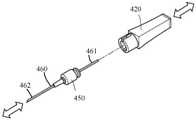
도 7은 영구 자석을 포함하는 본 개시내용의 조직-침투 의료 장치의 자화를 위한 장치의 또 다른 실시예의 사시도를 도시한다.
도 8은 본 개시내용의 조직-침투 의료 장치의 자화를 위한 장치의 도 7에 도시된 실시예의 단면도를 도시한다.
도 9는 하우징이 조직-침투 부조립체로부터 분리되어 있는 본 개시내용의 조직-침투 의료 장치의 자화를 위한 장치의 도 7에 도시된 실시예의 사시도를 도시한다.1 shows a perspective view of an embodiment of a device for magnetization of a tissue-penetrating medical device of the present disclosure.
2 shows a cross-sectional view of one embodiment of an apparatus for magnetizing a tissue-penetrating medical device of the present disclosure.
3 shows a perspective view of an embodiment of an apparatus for magnetizing a tissue-penetrating medical device of the present disclosure where the housing is separate from the tissue-penetrating subassembly.
4 shows a perspective view of another embodiment of an apparatus for magnetizing a tissue-penetrating medical device of the present disclosure comprising a catheter assembly.
FIG. 5 shows a cross-sectional view of the embodiment shown in FIG. 4 for magnetizing a tissue-penetrating medical device of the present disclosure.
Figure 6 shows a perspective view of one embodiment of the device as shown in Figure 4, where the housing is separate from the tissue-penetrating subassembly.
7 shows a perspective view of another embodiment of a device for magnetizing a tissue-penetrating medical device of the present disclosure comprising a permanent magnet.
FIG. 8 shows a cross-sectional view of the embodiment shown in FIG. 7 of an apparatus for magnetizing a tissue-penetrating medical device of the present disclosure.
FIG. 9 shows a perspective view of the embodiment shown in FIG. 7 of an apparatus for magnetizing a tissue-penetrating medical device of the present disclosure with the housing separated from the tissue-penetrating subassembly.
본 개시내용의 여러 예시적인 실시예들을 설명하기 전에, 제공된 설명은 이하의 설명에 기재된 구성 또는 프로세스 단계들의 세부 사항들에 제한되지 않는다는 것을 이해해야 한다. 본 명세서에 설명된 장치는 다른 실시예들이 가능하고, 다양한 방식으로 실시되거나 수행될 수 있다.Before describing various example embodiments of the present disclosure, it should be understood that the description provided is not limited to the details of construction or process steps set forth in the description below. The device described herein is capable of other embodiments and may be practiced or carried out in a variety of ways.
본 개시내용에서는, 장치의 원위 단부는 환자에 가장 가까운 단부이고, 장치의 근위 단부는 환자로부터 떨어져 있고 의사에게 가장 가까운 단부라는 관례를 따른다.In this disclosure, we follow the convention that the distal end of the device is the end closest to the patient and the proximal end of the device is the end away from the patient and closest to the physician.
본 개시내용의 양태는 조직-침투 의료 장치를 자화시키고, 초음파 이미징을 사용하여 정맥 내로의 삽입 중에 시각화를 개선하기 위해, 바늘과 같은 조직-침투 의료 장치에 대한 자기장을 발생시키기 위한 장치에 관한 것이다. 하나 이상의 실시예는 자기장을 생성하기 위해 하우징의 원위 부분 내에 수용된 재사용 가능한 자기장 발생기에 탈착 가능하게 연결된 일회용 조직-침투 의료 장치를 포함하는 장치에 관한 것이다. 하나 이상의 실시예에 따르면, 자기장 발생기는 비제한적인 수의 조직-침투 의료 장치를 자화시키기 위해 다수회 재사용될 수 있다. 특정 실시예가 말초 정맥내 카테터와 같은 카테터와 조합하여 사용되는 도입기 바늘을 도시하지만, 본 개시내용에서 설명된 장치가, 스타일렛, 가이드와이어, 척추 바늘, 경막외 바늘, 피하 주사 바늘 및 카테터와 함께 이용되는 도입기 바늘을 포함하지만 이에 제한되지 않는, 다양한 조직-침투 의료 장치 상에서 사용될 수 있는 것으로 이해된다. 하나 이상의 특정 실시예에서, 조직-침투 의료 장치는 중공 캐뉼러를 갖는 바늘을 포함하고, 이는 환자로부터 유체를 제거하거나 환자에게 유체를 전달하는데 사용될 수 있다. 하나 이상의 실시예에 따르면, 조직-침투 의료 장치를 수동적으로 그리고 일관적으로 자화할 수 있는 시스템 및 장치가 제공된다. 하나 이상의 실시예에 따르면, 조직-침투 의료 장치의 수동적인 자화는 임의의 추가적인 또는 새로운 임상적 단계 없이 달성될 수 있고, 더 일관되고 예측 가능한 자기장이 제공될 수 있다. 하나 이상의 실시예에서, 자화는 조직-침투 의료 장치에 대한 추가적인 손상 위험 없이 달성될 수 있고, 장치 및 시스템은 조직-침투 의료 장치의 오염에 대한 추가적인 위험을 도입하지 않는다.Aspects of the present disclosure relate to a device for generating a magnetic field for a tissue-penetrating medical device, such as a needle, to magnetize the tissue-penetrating medical device and improve visualization during insertion into a vein using ultrasound imaging. . One or more embodiments relate to a device comprising a disposable tissue-penetrating medical device detachably connected to a reusable magnetic field generator housed within a distal portion of a housing to generate a magnetic field. According to one or more embodiments, the magnetic field generator can be reused multiple times to magnetize an unlimited number of tissue-penetrating medical devices. Although certain embodiments show introducer needles used in combination with catheters, such as peripheral intravenous catheters, devices described in this disclosure can be used in conjunction with stylets, guidewires, spinal needles, epidural needles, hypodermic needles, and catheters. It is understood that it can be used on a variety of tissue-penetrating medical devices, including but not limited to the introducer needles used. In one or more specific embodiments, a tissue-penetrating medical device includes a needle with a hollow cannula, which can be used to remove fluid from or deliver fluid to a patient. According to one or more embodiments, systems and devices are provided that can passively and consistently magnetize a tissue-penetrating medical device. According to one or more embodiments, passive magnetization of a tissue-penetrating medical device may be achieved without any additional or new clinical steps and may provide a more consistent and predictable magnetic field. In one or more embodiments, magnetization can be achieved without additional risk of damage to the tissue-penetrating medical device, and the devices and systems do not introduce additional risk for contamination of the tissue-penetrating medical device.
이제 도 1을 참조하면, 본 개시내용의 일 양태는 근위 부분(21)과 원위 부분(22)을 갖는 하우징(20), 자기장을 생성하기 위해 하우징(20)의 원위 부분(22) 내에 수용된 자기장 발생기(30), 자기장 발생기(30)와 전기 통신하는 전원(40), 자기장 발생기(30)를 활성화 및 비활성화하기 위해 전원(40)과 통신하는 전원 스위치(50); 및 조직-침투 부조립체(60)를 포함하는 장치(10)에 관한 것이다.Referring now to FIG. 1 , one aspect of the present disclosure includes a
조직-침투 부조립체(60)는 허브(70) 및 근위 단부(81) 및 원위 단부(82)를 갖는 조직-침투 의료 장치(80)를 포함한다. 허브(70)는 하우징(20)의 원위 부분에 탈착 가능하게 연결될 수 있다. 조직-침투 의료 장치(80)의 근위 단부(81)는 조직-침투 의료 장치의 근위 단부(81)가 자기장에 노출되고 자기장에 의한 조직-침투 의료 장치(80)의 근위 단부(81)의 노출 시 조직-침투 의료 장치의 원위 단부(82)가 자화되도록 허브(70)로부터 근위 방향으로 연장된다.Tissue-penetrating
하나 이상의 실시예에서, 자기장 발생기(30)는 조직-침투 의료 장치(80) 내에서 그리고 그 주위에서 자기장을 생성하기 위해 자기장 발생기(30)에 의해 전기적으로 여기되는 코일(31)을 더 포함한다.In one or more embodiments,
하우징(20)은 그립(23)을 포함하고, 자기장 발생기(30)의 코일(31), 제어기(90), 전원(40) 및 래치 조립체(110)를 수납한다. 그립(23)은 임상의가 환자 내로의 조직-침투 의료 장치(80)의 삽입 중에 통상적으로 보유하는 하우징(20)의 부분이다. 하나 이상의 실시예에서, 하우징(20)은 조직-침투 의료 장치(80)에 제거 가능하게 연결된다. 하나 이상의 실시예에서, 조직-침투 의료 장치(80)는 일회용이다.
하우징(20)은 전원 스위치(50)를 더 포함하고, 전원 스위치는 전원(40)과 통신하여, 조직-침투 의료 장치(80)를 자화시키기 위해 전원(40)으로부터 코일(31)로의 전류의 유동을 유도하는 자기장 발생기(30)를 활성화 및 비활성화시킨다. 능동적 사용 중에, 전원(40)으로부터 코일(31)로의 전류 유동을 선택적으로 능동적으로 활성화하는 능력은 전원(40)의 보존을 허용한다.The
하나 이상의 실시예에서, 전원(40)은 하나 이상의 배터리(102)를 포함할 수 있는 직류 전원을 포함한다. 본 개시내용의 또 다른 실시예에서, 전원 스위치(50)는 도 1에 도시된 바와 같이, 잠재적으로 하우징(20)의 측면 내로 성형된, 장치(10)의 측면 상에 위치된 측면 푸시 전원 버튼의 형태일 수 있다. 대안적으로, 전원 스위치(50)는 장치(10)의 하우징(20) 또는 그립(23) 내로 상단 또는 상단 장착 버튼(도시되지 않음)의 형태일 수 있고, 장치는 전원 버튼을 가압함으로써 활성화되어, 조직-침투 의료 장치(80)를 자화시킬 수 있다. 전원 스위치(50)는 로커 스위치, 슬라이딩 스위치, 토글 스위치, 또는 회전 스위치와 같은 다양한 방식으로 구성될 수 있다. 바늘을 자화시키기 위해서 전원 스위치(50)를 접촉시킴으로써 장치(10)를 활성화시킨 후에, 바늘이 환자의 피부 표면 내로 삽입될 수 있다. 하나 이상의 실시예에서, 조직-침투 의료 장치(80)는 바늘 및/또는 카테터일 수 있고, 여기서 바늘 및 카테터는 바늘을 자화시키기 위해 전원 스위치(50)를 누름으로써 장치를 활성화한 후에 피부 표면 내로 삽입될 수 있다.In one or more embodiments,
전원(40)은 5 내지 20 볼트의 범위일 수 있다. 전원(40)은 그 의도된 목적을 충족시키기 위해 제어기(90), 자기장 발생기(30) 및 코일(31)에 전력을 공급할 수 있는 임의의 적절한 장치를 포함할 수 있다. 적절한 DC 전원의 일부 예들은 하나 이상의 배터리(102) 또는 커패시터를 포함한다. 배터리(102)는 저비용, 상업적으로 입수 가능한 버튼 전지, 보청기 또는 시계형 배터리를 포함할 수 있다. 하나 이상의 실시예에서, 전원(40)은 하우징(20) 내에 포함되는 DC 배터리 또는 커패시터이다. 예시로서, 도 1은 전원(40)이 제어기(90), 자기장 발생기(30) 및 코일(31)에 전력을 공급하는 하나 이상의 배터리(102)를 포함하는 일 실시예를 도시한다. 제어기(90)는 하나 이상의 인쇄 회로 기판(91)을 포함할 수 있다. 하나 이상의 실시예에서, 하우징(20)의 근위 부분(21)은 배터리(102)로의 접근을 허용하기 위한 배터리 접근 덮개(103)를 포함한다.
또 다른 실시예에서, 전원은 교류("AC") 전원을 포함한다. 적절한 AC 전원의 예는 적합한 연결(예를 들어, 플러그, 변압기 및/또는 다른 적합한 구성요소)이며, 도시 전원과 같은 전력 그리드에 적합하다. 하나 이상의 실시예에서, 전원은 하우징의 근위 부분에 부착된 전력 코드(도시되지 않음)이다.In another embodiment, the power source includes alternating current (“AC”) power. An example of a suitable AC power source is a suitable connection (e.g., plug, transformer and/or other suitable components) and suitable for a power grid, such as a city power source. In one or more embodiments, the power source is a power cord (not shown) attached to the proximal portion of the housing.
도 1에 도시된 바와 같이, 장치는 전원(400), 제어기(90) 및 코일(31)을 전기적으로 연결하도록 구성된 배선을 포함하는 하나 이상의 전기적 구성요소를 포함한다. 하나 이상의 실시예에서, 제어기(90)는 하나 이상의 인쇄 회로 기판을 포함할 수 있다.As shown in FIG. 1 , the device includes one or more electrical components including wiring configured to electrically connect a power source 400, a
하나 이상의 실시예에서, 조직-침투 부조립체(60)는 허브(70) 및 근위 단부(81) 및 원위 단부(82)를 갖는 조직-침투 의료 장치(80)를 포함한다. 허브(70)는 하우징(20)의 원위 부분(22)에 탈착 가능하게 연결되고, 조직-침투 의료 장치(80)의 근위 단부(81)는 조직-침투 의료 장치의 근위 단부(81)가 자기장에 노출되고 자기장에 의해 조직-침투 의료 장치(80)의 근위 단부(81)의 노출 시 조직-침투 의료 장치(80)의 원위 단부(82)가 자화되도록 허브(70)로부터 근위 방향으로 연장한다.In one or more embodiments, tissue-penetrating
하나 이상의 실시예에서, 조직-침투 의료 장치(80)는 바늘일 수 있다. 본 명세서에서 용어 "바늘"은 피하 주사 바늘, 척추 바늘, 경막외 바늘, 카테터와 함께 사용되는 도입기 바늘, 및 신체의 외부 표면 근처의 해부 구조에 접근하고 그리고/또는 그에 유체를 전달하기 위해 사용될 수 있는 다른 유사한 장치와 같은 표준 바늘을 포함할 것이다. 하나 이상의 실시예에서, 바늘은 유체를 환자로부터 인출하거나 유체를 전달할 수 있는 중공 캐뉼러를 갖는다.In one or more embodiments, tissue-penetrating
특정 실시예에서, 조직-침투 의료 장치(80)는 바늘의 형태일 수 있다. 자화될 때 바늘은 침습 의료 시술 중에 바늘의 위치를 위치확인 및 투영할 수 있는 초음파 검출기를 포함하는 시술 안내 시스템과 함께 사용될 수 있다. 하나 이상의 실시예에서, 조직-침투 장치는 중공 캐뉼러를 갖는 바늘일 수 있다. 중공 캐뉼러를 갖는 바늘은 날카로운 원위 선단부를 포함하는 사실상 임의의 강성 튜브를 포함할 수 있고, 이는 환자의 신체를 천공하도록, 의도된 공간에 접근하도록, 그리고 의도된 공간으로부터 또는 그 내로 재료(예를 들어, 유체)를 인출하거나 도입하도록 구성된다. 적합한 캐뉼러는 IV 카테터 조립체(예컨대, 오버-더-니들 말초 IV 카테터 조립체)에서 사용하기 위한 도입기 바늘, 정맥 바늘, 및 동맥 바늘을 포함할 수 있다.In certain embodiments, tissue-penetrating
조직-침투 의료 장치(80)는 자화 가능한 금속 재료로 제조된다. 하나 이상의 실시예에서, 자화 가능한 금속 재료는 스테인리스강 또는 유사 재료일 수 있다.The tissue-penetrating
하나 이상의 실시예에서, 조직-침투 의료 장치(80)는 원위 단부(82)로부터 근위 단부(81)까지 연장되는 고체 본체를 포함한다. 하나 이상의 실시예에서, 조직-침투 의료 장치(80)는 원위 단부(82)로부터 근위 단부(81)로 조직-침투 의료 장치(80)를 통해 연장하는 내부 루멘을 더 포함한다. 조직-침투 의료 장치(80)는 신체 내로의 진입을 용이하게 하기 위해 조직-침투 의료 장치(80)의 원위 단부에 형성된 경사진 선단부(83)를 포함할 수 있다. 일부 실시예에서, 코일(31)은 조직-침투 의료 장치(80)의 근위 단부 위에서만 연장된다. 대안적으로, 일부 실시예에서, 코일(31)은 원위 단부(82)에서 경사진 선단부(83)만을 제외한 조직-침투 의료 장치(80)의 전체 샤프트에 걸쳐 연장된다.In one or more embodiments, tissue-penetrating
자화될 때, 조직-침투 의료 장치(80)는 침습 의료 시술 중에 바늘의 위치를 위치확인 및 투영하기 위해 하나 이상의 초음파 검출기를 포함하는 시술 안내 시스템과 함께 사용될 수 있다.When magnetized, tissue-penetrating
하나 이상의 실시예에서, 도 2 및 도 3에 도시된 바와 같이, 조직-침투 의료 장치(80)는 조직-침투 의료 장치(80)의 허브(70)로부터 원위 및 근위 방향 양쪽 모두로 연장하는 바늘일 수 있다. 세장형 바늘은 코일 내에서 둘러싸여지기에 충분히 길어야 하며, 코일은 여기될 때, 바늘을 둘러싸는 자기장을 생성하고, 그에 따라 바늘을 자화시킬 것이다. 도 3에 도시된 실시예에서, 조직-침투 의료 장치(80)는 단일 사용 후에 폐기될 수 있다. 대조적으로, 하우징(20)은 많은 상이한 바늘과 함께 여러 번 재사용될 수 있다. 추가로, 하우징(20)은 단일 사용 후에 폐기되지 않기 때문에, 하우징(20)은 하나 이상의 인쇄 회로 기판, 자기장 발생기 및 전원을 포함하는 더 비싼 구성요소를 포함할 수 있다.In one or more embodiments, as shown in FIGS. 2 and 3, tissue-penetrating
하나 이상의 실시예에서, 래치(100)는 허브(70)를 하우징(20)의 원위 부분(22) 및 조직-침투 의료 장치(80)의 근위 단부(81)에 기계적으로 연결한다. 도 2에 도시된 바와 같이, 조직-침투 의료 장치(80)는 허브로부터 근위 방향으로 연장되어 코일(31)을 완전히 관통하는 세장형 바늘의 형태일 수 있다.In one or more embodiments, latch 100 mechanically connects
하나 이상의 실시예에서, 래치 버튼(110)은 하우징으로부터 조직-침투 의료 장치를 제거하기 위해 래치(100)를 분리하는 수단이다. 래치 버튼(110)은 가압될 때 래치(100)를 작동시켜, 조직-침투 의료 장치(80)의 허브(70)가 하우징의 허브 유지 요소로부터 해제될 수 있게 한다. 하나 이상의 실시예에서, 래치(100)는 래치 버튼(110)을 가압하는 것이 하우징(20)으로부터 조직-침투 의료 장치(80)의 제거를 허용하도록 조직-침투 부조립체(60)를 하우징(20)에 고정하도록 구성될 수 있다. 하나 이상의 실시예에서, 래치 버튼(110)은, 래치 버튼(110)이 제1 위치에 있는 경우, 조직-침투 의료 장치(80)가 하우징(20)으로부터 제거될 수 없고 래치 버튼이 제2 위치에 있을 때에는 제거될 수 있도록 하우징 상의 하나 이상의 멈춤쇠에 결합할 수 있다. 도 2는 하우징(20)으로부터 조직-침투 부조립체(60)의 부주의한 분리를 방지하기 위해 허브(70)의 베이스 내의 슬롯과 결합하는 래치(100)를 도시한다. 하나 이상의 실시예에서, 래치 버튼(110)은 하우징(20) 상에 포함될 수 있다. 하나 이상의 실시예에서, 래치 버튼은 바늘 허브와 결합하기 위한 정렬 핀을 포함할 수 있다. 하나 이상의 실시예에서, 래치 버튼은 장치 내로 하향 추진되도록 구성되고, 바늘 허브를 결합 및 해제하기 위한 안내 슬롯을 포함한다.In one or more embodiments,
하나 이상의 실시예에서, 도 2에 도시된 바와 같이, 래치(100)는 버섯 형상일 수 있고, 캡 부분 및 스템 부분을 포함한다. 래치(100)가 스템 부분에 인접한 베이스와 캡 사이에 슬롯 형성될 때, 하우징은 도 2에 도시된 바와 같이 베이스 상에 래칭된다. 래치(100)는 도 2에 도시된 바와 같이, 래칭된 상태에서 캡 부분, 스템 부분 및 스템 부분에 인접한 베이스의 부분 중 하나 이상에 마찰 결합될 수 있다.In one or more embodiments, as shown in Figure 2, latch 100 may be mushroom shaped and includes a cap portion and a stem portion. When the
그 후, 사용자가 조직-침투 의료 장치를 보유하는 베이스로부터 조직-침투 의료 장치(80)를 제거하기를 원하는 경우, 사용자는 래치(100)가 하우징(20)으로부터 분리되게 하여, 조직-침투 의료 장치(80)가 하우징(20)으로부터 분리될 수 있게 하도록 래치 버튼(110)을 가압한다.Thereafter, if the user wishes to remove the tissue-penetrating
하나 이상의 실시예에서, 래치(100)는 각각 아암을 갖는 한 쌍의 레버를 포함할 수 있다. 레버는 하우징에 힌지 결합되고 레버는 래치 버튼(110)을 누름으로써 편향될 수 있다. 허브를 하우징에 연결하기 위해, 사용자는 허브를 하우징 내의 대응 슬롯에 정렬하고, 레버의 아암을 하우징의 포켓 및 포획부 내로 로킹하기 위해 래치 버튼을 해제함으로써 레버의 아암을 결합한다. 허브(70)를 하우징(20)으로부터 분리하기 위해, 사용자는 하우징의 포켓 및 포획부로부터 허브의 레버를 해제하기 위해 래치 버튼을 압착하거나 누른다. 그 후, 사용자는 하우징(20)으로부터 허브(70)를 분리하기 위해 하우징으로부터 허브를 들어 올릴 수 있다.In one or more embodiments, latch 100 may include a pair of levers each having an arm. The lever is hinged to the housing and the lever can be biased by pressing the
하나 이상의 실시예에서, 전원 스위치(50) 및 래치 버튼(110)은 사용자가 각각의 버튼을 위치확인 및 사용하는 것을 돕기 위해 핑거 범프를 가질 수 있다.In one or more embodiments,
하나 이상의 실시예에서, 하우징(20)은 전원(40) 및 자기장 발생기(30)와 통신하는 제어기(90)를 더 포함하고, 제어기는 자기장 발생기(30)에 의해 발생되는 자기장의 크기를 제어한다. 발생된 자기장은 일정하거나 가변적일 수 있다. 하나 이상의 실시예에서, 제어기(90)는 코일(31)로의 전력을 공급 및 조절하고 조직-침투 의료 장치(80) 주위에 자기장을 발생시키는 인쇄 회로 조립체를 포함할 수 있다. 하나 이상의 실시예에서, 제어기(90)는 또한 다른 장치와의 블루투스 통신, 조명, 및 장치의 동작 중에 요구될 수 있는 임의의 추가적인 전자 특징부와 같은 추가적인 기능을 허용할 수 있다.In one or more embodiments,
자기장 발생기(30)는 수신 이미지 장치(도시되지 않음)에서 조직-침투 의료 장치(80)의 검출을 개선하기 위해 용이하게 구별 가능한 자기 서명의 생성을 허용하기 위해 필요에 따라 일정하거나 가변적인 전자기장을 생성할 수 있다. 장치(10)는 자기장의 강도 및/또는 주파수를 수정함으로써 향상된 자기 서명을 생성하는 잠재성을 갖는다.The
자기 서명은 수신 이미징 장치에 의해 해석될 수 있는 이진 정보 펄스들의 형태를 취할 수 있다. 일단 인식되면, 이미지는 향상될 수 있고, 배경 필드에 관련하여 신호가 증폭되어, 바늘 선단부의 더 선명한 이미지를 생성할 수 있다. 하나 이상의 실시예에서, 자기장 발생기는 요구에 따라 자기장을 생성하는 잠재력을 갖는다.The magnetic signature may take the form of binary information pulses that can be interpreted by a receiving imaging device. Once recognized, the image can be enhanced and the signal amplified relative to the background field, creating a clearer image of the needle tip. In one or more embodiments, a magnetic field generator has the potential to generate a magnetic field on demand.
하나 이상의 실시예에서, 플래시 챔버(120)는 허브(70) 내에 위치될 수 있고, 혈액이 혈관 진입의 확인을 사용자에게 제공하도록 플래시 챔버 내로 유동할 수 있게 하기 위해 조직-침투 의료 장치(80)와 유체 연통한다. 플래시 챔버(120)는 플래시백 챔버 내로의 혈액의 유동시에 밀봉되는 벤트 플러그(130)를 포함할 수 있다.In one or more embodiments,
하나 이상의 실시예에서, 바늘 찔림 부상을 방지하기 위해 다수의 안전 특징부가 제공될 수 있다. 하나 이상의 실시예에서, 장치는 바늘 차폐부 및 바늘(도시되지 않음)을 덮는 바늘 외피와 같은 안전 장치를 더 포함할 수 있다.In one or more embodiments, multiple safety features may be provided to prevent needlestick injuries. In one or more embodiments, the device may further include safety devices, such as a needle shield and a needle sheath covering the needle (not shown).
하나 이상의 실시예에서, 바늘 조립체는 하우징의 일부와 결합된 차폐부를 또한 포함할 수 있다. 차폐부는, 원위 단부가 노출되는 후퇴 위치로부터 원위 단부가 차폐부의 적어도 일부에 의해 차폐되는 연장 위치까지 조직-침투 장치 위로 이동 가능하다. 플래시 챔버의 적어도 일부는 후퇴 위치에서 가시적이다.In one or more embodiments, the needle assembly may also include a shield coupled with a portion of the housing. The shield is movable over the tissue-penetrating device from a retracted position where the distal end is exposed to an extended position where the distal end is shielded by at least a portion of the shield. At least a portion of the flash chamber is visible in the retracted position.
차폐부는 연장 위치에서 조직-침투 장치의 원위 단부를 적어도 부분적으로 둘러쌀 수 있다. 선택적으로, 차폐부는 캐뉼러의 적어도 일부 둘레에 실질적으로 원주 방향으로 배치되고, 후퇴 위치로부터 연장 위치로의 차폐부의 전이는 캐뉼러 위에서 차폐부를 삽통식으로 이동시킨다. 특정 실시예에서, 캐뉼러의 측벽은 캐뉼러 내부와 플래시 챔버 사이에서 연장하는 개구를 형성한다.The shield may at least partially surround the distal end of the tissue-penetrating device in the extended position. Optionally, the shield is disposed substantially circumferentially around at least a portion of the cannula, and transition of the shield from the retracted position to the extended position insertively moves the shield over the cannula. In certain embodiments, the side wall of the cannula defines an opening extending between the interior of the cannula and the flash chamber.
하나 이상의 실시예에서, 도 1 및 도 2에 도시된 바와 같이, 플래시 챔버(120)는 조직-침투 의료 장치(80)의 허브(70)의 일부 내에 일체로 형성될 수 있다. 다공성 벤트는 다공성 벤트가 플래시 챔버를 제1 챔버 및 제2 챔버로 분리하도록 플래시 챔버 내에 배치될 수 있다. 제1 챔버 및 제2 챔버는 캐뉼러의 원위 단부를 환자 내로 삽입할 때, 혈액이 다공성 벤트를 밀봉하지 않고 캐뉼러를 통해 제1 챔버 내로 유동하도록 구성될 수 있다. 플래시 챔버는 바늘 조립체를 둘러싸는 환경과 연통하는 벤트 메커니즘을 포함할 수 있다. 다공성 벤트는 제1 챔버로부터 제2 챔버로의 혈액의 통과를 위한 복수의 세공을 포함할 수 있다. 벤트 메커니즘은 소수성 재료로 형성된 다공성 플러그, 일방향 밸브, 또는 혈액과 접촉시 팽윤하는 친수성 재료로 형성된 다공성 플러그일 수 있다.In one or more embodiments, as shown in FIGS. 1 and 2,
바늘 조립체를 둘러싸는 외부 환경과 통신하는 벤트 메커니즘을 포함할 수 있는 플래시 챔버에 추가하여, 바늘 조립체가 플래시백 챔버 내로의 혈액의 유동시에 밀봉되는 벤트 플러그를 갖는 플래시 챔버를 포함할 수 있고, 이로써 챔버 내에 축적될 수 있는 임의의 가압된 공기가 캐뉼러의 입구를 향해 역방향으로 이동하는 것을 억제하는 것이 또한 본 명세서에서 고려된다.In addition to a flash chamber, which may include a vent mechanism that communicates with the external environment surrounding the needle assembly, the needle assembly may include a flash chamber with a vent plug that seals upon flow of blood into the flashback chamber, thereby It is also contemplated herein to inhibit any pressurized air that may accumulate within it from migrating back toward the mouth of the cannula.
하나 이상의 실시예에서, 벤트 플러그(130)는 플래시 챔버가 혈액으로 채워질 때 공기가 플래시 챔버로부터 빠져나갈 수 있게 한다. 습윤되고 나면, 벤트 플러그(130)는 혈액에 대한 노출 결과로 막혀진다.In one or more embodiments, vent
하나 이상의 실시예에서, 조직-침투 의료 장치(80)의 원위 단부는 삽입 시점에서 혈관 진입의 즉각적인 확인을 제공하도록 노치(140)를 포함한다.In one or more embodiments, the distal end of tissue-penetrating
하나 이상의 실시예에서, 하우징, 허브, 래치 메커니즘 및 안전 장치 요소는 성형 플라스틱 재료, 폴리카보네이트, 폴리에틸렌 테레프탈레이트(PET 및 PETG)와 같은 열가소성 폴리머, 또는 유사한 재료로 구성될 수 있다.In one or more embodiments, the housing, hub, latch mechanism, and safety catch elements may be constructed of molded plastic materials, polycarbonate, thermoplastic polymers such as polyethylene terephthalate (PET and PETG), or similar materials.
본 개시내용의 제2 양태는 카테터를 갖는 조직-침투 의료 장치를 자화시키기 위한 장치에 관한 것이다. 도 4에 도시된 바와 같이, 하나 이상의 실시예에서, 장치(210)는 근위 단부(221) 및 원위 단부(222)를 갖는 하우징(220); 하우징(220)의 원위 단부(222) 내에 수용된 자기장 발생기(230); 자기장 발생기(230)와 전기 통신하는 전원(240); 전원(240)과 통신하여 자기장 발생기(230)를 활성화 및 비활성화시키기 위한 스위치(250); 조직-침투 부조립체(260)로서, 근위 단부(262) 및 원위 단부(263)를 갖는 카테터(261), 카테터(261)를 통해 연장하는 근위 단부(265) 및 원위 단부(266)를 갖는 도입기 바늘(264), 카테터 어댑터(267), 내부 공동(268) 및 카테터가 관통 연장하는 원주를 갖는 원위 개구를 구비한 선단 영역(269)을 포함하고, 카테터 어댑터(267)는 카테터의 근위 단부(262)에 연결되는, 조직-침투 부조립체; 및 도입기 바늘(264)의 근위 단부(265)에 연결되는 허브(270)를 포함하고, 허브(270)는 하우징(220)의 원위 단부(222)에 탈착 가능하게 연결된다. 도입기 바늘(264)의 근위 단부(265)는, 도입기 바늘의 근위 단부(265)가 자기장에 노출되고, 자기장에 의한 도입기 바늘(264)의 근위 단부(265)의 노출 시 도입기 바늘의 원위 단부(266)가 자화되도록 허브(270)로부터 근위 방향으로 연장한다.A second aspect of the disclosure relates to a device for magnetizing a tissue-penetrating medical device having a catheter. 4 , in one or more embodiments,
도입기 바늘(264)은 IV 카테터 조립체와 함께 사용하기에 적합한 임의의 구성요소를 가질 수 있다. 도입기 바늘(264)은 카테터의 내부 공동(268) 내에 배치된다. 조직-침투 장치의 원위 선단부는 표준 경사부, 짧은 경사부, 매우 짧은 경사부, 바이어스 멈춤점(bias grind point), 베트 포인트(vet point), 랜싯 포인트(lancet point), 편향 지점(안티-코어링(anti-coring)), 또는 다른 적절한 공지된 또는 신규한 바늘 지점을 포함할 수 있다. 조직-침투 의료 장치(80)는 혈관 접근을 위해 사용될 수 있게 하는 임의의 적합한 길이 또는 임의의 적합한 게이지일 수 있다.
조직-침투 부조립체(260)는 스테인리스강 바늘을 포함하는 자화 가능 금속으로 제조될 수 있다.Tissue-penetrating
하나 이상의 실시예에서, 장치(210)는 조직-침투 부조립체(260)에 카테터(261)를 연결하기 위한 표준 카테터 허브 또는 혈액 제어 허브를 가질 수 있다. 하나 이상의 실시예에서, 접착, 압력 끼워 맞춤 또는 용제 결합과 같은 다른 결합 메커니즘이 카테터 어댑터(267)에 카테터(261)를 고정하기 위해 사용된다. 표준 카테터 튜브 또는 맞춤형 카테터 튜브가 이용될 수 있다.In one or more embodiments,
일부 실시예에서, 허브(270) 또는 카테터 어댑터(267)는 폴리비닐 클로라이드, 폴리에틸렌, 폴리카보네이트 또는 폴리우레탄 재료와 같은 열가소성 재료로 형성될 수 있다. 카테터(261)는 일반적으로 폴리머 또는 금속 재료와 같은 생체 적합성 재료를 포함하는 정맥내 카테터를 포함한다. 일부 실시예에서, 카테터(261)는 실리콘 고무, 라텍스 및/또는 다양한 열가소성 엘라스토머와 같은 가요성 폴리머 재료를 포함한다. 카테터(261)는 의도된 용도를 위해 바람직할 수 있는 바와 같이, 강성 폴리머 또는 금속 재료를 더 포함할 수 있다.In some embodiments,
카테터(261)의 길이 및 직경은 일반적으로 정맥내 카테터 장치가 의도되는 용례 또는 용도에 의해 결정된다. 따라서, 통상의 숙련자라면, 카테터가 원하는 용도를 용이하게 하기 위해 바람직하거나 필요할 수 있는 임의의 크기 및 치수를 포함하도록 수정 또는 조절될 수 있다는 것을 이해할 것이다.The length and diameter of
일부 실시예에서, 허브(270)는 도입기 바늘(264) 및 카테터(261)의 근위 단부(262)를 수납하도록 구성된 애퍼처를 포함한다. 도입기 바늘(264) 및 카테터(261)의 근위 단부(262)는 도입기 바늘, 정맥내 튜브, 및 카테터 어댑터(267)가 단일 구조를 형성하도록 허브(270)에 고정식으로 고정된다. 도입기 바늘(264)의 유체 경로 또는 중공 본체는 카테터(261)의 유체 경로와 유체 연통할 수 있다.In some embodiments,
하나 이상의 실시예에서, 근위 단부, 원위 단부, 및 그 사이에서 연장하는 경로를 갖는 카테터 어댑터(267)가 제공될 수 있다. 카테터(261)가 이어서 카테터 어댑터(267)의 원위 단부에 결합될 수 있고, 여기서 카테터(261)는 루멘 및 선단부를 포함한다. 허브(270)는 도입기 바늘(264)을 지지하기 위해 추가로 제공된다. 도입기 바늘(264)은 일반적으로 날카로운 단부, 베이스, 및 그 사이에서 연장하는 중공 본체를 포함한다. 도입기 바늘의 베이스는 바늘 어댑터에 결합되고 그에 의해 지지된다. 정맥내 튜브의 섹션이 바늘 어댑터에 추가로 결합되고, 바늘 어댑터는 도입기 바늘의 중공 본체와 카테터의 유체 경로 사이의 유체 연통을 용이하게 한다. 도입기 바늘, 바늘 어댑터, 및 카테터는 이어서 카테터 허브 어댑터의 루멘 내에 활주 가능하게 수납된다.In one or more embodiments, a
하나 이상의 실시예에서, 하우징(220)은 전원(240) 및 자기장 발생기(230)와 통신하여 자기장 발생기(230)에 의해 발생된 자기장의 크기를 제어하는 제어기(290)를 포함한다. 제어기(290)는 하나 이상의 인쇄 회로 기판을 포함할 수 있다. 발생된 자기장은 일정하거나 가변적일 수 있다.In one or more embodiments,
하나 이상의 실시예에서, 전원(240)은 복수의 배터리 또는 하우징의 근위 단부에 부착된 AC/DC 코드일 수 있다.In one or more embodiments,
하나 이상의 실시예에서, 허브(270)는 래치 버튼(310)에 의해 결합 및 분리되는 래치(300)에 의해 하우징(220)의 원위 단부(222)에 탈착 가능하게 연결된다.In one or more embodiments, the
하나 이상의 실시예에서, 장치는 임의의 적절한 방식으로 변경될 수 있는 하나 이상의 혈관 진입 확인 메커니즘을 포함할 수 있다. 하나 이상의 실시예에서, 도 4에 도시된 바와 같이, 플래시 챔버(320)는 조직-침투 부조립체(260)의 일회용 부분 내에 위치되어, 삽입 중에 혈액이 조직-침투 부조립체(260)를 통해 유동하는 것을 시각적으로 확인하고 카테터(261)가 환자의 정맥 내에 있다는 것을 확인할 수 있다. 하나 이상의 실시예에서, 도입기 바늘(264)은 플래시 챔버(320)에서 직접적으로 보이기 전에 도입기 바늘을 따른 플래시백을 시각화하기 위한 플래시백 특징부를 가질 수 있다. 하나 이상의 실시예에서, 노치(340)는 도입기 바늘의 원위 단부 상에 위치되어 최초 찌름 완성(first-stick success)을 개선하기 위한 삽입 시점에서 혈관 진입의 즉각적인 확인을 제공한다. 카테터(261)는 플래시백 확인을 제공하도록 혈액이 그를 통해 내부 루멘을 빠져나갈 수 있는 노치를 포함할 수 있다. 예를 들어, 장치를 사용할 때, 의료인은 혈관과 같은 목표 해부 구조 내로의 도입기 바늘 선단부의 진입을 시각화할 수 있다. 혈액이 도입기 바늘을 따라, 예컨대 도입기 바늘과 카테터 사이에서 유동하기 시작할 때, 의료인은 혈액이 플래시백 특징부 내로 진입함에 따라 플래시백을 관찰할 수 있다. 일부 실시예에서, 플래시백 확인 챔버는 환자의 혈관으로부터 혈액을 수용하고 조작자가 혈액을 볼 수 있게 하도록 구성되는 플래시백 구획을 포함한다.In one or more embodiments, the device may include one or more vascular entry confirmation mechanisms that may be modified in any suitable manner. In one or more embodiments, as shown in FIG. 4 ,
플래시 챔버(320) 및 노치(340)는 임의의 적합한 카테터 조립체를 포함하는 임의의 적절한 조직-침투 장치 또는 시스템과 함께 사용될 수 있다. 예시로서, 도 4는 대표적인 실시예에서, 플래시 챔버(320) 및 노치(340)가 카테터 어댑터 및 카테터를 포함하는 카테터 조립체와 함께 사용될 수 있음을 도시한다.
일부 실시예에서, 플래시백 구획의 적어도 일부는 조작자가 챔버가 점진적으로 혈액으로 채워지는 것을 볼 수 있게 하는 반투명 또는 투명 재료를 포함한다. 플래시백 확인 챔버는 (1) 혈관 접근 장치의 캐뉼러가 환자의 혈관을 천공하고 나서 확인 챔버를 채우는 혈액을 조작자가 확인할 수 있게 하고 (2) 캐뉼러의 원위 선단부가 환자의 혈관을 통해 완전히 추진되거나 혈관이 트랜스픽스되는 경우 챔버 내로의 혈류의 감소(즉, 중지)를 조작자가 볼 수 있게 하고, (3) 챔버가 조작자가 혈관 접근 장치로부터 액티브 동맥 플래시백 확인을 관찰하는 시간 기간을 연장시킬 수 있게 하는 임의의 구성요소를 포함할 수 있다.In some embodiments, at least a portion of the flashback compartment includes a translucent or transparent material that allows the operator to see the chamber gradually filling with blood. The flashback confirmation chamber (1) allows the operator to see the blood filling the confirmation chamber after the cannula of the vascular access device has punctured the patient's blood vessel and (2) the distal tip of the cannula is fully propelled through the patient's blood vessel or (3) allows the operator to see a decrease (i.e., cessation) of blood flow into the chamber when a vessel is transfixed; and (3) allows the chamber to extend the period of time over which the operator observes active arterial flashback confirmation from the vascular access device. It may include any component.
플래시백 구획은 그의 의도된 목적을 충족시킬 수 있게 하는 임의의 형상일 수 있다. 예를 들어, 플래시백 구획은 원통형, 입방체형, 세장형 입방체형, 타원형, 구형, 원추형, 나선형, 불규칙형, 관형, 다각형, 원추형, 및/또는 임의의 다른 적합한 형상일 수 있다. 예시로서, 도 4는 플래시백 구획이 원통형인 대표적인 실시예를 도시한다.The flashback compartment can be of any shape that allows it to fulfill its intended purpose. For example, the flashback compartment may be cylindrical, cubic, elongated cubic, elliptical, spherical, conical, spiral, irregular, tubular, polygonal, conical, and/or any other suitable shape. By way of example, Figure 4 shows a representative embodiment where the flashback compartment is cylindrical.
확인 챔버는 또한 벤트를 포함한다. 벤트는 혈액이 카테터, 연장 튜브, 및/또는 플래시백 구획에 진입함에 따라 공기가 플래시백 구획을 빠져나갈 수 있게 하는 것을 포함하여, 임의의 적절한 기능을 수행할 수 있다. 도 4에 도시된 벤트는 임의의 적합한 위치에 배치될 수 있다. 예로서, 도 4는 벤트가 플래시 챔버의 근위 단부에 배치될 수 있음을 도시한다. 벤트는 또한 그의 의도된 목적을 충족시킬 수 있게 하는 임의의 구성요소 또는 특성을 포함할 수 있다.The confirmation chamber also includes a vent. The vent may perform any suitable function, including allowing air to exit the flashback compartment as blood enters the catheter, extension tube, and/or flashback compartment. The vent shown in Figure 4 may be placed in any suitable location. As an example, Figure 4 shows that a vent can be placed at the proximal end of the flash chamber. The vent may also include any components or features that enable it to fulfill its intended purpose.
하나 이상의 실시예에서, 플래시 챔버는 도입기 바늘의 바늘 허브 내에 위치될 수 있다. 플래시 챔버는 플래시백 챔버 내로의 혈액의 유동시에 밀봉되는 벤트 플러그(330)를 포함할 수 있다.In one or more embodiments, the flash chamber may be located within the needle hub of the introducer needle. The flash chamber may include a
본 개시내용의 제3 양태는 바늘 선단부가 노출되고 자화되는 하나 이상의 영구 자석을 갖는 하우징을 구비한 조직-침투 의료 장치를 자화시키기 위한 장치에 관한 것이다. 하나 이상의 실시예에서, 도 7에 도시된 바와 같이, 장치(410)는 근위 부분(421) 및 원위 부분(422)을 갖는 하우징(420), 자기장을 생성하기 위해 하우징(420)의 원위 부분(422) 내에 수납된 하나 이상의 영구 자석(430), 및 조직-침투 부조립체(440)를 포함하고, 조직-침투 부조립체는 허브(450) 및 근위 단부(461) 및 원위 단부(462)를 갖는 조직-침투 의료 장치(460)를 포함하고, 허브(450)는 하우징(420)의 원위 부분(422)에 탈착 가능하게 연결되고, 조직-침투 의료 장치의 근위 단부(461)는 조직-침투 의료 장치(460)의 근위 단부(461)가 하우징(420)의 원위 부분(422) 내에 수용된 하나 이상의 영구 자석(430)에 의해 생성된 자기장에 노출되고, 자기장에 의한 조직-침투 의료 장치(460)의 근위 단부(461)의 노출시 조직-침투 의료 장치(460)의 원위 단부(462)가 자화되도록 허브(450)로부터 근위 방향으로 연장한다. 하나 이상의 실시예에서, 조직-침투 의료 장치(460)는 바늘, 가이드와이어 또는 스타일렛이다. 전술한 바와 같이, 바늘은 임의의 유형의 바늘일 수 있고, 특정 실시예에서, 바늘은 환자에 대한 유체의 인출 또는 전달을 위해서 이용될 수 있는 중공형 캐뉼러를 포함한다.A third aspect of the disclosure relates to an apparatus for magnetizing a tissue-penetrating medical device having a needle tip exposed and a housing having one or more permanent magnets that are magnetized. In one or more embodiments, as shown in FIG. 7 ,
특정 실시예에서, 도 8에 도시된 바와 같이, 조직-침투 의료 장치는 바늘이고, 이는 자화될 때, 침습 의료 시술 중에 바늘의 위치를 위치확인 및 투영하기 위해서 시술 안내 시스템과 함께 이용될 수 있다.In certain embodiments, as shown in Figure 8, the tissue-penetrating medical device is a needle, which, when magnetized, can be used with a procedure guidance system to localize and project the position of the needle during an invasive medical procedure. .
하나 이상의 실시예에서, 도 9에 도시된 바와 같이, 허브(450)는 래치 버튼(471)에 의해 동작되는 래치(470)에 의해 하우징(420)의 원위 부분(422)에 탈착 가능하게 연결된다.In one or more embodiments, as shown in FIG. 9 , the
하나 이상의 실시예에서, 도 7에 도시된 바와 같이, 플래시 챔버(480)는 조직-침투 부조립체(440)의 허브(450) 내에 위치될 수 있다. 하나 이상의 실시예에서, 플래시 챔버는 플래시백 챔버 내로의 혈액의 유동시에 밀봉되는 벤트 플러그(481)를 포함한다.In one or more embodiments, as shown in FIG. 7 ,
하나 이상의 실시예에서, 도 8에 도시된 바와 같이, 조직-침투 의료 장치(460)는 삽입 시점에서 혈관 진입의 즉각적인 확인을 제공하는 노치(490)를 포함한다.In one or more embodiments, as shown in FIG. 8 , tissue-penetrating
본 개시내용의 제4 양태는 근위 단부 및 원위 단부를 갖는 세장형 바늘을 구비하는 조직-침투 의료 장치를 획득하는 단계를 포함하는 조직-침투 의료 장치를 자화하기 위한 방법에 관한 것으로, 세장형 바늘은 세장형 바늘의 근위 단부가 허브로부터 근위 방향으로 연장되고 세장형 바늘의 원위 단부가 허브로부터 환자를 향해 원위 방향으로 연장되도록, 바늘 허브 부조립체 내에 배치된다. 이 방법은 사용자가 근위 부분 및 원위 부분을 갖는 하우징을 획득하는 것을 포함하고, 하우징은 하우징의 원위 부분 내에 수용된 자기장 발생기, 자기장 발생기와 전기 통신하는 전원, 및 자기장 발생기를 활성화 및 비활성화하기 위해 전원과 통신하는 스위치를 포함한다. 이어서, 사용자는, 세장형 바늘의 근위 단부가 자기장 발생기에 의해서 생성된 자기장에 노출되도록, 바늘 허브 조립체를 하우징의 원위 부분에 연결한다. 전원과 통신하는 스위치는 세장형 바늘을 자화시키기 위해 자기장 발생기를 활성화하도록 눌러진다. 사용자는 세장형 바늘의 원위 단부를 혈관 진입의 원하는 지점에 인접하게 위치시키고, 자화된 세장형 바늘은 환자의 혈관 내로 삽입된다. 하나 이상의 실시예에서, 방법은 자화된 세장형 바늘을 시각화하기 위해 초음파 이미징 장치를 사용하는 단계를 더 포함한다.A fourth aspect of the disclosure relates to a method for magnetizing a tissue-penetrating medical device comprising obtaining a tissue-penetrating medical device having an elongated needle having a proximal end and a distal end, the elongated needle is disposed within the needle hub subassembly such that the proximal end of the elongated needle extends proximally from the hub and the distal end of the elongated needle extends distally from the hub toward the patient. The method includes a user obtaining a housing having a proximal portion and a distal portion, the housing having a magnetic field generator housed within the distal portion of the housing, a power source in electrical communication with the magnetic field generator, and a power source to activate and deactivate the magnetic field generator. Includes a communicating switch. The user then connects the needle hub assembly to the distal portion of the housing such that the proximal end of the elongated needle is exposed to the magnetic field generated by the magnetic field generator. A switch in communication with the power source is pressed to activate a magnetic field generator to magnetize the elongated needle. The user positions the distal end of the elongated needle adjacent the desired point of vascular entry, and the magnetized elongated needle is inserted into the patient's blood vessel. In one or more embodiments, the method further includes using an ultrasound imaging device to visualize the magnetized elongated needle.
실제로, 사용자는 캐뉼러의 원위 첨단부를 사용하여 환자의 피부를 천공하고, 오버-더-니들 말초 IV 카테터를 혈관 내로 밀어 넣을 수 있다. 바늘이 혈관에 침투하고 혈액이 캐뉼러의 루멘 내로 유동하면, 일정하거나 가변적인 자기장이 생성된다.In practice, the user can use the distal tip of the cannula to puncture the patient's skin and push an over-the-needle peripheral IV catheter into the blood vessel. When the needle penetrates the blood vessel and blood flows into the lumen of the cannula, a constant or variable magnetic field is created.
사용자는 조직-침투 장치를 하우징의 베이스 상으로 아래로 가압하고 이를 제 위치에 스냅핑함으로써 조직-침투 장치를 하우징의 베이스에 부착한다. 이러한 프로세스에서, 래치는 래치가 포획부 위를 통과할 수 있게 하도록 탄성적으로 편향된다. 후속하여, 래치는 하우징으로부터 조직-침투 장치의 변위를 방지하기 위해 그의 변형되지 않은 위치로 복귀한다.The user attaches the tissue-penetrating device to the base of the housing by pressing the tissue-penetrating device down onto the base of the housing and snapping it into place. In this process, the latch is resiliently biased to allow the latch to pass over the catch. Subsequently, the latch returns to its undeformed position to prevent displacement of the tissue-penetrating device from the housing.
환자의 정맥 내로 바늘/카테터를 삽입한 후에, 사용자는 래치 버튼을 가압함으로써 하우징으로부터 바늘 허브를 분리할 수 있다. 래치가 슬롯으로부터 분리되면, 조직-침투 장치와 함께 허브가 하우징으로부터 제거될 수 있고, 이 때 바늘 찔림 보호 메커니즘이 활성화될 것이다. 추가로, 도입기 바늘이 또한 카테터로부터 후퇴될 수 있다. 사용 후에, 캐뉼러가 카테터 허브로부터 추출될 수 있고, 바늘 및 캐뉼러가 폐기될 수 있다.After inserting the needle/catheter into the patient's vein, the user can release the needle hub from the housing by pressing the latch button. Once the latch is disengaged from the slot, the hub along with the tissue-penetrating device can be removed from the housing, at which point the needlestick protection mechanism will be activated. Additionally, the introducer needle may also be retracted from the catheter. After use, the cannula can be extracted from the catheter hub and the needle and cannula can be discarded.
본 명세서 전반에 걸쳐 "일 실시예", "특정 실시예들", "하나 이상의 실시예" 또는 "실시예"에 대한 언급은 실시예와 관련하여 설명된 특정한 특징, 구조, 재료, 또는 특성이 본 개시내용의 적어도 하나의 실시예에 포함된다는 것을 의미한다. 따라서, 본 명세서 전반에 걸쳐 다양한 장소에서 "하나 이상의 실시예에서", "특정 실시예에서", "일 실시예에서" 또는 "실시예에서"와 같은 문구의 출현은 반드시 본 개시내용의 동일한 실시예를 참조하는 것은 아니다. 또한, 특정 특징, 구조, 재료, 또는 특성은 하나 이상의 실시예에서 임의의 적절한 방식으로 조합될 수 있다.References throughout this specification to “one embodiment,” “particular embodiments,” “one or more embodiments,” or “an embodiment” refer to a specific feature, structure, material, or characteristic described in connection with the embodiment. It means that it is included in at least one embodiment of the present disclosure. Accordingly, the appearance of phrases such as “in one or more embodiments,” “in a particular embodiment,” “in one embodiment,” or “in an embodiment” in various places throughout this specification do not necessarily refer to the same practice of the present disclosure. It is not intended to refer to examples. Additionally, specific features, structures, materials, or properties may be combined in any suitable way in one or more embodiments.
본 명세서의 개시내용이 특정 실시예들을 참조하여 설명을 제공하지만, 이러한 실시예들은 단지 본 개시내용의 원리들 및 응용들을 예시하는 것임을 이해해야 한다. 본 개시내용의 사상 및 범주로부터 벗어남이 없이 본 개시내용의 방법 및 장치에 대한 다양한 수정 및 변형이 이루어질 수 있다는 것이 통상의 숙련자에게 명백할 것이다. 따라서, 본 개시내용은 첨부된 청구항들 및 그 등가물들의 범위 내에 있는 수정들 및 변형들을 포함하는 것으로 의도된다.Although the disclosure herein provides explanation with reference to specific embodiments, it should be understood that such embodiments are merely illustrative of the principles and applications of the disclosure. It will be apparent to those skilled in the art that various modifications and variations may be made to the methods and devices of the present disclosure without departing from the spirit and scope of the disclosure. Accordingly, this disclosure is intended to cover modifications and variations that come within the scope of the appended claims and their equivalents.
Claims (29)
Translated fromKorean근위 부분 및 원위 부분을 갖는 하우징;
자기장을 생성하기 위해 하우징의 원위 부분 내에 수용된 자기장 발생기; 및
허브 및 근위 단부 및 원위 단부를 갖는 조직-침투 의료 장치를 포함하는 조직-침투 부조립체로서, 허브는 하우징의 원위 부분에 탈착 가능하게 연결되고, 조직-침투 의료 장치의 근위 단부는, 조직-침투 의료 장치의 근위 단부가 자기장에 노출되고 자기장에 의한 조직-침투 의료 장치의 근위 단부의 노출시 조직-침투 의료 장치의 원위 단부가 자화되도록 허브로부터 근위 방향으로 연장하는, 조직-침투 부조립체를 포함하는 장치.It is a device,
a housing having a proximal portion and a distal portion;
a magnetic field generator housed within the distal portion of the housing for generating a magnetic field; and
A tissue-penetrating subassembly comprising a hub and a tissue-penetrating medical device having a proximal end and a distal end, wherein the hub is removably connected to the distal portion of the housing, and the proximal end of the tissue-penetrating medical device includes: a tissue-penetrating subassembly extending proximally from the hub such that the proximal end of the medical device is exposed to a magnetic field and the distal end of the tissue-penetrating medical device is magnetized upon exposure of the proximal end of the tissue-penetrating medical device by the magnetic field. A device that does.
자기장 발생기와 전기 통신하는 전원; 및
자기장 발생기를 활성화 및 비활성화하기 위해 전원과 통신하는 스위치를 더 포함하는 장치.According to paragraph 1,
A power source in electrical communication with the magnetic field generator; and
A device further comprising a switch in communication with a power source to activate and deactivate the magnetic field generator.
근위 부분 및 원위 부분을 갖는 하우징;
하우징의 원위 부분 내에 수용된 자기장 발생기;
근위 단부 및 원위 단부를 갖는 카테터, 카테터를 통해 연장하는 도입기 바늘, 원위 단부 및 근위 단부를 갖는 카테터 어댑터, 내부 공동, 및 카테터가 그를 통해 연장하는 원주를 갖는 원위 개구를 구비한 선단 영역을 포함하는 조직-침투 부조립체로서, 카테터 어댑터는 카테터의 근위 단부에 연결되는, 조직-침투 부조립체; 및
도입기 바늘의 근위 단부에 연결된 허브로서, 허브는 하우징의 원위 부분에 탈착 가능하게 연결되고; 도입기 바늘의 근위 단부는 도입기 바늘의 근위 단부가 자기장 발생기에 노출되고, 도입기 바늘의 근위 단부의 자기장 발생기에 대한 노출시 도입기 바늘의 원위 단부가 자화되도록 허브로부터 근위 방향으로 연장되는, 허브를 포함하는 장치.It is a device,
a housing having a proximal portion and a distal portion;
a magnetic field generator housed within a distal portion of the housing;
A catheter having a proximal end and a distal end, an introducer needle extending through the catheter, a catheter adapter having a distal end and a proximal end, an internal cavity, and a tip region having a distal opening having a circumference through which the catheter extends. a tissue-penetrating subassembly, wherein the catheter adapter is connected to the proximal end of the catheter; and
a hub connected to the proximal end of the introducer needle, the hub being removably connected to the distal portion of the housing; The proximal end of the introducer needle includes a hub, wherein the proximal end of the introducer needle is exposed to the magnetic field generator and extends proximally from the hub such that the distal end of the introducer needle is magnetized upon exposure of the proximal end of the introducer needle to the magnetic field generator. Device.
자기장 발생기와 전기 통신하는 전원; 및
자기장 발생기를 활성화 및 비활성화하기 위해 전원과 통신하는 스위치를 더 포함하는 장치.According to clause 16,
A power source in electrical communication with the magnetic field generator; and
A device further comprising a switch in communication with a power source to activate and deactivate the magnetic field generator.
근위 단부 및 원위 단부를 갖는 세장형 바늘을 갖는 조직-침투 의료 장치를 획득하는 단계로서, 세장형 바늘은 바늘 허브 부조립체 내에 배치되고, 그에 따라 세장형 바늘의 근위 단부가 허브로부터 근위 방향으로 연장되고, 세장형 바늘의 원위 단부가 허브로부터 환자를 향해서 원위 방향으로 연장되는, 조직-침투 의료 장치를 획득하는 단계,
근위 부분 및 원위 부분을 갖는 하우징을 획득하는 단계로서, 하우징은 하우징의 원위 부분 내에 포함된 자기장 발생기, 자기장 발생기와 전기 통신하는 전원, 및 자기장 발생기를 활성화 및 비활성화하기 위해 전원과 통신하는 스위치를 포함하는, 하우징을 획득하는 단계;
세장형 바늘의 근위 단부가 자기장 발생기에 노출되도록, 바늘 허브 부조립체를 하우징의 원위 부분에 연결하는 단계; 및
자화된 세장형 바늘을 생성하기 위해 자기장 발생기를 활성화시키도록 전원과 통신하는 스위치를 누르는 단계
를 포함하는 방법.A method of magnetizing a tissue-penetrating medical device,
Obtaining a tissue-penetrating medical device having an elongated needle having a proximal end and a distal end, wherein the elongated needle is disposed within a needle hub subassembly, such that the proximal end of the elongated needle extends proximally from the hub. Obtaining a tissue-penetrating medical device, wherein the distal end of the elongated needle extends distally from the hub toward the patient,
Obtaining a housing having a proximal portion and a distal portion, the housing comprising a magnetic field generator contained within the distal portion of the housing, a power source in electrical communication with the magnetic field generator, and a switch in communication with the power source to activate and deactivate the magnetic field generator. Obtaining a housing;
Connecting the needle hub subassembly to the distal portion of the housing such that the proximal end of the elongated needle is exposed to the magnetic field generator; and
Depressing a switch in communication with a power source to activate a magnetic field generator to produce a magnetized elongated needle.
How to include .
Priority Applications (1)
| Application Number | Priority Date | Filing Date | Title |
|---|---|---|---|
| KR1020227008696AKR102420315B1 (en) | 2016-05-13 | 2017-05-08 | Electro-magnetic needle catheter insertion system |
Applications Claiming Priority (3)
| Application Number | Priority Date | Filing Date | Title |
|---|---|---|---|
| US15/154,362US10327667B2 (en) | 2016-05-13 | 2016-05-13 | Electro-magnetic needle catheter insertion system |
| US15/154,362 | 2016-05-13 | ||
| PCT/US2017/031569WO2017196734A1 (en) | 2016-05-13 | 2017-05-08 | Electro-magnetic needle catheter insertion system |
Related Child Applications (1)
| Application Number | Title | Priority Date | Filing Date |
|---|---|---|---|
| KR1020227008696ADivisionKR102420315B1 (en) | 2016-05-13 | 2017-05-08 | Electro-magnetic needle catheter insertion system |
Publications (2)
| Publication Number | Publication Date |
|---|---|
| KR20190008553A KR20190008553A (en) | 2019-01-24 |
| KR102376609B1true KR102376609B1 (en) | 2022-03-22 |
Family
ID=58709655
Family Applications (2)
| Application Number | Title | Priority Date | Filing Date |
|---|---|---|---|
| KR1020227008696AActiveKR102420315B1 (en) | 2016-05-13 | 2017-05-08 | Electro-magnetic needle catheter insertion system |
| KR1020187036110AActiveKR102376609B1 (en) | 2016-05-13 | 2017-05-08 | Electromagnetic Needle Catheterization System |
Family Applications Before (1)
| Application Number | Title | Priority Date | Filing Date |
|---|---|---|---|
| KR1020227008696AActiveKR102420315B1 (en) | 2016-05-13 | 2017-05-08 | Electro-magnetic needle catheter insertion system |
Country Status (11)
| Country | Link |
|---|---|
| US (2) | US10327667B2 (en) |
| EP (1) | EP3454931B1 (en) |
| JP (2) | JP6995781B2 (en) |
| KR (2) | KR102420315B1 (en) |
| CN (2) | CN113648036B (en) |
| AU (2) | AU2017262638B2 (en) |
| CA (1) | CA3023686C (en) |
| MX (1) | MX2018013897A (en) |
| MY (1) | MY191095A (en) |
| SG (1) | SG11201809809YA (en) |
| WO (1) | WO2017196734A1 (en) |
Families Citing this family (18)
| Publication number | Priority date | Publication date | Assignee | Title |
|---|---|---|---|---|
| US10327667B2 (en)* | 2016-05-13 | 2019-06-25 | Becton, Dickinson And Company | Electro-magnetic needle catheter insertion system |
| US11826522B2 (en) | 2016-06-01 | 2023-11-28 | Becton, Dickinson And Company | Medical devices, systems and methods utilizing permanent magnet and magnetizable feature |
| US10583269B2 (en)* | 2016-06-01 | 2020-03-10 | Becton, Dickinson And Company | Magnetized catheters, devices, uses and methods of using magnetized catheters |
| US11413429B2 (en) | 2016-06-01 | 2022-08-16 | Becton, Dickinson And Company | Medical devices, systems and methods utilizing permanent magnet and magnetizable feature |
| US20170347914A1 (en) | 2016-06-01 | 2017-12-07 | Becton, Dickinson And Company | Invasive Medical Devices Including Magnetic Region And Systems And Methods |
| US10032552B2 (en) | 2016-08-30 | 2018-07-24 | Becton, Dickinson And Company | Cover for tissue penetrating device with integrated magnets and magnetic shielding |
| USD857194S1 (en)* | 2017-01-25 | 2019-08-20 | Becton, Dickinson And Company | Needle tip shield |
| US11369410B2 (en) | 2017-04-27 | 2022-06-28 | Bard Access Systems, Inc. | Magnetizing system for needle assemblies including orientation key system for positioning needle tray in magnetizer |
| US11872356B2 (en) | 2018-01-05 | 2024-01-16 | Becton, Dickinson And Company | Echogenic catheter and catheter system |
| EP3629045B1 (en)* | 2018-09-27 | 2021-01-13 | Siemens Healthcare GmbH | Vascular access device and method for tracking a medical instrument in a body region of a patient |
| USD885560S1 (en)* | 2018-12-14 | 2020-05-26 | Avent, Inc. | Introducer hub with fluid delivery port |
| CN110974367B (en)* | 2019-12-10 | 2020-10-23 | 西安交通大学第一附属医院 | A multifunctional needle feeder for percutaneous lung puncture guided by CT images |
| US11911140B2 (en) | 2020-11-09 | 2024-02-27 | Bard Access Systems, Inc. | Medical device magnetizer |
| CN114464394A (en)* | 2020-11-10 | 2022-05-10 | 巴德阿克塞斯系统股份有限公司 | Devices, systems and methods for magnetizing medical devices while maintaining their sterility |
| KR102292079B1 (en)* | 2020-11-30 | 2021-08-25 | 주식회사 덴탈스튜디오 | Syringe Assembly Easy to Insert and Remove Needle |
| EP4358836A1 (en) | 2021-06-22 | 2024-05-01 | Bard Access Systems, Inc. | Medical device magnetizer system with indicators |
| EP4377976A1 (en) | 2021-07-26 | 2024-06-05 | Bard Access Systems, Inc. | Medical-device magnetizer systems and methods |
| KR20240177955A (en)* | 2023-06-21 | 2024-12-30 | 한양대학교 산학협력단 | Radiofrequency ablation apparatus |
Citations (3)
| Publication number | Priority date | Publication date | Assignee | Title |
|---|---|---|---|---|
| US20140046261A1 (en) | 2007-11-26 | 2014-02-13 | C. R. Bard, Inc. | Magnetic Element-Equipped Needle Assemblies |
| WO2014072238A1 (en) | 2012-11-08 | 2014-05-15 | Sanofi-Aventis Deutschland Gmbh | Needle magnetizing arrangement |
| US20140257080A1 (en) | 2013-03-05 | 2014-09-11 | Ezono Ag | System for ultrasound image guided procedure |
Family Cites Families (111)
| Publication number | Priority date | Publication date | Assignee | Title |
|---|---|---|---|---|
| FR2351646A1 (en) | 1976-05-19 | 1977-12-16 | Nogier Paul | IMPROVEMENTS IN ACUPUNCTURE METHODS AND EQUIPMENT |
| JPS5816599A (en) | 1981-07-22 | 1983-01-31 | 凸版印刷株式会社 | Electromagnetic shielding method |
| JPS61160998A (en) | 1985-01-10 | 1986-07-21 | 王子油化合成紙株式会社 | Manufacturing method for electromagnetic shielding composite container |
| US5154179A (en) | 1987-07-02 | 1992-10-13 | Medical Magnetics, Inc. | Device construction and method facilitating magnetic resonance imaging of foreign objects in a body |
| DE3742298A1 (en) | 1987-12-14 | 1989-06-22 | Merten Kg Pulsotronic | DEVICE FOR LOCATING A CATHETER OR PROBE IN AN ORGAN OF A LIVING BEING |
| JPH021291A (en)* | 1988-02-29 | 1990-01-05 | Mitsubishi Electric Corp | Magnetic induction position control device and magnetic therapy device |
| JPH0327774A (en) | 1989-06-23 | 1991-02-06 | Fujitsu General Ltd | discharge circuit |
| US5000912A (en) | 1989-12-15 | 1991-03-19 | Ethicon, Inc. | Nickel titanium martensitic steel for surgical needles |
| US5558651A (en) | 1990-04-20 | 1996-09-24 | Becton Dickinson And Company | Apparatus and method for a needle tip cover |
| US5215528C1 (en) | 1992-02-07 | 2001-09-11 | Becton Dickinson Co | Catheter introducer assembly including needle tip shield |
| US5359992A (en) | 1992-10-20 | 1994-11-01 | Linvatec Corporation | Endoscope coupler with magnetic focus control |
| US5461311A (en) | 1992-12-24 | 1995-10-24 | Kayaba Kogyo Kabushiki Kaisha | Rod axial position detector including plural scales wherein nonmagnetized portions have differing spacing and differing depths and means for calculating the absolute position are provided |
| ATE195258T1 (en) | 1993-04-14 | 2000-08-15 | Pharmacyclics Inc | MEDICAL DEVICES AND MATERIALS WITH INCREASED VISIBILITY DURING MAGNETIC IMAGING |
| US5817017A (en) | 1994-04-12 | 1998-10-06 | Pharmacyclics, Inc. | Medical devices and materials having enhanced magnetic images visibility |
| US5728079A (en) | 1994-09-19 | 1998-03-17 | Cordis Corporation | Catheter which is visible under MRI |
| NL9401518A (en) | 1994-09-19 | 1996-05-01 | Cordis Europ | MR visible catheter with particulate magnetizable material contained in cured material. |
| US5955881A (en) | 1994-10-18 | 1999-09-21 | Cts Corporation | Linkage position sensor having a magnet with two ramped sections for providing variable magnetic field |
| KR19990029038A (en) | 1995-07-16 | 1999-04-15 | 요아브 빨띠에리 | Free aiming of needle ceramic |
| US6263230B1 (en) | 1997-05-08 | 2001-07-17 | Lucent Medical Systems, Inc. | System and method to determine the location and orientation of an indwelling medical device |
| US6537232B1 (en)* | 1997-05-15 | 2003-03-25 | Regents Of The University Of Minnesota | Intracranial pressure monitoring device and method for use in MR-guided drug delivery |
| DE19736030A1 (en) | 1997-08-20 | 1999-02-25 | Philips Patentverwaltung | Method for navigation of a magnetic object and MR arrangement |
| US6171297B1 (en) | 1998-06-30 | 2001-01-09 | Schneider (Usa) Inc | Radiopaque catheter tip |
| KR100313130B1 (en)* | 1998-09-09 | 2002-02-19 | 황기선 | Acupuncture Syringe with Magnetic Field |
| ES2228165T3 (en) | 1998-12-09 | 2005-04-01 | Cook Incorporated | HOLLOW NEEDLE, CURVED, SUPERELASTIC, FOR MEDICAL USE. |
| US6475226B1 (en) | 1999-02-03 | 2002-11-05 | Scimed Life Systems, Inc. | Percutaneous bypass apparatus and method |
| AU3306500A (en) | 1999-03-19 | 2000-10-09 | Paul Cervi | Biopsy needle |
| US6493573B1 (en) | 1999-10-28 | 2002-12-10 | Winchester Development Associates | Method and system for navigating a catheter probe in the presence of field-influencing objects |
| KR100354232B1 (en) | 1999-12-15 | 2002-09-28 | 김치경 | device for acupuncture |
| US6401723B1 (en) | 2000-02-16 | 2002-06-11 | Stereotaxis, Inc. | Magnetic medical devices with changeable magnetic moments and method of navigating magnetic medical devices with changeable magnetic moments |
| US6337627B1 (en)* | 2000-10-27 | 2002-01-08 | International Business Machines Corporation | System of providing medical treatment |
| US7194296B2 (en)* | 2000-10-31 | 2007-03-20 | Northern Digital Inc. | Flexible instrument with optical sensors |
| US20020103430A1 (en)* | 2001-01-29 | 2002-08-01 | Hastings Roger N. | Catheter navigation within an MR imaging device |
| US7288085B2 (en) | 2001-04-10 | 2007-10-30 | Medtronic, Inc. | Permanent magnet solenoid pump for an implantable therapeutic substance delivery device |
| US7455666B2 (en)* | 2001-07-13 | 2008-11-25 | Board Of Regents, The University Of Texas System | Methods and apparatuses for navigating the subarachnoid space |
| US6911017B2 (en) | 2001-09-19 | 2005-06-28 | Advanced Cardiovascular Systems, Inc. | MRI visible catheter balloon |
| US6733458B1 (en) | 2001-09-25 | 2004-05-11 | Acuson Corporation | Diagnostic medical ultrasound systems and methods using image based freehand needle guidance |
| US20030100829A1 (en) | 2001-11-27 | 2003-05-29 | Sheng-Ping Zhong | Medical devices with magnetic resonance visibility enhancing material |
| US7162302B2 (en) | 2002-03-04 | 2007-01-09 | Nanoset Llc | Magnetically shielded assembly |
| US7563232B2 (en) | 2002-04-19 | 2009-07-21 | Pelikan Technologies, Inc. | Method and apparatus for penetrating tissue |
| ES2697329T3 (en) | 2002-06-20 | 2019-01-23 | Becton Dickinson Co | Apparatus to protect the tip of a catheter introducer needle |
| US7441559B2 (en) | 2002-09-06 | 2008-10-28 | Koninklijke Philips Electronics N.V. | Devices, systems, and methods to fixate tissue within the regions of body, such as the pharyngeal conduit |
| US20040167506A1 (en) | 2003-02-25 | 2004-08-26 | Scimed Life Systems, Inc. | Medical devices employing ferromagnetic heating |
| US7077808B2 (en) | 2003-07-31 | 2006-07-18 | Boston Scientific Scimed. Inc. | Ultrasonic imaging catheter |
| US7280863B2 (en) | 2003-10-20 | 2007-10-09 | Magnetecs, Inc. | System and method for radar-assisted catheter guidance and control |
| ATE544477T1 (en)* | 2003-12-03 | 2012-02-15 | Mayo Foundation | SETS FOR MAGNETIC COATING OF MEDICAL DEVICES WITH LIVING CELLS |
| US20050203333A1 (en) | 2003-12-15 | 2005-09-15 | Dailey James P. | Magnetized scleral buckle, polymerizing magnetic polymers, and other magnetic manipulations in living tissue |
| US8620406B2 (en) | 2004-01-23 | 2013-12-31 | Boston Scientific Scimed, Inc. | Medical devices visible by magnetic resonance imaging |
| ATE536813T1 (en) | 2004-03-10 | 2011-12-15 | Koninkl Philips Electronics Nv | DEVICE AND METHOD FOR THERAPEUTIC EMBOLIZATION |
| US8945116B2 (en) | 2004-05-17 | 2015-02-03 | Boston Scientific Scimed, Inc. | Mapping and ablation method for the treatment of ventricular tachycardia |
| US20080006280A1 (en) | 2004-07-20 | 2008-01-10 | Anthony Aliberto | Magnetic navigation maneuvering sheath |
| US7722578B2 (en) | 2004-09-08 | 2010-05-25 | Boston Scientific Scimed, Inc. | Medical devices |
| US20060264914A1 (en) | 2005-03-03 | 2006-11-23 | Icon Medical Corp. | Metal alloys for medical devices |
| IL179618A0 (en) | 2006-11-27 | 2007-10-31 | Eyoca Medical Ltd | Device for inducing vibrations |
| US8027714B2 (en) | 2005-05-27 | 2011-09-27 | Magnetecs, Inc. | Apparatus and method for shaped magnetic field control for catheter, guidance, control, and imaging |
| US20070016131A1 (en) | 2005-07-12 | 2007-01-18 | Munger Gareth T | Flexible magnets for navigable medical devices |
| US8784336B2 (en) | 2005-08-24 | 2014-07-22 | C. R. Bard, Inc. | Stylet apparatuses and methods of manufacture |
| US7963458B2 (en)* | 2006-01-23 | 2011-06-21 | Kimberly-Clark Worldwide, Inc. | Ultrasonic liquid delivery device |
| CN101454963A (en)* | 2006-03-17 | 2009-06-10 | 耐力节奏股份有限公司 | Energy generating systems for implanted medical devices |
| US7887516B2 (en)* | 2006-04-12 | 2011-02-15 | Ispg, Inc. | Safety cap for medical needles |
| IL187667A (en)* | 2006-11-27 | 2011-12-29 | Mediguide Ltd | System and method for navigating a surgical needle toward an organ of the body of a patient |
| US8249689B2 (en) | 2007-02-23 | 2012-08-21 | General Electric Company | Coil arrangement for electromagnetic tracking method and system |
| EP2173426B1 (en) | 2007-07-03 | 2016-04-20 | Irvine Biomedical, Inc. | Magnetically guided catheter |
| CN201138912Y (en) | 2007-09-15 | 2008-10-22 | 帕尔哈提·司马义 | Antimagnetic bag |
| US8080223B2 (en) | 2007-10-19 | 2011-12-20 | Biointraface, Inc. | Method of making a composite from metal oxide and polymer precursors |
| US8231618B2 (en) | 2007-11-05 | 2012-07-31 | Stereotaxis, Inc. | Magnetically guided energy delivery apparatus |
| ES2465915T3 (en) | 2007-11-26 | 2014-06-09 | C.R. Bard, Inc. | Integrated system for intravascular catheter placement |
| US9521961B2 (en) | 2007-11-26 | 2016-12-20 | C. R. Bard, Inc. | Systems and methods for guiding a medical instrument |
| US10524691B2 (en) | 2007-11-26 | 2020-01-07 | C. R. Bard, Inc. | Needle assembly including an aligned magnetic element |
| US8202251B2 (en) | 2008-03-14 | 2012-06-19 | Access Scientific, Inc. | Access device |
| US20100036238A1 (en) | 2008-06-13 | 2010-02-11 | Medtronic, Inc. | Device and method for assessing extension of a deployable object |
| WO2010042776A2 (en) | 2008-10-10 | 2010-04-15 | Vasostar, Inc. | Medical device with a guidewire for penetrating occlusions |
| WO2010085456A1 (en) | 2009-01-20 | 2010-07-29 | Guided Delivery Systems Inc. | Anchor deployment devices and related methods |
| WO2010086585A1 (en) | 2009-01-27 | 2010-08-05 | Renishaw Plc | Magnetic encoder apparatus |
| WO2010091269A1 (en) | 2009-02-06 | 2010-08-12 | Baylor College Of Medicine | Real-time magnetic dipole detection and tracking |
| US8892191B2 (en) | 2009-03-08 | 2014-11-18 | Oprobe, Llc | Methods of determining motion and distance during medical and veterinary procedures |
| US7932718B1 (en) | 2009-03-12 | 2011-04-26 | The United States Of America As Represented By The Secretary Of The Navy | System and method using magnetic anomaly field magnitudes for detection, localization, classification and tracking of magnetic objects |
| US20100241155A1 (en)* | 2009-03-20 | 2010-09-23 | Acclarent, Inc. | Guide system with suction |
| US20100305402A1 (en) | 2009-05-29 | 2010-12-02 | Magnetecs,Inc. | Method and apparatus for magnetic waveguide forming a shaped field employing a magnetic aperture for guiding and controlling a medical device |
| WO2011069525A1 (en) | 2009-12-09 | 2011-06-16 | Magnamedics Gmbh | Nanoparticle-based marking system for visualizing medical devices in different medical imaging modalities |
| US9486162B2 (en) | 2010-01-08 | 2016-11-08 | Ultrasonix Medical Corporation | Spatial needle guidance system and associated methods |
| EP2521479B1 (en)* | 2010-01-09 | 2019-08-28 | Olympus Endo Technology America Inc. | Rotate-to-advance catheterization system |
| EP2912999B1 (en) | 2010-05-28 | 2022-06-29 | C. R. Bard, Inc. | Apparatus for use with needle insertion guidance system |
| US20110301414A1 (en) | 2010-06-04 | 2011-12-08 | Robert Hotto | Intelligent endoscopy systems and methods |
| WO2012015771A2 (en) | 2010-07-30 | 2012-02-02 | Cook Medical Technologies Llc | Rotating full-core biopsy needle |
| CN102478591A (en) | 2010-11-24 | 2012-05-30 | 富泰华工业(深圳)有限公司 | Test pen |
| ES2900584T3 (en) | 2010-12-23 | 2022-03-17 | Bard Access Systems Inc | System for guiding a rigid instrument |
| ES2568225T3 (en) | 2011-09-06 | 2016-04-28 | Ezono Ag | Imaging probe and method to obtain position and / or orientation information |
| TWI493009B (en) | 2011-09-27 | 2015-07-21 | Hon Hai Prec Ind Co Ltd | Ultraviolet light curing adhesive and dispensing method of same |
| EP2827935B1 (en) | 2012-03-18 | 2018-01-10 | Traumatek Solutions B.V. | Devices for endovascular access and therapy |
| KR20130113775A (en)* | 2012-04-06 | 2013-10-16 | 삼성메디슨 주식회사 | Acoustic probe and acoustic diagnostic system including the same |
| EP4599879A2 (en) | 2012-05-31 | 2025-08-13 | Boston Scientific Medical Device Limited | Radiofrequency perforation apparatus |
| RU2669621C2 (en) | 2012-09-28 | 2018-10-12 | Си. Ар. БАРД, ИНК. | Needle assembly including an aligned magnetic element |
| CA2887877A1 (en) | 2012-10-18 | 2014-04-24 | C.R. Bard, Inc. | Magnetic element-equipped needle assemblies |
| US9463307B2 (en) | 2012-12-21 | 2016-10-11 | Medtronic Xomed, Inc. | Sinus dilation system and method |
| US9204820B2 (en) | 2012-12-31 | 2015-12-08 | Biosense Webster (Israel) Ltd. | Catheter with combined position and pressure sensing structures |
| US9204841B2 (en) | 2012-12-31 | 2015-12-08 | Biosense Webster (Israel) Ltd. | Catheter with serially connected sensing structures and methods of calibration and detection |
| US9257220B2 (en) | 2013-03-05 | 2016-02-09 | Ezono Ag | Magnetization device and method |
| GB201303917D0 (en)* | 2013-03-05 | 2013-04-17 | Ezono Ag | System for image guided procedure |
| US9295512B2 (en) | 2013-03-15 | 2016-03-29 | Myoscience, Inc. | Methods and devices for pain management |
| US20140296694A1 (en)* | 2013-04-02 | 2014-10-02 | General Electric Company | Method and system for ultrasound needle guidance |
| GB2508570C2 (en)* | 2013-08-21 | 2025-07-30 | Braun Melsungen Ag | Catheter assembly |
| US9526522B2 (en)* | 2013-09-27 | 2016-12-27 | Medtronic, Inc. | Interventional medical systems, tools, and assemblies |
| US20150126852A1 (en)* | 2013-11-01 | 2015-05-07 | Covidien Lp | Positioning catheter |
| JP2014230737A (en) | 2014-02-01 | 2014-12-11 | 佐藤 洋 | Position control system |
| US9789289B2 (en) | 2014-04-23 | 2017-10-17 | Becton, Dickinson And Company | Systems and methods for providing an integrated package and grip for catheter |
| US10398877B2 (en) | 2014-05-06 | 2019-09-03 | Jeff Vitullo | System and method for inserting a catheter |
| JP2016059549A (en) | 2014-09-17 | 2016-04-25 | テルモ株式会社 | Catheter and guide wire |
| EP3209353B1 (en) | 2014-10-20 | 2020-07-15 | Becton, Dickinson and Company | Improved systems and methods for medicine delivery |
| WO2016187456A1 (en) | 2015-05-20 | 2016-11-24 | Gravitas Medical, Inc. | Methods and apparatus for guiding medical care based on sensor data from the gastrointestinal tract |
| US11318287B2 (en) | 2015-06-10 | 2022-05-03 | B. Braun Melsungen Ag | Catheter hub with flexible extended fluid connector and related methods |
| US10327667B2 (en)* | 2016-05-13 | 2019-06-25 | Becton, Dickinson And Company | Electro-magnetic needle catheter insertion system |
- 2016
- 2016-05-13USUS15/154,362patent/US10327667B2/enactiveActive
- 2017
- 2017-05-08CACA3023686Apatent/CA3023686C/enactiveActive
- 2017-05-08KRKR1020227008696Apatent/KR102420315B1/enactiveActive
- 2017-05-08KRKR1020187036110Apatent/KR102376609B1/enactiveActive
- 2017-05-08MYMYPI2018001893Apatent/MY191095A/enunknown
- 2017-05-08EPEP17723915.9Apatent/EP3454931B1/enactiveActive
- 2017-05-08MXMX2018013897Apatent/MX2018013897A/enunknown
- 2017-05-08AUAU2017262638Apatent/AU2017262638B2/enactiveActive
- 2017-05-08CNCN202110971398.3Apatent/CN113648036B/enactiveActive
- 2017-05-08SGSG11201809809YApatent/SG11201809809YA/enunknown
- 2017-05-08JPJP2018560034Apatent/JP6995781B2/enactiveActive
- 2017-05-08WOPCT/US2017/031569patent/WO2017196734A1/ennot_activeCeased
- 2017-05-08CNCN201780037035.4Apatent/CN109328085B/enactiveActive
- 2019
- 2019-06-18USUS16/443,974patent/US11382529B2/enactiveActive
- 2019-07-30AUAU2019210508Apatent/AU2019210508B2/enactiveActive
- 2021
- 2021-12-15JPJP2021203361Apatent/JP7266663B2/enactiveActive
Patent Citations (3)
| Publication number | Priority date | Publication date | Assignee | Title |
|---|---|---|---|---|
| US20140046261A1 (en) | 2007-11-26 | 2014-02-13 | C. R. Bard, Inc. | Magnetic Element-Equipped Needle Assemblies |
| WO2014072238A1 (en) | 2012-11-08 | 2014-05-15 | Sanofi-Aventis Deutschland Gmbh | Needle magnetizing arrangement |
| US20140257080A1 (en) | 2013-03-05 | 2014-09-11 | Ezono Ag | System for ultrasound image guided procedure |
Also Published As
| Publication number | Publication date |
|---|---|
| US10327667B2 (en) | 2019-06-25 |
| EP3454931C0 (en) | 2025-07-02 |
| WO2017196734A1 (en) | 2017-11-16 |
| EP3454931A1 (en) | 2019-03-20 |
| SG11201809809YA (en) | 2018-12-28 |
| JP2019518516A (en) | 2019-07-04 |
| KR102420315B1 (en) | 2022-07-14 |
| US11382529B2 (en) | 2022-07-12 |
| AU2017262638B2 (en) | 2019-05-23 |
| CA3023686A1 (en) | 2017-11-16 |
| US20170325714A1 (en) | 2017-11-16 |
| US20190298221A1 (en) | 2019-10-03 |
| AU2017262638A1 (en) | 2018-11-22 |
| JP7266663B2 (en) | 2023-04-28 |
| JP6995781B2 (en) | 2022-01-17 |
| AU2019210508B2 (en) | 2020-07-02 |
| MX2018013897A (en) | 2019-06-10 |
| CN109328085A (en) | 2019-02-12 |
| KR20190008553A (en) | 2019-01-24 |
| BR112018073285A2 (en) | 2019-02-19 |
| MY191095A (en) | 2022-05-30 |
| EP3454931B1 (en) | 2025-07-02 |
| CN113648036B (en) | 2024-08-02 |
| KR20220040504A (en) | 2022-03-30 |
| JP2022031936A (en) | 2022-02-22 |
| AU2019210508A1 (en) | 2019-08-22 |
| CA3023686C (en) | 2022-05-31 |
| CN113648036A (en) | 2021-11-16 |
| CN109328085B (en) | 2021-08-06 |
Similar Documents
| Publication | Publication Date | Title |
|---|---|---|
| KR102376609B1 (en) | Electromagnetic Needle Catheterization System | |
| JP7356526B2 (en) | Magnetic covers for invasive medical devices | |
| KR20180037216A (en) | Drilling system | |
| US11779369B2 (en) | Vacuum-assisted insertion device | |
| JP6099612B2 (en) | Puncture needle unit, puncture needle device and safety tube for them | |
| CN119258374A (en) | Indwelling intravenous cannula | |
| BR112018073285B1 (en) | MEDICAL TISSUE PENETRATION DEVICE | |
| JP2016195678A (en) | Puncture needle for subcutaneous tunnel |
Legal Events
| Date | Code | Title | Description |
|---|---|---|---|
| PA0105 | International application | Patent event date:20181212 Patent event code:PA01051R01D Comment text:International Patent Application | |
| PG1501 | Laying open of application | ||
| PA0201 | Request for examination | Patent event code:PA02012R01D Patent event date:20200220 Comment text:Request for Examination of Application | |
| E902 | Notification of reason for refusal | ||
| PE0902 | Notice of grounds for rejection | Comment text:Notification of reason for refusal Patent event date:20211028 Patent event code:PE09021S01D | |
| E701 | Decision to grant or registration of patent right | ||
| PE0701 | Decision of registration | Patent event code:PE07011S01D Comment text:Decision to Grant Registration Patent event date:20220121 | |
| GRNT | Written decision to grant | ||
| PA0104 | Divisional application for international application | Comment text:Divisional Application for International Patent Patent event code:PA01041R01D Patent event date:20220316 | |
| PR0701 | Registration of establishment | Comment text:Registration of Establishment Patent event date:20220316 Patent event code:PR07011E01D | |
| PR1002 | Payment of registration fee | Payment date:20220317 End annual number:3 Start annual number:1 | |
| PG1601 | Publication of registration |