KR102375845B1 - Battery and Method for controlling battery temperature - Google Patents
Battery and Method for controlling battery temperatureDownload PDFInfo
- Publication number
- KR102375845B1 KR102375845B1KR1020170158761AKR20170158761AKR102375845B1KR 102375845 B1KR102375845 B1KR 102375845B1KR 1020170158761 AKR1020170158761 AKR 1020170158761AKR 20170158761 AKR20170158761 AKR 20170158761AKR 102375845 B1KR102375845 B1KR 102375845B1
- Authority
- KR
- South Korea
- Prior art keywords
- battery
- batteries
- temperature
- discharged
- current
- Prior art date
- Legal status (The legal status is an assumption and is not a legal conclusion. Google has not performed a legal analysis and makes no representation as to the accuracy of the status listed.)
- Active
Links
- 238000000034methodMethods0.000titleclaimsdescription50
- 238000010248power generationMethods0.000claimsabstractdescription38
- 238000007599dischargingMethods0.000claimsabstractdescription30
- 238000010438heat treatmentMethods0.000claimsdescription9
- 230000001276controlling effectEffects0.000description12
- HBBGRARXTFLTSG-UHFFFAOYSA-NLithium ionChemical compound[Li+]HBBGRARXTFLTSG-UHFFFAOYSA-N0.000description11
- 229910001416lithium ionInorganic materials0.000description11
- 238000010586diagramMethods0.000description8
- 238000011160researchMethods0.000description3
- 230000005540biological transmissionEffects0.000description2
- 230000007423decreaseEffects0.000description2
- 238000005516engineering processMethods0.000description2
- 238000005259measurementMethods0.000description2
- 230000001105regulatory effectEffects0.000description2
- OKTJSMMVPCPJKN-UHFFFAOYSA-NCarbonChemical compound[C]OKTJSMMVPCPJKN-UHFFFAOYSA-N0.000description1
- PXHVJJICTQNCMI-UHFFFAOYSA-NNickelChemical compound[Ni]PXHVJJICTQNCMI-UHFFFAOYSA-N0.000description1
- 230000000903blocking effectEffects0.000description1
- OJIJEKBXJYRIBZ-UHFFFAOYSA-Ncadmium nickelChemical compound[Ni].[Cd]OJIJEKBXJYRIBZ-UHFFFAOYSA-N0.000description1
- 229910052799carbonInorganic materials0.000description1
- 238000000354decomposition reactionMethods0.000description1
- 238000011161developmentMethods0.000description1
- 238000003487electrochemical reactionMethods0.000description1
- 239000003792electrolyteSubstances0.000description1
- 238000004146energy storageMethods0.000description1
- 230000020169heat generationEffects0.000description1
- 238000012986modificationMethods0.000description1
- 230000004048modificationEffects0.000description1
- 229910000652nickel hydrideInorganic materials0.000description1
- QELJHCBNGDEXLD-UHFFFAOYSA-Nnickel zincChemical compound[Ni].[Zn]QELJHCBNGDEXLD-UHFFFAOYSA-N0.000description1
Images


Classifications
- H—ELECTRICITY
- H01—ELECTRIC ELEMENTS
- H01M—PROCESSES OR MEANS, e.g. BATTERIES, FOR THE DIRECT CONVERSION OF CHEMICAL ENERGY INTO ELECTRICAL ENERGY
- H01M10/00—Secondary cells; Manufacture thereof
- H01M10/60—Heating or cooling; Temperature control
- H01M10/63—Control systems
- H01M10/637—Control systems characterised by the use of reversible temperature-sensitive devices, e.g. NTC, PTC or bimetal devices; characterised by control of the internal current flowing through the cells, e.g. by switching
- H—ELECTRICITY
- H01—ELECTRIC ELEMENTS
- H01M—PROCESSES OR MEANS, e.g. BATTERIES, FOR THE DIRECT CONVERSION OF CHEMICAL ENERGY INTO ELECTRICAL ENERGY
- H01M10/00—Secondary cells; Manufacture thereof
- H01M10/42—Methods or arrangements for servicing or maintenance of secondary cells or secondary half-cells
- H01M10/44—Methods for charging or discharging
- H01M10/443—Methods for charging or discharging in response to temperature
- H—ELECTRICITY
- H01—ELECTRIC ELEMENTS
- H01M—PROCESSES OR MEANS, e.g. BATTERIES, FOR THE DIRECT CONVERSION OF CHEMICAL ENERGY INTO ELECTRICAL ENERGY
- H01M10/00—Secondary cells; Manufacture thereof
- H01M10/04—Construction or manufacture in general
- H01M10/0445—Multimode batteries, e.g. containing auxiliary cells or electrodes switchable in parallel or series connections
- H—ELECTRICITY
- H01—ELECTRIC ELEMENTS
- H01M—PROCESSES OR MEANS, e.g. BATTERIES, FOR THE DIRECT CONVERSION OF CHEMICAL ENERGY INTO ELECTRICAL ENERGY
- H01M10/00—Secondary cells; Manufacture thereof
- H01M10/42—Methods or arrangements for servicing or maintenance of secondary cells or secondary half-cells
- H01M10/44—Methods for charging or discharging
- H01M10/441—Methods for charging or discharging for several batteries or cells simultaneously or sequentially
- H—ELECTRICITY
- H01—ELECTRIC ELEMENTS
- H01M—PROCESSES OR MEANS, e.g. BATTERIES, FOR THE DIRECT CONVERSION OF CHEMICAL ENERGY INTO ELECTRICAL ENERGY
- H01M10/00—Secondary cells; Manufacture thereof
- H01M10/42—Methods or arrangements for servicing or maintenance of secondary cells or secondary half-cells
- H01M10/48—Accumulators combined with arrangements for measuring, testing or indicating the condition of cells, e.g. the level or density of the electrolyte
- H01M10/482—Accumulators combined with arrangements for measuring, testing or indicating the condition of cells, e.g. the level or density of the electrolyte for several batteries or cells simultaneously or sequentially
- H—ELECTRICITY
- H01—ELECTRIC ELEMENTS
- H01M—PROCESSES OR MEANS, e.g. BATTERIES, FOR THE DIRECT CONVERSION OF CHEMICAL ENERGY INTO ELECTRICAL ENERGY
- H01M10/00—Secondary cells; Manufacture thereof
- H01M10/42—Methods or arrangements for servicing or maintenance of secondary cells or secondary half-cells
- H01M10/48—Accumulators combined with arrangements for measuring, testing or indicating the condition of cells, e.g. the level or density of the electrolyte
- H01M10/486—Accumulators combined with arrangements for measuring, testing or indicating the condition of cells, e.g. the level or density of the electrolyte for measuring temperature
- H—ELECTRICITY
- H01—ELECTRIC ELEMENTS
- H01M—PROCESSES OR MEANS, e.g. BATTERIES, FOR THE DIRECT CONVERSION OF CHEMICAL ENERGY INTO ELECTRICAL ENERGY
- H01M10/00—Secondary cells; Manufacture thereof
- H01M10/60—Heating or cooling; Temperature control
- H01M10/61—Types of temperature control
- H01M10/615—Heating or keeping warm
- H—ELECTRICITY
- H01—ELECTRIC ELEMENTS
- H01M—PROCESSES OR MEANS, e.g. BATTERIES, FOR THE DIRECT CONVERSION OF CHEMICAL ENERGY INTO ELECTRICAL ENERGY
- H01M10/00—Secondary cells; Manufacture thereof
- H01M10/60—Heating or cooling; Temperature control
- H01M10/62—Heating or cooling; Temperature control specially adapted for specific applications
- H01M10/627—Stationary installations, e.g. power plant buffering or backup power supplies
- H—ELECTRICITY
- H01—ELECTRIC ELEMENTS
- H01M—PROCESSES OR MEANS, e.g. BATTERIES, FOR THE DIRECT CONVERSION OF CHEMICAL ENERGY INTO ELECTRICAL ENERGY
- H01M10/00—Secondary cells; Manufacture thereof
- H01M10/60—Heating or cooling; Temperature control
- H01M10/63—Control systems
- H01M10/635—Control systems based on ambient temperature
- H—ELECTRICITY
- H01—ELECTRIC ELEMENTS
- H01M—PROCESSES OR MEANS, e.g. BATTERIES, FOR THE DIRECT CONVERSION OF CHEMICAL ENERGY INTO ELECTRICAL ENERGY
- H01M10/00—Secondary cells; Manufacture thereof
- H01M10/60—Heating or cooling; Temperature control
- H01M10/65—Means for temperature control structurally associated with the cells
- H01M10/656—Means for temperature control structurally associated with the cells characterised by the type of heat-exchange fluid
- H01M10/6561—Gases
- H01M10/6563—Gases with forced flow, e.g. by blowers
- H—ELECTRICITY
- H02—GENERATION; CONVERSION OR DISTRIBUTION OF ELECTRIC POWER
- H02J—CIRCUIT ARRANGEMENTS OR SYSTEMS FOR SUPPLYING OR DISTRIBUTING ELECTRIC POWER; SYSTEMS FOR STORING ELECTRIC ENERGY
- H02J7/00—Circuit arrangements for charging or depolarising batteries or for supplying loads from batteries
- H02J7/0013—Circuit arrangements for charging or depolarising batteries or for supplying loads from batteries acting upon several batteries simultaneously or sequentially
- H—ELECTRICITY
- H02—GENERATION; CONVERSION OR DISTRIBUTION OF ELECTRIC POWER
- H02J—CIRCUIT ARRANGEMENTS OR SYSTEMS FOR SUPPLYING OR DISTRIBUTING ELECTRIC POWER; SYSTEMS FOR STORING ELECTRIC ENERGY
- H02J7/00—Circuit arrangements for charging or depolarising batteries or for supplying loads from batteries
- H02J7/007—Regulation of charging or discharging current or voltage
- H02J7/00712—Regulation of charging or discharging current or voltage the cycle being controlled or terminated in response to electric parameters
- H02J7/007182—Regulation of charging or discharging current or voltage the cycle being controlled or terminated in response to electric parameters in response to battery voltage
- H—ELECTRICITY
- H02—GENERATION; CONVERSION OR DISTRIBUTION OF ELECTRIC POWER
- H02J—CIRCUIT ARRANGEMENTS OR SYSTEMS FOR SUPPLYING OR DISTRIBUTING ELECTRIC POWER; SYSTEMS FOR STORING ELECTRIC ENERGY
- H02J7/00—Circuit arrangements for charging or depolarising batteries or for supplying loads from batteries
- H02J7/007—Regulation of charging or discharging current or voltage
- H02J7/007188—Regulation of charging or discharging current or voltage the charge cycle being controlled or terminated in response to non-electric parameters
- H02J7/007192—Regulation of charging or discharging current or voltage the charge cycle being controlled or terminated in response to non-electric parameters in response to temperature
- H02J7/007194—Regulation of charging or discharging current or voltage the charge cycle being controlled or terminated in response to non-electric parameters in response to temperature of the battery
- H—ELECTRICITY
- H01—ELECTRIC ELEMENTS
- H01M—PROCESSES OR MEANS, e.g. BATTERIES, FOR THE DIRECT CONVERSION OF CHEMICAL ENERGY INTO ELECTRICAL ENERGY
- H01M10/00—Secondary cells; Manufacture thereof
- H01M10/42—Methods or arrangements for servicing or maintenance of secondary cells or secondary half-cells
- H01M10/44—Methods for charging or discharging
- H—ELECTRICITY
- H01—ELECTRIC ELEMENTS
- H01M—PROCESSES OR MEANS, e.g. BATTERIES, FOR THE DIRECT CONVERSION OF CHEMICAL ENERGY INTO ELECTRICAL ENERGY
- H01M2220/00—Batteries for particular applications
- H01M2220/10—Batteries in stationary systems, e.g. emergency power source in plant
- Y—GENERAL TAGGING OF NEW TECHNOLOGICAL DEVELOPMENTS; GENERAL TAGGING OF CROSS-SECTIONAL TECHNOLOGIES SPANNING OVER SEVERAL SECTIONS OF THE IPC; TECHNICAL SUBJECTS COVERED BY FORMER USPC CROSS-REFERENCE ART COLLECTIONS [XRACs] AND DIGESTS
- Y02—TECHNOLOGIES OR APPLICATIONS FOR MITIGATION OR ADAPTATION AGAINST CLIMATE CHANGE
- Y02E—REDUCTION OF GREENHOUSE GAS [GHG] EMISSIONS, RELATED TO ENERGY GENERATION, TRANSMISSION OR DISTRIBUTION
- Y02E60/00—Enabling technologies; Technologies with a potential or indirect contribution to GHG emissions mitigation
- Y02E60/10—Energy storage using batteries
Landscapes
- Engineering & Computer Science (AREA)
- Manufacturing & Machinery (AREA)
- Chemical & Material Sciences (AREA)
- Chemical Kinetics & Catalysis (AREA)
- Electrochemistry (AREA)
- General Chemical & Material Sciences (AREA)
- Power Engineering (AREA)
- Automation & Control Theory (AREA)
- Secondary Cells (AREA)
- Charge And Discharge Circuits For Batteries Or The Like (AREA)
Abstract
Translated fromKoreanDescription
Translated fromKorean본 발명은 배터리 장치 미 배터리 온도 조절방법에 관한 것으로, 더욱 상세하게는 배터리의 온도 저하를 방지할 수 배터리 장치 및 배터리 온도 조절방법에 관한 것이다.The present invention relates to a method for regulating the temperature of a battery in a battery device and, more particularly, to a battery device capable of preventing a decrease in the temperature of a battery and a method for regulating the temperature of a battery.
최근, 노트북, 비디오 카메라, 휴대용 전화기 등과 같은 휴대용 전자 제품의 수요가 급격하게 증대되고, 전기 자동차, 에너지 저장용 축전지, 로봇, 위성 등의 개발이 본격화됨에 따라, 반복적인 충방전이 가능한 고성능 배터리 장치에 대한 연구가 활발히 진행되고 있다. 또한, 최근에 탄소 에너지가 점차 고갈되고 환경에 대한 관심이 높아지면서, 저장된 전력을 효율적으로 활용할 수 있는 배터리 장치에 관심과 연구가 집중되고 있다.In recent years, as the demand for portable electronic products such as notebook computers, video cameras, and portable telephones is rapidly increasing, and development of electric vehicles, energy storage batteries, robots, satellites, etc. is in full swing, a high-performance battery device capable of repeatedly charging and discharging research is being actively conducted. In addition, recently, as carbon energy is gradually depleted and interest in the environment increases, interest and research are focused on a battery device that can efficiently utilize stored power.
배터리 장치에 구비되는 배터리로, 니켈 카드뮴 전지, 니켈 수소 전지, 니켈 아연 전지, 및 리튬 이온 전지 등이 사용될 수 있다. 이 중에서 리튬 이온 전지는 충방전이 자유롭고, 자가 방전율 매우 낮으며, 에너지 밀도가 높은 장점이 있기 때문에, 각광을 받고 있다.As a battery provided in the battery device, a nickel cadmium battery, a nickel hydride battery, a nickel zinc battery, a lithium ion battery, etc. can be used. Among them, lithium ion batteries are receiving attention because they have advantages of being free to charge and discharge, have a very low self-discharge rate, and have high energy density.
그러나 리튬 이온 전지는, 충전 또는 방전 과정이 전기 화학적 반응에 의하여 이루어지기 때문에, 주변 온도 환견 조건에 많은 영향을 받는다. 리튬 이온 전지가 고온 환경에 장시간 노출되는 경우, 충방전 효율이 낮아지고, 수명이 단축될 수 있다. 또한, 리튬 이온 전지의 온도가 지나치게 상승하는 경우, 발열로 인한 전해질 분해, 열폭주 형상 등이 발생할 우려가 있다. 이에, 에어컨 등의 냉각기를 가동하여 리튬 이온 전지가 고온 환경에 노출되는 것을 방지하였다.However, since the charging or discharging process of a lithium ion battery is performed by an electrochemical reaction, it is greatly affected by ambient temperature change conditions. When the lithium ion battery is exposed to a high temperature environment for a long time, the charging and discharging efficiency may be lowered, and the lifespan may be shortened. In addition, when the temperature of the lithium ion battery is excessively increased, there is a risk that electrolyte decomposition due to heat generation, thermal runaway shape, and the like may occur. Accordingly, the lithium ion battery was prevented from being exposed to a high temperature environment by operating a cooler such as an air conditioner.
반대로, 리튬 이온 전지가 저온 환경에 노출되는 경우, 방출되는 전류의 양이 감소하여, 리튬 이온 전지의 능력이 저하되는 문제가 발생할 수 있다. 그러나 리튬 이온 전지의 온도는 낮추는 기술에 비해, 리튬 이온 전지의 온도를 상승시키는 기술에 대한 연구는 미흡한 실정이다.Conversely, when the lithium ion battery is exposed to a low-temperature environment, the amount of emitted current decreases, which may cause a problem in that the performance of the lithium ion battery is deteriorated. However, compared to the technology for lowering the temperature of the lithium ion battery, research on the technology for increasing the temperature of the lithium ion battery is insufficient.
본 발명은 배터리의 온도를 용이하게 상승시킬 수 있는 배터리 장치 및 배터리 온도 조절방법을 제공한다.The present invention provides a battery device capable of easily increasing the temperature of a battery and a battery temperature control method.
본 발명은 배터리의 온도를 조절하는데 사용되는 에너지의 효율을 향상시킬 수 있는 배터리 장치 및 배터리 온도 조절방법을 제공한다.The present invention provides a battery device and a battery temperature control method capable of improving the efficiency of energy used to control the temperature of the battery.
본 발명은 외부 발전기에 연결되는 발전 전력라인에 연결되는 복수개의 배터리; 및 상기 배터리가 위치하는 공간의 온도에 따라 배터리들 간에 충방전을 제어하여, 배터리의 온도를 상승시킬 수 있는 제어기;를 포함하여 구성되며, 상기 복수개의 배터리는 병렬로 연결되고, 상기 병렬로 연결된 복수개의 배터리의 최종단자가 상기 발전 전력라인에 연결된다.The present invention includes a plurality of batteries connected to a power generation power line connected to an external generator; and a controller capable of increasing the temperature of the battery by controlling charging and discharging between the batteries according to the temperature of the space in which the battery is located, wherein the plurality of batteries are connected in parallel, and the plurality of batteries are connected in parallel. The last terminals of the plurality of batteries are connected to the power generation line.
상기 배터리와 연결되고, 상기 배터리가 위치하는 공간으로 온풍을 공급해주도록 설치되는 온풍기를 더 포함하고, 상기 제어기는, 상기 배터리에서 방전되는 전류 중 적어도 일부를 상기 온풍기로 공급해주도록 상기 배터리의 방전을 제어할 수 있다.and a heater connected to the battery and installed to supply warm air to a space in which the battery is located, wherein the controller controls the discharge of the battery to supply at least a portion of the current discharged from the battery to the heater. can do.
상기 발전 전력라인과 상기 배터리 사이에 설치되는 제1 스위치; 및 상기 온풍기와 상기 배터리 사이에 설치되는 제2 스위치;를 더 포함한다.a first switch installed between the power generation line and the battery; and a second switch installed between the warm air blower and the battery.
상기 복수개의 배터리 간의 전류의 흐름을 제어하도록, 상기 복수개의 배터리 사이에 설치되는 복수개의 보조 스위치를 더 포함한다.It further includes a plurality of auxiliary switches installed between the plurality of batteries to control the flow of current between the plurality of batteries.
상기 제어기는, 상기 배터리가 위치하는 공간의 온도를 측정할 수 있는 온도 감지부; 상기 온도 감지부에서 측정된 온도값과 미리 설정된 설정 온도값을 비교할 수 있는 제1 비교부; 및 상기 제1 비교부에서 비교한 결과에 따라, 상기 제1 스위치, 상기 제2 스위치, 및 상기 복수개의 보조 스위치의 작동을 제어하는 제어부;를 포함한다.The controller may include: a temperature sensing unit capable of measuring a temperature of a space in which the battery is located; a first comparison unit capable of comparing the temperature value measured by the temperature sensing unit with a preset temperature value; and a control unit configured to control operations of the first switch, the second switch, and the plurality of auxiliary switches according to the comparison result of the first comparison unit.
상기 제어기는, 상기 배터리의 전압을 측정할 수 있는 전압 측정부; 및 상기 전압 측정부에서 측정된 전압값과 미리 설정된 설정 전압값을 비교할 수 있는 제2 비교기;를 더 포함하고, 상기 제어부는, 상기 제2 비교부에서 비교한 결과에 따라, 상기 제1 스위치, 상기 제2 스위치, 및 상기 복수개의 보조 스위치의 작동을 제어한다.The controller may include: a voltage measuring unit capable of measuring the voltage of the battery; and a second comparator capable of comparing the voltage value measured by the voltage measurement unit with a preset voltage value, wherein the control unit includes, according to a result of the comparison by the second comparator, the first switch; Controls the operation of the second switch and the plurality of auxiliary switches.
본 발명은 발전기와 연결되는 발전 전력라인에 연결되는 복수개의 배터리를 마련하는 과정; 상기 복수개의 배터리가 위치하는 공간의 온도를 측정하는 과정; 및 측정된 온도에 따라, 상기 복수개의 배터리 간의 충방전을 제어하여 배터리의 온도를 상승시키는 과정;을 포함한다.The present invention is a process of providing a plurality of batteries connected to a power generation power line connected to the generator; measuring a temperature of a space in which the plurality of batteries are located; and controlling the charging and discharging between the plurality of batteries according to the measured temperature to increase the temperature of the batteries.
상기 복수개의 배터리 간의 충방전을 제어하는 과정은, 상기 복수개의 배터리와 상기 발전 전력라인의 연결을 차단하는 과정; 및 상기 복수개의 배터리 간의 충방전 경로를 형성하여 배터리를 발열시키는 과정;을 포함한다.The process of controlling the charging and discharging between the plurality of batteries may include: blocking a connection between the plurality of batteries and the power generation power line; and forming a charging/discharging path between the plurality of batteries to heat the batteries.
상기 복수개의 배터리 간에 충방전을 제어하는 과정은, 상기 배터리와, 상기 배터리가 위치하는 공간으로 온풍을 공급해주도록 설치되는 온풍기를 연결해주는 과정; 및 상기 배터리에서 방전되는 전류 중 적어도 일부를 상기 온풍기에 공급하는 과정;을 더 포함한다.The process of controlling charging and discharging between the plurality of batteries may include: connecting the battery and a hot air blower installed to supply hot air to a space in which the battery is located; and supplying at least a portion of the current discharged from the battery to the heater.
상기 배터리에서 방전되는 전류 중 적어도 일부를 상기 온풍기에 공급하는 과정은, 복수개의 배터리 중 적어도 일부를 방전시켜 상기 온풍기에 전류를 공급하는 과정; 및 방전되는 배터리를 발열시키는 과정;을 포함한다.The process of supplying at least a portion of the current discharged from the battery to the heater may include discharging at least a portion of a plurality of batteries to supply current to the heater; and a process of heating the discharged battery.
상기 복수개의 배터리 간에 충방전을 제어하는 과정은, 상기 온풍기에 전류를 공급을 중단하는 과정; 복수개의 배터리 중 방전된 배터리로, 다른 배터리의 전류를 공급하는 과정; 및 복수개의 배터리 중 충전되는 배터리와, 방전되는 배터리를 발열시키는 과정;을 포함한다.The process of controlling the charging and discharging between the plurality of batteries may include stopping supply of current to the hot air fan; supplying current from another battery to a discharged battery among the plurality of batteries; and a process of heating a charged battery and a discharged battery among the plurality of batteries.
상기 복수개의 배터리 간에 충방전을 제어하는 과정은, 상기 배터리의 전압을 측정하는 과정; 측정되는 전압값이 미리 설정된 전압값과 비교하는 과정; 및 측정되는 전압값이 미리 설정된 전압값보다 작으면, 상기 배터리와 상기 온풍기의 연결을 차단하는 과정;을 더 포함한다.The process of controlling charging and discharging between the plurality of batteries may include measuring voltages of the batteries; comparing the measured voltage value with a preset voltage value; and when the measured voltage value is less than a preset voltage value, cutting off the connection between the battery and the hot air heater.
측정되는 전압값이 미리 설정된 전압값과 비교한 후에, 측정되는 전압값이 미리 설정된 전압값보다 작으면, 상기 배터리와 상기 발전 전력라인을 연결하여, 상기 배터리를 충전하는 과정을 더 포함한다.After the measured voltage value is compared with a preset voltage value, if the measured voltage value is less than the preset voltage value, the method further includes charging the battery by connecting the battery and the generated power line.
상기 복수개의 배터리가 위치하는 공간의 온도를 측정하는 과정은, 측정된 온도값과 미리 설정된 설정 온도값을 비교하는 과정을 포함하고, 상기 측정된 온도에 따라 배터리의 온도를 상승시키는 과정은, 측정된 온도값이 상기 설정 온도값 이하이면, 상기 배터리의 온도를 상승시키는 과정을 포함한다.The process of measuring the temperature of the space in which the plurality of batteries are located includes a process of comparing the measured temperature value with a preset temperature value, and the process of increasing the temperature of the battery according to the measured temperature includes: If the set temperature value is equal to or less than the set temperature value, increasing the temperature of the battery.
본 발명의 실시 예들에 따르면, 배터리가 저온 환경에 노출되는 경우, 배터리의 온도를 용이하게 상승시킬 수 있다. 이에, 낮은 온도로 인해 배터리의 출력이 저하되는 문제를 방지할 수 있다.According to embodiments of the present invention, when the battery is exposed to a low-temperature environment, the temperature of the battery can be easily increased. Accordingly, it is possible to prevent a problem in which the output of the battery is lowered due to the low temperature.
또한, 배터리의 온도를 상승시키는데 사용되는 에너지를 효율적으로 사용할 수 있다. 이에, 에너지가 낭비되는 것을 방지할 수 있고, 적은 에너지로 배터리의 온도를 상승시킬 수 있다. 따라서, 에너지의 사용 효율이 향상될 수 있다.In addition, the energy used to increase the temperature of the battery can be efficiently used. Accordingly, energy can be prevented from being wasted, and the temperature of the battery can be increased with a small amount of energy. Accordingly, energy use efficiency can be improved.
도 1은 본 발명의 실시 예에 따른 배터리 장치의 구조를 나타내는 도면.
도 2는 본 발명의 실시 예에 따른 배터리 온도 조절방법을 나타내는 플로우 차트.
도 3은 본 발명의 실시 예에 따른 배터리에서 온풍기로 전류를 공급하는 구조를 나타내는 도면.
도 4는 본 발명의 실시 예에 따른 일 배터리에서 다른 배터리로 전류를 공급하는 구조를 나타내는 도면.
도 5는 본 발명의 실시 예에 따른 다른 배터리에서 또 다른 배터리로 전류를 공급하는 구조를 나타내는 도면.
도 6은 본 발명의 실시 예에 따른 배터리를 충전하는 구조를 나타내는 도면.1 is a view showing the structure of a battery device according to an embodiment of the present invention.
2 is a flowchart illustrating a battery temperature control method according to an embodiment of the present invention.
3 is a view showing a structure for supplying current from a battery to a hot air blower according to an embodiment of the present invention.
4 is a diagram illustrating a structure for supplying current from one battery to another battery according to an embodiment of the present invention.
5 is a diagram illustrating a structure for supplying current from another battery to another battery according to an embodiment of the present invention.
6 is a view showing a structure for charging a battery according to an embodiment of the present invention.
이하, 첨부된 도면을 참조하여 본 발명의 실시 예를 더욱 상세히 설명하기로 한다. 그러나 본 발명은 이하에서 개시되는 실시 예에 한정되는 것이 아니라 서로 다른 다양한 형태로 구현될 것이며, 단지 본 실시 예들은 본 발명의 개시가 완전하도록 하며, 통상의 지식을 가진 자에게 발명의 범주를 완전하게 알려주기 위해 제공되는 것이다. 발명을 상세하게 설명하기 위해 도면은 과장될 수 있고, 도면상에서 동일 부호는 동일한 요소를 지칭한다.Hereinafter, embodiments of the present invention will be described in more detail with reference to the accompanying drawings. However, the present invention is not limited to the embodiments disclosed below, but will be implemented in a variety of different forms, and only these embodiments allow the disclosure of the present invention to be complete, and the scope of the invention to those of ordinary skill in the art completely It is provided to inform you. In order to explain the invention in detail, the drawings may be exaggerated, and like reference numerals refer to like elements in the drawings.
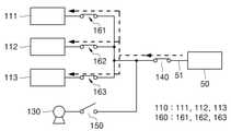
도 1은 본 발명의 실시 예에 따른 배터리 장치의 구조를 나타내는 도면이다.1 is a diagram showing the structure of a battery device according to an embodiment of the present invention.
도 1을 참조하면, 본 발명의 실시 예에 따른 배터리 장치(100)는, 발전 전력라인(51)과 연결되는 배터리(110), 및 제어기(120)를 포함한다. 또한, 배터리 장치(100)는 온풍기(130), 제1 스위치(140), 제2 스위치(150), 제3 스위치(미도시), 및 복수개의 보조 스위치를 더 포함할 수 있다.Referring to FIG. 1 , a
발전기(50)는, 배터리(110)로 전력을 공급하거나, 배터리(110)로부터 공급된 전력을 입력받는다. 이에, 배터리(110) 내 전압이 부족한 경우, 발전 전력라인(51)에서 배터리(110)로 전력을 공급해주어, 배터리(110)가 충전될 수 있다. 배터리(110) 내 전압이 충분한 경우, 배터리(110)가 발전 전력라인(51)으로 전력을 전달해줄 수 있다. 이때, 발전기(50) 대신 변전소, 송전선가 구비될 수도 있다.The
발전 전력라인(51)은, 발전기(50)와 배터리(110)를 전기적으로 연결해주는 역할을 한다. 이에, 발전기(50)의 전력이 발전 전력라인(51)을 통해 배터리(110)로 전달될 수 있다.The power
배터리(110)는 발전 전력라인(51)과 전기적으로 연결된다. 배터리(110)는 발전 전력라인(51)으로부터 공급되는 전력을 저장할 수 있다. 예를 들어, 배터리(110)는 리튬 이온 전지일 수 있다.The
또한, 배터리(110)는 복수개가 구비될 수 있다. 복수개의 배터리(110)는 병렬로 연결되어 서로 전기적으로 연결될 수 있다. 이에, 하나의 배터리(110)에 저장된 전류가 다른 배터리(110)로 흐를 수 있다. 따라서, 배터리(110)들 간에 전류가 흐르면서, 배터리(110)가 충방전될 수 있다. 이때, 병렬로 연결된 배터리(110)들의 최종단자가 발전 전력라인(51)과 연결된다.In addition, a plurality of
제1 스위치(140)는 발전 전력라인(51)(또는, 배터리(110)와 발전소(50) 사이)에 설치된다. 이에, 제1 스위치(140)는 발전소(50)와 배터리(110) 사이의 전기적 연결을 차단하거나, 전기적으로 연결해줄 수 있다. 즉, 제1 스위치(140)는 발전 전력라인(51)과 배터리(110) 사이를 온/오프할 수 있다. 따라서, 제1 스위치(140)의 작동을 제어하여, 발전 전력라인(51)에서 배터리(110)로 전력을 공급하거나, 배터리(110)에서 발전 전력라인(51)으로 전력을 전달해주는 것이 중단될 수 있다.The
보조 스위치(160)는 복수개의 배터리(110) 간의 전류의 흐름을 제어하는 역할을 한다. 보조 스위치(160)는 복수개가 구비되어, 복수개의 배터리(110) 사이에 설치될 수 있다. 보조 스위치(160)는 배터리(110)가 구비되는 개수만큼 구비될 수 있다. 이에, 보조 스위치(160)의 작동을 제어하여, 병렬로 연결된 배터리(110)들 간에 전류를 흘려 보낼 수 있다.The
또한, 복수개의 보조 스위치(160)는 제1 스위치(140)에 연결되는 라인과 연결될 수 있다. 이에, 복수개의 보조 스위치(160)의 작동을 제어하여, 원하는 배터리(110)에만 발전 전력라인(51)의 전력을 공급해주거나, 원하는 배터리(110)에서만 발전 전력라인(51)으로 전력을 전달해줄 수 있다.Also, the plurality of
온풍기(130)는 배터리(110)가 위치하는 공간으로 온풍을 공급해주는 역할을 한다. 온풍기(130)는 배터리(110)와 전기적으로 연결된다. 이때, 병렬로 연결된 배터리(110)들의 최종단자가 온풍기(130)와 연결될 수 있다. 즉, 병렬로 연결된 배터리(110)들의 최종단자가 발전 전력라인(51) 및 온풍기(130)와 병렬로 연결될 수 있다. 따라서, 배터리(110)에서 공급되는 전력에 의해 온풍기(130)가 작동하여 열풍을 발생시킬 수 있고, 배터리(110)의 온도를 상승시켜줄 수 있다.The
또한, 온풍기(130)는 발열체 및 팬을 포함할 수 있다. 발열체는 열을 발생시키는 역할을 하고, 팬은 발열체의 뒤쪽에 설치되어 전방의 배터리(110) 측으로 공기를 밀어보낼 수 있다. 이에, 발열체에서 열을 발생시키는 상태에서, 팬을 작동시키면 따뜻한 바람이 배터리(110)의 저장공간으로 강제적으로 보내질 수 있다.In addition, the
제2 스위치(150)는 온풍기(130)와 배터리(110)들 사이에 설치된다. 이에, 제2 스위치(150)는 온풍기(130)와 배터리(110) 사이의 전기적 연결을 차단하거나, 전기적으로 연결해줄 수 있다. 즉, 제2 스위치(150)는 온풍기(130)와 배터리(110) 사이를 온/오프할 수 있다. 따라서, 제2 스위치(150)의 작동을 제어하여, 배터리(110)에서 온풍기(130)로 전력을 전달되거나 전달되지 않으면서, 온풍기(130)가 작동하거나 작동하지 않을 수 있다.The
이때, 배터리(110)와 발전 전력라인(51)은 전력을 소비하는 장치(미도시)와 전기적으로 연결될 수 있다. 따라서, 배터리(110)에 저장된 전력이나 발전 전력라인(51)이 공급하는 전력이 전력을 소비하는 장치로 공급될 수 있고, 전력을 소비하는 장치가 공급되는 전력에 의해 작동할 수 있다.In this case, the
제3 스위치는 전력을 소비하는 장치와 배터리(110) 사이에 설치된다. 또한, 제3 스위치는 전력을 소비하는 장치와 발전 전력라인(51) 사이에 설치된다. 이에, 제3 스위치는 전력을 소모하는 장치와 배터리(110) 사이, 및 전력을 소모하는 장치와 발전 전력라인(51) 사이를 전기적으로 연결해 주거나 차단할 수 있다. 따라서, 제3 스위치의 작동을 제어하여, 전력을 소모하는 장치로 전력을 공급해주거나 공급을 중단시킬 수 있다.The third switch is installed between the device that consumes power and the
제어기(120)는 배터리(110)가 위치하는 공간의 온도에 따라 배터리(110)들 간에 충방전을 제어할 수 있다. 이에, 배터리(110)들 간의 충방전으로 발생하는 열을 이용하여, 배터리(110)의 온도를 상승시킬 수 있다.The
또한, 제어기(120)는 배터리(110)에서 방전되는 전류 중 적어도 일부를 온풍기(130)로 공급해주도록, 배터리(110)의 방전을 제어할 수 있다. 이에, 제어기(120)는 배터리(110)를 방전시켜 열을 발생시키면서, 온풍기(130)를 작동시켜 배터리(110)가 위치하는 공간으로 온풍을 공급해줄 수 있다. 따라서, 배터리(110)가 발열될 뿐만 아니라, 배터리(110)가 저장되는 공간도 가열되어, 배터리(110)의 온도가 신속하게 상승할 수 있다.In addition, the
제어기(120)는, 온도 감지부(121), 제1 비교부(122), 및 제어부(123)를 포함한다. 또한, 제어기(120)는 전압 측정부(124), 및 제2 비교부(125)를 더 포함할 수 있다.The
온도 감지부(121)는 배터리(110)가 위치하는 공간의 온도를 측정할 수 있다. 예를 들어, 온도 감지부(121)는 온도 측정센서일 수 있고, 배터리(110)가 위치하는 공간에 설치될 수 있다. 이에, 온도 감지부(121)로 배터리(110)가 위치하는 공간의 온도를 모니터링할 수 있다.The
제1 비교부(122)는 온도 감지부(121)와 연결된다. 제1 비교부(122)는 온도 감지부(121)에서 측정된 온도값과 미리 설정된 설정 온도값을 비교할 수 있다. 설정 온도값은 -20℃ 내지 0도 사이의 값 중 어느 하나가 선택될 수 있다. 이에, 측정되는 온도값이 설정 온도값보다 크면, 배터리(110)가 위치하는 공간의 온도가 상온이기 때문에 배터리(110)가 정상적으로 작동할 수 있다고 판단할 수 있다. 따라서, 배터리(110)의 온도를 상승시킬 필요가 없다고 판단할 수 있다.The
반면, 측정되는 온도값이 설정 온도값 이하이면, 배터리(110)가 위치하는 공간의 온도가 저온이기 때문에 배터리(110)의 출력이 저하될 수 있다고 판단할 수 있다. 따라서, 배터리(110) 또는 배터리(110)가 위치한 공간의 온도를 상승시키는 작업을 수행해야 한다고 판단할 수 있다.On the other hand, if the measured temperature value is equal to or less than the set temperature value, it may be determined that the output of the
제어부(123)는 제1 비교부(122)와 연결된다. 이에, 제어부(123)는 제1 비교부(122)에서 비교한 결과에 따라 배터리(110)들 간의 충방전 및 온풍기(130)로 전류 공급해주는 것을 제어할 수 있다. 즉, 제어부(123)는 제1 스위치(140), 제2 스위치(150), 제3 스위치, 및 복수개의 보조 스위치(160)의 작동을 제어할 수 있다.The
예를 들어, 배터리(110)가 위치한 공간의 온도가 저온이라도 판단되는 경우, 제어부(123)는 제1 스위치(140)와 제3 스위치를 끌 수 있다. 즉, 배터리(110)와 발전 전력라인(51)의 전기적 연결을 차단하고, 배터리(110)와 전력을 소모하는 장치의 전기적 연결을 차단할 수 있다. 제2 스위치(150)는 켜서 배터리(110)와 온풍기(130)를 전기적으로 연결해줄 수 있다.For example, when it is determined that the temperature of the space in which the
그 다음, 제어부(123)는 복수개의 보조 스위치(160) 중 적어도 일부는 키고 다른 일부는 끌 수 있다. 그런 상태에서 제어부(123)가 제2 스위치(150)를 키면, 복수개의 배터리(110) 중 보조 스위치(160)가 켜진 배터리(110)에서 온풍기(130)로 전류를 방전시킬 수 있다. 이에, 방전되는 배터리(110)가 발열할 수 있고, 온풍기(130)가 작동되어 배터리(110)가 저장된 공간으로 온풍을 공급해줄 수 있다. 따라서, 배터리(110)가 저장된 공간의 온도가 신속하게 상승할 수 있다.Then, the
그 다음, 보조 스위치(160)가 켜진 배터리(110)가 완전히 방전되면, 제어부(123)는 제2 스위치(150)를 끌 수 있다. 즉, 배터리(110)와 온풍기(130)의 전기적 연결을 차단할 수 있다. 이에, 온풍기(130)의 작동이 중단될 수 있다.Next, when the
그 다음, 제어부(123)는 보조 스위치(160)의 작동을 제어하여, 방전된 배터리(110)와 방전되지 않은 배터리(110)를 전기적으로 연결해줄 수 있다. 이에, 방전되지 않은 배터리(110)에서 방전된 배터리(110)로 전류가 공급될 수 있다. 방전되지 않은 배터리(110)는 방전되고, 방전된 배터리(110)는 충전되면서 배터리(110)들이 발열할 수 있다. 따라서, 배터리(110)가 상온 상태를 유지할 수 있다.Then, the
배터리(110)가 저장된 공간의 온도가 상온으로 상승하면, 배터리(110)들을 충방전시키는 작업을 중단할 수 있다. 이후, 제어부(123)는 제1 스위치(140)나 제3 스위치를 킬 수 있다. 즉, 배터리(110)와 발전 전력라인(51)의 전기적으로 연결해주거나, 배터리(110)와 전력을 소모하는 장치의 전기적으로 연결해줄 수 있다.When the temperature of the space in which the
전압 측정부(124)는 배터리(110)의 전압을 측정할 수 있다. 예를 들어, 전압 측정부(124)는 배터리(110)의 전압을 검출할 수 있는 검출기일 수 있다. 전압 측정부(124)는 하나가 구비되어 복수개의 배터리(110) 전체 전압을 측정할 수 있다. 또는, 전압 측정부(124)가 복수개가 구비되어 각 배터리(110)의 전압을 측정하고, 측정된 값들의 평균을 산출하여 복수개의 배터리(110) 전체 전압을 측정할 수도 있다. 이에, 전압 측정부(124)로 배터리(110) 전체의 전압 상태를 모니터링할 수 있다.The
제2 비교부(125)는 전압 측정부(124)와 연결된다. 제2 비교부(125)는 전압 측정부(124)에서 측정된 전압값과 미리 설정된 설정 전압값을 비교할 수 있다. 설정값은 완충된 배터리(110)의 전압 100%에 대하여, 40~60% 크기의 값 중 어느 하나가 선택될 수 있다. 이에, 측정되는 전압값이 설정 전압값보다 크면, 배터리(110)가 완전히 방전될 위험이 없다고 판단할 수 있다. 따라서, 배터리(110)의 온도를 상승시키는 작업을 중단할 필요가 없다고 판단할 수 있다.The
반면, 측정되는 전압값이 설정 전압값 이하이면, 배터리(110)가 완전히 방전될 위험이 있다고 판단할 수 있다. 따라서, 배터리(110)의 온도를 상승시키는 작업을 중단시켜, 배터리(110)가 방전되는 것을 방지해야 한다고 판단할 수 있다.On the other hand, if the measured voltage value is equal to or less than the set voltage value, it may be determined that there is a risk of the
이때, 제어부(123)는 제2 비교부(125)와도 연결된다. 이에, 제어부(123)는 제2 비교부(125)에서 비교한 결과에 따라 배터리(110)들 간의 충방전 및 온풍기(130)로 전류 공급해주는 것을 제어할 수 있다. 즉, 제어부(123)는 제1 스위치(140), 제2 스위치(150), 제3 스위치, 및 복수개의 보조 스위치(160)의 작동을 제어할 수 있다.In this case, the
예를 들어, 배터리(110)들 전체가 방전될 위험이 있다고 판단되는 경우, 제어부(123)는 제2 스위치(150)와 제3 스위치를 끌 수 있다. 즉, 배터리(110)와 전력을 소모하는 장치의 전기적 연결을 차단하고, 배터리(110)와 온풍기(130)의 전기적 연결을 차단할 수 있다.For example, when it is determined that all of the
그 다음, 제어부(123)는 보조 스위치(160)들을 모두 킨 상태에서 제1 스위치(140)를 킬 수 있다. 즉, 배터리(110)들을 전기적으로 모두 연결할 상태에서, 배터리(110)들과 발전 전력라인(51)을 전기적으로 연결해줄 수 있다. 이에, 발전 전력라인(51)이 배터리(110)들에 전력을 공급해주어, 배터리(110)들이 충전될 수 있다.Next, the
한편, 배터리(110)가 위치한 공간의 온도가 저온이라도 판단되는 동시에, 배터리(110)들 전체가 방전될 위험이 있다고 판단되는 경우, 제어부(123)는 제1 스위치(140), 제2 스위치(150), 및 보조 스위치(160)를 모두 킨 상태에서 제3 스위치만 끌 수 있다. 이에, 발전 전력라인(51)에서 공급해주는 전력이 배터리(110)를 충전시켜주면서, 온풍기(130)를 작동시켜 배터리(110)가 위치한 공간으로 온풍을 공급해줄 수 있다.On the other hand, when it is determined that the temperature of the space in which the
이처럼 배터리(110)가 저온 환경에 노출되는 경우, 자동으로 배터리(110)의 온도를 용이하게 상승시킬 수 있다. 이에, 낮은 온도로 인해 배터리(110)의 출력이 저하되는 문제를 방지할 수 있다. 또한, 배터리(110)의 온도를 상승시키는데 사용되는 에너지를 효율적으로 사용할 수 있다. 이에, 에너지가 낭비되는 것을 방지할 수 있고, 적은 에너지로 배터리의 온도를 상승시킬 수 있다. 따라서, 에너지의 사용 효율이 향상될 수 있다.As such, when the
도 2는 본 발명의 실시 예에 따른 배터리 온도 조절방법을 나타내는 플로우 차트이고, 도 3은 본 발명의 실시 예에 따른 배터리에서 온풍기로 전류를 공급하는 구조를 나타내는 도면이고, 도 4는 본 발명의 실시 예에 따른 일 배터리에서 다른 배터리로 전류를 공급하는 구조를 나타내는 도면이고, 도 5는 본 발명의 실시 예에 따른 다른 배터리에서 또 다른 배터리로 전류를 공급하는 구조를 나타내는 도면이고, 도 6은 본 발명의 실시 예에 따른 배터리를 충전하는 구조를 나타내는 도면이다. 하기에서는 본 발명의 실시 예에 따른 배터리 온도 조절방법에 대해 설명하기로 한다.2 is a flowchart illustrating a battery temperature control method according to an embodiment of the present invention, FIG. 3 is a diagram illustrating a structure for supplying current from a battery to a hot air fan according to an embodiment of the present invention, and FIG. 4 is a diagram of the present invention It is a diagram showing a structure for supplying current from one battery to another battery according to an embodiment, and FIG. 5 is a diagram showing a structure for supplying current from another battery to another battery according to an embodiment of the present invention, FIG. 6 is It is a diagram showing a structure for charging a battery according to an embodiment of the present invention. Hereinafter, a battery temperature control method according to an embodiment of the present invention will be described.
도 2를 참조하면, 본 발명의 실시 예에 따른 배터리 온도 조절방법은, 발전기와 연결되는 발전 전력라인에 연결되는 복수개의 배터리를 마련하는 과정(S110), 복수개의 배터리가 위치하는 공간의 온도를 측정하는 과정(S120), 및 측정된 온도에 따라 복수개의 배터리 간의 충방전을 제어하여 배터리의 온도를 상승시키는 과정(S130)을 포함한다.Referring to FIG. 2 , in the battery temperature control method according to an embodiment of the present invention, a process of providing a plurality of batteries connected to a power generation power line connected to a generator (S110), the temperature of a space in which the plurality of batteries are located It includes a process of measuring (S120), and a process of increasing the temperature of the batteries by controlling charging and discharging between the plurality of batteries according to the measured temperature (S130).
이때, 배터리의 온도조절은, 휴지기간(Rest)에 수행될 수 있다. 즉, 배터리가 충방전을 하지 않아 배터리의 발열이 없기 때문에, 휴지기간에 배터리가 쉽게 저온 상태가 될 수 있다. 따라서, 휴지기간에 배터리가 위치하는 공간의 온도에 따라, 배터리의 온도를 상승시키는 작업을 수행할 수 있다.In this case, the temperature control of the battery may be performed during the rest period (Rest). That is, since the battery does not charge and discharge and the battery does not generate heat, the battery can easily be in a low temperature state during the idle period. Accordingly, it is possible to perform an operation to increase the temperature of the battery according to the temperature of the space in which the battery is located during the idle period.
또한, 본 발명의 실시 예는 배터리가 제1 배터리, 제2 배터리, 및 제3 배터리를 포함하고, 보조 스위치가 제1 보조 스위치, 제2 보조 스위치, 및 제3 보조 스위치를 포함하는 경우를 예시하여 설명한다. 그러나 배터리 및 보조 스위치가 구비되는 개수는 이에 한정되지 않고 다양할 수 있다.In addition, an embodiment of the present invention exemplifies a case in which the battery includes a first battery, a second battery, and a third battery, and the auxiliary switch includes a first auxiliary switch, a second auxiliary switch, and a third auxiliary switch to explain However, the number of batteries and auxiliary switches is not limited thereto and may vary.
온도 감지부로 배터리가 위치하는 공간의 온도를 실시간으로 모니터링할 수 있다. 온도 감지부에서 측정되는 온도값과 미리 설정된 설정 온도값을 비교할 수 있다. 설정 온도값은 -20℃ 내지 0도 사이의 값 중 어느 하나가 선택될 수 있다. 이에, 측정되는 온도값이 설정 온도값보다 크면, 배터리가 위치하는 공간의 온도가 상온이기 때문에 배터리가 정상적으로 작동할 수 있다고 판단할 수 있다. 따라서, 배터리의 온도를 상승시킬 필요가 없다고 판단할 수 있다.With the temperature sensor, the temperature of the space where the battery is located can be monitored in real time. A temperature value measured by the temperature sensor may be compared with a preset temperature value. As the set temperature value, any one of values between -20°C and 0°C may be selected. Accordingly, when the measured temperature value is greater than the set temperature value, it can be determined that the battery can operate normally because the temperature of the space in which the battery is located is room temperature. Accordingly, it may be determined that there is no need to increase the temperature of the battery.
반면, 측정되는 온도값이 설정 온도값 이하이면, 배터리가 위치하는 공간의 온도가 저온이기 때문에 배터리의 출력이 저하될 수 있다고 판단할 수 있다. 따라서, 배터리 또는 배터리가 위치한 공간의 온도를 상승시키는 작업을 수행해야 한다고 판단할 수 있다.On the other hand, if the measured temperature value is less than or equal to the set temperature value, it may be determined that the output of the battery may be reduced because the temperature of the space in which the battery is located is low. Accordingly, it may be determined that the operation of increasing the temperature of the battery or the space in which the battery is located should be performed.
배터리가 위치한 공간의 온도가 저온이라도 판단되는 경우, 도 3과 같이 제1 스위치(140)와 제3 스위치를 끌 수 있다. 즉, 배터리(110)들과 발전 전력라인(51)의 전기적 연결을 차단하고, 배터리(110)들과 전력을 소모하는 장치의 전기적 연결을 차단할 수 있다. 제2 스위치(150)는 켜서 배터리(110)와, 배터리(110)가 위치하는 공간으로 온풍을 공급해주도록 설치되는 온풍기(130)를 전기적으로 연결해줄 수 있다.When it is determined that the temperature of the space in which the battery is located is low, the
이때, 제1 보조 스위치(161)는 끄고, 제2 보조 스위치(162)와 제3 보조 스위치(163)는 킬 수 있다. 따라서, 제2 배터리(112)와 제3 배터리(113)만 온풍기(130)와 전기적으로 연결되고, 제1 배터리(111)와 온풍기(130)는 전기적으로 연결되지 않는다. 이에, 제2 배터리(112)와 제3 배터리(113)에서 방전되는 전류가 온풍기(130)로 공급되어, 온풍기(130)를 작동시킬 수 있다.In this case, the first
제2 배터리(112)와 제3 배터리(113)는 방전되면서 발열할 수 있고, 온풍기(130)가 작동되어 배터리(110)가 저장된 공간으로 온풍을 공급해줄 수 있다. 따라서, 배터리(110)가 저장된 공간의 이중으로 가열되어 온도가 신속하게 상승할 수 있다. 이에, 제2 배터리(112)와 제3 배터리(113)의 전력을 효율적으로 사용하여 온도를 상승시킬 수 있다.The
그 다음, 제2 배터리(112)와 제3 배터리(113)가 방전되면, 도 4와 같이 제2 스위치(150)를 끌 수 있다. 즉, 배터리(110)와 온풍기(130)의 전기적 연결을 차단할 수 있다. 이에, 온풍기(130)에 전류 공급이 중단되어 온풍기(130)의 작동이 중단될 수 있다.Next, when the
그 다음, 배터리(110)들 간에 전류를 흘려 보내어 배터리(110)들을 충방전시킬 수 있도록, 배터리(110)들 간에 충방전 경로를 형성할 수 있다. 즉, 복수개의 배터리(110) 중 방전된 배터리(110)로, 방전되지 않은 다른 배터리(110)의 전류를 흘려 보낼 수 있다. 이에, 충전되는 배터리와, 방전되는 배터리(110)가 발열하여, 배터리(110)가 위치하는 공간의 온도가 상승할 수 있다.Next, a charging/discharging path may be formed between the
예를 들어, 제1 보조 스위치(161)와 제2 보조 스위치(162)를 킨 상태에서 제3 보조 스위치(163)를 끌 수 있다. 이에, 제1 배터리(111)와 제2 배터리(112)는 전기적으로 연결되고, 제3 배터리(113)는 제1 배터리(111) 및 제2 배터리(112)와 전기적으로 연결되지 않을 수 있다.For example, the third
방전되지 않은 제1 배터리(111) 내부의 전압이, 방전된 제2 배터리(112)의 내부 전압보다 높기 때문에, 제1 배터리(111)에서 제2 배터리(112)로 전류가 흘러간다. 이에, 제1 배터리(111)는 방전되고 제2 배터리(112)는 충전되면서, 제1 배터리(111)와 제2 배터리(112)가 발열할 수 있다. 제1 배터리(111)와 제2 배터리(112)의 전압이 같아지면, 전류의 공급이 중단될 수 있다.Since the internal voltage of the undischarged
그 다음, 도 5와 같이 제1 보조 스위치(161)를 끈 상태에서 제3 스위치를 킬 수 있다. 이에, 제2 배터리(112)와 제3 배터리(113)는 전기적으로 연결되고, 제1 배터리(111)는 제2 배터리(112) 및 제3 배터리(113)와 전기적으로 연결되지 않을 수 있다.Next, as shown in FIG. 5 , the third switch may be turned on while the first
제1 배터리(111)에 의해 충전된 제2 배터리(112) 내 전압이, 방전된 제3 배터리(113) 내부의 전압보다 높기 때문에, 제2 배터리(112)에서 제3 배터리(113)로 전류가 흘러간다. 이에, 제2 배터리(112)는 방전되고 제3 배터리(113)는 충전되면서, 제2 배터리(112)와 제3 배터리(113)가 발열할 수 있다. 제2 배터리(112)와 제3 배터리(113)의 전압이 같아지면, 전류의 공급이 중단될 수 있다.Since the voltage inside the
제2 배터리(112)의 전압이 제1 배터리(111)의 전압이 낮아졌기 때문에, 제2 배터리(112)와 제3 배터리(113)의 전기적 연결을 차단하고, 제1 배터리(111)와 제2 배터리(112)를 전기적으로 다시 연결해줄 수 있다. 이에, 제1 배터리(111)에서 제2 배터리(112)로 전류가 흐르면서 제1 배터리(111)는 방전되고 제2 배터리(112)는 충전된다. 따라서, 제1 배터리(111)와 제2 배터리(112)가 발열할 수 있다.Since the voltage of the
이후로 이러한 충방전을 반복하여, 배터리(110)들을 발열시킬 수 있다. 따라서, 온풍기(130)로 상승된 온도를, 배터리(110)들 간의 충방전으로 발생하는 열로 유지시켜줄 수 있다. 이에, 배터리(110)가 위치하는 공간이 상온을 유지할 수 있다. 배터리(110)가 저장된 공간의 온도가 일정 온도까지 상승하거나, 일정 온도로 유지되면, 배터리(110)들을 충방전시키는 작업을 중단시킬 수 있다.Thereafter, by repeating such charging and discharging, the
한편, 배터리(110)의 온도를 상승시키는 작업을 수행할 때, 전압 측정부에서 배터리(110)들의 전압을 측정하여, 실시간으로 모니터링할 수 있다. 전압 측정부에서 측정된 전압값과 미리 설정된 설정 전압값을 비교할 수 있다. 설정값은 완충된 배터리(110)의 전압 100%에 대하여, 40~60% 크기의 값 중 어느 하나가 선택될 수 있다. 이에, 측정되는 전압값이 설정 전압값보다 크면, 배터리(110)가 완전히 방전될 위험이 없다고 판단할 수 있다. 따라서, 배터리(110)의 온도를 상승시키는 작업을 중단할 필요가 없다고 판단할 수 있다.Meanwhile, when an operation of increasing the temperature of the
반면, 측정되는 전압값이 설정 전압값 이하이면, 배터리(110)가 완전히 방전될 위험이 있다고 판단할 수 있다. 따라서, 배터리(110)의 온도를 상승시키는 작업을 중단시켜, 배터리(110)가 방전되는 것을 방지해야 한다고 판단할 수 있다.On the other hand, if the measured voltage value is equal to or less than the set voltage value, it may be determined that there is a risk of the
온풍기(130)를 작동시킬 때, 측정되는 전압값이 설정 전압값 이하이면, 제2 스위치(150)를 끌 수 있다. 즉, 배터리(110)와 온풍기(130)의 전기적 연결을 차단할 수 있다. 이에, 배터리(110)에서 온풍기(130)로 전류가 방전되지 않을 수 있고, 배터리(110)의 전압이 낮아지는 것을 방지할 수 있다.When the
그 다음, 보조 스위치(160)들을 모두 킨 상태에서, 제1 스위치(140)를 킬 수 있다. 즉, 배터리(110)들과 발전 전력라인(51)을 전기적으로 연결해줄 수 있다. 이에, 도 6과 같이 발전 전력라인(51)에서 배터리(110)로 전력을 공급해주어, 배터리(110)들이 모두 방전되기 전에 충전될 수 있다. 이때, 제3 스위치는 꺼진 상태에 있다.Next, in a state in which all
또한, 배터리(110)가 위치한 공간의 온도가 저온이라도 판단되는 동시에, 배터리(110)들 전체가 방전될 위험이 있다고 판단되는 경우, 제1 스위치(140), 제2 스위치(150), 및 보조 스위치(160)를 모두 킨 상태에서 제3 스위치만 끌 수 있다. 이에, 발전 전력라인(51)에서 공급해주는 전력이 배터리(110)를 충전시켜주면서, 온풍기(130)를 작동시켜 배터리(110)가 위치한 공간으로 온풍을 공급해줄 수 있다. 따라서, 배터리(110)의 충전과, 배터리(110)가 위치한 공간의 온도를 상승시키는 작업이 동시에 수행될 수 있다.In addition, when it is determined that the temperature of the space in which the
이처럼 배터리(110)가 저온 환경에 노출되는 경우, 자동으로 배터리(110)의 온도를 용이하게 상승시킬 수 있다. 이에, 낮은 온도로 인해 배터리(110)의 출력이 저하되는 문제를 방지할 수 있다. 또한, 배터리(110)의 온도를 상승시키는데 사용되는 에너지를 효율적으로 사용할 수 있다. 이에, 에너지가 낭비되는 것을 방지할 수 있고, 적은 에너지로 배터리의 온도를 상승시킬 수 있다. 따라서, 에너지의 사용 효율이 향상될 수 있다.As such, when the
이와 같이, 본 발명의 상세한 설명에서는 구체적인 실시 예에 관해 설명하였으나, 본 발명의 범주에서 벗어나지 않는 한도 내에서 여러 가지 변형이 가능하다. 그러므로, 본 발명의 범위는 설명된 실시 예에 국한되어 정해져서는 안되며, 아래에 기재될 특허청구범위뿐만 아니라 이 청구범위와 균등한 것들에 의해 정해져야 한다.As such, although specific embodiments have been described in the detailed description of the present invention, various modifications are possible without departing from the scope of the present invention. Therefore, the scope of the present invention should not be limited to the described embodiments, but should be defined by the claims to be described below as well as the claims and equivalents.
100: 배터리 장치110: 배터리
120: 제어기121: 온도 감지부
122: 제1 비교부123: 제어부
124: 전압 측정부125: 제2 비교기
130: 온풍기140: 제1 스위치
150: 제2 스위치160: 보조 스위치100: battery device 110: battery
120: controller 121: temperature sensing unit
122: first comparison unit 123: control unit
124: voltage measuring unit 125: second comparator
130: warm blower 140: first switch
150: second switch 160: auxiliary switch
Claims (14)
Translated fromKorean상기 복수개의 배터리와 연결되고, 상기 배터리가 위치하는 공간으로 온풍을 공급해주도록 설치되는 온풍기; 및
상기 배터리가 위치하는 공간의 온도에 따라 배터리들 간에 충방전을 제어하여 배터리들을 발열시키거나, 상기 복수개의 배터리 중 일부에서 방전되는 전류를 상기 온풍기로 공급해주도록 제어하여, 배터리의 온도를 상승시킬 수 있는 제어기;를 포함하여 구성되며,
상기 복수개의 배터리는 병렬로 연결되고, 상기 병렬로 연결된 복수개의 배터리의 최종단자가 상기 발전 전력라인에 연결되고,
상기 제어기는,
상기 배터리의 전압을 측정할 수 있는 전압 측정부,
상기 전압 측정부에서 측정된 전압값과 미리 설정된 설정 전압값을 비교할 수 있는 전압 비교부, 및
측정되는 전압값이 미리 설정된 전압값보다 낮아지면, 상기 복수개의 배터리 중 일부와 상기 온풍기의 연결을 차단하고, 상기 복수개의 배터리 중 상기 온풍기에 전류를 방전하지 않은 배터리에서 상기 온풍기에 전류를 방전한 배터리로 전류를 공급하도록 충방전을 제어하여 배터리들을 발열시킬 수 있는 제어부를 포함하는 배터리 장치.a plurality of batteries connected to a power generation power line connected to an external generator;
a heater connected to the plurality of batteries and installed to supply warm air to a space in which the batteries are located; and
Depending on the temperature of the space in which the battery is located, charging and discharging between the batteries is controlled to heat the batteries, or by controlling the current discharged from some of the plurality of batteries to be supplied to the warm air fan, the temperature of the battery can be raised. It consists of a controller;
The plurality of batteries are connected in parallel, and the last terminals of the plurality of batteries connected in parallel are connected to the power generation power line,
The controller is
a voltage measuring unit capable of measuring the voltage of the battery;
a voltage comparator capable of comparing the voltage value measured by the voltage measuring unit with a preset voltage value; and
When the measured voltage value is lower than the preset voltage value, the connection between some of the plurality of batteries and the hot air blower is cut off, and the current is discharged from the battery that has not discharged the current to the hot air blower among the plurality of batteries. A battery device comprising a controller capable of heating the batteries by controlling charging and discharging to supply current to the battery.
상기 발전 전력라인에 설치되는 제1 스위치; 및
상기 온풍기와 상기 배터리 사이에 설치되는 제2 스위치;를 더 포함하는 배터리 장치.The method according to claim 1,
a first switch installed on the power generation line; and
The battery device further comprising a; a second switch installed between the warm air and the battery.
상기 복수개의 배터리 간의 전류의 흐름을 제어하도록, 상기 복수개의 배터리 사이에 설치되는 복수개의 보조 스위치를 더 포함하는 배터리 장치.4. The method according to claim 3,
The battery device further comprising a plurality of auxiliary switches installed between the plurality of batteries to control the flow of current between the plurality of batteries.
상기 제어기는,
상기 배터리가 위치하는 공간의 온도를 측정할 수 있는 온도 감지부; 및
상기 온도 감지부에서 측정된 온도값과 미리 설정된 설정 온도값을 비교할 수 있는 온도 비교부;를 더 포함하고,
상기 제어부는 상기 온도 비교부에서 비교한 결과에 따라, 상기 제1 스위치, 상기 제2 스위치, 및 상기 복수개의 보조 스위치의 작동을 제어할 수 있는 배터리 장치.5. The method according to claim 4,
The controller is
a temperature sensor capable of measuring a temperature of a space in which the battery is located; and
Further comprising; a temperature comparison unit capable of comparing the temperature value measured by the temperature sensing unit with a preset temperature value;
The control unit may control the operation of the first switch, the second switch, and the plurality of auxiliary switches according to a result of the comparison by the temperature comparison unit.
상기 복수개의 배터리가 위치하는 공간의 온도를 측정하는 과정; 및
측정된 온도에 따라, 상기 복수개의 배터리 간의 충방전을 제어하여 배터리의 온도를 상승시키는 과정;을 포함하고,
상기 배터리의 온도를 상승시키는 과정은,
상기 배터리와, 상기 배터리가 위치하는 공간으로 온풍을 공급해주도록 설치되는 온풍기를 연결해주는 과정,
상기 배터리에서 방전되는 전류 중 적어도 일부를 상기 온풍기에 공급하는 과정,
상기 배터리의 전압을 측정하는 과정,
측정되는 전압값이 미리 설정된 전압값과 비교하는 과정, 및
측정되는 전압값이 미리 설정된 전압값보다 낮아지면, 상기 복수개의 배터리 중 일부와 상기 온풍기의 연결을 차단하고, 상기 복수개의 배터리 중 상기 온풍기에 전류를 방전하지 않은 배터리에서 상기 온풍기에 전류를 방전한 배터리로 전류를 공급하도록 충방전을 제어하여 배터리들을 발열시키는 과정을 포함하는 배터리 온도 조절방법.A process of providing a plurality of batteries connected to a power generation power line connected to an external generator;
measuring a temperature of a space in which the plurality of batteries are located; and
The process of increasing the temperature of the battery by controlling the charging and discharging between the plurality of batteries according to the measured temperature;
The process of increasing the temperature of the battery,
A process of connecting the battery and a hot air fan installed to supply hot air to a space in which the battery is located;
supplying at least a portion of the current discharged from the battery to the hot air fan;
measuring the voltage of the battery;
The process of comparing the measured voltage value with a preset voltage value, and
When the measured voltage value is lower than the preset voltage value, the connection between some of the plurality of batteries and the hot air blower is cut off, and the current is discharged from the battery that has not discharged the current to the hot air blower among the plurality of batteries. A method of controlling a battery temperature, comprising the step of controlling charging and discharging to supply current to the battery to cause the batteries to generate heat.
상기 복수개의 배터리 간의 충방전을 제어하는 과정은,
상기 복수개의 배터리와 상기 발전 전력라인의 연결을 차단하는 과정; 및
상기 복수개의 배터리 간의 충방전 경로를 형성하여 배터리를 발열시키는 과정;을 포함하는 온도 조절방법.8. The method of claim 7,
The process of controlling the charging and discharging between the plurality of batteries,
cutting off the connection between the plurality of batteries and the power generation power line; and
The method of controlling a temperature including a process of forming a charging/discharging path between the plurality of batteries to heat the batteries.
상기 배터리에서 방전되는 전류 중 적어도 일부를 상기 온풍기에 공급하는 과정은,
복수개의 배터리 중 적어도 일부를 방전시켜 상기 온풍기에 전류를 공급하는 과정; 및
방전되는 배터리를 발열시키는 과정;을 포함하는 배터리 온도 조절방법.9. The method of claim 8,
The process of supplying at least a portion of the current discharged from the battery to the hot air blower,
discharging at least some of the plurality of batteries to supply current to the heater; and
A battery temperature control method comprising a; the process of heating the discharged battery.
상기 복수개의 배터리 간에 충방전을 제어하는 과정은,
상기 온풍기에 전류를 공급을 중단하는 과정;
복수개의 배터리 중 방전된 배터리로, 다른 배터리의 전류를 공급하는 과정; 및
복수개의 배터리 중 충전되는 배터리와, 방전되는 배터리를 발열시키는 과정;을 포함하는 배터리 온도 조절방법.11. The method of claim 10,
The process of controlling charging and discharging between the plurality of batteries,
stopping the supply of current to the hot air blower;
supplying current from another battery to a discharged battery among the plurality of batteries; and
A battery temperature control method comprising a; a process of heating a battery to be charged and a battery to be discharged from among the plurality of batteries.
상기 복수개의 배터리가 위치하는 공간의 온도를 측정하는 과정은, 측정된 온도값과 미리 설정된 설정 온도값을 비교하는 과정을 포함하고,
상기 측정된 온도에 따라 배터리의 온도를 상승시키는 과정은, 측정된 온도값이 상기 설정 온도값 이하이면, 상기 배터리의 온도를 상승시키는 과정을 포함하는 배터리 온도 조절방법.12. The method of any one of claims 7, 8, 10, and 11,
The process of measuring the temperature of the space in which the plurality of batteries are located includes the process of comparing the measured temperature value with a preset temperature value,
The process of raising the temperature of the battery according to the measured temperature includes raising the temperature of the battery when the measured temperature value is equal to or less than the set temperature value.
Priority Applications (5)
| Application Number | Priority Date | Filing Date | Title |
|---|---|---|---|
| KR1020170158761AKR102375845B1 (en) | 2017-11-24 | 2017-11-24 | Battery and Method for controlling battery temperature |
| EP18881490.9AEP3614485B1 (en) | 2017-11-24 | 2018-11-16 | Battery device and battery temperature adjusting method |
| PCT/KR2018/014154WO2019103412A1 (en) | 2017-11-24 | 2018-11-16 | Battery device and battery temperature adjusting method |
| JP2020514487AJP7091449B2 (en) | 2017-11-24 | 2018-11-16 | How to control the temperature of the battery device and battery |
| US16/629,446US11688893B2 (en) | 2017-11-24 | 2018-11-16 | Battery device and battery temperature adjusting method |
Applications Claiming Priority (1)
| Application Number | Priority Date | Filing Date | Title |
|---|---|---|---|
| KR1020170158761AKR102375845B1 (en) | 2017-11-24 | 2017-11-24 | Battery and Method for controlling battery temperature |
Publications (2)
| Publication Number | Publication Date |
|---|---|
| KR20190060497A KR20190060497A (en) | 2019-06-03 |
| KR102375845B1true KR102375845B1 (en) | 2022-03-17 |
Family
ID=66631124
Family Applications (1)
| Application Number | Title | Priority Date | Filing Date |
|---|---|---|---|
| KR1020170158761AActiveKR102375845B1 (en) | 2017-11-24 | 2017-11-24 | Battery and Method for controlling battery temperature |
Country Status (5)
| Country | Link |
|---|---|
| US (1) | US11688893B2 (en) |
| EP (1) | EP3614485B1 (en) |
| JP (1) | JP7091449B2 (en) |
| KR (1) | KR102375845B1 (en) |
| WO (1) | WO2019103412A1 (en) |
Families Citing this family (8)
| Publication number | Priority date | Publication date | Assignee | Title |
|---|---|---|---|---|
| CN110364785B (en)* | 2019-06-12 | 2021-12-28 | 爱驰汽车有限公司 | Temperature control device for electric vehicle and electric vehicle |
| CN112455290A (en)* | 2020-10-28 | 2021-03-09 | 东风汽车集团有限公司 | Power battery heating protection circuit, method and device |
| WO2022104372A1 (en)* | 2020-11-12 | 2022-05-19 | Polestar Performance Ab | Resilient high-voltage systems |
| JP7320027B2 (en)* | 2021-09-07 | 2023-08-02 | ソフトバンク株式会社 | Systems, programs and management methods |
| JP7605847B2 (en) | 2021-12-27 | 2024-12-24 | 香港時代新能源科技有限公司 | Battery heating control method, device and electronic device |
| KR20230161103A (en)* | 2022-05-18 | 2023-11-27 | 에스케이하이닉스 주식회사 | Apparatus for Power Supply, Method for Health Monitoring Therefor and Storage System Having the Same |
| WO2024092446A1 (en)* | 2022-10-31 | 2024-05-10 | 宁德时代新能源科技股份有限公司 | Battery heating control method and control apparatus |
| KR20250033724A (en) | 2023-09-01 | 2025-03-10 | 주식회사 엘지에너지솔루션 | Battery pack including a connector to prevent charging at low temperatures and its charging method |
Citations (1)
| Publication number | Priority date | Publication date | Assignee | Title |
|---|---|---|---|---|
| JP2010044895A (en)* | 2008-08-11 | 2010-02-25 | Toyota Motor Corp | Temperature control device of power supply device |
Family Cites Families (47)
| Publication number | Priority date | Publication date | Assignee | Title |
|---|---|---|---|---|
| JPH0562718A (en) | 1991-09-04 | 1993-03-12 | Nec Eng Ltd | Charging method for storage battery |
| JPH077866A (en) | 1993-06-16 | 1995-01-10 | Sanyo Electric Co Ltd | Circuit for charging secondary battery |
| JP2001251780A (en) | 2000-03-07 | 2001-09-14 | Sharp Corp | Rechargeable battery charger |
| US6574082B2 (en)* | 2001-10-09 | 2003-06-03 | Ericsson Inc. | Methods and systems for operating temperature controls for electronic equipment |
| JP4707346B2 (en)* | 2004-08-16 | 2011-06-22 | 三洋電機株式会社 | Power supply for vehicle |
| JP5314235B2 (en)* | 2006-03-07 | 2013-10-16 | プライムアースEvエナジー株式会社 | Secondary battery temperature control device, secondary battery heating system, and program |
| JP5162100B2 (en)* | 2006-03-07 | 2013-03-13 | プライムアースEvエナジー株式会社 | Secondary battery temperature control device, vehicle battery pack, and secondary battery temperature control program |
| WO2008095313A1 (en)* | 2007-02-09 | 2008-08-14 | Advanced Lithium Power Inc. | Battery thermal management system |
| JP4353305B2 (en)* | 2008-03-21 | 2009-10-28 | トヨタ自動車株式会社 | Power control circuit |
| JP4661895B2 (en)* | 2008-04-02 | 2011-03-30 | 株式会社デンソー | Battery cooling device |
| JP5272610B2 (en)* | 2008-09-24 | 2013-08-28 | 株式会社デンソー | In-vehicle battery device |
| WO2010042895A1 (en)* | 2008-10-10 | 2010-04-15 | Deeya Energy Technologies, Inc. | Thermal control of a flow cell battery |
| KR101036061B1 (en)* | 2009-04-21 | 2011-05-19 | 에스비리모티브 주식회사 | Battery Management System and Its Driving Method |
| JP5257220B2 (en) | 2009-04-23 | 2013-08-07 | 株式会社デンソー | Battery system |
| KR101036037B1 (en)* | 2009-08-26 | 2011-05-19 | 에스비리모티브 주식회사 | Secondary battery |
| JP5845639B2 (en) | 2011-06-03 | 2016-01-20 | トヨタ自動車株式会社 | Electric vehicle charging system and charging control method |
| JP5644691B2 (en) | 2011-06-21 | 2014-12-24 | 株式会社豊田自動織機 | Cell balance control device and cell balance control method |
| US20130020302A1 (en)* | 2011-07-21 | 2013-01-24 | Tzu-Chin Chiu | Heating module for maintaining battery working temperature |
| JP2013046559A (en) | 2011-08-26 | 2013-03-04 | Toshiba Corp | Electricity storage control device, electricity storage system, and control program |
| TWM421607U (en)* | 2011-08-30 | 2012-01-21 | Asia Vital Components Co Ltd | Heating and cooling module for battery |
| CA2857165A1 (en)* | 2011-11-30 | 2013-06-06 | George Y. Marji | Controlled battery box |
| JP6245789B2 (en)* | 2012-02-20 | 2017-12-13 | 日産自動車株式会社 | Electric vehicle battery pack temperature control structure |
| JP6201434B2 (en)* | 2012-07-18 | 2017-09-27 | 株式会社デンソー | Refrigeration cycle equipment |
| JP6036236B2 (en) | 2012-12-03 | 2016-11-30 | 住友電気工業株式会社 | Storage system and storage battery deterioration diagnosis method |
| KR101485347B1 (en) | 2012-12-05 | 2015-01-27 | 한국전기연구원 | Battery management system, and method of balancing battery cell in battery module using the same |
| KR101579569B1 (en) | 2012-12-10 | 2015-12-22 | 주식회사 엘지화학 | Heating system for a battery module and method of heating the battery module |
| KR101698771B1 (en) | 2013-01-16 | 2017-01-23 | 삼성에스디아이 주식회사 | temperature controlling system of battery and controlling method thereof |
| KR101301559B1 (en)* | 2013-01-16 | 2013-09-04 | 주식회사 이브텍 | Battery case |
| JP2014151802A (en)* | 2013-02-11 | 2014-08-25 | Denso Corp | Temperature regulation device |
| JP5975314B2 (en) | 2013-02-19 | 2016-08-23 | パナソニックIpマネジメント株式会社 | Power storage system |
| KR20140133472A (en) | 2013-05-08 | 2014-11-19 | 주식회사 엘지화학 | Battery warm up system and Method for warming up the battery using the same |
| KR101682457B1 (en) | 2013-09-12 | 2016-12-05 | 주식회사 엘지화학 | Battery warm up system and Method for warming up the battery using the same |
| WO2015050226A1 (en)* | 2013-10-03 | 2015-04-09 | 日産自動車株式会社 | Battery temperature adjustment device |
| KR20150108603A (en)* | 2014-03-18 | 2015-09-30 | 현대모비스 주식회사 | Apparatus and method for temperature rising battery module in eco-friendly vehicle |
| US20160023532A1 (en)* | 2014-07-25 | 2016-01-28 | Atieva, Inc. | EV Integrated Temperature Control System |
| JP6098610B2 (en)* | 2014-10-17 | 2017-03-22 | トヨタ自動車株式会社 | Power storage device |
| EP3208882B1 (en)* | 2014-10-17 | 2021-01-06 | Mitsubishi Electric Corporation | Charge-discharge control device |
| KR101799566B1 (en)* | 2014-11-21 | 2017-11-20 | 주식회사 엘지화학 | Battery Pack with Improved Charge Performance at High and Low Temperature |
| EP3227950B1 (en)* | 2014-12-01 | 2020-05-13 | EC Power LLC | All solid-state lithium battery |
| KR101736201B1 (en)* | 2015-03-17 | 2017-05-17 | 세방전지(주) | Energy storage device for electric vehicle capable of heating the low temperature battery and control method thereof |
| KR101780037B1 (en) | 2015-04-22 | 2017-09-19 | 주식회사 엘지화학 | Cooling device for battery cell and battery module comprising the same |
| KR102456811B1 (en)* | 2015-10-27 | 2022-10-20 | 엘지전자 주식회사 | Method for operating heater of energy storage device |
| US10886583B2 (en)* | 2016-03-02 | 2021-01-05 | Gentherm Incorporated | Battery and capacitor assembly for a vehicle and a method for heating and cooling the battery and capacitor assembly |
| US10608291B2 (en)* | 2016-05-20 | 2020-03-31 | Spiers New Technologies, Inc. | Battery pack having a supplemental power supply |
| KR20200024227A (en)* | 2017-06-15 | 2020-03-06 | 에이일이삼 시스템즈, 엘엘씨 | System and method for operating a dual battery system |
| US11495839B2 (en)* | 2017-10-18 | 2022-11-08 | Textron Innovations, Inc. | Internal battery heating |
| US10622607B2 (en)* | 2017-11-07 | 2020-04-14 | Ford Global Technologies, Llc | Electrified vehicle battery packs designed with sacrificial components |
- 2017
- 2017-11-24KRKR1020170158761Apatent/KR102375845B1/enactiveActive
- 2018
- 2018-11-16USUS16/629,446patent/US11688893B2/enactiveActive
- 2018-11-16WOPCT/KR2018/014154patent/WO2019103412A1/ennot_activeCeased
- 2018-11-16EPEP18881490.9Apatent/EP3614485B1/enactiveActive
- 2018-11-16JPJP2020514487Apatent/JP7091449B2/enactiveActive
Patent Citations (1)
| Publication number | Priority date | Publication date | Assignee | Title |
|---|---|---|---|---|
| JP2010044895A (en)* | 2008-08-11 | 2010-02-25 | Toyota Motor Corp | Temperature control device of power supply device |
Also Published As
| Publication number | Publication date |
|---|---|
| JP7091449B2 (en) | 2022-06-27 |
| US20200212512A1 (en) | 2020-07-02 |
| EP3614485B1 (en) | 2023-09-20 |
| KR20190060497A (en) | 2019-06-03 |
| EP3614485A4 (en) | 2020-08-19 |
| US11688893B2 (en) | 2023-06-27 |
| JP2020521428A (en) | 2020-07-16 |
| EP3614485A1 (en) | 2020-02-26 |
| WO2019103412A1 (en) | 2019-05-31 |
Similar Documents
| Publication | Publication Date | Title |
|---|---|---|
| KR102375845B1 (en) | Battery and Method for controlling battery temperature | |
| US6661203B2 (en) | Battery charging and discharging system optimized for high temperature environments | |
| CN108390131B (en) | Pure internal resistance battery heating system | |
| US10230139B2 (en) | Temperature control apparatus and method for energy storage system | |
| KR102052241B1 (en) | System and method for battery management using Balancing battery | |
| US11828806B2 (en) | Apparatus and method for calculating battery power | |
| US11646596B2 (en) | Portable power station having multiple battery modules and method of operating a portable power station having multiple battery modules | |
| KR20170123093A (en) | battery pack and battery pack charging method | |
| KR101715700B1 (en) | Apparatus for controlling secondary battery pack to improve a performance in low-temperature environment | |
| CN106876617B (en) | Automatic temperature control battery box and control method thereof | |
| KR20120032218A (en) | Apparatus for controlling secondary battery pack to improve a performance in low-temperature environment | |
| KR20140054320A (en) | Electricity storage device control system | |
| KR20190071455A (en) | Apparatus and method for cell balancing | |
| CN110277807B (en) | Charge current control method and apparatus, battery management system, vehicle, device, and computer-readable storage medium | |
| JP5946210B2 (en) | Power supply | |
| WO2017121021A1 (en) | Low-temperature high-power output auxiliary apparatus for portable battery pack | |
| JP7732722B2 (en) | Battery management device and method of operation thereof | |
| JP2011192425A (en) | Memory effect reducing circuit, battery power supply device, battery utilization system, and memory effect reducing method | |
| KR20150033126A (en) | Apparatus for controlling temperature of battery pack | |
| US20230006282A1 (en) | Power management device and power storage system | |
| US12395000B2 (en) | Autonomously activated electric energy storage device and control method thereof | |
| WO2015028964A1 (en) | Battery temperature regulating system and method | |
| KR20220100467A (en) | Battery management apparatus and method of the same | |
| TWI379485B (en) | Charger | |
| KR20240028849A (en) | Apparatus for managing battery and operating method of the same |
Legal Events
| Date | Code | Title | Description |
|---|---|---|---|
| PA0109 | Patent application | Patent event code:PA01091R01D Comment text:Patent Application Patent event date:20171124 | |
| PG1501 | Laying open of application | ||
| A201 | Request for examination | ||
| PA0201 | Request for examination | Patent event code:PA02012R01D Patent event date:20200414 Comment text:Request for Examination of Application Patent event code:PA02011R01I Patent event date:20171124 Comment text:Patent Application | |
| E902 | Notification of reason for refusal | ||
| PE0902 | Notice of grounds for rejection | Comment text:Notification of reason for refusal Patent event date:20210420 Patent event code:PE09021S01D | |
| E90F | Notification of reason for final refusal | ||
| PE0902 | Notice of grounds for rejection | Comment text:Final Notice of Reason for Refusal Patent event date:20210917 Patent event code:PE09021S02D | |
| PN2301 | Change of applicant | Patent event date:20211109 Comment text:Notification of Change of Applicant Patent event code:PN23011R01D | |
| E701 | Decision to grant or registration of patent right | ||
| PE0701 | Decision of registration | Patent event code:PE07011S01D Comment text:Decision to Grant Registration Patent event date:20220204 | |
| GRNT | Written decision to grant | ||
| PR0701 | Registration of establishment | Comment text:Registration of Establishment Patent event date:20220314 Patent event code:PR07011E01D | |
| PR1002 | Payment of registration fee | Payment date:20220315 End annual number:3 Start annual number:1 | |
| PG1601 | Publication of registration |