KR102373206B1 - Thermoplastic poromeric polishing pad - Google Patents
Thermoplastic poromeric polishing padDownload PDFInfo
- Publication number
- KR102373206B1 KR102373206B1KR1020170097646AKR20170097646AKR102373206B1KR 102373206 B1KR102373206 B1KR 102373206B1KR 1020170097646 AKR1020170097646 AKR 1020170097646AKR 20170097646 AKR20170097646 AKR 20170097646AKR 102373206 B1KR102373206 B1KR 102373206B1
- Authority
- KR
- South Korea
- Prior art keywords
- pad
- thermoplastic
- porous
- polyurethane
- polishing pad
- Prior art date
- Legal status (The legal status is an assumption and is not a legal conclusion. Google has not performed a legal analysis and makes no representation as to the accuracy of the status listed.)
- Active
Links
- 238000005498polishingMethods0.000titleclaimsabstractdescription111
- 229920001169thermoplasticPolymers0.000titleclaimsabstractdescription16
- 239000004416thermosoftening plasticSubstances0.000titledescription4
- 239000011148porous materialSubstances0.000claimsabstractdescription89
- 239000004433Thermoplastic polyurethaneSubstances0.000claimsabstractdescription66
- 229920002803thermoplastic polyurethanePolymers0.000claimsabstractdescription66
- 239000004814polyurethaneSubstances0.000claimsabstractdescription33
- 229920002635polyurethanePolymers0.000claimsabstractdescription32
- 239000011159matrix materialSubstances0.000claimsabstractdescription31
- 239000000203mixtureSubstances0.000claimsabstractdescription29
- WNLRTRBMVRJNCN-UHFFFAOYSA-Nadipic acidChemical compoundOC(=O)CCCCC(O)=OWNLRTRBMVRJNCN-UHFFFAOYSA-N0.000claimsabstractdescription24
- LYCAIKOWRPUZTN-UHFFFAOYSA-Nethylene glycolSubstancesOCCOLYCAIKOWRPUZTN-UHFFFAOYSA-N0.000claimsabstractdescription15
- 235000011037adipic acidNutrition0.000claimsabstractdescription12
- 239000001361adipic acidSubstances0.000claimsabstractdescription12
- PTIXVVCRANICNC-UHFFFAOYSA-Nbutane-1,1-diol;hexanedioic acidChemical compoundCCCC(O)O.OC(=O)CCCCC(O)=OPTIXVVCRANICNC-UHFFFAOYSA-N0.000claimsabstractdescription7
- 239000000758substrateSubstances0.000claimsdescription24
- XLYOFNOQVPJJNP-UHFFFAOYSA-NwaterSubstancesOXLYOFNOQVPJJNP-UHFFFAOYSA-N0.000claimsdescription12
- 239000012815thermoplastic materialSubstances0.000claimsdescription10
- 239000012153distilled waterSubstances0.000claimsdescription4
- 229920005594polymer fiberPolymers0.000claims2
- 235000012431wafersNutrition0.000description53
- 230000007547defectEffects0.000description49
- BOTDANWDWHJENH-UHFFFAOYSA-NTetraethyl orthosilicateChemical compoundCCO[Si](OCC)(OCC)OCCBOTDANWDWHJENH-UHFFFAOYSA-N0.000description42
- ZMXDDKWLCZADIW-UHFFFAOYSA-NN,N-DimethylformamideChemical compoundCN(C)C=OZMXDDKWLCZADIW-UHFFFAOYSA-N0.000description33
- 239000002002slurrySubstances0.000description33
- VYPSYNLAJGMNEJ-UHFFFAOYSA-NSilicium dioxideChemical compoundO=[Si]=OVYPSYNLAJGMNEJ-UHFFFAOYSA-N0.000description28
- 239000010949copperSubstances0.000description19
- 239000010408filmSubstances0.000description16
- 238000000034methodMethods0.000description16
- 239000004065semiconductorSubstances0.000description13
- 239000000835fiberSubstances0.000description12
- 230000006872improvementEffects0.000description11
- RYGMFSIKBFXOCR-UHFFFAOYSA-NCopperChemical compound[Cu]RYGMFSIKBFXOCR-UHFFFAOYSA-N0.000description10
- 239000002585baseSubstances0.000description10
- -1copperChemical class0.000description10
- 229910052802copperInorganic materials0.000description10
- 229910021485fumed silicaInorganic materials0.000description9
- 230000008569processEffects0.000description9
- 239000000463materialSubstances0.000description8
- 239000000126substanceSubstances0.000description8
- UPMLOUAZCHDJJD-UHFFFAOYSA-N4,4'-Diphenylmethane DiisocyanateChemical compoundC1=CC(N=C=O)=CC=C1CC1=CC=C(N=C=O)C=C1UPMLOUAZCHDJJD-UHFFFAOYSA-N0.000description7
- 238000009472formulationMethods0.000description7
- 230000000977initiatory effectEffects0.000description7
- 229920003171Poly (ethylene oxide)Polymers0.000description6
- 239000011248coating agentSubstances0.000description6
- 238000000576coating methodMethods0.000description6
- 239000003989dielectric materialSubstances0.000description6
- 229920000642polymerPolymers0.000description6
- 238000005054agglomerationMethods0.000description5
- 230000002776aggregationEffects0.000description5
- 239000003945anionic surfactantSubstances0.000description5
- 230000015572biosynthetic processEffects0.000description5
- 230000007423decreaseEffects0.000description5
- 238000013461designMethods0.000description5
- 238000000227grindingMethods0.000description5
- 238000002844meltingMethods0.000description5
- 230000008018meltingEffects0.000description5
- 230000003287optical effectEffects0.000description5
- 230000009467reductionEffects0.000description5
- 239000000377silicon dioxideSubstances0.000description5
- 238000012360testing methodMethods0.000description5
- CDOUZKKFHVEKRI-UHFFFAOYSA-N3-bromo-n-[(prop-2-enoylamino)methyl]propanamideChemical classBrCCC(=O)NCNC(=O)C=CCDOUZKKFHVEKRI-UHFFFAOYSA-N0.000description4
- 230000008901benefitEffects0.000description4
- 239000008119colloidal silicaSubstances0.000description4
- 239000000084colloidal systemSubstances0.000description4
- 230000003247decreasing effectEffects0.000description4
- 235000019329dioctyl sodium sulphosuccinateNutrition0.000description4
- 238000001035dryingMethods0.000description4
- 238000010438heat treatmentMethods0.000description4
- 229910052751metalInorganic materials0.000description4
- 239000002184metalSubstances0.000description4
- 239000002736nonionic surfactantSubstances0.000description4
- 239000002245particleSubstances0.000description4
- 230000000704physical effectEffects0.000description4
- 229920003023plasticPolymers0.000description4
- 239000004033plasticSubstances0.000description4
- 229920000728polyesterPolymers0.000description4
- 230000004044responseEffects0.000description4
- 238000012552reviewMethods0.000description4
- 239000004094surface-active agentSubstances0.000description4
- 125000000129anionic groupChemical group0.000description3
- 239000007864aqueous solutionSubstances0.000description3
- 238000005229chemical vapour depositionMethods0.000description3
- 238000000151depositionMethods0.000description3
- 230000000694effectsEffects0.000description3
- 238000005227gel permeation chromatographyMethods0.000description3
- 238000005259measurementMethods0.000description3
- 238000005070samplingMethods0.000description3
- 238000004078waterproofingMethods0.000description3
- WYURNTSHIVDZCO-UHFFFAOYSA-NTetrahydrofuranChemical compoundC1CCOC1WYURNTSHIVDZCO-UHFFFAOYSA-N0.000description2
- 150000001298alcoholsChemical class0.000description2
- 238000004458analytical methodMethods0.000description2
- 230000004888barrier functionEffects0.000description2
- 239000006229carbon blackSubstances0.000description2
- ABDBNWQRPYOPDF-UHFFFAOYSA-Ncarbonofluoridic acidChemical classOC(F)=OABDBNWQRPYOPDF-UHFFFAOYSA-N0.000description2
- 238000004140cleaningMethods0.000description2
- 239000004020conductorSubstances0.000description2
- 239000008367deionised waterSubstances0.000description2
- 229910021641deionized waterInorganic materials0.000description2
- 238000004049embossingMethods0.000description2
- 239000012530fluidSubstances0.000description2
- 239000004615ingredientSubstances0.000description2
- 230000003993interactionEffects0.000description2
- 230000007246mechanismEffects0.000description2
- 150000002739metalsChemical class0.000description2
- 238000005240physical vapour depositionMethods0.000description2
- 229920000139polyethylene terephthalatePolymers0.000description2
- 239000005020polyethylene terephthalateSubstances0.000description2
- 229920006254polymer filmPolymers0.000description2
- 239000002243precursorSubstances0.000description2
- 238000012545processingMethods0.000description2
- 239000000047productSubstances0.000description2
- 238000001878scanning electron micrographMethods0.000description2
- 239000007787solidSubstances0.000description2
- 239000002904solventSubstances0.000description2
- 238000007619statistical methodMethods0.000description2
- 229910000838Al alloyInorganic materials0.000description1
- ILCKTDZTOARPAS-UHFFFAOYSA-NC(CO)O.C(C1=C(C=CC=C1)N=C=O)C1=C(C=CC=C1)N=C=OChemical compoundC(CO)O.C(C1=C(C=CC=C1)N=C=O)C1=C(C=CC=C1)N=C=OILCKTDZTOARPAS-UHFFFAOYSA-N0.000description1
- OKTJSMMVPCPJKN-UHFFFAOYSA-NCarbonChemical compound[C]OKTJSMMVPCPJKN-UHFFFAOYSA-N0.000description1
- RWSOTUBLDIXVET-UHFFFAOYSA-NDihydrogen sulfideChemical classSRWSOTUBLDIXVET-UHFFFAOYSA-N0.000description1
- JOYRKODLDBILNP-UHFFFAOYSA-NEthyl urethaneChemical compoundCCOC(N)=OJOYRKODLDBILNP-UHFFFAOYSA-N0.000description1
- KRHYYFGTRYWZRS-UHFFFAOYSA-NFluoraneChemical compoundFKRHYYFGTRYWZRS-UHFFFAOYSA-N0.000description1
- DGAQECJNVWCQMB-PUAWFVPOSA-MIlexoside XXIXChemical classC[C@@H]1CC[C@@]2(CC[C@@]3(C(=CC[C@H]4[C@]3(CC[C@@H]5[C@@]4(CC[C@@H](C5(C)C)OS(=O)(=O)[O-])C)C)[C@@H]2[C@]1(C)O)C)C(=O)O[C@H]6[C@@H]([C@H]([C@@H]([C@H](O6)CO)O)O)O.[Na+]DGAQECJNVWCQMB-PUAWFVPOSA-M0.000description1
- 229920000562Poly(ethylene adipate)Polymers0.000description1
- 239000004793PolystyreneSubstances0.000description1
- 229920002396PolyureaPolymers0.000description1
- XUIMIQQOPSSXEZ-UHFFFAOYSA-NSiliconChemical compound[Si]XUIMIQQOPSSXEZ-UHFFFAOYSA-N0.000description1
- 239000003082abrasive agentSubstances0.000description1
- 238000009825accumulationMethods0.000description1
- 239000002253acidSubstances0.000description1
- 239000003522acrylic cementSubstances0.000description1
- 230000009471actionEffects0.000description1
- 239000000853adhesiveSubstances0.000description1
- 230000001070adhesive effectEffects0.000description1
- 239000002313adhesive filmSubstances0.000description1
- 229910052783alkali metalInorganic materials0.000description1
- 150000001340alkali metalsChemical class0.000description1
- 150000004996alkyl benzenesChemical class0.000description1
- OGBUMNBNEWYMNJ-UHFFFAOYSA-NbatilolChemical classCCCCCCCCCCCCCCCCCCOCC(O)COOGBUMNBNEWYMNJ-UHFFFAOYSA-N0.000description1
- 238000005452bendingMethods0.000description1
- 239000011230binding agentSubstances0.000description1
- 229910052799carbonInorganic materials0.000description1
- 150000001733carboxylic acid estersChemical class0.000description1
- 150000001734carboxylic acid saltsChemical class0.000description1
- 238000009960cardingMethods0.000description1
- 210000002421cell wallAnatomy0.000description1
- 230000008859changeEffects0.000description1
- 238000002485combustion reactionMethods0.000description1
- 230000000052comparative effectEffects0.000description1
- 230000003750conditioning effectEffects0.000description1
- 229920001577copolymerPolymers0.000description1
- 239000013078crystalSubstances0.000description1
- 238000000354decomposition reactionMethods0.000description1
- 238000001514detection methodMethods0.000description1
- 229910003460diamondInorganic materials0.000description1
- 239000010432diamondSubstances0.000description1
- 238000006073displacement reactionMethods0.000description1
- 238000009826distributionMethods0.000description1
- 230000009977dual effectEffects0.000description1
- 239000012776electronic materialSubstances0.000description1
- 239000003480eluentSubstances0.000description1
- 150000002148estersChemical class0.000description1
- 238000005530etchingMethods0.000description1
- FZWBABZIGXEXES-UHFFFAOYSA-Nethane-1,2-diol;hexanedioic acidChemical compoundOCCO.OC(=O)CCCCC(O)=OFZWBABZIGXEXES-UHFFFAOYSA-N0.000description1
- 238000011156evaluationMethods0.000description1
- 230000007717exclusionEffects0.000description1
- 238000013401experimental designMethods0.000description1
- 238000002474experimental methodMethods0.000description1
- 238000001914filtrationMethods0.000description1
- 239000006260foamSubstances0.000description1
- 238000005187foamingMethods0.000description1
- 150000002334glycolsChemical class0.000description1
- FRXFBIWLAJRBQW-UHFFFAOYSA-Nhexanedioic acid;2-(2-hydroxyethoxy)ethanolChemical compoundOCCOCCO.OC(=O)CCCCC(O)=OFRXFBIWLAJRBQW-UHFFFAOYSA-N0.000description1
- 238000004128high performance liquid chromatographyMethods0.000description1
- 229910000040hydrogen fluorideInorganic materials0.000description1
- 238000007689inspectionMethods0.000description1
- 230000010354integrationEffects0.000description1
- 230000002427irreversible effectEffects0.000description1
- 239000012948isocyanateSubstances0.000description1
- 150000002513isocyanatesChemical class0.000description1
- 239000002649leather substituteSubstances0.000description1
- 150000004668long chain fatty acidsChemical class0.000description1
- 238000004519manufacturing processMethods0.000description1
- 239000000155meltSubstances0.000description1
- 238000002156mixingMethods0.000description1
- 239000012457nonaqueous mediaSubstances0.000description1
- 239000003960organic solventSubstances0.000description1
- 238000000643oven dryingMethods0.000description1
- 239000012466permeateSubstances0.000description1
- 238000000206photolithographyMethods0.000description1
- 238000007747platingMethods0.000description1
- 239000002574poisonSubstances0.000description1
- 231100000614poisonToxicity0.000description1
- 231100000572poisoningToxicity0.000description1
- 230000000607poisoning effectEffects0.000description1
- 229920000582polyisocyanuratePolymers0.000description1
- 239000011495polyisocyanurateSubstances0.000description1
- 229920000307polymer substratePolymers0.000description1
- 229920000137polyphosphoric acidPolymers0.000description1
- 229920001451polypropylene glycolPolymers0.000description1
- 229920001296polysiloxanePolymers0.000description1
- 229920002223polystyrenePolymers0.000description1
- 229920003226polyurethane ureaPolymers0.000description1
- 238000003825pressingMethods0.000description1
- 238000004080punchingMethods0.000description1
- 230000002940repellentEffects0.000description1
- 239000005871repellentSubstances0.000description1
- 150000003839saltsChemical class0.000description1
- 239000012488sample solutionSubstances0.000description1
- 238000006748scratchingMethods0.000description1
- 230000002393scratching effectEffects0.000description1
- 229910052710siliconInorganic materials0.000description1
- 239000010703siliconSubstances0.000description1
- 229910052708sodiumInorganic materials0.000description1
- 239000011734sodiumChemical class0.000description1
- 238000007711solidificationMethods0.000description1
- 230000008023solidificationEffects0.000description1
- 239000000243solutionSubstances0.000description1
- 238000004544sputter depositionMethods0.000description1
- BDHFUVZGWQCTTF-UHFFFAOYSA-MsulfonateChemical compound[O-]S(=O)=OBDHFUVZGWQCTTF-UHFFFAOYSA-M0.000description1
- 150000003460sulfonic acidsChemical class0.000description1
- QAOWNCQODCNURD-UHFFFAOYSA-Nsulfuric acidSubstancesOS(O)(=O)=OQAOWNCQODCNURD-UHFFFAOYSA-N0.000description1
- 230000003746surface roughnessEffects0.000description1
- YLQBMQCUIZJEEH-UHFFFAOYSA-NtetrahydrofuranNatural productsC=1C=COC=1YLQBMQCUIZJEEH-UHFFFAOYSA-N0.000description1
- 239000004753textileSubstances0.000description1
- 230000000930thermomechanical effectEffects0.000description1
- 239000010409thin filmSubstances0.000description1
Images


Classifications
- B—PERFORMING OPERATIONS; TRANSPORTING
- B24—GRINDING; POLISHING
- B24D—TOOLS FOR GRINDING, BUFFING OR SHARPENING
- B24D3/00—Physical features of abrasive bodies, or sheets, e.g. abrasive surfaces of special nature; Abrasive bodies or sheets characterised by their constituents
- B24D3/02—Physical features of abrasive bodies, or sheets, e.g. abrasive surfaces of special nature; Abrasive bodies or sheets characterised by their constituents the constituent being used as bonding agent
- B24D3/20—Physical features of abrasive bodies, or sheets, e.g. abrasive surfaces of special nature; Abrasive bodies or sheets characterised by their constituents the constituent being used as bonding agent and being essentially organic
- B24D3/28—Resins or natural or synthetic macromolecular compounds
- B24D3/32—Resins or natural or synthetic macromolecular compounds for porous or cellular structure
- C—CHEMISTRY; METALLURGY
- C08—ORGANIC MACROMOLECULAR COMPOUNDS; THEIR PREPARATION OR CHEMICAL WORKING-UP; COMPOSITIONS BASED THEREON
- C08J—WORKING-UP; GENERAL PROCESSES OF COMPOUNDING; AFTER-TREATMENT NOT COVERED BY SUBCLASSES C08B, C08C, C08F, C08G or C08H
- C08J9/00—Working-up of macromolecular substances to porous or cellular articles or materials; After-treatment thereof
- C08J9/0061—Working-up of macromolecular substances to porous or cellular articles or materials; After-treatment thereof characterized by the use of several polymeric components
- B—PERFORMING OPERATIONS; TRANSPORTING
- B24—GRINDING; POLISHING
- B24B—MACHINES, DEVICES, OR PROCESSES FOR GRINDING OR POLISHING; DRESSING OR CONDITIONING OF ABRADING SURFACES; FEEDING OF GRINDING, POLISHING, OR LAPPING AGENTS
- B24B37/00—Lapping machines or devices; Accessories
- B24B37/11—Lapping tools
- B24B37/20—Lapping pads for working plane surfaces
- B24B37/24—Lapping pads for working plane surfaces characterised by the composition or properties of the pad materials
- C—CHEMISTRY; METALLURGY
- C08—ORGANIC MACROMOLECULAR COMPOUNDS; THEIR PREPARATION OR CHEMICAL WORKING-UP; COMPOSITIONS BASED THEREON
- C08J—WORKING-UP; GENERAL PROCESSES OF COMPOUNDING; AFTER-TREATMENT NOT COVERED BY SUBCLASSES C08B, C08C, C08F, C08G or C08H
- C08J2205/00—Foams characterised by their properties
- C08J2205/04—Foams characterised by their properties characterised by the foam pores
- C08J2205/05—Open cells, i.e. more than 50% of the pores are open
- C—CHEMISTRY; METALLURGY
- C08—ORGANIC MACROMOLECULAR COMPOUNDS; THEIR PREPARATION OR CHEMICAL WORKING-UP; COMPOSITIONS BASED THEREON
- C08J—WORKING-UP; GENERAL PROCESSES OF COMPOUNDING; AFTER-TREATMENT NOT COVERED BY SUBCLASSES C08B, C08C, C08F, C08G or C08H
- C08J2207/00—Foams characterised by their intended use
- C—CHEMISTRY; METALLURGY
- C08—ORGANIC MACROMOLECULAR COMPOUNDS; THEIR PREPARATION OR CHEMICAL WORKING-UP; COMPOSITIONS BASED THEREON
- C08J—WORKING-UP; GENERAL PROCESSES OF COMPOUNDING; AFTER-TREATMENT NOT COVERED BY SUBCLASSES C08B, C08C, C08F, C08G or C08H
- C08J2375/00—Characterised by the use of polyureas or polyurethanes; Derivatives of such polymers
- C08J2375/04—Polyurethanes
- C—CHEMISTRY; METALLURGY
- C08—ORGANIC MACROMOLECULAR COMPOUNDS; THEIR PREPARATION OR CHEMICAL WORKING-UP; COMPOSITIONS BASED THEREON
- C08J—WORKING-UP; GENERAL PROCESSES OF COMPOUNDING; AFTER-TREATMENT NOT COVERED BY SUBCLASSES C08B, C08C, C08F, C08G or C08H
- C08J2475/00—Characterised by the use of polyureas or polyurethanes; Derivatives of such polymers
- C08J2475/04—Polyurethanes
Landscapes
- Engineering & Computer Science (AREA)
- Chemical & Material Sciences (AREA)
- Mechanical Engineering (AREA)
- Materials Engineering (AREA)
- Health & Medical Sciences (AREA)
- Chemical Kinetics & Catalysis (AREA)
- Medicinal Chemistry (AREA)
- Polymers & Plastics (AREA)
- Organic Chemistry (AREA)
- Finish Polishing, Edge Sharpening, And Grinding By Specific Grinding Devices (AREA)
- Mechanical Treatment Of Semiconductor (AREA)
- Polishing Bodies And Polishing Tools (AREA)
Abstract
Translated fromKoreanDescription
Translated fromKorean배경기술background
본 발명은 화학 기계적 연마 패드 및 연마 패드 형성 방법에 관한 것이다. 더 상세하게는, 본 발명은 다공성 화학 기계적 연마 패드 및 다공성 연마 패드의 형성 방법에 관한 것이다.The present invention relates to a chemical mechanical polishing pad and a method of forming the polishing pad. More particularly, the present invention relates to a porous chemical mechanical polishing pad and a method of forming the porous polishing pad.
집적회로 및 다른 전자 디바이스의 제작에서, 도체, 반도체 및 유전체 물질의 다중 층은 반도체 웨이퍼의 표면 상에 침착되고 이로부터 제거된다. 도전성 재료, 반도전성 재료 및 유전체의 얇은 층은 다수의 증착 기술을 사용하여 증착될 수 있다. 현대 웨이퍼 가공에서의 일반적인 증착 기술에는 특히 스퍼터링으로도 공지된 물리적 기상 증착 (PVD), 화학적 기상 증착 (CVD), 플라즈마 화학적 기상 증착 (PECVD) 및 전기화학적 도금이 포함된다. 일반적인 제거 기술에는 특히 습식 및 건식의 등방성 및 이방성 에칭이 포함된다.In the fabrication of integrated circuits and other electronic devices, multiple layers of conductor, semiconductor, and dielectric materials are deposited on and removed from the surface of a semiconductor wafer. Thin layers of conductive, semiconducting, and dielectric materials may be deposited using a number of deposition techniques. Common deposition techniques in modern wafer processing include physical vapor deposition (PVD), also known as sputtering, chemical vapor deposition (CVD), plasma chemical vapor deposition (PECVD) and electrochemical plating, among others. Common removal techniques include isotropic and anisotropic etching, especially wet and dry.
재료 층이 순차적으로 증착되고 제거됨에 따라서, 웨이퍼의 최상부 표면은 비평면이 된다. 후속의 반도체 가공 (예를 들면, 포토리쏘그래피)이 웨이퍼가 편평한 표면을 갖도록 요구하기 때문에, 웨이퍼는 평탄화될 필요가 있다. 평탄화는 원하지 않는 표면 형상 및 표면 결함, 예컨대 거친 표면, 응집된 물질, 결정 격자 손상, 스크래치 및 오염된 층 또는 물질 제거에 유용하다.As material layers are sequentially deposited and removed, the top surface of the wafer becomes non-planar. Since subsequent semiconductor processing (eg, photolithography) requires the wafer to have a flat surface, the wafer needs to be planarized. Planarization is useful for removing unwanted surface features and surface defects such as rough surfaces, agglomerated material, crystal lattice damage, scratches and contaminating layers or materials.
화학 기계적 평탄화, 또는 화학 기계적 연마 (CMP)는 워크 피스, 예컨대 반도체 웨이퍼를 평탄화시키거나 연마시키는데 사용된 일반적인 기술이다. 종래 CMP에서, 웨이퍼 캐리어, 또는 연마 헤드는 캐리어 어셈블리 상에 장착된다. 연마 헤드는 웨이퍼를 붙들며, CMP 장치 내 테이블 또는 플래튼(platen) 상에 장착되는 연마 패드의 연마 층과 접촉되게 웨이퍼를 배치시킨다. 캐리어 어셈블리는 웨이퍼와 연마 패드 사이에 조절가능한 압력을 제공한다. 동시에, 연마 매체 (예를 들어, 슬러리)가 연마 패드 상으로 분배되며, 웨이퍼와 연마 층 사이의 틈 내로 끌어 당겨진다. 연마 효과를 내기 위해, 연마 패드 및 웨이퍼는 전형적으로 서로에 대하여 회전한다. 연마 패드가 웨이퍼 바로 밑에서 회전함에 따라, 웨이퍼는 전형적으로 환상 연마 트랙, 또는 연마 영역을 청소하고, 여기서 상기 웨이퍼의 표면은 연마 층을 직접적으로 대면한다. 연마 층과 상기 표면 상의 연마 매체의 화학적 및 기계적 작용에 의해 웨이퍼 표면이 연마되고 평탄화된다.Chemical mechanical planarization, or chemical mechanical polishing (CMP), is a common technique used to planarize or polish workpieces, such as semiconductor wafers. In conventional CMP, a wafer carrier, or polishing head, is mounted on a carrier assembly. A polishing head holds the wafer and places the wafer in contact with the polishing layer of a polishing pad mounted on a table or platen in the CMP apparatus. The carrier assembly provides adjustable pressure between the wafer and the polishing pad. At the same time, a polishing medium (eg, slurry) is dispensed onto the polishing pad and drawn into the gap between the wafer and the polishing layer. To achieve a polishing effect, the polishing pad and wafer are typically rotated relative to each other. As the polishing pad rotates beneath the wafer, the wafer typically cleans an annular polishing track, or polishing area, where the surface of the wafer directly faces the polishing layer. The wafer surface is polished and planarized by the chemical and mechanical action of the polishing layer and the polishing medium on the surface.
CMP 공정은 보통 2 또는 3 단계로 단일 연마 도구 상에서 발생한다. 제1 단계는 웨이퍼를 평탄화하고 과잉의 물질의 벌크를 제거한다. 평탄화 이후, 후속의 단계 또는 단계들은 평탄화 단계 동안 도입된 스크래치 또는 채터마크를 제거한다. 이들 적용에 사용된 연마 패드는 스크래칭 없이 기판을 연마하기 위해 연질 및 등각이어야 한다. 더욱이, 이들 단계용 이들 연마 패드 및 슬러리는 금속 제거 속도로 물질, 예컨대 고 TEOS의 선택적 제거를 종종 필요로 한다. 본 명세서의 목적을 위하여, TEOS는 테트라에틸옥시실리케이트의 분해 생성물이다. TEOS가 금속 예컨대 구리보다 더 경질 물질이기 때문에, 이는 제조사가 수년간 고심해온 어려운 문제이다.The CMP process usually occurs on a single abrasive tool in two or three steps. The first step planarizes the wafer and removes the bulk of excess material. After planarization, a subsequent step or steps removes scratches or chattermarks introduced during the planarization step. The polishing pad used in these applications must be soft and conformal to polish the substrate without scratching. Moreover, these polishing pads and slurries for these steps often require selective removal of materials, such as high TEOS, at metal removal rates. For the purposes of this specification, TEOS is the decomposition product of tetraethyloxysilicate. Because TEOS is a harder material than metals such as copper, this is a difficult problem that manufacturers have been struggling with for years.
지난 수년에 걸쳐, 반도체 제조사는 저-결함도가 더욱 중요한 요건인 마감 또는 최종 연마 작업을 위하여 다공성 연마 패드, 예컨대 Politex™ 및 Optivision™ 폴리우레탄 패드로 점점 더 이동하였다 (Politex 및 Optivision는 Dow Electronic Materials 또는 이의 계열사의 상표명이다.). 본 명세서의 목적을 위하여, 용어 다공성은 수용액, 비-수용액 또는 수용액 및 비-수용액의 조합으로부터 응집에 의해 생산된 다공성 폴리우레탄 연마 패드를 지칭한다. 이들 연마 패드의 이점은 이들이 저-결함도로 효율적인 제거를 제공한다는 점이다. 결함의 감소는 현저한 웨이퍼 수율 증가를 초래할 수 있다.Over the past few years, semiconductor manufacturers have increasingly moved to porous polishing pads, such as Politex™ and Optivision™ polyurethane pads, for finishing or final polishing operations where low-defectivity is a more important requirement (Politex and Optivision are Dow Electronic Materials or a trade name of its affiliates). For the purposes of this specification, the term porous refers to a porous polyurethane polishing pad produced by agglomeration from an aqueous solution, a non-aqueous solution, or a combination of aqueous and non-aqueous solutions. An advantage of these polishing pads is that they provide efficient removal with low defectivity. The reduction in defects can result in significant wafer yield increases.
특히 중요한 연마 적용은 저-결함도가 구리 및 TEOS 유전체 모두를 동시에 제거하기 위한 능력과 조합으로 요구되는 구리-배리어 연마(copper-barrier polishing)이고, 이로써 TEOS 제거 속도는 개선된 웨이퍼 통합 디자인을 만족시키기 위해 구리 제거 속도보다 더 높다. 상업적 패드 예컨대 Politex 연마 패드는 향후 디자인을 위하여 충분한 저-결함도를 전달하지 않을 뿐만 아니라, TEOS:Cu 선택성 비가 충분히 높지 않다. 다른 상업적 패드는 연마를 방해하는 과도한 양의 발포물을 생산하는, 연마 동안 침출하는 계면활성제를 함유한다. 더욱이, 계면활성제는 유전체를 중독시킬 수 있고 반도체의 작용성 성능을 감소시킬 수 있는 알칼리 금속을 함유할 수 있다.A particularly important polishing application is copper-barrier polishing, where low-defectivity is required in combination with the ability to remove both copper and TEOS dielectrics simultaneously, so that TEOS removal rates meet improved wafer integration designs. higher than the copper removal rate. Commercial pads such as Politex polishing pads do not deliver sufficient low-defectivity for future designs, nor do the TEOS:Cu selectivity ratios are high enough. Other commercial pads contain surfactants that leach during polishing, producing excessive amounts of foam that interferes with polishing. Moreover, surfactants may contain alkali metals which can poison the dielectric and reduce the functional performance of the semiconductor.
다공성 연마 패드와 관련된 낮은 TEOS 제거 속도에도 불구하고, 일부 개선된 연마 적용은 다른 패드 유형 예컨대 IC1000™ 연마 패드에 대해 다공성 패드의 보다 낮은 결함도를 달성하는 잠재력으로 인하여 전체-다공성 패드 CMP 연마 작업으로 이동하고 있다. 이들 작업이 저-결함을 제공함에도 불구하고, 추가로 패드-유도된 결함을 감소시키기 위한, 그리고 연마 속도를 증가시키기 위한 난제가 여전히 있다.Despite the low TEOS removal rates associated with porous polishing pads, some improved polishing applications have been reduced to all-porous pad CMP polishing operations due to the potential to achieve lower defectivity of porous pads versus other pad types such as IC1000™ polishing pads. are moving Although these operations provide low-defect, there are still challenges to further reduce pad-induced defects and to increase polishing rates.
발명의 요약Summary of the invention
본 발명의 일 양태는 하기를 포함하는 다공성 폴리우레탄 연마 패드를 제공한다:One aspect of the present invention provides a porous polyurethane polishing pad comprising:
기저 표면으로부터 상향으로 확장되고, 상면으로 개방된 대 기공을 갖는 다공성 매트릭스로서, 상기 대 기공은 소 기공과 상호연결되어 있으며, 상기 대 기공의 일부분은 최상부 연마 표면으로 개방되어 있고, 상기 대 기공은 실질적으로 수직 배향을 갖는 상기 최상부 연마 표면까지 확장되고, 상기 다공성 매트릭스는 2종의 열가소성 폴리머를 포함하는 배합물인, 상기 다공성 매트릭스; 분자 퍼센트로, 45 내지 60 아디프산, 10 내지 30 MDI-에틸렌 글리콜 및 15 내지 35 MDI를 갖는 제1 열가소성 폴리우레탄으로서, 40,000 내지 60,000의 Mn, 및 125,000 내지 175,000의 Mw, 및 2.5 내지 4의 Mn에 대한 Mw 비를 갖는, 상기 제1 열가소성 폴리우레탄; 및 분자 퍼센트로, 40 내지 50 아디프산, 20 내지 40 아디프산 부탄 디올, 5 내지 20 MDI-에틸렌 글리콜 및 5 내지 25 MDI를 갖는 제2 열가소성 폴리우레탄으로서, 상기 제2 열가소성 폴리우레탄은 60,000 내지 80,000의 Mn, 및 125,000 내지 175,000의 Mw, 및 1.5 내지 3의 Mn에 대한 Mw 비를 갖고, 상기 제2 열가소성 물질은 상기 제1 열가소성 폴리우레탄보다 적어도 20 퍼센트 더 낮은 100%의 인장 연신 (ASTM D886)에서 측정된 인장 탄성률을 가지며, 상기 제1 및 제2 열가소성 폴리우레탄의 배합물은 상기 제2 열가소성 폴리머보다 적어도 30 퍼센트 더 큰 100%의 인장 연신 (ASTM D886)에서 측정된 인장 탄성률을 갖는, 상기 제2 열가소성 폴리우레탄.A porous matrix extending upwardly from a basal surface and having large pores open to a top surface, wherein the large pores are interconnected with small pores, a portion of the large pores opening to a top abrasive surface, the large pores comprising: said porous matrix extending to said uppermost abrasive surface having a substantially vertical orientation, said porous matrix being a blend comprising two thermoplastic polymers; a first thermoplastic polyurethane having, in molecular percent, 45 to 60 adipic acid, 10 to 30 MDI-ethylene glycol and 15 to 35 MDI, an Mn of 40,000 to 60,000, and a Mw of 125,000 to 175,000, and a Mw of 2.5 to 4 said first thermoplastic polyurethane having a Mw to Mn ratio; and a second thermoplastic polyurethane having, in molecular percent, 40 to 50 adipic acid, 20 to 40 adipic acid butane diol, 5 to 20 MDI-ethylene glycol and 5 to 25 MDI, wherein the second thermoplastic polyurethane is 60,000 a Mn of 80,000, and a Mw of 125,000 to 175,000, and an Mw to Mn ratio of 1.5 to 3, wherein the second thermoplastic material has a tensile elongation of 100% (ASTM) at least 20 percent lower than the first thermoplastic polyurethane. D886), wherein the blend of the first and second thermoplastic polyurethanes has a tensile modulus measured at 100% tensile elongation (ASTM D886) that is at least 30 percent greater than the second thermoplastic polymer; The second thermoplastic polyurethane.
본 발명의 제2 양태는 하기를 포함하는 다공성 폴리우레탄 연마 패드를 제공한다: 기저 표면으로부터 상향으로 확장되고, 상면으로 개방된 대 기공을 갖는 다공성 매트릭스로서, 상기 대 기공은 소 기공과 상호연결되어 있으며, 상기 대 기공의 일부분은 최상부 연마 표면으로 개방되어 있고, 상기 대 기공은 실질적으로 수직 배향을 갖는 상기 최상부 연마 표면까지 확장되고, 상기 다공성 매트릭스는 2종의 열가소성 폴리머를 포함하는 배합물인, 상기 다공성 매트릭스; 분자 퍼센트로, 45 내지 60 아디프산, 10 내지 30 MDI-에틸렌 글리콜 및 15 내지 35 MDI를 갖는 제1 열가소성 폴리우레탄으로서, 45,000 내지 55,000의 Mn, 및 140,000 내지 160,000의 Mw, 및 2.8 내지 3.3의 Mn에 대한 Mw 비를 갖는, 상기 제1 열가소성 폴리우레탄; 및 분자 퍼센트로, 40 내지 50 아디프산, 20 내지 40 아디프산 부탄 디올, 5 내지 20 MDI-에틸렌 글리콜 및 5 내지 25 MDI를 갖는 제2 열가소성 폴리우레탄으로서, 상기 제2 열가소성 폴리우레탄은 65,000 내지 75,000의 Mn, 및 140,000 내지 160,000의 Mw, 및 1.8 내지 2.4의 Mn에 대한 Mw 비를 갖고, 상기 제2 열가소성 물질은 상기 제1 열가소성 폴리우레탄보다 적어도 30 퍼센트 더 낮은 100%의 인장 연신 (ASTM D886)에서 측정된 인장 탄성률을 가지며, 상기 제1 및 제2 열가소성 폴리우레탄의 배합물은 8.5 내지 14.5 MPa의 100%의 인장 연신 (ASTM D886)에서 측정된 인장 탄성률을 가지며, 그리고 상기 제1 및 제2 열가소성 폴리우레탄의 배합물은 상기 제2 열가소성 폴리머보다 적어도 50 퍼센트 더 큰 100%의 인장 연신 (ASTM D886)에서 측정된 인장 탄성률을 갖는, 상기 제2 열가소성 폴리우레탄.A second aspect of the present invention provides a porous polyurethane polishing pad comprising: a porous matrix extending upwardly from a base surface, the porous matrix having large pores open to the top surface, the large pores being interconnected with the small pores; wherein a portion of said large pores open to a top abrasive surface, said large pores extend to said top abrasive surface having a substantially vertical orientation, and wherein said porous matrix is a blend comprising two thermoplastic polymers. porous matrix; a first thermoplastic polyurethane having, in molecular percent, 45 to 60 adipic acid, 10 to 30 MDI-ethylene glycol and 15 to 35 MDI, an Mn of 45,000 to 55,000, and a Mw of 140,000 to 160,000, and a Mw of 2.8 to 3.3. said first thermoplastic polyurethane having a Mw to Mn ratio; and a second thermoplastic polyurethane having, in molecular percent, 40 to 50 adipic acid, 20 to 40 adipic acid butane diol, 5 to 20 MDI-ethylene glycol and 5 to 25 MDI, wherein the second thermoplastic polyurethane is 65,000 a Mn to 75,000, and a Mw from 140,000 to 160,000, and a Mw to Mn ratio of 1.8 to 2.4, wherein the second thermoplastic material has a tensile elongation of 100% (ASTM) at least 30 percent lower than the first thermoplastic polyurethane. D886), wherein the blend of the first and second thermoplastic polyurethanes has a tensile modulus measured at 100% tensile elongation (ASTM D886) of 8.5 to 14.5 MPa, and wherein the blend of two thermoplastic polyurethanes has a tensile modulus measured at 100% tensile elongation (ASTM D886) that is at least 50 percent greater than the second thermoplastic polyurethane.
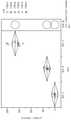
도 1은 본 발명의 연마 패드로 수득된 스크래치 및 채터마크에서의 개선을 예시하는 연마 스크래치 도식이다.
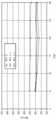
도 2는 본 발명의 연마 패드에 대하여 구리 제거 속도 안정성을 예시하는 도식이다.
도 3은 본 발명의 연마 패드에 대하여 TEOS 제거 속도 안정성을 예시하는 도식이다.
도 4는 연화 개시 온도 계측용 TMA 방법을 예시한다.
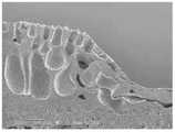
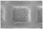
도 5a는 평균 연화 개시 온도 미만의 온도에서 엠보싱된 저 배율 SEM이다.
도 5b는 평균 연화 개시 온도 초과의 온도에서 엠보싱된 저 배율 SEM이다.
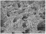
도 6a는 평균 연화 개시 온도 미만의 온도에서 엠보싱된 고 배율 SEM이다.
도 6b는 평균 연화 개시 온도 초과의 온도에서 엠보싱된 고 배율 SEM이다.
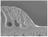
도 7a는 평활성 그루브 최하부 표면을 예시하는 평균 연화 개시 온도 미만의 온도에서 엠보싱된 저 배율 SEM이다.
도 7b는 평활성 그루브 최하부 표면을 예시하는 평균 연화 개시 온도 초과의 온도에서 엠보싱된 저 배율 SEM이다.
도 8은 도 5a, 6a 및 7a 대 5b, 6b 및 7b의 구조로 달성된 저-결함을 예시한다.1 is a polishing scratch schematic illustrating the improvement in scratches and chatter marks obtained with the polishing pad of the present invention.
2 is a schematic illustrating copper removal rate stability for a polishing pad of the present invention.
3 is a schematic illustrating TEOS removal rate stability for a polishing pad of the present invention.
4 illustrates the TMA method for measuring the softening initiation temperature.
5A is a low magnification SEM embossed at a temperature below the average softening onset temperature.
5B is a low magnification SEM embossed at a temperature above the average softening onset temperature.
6A is a high magnification SEM embossed at a temperature below the average softening onset temperature.
6B is a high magnification SEM embossed at a temperature above the average softening onset temperature.
7A is a low magnification SEM embossed at a temperature below the average softening onset temperature illustrating a smooth groove bottom surface.
7B is a low magnification SEM embossed at a temperature above the average softening onset temperature illustrating a smooth grooved bottom surface.
Figure 8 illustrates the low-defect achieved with the structures of Figures 5a, 6a and 7a versus 5b, 6b and 7b.
본 발명의 연마 패드는 적어도 하나의 자기, 광학적 및 반도체 기판의 연마에 유용하다. 특히, 폴리우레탄 패드는 반도체 웨이퍼의 연마에 유용하고; 특히, 패드는 극저-결함도가 평탄화하기 위한 능력보다 더욱 중요한, 그리고 동시에 다중 물질 예컨대, 구리, 배리어 금속 및 비제한적으로 TEOS, 저 k 및 초-저 k 유전체를 포함한, 유전체 물질을 제거하기 위해 필요한 개선된 적용 예컨대 구리-배리어 적용 연마에 유용하다. 본 명세서의 목적을 위하여, "폴리우레탄"은 2작용성 또는 다작용성 이소시아네이트, 예를 들면 폴리에테르우레아, 폴리이소시아누레이트, 폴리우레탄, 폴리우레아, 폴리우레탄우레아, 이들의 코폴리머 및 이들의 혼합물로부터 유도된 생성물이다. 유전체의 포말화 문제 및 잠재적인 중독을 피하기 위해, 이들 제형은 유익하게는 계면활성제가 없는 제형이다. 연마 패드는 지지 베이스 기판 상에서 코팅된 폴리우레탄 매트릭스 내에서 이중 기공 구조를 갖는 다공성 연마 층을 포함한다. 이중 기공 구조는 보다 큰 기공의 1차 세트 및 보다 큰 기공의 세포벽 내에서, 그리고 그 사이에서 보다 작은 기공의 2차 세트를 갖는다. 상기 이중 다공성 구조는 일부 연마 시스템에 대하여 제거 속도를 증가시키면서 결함을 감소시키는 작용을 한다.The polishing pad of the present invention is useful for polishing at least one magnetic, optical and semiconductor substrate. In particular, polyurethane pads are useful for polishing semiconductor wafers; In particular, the pad is designed to remove dielectric materials, including, but not limited to, TEOS, low-k and ultra-low-k dielectrics, where extremely low-defectivity is more important than ability to planarize, and at the same time, multiple materials such as copper, barrier metals, and ultra-low-k dielectrics. It is useful for improved applications where necessary, such as polishing copper-barrier applications. For the purposes of this specification, "polyurethane" refers to difunctional or polyfunctional isocyanates, such as polyetherurea, polyisocyanurate, polyurethane, polyurea, polyurethaneurea, copolymers thereof and mixtures thereof. It is a product derived from To avoid problems with foaming of the genome and potential poisoning, these formulations are advantageously surfactant-free formulations. The polishing pad includes a porous polishing layer having a double pore structure in a polyurethane matrix coated on a supporting base substrate. The double pore structure has a primary set of larger pores and a secondary set of smaller pores within and between the larger pores in the cell wall. The dual porous structure serves to reduce defects while increasing removal rates for some polishing systems.
다공성 연마 층은 폴리머 필름 기판에 고정되거나 또는 직물 또는 부직물 구조로 형성되어 연마 패드를 형성한다. 폴리머 기판, 예컨대 비-다공성 폴리 (에틸렌테레프탈레이트) 필름 또는 시트 상에 다공성 연마 층을 침착시키는 경우, 필름 또는 시트에 접착을 증가시키기 위해 결합제, 예컨대 전매 우레탄 또는 아크릴 접착제를 사용하는 것이 종종 유리하다. 이들 필름 또는 시트가 다공성을 함유할 수 있어도, 유익하게는 이들 필름 또는 시트는 비-다공성이다. 비-다공성 필름 또는 시트의 이점은 이들이 균일한 두께 또는 평탄성을 촉진시키고, 전체 강성도를 증가시키고 연마 패드의 전체 압축성을 감소시키고, 그리고 연마 동안 슬러리 위킹(wicking) 효과를 제거시킨다는 점이다.The porous polishing layer is fixed to a polymer film substrate or formed into a woven or non-woven structure to form a polishing pad. When depositing a porous abrasive layer on a polymeric substrate, such as a non-porous poly (ethyleneterephthalate) film or sheet, it is often advantageous to use a binder such as a proprietary urethane or acrylic adhesive to increase adhesion to the film or sheet. . Although these films or sheets may contain porosity, advantageously these films or sheets are non-porous. Advantages of non-porous films or sheets are that they promote uniform thickness or flatness, increase overall stiffness and reduce overall compressibility of the polishing pad, and eliminate the effect of slurry wicking during polishing.
대안적인 구현예에서, 직물 또는 부직물 구조는 다공성 연마 층에 대하여 베이스로서 작용한다. 베이스 기판으로서 비-다공성 필름의 사용이 상기 개괄된 바와 같은 이점을 가져도, 필름은 또한 약점을 갖는다. 가장 특히, 접착 필름과 조합하여 비-다공성 필름 또는 다공성 기판이 베이스 기판으로서 사용된 경우 기포는 연마 패드와 연마 도구의 플래튼 사이에서 포획될 수 있다. 이들 기포는 연마 패드를 왜곡시켜 연마 동안 결함을 생성한다. 패턴화된 이형 라이너는 이러한 상황 하에서 기포를 제거하기 위해 공기 제거를 용이하게 한다. 이는 연마 비-균일성, 보다 높은 결함도, 고 패드 마모 및 감소된 패드 수명을 가진 주요 문제를 초래한다. 공기가 펠트를 통해 투과할 수 있고 기포가 포획되지 않기 때문에 펠트가 베이스 기판으로서 사용된 경우 이들 문제는 제거된다. 두 번째로, 연마 층이 필름에 적용된 경우 필름에 연마 층의 접착은 접착제 결합의 강도에 의존한다. 일부 공격적인 연마 조건 하에서, 상기 결합은 실패할 수 있고 파국적 실패를 초래할 수 있다. 펠트가 사용된 경우 연마 층은 펠트에 특정 깊이를 실제로 관통하고 강한, 기계적으로 연동된 계면을 형성한다. 직물 구조가 허용가능하여도, 부직물 구조는 다공성 폴리머 기판에 강한 결합을 위하여 추가의 표면적을 제공할 수 있다. 적합한 부직물 구조의 탁월한 예는 섬유를 함께 보유하기 위해 폴리우레탄으로 함침된 폴리에스테르 펠트이다. 전형적인 폴리에스테르 펠트는 500 내지 1500 μm의 두께를 가질 것이다.In an alternative embodiment, the woven or non-woven structure serves as a base for the porous abrasive layer. Although the use of a non-porous film as a base substrate has advantages as outlined above, the film also has disadvantages. Most particularly, when a non-porous film or a porous substrate in combination with an adhesive film is used as the base substrate, air bubbles may be trapped between the polishing pad and the platen of the polishing tool. These bubbles distort the polishing pad, creating defects during polishing. The patterned release liner facilitates air removal to remove air bubbles under these circumstances. This leads to major problems with polishing non-uniformity, higher defectivity, high pad wear and reduced pad life. These problems are eliminated when a felt is used as the base substrate because air can permeate through the felt and air bubbles are not trapped. Second, when the abrasive layer is applied to the film, the adhesion of the abrasive layer to the film depends on the strength of the adhesive bond. Under some aggressive abrasive conditions, the bond can fail and lead to catastrophic failure. When a felt is used, the abrasive layer actually penetrates a certain depth into the felt and forms a strong, mechanically interlocked interface. Although the woven structure is acceptable, the non-woven structure may provide additional surface area for strong bonding to the porous polymer substrate. An excellent example of a suitable nonwoven structure is a polyester felt impregnated with polyurethane to hold the fibers together. A typical polyester felt will have a thickness of 500 to 1500 μm.
본 발명의 연마 패드는 연마 유체로 적어도 하나의 반도체, 광학 및 자기 기판의 연마 또는 평탄화 및 연마 패드와 적어도 하나의 반도체, 광학 및 자기 기판 사이 상대 운동에 적합하다. 연마 층은 개방-셀 폴리머 매트릭스를 갖는다. 적어도 일부분의 개방-세포 구조는 연마 표면을 최대로 개방한다. 대 기공은 수직 배향을 갖는 연마 표면으로 확장된다. 이들 대 기공은 응집된 폴리머 매트릭스 형태 내에서 냅(nap) 층을 특이적 냅 높이로 함유하였다. 수직 기공의 높이는 냅 층 높이와 동등하다. 수직 기공 배향은 응집 과정 동안 형성된다. 본 특허 출원의 목적을 위하여, 수직 또는 아래위 방향은 연마 표면에 직교이다. 수직 기공은 연마 표면으로부터 또는 아래로 거리가 증가하는 평균 직경을 갖는다. 연마 층은 전형적으로 20 내지 200 mils (0.5 내지 5 mm) 및 바람직하게는 30 내지 80 mils (0.76 내지 2.0 mm)의 두께를 갖는다. 수직 기공 및 수직 기공과 상호연결되는 개방 채널을 갖는 개방-셀 폴리머 매트릭스. 바람직하게는, 개방-셀 폴리머 매트릭스는 유체의 수송을 허용하기 위해 충분한 직경을 갖는 상호연결 기공을 갖는다. 이들 상호연결 기공은 수직 기공의 평균 직경 보다 훨씬 더 작은 평균 직경을 갖는다.The polishing pad of the present invention is suitable for polishing or planarizing at least one semiconductor, optical and magnetic substrate with a polishing fluid and for relative motion between the polishing pad and at least one semiconductor, optical and magnetic substrate. The polishing layer has an open-cell polymer matrix. At least a portion of the open-cell structure maximally opens the abrasive surface. The large pores extend into the abrasive surface with a vertical orientation. These large pores contained nap layers with specific nap heights within the aggregated polymer matrix morphology. The height of the vertical pore is equal to the height of the nap layer. The vertical pore orientation is formed during the agglomeration process. For the purposes of this patent application, the vertical or up-down direction is orthogonal to the abrasive surface. The vertical pores have an average diameter that increases with distance from or below the abrasive surface. The abrasive layer typically has a thickness of 20 to 200 mils (0.5 to 5 mm) and preferably 30 to 80 mils (0.76 to 2.0 mm). An open-cell polymer matrix having vertical pores and open channels interconnecting the vertical pores. Preferably, the open-cell polymer matrix has interconnecting pores of sufficient diameter to allow for transport of fluids. These interconnected pores have an average diameter that is much smaller than the average diameter of the vertical pores.
연마 층에서 복수의 그루브는 슬러리의 분포 및 연마 잔해를 용이하게 한다. 바람직하게는, 복수의 그루브는 직교 그리드 패턴을 형성한다. 전형적으로, 이들 그루브는 연마 층에서 X-Y 좌표 그리드 패턴을 형성한다. 그루브는 연마 표면에 인접하여 측정된 평균 폭을 갖는다. 복수의 그루브는 고정된 속도로 회전된 적어도 하나의 반도체, 광학 및 자기 기판 상의 한 지점이 복수의 그루브의 폭에 걸쳐 잔해 제거 체류 시간을 갖는다. 복수의 그루브 내에서 복수의 돌출형 랜드 영역은 복수의 돌출형 랜드 영역의 연마 표면의 최상부 또는 평면으로부터 외향으로 및 하향으로 확장되는 테이퍼된 지지 구조로 지지된다. 바람직하게는, 연마 표면의 평면으로부터 측정시 30 내지 60 도의 기울기에서. 복수의 랜드 영역은 수직 기공을 함유한 폴리머 매트릭스로부터 연마 표면을 형성하는 절두체 또는 비점형 최상부를 갖는다. 전형적으로, 돌출형 랜드 영역은 반구형, 절두체-피라미드, 절두체-사다리꼴 및 이들과 선형 방식으로 돌출형 랜드 영역 사이를 확장되는 복수의 그루브와의 조합으로부터 선택된 형상을 갖는다. 복수의 그루브는 수직 기공의 평균 높이 초과의 평균 깊이를 갖는다. 또한, 수직 기공은 연마 표면 아래에 적어도 하나의 깊이를 증가시키는 평균 직경을 갖는다.A plurality of grooves in the abrasive layer facilitate distribution of the slurry and abrasive debris. Preferably, the plurality of grooves form an orthogonal grid pattern. Typically, these grooves form an X-Y coordinate grid pattern in the abrasive layer. The groove has an average width measured adjacent the abrasive surface. The plurality of grooves has a debris removal residence time at a point on the at least one semiconductor, optical and magnetic substrate rotated at a fixed speed across the width of the plurality of grooves. The plurality of protruding land regions in the plurality of grooves is supported with a tapered support structure extending outwardly and downwardly from a top or plane of the abrasive surface of the plurality of protruding land regions. Preferably, at an inclination of 30 to 60 degrees measured from the plane of the abrasive surface. The plurality of land regions has a frustum or non-point-shaped top forming an abrasive surface from a polymer matrix containing vertical pores. Typically, the protruding land regions have a shape selected from a hemispherical shape, a frustum-pyramid, a frustum-trapezoid, and combinations thereof with a plurality of grooves extending between the protruding land regions in a linear manner. The plurality of grooves have an average depth greater than an average height of the vertical pores. Further, the vertical pores have an average diameter that increases at least one depth below the abrasive surface.
가장 바람직하게는, 거리가 점점 커지는 수직 기공 직경 및 테이퍼된 지지 구조의 조합은 연마 표면에서의 접촉점에 대하여 서로 오프셋된다. 증가하는 수직 기공 직경은 패드 마모와의 연마 패드 접촉을 감소시킨다. 수직 기공에 반대로, 테이퍼된 표면 구조는 증가된 패드 마모와의 연마 패드 접촉에서 증가를 초래한다. 이들 오프셋(offsetting) 힘은 일정한 제거 속도로 다중 웨이퍼의 연마를 용이하게 한다.Most preferably, the combination of tapered support structures and vertical pore diameters of increasing distance are offset from each other with respect to the point of contact at the abrasive surface. Increasing vertical pore diameter reduces polishing pad contact with pad wear. As opposed to vertical pores, the tapered surface structure results in an increase in polishing pad contact with increased pad wear. These offsetting forces facilitate polishing of multiple wafers at a constant removal rate.
복수의 돌출형 랜드 영역은 고정된 속도로 회전된 적어도 하나의 반도체, 광학 및 자기 기판 상의 한 지점이 복수의 돌출형 랜드 영역에 걸쳐 연마 체류 시간을 갖는다. 복수의 돌출형 랜드 영역은, 돌출형 랜드 영역의 연마 체류 시간의 감소를 위하여, 그리고 연마 체류 시간 초과 값으로의 그루브 영역의 잔해 제거 체류 시간의 증가를 위하여, 복수의 그루브의 평균 폭 미만의 평균 폭을 갖는다.The plurality of raised land regions has a polishing residence time over the plurality of raised land regions at a point on at least one semiconductor, optical and magnetic substrate rotated at a fixed speed. The plurality of raised land areas have an average less than the average width of the plurality of grooves for reducing abrasive residence time of the raised land area and for increasing debris removal residence time of the groove area to a value exceeding the abrasive residence time. have a width
그루브는 바람직하게는 대 기공 및 소 기공을 포함한 다공성 매트릭스로부터 형성된 일련의 필로우 구조를 형성한다. 바람직하게는, 필로우는 그리드 패턴, 예컨대 X-Y 좌표 그리드 패턴이다. 필로우 구조는 연마 표면으로부터 30 내지 60 도 각으로 하향 경사 측벽의 형성을 위하여 최상부 연마 표면으로부터 하향 표면을 갖는다. 상기 하향 경사 측벽은 상기 필로우 구조물의 모든 측면으로부터 확장된다. 바람직하게는, 하향 경사 측벽은 하향 경사 측벽으로 선도하는 연마 표면으로부터 측정시 5 내지 30 도의 초기 테이퍼 영역을 갖는다. 바람직하게는, 하향 기울기는 폴리우레탄 매트릭스의 수평 그루브 최하부에서 종료하고, 그루브 최하부는 필로우 구조의 것보다 적은 다공성을 갖는다. 가장 바람직하게는, 그루브의 최하부는 평활성이며, 개방 수직 또는 소 기공이 없다. 이들 평활성 그루브는 연마 잔해를 보유 및 축적할 수 있는 표면 구조 없이 효율적인 연마 제거를 용이하게 한다.The grooves preferably form a series of pillow structures formed from a porous matrix comprising large pores and small pores. Preferably, the pillow is a grid pattern, such as an X-Y coordinate grid pattern. The pillow structure has a surface downward from the top abrasive surface for the formation of sidewalls that slope downward at an angle of 30 to 60 degrees from the abrasive surface. The downwardly sloping sidewalls extend from all sides of the pillow structure. Preferably, the downward sloping sidewall has an initial taper area of 5 to 30 degrees as measured from the abrasive surface leading to the downward sloping sidewall. Preferably, the downward slope terminates at the bottom of the horizontal groove of the polyurethane matrix, the bottom of the groove having less porosity than that of the pillow structure. Most preferably, the bottom of the groove is smooth and free from open vertical or small pores. These smooth grooves facilitate efficient abrasive removal without surface structures that can retain and accumulate abrasive debris.
대 기공의 일 부분은 하향 경사 측벽에 개방된다. 하향 경사 측벽에 개방된 대 기공은 최상부 연마 표면에 개방된 대 기공 보다 덜 수직이고 경사 측벽에 더욱 직교인 방향으로 수직 방향으로부터 10 내지 60 도 오프셋된다. 측벽에서 기공을 개방시키는 것은 잔해의 자유-유동을 허용하여 결함에서 추가 감소를 용이하게 한다. 바람직하게는, 다공성 폴리우레탄 연마 패드는 탈이온수를 대 기공 사이에서 유동시키기에 충분한 평균 직경을 갖는 상호연결된 측 기공을 함유한다.A portion of the large pore is open to the downwardly sloping sidewall. Large pores open to the downward sloping sidewall are less perpendicular than the large pores open to the top abrasive surface and are offset 10 to 60 degrees from the normal direction in a direction more orthogonal to the sloped sidewall. Opening the pores in the sidewalls allows free-flow of debris, facilitating further reduction in defects. Preferably, the porous polyurethane polishing pad contains interconnected side pores having an average diameter sufficient to allow deionized water to flow between the large pores.
다공성 폴리우레탄 연마 패드의 형성 방법은 또한 결함 저하에 결정적인 요인이다. 제1 단계에서, 열가소성 폴리우레탄 응집은 베이스 표면으로부터 상향으로 확장되는, 그리고 상부 표면에 개방된 대 기공을 갖는 다공성 매트릭스를 생성한다. 대 기공은 보다 작은 기공으로 상호연결된다. 대 기공의 일 부분은 최상부 연마 표면에 개방된다. 대 기공은 그 표면에 대하여 실질적으로 수직 배향을 갖는 최상부 연마 표면으로 확장된다.The method of forming the porous polyurethane polishing pad is also a decisive factor in defect reduction. In a first step, the thermoplastic polyurethane agglomeration produces a porous matrix with large pores extending upward from the base surface and open to the upper surface. Large pores are interconnected by smaller pores. A portion of the large pores is open to the top abrasive surface. The large pores extend to the top abrasive surface having a substantially perpendicular orientation with respect to the surface.
열가소성 폴리우레탄은 비가역적 열가소성 변형을 허용하기 위한 연화 개시 온도를 갖는다. 연화 개시 온도는 ASTM E831에 따라 열 기계적 분석 (TMA)을 이용하여 계측된다. 특히, 기울기에서의 변화에 대한 초기 TMA 변곡점의 계측은 연화 개시 온도를 제공한다 - 참고: 도 4. 바람직하게는 (그루브를 형성하기 위해 사용된) 프레스 가열은 열가소성 폴리우레탄의 연화 개시 온도 10K 미만 내지 10K 초과 온도의 범위이다. 더욱 바람직하게는, 프레스 가열은 열가소성 폴리우레탄의 연화 개시 온도의 5K 미만 내지 5K 초과 온도의 범위이다. 가장 바람직하게는, 프레스 가열은 열가소성 폴리우레탄의 연화 개시 온도의 5K 미만 내지 동등 온도의 범위이다.Thermoplastic polyurethanes have a softening onset temperature to allow for irreversible thermoplastic deformation. The softening onset temperature is measured using thermomechanical analysis (TMA) according to ASTM E831. In particular, measurement of the initial TMA inflection point for the change in slope gives the softening initiation temperature - see Fig. 4. Preferably press heating (used to form the grooves) is less than 10K softening initiation temperature of the thermoplastic polyurethane to temperatures above 10K. More preferably, the press heating ranges from less than 5K to more than 5K of the softening initiation temperature of the thermoplastic polyurethane. Most preferably, the press heating ranges from less than 5K to equivalent to the softening initiation temperature of the thermoplastic polyurethane.
연화 개시 온도 근처 또는 초과의 온도로 프레스 가열은 열가소성 변형용 프레스를 제조한다. 열가소성 폴리우레탄에 대한 가열된 프레스의 프레싱은 대 기공 및 소 기공을 포함하는 다공성 매트릭스로부터 일련의 필로우 구조를 형성한다. 프레스는 이의 중심 축 또는 편평 가열된 프레스를 회전하는 홈형 실린더일 수 있다. 바람직하게는, 프레스는 연마 패드를 엠보싱하기 위해 선형 방식으로 압축시키는 알루미늄 합금 플레이트이다. 필로우 구조의 플라스틱 변형 측벽은 하향 경사 측벽을 형성한다. 상기 하향 경사 측벽은 상기 필로우 구조물의 모든 측면으로부터 확장된다. 대 기공의 일 부분은 하향 경사 측벽에 개방된다. 하향 경사 측벽에 개방된 대 기공은 최상부 연마 표면에 개방된 대 기공 보다 덜 수직이고 경사 측벽에 더욱 직교인 방향으로 수직 방향으로부터 10 내지 60 도 오프셋된다. 바람직하게는, 가소성 변형된 측벽에서 대다수의 소 기공은 연마 표면에서 측벽의 최상부에서 그루브 채널까지 측정시 적어도 100 μm의 거리 만큼 개방된 채로 유지된다.Heating the press to a temperature near or above the softening initiation temperature produces a press for thermoplastic deformation. The pressing of a heated press against a thermoplastic polyurethane forms a series of pillow structures from a porous matrix comprising large pores and small pores. The press may be a grooved cylinder rotating on its central axis or a flat heated press. Preferably, the press is an aluminum alloy plate that compresses in a linear fashion to emboss the polishing pad. The plastic deformable sidewalls of the pillow structure form downwardly sloping sidewalls. The downwardly sloping sidewalls extend from all sides of the pillow structure. A portion of the large pore is open to the downwardly sloping sidewall. Large pores open to the downward sloping sidewall are less perpendicular than the large pores open to the top abrasive surface and are offset 10 to 60 degrees from the normal direction in a direction more orthogonal to the sloped sidewall. Preferably, the majority of small pores in the plastically deformed sidewall remain open by a distance of at least 100 μm as measured from the abrasive surface to the grooved channel at the top of the sidewall.
마지막으로, 경사 측벽의 최하부에서 열가소성 폴리우레탄의 용융 및 고형화는 대 및 소 기공의 대다수를 밀폐시키고 그루브 채널을 형성한다. 바람직하게는, 측벽의 가소성 변형 및 용융 및 고형화 단계는 상호연결 그루브의 그리드를 형성한다. 그루브 채널의 최하부 표면은 소수 또는 무 개방 기공을 갖는다. 이는 잔해의 평활성 제거를 용이하게 하고 다공성 연마 패드를 이의 개방-기공-테이퍼-필로우 구조 속으로 가둔다. 바람직하게는, 그루브는 대 기공 및 소 기공을 포함한 다공성 매트릭스로부터 형성된 일련의 필로우 구조를 형성한다. 바람직하게는, 소 기공은 수직 기공 사이 탈이온수를 유동시키기에 충분한 직경을 갖는다.Finally, melting and solidification of the thermoplastic polyurethane at the bottom of the inclined sidewalls seals the majority of the large and small pores and forms grooved channels. Preferably, the plastic deformation of the sidewalls and the melting and solidifying steps form a grid of interconnecting grooves. The lowermost surface of the grooved channel has few or no open pores. This facilitates smooth removal of debris and traps the porous polishing pad into its open-pore-taper-pillow structure. Preferably, the grooves form a series of pillow structures formed from a porous matrix comprising large pores and small pores. Preferably, the small pores have a diameter sufficient to flow deionized water between the vertical pores.
베이스 층은 적절한 토대의 형성에 결정적인 요인이다. 베이스 층은 폴리머 필름 또는 시트일 수 있다. 그러나 직물 또는 부직물 섬유는 다공성 연마 패드에 최상의 기판을 제공한다. 본 명세서의 목적을 위하여, 다공성 물질은 유기 용매의 수성 치환으로부터 형성된 통기성 합성 가죽이다. 부직물 펠트는 대부분의 적용에 탁월한 기판을 제공한다. 전형적으로, 이들 기판은 혼합, 카딩(carding) 및 니들 펀칭에 의해 형성된 폴리에틸렌 테레프탈레이트 섬유를 나타낸다.The base layer is a decisive factor in the formation of a suitable foundation. The base layer may be a polymer film or sheet. However, woven or non-woven fibers provide the best substrate for porous polishing pads. For the purposes of this specification, a porous material is a breathable synthetic leather formed from aqueous displacement of an organic solvent. Nonwoven felts provide an excellent substrate for most applications. Typically, these substrates represent polyethylene terephthalate fibers formed by mixing, carding and needle punching.
일관된 특성에 대하여, 펠트가 일관된 두께, 밀도 및 압축성을 갖는 것이 중요하다. 일관된 물리적 특성을 가진 일관된 섬유로부터 펠트 형성은 일관된 압축성을 갖는 베이스 기판을 초래한다. 추가의 일관성에 대하여, 펠트의 밀도를 제어하기 위해 가열된 수조를 통해 펠트를 운영하는, 수축성 섬유 및 비-수축성 섬유를 배합하는 것이 가능하다. 이는 최종 펠트 밀도를 미세 조정하기 위해 배쓰 온도 및 체류 시간 이용의 이점을 갖는다. 펠트 형성 이후, 이것을 폴리머 침투 배쓰, 예컨대 수성 폴리우레탄 용액을 통해 보냄으로써 섬유를 코팅시킨다. 섬유의 코팅 이후, 펠트를 오븐 경화시키는 것은 강성도 및 회복력을 부가한다.For consistent properties, it is important that the felt has a consistent thickness, density and compressibility. Forming a felt from a consistent fiber with consistent physical properties results in a base substrate with consistent compressibility. For additional consistency, it is possible to blend shrinkable and non-shrinkable fibers, running the felt through a heated water bath to control the density of the felt. This has the advantage of using the bath temperature and residence time to fine tune the final felt density. After the felt is formed, the fibers are coated by passing it through a polymer permeation bath, such as an aqueous polyurethane solution. After coating the fibers, oven curing the felt adds stiffness and resilience.
후-코팅 경화 그 다음 버핑(buffing) 단계는 펠트 두께를 제어한다. 두께 미세-조정에 대하여, 거친 그릿으로 먼저 버핑시키고, 그 다음 펠트를 미세 그릿으로 마감하는 것이 가능하다. 펠트의 버핑 이후, 펠트를 세정 및 건조시켜 버핑 단계 동안 취득된 임의의 그릿 또는 잔해를 제거하는 것이 바람직하다. 그 다음 건조 이후 배면측을 디메틸포름아미드 (DMF)로 파일링은 방수 단계용 펠트를 제조한다. 예를 들어, 퍼플루오로카복실산 및 이의 전구체, 예컨대 AGC 화학물질로부터 텍스타일용 AG-E092 퇴치제는 펠트의 최상부 표면을 방수시킬 수 있다. 방수 이후, 펠트는 건조를 필요로 하고 그 다음 선택적인 연소 단계는 펠트의 최상부 층을 통해 돌출하는 임의의 섬유 말단을 제거할 수 있다. 방수된 펠트는 그 다음 코팅 및 응집을 위하여 제조된다.Post-coat curing followed by a buffing step to control the felt thickness. For thickness fine-tuning, it is possible to first buff with coarse grit and then finish the felt with fine grit. After buffing the felt, it is preferred to wash and dry the felt to remove any grit or debris acquired during the buffing step. Then, after drying, the back side is filed with dimethylformamide (DMF) to prepare a felt for the waterproofing step. For example, the AG-E092 repellent for textiles from perfluorocarboxylic acids and their precursors, such as AGC chemicals, can waterproof the top surface of the felt. After waterproofing, the felt requires drying and then an optional combustion step can remove any fiber ends that protrude through the top layer of the felt. The waterproofed felt is then prepared for coating and agglomeration.
전달 시스템은 펠트의 방수된 측상에서 DMF 용매내 폴리우레탄을 침착시킨다. 닥터 블레이드는 코팅을 안정시킨다. 바람직하게는 코팅된 펠트는 그 다음 다중 응집 홈통을 거치고 여기서 물은 2차 기공과 상호연결된 대 기공을 형성하기 위해 코팅물에 확산된다. 그 다음 응집된 코팅물을 갖는 펠트는 다중 세정 탱크를 거쳐서 DMF를 제거한다. DMF 제거 이후, 오븐 건조는 열가소성 폴리우레탄을 경화시킨다. 선택적으로, 고-압 세정 및 건조 단계는 추가로 기판을 세정한다.The delivery system deposits the polyurethane in DMF solvent on the waterproof side of the felt. The doctor blade stabilizes the coating. Preferably the coated felt is then passed through multiple cohesive troughs in which water diffuses into the coating to form macropores interconnected with secondary pores. The felt with the agglomerated coating is then passed through multiple wash tanks to remove the DMF. After DMF removal, oven drying cures the thermoplastic polyurethane. Optionally, the high-pressure cleaning and drying steps further clean the substrate.
건조 이후, 버핑 단계는 기공을 제어된 깊이로 개방한다. 이는 최상부 표면상에서 일관된 기공 계수를 가능하게 한다. 버핑 동안, 제거하지 않는 안정적인 연마제를 사용하는 것, 및 이의 방식으로 다공성 기판에 작업하는 것이 유리하다. 전형적으로 다이아몬드 연마제는 가장 일관된 텍스처를 생산하고 버핑 동안 파단되기 어렵다. 버핑 이후, 기판은 10 내지 30 mils (0.25 내지 0.76 mm)의 전형적인 냅 높이 및 30 내지 60 mils (0.76 내지 1.52 mm)의 총 두께를 갖는다. 평균 대 기공 직경은 5 내지 85 mils (0.13 내지 2.2 mm)범위일 수 있다. 전형적인 밀도 값은 0.2 내지 0.5 g/cm3이다. 단면 기공 영역은 14 미만의 표면 조도 Ra 및 40 미만의 Rp로 전형적으로 10 내지 30 퍼센트이다. 연마 패드의 경도는 바람직하게는 40 내지 74 애스커(Asker) C이다.After drying, the buffing step opens the pores to a controlled depth. This allows for a consistent pore count on the top surface. It is advantageous to use a stable abrasive that does not remove during buffing, and in this way to work with porous substrates. Diamond abrasives typically produce the most consistent texture and are difficult to break during buffing. After buffing, the substrate has a typical nap height of 10 to 30 mils (0.25 to 0.76 mm) and a total thickness of 30 to 60 mils (0.76 to 1.52 mm). The average to pore diameter may range from 5 to 85 mils (0.13 to 2.2 mm). Typical density values are between 0.2 and 0.5 g/cm3 . The cross-sectional pore area is typically 10 to 30 percent with a surface roughness Ra of less than 14 and Rp of less than 40. The hardness of the polishing pad is preferably 40 to 74 Asker C.
다공성 매트릭스는 2개의 열가소성 폴리머를 포함하는 배합물이다. 제1 열가소성 폴리우레탄은 분자 퍼센트로 45 내지 60 아디프산, 10 내지 30 MDI-에틸렌 글리콜 및 15 내지 35 MDI를 갖는다. 제1 열가소성 폴리우레탄은 40,000 내지 60,000의 Mn 및 125,000 내지 175,000의 Mw 및 2.5 내지 4의 Mw 대 Mn 비를 갖는다. 본 명세서의 목적을 위하여, Mn 및 Mw 는 겔 투과 크로마토그래피에 의해 계측 시 수 평균 및 중량 평균 분자량 값 각각을 나타낸다. 바람직하게는, 제1 열가소성 물질은 45,000 내지 55,000의 Mn 및 140,000 내지 160,000의 Mw 및 2.8 내지 3.3의 Mw 대 Mn 비를 갖는다. 바람직하게는, 제1 열가소성 폴리우레탄은 100% (ASTM D886)의 인장 연신에서 8.5 내지 14.5 MPa의 인장 탄성률을 갖는다. 더욱 바람직하게는, 제1 열가소성 폴리우레탄은 100% (ASTM D886)의 인장 연신에서 9 내지 14 MPa의 인장 탄성률을 갖는다. 가장 바람직하게는, 제1 열가소성 폴리우레탄은 100% (ASTM D886)의 인장 연신에서 9.5 내지 13.5 MPa의 인장 탄성률을 갖는다.The porous matrix is a blend comprising two thermoplastic polymers. The first thermoplastic polyurethane has, in molecular percent, 45 to 60 adipic acid, 10 to 30 MDI-ethylene glycol, and 15 to 35 MDI. The first thermoplastic polyurethane has a Mn of 40,000 to 60,000 and a Mw of 125,000 to 175,000 and a Mw to Mn ratio of 2.5 to 4. For the purposes of this specification, Mn and Mw represent the number average and weight average molecular weight values, respectively, as determined by gel permeation chromatography. Preferably, the first thermoplastic material has a Mn of 45,000 to 55,000 and a Mw of 140,000 to 160,000 and a Mw to Mn ratio of 2.8 to 3.3. Preferably, the first thermoplastic polyurethane has a tensile modulus of 8.5 to 14.5 MPa at a tensile elongation of 100% (ASTM D886). More preferably, the first thermoplastic polyurethane has a tensile modulus of 9 to 14 MPa at a tensile elongation of 100% (ASTM D886). Most preferably, the first thermoplastic polyurethane has a tensile modulus of 9.5 to 13.5 MPa at a tensile elongation of 100% (ASTM D886).
제2 열가소성 폴리우레탄은 분자 퍼센트로 40 내지 50 아디프산, 20 내지 40 아디프산 부탄 디올, 5 내지 20 MDI-에틸렌 글리콜 및 5 내지 25 MDI를 갖는다. 제2 열가소성 폴리우레탄은 60,000 내지 80,000의 Mn 및 125,000 내지 175,000의 Mw 및 1.5 내지 3의 Mw 대 Mn 비를 갖는다. 바람직하게는, 제2 열가소성 폴리우레탄은 65,000 내지 75,000의 Mn 및 140,000 내지 160,000의 Mw 및 1.8 내지 2.4의 Mw 대 Mn 비를 갖는다. 제2 열가소성 물질은 100% (ASTM D886)의 인장 연신에서 측정시 제1 열가소성 폴리우레탄 미만의 인장 탄성률을 갖고 제1 및 제2 열가소성 폴리우레탄의 배합물은 100% (ASTM D886)에서 인장 연신에서 각각의 개별 성분 초과의 인장 탄성률을 갖는다. 바람직하게는, 제2 열가소성 폴리우레탄은 100% (ASTM D886)의 인장 연신에서 4 내지 8 MPa의 인장 탄성률을 갖는다. 더욱 바람직하게는, 제2 열가소성 폴리우레탄은 100% (ASTM D886)의 인장 연신에서 4.5 내지 7.5 MPa의 인장 탄성률을 갖는다. 바람직하게는 다공성 매트릭스는 카본블랙 입자가 없다. 바람직하게는, 제1 및 제2 열가소성 폴리머는 65 도 ± 5 도의 증류수 접촉각을 갖는다. 가장 바람직하게는, 제1 및 제2 열가소성 폴리머는 65 도 ± 3 도의 증류수 접촉각을 갖는다.The second thermoplastic polyurethane has, in molecular percent, 40 to 50 adipic acid, 20 to 40 adipic acid butane diol, 5 to 20 MDI-ethylene glycol and 5 to 25 MDI. The second thermoplastic polyurethane has a Mn of 60,000 to 80,000 and a Mw of 125,000 to 175,000 and a Mw to Mn ratio of 1.5 to 3. Preferably, the second thermoplastic polyurethane has a Mn of 65,000 to 75,000 and a Mw of 140,000 to 160,000 and a Mw to Mn ratio of 1.8 to 2.4. The second thermoplastic material has a tensile modulus of less than the first thermoplastic polyurethane as measured at a tensile elongation of 100% (ASTM D886) and the blends of the first and second thermoplastic polyurethanes each have a tensile elongation at 100% (ASTM D886). has a tensile modulus greater than that of the individual components. Preferably, the second thermoplastic polyurethane has a tensile modulus of 4 to 8 MPa at a tensile elongation of 100% (ASTM D886). More preferably, the second thermoplastic polyurethane has a tensile modulus of 4.5 to 7.5 MPa at a tensile elongation of 100% (ASTM D886). Preferably the porous matrix is free of carbon black particles. Preferably, the first and second thermoplastic polymers have a distilled water contact angle of 65 degrees ± 5 degrees. Most preferably, the first and second thermoplastic polymers have a distilled water contact angle of 65 degrees ± 3 degrees.
바람직하게는, 제2 열가소성 물질은 제1 열가소성 폴리우레탄 적어도 20 퍼센트 미만의 100% (ASTM D886)의 인장 연신에서 측정시 인장 탄성률을 갖는다. 가장 바람직하게는, 제2 열가소성 물질은 제1 열가소성 폴리우레탄 적어도 30 퍼센트 미만의 100% (ASTM D886)의 인장 연신에서 측정시 인장 탄성률을 갖는다.Preferably, the second thermoplastic material has a tensile modulus as measured at a tensile elongation of 100% (ASTM D886) of at least 20 percent less than the first thermoplastic polyurethane. Most preferably, the second thermoplastic material has a tensile modulus as measured at a tensile elongation of 100% (ASTM D886) of at least 30 percent less than the first thermoplastic polyurethane.
더욱이, 제1 및 제2 열가소성 폴리우레탄의 배합물은 바람직하게는 8.5 내지 12.5 MPa의 100% 인장 연신 (ASTM D886)에서 인장 탄성률을 갖는다. 제1 및 제2 열가소성 폴리우레탄의 배합물은 가장 바람직하게는 9 내지 12 MPa의 100% 연신(ASTM D886)에서 인장 탄성률을 갖는다. 제1 및 제2 열가소성 폴리우레탄의 배합물은 바람직하게는 100% 인장 연신 (ASTM D886)에서 제2 열가소성 물질보다 적어도 30 퍼센트 초과인 인장 탄성률을 갖는다. 제1 및 제2 열가소성 폴리우레탄의 배합물은 바람직하게는 제2 열가소성 물질 보다 적어도 50 퍼센트 초과인 100% 인장 연신 (ASTM D886)에서 인장 탄성률을 갖는다. 제1 및 제2 열가소성 폴리우레탄의 동등 비율이 가장 바람직하지만, 제1 또는 제2열가소성 폴리우레탄 성분을 다른 성분 보다 최대 50 wt% 높은 농도로 증가시키는 것이 가능하다. 그러나 바람직하게는, 제1 또는 제2 열가소성 폴리우레탄 성분에서의 증가는 다른 성분보다 최대 20 wt% 높은 농도까지일 뿐이다.Moreover, the blend of the first and second thermoplastic polyurethanes preferably has a tensile modulus at 100% tensile elongation (ASTM D886) of 8.5 to 12.5 MPa. The blend of the first and second thermoplastic polyurethanes most preferably has a tensile modulus at 100% elongation (ASTM D886) of 9 to 12 MPa. The blend of the first and second thermoplastic polyurethanes preferably has a tensile modulus at 100% tensile elongation (ASTM D886) that is at least 30 percent greater than the second thermoplastic material. The blend of the first and second thermoplastic polyurethanes preferably has a tensile modulus at 100% tensile elongation (ASTM D886) that is at least 50 percent greater than the second thermoplastic material. Although equal proportions of the first and second thermoplastic polyurethanes are most preferred, it is possible to increase the first or second thermoplastic polyurethane component to concentrations up to 50 wt % higher than the other components. Preferably, however, the increase in the first or second thermoplastic polyurethane component is only up to a concentration of up to 20 wt % higher than the other component.
음이온성 및 비이온성 계면활성제의 혼합물은 바람직하게는 응집 동안 기공을 형성하고 개선된 경질 세그먼트-연질 세그먼트 형성 및 최적의 물리적 특성에 기여한다. 음이온성 계면활성제에 대하여, 분자의 표면-활성 부분은 음전하를 보유한다. 음이온성 계면활성제의 예는 비제한적으로 카복실산 염, 설폰산 염, 황산 에스테르 염, 인산 및 다인산 에스테르 및 불소화된 음이온성 물질을 포함한다. 더욱 구체적인 예는 비제한적으로 디옥틸 나트륨 설포석시네이트, 나트륨 알킬벤젠 설포네이트 및 폴리옥시에틸렌화된 지방 알코올 카복실레이트의 염을 포함한다. 비이온성 계면활성제에 대하여, 표면-활성 부분은 명백한 이온성 전하를 보유하지 않는다. 비이온성 계면활성제의 예는 비제한적으로 폴리옥시에틸렌 (POE) 알킬페놀, POE 직쇄 알코올, POE 폴리옥시프로필렌 글리콜, POE 메르캅탄, 장쇄 카복실산 에스테르, 알칸올아민 알칸올아미드, 3차 아세틸렌성 글리콜, POE 실리콘, N-알킬피롤리돈 및 알킬폴리글리코사이드를 포함한다. 더욱 구체적인 예는 비제한적으로 장쇄 지방산의 모노글리세라이드, 폴리옥스에틸렌화된 알킬페놀, 폴리옥시에틸렌화된 알코올 및 폴리옥시에틸렌 세틸-스테아릴 에테르를 포함한다. 예를 들어, 음이온성 및 비이온성 계면활성제의 더욱 완벽한 설명을 위하여 다음을 참고한다: "Surfactants and Interfacial Phenomena", by Milton J. Rosen, Third Edition, Wiley-Interscience, 2004, Chapter 1.The mixture of anionic and nonionic surfactants preferably forms pores during agglomeration and contributes to improved hard segment-soft segment formation and optimal physical properties. For anionic surfactants, the surface-active portion of the molecule carries a negative charge. Examples of anionic surfactants include, but are not limited to, carboxylic acid salts, sulfonic acid salts, sulfuric acid ester salts, phosphoric and polyphosphoric acid esters, and fluorinated anionic substances. More specific examples include, but are not limited to, salts of dioctyl sodium sulfosuccinate, sodium alkylbenzene sulfonate and polyoxyethylenated fatty alcohol carboxylates. For non-ionic surfactants, the surface-active moiety does not possess an apparent ionic charge. Examples of nonionic surfactants include, but are not limited to, polyoxyethylene (POE) alkylphenols, POE straight chain alcohols, POE polyoxypropylene glycols, POE mercaptans, long chain carboxylic acid esters, alkanolamine alkanolamides, tertiary acetylenic glycols, POE silicones, N-alkylpyrrolidone and alkylpolyglycosides. More specific examples include, but are not limited to, monoglycerides of long chain fatty acids, polyoxethylenated alkylphenols, polyoxyethylenated alcohols, and polyoxyethylene cetyl-stearyl ethers. See, for example, for a more complete description of anionic and nonionic surfactants see "Surfactants and Interfacial Phenomena", by Milton J. Rosen, Third Edition, Wiley-Interscience, 2004,
실시예 1Example 1
본 실시예는 0.002 m2 의 평균 기공 면적 및 0.39 mm의 높이로 개방-세포 수직 기공을 가진 1.5 mm 두께 다공성 폴리우레탄 연마 패드에 의존한다. 연마 패드는 0.409 g/mL의 중량 밀도를 가졌다. 연마 패드는 표 1의 치수로 엠보싱된 그루브를 가졌다.This example relies on a 1.5 mm thick porous polyurethane polishing pad with open-cell vertical pores with an average pore area of 0.002 m2 and a height of 0.39 mm. The polishing pad had a weight density of 0.409 g/mL. The polishing pad had grooves embossed with the dimensions in Table 1.
표 1 엠보싱된 시험 패드는 엠보싱 깊이 스타일 배치구성에 대하여 옥사이드 CMP 공정 조건 하에서 평가되었다. 각 패드 유형은 동일한 공정 조건하에서 시험되었다. 성능 웨이퍼는 제거 속도, 비-균일성 퍼센트 (NU%), 및 KLA-Tencor 계측 도구를 이용한 결함에 대하여 조사되었다. 연마 조건은 아래와 같았다:Table 1 Embossed test pads were evaluated under oxide CMP process conditions for the embossed depth style configuration. Each pad type was tested under identical process conditions. Performance wafers were examined for removal rate, percent non-uniformity (NU%), and defects using a KLA-Tencor metrology tool. The polishing conditions were as follows:
패드 컨디셔너:............없음Pad conditioner: .............. None
슬러리:................... Klebosol® 1730 (16%) 콜로이드 실리카 슬러리;Slurry:.............. Klebosol® 1730 (16%) colloidal silica slurry;
NH ILD 3225 (12.5%) 흄드 실리카NH ILD 3225 (12.5%) Fumed Silica
여과:....................Pall 0.3um StarKleen® POUFiltration:...................Pall 0.3um StarKleen® POU
도구:....................Applied Materials Reflexion-DEMDCLabTool:................................Applied Materials Reflexion-DEMDCLab
세정:....................SP100® ATMI IncCleaning: ....SP100® ATMI Inc
불소화수소: 200 옹스트롬/min.의 식각 속도로 1 분Hydrogen Fluoride: 1 minute at an etch rate of 200 Angstroms/min.
필름 계측:.....KLA-Tencor™ F5X, 박막 계측Film Metrology:.....KLA-Tencor™ F5X, Thin Film Metrology
결함 계측:.....KLA-TencorSP2XP,0.12um까지의 분해능.Defect Metrology:.....KLA-TencorSP2XP, resolution down to 0.12um.
KLA-Tencor™ eDR5200 SEMKLA-Tencor™ eDR5200 SEM
웨이퍼:............300mm 더미(dummy) 실리콘 웨이퍼 (때때로 잔류 TEOS로)Wafer:.....300mm dummy silicon wafer (sometimes with residual TEOS)
300mm 블랭킷 TEOS 20K 두께 웨이퍼300mm blanket TEOS 20K thick wafer
표적:Target:
제거 속도removal rate
비-균일성 백분율 NU%Non-uniformity percentage NU%
결함도 계수 (포스트 HF)Defect Degree Factor (Post HF)
결함도 분류 (포스트 HF 채터마크)Defect Level Classification (Post HF Chattermark)
실험 설계:Experimental Design:
전체 연마에 대하여 사용된 매칭된 캐리어로 단일 플래튼 시험.Single platen test with matched carrier used for all grinding.
공정 - 60 초 ILD 연마 3 psi (20.7 kPa) & 5 psi (34.5 kPa)/93 rpm 플래튼 스피드/87 rpm 캐리어 스피드 /250ml/min. 슬러리 공급 속도Process - 60 sec ILD grinding 3 psi (20.7 kPa) & 5 psi (34.5 kPa)/93 rpm platen speed/87 rpm carrier speed/250ml/min. Slurry Feed Rate
전체 패드 및 웨이퍼는 실험에 대하여 전체적으로 랜덤화되었다.The entire pad and wafer were randomly randomized throughout the experiment.
각 패드 구동은 하기로 이루어졌다:Each pad actuation consisted of:
20 더미(dummy) 웨이퍼 60 초 연마 w/ 슬러리로 총 시간 20 분 패드 파단.20 dummy wafer 60 sec Polish w/ slurry 20 min total time Pad break.
연마 순서 (60 초 연마)Grinding sequence (60 sec grinding)
(A) 3 psi (20.7 kPa)/93 rpm 플래튼 스피드/87 rpm 캐리어 스피드/250 ml/min 슬러리 유동 속도 블랭킷 TEOS 웨이퍼(A) 3 psi (20.7 kPa)/93 rpm platen speed/87 rpm carrier speed/250 ml/min slurry flow rate blanket TEOS wafer
(B) 3 psi (20.7 kPa)/93 rpm 플래튼 스피드/87 rpm 캐리어 스피드/250 ml/min 슬러리 유동 속도 블랭킷 TEOS 블랭킷 TEOS 웨이퍼(B) 3 psi (20.7 kPa)/93 rpm platen speed/87 rpm carrier speed/250 ml/min slurry flow rate blanket TEOS blanket TEOS wafer
(C) 5 psi (34.5 kPa)/93 rpm 플래튼 스피드/87 rpm 캐리어 스피드/250 ml/min 슬러리 유동 속도 블랭킷 TEOS 웨이퍼(C) 5 psi (34.5 kPa)/93 rpm platen speed/87 rpm carrier speed/250 ml/min slurry flow rate blanket TEOS wafer
(D) 5 psi (34.5 kPa)/93 rpm 플래튼 스피드/87 rpm 캐리어 스피드/250 ml/min 슬러리 유동 속도 블랭킷 TEOS 웨이퍼(D) 5 psi (34.5 kPa)/93 rpm platen speed/87 rpm carrier speed/250 ml/min slurry flow rate blanket TEOS wafer
(E) 5 psi (34.5 kPa)/93 rpm 플래튼 스피드/87 rpm 캐리어 스피드/250 ml/min 슬러리 유동 속도 블랭킷 TEOS 웨이퍼(E) 5 psi (34.5 kPa)/93 rpm platen speed/87 rpm carrier speed/250 ml/min slurry flow rate blanket TEOS wafer
(F) 3 psi (20.7 kPa)/93 rpm 플래튼 스피드/87 rpm 캐리어 스피드/250 ml/min 슬러리 유동 속도 더미(Dummy) TEOS 웨이퍼(F) 3 psi (20.7 kPa)/93 rpm platen speed/87 rpm carrier speed/250 ml/min slurry flow rate Dummy TEOS wafer
순서 A-F는 1회 반복되었다Sequences A-F were repeated once
웨이퍼는 NU% 포스트 CMP에 대하여 측정되었다. TEOS 웨이퍼는 HF 산 부식액으로 추가로 세정되었고 SP2 결함 계수 및 SEM 검토를 위하여 보내졌다. JMP 소프트웨어는 반응의 통계적인 분석을 위하여 사용되었다.Wafers were measured for NU% post CMP. The TEOS wafer was further cleaned with HF acid etchant and sent for SP2 defect count and SEM review. JMP software was used for statistical analysis of responses.
제거 속도 및 웨이퍼내 비-균일성 검토:Removal rate and intra-wafer non-uniformity review:
블랭킷 TEOS 웨이퍼는 전형적인 산화물 연마 조건 하에서 제거 속도 및 NU% 반응에 대하여 평가되었다. 필름 두께는 KLA-Tencor F5XTM 도구상에서 측정되었다. 3 밀리미터 모서리 배제로 65 포인트 방사상 레시피의 측정 레시피는 평가에서 사용되었다.Blanket TEOS wafers were evaluated for removal rate and NU% response under typical oxide polishing conditions. Film thickness was measured on a KLA-Tencor F5XTM tool. A measurement recipe of a 65 point radial recipe with 3 millimeter edge exclusion was used in the evaluation.
결함 검토:Defect review:
블랭킷 TEOS 웨이퍼는 전형적인 산화물 연마 조건 하에서 결함 반응에 대하여 평가되었다. 결함도는 0.10μm 입자 크기로 저하된 KLA-Tencor SP2XPTM 도구 상에서 측정되었다. SP2 웨이퍼 맵은 결함을 사전-분류하기 위해 및 불필요한 분석, 예컨대 마크, 큰 스크래치 및 얼룩 조작을 감소하기 위해 수작업으로 검토되었다.Blanket TEOS wafers were evaluated for defect response under typical oxide polishing conditions. Defectivity was measured on a KLA-Tencor SP2XPTM tool downgraded to a 0.10 μm particle size. The SP2 wafer map was manually reviewed to pre-classify defects and to reduce unnecessary analysis such as mark, large scratches and smudge manipulation.
결함 분류 이미지는 eDR5200 SEM으로 수집되었다. 다수의 결함 때문에, 검토 샘플링 계획은 SEM 이미지 수집에 이용되었다. 샘플링 계획은 클러스터에 시찰에 대하여 각 웨이퍼 및 세트 규칙으로부터 100 결함의 랜덤 샘플링을 제공하였다.Defect classification images were acquired with an eDR5200 SEM. Due to a number of defects, a review sampling plan was used for SEM image acquisition. The sampling scheme gave the cluster a random sampling of 100 defects from each wafer and set rule per inspection.
결함은 시계 (FOV) 2 μm에서 화상형성되었고 더 높은 배율에서 필요할 때 재-화상형성되었다. 전체 수집된 결함 이미지는 수작업으로 분류되었다.Defects were imaged at 2 μm field of view (FOV) and re-imaged as needed at higher magnifications. All collected defect images were manually sorted.
SAS로부터 JMP 통계적인 소프트웨어는 반응의 통계적인 분석에 대하여 사용되었다.JMP statistical software from SAS was used for statistical analysis of responses.
결과 :result :
패드 A 엠보싱된 그루브에 비교 시 패드 1 엠보싱된 그루브의 개선을 평가하기 위해, 평균 결함 계수의 패드 1 퍼센트 개선은 하기와 같이 아래 방정식 (1)로 산출되었다:To evaluate the improvement of the
패드 1 % 개선 =(X 패드 A - Y 패드 1)/X 패드 A * 100%
식 중 X는 주어진 시험 조건에 대하여 패드 A의 평균 결함 계수이고 Y는 패드 1 각각의 평균 결함 계수이다.where X is the average defect coefficient of pad A and Y is the average defect coefficient of each of
제거 속도: 패드 1 대 패드 A 패드의 비교를 위하여 수집된 TEOS 제거 속도는 표 2에서 보여진다.Removal Rate: TEOS removal rates collected for comparison of
패드 1 패드는 Klebosol 1730 콜로이드성 슬러리를 이용한 전체 실험 조건 하에서 패드 A 엠보싱된 패드에 비교 시 약간 감소된 제거 속도를 나타냈다. 패드 1 엠보싱된 패드는 ILD 3225 흄드 실리카 슬러리를 이용한 패드 A 엠보싱된 패드와 비교된 경우 3psi 및 5psi (20.7 kPa 및 34.5 kPa)/공정 조건 각각 상에서 제거 속도의 증가 및 감소를 나타냈다.
NU%: 비-균일성 백분율NU%: non-uniformity percentage
NU%는 평균 제거 속도 및 이의 표준 편차로부터 산출된 백분율을 나타낸다. NU% 및 이의 차이는 패드 1 대 패드 A 패드의 비교를 위하여 표 3에서 제시된다.NU% represents the percentage calculated from the mean removal rate and its standard deviation. NU% and its differences are presented in Table 3 for comparison of
실리카colloid
silica
실리카fumed
silica
패드 1 패드는 Klebosol 1730 콜로이드성 슬러리를 이용한 전체 실험 조건 하에서 패드 A 엠보싱된 패드에 비교 시 NU%에서 약간 더 높은 % 차이를 나타냈다. 패드 1 엠보싱된 패드는 ILD 3225 흄드 실리카 슬러리를 이용한 패드 A 엠보싱된 패드에 비교 시 NU%에서 차이 없음을 나타냈다.
포스트 HF 결함 계수Post HF defect coefficient
깊은 대 표준 엠보싱된 홈형 연마 패드의 비교를 위하여 수집된 총 포스트 HF 결함은 표 4에서 보여진다.Total post HF defects collected for comparison of deep versus standard embossed grooved polishing pads are shown in Table 4.
실리카colloid
silica
실리카fumed
silica
패드 1 엠보싱된 패드는 Klebosol 1730 콜로이드성 슬러리를 이용한 전체 실험 조건 하에서 패드 A 엠보싱된 패드에 비교 시 40% 결함 계수 개선 보다 더 양호하게 나타냈다. 패드 1 엠보싱된 패드는 ILD 3225 흄드 실리카 슬러리를 이용한 전체 실험 조건 하에서 패드 A 엠보싱된 패드에 비교 시 더 높은 결함 수준을 보여주었다.
포스트 HF 결함 분류Post HF Fault Classification
SEM 이미지로 분류된 포스트 HF TEOS 웨이퍼는 표 5에서 보여진다. 100 랜덤하게 선택된 결함은 수집되고 분류되었다: 채터마크, 스크래치, 입자, 패드 잔해 및 유기 잔기 등. 채터마크는 CMP 윈도우 패드에 관련된 주요 결함 및 웨이퍼와 이의 상호작용으로서 인식된다. 포스트 HF 채터마크 결함 계수는 표 5에서 포함된다.Post HF TEOS wafers sorted by SEM images are shown in Table 5. 100 randomly selected defects were collected and classified: chattermarks, scratches, particles, pad debris and organic residues, etc. Chattermarks are recognized as major defects associated with CMP window pads and their interactions with the wafer. Post HF chattermark defect coefficients are included in Table 5.
실리카colloid
silica
패드 1 엠보싱된 패드는 Klebosol 1730 콜로이드성 슬러리를 이용한 전체 실험 조건 하에서 패드 A 엠보싱된 패드에 비교 시 채터마크 계수에서의 감소를 보여주었다. 패드 1 엠보싱된 패드는, ILD 3225 흄드 실리카 슬러리를 이용한 동일한 실험 조건 하에서 패드 A 엠보싱된 패드에 각각 비교 시, 5 psi (34.5 kPa) 및 3 psi (20.7 kPa)의 공정 조건에 의해 채터마크 계수에서의 증가 및 감소를 보여주었다.
결론:conclusion:
패드 1 엠보싱된 패드는 패드 A 엠보싱된 패드에 비교된 경우 약간 감소된 TEOS 제거 속도 결과에 필적함을 나타냈다. 제거 속도 차이는 더 높은 다운-포스 5psi (34.5 kPa) 공정 조건에 기인되었다. 표 4 및 5에서 강조된 결과는 패드 A 엠보싱된 패드를 이용한 이의 각각 패드 대응물에 비교된 경우 옥사이드 CMP에서 패드 1 엠보싱된 패드의 유의미하게 더 낮은 결함을 보여준다. 패드 1 엠보싱된 패드는 K1730 콜로이드 실리카 슬러리를 이용하여 패드 A 엠보싱된 패드에 대해 40% 내지 66%의 결함 계수 개선을 나타냈다. 패드 A 엠보싱된 패드에 의해 생성된 총 결함은 패드 배치구성에서 패드 1 엠보싱된 패드에 비교 시 2.4 내지 2.9 배 더 높았다.The
SEM 결함 분류는 패드 / 웨이퍼 상호작용에 통상적으로 기인된 채터마크 결함에 대하여 실시되었다. 패드 1 엠보싱된 패드는 K1730 콜로이드성 슬러리를 이용하여 패드 A 엠보싱된 패드로 연마된 웨이퍼에 비교 시 43 내지 66% 더 낮은 채터마크 결함 계수를 나타냈다. 패드 1 패드는 또한 3psi 공정 조건에서 흄드 실리카 슬러리를 이용하여 31% 결함 계수 감소 개선을 보여주었다. 패드 A 엠보싱된 패드에 의해 생성된 채터마크 결함 계수는 배치구성된 패드에서 패드 1 엠보싱된 그루브에 비교 시 1.7 내지 2.4 배 더 높았다.SEM defect classification was performed for chattermark defects commonly attributed to pad/wafer interactions.
실시예 2Example 2
1.1 mm의 두께, 334 g/m2의 중량 및 0.303 g/m3의 밀도를 갖는 폴리에스테르 펠트 롤. 펠트는 2 수축성 부분 (70 ℃에서 -55%) 대 1 수축성 부분 (70 ℃에서 -2.5%)의 비로 2 폴리에스테르 섬유의 배합물이었다. 제1 섬유는 2.11 dtex (kg/1000m)의 중량, 3.30 cN/dtex의 강도 및 75%의 파단시 연신 비를 가졌다. 제2 섬유는 2.29 dtex (kg/1000m)의 중량, 2.91 cN/dtex의 강도 및 110%의 파단시 연신 비를 가졌다. AG-E092 퍼플루오로카복실산 및 이의 전구체를 이용한 펠트 코팅은 펠트의 최상부 표면을 방수하였다. 방수 이후, 펠트를 건조하고 연소하여 펠트의 최상부 층을 통해 돌출되는 임의의 섬유 말단을 제거하였다.A polyester felt roll having a thickness of 1.1 mm, a weight of 334 g/m2 and a density of 0.303 g/m3. The felt was a blend of 2 polyester fibers in a ratio of 2 shrinkable parts (-55% at 70°C) to 1 shrinkable part (-2.5% at 70°C). The first fiber had a weight of 2.11 dtex (kg/1000 m), a strength of 3.30 cN/dtex and a draw ratio at break of 75%. The second fiber had a weight of 2.29 dtex (kg/1000 m), a strength of 2.91 cN/dtex and a draw ratio at break of 110%. The felt coating with AG-E092 perfluorocarboxylic acid and its precursors waterproofed the top surface of the felt. After waterproofing, the felt was dried and burned to remove any fiber ends protruding through the top layer of the felt.
일련의 다공성 연마 패드는 디메틸 포름아미드 용매내 열가소성 물질의 배합물로부터 제조되었고 실시예 3의 패드 3-2의 치수로 엠보싱되었다. 표 6은 시험된 열가소성 폴리우레탄 성분 및 이의 몰 제형의 목록을 제공한다. Samprene 및 Crison은 Sanyo Chemical Industry 및 DIC 각각의 상표명이다.A series of porous polishing pads were prepared from a blend of a thermoplastic in dimethyl formamide solvent and embossed to the dimensions of pads 3-2 of Example 3. Table 6 provides a list of the tested thermoplastic polyurethane components and their molar formulations. Samprene and Crison are trade names of Sanyo Chemical Industry and DIC, respectively.
표 7은 겔 투과 크로마토그래피 "GPC"에 의해 시험된 상기 성분이 하기와 같았음을 보여준다:Table 7 shows that the components tested by gel permeation chromatography "GPC" were as follows:
HPLC 시스템: Agilent 1100HPLC system: Agilent 1100
칼럼: 5μ 가드를 가진 2 X PLgel 5μ 혼합-D (300 x 8 mm ID)Column: 2 X PLgel 5μ Mix-D with 5μ Guard (300 x 8 mm ID)
용리액: 테트라하이드로푸란Eluent: tetrahydrofuran
유속: 1.0 mL/minFlow rate: 1.0 mL/min
검출: RI @ 40oCDetection: RI @ 40o C
샘플 용액의 주사된 용적: 100 μL.Injected volume of sample solution: 100 μL.
보정 표준: 폴리스티렌Calibration Standard: Polystyrene
표 8은 성분 및 50:50 배합물의 물리적 특성을 제공한다.Table 8 provides the physical properties of the ingredients and the 50:50 formulation.
50:50 wt%LQ660/LQ202
50:50 wt%
후속조치 시험에서, 배합물에 카본블랙 입자 첨가는 물리적 특성에 거의 영향을 갖지 않았다.In follow-up tests, the addition of carbon black particles to the formulation had little effect on the physical properties.
표 9는 일련의 연마 패드 제형을 제공한다.Table 9 provides a series of polishing pad formulations.
나머지 디메틸 포름아미드 (DMF)로 30 중량 퍼센트 고형물에서 LQ-660, LQ-220 및 PS542U; 나머지 디메틸 포름아미드 (DMF)로 20 중량 퍼센트 고형물에서 L3270, CUT30은 DIC에 의해 10 내지 20 wt% 에틸렌 글리콜을 가진 69.5 내지 73.5 wt% 디옥틸 나트륨 설포석시네이트 음이온성 계면활성제이고 PL220은 KAO로부터 16.1의 친수성-친유성 균형(HLB)을 갖는 폴리옥시에틸렌 세틸-스테아릴 에테르이다.LQ-660, LQ-220 and PS542U at 30 weight percent solids with the remainder dimethyl formamide (DMF); L3270 at 20 weight percent solids with the remainder dimethyl formamide (DMF), CUT30 is 69.5 to 73.5 wt % dioctyl sodium sulfosuccinate anionic surfactant with 10 to 20 wt % ethylene glycol by DIC and PL220 is from KAO polyoxyethylene cetyl-stearyl ether having a hydrophilic-lipophilic balance (HLB) of 16.1.
연마 조건은 하기와 같았다:The grinding conditions were as follows:
1. 연마기: Reflexion LK, 등고선 헤드1. Grinder: Reflexion LK, contour head
2. 슬러리: LK393C4 콜로이드 실리카 배리어 슬러리.2. Slurry: LK393C4 colloidal silica barrier slurry.
3. 패드 파단:3. Pad Break:
i. 73 rpm 플래튼 스피드/111rpm 캐리어 스피드, 2 psi (13.8 kPa) 다운포스, 10 min, HPR 온i. 73 rpm platen speed/111 rpm carrier speed, 2 psi (13.8 kPa) downforce, 10 min, HPR on
4. 컨디셔닝:4. Conditioning:
i. 121 rpm 플래튼 스피드 /108rpm 캐리어 스피드, 3 psi (20.7 kPa) 다운포스 6.3sec_A82 + 26sec_HPR 단독i. 121 rpm platen speed /108 rpm carrier speed, 3 psi (20.7 kPa) downforce 6.3sec_A82 + 26sec_HPR only
5. Cu 블랭킷 시트 사전-연마: VP6000 폴리우레탄 연마 패드/평면 CSL9044C 콜로이드 실리카 슬러리로 연마, ~4000Å 제거.5. Cu blanket sheet pre-polishing: VP6000 polyurethane polishing pad/flat polished with CSL9044C colloidal silica slurry, removing ~4000 Å.
6. 대체 Cu 및 TEOS 더미(dummy).6. Alternative Cu and TEOS dummy.
7. 방법론: 패드 파단 -> 다양한 구동 수에서 제거 속도 및 결함 수집.7. Methodology: Pad Fracture -> Removal rate and defect collection at various actuation numbers.
전체 연마 패드는 표 10에 나타낸 바와 같이 구리 및 TEOS 제거 속도의 탁월한 조합을 가졌다.The overall polishing pad had an excellent combination of copper and TEOS removal rates as shown in Table 10.
범위Average copper RR (Å/min.)
range
범위Mean TEOS RR (Å/min.)
range
디옥틸 나트륨 설포석시네이트의 양 증가는 수직 기공 및 감소된 TEOS 속도의 크기를 감소시켰다. 폴리옥시에틸렌 세틸-스테아릴 에테르의 양 증가는 수직 기공 및 증가된 TEOS 속도의 크기를 증가시켰다. 디옥틸 나트륨 설포석시네이트 대 폴리옥시에틸렌 세틸-스테아릴 에테르의 비 증가는 수직 기공 및 감소된 TEOS 속도의 크기를 감소시켰다. 패드 2 엠보싱된 패드는, 그러나 표 11에 나타낸 바와 같이 결함의 최저 수를 생산하였다.Increasing the amount of dioctyl sodium sulfosuccinate decreased the size of the vertical pores and decreased TEOS rate. Increasing the amount of polyoxyethylene cetyl-stearyl ether increased the size of the vertical pores and increased TEOS rate. Increasing the ratio of dioctyl sodium sulfosuccinate to polyoxyethylene cetyl-stearyl ether decreased the size of the vertical pores and decreased TEOS rate. Pad 2 The embossed pad, however, produced the lowest number of defects as shown in Table 11.
도 1은 패드 2 엠보싱된 연마 패드로 제공된 결함에서의 개선을 도식화한다. 패드 2 엠보싱된 패드는 연마 잔해를 축적하지 않았다. 패드 B 및 C 각각은 2차 기공 및 매트릭스에서 연마 잔해를 축적하였다. 연마 잔해의 축적은 연마 결함 생성에 대한 근본적인 구동인자인 것으로 보였다. 패드 2는 비교 패드 B 및 C에 비교 시 구리 또는 TEOS 제거 속도의 손실 없이 결함 계수에서 유의미한 감소를 가졌다.1 schematically depicts the improvement in defects provided with the Pad 2 embossed polishing pad. Pad 2 The embossed pad did not accumulate abrasive debris. Pads B and C each accumulated abrasive debris in the secondary pores and matrix. Accumulation of abrasive debris appeared to be a fundamental driving factor for the generation of abrasive defects. Pad 2 had a significant decrease in defect count when compared to comparative pads B and C without loss of copper or TEOS removal rate.
실시예 3Example 3
상업적 다공성 연마 패드 "D" 및 실시예 2의 2개 패드 (패드 3; 패드 3-1 및 패드 3-2)는 상이한 치수로 엠보싱되었다. 패드 3-1은 필로우 폭이 연마 표면에서 측정 시 그루브 폭을 초과하는 엠보싱된 디자인을 가졌고 패드 3-2는 그루브 폭이 연마 표면에서 측정 시 필로우 폭을 초과하는 엠보싱된 디자인을 가졌다.Commercial porous polishing pad “D” and the two pads of Example 2 (pad 3; pad 3-1 and pad 3-2) were embossed with different dimensions. Pad 3-1 had an embossed design in which the pillow width exceeded the groove width as measured at the abrasive surface and pad 3-2 had an embossed design in which the groove width exceeded the pillow width as measured at the abrasive surface.
패드는 그 다음 실시예 2의 조건 하에서 연마되었다. 표 13 및 도 2에 나타낸 바와 같이, 패드 3-2는 최상의 Cu 속도 안정성을 나타냈다. 따라서, 필로우 폭을 초과하는 그루브 폭을 가진, 깊은 엠보싱 패드는 약간 더 높은 Cu 속도를 전달하였다.The pad was then polished under the conditions of Example 2. As shown in Table 13 and Figure 2, pad 3-2 exhibited the best Cu rate stability. Thus, the deep embossing pad, with a groove width exceeding the pillow width, delivered a slightly higher Cu rate.
(Å)range
(Å)
특히, 패드 3-2는 Cu 웨이퍼 계수 증가와 함께 상업적 패드 D의 1/3 미만의 구리 제거 속도에 대하여 보다 밀집된 범위를 입증하였다.In particular, pad 3-2 demonstrated a denser range for copper removal rates less than 1/3 that of commercial pad D with increasing Cu wafer count.
도 3에 나타낸 바와 같이, 전체 시험 패드는 양호한 TEOS 속도 안정성을 나타냈다. 그러나 패드 3-2는 확장된 연마 기간 동안 최상의 TEOS 속도 안정성을 나타냈다.As shown in Figure 3, the entire test pad exhibited good TEOS rate stability. However, pad 3-2 showed the best TEOS rate stability during extended polishing period.
표 14에 나타낸 바와 같이, 패드 3-2는 최저 스크래치 평균 계수를 보여주었다. 패드 3-2는 상업적 다공성 연마 패드 D보다 더 낮은 스크래치 계수를 나타냈다.As shown in Table 14, pads 3-2 showed the lowest average scratch coefficient. Pad 3-2 exhibited a lower scratch coefficient than commercial porous polishing pad D.
결론:conclusion:
엠보싱된 패드 3-2는 Cu 및 TEOS 속도 안정성에 대하여 최상으로 수행하였다. 또한, 연마 표면의 평면에서 측정 시 증가된 그루브 폭 대 필로우 폭 패드를 갖는 패드 3-2는 표준 엠보싱 디자인보다 약간 더 높은 Cu 및 TEOS 속도를 전달하였다. 패드 3-2는 최저 스크래치 평균 계수를 제공하였고 중요하게는 상업적 패드 D보다 유의미하게 더 낮은 스크래치 계수를 나타냈다.Embossed pads 3-2 performed best for Cu and TEOS rate stability. In addition, pads 3-2 with increased groove width to pillow width pads as measured in the plane of the polishing surface delivered slightly higher Cu and TEOS rates than the standard embossing design. Pads 3-2 provided the lowest average scratch coefficient and importantly exhibited a significantly lower scratch coefficient than commercial Pad D.
실시예 4Example 4
실시예 2의 폴리우레탄 (패드 3)의 4개 샘플은, 도 4에 나타낸 바와 같이 변곡점 측정에 의해, ASTM E831에 따라 TMA를 이용하여 162 ℃의 평균 연화 개시 온도를 가졌다. 실시예 2의 2개 패드는 160 (도 5a, 6a 및 7a) (패드 4) 및 175 (도 5b, 6b 및 7b) (패드 3-2에 유사)로 가열된 금속 다이로 엠보싱되어 연마 표면의 평면에서 (즉 TMA 연화 개시 온도 미만 및 초과 온도에서) 측정 시 거의 동일한 필로우 높이 및 그루브 폭을 가진 패드를 형성하였다. 도 5a 및 5b는 그루브 형성에서 극적인 이동이 용융 개시 온도 초과 과열의 양을 제한함으로써 달성하였다는 것을 입증한다. 175 ℃에서 엠보싱된 측벽은 전체 수직 기공이 수직인 채로 남는 경향이 있는 1차 형성 기전으로서 용융을 가졌다. 이는 필로우의 중심에서 수직 기공 및 필로우의 테이퍼된 측벽에 의해 보여질 수 있다. 160 ℃에서 형성된 측벽은 필로우 형성용 기전으로서 용융과 조합으로 가소성 변형을 가졌다. 가소성 변형의 증거는 테이퍼된 그루브에 직교 방향으로 기공 구부러짐 및 테이퍼된 측벽에 인접하여 발생한 관련된 필로우 높이 감소를 포함한다.Four samples of the polyurethane of Example 2 (pad 3) had an average softening onset temperature of 162° C. using TMA according to ASTM E831 by inflection point measurement as shown in FIG. 4 . The two pads of Example 2 were embossed with a metal die heated to 160 (FIGS. 5A, 6A and 7A) (Pad 4) and 175 (FIG. 5B, 6B and 7B) (similar to Pad 3-2) to remove the polishing surface. Pads with approximately the same pillow height and groove width as measured in the plane (ie at temperatures below and above the TMA softening onset temperature) were formed. 5a and 5b demonstrate that a dramatic shift in groove formation was achieved by limiting the amount of superheat above the melt initiation temperature. The embossed sidewalls at 175° C. had melting as the primary mechanism of formation where the entire vertical pores tended to remain vertical. This can be seen by the vertical pore in the center of the pillow and the tapered sidewalls of the pillow. The sidewalls formed at 160 °C had plastic deformation in combination with melting as a mechanism for forming pillows. Evidence of plastic deformation includes pore bending in a direction orthogonal to the tapered groove and an associated decrease in pillow height that occurred adjacent the tapered sidewall.
도 6a 및 6b의 고 배율 SEM에 나타낸 바와 같이, 평균 연화 개시 온도 미만 온도에서 엠보싱된 연마 패드는 대 기공 플러스 상호연결한 더 소 기공의 조합을 유지하였다. 이는 1차 기공의 크기 감소 및 도 6b에서 보이는 측벽의 조대화(coarsening)에 의해 명백해졌다.As shown in the high magnification SEM of FIGS. 6A and 6B , at temperatures below the average softening onset temperature, the embossed polishing pad maintained a combination of large pores plus interconnected smaller pores. This was evident by the reduction in the size of the primary pores and the coarsening of the sidewalls shown in FIG. 6b .
도 7a 및 7b에 나타낸 바와 같이, 전체 연마 패드는 더 낮은 그루브 표면을 용융시켰다. 최하부 그루브의 용융은 아마도 필로우를 위치에 고정시키고 필로우 구조의 반향을 제한시켰다. 더욱이, 평활성 최하부는, 잔해가 슬러리 시스템에 따라, 축적 및 응집할 수 있는 갈라진 틈 생성 없이 잔해 제거를 도왔다. 175 ℃에서 엠보싱된 패드 모두는 하지에서 평활성 용융된 그루브 최하부 및 측벽을 가졌다. 평활성 벽은, 그러나 전체 필로우 크기를 감소시키기에 충분한 측벽의 조대화를 초래하였다.As shown in Figures 7a and 7b, the entire polishing pad melted the lower grooved surface. Melting of the lowermost groove probably held the pillow in place and limited the reverberation of the pillow structure. Moreover, the smooth bottom aided in debris removal without creating cracks where debris could accumulate and agglomerate, depending on the slurry system. All of the pads embossed at 175° C. had smooth molten groove bottoms and sidewalls on the underside. The smooth walls, however, resulted in sufficient sidewall coarsening to reduce the overall pillow size.
엠보싱된 패드를 비교하기 위해, 도 5a, 6a 및 7a 및 도 5b, 6b 및 7b의 연마 패드는 실시예 2 및 3에서와 동일한 조건 하에서 연마되었다. 도 8에 나타낸 바와 같이, 연화 개시 온도 미만 엠보싱된 패드, 패드 4는 실시예 3의 패드 3-2보다 유의미하게 보다 낮은 스크래치 계수를 나타내었다.To compare the embossed pads, the polishing pads of FIGS. 5A, 6A and 7A and 5B, 6B and 7B were polished under the same conditions as in Examples 2 and 3. As shown in FIG. 8 , pad 4 embossed below the softening onset temperature exhibited a significantly lower scratch coefficient than pad 3-2 of Example 3.
본 발명은 초-저-결함 구리-배리어 연마(ultra-low defect copper-barrier polishing)에 효력이 있다. 특히, 상기 패드는 다중 웨이퍼에 대하여 안정적으로 유지되는, 탁월한 구리 및 TEOS 속도로 연마된다. 더욱이, 상기 패드는 종래의 연마 패드 보다 유의미하게 보다 낮은 스크래치 및 채터마크 결함을 갖는다.The present invention is effective for ultra-low defect copper-barrier polishing. In particular, the pad is polished with excellent copper and TEOS rates, which remain stable over multiple wafers. Moreover, the pad has significantly lower scratch and chattermark defects than conventional polishing pads.
Claims (10)
Translated fromKorean기저 표면으로부터 상향으로 확장되고, 상면으로 개방된 대 기공을 갖는 다공성 매트릭스로서, 상기 대 기공은 소 기공과 상호연결되어 있으며, 상기 대 기공의 일부분은 최상부 연마 표면으로 개방되어 있고, 상기 대 기공은 실질적으로 수직 배향을 갖는 상기 최상부 연마 표면까지 확장되고, 상기 다공성 매트릭스는 2종의 열가소성 폴리머를 포함하는 배합물인, 상기 다공성 매트릭스;
분자 퍼센트로, 45 내지 60 아디프산, 10 내지 30 MDI-에틸렌 글리콜 및 15 내지 35 MDI를 갖는 제1 열가소성 폴리우레탄으로서, 40,000 내지 60,000의 Mn, 및 125,000 내지 175,000의 Mw, 및 2.5 내지 4의 Mn에 대한 Mw 비를 갖는, 상기 제1 열가소성 폴리우레탄; 및
분자 퍼센트로, 40 내지 50 아디프산, 20 내지 40 아디프산 부탄 디올, 5 내지 20 MDI-에틸렌 글리콜 및 5 내지 25 MDI를 갖는 제2 열가소성 폴리우레탄으로서, 상기 제2 열가소성 폴리우레탄은 60,000 내지 80,000의 Mn, 및 125,000 내지 175,000의 Mw, 및 1.5 내지 3의 Mn에 대한 Mw 비를 갖고, 상기 제2 열가소성 물질은 상기 제1 열가소성 폴리우레탄보다 적어도 20 퍼센트 더 낮은 100%의 인장 연신 (ASTM D886)에서 측정된 인장 탄성률을 가지며, 상기 제1 및 제2 열가소성 폴리우레탄의 배합물은 상기 제2 열가소성 폴리머보다 적어도 30 퍼센트 더 큰 100%의 인장 연신 (ASTM D886)에서 측정된 인장 탄성률을 갖는, 상기 제2 열가소성 폴리우레탄을 포함하는, 다공성 폴리우레탄 연마 패드.A porous polyurethane polishing pad comprising:
A porous matrix extending upwardly from a basal surface and having large pores open to a top surface, wherein the large pores are interconnected with small pores, a portion of the large pores opening to a top abrasive surface, the large pores comprising: said porous matrix extending to said uppermost abrasive surface having a substantially vertical orientation, said porous matrix being a blend comprising two thermoplastic polymers;
a first thermoplastic polyurethane having, in molecular percent, 45 to 60 adipic acid, 10 to 30 MDI-ethylene glycol and 15 to 35 MDI, an Mn of 40,000 to 60,000, and a Mw of 125,000 to 175,000, and a Mw of 2.5 to 4 said first thermoplastic polyurethane having a Mw to Mn ratio; and
A second thermoplastic polyurethane having, in molecular percent, 40 to 50 adipic acid, 20 to 40 adipic acid butane diol, 5 to 20 MDI-ethylene glycol and 5 to 25 MDI, wherein the second thermoplastic polyurethane is from 60,000 to having an Mn of 80,000, and a Mw of 125,000 to 175,000, and a Mw to Mn ratio of 1.5 to 3, wherein the second thermoplastic material has a tensile elongation of 100% (ASTM D886) that is at least 20 percent lower than the first thermoplastic polyurethane. ), wherein the blend of the first and second thermoplastic polyurethanes has a tensile modulus measured at a tensile elongation of 100% (ASTM D886) that is at least 30 percent greater than the second thermoplastic polymer. A porous polyurethane polishing pad comprising a second thermoplastic polyurethane.
기저 표면으로부터 상향으로 확장되고, 상면으로 개방된 대 기공을 갖는 다공성 매트릭스로서, 상기 대 기공은 소 기공과 상호연결되어 있으며, 상기 대 기공의 일부분은 최상부 연마 표면으로 개방되어 있고, 상기 대 기공은 실질적으로 수직 배향을 갖는 상기 최상부 연마 표면까지 확장되고, 상기 다공성 매트릭스는 2종의 열가소성 폴리머를 포함하는 배합물인, 상기 다공성 매트릭스;
분자 퍼센트로, 45 내지 60 아디프산, 10 내지 30 MDI-에틸렌 글리콜 및 15 내지 35 MDI를 갖는 제1 열가소성 폴리우레탄으로서, 45,000 내지 55,000의 Mn, 및 140,000 내지 160,000의 Mw, 및 2.8 내지 3.3의 Mn에 대한 Mw 비를 갖는, 상기 제1 열가소성 폴리우레탄; 및
분자 퍼센트로, 40 내지 50 아디프산, 20 내지 40 아디프산 부탄 디올, 5 내지 20 MDI-에틸렌 글리콜 및 5 내지 25 MDI를 갖는 제2 열가소성 폴리우레탄으로서, 상기 제2 열가소성 폴리우레탄은 65,000 내지 75,000의 Mn, 및 140,000 내지 160,000의 Mw, 및 1.8 내지 2.4의 Mn에 대한 Mw 비를 갖고, 상기 제2 열가소성 물질은 상기 제1 열가소성 폴리우레탄보다 적어도 30 퍼센트 더 낮은 100%의 인장 연신 (ASTM D886)에서 측정된 인장 탄성률을 가지며, 상기 제1 및 제2 열가소성 폴리우레탄의 배합물은 8.5 내지 14.5 MPa의 100%의 인장 연신 (ASTM D886)에서 측정된 인장 탄성률을 가지며, 그리고 상기 제1 및 제2 열가소성 폴리우레탄의 배합물은 상기 제2 열가소성 폴리머보다 적어도 50 퍼센트 더 큰 100%의 인장 연신 (ASTM D886)에서의 인장 탄성률을 갖는, 상기 제2 열가소성 폴리우레탄
을 포함하는, 다공성 폴리우레탄 연마 패드.A porous polyurethane polishing pad comprising:
A porous matrix extending upwardly from a basal surface and having large pores open to a top surface, wherein the large pores are interconnected with small pores, a portion of the large pores opening to a top abrasive surface, the large pores comprising: said porous matrix extending to said uppermost abrasive surface having a substantially vertical orientation, said porous matrix being a blend comprising two thermoplastic polymers;
a first thermoplastic polyurethane having, in molecular percent, 45 to 60 adipic acid, 10 to 30 MDI-ethylene glycol and 15 to 35 MDI, an Mn of 45,000 to 55,000, and a Mw of 140,000 to 160,000, and a Mw of 2.8 to 3.3. said first thermoplastic polyurethane having a Mw to Mn ratio; and
A second thermoplastic polyurethane having, in molecular percent, 40 to 50 adipic acid, 20 to 40 adipic acid butane diol, 5 to 20 MDI-ethylene glycol and 5 to 25 MDI, wherein the second thermoplastic polyurethane is from 65,000 to 25 MDI. having a Mn of 75,000, and a Mw of 140,000 to 160,000, and an Mw to Mn ratio of 1.8 to 2.4, wherein the second thermoplastic material has a tensile elongation of 100% (ASTM D886) that is at least 30 percent lower than the first thermoplastic polyurethane. ), wherein the blend of the first and second thermoplastic polyurethanes has a tensile modulus measured at 100% tensile elongation (ASTM D886) of 8.5 to 14.5 MPa, and the first and second blends wherein the blend of thermoplastic polyurethane has a tensile modulus at 100% tensile elongation (ASTM D886) that is at least 50 percent greater than that of the second thermoplastic polyurethane.
A porous polyurethane polishing pad comprising a.
Applications Claiming Priority (2)
| Application Number | Priority Date | Filing Date | Title |
|---|---|---|---|
| US15/229,017 | 2016-08-04 | ||
| US15/229,017US10106662B2 (en) | 2016-08-04 | 2016-08-04 | Thermoplastic poromeric polishing pad |
Publications (2)
| Publication Number | Publication Date |
|---|---|
| KR20180016289A KR20180016289A (en) | 2018-02-14 |
| KR102373206B1true KR102373206B1 (en) | 2022-03-11 |
Family
ID=61071878
Family Applications (1)
| Application Number | Title | Priority Date | Filing Date |
|---|---|---|---|
| KR1020170097646AActiveKR102373206B1 (en) | 2016-08-04 | 2017-08-01 | Thermoplastic poromeric polishing pad |
Country Status (5)
| Country | Link |
|---|---|
| US (1) | US10106662B2 (en) |
| JP (1) | JP7127971B2 (en) |
| KR (1) | KR102373206B1 (en) |
| CN (1) | CN107685282B (en) |
| TW (1) | TWI733868B (en) |
Families Citing this family (6)
| Publication number | Priority date | Publication date | Assignee | Title |
|---|---|---|---|---|
| JP6582057B2 (en)* | 2015-10-29 | 2019-09-25 | 古河電気工業株式会社 | Polishing pad, polishing method using the polishing pad, and method of using the polishing pad |
| US11697183B2 (en) | 2018-07-26 | 2023-07-11 | Taiwan Semiconductor Manufacturing Co., Ltd. | Fabrication of a polishing pad for chemical mechanical polishing |
| US12330261B2 (en)* | 2020-04-18 | 2025-06-17 | Rohm And Haas Electronic Materials Cmp Holdings, Inc. | Offset pore poromeric polishing pad |
| US11667061B2 (en) | 2020-04-18 | 2023-06-06 | Rohm And Haas Electronic Materials Cmp Holdings, Inc. | Method of forming leveraged poromeric polishing pad |
| CN113021200B (en)* | 2021-03-12 | 2022-10-14 | 安徽禾臣新材料有限公司 | Low-damage wax-free pad for polishing optical crystal wafer and production process thereof |
| WO2023054331A1 (en) | 2021-09-30 | 2023-04-06 | 株式会社クラレ | Thermoplastic polyurethane for polishing layer, polishing layer, and polishing pad |
Citations (2)
| Publication number | Priority date | Publication date | Assignee | Title |
|---|---|---|---|---|
| US20090298392A1 (en) | 2005-09-22 | 2009-12-03 | Kuraray Co., Ltd | Polymer material, foam obtained from same, and polishing pad using those |
| US20100120343A1 (en) | 2007-03-20 | 2010-05-13 | Kuraray Co., Ltd. | Cushion for polishing pad and polishing pad using the cushion |
Family Cites Families (18)
| Publication number | Priority date | Publication date | Assignee | Title |
|---|---|---|---|---|
| US4629473A (en)* | 1985-06-26 | 1986-12-16 | Norton Company | Resilient abrasive polishing product |
| US6126532A (en)* | 1997-04-18 | 2000-10-03 | Cabot Corporation | Polishing pads for a semiconductor substrate |
| JPH11156699A (en) | 1997-11-25 | 1999-06-15 | Speedfam Co Ltd | Surface polishing pad |
| US6093651A (en) | 1997-12-23 | 2000-07-25 | Intel Corporation | Polish pad with non-uniform groove depth to improve wafer polish rate uniformity |
| US6117000A (en)* | 1998-07-10 | 2000-09-12 | Cabot Corporation | Polishing pad for a semiconductor substrate |
| JP2001150332A (en) | 1999-11-22 | 2001-06-05 | Nec Corp | Polishing pad and polishing method |
| US6241596B1 (en) | 2000-01-14 | 2001-06-05 | Applied Materials, Inc. | Method and apparatus for chemical mechanical polishing using a patterned pad |
| US20050276967A1 (en)* | 2002-05-23 | 2005-12-15 | Cabot Microelectronics Corporation | Surface textured microporous polishing pads |
| US7311862B2 (en) | 2002-10-28 | 2007-12-25 | Cabot Microelectronics Corporation | Method for manufacturing microporous CMP materials having controlled pore size |
| JP4292025B2 (en)* | 2003-05-23 | 2009-07-08 | Jsr株式会社 | Polishing pad |
| US6899602B2 (en) | 2003-07-30 | 2005-05-31 | Rohm And Haas Electronic Materials Cmp Holdings, Nc | Porous polyurethane polishing pads |
| US6942549B2 (en) | 2003-10-29 | 2005-09-13 | International Business Machines Corporation | Two-sided chemical mechanical polishing pad for semiconductor processing |
| US7186651B2 (en) | 2003-10-30 | 2007-03-06 | Texas Instruments Incorporated | Chemical mechanical polishing method and apparatus |
| JP4994894B2 (en) | 2007-03-09 | 2012-08-08 | 株式会社クラレ | Resin foam and polishing pad comprising the same |
| US8162728B2 (en)* | 2009-09-28 | 2012-04-24 | Rohm And Haas Electronic Materials Cmp Holdings, Inc. | Dual-pore structure polishing pad |
| WO2012117789A1 (en)* | 2011-02-28 | 2012-09-07 | 東レコーテックス株式会社 | Polishing pad |
| JP5917236B2 (en) | 2012-03-30 | 2016-05-11 | 富士紡ホールディングス株式会社 | Polishing pad sheet and manufacturing method thereof, polishing pad and manufacturing method thereof, and polishing method |
| JP6396888B2 (en) | 2013-03-12 | 2018-09-26 | 国立大学法人九州大学 | Polishing pad and polishing method |
- 2016
- 2016-08-04USUS15/229,017patent/US10106662B2/enactiveActive
- 2017
- 2017-07-31TWTW106125778Apatent/TWI733868B/enactive
- 2017-08-01JPJP2017148996Apatent/JP7127971B2/enactiveActive
- 2017-08-01KRKR1020170097646Apatent/KR102373206B1/enactiveActive
- 2017-08-01CNCN201710645617.2Apatent/CN107685282B/enactiveActive
Patent Citations (2)
| Publication number | Priority date | Publication date | Assignee | Title |
|---|---|---|---|---|
| US20090298392A1 (en) | 2005-09-22 | 2009-12-03 | Kuraray Co., Ltd | Polymer material, foam obtained from same, and polishing pad using those |
| US20100120343A1 (en) | 2007-03-20 | 2010-05-13 | Kuraray Co., Ltd. | Cushion for polishing pad and polishing pad using the cushion |
Also Published As
| Publication number | Publication date |
|---|---|
| JP7127971B2 (en) | 2022-08-30 |
| JP2018039105A (en) | 2018-03-15 |
| CN107685282B (en) | 2019-06-04 |
| KR20180016289A (en) | 2018-02-14 |
| US10106662B2 (en) | 2018-10-23 |
| CN107685282A (en) | 2018-02-13 |
| TW201809094A (en) | 2018-03-16 |
| TWI733868B (en) | 2021-07-21 |
| US20180037706A1 (en) | 2018-02-08 |
Similar Documents
| Publication | Publication Date | Title |
|---|---|---|
| KR102373206B1 (en) | Thermoplastic poromeric polishing pad | |
| KR102376129B1 (en) | Tapered poromeric polishing pad | |
| KR102301910B1 (en) | Tapering method for poromeric polishing pad | |
| KR102848678B1 (en) | Offset pore poromeric polishing pad | |
| KR102829859B1 (en) | Method of forming leveraged poromeric polishing pad | |
| KR102360623B1 (en) | Low-defect-porous polishing pad | |
| US20250058426A1 (en) | Leveraged poromeric polishing pad |
Legal Events
| Date | Code | Title | Description |
|---|---|---|---|
| PA0109 | Patent application | Patent event code:PA01091R01D Comment text:Patent Application Patent event date:20170801 | |
| PG1501 | Laying open of application | ||
| A201 | Request for examination | ||
| PA0201 | Request for examination | Patent event code:PA02012R01D Patent event date:20200518 Comment text:Request for Examination of Application Patent event code:PA02011R01I Patent event date:20170801 Comment text:Patent Application | |
| E902 | Notification of reason for refusal | ||
| PE0902 | Notice of grounds for rejection | Comment text:Notification of reason for refusal Patent event date:20210531 Patent event code:PE09021S01D | |
| E701 | Decision to grant or registration of patent right | ||
| PE0701 | Decision of registration | Patent event code:PE07011S01D Comment text:Decision to Grant Registration Patent event date:20211212 | |
| GRNT | Written decision to grant | ||
| PR0701 | Registration of establishment | Comment text:Registration of Establishment Patent event date:20220307 Patent event code:PR07011E01D | |
| PR1002 | Payment of registration fee | Payment date:20220308 End annual number:3 Start annual number:1 | |
| PG1601 | Publication of registration | ||
| PR1001 | Payment of annual fee | Payment date:20250217 Start annual number:4 End annual number:4 |