KR102372853B1 - Rotating type water apparatus and construction method thereof - Google Patents
Rotating type water apparatus and construction method thereofDownload PDFInfo
- Publication number
- KR102372853B1 KR102372853B1KR1020210113128AKR20210113128AKR102372853B1KR 102372853 B1KR102372853 B1KR 102372853B1KR 1020210113128 AKR1020210113128 AKR 1020210113128AKR 20210113128 AKR20210113128 AKR 20210113128AKR 102372853 B1KR102372853 B1KR 102372853B1
- Authority
- KR
- South Korea
- Prior art keywords
- water supply
- water
- supply pipe
- rotor
- outside
- Prior art date
- Legal status (The legal status is an assumption and is not a legal conclusion. Google has not performed a legal analysis and makes no representation as to the accuracy of the status listed.)
- Active
Links
Images


Classifications
- A—HUMAN NECESSITIES
- A63—SPORTS; GAMES; AMUSEMENTS
- A63G—MERRY-GO-ROUNDS; SWINGS; ROCKING-HORSES; CHUTES; SWITCHBACKS; SIMILAR DEVICES FOR PUBLIC AMUSEMENT
- A63G31/00—Amusement arrangements
- A63G31/007—Amusement arrangements involving water
- B—PERFORMING OPERATIONS; TRANSPORTING
- B05—SPRAYING OR ATOMISING IN GENERAL; APPLYING FLUENT MATERIALS TO SURFACES, IN GENERAL
- B05B—SPRAYING APPARATUS; ATOMISING APPARATUS; NOZZLES
- B05B1/00—Nozzles, spray heads or other outlets, with or without auxiliary devices such as valves, heating means
- B05B1/14—Nozzles, spray heads or other outlets, with or without auxiliary devices such as valves, heating means with multiple outlet openings; with strainers in or outside the outlet opening
- B05B1/20—Perforated pipes or troughs, e.g. spray booms; Outlet elements therefor
- B—PERFORMING OPERATIONS; TRANSPORTING
- B05—SPRAYING OR ATOMISING IN GENERAL; APPLYING FLUENT MATERIALS TO SURFACES, IN GENERAL
- B05B—SPRAYING APPARATUS; ATOMISING APPARATUS; NOZZLES
- B05B12/00—Arrangements for controlling delivery; Arrangements for controlling the spray area
- B05B12/004—Arrangements for controlling delivery; Arrangements for controlling the spray area comprising sensors for monitoring the delivery, e.g. by displaying the sensed value or generating an alarm
- B05B12/006—Pressure or flow rate sensors
- B—PERFORMING OPERATIONS; TRANSPORTING
- B05—SPRAYING OR ATOMISING IN GENERAL; APPLYING FLUENT MATERIALS TO SURFACES, IN GENERAL
- B05B—SPRAYING APPARATUS; ATOMISING APPARATUS; NOZZLES
- B05B12/00—Arrangements for controlling delivery; Arrangements for controlling the spray area
- B05B12/08—Arrangements for controlling delivery; Arrangements for controlling the spray area responsive to condition of liquid or other fluent material to be discharged, of ambient medium or of target ; responsive to condition of spray devices or of supply means, e.g. pipes, pumps or their drive means
- B05B12/085—Arrangements for controlling delivery; Arrangements for controlling the spray area responsive to condition of liquid or other fluent material to be discharged, of ambient medium or of target ; responsive to condition of spray devices or of supply means, e.g. pipes, pumps or their drive means responsive to flow or pressure of liquid or other fluent material to be discharged
- B05B12/087—Flow or presssure regulators, i.e. non-electric unitary devices comprising a sensing element, e.g. a piston or a membrane, and a controlling element, e.g. a valve
- B—PERFORMING OPERATIONS; TRANSPORTING
- B05—SPRAYING OR ATOMISING IN GENERAL; APPLYING FLUENT MATERIALS TO SURFACES, IN GENERAL
- B05B—SPRAYING APPARATUS; ATOMISING APPARATUS; NOZZLES
- B05B13/00—Machines or plants for applying liquids or other fluent materials to surfaces of objects or other work by spraying, not covered by groups B05B1/00 - B05B11/00
- B05B13/02—Means for supporting work; Arrangement or mounting of spray heads; Adaptation or arrangement of means for feeding work
- B05B13/04—Means for supporting work; Arrangement or mounting of spray heads; Adaptation or arrangement of means for feeding work the spray heads being moved during spraying operation
- B05B13/0421—Means for supporting work; Arrangement or mounting of spray heads; Adaptation or arrangement of means for feeding work the spray heads being moved during spraying operation with rotating spray heads
- B—PERFORMING OPERATIONS; TRANSPORTING
- B05—SPRAYING OR ATOMISING IN GENERAL; APPLYING FLUENT MATERIALS TO SURFACES, IN GENERAL
- B05B—SPRAYING APPARATUS; ATOMISING APPARATUS; NOZZLES
- B05B3/00—Spraying or sprinkling apparatus with moving outlet elements or moving deflecting elements
- B05B3/02—Spraying or sprinkling apparatus with moving outlet elements or moving deflecting elements with rotating elements
- B05B3/04—Spraying or sprinkling apparatus with moving outlet elements or moving deflecting elements with rotating elements driven by the liquid or other fluent material discharged, e.g. the liquid actuating a motor before passing to the outlet
- B05B3/06—Spraying or sprinkling apparatus with moving outlet elements or moving deflecting elements with rotating elements driven by the liquid or other fluent material discharged, e.g. the liquid actuating a motor before passing to the outlet by jet reaction
- B—PERFORMING OPERATIONS; TRANSPORTING
- B05—SPRAYING OR ATOMISING IN GENERAL; APPLYING FLUENT MATERIALS TO SURFACES, IN GENERAL
- B05B—SPRAYING APPARATUS; ATOMISING APPARATUS; NOZZLES
- B05B9/00—Spraying apparatus for discharge of liquids or other fluent material, without essentially mixing with gas or vapour
- B05B9/03—Spraying apparatus for discharge of liquids or other fluent material, without essentially mixing with gas or vapour characterised by means for supplying liquid or other fluent material
- B05B9/04—Spraying apparatus for discharge of liquids or other fluent material, without essentially mixing with gas or vapour characterised by means for supplying liquid or other fluent material with pressurised or compressible container; with pump
- G—PHYSICS
- G05—CONTROLLING; REGULATING
- G05D—SYSTEMS FOR CONTROLLING OR REGULATING NON-ELECTRIC VARIABLES
- G05D16/00—Control of fluid pressure
- G05D16/20—Control of fluid pressure characterised by the use of electric means
- G05D16/2006—Control of fluid pressure characterised by the use of electric means with direct action of electric energy on controlling means
- G05D16/2013—Control of fluid pressure characterised by the use of electric means with direct action of electric energy on controlling means using throttling means as controlling means
Landscapes
- Physics & Mathematics (AREA)
- Fluid Mechanics (AREA)
- Chemical & Material Sciences (AREA)
- Analytical Chemistry (AREA)
- General Physics & Mathematics (AREA)
- Engineering & Computer Science (AREA)
- Automation & Control Theory (AREA)
- Hydraulic Turbines (AREA)
Abstract
Translated fromKoreanDescription
Translated fromKorean본 발명은 회전형 물놀이 장치 및 그 시공 방법에 관한 것으로, 보다 상세하게는 물놀이를 즐기는 공원이나 놀이시설 등에서 방문객들에게 시원한 물줄기를 회전하면서 방출하는 회전형 물놀이 장치 및 시공 방법에 관한 것이다.The present invention relates to a rotating water play apparatus and a construction method thereof, and more particularly, to a rotating water play apparatus and a construction method for rotating and discharging cool water to visitors at a park or amusement facility enjoying water play.
여름이 되면 많은 사람들이 물놀이 시설들이 있는 장소를 방문하여 더위를 식히며 즐기곤 하는데, 이러한 장소에는 간이 풀장처럼 물을 받아놓고 수영을 할 수 있도록 하거나 또는 분수 형태의 물줄기를 내뿜는 시설들이 구비되어 있다.In summer, many people visit places with water play facilities to cool off and enjoy. These places are equipped with facilities that allow you to swim while receiving water like a simple pool or spewing water in the form of a fountain.
이 중에서 물줄기를 내뿜는 시설들 중에는 복수 개의 유출공이 형성된 회전부가 구비되어 있어서, 그 회전부가 회전함에 따라 유출공으로 물줄기가 외부로 뿜어져 나오도록 하는 시설물(이하, '회전형 물놀이 장치'라 함)의 경우 특히 아이들에게 많은 인기를 끌고 있다.Among these, facilities that spout a stream of water are provided with a rotating part having a plurality of outlet holes, and as the rotating part rotates, a water stream is ejected to the outside through the outlet hole (hereinafter referred to as a 'rotating water play device') It is especially popular with children.
그런데 물놀이 시설에 관한 법규정으로 인해 물놀이 시설에 구비된 각종 장치들은 전기에 의한 동력을 사용하지 못하게 되어 있다.However, due to laws and regulations on water play facilities, various devices provided in water play facilities are prohibited from using electric power.
따라서 종래에는 이러한 회전형 물놀이 장치의 회전부에 형성된 유출공을 통해 물줄기를 뿜어내는 힘에 의해 그 회전부가 회전하도록 하는 방식을 이용해 왔다.Therefore, in the prior art, a method has been used in which the rotating part is rotated by the force of spraying a water stream through an outlet hole formed in the rotating part of the rotating water play device.
이러한 경우 물놀이 시설 내에는 전혀 전기선이 들어올 필요가 없고, 단지 고압수를 파이프를 통해 회전형 물놀이 장치에 공급해주기만 하면 되어 안전성이 확보되었다.In this case, there is no need for an electric wire to enter the water play facility, and safety is ensured only by supplying high-pressure water to the rotating water play device through a pipe.
그런데 이러한 종래의 방식에 의하면, 물줄기가 외부로 토출되는 힘에 의해 회전력이 발생하게 되므로, 물줄기의 수압과 회전속도는 항상 비례하게 되어서, 물줄기 수압과 회전속도를 별도로 제어하지 못하는 문제점이 있다. 즉, 수압을 조금 더 강하게 하면서도, 천천히 회전하도록 하는 제어는 애초에 불가능한 것이다.However, according to this conventional method, since rotational force is generated by the force of the water jet being discharged to the outside, the water pressure and rotation speed of the water stream are always proportional, so there is a problem that it is impossible to separately control the water pressure and the rotation speed of the water stream. In other words, it is impossible to control the water pressure to be slightly stronger while rotating slowly.
더 나아가 수압에 비례하여 회전하는 상태를 유지한다 하여도 원하는 수압에서 원하는 회전 속도를 만들어 내는 것이 용이하지 않다는 문제점이 있다.Furthermore, there is a problem that it is not easy to create a desired rotation speed at a desired water pressure even if the rotation state is maintained in proportion to the water pressure.
본 발명은 상기한 종래의 문제점을 해결하기 위해 안출된 것으로서, 그 목적은 물놀이 시설 등에서 전기를 사용하지 않고, 유체의 유입힘 만으로 소정의 회전을 발생시켜서 회전하는 물줄기를 만들어내는 회전형 물놀이 장치 및 시공 방법을 제공하는 것이다.The present invention has been devised to solve the above problems of the prior art, and its purpose is to generate a rotating stream of water by generating a predetermined rotation only by the inflow force of a fluid without using electricity in a water play facility, etc., and To provide a construction method.
상기한 목적을 달성하기 위해 본 발명에 따른 회전형 물놀이 장치는, 하부 구조물과; 상기 하부 구조물에 고정 장착되고, 외부로부터 인입되는 유체에 의해 회전하는 제1 회전자를 포함하는 회전력 발생 장치와; 상기 회전력 발생 장치의 제1 회전자와 연동하여 회전하는 물줄기를 방출하고 상기 하부 구조물에 고정 장착된 물줄기 방출 장치를 포함하여 구성되고, 상기 물줄기 방출 장치는, 수직방향으로 배치되고 하부에 상기 회전력 발생 장치의 제1 회전자와 연계하여 회전하는 제2 회전자가 고정 장착된 제1 급수관과; 상기 제1 급수관의 외부를 감싸 보호하는 주기둥과; 상기 제1 급수관과 연결되고 일 측에 물줄기를 방출하는 토출구가 적어도 하나 구비된 제2 급수관과; 외부로부터 물을 공급받는 급수부와; 상기 급수부와 상기 제1 급수관 사이에서 연결되어 상기 물 공급부는 고정된 채로 상기 제1 급수관만 회전하는 상태에서 상기 물 공급부가 공급하는 물을 상기 제1 급수관 내로 전달하는 무빙 조인트를 포함하여 구성될 수 있다.In order to achieve the above object, there is provided a rotary water play device according to the present invention, comprising: a lower structure; a rotational force generating device fixedly mounted to the lower structure and including a first rotor rotated by a fluid introduced from the outside; and a water stream discharging device fixedly mounted to the lower structure and discharging a rotating water stream in association with the first rotor of the rotating force generating device, wherein the water stream discharging device is disposed in a vertical direction and generates the rotating force at a lower portion a first water supply pipe to which a second rotor rotating in association with the first rotor of the apparatus is fixedly mounted; and a main pillar for protecting the outside of the first water supply pipe; a second water supply pipe connected to the first water supply pipe and provided with at least one outlet for discharging a water stream on one side; a water supply unit receiving water from the outside; A moving joint connected between the water supply unit and the first water supply pipe to transfer the water supplied by the water supply unit into the first water supply pipe in a state where only the first water supply pipe rotates while the water supply unit is fixed can
여기서, 상기 회전력 발생 장치는 외부로부터 에어콤프레샤로부터 인입되는 압축 공기의 힘에 의해 상기 제1 회전자를 회전시킬 수 있다.Here, the rotational force generating device may rotate the first rotor by the force of compressed air introduced from the air compressor from the outside.
여기서, 상기 제1 회전자와 상기 제2 회전자는 각각 기어를 포함하여 구성되어 상호 치합하는 구조로 이루어질 수 있다.Here, the first rotor and the second rotor may each include a gear and may have a structure to mesh with each other.
여기서, 상기 제1 회전자에 포함된 기어와 상기 제2 회전자에 포함된 기어의 기어비는 40:1 ~ 50:1의 범위를 갖도록 구성될 수 있다.Here, the gear ratio of the gear included in the first rotor to the gear included in the second rotor may be configured to have a range of 40:1 to 50:1.
여기서, 상기 제1 급수관과 상기 제2 급수관은 일체로 형성될 수 있다.Here, the first water supply pipe and the second water supply pipe may be integrally formed.
여기서, 제어부를 더 포함하고, 상기 회전력 발생 장치에의 유입구에는 상기 제어부의 제어에 따라 외부로부터의 유체의 인입 여부와 그 정도를 조절하는 조절 밸브가 구비되어 있고, 상기 급수부 내에는 유입되는 물의 압력을 감지하는 압력 센서가 구비되어 있고, 상기 제어부는 상기 압력 센서에서 감지된 물의 압력의 정도에 비례하여 상기 조절 밸브의 개방 정도를 제어할 수 있다.Here, further comprising a control unit, the inlet to the rotational force generating device is provided with a control valve for regulating whether the fluid is introduced from the outside and the degree of inflow according to the control of the control unit, and the water flowing into the water supply unit A pressure sensor for sensing a pressure is provided, and the control unit may control an opening degree of the control valve in proportion to a degree of water pressure sensed by the pressure sensor.
또, 상기한 목적을 달성하기 위해 본 발명에 따른 물놀이 장치의 시공 방법은, 외부로부터 인입되는 유체에 의해 회전하는 제1 회전자를 포함하는 회전력 발생 장치를 하부 구조물 하단에 고정 장착하는 단계와; 보호용 주기둥을 상기 하부 구조물의 통공이 형성된 위치 상단에 고정 장착하는 단계와; 물이 지나가는 제1 급수관을 상기 보호용 주기둥 및 상기 하부 구조물의 통공을 관통하여 내삽하는 단계와; 상기 하부 구조물 아래로 돌출되고 제2 회전자가 구비된 상기 제1 급수관의 하부 끝단을 일단이 고정부로 형성되고 타단이 회전부로 형성되되 그 내부에 물이 지나가는 통공이 형성된 무빙 조인트의 회전부에 장착하는 단계와; 상기 무빙 조인트의 고정부에 외부로부터 물을 공급받는 급수부를 장착하는 단계와; 상기 제1 회전자의 회전과 연동되어 상기 제2 회전자가 회전되도록 상기 제1 회전자 및 상기 제2 회전자를 배치하는 단계를 포함하여 이루어진다.In addition, in order to achieve the above object, a method of constructing a water play device according to the present invention includes the steps of: fixing and mounting a rotational force generating device including a first rotor rotated by a fluid introduced from the outside to the lower end of the lower structure; Fixing and mounting a main pillar for protection at an upper end of a position where a through hole of the lower structure is formed; interpolating a first water supply pipe through which water passes through the through-holes of the protective main pillar and the lower structure; The lower end of the first water supply pipe protruding under the lower structure and provided with a second rotor is mounted on a rotating part of a moving joint having one end formed as a fixed part and the other end as a rotating part, and having a through hole through which water passes. step; mounting a water supply unit receiving water supplied from the outside to the fixing unit of the moving joint; and disposing the first rotor and the second rotor so that the second rotor rotates in association with the rotation of the first rotor.
이상 설명한 바와 같이 본 발명에 따르면, 전기를 사용하지 않으면서도 물줄기의 세기와 회전 속도를 관리자의 의도에 맞게 용이하게 변경시킬 수 있는 회전형 물놀이 장치를 제공할 수 있다.As described above, according to the present invention, it is possible to provide a rotary type water play device capable of easily changing the strength and rotational speed of a water stream according to the intention of an administrator without using electricity.
특히, 물줄기의 세기와 회전속도가 직접 연동되는 것이 아니라, 제어부에서 급수부 내의 물의 압력에 따라 설정값을 고려하여 정교 하게 제어되거나, 또는 기어 교체에 의해 제1 회전자와 제2 회전자의 기어비 변경을 통해 용이하게 제어될 수 있는 효과가 있다.In particular, the strength of the water stream and the rotation speed are not directly linked, but the control unit precisely controls the set value in consideration of the set value according to the pressure of the water in the water supply unit, or the gear ratio of the first rotor and the second rotor by replacing the gears. There is an effect that can be easily controlled through the change.
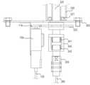
도 1은 본 발명의 일 실시예에 따른 회전형 물놀이 장치의 전체적인 외관 사시도이고,
도 2는 도 1의 주요 부분에 대한 분해 사시도이고,
도 3은 도 1의 단면도를 나타낸 도면이고,
도 4는 도 2 중에서 제1 회전자와 제2 회전자가 맞물려 있는 상태와 그 주변 구성들을 나타낸 도면이고,
도 5는 제1 회전자와 제2 회전자 및 제1 회전자를 감싸는 주기둥의 관계를 나타낸 도면이다.1 is an overall external perspective view of a rotating water play device according to an embodiment of the present invention;
Figure 2 is an exploded perspective view of the main part of Figure 1,
Figure 3 is a view showing a cross-sectional view of Figure 1,
4 is a view showing a state in which the first rotor and the second rotor are engaged in FIG. 2 and the surrounding configurations thereof;
5 is a diagram illustrating a relationship between a first rotor, a second rotor, and a main column surrounding the first rotor.
이하에서는 첨부도면을 참조하여 본 발명에 대해 상세히 설명한다.Hereinafter, the present invention will be described in detail with reference to the accompanying drawings.
이하 본 발명에 따른 각 실시예는 본 발명의 이해를 돕기 위한 하나의 예에 불과하고, 본 발명이 이러한 실시예에 한정되는 것은 아니다. 특히 본 발명은 각 실시예에 포함되는 개별 구성, 개별 기능, 또는 개별 단계 중 적어도 어느 하나 이상의 조합으로 구성될 수 있다.Hereinafter, each embodiment according to the present invention is merely an example for helping the understanding of the present invention, and the present invention is not limited to these embodiments. In particular, the present invention may be composed of a combination of at least any one of individual components, individual functions, or individual steps included in each embodiment.
특히, 편의상 청구 범위의 일부 청구항에는 '(a)'와 같은 알파벳을 포함시켰으나, 이러한 알파벳이 각 단계의 순서를 규정하는 것은 아니다.In particular, some claims of the claims include an alphabet such as '(a)' for convenience, but the alphabet does not define the order of each step.
본 발명의 일 실시예에 따른 회전형 물놀이 장치(1)의 전체적인 외관 형상은 도 1에 도시된 바와 같고, 주요 부분들에 대한 분해 사시도는 도 2에 도시된 바와 같다.The overall external shape of the rotatable
또한 도 3은 도 1의 내부가 보이도록 단면도를 도시한 것이고, 도 4는 후술하는 하부 구조물(300)에 다른 구성요소들이 장착되어 있는 부분을 확대 도시한 것이며, 도 5는 후술하는 제1 급수관(220)과 제2 급수관(210)이 만나는 부분의 단면을 확대 도시한 것이다.In addition, FIG. 3 is a cross-sectional view showing the inside of FIG. 1 , FIG. 4 is an enlarged view of a portion in which other components are mounted to a
동 도면들에 도시된 바와 같이 본 발명의 일 실시예에 따른 회전형 물놀이 장치(1)는 회전력 발생 장치(100)와 물줄기 방출 장치(200), 하부 구조물(300), 보호 바디(400)를 포함하여 구성될 수 있다.As shown in the drawings, the rotational
우선 하부 구조물(300)은 회전력 발생 장치(100)와 물줄기 방출 장치(200)를 고정 장착되도록 하는 것으로서, 설치가 완료된 상태에서 지면에 맞닿아 노출될 수도 있고, 또는 지면 아래에 매립될 수도 있다.First, the
또한 보호 바디(400)는 후술하는 바와 같이 하부 구조물(300)에 장착된 여러 장치들을 보호하는 기능을 수행하는 것으로서, 이러한 하부 고물과 보호 바디(400)의 구성 및 그 기능은 공지된 것에 불과하므로 보다 상세한 설명은 생략한다.In addition, the
한편, 회전력 발생 장치(100)는 하부 구조물(300)에 고정 장착되고, 외부로부터 인입되는 유체에 의해 회전하는 제1 회전자(110)를 포함하도록 구성된 것으로서, 즉, 외부로부터 인입되는 유체에 의해 제1 회전자(110)를 회전하도록 하는 구조를 갖는다. 여기서 제1 회전자(110)는 기어 또는 풀리를 포함하여 구성될 수 있다.On the other hand, the rotational
여기서 유체에 의해 회전한다는 것은 전기 공급이 없더라도 기름이나 공기와 같은 유체의 인입압력만으로 회전한다는 것을 의미한다.Here, rotation by the fluid means that it rotates only with the incoming pressure of a fluid such as oil or air even if there is no electricity supply.
예를 들어 회전력 발생 장치(100)는 외부로부터 압축 공기를 받아 회전력을 발생시킬 수 있는 것이다.For example, the rotational
이처럼 압축 공기를 공급받아 소정의 회전력을 발생시키는 것은 예를 들어 에어 드릴/어에 브러시 등과 같은 공구류뿐만 아니라, 소정의 에어 탱크와 이 에어 탱크로부터 배출되는 압축 공기를 일정 압력으로 공급하는 이동시키면서 내부의 터빈을 회전시키는 산업용 장치 등에 널리 이용되는 것이므로 그 구체적인 기능 및 구조에 대한 설명은 생략한다.In this way, generating a predetermined rotational force by receiving compressed air is to supply a predetermined air tank and compressed air discharged from the air tank at a predetermined pressure, as well as tools such as an air drill/air brush, for example, while moving the inside while moving. Since it is widely used in industrial devices that rotate turbines of
다만, 본 실시예에서 회전력 발생 장치(100) 내에는 조절 밸브(미 도시함)가 구비되어서 후술하는 제어부의 제어신호에 따라 회전 여부 또는 그 회전 속도를 조절할 수 있다. 소정의 유체의 유입을 제어하는 조절 밸브의 구성 그 자체는 공지된 기술에 해당하므로 보다 상세한 설명은 생략한다.However, in the present embodiment, a control valve (not shown) is provided in the rotational
예를 들어 인입되는 공기의 양을 조절하여 회전을 중단/개시하거나 회전 속도를 낮추거나 높일 수 있는 것이다.For example, by controlling the amount of incoming air, rotation can be stopped/started, or rotation speed can be reduced or increased.
한편, 물줄기 방출 장치(200)는 하부 구조물(300)에 고정 장착된 상태에서 회전력 발생 장치(100)의 제1 회전자(110)와 연동하여 회전하는 물줄기를 방출하는 기능을 수행한다.On the other hand, the water
구체적으로 물줄기 방출 장치(200)는 제1 급수관(220), 주기둥(230), 제2 급수관(210), 급수부(250), 무빙 조인트(240)를 포함하여 구성될 수 있다.Specifically, the water
여기서 제1 급수관(220)은 수직방향으로 배치되고 하부에 상기 회전력 발생 장치(100)의 제1 회전자(110)와 연계하여 회전하는 제2 회전자(222)가 고정 장착된 것으로서, 이러한 제2 회전자(222)는 기어 또는 풀리를 포함하여 구성될 수 있다.Here, the first
여기서 기어는 일종의 톱니바퀴 형식으로 되어 있어서, 톱니의 맞물림으로 인해 동력을 전달하는 것이고, 풀리는 벨트가 안착되도록 하는 홈을 외주변을 따라 형성되어 벨트의 상호 연결에 의해 동력을 전달하는 것이다.Here, the gear is in the form of a cogwheel, and transmits power due to the meshing of the gears, and a groove for the belt to be loosened is formed along the outer periphery to transmit power by interconnection of the belts.
이러한 제1 급수관(220)은 이처럼 제2 회전자(222)와 제1 회전자(110)의 연계 동작(예를 들어 기어인 경우 치합, 풀리인 경우 벨트 연결)에 의해 회전할 수 있다.The first
제1 회전자(110)와 제2 회전자(222)는 각각 기어를 포함하여 구성되는 경우 상호 치합하는 구조를 가질 수 있고, 또한 제1 회전자(110)와 제2 회전자(222)가 풀리로 형성된 경우 소정의 벨트에 의해 서로 연결되는 구조를 가질 수 있다.The
특히, 제1 회전자(110)에 포함된 기어와 제2 회전자(222)에 포함된 기어의 기어비는 40:1 ~ 50:1의 범위를 갖도록 하여 제1 회전자(110)가 고속으로 회전한다 하여도 제2 회전자(222)는 그보다 한참 천천히 회전하도록 할 수 있다.In particular, the gear ratio of the gear included in the
이는 제2 회전자(222)의 회전에 따라 후술하는 바와 같이 제1 급수관(220) 및 제2 급수관(210)의 회전이 발생하게 되는데, 이때 물놀이 시설에서 사람들에게 노출되어 회전되는 제2 급수관(210)의 속도를 떨어뜨려 안정성을 확보하기 위함이다.This causes the rotation of the first
특히 제1 회전자(110)만을 교체함으로써 제1 회전자(110)와 제2 회전자(222)의 기어비는 용이하게 변경할 수 있고, 이에 따라 제1 회전자(110)의 회전속도에 따른 제2 회전자(222)가 부착된 제1 급수관(220)의 회전속도를 적절한 수준으로 조정할 수 있는 장점이 있다.In particular, by replacing only the
이러한 제1 급수관(220)은 내부가 비어있어서 물이 통과될 수 있다.The first
한편 도 4를 참조하면, 제2 회전자(222)가 하부 구조물(300)의 아랫면과 직접 닿아서 마찰이 발생하지 않도록 이격을 두고 있음을 알 수 있다. 이격을 위해서 제2 회전자(222) 상하에 볼트를 체결할 수도 있다.Meanwhile, referring to FIG. 4 , it can be seen that the
주기둥(230)은 제1 급수관(220)의 외부를 감싸 보호하는 기능을 수행하는 것으로서, 외부에서는 주기둥(230) 내부에서 회전하는 제1 급수관(220)이 보이지도 않고 만질 수도 없으므로 안전성을 확보할 수 있다.The
제2 급수관(210)은 제1 급수관(220)과 연결되고 일 측에 물줄기를 방출하는 토출구(211)가 적어도 하나 구비된 것으로서, 바람직하게는 제1 급수관(220) 하단부에 상술한 제2 회전자(222)가 구비된 경우, 제2 급수관(210)은 제1 급수관(220) 상단부에 연결되게 된다.The second
즉, 제2 급수관(210)은 제2 급수관(210)과 함께 회전운동을 하고, 또한 제1 급수관(220)과 마찬가지로 내부가 비어 있어서, 제1 급수관(220)으로부터 전달되는 물을 토출구(211)를 통해 방출시키는 기능을 수행한다.That is, the second
이러한 제1 급수관(220)과 제2 급수관(210)은 서로 결합 구조로 이루어져 있을 수도 있고, 바람직하게는 일체로 형성될 수도 있다.The first
제1 급수관(220)과 제2 급수관(210)이 일체로 형성된 경우, 주기둥(230)에 의해 보호된 부분이 제1 급수관(220)이 되고, 주기둥(230) 외부로 노출된 부분이 제2 급수관(210)이 된다.When the first
도 1 및 도 2를 참조하면, 제2 급수관(210)이 주기둥(230)과 만나는 부분에는 보호용 캡이 구비되어 있을 수 있고, 또한 제1 급수관(220)과 주기둥(230) 사이에는 적어도 하나 이상의 베어링(221,231)이 구비되어 있어서, 주기둥(230) 내부에서 제1 급수관(220)의 회전 운동이 최소한의 마찰로 원활히 이루어지도록 할 수 있다.1 and 2 , a protective cap may be provided at a portion where the second
한편, 급수부(250)는 외부로부터 물을 공급받아 이를 상술한 제1 급수관(220) 내부로 전달하는 기능을 수행한다.On the other hand, the
예를 들어 급수부(250)는 수압펌프(미 도시함)와 호스관(260)으로 연결되어 물을 공급받고 이를 제1 급수관(220) 내부로 전달하는 기능을 수행한다. 이러한 급수부(250) 내에는 급수부(250) 내부로 유입되는 물의 압력을 감지하는 압력 센서(미 도시함)가 구비될 수 있다.For example, the
무빙 조인트(240)는 일측은 고정되도록 하고 타측은 회전되도록 하는 구조를 갖는 것으로서, 특히 본 실시예에서 급수부(250)와 제1 급수관(220) 사이에서 연결되어 물 공급부는 회전운동을 하지 않고 고정된 상태를 유지하도록 하면서도 제1 급수관(220)만 회전하도록 하는 상태가 가능하도록 한다.The moving joint 240 has a structure such that one side is fixed and the other side is rotated. In particular, in this embodiment, it is connected between the
즉, 앞서 설명한 바와 같이 제1 회전자(110)와 연동해서 제2 회전자(222)가 회전함에 따라 제2 회전자(222)가 부착되어 있는 제1 급수관(220)이 회전하게 되는데, 이 경우 제1 급수관(220)과 급수부(250)가 상호 고정 결합되어 있게 되면 제1 급수부(250) 역시 함께 회전하게 되고, 이렇게 되면 외부에서 급수부(250)로 물 공급을 위한 호스 등이 감기게 되는 문제점이 있는데, 본 실시예와 같이 제1 급수관(220)과 급수부(250) 사이에 무빙 조인트(240)를 두고, 제1 급수관(220)이 회전하더라도 급수부(250)는 움직임이 없는 상태가 유지되도록 하면 상술한 문제점을 해결할 수 있다.That is, as described above, as the
이처럼 무빙 조인트(240)를 구비한 상태에서도, 급수부(250)에 공급되는 물은 무빙 조인트(240) 내에 형성된 홈 등을 통해 제1 급수관(220)을 전달될 수 있고, 이러한 무빙 조인트(240) 내부의 구조 그 자체는 공지된 기술에 해당하므로 보다 상세한 설명은 생략한다.Even in a state in which the moving joint 240 is provided, the water supplied to the
한편, 구조를 나타내는 도면에는 도시하지 않았지만 제어부는 급수부(250) 내에 구비된 압력 센서로부터 인입되는 물의 압력을 감지한 감지 신호를 수신하고, 회전력 발생 장치(100)에 구비된 조절 밸브(미 도시함)에 제어 신호를 인가하는 기능을 수행한다.On the other hand, although not shown in the drawings showing the structure, the control unit receives a detection signal for sensing the pressure of incoming water from the pressure sensor provided in the
예를 들어 제어부는 압력 센서에서 감지된 물의 압력의 정도에 비례하여 조절 밸브의 개방 정도를 제어할 수 있고, 이때 물의 압력에 따른 조절 밸브의 개방 정도를 나타내는 설정값을 참고할 수 있다.For example, the controller may control the degree of opening of the control valve in proportion to the degree of water pressure sensed by the pressure sensor, and in this case, reference may be made to a set value indicating the degree of opening of the control valve according to the pressure of water.
일 예로 제어부는 물의 특정 압력에 조절 밸브의 개방각도가 매칭된 매칭 테이블을 참고하여 제어할 수 있다.For example, the control unit may control with reference to a matching table in which the opening angle of the control valve is matched to a specific pressure of water.
이러한 제어부는 원격에서 급수부(250)와 연결되는 일종의 물탱크, 회전력 발생 장치(100)와 소정의 호스(120)를 통해 연결되는 에어컴프레샤(미 도시함) 등을 제어할 수도 있는데, 본 발명에 따른 회전력 발생 장치(100) 및 물줄기 방출 장치(200)와는 거리가 떨어진 곳에 설치될 수 있다.Such a control unit may remotely control a kind of water tank connected to the
한편, 상술한 회전형 물놀이 장치(1)를 시공하는 방법의 일 예를 설명하면 다음과 같다.On the other hand, an example of a method of constructing the above-described rotary type
우선, 외부로부터 인입되는 유체에 의해 회전하는 제1 회전자(110)를 포함하는 회전력 발생 장치(100)를 하부 구조물(300) 하단에 고정 장착한다.First, the rotational
이어서 보호용 주기둥(230)을 하부 구조물(300)의 통공(후술하는 제1 급수관(220)이 통과하기 위한 통공)이 형성된 위치 상단에 고정 장착하여 지지대로써 움직이지 않도록 한다.Then, the protective
이후, 물이 지나가는 제1 급수관(220)을 보호용 주기둥(230) 및 하부 구조물(300)의 통공을 관통하여 내삽한다.Thereafter, the first
이어서 무빙 조인트(240)를 제1 급수관(220)의 하부와 결합하는데, 제1 급수관(220)의 하부는 하부 구조물(300) 아래로 돌출되고 제2 회전자(222)가 구비된 것이고, 무빙 조인트(240)는 일단이 고정부(242)로 형성되고 타단이 회전부(241)로 형성되되 그 내부에 물이 지나가는 통공이 형성된 것으로서, 그 회전부(341)와 제1 급수관(220)의 하부를 상호 결합하는 것이다.Then, the moving joint 240 is coupled with the lower part of the first
또한 무빙 조인트(240)의 고정부에 외부로부터 물을 공급받는 급수부(250)를 장착한다.In addition, a
이에 따라 제1 급수관(220)이 회전한다 하여도 급수부(250)는 고정된 상태를 유지할 수 있고, 이 상태에서 급수부(250)로 공급된 물이 무빙 조인트(240)를 경유하여 제1 급수관(220) 내부로 공급될 수 있다. 제1 급수관(220) 내부로 공급된 물은 결국 제2 급수관(210)의 토출구(211)를 통해 외부로 물줄기 형태로 분출될 수 있다.Accordingly, even when the first
마지막으로 제1 회전자(110)의 회전과 연동되어 제2 회전자(222)가 회전되도록 제1 회전자(110) 및 제2 회전자(222)를 상호 배치(일 예로 결합, 치합 배치 등)할 수 있다.Finally, the
한편, 상술한 각 실시예를 수행하는 과정은 소정의 기록 매체(예를 들어 컴퓨터로 판독 가능한)에 저장된 프로그램 또는 애플리케이션에 의해 이루어질 수 있음은 물론이다. 여기서 기록 매체는 RAM(Random Access Memory)과 같은 전자적 기록 매체, 하드 디스크와 같은 자기적 기록 매체, CD(Compact Disk)와 같은 광학적 기록 매체 등을 모두 포함한다.Meanwhile, it goes without saying that the process of performing each of the above-described embodiments may be performed by a program or application stored in a predetermined recording medium (eg, computer-readable). Here, the recording medium includes an electronic recording medium such as a random access memory (RAM), a magnetic recording medium such as a hard disk, and an optical recording medium such as a compact disk (CD).
또한, 본 발명은 상기한 특정 실시예에 한정되는 것이 아니라 본 발명의 요지를 벗어나지 않는 범위 내에서 여러 가지로 변형 및 수정하여 실시할 수 있는 것이다. 이러한 변형 및 수정이 첨부되는 특허청구범위에 속한다면 본 발명에 포함된다는 것은 자명할 것이다.In addition, the present invention is not limited to the specific embodiments described above, but can be practiced with various modifications and modifications within the scope without departing from the gist of the present invention. It will be apparent that such modifications and variations are included in the present invention provided they fall within the scope of the appended claims.
1 : 회전형 물놀이 장치 100 : 회전력 발생 장치
200 : 물줄기 방출 장치 300 : 하부 구조물
400 : 보호 바디 110 : 제1 회전자
210 : 제2 급수관 220 : 제1 급수관
230 : 주기둥 240 : 무빙 조인트
250 : 급수부 221,231 : 베어링
222 : 제2 회전자1: rotating water play device 100: rotational force generating device
200: water discharge device 300: lower structure
400: protective body 110: first rotor
210: second water supply pipe 220: first water supply pipe
230: main column 240: moving joint
250: water supply 221,231: bearing
222: second rotor
Claims (7)
Translated fromKorean상기 하부 구조물에 고정 장착되고, 외부로부터 인입되는 유체에 의해 회전하는 제1 회전자를 포함하는 회전력 발생 장치와;
상기 회전력 발생 장치의 제1 회전자와 연동하여 회전하는 물줄기를 방출하고 상기 하부 구조물에 고정 장착된 물줄기 방출 장치와;
제어부를 포함하여 구성되고,
상기 물줄기 방출 장치는, 수직방향으로 배치되고 하부에 상기 회전력 발생 장치의 제1 회전자와 연계하여 회전하는 제2 회전자가 고정 장착된 제1 급수관과; 상기 제1 급수관의 외부를 감싸 보호하는 주기둥과; 상기 제1 급수관과 연결되고 일 측에 물줄기를 방출하는 토출구가 적어도 하나 구비된 제2 급수관과; 외부로부터 물을 공급받는 급수부와; 상기 급수부와 상기 제1 급수관 사이에서 연결되어 상기 급수부는 고정된 채로 상기 제1 급수관만 회전하는 상태에서 상기 급수부가 공급하는 물을 상기 제1 급수관 내로 전달하는 무빙 조인트를 포함하고,
상기 회전력 발생 장치에의 유입구에는 상기 제어부의 제어에 따라 외부로부터의 유체의 인입 여부와 그 정도를 조절하는 조절 밸브가 구비되어 있고,
상기 급수부 내에는 유입되는 물의 압력을 감지하는 압력 센서가 구비되어 있으며,
상기 제어부는 상기 압력 센서에서 감지된 물의 압력을 참고하여 상기 조절 밸브의 개방 정도를 제어하는 것을 특징으로 하는 회전형 물놀이 장치.substructure;
a rotational force generating device fixedly mounted to the lower structure and including a first rotor rotated by a fluid introduced from the outside;
a water stream discharging device fixedly mounted to the lower structure and discharging a rotating water stream in association with the first rotor of the rotational force generating device;
Consists of a control unit,
The water discharge device may include: a first water supply pipe disposed in a vertical direction and having a second rotor fixedly mounted at a lower portion thereof to rotate in connection with the first rotor of the rotational force generating device; and a main pillar for protecting the outside of the first water supply pipe; a second water supply pipe connected to the first water supply pipe and provided with at least one outlet for discharging a water stream on one side; a water supply unit receiving water from the outside; A moving joint connected between the water supply unit and the first water supply pipe to deliver the water supplied by the water supply unit into the first water supply pipe in a state where only the first water supply pipe rotates while the water supply unit is fixed,
The inlet to the rotational force generating device is provided with a control valve for regulating whether the fluid from the outside is drawn in and the degree thereof according to the control of the control unit,
A pressure sensor for sensing the pressure of the incoming water is provided in the water supply unit,
wherein the control unit controls the degree of opening of the control valve with reference to the pressure of the water sensed by the pressure sensor.
상기 회전력 발생 장치는 외부로부터 에어콤프레샤로부터 인입되는 압축 공기의 힘에 의해 상기 제1 회전자를 회전시키는 구조를 갖는 것을 특징으로 하는 회전형 물놀이 장치.The method of claim 1,
The rotational force generating device has a structure for rotating the first rotor by the force of compressed air introduced from the air compressor from the outside.
상기 제1 회전자와 상기 제2 회전자는 각각 기어를 포함하여 구성되어 상호 치합하는 구조를 갖는 것을 특징으로 하는 회전형 물놀이 장치.The method of claim 1,
The first rotor and the second rotor are each configured to include a gear and have a structure in which they mesh with each other.
상기 제1 회전자에 포함된 기어와 상기 제2 회전자에 포함된 기어의 기어비는 40:1 ~ 50:1의 범위를 갖는 것을 특징으로 하는 회전형 물놀이 장치.4. The method of claim 3,
A gear ratio between the gear included in the first rotor and the gear included in the second rotor is in the range of 40:1 to 50:1.
상기 제1 급수관과 상기 제2 급수관은 일체로 형성되는 것을 특징으로 하는 회전형 물놀이 장치.The method of claim 1,
The first water supply pipe and the second water supply pipe are integrally formed.
Priority Applications (1)
| Application Number | Priority Date | Filing Date | Title |
|---|---|---|---|
| KR1020210113128AKR102372853B1 (en) | 2021-08-26 | 2021-08-26 | Rotating type water apparatus and construction method thereof |
Applications Claiming Priority (1)
| Application Number | Priority Date | Filing Date | Title |
|---|---|---|---|
| KR1020210113128AKR102372853B1 (en) | 2021-08-26 | 2021-08-26 | Rotating type water apparatus and construction method thereof |
Publications (1)
| Publication Number | Publication Date |
|---|---|
| KR102372853B1true KR102372853B1 (en) | 2022-03-11 |
Family
ID=80814424
Family Applications (1)
| Application Number | Title | Priority Date | Filing Date |
|---|---|---|---|
| KR1020210113128AActiveKR102372853B1 (en) | 2021-08-26 | 2021-08-26 | Rotating type water apparatus and construction method thereof |
Country Status (1)
| Country | Link |
|---|---|
| KR (1) | KR102372853B1 (en) |
Citations (6)
| Publication number | Priority date | Publication date | Assignee | Title |
|---|---|---|---|---|
| US5194048A (en)* | 1989-11-20 | 1993-03-16 | Briggs Rick A | Participatory water play apparatus |
| KR19990003470A (en)* | 1997-06-25 | 1999-01-15 | 김동암 | Water fountain |
| KR100339516B1 (en)* | 1999-04-02 | 2002-05-31 | 이계욱 | Unmanned hydraulic power automatic rotation, movement spraying system |
| KR101125616B1 (en) | 2011-07-21 | 2012-03-27 | (주)셈투유 | a rippling of water instrument of smart type |
| KR101297220B1 (en)* | 2012-06-26 | 2013-08-16 | (주)디자인가교 | A rotating water agency |
| KR101445556B1 (en)* | 2014-02-11 | 2014-10-15 | 주식회사 테크노믹스 | Rotary injection nozzle assembly |
- 2021
- 2021-08-26KRKR1020210113128Apatent/KR102372853B1/enactiveActive
Patent Citations (6)
| Publication number | Priority date | Publication date | Assignee | Title |
|---|---|---|---|---|
| US5194048A (en)* | 1989-11-20 | 1993-03-16 | Briggs Rick A | Participatory water play apparatus |
| KR19990003470A (en)* | 1997-06-25 | 1999-01-15 | 김동암 | Water fountain |
| KR100339516B1 (en)* | 1999-04-02 | 2002-05-31 | 이계욱 | Unmanned hydraulic power automatic rotation, movement spraying system |
| KR101125616B1 (en) | 2011-07-21 | 2012-03-27 | (주)셈투유 | a rippling of water instrument of smart type |
| KR101297220B1 (en)* | 2012-06-26 | 2013-08-16 | (주)디자인가교 | A rotating water agency |
| KR101445556B1 (en)* | 2014-02-11 | 2014-10-15 | 주식회사 테크노믹스 | Rotary injection nozzle assembly |
Similar Documents
| Publication | Publication Date | Title |
|---|---|---|
| US3506489A (en) | Method and apparatus of cleaning a pool | |
| US8474733B1 (en) | Irrigation sprinkler with reversing planetary gear drive including two ring gears with different profiles | |
| KR100924802B1 (en) | Multi-Vector Control Nozzle Unit | |
| US10099231B2 (en) | Reversing mechanism for an irrigation sprinkler with a reversing gear drive | |
| KR102372853B1 (en) | Rotating type water apparatus and construction method thereof | |
| KR100957838B1 (en) | Multi vector control nozzle device | |
| KR20130011881A (en) | Hydro power gear with spiral flow path | |
| CN215744178U (en) | Rotary swing water outlet device and shower head | |
| KR102038024B1 (en) | Floating type wind turbine and control method of the same | |
| US7344092B1 (en) | Rotary atomizer, and air bearing protection system for rotary atomizer | |
| JP5345608B2 (en) | Fountain equipment | |
| KR101686188B1 (en) | Automatic firefighting monitor | |
| WO1990015014A1 (en) | Water closet tank fill valve | |
| KR101051775B1 (en) | Rotary Fountain Drive | |
| CN112313015B (en) | Robot fountain | |
| JP2017209645A (en) | Injection state display device of cleaning nozzle | |
| KR101531705B1 (en) | The multidegree of freedom fountain nozzle device | |
| KR100701830B1 (en) | Flexible wire for pipe descalers | |
| CN116290950B (en) | Water spray propulsion type swimming pool robot and control method thereof | |
| KR101802714B1 (en) | A pump having a rotary vane coupling structure having a rotary angle varying function | |
| US20040216226A1 (en) | System for creating waves or movement of the surface of a liquid | |
| US20080168610A1 (en) | Steering Adaptor for Suction Pool Cleaner | |
| JPH06123273A (en) | Rotary device and torque extraction device | |
| KR101115824B1 (en) | A multy type eject nozzle operate apparatus for fountain | |
| CN109506026A (en) | A kind of quantitative self-closing valve |
Legal Events
| Date | Code | Title | Description |
|---|---|---|---|
| PA0109 | Patent application | Patent event code:PA01091R01D Comment text:Patent Application Patent event date:20210826 | |
| PA0201 | Request for examination | ||
| PA0302 | Request for accelerated examination | Patent event date:20210826 Patent event code:PA03022R01D Comment text:Request for Accelerated Examination | |
| PE0902 | Notice of grounds for rejection | Comment text:Notification of reason for refusal Patent event date:20211115 Patent event code:PE09021S01D | |
| E701 | Decision to grant or registration of patent right | ||
| GRNT | Written decision to grant | ||
| PE0701 | Decision of registration | Patent event code:PE07011S01D Comment text:Decision to Grant Registration Patent event date:20220304 | |
| PR0701 | Registration of establishment | Comment text:Registration of Establishment Patent event date:20220304 Patent event code:PR07011E01D | |
| PR1002 | Payment of registration fee | Payment date:20220307 End annual number:3 Start annual number:1 | |
| PG1601 | Publication of registration | ||
| PR1001 | Payment of annual fee | Payment date:20250122 Start annual number:4 End annual number:4 |