KR102372026B1 - Display apparatus and electronic system including the same - Google Patents
Display apparatus and electronic system including the sameDownload PDFInfo
- Publication number
- KR102372026B1 KR102372026B1KR1020150076387AKR20150076387AKR102372026B1KR 102372026 B1KR102372026 B1KR 102372026B1KR 1020150076387 AKR1020150076387 AKR 1020150076387AKR 20150076387 AKR20150076387 AKR 20150076387AKR 102372026 B1KR102372026 B1KR 102372026B1
- Authority
- KR
- South Korea
- Prior art keywords
- image data
- grayscales
- image
- operation mode
- grayscale
- Prior art date
- Legal status (The legal status is an assumption and is not a legal conclusion. Google has not performed a legal analysis and makes no representation as to the accuracy of the status listed.)
- Active
Links
Images


Classifications
- G—PHYSICS
- G09—EDUCATION; CRYPTOGRAPHY; DISPLAY; ADVERTISING; SEALS
- G09G—ARRANGEMENTS OR CIRCUITS FOR CONTROL OF INDICATING DEVICES USING STATIC MEANS TO PRESENT VARIABLE INFORMATION
- G09G3/00—Control arrangements or circuits, of interest only in connection with visual indicators other than cathode-ray tubes
- G09G3/20—Control arrangements or circuits, of interest only in connection with visual indicators other than cathode-ray tubes for presentation of an assembly of a number of characters, e.g. a page, by composing the assembly by combination of individual elements arranged in a matrix no fixed position being assigned to or needed to be assigned to the individual characters or partial characters
- G09G3/2007—Display of intermediate tones
- G—PHYSICS
- G09—EDUCATION; CRYPTOGRAPHY; DISPLAY; ADVERTISING; SEALS
- G09G—ARRANGEMENTS OR CIRCUITS FOR CONTROL OF INDICATING DEVICES USING STATIC MEANS TO PRESENT VARIABLE INFORMATION
- G09G2320/00—Control of display operating conditions
- G09G2320/02—Improving the quality of display appearance
- G09G2320/0247—Flicker reduction other than flicker reduction circuits used for single beam cathode-ray tubes
- G—PHYSICS
- G09—EDUCATION; CRYPTOGRAPHY; DISPLAY; ADVERTISING; SEALS
- G09G—ARRANGEMENTS OR CIRCUITS FOR CONTROL OF INDICATING DEVICES USING STATIC MEANS TO PRESENT VARIABLE INFORMATION
- G09G2330/00—Aspects of power supply; Aspects of display protection and defect management
- G09G2330/02—Details of power systems and of start or stop of display operation
- G09G2330/021—Power management, e.g. power saving
- G—PHYSICS
- G09—EDUCATION; CRYPTOGRAPHY; DISPLAY; ADVERTISING; SEALS
- G09G—ARRANGEMENTS OR CIRCUITS FOR CONTROL OF INDICATING DEVICES USING STATIC MEANS TO PRESENT VARIABLE INFORMATION
- G09G2360/00—Aspects of the architecture of display systems
- G09G2360/16—Calculation or use of calculated indices related to luminance levels in display data
Landscapes
- Engineering & Computer Science (AREA)
- Physics & Mathematics (AREA)
- Computer Hardware Design (AREA)
- General Physics & Mathematics (AREA)
- Theoretical Computer Science (AREA)
- Control Of Indicators Other Than Cathode Ray Tubes (AREA)
Abstract
Translated fromKorean
Description
Translated fromKorean본 발명은 표시 장치에 관한 것으로서, 더욱 상세하게는 다양한 전자 시스템에서 입출력 장치의 하나로서 사용되는 표시 장치 및 상기 표시 장치를 포함하는 전자 시스템에 관한 것이다.The present invention relates to a display device, and more particularly, to a display device used as one of input/output devices in various electronic systems, and an electronic system including the display device.
대면적이 용이하고 박형 및 경량화가 가능한 평판 디스플레이(flat panel display, FPD)가 표시 장치로서 널리 이용되고 있으며, 이러한 평판 디스플레이로는 액정 표시 장치(liquid crystal display, LCD), 플라스마 디스플레이 패널(plasma display panel, PDP), 유기 발광 표시 장치(organic light emitting display, OLED) 등이 사용되고 있다.A flat panel display (FPD), which has a large area and can be thin and lightweight, is widely used as a display device, and such a flat panel display includes a liquid crystal display (LCD), a plasma display panel panel, PDP), an organic light emitting display (OLED), etc. are being used.
상기와 같은 표시 장치들은 휴대폰(Mobile Phone), 스마트 폰(Smart Phone), 개인 정보 단말기(Personal Digital Assistant; PDA) 등과 같은 다양한 전자 시스템에 사용될 수 있다. 최근에는 배터리를 사용하는 모바일 기기(mobile device)와 같은 전자 시스템에 다양한 기능이 컨버전스되면서, 전자 시스템의 성능뿐만 아니라, 전자 시스템의 전력 소모량을 최소화하는 방안에 대한 연구가 진행되고 있다.The display devices as described above may be used in various electronic systems such as a mobile phone, a smart phone, and a personal digital assistant (PDA). Recently, as various functions converge in an electronic system such as a mobile device using a battery, research on a method for minimizing the power consumption of the electronic system as well as the performance of the electronic system is being conducted.
본 발명의 일 목적은 전력 소모가 감소된 표시 장치를 제공하는 것이다.SUMMARY OF THE INVENTION One object of the present invention is to provide a display device with reduced power consumption.
본 발명의 다른 목적은 상기 표시 장치를 포함하는 전자 시스템을 제공하는 것이다.Another object of the present invention is to provide an electronic system including the display device.
상기 일 목적을 달성하기 위해, 본 발명의 실시예들에 따른 표시 장치는 표시 패널 및 타이밍 제어 회로를 포함한다. 상기 타이밍 제어 회로는 제1 동작 모드에서 입력 영상 데이터에 기초하여 제1 출력 영상 데이터를 발생하고 상기 표시 패널의 동작 주파수를 제1 주파수로 설정하며, 제2 동작 모드에서 상기 입력 영상 데이터를 변환하여 제2 출력 영상 데이터를 발생하고 상기 표시 패널의 동작 주파수를 상기 제1 주파수보다 낮은 제2 주파수로 설정한다. 상기 표시 패널은 상기 제1 동작 모드에서 상기 제1 주파수 및 상기 제1 출력 영상 데이터에 기초하여 X(X는 2 이상의 자연수)개의 계조들을 포함하는 제1 영상을 표시하며, 상기 제2 동작 모드에서 상기 제2 주파수 및 상기 제2 출력 영상 데이터에 기초하여 Y(Y는 X보다 작은 자연수)개의 계조들을 포함하는 제2 영상을 표시한다.In order to achieve the above object, a display device according to example embodiments includes a display panel and a timing control circuit. The timing control circuit generates first output image data based on input image data in a first operation mode, sets an operation frequency of the display panel to a first frequency, and converts the input image data in a second operation mode to The second output image data is generated and the operating frequency of the display panel is set to a second frequency lower than the first frequency. The display panel displays a first image including X (where X is a natural number equal to or greater than 2) grayscales based on the first frequency and the first output image data in the first operation mode, and in the second operation mode A second image including Y (Y is a natural number less than X) grayscales is displayed based on the second frequency and the second output image data.
일 실시예에서, 상기 표시 장치는 상기 제2 동작 모드에서 상기 제2 영상을 표시하기 위한 복수의 영상 프레임들 중 일부를 차단하는 프레임 마스킹 구동(Frame Masking Driving; FMD) 방식에 기초하여 동작할 수 있다.In an embodiment, the display device may operate based on a frame masking driving (FMD) method that blocks some of a plurality of image frames for displaying the second image in the second operation mode. there is.
일 실시예에서, 상기 표시 장치는 상기 제1 출력 영상 데이터 또는 상기 제2 출력 영상 데이터를 기초로 복수의 데이터 전압들을 발생하여 상기 표시 패널에 제공하는 데이터 구동 회로를 더 포함할 수 있다. 상기 제2 동작 모드에서 상기 제2 영상을 표시하기 위한 상기 복수의 영상 프레임들은 연속하는 제1 프레임 및 제2 프레임을 포함할 수 있다. 상기 데이터 구동 회로는 상기 제1 프레임에서 상기 복수의 데이터 전압들을 출력하고, 상기 제2 프레임에서 상기 복수의 데이터 전압들의 출력을 차단할 수 있다.In an embodiment, the display device may further include a data driving circuit that generates a plurality of data voltages based on the first output image data or the second output image data and provides them to the display panel. The plurality of image frames for displaying the second image in the second operation mode may include successive first and second frames. The data driving circuit may output the plurality of data voltages in the first frame and block the output of the plurality of data voltages in the second frame.
일 실시예에서, 상기 표시 장치는 복수의 게이트 신호들을 발생하여 상기 표시 패널에 제공하는 게이트 구동 회로를 더 포함할 수 있다. 상기 제2 동작 모드에서 상기 제2 영상을 표시하기 위한 상기 복수의 영상 프레임들은 연속하는 제1 프레임 및 제2 프레임을 포함할 수 있다. 상기 게이트 구동 회로는 상기 제1 프레임에서 상기 복수의 게이트 신호들을 출력하고, 상기 제2 프레임에서 상기 복수의 게이트 신호들의 출력을 차단할 수 있다.In an embodiment, the display device may further include a gate driving circuit that generates a plurality of gate signals and provides them to the display panel. The plurality of image frames for displaying the second image in the second operation mode may include successive first and second frames. The gate driving circuit may output the plurality of gate signals in the first frame and block output of the plurality of gate signals in the second frame.
일 실시예에서, 상기 타이밍 제어 회로는 영상 보정부, 영상 분할부, 영상 분석부, 계조 선택부 및 영상 변환부를 포함할 수 있다. 상기 영상 보정부는 상기 제1 동작 모드에서 상기 입력 영상 데이터에 기초하여 상기 제1 출력 영상 데이터를 발생할 수 있다. 상기 영상 분할부는 상기 제2 동작 모드에서 상기 입력 영상 데이터를 분할하여, 상기 제1 영상이 분할된 복수의 부분 영상들에 상응하는 복수의 부분 영상 데이터들을 발생할 수 있다. 상기 영상 분석부는 상기 복수의 부분 영상 데이터들에 대한 복수의 계조 히스토그램들을 발생할 수 있다. 상기 계조 선택부는 상기 복수의 계조 히스토그램들 및 복수의 기준 계조들에 기초하여 상기 복수의 부분 영상 데이터들에 대한 복수의 대표 계조들을 선택할 수 있다. 상기 영상 변환부는 상기 복수의 부분 영상 데이터들 및 상기 복수의 대표 계조들에 기초하여 상기 제2 출력 영상 데이터를 발생할 수 있다.In an embodiment, the timing control circuit may include an image corrector, an image divider, an image analyzer, a grayscale selector, and an image converter. The image compensator may generate the first output image data based on the input image data in the first operation mode. The image divider may divide the input image data in the second operation mode to generate a plurality of partial image data corresponding to a plurality of partial images from which the first image is divided. The image analyzer may generate a plurality of grayscale histograms for the plurality of partial image data. The grayscale selector may select a plurality of representative grayscales for the plurality of partial image data based on the plurality of grayscale histograms and the plurality of reference grayscales. The image converter may generate the second output image data based on the plurality of partial image data and the plurality of representative grayscales.
상기 복수의 기준 계조들을 포함하는 영상이 상기 표시 패널에 표시되는 경우에, 상기 표시 패널의 플리커 수치는 기준 플리커 지수보다 낮을 수 있다. 상기 복수의 대표 계조들은 상기 복수의 기준 계조들에 포함될 수 있다.When the image including the plurality of reference grayscales is displayed on the display panel, a flicker value of the display panel may be lower than a reference flicker index. The plurality of representative grayscales may be included in the plurality of reference grayscales.
상기 복수의 부분 영상들은 제1 부분 영상을 포함하고, 상기 영상 분할부는 상기 제1 부분 영상에 상응하는 제1 부분 영상 데이터를 발생하고, 상기 영상 분석부는 상기 제1 부분 영상 데이터에 대한 제1 계조 히스토그램을 발생하고, 상기 계조 선택부는 상기 제1 계조 히스토그램 및 상기 복수의 기준 계조들에 기초하여 상기 제1 부분 영상 데이터에 대한 제1 대표 계조들을 선택하며, 상기 영상 변환부는 상기 제1 부분 영상 데이터 및 상기 제1 대표 계조들에 기초하여 상기 제2 출력 영상 데이터의 제1 부분을 발생할 수 있다.The plurality of partial images include a first partial image, the image division unit generates first partial image data corresponding to the first partial image, and the image analyzer generates a first grayscale for the first partial image data generate a histogram, the grayscale selector selects first representative grayscales for the first partial image data based on the first grayscale histogram and the plurality of reference grayscales, and the image converter selects the first partial image data and a first portion of the second output image data may be generated based on the first representative grayscales.
일 실시예에서, 상기 계조 선택부는 상기 복수의 기준 계조들 중 상기 제1 계조 히스토그램에 가장 많이 포함된 Z(Z는 Y보다 작거나 같은 자연수)개의 계조들을 상기 제1 대표 계조들로 선택할 수 있다. 상기 영상 변환부는 상기 제1 부분 영상 데이터의 계조들 각각을 상기 제1 대표 계조들 중 하나로 변환할 수 있다.In an embodiment, the grayscale selector may select Z (Z is a natural number less than or equal to Y) grayscales most included in the first grayscale histogram among the plurality of reference grayscales as the first representative grayscales. . The image converter may convert each of the grayscales of the first partial image data into one of the first representative grayscales.
상기 복수의 부분 영상들은 제2 부분 영상을 포함하고, 상기 영상 분할부는 상기 제2 부분 영상에 상응하는 제2 부분 영상 데이터를 발생하고, 상기 영상 분석부는 상기 제2 부분 영상 데이터에 대한 제2 계조 히스토그램을 발생하고, 상기 계조 선택부는 상기 제2 계조 히스토그램 및 상기 복수의 기준 계조들에 기초하여 상기 제2 부분 영상 데이터에 대한 제2 대표 계조들을 선택하며, 상기 영상 변환부는 상기 제2 부분 영상 데이터 및 상기 제2 대표 계조들에 기초하여 상기 제2 출력 영상 데이터의 제2 부분을 발생할 수 있다. 상기 제2 대표 계조들 중 일부는 상기 제1 대표 계조들에 포함되고, 상기 제2 대표 계조들 중 다른 일부는 상기 제1 대표 계조들에 포함되지 않을 수 있다.The plurality of partial images include a second partial image, the image division unit generates second partial image data corresponding to the second partial image, and the image analyzer generates a second grayscale for the second partial image data generate a histogram, the grayscale selector selects second representative grayscales for the second partial image data based on the second grayscale histogram and the plurality of reference grayscales, and the image converter selects the second partial image data and a second portion of the second output image data may be generated based on the second representative grayscales. Some of the second representative grayscales may be included in the first representative grayscales, and other portions of the second representative grayscales may not be included in the first representative grayscales.
일 실시예에서, 상기 타이밍 제어 회로는 상기 복수의 기준 계조들을 저장하는 저장부를 더 포함할 수 있다.In an embodiment, the timing control circuit may further include a storage unit for storing the plurality of reference grayscales.
일 실시예에서, 상기 타이밍 제어 회로는 외부의 플리커 측정 장치로부터 획득된 플리커 측정 값들에 기초하여 상기 복수의 기준 계조들을 설정하는 기준 계조 설정부를 더 포함할 수 있다.In an embodiment, the timing control circuit may further include a reference grayscale setting unit configured to set the plurality of reference grayscales based on flicker measurement values obtained from an external flicker measurement apparatus.
일 실시예에서, 상기 타이밍 제어 회로는 상기 제1 동작 모드에서 상기 표시 패널의 동작 주파수를 상기 제1 주파수로 설정하며, 상기 제2 동작 모드에서 상기 표시 패널의 동작 주파수를 상기 제2 주파수로 설정하는 동작 주파수 설정부를 더 포함할 수 있다.In an exemplary embodiment, the timing control circuit sets the operating frequency of the display panel to the first frequency in the first operation mode, and sets the operating frequency of the display panel to the second frequency in the second operation mode It may further include an operating frequency setting unit.
일 실시예에서, 상기 타이밍 제어 회로는 상기 제1 동작 모드 또는 상기 제2 동작 모드를 선택적으로 활성화시키는 모드 선택 신호를 수신할 수 있다.In an embodiment, the timing control circuit may receive a mode selection signal for selectively activating the first operation mode or the second operation mode.
상기 다른 목적을 달성하기 위해, 본 발명의 실시예들에 따른 전자 시스템은 표시 장치 및 프로세서를 포함한다. 상기 표시 장치는 표시 패널 및 상기 표시 패널의 동작을 제어하는 타이밍 제어 회로를 포함한다. 상기 프로세서는 상기 표시 장치의 동작을 제어한다. 상기 타이밍 제어 회로는 제1 동작 모드에서 입력 영상 데이터에 기초하여 제1 출력 영상 데이터를 발생하고 상기 표시 패널의 동작 주파수를 제1 주파수로 설정하며, 제2 동작 모드에서 상기 입력 영상 데이터를 변환하여 제2 출력 영상 데이터를 발생하고 상기 표시 패널의 동작 주파수를 상기 제1 주파수보다 낮은 제2 주파수로 설정한다. 상기 표시 패널은 상기 제1 동작 모드에서 상기 제1 주파수 및 상기 제1 출력 영상 데이터에 기초하여 X(X는 2 이상의 자연수)개의 계조들을 포함하는 제1 영상을 표시하며, 상기 제2 동작 모드에서 상기 제2 주파수 및 상기 제2 출력 영상 데이터에 기초하여 Y(Y는 X보다 작은 자연수)개의 계조들을 포함하는 제2 영상을 표시한다.In order to achieve the above another object, an electronic system according to embodiments of the present invention includes a display device and a processor. The display device includes a display panel and a timing control circuit for controlling an operation of the display panel. The processor controls an operation of the display device. The timing control circuit generates first output image data based on input image data in a first operation mode, sets an operation frequency of the display panel to a first frequency, and converts the input image data in a second operation mode to The second output image data is generated and the operating frequency of the display panel is set to a second frequency lower than the first frequency. The display panel displays a first image including X (where X is a natural number equal to or greater than 2) grayscales based on the first frequency and the first output image data in the first operation mode, and in the second operation mode A second image including Y (Y is a natural number less than X) grayscales is displayed based on the second frequency and the second output image data.
일 실시예에서, 상기 표시 장치는 상기 제2 동작 모드에서 상기 제2 영상을 표시하기 위한 복수의 영상 프레임들 중 일부를 차단하는 프레임 마스킹 구동(Frame Masking Driving; FMD) 방식에 기초하여 동작할 수 있다.In an embodiment, the display device may operate based on a frame masking driving (FMD) method that blocks some of a plurality of image frames for displaying the second image in the second operation mode. there is.
일 실시예에서, 상기 표시 장치는 상기 제1 출력 영상 데이터 또는 상기 제2 출력 영상 데이터를 기초로 복수의 데이터 전압들을 발생하여 상기 표시 패널에 제공하는 데이터 구동 회로를 더 포함할 수 있다. 상기 제2 동작 모드에서 상기 제2 영상을 표시하기 위한 상기 복수의 영상 프레임들은 연속하는 제1 프레임 및 제2 프레임을 포함할 수 있다. 상기 데이터 구동 회로는 상기 제1 프레임에서 상기 복수의 데이터 전압들을 출력하고, 상기 제2 프레임에서 상기 복수의 데이터 전압들의 출력을 차단할 수 있다.In an embodiment, the display device may further include a data driving circuit that generates a plurality of data voltages based on the first output image data or the second output image data and provides them to the display panel. The plurality of image frames for displaying the second image in the second operation mode may include successive first and second frames. The data driving circuit may output the plurality of data voltages in the first frame and block the output of the plurality of data voltages in the second frame.
일 실시예에서, 상기 표시 장치는 복수의 게이트 신호들을 발생하여 상기 표시 패널에 제공하는 게이트 구동 회로를 더 포함할 수 있다. 상기 제2 동작 모드에서 상기 제2 영상을 표시하기 위한 상기 복수의 영상 프레임들은 연속하는 제1 프레임 및 제2 프레임을 포함할 수 있다. 상기 게이트 구동 회로는 상기 제1 프레임에서 상기 복수의 게이트 신호들을 출력하고, 상기 제2 프레임에서 상기 복수의 게이트 신호들의 출력을 차단할 수 있다.In an embodiment, the display device may further include a gate driving circuit that generates a plurality of gate signals and provides them to the display panel. The plurality of image frames for displaying the second image in the second operation mode may include successive first and second frames. The gate driving circuit may output the plurality of gate signals in the first frame and block output of the plurality of gate signals in the second frame.
일 실시예에서, 상기 타이밍 제어 회로는 영상 보정부, 영상 분할부, 영상 분석부, 계조 선택부 및 영상 변환부를 포함할 수 있다. 상기 영상 보정부는 상기 제1 동작 모드에서 상기 입력 영상 데이터에 기초하여 상기 제1 출력 영상 데이터를 발생할 수 있다. 상기 영상 분할부는 상기 제2 동작 모드에서 상기 입력 영상 데이터를 분할하여, 상기 제1 영상이 분할된 복수의 부분 영상들에 상응하는 복수의 부분 영상 데이터들을 발생할 수 있다. 상기 영상 분석부는 상기 복수의 부분 영상 데이터들에 대한 복수의 계조 히스토그램들을 발생할 수 있다. 상기 계조 선택부는 상기 복수의 계조 히스토그램들 및 복수의 기준 계조들에 기초하여 상기 복수의 부분 영상 데이터들에 대한 복수의 대표 계조들을 선택할 수 있다. 상기 영상 변환부는 상기 복수의 부분 영상 데이터들 및 상기 복수의 대표 계조들에 기초하여 상기 제2 출력 영상 데이터를 발생할 수 있다.In an embodiment, the timing control circuit may include an image corrector, an image divider, an image analyzer, a grayscale selector, and an image converter. The image compensator may generate the first output image data based on the input image data in the first operation mode. The image divider may divide the input image data in the second operation mode to generate a plurality of partial image data corresponding to a plurality of partial images from which the first image is divided. The image analyzer may generate a plurality of grayscale histograms for the plurality of partial image data. The grayscale selector may select a plurality of representative grayscales for the plurality of partial image data based on the plurality of grayscale histograms and the plurality of reference grayscales. The image converter may generate the second output image data based on the plurality of partial image data and the plurality of representative grayscales.
일 실시예에서, 상기 복수의 부분 영상들은 제1 부분 영상을 포함하고, 상기 영상 분할부는 상기 제1 부분 영상에 상응하는 제1 부분 영상 데이터를 발생하고, 상기 영상 분석부는 상기 제1 부분 영상 데이터에 대한 제1 계조 히스토그램을 발생하고, 상기 계조 선택부는 상기 제1 계조 히스토그램 및 상기 복수의 기준 계조들에 기초하여 상기 제1 부분 영상 데이터에 대한 제1 대표 계조들을 선택하고, 상기 영상 변환부는 상기 제1 부분 영상 데이터 및 상기 제1 대표 계조들에 기초하여 상기 제2 출력 영상 데이터의 제1 부분을 발생할 수 있다. 상기 계조 선택부는 상기 복수의 기준 계조들 중 상기 제1 계조 히스토그램에 가장 많이 포함된 Z(Z는 Y보다 작거나 같은 자연수)개의 계조들을 상기 제1 대표 계조들로 선택할 수 있다. 상기 영상 변환부는 상기 제1 부분 영상 데이터의 계조들 각각을 상기 제1 대표 계조들 중 하나로 변환할 수 있다.In an embodiment, the plurality of partial images include a first partial image, the image division unit generates first partial image data corresponding to the first partial image, and the image analyzer generates the first partial image data generates a first grayscale histogram for , wherein the grayscale selector selects first representative grayscales for the first partial image data based on the first grayscale histogram and the plurality of reference grayscales, and the image converter selects the first representative grayscales for the first partial image data. A first portion of the second output image data may be generated based on the first partial image data and the first representative grayscales. The grayscale selector may select Z (Z is a natural number less than or equal to Y) grayscales most included in the first grayscale histogram among the plurality of reference grayscales as the first representative grayscales. The image converter may convert each of the grayscales of the first partial image data into one of the first representative grayscales.
일 실시예에서, 상기 프로세서는 상기 제1 동작 모드 또는 상기 제2 동작 모드를 선택적으로 활성화시키는 모드 선택 신호를 발생하여 상기 타이밍 컨트롤러에 제공할 수 있다.In an embodiment, the processor may generate and provide a mode selection signal for selectively activating the first operation mode or the second operation mode to the timing controller.
상기와 같은 본 발명의 실시예들에 따른 표시 장치에 따르면, 제1 동작 모드에서 상대적으로 빠른 주파수 및 제1 출력 영상 데이터에 기초하여 고화질 영상을 표시하고 상기 제2 동작 모드에서 상대적으로 느린 주파수 및 제2 출력 영상 데이터에 기초하여 저화질 영상을 표시할 수 있다. 다시 말하면, 저전력 모드에서 저주파 구동하고 저화질 영상을 표시함으로써, 표시 장치 및 이를 포함하는 전자 시스템의 소비 전력이 감소될 수 있다.According to the display device according to the embodiments of the present invention as described above, a high-quality image is displayed based on a relatively fast frequency and first output image data in the first operation mode, and a relatively low frequency and A low-quality image may be displayed based on the second output image data. In other words, power consumption of a display device and an electronic system including the same may be reduced by driving at a low frequency in the low power mode and displaying a low-quality image.
도 1은 본 발명의 실시예들에 따른 표시 장치를 나타내는 블록도이다.
도 2a, 2b 및 2c는 본 발명의 실시예들에 따른 표시 장치에서 영상을 표시하는 방식을 설명하기 위한 도면들이다.
도 3은 본 발명의 실시예들에 따른 표시 장치에 포함되는 타이밍 제어 회로를 나타내는 블록도이다.
도 4는 도 3의 타이밍 제어 회로의 동작을 나타내는 순서도이다.
도 5, 6a, 6b, 6c, 6d, 7 및 8은 도 3의 타이밍 제어 회로의 동작을 설명하기 위한 도면들이다.
도 9는 도 4의 단계 S400의 일 예를 나타내는 순서도이다.
도 10은 본 발명의 실시예들에 따른 표시 장치에 포함되는 타이밍 제어 회로를 나타내는 블록도이다.
도 11은 본 발명의 실시예들에 따른 표시 장치의 플리커 특성을 측정하는 플리커 측정 장치를 나타내는 블록도이다.
도 12는 본 발명의 실시예들에 따른 전자 시스템을 나타내는 블록도이다.
도 13은 도 12의 전자 시스템이 모바일 기기로 구현되는 예를 나타내는 도면이다.1 is a block diagram illustrating a display device according to example embodiments.
2A, 2B, and 2C are diagrams for explaining a method of displaying an image in a display device according to embodiments of the present invention.
3 is a block diagram illustrating a timing control circuit included in a display device according to example embodiments.
4 is a flowchart illustrating an operation of the timing control circuit of FIG. 3 .
5, 6A, 6B, 6C, 6D, 7 and 8 are diagrams for explaining the operation of the timing control circuit of FIG. 3 .
9 is a flowchart illustrating an example of step S400 of FIG. 4 .
10 is a block diagram illustrating a timing control circuit included in a display device according to example embodiments.
11 is a block diagram illustrating a flicker measuring apparatus for measuring a flicker characteristic of a display device according to an exemplary embodiment of the present invention.
12 is a block diagram illustrating an electronic system according to embodiments of the present invention.
13 is a diagram illustrating an example in which the electronic system of FIG. 12 is implemented as a mobile device.
이하, 첨부한 도면들을 참조하여, 본 발명의 실시예를 보다 상세하게 설명하고자 한다. 도면상의 동일한 구성요소에 대해서는 동일한 참조부호를 사용하고 동일한 구성요소에 대해서 중복된 설명은 생략한다.Hereinafter, with reference to the accompanying drawings, an embodiment of the present invention will be described in more detail. The same reference numerals are used for the same components in the drawings, and repeated descriptions of the same components are omitted.
도 1은 본 발명의 실시예들에 따른 표시 장치를 나타내는 블록도이다.1 is a block diagram illustrating a display device according to example embodiments.
도 1을 참조하면, 표시 장치(10)는 표시 패널(100), 타이밍 제어 회로(200), 게이트 구동 회로(300) 및 데이터 구동 회로(400)를 포함한다.Referring to FIG. 1 , a
표시 패널(100)은 복수의 게이트 라인들(GL) 및 복수의 데이터 라인들(DL)과 연결되고, 타이밍 제어 회로(200)로부터 제공되는 출력 영상 데이터(DAT1 또는 DAT2)에 기초하여 영상을 표시한다. 복수의 게이트 라인들(GL)은 제1 방향(D1)으로 연장되고, 복수의 데이터 라인들(DL)은 제1 방향(D1)과 교차하는 제2 방향(D2)으로 연장될 수 있다.The
표시 패널(100)은 매트릭스 형태로 배치된 복수의 픽셀들을 포함한다. 상기 복수의 픽셀들 각각은 게이트 라인들(GL) 중 하나 및 데이터 라인들(DL) 중 하나와 전기적으로 연결될 수 있다.The
상기 복수의 픽셀들 각각은 스위칭 소자, 상기 스위칭 소자에 전기적으로 연결된 액정 커패시터 및 스토리지 커패시터를 포함할 수 있다. 상기 스위칭 소자는 박막 트랜지스터일 수 있다. 상기 액정 커패시터는 픽셀 전극과 연결되어 데이터 전압이 인가되는 제1 전극 및 공통 전극과 연결되어 공통 전압이 인가되는 제2 전극을 포함할 수 있다. 상기 스토리지 커패시터는 상기 픽셀 전극과 연결되어 상기 데이터 전압이 인가되는 제1 전극 및 스토리지 전극과 연결되어 스토리지 전압이 인가되는 제2 전극을 포함할 수 있다. 상기 스토리지 전압은 상기 공통 전압과 동일한 레벨을 가질 수 있다.Each of the plurality of pixels may include a switching element, a liquid crystal capacitor electrically connected to the switching element, and a storage capacitor. The switching element may be a thin film transistor. The liquid crystal capacitor may include a first electrode connected to the pixel electrode to which a data voltage is applied, and a second electrode connected to the common electrode to apply a common voltage. The storage capacitor may include a first electrode connected to the pixel electrode to which the data voltage is applied, and a second electrode connected to the storage electrode to receive a storage voltage. The storage voltage may have the same level as the common voltage.
일 실시예에서, 상기 복수의 픽셀들 각각은 직사각형 형상을 가질 수 있다. 상기 복수의 픽셀들 각각은 제1 방향(D1)의 제1 변 및 제2 방향(D2)의 제2 변을 가질 수 있다. 상기 복수의 픽셀들 각각의 제1 변은 게이트 라인들(GL)과 평행할 수 있고, 상기 복수의 픽셀들 각각의 제2 변은 데이터 라인들(DL)과 평행할 수 있다.In an embodiment, each of the plurality of pixels may have a rectangular shape. Each of the plurality of pixels may have a first side in the first direction D1 and a second side in the second direction D2. A first side of each of the plurality of pixels may be parallel to the gate lines GL, and a second side of each of the plurality of pixels may be parallel with the data lines DL.
타이밍 제어 회로(200)는 표시 패널(100)의 동작을 제어하며, 게이트 구동 회로(300) 및 데이터 구동 회로(400)의 동작을 제어한다. 타이밍 제어 회로(200)는 외부의 장치(예를 들어, 호스트)로부터 입력 영상 데이터(IDAT), 입력 제어 신호(ICONT) 및 모드 선택 신호(MS)를 수신한다. 입력 영상 데이터(IDAT)는 상기 복수의 픽셀들에 대한 입력 픽셀 데이터들을 포함할 수 있으며, 상기 입력 픽셀 데이터들 각각은 상응하는 픽셀에 대한 적색 계조 데이터(R), 녹색 계조 데이터(G) 및 청색 계조 데이터(B)를 포함할 수 있다. 입력 제어 신호(ICONT)는 마스터 클럭 신호, 데이터 인에이블 신호, 수직 동기 신호 및 수평 동기 신호 등을 포함할 수 있다. 모드 선택 신호(MS)는 제1 동작 모드 또는 제2 동작 모드를 선택적으로 활성화시킬 수 있다.The
타이밍 제어 회로(200)는 입력 영상 데이터(IDAT), 입력 제어 신호(ICONT) 및 모드 선택 신호(MS)에 기초하여 출력 영상 데이터(DAT1 또는 DAT2), 제1 제어 신호(CONT1) 및 제2 제어 신호(CONT2)를 발생한다.The
구체적으로, 타이밍 제어 회로(200)는 입력 영상 데이터(IDAT) 및 모드 선택 신호(MS)를 기초로 출력 영상 데이터(DAT1 또는 DAT2)를 발생하여 데이터 구동 회로(400)에 제공할 수 있다. 또한, 타이밍 제어 회로(200)는 입력 제어 신호(ICONT) 및 모드 선택 신호(MS)를 기초로 게이트 구동 회로(300)의 동작을 제어하기 위한 제1 제어 신호(CONT1)를 발생하여 게이트 구동 회로(300)에 제공할 수 있다. 제1 제어 신호(CONT1)는 수직 개시 신호 및 게이트 클럭 신호 등을 포함할 수 있다. 타이밍 제어 회로(200)는 입력 제어 신호(ICONT) 및 모드 선택 신호(MS)를 기초로 데이터 구동 회로(400)의 동작을 제어하기 위한 제2 제어 신호(CONT2)를 발생하여 데이터 구동 회로(400)에 제공할 수 있다. 제2 제어 신호(CONT2)는 수평 개시 신호, 데이터 클럭 신호, 데이터 로드 신호, 극성 제어 신호 등을 포함할 수 있다.Specifically, the
게이트 구동 회로(300)는 타이밍 제어 회로(200)로부터 제1 제어 신호(CONT1)를 수신한다. 게이트 구동 회로(300)는 제1 제어 신호(CONT1)에 기초하여 복수의 게이트 라인들(GL)을 구동하기 위한 게이트 신호들을 발생한다. 게이트 구동 회로(300)는 상기 게이트 신호들을 복수의 게이트 라인들(GL)에 순차적으로 인가할 수 있다.The
데이터 구동 회로(400)는 타이밍 제어 회로(200)로부터 제2 제어 신호(CONT2) 및 출력 영상 데이터(DAT1 또는 DAT2)를 수신한다. 데이터 구동 회로(400)는 제2 제어 신호(CONT2) 및 디지털 형태의 출력 영상 데이터에 기초하여 아날로그 형태의 데이터 전압들을 발생한다. 데이터 구동 회로(400)는 상기 데이터 전압들을 복수의 데이터 라인들(DL)에 순차적으로 인가할 수 있다.The
일 실시예에서, 데이터 구동 회로(400)는 쉬프트 레지스터(미도시), 래치(미도시), 신호 처리부(미도시) 및 버퍼부(미도시)를 포함할 수 있다. 상기 쉬프트 레지스터는 래치 펄스를 상기 래치에 출력할 수 있다. 상기 래치는 상기 출력 영상 데이터를 일시 저장한 후 상기 신호 처리부에 출력할 수 있다. 상기 신호 처리부는 디지털 형태의 상기 출력 영상 데이터에 기초하여 아날로그 형태의 상기 데이터 전압들을 발생하여 상기 버퍼부에 출력할 수 있다. 상기 버퍼부는 상기 데이터 전압들의 레벨이 일정한 레벨을 갖도록 보상하여 상기 데이터 전압들을 데이터 라인들(DL)에 출력할 수 있다.In an embodiment, the
실시예에 따라서, 게이트 구동 회로(300) 및/또는 데이터 구동 회로(400)는 표시 패널(100) 상에 실장되거나, 테이프 캐리어 패키지(tape carrier package: TCP) 형태로 표시 패널(100)에 연결될 수 있다. 실시예에 따라서, 게이트 구동 회로(300) 및/또는 데이터 구동 회로(400)는 표시 패널(100)에 집적될 수도 있다.According to an embodiment, the
본 발명의 실시예들에 따른 표시 장치(10)는 모드 선택 신호(MS)에 기초하여 상기 제1 동작 모드 또는 상기 제2 동작 모드로 동작할 수 있다. 타이밍 제어 회로(200)는 상기 제1 동작 모드에서 입력 영상 데이터(IDAT)에 기초하여 제1 출력 영상 데이터(DAT1)를 발생하고 표시 패널(100)의 동작 주파수를 제1 주파수로 설정한다. 표시 패널(100)은 상기 제1 동작 모드에서 상기 제1 주파수 및 제1 출력 영상 데이터(DAT1)에 기초하여 X(X는 2 이상의 자연수)개의 계조들을 포함하는 제1 영상을 표시한다. 타이밍 제어 회로(200)는 상기 제2 동작 모드에서 입력 영상 데이터(IDAT)를 변환하여 제2 출력 영상 데이터(DAT2)를 발생하고 상기 표시 패널(100)의 동작 주파수를 상기 제1 주파수보다 낮은 제2 주파수로 설정한다. 표시 패널(100)은 상기 제2 동작 모드에서 상기 제2 주파수 및 제2 출력 영상 데이터(DAT2)에 기초하여 Y(Y는 X보다 작은 자연수)개의 계조들을 포함하는 제2 영상을 표시한다.The
일 실시예에서, 상기 제1 동작 모드는 정상 동작 모드 또는 고주파 구동 모드일 수 있으며, 상기 제2 동작 모드는 저전력 모드 또는 저주파 구동 모드일 수 있다. 또한, 상기 제1 영상은 상대적으로 빠른 주파수에 기초하여 표시되고 상대적으로 많은 수의 계조들을 포함하는 고화질 영상일 수 있으며, 상기 제2 영상은 상대적으로 느린 주파수에 기초하여 표시되고 상대적으로 적은 수의 계조들을 포함하는 저화질 영상일 수 있다. 본 발명의 실시예들에 따른 표시 장치(10)는 저전력 모드에서 저주파 구동하고 저화질 영상을 표시함으로써, 소비 전력이 감소될 수 있다.In an embodiment, the first operation mode may be a normal operation mode or a high frequency driving mode, and the second operation mode may be a low power mode or a low frequency driving mode. Also, the first image may be a high-quality image that is displayed based on a relatively fast frequency and includes a relatively large number of grayscales, and the second image is displayed based on a relatively slow frequency and contains a relatively small number of grayscales. It may be a low-quality image including grayscales. The
도 2a, 2b 및 2c는 본 발명의 실시예들에 따른 표시 장치에서 영상을 표시하는 방식을 설명하기 위한 도면들이다.2A, 2B, and 2C are diagrams for explaining a method of displaying an image in a display device according to embodiments of the present invention.
도 1 및 2a를 참조하면, 표시 장치(10)는 상기 제1 동작 모드에서 상기 제1 영상을 표시하기 위한 복수의 영상 프레임들(F11, F12, F13, F14, F15, F16)을 모두 출력할 수 있다. 이 때, 상기 표시 패널(100)의 구동 주파수는 하나의 영상 프레임(예를 들어, F11)의 주기(T1)의 역수일 수 있다. 예를 들어, 하나의 영상 프레임의 주기(T1)는 약 16.66 ms일 수 있으며, 상기 제1 동작 모드에서 상기 표시 패널(100)의 구동 주파수(예를 들어, 상기 제1 주파수)는 약 60 Hz일 수 있다.1 and 2A , the
도 1, 2b 및 2c를 참조하면, 표시 장치(10)는 상기 제2 동작 모드에서 프레임 마스킹 구동(Frame Masking Driving; FMD) 방식에 기초하여 저주파 구동할 수 있다. 상기 FMD 방식은 영상을 표시하기 위한 복수의 영상 프레임들 중 일부만을 출력하고 다른 일부를 차단하는 방식을 나타낼 수 있다.1, 2B, and 2C , the
예를 들어, 도 2b에 도시된 것처럼, 표시 장치(10)는 상기 제2 동작 모드에서 상기 제2 영상을 표시하기 위한 복수의 영상 프레임들 중 일부 영상 프레임들(F21, F23, F25)을 출력하고 다른 일부 영상 프레임들(F22, F24, F26)의 출력을 차단할 수 있다. 다시 말하면, 연속하는 두 개의 영상 프레임들(예를 들어, F21, F22) 중 하나의 영상 프레임(F22)의 출력이 차단될 수 있다. 이 때, 상기 표시 패널(100)의 구동 주파수는 연속하는 두 개의 영상 프레임들(F21, F22)의 주기들의 합(T2)의 역수일 수 있다. 예를 들어, 두 개의 영상 프레임들의 주기들의 합(T2)은 약 33.33 ms일 수 있으며, 상기 제2 동작 모드에서 상기 표시 패널(100)의 구동 주파수(예를 들어, 상기 제2 주파수)는 약 30 Hz일 수 있다.For example, as shown in FIG. 2B , the
다른 예에서, 도 2c에 도시된 것처럼, 표시 장치(10)는 상기 제2 동작 모드에서 상기 제2 영상을 표시하기 위한 복수의 영상 프레임들 중 일부 영상 프레임들(F31, F34)을 출력하고 다른 일부 영상 프레임들(F32, F33, F35, F36)의 출력을 차단할 수 있다. 다시 말하면, 연속하는 세 개의 영상 프레임들(예를 들어, F31, F32, F33) 중 두 개의 영상 프레임들(F32, F33)의 출력이 차단될 수 있다. 이 때, 상기 표시 패널(100)의 구동 주파수는 연속하는 세 개의 영상 프레임들(F31, F32, F33)의 주기들의 합(T3)의 역수일 수 있다. 예를 들어, 세 개의 영상 프레임들의 주기들의 합(T3)은 약 50 ms일 수 있으며, 상기 제2 동작 모드에서 상기 표시 패널(100)의 구동 주파수(예를 들어, 상기 제2 주파수)는 약 20 Hz일 수 있다.In another example, as shown in FIG. 2C , the
일 실시예에서, 상기 FMD 방식에서, 데이터 구동 회로(400)의 출력을 차단하여 상기 복수의 영상 프레임들 중 일부를 차단할 수 있다. 도 2b의 예에서, 데이터 구동 회로(400)는 일부 영상 프레임들(F21, F23, F25)에서 상기 복수의 데이터 전압들을 출력하고 다른 일부 영상 프레임들(F22, F24, F26)에서 상기 복수의 데이터 전압들의 출력을 차단할 수 있다. 도 2c의 예에서, 데이터 구동 회로(400)는 일부 영상 프레임들(F31, F34)에서 상기 복수의 데이터 전압들을 출력하고 다른 일부 영상 프레임들(F32, F33, F35, F36)에서 상기 복수의 데이터 전압들의 출력을 차단할 수 있다.In an embodiment, in the FMD method, some of the plurality of image frames may be blocked by blocking the output of the
다른 실시예에서, 상기 FMD 방식에서, 게이트 구동 회로(300)의 출력을 차단하여 상기 복수의 영상 프레임들 중 일부를 차단할 수 있다. 도 2b의 예에서, 게이트 구동 회로(300)는 일부 영상 프레임들(F21, F23, F25)에서 상기 복수의 게이트 신호들을 출력하고 다른 일부 영상 프레임들(F22, F24, F26)에서 상기 복수의 게이트 신호들의 출력을 차단할 수 있다. 도 2c의 예에서, 게이트 구동 회로(300)는 일부 영상 프레임들(F31, F34)에서 상기 복수의 게이트 신호들을 출력하고 다른 일부 영상 프레임들(F32, F33, F35, F36)에서 상기 복수의 게이트 신호들의 출력을 차단할 수 있다.In another embodiment, in the FMD method, some of the plurality of image frames may be blocked by blocking the output of the
또 다른 실시예에서, 상기 FMD 방식에서, 데이터 구동 회로(400)의 출력 및 게이트 구동 회로(300)의 출력을 모두 차단하여 상기 복수의 영상 프레임들 중 일부를 차단할 수 있다.In another embodiment, in the FMD method, some of the plurality of image frames may be blocked by blocking both the output of the
한편, 도시하지는 않았지만, 표시 장치(10)는 상기 제2 동작 모드에서 상기 FMD 방식이 아닌 임의의 방식에 기초하여 저주파 구동할 수 있다. 예를 들어, 도 2b에 도시된 것과 다르게, 표시 장치(10)는 상기 제2 동작 모드의 주기(T2) 동안에 영상 프레임(F21)을 계속적으로 출력할 수 있고, 도 2c에 도시된 것과 다르게, 표시 장치(10)는 상기 제2 동작 모드의 주기(T3) 동안에 영상 프레임(F31)을 계속적으로 출력할 수 있다.Meanwhile, although not shown, the
도 3은 본 발명의 실시예들에 따른 표시 장치에 포함되는 타이밍 제어 회로를 나타내는 블록도이다.3 is a block diagram illustrating a timing control circuit included in a display device according to example embodiments.
도 1 및 3을 참조하면, 타이밍 제어 회로(200)는 영상 보정부(210), 영상 분할부(220), 영상 분석부(230), 저장부(240), 계조 선택부(250), 영상 변환부(260), 동작 주파수 설정부(270) 및 제어 신호 발생부(280)를 포함할 수 있다.1 and 3 , the
영상 보정부(210)는 모드 선택 신호(MS) 및 입력 영상 데이터(IDAT)를 수신할 수 있다. 영상 보정부(210)는 상기 제1 동작 모드에서 입력 영상 데이터(IDAT)에 기초하여 제1 출력 영상 데이터(DAT1)를 발생할 수 있다. 실시예에 따라서, 제1 출력 영상 데이터(DAT1)는 입력 영상 데이터(IDAT)와 실질적으로 동일한 영상 데이터일 수도 있고 입력 영상 데이터(IDAT)를 보정하여 발생된 보정 영상 데이터일 수도 있다. 예를 들어, 영상 보정부(210)는 입력 영상 데이터(IDAT)에 대한 화질 보정, 얼룩 보정, 색 특성 보상(Adaptive Color Correction, 이하, ACC라 칭함) 및/또는 능동 커패시턴스 보상(Dynamic Capacitance Compensation, 이하, DCC라 칭함) 등을 선택적으로 수행하여 제1 출력 영상 데이터(DAT1)를 발생할 수 있다.The
영상 분할부(220)는 모드 선택 신호(MS) 및 입력 영상 데이터(IDAT)를 수신할 수 있다. 영상 분할부(220)는 상기 제2 동작 모드에서 입력 영상 데이터(IDAT)를 분할하여, 상기 제1 영상이 분할된 복수의 부분 영상들에 상응하는 복수의 부분 영상 데이터들(PDAT)을 발생할 수 있다. 상기 복수의 부분 영상들의 개수 및 복수의 부분 영상 데이터들(PDAT)의 개수는 실시예에 따라서 다양하게 변경될 수 있다.The
영상 분석부(230)는 복수의 부분 영상 데이터들(PDAT)에 대한 복수의 계조 히스토그램들(HIS)을 발생할 수 있다. 계조 히스토그램은 복수의 계조들과 상기 복수의 계조들 각각에 상응하는 픽셀들의 개수의 관계를 나타내는 그래프일 수 있다.The
저장부(240)는 복수의 기준 계조들(GREF)을 저장할 수 있다. 예를 들어, 저장부(240)는 이피롬(Erasable Programmable Read-Only Memory; EPROM), 이이피롬(Electrically Erasable Programmable Read-Only Memory; EEPROM), 플래시 메모리(flash memory), 상변화 랜덤 액세스 메모리(Phase change Random Access Memory; PRAM), 강유전체 랜덤 액세스 메모리(Ferroelectric Random Access Memory; FRAM), 저항 랜덤 액세스 메모리(Resistive Random Access Memory; RRAM), 강자성 랜덤 액세스 메모리(Magnetic Random Access Memory; MRAM) 등과 같은 임의의 비휘발성 메모리 장치를 포함할 수 있다.The
복수의 기준 계조들(GREF)은 저주파 구동이 가능한 플리커 프리(flicker free) 계조들을 나타낼 수 있다. 복수의 기준 계조들(GREF)에 대해서는 도 7을 참조하여 후술하도록 한다.The plurality of reference grayscales GREF may represent flicker-free grayscales capable of low-frequency driving. The plurality of reference grayscales GREF will be described later with reference to FIG. 7 .
계조 선택부(250)는 복수의 계조 히스토그램들(HIS) 및 복수의 기준 계조들(GREF)에 기초하여 복수의 부분 영상 데이터들(PDAT)에 대한 복수의 대표 계조들(GREP)을 선택할 수 있다. 도 8을 참조하여 후술하는 것처럼, 복수의 대표 계조들(GREP)은 복수의 기준 계조들(GREF) 중 일부일 수 있다.The
영상 변환부(260)는 복수의 부분 영상 데이터들(PDAT) 및 복수의 대표 계조들(GREP)에 기초하여 제2 출력 영상 데이터(DAT2)를 발생할 수 있다. 영상 변환부(260)는 복수의 부분 영상 데이터들(PDAT) 각각을 변환하고 변환된 부분 영상 데이터들을 조합하여 제2 출력 영상 데이터(DAT2)를 발생할 수 있다.The
동작 주파수 설정부(270)는 모드 선택 신호(MS)에 기초하여 상기 표시 패널(100)의 동작 주파수를 나타내는 주파수 설정 신호(FS)를 발생할 수 있다. 동작 주파수 설정부(270)는 상기 제1 동작 모드에서 상기 표시 패널(100)의 동작 주파수를 상기 제1 주파수로 설정하며, 상기 제1 동작 모드에서 상기 표시 패널(100)의 동작 주파수를 상기 제1 주파수보다 낮은 상기 제2 주파수로 설정할 수 있다. 예를 들어, 도 2a, 2b 및 2c를 참조하여 상술한 것처럼, 상기 제1 주파수는 약 60 Hz일 수 있고, 상기 제2 주파수는 약 30 Hz, 약 20 Hz 등일 수 있다.The operating
제어 신호 발생부(280)는 입력 제어 신호(ICONT)를 수신할 수 있으며, 입력 제어 신호(ICONT) 및 동작 주파수 설정부(270)에서 설정된 상기 표시 패널(100)의 동작 주파수에 기초하여(즉, 주파수 설정 신호(FS)에 기초하여), 게이트 구동 회로(300)의 구동 타이밍을 조절하기 위한 제1 제어 신호(CONT1) 및 데이터 구동 회로(400)의 구동 타이밍을 조절하기 위한 제2 제어 신호(CONT2)를 발생할 수 있다. 제어 신호 발생부(280)는 제1 제어 신호(CONT1)를 게이트 구동 회로(300)에 출력하고, 제2 제어 신호(CONT2)를 데이터 구동 회로(400)에 출력할 수 있다.The
상술한 것처럼, 상기 제2 동작 모드에서는 영상 분할부(220)가 활성화되며, 이에 따라 영상 분석부(230), 저장부(240), 계조 선택부(250) 및 영상 변환부(260)가 활성화될 수 있다. 또한, 상기 제1 동작 모드에서는 영상 분할부(220)가 비활성화되며, 이에 따라 영상 분석부(230), 저장부(240), 계조 선택부(250) 및 영상 변환부(260)가 비활성화될 수 있다. 영상 보정부(210)는 상기 제1 동작 모드에서 활성화되고 상기 제2 동작 모드에서 비활성화될 수 있다.As described above, in the second operation mode, the
한편, 도시하지는 않았지만, 상기 제2 동작 모드에서도 입력 영상 데이터(IDAT) 또는 제2 출력 영상 데이터(DAT2)에 대한 화질 보정, 얼룩 보정, ACC 및/또는 DCC 등이 선택적으로 수행될 수 있다. 다시 말하면, 영상 보정부(210)는 상기 제1 동작 모드 및 상기 제2 동작 모드에서 모두 활성화될 수도 있다.Meanwhile, although not shown, image quality correction, spot correction, ACC and/or DCC, etc. on the input image data IDAT or the second output image data DAT2 may be selectively performed even in the second operation mode. In other words, the
도 4는 도 3의 타이밍 제어 회로의 동작을 나타내는 순서도이다. 도 5, 6a, 6b, 6c, 6d, 7 및 8은 도 3의 타이밍 제어 회로의 동작을 설명하기 위한 도면들이다. 도 5는 영상 분할의 일 예를 나타내는 평면도이고, 도 6a, 6b, 6c 및 6d는 계조 히스토그램의 예들을 나타내는 그래프이고, 도 7은 기준 계조들(GREF)의 일 예를 나타내는 그래프이며, 도 8은 대표 계조들(GREP)의 일 예를 나타내는 표이다. 도 9는 도 4의 단계 S400의 일 예를 나타내는 순서도이다.4 is a flowchart illustrating an operation of the timing control circuit of FIG. 3 . 5, 6A, 6B, 6C, 6D, 7 and 8 are diagrams for explaining the operation of the timing control circuit of FIG. 3 . 5 is a plan view illustrating an example of image segmentation, FIGS. 6A, 6B, 6C, and 6D are graphs illustrating examples of grayscale histograms, FIG. 7 is a graph illustrating an example of reference grayscales (GREF), and FIG. 8 is a table showing an example of the representative grayscales GREP. 9 is a flowchart illustrating an example of step S400 of FIG. 4 .
이하에서는, 본 발명의 실시예들에 따른 표시 장치에 포함되는 타이밍 컨트롤러가 상기 제2 동작 모드에서 제2 출력 영상 데이터(DAT2)를 발생하는 과정을 보다 상세하게 설명하도록 한다.Hereinafter, a process in which the timing controller included in the display device according to embodiments of the present invention generates the second output image data DAT2 in the second operation mode will be described in more detail.
도 3 및 4를 참조하면, 영상 분할부(220)는 상기 제2 동작 모드에서 입력 영상 데이터(IDAT)를 분할하여 복수의 부분 영상 데이터들(PDAT)을 발생할 수 있다(단계 S100). 예를 들어, 도 5에 도시된 것처럼, 입력 영상 데이터(IDAT)에 상응하는 제1 영상(IMG1)은 제1 내지 제4 부분 영상들(PI1, PI2, PI3, PI4)로 분할될 수 있다. 다시 말하면, 제1 영상(IMG1)은 제1 내지 제4 부분 영상들(PI1, PI2, PI3, PI4)을 포함하며, 영상 분할부(220)는 입력 영상 데이터(IDAT)를 분할하여 제1 내지 제4 부분 영상들(PI1, PI2, PI3, PI4)에 상응하는 제1 내지 제4 부분 영상 데이터들을 발생할 수 있다.3 and 4 , the
도 5에서는 제1 영상(IMG1)이 2*2개의 부분 영상들로 분할되는 예를 도시하였으나, 실시예에 따라서 제1 영상(IMG1)은 임의의 I*J(I, J는 자연수)개의 부분 영상들로 분할될 수 있다.5 illustrates an example in which the first image IMG1 is divided into 2*2 partial images, according to an exemplary embodiment, the first image IMG1 includes arbitrary I*J (I, J are natural numbers) parts. It can be divided into images.
영상 분석부(230)는 상기 제2 동작 모드에서 복수의 부분 영상 데이터들(PDAT)에 대한 복수의 계조 히스토그램들(HIS)을 발생할 수 있다(단계 S200). 예를 들어, 도 6a에 도시된 것처럼, 영상 분석부(230)는 상기 제1 부분 영상 데이터에 대한 제1 계조 히스토그램을 발생할 수 있다. 도 6b에 도시된 것처럼, 영상 분석부(230)는 상기 제2 부분 영상 데이터에 대한 제2 계조 히스토그램을 발생할 수 있다. 도 6c에 도시된 것처럼, 영상 분석부(230)는 상기 제3 부분 영상 데이터에 대한 제3 계조 히스토그램을 발생할 수 있다. 도 6d에 도시된 것처럼, 영상 분석부(230)는 상기 제4 부분 영상 데이터에 대한 제4 계조 히스토그램을 발생할 수 있다.The
도 6a, 6b, 6c 및 6d에서는 도 5의 제1 영상(IMG1)에 포함되는 제1 내지 제4 부분 영상들(PI1, PI2, PI3, PI4)이 0 계조에서 255 계조까지 256개의 계조들에 의해 표시되는 예를 도시하였으나, 실시예에 따라서 제1 영상(IMG1) 및 제1 영상(IMG1)에 포함되는 제1 내지 제4 부분 영상들(PI1, PI2, PI3, PI4)은 임의의 개수의 계조들에 의해 표시될 수 있다.In FIGS. 6A, 6B, 6C, and 6D, the first to fourth partial images PI1, PI2, PI3, and PI4 included in the first image IMG1 of FIG. 5 have 256 gray levels ranging from 0 to 255 grays. Although the example indicated by , according to an embodiment, the first image IMG1 and the first to fourth partial images PI1 , PI2 , PI3 and PI4 included in the first image IMG1 may be any number. It can be indicated by gradations.
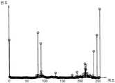
복수의 기준 계조들(GREF)은 표시 패널(도 1의 100)의 특성에 기초하여 결정될 수 있다. 예를 들어, 표시 패널(100)의 제조 시에 표시 패널(100)에 테스트 영상을 표시하고 계조들 각각에 대한 플리커 특성을 측정하여, 도 7에 도시된 것과 같은 계조별 플리커 수치를 획득할 수 있다. 이 때, 표시 패널(100)의 플리커 수치가 기준 플리커 지수(RFLK)보다 낮은 계조들(즉, 플리커 프리 계조들)인 GREFA와 GREFB 사이의 계조들(예를 들어, 32 계조 내지 162 계조) 및 최소 계조인 0 계조가 복수의 기준 계조들(GREF)로 결정될 수 있다. 다시 말하면, 복수의 기준 계조들(GREF)을 포함하는 영상이 표시 패널(100)에 표시되는 경우에, 상기 표시 패널(100)의 플리커 수치는 기준 플리커 지수(RFLK)보다 낮을 수 있다.The plurality of reference grayscales GREF may be determined based on a characteristic of the
도 7에서는 기준 플리커 지수(RFLK)가 약 1.0이고 저주파 구동이 가능한 복수의 기준 계조들(GREF)(즉, 플리커 프리 계조들)이 0 계조 및 32 계조 내지 162 계조로 설정되는 예를 도시하였으나, 실시예에 따라서 기준 플리커 지수(RFLK) 및 복수의 기준 계조들(GREF)은 임의의 값을 가질 수 있다.7 shows an example in which the reference flicker index RFLK is about 1.0 and the plurality of reference grayscales GREF (ie, flicker-free grayscales) capable of low-frequency driving are set to 0 grayscale and 32 to 162 grayscales. According to an embodiment, the reference flicker index RFLK and the plurality of reference grayscales GREF may have arbitrary values.
계조 선택부(250)는 상기 제2 동작 모드에서 복수의 계조 히스토그램들(HIS) 및 복수의 기준 계조들(GREF)에 기초하여 복수의 부분 영상 데이터들(PDAT)에 대한 복수의 대표 계조들(GREP)을 선택할 수 있다(단계 S300). 예를 들어, 계조 선택부(250)는 도 6a에 도시된 상기 제1 계조 히스토그램 및 도 7을 참조하여 획득된 복수의 기준 계조들(GREF)에 기초하여 상기 제1 부분 영상 데이터에 대한 제1 대표 계조들을 선택할 수 있다. 계조 선택부(250)는 도 6b에 도시된 상기 제2 계조 히스토그램 및 복수의 기준 계조들(GREF)에 기초하여 상기 제2 부분 영상 데이터에 대한 제2 대표 계조들을 선택할 수 있다. 계조 선택부(250)는 도 6c에 도시된 상기 제3 계조 히스토그램 및 복수의 기준 계조들(GREF)에 기초하여 상기 제3 부분 영상 데이터에 대한 제3 대표 계조들을 선택할 수 있다. 계조 선택부(250)는 도 6d에 도시된 상기 제4 계조 히스토그램 및 복수의 기준 계조들(GREF)에 기초하여 상기 제4 부분 영상 데이터에 대한 제4 대표 계조들을 선택할 수 있다.In the second operation mode, the
일 실시예에서, 계조 선택부(250)는 복수의 기준 계조들(GREF) 중 상기 제1 계조 히스토그램에 가장 많이 포함된 Z(Z는 Y보다 작거나 같은 자연수)개의 계조들을 상기 제1 대표 계조들로 선택할 수 있다. 예를 들어, 도 8에 도시된 것처럼, 0 계조 및 32 계조 내지 162 계조의 복수의 기준 계조들(GREF) 중에서, 상기 제1 계조 히스토그램에 가장 많이 포함된 0 계조, 32 계조, 43 계조, 81 계조, 89 계조, 130 계조, 139 계조 및 162 계조가 상기 제1 대표 계조들로 선택될 수 있다. 이 경우, 상기 제1 대표 계조들은 복수의 기준 계조들(GREF)에 포함될 수 있다. 다시 말하면, 상기 제1 대표 계조들은 복수의 기준 계조들(GREF)의 부분 집합일 수 있다.In an embodiment, the
이와 유사하게, 0 계조 및 32 계조 내지 162 계조의 복수의 기준 계조들(GREF) 중에서, 상기 제2 계조 히스토그램에 가장 많이 포함된 0 계조, 32 계조, 43 계조, 77 계조, 81 계조, 89 계조, 130 계조 및 162 계조가 상기 제2 대표 계조들로 선택될 수 있고, 상기 제3 계조 히스토그램에 가장 많이 포함된 0 계조, 32 계조, 43 계조, 83 계조, 112 계조, 128 계조, 151 계조 및 162 계조가 상기 제3 대표 계조들로 선택될 수 있으며, 상기 제4 계조 히스토그램에 가장 많이 포함된 0 계조, 32 계조, 43 계조, 83 계조, 90 계조, 112 계조, 141 계조 및 162 계조가 상기 제4 대표 계조들로 선택될 수 있다. 상기 제2 내지 제4 대표 계조들 각각은 복수의 기준 계조들(GREF)에 포함될 수 있다.Similarly, 0 grayscale, 32 grayscale, 43 grayscale, 77 grayscale, 81 grayscale, and 89 grayscale included the most in the second grayscale histogram among the plurality of reference grayscales GREF of 0 grayscale and 32 grayscale to 162 grayscale , 130 gradations and 162 gradations may be selected as the second representative gradations, and 0 gradation, 32 gradation, 43 gradation, 83 gradation, 112 gradation, 128 gradation, 151 gradation and 162 grayscales may be selected as the third representative grayscales, and 0, 32, 43, 83, 90, 112, 141, and 162 grays most included in the fourth grayscale histogram are The fourth representative grayscales may be selected. Each of the second to fourth representative grayscales may be included in a plurality of reference grayscales GREF.
실시예에 따라서, 부분 영상들(PI1, PI2, PI3, PI4)의 계조 특성에 따라서 대표 계조들(GREP)은 서로 동일할 수도 있고 서로 상이할 수도 있다. 예를 들어, 상기 제2 대표 계조들 중 일부(예를 들어, 0 계조, 32 계조, 43 계조, 81 계조, 89 계조, 130 계조 및 162 계조)는 상기 제1 대표 계조들에 포함될 수 있고, 상기 제2 대표 계조들 중 다른 일부(예를 들어, 77 계조)는 상기 제1 대표 계조들에 포함되지 않을 수 있다.According to an exemplary embodiment, the representative grayscales GREP may be the same or different from each other according to grayscale characteristics of the partial images PI1 , PI2 , PI3 , and PI4 . For example, some of the second representative grayscales (eg, 0 grayscale, 32 grayscale, 43 grayscale, 81 grayscale, 89 grayscale, 130 grayscale, and 162 grayscale) may be included in the first representative grayscale, Other portions (eg, 77 grays) among the second representative grayscales may not be included in the first representative grayscales.
도 8에서는 하나의 부분 영상 데이터에 대하여 8개의 대표 계조들이 선택되는 예를 도시하였으나, 실시예에 따라서 하나의 부분 영상 데이터에 대하여 임의의 개수의 대표 계조들이 선택될 수 있다.Although FIG. 8 illustrates an example in which eight representative grayscales are selected for one partial image data, an arbitrary number of representative grayscales may be selected for one partial image data according to an embodiment.
영상 변환부(260)는 상기 제2 동작 모드에서 복수의 부분 영상 데이터들(PDAT) 및 복수의 대표 계조들(GREP)에 기초하여 제2 출력 영상 데이터(DAT2)를 발생할 수 있다(단계 S400). 예를 들어, 영상 변환부(260)는 상기 제1 부분 영상 데이터 및 도 8에 도시된 상기 제1 대표 계조들에 기초하여 상기 제1 부분 영상 데이터에 상응하는 제2 출력 영상 데이터(DAT2)의 제1 부분을 발생할 수 있다. 영상 변환부(260)는 상기 제2 부분 영상 데이터 및 도 8에 도시된 상기 제2 대표 계조들에 기초하여 상기 제2 부분 영상 데이터에 상응하는 제2 출력 영상 데이터(DAT2)의 제2 부분을 발생할 수 있다. 영상 변환부(260)는 상기 제3 부분 영상 데이터 및 도 8에 도시된 상기 제3 대표 계조들에 기초하여 상기 제3 부분 영상 데이터에 상응하는 제2 출력 영상 데이터(DAT2)의 제3 부분을 발생할 수 있다. 영상 변환부(260)는 상기 제4 부분 영상 데이터 및 도 8에 도시된 상기 제4 대표 계조들에 기초하여 상기 제4 부분 영상 데이터에 상응하는 제2 출력 영상 데이터(DAT2)의 제4 부분을 발생할 수 있다. 영상 변환부(260)는 상기 제1 내지 제4 부분들을 조합하여 제2 출력 영상 데이터(DAT2)를 발생할 수 있다.The
일 실시예에서, 영상 변환부(260)는 상기 제1 부분 영상 데이터의 계조들 각각을 상기 제1 대표 계조들 중 하나로 변환할 수 있다. 예를 들어, 영상 변환부(260)는 상기 제1 부분 영상 데이터에 대한 계조 변환을 수행하며, 상기 계조 변환 시에 발생되는 입력 계조와 출력 계조 사이의 양자화 오차(quantization error)를 최소화하도록 디더링(dithering)을 수행할 수 있다.In an embodiment, the
구체적으로, 도 9를 참조하면, 영상 변환부(260)는 상기 제1 부분 영상 데이터에 포함된 복수의 픽셀 데이터들 중 제1 픽셀 데이터의 변환 전 계조(GN)와 상기 제1 대표 계조들을 비교할 수 있다(단계 S410).Specifically, referring to FIG. 9 , the
변환 전 계조(GN)가 상기 제1 대표 계조들 중 하나와 동일한 경우에(단계 S410: 예), 영상 변환부(260)는 상기 제1 픽셀 데이터의 변환 후 계조(GN')를 변환 전 계조(GN)로 유지할 수 있다(단계 S420).When the grayscale GN before conversion is the same as one of the first representative grayscales (step S410: Yes), the
변환 전 계조(GN)가 상기 제1 대표 계조들 모두와 상이한 경우에(단계 S410: 아니오), 영상 변환부(260)는 문턱 계조들(THL)에 기초하여 상기 제1 픽셀 데이터의 변환 후 계조(GN')를 상기 제1 대표 계조들 중 변환 전 계조(GN)와 가장 근사한 계조로 설정할 수 있다(단계 S430). 단계 S430 이후에,When the grayscale GN before conversion is different from all of the first representative grayscales (step S410: No), the
일 실시예에서, 문턱 계조들(THL)은 상기 제1 대표 계조들 중 두 개의 중간 값들일 수 있다. 예를 들어, 도 8에 도시된 것처럼, 0 계조, 32 계조, 43 계조, 81 계조, 89 계조, 130 계조, 139 계조 및 162 계조가 상기 제1 대표 계조들인 경우에, 상기 제1 대표 계조들에 대한 문턱 계조들(THL)은 16 계조, 37.5 계조, 62 계조, 85 계조, 109.5 계조, 134.5 계조 및 150.5 계조일 수 있다. 예를 들어, 변환 전 계조(GN)가 16 계조보다 크고 32 계조보다 작은 20 계조인 경우에, 상기 제1 픽셀 데이터의 변환 후 계조(GN')를 상기 제1 대표 계조들 중 32 계조로 설정할 수 있다.In an embodiment, the threshold grayscales THL may be intermediate values of two of the first representative grayscales. For example, as shown in FIG. 8 , when 0 grayscale, 32 grayscale, 43 grayscale, 81 grayscale, 89 grayscale, 130 grayscale, 139 grayscale, and 162 grayscale are the first representative grayscales, the first representative grayscales Threshold gradations THL may be 16 gradations, 37.5 gradations, 62 gradations, 85 gradations, 109.5 gradations, 134.5 gradations, and 150.5 gradations. For example, when the grayscale GN before conversion is greater than 16 grayscales and less than 32 grayscales, the grayscale GN' after conversion of the first pixel data is set to 32 grayscales among the first representative grayscales. can
영상 변환부(260)는 상기 제1 픽셀 데이터의 변환 후 계조(GN')에서 변환 전 계조(GN)를 감산하여 오차 값(Err)을 발생할 수 있다(단계 S440). 예를 들어, 상기 제1 픽셀 데이터의 변환 후 계조(GN')가 32 계조이고 변환 전 계조(GN)가 20 계조인 경우에 오차 값(Err)은 약 10 계조일 수 있다.The
영상 변환부(260)는 오차 값(Err)에 기초하여 오차 확산(error diffusion)을 수행할 수 있다(단계 S450). 예를 들어, 상기 제1 픽셀 데이터를 제공받는 제1 픽셀과 인접하는 이웃 픽셀들로 오차 값(Err)의 일부를 확산시킬 수 있다.The
일 실시예에서, 단계 S440 및 S450은 플로이드-스타인버그 디더링(Floyd-Steinberg dithering) 알고리즘에 기초하여 수행될 수 있다. 상기 플로이드-스타인버그 디더링 알고리즘은 통상의 기술자에게 널리 알려져 있으므로 구체적인 설명은 생략하도록 한다.In an embodiment, steps S440 and S450 may be performed based on a Floyd-Steinberg dithering algorithm. Since the Floyd-Steinberg dithering algorithm is widely known to those skilled in the art, a detailed description thereof will be omitted.
상기 제1 부분 영상 데이터에 포함된 상기 복수의 픽셀 데이터들 모두에 대한 오차 계산 및 디더링이 완료되지 않은 경우에(단계 S460: 아니오), 영상 변환부(260)는 N을 증가시키고(단계 S470) 다른 픽셀 데이터에 대하여 단계 S410, S420, S430, S440, S450 및 S460을 반복할 수 있다. 상기의 단계들은 상기 복수의 픽셀 데이터들 모두에 대한 오차 계산 및 디더링이 완료될 때까지 반복될 수 있다.When error calculation and dithering for all of the plurality of pixel data included in the first partial image data are not completed (step S460: No), the
상기 제1 부분 영상 데이터에 포함된 상기 복수의 픽셀 데이터들 모두에 대한 오차 계산 및 디더링이 완료된 경우에(단계 S460: 예), 영상 변환부(260)는 상기 제1 부분 영상 데이터의 변환을 종료하고 상기 제1 부분 영상 데이터에 상응하는 상기 제2 출력 영상 데이터(DAT2)의 제1 부분을 발생할 수 있다.When error calculation and dithering for all of the plurality of pixel data included in the first partial image data are completed (step S460: Yes), the
이와 유사하게, 영상 변환부(260)는 상기 제2 부분 영상 데이터의 계조들 각각을 상기 제2 대표 계조들 중 하나로 변환할 수 있고, 상기 제3 부분 영상 데이터의 계조들 각각을 상기 제3 대표 계조들 중 하나로 변환할 수 있으며, 상기 제4 부분 영상 데이터의 계조들 각각을 상기 제4 대표 계조들 중 하나로 변환할 수 있다.Similarly, the
본 발명의 실시예들에 따른 표시 장치는, 상기 제2 동작 모드에서 상대적으로 느린 주파수 및 제2 출력 영상 데이터(DAT2)에 기초하여 저화질 영상을 표시함으로써, 소비 전력이 감소될 수 있다.In the display device according to embodiments of the present invention, power consumption may be reduced by displaying a low-quality image based on a relatively low frequency and second output image data DAT2 in the second operation mode.
도 10은 본 발명의 실시예들에 따른 표시 장치에 포함되는 타이밍 제어 회로를 나타내는 블록도이다. 도 11은 본 발명의 실시예들에 따른 표시 장치의 플리커 특성을 측정하는 플리커 측정 장치를 나타내는 블록도이다.10 is a block diagram illustrating a timing control circuit included in a display device according to example embodiments. 11 is a block diagram illustrating a flicker measuring apparatus for measuring a flicker characteristic of a display device according to an exemplary embodiment of the present invention.
도 10 및 11을 참조하면, 타이밍 제어 회로(200a)는 영상 보정부(210), 영상 분할부(220), 영상 분석부(230), 기준 계조 설정부(245), 계조 선택부(250), 영상 변환부(260), 동작 주파수 설정부(270) 및 제어 신호 발생부(280)를 포함할 수 있다.10 and 11 , the
저장부(240)를 대신하여 기준 계조 설정부(245)를 포함하는 것을 제외하면, 도 10의 타이밍 제어 회로(200a)는 도 3의 타이밍 제어 회로(200)와 실질적으로 동일할 수 있다. 도 10의 영상 보정부(210), 영상 분할부(220), 영상 분석부(230), 계조 선택부(250), 영상 변환부(260), 동작 주파수 설정부(270) 및 제어 신호 발생부(280)는 도 3의 영상 보정부(210), 영상 분할부(220), 영상 분석부(230), 계조 선택부(250), 영상 변환부(260), 동작 주파수 설정부(270) 및 제어 신호 발생부(280)와 각각 실질적으로 동일할 수 있다.Except for including the reference gray
기준 계조 설정부(245)는 외부의 플리커 측정 장치(30)로부터 획득된 플리커 측정 값들(FV)에 기초하여 복수의 기준 계조들(GREF)을 설정할 수 있다. 예를 들어, 표시 패널(100)에 테스트 영상을 표시하고 계조들 각각에 대한 플리커 특성을 실시간으로 측정하여, 도 7에 도시된 것과 같은 계조별 플리커 수치를 획득할 수 있으며, 계조별 플리커 수치 및 기준 플리커 지수(RFLK)에 기초하여 복수의 기준 계조들(GREF)을 설정할 수 있다.The reference
일 실시예에서, 표시 장치(10)는 플리커 측정 장치(30)와 일시적으로 연결되어 플리커 측정 값들(FV)을 수신할 수 있다. 예를 들어, 표시 장치(10)는 플리커 측정 장치(30)와 I2C 인터페이스 방식으로 연결될 수 있다. 복수의 기준 계조들(GREF)의 설정이 완료된 경우에, 표시 장치(10)는 플리커 측정 장치(30)와 분리될 수 있다.In an embodiment, the
한편, 도시하지는 않았지만, 복수의 기준 계조들(GREF)은 입력 영상 데이터(IDAT)와 함께 제공될 수 있다. 예를 들어, 복수의 기준 계조들(GREF)은 입력 영상 데이터(IDAT)의 헤더(header) 부분에 삽입될 수 있다.Meanwhile, although not illustrated, the plurality of reference grayscales GREF may be provided together with the input image data IDAT. For example, the plurality of reference grayscales GREF may be inserted into a header portion of the input image data IDAT.
도 12는 본 발명의 실시예들에 따른 전자 시스템을 나타내는 블록도이다. 도 13은 도 12의 전자 시스템이 모바일 기기로 구현되는 예를 나타내는 도면이다.12 is a block diagram illustrating an electronic system according to embodiments of the present invention. 13 is a diagram illustrating an example in which the electronic system of FIG. 12 is implemented as a mobile device.
도 12 및 13을 참조하면, 전자 시스템(1000)은 프로세서(1010), 통신(Connectivity)부(1020), 메모리 장치(1030), 표시 장치(1040), 사용자 인터페이스(1050) 및 파워 서플라이(1060)를 포함한다. 실시예에 따라서, 전자 시스템(1000)은 휴대폰(Mobile Phone), 스마트 폰(Smart Phone), 개인 정보 단말기(Personal Digital Assistant; PDA), 휴대형 멀티미디어 플레이어(Portable Multimedia Player; PMP), 디지털 카메라(Digital Camera), 음악 재생기(Music Player), 휴대용 게임 콘솔(Portable Game Console), 네비게이션(Navigation) 시스템 등과 같은 임의의 모바일 시스템일 수 있다.12 and 13 , the
프로세서(1010)는 인터넷 브라우저, 게임, 동영상 등을 제공하는 소프트웨어, 프로그램 또는 어플리케이션들을 실행할 수 있다. 예를 들어, 프로세서(1010)는 중앙 처리 장치(Central Processing Unit; CPU) 또는 어플리케이션 프로세서(Application Processor; AP)일 수 있다.The
실시예에 따라서, 프로세서(1010)는 하나의 프로세서 코어(Single Core)를 포함하거나, 복수의 프로세서 코어들(Multi-Core)을 포함할 수 있다. 예를 들어, 프로세서(1010)는 듀얼 코어(Dual-Core), 쿼드 코어(Quad-Core), 헥사 코어(Hexa-Core) 등의 멀티 코어(Multi-Core)를 포함할 수 있다. 또한, 실시예에 따라서, 프로세서(1010)는 내부 또는 외부에 위치한 캐시 메모리(Cache Memory)를 더 포함할 수 있다.According to an embodiment, the
통신부(1020)는 외부 장치와 무선 통신 또는 유선 통신을 수행할 수 있다. 예를 들어, 통신부(1020)는 이더넷(Ethernet) 통신, 근거리 자기장 통신(Near Field Communication; NFC), 무선 식별(Radio Frequency Identification; RFID) 통신, 이동 통신(Mobile Telecommunication), 메모리 카드 통신, 범용 직렬 버스(Universal Serial Bus; USB) 통신 등을 수행할 수 있다. 예를 들어, 통신부(1020)는 베이스밴드 칩 셋(Baseband Chipset)을 포함할 수 있고, GSM, GPRS, WCDMA, HSxPA 등의 통신을 지원할 수 있다.The
메모리 장치(1030)는 프로세서(1010)에 의해 처리되는 데이터를 저장하거나, 동작 메모리(Working Memory)로서 작동하거나, 전자 시스템(1000)을 부팅하기 위한 부트 이미지를 저장할 수 있다. 예를 들어, 메모리 장치(1030)는 DRAM(Dynamic Random Access Memory), SRAM(Static Random Access Memory) 등과 같은 적어도 하나의 휘발성 메모리 장치를 포함하거나, EEPROM, 플래시 메모리, PRAM, RRAM, MRAM, FRAM, NFGM(Nano Floating Gate Memory), PoRAM(Polymer Random Access Memory) 등과 같은 적어도 하나의 비휘발성 메모리 장치를 포함할 수 있다.The
표시 장치(1040)는 도 1의 표시 장치일 수 있다. 예를 들어, 표시 장치(1040)는 프로세서(1010)에 의해 동작이 제어되고, 표시 패널(도 1의 100) 및 상기 표시 패널의 동작을 제어하는 타이밍 제어 회로(도 1의 200)를 포함하며, 도 2 내지 도 11을 참조하여 상술한 실시예들에 기초하여 구현되고 동작할 수 있다. 표시 장치(1040)는 제1 동작 모드에서 상대적으로 빠른 주파수 및 제1 출력 영상 데이터(DAT1)에 기초하여 고화질 영상을 표시하고 상기 제2 동작 모드에서 상대적으로 느린 주파수 및 제2 출력 영상 데이터(DAT2)에 기초하여 저화질 영상을 표시함으로써, 즉 저전력 모드에서 저주파 구동하고 저화질 영상을 표시함으로써, 표시 장치(1040) 및 전자 시스템(100)의 소비 전력이 감소될 수 있다.The
일 실시예에서, 프로세서(1010)는 상기 제1 동작 모드 또는 상기 제2 동작 모드를 선택적으로 활성화시키는 모드 선택 신호(MS)를 발생하여 타이밍 컨트롤러(200)에 제공할 수 있다. 상기 제2 동작 모드가 활성화된 경우에, 소비 전력을 추가적으로 감소시키기 위하여, 프로세서(1010)에 포함되는 복수의 프로세서 코어들 중 일부만이 동작할 수도 있고, 표시 장치(1040)의 밝기가 감소될 수도 있으며, 프로세서(1010)가 실행할 수 있는 소프트웨어, 프로그램 또는 어플리케이션들의 개수가 감소될 수도 있다.In an embodiment, the
사용자 인터페이스(1050)는 키패드, 터치 스크린과 같은 하나 이상의 입력 장치, 및/또는 스피커와 같은 하나 이상의 출력 장치를 포함할 수 있다. 파워 서플라이(1060)는 전자 시스템(1000)의 동작 전압을 공급할 수 있다. 또한, 실시예에 따라서, 전자 시스템(1000)은 카메라 이미지 프로세서(Camera Image Processor; CIS)를 더 포함할 수 있고, 메모리 카드(Memory Card), 솔리드 스테이트 드라이브(Solid State Drive; SSD), 하드 디스크 드라이브(Hard Disk Drive; HDD), 씨디롬(CD-ROM) 등과 같은 저장 장치를 더 포함할 수 있다.
전자 시스템(1000) 또는 전자 시스템(1000)의 구성요소들은 다양한 형태들의 패키지를 이용하여 실장될 수 있는데, 예를 들어, PoP(Package on Package), BGAs(Ball grid arrays), CSPs(Chip scale packages), PLCC(Plastic Leaded Chip Carrier), PDIP(Plastic Dual In-Line Package), Die in Waffle Pack, Die in Wafer Form, COB(Chip On Board), CERDIP(Ceramic Dual In-Line Package), MQFP(Plastic Metric Quad Flat Pack), TQFP(Thin Quad Flat-Pack), SOIC(Small Outline Integrated Circuit), SSOP(Shrink Small Outline Package), TSOP(Thin Small Outline Package), TQFP(Thin Quad Flat-Pack), SIP(System In Package), MCP(Multi Chip Package), WFP(Wafer-level Fabricated Package), WSP(Wafer-Level Processed Stack Package) 등과 같은 패키지들을 이용하여 실장될 수 있다.The
이상, 특정 주파수들, 특정 계조 값들 및 특정 개수로 분할된 영상에 기초하여 본 발명의 실시예들을 설명하였으나, 본 발명의 실시예들은 임의의 주파수들, 임의의 계조 값들 및 임의의 개수로 분할된 영상에 대해서도 적용될 수 있다.In the above, embodiments of the present invention have been described based on images divided into specific frequencies, specific grayscale values, and a specific number. However, embodiments of the present invention are divided into arbitrary frequencies, arbitrary grayscale values and arbitrary numbers. It can also be applied to images.
본 발명은 표시 장치 및 이를 포함하는 다양한 장치 및 시스템에 적용될 수 있다. 따라서 본 발명은 휴대폰, 스마트 폰, PDA, PMP, 디지털 카메라, 캠코더, PC, 서버 컴퓨터, 워크스테이션, 노트북, 디지털 TV, 셋-탑 박스, 음악 재생기, 휴대용 게임 콘솔, 네비게이션 시스템, 스마트 카드, 프린터 등과 같은 다양한 전자 기기에 유용하게 이용될 수 있다.The present invention can be applied to a display device and various devices and systems including the same. Accordingly, the present invention is a mobile phone, a smart phone, a PDA, a PMP, a digital camera, a camcorder, a PC, a server computer, a workstation, a notebook computer, a digital TV, a set-top box, a music player, a portable game console, a navigation system, a smart card, a printer It can be usefully used in various electronic devices such as
상기에서는 본 발명의 바람직한 실시예를 참조하여 설명하였지만, 해당 기술분야의 숙련된 당업자는 하기의 특허청구범위에 기재된 본 발명의 사상 및 영역으로부터 벗어나지 않는 범위 내에서 본 발명을 다양하게 수정 및 변경시킬 수 있음을 이해할 것이다.Although the above has been described with reference to the preferred embodiments of the present invention, those skilled in the art can variously modify and change the present invention without departing from the spirit and scope of the present invention as set forth in the claims below. you will understand that you can
Claims (20)
Translated fromKorean제1 동작 모드에서 입력 영상 데이터에 기초하여 제1 출력 영상 데이터를 발생하고 상기 표시 패널의 동작 주파수를 제1 주파수로 설정하며, 제2 동작 모드에서 상기 입력 영상 데이터를 변환하여 제2 출력 영상 데이터를 발생하고 상기 표시 패널의 동작 주파수를 상기 제1 주파수보다 낮은 제2 주파수로 설정하는 타이밍 제어 회로를 포함하며,
상기 표시 패널은 상기 제1 동작 모드에서 상기 제1 주파수 및 상기 제1 출력 영상 데이터에 기초하여 X(X는 2 이상의 자연수)개의 계조들을 포함하는 제1 영상을 표시하며, 상기 제2 동작 모드에서 상기 제2 주파수 및 상기 제2 출력 영상 데이터에 기초하여 Y(Y는 X보다 작은 자연수)개의 계조들을 포함하는 제2 영상을 표시하는 표시 장치.display panel; and
In a first operation mode, first output image data is generated based on input image data, an operation frequency of the display panel is set to a first frequency, and in a second operation mode, the input image data is converted to second output image data and a timing control circuit for generating and setting an operating frequency of the display panel to a second frequency lower than the first frequency;
The display panel displays a first image including X (where X is a natural number equal to or greater than 2) grayscales based on the first frequency and the first output image data in the first operation mode, and in the second operation mode A display device for displaying a second image including Y (Y is a natural number less than X) grayscales based on the second frequency and the second output image data.
상기 제2 동작 모드에서 상기 제2 영상을 표시하기 위한 복수의 영상 프레임들 중 일부를 차단하는 프레임 마스킹 구동(Frame Masking Driving; FMD) 방식에 기초하여 동작하는 것을 특징으로 하는 표시 장치.The method of claim 1,
and operating based on a frame masking driving (FMD) method of blocking some of a plurality of image frames for displaying the second image in the second operation mode.
상기 제1 출력 영상 데이터 또는 상기 제2 출력 영상 데이터를 기초로 복수의 데이터 전압들을 발생하여 상기 표시 패널에 제공하는 데이터 구동 회로를 더 포함하고,
상기 제2 동작 모드에서 상기 제2 영상을 표시하기 위한 상기 복수의 영상 프레임들은 연속하는 제1 프레임 및 제2 프레임을 포함하며,
상기 데이터 구동 회로는 상기 제1 프레임에서 상기 복수의 데이터 전압들을 출력하고, 상기 제2 프레임에서 상기 복수의 데이터 전압들의 출력을 차단하는 것을 특징으로 하는 표시 장치.3. The method of claim 2,
a data driving circuit that generates a plurality of data voltages based on the first output image data or the second output image data and provides them to the display panel;
The plurality of image frames for displaying the second image in the second operation mode include successive first and second frames,
and the data driving circuit outputs the plurality of data voltages in the first frame and blocks the output of the plurality of data voltages in the second frame.
복수의 게이트 신호들을 발생하여 상기 표시 패널에 제공하는 게이트 구동 회로를 더 포함하고,
상기 제2 동작 모드에서 상기 제2 영상을 표시하기 위한 상기 복수의 영상 프레임들은 연속하는 제1 프레임 및 제2 프레임을 포함하며,
상기 게이트 구동 회로는 상기 제1 프레임에서 상기 복수의 게이트 신호들을 출력하고, 상기 제2 프레임에서 상기 복수의 게이트 신호들의 출력을 차단하는 것을 특징으로 하는 표시 장치.3. The method of claim 2,
a gate driving circuit that generates a plurality of gate signals and provides them to the display panel;
The plurality of image frames for displaying the second image in the second operation mode include successive first and second frames,
and the gate driving circuit outputs the plurality of gate signals in the first frame and blocks the output of the plurality of gate signals in the second frame.
상기 제1 동작 모드에서 상기 입력 영상 데이터에 기초하여 상기 제1 출력 영상 데이터를 발생하는 영상 보정부;
상기 제2 동작 모드에서 상기 입력 영상 데이터를 분할하여, 상기 제1 영상이 분할된 복수의 부분 영상들에 상응하는 복수의 부분 영상 데이터들을 발생하는 영상 분할부;
상기 복수의 부분 영상 데이터들에 대한 복수의 계조 히스토그램들을 발생하는 영상 분석부;
상기 복수의 계조 히스토그램들 및 복수의 기준 계조들에 기초하여 상기 복수의 부분 영상 데이터들에 대한 복수의 대표 계조들을 선택하는 계조 선택부; 및
상기 복수의 부분 영상 데이터들 및 상기 복수의 대표 계조들에 기초하여 상기 제2 출력 영상 데이터를 발생하는 영상 변환부를 포함하는 것을 특징으로 하는 표시 장치.The method of claim 1 , wherein the timing control circuit comprises:
an image corrector configured to generate the first output image data based on the input image data in the first operation mode;
an image dividing unit dividing the input image data in the second operation mode to generate a plurality of partial image data corresponding to the plurality of partial images from which the first image is divided;
an image analyzer generating a plurality of grayscale histograms for the plurality of partial image data;
a grayscale selector configured to select a plurality of representative grayscales for the plurality of partial image data based on the plurality of grayscale histograms and a plurality of reference grayscales; and
and an image converter configured to generate the second output image data based on the plurality of partial image data and the plurality of representative grayscales.
상기 복수의 기준 계조들을 포함하는 영상이 상기 표시 패널에 표시되는 경우에, 상기 표시 패널의 플리커 수치는 기준 플리커 지수보다 낮으며,
상기 복수의 대표 계조들은 상기 복수의 기준 계조들에 포함되는 것을 특징으로 하는 표시 장치.6. The method of claim 5,
When the image including the plurality of reference grayscales is displayed on the display panel, a flicker value of the display panel is lower than a reference flicker index,
The plurality of representative grayscales are included in the plurality of reference grayscales.
상기 복수의 부분 영상들은 제1 부분 영상을 포함하고, 상기 영상 분할부는 상기 제1 부분 영상에 상응하는 제1 부분 영상 데이터를 발생하고, 상기 영상 분석부는 상기 제1 부분 영상 데이터에 대한 제1 계조 히스토그램을 발생하고, 상기 계조 선택부는 상기 제1 계조 히스토그램 및 상기 복수의 기준 계조들에 기초하여 상기 제1 부분 영상 데이터에 대한 제1 대표 계조들을 선택하며, 상기 영상 변환부는 상기 제1 부분 영상 데이터 및 상기 제1 대표 계조들에 기초하여 상기 제2 출력 영상 데이터의 제1 부분을 발생하는 것을 특징으로 하는 표시 장치.6. The method of claim 5,
The plurality of partial images include a first partial image, the image division unit generates first partial image data corresponding to the first partial image, and the image analyzer generates a first grayscale for the first partial image data generate a histogram, the grayscale selector selects first representative grayscales for the first partial image data based on the first grayscale histogram and the plurality of reference grayscales, and the image converter selects the first partial image data and generating a first portion of the second output image data based on the first representative grayscales.
상기 계조 선택부는 상기 복수의 기준 계조들 중 상기 제1 계조 히스토그램에 가장 많이 포함된 Z(Z는 Y보다 작거나 같은 자연수)개의 계조들을 상기 제1 대표 계조들로 선택하며,
상기 영상 변환부는 상기 제1 부분 영상 데이터의 계조들 각각을 상기 제1 대표 계조들 중 하나로 변환하는 것을 특징으로 하는 표시 장치.8. The method of claim 7,
The grayscale selector selects Z (Z is a natural number less than or equal to Y) grayscales most included in the first grayscale histogram among the plurality of reference grayscales as the first representative grayscales;
and the image converter converts each of the grayscales of the first partial image data into one of the first representative grayscales.
상기 복수의 부분 영상들은 제2 부분 영상을 포함하고, 상기 영상 분할부는 상기 제2 부분 영상에 상응하는 제2 부분 영상 데이터를 발생하고, 상기 영상 분석부는 상기 제2 부분 영상 데이터에 대한 제2 계조 히스토그램을 발생하고, 상기 계조 선택부는 상기 제2 계조 히스토그램 및 상기 복수의 기준 계조들에 기초하여 상기 제2 부분 영상 데이터에 대한 제2 대표 계조들을 선택하며, 상기 영상 변환부는 상기 제2 부분 영상 데이터 및 상기 제2 대표 계조들에 기초하여 상기 제2 출력 영상 데이터의 제2 부분을 발생하며,
상기 제2 대표 계조들 중 일부는 상기 제1 대표 계조들에 포함되고, 상기 제2 대표 계조들 중 다른 일부는 상기 제1 대표 계조들에 포함되지 않는 것을 특징으로 하는 표시 장치.8. The method of claim 7,
The plurality of partial images include a second partial image, the image division unit generates second partial image data corresponding to the second partial image, and the image analyzer generates a second grayscale for the second partial image data generate a histogram, the grayscale selector selects second representative grayscales for the second partial image data based on the second grayscale histogram and the plurality of reference grayscales, and the image converter selects the second partial image data and generating a second portion of the second output image data based on the second representative grayscales,
The display device of claim 1, wherein some of the second representative grayscales are included in the first representative grayscales, and other portions of the second representative grayscales are not included in the first representative grayscales.
상기 복수의 기준 계조들을 저장하는 저장부를 더 포함하는 것을 특징으로 하는 표시 장치.6. The method of claim 5, wherein the timing control circuit comprises:
and a storage unit configured to store the plurality of reference grayscales.
외부의 플리커 측정 장치로부터 획득된 플리커 측정 값들에 기초하여 상기 복수의 기준 계조들을 설정하는 기준 계조 설정부를 더 포함하는 것을 특징으로 하는 표시 장치.6. The method of claim 5, wherein the timing control circuit comprises:
The display device of claim 1, further comprising: a reference gray level setting unit configured to set the plurality of reference gray levels based on flicker measurement values obtained from an external flicker measurement device.
상기 제1 동작 모드에서 상기 표시 패널의 동작 주파수를 상기 제1 주파수로 설정하며, 상기 제2 동작 모드에서 상기 표시 패널의 동작 주파수를 상기 제2 주파수로 설정하는 동작 주파수 설정부를 더 포함하는 것을 특징으로 하는 표시 장치.6. The method of claim 5, wherein the timing control circuit comprises:
and an operating frequency setting unit configured to set the operating frequency of the display panel to the first frequency in the first operation mode and set the operating frequency of the display panel to the second frequency in the second operation mode display device.
상기 타이밍 제어 회로는 상기 제1 동작 모드 또는 상기 제2 동작 모드를 선택적으로 활성화시키는 모드 선택 신호를 수신하는 것을 특징으로 하는 표시 장치.The method of claim 1,
and the timing control circuit receives a mode selection signal for selectively activating the first operation mode or the second operation mode.
상기 표시 장치의 동작을 제어하는 프로세서를 포함하고,
상기 타이밍 제어 회로는 제1 동작 모드에서 입력 영상 데이터에 기초하여 제1 출력 영상 데이터를 발생하고 상기 표시 패널의 동작 주파수를 제1 주파수로 설정하며, 제2 동작 모드에서 상기 입력 영상 데이터를 변환하여 제2 출력 영상 데이터를 발생하고 상기 표시 패널의 동작 주파수를 상기 제1 주파수보다 낮은 제2 주파수로 설정하며,
상기 표시 패널은 상기 제1 동작 모드에서 상기 제1 주파수 및 상기 제1 출력 영상 데이터에 기초하여 X(X는 2 이상의 자연수)개의 계조들을 포함하는 제1 영상을 표시하며, 상기 제2 동작 모드에서 상기 제2 주파수 및 상기 제2 출력 영상 데이터에 기초하여 Y(Y는 X보다 작은 자연수)개의 계조들을 포함하는 제2 영상을 표시하는 전자 시스템.a display device including a display panel and a timing control circuit for controlling an operation of the display panel; and
a processor for controlling the operation of the display device;
The timing control circuit generates first output image data based on input image data in a first operation mode, sets an operation frequency of the display panel to a first frequency, and converts the input image data in a second operation mode to generating second output image data and setting an operating frequency of the display panel to a second frequency lower than the first frequency;
The display panel displays a first image including X (where X is a natural number equal to or greater than 2) grayscales based on the first frequency and the first output image data in the first operation mode, and in the second operation mode An electronic system for displaying a second image including Y (Y is a natural number less than X) grayscales based on the second frequency and the second output image data.
상기 표시 장치는 상기 제2 동작 모드에서 상기 제2 영상을 표시하기 위한 복수의 영상 프레임들 중 일부를 차단하는 프레임 마스킹 구동(Frame Masking Driving; FMD) 방식에 기초하여 동작하는 것을 특징으로 하는 전자 시스템.15. The method of claim 14,
and the display device operates based on a frame masking driving (FMD) method of blocking some of a plurality of image frames for displaying the second image in the second operation mode. .
상기 표시 장치는 상기 제1 출력 영상 데이터 또는 상기 제2 출력 영상 데이터를 기초로 복수의 데이터 전압들을 발생하여 상기 표시 패널에 제공하는 데이터 구동 회로를 더 포함하고,
상기 제2 동작 모드에서 상기 제2 영상을 표시하기 위한 상기 복수의 영상 프레임들은 연속하는 제1 프레임 및 제2 프레임을 포함하며,
상기 데이터 구동 회로는 상기 제1 프레임에서 상기 복수의 데이터 전압들을 출력하고, 상기 제2 프레임에서 상기 복수의 데이터 전압들의 출력을 차단하는 것을 특징으로 하는 전자 시스템.16. The method of claim 15,
The display device further includes a data driving circuit that generates a plurality of data voltages based on the first output image data or the second output image data and provides them to the display panel;
The plurality of image frames for displaying the second image in the second operation mode include successive first and second frames,
and the data driving circuit outputs the plurality of data voltages in the first frame and blocks the output of the plurality of data voltages in the second frame.
상기 표시 장치는 복수의 게이트 신호들을 발생하여 상기 표시 패널에 제공하는 게이트 구동 회로를 더 포함하고,
상기 제2 동작 모드에서 상기 제2 영상을 표시하기 위한 상기 복수의 영상 프레임들은 연속하는 제1 프레임 및 제2 프레임을 포함하며,
상기 게이트 구동 회로는 상기 제1 프레임에서 상기 복수의 게이트 신호들을 출력하고, 상기 제2 프레임에서 상기 복수의 게이트 신호들의 출력을 차단하는 것을 특징으로 하는 전자 시스템.16. The method of claim 15,
The display device further includes a gate driving circuit that generates a plurality of gate signals and provides them to the display panel;
The plurality of image frames for displaying the second image in the second operation mode include successive first and second frames,
and the gate driving circuit outputs the plurality of gate signals in the first frame and blocks the output of the plurality of gate signals in the second frame.
상기 제1 동작 모드에서 상기 입력 영상 데이터에 기초하여 상기 제1 출력 영상 데이터를 발생하는 영상 보정부;
상기 제2 동작 모드에서 상기 입력 영상 데이터를 분할하여, 상기 제1 영상이 분할된 복수의 부분 영상들에 상응하는 복수의 부분 영상 데이터들을 발생하는 영상 분할부;
상기 복수의 부분 영상 데이터들에 대한 복수의 계조 히스토그램들을 발생하는 영상 분석부;
상기 복수의 계조 히스토그램들 및 복수의 기준 계조들에 기초하여 상기 복수의 부분 영상 데이터들에 대한 복수의 대표 계조들을 선택하는 계조 선택부; 및
상기 복수의 부분 영상 데이터들 및 상기 복수의 대표 계조들에 기초하여 상기 제2 출력 영상 데이터를 발생하는 영상 변환부를 포함하는 것을 특징으로 하는 전자 시스템.15. The method of claim 14, wherein the timing control circuit,
an image corrector configured to generate the first output image data based on the input image data in the first operation mode;
an image dividing unit dividing the input image data in the second operation mode to generate a plurality of partial image data corresponding to the plurality of partial images from which the first image is divided;
an image analyzer generating a plurality of grayscale histograms for the plurality of partial image data;
a grayscale selector configured to select a plurality of representative grayscales for the plurality of partial image data based on the plurality of grayscale histograms and a plurality of reference grayscales; and
and an image converter configured to generate the second output image data based on the plurality of partial image data and the plurality of representative grayscales.
상기 복수의 부분 영상들은 제1 부분 영상을 포함하고, 상기 영상 분할부는 상기 제1 부분 영상에 상응하는 제1 부분 영상 데이터를 발생하고, 상기 영상 분석부는 상기 제1 부분 영상 데이터에 대한 제1 계조 히스토그램을 발생하고, 상기 계조 선택부는 상기 제1 계조 히스토그램 및 상기 복수의 기준 계조들에 기초하여 상기 제1 부분 영상 데이터에 대한 제1 대표 계조들을 선택하고, 상기 영상 변환부는 상기 제1 부분 영상 데이터 및 상기 제1 대표 계조들에 기초하여 상기 제2 출력 영상 데이터의 제1 부분을 발생하며,
상기 계조 선택부는 상기 복수의 기준 계조들 중 상기 제1 계조 히스토그램에 가장 많이 포함된 Z(Z는 Y보다 작거나 같은 자연수)개의 계조들을 상기 제1 대표 계조들로 선택하며,
상기 영상 변환부는 상기 제1 부분 영상 데이터의 계조들 각각을 상기 제1 대표 계조들 중 하나로 변환하는 것을 특징으로 하는 전자 시스템.19. The method of claim 18,
The plurality of partial images include a first partial image, the image division unit generates first partial image data corresponding to the first partial image, and the image analyzer generates a first grayscale for the first partial image data generate a histogram, the grayscale selector selects first representative grayscales for the first partial image data based on the first grayscale histogram and the plurality of reference grayscales, and the image converter selects the first partial image data and generating a first portion of the second output image data based on the first representative grayscales,
The grayscale selector selects Z (Z is a natural number less than or equal to Y) grayscales most included in the first grayscale histogram among the plurality of reference grayscales as the first representative grayscales;
and the image converter converts each of the grayscales of the first partial image data into one of the first representative grayscales.
상기 프로세서는 상기 제1 동작 모드 또는 상기 제2 동작 모드를 선택적으로 활성화시키는 모드 선택 신호를 발생하여 상기 타이밍 제어 회로에 제공하는 것을 특징으로 하는 전자 시스템.
15. The method of claim 14,
and the processor generates and provides a mode selection signal for selectively activating the first operation mode or the second operation mode to the timing control circuit.
Priority Applications (4)
| Application Number | Priority Date | Filing Date | Title |
|---|---|---|---|
| KR1020150076387AKR102372026B1 (en) | 2015-05-29 | 2015-05-29 | Display apparatus and electronic system including the same |
| US14/993,494US10339848B2 (en) | 2015-05-29 | 2016-01-12 | Display apparatus with multiple power modes and electronic system including the same |
| US16/420,400US10964250B2 (en) | 2015-05-29 | 2019-05-23 | Display apparatus with frame masking driving scheme and electronic system including the same |
| US17/189,557US11335233B2 (en) | 2015-05-29 | 2021-03-02 | Display apparatus and electronic system including the same |
Applications Claiming Priority (1)
| Application Number | Priority Date | Filing Date | Title |
|---|---|---|---|
| KR1020150076387AKR102372026B1 (en) | 2015-05-29 | 2015-05-29 | Display apparatus and electronic system including the same |
Publications (2)
| Publication Number | Publication Date |
|---|---|
| KR20160141277A KR20160141277A (en) | 2016-12-08 |
| KR102372026B1true KR102372026B1 (en) | 2022-03-11 |
Family
ID=57398868
Family Applications (1)
| Application Number | Title | Priority Date | Filing Date |
|---|---|---|---|
| KR1020150076387AActiveKR102372026B1 (en) | 2015-05-29 | 2015-05-29 | Display apparatus and electronic system including the same |
Country Status (2)
| Country | Link |
|---|---|
| US (3) | US10339848B2 (en) |
| KR (1) | KR102372026B1 (en) |
Families Citing this family (9)
| Publication number | Priority date | Publication date | Assignee | Title |
|---|---|---|---|---|
| KR102372026B1 (en) | 2015-05-29 | 2022-03-11 | 삼성디스플레이 주식회사 | Display apparatus and electronic system including the same |
| KR102609072B1 (en)* | 2016-09-23 | 2023-12-04 | 엘지디스플레이 주식회사 | Organic light emitting display panel, organic light emitting display device, data driver, and low power driving method |
| KR102462008B1 (en) | 2017-09-22 | 2022-11-03 | 삼성디스플레이 주식회사 | Organic light emitting display device |
| KR102614894B1 (en)* | 2019-05-02 | 2023-12-19 | 삼성디스플레이 주식회사 | Display apparatus and method of driving the same |
| KR102699835B1 (en)* | 2019-06-25 | 2024-08-30 | 삼성디스플레이 주식회사 | Display device performing apdaptive refresh |
| KR102690742B1 (en)* | 2019-08-16 | 2024-08-02 | 삼성디스플레이 주식회사 | Display apparatus and method of driving the same |
| KR102865725B1 (en)* | 2020-08-05 | 2025-09-30 | 삼성디스플레이 주식회사 | Flexible display apparatus and method of driving display panel using the same |
| KR102801474B1 (en)* | 2020-09-09 | 2025-05-02 | 삼성디스플레이 주식회사 | Display apparatus and method of driving the same |
| CN112598585B (en)* | 2020-12-07 | 2024-08-23 | 京东方科技集团股份有限公司 | Color image processing method and device, electronic ink screen and storage medium |
Citations (1)
| Publication number | Priority date | Publication date | Assignee | Title |
|---|---|---|---|---|
| JP2013088609A (en) | 2011-10-18 | 2013-05-13 | Nippon Hoso Kyokai <Nhk> | Display device using sub-field driving method, display method, and program |
Family Cites Families (23)
| Publication number | Priority date | Publication date | Assignee | Title |
|---|---|---|---|---|
| TW559771B (en)* | 2001-07-23 | 2003-11-01 | Hitachi Ltd | Matrix-type display device |
| US20040158878A1 (en)* | 2003-02-07 | 2004-08-12 | Viresh Ratnakar | Power scalable digital video decoding |
| KR101255701B1 (en)* | 2006-06-27 | 2013-04-17 | 엘지디스플레이 주식회사 | Appratus and method for driving LCD |
| KR101214658B1 (en)* | 2006-06-27 | 2012-12-27 | 엘지디스플레이 주식회사 | Appratus and method for driving LCD |
| DE102006060049B4 (en) | 2006-06-27 | 2010-06-10 | Lg Display Co., Ltd. | Liquid crystal display and driving method |
| KR20080097554A (en)* | 2007-05-02 | 2008-11-06 | 삼성전자주식회사 | Flicker tuning method, flicker tuning circuit for performing the same, and display device having same |
| KR20090032262A (en) | 2007-09-27 | 2009-04-01 | 삼성전자주식회사 | Subpixel data conversion apparatus and conversion method using pipelined 4-bit dither module |
| KR20090096999A (en) | 2008-03-10 | 2009-09-15 | 삼성전자주식회사 | Display device with reduced transmission channel frequency between timing controller and display driving circuit |
| US20100027663A1 (en)* | 2008-07-29 | 2010-02-04 | Qualcomm Incorporated | Intellegent frame skipping in video coding based on similarity metric in compressed domain |
| KR20120098704A (en) | 2009-10-20 | 2012-09-05 | 코닌클리케 필립스 일렉트로닉스 엔.브이. | Method and apparatus for highlighting functional display items |
| US9398666B2 (en)* | 2010-03-11 | 2016-07-19 | Pixtronix, Inc. | Reflective and transflective operation modes for a display device |
| KR101791865B1 (en)* | 2011-02-01 | 2017-11-01 | 삼성디스플레이 주식회사 | Method of processing data and dispay apparatus performing the method |
| JP5799676B2 (en) | 2011-08-31 | 2015-10-28 | ブラザー工業株式会社 | Image processing apparatus, image reading apparatus, and image processing program |
| TWI464720B (en)* | 2012-02-02 | 2014-12-11 | Novatek Microelectronics Corp | Liquid crystal display driving method and display device |
| US10242481B2 (en)* | 2012-03-15 | 2019-03-26 | Qualcomm Incorporated | Visibility-based state updates in graphical processing units |
| KR102072781B1 (en) | 2012-09-24 | 2020-02-04 | 삼성디스플레이 주식회사 | Display driving method and integrated driving appratus thereon |
| JP5971068B2 (en) | 2012-10-02 | 2016-08-17 | 富士ゼロックス株式会社 | Image processing apparatus, image forming system, and image processing program |
| US9530384B2 (en)* | 2012-11-14 | 2016-12-27 | Sharp Kabushiki Kaisha | Display device that compensates for changes in driving frequency and drive method thereof |
| KR20140106013A (en)* | 2013-02-25 | 2014-09-03 | 삼성디스플레이 주식회사 | Display device for reducing dynamic false contour |
| KR102060627B1 (en) | 2013-04-22 | 2019-12-31 | 삼성디스플레이 주식회사 | Display device and driving method thereof |
| CN105469746B (en)* | 2014-06-16 | 2019-02-26 | 青岛海信电器股份有限公司 | A kind of liquid crystal display backlight control apparatus, LCD TV and MCU chip |
| KR102372026B1 (en) | 2015-05-29 | 2022-03-11 | 삼성디스플레이 주식회사 | Display apparatus and electronic system including the same |
| US10339484B2 (en) | 2015-10-23 | 2019-07-02 | Kpmg Llp | System and method for performing signal processing and dynamic analysis and forecasting of risk of third parties |
- 2015
- 2015-05-29KRKR1020150076387Apatent/KR102372026B1/enactiveActive
- 2016
- 2016-01-12USUS14/993,494patent/US10339848B2/enactiveActive
- 2019
- 2019-05-23USUS16/420,400patent/US10964250B2/enactiveActive
- 2021
- 2021-03-02USUS17/189,557patent/US11335233B2/enactiveActive
Patent Citations (1)
| Publication number | Priority date | Publication date | Assignee | Title |
|---|---|---|---|---|
| JP2013088609A (en) | 2011-10-18 | 2013-05-13 | Nippon Hoso Kyokai <Nhk> | Display device using sub-field driving method, display method, and program |
Also Published As
| Publication number | Publication date |
|---|---|
| KR20160141277A (en) | 2016-12-08 |
| US11335233B2 (en) | 2022-05-17 |
| US20210183298A1 (en) | 2021-06-17 |
| US20190279551A1 (en) | 2019-09-12 |
| US10964250B2 (en) | 2021-03-30 |
| US20160351103A1 (en) | 2016-12-01 |
| US10339848B2 (en) | 2019-07-02 |
Similar Documents
| Publication | Publication Date | Title |
|---|---|---|
| KR102372026B1 (en) | Display apparatus and electronic system including the same | |
| CN107545868B (en) | display screen | |
| KR20200133129A (en) | Display device compensating for horizontal crosstalk | |
| US10971065B2 (en) | Display device, and method of determining a power supply voltage | |
| US10733932B2 (en) | Gamma correction device for a display device, gamma correction method for a display device, and display device | |
| US11244590B2 (en) | Gamma voltage generator and display device | |
| CN106205472B (en) | Driving unit, display device, and method of driving display panel | |
| US11735118B2 (en) | Organic light emitting display device and driving method of the same | |
| KR102238496B1 (en) | Method of driving display panel and display device performing the same | |
| US9672765B2 (en) | Sub-pixel layout compensation | |
| US11651719B2 (en) | Enhanced smoothness digital-to-analog converter interpolation systems and methods | |
| US12062163B2 (en) | High dynamic range post-processing device, and display device including the same | |
| JP7181597B2 (en) | Processing circuit, display device, and processing method | |
| US11961493B2 (en) | Display device, and method of operating a display device | |
| KR20210016205A (en) | Display device adjusting a scan pulse | |
| US11984057B2 (en) | Display device, and method of operating a display device | |
| KR102519397B1 (en) | Method of operating display apparatus and display apparatus performing the same | |
| US20180374450A1 (en) | Display pixel overdrive systems and methods | |
| US20220139289A1 (en) | Display device performing peak luminance driving, and method of operating a display device | |
| US9558539B2 (en) | Method of processing image data and display system for display power reduction | |
| US20190057493A1 (en) | Display device and display method therefor | |
| CN110021268A (en) | The display control method and device of OLED | |
| US20240135856A1 (en) | Multi-least significant bit (lsb) dithering systems and methods | |
| JP2023079069A (en) | CURRENT LIMITING CIRCUIT, DISPLAY DEVICE AND CURRENT LIMITING METHOD | |
| CN113409733A (en) | Brightness compensation method and system of display panel and display panel |
Legal Events
| Date | Code | Title | Description |
|---|---|---|---|
| PA0109 | Patent application | Patent event code:PA01091R01D Comment text:Patent Application Patent event date:20150529 | |
| PG1501 | Laying open of application | ||
| A201 | Request for examination | ||
| PA0201 | Request for examination | Patent event code:PA02012R01D Patent event date:20200511 Comment text:Request for Examination of Application Patent event code:PA02011R01I Patent event date:20150529 Comment text:Patent Application | |
| E902 | Notification of reason for refusal | ||
| PE0902 | Notice of grounds for rejection | Comment text:Notification of reason for refusal Patent event date:20210617 Patent event code:PE09021S01D | |
| E701 | Decision to grant or registration of patent right | ||
| PE0701 | Decision of registration | Patent event code:PE07011S01D Comment text:Decision to Grant Registration Patent event date:20211217 | |
| GRNT | Written decision to grant | ||
| PR0701 | Registration of establishment | Comment text:Registration of Establishment Patent event date:20220303 Patent event code:PR07011E01D | |
| PR1002 | Payment of registration fee | Payment date:20220304 End annual number:3 Start annual number:1 | |
| PG1601 | Publication of registration | ||
| PR1001 | Payment of annual fee | Payment date:20250224 Start annual number:4 End annual number:4 |